VS Compact Applications 1-Pair Dropwire Module Modules, platforms, accessories Product Catalogue 2005/2006 090.2000 010.1536

Welcome message from author
This document is posted to help you gain knowledge. Please leave a comment to let me know what you think about it! Share it to your friends and learn new things together.
Transcript

VS Compact Applications 1-Pair Dropwire ModuleModules, platforms, accessories
Product Catalogue 2005/2006
090.2000
010.1536

This document has been drafted with utmost care and reflects the products engineering level at the time of publication. Amendments or corrections to this document will be included in each new edition. Subject to technical change without notice.
R&M – a decision with a future
Choosing the right passive network structure is one of the most important and far-reaching decisions a network operator will ever have to make. The constantly growing demand for bandwidth, the staggering speed of techno-logical developments, and the call for of maximum availability are important factors when evaluating a system. So finance is not the only factor to be considered in a major network investment: the decision must take account of future requirements and developments.
The cabling solutions from R&M allow you to design your own modular and flexible network. This way you are prepared for the future and ensure long-term protection for your investment. The products' quality plus their simple installation and maintenance lowers operating costs and significantly increases network availability.
In this catalogue we present you with VS Compact, a state-of-the-art solution in copper distribution systems for access networks. Be it conventional tele-phony or high-speed data transmission via ISDN and xDSL, with VS-Compact you are well prepared for every application.
We gladly assist you in finding the perfect solution for your network. Why not-discover the intelligence, versatility and quality of R&M's product range yourself.
In order to facilitate your choice from our wide range of products, we have highlighted distinctive TOP PRODUCTS for the first time in this catalogue. They are TOP PRODUCTS because they have proven their worth many times over, and are favoured by our customers all around the world. They are the ideal solution for your cabling needs, and instantly available through our distribution channels. So look out for the part numbers highlighted in red.
Edition 1.2March 2005
ISO 9001 quality standard

1
Contents
Contents Page
Introduction
R&M – The Company 5
Products Overview 7
Applications 8
Cross Connection Cabinets 41
Customer Benefits 42
CCC Polyester 43
CCC Polycarbonate 45
CCC Accessories 47
030.0989
Small Distributors 49
Customer Benefits 50
Plastic Housings 51
Plastic Distributors 52
Customer Benefits Venus Housings 55
Venus type CSM 57
Venus type CME 58
Venus type CLA 60
Venus type HLA 62
Accessories 63
030.1495
Freestanding Distribution Frames (MDF), Wall Distribution Frames 11
Customer Benefits 12
Freestanding MDF Horizontal/Vertical 13
Freestanding MDF Vertical/Vertical 15
Wall Distribution Frames 17
19" Sub-Racks 21
Accessories 22
030.0742
Splice Closures 29
Customer Benefits 31
System Descriptions Types DC + FE 32
System Descriptions Types CM + DM 33
Cu Splice Closures, Type DC 34
Cu Splice Closures, Type FE 35
Cu Splice Closures, Type CM 36
Cu Splice Closures, Type DM 37
Splice Closures Accessories 38
010.2897

2
Contents Page
Modules and Accessories
VS Compact 75
Customer Benefits 76
Modules 77
PCB Base 80
Protection 81
Accessories Modules 84
Test Plugs 88
Test Cords 90
Connection and Patch Cords 91
Miscellaneous 92
Contents
Miscellaneous 96
Jumper Wires 96
VS Compact ADSL Splitter 65
Splitter Boards 68
Frames 70
Modules and Accessories 72
010.2708
030.0652
1-Pair Dropwire Module 93
Customer Benefits 93
Module and Protection 94
Accessories 95
010.2185
010.0256

3
Contents
Contents Page
Technical Data 97
Splice Closures 98
Cross Connection Cabinets 101
Small Distributors 103
VS Compact Modules 106
1-Pair Dropwire Module 110
Index 113
Part Number Index 113
Alphabetical Index 119

4
Notes

5
IntroductionR&M – The Company
Competent, innovative, customer-oriented
R&M – The Company
010.1536 Reichle & De-Massari AG is an independent family enterprise with 41 years of experience in the information and communication technology market (ICT). We have been successfully concentrating on passive cabling solutions for communication networks (layer 1). Thanks to our copper, fiber optic and plastic optical fiber (POF) of outstanding quality and our commitment to customers and their requirements we have acquired an enviable reputation. Today, R&M sets standards in modularity, quality and ease of installation and maintenance. We have worked our way to the market-leading position in Switzerland and are internationally growing. The company has regional marketing organizations in several countries and a global network of qualified distributing partners.
We are committed to innovative solutions and invest nearly 6% of our turnover in research and development every year. With great success! Today, 20% of our turnover is achieved with products less than 3 years old. Remarkable features of R&M are a profound experience and competence in connecting and distributive technology for copper, fiber optic and POF networks. We are supplying convincing cabling solutions to the segments of enterprise, carrier, industrial and residential cabling on the basis of these technologies, all the while being in the growing markets of residential and industrial cabling, too

6
Convincing Cabling SolutionsR&M provides convincing cabling solutions in all four following strategic segments:
Enterprise CablingThis segment comprises cabling solutions for any type of enterprise – from large corporations to small offices. We guarantee highest network availability and maximum bandwidth for voice, data and video transmission in copper and fiber optic transmission systems. The modular concept ensures flexibility for future expansions. The installation can always be upgraded according on requirements, e.g. for boosting the level of security or protection against environmental factors.(Overview Brochure R35034 [En], R35033 [Ge], Product Catalogue R35027 [En], R35026 [Ge])
Carrier CablingThis segment covers international and national telecom companies, the great number of regional network operators as well as city carriers. We provide comprehensive solutions for copper and fiber optic networks as a one-stop supplier. On the basis of individual customer consulting, products and systems are developed into custom-tailored solutions for inside and outside plant applications. (Overview Brochure R27990 [En], R300920 [Ge], Product Catalogue Fiber Optic R305470 [En], R305469-[Ge])
Residential CablingHere, the future growth market of multimedia networks in private homes is addressed. These cabling solutions combine all the different applications of telephony, data, TV, radio etc. in one universal infrastructure with a distribution centre. (Brochure R304926 [En], R304925 [Ge])
Industrial CablingIndustrial networks place extremely high demands on connector and distributive technology. We therefore developed special solutions such as plug connectors for highest mechanical loads, fully protected from environmental effects, up to IP67.
(Brochure R311820 [En], R311819 [Ge])
IntroductionR&M – The Company
Flexible system solutions for-enterprise, carrier and residential cabling.
030.1415
WAN
LAN
SOHO

7
IntroductionProducts Overview
31 2 4
75
9
6 8
1210 11
13
Products Page
Freestanding MDF, Wall Distribution Frames 11
1 Freestanding MDF Horizontal/Vertical 13
2 Freestanding MDF Vertical/Vertical 15
3 Wall Distribution Frames 17
4 19" Sub-Racks 21
Splice Closures 29
5 Splice Closures 31
Cross Connection Cabinets 41
6 Cross Connection Cabinets Polyester, Polycarbonate 43
Products Page
Small Distributors 49
7 SM Housing Plastic 51
8 Venus Housing 53
ADSL Splitter 65
9 ADSL Splitter Boards 68
Modules and Accessories 75
10 VS Compact Modules 77
11 VS Compact Protection 81
12 VS Compact Accessories 84
13 Dropwire Module and Protection 93
030.0778030.0742a 030.0738 030.0770
010.1317010.2897
010.2708
020.1177
090.2054
020.0806
030.0665030.0667
010.2185

8
Introduction Applications
1 Main Distribution Frames Horizontal/VerticalWith the modular distribution frames from R&M main distributors of medium to large capacities can be set up. Please see page 13 and foll.
2 Freestanding Distribution Frames Vertical/Vertical It is recommended to equip main distributors in medium sized PBX with vertical/vertical distribution frames. They can house VS Compact modules of 16, 20 or 25 pairs. Please see page 15 and foll.
3 Copper Splice ClosuresThe splice closures are ideal for direct use in sub-soil, underground or aerial applications without requiring any additional protection measures. Please see page 29 and foll.
4 Cross Connection CabinetsSimple installation of passive components for outside plant applications. Up to 3200 pairs. Please see page 41 and foll.
5 Distribution Point Terminal HousingsFor use in outdoor distributors in above-ground local distribution networks. Easy and time-saving handling of up to 100 pairs. Please see page 60 and foll.
Telecom and Carrier Networks 030.1573.1
1/2
1/2
3
4
5
1/2
A B
Operational Areas of ModulesA VS Compact ModulesB 1-Pair Dropwire Module
Copper Fiber optic

9
IntroductionApplications
1 Freestanding Distribution Frames Vertical/Vertical It is advisory to equip medium size central distributors with vertical/vertical distribution frames. They can house VS Compact modules of 16, 20 or 25 pairs. Please see page 13 and foll.
2 Wall Distribution FramesThanks to their simple design practically any configuration can be achieved with the VS Compact wall distribution frames. Between 8-pair and 25-pair modules can be used. Please see page 17 and foll.
3 19" Sub-RacksThe 19" sub-racks are ideal for the termination of the secondary cabling in floor distributors. Up to 300 pairs on 3 height units. Please see page 21 and foll.
4 Housings for Indoor Applications For a simple installation in floor distributors with up to 300 pairs. Please see page 51 and foll.
5 Copper Splice ClosuresThe splice closures are ideal for direct use in sub-soil, underground or aerial applications without requiring any additional protection measures. Please see page 29 and foll.
6 Cross Connection CabinetsSimple installation of passive components for outside plant applications. Up to 3200 pairs. Please see page 41 and foll.
7 Distribution Point Terminal Housings (VENUS)For use in outdoor distributors in above-ground local distribution networks. Easy and time-saving handling of up to 100 pairs. Please see page 60 and foll.
8 Subscriber Terminal Housings (VENUS)For use as subscriber terminals in above-ground local distribution networks. Up to 10 pairs. Please see page 57 and foll.
030.1575.1Subscriber Networks
A B
1/2
52
63/4
8 7
Operational Areas of ModulesA VS Compact ModulesB 1-Pair Dropwire Module
Copper

10
Notes

11
Freestanding and Wall Distribution FramesOverview
Products Page
1 Freestanding MDF Horizontal/Vertical 13
2 Freestanding MDF Vertical/Vertical 15
3 Wall Distribution Frames 17
4 19" Sub-Racks 21
5 Accessories 22
010.1284 – Fast and easy installation– High packing density without interfering with
installation or jumpering comfort– High modularity and flexibility– Neat cabling management
030.0770
4010.1864
5
030.0742
1030.0751
2030.0778
3
12
Freestanding and Wall Distribution FramesCustomer Benefits
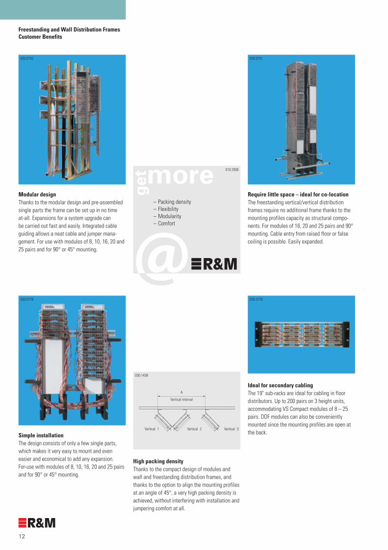
Modular designThanks to the modular design and pre-assembled single parts the frame can be set up in no time at-all. Expansions for a system upgrade can be carried out fast and easily. Integrated cable guiding allows a neat cable and jumper mana-gement. For use with modules of 8, 10, 16, 20 and 25 pairs and for 90° or 45° mounting.
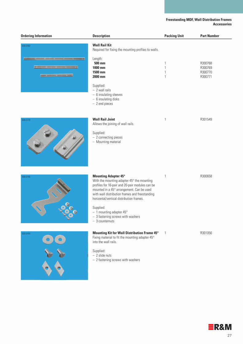
Require little space – ideal for co-locationThe freestanding vertical/vertical distribution frames require no additional frame thanks to the mounting profiles capacity as structural compo-nents. For modules of 16, 20 and 25 pairs and 90° mounting. Cable entry from raised floor or false ceiling is possible. Easily expanded.
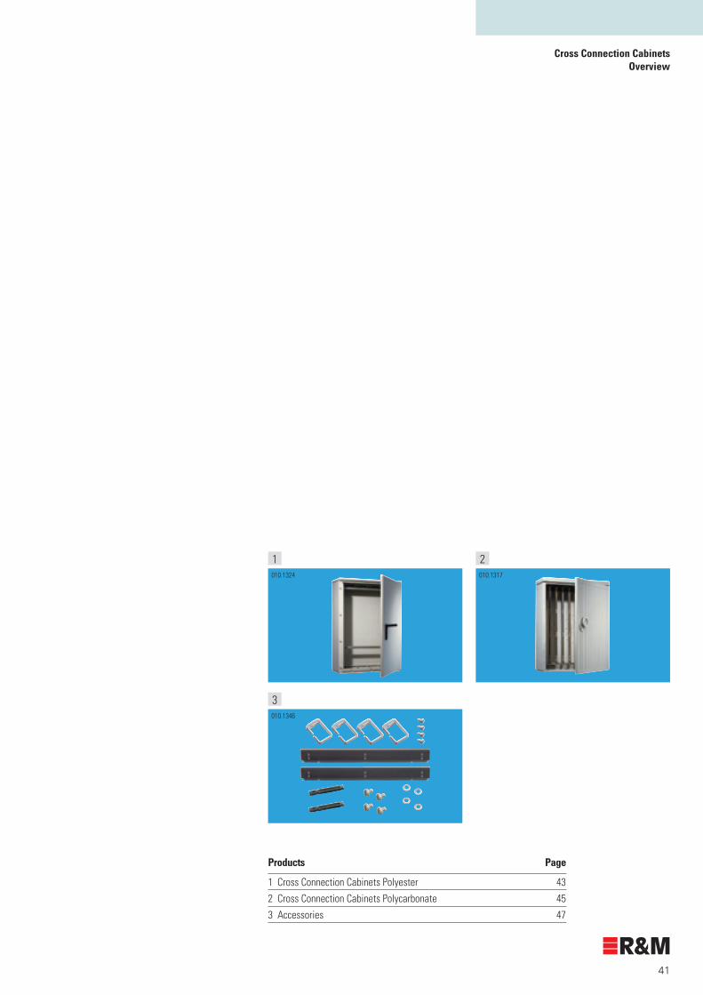
Ideal for secondary cablingThe 19" sub-racks are ideal for cabling in floor distributors. Up to 200 pairs on 3 height units, accommodating VS Compact modules of 8 – 25 pairs. DDF modules can also be conveniently mounted since the mounting profiles are open at the back. Simple installation
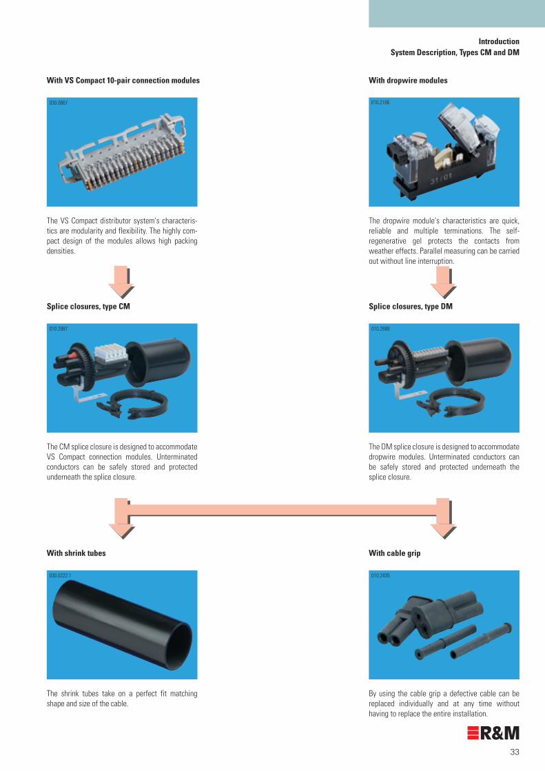
The design consists of only a few single parts, which makes it very easy to mount and even easier and economical to add any expansion. For-use with modules of 8, 10, 16, 20 and 25 pairs and for 90° or 45° mounting.
High packing densityThanks to the compact design of modules and wall and freestanding distribution frames, and thanks to the option to align the mounting profiles at an angle of 45°, a very high packing density is achieved, without interfering with installation and jumpering comfort at all.
030.1438
A
Vertical interval
Vertical 2 Vertical 3Vertical 1
030.0751030.0742
– Packing density– Flexibility– Modularity– Comfort
010.2936
030.0778 030.0770

13
Freestanding MDF, Wall Distribution FramesFreestanding MDF Horizontal/Vertical
Ordering Information
Dimensions of the horizontal/vertical MDFLength L Number of verticals x AHeight H 800 mm + (number of horizontals x A')
Distances and connections density in verticals and horizontals in horizontal/vertical MDF
Arrangement VS Compact Recommended Max. connection density per vertical/horizontal Modules vertical interval horizontal interval Profile length: A [mm] A [mm] A' [mm] 1.5 m 2.0 m 2,2 m 2,5 m
45° 16 pairs 220 240 960 pairs 1280 pairs 1408 pairs 1600 pairs
20 pairs 220 240 1200 pairs 1600 pairs 1760 pairs 2000 pairs
90° 8 pairs 220 240 600 pairs 800 pairs 880 pairs 1000 pairs
10 pairs 220 240 750 pairs 1000 pairs 1100 pairs 1250 pairs
16 pairs 220 240 960 pairs 1280 pairs 1408 pairs 1600 pairs
20 pairs 220 240 1200 pairs 1600 pairs 1760 pairs 2000 pairs
25 pairs 300 300 1500 pairs 2000 pairs 2200 pairs 2500 pairs
Ordering information MDF horizontal/vertical for VS Compact Modules:
Each frame is manufactured and delivered according to your requirements. In order to avoid any additional inquiries, we need the following data:
Type of distribution frame 1 column □
2 columns □
Number of verticals Min. 3 verticals Vertical interval A [mm]
and horizontals Min. 6 horizontals Horizontal interval A' [mm]
Protection bar No □ 1 column (recommended 950 mm)
Yes □ 2 columns (recommended 1300 mm)
Sliding rail for trolley No □ 1 column (recommended 950 mm)
Yes □ 2 columns (recommended 1300 mm)
False ceiling mounting No □ 1 column absolutely necessary: Yes □ Height [mm]
Raised floor No □
Yes □ Height [mm]
Earthing rail No □ Option: a copper rail is attached over the whole Yes □ length of the distribution frame.
Mounting adapter, mounting profile for modules and accessories are not included.
030.0743
H
L
Columns
Transfer strap
Vertical
Mounting profile
Protection bar
Floor rail
Horizontal
360
1200
A’
A

14
Freestanding MDF, Wall Distribution FramesFreestanding MDF Horizontal/Vertical Ordering Information
Mounting material
Material per vertical or horizontal Profile depth 25 mm – grid 20/25 mm – length: Part number Designation 1,5 m 2,0 m 2,2 m 2,5 m
For 45° arrangement
R300658 Mounting adapter 45° 16/20 pairs 2 3 3 4
R300011 Mounting profile 25/1500 2
R300012 Mounting profile 25/2000 2
R304636 Mounting profile 25/2200 2
R300659 Mounting profile 25/2500 2
Material per vertical or horizontal Profile depth 25 mm – grid 20/25 mm – length: 1,5 m 2,0 m 2,2 m 2,5 m
For 90° arrangement
R300648 Mounting adapter 90° 8 pairs
R300649 Mounting adapter 90° 10 pairs
R300650 Mounting adapter 90° 16 pairs 2 3 3 4
R300651 Mounting adapter 90° 20 pairs
R306267 Mounting adapter 90° 25 pairs
R300011 Mounting profile 25/1500 2
R300012 Mounting profile 25/2000 2
R304636 Mounting profile 25/2200 2
R300659 Mounting profile 25/2500 2
}
45° arrangement
030.0748
Vertical 1
Vertical 2
Vertical 3
90° arrangement
030.0749
Vertical 1
Vertical 2
Vertical 3

15
Freestanding MDF, Wall Distribution FramesFreestanding MDF Vertical /Vertical
Ordering Information
Dimensions of the vertical/vertical freestanding-MDFHeight: 2.10 m 960 pairs with 16-pair VS Compact 1200 pairs with 20-pair VS Compact 1600 pairs with 25-pair VS Compact 2,60 m 1280 pairs with 16-pair VS Compact 1600 pairs with 20-pair VS Compact 2000 pairs with 25-pair VS Compact
Number A1 [mm] A2 [mm] L1 [mm] L2 [mm] of double Vertical width Spacer kitverticals 16 pairs 20 pairs 25 pairs Kit 1 Kit 2 Kit 3 Kit 4 16 pairs 20 pairs 25 pairs 16 pairs 20 pairs 25 pairs 2 120 148 184 64 304 360 432 500 500 500 78 318 374 446 500 500 500 120 360 416 488 500 500 500 148 388 444 516 500 500 1000 3 120 148 184 64 488 572 680 500 1000 1000 78 516 600 708 1000 1000 1000 120 600 684 792 1000 1000 1000 148 656 740 848 1000 1000 1000 4 120 148 184 64 672 784 928 1000 1000 1000 78 714 826 970 1000 1000 1000 120 840 952 1096 1000 1000 1500 148 924 1036 1180 1500 1500 1500 5 120 148 184 64 856 996 1176 1500 1500 1500 78 912 1052 1232 1500 1500 1500 120 1080 1220 1400 1500 1500 1500 148 1192 1332 1512 1500 1500 2000 6 120 148 184 64 1040 1208 1424 1500 1500 2000 78 1110 1278 1494 1500 1500 2000 120 1320 1488 1704 2000 2000 2000 148 1460 1628 1844 2000 2000 2000 7 120 148 184 64 1224 1420 1672 1500 1500 2000 78 1308 1504 1756 1500 2000 2000 120 1560 1756 2008 2000 2000 2500 148 1728 1924 2176 2000 2000 2500 8 120 148 184 64 1408 1632 1920 1500 2000 2000 78 1506 1730 2018 2000 2000 2500 120 1800 2024 2312 2000 2500 2500 148 1996 2220 2508 2500 2500 3000 9 120 148 184 64 1592 1844 2168 2000 2000 2500 78 1704 1956 2280 2000 2000 2500 120 2040 2292 2616 2500 2500 3000 148 2264 2516 2840 2500 3000 300010 120 148 184 64 1776 2056 2416 2000 2500 2500 78 1902 2182 2542 2000 2500 3000 120 2280 2560 2920 2500 3000 3000 148 2532 2812 3172 3000 3000 3500
Ground plan (seen from above)
Example: 7 double verticals / 25-pair modules / spacer kit 4 L1 = 7 x A1 + 6 x A2 = 7 x 184 + 6 x 148 = 2176 mm L2 > L1 = 2500 mm
030.1439 L2
L1
A1 A2
840
720
452
400
360
030.0751

16
Freestanding MDF, Wall Distribution FramesFreestanding MDF Vertical/Vertical Material List
H = Distribution frame height (2.10 m or 2.60 m) T = Profile depth (200 mm)A1 = Width of vertical (depending on the modules inserted) A2 = Vertical interval (depending on the spacer kit)
Material list of the freestanding vertical/vertical MDF for 16-pair to 25-pair VS Compact modules This material list is a suggestion.
Part Designation Number of double verticals number 2 3 4 5 6 7 8 9 10
R300020 Mounting profile 2000/200 H = 2,10 m 8 12 16 20 24 28 32 36 40
R300021 Mounting profile 2500/200 H = 2,60 m
R300031 Mounting plate 16 pairs For 16-pair modules
R300032 Mounting plate 20 pairs For 20-pair modules 16 24 32 40 48 56 64 72 80
R306556 Mounting plate 25 pairs For 25-pair modules
R300660 Spacer 16 pairs For 16-pair modules
R300661 Spacer 20 pairs For 20-pair modules 16 24 32 40 48 56 64 72 80
R304974 Spacer 25 pairs For 25-pair modules
R301277 Spacer kit 1
R301278 Spacer kit 2 Determines 1 2 3 4 5 6 7 8 9
R301279 Spacer kit 3 vertical interval
R301280 Spacer kit 4
R301281 Mounting kit V/V distribution frame 2 3 4 5 6 7 8 9 10
R300772 Floor rail kit 500 mm/L21) 1
R300773 Floor rail kit 1000 mm/L21) 1 1 1 1
R300774 Floor rail kit 1500 mm/L21) 1 1
R300775 Floor rail kit 2000 mm/L21) 1 1 1 1 1 1
R301051 Connecting piece for floor rail11) 1 1 1 1
R301050 Transfer ring large 20 20 20 20 20 20 20 20 20
R300025 Transfer strap 8 12 16 20 24 28 32 36 40
Options
R301052 Protection bar kit 500 mm1) 1
R301053 Protection bar kit 1000 mm1) 1 1 1 1
R301054 Protection bar kit 1500 mm1) 1 1
R301055 Protection bar kit 2000 mm1) 1 1 1 1 1 1
R20069 Connecting piece for protection bar1) 1 1 1 1
R20020-100 Double floor support 100–155 mm 2 2 2 3 3 3 3 5 5
R20020-150 Double floor support 150–240 mm 2 2 2 3 3 3 3 5 5
The cables are led to the modules through the vertical, either from the bottom or the top. We therefore recommend using this distribution frame only with 16-pair VS Compact modules onward, resulting in a vertical width of > 120 mm.
030.1439
L2
L1
A1 A2
840
720
452
400
360
i 1) The here listed number is calculated with 25-pair VS Compact modules and spacer kit-4 (148-mm). Please refer to page 22 and foll. for further details on the listed single parts.
}
}}}

17
Freestanding MDF, Wall Distribution FramesWall Distribution Frames 90°
Ordering Information
Number A2 [mm] L1 [mm] L2 [mm] of Spacerverticals 8 pairs 10 pairs 16 pairs 20 pairs 25 pairs 8 pairs 10 pairs 16 pairs 20 pairs 25 pairs 8 pairs 10 pairs 16 pairs 20 pairs 25 pairs 2 64 192 220 304 360 432 500 500 500 500 500 78 206 234 318 374 446 500 500 500 500 500 120 248 276 360 416 488 500 500 500 500 500 148 276 304 388 444 516 500 500 500 500 1000 184 312 340 424 480 552 500 500 500 500 1000 3 64 320 362 488 572 680 500 500 500 1000 1000 78 348 390 516 600 708 500 500 1000 1000 1000 120 432 474 600 684 792 500 500 1000 1000 1000 148 488 530 656 740 848 500 1000 1000 1000 1000 184 560 602 728 812 920 1000 1000 1000 1000 1000 4 64 448 504 672 784 928 500 1000 1000 1000 1000 78 490 546 714 826 970 500 1000 1000 1000 1000 120 616 672 840 952 1096 1000 1000 1000 1000 1500 148 700 756 924 1036 1180 1000 1000 1000 1500 1500 184 808 864 1032 1144 1288 1000 1000 1500 1500 1500 5 64 576 646 856 996 1176 1000 1000 1000 1000 1500 78 632 702 912 1052 1232 1000 1000 1000 1500 1500 120 800 870 1080 1220 1400 1000 1000 1500 1500 1500 148 912 982 1192 1332 1512 1000 1000 1500 1500 2000 184 1056 1126 1336 1476 1656 1500 1500 1500 1500 2000 6 64 704 788 1040 1208 1424 1000 1000 1500 1500 1500 78 774 858 1110 1278 1494 1000 1000 1500 1500 1500 120 984 1068 1320 1488 1704 1000 1500 1500 1500 2000 148 1124 1208 1460 1628 1844 1500 1500 1500 2000 2000 184 1304 1388 1640 1808 2024 1500 1500 2000 2000 2500 7 64 832 930 1224 1420 1672 1000 1000 1500 1500 2000 78 916 1014 1308 1504 1756 1000 1500 1500 2000 2000 120 1168 1266 1560 1756 2008 1500 1500 2000 2000 2500 148 1336 1434 1728 1924 2176 1500 1500 2000 2000 2500 184 1552 1650 1944 2140 2392 2000 2000 2000 2500 2500 8 64 960 1072 1408 1632 1920 1000 1500 1500 2000 2000 78 1058 1170 1506 1730 2018 1500 1500 2000 2000 2500 120 1352 1464 1800 2024 2312 1500 1500 2000 2500 2500 148 1548 1660 1996 2220 2508 2000 2000 2000 2500 3000 184 1800 1912 2248 2472 2760 2000 2000 2500 2500 3000 9 64 1088 1214 1592 1844 2168 1500 1500 2000 2000 2500 78 1200 1326 1704 1956 2280 1500 1500 2000 2000 2500 120 1536 1662 2040 2292 2616 2000 2000 2500 2500 3000 148 1760 1886 2264 2516 2840 2000 2000 2500 3000 3000 184 2048 2174 2552 2804 3128 2500 2500 3000 3000 350010 64 1216 1356 1776 2056 2416 1500 1500 2000 2500 2500 78 1342 1482 1902 2182 2542 1500 1500 2000 2500 3000 120 1720 1860 2280 2560 2920 2000 2000 2500 3000 3000 148 1972 2112 2532 2812 3172 2000 2500 3000 3000 3500 184 2296 2436 2856 3136 3496 2500 2500 3000 3500 3500
Dimensions wall distribution frames 90°, in mm
Example: Please see page 15
A1 [mm] For VS Compact modules
8 pairs 10 pairs 16 pairs 20 pairs 25 pairs
64 78 120 148 184
030.1437.1
Ground plan of 90° arrangement (seen from above
L2
Vertical 1L1
Wall rail
A1 A2
Vertical 2 Vertical 3
030.0778

18
Freestanding MDF, Wall Distribution Frames Wall Distribution Frames 90° Material List
The profile depth [T] of the mounting profiles depends on the distribution frame's height [H] and the modules mounted in it since the cables are led in the mounting profiles.
Mounting profiles of a profile depth [T] = 25 mm do not allow the mounting of-spacers and transfer straps.
H = Distribution frame heightT = Profile depthA1 = Width of verticalA2 = Vertical interval
Material list for wall distribution frame in 90° arrangement for 8 to 25-pair modules with grid measures 20/25 mm This material list is a suggestion. Dimensions acc. to Table on page 17.
Part Designation Number of vertical number 1 2 3 4 5 6 7 8
Mounting profile see from page 22 2 4 6 8 10 12 14 16
R300022 Spacer 8 pairs
R300023 Spacer 10 pairs A1 with H < 1000 mm 2 4 6 8 10 10 14 16
R300660 Spacer 16 pairs A1 with H > 1000 mm 4 8 12 16 20 24 28 32
R300661 Spacer 20 pairs
R304974 Spacer 25 pairs
R300022 Spacer 8 pairs A2 for vertical interval
R300023 Spacer 10 pairs 3 6 9 12 15 18 21
R300660 Spacer 16 pairs
R300661 Spacer 20 pairs
R304974 Spacer 25 pairs
R301058 Mounting kit wall dist. frame 90° 1 2 3 4 5 6 7 8
R300768 Wall rail kit 500 mm/L21) 1 1
R300769 Wall rail kit 1000 mm/L21) 1 1 1
R300770 Wall rail kit 1500 mm/L21) 1 1
R300771 Wall rail kit 2000 mm/L21) 1 1
R301549 Connecting piece for wall rail1) 1
R301050 Transfer ring large for depth T = 50 mm 2 4 6 8 10 12 14 16
R301050 Transfer ring large for depth T = 100 mm 6 6 6 6 6 6 6 6
R300025 Transfer strap 2 4 6 8 10 12 14 16
T
030.1437.2
L2
Vertical 1L1
Wall rail
A1 A2
Vertical 2 Vertical 3
i 1) The here listed number is calculated with 16-pair VS Compact modules and 16-pair spacer. Please refer to pages 22 and foll. For-further details on the listed single parts.

19
Freestanding Distribution Frames, Wall Distribution Frames,
Wall Distribution Frames 90°, Material List
The profile depth [T] of the mounting profiles depends on the distribution frame's height [H] and the modules mounted in it since the cables are led in the mounting profiles.
Mounting profiles of a profile depth [T] = 25 mm do not allow the mounting of-spacers and transfer straps.
H = Distribution frame heightT = Profile depthA1 = Width of verticalA2 = Vertical interval
Material list for wall distribution frames in 90° arrangement for 10-pair modules with grid measures 17.5 mm This material list is a suggestion. Dimensions acc. to Table on page 17.
Part- Designation Number of verticals number 1 2 3 4 5 6 7 8
Mounting profile 17.5 see from page 22 2 4 6 8 10 12 14 16
R300023 Spacer 10 pairs A1 with H < 1000 mm 2 4 6 8 10 10 14 16
A1 with H > 1000 mm 4 8 12 16 20 24 28 32
R300022 Spacer 8 pairs A2 for vertical interval 3 6 9 12 15 18 21
R300023 Spacer 10 pairs
R301058 Mounting kit wall dist. frame 90° 1 2 3 4 5 6 7 8
R300768 Wall rail kit 500 mm/L22) 1 1 1
R300769 Wall rail kit 1000 mm/L22) 1 1
R300770 Wall rail kit 1500 mm/L22) 1 1 1
R300771 Wall rail kit 2000 mm/L22)
R301549 Connecting piece for wall rail2)
R301050 Transfer ring large for depth T = 50 mm 2 4 6 8 10 12 14 16
R301050 Transfer ring large for depth T = 100 mm 6 6 6 6 6 6 6 6
R300025 Transfer strap 2 4 6 8 10 12 14 16
T
030.1437.2
L2
Vertical 1L1
Wall rail
A1 A2
Vertical 2 Vertical 3
i 2) The here listed number is calculated with 10-pair VS Compact modules and 10-pair spacer. Please refer to page 22 and foll. For-further details on the listed single parts.

20
Freestanding MDF, Wall Distribution FramesWall Distribution Frames 45°Ordering Information
Dimensions of the wall distribution frame 45° in mm for 16- and 20-pair VS Compact modules
Number of verticals L1 [mm] L2 [mm]
1 115 500
2 230 500
3 445 500
4 560 1000
5 775 1000
6 890 1000
7 1105 1500
8 1220 1500
9 1435 1500
10 1550 2000
Material list for wall distribution frame 45° for 16- and 20-pair modules with grid measure 25 mm This material list is a suggestion. Dimensions acc. to Table on page 17.
Part- Designation Number of double verticals number 1 2 3 4 5 6 7 8 9 10
Mounting profile 25 mm see page 22 2 4 6 8 10 12 14 16 18 20
R300568 Mounting adapter 45° 2 4 6 8 10 12 14 16 18 20
R300768 Wandschienen-Set 500 mm/L2 acc. to dimensions wall dist. frame 45° 1 1 1
R300769 Wall rail kit 1000 mm/L2 1 1 1
R300770 Wall rail kit 1500 mm/L2 1 1 1
R300771 Wall rail kit 2000 mm/L2 1
R301549 Connecting piece for wall rail1)
R301056 Wall distribution frame 45° mounting kit 1 2 3 4 5 6 7 8 9 10
R301050 Transfer ring large 2 4 6 8 10 12 14 16 18 20
A1 = 115 mmA2 = 100 mm (recommended interval)
030.1438.1
L2
Vertical 1
L1
Ground plan of 45° arrangement (seen from above)
A1 A2
Vertical 2
Vertical 3
Dimensions of wall distribution frame 45°, in mm
030.1436 L1
H =
Prof
ile le
ngth

21
Freestanding MDF, Wall Distribution Frames19" Sub-Racks
Ordering Information Description Packing Unit Part Number
19" Mounting Profile KitMounting profile for empty 19" 3U sub-racks. Maximum number of VS Compact modules:– 6 with grid size 20 mm– 5 with grid size 25 mm
19" Mounting Profile KitMounting profile for empty 19" 3U sub-racks.Maximum number of VS Compact modules:– 7 with grid size 17.5 mm
1 R300663
1 R301943
19" 1U Cable Guide PanelAluminium panel with 4 plastic cable guide brackets (incl. mounting kit). To ensure neat and structured horizontal jumper wire alignment between distribution panels.
1 R302705
19" 3U Sub-RackEmpty 19" sub-rack of three height units (incl. mounting kit). Used to fasten the mounting profiles for VS Compact modules. Depending on module size the sub-rack can be equipped with 2-to 4 mounting profile kits.Designed for max.:8/10-pair module 4 mounting profile kits16-pair module 3 mounting profile kits 20/25-pair module 2 mounting profile kits
1 R300662010.2240
010.0654
010.2234
010.1863
010.0654

22
Freestanding MDF, Wall Distribution FramesAccessories
Ordering Information Description Packing Unit Part Number
Mounting ProfilesTwo mounting profiles are required to mount VS-Compact connection modules
Grid size 20/25 mmDepth [mm] Length [mm] 25 100 25 200 25 400 25 440 25 600 25 800 25 1000 25 1500 25 2000 25 2200 25 2500
50 200 50 250 50 400 50 1000 50 2000
100 200100 400100 800100 900100 1000100 1500100 2200 200 1500200 2000200 2500
Grid size 17.5 mmDepth [mm] Length [mm] 25 175 25 2187
50 175 50 350
100 350100 700100 1313100 2187
2 R3049382 R3000102 R3030072 R3073482 R3030082 R3020642 R3020652 R3000112 R3000122 R3046362 R300659
2 R3000132 R3078382 R3000142 R3049952 R304494
2 R3032112 R3000162 R3000172 R3032122 R3018632 R3000182 R304997
2 R3000192 R3000202 R300021
2 R3009632 R304637
2 R3009642 R300965
2 R3009662 R3009672 R3009682 R304996
Mounting Profile Kit, 1 Space Consists of 2 mounting profiles
Depth 15 mmDepth 25 mm
1 R3020151 R302016
010.1864
010.1865.1

23
Freestanding MDF, Wall Distribution FramesAccessories
Ordering Information Description Packing Unit Part Number
SpacerTo maintain the distance between two mounting profiles or back mount frames, and ensure a neat jumpering layout.Size 8 pairsSize 10 pairsSize 16 pairsSize 20 pairsSize 25 pairs
Transfer Ring, smallTo snap onto the side of mounting profile or back mount frame. Min. profile depth to snap on is 50-mm.
Transfer Ring, largeTo snap onto the side or front of mounting profile or back mount frame. Min. profile depth to snap on is 100 mm.
1 R301050
10 R300024
10 R30002210 R30002310 R30066010 R30066110 R304974
Depth [mm] Length [mm] Max.-no.-of-modules
Back Mount Frame, 8 pairs (128 pairs block)50 320 16
Back Mount Frame, 10 pairs (100 pairs block)50 200 10
Back Mount Frame, 16 pairs (128 pairs block)50 225 9100 1500 60
Back Mount Frame, 20 pairs 50 250 10 50 375 15100 400 16
Back Mount Frame, 25 pairs 50 125 5 50 250 10100 375 15100 500 20Back Mount Frame, 10 pairs, grid size 17.5 mm50 175 1075 297.5 1775 367.5 2175 525 3075 595 3475 700 40
1 R300004
1 R300009
1 R3027061 R310094
1 R3028181 R3049841 R305429
1 R306631*1 R306633*1 R308542*1 R308543*
1 R3000081 R3012721 R3012731 R3012741 R3012751 R301276
i * With M4 earth clamp.
030.0762
030.0756
020.1052
010.2229

24
Freestanding MDF, Wall Distribution FramesAccessories
Ordering Information Description Packing Unit Part Number
Label HolderConsists of a frame, a cover and labelling strips.
Size Grid size 8 pairs 20 mm10 pairs 20 mm10 pairs 17.5 mm16 pairs 25 mm20 pairs 25 mm25 pairs 25 mm
Kit for Hinged Label HolderKit to attach block labelling directly to the module. Swings back for testing or jumpering purposes.
Single Blind CoverTo cover single unused spaces.
Size Grid size 8 pairs 20 mm10 pairs 20 mm16 pairs 25 mm20 pairs 25 mm25 pairs 25 mm
10 R30104610 R30104710 R30104810 R30104910 R311841
20 R300668
10 R30066410 R30066510 R30201710 R30066610 R30066710 R305208
Multiple Blind CoverTo cover several unused spaces.
Size Grid size 8 pairs 200 mm10 pairs 200 mm16 pairs 250 mm20 pairs 250 mm25 pairs 250 mm
10 R30067010 R30067110 R30067210 R30067310 R306598
Transfer StrapTo be screwed to the side of the mounting profile or back mount frame, mounting material included. Material: chromium-plated steel.Minimum profile depth for side mounting is 50-mm.
1 R300025
030.0776
030.0775
030.0758
030.0773
030.0774

25
Freestanding MDF, Wall Distribution FramesAccessories
Ordering Information Description Packing Unit Part Number
Floor Rail JointTo extend the floor rail.
Supplied:– 2 connecting pieces– Mounting material
Mounting PlateDetermines vertical width and fixes the mounting rails to the floor rails. Mounting material (R301281) for floor rails not included.
16 pairs20 pairs25 pairs
Supplied: – 1 fixing brackets– 6 fastening screws with washers– 6 counternuts
1 R3000311 R3000321 R306556
1 R301051
Mounting Kit for Freestanding MDF Vertical/VerticalUtensils required for mounting a double vertical to floor rail.
Supplied:– 4 slide nuts– 4 fastening screws with washers
1 R301281
Floor Rail KitTo set up freestanding vertical/vertical distribution frames.
Length 500 mm1000 mm1500 mm2000 mm
Supplied: – 2 floor rails– 4 insulating disks– 4 insulating sleeves– 4 end pieces
1 R3007721 R3007731 R3007741 R300775
030.0754
030.0780
030.0759
030.0755

26
Freestanding MDF, Wall Distribution FramesAccessories
Ordering Information Description Packing Unit Part Number
Protection Rail KitTwo pieces are required for one freestanding distribution frame.
Length: 500 mm1000 mm1500 mm2000 mm
Supplied: – 1 protection bar– 2 protection bar carriers– 8 fastening screws with washers– 8 counternuts– 2 fastening screws with lock washers– 2 slide nuts
1 R3010521 R3010531 R3010541 R301055
Protection Bar JointTo extend the protection bar.
Supports for Raised FloorsFour supports are needed for one freestanding distribution frame.
Height:100–155 mm160–240 mm
Supplied:– 2 supports– 2 screw necks with 4 nuts– 2 fastening screws with washers
1 R20020-1001 R20020-150
1 R20069
Spacer KitDetermines the distance between two double verticals. Includes a spacer to ensure neat jumper wire alignment.
Size: Distance:Size 1 64 mmSize 2 78 mmSize 3 120 mmSize 4 148 mm
Supplied: – 4 fixing brackets– 6 VS Compact spacers– 19 fastening screws with washers– 19 counternuts
1 R3012771 R3012781 R3012791 R301280
010.0656
010.1862
010.0659
010.0669
27
Freestanding MDF, Wall Distribution FramesAccessories
Ordering Information Description Packing Unit Part Number
Wall Rail JointAllows the joining of wall rails.
Supplied: – 2 connecting pieces– Mounting material
1 R301549
Mounting Adapter 45°With the mounting adapter 45° the mounting profiles for 16-pair and 20-pair modules can be mounted in a 45° arrangement. Can be used with wall distribution frames and freestanding horizontal/vertical distribution frames.
Supplied: – 1 mounting adapter 45° – 3 fastening screws with washers– 3 counternuts
1 R300658
Mounting Kit for Wall Distribution Frame 45°Fixing material to fit the mounting adapter 45° into the wall rails.
Supplied:– 2 slide nuts– 2 fastening screws with washers
030.0764 1 R301056
Wall Rail KitRequired for fixing the mounting profiles to walls.
Length: 500 mm 1000 mm 1500 mm 2000 mm
Supplied:– 2 wall rails– 6 insulating sleeves– 6 insulating disks– 2 end pieces
1 R3007681 R3007691 R3007701 R300771
030.0779
030.0746
030.0763

28
Freestanding MDF, Wall Distribution FramesAccessories
Ordering Information Description Packing Unit Part Number
Mounting Kit for Wall Distribution Frames-90°Fixing material to directly fit the mounting profiles into the wall rails.
Supplied: – 4 slide nuts– 4 fastening screws with washers
1 R301058
Trolley for 2 Wire CoilsTrolley for 2 wire coils of 120 mm diameter and a maximum width of 125 mm.
1 R20062
Safety StairsWheeled with automatic safety stop and extra large non-skid steps. Space for depositing tools.Material: aluminium
Top height: 1160 mm 1 R20036-3
Mounting Adapter 90° for Freestanding MDF Horizontal/VerticalTo fit the mounting profiles in a 90° arrangement. Suitable for freestanding horizontal/vertical distribution frames.
For modules 8 pairs10 pairs16 pairs20 pairs25 pairs
Supplied:– 1 mounting adapter 90° – 2 fastening screws with washers– 1 fastening screw with lock washer– 2 counternuts
1 R3006481 R3006491 R3006501 R3006511 R306267
030.0764
010.0057
020.0392
030.0747

29
IntroductionProducts Overview
Products Page
1 Cu Splice Closures, Type DC 34
2 Cu Splice Closures, Type FE 35
3 Cu Splice Closures, Type CM 36
4 Cu Splice Closures, Type DM 37
5 Cu Splice Closures Accessories 38
54
1 2 3
Cu Splice Closure VersionsApplication: the ideal operating areas of R&M's splice closure product range are telecom and carrier networks, city networks and networking in the industrial sector.
DesignThe entire R&M splice closure product range has been designed for modularity and flexibility, allowing it to freely determine size and number of end cap tubes and to choose between fixed or flexible dropwire entries. There is even the option to connect the installation with VS connection modules (VS Compact), dropwire modules or simply single connectors. The fiber-glass reinforced turn-lock fastener allows repeated opening and closing without the need for tools, not even a screwdriver is required. For reasons of security the locking system allows sealing the entire installation or securing it by lock. Finally, with the comprehensive range of accessories all possible requirements are easily satisfied.
Operating AreasR&M's splice closures are made of the same materials as the cables, meaning wherever a cable is used a splice closure can also be used. The high-end polyethylene is particularly resistant to alkaline earths, salt water, fungal and putrefication bacteria. Thanks to their ingenious design and compact construc-tions the splice closures are absolutely watertight (IP68). Consequently, they are ideal for direct use in subsoil, underground or aerial applications without requiring any additional protective measures.
010.2897
010.2432010.2888
010.2885 010.2886 010.2887

30
Telecom and Carrier Networks
City Networks
IntroductionApplications
030.1573.1
030.1575.1

31
IntroductionCustomer Benefits
FlexibilityFor each application the right cable entry. You choose between flexible, fixed and dropwire entries
Earth connection and leak testingContinuous earth connection for shielded cables. Valve for leak testing after installation.
Cable managementNeat and tidy solutions for each application.
Simple and secure locking systemRepeated opening without having to replace the seal. The locking system offers optional sealing or locking of the splice closure.
Resistance to chemicals As a result of using high-quality polyethylene, the splice closure system is particularly resistant to alkaline earths, salt water, fungal and putrefica-tion bacteria.
Environmental factorsThanks to the splice closure system's compact design, external influences such as environmental temperatures of between -20° and +60° or water depths of up to 6 meters (IP68) pose no more threats.
010.2889 010.2436
010.2936
– Reliability– Modularity– Flexibility– Re-usability– Repeatability– Protection
010.2897010.2427

32
IntroductionSystem Description, Types DC and FE
With double or triple connectors
Telecommunication cables are perfectly connec-ted with single connectors. The conductors to be connected are simply inserted into the connector without previous stripping.
Splice closures, type DC Splice closures, type FE
The DC splice closure is designed for cable-to-cable splicing with or without branches. With the DC type the cable entries can only be fitted with shrink tubes.
With shrink tubes With cable grip
By using the cable grip a defective cable can be replaced individually and at any time without having to replace the entire installation.
The shrink tubes take on a perfect fit matching shape and size of the cable.
The FE splice closure is designed for cable-to-cable splicing with or without branches. It is particularly suitable for tight spaces. The fixed cable entries of this closure type accept shrink tubes and cable grips.
010.1768.1
010.2885 010.2886
030.0222.1 010.2435
33
IntroductionSystem Description, Types CM and DM
With shrink tubes With cable grip
By using the cable grip a defective cable can be replaced individually and at any time without having to replace the entire installation.
The shrink tubes take on a perfect fit matching shape and size of the cable.
Splice closures, type CM Splice closures, type DM
The CM splice closure is designed to accommodate VS Compact connection modules. Unterminated conductors can be safely stored and protected underneath the splice closure.
The DM splice closure is designed to accommodate dropwire modules. Unterminated conductors can be safely stored and protected underneath the splice closure.
With VS Compact 10-pair connection modules With dropwire modules
The VS Compact distributor system's characteris-tics are modularity and flexibility. The highly com-pact design of the modules allows high packing densities.
The dropwire module's characteristics are quick, reliable and multiple terminations. The self-regenerative gel protects the contacts from weather effects. Parallel measuring can be carried out without line interruption.
030.0222.1 010.2435
010.2887 010.2888
030.0667 010.2186

34
Cu Splice ClosuresCu Splice Closures, Type DC
i Note: the splice closure is delivered as shown above, without accessories like shrink tubes, silicagel, etc. For these, please see accessories.
Features– Allows cable-to-cable splicing with branching– All around protected installation IP68– Complete with wall and pole fastenings– Continuous earth connection– Valve for leak testing– Quick assembly thanks to compact design– Repeated opening possible without having to replace the seal– Locking system options sealing or locking– Number and size of entries can be individually adjusted in
custom-made versions
Ordering Information
End cap tubeentry in mm
4 x 152 x 22
2 x 222 x 32
2 x 322 x 42
4 x 201 x Oval
2 x 321 x Oval
Overall diameter in mm
125
135
150
150
150
Total lengthin mm
332
332
432
332
332
Earthing
yes
yes
yes
yes
yes
Valve
yes
yes
yes
yes
yes
Shrink tube option
yes
yes
yes
yes
yes
Cable grip option
no
no
no
yes
yes
Packing unit
1
1
1
1
1
Partnumber
R309083
R309084
R309085
R309100
R309101
End cap tubeentry in mm
15
22
32
42
Guideline: maximum capacity per entry, in pairs
Conductor diameter0.4 mm 0.5 mm 0.63 mm 0.9 mm
30 20 10 6
100 50 25 10
300 200 100 50
600 400 200 100
Total length
Outs
ide
010.2809
010.2885

35
Cu Splice ClosuresCu Splice Closures, Type FE
Features– Allows cable-to-cable splicing with branching– All around protected installation IP68– Complete with wall and pole fastenings– Ideal for tight spaces– Flexible cable entries with pre-fitted shrink tubes– Quick assembly thanks to compact design– Repeated opening possible without having to replace the seal– Locking system options sealing or locking– Continuous earth connection– Valve for leak testing– Number and size of entries can be individually adjusted in
custom-made versions
i Note: the splice closure is delivered as shown above, without accessories like shrink tubes, silicagel, etc. For these, please see accessories. The flexi entries are with pre-fitted heatshrink tubes
Total length
Outs
ide
010.2809
Ordering Information
End cap tubeentry in mm
10 x 8 Flexi*02 x 20 Flexi*
10 x 8 Flexi*02 x 2001 x oval
Overall diameterin mm
125
150
Total lengthin mm
282
332
Earthing
yes
yes
Valve
yes
yes
Shrink tube option
pre-fitted*
pre-fitted*yes
Cable grip option
no*
no*/yes
Packingunit
1
1
Partnumber
R309086
R309087
*"Flexi" refers to the flexible cable entries, pre-fitted with shrink tubes
010.2886

36
Cu Splice ClosuresCu Splice Closures, Type CM
Features– Ideal for the distribution with VS Compact 10-pair connection modules– All around protected installation IP68– Fully protected cable reserve space– Complete with wall and pole fastenings– Continuous earth connection– Valve for leak testing– Quick assembly thanks to compact design– Repeated opening possible without having to replace the seal– Locking system options sealing or locking– Number and size of entries can be individually adjusted in
custom-made versions
i Note: the splice closure is delivered as shown above, without accessories like VS Compact Connection modules, shrink tubes, silicagel, etc. For these, please see accessories.
Total length
Outs
ide
010.2809
Ordering Information
VS Compact10-pair modules
51)
101)
Total diameterin mm
150
150
End cap tube entry in mm
4 x 201 x oval
4 x 201 x oval
Total lengthin mm
332
332
Earthing
yes
yes
Valve
yes
yes
Shrink tubeoption
yes
yes
Cable grip option
yes
yes
Packingunit
1
1
Partnumber
R309088
R309089
1) Maximum number of VS Compact 10-pair connection modules
010.2887

37
Cu Splice ClosuresCu Splice Closures, Type DM
Features– Designed for the distribution with dropwire modules– Protected installation IP68– Fully protected cable reserve space– Complete with wall and pole fastenings– Continuous earth connection– Quick assembly thanks to compact design– Repeated opening possible without having to replace the seal– Locking system options sealing or locking– Number and size of entries can be individually adjusted in
custom-made versions
i Note: the splice closure is delivered as shown above, without accessories like shrink tubes, silicagel, etc. For these, please see accessories. The drop entries are already fitted.
Total length
Outs
ide
010.2809
Ordering Information
1-pair dropwire
modules
101)
Total diameter in mm
150
End cap tube entry in mm
12 x 5 Drop2)
02 x 2001 x oval
Total length in mm
282
Earthing
yes
Valve
no
Shrink tubeoption
pre-fitted2)/ yes
Cable grip option
yes
Packing unit
1
Partnumber
R309090
1) Maximum number of 1-pair dropwire modules2) "Drop" refers to dropwire entries – and they are already fitted!
010.2888

38
Cu Splice ClosuresCu Splice Closures Accessories
Ordering Information Description Packing Unit Part Number
Connectors To connect plastic insulated telecommunication cables. Only for use with types DC and FE!Supplied: connector incl. sorting ringDouble Connector For wire 0.4 - 0.9 mmTriple ConnectorFor wire 0.4 - 0.8 mmConnector PliersWith safety locking for constant pressing force.
100 R13001-02
100 R13001-03
1 R19018
VS Compact 10-Pair Connection ModuleFor the easy wiring of lines.Grid size = 20 mm – only for use with type CM!Supplied: – VS Compact module, printed – Installation instructions– Mini-tool (wiring tool)VS Compact 10-Pair Connection ModuleVS Compact 10-Pair Disconnection Module
10 R30003910 R300040
1-Pair Dropwire ModuleFor a fast and easy termination of dropwire cables.Only for use with type DM!1-Pair Dropwire Module without ArresterSupplied: – Dropwire module filled with polymer 1-Pair Dropwire Module with Arresterwithout FailsafeSupplied:– Dropwire module filled with polymer– Primary protection holder– 3-pole arrester without failsafe (FS)1-Pair Dropwire Module with Arresterand FailsafeSupplied: – Dropwire module filled with polymer– Primary protection holder– 3-pole arrester with FS
10 R304330
10 R304331
10 R304332
Silica GelTo keep the closure dry and protected from condensing water.
1 R30392
010.1768.1
030.0667
010.2186
030.0235

39
Cu Splice ClosuresCu Splice Closures Accessories
Ordering Information Description Packing Unit Part Number
Shrink Tube Set To connect individual cables to the splice closure.Supplied:– 1 shrink tube– 1 heat protection foil– 1 cleaning tissue– 1 sand tapeShrink Tube Set 31/8x150Shrink Tube Set 41/12x150Shrink Tube Set 50/18x150
1 R3073211 R3073221 R308560
Shrink Tube Set Oval
To connect uncut cables to the splice closure.Only for use with types FE, CM and DM!Supplied:– 1 shrink tube, oval– 2 heat protection foils– 2 cleaning tissues– 1 sand tape– 1 branch clip
1 R307323
Cable Grip Single SetFor the mechanical connecting of individual cablesto the splice closure.Only for use with types FE, CM and DM!Supplied:– 1 cable grip, S– 1 cleaning tissue– 1x lubricantCable Grip Single Set for 9.5 – 11.5Cable Grip Single Set for 12 – 14
1 R3073271 R307328
Cable Grip Loop SetFor the mechanical connecting of uncut cablesto the splice closure.Only for use with types FE, CM and DM!Supplied:– 1 cable grip, L– 2 cleaning tissues– 1x lubricant– 2 mastic tapes– 2 cable ties, largeCable Grip Loop Set for 9.5 – 11.5Cable Grip Loop Set for 12 – 14Cable Grip Loop Set for 15 – 17Cable Grip Loop Set for 19 – 21
1 R3073241 R3073251 R3080861 R307326
010.2431
010.2432
010.2433
010.2434

40
Cu Splice ClosuresCu Splice Closures Accessories
Earthing Kit for Splice ClosuresTo establish a conductive connection between two metal-shielded cables or conductive central units.Supplied:– Cross section earthing cable: 2.5 mm2
Shield Connection Cable V shape / M6 400 mmTo connect cable and earthing screw ofthe splice closure.Shield Connection Cable V shape / V shape, 500 mmTo connect cable and cable (bridge).
10 R303002
10 R303003
Earthing Kit for Steel-Armoured CablesTo establish a conductive connection between two steel-armoured cables. For two cables (bridge).Supplied:– Cross section earthing cable: 2.5 mm2
– 2 roller springs– 2 mastic tapes– 2 shrink tubes– 4 heat protection foils– 2 cleaning tissues– 1 sand tapeEarthing Kit for Steel-Armoured Cables 22/6For cable diameters between 22 mm and 6 mmEarthing Kit for Steel-Armoured Cables 32/10For cable diameters between 32 mm and 10 mm
1 R308561
1 R308562
Ordering Information Description Packing Unit Part Number
010.0843.1 010.0843
010.2868
41
Cross Connection CabinetsOverview
Products Page
1 Cross Connection Cabinets Polyester 43
2 Cross Connection Cabinets Polycarbonate 45
3 Accessories 47
3010.1346
1010.1324
2010.1317

42
Cross Connection Cabinets Customer Benefits
Saving timeThanks to the simple mounting of cabinets and mounting rails.
Highest packing densityThanks to the VS Compact module family's highly compact design the packing density has been increased by 1/3. The one-door cabinet has a capacity of 1600 pairs and the two-door cabinet of-3200 pairs without affecting installation or jumpering comfort at all.
030.0989
Top securityMaximum security and protection from unauthorised access with the 3-point locking system.
010.1338
Safe storing of documentsAll papers and documents are safe in their document holder and are always easily found.
010.1336 010.1338
Easy accessThanks to the doors' large opening angle of above 96° access to inside installations is a child's play. A door guard prevents the door from falling shut even in strong winds.
030.0989
010.2936
– Packing density

43
Cross Connection Cabinets Polyester
i * Number of flexes acc. to application. For use in countries with high air humidity it is recommended to equip the CCC with additional ventilation slots. Available on request.
1100
982
160
685785
690
320785
690
A
A
Cross section A-A
320
160
255
900
010.0485.1010.0484.1
For 1600 pairs – 3200 pairs with Compact modules
Material list for polyester CCC with VS Compact modules R27376 R27377
CCC 1600 pairs CCC 3200 pairs with front door with front and back door Part number Description for VS Compact modules for VS Compact modules
R27376 Cross connection cabinet polyester 1/1100-1 1
R27377 Cross connection cabinet polyester 1/1100-2 1
R27389-40 Mounting kit VS Compact for CCC 4 8
VS Compact modules, 10 pairs Max. 160 Max. 320
Options
R27382 Base for CCC "1"/xxx 1 1
R27386 Concrete base mounting kit for "1"/xxx 1 1
R27394 Standard cylinder for polyester CCC 1 2
R27395 Multi-lock cylinder for polyester CCC 1 2
R27039 Earthing flex for CCC * *
010.1324

44
Cross Connection Cabinets Polyester
i * Not supplied are: mounting kit, connection modules, locks
Ordering Information Description Packing Unit Part Number
Cylinders for CCCFits the locking system of the cross connection cabinet. Delivered with two keys and an erection bolt. A multi-lock cylinder with patent key is recommended for increased security.
Standard Cylinder for Polyester CCCMulti-Cylinder for Polyester CCC
1 R273941 R27395
Concrete Base Mounting Kit for “1”/xxxSupplied: – 1 template– 4 fastening screws M12 x 200– 4 lock washers M12– 4 washers M12– 4 nuts M12
1 R27386
Base for CCC “1”/xxxBase featuring integral corrosion-proof cable mounting rail plus cabinet fixing material. Delivered in knock-down form.
1 R27382
Cross Connection Cabinet Polyester 1/1100-2With front and back doors. Equipped with a mounting rack to install the mounting kits, transfer strap and integral bottom plate with four cable entries. Delivery without mounting kits, connec-tion modules and locks. Delivered in knock-down form.*
1 R27377
Cross Connection Cabinet Polyester 1/1100-1With a front door. Equipped with a mounting rack to install the mounting kits, transfer strap and integral bottom plate with four cable entries. Delivery without mounting kits, connection modules and locks.Delivered in knock-down form.*
010.1324 1 R27376
010.1370
010.0453
010.0415.1
010.1323

45
Cross Connection Cabinets Polycarbonate
i * Number of flexes acc. to application. For use in countries with high air humidity it is recommended to equip the CCC with additional ventilation slots. Available on request.
010.0464.1010.0465.1
For 1600 pairs – 3200 pairs with Compact modules
668
718
618
900
550
270
320
-1
4
160
010.0466.1
313695
754
998
848
310
754618
164
158
-13 for earthing
158158
Material list for polycarbonate CCC with VS Compact modules R27300 R27301
CCC 1600 pairs CCC 3200 pairs with front door with front and back door Part number Description for VS Compact modules for VS Compact modules
R27300 CCC polycarbonate, 1200 pairs 1
R27301 CCC polycarbonate, 2400 pairs 1
R27389-40 Mounting kit VS Compact for CCC 4 8
VS Compact modules 10 pairs Max. 160 Max. 320
Options
R27305 Base for polycarbonate CCC 1 1
R27390 Concrete base mounting kit for polycarbonate CCC 1 1
R27391 Half-profile cylinder for CCC, LIC 1 2
R300864 Half-profile cylinder for CCC, especially LIC 1 2
R27039 Earthing flex for CCC * *
010.1317

46
Cross Connection Cabinets Polycarbonate
Ordering Information Description Packing Unit Part Number
Base for Polycarbonate CCCBase featuring integral corrosion-proof cable mounting rail plus cabinet fixing material. Delivered in knock-down form.
1 R27305
Polycarbonate Cross Connection Cabinet 2400 pairs (copper version)With front and back doors. Equipped with a mounting rack to install the mounting kits, transfer strap and integral bottom plate with four cable entries.*
1 R27301
Polycarbonate Cross Connection Cabinet 1200 pairs (copper version)With a front door. Equipped with a mounting rack to install the mounting kits, transfer strap and integral bottom plate with four cable entries.*
1 R27300
Concrete Base Mounting Kit for Polycarbonate CCCSupplied: – 1 template– 4 fastening screws M12 x 200– 4 lock washers M12– 4 washers M12– 4 nuts M12
1 R27390
Half-Profile Cylinders for CCCFits the locking system of the cross connection cabinet. Delivered with two keys and an erection bolt.
Half-Profile Cylinder for CCC, LICHalf-Profile Cylinder for CCC, especially for-LIC
1 R273911 R300864
010.1345010.1370
010.0453
010.1298
010.1318
010.1317

47
Cross Connection Cabinets Accessories
Ordering Information Description Packing Unit Part Number
Earthing Flex for CCCEarthing wire with a special contact terminal to contact the cable jacket. The other side is fitted with a cable shoe and can be mounted under an M5 screw.Length: 200 mm, cross-section 2.5 mm2, red.
1 R27039
Mounting Kit for CCC A kit includes all parts required to install one vertical. Accommodates up to 40 10-pair VS Compact modules.
400 pairs VS Compact 40 positions 1 R27389-40
010.0287
010.1346

48
Notes

49
Small DistributorsOverview
321
54
Products Page
1 SM Housing, magnetic 51
2 SM Plastic Distributor 52
3 Venus type CSM 57
4 Venus type CME 58
5 Venus type CLA 60
6 Venus type HLA 62
020.1085020.1084
020.1083020.1177010.1897
6010.2966
50
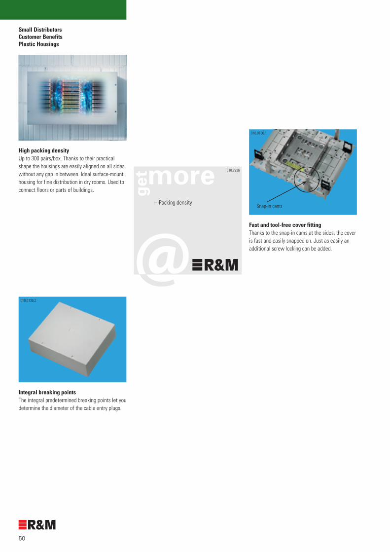
Small Distributors Customer Benefits Plastic Housings
High packing densityUp to 300 pairs/box. Thanks to their practical shape the housings are easily aligned on all sides without any gap in between. Ideal surface-mount housing for fine distribution in dry rooms. Used to connect floors or parts of buildings.
Integral breaking pointsThe integral predetermined breaking points let you determine the diameter of the cable entry plugs.
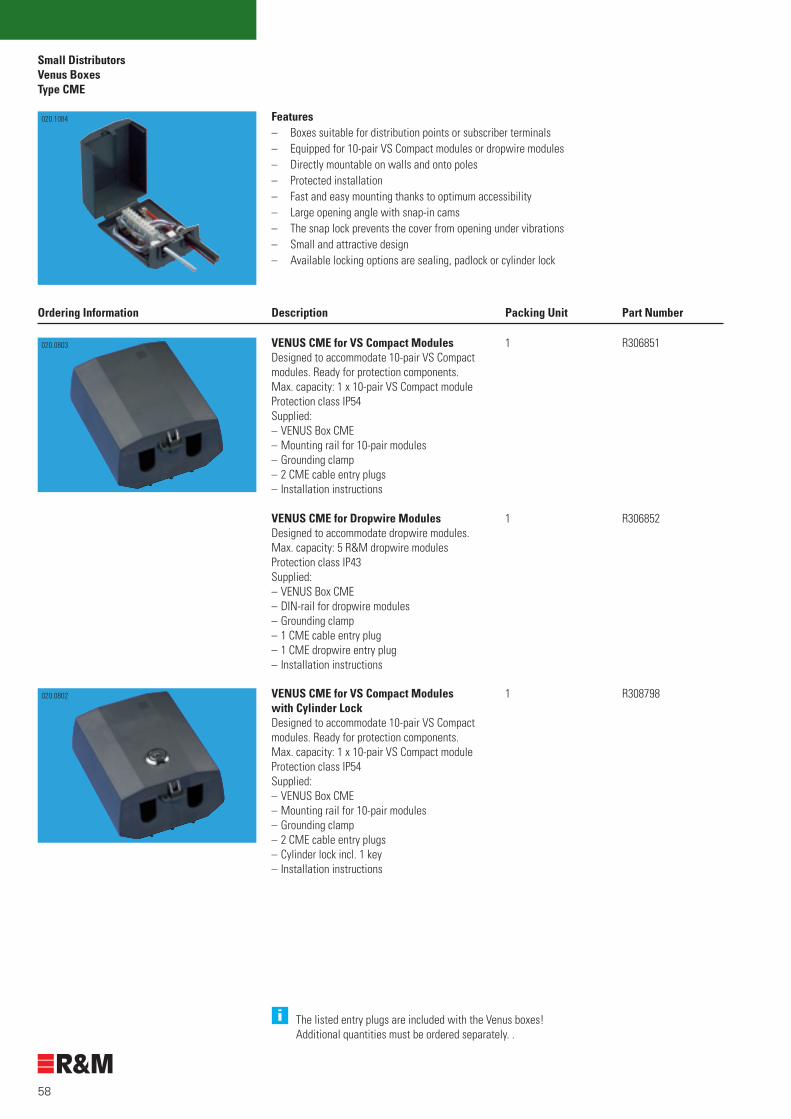
Fast and tool-free cover fittingThanks to the snap-in cams at the sides, the cover is fast and easily snapped on. Just as easily an additional screw locking can be added.
010.2936
– Packing density
010.0136.1
Snap-in cams
010.0136.2

51
Small DistributorsPlastic Housings
SM Housing, magnetic
Ordering Information Description Packing Unit Part Number
10 R302861SM Housing, magneticIdeal wherever the location of the small distributor has to be flexible. Cannot be equipped with protection components.Max. capacity: 1 x 10 pairs VS Compact Dimensions: 73 x 40 x 120 mm [WxDxH]
010.1897

52
Small DistributorsPlastic HousingsSM Housing
Ordering Information Description Packing Unit Part Number
SM Housing, 8 pairsSM Housing, 10 pairsCannot be equipped with protection components.Max. capacity: 1 x 8-/10-pair VS Compact Dimensions: 60 x 50 x 180 mm [WxDxH]
10 R30291210 R302914
SM Housing, 20 pairs Cannot be equipped with protection components.Max. capacity: 2 x 10-pair VS CompactDimensions: 102 x 57 x 162 mm [WxDxH]
10 R302915
SM Housing, 40 pairsSM Housing, 50 pairsCan be equipped with protection components.Max. capacity: 5 x 8-/10-pair VS CompactDimensions : 130 x 80 x 220 mm [WxDxH]
10 R30291310 R302916
SM Housing, 100 pairsCan be equipped with protection components.Max. capacity: 12 x 10-pair VS CompactDimensions : 220 x 80 x 260 mm [WxDxH]
10 R302917
SM Housing, 300 pairsCan be equipped with protection components.Max. capacity: 30 x 10 pairs VS Compact Dimensions : 440 x 110 x 260 mm [WxDxH]
10 R302918
020.1172
020.1175
020.1176
020.1173
020.1177
020.1179

53
Small DistributorsVenus Boxes
Product Overview
VENUS BoxGeneral use: Venus boxes are ideal for use in telecommunications networks as well as in industrial networking.
ConstructionVenus boxes are made of UV stabilized ASA (acrylonitrile styrene acrylate), which is an excellent material also used in the automobile industry, in sports and recreation, and in many installations. The boxes are ideal for indoor and outdoor applications. The distinctive features of the ASA material are:
– high-grade resistance against weathering, ageing and yellowing– high impact and scratch resistance– absolute stability even in extreme temperatures
All metal parts are made of stainless steel. The boxes are available with or without lock, and can all be additionally secured with seal or padlock. The wide opening angle of 130° and the snap-in cams allow for a quick installation.The cover can simply be taken off, whenever necessary, saving time and money! Venus boxes accommodate VS Compact connection modules (up to 100 pairs) or dropwire modules (up to 20 pairs). They are also ideal for hybrid applications. Their discreet and attractive design gives your installation a perfectly smooth appearance.
Areas of applicationVenus boxes were specifically designed for outdoor applications. Thanks to their well thought-out construction and compact design they fulfill the criteria of protection classification IP54. They allow both pole and wall mounting. And due to their tasteful design Venus boxes are increasingly used indoors and in industrial systems.
020.0806
Products Page
1 VENUS Type CSM 57
2 VENUS Type CME 58
3 VENUS Type CLA 60
4 VENUS Type HLA 62
5 VENUS Accessories 63
1 2 3
010.2966
5020.0805, 020.0807
4
020.1083 020.1084 020.1085

54
Small DistributorsVenus BoxesAreas of application
Outside Plant (OSP)
030.1575.1

55
Small DistributorsVenus Boxes
Customer Benefits
Weather-resistant housingsVenus housings were developed to withstand the toughest environmental conditions like rain, splashing water (IP54), heat and strong ultraviolet radiation.
Robust housingThe high-impact resistant material and the modern construction protect your installation against vandalism too.
Cylinder lockThe special cylinder lock effortlessly meets all the requirements of outdoor applications.
Snap lockThe unique snap lock effectively prevents accidental opening of the cover under vibrations.
SealAll Venus boxes can be secured with a seal or a padlock. Any unauthorized access is spotted immediately.
ModularityThanks to their modular design Venus Boxes can be equipped for copper applications, accommodating VS Compact connection modules or dropwire modules.In addition, Venus boxes can also be used for hybrid applications.
DesignThe Venus box’ discreet and dynamic design lets your installation look good. Evidently they also fit nicely onto modern facades.
010.2936
– Security– Modularity– Flexibility– Reusable– Re-entry– Guard
020.0822 020.0817
020.0813020.0816 020.0815

56
Small DistributorsVenus BoxesSystem Description Types CSM, CME, CLA
VENUS Type CME (Copper MEdium) VENUS Type CLA (Copper LArge)VENUS Type CSM (Copper SMall)
Without Cylinder Lock With Cylinder Lock
With 2-pair VS Compact modules With dropwire modules With 10- and 20-pair VS Compact modules
030.0670 010.2186 030.0667
020.0802020.0803
020.0803 020.0819010.1162

57
Small DistributorsVenus Boxes
Type CSM
i The listed entry plugs are included with the Venus boxes! Additional quantities must be ordered separately.
Features– Boxes suitable for subscriber terminals– Equipped for 2-pair VS Compact modules and dropwire modules– Directly mountable on walls and onto poles– Protected installation– Fast and easy mounting thanks to optimum accessibility– Large opening angle with snap-in cams– Small and attractive design– Available locking options are sealing or padlock
Ordering Information Description Packing Unit Part Number
VENUS CSM for VS Compact ModulesDesigned to accommodate 2-pair VS Compact modules. Ready for protection components.Max. capacity: 3 x 2-pair VS Compact modulesProtection class IP54Supplied:– VENUS box CSM– Mounting rail for 2-pair modules– Grounding clamp– 1 CSM cable entry plug– Installation instructions
VENUS CSM for Dropwire ModulesDesigned to accommodate dropwire modules. Max. capacity: 2 R&M dropwire modules Protection class IP43Supplied:– VENUS Box CSM– DIN-rail for dropwire modules– Grounding clamp– 1 CSM dropwire entry plug– Installation instructions
1 R307172
1 R307173
020.1083
010.1162
CSM Cable Entry PlugThe plug is inserted into the back panel.For cables:– 1 x 4 mm (for grounding)– 1 x 4-8 mm– 1 x 7-11 mmSupplied: qty 10
1 R307353010.1159
CSM Dropwire Entry PlugThe plug is inserted into the back panel.For cables:– 1 x 4 mm (for grounding)– 1 x 4-8 mm– 1 x slotSupplied: qty 10
1 R307354010.1160
58
Small DistributorsVenus BoxesType CME
020.1083 Features– Boxes suitable for distribution points or subscriber terminals– Equipped for 10-pair VS Compact modules or dropwire modules– Directly mountable on walls and onto poles– Protected installation– Fast and easy mounting thanks to optimum accessibility– Large opening angle with snap-in cams– The snap lock prevents the cover from opening under vibrations– Small and attractive design– Available locking options are sealing, padlock or cylinder lock
Ordering Information Description Packing Unit Part Number
VENUS CME for VS Compact ModulesDesigned to accommodate 10-pair VS Compact modules. Ready for protection components. Max. capacity: 1 x 10-pair VS Compact moduleProtection class IP54Supplied:– VENUS Box CME– Mounting rail for 10-pair modules– Grounding clamp– 2 CME cable entry plugs– Installation instructions
VENUS CME for Dropwire ModulesDesigned to accommodate dropwire modules.Max. capacity: 5 R&M dropwire modulesProtection class IP43Supplied:– VENUS Box CME– DIN-rail for dropwire modules– Grounding clamp– 1 CME cable entry plug– 1 CME dropwire entry plug– Installation instructions
1 R306851
1 R306852
020.0803
1 R308798020.0802 VENUS CME for VS Compact Modules with Cylinder LockDesigned to accommodate 10-pair VS Compact modules. Ready for protection components. Max. capacity: 1 x 10-pair VS Compact moduleProtection class IP54Supplied:– VENUS Box CME– Mounting rail for 10-pair modules– Grounding clamp– 2 CME cable entry plugs– Cylinder lock incl. 1 key– Installation instructions
i The listed entry plugs are included with the Venus boxes! Additional quantities must be ordered separately. .
020.1084

59
Small DistributorsVenus Boxes
Type CME
Ordering Information Description Packing Unit Part Number
VENUS CME for Dropwire Moduleswith Cylinder LockDesigned to accommodate dropwire modules.Max. capacity: 5 R&M dropwire modulesProtection class IP43Supplied:– VENUS Box CME– DIN-rail for dropwire modules– Grounding clamp– 1 CME cable entry plug– 1 CME dropwire entry plug– Cylinder lock incl. 1 key– Installation instructions
1 R308797020.0802
i The listed entry plugs are included with the Venus boxes! Additional quantities must be ordered separately.
CME Cable Entry PlugThe entry plug is inserted into the back panel.For cables:– 1 x 4 mm (for grounding)– 1 x 5–14 mmSupplied: qty 10
1 R307355
CME Special Cable Entry PlugThe entry plug is inserted into the back panel.For cables:– 5 x 4 mmSupplied: qty 10
1 R307356
CME Dropwire Entry PlugThis entry plug is inserted into the back panel.For cables:– 1 x slot (for 5 dropwire modules)Supplied: qty 10
1 R307357
CME Pole Fixing BracketThe metal brackets are screwed to the housing’sback panel and fixed to the pole with mounting strap (max. width 20 mm).Note: these brackets are only required with steelpoles.The hose clamp is not included. Supplied:– 1 metal bracket– 2 fixing screws
1 R307361
090.2116
010.1894
020.0809
020.0805

60
Small DistributorsVenus BoxesType CLA
020.1083 Features– Boxes suitable for distribution points or subscriber terminals– Equipped for 10-pair, 20-pair VS Compact modules and dropwire modules– Directly mountable on walls and onto poles– Protected installation– Fast and easy mounting thanks to optimum accessibility– Large opening angle with snap-in cams– The snap lock prevents the cover from opening under vibrations– Small and attractive design– Available locking options are sealing, padlock or cylinder lock
Ordering Information Description Packing Unit Part Number
VENUS CLA for VS Compact ModulesDesigned to accommodate 10-pair or 20-pair VS Compact modules. Ready for protection components.Protection class IP54Supplied:– VENUS Box CLA– Mounting rail for 10-pair / 20-pair modules– Grounding clamp– 2 cable entry plugs for main cables of
10-25 mm– 1 CLA cable entry plug– Installation instructions
VENUS CLA for 10-pair VS Compact ModulesMax. capacity : 50 pairsVENUS CLA for 20-pair VS Compact ModulesMax. capacity : 100 pairs
1 R306853
1 R309814
020.0819
VENUS CLA for Dropwire ModulesDesigned to accommodate dropwire modules.Protection class IP43Supplied:– VENUS Box CME– DIN-rail for dropwire modules– Grounding clamp– 2 cable entry plugs for main cables of
10-25 mm– 1 CLA dropwire entry plug– Installation instructions
VENUS CLA for Dropwire ModulesMax. capacity: 20 R&M dropwire modules
1 R306850
020.0819
i The listed entry plugs are included with the Venus boxes! Additional quantities must be ordered separately.
020.1085

61
Small DistributorsVenus Boxes
Type CLA
Ordering Information Description Packing Unit Part Number
VENUS CLA for VS Compact Moduleswith cylinder lockDesigned to accommodate 10-pair or 20-pair VS Compact modules. Ready for protection components.Protection class IP54Supplied:– VENUS Box CLA– Mounting rail for 10-pair / 20-pair modules– Grounding clamp– 2 cable entry plugs for main cables of
10-25 mm– 1 CLA cable entry plug– Cylinder lock incl. 1 key– Installation instructions
VENUS CLA for 10-pair VS Compact Modules, wkMax. capacity: 50 pairsVENUS CLA for 20-pair VS Compact Modules, wkMax. capacity: 100 pairs
1 R308796
1 R309815
020.0826
i The listed entry plugs are included with the Venus boxes! Additional quantities must be ordered separately.
VENUS CLA for Dropwire Moduleswith Cylinder LockDesigned to accommodate dropwire modules.Protection class IP43Supplied:– VENUS Box CLA– DIN-rail for dropwire modules– Grounding clamp– 2 cable entry plugs for main cables of
10-25 mm– 1 CLA dropwire entry plug– Cylinder lock incl. 1 key– Installation instructions
VENUS CLA for Dropwire Modules, wkMax. capacity : 20 dropwire modules
1 R308795
020.0826

62
Small DistributorsVenus BoxesType HLA
020.1083 Features– Hybrid solutions for up to 12 fibers (splicing through) and up to 50 pairs with VS Compact modules– Directly mountable on walls and onto poles– Protected installation– Fast and easy mounting thanks to optimum accessibility– Large opening angle with snap-in cams– Available locking options are sealing, padlock or cylinder lock
Ordering Information Description Packing Unit Part Number
VENUS HLA HybridFor up to 12 fibers (splicing through) and 50 pairs with VS Compact modules.Protection class IP54Supplied:– VENUS Box HLA– Back panel for FO and connector modules– Grounding clamp– 2 cable entry plugs for main cables of
10-25 mm– 1 CLA cable entry plug– Installation instructions
1 R309816020.0819
VENUS HLA Hybrid with Cylinder LockFor up to 12 fibers (splicing through) and 50 pairs with VS Compact modules.Protection class IP54Supplied:– VENUS Box HLA– Back panel for FO and connector modules– Grounding clamp– 2 cable entry plugs for main cables of
10-25 mm– 1 CLA cable entry plug– Cylinder lock incl. 1 key– Installation instructions
1 R309817
i The listed entry plugs are included with the Venus boxes! Additional quantities must be ordered separately.
010.2966
020.0826

63
Small DistributorsVenus Boxes
Accessories Types CLA and HLA
Ordering Information Description Packing Unit Part Number
i The listed entry plugs are included with the Venus boxes! Additional quantities must be ordered separately.
CLA Cable Entry PlugThe entry plug is inserted into the back panel.For cables:– 5 x 13 mmSupplied: qty 10
1 R307358
CLA Dropwire Entry PlugThe entry plug is inserted into the back panel.Cable sizes:– 5 x slots (for 20 dropwires)Supplied: qty 10
1 R307359
CLA Pole Fixing BracketsThe metal brackets are screwed to the housing’sback panel and fixed to the pole with pole mounting strap (max. width 20 mm).Note: these brackets are only required with steel poles.The hose clamp is not included. Supplied:– 2 metal brackets– 4 fixing screws
1 R307362
020.0829
020.0828
020.0805
Cable Clamp for the Main CableTo provide additional strain relief for themain cable if the cable ties are not enough.Supplied:– 1 cable clamp
1 R307363020.0807
Universal CLA Pole Fixing BracketThe metal brackets are screwed to the housing’sback panel and fixed to the pole with pole mounting strap.Note: the hose clamp is not included. Supplied:– 1 metal bracket– 2 fixing screws
1 R311859090.2132

64
Small DistributorsVenus BoxesAccessories Types CLA and HLA
Ordering Information Description Packing Unit Part Number
Shield Connection Cable, V shape / M6 150 mmTo connect cable and grounding screw at the Venus Box.Supplied: – Cross section grounding cable 2.5 mm2
1 R311658010.0843.1

65
VS Compact ADSL SplitterProduct Overview
Products Page
1 Splitter Boards 62
2 Frames 64
3 Modules and Accessories 66
General information
The R&M splitter is a 4-port ADSL/POTS splitter card designed to maximize the separation of voice and ADSL DataStream over copper transmission lines.
Asymmetric Digital Subscriber Line (ADSL) transmission technology operates over existing copper wires that connect home and businesses to the Public Switched Telephone Network (PSTN). ADSL is a very viable technology to support high-speed access, enabling a maximum downstream rate of 9 Mbps and a maximum upstream rate of 640 kbps. Traditional voice services can coexist with ADSL without interruption through POTS low pass filters.
Blocking capacitors as defined in ETSI 101 952-1-2 v1.1.1 (2002-05) option B are inserted in the Line to ADSL path. The additional matching ADSL high pass filter is usually not included in the design of the splitter and installed on the corresponding ADSL-modem board.
The R&M splitter integrates a low pass filter which prevents the high frequency energy from reaching the POTS device and provides isolation from impedance effects of the POTS device on ADSL. In addition, this filter will also attenuate any wideband impulse noise generated by the POTS device due to the interruption of Line current (e.g. pulse dialling or on hook/off hook transition). As the POTS splitter connects directly to the Subscriber Line media, it must also provide some protection for externally induced line hits or fault which could damage any attached equipment or endanger humans interacting with the installed equipment.
010.2708
3
1 2
030.0667
010.3056 010.2719

66
VS Compact ADSL SplitterApplication
For more details see VS Compact Product Catalogue (English R306888 / German R306800)
Freestanding Wall Mounted 19” Sub-Rack
Network configurationThis splitter is designed for the installation in Central Office buildings for MDF applications with disconnection modules.
MDF’s
Distributed Splitter Configuration MASTER SPLITTER CONFIGURATION
User’s PC
Telephone
Copper Line
Web Server
www
DSLAM
Telephone Network
CENTRAL OFFICECUSTOMER PREMISE
MDFCO SplitterCPE
MasterSplitter
Master Splitter Configuration DISTRIBUTED SPLITTER CONFIGURATION
User’s PC
Telephones
Distributed Filters
Copper Line
Web Server
www
DSLAM
Telephone Network
CUSTOMER PREMISE CENTRAL OFFICE
MDFCO Splitter
030.0742 030.0778 030.0770

67
VS Compact ADSL SplitterIntroduction
Customer Benefits
ModularityThe R&M Splitter boards are designed to cover different line impedances without changing the line size. This enables global acting companies to use always the same distribution system, the VS Compact.
Pre-assembled DSLAM ConnectionDue to 9-pole D-sub connector on the board you will be able to prepare the DSLAM connection in advance and save time on the installation.
CostsThrough the integration of the ADSL splitter into the MDF at the Central Office a significant cost advantage is reached. Flexibility, density, testing possibility and easy handling are increased. These will not only reduce installation cost but also maintenance costs.
StandardsOf course R&M splitters complies with all relevant standards like ITU-T G992.1 orETSI TS 101 952-1-1 V1.1.1 (2002-05).
Comfort and FlexibilityThe splitter boards can be easily mounted or replaced on a standard VS Compact 10-pair disconnection or connection module.
VS Compact ModulesOf course you can also profit also from the proven VS Compact benefits like space saving, top re-liability and durability due to gold-plated rear and disconnection contacts, free termination tool, etc.
Testing and MaintenanceUsing VS Compact disconnection modules testing and jumpering proves an easy job, because of free access to the modules without removing the splitter board. Simple termination of the lines due to IDC is guarantee (free of charge tool comes with every 10 modules).
030.0661
010.2717 010.2711
010.2716
010.2715
010.2936
– Comfort– Flexibility– Security– Cost saving

68
VS Compact ADSL SplitterSplitter BoardsOrdering Information
4 Ports ADSL SplitterThese boards can be inserted into disconnection module 10 pairs R3000449-pole D-sub interface for DSLAM
Line Impedance:Zc = 270 Ω + (750 Ω//150 nF)Zreal = 600 ΩCombi ISDN/POTS
In preperation (at date of issue)With PK94 (IDC) interface for DSLAM
Combi ISDN/POTSZc = 270 Ω + (750 Ω//150 nF)
1 R3080911 R3080921 R309233
1 R3110681 R311074
Ordering Information Description Packing Unit Part Number
010.3056
4 Ports ADSL SplitterThese boards can be inserted into disconnection module 16 pairs R300046All interfaces front connected
Line Impedance:Zreal = 600 Ω
In preperation (at date of issue) Combi ISDN/POTS
1 R310095
1 R310607
090.2115
Options on request - Other line impedances - Voltage/current protection devices on the board - PK94 (IDC) connector instead of D-Sub - Without DC-Block capacitors
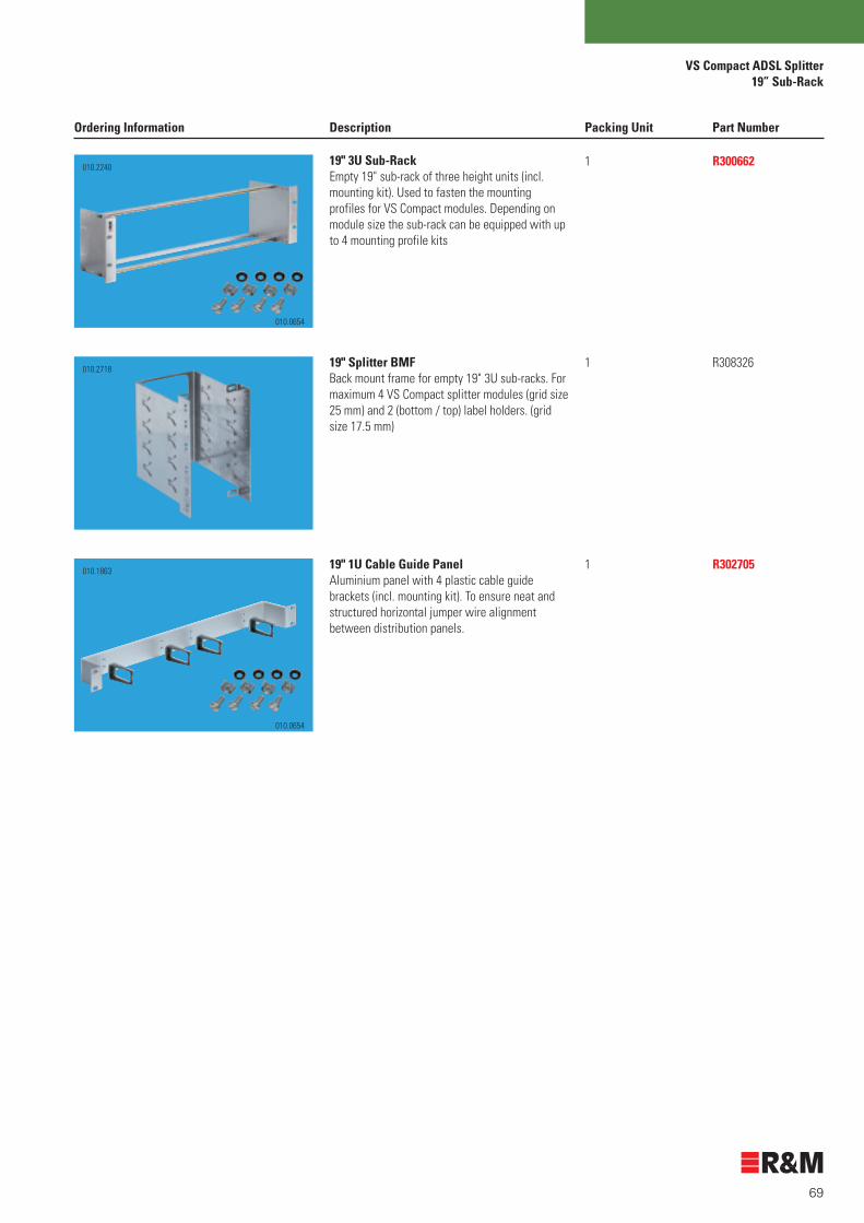
69
VS Compact ADSL Splitter19” Sub-Rack
19" 3U Sub-RackEmpty 19" sub-rack of three height units (incl. mounting kit). Used to fasten the mounting profiles for VS Compact modules. Depending on module size the sub-rack can be equipped with up to 4 mounting profile kits
19" Splitter BMFBack mount frame for empty 19" 3U sub-racks. For maximum 4 VS Compact splitter modules (grid size 25 mm) and 2 (bottom / top) label holders. (grid size 17.5 mm)
19" 1U Cable Guide PanelAluminium panel with 4 plastic cable guide brackets (incl. mounting kit). To ensure neat and structured horizontal jumper wire alignment between distribution panels.
1 R300662
1 R308326
1 R302705
Ordering Information Description Packing Unit Part Number
010.2240
010.1863
010.2718
010.0654
010.0654

70
VS Compact ADSL SplitterFramesBMF and Accessories
Back Mount Frame For mountingonto freestanding frame or for wall mounting with wall rail kit.Each label holder can be mounted on top or bottom of the BMF
Width: 78 mm (10 pair modules)Depth: 117 mm
Length [mm]: Max. no. of modules/ports300 mm 10 / 40500 mm 18 / 721000 mm 38 / 152
Width: 120 mm (16 pair modules)Depth: 117 mm
Length [mm]: Max. no. of modules/ports500 mm 15 / 601000 mm 31 / 124
Wall Rail KitRequired for fixing the mounting profiles to walls.Length:500 mm1000 mm1500 mm2000 mmSupplied:– 2 wall rails– 6 insulating sleeves– 6 insulating disks– 2 end pieces
Mounting Kit for Wall Distribution Frames 90°Fixing material to directly fit the mounting profilesinto the wall rails.
Supplied:– 4 slide nuts– 4 fastening screws with washers
1 R3085201 R3083271 R308328
1 R3100961 R310097
1 R3007681 R3007691 R3007701 R300771
1 R301058
Ordering Information Description Packing Unit Part Number
010.2719
030.0764
030.0763
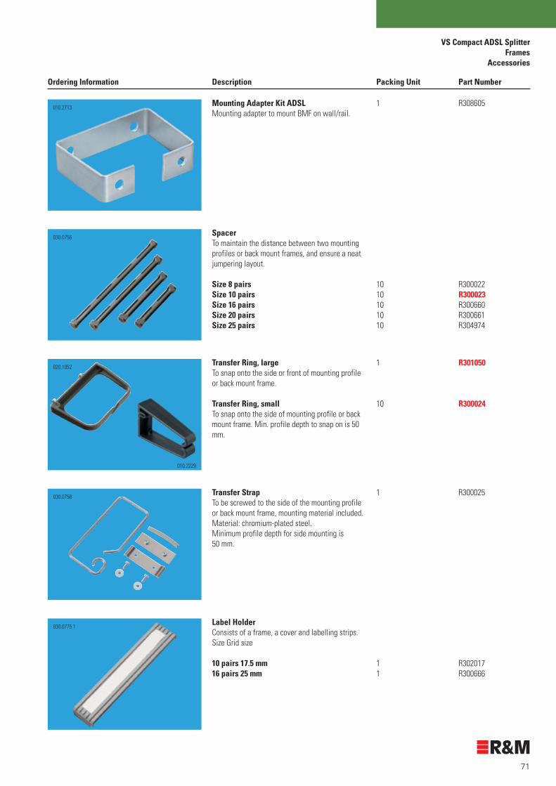
71
VS Compact ADSL SplitterFrames
Accessories
SpacerTo maintain the distance between two mounting profiles or back mount frames, and ensure a neat jumpering layout.
Size 8 pairsSize 10 pairsSize 16 pairsSize 20 pairsSize 25 pairs
Mounting Adapter Kit ADSLMounting adapter to mount BMF on wall/rail.
Transfer Ring, large To snap onto the side or front of mounting profile or back mount frame.
Transfer Ring, smallTo snap onto the side of mounting profile or back mount frame. Min. profile depth to snap on is 50 mm.
Transfer StrapTo be screwed to the side of the mounting profileor back mount frame, mounting material included.Material: chromium-plated steel.Minimum profile depth for side mounting is50 mm.
10 R30002210 R30002310 R30066010 R30066110 R304974
1 R301050
10 R300024
1 R308605
1 R300025
Label HolderConsists of a frame, a cover and labelling strips.Size Grid size
10 pairs 17.5 mm16 pairs 25 mm
1 R3020171 R300666
Ordering Information Description Packing Unit Part Number
010.2229
020.1052
030.0775.1
030.0758
010.2713
030.0756

72
VS Compact ADSL SplitterModules and Accessories
Disconnection Module, 10 pairs (17.5 mm)Disconnection Module, 16 pairs (25 mm) Supplied:– VS Compact module– Installation instructions– Mini-tool (wiring tool)
Wiring ToolFor wiring all VS Compact modules. The wires are contacted and cut to length in one single and efficient step.
"Mini Tool"A Mini Tool is supplied for free with 10VS Compact modules.
"Comfort Tool"Recommended for wire diameter 0.8 mm. The point is made of metal. With an integral hook to remove jumper wires from the module.
Module Label Holder 10 pairsModule Label Holder 16 pairsAttachable to all VS Compact ADSL modules forindividual labelling of the modules. Jumper side and test point stay accessible.
Supplied:– Module label holder– Labelling sheet for module label– Labelling sheet for label holder
10 R30004410 R300046
10 R300069
10 R300068
10 R30860010 R310098
10 R30006510 R30250110 R30192010 R30341610 R30341710 R30341810 R30341910 R30342010 R303421
Number ClipFor the numbering of the modules. To be snapped onto the side. Binary code also possible.
01 to 10 Colour: grey01 to 10 Colour: yellow00 to 90 Colour: grey20 to 200 Colour: grey100 to (1)000 Colour: grey08 to 80 Colour: grey88 to 160 Colour: grey16 to 160 Colour: grey176 to 320 Colour: grey
Ordering Information Description Packing Unit Part Number
030.0679.1
030.0673.2
030.0667
010.1743

73
VS Compact ADSL SplitterAccessories
Disconnection PlugTo disconnect one to ten lines between cable side and jumper side in disconnection modules.Material: POMColour: black
Disconnection Plug, 1 pair
Marking Plug, 1 pairTo identify a line in all VS Compact modules. Ideal as protection from inadvertent disconnection in disconnection modules.
Marking Plug, redMarking Plug, blue
100 R300066100 R306376
100 R300067
Designation ClipFor the labeling of all VS Compact modules. Can be snapped on at both sides of a module.
Designation Clip, redDesignation Clip, blackDesignation Clip, yellowDesignation Clip, blueSupplied:– 20 designation clips– Labelling sheet
20 R30029220 R30029320 R30029420 R300295
Ordering Information Description Packing Unit Part Number
030.0674
030.0675
030.0678.3

74
VS Compact ADSL SplitterTest Accessories
Test Plug, 1 pairFor customer assembly. Used to test a line in all VS Compact modules. Contact interface on cable and jumper side.
Test Plug, 1 pairTest Plug, 1 pair, short
Test Cord "Universal"For customer assembly. Used as test adapter for connecting any testing device. Contact interface on cable or jumper side. Cable end open.
Length: 2.5 m
Test Cord, 4 x 4 mm JackTest adapter with 4 mm banana sockets for con-necting any measuring and testing device. The sockets are marked in different colours. Can be used with all VS Compact modules. Contact interface on cable or jumper side.
Length: 3.0 m
10 R30007110 R304558
1 R300073
1 R302603
Ordering Information Description Packing Unit Part Number
030.0676
010.2224
Test
and
sol
der
cont
act i
nter
face
s
030.0677
010.2224
whiteturquoise
blueviolet
Cabl
e en
d op
en
010.1745
010.0245
Test adapter 1 pair Test adapter
(white)
(blue)
(turquoise)
(violet)
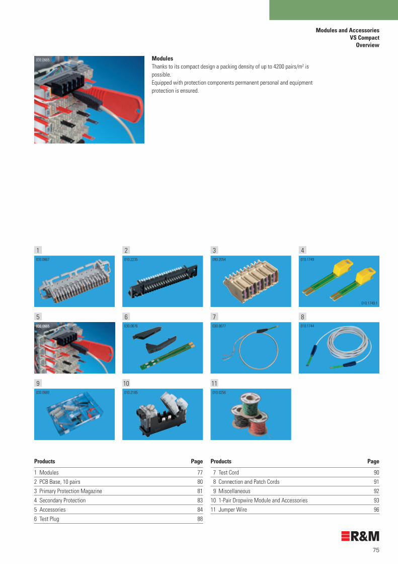
75
Products Page
1 Modules 77
2 PCB Base, 10 pairs 80
3 Primary Protection Magazine 81
4 Secondary Protection 83
5 Accessories 84
6 Test Plug 88
31 2 4
75030.0665
6 8
9 10 11
ModulesThanks to its compact design a packing density of up to 4200 pairs/m2 is possible. Equipped with protection components permanent personal and equipment protection is ensured.
Modules and Accessories VS Compact
Overview
030.0665
Products Page
7 Test Cord 90
8 Connection and Patch Cords 91
9 Miscellaneous 92
10 1-Pair Dropwire Module and Accessories 93
11 Jumper Wire 96
030.0667
010.1749.1
010.1749
030.0677
010.2235 090.2054
030.0676 010.1744
030.0680 010.2185 010.0256
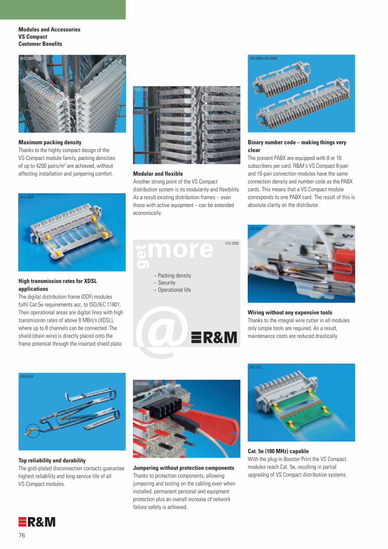
76
Modules and AccessoriesVS CompactCustomer Benefits
010.1859
High transmission rates for XDSL applicationsThe digital distribution frame (DDF) modules fulfil Cat.5e requirements acc. to ISO/IEC 11801. Their operational areas are digital lines with high transmission rates of above 8 MBit/s (XDSL), where up to 8 channels can be connected. The shield (drain wire) is directly placed onto the frame potential through the inserted shield plate.
030.0661
Wiring without any expensive tools Thanks to the integral wire cutter in all modules only simple tools are required. As a result, maintenance costs are reduced drastically.
030.0721
Cat. 5e (100 MHz) capableWith the plug-in Booster Print the VS Compact modules reach Cat. 5e, resulting in partial upgrading of VS Compact distribution systems.
Maximum packing densityThanks to the highly compact design of the VS-Compact module family, packing densities of up to 4200 pairs/m2 are achieved, without affecting installation and jumpering comfort.
010.1285
Modular and flexibleAnother strong point of the VS Compact distribution system is its modularity and flexibility. As a result existing distribution frames – even those with active equipment – can be extended economically.
010.1284
Jumpering without protection componentsThanks to protection components, allowing jumpering and testing on the cabling even when installed, permanent personal and equipment protection plus an overall increase of network failure safety is achieved.
030.0665
Binary number code – making things very clearThe present PABX are equipped with 8 or 16 subscribers per card. R&M's VS Compact 8-pair and 16-pair connection modules have the same connection density and number code as the PABX cards. This means that a VS Compact module corresponds to one PABX card. The result of this is absolute clarity on the distributor.
Top reliability and durabilityThe gold-plated disconnection contacts guarantee highest reliability and long service life of all VS-Compact modules.
030.0666/030.0668
010.2936
– Packing density– Security– Operational life
030.0664

77
Modules and AccessoriesVS Compact
Modules
– To snap on onto back mount frames and profiles – Packing density of up to 4200 pairs/m2 – Wiring in IDC technology without expensive tools– Gold-plated contacts– Protection components ensure permanent personal and equipment
protection– Protection components are plugged in at the front– Contacts for disconnection and testing at the front– Module bodies made of one piece
Ordering Information Description Packing Unit Part Number
Connection Module, 8 pairsDisconnection Module, 8 pairsNormally Open Module, 8 pairsGrid size = 20 mmSupplied: – VS Compact module, printed – Installation instructions– Mini-tool (wiring tool)
10 R30003510 R30003610 R300037
Connection Module, 10 pairsDisconnection Module, 10 pairsNormally Open Module, 10 pairsGrid size = 20 mmSupplied: – VS Compact module, printed – Installation instructions– Mini-tool (wiring tool)
10 R30003910 R30004010 R300041
Connection Module, 16 pairsDisconnection Module, 16 pairsNormally Open Module, 16 pairsGrid size = 20 mmSupplied: – VS Compact module, printed – Installation instructions– Mini-tool (wiring tool)
10 R30004510 R30004610 R300047
Connection Module, 20 pairs Disconnection Module, 20 pairs Normally Open Module, 20 pairs Grid size = 25 mmSupplied: – VS Compact module, printed – Installation instructions– Mini-tool (wiring tool)
10 R30004910 R30005010 R300051
030.0666
030.0667
030.0668
030.0669
030.0667

78
Modules and AccessoriesVS CompactModules
Ordering Information Description Packing Unit Part Number
Connection Module, 25 pairs Disconnection Module, 25 pairs Normally Open Module, 25 pairs Grid size = 25 mmSupplied: – VS Compact module, printed – Installation instructions– Mini-tool (wiring tool)
10 R30067410 R30067510 R300757
Connection Module, 10-pairs/17.5 mmDisconnection Module, 10-pairs/17.5 mmNormally Open Module, 10-pairs/17.5 mmGrid size = 17.5 mmSupplied: – VS Compact module, printed – Installation instructions– Mini-tool (wiring tool)
10 R30004310 R30004410 R302060
DDF ModuleThe DDF modules are used for high transmission rates (XDSL). 8 lines (8 times a, b, s) can be connected on the DDF modules. The shield plate inserted from the rear connects the s-contact directly with the back mount frame or mounting profile, guaranteeing top earthing contact quality.
Disconnection Module, 16 pairs, DDFGrid size = 25 mmSupplied: – VS Compact module, printed – Installation instructions– Mini-tool (wiring tool)
10 R302788
Shield Plate, 16 pairsFor VS Compact 16-pair DDF module
10 R302704
010.2188
030.0672
010.1848.1
010.1845
010.1848.1
010.1845

79
Modules and AccessoriesVS Compact
Modules
Ordering Information Description Packing Unit Part Number
Shield Plate, 16 pairs, type CFor VS Compact 16-pair DDF module providing the option to contact the cable shield directly onto the shield plate. Supplied: – Shield plate, 16 pairs, type C– Sleeve screen for small cable diameter– Shield contact spring– 2 cable ties
10 R304383
Connection Module, 2 pairsDisconnection Module, 2 pairsThe module is snapped onto the 2-pair back mount frames and used in R&M's Venus subscriber terminal housings.Supplied: – VS Compact module, printed – Installation instructions– Mini-tool (wiring tool)
10 R30003310 R300034
Adapter Connection Module, 10-pairs Adapter Disconnection Module, 10-pairs The adapter module is snapped onto the back mount frames.Grid size: 22.5 mmSupplied: – VS Compact module, printed – Installation instructions– Mini-tool (wiring tool)
10 R30005310 R300054
Round Profile Adapter KitTo mount VS Compact modules(grid size 20/25mm) onto round profiles (of 12)
10 R300669
010.2233
030.0670
030.0671
010.3058

80
Modules and AccessoriesVS CompactPCB Based
Ordering Information Description Packing Unit Part Number
PCB Base, 10 pairsSoldered onto a print board as holder of a VS-Compact 10-pair connection module. Thanks to an earthing rail at the front the same protection components ensuring permanent personal and equipment protection can be fitted.
10 R306484010.2235

81
Modules and AccessoriesVS Compact
Primary Protection Magazine
Ordering Information Description Packing Unit Part Number
Protection Magazine, 1 pair, emptyCan be equipped with a 3-pole arrester, 6 x 8 mm, 2 x 5 kA, 230 V. Fits all VS Compact modules. For-overvoltage protection an earthing rail is required.
10 R304953
Protection Magazine, 5 pairs, emptyCan be equipped with a 3-pole arrester, 6 x 8 mm, 2 x 5 kA, 230 V. Fits all VS Compact modules. For-overvoltage protection an earthing rail is required.
20 R304954
Protection Magazine, 1 pair, equippedCan be equipped with a 3-pole arrester, 6 x 8 mm, 2 x 5 kA, 230 V. Fits all VS Compact modules. For-overvoltage protection an earthing rail is required.
Protection Magazine, 1 pair With arrester without failsafe (FS) With arrester with FS plus FS display
10 R30495510 R304957
Protection Magazine, 5 pairs, equippedCan be equipped with a 3-pole arrester, 6 x 8 mm, 2 x 5 kA, 230 V. Fits all VS Compact modules from 5 pairs up. For overvoltage protection an earthing rail is required.
Protection Magazine, 5 pairsWith arrester without failsafe (FS)With arrester with FS plus FS display
20 R30495620 R304958
Earthing RailConnects protection magazine and earth of the VS-Compact back mount frame. The earthing plates are plugged in at the front of the modules.8 pairs10 pairs16 pairs20 pairs25 pairs
Adapter Earthing Rail, 10 pairs
10 R30076110 R30009210 R30009410 R30009510 R305209
10 R300093
090.2052
090.2055
090.2053
090.2054
030.0686a
030.0686c
030.0686b
030.0687

82
Modules and AccessoriesVS CompactPrimary Protection Magazine
Ordering Information Description Packing Unit Part Number
Arrester3-pole arrester 6 x 8 mm, 2 x 5 kA, 230 V. Fits the VS Compact protection magazine 1 and 5-pairs.
Arrester without Failsafe (FS) Arrester incl. FS and FS Display
100 R300231100 R300233
Arrester Tool Tool used for inserting and taking the arrester out of the protection magazine.
10 R302770
Extraction Tool for 5-Pair Protection MagazineExtraction tool to easily remove the 5-pair protection magazine form VS Compact modules.
10 R305586
010.1750
090.2066
010.2230
030.0711

83
Modules and AccessoriesVS Compact
Secondary Protection
Ordering Information Description Packing Unit Part Number
Protection Plug, PTC, 150 mAPlug with reversible PTC overcurrent protection elements and test socket. Fits VS Compact disconnection and normally open modules. To be plugged in at the front of the modules. PTC, 150-mA, short, cannot be used with grid size 17.5-mm.
Test Plug PTC, 150 mATest Plug PTC, 150 mA, short
10 R30006310 R302977
010.2249
Protection Plug, 230 V/150 mA1-pair protection plug with 3-pole arrester (2-x-5-kA, 230 V FS and FS display) for overcurrent and overvoltage protection. With measuring and test contact interface. Can be plugged into all VS-Compact disconnection and normally open module in combination with the earthing rail.
Protection Plug, 230 V/130 mA (subscriber side)Protection Plug, 230 V/130 mA inverse (exchange side)
10 R302101
10 R302102
010.2248
010.1749
010.1749.1
010.1748
010.1747

84
Modules and AccessoriesVS CompactAccessories
Ordering Information Description Packing Unit Part Number
Earthing Module KitTo convert a VS Compact connection module into an earthing module. The earthing plate is plugged in at the module's back, safely avoiding any contact with back mount frames or profiles.
Earthing Module Kit, 8 pairsEarthing Module Kit, 10 pairsEarthing Module Kit, 16 pairsEarthing Module Kit, 20 pairsEarthing Module Kit, 25 pairsSupplied:– 1 earthing plate, 2 labelling clip, red– 2 labelling sheets– 2 clips indicating earth
10 R30218310 R30046610 R30218410 R30046710 R306615
Wiring BaseTool to aid wiring all VS Compact modules. Material: PA66-GF25, chrome-nickel-steel
Wiring Base, 8 pairs/10 pairsWiring Base, 16 pairs /20 pairsWiring Base, 25 pairsSupplied:– Holder rail– Side parts left/right – Instructions for the wiring base
1 R3004641 R3004651 R306617
Disconnection PlugTo disconnect one to ten lines between cable side and jumper side in disconnection modules. Material: POM Colour: black
Disconnection Plug, 1 pairDisconnection Plug, 5 pairsDisconnection Plug, 8 pairsDisconnection Plug, 10 pairs
100 R300067100 R302606100 R302607100 R302608
Wiring ToolFor wiring all VS Compact modules. The wires are contacted and cut to length in one single and efficient step.Material: PA66-GF25, chrome-nickel-steel, POM
"Mini Tool" A Mini Tool is supplied for free with 10 VS-Compact modules.
"Comfort Tool" Recommended for wire diameter 0.8 mm. The point is made of metal. With an integral hook to remove jumper wires from the module.
"Micro Tool"Recommended as extra with the smallest distributors. Can be attached to the side of the VS-Compact modules.
10 R300068
10 R300069
10 R300070
010.1834.1
030.0715
030.0674
030.0673
R300070R300068
R300069b
ca

85
Modules and AccessoriesVS CompactAccessories
Ordering Information Description Packing Unit Part Number
Marking Plug, 1 pairTo identify a line in all VS Compact modules. Ideal-as protection from inadvertent disconnection in disconnection modules.Material: POM
Marking Plug, redMarking Plug, blueMarking Cap, green
100 R300066100 R306376100 R309931
Designation ClipFor the labelling of all VS Compact modules. Can-be snapped on at both sides of a module.
Designation Clip, redDesignation Clip, blackDesignation Clip, yellowDesignation Clip, blueSupplied: – 20 designation clips– Labelling sheet
20 R30029220 R30029320 R30029420 R300295
Number ClipFor the numbering of the modules. To be snapped onto the side. Binary code also possible.
01 to 10 Colour: grey01 to 10 Colour: yellow00 to 90 Colour: grey20 to 200 Colour: grey100 to (1)000 Colour: grey08 to 80 Colour: grey88 to 160 Colour: grey16 to 160 Colour: grey176 to 320 Colour: grey0 to 18 Colour: grey
10 R30006510 R30250110 R30192010 R30341610 R30341710 R30341810 R30341910 R30342010 R30342110 R306786
Module Label HolderAttachable to all VS Compact modules for individual labelling of the modules. Jumper side and test point stay accessible. Supplied: – Module label holder – Labelling sheet for module label – Labelling sheet for label holder
8 pairs10 pairs16 pairs20 pairs25 pairs
10 R30251310 R30251410 R30251510 R30251610 R305215
030.0675
030.0678.3
030.0679.1
010.1743
090.2125

86
Modules and AccessoriesVS CompactAccessories
Ordering Information Description Packing Unit Part Number
Snap-On Kit for Label HolderFor direct mounting of the label holder onto the module.
20 R300668
Single Cover
8 pairs10 pairs16 pairs20 pairs
10 R30104610 R30104710 R30104810 R301049
Multiple Blind CoverTo cover several unused spaces.
Size Grid size 8 pairs 200 mm10 pairs 200 mm16 pairs 250 mm20 pairs 250 mm25 pairs 250 mm
10 R30067010 R30067110 R30067210 R30067310 R306598
Label HolderFor the labelling of entire verticals and blocks. Can-be mounted directly to the profiles or even to the label holder snap-on kit when there is only little space. 8 pairs, grid size 20 mm10 pairs, grid size 20 mm16 pairs, grid size 25 mm20 pairs, grid size 25 mm25 pairs, grid size 25 mm10 pairs, grid size 17.5 mm
10 R30066410 R30066510 R30066610 R30066710 R30520810 R302017
Hinged Label HolderCan be used with all VS Compact modules.
8 pairs10 pairs16 pairs20 pairs25 pairs
1 R1006221 R1006231 R1006411 R1006421 R101390
030.0776
030.0773
030.0774
030.0775
010.1800

87
Print for Ribbon CableFor easy connection of ribbon cables. To be plugged in at the back of the module.
8 pairs10 pairs16 pairs20 pairs25 pairs
10 R30076410 R30076510 R30076610 R30076710 R306630
Booster PrintThis print makes VS Compact modules Cat. 5e capable.To be plugged in at the back of the module.
10 pairs20 pairs
1 R3005611 R300763
AMP Test Adapter, front 1 R307383
AMP Test Adapter, back 1 R307384
Modules and AccessoriesVS CompactAccessories
Ordering Information Description Packing Unit Part Number
010.1754
030.0722
010.3061
010.3062

88
Modules and AccessoriesVS CompactTest Plugs
Ordering Information Description Packing Unit Part Number
Parallel Plug, 10 pairs "a/b"For different end users with one line, for example in analogue telephony. One dial number for several connection points.
10 R302925
Test Plug, 1 pairFor customer assembly. Used to test a line in all VS Compact modules. Contact interface on cable and jumper side. Material: PPE /PS, FR4
Test Plug, 1 pairTest Plug, 1 pair, short 10 R300071
10 R304558
Test Plug, 10 pairs, "Universal" For customer assembly. Used to test lines in all VS-Compact modules (from 10 pairs up). Contact interface at cable and jumper side.
010.2227
10 R100659
Test contact interfaces
010.2224
Test
and
sol
der
cont
act-i
nter
face
s
030.0676
010.1847
010.2232

89
Modules and AccessoriesVS Compact
Test Plugs
Ordering Information Description Packing Unit Part Number
Test Plug, 10 pairs, with LED10-pair test adapter with LED display.
1 R305339
Power Supply for Test Plug, 10-pairs, with LEDSplicing (9V) for 10-pair test adapter with LED display.
1 R300987
010.2231
010.2239

90
Modules and AccessoriesVS CompactTest Cords
Ordering Information Description Packing Unit Part Number
Test Cord "Universal"Fur customer assembly. Used as test adapter for connecting any testing device. Contact interface on cable and jumper side. Cable end open.Length = 2.5 m
Without snap-in stopWith snap-in stop
10 R30007310 R307035
Test Cord 4 x 4 JackTest adapter with 4 mm banana sockets for connecting any measuring or testing device. The sockets are marked in different colours. Can be used with all VS Compact modules. Contact interface on cable or jumper side.Length = 3.0 m
1 R302603
Please note: Cannot be used in connection with protection components.
010.2224
Cabl
e en
d op
enwhite turquois
blue violet
010.0245
(white) (blue) (turquoise) (violet)Test plug 1 pair
Test adapter
VS-RJ45 Patch Cord2.0 m patch cord, equipped with a VS Compact plug on one side and a RJ45 on the other (pin 4/5 or 3/5). For the direct patching of VS Compact onto RJ45.
VS Compact Patch Cord VS-RJ45 (3/6) 2m
1 R307232
VS Compact Patch Cord VS-RJ45 (4/5) 2m
1 R307231
3
6
4
5
030.0677
010.1745
010.0245.1
010.0245.2
010.3057

91
Modules and AccessoriesVS Compact
Connection and Patch Cords
Connection CordEquipped with a VS Compact 1-pair test plug on both sides. Contact interface on patch or cable side.
Connection Cord 2.5 mConnection Cord 3.0 m
010.0239.1
1 R3026041 R302605
Patch CordEquipped with a VS Compact 1-pair test plug on both sides. Contact interface on patch or cable side. The snap-in stops on both sides prevent any inadvertent connection interruption.
Please note: cannot be used in combination with protection components. Patch Cord 0.5 m Patch Cord 1.0 m Patch Cord 1.5 m Patch Cord 2.0 m Patch Cord 2.5 m
010.0239
010.2237
1 R3044641 R3044651 R3044661 R3044671 R304468
Monitoring Cable, 1 pair, 2.5 mTest cord with through-connected contact interface. Parallel contacting of a line is possible without any interruption. The snap-in stops on both sides prevent any inadvertent connection interruption.
Plug coloured green.
Please note: cannot be used in combination with protection components.
010.2225
010.2236 1 R305187
Ordering Information Description Packing Unit Part Number
010.1744

92
Modules and AccessoriesVS CompactMiscellaneous
Ordering Information Description Packing Unit Part Number
Sample KitSample assortment for customer presentations.Size: 33 x 22 x 7 cm (WxHxD)
1 R300221
Sample CaseSample assortment for customer presentations.Includes various modules 2 pairs – 25 pairs, protection components, tools and accessories.Size: 39 x 30 x 11 cm (WxHxD)Weight: 2 kg
Supplied:– Sample case with foamed lining– Back mount frames– Connection and disconnection modules up to
25-pairs– Earthing rail– Protection magazines 1 pair and 5 pairs– Protection plug PTC, 150 mA– Protection plug 230 V/150 mA– Designation clip– Number clip– Module label– Disconnection plug 1 pair – 10 pairs– Marking plug– Test cord 0.5 m– Test cord "Universal" 2.5 m– Mini Tool– Comfort Tool– Operation and installation instructions
1 R305705
030.0680
010.2247

93
Modules and Accessories1-Pair Dropwire Module
Customer Benefits
030.2000
Weather-resistant IDC wiring area. Self-regenerative gel protects wiring chambers. Visual monitoring of wiring area.
Compact design Thanks to its dimensions of 34 x 15 x 56 mm (HxDxW) up to 1/3 more connections fit into the same space.
010.2243
Testing during operation.Parallel testing can be performed without disconnecting the line.
Aufrastbar auf DIN 35 Tragschienen.Ermöglicht bedarfsorientierte Netzerweiterung. Minimale Installations- und Wartungskosten.
010.2242
Retrofittable overvoltage protection. Standard 3-pole arrester can be used. Overvoltage protection can be added by the customer.
010.2241
No special tools required for wiring. IDC-contacting. Fast and reliable conductor wiring. Repeated conductor wiring possible. Can be used with a wide range of diameters.
010.2246
Can be disconnected without removing the conductors.Convenient line testing without having to remove the conductors. Testing of exchange and subscriber lines with standard testing devices.
010.2936
– Weather resistance– Security– Comfort
030.1555
55.75 14.5
33.5
5
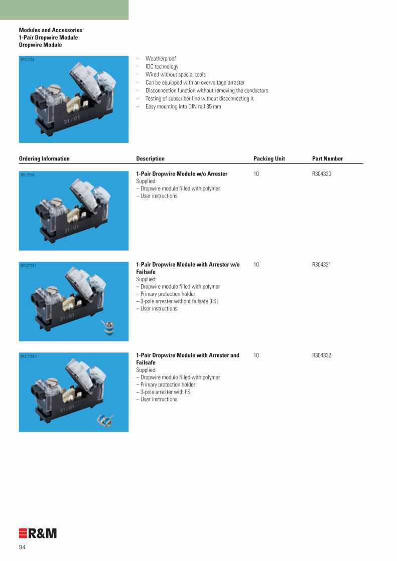
94
Modules and Accessories1-Pair Dropwire ModuleDropwire Module
– Weatherproof– IDC technology– Wired without special tools– Can be equipped with an overvoltage arrester– Disconnection function without removing the conductors – Testing of subscriber line without disconnecting it– Easy mounting into DIN rail 35 mm
Ordering Information Description Packing Unit Part Number
1-Pair Dropwire Module w/o Arrester Supplied: – Dropwire module filled with polymer – User instructions
10 R304330
1-Pair Dropwire Module with Arrester w/o FailsafeSupplied:– Dropwire module filled with polymer– Primary protection holder– 3-pole arrester without failsafe (FS)– User instructions
10 R304331
1-Pair Dropwire Module with Arrester and FailsafeSupplied: – Dropwire module filled with polymer– Primary protection holder– 3-pole arrester with FS – User instructions
10 R304332
010.2186
010.2186
010.2186.1
010.2186.2

95
Modules and Accessories1-Pair Dropwire Module
Accessories
Ordering Information Description Packing Unit Part Number
Holder and Arrester w/o FailsafeSupplied: – Primary protection holder– 3-pole arrester without FS
10 R303310
Holder and Arrester with FailsafeSupplied: – Primary protection holder– 3-pole arrester with FS
10 R304333
010.2184.1
010.2184.2

96
Modules and AccessoriesMiscellaneousJumper Wires
Ordering Information Description Packing Unit Part Number
Jumper Wire, 2 pairs, 0.5 mm, 100 mJumper wire for use with connection modules, disconnection and normally open modules. 2-pair jumper wire, twisted, in different colour combinations. Copper wire, tin-plated, conductor 0.5 mm. Delivered in 500 m coils.
ColoursWire a Wire b Wire c Wire dwhite black turquoise violetwhite red turquoise violet
1 R21095-04-SZ1 R21095-04-RT
Jumper Wire, 1 pair, 0.5 mm, 100 mJumper wire for use with connection modules, disconnection and normally open modules. 1-pair jumper wire, twisted, in different colour combinations. Copper wire, tin-plated, conductor 0.5 mm. Delivered in 500 m coils.
ColoursWire a Wire bwhite bluewhite brownwhite yellowwhite greenwhite greywhite orangewhite redwhite black
1 R21095-02-WS/BL1 R21095-02-WS/BN1 R21095-02-WS/GB1 R21095-02-WS/GN1 R21095-02-WS/GU1 R21095-02-WS/OG1 R21095-02-WS/RT1 R21095-02-WS/SZ
There are eight different colour combinations available for wiring work at the-distribution frame. Thanks to the excellent sliding characteristics of the insulation these jumper wires are ideal for all distribution frames. Identification and wiring in the distribution frame is also made considerably easier by the different colour combinations.
Recommended colour code for jumper wires
Module type Colour combination Wire a Wire b Wire c Wire d
Exchange, data, alarm white red
Stub cables (branches) white black
Supply lines white black
Ringing current circuit white black
Clock and time signals white green
Paging system white green
Operational safety white yellow
Military, civil defence white yellow
ISDN services white black turquoise violet
white red turquoise violet
010.0257
010.0256
010.0256

97
Technical DataOverview
Technical Data Page
1 Splice Closures 98
2 Cross Connection Cabinets 101
3 Small Distributors 103
4 VS Compact Modules 106
5 1-Pair Dropwire Module 110
030.0989 (010.1317) 030.1495
321
54030.0667 010.2185
010.2897

98
Technical DataCu Splice Closures Material
Shrink tube Cable grip
Splice closure material
Outside material Part Material Colour
End cap HD polyethylene black
Body HD polyethylene black
Turnlock fastener Fiber-glass reinforced nylon black
Wall holder Galvanised steel
Earthing Brass
Inside material
Holder HD polyethylene black
Overlength protection HD polyethylene black
Back mount frame VS Compact Stainless steel
DIN rail dropwire module Stainless steel
Material of accessories
Part Material Colour
Shrink tube Polyolefin, medium wall thickness black
Cable grip Thermoplastic elastomer black
030.0222.1 010.2435
010.2427 010.2890

99
Technical DataCu Splice Closures
Total length
Outs
ide
010.2809
Dimensions
Closure type Cable entry Total diameter Total length Earthing / valve Shrink tube / type and size in mm in mm cable grip option
Type DC 4 x 15 125 332 yes / yes yes / no
2 x 22 yes / no
2 x 22 135 332 yes / yes yes / no
2 x 32 yes / no
2 x 32 150 432 yes / yes yes / no
2 x 42 yes / no
4 x 20 150 332 yes / yes yes / yes
1 x oval (66 x 36) yes / yes
2 x 32 150 332 yes / yes yes / yes
1 x oval (66 x 36) yes / yes
Type FE 10 x 8 Flexi1) 125 282 yes / yes pre-fitted / no
02 x 20 Flexi1) pre-fitted / no
10 x 8 Flexi 1) 150 332 yes / yes pre-fitted / no
02 x 20 yes / yes
01 x oval (66 x 36) yes / yes
Type CM 4 x 20 150 332 yes / yes yes /yes
1 x oval (66 x 36) yes / yes
4 x 20 150 332 yes / yes yes / yes
1 x oval (66 x 36) yes / yes
Type DM 12 x 5 Drop 2) 150 282 yes / no pre-fitted / no
02 x 20 yes / yes
01 x oval (66 x 36) yes / yes
1) "Flexi" refers to the flexible cable entries, pre-fitted with shrink tubes!2) "Drop" refers to dropwire entries – and they are already fitted!

100
Technical DataClosure Bodies / Shrink Tubes / Bonding Agent
Material specifications of the splice closure bodies
Test criteria Data/value Standard
Density 0.953 g/cm3 ISO 1183/DIN 53 479
Tensile strength 21 N/mm2 ISO 527/DIN 53 455
Ultimate elongation 800 % ISO 527/DIN 53 455
Hardness/shore D 60 DIN 53 505
Cold brittleness no breaking DIN 53 453/ASTM D746
Continuous heat resistance + 80°C DIN 53 466
Dielectric strength 35 kV mm VDE 0303 Part 2
Volume resistivity 1018 Ω/cm IEC 93/VDE 0303 Part 3
Stress cracking resistance no cracking ASTM D 1693
Resistance to fungi and rotting < rate 1 ASTM D 876
Soot content for UV resistance > 2 % VDE 0472 T702
Water density IP 68
Material specifications of the heat shrink tubes (without bonding agent)
Test criteria Data/value Standard
Tensile strength ≥ 12 N/mm2 DIN 53 455
Ultimate elongation ≥ 350 % DIN 53 455
Heat ageing
– Tensile strength ≥ 12 N/mm2 DIN 53 455
– Ultimate elongation ≥ 350 %
Soot content for UV resistance ≥ 2 % VDE 0472 Part 702
Cold brittleness no breaking above -30° ISO 974
Dielectric strength ≥ 12 kV/mm DIN VDE 0303 T. 2
Resistance to chemicals DIN 53 476
– Tensile strength ≥ 12 N/mm2
– Ultimate elongation ≥ 300 %
Resistance to fungi and rotting Class 1 DIN 53 739 Tab. 1 Method A
Material specifications of the bonding agent
Test criteria Data/value Standard
Softening point (95 ± 15) °C DIN 52 011 / STM E 28 / DIN VDE 0472 Part 621
Water absorption ≥ 0.5 % compared DIN 53 495 Method IL to dry state
Resistance to fungi and rotting Class 1 DIN 53 739 Method A Stress cracking resistance no cracking ASTM D 1693 Peel strength in a temperature range – of (-30 ± 2) °C on PE
– After storage in up to (60 ± 2) °C ≥ 150 N/25 mm –
– In chemicals in a cycle of 12 h, on Cu; Ms* split up in
– 2 h change-over time from -30 to 60 °C ≥ 100 N/25 mm
– 4 h at 60 °C
– 2 h change-over time from 60 to -30 °C
– 4 h at -30 °C
Corrosivity not corrosive ASTMD 2671 § 83 Method B
*) Ms = clear brass, silver-, chrome- and nickel-plated

101
Technical DataCross Connection Cabinets
Polyester
Dimensions
1100
982
160
685785
690
320
010.0484.1
785
690
A
A
Cross section A-A
320
160
255
900
010.0485.1
Test criteria Data/value Standard
Impact strength ≥ 60 kj/m2 DIN 53 453
Tensile strength > 64 N/mm2 DIN 53 455
Tensile modulus > 8000 N/mm2 DIN 53 457
Flexural strength > 160 N/mm2 DIN 53 452
Flexural modulus > 8500 N/mm2 DIN 53 457
Dimensional stability > 200-°C DIN 53 462
Temperature range –50-°C to +150-°C continuous
Water absorption < 45 mg DIN 53 495
Light-fastness 7–8 DIN 53 388
Moisture resistance with no degradation of IEC 68-2-5 mech. and electrical properties
Flame-resistance class V-0 UL 94
Dielectric strength > 18 kV/mm DIN 53 481
Surface resistivity > 1012 Ω IEC 93
Tracking resistance CTI 600 DIN 53 480
Termite resistance good –
Chemical resistance good for a wide range of products –
Fungus resistance grade 0 ASTM G21
Colour Data/value Standard
Colour of housing similar to RAL. Other colours on request. grey 7032 –
Protection class Data/value Standard
Standard version IP44 DIN 40050
Extension to (on request) IP54 DIN 40050

102
Technical DataCross Connection CabinetsPolycarbonate
Dimensions
010.0465.1 010.0464.1
668
718
618
900
550
270
320
-1
4
160
313695
754
998
848
010.0466.1
310
754618
164
158
13 for earthing
158158
Test criteria Data/value Standard
Impact strength ≥ 40 kj/m2 DIN 53 453
Tensile strength ≥ 35 N/mm2 DIN 53 455
Tensile modulus ≥ 1800 N/mm2 DIN 53 457
Flexural strength ≥ 65 N/mm2 DIN 53 452
Flexural modulus ≥ 2300 N/mm2 DIN 53 457-B3
Dimensional stability ≥ 120-°C DIN 53 462
Temperature range –40 °C to +125 °C continuous
Water absorption < 1.5% DIN 53 473
Light-fastness 0.21 W/km DIN 52 612
UV reduction loss in shock resistance < 10% of initial value IEC 53 387
Flame-resistance class V-0 UL 94
Dielectric strength > 30 kV/mm DIN 53 481
Insulation value > 1016 Ω/cm DIN 53 482
Tracking resistance KC/F 200–250 DIN 53 480
Chemical resistance no visual changes DIN 53476
Fungus resistance grade 0 ASTM G21
Colour Data/value Standard
Colour of housing similar to RAL. Other colours on request. grey 7038 –
Protection class Data/value Standard
Standard version IP44 DIN 40050

103
Technical DataSmall Distributors
Plastic Distributors
Plastic DistributorsPlastic distributors of 5 to 300 pairs are used for the fine distribution of bundled loose tube cables. They-are flush-mounted and installed in dry rooms. They connect floors or building parts with the respective main distributor and depending on application and pair capacity they accept a wide range of-VS Compact products. If required the connecting hardware can also be equipped with protection components. The housings are made of high-quality, flame-resistant material (UL 94 V0) and offer protection class IP 30.
Material
Base plate and cover plastic ABS-Novodur M3-FR
Flammability class V-0 UL 94
Protection class IP 30
Jumper brackets plastic POM
Mounting profile/back mount frame steel 1.4301
020.1177
Jumper brackets
Back mount frame

104
VENUS Material
Outside Material Component Material Colour
Back panel ASA-UV stabilized Anthracite, RAL 7016
Cover ASA-UV stabilized Anthracite, RAL 7016
Entry plug TPE + PP Santoprene Black, RAL 9005
Inside Material
Mounting rail Stainless steel (1.4301)
DIN 35 rail Stainless steel (1.4301)
Strain relief PA66 GF Black, RAL 9005
Earthing Stainless steel (1.4301)
Material of accessories
Components Material
Pole fixing bracket Stainless steel (1.4301)
Cable clamp Stainless steel (1.4301)
Pole fixing bracket Cable clamp
Technical Data Small DistributorsVenus Box
020.1085 010.1159, 010.1894, 020.0829
020.0805 020.0807
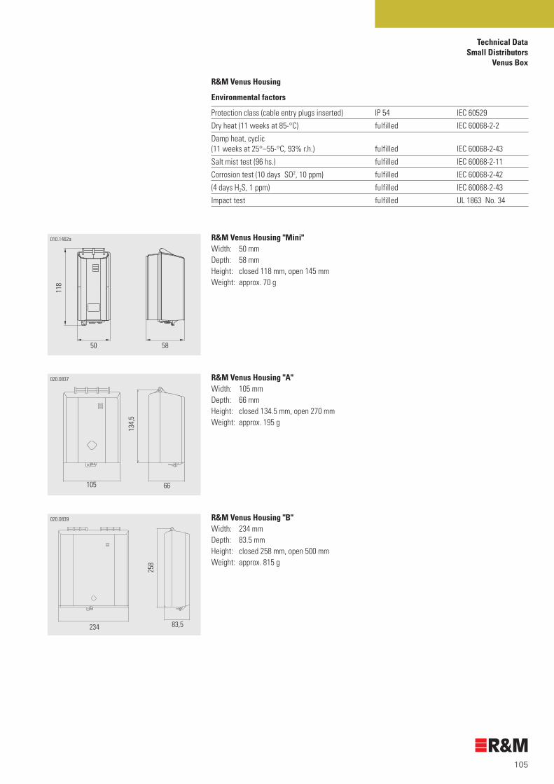
105
Technical Data Small Distributors
Venus Box
R&M Venus Housing "A" Width: 105 mmDepth: 66 mmHeight: closed 134.5 mm, open 270 mmWeight: approx. 195 g
R&M Venus Housing "B"Width: 234 mmDepth: 83.5 mmHeight: closed 258 mm, open 500 mmWeight: approx. 815 g
R&M Venus Housing "Mini"Width: 50 mmDepth: 58 mmHeight: closed 118 mm, open 145 mmWeight: approx. 70 g
R&M Venus Housing
Environmental factors
Protection class (cable entry plugs inserted) IP 54 IEC 60529
Dry heat (11 weeks at 85-°C) fulfilled IEC 60068-2-2
Damp heat, cyclic (11 weeks at 25°–55-°C, 93% r.h.) fulfilled IEC 60068-2-43
Salt mist test (96 hs.) fulfilled IEC 60068-2-11
Corrosion test (10 days SO2, 10 ppm) fulfilled IEC 60068-2-42
(4 days H2S, 1 ppm) fulfilled IEC 60068-2-43
Impact test fulfilled UL 1863 No. 34
010.1462a
50 58
118
020.0837
105 66
134,
5
020.0839
234
258
83,5

106
Technical DataVS Compact Modules
VS Compact Contact TechnologyThe contact used by R&M secures high contact pressures, dependability and a long service life of the modules. Gastightness is always maintained, even in aggressive environment or when conductors are moved due to tensile strain on cables. Thanks to excellent resistance to stress cracking, soiling and mechanical vibrations, the VS Compact modules can be used everywhere in the telecommunications cabling.
VS Compact connection moduleFront: black module labelling
VS Compact disconnection moduleFront: yellow module labelling
VS Compact normally open moduleFront: blue module labelling
VS Compact connection module with earthing railFront: black module labelling
VS Compact disconnection module with marking plugMarking plug: red
VS Compact disconnection module with disconnection moduleDisconnection plug: black
VS Compact disconnection module with test plug
VS Compact connection module with print insert
VS Compact connection module with primary protection
VS Compact disconnection module with primary and secondary protection
030.0692
030.0690.1
030.0698
030.0696
030.0694
030.0697
030.0695
030.0693
030.0689.1Cable
Jumper wire
030.0691.1
030.0664030.0667

107
Technical DataVS Compact Modules
030.0699 VS Compact Module, 2 pairs
Abmessungen
20 mm 28 mm15
mm
VS Compact Module, 8/10 pairsGrid size 20 mm
86 mm 36 mm
20 m
m
100 mm
030.0701/030.0701.1 VS Compact Module, 10 pairsGrid size 17.5 mm
100 mm 36 mm
17,5
mm
VS Compact Adapter Module, 10 pairsGrid size 22.5 mm
030.1593 VS Compact Module, 25 pairsGrid size 25 mm205 36 mm
25 m
m
VS Compact Module, 16/20 pairsGrid size 25 mm
16 pairs: 142 mm
20 pairs: 170 mm
25 m
m
36 mm
030.0703/030.0703.1
124.4 mm 36 mm
20 m
m

108
Technical DataVS Compact Modules
Module
Mechanical data
IDC contact corresponds to IEC 60 352-4Repeated wiring with identical or increased wire ≥ 100 IEC 60 352-4Wiring force with wire 0.35 – 0.50 < 50 N –Wiring force with wire 0.60 – 0.80 < 100 N –Solid wire diameter rangeJumper side 0.35–0.80 mm (26-20 AWG) –Double wiring 0.35–0.50 mm (26-24 AWG) –Solid wire insulation diameter rangeJumper side 0.60–1.60 mm PE/PVCDouble wiring 0.60–1.60 mmStranded wire 7 x 0.15 (26-24 AWG) PE Material
Modules polycarbonate (10% fiber-glass-reinforced) PC-GF 10Flammability class V-0 UL 94Flame retardant halogen-free VDE 0742 Part 815Contact spring bronze CuSn6Surface treatment spring bronze CuSn8– Disconnection contact and rear contact Ni/AuCo 1–2 mm/= 0.8 mm – IDC Ni/SnPb 1–2 mm/2–4 mm Electrical characteristics
IDC contact resistance RK ≤ 3 mΩ Type < 1,0 mΩ IEC 60 352-4Resistance module RAL ≤ 10 mΩ Type < 6,5 mΩ IEC 60 512-2-1Resistance disconnection module RTL ≤ 15 mΩ Type < 11 mΩ IEC 60 512-2-1Insulation resistance RIS (100 V normal climate) > 5 x 10⁵ MΩ IEC 60 512-3-1Alternating voltage strength Ueff (50 Hz/60 s) Conductor – conductor > 2000 V IEC 60 512-4-1Conductor – earth > 2000 V DIN 47 608-2Surge voltage strength USS (1.2/50 µs) > 3600 V DIN 47 608-2Nominal current IN 2 A IEC 60512-5-1Nominal voltage UN (a-b/a-E/b-E with DC and AC peak) 125 V –Rupturing capacity PT for disconnection module 50 W – Transmission characteristicsAttenuation (ATT) 1 MHz < 0,05 dB IEC 1180116 MHz < 0,05 dB100 MHz < 0,10 dBNear-end crosstalk (NEXT) 1 MHz > 70 dB16 MHz > 50 dB100 MHz > 34 dBReturn loss (RL) 1 MHz > 35 dB IEC 1180116 MHz > 35 dB100 MHz > 25 dBCategory Cat.3 Cat. 5e (with Booster Print)

109
Technical DataVS Compact Modules
Primary protection magazine
Material
Magazine body PBT PBT-GF15
Contacts spring bronze CuSn 6
Surface treatment silver Ag
Flammability class V-0 UL 94
Flame retardant halogen-containing IEC 60 472 Part 815
Electrical characteristics
Alternating current strength Ieff (230 V/50 Hz/5 x/1 s) 2 x 5 A ITU-T K 12
Surge current strength ISS (a + b – e) (8/20 µs/10 x ) 2 x 5 kA ITU-T K 12
Contact resistance module – magazine < 10 mΩ IEC 60 512-2-1
Arrester
Electrical characteristics
Response voltage Umax (1 kV/µs) 230 V ± 20% ITU-T K12 Depending on arrester type
Values acc. to data sheet of the arrester
Arrester
Dimensions
Arrester type 3-pole arrester, 6 x 8 mm, with earth wire
Overcurrent protection plug, 150 mA
Electrical characteristics
Max. operating voltage 245 V
Nominal resistance 10 Ω ± 20%
Nominal voltage 220 V
Nominal current 150 mA
Max. switching current 1 A
Switching time at 350 mA < 210 s
Range of operating temperature –25 to +125-°C
Overvoltage protection magazine
1 pair, 07 x 13 x 22 mm1)
5 pairs, 35 x 13 x 22 mm1)
i 1) Depth of the protection magazine when inserted = 14 mm.
030.0711.1
8
6
9
1
090.2052
1324
7
24 35
13
090.2055

110
Technical Data1-Pair Dropwire Module
1-Pair Dropwire ModuleTo be snapped onto DIN rail 35 mm
Module
Mechanical data
IDC contact corresponds to IEC 60 352-4
Repeated wiring with identical or increasing wire ≥ 10 IEC 60 352-4
Solid wire diameter range
Jumper side 0.40–1.00 mm (26-19 AWG) –
Cable side 0.40–1.00 mm (26-19 AWG) –
Solid wire insulation diameter range
Jumper side 0.80–1.60 mm (2.50 mm)1)
Cable side 0.80–1.60 mm PE/PVC/PT FE
Material
Module base polycarbonate PC
Wiring screw nickel-plated brass CuZn39Pb3
Stripper and seal never-lost rubber EPDM
Cover seal silicone
Insulation protection compound soft polymer
Flammability class V-0 (self-extinguishing) UL 94
Contact spring bronze, tin-coated CuSn6 + Sn
Electrical characteristics
IDC contact resistance RK ≤ 1 mΩ IEC 60 352-4
Total contact resistance R ≤ 10 mΩ –
Insulation resistance RIS (100 V normal climate) > 5 x 10⁵ MΩ IEC 60 512-3-1
Alternating voltage strength Ueff (50 Hz/60 s) > 2000 V IEC 60 512-4-1
Conductor – conductor type 6000 V DIN 47 608-2
Conductor – earth type 3400 V
Surge voltage strength USS (1.2/50 µs) > 3600 V DIN 47 608-2
Conductor – conductor type 10000 V
Conductor – earth type 6000 V
Surge current strength ISS (8/20 ms/10x/a-a') with wire diameter > 0.5 mm 5 kA DIN 47608-2
i 1) Insulation diameter range > 1.60 mm must be tested before installation.
030.1555
55,75 14,5
33,5
5

111
Technical Data 1-Pair Dropwire Module
Climatic characteristics
Dry heat Δ RK ≤ 3 mΩ IEC 60 068-2-2 Ba
(15 weeks/85°) RINST ≤ 3 mΩ Swisscom 839.76
Climatic sequence Δ RK ≤ 3 mΩ IEC 60 068-2-30 Db
(15 weeks/25° – 55°/93% relative humidity) RINST ≤ 3 mΩ Swisscom 839.76
Sudden change of temperature Δ RK ≤ 3 mΩ IEC 60 068-2-14 Na
(5 cycles/–40° to +70°) RINST ≤ 3 mΩ Swisscom 839.76
Immersing in salt water 3% NaCI RI ≥ 100 MΩ Bellcore
(7 days/voltage a-b 48V DC) TR-NWT 000975
Salt mist test RI ≥ 100 MΩ Bellcore
(7 days/voltage a-b 48 VDC) TR-NWT 000975
Primary protection holder
Material
Primary protection holder plastic LCP
Overvoltage arrester
Electrical characteristics
Arrester type 3-pole arrester, 6 x 8 mm, with earth wire –
Nominal response voltage 230 V ITU-T K. 12
Nominal surge current strength (cycles 8/20 ms/10x) 10 kA (each side 5 kA) ITU-T K. 12
Nominal alternating current strength (50 Hz, 1s/10x) 10 A (each side 5 A) ITU-T K. 12

112
Notes

Part Number Index
Part No Description Page Part No Description Page
113113
R100622 Hinged Label Holder 8 pairs 86
R100623 Hinged Label Holder 10 pairs 86
R100641 Hinged Label Holder 16 pairs 86
R100642 Hinged Label Holder 20 pairs 86
R100659 Test Plug, 10 pairs, “Universal” 88
R101390 Hinged Label Holder 25 pairs 86
R13001-02 Double Connector (for wire 0,4–0,64 mm) 38
R13001-03 Triple Connector (for wire 0,4– 0,9 mm) 38
R19018 Connector Pliers 38
R20020-100 Supports for Raised Floors, height 100–155 mm 26
R20020-150 Supports for Raised Floors, height 160–240 mm 26
R20036-3 Safety Stairs, height 1160 mm 28
R20062 Trolley for 2 Wire Coils 28
R20069 Protection Bar Joint 26
R21095-02-WS/BL Jumper Wire, 1 pair, 0,5 mm, 100 m, white/blue 96
R21095-02-WS/BN Jumper Wire, 1 pair, 0,5 mm, 100 m, white/brown 96
R21095-02-WS/GB Jumper Wire, 1 pair, 0,5 mm, 100 m, white/yellow 96
R21095-02-WS/GN Jumper Wire, 1 pair, 0,5 mm, 100 m, white/green 96
R21095-02-WS/GU Jumper Wire, 1 pair, 0,5 mm, 100 m, white/grey 96
R21095-02-WS/OG Jumper Wire, 1 pair, 0,5 mm, 100 m, white/orange 96
R21095-02-WS/RT Jumper Wire, 1 pair, 0,5 mm, 100 m, white/red 96
R21095-02-WS/SZ Jumper Wire, 1 pair, 0,5 mm, 100 m, white/black 96
R21095-04-RT Jumper Wire, 2 pairs, 0.5 mm, 100 m, white/red/turquoise/violet 96
R21095-04-SZ Jumper Wire, 2 pairs, 0.5 mm, 100 m, white/black/turquoise/violet 96
R27039 Earthing Flex for CCC, 200 mm, cross-section 2.5 mm2 47
R27300 Polycarbonate Cross Connection Cabinet,1200 pairs (copper version) 46
R27301 Polycarbonate Cross Connection Cabinet, 2400 pairs (copper version) 46
R27305 Base for Polycarbonate CCC 46
R27376 Cross Connection Cabinet Polyester 1/1100-1 44
R27377 Cross Connection Cabinet Polyester 1/1100-2 44
R27382 Base for CCC “1”/xxx 44
R27386 Concrete Base Mounting Kit for “1”/xxx 44
R27389-40 Mounting Kit for CCC, 400 pairs VS Compact 40 positions 47
R27390 Concrete Base Mounting Kit for Polycarbonate CCC 46
R27391 Half-Profile Cylinder for CCC, LIC 46
R27394 Standard Cylinder for Polyester CCC 44
R27395 Multi-Cylinder for Polyester CCC 44
R300004 Back Mount Frame, 8 pairs (128-pair block), depth 50 mm, length 320 mm , max. no. of modules 16 23
R300008 Back Mount Frame, 10 pairs, grid 17.5, depth 50 mm, length 175 mm, max. no. of modules 10 23
R300009 Back Mount Frame, 10 pairs (100-pair block), depth 50 mm, length 200 mm, max. no. of modules 10 23
R300010 Mounting Profile, grid 20/25, depth 25 mm, length 200 mm 22
R300011 Mounting Profile, grid 20/25, depth 25 mm, length 1500 mm 22
R300012 Mounting Profile, grid 20/25, depth 25 mm, length 2000 mm 22
R300013 Mounting Profile, grid 20/25, depth 50 mm, length 200 mm 22
R300014 Mounting Profile, grid 20/25, depth 50 mm, length 400 mm 22
R300016 Mounting Profile, grid 20/25, depth 100 mm, length 400 mm 22
R300017 Mounting Profile, grid 20/25, depth 100 mm, length 800 mm 22
R300018 Mounting Profile, grid 20/25, depth 100 mm, length 1500 mm 22
R300019 Mounting Profile, grid 20/25, depth 200 mm, length 1500 mm 22
R300020 Mounting Profile, grid 20/25, depth 200 mm, length 2000 mm 22
R300021 Mounting Profile, grid 20/25, depth 200 mm, length 2500 mm 22
R300022 Spacer, size 8 pairs 23/71
R300023 Spacer, size 10 pairs 23/71
R300024 Transfer Ring, small, min profile depth 50 mm 23/71
R300025 Transfer Strap, min. profile depth 50 mm 24/71
R300031 Mounting Plate, 16 pairs 25
R300032 Mounting Plate, 20 pairs 25
R300033 Connection Module, 2 pairs 79
R300034 Disconnection Module, 2 pairs 79
R300035 Connection Module, 8 pairs 77
R300036 Disconnection Module, 8 pairs 77
R300037 Normally Open Module, 8 pairs 77
R300039 Connection Module, 10 pairs 38/77
R300040 Disconnection Module, 10 pairs 38/77
R300041 Normally Open Module, 10 pairs 77
R300043 Connection Module, 10 pairs/17.5 mm 78
R300044 Disconnection Module, 10 pairs/17.5 mm 72/78
R300045 Connection Module, 16 pairs 77
R300046 Disconnection Module, 16 pairs 72/77
R300047 Normally Open Module, 16 pairs 77
R300049 Connection Module, 20 pairs 77
R300050 Disconnection Module, 20 pairs 77
R300051 Normally Open Module, 20 pairs 77
R300053 Adapter Connection Module, 10 pairs 79
R300054 Adapter Disconnection Module, 10 pairs 79
R300063 Protection Plug, PTC, 150 mA 83
R300065 Number Clip 01 to 10, colour: grey 72/85
R300066 Marking Plug, 1 pair, red 73/85
R300067 Disconnection Plug, 1 pair 73/84
R300068 Mini Tool 72/84
R300069 Comfort Tool 72/84
R300070 Micro Tool 84
R300071 Test Plug, 1 pair 74/88
R300073 Test Cord “Universal” 74/90

114
Part Number Index
Part No Description Page
R300092 Earthing Rail, 10 pairs 81
R300093 Adapter Earthing Rail, 10 pairs 81
R300094 Earthing Rail, 16 pairs 81
R300095 Earthing Rail, 20 pairs 81
R300221 Sample Kit 92
R300231 Arrester without Failsafe 82
R300233 Arrester incl. FS and FS Display 82
R300292 Designation Clip, red 73/85
R300293 Designation Clip, black 73/85
R300294 Designation Clip, yellow 73/85
R300295 Designation Clip, blue 73/85
R300464 Wiring Base, 8 pairs/10 pairs 84
R300465 Wiring Base, 16 pairs /20 pairs 84
R300466 Earthing Module Kit, 10 pairs 84
R300467 Earthing Module Kit, 20 pairs 84
R300561 Booster Print, 10 pairs 87
R300648 Mounting Adapter 90° for Freestanding Distributor Horizontal/Vertical, 8 pairs 28
R300649 Mounting Adapter 90° for Freestanding Distributor Horizontal/Vertical, 10 pairs 28
R300650 Mounting Adapter 90° for Freestanding Distributor Horizontal/Vertical, 16 pairs 28
R300651 Mounting Adapter 90° for Freestanding Distributor Horizontal/Vertical, 20 pairs 28
R300658 Mounting Adapter 45 27
R300659 Mounting Profile, grid 20/25, depth 25 mm, length 2500 mm 22
R300660 Spacer, size 16 pairs 23/71
R300661 Spacer, size 20 pairs 23/71
R300662 19” 3U Sub-Rack, empty 21/69
R300663 19” Mounting Profile Kit 21
R300664 Label Holder, 8 pairs, grid size 20 mm 24/86
R300665 Label Holder, 10 pairs, grid size 20 mm 24/86
R300666 Label Holder, 16 pairs, grid size 25 mm 24/71/86
R300667 Label Holder, 20 pairs, grid size 25 mm 24/86
R300668 Snap-On Kit for Label Holder 24/86
R300669 Round Profile Adapter Kit 79
R300670 Multiple Blind Cover, 8 pairs, grid size 200 mm 24/86
R300671 Multiple Blind Cover, 10 pairs, grid size 200 mm 24/86
R300672 Multiple Blind Cover, 16 pairs, grid size 250 mm 24/86
R300673 Multiple Blind Cover, 20 pairs, grid size 250 mm 24/86
R300674 Connection Module, 25 pairs 78
R300675 Disconnection Module, 25 pairs 78
R300757 Normally Open Module, 25 pairs 78
R300761 Earthing Rail, 8 pairs 81
R300763 Booster Print, 20 pairs 87
R300764 Print for Ribbon Cable, 8 pairs 87
R300765 Print for Ribbon Cable, 10 pairs 87
R300766 Print for Ribbon Cable, 16 pairs 87
R300767 Print for Ribbon Cable, 20 pairs 87
Part No Description Page
R300768 Wall Rail Kit, length 500 mm 27/70
R300769 Wall Rail Kit, length 1000 mm 27/70
R300770 Wall Rail Kit, length 1500 mm 27/70
R300771 Wall Rail Kit, length 2000 mm 27/70
R300772 Floor Rail Kit, 500 mm 25
R300773 Floor Rail Kit, 1000 mm 25
R300774 Floor Rail Kit, 1500 mm 25
R300775 Floor Rail Kit, 2000 mm 25
R300864 Half-Profile Cylinder for CCC, especially LIC 46
R300963 Mounting Profile, grid 20/25, depth 25 mm, length 175 mm 22
R300964 Mounting Profile, grid 17.5, depth 50 mm, length 175 mm 22
R300965 Mounting Profile, grid 17.5, depth 50 mm, length 350 mm 22
R300966 Mounting Profile, grid 17.5, depth 100 mm, length 350 mm 22
R300967 Mounting Profile, grid 17.5, depth 100 mm, length 700 mm 22
R300968 Mounting Profile, grid 17.5, depth 100 mm, length 1313 mm 22
R300987 Line Entry for Test Plug, 10 pairs, with LED 89
R301046 Single Blind Cover, 8 pairs, grid size 20 mm 24/86
R301047 Single Blind Cover, 10 pairs, grid size 20 mm 24/86
R301048 Single Blind Cover, 16 pairs, grid size 25 mm 24/86
R301049 Single Blind Cover, 20 pairs, grid size 25 mm 24/86
R301050 Transfer Ring, large, min profile depth 100 mm 23/71
R301051 Floor Rail Joint 25
R301052 Protection Rail Kit, length 500 mm 26
R301053 Protection Rail Kit, length 1000 mm 26
R301054 Protection Rail Kit, length 1500 mm 26
R301055 Protection Rail Kit, length 2000 mm 26
R301056 Mounting Kit for Wall Distributor 45° 27
R301058 Mounting Kit for Wall Distributor 90° 28/70
R301272 Back Mount Frame, 10 pairs, grid 17.5, depth 75 mm, length 297.5 mm, max. no. of modules 17 23
R301273 Back Mount Frame, 10 pairs, grid 17.5, depth 75 mm, length 367.5 mm, max. no. of modules 21 23
R301274 Back Mount Frame, 10 pairs, grid 17.5, depth 75 mm, length 525 mm, max. no. of modules 30 23
R301275 Back Mount Frame, 10 pairs, grid 17.5, depth 75 mm, length 595 mm, max. no. of modules 34 23
R301276 Back Mount Frame, 10 pairs, grid 17.5, depth 75 mm, length 700 mm, max. no. of modules 40 23
R301277 Spacer Kit, size 1, distance 64 mm 26
R301278 Spacer Kit, size 2, distance 78 mm 26
R301279 Spacer Kit, size 3, distance 120 mm 26
R301280 Spacer Kit, size 4, distance 148 mm 26
R301281 Mounting Kit for Freestanding MDF Vertical/Vertical 25
R301549 Wall Rail Joint 27
R301863 Mounting Profile, grid 20/25, depth 100 mm, length 1000 mm 22

115
Part Number Index
Part No Description Page
R301920 Number Clip 00 to 90, colour: grey 72/85
R301943 19” Mounting Profile Kit, 7 modules 17.5 mm 21
R302015 Mounting Profile Kit, 1 Space, depth 15 mm 22
R302016 Mounting Profile Kit, 1 Space, depth 25 mm 22
R302017 Label Holder, 10 pairs, grid size 17.5 mm 24/71/86
R302060 Normally Open Module, 10 pairs/17.5 mm 78
R302064 Mounting Profile, grid 20/25, depth 25 mm, length 800 mm 22
R302065 Mounting Profile, grid 20/25, depth 25 mm, length 1000 mm 22
R302101 Protection Plug, 230 V/130 mA (subscriber side) 83
R302102 Protection Plug, 230 V/130 mA inverse (exchange side) 83
R302183 Earthing Module Kit, 8 pairs 84
R302184 Earthing Module Kit, 16 pairs 84
R302501 Number Clip 01 to 10, colour: yellow 72/85
R302513 Module Label Holder, 8 pairs 85
R302514 Module Label Holder, 10 pairs 85
R302515 Module Label Holder, 16 pairs 85
R302516 Module Label Holder, 20 pairs 85
R302603 Test Cord, 4 x 4 mm Jack 74/90
R302604 Line Cord 2,5 m 91
R302605 Line Cord 3,0 m 91
R302606 Disconnection Plug, 5 pairs 84
R302607 Disconnection Plug, 8 pairs 84
R302608 Disconnection Plug, 10 pairs 84
R302704 EMC Cover, 16 pairs 78
R302705 19” 1U Cable Guide Panel 21/69
R302706 Back Mount Frame, 16 pairs (128-pair block), depth 50 mm, length 225 mm, max, no. of modules 9 23
R302770 Arrester Tool 82
R302788 Disconnection Module, 16 pairs, DDF 78
R302818 Back Mount Frame, 20 pairs, depth 50 mm, length 250 mm, max. no. of modules 10 23
R302861 SM Housing, magnetic 51
R302912 SM Housing, 5/8 pairs 52
R302913 SM Housing, 25/40 pairs 52
R302914 SM Housing, 10 pairs 52
R302915 SM Housing, 20 pairs 52
R302916 SM Housing, 50 pairs 52
R302917 SM Housing, 100 pairs 52
R302918 SM Housing, 300 pairs 52
R302925 Parallel Plug, 10 pairs “a/b” 88
R302977 Protection Plug, PTC, 150 mA, short 83
R303002 Earthing Kit for Splice Closures, Shield Connecting Lead: V shape/M6 cable lug, 400 mm 40
R303003 Earthing Kit for Splice Closures, Shield Connecting Lead: V shape/V shape, 500 mm 40
R303007 Mounting Profile, grid 20/25, depth 25 mm, length 400 mm 22
R303008 Mounting Profile, grid 20/25, depth 25 mm, length 600 mm 22
Part No Description Page
R303211 Mounting Profile, grid 20/25, depth 100 mm, length 200 mm 22
R303212 Mounting Profile, grid 20/25, depth 100 mm, length 900 mm 22
R303310 Holder and Arrester w/o Failsafe 95
R303416 Number Clip 20 to 200, colour: grey 72/85
R303417 Number Clip 100 to (1)000, colour: grey 72/85
R303418 Number Clip 08 to 80, colour: grey 72/85
R303419 Number Clip 88 to 160, colour: grey 72/85
R303420 Number Clip 16 to 160, colour: grey 72/85
R303421 Number Clip 176 to 320, colour: grey 72/85
R30392 Silica Gel 38
R304330 1-Pair Dropwire Module w/o Arrester 38/94
R304331 1-Pair Dropwire Module with Arrester w/o Failsafe 38/94
R304332 1-Pair Dropwire Module with Arrester and Failsafe 38/94
R304333 Holder and Arrester with Failsafe 95
R304383 EMC Cover, 16 pairs, type C 79
R304464 Jumper Cord 0,5 m 91
R304465 Jumper Cord 1,0 m 91
R304466 Jumper Cord 1,5 m 91
R304467 Jumper Cord 2,0 m 91
R304468 Jumper Cord 2,5 m 91
R304494 Mounting Profile, grid 20/25, depth 50 mm, length 2000 mm 22
R304558 Test Plug, 1 pair, short 74/88
R304636 Mounting Profile, grid 20/25, depth 25 mm, length 2200 mm 22
R304637 Mounting Profile, grid 20/25, depth 25 mm, length 2205 mm 22
R304938 Mounting Profile, grid 20/25, depth 25 mm, length 100 mm 22
R304953 Protection Magazine, 1 pair, empty 81
R304954 Protection Magazine, 5 pairs, empty 81
R304955 Protection Magazine, 1 pair, with arrester without failsafe 81
R304956 Protection Magazine, 5 pairs, with arrester without failsafe 81
R304957 Protection Magazine, 1 pair, with arrester with FS plus FS display 81
R304958 Protection Magazine, 5 pairs, with arrester with FS plus FS display 81
R304974 Spacer, size 25 pairs 23/71
R304984 Back Mount Frame, 20 pairs, depth 50 mm, length 375 mm, max. no. of modules 15 23
R304995 Mounting Profile, grid 20/25, depth 50 mm, length 1000 mm 22
R304996 Mounting Profile, grid 17,5, depth 100 mm, length 2187 mm 22
R304997 Mounting Profile, grid 20/25, depth 100 mm, length 2200 mm 22
R305187 Monitoring Cable, 1 pair, 2,5 m 91
R305208 Label Holder, 25 pairs, grid size25 mm 24/86

116
Part Number Index
Part No Description Page
R305209 Earthing Rail, 25 pairs 81
R305215 Module Label Holder, 25 pairs 85
R305339 Test Plug, 10 pairs, with LED 89
R305429 Back Mount Frame, 20 pairs, depth 100 mm, length 400 mm, max. no. of modules 16 23
R305586 Extraction Tool for 5-Pair Protection Magazine 82
R305705 Sample Case 92
R306267 Mounting Adapter 90° for Freestanding Distributor Horizontal/Vertical, 25 pairs 28
R306376 Marking Plug, 1 pair, blue 73/85
R306484 PCB Based, 10 pairs 80
R306556 Mounting Plate, 25 pairs 25
R306598 Multiple Blind Cover, 25 pairs, grid size 250 mm 24/86
R306615 Earthing Module Kit, 25 pairs 84
R306617 Wiring Base, 25 pairs 84
R306630 Print for Ribbon Cable, 25 pairs 87
R306631 Back Mount Frame, 25 pairs, depth 50 mm, length 125 mm, max. no. of modules 5 23
R306633 Back Mount Frame, 25 pairs, depth 50 mm, length 250 mm, max. no. of modules 10 23
R306786 Number Clip 0 to 18, colour: grey 85
R306850 VENUS CLA for Dropwire Modules 60
R306851 VENUS CME for VS Compact 58
R306852 VENUS CME for Dropwire Modules 58
R306853 VENUS CLA for VS Compact 10 pairs 60
R307035 Testing Cord “Universal” with snap-in stop 90
R307172 VENUS CSM for VS Compact 57
R307173 VENUS CSM for Dropwire Modules 57
R307231 Patch Cord VS-RJ45 (4/5) 2m 90
R307232 Patch Cord VS-RJ45 (3/6) 2m 90
R307321 Shrink Tube Set 28/6x100 39
R307322 Shrink Tube Set 38/10x100 39
R307323 Shrink Tube Set Oval 39
R307324 Cable Grip Loop Set for 9,5 – 11,5 39
R307325 Cable Grip loop Set for 12 – 14 39
R307326 Cable Grip Loop Set for 19 – 21 39
R307327 Cable Grip Single Set for für 9,5 – 11,5 39
R307328 Cable Grip Single Set for für 12 – 14 39
R307348 Mounting Profile, grid 20/25, depth 25 mm, length 440 mm 22
R307353 Cable-entry Plug CSM 57
R307354 Dropwire-Entry Plug CSM 57
R307355 Cable-Entry Plug CME 59
R307356 Cable-Entry Plug Special CME 59
R307357 Dropwire-Entry Plug CME 59
R307358 Cable-Entry Plug CLA 63
R307359 Dropwire-Entry Plug CLA 63
R307361 Pole Fixing Bracket CME 59
R307362 Pole Fixing Bracket CLA 63
R307363 Cable Clamp for Maincable 63
Part No Description Page
R307383 AMP Test Adapter, front 87
R307384 AMP Test Adapter, back 87
R307838 Mounting Profile, grid 20/25, depth 50 mm, l ength 250 mm 22
R308086 Cable Grip Loop Set for 15 – 17 39
R308091 ADSL Splitter PC0270P04RM 68
R308092 ADSL Splitter PC0600P04RM 68
R308326 19” Splitter BMF 69
R308327 Splitter BMF 500 mm 70
R308328 Splitter BMF 1000 mm 70
R308520 Splitter BMF 300 mm 70
R308542 Back Mount Frame, 25 pairs, depth 100 mm, length 375 mm, max. no. of modules 15 23
R308543 Back Mount Frame, 25 pairs, depth 100 mm, length 500 mm, max. no. of modules 20 23
R308560 Shrink Tube Set 50/18x150 39
R308561 Earthing Kit for Steel-Armoured Cables 22/6 40
R308562 Earthing Kit for Steel-Armoured Cables 32/10 40
R308600 Module Label Holder, 10 pairs 72
R308605 Mounting Adapter Kit ADSL 70
R308795 VENUS CLA for Dropwire Modules, wk 61
R308796 VENUS CLA for VS Compact 10 pairs, wk 61
R308797 VENUS CME for Dropwire Modules with cylinder lock 59
R308798 VENUS CME for VS Compact with cylinder lock 58
R309083 Cu Splice Closures, Type DC, Entry 4 x 15 mm, 2 x 22 mm, Overall Diameter 125 mm 34
R309084 Cu Splice Closures,Type DC, Entry 2 x 22 mm, 2 x 32 mm, Overall Diameter 135 mm 34
R309085 Cu Splice Closures, Type DC, Entry 2 x 32 mm, 2 x 42 mm, Overall Diameter 150 mm 34
R309086 Cu Splice Closures, Type FE, Entry 10 x 8 Flexi, 2 x 20 Flexi, Overall Diameter 125 mm 35
R309087 Cu Splice Closures, Type FE, Entry 10 x 8 Flexi, 2 x 20, 1 x Oval, Overall Diameter 125 mm 35
R309088 Cu Splice Closures, Type CM, Entry 4 x 20 mm, 1 x Oval, Overall Diameter 150 mm, Lenth 282 mm 36
R309089 Cu Splice Closures, Type CM, Entry 4 x 20 mm, 1 x Oval, Overall Diameter 150 mm, Lenth 332 mm 36
R309090 Cu Splice Closures, Type DM, Entry 12 x 5 Drop, 2 x 20, 1 x Oval, Overall Diameter 150 mm, Lenth 282 mm 36
R309100 Cu Splice Closures, Type DC, Entry 4 x 20 mm, 1 x Oval, Overall Diameter 150 mm 34
R309101 Cu Splice Closures, Type DC, Entry 2 x 32 mm, 1 x Oval, Overall Diameter 150 mm 34
R309233 ADSL Splitter PC0220C04RM-D 68
R309814 VENUS CLA for VS Compact 20 pairs 60
R309815 VENUS CLA for VS Compact 20 pairs, wk 61
R309816 VENUS HLA hybrid 62
R309817 VENUS HLA hybrid with cylinder lock 62
R309931 Marking Cap, green 85
R310094 Back Mount Frame, 16 pairs (128-pair block), depth 100 mm, length 1500 mm, max. no. of modules 60 23

117
R310095 ADSL Splitter PC0600P04RME 68
R310096 Splitter BMF 16 pairs/500 70
R310097 Splitter BMF 16 pairs/1000 70
R310098 Module Label Holder, 16 pairs 72
R310607 ADSL Splitter PC0220C04RME-K 68
R311068 ADSL Splitter PC0220C04RMX-K 68
R311074 ADSL Splitter PC0270P04RM-K 68
R311658 Shield Connection Cable V shape / M6 150 mm 64
R311841 Single Blind Cover, 25 pairs, grid size 25 mm 24
R311859 Pole Fixing Bracket Universal CLA 63
Part No Description Page
Part Number Index

118
Notes
Alphabetical Index
Description Part No Page Description Part No Page
119119
1
19” 1U Cable Guide Panel R302705 21/69
19” 3U Sub-Rack, empty R300662 21/69
19” Mounting Profile Kit R300663 21
19” Mounting Profile Kit, 7 modules 17.5 mm R301943 21
19” Splitter BMF R308326 69
1-Pair Dropwire Module w/o Arrester R304330 38/94
1-Pair Dropwire Module with Arrester and Failsafe R304332 38/94
1-Pair Dropwire Module with Arrester w/o Failsafe R304331 38/94
A
Adapter Connection Module, 10 pairs R300053 79
Adapter Disconnection Module, 10 pairs R300054 79
Adapter Earthing Rail, 10 pairs R300093 81
ADSL Splitter PC0220C04RM-D R309233 68
ADSL Splitter PC0220C04RME-K R310607 68
ADSL Splitter PC0220C04RMX-K R311068 68
ADSL Splitter PC0270P04RM R308091 68
ADSL Splitter PC0270P04RM-K R311074 68
ADSL Splitter PC0600P04RM R308092 68
ADSL Splitter PC0600P04RME R310095 68
AMP Test Adapter, back R307384 87
AMP Test Adapter, front R307383 87
Arrester incl. FS and FS Display R300233 82
Arrester Tool R302770 82
Arrester without Failsafe R300231 82
B
Back Mount Frame, 10 pairs (100-pair block), depth 50 mm, length 200 mm, max. no. of modules 10 R300009 23
Back Mount Frame, 10 pairs, grid 17.5, depth 50 mm, length 175 mm, max. no. of modules 10 R300008 23
Back Mount Frame, 10 pairs, grid 17.5, depth 75 mm, length 297.5 mm, max. no. of modules 17 R301272 23
Back Mount Frame, 10 pairs, grid 17.5, depth 75 mm, length 367.5 mm, max. no. of modules 21 R301273 23
Back Mount Frame, 10 pairs, grid 17.5, depth 75 mm, length 525 mm, max. no. of modules 30 R301274 23
Back Mount Frame, 10 pairs, grid 17.5, depth 75 mm, length 700 mm, max. no. of modules 40 R301276 23
Back Mount Frame, 10 pairs, grid 17.5, depth 75 mm, length 595 mm, max. no. of modules 34 R301275 23
Back Mount Frame, 16 pairs (128-pair block), depth 100 mm, length 1500 mm, max. no. of modules 60 R310094 23
Back Mount Frame, 16 pairs (128-pair block), depth 50 mm, length 225 mm, max. no. of modules 9 R302706 23
Back Mount Frame, 20 pairs, depth 100 mm, length 400 mm, max. no. of modules 16 R305429 23
Back Mount Frame, 20 pairs, depth 50 mm, length 250 mm, max. no. of modules 10 R302818 23
Back Mount Frame, 20 pairs, depth 50 mm, length 375 mm, max. no. of modules 15 R304984 23
Back Mount Frame, 25 pairs, depth 100 mm, length 375 mm, max. no. of modules 15 R308542 23
Back Mount Frame, 25 pairs, depth 100 mm, length 500 mm, max. no. of modules 20 R308543 23
Back Mount Frame, 25 pairs, depth 50 mm, length 125 mm, max. no. of modules 5 R306631 23
Back Mount Frame, 25 pairs, depth 50 mm, length 250 mm, max. no. of modules 10 R306633 23
Back Mount Frame, 8 pairs (128-pair block), depth 50 mm, length 320 mm , max. no. of modules 16 R300004 23
Base for CCC “1”/xxx R27382 44
Base for Polycarbonate CCC R27305 46
Booster Print, 10 pairs R300561 87
Booster Print, 20 pairs R300763 87
C
Cable Clamp for Maincable R307363 63
Cable Grip loop Set for 12 – 14 R307325 39
Cable Grip Loop Set for 15 – 17 R308086 39
Cable Grip Loop Set for 19 – 21 R307326 39
Cable Grip Loop Set for 9.5 – 11.5 R307324 39
Cable Grip Single Set for für 12 – 14 R307328 39
Cable Grip Single Set for für 9.5 – 11.5 R307327 39
Cable-Entry Plug CLA R307358 63
Cable-Entry Plug CME R307355 59
Cable-entry Plug CSM R307353 57
Cable-Entry Plug Special CME R307356 59
Comfort Tool R300069 72/84
Concrete Base Mounting Kit for “1”/xxx R27386 44
Concrete Base Mounting Kit for Polycarbonate CCC R27390 46
Connection Module, 10 pairs R300039 38/77
Connection Module, 10 pairs/17.5 mm R300043 78
Connection Module, 16 pairs R300045 77
Connection Module, 2 pairs R300033 79
Connection Module, 20 pairs R300049 77
Connection Module, 25 pairs R300674 78
Connection Module, 8 pairs R300035 77
Connector Pliers R19018 38
Cross Connection Cabinet Polyester 1/1100-1 R27376 44
Cross Connection Cabinet Polyester 1/1100-2 R27377 44
Cu Splice Closures, Type CM, Entry 4 x 20 mm, 1 x Oval, Overall Diameter 150 mm, Lenth 282 mm R309088 36
Cu Splice Closures, Type CM, Entry 4 x 20 mm, 1 x Oval, Overall Diameter 150 mm, Lenth 332 mm R309089 36
Cu Splice Closures, Type DC, Entry 2 x 32 mm, 1 x Oval, Overall Diameter 150 mm R309101 34
Cu Splice Closures, Type DC, Entry 2 x 32 mm, 2 x 42 mm, Overall Diameter 150 mm R309085 34

120
Alphabetical Index
Description Part No Page
Cu Splice Closures, Type DC, Entry 4 x 15 mm, 2 x 22 mm, Overall Diameter 125 mm R309083 34
Cu Splice Closures, Type DC, Entry 4 x 20 mm, 1 x Oval, Overall Diameter 150 mm R309100 34
Cu Splice Closures, Type DM, Entry 12 x 5 Drop, 2 x 20,1 x Oval, Overall Diameter 150 mm, Lenth 282 mm R309090 36
Cu Splice Closures, Type FE, Entry 10 x 8 Flexi, 2 x 20 Flexi, Overall Diameter 125 mm R309086 35
Cu Splice Closures, Type FE, Entry 10 x 8 Flexi, 2 x 20, 1 x Oval, Overall Diameter 125 mm R309087 35
Cu Splice Closures,Type DC, Entry 2 x 22 mm, 2 x 32 mm, Overall Diameter 135 mm R309084 34
D
Designation Clip, black R300293 73/85
Designation Clip, blue R300295 73/85
Designation Clip, red R300292 73/85
Designation Clip, yellow R300294 73/85
Disconnection Module, 10 pairs R300040 38/77
Disconnection Module, 10 pairs/17.5 mm R300044 72/78
Disconnection Module, 16 pairs R300046 72/77
Disconnection Module, 16 pairs, DDF R302788 78
Disconnection Module, 2 pairs R300034 79
Disconnection Module, 20 pairs R300050 77
Disconnection Module, 25 pairs R300675 78
Disconnection Module, 8 pairs R300036 77
Disconnection Plug, 1 pair R300067 73/84
Disconnection Plug, 10 pairs R302608 84
Disconnection Plug, 5 pairs R302606 84
Disconnection Plug, 8 pairs R302607 84
Double Connector (for wire B 0.4–0.64 mm) R13001-02 38
Dropwire-Entry Plug CLA R307359 63
Dropwire-Entry Plug CME R307357 59
Dropwire-Entry Plug CSM R307354 57
E
Earthing Flex for CCC, 200 mm, cross-section 2.5 mm2 R27039 47
Earthing Kit for Splice Closures, Shield Connecting Lead: V shape/M6 cable lug, 400 mm R303002 40
Earthing Kit for Splice Closures, Shield Connecting Lead: V shape/V shape, 500 mm R303003 40
Earthing Kit for Steel-Armoured Cables 22/6 R308561 40
Earthing Kit for Steel-Armoured Cables 32/10 R308562 40
Earthing Module Kit, 10 pairs R300466 84
Earthing Module Kit, 16 pairs R302184 84
Earthing Module Kit, 20 pairs R300467 84
Earthing Module Kit, 25 pairs R306615 84
Earthing Module Kit, 8 pairs R302183 84
Earthing Rail, 10 pairs R300092 81
Earthing Rail, 16 pairs R300094 81
Description Part No Page
Earthing Rail, 20 pairs R300095 81
Earthing Rail, 25 pairs R305209 81
Earthing Rail, 8 pairs R300761 81
EMC Cover, 16 pairs R302704 78
EMC Cover, 16 pairs, type C R304383 79
Extraction Tool for 5-Pair Protection Magazine R305586 82
F
Floor Rail Joint R301051 25
Floor Rail Kit, 1000 mm R300773 25
Floor Rail Kit, 1500 mm R300774 25
Floor Rail Kit, 2000 mm R300775 25
Floor Rail Kit, 500 mm R300772 25
H
Half-Profile Cylinder for CCC, especially LIC R300864 46
Half-Profile Cylinder for CCC, LIC R27391 46
Hinged Label Holder 10 pairs R100623 86
Hinged Label Holder 16 pairs R100641 86
Hinged Label Holder 20 pairs R100642 86
Hinged Label Holder 8 pairs R100622 86
Hinged Label Holder 25 pairs R101390 86
Holder and Arrester w/o Failsafe R303310 95
Holder and Arrester with Failsafe R304333 95
J
Jumper Cord 0.5 m R304464 91
Jumper Cord 1.0 m R304465 91
Jumper Cord 1.5 m R304466 91
Jumper Cord 2.0 m R304467 91
Jumper Cord 2.5 m R304468 91
Jumper Wire, 1 pair, 0.5 mm, 100 m, white/black R21095-02-WS/SZ 96
Jumper Wire, 1 pair, 0.5 mm, 100 m, white/blue R21095-02-WS/BL 96
Jumper Wire, 1 pair, 0.5 mm, 100 m, white/brown R21095-02-WS/BN 96
Jumper Wire, 1 pair, 0.5 mm, 100 m, white/green R21095-02-WS/GN 96
Jumper Wire, 1 pair, 0.5 mm, 100 m, white/grey R21095-02-WS/GU 96
Jumper Wire, 1 pair, 0.5 mm, 100 m, white/orange R21095-02-WS/OG 96
Jumper Wire, 1 pair, 0.5 mm, 100 m, white/red R21095-02-WS/RT 96
Jumper Wire, 1 pair, 0.5 mm, 100 m, white/yellow R21095-02-WS/GB 96
Jumper Wire, 2 pairs, 0.5 mm, 100 m, white/black/turquoise/violet R21095-04-SZ 96
Jumper Wire, 2 pairs, 0.5 mm, 100 m, white/red/turquoise/violet R21095-04-RT 96
L
Label Holder, 10 pairs, grid size 17.5 mm R302017 24/71/86
Label Holder, 10 pairs, grid size 20 mm R300665 24/86
Label Holder, 16 pairs, grid size 25 mm R300666 24/71/86
Label Holder, 20 pairs, grid size 25 mm R300667 24/86
Label Holder, 25 pairs, grid size25 mm R305208 24/86

121
Alphabetical Index
Description Part No Page
Label Holder, 8 pairs, grid size 20 mm R300664 24/86
Line Cord 2.5 m R302604 91
Line Cord 3.0 m R302605 91
Line Entry for Test Plug, 10 pairs, with LED R300987 89
M
Marking Cap, green R309931 85
Marking Plug, 1 pair, blue R306376 73/85
Marking Plug, 1 pair, red R300066 73/85
Micro Tool R300070 84
Mini Tool R300068 72/84
Module Label Holder, 10 pairs R302514 85
Module Label Holder, 10 pairs R308600 72
Module Label Holder, 16 pairs R302515 85
Module Label Holder, 16 pairs R310098 72
Module Label Holder, 20 pairs R302516 85
Module Label Holder, 25 pairs R305215 85
Module Label Holder, 8 pairs R302513 85
Monitoring Cable, 1 pair, 2.5 m R305187 91
Mounting Adapter 45 R300658 27
Mounting Adapter 90° for Freestanding Distributor Horizontal/Vertical, 10 pairs R300649 28
Mounting Adapter 90° for Freestanding Distributor Horizontal/Vertical, 16 pairs R300650 28
Mounting Adapter 90° for Freestanding Distributor Horizontal/Vertical, 20 pairs R300651 28
Mounting Adapter 90° for Freestanding Distributor Horizontal/Vertical, 25 pairs R306267 28
Mounting Adapter 90° for Freestanding Distributor Horizontal/Vertical, 8 pairs R300648 28
Mounting Adapter Kit ADSL R308605 70
Mounting Kit for CCC, 400 pairs VS Compact 40 positions R27389-40 47
Mounting Kit for Freestanding MDF Vertical/Vertical R301281 25
Mounting Kit for Wall Distributor 45° R301056 27
Mounting Kit for Wall Distributor 90° R301058 28/70
Mounting Plate, 16 pairs R300031 25
Mounting Plate, 20 pairs R300032 25
Mounting Plate, 25 pairs R306556 25
Mounting Profile Kit, 1 Space, depth 15 mm R302015 22
Mounting Profile Kit, 1 Space, depth 25 mm R302016 22
Mounting Profile, grid 17.5, depth 100 mm, length 1313 mm R300968 22
Mounting Profile, grid 17.5, depth 100 mm, length 2187 mm R304996 22
Mounting Profile, grid 17.5, depth 100 mm, length 350 mm R300966 22
Mounting Profile, grid 17.5, depth 100 mm, length 700 mm R300967 22
Mounting Profile, grid 17.5, depth 50 mm, length 175 mm R300964 22
Description Part No Page
Mounting Profile, grid 17.5, depth 50 mm, length 350 mm R300965 22
Mounting Profile, grid 20/25, depth 100 mm, length 1000 mm R301863 22
Mounting Profile, grid 20/25, depth 100 mm, length 1500 mm R300018 22
Mounting Profile, grid 20/25, depth 100 mm, length 200 mm R303211 22
Mounting Profile, grid 20/25, depth 100 mm, length 2200 mm R304997 22
Mounting Profile, grid 20/25, depth 100 mm, length 400 mm R300016 22
Mounting Profile, grid 20/25, depth 100 mm, length 800 mm R300017 22
Mounting Profile, grid 20/25, depth 100 mm, length 900 mm R303212 22
Mounting Profile, grid 20/25, depth 200 mm, length 1500 mm R300019 22
Mounting Profile, grid 20/25, depth 200 mm, length 2000 mm R300020 22
Mounting Profile, grid 20/25, depth 200 mm, length 2500 mm R300021 22
Mounting Profile, grid 20/25, depth 25 mm, length 100 mm R304938 22
Mounting Profile, grid 20/25, depth 25 mm, length 1000 mm R302065 22
Mounting Profile, grid 20/25, depth 25 mm, length 1500 mm R300011 22
Mounting Profile, grid 20/25, depth 25 mm, length 200 mm R300010 22
Mounting Profile, grid 20/25, depth 25 mm, length 2000 mm R300012 22
Mounting Profile, grid 20/25, depth 25 mm, length 2200 mm R304636 22
Mounting Profile, grid 20/25, depth 25 mm, length 2205 mm R304637 22
Mounting Profile, grid 20/25, depth 25 mm, length 2500 mm R300659 22
Mounting Profile, grid 20/25, depth 25 mm, length 400 mm R303007 22
Mounting Profile, grid 20/25, depth 25 mm, length 440 mm R307348 22
Mounting Profile, grid 20/25, depth 25 mm, length 600 mm R303008 22
Mounting Profile, grid 20/25, depth 25 mm, length 800 mm R302064 22
Mounting Profile, grid 20/25, depth 25 mm, length 175 mm R300963 22
Mounting Profile, grid 20/25, depth 50 mm, length 1000 mm R304995 22
Mounting Profile, grid 20/25, depth 50 mm, length 200 mm R300013 22
Mounting Profile, grid 20/25, depth 50 mm, length 2000 mm R304494 22

122
Alphabetical Index
Description Part No Page
Mounting Profile, grid 20/25, depth 50 mm, length 250 mm R307838 22
Mounting Profile, grid 20/25, depth 50 mm, length 400 mm R300014 22
Multi-Cylinder for Polyester CCC R27395 44
Multiple Blind Cover, 10 pairs, grid size 200 mm R300671 24/86
Multiple Blind Cover, 16 pairs, grid size 250 mm R300672 24/86
Multiple Blind Cover, 20 pairs, grid size 250 mm R300673 24/86
Multiple Blind Cover, 25 pairs, grid size 250 mm R306598 24/86
Multiple Blind Cover, 8 pairs, grid size 200 mm R300670 24/86
N
Normally Open Module, 10 pairs R300041 77
Normally Open Module, 10 pairs/17.5 mm R302060 78
Normally Open Module, 16 pairs R300047 77
Normally Open Module, 20 pairs R300051 77
Normally Open Module, 25 pairs R300757 78
Normally Open Module, 8 pairs R300037 77
Number Clip 0 to 18, colour: grey R306786 85
Number Clip 00 to 90, colour: grey R301920 72/85
Number Clip 01 to 10, colour: grey R300065 72/85
Number Clip 01 to 10, colour: yellow R302501 72/85
Number Clip 08 to 80, colour: grey R303418 72/85
Number Clip 100 to (1)000, colour: grey R303417 72/85
Number Clip 16 to 160, colour: grey R303420 72/85
Number Clip 176 to 320, colour: grey R303421 72/85
Number Clip 20 to 200, colour: grey R303416 72/85
Number Clip 88 to 160, colour: grey R303419 72/85
P
Parallel Plug, 10 pairs “a/b” R302925 88
Patch Cord VS-RJ45 (3/6) 2m R307232 90
Patch Cord VS-RJ45 (4/5) 2m R307231 90
PCB Based, 10 pairs R306484 80
Pole Fixing Bracket CLA R307362 63
Pole Fixing Bracket CME R307361 59
Pole Fixing Bracket Universal CLA R311859 63
Polycarbonate Cross Connection Cabinet, 2400 pairs (copper version) R27301 46
Polycarbonate Cross Connection Cabinet, 1200 pairs (copper version) R27300 46
Print for Ribbon Cable, 10 pairs R300765 87
Print for Ribbon Cable, 16 pairs R300766 87
Print for Ribbon Cable, 20 pairs R300767 87
Print for Ribbon Cable, 25 pairs R306630 87
Print for Ribbon Cable, 8 pairs R300764 87
Protection Bar Joint R20069 26
Protection Magazine, 1 pair, empty R304953 81
Protection Magazine, 1 pair, with arrester with FS plus FS display R304957 81
Description Part No Page
Protection Magazine, 1 pair, with arrester without failsafe R304955 81
Protection Magazine, 5 pairs, empty R304954 81
Protection Magazine, 5 pairs, with arrester with FS plus FS display R304958 81
Protection Magazine, 5 pairs, with arrester without failsafe R304956 81
Protection Plug, 230 V/130 mA (subscriber side) R302101 83
Protection Plug, 230 V/130 mA inverse (exchange side) R302102 83
Protection Plug, PTC, 150 mA R300063 83
Protection Plug, PTC, 150 mA, short R302977 83
Protection Rail Kit, length 1000 mm R301053 26
Protection Rail Kit, length 1500 mm R301054 26
Protection Rail Kit, length 2000 mm R301055 26
Protection Rail Kit, length 500 mm R301052 26
R
Round Profile Adapter Kit R300669 79
S
Safety Stairs, height 1160 mm R20036-3 28
Sample Case R305705 92
Sample Kit R300221 92
Shield Connection Cable V shape / M6 150 mm R311658 64
Shrink Tube Set 28/6x100 R307321 39
Shrink Tube Set 38/10x100 R307322 39
Shrink Tube Set 50/18x150 R308560 39
Shrink Tube Set Oval R307323 39
Silica Gel R30392 38
Single Blind Cover, 10 pairs, grid size 20 mm R301047 24/86
Single Blind Cover, 16 pairs, grid size 25 mm R301048 24/86
Single Blind Cover, 20 pairs, grid size 25 mm R301049 24/86
Single Blind Cover, 25 pairs, grid size 25 mm R311841 24
Single Blind Cover, 8 pairs, grid size 20 mm R301046 24/86
SM Housing, 10 pairs R302914 52
SM Housing, 100 pairs R302917 52
SM Housing, 20 pairs R302915 52
SM Housing, 25/40 pairs R302913 52
SM Housing, 300 pairs R302918 52
SM Housing, 5/8 pairs R302912 52
SM Housing, 50 pairs R302916 52
SM Housing, magnetic R302861 51
Snap-On Kit for Label Holder R300668 24/86
Spacer Kit, size 1, distance 64 mm R301277 26
Spacer Kit, size 2, distance 78 mm R301278 26
Spacer Kit, size 3, distance 120 mm R301279 26
Spacer Kit, size 4, distance 148 mm R301280 26
Spacer, size 10 pairs R300023 23/71
Spacer, size 16 pairs R300660 23/71
Spacer, size 20 pairs R300661 23/71

123
Alphabetical Index
Description Part No Page
Spacer, size 25 pairs R304974 23/71
Spacer, size 8 pairs R300022 23/71
Splitter BMF 1000 mm R308328 70
Splitter BMF 16 pairs/1000 R310097 70
Splitter BMF 16 pairs/500 R310096 70
Splitter BMF 300 mm R308520 70
Splitter BMF 500 mm R308327 70
Standard Cylinder for Polyester CCC R27394 44
Supports for Raised Floors, height 100–155 mm R20020-100 26
Supports for Raised Floors, height 160–240 mm R20020-150 26
T
Test Cord “Universal” R300073 74/90
Test Cord, 4 x 4 mm Jack R302603 74/90
Test Plug, 1 pair R300071 74/88
Test Plug, 1 pair, short R304558 74/88
Test Plug, 10 pairs, “Universal” R100659 88
Test Plug, 10 pairs, with LED R305339 89
Testing Cord “Universal” with snap-in stop R307035 90
Transfer Ring, large, min profile depth 100 mm R301050 23/71
Transfer Ring, small, min profile depth 50 mm R300024 23/71
Transfer Strap, min. profile depth 50 mm R300025 24/71
Triple Connector (for wire B 0.4– 0.9 mm) R13001-03 38
Trolley for 2 Wire Coils R20062 28
Description Part No Page
V
VENUS CLA for Dropwire Modules R306850 60
VENUS CLA for Dropwire Modules, wk R308795 61
VENUS CLA for VS Compact 10 pairs R306853 60
VENUS CLA for VS Compact 10 pairs, wk R308796 61
VENUS CLA for VS Compact 20 pairs R309814 60
VENUS CLA for VS Compact 20 pairs, wk R309815 61
VENUS CME for Dropwire Modules R306852 58
VENUS CME for Dropwire Modules with cylinder lock R308797 59
VENUS CME for VS Compact R306851 58
VENUS CME for VS Compact with cylinder lock R308798 58
VENUS CSM for Dropwire Modules R307173 57
VENUS CSM for VS Compact R307172 57
VENUS HLA hybrid R309816 62
VENUS HLA hybrid with cylinder lock R309817 62
W
Wall Rail Joint R301549 27
Wall Rail Kit, length 1000 mm R300769 27/70
Wall Rail Kit, length 1500 mm R300770 27/70
Wall Rail Kit, length 2000 mm R300771 27/70
Wall Rail Kit, length 500 mm R300768 27/70
Wiring Base, 16 pairs /20 pairs R300465 84
Wiring Base, 25 pairs R306617 84
Wiring Base, 8 pairs/10 pairs R300464 84

124
Notes
Distributed by:
The R&M partner near you
AustriaReichle & De-Massari Austria GmbHSeybelgasse 6-8AUT-1230 WienTelephone +43 1 865 3200 0Telefax +43 1 865 32 00 120e-mail [email protected]
BelgiumReichle & De-Massari BeneluxBukenberg 19/1BEL-2491 Balen-OlmenTelephone +32 14 304642Telefax +32 14 304642e-mail [email protected]
ChinaReichle & De-Massari Far East (Pte) LtdRoom #1805, Huaihai China TowerRenmin Rd. #889Shanghai, P.R. China
FranceReichle & De-Massari58, Rue PottierFRA-78150 Le ChesnayTelephone +33 139 23 96 65Telefax +33 139 43 05 87e-mail [email protected]
GermanyReichle & De-Massari GmbHWeismüllerstrasse 31 (GiP)DEU-60314 FrankfurtTelephone +49 69 420 008 0Telefax +49 69 408 046 02e-mail [email protected]
Hong KongReichle & De-Massari Far East (Pte) Ltd.UNit 4, 4/FMai Hing Industrial Bldg.16-18 Hing Yip Street, Kwun TongHKG-Kowloon, Hong KongTelephone +852 2401 3228Telefax +852 240 133 63e-mail [email protected]
HungaryReichle & De-Massari Kft.Petneházy u. 34-36HUN-1139 BudapestTelephone +36 1 412 2690Telefax +36 1 412 2699e-mail [email protected]
IndiaTVS R&M LimitedMadurai-Melur Road, VellaripattiIND-Madurai 625 122Telephone +91 452 420215/420216Telefax +91 452 420381/341587e-mail [email protected]
ItalyReichle & De-Massari Italia S.r.l.Via Saronnino 103ITA-21040 Origgio (VA)Telephone +39 02 96 95 2 111Telefax +39 02 96 95 2 110e-mail [email protected]
JapanReichle & De-Massari Far East (Pte) Ltd.Yokohama Aioi-chou BuildingAioi-chou 6-104JPN-Naka-ku, YokohamaTelephone +81 45 640 1724Telefax +81 45 640 1728e-mail [email protected]
NetherlandsReichle & De-Massari Netherland OfficeDorpstraat 51688 CA Nibbixwoud, Nederlande Telephone +31 (0)229-578 911Telefax +31 (0)229-578 615e-mail [email protected]
PolandReichle & De-Massari Polska Sp. z o.o.Ul. Farbiarska 49POL-02-862 WarschauTelephone +48 22 644 47 37Telefax +48 22 643 25 54e-mail [email protected]
SingaporeReichle & De-Massari Far East (Pte) Ltd.50 Bukit Batok Street 23#02-18 Midview BuildingSGP-659578 SingapurTelephone +65 6896 6629Telefax +65 6896 6625e-mail [email protected]
SpainReichle & De-Massari IbéricaC/Plantio, 29-1ESP-28224 Pozuelo, MadridTelephone +34 91 709 0012Telefax +34 91 709 0024e-mail [email protected]
SwedenReichle & De-Massari NordicBox 19062SWE-25019 HelsingborgTelephone +46 70 22 79 369Telefax +46 4291209e-mail [email protected]
UkraineReichle & De-Massari Ukraine Ltd.38, Druzhby Narodiv Ave.UKR-01014 KiewTelephone +380 44 2011 900/919Telefax +380 44 2956 969e-mail [email protected]
United Arab EmiratesReichle & De-Massari MEAP.O. Box 542812E-205 Dubai Airport Free ZoneARE-DubaiTelephone +971 4299 6428Telefax +971 4299 6429e-mail [email protected]
United KingdomNew Address:Please see:www.rdm.comContactsRepresentative Offices
Headquarters
SwitzerlandReichle & De-Massari AGBinzstrasse 31CHE-8622 WetzikonTelephone HQ +41 (0)44 933 81 11Telefax HQ +41 (0)44 930 49 41
Sales SwitzerlandBuchgrindelstrasse 13Telephone +41 (0)44 931 97 77Telefax +41 (0)44 931 93 29E-Mail [email protected]
www.rdm.com

Product Catalogue 2005/2006
Reichle & De-Massari AGBinzstrasse 31CH-8622 WetzikonTelefon +41 (0)44 933 81 11Telefax +41 (0)44 930 49 41www.rdm.com
090.2010.1
Related Documents