® Productivity through Precision® SBS DYNAMIC BALANCE SYSTEM PRODUCT CATALOG REV. 8/15/2018 (DESIGN) PRODUCT OVERVIEW CONTROLS/ELECTRONICS EXTERNAL BALANCERS NON-CONTACT BALANCER SENDERS INTERNAL BALANCERS AE MONITORING SYSTEM VIBRATION SENSORS HYDROKOMPENSER

Welcome message from author
This document is posted to help you gain knowledge. Please leave a comment to let me know what you think about it! Share it to your friends and learn new things together.
Transcript

Eine Produktlinie der Schmitt Industries, Inc.
®
Productivity through Precision®
SBS DYNAMIC BALANCE SYSTEMPRODUCT CATALOG
REV. 8/15/2018 (DESIGN)
PRODUCT OVERVIEW
CONTROLS/ELECTRONICS
EXTERNAL BALANCERS
NON-CONTACT BALANCER SENDERS
INTERNAL BALANCERS
AE MONITORING SYSTEM
VIBRATION SENSORS
HYDROKOMPENSER

Productivity through Precision™ SBS DYNAMIC BALANCE SYSTEM
More strategies and further information can be found on www.grindingcontrol.com. Or contact your nearest SBS Sales Representative or call Schmitt Industries.
Schmitt Industries, Inc. 2765 NW Nicolai St.Portland, OR, 97210USATel: +1 (503) [email protected]
© 2012 Schmitt Industries, Inc. All rights reserved. Printed in USA. 160714 EXACTCONTROL is a trademark and SBS DYNAMIC BALANCE SYSTEM, SCHMITT INDUSTRIES and SCHMITT EUROPE LTD are registered trademarks of Schmitt Industries, Inc.
Schmitt Europe, Ltd. 2 Leofric CourtProgress WayCoventry CV3 2NTUKTel: +44 (2476) [email protected]
Eine Produktlinie der Schmitt Industries, Inc.
®
A Product Line of Schmitt Industries, Inc.
1 Product Overview ....................................................... 3 – 4 Description of SBS products
2 Controls/Electronics ................................................... 5 – 9 Control units for all our balancers and related accessories
3 External Balancers ................................................. 10 – 23 Mounted at either end of the grinder spindle for easy installation
4 Non-Contact Balancer Senders ......................... 24 – 26
Used to provide power to non-contact versions of external and internal balancers
5 Internal Balancers ................................................... 27 – 33
Mounted internal to the grinder spindle for minimum interference
6 AE Monitoring System ........................................... 34 – 42
AEMS system provides in process monitoring of grinding and dressing functions
7 Vibration Sensors ................................................... 43 – 44
Sensor options used with SBS equipment
8 Hydrokompenser ................................................... 45 – 53 Service parts for the original water type balance system
ABOUT SBS TABLE OF CONTENTS
SBS has become a leader in its industry by listening and responding to our customers. We design, manufacture and market the most extensive line of balancers in the orld to cover the diverse needs of our customers. We engineer our balancer applications to allow quick and easy installation, and provide trouble free service. The SBS AEMS acoustic monitoring product line allows precision control of grinding and dressing operations. We are dedicated to compre-hensive customer service, and maintain an ample inventory of all products. SBS has proven itself a reliable partner to the grinding industry in over 15 years of service with excellence.

Internal Balancers
The Internal Balancer is a preferred choice by many European grinding machine builders. This balancer type is designed to fit inside the grind-ing spindle, in a bore supplied by the machine builder. The balance weights are located under the wheel, eliminating any possible lateral coupled forces on the spindle. Placement of the Balancer inside the spindle minimizes possible interferences between the Balancer and other machine components.
Internal Balancers use internal motors and precision gear trains to posi-tion two balance weights inside the unit, to compensate for unbalance in the spinning wheel/spindle assembly. Power transfer systems are identical to external balancers, either long life rotary slip ring, or non-contact systems are available.
Balance compensation range of 100 – 4,500 g cm Operation from 300 – 13,000 rpm
AEMS Monitoring System
This optional add-in card for the SBS control system offers our custom-ers the capability to monitor their grinding process with exceptional precision.
The AEMS product uses proprietary acoustic sensor technology to monitor the very high frequency signals generated in the grinding machine structure during wheel contact in the grinding and dressing processes. The user can set up the system easily, and immediately reap the benefits of improved control.
AEMS can substantially eliminate grind cycle gap time (time required for wheel infeed prior to contact with the work piece). Gap time can add significantly to the overall part cycle time, reducing production efficiency.
The AEMS system provides detection of any crash contact immedi-ately as it happens, providing input to the CNC control to stop wheel infeed.
Using the AEMS system, the user can set up minimum and maximum expected acoustic levels during normal wheel dressing. The operator or CNC control can then determine not only if the wheel is being dressed all the way across it’s width, but also can control the aggressiveness
of the dressing process, and the resulting quality of the dressed wheel.
Elimination of grinding cycle gap time Notification of crash conditions Monitoring wheel dressing
Modular Control System
SBS produces a series of controls which integrate and standardize the operation all of our prod-ucts. Our control system has taken balancing of grinding machines to a new level of accuracy (.02 microns), speed (300 to 30,000 RPM) and convenience. The bright, easy to read display puts more control and information at your fingertips. Quick setups and dynamic graphic displays provide superior control of the grinding process.
4 channel operation (each channel controls a separate device)
Front panel keypad/display can be mounted remotely from control
Variety of mounting hardware
External BalancersIn the U.S., external balancers are the optimum solution for most grinding machines. SBS exter-nal balancers are easy to mount, highly reliable and require little operator training, making them exceedingly popular. They are designed as an inexpensive, permanent installation on grinding machines.
External Balancers use internal motors and preci-sion gear trains to position two balance weights inside the unit, to compensate for unbalance in the spinning wheel/spindle assembly.
Standard systems use a long life rotary slip ring power transfer system to send power to the spinning balancer. A Non-Contact Power transfer system is available as an option.
A system includes the Balancer needed for your application, a custom designed Adaptor for mounting the balancer, Control Unit, Vibration Sensor, Balancer Cable, and any needed tools or
accessories.
Easy to retrofit to existing grinders Mounts to either wheel end or pulley end of
spindle Balance compensation range of 75 – 12,000 g cm Operation from 300 – 13,000 rpm
Eine Produktlinie der Schmitt Industries, Inc.
®
Productivity through Precision®
PRODUCT OVERVIEW SBS DYNAMIC BALANCE SYSTEM
3

Eine Produktlinie der Schmitt Industries, Inc.
®
Productivity through Precision®
PRODUCT OVERVIEW SBS DYNAMIC BALANCE SYSTEM
Sources of Unbalance
Unbalance is caused by many factors on a grinding machine, many of which are not static, but continually change as the grinder operates. Once a new wheel is initially balanced, balance will immediately begin to degrade due to these factors.
Wheel wear
Coolant absorption
Wheel dressing
New wheel installation wheel and tool wear
Poor quality control of work piece geometry and finish
System Operation TheoryA vibration sensor is mounted on the machine to monitor the ma-chine’s balance condition. The Control filters incoming vibration signals to the rotational frequency of the machine to measure the unbalance level, and correction of unbalance is provided by movement of the two compen sating masses inside the Balancer mounted on the machine.
ControlVibration Signal Control Signals
(Balancer Cable)
Sensor Balancer
System Components
A typical balance system consists of:
SB-14xx Vibration Sensor (xx= 11, 20, 40 ft. cable) [3.5m, 6.0m, 12m]
SB-55xx series Control (see control model table)
External, Internal, or Hydrokompenser Balancer (see details under each product)
Balancer Cable (see details under balancer type)
Balancer mounting adaptor for specific grinder (contact SBS sales for details)
Optional control mounting hardware or other accessories
Manual Balance Control
The Manual Balance Control is designed to measure unbalance in grinding machines, calculate the compensation needed to elimi-nate unbalance, and guide the user in making manual corrections to achieve balance. Balance is achieved by positioning the existing spread balance weights on the grinding machine to calculated positions. This product provides a lower cost dedicated machine balancing alter-native for applications which do not justify the cost of fully automatic control. The Manual Balance Control is based on the same rugged hardware as our high end automatic balance system control units, and can even be upgraded in the future to perform automatic balance control by adding the required control card.
Balance System Purpose
The SBS control is used as part of a complete system which allows the user to monitor and correct for unbalance in grinding wheels and other types of rotating machinery. Balance is a critical process variable and even a small degree of unbalance can cause problems such as:
Excess bearing wear and maintenance prob-lems.
High costs of premature grinding wheel and tool wear
Poor quality control of work piece geometry and finish
4

Eine Produktlinie der Schmitt Industries, Inc.
®
Productivity through Precision®
CONTROLS AND ELECTRONICS SBS DYNAMIC BALANCE SYSTEM
5
Control Model Table110–220 AC Input 24 VDC Input
Balancer Type Front Panel No Panel Front Panel No Panel
Profibus
Standard External/Internal SB-5500 SB-5510 SB-5520 SB-5530
Non-Contact External/ Internal SB-5500-N SB-5510-N SB-5520-N SB-5530-N
Hydro Balancer SB-5500-H SB-5510-H SB-5520-H SB-5530-H
AEMS Monitoring SB-5500-G SB-5510-G SB-5520-G SB-5530-G
No Profibus
Standard External/ Internal SB-5501 SB-5511 SB-5521 SB-5531
Non-Contact External/ Internal SB-5501-N SB-5511-N SB-5521-N SB-5531-N
Hydro Balancer SB-5501-H SB-5511-H SB-5521-H SB-5531-H
AEMS Monitoring SB-5501-G SB-5511-G SB-5521-G SB-5531-G
Manual Balance SB-5500-M SB-5510-M SB-5520-G SB-5530-G
Standard Control Features
A typical balance system consists of:
Operation of multiple SBS products in one unit
Easy to use standard interface for all products
Calibrated vibration reporting to 0.001 micron resolution
NEMA 13/ IP 54 rated construction
Individual hardwire interface for each device card (DB-25)
Common software interface (via USB or Ethernet ports)
Multi-language capable (English, Chinese, French, German, Spanish)
Windows XP/Vista/Win7 compatible interface software available
Control Models
SBS control models are based on three configuration choices:
1. Type of Balancer installed. Specifies the type of device control card installed in device slot #1 when shipped. Each control card provides independent control of a single balancer or AEMS monitoring system. Additional device controlcards can be ordered separately and installed as needed.
2. 110–220 VAC Input or 24 VDC Input. Controls can be ordered in two configurations for the desired power input.
3. Front Panel or Remote display configuration. All controls can be shipped with a detachable Keypad/Display Panel as part of the control, or supplied in a Remote Configuration with no Front Panel. Operation of the control without front panel connected can be performed only via the software interface over USB or Ethernet
4. Profibus or no Profibus option. The standard control comes equipped with Profibus DP connectivity, or the control can be ordered without this interface.

Eine Produktlinie der Schmitt Industries, Inc.
®
Productivity through Precision®
CONTROLS AND ELECTRONICS SBS DYNAMIC BALANCE SYSTEM
6
Controls and Electronics
©Schmitt Industries, Inc. – www.schmitt-ind.com 7 Specifications subject to change without notice – rev. 08-31-10
SB-5500 series Control

Eine Produktlinie der Schmitt Industries, Inc.
®
Productivity through Precision®
CONTROLS AND ELECTRONICS SBS DYNAMIC BALANCE SYSTEM
7
Controls and Electronics
©Schmitt Industries, Inc. – www.schmitt-ind.com 8 Specifications subject to change without notice – rev. 08-31-10
Front Panel – Remote Mounting
Panel Mounting Requirements:

Eine Produktlinie der Schmitt Industries, Inc.
®
Productivity through Precision®
CONTROLS AND ELECTRONICS SBS DYNAMIC BALANCE SYSTEM
8
Controls and Electronics
©Schmitt Industries, Inc. – www.schmitt-ind.com 9 Specifications subject to change without notice – rev. 08-31-10
SB-43xx Remote Display Cable Cable required to connect the front panel display to the control unit, when the Front Panel is to be mounted separately.
xx = 11, 20, 40 ft. cable length (3.5m, 6.0m, 12m)

Eine Produktlinie der Schmitt Industries, Inc.
®
Productivity through Precision®
CONTROLS AND ELECTRONICS SBS DYNAMIC BALANCE SYSTEM
9
Controls and Electronics
©Schmitt Industries, Inc. – www.schmitt-ind.com 10 Specifications subject to change without notice – rev. 08-31-10
Additional Device Control Cards These cards can be installed in empty slots in SBS Controls to provide control of multiple balancers with one control unit, or add AEMS acoustic monitoring control along with a balance system.
Device Control Card Table Balancer Type Card Part#
Standard External/ Internal SB-5512
Non-Contact External/ Internal SB-5532
Hydro Balancer SB-5518
AEMS AE Monitoring SB-5522
Manual Balance Control SB-5543
Hardwire Interface Cable SB-24xx-L cable directly connects each device card in the SBS control to a PLC or other similar machine controller.
Hardwire Interface Adaptors These adaptors make is easy to update existing older balance systems to new SBS controls. These adaptors translate the standard I/O hardwire interface from common older balance controls to match the interface of the SB-4500 control family, eliminating the need to reprogram the PLC or machine control.
Hardwire Interface Adaptor Table Control being replaced Part#
HK-5000 Hydrokompenser SB-4902
SB-2500 Mechanical Balancer SB-4903

Eine Produktlinie der Schmitt Industries, Inc.
®
Productivity through Precision®
EXTERNAL BALANCERS SBS DYNAMIC BALANCE SYSTEM
10
External Balancers
©Schmitt Industries, Inc. – www.schmitt-ind.com 11 Specifications subject to change without notice – rev. 08-31-10
External Balancer Models External Balancers mount on the end of the machine spindle, using a mounting adaptor designed by SBS for each specific model of grinder. This mounting method allows for easy retrofit and installation. External balancers are grouped into four basic connection types, which are pictured on the following pages. This connection type indicates the method of connecting the Balancer to the Balance Control unit.
Type -F – Remote cable connect Type -L – Standard cable Type -V – Heavy duty cable Type -N – Non-Contact Type -G – Non Contact with integral AEMS sensor Type -N and -G balancers use non-contact inductive power transmission, and must be used with a Non-Contact Sender coil assembly.
SB- xxxx -x
Model number (see table below)
Connection type (L,V,N,G)
Models Case Type (see drawings)
Compensation (g*cm)
SB-0075-x
Low Mass
75 SB-0250-x 250 SB-0252-x 350 SB-0254-x 550 SB-0256-x 850 SB-0325-x
95mm
250 SB-0350-x 350 SB-0550-x 550 SB-0850-x 850 SB-1450-x
114mm 1450
SB-2550-x 2550 SB-3000-x 3000 SB-3700-x
130mm 3700
SB-5000-x 5000 SB-7500-x 7500 SB-9500-x
147mm 9500
SB-9800-x 12,000

Eine Produktlinie der Schmitt Industries, Inc.
®
Productivity through Precision®
EXTERNAL BALANCERS SBS DYNAMIC BALANCE SYSTEM
11
External Balancers
©Schmitt Industries, Inc. – www.schmitt-ind.com 12 Specifications subject to change without notice – rev. 08-31-10
SB-0850-G – Type G Non-Contact w/ AEMS sensor
Non-Contact Sender + AEMS SB-8650-I – side connections SB-8660-I – back connections
SB-0252-L – Type L Standard cable
SB-0254-V – Type V Heavy duty cable
SB-0550-N – Type N Non-Contact
Non-Contact Sender SB-8650-H – side connection SB-8660-H – back connection

Eine Produktlinie der Schmitt Industries, Inc.
®
Productivity through Precision®
EXTERNAL BALANCERS SBS DYNAMIC BALANCE SYSTEM
12
External Balancers
©Schmitt Industries, Inc. – www.schmitt-ind.com 13 Specifications subject to change without notice – rev. 08-31-10
Low Mass Cable Models
Models Compensation (g*cm) Mount
SB-0075-x 75 6 x M3 SB-0250-x 250 6 x M3 SB-0252-x 350 6 x M3 SB-0254-x 550 6 x M3 SB-0256-x 850 6 x M3
Type -L
Type -V

Eine Produktlinie der Schmitt Industries, Inc.
®
Productivity through Precision®
EXTERNAL BALANCERS SBS DYNAMIC BALANCE SYSTEM
13
External Balancers
©Schmitt Industries, Inc. – www.schmitt-ind.com 14 Specifications subject to change without notice – rev. 08-31-10
Low Mass Non-Contact Models
Models Compensation (g*cm) Mount
SB-0075-x 75 6 x M3 SB-0250-x 250 6 x M3 SB-0252-x 350 6 x M3 SB-0254-x 550 6 x M3 SB-0256-x 850 6 x M3
Type -N
Type -G

Eine Produktlinie der Schmitt Industries, Inc.
®
Productivity through Precision®
EXTERNAL BALANCERS SBS DYNAMIC BALANCE SYSTEM
14
External Balancers
©Schmitt Industries, Inc. – www.schmitt-ind.com 15 Specifications subject to change without notice – rev. 08-31-10
Type –L Standard Cable Models
Models A B C D Mount SB-0325-L
3.740/3.738 [95 h7]
3.35 [85]
4.173 [106.0]
4.645 [118.0]
3 x M6 SB-0350-L SB-0550-L SB-0850-L SB-1450-L
4.488/4.486 [114 h7]
3.35 [85]
4.960 [126.0]
5.433 [138.0]
3 x M6 SB-2550-L SB-3000-L SB-3700-L
5.118/5.116 [130 h7]
3.98 [101]
5.590 [142.0]
6.063 [154.0]
4 x M6 SB-5000-L SB-7500-L SB-9500-L 5.787/5.785
[147 h7] 3.98 [101]
6.312 [160.3]
6.750 [171.5]
4 x M6 SB-9850-L

Eine Produktlinie der Schmitt Industries, Inc.
®
Productivity through Precision®
EXTERNAL BALANCERS SBS DYNAMIC BALANCE SYSTEM
15
External Balancers
©Schmitt Industries, Inc. – www.schmitt-ind.com 16 Specifications subject to change without notice – rev. 08-31-10
Type –V Heavy Duty Cable Models
Models A B C D Mount SB-0325-V
3.740/3.738 [95 h7]
3.47 [88.1]
4.173 [106.0]
4.645 [118.0]
3 x M6 SB-0350-V SB-0550-V SB-0850-V SB-1450-V
4.488/4.486 [114 h7]
3.47 [88.1]
4.960 [126.0]
5.433 [138.0]
3 x M6 SB-2550-V SB-3000-V SB-3700-V
5.118/5.116 [130 h7]
4.08 [103.6]
5.590 [142.0]
6.063 [154.0]
4 x M6 SB-5000-V SB-7500-V SB-9500-V 5.787/5.785
[147 h7] 4.08
[103.6] 6.312
[160.3] 6.750
[171.5] 4 x M6
SB-9850-V

Eine Produktlinie der Schmitt Industries, Inc.
®
Productivity through Precision®
EXTERNAL BALANCERS SBS DYNAMIC BALANCE SYSTEM
16
External Balancers
©Schmitt Industries, Inc. – www.schmitt-ind.com 17 Specifications subject to change without notice – rev. 08-31-10
Type –N Non-Contact Models
Models A B C D Mount SB-0325-N
3.740/3.738 [95 h7]
3.14 [79.8]
4.173 [106.0]
4.645 [118.0]
3 x M6 SB-0350-N SB-0550-N SB-0850-N SB-1450-N
4.488/4.486 [114 h7]
3.14 [79.8]
4.960 [126.0]
5.433 [138.0]
3 x M6 SB-2550-N SB-3000-N SB-3700-N
5.118/5.116 [130 h7]
3.77 [95.8]
5.590 [142.0]
6.063 [154.0]
4 x M6 SB-5000-N SB-7500-N SB-9500-N 5.787/5.785
[147 h7] 3.81
[96.8] 6.312
[160.3] 6.750
[171.5] 4 x M6
SB-9850-N

Eine Produktlinie der Schmitt Industries, Inc.
®
Productivity through Precision®
EXTERNAL BALANCERS SBS DYNAMIC BALANCE SYSTEM
17
External Balancers
©Schmitt Industries, Inc. – www.schmitt-ind.com 18 Specifications subject to change without notice – rev. 08-31-10
Type –G Non-Contact + AEMS Models
Models A B C D Mount SB-0325-G
3.740/3.738 [95 h7]
3.65 [92.7]
4.173 [106.0]
4.645 [118.0]
3 x M6 SB-0350-G SB-0550-G SB-0850-G SB-1450-G
4.488/4.486 [114 h7]
3.65 [92.7]
4.960 [126.0]
5.433 [138.0]
3 x M6 SB-2550-G SB-3000-G SB-3700-G
5.118/5.116 [130 h7]
4.28 [108.7]
5.590 [142.0]
6.063 [154.0]
4 x M6 SB-5000-G SB-7500-G SB-9500-G 5.787/5.785
[147 h7] 4.32
[109.7] 6.312
[160.3] 6.750
[171.5] 4 x M6
SB-9850-G

Eine Produktlinie der Schmitt Industries, Inc.
®
Productivity through Precision®
EXTERNAL BALANCERS SBS DYNAMIC BALANCE SYSTEM
18
External Balancers
©Schmitt Industries, Inc. – www.schmitt-ind.com 19 Specifications subject to change without notice – rev. 08-31-10
Balancer Mounting Adaptors Adaptors are designed to mount Balancers on a specific make and model of grinder.
SBS has an extensive list of pre-engineered solutions available. When required, SBS will custom design a new mounting adaptor for your application.
Most adaptors are a one or two part assembly. Two part designs (type 3,4,5,6) use a standard flange which holds the balancer, and mounts to a separate Adaptor Nut via. a threaded connection. This quick change design allows the balancer to be easily removed from the machine for wheel changes or other requirements. Locking versions are required where grinders have speed controls or spindle brakes.
For details on your machine model, please contact your SBS sales representative.
One Part Adaptor Type 1
Two Part Adaptor Types 3,4,5,6

Eine Produktlinie der Schmitt Industries, Inc.
®
Productivity through Precision®
EXTERNAL BALANCERS SBS DYNAMIC BALANCE SYSTEM
19
External Balancers
©Schmitt Industries, Inc. – www.schmitt-ind.com 20 Specifications subject to change without notice – rev. 08-31-10
Adaptor Type Descriptions: TYPE 1 One Part Adaptor TYPE 3 Two Part Adaptor - (3.000-12 LH thread connect - cw rotation) TYPE 4 Two Part Adaptor - (2.750-12 RH thread connect - counter-cw rotation) TYPE 5 Small Two Part Adaptor - (2.250-16 LH thread connect - cw rotation) TYPE 6 Small Two Part Adaptor - (2.000-16 RH thread connect - counter-cw rotation) Available Standard Adaptor Flanges for Two Part Adaptors
Balance Head
Flange Lock Type 3 Type 4 Type 5 Type 6
SB-0250-L SB-0252-L SB-0254-L SB-0256-L
A-0146-B A-0800-B
� A-0146-C
SB-0325-L SB-0350-L SB-0550-L SB-0850-L
A-0018-B A-0064-B A-0088-B A-0085-B
� A-0018-C A-0088-C
SB-1450-L SB-2550-L SB-3000-L
A-0026-B A-0111-B A-0096-B A-0099-B
� A-0026-C A-0096-C
SB-3700-L SB-5000-L SB-7500-L
A-0048-B A-0104-B A-0294-B
� A-0048-C A-0294-C
SB-9500-L SB-9800-L
A-0384-B A-0434-B

Eine Produktlinie der Schmitt Industries, Inc.
®
Productivity through Precision®
EXTERNAL BALANCERS SBS DYNAMIC BALANCE SYSTEM
20
External Balancers
©Schmitt Industries, Inc. – www.schmitt-ind.com 21 Specifications subject to change without notice – rev. 08-31-10
Standard Cable SB-48xx – Standard Balancer Cable: 12-pin M DIN > 7-pin F Bayonet Connects SB-xxxx-L model Balancers to Balance Control xx = 11, 20, or 40 (cable length in feet - 3.5m, 6.0m, 12m)
Heavy Duty Cable SB-48xx-V – Heavy Duty Balancer Cable: 12-pin M DIN > 7-pin F Bayonet Connects SB-xxxx-V model Balancers to Control xx = 11, 20, or 40 (cable length in feet - 3.5m, 6.0m, 12m)

Eine Produktlinie der Schmitt Industries, Inc.
®
Productivity through Precision®
EXTERNAL BALANCERS SBS DYNAMIC BALANCE SYSTEM
21
External Balancers
©Schmitt Industries, Inc. – www.schmitt-ind.com 22 Specifications subject to change without notice – rev. 08-31-10
Non-Contact Balancer Cable SB-87xx-H – Non-Contact Balancer Cable: 8-pin M DIN > 8-pin F Bayonet Connects Non-Contact Sender (SB-8650-x/ SB-8660-x) to Balance Control xx = 11, 20, or 40 (cable length in feet - 3.5m, 6.0m, 12m)
Non-Contact AEMS Cable SB-41xx-I – Non-Contact AEMS Cable: 4-pin M DIN > 3-pin F Bayonet Connects Non-Contact Sender w/ AEMS (SB-8650-I/ SB-8660-I) to AEMS Control Card in Control Unit. xx = 11, 20, or 40 (cable length in feet - 3.5m, 6.0m, 12m)

Eine Produktlinie der Schmitt Industries, Inc.
®
Productivity through Precision®
EXTERNAL BALANCERS SBS DYNAMIC BALANCE SYSTEM
22
External Balancers
©Schmitt Industries, Inc. – www.schmitt-ind.com 23 Specifications subject to change without notice – rev. 08-31-10
Extension Cables SB-46xx – Balancer Extension Cable: 12-pin M DIN > 12-pin F DIN Extends cable run for SB-48xx and SB-48xx-V xx = 11, 20, or 40 (cable length in feet - 3.5m, 6.0m, 12m)
SB-46xx-C – Balancer Extension Cable: 12-pin M DIN > 12-pin F DIN Extends cable run for SB-48xx and SB-48xx-V Added strain relief for bulkhead pass-through xx = 11, 20, or 40 (cable length in feet - 3.5m, 6.0m, 12m)

Eine Produktlinie der Schmitt Industries, Inc.
®
Productivity through Precision®
EXTERNAL BALANCERS SBS DYNAMIC BALANCE SYSTEM
23
External Balancers
©Schmitt Industries, Inc. – www.schmitt-ind.com 24 Specifications subject to change without notice – rev. 08-31-10
SB-41xx – AEMS Extension Cable: 4-pin M DIN > 4-pin F DIN Extends cable run for SB-41xx-I xx = 11, 20, or 40 (cable length in feet - 3.5m, 6.0m, 12m)

Eine Produktlinie der Schmitt Industries, Inc.
®
Productivity through Precision®
NON-CONTACT BALANCER SENDERS SBS DYNAMIC BALANCE SYSTEM
24
Non-Contact Balancer Senders
©Schmitt Industries, Inc. – www.schmitt-ind.com 25 Specifications subject to change without notice – rev. 08-31-10
Balancer Only Models The Non-Contact Sender is used with both External and Internal type Non-Contact Balancers. Connection to the Balance Control is made via. SB-87xx-H cable.
The Sender is mounted on a stationary part of the grinder, so that the round coil face is opposite the matching receiving coil face on the Balancer.
SB-8650-H – Side Connection
SB-8660-H – Back Connection

Eine Produktlinie der Schmitt Industries, Inc.
®
Productivity through Precision®
NON-CONTACT BALANCER SENDERS SBS DYNAMIC BALANCE SYSTEM
25
Non-Contact Balancer Senders
©Schmitt Industries, Inc. – www.schmitt-ind.com 26 Specifications subject to change without notice – rev. 08-31-10
Balancer + AEMS Models The Non-Contact Sender is used with External and Internal Non-Contact Balancers with integrated AEMS (AE Monitoring) Sensor. Connection to the Balance Control unit is via. SB-87xx-H cable. Connection to the AEMS control card mounted in the Control Unit is via. SB-41xx-I cable.
The Sender is mounted on a stationary part of the grinder, so that the round coil face is opposite the matching receiving coil face on the Balancer. SB-8650-I – Side Connection
SB-8660-I – Back Connection

Eine Produktlinie der Schmitt Industries, Inc.
®
Productivity through Precision®
NON-CONTACT BALANCER SENDERS SBS DYNAMIC BALANCE SYSTEM
26
Non-Contact Balancer Senders
©Schmitt Industries, Inc. – www.schmitt-ind.com 27 Specifications subject to change without notice – rev. 08-31-10
Installation In Non-contact applications, the Sender unit must be mounted to a fixed portion of the grinder, often the machine guard when the balancer is mounted on the wheel end of the spindle. The standard mounting kit provides a flexible mounting option for most installations. The customer may create their own mounting method for some applications. At installation, the Sender unit must be aligned to the receiving coil on the Balancer within the following specifications.
• Distance between faces = 0.120 / 0.020 [3.0 / 0.5mm]
• Radial offset = 0.080 [2.0mm] max. MC-8606 – Non-Contact Sender Mount Kit

Eine Produktlinie der Schmitt Industries, Inc.
®
Productivity through Precision®
INTERNAL BALANCERS SBS DYNAMIC BALANCE SYSTEM
27
Internal Balancers
©Schmitt Industries, Inc. – www.schmitt-ind.com 28 Specifications subject to change without notice – rev. 08-31-10
Internal Balancer Models The SBS internal balancer is the solution for grinding machines where the balancer needs to be “out of the way”. It is designed to fit into the grinding spindle, in a bore supplied by the machine builder. The balance weights are designed with an “over/under” configuration which eliminates dynamic couple when the balance weights are positioned under the wheel. Power transmission to the balancer is provided in two basic methods.
Rear Power type balancers are most common, and use a remote power transmitter unit, mounted separately at the rear end of the spindle, and connected via. cable to the balancer.
Front Power type balancers have the power transmitter assembly attached directly to the front of the balancer.
Both Rear and Front power type models are available with either a maintenance free Slip Ring power transmitter or with a Non-Contact transmitter system. The non-contact system can also accommodate an optional integrated AEMS sensor in the balancer. Part numbers are application specific. Systems have an IA-xxxx application number, which includes the balancer, power transmitter and any additionally supplied components such as an in-spindle cable, mounting hardware, etc. For design consultation, please contact SBS.
Front Power with Non-Contact Transmitter
Rear Power with Slip Ring Transmitter
Over/Under Weight Design

Eine Produktlinie der Schmitt Industries, Inc.
®
Productivity through Precision®
INTERNAL BALANCERS SBS DYNAMIC BALANCE SYSTEM
28
Internal Balancers
©Schmitt Industries, Inc. – www.schmitt-ind.com 29 Specifications subject to change without notice – rev. 08-31-10
Rear Power Models A complete IA-xxxx Internal Balancer is a kit which consists of balancer, power transmitter, and spindle specific mounting parts. The following chart shows the standard rear power type balancer subcomponents available, for reference in planning of new applications. Please contact SBS for application assistance.
D1 D2 D3 L1 L2 Mounting Capacity mm [In]
mm [In]
mm [In]
mm [In]
mm [In]
gm*cm
38 f6 [1.4951] [1.4945]
44.0 [1.732]
52 [2.05]
7 [0.28]
108 [4.25]
4 x M3 100
38 f6 [1.4951] [1.4945]
44.0 [1.732]
52 [2.05]
7 [0.28]
108 [4.25]
4 x M3 200
50 f6 [1.9673] [1.9667]
58.0 [2.283]
68 [2.68]
17 [0.67]
120 [4.73]
3 x M4 400
50 f6 [1.9673] [1.9667]
58.0 [2.283]
68 [2.68]
17 [0.67]
160 [6.30]
3 x M4 700
50 f6 [1.9673] [1.9667]
58.0 [2.283]
68 [2.68]
17 [0.67]
160 [6.30]
3 x M4 1400
60 f6 [2.3610] [2.3603]
67.0 [2.638]
77 [3.03]
17 [0.67]
120 [4.73]
4 x M4 800
60 f6 [2.3610] [2.3603]
67.0 [2.638]
77 [3.03]
17 [0.67]
160 [6.30]
4 x M4 2700
70 f6 [2.7547] [2.7540]
80.0 [3.150]
92 [3.62]
17 [0.67]
160 [6.30]
4 x M5 4500

Eine Produktlinie der Schmitt Industries, Inc.
®
Productivity through Precision®
INTERNAL BALANCERS SBS DYNAMIC BALANCE SYSTEM
29
Internal Balancers
©Schmitt Industries, Inc. – www.schmitt-ind.com 30 Specifications subject to change without notice – rev. 08-31-10
Rear Power Transmitters These standard power transmitter subcomponents are available for integration into IA-xxxx Internal Balancer kits. Subcomponents are listed for reference in planning of new applications. Please contact SBS for application assistance
IK-0002
Slip Ring IK-0004-N
Non-Contact
IK-0004-G Non-Contact w/
AE Sensor L1 2.83 [72] 2.20 [56] 2.82 [71.7]
L2 1.02 [26] 0.39 [10] 0.93 [23.7]
L3 1.02 [26] 1.02 [26] 1.14 [29]
Rear Power Non-Contact Transmitter
Rear Power Slip Ring Transmitter

Eine Produktlinie der Schmitt Industries, Inc.
®
Productivity through Precision®
INTERNAL BALANCERS SBS DYNAMIC BALANCE SYSTEM
30
Internal Balancers
©Schmitt Industries, Inc. – www.schmitt-ind.com 31 Specifications subject to change without notice – rev. 08-31-10
Non-Contact Front Power Models A complete IA-xxxx Internal Balancer is a kit which includes balancer, power transmitter, and spindle mounting parts. The following chart shows standard Non-Contact front power balancer subcomponents available, for reference in planning of new applications. Contact SBS for application assistance.
D1 D2 D3 L1 L2 L2 (w/ AEMS) Mount Capacity
mm [In] mm [In] mm [In] mm [In] mm [In] mm [In] gm*cm
38 f6 [1.4951] [1.4945]
68.0 [2.677]
76 [2.05]
30.7 [1.21]
103 [4.06]
110 [4.33]
4 x M3 100
38 f6 [1.4951] [1.4945]
68.0 [2.677]
76 [2.05]
30.7 [1.21]
103 [4.06]
110 [4.33]
4 x M3 200
50 f6 [1.9673] [1.9667]
70.0 [2.756]
80 [3.15]
30.7 [1.21]
130 [5.12]
145 [5.71]
3 x M4 400
50 f6 [1.9673] [1.9667]
70.0 [2.756]
80 [3.15]
30.7 [1.21]
170 [6.30]
185 [7.28]
3 x M4 700
50 f6 [1.9673] [1.9667]
70.0 [2.756]
80 [3.15]
30.7 [1.21]
170 [6.30]
185 [7.28]
3 x M4 1400
60 f6 [2.3610] [2.3603]
70.0 [2.756]
80 [3.15]
24.7 [0.97]
138 [5.43]
153 [6.02]
4 x M4 800
60 f6 [2.3610] [2.3603]
70.0 [2.756]
80 [3.15]
24.7 [0.97]
178 [7.01]
193 [7.60]
4 x M4 2700
70 f6 [2.7547] [2.7540]
80.0 [3.150]
92 [3.62]
24.7 [0.97]
178 [7.01]
193 [7.60]
4 x M5 4500

Eine Produktlinie der Schmitt Industries, Inc.
®
Productivity through Precision®
INTERNAL BALANCERS SBS DYNAMIC BALANCE SYSTEM
31
Internal Balancers
©Schmitt Industries, Inc. – www.schmitt-ind.com 32 Specifications subject to change without notice – rev. 08-31-10
Standard Cable SB-48xx – Standard Balancer Cable: 12-pin M DIN > 7-pin F Bayonet Connects Slip Ring model Balancers to the Balance Control xx = 11, 20, or 40 (cable length in feet - 3.5m, 6.0m, 12m)
Non-Contact Cable SB-87xx-H – Non-Contact Balancer Cable: 8-pin M DIN > 8-pin F Bayonet Connects Non-Contact Sender (SB-8650-x/ SB-8660-x) to Balance Control xx = 11, 20, or 40 (cable length in feet - 3.5m, 6.0m, 12m)

Eine Produktlinie der Schmitt Industries, Inc.
®
Productivity through Precision®
INTERNAL BALANCERS SBS DYNAMIC BALANCE SYSTEM
32
Internal Balancers
©Schmitt Industries, Inc. – www.schmitt-ind.com 33 Specifications subject to change without notice – rev. 08-31-10
Extension Cables SB-46xx – Balancer Extension Cable: 12-pin M DIN > 12-pin F DIN Extends cable run for SB-48xx xx = 11, 20, or 40 (cable length in feet - 3.5m, 6.0m, 12m)
SB-46xx-C – Balancer Extension Cable: 12-pin M DIN > 12-pin F DIN Extends cable run for SB-48xx Added strain relief for bulkhead pass-through xx = 11, 20, or 40 (cable length in feet - 3.5m, 6.0m, 12m)

Eine Produktlinie der Schmitt Industries, Inc.
®
Productivity through Precision®
INTERNAL BALANCERS SBS DYNAMIC BALANCE SYSTEM
33
Internal Balancers
©Schmitt Industries, Inc. – www.schmitt-ind.com 34 Specifications subject to change without notice – rev. 08-31-10
SB-87xx – Non-Contact Extension Cable: 8-pin M DIN > 8-pin F DIN Extends cable run for SB-87xx-H xx = 11, 20, or 40 (cable length in feet - 3.5m, 6.0m, 12m)

Eine Produktlinie der Schmitt Industries, Inc.
®
Productivity through Precision®
AE MONITORING SYSTEM SBS DYNAMIC BALANCE SYSTEM
34
AE Monitoring System
©Schmitt Industries, Inc. – www.schmitt-ind.com 35 Specifications subject to change without notice – rev. 08-31-10
AEMS System Card This optional add-in card for the SBS control system offers our customers the capability to monitor their grinding process with exceptional precision.
The AEMS product uses proprietary acoustic sensor technology to monitor the very high frequency signals generated in the grinding machine structure during wheel contact in the grinding and dressing processes.
Key process events which can be addressed include:
• Substantial reduction of grinding cycle gap time • Notification of crash conditions • Monitoring wheel dressing
A variety of AE sensors are available, which cover the needs of different types of applications. These sensors are listed separately following.
Stud Mount Non-Contact Sensors SB-3208 – AE Sensor: Non-contact spindle mounted Mini-Stud Mount – M6x1.0 LH (use with SB-3230/ SB-3231 Receivers) SB-3209 – AE Sensor: Non-contact spindle mounted Mini-Stud Mount – M6x1.0 RH (use with SB-3230/ SB-3231 Receivers)

Eine Produktlinie der Schmitt Industries, Inc.
®
Productivity through Precision®
AE MONITORING SYSTEM SBS DYNAMIC BALANCE SYSTEM
35
AE Monitoring System
©Schmitt Industries, Inc. – www.schmitt-ind.com 36 Specifications subject to change without notice – rev. 08-31-10
Bolt On Sensors SB-42xx – Bolt on AE Sensor w/ Cable: 4-pin M DIN Sensor bolts directly to stationary portions of machine structure. xx = 11, 20, or 40 (cable length in feet - 3.5m, 6.0m, 12m)

Eine Produktlinie der Schmitt Industries, Inc.
®
Productivity through Precision®
AE MONITORING SYSTEM SBS DYNAMIC BALANCE SYSTEM
36
AE Monitoring System
©Schmitt Industries, Inc. – www.schmitt-ind.com 37 Specifications subject to change without notice – rev. 08-31-10
SB-42xx-C – Bolt on AE Sensor w/ Cable: 4-pin M DIN Sensor bolts directly to stationary portions of machine structure. Added strain relief for bulkhead pass-through xx = 11, 20, or 40 (cable length in feet - 3.5m, 6.0m, 12m)

Eine Produktlinie der Schmitt Industries, Inc.
®
Productivity through Precision®
AE MONITORING SYSTEM SBS DYNAMIC BALANCE SYSTEM
37
AE Monitoring System
©Schmitt Industries, Inc. – www.schmitt-ind.com 38 Specifications subject to change without notice – rev. 08-31-10
In Spindle Non-Contact Sensors SB-3225 – AE Sensor/ Sender Package: Non-Contact In-Spindle (use with SB-3230/ SB-3231 Receivers)

Eine Produktlinie der Schmitt Industries, Inc.
®
Productivity through Precision®
AE MONITORING SYSTEM SBS DYNAMIC BALANCE SYSTEM
38
AE Monitoring System
©Schmitt Industries, Inc. – www.schmitt-ind.com 39 Specifications subject to change without notice – rev. 08-31-10
SB-3210 – AE Sensor: Non-Contact In-Spindle w/ slide tube connection. Slide Tube extends to ease connection at installation, but should be near minimum length when operating. (use with SB-3213/ SB-3214 Senders, and SB-3230/ SB-3231 Receivers)
Mounting requirements for SB-3210

Eine Produktlinie der Schmitt Industries, Inc.
®
Productivity through Precision®
AE MONITORING SYSTEM SBS DYNAMIC BALANCE SYSTEM
39
AE Monitoring System
©Schmitt Industries, Inc. – www.schmitt-ind.com 40 Specifications subject to change without notice – rev. 08-31-10
N/C Sender – Slide Tube Connect SB-3213, SB-3214 – AE Sender: Non-Contact In-Spindle w/ slide tube connection. Slide Tube extends to ease connection at installation, but should be near minimum length when operating. (use with SB-3210 Sensor, and SB-3230/ SB-3231 Receivers)
Part# SB-3213 SB-3214 L
max./min. 7.00/5.25 [177/133]
11.50/9.75 [292/247]

Eine Produktlinie der Schmitt Industries, Inc.
®
Productivity through Precision®
AE MONITORING SYSTEM SBS DYNAMIC BALANCE SYSTEM
40
AE Monitoring System
©Schmitt Industries, Inc. – www.schmitt-ind.com 41 Specifications subject to change without notice – rev. 08-31-10
Non-Contact Sensor Receivers SB-3230 – AE Sensor Receiver: Non-Contact, Side Cable exit (use with all Non-Contact Sensors)

Eine Produktlinie der Schmitt Industries, Inc.
®
Productivity through Precision®
AE MONITORING SYSTEM SBS DYNAMIC BALANCE SYSTEM
41
AE Monitoring System
©Schmitt Industries, Inc. – www.schmitt-ind.com 42 Specifications subject to change without notice – rev. 08-31-10
SB-3231 – AE Sensor Receiver: Non-Contact, Back Cable exit (use with all Non-Contact Sensors)

Eine Produktlinie der Schmitt Industries, Inc.
®
Productivity through Precision®
AE MONITORING SYSTEM SBS DYNAMIC BALANCE SYSTEM
42
AE Monitoring System
©Schmitt Industries, Inc. – www.schmitt-ind.com 43 Specifications subject to change without notice – rev. 08-31-10
Extension Cables SB-41xx – AEMS Extension Cable: 4-pin M DIN > 4-pin F DIN Extends cable run for SB-42xx xx = 11, 20, or 40 (cable length in feet - 3.5m, 6.0m, 12m)
SB-41xx-I – Non-Contact AEMS Cable: 4-pin M DIN > 3-pin F Bayonet Extends cable run for SB-3230, SB-3231 Non-Contact Receivers. xx = 11, 20, or 40 (cable length in feet - 3.5m, 6.0m, 12m)

Eine Produktlinie der Schmitt Industries, Inc.
®
Productivity through Precision®
VIBRATION SENSORS SBS DYNAMIC BALANCE SYSTEM
43
Vibration Sensors
©Schmitt Industries, Inc. – www.schmitt-ind.com 44 Specifications subject to change without notice – rev. 08-31-10
SB-14xx Accelerometer Standardized with integral cable. Used with all 4500 series controls. xx = 11, 20, or 40 (cable length in feet - 3.5m, 6.0m, 12m)
Eine Produktlinie der Schmitt Industries, Inc.
®
Productivity through Precision®
VIBRATION SENSORS SBS DYNAMIC BALANCE SYSTEM
44
Vibration Sensors
©Schmitt Industries, Inc. – www.schmitt-ind.com 45 Specifications subject to change without notice – rev. 08-31-10
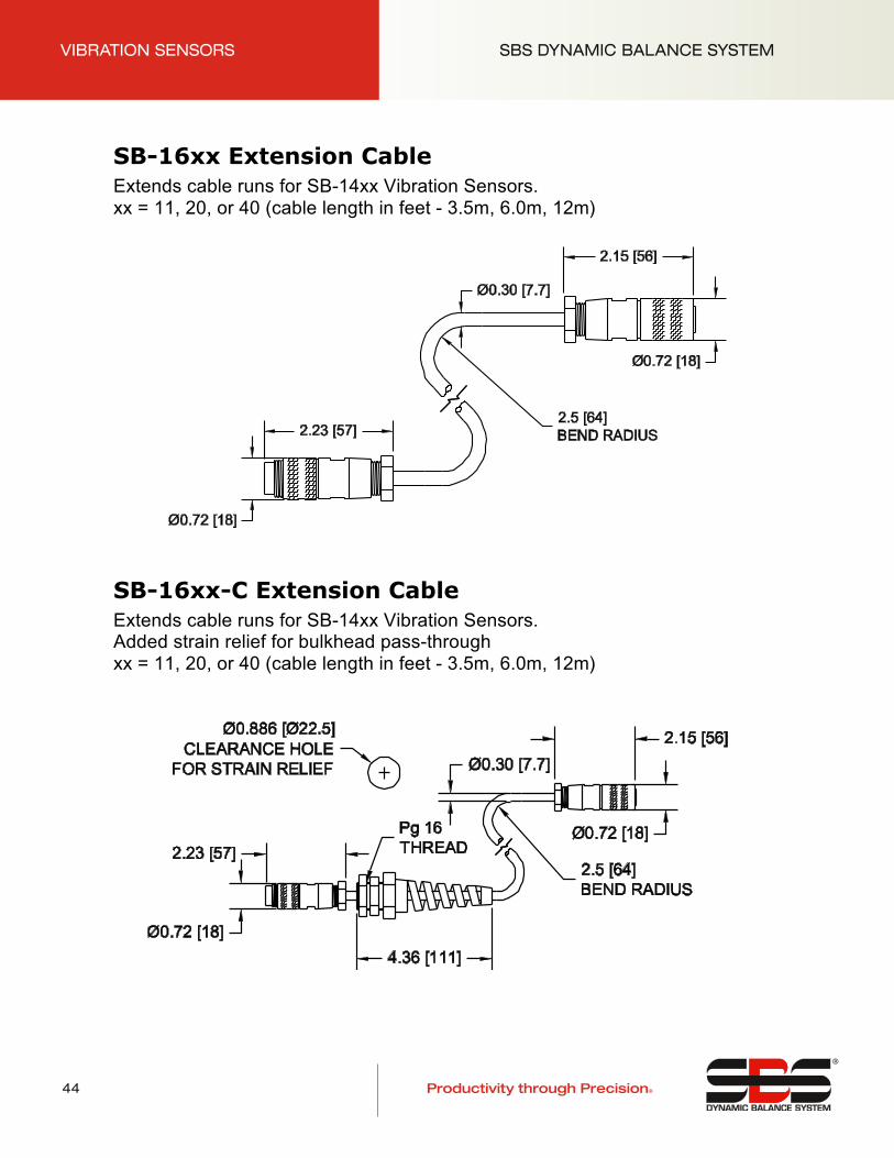
SB-16xx Extension Cable Extends cable runs for SB-14xx Vibration Sensors. xx = 11, 20, or 40 (cable length in feet - 3.5m, 6.0m, 12m)
SB-16xx-C Extension Cable Extends cable runs for SB-14xx Vibration Sensors. Added strain relief for bulkhead pass-through xx = 11, 20, or 40 (cable length in feet - 3.5m, 6.0m, 12m)

Eine Produktlinie der Schmitt Industries, Inc.
®
Productivity through Precision®
HYDROKOMPENSER SBS DYNAMIC BALANCE SYSTEM
45
Hydrokompenser
©Schmitt Industries, Inc. – www.schmitt-ind.com 46 Specifications subject to change without notice – rev. 08-31-10
System Components Overview While new applications based on Hydrokompenser (HK) components are no longer offered, service and replacement parts for existing applications are available, as described in the following section.
An HK balance system uses fluid, usually grinding machine coolant, as the balance medium. A four chambered Ring Container is mounted on the rotating machine spindle. An injection Nozzle is aligned with the container so that fluid can be injected into each of the four chambers in the rotating Ring Container as needed to achieve balance. The Nozzle has four separate fluid lines which are connected to the Valve Block, which supplies filtered and pressure regulated fluid to the nozzle. The Valve Block is operated by the Control, and is connected via. the Control Cable. The Control receives input from both the Vibration Sensor, and from the Speed (RPM) Sensor. The Speed Sensor is inductive. The Speed sensor may be integrated into the Nozzle assembly and triggered by a hole in the face of the Ring Container, or mounted separately (as pictured) and triggered by a feature located elsewhere on the Ring Container or machine pulley.
Vibration Sensor SB-14xx
SB-4500-H Or other -H model Control
Valve Block Assembly SH-4000
Speed Sensor SH-1778 (3m cable) Extension Cable SH-1779 (10m)
HK Ring Container
HK Nozzle
System Shown With Current Revision Components
Valve Control Cable SB-46xx
Fluid Input

Eine Produktlinie der Schmitt Industries, Inc.
®
Productivity through Precision®
HYDROKOMPENSER SBS DYNAMIC BALANCE SYSTEM
46
Hydrokompenser
©Schmitt Industries, Inc. – www.schmitt-ind.com 47 Specifications subject to change without notice – rev. 08-31-10
HK-5000 System Replacement Parts Older Hydrokompenser Systems were shipped with model HK-5000 Control. The following diagram shows replacement parts available for these older systems, including which parts are obsolete and superceded by new part numbers.

Eine Produktlinie der Schmitt Industries, Inc.
®
Productivity through Precision®
HYDROKOMPENSER SBS DYNAMIC BALANCE SYSTEM
47
Hydrokompenser
©Schmitt Industries, Inc. – www.schmitt-ind.com 48 Specifications subject to change without notice – rev. 08-31-10
Control / Valve Block Replacement
Control Application/ Parts Needed to Connect Valve Block
SB-4500-H SB-4475-H
SB-46xx Control Cable, -S connect Nozzle (fluid connector)
SB-14xx Vibration Sensor SH-4000
HK-5000
Replace SH-1942 Valve Block and Control Cable SH-5015 Adapter, SB-46xx Control Cable,
-S connect Nozzle (fluid connector) BM-5101, BM-5101-9 Vibration Sensors
SH-4000
SB-4500-H SB-4475-H
Replace HK-4410 or HK-5000 and Control Cable SB-46xx-W new Control Cable,
-(blank) model Nozzle (4-separate tube connect) SB-14xx Vibration Sensor
SH-1942
SB-4500-H SB-4475-H
Replace HK-5000 Control SB-4901 Adapter for existing Control Cable
-(blank) model Nozzle (4-separate tube connect) SB-14xx Vibration Sensor
SH-1942
SB-4500-H SB-4475-H
Replace HK-4410 Control: SH-5010 Adapter for existing Control Cable
-(blank) model Nozzle (4-separate tube connect) SB-14xx Vibration Sensor
SH-1942
Replacement Parts for SH-1942 Valve Block (Filter, Regulator, and Indicator sold separately, see HK-5000 System Replacement Parts Chart)
Fluid Valve Solenoid (x4) CH-3706 4mm Tube Quick Connect (x4) CH-0246

Eine Produktlinie der Schmitt Industries, Inc.
®
Productivity through Precision®
HYDROKOMPENSER SBS DYNAMIC BALANCE SYSTEM
48
Hydrokompenser
©Schmitt Industries, Inc. – www.schmitt-ind.com 49 Specifications subject to change without notice – rev. 08-31-10
Standard Nozzles – Flat Type w/ 4 Separate Tube Connect – used with SH-1942 Valve Block
Model List (IF=1 – RPM Sensor Included) (IF=0 – RPM Sensor NOT Included)
Pitch T=3mm Pitch T=5mm
Size IF=1 IF=0 IF=1 IF=0 Z = mm
1 SH-0948 SH-1168 SH-0945 SH-1165 60 - 80 2 SH-0949 SH-1169 SH-0946 SH-1166 90 - 110 3 SH-1197 SH-1198 SH-0947 SH-1167 130 - 150

Eine Produktlinie der Schmitt Industries, Inc.
®
Productivity through Precision®
HYDROKOMPENSER SBS DYNAMIC BALANCE SYSTEM
49
Hydrokompenser
©Schmitt Industries, Inc. – www.schmitt-ind.com 50 Specifications subject to change without notice – rev. 08-31-10
Standard Nozzles – Flat Type –S Connect w/ Fluid Quick Connector – used with SH-4000 Valve Block
Model List (IF=1 – RPM Sensor Included) (IF=0 – RPM Sensor NOT Included)
Pitch T=3mm Pitch T=5mm
Size IF=1 IF=0 IF=1 IF=0 Z = mm
1 SH-0948-S SH-1168-S SH-0945-S SH-1165-S 60 - 80 2 SH-0949-S SH-1169-S SH-0946-S SH-1166-S 90 - 110 3 SH-1197-S SH-1198-S SH-0947-S SH-1167-S 130 - 150

Eine Produktlinie der Schmitt Industries, Inc.
®
Productivity through Precision®
HYDROKOMPENSER SBS DYNAMIC BALANCE SYSTEM
50
Hydrokompenser
©Schmitt Industries, Inc. – www.schmitt-ind.com 51 Specifications subject to change without notice – rev. 08-31-10
Standard Nozzles – Round Type w/ 4 Separate Tube Connect – used with SH-1942 Valve Block
Model List (IF=1 – RPM Sensor Included) (IF=0 – RPM Sensor NOT Included)
Pitch T=3mm Pitch T=5mm
Size IF=1 IF=0 IF=1 IF=0 V = mm L = mm
1 SH-0943 SH-1163 SH-0940 SH-1160 0 - 50 90
2 SH-0944 SH-1164 SH-0941 SH-1161 0 - 100 140
3 SH-1273 SH-1274 SH-0942 SH-1162 0 - 150 190

Eine Produktlinie der Schmitt Industries, Inc.
®
Productivity through Precision®
HYDROKOMPENSER SBS DYNAMIC BALANCE SYSTEM
51
Hydrokompenser
©Schmitt Industries, Inc. – www.schmitt-ind.com 52 Specifications subject to change without notice – rev. 08-31-10
Standard Nozzles – Round Type –S Connect w/ Fluid Quick Connector – used with SH-4000 Valve Block
Model List (IF=1 – RPM Sensor Included) (IF=0 – RPM Sensor NOT Included)
Pitch T=3mm Pitch T=5mm
Size IF=1 IF=0 IF=1 IF=0 V = mm L = mm
1 SH-0943-S SH-1163-S SH-0940-S SH-1160-S 0 - 50 90
2 SH-0944-S SH-1164-S SH-0941-S SH-1161-S 0 - 100 140
3 SH-1273-S SH-1274-S SH-0942-S SH-1162-S 0 - 150 190

Eine Produktlinie der Schmitt Industries, Inc.
®
Productivity through Precision®
HYDROKOMPENSER SBS DYNAMIC BALANCE SYSTEM
52
Hydrokompenser
©Schmitt Industries, Inc. – www.schmitt-ind.com 53 Specifications subject to change without notice – rev. 08-31-10
SH-4000 Valve Block Includes Filter, Regulator, and Indicator – use with –S Connect Nozzles
Description Replacement Part
a Fluid Pressure Indicator (0-4 bar) CH-4013
b Fluid Pressure Regulator CH-1071
c Complete Filter Housing w/ Service Indicator CH-0080
d Filter Element (25µm screen) CH-0080-E
e Fluid Valve Solenoid (x4) CH-4001

Eine Produktlinie der Schmitt Industries, Inc.
®
Productivity through Precision®
HYDROKOMPENSER SBS DYNAMIC BALANCE SYSTEM
53
Hydrokompenser
©Schmitt Industries, Inc. www.schmitt-ind.com 54 Specifications subject to change without notice rev. 08-31-10
SH-1778 Speed Sensor Inductive sensor mounts separate from Nozzle Includes 3m cable (older models used grey flex hose in place of black cable)
Speed Sensor Extension Cable (not pictured) SH-1779 10m extension cable SH-1779-5 5m extension cable
Related Documents


