Form No. 07155SL Rev A ProCore ® 864/1298 Original Instructions (EN)

Welcome message from author
This document is posted to help you gain knowledge. Please leave a comment to let me know what you think about it! Share it to your friends and learn new things together.
Transcript

Form No. 07155SL Rev A
ProCore® 864/1298
Original Instructions (EN)

Revision History Revision Date Description
-- 2007 Initial Issue.
A 02/2018 Added revision history.
© THE TORO COMPANY 2018 This document and all information contained herein is the sole property of The Toro Company (and/or its affiliated companies). No intellectual property rights are granted by the delivery of this document or the disclosure of its content. This document shall not be reproduced by a third party without the express written consent of The Toro Company (and/or the appropriate affiliated company).

Reader Comments
The Toro Company Technical Assistance Center maintains a continuous effort to improve the quality and usefulness of its publications. To do this effectively, we encourage user feedback. Please comment on the completeness, accuracy, organization, usability, and readability of this manual by an e-mail to [email protected] or Mail to: Technical Publication Manager, Commercial The Toro Company 8111 Lyndale Avenue South Bloomington, MN 55420-1196 Phone: +1 952-887-8495

NOTES _

Part No. 07155SL (Rev. A)
Service Manual
ProCore� 864/1298
Preface
The purpose of this publication is to provide the servicetechnician with information for troubleshooting, testingand repair of major systems and components on theProCore 864 and 1298 aerators.
REFER TO THE OPERATOR’S MANUALS FOR OP-ERATING, MAINTENANCE AND ADJUSTMENTINSTRUCTIONS. Space is provided in Chapter 2 of thisbook to insert the Operator’s Manuals and Parts Cata-logs for your machine. Replacement Operator’s Manu-als are available on the internet at www.toro.com or bysending complete Model and Serial Number to:
The Toro CompanyAttn. Technical Publications8111 Lyndale Avenue SouthMinneapolis, MN 55420
The Toro Company reserves the right to change productspecifications or this publication without notice.
This safety symbol means DANGER, WARNING,or CAUTION, PERSONAL SAFETY INSTRUC-TION. When you see this symbol, carefully readthe instructions that follow. Failure to obey theinstructions may result in personal injury.
NOTE: A NOTE will give general information about thecorrect operation, maintenance, service, testing or re-pair of the machine.
IMPORTANT: The IMPORTANT notice will give im-portant instructions which must be followed to pre-vent damage to systems or components on themachine.
� The Toro Company − 2007, 2018

ProCore 864/1298
This page is intentionally blank.

ProCore 864/1298
Table Of Contents
Chapter 1 − Safety
Safety Instructions 1 − 2. . . . . . . . . . . . . . . . . . . . . . . . . . Safety and Instruction Decals 1 − 4. . . . . . . . . . . . . . . .
Chapter 2 − Product Records and Maintenance
Product Records 2 − 1. . . . . . . . . . . . . . . . . . . . . . . . . . . Maintenance 2 − 1. . . . . . . . . . . . . . . . . . . . . . . . . . . . . . . Equivalents and Conversions 2 − 2. . . . . . . . . . . . . . . . Torque Specifications 2 − 3. . . . . . . . . . . . . . . . . . . . . . .
Chapter 3 − Chassis
Service and Repairs 3 − 2. . . . . . . . . . . . . . . . . . . . . . . .
Chapter 4 − Coring Head
Specifications 4 − 2. . . . . . . . . . . . . . . . . . . . . . . . . . . . . . General Information 4 − 4. . . . . . . . . . . . . . . . . . . . . . . . Special Tools 4 − 9. . . . . . . . . . . . . . . . . . . . . . . . . . . . . . Service and Repairs 4 − 10. . . . . . . . . . . . . . . . . . . . . . .
Saf
ety
Pro
du
ct R
eco
rds
and
Mai
nte
nan
ceC
has
sis
Co
rin
g H
ead

ProCore 864/1298
This page is intentionally blank.

ProCore 864/1298 Page 1 − 1 Safety
Chapter 1
Safety
Table of Contents
SAFETY INSTRUCTIONS 2. . . . . . . . . . . . . . . . . . . . . . Before Operating 2. . . . . . . . . . . . . . . . . . . . . . . . . . . . While Operating 3. . . . . . . . . . . . . . . . . . . . . . . . . . . . . Maintenance and Service 3. . . . . . . . . . . . . . . . . . . .
SAFETY AND INSTRUCTION DECALS 4. . . . . . . . . .
Saf
ety

ProCore 864/1298Page 1 − 2Safety
Safety Instructions
The ProCore 864 and 1298 are designed and tested tooffer safe service when operated and maintained prop-erly. Although hazard control and accident preventionpartially are dependent upon the design and configura-tion of the machine, these factors are also dependentupon the awareness, concern and proper training of thepersonnel involved in the operation, transport, mainte-nance and storage of the machine. Improper use ormaintenance of the machine can result in injury ordeath. To reduce the potential for injury or death, complywith the following safety instructions.
WARNING
To reduce the potential for injury or death, com-ply with the following safety instructions.
Before Operating
1. Read and understand the contents of the Operator’sManual before starting and operating the aerator. Be-come familiar with the controls and know how to stop themachine quickly. A replacement Operator’s Manual isavailable on the Internet at www.Toro.com or by sendingthe complete model and serial number to:
The Toro CompanyAttn. Technical Publications8111 Lyndale Avenue SouthBloomington, Minnesota 55420−1196
2. Keep all shields, safety devices and decals in place.If a shield, safety device or decal is defective, illegibleor damaged, repair or replace it before operating themachine.
3. Make sure that the tractor is carefully selected to as-sure the best performance and safe operation of theProCore aerator.
4. Make sure that operator is familiar with safe tractoroperation.
5. Tighten any loose nuts, bolts or screws to ensuremachine is in safe operating condition.
6. Make sure that the ProCore aerator is properly at-tached to tractor.

ProCore 864/1298 Page 1 − 3 Safety
While Operating
1. Operator should be on the tractor when starting theengine and when operating the aerator. Stay away fromthe aerator coring head when it is engaged.
2. Before starting the engine on the tractor:
A. Apply the parking brake.
B. Make sure traction lever or transmission is in neu-tral and PTO is disengaged.
C. Refer to Tractor Operator’s Manual for safe start-ing procedures.
3. Do not run tractor engine in a confined area withoutadequate ventilation. Exhaust fumes are hazardousand could possibly be deadly.
4. If abnormal vibration is detected, disengage PTOand stop tractor immediately. Determine source ofvibration and correct problem(s) before resuming theuse of aerator.
5. While operating, the combination of the tractor andthe ProCore aerator may exceed noise levels of85dB(A) at the operator position. Hearing protection isrecommended for prolonged exposure to reduce the po-tential of permanent hearing damage.
IMPORTANT: Never operate aerator without tineheads installed.
IMPORTANT: Never operate the tractor PTO in ex-cess of 540 RPM or damage to the aerator could oc-cur.
6. Before leaving the operator’s position of the tractor:
A. Disengage PTO power to aerator and lower aera-tor to the ground.
B. Apply parking brake on tractor. Stop engine andremove key from ignition switch.
C. Wait for all moving parts to stop before leavingthe tractor.
Maintenance and Service
1. Before servicing or making adjustments to aerator,disengage tractor PTO, position aerator on a level sur-face and lower aerator to the ground. Apply tractor park-ing brake, stop engine and remove key from the ignitionswitch.
2. Make sure machine is in safe operating condition bykeeping all nuts, bolts and screws tight.
3. Use care when checking or servicing the coringhead: wear gloves and use caution.
4. Never step over the PTO shaft to reach other side ofaerator. Walk around the machine instead.
5. Before disconnecting aerator from tractor, installstorage stand to aerator hitch frame and park aerator ona hard, level surface.
6. After servicing the aerator, be sure that all guardsand covers are properly installed and that the rear hoodis secured shut.
7. At the time of manufacture, the machine conformedto all applicable safety standards. To assure optimumperformance and continued safety certification of themachine, use genuine Toro replacement parts and ac-cessories. Replacement parts and accessories madeby other manufacturers may result in non-conformancewith the safety standards, and the warranty may bevoided.
8. If major repairs are ever needed or assistance is de-sired, contact an Authorized Toro Distributor.
Saf
ety

ProCore 864/1298Page 1 − 4Safety
Safety and Instruction Decals
Numerous safety and instruction decals are affixed tothe ProCore 864 and 1298. If any decal becomes illeg-ible or damaged, install a new decal. Part numbers forreplacement decals are listed in your Parts Catalog. Or-der replacement decals from your Authorized Toro Dis-tributor.

ProCore 864/1298 Page 2 − 1 Product Records and Maintenance
Chapter 2
Product Records and Maintenance
Table of Contents
PRODUCT RECORDS 1. . . . . . . . . . . . . . . . . . . . . . . . . MAINTENANCE 1. . . . . . . . . . . . . . . . . . . . . . . . . . . . . . EQUIVALENTS AND CONVERSIONS 2. . . . . . . . . . .
Decimal and Millimeter Equivalents 2. . . . . . . . . . . . U.S. to Metric Conversions 2. . . . . . . . . . . . . . . . . . .
TORQUE SPECIFICATIONS 3. . . . . . . . . . . . . . . . . . . Fastener Identification 3. . . . . . . . . . . . . . . . . . . . . . . Standard Torque for Dry, Zinc Plated and
Steel Fasteners (Inch Series) 4. . . . . . . . . . . . . . . Standard Torque for Dry, Zinc Plated and
Steel Fasteners (Metric Fasteners) 5. . . . . . . . . . Other Torque Specifications 6. . . . . . . . . . . . . . . . . . Conversion Factors 6. . . . . . . . . . . . . . . . . . . . . . . . .
Product Records
Insert Operator’s Manual and Parts Catalog for yourProCore 864 or 1298 at the end of this chapter. Addition-ally, if any optional equipment or accessories have beeninstalled to your ProCore, insert the Installation Instruc-tions, Operator’s Manuals and Parts Catalogs for thoseoptions at the end of this chapter.
Maintenance
Maintenance procedures and recommended service in-tervals for the ProCore 864 or 1298 are covered in theOperator’s Manual. Refer to that publication when per-forming regular equipment maintenance.
Pro
du
ct R
eco
rds
and
Mai
nte
nan
ce

0.09375
ProCore 864/1298Page 2 − 2Product Records and Maintenance
Equivalents and Conversions

ProCore 864/1298 Page 2 − 3 Product Records and Maintenance
Torque Specifications
Recommended fastener torque values are listed in thefollowing tables. For critical applications, as determinedby Toro, either the recommended torque or a torque thatis unique to the application is clearly identified and spe-cified in this Service Manual.
These Torque Specifications for the installation andtightening of fasteners shall apply to all fasteners whichdo not have a specific requirement identified in this Ser-vice Manual. The following factors shall be consideredwhen applying torque: cleanliness of the fastener, useof a thread sealant (e.g. Loctite), degree of lubricationon the fastener, presence of a prevailing torque feature,hardness of the surface underneath the fastener’s heador similar condition which affects the installation.
As noted in the following tables, torque values should bereduced by 25% for lubricated fasteners to achievethe similar stress as a dry fastener. Torque values mayalso have to be reduced when the fastener is threadedinto aluminum or brass. The specific torque valueshould be determined based on the aluminum or brassmaterial strength, fastener size, length of thread en-gagement, etc.
The standard method of verifying torque shall be per-formed by marking a line on the fastener (head or nut)and mating part, then back off fastener 1/4 of a turn.Measure the torque required to tighten the fastener untilthe lines match up.
Fastener Identification
Figure 1
Grade 1 Grade 5 Grade 8
Inch Series Bolts and Screws
Figure 2
Class 8.8 Class 10.9
Metric Bolts and Screws
Pro
du
ct R
eco
rds
and
Mai
nte
nan
ce

ProCore 864/1298Page 2 − 4Product Records and Maintenance
Standard Torque for Dry, Zinc Plated and Steel Fasteners (Inch Series)
Thread SizeGrade 1, 5 &8 with ThinHeight Nuts
SAE Grade 1 Bolts, Screws, Studs &Sems with Regular Height Nuts
(SAE J995 Grade 2 or Stronger Nuts)
SAE Grade 5 Bolts, Screws, Studs &Sems with Regular Height Nuts
(SAE J995 Grade 2 or Stronger Nuts)
SAE Grade 8 Bolts, Screws, Studs &Sems with Regular Height Nuts
(SAE J995 Grade 5 or Stronger Nuts)
in−lb in−lb N−cm in−lb N−cm in−lb N−cm
# 6 − 32 UNC10 + 2 13 + 2 147 + 23
15 + 2 170 + 20 23 + 2 260 + 20
# 6 − 40 UNF10 + 2 13 + 2 147 + 23
17 + 2 190 + 20 25 + 2 280 + 20
# 8 − 32 UNC13 + 2 25 + 5 282 + 30
29 + 3 330 + 30 41 + 4 460 + 45
# 8 − 36 UNF13 + 2 25 + 5 282 + 30
31 + 3 350 + 30 43 + 4 485 + 45
# 10 − 24 UNC18 + 2 30 + 5 339 + 56
42 + 4 475 + 45 60 + 6 675 + 70
# 10 − 32 UNF18 + 2 30 + 5 339 + 56
48 + 4 540 + 45 68 + 6 765 + 70
1/4 − 20 UNC 48 + 7 53 + 7 599 + 79 100 + 10 1125 + 100 140 + 15 1580 + 170
1/4 − 28 UNF 53 + 7 65 + 10 734 + 113 115 + 10 1300 + 100 160 + 15 1800 + 170
5/16 − 18 UNC 115 + 15 105 + 17 1186 + 169 200 + 25 2250 + 280 300 + 30 3390 + 340
5/16 − 24 UNF 138 + 17 128 + 17 1446 + 192 225 + 25 2540 + 280 325 + 30 3670 + 340
ft−lb ft−lb N−m ft−lb N−m ft−lb N−m
3/8 − 16 UNC 16 + 2 16 + 2 22 + 3 30 + 3 41 + 4 43 + 4 58 + 5
3/8 − 24 UNF 17 + 2 18 + 2 24 + 3 35 + 3 47 + 4 50 + 4 68 + 5
7/16 − 14 UNC 27 + 3 27 + 3 37 + 4 50 + 5 68 + 7 70 + 7 95 + 9
7/16 − 20 UNF 29 + 3 29 + 3 39 + 4 55 + 5 75 + 7 77 + 7 104 + 9
1/2 − 13 UNC 30 + 3 48 + 7 65 + 9 75 + 8 102 + 11 105 + 10 142 + 14
1/2 − 20 UNF 32 + 3 53 + 7 72 + 9 85 + 8 115 + 11 120 + 10 163 + 14
5/8 − 11 UNC 65 + 10 88 + 12 119 + 16 150 + 15 203 + 20 210 + 20 285 + 27
5/8 − 18 UNF 75 + 10 95 + 15 129 + 20 170 + 15 230 + 20 240 + 20 325 + 27
3/4 − 10 UNC 93 + 12 140 + 20 190 + 27 265 + 25 359 + 34 375 + 35 508 + 47
3/4 − 16 UNF 115 + 15 165 + 25 224 + 34 300 + 25 407 + 34 420 + 35 569 + 47
7/8 − 9 UNC 140 + 20 225 + 25 305 + 34 430 + 45 583 + 61 600 + 60 813 + 81
7/8 − 14 UNF 155 + 25 260 + 30 353 + 41 475 + 45 644 + 61 660 + 60 895 + 81
NOTE: Reduce torque values listed in the table aboveby 25% for lubricated fasteners. Lubricated fastenersare defined as threads coated with a lubricant such asoil, graphite or thread sealant such as Loctite.
NOTE: Torque values may have to be reduced wheninstalling fasteners into threaded aluminum or brass.The specific torque value should be determined basedon the fastener size, the aluminum or base materialstrength, length of thread engagement, etc.
NOTE: The nominal torque values listed above forGrade 5 and 8 fasteners are based on 75% of the mini-mum proof load specified in SAE J429. The tolerance isapproximately + 10% of the nominal torque value. Thinheight nuts include jam nuts.

ProCore 864/1298 Page 2 − 5 Product Records and Maintenance
Standard Torque for Dry, Zinc Plated and Steel Fasteners (Metric Fasteners)
Thread SizeClass 8.8 Bolts, Screws and Studs with
Regular Height NutsClass 10.9 Bolts, Screws and Studs with
Regular Height NutsThread Size Regular Height Nuts(Class 8 or Stronger Nuts)
Regular Height Nuts(Class 10 or Stronger Nuts)
M5 X 0.8 57 + 5 in−lb 640 + 60 N−cm 78 + 7 in−lb 885 + 80 N−cm
M6 X 1.0 96 + 9 in−lb 1018 + 100 N−cm 133 + 13 in−lb 1500 + 150 N−cm
M8 X 1.25 19 + 2 ft−lb 26 + 3 N−m 27 + 2 ft−lb 36 + 3 N−m
M10 X 1.5 38 + 4 ft−lb 52 + 5 N−m 53 + 5 ft−lb 72 + 7 N−m
M12 X 1.75 66 + 7 ft−lb 90 + 10 N−m 92 + 9 ft−lb 125 + 12 N−m
M16 X 2.0 166 + 15 ft−lb 225 + 20 N−m 229 + 22 ft−lb 310 + 30 N−m
M20 X 2.5 325 + 33 ft−lb 440 + 45 N−m 450 + 37 ft−lb 610 + 50 N−m
NOTE: Reduce torque values listed in the table aboveby 25% for lubricated fasteners. Lubricated fastenersare defined as threads coated with a lubricant such asoil, graphite or thread sealant such as Loctite.
NOTE: Torque values may have to be reduced wheninstalling fasteners into threaded aluminum or brass.The specific torque value should be determined basedon the fastener size, the aluminum or base materialstrength, length of thread engagement, etc.
NOTE: The nominal torque values listed above arebased on 75% of the minimum proof load specified inSAE J1199. The tolerance is approximately + 10% of thenominal torque value.
Pro
du
ct R
eco
rds
and
Mai
nte
nan
ce

ProCore 864/1298Page 2 − 6Product Records and Maintenance
Other Torque Specifications
SAE Grade 8 Steel Set Screws
Thread SizeRecommended Torque
Thread SizeSquare Head Hex Socket
1/4 − 20 UNC 140 + 20 in−lb 73 + 12 in−lb
5/16 − 18 UNC 215 + 35 in−lb 145 + 20 in−lb
3/8 − 16 UNC 35 + 10 ft−lb 18 + 3 ft−lb
1/2 − 13 UNC 75 + 15 ft−lb 50 + 10 ft−lb
Thread Cutting Screws(Zinc Plated Steel)
Type 1, Type 23 or Type F
Thread Size Baseline Torque*
No. 6 − 32 UNC 20 + 5 in−lb
No. 8 − 32 UNC 30 + 5 in−lb
No. 10 − 24 UNC 38 + 7 in−lb
1/4 − 20 UNC 85 + 15 in−lb
5/16 − 18 UNC 110 + 20 in−lb
3/8 − 16 UNC 200 + 100 in−lb
Wheel Bolts and Lug Nuts
Thread Size Recommended Torque**
7/16 − 20 UNFGrade 5
65 + 10 ft−lb 88 + 14 N−m
1/2 − 20 UNFGrade 5
80 + 10 ft−lb 108 + 14 N−m
M12 X 1.25Class 8.8
80 + 10 ft−lb 108 + 14 N−m
M12 X 1.5Class 8.8
80 + 10 ft−lb 108 + 14 N−m
** For steel wheels and non−lubricated fasteners.
Thread Cutting Screws(Zinc Plated Steel)
ThreadSize
Threads per InchBaseline Torque*Size
Type A Type BBaseline Torque*
No. 6 18 20 20 + 5 in−lb
No. 8 15 18 30 + 5 in−lb
No. 10 12 16 38 + 7 in−lb
No. 12 11 14 85 + 15 in−lb
* Hole size, material strength, material thickness & finishmust be considered when determining specific torquevalues. All torque values are based on non−lubricatedfasteners.
Conversion Factors
in−lb X 11.2985 = N−cm N−cm X 0.08851 = in−lbft−lb X 1.3558 = N−m N−m X 0.7376 = ft−lb

ProCore 864/1298 Page 3 − 1 Chassis
Chapter 3
Chassis
Table of Contents
SERVICE AND REPAIRS 2. . . . . . . . . . . . . . . . . . . . . . Roller 2. . . . . . . . . . . . . . . . . . . . . . . . . . . . . . . . . . . . . . Turf Guards 4. . . . . . . . . . . . . . . . . . . . . . . . . . . . . . . . Front Covers (ProCore 864) 6. . . . . . . . . . . . . . . . . . Front Covers (ProCore 1298) 8. . . . . . . . . . . . . . . . . Hitch Frame (ProCore 1298) 10. . . . . . . . . . . . . . . . .
Ch
assi
s
ProCore 864/1298Page 3 − 2Chassis
Service and Repairs
Roller
1. Roller2. Flange bearing (2 used)3. Cap screw (2 used per bearing)4. Lock nut (2 used per bearing)5. Scraper arm (2 used)
6. Carriage screw (2 used per arm)7. Flange nut8. Roller scraper9. Compression spring10. Grease fitting
11. Bolt12. Hex nut13. Set screw14. Hitch frame
Figure 1
FRONT
RIGHT
PROCORE 864 SHOWN
7 3
4
6
8
2
5
1
9
10
11
12
13
14
10
7
25
ANTISEIZELUBRICANT
ANTISEIZELUBRICANT

ProCore 864/1298 Page 3 − 3 Chassis
Roller Removal (Fig. 1)
1. Position aerator on a firm, level surface with aeratorattached to tractor. Disengage PTO, apply tractor park-ing brake, stop engine and remove key from the ignitionswitch. Support aerator to prevent it from moving.
2. Chock roller to prevent it from moving.
3. Loosen flange bearings from roller shaft:
A. Loosen set screw (item 2.1) that secures eachbearing locking collar to roller shaft.
B. Using the blind hole in bearing locking collars as astriking point, unlock collars from roller shaft by rotat-ing the collars with a punch in the opposite directionof normal roller rotation.
4. Remove two (2) cap screws and lock nuts that se-cure both flange bearings (item 2) to aerator frame.
5. Start engine on tow vehicle. Slowly raise aeratorwhile allowing roller to remain on the ground. Stop towvehicle engine. Support raised aerator to prevent it fromlowering unexpectedly.
CAUTION
To prevent personal injury, make sure that roll-er is supported as it is removed from the ma-chine. Roller weighs approximately 133pounds (60 kg).
6. Remove roller with flange bearings from under ma-chine.
7. Slide bearings from roller shaft.
Roller Installation (Fig. 1)
1. Clean roller shaft ends and apply antiseize lubricantto shaft ends. Slide bearings onto roller shafts. Do nottighten set screws at this time.
CAUTION
To prevent personal injury, make sure that roll-er is supported as it is installed to the machine.Roller weighs approximately 133 pounds (60kg).
2. Position roller with flange bearings under raised aer-ator.
3. Start engine on tow vehicle. Slowly lower aerator toposition aerator frame to roller assembly.
4. Align holes in bearing flanges with holes in aeratorframe. Orientate bearing so that grease fittings point tofront of aerator. Secure both flange bearings to framewith two (2) cap screws and lock nuts.
5. Check that roller is free to rotate and no binding ex-ists. Center roller between bearings.
6. Using the blind hole in the flange mount bearing lock-ing collars as a striking point, lock collars to roller shaftby rotating the collars with a punch in the direction of nor-mal roller rotation. Tighten set screw (item 2.1) to secureeach bearing locking collar to roller shaft.
7. Check that clearance between roller scraper androller is from 0.060” to 0.090” (1.5 to 2.2 mm) along en-tire length of scraper. Adjust scraper position if neces-sary.
8. Lubricate grease fittings on roller bearings.
Ch
assi
s

ProCore 864/1298Page 3 − 4Chassis
Turf Guards
Figure 21. Lock nut2. Thrust washer3. Spring bracket4. Screw (2 used per bracket)5. Flat washer6. Spring rod sleeve7. Compression spring8. Spring rod
9. Jam nut10. Spring tube11. Cap screw12. Flange nut13. Carriage screw14. Flange nut15. Turf guard clamp16. Flange bushing
17. Thrust washer18. Stub shaft19. RH turf guard20. Shaft21. LH turf guard22. Rib neck screw23. Hitch frame24. Turf guard
FRONT
RIGHT
PROCORE 864 SHOWN
7
3
46
8
2
5
19
1011
12
1314
15
1716
18
19
20
23
21
22
14
14
1
1716
2
1716
24
1716

ProCore 864/1298 Page 3 − 5 Chassis
Removal (Fig. 2)
1. Position aerator on a firm, level surface. If attachedto tractor, disengage PTO, apply tractor parking brake,stop engine and remove key from the ignition switch.
2. Disconnect spring assembly from turf guard:
A. Remove flange nut (item 12) that secures springassembly to turf guard.
B. Slide end of cap screw (item 11) from bracket onturf guard.
C. Position spring assembly away from turf guard.
3. On both sides of frame, loosen and remove two (2)carriage screws and flange nuts that secure turf guardpivot shafts to frame.
NOTE: On ProCore 864 machines, the LH pivot shaftextends completely through the LH turf guard and intothe RH turf guard.
4. Slide pivot shafts from frame and turf guard.
NOTE: On ProCore 864 machines, there is one (1)thrust washer on each side of the turf guard. On ProCore1298 machines, there are two (2) thrust washers oneach side of turf guard (Fig. 3).
5. Remove turf guard assembly from machine. Locateand retrieve thrust washer(s) from each side of turfguard.
6. Disassemble turf guard and spring assembly asneeded using Figure 2 as a guide.
7. If necessary, use press to remove rib neck screws(item 22) from turf guard.
Installation (Fig. 2)
1. If rib neck screws were removed from turf guard, usepress to install screws into turf guard. Make sure thatscrew heads are flush with turf guard surface.
2. Assemble turf guard and spring assembly as neededusing Figure 2 as a guide. If spring assembly was takenapart, use dimensions shown in Figure 4 during the as-sembly process.
3. Make sure that keyed flange bushing (item 16) is cor-rectly placed in each end of turf guard. Position turfguard assembly to aerator.
NOTE: On ProCore 864 machines, there is one (1)thrust washer on each side of the turf guard. On ProCore1298 machines, there are two (2) thrust washers oneach side of turf guard (Fig. 3).
4. Place thrust washer(s) between each side of turfguard and frame.
5. On both sides of frame, slide turf guard pivot shaftsthrough frame and into turf guard. Secure pivot shafts toframe with two (2) carriage screws and flange nuts.
6. Connect spring assembly to turf guard:
A. Slide end of cap screw (item 11) through bracketon turf guard.
B. Secure spring assembly to turf guard with flangenut.
1. Turf guard2. Stub shaft
3. Thrust washerFigure 3
PROCORE 1298
2
31
2
Figure 4
5.940” to 6.060”(150.9 to 153.9 mm)
2.410” to 2.530”(61.2 to 64.2 mm)
Ch
assi
s

ProCore 864/1298Page 3 − 6Chassis
Front Covers (ProCore 864)
Figure 51. Front cover2. RH pulley shield3. LH pulley shield4. Flange head screw5. Flat washer6. Iso mount7. Flat washer
8. Tinnerman nut9. Front cover support (3 used)10. Carriage screw (2 used per support)11. Flange nut12. Side shield (2 used)13. Screw (2 used)14. LH shield support
15. RH shield support16. Lock nut (2 used)17. Manual housing18. Housing cap19. R−Clamp (2 used)20. PTO shield
FRONT
RIGHT
7
3
46
8
2
5
1
9
10
11
12
13
14
15
17
16
18
19
20
54
4
65
4
65
8
4
5
8
411

ProCore 864/1298 Page 3 − 7 Chassis
Removal (Fig. 5)
1. Position aerator on a firm, level surface. If attachedto tractor, disengage PTO, apply tractor parking brake,stop engine and remove key from the ignition switch.
2. Remove rear hood.
3. To remove either pulley shield (items 2 or 3), removefour (4) flange head screws and flat washers that securepulley shield to coring frame. Remove pulley shield.
4. To remove front cover (item 1):
A. Remove four (4) flange head screws and four (4)flat washers that secure PTO shield (item 20) to frontcover. Remove PTO shield.
B. Remove one of the pulley shields (see step 3above).
C. Remove seven (7) flange head screws and flatwashers that secure front cover to frame. Removefront cover.
Installation (Fig. 5)
1. Make sure that tinnerman nuts (item 8) are properlypositioned to frame. Also, make sure that iso mounts(item 6) are placed in cover holes.
2. Position front cover to aerator frame and secure withremoved fasteners. Attach PTO shield to front coverwith removed fasteners.
3. After front cover is installed, position pulley shield toaerator frame and secure with removed fasteners.
4. Install rear hood.
Ch
assi
s

ProCore 864/1298Page 3 − 8Chassis
Front Covers (ProCore 1298)
Figure 61. Front cover (RH shown)2. Pulley shield (RH shown)3. Yoke cover4. Flange head screw5. Flat washer6. Iso mount7. Screw (2 used)
8. Tinnerman nut9. Front cover support (2 used)10. Carriage screw (4 used)11. Flange nut (8 used)12. Side shield13. Flat washer (2 used)14. Hitch frame
15. Shield support (RH shown)16. Screw (4 used)17. Manual housing18. Housing cap19. R−clamp (2 used)20. Lock nut (2 used)21. Subframe (RH shown)
FRONT
RIGHT
7
3
468
2
5
1
9
1011
12
13
14
1517
16
18
19
20
21
4
65
45
11
4
65

ProCore 864/1298 Page 3 − 9 Chassis
Removal (Fig. 6)
1. Position aerator on a firm, level surface. If attachedto tractor, disengage PTO, apply tractor parking brake,stop engine and remove key from the ignition switch.
2. Remove rear hood.
3. To remove pulley shield (item 2), remove four (4)flange head screws and flat washers that secure pulleyshield to coring frame. Remove pulley shield.
4. To remove front cover (item 1):
A. Remove one of the pulley shields (see step 3above).
B. Remove five (5) flange head screws and flatwashers that secure front cover to frame. Removefront cover.
5. To remove yoke cover (item 3), remove four (4)flange head screws and flat washers that secure yokecover to hitch frame. Remove yoke cover.
Installation (Fig. 6)
1. Make sure that tinnerman nuts (item 8) are properlypositioned to machine. Also, make sure that iso mountsare placed in cover holes.
2. Position cover to aerator frame and secure with re-moved fasteners.
3. After front cover is installed, position shield to aeratorframe and secure with removed fasteners.
4. Install rear hood.
Ch
assi
s

ProCore 864/1298Page 3 − 10Chassis
Hitch Frame (ProCore 1298)
1. Hitch frame2. Lynch pin (2 used)3. Link pin (2 used)4. Washer (2 used)5. Hex nut (2 used)6. Grease fitting (2 used)
7. Pad (2 used)8. Flange head screw (4 used per pad)9. Lynch pin (2 used)10. Clevis pin11. Flange nut (4 used per pad)12. RH subframe
13. LH subframe14. Pivot shaft (2 used)15. Roll pin (2 used)16. Thrust washer (4 used)17. Lock nut (2 used)
Figure 7
FRONT
RIGHT
7
3
4
6
8
2
5
1
910
11
12
13
14
15
1716
9

ProCore 864/1298 Page 3 − 11 Chassis
Removal (Fig. 7)
1. Position aerator on a firm, level surface and discon-nect aerator from tractor.
2. Support subframes, coring frames and hitch frameassemblies to prevent them from falling or shifting unex-pectedly.
3. Remove front covers (see Front Covers (ProCore1298) Removal in this section).
4. Disconnect both coring head driveshafts from gear-box (see Driveshaft Removal in the Service and Repairssection of Chapter 4 − Coring Head). Position and sup-port driveshafts away from hitch frame.
5. Remove gearbox from hitch frame (see Gearbox Re-moval in the Service and Repairs section of Chapter 4− Coring Head).
6. Remove lock nuts that secure pivot shafts to sub-frames and hitch frame.
7. Make sure that aerator frame sections are sup-ported.
8. Slide both pivot shafts from subframe and hitchframe. Locate and retrieve thrust washer (item 16) fromeach side of subframe.
9. Lift subframe assemblies from hitch frame. Removehitch frame.
10.Inspect bushings in subframe for wear or damage(Fig. 8). Replace bushings if necessary.
Installation (Fig. 7)
1. Position hitch frame to subframe assemblies.
2. Connect both subframes to hitch frame:
A. Place thrust washer on each side of subframepivot tube.
B. Slide pivot shaft through hitch frame, both thrustwashers and subframe pivot. Make sure that roll pinin pivot shaft is positioned in frame reliefs.
C. Install lock nut onto pivot shaft. Tighten lock nutuntil the total clearance between the subframe andhitch frame is from 0.010” to 0.030” (0.3 to 0.7 mm).
3. Install gearbox to hitch frame (see Gearbox Installa-tion in the Service and Repairs section of Chapter 4 −Coring Head).
4. Connect both coring head driveshafts to gearbox(see Driveshaft Installation in the Service and Repairssection of Chapter 4 − Coring Head).
5. Install front covers (see Front Covers (ProCore1298) Installation in this section).
6. Lubricate grease fittings on subframe pivot tubes.
1. Subframe 2. Flange bushing
Figure 8
1
2
Ch
assi
s

ProCore 864/1298Page 3 − 12Chassis
This page is intentionally blank.

ProCore 864/1298 Page 4 − 1 Coring Head
Chapter 4
Coring HeadTable of ContentsSPECIFICATIONS 2. . . . . . . . . . . . . . . . . . . . . . . . . . . . GENERAL INFORMATION 4. . . . . . . . . . . . . . . . . . . . .
ProCore 864 Coring Head 4. . . . . . . . . . . . . . . . . . . . ProCore 1298 Coring Head 6. . . . . . . . . . . . . . . . . . . Coring Head Adjustments 8. . . . . . . . . . . . . . . . . . . .
SPECIAL TOOLS 9. . . . . . . . . . . . . . . . . . . . . . . . . . . . . SERVICE AND REPAIRS 10. . . . . . . . . . . . . . . . . . . . .
Rotolink Damper Assemblies 10. . . . . . . . . . . . . . . . Stomper Arms 12. . . . . . . . . . . . . . . . . . . . . . . . . . . . . Coring Crankshaft Bearing Housings
(ProCore 864) 16. . . . . . . . . . . . . . . . . . . . . . . . . . . Coring Crankshaft Bearing Housings
(ProCore 1298) 20. . . . . . . . . . . . . . . . . . . . . . . . . . Coring Head Drive Belt 24. . . . . . . . . . . . . . . . . . . . . Coring Head Drive 26. . . . . . . . . . . . . . . . . . . . . . . . . Coring Head Pivot (H−Frame) 28. . . . . . . . . . . . . . . Depth Control Assembly 32. . . . . . . . . . . . . . . . . . . . Depth Control Assembly Service 34. . . . . . . . . . . . . Driveshafts 36. . . . . . . . . . . . . . . . . . . . . . . . . . . . . . . . Driveshaft Cross and Bearing Service 38. . . . . . . . Gearbox 40. . . . . . . . . . . . . . . . . . . . . . . . . . . . . . . . . . Gearbox Service 42. . . . . . . . . . . . . . . . . . . . . . . . . . . C
ori
ng
Hea
d

ProCore 864/1298Page 4 − 2Coring Head
SpecificationsItem Description
GearboxLubricant GL−5 API, SAE 80W−90 gear lubeCapacity 56 US fl. oz. (1.65 liter)

ProCore 864/1298 Page 4 − 3 Coring Head
This page is intentionally blank.
Co
rin
g H
ead

ProCore 864/1298Page 4 − 4Coring Head
General Information
ProCore 864 Coring Head
1. Driven pulley2. #1 stomper arm3. #8 stomper arm
4. Bearing housing (4 used)5. Crankarm (2, 4, 6) (4 used)6. Crankarm (3, 5) (3 used)
7. Coupler assembly (3 used)8. Counter weight
Figure 1
1
8 4
7
5
2
3
6

ProCore 864/1298 Page 4 − 5 Coring Head
Operation
The coring head of the ProCore 864 consists of a frame,a coring crankshaft assembly, turf holders, tine holdersand aerating tines. The crankshaft assembly operateseight (8) stomper arms with rotolink assemblies to pro-vide vertical tine motion. The coring head frame pivotsto allow aerating depth control.
Drive for the coring head comes from the tow tractorPTO. A gearbox on the ProCore is turned by a driveshaftconnected to the tractor PTO. The gearbox providesrotation for the coring head crankshaft assembly.
The gearbox rotates a single driveshaft which in turn ro-tates a pulley to drive the coring crankshaft assemblywith a 4 groove drive belt. This drive belt is tensioned bya spring loaded idler pulley.
The coring crankshaft is composed of multiple crank-arms, bearings, bearing housings and couplings. Thecrankshaft assembly is designed to ensure minimalvibration during aerator operation.
Aeration depth control is performed by adjusting the cor-ing head depth control assembly to obtain the desiredaerating depth.
Turf holders are used to prevent damage to the turf asthe tines are lifted from the ground.
A variety of tines, tine heads and turf holders are avail-able for use on the ProCore 864. See the Operator’sManual for available options.
Coring Crankshaft (Fig. 1)
The coring crankshaft assembly is composed of eight(8) crankarms. The crankarms are timed for proper aer-ating operation. Coring crankshaft positions are identi-fied based on their relationship with the crankshaftdriven pulley. The #1 position is at the pulley side of thecrankshaft (Fig. 1).
The crankshaft assembly is supported with four (4) iden-tical bearing housing assemblies. Each bearing housingsupports two (2) crankarms.
The crankarm used in the #1 crankshaft position is in-corporated into the driven pulley. The remaining oddnumbered crankshaft positions (#3, #5 and #7) use thesame crankarm. These crankarm castings can be iden-tified with the numbers 3 and 5 in the castings. Cran-karms used in even numbered crankshaft positions (#2,#4, #6 and #8) are the same component. These cran-karms can be identified with the numbers 2, 4 and 6 inthe crankarm castings.
Three (3) coupler assemblies are used to connect thecrankarms that are secured in the bearing housings.These coupler assemblies use the same components:a #2 coupling, a #3 coupling, a coupling plate, two (2)iso−mounts and necessary fasteners. The #2 couplingsattach to even numbered crankarms. The #3 couplingsare secured to odd numbered crankarms.
Two counterweights are incorporated into the ProCore864 coring crankshaft to ensure the rotational balanceof the crankshaft assembly. One of the counterweightsis bolted to the driven pulley. The second counterweightis attached to the #8 crankarm position.
The stomper arms and rotolink assemblies used on theProCore 864 are the same for all crankshaft positions.
Coring Crankshaft Timing
On the ProCore 864 aerator, each pair of crankarmsjoined through a bearing housing are assembled withthe crankarm journals positioned 180o apart. The cou-pler assemblies that connect these pairs of crankarmsallow for proper phasing of the crankshaft to allow mini-mal operating vibration.
NOTE: On the ProCore 864, the numbers cast into thecrankarms will not align with the raised indicator markson the bearing housings.
Co
rin
g H
ead

ProCore 864/1298Page 4 − 6Coring Head
ProCore 1298 Coring Head
1. Driven pulley2. #1 stomper arm3. #6 stomper arm
4. Bearing housing (3 used)5. Crankarm (#2 and #4)6. Crankarm (#3 and #5)
7. Crankarm (#6)8. Coupling assembly (2 / 3)9. Coupling Assembly (4 / 5)
Figure 2
1
2
3
6
4
5
5
8
6
7
9

ProCore 864/1298 Page 4 − 7 Coring Head
Operation
The ProCore 1298 is comprised of two (2) independentcoring heads connected with a pivoting subframe sys-tem. Each of the coring heads includes a coring crank-shaft assembly, turf holders, tine holders and aeratingtines. The crankshaft assembly operates six (6) stomperarms with rotolink assemblies to provide vertical tinemotion. The coring head frame pivots to allow aeratingdepth control.
Drive for the dual coring heads comes from the tow trac-tor PTO. A single gearbox on the ProCore is turned bya driveshaft connected to the tractor PTO. The gearboxprovides rotation for the two (2) coring head crankshaftassemblies.
The ProCore gearbox rotates two (2) driveshafts. Eachof these driveshafts rotates a coring head crankshaftwith a pulley and 4 groove drive belt tensioned by aspring loaded idler pulley.
The two (2) coring crankshafts are composed of multiplecrankarms, bearings, bearing housings and couplings.For assembly purposes, proper crankshaft componentposition is identified by alignment marks on bearinghousings and numbers cast into crankarms and cou-pling components. Crankarm journals are timed to en-sure minimal vibration.
Aeration depth control is performed by adjusting the cor-ing head depth control assembly to obtain the desiredaerating depth.
Turf holders are used to prevent damage to the turf asthe tines are lifted from the ground.
A variety of tines, tine heads and turf holders are avail-able for use on the ProCore 1298. See the Operator’sManual for available options.
Coring Crankshaft (Fig. 2)
Each of the ProCore 1298 coring crankshaft assembliesis composed of six (6) crankarms. The crankarms aretimed for proper aerating operation. Coring crankshaftpositions are identified based on their relationship withthe crankshaft driven pulley. The #1 position is at thepulley side of the crankshaft (Fig. 2).
The crankshaft assembly on each of the coring heads issupported with three (3) identical bearing housing as-semblies. Each bearing housing supports two (2) cran-karms.
The crankarm used in the #1 crankshaft position is in-corporated into the driven pulley. Crankarms used incrankshaft positions #2 and #4 are the same compo-nent. These crankarms can be identified with the num-bers 2, 4 and 6 in the crankarm castings. Crankarmsused in crankshaft positions #3 and #5 use the samecrankarm and can be identified with the numbers 3 and5 in the castings. The crankarm used in crankshaft posi-tion #6 is different than other crankarms and has thenumbers 2, 4 and 6 in the casting.
Two (2) coupler assemblies are used to connect thecrankarms that are secured in the bearing housings.These coupler assemblies use two (2) couplings, a cou-pling plate, two (2) iso−mounts and necessary fasten-ers. The couplings used on the ProCore 1298 are alldifferent. The couplings are identified with the crank-shaft position in the coupling casting.
The stomper arms and rotolink assemblies used on theProCore 1298 are the same for all crankshaft positions.
Coring Crankshaft Timing
When properly assembled, the crankshaft position num-bers on the crankarms will align with the raised align-ment marks on the bearing housing (Fig. 3). The timingof either coring head is not dependent on the adjacentcoring head.
1. Housing timing mark 2. Crankarm position
Figure 3
1
2
1
2
2
Co
rin
g H
ead

ProCore 864/1298Page 4 − 8Coring Head
Coring Head Adjustments
See Operator’s Manual for adjustment procedures forthe coring head on the ProCore 864 and 1298.
CAUTION
Never work on the coring head with the tow trac-tor PTO engaged or engine running. Always dis-engage the PTO, stop tractor engine, remove keyfrom the ignition switch and wait for all machinemovement to stop before performing any serviceto coring head components.

ProCore 864/1298 Page 4 − 9 Coring Head
Special Tools
Compression Spring Tool
Use to remove and install the coring head compressionsprings. Obtain these items locally.
NOTE: The ProCore 864 uses two (2) compressionsprings for its single coring frame. The ProCore 1298uses one (1) compression spring for each of its dual cor-ing frames.
1. Threaded rod (1/2” or 5/8” diameter)2. Nut (2 used)3. Flat washer (2 used)
Figure 4
20”
5”
5”
1
23
Coring Head Drive Pulley Tool
Use to remove the coring head drive pulley. Obtainthese items locally.
1. Drive pulley 2. Cap screw (full thread)
Figure 5
.375” − 16 UNC − 2B
1
2
Cap Screw (Full Thread)
Co
rin
g H
ead

ProCore 864/1298Page 4 − 10Coring Head
Service and Repairs
Rotolink Damper Assemblies
1. Rotolink damper2. Stud (2 used per rotolink)3. Bumper (2 used per rotolink)4. Standoff (4 used per rotolink)5. Hardened D washer6. Flange nut (2 used per rotolink)
7. Cap screw8. Ball bearing9. Damper link10. Lock nut11. Cap screw
12. Hardened washer13. Flange nut14. Rubber bumper (2 used per rotolink)15. Stomper arm16. Coring head frame
Figure 6
FRONT
RIGHT
2
3
4
6
8
9
10
11
13
1
5
7
12
14
15
16
8
11
10
9 8
8
150 to 170 ft−lb(204 to 230 N−m)
LOCTITE #242
2
NOTE: The rotolink damper assemblies for all stomperarms used on ProCore 864 and 1298 aerators are iden-tical.

ProCore 864/1298 Page 4 − 11 Coring Head
Disassembly (Fig. 6)
1. Position aerator on a firm, level surface. If attachedto tractor, disengage PTO, apply tractor parking brake,stop engine and remove key from the ignition switch.
2. Remove rotolink components as needed using Fig-ure 6 as a guide.
Assembly (Fig. 6)
1. If studs (item 2) were removed from rotolink damper(item 1), apply Loctite #242 (or equivalent) to threads ofstuds. Thread stud fully into damper.
2. If bearings (item 8) were removed from damper links,press new bearings into links. Make sure that bearingsare pressed completely to the shoulder of the link bore.
3. Assemble all components before fully tightening anyfasteners so there is no preload on rotolink damper com-ponents. Tighten fasteners in the following order:
A. Secure damper links (item 9) to stomper arm(item 15) and damper (item 1). Torque lock nuts (item10) from 150 to 170 ft−lb (204 to 230 N−m).
B. Tighten two (2) flange nuts (item 13) that securedamper links.
C. Tighten two (2) flange nuts (item 6) that securedamper to frame.
4. After assembly, rotate coring crankshaft by hand tomake sure that no binding occurs.
Co
rin
g H
ead

ProCore 864/1298Page 4 − 12Coring Head
Stomper Arms
1. Cap screw2. Flat washer3. Ball bearing (2 used per arm)4. Retaining ring
5. Bearing spacer6. Stomper arm7. Crankshaft driven pulley8. Bearing housing assembly
9. Coring head frame10. Square key11. Coupling12. Crankarm
Figure 7
FRONT
RIGHT
PROCORE 1298 STOMPER ARMS #1 AND #2 SHOWN
210 to 230 ft−lb(285 to 311 N−m)
9
10
12
11
210 to 230 ft−lb(285 to 311 N−m)
ANTISEIZELUBRICANT
2
3
4
1
5
1
2
3
7
6
8
6
12
3
4
3
5
NOTE: All stomper arms used on ProCore 864 and1298 aerators are identical. Coring crankshaft positionsare identified based on their relationship with the crank-shaft driven pulley. The #1 position is at the pulley sideof the coring crankshaft (Fig. 8).
IMPORTANT: Before disassembling the coringcrankshaft, label location of components that are tobe removed. Correct component location and orien-tation are necessary for proper aerator operation.
1. Crankshaft driven pulley2. #1 position (ProCore 1298 LH coring head shown)3. #6 position (ProCore 1298 LH coring head shown)
Figure 8
23
1

ProCore 864/1298 Page 4 − 13 Coring Head
Removal (Fig. 7)
1. Position aerator on a firm, level surface. If attachedto tractor, disengage PTO, apply tractor parking brake,stop engine and remove key from the ignition switch.
2. Remove rear hood.
3. For stomper arm that is to be removed, remove two(2) flange nuts and hardened D washers that secure ro-tolink damper to coring head frame (Fig. 9) (see RotolinkDamper Assemblies in this section).
WARNING
As crankshaft components are removed frommachine, the crankshaft will become out of bal-ance and may rotate quickly, creating pinchpoints and potential for personal injury. Be cau-tious when disassembling the coring crankshaft.
4. If an outside stomper arm is to be removed:
A. If #1 (pulley side) stomper arm is being removed,remove coring head drive belt (see Coring HeadDrive Belt Removal in this section).
B. Remove cap screw and flat washer that retainstomper arm to coring crankshaft.
C. If #8 (final) stomper arm is being removed from aProCore 864, remove counter weight (item 3, Fig.10) from coring crankshaft.
D. Support stomper arm assembly to prevent it fromfalling during removal. Slide stomper arm from cor-ing crankshaft. Carefully lower stomper arm assem-bly from coring head frame.
5. If an inside stomper arm is to be removed:
A. Remove fasteners that secure coupling plate tocoupling on stomper arm to be removed (Fig. 11).
B. Remove cap screw and flat washer that securescoupling and stomper arm to coring crankshaft.
C. Slide coupling from coring crankshaft. Locateand retrieve square key.
D. Support stomper arm assembly to prevent it fromfalling during removal. Slide stomper arm from cor-ing crankshaft. Carefully lower stomper arm assem-bly from coring head frame.
6. If necessary, remove ball bearings, bearing spacerand retaining ring from stomper arm.
1. Rotolink damper2. D washer (2 used)
3. Flange nut (2 used)4. Stomper arm
Figure 9
2
34
1
1. Stomper arm (#8)2. Crankarm
3. Counter weight
Figure 10
1
2
3
PROCORE 864
Co
rin
g H
ead

ProCore 864/1298Page 4 − 14Coring Head
7. If necessary, remove tines and tine holders fromstomper arm (see Operator’s Manual).
8. Remove rotolink damper components from stomperarm as needed (see Rotolink Damper Assemblies in thissection).
Installation (Fig. 7 and 11)
1. If bearings were removed from stomper arm, installretaining ring into groove in upper bore of stomper arm.Make sure that retaining ring is properly seated ingroove. Position bearing spacer and press two (2) ballbearings into stomper arm bore.
2. Install all rotolink damper components that were re-moved during disassembly (see Rotolink Damper As-semblies in this section).
3. Apply antiseize lubricant liberally to crankarm shaftsurface.
4. Raise stomper arm assembly up through coringhead frame. Slide stomper arm onto coring crankshaft.
5. Secure stomper arm to coring crankshaft in the re-verse order of disassembly.
A. Torque grade 5, 5/8” cap screws (item 4, Fig. 11)from 150 to 170 ft−lb (204 to 230 N−m).
B. Torque grade 8, 5/8” cap screws (item 1, Fig. 7)from 210 to 230 ft−lb (285 to 311 N−m).
C. Torque 1/2” cap screws (item 6, Fig. 11) from 70to 80 ft−lb (95 to 108 N−m).
6. Secure rotolink damper to coring head frame withtwo (2) lock nuts and hardened D washers (Fig. 9) (seeRotolink Damper Assemblies in this section).
7. After assembly, rotate coring crankshaft by hand tomake sure that no binding occurs.
8. If removed, install tine holders and tines to stomperarm (see Operator’s Manual).
9. If removed, install coring head drive belt (see CoringHead Drive Belt Installation in this section).
10.Install rear hood.
1. Coupling (#3 shown)2. Iso mount (2 used)3. Coupling (#2 shown)4. Cap screw (2 used)
5. Coupling plate6. Cap screw (4 used)7. Lock nut (2 used)8. Flat washer (2 used)
Figure 11
1
2 3 4
5
6
7 8
150 to 170 ft−lb(204 to 230 N−m)
70 to 80 ft−lb(95 to 108 N−m)
4

ProCore 864/1298 Page 4 − 15 Coring Head
This page is intentionally blank.
Co
rin
g H
ead
ProCore 864/1298Page 4 − 16Coring Head
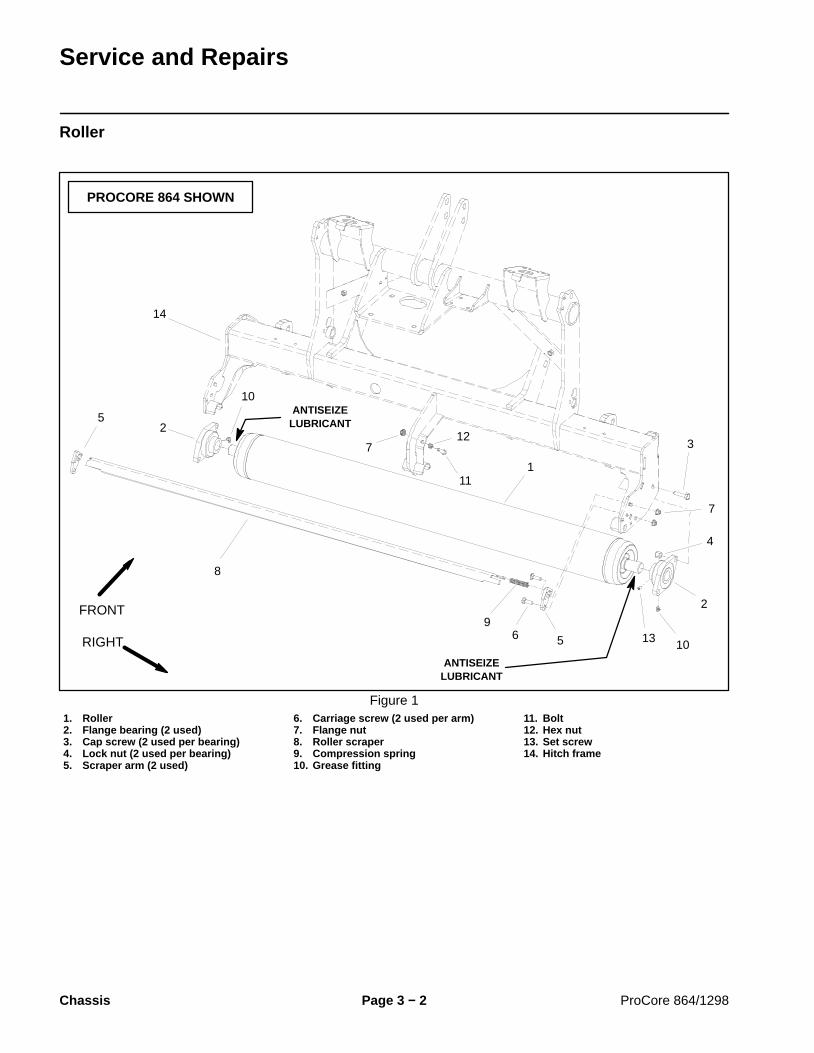
Coring Crankshaft Bearing Housings (ProCore 864)
1. Cap screw2. Flat washer3. Ball bearing (2 used per arm)4. Retaining ring5. Bearing spacer6. Stomper arm (8 used)7. Ball bearing (2 used per housing)8. Bearing housing (4 used)9. Bearing spacer
10. Square key11. Spring pin (2 used per housing)12. Cap screw (4 used per housing)13. Hardened washer14. Lock nut (4 used per housing)15. Crankarm (#2/4/6 casting) (4 used)16. Coupling (#2 casting) (3 used)17. Crankarm (#3/5/7 casting) (3 used)
18. Coring head frame19. Coupling (#3 casting) (3 used)20. Cap screw (4 used per plate)21. Cap screw (2 used per plate)22. Coupling plate (3 used)23. Iso mount (2 used per plate)24. Snubbing washer (2 used per plate)25. Lock nut (2 used per plate)
Figure 12
FRONT
RIGHT
PROCORE 864 STOMPER ARMS #3 AND #4 SHOWN
89
10
1113
7
12
15
16
17
1
1
2
34
3
3
7
10 4 5
6
192
22
6
210 to 230 ft−lb(285 to 311 N−m)
5
20
2524
23
21
12
210 to 230 ft−lb(285 to 311 N−m)
ANTISEIZELUBRICANT
14
1813
70 to 80 ft−lb(95 to 108 N−m)
21
2524
2316
210 to 230 ft−lb(285 to 311 N−m)
NOTE: The bearing housings used on ProCore 864aerators are identical. Coring crankshaft positions areidentified based on their relationship with the crankshaftdriven pulley. The #1 position is at the pulley side of thecoring crankshaft (Fig. 13).
IMPORTANT: Before disassembling the coringcrankshaft, label location of components that are tobe removed. Correct component location and orien-tation are necessary for proper aerator operation.

ProCore 864/1298 Page 4 − 17 Coring Head
Removal (Fig. 12)
1. Position aerator on a firm, level surface. If attachedto tractor, disengage PTO, apply tractor parking brake,stop engine and remove key from the ignition switch.
2. Remove rear hood.
3. If bearing housing for #1 and #2 stomper arms is tobe removed, remove coring head drive belt (see CoringHead Drive Belt Removal in this section).
WARNING
As crankshaft components are removed frommachine, the crankshaft will become out of bal-ance and may rotate quickly, creating pinchpoints and potential for personal injury. Be cau-tious when disassembling the coring crankshaft.
4. Remove stomper arms and couplings on both sidesof bearing housing that is to be removed (see StomperArm Removal in this section).
5. Drive spring pins (item 11) from bearing housing andcoring head frame.
6. Support bearing housing assembly to prevent it fromfalling. Remove fasteners that secure bearing housingassembly to coring head frame. Remove bearing hous-ing assembly from machine.
7. Disassemble bearing housing assembly:
A. Remove cap screw (item 1) and flat washer (item2) that fasten crankarms together. Note that cran-karm journals are positioned 180o from each other.
B. Slide crankarms from bearing housing.
C. If necessary, remove bearings and bearingspacer from bearing housing.
8. If necessary, remove counterweight from drivenpulley (Fig. 15).
Installation (Fig. 12)
1. Install new bearings if they were removed from bear-ing housing:
A. Install new bearing into one side of housing bypressing on outer race of bearing.
B. Position bearing spacer into bearing housing.
C. Install second new bearing into housing by press-ing on outer race of bearing. Make sure that spacer iscentered between bearings.
1. Crankshaft driven pulley2. #1 crankshaft position
3. #8 crankshaft position
Figure 13
1
23
1. Coupling (#3 shown)2. Iso mount (2 used)3. Coupling (#2 shown)4. Cap screw (2 used)
5. Coupling plate6. Cap screw (4 used)7. Lock nut (2 used)8. Washer (2 used)
Figure 14
1
2 3 4
5
6
7 8
150 to 170 ft−lb(204 to 230 N−m)
70 to 80 ft−lb(95 to 108 N−m)
4
1. Driven pulley2. Counterweight
3. Flange head screwFigure 15
1
2
3
Loctite #242
Co
rin
g H
ead

ProCore 864/1298Page 4 − 18Coring Head
2. If counterweight was removed from driven pulley, ap-ply Loctite #242 (or equivalent) to threads of flange headscrews and secure counterweight to pulley.
3. Apply antiseize lubricant liberally to crankarmsplines and journals.
4. Install crankarms into bearing housing. Make surethat crankarm journals are positioned 180o from eachother.
5. Install cap screw (item 1) and flat washer (item 2) toretain crankarms. Do not fully tighten cap screw.
6. Drive new spring pins (item 11) into coring headframe holes.
7. Position bearing housing assembly to coring headframe. Make sure that crankarms identified with 2/4/6 inthe casting are orientated toward the left side of the ma-chine.
8. Secure bearing housing to frame with four (4) capscrews, eight (8) hardened washers and four (4) locknuts. Torque fasteners from 70 to 80 ft−lb (95 to 108N−m).
9. Install stomper arms and couplings to crankarms onboth sides of bearing housing (see Stomper Arm Instal-lation in this section). Do not fully tighten fasteners.
IMPORTANT: On the ProCore 864, the numbers castinto the crankarms will not align with the raised indi-cator marks on the bearing housings.
10.Once all stomper arm and crankarm componentshave been installed, fully tighten fasteners in the follow-ing order (Fig. 16). Tighten fasteners to the torque speci-fications identified in Figures 12 and 14:
A. Cap screw used to secure crankarms.
B. Cap screws that secure top of stomper arms.
C. Cap screws that secure coupling plates (Fig. 14).
D. Lock nuts that secure rotolink dampers to frame(see Rotolink Damper Assemblies in this section).
11.After assembly, rotate coring crankshaft by hand tomake sure that no binding occurs.
12.If removed, install coring head drive belt (see CoringHead Drive Belt Installation in this section).
13.Install rear hood.
1. Crankarm screw2. Stomper arm screw
3. Coupling plate screw4. Damper lock nut
Figure 16
1
2
4
33

ProCore 864/1298 Page 4 − 19 Coring Head
This page is intentionally blank.
Co
rin
g H
ead

ProCore 864/1298Page 4 − 20Coring Head
Coring Crankshaft Bearing Housings (ProCore 1298)
1. Cap screw2. Flat washer3. Ball bearing (2 used per arm)4. Retaining ring5. Bearing spacer6. Stomper arm
7. Ball bearing (2 used per housing)8. Bearing housing9. Bearing spacer10. Square key11. Spring pin (2 used per housing)12. Cap screw (4 used per housing)
13. Hardened washer14. Lock nut (4 used per housing)15. Crankarm16. Coupling17. Coring head frame18. Crankshaft driven pulley
Figure 17
FRONT
RIGHT
PROCORE 1298 STOMPER ARMS #1 AND #2 SHOWN
70 to 80 ft−lb(95 to 108 N−m)
210 to 230 ft−lb(285 to 311 N−m)
9
210 to 230 ft−lb(285 to 311 N−m)
ANTISEIZELUBRICANT
2
5
1
76
8
12
3
4
3
10
12
11
3
4
1
2
36
5
1413
13
15
16
18
17
7ANTISEIZELUBRICANT
NOTE: The bearing housings used on ProCore 1298aerators are identical. Coring crankshaft positions areidentified based on their relationship with the crankshaftdriven pulley. The #1 position is at the pulley side of thecoring crankshaft (Fig. 18).
IMPORTANT: Before disassembling the coringcrankshaft, label location of components that are tobe removed. Correct component location and orien-tation are necessary for proper aerator operation.

ProCore 864/1298 Page 4 − 21 Coring Head
Removal (Fig. 17)
1. Position aerator on a firm, level surface. If attachedto tractor, disengage PTO, apply tractor parking brake,stop engine and remove key from the ignition switch.
2. Remove rear hood.
WARNING
As crankshaft components are removed frommachine, the crankshaft will become out of bal-ance and may rotate quickly, creating pinchpoints and potential for personal injury. Be cau-tious when disassembling the coring crankshaft.
3. If bearing housing for #1 and #2 stomper arms is tobe removed, remove coring head drive belt (see CoringHead Drive Belt Removal in this section).
4. Remove stomper arms and couplings on both sidesof bearing housing that is to be removed (see StomperArm Removal in this section).
5. Drive spring pins (item 11) from bearing housing andcoring head frame.
6. Support bearing housing assembly to prevent it fromfalling. Remove fasteners that secure bearing housingassembly to coring head frame. Remove bearing hous-ing assembly from machine.
7. Disassemble bearing housing assembly:
A. Remove cap screw (item 1) and flat washer (item2) that fasten crankarms together. Take note of align-ment of crankarm identification number with timingmark on bearing housing (Fig. 19).
B. Slide crankarms from bearing housing.
C. If necessary, remove bearings and bearingspacer from bearing housing.
Installation (Fig. 17)
1. Install new bearings if they were removed from bear-ing housing:
A. Install new bearing into one side of housing bypressing on outer race of bearing.
B. Position bearing spacer into bearing housing.
C. Install second new bearing into housing by press-ing on outer race of bearing. Make sure that spacer iscentered between bearings.
1. Crankshaft driven pulley2. #1 position (ProCore 1298 LH coring head shown)3. #6 position (ProCore 1298 LH coring head shown)
Figure 18
23
1
1. Housing timing mark 2. Crankarm position
Figure 19
1
2
1
2
2
1. Coupling (#3 shown)2. Iso mount (2 used)3. Coupling (#2 shown)4. Cap screw (2 used)
5. Coupling plate6. Cap screw (4 used)7. Lock nut (2 used)8. Flat washer (2 used)
Figure 20
1
2 3 4
5
6
7 8
150 to 170 ft−lb(204 to 230 N−m)
70 to 80 ft−lb(95 to 108 N−m)
4
Co
rin
g H
ead

ProCore 864/1298Page 4 − 22Coring Head
2. Apply antiseize lubricant liberally to crankarmsplines and journals.
3. Install crankarms into bearing housing. Make surethat correct identification number on crankarm is alignedwith timing mark on bearing housing (Fig. 19).
4. Install cap screw (item 1) and flat washer (item 2) toretain crankarms. Do not fully tighten cap screw.
5. Drive new spring pins (item 11) into coring headframe holes.
6. Position bearing housing assembly to coring headframe.
7. Secure bearing housing to frame with four (4) capscrews, eight (8) hardened washers and four (4) locknuts. Torque fasteners from 70 to 80 ft−lb (95 to 108N−m).
8. Install stomper arms and couplings to crankarms onboth sides of bearing housing (see Stomper Arm Instal-lation in this section). Do not fully tighten fasteners.
9. Make sure that when #1 crankarm (at pulley) isaligned with cast mark on bearing housing, all subse-quent crankarm cast timing numbers are in numericalorder (Fig. 19).
10.Once all stomper arm and crankarm componentshave been installed, fully tighten fasteners in the follow-ing order (Fig. 21). Tighten fasteners to the torque speci-fications identified in Figures 17 and 20:
A. Cap screw used to secure crankarms.
B. Cap screws that secure top of stomper arms.
C. Cap screws that secure coupling plates (Fig. 20).
D. Lock nuts that secure rotolink dampers to frame(see Rotolink Damper Installation in this section).
11.After assembly, rotate coring crankshaft by hand tomake sure that no binding occurs.
12.If removed, install coring head drive belt (see CoringHead Drive Belt Installation in this section).
13.Install rear hood.
1. Crankarm screw2. Stomper arm screw
3. Coupling plate screw4. Damper lock nut
Figure 21
1
2
4
33

ProCore 864/1298 Page 4 − 23 Coring Head
This page is intentionally blank.
Co
rin
g H
ead

ProCore 864/1298Page 4 − 24Coring Head
Coring Head Drive Belt
1. Tinnerman nut (4 used)2. Belt guard support3. Dirt shield4. Belt guard5. Flat washer (4 used)6. Flange head screw (4 used)7. Flange nut8. Flat washer
9. Cap screw10. Idler pulley11. Idler arm12. Spring mount13. Pulley shaft14. Pulley support15. Lock nut
16. Idler nut17. Spacer hose18. Compression spring19. Pulley20. Flat washer21. Cap screw22. Drive belt
Figure 22
PROCORE 864 SHOWN
FRONT
RIGHT
2
3
4
6 8 910
11
13
1
5
7
12
14
1815
19
1617
20
21
6
5
22
15
Removal (Fig. 22)
1. Position aerator on a firm, level surface. If attachedto tractor, disengage PTO, apply tractor parking brake,stop engine and remove key from the ignition switch.
2. Remove rear hood from machine to allow access tocoring head drive belt.
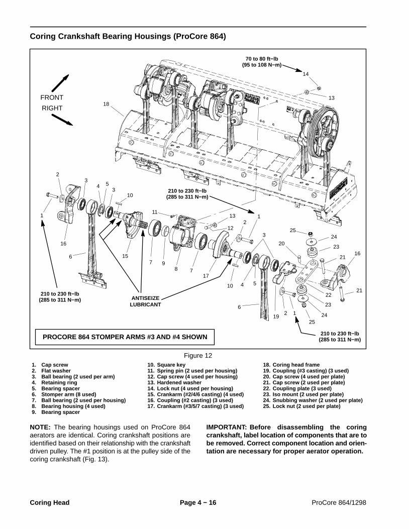
3. Remove pulley shield from machine (see Cover Re-moval in the Service and Repairs section of Chapter 3− Chassis).
4. Remove fasteners (items 5, 6 and 7) that secure beltguard to support. Remove belt guard from machine. Flatwasher (item 8) and cap screw (item 9) can remain onframe. 1. Drive pulley
2. Idler pulley3. Driven pulley4. Drive belt
Figure 23
1
2
4
3

ProCore 864/1298 Page 4 − 25 Coring Head
5. Loosen lock nut (item 15) that secures idler nut inposition on idler spring mount. Loosen idler nut (item 16)to remove idler tension on drive belt.
CAUTIONBe careful when lifting the idler pulley. The idlerpulley is spring loaded and may cause personalinjury.
6. Lift and hold idler pulley away from belt. Remove beltfrom drive pulley. Carefully lower idler pulley.
7. Loosen and remove two (2) flange nuts and hard-ened D washers that secure rotolink damper for #1stomper arm (see Rotolink Damper Disassembly in thissection). Lower rotolink damper from coring head frame.
8. Remove drive belt from driven pulley on coringcrankshaft.
9. Route drive belt down through coring head frameand around lower end of #1 stomper arm to remove cor-ing head drive belt from machine (Fig. 24 and 25).
Installation (Fig. 22)
1. Route drive belt around lower end of #1 stomper armand up through coring head frame (Fig. 24 and 25).
2. Position drive belt to driven pulley on coring crank-shaft.
3. Lift idler pulley, route drive belt under idler pulley andinstall belt onto drive pulley (Fig. 23).
4. Apply tension to idler pulley by adjusting idler nut(item 16) until compression spring length is 5.750” (145mm). Secure idler nut location with lock nut (item 15).
5. Raise rotolink damper for #1 stomper arm to coringhead frame. Make sure that damper standoffs andbumper are on damper studs. Secure damper to coringhead frame with two (2) D washers and lock nuts (seeRotolink Damper Assembly in this section).
6. Make sure that tinnerman nuts (item 1), flat washer(item 8) and cap screw (item 9) are on frame. Positionbelt guard to machine. Secure belt guard to support withflange nut (item 7), two (2) flange head screws (item 6)and flat washers (item 5).
7. Install pulley shield to machine (see Cover Installa-tion in the Service and Repairs section of Chapter 3 −Chassis).
8. Install rear hood to machine.
1. Drive belt 2. #1 stomper arm
Figure 24
1
2
1. Drive belt 2. #1 rotolink damper
Figure 25
1
2
1. Idler pulley2. Drive belt3. Compression spring
4. Idler nut5. Lock nut
Figure 26
1
2
34
5
5.750”(145 mm)
Co
rin
g H
ead

ProCore 864/1298Page 4 − 26Coring Head
Coring Head Drive
1. Pulley support2. Pulley shaft3. Bearing (2 used)4. Bearing spacer5. Shim washer6. Pulley7. Flat washer8. Cap screw9. Spacer tube10. Spring mount11. Washer12. Cap screw
13. Flange bushing (2 used)14. Pivot sleeve15. Idler arm16. Flat washer17. Cap screw18. Cap screw19. Idler pulley20. Flat washer21. Lock nut22. Compression spring23. Idler nut24. Lock nut
25. Drive belt26. Cap screw27. Tinnerman nut (4 used)28. Belt guard support29. Dirt shield30. Belt guard31. Flat washer (4 used)32. Flange head screw (6 used)33. Spacer hose34. Flange nut35. Bushing (2 used)
Figure 27
PROCORE 864 SHOWN
ANTISEIZELUBRICANT
FRONT
RIGHT
210 to 230 ft−lb(285 to 311 N−m)
2
30
4
6
1
5
87
9
10
11
12
14
15 1318
1617
19
20
24
35
21
25
34
32
31
3
29
27
28
26
24
2333
223
11
11
The coring head on the ProCore 864 is driven by a single4 grooved banded belt on the right side of the coringhead. The ProCore 1298 dual coring heads are eachdriven by a banded belt on the outside of the coringhead. The drive belt, drive pulley, belt tensioning systemand other coring head drive components are similar onboth the ProCore 864 and 1298.

ProCore 864/1298 Page 4 − 27 Coring Head
Removal (Fig. 27)
1. Position aerator on a firm, level surface. If attachedto tractor, disengage PTO, apply tractor parking brake,stop engine and remove key from the ignition switch.
2. Remove rear hood from machine.
3. Remove front cover and pulley shield from machine(see Cover Removal in the Service and Repairs sectionof Chapter 3 − Chassis).
4. Remove coring head drive belt (see Coring HeadDrive Belt Removal in this section).
5. Remove driveshaft from pulley shaft (see DriveshaftRemoval in this section).
6. Remove pulley (item 6) from pulley shaft:
A. Install a .375” − 16 UNC − 2B screw into one of thethreaded pulley holes leaving 1” to 2” of the screw ex-tending from the pulley surface. Do not tighten screwwith a wrench. Use a suitable pry bar between thepulley flange and screw extension to prevent thepulley and pulley shaft from rotating.
B. Remove cap screw and flat washer that securepulley to pulley shaft.
C. If needed, the use of three (3) .375” − 16 UNC −2B screws (see Special Tools) can be installed intothreaded holes of pulley to aid in pulley removal.Tighten screws progressively and evenly until thepulley is loose on the pulley shaft.
7. Remove additional components as necessary usingFigure 27 as a guide.
Installation (Fig. 27)
1. Install all removed components using Figure 27 as aguide.
A. If pulley shaft (item 2) was removed, apply anti-seize lubricant to shaft bearing surface before slidingshaft into bearing bores.
B. Apply antiseize lubricant to splines of pulley shaft(item 2) before installing pulley and driveshaft.
C. As drive pulley (item 6) is being installed, place 0,1 or 2 shims (item 5) between outer shaft bearing anddrive pulley to align drive pulley with driven pulley oncoring crankshaft. Pulleys should be aligned within0.070” (1.8 mm).
D. Install a .375” − 16 UNC − 2B screw into one of thethreaded pulley holes leaving 1” to 2” of the screw ex-tending from the pulley surface. Make sure that theend of the screw does not contact pulley drive hous-ing. Use a suitable pry bar between the pulley flangeand screw extension to prevent the pulley and pulleyshaft from rotating.
E. Secure drive pulley to pulley shaft with flat washerand cap screw. Torque cap screw from 210 to 230 ft−lb (285 to 311 N−m).
F. Remove screw from pulley hole.
2. Install coring head drive belt (see Coring Head DriveBelt Installation in this section). Make sure that drive beltis properly tensioned.
3. Install driveshaft to pulley shaft (see DriveshaftInstallation in this section).
4. Install front cover and pulley shield to machine (seeCover Installation in the Service and Repairs section ofChapter 3 − Chassis).
5. Install rear hood to machine.
1. Drive pulley2. Idler pulley
3. Driven pulley4. Drive belt
Figure 28
1
2
4
3
Co
rin
g H
ead

ProCore 864/1298Page 4 − 28Coring Head
Coring Head Pivot (H−Frame)
1. H−frame2. Thrust washer (4 used)3. Pivot shaft (2 used)4. Cap screw5. Flange nut6. Carriage screw7. Rod end (LH threads) (2 used)8. Jam nut (LH threads) (2 used)
9. Upper link (2 used)10. Jam nut (2 used)11. Rod end (2 used)12. Lock washer (4 used)13. Hex nut (4 used)14. Spring cup15. Compression spring
16. Depth control assembly17. Carriage screw (4 used)18. Upper link assembly19. Flange nut (4 used)20. Bushing (8 used)21. Coring head frame (RH shown)22. Subframe (RH shown)
Figure 29
FRONT
RIGHT
PROCORE 1298 SHOWN
7
3 4
6
8
251
1011
12
13
14
15
16 17
18
19
20
9
3
5
14
22
21

ProCore 864/1298 Page 4 − 29 Coring Head
Disassembly (Fig. 29)
1. Position aerator on a firm, level surface. If attachedto tractor, disengage PTO, apply tractor parking brake,stop engine and remove key from the ignition switch.
2. Remove rear hood from machine. Adjust coringhead depth to the deepest setting.
3. Remove front cover and pulley shield from machine(see Cover Removal in the Service and Repairs sectionof Chapter 3 − Chassis).
4. Support the aerator to prevent the machine frommoving.
NOTE: The ProCore 1298 uses one (1) compressionspring for each of its dual coring frames. The ProCore864 uses two (2) compression springs for its single cor-ing frame.
WARNING
THE CORING HEAD FRAME IS SPRING LOADED!To prevent possible personal injury, use com-pression spring tool (see Special Tools) to re-move compression spring(s) before disassem-bling the coring head pivot.
5. Use compression spring tool (see Special Tools) toremove compression spring(s) from coring head frame:
A. Install compression spring tool threaded rodthrough holes in each spring cup (item 1), then installwasher and nut on both ends of rod.
B. Tighten upper nut on rod to compress spring(item 2).
C. With tool compressing the spring, carefully liftbottom of spring, slide it from coring head frame, low-er from hitch frame and remove from machine.
D. If working on ProCore 864, repeat for secondcompression spring.
6. Make sure that machine is well supported with jack-stands or blocking.
CAUTION
The ProCore 864 coring head frame assemblyweighs approximately 900 pounds (408 kg). TheProCore 1298 coring head frame assemblyweighs approximately 675 pounds (306 kg).Make sure that proper lift or hoist is used to sup-port coring head frame during repairs.
7. Using suitable lift or hoist, raise coring head slightlyusing lifting eyelets on coring crankshaft as lift points(Fig. 30). Use appropriate jackstands or blocking to sup-port the coring head to prevent it from shifting.
8. Remove upper link assemblies (item 21) from hitchframe and coring head frame.
9. Remove fasteners (items 4, 5 and 6) that secure endof pivot shafts to machine.
10.Carefully slide pivot shafts from H−frame. Locateand retrieve four (4) thrust washers (item 2) from be-tween H−frame and machine frame.
11.Remove H−frame from machine.
12.If necessary, remove bushings (item 20) from H−frame.
1. Bearing housing 2. Lifting eyelet
Figure 30
2
1
Assembly (Fig. 29)
1. If upper links were disassembled, note that link hasa groove on the end that has left hand threads. Install rodends equally to make link assembly from 8.170” to8.230” (208 to 209 mm) long (rod center to rod center)(Fig. 31). Also, align rod ends before tightening jamnuts.
2. If bushings were removed from H−frame, press newbushings into H−frame bores. Bushings should be re-cessed into the H−frame at least 0.030” (0.8 mm).
IMPORTANT: When installing pivot shafts, makesure that both sides of H−frame are aligned withholes in frame before installing pivot shaft.
3. Position H−frame to hitch frame making sure thatthrust washers are placed between H−frame and hitchframe. Align both sides of H−frame to pivot shaft holesin hitch frame. Slide pivot shaft through hitch frame andH−frame. Secure pivot shaft to hitch frame with capscrew and flange nut.
Co
rin
g H
ead

ProCore 864/1298Page 4 − 30Coring Head
4. Position coring head to allow alignment of both sidesof H−frame to pivot shaft holes in coring head frame.Slide pivot shaft through coring head frame and H−frame. Secure pivot shaft to coring head frame with car-riage screw and flange nut.
5. Position upper link assemblies to hitch frame andcoring head frame. Make sure that link assemblies (Fig.31) have the groove installed in the same direction. Se-cure upper link rod ends to machine with lock washerand hex nut.
6. Install compression spring(s) to coring head frame:
A. With compression spring tool (see Special Tools)compressing the spring, position upper end of springto hitch frame and then slide bottom of spring to cor-ing head frame spring bracket.
B. Loosen lower nut on threaded rod to allow spring(item 2) to extend.
C. Remove compression spring tool threaded rod,washers and nuts from spring cups (item 1) andspring.
D. If working on ProCore 864, repeat for secondspring.
7. Install pulley shield and front cover to machine (seeCover Installation in the Service and Repairs section ofChapter 3 − Chassis).
8. Install rear hood to machine.
9. Adjust aerator to desired depth setting.
1. Rod end (RH threads)2. Rod end (LH threads)
3. Link groove
Figure 31
1
3
8.170” to 8.230”(208 to 209 mm)
2

ProCore 864/1298 Page 4 − 31 Coring Head
This page is intentionally blank.
Co
rin
g H
ead

ProCore 864/1298Page 4 − 32Coring Head
Depth Control Assembly
1. H−frame2. Depth control assembly3. Flange nut (4 used)4. Carriage screw (4 used)
5. Coring head frame6. Compression spring7. Spring cup8. Hitch frame
9. Flange head screw (4 used)10. Pad11. Flange nut (4 used)
Figure 32
PROCORE 1298 SHOWN
FRONT
RIGHT
2
3
4
6
89
10
1
5
7
7
11

ProCore 864/1298 Page 4 − 33 Coring Head
Removal (Fig. 32)
1. Position aerator on a firm, level surface. If attachedto tractor, disengage PTO, apply tractor parking brake,stop engine and remove key from the ignition switch.
2. Remove rear hood from machine.
3. Remove front cover to allow access to depth controlassembly (see Cover Removal in the Service and Re-pairs section of Chapter 3 − Chassis).
4. Use compression spring tool (see Special Tools) tocompress coring head compression spring(s) slightly.The springs do not have to be removed from machine.
A. Install compression spring tool threaded rodthrough holes in each spring cup (item 7), then installwasher and nut on both ends of rod.
B. Tighten upper nut on rod to compress spring(item 6) until upper spring cup is approximately 1/2”(13 mm) from spring seat on hitch frame.
C. If working on ProCore 864, repeat for secondcompression spring.
CAUTION
The ProCore 864 coring head frame assemblyweighs approximately 900 pounds (408 kg). TheProCore 1298 coring head frame assemblyweighs approximately 675 pounds (306 kg).Make sure that proper lift or hoist is used to sup-port coring head frame during repairs.
5. Use suitable lift or hoist and lifting eyelets on coringcrankshaft as lift points (Fig. 33) to raise coring head.Raise coring head so that clearance exists betweendepth control assembly and pad on hitch frame.
6. Use appropriate jackstands or blocking to supportthe coring head to prevent it from shifting or lowering.
7. Remove four (4) carriage screws and flange nutsthat secure depth control assembly to coring frame.
8. Remove depth control assembly from coring frame.
Installation (Fig. 32)
1. Make sure that coring frame is supported in a raisedposition to prevent unexpected lowering of coring frame.
2. Position depth control assembly to coring frame.
3. Secure depth control assembly to coring frame withfour (4) carriage screws and flange nuts.
4. Use appropriate hoist to lower coring frame so thatdepth control assembly is supporting coring frame.
5. Remove compression spring tool from coring headcompression spring(s):
A. Loosen lower nut on threaded rod to allow spring(item 2) to extend. Make sure that upper spring cup(item 1) extends into spring seat on hitch frame.
B. Remove compression spring tool components(threaded rod, washers and nuts) from spring.
C. If working on ProCore 864, repeat for secondspring.
6. Adjust aerator to desired depth setting.
7. Install front cover to machine (see Cover Installationin the Service and Repairs section of Chapter 3 − Chas-sis).
8. Install rear hood to machine.
1. Bearing housing 2. Lifting eyelet
Figure 33
2
1
Co
rin
g H
ead

ProCore 864/1298Page 4 − 34Coring Head
Depth Control Assembly Service
1. Flange head screw2. Flat washer3. Depth control gage4. Oil seal5. Depth control hub6. Plug7. Oil seal8. Shoe9. Hairpin clip
10. Depth control shaft11. Flange bushing12. Thrust bearing13. Thrust washer14. Worm15. Worm gear spacer16. Bearing washer17. Thrust bearing18. Worm gear
19. Plain washer20. Gasket21. Cover22. Lock plate23. Flange head screw (6 used)24. Key25. Adjustment shaft26. Decal
Figure 34
2
3
4
6
8
9
10
11
13
1
5
7
12
11
12
13
14
15
18
19
16
17
20
21
22
23
24
25
16
25
26
UP
23

ProCore 864/1298 Page 4 − 35 Coring Head
Disassembly (Fig. 34)
1. Remove flange head screw (item 1), flat washer(item 2) and depth control gage (item 3) from top ofdepth control shaft.
2. Remove hairpin clip (item 9) and shoe (item 8) frombottom of depth control shaft.
3. Unscrew depth control shaft (item 10) and removefrom depth control hub.
4. Remove upper and lower oil seals (items 4 and 7)from depth control hub. Take care to not damage sealbores in hub. Discard seals.
5. Remove six (6) flange head screws (item 23) that se-cure lock plate and cover to depth control hub. Removelock plate, cover and gasket.
6. Slide adjustment shaft assembly from depth controlhub. Remove flange bushings (item 11), thrust washers(item 13), thrust bearings (item 12), worm (item 14), key(item 24) and worm gear spacer (item 15) from adjust-ment shaft.
7. Remove plain washer (item 19) from depth controlhub.
8. Slide worm gear (item 18) with two (2) bearing wash-ers (item 16) and thrust bearing (item 17) from depthcontrol hub. Remove bearing washers and thrust bear-ing from worm gear flange.
9. Clean and inspect all components. Replace all com-ponents that are worn or damaged.
Assembly (Fig. 34)
1. Apply grease to depth control components:
A. Pack thrust bearings (items 12 and 17) 60% to100% full with grease.
B. Fill all threads of depth control shaft (item 10)60% to 100% full with grease.
C. Fill all gear teeth voids of worm (item 14) andworm gear (item 18) 60% to 100% full with grease.
2. Place bearing washer (item 16), greased thrust bear-ing (item 17) and then second bearing washer ontoflange of greased worm gear (item 18).
3. Position worm gear assembly into depth control hub.Slide plain washer (item 19) between worm gear andcontrol hub.
4. Place inner flange bushing (item 11) into depth con-trol hub.
5. Install components onto adjustment shaft (item 25):
A. Slide outer flange bushing (item 11), worm gearspacer (item 15), thrust washer (item 13), greasedthrust bearing (item 12) and second thrust washeronto shaft.
B. Place key (item 24) into shaft slot, align worm(item 14) with key and then slide greased worm ontoshaft.
C. Place thrust washer (item 13), greased thrustbearing (item 12) and final thrust washer onto shaft.
6. Slide assembled adjustment shaft into inner flangebushing in depth control hub. Make sure that innerflange bushing is still properly positioned in hub bore.
7. Place gasket (item 20) and cover (item 21) ontodepth control hub. Make sure that outer flange bushing(item 11) is properly positioned into cover bore. Installfour (4) flange head screws that surround adjustmentshaft. Do not fully tighten screws at this time.
8. Lightly oil upper and lower oil seals. Install seals intodepth control hub taking care to not damage seals dur-ing installation.
9. Insert greased depth control shaft (item 10) into bot-tom of depth control hub and thread shaft into wormgear. Take care to not damage seals during depth con-trol shaft installation.
10.Position lock plate (item 22) to cover and secure withtwo (2) flange head screws. Fully tighten all six (6) coverscrews.
11.Place shoe (item 8) on bottom of depth control shaftand secure with hairpin clip.
12.Position depth control gage (item 3) to top of depthcontrol shaft and align slot in gage with tab on shaft. Se-cure gage to control shaft with flat washer and flangehead screw.
Co
rin
g H
ead

ProCore 864/1298Page 4 − 36Coring Head
Driveshafts
1. PTO driveshaft2. Lock nut3. Cap screw
4. Coring head driveshaft5. Hitch frame6. Gearbox
7. RH pulley support assembly8. LH pulley support assembly
Figure 35
70 to 80 ft−lb(95 to 108 N−m)
FRONT
RIGHT
ANTISEIZELUBRICANT
ANTISEIZELUBRICANT
ANTISEIZELUBRICANT
ANTISEIZELUBRICANT
70 to 80 ft−lb(95 to 108 N−m)
70 to 80 ft−lb(95 to 108 N−m)
PROCORE 1298 SHOWN
2
3
4
6
8
1
57
2
2
2
3
33
4
NOTE: The ProCore 1298 uses two (2) identical coringhead driveshafts (shown in Figure 35). The ProCore 864uses one (1) coring head driveshaft.
Removal (Fig. 35)
1. Position aerator on a firm, level surface. If attachedto tractor, disengage PTO, apply tractor parking brake,stop engine and remove key from the ignition switch.
2. Remove front covers to allow access to driveshaft(see Cover Removal in the Service and Repairs sectionof Chapter 3 − Chassis).
3. Remove two (2) cap screws and lock nuts from bothend yokes of driveshaft.
4. Slide driveshaft end yokes from shafts and removedriveshaft from machine.
1. End yoke2. Cross and bearings3. Shaft and yoke
4. Grease fitting5. Tube and yoke6. Grease fitting
Figure 36
CORING HEAD DRIVESHAFT2
3
4
6
1
5
12
4
ProCore 864/1298 Page 4 − 37 Coring Head
5. If necessary, remove guards from PTO driveshaft(Fig. 38):
A. Press clip end and rotate clip from guard.
B. Rotate bushing to disengage bushing fromguard.
C. Slide guard from driveshaft.
D. Remove bushing from groove in yoke. Cleanbushing and groove.
Installation (Fig. 35)
1. Apply antiseize lubricant to shaft surfaces.
2. If driveshaft halves were separated, note that splineson shaft and tube have a blind spline to ensure align-ment of end yokes when the driveshaft is assembled.Align blind spline in shaft and tube when assembling dri-veshaft halves.
3. Install guards to PTO driveshaft if removed (Fig. 38):
A. Grease bushing groove in yoke and install bush-ing into groove.
B. Slide guard onto driveshaft and insert guardopenings over bushing tabs.
C. Rotate bushing to engage bushing tabs andguard.
D. Secure bushing and guard by pushing the clipinto guard.
4. Position driveshaft to aerator:
A. Coring head driveshaft should be installed withslip tube yoke to gearbox (Fig. 36).
B. PTO driveshaft should be installed with safetyslide lock yoke toward tractor (Fig. 37).
5. Align splines of driveshaft yokes with shafts. Slidedriveshaft end yokes onto shafts.
6. Secure driveshaft end yokes to shafts with two (2)cap screws and lock nuts. Torque lock nuts from 70 to80 ft−lb (95 to 108 N−m).
7. Lubricate driveshaft grease fittings.
8. Install front covers to machine (see Cover Installa-tion in the Service and Repairs section of Chapter 3 −Chassis).
1. Safety slide lock yoke2. Cross and bearings3. Shaft and yoke4. Outer guard
5. Inner guard6. Tube and yoke7. End yoke
Figure 37
PTO DRIVESHAFT2
3
4
6
15
72
1. Clip (locked)2. Clip (unlocked)
3. Bushing (engaged)4. Bushing (disengaged)
Figure 38
2
1
3
4C
ori
ng
Hea
d

ProCore 864/1298Page 4 − 38Coring Head
Driveshaft Cross and Bearing Service
1. Remove driveshaft from aerator (see Driveshaft Re-moval in this section).
IMPORTANT: When placing yoke in vise, clamplightly on the solid part of the yoke to prevent yokedamage. Also, the use of a vise with soft jaws is rec-ommended.
2. Lightly clamp yoke in vise. Remove snap rings thatsecure bearings in each yoke. Remove yoke from vise.
IMPORTANT: Yokes must be supported when re-moving and installing bearings to prevent damage.
3. Use a press to remove cross and bearings fromyokes:
A. Place a small socket against one bearing and alarge socket against the yoke on the opposite side.
B. While supporting the large socket, apply pres-sure on small socket to partially push the oppositebearing into the large socket.
C. Remove yoke from press, grasp partially re-moved bearing and tap on yoke to completely re-move the bearing.
D. Repeat process for remaining bearings.
E. Thoroughly clean and inspect all components.
4. To install new cross and bearings:
A. Apply a coating of grease to bearing bores of endyoke and shaft yoke. Also, apply grease to bearingsand seal of bearing assembly. Make sure that allbearing rollers are properly seated in bearing cage.
B. Press one bearing partially into yoke.
IMPORTANT: Take care when installing crossinto bearing to avoid damaging bearing seal.
C. Carefully insert cross into bearing and yoke.
D. Hold cross in alignment and press bearing in untilit hits the yoke.
E. Carefully place second bearing into yoke boreand onto cross shaft. Press bearing into yoke.
F. Install snap rings to secure bearings in place.
G. Repeat procedure for other yoke.
H. Grease cross until grease comes out of all four (4)bearing cups.
5. Make sure that assembled joint moves without bind-ing. Slight binding can usually be eliminated by lightlyrapping the yoke lugs with a soft faced hammer. If bind-ing continues, disassemble joint to identify source ofbinding.
6. If driveshaft halves were separated during cross andbearing service, note that splines on shaft and tube havea blind spline to ensure alignment of end yokes when thedriveshaft is assembled. Align blind spline in shaft andtube when assembling driveshaft halves.
7. Install driveshaft to aerator (see Driveshaft Installa-tion in this section).
1. End yoke2. Cross and bearing kit
3. Snap ring (4 used)4. Shaft yoke
Figure 39
1
2
3
4
3

ProCore 864/1298 Page 4 − 39 Coring Head
This page is intentionally blank.
Co
rin
g H
ead

ProCore 864/1298Page 4 − 40Coring Head
Gearbox
1. PTO driveshaft2. Gearbox3. Flange head screw (4 used)4. Reducer fitting5. Adapter6. Tube7. Hardline keeper
8. Lock nut9. Cap10. Cap screw11. Lock nut12. Cap screw13. Lock nut
14. Relief vent15. Coring head driveshaft16. Pulley drive17. O−ring18. Hitch frame19. O−ring
Figure 40
FRONT
RIGHT
PROCORE 1298 SHOWN
7
3
4
6
8
2
5
1
10
11
12
1314
15
16
17
18
19
9
13
12
1312
13
12
15

ProCore 864/1298 Page 4 − 41 Coring Head
Removal (Fig. 40)
1. Position aerator on a firm, level surface. If attachedto tractor, disengage PTO, apply tractor parking brake,stop engine and remove key from the ignition switch.
2. Remove front cover from hitch frame (see Front Cov-er Removal in the Service and Repairs section of Chap-ter 3 − Chassis).
3. Drain lubricant from gearbox.
NOTE: The ProCore 864 uses one (1) coring head dri-veshaft. The ProCore 1298 has two (2) coring head dri-veshafts.
4. Disconnect PTO and coring head driveshaft(s) fromgearbox shafts (see Driveshafts Removal in this sec-tion).
5. Disconnect drain tube from adapter on bottom ofgearbox.
CAUTION
To prevent personal injury, make sure thatgearbox is supported as it is removed from themachine. Gearbox weighs approximately 120pounds (54 kg).
6. Support gearbox to prevent it from shifting.
7. Remove four (4) flange head screws that securegearbox to hitch frame.
8. Carefully remove gearbox from machine.
Installation (Fig. 40)
CAUTION
To prevent personal injury, make sure thatgearbox is supported as it is installed to themachine. Gearbox weighs approximately 120pounds (54 kg).
1. Position gearbox to machine hitch frame. Securegearbox to frame with four (4) flange head screws.
2. Make sure that O−ring is positioned in groove inadapter on bottom of gearbox. Connect drain tube toadapter.
3. Connect PTO and coring head driveshaft(s) to gear-box shafts (see Driveshafts Installation in this section).
4. Fill gearbox with proper lubricant (see Operator’sManual).
5. Install front cover to machine (see Front CoverInstallation in the Service and Repairs section of Chap-ter 3 − Chassis).
Co
rin
g H
ead

ProCore 864/1298Page 4 − 42Coring Head
Gearbox Service
1. Oil seal2. Retaining ring3. Hard shim4. Soft shim5. Bearing (cup and cone)6. Cross shaft7. Relief vent
8. Fitting9. Housing10. Oil seal11. Plug12. Adapter13. Input gear and shaft14. Bearing (cup and cone)
15. Gasket16. O−ring17. Quill18. Flange head screw (6 used)19. Retaining shim20. Lock nut21. Oil seal
Figure 41
2
3
4
6
8
9
10
11
13
1
5
7
12
5
14
15
16
17
181920
14
4
81 ft−lb(109 N−m)
21
ThreadSealant
ThreadSealant
NOTE: The gearbox used on ProCore 864 and 1298machines is identical.
Disassembly (Fig. 41)
1. Remove six (6) flange head screws that secure quillassembly to gearbox housing.
NOTE: Gaskets (item 15) are used to adjust gearboxbacklash. Take note of number of gaskets to assist in as-sembly process.
2. Pull quill assembly from gearbox housing. Removeand discard O−ring and gasket(s).

ProCore 864/1298 Page 4 − 43 Coring Head
3. Disassemble quill assembly:
A. Remove oil seal (item 21) from quill housing. Dis-card oil seal.
B. Bend retaining tab of retaining shim and removelock nut and shim from shaft. Discard retaining shim.
C. Remove outer bearing. Slide shaft and innerbearing from quill housing.
D. Remove inner bearing from shaft.
E. Use press to remove bearing cups from quillhousing.
4. Remove oil seal (item 1) from housing to allow re-moval of cross shaft assembly. Discard oil seal.
5. Remove retaining ring that secures cross shaft as-sembly in gearbox housing.
NOTE: Soft shims (item 4) between hard shim (item 3)and outer bearing (item 5) are used to adjust cross shaftend play. Take note of number and location of shims toassist in assembly process.
6. Slide cross shaft assembly from gearbox housing.Note location of hard shim (item 3) and soft shim(s) justinside retaining ring location. Remove outer bearing cupand both bearing cones from cross shaft.
NOTE: Soft shims (item 4) between inner bearing cupand gearbox housing are used to adjust gear mesh andpattern. Take note of number of shims to assist in as-sembly process.
7. Remove inner bearing cup from gearbox housing.Remove soft shim(s) from between inner bearing cuplocation and gearbox housing. Note the number of softshim(s).
8. Remove and discard remaining oil seal (item 10)from gearbox housing. Discard oil seal.
9. Thoroughly clean and inspect all gearbox compo-nents. Replace all worn or damaged parts.
Assembly (Fig. 41)
NOTE: Soft shims (item 4) between inner bearing cupand gearbox housing are used to adjust gear mesh andpattern. During assembly, install same number of softshims as were removed.
1. Position soft shim(s) in housing and then press innerbearing cup fully into housing bore.
2. Press inner and outer bearing cones onto crossshaft. Make sure that bearings are pressed fully toshoulders on shaft.
3. Install cross shaft assembly into gearbox housing:
A. Slide cross shaft assembly into gearbox housing.
NOTE: Soft shims (item 4) between hard shim andouter bearing are used to adjust cross shaft end play.During assembly, install same number of soft shimsas were removed.
B. Position outer bearing cup, soft shim(s) and hardshim (item 3) onto cross shaft. Secure cross shaftwith retaining ring.
C. Check that cross shaft has from 0.001” to 0.003”(0.03 to 0.07 mm) end play. If necessary, add or re-move soft shim(s) between outer bearing and hardshim to adjust end play.
4. Assemble quill assembly:
A. Install bearing cups into quill housing. Make surethat cups are fully installed to shoulder in housing.
B. Install inner bearing cone fully onto shaft.
C. Slide shaft into housing.
D. Slide outer bearing cone onto shaft.
E. Install retaining shim and then lock nut onto shaft.Make sure that tab on retaining shim is aligned withslot in shaft.
F. Tighten lock nut until shaft has from 0.001” to0.003” (0.03 to 0.07 mm) end play. Secure lock nut inplace by bending a locking tab on retaining shim intoone of the slots in the lock nut.
5. Lightly grease O−ring (item 16) and install intogroove of quill housing.
NOTE: Gaskets (item 15) are used to adjust gearboxbacklash. During assembly, install same number of gas-ket(s) as were removed.
6. Position gasket(s) to quill housing and install hous-ing assembly into gearbox housing. Make sure that gearteeth mesh properly with gear on cross shaft. Securequill housing with six (6) flange head screws. Torquescrews 81 ft−lbs (109 N−m).
7. Check gearbox backlash (Fig. 42):
A. Clamp the output shaft of gearbox in a soft jawedvise.
B. Lightly clamp a pair of locking pliers onto thegearbox input shaft.
Co
rin
g H
ead

ProCore 864/1298Page 4 − 44Coring Head
C. Mount a dial indicator with a magnetic base to thevise so that the dial indicator touches the pliers3.100” (78.7 mm) from the center of the input shaft.
D. Rotate the pliers and monitor the dial indicatorreading to check gearbox backlash. Allowable back-lash is from 0.006” to 0.013” (0.16 to 0.33 mm).
E. If backlash adjustment is necessary, remove gas-ket(s) from between quill and gearbox housing to de-crease backlash. Increase backlash by installingadditional gasket(s). Recheck backlash after anygasket change. Repeat process until backlash is cor-rect.
F. Remove gearbox from vise.
8. After backlash is correct, check gear pattern to as-sure that proper gear mesh exists:
A. Remove quill housing assembly and coat gearteeth on cross shaft with gear mounting compound.
B. Install quill housing into gearbox housing usingthe same number of gaskets and secure with six (6)flange head screws. Torque screws 81 ft−lbs (109N−m).
C. Rotate the input shaft to establish a gearmeshpattern in the gear mounting compound. Rotating theinput shaft 1/2 turn will allow all cross shaft gear teethto contact input shaft gear teeth.
D. Remove quill assembly from gearbox and inspectthe pattern on the gear teeth.
E. Ideal pattern should cover from 40% to 80% of thegear face width (Fig. 43). The contact area should bein the center of each tooth and extend from 20% to50% of the gear face height. The pattern should notrun off the tooth heel, toe or top.
F. If necessary, adjust the number of soft shim(s)between housing and inner bearing cone to correctgear pattern. Make sure to also check and adjustcross shaft end play.
G. Recheck backlash if any changes are made. Ad-just backlash if necessary.
9. Apply a light coating of grease on seal lips and sealOD. Install seals into gearbox bores taking care to notdamage seals during installation. Seals should beinstalled until they are flush with the housing.
Figure 42
LOCKING PLIERS(LIGHTLY CLAMPED)
DIAL
SOFT JAWED
3.100”
INDICATOR
VISE
(78.7 mm)
Figure 43
40% to 80% ofTooth Width
0.118” (3.0 mm)MINIMUM
MINIMUM0.197” (5.0 mm)
20% to 50% ofTOE
Tooth Height
HEEL
GEAR PATTERN REQUIREMENTS
0.118” (3.0 mm)MINIMUM
1. Input gear and shaft2. Cross shaft
3. Gasket location4. Soft shim location
Figure 44
2
1
3
4

This page is intentionally blank.

Commercial Products
© The Toro Company
Related Documents