BASE STATION ANTENNAS Amphenol Private Networks PROCOM - Making the world smaller www.procom.dk

Welcome message from author
This document is posted to help you gain knowledge. Please leave a comment to let me know what you think about it! Share it to your friends and learn new things together.
Transcript

BASE STATIONANTENNASAmphenol Private Networks
PROCOM - Making the world smaller www.procom.dk
Base Station Antennas
Table Of Content
Home 1CXL 380-470C 9CXL 3-3C 12CXL 3-2C 15S.M2 18S.8Y series 21S.6Y series 24S.4Y series 27S.3Y series 30YA 900 34S.2Y series 37YA 2100 40S.1H series 42S.1 series 45RX 5000 48YA 1800 50R 900-7/..., R 900-10/..., R 900-14/... 52R 900/1800-12/14 55R 700-2700/10 58R 2400-... 61QHAM 2500-RC/... 65QHA TETRA-RH 67R 1800-… 69SMC 2300/65-105 73SMC 2300/30-65 75PLPO TETRA/380-470 77PATCH-MAMO 79NTA 3E-SHT 81MA DAB SC 83MA 450/... 86MA 160/... 89GP 80 B/... 92GP 80/160 94PRO GHz-LINK SERIES 96GP 80 99GP 450-3/... 101GP 450/... 103GP 40 105GP 27 107GP 160 B 109GP 160 5/8 111GP 160 113CXL 2400-8LW/... 116CXL 2400-6LW/... 119CXL 2400-6/... 122CXL 2400-3LW/... 125CXL 2400-3/... 128
Page 2/783
Base Station Antennas
CXL 2400-1LW/... 131CXL 2400-1/... 134CXL 230-3LW/DAB 137CXL 230-3/DAB 140CXL 230-1LW/DAB 143CXL 230-1/DAB 146CXL 23-7C/... 149CXL 225-450C 152CXL 2000-6LW/... 155CXL 2000-3LW 158CXL 2/70C 161CXL 2-5SL/... 164CXL 2-5HD/... 167CXL 2-3LW/... 170CXL 2-3C/...-PT 173CXL 2-3C/... 177CXL 2-3 180CXL 1800-8C 183CXL 1800-6LW 186CXL 1800-6/DECT 189CXL 1800-6 192CXL 1800-3LW 195CXL 1800-3/DECT 198CXL 2-3 GHz 201CXL 2-2C 204G-CXL 900-1LW/... 207CXL 2-1LW/... 210CXL 2-1HD-PT 213G-CXL 900/1800/1900/UMTS/LW 216CXL 2-1/... 219G-CXL 70-1LW/... 222CXL 1800-8C/t-6 225CXL 1800-3 228CXL 1800-1LW 231CXL 1800-1/DECT 234CXL 1800-1/... 237CXL 175-400C 240CXL 108-185C 243BCL 1-KA 246AAC 1/... 250CXL VHF/GSM 253CXL 800-1/... 256CXL 700-3SL 258CXL TETRA/LTE 800C/... 261CXL 70-8HD/...-PT 265CXL TETRA-5SL 268CXL 900-6LW-NB/868 MHz 271CXL 900-6LW/... 274CXL 70-8HD/... 277CXL 900-3LW-NB/868 MHz 280
Page 3/783
Base Station Antennas
CXL 70-5SL/... 283CXL 900-3LW/... 286CXL 70-5HD/...-PT 289CXL 900-3/... 292CXL 70-5HD/... 295CXL 900-1LW/... 298CXL 900/1800/1900/UMTS/LW 301CXL 70-5C/T-8/...-PT 304CXL 70-5C/T-7/... 307CXL 900/1800/1900/UMTS 310CXL 70-5C/T-12/... 313CXL 70-5C/... 316CXL 450-3LW-SS 320CXL 450-6HD/T-X/... 323CXL 70-3C/... 326G-CXL 2400-1LW/... 329G-CXL 225-450C 332CXL 70-3/GPS 4/... 335G-CXL 2-2C 339CXL 70-3/... 342G-CXL 2-1LW/... 345CXL 70-1LW/... 348CXL 70-1HD/...-PT 351CXL 70-1/... 354CXL 5700-6 357CXL 5700-3 360CXL 5200-6LW 363CXL 5200-6 366CXL 5700-1/... 369CXL 470-870 372CXL 450-1LW-SS-Ex 375CXL 4/70C/... 379CXL 4-2C/... 382CXL 4-1LW/... 385CXL 3-1LW 388CXL 3-1 391PRO 2.5-001HD/TSV50/... 394PRO-145-... 396PMC 1250 397VHF-DP-ARRAY 399R 2-3/..., R 2-6/... 402R 2-8/..., R 2-10/... 405DP 70/... 408R 70-3/..., R 70-7/..., R 70-10/... 410DP 4/... 413R 4-3/..., R 4-6/... 416DP 2 419UHF-DP-ARRAY 421CXL 130-1-Ex 424CXL 130-1LW-SS-Ex 428
Page 4/783
Base Station Antennas
CXL 130-1C-Ex 431CXL 150-1LW-SS-Ex 435CXL 150-3LW-SS-Ex 439CXL 150-1LW-SS-R/... 443R 2600-... 447PCPI 434/868/RHCP 451G-CXL 900/1800LW 454G-CXL 1800-1LW 457S.M4 460CXL 2000-6/... 463CXL 2000-3 466CXL 2000-8LW/... 469CXL 1090-1 472CXL 1090-1LW 474CXL 450-3LW-SS-Ex 476CXL 2400-3LW-SS-Ex 48055143xx Amphenol Jaybeam Antenna 48471482xx Amphenol Jaybeam Antenna 486MA411D00 Amphenol Jaybeam Antenna 4875004380 Amphenol Jaybeam Antenna 489MA411H02 Amphenol Jaybeam Antenna 491MA412D00 Amphenol Jaybeam Antrenna 4935004100 Amphenol Jaybeam Antenna 495MA421X61 Amphenol Jaybeam Antenna 497MA431E40 Amphenol Jaybeam Antenna 499MA431H00 Amphenol Jaybeam Antenna 501MA431X26 Amphenol Jaybeam Antenna 503MA431Z00 Amphenol Jaybeam Antenna 504MA432H00 Amphenol Jaybeam Antenna 506MA432H01 Amphenol Jaybeam Antenna 508MA432H02 Amphenol Jaybeam Antenna 510MA432H03 Amphenol Jaybeam Antenna 512MA100LM01 Amphenol Jaybeam Antenna 514MA421X45 Amphenol Jaybeam Antenna 5157636000 Amphenol Jaybeam Antenna 516MA432H10 Amphenol Jaybeam Antenna 517MA432H12 Amphenol Jaybeam Antenna 519MA432H13 Amphenol Jaybeam Antenna 521MA432H80 Amphenol Jaybeam Antenna 523MA432H85 Amphenol Jaybeam Antenna 525MA432J00 Amphenol Jaybeam Antenna 527MA432KM00 Amphenol Jaybeam Antenna 529MA432KM01 Amphenol Jaybeam Antenna 5317636000 Amphenol Jaybeam Antenna 5337527xxx Amphenol Jaybeam Antenna 5355680000 Amphenol Jaybeam Antenna 537MA461H01 Amphenol Jaybeam Antenna 5395029000 Amphenol Jaybeam Antenna 541MA462DS06 Amphenol Jaybeam Antenna 5437363260 Amphenol Jaybeam Antenna 545
Page 5/783
Base Station Antennas
MA462DS08 Amphenol Jaybeam Antenna 547MA481KM22 Amphenol Jaybeam Antenna 549MA481Q02 Amphenol Jaybeam Antenna 551MA481QS06 Amphenol Jaybeam Antenna 553MA481S02 Amphenol Jaybeam Antenna 555MA521F00 Amphenol Jaybeam Antenna 557MA521J00 Amphenol Jaybeam Antenna 5597825200 Amphenol Jaybeam Antenna 5617825100 Amphenol Jaybeam Antenna 5637586307 Amphenol Jaybeam Antenna 5657556xxx Amphenol Jaybeam Antenna 5677548xxx Amphenol Jaybeam Antenna 5697530xxx Amphenol Jaybeam Antenna 5717511xxx Amphenol Jaybeam Antenna 5737502xxx Amphenol Jaybeam Antenna 5757548415 Amphenol Jaybeam Antenna 5777497390 Amphenol Jaybeam Antenna 5797437010 Amphenol Jaybeam Antenna 5817277010 Amphenol Jaybeam Antenna 5827273xxx Amphenol Jaybeam Antenna 5837242xxx Amphenol Jaybeam Antenna 5857177010 Amphenol Jaybeam Antenna 5877148xxx Amphenol Jaybeam Antenna 58871482xxHD Amphenol Jaybeam Antenna 59071482xx Amphenol Jaybeam Antenna 5927074xxx Amphenol Jaybeam Antenna 5947073xxx Amphenol Jaybeam Antenna 5967051xxx Amphenol Jaybeam Antenna 5987050xxx Amphenol Jaybeam Antenna 6007047xxx Amphenol Jaybeam Antenna 6027047200 Amphenol Jaybeam Antenna 6047034xxx Amphenol Jaybeam Antenna 6067014385 Amphenol Jaybeam Antenna 6087014xxx Amphenol Jaybeam Antenna 6107018xxx Amphenol Jaybeam Antenna 6127019xxx Amphenol Jaybeam Antenna 6147029xxx Amphenol Jaybeam Antenna 6167031xxx Amphenol Jaybeam Antenna 6187039xxx Amphenol Jaybeam Antenna 6207040444 Amphenol Jaybeam Antenna 6227040xxx Amphenol Jaybeam Antenna 6247041xxx Amphenol Jaybeam Antenna 6267042488 Amphenol Jaybeam Antenna 6287043360 Amphenol Jaybeam Antenna 6307043481 Amphenol Jaybeam Antenna 6327043xxx Amphenol Jaybeam Antenna 6347049xxx Amphenol Jaybeam Antenna 6367051440 Amphenol Jaybeam Antenna 6387130xxx Amphenol Jaybeam Antenna 6407148438 Amphenol Jaybeam Antenna 642
Page 6/783
Base Station Antennas
7148481 Amphenol Jaybeam Antenna 6447157400 Amphenol Jaybeam Antenna 6467170xxx Amphenol Jaybeam Antenna 6487175872 Amphenol Jaybeam Antenna 6507175890 Amphenol Jaybeam Antenna 6527176xxx Amphenol Jaybeam Antenna 6547227000 Amphenol Jaybeam Antenna 6567249071 Amphenol Jaybeam Antenna 6587335000 Amphenol Jaybeam Antenna 6597356561 Amphenol Jaybeam Antenna 6607356710 Amphenol Jaybeam Antenna 6627356825 Amphenol Jaybeam Antenna 6647360010 Amphenol Jaybeam Antenna 6667360012 Amphenol Jaybeam Antenna 6687360016 Amphenol Jaybeam Antenna 6707362240 Amphenol Jaybeam Antenna 6727363240 Amphenol Jaybeam Antenna 673CXL 70-3HD/...-PT 674CXL 450-3HD/T-X/... 677UWB-I 380-6000 680MA 160-Ex 686CXL 70-3LW/... 689CXL 2-5SL/171 MHz 692CXL 900-1/... 694XCPI 160/RHCP 697XCPI 160/450/RHCP 700LPO TETRA/380-470 704PCPI 70/xH/ 706XCPI 160/900/1800/1900/2100/R 710PCPI xH/TETRA/... 714PCPO xH/TETRA/ 717PCPI TETRA/LTE 800/RH 720PCPI 70/900/xHCP 723PCPI 70/900/1800/PCS/UMTS/R/... 727PCPI 800/xH 731PCPI 900/RHCP 734PCPI GPS 737PCPI GPS EXTEND 740PCPI PCS 743PCPI DECT 745PCPI DCS 747PCPI UMTS 749PCPI DCS/UMTS 751PCPI WIFI 753PLPI/TETRA/ 755PLPO/TETRA/ 758PLPI 900/1800 762PLPI UMTS 2100 765GP 450 B 767CXL 150-1/... 769
Page 7/783
Base Station Antennas
CXL 450-1LW-SS 774CXL 5700-1LW/... 778CXL 2000-8/... 780End 783
Page 8/783
Base Station Antennas
CXL 380-470CUnity Gain, Broad-Band Base Station Antenna for 380 - 470 MHz
CXL 380-470C is a sturdy, 0 dBd, vertically polarized, omnidirectional base stationantenna, which covers 380 - 470 MHz.The antenna is provided with our “C” mast bracket, which is a universal, epoxy-coated mounting bracket made of non-corrosive aluminium. The accompanying U-bolts and fittings are made of stainless steel.The antenna can be mounted on 27 to 65 mm dia. mast tubes and it is possible tolead the cable either along the inside or on the outside of the mast tube.
DESCRIPTION
The broad-banded antenna element is completely enclosed in a glass fibre shroud, which will ensure performanceundisturbed by corrosive environments.To substantially reduce noise caused by atmospherical discharges, all metal parts in the antenna are DC-grounded.Consequently, the antenna shows a DC-short across the coaxial cable.This antenna is constructed to ensure long dependable service in all climates.
ORDERING DESIGNATIONS
TYPE PRODUCT NO.
CXL 380-470C 100000509
SPECIFICATIONS
ELECTRICAL
MODEL CXL 380-470C
ANTENNA TYPE ½ λ, broad-banded
FREQUENCY 380 - 470 MHz
IMPEDANCE Nom. 50 Ω
RADIATION Omnidirectional
POLARIZATION Vertical
GAIN 0 dBd
BANDWIDTH 90 MHz
SWR ≤ 2.0
MAX. POWER 150 W
ANTISTATIC PROTECTION All metal parts DC-grounded(connector shows a DC-short)
MECHANICAL
TEMP. RANGE –30° C → +70° C
CONNECTOR N-female
Page 9/783
Base Station Antennas
WIND SURFACE 0.042 m² / 0.45 ft²
WIND LOAD 49 N @ 160 km/h / 99.42 mph.
MAX. WIND SPEED 200 km/h / 125 mph.
COLOUR Marine white
MATERIALS Radome : Polyurethane-coated glass fibreMounting bracket : Seawater resistant aluminium, epoxy-coated
TOTAL HEIGHT Approx. 1.20 m / 47.25 in.
WEIGHT Approx. 2.2 kg / 4.85 lb.
MOUNTING On 27 - 65 mm / 1.06 - 2.56 in. dia. mast tube
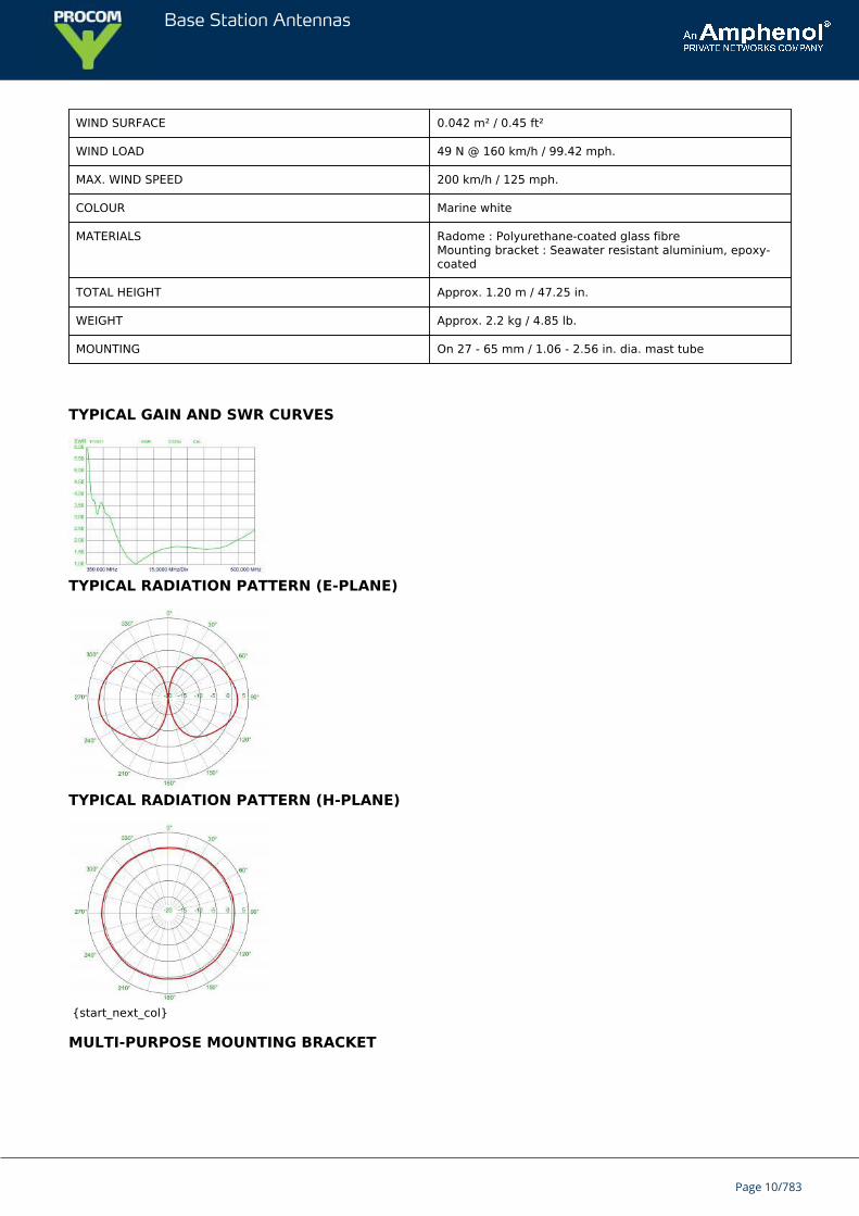
TYPICAL GAIN AND SWR CURVES
TYPICAL RADIATION PATTERN (E-PLANE)
TYPICAL RADIATION PATTERN (H-PLANE)
{start_next_col}
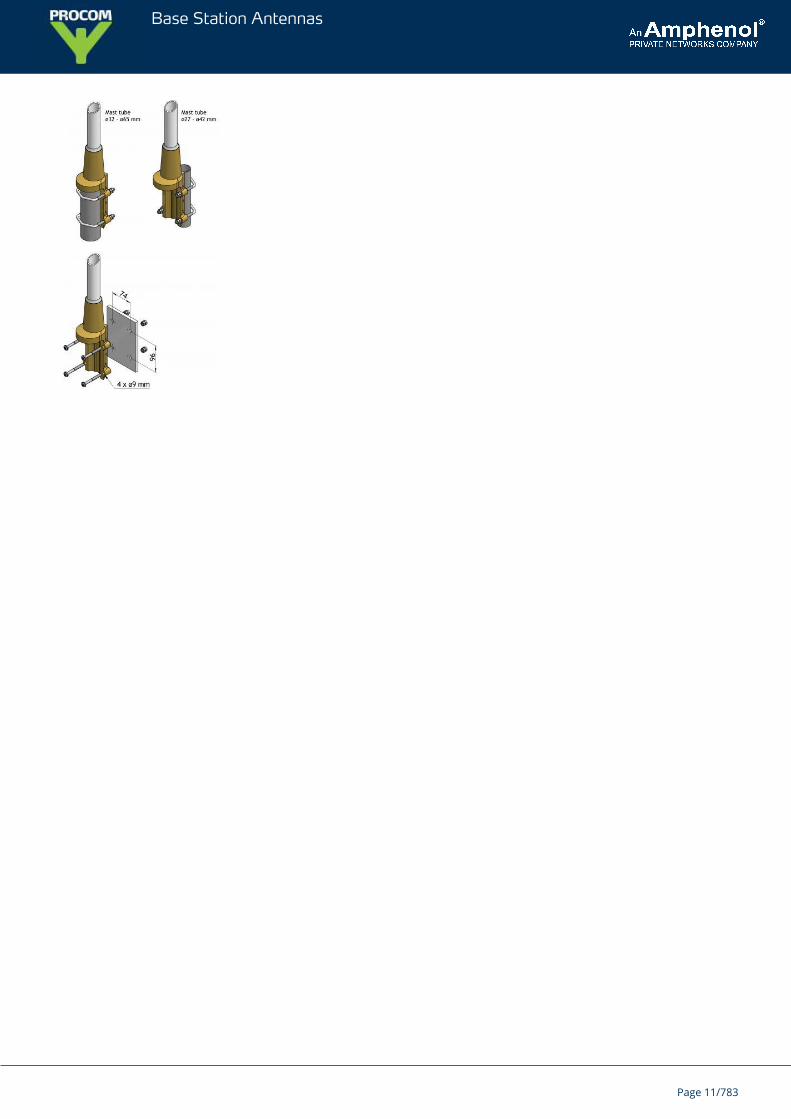
MULTI-PURPOSE MOUNTING BRACKET
Page 10/783
Base Station Antennas
Page 11/783
Base Station Antennas
CXL 3-3CSturdy 3 dBd Gain Base Station Antenna for the air Band
CXL 3-3C is a sturdy, 3 dBd, vertically polarized, omnidirectional base stationantenna, which covers the air band.The antenna is provided with our “C” mast bracket, which is a universal, epoxy-coated mounting bracket made of non-corrosive aluminium. The accompanying U-bolts and fittings are made of stainless steel.The antenna can be mounted on 27 to 65 mm dia. mast tubes and it is possible tolead the cable either along the inside or on the outside of the mast tube.
DESCRIPTION
The phasing of the radiating elements is carefully adjusted to yield maximum gain in the horizontal plane, with thelevel of the sidelobes reduced to a minimum. Special emphasis has been laid on obtaining a large bandwidth both inrelation to SWR and gain.The broad-banded antenna element is completely enclosed in a glass fibre shroud, which will ensure performanceundisturbed by corrosive environments.To substantially reduce noise caused by atmospherical discharges, all metal parts in the antenna are DC-grounded.Consequently, the antenna shows a DC-short across the coaxial cable.This antenna is constructed to ensure long dependable service in all climates.
ORDERING DESIGNATIONS
TYPE PRODUCT NO.
CXL 3-3C 100000079
SPECIFICATIONS
ELECTRICAL
MODEL CXL 3-3C
ANTENNA TYPE Coaxial, broad-band dipole
FREQUENCY 119 - 131 MHz
IMPEDANCE Nom. 50 Ω
RADIATION Omnidirectional
POLARIZATION Vertical
GAIN 5 dBi 3 dBd
HALF POWER BEAMWIDTH 30°
BANDWIDTH 12 MHz
SWR ≤ 1.5 @ 119 - 131 MHz (< 3 @ 118 - 137 MHz)
MAX. POWER 400 W
ANTISTATIC PROTECTION All metal parts DC-grounded(Connector shows a DC-short)
Page 12/783
Base Station Antennas
HCM CODES HCM000ND00, 030DE00
MECHANICAL
TEMP. RANGE –30° C → +70° C
CONNECTOR N-female
WIND SURFACE 0.165 m²
WIND LOAD 209 N @ 160 km/h / 99 mph
MAX. WIND SPEED 200 km/h / 125 mph
COLOUR Marine white
MATERIALS Radome : Polyurethane coated glass fibreMounting bracket : Seawater resistant aluminium,epoxy-coated
TOTAL HEIGHT Approx. 3.5 m
WEIGHT Approx. 4.5 kg
MOUNTING On 27 - 65 mm dia. mast tube
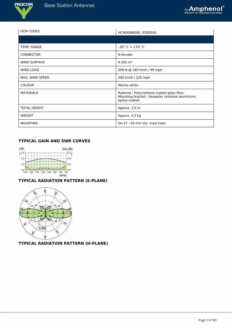
TYPICAL GAIN AND SWR CURVES
TYPICAL RADIATION PATTERN (E-PLANE)
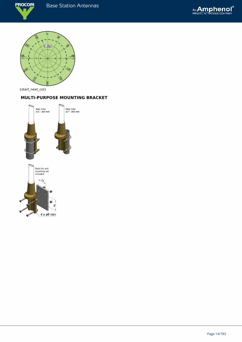
TYPICAL RADIATION PATTERN (H-PLANE)
Page 13/783
Base Station Antennas
{start_next_col}
MULTI-PURPOSE MOUNTING BRACKET
Page 14/783
Base Station Antennas
CXL 3-2CSturdy, Unity-Gain, Omnidirectional Base Station Antenna for theInternational Aircraft Band
CXL 3-2C is a sturdy, 0 dBd, vertically polarized, omnidirectional base stationantenna for the 110 - 140 MHz civil aircraft band.CXL 3-2C is extremely broad-banded – and it is most suitable for use on controltowers etc., where reliability is of the utmost importance.The antenna is provided with our “C” mast bracket, which is a universal, epoxy-coated mounting bracket made of non-corrosive aluminium.
DESCRIPTION
The accompanying U-bolts and fittings are made of stainless steel.The antenna can be mounted on 27 to 65 mm dia. mast tubes, and it is possible to lead the cable either along theinside or on the outside of the mast tube.To substantially reduce noise caused by atmospherical discharges, all metal parts in the antenna are DC-grounded.Consequently, the antenna shows a DC-short across the coaxial cable.The broad-banded antenna element is completely enclosed in a glass fibre shroud, which will ensure performanceundisturbed by corrosive environments.CXL 3-2C is constructed to ensure long dependable service in all climates.
ORDERING DESIGNATIONS
TYPE PRODUCT NO.
CXL 3-2C 100000076
SPECIFICATIONS
ELECTRICAL
MODEL CXL 3-2C
ANTENNA TYPE Coaxial, broad-band dipole
FREQUENCY 110 - 140 MHz
IMPEDANCE Nom. 50 Ω
RADIATION Omnidirectional
POLARIZATION Vertical
GAIN 2 dBi 0 dBd
BANDWIDTH 30 MHz
SWR ≤ 1.6
MAX. POWER 500 W
ANTISTATIC PROTECTION All metal parts DC-grounded(Connector shows a DC-short)
HCM CODES HCM000ND00, 040DE00
Page 15/783
Base Station Antennas
MECHANICAL
TEMP. RANGE –30° C → +70° C
CONNECTOR N-female
WIND SURFACE 0.12 m²
WIND LOAD 152 N @ 160 km/h / 99 mph
MAX. WIND SPEED 200 km/h / 125 mph
COLOUR Marine white
MATERIALS Radome : Polyurethane-coated glass fibreMast clamp : Seawater resistant aluminium, epoxy-coated
TOTAL HEIGHT Approx. 2.3 m
WEIGHT Approx. 3.6 kg
MOUNTING On 27 - 65 mm dia. mast tube
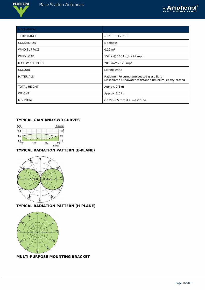
TYPICAL GAIN AND SWR CURVES
TYPICAL RADIATION PATTERN (E-PLANE)
TYPICAL RADIATION PATTERN (H-PLANE)
MULTI-PURPOSE MOUNTING BRACKET
Page 16/783

Base Station Antennas
Page 17/783
Base Station Antennas
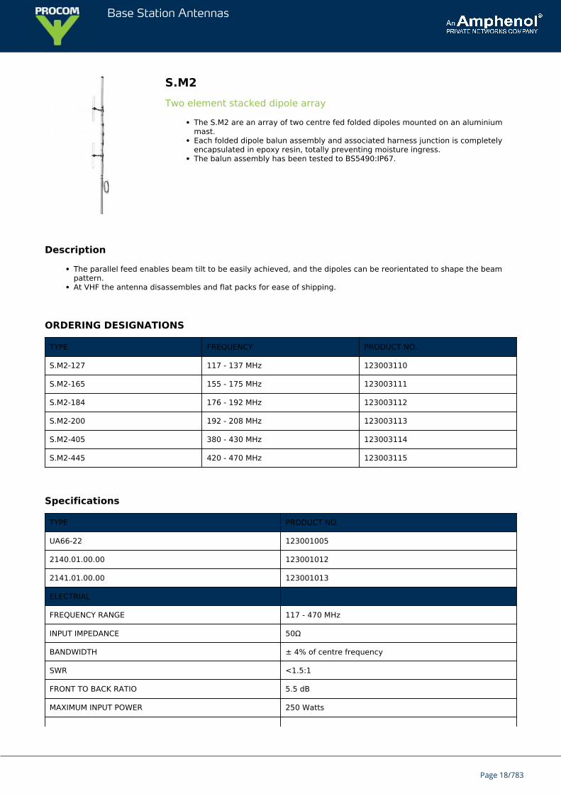
S.M2Two element stacked dipole array
The S.M2 are an array of two centre fed folded dipoles mounted on an aluminiummast.Each folded dipole balun assembly and associated harness junction is completelyencapsulated in epoxy resin, totally preventing moisture ingress.The balun assembly has been tested to BS5490:IP67.
Description
The parallel feed enables beam tilt to be easily achieved, and the dipoles can be reorientated to shape the beampattern.At VHF the antenna disassembles and flat packs for ease of shipping.
ORDERING DESIGNATIONS
TYPE FREQUENCY PRODUCT NO.
S.M2-127 117 - 137 MHz 123003110
S.M2-165 155 - 175 MHz 123003111
S.M2-184 176 - 192 MHz 123003112
S.M2-200 192 - 208 MHz 123003113
S.M2-405 380 - 430 MHz 123003114
S.M2-445 420 - 470 MHz 123003115
Specifications
TYPE PRODUCT NO.
UA66-22 123001005
2140.01.00.00 123001012
2141.01.00.00 123001013
ELECTRIAL
FREQUENCY RANGE 117 - 470 MHz
INPUT IMPEDANCE 50Ω
BANDWIDTH ± 4% of centre frequency
SWR <1.5:1
FRONT TO BACK RATIO 5.5 dB
MAXIMUM INPUT POWER 250 Watts
Page 18/783
Base Station Antennas
POLARISATION Vertical
FORWARD GAIN 5 dBd
3 dB BEAMWIDTH E Plane 36ºH Plane 180º
MECHANICAL
STANDARD CONNECTION 3 m (118.11 in.) Length of RG 213c/w 'N' type socket
ELEMENTS 12.7 mm dia. x 1.6 mm wallaluminium alloy grade 6063T6
SUPPORT BOOM UHF UHF 38.1 mm dia. x 3.2 mm wallaluminium alloy grade 6082T6
SUPPORT BOOM VHF VHF 63.5 mm dia. x 6.3 mm wallaluminium alloy grade 6082T6
FASTENERS Stainless steel grade A2-70
DIPOLE CLAMPS Cast aluminium alloy
DIPOLE ADJUSTMENT M8 stainless steel screws
SADDLE CLAMPS Diecast zinc alloy
INSULATOR Epoxy resin encapsulant
LIGHTNING PROTECTION Direct grounded VHF lightning finial
MOUNTING BRACKETS UHF UHF fit inside scaffold pole
MOUNTING BRACKETS VHF VHF to suit structure
TYPICAL WEIGHT (UHF) UHF 4 kg (8.82 lb.)
TYPICAL WEIGHT (VHF) VHF 9 kg (19.84 lb.)
TYPICAL LENGTH (UHF) UHF 1.25 m (49.21 in.)
TYPICAL LENGTH (VHF) VHF 4 m (157.48 in.)
TYPICAL WIND LOADING@ 162 km/h (UHF)
UHF 85N
TYPICAL WIND LOADING@ 162 km/h (VHF)
VHF 292N
MOUNTING ACCESSORIES
Mounting accessories to be ordered separately.
UA66-22
Very strong square cast alloy clamp, fits up to 50 mm diameter tubes as either a cross-over or parallel clamp. Supplied withtwo stainless steel ‘U’ bolts.
Page 19/783
Base Station Antennas
2140.01.00.00
Parallel clamps, in galvanised steel with stainless steel fixings, fits from 25-60 mm diameter tubes.
2141.01.00.00
Parallel clamps, in galvanised steel with stainless steel fixings, fits from 38-120 mm diameter tubes.
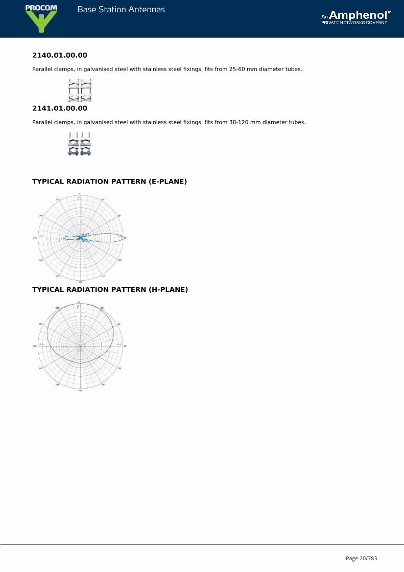
TYPICAL RADIATION PATTERN (E-PLANE)
TYPICAL RADIATION PATTERN (H-PLANE)
Page 20/783
Base Station Antennas
S.8Y seriesDirectional antennas
The S.8Y series are of a rugged and reliable construction for long rangecommunication networks at both UHF & VHF.The one piece folded dipole incorporates a d.c. short to minimise static interference.The balun assembly is completely encapsulated in epoxy resin, totally preventingmoisture ingress, and has been tested to BS5490:IP67.
These antennas give a gain of 10 dBd with front to back ratio typically 18 dB.They are supplied as standard with 3 metres of RG 213 cable terminated with an 'N' type socket, although cable andconnector options are available upon request.The S.8Y is approved to MPT1411: Part 2.
ORDERING DESIGNATIONS
TYPE FREQUENCY PRODUCT NO.
S.8Y-155 145 - 165 MHz Replaced by 7043150
S.8Y-165 155 - 165 MHz Replaced by 7043155
S.8Y-405 380 - 430 MHz Replaced by 7043410
S.8Y-445 420 - 470 MHz Replaced by 7043420
SPECIFICATIONS
ELECTRIAL
FREQUENCY RANGE 140 - 500 MHz
INPUT IMPEDANCE 50Ω
BANDWIDTH ± 4% of centre frequency
SWR <1.5:1
FRONT TO BACK RATIO 18 dB
MAXIMUM INPUT POWER 150 Watts
POLARISATION Vertical & horizontal
FORWARD GAIN 10 dBd
3 dB BEAMWIDTH E Plane 43ºH Plane 50º
MECHANICAL
STANDARD CONNECTION 3 m (118.11 in.) Length of RG 213c/w 'N' type socket
ELEMENTS UHF UHF 12.7 mm dia. x 1.6 mm(0.50 in. dia x 0.06 in.)wall aluminium alloy grade 6063T6
ELEMENTS VHF VHF 19.0 mm dia. x 1.6 mm
Page 21/783
Base Station Antennas
(0.75 in. dia x 0.06 in.)wall aluminium alloy grade 6063T6
SUPPORT BOOM 31.7 mm dia. x 2.6 mm(1.25 in. dia x 0.10 in.)wall aluminium alloy grade 6082T6
FASTENERS Stainless steel grade A2-70
SADDLE CLAMPS Diecast zinc alloy
INSULATOR Epoxy resin encapsulant
LIGHTNING PROTECTION Direct grounded
MOUNTING BRACKETS See mounting accessories (not supplied)
TYPICAL WEIGHT (UHF) 3 kg
TYPICAL WEIGHT (VHF) 5.2 kg
TYPICAL LENGTH (UHF) 1.6 m
TYPICAL LENGTH (VHF) 4 m
TYPICAL WIND LOADING@ 162 km/h (UHF)
UHF 100 N
TYPICAL WIND LOADING@ 162 km/h (VHF)
VHF 230 N
MOUNTING ACCESSORIES
Mounting accessories to be ordered separately.
TYPE DIMENSION PRODUCT NO.
1763-100 123001001
UA64-23 25 - 50 mm 123001006
UA64-23 25 - 76 mm 123001007
UA66-24 25 - 50 mm 123001017
UA66-24 25 - 76 mm 123001018
UA66-24 25 - 100 mm 123001019
UA66-24 25 - 115 mm 123001020
{start_next_col}
1763-100
Galvanised steel-cross-over clamp, fits 32 mm (1-1/4") diameter antenna booms to up to 50 mm (2") diameter poles, max.length 1500 mm.
{start_next_col}
Page 22/783
Base Station Antennas
UA64-23
Circular cast alloy clamp, gives a good two point fixing, supplied as standard with 4 x 50 mm stainless steel ‘U’ bolts andtwo half-moon cast spacers to fit antenna booms of 25 to 50 mm diameter. Will also accomodate 76 mm (3”) ‘U’ bolts to fitmasts of that diameter. (order UB06).
{start_next_col}
UA66-24Rectangular cast alloy clamp, gives a good two point fixing, supplied as standard with 4 x 50 mm stainless steel ‘U’ boltsand two half-moon cast spacers to fit antenna booms of 25 to 50 mm diameter. To fit 76 mm (3”) masts (order UB06 ‘U’bolts). To fit 100 mm (4”) masts (order UB07 ‘U’ bolts). To fit 115 mm (4 1/2”) masts (order UB09 ‘U’ bolts).
{start_next_col}
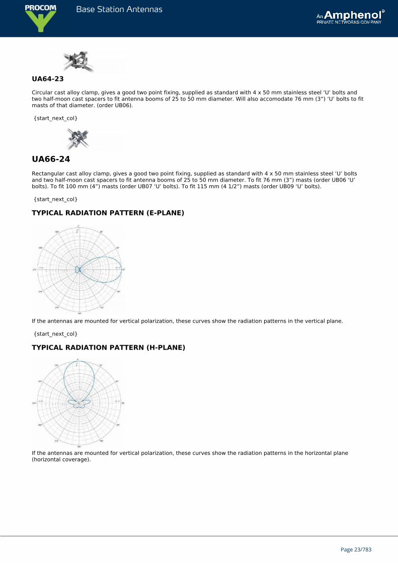
TYPICAL RADIATION PATTERN (E-PLANE)
If the antennas are mounted for vertical polarization, these curves show the radiation patterns in the vertical plane.
{start_next_col}
TYPICAL RADIATION PATTERN (H-PLANE)
If the antennas are mounted for vertical polarization, these curves show the radiation patterns in the horizontal plane(horizontal coverage).
Page 23/783
Base Station Antennas
S.6Y seriesDirectional antennas
The S.6Y series are of a rugged and reliable construction for communicationnetworks at both UHF & VHF.The one piece folded dipole incorporates a d.c. short to minimise static interference.The balun assembly is completely encapsulated in epoxy resin, totally preventingmoisture ingress, and has been tested to BS5490:IP67.
These antennas give a gain of 8.5 dBd with front to back ratio typically 16 dB.They are supplied as standard with 3 metres of RG 213 cable terminated with an 'N' type socket, although cable andconnector options are available upon request.
ORDERING DESIGNATIONS
TYPE FREQUENCY PRODUCT NO.
S.6Y-148 140 - 155 MHz Replaced by 7042140
S.6Y-165 156 - 175 MHz Replaced by 7042155
S.6Y-184 176 - 192 MHz 123002062
S.6Y-200 192 - 208 MHz 123002063
S.6Y-395 380 - 410 MHz 123002064
S.6Y-420 410 - 430 MHz 123002065
S.6Y-445 420 - 470 MHz 123002066
SPECIFICATIONS
ELECTRIAL
FREQUENCY RANGE 140 - 470 MHz
INPUT IMPEDANCE 50Ω
BANDWIDTH ± 5% of centre frequency
SWR <1.5:1
FRONT TO BACK RATIO 16 dB
MAXIMUM INPUT POWER 150 Watts
POLARISATION Vertical & horizontal
FORWARD GAIN 8.5 dBd
3 dB BEAMWIDTH E Plane 56ºH Plane 63º
MECHANICAL
STANDARD CONNECTION 3 m (118.11 in.) Length of RG 213c/w 'N' type socket
Page 24/783
Base Station Antennas
ELEMENTS UHF UHF 12.7 mm dia. x 1.6 mm(0.50 in. dia x 0.06 in.)wall aluminium alloy grade 6063T6
ELEMENTS VHF VHF 19.0 mm dia. x 1.6 mm(0.75 in. dia x 0.06 in.)wall aluminium alloy grade 6063T6
SUPPORT BOOM 31.7 mm dia. x 2.6 mm(1.25 in. dia x 0.10 in.)wall aluminium alloy grade 6082T6
FASTENERS Stainless steel grade A2-70
SADDLE CLAMPS Diecast zinc alloy
INSULATOR Epoxy resin encapsulant
LIGHTNING PROTECTION Direct grounded
MOUNTING BRACKETS See mounting accessories (not supplied)
TYPICAL WEIGHT (UHF) UHF 2.7 kg (5.95 lb.)
TYPICAL WEIGHT (VHF) VHF 5.5 kg (12.13 lb.)
TYPICAL LENGTH (UHF) UHF 1.3 m (51.18 in.)
TYPICAL LENGTH (VHF) VHF 4 m (157.48 in.)
TYPICAL WIND LOADING@ 162 km/h (UHF)
UHF 100 N
TYPICAL WIND LOADING@ 162 km/h (VHF)
VHF 208 N
MOUNTING ACCESSORIES
Mounting accessories to be ordered separately.
TYPE DIMENSION PRODUCT NO.
1763-100 123001001
UA64-23 25 - 50 mm 123001006
UA64-23 25 - 76 mm 123001007
UA66-24 25 - 50 mm 123001017
UA66-24 25 - 76 mm 123001018
UA66-24 25 - 100 mm 123001019
UA66-24 25 - 115 mm 123001020
1763-100
Galvanised steel-cross-over clamp, fits 32 mm (1-1/4") diameter antenna booms to up to 50 mm (2") diameter poles, max.length 1500 mm.
Page 25/783
Base Station Antennas
UA64-23
Circular cast alloy clamp, gives a good two point fixing, supplied as standard with 4 x 50 mm stainless steel ‘U’ bolts andtwo half-moon cast spacers to fit antenna booms of 25 to 50 mm diameter. Will also accomodate 76 mm (3”) ‘U’ bolts to fitmasts of that diameter. (order UB06).
UA66-24
Rectangular cast alloy clamp, gives a good two point fixing, supplied as standard with 4 x 50 mm stainless steel ‘U’ boltsand two half-moon cast spacers to fit antenna booms of 25 to 50 mm diameter. To fit 76 mm (3”) masts (order UB06 ‘U’bolts). To fit 100 mm (4”) masts (order UB07 ‘U’ bolts). To fit 115 mm (4 1/2”) masts (order UB09 ‘U’ bolts).
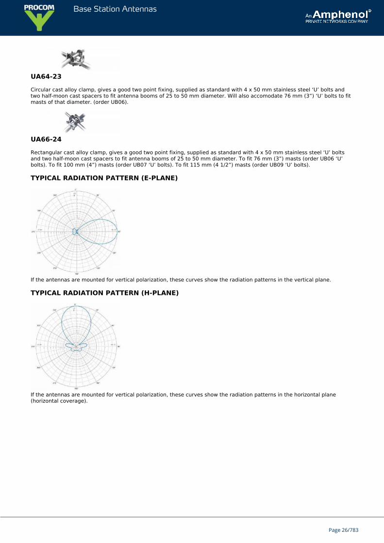
TYPICAL RADIATION PATTERN (E-PLANE)
If the antennas are mounted for vertical polarization, these curves show the radiation patterns in the vertical plane.
TYPICAL RADIATION PATTERN (H-PLANE)
If the antennas are mounted for vertical polarization, these curves show the radiation patterns in the horizontal plane(horizontal coverage).
Page 26/783
Base Station Antennas
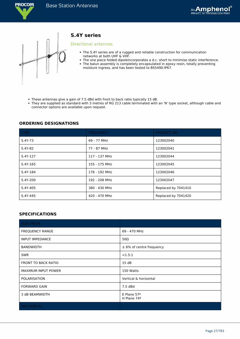
S.4Y seriesDirectional antennas
The S.4Y series are of a rugged and reliable construction for communicationnetworks at both UHF & VHF.The one piece folded dipoleincorporates a d.c. short to minimise static interference.The balun assembly is completely encapsulated in epoxy resin, totally preventingmoisture ingress, and has been tested to BS5490:IP67.
These antennas give a gain of 7.5 dBd with front to back ratio typically 15 dB.They are supplied as standard with 3 metres of RG 213 cable terminated with an 'N' type socket, although cable andconnector options are available upon request.
ORDERING DESIGNATIONS
TYPE FREQUENCY PRODUCT NO.
S.4Y-73 69 - 77 MHz 123002040
S.4Y-82 77 - 87 MHz 123002041
S.4Y-127 117 - 137 MHz 123002044
S.4Y-165 155 - 175 MHz 123002045
S.4Y-184 176 - 192 MHz 123002046
S.4Y-200 192 - 208 MHz 123002047
S.4Y-405 380 - 430 MHz Replaced by 7041410
S.4Y-445 420 - 470 MHz Replaced by 7041420
SPECIFICATIONS
ELECTRICAL
FREQUENCY RANGE 69 - 470 MHz
INPUT IMPEDANCE 50Ω
BANDWIDTH ± 6% of centre frequency
SWR <1.5:1
FRONT TO BACK RATIO 15 dB
MAXIMUM INPUT POWER 150 Watts
POLARISATION Vertical & horizontal
FORWARD GAIN 7.5 dBd
3 dB BEAMWIDTH E Plane 57ºH Plane 74º
MECHANICAL
Page 27/783
Base Station Antennas
STANDARD CONNECTION 3 m (118.11 in.) Length of RG 213c/w 'N' type socket
ELEMENTS UHF UHF 12.7 mm dia. x 1.6 mm(0.50 in. dia x 0.06 in.)wall aluminium alloy grade 6063T6
ELEMENTS VHF VHF 19.0 mm dia. x 1.6 mm(0.75 in. dia x 0.06 in.)wall aluminium alloy grade 6063T6
SUPPORT BOOM 31.7 mm dia. x 2.6 mm(1.25 in. dia x 0.10 in.)wall aluminium alloy grade 6082T6
FASTENERS Stainless steel grade A2-70
SADDLE CLAMPS Diecast zinc alloy
INSULATOR Epoxy resin encapsulant
LIGHTNING PROTECTION Direct grounded
MOUNTING BRACKETS See mounting accessories (not supplied)
TYPICAL WEIGHT (UHF) UHF 2.3 kg (5.07 lb.)
TYPICAL WEIGHT (VHF) VHF 6.0 kg (13.23 lb.)
TYPICAL LENGTH (UHF) UHF 0.9 m (35.43 in.)
TYPICAL LENGTH (VHF) VHF 3 m (118.11 in.)
TYPICAL WIND LOADING@ 162 km/h (UHF)
UHF 60 N
TYPICAL WIND LOADING@ 162 km/h (VHF)
VHF 340 N
MOUNTING ACCESSORIES
Mounting accessories to be ordered separately.
TYPE DIMENSION PRODUCT NO.
1763-100 123001001
UA64-23 25 - 50 mm 123001006
UA64-23 25 - 76 mm 123001007
UA66-24 25 - 50 mm 123001017
UA66-24 25 - 76 mm 123001018
UA66-24 25 - 100 mm 123001019
UA66-24 25 - 115 mm 123001020
1763-100
Page 28/783
Base Station Antennas
Galvanised steel-cross-over clamp, fits 32 mm (1-1/4") diameter antenna booms to up to 50 mm (2") diameter poles, max.length 1500 mm.
UA64-23
Circular cast alloy clamp, gives a good two point fixing, supplied as standard with 4 x 50 mm stainless steel ‘U’ bolts andtwo half-moon cast spacers to fit antenna booms of 25 to 50 mm diameter. Will also accomodate 76 mm (3”) ‘U’ bolts to fitmasts of that diameter. (order UB06).
UA66-24
Rectangular cast alloy clamp, gives a good two point fixing, supplied as standard with 4 x 50 mm stainless steel ‘U’ boltsand two half-moon cast spacers to fit antenna booms of 25 to 50 mm diameter. To fit 76 mm (3”) masts (order UB06 ‘U’bolts). To fit 100 mm (4”) masts (order UB07 ‘U’ bolts). To fit 115 mm (4 1/2”) masts (order UB09 ‘U’ bolts).
TYPICAL RADIATION PATTERN (E-PLANE)
If the antennas are mounted for vertical polarization, these curves show the radiation patterns in the vertical plane.
TYPICAL RADIATION PATTERN (H-PLANE)
If the antennas are mounted for vertical polarization, these curves show the radiation patterns in the horizontal plane(horizontal coverage).
Page 29/783
Base Station Antennas
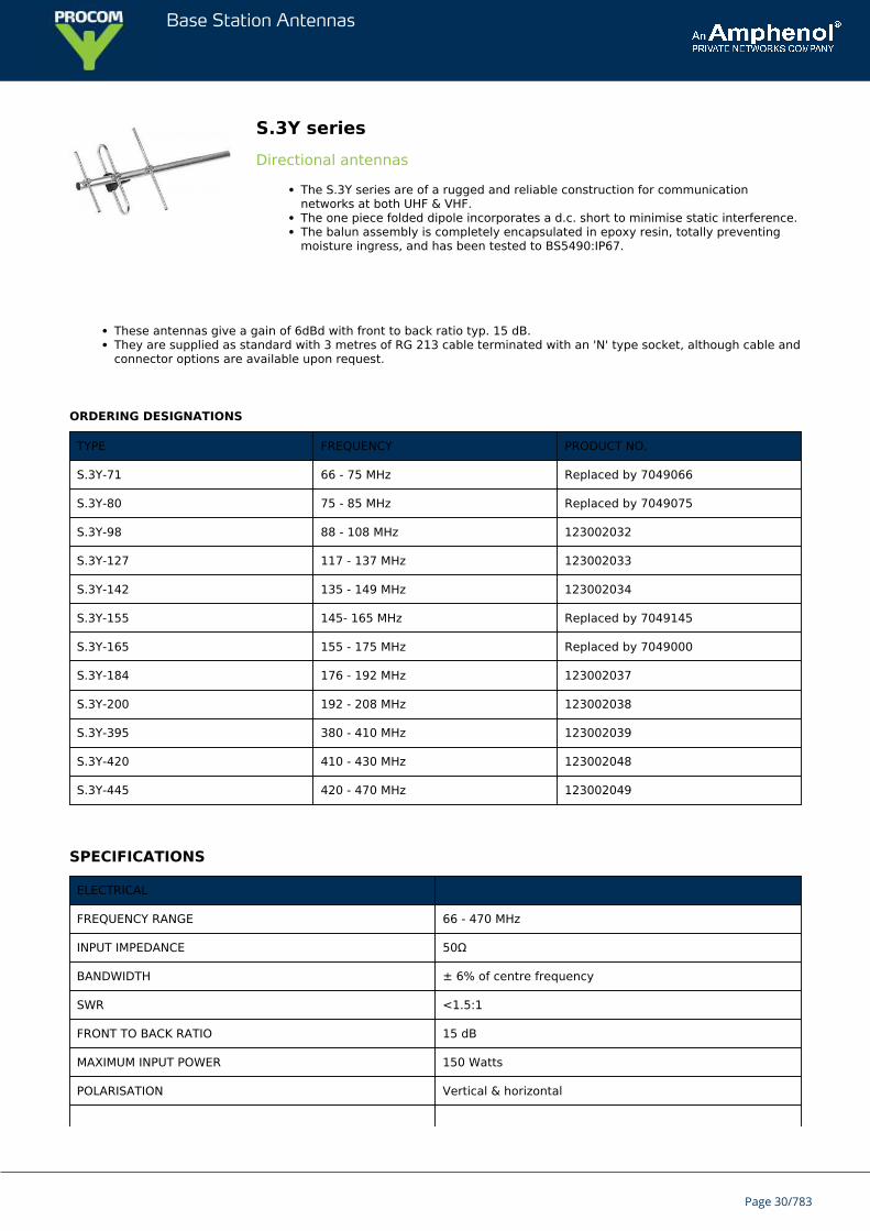
S.3Y seriesDirectional antennas
The S.3Y series are of a rugged and reliable construction for communicationnetworks at both UHF & VHF.The one piece folded dipole incorporates a d.c. short to minimise static interference.The balun assembly is completely encapsulated in epoxy resin, totally preventingmoisture ingress, and has been tested to BS5490:IP67.
These antennas give a gain of 6dBd with front to back ratio typ. 15 dB.They are supplied as standard with 3 metres of RG 213 cable terminated with an 'N' type socket, although cable andconnector options are available upon request.
ORDERING DESIGNATIONS
TYPE FREQUENCY PRODUCT NO.
S.3Y-71 66 - 75 MHz Replaced by 7049066
S.3Y-80 75 - 85 MHz Replaced by 7049075
S.3Y-98 88 - 108 MHz 123002032
S.3Y-127 117 - 137 MHz 123002033
S.3Y-142 135 - 149 MHz 123002034
S.3Y-155 145- 165 MHz Replaced by 7049145
S.3Y-165 155 - 175 MHz Replaced by 7049000
S.3Y-184 176 - 192 MHz 123002037
S.3Y-200 192 - 208 MHz 123002038
S.3Y-395 380 - 410 MHz 123002039
S.3Y-420 410 - 430 MHz 123002048
S.3Y-445 420 - 470 MHz 123002049
SPECIFICATIONS
ELECTRICAL
FREQUENCY RANGE 66 - 470 MHz
INPUT IMPEDANCE 50Ω
BANDWIDTH ± 6% of centre frequency
SWR <1.5:1
FRONT TO BACK RATIO 15 dB
MAXIMUM INPUT POWER 150 Watts
POLARISATION Vertical & horizontal
Page 30/783
Base Station Antennas
FORWARD GAIN 6 dBd
3 dB BEAMWIDTH E Plane 62ºH Plane 84º
MECHANICAL
STANDARD CONNECTION 3m (118.11 in.) Length of RG 213c/w 'N' type socket
ELEMENTS UHF UHF 12.7 mm dia. x 1.6 mm(0.50 in. dia x 0.06 in.)wall aluminium alloy grade 6063T6
ELEMENTS VHF VHF 19.0 mm dia. x 1.6 mm(0.75 in. dia x 0.06 in.)wall aluminium alloy grade 6063T6
SUPPORT BOOM 31.7 mm dia. x 2.6 mm(1.25 in. dia x 0.10 in.)wall aluminium alloy grade 6082T6
FASTENERS Stainless steel grade A2-70
SADDLE CLAMPS Diecast zinc alloy
INSULATOR Epoxy resin encapsulant
LIGHTNING PROTECTION Direct grounded
MOUNTING BRACKETS See mounting accessories (not supplied)
TYPICAL WEIGHT (UHF) UHF 1.5 kg (3.31 lb.)
TYPICAL WEIGHT (VHF) VHF 4.5 kg (9.92 lb.)
TYPICAL LENGTH (UHF) UHF 0.7 m (27.56 in.)
TYPICAL LENGTH (VHF) VHF 1.5 m (88.61 in.)
TYPICAL WIND LOADING@ 162 km/h (UHF)
UHF 52 N
TYPICAL WIND LOADING@ 162 km/h (VHF)
VHF 240 N
MOUNTING ACCESSORIES
Mounting accessories to be ordered separately.
TYPE DIMENSION PRODUCT NO.
1763-100 123001001
UA64-23 25 - 50 mm 123001006
UA64-23 25 - 76 mm 123001007
UA66-24 25 - 50 mm 123001017
UA66-24 25 - 76 mm 123001018
UA66-24 25 - 100 mm 123001019
UA66-24 25 - 115 mm 123001020
Page 31/783
Base Station Antennas
1763-100
Galvanised steel-cross-over clamp, fits 32 mm (1-1/4") diameter antenna booms to up to 50 mm (2") diameter poles, max.length 1500 mm.
UA64-23
Circular cast alloy clamp, gives a good two point fixing, supplied as standard with 4 x 50 mm stainless steel ‘U’ bolts andtwo half-moon cast spacers to fit antenna booms of 25 to 50 mm diameter. Will also accomodate 76 mm (3”) ‘U’ bolts to fitmasts of that diameter. (order UB06).
UA66-24
Rectangular cast alloy clamp, gives a good two point fixing, supplied as standard with 4 x 50 mm stainless steel ‘U’ boltsand two half-moon cast spacers to fit antenna booms of 25 to 50 mm diameter.
To fit 76 mm (3”) masts (order UB06 ‘U’ bolts).
To fit 100 mm (4”) masts (order UB07 ‘U’ bolts).
To fit 115 mm (4 1/2”) masts (order UB09 ‘U’ bolts).
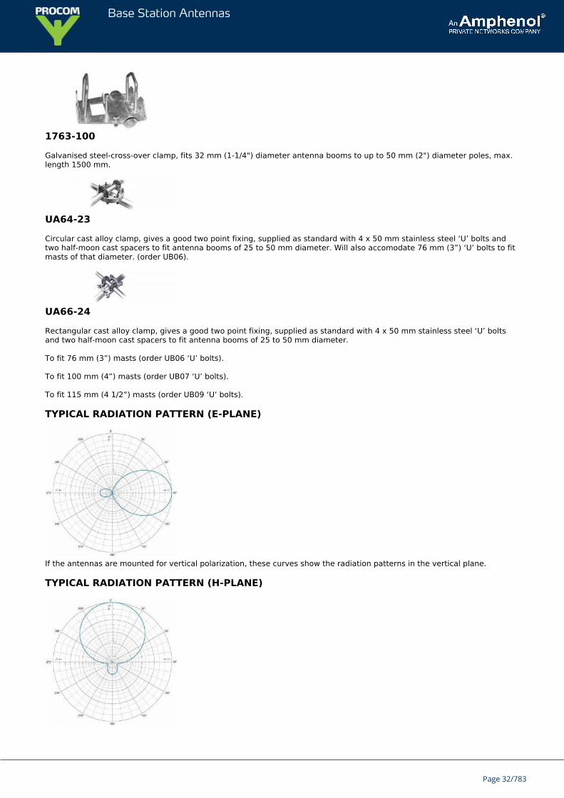
TYPICAL RADIATION PATTERN (E-PLANE)
If the antennas are mounted for vertical polarization, these curves show the radiation patterns in the vertical plane.
TYPICAL RADIATION PATTERN (H-PLANE)
Page 32/783

Base Station Antennas
If the antennas are mounted for vertical polarization, these curves show the radiation patterns in the horizontal plane(horizontal coverage).
Page 33/783
Base Station Antennas
YA 900Low-Cost Holiday and Weekend Cottage Directional Antenna for CellularNetworks in the 900 MHz Band
Low-cost and low-weight directional antenna.Ideal for use on caravans, mobile homes and at weekend cottages.Significant improvement of the quality of the mobile communitation in areas withunsatisfactory coverage (YA 900 to be directed towards the nearest base station).
DESCRIPTION
Approx. 10 dBd gain.For use with 900 MHz cellular networks (EGSM, NMT-900, ETACS).For mobile telephones being used in “semi-stationary” installations.“Built-in” mounting bracket.Supplied with fittings and bolts for mounting on 30 - 50 mm diameter mast tube.
ORDERING DESIGNATIONS
TYPE PRODUCT NO.
YA 900 130001255
SPECIFICATIONS
ELECTRICAL
MODEL YA 900
ANTENNA TYPE 7-element Yagi-antenna
FREQUENCY 870 – 960 MHz
IMPEDANCE Nom. 50 Ω
POLARIZATION Linear (vertical or horizontal dep. on orientation)
GAIN 12 dBi 10 dBd
FRONT-TO-BACK-RATIO ≥ 15 dB
HALF-POWER BEAMWIDTH Approx. 50° (H-plane)
BANDWIDTH 100 MHz
SWR ≤ 1.5
MAX. POWER 25 W
MECHANICAL
MATERIALS Antenna: Gold aludine, AluminiumFittings: Stainless steel
COLOUR Aludine “gold”
TOTAL LENGTH 710 mm
HEIGHT 170 mm
Page 34/783
Base Station Antennas
WEIGHT 315 g
CONNECTORS FME-connector (cable to be ordered separately)
MOUNTING On 30–50 mm dia. mast tube
HOW TO USE THE ANTENNA
With the YA 900 you will experience a significant improvement of the quality of your communication on the 900 MHzcellular networks (EGSM, NMT-900, ETACS ect.).
The antenna makes it possible to use your mobile telephone in areas with a poor coverage and where it is sometimes verydifficult to obtain and maintain a satisfactory connection.
The YA 900 is ideal for use on caravans, mobile homes, at weekend cottages and other places where the mobile telephoneis used in "semi-stationary" installations.
{start_next_col}
INSTALLATION STEPS
Mount the antenna on a 30 - 50 mm diameter mast tube using the accompanying fittings and bolts (see illustrationon the other page). The antenna is to be oriented as indicated on the connection box of the antenna.Connect the antenna to the mobile telephone using an FME-cable of appropriate length and an adapter forconnection of an exterior antenna to the handportable.Direct the antenna towards the nearest base station for the 900 MHz cellular network in question. The correctdirection may be determined using the field strength indicator on the mobile telephone:
Turn on the telephone and note the field strength level on the indicator.Rotate the antenna (in the horizontal plane) while observing the field strength indicator.Choose the direction in which the highest field strength level is observed and fasten the antenna.
{start_next_col}
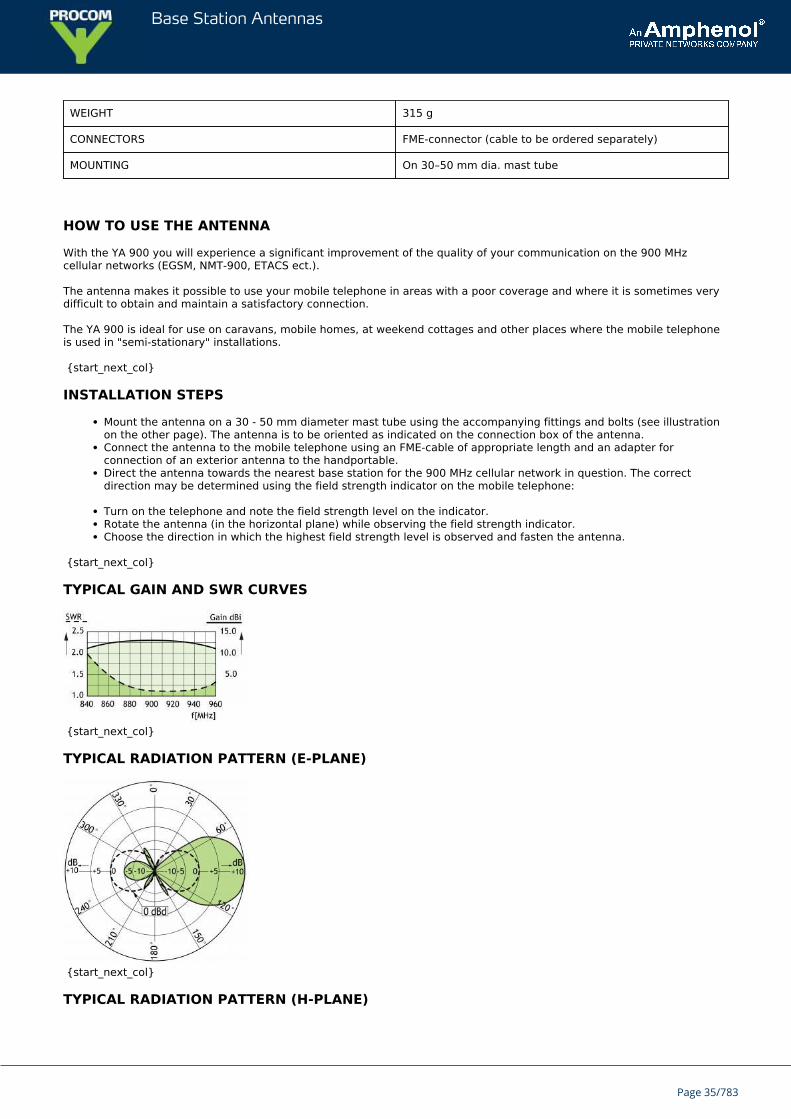
TYPICAL GAIN AND SWR CURVES
{start_next_col}
TYPICAL RADIATION PATTERN (E-PLANE)
{start_next_col}
TYPICAL RADIATION PATTERN (H-PLANE)
Page 35/783

Base Station Antennas
Page 36/783
Base Station Antennas
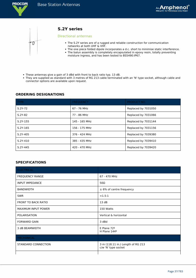
S.2Y seriesDirectional antennas
The S.2Y series are of a rugged and reliable construction for communicationnetworks at both UHF & VHF.The one piece folded dipole incorporates a d.c. short to minimise static interference.The balun assembly is completely encapsulated in epoxy resin, totally preventingmoisture ingress, and has been tested to BS5490:IP67.
These antennas give a gain of 3 dBd with front to back ratio typ. 13 dB.They are supplied as standard with 3 metres of RG 213 cable terminated with an 'N' type socket, although cable andconnector options are available upon request.
ORDERING DESIGNATIONS
TYPE FREQUENCY PRODUCT NO.
S.2Y-72 67 - 76 MHz Replaced by 7031050
S.2Y-82 77 - 86 MHz Replaced by 7031066
S.2Y-155 145 - 165 MHz Replaced by 7031144
S.2Y-165 156 - 175 MHz Replaced by 7031156
S.2Y-405 376 - 424 MHz Replaced by 7039380
S.2Y-410 385 - 435 MHz Replaced by 7039410
S.2Y-445 420 - 470 MHz Replaced by 7039420
SPECIFICATIONS
ELECTRICAL
FREQUENCY RANGE 67 - 470 MHz
INPUT IMPEDANCE 50Ω
BANDWIDTH ± 6% of centre frequency
SWR <1.5:1
FRONT TO BACK RATIO 13 dB
MAXIMUM INPUT POWER 150 Watts
POLARISATION Vertical & horizontal
FORWARD GAIN 3 dBd
3 dB BEAMWIDTH E Plane 72ºH Plane 144º
MECHANICAL
STANDARD CONNECTION 3 m (118.11 in.) Length of RG 213c/w 'N' type socket
Page 37/783

Base Station Antennas
ELEMENTS UHF UHF 12.7 mm dia. x 1.6 mm(0.50 in. dia x 0.06 in.)wall aluminium alloy grade 6063T6
ELEMENTS VHF VHF 19.0 mm dia. x 1.6 mm(0.75 in. dia x 0.06 in.)wall aluminium alloy grade 6063T6
SUPPORT BOOM 31.7 mm dia. x 2.6 mm(1.25 in. dia x 0.10 in.)wall aluminium alloy grade 6082T6
FASTENERS Stainless steel grade A2-70
SADDLE CLAMPS Diecast zinc alloy
INSULATOR Epoxy resin encapsulant
LIGHTNING PROTECTION Direct grounded
MOUNTING BRACKETS See mounting accessories (not supplied)
TYPICAL WEIGHT (UHF) UHF 1.3 kg (2.87 lb.)
YPICAL WEIGHT (VHF) VHF 3.5 kg (7.71 lb.)
TYPICAL LENGTH (UHF) UHF 0.6 m (23.62 in.)
TYPICAL LENGTH (VHF) VHF 1.5 m (59.06 in.)
TYPICAL WIND LOADING@ 162 km/h (UHF)
UHF 50 N
TYPICAL WIND LOADING@ 162 km/h (VHF)
VHF 180 N
MOUNTING ACCESSORIES
Mounting accessories to be ordered separately.
TYPE DIMENSION PRODUCT NO.
1763-100 123001001
UA64-23 25 - 50 mm 123001006
UA64-23 25 - 76 mm 123001007
UA66-24 25 - 50 mm 123001017
UA66-24 25 - 76 mm 123001018
UA66-24 25 - 100 mm 123001019
UA66-24 25 - 115 mm 123001020
1763-100
Galvanised steel-cross-over clamp, fits 32 mm (1-1/4") diameter antenna booms to up to 50 mm (2") diameter poles, max.length 1500 mm.
Page 38/783
Base Station Antennas
UA64-23
Circular cast alloy clamp, gives a good two point fixing, supplied as standard with 4 x 50 mm stainless steel ‘U’ bolts andtwo half-moon cast spacers to fit antenna booms of 25 to 50 mm diameter. Will also accomodate 76 mm (3”) ‘U’ bolts to fitmasts of that diameter. (order UB06).
UA66-24
Rectangular cast alloy clamp, gives a good two point fixing, supplied as standard with 4 x 50 mm stainless steel ‘U’ boltsand two half-moon cast spacers to fit antenna booms of 25 to 50 mm diameter.
To fit 76 mm (3”) masts (order UB06 ‘U’ bolts).
To fit 100 mm (4”) masts (order UB07 ‘U’ bolts).
To fit 115 mm (4 1/2”) masts (order UB09 ‘U’ bolts).
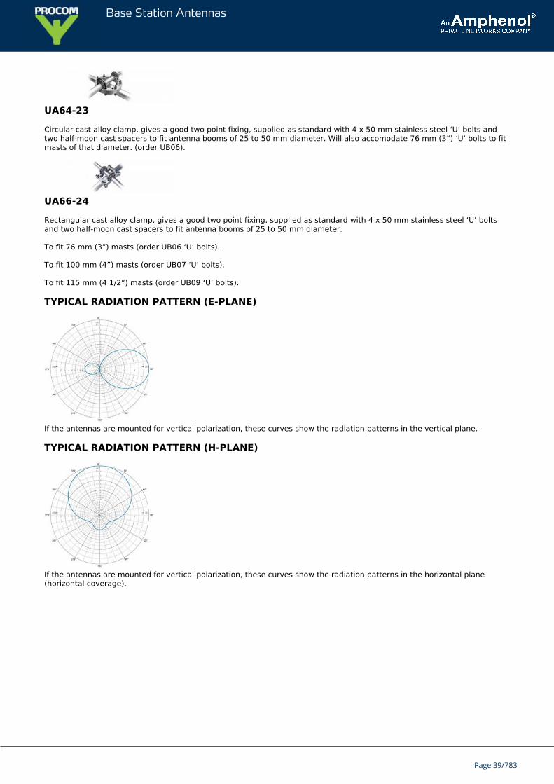
TYPICAL RADIATION PATTERN (E-PLANE)
If the antennas are mounted for vertical polarization, these curves show the radiation patterns in the vertical plane.
TYPICAL RADIATION PATTERN (H-PLANE)
If the antennas are mounted for vertical polarization, these curves show the radiation patterns in the horizontal plane(horizontal coverage).
Page 39/783
Base Station Antennas
YA 2100Low-Cost 10 dB Directional Antenna for Networks in the 2100 MHz Band
Low-cost and low-weight directional antenna.
Approx. 10 dBi gain.
DESCRIPTION
“Built-in” mounting bracket.
Supplied with fittings and bolts for mounting on 30 - 50 mm diameter mast tube.
ORDERING DESIGNATIONS
TYPE PRODUCT NO.
YA 2100 130001553
SPECIFICATIONS
ELECTRICAL
MODEL YA 2100
ANTENNA TYPE 9-element Yagi-antenna
FREQUENCY 1900 – 2200 MHz
IMPEDANCE Nom. 50 Ω
POLARIZATION Linear(vertical or horizontal dep. on orientation)
GAIN 10 dBi 8 dBd
FRONT-TO-BACK-RATIO ≥ 15 dB
HALF-POWER BEAMWIDTH Approx. 35° (E-plane)Approx. 45° (H-plane)
BANDWIDTH 300 MHz
SWR ≤ 1.8 @ 1.9 - 2.2 GHz
MAX. POWER 25 W
MECHANICAL
MATERIALS Antenna: Gold aludine, AluminiumFittings: Stainless steel
COLOUR Aludine “gold”
TOTAL LENGTH 570 mm
MAX. ELEMENT HEIGHT 100 mm
WEIGHT 300 g (incl. bolts)
Page 40/783
Base Station Antennas
CONNECTORS FME-connector(cable to be ordered separately)
MOUNTING On 30 – 50 mm dia. mast tube
INSTALLATION STEPS
Mount the antenna on a 30-50 mm diameter mast tube using the accompanying fittings and bolts (see illustrationoverleaf). The antenna is to be oriented as indicated on the connection box of the antenna.Direct the antenna towards the nearest base station for the 2100 MHz network in question. The correct directionmay be determined using the field strength indicator telephone.
Mount the antenna on your mast.Rotate the antenna (in the horizontal plane) while observing the field strength indicator.Choose the direction in which the highest field strength level is observed and fasten the antenna.
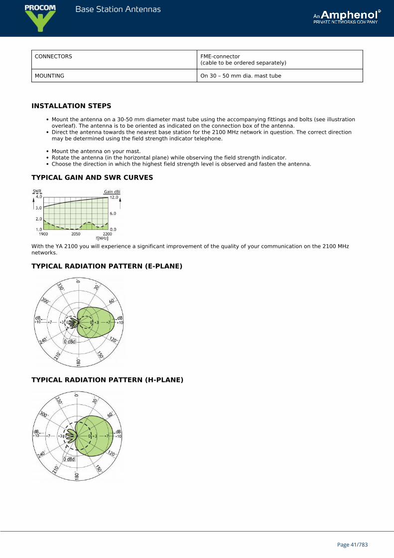
TYPICAL GAIN AND SWR CURVES
With the YA 2100 you will experience a significant improvement of the quality of your communication on the 2100 MHznetworks.
TYPICAL RADIATION PATTERN (E-PLANE)
TYPICAL RADIATION PATTERN (H-PLANE)
Page 41/783
Base Station Antennas
S.1H seriesHeavy duty centre-fed folded dipole antenna.
The S.1H series are designed for use in extreme environments, or for multi channelapplications.The one piece folded dipole assembly incorporates a d.c. short and is completelyencapsulated in epoxy resin, totally preventing moisture ingress.A sleeve is welded to the dipole to increase strength, and improve VSWR.
These antennas can be arranged in a variety of arrays to produce a wide range of radiation patterns.They are supplied as standard with 3 m of RG 213 cable terminated with an 'N' type socket.
ORDERING DESIGNATIONS
TYPE FREQUENCY PRODUCT NO.
S.1H-78 66 - 88 MHz 123003020
S.1H-98 88 - 108 MHz 123003021
S.1H-127 117 - 137 MHz 123003022
S.1H-165 155 - 175 MHz 123003023
SPECIFICATIONS
ELECTRICAL
FREQUENCY RANGE 66 - 175 MHz
INPUT IMPEDANCE 50Ω
BANDWIDTH ± 10% of centre frequency
SWR <1.5:1
FRONT TO BACK RATIO 4 dB
MAXIMUM INPUT POWER 500 Watts
POLARISATION Vertical
FORWARD GAIN 2 dBd
3 dB BEAMWIDTH E Plane 85ºH Plane 200º(Gain & RPE assmes mount on conductive pole)
MECHANICAL
STANDARD CONNECTION 3 m (118.11 in.) Length of RG 213c/w 'N' type socket
ELEMENTS 19.0 mm dia. x 1.6 mm(0.75 in. dia x 0.06 in.)wall aluminium alloy grade 6063T6
Page 42/783
Base Station Antennas
DIPOLE SLEEVE (WELDED) 31.7 mm dia. x 2.6 mm(1.25 in. dia x 0.10 in.)wall aluminium alloy grade 6063T6
SUPPORT BOOM 48.4 mm dia. x 4.5 mm(1.91 in. dia x 0.18 in.)wall aluminium alloy grade 6082T6
FASTENERS Stainless steel grade A2-70
SADDLE CLAMPS Machined aluminium alloy
INSULATOR Epoxy resin encapsulant
LIGHTNING PROTECTION Direct grounded
MOUNTING BRACKETS See mounting accessories (not supplied)
TYPICAL WEIGHT 5.3 kg (11.68 lb.)
TYPICAL LENGTH 1.5 m (59.06 in.)
TYPICAL WIND LOADING@ 162 km/h
202 N
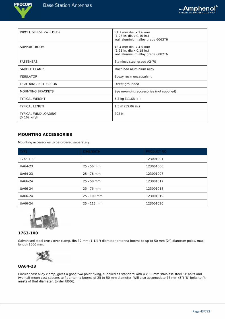
MOUNTING ACCESSORIES
Mounting accessories to be ordered separately.
TYPE DIMENSION PRODUCT NO.
1763-100 123001001
UA64-23 25 - 50 mm 123001006
UA64-23 25 - 76 mm 123001007
UA66-24 25 - 50 mm 123001017
UA66-24 25 - 76 mm 123001018
UA66-24 25 - 100 mm 123001019
UA66-24 25 - 115 mm 123001020
1763-100
Galvanised steel-cross-over clamp, fits 32 mm (1-1/4") diameter antenna booms to up to 50 mm (2") diameter poles, max.length 1500 mm.
UA64-23
Circular cast alloy clamp, gives a good two point fixing, supplied as standard with 4 x 50 mm stainless steel ‘U’ bolts andtwo half-moon cast spacers to fit antenna booms of 25 to 50 mm diameter. Will also accomodate 76 mm (3”) ‘U’ bolts to fitmasts of that diameter. (order UB06).
Page 43/783
Base Station Antennas
UA66-24
Rectangular cast alloy clamp, gives a good two point fixing, supplied as standard with 4 x 50 mm stainless steel ‘U’ boltsand two half-moon cast spacers to fit antenna booms of 25 to 50 mm diameter.
To fit 76 mm (3”) masts (order UB06 ‘U’ bolts).
To fit 100 mm (4”) masts (order UB07 ‘U’ bolts).
To fit 115 mm (4 1/2”) masts (order UB09 ‘U’ bolts).
TYPICAL RADIATION PATTERN (E-PLANE)
TYPICAL RADIATION PATTERN (H-PLANE)
Page 44/783
Base Station Antennas
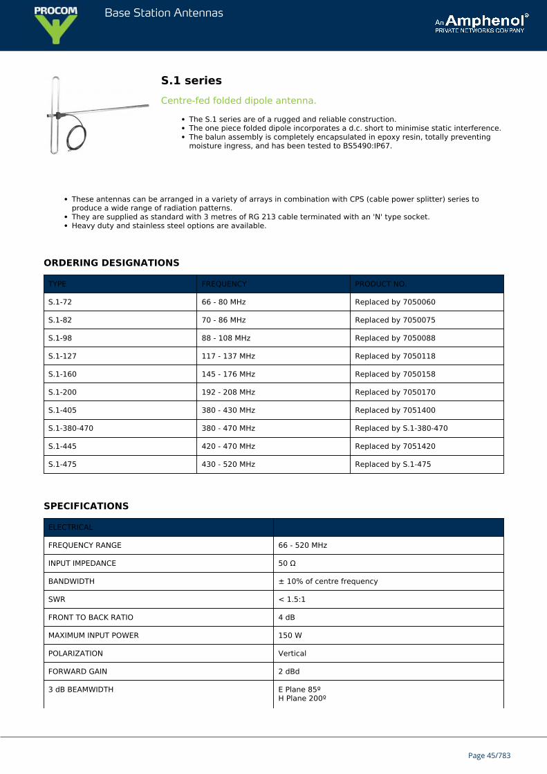
S.1 seriesCentre-fed folded dipole antenna.
The S.1 series are of a rugged and reliable construction.The one piece folded dipole incorporates a d.c. short to minimise static interference.The balun assembly is completely encapsulated in epoxy resin, totally preventingmoisture ingress, and has been tested to BS5490:IP67.
These antennas can be arranged in a variety of arrays in combination with CPS (cable power splitter) series toproduce a wide range of radiation patterns.They are supplied as standard with 3 metres of RG 213 cable terminated with an 'N' type socket.Heavy duty and stainless steel options are available.
ORDERING DESIGNATIONS
TYPE FREQUENCY PRODUCT NO.
S.1-72 66 - 80 MHz Replaced by 7050060
S.1-82 70 - 86 MHz Replaced by 7050075
S.1-98 88 - 108 MHz Replaced by 7050088
S.1-127 117 - 137 MHz Replaced by 7050118
S.1-160 145 - 176 MHz Replaced by 7050158
S.1-200 192 - 208 MHz Replaced by 7050170
S.1-405 380 - 430 MHz Replaced by 7051400
S.1-380-470 380 - 470 MHz Replaced by S.1-380-470
S.1-445 420 - 470 MHz Replaced by 7051420
S.1-475 430 - 520 MHz Replaced by S.1-475
SPECIFICATIONS
ELECTRICAL
FREQUENCY RANGE 66 - 520 MHz
INPUT IMPEDANCE 50 Ω
BANDWIDTH ± 10% of centre frequency
SWR < 1.5:1
FRONT TO BACK RATIO 4 dB
MAXIMUM INPUT POWER 150 W
POLARIZATION Vertical
FORWARD GAIN 2 dBd
3 dB BEAMWIDTH E Plane 85ºH Plane 200º
Page 45/783
Base Station Antennas
(Gain & RPE assmes mount on conductive pole)
MECHANICAL
STANDARD CONNECTION 3 m (118.11 in.) Length of RG 213c/w 'N' type socket
ELEMENTS (UHF)(> 138 MHz)
UHF 12.7 mm dia. x 1.6 mm(0.50 in. dia x 0.06 in.)wall aluminium alloy grade 6063T6
ELEMENTS (VHF)(< 138 MHz)
VHF 19.0 mm dia. x 1.6 mm(0.75 in. dia x 0.06 in.)wall aluminium alloy grade 6063T6
SUPPORT BOOM 31.7 mm dia. x 2.6 mm(1.25 in. dia x 0.10 in.)wall aluminium alloy grade 6082T6
FASTENERS Stainless steel grade A2-70
SADDLE CLAMPS Diecast zinc alloy
INSULATOR Epoxy resin encapsulant
LIGHTNING PROTECTION Direct grounded
MOUNTING BRACKETS See mounting accessories (not supplied)
TYPICAL WEIGHT (UHF) UHF 1.9 kg (4.19 lb.)
TYPICAL WEIGHT (VHF) VHF 2.8 kg (6.17 lb.)
TYPICAL LENGTH (UHF) UHF 1 m (39.37 in.)
TYPICAL LENGTH (VHF) VHF 1.33 m ( 52.36 in.)
TYPICAL WIND LOADING@ 162 km/h (UHF)
UHF 54 N
TYPICAL WIND LOADING@ 162 km/h (VHF)
VHF 148 N
MOUNTING ACCESSORIES
Mounting accessories to be ordered separately.
TYPE DIMENSION PRODUCT NO.
1763-100 123001001
UA64-23 25 - 50 mm 123001006
UA64-23 25 - 76 mm 123001007
UA66-24 25 - 50 mm 123001017
UA66-24 25 - 76 mm 123001018
UA66-24 25 - 100 mm 123001019
UA66-24 25 - 115 mm 123001020
Page 46/783
Base Station Antennas
1763-100
Galvanised steel-cross-over clamp, fits 32 mm (1-1/4") diameter antenna booms to up to 50 mm (2") diameter poles, max.length 1500 mm.
UA64-23
Circular cast alloy clamp, gives a good two point fixing, supplied as standard with 4 x 50 mm stainless steel ‘U’ bolts andtwo half-moon cast spacers to fit antenna booms of 25 to 50 mm diameter. Will also accomodate 76 mm (3”) ‘U’ bolts to fitmasts of that diameter. (order UB06).
UA66-24
Rectangular cast alloy clamp, gives a good two point fixing, supplied as standard with 4 x 50 mm stainless steel ‘U’ boltsand two half-moon cast spacers to fit antenna booms of 25 to 50 mm diameter.
To fit 76 mm (3”) masts (order UB06 ‘U’ bolts).
To fit 100 mm (4”) masts (order UB07 ‘U’ bolts).
To fit 115 mm (4 1/2”) masts (order UB09 ‘U’ bolts).
TYPICAL RADIATION PATTERN (E-PLANE)
TYPICAL RADIATION PATTERN (H-PLANE)
Page 47/783
Base Station Antennas
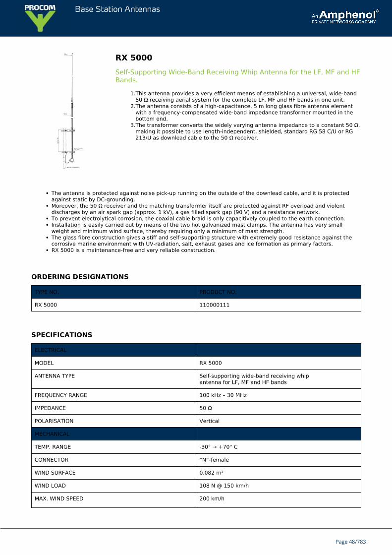
RX 5000Self-Supporting Wide-Band Receiving Whip Antenna for the LF, MF and HFBands.
1.This antenna provides a very efficient means of establishing a universal, wide-band50 Ω receiving aerial system for the complete LF, MF and HF bands in one unit.
2.The antenna consists of a high-capacitance, 5 m long glass fibre antenna elementwith a frequency-compensated wide-band impedance transformer mounted in thebottom end.
3.The transformer converts the widely varying antenna impedance to a constant 50 Ω,making it possible to use length-independent, shielded, standard RG 58 C/U or RG213/U as downlead cable to the 50 Ω receiver.
The antenna is protected against noise pick-up running on the outside of the downlead cable, and it is protectedagainst static by DC-grounding.Moreover, the 50 Ω receiver and the matching transformer itself are protected against RF overload and violentdischarges by an air spark gap (approx. 1 kV), a gas filled spark gap (90 V) and a resistance network.To prevent electrolytical corrosion, the coaxial cable braid is only capacitively coupled to the earth connection.Installation is easily carried out by means of the two hot galvanized mast clamps. The antenna has very smallweight and minimum wind surface, thereby requiring only a minimum of mast strength.The glass fibre construction gives a stiff and self-supporting structure with extremely good resistance against thecorrosive marine environment with UV-radiation, salt, exhaust gases and ice formation as primary factors.RX 5000 is a maintenance-free and very reliable construction.
ORDERING DESIGNATIONS
TYPE NO. PRODUCT NO.
RX 5000 110000111
SPECIFICATIONS
ELECTRICAL
MODEL RX 5000
ANTENNA TYPE Self-supporting wide-band receiving whipantenna for LF, MF and HF bands
FREQUENCY RANGE 100 kHz – 30 MHz
IMPEDANCE 50 Ω
POLARISATION Vertical
MECHANICAL
TEMP. RANGE -30° → +70° C
CONNECTOR “N”-female
WIND SURFACE 0.082 m²
WIND LOAD 108 N @ 150 km/h
MAX. WIND SPEED 200 km/h
Page 48/783
Base Station Antennas
COLOUR Marine white
MATERIALS Shroud : Glass fibre, stainless steel and chromed brassHousing: Polycarbonate
TOTAL HEIGHT Approx. 5.17 m (incl. box)
DIA. IN TOP END 5 mm
DIA. IN BOTTOM END 20 mm
WEIGHT Approx. 2.9 kg (clamps inclusive)
MOUNTING With side-mounting clamps on35 – 65 mm dia. mast tube
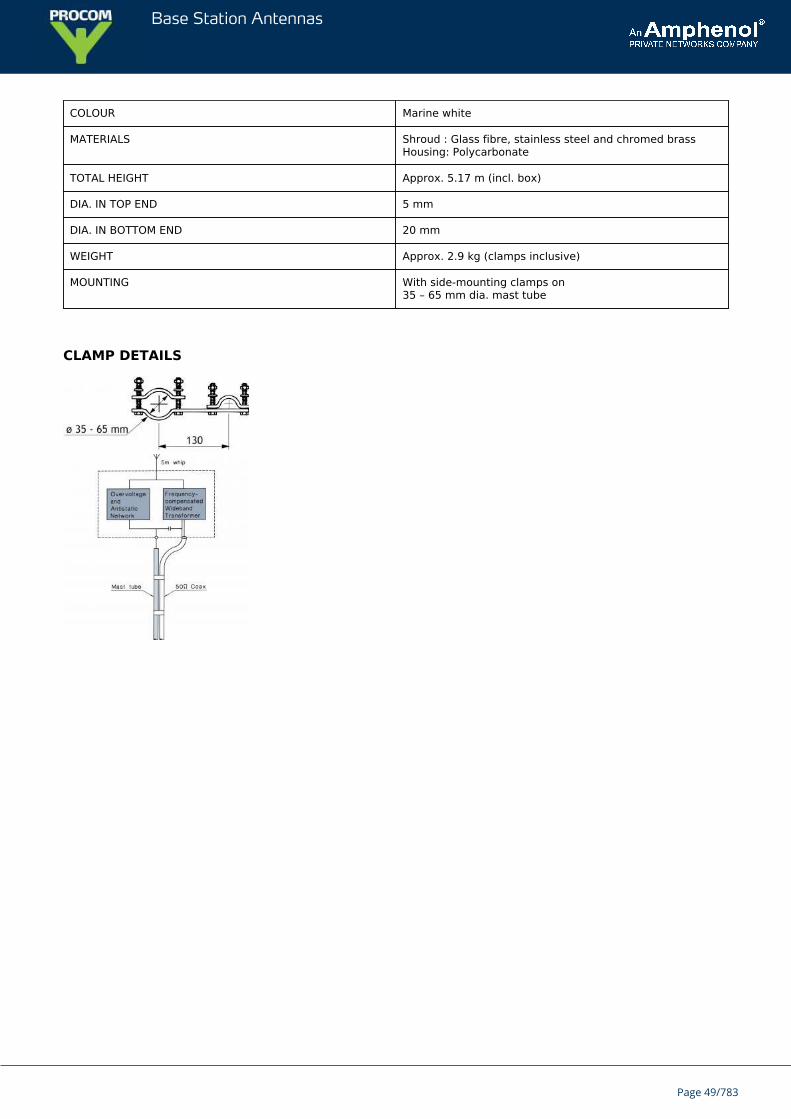
CLAMP DETAILS
Page 49/783
Base Station Antennas
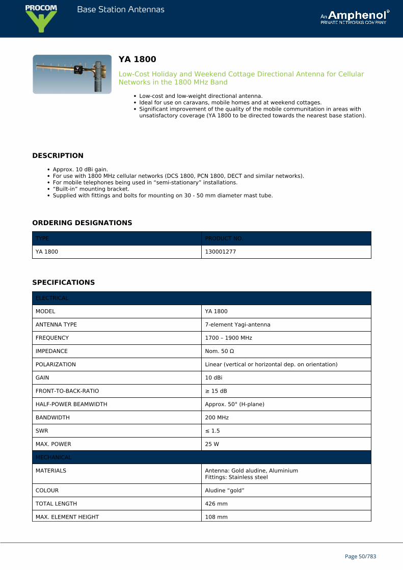
YA 1800Low-Cost Holiday and Weekend Cottage Directional Antenna for CellularNetworks in the 1800 MHz Band
Low-cost and low-weight directional antenna.Ideal for use on caravans, mobile homes and at weekend cottages.Significant improvement of the quality of the mobile communitation in areas withunsatisfactory coverage (YA 1800 to be directed towards the nearest base station).
DESCRIPTION
Approx. 10 dBi gain.For use with 1800 MHz cellular networks (DCS 1800, PCN 1800, DECT and similar networks).For mobile telephones being used in “semi-stationary” installations.“Built-in” mounting bracket.Supplied with fittings and bolts for mounting on 30 - 50 mm diameter mast tube.
ORDERING DESIGNATIONS
TYPE PRODUCT NO.
YA 1800 130001277
SPECIFICATIONS
ELECTRICAL
MODEL YA 1800
ANTENNA TYPE 7-element Yagi-antenna
FREQUENCY 1700 – 1900 MHz
IMPEDANCE Nom. 50 Ω
POLARIZATION Linear (vertical or horizontal dep. on orientation)
GAIN 10 dBi
FRONT-TO-BACK-RATIO ≥ 15 dB
HALF-POWER BEAMWIDTH Approx. 50° (H-plane)
BANDWIDTH 200 MHz
SWR ≤ 1.5
MAX. POWER 25 W
MECHANICAL
MATERIALS Antenna: Gold aludine, AluminiumFittings: Stainless steel
COLOUR Aludine “gold”
TOTAL LENGTH 426 mm
MAX. ELEMENT HEIGHT 108 mm
Page 50/783
Base Station Antennas
WEIGHT 250 g (incl. bolts)
CONNECTORS FME-connector(cable to be ordered separately)
MOUNTING On 30–50 mm dia. mast tube
HOW TO USE THE ANTENNA
With the YA 1800 you will experience a significant improvement of the quality of your communication on the 1800 MHzcellular networks (DCS 1800, PCN 1800, DECT and similar networks).
The antenna makes it possible to use your mobile telephone in areas with a poor coverage and where it is sometimes verydifficult to obtain and maintain a satisfactory connection.
The YA 1800 is ideal for use on caravans, mobile homes, at weekend cottages and other places where the mobile telephoneis used in “semi-stationary” installations.
INSTALLATION STEPS
Mount the antenna on a 30-50 mm diameter mast tube using the accompanying fittings and bolts (see illustrationon the other page). The antenna is to be oriented as indicated on the connection box of the antenna.Connect the antenna to the mobile telephone using an FME-cable of appropriate length and an adapter forconnection of an exterior antenna to the handportable.Direct the antenna towards the nearest base station for the 1800 MHz cellular network in question. The correctdirection may be determined using the field strength indicator on the mobile telephone:
Turn on the telephone and note the field strength level on the indicator.Rotate the antenna (in the horizontal plane) while observing the field strength indicator.Choose the direction in which the highest field strength level isobserved and fasten the antenna.
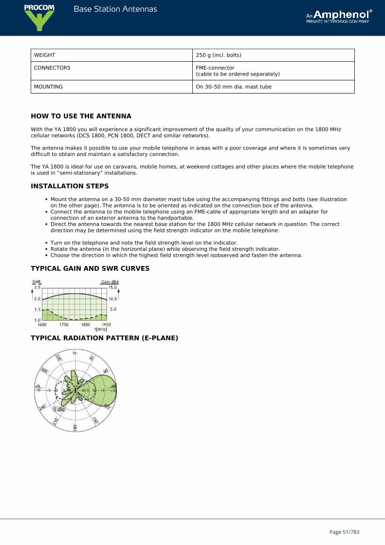
TYPICAL GAIN AND SWR CURVES
TYPICAL RADIATION PATTERN (E-PLANE)
Page 51/783
Base Station Antennas
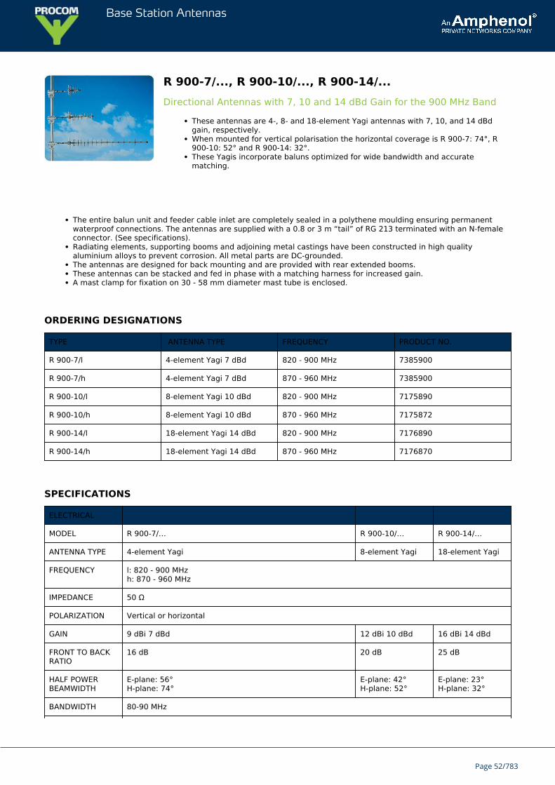
R 900-7/..., R 900-10/..., R 900-14/...Directional Antennas with 7, 10 and 14 dBd Gain for the 900 MHz Band
These antennas are 4-, 8- and 18-element Yagi antennas with 7, 10, and 14 dBdgain, respectively.When mounted for vertical polarisation the horizontal coverage is R 900-7: 74°, R900-10: 52° and R 900-14: 32°.These Yagis incorporate baluns optimized for wide bandwidth and accuratematching.
The entire balun unit and feeder cable inlet are completely sealed in a polythene moulding ensuring permanentwaterproof connections. The antennas are supplied with a 0.8 or 3 m “tail” of RG 213 terminated with an N-femaleconnector. (See specifications).Radiating elements, supporting booms and adjoining metal castings have been constructed in high qualityaluminium alloys to prevent corrosion. All metal parts are DC-grounded.The antennas are designed for back mounting and are provided with rear extended booms.These antennas can be stacked and fed in phase with a matching harness for increased gain.A mast clamp for fixation on 30 - 58 mm diameter mast tube is enclosed.
ORDERING DESIGNATIONS
TYPE ANTENNA TYPE FREQUENCY PRODUCT NO.
R 900-7/l 4-element Yagi 7 dBd 820 - 900 MHz 7385900
R 900-7/h 4-element Yagi 7 dBd 870 - 960 MHz 7385900
R 900-10/l 8-element Yagi 10 dBd 820 - 900 MHz 7175890
R 900-10/h 8-element Yagi 10 dBd 870 - 960 MHz 7175872
R 900-14/l 18-element Yagi 14 dBd 820 - 900 MHz 7176890
R 900-14/h 18-element Yagi 14 dBd 870 - 960 MHz 7176870
SPECIFICATIONS
ELECTRICAL
MODEL R 900-7/… R 900-10/… R 900-14/…
ANTENNA TYPE 4-element Yagi 8-element Yagi 18-element Yagi
FREQUENCY l: 820 - 900 MHzh: 870 - 960 MHz
IMPEDANCE 50 Ω
POLARIZATION Vertical or horizontal
GAIN 9 dBi 7 dBd 12 dBi 10 dBd 16 dBi 14 dBd
FRONT TO BACKRATIO
16 dB 20 dB 25 dB
HALF POWERBEAMWIDTH
E-plane: 56°H-plane: 74°
E-plane: 42°H-plane: 52°
E-plane: 23°H-plane: 32°
BANDWIDTH 80-90 MHz
Page 52/783
Base Station Antennas
SWR ≤ 1.5
MAX. POWER 150 W
ANTISTATICPROTECTION
All metal parts DC-grounded(Connector shows a DC-short)
MECHANICAL
TEMP. RANGE -25°C → +60°C
CONNECTION 0.8 m tail ofRG 213 terminatedwith type“N” female connector
0.8 m tail ofRG 213terminatedwith type“N” femaleconnector
3 m tail ofRG 213terminatedwith type“N” femaleconnector
WIND SURFACE 0.034 m² 0.047 m² 0.091 m²
WIND LOAD 43 N @160 km/h
59 N @160 km/h
119 N @160 km/h
COLOUR “Aluminium”
MATERIALS Elements/Boom/Saddle clamps: Aluminium alloys.Fittings: Stainless steel.Bracket: Hot-dipped galvanized steel
BOOM LENGTH Approx. 0.69 m Approx. 0.97 m Approx. 2.04 m
BOOM DIA. 25.4 mm
MAX. ELEMENTLENGTH
0.21 m
DIA. OFELEMENTS
9.5 mm
WEIGHT Approx. 2.1 kg Approx. 2.8 kg Approx. 4.2 kg
MOUNTING Supplied with mast bracket suiting 30-58 mm dia. mast tube
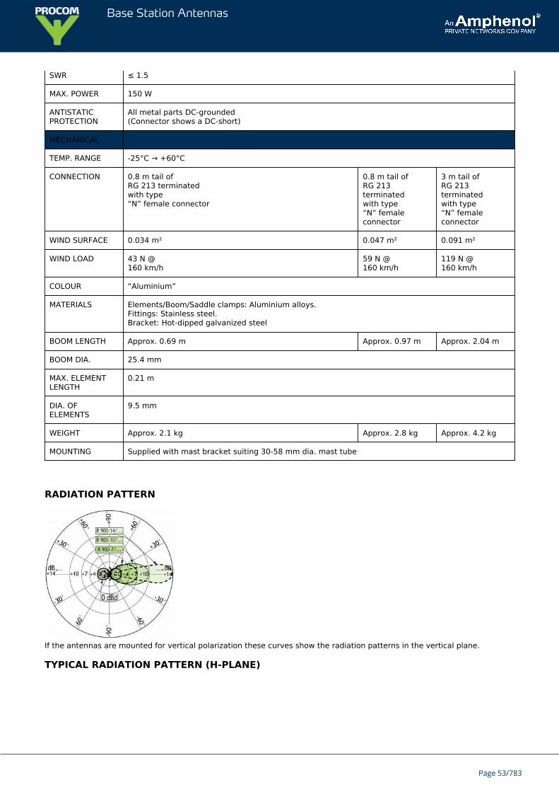
RADIATION PATTERN
If the antennas are mounted for vertical polarization these curves show the radiation patterns in the vertical plane.
TYPICAL RADIATION PATTERN (H-PLANE)
Page 53/783
Base Station Antennas
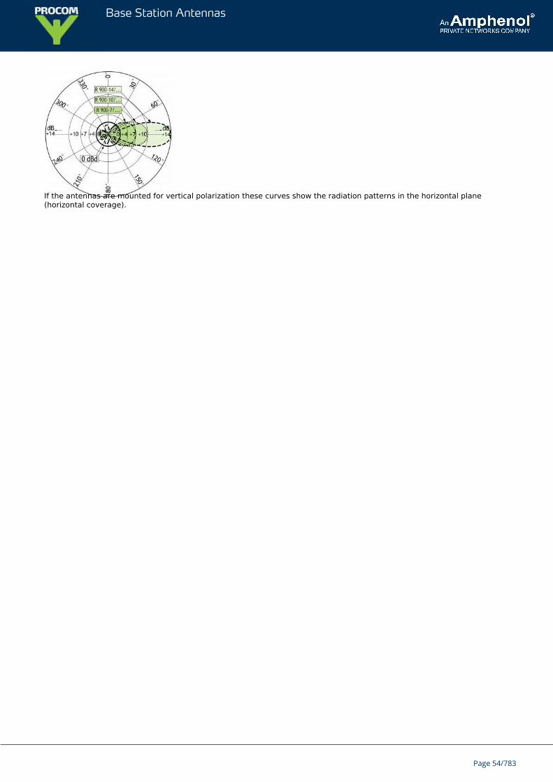
If the antennas are mounted for vertical polarization these curves show the radiation patterns in the horizontal plane(horizontal coverage).
Page 54/783
Base Station Antennas
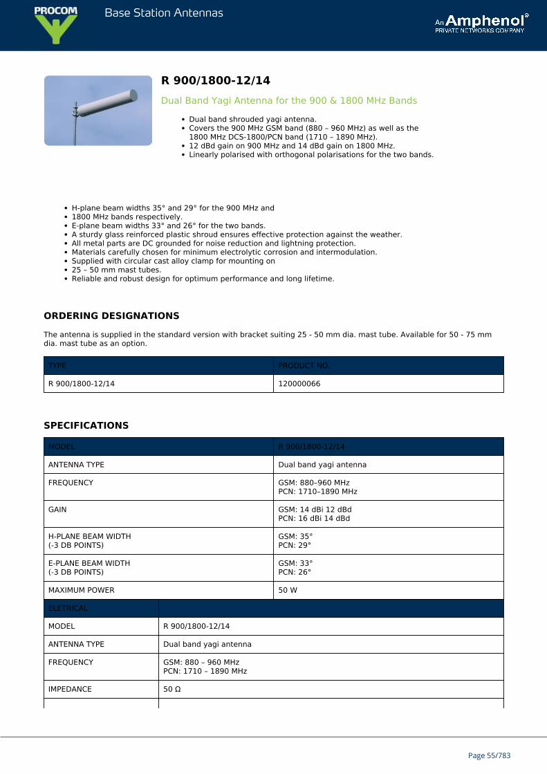
R 900/1800-12/14Dual Band Yagi Antenna for the 900 & 1800 MHz Bands
Dual band shrouded yagi antenna.Covers the 900 MHz GSM band (880 – 960 MHz) as well as the1800 MHz DCS-1800/PCN band (1710 – 1890 MHz).12 dBd gain on 900 MHz and 14 dBd gain on 1800 MHz.Linearly polarised with orthogonal polarisations for the two bands.
H-plane beam widths 35° and 29° for the 900 MHz and1800 MHz bands respectively.E-plane beam widths 33° and 26° for the two bands.A sturdy glass reinforced plastic shroud ensures effective protection against the weather.All metal parts are DC grounded for noise reduction and lightning protection.Materials carefully chosen for minimum electrolytic corrosion and intermodulation.Supplied with circular cast alloy clamp for mounting on25 – 50 mm mast tubes.Reliable and robust design for optimum performance and long lifetime.
ORDERING DESIGNATIONS
The antenna is supplied in the standard version with bracket suiting 25 - 50 mm dia. mast tube. Available for 50 - 75 mmdia. mast tube as an option.
TYPE PRODUCT NO.
R 900/1800-12/14 120000066
SPECIFICATIONS
MODEL R 900/1800-12/14
ANTENNA TYPE Dual band yagi antenna
FREQUENCY GSM: 880–960 MHzPCN: 1710–1890 MHz
GAIN GSM: 14 dBi 12 dBdPCN: 16 dBi 14 dBd
H-PLANE BEAM WIDTH(-3 DB POINTS)
GSM: 35°PCN: 29°
E-PLANE BEAM WIDTH(-3 DB POINTS)
GSM: 33°PCN: 26°
MAXIMUM POWER 50 W
ELETRICAL
MODEL R 900/1800-12/14
ANTENNA TYPE Dual band yagi antenna
FREQUENCY GSM: 880 – 960 MHzPCN: 1710 – 1890 MHz
IMPEDANCE 50 Ω
Page 55/783
Base Station Antennas
POLARIZATION Two linear orthogonal
GAIN GSM: 14 dBi 12 dBdPCN: 16 dBi 14 dBd
H-PLANE BEAM WIDTH(-3 DB POINTS)
GSM: 35°PCN: 29°
E-PLANE BEAM WIDTH(-3 DB POINTS)
GSM: 33°PCN: 26°
FRONT TO BACK RATIO 20 dB
BANDWIDTH GSM : 80 MHzPCN : 180 MHz
SWR ≤ 1.5 (typ. ≤ 1.3)
MAX. POWER 50 W
ANTISTATICPROTECTION
All metal parts DC-grounded
MECHANICAL
TEMP. RANGE -25°C → +60°C
CONNECTOR “N” type female
WIND LOAD 244 N @ 160 km/h
COLOUR Grey
SHROUD 183 mm dia. glass fiber tube
DIMENSIONS Length 1300 mm, diameter 183 mm
WEIGHT 5 kg
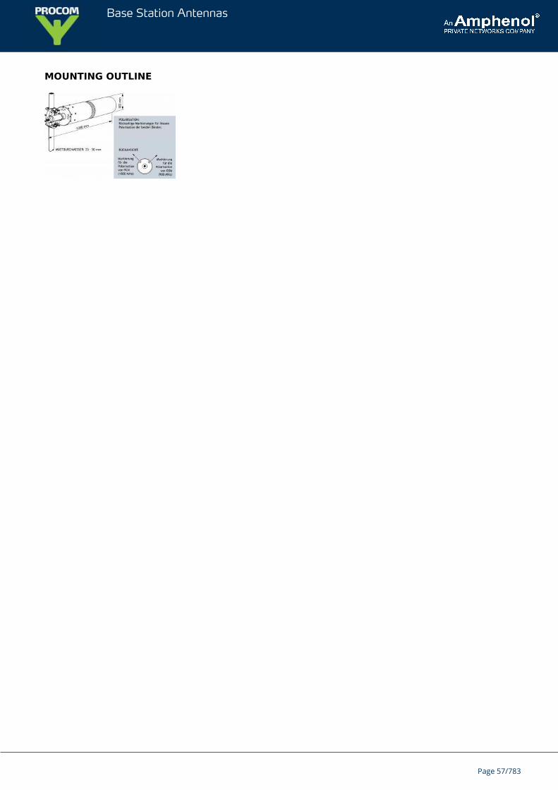
MOUNTING Supplied with circular cast alloy clamp for mounting on25 – 50 mm dia. mast tubes
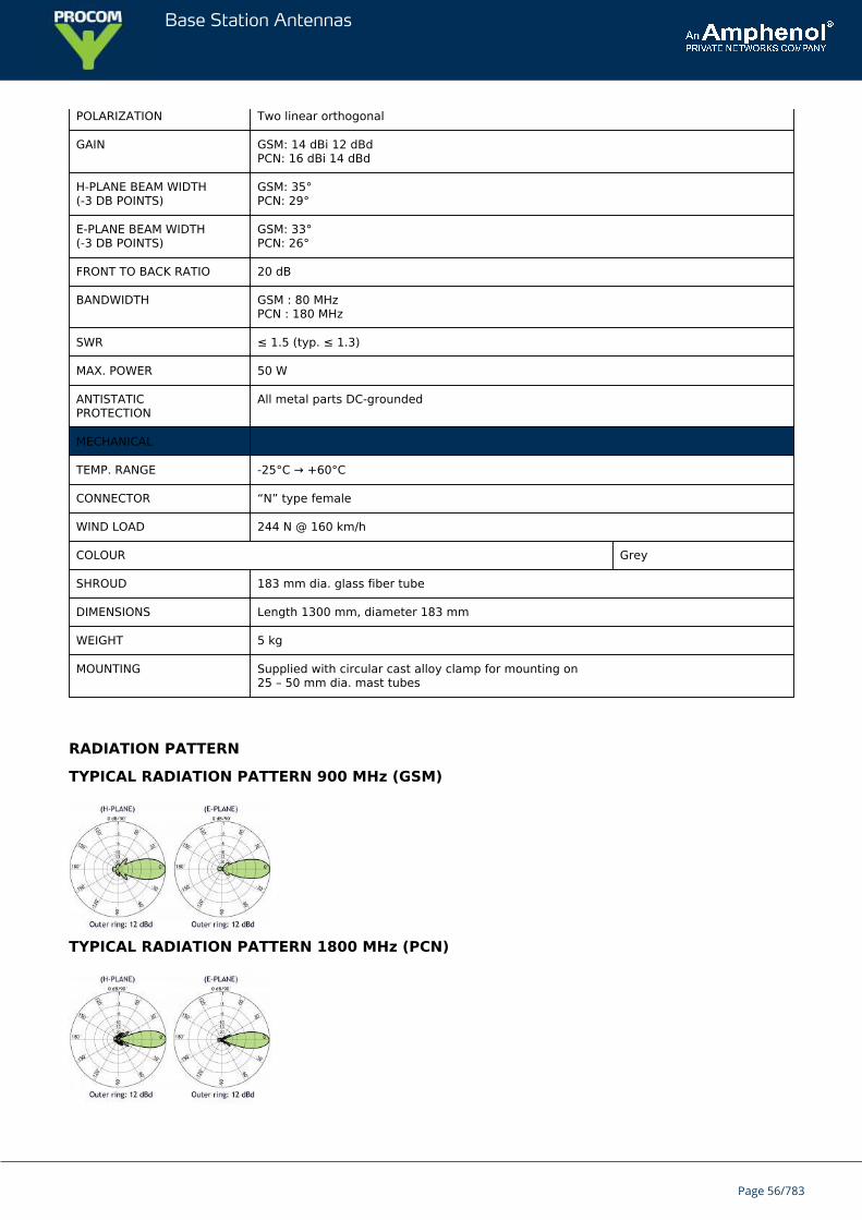
RADIATION PATTERN
TYPICAL RADIATION PATTERN 900 MHz (GSM)
TYPICAL RADIATION PATTERN 1800 MHz (PCN)
Page 56/783
Base Station Antennas
MOUNTING OUTLINE
Page 57/783
Base Station Antennas
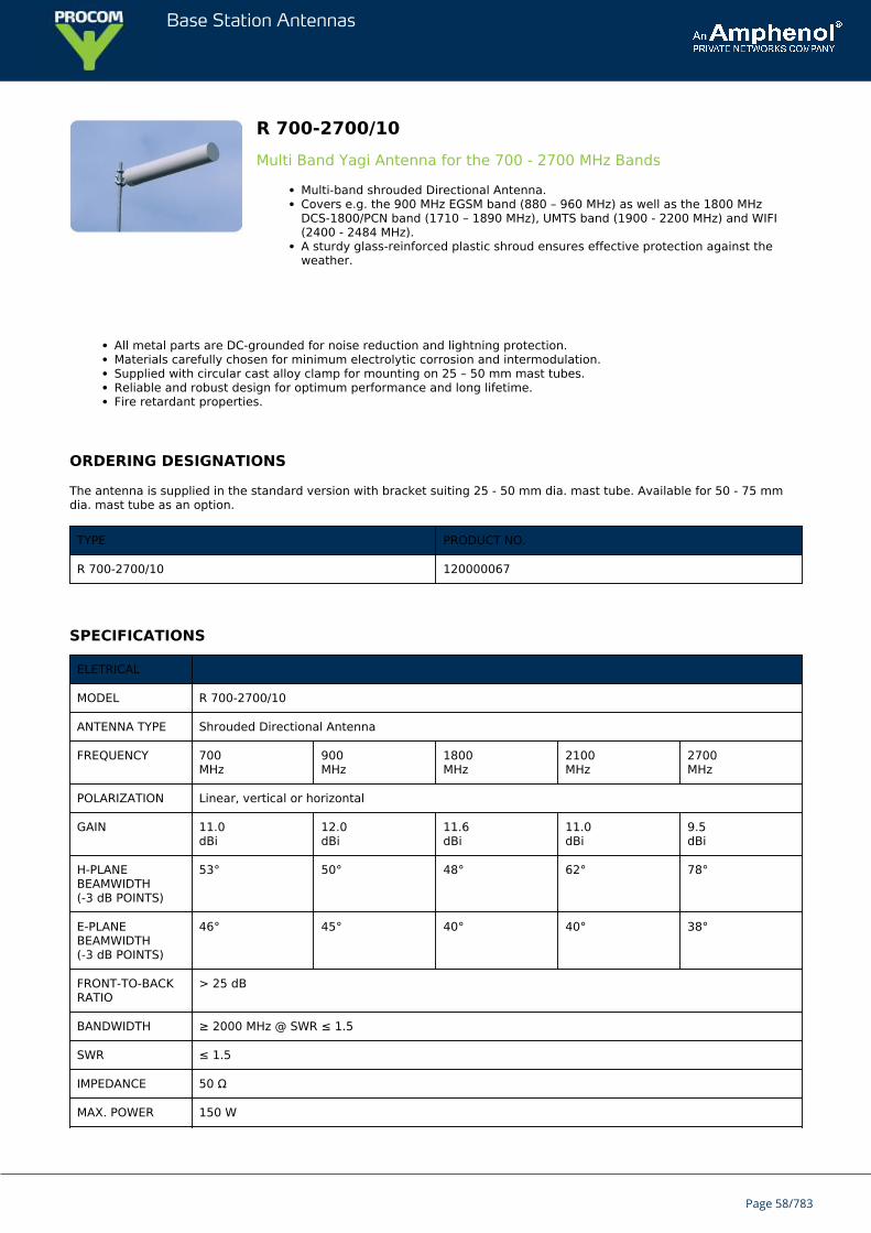
R 700-2700/10Multi Band Yagi Antenna for the 700 - 2700 MHz Bands
Multi-band shrouded Directional Antenna.Covers e.g. the 900 MHz EGSM band (880 – 960 MHz) as well as the 1800 MHzDCS-1800/PCN band (1710 – 1890 MHz), UMTS band (1900 - 2200 MHz) and WIFI(2400 - 2484 MHz).A sturdy glass-reinforced plastic shroud ensures effective protection against theweather.
All metal parts are DC-grounded for noise reduction and lightning protection.Materials carefully chosen for minimum electrolytic corrosion and intermodulation.Supplied with circular cast alloy clamp for mounting on 25 – 50 mm mast tubes.Reliable and robust design for optimum performance and long lifetime.Fire retardant properties.
ORDERING DESIGNATIONS
The antenna is supplied in the standard version with bracket suiting 25 - 50 mm dia. mast tube. Available for 50 - 75 mmdia. mast tube as an option.
TYPE PRODUCT NO.
R 700-2700/10 120000067
SPECIFICATIONS
ELETRICAL
MODEL R 700-2700/10
ANTENNA TYPE Shrouded Directional Antenna
FREQUENCY 700MHz
900MHz
1800MHz
2100MHz
2700MHz
POLARIZATION Linear, vertical or horizontal
GAIN 11.0dBi
12.0dBi
11.6dBi
11.0dBi
9.5dBi
H-PLANEBEAMWIDTH(-3 dB POINTS)
53° 50° 48° 62° 78°
E-PLANEBEAMWIDTH(-3 dB POINTS)
46° 45° 40° 40° 38°
FRONT-TO-BACKRATIO
> 25 dB
BANDWIDTH ≥ 2000 MHz @ SWR ≤ 1.5
SWR ≤ 1.5
IMPEDANCE 50 Ω
MAX. POWER 150 W
Page 58/783
Base Station Antennas
ANTISTATICPROTECTION
All metal parts DC-grounded
MECHANICAL
TEMP. RANGE -25°C → +60°C
CONNECTOR “N” type female
WIND LOAD 250 N (max. @ 160 km/h)
COLOUR Grey
SHROUD 180 mm glass fibre tube
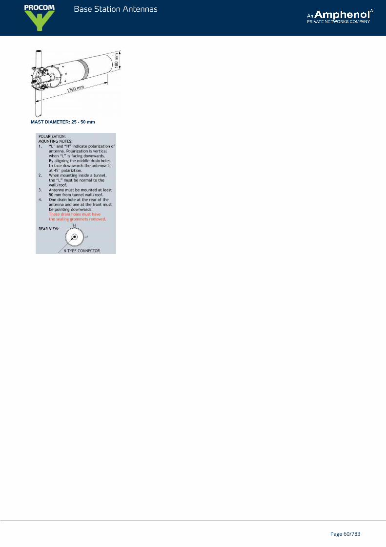
DIMENSIONS Length 1360 mm, diameter 180 mm
WEIGHT 7 kg excl. mounting hardware
MOUNTING Supplied with circular cast alloy clamp for mountingon 25 – 50 mm dia. mast tubes
RADIATION PATTERN
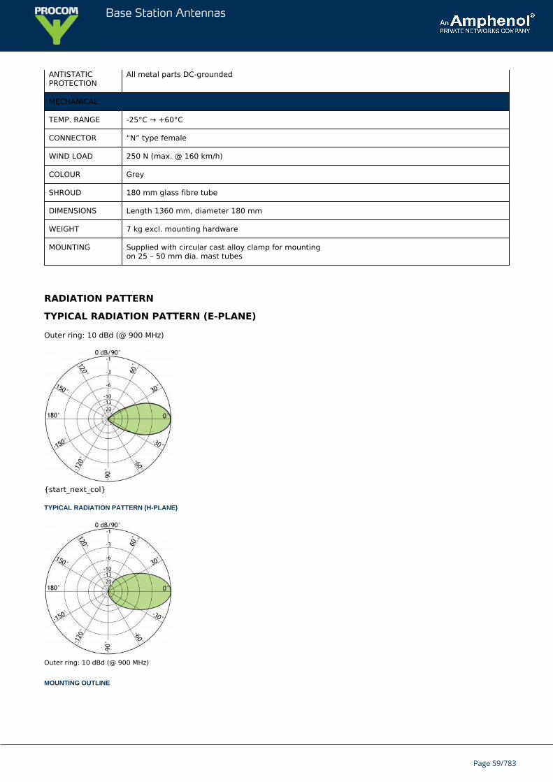
TYPICAL RADIATION PATTERN (E-PLANE)
Outer ring: 10 dBd (@ 900 MHz)
{start_next_col}
TYPICAL RADIATION PATTERN (H-PLANE)
Outer ring: 10 dBd (@ 900 MHz)
MOUNTING OUTLINE
Page 59/783
Base Station Antennas
MAST DIAMETER: 25 - 50 mm
Page 60/783
Base Station Antennas
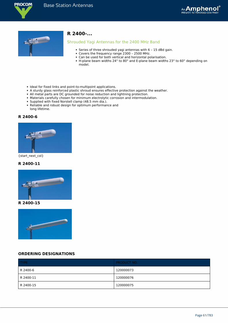
R 2400-...Shrouded Yagi Antennas for the 2400 MHz Band
Series of three shrouded yagi antennas with 6 – 15 dBd gain.Covers the frequency range 2300 – 2500 MHz.Can be used for both vertical and horizontal polarisation.H-plane beam widths 24° to 80° and E-plane beam widths 23° to 60° depending onmodel.
Ideal for fixed links and point-to-multipoint applications.A sturdy glass reinforced plastic shroud ensures effective protection against the weather.All metal parts are DC grounded for noise reduction and lightning protection.Materials carefully chosen for minimum electrolytic corrosion and intermodulation.Supplied with fixed Norstell clamp (48.5 mm dia.).Reliable and robust design for optimum performance andlong lifetime.
R 2400-6
{start_next_col}
R 2400-11
R 2400-15
ORDERING DESIGNATIONS
TYPE PRODUCT NO.
R 2400-6 120000073
R 2400-11 120000076
R 2400-15 120000075
Page 61/783
Base Station Antennas
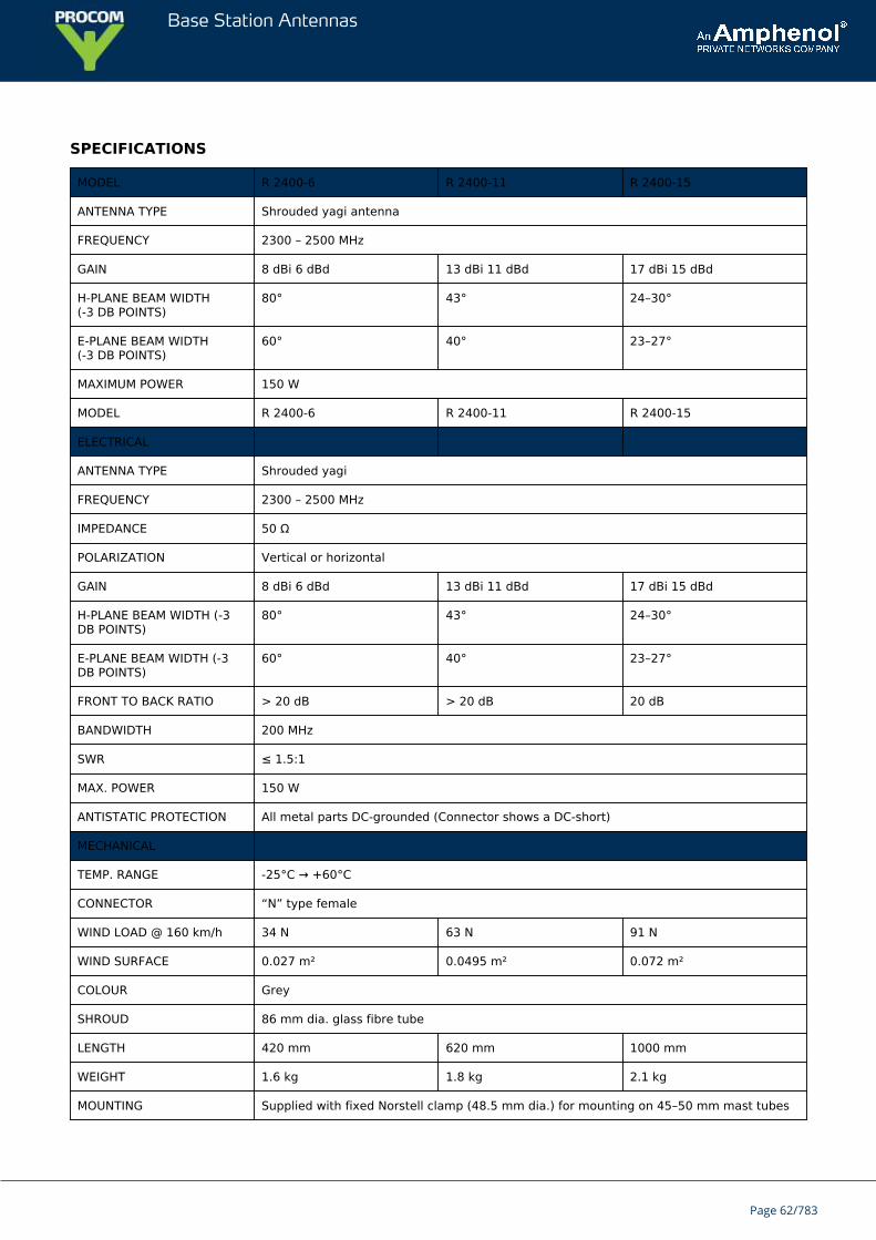
SPECIFICATIONS
MODEL R 2400-6 R 2400-11 R 2400-15
ANTENNA TYPE Shrouded yagi antenna
FREQUENCY 2300 – 2500 MHz
GAIN 8 dBi 6 dBd 13 dBi 11 dBd 17 dBi 15 dBd
H-PLANE BEAM WIDTH(-3 DB POINTS)
80° 43° 24–30°
E-PLANE BEAM WIDTH(-3 DB POINTS)
60° 40° 23–27°
MAXIMUM POWER 150 W
MODEL R 2400-6 R 2400-11 R 2400-15
ELECTRICAL
ANTENNA TYPE Shrouded yagi
FREQUENCY 2300 – 2500 MHz
IMPEDANCE 50 Ω
POLARIZATION Vertical or horizontal
GAIN 8 dBi 6 dBd 13 dBi 11 dBd 17 dBi 15 dBd
H-PLANE BEAM WIDTH (-3DB POINTS)
80° 43° 24–30°
E-PLANE BEAM WIDTH (-3DB POINTS)
60° 40° 23–27°
FRONT TO BACK RATIO > 20 dB > 20 dB 20 dB
BANDWIDTH 200 MHz
SWR ≤ 1.5:1
MAX. POWER 150 W
ANTISTATIC PROTECTION All metal parts DC-grounded (Connector shows a DC-short)
MECHANICAL
TEMP. RANGE -25°C → +60°C
CONNECTOR “N” type female
WIND LOAD @ 160 km/h 34 N 63 N 91 N
WIND SURFACE 0.027 m² 0.0495 m² 0.072 m²
COLOUR Grey
SHROUD 86 mm dia. glass fibre tube
LENGTH 420 mm 620 mm 1000 mm
WEIGHT 1.6 kg 1.8 kg 2.1 kg
MOUNTING Supplied with fixed Norstell clamp (48.5 mm dia.) for mounting on 45–50 mm mast tubes
Page 62/783
Base Station Antennas
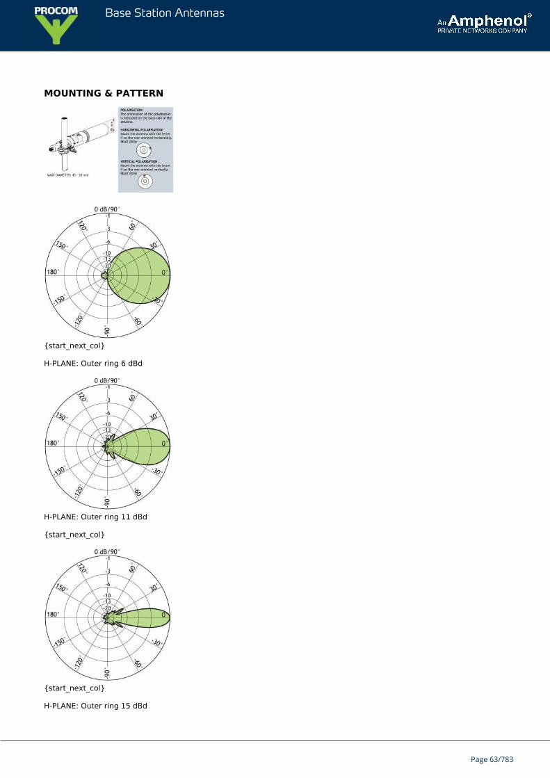
MOUNTING & PATTERN
{start_next_col}
H-PLANE: Outer ring 6 dBd
H-PLANE: Outer ring 11 dBd
{start_next_col}
{start_next_col}
H-PLANE: Outer ring 15 dBd
Page 63/783
Base Station Antennas
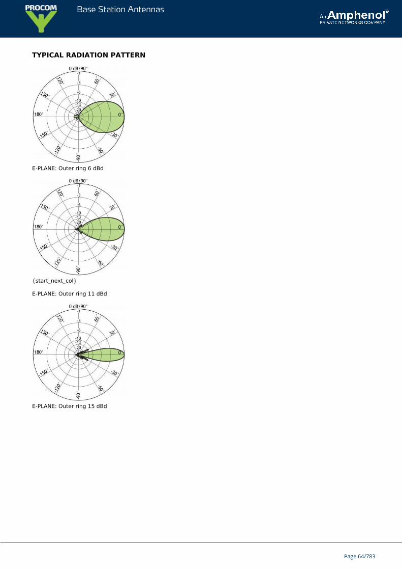
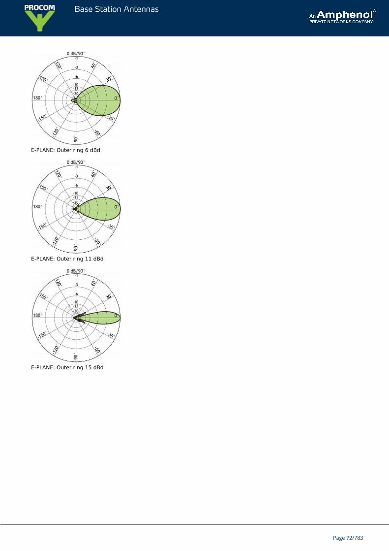
TYPICAL RADIATION PATTERN
E-PLANE: Outer ring 6 dBd
{start_next_col}
E-PLANE: Outer ring 11 dBd
E-PLANE: Outer ring 15 dBd
Page 64/783
Base Station Antennas
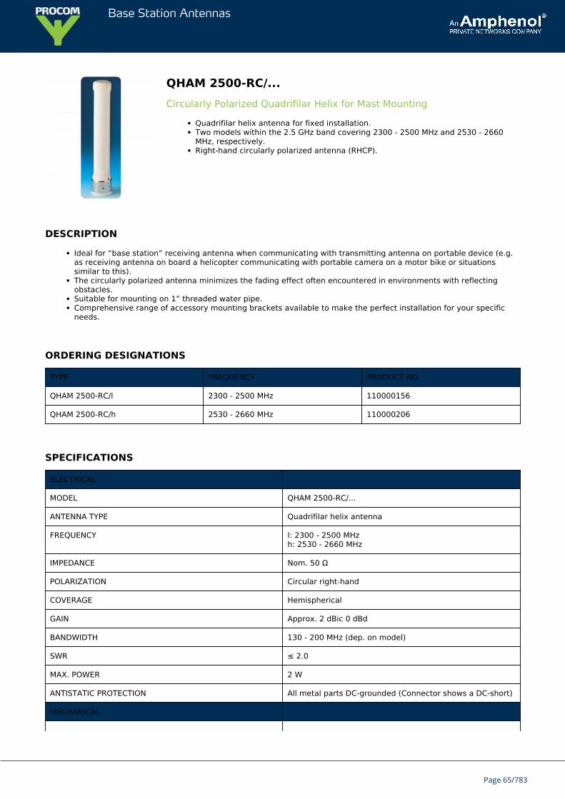
QHAM 2500-RC/...Circularly Polarized Quadrifilar Helix for Mast Mounting
Quadrifilar helix antenna for fixed installation.Two models within the 2.5 GHz band covering 2300 - 2500 MHz and 2530 - 2660MHz, respectively.Right-hand circularly polarized antenna (RHCP).
DESCRIPTION
Ideal for “base station” receiving antenna when communicating with transmitting antenna on portable device (e.g.as receiving antenna on board a helicopter communicating with portable camera on a motor bike or situationssimilar to this).The circularly polarized antenna minimizes the fading effect often encountered in environments with reflectingobstacles.Suitable for mounting on 1” threaded water pipe.Comprehensive range of accessory mounting brackets available to make the perfect installation for your specificneeds.
ORDERING DESIGNATIONS
TYPE FREQUENCY PRODUCT NO.
QHAM 2500-RC/l 2300 - 2500 MHz 110000156
QHAM 2500-RC/h 2530 - 2660 MHz 110000206
SPECIFICATIONS
ELECTRICAL
MODEL QHAM 2500-RC/...
ANTENNA TYPE Quadrifilar helix antenna
FREQUENCY l: 2300 - 2500 MHzh: 2530 - 2660 MHz
IMPEDANCE Nom. 50 Ω
POLARIZATION Circular right-hand
COVERAGE Hemispherical
GAIN Approx. 2 dBic 0 dBd
BANDWIDTH 130 - 200 MHz (dep. on model)
SWR ≤ 2.0
MAX. POWER 2 W
ANTISTATIC PROTECTION All metal parts DC-grounded (Connector shows a DC-short)
MECHANICAL
Page 65/783
Base Station Antennas
TEMP. RANGE -30°C → +70°C
CONNECTOR FME-male
WIND SURFACE Approx. 0.0072 m²
MAX. WIND SPEED 200 km/h
WIND LOAD Approx. 9.6 N @ 150 km/h
COLOUR Marine white
MATERIALS Shroud: Weather resistant low loss plastic
TOTAL HEIGHT Approx. 23 cm
ANTENNA DIA. 33 mm
WEIGHT Approx. 140 g
MOUNTING On 1” threaded water pipe or on PROCOM 1” mountingbrackets (see below)
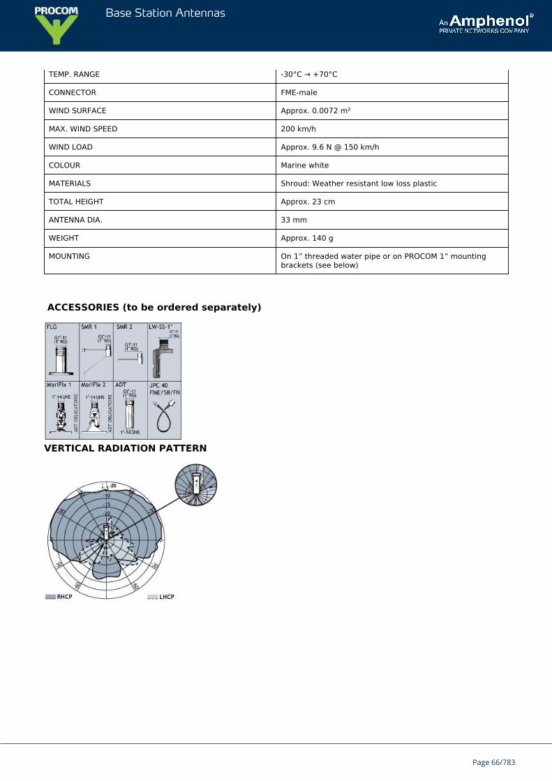
ACCESSORIES (to be ordered separately)
VERTICAL RADIATION PATTERN
Page 66/783
Base Station Antennas
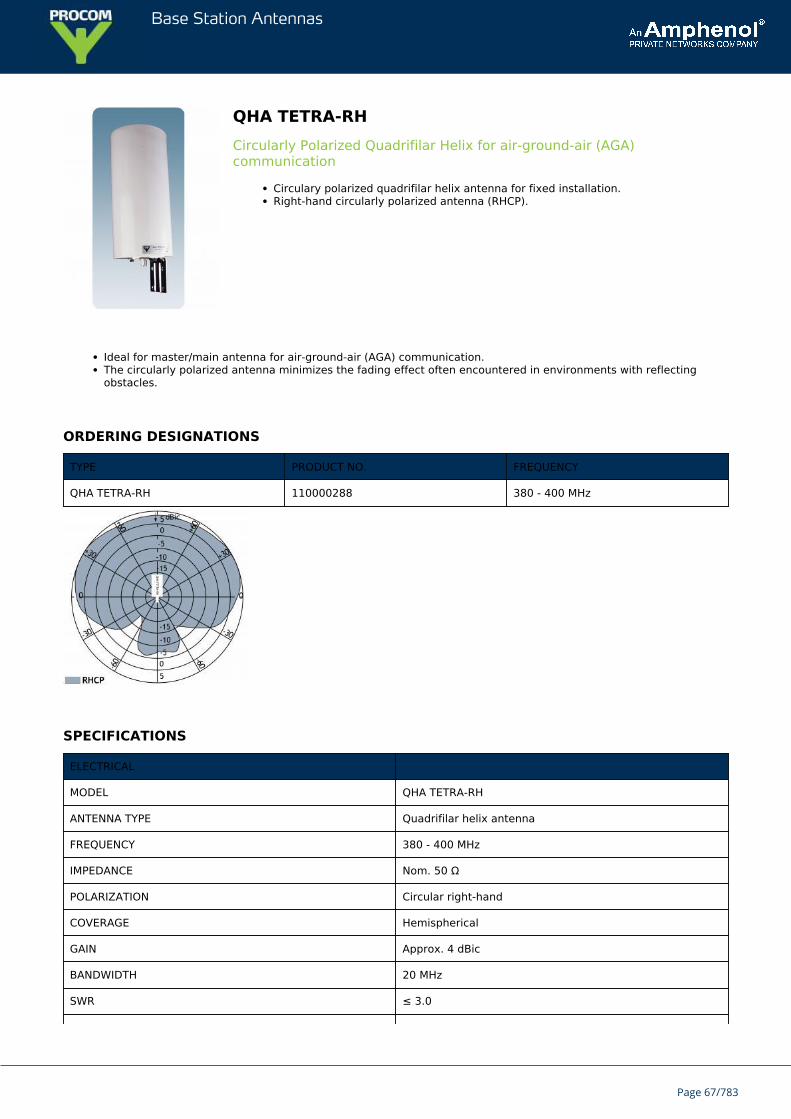
QHA TETRA-RHCircularly Polarized Quadrifilar Helix for air-ground-air (AGA)communication
Circulary polarized quadrifilar helix antenna for fixed installation.Right-hand circularly polarized antenna (RHCP).
Ideal for master/main antenna for air-ground-air (AGA) communication.The circularly polarized antenna minimizes the fading effect often encountered in environments with reflectingobstacles.
ORDERING DESIGNATIONS
TYPE PRODUCT NO. FREQUENCY
QHA TETRA-RH 110000288 380 - 400 MHz
SPECIFICATIONS
ELECTRICAL
MODEL QHA TETRA-RH
ANTENNA TYPE Quadrifilar helix antenna
FREQUENCY 380 - 400 MHz
IMPEDANCE Nom. 50 Ω
POLARIZATION Circular right-hand
COVERAGE Hemispherical
GAIN Approx. 4 dBic
BANDWIDTH 20 MHz
SWR ≤ 3.0
Page 67/783
Base Station Antennas
MAX. POWER 100 W
ANTISTATIC PROTECTION All metal parts DC-grounded(Connector shows a DC-short)
MECHANICAL
TEMP. RANGE -20°C → +60°C
CONNECTOR N-female
COLOUR Silver, white housing
MATERIALS Antenna: Copper with semi-rigid coaxial cableHousing: White, weather-resistant plasticFittings: Stainless Steel
TOTAL HEIGHT Approx. 350 mm / 13.8 in.
ANTENNA DIA. 150 mm / 5.9 in.
WEIGHT Approx. 1650 gr. / 3.6 lb.
MOUNTING On 30 - 40 mm / 11.8 - 15.7 in. dia. mast tube
MOUNTING
Mast mounting bracket: SM-MAS
Page 68/783
Base Station Antennas
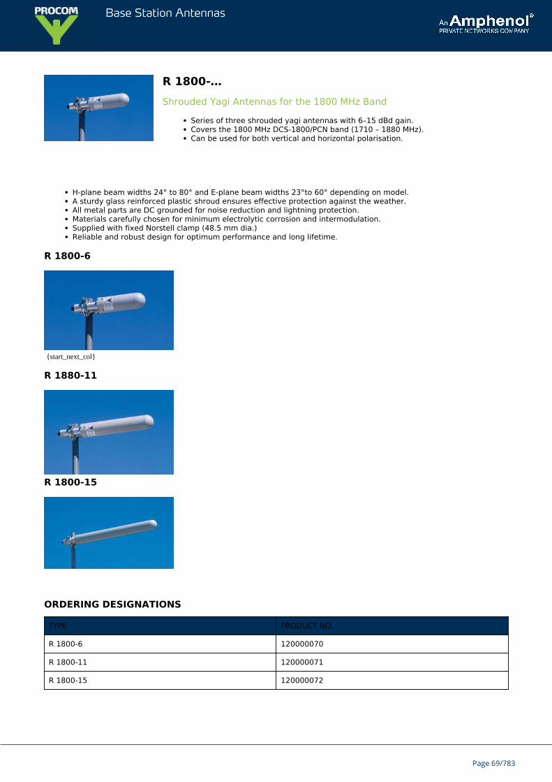
R 1800-…Shrouded Yagi Antennas for the 1800 MHz Band
Series of three shrouded yagi antennas with 6–15 dBd gain.Covers the 1800 MHz DCS-1800/PCN band (1710 – 1880 MHz).Can be used for both vertical and horizontal polarisation.
H-plane beam widths 24° to 80° and E-plane beam widths 23°to 60° depending on model.A sturdy glass reinforced plastic shroud ensures effective protection against the weather.All metal parts are DC grounded for noise reduction and lightning protection.Materials carefully chosen for minimum electrolytic corrosion and intermodulation.Supplied with fixed Norstell clamp (48.5 mm dia.)Reliable and robust design for optimum performance and long lifetime.
R 1800-6
{start_next_col}
R 1880-11
R 1800-15
ORDERING DESIGNATIONS
TYPE PRODUCT NO.
R 1800-6 120000070
R 1800-11 120000071
R 1800-15 120000072
Page 69/783
Base Station Antennas
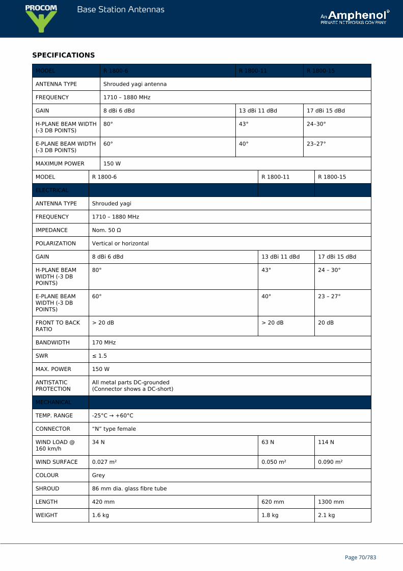
SPECIFICATIONS
MODEL R 1800-6 R 1800-11 R 1800-15
ANTENNA TYPE Shrouded yagi antenna
FREQUENCY 1710 – 1880 MHz
GAIN 8 dBi 6 dBd 13 dBi 11 dBd 17 dBi 15 dBd
H-PLANE BEAM WIDTH(-3 DB POINTS)
80° 43° 24–30°
E-PLANE BEAM WIDTH(-3 DB POINTS)
60° 40° 23–27°
MAXIMUM POWER 150 W
MODEL R 1800-6 R 1800-11 R 1800-15
ELECTRICAL
ANTENNA TYPE Shrouded yagi
FREQUENCY 1710 – 1880 MHz
IMPEDANCE Nom. 50 Ω
POLARIZATION Vertical or horizontal
GAIN 8 dBi 6 dBd 13 dBi 11 dBd 17 dBi 15 dBd
H-PLANE BEAMWIDTH (-3 DBPOINTS)
80° 43° 24 – 30°
E-PLANE BEAMWIDTH (-3 DBPOINTS)
60° 40° 23 – 27°
FRONT TO BACKRATIO
> 20 dB > 20 dB 20 dB
BANDWIDTH 170 MHz
SWR ≤ 1.5
MAX. POWER 150 W
ANTISTATICPROTECTION
All metal parts DC-grounded(Connector shows a DC-short)
MECHANICAL
TEMP. RANGE -25°C → +60°C
CONNECTOR “N” type female
WIND LOAD @160 km/h
34 N 63 N 114 N
WIND SURFACE 0.027 m² 0.050 m² 0.090 m²
COLOUR Grey
SHROUD 86 mm dia. glass fibre tube
LENGTH 420 mm 620 mm 1300 mm
WEIGHT 1.6 kg 1.8 kg 2.1 kg
Page 70/783
Base Station Antennas
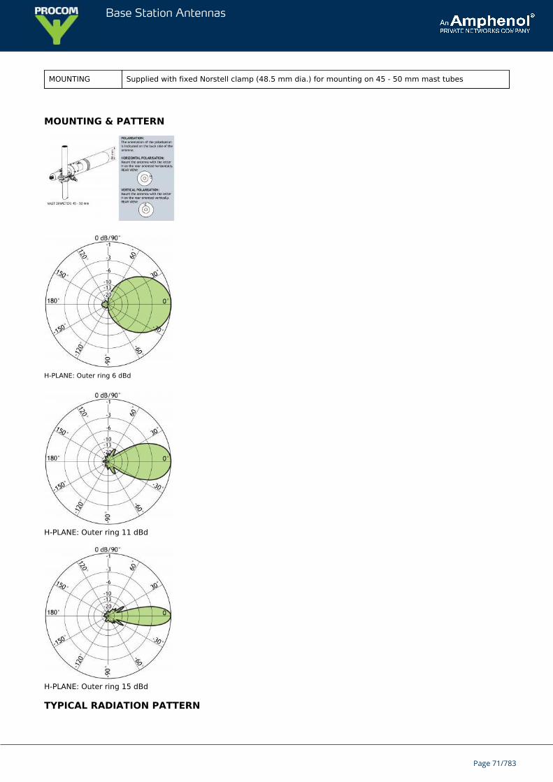
MOUNTING Supplied with fixed Norstell clamp (48.5 mm dia.) for mounting on 45 - 50 mm mast tubes
MOUNTING & PATTERN
H-PLANE: Outer ring 6 dBd
H-PLANE: Outer ring 11 dBd
H-PLANE: Outer ring 15 dBd
TYPICAL RADIATION PATTERN
Page 71/783
Base Station Antennas
E-PLANE: Outer ring 6 dBd
E-PLANE: Outer ring 11 dBd
E-PLANE: Outer ring 15 dBd
Page 72/783
Base Station Antennas
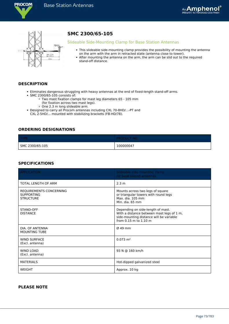
SMC 2300/65-105Slideable Side-Mounting Clamp for Base Station Antennas
This slideable side-mounting clamp provides the possibility of mounting the antennaon the arm with the arm in retracted state (antenna close to tower).After mounting the antenna on the arm, the arm can be slid out to the requiredstand-off distance.
DESCRIPTION
Eliminates dangerous struggling with heavy antennas at the end of fixed-length stand-off arms.SMC 2300/65-105 consists of:
Two mast fixation clamps for mast leg diameters 65 - 105 mm(for fixation across two mast legs).One 2.3 m long slideable arm.
Designed to carry all Procom antennas including CXL 70-8HD/...-PT andCXL 2-5HD/... mounted with stabilizing brackets (FB-HD/78).
ORDERING DESIGNATIONS
TYPE PRODUCT NO.
SMC 2300/65-105 100000047
SPECIFICATIONS
APPLICATION Slideable side-mounting clampfor base station antennas
TOTAL LENGTH OF ARM 2.3 m
REQUIREMENTS CONCERNINGSUPPORTINGSTRUCTURE
Mounts across two legs of squareor triangular towers with round legsMax. dia. 105 mmMin. dia. 65 mm
STAND-OFFDISTANCE
Depending on side-length of mast.With a distance between mast legs of 1 m,side-mounting distance will be variablefrom 0.15 m to 1.10 m
DIA. OF ANTENNAMOUNTING TUBE
Ø 49 mm
WIND SURFACE(Excl. antenna)
0.073 m²
WIND LOAD(Excl. antenna)
93 N @ 160 km/h
MATERIALS Hot-dipped galvanized steel
WEIGHT Approx. 10 kg
PLEASE NOTE
Page 73/783

Base Station Antennas
The optimum position for an omnidirectional antenna is at the top of the mast as this ensures undisturbed radiation in allhorizontal directions.
Mounting of an omnidirectional antenna at the side of a mast imposes some distortion of the radiation pattern as well asthe SWR. The influence is dependent on the distance to the mast and the mast diameter.
Often this effect can be advantageously exploited to create directional patterns when a certain “preferred area” has to becovered by the antenna system.
Page 74/783
Base Station Antennas
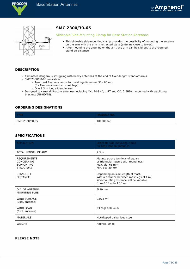
SMC 2300/30-65Slideable Side-Mounting Clamp for Base Station Antennas
This slideable side-mounting clamp provides the possibility of mounting the antennaon the arm with the arm in retracted state (antenna close to tower).After mounting the antenna on the arm, the arm can be slid out to the requiredstand-off distance.
DESCRIPTION
Eliminates dangerous struggling with heavy antennas at the end of fixed-length stand-off arms.SMC 2300/30-65 consists of:
Two mast fixation clamps for mast leg diameters 30 - 65 mm(for fixation across two mast legs).One 2.3 m long slideable arm.
Designed to carry all Procom antennas including CXL 70-8HD/...-PT and CXL 2-5HD/... mounted with stabilizingbrackets (FB-HD/78).
ORDERING DESIGNATIONS
TYPE PRODUCT NO.
SMC 2300/30-65 100000046
SPECIFICATIONS
APPLICATION Slideable side-mounting clampfor base station antennas
TOTAL LENGTH OF ARM 2.3 m
REQUIREMENTSCONCERNINGSUPPORTINGSTRUCTURE
Mounts across two legs of squareor triangular towers with round legsMax. dia. 65 mmMin. dia. 30 mm
STAND-OFFDISTANCE
Depending on side-length of mast.With a distance between mast legs of 1 m,side-mounting distance will be variablefrom 0.15 m to 1.10 m
DIA. OF ANTENNAMOUNTING TUBE
Ø 49 mm
WIND SURFACE(Excl. antenna)
0.073 m²
WIND LOAD(Excl. antenna)
93 N @ 160 km/h
MATERIALS Hot-dipped galvanized steel
WEIGHT Approx. 10 kg
PLEASE NOTE
Page 75/783

Base Station Antennas
The optimum position for an omnidirectional antenna is at the top of the mast as this ensures undisturbed radiation in allhorizontal directions.
Mounting of an omnidirectional antenna at the side of a mast imposes some distortion of the radiation pattern as well asthe SWR. The influence is dependent on the distance to the mast and the mast diameter.
Often this effect can be advantageously exploited to create directional patterns when a certain "preferred area" has to becovered by the antenna system.
Page 76/783
Base Station Antennas
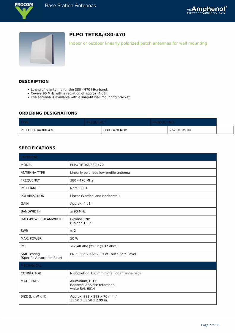
PLPO TETRA/380-470Indoor or outdoor linearly polarized patch antennas for wall mounting
DESCRIPTION
Low-profile antenna for the 380 - 470 MHz band.Covers 90 MHz with a radiation of approx. 4 dBi.The antenna is available with a snap-fit wall mounting bracket.
ORDERING DESIGNATIONS
TYPE FREQUENCY PRODUCT NO.
PLPO TETRA/380-470 380 - 470 MHz 752.01.05.00
SPECIFICATIONS
ELETRICAL
MODEL PLPO TETRA/380-470
ANTENNA TYPE Linearly polarized low-profile antenna
FREQUENCY 380 - 470 MHz
IMPEDANCE Nom. 50 Ω
POLARIZATION Linear (Vertical and Horizontal)
GAIN Approx. 4 dBi
BANDWIDTH ≥ 90 MHz
HALF-POWER BEAMWIDTH E-plane 120°H-plane 130°
SWR ≤ 2
MAX. POWER 50 W
IM3 ≤ -140 dBc (2x Tx @ 37 dBm)
SAR Testing(Specific Absorption Rate)
EN 50385:2002; 7.19 W Touch Safe Level
MECHANICAL
CONNECTOR N-Socket on 150 mm pigtail or antenna back
MATERIALS Aluminium, PTFERadome: ABS fire retardant,white RAL 6014
SIZE (L x W x H) Approx. 292 x 292 x 76 mm /11.50 x 11.50 x 2.99 in.
Page 77/783
Base Station Antennas
WEIGHT Approx. 0.4 kg / 0.88 lb.
MOUNTING Click mounting on stainless steel plate A2-70
IP-RATING IP65
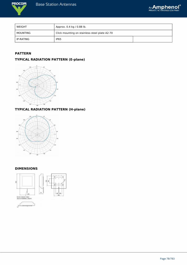
PATTERN
TYPICAL RADIATION PATTERN (E-plane)
TYPICAL RADIATION PATTERN (H-plane)
DIMENSIONS
Page 78/783
Base Station Antennas
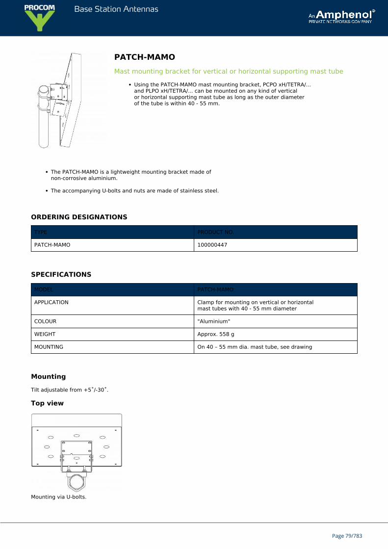
PATCH-MAMOMast mounting bracket for vertical or horizontal supporting mast tube
Using the PATCH-MAMO mast mounting bracket, PCPO xH/TETRA/...and PLPO xH/TETRA/... can be mounted on any kind of verticalor horizontal supporting mast tube as long as the outer diameterof the tube is within 40 - 55 mm.
The PATCH-MAMO is a lightweight mounting bracket made ofnon-corrosive aluminium.
The accompanying U-bolts and nuts are made of stainless steel.
ORDERING DESIGNATIONS
TYPE PRODUCT NO.
PATCH-MAMO 100000447
SPECIFICATIONS
MODEL PATCH-MAMO
APPLICATION Clamp for mounting on vertical or horizontalmast tubes with 40 - 55 mm diameter
COLOUR "Aluminium"
WEIGHT Approx. 558 g
MOUNTING On 40 – 55 mm dia. mast tube, see drawing
Mounting
Tilt adjustable from +5˚/-30˚.
Top view
Mounting via U-bolts.
Page 79/783
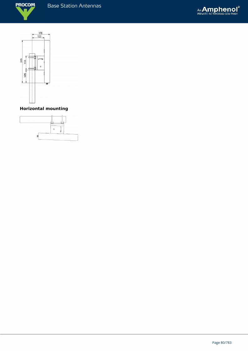
Base Station Antennas
Horizontal mounting
Page 80/783
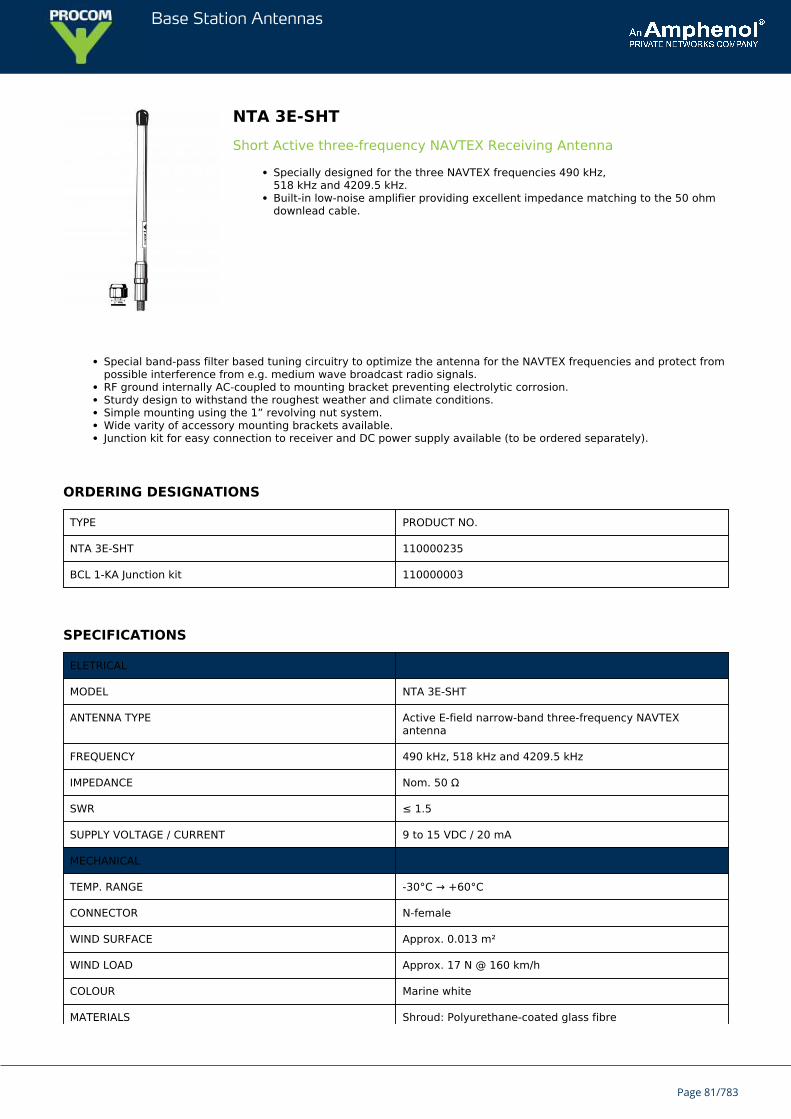
Base Station Antennas
NTA 3E-SHTShort Active three-frequency NAVTEX Receiving Antenna
Specially designed for the three NAVTEX frequencies 490 kHz,518 kHz and 4209.5 kHz.Built-in low-noise amplifier providing excellent impedance matching to the 50 ohmdownlead cable.
Special band-pass filter based tuning circuitry to optimize the antenna for the NAVTEX frequencies and protect frompossible interference from e.g. medium wave broadcast radio signals.RF ground internally AC-coupled to mounting bracket preventing electrolytic corrosion.Sturdy design to withstand the roughest weather and climate conditions.Simple mounting using the 1” revolving nut system.Wide varity of accessory mounting brackets available.Junction kit for easy connection to receiver and DC power supply available (to be ordered separately).
ORDERING DESIGNATIONS
TYPE PRODUCT NO.
NTA 3E-SHT 110000235
BCL 1-KA Junction kit 110000003
SPECIFICATIONS
ELETRICAL
MODEL NTA 3E-SHT
ANTENNA TYPE Active E-field narrow-band three-frequency NAVTEXantenna
FREQUENCY 490 kHz, 518 kHz and 4209.5 kHz
IMPEDANCE Nom. 50 Ω
SWR ≤ 1.5
SUPPLY VOLTAGE / CURRENT 9 to 15 VDC / 20 mA
MECHANICAL
TEMP. RANGE -30°C → +60°C
CONNECTOR N-female
WIND SURFACE Approx. 0.013 m²
WIND LOAD Approx. 17 N @ 160 km/h
COLOUR Marine white
MATERIALS Shroud: Polyurethane-coated glass fibre
Page 81/783
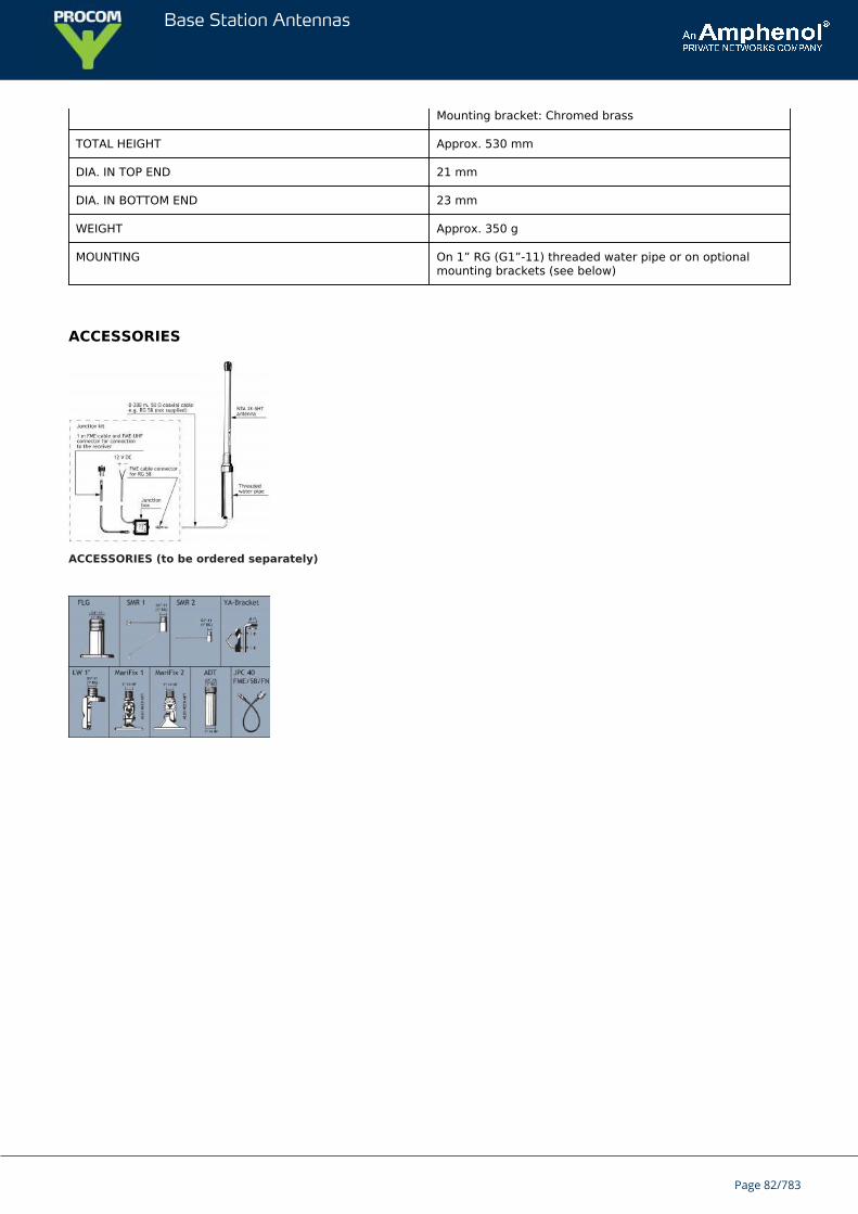
Base Station Antennas
Mounting bracket: Chromed brass
TOTAL HEIGHT Approx. 530 mm
DIA. IN TOP END 21 mm
DIA. IN BOTTOM END 23 mm
WEIGHT Approx. 350 g
MOUNTING On 1” RG (G1”-11) threaded water pipe or on optionalmounting brackets (see below)
ACCESSORIES
ACCESSORIES (to be ordered separately)
Page 82/783
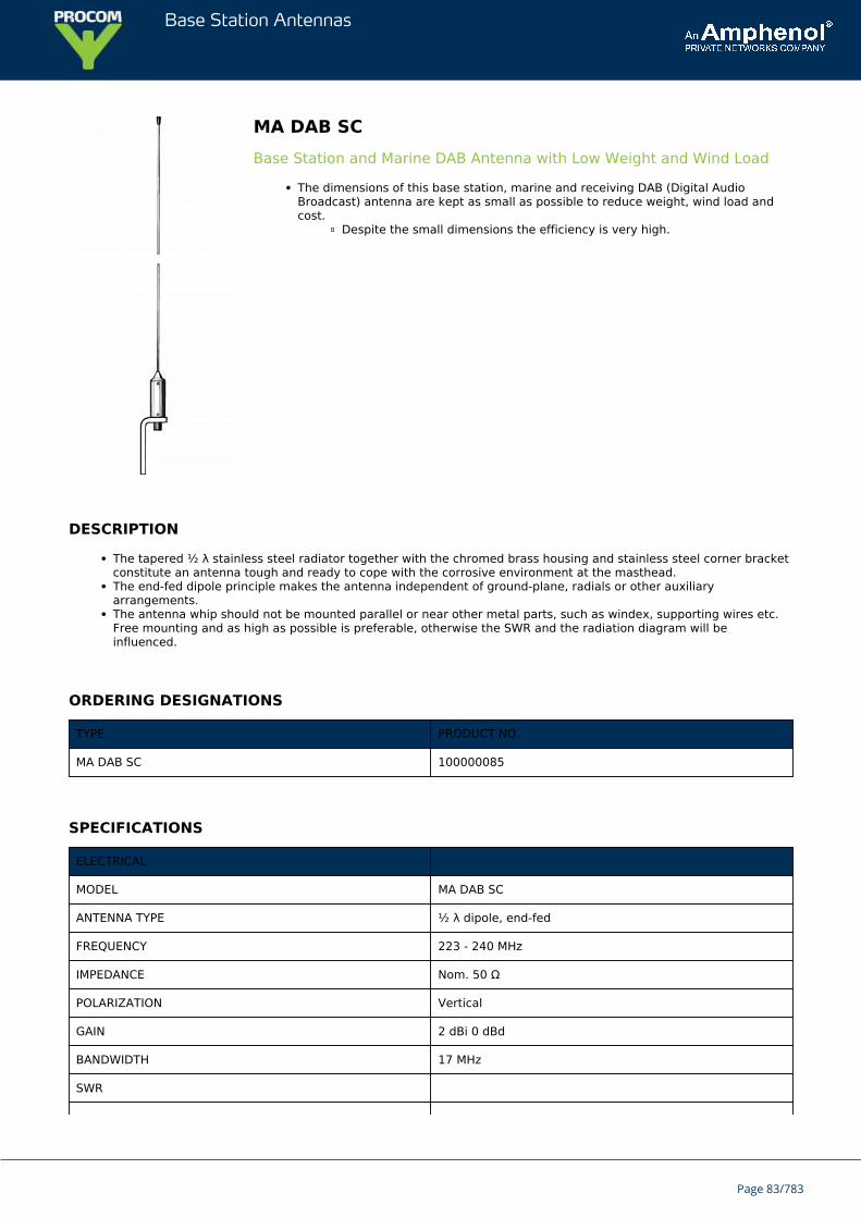
Base Station Antennas
MA DAB SCBase Station and Marine DAB Antenna with Low Weight and Wind Load
The dimensions of this base station, marine and receiving DAB (Digital AudioBroadcast) antenna are kept as small as possible to reduce weight, wind load andcost.
Despite the small dimensions the efficiency is very high.
DESCRIPTION
The tapered ½ λ stainless steel radiator together with the chromed brass housing and stainless steel corner bracketconstitute an antenna tough and ready to cope with the corrosive environment at the masthead.The end-fed dipole principle makes the antenna independent of ground-plane, radials or other auxiliaryarrangements.The antenna whip should not be mounted parallel or near other metal parts, such as windex, supporting wires etc.Free mounting and as high as possible is preferable, otherwise the SWR and the radiation diagram will beinfluenced.
ORDERING DESIGNATIONS
TYPE PRODUCT NO.
MA DAB SC 100000085
SPECIFICATIONS
ELECTRICAL
MODEL MA DAB SC
ANTENNA TYPE ½ λ dipole, end-fed
FREQUENCY 223 - 240 MHz
IMPEDANCE Nom. 50 Ω
POLARIZATION Vertical
GAIN 2 dBi 0 dBd
BANDWIDTH 17 MHz
SWR
Page 83/783
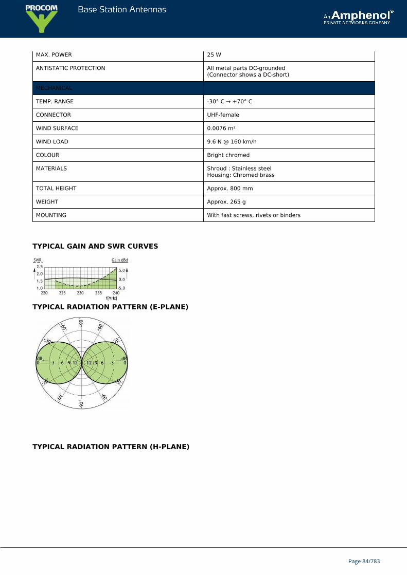
Base Station Antennas
MAX. POWER 25 W
ANTISTATIC PROTECTION All metal parts DC-grounded(Connector shows a DC-short)
MECHANICAL
TEMP. RANGE -30° C → +70° C
CONNECTOR UHF-female
WIND SURFACE 0.0076 m²
WIND LOAD 9.6 N @ 160 km/h
COLOUR Bright chromed
MATERIALS Shroud : Stainless steelHousing: Chromed brass
TOTAL HEIGHT Approx. 800 mm
WEIGHT Approx. 265 g
MOUNTING With fast screws, rivets or binders
TYPICAL GAIN AND SWR CURVES
TYPICAL RADIATION PATTERN (E-PLANE)
TYPICAL RADIATION PATTERN (H-PLANE)
Page 84/783
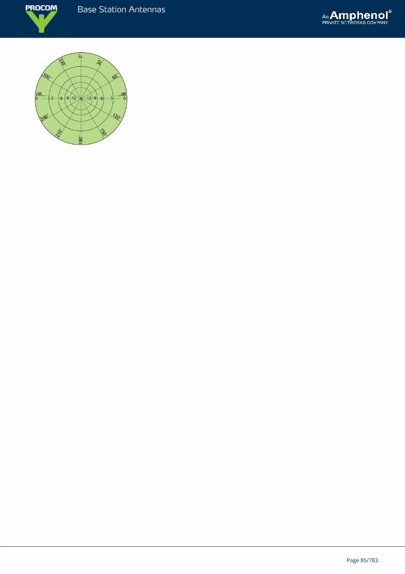
Base Station Antennas
Page 85/783
Base Station Antennas
MA 450/...End-fed ½ λ dipole marine and base station antenna.
Black-chromed stainless steel whip.Full-size, end-fed ½ λ antenna whip.
DESCRIPTION
This base station and maritime UHF antenna is developed for use on board ships as well as on masts and thanks tothe 1” revolving nut mounting system it can be mounted in the mast, in the auxilliary mast as well as on the cross-beam. By means of Procom’s flange mount it can also be mounted on deck or rooftop.Bear in mind that the higher the antenna is mounted the better the coverage.Avoid mounting the antenna parallel with and in the neighbourhood of other metal parts, such as mast, supportingwires etc. Free mounting and as high as possible is most preferable, otherwise the SWR and the radiation diagramwill be influenced.The antenna is a ½ λ design and this means that it needs neither loading coils, ground-plane, radials nor otherauxiliary arrangements.
ORDERING DESIGNATIONS
TYPE PRODUCT NO.
MA 450/ 380-400 MHz 110000343
MA 450/ 440-460 MHz 110000352
Other frequencies on request
SPECIFICATIONS
ELECTRICAL
MODEL MA 450/...
ANTENNA TYPE ½ λ antenna
FREQUENCY Models within 380 - 460 MHz
IMPEDANCE Nom. 50 Ω
POLARIZATION Vertical
GAIN 2 dBi0 dBd
BANDWIDTH 20 MHz
SWR ≤ 2 typ. ≤ 1.5
MAX. POWER 25 W
Page 86/783
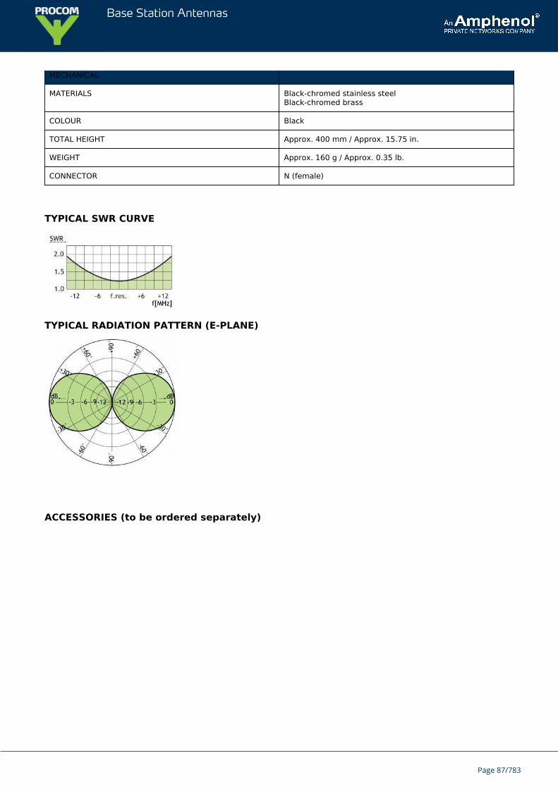
Base Station Antennas
MECHANICAL
MATERIALS Black-chromed stainless steelBlack-chromed brass
COLOUR Black
TOTAL HEIGHT Approx. 400 mm / Approx. 15.75 in.
WEIGHT Approx. 160 g / Approx. 0.35 lb.
CONNECTOR N (female)
TYPICAL SWR CURVE
TYPICAL RADIATION PATTERN (E-PLANE)
ACCESSORIES (to be ordered separately)
Page 87/783

Base Station Antennas
Page 88/783
Base Station Antennas
MA 160/...End-fed ½ λ dipole marine and base station antenna.
Black-chromed stainless steel whip.Full-size, end-fed ½ λ antenna whip.
DESCRIPTION
This base station and maritime VHF antenna is developed for use on board ships as well as on masts and thanks tothe 1” revolving nut mounting system it can be mounted in the mast, in the auxilliary mast as well as on the cross-beam. By means of Procom’s flange mount it can also be mounted on deck or rooftop.Bear in mind that the higher the antenna is mounted the better the coverage.Avoid mounting the antenna parallel with and in the neighbourhood of other metal parts, such as mast, supportingwires etc. Free mounting and as high as possible is most preferable, otherwise the SWR and the radiation diagramwill be influenced.The antenna is a ½ λ design and this means that it needs neither loading coils, ground-plane, radials nor otherauxiliary arrangements.
ORDERING DESIGNATIONS
TYPE PRODUCT NO.
MA 160/149-164 MHz 110000340
MA 160/156-162.5 MHz 110000350
MA 160/164-170 MHz 110000351
MA 160/167-175 MHz 110000358
Other frequencies on request
SPECIFICATIONS
ELECTRICAL
MODEL MA 160/...
ANTENNA TYPE ½ λ antenna
FREQUENCY Models within 149 - 164 MHz
IMPEDANCE Nom. 50 Ω
POLARIZATION Vertical
GAIN@ BW of 6 MHz
2 dBi0 dBd
BANDWIDTH Up to 15 MHz
Page 89/783
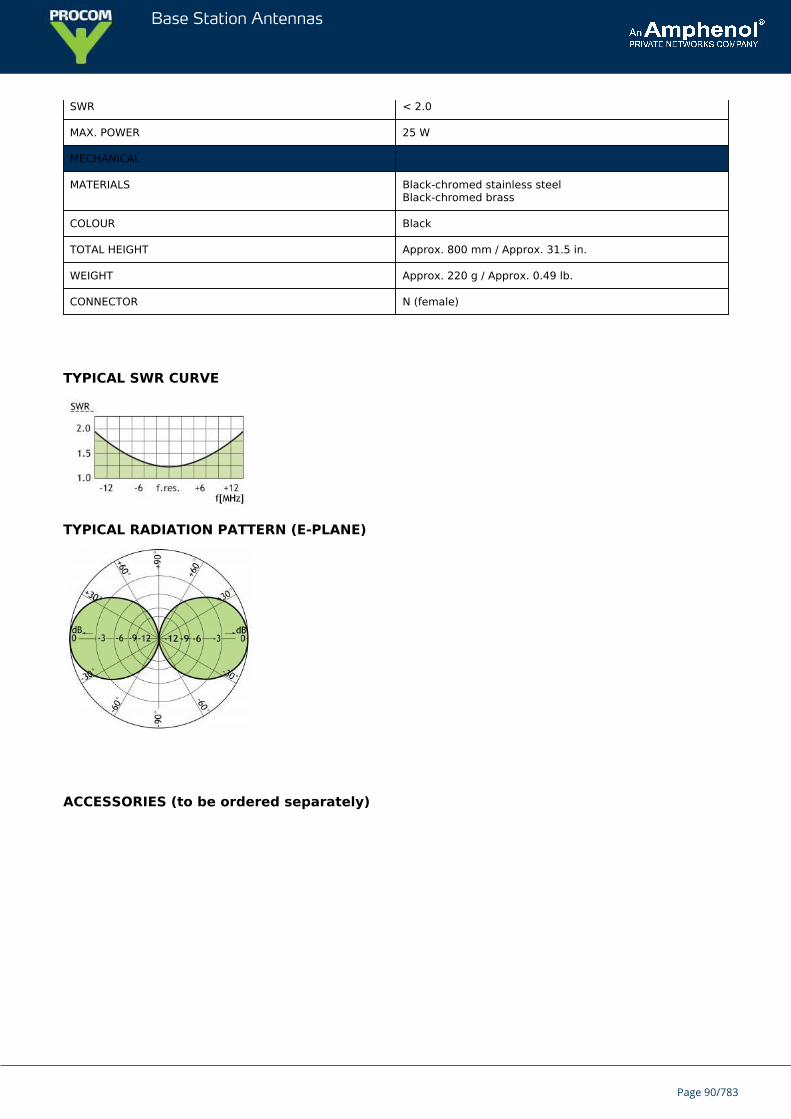
Base Station Antennas
SWR < 2.0
MAX. POWER 25 W
MECHANICAL
MATERIALS Black-chromed stainless steelBlack-chromed brass
COLOUR Black
TOTAL HEIGHT Approx. 800 mm / Approx. 31.5 in.
WEIGHT Approx. 220 g / Approx. 0.49 lb.
CONNECTOR N (female)
TYPICAL SWR CURVE
TYPICAL RADIATION PATTERN (E-PLANE)
ACCESSORIES (to be ordered separately)
Page 90/783
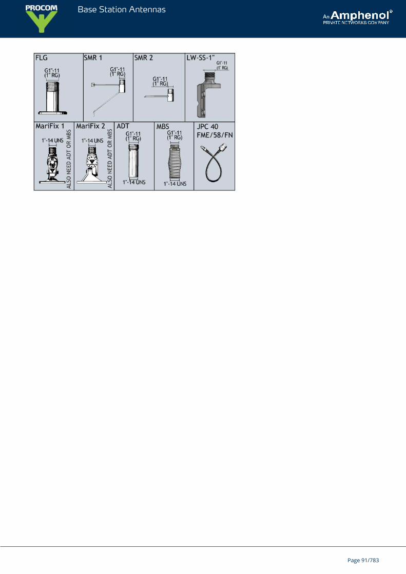
Base Station Antennas
Page 91/783
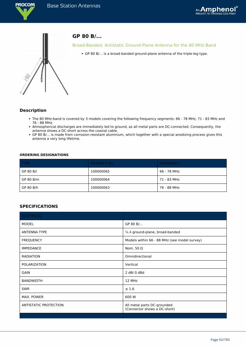
Base Station Antennas
GP 80 B/...Broad-Banded, Antistatic Ground-Plane Antenna for the 80 MHz Band
GP 80 B/… is a broad-banded ground-plane antenna of the triple-leg type.
Description
The 80 MHz-band is covered by 3 models covering the following frequency segments: 66 - 78 MHz, 71 - 83 MHz and76 - 88 MHz.Atmospherical discharges are immediately led to ground, as all metal parts are DC-connected. Consequently, theantenna shows a DC-short across the coaxial cable.GP 80 B/… is made from corrosion-resistant aluminium, which together with a special anodizing process gives thisantenna a very long lifetime.
ORDERING DESIGNATIONS
TYPE PRODUCT NO. FREQUENCY
GP 80 B/l 100000065 66 - 78 MHz
GP 80 B/m 100000064 71 - 83 MHz
GP 80 B/h 100000063 76 - 88 MHz
SPECIFICATIONS
ELECTRICAL
MODEL GP 80 B/...
ANTENNA TYPE ¼ λ ground-plane, broad-banded
FREQUENCY Models within 66 - 88 MHz (see model survey)
IMPEDANCE Nom. 50 Ω
RADIATION Omnidirectional
POLARIZATION Vertical
GAIN 2 dBi 0 dBd
BANDWIDTH 12 MHz
SWR ≤ 1.6
MAX. POWER 600 W
ANTISTATIC PROTECTION All metal parts DC-grounded(Connector shows a DC-short)
Page 92/783
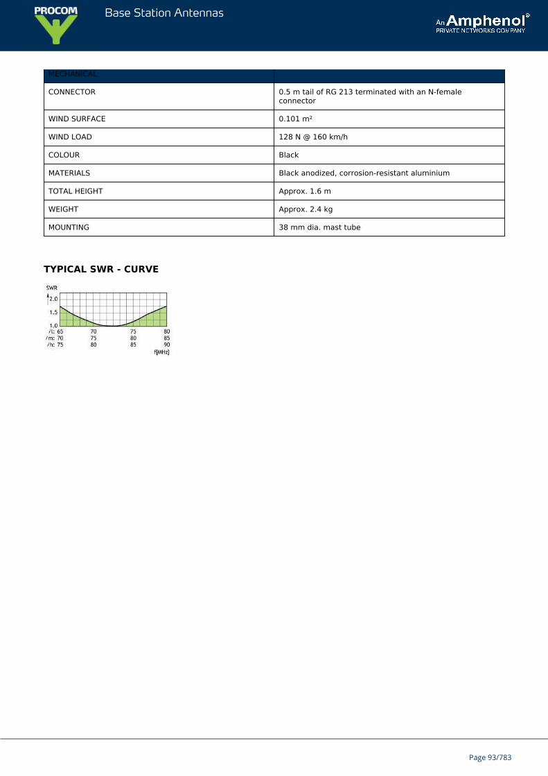
Base Station Antennas
MECHANICAL
CONNECTOR 0.5 m tail of RG 213 terminated with an N-femaleconnector
WIND SURFACE 0.101 m²
WIND LOAD 128 N @ 160 km/h
COLOUR Black
MATERIALS Black anodized, corrosion-resistant aluminium
TOTAL HEIGHT Approx. 1.6 m
WEIGHT Approx. 2.4 kg
MOUNTING 38 mm dia. mast tube
TYPICAL SWR - CURVE
Page 93/783
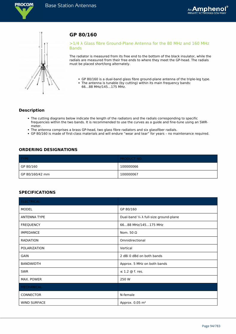
Base Station Antennas
GP 80/160>1/4 λ Glass fibre Ground-Plane Antenna for the 80 MHz and 160 MHzBands
The radiator is measured from its free end to the bottom of the black insulator, while theradials are measured from their free ends to where they meet the GP-head. The radialsmust be placed short/long alternately.
GP 80/160 is a dual-band glass fibre ground-plane antenna of the triple-leg type.The antenna is tunable (by cutting) within its main frequency bands:66…88 MHz/145…175 MHz.
Description
The cutting diagrams below indicate the length of the radiators and the radials corresponding to specificfrequencies within the two bands. It is recommended to use the curves as a guide and fine-tune using an SWR-meter.The antenna comprises a brass GP-head, two glass fibre radiators and six glassfiber radials.GP 80/160 is made of first-class materials and will endure “wear and tear” for years – no maintenance required.
ORDERING DESIGNATIONS
TYPE PRODUCT NO.
GP 80/160 100000066
GP 80/160/42 mm 100000067
SPECIFICATIONS
ELECTRICAL
MODEL GP 80/160
ANTENNA TYPE Dual-band ¼ λ full-size ground-plane
FREQUENCY 66…88 MHz/145…175 MHz
IMPEDANCE Nom. 50 Ω
RADIATION Omnidirectional
POLARIZATION Vertical
GAIN 2 dBi 0 dBd on both bands
BANDWIDTH Approx. 5 MHz on both bands
SWR ≤ 1.2 @ f. res.
MAX. POWER 250 W
MECHANICAL
CONNECTOR N-female
WIND SURFACE Approx. 0.05 m²
Page 94/783
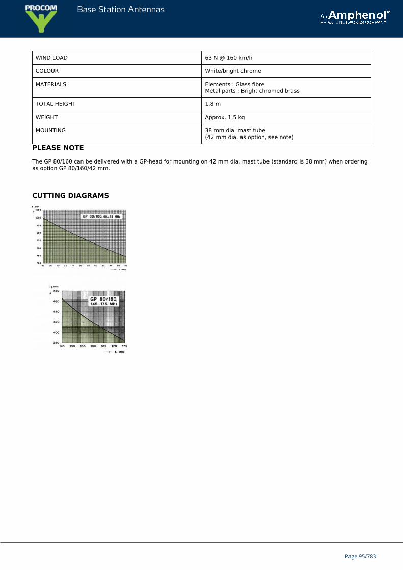
Base Station Antennas
WIND LOAD 63 N @ 160 km/h
COLOUR White/bright chrome
MATERIALS Elements : Glass fibreMetal parts : Bright chromed brass
TOTAL HEIGHT 1.8 m
WEIGHT Approx. 1.5 kg
MOUNTING 38 mm dia. mast tube(42 mm dia. as option, see note)
PLEASE NOTE
The GP 80/160 can be delivered with a GP-head for mounting on 42 mm dia. mast tube (standard is 38 mm) when orderingas option GP 80/160/42 mm.
CUTTING DIAGRAMS
Page 95/783
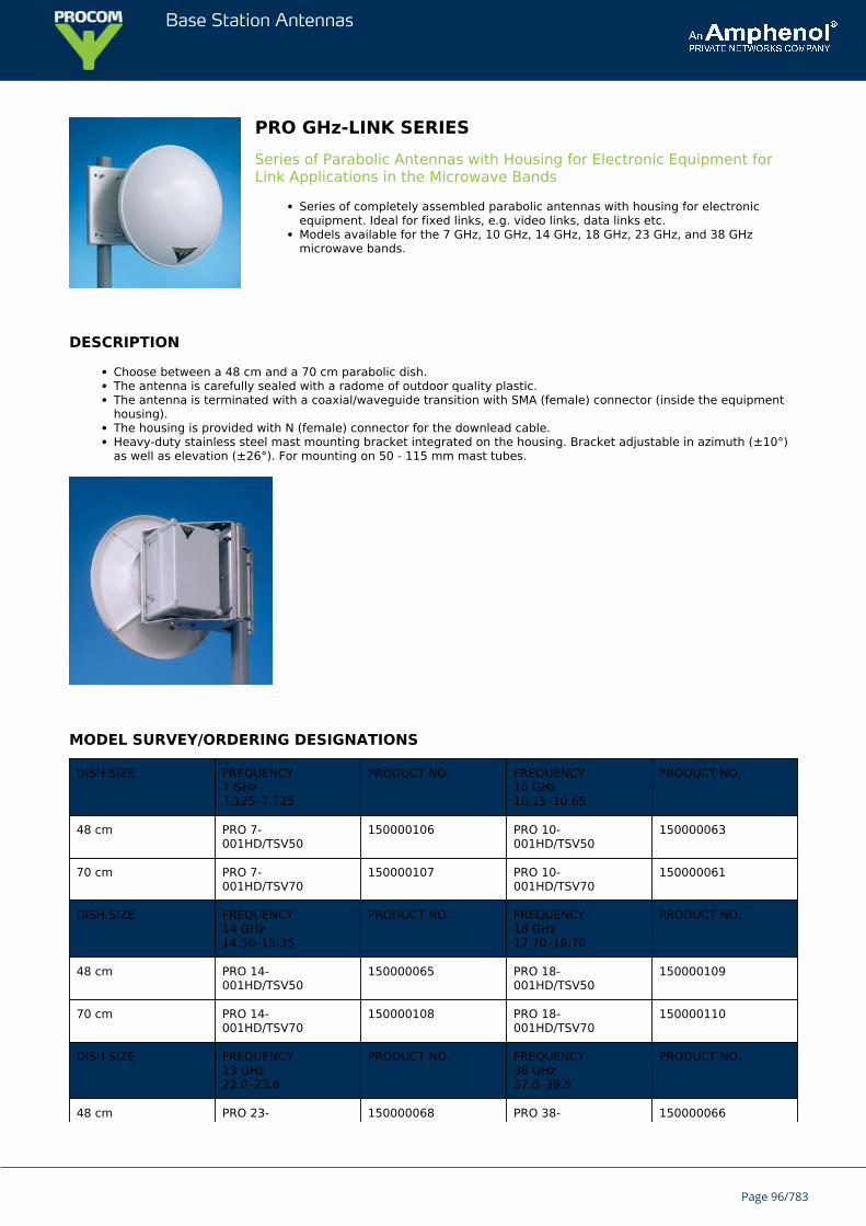
Base Station Antennas
PRO GHz-LINK SERIESSeries of Parabolic Antennas with Housing for Electronic Equipment forLink Applications in the Microwave Bands
Series of completely assembled parabolic antennas with housing for electronicequipment. Ideal for fixed links, e.g. video links, data links etc.Models available for the 7 GHz, 10 GHz, 14 GHz, 18 GHz, 23 GHz, and 38 GHzmicrowave bands.
DESCRIPTION
Choose between a 48 cm and a 70 cm parabolic dish.The antenna is carefully sealed with a radome of outdoor quality plastic.The antenna is terminated with a coaxial/waveguide transition with SMA (female) connector (inside the equipmenthousing).The housing is provided with N (female) connector for the downlead cable.Heavy-duty stainless steel mast mounting bracket integrated on the housing. Bracket adjustable in azimuth (±10°)as well as elevation (±26°). For mounting on 50 - 115 mm mast tubes.
MODEL SURVEY/ORDERING DESIGNATIONS
DISH SIZE FREQUENCY7 GHz7.125–7.725
PRODUCT NO. FREQUENCY10 GHz10.15–10.65
PRODUCT NO.
48 cm PRO 7-001HD/TSV50
150000106 PRO 10-001HD/TSV50
150000063
70 cm PRO 7-001HD/TSV70
150000107 PRO 10-001HD/TSV70
150000061
DISH SIZE FREQUENCY14 GHz14.50–15.35
PRODUCT NO. FREQUENCY18 GHz17.70–19.70
PRODUCT NO.
48 cm PRO 14-001HD/TSV50
150000065 PRO 18-001HD/TSV50
150000109
70 cm PRO 14-001HD/TSV70
150000108 PRO 18-001HD/TSV70
150000110
DISH SIZE FREQUENCY23 GHz22.0–23.6
PRODUCT NO. FREQUENCY38 GHz37.0–39.5
PRODUCT NO.
48 cm PRO 23- 150000068 PRO 38- 150000066
Page 96/783
Base Station Antennas
001HD/TSV50 001HD/TSV50
70 cm PRO 23-001HD/TSV70
150000076 PRO 38-001HD/TSV70
150000111
FREQUENCY DEPENDENT SPECIFICATIONS
MODE PRO 7-001HD/… PRO 10-001HD/… PRO 14-001HD/…
FREQUENCY GHz 7.125–7.725 10.15–10.65 14.50–15.35
APPROXIMATEGAIN, …/TSV50
24 dBd26 dBi
27 dBd29 dBi
30 dBd32 dBi
APPROXIMATEGAIN, …/TSV70
27 dBd29 dBi
30 dBd32 dBi
33 dBd35 dBi
MODE PRO 18-001HD/… PRO 23-001HD/… PRO 38-001HD/…
FREQUENCY GHz 17.70–19.70 22.0–23.6 37.0–39.5
APPROXIMATEGAIN, …/TSV50
32 dBd34 dBi
34 dBd36 dBi
38 dBd40 dBi
APPROXIMATEGAIN, …/TSV70
35 dBd37 dBi
37 dBd39 dBi
41 dBd43 dBi
GENERAL SPECIFICATIONS
MODEL PRO...-001HD/TSV50 PRO...-001HD/TSV70
ELECTRICAL
ANTENNA TYPE Parabolic dish antenna with radome, housing and mounting bracket
IMPEDANCE Nom. 50 Ω
POLARIZATION Horizontal
SWR < 1.5 within the band
MAX. POWER 250 W
MECHANICAL
CONNECTION Antenna: SMA (female) (coaxial/waveguide transition inside housing)Housing: N (female) (for connection of the downlead cable)
WIND SURFACE Approx. 0.25 m² Approx. 0.38 m²
WIND LOAD Approx. 316 N @ 160 km/h Approx. 480 N @ 160 km/h
COLOUR Radome: Light greyHousing, brackets: Grey
MATERIALS Parabolic dish: AluminiumWaveguide components: Brass and copperHousing: Glass reinforced plasticBrackets: Stainless steel
DIMENSIONS,dish diameter
480 mm 700 mm
DIMENSIONS,housing(H x W x D)
Outside: 220 x 170 x 150 mmInside: 190 x 135 x 120 mm
Page 97/783
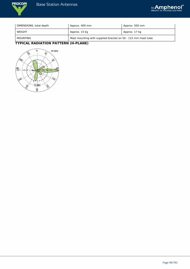
Base Station Antennas
DIMENSIONS, total depth Approx. 400 mm Approx. 500 mm
WEIGHT Approx. 15 kg Approx. 17 kg
MOUNTING Mast mounting with supplied bracket on 50 - 115 mm mast tube
TYPICAL RADIATION PATTERN (H-PLANE)
Page 98/783
Base Station Antennas
GP 80¼ λ Glass fibre Ground-Plane Antenna for the 80 MHz Band
The radiator is measured from its free end to the bottom of the black insulator, while theradials are measured from their free ends to where they meet the GP-head.
GP 80 is a glass fibre ground-plane antenna of the triple-leg type.The antenna is tunable (by cutting) within its main frequency band: 66…88 MHz butis further applicable up to 150 MHz.
Description
The cutting diagrams on the diagrams tab indicate the length of the radiator and the radials corresponding to aspecific frequency. It is recommended to use the curves as a guide and fine-tune using an SWR-meter.The antenna comprises a brass GP-head, one glassfiber radiator and three glass fibre radials.GP 80 is made of first-class materials and will endure “wear and tear” for years – no maintenance required.
ORDERING DESIGNATIONS
TYPE PRODUCT NO.
GP 80 100000061
GP 80/42 mm 100000062
SPECIFICATIONS
ELECTRICAL
MODEL GP 80
ANTENNA TYPE ¼ λ triple-leg ground-plane
FREQUENCY Tunable by cutting within: 66…88 MHz(Also applicable: 88…150 MHz)
IMPEDANCE Nom. 50 Ω
RADIATION Omnidirectional
POLARIZATION Vertical
GAIN 2 dBi 0 dBd
BANDWIDTH 8 MHz (SWR < 2.0)
SWR ≤ 1.2 @ f. res.
Page 99/783
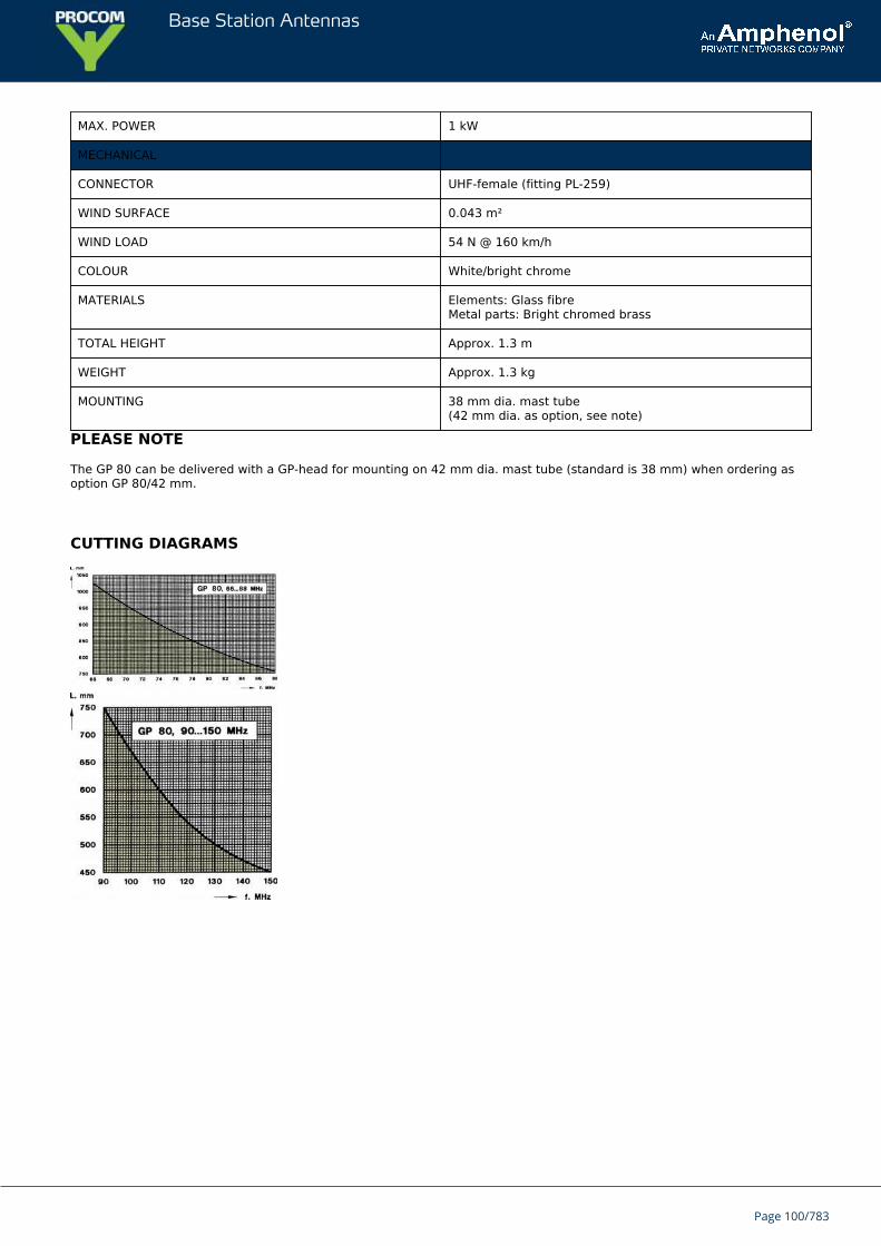
Base Station Antennas
MAX. POWER 1 kW
MECHANICAL
CONNECTOR UHF-female (fitting PL-259)
WIND SURFACE 0.043 m²
WIND LOAD 54 N @ 160 km/h
COLOUR White/bright chrome
MATERIALS Elements: Glass fibreMetal parts: Bright chromed brass
TOTAL HEIGHT Approx. 1.3 m
WEIGHT Approx. 1.3 kg
MOUNTING 38 mm dia. mast tube(42 mm dia. as option, see note)
PLEASE NOTE
The GP 80 can be delivered with a GP-head for mounting on 42 mm dia. mast tube (standard is 38 mm) when ordering asoption GP 80/42 mm.
CUTTING DIAGRAMS
Page 100/783
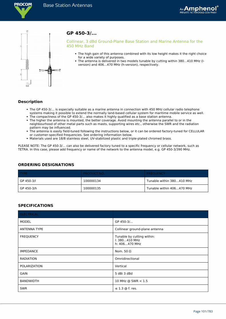
Base Station Antennas
GP 450-3/...Collinear, 3 dBd Ground-Plane Base Station and Marine Antenna for the450 MHz Band
The high gain of this antenna combined with its low height makes it the right choicefor a wide variety of purposes.The antenna is delivered in two models tunable by cutting within 380…410 MHz (l-version) and 406…470 MHz (h-version), respectively.
Description
The GP 450-3/… is especially suitable as a marine antenna in connection with 450 MHz cellular radio telephonesystems making it possible to extend the normally land-based cellular system for maritime mobile service as well.The compactness of the GP 450-3/… also makes it highly qualified as a base station antenna.The higher the antenna is mounted, the better coverage. Avoid mounting the antenna parallel to or in theneighbourhood of other metal parts such as masts, supporting wires etc., otherwise the SWR and the radiationpattern may be influenced.The antenna is easily field-tuned following the instructions below, or it can be ordered factory-tuned for CELLULARor customer-specified frequencies. See ordering information below.Materials used are 18/8 stainless steel, UV-stabilized plastic and triple-plated chromed brass.
PLEASE NOTE: The GP 450-3/… can also be delivered factory tuned to a specific frequency or cellular network, such asTETRA. In this case, please add frequency or name of the network to the antenna model, e.g. GP 450-3/390 MHz.
ORDERING DESIGNATIONS
TYPE PRODUCT NO. FREQUENCY
GP 450-3/l 100000134 Tunable within 380…410 MHz
GP 450-3/h 100000135 Tunable within 406…470 MHz
SPECIFICATIONS
ELECTRICAL
MODEL GP 450-3/...
ANTENNA TYPE Collinear ground-plane antenna
FREQUENCY Tunable by cutting within:l: 380…410 MHzh: 406…470 MHz
IMPEDANCE Nom. 50 Ω
RADIATION Omnidirectional
POLARIZATION Vertical
GAIN 5 dBi 3 dBd
BANDWIDTH 10 MHz @ SWR < 1.5
SWR ≤ 1.3 @ f. res.
Page 101/783
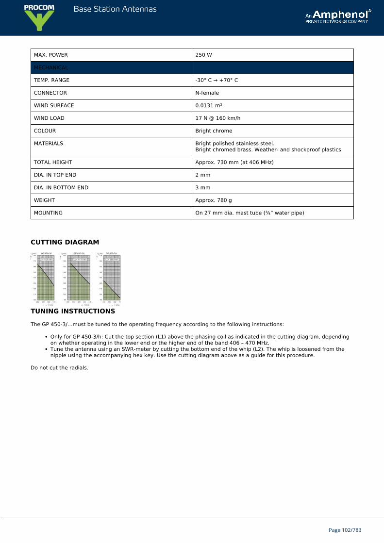
Base Station Antennas
MAX. POWER 250 W
MECHANICAL
TEMP. RANGE -30° C → +70° C
CONNECTOR N-female
WIND SURFACE 0.0131 m²
WIND LOAD 17 N @ 160 km/h
COLOUR Bright chrome
MATERIALS Bright polished stainless steel.Bright chromed brass. Weather- and shockproof plastics
TOTAL HEIGHT Approx. 730 mm (at 406 MHz)
DIA. IN TOP END 2 mm
DIA. IN BOTTOM END 3 mm
WEIGHT Approx. 780 g
MOUNTING On 27 mm dia. mast tube (¾” water pipe)
CUTTING DIAGRAM
TUNING INSTRUCTIONS
The GP 450-3/…must be tuned to the operating frequency according to the following instructions:
Only for GP 450-3/h: Cut the top section (L1) above the phasing coil as indicated in the cutting diagram, dependingon whether operating in the lower end or the higher end of the band 406 – 470 MHz.Tune the antenna using an SWR-meter by cutting the bottom end of the whip (L2). The whip is loosened from thenipple using the accompanying hex key. Use the cutting diagram above as a guide for this procedure.
Do not cut the radials.
Page 102/783
Base Station Antennas
GP 450/...¼ λ Ground-Plane Antenna for the 450 MHz Band
GP 450/… is a ground-plane antenna of the triple-leg type.The antenna is delivered in two models tunable over the ranges 380…430 MHz (l)and 420…470 MHz (h), respectively, by adjusting the length of the radiator.
Description
The cutting diagram on the diagrams tab indicates how long the radiator must be corresponding to a specific centrefrequency. The radiator is measured from its free end (excl. top knob) to the bottom of the black insulator. Do notcut the radials – they should be left untouched.GP 450/… comprises a GP-head, one radiator and threeradials – all made of chromed brass.GP 450/… is made of first-class materials and will endure “wear and tear” for years – no maintenance required.
ORDERING DESIGNATIONS
TYPE NO. PRODUCT NO. FREQUENCY
GP 450/l 100000128 Tunable within 380…430 MHz
GP 450/l-42 mm 100000130 Same as above
GP 450/h 100000129 Tunable within 420…470 MHz
GP 450/h-42 mm 100000133 Same as above
SPECIFICATIONS
ELECTRICAL
MODEL GP 450/...
ANTENNA TYPE ¼ λ ground-plane antenna
FREQUENCY l: 380…430 MHzh: 420…470 MHz
IMPEDANCE Nom. 50 Ω
RADIATION Omnidirectional
POLARIZATION Vertical
GAIN 2 dBi 0 dBd
BANDWIDTH 40 MHz @ SWR 2.0
SWR ≤ 1.2 @ f. res.
MAX. POWER 1 kW
MECHANICAL
Page 103/783
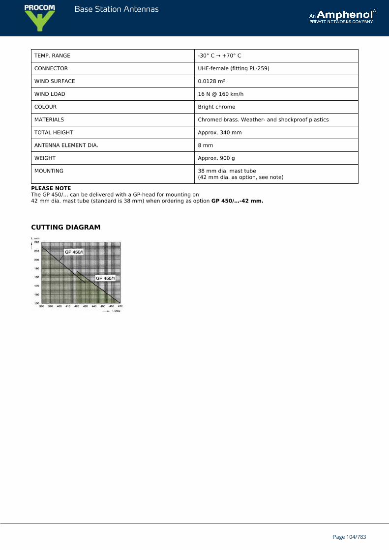
Base Station Antennas
TEMP. RANGE -30° C → +70° C
CONNECTOR UHF-female (fitting PL-259)
WIND SURFACE 0.0128 m²
WIND LOAD 16 N @ 160 km/h
COLOUR Bright chrome
MATERIALS Chromed brass. Weather- and shockproof plastics
TOTAL HEIGHT Approx. 340 mm
ANTENNA ELEMENT DIA. 8 mm
WEIGHT Approx. 900 g
MOUNTING 38 mm dia. mast tube(42 mm dia. as option, see note)
PLEASE NOTEThe GP 450/… can be delivered with a GP-head for mounting on42 mm dia. mast tube (standard is 38 mm) when ordering as option GP 450/…-42 mm.
CUTTING DIAGRAM
Page 104/783
Base Station Antennas
GP 40¼ λ Glass fibre Ground-Plane Antenna for the 40 - 70 MHz Range
GP 40 is a glass fibre ground-plane antenna of the triple-leg type.The antenna is tunable (by cutting) within: 40…70 MHz.
The cutting diagrams below indicate the length of the radiator and the radials corresponding to a specific frequency.It is recommended to use the curves as a guide and fine-tune using an SWR-meter.The antenna comprises a brass GP-head, one glass fibre radiator and three glass fibre radials.GP 40 is made of first-class materials and will endure "wear and tear" for years – no maintenance required.
ORDERING DESIGNATIONS
TYPE PRODUCT NO.
GP 40 100000165
GP 40/42 mm 100000167
SPECIFICATIONS
ELECTRICAL
MODEL GP 40
ANTENNA TYPE ¼ λ triple-leg ground-plane
FREQUENCY Tunable by cutting within: 40…70 MHz
IMPEDANCE Nom. 50 Ω
RADIATION Omnidirectional
POLARIZATION Vertical
GAIN 2 dBi 0 dBd
BANDWIDTH 1.5 MHz @ 40 MHz (SWR ≤ 1.5)3 MHz @ 70 MHz (SWR ≤ 1.5)
SWR < 1.2 @ f. res.
MAX. POWER 1 kW
MECHANICAL
Page 105/783
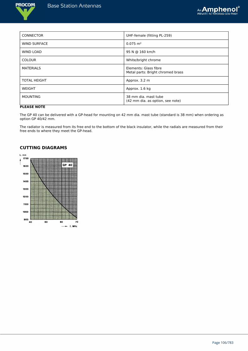
Base Station Antennas
CONNECTOR UHF-female (fitting PL-259)
WIND SURFACE 0.075 m²
WIND LOAD 95 N @ 160 km/h
COLOUR White/bright chrome
MATERIALS Elements: Glass fibreMetal parts: Bright chromed brass
TOTAL HEIGHT Approx. 3.2 m
WEIGHT Approx. 1.6 kg
MOUNTING 38 mm dia. mast tube(42 mm dia. as option, see note)
PLEASE NOTE
The GP 40 can be delivered with a GP-head for mounting on 42 mm dia. mast tube (standard is 38 mm) when ordering asoption GP 40/42 mm.
The radiator is measured from its free end to the bottom of the black insulator, while the radials are measured from theirfree ends to where they meet the GP-head.
CUTTING DIAGRAMS
Page 106/783
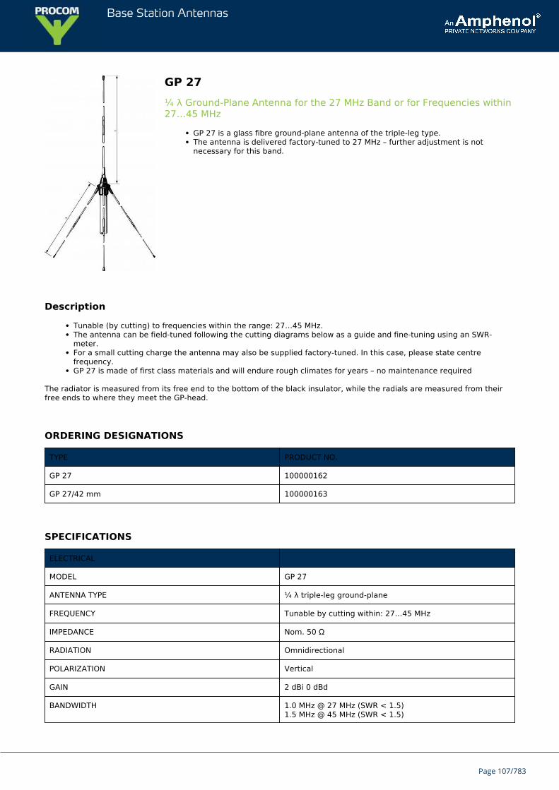
Base Station Antennas
GP 27¼ λ Ground-Plane Antenna for the 27 MHz Band or for Frequencies within27…45 MHz
GP 27 is a glass fibre ground-plane antenna of the triple-leg type.The antenna is delivered factory-tuned to 27 MHz – further adjustment is notnecessary for this band.
Description
Tunable (by cutting) to frequencies within the range: 27…45 MHz.The antenna can be field-tuned following the cutting diagrams below as a guide and fine-tuning using an SWR-meter.For a small cutting charge the antenna may also be supplied factory-tuned. In this case, please state centrefrequency.GP 27 is made of first class materials and will endure rough climates for years – no maintenance required
The radiator is measured from its free end to the bottom of the black insulator, while the radials are measured from theirfree ends to where they meet the GP-head.
ORDERING DESIGNATIONS
TYPE PRODUCT NO.
GP 27 100000162
GP 27/42 mm 100000163
SPECIFICATIONS
ELECTRICAL
MODEL GP 27
ANTENNA TYPE ¼ λ triple-leg ground-plane
FREQUENCY Tunable by cutting within: 27…45 MHz
IMPEDANCE Nom. 50 Ω
RADIATION Omnidirectional
POLARIZATION Vertical
GAIN 2 dBi 0 dBd
BANDWIDTH 1.0 MHz @ 27 MHz (SWR < 1.5)1.5 MHz @ 45 MHz (SWR < 1.5)
Page 107/783
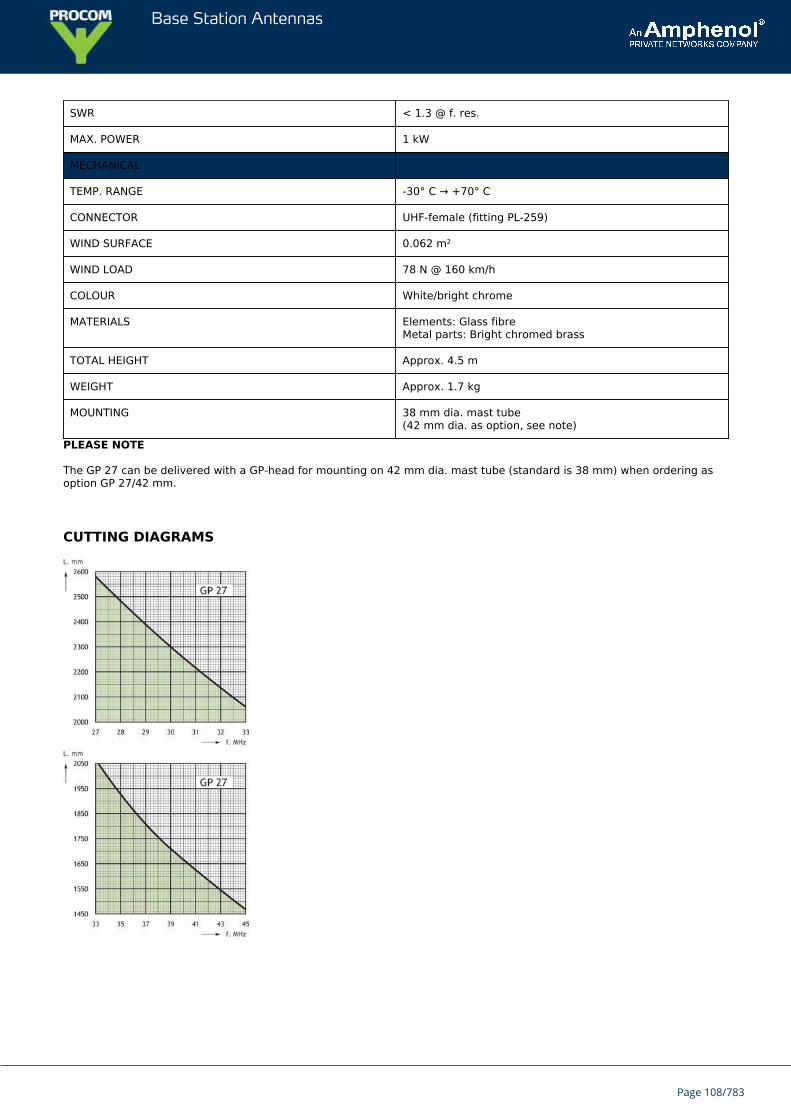
Base Station Antennas
SWR < 1.3 @ f. res.
MAX. POWER 1 kW
MECHANICAL
TEMP. RANGE -30° C → +70° C
CONNECTOR UHF-female (fitting PL-259)
WIND SURFACE 0.062 m²
WIND LOAD 78 N @ 160 km/h
COLOUR White/bright chrome
MATERIALS Elements: Glass fibreMetal parts: Bright chromed brass
TOTAL HEIGHT Approx. 4.5 m
WEIGHT Approx. 1.7 kg
MOUNTING 38 mm dia. mast tube(42 mm dia. as option, see note)
PLEASE NOTE
The GP 27 can be delivered with a GP-head for mounting on 42 mm dia. mast tube (standard is 38 mm) when ordering asoption GP 27/42 mm.
CUTTING DIAGRAMS
Page 108/783
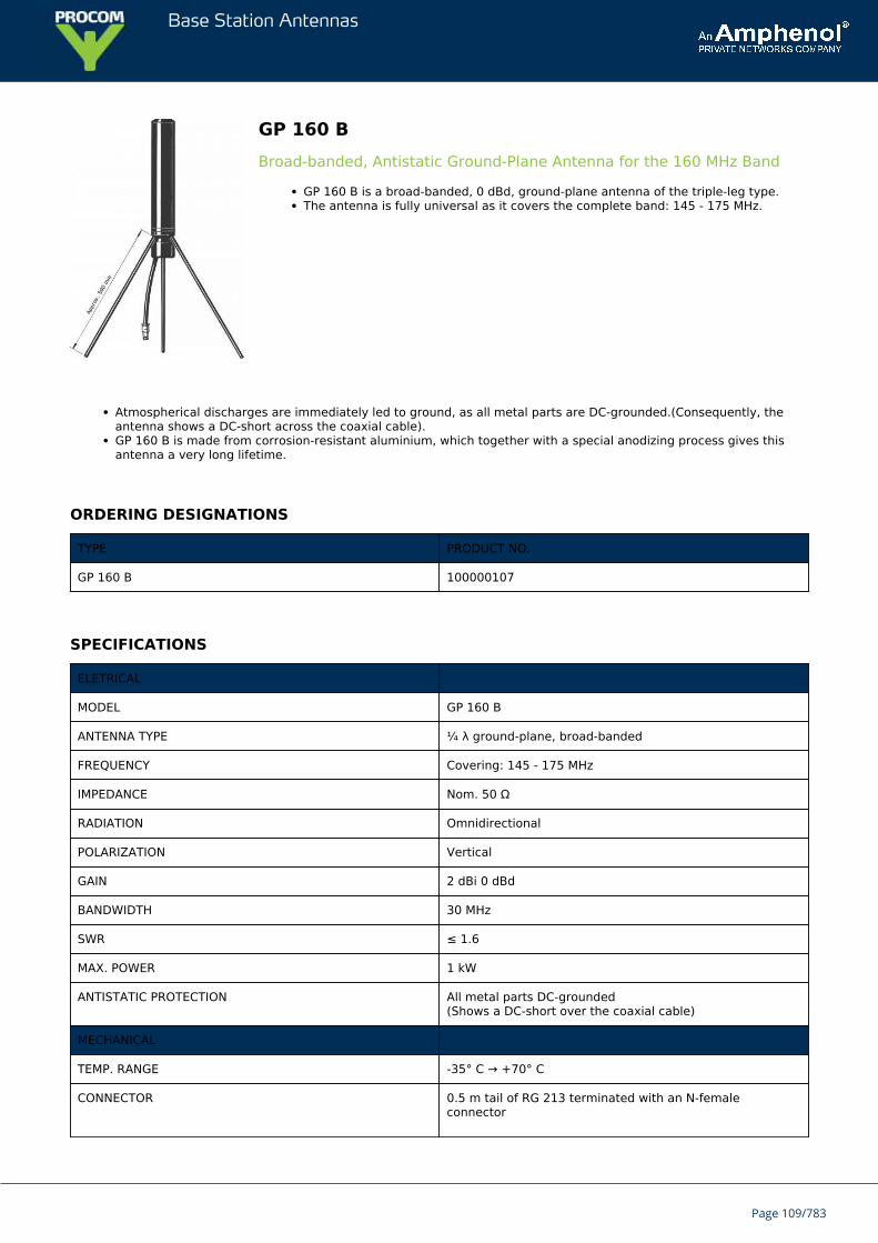
Base Station Antennas
GP 160 BBroad-banded, Antistatic Ground-Plane Antenna for the 160 MHz Band
GP 160 B is a broad-banded, 0 dBd, ground-plane antenna of the triple-leg type.The antenna is fully universal as it covers the complete band: 145 - 175 MHz.
Atmospherical discharges are immediately led to ground, as all metal parts are DC-grounded.(Consequently, theantenna shows a DC-short across the coaxial cable).GP 160 B is made from corrosion-resistant aluminium, which together with a special anodizing process gives thisantenna a very long lifetime.
ORDERING DESIGNATIONS
TYPE PRODUCT NO.
GP 160 B 100000107
SPECIFICATIONS
ELETRICAL
MODEL GP 160 B
ANTENNA TYPE ¼ λ ground-plane, broad-banded
FREQUENCY Covering: 145 - 175 MHz
IMPEDANCE Nom. 50 Ω
RADIATION Omnidirectional
POLARIZATION Vertical
GAIN 2 dBi 0 dBd
BANDWIDTH 30 MHz
SWR ≤ 1.6
MAX. POWER 1 kW
ANTISTATIC PROTECTION All metal parts DC-grounded(Shows a DC-short over the coaxial cable)
MECHANICAL
TEMP. RANGE -35° C → +70° C
CONNECTOR 0.5 m tail of RG 213 terminated with an N-femaleconnector
Page 109/783
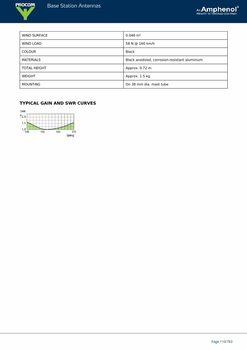
Base Station Antennas
WIND SURFACE 0.046 m²
WIND LOAD 58 N @ 160 km/h
COLOUR Black
MATERIALS Black anodized, corrosion-resistant aluminium
TOTAL HEIGHT Approx. 0.72 m
WEIGHT Approx. 1.5 kg
MOUNTING On 38 mm dia. mast tube
TYPICAL GAIN AND SWR CURVES
Page 110/783
Base Station Antennas
GP 160 5/8⅝ λ Ground-Plane Base Station and Marine Antenna for the 2 m Band
The antenna is tunable (by cutting the radiator) within the frequency band 145…175MHz.GP 160 5/8 is a very sturdy construction which can stand mounting under extremeconditions. It is well suited for mounting on fishing vessels etc. and a good choice forbase stations in the land mobile field.
GP 160 5/8 is a 1 dBd, vertically polarised omnidirectional base station and marine antenna.The antenna is delivered adjusted to 145 MHz unless otherwise specified. It may, however, be delivered preadjustedfor the maritime VHF band provided this is stated on the purchase order.GP 160 5/8 is DC-grounded and antistatically protected as all metal parts are ground-connected. Consequently, theantenna shows a DC-short across the coaxial cable.The materials used are glass fibre and chromed brass.
ORDERING DESIGNATIONS
TYPE PRODUCT NO.
GP 160 5/8 100000108
SPECIFICATIONS
ELECTRICAL
MODEL GP 160 5/8
ANTENNA TYPE ⅝ λ ground-plane
FREQUENCY Tunable by cutting within: 145…175 MHz
IMPEDANCE Nom. 50 Ω
RADIATION Omnidirectional
POLARIZATION Vertical
GAIN 3 dBi 1 dBd
BANDWIDTH 6 MHz (SWR ≤ 2.0)
SWR ≤ 1.2 @ f. res.
MAX. POWER 500 W
ANTISTATIC PROTECTION All metal parts DC-grounded(Connector shows a DC-short)
MECHANICAL
TEMP. RANGE -30° C → +70° C
Page 111/783
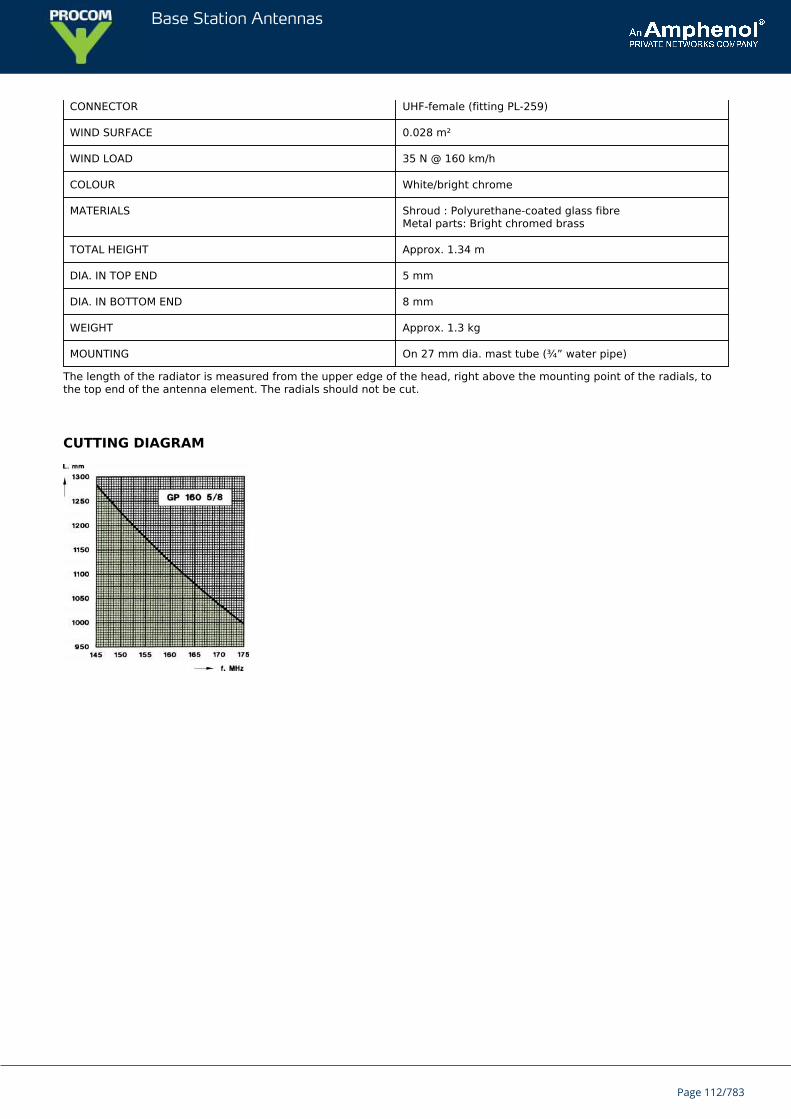
Base Station Antennas
CONNECTOR UHF-female (fitting PL-259)
WIND SURFACE 0.028 m²
WIND LOAD 35 N @ 160 km/h
COLOUR White/bright chrome
MATERIALS Shroud : Polyurethane-coated glass fibreMetal parts: Bright chromed brass
TOTAL HEIGHT Approx. 1.34 m
DIA. IN TOP END 5 mm
DIA. IN BOTTOM END 8 mm
WEIGHT Approx. 1.3 kg
MOUNTING On 27 mm dia. mast tube (¾” water pipe)
The length of the radiator is measured from the upper edge of the head, right above the mounting point of the radials, tothe top end of the antenna element. The radials should not be cut.
CUTTING DIAGRAM
Page 112/783
Base Station Antennas
GP 160¼ λ Glass fibre Ground-Plane Antenna for the 160 MHz Band
GP 160 is a glass fibre ground-plane antenna of the triple-leg type.The antenna is tunable (by cutting) within its main frequency band: 145…175 MHz,but is further applicable up to 400 MHz.
DESCRIPTION
The cutting diagrams below indicate the length of the radiator and the radials corresponding to a specific frequency.It is recommended to use the curves as a guide and fine-tune using an SWR-meter.The antenna comprises a GP-head made of chromed brass, one glassfiber radiator and three glass fibre radials.GP 160 is made of first-class materials and will endure “wear and tear” for years – no maintenance required.LW-SS-1" mounting bracket and GP Adaptor is available as accessories.
ORDERING DESIGNATIONS
TYPE PRODUCT NO.
GP 160 100000104
GP 160/42 mm 100000105
ACCESSORIES
LW-SS-1" 110000394
GP Adaptor 100000679
SPECIFICATIONS
ELETRICAL
MODEL GP 160
ANTENNA TYPE ¼ λ ground-plane
FREQUENCY Tunable by cutting within: 145…175 MHz(Also applicable: 175…400 MHz)
IMPEDANCE Nom. 50 Ω
RADIATION Omnidirectional
POLARIZATION Vertical
GAIN 2 dBi 0 dBd
Page 113/783
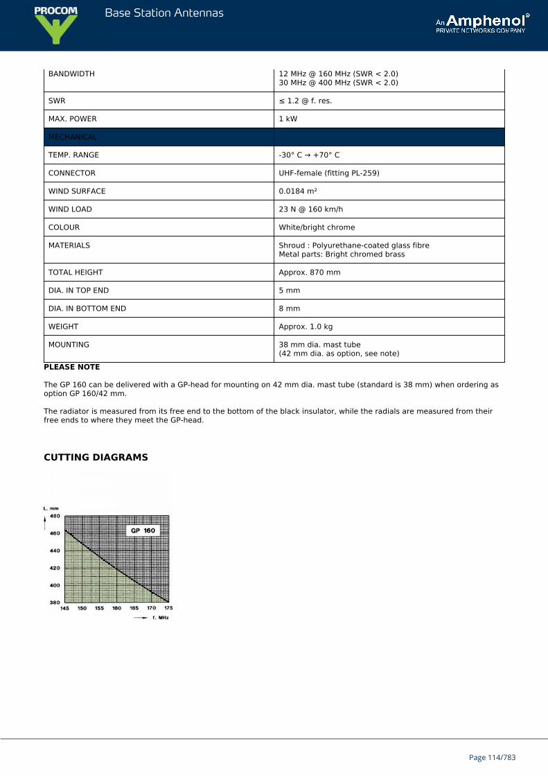
Base Station Antennas
BANDWIDTH 12 MHz @ 160 MHz (SWR < 2.0)30 MHz @ 400 MHz (SWR < 2.0)
SWR ≤ 1.2 @ f. res.
MAX. POWER 1 kW
MECHANICAL
TEMP. RANGE -30° C → +70° C
CONNECTOR UHF-female (fitting PL-259)
WIND SURFACE 0.0184 m²
WIND LOAD 23 N @ 160 km/h
COLOUR White/bright chrome
MATERIALS Shroud : Polyurethane-coated glass fibreMetal parts: Bright chromed brass
TOTAL HEIGHT Approx. 870 mm
DIA. IN TOP END 5 mm
DIA. IN BOTTOM END 8 mm
WEIGHT Approx. 1.0 kg
MOUNTING 38 mm dia. mast tube(42 mm dia. as option, see note)
PLEASE NOTE
The GP 160 can be delivered with a GP-head for mounting on 42 mm dia. mast tube (standard is 38 mm) when ordering asoption GP 160/42 mm.
The radiator is measured from its free end to the bottom of the black insulator, while the radials are measured from theirfree ends to where they meet the GP-head.
CUTTING DIAGRAMS
Page 114/783
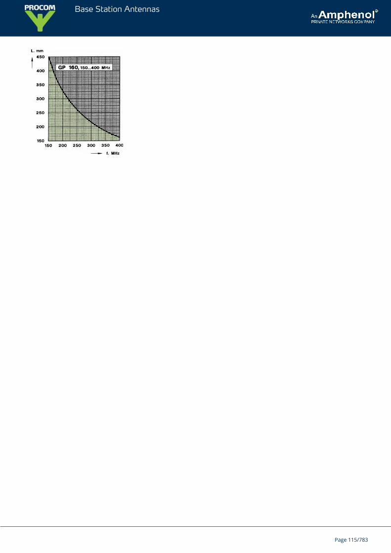
Base Station Antennas
Page 115/783

Base Station Antennas
CXL 2400-8LW/...8 db Omnidirectional Base Station and Marine Antenna for the 2400 MHzBand
Vertically polarized, omnidirectional base station and marine antenna.Approximately 8 dBd gain.
DESCRIPTION
Provided with the sturdy “LW” mast mount – a lightweight, multipurpose, epoxy-coated mounting bracket made ofnon-corrosive aluminium.The accompanying U-bolts and fittings are made of stainless steel.To be mounted on vertical or horizontal mast tubes, 16 to54 mm in outer diameter.The cable can be led either on the outside or along the inside of the mast tube.Large bandwidth with respect to both SWR and gain.Highly suitable for duplex operation with large spacing between the TX and the RX frequencies.The antenna element is sealed in a high-quality, conical glass fibre tube.All metal parts in the antenna are DC-grounded to reduce the noise caused by atmospherical discharge.Consequently, the antenna shows a DC-short across the coaxial cable.The CXL 2400-8LW/… is a vibration-proof, lightweight, slim-line, corrosion resistant, modern style base station andmarine antenna.
ORDERING DESIGNATIONS
TYPE PRODUCT NO. FREQUENCY
CXL 2400-8LW/l 100000170 2300 – 2400 MHz
CXL 2400-8LW/m 100000172 2400 – 2500 MHz
CXL 2400-8LW/h 100000168 2530 – 2660 MHz
SPECIFICATIONS
ELECTRICAL
MODEL CXL 2400-8LW/...
ANTENNA TYPE Coaxial, collinear antenna, broadbanded
FREQUENCY Models within 2300 – 2660 MHz
IMPEDANCE Nom. 50 Ω
POLARIZATION Vertical
GAIN Average gain 10 dBi 8 dBd
HALF POWER BEAMWIDTH 7°
BANDWIDTH ≥ 100 MHz @ SWR ≤ 1.5
Page 116/783
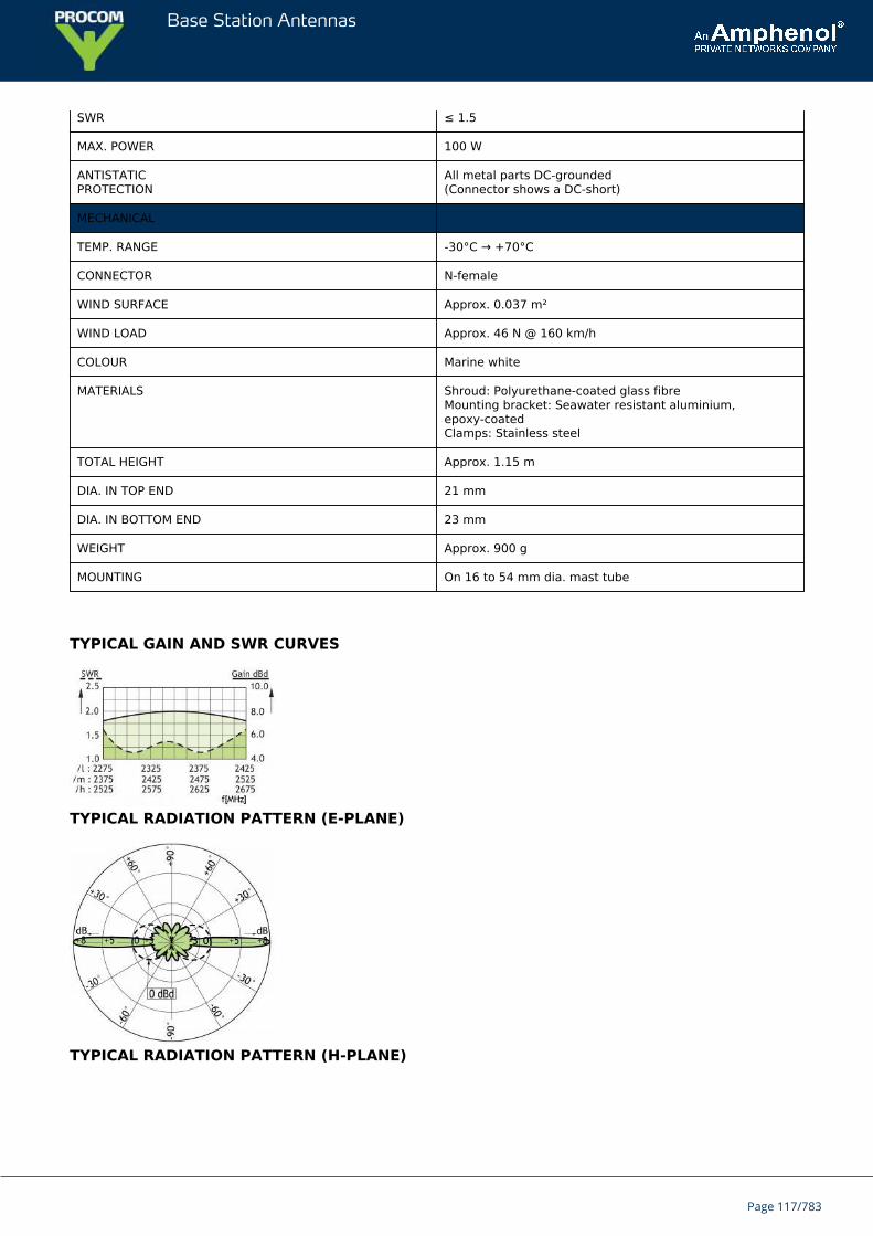
Base Station Antennas
SWR ≤ 1.5
MAX. POWER 100 W
ANTISTATICPROTECTION
All metal parts DC-grounded(Connector shows a DC-short)
MECHANICAL
TEMP. RANGE -30°C → +70°C
CONNECTOR N-female
WIND SURFACE Approx. 0.037 m²
WIND LOAD Approx. 46 N @ 160 km/h
COLOUR Marine white
MATERIALS Shroud: Polyurethane-coated glass fibreMounting bracket: Seawater resistant aluminium,epoxy-coatedClamps: Stainless steel
TOTAL HEIGHT Approx. 1.15 m
DIA. IN TOP END 21 mm
DIA. IN BOTTOM END 23 mm
WEIGHT Approx. 900 g
MOUNTING On 16 to 54 mm dia. mast tube
TYPICAL GAIN AND SWR CURVES
TYPICAL RADIATION PATTERN (E-PLANE)
TYPICAL RADIATION PATTERN (H-PLANE)
Page 117/783

Base Station Antennas
MULTI-PURPOSE MOUNTING BRACKET
PLEASE NOTE
The antenna is delivered with a DC-connection between the antenna element and the mounting bracket.
Page 118/783
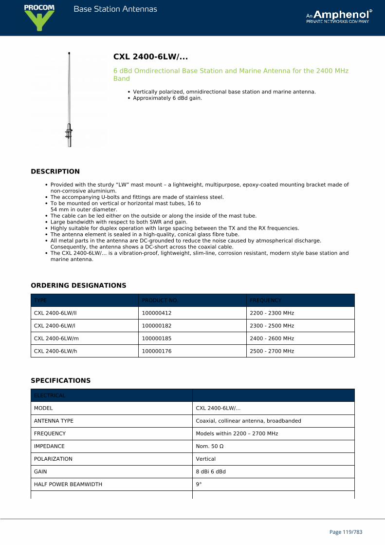
Base Station Antennas
CXL 2400-6LW/...6 dBd Omdirectional Base Station and Marine Antenna for the 2400 MHzBand
Vertically polarized, omnidirectional base station and marine antenna.Approximately 6 dBd gain.
DESCRIPTION
Provided with the sturdy “LW” mast mount – a lightweight, multipurpose, epoxy-coated mounting bracket made ofnon-corrosive aluminium.The accompanying U-bolts and fittings are made of stainless steel.To be mounted on vertical or horizontal mast tubes, 16 to54 mm in outer diameter.The cable can be led either on the outside or along the inside of the mast tube.Large bandwidth with respect to both SWR and gain.Highly suitable for duplex operation with large spacing between the TX and the RX frequencies.The antenna element is sealed in a high-quality, conical glass fibre tube.All metal parts in the antenna are DC-grounded to reduce the noise caused by atmospherical discharge.Consequently, the antenna shows a DC-short across the coaxial cable.The CXL 2400-6LW/… is a vibration-proof, lightweight, slim-line, corrosion resistant, modern style base station andmarine antenna.
ORDERING DESIGNATIONS
TYPE PRODUCT NO. FREQUENCY
CXL 2400-6LW/ll 100000412 2200 - 2300 MHz
CXL 2400-6LW/l 100000182 2300 - 2500 MHz
CXL 2400-6LW/m 100000185 2400 - 2600 MHz
CXL 2400-6LW/h 100000176 2500 - 2700 MHz
SPECIFICATIONS
ELECTRICAL
MODEL CXL 2400-6LW/...
ANTENNA TYPE Coaxial, collinear antenna, broadbanded
FREQUENCY Models within 2200 – 2700 MHz
IMPEDANCE Nom. 50 Ω
POLARIZATION Vertical
GAIN 8 dBi 6 dBd
HALF POWER BEAMWIDTH 9°
Page 119/783
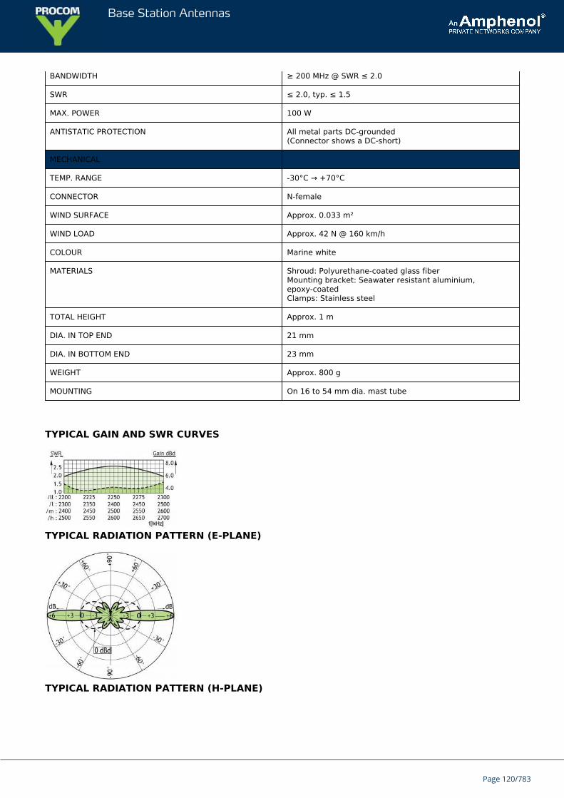
Base Station Antennas
BANDWIDTH ≥ 200 MHz @ SWR ≤ 2.0
SWR ≤ 2.0, typ. ≤ 1.5
MAX. POWER 100 W
ANTISTATIC PROTECTION All metal parts DC-grounded(Connector shows a DC-short)
MECHANICAL
TEMP. RANGE -30°C → +70°C
CONNECTOR N-female
WIND SURFACE Approx. 0.033 m²
WIND LOAD Approx. 42 N @ 160 km/h
COLOUR Marine white
MATERIALS Shroud: Polyurethane-coated glass fiberMounting bracket: Seawater resistant aluminium,epoxy-coatedClamps: Stainless steel
TOTAL HEIGHT Approx. 1 m
DIA. IN TOP END 21 mm
DIA. IN BOTTOM END 23 mm
WEIGHT Approx. 800 g
MOUNTING On 16 to 54 mm dia. mast tube
TYPICAL GAIN AND SWR CURVES
TYPICAL RADIATION PATTERN (E-PLANE)
TYPICAL RADIATION PATTERN (H-PLANE)
Page 120/783

Base Station Antennas
MULTI-PURPOSE MOUNTING BRACKET
PLEASE NOTE
The antenna is delivered with a DC-connection between the antenna element and the mounting bracket.
Page 121/783
Base Station Antennas
CXL 2400-6/...6 dBd Omdirectional Base Station and Marine Antenna for the 2400 MHzBand
Vertically polarized, omnidirectional base station antenna and marine.Approximately 6 dBd gain.
DESCRIPTION
Simple mounting using the 1” revolving nut system.Wide variety of accessory mounting brackets available.Large bandwidth with respect to both SWR and gain.Highly suitable for duplex operation with large spacing between the TX and the RX frequencies.The antenna element is sealed in a high-quality, conical glass fibre tube.All metal parts in the antenna are DC-grounded to reduce the noise caused by atmospherical discharge.Consequently, the antenna shows a DC-short across the coaxial cable.The CXL 2400-6/… is a vibration-proof, lightweight, slim-line, corrosion resistant, modern style base station antennaand marine.
ORDERING DESIGNATIONS
TYPE PRODUCT NO. FREQUENCY
CXL 2400-6/ll 100000432 2200 - 2300 MHz
CXL 2400-6/l 110000161 2300 - 2500 MHz
CXL 2400-6/m 110000163 2400 - 2600 MHz
CXL 2400-6/h 110000162 2500 - 2700 MHz
SPECIFICATIONS
ELECTRICAL
MODEL CXL 2400-6/...
ANTENNA TYPE Coaxial, collinear antenna, broad-banded
FREQUENCY Models within 2200 – 2700 MHz
IMPEDANCE Nom. 50 Ω
POLARIZATION Vertical
GAIN 8 dBi 6 dBd
BANDWIDTH ≥ 200 MHz @ SWR ≤ 2.0
SWR ≤ 2.0, typ. ≤ 1.5
MAX. POWER 100 W
Page 122/783
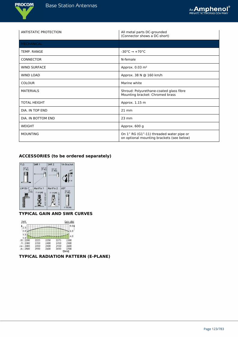
Base Station Antennas
ANTISTATIC PROTECTION All metal parts DC-grounded(Connector shows a DC-short)
MECHANICAL
TEMP. RANGE -30°C → +70°C
CONNECTOR N-female
WIND SURFACE Approx. 0.03 m²
WIND LOAD Approx. 38 N @ 160 km/h
COLOUR Marine white
MATERIALS Shroud: Polyurethane-coated glass fibreMounting bracket: Chromed brass
TOTAL HEIGHT Approx. 1.15 m
DIA. IN TOP END 21 mm
DIA. IN BOTTOM END 23 mm
WEIGHT Approx. 600 g
MOUNTING On 1” RG (G1”-11) threaded water pipe oron optional mounting brackets (see below)
ACCESSORIES (to be ordered separately)
TYPICAL GAIN AND SWR CURVES
TYPICAL RADIATION PATTERN (E-PLANE)
Page 123/783

Base Station Antennas
TYPICAL RADIATION PATTERN (H-PLANE),
Page 124/783
Base Station Antennas
CXL 2400-3LW/...3 dBd Omnidirectional Base Station and Marine Antenna for the 2400 MHzBand
Vertically polarized, omnidirectional base station and marine antenna.Approximately 3 dBd gain.
DESCRIPTION
Provided with the sturdy “LW” mast mount – a lightweight, multipurpose, epoxy-coated mounting bracket made ofnon-corrosive aluminium.The accompanying U-bolts and fittings are made of stainless steel.To be mounted on vertical or horizontal mast tubes, 16 to54 mm in outer diameter.The cable can be led either on the outside or along the inside of the mast tube.Large bandwidth with respect to both SWR and gain.Highly suitable for duplex operation with large spacing between the TX and the RX frequencies.The antenna element is sealed in a high-quality, conical glass fibre tube.All metal parts in the antenna are DC-grounded to reduce the noise caused by atmospherical discharge.Consequently, the antenna shows a DC-short across the coaxial cable.The CXL 2400-3LW/… is a vibration-proof, lightweight, slim-line, corrosion resistant, modern style base station andmarine antenna.
ORDERING DESIGNATIONS
TYPE PRODUCT NO. FREQUENCY
CXL 2400-3LW/ll 100000557 2200 - 2300 MHz
CXL 2400-3LW/l 100000183 2300 – 2500 MHz
CXL 2400-3LW/m 100000169 2400 – 2600 MHz
CXL 2400-3LW/h 100000171 2500 – 2700 MHz
SPECIFICATIONS
ELECTRICAL
MODEL CXL 2400-3LW/...
ANTENNA TYPE Coaxial, collinear antenna, broadbanded
FREQUENCY Models within 2200 – 2700 MHz
IMPEDANCE Nom. 50 Ω
POLARIZATION Vertical
GAIN 5 dBi 3 dBd
Page 125/783
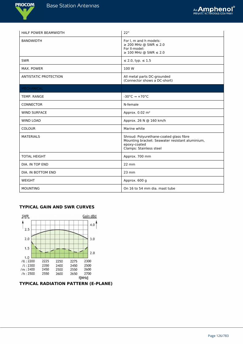
Base Station Antennas
HALF POWER BEAMWIDTH 22°
BANDWIDTH For l, m and h models:≥ 200 MHz @ SWR ≤ 2.0For ll-model:≥ 100 MHz @ SWR ≤ 2.0
SWR ≤ 2.0, typ. ≤ 1.5
MAX. POWER 100 W
ANTISTATIC PROTECTION All metal parts DC-grounded(Connector shows a DC-short)
MECHANICAL
TEMP. RANGE -30°C → +70°C
CONNECTOR N-female
WIND SURFACE Approx. 0.02 m²
WIND LOAD Approx. 26 N @ 160 km/h
COLOUR Marine white
MATERIALS Shroud: Polyurethane-coated glass fibreMounting bracket: Seawater resistant aluminium,epoxy-coatedClamps: Stainless steel
TOTAL HEIGHT Approx. 700 mm
DIA. IN TOP END 22 mm
DIA. IN BOTTOM END 23 mm
WEIGHT Approx. 600 g
MOUNTING On 16 to 54 mm dia. mast tube
TYPICAL GAIN AND SWR CURVES
TYPICAL RADIATION PATTERN (E-PLANE)
Page 126/783

Base Station Antennas
TYPICAL RADIATION PATTERN (H-PLANE)
MULTI-PURPOSE MOUNTING BRACKET
PLEASE NOTE
The antenna is delivered with a DC-connection between the antenna element and the mounting bracket.
Page 127/783
Base Station Antennas
CXL 2400-3/...3 dBd Omnidirectional Base Station and Marine Antenna for the 2400 MHzBand
Vertically polarized, omnidirectional base station and marine antenna.Approximately 3 dBd gain.
DESCRIPTION
Simple mounting using the 1” revolving nut system.Wide variety of accessory mounting brackets available.Large bandwidth with respect to both SWR and gain.Highly suitable for duplex operation with large spacing between the TX and the RX frequencies.The antenna element is sealed in a high-quality, conical glass fibre tube.All metal parts in the antenna are DC-grounded to reduce the noise caused by atmospherical discharge.Consequently, the antenna shows a DC-short across the coaxial cable.The CXL 2400-3/… is a vibration-proof, lightweight, slim-line, corrosion resistant, modern style base station andmarine antenna.
ORDERING DESIGNATIONS
TYPE PRODUCT NO. FREQUENCY
CXL 2400-3/ll 100000586 2200 – 2300 MHz
CXL 2400-3/l 110000157 2300 – 2500 MHz
CXL 2400-3/m 110000158 2400 - 2600 MHz
CXL 2400-3/h 110000159 2500 – 2700 MHz
SPECIFICATIONS
ELECTRICAL
MODEL CXL 2400-3/...
ANTENNA TYPE Coaxial, collinear antenna, broad-banded
FREQUENCY Models within 2200 – 2700 MHz
IMPEDANCE Nom. 50 Ω
POLARIZATION Vertical
GAIN 5 dBi 3 dBd
BANDWIDTH ≥ 200 MHz @ SWR ≤ 2.0
SWR ≤ 2.0, typ. ≤ 1.5
MAX. POWER 100 W
Page 128/783
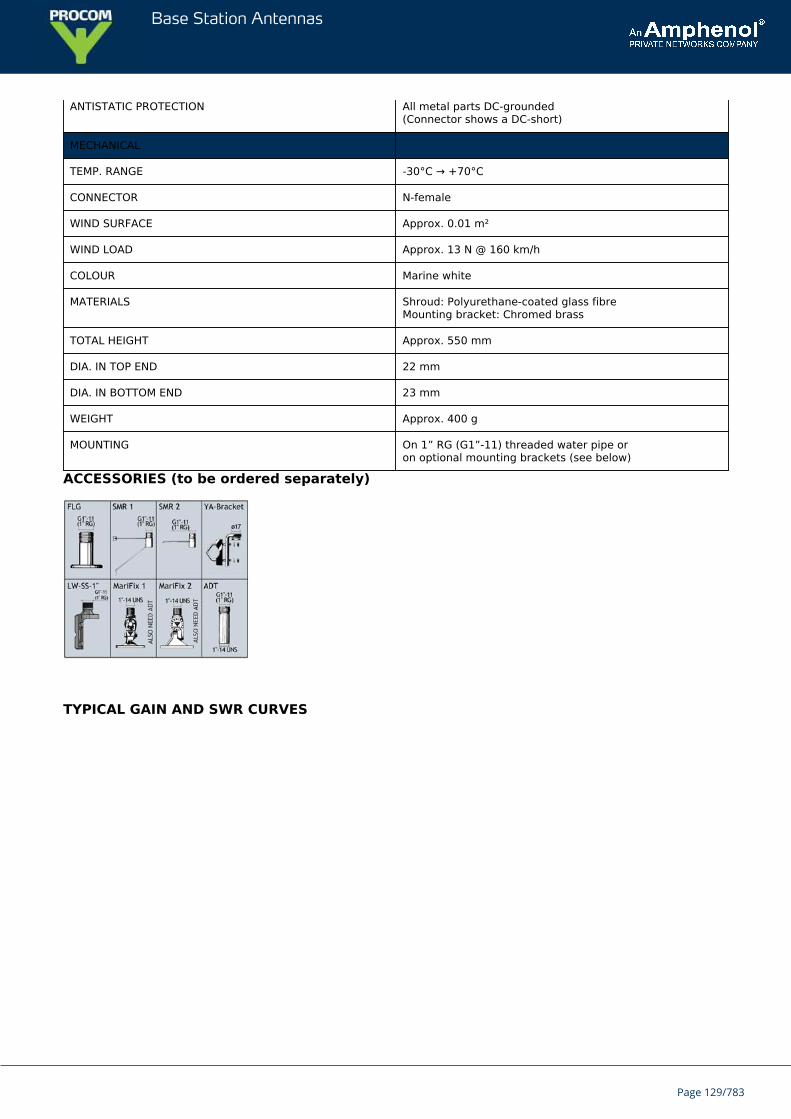
Base Station Antennas
ANTISTATIC PROTECTION All metal parts DC-grounded(Connector shows a DC-short)
MECHANICAL
TEMP. RANGE -30°C → +70°C
CONNECTOR N-female
WIND SURFACE Approx. 0.01 m²
WIND LOAD Approx. 13 N @ 160 km/h
COLOUR Marine white
MATERIALS Shroud: Polyurethane-coated glass fibreMounting bracket: Chromed brass
TOTAL HEIGHT Approx. 550 mm
DIA. IN TOP END 22 mm
DIA. IN BOTTOM END 23 mm
WEIGHT Approx. 400 g
MOUNTING On 1” RG (G1”-11) threaded water pipe oron optional mounting brackets (see below)
ACCESSORIES (to be ordered separately)
TYPICAL GAIN AND SWR CURVES
Page 129/783
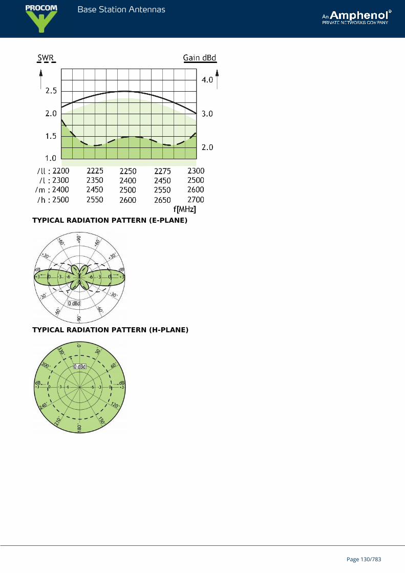
Base Station Antennas
TYPICAL RADIATION PATTERN (E-PLANE)
TYPICAL RADIATION PATTERN (H-PLANE)
Page 130/783
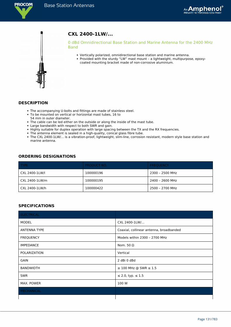
Base Station Antennas
CXL 2400-1LW/...0 dBd Omnidirectional Base Station and Marine Antenna for the 2400 MHzBand
Vertically polarized, omnidirectional base station and marine antenna.Provided with the sturdy “LW” mast mount – a lightweight, multipurpose, epoxy-coated mounting bracket made of non-corrosive aluminium.
DESCRIPTION
The accompanying U-bolts and fittings are made of stainless steel.To be mounted on vertical or horizontal mast tubes, 16 to54 mm in outer diameter.The cable can be led either on the outside or along the inside of the mast tube.Large bandwidth with respect to both SWR and gain.Highly suitable for duplex operation with large spacing between the TX and the RX frequencies.The antenna element is sealed in a high-quality, conical glass fibre tube.The CXL 2400-1LW/... is a vibration-proof, lightweight, slim-line, corrosion resistant, modern style base station andmarine antenna.
ORDERING DESIGNATIONS
TYPE PRODUCT NO. FREQUENCY
CXL 2400-1LW/l 100000196 2300 – 2500 MHz
CXL 2400-1LW/m 100000195 2400 – 2600 MHz
CXL 2400-1LW/h 100000422 2500 – 2700 MHz
SPECIFICATIONS
ELECTRICAL
MODEL CXL 2400-1LW/...
ANTENNA TYPE Coaxial, collinear antenna, broadbanded
FREQUENCY Models within 2300 – 2700 MHz
IMPEDANCE Nom. 50 Ω
POLARIZATION Vertical
GAIN 2 dBi 0 dBd
BANDWIDTH ≥ 100 MHz @ SWR ≤ 1.5
SWR ≤ 2.0, typ. ≤ 1.5
MAX. POWER 100 W
MECHANICAL
Page 131/783
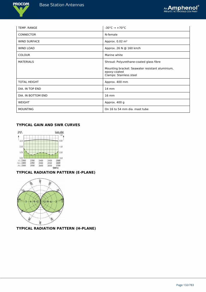
Base Station Antennas
TEMP. RANGE -30°C → +70°C
CONNECTOR N-female
WIND SURFACE Approx. 0.02 m²
WIND LOAD Approx. 26 N @ 160 km/h
COLOUR Marine white
MATERIALS Shroud: Polyurethane-coated glass fibre
Mounting bracket: Seawater resistant aluminium,epoxy-coatedClamps: Stainless steel
TOTAL HEIGHT Approx. 400 mm
DIA. IN TOP END 14 mm
DIA. IN BOTTOM END 16 mm
WEIGHT Approx. 400 g
MOUNTING On 16 to 54 mm dia. mast tube
TYPICAL GAIN AND SWR CURVES
TYPICAL RADIATION PATTERN (E-PLANE)
TYPICAL RADIATION PATTERN (H-PLANE)
Page 132/783

Base Station Antennas
MULTI-PURPOSE MOUNTING BRACKET
PLEASE NOTE
The antenna is delivered with a DC-connection between the antenna element and the mounting bracket.
Page 133/783
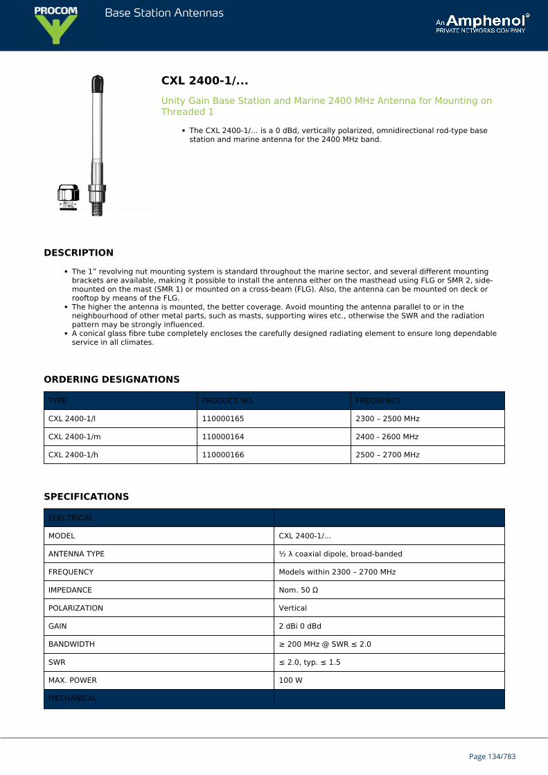
Base Station Antennas
CXL 2400-1/...Unity Gain Base Station and Marine 2400 MHz Antenna for Mounting onThreaded 1
The CXL 2400-1/… is a 0 dBd, vertically polarized, omnidirectional rod-type basestation and marine antenna for the 2400 MHz band.
DESCRIPTION
The 1” revolving nut mounting system is standard throughout the marine sector, and several different mountingbrackets are available, making it possible to install the antenna either on the masthead using FLG or SMR 2, side-mounted on the mast (SMR 1) or mounted on a cross-beam (FLG). Also, the antenna can be mounted on deck orrooftop by means of the FLG.The higher the antenna is mounted, the better coverage. Avoid mounting the antenna parallel to or in theneighbourhood of other metal parts, such as masts, supporting wires etc., otherwise the SWR and the radiationpattern may be strongly influenced.A conical glass fibre tube completely encloses the carefully designed radiating element to ensure long dependableservice in all climates.
ORDERING DESIGNATIONS
TYPE PRODUCT NO. FREQUENCY
CXL 2400-1/l 110000165 2300 – 2500 MHz
CXL 2400-1/m 110000164 2400 - 2600 MHz
CXL 2400-1/h 110000166 2500 – 2700 MHz
SPECIFICATIONS
ELECTRICAL
MODEL CXL 2400-1/...
ANTENNA TYPE ½ λ coaxial dipole, broad-banded
FREQUENCY Models within 2300 – 2700 MHz
IMPEDANCE Nom. 50 Ω
POLARIZATION Vertical
GAIN 2 dBi 0 dBd
BANDWIDTH ≥ 200 MHz @ SWR ≤ 2.0
SWR ≤ 2.0, typ. ≤ 1.5
MAX. POWER 100 W
MECHANICAL
Page 134/783

Base Station Antennas
TEMP. RANGE -30°C → +70°C
CONNECTOR N-female
WIND SURFACE Approx. 0.006 m²
WIND LOAD Approx. 8 N @ 160 km/h
COLOUR Marine white
MATERIALS Shroud: Polyurethane-coated glass fibreMounting bracket: Chromed brass
TOTAL HEIGHT Approx. 230 mm
DIA. IN TOP END 14 mm
DIA. IN BOTTOM END 16 mm
WEIGHT Approx. 180 g
MOUNTING On 1” RG (G1”-11) threaded water pipe oron optional mounting brackets (see accessories)
ACCESSORIES (to be ordered separately)
TYPICAL GAIN AND SWR CURVES
TYPICAL RADIATION PATTERN (E-PLANE)
Page 135/783

Base Station Antennas
TYPICAL RADIATION PATTERN (H-PLANE)
Page 136/783
Base Station Antennas
CXL 230-3LW/DABLightweight, 3 dBd BAse Station and Marine Antenna for the DAB Band
CXL 230-3LW/DAB is a vertically polarised, omnidirectional base station and marineantenna, which covers the DAB (Digital Audio Broadcast) Band.Approximately 3 dBd gain.
DESCRIPTION
Provided with the sturdy “LW” mast mount – a lightweight, multipurpose,epoxy-coated mounting bracket made of non-corrosive aluminium.The accompanying U-bolts and fittings are made of stainless steel.To be mounted on vertical or horizontal mast tubes, 16 to 54 mm in outer diameter.The cable can be led either on the outside or along the inside of the mast tube.Large bandwidth with respect to both SWR and gain.The phasing of the radiating elements is adjusted to yield maximum gain in the horizontal plane, with the level ofthe sidelobes reduced to a minimum.The carefully designed, broad-banded antenna element is sealed in a high-quality conical glass fibre tube with lowwind-load, which will ensure performance undisturbed by corrosive environments.All metal parts in the antenna are DC-grounded to reduce the noise caused by atmospherical discharge.Consequently, the antenna shows a DC-short across the coaxial cable.The CXL 230-3LW/DAB is a vibration-proof, lightweight, slim-line, corrosion resistant, modern style base station andmarine antenna.
ORDERING DESIGNATIONS
TYPE PRODUCT NO.
CXL 230-3LW/DAB 110000115
SPECIFICATIONS
ELECTRICAL
MODEL CXL 230-3LW/DAB
ANTENNA TYPE Broad-banded collinear antenna
FREQUENCY 223 - 240 MHz
IMPEDANCE Nom. 50 Ω
RADIATION Omnidirectional
POLARIZATION Vertical
GAIN 5 dBi 3 dBd
HALF POWER BEAMWIDTH 30°
BANDWIDTH 17 MHz
SWR < 1.5
MAX. POWER 150 W
ANTISTATICPROTECTION
All metal parts DC-grounded(Connector shows a DC-short)
Page 137/783
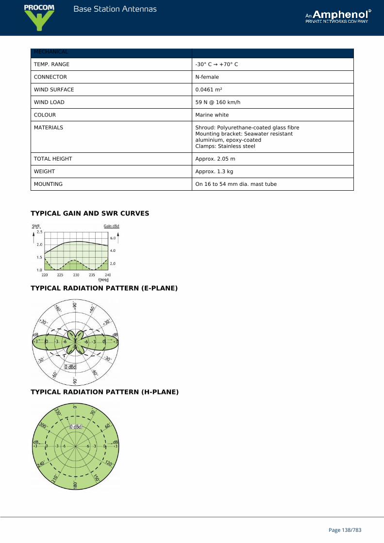
Base Station Antennas
MECHANICAL
TEMP. RANGE -30° C → +70° C
CONNECTOR N-female
WIND SURFACE 0.0461 m²
WIND LOAD 59 N @ 160 km/h
COLOUR Marine white
MATERIALS Shroud: Polyurethane-coated glass fibreMounting bracket: Seawater resistantaluminium, epoxy-coatedClamps: Stainless steel
TOTAL HEIGHT Approx. 2.05 m
WEIGHT Approx. 1.3 kg
MOUNTING On 16 to 54 mm dia. mast tube
TYPICAL GAIN AND SWR CURVES
TYPICAL RADIATION PATTERN (E-PLANE)
TYPICAL RADIATION PATTERN (H-PLANE)
Page 138/783
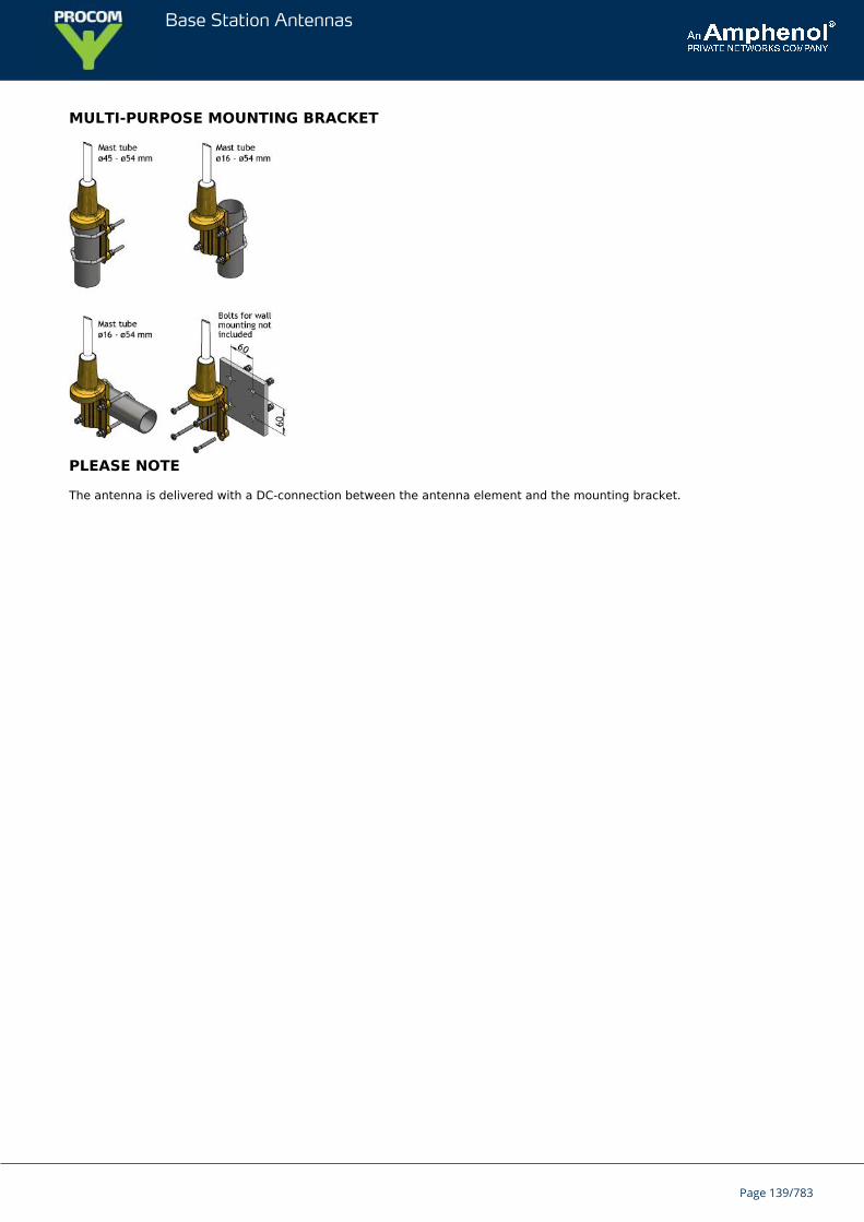
Base Station Antennas
MULTI-PURPOSE MOUNTING BRACKET
PLEASE NOTE
The antenna is delivered with a DC-connection between the antenna element and the mounting bracket.
Page 139/783
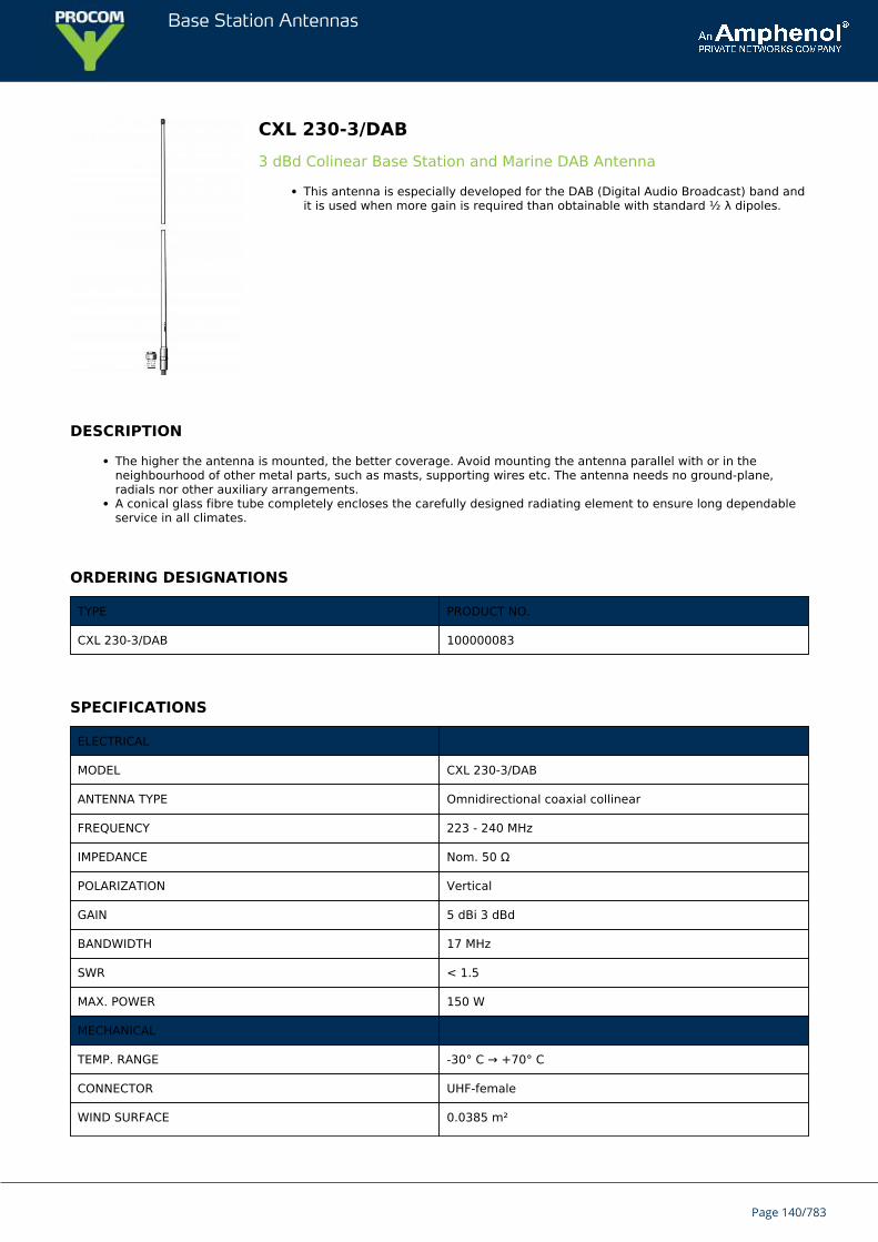
Base Station Antennas
CXL 230-3/DAB3 dBd Colinear Base Station and Marine DAB Antenna
This antenna is especially developed for the DAB (Digital Audio Broadcast) band andit is used when more gain is required than obtainable with standard ½ λ dipoles.
DESCRIPTION
The higher the antenna is mounted, the better coverage. Avoid mounting the antenna parallel with or in theneighbourhood of other metal parts, such as masts, supporting wires etc. The antenna needs no ground-plane,radials nor other auxiliary arrangements.A conical glass fibre tube completely encloses the carefully designed radiating element to ensure long dependableservice in all climates.
ORDERING DESIGNATIONS
TYPE PRODUCT NO.
CXL 230-3/DAB 100000083
SPECIFICATIONS
ELECTRICAL
MODEL CXL 230-3/DAB
ANTENNA TYPE Omnidirectional coaxial collinear
FREQUENCY 223 - 240 MHz
IMPEDANCE Nom. 50 Ω
POLARIZATION Vertical
GAIN 5 dBi 3 dBd
BANDWIDTH 17 MHz
SWR < 1.5
MAX. POWER 150 W
MECHANICAL
TEMP. RANGE -30° C → +70° C
CONNECTOR UHF-female
WIND SURFACE 0.0385 m²
Page 140/783
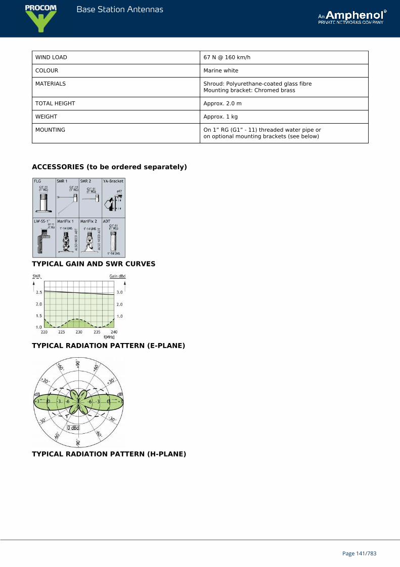
Base Station Antennas
WIND LOAD 67 N @ 160 km/h
COLOUR Marine white
MATERIALS Shroud: Polyurethane-coated glass fibreMounting bracket: Chromed brass
TOTAL HEIGHT Approx. 2.0 m
WEIGHT Approx. 1 kg
MOUNTING On 1” RG (G1” - 11) threaded water pipe oron optional mounting brackets (see below)
ACCESSORIES (to be ordered separately)
TYPICAL GAIN AND SWR CURVES
TYPICAL RADIATION PATTERN (E-PLANE)
TYPICAL RADIATION PATTERN (H-PLANE)
Page 141/783

Base Station Antennas
Page 142/783
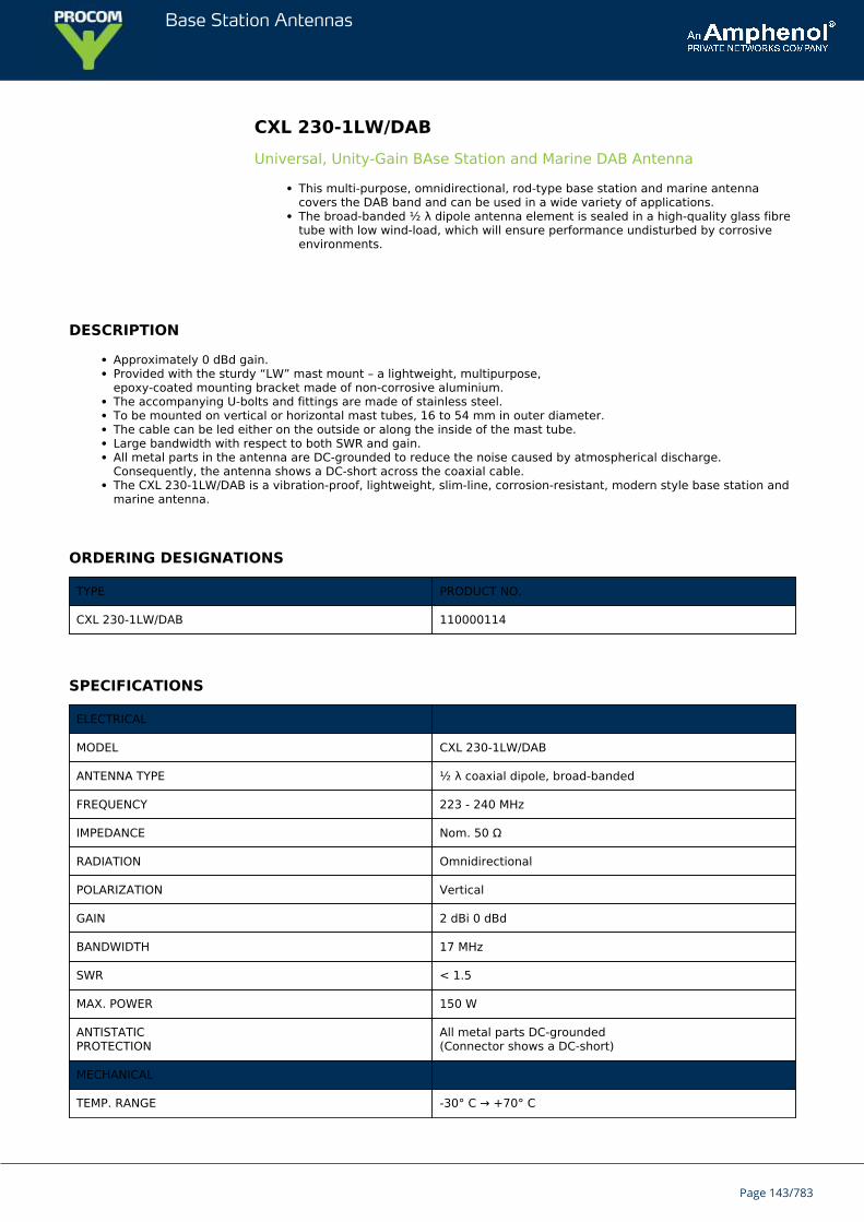
Base Station Antennas
CXL 230-1LW/DABUniversal, Unity-Gain BAse Station and Marine DAB Antenna
This multi-purpose, omnidirectional, rod-type base station and marine antennacovers the DAB band and can be used in a wide variety of applications.The broad-banded ½ λ dipole antenna element is sealed in a high-quality glass fibretube with low wind-load, which will ensure performance undisturbed by corrosiveenvironments.
DESCRIPTION
Approximately 0 dBd gain.Provided with the sturdy “LW” mast mount – a lightweight, multipurpose,epoxy-coated mounting bracket made of non-corrosive aluminium.The accompanying U-bolts and fittings are made of stainless steel.To be mounted on vertical or horizontal mast tubes, 16 to 54 mm in outer diameter.The cable can be led either on the outside or along the inside of the mast tube.Large bandwidth with respect to both SWR and gain.All metal parts in the antenna are DC-grounded to reduce the noise caused by atmospherical discharge.Consequently, the antenna shows a DC-short across the coaxial cable.The CXL 230-1LW/DAB is a vibration-proof, lightweight, slim-line, corrosion-resistant, modern style base station andmarine antenna.
ORDERING DESIGNATIONS
TYPE PRODUCT NO.
CXL 230-1LW/DAB 110000114
SPECIFICATIONS
ELECTRICAL
MODEL CXL 230-1LW/DAB
ANTENNA TYPE ½ λ coaxial dipole, broad-banded
FREQUENCY 223 - 240 MHz
IMPEDANCE Nom. 50 Ω
RADIATION Omnidirectional
POLARIZATION Vertical
GAIN 2 dBi 0 dBd
BANDWIDTH 17 MHz
SWR < 1.5
MAX. POWER 150 W
ANTISTATICPROTECTION
All metal parts DC-grounded(Connector shows a DC-short)
MECHANICAL
TEMP. RANGE -30° C → +70° C
Page 143/783
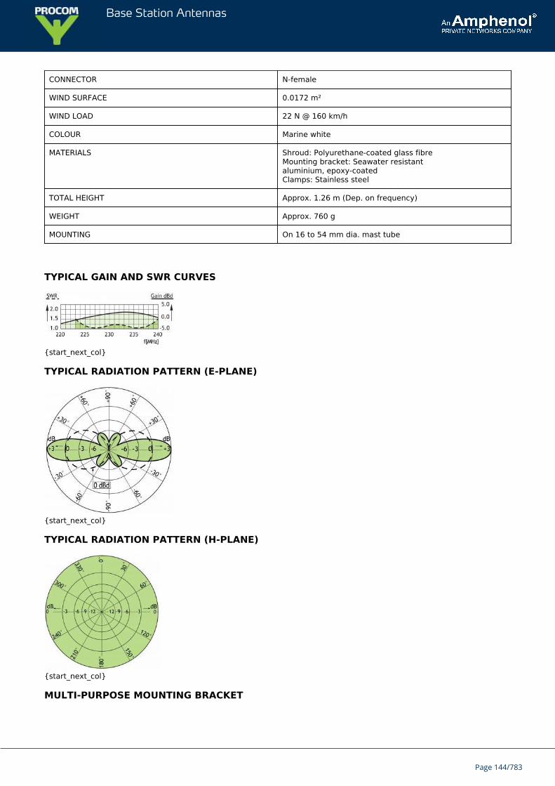
Base Station Antennas
CONNECTOR N-female
WIND SURFACE 0.0172 m²
WIND LOAD 22 N @ 160 km/h
COLOUR Marine white
MATERIALS Shroud: Polyurethane-coated glass fibreMounting bracket: Seawater resistantaluminium, epoxy-coatedClamps: Stainless steel
TOTAL HEIGHT Approx. 1.26 m (Dep. on frequency)
WEIGHT Approx. 760 g
MOUNTING On 16 to 54 mm dia. mast tube
TYPICAL GAIN AND SWR CURVES
{start_next_col}
TYPICAL RADIATION PATTERN (E-PLANE)
{start_next_col}
TYPICAL RADIATION PATTERN (H-PLANE)
{start_next_col}
MULTI-PURPOSE MOUNTING BRACKET
Page 144/783
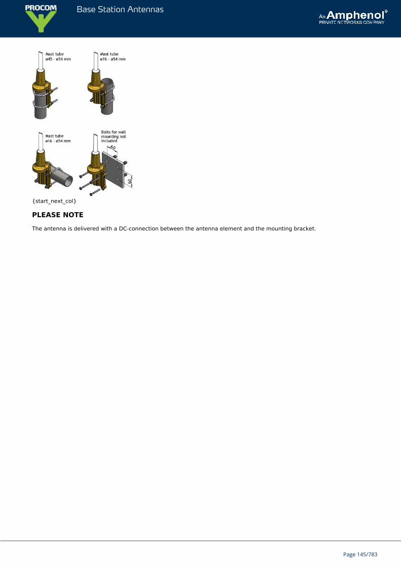
Base Station Antennas
{start_next_col}
PLEASE NOTE
The antenna is delivered with a DC-connection between the antenna element and the mounting bracket.
Page 145/783
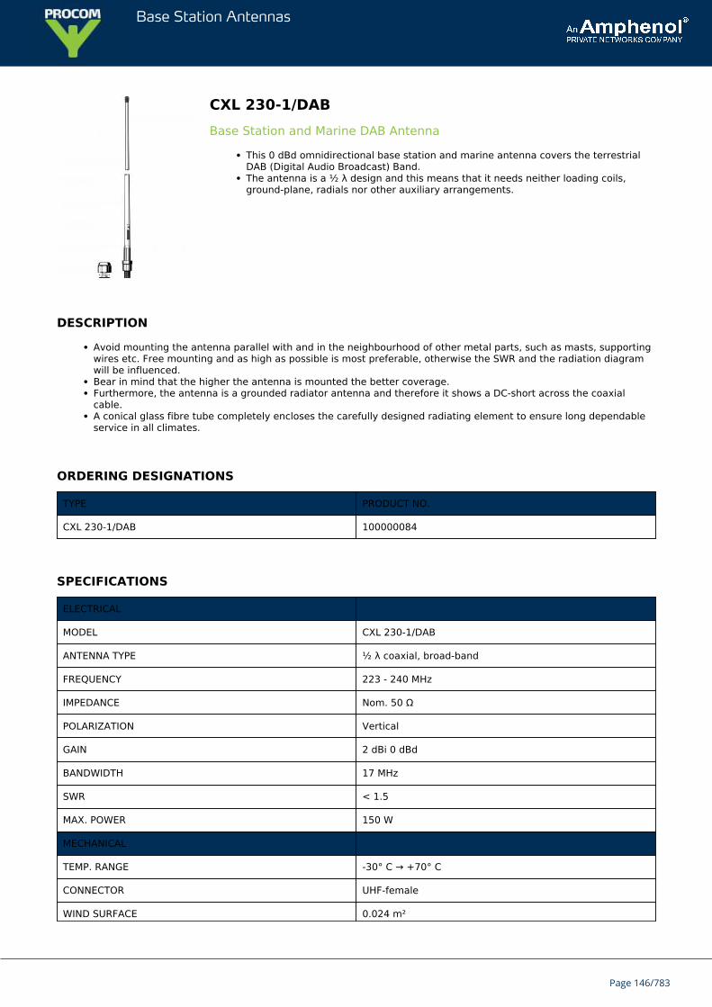
Base Station Antennas
CXL 230-1/DABBase Station and Marine DAB Antenna
This 0 dBd omnidirectional base station and marine antenna covers the terrestrialDAB (Digital Audio Broadcast) Band.The antenna is a ½ λ design and this means that it needs neither loading coils,ground-plane, radials nor other auxiliary arrangements.
DESCRIPTION
Avoid mounting the antenna parallel with and in the neighbourhood of other metal parts, such as masts, supportingwires etc. Free mounting and as high as possible is most preferable, otherwise the SWR and the radiation diagramwill be influenced.Bear in mind that the higher the antenna is mounted the better coverage.Furthermore, the antenna is a grounded radiator antenna and therefore it shows a DC-short across the coaxialcable.A conical glass fibre tube completely encloses the carefully designed radiating element to ensure long dependableservice in all climates.
ORDERING DESIGNATIONS
TYPE PRODUCT NO.
CXL 230-1/DAB 100000084
SPECIFICATIONS
ELECTRICAL
MODEL CXL 230-1/DAB
ANTENNA TYPE ½ λ coaxial, broad-band
FREQUENCY 223 - 240 MHz
IMPEDANCE Nom. 50 Ω
POLARIZATION Vertical
GAIN 2 dBi 0 dBd
BANDWIDTH 17 MHz
SWR < 1.5
MAX. POWER 150 W
MECHANICAL
TEMP. RANGE -30° C → +70° C
CONNECTOR UHF-female
WIND SURFACE 0.024 m²
Page 146/783
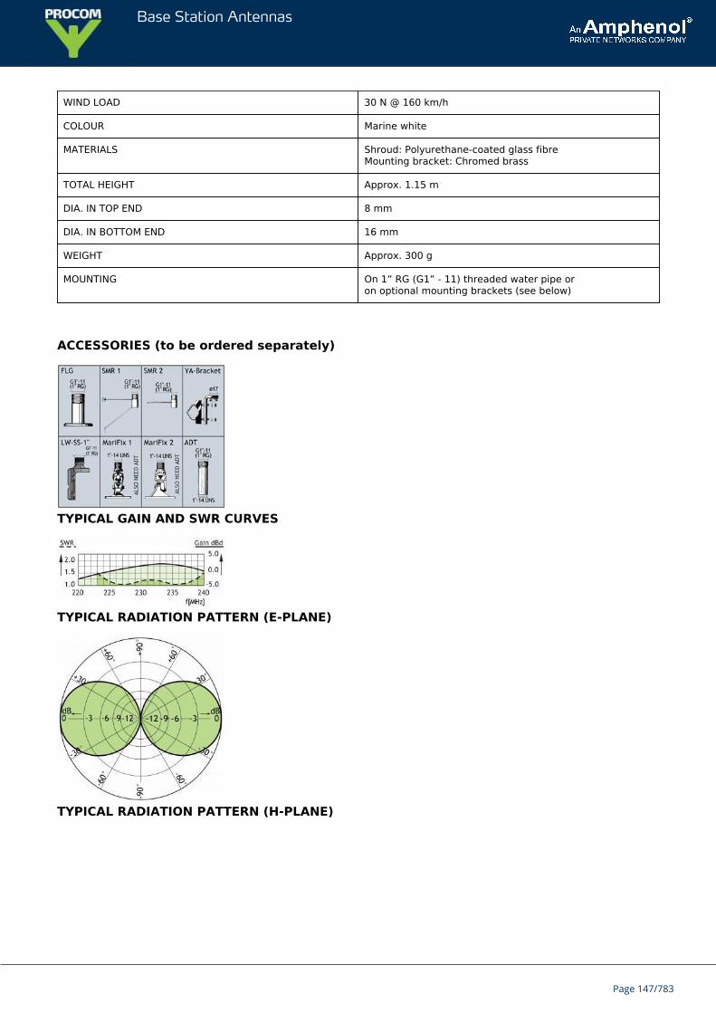
Base Station Antennas
WIND LOAD 30 N @ 160 km/h
COLOUR Marine white
MATERIALS Shroud: Polyurethane-coated glass fibreMounting bracket: Chromed brass
TOTAL HEIGHT Approx. 1.15 m
DIA. IN TOP END 8 mm
DIA. IN BOTTOM END 16 mm
WEIGHT Approx. 300 g
MOUNTING On 1” RG (G1” - 11) threaded water pipe oron optional mounting brackets (see below)
ACCESSORIES (to be ordered separately)
TYPICAL GAIN AND SWR CURVES
TYPICAL RADIATION PATTERN (E-PLANE)
TYPICAL RADIATION PATTERN (H-PLANE)
Page 147/783

Base Station Antennas
Page 148/783
Base Station Antennas
CXL 23-7C/...7 dBd Omnidirecctional Base Station Antenna for the 23 cm AmateurBand
The CXL 23-7C/… is a 7 dBd, vertically polarized, omnidirectional base stationantenna, which covers 1240 – 1340 MHz in three models.The antenna is provided with the type “C” universal fixing bracket. The epoxycoated cast aluminium bracket and accompanying stainless steel “U” bolts aresuitable for the most severe marine environment.
DESCRIPTION
The CXL 23-7C/… is suitable for 27 – 65 mm dia. mast tubes. The coaxial feeder cable can be routed eitherinternally or externally to the support tube.The antenna has excellent VSWR and gain characteristics and is highly suitable for repeater operation.The radiating element of the antenna is housed in a sealed high quality tapered glass fibre tube providing low windloading and excellent all weather performance.The antenna is DC grounded for static discharge protection.The CXL 23-7C/… is a vibration-proof, slim-line, corrosion resistant, modern style base station antenna.
ORDERING DESIGNATIONS
TYPE PRODUCT NO. FREQUENCY
CXL 23-7C/l 100000173 1240 – 1270 MHz
CXL 23-7C/h 100000174 1260 – 1300 MHz
CXL 23-7C/hh 100000282 1300 - 1340 MHz
ELECTRICAL
MODEL CXL 23-7C/...
ANTENNA TYPE Collinear, broad-banded
FREQUENCY Covering: 1240 – 1340 MHz
IMPEDANCE Nom. 50 Ω
RADIATION Omnidirectional
POLARIZATION Vertical
GAIN 9 dBi 7 dBd
HALF POWERBEAMWIDTH
11°
BANDWIDTH 30 MHz for CXL 23-7C/l40 MHz for CXL 23-7C/h40 MHz for CXL 23-7C/hh
SWR ≤ 1.5 for CXL 23-7C/l≤ 1.75 for CXL 23-7C/h≤ 1.75 for CXL 23-7C/hh
Page 149/783
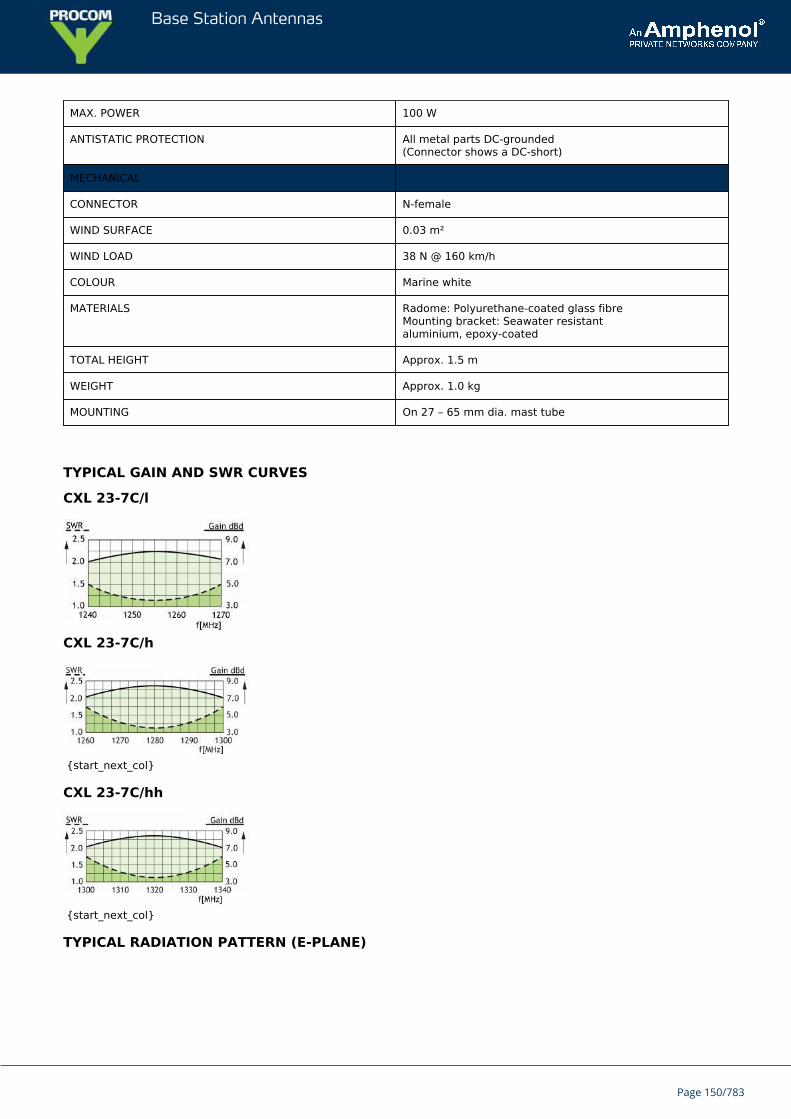
Base Station Antennas
MAX. POWER 100 W
ANTISTATIC PROTECTION All metal parts DC-grounded(Connector shows a DC-short)
MECHANICAL
CONNECTOR N-female
WIND SURFACE 0.03 m²
WIND LOAD 38 N @ 160 km/h
COLOUR Marine white
MATERIALS Radome: Polyurethane-coated glass fibreMounting bracket: Seawater resistantaluminium, epoxy-coated
TOTAL HEIGHT Approx. 1.5 m
WEIGHT Approx. 1.0 kg
MOUNTING On 27 – 65 mm dia. mast tube
TYPICAL GAIN AND SWR CURVES
CXL 23-7C/l
CXL 23-7C/h
{start_next_col}
CXL 23-7C/hh
{start_next_col}
TYPICAL RADIATION PATTERN (E-PLANE)
Page 150/783
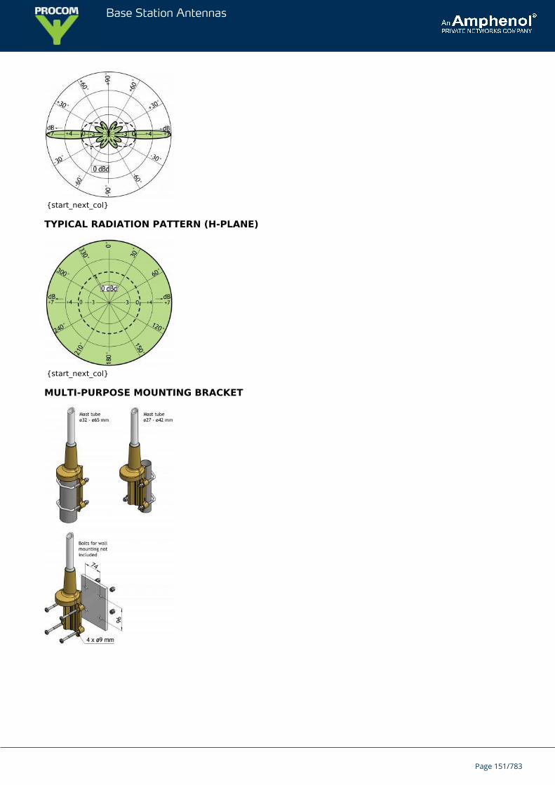
Base Station Antennas
{start_next_col}
TYPICAL RADIATION PATTERN (H-PLANE)
{start_next_col}
MULTI-PURPOSE MOUNTING BRACKET
Page 151/783

Base Station Antennas
CXL 225-450CUnity Gain, Broad-Banded Base Station Antenna for 225 - 450 MHz
CXL 225-450C is a 0 dBd gain, omnidirectional base station antenna.The antenna is extremely broad-banded and covers the complete band:225 – 450 MHz.
DESCRIPTION
CXL 225-450C is designed for fixation on supporting tubes with outer diameter between 27 mm and 65 mm.The construction of the mount makes it possible to lead the cable either inside or along the outside of the masttube.A glass fibre tube completely encloses the carefully designed radiating element to ensure long dependable servicein all climates.Atmospherical discharges are immediately led to ground as all metal parts are DC-grounded (consequently, theantenna shows a DC-short across the coaxial cable).This antenna is used where reliability is of utmost importance. A long lifetime has been taken into considerationwhen designing this antenna – it is sturdy and strong.
ORDERING DESIGNATIONS
TYPE PRODUCT NO.
CXL 225-450C 100000088
SPECIFICATIONS
ELECTRICAL
MODEL CXL 225-450C
ANTENNA TYPE Coaxial, broad-band dipole
FREQUENCY Covering: 225 – 450 MHz
IMPEDANCE Nom. 50 Ω
RADIATION Omnidirectional
POLARIZATION Vertical
GAIN 0 dBd (see curve)
BANDWIDTH 225 MHz
SWR ≤ 2.5, typ. ≤ 2.0
MAX. POWER 200 W
ANTISTATIC PROTECTION All metal parts DC-grounded(Connector shows a DC-short)
MECHANICAL
Page 152/783
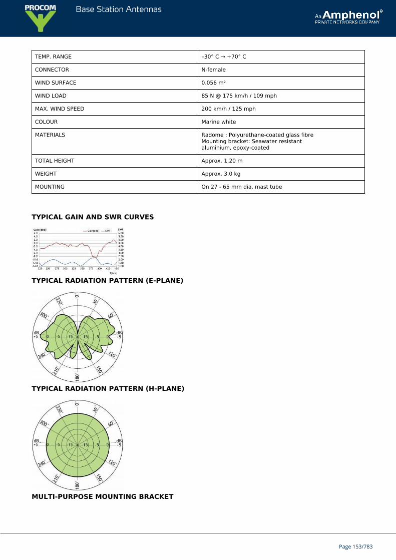
Base Station Antennas
TEMP. RANGE –30° C → +70° C
CONNECTOR N-female
WIND SURFACE 0.056 m²
WIND LOAD 85 N @ 175 km/h / 109 mph
MAX. WIND SPEED 200 km/h / 125 mph
COLOUR Marine white
MATERIALS Radome : Polyurethane-coated glass fibreMounting bracket: Seawater resistantaluminium, epoxy-coated
TOTAL HEIGHT Approx. 1.20 m
WEIGHT Approx. 3.0 kg
MOUNTING On 27 - 65 mm dia. mast tube
TYPICAL GAIN AND SWR CURVES
TYPICAL RADIATION PATTERN (E-PLANE)
TYPICAL RADIATION PATTERN (H-PLANE)
MULTI-PURPOSE MOUNTING BRACKET
Page 153/783

Base Station Antennas
Page 154/783
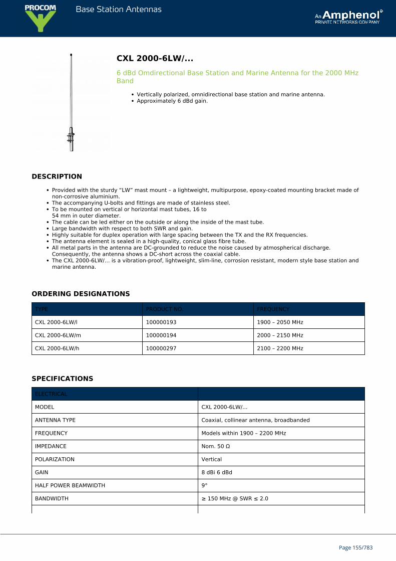
Base Station Antennas
CXL 2000-6LW/...6 dBd Omdirectional Base Station and Marine Antenna for the 2000 MHzBand
Vertically polarized, omnidirectional base station and marine antenna.Approximately 6 dBd gain.
DESCRIPTION
Provided with the sturdy “LW” mast mount – a lightweight, multipurpose, epoxy-coated mounting bracket made ofnon-corrosive aluminium.The accompanying U-bolts and fittings are made of stainless steel.To be mounted on vertical or horizontal mast tubes, 16 to54 mm in outer diameter.The cable can be led either on the outside or along the inside of the mast tube.Large bandwidth with respect to both SWR and gain.Highly suitable for duplex operation with large spacing between the TX and the RX frequencies.The antenna element is sealed in a high-quality, conical glass fibre tube.All metal parts in the antenna are DC-grounded to reduce the noise caused by atmospherical discharge.Consequently, the antenna shows a DC-short across the coaxial cable.The CXL 2000-6LW/… is a vibration-proof, lightweight, slim-line, corrosion resistant, modern style base station andmarine antenna.
ORDERING DESIGNATIONS
TYPE PRODUCT NO. FREQUENCY
CXL 2000-6LW/l 100000193 1900 – 2050 MHz
CXL 2000-6LW/m 100000194 2000 – 2150 MHz
CXL 2000-6LW/h 100000297 2100 – 2200 MHz
SPECIFICATIONS
ELECTRICAL
MODEL CXL 2000-6LW/...
ANTENNA TYPE Coaxial, collinear antenna, broadbanded
FREQUENCY Models within 1900 – 2200 MHz
IMPEDANCE Nom. 50 Ω
POLARIZATION Vertical
GAIN 8 dBi 6 dBd
HALF POWER BEAMWIDTH 9°
BANDWIDTH ≥ 150 MHz @ SWR ≤ 2.0
Page 155/783
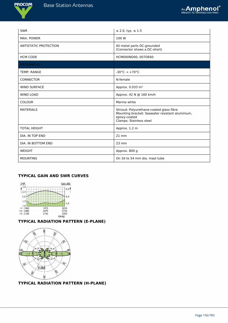
Base Station Antennas
SWR ≤ 2.0, typ. ≤ 1.5
MAX. POWER 100 W
ANTISTATIC PROTECTION All metal parts DC-grounded(Connector shows a DC-short)
HCM CODE HCM000ND00, 007DE60
MECHANICAL
TEMP. RANGE -30°C → +70°C
CONNECTOR N-female
WIND SURFACE Approx. 0.033 m²
WIND LOAD Approx. 42 N @ 160 km/h
COLOUR Marine white
MATERIALS Shroud: Polyurethane-coated glass fibreMounting bracket: Seawater resistant aluminium,epoxy-coatedClamps: Stainless steel
TOTAL HEIGHT Approx. 1.2 m
DIA. IN TOP END 21 mm
DIA. IN BOTTOM END 23 mm
WEIGHT Approx. 800 g
MOUNTING On 16 to 54 mm dia. mast tube
TYPICAL GAIN AND SWR CURVES
TYPICAL RADIATION PATTERN (E-PLANE)
TYPICAL RADIATION PATTERN (H-PLANE)
Page 156/783
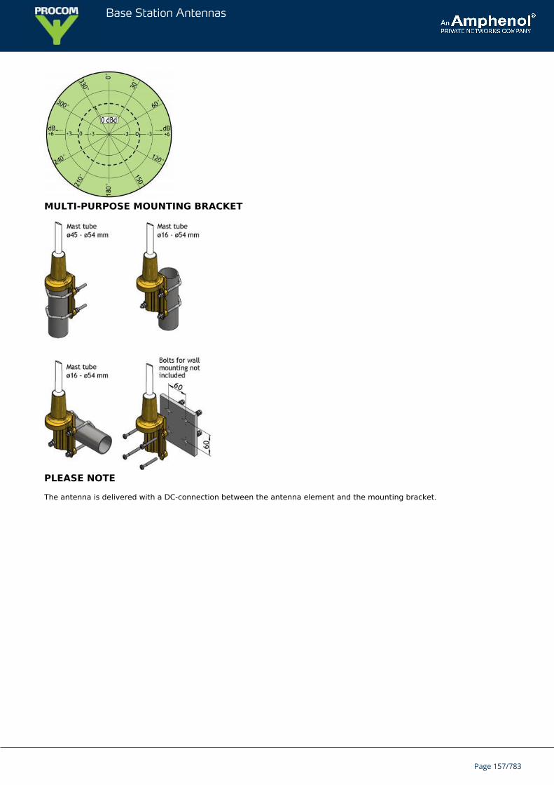
Base Station Antennas
MULTI-PURPOSE MOUNTING BRACKET
PLEASE NOTE
The antenna is delivered with a DC-connection between the antenna element and the mounting bracket.
Page 157/783
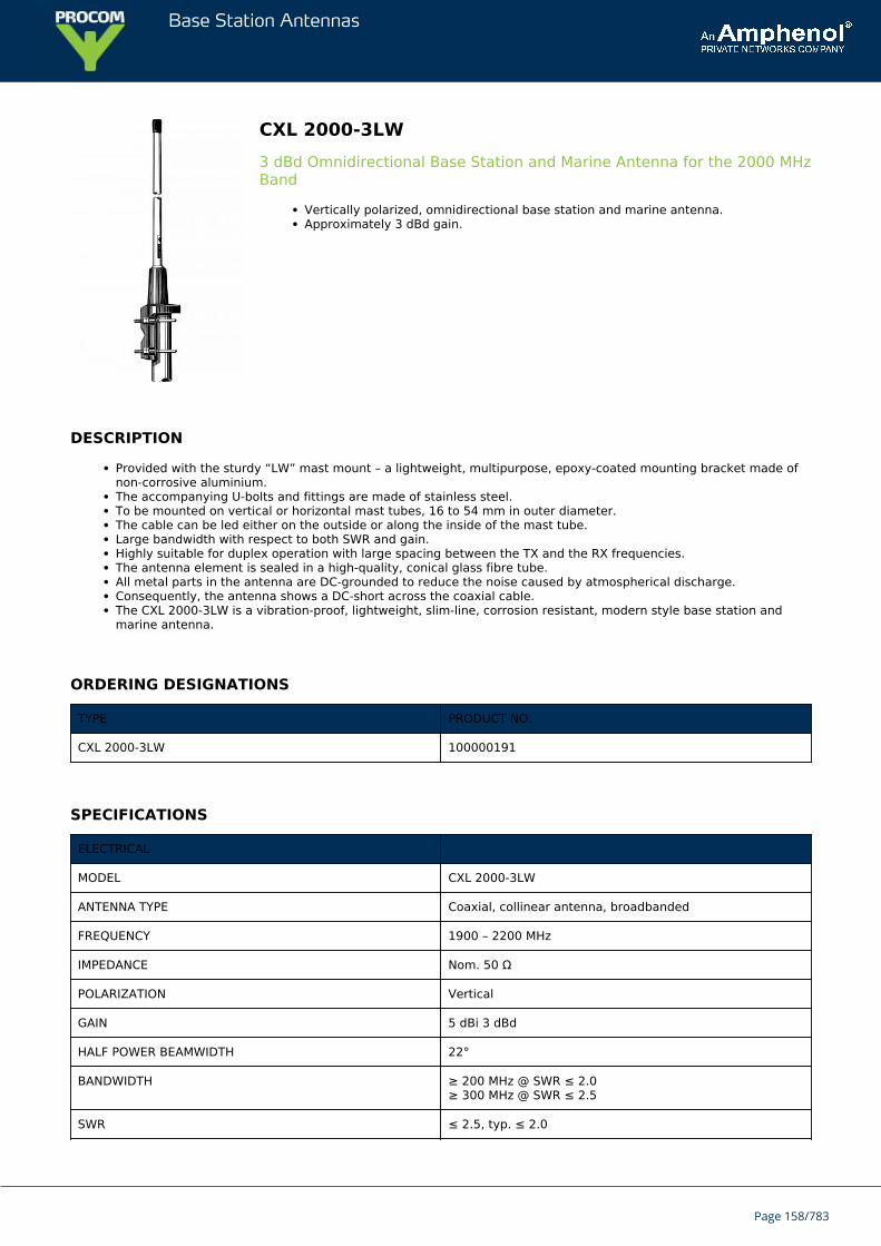
Base Station Antennas
CXL 2000-3LW3 dBd Omnidirectional Base Station and Marine Antenna for the 2000 MHzBand
Vertically polarized, omnidirectional base station and marine antenna.Approximately 3 dBd gain.
DESCRIPTION
Provided with the sturdy “LW” mast mount – a lightweight, multipurpose, epoxy-coated mounting bracket made ofnon-corrosive aluminium.The accompanying U-bolts and fittings are made of stainless steel.To be mounted on vertical or horizontal mast tubes, 16 to 54 mm in outer diameter.The cable can be led either on the outside or along the inside of the mast tube.Large bandwidth with respect to both SWR and gain.Highly suitable for duplex operation with large spacing between the TX and the RX frequencies.The antenna element is sealed in a high-quality, conical glass fibre tube.All metal parts in the antenna are DC-grounded to reduce the noise caused by atmospherical discharge.Consequently, the antenna shows a DC-short across the coaxial cable.The CXL 2000-3LW is a vibration-proof, lightweight, slim-line, corrosion resistant, modern style base station andmarine antenna.
ORDERING DESIGNATIONS
TYPE PRODUCT NO.
CXL 2000-3LW 100000191
SPECIFICATIONS
ELECTRICAL
MODEL CXL 2000-3LW
ANTENNA TYPE Coaxial, collinear antenna, broadbanded
FREQUENCY 1900 – 2200 MHz
IMPEDANCE Nom. 50 Ω
POLARIZATION Vertical
GAIN 5 dBi 3 dBd
HALF POWER BEAMWIDTH 22°
BANDWIDTH ≥ 200 MHz @ SWR ≤ 2.0≥ 300 MHz @ SWR ≤ 2.5
SWR ≤ 2.5, typ. ≤ 2.0
Page 158/783
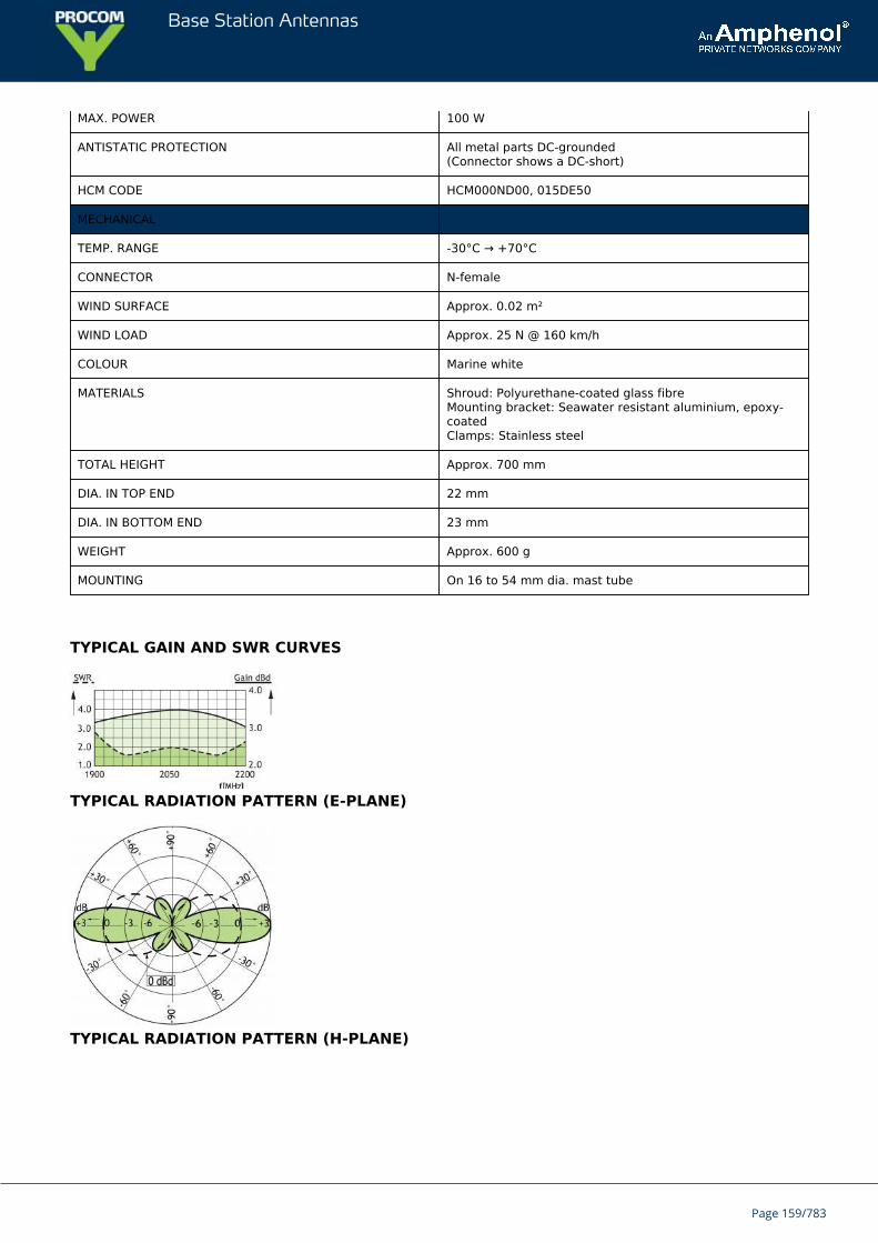
Base Station Antennas
MAX. POWER 100 W
ANTISTATIC PROTECTION All metal parts DC-grounded(Connector shows a DC-short)
HCM CODE HCM000ND00, 015DE50
MECHANICAL
TEMP. RANGE -30°C → +70°C
CONNECTOR N-female
WIND SURFACE Approx. 0.02 m²
WIND LOAD Approx. 25 N @ 160 km/h
COLOUR Marine white
MATERIALS Shroud: Polyurethane-coated glass fibreMounting bracket: Seawater resistant aluminium, epoxy-coatedClamps: Stainless steel
TOTAL HEIGHT Approx. 700 mm
DIA. IN TOP END 22 mm
DIA. IN BOTTOM END 23 mm
WEIGHT Approx. 600 g
MOUNTING On 16 to 54 mm dia. mast tube
TYPICAL GAIN AND SWR CURVES
TYPICAL RADIATION PATTERN (E-PLANE)
TYPICAL RADIATION PATTERN (H-PLANE)
Page 159/783

Base Station Antennas
MULTI-PURPOSE MOUNTING BRACKET
PLEASE NOTEThe antenna is delivered with a DC-connection between the antenna element and the mounting bracket.
Page 160/783
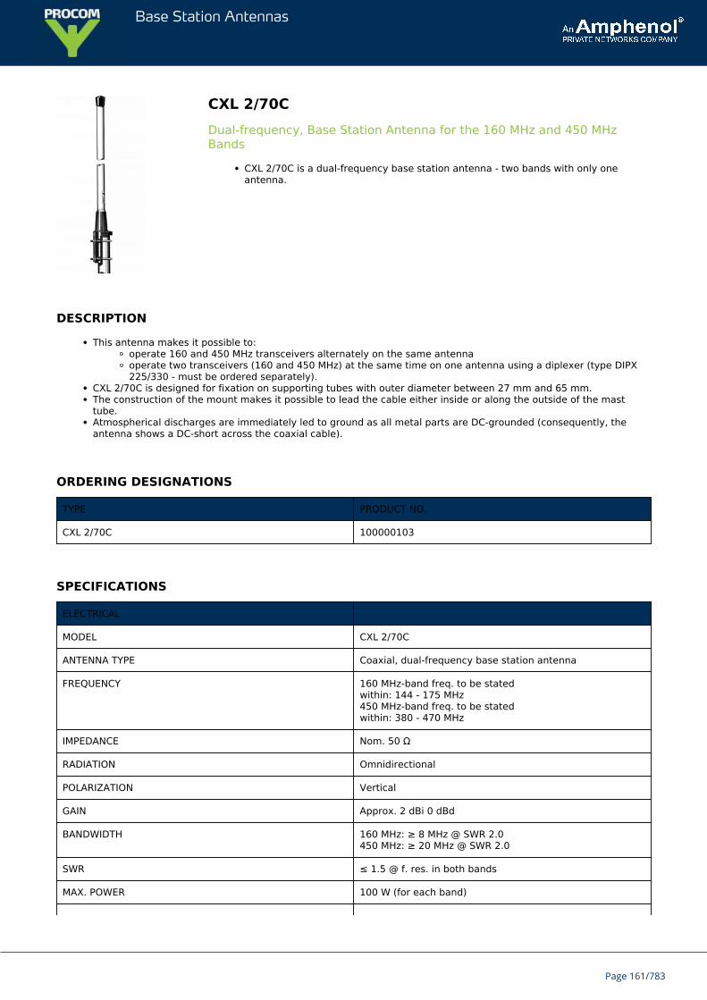
Base Station Antennas
CXL 2/70CDual-frequency, Base Station Antenna for the 160 MHz and 450 MHzBands
CXL 2/70C is a dual-frequency base station antenna - two bands with only oneantenna.
DESCRIPTION
This antenna makes it possible to:operate 160 and 450 MHz transceivers alternately on the same antennaoperate two transceivers (160 and 450 MHz) at the same time on one antenna using a diplexer (type DIPX225/330 - must be ordered separately).
CXL 2/70C is designed for fixation on supporting tubes with outer diameter between 27 mm and 65 mm.The construction of the mount makes it possible to lead the cable either inside or along the outside of the masttube.Atmospherical discharges are immediately led to ground as all metal parts are DC-grounded (consequently, theantenna shows a DC-short across the coaxial cable).
ORDERING DESIGNATIONS
TYPE PRODUCT NO.
CXL 2/70C 100000103
SPECIFICATIONS
ELECTRICAL
MODEL CXL 2/70C
ANTENNA TYPE Coaxial, dual-frequency base station antenna
FREQUENCY 160 MHz-band freq. to be statedwithin: 144 - 175 MHz450 MHz-band freq. to be statedwithin: 380 - 470 MHz
IMPEDANCE Nom. 50 Ω
RADIATION Omnidirectional
POLARIZATION Vertical
GAIN Approx. 2 dBi 0 dBd
BANDWIDTH 160 MHz: ≥ 8 MHz @ SWR 2.0450 MHz: ≥ 20 MHz @ SWR 2.0
SWR ≤ 1.5 @ f. res. in both bands
MAX. POWER 100 W (for each band)
Page 161/783
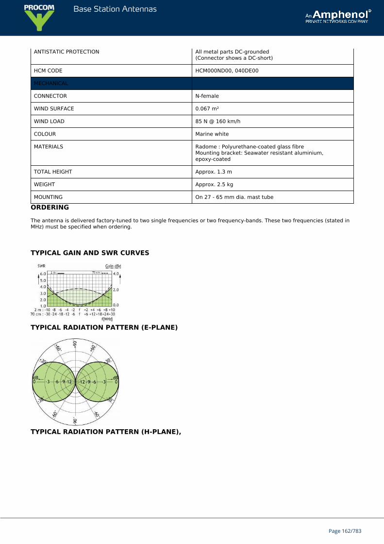
Base Station Antennas
ANTISTATIC PROTECTION All metal parts DC-grounded(Connector shows a DC-short)
HCM CODE HCM000ND00, 040DE00
MECHANICAL
CONNECTOR N-female
WIND SURFACE 0.067 m²
WIND LOAD 85 N @ 160 km/h
COLOUR Marine white
MATERIALS Radome : Polyurethane-coated glass fibreMounting bracket: Seawater resistant aluminium,epoxy-coated
TOTAL HEIGHT Approx. 1.3 m
WEIGHT Approx. 2.5 kg
MOUNTING On 27 - 65 mm dia. mast tube
ORDERING
The antenna is delivered factory-tuned to two single frequencies or two frequency-bands. These two frequencies (stated inMHz) must be specified when ordering.
TYPICAL GAIN AND SWR CURVES
TYPICAL RADIATION PATTERN (E-PLANE)
TYPICAL RADIATION PATTERN (H-PLANE),
Page 162/783
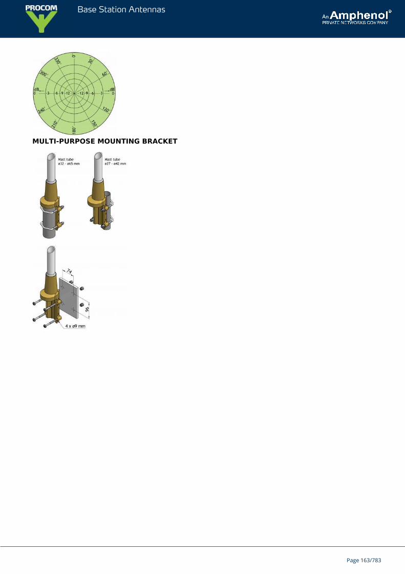
Base Station Antennas
MULTI-PURPOSE MOUNTING BRACKET
Page 163/783
Base Station Antennas
CXL 2-5SL/...Sturdy, 5 dBd Gain, Base Station Antenna for the 160 MHz Band
CXL 2-5SL/… is a 5 dBd, vertically polarized, omnidirectional base station antenna.The antenna has a bandwidth of 8 MHz. Please specify centre frequency or duplexTX and RX when ordering.
DESCRIPTION
The antenna is provided with our type "SL" (Slim Line) mast mount, which is a multipurpose mounting tube made ofnon-corrosive aluminium. The accompanying clamp set and fittings are made of hot galvanized steel.The antenna can be mounted on mast tubes of 33 to 70 mm in outer diameter.In designing this antenna, special emphasis has been laid on obtaining a large bandwidth both in relation to SWRand gain. The phasing of the radiating elements is carefully adjusted to yield maximum gain in the horizontal plane,with the level of the side lobes reduced to a minimum.The antenna element is sealed in a high-quality, conical glass fibre tube with low wind-load, which will ensureperformance undisturbed in all climates.To substantially reduce noise caused by atmospherical discharges, all metal parts in the antenna are DC-grounded.Consequently, the antenna shows a DC-short across the coaxial cable.CXL 2-5SL/… is a vibration-proof, lightweight, slim-line, corrosion-resistant, modern style base station antenna.
ORDERING DESIGNATIONS
TYPE PRODUCT NO.
CXL 2-5SL/144 - 152 MHZ 100000574
CXL 2-5SL/151 - 159 MHZ 100000575
CXL 2-5SL/156 - 164 MHZ 100000576
CXL 2-5SL/164 - 172 MHZ 100000577
CXL 2-5SL/167 - 175 MHZ Contact for availability
SPECIFICATIONS
ELECTRICAL
MODEL CXL 2-5SL/...
ANTENNA TYPE High-gain collinear
FREQUENCY 8 MHz wide frequency segments within the 144 - 175 MHzrange. Please specify centre frequency or duplex TX andRX
IMPEDANCE Nom. 50 Ω
RADIATION Omnidirectional
POLARIZATION Vertical
Page 164/783
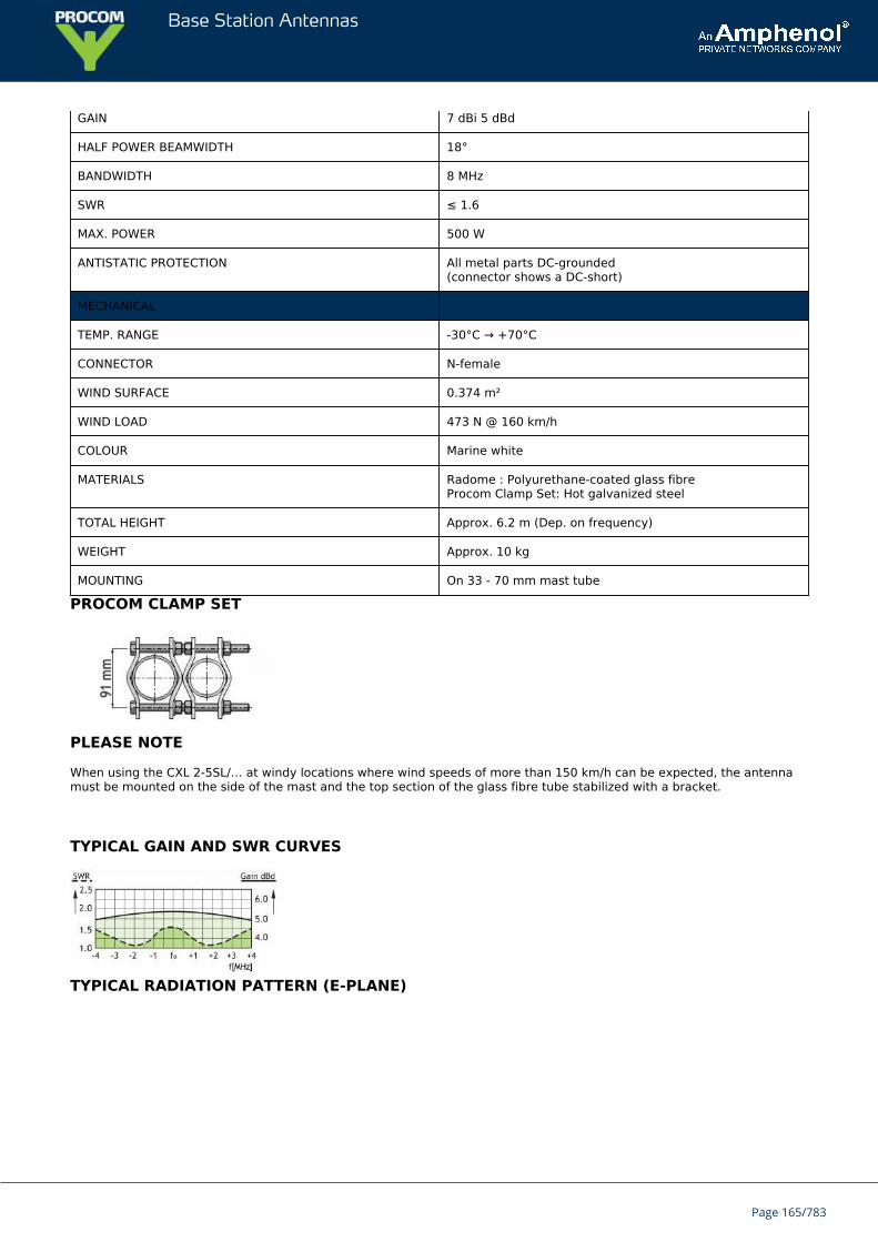
Base Station Antennas
GAIN 7 dBi 5 dBd
HALF POWER BEAMWIDTH 18°
BANDWIDTH 8 MHz
SWR ≤ 1.6
MAX. POWER 500 W
ANTISTATIC PROTECTION All metal parts DC-grounded(connector shows a DC-short)
MECHANICAL
TEMP. RANGE -30°C → +70°C
CONNECTOR N-female
WIND SURFACE 0.374 m²
WIND LOAD 473 N @ 160 km/h
COLOUR Marine white
MATERIALS Radome : Polyurethane-coated glass fibreProcom Clamp Set: Hot galvanized steel
TOTAL HEIGHT Approx. 6.2 m (Dep. on frequency)
WEIGHT Approx. 10 kg
MOUNTING On 33 - 70 mm mast tube
PROCOM CLAMP SET
PLEASE NOTE
When using the CXL 2-5SL/… at windy locations where wind speeds of more than 150 km/h can be expected, the antennamust be mounted on the side of the mast and the top section of the glass fibre tube stabilized with a bracket.
TYPICAL GAIN AND SWR CURVES
TYPICAL RADIATION PATTERN (E-PLANE)
Page 165/783

Base Station Antennas
TYPICAL RADIATION PATTERN (H-PLANE)
Page 166/783
Base Station Antennas
CXL 2-5HD/...Sturdy, 5 dBd Gain, Base Station Antenna for the 160 MHz Band
CXL 2-5HD/… is a 5 dBd, vertically polarized, omnidirectional base station antenna.The antenna has a bandwidth of 7 MHz. Please specify centre frequency or duplexTX and RX when ordering.
DESCRIPTION
The antenna is provided with our sturdy type “HD” mast mount, which is a heavy-duty, multipurpose mountingbracket made of non-corrosive aluminium. The accompanying U-bolts and fittings are made of stainless steel.The antenna can be mounted on mast tubes of 58 to 105 mm in outer diameter. Further, the construction of themount makes it possible to lead the cable either along the inside or on the outside of the mast tube.In designing this antenna, special emphasis has been laid on obtaining a large bandwidth both in relation to SWRand gain. The phasing of the radiating elements is carefully adjusted to yield maximum gain in the horizontal plane,with the level of the sidelobes reduced to a minimum.The antenna element is sealed in a high-quality, conical glass fibre tube with low wind-load, which will ensureperformance undisturbed in all climates.To substantially reduce noise caused by atmospherical discharges, all metal parts in the antenna are DC-grounded.Consequently, the antenna shows a DC-short across the coaxial cable.CXL 2-5HD/… is a vibration-proof, lightweight, slim-line, corrosion-resistant, modern style base station antenna.
ORDERING DESIGNATIONS
TYPE PRODUCT NO.
CXL 2-5HD/... 100000101
SPECIFICATIONS
ELECTRICAL
MODEL CXL 2-5HD/...
ANTENNA TYPE High-gain collinear
FREQUENCY 7 MHz wide frequency segments within the 144 - 175 MHzrange. Please specify centre frequency, or duplex TX andRX
IMPEDANCE Nom. 50 Ω
RADIATION Omnidirectional
POLARIZATION Vertical
GAIN 7 dBi 5 dBd
HALF POWER BEAMWIDTH 18°
BANDWIDTH 7 MHz
SWR ≤ 1.5
MAX. POWER 500 W
Page 167/783
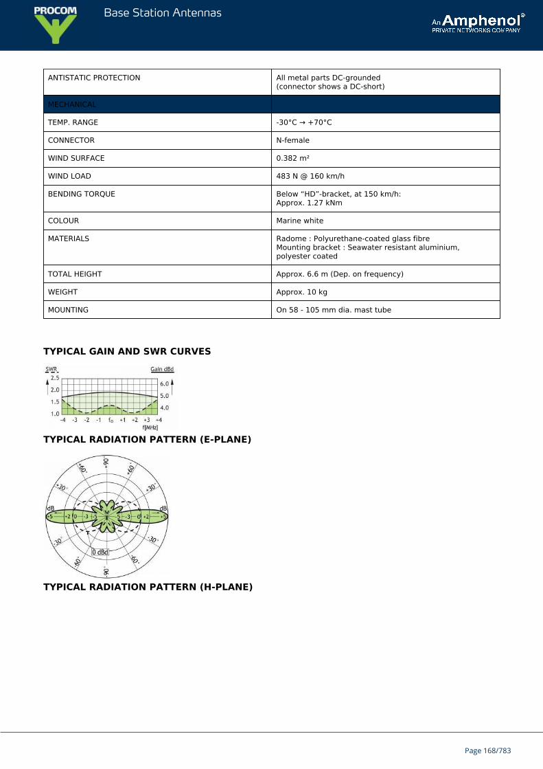
Base Station Antennas
ANTISTATIC PROTECTION All metal parts DC-grounded(connector shows a DC-short)
MECHANICAL
TEMP. RANGE -30°C → +70°C
CONNECTOR N-female
WIND SURFACE 0.382 m²
WIND LOAD 483 N @ 160 km/h
BENDING TORQUE Below “HD”-bracket, at 150 km/h:Approx. 1.27 kNm
COLOUR Marine white
MATERIALS Radome : Polyurethane-coated glass fibreMounting bracket : Seawater resistant aluminium,polyester coated
TOTAL HEIGHT Approx. 6.6 m (Dep. on frequency)
WEIGHT Approx. 10 kg
MOUNTING On 58 - 105 mm dia. mast tube
TYPICAL GAIN AND SWR CURVES
TYPICAL RADIATION PATTERN (E-PLANE)
TYPICAL RADIATION PATTERN (H-PLANE)
Page 168/783
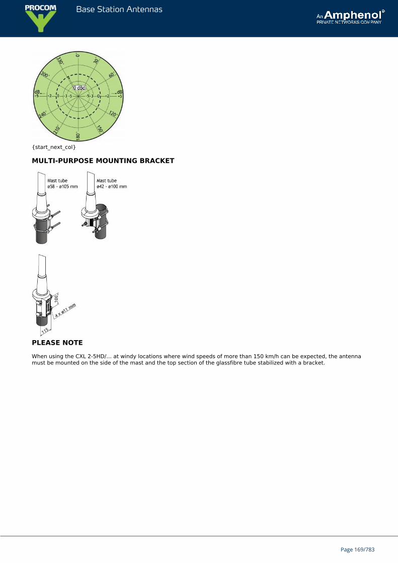
Base Station Antennas
{start_next_col}
MULTI-PURPOSE MOUNTING BRACKET
PLEASE NOTE
When using the CXL 2-5HD/… at windy locations where wind speeds of more than 150 km/h can be expected, the antennamust be mounted on the side of the mast and the top section of the glassfibre tube stabilized with a bracket.
Page 169/783
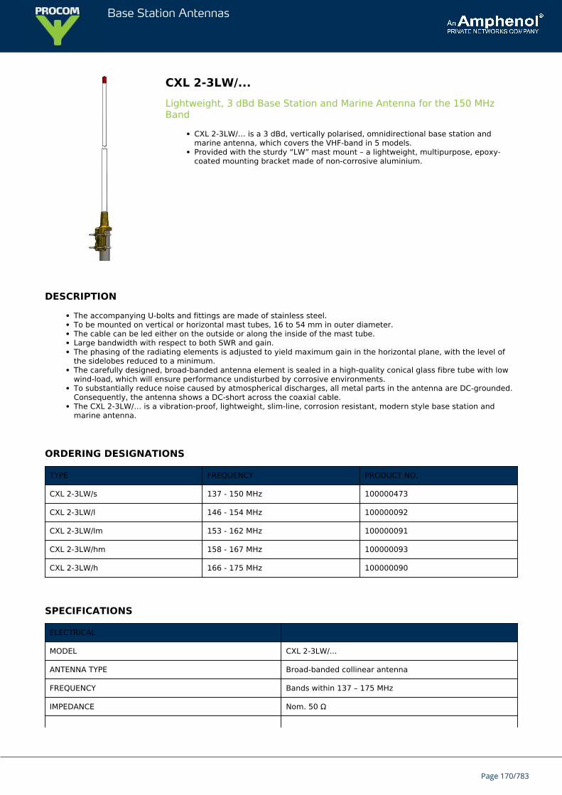
Base Station Antennas
CXL 2-3LW/...Lightweight, 3 dBd Base Station and Marine Antenna for the 150 MHzBand
CXL 2-3LW/… is a 3 dBd, vertically polarised, omnidirectional base station andmarine antenna, which covers the VHF-band in 5 models.Provided with the sturdy “LW” mast mount – a lightweight, multipurpose, epoxy-coated mounting bracket made of non-corrosive aluminium.
DESCRIPTION
The accompanying U-bolts and fittings are made of stainless steel.To be mounted on vertical or horizontal mast tubes, 16 to 54 mm in outer diameter.The cable can be led either on the outside or along the inside of the mast tube.Large bandwidth with respect to both SWR and gain.The phasing of the radiating elements is adjusted to yield maximum gain in the horizontal plane, with the level ofthe sidelobes reduced to a minimum.The carefully designed, broad-banded antenna element is sealed in a high-quality conical glass fibre tube with lowwind-load, which will ensure performance undisturbed by corrosive environments.To substantially reduce noise caused by atmospherical discharges, all metal parts in the antenna are DC-grounded.Consequently, the antenna shows a DC-short across the coaxial cable.The CXL 2-3LW/… is a vibration-proof, lightweight, slim-line, corrosion resistant, modern style base station andmarine antenna.
ORDERING DESIGNATIONS
TYPE FREQUENCY PRODUCT NO.
CXL 2-3LW/s 137 - 150 MHz 100000473
CXL 2-3LW/l 146 - 154 MHz 100000092
CXL 2-3LW/lm 153 - 162 MHz 100000091
CXL 2-3LW/hm 158 - 167 MHz 100000093
CXL 2-3LW/h 166 - 175 MHz 100000090
SPECIFICATIONS
ELECTRICAL
MODEL CXL 2-3LW/...
ANTENNA TYPE Broad-banded collinear antenna
FREQUENCY Bands within 137 – 175 MHz
IMPEDANCE Nom. 50 Ω
Page 170/783
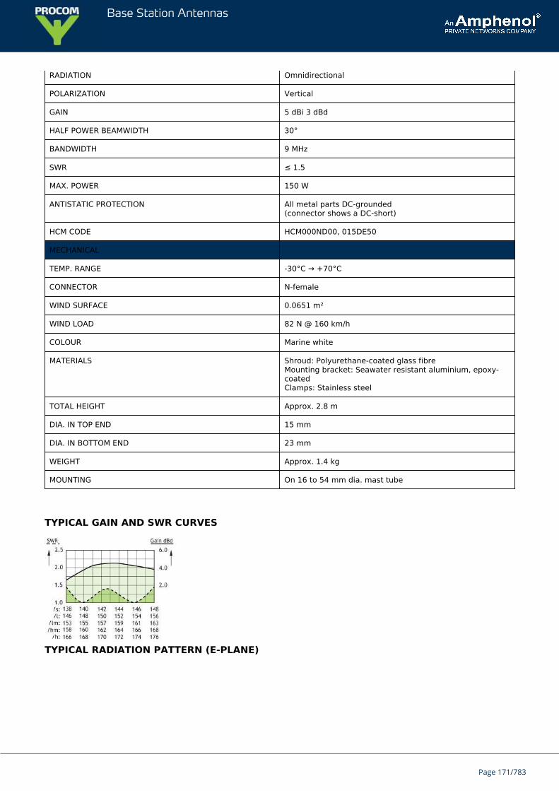
Base Station Antennas
RADIATION Omnidirectional
POLARIZATION Vertical
GAIN 5 dBi 3 dBd
HALF POWER BEAMWIDTH 30°
BANDWIDTH 9 MHz
SWR ≤ 1.5
MAX. POWER 150 W
ANTISTATIC PROTECTION All metal parts DC-grounded(connector shows a DC-short)
HCM CODE HCM000ND00, 015DE50
MECHANICAL
TEMP. RANGE -30°C → +70°C
CONNECTOR N-female
WIND SURFACE 0.0651 m²
WIND LOAD 82 N @ 160 km/h
COLOUR Marine white
MATERIALS Shroud: Polyurethane-coated glass fibreMounting bracket: Seawater resistant aluminium, epoxy-coatedClamps: Stainless steel
TOTAL HEIGHT Approx. 2.8 m
DIA. IN TOP END 15 mm
DIA. IN BOTTOM END 23 mm
WEIGHT Approx. 1.4 kg
MOUNTING On 16 to 54 mm dia. mast tube
TYPICAL GAIN AND SWR CURVES
TYPICAL RADIATION PATTERN (E-PLANE)
Page 171/783
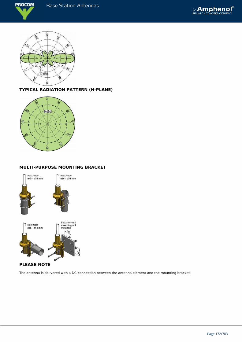
Base Station Antennas
TYPICAL RADIATION PATTERN (H-PLANE)
MULTI-PURPOSE MOUNTING BRACKET
PLEASE NOTE
The antenna is delivered with a DC-connection between the antenna element and the mounting bracket.
Page 172/783
Base Station Antennas
CXL 2-3C/...-PT3 dBd Omnidirectional lighting protected Base Station Antenna for 167 -174 MHz
CXL 2-3C/167-174-PT is a sturdy, 3 dBd, vertically polarized, omnidirectional basestation antenna, covering 167 - 174 MHz.The antenna has been approved to withstand lightning (10/350 μs impulses/150 kA)according to EN 61643-11, VDE 0855-300 and VDE 0185-305-114 in FH-KielLaboratory in Germany.
DESCRIPTION
The antenna is provided with our “C” mast bracket, which is a universal, epoxy-coated mounting bracket made ofnon-corrosive aluminium. The accompanying U-bolts and fittings are made of stainless steel.The antenna can be mounted on 27 to 65 mm dia. mast tubes and it is possible to lead the cable either along theinside or on the outside of the mast tube.The antenna element is completely enclosed in a glass fibre shroud, ensureing undisturbed performance in allclimates.To substantially reduce noise caused by atmospherical discharges, all metal parts in the antenna are DC-grounded.Consequently, the antenna shows a DC-short across the coaxial cable.This antenna is constructed to ensure long dependable service in all climates.
ORDERING DESIGNATIONS
TYPE PRODUCT NO.
CXL 2-3C/167-174-PT 100000519
SPECIFICATIONS
ELECTRICAL
MODEL CXL 2-3C/...-PT
ANTENNA TYPE ½ λ coaxial dipole
FREQUENCY 167 - 174 MHz
IMPEDANCE Nom. 50 Ω
RADIATION Omnidirectional
POLARIZATION Vertical
GAIN 5 dBi 3 dBd
BANDWIDTH 7 MHz
SWR ≤ 1.75
MAX. POWER 150 W
Page 173/783
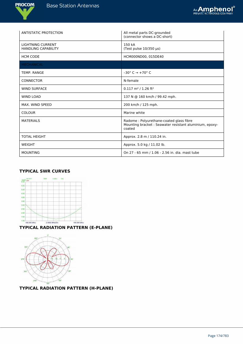
Base Station Antennas
ANTISTATIC PROTECTION All metal parts DC-grounded(connector shows a DC-short)
LIGHTNING CURRENTHANDLING CAPABILITY
150 kA(Test pulse 10/350 μs)
HCM CODE HCM000ND00, 015DE40
MECHANICAL
TEMP. RANGE –30° C → +70° C
CONNECTOR N-female
WIND SURFACE 0.117 m² / 1.26 ft²
WIND LOAD 137 N @ 160 km/h / 99.42 mph.
MAX. WIND SPEED 200 km/h / 125 mph.
COLOUR Marine white
MATERIALS Radome : Polyurethane-coated glass fibreMounting bracket : Seawater resistant aluminium, epoxy-coated
TOTAL HEIGHT Approx. 2.8 m / 110.24 in.
WEIGHT Approx. 5.0 kg / 11.02 lb.
MOUNTING On 27 - 65 mm / 1.06 - 2.56 in. dia. mast tube
TYPICAL SWR CURVES
TYPICAL RADIATION PATTERN (E-PLANE)
TYPICAL RADIATION PATTERN (H-PLANE)
Page 174/783
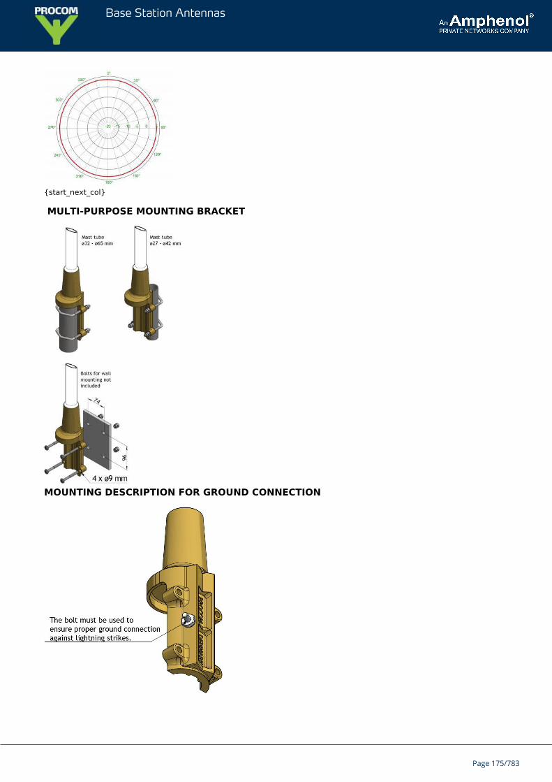
Base Station Antennas
{start_next_col}
MULTI-PURPOSE MOUNTING BRACKET
MOUNTING DESCRIPTION FOR GROUND CONNECTION
Page 175/783

Base Station Antennas
Page 176/783
Base Station Antennas
CXL 2-3C/...Sturdy, 3 dBd Gain Base Station Antenna for the 160 MHz Band
CXL 2-3C/… is a sturdy, 3 dBd, vertically polarized, omnidirectional base stationantenna, which covers the 160 MHz band in 4 models.The antenna is provided with our “C” mast bracket, which is a universal, epoxy-coated mounting bracket made of non-corrosive aluminium. The accompanying U-bolts and fittings are made of stainless steel.
DESCRIPTION
The antenna can be mounted on 27 to 65 mm dia. mast tubes and it is possible to lead the cable either along theinside or on the outside of the mast tube.The phasing of the radiating elements is carefully adjusted to yield maximum gain in the horizontal plane, with thelevel of the sidelobes reduced to a minimum. Special emphasis has been laid on obtaining a large bandwidth both inrelation to SWR and gain.The broad-banded antenna element is completely enclosed in a glass fibre shroud, which will ensure performanceundisturbed by corrosive environments.To substantially reduce noise caused by atmospherical discharges, all metal parts in the antenna are DC-grounded.Consequently, the antenna shows a DC-short across the coaxial cable.This antenna is constructed to ensure long dependable service in all climates.
ORDERING DESIGNATIONS
TYPE FREQUENCY PRODUCT NO.
CXL 2-3C/s 137 - 150 MHz 100000096
CXL 2-3C/l 144 - 157 MHz 100000097
CXL 2-3C/m 153 - 166 MHz 100000098
CXL 2-3C/h 162 - 175 MHz 100000095
SPECIFICATIONS
ELECTRICAL
MODEL CXL 2-3C/...
ANTENNA TYPE Collinear, broad-banded
FREQUENCY 137 - 175 MHz covered by 4 models.See model survey
IMPEDANCE Nom. 50 Ω
RADIATION Omnidirectional
POLARIZATION Vertical
GAIN 5 dBi 3 dBd
HALF POWERBEAMWIDTH
30°
Page 177/783
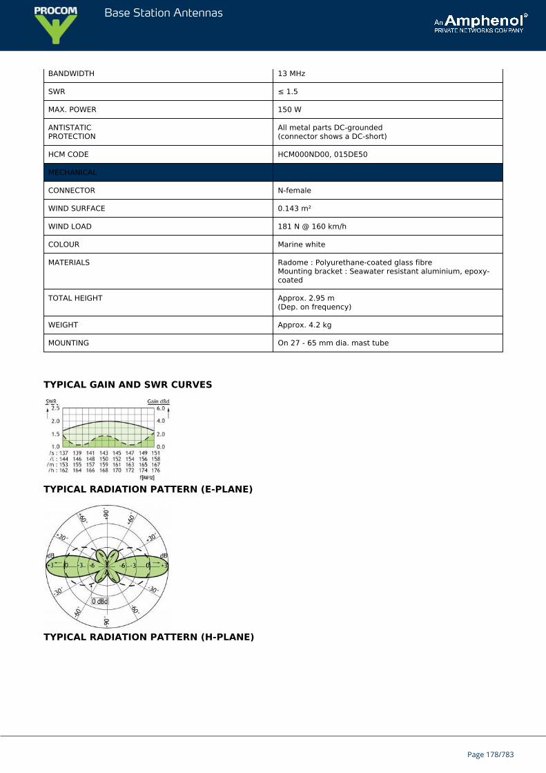
Base Station Antennas
BANDWIDTH 13 MHz
SWR ≤ 1.5
MAX. POWER 150 W
ANTISTATICPROTECTION
All metal parts DC-grounded(connector shows a DC-short)
HCM CODE HCM000ND00, 015DE50
MECHANICAL
CONNECTOR N-female
WIND SURFACE 0.143 m²
WIND LOAD 181 N @ 160 km/h
COLOUR Marine white
MATERIALS Radome : Polyurethane-coated glass fibreMounting bracket : Seawater resistant aluminium, epoxy-coated
TOTAL HEIGHT Approx. 2.95 m(Dep. on frequency)
WEIGHT Approx. 4.2 kg
MOUNTING On 27 - 65 mm dia. mast tube
TYPICAL GAIN AND SWR CURVES
TYPICAL RADIATION PATTERN (E-PLANE)
TYPICAL RADIATION PATTERN (H-PLANE)
Page 178/783

Base Station Antennas
MULTI-PURPOSE MOUNTING BRACKET
Page 179/783
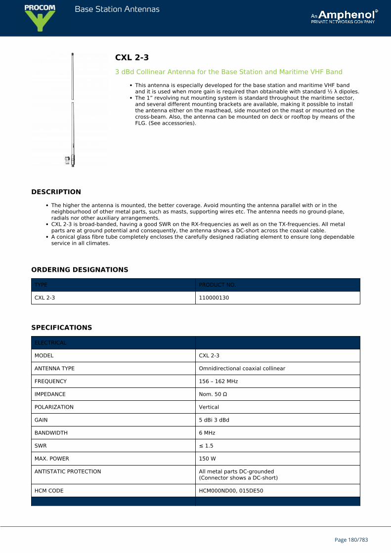
Base Station Antennas
CXL 2-33 dBd Collinear Antenna for the Base Station and Maritime VHF Band
This antenna is especially developed for the base station and maritime VHF bandand it is used when more gain is required than obtainable with standard ½ λ dipoles.The 1” revolving nut mounting system is standard throughout the maritime sector,and several different mounting brackets are available, making it possible to installthe antenna either on the masthead, side mounted on the mast or mounted on thecross-beam. Also, the antenna can be mounted on deck or rooftop by means of theFLG. (See accessories).
DESCRIPTION
The higher the antenna is mounted, the better coverage. Avoid mounting the antenna parallel with or in theneighbourhood of other metal parts, such as masts, supporting wires etc. The antenna needs no ground-plane,radials nor other auxiliary arrangements.CXL 2-3 is broad-banded, having a good SWR on the RX-frequencies as well as on the TX-frequencies. All metalparts are at ground potential and consequently, the antenna shows a DC-short across the coaxial cable.A conical glass fibre tube completely encloses the carefully designed radiating element to ensure long dependableservice in all climates.
ORDERING DESIGNATIONS
TYPE PRODUCT NO.
CXL 2-3 110000130
SPECIFICATIONS
ELECTRICAL
MODEL CXL 2-3
ANTENNA TYPE Omnidirectional coaxial collinear
FREQUENCY 156 – 162 MHz
IMPEDANCE Nom. 50 Ω
POLARIZATION Vertical
GAIN 5 dBi 3 dBd
BANDWIDTH 6 MHz
SWR ≤ 1.5
MAX. POWER 150 W
ANTISTATIC PROTECTION All metal parts DC-grounded(Connector shows a DC-short)
HCM CODE HCM000ND00, 015DE50
Page 180/783
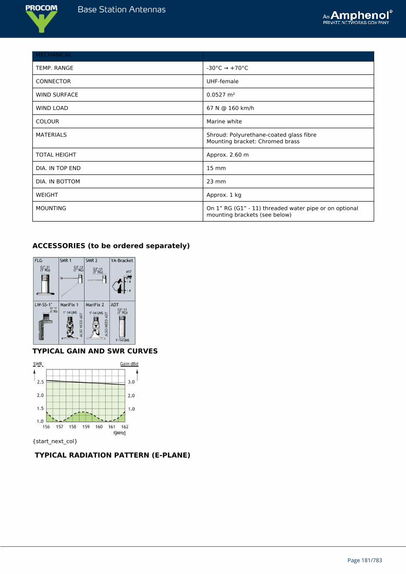
Base Station Antennas
MECHANICAL
TEMP. RANGE -30°C → +70°C
CONNECTOR UHF-female
WIND SURFACE 0.0527 m²
WIND LOAD 67 N @ 160 km/h
COLOUR Marine white
MATERIALS Shroud: Polyurethane-coated glass fibreMounting bracket: Chromed brass
TOTAL HEIGHT Approx. 2.60 m
DIA. IN TOP END 15 mm
DIA. IN BOTTOM 23 mm
WEIGHT Approx. 1 kg
MOUNTING On 1” RG (G1” - 11) threaded water pipe or on optionalmounting brackets (see below)
ACCESSORIES (to be ordered separately)
TYPICAL GAIN AND SWR CURVES
{start_next_col}
TYPICAL RADIATION PATTERN (E-PLANE)
Page 181/783

Base Station Antennas
TYPICAL RADIATION PATTERN (H-PLANE)
Page 182/783
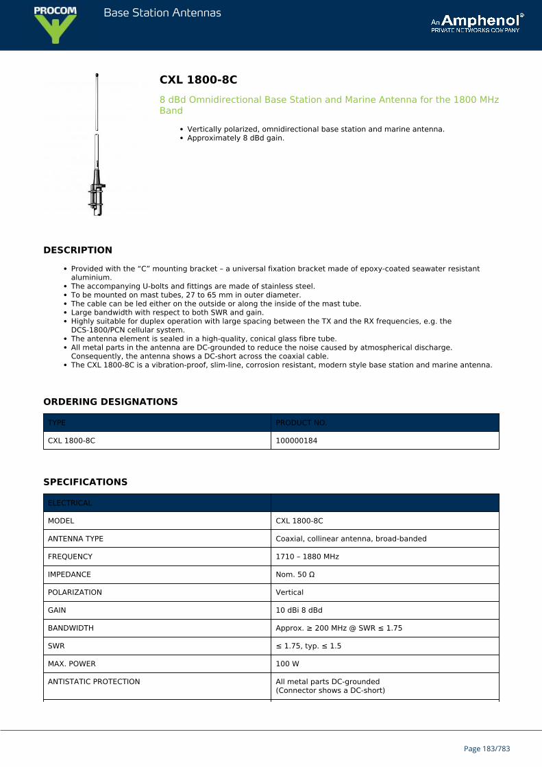
Base Station Antennas
CXL 1800-8C8 dBd Omnidirectional Base Station and Marine Antenna for the 1800 MHzBand
Vertically polarized, omnidirectional base station and marine antenna.Approximately 8 dBd gain.
DESCRIPTION
Provided with the “C” mounting bracket – a universal fixation bracket made of epoxy-coated seawater resistantaluminium.The accompanying U-bolts and fittings are made of stainless steel.To be mounted on mast tubes, 27 to 65 mm in outer diameter.The cable can be led either on the outside or along the inside of the mast tube.Large bandwidth with respect to both SWR and gain.Highly suitable for duplex operation with large spacing between the TX and the RX frequencies, e.g. theDCS-1800/PCN cellular system.The antenna element is sealed in a high-quality, conical glass fibre tube.All metal parts in the antenna are DC-grounded to reduce the noise caused by atmospherical discharge.Consequently, the antenna shows a DC-short across the coaxial cable.The CXL 1800-8C is a vibration-proof, slim-line, corrosion resistant, modern style base station and marine antenna.
ORDERING DESIGNATIONS
TYPE PRODUCT NO.
CXL 1800-8C 100000184
SPECIFICATIONS
ELECTRICAL
MODEL CXL 1800-8C
ANTENNA TYPE Coaxial, collinear antenna, broad-banded
FREQUENCY 1710 – 1880 MHz
IMPEDANCE Nom. 50 Ω
POLARIZATION Vertical
GAIN 10 dBi 8 dBd
BANDWIDTH Approx. ≥ 200 MHz @ SWR ≤ 1.75
SWR ≤ 1.75, typ. ≤ 1.5
MAX. POWER 100 W
ANTISTATIC PROTECTION All metal parts DC-grounded(Connector shows a DC-short)
Page 183/783
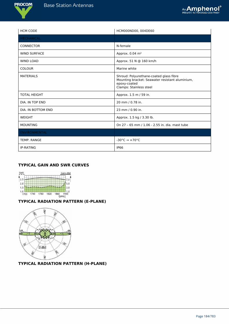
Base Station Antennas
HCM CODE HCM000ND00, 004DE60
MECHANICAL
CONNECTOR N-female
WIND SURFACE Approx. 0.04 m²
WIND LOAD Approx. 51 N @ 160 km/h
COLOUR Marine white
MATERIALS Shroud: Polyurethane-coated glass fibreMounting bracket: Seawater resistant aluminium,epoxy-coatedClamps: Stainless steel
TOTAL HEIGHT Approx. 1.5 m / 59 in.
DIA. IN TOP END 20 mm / 0.78 in.
DIA. IN BOTTOM END 23 mm / 0.90 in.
WEIGHT Approx. 1.5 kg / 3.30 lb.
MOUNTING On 27 – 65 mm / 1.06 - 2.55 in. dia. mast tube
ENVIRONMENTAL
TEMP. RANGE -30°C → +70°C
IP-RATING IP66
TYPICAL GAIN AND SWR CURVES
TYPICAL RADIATION PATTERN (E-PLANE)
TYPICAL RADIATION PATTERN (H-PLANE)
Page 184/783

Base Station Antennas
MULTI-PURPOSE MOUNTING BRACKET
PLEASE NOTE
The antenna is delivered with a DC-connection between the antenna element and the mounting bracket.
Page 185/783
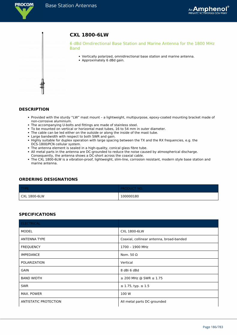
Base Station Antennas
CXL 1800-6LW6 dBd Omdirectional Base Station and Marine Antenna for the 1800 MHzBand
Vertically polarized, omnidirectional base station and marine antenna.Approximately 6 dBd gain.
DESCRIPTION
Provided with the sturdy “LW” mast mount – a lightweight, multipurpose, epoxy-coated mounting bracket made ofnon-corrosive aluminium.The accompanying U-bolts and fittings are made of stainless steel.To be mounted on vertical or horizontal mast tubes, 16 to 54 mm in outer diameter.The cable can be led either on the outside or along the inside of the mast tube.Large bandwidth with respect to both SWR and gain.Highly suitable for duplex operation with large spacing between the TX and the RX frequencies, e.g. theDCS-1800/PCN cellular system.The antenna element is sealed in a high-quality, conical glass fibre tube.All metal parts in the antenna are DC-grounded to reduce the noise caused by atmospherical discharge.Consequently, the antenna shows a DC-short across the coaxial cable.The CXL 1800-6LW is a vibration-proof, lightweight, slim-line, corrosion resistant, modern style base station andmarine antenna.
ORDERING DESIGNATIONS
TYPE PRODUCT NO.
CXL 1800-6LW 100000180
SPECIFICATIONS
ELECTRICAL
MODEL CXL 1800-6LW
ANTENNA TYPE Coaxial, collinear antenna, broad-banded
FREQUENCY 1700 – 1900 MHz
IMPEDANCE Nom. 50 Ω
POLARIZATION Vertical
GAIN 8 dBi 6 dBd
BAND WIDTH ≥ 200 MHz @ SWR ≤ 1.75
SWR ≤ 1.75, typ. ≤ 1.5
MAX. POWER 100 W
ANTISTATIC PROTECTION All metal parts DC-grounded
Page 186/783
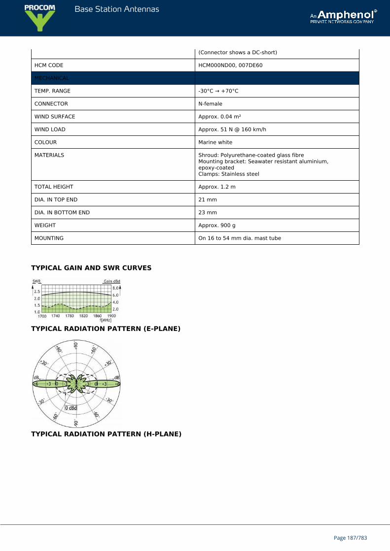
Base Station Antennas
(Connector shows a DC-short)
HCM CODE HCM000ND00, 007DE60
MECHANICAL
TEMP. RANGE -30°C → +70°C
CONNECTOR N-female
WIND SURFACE Approx. 0.04 m²
WIND LOAD Approx. 51 N @ 160 km/h
COLOUR Marine white
MATERIALS Shroud: Polyurethane-coated glass fibreMounting bracket: Seawater resistant aluminium,epoxy-coatedClamps: Stainless steel
TOTAL HEIGHT Approx. 1.2 m
DIA. IN TOP END 21 mm
DIA. IN BOTTOM END 23 mm
WEIGHT Approx. 900 g
MOUNTING On 16 to 54 mm dia. mast tube
TYPICAL GAIN AND SWR CURVES
TYPICAL RADIATION PATTERN (E-PLANE)
TYPICAL RADIATION PATTERN (H-PLANE)
Page 187/783

Base Station Antennas
MULTI-PURPOSE MOUNTING BRACKET
PLEASE NOTE
The antenna is delivered with a DC-connection between the antenna element and the mounting bracket.
Page 188/783
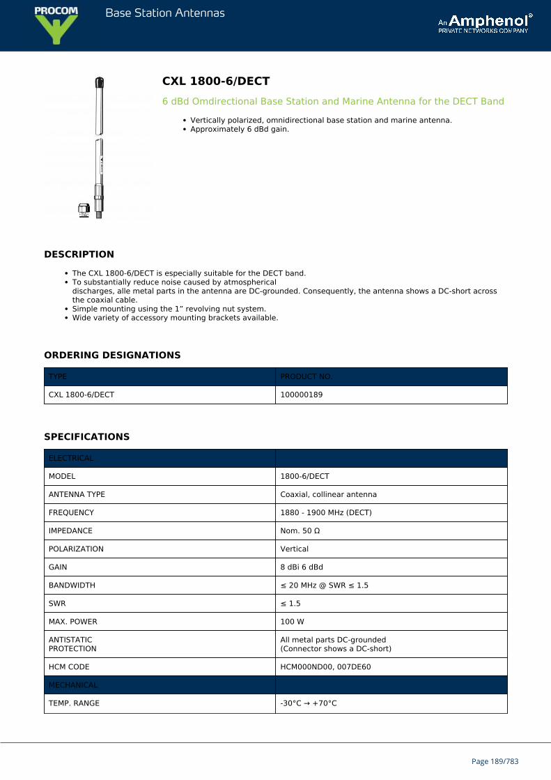
Base Station Antennas
CXL 1800-6/DECT6 dBd Omdirectional Base Station and Marine Antenna for the DECT Band
Vertically polarized, omnidirectional base station and marine antenna.Approximately 6 dBd gain.
DESCRIPTION
The CXL 1800-6/DECT is especially suitable for the DECT band.To substantially reduce noise caused by atmosphericaldischarges, alle metal parts in the antenna are DC-grounded. Consequently, the antenna shows a DC-short acrossthe coaxial cable.Simple mounting using the 1” revolving nut system.Wide variety of accessory mounting brackets available.
ORDERING DESIGNATIONS
TYPE PRODUCT NO.
CXL 1800-6/DECT 100000189
SPECIFICATIONS
ELECTRICAL
MODEL 1800-6/DECT
ANTENNA TYPE Coaxial, collinear antenna
FREQUENCY 1880 - 1900 MHz (DECT)
IMPEDANCE Nom. 50 Ω
POLARIZATION Vertical
GAIN 8 dBi 6 dBd
BANDWIDTH ≤ 20 MHz @ SWR ≤ 1.5
SWR ≤ 1.5
MAX. POWER 100 W
ANTISTATICPROTECTION
All metal parts DC-grounded(Connector shows a DC-short)
HCM CODE HCM000ND00, 007DE60
MECHANICAL
TEMP. RANGE -30°C → +70°C
Page 189/783
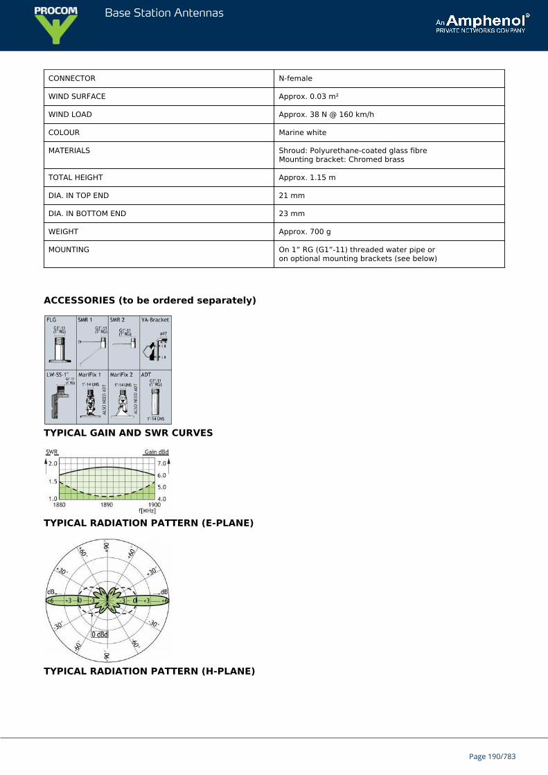
Base Station Antennas
CONNECTOR N-female
WIND SURFACE Approx. 0.03 m²
WIND LOAD Approx. 38 N @ 160 km/h
COLOUR Marine white
MATERIALS Shroud: Polyurethane-coated glass fibreMounting bracket: Chromed brass
TOTAL HEIGHT Approx. 1.15 m
DIA. IN TOP END 21 mm
DIA. IN BOTTOM END 23 mm
WEIGHT Approx. 700 g
MOUNTING On 1” RG (G1”-11) threaded water pipe oron optional mounting brackets (see below)
ACCESSORIES (to be ordered separately)
TYPICAL GAIN AND SWR CURVES
TYPICAL RADIATION PATTERN (E-PLANE)
TYPICAL RADIATION PATTERN (H-PLANE)
Page 190/783

Base Station Antennas
Page 191/783
Base Station Antennas
CXL 1800-66 dBd Omdirectional Base Station and Marine Antenna for the 1800 MHzBand
Vertically polarized, omnidirectional base station and marine antenna.Approximately 6 dBd gain.
DESCRIPTION
Simple mounting using the 1” revolving nut system.Wide variety of accessory mounting brackets available.Large bandwidth with respect to both SWR and gain. Highly suitable for duplex operation with large spacingbetween the TX and the RX frequencies, e.g. the DCS-1800/PCN cellular system.The antenna element is sealed in a high-quality, conical glass fibre tube.All metal parts in the antenna are DC-grounded to reduce the noise caused by atmospherical discharge.Consequently, the antenna shows a DC-short across the coaxial cable.The CXL 1800-6 is a vibration-proof, lightweight, slim-line, corrosion resistant, modern style base station and marineantenna.
ORDERING DESIGNATIONS
TYPE PRODUCT NO.
CXL 1800-6 100000186
SPECIFICATIONS
ELECTRICAL
MODEL CXL 1800-6
ANTENNA TYPE Coaxial, collinear antenna, broad-banded
FREQUENCY 1700 – 1900 MHz
IMPEDANCE Nom. 50 Ω
POLARIZATION Vertical
GAIN 8 dBi 6 dBd
BANDWIDTH ≥ 200 MHz @ SWR ≤ 1.75
SWR ≤ 1.75, typ. ≤ 1.5
MAX. POWER 100 W
ANTISTATICPROTECTION
All metal parts DC-grounded(Connector shows a DC-short)
MECHANICAL
TEMP. RANGE -30°C → +70°C
Page 192/783
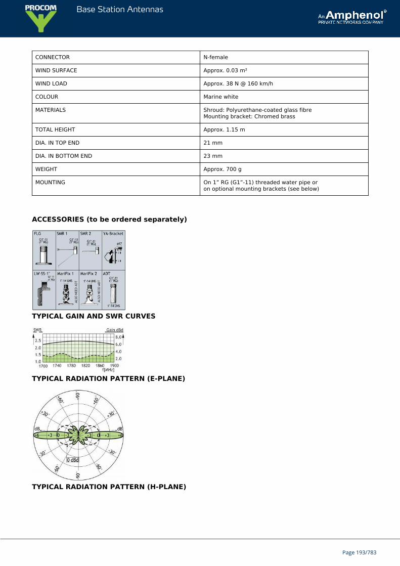
Base Station Antennas
CONNECTOR N-female
WIND SURFACE Approx. 0.03 m²
WIND LOAD Approx. 38 N @ 160 km/h
COLOUR Marine white
MATERIALS Shroud: Polyurethane-coated glass fibreMounting bracket: Chromed brass
TOTAL HEIGHT Approx. 1.15 m
DIA. IN TOP END 21 mm
DIA. IN BOTTOM END 23 mm
WEIGHT Approx. 700 g
MOUNTING On 1” RG (G1”-11) threaded water pipe oron optional mounting brackets (see below)
ACCESSORIES (to be ordered separately)
TYPICAL GAIN AND SWR CURVES
TYPICAL RADIATION PATTERN (E-PLANE)
TYPICAL RADIATION PATTERN (H-PLANE)
Page 193/783
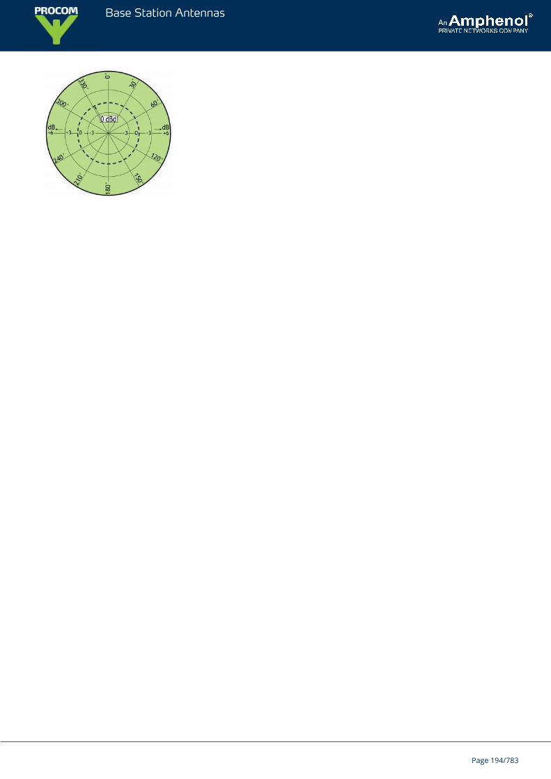
Base Station Antennas
Page 194/783
Base Station Antennas
CXL 1800-3LW3 dBd Omnidirectional Base Station and Marine Antenna for the 1800 MHzBand
Vertically polarized, omnidirectional base station and marine antenna.Approximately 3 dBd gain.
DESCRIPTION
Provided with the sturdy “LW” mast mount – a lightweight, multipurpose, epoxy-coated mounting bracket made ofnon-corrosive aluminium.The accompanying U-bolts and fittings are made of stainless steel.To be mounted on vertical or horizontal mast tubes, 16 to54 mm in outer diameter.The cable can be led either on the outside or along the inside of the mast tube.Large bandwidth with respect to both SWR and gain.Highly suitable for duplex operation with large spacing between the TX and the RX frequencies, e.g. theDCS-1800/PCN cellular system.The antenna element is sealed in a high-quality, conical glass fibre tube.All metal parts in the antenna are DC-grounded to reduce the noise caused by atmospherical discharge.Consequently, the antenna shows a DC-short across the coaxial cable.The CXL 1800-3LW is a vibration-proof, lightweight, slim-line, corrosion resistant, modern style base station andmarine antenna.
ORDERING DESIGNATIONS
TYPE PRODUCT NO.
CXL 1800-3LW 100000175
SPECIFICATIONS
ELECTRICAL
MODEL CXL 1800-3LW
ANTENNA TYPE Coaxial, collinear antenna, broadbanded
FREQUENCY 1710 – 1880 MHz
IMPEDANCE Nom. 50 Ω
POLARIZATION Vertical
GAIN 5 dBi 3 dBd
BANDWIDTH ≥ 170 MHz @ SWR ≤ 2.0
SWR ≤ 2.0, typ. ≤ 1.75
Page 195/783
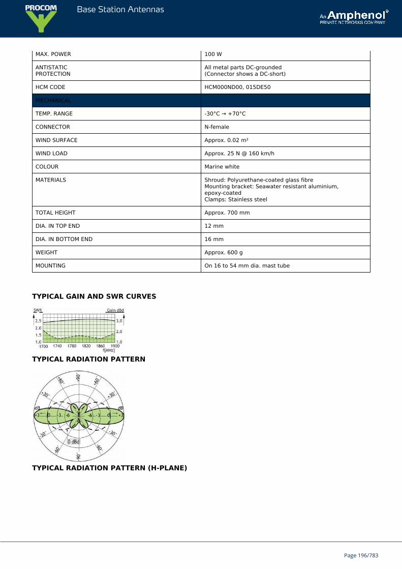
Base Station Antennas
MAX. POWER 100 W
ANTISTATICPROTECTION
All metal parts DC-grounded(Connector shows a DC-short)
HCM CODE HCM000ND00, 015DE50
MECHANICAL
TEMP. RANGE -30°C → +70°C
CONNECTOR N-female
WIND SURFACE Approx. 0.02 m²
WIND LOAD Approx. 25 N @ 160 km/h
COLOUR Marine white
MATERIALS Shroud: Polyurethane-coated glass fibreMounting bracket: Seawater resistant aluminium,epoxy-coatedClamps: Stainless steel
TOTAL HEIGHT Approx. 700 mm
DIA. IN TOP END 12 mm
DIA. IN BOTTOM END 16 mm
WEIGHT Approx. 600 g
MOUNTING On 16 to 54 mm dia. mast tube
TYPICAL GAIN AND SWR CURVES
TYPICAL RADIATION PATTERN
TYPICAL RADIATION PATTERN (H-PLANE)
Page 196/783
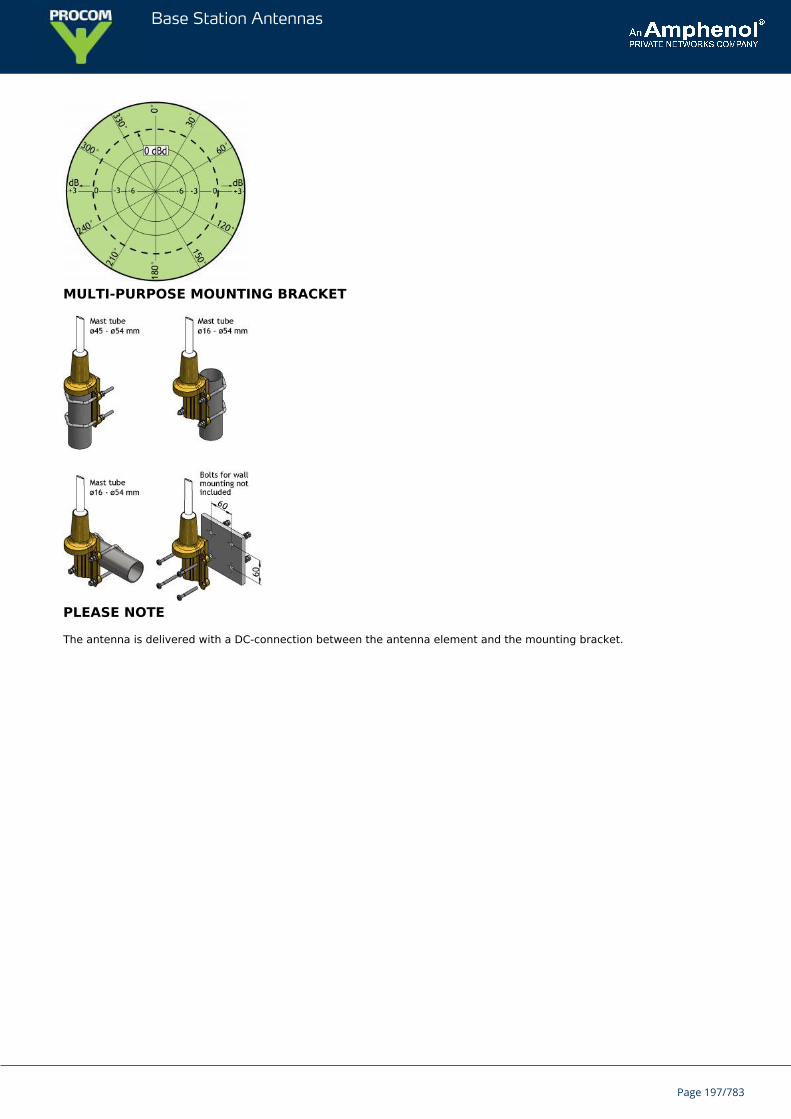
Base Station Antennas
MULTI-PURPOSE MOUNTING BRACKET
PLEASE NOTE
The antenna is delivered with a DC-connection between the antenna element and the mounting bracket.
Page 197/783
Base Station Antennas
CXL 1800-3/DECT3 dBd Omnidirectional Base Station and Marine Antenna for the DECTBand
Vertically polarized, omnidirectional base station and marine antenna.Approximately 3 dBd gain.
DESCRIPTION
The CXL 1800-3/DECT is especially suitable for the DECT band.To substantially reduce noise caused by atmospherical discharges, all metal parts in the antenna are DC-grounded.Consequently, the antenna shows a DC-short across the coaxial cable.Simple mounting using the 1” revolving nut system.Wide variety of accessory mounting brackets available.
ORDERING DESIGNATIONS
TYPE PRODUCT NO.
CXL 1800-3/DECT 100000178
SPECIFICATIONS
ELECTRICAL
MODEL CXL 1800-3/DECT
ANTENNA TYPE Coaxial, collinear antenna
FREQUENCY 1880 - 1900 MHz (DECT)
IMPEDANCE Nom. 50 Ω
POLARIZATION Vertical
GAIN 5 dBi 3 dBd
BANDWIDTH ≤ 20 MHz @ SWR ≤ 1.5
SWR ≤ 1.5
MAX. POWER 100 W
ANTISTATICPROTECTION
All metal parts DC-grounded(Connector shows a DC-short)
HCM CODE HCM000ND00, 015DE50
MECHANICAL
TEMP. RANGE -30°C → +70°C
CONNECTOR N-female
Page 198/783
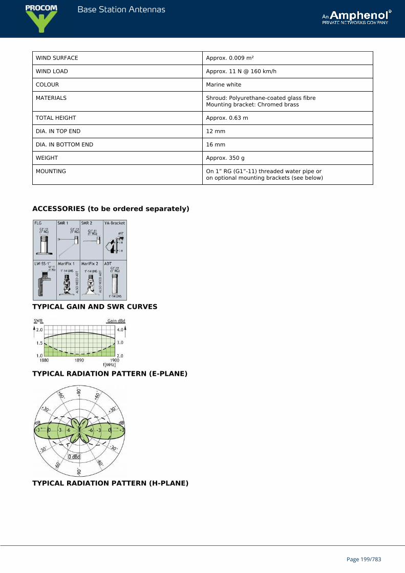
Base Station Antennas
WIND SURFACE Approx. 0.009 m²
WIND LOAD Approx. 11 N @ 160 km/h
COLOUR Marine white
MATERIALS Shroud: Polyurethane-coated glass fibreMounting bracket: Chromed brass
TOTAL HEIGHT Approx. 0.63 m
DIA. IN TOP END 12 mm
DIA. IN BOTTOM END 16 mm
WEIGHT Approx. 350 g
MOUNTING On 1” RG (G1”-11) threaded water pipe oron optional mounting brackets (see below)
ACCESSORIES (to be ordered separately)
TYPICAL GAIN AND SWR CURVES
TYPICAL RADIATION PATTERN (E-PLANE)
TYPICAL RADIATION PATTERN (H-PLANE)
Page 199/783

Base Station Antennas
Page 200/783
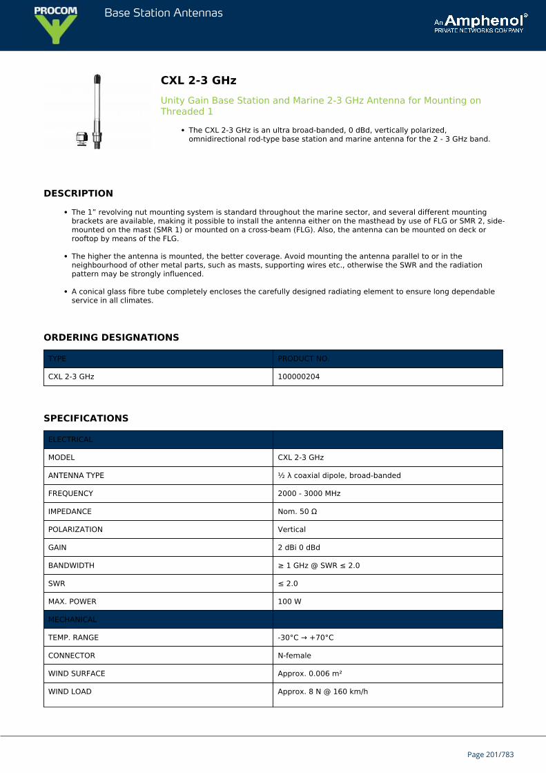
Base Station Antennas
CXL 2-3 GHzUnity Gain Base Station and Marine 2-3 GHz Antenna for Mounting onThreaded 1
The CXL 2-3 GHz is an ultra broad-banded, 0 dBd, vertically polarized,omnidirectional rod-type base station and marine antenna for the 2 - 3 GHz band.
DESCRIPTION
The 1” revolving nut mounting system is standard throughout the marine sector, and several different mountingbrackets are available, making it possible to install the antenna either on the masthead by use of FLG or SMR 2, side-mounted on the mast (SMR 1) or mounted on a cross-beam (FLG). Also, the antenna can be mounted on deck orrooftop by means of the FLG.
The higher the antenna is mounted, the better coverage. Avoid mounting the antenna parallel to or in theneighbourhood of other metal parts, such as masts, supporting wires etc., otherwise the SWR and the radiationpattern may be strongly influenced.
A conical glass fibre tube completely encloses the carefully designed radiating element to ensure long dependableservice in all climates.
ORDERING DESIGNATIONS
TYPE PRODUCT NO.
CXL 2-3 GHz 100000204
SPECIFICATIONS
ELECTRICAL
MODEL CXL 2-3 GHz
ANTENNA TYPE ½ λ coaxial dipole, broad-banded
FREQUENCY 2000 - 3000 MHz
IMPEDANCE Nom. 50 Ω
POLARIZATION Vertical
GAIN 2 dBi 0 dBd
BANDWIDTH ≥ 1 GHz @ SWR ≤ 2.0
SWR ≤ 2.0
MAX. POWER 100 W
MECHANICAL
TEMP. RANGE -30°C → +70°C
CONNECTOR N-female
WIND SURFACE Approx. 0.006 m²
WIND LOAD Approx. 8 N @ 160 km/h
Page 201/783
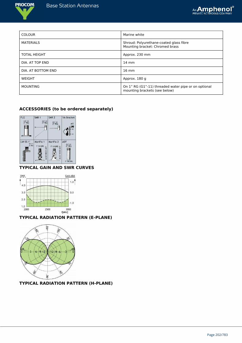
Base Station Antennas
COLOUR Marine white
MATERIALS Shroud: Polyurethane-coated glass fibreMounting bracket: Chromed brass
TOTAL HEIGHT Approx. 230 mm
DIA. AT TOP END 14 mm
DIA. AT BOTTOM END 16 mm
WEIGHT Approx. 180 g
MOUNTING On 1” RG (G1”-11) threaded water pipe or on optionalmounting brackets (see below)
ACCESSORIES (to be ordered separately)
TYPICAL GAIN AND SWR CURVES
TYPICAL RADIATION PATTERN (E-PLANE)
TYPICAL RADIATION PATTERN (H-PLANE)
Page 202/783
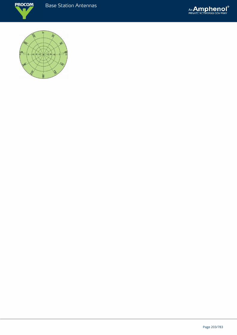
Base Station Antennas
Page 203/783

Base Station Antennas
CXL 2-2CUnity Gain, Broad.Banded Base Station Antenna for the 160 MHz Band
CXL 2-2C is a 0 dBd gain, omnidirectional base station antenna.The antenna covers the complete band: 144 - 175 MHz.
DESCRIPTION
CXL 2-2C is designed for fixation on supporting tubes with outer diameter between 27 mm and 65 mm.The construction of the mount makes it possible to lead the cable either inside or along the outside of the masttube.A glass fibre tube completely encloses the carefully designed radiating element to ensure long dependable servicein all climates.Atmospherical discharges are immediately led to ground as all metal parts are DC-grounded (consequently, theantenna shows a DC-short across the coaxial cable).This antenna is used where reliability is of utmost importance. A long lifetime has been taken into considerationwhen designing this antenna – it is sturdy and strong.
ORDERING DESIGNATIONS
TYPE PRODUCT NO.
CXL 2-2C 100000087
SPECIFICATIONS
ELECTRICAL
MODEL CXL 2-2C
ANTENNA TYPE Coaxial, broad-band dipole
FREQUENCY Covering: 144 - 175 MHz
IMPEDANCE Nom. 50 Ω
RADIATION Omnidirectional
POLARIZATION Vertical
GAIN 2 dBi 0 dBd
BANDWIDTH 31 MHz
SWR ≤ 1.5
MAX. POWER 600 W
ANTISTATIC PROTECTION All metal parts DC-grounded(Connector shows a DC-short)
MECHANICAL
Page 204/783
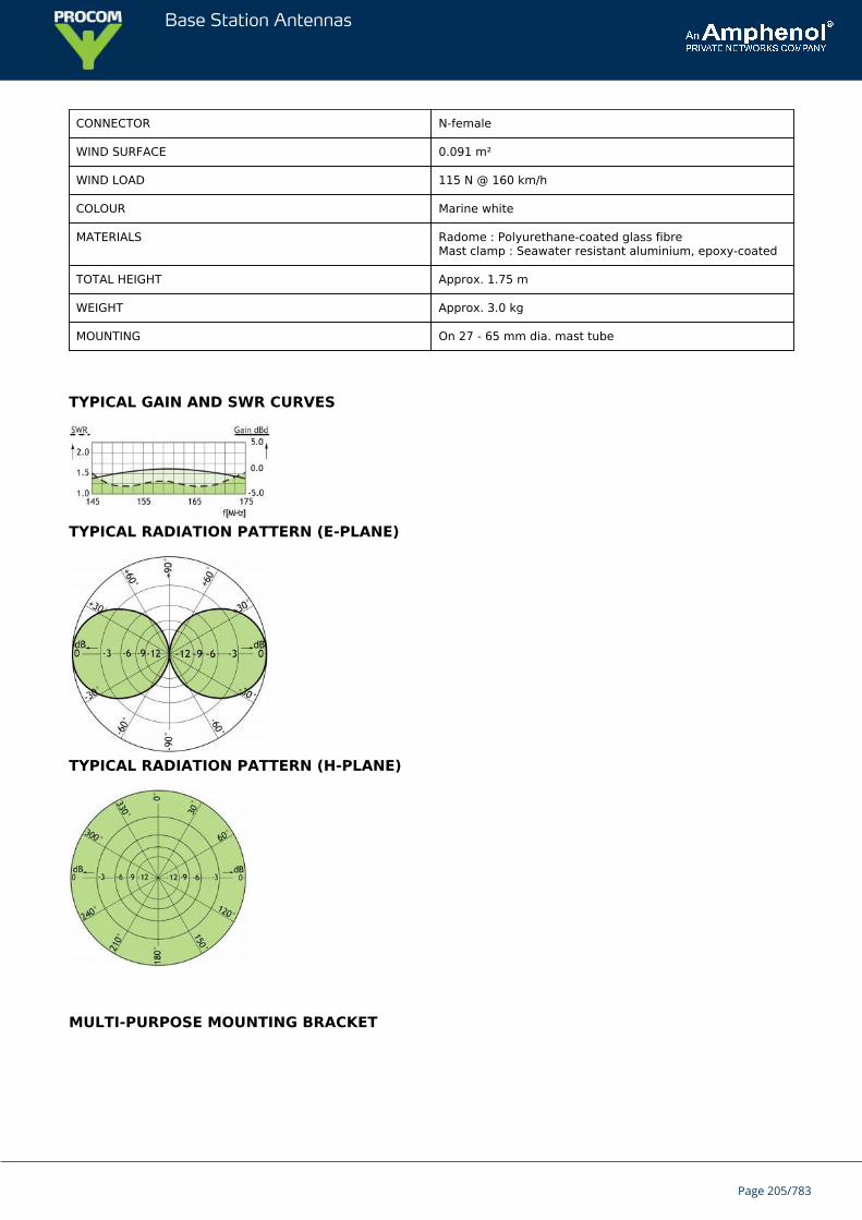
Base Station Antennas
CONNECTOR N-female
WIND SURFACE 0.091 m²
WIND LOAD 115 N @ 160 km/h
COLOUR Marine white
MATERIALS Radome : Polyurethane-coated glass fibreMast clamp : Seawater resistant aluminium, epoxy-coated
TOTAL HEIGHT Approx. 1.75 m
WEIGHT Approx. 3.0 kg
MOUNTING On 27 - 65 mm dia. mast tube
TYPICAL GAIN AND SWR CURVES
TYPICAL RADIATION PATTERN (E-PLANE)
TYPICAL RADIATION PATTERN (H-PLANE)
MULTI-PURPOSE MOUNTING BRACKET
Page 205/783
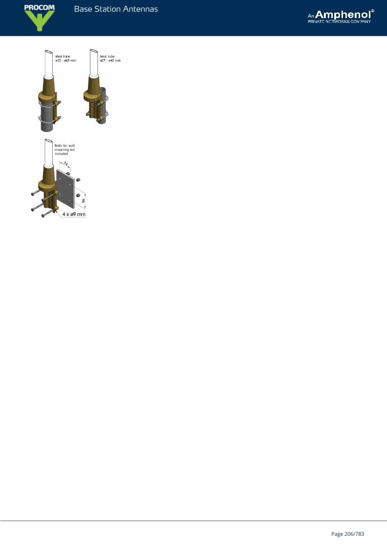
Base Station Antennas
Page 206/783
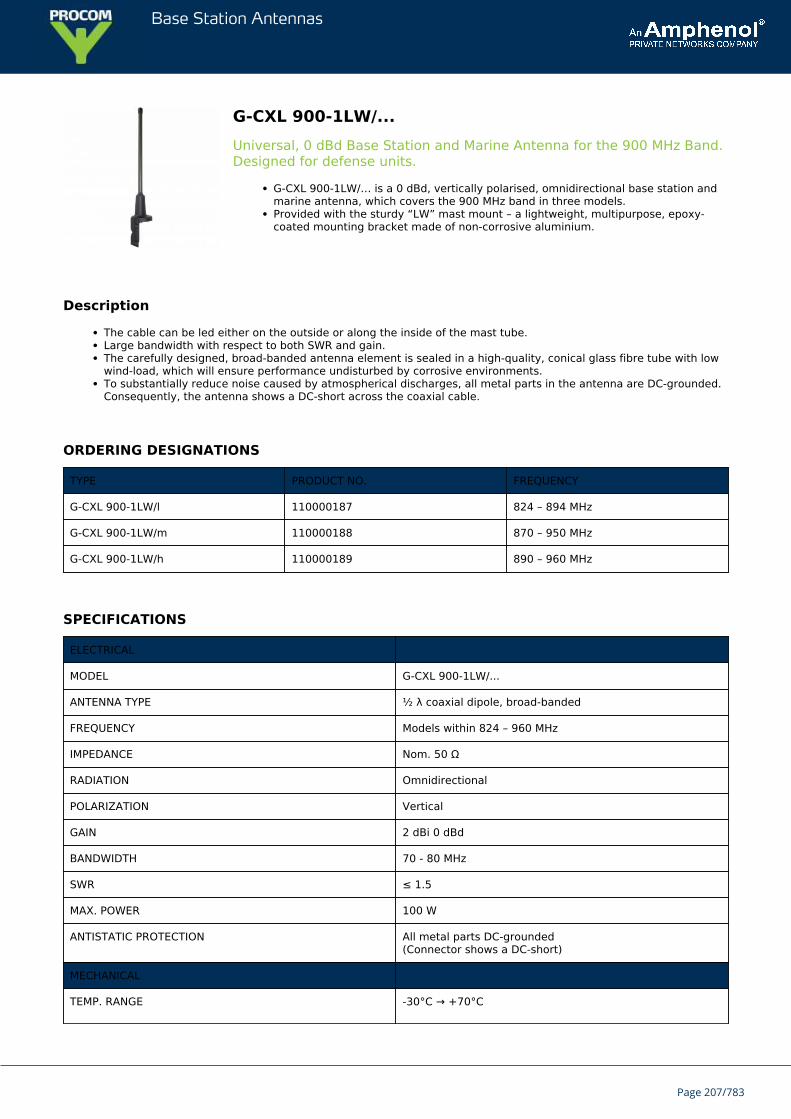
Base Station Antennas
G-CXL 900-1LW/...Universal, 0 dBd Base Station and Marine Antenna for the 900 MHz Band.Designed for defense units.
G-CXL 900-1LW/… is a 0 dBd, vertically polarised, omnidirectional base station andmarine antenna, which covers the 900 MHz band in three models.Provided with the sturdy “LW” mast mount – a lightweight, multipurpose, epoxy-coated mounting bracket made of non-corrosive aluminium.
Description
The cable can be led either on the outside or along the inside of the mast tube.Large bandwidth with respect to both SWR and gain.The carefully designed, broad-banded antenna element is sealed in a high-quality, conical glass fibre tube with lowwind-load, which will ensure performance undisturbed by corrosive environments.To substantially reduce noise caused by atmospherical discharges, all metal parts in the antenna are DC-grounded.Consequently, the antenna shows a DC-short across the coaxial cable.
ORDERING DESIGNATIONS
TYPE PRODUCT NO. FREQUENCY
G-CXL 900-1LW/l 110000187 824 – 894 MHz
G-CXL 900-1LW/m 110000188 870 – 950 MHz
G-CXL 900-1LW/h 110000189 890 – 960 MHz
SPECIFICATIONS
ELECTRICAL
MODEL G-CXL 900-1LW/...
ANTENNA TYPE ½ λ coaxial dipole, broad-banded
FREQUENCY Models within 824 – 960 MHz
IMPEDANCE Nom. 50 Ω
RADIATION Omnidirectional
POLARIZATION Vertical
GAIN 2 dBi 0 dBd
BANDWIDTH 70 - 80 MHz
SWR ≤ 1.5
MAX. POWER 100 W
ANTISTATIC PROTECTION All metal parts DC-grounded(Connector shows a DC-short)
MECHANICAL
TEMP. RANGE -30°C → +70°C
Page 207/783
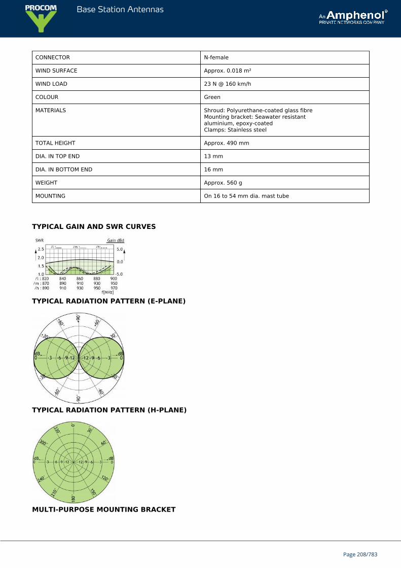
Base Station Antennas
CONNECTOR N-female
WIND SURFACE Approx. 0.018 m²
WIND LOAD 23 N @ 160 km/h
COLOUR Green
MATERIALS Shroud: Polyurethane-coated glass fibreMounting bracket: Seawater resistantaluminium, epoxy-coatedClamps: Stainless steel
TOTAL HEIGHT Approx. 490 mm
DIA. IN TOP END 13 mm
DIA. IN BOTTOM END 16 mm
WEIGHT Approx. 560 g
MOUNTING On 16 to 54 mm dia. mast tube
TYPICAL GAIN AND SWR CURVES
TYPICAL RADIATION PATTERN (E-PLANE)
TYPICAL RADIATION PATTERN (H-PLANE)
MULTI-PURPOSE MOUNTING BRACKET
Page 208/783
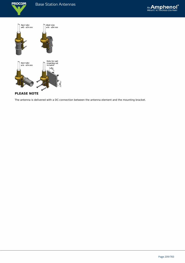
Base Station Antennas
PLEASE NOTE
The antenna is delivered with a DC-connection between the antenna element and the mounting bracket.
Page 209/783
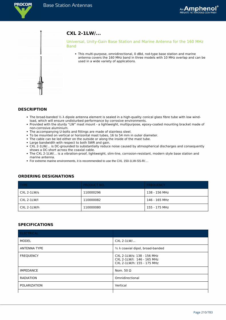
Base Station Antennas
CXL 2-1LW/...Universal, Unity-Gain Base Station and Marine Antenna for the 160 MHzBand
This multi-purpose, omnidirectional, 0 dBd, rod-type base station and marineantenna covers the 160 MHz band in three models with 10 MHz overlap and can beused in a wide variety of applications.
DESCRIPTION
The broad-banded ½ λ dipole antenna element is sealed in a high-quality conical glass fibre tube with low wind-load, which will ensure undisturbed performance by corrosive environments.Provided with the sturdy “LW” mast mount - a lightweight, multipurpose, epoxy-coated mounting bracket made ofnon-corrosive aluminium.The accompanying U-bolts and fittings are made of stainless steel.To be mounted on vertical or horizontal mast tubes, 16 to 54 mm in outer diameter.The cable can be led either on the outside or along the inside of the mast tube.Large bandwidth with respect to both SWR and gain.CXL 2-1LW/… is DC-grounded to substantially reduce noise caused by atmospherical discharges and consequentlyshows a DC-short across the coaxial cable.The CXL 2-1LW/… is a vibration-proof, lightweight, slim-line, corrosion-resistant, modern style base station andmarine antenna.For extreme marine environments, it is recommended to use the CXL 150-1LW-SS-R/....
ORDERING DESIGNATIONS
TYPE PRODUCT NO. FREQUENCY
CXL 2-1LW/s 110000296 138 - 156 MHz
CXL 2-1LW/l 110000082 146 - 165 MHz
CXL 2-1LW/h 110000080 155 - 175 MHz
SPECIFICATIONS
ELECTRICAL
MODEL CXL 2-1LW/...
ANTENNA TYPE ½ λ coaxial dipol, broad-banded
FREQUENCY CXL 2-1LW/s: 138 - 156 MHzCXL 2-1LW/l: 146 - 165 MHzCXL 2-1LW/h: 155 - 175 MHz
IMPEDANCE Nom. 50 Ω
RADIATION Omnidirectional
POLARIZATION Vertical
Page 210/783
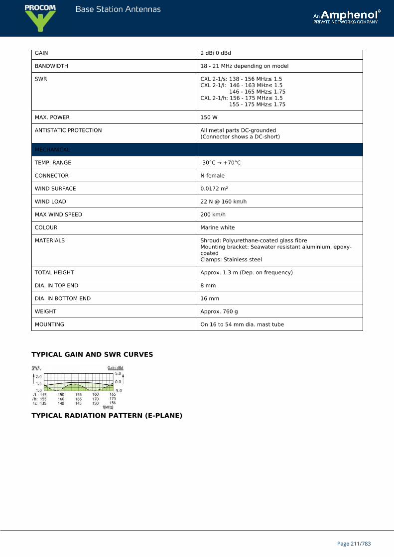
Base Station Antennas
GAIN 2 dBi 0 dBd
BANDWIDTH 18 - 21 MHz depending on model
SWR CXL 2-1/s: 138 - 156 MHz≤ 1.5CXL 2-1/l: 146 - 163 MHz≤ 1.5 146 - 165 MHz≤ 1.75CXL 2-1/h: 156 - 175 MHz≤ 1.5 155 - 175 MHz≤ 1.75
MAX. POWER 150 W
ANTISTATIC PROTECTION All metal parts DC-grounded(Connector shows a DC-short)
MECHANICAL
TEMP. RANGE -30°C → +70°C
CONNECTOR N-female
WIND SURFACE 0.0172 m²
WIND LOAD 22 N @ 160 km/h
MAX WIND SPEED 200 km/h
COLOUR Marine white
MATERIALS Shroud: Polyurethane-coated glass fibreMounting bracket: Seawater resistant aluminium, epoxy-coatedClamps: Stainless steel
TOTAL HEIGHT Approx. 1.3 m (Dep. on frequency)
DIA. IN TOP END 8 mm
DIA. IN BOTTOM END 16 mm
WEIGHT Approx. 760 g
MOUNTING On 16 to 54 mm dia. mast tube
TYPICAL GAIN AND SWR CURVES
TYPICAL RADIATION PATTERN (E-PLANE)
Page 211/783
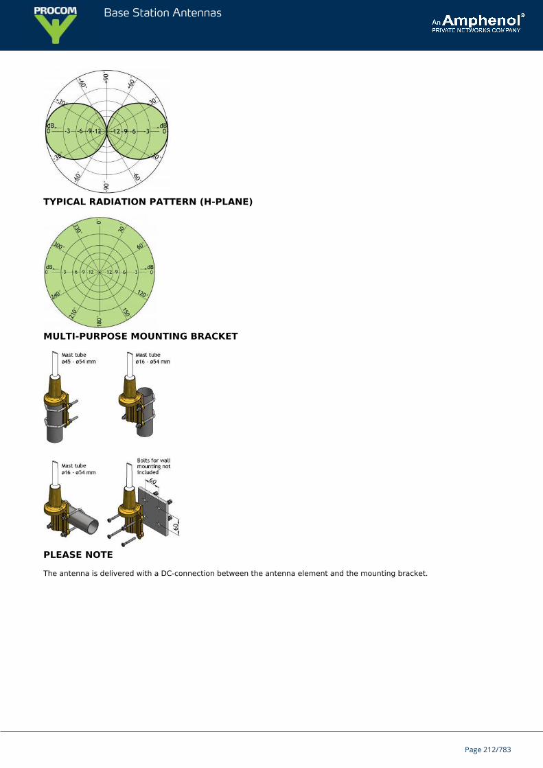
Base Station Antennas
TYPICAL RADIATION PATTERN (H-PLANE)
MULTI-PURPOSE MOUNTING BRACKET
PLEASE NOTE
The antenna is delivered with a DC-connection between the antenna element and the mounting bracket.
Page 212/783
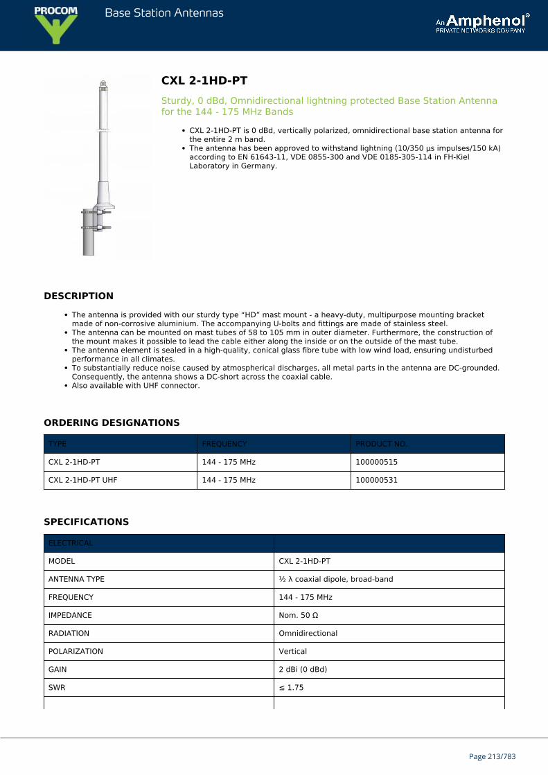
Base Station Antennas
CXL 2-1HD-PTSturdy, 0 dBd, Omnidirectional lightning protected Base Station Antennafor the 144 - 175 MHz Bands
CXL 2-1HD-PT is 0 dBd, vertically polarized, omnidirectional base station antenna forthe entire 2 m band.The antenna has been approved to withstand lightning (10/350 μs impulses/150 kA)according to EN 61643-11, VDE 0855-300 and VDE 0185-305-114 in FH-KielLaboratory in Germany.
DESCRIPTION
The antenna is provided with our sturdy type “HD” mast mount - a heavy-duty, multipurpose mounting bracketmade of non-corrosive aluminium. The accompanying U-bolts and fittings are made of stainless steel.The antenna can be mounted on mast tubes of 58 to 105 mm in outer diameter. Furthermore, the construction ofthe mount makes it possible to lead the cable either along the inside or on the outside of the mast tube.The antenna element is sealed in a high-quality, conical glass fibre tube with low wind load, ensuring undisturbedperformance in all climates.To substantially reduce noise caused by atmospherical discharges, all metal parts in the antenna are DC-grounded.Consequently, the antenna shows a DC-short across the coaxial cable.Also available with UHF connector.
ORDERING DESIGNATIONS
TYPE FREQUENCY PRODUCT NO.
CXL 2-1HD-PT 144 - 175 MHz 100000515
CXL 2-1HD-PT UHF 144 - 175 MHz 100000531
SPECIFICATIONS
ELECTRICAL
MODEL CXL 2-1HD-PT
ANTENNA TYPE ½ λ coaxial dipole, broad-band
FREQUENCY 144 - 175 MHz
IMPEDANCE Nom. 50 Ω
RADIATION Omnidirectional
POLARIZATION Vertical
GAIN 2 dBi (0 dBd)
SWR ≤ 1.75
Page 213/783
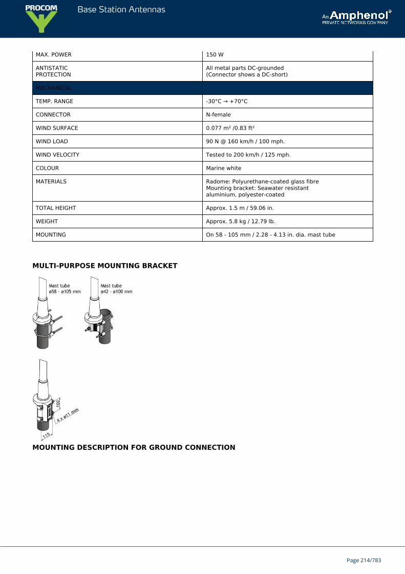
Base Station Antennas
MAX. POWER 150 W
ANTISTATICPROTECTION
All metal parts DC-grounded(Connector shows a DC-short)
MECHANICAL
TEMP. RANGE -30°C → +70°C
CONNECTOR N-female
WIND SURFACE 0.077 m² /0.83 ft²
WIND LOAD 90 N @ 160 km/h / 100 mph.
WIND VELOCITY Tested to 200 km/h / 125 mph.
COLOUR Marine white
MATERIALS Radome: Polyurethane-coated glass fibreMounting bracket: Seawater resistantaluminium, polyester-coated
TOTAL HEIGHT Approx. 1.5 m / 59.06 in.
WEIGHT Approx. 5.8 kg / 12.79 lb.
MOUNTING On 58 - 105 mm / 2.28 - 4.13 in. dia. mast tube
MULTI-PURPOSE MOUNTING BRACKET
MOUNTING DESCRIPTION FOR GROUND CONNECTION
Page 214/783
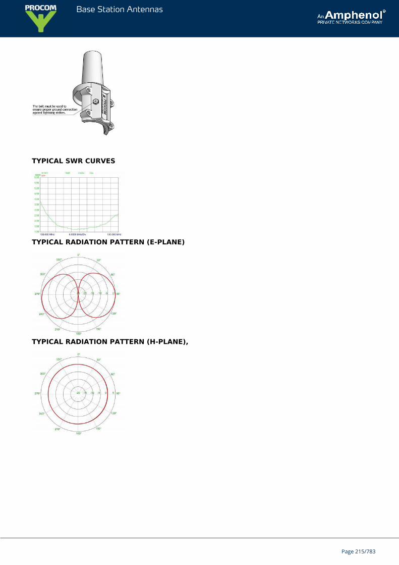
Base Station Antennas
TYPICAL SWR CURVES
TYPICAL RADIATION PATTERN (E-PLANE)
TYPICAL RADIATION PATTERN (H-PLANE),
Page 215/783
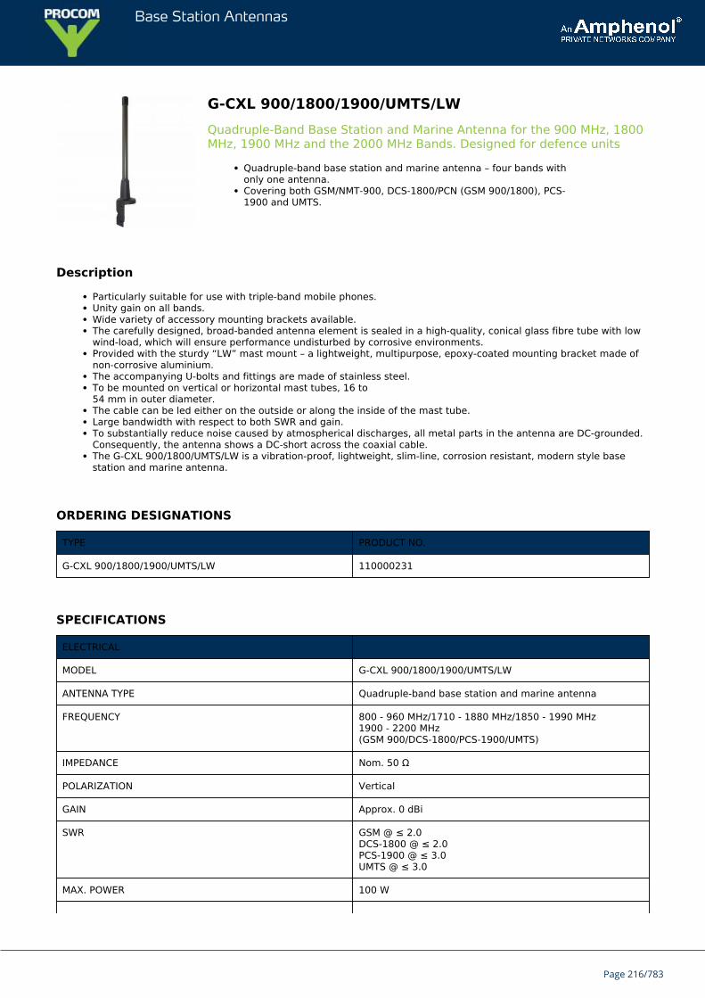
Base Station Antennas
G-CXL 900/1800/1900/UMTS/LWQuadruple-Band Base Station and Marine Antenna for the 900 MHz, 1800MHz, 1900 MHz and the 2000 MHz Bands. Designed for defence units
Quadruple-band base station and marine antenna – four bands withonly one antenna.Covering both GSM/NMT-900, DCS-1800/PCN (GSM 900/1800), PCS-1900 and UMTS.
Description
Particularly suitable for use with triple-band mobile phones.Unity gain on all bands.Wide variety of accessory mounting brackets available.The carefully designed, broad-banded antenna element is sealed in a high-quality, conical glass fibre tube with lowwind-load, which will ensure performance undisturbed by corrosive environments.Provided with the sturdy “LW” mast mount – a lightweight, multipurpose, epoxy-coated mounting bracket made ofnon-corrosive aluminium.The accompanying U-bolts and fittings are made of stainless steel.To be mounted on vertical or horizontal mast tubes, 16 to54 mm in outer diameter.The cable can be led either on the outside or along the inside of the mast tube.Large bandwidth with respect to both SWR and gain.To substantially reduce noise caused by atmospherical discharges, all metal parts in the antenna are DC-grounded.Consequently, the antenna shows a DC-short across the coaxial cable.The G-CXL 900/1800/UMTS/LW is a vibration-proof, lightweight, slim-line, corrosion resistant, modern style basestation and marine antenna.
ORDERING DESIGNATIONS
TYPE PRODUCT NO.
G-CXL 900/1800/1900/UMTS/LW 110000231
SPECIFICATIONS
ELECTRICAL
MODEL G-CXL 900/1800/1900/UMTS/LW
ANTENNA TYPE Quadruple-band base station and marine antenna
FREQUENCY 800 - 960 MHz/1710 - 1880 MHz/1850 - 1990 MHz1900 - 2200 MHz(GSM 900/DCS-1800/PCS-1900/UMTS)
IMPEDANCE Nom. 50 Ω
POLARIZATION Vertical
GAIN Approx. 0 dBi
SWR GSM @ ≤ 2.0DCS-1800 @ ≤ 2.0PCS-1900 @ ≤ 3.0UMTS @ ≤ 3.0
MAX. POWER 100 W
Page 216/783
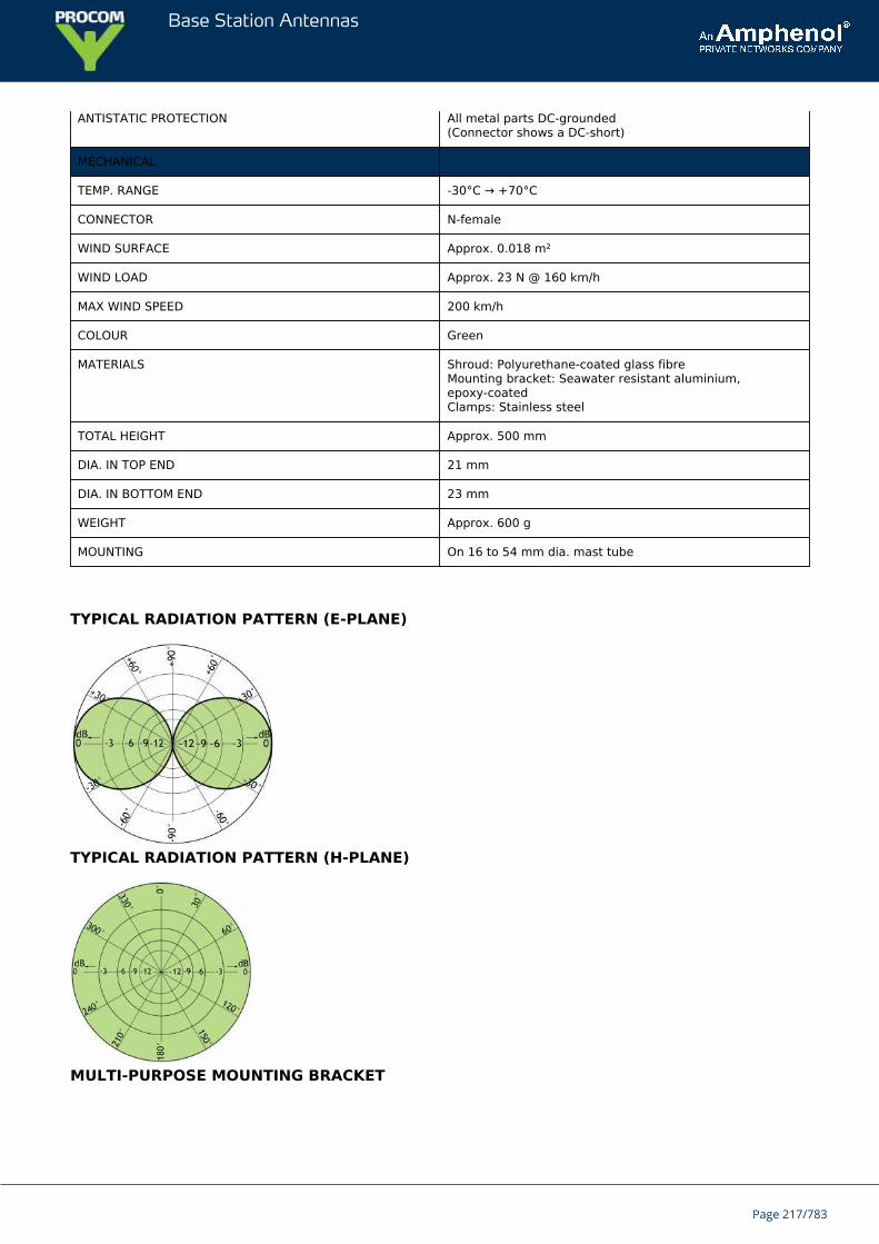
Base Station Antennas
ANTISTATIC PROTECTION All metal parts DC-grounded(Connector shows a DC-short)
MECHANICAL
TEMP. RANGE -30°C → +70°C
CONNECTOR N-female
WIND SURFACE Approx. 0.018 m²
WIND LOAD Approx. 23 N @ 160 km/h
MAX WIND SPEED 200 km/h
COLOUR Green
MATERIALS Shroud: Polyurethane-coated glass fibreMounting bracket: Seawater resistant aluminium,epoxy-coatedClamps: Stainless steel
TOTAL HEIGHT Approx. 500 mm
DIA. IN TOP END 21 mm
DIA. IN BOTTOM END 23 mm
WEIGHT Approx. 600 g
MOUNTING On 16 to 54 mm dia. mast tube
TYPICAL RADIATION PATTERN (E-PLANE)
TYPICAL RADIATION PATTERN (H-PLANE)
MULTI-PURPOSE MOUNTING BRACKET
Page 217/783

Base Station Antennas
Page 218/783
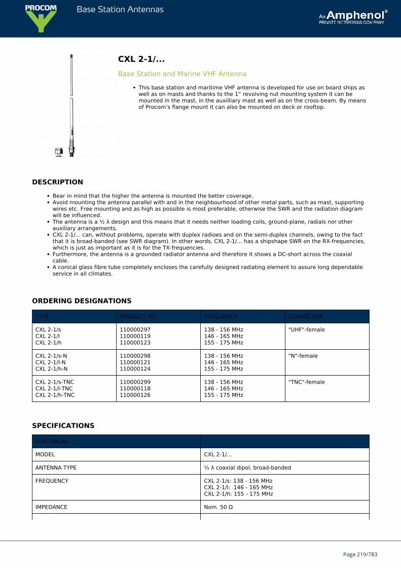
Base Station Antennas
CXL 2-1/...Base Station and Marine VHF Antenna
This base station and maritime VHF antenna is developed for use on board ships aswell as on masts and thanks to the 1” revolving nut mounting system it can bemounted in the mast, in the auxilliary mast as well as on the cross-beam. By meansof Procom’s flange mount it can also be mounted on deck or rooftop.
DESCRIPTION
Bear in mind that the higher the antenna is mounted the better coverage.Avoid mounting the antenna parallel with and in the neighbourhood of other metal parts, such as mast, supportingwires etc. Free mounting and as high as possible is most preferable, otherwise the SWR and the radiation diagramwill be influenced.The antenna is a ½ λ design and this means that it needs neither loading coils, ground-plane, radials nor otherauxiliary arrangements.CXL 2-1/... can, without problems, operate with duplex radioes and on the semi-duplex channels, owing to the factthat it is broad-banded (see SWR diagram). In other words, CXL 2-1/... has a shipshape SWR on the RX-frequencies,which is just as important as it is for the TX-frequencies.Furthermore, the antenna is a grounded radiator antenna and therefore it shows a DC-short across the coaxialcable.A conical glass fibre tube completely encloses the carefully designed radiating element to assure long dependableservice in all climates.
ORDERING DESIGNATIONS
TYPE PRODUCT NO. FREQUENCY CONNECTOR
CXL 2-1/sCXL 2-1/lCXL 2-1/h
110000297110000119110000123
138 - 156 MHz146 - 165 MHz155 - 175 MHz
"UHF"-female
CXL 2-1/s-NCXL 2-1/l-NCXL 2-1/h-N
110000298110000121110000124
138 - 156 MHz146 - 165 MHz155 - 175 MHz
"N"-female
CXL 2-1/s-TNCCXL 2-1/l-TNCCXL 2-1/h-TNC
110000299110000118110000126
138 - 156 MHz146 - 165 MHz155 - 175 MHz
"TNC"-female
SPECIFICATIONS
ELECTRICAL
MODEL CXL 2-1/...
ANTENNA TYPE ½ λ coaxial dipol, broad-banded
FREQUENCY CXL 2-1/s: 138 - 156 MHzCXL 2-1/l: 146 - 165 MHzCXL 2-1/h: 155 - 175 MHz
IMPEDANCE Nom. 50 Ω
Page 219/783
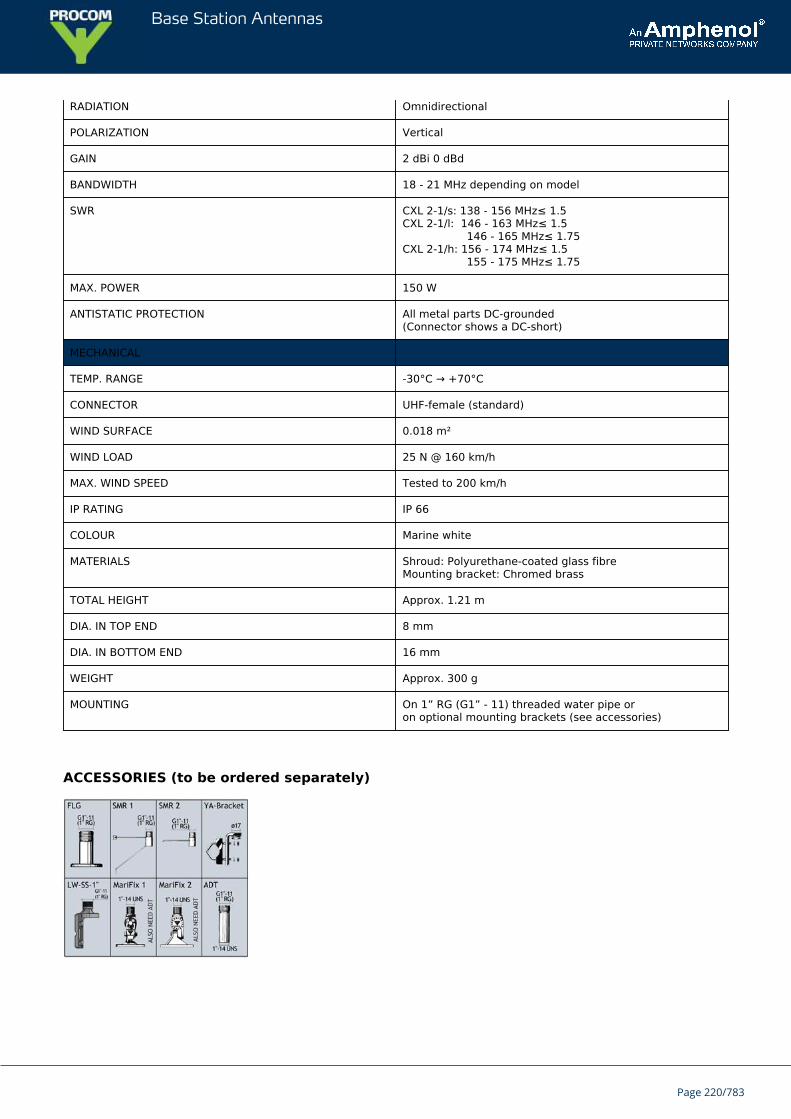
Base Station Antennas
RADIATION Omnidirectional
POLARIZATION Vertical
GAIN 2 dBi 0 dBd
BANDWIDTH 18 - 21 MHz depending on model
SWR CXL 2-1/s: 138 - 156 MHz≤ 1.5CXL 2-1/l: 146 - 163 MHz≤ 1.5 146 - 165 MHz≤ 1.75CXL 2-1/h: 156 - 174 MHz≤ 1.5 155 - 175 MHz≤ 1.75
MAX. POWER 150 W
ANTISTATIC PROTECTION All metal parts DC-grounded(Connector shows a DC-short)
MECHANICAL
TEMP. RANGE -30°C → +70°C
CONNECTOR UHF-female (standard)
WIND SURFACE 0.018 m²
WIND LOAD 25 N @ 160 km/h
MAX. WIND SPEED Tested to 200 km/h
IP RATING IP 66
COLOUR Marine white
MATERIALS Shroud: Polyurethane-coated glass fibreMounting bracket: Chromed brass
TOTAL HEIGHT Approx. 1.21 m
DIA. IN TOP END 8 mm
DIA. IN BOTTOM END 16 mm
WEIGHT Approx. 300 g
MOUNTING On 1” RG (G1” - 11) threaded water pipe oron optional mounting brackets (see accessories)
ACCESSORIES (to be ordered separately)
Page 220/783
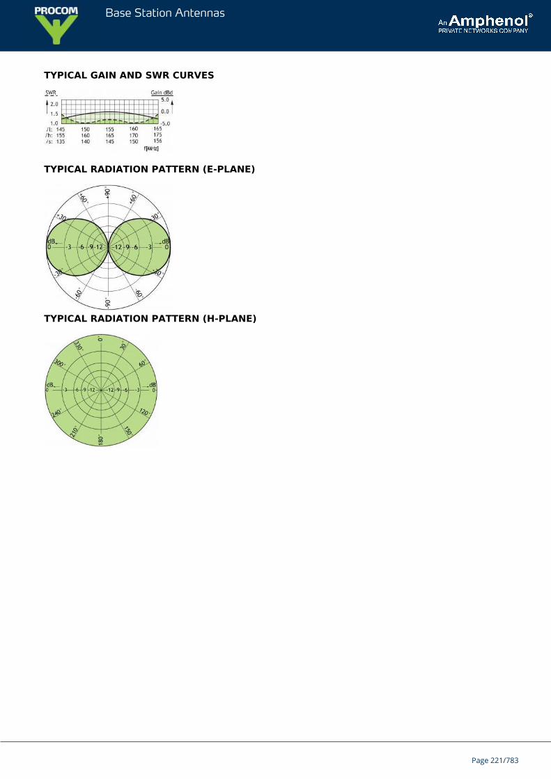
Base Station Antennas
TYPICAL GAIN AND SWR CURVES
TYPICAL RADIATION PATTERN (E-PLANE)
TYPICAL RADIATION PATTERN (H-PLANE)
Page 221/783
Base Station Antennas
G-CXL 70-1LW/...Unity-Gain, Omnidirectional Base Station and Marine Antenna for the 450MHz Band. Designed for defense units.
G-CXL 70-1LW/… is a 0 dBd, vertically polarized, omnidirectional base station andmarine antenna which covers the 450 MHz band in three models.The carefully designed, broadbanded ½ λ-dipole radiating element is made of brasstube and sealed in a high-quality conical glass fibre tube with low wind-load.
Description
Provided with the sturdy “LW” mast mount – a lightweight, multipurpose, epoxy-coated mounting bracket made ofnon-corrosive aluminium.The cable can be led either on the outside or along the inside of the mast tube.Large bandwidth with respect to both SWR and gain.To substantially reduce noise caused by atmospherical discharges, all metal parts in the antenna are DC-grounded.Consequently, the antenna shows a DC-short across the coaxial cable.
ORDERING DESIGNATIONS
TYPE PRODUCT NO. FREQUENCY
G-CXL 70-1LW/l 100000269 380 - 430 MHz
G-CXL 70-1LW/h 100000270 420 - 470 MHz
G-CXL 70-1LW/hs 100000271 460 - 510 MHz
SPECIFICATIONS
ELECTRICAL
MODEL G-CXL 70-1LW/...
ANTENNA TYPE ½ λ coaxial dipole, broad-banded
FREQUENCY
G-CXL 70-1LW/l : 380 - 430 MHz
G-CXL 70-1LW/h : 420 - 470 MHz
G-CXL 70-1LW/hs : 460 - 510 MHz
IMPEDANCE Nom. 50 Ω
RADIATION Omnidirectional
POLARIZATION Vertical
GAIN 2 dBi 0 dBd
BANDWIDTH 50 MHz
SWR ≤ 1.5
MAX. POWER 200 W
ANTISTATIC PROTECTION All metal parts DC-grounded
Page 222/783
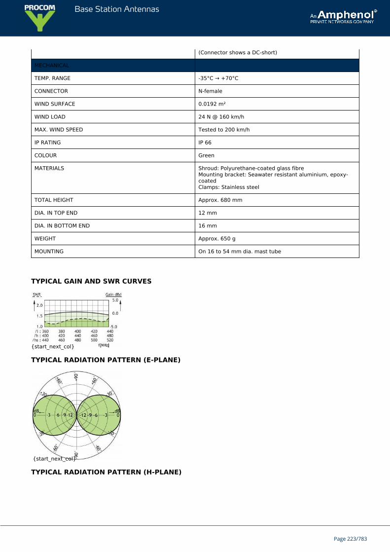
Base Station Antennas
(Connector shows a DC-short)
MECHANICAL
TEMP. RANGE -35°C → +70°C
CONNECTOR N-female
WIND SURFACE 0.0192 m²
WIND LOAD 24 N @ 160 km/h
MAX. WIND SPEED Tested to 200 km/h
IP RATING IP 66
COLOUR Green
MATERIALS Shroud: Polyurethane-coated glass fibreMounting bracket: Seawater resistant aluminium, epoxy-coatedClamps: Stainless steel
TOTAL HEIGHT Approx. 680 mm
DIA. IN TOP END 12 mm
DIA. IN BOTTOM END 16 mm
WEIGHT Approx. 650 g
MOUNTING On 16 to 54 mm dia. mast tube
TYPICAL GAIN AND SWR CURVES
{start_next_col}
TYPICAL RADIATION PATTERN (E-PLANE)
{start_next_col}
TYPICAL RADIATION PATTERN (H-PLANE)
Page 223/783
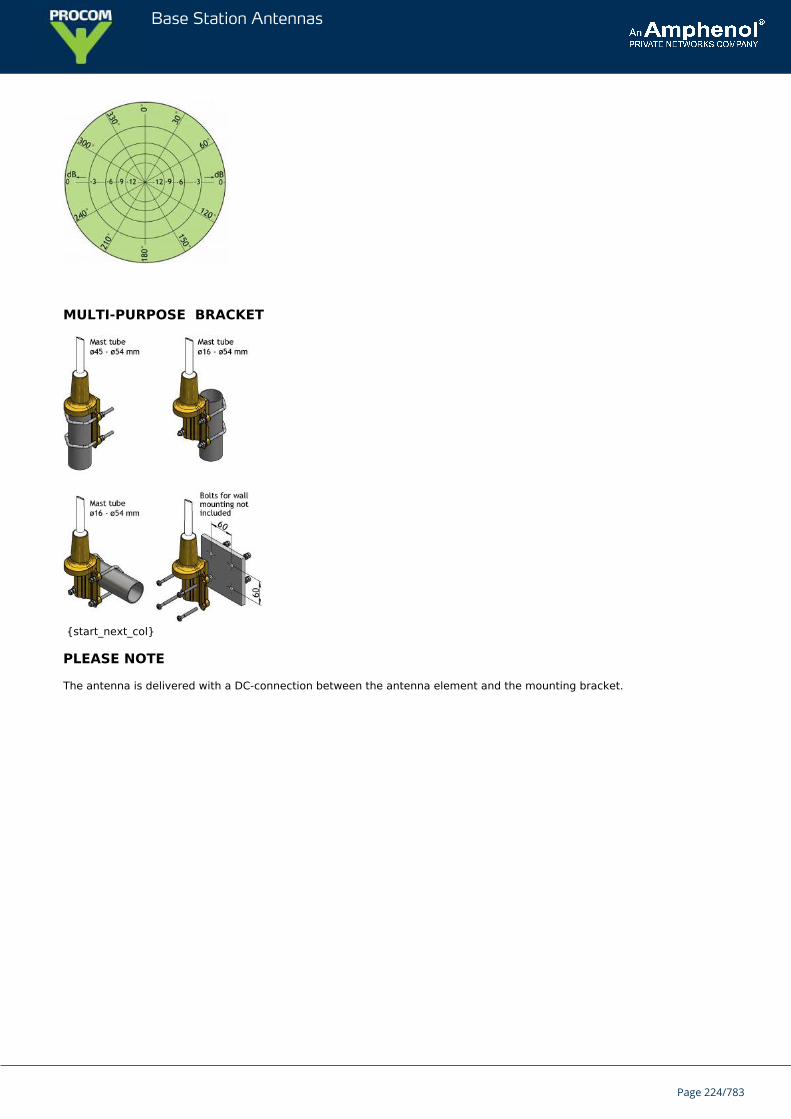
Base Station Antennas
MULTI-PURPOSE BRACKET
{start_next_col}
PLEASE NOTE
The antenna is delivered with a DC-connection between the antenna element and the mounting bracket.
Page 224/783
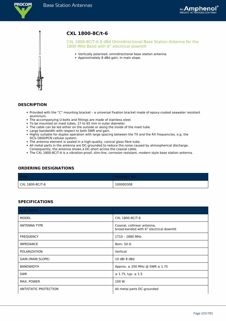
Base Station Antennas
CXL 1800-8C/t-6CXL 1800-8C/T-6 8 dBd Omnidirectional Base Station Antenna for the1800 MHz Band with 6° electrical downtilt
Vertically polarized, omnidirectional base station antenna.Approximately 8 dBd gain, in main slope.
DESCRIPTION
Provided with the “C” mounting bracket – a universal fixation bracket made of epoxy-coated seawater resistantaluminium.The accompanying U-bolts and fittings are made of stainless steel.To be mounted on mast tubes, 27 to 65 mm in outer diameter.The cable can be led either on the outside or along the inside of the mast tube.Large bandwidth with respect to both SWR and gain.Highly suitable for duplex operation with large spacing between the TX and the RX frequencies, e.g. theDCS-1800/PCN cellular system.The antenna element is sealed in a high-quality, conical glass fibre tube.All metal parts in the antenna are DC-grounded to reduce the noise caused by atmospherical discharge.Consequently, the antenna shows a DC-short across the coaxial cable.The CXL 1800-8C/T-6 is a vibration-proof, slim-line, corrosion resistant, modern style base station antenna.
ORDERING DESIGNATIONS
TYPE PRODUCT NO.
CXL 1800-8C/T-6 100000308
SPECIFICATIONS
ELECTRICAL
MODEL CXL 1800-8C/T-6
ANTENNA TYPE Coaxial, collinear antenna,broad-banded with 6° electrical downtilt
FREQUENCY 1710 – 1880 MHz
IMPEDANCE Nom. 50 Ω
POLARIZATION Vertical
GAIN (MAIN SLOPE) 10 dBi 8 dBd
BANDWIDTH Approx. ≥ 200 MHz @ SWR ≤ 1.75
SWR ≤ 1.75, typ. ≤ 1.5
MAX. POWER 100 W
ANTISTATIC PROTECTION All metal parts DC-grounded
Page 225/783
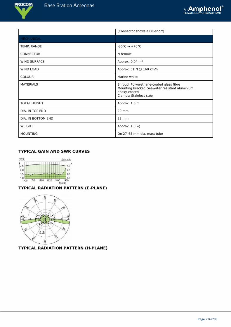
Base Station Antennas
(Connector shows a DC-short)
MECHANICAL
TEMP. RANGE -30°C → +70°C
CONNECTOR N-female
WIND SURFACE Approx. 0.04 m²
WIND LOAD Approx. 51 N @ 160 km/h
COLOUR Marine white
MATERIALS Shroud: Polyurethane-coated glass fibreMounting bracket: Seawater resistant aluminium,epoxy-coatedClamps: Stainless steel
TOTAL HEIGHT Approx. 1.5 m
DIA. IN TOP END 20 mm
DIA. IN BOTTOM END 23 mm
WEIGHT Approx. 1.5 kg
MOUNTING On 27–65 mm dia. mast tube
TYPICAL GAIN AND SWR CURVES
TYPICAL RADIATION PATTERN (E-PLANE)
TYPICAL RADIATION PATTERN (H-PLANE)
Page 226/783
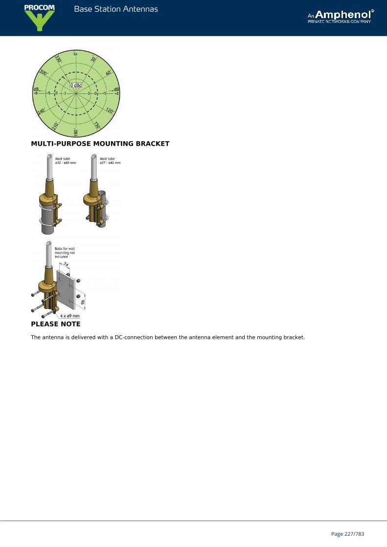
Base Station Antennas
MULTI-PURPOSE MOUNTING BRACKET
PLEASE NOTE
The antenna is delivered with a DC-connection between the antenna element and the mounting bracket.
Page 227/783
Base Station Antennas
CXL 1800-33 dBd Omnidirectional Base Station and Marine Antenna for the 1800 MHzBand
Vertically polarized, omnidirectional base station and marine antenna.Approximately 3 dBd gain.
DESCRIPTION
Simple mounting using the 1” revolving nut system.Wide variety of accessory mounting brackets available.Large bandwidth with respect to both SWR and gain.Highly suitable for duplex operation with large spacing between the TX and the RX frequencies, e.g. theDCS-1800/PCN cellular system.The antenna element is sealed in a high-quality, conical glass fibre tube.All metal parts in the antenna are DC-grounded to reduce the noise caused by atmospherical discharge.Consequently, the antenna shows a DC-short across the coaxial cable.The CXL 1800-3 is a vibration-proof, lightweight, slim-line, corrosion resistant, modern style base station and marineantenna.
ORDERING DESIGNATIONS
TYPE PRODUCT NO.
CXL 1800-3 100000188
SPECIFICATIONS
ELECTRICAL
MODEL CXL 1800-3
ANTENNA TYPE Coaxial, collinear antenna, broad-banded
FREQUENCY 1710–1880 MHz
IMPEDANCE Nom. 50 Ω
POLARIZATION Vertical
GAIN 5 dBi 3 dBd
BANDWIDTH ≥ 170 MHz @ SWR ≤ 2.0
SWR ≤ 2.0, typ. ≤ 1.75
MAX. POWER 100 W
ANTISTATICPROTECTION
All metal parts DC-grounded(Connector shows a DC-short)
HCM CODE HCM000ND00, 015DE50
Page 228/783

Base Station Antennas
MECHANICAL
TEMP. RANGE -30°C → +70°C
CONNECTOR N-female
WIND SURFACE Approx. 0.009 m²
WIND LOAD Approx. 11 N @ 160 km/h
COLOUR Marine white
MATERIALS Shroud: Polyurethane-coated glass fibreMounting bracket: Chromed brass
TOTAL HEIGHT Approx. 630 mm
DIA. IN TOP END 12 mm
DIA. IN BOTTOM END 16 mm
WEIGHT Approx. 350 g
MOUNTING On 1” RG (G1”-11) threaded water pipe oron optional mounting brackets (see below)
ACCESSORIES (to be ordered separately)
TYPICAL GAIN AND SWR CURVES
TYPICAL RADIATION PATTERN (E-PLANE)
TYPICAL RADIATION PATTERN (H-PLANE)
Page 229/783
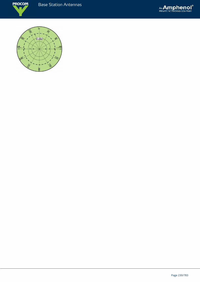
Base Station Antennas
Page 230/783
Base Station Antennas
CXL 1800-1LWUniversal, 0 dBd Base Station and Marine Antenna for the 1800 MHz Band
CXL 1800-1LW is a 0 dBd, vertically polarized, omnidirectional base station andmarine antenna for the 1800 MHz band.The carefully designed, broad-banded antenna element is sealed in a high-quality,conical glass fibre tube with low wind-load, which will ensure performanceundisturbed by corrosive environments.
DESCRIPTION
Provided with the sturdy “LW” mast mount – a lightweight, multipurpose, epoxy-coated mounting bracket made ofnon-corrosive aluminium.The accompanying U-bolts and fittings are made of stainless steel.To be mounted on vertical or horizontal mast tubes, 16 to54 mm in outer diameter.The cable can be led either on the outside or along the inside of the mast tube.Large bandwidth with respect to both SWR and gain.To substantially reduce noise caused by atmospherical discharges, all metal parts in the antenna are DC-grounded.Consequently, the antenna shows a DC-short across the coaxial cable.The CXL 1800-1LW is a vibration-proof, lightweight, slim-line, corrosion resistant, modern style base station andmarine antenna.
ORDERING DESIGNATIONS
TYPE PRODUCT NO.
CXL 1800-1LW 100000177
SPECIFICATIONS
ELECTRICAL
MODEL CXL 1800-1LW
ANTENNA TYPE ½ λ coaxial dipole, broad-banded
FREQUENCY 1710 – 1880 MHz
IMPEDANCE Nom. 50 Ω
RADIATION Omnidirectional
POLARIZATION Vertical
GAIN 2 dBi 0 dBd
BANDWIDTH ≥ 170 MHz @ SWR ≤ 2.0
SWR ≤ 2.0
MAX. POWER 100 W
ANTISTATICPROTECTION
All metal parts DC-grounded(Connector shows a DC-short)
Page 231/783
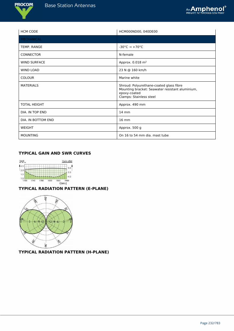
Base Station Antennas
HCM CODE HCM000ND00, 040DE00
MECHANICAL
TEMP. RANGE -30°C → +70°C
CONNECTOR N-female
WIND SURFACE Approx. 0.018 m²
WIND LOAD 23 N @ 160 km/h
COLOUR Marine white
MATERIALS Shroud: Polyurethane-coated glass fibreMounting bracket: Seawater resistant aluminium,epoxy-coatedClamps: Stainless steel
TOTAL HEIGHT Approx. 490 mm
DIA. IN TOP END 14 mm
DIA. IN BOTTOM END 16 mm
WEIGHT Approx. 500 g
MOUNTING On 16 to 54 mm dia. mast tube
TYPICAL GAIN AND SWR CURVES
TYPICAL RADIATION PATTERN (E-PLANE)
TYPICAL RADIATION PATTERN (H-PLANE)
Page 232/783

Base Station Antennas
MULTI-PURPOSE MOUNTING BRACKET
PLEASE NOTE
The antenna is delivered with a DC-connection between the antenna element and the mounting bracket.
Page 233/783
Base Station Antennas
CXL 1800-1/DECTUnity Gain Omnidirectional Base Station and Marine Antenna for theDECT
Vertically polarized, omnidirectional base station and marine antenna.Approximately 0 dBd gain.
DESCRIPTION
The CXL 1800-1/DECT is especially suitable for the DECT band.To substantially reduce noise caused by atmospherical discharges, all metal parts in the antenna are DC-grounded.Consequently, the antenna shows a DC-short across the coaxial cable.Simple mounting using the 1” revolving nut system.Wide variety of accessory mounting brackets available.
ORDERING DESIGNATIONS
TYPE PRODUCT NO.
CXL 1800-1/DECT 100000197
SPECIFICATIONS
ELECTRICAL
MODEL CXL 1800-1/DECT
ANTENNA TYPE Coaxial, collinear antenna
FREQUENCY 1880 - 1900 MHz (DECT)
IMPEDANCE Nom. 50 Ω
POLARIZATION Vertical
GAIN 2 dBi 0 dBd
BANDWIDTH ≥ 20 MHz @ SWR ≤ 1.5
SWR ≤ 1.5
MAX. POWER 100 W
ANTISTATICPROTECTION
All metal parts DC-grounded(Connector shows a DC-short)
MECHANICAL
TEMP. RANGE -30°C → +70°C
CONNECTOR N-female
Page 234/783
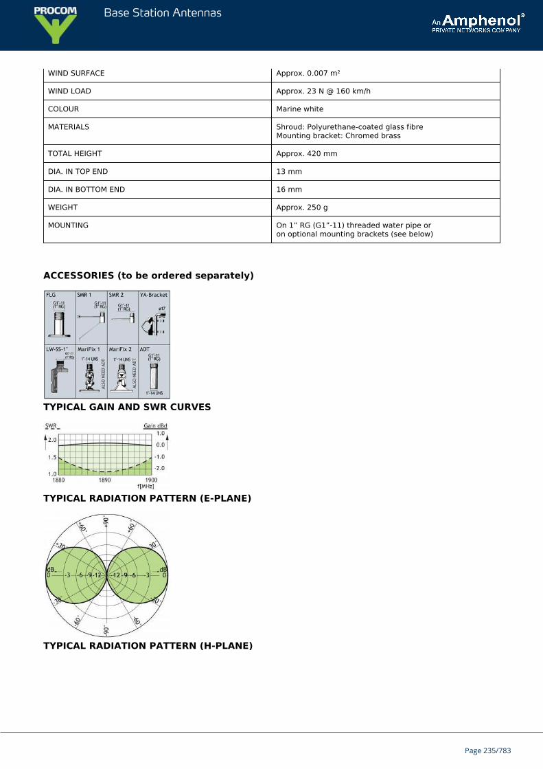
Base Station Antennas
WIND SURFACE Approx. 0.007 m²
WIND LOAD Approx. 23 N @ 160 km/h
COLOUR Marine white
MATERIALS Shroud: Polyurethane-coated glass fibreMounting bracket: Chromed brass
TOTAL HEIGHT Approx. 420 mm
DIA. IN TOP END 13 mm
DIA. IN BOTTOM END 16 mm
WEIGHT Approx. 250 g
MOUNTING On 1” RG (G1”-11) threaded water pipe oron optional mounting brackets (see below)
ACCESSORIES (to be ordered separately)
TYPICAL GAIN AND SWR CURVES
TYPICAL RADIATION PATTERN (E-PLANE)
TYPICAL RADIATION PATTERN (H-PLANE)
Page 235/783

Base Station Antennas
Page 236/783
Base Station Antennas
CXL 1800-1/...Unity Gain Base Station and Marine 1800 MHz Antenna for Mounting onThreaded 1
The CXL 1800-1/… is a 0 dBd, vertically polarized, omnidirectional rod-type basestation and marine antenna for the 1800 MHz band.The 1” revolving nut mounting system is standard throughout the base station andmarine sector, and several different mounting brackets are available, making itpossible to install the antenna either on the masthead using FLG or SMR 2, side-mounted on the mast (SMR 1) or mounted on a cross-beam (FLG). Also, the antennacan be mounted on deck or rooftop by means of the FLG.
DESCRIPTION
The CXL 1800-1/… is especially suitable for use in connection with 1800 MHz CELLULAR systems – as for instancethe DCS-1800/PCN system – making it possible to extend the normally land-based cellular telephone system formaritime mobile service as well.The higher the antenna is mounted, the better coverage. Avoid mounting the antenna parallel to or in theneighbourhood of other metal parts, such as masts, supporting wires etc., otherwise the SWR and the radiationpattern may be strongly influenced.To substantially reduce noise caused by atmospherical discharges, all metal parts in the antenna are DC-grounded.Consequently, the antenna shows a DC-short across the coaxial cable.A conical glass fibre tube completely encloses the carefully designed radiating element to ensure long dependableservice in all climates.
ORDERING DESIGNATIONS
TYPE PRODUCT NO. FREQUENCY
CXL 1800-1/l 100000179 1710 – 1880 MHz
CXL 1800-1/h 100000181 1850 – 2000 MHz
SPECIFICATIONS
ELECTRICAL
MODEL CXL 1800-1/...
ANTENNA TYPE ½ λ coaxial dipole, broad-banded
FREQUENCY l: 1710 – 1880 MHzh: 1850 – 2000 MHz
IMPEDANCE Nom. 50 Ω
POLARISATION Vertical
GAIN 2 dBi 0 dBd
BANDWIDTH ≥ 170 MHz @ SWR ≤ 2.0
SWR ≤ 2.0
MAX. POWER 100 W
HCM CODE HCM000ND00, 040DE00
Page 237/783
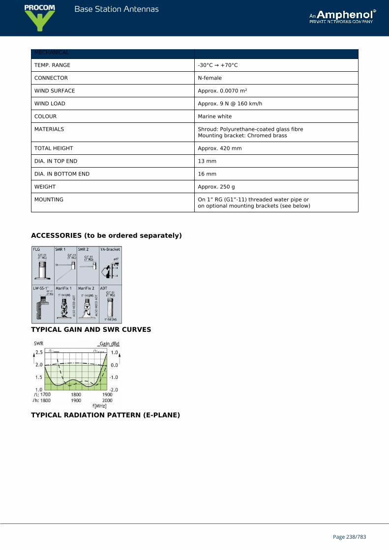
Base Station Antennas
MECHANICAL
TEMP. RANGE -30°C → +70°C
CONNECTOR N-female
WIND SURFACE Approx. 0.0070 m²
WIND LOAD Approx. 9 N @ 160 km/h
COLOUR Marine white
MATERIALS Shroud: Polyurethane-coated glass fibreMounting bracket: Chromed brass
TOTAL HEIGHT Approx. 420 mm
DIA. IN TOP END 13 mm
DIA. IN BOTTOM END 16 mm
WEIGHT Approx. 250 g
MOUNTING On 1” RG (G1”-11) threaded water pipe oron optional mounting brackets (see below)
ACCESSORIES (to be ordered separately)
TYPICAL GAIN AND SWR CURVES
TYPICAL RADIATION PATTERN (E-PLANE)
Page 238/783
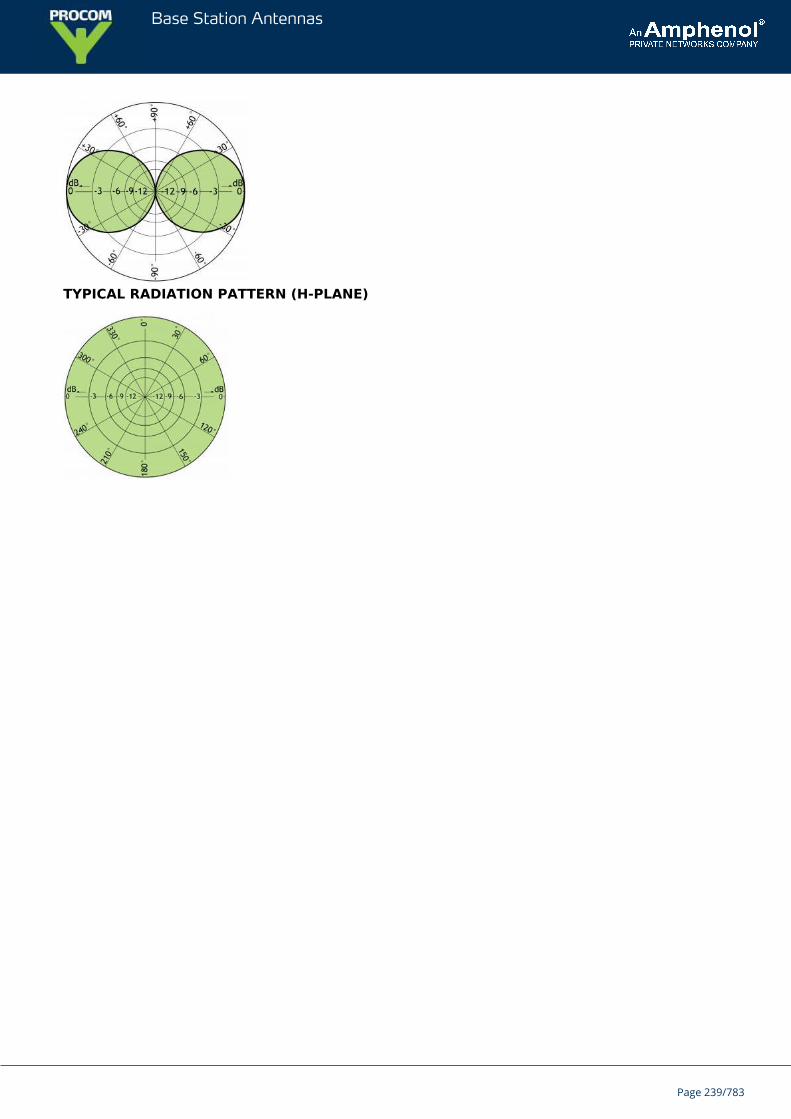
Base Station Antennas
TYPICAL RADIATION PATTERN (H-PLANE)
Page 239/783
Base Station Antennas
CXL 175-400CUnity Gain, Broad-Banded Base Station Antenna for 175 - 400 MHz
CXL 175-400C is a 0 dBd gain, omnidirectional base station antenna.The antenna is extremely broad-banded and covers the complete band: 175 – 400MHz.
DESCRIPTION
CXL 175-400C is designed for fixation on supporting tubes with outer diameter between 27 mm and 65 mm.The construction of the mount makes it possible to lead the cable either inside or along the outside of the masttube.A glass fibre tube completely encloses the carefully designed radiating element to ensure long dependable servicein all climates.Atmospherical discharges are immediately led to ground as all metal parts are DC-grounded (consequently, theantenna shows a DC-short across the coaxial cable).This antenna is used where reliability is of utmost importance. A long lifetime has been taken into considerationwhen designing this antenna – it is sturdy and strong.
ORDERING DESIGNATIONS
TYPE PRODUCT NO.
CXL 175-400C 100000086
SPECIFICATIONS
ELECTRICAL
MODEL CXL 175-400C
ANTENNA TYPE Coaxial, broad-band dipole
FREQUENCY Covering: 175 – 400 MHz
IMPEDANCE Nom. 50 Ω
RADIATION Omnidirectional
POLARIZATION Vertical
GAIN 0 dBd ± 3 dB
BANDWIDTH 225 MHz
SWR See curve
MAX. POWER 200 W
ANTISTATIC PROTECTION All metal parts DC-grounded(Connector shows a DC-short)
MECHANICAL
Page 240/783
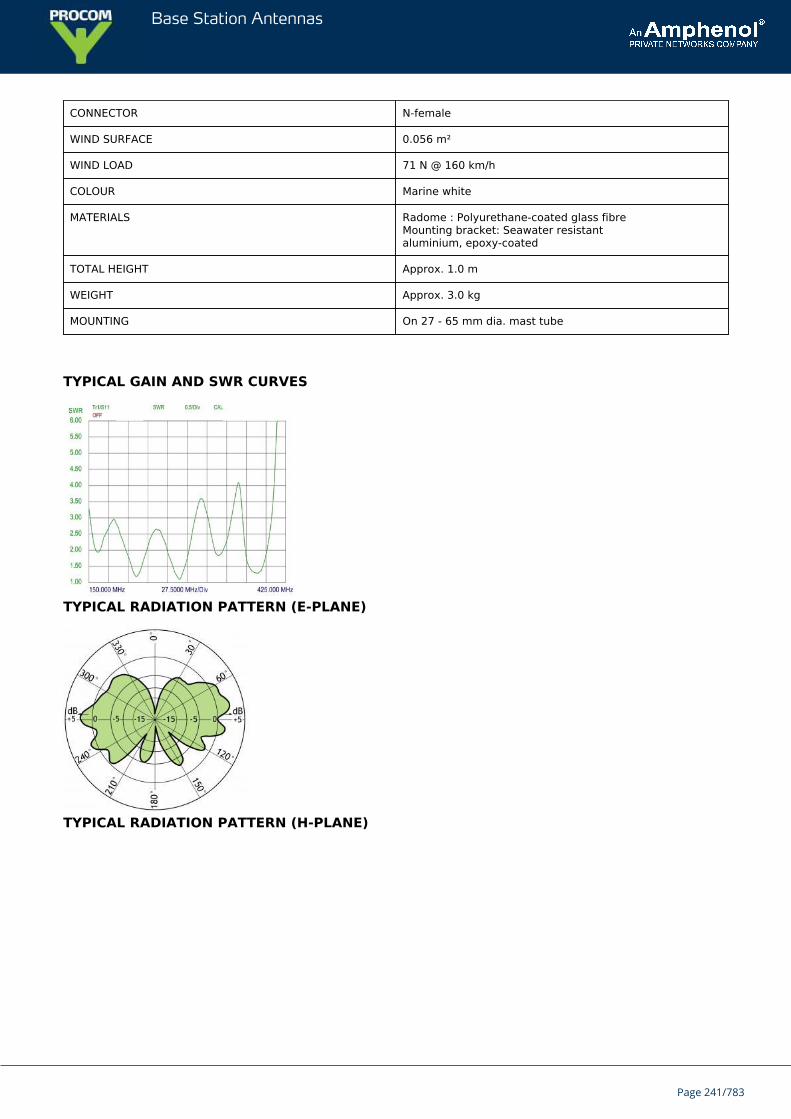
Base Station Antennas
CONNECTOR N-female
WIND SURFACE 0.056 m²
WIND LOAD 71 N @ 160 km/h
COLOUR Marine white
MATERIALS Radome : Polyurethane-coated glass fibreMounting bracket: Seawater resistantaluminium, epoxy-coated
TOTAL HEIGHT Approx. 1.0 m
WEIGHT Approx. 3.0 kg
MOUNTING On 27 - 65 mm dia. mast tube
TYPICAL GAIN AND SWR CURVES
TYPICAL RADIATION PATTERN (E-PLANE)
TYPICAL RADIATION PATTERN (H-PLANE)
Page 241/783
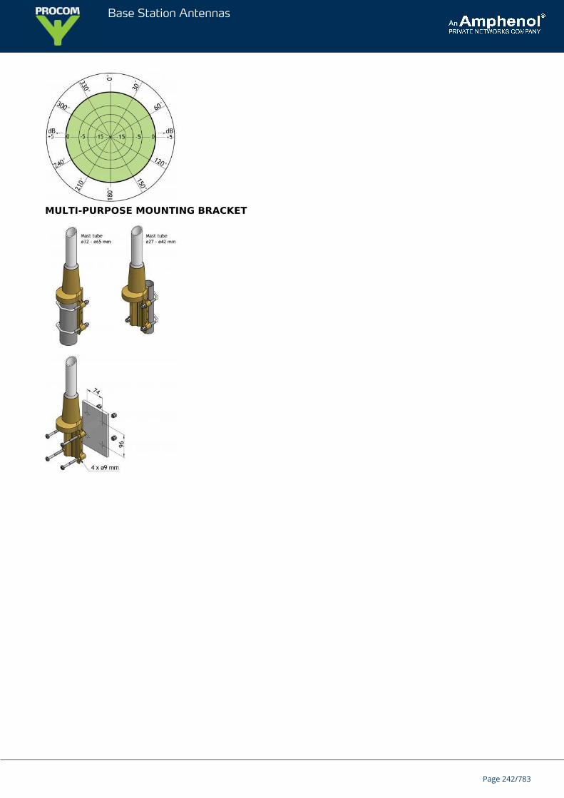
Base Station Antennas
MULTI-PURPOSE MOUNTING BRACKET
Page 242/783
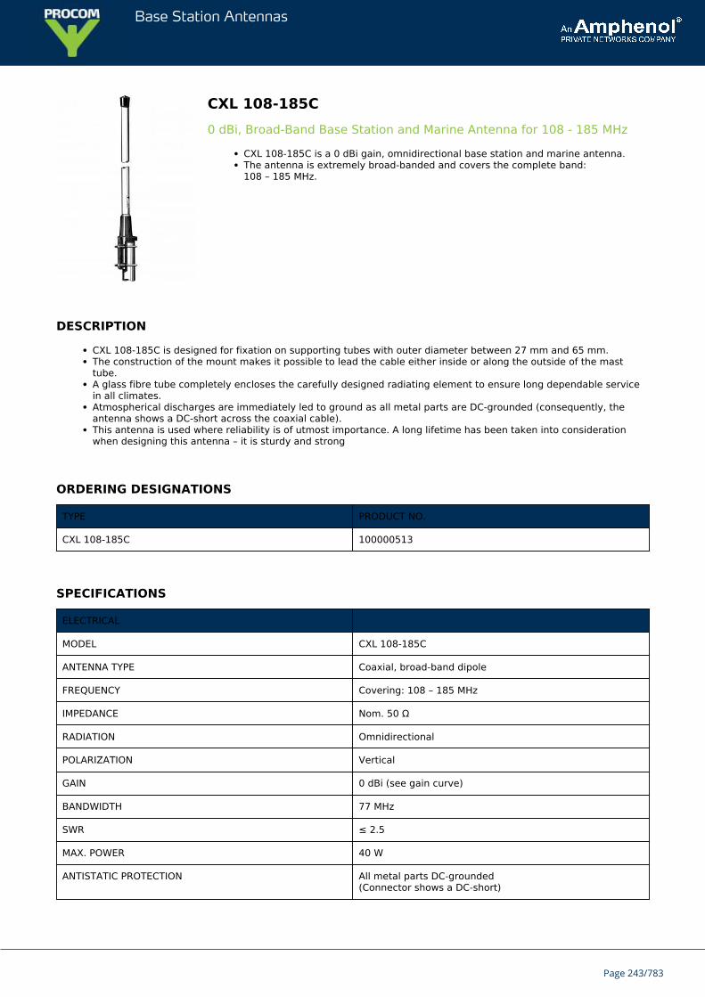
Base Station Antennas
CXL 108-185C0 dBi, Broad-Band Base Station and Marine Antenna for 108 - 185 MHz
CXL 108-185C is a 0 dBi gain, omnidirectional base station and marine antenna.The antenna is extremely broad-banded and covers the complete band:108 – 185 MHz.
DESCRIPTION
CXL 108-185C is designed for fixation on supporting tubes with outer diameter between 27 mm and 65 mm.The construction of the mount makes it possible to lead the cable either inside or along the outside of the masttube.A glass fibre tube completely encloses the carefully designed radiating element to ensure long dependable servicein all climates.Atmospherical discharges are immediately led to ground as all metal parts are DC-grounded (consequently, theantenna shows a DC-short across the coaxial cable).This antenna is used where reliability is of utmost importance. A long lifetime has been taken into considerationwhen designing this antenna – it is sturdy and strong
ORDERING DESIGNATIONS
TYPE PRODUCT NO.
CXL 108-185C 100000513
SPECIFICATIONS
ELECTRICAL
MODEL CXL 108-185C
ANTENNA TYPE Coaxial, broad-band dipole
FREQUENCY Covering: 108 – 185 MHz
IMPEDANCE Nom. 50 Ω
RADIATION Omnidirectional
POLARIZATION Vertical
GAIN 0 dBi (see gain curve)
BANDWIDTH 77 MHz
SWR ≤ 2.5
MAX. POWER 40 W
ANTISTATIC PROTECTION All metal parts DC-grounded(Connector shows a DC-short)
Page 243/783
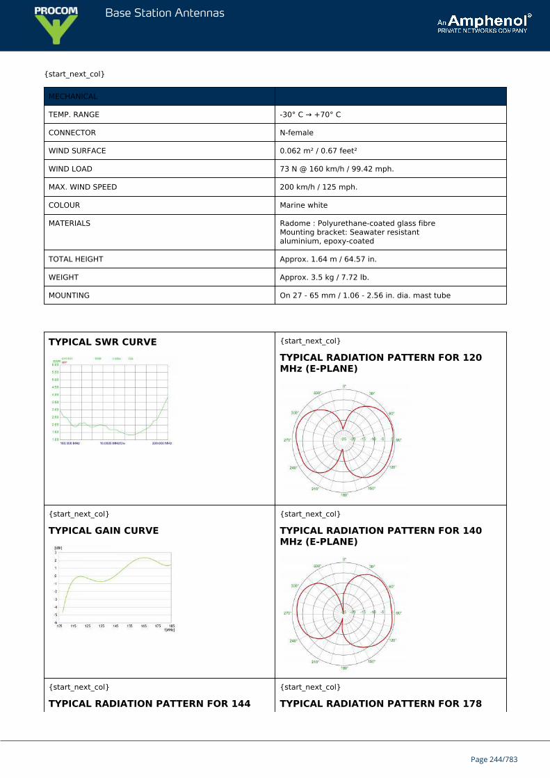
Base Station Antennas
{start_next_col}
MECHANICAL
TEMP. RANGE -30° C → +70° C
CONNECTOR N-female
WIND SURFACE 0.062 m² / 0.67 feet²
WIND LOAD 73 N @ 160 km/h / 99.42 mph.
MAX. WIND SPEED 200 km/h / 125 mph.
COLOUR Marine white
MATERIALS Radome : Polyurethane-coated glass fibreMounting bracket: Seawater resistantaluminium, epoxy-coated
TOTAL HEIGHT Approx. 1.64 m / 64.57 in.
WEIGHT Approx. 3.5 kg / 7.72 lb.
MOUNTING On 27 - 65 mm / 1.06 - 2.56 in. dia. mast tube
TYPICAL SWR CURVE {start_next_col}
TYPICAL RADIATION PATTERN FOR 120MHz (E-PLANE)
{start_next_col}
TYPICAL GAIN CURVE
{start_next_col}
TYPICAL RADIATION PATTERN FOR 140MHz (E-PLANE)
{start_next_col}
TYPICAL RADIATION PATTERN FOR 144
{start_next_col}
TYPICAL RADIATION PATTERN FOR 178
Page 244/783
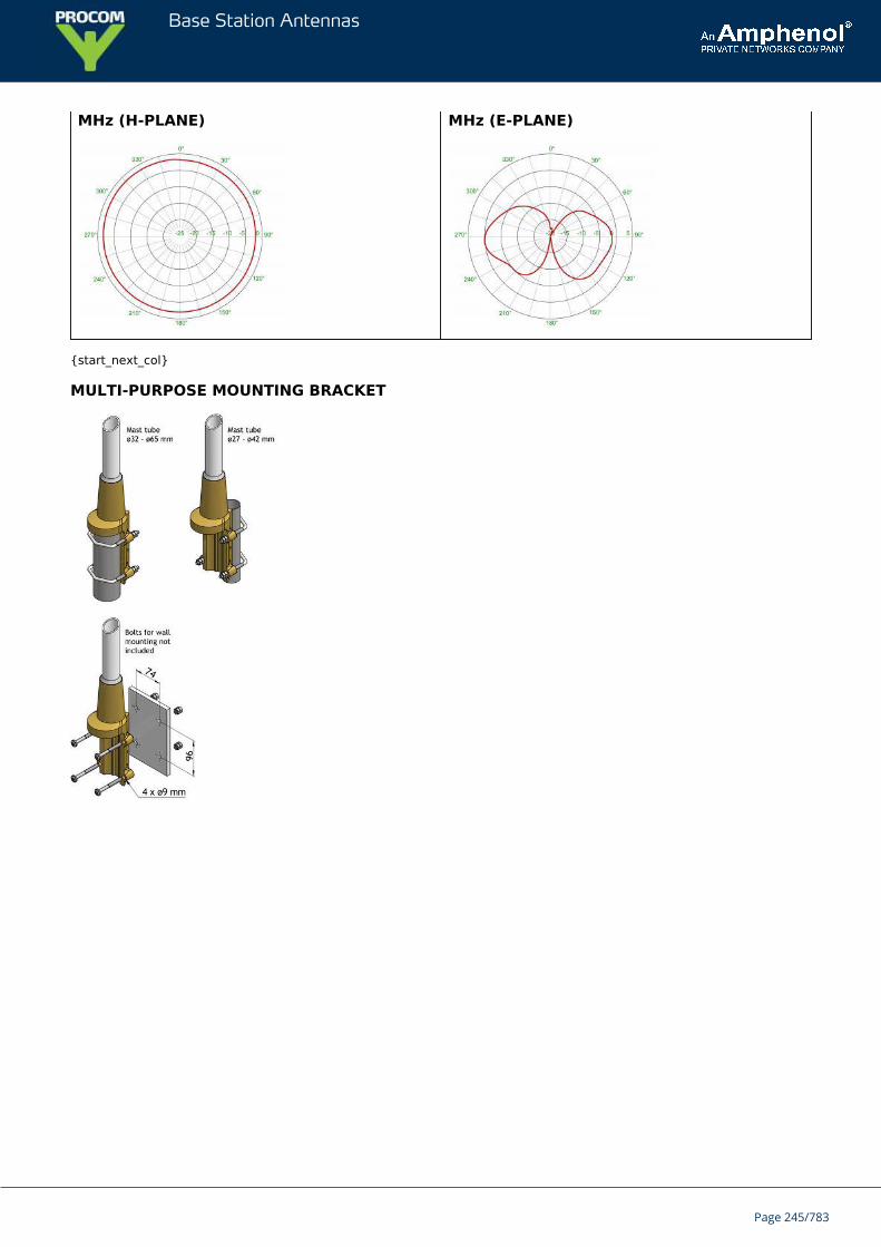
Base Station Antennas
MHz (H-PLANE) MHz (E-PLANE)
{start_next_col}
MULTI-PURPOSE MOUNTING BRACKET
Page 245/783
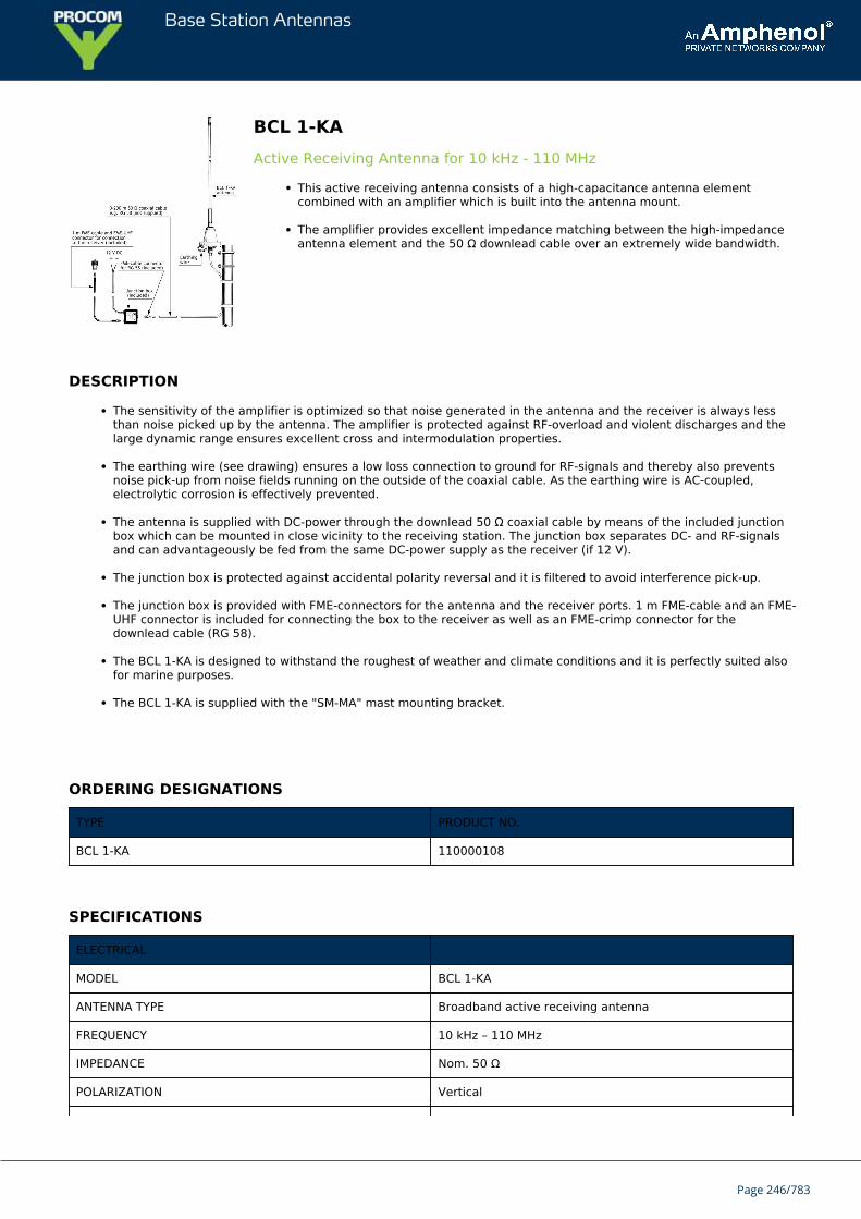
Base Station Antennas
BCL 1-KAActive Receiving Antenna for 10 kHz - 110 MHz
This active receiving antenna consists of a high-capacitance antenna elementcombined with an amplifier which is built into the antenna mount.
The amplifier provides excellent impedance matching between the high-impedanceantenna element and the 50 Ω downlead cable over an extremely wide bandwidth.
DESCRIPTION
The sensitivity of the amplifier is optimized so that noise generated in the antenna and the receiver is always lessthan noise picked up by the antenna. The amplifier is protected against RF-overload and violent discharges and thelarge dynamic range ensures excellent cross and intermodulation properties.
The earthing wire (see drawing) ensures a low loss connection to ground for RF-signals and thereby also preventsnoise pick-up from noise fields running on the outside of the coaxial cable. As the earthing wire is AC-coupled,electrolytic corrosion is effectively prevented.
The antenna is supplied with DC-power through the downlead 50 Ω coaxial cable by means of the included junctionbox which can be mounted in close vicinity to the receiving station. The junction box separates DC- and RF-signalsand can advantageously be fed from the same DC-power supply as the receiver (if 12 V).
The junction box is protected against accidental polarity reversal and it is filtered to avoid interference pick-up.
The junction box is provided with FME-connectors for the antenna and the receiver ports. 1 m FME-cable and an FME-UHF connector is included for connecting the box to the receiver as well as an FME-crimp connector for thedownlead cable (RG 58).
The BCL 1-KA is designed to withstand the roughest of weather and climate conditions and it is perfectly suited alsofor marine purposes.
The BCL 1-KA is supplied with the "SM-MA" mast mounting bracket.
ORDERING DESIGNATIONS
TYPE PRODUCT NO.
BCL 1-KA 110000108
SPECIFICATIONS
ELECTRICAL
MODEL BCL 1-KA
ANTENNA TYPE Broadband active receiving antenna
FREQUENCY 10 kHz – 110 MHz
IMPEDANCE Nom. 50 Ω
POLARIZATION Vertical
Page 246/783
Base Station Antennas
HORIZ. COVERAGE Omni-directional
ANTENNA FACTOR Typ. 0.25 mV output in 50 Ω by a field strength of 1mV/m
1 dB COMPRESSION POINT Typ. occurring at a field stength of 1.5 V/m
1 dB QUIETING Typ. occurring at a field stength of 1 V/m form aninterfering signal
CROSS MODULATION 40 dB cross modulation attenuation typically occurring atfield strength of 0.7 V/m from an interfering source
INTERMODULATION OIP2 > 40 dBmOIP3 > 27 dBm
AERIAL PROTECTION Spark gap
SUPPLY VOLTAGE 12 V DC (9 – 14 V)
CURRENT CONSUMP. Approx. 60 mA
MAX. INTENSITY OFRECEIVED FIELD
Distortion due to amplifier voltage limitation occurs at fieldintensities exceeding 1.5 V/m
MECHANICAL
TEMP. RANGE -30° C → +60° C
CONNECTOR, ANT. UHF (for PL 259)
CONNECTORS,JUNCTION BOX
Antenna: FME-connector (M)RX: FME-connector (M)
CABLE/CONNECTOR 1 m FME-cable and FME-UHF included.FME-cable connector for RG 58 downlead cable included
WIND SURFACE 0.0259 m²
WIND LOAD 28.8 N @ 150 km/h
COLOUR Marine white
MATERIALS Shroud: Glass fibre and chromed brassMA housing: Lexan and chromed brass
TOTAL HEIGHT Approx. 0.92 m (1.01 m incl. mounting bracket)
DIA. IN TOP END 7 mm
DIA. IN BOTTOM END 10 mm
WEIGHT Approx. 600 g (800 g incl. mounting bracket)
MOUNTING On 30 - 44 mm dia. mast tube or on a flat surface
FME-SYSTEM ACCESSORIES
FME-CABLES
TYPE PRODUCT NO.
1 m FME 130000437
2 m FME 130000447
3 m FME 130000457
4 m FME 130000466
5 m FME 130000474
Page 247/783
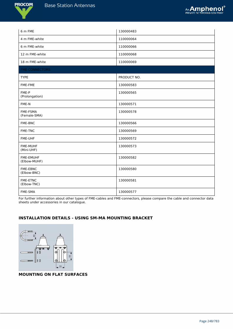
Base Station Antennas
6 m FME 130000483
4 m FME-white 110000064
6 m FME-white 110000066
12 m FME-white 110000068
18 m FME-white 110000069
FME-CONNECTORS
TYPE PRODUCT NO.
FME-FME 130000583
FME-P(Prolongation)
130000565
FME-N 130000571
FME-FSMA(Female-SMA)
130000578
FME-BNC 130000566
FME-TNC 130000569
FME-UHF 130000572
FME-MUHF(Mini-UHF)
130000573
FME-EMUHF(Elbow-MUHF)
130000582
FME-EBNC(Elbow-BNC)
130000580
FME-ETNC(Elbow-TNC)
130000581
FME-SMA 130000577
For further information about other types of FME-cables and FME-connectors, please compare the cable and connector datasheets under accessories in our catalogue.
INSTALLATION DETAILS - USING SM-MA MOUNTING BRACKET
MOUNTING ON FLAT SURFACES
Page 248/783
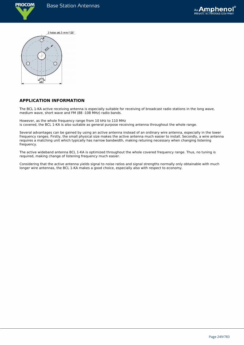
Base Station Antennas
APPLICATION INFORMATION
The BCL 1-KA active receiving antenna is especially suitable for receiving of broadcast radio stations in the long wave,medium wave, short wave and FM (88 -108 MHz) radio bands.
However, as the whole frequency range from 10 kHz to 110 MHzis covered, the BCL 1-KA is also suitable as general purpose receiving antenna throughout the whole range.
Several advantages can be gained by using an active antenna instead of an ordinary wire antenna, especially in the lowerfrequency ranges. Firstly, the small physical size makes the active antenna much easier to install. Secondly, a wire antennarequires a matching unit which typically has narrow bandwidth, making retuning necessary when changing listeningfrequency.
The active wideband antenna BCL 1-KA is optimized throughout the whole covered frequency range. Thus, no tuning isrequired, making change of listening frequency much easier.
Considering that the active antenna yields signal to noise ratios and signal strengths normally only obtainable with muchlonger wire antennas, the BCL 1-KA makes a good choice, especially also with respect to economy.
Page 249/783
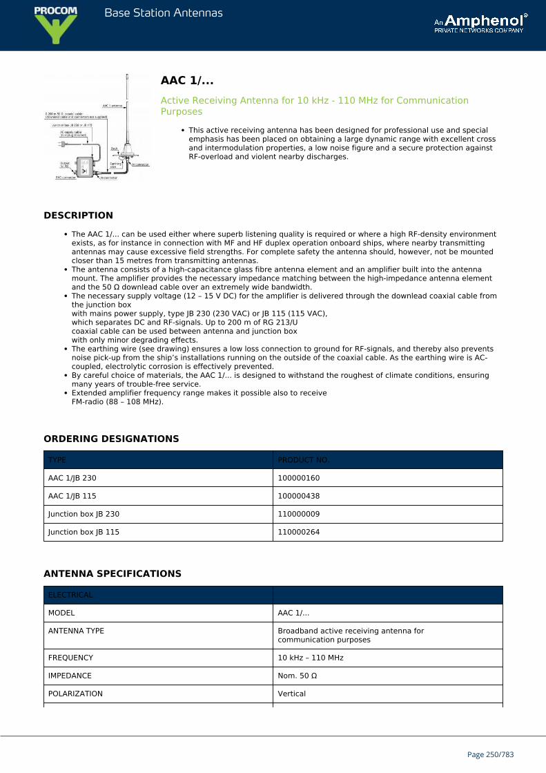
Base Station Antennas
AAC 1/...Active Receiving Antenna for 10 kHz - 110 MHz for CommunicationPurposes
This active receiving antenna has been designed for professional use and specialemphasis has been placed on obtaining a large dynamic range with excellent crossand intermodulation properties, a low noise figure and a secure protection againstRF-overload and violent nearby discharges.
DESCRIPTION
The AAC 1/... can be used either where superb listening quality is required or where a high RF-density environmentexists, as for instance in connection with MF and HF duplex operation onboard ships, where nearby transmittingantennas may cause excessive field strengths. For complete safety the antenna should, however, not be mountedcloser than 15 metres from transmitting antennas.The antenna consists of a high-capacitance glass fibre antenna element and an amplifier built into the antennamount. The amplifier provides the necessary impedance matching between the high-impedance antenna elementand the 50 Ω downlead cable over an extremely wide bandwidth.The necessary supply voltage (12 – 15 V DC) for the amplifier is delivered through the downlead coaxial cable fromthe junction boxwith mains power supply, type JB 230 (230 VAC) or JB 115 (115 VAC),which separates DC and RF-signals. Up to 200 m of RG 213/Ucoaxial cable can be used between antenna and junction boxwith only minor degrading effects.The earthing wire (see drawing) ensures a low loss connection to ground for RF-signals, and thereby also preventsnoise pick-up from the ship’s installations running on the outside of the coaxial cable. As the earthing wire is AC-coupled, electrolytic corrosion is effectively prevented.By careful choice of materials, the AAC 1/... is designed to withstand the roughest of climate conditions, ensuringmany years of trouble-free service.Extended amplifier frequency range makes it possible also to receiveFM-radio (88 – 108 MHz).
ORDERING DESIGNATIONS
TYPE PRODUCT NO.
AAC 1/JB 230 100000160
AAC 1/JB 115 100000438
Junction box JB 230 110000009
Junction box JB 115 110000264
ANTENNA SPECIFICATIONS
ELECTRICAL
MODEL AAC 1/...
ANTENNA TYPE Broadband active receiving antenna forcommunication purposes
FREQUENCY 10 kHz – 110 MHz
IMPEDANCE Nom. 50 Ω
POLARIZATION Vertical
Page 250/783
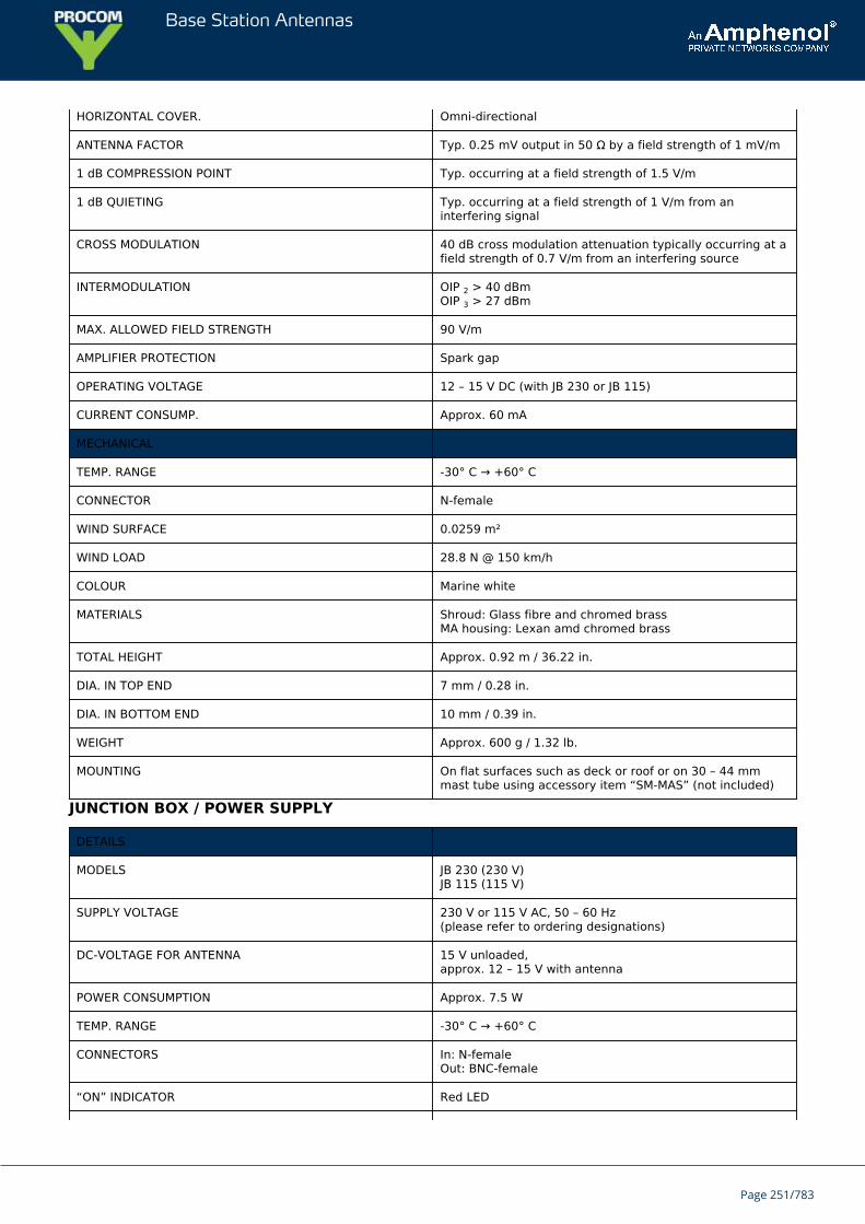
Base Station Antennas
HORIZONTAL COVER. Omni-directional
ANTENNA FACTOR Typ. 0.25 mV output in 50 Ω by a field strength of 1 mV/m
1 dB COMPRESSION POINT Typ. occurring at a field strength of 1.5 V/m
1 dB QUIETING Typ. occurring at a field strength of 1 V/m from aninterfering signal
CROSS MODULATION 40 dB cross modulation attenuation typically occurring at afield strength of 0.7 V/m from an interfering source
INTERMODULATION OIP 2 > 40 dBmOIP 3 > 27 dBm
MAX. ALLOWED FIELD STRENGTH 90 V/m
AMPLIFIER PROTECTION Spark gap
OPERATING VOLTAGE 12 – 15 V DC (with JB 230 or JB 115)
CURRENT CONSUMP. Approx. 60 mA
MECHANICAL
TEMP. RANGE -30° C → +60° C
CONNECTOR N-female
WIND SURFACE 0.0259 m²
WIND LOAD 28.8 N @ 150 km/h
COLOUR Marine white
MATERIALS Shroud: Glass fibre and chromed brassMA housing: Lexan amd chromed brass
TOTAL HEIGHT Approx. 0.92 m / 36.22 in.
DIA. IN TOP END 7 mm / 0.28 in.
DIA. IN BOTTOM END 10 mm / 0.39 in.
WEIGHT Approx. 600 g / 1.32 lb.
MOUNTING On flat surfaces such as deck or roof or on 30 – 44 mmmast tube using accessory item “SM-MAS” (not included)
JUNCTION BOX / POWER SUPPLY
DETAILS
MODELS JB 230 (230 V)JB 115 (115 V)
SUPPLY VOLTAGE 230 V or 115 V AC, 50 – 60 Hz(please refer to ordering designations)
DC-VOLTAGE FOR ANTENNA 15 V unloaded,approx. 12 – 15 V with antenna
POWER CONSUMPTION Approx. 7.5 W
TEMP. RANGE -30° C → +60° C
CONNECTORS In: N-femaleOut: BNC-female
“ON” INDICATOR Red LED
Page 251/783
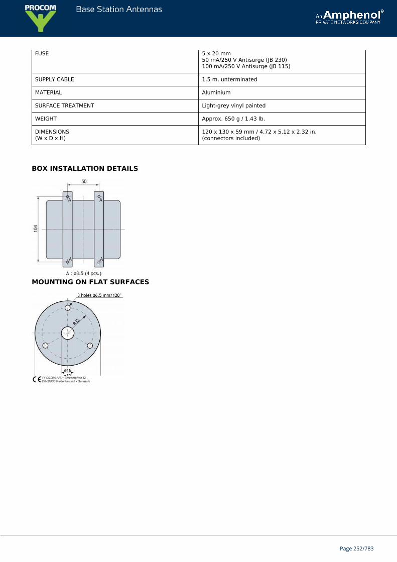
Base Station Antennas
FUSE 5 x 20 mm50 mA/250 V Antisurge (JB 230)100 mA/250 V Antisurge (JB 115)
SUPPLY CABLE 1.5 m, unterminated
MATERIAL Aluminium
SURFACE TREATMENT Light-grey vinyl painted
WEIGHT Approx. 650 g / 1.43 lb.
DIMENSIONS(W x D x H)
120 x 130 x 59 mm / 4.72 x 5.12 x 2.32 in.(connectors included)
BOX INSTALLATION DETAILS
MOUNTING ON FLAT SURFACES
Page 252/783
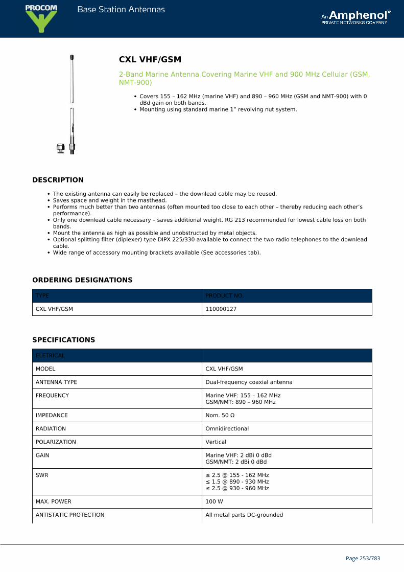
Base Station Antennas
CXL VHF/GSM2-Band Marine Antenna Covering Marine VHF and 900 MHz Cellular (GSM,NMT-900)
Covers 155 – 162 MHz (marine VHF) and 890 – 960 MHz (GSM and NMT-900) with 0dBd gain on both bands.Mounting using standard marine 1” revolving nut system.
DESCRIPTION
The existing antenna can easily be replaced – the downlead cable may be reused.Saves space and weight in the masthead.Performs much better than two antennas (often mounted too close to each other – thereby reducing each other’sperformance).Only one downlead cable necessary – saves additional weight. RG 213 recommended for lowest cable loss on bothbands.Mount the antenna as high as possible and unobstructed by metal objects.Optional splitting filter (diplexer) type DIPX 225/330 available to connect the two radio telephones to the downleadcable.Wide range of accessory mounting brackets available (See accessories tab).
ORDERING DESIGNATIONS
TYPE PRODUCT NO.
CXL VHF/GSM 110000127
SPECIFICATIONS
ELETRICAL
MODEL CXL VHF/GSM
ANTENNA TYPE Dual-frequency coaxial antenna
FREQUENCY Marine VHF: 155 – 162 MHzGSM/NMT: 890 – 960 MHz
IMPEDANCE Nom. 50 Ω
RADIATION Omnidirectional
POLARIZATION Vertical
GAIN Marine VHF: 2 dBi 0 dBdGSM/NMT: 2 dBi 0 dBd
SWR ≤ 2.5 @ 155 - 162 MHz≤ 1.5 @ 890 - 930 MHz≤ 2.5 @ 930 - 960 MHz
MAX. POWER 100 W
ANTISTATIC PROTECTION All metal parts DC-grounded
Page 253/783
Base Station Antennas
(Shows a DC-short at the connector)
MECHANICAL
TEMP. RANGE -30°C → +70°C
MATERIALS Shroud: Polyurethane coated glass fibreMounting bracket: Chromed brass
CONNECTOR N-female
WIND SURFACE Approx. 0.013 m²
WIND LOAD Approx. 15 N @ 150 km/h
COLOUR Marine white
TOTAL HEIGHT Approx. 1.1 m
DIA. IN TOP END 8 mm
DIA. IN BOTTOM END 16 mm
WEIGHT Approx. 400 g
MOUNTING On 1” RG (G1”-11) threaded pipe or on optional mountingbrackets (see below).Revolving nut enclosed
FME-SYSTEM ACCESSORIES
FME-CABLES
TYPE PRODUCT NO.
1 m FME 130000437
2 m FME 130000447
3 m FME 130000457
4 m FME 130000466
5 m FME 130000474
6 m FME 130000483
4 m FME-white 110000064
6 m FME-white 110000066
12 m FME-white 110000068
18 m FME-white 110000069
FME-CONNECTORS
TYPE PRODUCT NO.
FME-FME 130000583
FME-P(Prolongation)
130000565
FME-N 130000571
FME-FSMA(Female-SMA)
130000578
Page 254/783
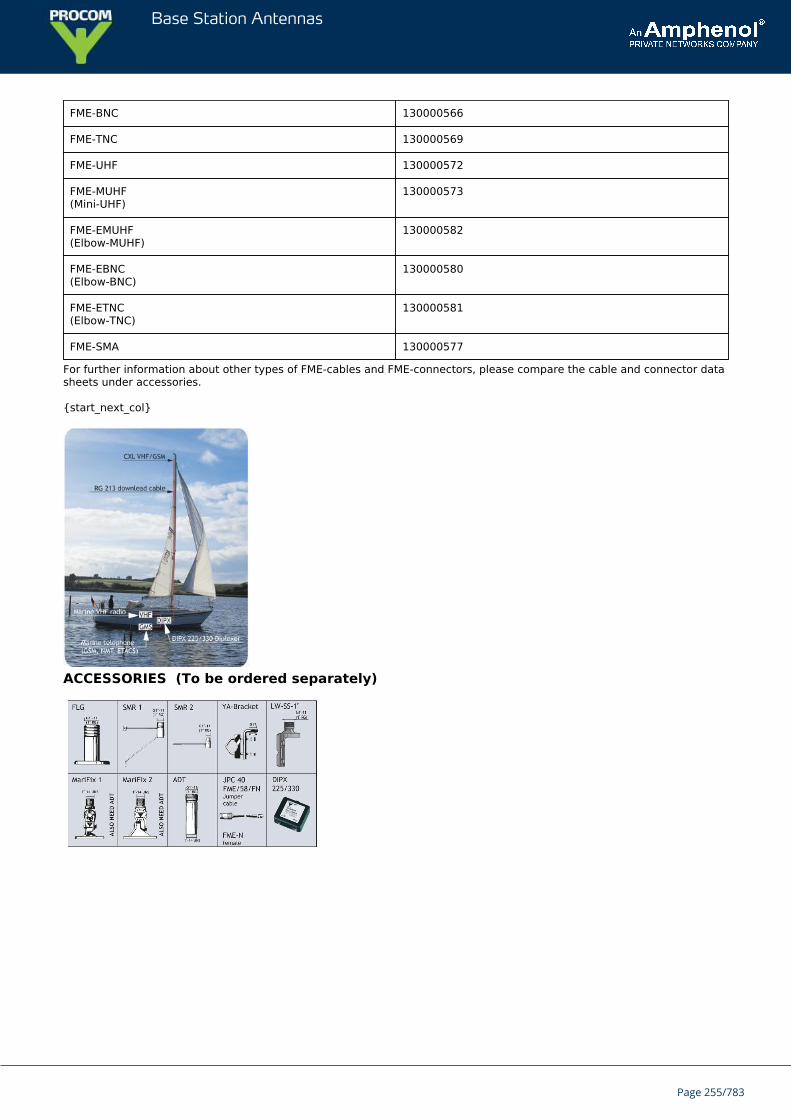
Base Station Antennas
FME-BNC 130000566
FME-TNC 130000569
FME-UHF 130000572
FME-MUHF(Mini-UHF)
130000573
FME-EMUHF(Elbow-MUHF)
130000582
FME-EBNC(Elbow-BNC)
130000580
FME-ETNC(Elbow-TNC)
130000581
FME-SMA 130000577
For further information about other types of FME-cables and FME-connectors, please compare the cable and connector datasheets under accessories.
{start_next_col}
ACCESSORIES (To be ordered separately)
Page 255/783
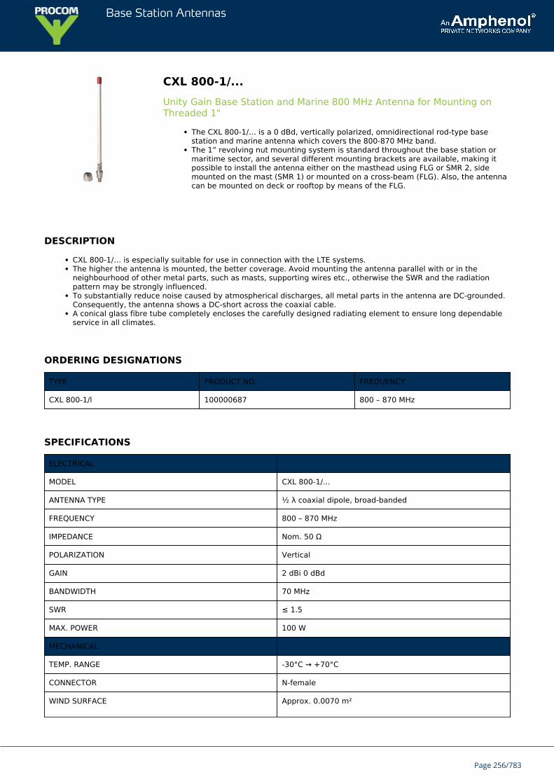
Base Station Antennas
CXL 800-1/...Unity Gain Base Station and Marine 800 MHz Antenna for Mounting onThreaded 1"
The CXL 800-1/… is a 0 dBd, vertically polarized, omnidirectional rod-type basestation and marine antenna which covers the 800-870 MHz band.The 1” revolving nut mounting system is standard throughout the base station ormaritime sector, and several different mounting brackets are available, making itpossible to install the antenna either on the masthead using FLG or SMR 2, sidemounted on the mast (SMR 1) or mounted on a cross-beam (FLG). Also, the antennacan be mounted on deck or rooftop by means of the FLG.
DESCRIPTION
CXL 800-1/… is especially suitable for use in connection with the LTE systems.The higher the antenna is mounted, the better coverage. Avoid mounting the antenna parallel with or in theneighbourhood of other metal parts, such as masts, supporting wires etc., otherwise the SWR and the radiationpattern may be strongly influenced.To substantially reduce noise caused by atmospherical discharges, all metal parts in the antenna are DC-grounded.Consequently, the antenna shows a DC-short across the coaxial cable.A conical glass fibre tube completely encloses the carefully designed radiating element to ensure long dependableservice in all climates.
ORDERING DESIGNATIONS
TYPE PRODUCT NO. FREQUENCY
CXL 800-1/l 100000687 800 – 870 MHz
SPECIFICATIONS
ELECTRICAL
MODEL CXL 800-1/...
ANTENNA TYPE ½ λ coaxial dipole, broad-banded
FREQUENCY 800 – 870 MHz
IMPEDANCE Nom. 50 Ω
POLARIZATION Vertical
GAIN 2 dBi 0 dBd
BANDWIDTH 70 MHz
SWR ≤ 1.5
MAX. POWER 100 W
MECHANICAL
TEMP. RANGE -30°C → +70°C
CONNECTOR N-female
WIND SURFACE Approx. 0.0070 m²
Page 256/783
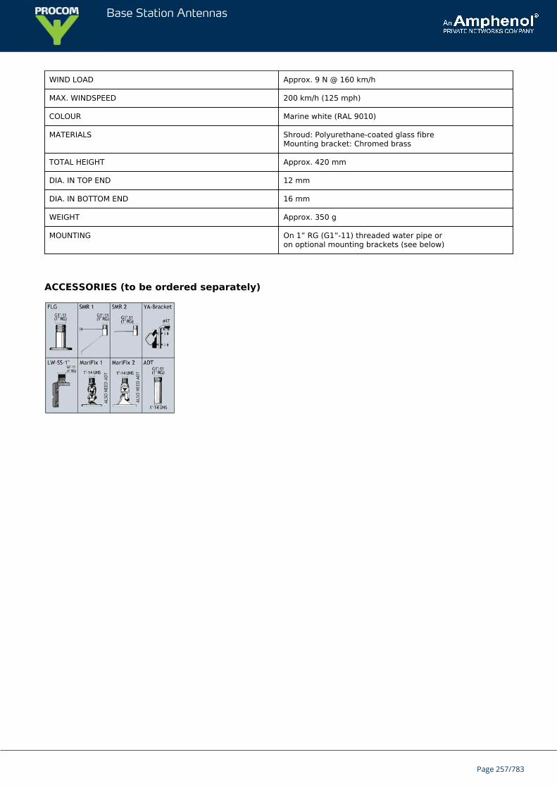
Base Station Antennas
WIND LOAD Approx. 9 N @ 160 km/h
MAX. WINDSPEED 200 km/h (125 mph)
COLOUR Marine white (RAL 9010)
MATERIALS Shroud: Polyurethane-coated glass fibreMounting bracket: Chromed brass
TOTAL HEIGHT Approx. 420 mm
DIA. IN TOP END 12 mm
DIA. IN BOTTOM END 16 mm
WEIGHT Approx. 350 g
MOUNTING On 1” RG (G1”-11) threaded water pipe oron optional mounting brackets (see below)
ACCESSORIES (to be ordered separately)
Page 257/783
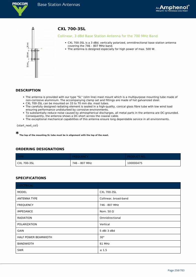
Base Station Antennas
CXL 700-3SLCollinear, 3 dBd Base Station Antenna for the 700 MHz Band
CXL 700-3SL is a 3 dBd, vertically polarized, omnidirectional base station antennacovering the 746 – 807 MHz band.The antenna is designed especially for high power of max. 500 W.
DESCRIPTION
The antenna is provided with our type "SL" (slim line) mast mount which is a multipurpose mounting tube made ofnon-corrosive aluminium. The accompanying clamp set and fittings are made of hot galvanized steel.CXL 700-3SL can be mounted on 33 to 70 mm dia. mast tubes.The carefully designed radiating element is sealed in a high-quality, conical glass fibre tube with low wind loadensuring performance undisturbed by corrosive environments.To substantially reduce noise caused by atmospherical discharges, all metal parts in the antenna are DC-grounded.Consequently, the antenna shows a DC-short across the coaxial cable.The exceptional mechanical capabilities of this antenna ensure long dependable service in all environments.
{start_next_col}
* The top of the mounting SL tube must be in alignment with the top of the mast.
ORDERING DESIGNATIONS
TYPE FREQUENCY PRODUCT NO.
CXL 700-3SL 746 – 807 MHz 100000475
SPECIFICATIONS
ELECTRICAL
MODEL CXL 700-3SL
ANTENNA TYPE Collinear, broad-band
FREQUENCY 746 - 807 MHz
IMPEDANCE Nom. 50 Ω
RADIATION Omnidirectional
POLARIZATION Vertical
GAIN 5 dBi 3 dBd
HALF POWER BEAMWIDTH 30°
BANDWIDTH 61 MHz
SWR ≤ 1.5
Page 258/783
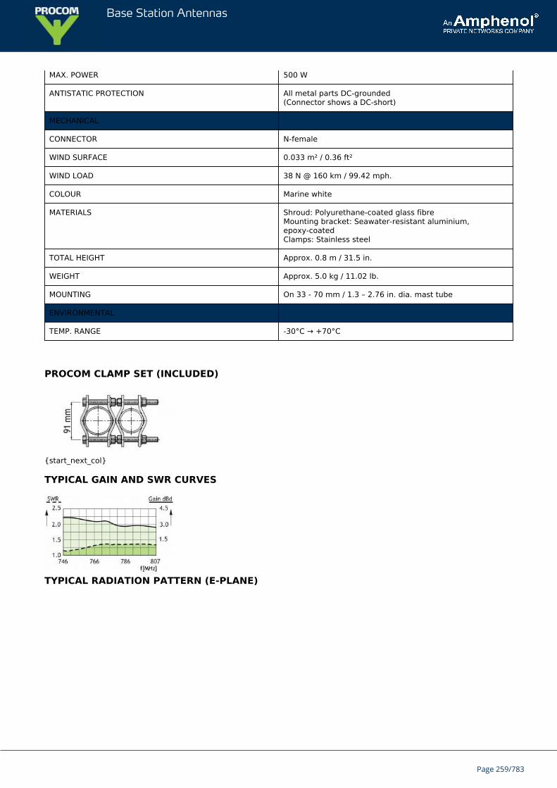
Base Station Antennas
MAX. POWER 500 W
ANTISTATIC PROTECTION All metal parts DC-grounded(Connector shows a DC-short)
MECHANICAL
CONNECTOR N-female
WIND SURFACE 0.033 m² / 0.36 ft²
WIND LOAD 38 N @ 160 km / 99.42 mph.
COLOUR Marine white
MATERIALS Shroud: Polyurethane-coated glass fibreMounting bracket: Seawater-resistant aluminium,epoxy-coatedClamps: Stainless steel
TOTAL HEIGHT Approx. 0.8 m / 31.5 in.
WEIGHT Approx. 5.0 kg / 11.02 lb.
MOUNTING On 33 - 70 mm / 1.3 – 2.76 in. dia. mast tube
ENVIRONMENTAL
TEMP. RANGE -30°C → +70°C
PROCOM CLAMP SET (INCLUDED)
{start_next_col}
TYPICAL GAIN AND SWR CURVES
TYPICAL RADIATION PATTERN (E-PLANE)
Page 259/783

Base Station Antennas
TYPICAL RADIATION PATTERN (H-PLANE)
Page 260/783
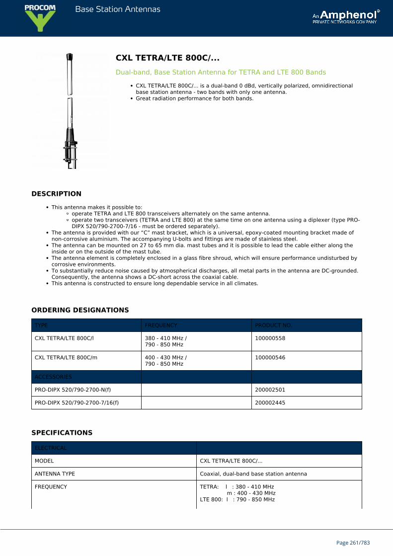
Base Station Antennas
CXL TETRA/LTE 800C/...Dual-band, Base Station Antenna for TETRA and LTE 800 Bands
CXL TETRA/LTE 800C/... is a dual-band 0 dBd, vertically polarized, omnidirectionalbase station antenna - two bands with only one antenna.Great radiation performance for both bands.
DESCRIPTION
This antenna makes it possible to:operate TETRA and LTE 800 transceivers alternately on the same antenna.operate two transceivers (TETRA and LTE 800) at the same time on one antenna using a diplexer (type PRO-DIPX 520/790-2700-7/16 - must be ordered separately).
The antenna is provided with our “C” mast bracket, which is a universal, epoxy-coated mounting bracket made ofnon-corrosive aluminium. The accompanying U-bolts and fittings are made of stainless steel.The antenna can be mounted on 27 to 65 mm dia. mast tubes and it is possible to lead the cable either along theinside or on the outside of the mast tube.The antenna element is completely enclosed in a glass fibre shroud, which will ensure performance undisturbed bycorrosive environments.To substantially reduce noise caused by atmospherical discharges, all metal parts in the antenna are DC-grounded.Consequently, the antenna shows a DC-short across the coaxial cable.This antenna is constructed to ensure long dependable service in all climates.
ORDERING DESIGNATIONS
TYPE FREQUENCY PRODUCT NO.
CXL TETRA/LTE 800C/l 380 - 410 MHz /790 - 850 MHz
100000558
CXL TETRA/LTE 800C/m 400 - 430 MHz /790 - 850 MHz
100000546
ACCESSORIES
PRO-DIPX 520/790-2700-N(f) 200002501
PRO-DIPX 520/790-2700-7/16(f) 200002445
SPECIFICATIONS
ELECTRICAL
MODEL CXL TETRA/LTE 800C/...
ANTENNA TYPE Coaxial, dual-band base station antenna
FREQUENCY TETRA: l : 380 - 410 MHz m : 400 - 430 MHzLTE 800: l : 790 - 850 MHz
Page 261/783
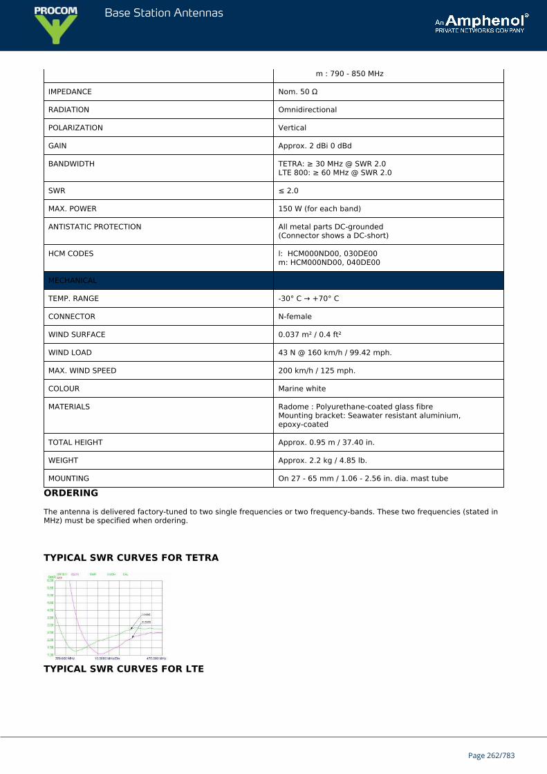
Base Station Antennas
m : 790 - 850 MHz
IMPEDANCE Nom. 50 Ω
RADIATION Omnidirectional
POLARIZATION Vertical
GAIN Approx. 2 dBi 0 dBd
BANDWIDTH TETRA: ≥ 30 MHz @ SWR 2.0LTE 800: ≥ 60 MHz @ SWR 2.0
SWR ≤ 2.0
MAX. POWER 150 W (for each band)
ANTISTATIC PROTECTION All metal parts DC-grounded(Connector shows a DC-short)
HCM CODES l: HCM000ND00, 030DE00m: HCM000ND00, 040DE00
MECHANICAL
TEMP. RANGE -30° C → +70° C
CONNECTOR N-female
WIND SURFACE 0.037 m² / 0.4 ft²
WIND LOAD 43 N @ 160 km/h / 99.42 mph.
MAX. WIND SPEED 200 km/h / 125 mph.
COLOUR Marine white
MATERIALS Radome : Polyurethane-coated glass fibreMounting bracket: Seawater resistant aluminium,epoxy-coated
TOTAL HEIGHT Approx. 0.95 m / 37.40 in.
WEIGHT Approx. 2.2 kg / 4.85 lb.
MOUNTING On 27 - 65 mm / 1.06 - 2.56 in. dia. mast tube
ORDERING
The antenna is delivered factory-tuned to two single frequencies or two frequency-bands. These two frequencies (stated inMHz) must be specified when ordering.
TYPICAL SWR CURVES FOR TETRA
TYPICAL SWR CURVES FOR LTE
Page 262/783
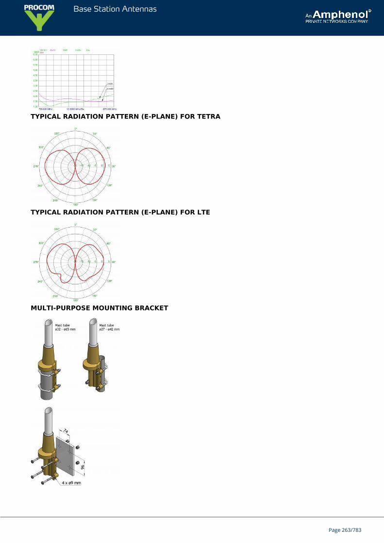
Base Station Antennas
TYPICAL RADIATION PATTERN (E-PLANE) FOR TETRA
TYPICAL RADIATION PATTERN (E-PLANE) FOR LTE
MULTI-PURPOSE MOUNTING BRACKET
Page 263/783

Base Station Antennas
Page 264/783
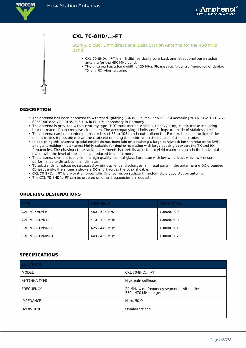
Base Station Antennas
CXL 70-8HD/...-PTSturdy, 8 dBd, Omnidirectional Base Station Antenna for the 450 MHzBand
CXL 70-8HD/…-PT is an 8 dBd, vertically polarized, omnidirectional base stationantenna for the 450 MHz band.The antenna has a bandwidth of 20 MHz. Please specify centre frequency or duplexTX and RX when ordering.
DESCRIPTION
The antenna has been approved to withstand lightning (10/350 μs impulses/100 kA) according to EN 61643-11, VDE0855-300 and VDE 0185-305-114 in FH-Kiel Laboratory in Germany.The antenna is provided with our sturdy type “HD” mast mount, which is a heavy-duty, multipurpose mountingbracket made of non-corrosive aluminium. The accompanying U-bolts and fittings are made of stainless steel.The antenna can be mounted on mast tubes of 58 to 105 mm in outer diameter. Further, the construction of themount makes it possible to lead the cable either along the inside or on the outside of the mast tube.In designing this antenna special emphasis has been laid on obtaining a large bandwidth both in relation to SWRand gain, making this antenna highly suitable for duplex operation with large spacing between the TX and RXfrequencies. The phasing of the radiating elements is carefully adjusted to yield maximum gain in the horizontalplane, with the level of the sidelobes reduced to a minimum.The antenna element is sealed in a high-quality, conical glass fibre tube with low wind-load, which will ensureperformance undisturbed in all climates.To substantially reduce noise caused by atmospherical discharges, all metal parts in the antenna are DC-grounded.Consequently, the antenna shows a DC-short across the coaxial cable.CXL 70-8HD/…-PT is a vibration-proof, slim-line, corrosion-resistant, modern style base station antenna.The CXL 70-8HD/... PT can be ordered on other frequencies on request.
ORDERING DESIGNATIONS
TYPE FREQUENCY PRODUCT NO.
CXL 70-8HD/l-PT 380 - 395 MHz 100000499
CXL 70-8HD/h-PT 410 - 430 MHz 100000500
CXL 70-8HD/lm-PT 425 - 445 MHz 100000501
CXL 70-8HD/hm-PT 440 - 460 MHz 100000502
SPECIFICATIONS
ELECTRICAL
MODEL CXL 70-8HD/...-PT
ANTENNA TYPE High-gain collinear
FREQUENCY 20 MHz wide frequency segments within the380 - 470 MHz range.
IMPEDANCE Nom. 50 Ω
RADIATION Omnidirectional
Page 265/783
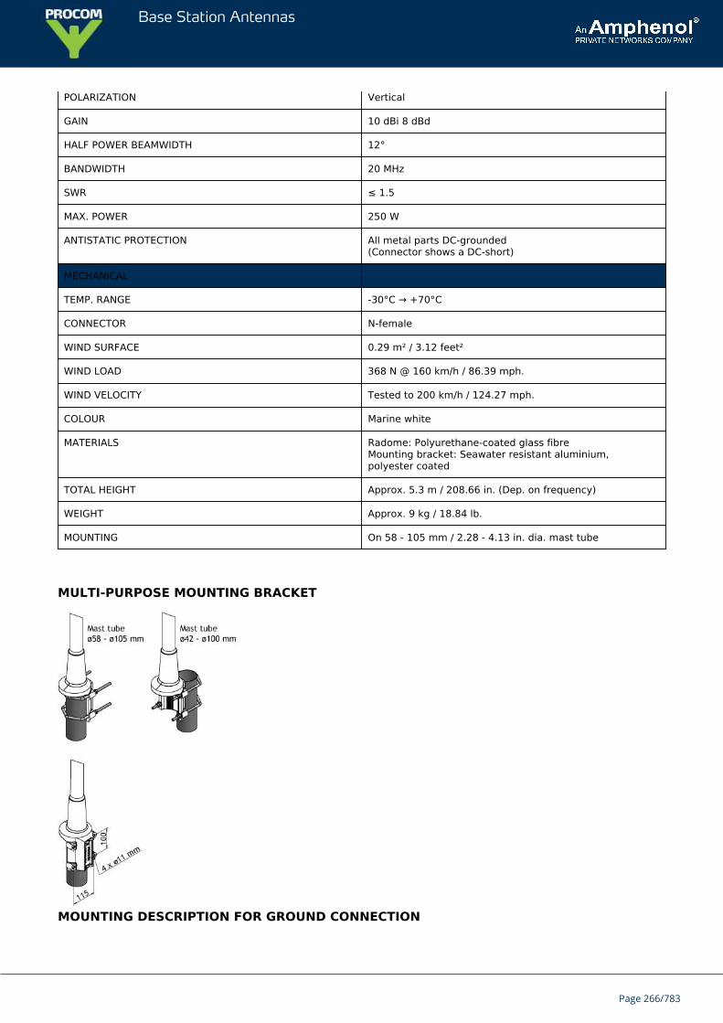
Base Station Antennas
POLARIZATION Vertical
GAIN 10 dBi 8 dBd
HALF POWER BEAMWIDTH 12°
BANDWIDTH 20 MHz
SWR ≤ 1.5
MAX. POWER 250 W
ANTISTATIC PROTECTION All metal parts DC-grounded(Connector shows a DC-short)
MECHANICAL
TEMP. RANGE -30°C → +70°C
CONNECTOR N-female
WIND SURFACE 0.29 m² / 3.12 feet²
WIND LOAD 368 N @ 160 km/h / 86.39 mph.
WIND VELOCITY Tested to 200 km/h / 124.27 mph.
COLOUR Marine white
MATERIALS Radome: Polyurethane-coated glass fibreMounting bracket: Seawater resistant aluminium,polyester coated
TOTAL HEIGHT Approx. 5.3 m / 208.66 in. (Dep. on frequency)
WEIGHT Approx. 9 kg / 18.84 lb.
MOUNTING On 58 - 105 mm / 2.28 - 4.13 in. dia. mast tube
MULTI-PURPOSE MOUNTING BRACKET
MOUNTING DESCRIPTION FOR GROUND CONNECTION
Page 266/783
Base Station Antennas
PLEASE NOTE
When using the CXL 70-8HD/…-PT at windy locations where wind speeds of more than (e.g. 150 km/h) can be expected, theantenna must be mounted on the side of the mast and the top section of the glass fibre tube stabilized with a bracket. Forthis purpose the Fixatid Bracket FB-HD/78 with the slideable side mounting Arms (SMC) can be used.
TYPICAL GAIN AND SWR CURVES
TYPICAL RADIATION PATTERN (E-PLANE)
TYPICAL RADIATION PATTERN (H-PLANE)
Page 267/783
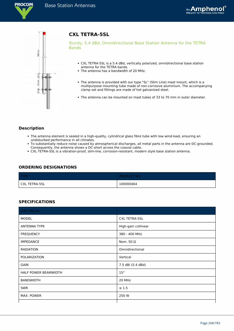
Base Station Antennas
CXL TETRA-5SLSturdy, 5.4 dBd, Omnidirectional Base Station Antenna for the TETRABands
CXL TETRA-5SL is a 5.4 dBd, vertically polarized, omnidirectional base stationantenna for the TETRA bands.The antenna has a bandwidth of 20 MHz.
The antenna is provided with our type "SL" (Slim Line) mast mount, which is amultipurpose mounting tube made of non-corrosive aluminium. The accompanyingclamp set and fittings are made of hot galvanized steel.
The antenna can be mounted on mast tubes of 33 to 70 mm in outer diameter.
Description
The antenna element is sealed in a high-quality, cylindrical glass fibre tube with low wind-load, ensuring anundisturbed performance in all climates.To substantially reduce noise caused by atmospherical discharges, all metal parts in the antenna are DC-grounded.Consequently, the antenna shows a DC-short across the coaxial cable.CXL TETRA-5SL is a vibration-proof, slim-line, corrosion-resistant, modern style base station antenna.
ORDERING DESIGNATIONS
TYPE PRODUCT NO.
CXL TETRA-5SL 100000464
SPECIFICATIONS
ELECTRICAL
MODEL CXL TETRA-5SL
ANTENNA TYPE High-gain collinear
FREQUENCY 380 - 400 MHz
IMPEDANCE Nom. 50 Ω
RADIATION Omnidirectional
POLARIZATION Vertical
GAIN 7.5 dBi (5.4 dBd)
HALF POWER BEAMWIDTH 15°
BANDWIDTH 20 MHz
SWR ≤ 1.5
MAX. POWER 250 W
Page 268/783
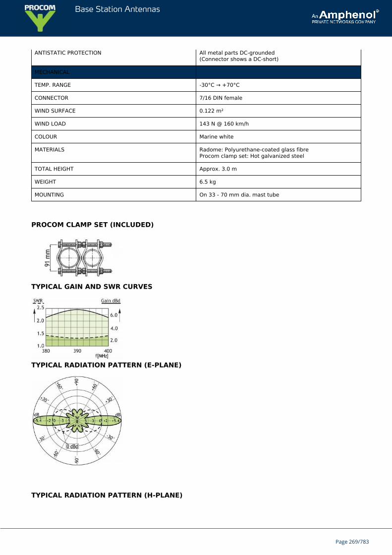
Base Station Antennas
ANTISTATIC PROTECTION All metal parts DC-grounded(Connector shows a DC-short)
MECHANICAL
TEMP. RANGE -30°C → +70°C
CONNECTOR 7/16 DIN female
WIND SURFACE 0.122 m²
WIND LOAD 143 N @ 160 km/h
COLOUR Marine white
MATERIALS Radome: Polyurethane-coated glass fibreProcom clamp set: Hot galvanized steel
TOTAL HEIGHT Approx. 3.0 m
WEIGHT 6.5 kg
MOUNTING On 33 - 70 mm dia. mast tube
PROCOM CLAMP SET (INCLUDED)
TYPICAL GAIN AND SWR CURVES
TYPICAL RADIATION PATTERN (E-PLANE)
TYPICAL RADIATION PATTERN (H-PLANE)
Page 269/783
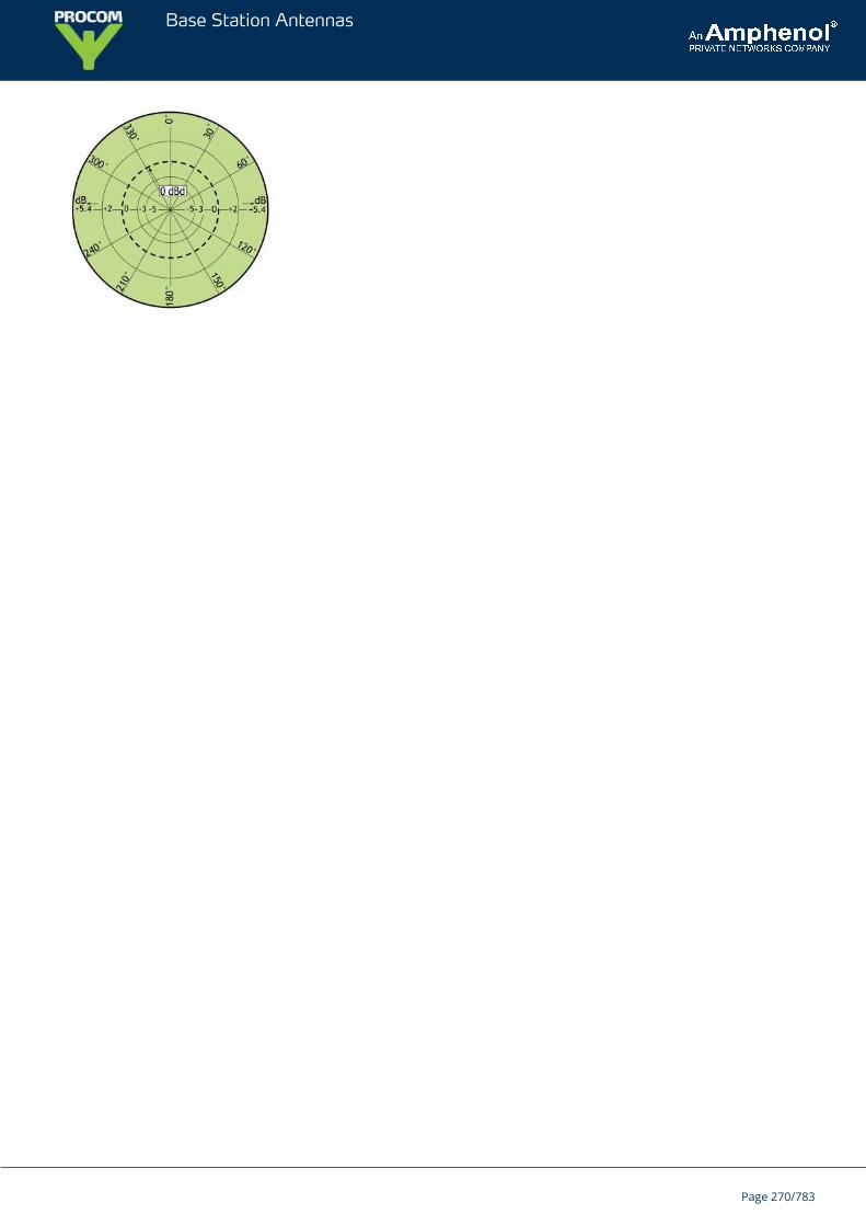
Base Station Antennas
Page 270/783
Base Station Antennas
CXL 900-6LW-NB/868 MHzLightweight, 6 dBd, Omnidirectional Base Station and Marine Antenna forthe 900 MHz Band
CXL 900-6LW-NB/868 MHz is a narrow-band 6 dBd,vertically polarized, omnidirectional base station and marine antenna.Provided with the sturdy “LW” mast mount – a lightweight, multipurpose, epoxy-coated mounting bracket made of non-corrosive aluminium.
DESCRIPTION
The accompanying U-bolts and fittings are made of stainless steel.To be mounted on vertical or horizontal mast tubes, 16 to 54 mm in outer diameter.The cable can be led either on the outside or along the inside of the mast tube.The carefully designed radiating element is sealed in a high-quality, conical glass fibre tube with low wind-load,ensuring undisturbed performance in all climates.To substantially reduce noise caused by atmospherical discharges, all metal parts in the antenna are DC-grounded.Consequently, the antenna shows a DC-short across the coaxial cable.The CXL 900-6LW-NB/868 MHz is a vibration-proof, lightweight, slim-line, corrosion resistant, modern style basestation and marine antenna.
ORDERING DESIGNATIONS
TYPE PRODUCT NO.
CXL 900-6LW-NB/868 MHz 100000471
SPECIFICATIONS
ELECTRICAL
MODEL CXL 900-6LW-NB/868 MHz
ANTENNA TYPE Collinear, narrow-band
FREQUENCY 860 – 880 MHz
IMPEDANCE Nom. 50 Ω
RADIATION Omnidirectional
POLARIZATION Vertical
GAIN 8 dBi 6 dBd
HALF POWER BEAMWIDTH 14°
BANDWIDTH 20 MHz
SWR ≤ 2.0≤ 1.5 @ centre frequency ±2 MHz
MAX. POWER 150 W
ANTISTATIC PROTECTION All metal parts DC-grounded
Page 271/783
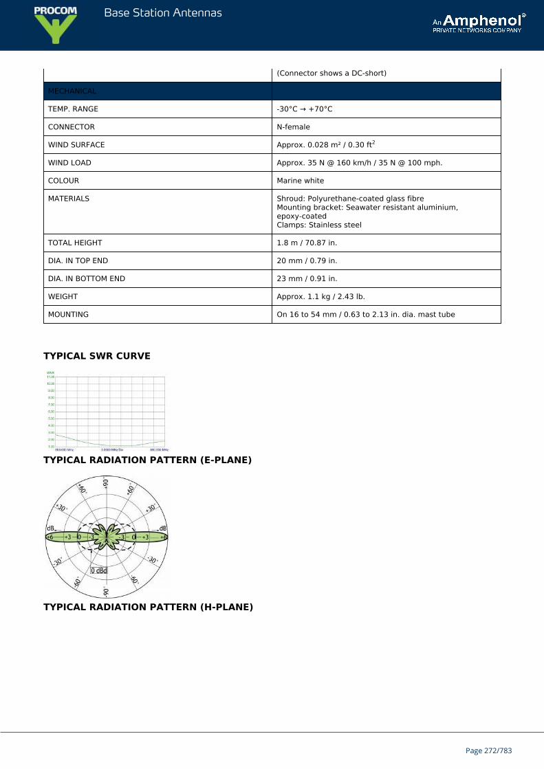
Base Station Antennas
(Connector shows a DC-short)
MECHANICAL
TEMP. RANGE -30°C → +70°C
CONNECTOR N-female
WIND SURFACE Approx. 0.028 m² / 0.30 ft2
WIND LOAD Approx. 35 N @ 160 km/h / 35 N @ 100 mph.
COLOUR Marine white
MATERIALS Shroud: Polyurethane-coated glass fibreMounting bracket: Seawater resistant aluminium,epoxy-coatedClamps: Stainless steel
TOTAL HEIGHT 1.8 m / 70.87 in.
DIA. IN TOP END 20 mm / 0.79 in.
DIA. IN BOTTOM END 23 mm / 0.91 in.
WEIGHT Approx. 1.1 kg / 2.43 lb.
MOUNTING On 16 to 54 mm / 0.63 to 2.13 in. dia. mast tube
TYPICAL SWR CURVE
TYPICAL RADIATION PATTERN (E-PLANE)
TYPICAL RADIATION PATTERN (H-PLANE)
Page 272/783

Base Station Antennas
MULTI-PURPOSE MOUNTING BRACKET
PLEASE NOTE
The antenna is delivered with a DC-connection between the antenna element and the mounting bracket.
Page 273/783
Base Station Antennas
CXL 900-6LW/...ightweight, 6 dBd, Omnidirectional Base Station and Marine Antenna forthe 900 MHz Band
CXL 900-6LW/… is a 6 dBd, vertically polarized, omnidirectional base station andmarine antenna, covering the 900 MHz band in three models.Provided with the sturdy “LW” mast mount – a lightweight, multipurpose, epoxy-coated mounting bracket made of non-corrosive aluminium.
Description
The accompanying U-bolts and fittings are made of stainless steel.To be mounted on vertical or horizontal mast tubes, 16 to 54 mm in outer diameter.The cable can be led either on the outside or along the inside of the mast tube.Large bandwidth with respect to both SWR and gain.Highly suitable for duplex operation with large spacing between the TX and RX frequencies.The carefully designed radiating element is sealed in a high-quality, conical glass fibre tube with low wind-load,ensuring undisturbed performance in all climates.To substantially reduce noise caused by atmospherical discharges, all metal parts in the antenna are DC-grounded.Consequently, the antenna shows a DC-short across the coaxial cable.The CXL 900-6LW/… is a vibration-proof, lightweight, slim-line, corrosion resistant, modern style base station andmarine antenna.
ORDERING DESIGNATIONS
TYPE FREQUENCY PRODUCT NO.
CXL 900-6LW/l 824 – 894 MHz 100000139
CXL 900-6LW/m 870 – 950 MHz 100000138
CXL 900-6LW/h 890 – 960 MHz 100000137
SPECIFICATIONS
ELECTRICAL
MODEL CXL 900-6LW/...
ANTENNA TYPE Collinear, broad-band
FREQUENCY Models within 824 – 960 MHz
IMPEDANCE Nom. 50 Ω
RADIATION Omnidirectional
POLARIZATION Vertical
GAIN 8 dBi 6 dBd
HALF POWER BEAMWIDTH 14°
BANDWIDTH 70 – 80 MHz
Page 274/783
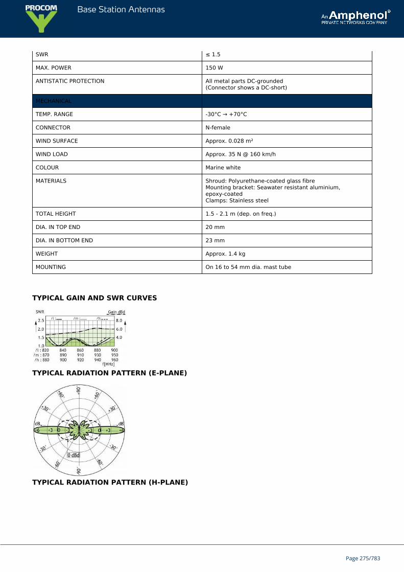
Base Station Antennas
SWR ≤ 1.5
MAX. POWER 150 W
ANTISTATIC PROTECTION All metal parts DC-grounded(Connector shows a DC-short)
MECHANICAL
TEMP. RANGE -30°C → +70°C
CONNECTOR N-female
WIND SURFACE Approx. 0.028 m²
WIND LOAD Approx. 35 N @ 160 km/h
COLOUR Marine white
MATERIALS Shroud: Polyurethane-coated glass fibreMounting bracket: Seawater resistant aluminium,epoxy-coatedClamps: Stainless steel
TOTAL HEIGHT 1.5 - 2.1 m (dep. on freq.)
DIA. IN TOP END 20 mm
DIA. IN BOTTOM END 23 mm
WEIGHT Approx. 1.4 kg
MOUNTING On 16 to 54 mm dia. mast tube
TYPICAL GAIN AND SWR CURVES
TYPICAL RADIATION PATTERN (E-PLANE)
TYPICAL RADIATION PATTERN (H-PLANE)
Page 275/783

Base Station Antennas
MULTI-PURPOSE MOUNTING BRACKET
Page 276/783
Base Station Antennas
CXL 70-8HD/...Sturdy, 8 dBd, Omnidirectional Base Station Antenna for the 450 MHzBand
CXL 70-8HD/… is an 8 dBd, vertically polarized, omnidirectional base stationantenna for the 450 MHz band.The antenna is provided with our sturdy type “HD” mast mount, which is a heavy-duty, multipurpose mounting bracket made of non-corrosive aluminium.The accompanying U-bolts and fittings are made of stainless steel.
DESCRIPTION
The antenna can be mounted on mast tubes of 58 to 105 mm in outer diameter. Further, the construction of themount makes it possible to lead the cable either along the inside oron the outside of the mast tube.In designing this antenna special emphasis has been laid on obtaining a large bandwidth both in relation to SWRand gain, making this antenna highly suitable for duplex operation with large spacing between the TX and RXfrequencies. The phasing of the radiating elements is carefully adjusted to yield maximum gain in the horizontalplane, with the level of the sidelobes reduced to a minimum.The antenna element is sealed in a high-quality, conical glass fibre tube with low wind-load, which will ensureperformance undisturbed in all climates.To substantially reduce noise caused by atmospherical discharges, all metal parts in the antenna are DC-grounded.Consequently, the antenna shows a DC-short across the coaxial cable.CXL 70-8HD/… is a vibration-proof, slim-line, corrosion-resistant, modern style base station antenna.The CXL 70-8HD/... can be ordered on other frequencies on request.
ORDERING DESIGNATIONS
TYPE FREQUENCY PRODUCT NO.
CXL 70-8HD/s 360 - 380 MHz 100000537
CXL 70-8HD/f 380 - 400 MHz 100000516
CXL 70-8HD/l 400 - 420 MHz 100000538
CXL 70-8HD/lm 421 - 440 MHz 100000539
CXL 70-8HD/m 430 - 450 MHz 100000535
CXL 70-8HD/hm 439 - 457 MHz 100000540
CXL 70-8HD/h 451 - 470 MHz 100000507
CXL 70-8HD/hh 460 - 484 MHz 100000541
SPECIFICATIONS
ELECTRICAL
MODEL CXL 70-8HD/...
ANTENNA TYPE High-gain collinear
FREQUENCY Models within the 360 - 484 MHz range.
IMPEDANCE Nom. 50 Ω
Page 277/783
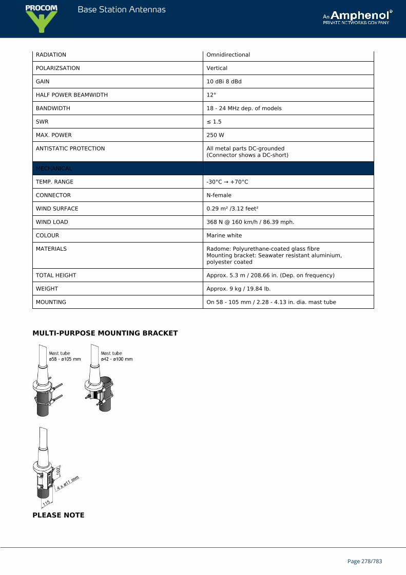
Base Station Antennas
RADIATION Omnidirectional
POLARIZSATION Vertical
GAIN 10 dBi 8 dBd
HALF POWER BEAMWIDTH 12°
BANDWIDTH 18 - 24 MHz dep. of models
SWR ≤ 1.5
MAX. POWER 250 W
ANTISTATIC PROTECTION All metal parts DC-grounded(Connector shows a DC-short)
MECHANICAL
TEMP. RANGE -30°C → +70°C
CONNECTOR N-female
WIND SURFACE 0.29 m² /3.12 feet²
WIND LOAD 368 N @ 160 km/h / 86.39 mph.
COLOUR Marine white
MATERIALS Radome: Polyurethane-coated glass fibreMounting bracket: Seawater resistant aluminium,polyester coated
TOTAL HEIGHT Approx. 5.3 m / 208.66 in. (Dep. on frequency)
WEIGHT Approx. 9 kg / 19.84 lb.
MOUNTING On 58 - 105 mm / 2.28 - 4.13 in. dia. mast tube
MULTI-PURPOSE MOUNTING BRACKET
PLEASE NOTE
Page 278/783
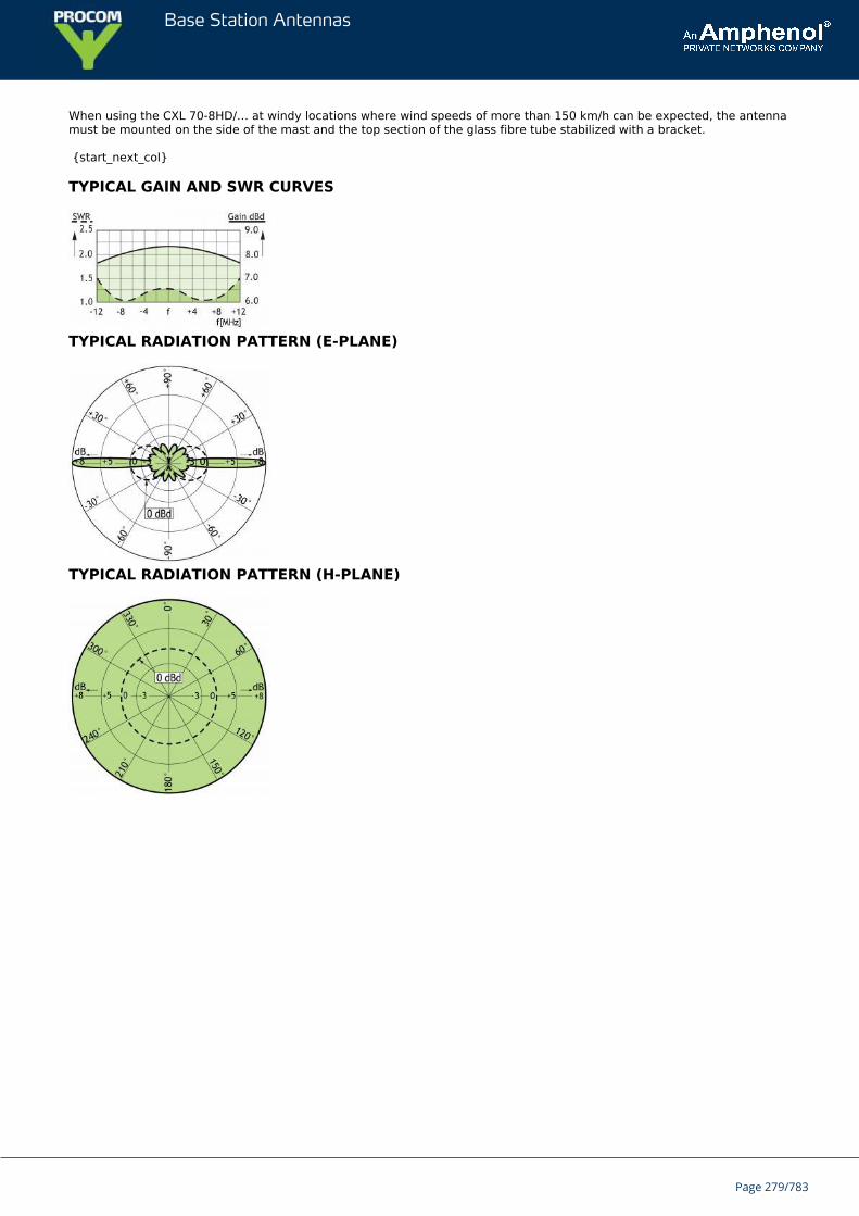
Base Station Antennas
When using the CXL 70-8HD/… at windy locations where wind speeds of more than 150 km/h can be expected, the antennamust be mounted on the side of the mast and the top section of the glass fibre tube stabilized with a bracket.
{start_next_col}
TYPICAL GAIN AND SWR CURVES
TYPICAL RADIATION PATTERN (E-PLANE)
TYPICAL RADIATION PATTERN (H-PLANE)
Page 279/783
Base Station Antennas
CXL 900-3LW-NB/868 MHzUniversal, 4 dBd Omnidirectional Base Station and Marine Antenna for the900 MHz Band
CXL 900-3LW-NB/868 MHz is a narrow-band 4 dBd,vertically polarized, omnidirectional base station and marine antenna.The phasing of the radiating elements is adjusted to yield maximum gain in thehorizontal plane, with the level of the side lobes reduced to a minimum.
Description
Provided with the sturdy “LW” mast mount – a lightweight, multipurpose, epoxy-coated mounting bracket made ofnon-corrosive aluminium.The accompanying U-bolts and fittings are made of stainless steel.To be mounted on vertical or horizontal mast tubes, 16 to 54 mm in outer diameter.The cable can be led either on the outside or along the inside of the mast tube.To substantially reduce noise caused by atmospherical discharges, all metal parts in the antenna are DC-grounded.Consequently, the antenna shows a DC-short across the coaxial cable.The CXL 900-3LW-NB/868 MHz is a vibration-proof, lightweight, slim-line, corrosion resistant, modern style basestation and marine antenna.
ORDERING DESIGNATIONS
TYPE PRODUCT NO.
CXL 900-3LW-NB/868 MHz 110000338
SPECIFICATIONS
ELECTRICAL
MODEL CXL 900-3LW-NB/868 MHz
ANTENNA TYPE Collinear, narrow-band
FREQUENCY 860 – 880 MHz
IMPEDANCE Nom. 50 Ω
RADIATION Omnidirectional
POLARIZATION Vertical
GAIN 6 dBi 4 dBd
HALF POWER BEAMWIDTH 23°
BANDWIDTH 20 MHz
Page 280/783
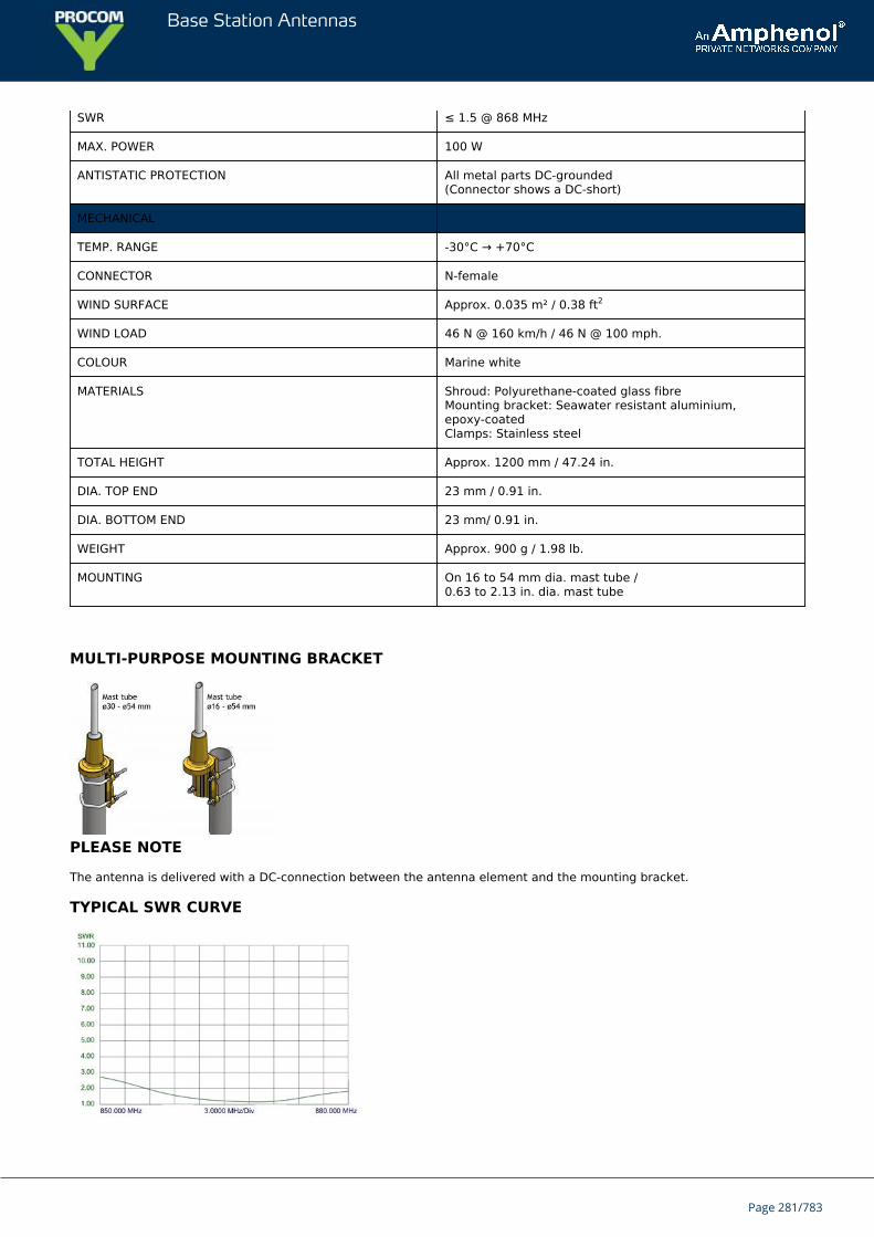
Base Station Antennas
SWR ≤ 1.5 @ 868 MHz
MAX. POWER 100 W
ANTISTATIC PROTECTION All metal parts DC-grounded(Connector shows a DC-short)
MECHANICAL
TEMP. RANGE -30°C → +70°C
CONNECTOR N-female
WIND SURFACE Approx. 0.035 m² / 0.38 ft2
WIND LOAD 46 N @ 160 km/h / 46 N @ 100 mph.
COLOUR Marine white
MATERIALS Shroud: Polyurethane-coated glass fibreMounting bracket: Seawater resistant aluminium,epoxy-coatedClamps: Stainless steel
TOTAL HEIGHT Approx. 1200 mm / 47.24 in.
DIA. TOP END 23 mm / 0.91 in.
DIA. BOTTOM END 23 mm/ 0.91 in.
WEIGHT Approx. 900 g / 1.98 lb.
MOUNTING On 16 to 54 mm dia. mast tube /0.63 to 2.13 in. dia. mast tube
MULTI-PURPOSE MOUNTING BRACKET
PLEASE NOTE
The antenna is delivered with a DC-connection between the antenna element and the mounting bracket.
TYPICAL SWR CURVE
Page 281/783
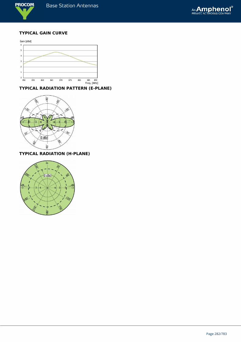
Base Station Antennas
TYPICAL GAIN CURVE
TYPICAL RADIATION PATTERN (E-PLANE)
TYPICAL RADIATION (H-PLANE)
Page 282/783
Base Station Antennas
CXL 70-5SL/...Sturdy, 5 dBd, Omnidirectional Base Station Antenna for the TETRA Band
CXL 70-5SL/… is an 5 dBd, vertically polarized, omnidirectional base station antennafor the TETRA bands.The antenna has a band width of 20 MHz.
DESCRIPTION
The antenna is provided with our type "SL" (Slim Line) mast mount, which is a multipurpose mounting tube made ofnon-corrosive aluminium. The accompanying clamp set and fittings are made of hot galvanized steel.The antenna can be mounted on mast tubes of 33 to 70 mm in outer diameter.The antenna element is sealed in a high-quality, conical glass fibre tube with low wind-load, which will ensureperformance undisturbed in all climates.To substantially reduce noise caused by atmospherical discharges, all metal parts in the antenna are DC-grounded.Consequently, the antenna shows a DC-short across the coaxial cable.CXL 70-5SL/… is a vibration-proof, slim-line, corrosion-resistant, modern style base station antenna.
The top of the mounting SL tube must be in alignment with the top of the mast.
ORDERING DESIGNATIONS
TYPE PRODUCT NO. FREQUENCY
CXL 70-5SL/l 100000326 380 - 400 MHz
CXL 70-5SL/h 100000327 410 - 430 MHz
SPECIFICATIONS
ELECTRICAL
MODEL CXL 70-5SL/...
ANTENNA TYPE High-gain collinear
FREQUENCY 380 - 400 MHz and 410 - 430 MHz
IMPEDANCE Nom. 50 Ω
RADIATION Omnidirectional
POLARIZATION Vertical
GAIN 7 dBi 5 dBd
HALF POWER BEAMWIDTH 15°
BANDWIDTH 20 MHz
SWR ≤ 1.5
Page 283/783
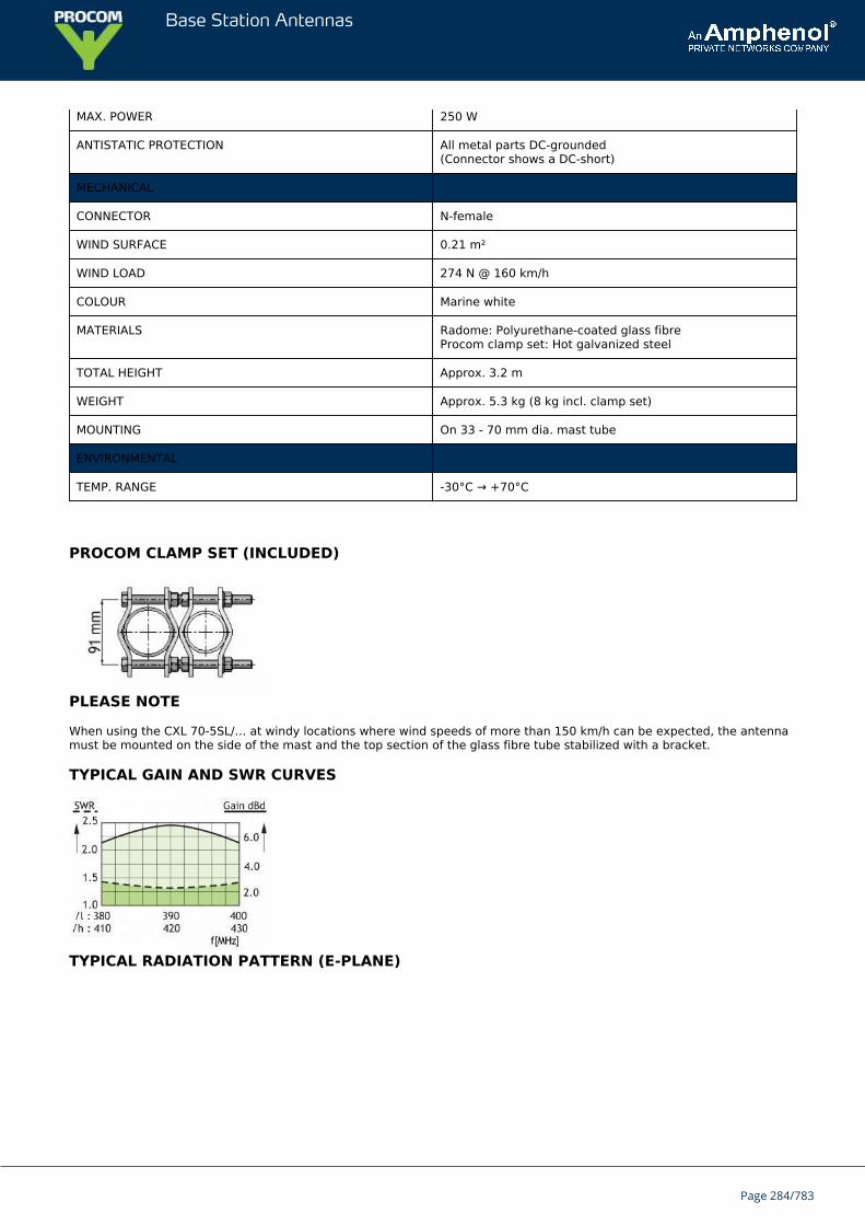
Base Station Antennas
MAX. POWER 250 W
ANTISTATIC PROTECTION All metal parts DC-grounded(Connector shows a DC-short)
MECHANICAL
CONNECTOR N-female
WIND SURFACE 0.21 m²
WIND LOAD 274 N @ 160 km/h
COLOUR Marine white
MATERIALS Radome: Polyurethane-coated glass fibreProcom clamp set: Hot galvanized steel
TOTAL HEIGHT Approx. 3.2 m
WEIGHT Approx. 5.3 kg (8 kg incl. clamp set)
MOUNTING On 33 - 70 mm dia. mast tube
ENVIRONMENTAL
TEMP. RANGE -30°C → +70°C
PROCOM CLAMP SET (INCLUDED)
PLEASE NOTE
When using the CXL 70-5SL/… at windy locations where wind speeds of more than 150 km/h can be expected, the antennamust be mounted on the side of the mast and the top section of the glass fibre tube stabilized with a bracket.
TYPICAL GAIN AND SWR CURVES
TYPICAL RADIATION PATTERN (E-PLANE)
Page 284/783

Base Station Antennas
TYPICAL RADIATION PATTERN (H-PLANE)
Page 285/783
Base Station Antennas
CXL 900-3LW/...Universal, 3 dBd Base Station and Marine Antenna for the 900 MHz Band
CXL 900-3LW/… is a 3 dBd, vertically polarized, omnidirectional rod-type basestation and marine antenna which covers the 900 MHz band in three models.The carefully designed, broad-banded antenna element is sealed in a high-quality,conical glass fibre tube with low wind-load, which will ensure performanceundisturbed by corrosive environments.
Description
The phasing of the radiating elements is adjusted to yield maximum gain in the horizontal plane, with the level ofthe sidelobes reduced to a minimum.Provided with the sturdy “LW” mast mount – a lightweight, multipurpose, epoxy-coated mounting bracket made ofnon-corrosive aluminium.The accompanying U-bolts and fittings are made of stainless steel.To be mounted on vertical or horizontal mast tubes, 16 to 54 mm in outer diameter.The cable can be led either on the outside or along the inside of the mast tube.Large bandwidth with respect to both SWR and gain.To substantially reduce noise caused by atmospherical discharges, all metal parts in the antenna are DC-grounded.Consequently, the antenna shows a DC-short across the coaxial cable.The CXL 900-3LW/… is a vibration-proof, lightweight, slim-line, corrosion resistant, modern style base station andmarine antenna.
ORDERING DESIGNATIONS
TYPE PRODUCT NO. FREQUENCY
CXL 900-3LW/l 110000106 824 – 894 MHz
CXL 900-3LW/m 110000107 870 – 950 MHz
CXL 900-3LW/h 110000105 890 – 960 MHz
SPECIFICATIONS
ELECTRICAL
MODEL CXL 900-3LW/...
ANTENNA TYPE Collinear, broad-banded
FREQUENCY Models within 824 – 960 MHz
IMPEDANCE Nom. 50 Ω
RADIATION Omnidirectional
POLARIZATION Vertical
GAIN 5 dBi 3 dBd
Page 286/783
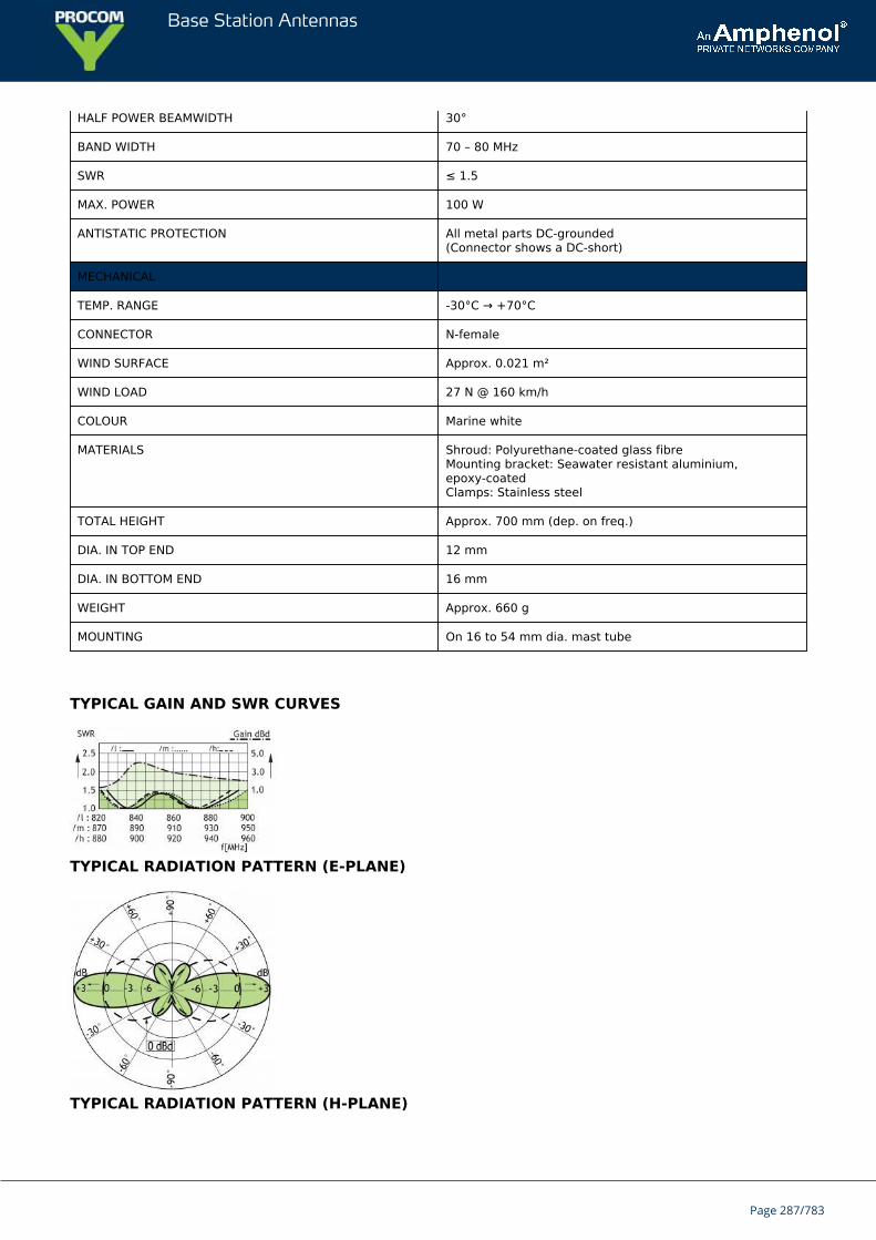
Base Station Antennas
HALF POWER BEAMWIDTH 30°
BAND WIDTH 70 – 80 MHz
SWR ≤ 1.5
MAX. POWER 100 W
ANTISTATIC PROTECTION All metal parts DC-grounded(Connector shows a DC-short)
MECHANICAL
TEMP. RANGE -30°C → +70°C
CONNECTOR N-female
WIND SURFACE Approx. 0.021 m²
WIND LOAD 27 N @ 160 km/h
COLOUR Marine white
MATERIALS Shroud: Polyurethane-coated glass fibreMounting bracket: Seawater resistant aluminium,epoxy-coatedClamps: Stainless steel
TOTAL HEIGHT Approx. 700 mm (dep. on freq.)
DIA. IN TOP END 12 mm
DIA. IN BOTTOM END 16 mm
WEIGHT Approx. 660 g
MOUNTING On 16 to 54 mm dia. mast tube
TYPICAL GAIN AND SWR CURVES
TYPICAL RADIATION PATTERN (E-PLANE)
TYPICAL RADIATION PATTERN (H-PLANE)
Page 287/783

Base Station Antennas
MULTI-PURPOSE MOUNTING BRACKET
Page 288/783
Base Station Antennas
CXL 70-5HD/...-PTSturdy, 5 dBd, Omnidirectional Base Station Antenna for the TETRA Band
CXL 70-5HD/…-PT is an 5 dBd, vertically polarized, omnidirectional base stationantenna for the TETRA bands.The antenna has a band width of 20 MHz.
DESCRIPTION
The antenna has been approved to withstand lightning (10/350 μs impulses/100 kA) according to EN 61643-11, VDE0855-300 and VDE 0185-305-114 in FH-Kiel Laboratory in Germany.The antenna is provided with our sturdy type “HD” mast mount,which is a heavy-duty, multipurpose mounting bracket made ofnoncorrosive aluminium. The accompanying U-bolts and fittings aremade of stainless steel.The antenna can be mounted on mast tubes of 58 to 105 mm in outer diameter. Further, the construction of themount makes it possible to lead the cable either along the inside or on the outside of the mast tube.The antenna element is sealed in a high-quality, conical glass fibre tube with low wind-load, which will ensureperformance undisturbed in all climates.To substantially reduce noise caused by atmospherical discharges, all metal parts in the antenna are DC-grounded.Consequently, the antenna shows a DC-short across the coaxial cable.CXL 70-5HD/…-PT is a vibration-proof, slim-line, corrosion-resistant, modern style base station antenna.
ORDERING DESIGNATIONS
TYPE FREQUENCY PRODUCT NO.
CXL 70-5HD/l-PT 380 - 400 MHz 100000237
CXL 70-5HD/h-PT 410 - 430 MHz 100000232
SPECIFICATIONS
ELECTRICAL
MODEL CXL 70-5HD/...-PT
ANTENNA TYPE High-gain collinear
FREQUENCY 380 - 400 MHz and 410 - 430 MHz
IMPEDANCE Nom. 50 Ω
RADIATION Omnidirectional
POLARIZATION Vertical
GAIN 7 dBi 5 dBd
HALF POWER BEAMWIDTH 15°
BANDWIDTH 20 MHz
Page 289/783
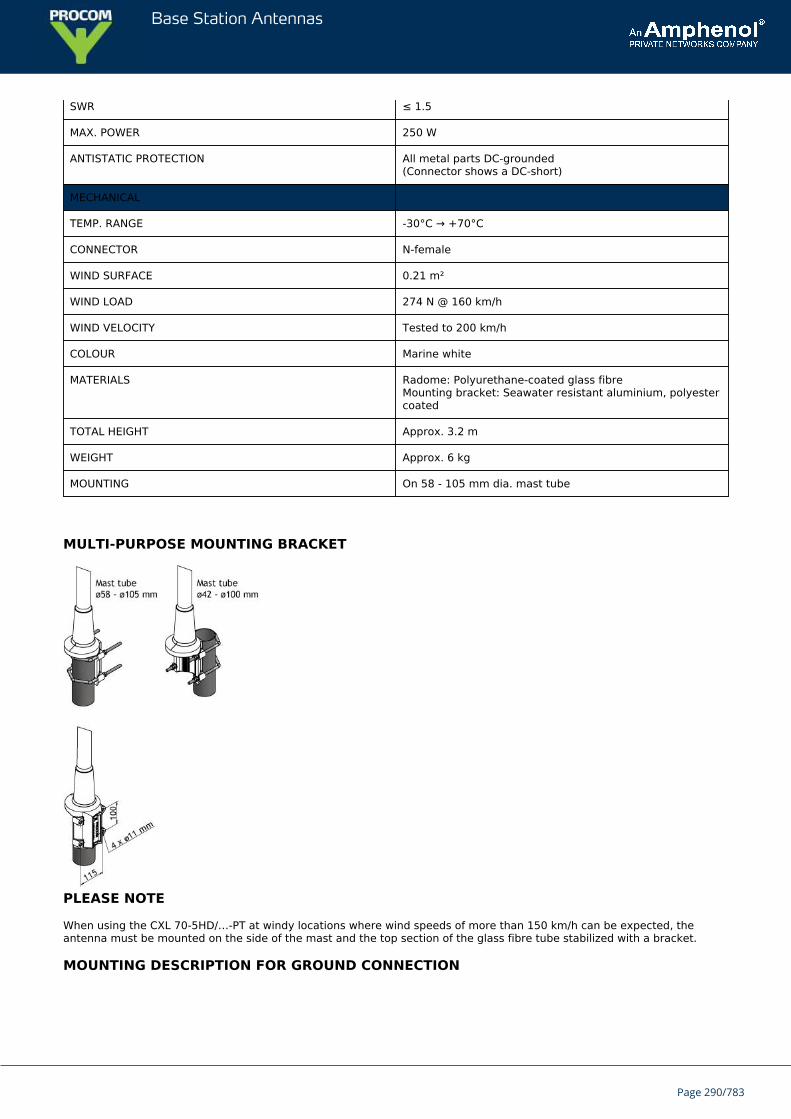
Base Station Antennas
SWR ≤ 1.5
MAX. POWER 250 W
ANTISTATIC PROTECTION All metal parts DC-grounded(Connector shows a DC-short)
MECHANICAL
TEMP. RANGE -30°C → +70°C
CONNECTOR N-female
WIND SURFACE 0.21 m²
WIND LOAD 274 N @ 160 km/h
WIND VELOCITY Tested to 200 km/h
COLOUR Marine white
MATERIALS Radome: Polyurethane-coated glass fibreMounting bracket: Seawater resistant aluminium, polyestercoated
TOTAL HEIGHT Approx. 3.2 m
WEIGHT Approx. 6 kg
MOUNTING On 58 - 105 mm dia. mast tube
MULTI-PURPOSE MOUNTING BRACKET
PLEASE NOTE
When using the CXL 70-5HD/…-PT at windy locations where wind speeds of more than 150 km/h can be expected, theantenna must be mounted on the side of the mast and the top section of the glass fibre tube stabilized with a bracket.
MOUNTING DESCRIPTION FOR GROUND CONNECTION
Page 290/783
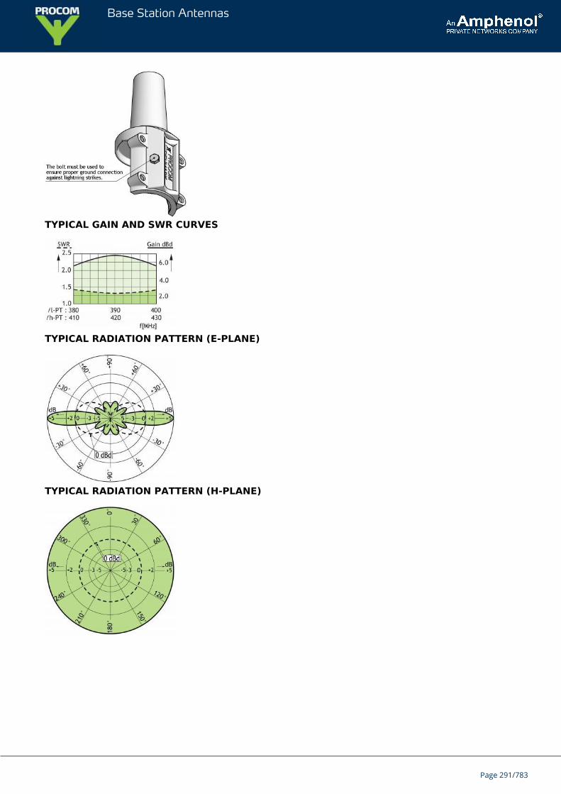
Base Station Antennas
TYPICAL GAIN AND SWR CURVES
TYPICAL RADIATION PATTERN (E-PLANE)
TYPICAL RADIATION PATTERN (H-PLANE)
Page 291/783
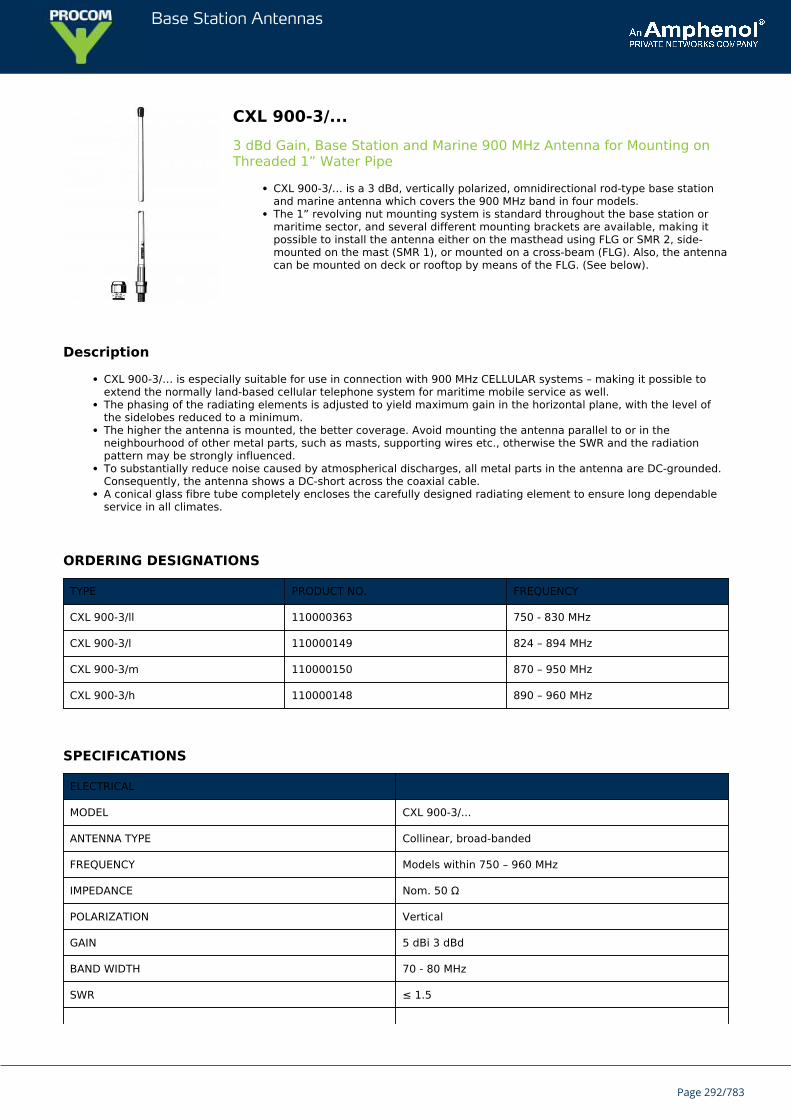
Base Station Antennas
CXL 900-3/...3 dBd Gain, Base Station and Marine 900 MHz Antenna for Mounting onThreaded 1” Water Pipe
CXL 900-3/… is a 3 dBd, vertically polarized, omnidirectional rod-type base stationand marine antenna which covers the 900 MHz band in four models.The 1” revolving nut mounting system is standard throughout the base station ormaritime sector, and several different mounting brackets are available, making itpossible to install the antenna either on the masthead using FLG or SMR 2, side-mounted on the mast (SMR 1), or mounted on a cross-beam (FLG). Also, the antennacan be mounted on deck or rooftop by means of the FLG. (See below).
Description
CXL 900-3/… is especially suitable for use in connection with 900 MHz CELLULAR systems – making it possible toextend the normally land-based cellular telephone system for maritime mobile service as well.The phasing of the radiating elements is adjusted to yield maximum gain in the horizontal plane, with the level ofthe sidelobes reduced to a minimum.The higher the antenna is mounted, the better coverage. Avoid mounting the antenna parallel to or in theneighbourhood of other metal parts, such as masts, supporting wires etc., otherwise the SWR and the radiationpattern may be strongly influenced.To substantially reduce noise caused by atmospherical discharges, all metal parts in the antenna are DC-grounded.Consequently, the antenna shows a DC-short across the coaxial cable.A conical glass fibre tube completely encloses the carefully designed radiating element to ensure long dependableservice in all climates.
ORDERING DESIGNATIONS
TYPE PRODUCT NO. FREQUENCY
CXL 900-3/ll 110000363 750 - 830 MHz
CXL 900-3/l 110000149 824 – 894 MHz
CXL 900-3/m 110000150 870 – 950 MHz
CXL 900-3/h 110000148 890 – 960 MHz
SPECIFICATIONS
ELECTRICAL
MODEL CXL 900-3/...
ANTENNA TYPE Collinear, broad-banded
FREQUENCY Models within 750 – 960 MHz
IMPEDANCE Nom. 50 Ω
POLARIZATION Vertical
GAIN 5 dBi 3 dBd
BAND WIDTH 70 - 80 MHz
SWR ≤ 1.5
Page 292/783
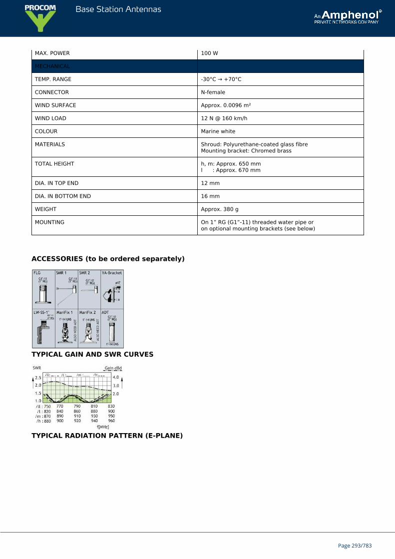
Base Station Antennas
MAX. POWER 100 W
MECHANICAL
TEMP. RANGE -30°C → +70°C
CONNECTOR N-female
WIND SURFACE Approx. 0.0096 m²
WIND LOAD 12 N @ 160 km/h
COLOUR Marine white
MATERIALS Shroud: Polyurethane-coated glass fibreMounting bracket: Chromed brass
TOTAL HEIGHT h, m: Approx. 650 mml : Approx. 670 mm
DIA. IN TOP END 12 mm
DIA. IN BOTTOM END 16 mm
WEIGHT Approx. 380 g
MOUNTING On 1” RG (G1”-11) threaded water pipe oron optional mounting brackets (see below)
ACCESSORIES (to be ordered separately)
TYPICAL GAIN AND SWR CURVES
TYPICAL RADIATION PATTERN (E-PLANE)
Page 293/783

Base Station Antennas
TYPICAL RADIATION PATTERN (H-PLANE)
Page 294/783
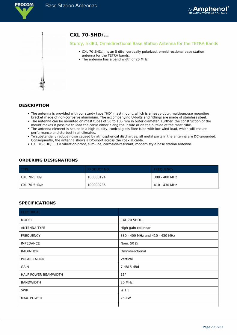
Base Station Antennas
CXL 70-5HD/...Sturdy, 5 dBd, Omnidirectional Base Station Antenna for the TETRA Bands
CXL 70-5HD/… is an 5 dBd, vertically polarized, omnidirectional base stationantenna for the TETRA bands.The antenna has a band width of 20 MHz.
DESCRIPTION
The antenna is provided with our sturdy type “HD” mast mount, which is a heavy-duty, multipurpose mountingbracket made of non-corrosive aluminium. The accompanying U-bolts and fittings are made of stainless steel.The antenna can be mounted on mast tubes of 58 to 105 mm in outer diameter. Further, the construction of themount makes it possible to lead the cable either along the inside or on the outside of the mast tube.The antenna element is sealed in a high-quality, conical glass fibre tube with low wind-load, which will ensureperformance undisturbed in all climates.To substantially reduce noise caused by atmospherical discharges, all metal parts in the antenna are DC-grounded.Consequently, the antenna shows a DC-short across the coaxial cable.CXL 70-5HD/… is a vibration-proof, slim-line, corrosion-resistant, modern style base station antenna.
ORDERING DESIGNATIONS
TYPE PRODUCT NO. FREQUENCY
CXL 70-5HD/l 100000124 380 - 400 MHz
CXL 70-5HD/h 100000235 410 - 430 MHz
SPECIFICATIONS
ELECTRICAL
MODEL CXL 70-5HD/...
ANTENNA TYPE High-gain collinear
FREQUENCY 380 - 400 MHz and 410 - 430 MHz
IMPEDANCE Nom. 50 Ω
RADIATION Omnidirectional
POLARIZATION Vertical
GAIN 7 dBi 5 dBd
HALF POWER BEAMWIDTH 15°
BANDWIDTH 20 MHz
SWR ≤ 1.5
MAX. POWER 250 W
Page 295/783
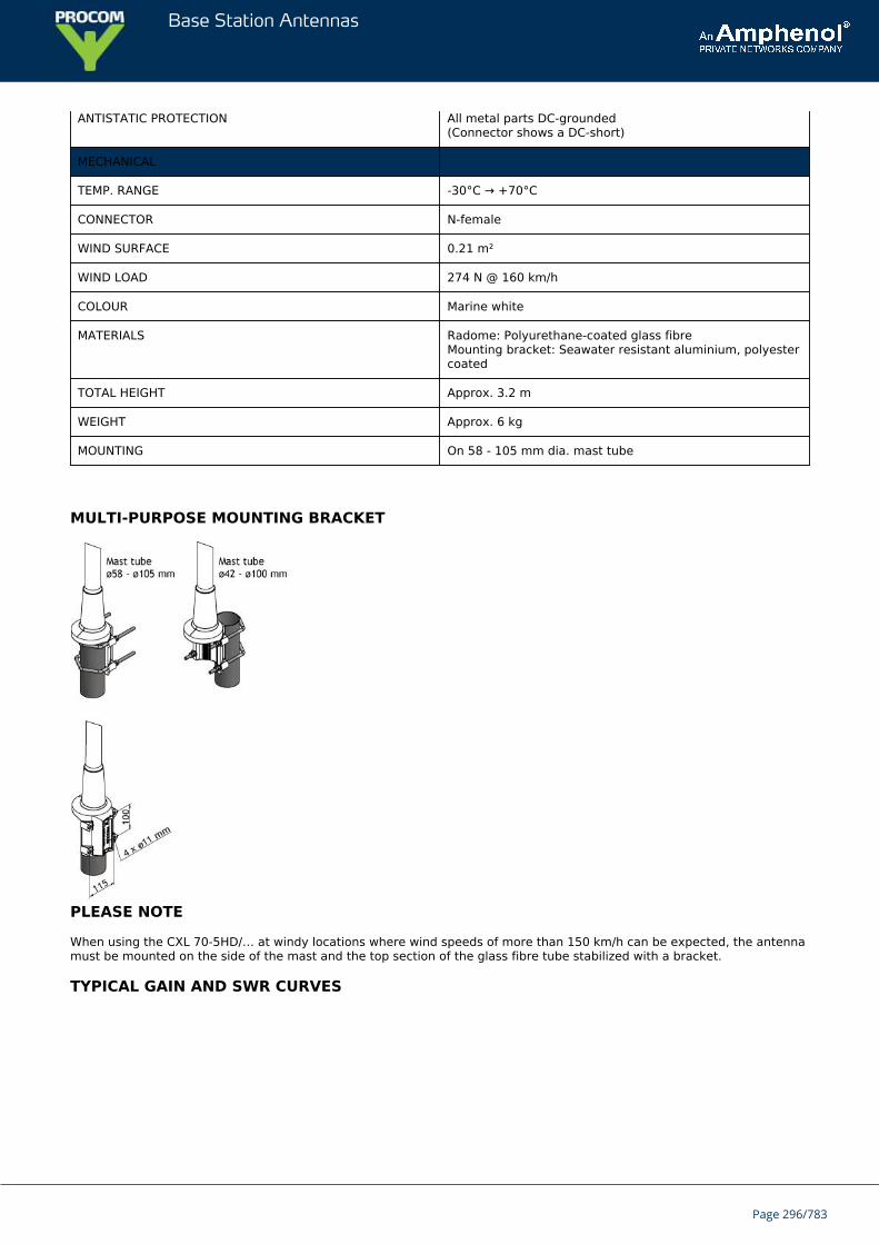
Base Station Antennas
ANTISTATIC PROTECTION All metal parts DC-grounded(Connector shows a DC-short)
MECHANICAL
TEMP. RANGE -30°C → +70°C
CONNECTOR N-female
WIND SURFACE 0.21 m²
WIND LOAD 274 N @ 160 km/h
COLOUR Marine white
MATERIALS Radome: Polyurethane-coated glass fibreMounting bracket: Seawater resistant aluminium, polyestercoated
TOTAL HEIGHT Approx. 3.2 m
WEIGHT Approx. 6 kg
MOUNTING On 58 - 105 mm dia. mast tube
MULTI-PURPOSE MOUNTING BRACKET
PLEASE NOTE
When using the CXL 70-5HD/… at windy locations where wind speeds of more than 150 km/h can be expected, the antennamust be mounted on the side of the mast and the top section of the glass fibre tube stabilized with a bracket.
TYPICAL GAIN AND SWR CURVES
Page 296/783
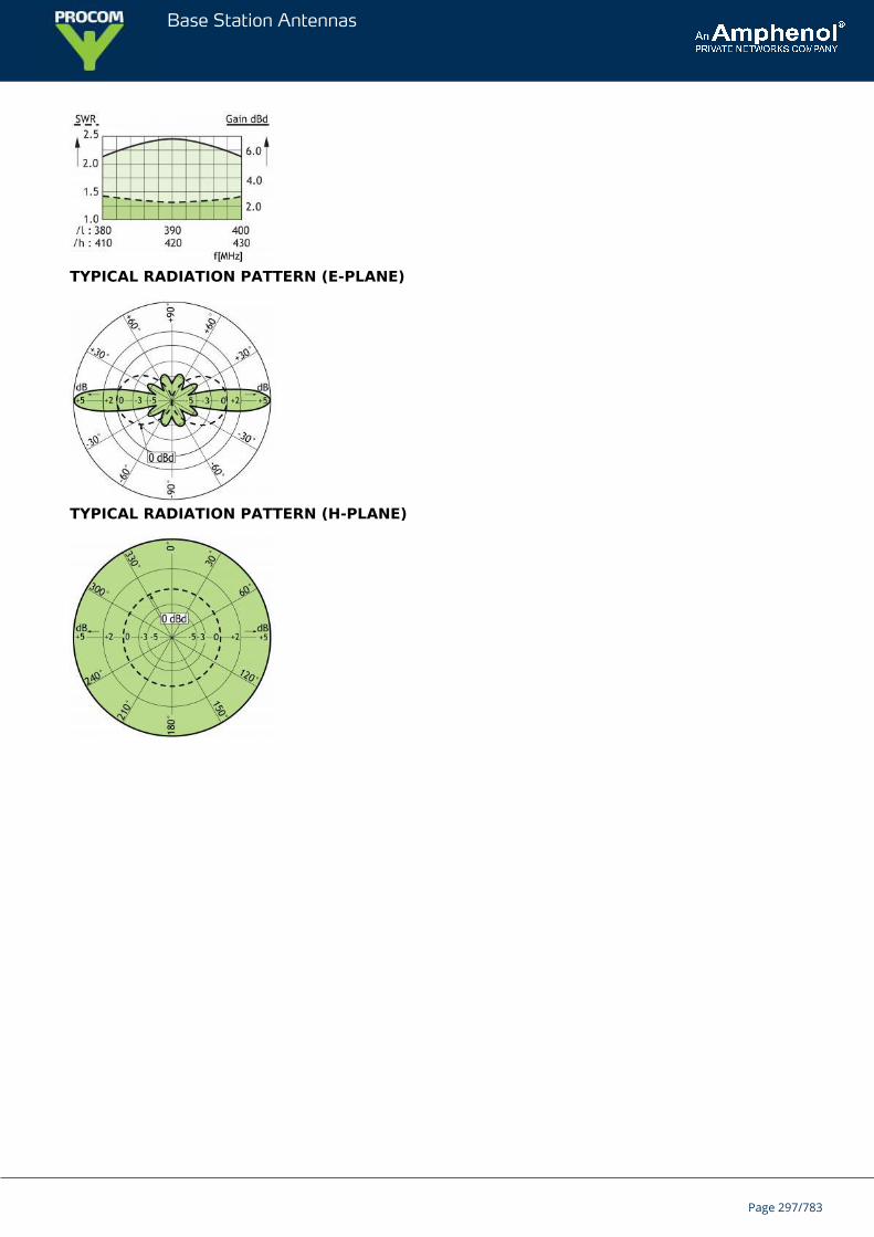
Base Station Antennas
TYPICAL RADIATION PATTERN (E-PLANE)
TYPICAL RADIATION PATTERN (H-PLANE)
Page 297/783
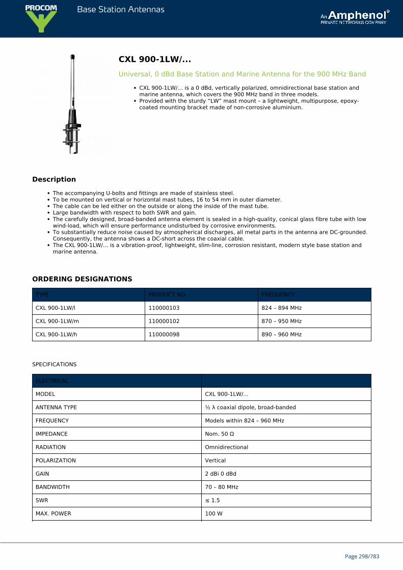
Base Station Antennas
CXL 900-1LW/...Universal, 0 dBd Base Station and Marine Antenna for the 900 MHz Band
CXL 900-1LW/… is a 0 dBd, vertically polarized, omnidirectional base station andmarine antenna, which covers the 900 MHz band in three models.Provided with the sturdy “LW” mast mount – a lightweight, multipurpose, epoxy-coated mounting bracket made of non-corrosive aluminium.
Description
The accompanying U-bolts and fittings are made of stainless steel.To be mounted on vertical or horizontal mast tubes, 16 to 54 mm in outer diameter.The cable can be led either on the outside or along the inside of the mast tube.Large bandwidth with respect to both SWR and gain.The carefully designed, broad-banded antenna element is sealed in a high-quality, conical glass fibre tube with lowwind-load, which will ensure performance undisturbed by corrosive environments.To substantially reduce noise caused by atmospherical discharges, all metal parts in the antenna are DC-grounded.Consequently, the antenna shows a DC-short across the coaxial cable.The CXL 900-1LW/… is a vibration-proof, lightweight, slim-line, corrosion resistant, modern style base station andmarine antenna.
ORDERING DESIGNATIONS
TYPE PRODUCT NO. FREQUENCY
CXL 900-1LW/l 110000103 824 – 894 MHz
CXL 900-1LW/m 110000102 870 – 950 MHz
CXL 900-1LW/h 110000098 890 – 960 MHz
SPECIFICATIONS
ELECTRICAL
MODEL CXL 900-1LW/...
ANTENNA TYPE ½ λ coaxial dipole, broad-banded
FREQUENCY Models within 824 – 960 MHz
IMPEDANCE Nom. 50 Ω
RADIATION Omnidirectional
POLARIZATION Vertical
GAIN 2 dBi 0 dBd
BANDWIDTH 70 – 80 MHz
SWR ≤ 1.5
MAX. POWER 100 W
Page 298/783
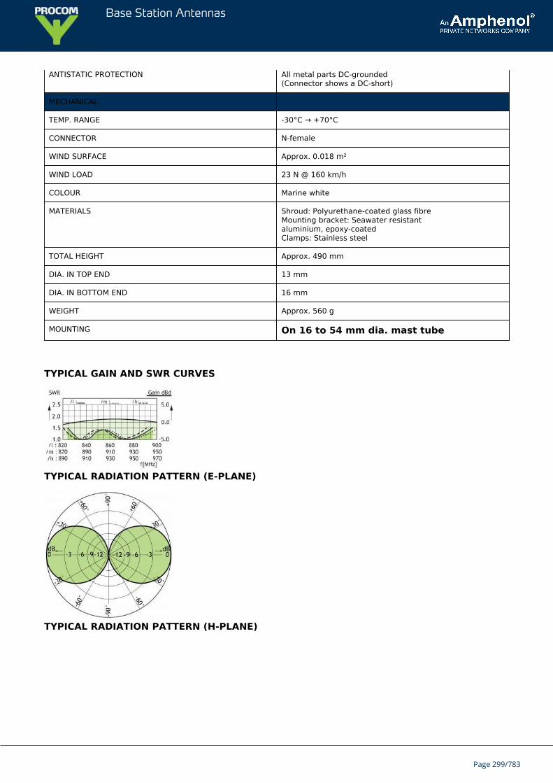
Base Station Antennas
ANTISTATIC PROTECTION All metal parts DC-grounded(Connector shows a DC-short)
MECHANICAL
TEMP. RANGE -30°C → +70°C
CONNECTOR N-female
WIND SURFACE Approx. 0.018 m²
WIND LOAD 23 N @ 160 km/h
COLOUR Marine white
MATERIALS Shroud: Polyurethane-coated glass fibreMounting bracket: Seawater resistantaluminium, epoxy-coatedClamps: Stainless steel
TOTAL HEIGHT Approx. 490 mm
DIA. IN TOP END 13 mm
DIA. IN BOTTOM END 16 mm
WEIGHT Approx. 560 g
MOUNTING On 16 to 54 mm dia. mast tube
TYPICAL GAIN AND SWR CURVES
TYPICAL RADIATION PATTERN (E-PLANE)
TYPICAL RADIATION PATTERN (H-PLANE)
Page 299/783
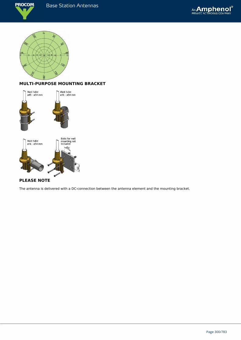
Base Station Antennas
MULTI-PURPOSE MOUNTING BRACKET
PLEASE NOTE
The antenna is delivered with a DC-connection between the antenna element and the mounting bracket.
Page 300/783
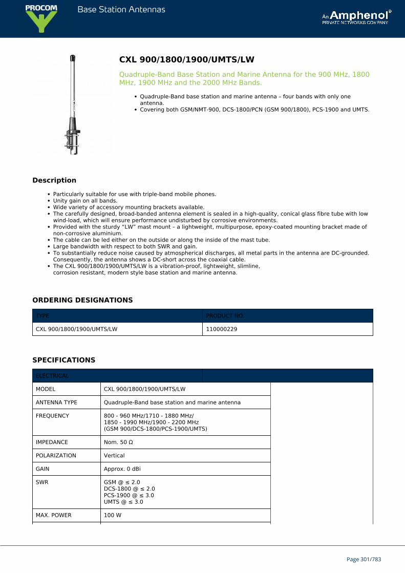
Base Station Antennas
CXL 900/1800/1900/UMTS/LWQuadruple-Band Base Station and Marine Antenna for the 900 MHz, 1800MHz, 1900 MHz and the 2000 MHz Bands.
Quadruple-Band base station and marine antenna – four bands with only oneantenna.Covering both GSM/NMT-900, DCS-1800/PCN (GSM 900/1800), PCS-1900 and UMTS.
Description
Particularly suitable for use with triple-band mobile phones.Unity gain on all bands.Wide variety of accessory mounting brackets available.The carefully designed, broad-banded antenna element is sealed in a high-quality, conical glass fibre tube with lowwind-load, which will ensure performance undisturbed by corrosive environments.Provided with the sturdy “LW” mast mount – a lightweight, multipurpose, epoxy-coated mounting bracket made ofnon-corrosive aluminium.The cable can be led either on the outside or along the inside of the mast tube.Large bandwidth with respect to both SWR and gain.To substantially reduce noise caused by atmospherical discharges, all metal parts in the antenna are DC-grounded.Consequently, the antenna shows a DC-short across the coaxial cable.The CXL 900/1800/1900/UMTS/LW is a vibration-proof, lightweight, slimline,corrosion resistant, modern style base station and marine antenna.
ORDERING DESIGNATIONS
TYPE PRODUCT NO.
CXL 900/1800/1900/UMTS/LW 110000229
SPECIFICATIONS
ELECTRICAL
MODEL CXL 900/1800/1900/UMTS/LW
ANTENNA TYPE Quadruple-Band base station and marine antenna
FREQUENCY 800 - 960 MHz/1710 - 1880 MHz/1850 - 1990 MHz/1900 - 2200 MHz(GSM 900/DCS-1800/PCS-1900/UMTS)
IMPEDANCE Nom. 50 Ω
POLARIZATION Vertical
GAIN Approx. 0 dBi
SWR GSM @ ≤ 2.0DCS-1800 @ ≤ 2.0PCS-1900 @ ≤ 3.0UMTS @ ≤ 3.0
MAX. POWER 100 W
Page 301/783
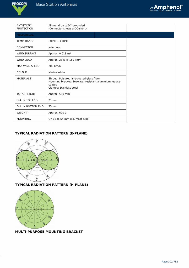
Base Station Antennas
ANTISTATICPROTECTION
All metal parts DC-grounded(Connector shows a DC-short)
MECHANICAL
TEMP. RANGE -30°C → +70°C
CONNECTOR N-female
WIND SURFACE Approx. 0.018 m²
WIND LOAD Approx. 23 N @ 160 km/h
MAX WIND SPEED 200 Km/h
COLOUR Marine white
MATERIALS Shroud: Polyurethane-coated glass fibreMounting bracket: Seawater resistant aluminium, epoxy-coatedClamps: Stainless steel
TOTAL HEIGHT Approx. 500 mm
DIA. IN TOP END 21 mm
DIA. IN BOTTOM END 23 mm
WEIGHT Approx. 600 g
MOUNTING On 16 to 54 mm dia. mast tube
TYPICAL RADIATION PATTERN (E-PLANE)
TYPICAL RADIATION PATTERN (H-PLANE)
MULTI-PURPOSE MOUNTING BRACKET
Page 302/783
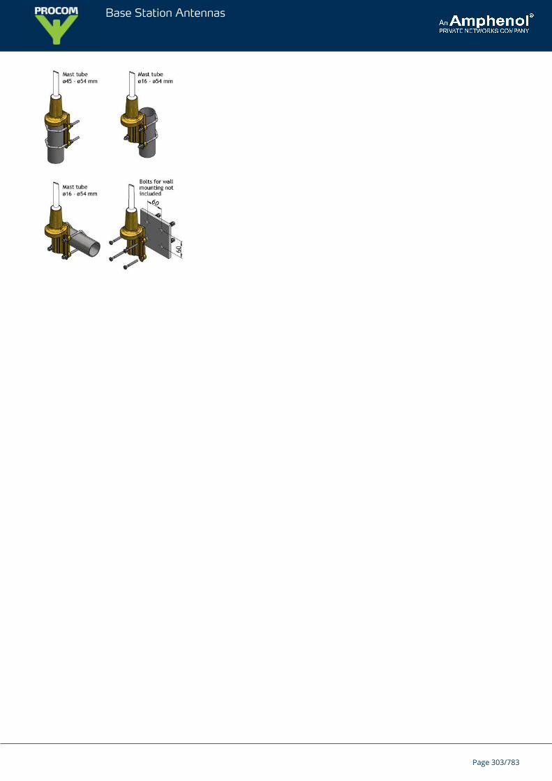
Base Station Antennas
Page 303/783
Base Station Antennas
CXL 70-5C/T-8/...-PTSturdy, 5 dBd, Omnidirectional Base Station Antenna with 8 degreeselectrical downtilt for the TETRA Bands
CXL 70-5C/T-8/…-PT is an 5 dBd, vertically polarized, omnidirectional base stationantenna for the TETRA bands.The antenna has a bandwidth of 20 MHz.
DESCRIPTION
The antenna has been approved to withstand lightning of max. (10/350 μs impulses/200 kA) according to DIN EN62475 in FH-Kiel Laboratory in Germany.The antenna is provided with our “C” universal fixation bracket made of epoxy-coated, seawater resistantaluminium. The accompanying U-bolts and fittings are made of stainless steel.CXL 70-5C/T-8/…-PT can be mounted on 27 to 65 mm dia. mast tubes, and it is possible to lead the cable eitheralong the inside or on the outside of the mast tube.The antenna element is sealed in a high-quality, cylindrical glass fibre tube with low wind-load, which will ensureperformance undisturbed in all climates.To substantially reduce noise caused by atmospherical discharges, all metal parts in the antenna are DC-grounded.Consequently, the antenna shows a DC-short across the coaxial cable.The exceptional mechanical capabilities of this antenna ensure long dependable service in all environments.
ORDERING DESIGNATIONS
TYPE FREQUENCY PRODUCT NO.
CXL 70-5C/T-8/h-PT 410 – 430 MHz 100000521
SPECIFICATIONS
ELECTRICAL
MODEL CXL 70-5C/T-8/...-PT
ANTENNA TYPE High-gain collinear
FREQUENCY 410 - 430 MHz
IMPEDANCE Nom. 50 Ω
RADIATION Omnidirectional
POLARIZATION Vertical
GAIN 7 dBi (5 dBd)
ELECTRICAL TILT * 8°
Page 304/783
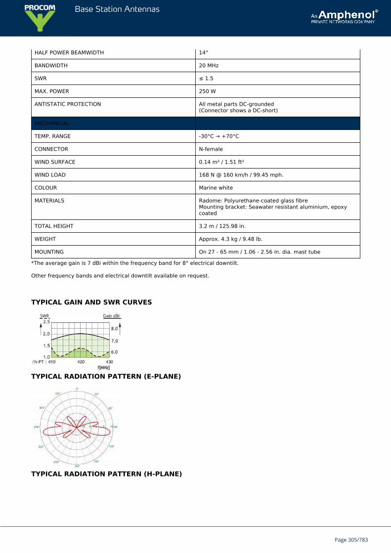
Base Station Antennas
HALF POWER BEAMWIDTH 14°
BANDWIDTH 20 MHz
SWR ≤ 1.5
MAX. POWER 250 W
ANTISTATIC PROTECTION All metal parts DC-grounded(Connector shows a DC-short)
MECHANICAL
TEMP. RANGE -30°C → +70°C
CONNECTOR N-female
WIND SURFACE 0.14 m² / 1.51 ft²
WIND LOAD 168 N @ 160 km/h / 99.45 mph.
COLOUR Marine white
MATERIALS Radome: Polyurethane-coated glass fibreMounting bracket: Seawater resistant aluminium, epoxycoated
TOTAL HEIGHT 3.2 m / 125.98 in.
WEIGHT Approx. 4.3 kg / 9.48 lb.
MOUNTING On 27 - 65 mm / 1.06 - 2.56 in. dia. mast tube
*The average gain is 7 dBi within the frequency band for 8° electrical downtilt.
Other frequency bands and electrical downtilt available on request.
TYPICAL GAIN AND SWR CURVES
TYPICAL RADIATION PATTERN (E-PLANE)
TYPICAL RADIATION PATTERN (H-PLANE)
Page 305/783
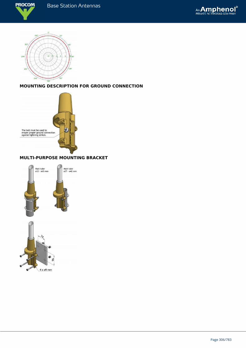
Base Station Antennas
MOUNTING DESCRIPTION FOR GROUND CONNECTION
MULTI-PURPOSE MOUNTING BRACKET
Page 306/783
Base Station Antennas
CXL 70-5C/T-7/...Collinear, 5 dBd Base Station Antenna and Marine Antenna with 7degrees electrical downtilt
CXL 70-5C/T-7/... is a 5 dBd, vertically polarized, omnidirectional base station andmarine antenna, covering the 380 - 470 MHz band.The antenna is provided with our “C” universal fixation bracket made of epoxy-coated, seawater-resistant aluminium. The accompanying U-bolts and fittings aremade of stainless steel.
DESCRIPTION
CXL 70-5C/T-7/... can be mounted on 27 to 65 mm dia. mast tubes and it is possible to lead the cable either alongthe inside or on the outside of the mast tube.The carefully designed radiating element is sealed in a high-quality, conical glass fibre tube with low wind-load,ensuring a performance undisturbed by corrosive environments.To substantially reduce noise caused by atmospherical discharges, all metal parts in the antenna are DC-grounded.Consequently, the antenna shows a DC-short across the coaxial cable.The exceptional mechanical capabilities of this antenna ensure long dependable service in all environments.
ORDERING DESIGNATIONS
TYPE FREQUENCY PRODUCT NO.
CXL 70-5C/T-7/s 380 - 400 MHz Contact for availability
CXL 70-5C/T-7/f 410 - 430 MHz 100000478
CXL 70-5C/T-7/l 430 - 450 MHz 100000536
CXL 70-5C/T-7/h 450 – 470 MHz 100000459
SPECIFICATIONS
ELECTRICAL
MODEL CXL 70-5C/T-7/...
ANTENNA TYPE Collinear, broad-banded
FREQUENCY * 380 - 470 MHz
IMPEDANCE Nom. 50 Ω
RADIATION Omnidirectional
POLARIZATION Vertical
GAIN 5 dBd (7 dBi)
ELECTRICAL TILT * 7°
HALF POWER BEAMWIDTH 14°
BANDWIDTH 20 MHz
Page 307/783
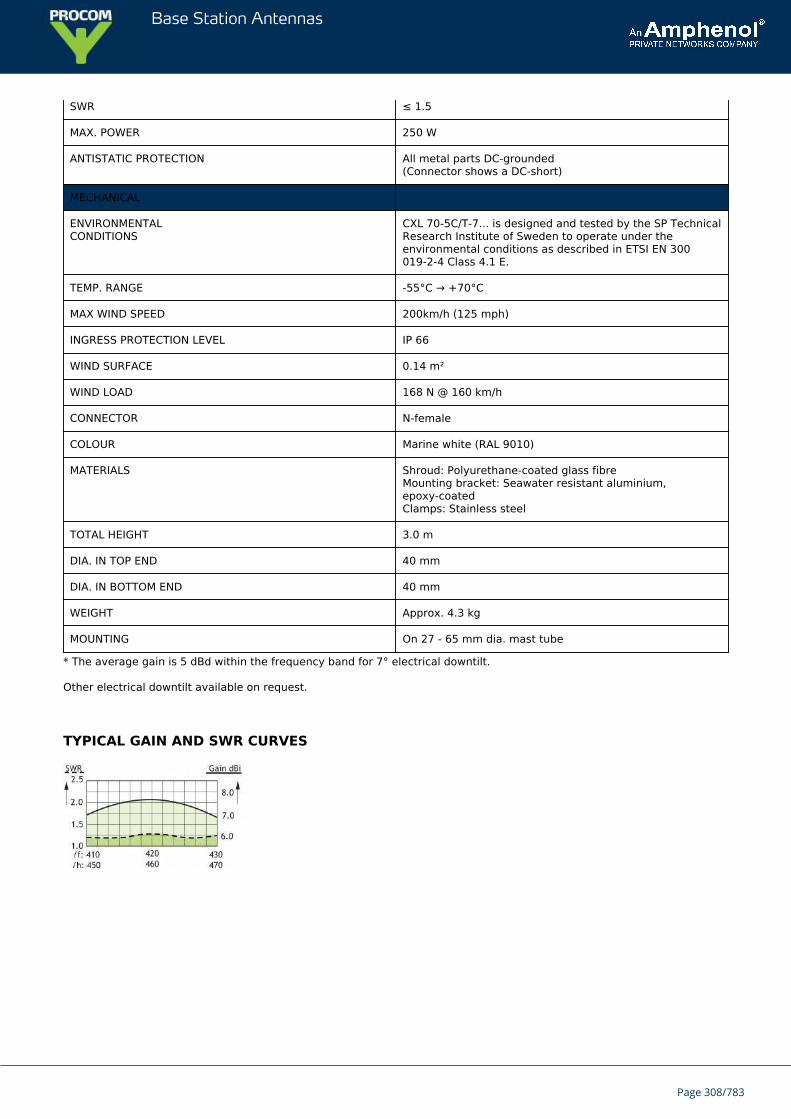
Base Station Antennas
SWR ≤ 1.5
MAX. POWER 250 W
ANTISTATIC PROTECTION All metal parts DC-grounded(Connector shows a DC-short)
MECHANICAL
ENVIRONMENTALCONDITIONS
CXL 70-5C/T-7... is designed and tested by the SP TechnicalResearch Institute of Sweden to operate under theenvironmental conditions as described in ETSI EN 300019-2-4 Class 4.1 E.
TEMP. RANGE -55°C → +70°C
MAX WIND SPEED 200km/h (125 mph)
INGRESS PROTECTION LEVEL IP 66
WIND SURFACE 0.14 m²
WIND LOAD 168 N @ 160 km/h
CONNECTOR N-female
COLOUR Marine white (RAL 9010)
MATERIALS Shroud: Polyurethane-coated glass fibreMounting bracket: Seawater resistant aluminium,epoxy-coatedClamps: Stainless steel
TOTAL HEIGHT 3.0 m
DIA. IN TOP END 40 mm
DIA. IN BOTTOM END 40 mm
WEIGHT Approx. 4.3 kg
MOUNTING On 27 - 65 mm dia. mast tube
* The average gain is 5 dBd within the frequency band for 7° electrical downtilt.
Other electrical downtilt available on request.
TYPICAL GAIN AND SWR CURVES
Page 308/783
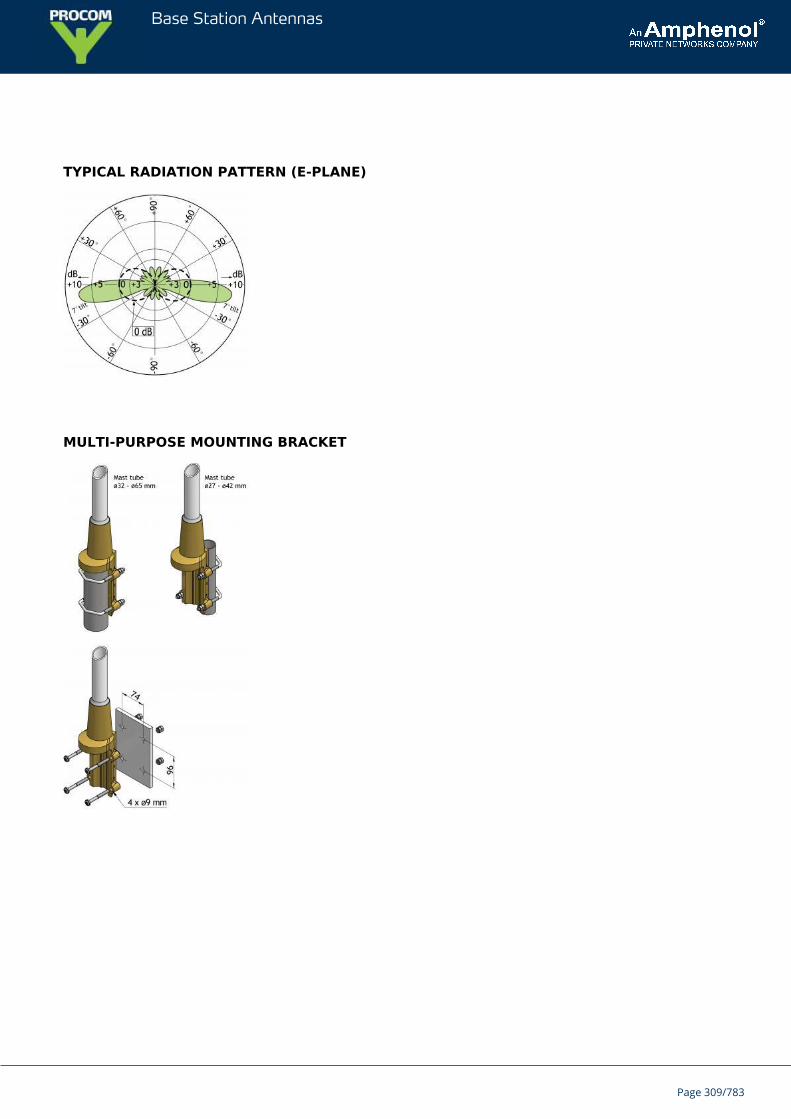
Base Station Antennas
TYPICAL RADIATION PATTERN (E-PLANE)
MULTI-PURPOSE MOUNTING BRACKET
Page 309/783
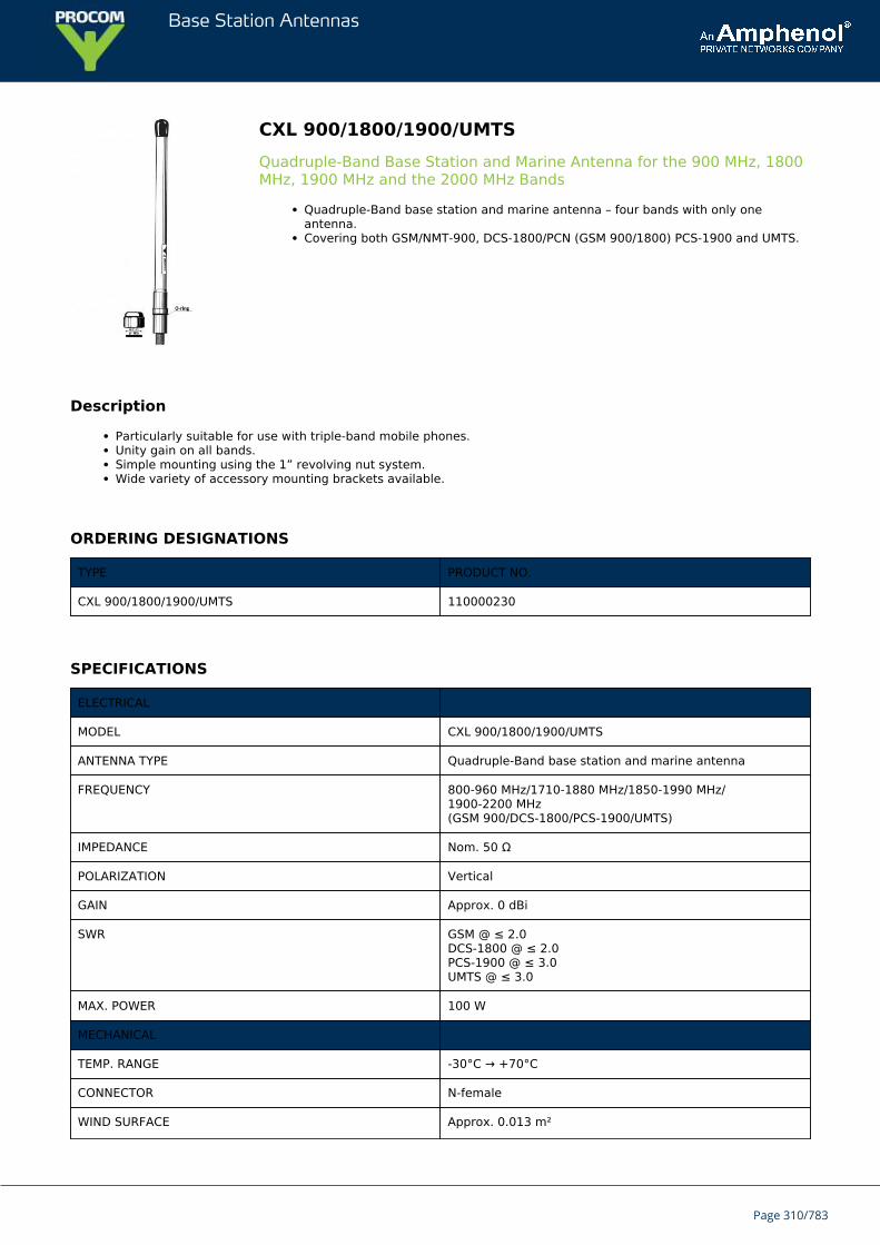
Base Station Antennas
CXL 900/1800/1900/UMTSQuadruple-Band Base Station and Marine Antenna for the 900 MHz, 1800MHz, 1900 MHz and the 2000 MHz Bands
Quadruple-Band base station and marine antenna – four bands with only oneantenna.Covering both GSM/NMT-900, DCS-1800/PCN (GSM 900/1800) PCS-1900 and UMTS.
Description
Particularly suitable for use with triple-band mobile phones.Unity gain on all bands.Simple mounting using the 1” revolving nut system.Wide variety of accessory mounting brackets available.
ORDERING DESIGNATIONS
TYPE PRODUCT NO.
CXL 900/1800/1900/UMTS 110000230
SPECIFICATIONS
ELECTRICAL
MODEL CXL 900/1800/1900/UMTS
ANTENNA TYPE Quadruple-Band base station and marine antenna
FREQUENCY 800-960 MHz/1710-1880 MHz/1850-1990 MHz/1900-2200 MHz(GSM 900/DCS-1800/PCS-1900/UMTS)
IMPEDANCE Nom. 50 Ω
POLARIZATION Vertical
GAIN Approx. 0 dBi
SWR GSM @ ≤ 2.0DCS-1800 @ ≤ 2.0PCS-1900 @ ≤ 3.0UMTS @ ≤ 3.0
MAX. POWER 100 W
MECHANICAL
TEMP. RANGE -30°C → +70°C
CONNECTOR N-female
WIND SURFACE Approx. 0.013 m²
Page 310/783
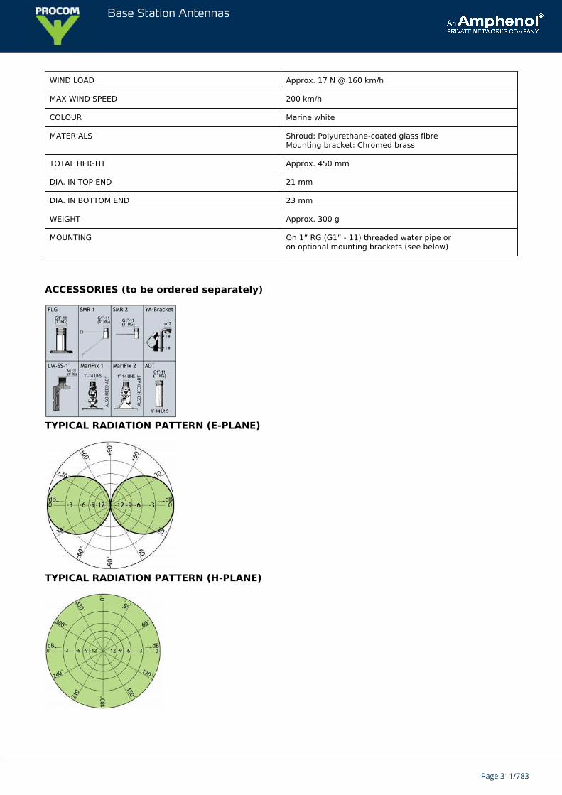
Base Station Antennas
WIND LOAD Approx. 17 N @ 160 km/h
MAX WIND SPEED 200 km/h
COLOUR Marine white
MATERIALS Shroud: Polyurethane-coated glass fibreMounting bracket: Chromed brass
TOTAL HEIGHT Approx. 450 mm
DIA. IN TOP END 21 mm
DIA. IN BOTTOM END 23 mm
WEIGHT Approx. 300 g
MOUNTING On 1” RG (G1” - 11) threaded water pipe oron optional mounting brackets (see below)
ACCESSORIES (to be ordered separately)
TYPICAL RADIATION PATTERN (E-PLANE)
TYPICAL RADIATION PATTERN (H-PLANE)
Page 311/783

Base Station Antennas
Page 312/783
Base Station Antennas
CXL 70-5C/T-12/...Collinear, 5 dBd Base Station and Marine Antenna with 12 degreeselectrical downtilt
CXL 70-5C/T-12/... is a 5 dBd, vertically polarized, omnidirectional base station andmarine antenna, covering the 380 – 470 MHz band.The antenna is provided with our type “C” universal fixation bracket made of epoxy-coated, seawater-resistant aluminium. The accompanying U-bolts and fittings aremade of stainless steel.
DESCRIPTION
CXL 70-5C/T-12/... can be mounted on 27 to 65 mm dia. mast tubes and it is possible to lead the cable either alongthe inside or on the outside of the mast tube.The carefully designed radiating element is sealed in a high-quality, conical glass fibre tube with low wind-load,ensuring a performance undisturbed by corrosive environments.To substantially reduce noise caused by atmospherical discharges, all metal parts in the antenna are DC-grounded.Consequently, the antenna shows a DC-short across the coaxial cable.The exceptional mechanical capabilities of this antenna ensure long dependable service in all environments.
ORDERING DESIGNATIONS
TYPE FREQUENCY PRODUCT NO.
CXL 70-5C/T-12/s 380 – 400 MHz 100000460
CXL 70-5C/T-12/f 410 – 430 MHz 100000618
CXL 70-5C/T-12/l 430 – 450 MHz 100000598
CXL 70-5C/T-12/h 450 – 470 MHz 100000489
SPECIFICATIONS
ELECTRICAL
MODEL CXL 70-5C/T-12/...
ANTENNA TYPE Collinear, broad-banded
FREQUENCY * 380 - 470 MHz
IMPEDANCE Nom. 50 Ω
RADIATION Omnidirectional
POLARIZATION Vertical
GAIN 5 dBd 7 dBi
ELECTRICAL TILT * 12°
HALF POWER BEAMWIDTH 18°
BANDWIDTH 20 MHz
Page 313/783
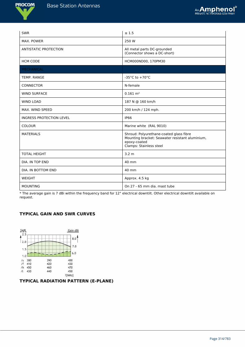
Base Station Antennas
SWR ≤ 1.5
MAX. POWER 250 W
ANTISTATIC PROTECTION All metal parts DC-grounded(Connector shows a DC-short)
HCM CODE HCM000ND00, 170PM30
MECHANICAL
TEMP. RANGE -35°C to +70°C
CONNECTOR N-female
WIND SURFACE 0.161 m²
WIND LOAD 187 N @ 160 km/h
MAX. WIND SPEED 200 km/h / 124 mph.
INGRESS PROTECTION LEVEL IP66
COLOUR Marine white (RAL 9010)
MATERIALS Shroud: Polyurethane-coated glass fibreMounting bracket: Seawater resistant aluminium,epoxy-coatedClamps: Stainless steel
TOTAL HEIGHT 3.2 m
DIA. IN TOP END 40 mm
DIA. IN BOTTOM END 40 mm
WEIGHT Approx. 4.5 kg
MOUNTING On 27 - 65 mm dia. mast tube
* The average gain is 7 dBi within the frequency band for 12° electrical downtilt. Other electrical downtilt available onrequest.
TYPICAL GAIN AND SWR CURVES
TYPICAL RADIATION PATTERN (E-PLANE)
Page 314/783
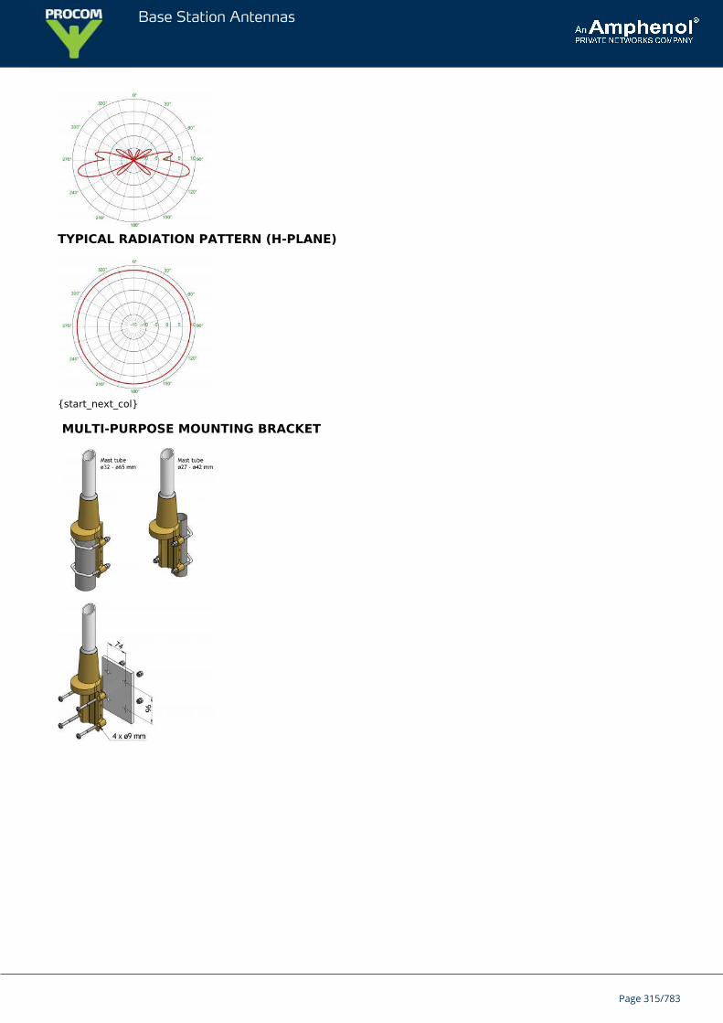
Base Station Antennas
TYPICAL RADIATION PATTERN (H-PLANE)
{start_next_col}
MULTI-PURPOSE MOUNTING BRACKET
Page 315/783
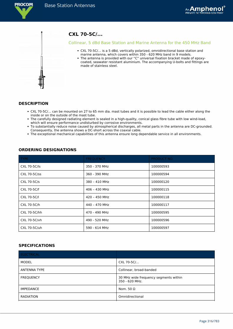
Base Station Antennas
CXL 70-5C/...Collinear, 5 dBd Base Station and Marine Antenna for the 450 MHz Band
CXL 70-5C/… is a 5 dBd, vertically polarized, omnidirectional base station andmarine antenna, which covers within 350 - 620 MHz band in 9 models.The antenna is provided with our “C” universal fixation bracket made of epoxy-coated, seawater resistant aluminium. The accompanying U-bolts and fittings aremade of stainless steel.
DESCRIPTION
CXL 70-5C/… can be mounted on 27 to 65 mm dia. mast tubes and it is possible to lead the cable either along theinside or on the outside of the mast tube.The carefully designed radiating element is sealed in a high-quality, conical glass fibre tube with low wind-load,which will ensure performance undisturbed by corrosive environments.To substantially reduce noise caused by atmospherical discharges, all metal parts in the antenna are DC-grounded.Consequently, the antenna shows a DC-short across the coaxial cable.The exceptional mechanical capabilities of this antenna ensure long dependable service in all environments.
ORDERING DESIGNATIONS
TYPE FREQUENCY PRODUCT NO.
CXL 70-5C/ls 350 - 370 MHz 100000593
CXL 70-5C/ss 360 - 390 MHz 100000594
CXL 70-5C/s 380 – 410 MHz 100000120
CXL 70-5C/f 406 – 430 MHz 100000115
CXL 70-5C/l 420 – 450 MHz 100000118
CXL 70-5C/h 440 – 470 MHz 100000117
CXL 70-5C/hh 470 - 490 MHz 100000595
CXL 70-5C/vh 490 - 520 MHz 100000596
CXL 70-5C/uh 590 - 614 MHz 100000597
SPECIFICATIONS
ELECTRICAL
MODEL CXL 70-5C/...
ANTENNA TYPE Collinear, broad-banded
FREQUENCY 30 MHz wide frequency segments within350 - 620 MHz.
IMPEDANCE Nom. 50 Ω
RADIATION Omnidirectional
Page 316/783
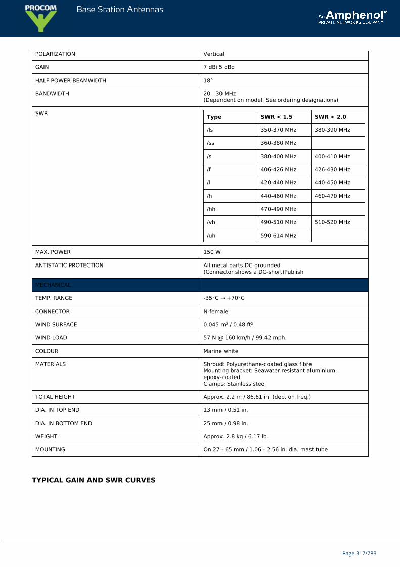
Base Station Antennas
POLARIZATION Vertical
GAIN 7 dBi 5 dBd
HALF POWER BEAMWIDTH 18°
BANDWIDTH 20 - 30 MHz(Dependent on model. See ordering designations)
SWR Type SWR < 1.5 SWR < 2.0
/ls 350-370 MHz 380-390 MHz
/ss 360-380 MHz
/s 380-400 MHz 400-410 MHz
/f 406-426 MHz 426-430 MHz
/l 420-440 MHz 440-450 MHz
/h 440-460 MHz 460-470 MHz
/hh 470-490 MHz
/vh 490-510 MHz 510-520 MHz
/uh 590-614 MHz
MAX. POWER 150 W
ANTISTATIC PROTECTION All metal parts DC-grounded(Connector shows a DC-short)Publish
MECHANICAL
TEMP. RANGE -35°C → +70°C
CONNECTOR N-female
WIND SURFACE 0.045 m² / 0.48 ft²
WIND LOAD 57 N @ 160 km/h / 99.42 mph.
COLOUR Marine white
MATERIALS Shroud: Polyurethane-coated glass fibreMounting bracket: Seawater resistant aluminium,epoxy-coatedClamps: Stainless steel
TOTAL HEIGHT Approx. 2.2 m / 86.61 in. (dep. on freq.)
DIA. IN TOP END 13 mm / 0.51 in.
DIA. IN BOTTOM END 25 mm / 0.98 in.
WEIGHT Approx. 2.8 kg / 6.17 lb.
MOUNTING On 27 - 65 mm / 1.06 - 2.56 in. dia. mast tube
TYPICAL GAIN AND SWR CURVES
Page 317/783
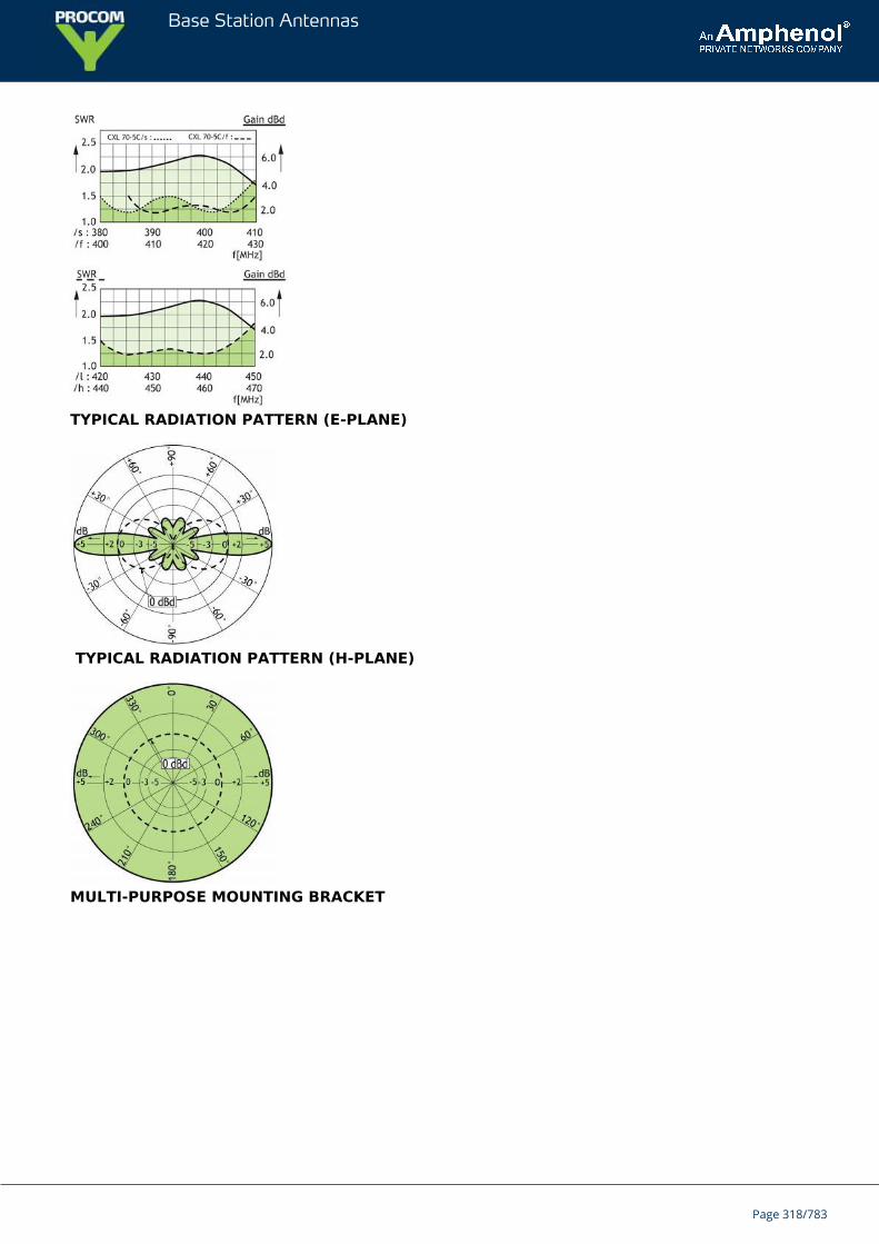
Base Station Antennas
TYPICAL RADIATION PATTERN (E-PLANE)
TYPICAL RADIATION PATTERN (H-PLANE)
MULTI-PURPOSE MOUNTING BRACKET
Page 318/783

Base Station Antennas
Page 319/783
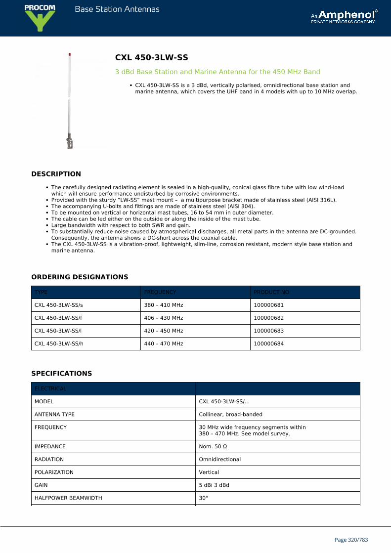
Base Station Antennas
CXL 450-3LW-SS3 dBd Base Station and Marine Antenna for the 450 MHz Band
CXL 450-3LW-SS is a 3 dBd, vertically polarised, omnidirectional base station andmarine antenna, which covers the UHF band in 4 models with up to 10 MHz overlap.
DESCRIPTION
The carefully designed radiating element is sealed in a high-quality, conical glass fibre tube with low wind-loadwhich will ensure performance undisturbed by corrosive environments.Provided with the sturdy “LW-SS” mast mount – a multipurpose bracket made of stainless steel (AISI 316L).The accompanying U-bolts and fittings are made of stainless steel (AISI 304).To be mounted on vertical or horizontal mast tubes, 16 to 54 mm in outer diameter.The cable can be led either on the outside or along the inside of the mast tube.Large bandwidth with respect to both SWR and gain.To substantially reduce noise caused by atmospherical discharges, all metal parts in the antenna are DC-grounded.Consequently, the antenna shows a DC-short across the coaxial cable.The CXL 450-3LW-SS is a vibration-proof, lightweight, slim-line, corrosion resistant, modern style base station andmarine antenna.
ORDERING DESIGNATIONS
TYPE FREQUENCY PRODUCT NO
CXL 450-3LW-SS/s 380 – 410 MHz 100000681
CXL 450-3LW-SS/f 406 – 430 MHz 100000682
CXL 450-3LW-SS/l 420 – 450 MHz 100000683
CXL 450-3LW-SS/h 440 – 470 MHz 100000684
SPECIFICATIONS
ELECTRICAL
MODEL CXL 450-3LW-SS/...
ANTENNA TYPE Collinear, broad-banded
FREQUENCY 30 MHz wide frequency segments within380 – 470 MHz. See model survey.
IMPEDANCE Nom. 50 Ω
RADIATION Omnidirectional
POLARIZATION Vertical
GAIN 5 dBi 3 dBd
HALFPOWER BEAMWIDTH 30°
Page 320/783
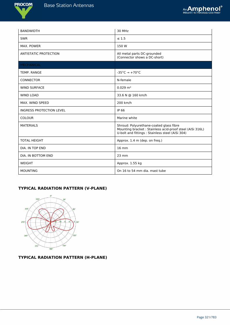
Base Station Antennas
BANDWIDTH 30 MHz
SWR ≤ 1.5
MAX. POWER 150 W
ANTISTATIC PROTECTION All metal parts DC-grounded(Connector shows a DC-short)
MECHANICAL
TEMP. RANGE -35°C → +70°C
CONNECTOR N-female
WIND SURFACE 0.029 m²
WIND LOAD 33.6 N @ 160 km/h
MAX. WIND SPEED 200 km/h
INGRESS PROTECTION LEVEL IP 66
COLOUR Marine white
MATERIALS Shroud: Polyurethane-coated glass fibreMounting bracket : Stainless acid-proof steel (AiSi 316L)U-bolt and fittings : Stainless steel (AiSi 304)
TOTAL HEIGHT Approx. 1.4 m (dep. on freq.)
DIA. IN TOP END 16 mm
DIA. IN BOTTOM END 23 mm
WEIGHT Approx. 1.55 kg
MOUNTING On 16 to 54 mm dia. mast tube
TYPICAL RADIATION PATTERN (V-PLANE)
TYPICAL RADIATION PATTERN (H-PLANE)
Page 321/783
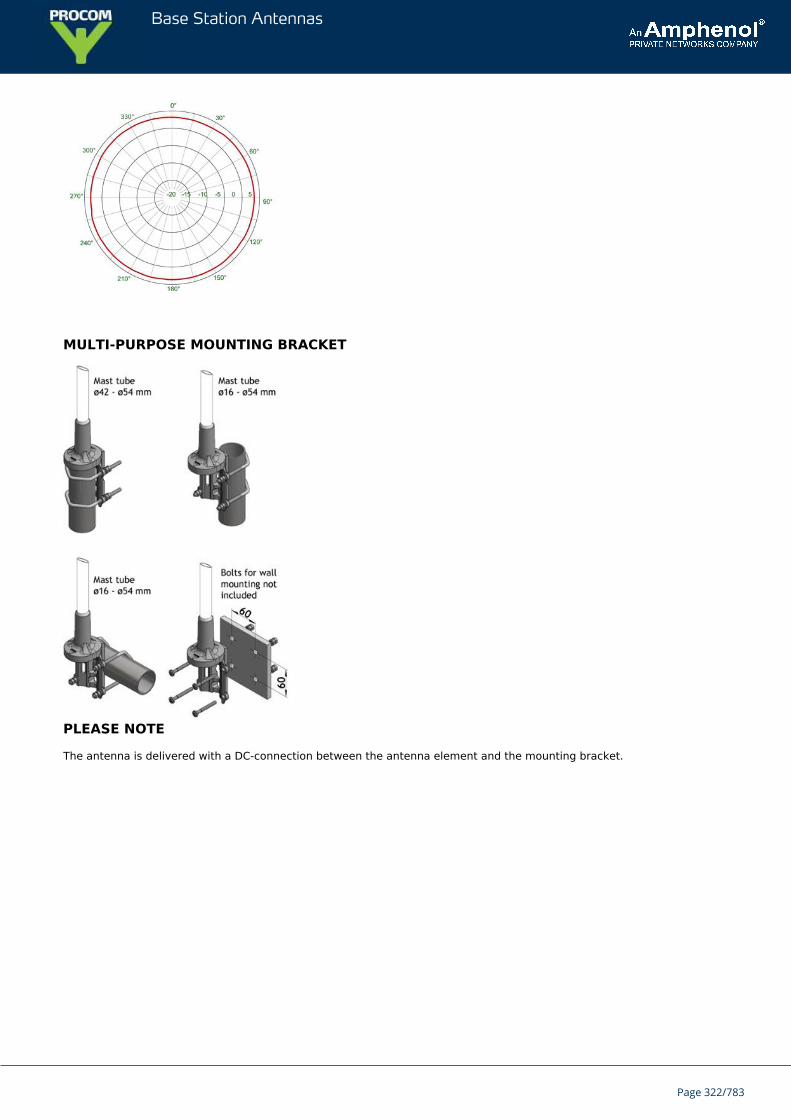
Base Station Antennas
MULTI-PURPOSE MOUNTING BRACKET
PLEASE NOTE
The antenna is delivered with a DC-connection between the antenna element and the mounting bracket.
Page 322/783
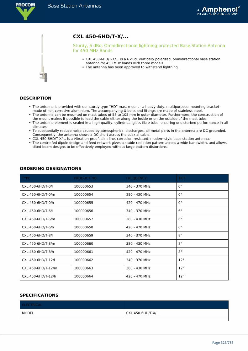
Base Station Antennas
CXL 450-6HD/T-X/...Sturdy, 6 dBd, Omnidirectional lightning protected Base Station Antennafor 450 MHz Bands
CXL 450-6HD/T-X/… is a 6 dBd, vertically polarized, omnidirectional base stationantenna for 450 MHz bands with three models.The antenna has been approved to withstand lightning.
DESCRIPTION
The antenna is provided with our sturdy type “HD” mast mount - a heavy-duty, multipurpose mounting bracketmade of non-corrosive aluminium. The accompanying U-bolts and fittings are made of stainless steel.The antenna can be mounted on mast tubes of 58 to 105 mm in outer diameter. Furthermore, the construction ofthe mount makes it possible to lead the cable either along the inside or on the outside of the mast tube.The antenna element is sealed in a high-quality, cylindrical glass fibre tube, ensuring undisturbed performance in allclimates.To substantially reduce noise caused by atmospherical discharges, all metal parts in the antenna are DC-grounded.Consequently, the antenna shows a DC-short across the coaxial cable.CXL 450-6HD/T-X/… is a vibration-proof, slim-line, corrosion-resistant, modern style base station antenna.The centre fed dipole design and feed network gives a stable radiation pattern across a wide bandwidth, and allowstilted beam designs to be effectively employed without large pattern distortions.
ORDERING DESIGNATIONS
TYPE PRODUCT NO. FREQUENCY TILT
CXL 450-6HD/T-0/l 100000653 340 - 370 MHz 0°
CXL 450-6HD/T-0/m 100000654 380 - 430 MHz 0°
CXL 450-6HD/T-0/h 100000655 420 - 470 MHz 0°
CXL 450-6HD/T-6/l 100000656 340 - 370 MHz 6°
CXL 450-6HD/T-6/m 100000657 380 - 430 MHz 6°
CXL 450-6HD/T-6/h 100000658 420 - 470 MHz 6°
CXL 450-6HD/T-8/l 100000659 340 - 370 MHz 8°
CXL 450-6HD/T-8/m 100000660 380 - 430 MHz 8°
CXL 450-6HD/T-8/h 100000661 420 - 470 MHz 8°
CXL 450-6HD/T-12/l 100000662 340 - 370 MHz 12°
CXL 450-6HD/T-12/m 100000663 380 - 430 MHz 12°
CXL 450-6HD/T-12/h 100000664 420 - 470 MHz 12°
SPECIFICATIONS
ELECTRICAL
MODEL CXL 450-6HD/T-X/...
Page 323/783
Base Station Antennas
ANTENNA TYPE Medium-gain collinear
FREQUENCY 340 - 470 MHz
IMPEDANCE Nom. 50 Ω
RADIATION Omnidirectional
POLARIZATION Vertical
GAIN 8 dBi 6 dBd
HALF POWER BEAMWIDTH 16°
SWR ≤ 1.5
MAX. POWER 300 W
ANTISTATIC PROTECTION All metal parts DC-grounded(Connector shows a DC-short)
AVAILABLE BEAMTILTS 0, 6, 8 and 12°
PIM -153 dBc @ 2x43 dBm
MECHANICAL
TEMP. RANGE -30°C to +70°C
CONNECTOR 7/16 DIN female
WIND SURFACE 0.166 m²
WIND LOAD 236.7 N @ 160 km/h
WIND VELOCITY Tested to 200 km/h
COLOUR Marine white
MATERIALS Radome: Polyurethane-coated glass fibreMounting bracket: Seawater resistant aluminium, polyester-coated
TOTAL HEIGHT Approx. 2.92 m, 115 Inch
WEIGHT Approx. 8.5 kg, 19 Ib
MOUNTING On 58 - 105 mm dia. mast tube
MULTI-PURPOSE MOUNTING BRACKET
Page 324/783

Base Station Antennas
Page 325/783
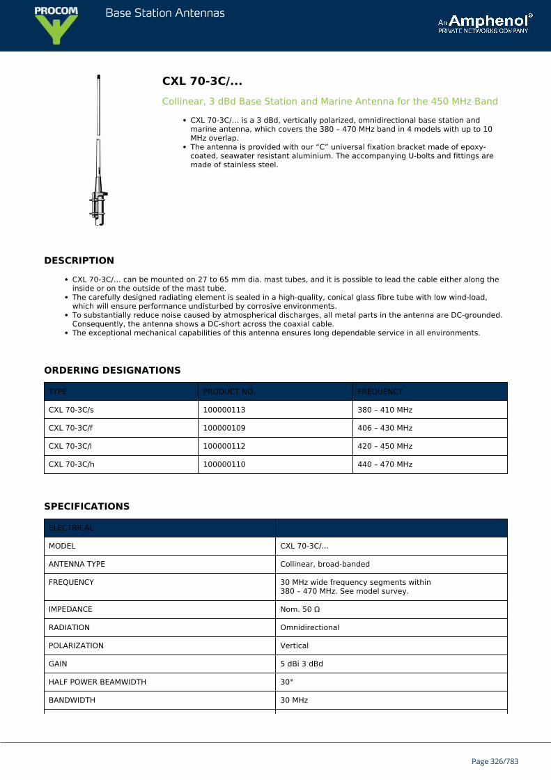
Base Station Antennas
CXL 70-3C/...Collinear, 3 dBd Base Station and Marine Antenna for the 450 MHz Band
CXL 70-3C/… is a 3 dBd, vertically polarized, omnidirectional base station andmarine antenna, which covers the 380 – 470 MHz band in 4 models with up to 10MHz overlap.The antenna is provided with our “C” universal fixation bracket made of epoxy-coated, seawater resistant aluminium. The accompanying U-bolts and fittings aremade of stainless steel.
DESCRIPTION
CXL 70-3C/… can be mounted on 27 to 65 mm dia. mast tubes, and it is possible to lead the cable either along theinside or on the outside of the mast tube.The carefully designed radiating element is sealed in a high-quality, conical glass fibre tube with low wind-load,which will ensure performance undisturbed by corrosive environments.To substantially reduce noise caused by atmospherical discharges, all metal parts in the antenna are DC-grounded.Consequently, the antenna shows a DC-short across the coaxial cable.The exceptional mechanical capabilities of this antenna ensures long dependable service in all environments.
ORDERING DESIGNATIONS
TYPE PRODUCT NO. FREQUENCY
CXL 70-3C/s 100000113 380 – 410 MHz
CXL 70-3C/f 100000109 406 – 430 MHz
CXL 70-3C/l 100000112 420 – 450 MHz
CXL 70-3C/h 100000110 440 – 470 MHz
SPECIFICATIONS
ELECTRICAL
MODEL CXL 70-3C/...
ANTENNA TYPE Collinear, broad-banded
FREQUENCY 30 MHz wide frequency segments within380 – 470 MHz. See model survey.
IMPEDANCE Nom. 50 Ω
RADIATION Omnidirectional
POLARIZATION Vertical
GAIN 5 dBi 3 dBd
HALF POWER BEAMWIDTH 30°
BANDWIDTH 30 MHz
Page 326/783
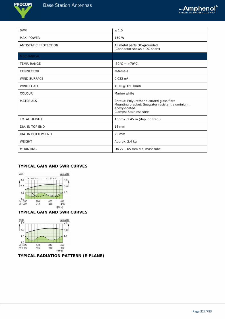
Base Station Antennas
SWR ≤ 1.5
MAX. POWER 150 W
ANTISTATIC PROTECTION All metal parts DC-grounded(Connector shows a DC-short)
MECHANICAL
TEMP. RANGE -30°C → +70°C
CONNECTOR N-female
WIND SURFACE 0.032 m²
WIND LOAD 40 N @ 160 km/h
COLOUR Marine white
MATERIALS Shroud: Polyurethane-coated glass fibreMounting bracket: Seawater resistant aluminium,epoxy-coatedClamps: Stainless steel
TOTAL HEIGHT Approx. 1.45 m (dep. on freq.)
DIA. IN TOP END 16 mm
DIA. IN BOTTOM END 25 mm
WEIGHT Approx. 2.4 kg
MOUNTING On 27 – 65 mm dia. mast tube
TYPICAL GAIN AND SWR CURVES
TYPICAL GAIN AND SWR CURVES
TYPICAL RADIATION PATTERN (E-PLANE)
Page 327/783
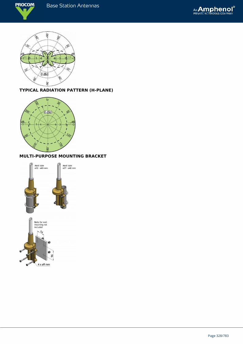
Base Station Antennas
TYPICAL RADIATION PATTERN (H-PLANE)
MULTI-PURPOSE MOUNTING BRACKET
Page 328/783
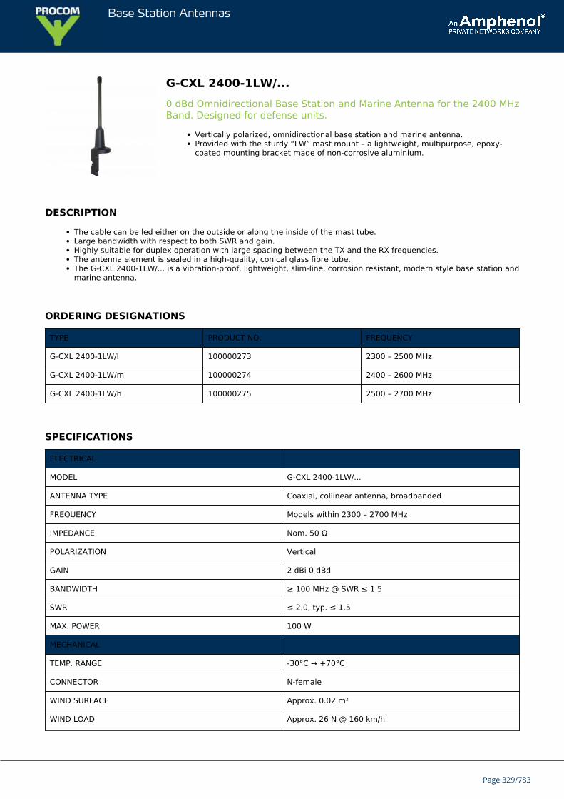
Base Station Antennas
G-CXL 2400-1LW/...0 dBd Omnidirectional Base Station and Marine Antenna for the 2400 MHzBand. Designed for defense units.
Vertically polarized, omnidirectional base station and marine antenna.Provided with the sturdy “LW” mast mount – a lightweight, multipurpose, epoxy-coated mounting bracket made of non-corrosive aluminium.
DESCRIPTION
The cable can be led either on the outside or along the inside of the mast tube.Large bandwidth with respect to both SWR and gain.Highly suitable for duplex operation with large spacing between the TX and the RX frequencies.The antenna element is sealed in a high-quality, conical glass fibre tube.The G-CXL 2400-1LW/... is a vibration-proof, lightweight, slim-line, corrosion resistant, modern style base station andmarine antenna.
ORDERING DESIGNATIONS
TYPE PRODUCT NO. FREQUENCY
G-CXL 2400-1LW/l 100000273 2300 – 2500 MHz
G-CXL 2400-1LW/m 100000274 2400 – 2600 MHz
G-CXL 2400-1LW/h 100000275 2500 – 2700 MHz
SPECIFICATIONS
ELECTRICAL
MODEL G-CXL 2400-1LW/...
ANTENNA TYPE Coaxial, collinear antenna, broadbanded
FREQUENCY Models within 2300 – 2700 MHz
IMPEDANCE Nom. 50 Ω
POLARIZATION Vertical
GAIN 2 dBi 0 dBd
BANDWIDTH ≥ 100 MHz @ SWR ≤ 1.5
SWR ≤ 2.0, typ. ≤ 1.5
MAX. POWER 100 W
MECHANICAL
TEMP. RANGE -30°C → +70°C
CONNECTOR N-female
WIND SURFACE Approx. 0.02 m²
WIND LOAD Approx. 26 N @ 160 km/h
Page 329/783
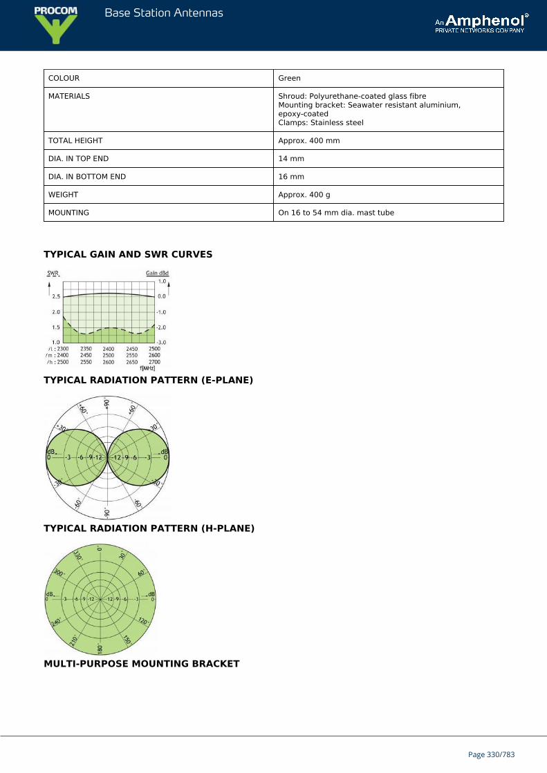
Base Station Antennas
COLOUR Green
MATERIALS Shroud: Polyurethane-coated glass fibreMounting bracket: Seawater resistant aluminium,epoxy-coatedClamps: Stainless steel
TOTAL HEIGHT Approx. 400 mm
DIA. IN TOP END 14 mm
DIA. IN BOTTOM END 16 mm
WEIGHT Approx. 400 g
MOUNTING On 16 to 54 mm dia. mast tube
TYPICAL GAIN AND SWR CURVES
TYPICAL RADIATION PATTERN (E-PLANE)
TYPICAL RADIATION PATTERN (H-PLANE)
MULTI-PURPOSE MOUNTING BRACKET
Page 330/783

Base Station Antennas
PLEASE NOTE
The antenna is delivered with a DC-connection between the antenna element and the mounting bracket.
Page 331/783
Base Station Antennas
G-CXL 225-450CUnity Gain, Broad-Banded Base Station Antenna for 225 – 450 MHz.Designed for defense units.
G-CXL 225-450C is a 0 dBd gain, omnidirectional base station antenna.The antenna is extremely broad-banded and covers the complete band:225 – 450 MHz.
DESCRIPTION
G-CXL 225-450C is designed for fixation on supporting tubes with outer diameter between 27 mm and 65 mm.The construction of the mount makes it possible to lead the cable either inside or along the outside of the masttube.A glass fibre tube completely encloses the carefully designed radiating element to ensure long dependable servicein all climates.Atmospherical discharges are immediately led to ground as all metal parts are DC-grounded (consequently, theantenna shows a DC-short across the coaxial cable).This antenna is used where reliability is of utmost importance. A long lifetime has been taken into considerationwhen designing this antenna – it is sturdy and strong.
ORDERING DESIGNATIONS
TYPE PRODUCT NO.
G-CXL 225-450C 100000268
SPECIFICATIONS
ELECTRICAL
MODEL G-CXL 225-450C
ANTENNA TYPE Coaxial, broad-band dipole
FREQUENCY Covering: 225 – 450 MHz
IMPEDANCE Nom. 50 Ω
RADIATION Omnidirectional
POLARIZATION Vertical
GAIN 0 dBd (see curve)
BANDWIDTH 225 MHz
SWR ≤ 2.5, typ. ≤ 2.0
MAX. POWER 200 W
ANTISTATIC PROTECTION All metal parts DC-grounded(Connector shows a DC-short)
MECHANICAL
TEMP. RANGE –30° C → +70° C
Page 332/783
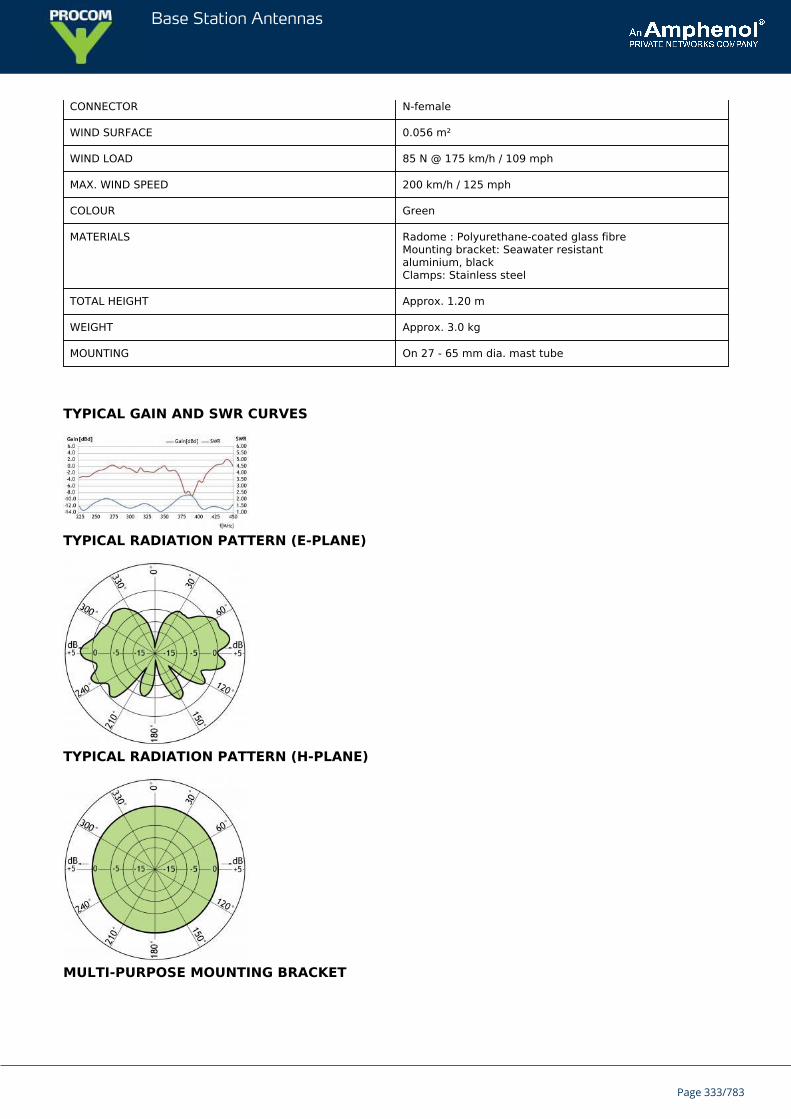
Base Station Antennas
CONNECTOR N-female
WIND SURFACE 0.056 m²
WIND LOAD 85 N @ 175 km/h / 109 mph
MAX. WIND SPEED 200 km/h / 125 mph
COLOUR Green
MATERIALS Radome : Polyurethane-coated glass fibreMounting bracket: Seawater resistantaluminium, blackClamps: Stainless steel
TOTAL HEIGHT Approx. 1.20 m
WEIGHT Approx. 3.0 kg
MOUNTING On 27 - 65 mm dia. mast tube
TYPICAL GAIN AND SWR CURVES
TYPICAL RADIATION PATTERN (E-PLANE)
TYPICAL RADIATION PATTERN (H-PLANE)
MULTI-PURPOSE MOUNTING BRACKET
Page 333/783
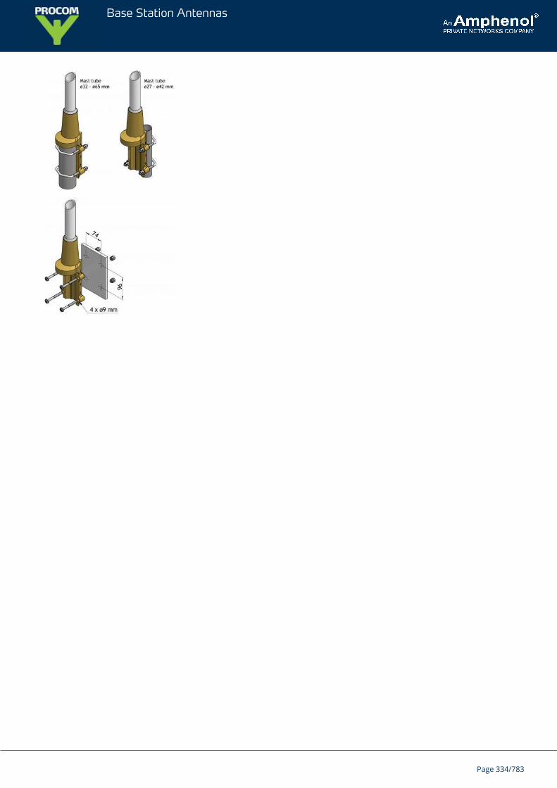
Base Station Antennas
Page 334/783
Base Station Antennas
CXL 70-3/GPS 4/...Dual Band Antenna for the UHF Band and GPS
This active antenna has been designed for use on the TETRA band and GPS.The antenna consists of a high-performance 3 dBd glass fibre- encapsulated antennaelement and an active GPS antenna. The latter is built into the bottom part of theantenna together with a diplex filter. Only one down lead cable is thereforenecessary.
DESCRIPTION
The antenna element is a colinear antenna for the UHF band frequency range within 380 - 430 MHz.The GPS antenna has a full hemispherical coverage and a built-in high-gain, low-noise amplifier.The necessary supply voltage (5 V DC) for the amplifier is delivered through the down lead coaxial cable. Up to 30m of RG 214/U coaxial cable can be used between the antenna and the receiver/transceiver.By careful choice of materials, the CXL 70-3/GPS 4/... is designed to withstand the roughest of climate conditions,ensuring many years of trouble-free service.
ORDERING DESIGNATIONS
TYPE PRODUCT NO. FREQUENCY
CXL 70-3/GPS 4/TETRA-l 112000052 380 - 400 MHz
CXL 70-3/GPS 4/TETRA-h 112000053 410 - 430 MHz
ACCESSORIES PRODUCT NO. FREQUENCY
DIPX 1000/1550-DC-H 200000749
PRO-DIPX 1000/1550-DC-H HP 200001998
SPECIFICATIONS
ELECTRICAL UHF
MODEL CXL 70-3/GPS 4/...
ANTENNA TYPE Collinear antenna element
FREQUENCY 380 - 400 MHz, 410 - 430 MHzand other frequencies on request
BANDWITH 14 - 20 MHz dependent on model
IMPEDANCE Nom. 50 Ω
POLARIZATION Vertical
GAIN Approx. 5.2 dBi 3 dBd
SWR Typ. < 2.0
MAX. POWER 25 W
Page 335/783
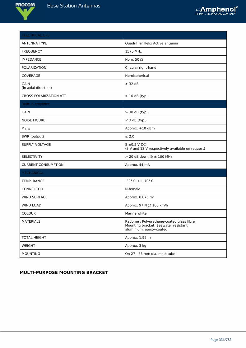
Base Station Antennas
ELECTRICAL GPS
ANTENNA TYPE Quadrifilar Helix Active antenna
FREQUENCY 1575 MHz
IMPEDANCE Nom. 50 Ω
POLARIZATION Circular right-hand
COVERAGE Hemispherical
GAIN(in axial direction)
> 32 dBi
CROSS POLARIZATION ATT > 10 dB (typ.)
Built-in Amplifier
GAIN > 30 dB (typ.)
NOISE FIGURE < 3 dB (typ.)
P 1 dB Approx. +10 dBm
SWR (output) ≤ 2.0
SUPPLY VOLTAGE 5 ±0.5 V DC(3 V and 12 V respectively available on request)
SELECTIVITY > 20 dB down @ ± 100 MHz
CURRENT CONSUMPTION Approx. 44 mA
MECHANICAL
TEMP. RANGE -30° C → + 70° C
CONNECTOR N-female
WIND SURFACE Approx. 0.076 m²
WIND LOAD Approx. 97 N @ 160 km/h
COLOUR Marine white
MATERIALS Radome : Polyurethane-coated glass fibreMounting bracket: Seawater resistantaluminium, epoxy-coated
TOTAL HEIGHT Approx. 1.95 m
WEIGHT Approx. 3 kg
MOUNTING On 27 - 65 mm dia. mast tube
MULTI-PURPOSE MOUNTING BRACKET
Page 336/783
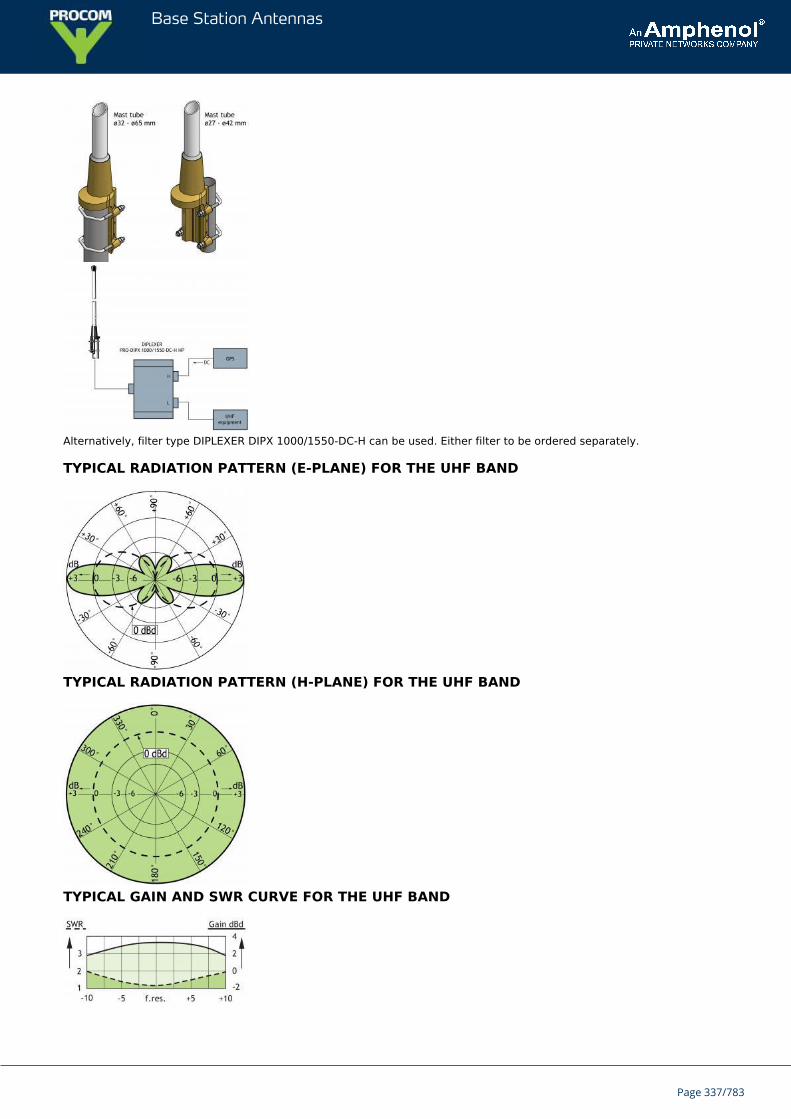
Base Station Antennas
Alternatively, filter type DIPLEXER DIPX 1000/1550-DC-H can be used. Either filter to be ordered separately.
TYPICAL RADIATION PATTERN (E-PLANE) FOR THE UHF BAND
TYPICAL RADIATION PATTERN (H-PLANE) FOR THE UHF BAND
TYPICAL GAIN AND SWR CURVE FOR THE UHF BAND
Page 337/783
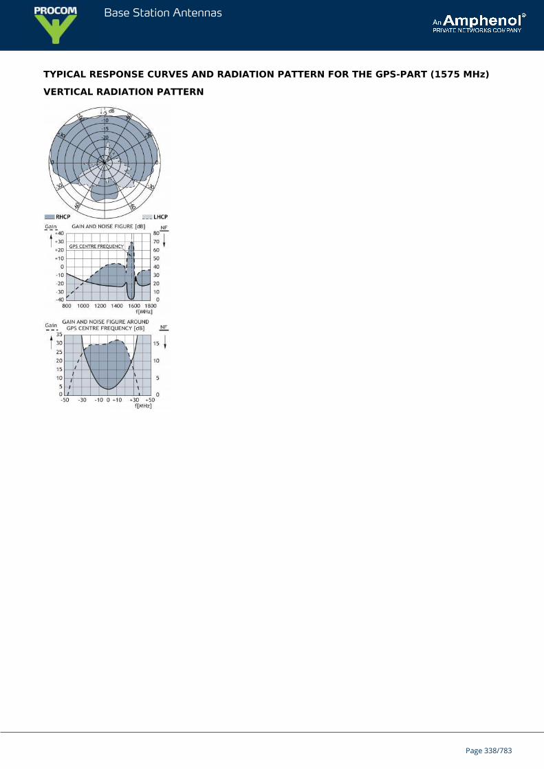
Base Station Antennas
TYPICAL RESPONSE CURVES AND RADIATION PATTERN FOR THE GPS-PART (1575 MHz)
VERTICAL RADIATION PATTERN
Page 338/783
Base Station Antennas
G-CXL 2-2CUniversal, Unity-Gain Base Station and Marine Antenna for the 160 MHzBand. Designed for defense units.
G-CXL 2-2C is a 0 dBd gain, omnidirectional base station antenna.The antenna covers the complete band: 144 - 175 MHz.G-CXL 2-2C is designed for fixation on supporting tubes with outer diameterbetween 27 mm and 65 mm.
DESCRIPTION
The construction of the mount makes it possible to lead the cable either inside or along the outside of the masttube.A glass fibre tube completely encloses the carefully designed radiating element to ensure long dependable servicein all climates.Atmospherical discharges are immediately led to ground as all metal parts are DC-grounded (consequently, theantenna shows a DC-short across the coaxial cable).This antenna is used where reliability is of utmost importance. A long lifetime has been taken into considerationwhen designing this antenna – it is sturdy and strong.
ORDERING DESIGNATIONS
TYPE PRODUCT NO.
G-CXL 2-2C 100000267
SPECIFICATIONS
ELECTRICAL
MODEL G-CXL 2-2C
ANTENNA TYPE Coaxial, broad-band dipole
FREQUENCY Covering: 144 - 175 MHz
IMPEDANCE Nom. 50 Ω
RADIATION Omnidirectional
POLARIZATION Vertical
GAIN 2 dBi 0 dBd
BANDWIDTH 31 MHz
SWR ≤ 1.5
MAX. POWER 600 W
ANTISTATIC PROTECTION All metal parts DC-grounded(Connector shows a DC-short)
MECHANICAL
CONNECTOR N-female
WIND SURFACE 0.091 m²
Page 339/783
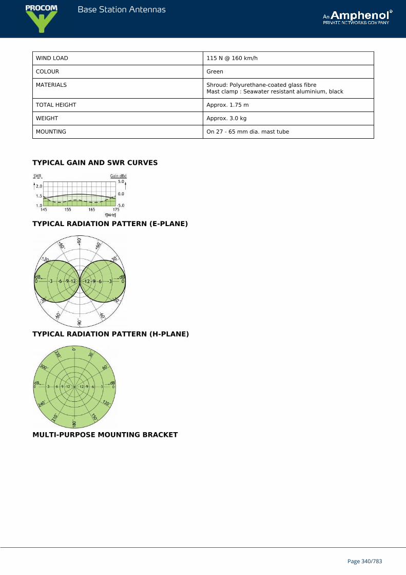
Base Station Antennas
WIND LOAD 115 N @ 160 km/h
COLOUR Green
MATERIALS Shroud: Polyurethane-coated glass fibreMast clamp : Seawater resistant aluminium, black
TOTAL HEIGHT Approx. 1.75 m
WEIGHT Approx. 3.0 kg
MOUNTING On 27 - 65 mm dia. mast tube
TYPICAL GAIN AND SWR CURVES
TYPICAL RADIATION PATTERN (E-PLANE)
TYPICAL RADIATION PATTERN (H-PLANE)
MULTI-PURPOSE MOUNTING BRACKET
Page 340/783
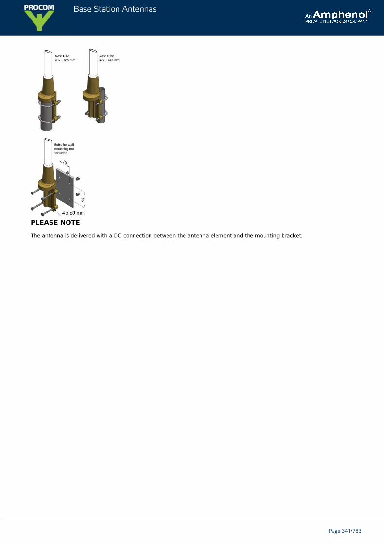
Base Station Antennas
PLEASE NOTE
The antenna is delivered with a DC-connection between the antenna element and the mounting bracket.
Page 341/783
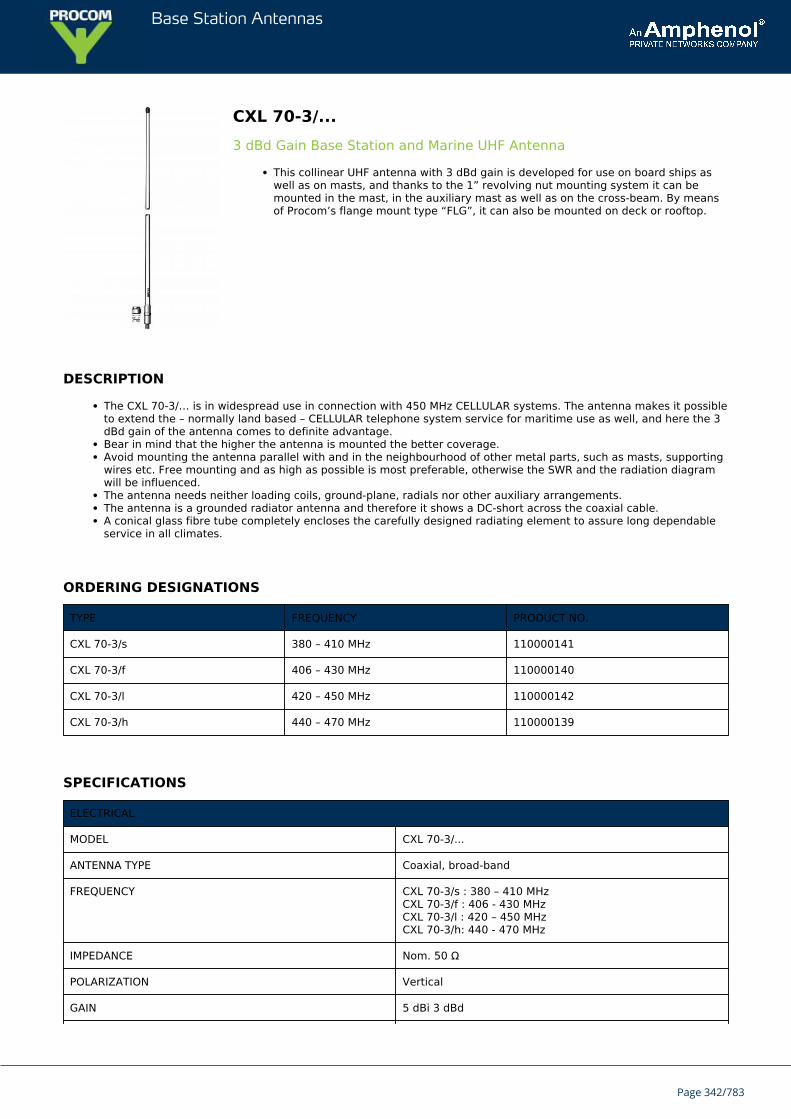
Base Station Antennas
CXL 70-3/...3 dBd Gain Base Station and Marine UHF Antenna
This collinear UHF antenna with 3 dBd gain is developed for use on board ships aswell as on masts, and thanks to the 1” revolving nut mounting system it can bemounted in the mast, in the auxiliary mast as well as on the cross-beam. By meansof Procom’s flange mount type “FLG”, it can also be mounted on deck or rooftop.
DESCRIPTION
The CXL 70-3/… is in widespread use in connection with 450 MHz CELLULAR systems. The antenna makes it possibleto extend the – normally land based – CELLULAR telephone system service for maritime use as well, and here the 3dBd gain of the antenna comes to definite advantage.Bear in mind that the higher the antenna is mounted the better coverage.Avoid mounting the antenna parallel with and in the neighbourhood of other metal parts, such as masts, supportingwires etc. Free mounting and as high as possible is most preferable, otherwise the SWR and the radiation diagramwill be influenced.The antenna needs neither loading coils, ground-plane, radials nor other auxiliary arrangements.The antenna is a grounded radiator antenna and therefore it shows a DC-short across the coaxial cable.A conical glass fibre tube completely encloses the carefully designed radiating element to assure long dependableservice in all climates.
ORDERING DESIGNATIONS
TYPE FREQUENCY PRODUCT NO.
CXL 70-3/s 380 – 410 MHz 110000141
CXL 70-3/f 406 – 430 MHz 110000140
CXL 70-3/l 420 – 450 MHz 110000142
CXL 70-3/h 440 – 470 MHz 110000139
SPECIFICATIONS
ELECTRICAL
MODEL CXL 70-3/...
ANTENNA TYPE Coaxial, broad-band
FREQUENCY CXL 70-3/s : 380 – 410 MHzCXL 70-3/f : 406 - 430 MHzCXL 70-3/l : 420 – 450 MHzCXL 70-3/h: 440 - 470 MHz
IMPEDANCE Nom. 50 Ω
POLARIZATION Vertical
GAIN 5 dBi 3 dBd
Page 342/783
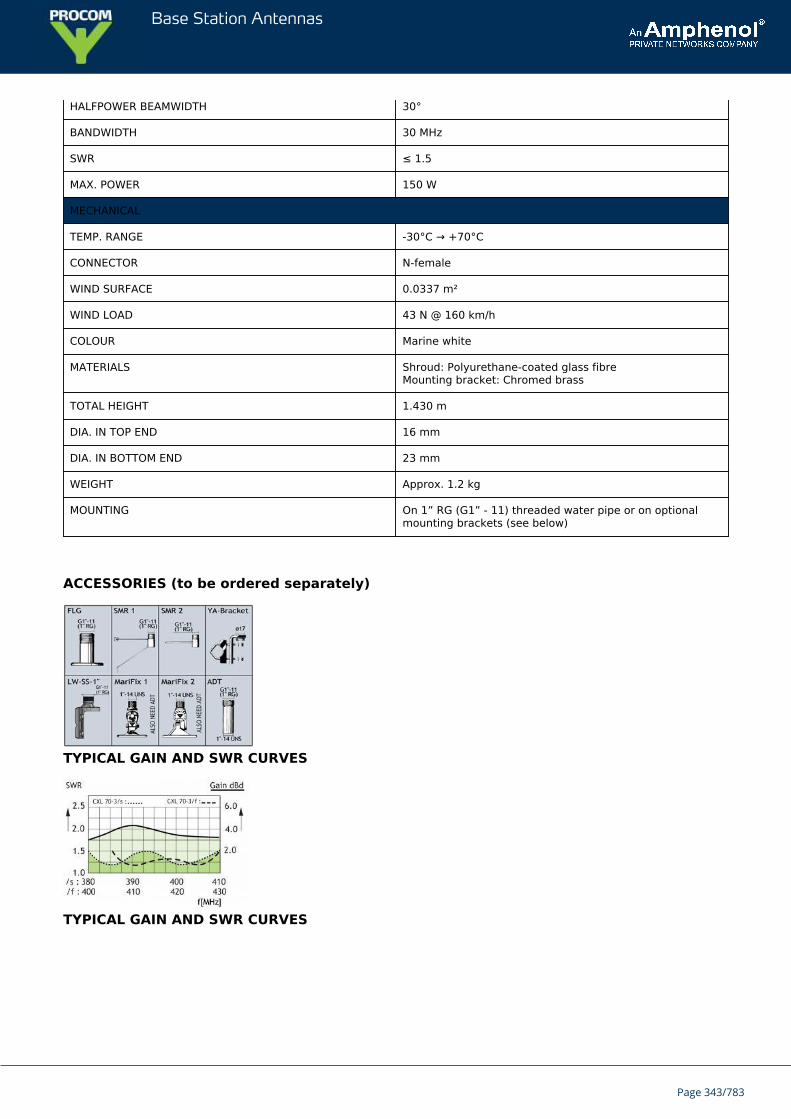
Base Station Antennas
HALFPOWER BEAMWIDTH 30°
BANDWIDTH 30 MHz
SWR ≤ 1.5
MAX. POWER 150 W
MECHANICAL
TEMP. RANGE -30°C → +70°C
CONNECTOR N-female
WIND SURFACE 0.0337 m²
WIND LOAD 43 N @ 160 km/h
COLOUR Marine white
MATERIALS Shroud: Polyurethane-coated glass fibreMounting bracket: Chromed brass
TOTAL HEIGHT 1.430 m
DIA. IN TOP END 16 mm
DIA. IN BOTTOM END 23 mm
WEIGHT Approx. 1.2 kg
MOUNTING On 1” RG (G1” - 11) threaded water pipe or on optionalmounting brackets (see below)
ACCESSORIES (to be ordered separately)
TYPICAL GAIN AND SWR CURVES
TYPICAL GAIN AND SWR CURVES
Page 343/783
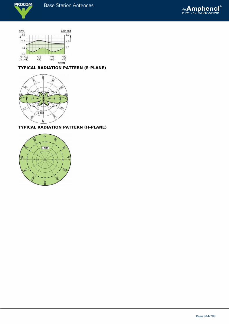
Base Station Antennas
TYPICAL RADIATION PATTERN (E-PLANE)
TYPICAL RADIATION PATTERN (H-PLANE)
Page 344/783
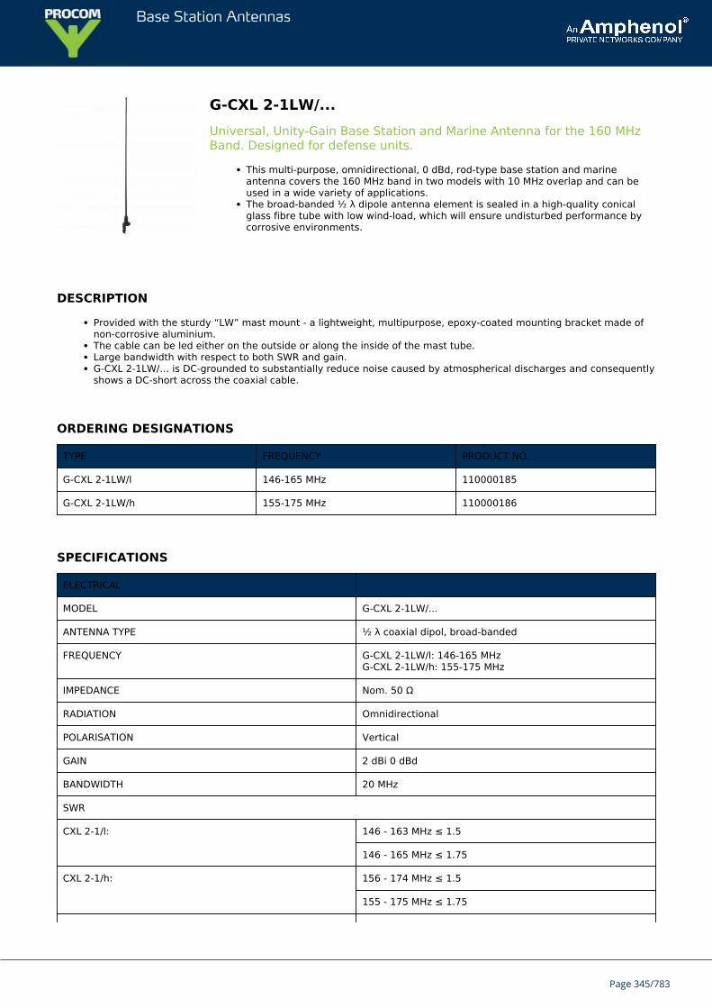
Base Station Antennas
G-CXL 2-1LW/...Universal, Unity-Gain Base Station and Marine Antenna for the 160 MHzBand. Designed for defense units.
This multi-purpose, omnidirectional, 0 dBd, rod-type base station and marineantenna covers the 160 MHz band in two models with 10 MHz overlap and can beused in a wide variety of applications.The broad-banded ½ λ dipole antenna element is sealed in a high-quality conicalglass fibre tube with low wind-load, which will ensure undisturbed performance bycorrosive environments.
DESCRIPTION
Provided with the sturdy “LW” mast mount - a lightweight, multipurpose, epoxy-coated mounting bracket made ofnon-corrosive aluminium.The cable can be led either on the outside or along the inside of the mast tube.Large bandwidth with respect to both SWR and gain.G-CXL 2-1LW/… is DC-grounded to substantially reduce noise caused by atmospherical discharges and consequentlyshows a DC-short across the coaxial cable.
ORDERING DESIGNATIONS
TYPE FREQUENCY PRODUCT NO.
G-CXL 2-1LW/l 146-165 MHz 110000185
G-CXL 2-1LW/h 155-175 MHz 110000186
SPECIFICATIONS
ELECTRICAL
MODEL G-CXL 2-1LW/...
ANTENNA TYPE ½ λ coaxial dipol, broad-banded
FREQUENCY G-CXL 2-1LW/l: 146-165 MHzG-CXL 2-1LW/h: 155-175 MHz
IMPEDANCE Nom. 50 Ω
RADIATION Omnidirectional
POLARISATION Vertical
GAIN 2 dBi 0 dBd
BANDWIDTH 20 MHz
SWR
CXL 2-1/l: 146 - 163 MHz ≤ 1.5
146 - 165 MHz ≤ 1.75
CXL 2-1/h: 156 - 174 MHz ≤ 1.5
155 - 175 MHz ≤ 1.75
Page 345/783
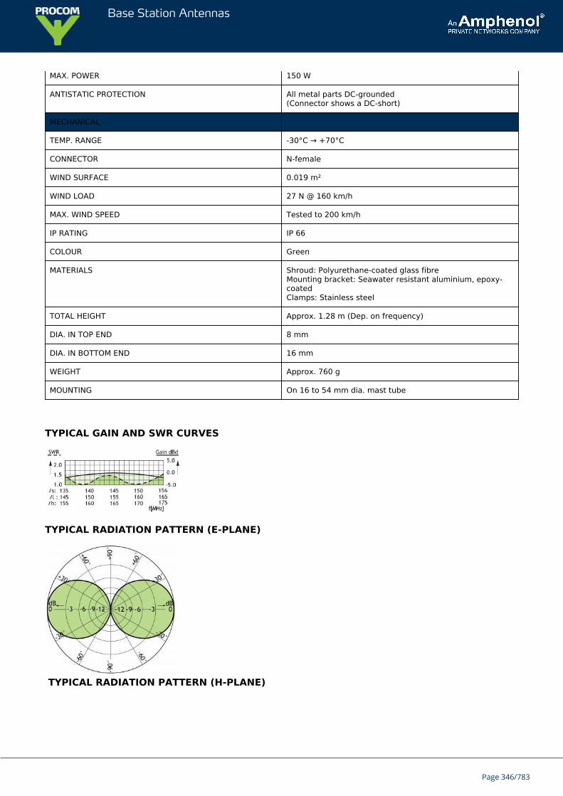
Base Station Antennas
MAX. POWER 150 W
ANTISTATIC PROTECTION All metal parts DC-grounded(Connector shows a DC-short)
MECHANICAL
TEMP. RANGE -30°C → +70°C
CONNECTOR N-female
WIND SURFACE 0.019 m²
WIND LOAD 27 N @ 160 km/h
MAX. WIND SPEED Tested to 200 km/h
IP RATING IP 66
COLOUR Green
MATERIALS Shroud: Polyurethane-coated glass fibreMounting bracket: Seawater resistant aluminium, epoxy-coatedClamps: Stainless steel
TOTAL HEIGHT Approx. 1.28 m (Dep. on frequency)
DIA. IN TOP END 8 mm
DIA. IN BOTTOM END 16 mm
WEIGHT Approx. 760 g
MOUNTING On 16 to 54 mm dia. mast tube
TYPICAL GAIN AND SWR CURVES
TYPICAL RADIATION PATTERN (E-PLANE)
TYPICAL RADIATION PATTERN (H-PLANE)
Page 346/783
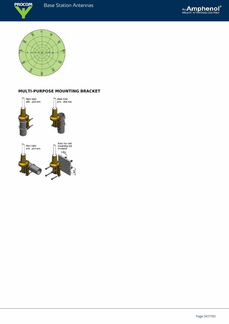
Base Station Antennas
MULTI-PURPOSE MOUNTING BRACKET
Page 347/783
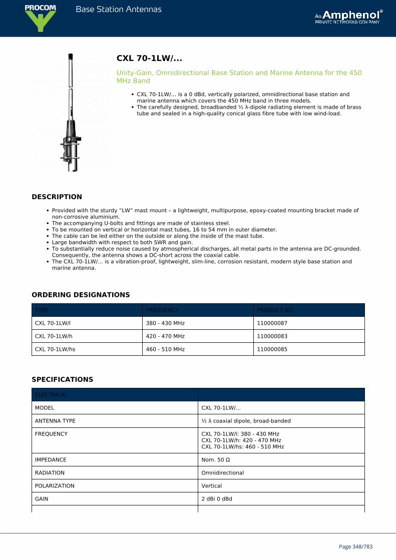
Base Station Antennas
CXL 70-1LW/...Unity-Gain, Omnidirectional Base Station and Marine Antenna for the 450MHz Band
CXL 70-1LW/… is a 0 dBd, vertically polarized, omnidirectional base station andmarine antenna which covers the 450 MHz band in three models.The carefully designed, broadbanded ½ λ-dipole radiating element is made of brasstube and sealed in a high-quality conical glass fibre tube with low wind-load.
DESCRIPTION
Provided with the sturdy “LW” mast mount – a lightweight, multipurpose, epoxy-coated mounting bracket made ofnon-corrosive aluminium.The accompanying U-bolts and fittings are made of stainless steel.To be mounted on vertical or horizontal mast tubes, 16 to 54 mm in outer diameter.The cable can be led either on the outside or along the inside of the mast tube.Large bandwidth with respect to both SWR and gain.To substantially reduce noise caused by atmospherical discharges, all metal parts in the antenna are DC-grounded.Consequently, the antenna shows a DC-short across the coaxial cable.The CXL 70-1LW/… is a vibration-proof, lightweight, slim-line, corrosion resistant, modern style base station andmarine antenna.
ORDERING DESIGNATIONS
TYPE FREQUENCY PRODUCT NO.
CXL 70-1LW/l 380 - 430 MHz 110000087
CXL 70-1LW/h 420 - 470 MHz 110000083
CXL 70-1LW/hs 460 - 510 MHz 110000085
SPECIFICATIONS
ELECTRICAL
MODEL CXL 70-1LW/...
ANTENNA TYPE ½ λ coaxial dipole, broad-banded
FREQUENCY CXL 70-1LW/l: 380 - 430 MHzCXL 70-1LW/h: 420 - 470 MHzCXL 70-1LW/hs: 460 - 510 MHz
IMPEDANCE Nom. 50 Ω
RADIATION Omnidirectional
POLARIZATION Vertical
GAIN 2 dBi 0 dBd
Page 348/783
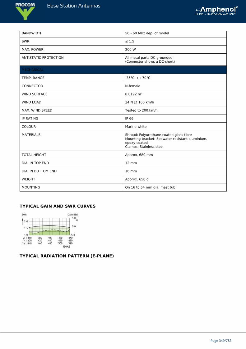
Base Station Antennas
BANDWIDTH 50 - 60 MHz dep. of model
SWR ≤ 1.5
MAX. POWER 200 W
ANTISTATIC PROTECTION All metal parts DC-grounded(Connector shows a DC-short)
MECHANICAL
TEMP. RANGE -35°C → +70°C
CONNECTOR N-female
WIND SURFACE 0.0192 m²
WIND LOAD 24 N @ 160 km/h
MAX. WIND SPEED Tested to 200 km/h
IP RATING IP 66
COLOUR Marine white
MATERIALS Shroud: Polyurethane-coated glass fibreMounting bracket: Seawater resistant aluminium,epoxy-coatedClamps: Stainless steel
TOTAL HEIGHT Approx. 680 mm
DIA. IN TOP END 12 mm
DIA. IN BOTTOM END 16 mm
WEIGHT Approx. 650 g
MOUNTING On 16 to 54 mm dia. mast tub
TYPICAL GAIN AND SWR CURVES
TYPICAL RADIATION PATTERN (E-PLANE)
Page 349/783
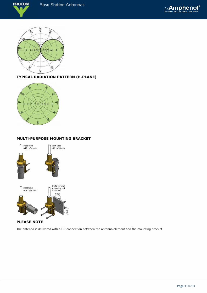
Base Station Antennas
TYPICAL RADIATION PATTERN (H-PLANE)
MULTI-PURPOSE MOUNTING BRACKET
PLEASE NOTE
The antenna is delivered with a DC-connection between the antenna element and the mounting bracket.
Page 350/783
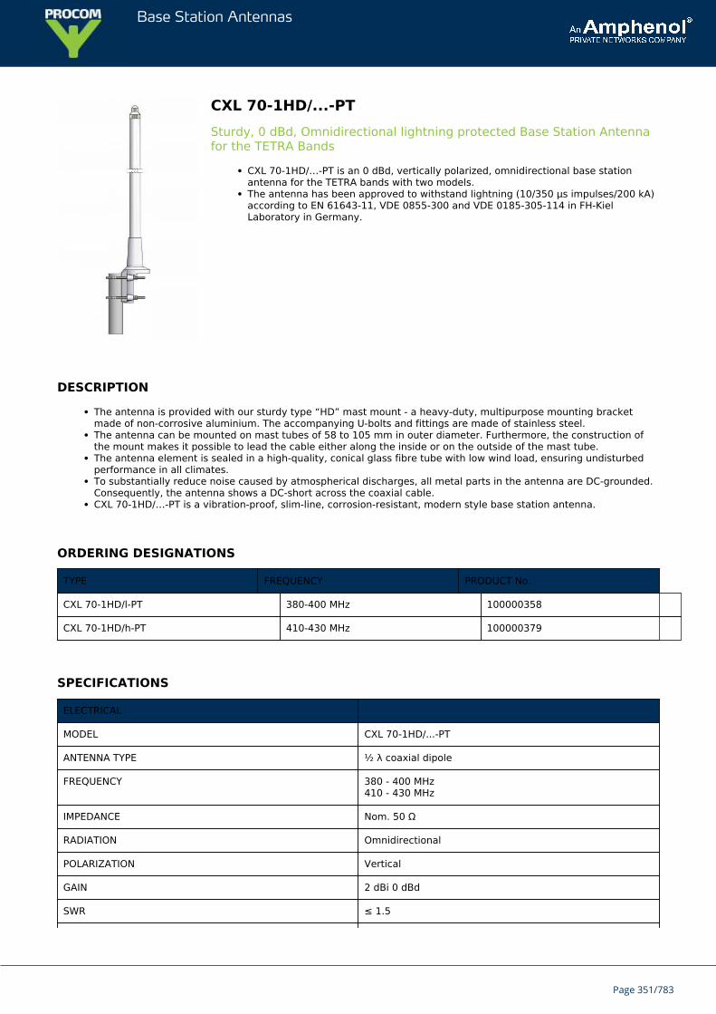
Base Station Antennas
CXL 70-1HD/...-PTSturdy, 0 dBd, Omnidirectional lightning protected Base Station Antennafor the TETRA Bands
CXL 70-1HD/…-PT is an 0 dBd, vertically polarized, omnidirectional base stationantenna for the TETRA bands with two models.The antenna has been approved to withstand lightning (10/350 μs impulses/200 kA)according to EN 61643-11, VDE 0855-300 and VDE 0185-305-114 in FH-KielLaboratory in Germany.
DESCRIPTION
The antenna is provided with our sturdy type “HD” mast mount - a heavy-duty, multipurpose mounting bracketmade of non-corrosive aluminium. The accompanying U-bolts and fittings are made of stainless steel.The antenna can be mounted on mast tubes of 58 to 105 mm in outer diameter. Furthermore, the construction ofthe mount makes it possible to lead the cable either along the inside or on the outside of the mast tube.The antenna element is sealed in a high-quality, conical glass fibre tube with low wind load, ensuring undisturbedperformance in all climates.To substantially reduce noise caused by atmospherical discharges, all metal parts in the antenna are DC-grounded.Consequently, the antenna shows a DC-short across the coaxial cable.CXL 70-1HD/…-PT is a vibration-proof, slim-line, corrosion-resistant, modern style base station antenna.
ORDERING DESIGNATIONS
TYPE FREQUENCY PRODUCT No.
CXL 70-1HD/l-PT 380-400 MHz 100000358
CXL 70-1HD/h-PT 410-430 MHz 100000379
SPECIFICATIONS
ELECTRICAL
MODEL CXL 70-1HD/...-PT
ANTENNA TYPE ½ λ coaxial dipole
FREQUENCY 380 - 400 MHz410 - 430 MHz
IMPEDANCE Nom. 50 Ω
RADIATION Omnidirectional
POLARIZATION Vertical
GAIN 2 dBi 0 dBd
SWR ≤ 1.5
Page 351/783
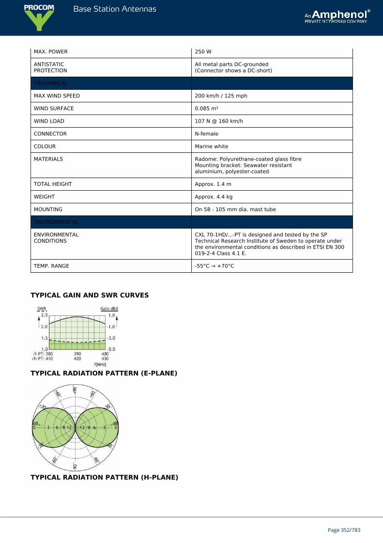
Base Station Antennas
MAX. POWER 250 W
ANTISTATICPROTECTION
All metal parts DC-grounded(Connector shows a DC-short)
MECHANICAL
MAX WIND SPEED 200 km/h / 125 mph
WIND SURFACE 0.085 m²
WIND LOAD 107 N @ 160 km/h
CONNECTOR N-female
COLOUR Marine white
MATERIALS Radome: Polyurethane-coated glass fibreMounting bracket: Seawater resistantaluminium, polyester-coated
TOTAL HEIGHT Approx. 1.4 m
WEIGHT Approx. 4.4 kg
MOUNTING On 58 - 105 mm dia. mast tube
ENVIRONMENTAL
ENVIRONMENTALCONDITIONS
CXL 70-1HD/...-PT is designed and tested by the SPTechnical Research Institute of Sweden to operate underthe environmental conditions as described in ETSI EN 300019-2-4 Class 4.1 E.
TEMP. RANGE -55°C → +70°C
TYPICAL GAIN AND SWR CURVES
TYPICAL RADIATION PATTERN (E-PLANE)
TYPICAL RADIATION PATTERN (H-PLANE)
Page 352/783
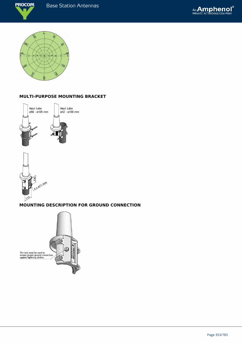
Base Station Antennas
MULTI-PURPOSE MOUNTING BRACKET
MOUNTING DESCRIPTION FOR GROUND CONNECTION
Page 353/783
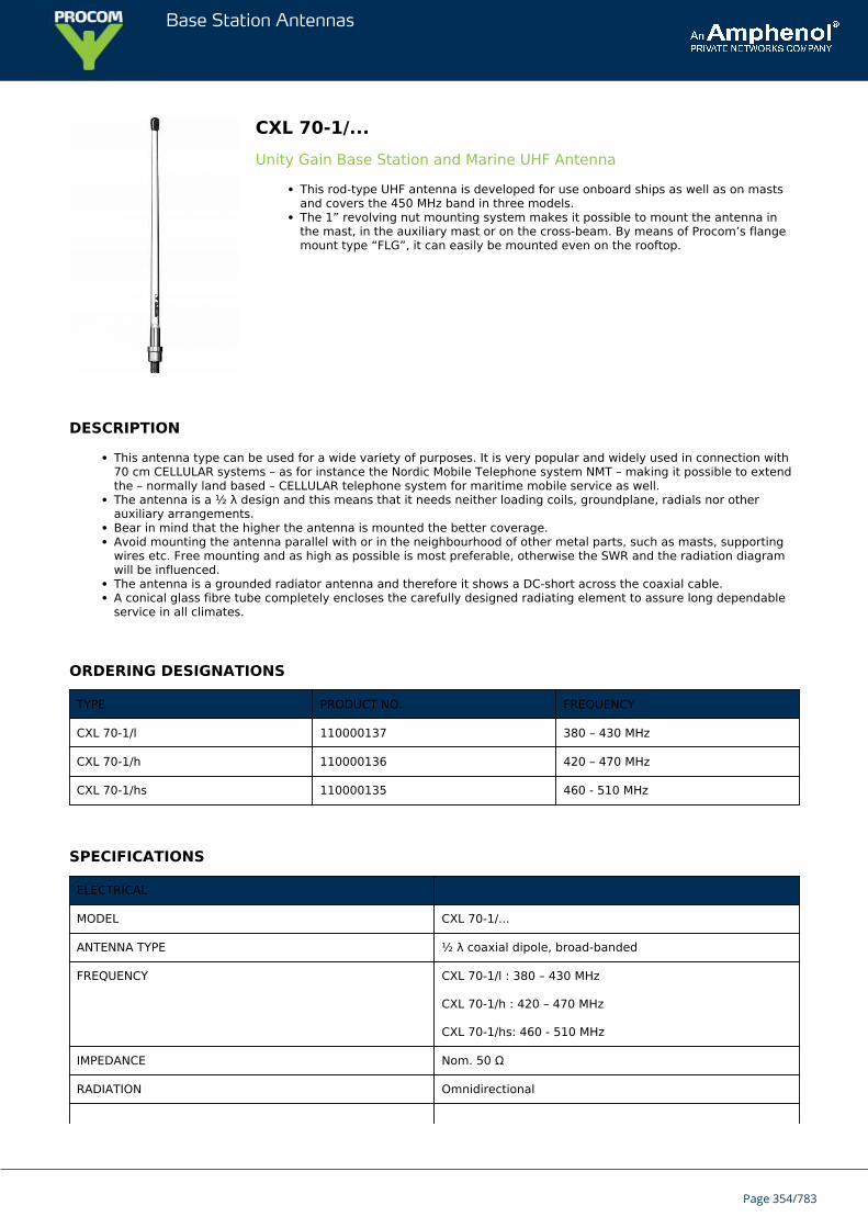
Base Station Antennas
CXL 70-1/...Unity Gain Base Station and Marine UHF Antenna
This rod-type UHF antenna is developed for use onboard ships as well as on mastsand covers the 450 MHz band in three models.The 1” revolving nut mounting system makes it possible to mount the antenna inthe mast, in the auxiliary mast or on the cross-beam. By means of Procom’s flangemount type “FLG”, it can easily be mounted even on the rooftop.
DESCRIPTION
This antenna type can be used for a wide variety of purposes. It is very popular and widely used in connection with70 cm CELLULAR systems – as for instance the Nordic Mobile Telephone system NMT – making it possible to extendthe – normally land based – CELLULAR telephone system for maritime mobile service as well.The antenna is a ½ λ design and this means that it needs neither loading coils, groundplane, radials nor otherauxiliary arrangements.Bear in mind that the higher the antenna is mounted the better coverage.Avoid mounting the antenna parallel with or in the neighbourhood of other metal parts, such as masts, supportingwires etc. Free mounting and as high as possible is most preferable, otherwise the SWR and the radiation diagramwill be influenced.The antenna is a grounded radiator antenna and therefore it shows a DC-short across the coaxial cable.A conical glass fibre tube completely encloses the carefully designed radiating element to assure long dependableservice in all climates.
ORDERING DESIGNATIONS
TYPE PRODUCT NO. FREQUENCY
CXL 70-1/l 110000137 380 – 430 MHz
CXL 70-1/h 110000136 420 – 470 MHz
CXL 70-1/hs 110000135 460 - 510 MHz
SPECIFICATIONS
ELECTRICAL
MODEL CXL 70-1/...
ANTENNA TYPE ½ λ coaxial dipole, broad-banded
FREQUENCY CXL 70-1/l : 380 – 430 MHz
CXL 70-1/h : 420 – 470 MHz
CXL 70-1/hs: 460 - 510 MHz
IMPEDANCE Nom. 50 Ω
RADIATION Omnidirectional
Page 354/783
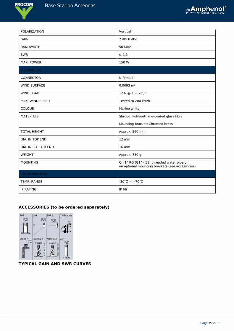
Base Station Antennas
POLARIZATION Vertical
GAIN 2 dBi 0 dBd
BANDWIDTH 50 MHz
SWR ≤ 1.5
MAX. POWER 150 W
MECHANICAL
CONNECTOR N-female
WIND SURFACE 0.0093 m²
WIND LOAD 12 N @ 160 km/h
MAX. WIND SPEED Tested to 200 km/h
COLOUR Marine white
MATERIALS Shroud: Polyurethane-coated glass fibre
Mounting bracket: Chromed brass
TOTAL HEIGHT Approx. 560 mm
DIA. IN TOP END 12 mm
DIA. IN BOTTOM END 16 mm
WEIGHT Approx. 350 g
MOUNTING On 1” RG (G1” - 11) threaded water pipe oron optional mounting brackets (see accessories)
ENVIRONMENTAL
TEMP. RANGE -30°C → +70°C
IP RATING IP 66
ACCESSORIES (to be ordered separately)
TYPICAL GAIN AND SWR CURVES
Page 355/783
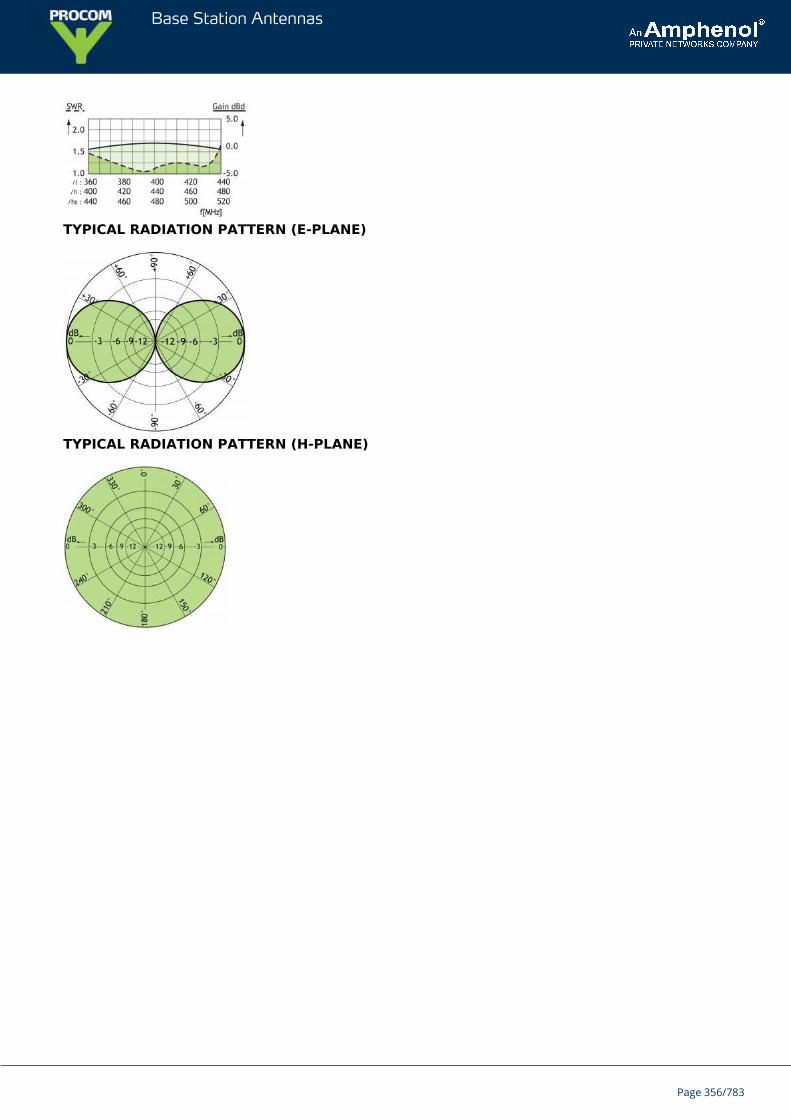
Base Station Antennas
TYPICAL RADIATION PATTERN (E-PLANE)
TYPICAL RADIATION PATTERN (H-PLANE)
Page 356/783
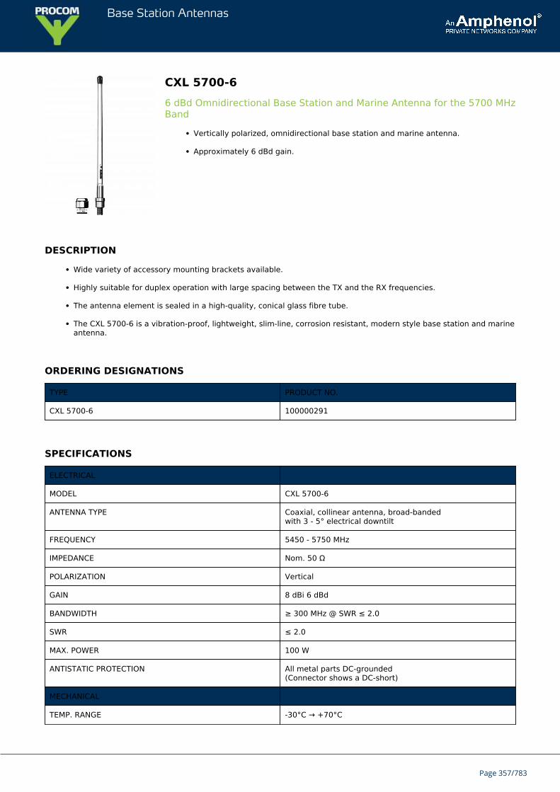
Base Station Antennas
CXL 5700-66 dBd Omnidirectional Base Station and Marine Antenna for the 5700 MHzBand
Vertically polarized, omnidirectional base station and marine antenna.
Approximately 6 dBd gain.
DESCRIPTION
Wide variety of accessory mounting brackets available.
Highly suitable for duplex operation with large spacing between the TX and the RX frequencies.
The antenna element is sealed in a high-quality, conical glass fibre tube.
The CXL 5700-6 is a vibration-proof, lightweight, slim-line, corrosion resistant, modern style base station and marineantenna.
ORDERING DESIGNATIONS
TYPE PRODUCT NO.
CXL 5700-6 100000291
SPECIFICATIONS
ELECTRICAL
MODEL CXL 5700-6
ANTENNA TYPE Coaxial, collinear antenna, broad-bandedwith 3 - 5° electrical downtilt
FREQUENCY 5450 - 5750 MHz
IMPEDANCE Nom. 50 Ω
POLARIZATION Vertical
GAIN 8 dBi 6 dBd
BANDWIDTH ≥ 300 MHz @ SWR ≤ 2.0
SWR ≤ 2.0
MAX. POWER 100 W
ANTISTATIC PROTECTION All metal parts DC-grounded(Connector shows a DC-short)
MECHANICAL
TEMP. RANGE -30°C → +70°C
Page 357/783
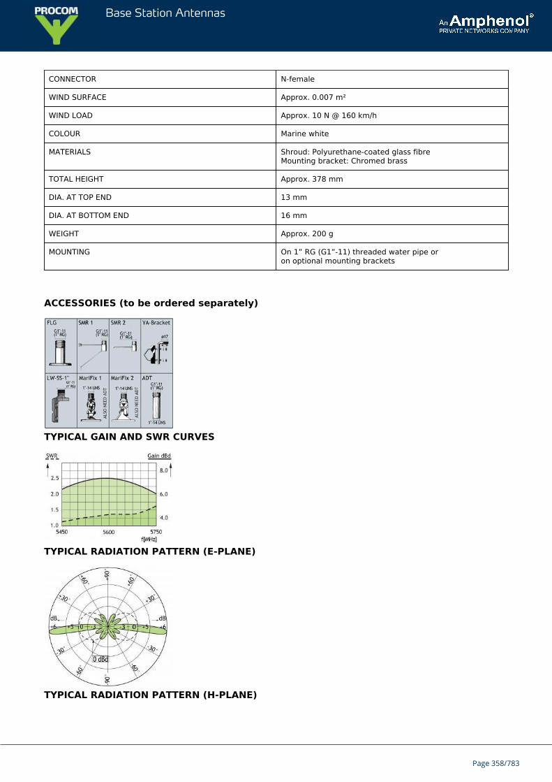
Base Station Antennas
CONNECTOR N-female
WIND SURFACE Approx. 0.007 m²
WIND LOAD Approx. 10 N @ 160 km/h
COLOUR Marine white
MATERIALS Shroud: Polyurethane-coated glass fibreMounting bracket: Chromed brass
TOTAL HEIGHT Approx. 378 mm
DIA. AT TOP END 13 mm
DIA. AT BOTTOM END 16 mm
WEIGHT Approx. 200 g
MOUNTING On 1” RG (G1”-11) threaded water pipe oron optional mounting brackets
ACCESSORIES (to be ordered separately)
TYPICAL GAIN AND SWR CURVES
TYPICAL RADIATION PATTERN (E-PLANE)
TYPICAL RADIATION PATTERN (H-PLANE)
Page 358/783

Base Station Antennas
Page 359/783
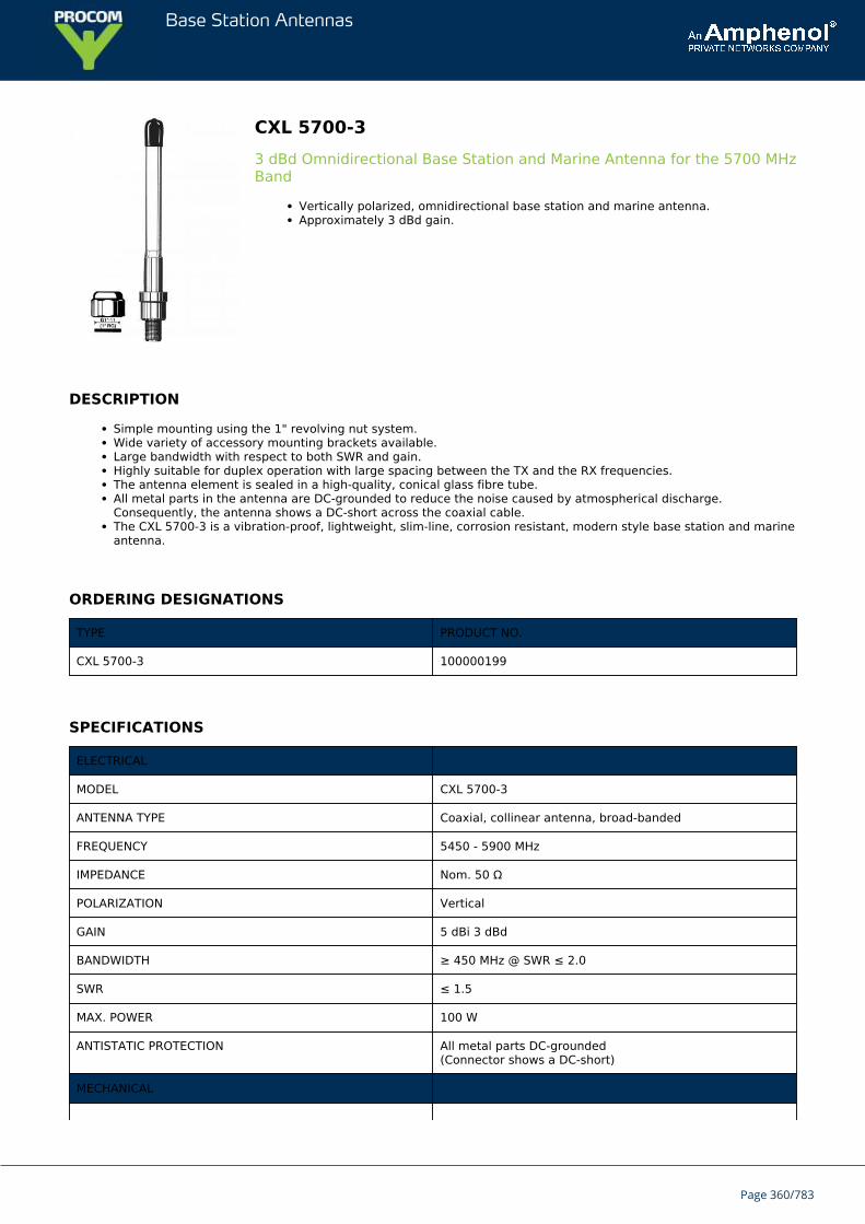
Base Station Antennas
CXL 5700-33 dBd Omnidirectional Base Station and Marine Antenna for the 5700 MHzBand
Vertically polarized, omnidirectional base station and marine antenna.Approximately 3 dBd gain.
DESCRIPTION
Simple mounting using the 1" revolving nut system.Wide variety of accessory mounting brackets available.Large bandwidth with respect to both SWR and gain.Highly suitable for duplex operation with large spacing between the TX and the RX frequencies.The antenna element is sealed in a high-quality, conical glass fibre tube.All metal parts in the antenna are DC-grounded to reduce the noise caused by atmospherical discharge.Consequently, the antenna shows a DC-short across the coaxial cable.The CXL 5700-3 is a vibration-proof, lightweight, slim-line, corrosion resistant, modern style base station and marineantenna.
ORDERING DESIGNATIONS
TYPE PRODUCT NO.
CXL 5700-3 100000199
SPECIFICATIONS
ELECTRICAL
MODEL CXL 5700-3
ANTENNA TYPE Coaxial, collinear antenna, broad-banded
FREQUENCY 5450 - 5900 MHz
IMPEDANCE Nom. 50 Ω
POLARIZATION Vertical
GAIN 5 dBi 3 dBd
BANDWIDTH ≥ 450 MHz @ SWR ≤ 2.0
SWR ≤ 1.5
MAX. POWER 100 W
ANTISTATIC PROTECTION All metal parts DC-grounded(Connector shows a DC-short)
MECHANICAL
Page 360/783
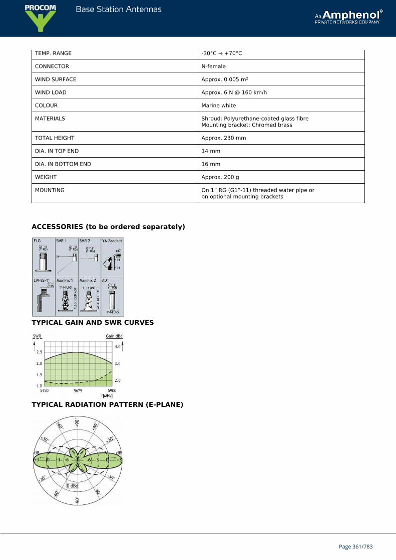
Base Station Antennas
TEMP. RANGE -30°C → +70°C
CONNECTOR N-female
WIND SURFACE Approx. 0.005 m²
WIND LOAD Approx. 6 N @ 160 km/h
COLOUR Marine white
MATERIALS Shroud: Polyurethane-coated glass fibreMounting bracket: Chromed brass
TOTAL HEIGHT Approx. 230 mm
DIA. IN TOP END 14 mm
DIA. IN BOTTOM END 16 mm
WEIGHT Approx. 200 g
MOUNTING On 1” RG (G1”-11) threaded water pipe oron optional mounting brackets
ACCESSORIES (to be ordered separately)
TYPICAL GAIN AND SWR CURVES
TYPICAL RADIATION PATTERN (E-PLANE)
Page 361/783
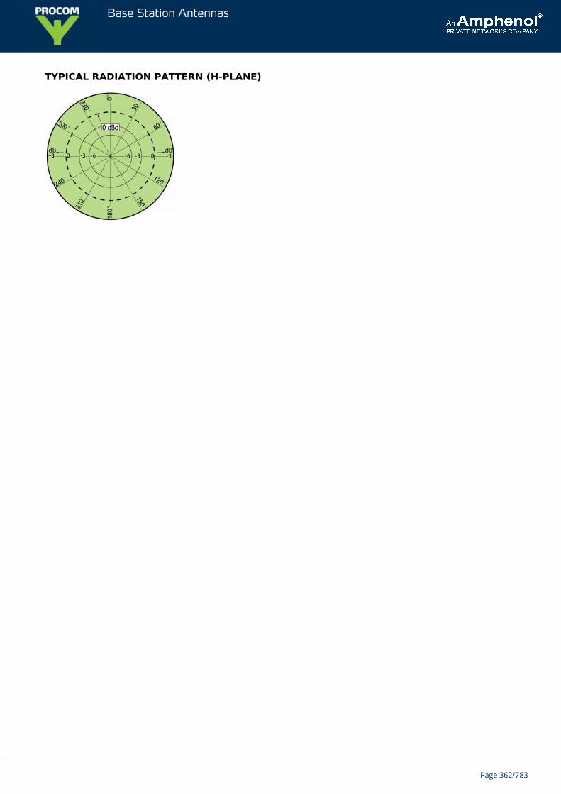
Base Station Antennas
TYPICAL RADIATION PATTERN (H-PLANE)
Page 362/783
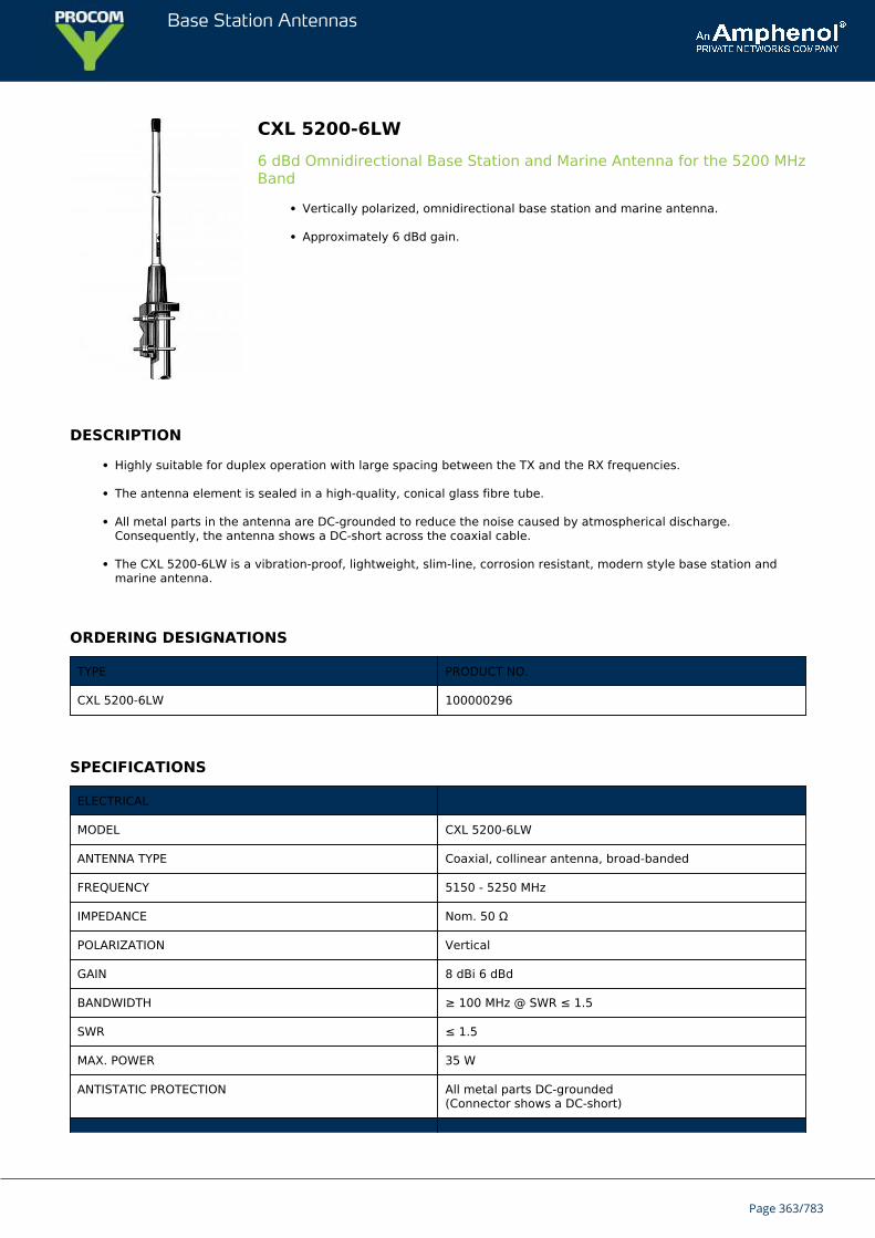
Base Station Antennas
CXL 5200-6LW6 dBd Omnidirectional Base Station and Marine Antenna for the 5200 MHzBand
Vertically polarized, omnidirectional base station and marine antenna.
Approximately 6 dBd gain.
DESCRIPTION
Highly suitable for duplex operation with large spacing between the TX and the RX frequencies.
The antenna element is sealed in a high-quality, conical glass fibre tube.
All metal parts in the antenna are DC-grounded to reduce the noise caused by atmospherical discharge.Consequently, the antenna shows a DC-short across the coaxial cable.
The CXL 5200-6LW is a vibration-proof, lightweight, slim-line, corrosion resistant, modern style base station andmarine antenna.
ORDERING DESIGNATIONS
TYPE PRODUCT NO.
CXL 5200-6LW 100000296
SPECIFICATIONS
ELECTRICAL
MODEL CXL 5200-6LW
ANTENNA TYPE Coaxial, collinear antenna, broad-banded
FREQUENCY 5150 - 5250 MHz
IMPEDANCE Nom. 50 Ω
POLARIZATION Vertical
GAIN 8 dBi 6 dBd
BANDWIDTH ≥ 100 MHz @ SWR ≤ 1.5
SWR ≤ 1.5
MAX. POWER 35 W
ANTISTATIC PROTECTION All metal parts DC-grounded(Connector shows a DC-short)
Page 363/783
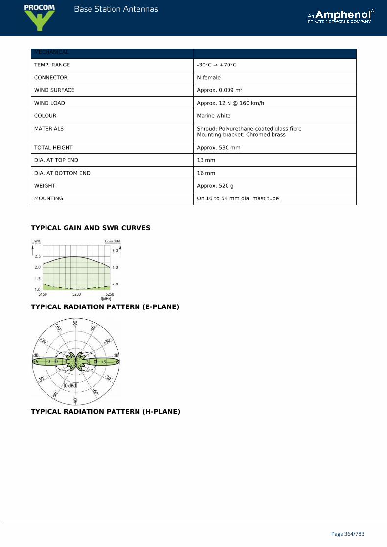
Base Station Antennas
MECHANICAL
TEMP. RANGE -30°C → +70°C
CONNECTOR N-female
WIND SURFACE Approx. 0.009 m²
WIND LOAD Approx. 12 N @ 160 km/h
COLOUR Marine white
MATERIALS Shroud: Polyurethane-coated glass fibreMounting bracket: Chromed brass
TOTAL HEIGHT Approx. 530 mm
DIA. AT TOP END 13 mm
DIA. AT BOTTOM END 16 mm
WEIGHT Approx. 520 g
MOUNTING On 16 to 54 mm dia. mast tube
TYPICAL GAIN AND SWR CURVES
TYPICAL RADIATION PATTERN (E-PLANE)
TYPICAL RADIATION PATTERN (H-PLANE)
Page 364/783

Base Station Antennas
MULTI-PURPOSE MOUNTING BRACKET
Page 365/783
Base Station Antennas
CXL 5200-66 dBd Omnidirectional Base Station and Marine Antenna for the 5200 MHzBand
Vertically polarized, omnidirectional base station and marine antenna.Approximately 6 dBd gain.
DESCRIPTION
Simple mounting using the 1" revolving nut system.Wide variety of accessory mounting brackets available.Highly suitable for duplex operation with large spacing between the TX and the RX frequencies.The antenna element is sealed in a high-quality, conical glass fibre tube.All metal parts in the antenna are DC-grounded to reduce the noise caused by atmospherical discharge.Consequently, the antenna shows a DC-short across the coaxial cable.The CXL 5200-6 is a vibration-proof, lightweight, slim-line, corrosion resistant, modern style base station and marineantenna.
ORDERING DESIGNATIONS
TYPE PRODUCT NO.
CXL 5200-6 100000216
SPECIFICATIONS
ELECTRICAL
MODEL CXL 5200-6
ANTENNA TYPE Coaxial, collinear antenna, broad-banded
FREQUENCY 5150 - 5250 MHz
IMPEDANCE Nom. 50 Ω
POLARIZATION Vertical
GAIN 8 dBi 6 dBd
BANDWIDTH ≥ 100 MHz @ SWR ≤ 2.0
SWR ≤ 2.0
MAX. POWER 100 W
ANTISTATIC PROTECTION All metal parts DC-grounded(Connector shows a DC-short)
MECHANICAL
TEMP. RANGE -30°C → +70°C
Page 366/783
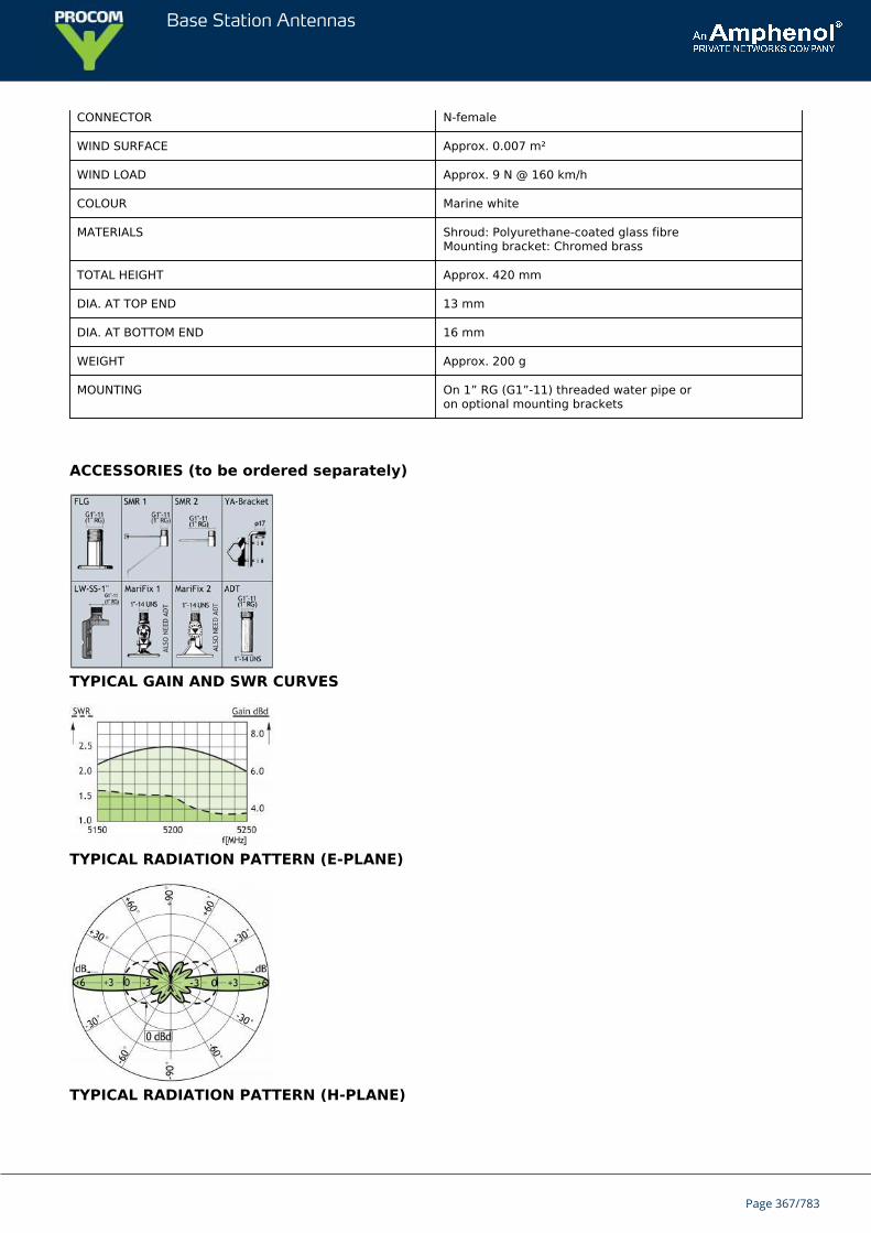
Base Station Antennas
CONNECTOR N-female
WIND SURFACE Approx. 0.007 m²
WIND LOAD Approx. 9 N @ 160 km/h
COLOUR Marine white
MATERIALS Shroud: Polyurethane-coated glass fibreMounting bracket: Chromed brass
TOTAL HEIGHT Approx. 420 mm
DIA. AT TOP END 13 mm
DIA. AT BOTTOM END 16 mm
WEIGHT Approx. 200 g
MOUNTING On 1” RG (G1”-11) threaded water pipe oron optional mounting brackets
ACCESSORIES (to be ordered separately)
TYPICAL GAIN AND SWR CURVES
TYPICAL RADIATION PATTERN (E-PLANE)
TYPICAL RADIATION PATTERN (H-PLANE)
Page 367/783

Base Station Antennas
Page 368/783
Base Station Antennas
CXL 5700-1/...Unity Gain Base Statin and Marine 5700 MHz Antenna for Mounting onThreaded 1
The CXL 5700-1/… is a 0 dBd, vertically polarized, omnidirectional rod-type basestation and marine antenna for the 5700 MHz band.
DESCRIPTION
The 1” revolving nut mounting system is standard throughout the marine sector, and several different mountingbrackets are available, making it possible to install the antenna either on the masthead using FLG or SMR 2, side-mounted on the mast(SMR 1) or mounted on a cross-beam (FLG). Also, the antenna can be mounted on deck or rooftop by means of theFLG.
The higher the antenna is mounted, the better coverage. Avoid mounting the antenna parallel to or in theneighbourhood of other metal parts, such as masts, supporting wires etc., otherwise the SWR and the radiationpattern may be strongly influenced.
A conical glass fibre tube completely encloses the carefully designed radiating element to ensure long dependableservice in all climates.
ORDERING DESIGNATIONS
TYPE FREQUENCY PRODUCT NO.
CXL 5700-1/l 5150 - 5350 MHz 100000285
CXL 5700-1/m 5300 - 5500 MHz 100000286
CXL 5700-1/h 5450 - 5900 MHz 100000198
SPECIFICATIONS
ELECTRICAL
MODEL CXL 5700-1/...
ANTENNA TYPE ½ λ coaxial dipole, broad-banded
FREQUENCY Models within 5150 – 5900 MHz
IMPEDANCE Nom. 50 Ω
POLARIZATION Vertical
GAIN 2 dBi 0 dBd
BANDWIDTH ≥ 300 MHz @ SWR ≤ 2.0
SWR ≤ 2.0, typ. ≤ 1.5
Page 369/783
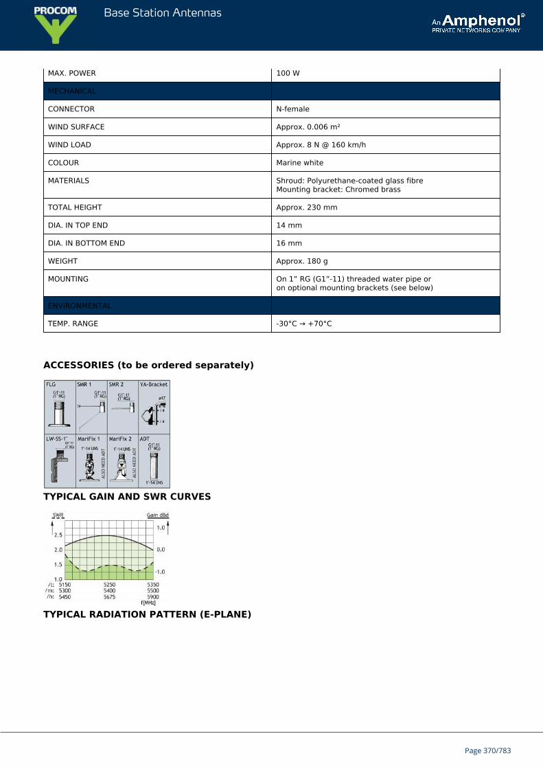
Base Station Antennas
MAX. POWER 100 W
MECHANICAL
CONNECTOR N-female
WIND SURFACE Approx. 0.006 m²
WIND LOAD Approx. 8 N @ 160 km/h
COLOUR Marine white
MATERIALS Shroud: Polyurethane-coated glass fibreMounting bracket: Chromed brass
TOTAL HEIGHT Approx. 230 mm
DIA. IN TOP END 14 mm
DIA. IN BOTTOM END 16 mm
WEIGHT Approx. 180 g
MOUNTING On 1” RG (G1”-11) threaded water pipe oron optional mounting brackets (see below)
ENVIRONMENTAL
TEMP. RANGE -30°C → +70°C
ACCESSORIES (to be ordered separately)
TYPICAL GAIN AND SWR CURVES
TYPICAL RADIATION PATTERN (E-PLANE)
Page 370/783
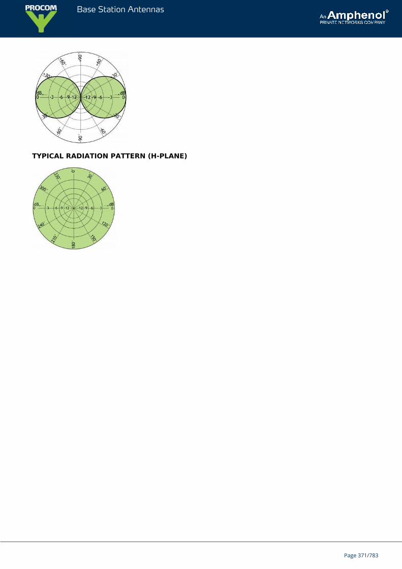
Base Station Antennas
TYPICAL RADIATION PATTERN (H-PLANE)
Page 371/783
Base Station Antennas
CXL 470-8700 dBd Broad-Band Base Station and Marine Antenna for the 470 - 870MHz Band
Vertically polarized, omnidirectional base station and marine antenna.Approximately 0 dBd gain.Simple mounting using the 1” revolving nut system.
DESCRIPTION
Wide variety of accessory mounting brackets available.Large bandwidth (470 - 870 MHz) with respect to both SWR and gain.The antenna element is sealed in a high-quality, conical glass-fibre tube.The CXL 470-870 is a vibration-proof, lightweight, slim-line, corrosion resistant, modern style base station andmarine antenna.The CXL 470-870 is designed specially for both digital and analog communication systems.
ORDERING DESIGNATIONS
TYPE PRODUCT NO.
CXL 470-870 100000226
SPECIFICATIONS
ELECTRICAL
MODEL CXL 470-870
ANTENNA TYPE Coaxial, collinear antenna, broad-band
FREQUENCY 470 - 870 MHz
IMPEDANCE Nom. 50 Ω
POLARIZATION Vertical
GAIN 2 dBi 0 dBd (see Gain Curve)
BANDWIDTH ≥ 400 MHz
SWR ≤ 2.5
MAX. POWER 100 W
MECHANICAL
TEMP. RANGE -30° C → +70° C
CONNECTOR N-female
WIND SURFACE Approx. 0.013 m²
Page 372/783

Base Station Antennas
WIND LOAD Approx. 20 N @ 160 km/h
MAX. WIND SPEED 200 Km/h / 125 mph
COLOUR Marine white
MATERIALS Shroud: Polyurethane-coated glass fibreMounting bracket: Chromed brass
TOTAL HEIGHT Approx. 600 mm / 23.6 in.
DIA. AT TOP END 22.5 mm / 0.8 in.
DIA. AT BOTTOM END 23 mm / 0.9 in.
WEIGHT Approx. 350 g / 0.7 Ib.
MOUNTING On 1” RG (G1” - 11) threaded water pipe oron optional mounting brackets (see below)
ACCESSORIES (to be ordered separately)
TYPICAL GAIN CURVE
TYPICAL SWR CURVE
TYPICAL RADIATION PATTERN (E-PLANE) 470 Mhz
Page 373/783
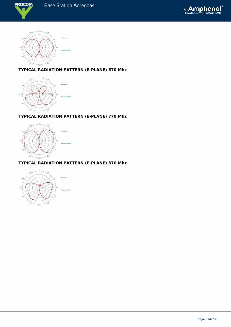
Base Station Antennas
TYPICAL RADIATION PATTERN (E-PLANE) 670 Mhz
TYPICAL RADIATION PATTERN (E-PLANE) 770 Mhz
TYPICAL RADIATION PATTERN (E-PLANE) 870 Mhz
Page 374/783
Base Station Antennas
CXL 450-1LW-SS-ExATEX certified, 0 dBd, Omnidirectional Base Station and Marine Antennafor the 450 MHz Band in hazardous areas
CXL 450-1LW-SS-Ex is a 0 dBd, vertically polarized, omnidirectional base stationantenna which covers the 380 - 510 MHz band in three models.The antenna is specified as ATEX antenna for use in zone 2 in potentially explosiveareas.
DESCRIPTION
Before installing the antenna, read the ATEX Product Manual carefully.The antenna is suitable for use in gas groups IIA, IIB and IIC in zone 2.It’s only necessary to install a ATEX grounding Kit on the LW-SS-Ex bracket, when the point of installation has adifferent electrical potential than the system.The carefully designed, broadbanded ½ λ-dipole radiating element is made of brass tube and sealed in a high-quality cylindrical glass fibre tube with low wind-load.The accompanying U-bolts and fittings are made of stainless steel.The antenna element is sealed in a high-quality glass fibre tube.All metal parts in the antenna are DC-grounded. Consequently, the antenna shows a DC-short across the coaxialcable.
ORDERING DESIGNATIONS
TYPE FREQUENCY PRODUCT NO.
CXL 450-1LW-SS-Ex/l 380 - 430 MHz 115000010
CXL 450-1LW-SS-Ex/h 420 - 470 MHz 115000011
CXL 450-1LW-SS-Ex/hs 460 - 510 MHz 115000012
ACCESSORIES
ATEX grounding Kit 115000100
SPECIFICATIONS
ELECTRICAL
MODEL CXL 450-1LW-SS-Ex
ANTENNA TYPE ½ λ coaxial dipole, broad-banded
FREQUENCY 50 MHz wide frequency segments within
Page 375/783
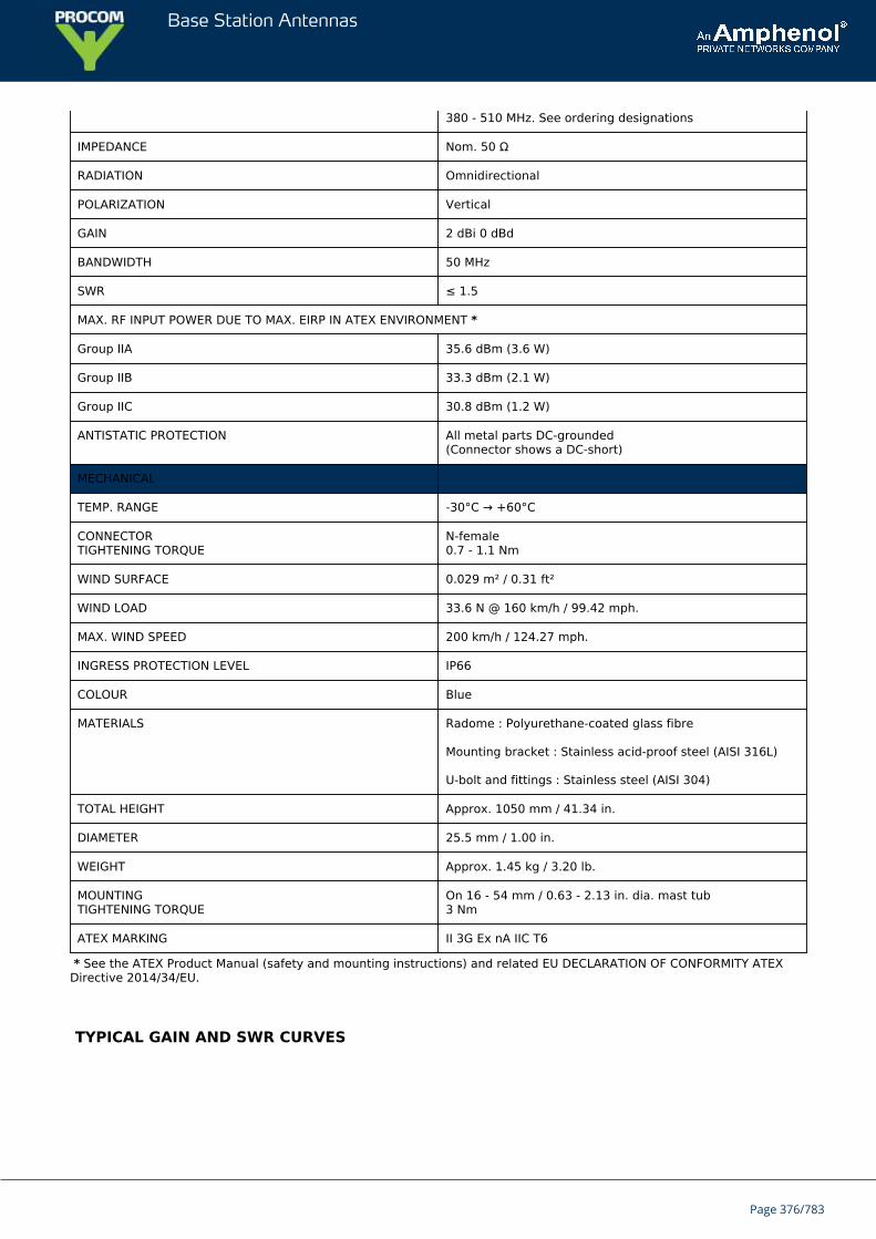
Base Station Antennas
380 - 510 MHz. See ordering designations
IMPEDANCE Nom. 50 Ω
RADIATION Omnidirectional
POLARIZATION Vertical
GAIN 2 dBi 0 dBd
BANDWIDTH 50 MHz
SWR ≤ 1.5
MAX. RF INPUT POWER DUE TO MAX. EIRP IN ATEX ENVIRONMENT *
Group IIA 35.6 dBm (3.6 W)
Group IIB 33.3 dBm (2.1 W)
Group IIC 30.8 dBm (1.2 W)
ANTISTATIC PROTECTION All metal parts DC-grounded(Connector shows a DC-short)
MECHANICAL
TEMP. RANGE -30°C → +60°C
CONNECTORTIGHTENING TORQUE
N-female0.7 - 1.1 Nm
WIND SURFACE 0.029 m² / 0.31 ft²
WIND LOAD 33.6 N @ 160 km/h / 99.42 mph.
MAX. WIND SPEED 200 km/h / 124.27 mph.
INGRESS PROTECTION LEVEL IP66
COLOUR Blue
MATERIALS Radome : Polyurethane-coated glass fibre
Mounting bracket : Stainless acid-proof steel (AISI 316L)
U-bolt and fittings : Stainless steel (AISI 304)
TOTAL HEIGHT Approx. 1050 mm / 41.34 in.
DIAMETER 25.5 mm / 1.00 in.
WEIGHT Approx. 1.45 kg / 3.20 lb.
MOUNTINGTIGHTENING TORQUE
On 16 - 54 mm / 0.63 - 2.13 in. dia. mast tub3 Nm
ATEX MARKING II 3G Ex nA IIC T6
* See the ATEX Product Manual (safety and mounting instructions) and related EU DECLARATION OF CONFORMITY ATEXDirective 2014/34/EU.
TYPICAL GAIN AND SWR CURVES
Page 376/783
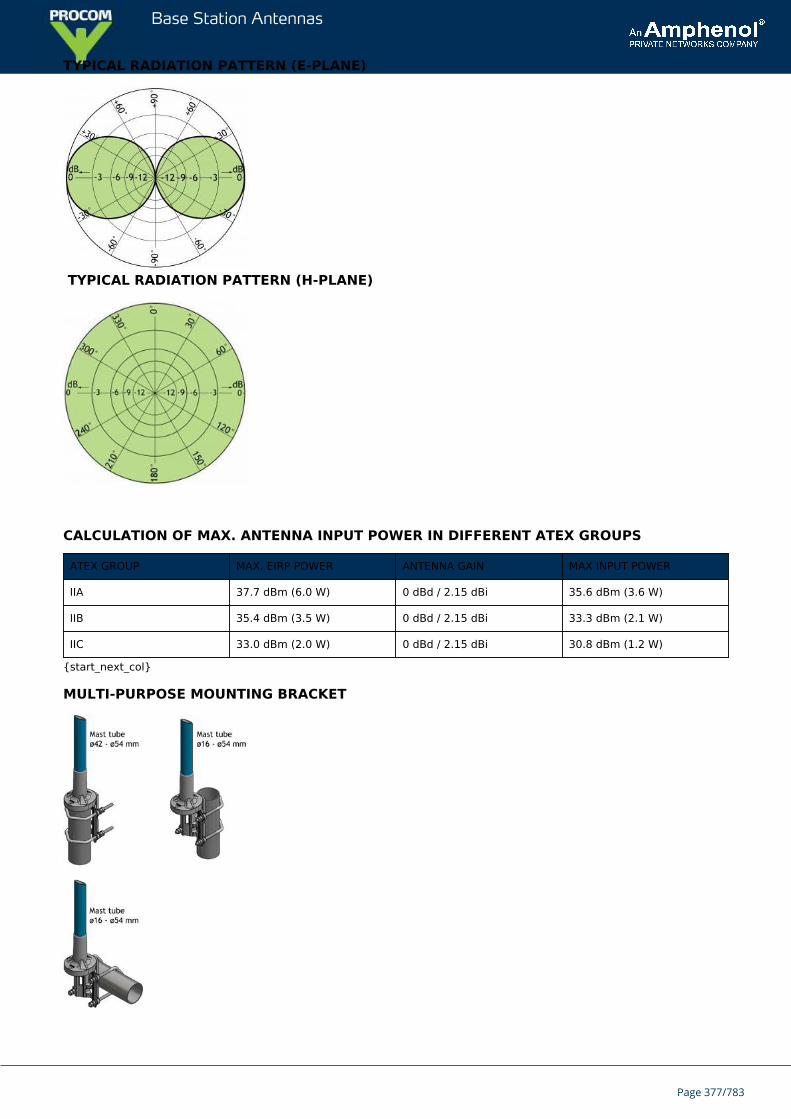
Base Station Antennas
TYPICAL RADIATION PATTERN (E-PLANE)
TYPICAL RADIATION PATTERN (H-PLANE)
CALCULATION OF MAX. ANTENNA INPUT POWER IN DIFFERENT ATEX GROUPS
ATEX GROUP MAX. EIRP POWER ANTENNA GAIN MAX INPUT POWER
IIA 37.7 dBm (6.0 W) 0 dBd / 2.15 dBi 35.6 dBm (3.6 W)
IIB 35.4 dBm (3.5 W) 0 dBd / 2.15 dBi 33.3 dBm (2.1 W)
IIC 33.0 dBm (2.0 W) 0 dBd / 2.15 dBi 30.8 dBm (1.2 W)
{start_next_col}
MULTI-PURPOSE MOUNTING BRACKET
Page 377/783

Base Station Antennas
Page 378/783
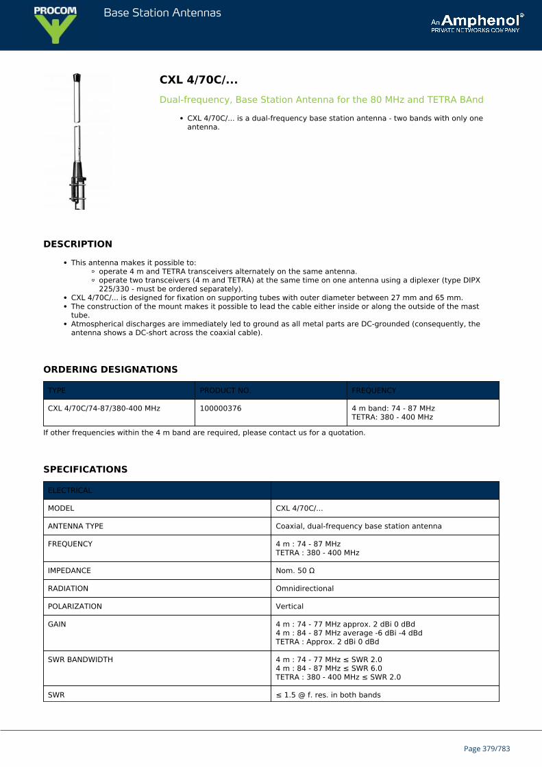
Base Station Antennas
CXL 4/70C/...Dual-frequency, Base Station Antenna for the 80 MHz and TETRA BAnd
CXL 4/70C/... is a dual-frequency base station antenna - two bands with only oneantenna.
DESCRIPTION
This antenna makes it possible to:operate 4 m and TETRA transceivers alternately on the same antenna.operate two transceivers (4 m and TETRA) at the same time on one antenna using a diplexer (type DIPX225/330 - must be ordered separately).
CXL 4/70C/... is designed for fixation on supporting tubes with outer diameter between 27 mm and 65 mm.The construction of the mount makes it possible to lead the cable either inside or along the outside of the masttube.Atmospherical discharges are immediately led to ground as all metal parts are DC-grounded (consequently, theantenna shows a DC-short across the coaxial cable).
ORDERING DESIGNATIONS
TYPE PRODUCT NO. FREQUENCY
CXL 4/70C/74-87/380-400 MHz 100000376 4 m band: 74 - 87 MHzTETRA: 380 - 400 MHz
If other frequencies within the 4 m band are required, please contact us for a quotation.
SPECIFICATIONS
ELECTRICAL
MODEL CXL 4/70C/...
ANTENNA TYPE Coaxial, dual-frequency base station antenna
FREQUENCY 4 m : 74 - 87 MHzTETRA : 380 - 400 MHz
IMPEDANCE Nom. 50 Ω
RADIATION Omnidirectional
POLARIZATION Vertical
GAIN 4 m : 74 - 77 MHz approx. 2 dBi 0 dBd4 m : 84 - 87 MHz average -6 dBi -4 dBdTETRA : Approx. 2 dBi 0 dBd
SWR BANDWIDTH 4 m : 74 - 77 MHz ≤ SWR 2.04 m : 84 - 87 MHz ≤ SWR 6.0TETRA : 380 - 400 MHz ≤ SWR 2.0
SWR ≤ 1.5 @ f. res. in both bands
Page 379/783
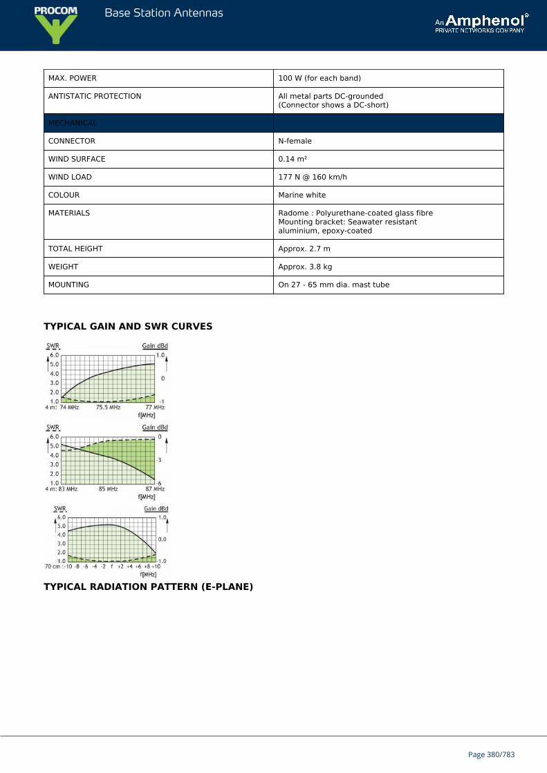
Base Station Antennas
MAX. POWER 100 W (for each band)
ANTISTATIC PROTECTION All metal parts DC-grounded(Connector shows a DC-short)
MECHANICAL
CONNECTOR N-female
WIND SURFACE 0.14 m²
WIND LOAD 177 N @ 160 km/h
COLOUR Marine white
MATERIALS Radome : Polyurethane-coated glass fibreMounting bracket: Seawater resistantaluminium, epoxy-coated
TOTAL HEIGHT Approx. 2.7 m
WEIGHT Approx. 3.8 kg
MOUNTING On 27 - 65 mm dia. mast tube
TYPICAL GAIN AND SWR CURVES
TYPICAL RADIATION PATTERN (E-PLANE)
Page 380/783
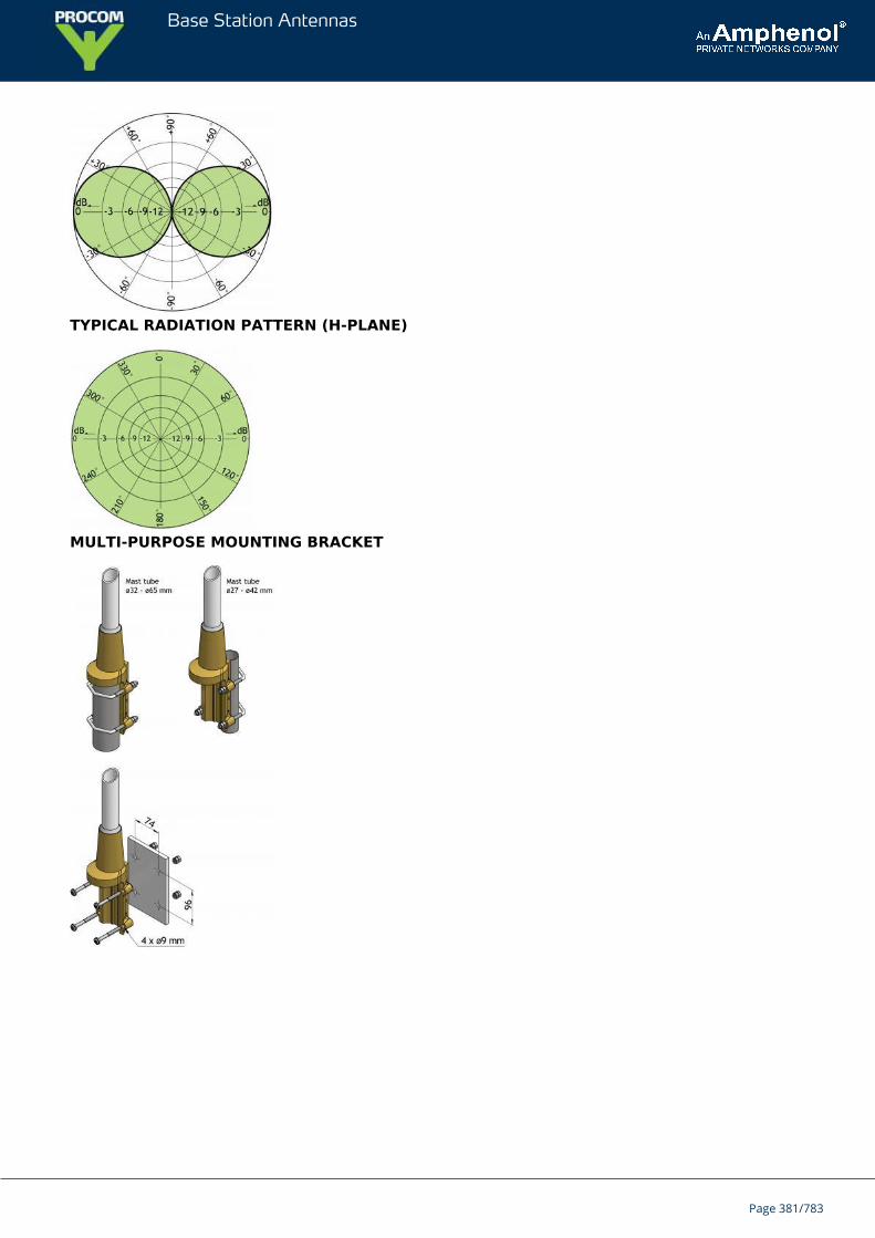
Base Station Antennas
TYPICAL RADIATION PATTERN (H-PLANE)
MULTI-PURPOSE MOUNTING BRACKET
Page 381/783
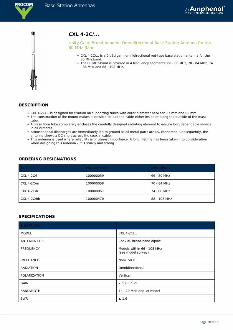
Base Station Antennas
CXL 4-2C/...Unity Gain, Broad-banded, Omnidirectional Base Station Antenna for the80 MHz Band
CXL 4-2C/… is a 0 dBd gain, omnidirectional rod-type base station antenna for the80 MHz band.The 80 MHz-band is covered in 4 frequency segments: 66 - 80 MHz, 70 - 84 MHz, 74- 88 MHz and 88 - 108 MHz.
DESCRIPTION
CXL 4-2C/… is designed for fixation on supporting tubes with outer diameter between 27 mm and 65 mm.The construction of the mount makes it possible to lead the cable either inside or along the outside of the masttube.A glass fibre tube completely encloses the carefully designed radiating element to ensure long dependable servicein all climates.Atmospherical discharges are immediately led to ground as all metal parts are DC-connected. Consequently, theantenna shows a DC-short across the coaxial cable.This antenna is used where reliability is of utmost importance. A long lifetime has been taken into considerationwhen designing this antenna – it is sturdy and strong.
ORDERING DESIGNATIONS
TYPE PRODUCT NO. FREQUENCY
CXL 4-2C/l 100000059 66 - 80 MHz
CXL 4-2C/m 100000058 70 - 84 MHz
CXL 4-2C/h 100000057 74 - 88 MHz
CXL 4-2C/hh 100000470 88 - 108 MHz
SPECIFICATIONS
ELECTRICAL
MODEL CXL 4-2C/...
ANTENNA TYPE Coaxial, broad-band dipole
FREQUENCY Models within 66 - 108 MHz(see model survey)
IMPEDANCE Nom. 50 Ω
RADIATION Omnidirectional
POLARIZATION Vertical
GAIN 2 dBi 0 dBd
BANDWIDTH 14 - 20 MHz dep. of model
SWR ≤ 1.6
Page 382/783
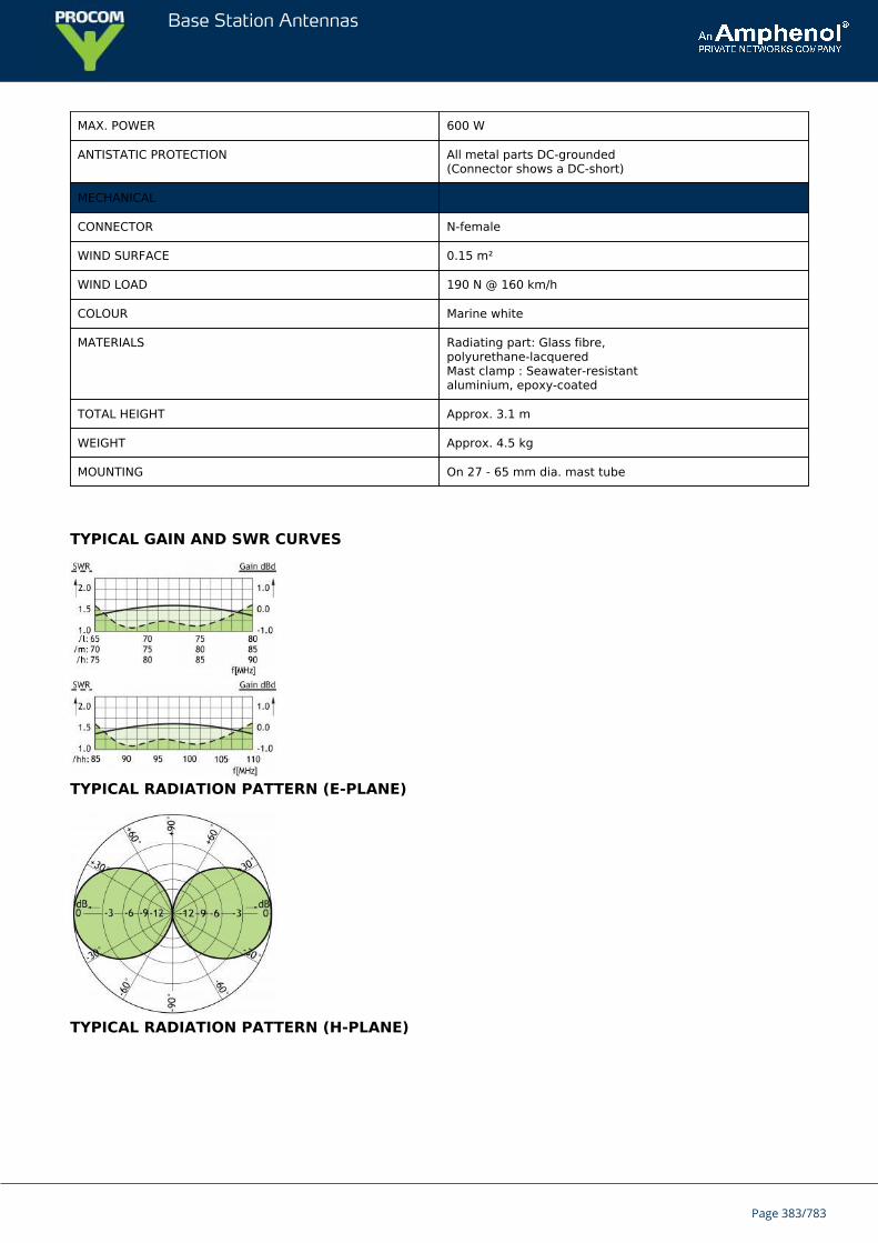
Base Station Antennas
MAX. POWER 600 W
ANTISTATIC PROTECTION All metal parts DC-grounded(Connector shows a DC-short)
MECHANICAL
CONNECTOR N-female
WIND SURFACE 0.15 m²
WIND LOAD 190 N @ 160 km/h
COLOUR Marine white
MATERIALS Radiating part: Glass fibre,polyurethane-lacqueredMast clamp : Seawater-resistantaluminium, epoxy-coated
TOTAL HEIGHT Approx. 3.1 m
WEIGHT Approx. 4.5 kg
MOUNTING On 27 - 65 mm dia. mast tube
TYPICAL GAIN AND SWR CURVES
TYPICAL RADIATION PATTERN (E-PLANE)
TYPICAL RADIATION PATTERN (H-PLANE)
Page 383/783

Base Station Antennas
MULTI-PURPOSE MOUNTING BRACKET
Page 384/783
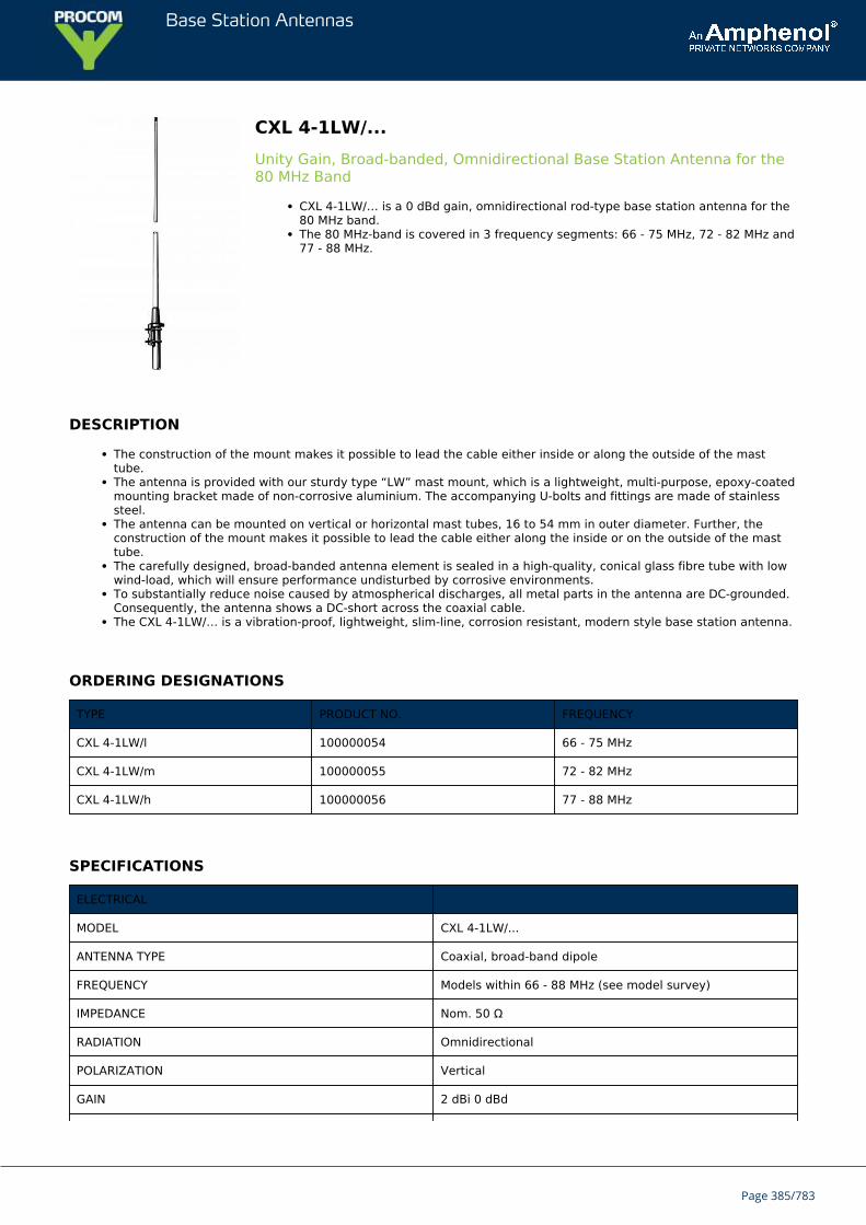
Base Station Antennas
CXL 4-1LW/...Unity Gain, Broad-banded, Omnidirectional Base Station Antenna for the80 MHz Band
CXL 4-1LW/… is a 0 dBd gain, omnidirectional rod-type base station antenna for the80 MHz band.The 80 MHz-band is covered in 3 frequency segments: 66 - 75 MHz, 72 - 82 MHz and77 - 88 MHz.
DESCRIPTION
The construction of the mount makes it possible to lead the cable either inside or along the outside of the masttube.The antenna is provided with our sturdy type “LW” mast mount, which is a lightweight, multi-purpose, epoxy-coatedmounting bracket made of non-corrosive aluminium. The accompanying U-bolts and fittings are made of stainlesssteel.The antenna can be mounted on vertical or horizontal mast tubes, 16 to 54 mm in outer diameter. Further, theconstruction of the mount makes it possible to lead the cable either along the inside or on the outside of the masttube.The carefully designed, broad-banded antenna element is sealed in a high-quality, conical glass fibre tube with lowwind-load, which will ensure performance undisturbed by corrosive environments.To substantially reduce noise caused by atmospherical discharges, all metal parts in the antenna are DC-grounded.Consequently, the antenna shows a DC-short across the coaxial cable.The CXL 4-1LW/… is a vibration-proof, lightweight, slim-line, corrosion resistant, modern style base station antenna.
ORDERING DESIGNATIONS
TYPE PRODUCT NO. FREQUENCY
CXL 4-1LW/l 100000054 66 - 75 MHz
CXL 4-1LW/m 100000055 72 - 82 MHz
CXL 4-1LW/h 100000056 77 - 88 MHz
SPECIFICATIONS
ELECTRICAL
MODEL CXL 4-1LW/...
ANTENNA TYPE Coaxial, broad-band dipole
FREQUENCY Models within 66 - 88 MHz (see model survey)
IMPEDANCE Nom. 50 Ω
RADIATION Omnidirectional
POLARIZATION Vertical
GAIN 2 dBi 0 dBd
Page 385/783
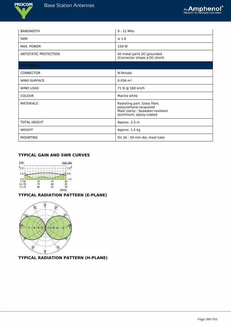
Base Station Antennas
BANDWIDTH 9 - 11 MHz
SWR ≤ 1.8
MAX. POWER 150 W
ANTISTATIC PROTECTION All metal parts DC-grounded(Connector shows a DC-short)
MECHANICAL
CONNECTOR N-female
WIND SURFACE 0.056 m²
WIND LOAD 71 N @ 160 km/h
COLOUR Marine white
MATERIALS Radiating part: Glass fibre,polyurethane-lacqueredMast clamp : Seawater-resistantaluminium, epoxy-coated
TOTAL HEIGHT Approx. 2.3 m
WEIGHT Approx. 1.5 kg
MOUNTING On 16 - 54 mm dia. mast tube
TYPICAL GAIN AND SWR CURVES
TYPICAL RADIATION PATTERN (E-PLANE)
TYPICAL RADIATION PATTERN (H-PLANE)
Page 386/783

Base Station Antennas
MULTI-PURPOSE MOUNTING BRACKET
Page 387/783
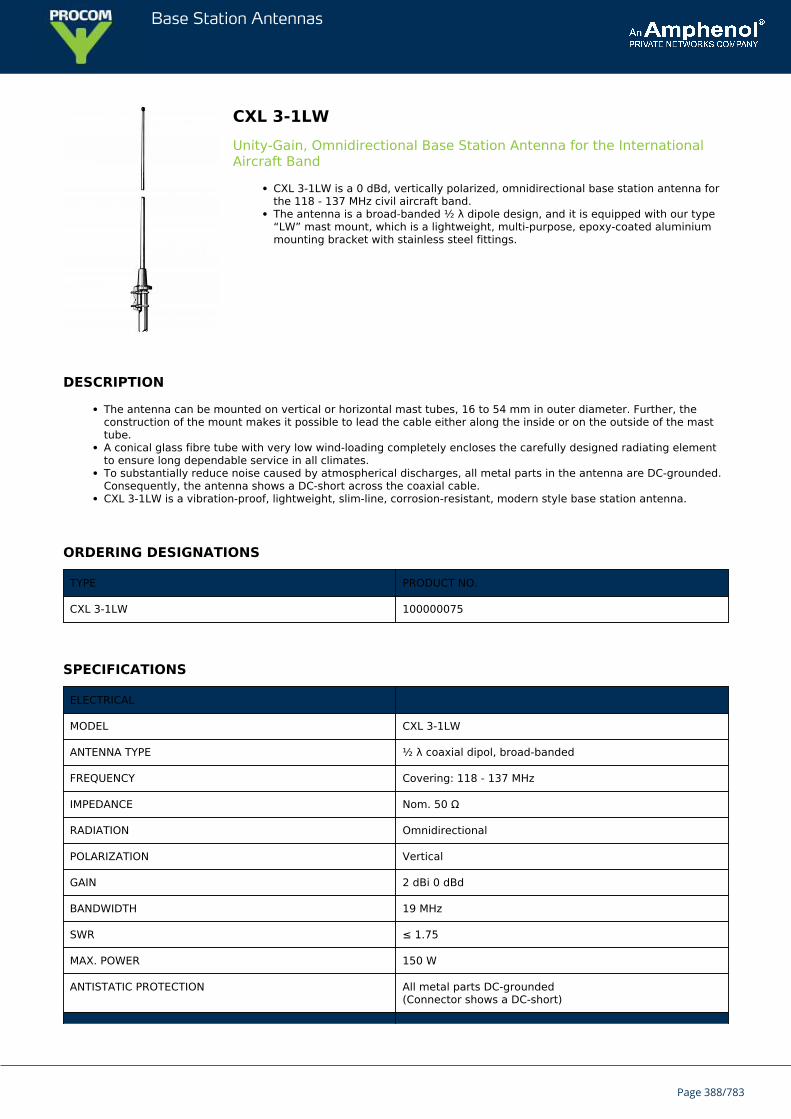
Base Station Antennas
CXL 3-1LWUnity-Gain, Omnidirectional Base Station Antenna for the InternationalAircraft Band
CXL 3-1LW is a 0 dBd, vertically polarized, omnidirectional base station antenna forthe 118 - 137 MHz civil aircraft band.The antenna is a broad-banded ½ λ dipole design, and it is equipped with our type“LW” mast mount, which is a lightweight, multi-purpose, epoxy-coated aluminiummounting bracket with stainless steel fittings.
DESCRIPTION
The antenna can be mounted on vertical or horizontal mast tubes, 16 to 54 mm in outer diameter. Further, theconstruction of the mount makes it possible to lead the cable either along the inside or on the outside of the masttube.A conical glass fibre tube with very low wind-loading completely encloses the carefully designed radiating elementto ensure long dependable service in all climates.To substantially reduce noise caused by atmospherical discharges, all metal parts in the antenna are DC-grounded.Consequently, the antenna shows a DC-short across the coaxial cable.CXL 3-1LW is a vibration-proof, lightweight, slim-line, corrosion-resistant, modern style base station antenna.
ORDERING DESIGNATIONS
TYPE PRODUCT NO.
CXL 3-1LW 100000075
SPECIFICATIONS
ELECTRICAL
MODEL CXL 3-1LW
ANTENNA TYPE ½ λ coaxial dipol, broad-banded
FREQUENCY Covering: 118 - 137 MHz
IMPEDANCE Nom. 50 Ω
RADIATION Omnidirectional
POLARIZATION Vertical
GAIN 2 dBi 0 dBd
BANDWIDTH 19 MHz
SWR ≤ 1.75
MAX. POWER 150 W
ANTISTATIC PROTECTION All metal parts DC-grounded(Connector shows a DC-short)
Page 388/783
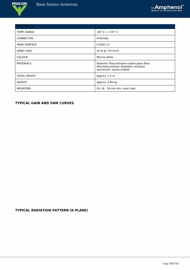
Base Station Antennas
MECHANICAL
TEMP. RANGE -40° C → +70° C
CONNECTOR N-female
WIND SURFACE 0.0162 m²
WIND LOAD 25 N @ 175 km/h
COLOUR Marine white
MATERIALS Radome: Polyurethane-coated glass fibreMounting bracket: Seawater resistantaluminium, epoxy-coated
TOTAL HEIGHT Approx. 1.5 m
WEIGHT Approx. 0.80 kg
MOUNTING On 16 - 54 mm dia. mast tube
TYPICAL GAIN AND SWR CURVES
TYPICAL RADIATION PATTERN (E-PLANE)
Page 389/783
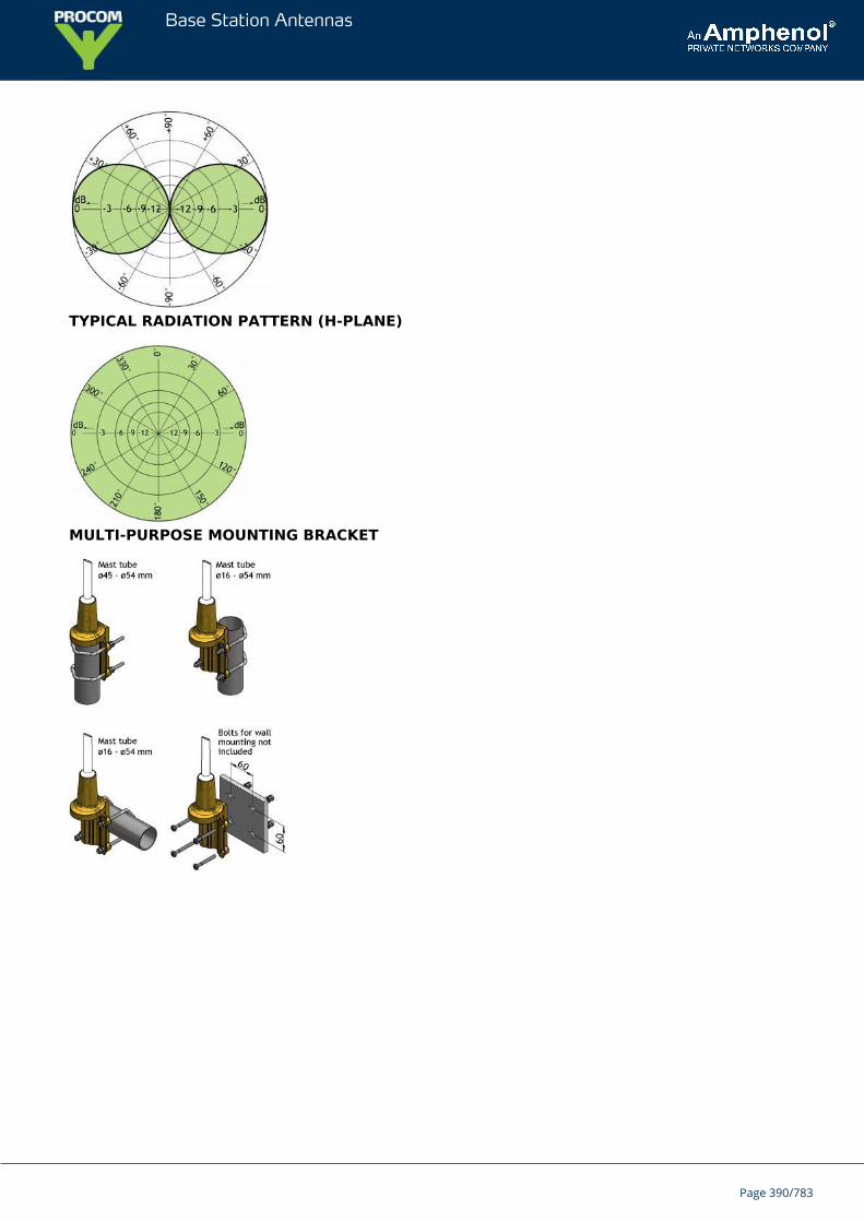
Base Station Antennas
TYPICAL RADIATION PATTERN (H-PLANE)
MULTI-PURPOSE MOUNTING BRACKET
Page 390/783
Base Station Antennas
CXL 3-1Unity-Gain, Omnidirectional Base Station Antenna for the InternationalAircraft Band
CXL 3-1 is a 0 dBd, vertically polarized, omnidirectional base station antenna for the118 - 137 MHz civil aircraft band.The antenna is a broad-banded ½ λ dipole design.The antenna can be mounted on threaded 1" water pipe using the supplied 1"revolving nut. In this way, a nice, slim installation is obtained.
DESCRIPTION
A wide variety of accessory mounting hardware (see below) gives ample choice regarding alternative ways ofinstallation.To substantially reduce noise caused by atmospherical discharges, all metal parts in the antenna are DC-grounded.Consequently, the antenna shows a DC-short across the coaxial cable.A conical glass fibre tube with very low wind-loading completely encloses the carefully designed radiating elementto ensure long dependable service in all climates.
ORDERING DESIGNATIONS
TYPE PRODUCT NO.
CXL 3-1 100000068
SPECIFICATIONS
ELECTRICAL
MODEL CXL 3-1
ANTENNA TYPE ½ λ coaxial dipol, broad-banded
FREQUENCY Covering: 118 - 137 MHz
IMPEDANCE Nom. 50 Ω
RADIATION Omnidirectional
POLARIZATION Vertical
GAIN 2 dBi 0 dBd
BANDWIDTH 19 MHz
SWR ≤ 1.75
MAX. POWER 150 W
ANTISTATIC PROTECTION All metal parts DC-grounded(Connector shows a DC-short)
Page 391/783
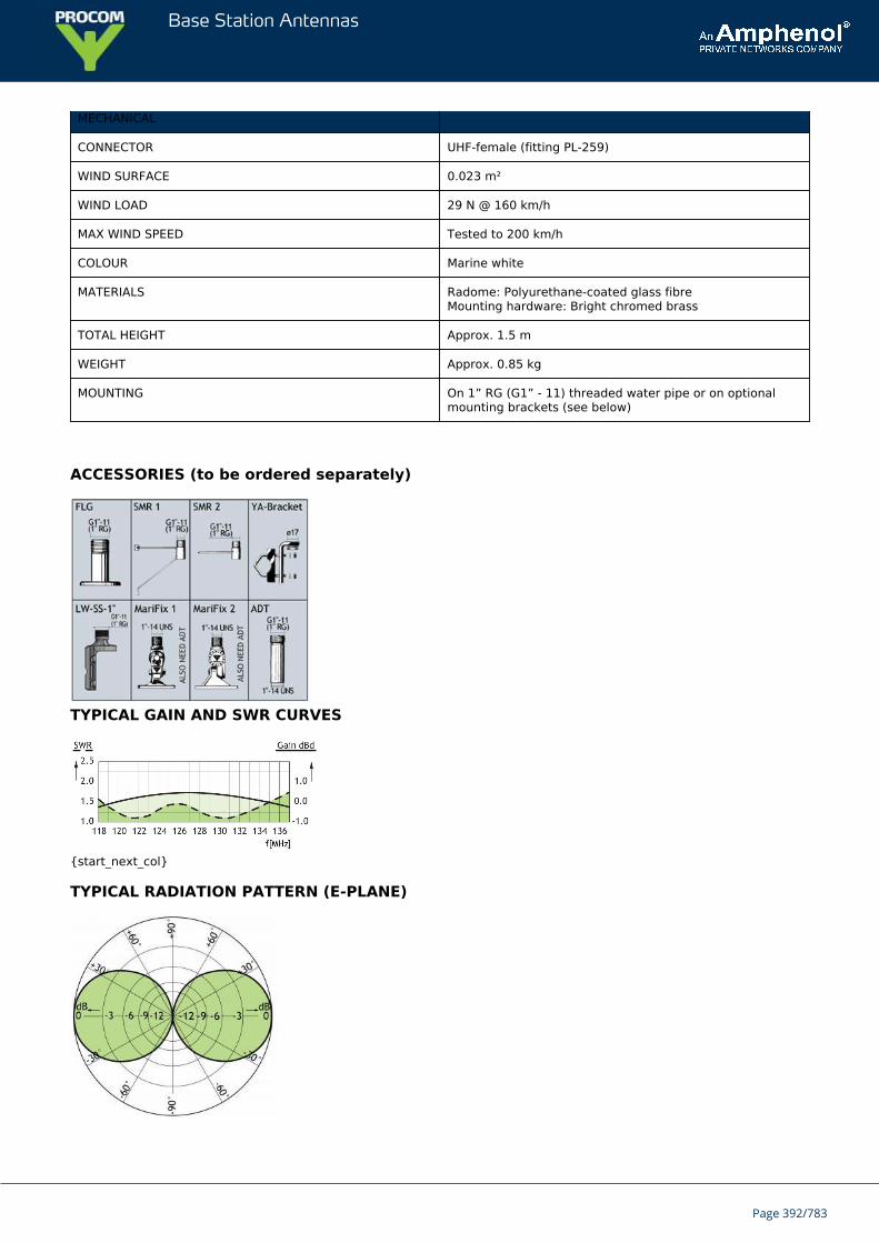
Base Station Antennas
MECHANICAL
CONNECTOR UHF-female (fitting PL-259)
WIND SURFACE 0.023 m²
WIND LOAD 29 N @ 160 km/h
MAX WIND SPEED Tested to 200 km/h
COLOUR Marine white
MATERIALS Radome: Polyurethane-coated glass fibreMounting hardware: Bright chromed brass
TOTAL HEIGHT Approx. 1.5 m
WEIGHT Approx. 0.85 kg
MOUNTING On 1” RG (G1” - 11) threaded water pipe or on optionalmounting brackets (see below)
ACCESSORIES (to be ordered separately)
TYPICAL GAIN AND SWR CURVES
{start_next_col}
TYPICAL RADIATION PATTERN (E-PLANE)
Page 392/783
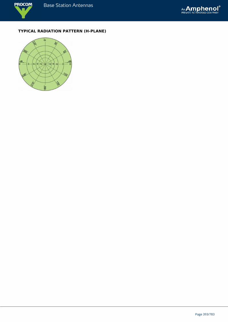
Base Station Antennas
TYPICAL RADIATION PATTERN (H-PLANE)
Page 393/783
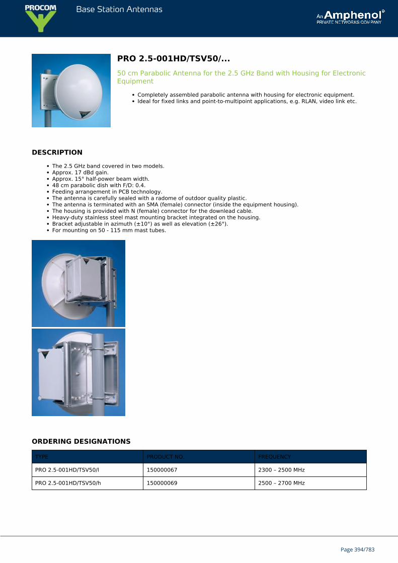
Base Station Antennas
PRO 2.5-001HD/TSV50/...50 cm Parabolic Antenna for the 2.5 GHz Band with Housing for ElectronicEquipment
Completely assembled parabolic antenna with housing for electronic equipment.Ideal for fixed links and point-to-multipoint applications, e.g. RLAN, video link etc.
DESCRIPTION
The 2.5 GHz band covered in two models.Approx. 17 dBd gain.Approx. 15° half-power beam width.48 cm parabolic dish with F/D: 0.4.Feeding arrangement in PCB technology.The antenna is carefully sealed with a radome of outdoor quality plastic.The antenna is terminated with an SMA (female) connector (inside the equipment housing).The housing is provided with N (female) connector for the downlead cable.Heavy-duty stainless steel mast mounting bracket integrated on the housing.Bracket adjustable in azimuth (±10°) as well as elevation (±26°).For mounting on 50 - 115 mm mast tubes.
ORDERING DESIGNATIONS
TYPE PRODUCT NO. FREQUENCY
PRO 2.5-001HD/TSV50/l 150000067 2300 – 2500 MHz
PRO 2.5-001HD/TSV50/h 150000069 2500 – 2700 MHz
Page 394/783
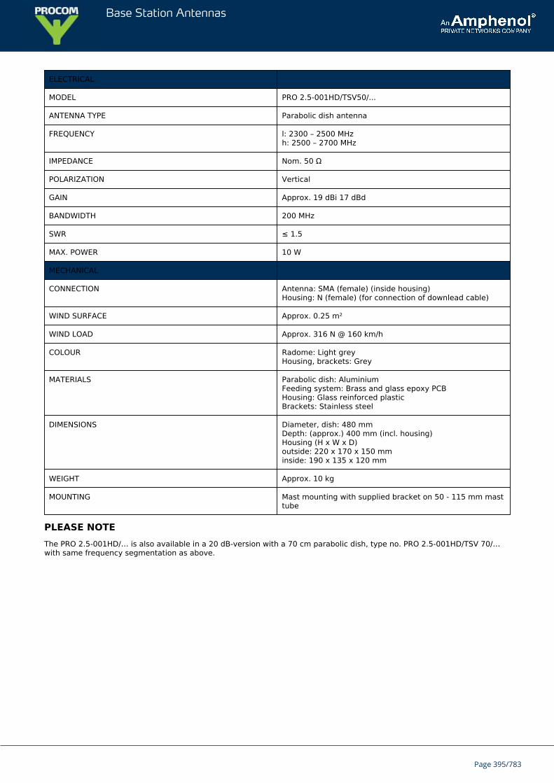
Base Station Antennas
ELECTRICAL
MODEL PRO 2.5-001HD/TSV50/...
ANTENNA TYPE Parabolic dish antenna
FREQUENCY l: 2300 – 2500 MHzh: 2500 – 2700 MHz
IMPEDANCE Nom. 50 Ω
POLARIZATION Vertical
GAIN Approx. 19 dBi 17 dBd
BANDWIDTH 200 MHz
SWR ≤ 1.5
MAX. POWER 10 W
MECHANICAL
CONNECTION Antenna: SMA (female) (inside housing)Housing: N (female) (for connection of downlead cable)
WIND SURFACE Approx. 0.25 m²
WIND LOAD Approx. 316 N @ 160 km/h
COLOUR Radome: Light greyHousing, brackets: Grey
MATERIALS Parabolic dish: AluminiumFeeding system: Brass and glass epoxy PCBHousing: Glass reinforced plasticBrackets: Stainless steel
DIMENSIONS Diameter, dish: 480 mmDepth: (approx.) 400 mm (incl. housing)Housing (H x W x D)outside: 220 x 170 x 150 mminside: 190 x 135 x 120 mm
WEIGHT Approx. 10 kg
MOUNTING Mast mounting with supplied bracket on 50 - 115 mm masttube
PLEASE NOTEThe PRO 2.5-001HD/… is also available in a 20 dB-version with a 70 cm parabolic dish, type no. PRO 2.5-001HD/TSV 70/…with same frequency segmentation as above.
Page 395/783
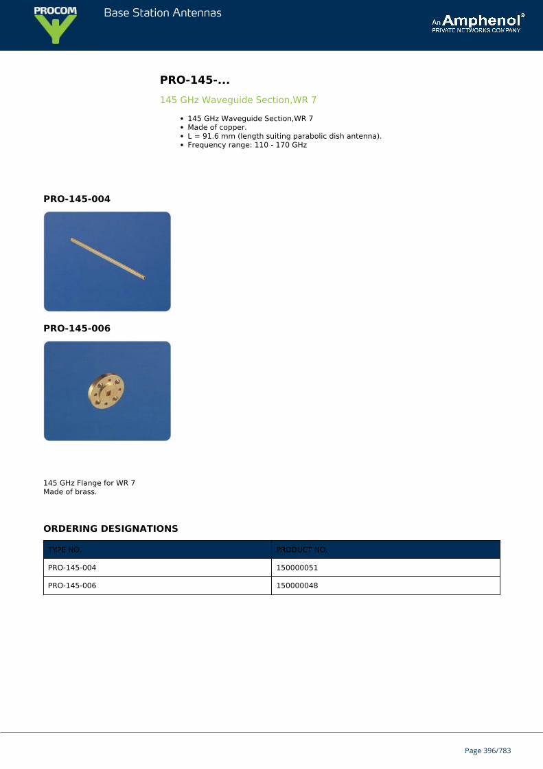
Base Station Antennas
PRO-145-...145 GHz Waveguide Section,WR 7
145 GHz Waveguide Section,WR 7Made of copper.L = 91.6 mm (length suiting parabolic dish antenna).Frequency range: 110 - 170 GHz
PRO-145-004
PRO-145-006
145 GHz Flange for WR 7Made of brass.
ORDERING DESIGNATIONS
TYPE NO. PRODUCT NO.
PRO-145-004 150000051
PRO-145-006 150000048
Page 396/783
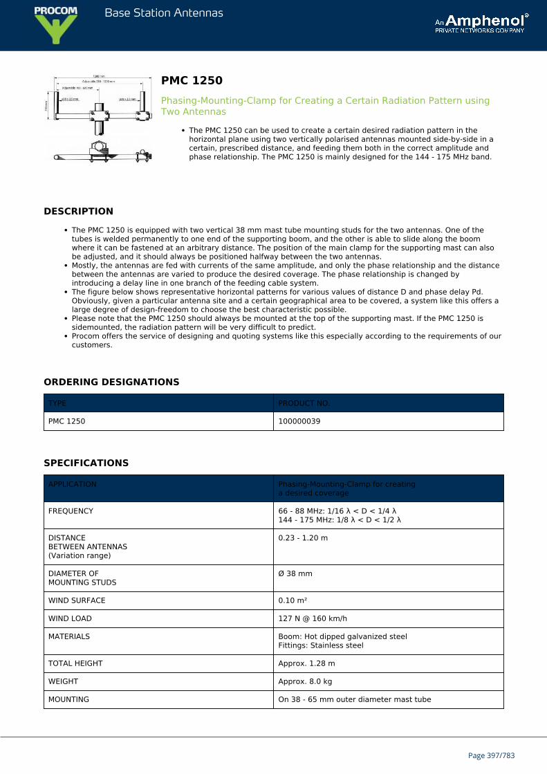
Base Station Antennas
PMC 1250Phasing-Mounting-Clamp for Creating a Certain Radiation Pattern usingTwo Antennas
The PMC 1250 can be used to create a certain desired radiation pattern in thehorizontal plane using two vertically polarised antennas mounted side-by-side in acertain, prescribed distance, and feeding them both in the correct amplitude andphase relationship. The PMC 1250 is mainly designed for the 144 - 175 MHz band.
DESCRIPTION
The PMC 1250 is equipped with two vertical 38 mm mast tube mounting studs for the two antennas. One of thetubes is welded permanently to one end of the supporting boom, and the other is able to slide along the boomwhere it can be fastened at an arbitrary distance. The position of the main clamp for the supporting mast can alsobe adjusted, and it should always be positioned halfway between the two antennas.Mostly, the antennas are fed with currents of the same amplitude, and only the phase relationship and the distancebetween the antennas are varied to produce the desired coverage. The phase relationship is changed byintroducing a delay line in one branch of the feeding cable system.The figure below shows representative horizontal patterns for various values of distance D and phase delay Pd.Obviously, given a particular antenna site and a certain geographical area to be covered, a system like this offers alarge degree of design-freedom to choose the best characteristic possible.Please note that the PMC 1250 should always be mounted at the top of the supporting mast. If the PMC 1250 issidemounted, the radiation pattern will be very difficult to predict.Procom offers the service of designing and quoting systems like this especially according to the requirements of ourcustomers.
ORDERING DESIGNATIONS
TYPE PRODUCT NO.
PMC 1250 100000039
SPECIFICATIONS
APPLICATION Phasing-Mounting-Clamp for creatinga desired coverage
FREQUENCY 66 - 88 MHz: 1/16 λ < D < 1/4 λ144 - 175 MHz: 1/8 λ < D < 1/2 λ
DISTANCEBETWEEN ANTENNAS(Variation range)
0.23 - 1.20 m
DIAMETER OFMOUNTING STUDS
Ø 38 mm
WIND SURFACE 0.10 m²
WIND LOAD 127 N @ 160 km/h
MATERIALS Boom: Hot dipped galvanized steelFittings: Stainless steel
TOTAL HEIGHT Approx. 1.28 m
WEIGHT Approx. 8.0 kg
MOUNTING On 38 - 65 mm outer diameter mast tube
Page 397/783
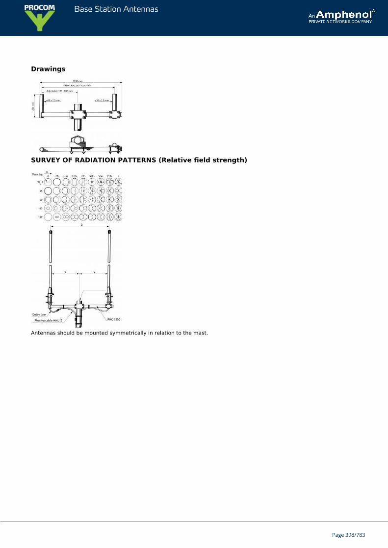
Base Station Antennas
Drawings
SURVEY OF RADIATION PATTERNS (Relative field strength)
Antennas should be mounted symmetrically in relation to the mast.
Page 398/783
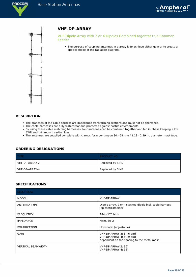
Base Station Antennas
VHF-DP-ARRAYVHF-Dipole Array with 2 or 4 Dipoles Combined togehter to a CommonFeeder
The purpose of coupling antennas in a array is to achieve either gain or to create aspecial shape of the radiation diagram.
DESCRIPTION
The branches of the cable harness are impedance transforming sections and must not be shortened.The cable harnesses are fully waterproof and protected against hostile environments.By using these cable matching harnesses, four antennas can be combined together and fed in phase keeping a lowSWR and minimum insertion loss.The antennas are supplied complete with clamps for mounting on 30 - 58 mm / 1.18 - 2.29 in. diameter mast tube.
ORDERING DESIGNATIONS
TYPE PRODUCT NO.
VHF-DP-ARRAY-2 Replaced by S.M2
VHF-DP-ARRAY-4 Replaced by S.M4
SPECIFICATIONS
ELECTRICAL
MODEL VHF-DP-ARRAY
ANTENNA TYPE Dipole array, 2 or 4 stacked dipole incl. cable harness(splitter/combiner)
FREQUENCY 144 - 175 MHz
IMPEDANCE Nom. 50 Ω
POLARIZATION Horizontal (adjustable)
GAIN VHF-DP-ARRAY-2: 3 - 6 dBdVHF-DP-ARRAY-4: 6 - 9 dBddependent on the spacing to the metal mast
VERTICAL BEAMWIDTH VHF-DP-ARRAY-2: 36°VHF-DP-ARRAY-4: 18°
Page 399/783
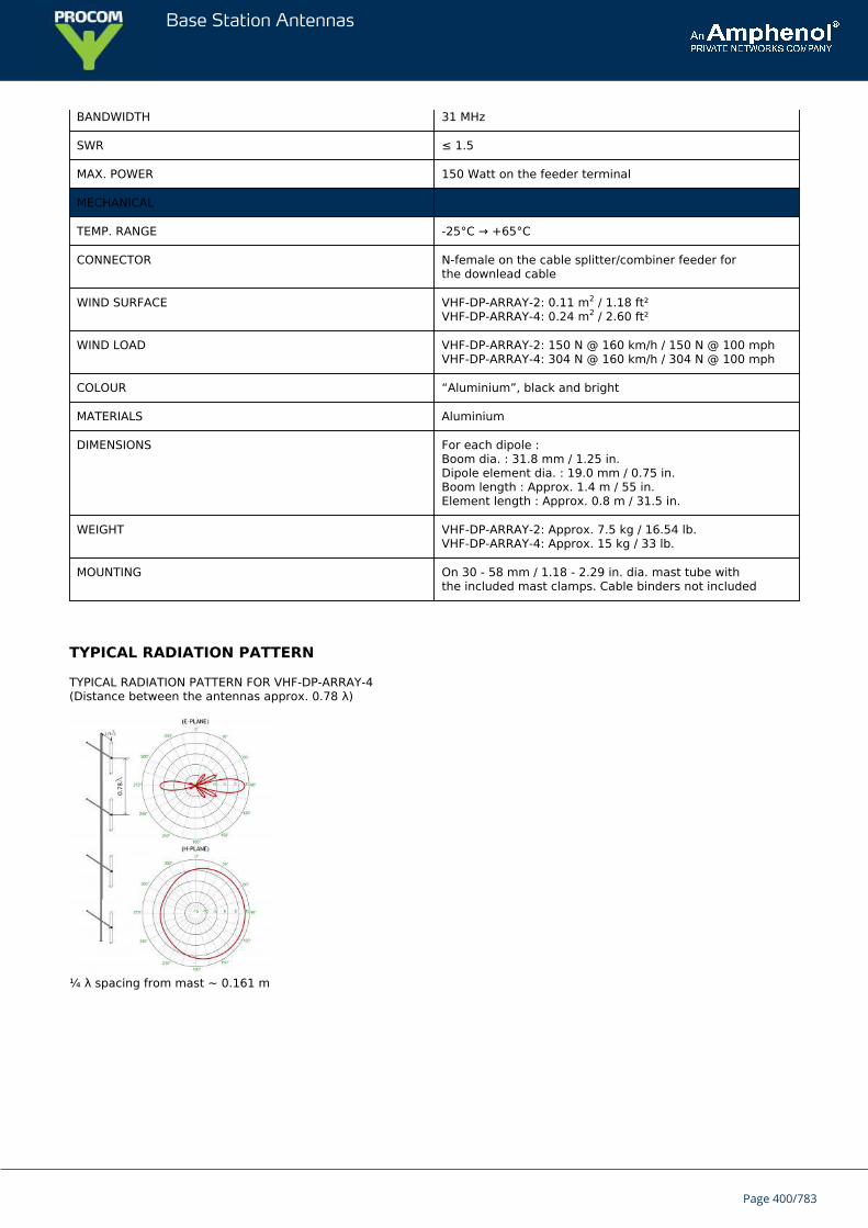
Base Station Antennas
BANDWIDTH 31 MHz
SWR ≤ 1.5
MAX. POWER 150 Watt on the feeder terminal
MECHANICAL
TEMP. RANGE -25°C → +65°C
CONNECTOR N-female on the cable splitter/combiner feeder forthe downlead cable
WIND SURFACE VHF-DP-ARRAY-2: 0.11 m2 / 1.18 ft²VHF-DP-ARRAY-4: 0.24 m2 / 2.60 ft²
WIND LOAD VHF-DP-ARRAY-2: 150 N @ 160 km/h / 150 N @ 100 mphVHF-DP-ARRAY-4: 304 N @ 160 km/h / 304 N @ 100 mph
COLOUR “Aluminium”, black and bright
MATERIALS Aluminium
DIMENSIONS For each dipole :Boom dia. : 31.8 mm / 1.25 in.Dipole element dia. : 19.0 mm / 0.75 in.Boom length : Approx. 1.4 m / 55 in.Element length : Approx. 0.8 m / 31.5 in.
WEIGHT VHF-DP-ARRAY-2: Approx. 7.5 kg / 16.54 lb.VHF-DP-ARRAY-4: Approx. 15 kg / 33 lb.
MOUNTING On 30 - 58 mm / 1.18 - 2.29 in. dia. mast tube withthe included mast clamps. Cable binders not included
TYPICAL RADIATION PATTERN
TYPICAL RADIATION PATTERN FOR VHF-DP-ARRAY-4(Distance between the antennas approx. 0.78 λ)
¼ λ spacing from mast ~ 0.161 m
Page 400/783
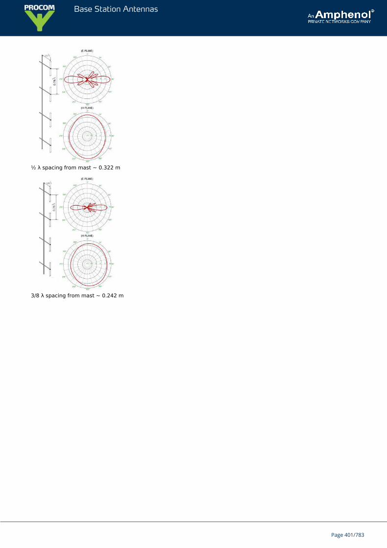
Base Station Antennas
½ λ spacing from mast ~ 0.322 m
3/8 λ spacing from mast ~ 0.242 m
Page 401/783
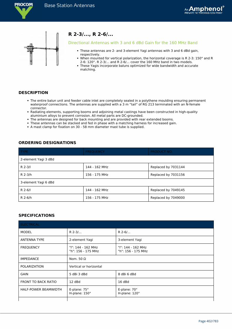
Base Station Antennas
R 2-3/..., R 2-6/...Directional Antennas with 3 and 6 dBd Gain for the 160 MHz Band
These antennas are 2- and 3-element Yagi antennas with 3 and 6 dBd gain,respectively.When mounted for vertical polarization, the horizontal coverage is R 2-3: 150° and R2-6: 120°. R 2-3/… and R 2-6/… cover the 160 MHz band in two models.These Yagis incorporate baluns optimized for wide bandwidth and accuratematching.
DESCRIPTION
The entire balun unit and feeder cable inlet are completely sealed in a polythene moulding ensuring permanentwaterproof connections. The antennas are supplied with a 3 m “tail” of RG 213 terminated with an N-femaleconnector.Radiating elements, supporting booms and adjoining metal castings have been constructed in high-qualityaluminium alloys to prevent corrosion. All metal parts are DC-grounded.The antennas are designed for back mounting and are provided with rear extended booms.These antennas can be stacked and fed in phase with a matching harness for increased gain.A mast clamp for fixation on 30 - 58 mm diameter mast tube is supplied.
ORDERING DESIGNATIONS
TYPE FREQUENCY PRODUCT NO.
2-element Yagi 3 dBd
R 2-3/l 144 - 162 MHz Replaced by 7031144
R 2-3/h 156 - 175 MHz Replaced by 7031156
3-element Yagi 6 dBd
R 2-6/l 144 - 162 MHz Replaced by 7049145
R 2-6/h 156 - 175 MHz Replaced by 7049000
SPECIFICATIONS
ELECTRICAL
MODEL R 2-3/... R 2-6/...
ANTENNA TYPE 2-element Yagi 3-element Yagi
FREQUENCY "l": 144 - 162 MHz"h": 156 - 175 MHz
"l": 144 - 162 MHz"h": 156 - 175 MHz
IMPEDANCE Nom. 50 Ω
POLARIZATION Vertical or horizontal
GAIN 5 dBi 3 dBd 8 dBi 6 dBd
FRONT TO BACK RATIO 12 dBd 16 dBd
HALF-POWER BEAMWIDTH E-plane: 75°H-plane: 150°
E-plane: 70°H-plane: 120°
Page 402/783
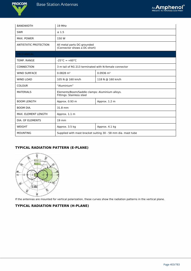
Base Station Antennas
BANDWIDTH 19 MHz
SWR ≤ 1.5
MAX. POWER 150 W
ANTISTATIC PROTECTION All metal parts DC-grounded(Connector shows a DC-short)
MECHANICAL
TEMP. RANGE -25°C → +60°C
CONNECTION 3 m tail of RG 213 terminated with N-female connector
WIND SURFACE 0.0828 m² 0.0936 m²
WIND LOAD 105 N @ 160 km/h 118 N @ 160 km/h
COLOUR “Aluminium”
MATERIALS Elements/Boom/Saddle clamps: Aluminium alloys.Fittings: Stainless steel
BOOM LENGTH Approx. 0.93 m Approx. 1.2 m
BOOM DIA. 31.8 mm
MAX. ELEMENT LENGTH Approx. 1.1 m
DIA. OF ELEMENTS 19 mm
WEIGHT Approx. 3.5 kg Approx. 4.1 kg
MOUNTING Supplied with mast bracket suiting 30 - 58 mm dia. mast tube
TYPICAL RADIATION PATTERN (E-PLANE)
If the antennas are mounted for vertical polarization, these curves show the radiation patterns in the vertical plane.
TYPICAL RADIATION PATTERN (H-PLANE)
Page 403/783
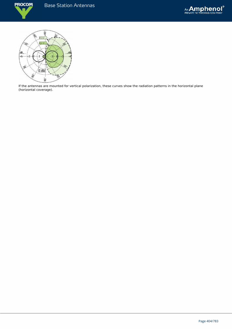
Base Station Antennas
If the antennas are mounted for vertical polarization, these curves show the radiation patterns in the horizontal plane(horizontal coverage).
Page 404/783
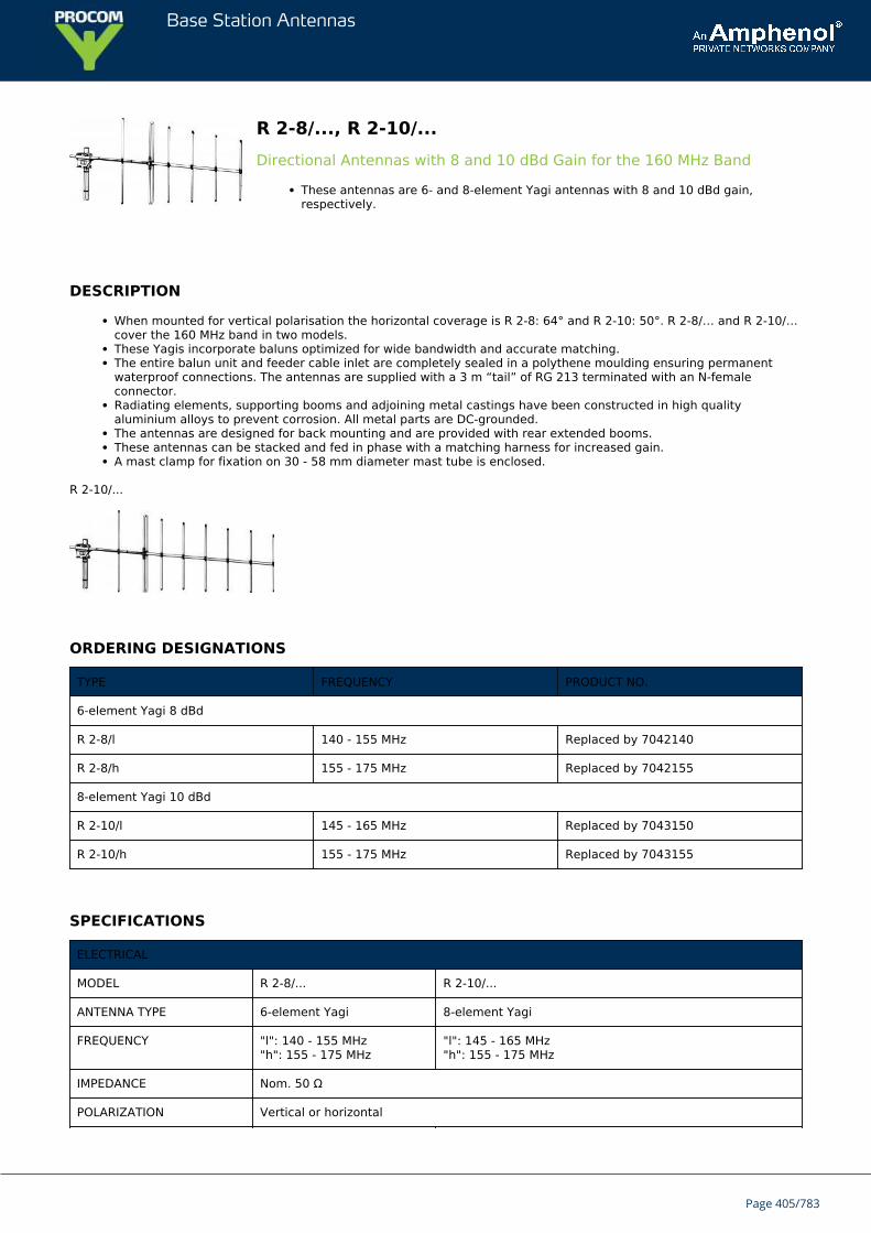
Base Station Antennas
R 2-8/..., R 2-10/...Directional Antennas with 8 and 10 dBd Gain for the 160 MHz Band
These antennas are 6- and 8-element Yagi antennas with 8 and 10 dBd gain,respectively.
DESCRIPTION
When mounted for vertical polarisation the horizontal coverage is R 2-8: 64° and R 2-10: 50°. R 2-8/… and R 2-10/…cover the 160 MHz band in two models.These Yagis incorporate baluns optimized for wide bandwidth and accurate matching.The entire balun unit and feeder cable inlet are completely sealed in a polythene moulding ensuring permanentwaterproof connections. The antennas are supplied with a 3 m “tail” of RG 213 terminated with an N-femaleconnector.Radiating elements, supporting booms and adjoining metal castings have been constructed in high qualityaluminium alloys to prevent corrosion. All metal parts are DC-grounded.The antennas are designed for back mounting and are provided with rear extended booms.These antennas can be stacked and fed in phase with a matching harness for increased gain.A mast clamp for fixation on 30 - 58 mm diameter mast tube is enclosed.
R 2-10/...
ORDERING DESIGNATIONS
TYPE FREQUENCY PRODUCT NO.
6-element Yagi 8 dBd
R 2-8/l 140 - 155 MHz Replaced by 7042140
R 2-8/h 155 - 175 MHz Replaced by 7042155
8-element Yagi 10 dBd
R 2-10/l 145 - 165 MHz Replaced by 7043150
R 2-10/h 155 - 175 MHz Replaced by 7043155
SPECIFICATIONS
ELECTRICAL
MODEL R 2-8/... R 2-10/...
ANTENNA TYPE 6-element Yagi 8-element Yagi
FREQUENCY "l": 140 - 155 MHz"h": 155 - 175 MHz
"l": 145 - 165 MHz"h": 155 - 175 MHz
IMPEDANCE Nom. 50 Ω
POLARIZATION Vertical or horizontal
Page 405/783
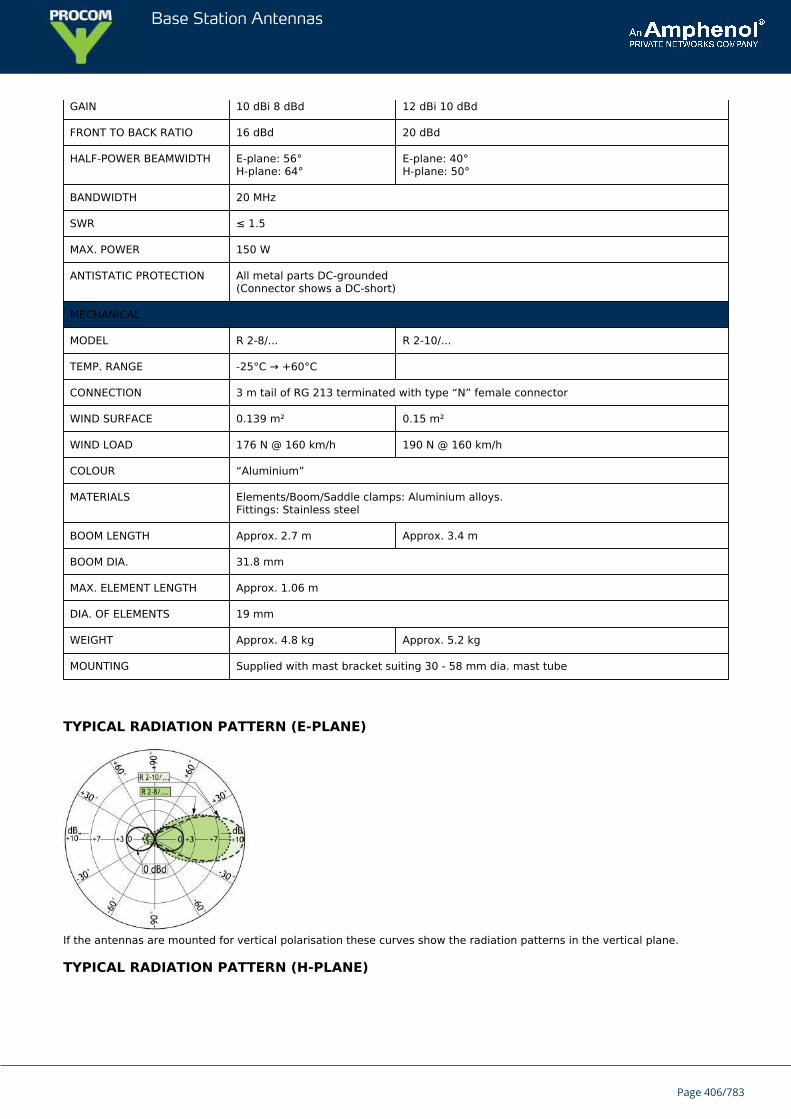
Base Station Antennas
GAIN 10 dBi 8 dBd 12 dBi 10 dBd
FRONT TO BACK RATIO 16 dBd 20 dBd
HALF-POWER BEAMWIDTH E-plane: 56°H-plane: 64°
E-plane: 40°H-plane: 50°
BANDWIDTH 20 MHz
SWR ≤ 1.5
MAX. POWER 150 W
ANTISTATIC PROTECTION All metal parts DC-grounded(Connector shows a DC-short)
MECHANICAL
MODEL R 2-8/... R 2-10/...
TEMP. RANGE -25°C → +60°C
CONNECTION 3 m tail of RG 213 terminated with type “N” female connector
WIND SURFACE 0.139 m² 0.15 m²
WIND LOAD 176 N @ 160 km/h 190 N @ 160 km/h
COLOUR “Aluminium”
MATERIALS Elements/Boom/Saddle clamps: Aluminium alloys.Fittings: Stainless steel
BOOM LENGTH Approx. 2.7 m Approx. 3.4 m
BOOM DIA. 31.8 mm
MAX. ELEMENT LENGTH Approx. 1.06 m
DIA. OF ELEMENTS 19 mm
WEIGHT Approx. 4.8 kg Approx. 5.2 kg
MOUNTING Supplied with mast bracket suiting 30 - 58 mm dia. mast tube
TYPICAL RADIATION PATTERN (E-PLANE)
If the antennas are mounted for vertical polarisation these curves show the radiation patterns in the vertical plane.
TYPICAL RADIATION PATTERN (H-PLANE)
Page 406/783
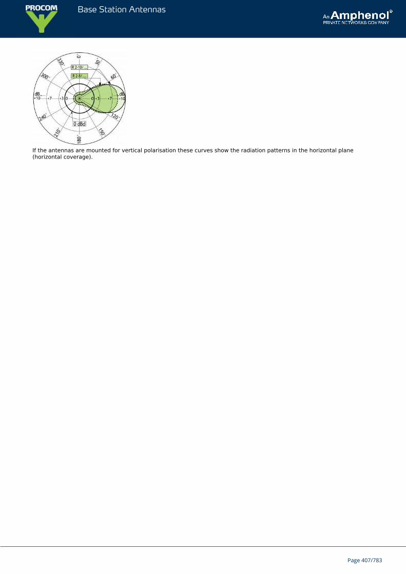
Base Station Antennas
If the antennas are mounted for vertical polarisation these curves show the radiation patterns in the horizontal plane(horizontal coverage).
Page 407/783
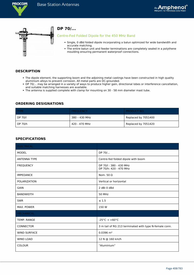
Base Station Antennas
DP 70/...Centre-Fed Folded Dipole for the 450 MHz Band
Single, 0 dBd folded dipole incorporating a balun optimized for wide bandwidth andaccurate matching.The entire balun unit and feeder terminations are completely sealed in a polythenemoulding ensuring permanent waterproof connections.
DESCRIPTION
The dipole element, the supporting boom and the adjoining metal castings have been constructed in high qualityaluminium alloys to prevent corrosion. All metal parts are DC-grounded.DP 70/… may be arranged in a variety of ways to produce higher gain, directional lobes or interference cancellation,and suitable matching harnesses are available.The antenna is supplied complete with clamp for mounting on 30 - 58 mm diameter mast tube.
ORDERING DESIGNATIONS
TYPE FREQUENCY PRODUCT NO.
DP 70/l 380 – 430 MHz Replaced by 7051400
DP 70/h 420 - 470 MHz Replaced by 7051420
SPECIFICATIONS
ELECTRICAL
MODEL DP 70/...
ANTENNA TYPE Centre-fed folded dipole with boom
FREQUENCY DP 70/l : 380 - 430 MHzDP 70/h: 420 - 470 MHz
IMPEDANCE Nom. 50 Ω
POLARIZATION Vertical or horizontal
GAIN 2 dBi 0 dBd
BANDWIDTH 50 MHz
SWR ≤ 1.5
MAX. POWER 150 W
MECHANICAL
TEMP. RANGE -25°C → +60°C
CONNECTOR 3 m tail of RG 213 terminated with type N-female conn.
WIND SURFACE 0.0396 m²
WIND LOAD 12 N @ 160 km/h
COLOUR “Aluminium”
Page 408/783
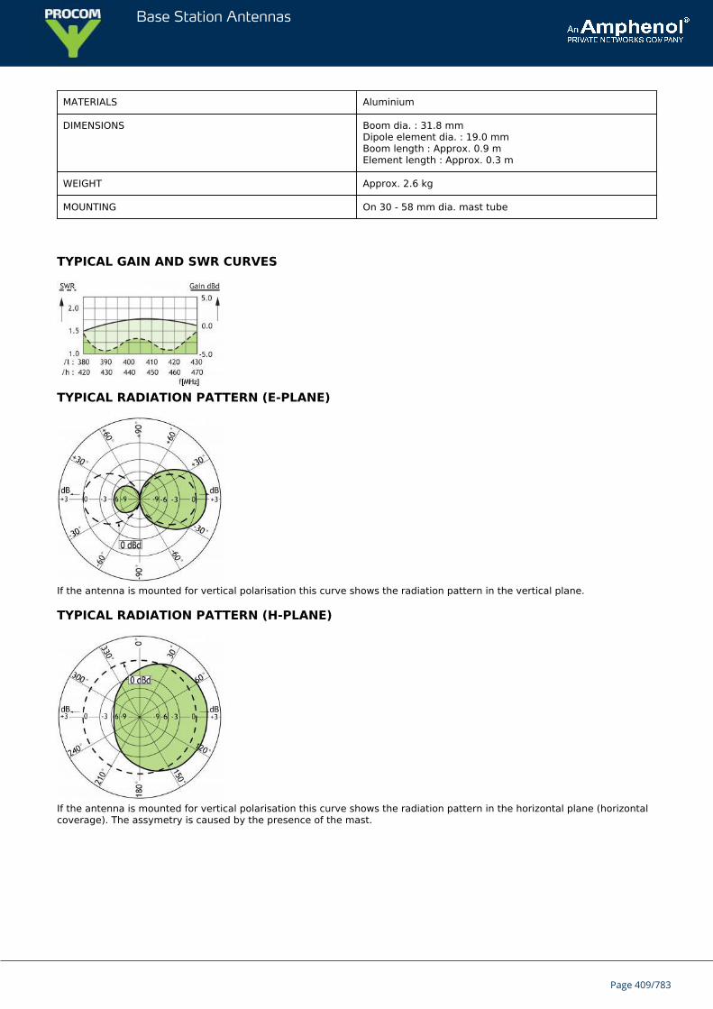
Base Station Antennas
MATERIALS Aluminium
DIMENSIONS Boom dia. : 31.8 mmDipole element dia. : 19.0 mmBoom length : Approx. 0.9 mElement length : Approx. 0.3 m
WEIGHT Approx. 2.6 kg
MOUNTING On 30 - 58 mm dia. mast tube
TYPICAL GAIN AND SWR CURVES
TYPICAL RADIATION PATTERN (E-PLANE)
If the antenna is mounted for vertical polarisation this curve shows the radiation pattern in the vertical plane.
TYPICAL RADIATION PATTERN (H-PLANE)
If the antenna is mounted for vertical polarisation this curve shows the radiation pattern in the horizontal plane (horizontalcoverage). The assymetry is caused by the presence of the mast.
Page 409/783
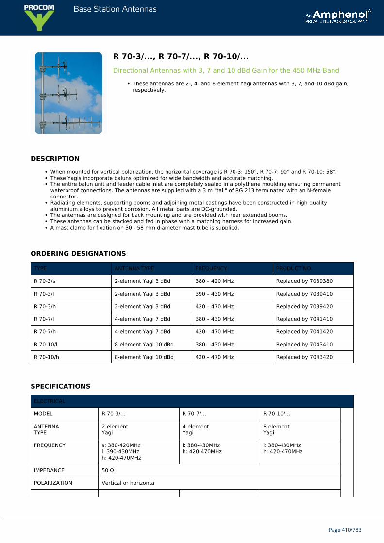
Base Station Antennas
R 70-3/..., R 70-7/..., R 70-10/...Directional Antennas with 3, 7 and 10 dBd Gain for the 450 MHz Band
These antennas are 2-, 4- and 8-element Yagi antennas with 3, 7, and 10 dBd gain,respectively.
DESCRIPTION
When mounted for vertical polarization, the horizontal coverage is R 70-3: 150°, R 70-7: 90° and R 70-10: 58°.These Yagis incorporate baluns optimized for wide bandwidth and accurate matching.The entire balun unit and feeder cable inlet are completely sealed in a polythene moulding ensuring permanentwaterproof connections. The antennas are supplied with a 3 m "tail" of RG 213 terminated with an N-femaleconnector.Radiating elements, supporting booms and adjoining metal castings have been constructed in high-qualityaluminium alloys to prevent corrosion. All metal parts are DC-grounded.The antennas are designed for back mounting and are provided with rear extended booms.These antennas can be stacked and fed in phase with a matching harness for increased gain.A mast clamp for fixation on 30 - 58 mm diameter mast tube is supplied.
ORDERING DESIGNATIONS
TYPE ANTENNA TYPE FREQUENCY PRODUCT NO.
R 70-3/s 2-element Yagi 3 dBd 380 – 420 MHz Replaced by 7039380
R 70-3/l 2-element Yagi 3 dBd 390 – 430 MHz Replaced by 7039410
R 70-3/h 2-element Yagi 3 dBd 420 – 470 MHz Replaced by 7039420
R 70-7/l 4-element Yagi 7 dBd 380 – 430 MHz Replaced by 7041410
R 70-7/h 4-element Yagi 7 dBd 420 – 470 MHz Replaced by 7041420
R 70-10/l 8-element Yagi 10 dBd 380 – 430 MHz Replaced by 7043410
R 70-10/h 8-element Yagi 10 dBd 420 – 470 MHz Replaced by 7043420
SPECIFICATIONS
ELECTRICAL
MODEL R 70-3/… R 70-7/… R 70-10/…
ANTENNATYPE
2-elementYagi
4-elementYagi
8-elementYagi
FREQUENCY s: 380-420MHzl: 390-430MHzh: 420-470MHz
l: 380-430MHzh: 420-470MHz
l: 380-430MHzh: 420-470MHz
IMPEDANCE 50 Ω
POLARIZATION Vertical or horizontal
Page 410/783
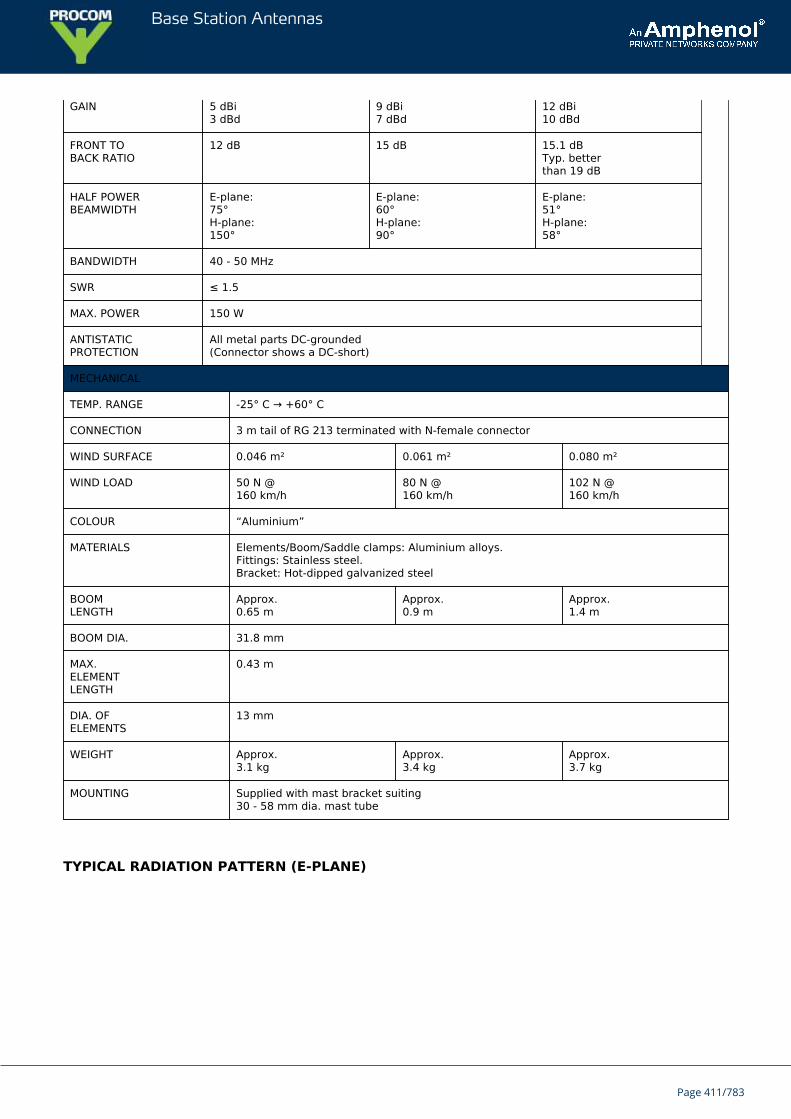
Base Station Antennas
GAIN 5 dBi3 dBd
9 dBi7 dBd
12 dBi10 dBd
FRONT TOBACK RATIO
12 dB 15 dB 15.1 dBTyp. betterthan 19 dB
HALF POWERBEAMWIDTH
E-plane:75°H-plane:150°
E-plane:60°H-plane:90°
E-plane:51°H-plane:58°
BANDWIDTH 40 - 50 MHz
SWR ≤ 1.5
MAX. POWER 150 W
ANTISTATICPROTECTION
All metal parts DC-grounded(Connector shows a DC-short)
MECHANICAL
TEMP. RANGE -25° C → +60° C
CONNECTION 3 m tail of RG 213 terminated with N-female connector
WIND SURFACE 0.046 m² 0.061 m² 0.080 m²
WIND LOAD 50 N @160 km/h
80 N @160 km/h
102 N @160 km/h
COLOUR “Aluminium”
MATERIALS Elements/Boom/Saddle clamps: Aluminium alloys.Fittings: Stainless steel.Bracket: Hot-dipped galvanized steel
BOOMLENGTH
Approx.0.65 m
Approx.0.9 m
Approx.1.4 m
BOOM DIA. 31.8 mm
MAX.ELEMENTLENGTH
0.43 m
DIA. OFELEMENTS
13 mm
WEIGHT Approx.3.1 kg
Approx.3.4 kg
Approx.3.7 kg
MOUNTING Supplied with mast bracket suiting30 - 58 mm dia. mast tube
TYPICAL RADIATION PATTERN (E-PLANE)
Page 411/783
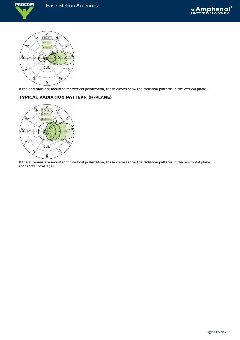
Base Station Antennas
If the antennas are mounted for vertical polarization, these curves show the radiation patterns in the vertical plane.
TYPICAL RADIATION PATTERN (H-PLANE)
If the antennas are mounted for vertical polarization, these curves show the radiation patterns in the horizontal plane(horizontal coverage).
Page 412/783
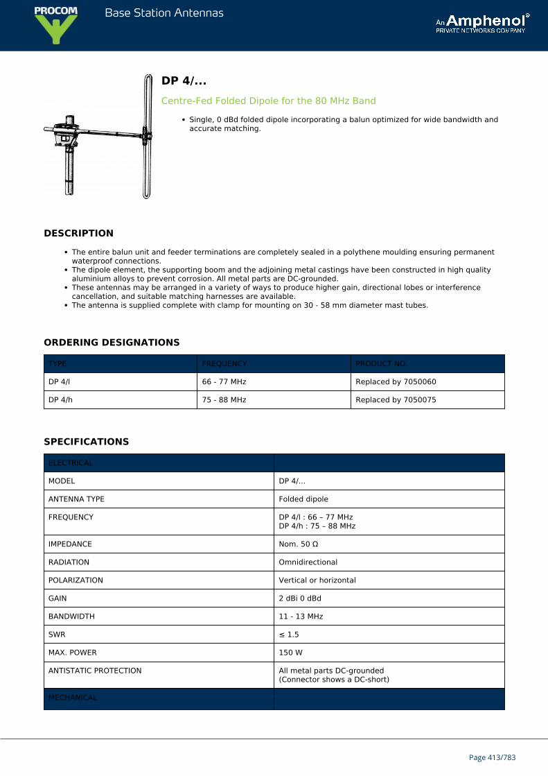
Base Station Antennas
DP 4/...Centre-Fed Folded Dipole for the 80 MHz Band
Single, 0 dBd folded dipole incorporating a balun optimized for wide bandwidth andaccurate matching.
DESCRIPTION
The entire balun unit and feeder terminations are completely sealed in a polythene moulding ensuring permanentwaterproof connections.The dipole element, the supporting boom and the adjoining metal castings have been constructed in high qualityaluminium alloys to prevent corrosion. All metal parts are DC-grounded.These antennas may be arranged in a variety of ways to produce higher gain, directional lobes or interferencecancellation, and suitable matching harnesses are available.The antenna is supplied complete with clamp for mounting on 30 - 58 mm diameter mast tubes.
ORDERING DESIGNATIONS
TYPE FREQUENCY PRODUCT NO.
DP 4/l 66 - 77 MHz Replaced by 7050060
DP 4/h 75 - 88 MHz Replaced by 7050075
SPECIFICATIONS
ELECTRICAL
MODEL DP 4/...
ANTENNA TYPE Folded dipole
FREQUENCY DP 4/l : 66 – 77 MHzDP 4/h : 75 – 88 MHz
IMPEDANCE Nom. 50 Ω
RADIATION Omnidirectional
POLARIZATION Vertical or horizontal
GAIN 2 dBi 0 dBd
BANDWIDTH 11 - 13 MHz
SWR ≤ 1.5
MAX. POWER 150 W
ANTISTATIC PROTECTION All metal parts DC-grounded(Connector shows a DC-short)
MECHANICAL
Page 413/783
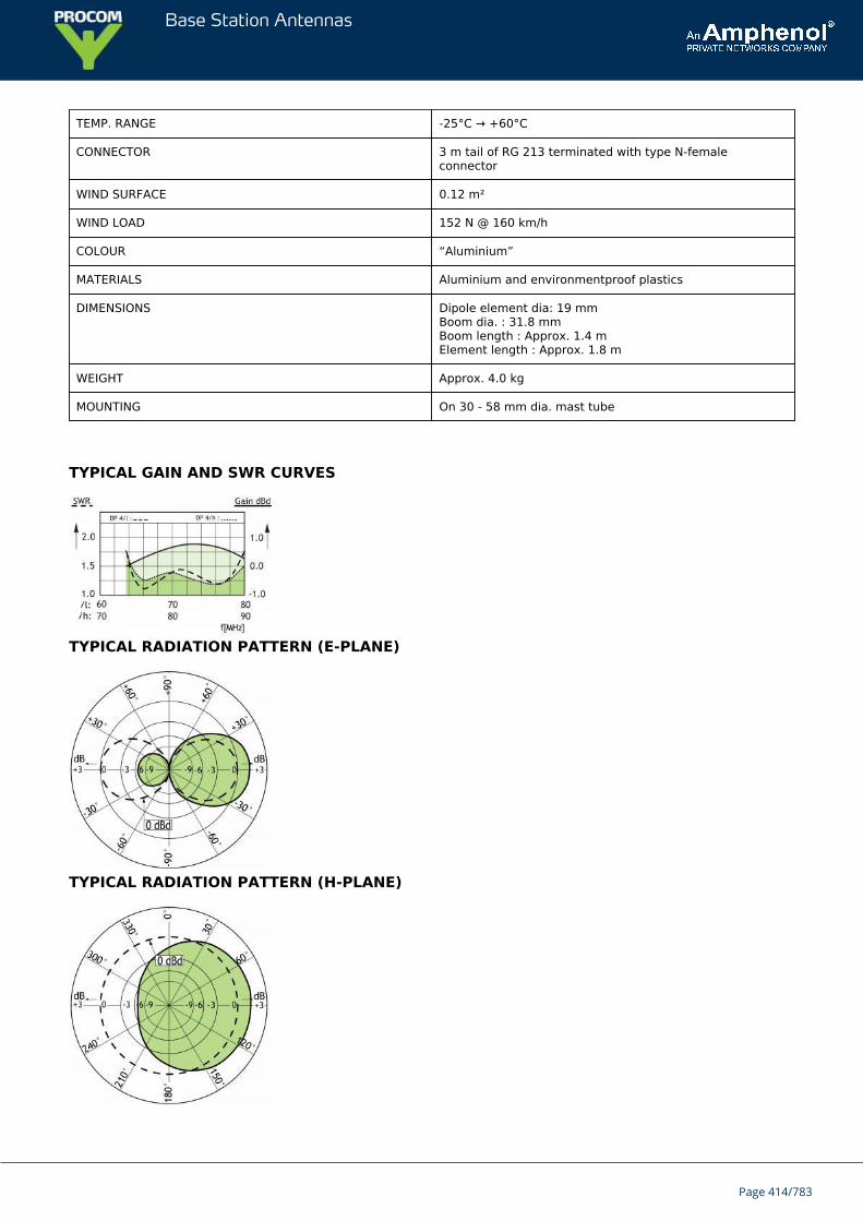
Base Station Antennas
TEMP. RANGE -25°C → +60°C
CONNECTOR 3 m tail of RG 213 terminated with type N-femaleconnector
WIND SURFACE 0.12 m²
WIND LOAD 152 N @ 160 km/h
COLOUR “Aluminium”
MATERIALS Aluminium and environmentproof plastics
DIMENSIONS Dipole element dia: 19 mmBoom dia. : 31.8 mmBoom length : Approx. 1.4 mElement length : Approx. 1.8 m
WEIGHT Approx. 4.0 kg
MOUNTING On 30 - 58 mm dia. mast tube
TYPICAL GAIN AND SWR CURVES
TYPICAL RADIATION PATTERN (E-PLANE)
TYPICAL RADIATION PATTERN (H-PLANE)
Page 414/783

Base Station Antennas
Page 415/783
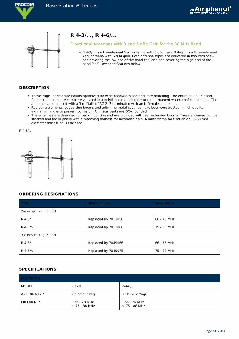
Base Station Antennas
R 4-3/..., R 4-6/...Directional Antennas with 3 and 6 dBd Gain for the 80 MHz Band
R 4-3/… is a two-element Yagi antenna with 3 dBd gain. R 4-6/… is a three-elementYagi antenna with 6 dBd gain. Both antenna types are delivered in two versions –one covering the low end of the band ("l") and one covering the high end of theband ("h"), see specifications below.
DESCRIPTION
These Yagis incorporate baluns optimized for wide bandwidth and accurate matching. The entire balun unit andfeeder cable inlet are completely sealed in a polythene moulding ensuring permanent waterproof connections. Theantennas are supplied with a 3 m "tail" of RG 213 terminated with an N-female connector.Radiating elements, supporting booms and adjoining metal castings have been constructed in high qualityaluminium alloys to prevent corrosion. All metal parts are DC-grounded.The antennas are designed for back mounting and are provided with rear extended booms. These antennas can bestacked and fed in phase with a matching harness for increased gain. A mast clamp for fixation on 30-58 mmdiameter mast tube is enclosed.
R 4-6/...
ORDERING DESIGNATIONS
TYPE PRODUCT NO. FREQUENCY
2-element Yagi 3 dBd
R 4-3/l Replaced by 7031050 66 - 78 MHz
R 4-3/h Replaced by 7031066 75 - 88 MHz
3-element Yagi 6 dBd
R 4-6/l Replaced by 7049066 66 - 76 MHz
R 4-6/h Replaced by 7049075 75 - 88 MHz
SPECIFICATIONS
ELECTRICAL
MODEL R 4-3/... R-4-6/...
ANTENNA TYPE 2-element Yagi 3-element Yagi
FREQUENCY l: 66 - 78 MHzh: 75 - 88 MHz
l: 66 - 76 MHzh: 75 - 88 MHz
Page 416/783
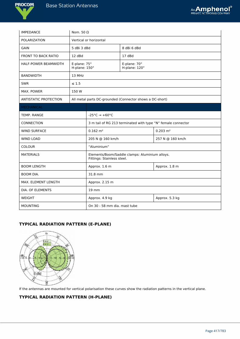
Base Station Antennas
IMPEDANCE Nom. 50 Ω
POLARIZATION Vertical or horizontal
GAIN 5 dBi 3 dBd 8 dBi 6 dBd
FRONT TO BACK RATIO 12 dBd 17 dBd
HALF-POWER BEAMWIDTH E-plane: 75°H-plane: 150°
E-plane: 70°H-plane: 120°
BANDWIDTH 13 MHz
SWR ≤ 1.5
MAX. POWER 150 W
ANTISTATIC PROTECTION All metal parts DC-grounded (Connector shows a DC-short)
MECHANICAL
TEMP. RANGE -25°C → +60°C
CONNECTION 3 m tail of RG 213 terminated with type “N” female connector
WIND SURFACE 0.162 m² 0.203 m²
WIND LOAD 205 N @ 160 km/h 257 N @ 160 km/h
COLOUR “Aluminium”
MATERIALS Elements/Boom/Saddle clamps: Aluminium alloys.Fittings: Stainless steel.
BOOM LENGTH Approx. 1.6 m Approx. 1.8 m
BOOM DIA. 31.8 mm
MAX. ELEMENT LENGTH Approx. 2.15 m
DIA. OF ELEMENTS 19 mm
WEIGHT Approx. 4.9 kg Approx. 5.3 kg
MOUNTING On 30 - 58 mm dia. mast tube
TYPICAL RADIATION PATTERN (E-PLANE)
If the antennas are mounted for vertical polarisation these curves show the radiation patterns in the vertical plane.
TYPICAL RADIATION PATTERN (H-PLANE)
Page 417/783
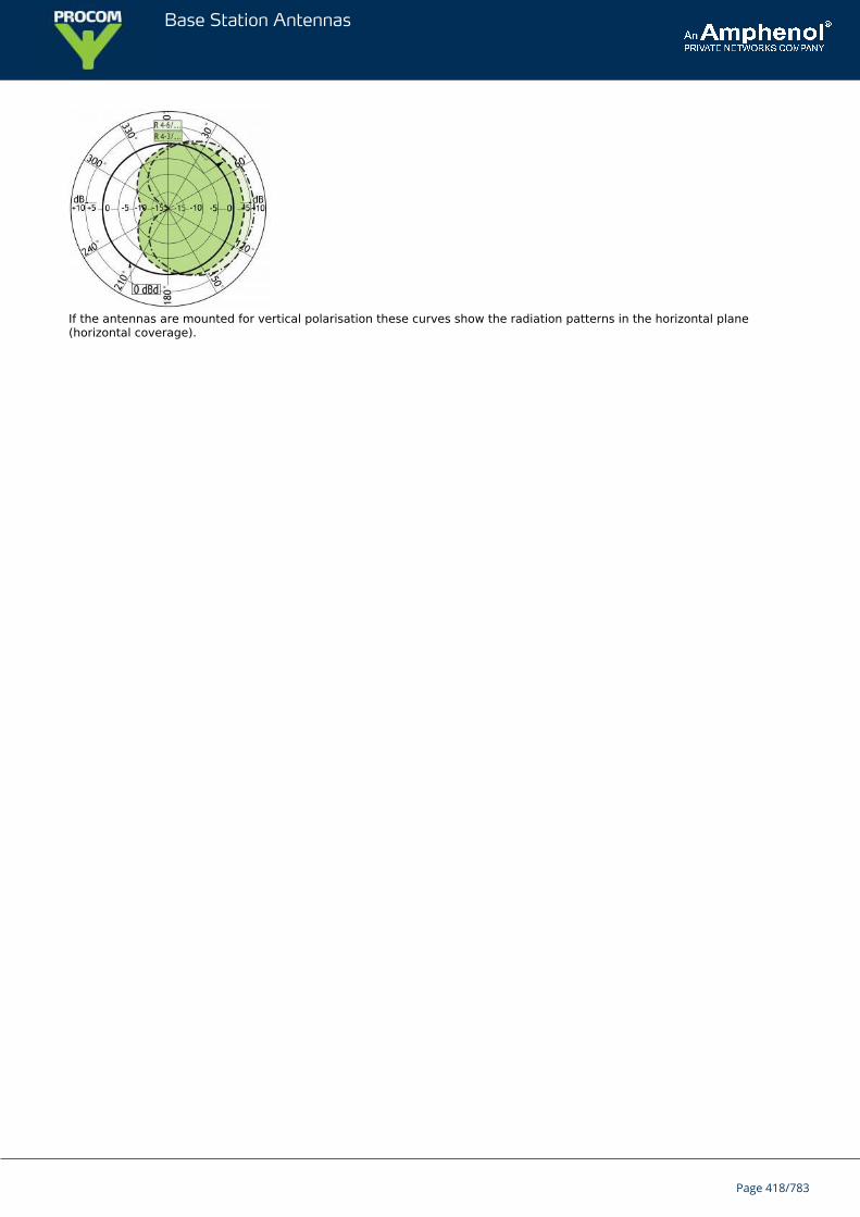
Base Station Antennas
If the antennas are mounted for vertical polarisation these curves show the radiation patterns in the horizontal plane(horizontal coverage).
Page 418/783
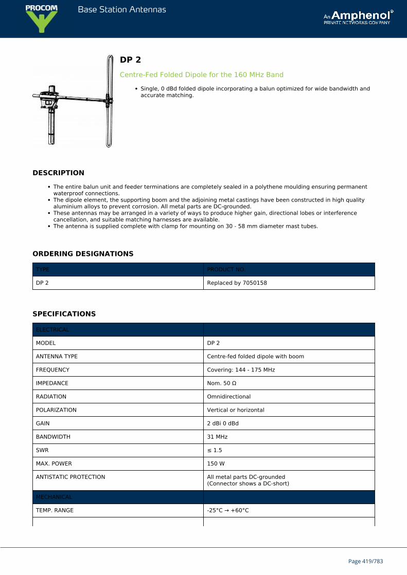
Base Station Antennas
DP 2Centre-Fed Folded Dipole for the 160 MHz Band
Single, 0 dBd folded dipole incorporating a balun optimized for wide bandwidth andaccurate matching.
DESCRIPTION
The entire balun unit and feeder terminations are completely sealed in a polythene moulding ensuring permanentwaterproof connections.The dipole element, the supporting boom and the adjoining metal castings have been constructed in high qualityaluminium alloys to prevent corrosion. All metal parts are DC-grounded.These antennas may be arranged in a variety of ways to produce higher gain, directional lobes or interferencecancellation, and suitable matching harnesses are available.The antenna is supplied complete with clamp for mounting on 30 - 58 mm diameter mast tubes.
ORDERING DESIGNATIONS
TYPE PRODUCT NO.
DP 2 Replaced by 7050158
SPECIFICATIONS
ELECTRICAL
MODEL DP 2
ANTENNA TYPE Centre-fed folded dipole with boom
FREQUENCY Covering: 144 - 175 MHz
IMPEDANCE Nom. 50 Ω
RADIATION Omnidirectional
POLARIZATION Vertical or horizontal
GAIN 2 dBi 0 dBd
BANDWIDTH 31 MHz
SWR ≤ 1.5
MAX. POWER 150 W
ANTISTATIC PROTECTION All metal parts DC-grounded(Connector shows a DC-short)
MECHANICAL
TEMP. RANGE -25°C → +60°C
Page 419/783
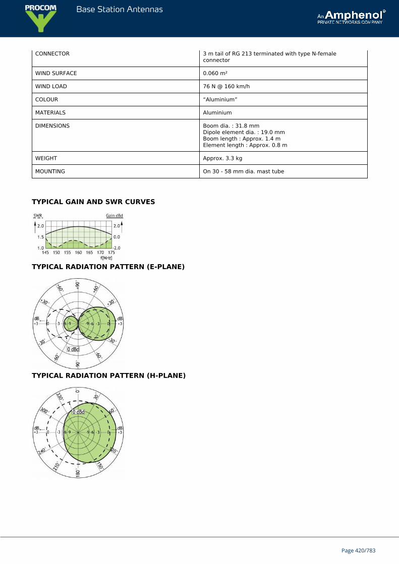
Base Station Antennas
CONNECTOR 3 m tail of RG 213 terminated with type N-femaleconnector
WIND SURFACE 0.060 m²
WIND LOAD 76 N @ 160 km/h
COLOUR “Aluminium”
MATERIALS Aluminium
DIMENSIONS Boom dia. : 31.8 mmDipole element dia. : 19.0 mmBoom length : Approx. 1.4 mElement length : Approx. 0.8 m
WEIGHT Approx. 3.3 kg
MOUNTING On 30 - 58 mm dia. mast tube
TYPICAL GAIN AND SWR CURVES
TYPICAL RADIATION PATTERN (E-PLANE)
TYPICAL RADIATION PATTERN (H-PLANE)
Page 420/783
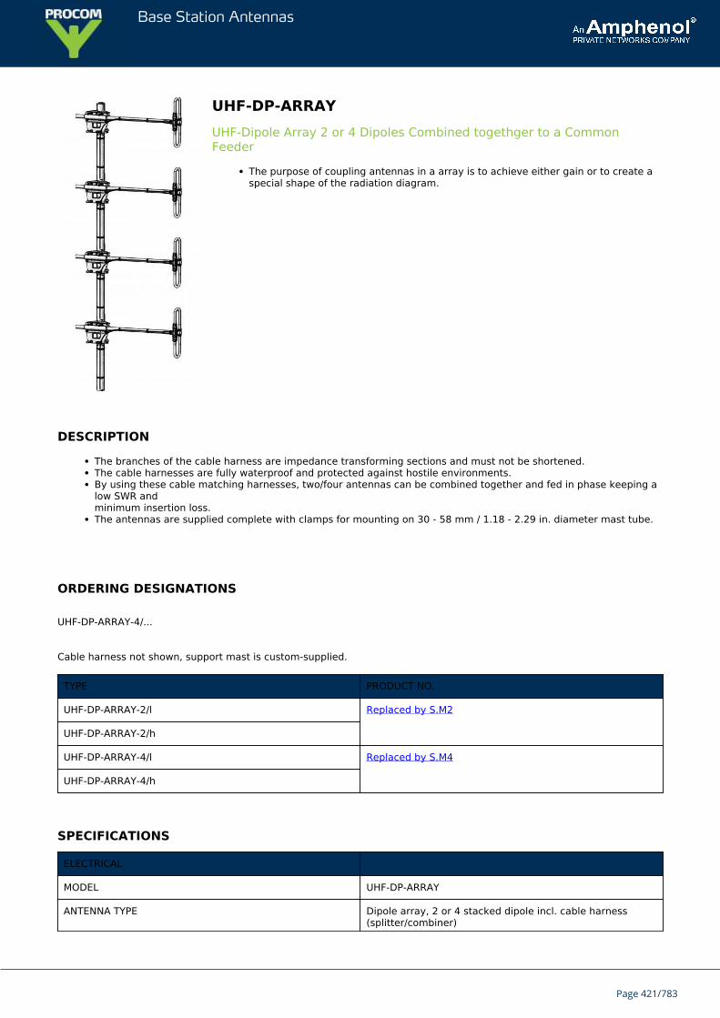
Base Station Antennas
UHF-DP-ARRAYUHF-Dipole Array 2 or 4 Dipoles Combined togethger to a CommonFeeder
The purpose of coupling antennas in a array is to achieve either gain or to create aspecial shape of the radiation diagram.
DESCRIPTION
The branches of the cable harness are impedance transforming sections and must not be shortened.The cable harnesses are fully waterproof and protected against hostile environments.By using these cable matching harnesses, two/four antennas can be combined together and fed in phase keeping alow SWR andminimum insertion loss.The antennas are supplied complete with clamps for mounting on 30 - 58 mm / 1.18 - 2.29 in. diameter mast tube.
ORDERING DESIGNATIONS
UHF-DP-ARRAY-4/...
Cable harness not shown, support mast is custom-supplied.
TYPE PRODUCT NO.
UHF-DP-ARRAY-2/l Replaced by S.M2
UHF-DP-ARRAY-2/h
UHF-DP-ARRAY-4/l Replaced by S.M4
UHF-DP-ARRAY-4/h
SPECIFICATIONS
ELECTRICAL
MODEL UHF-DP-ARRAY
ANTENNA TYPE Dipole array, 2 or 4 stacked dipole incl. cable harness(splitter/combiner)
Page 421/783
Base Station Antennas
FREQUENCY UHF-DP-ARRAY-2/l : 380 - 430 MHzUHF-DP-ARRAY-2/h: 420 - 470 MHzUHF-DP-ARRAY-4/l : 380 - 430 MHzUHF-DP-ARRAY-4/h: 420 - 470 MHz
IMPEDANCE Nom. 50 Ω
POLARIZATION Horizontal (adjustable)
GAIN UHF-DP-ARRAY-2/...: 3 - 6 dBdUHF-DP-ARRAY-4/...: 6 - 9 dBddependent on the spacing to the metal mast
VERTICAL BEAMWIDTH UHF-DP-ARRAY-2/...: 36°UHF-DP-ARRAY-4/...: 18°
BANDWIDTH 50 MHz
SWR ≤ 1.5
MAX. POWER 100 Watt on the feeder terminal
MECHANICAL
TEMP. RANGE -25°C → +65°C
CONNECTOR N-female on the cable splitter/combiner feeder for thedownlead cable
WIND SURFACE UHF-DP-ARRAY-2/...: 0.7 m2 / 8 ft2
UHF-DP-ARRAY-4/...: 0.16 m2 / 1.7 ft²
WIND LOAD UHF-DP-ARRAY-2/...: 23 N @ 160 km/h / 23 N @100 mphUHF-DP-ARRAY-4/...: 48 N @ 160 km/h / 48 N @100 mph
COLOUR “Aluminium”, black and bright
MATERIALS Aluminium
DIMENSIONS For each dipole :Boom dia. : 31.8 mm / 1.25 in.Dipole element dia. : 19.0 mm / 0.75 in.Boom length : Approx. 0.9 m / 35 in.Element length : Approx. 0.3 m / 12 in.
WEIGHT UHF-DP-ARRAY-2/...: Approx. 5 kg / 11 lb.UHF-DP-ARRAY-4/...: Approx. 12 kg / 26 lb.
MOUNTING On 30 - 58 mm / 1.18 - 2.29 in. dia. mast tube withthe included mast clamps. Cable binders not included
TYPICAL RADIATION PATTERN
Page 422/783
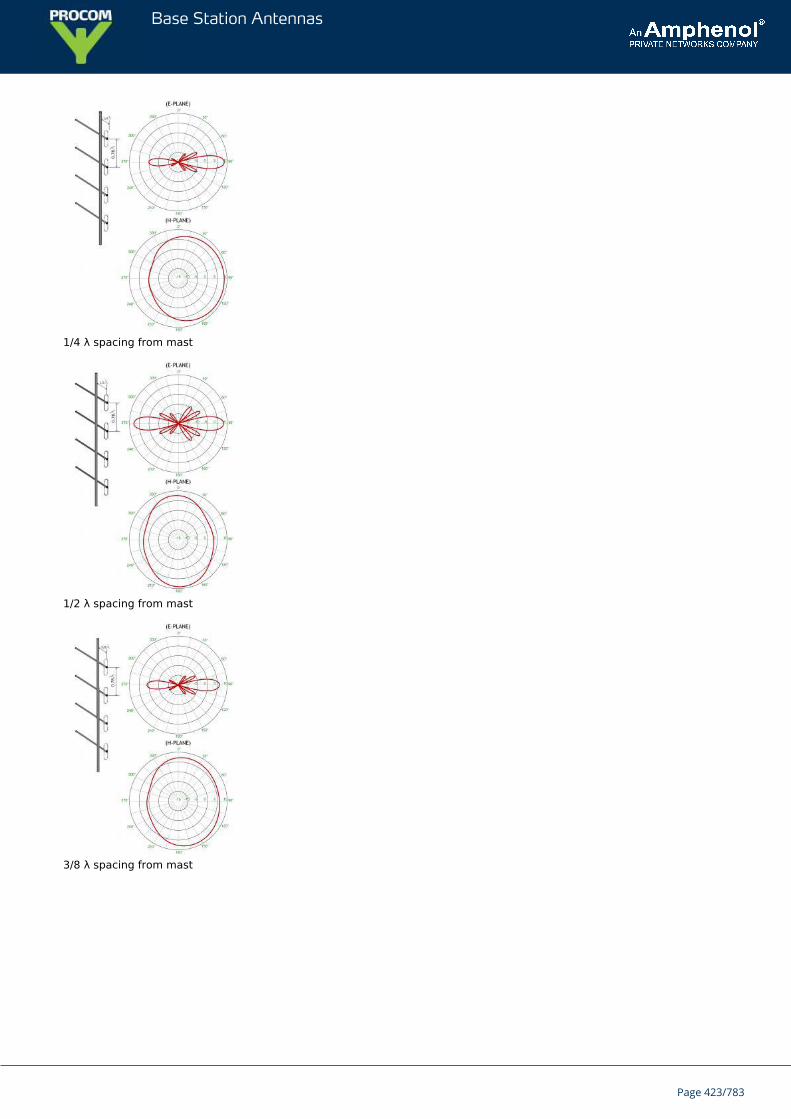
Base Station Antennas
1/4 λ spacing from mast
1/2 λ spacing from mast
3/8 λ spacing from mast
Page 423/783
Base Station Antennas
CXL 130-1-ExATEX certified, 0 dBd, Omnidirectional Base Station Antenna for theInternational Aircraft Band in Hazardous areas
CXL 130-1-Ex is a 0 dBd, vertically polarized, omnidirectional base station antennafor the 118 - 137 MHz civil aircraft band.The antenna is specified as ATEX antenna for use in zone 2 in potentially explosiveareas.
DESCRIPTION
Before installing the antenna, read the ATEX Product Manual carefully.The antenna is suitable for use in gas groups IIA, IIB and IIC in zone 2.The antenna is a broad-banded ½ λ dipole design.The antenna can be mounted on threaded 1" water pipe using the supplied 1" revolving nut. In this way, a nice, sliminstallation is obtained.A wide variety of accessory mounting hardware (see below) gives ample choice regarding alternative ways ofinstallation.All metal parts in the antenna are DC-grounded. Consequently, the antenna shows a DC-short across the coaxialcable.A conical glass fibre tube with very low wind-loading completely encloses the carefully designed radiating elementto ensure long dependable service in all climates.
ORDERING DESIGNATIONS
TYPE PRODUCT NO.
CXL 130-1-Ex 115000026
ACCESSORIES
ATEX grounding kit 1115000100
SPECIFICATIONS
ELECTRICAL
MODEL CXL 130-1-Ex
ANTENNA TYPE ½ λ coaxial dipol, broad-banded
FREQUENCY 118 - 137 MHz
IMPEDANCE Nom. 50 Ω
RADIATION Omnidirectional
POLARIZATION Vertical
GAIN 2 dBi 0 dBd
BANDWIDTH 19 MHz
SWR ≤ 1.75
Page 424/783
Base Station Antennas
MAX. RF INPUT POWER DUE TO MAX. EIRP IN ATEX ENVIRONMENT * Group IIAGroup IIBGroup IIC
: 35.6 dBm (3.6 W): 33.3 dBm (2.1 W): 30.8 dBm (1.2 W)
ANTISTATIC PROTECTION All metal parts DC-grounded(Connector shows a DC-short)
CONNECTORTIGHTENING TORQUE
UHF-female (fitting PL-259)0.7 - 1.1 Nm
WIND SURFACE 0.023 m² / 0.25 ft²
WIND LOAD 29 N @ 160 km/h / 99.42 mph
MAX. WIND SPEED 200 km/h / 124.27 mph
INGRESS PROTECTION LEVEL IP66
COLOUR Blue
MATERIALS Radome: Polyurethane-coated glass fibreMounting hardware: Black chromed brass
TOTAL HEIGHT Approx. 1.43 m / 56.3 in.
WEIGHT Approx. 0.85 kg / 1.87 lb.
MOUNTING
TIGHTENING TORQUE
On 1” RG (G1” - 11)
threaded water pipe or on optional
mounting brackets (see below)
20 - 25 Nm
ATEX MARKING II 3G Ex nA IIC T6
{start_next_col}
MECHANICAL
TEMP. RANGE -30° C → +60° C
CONNECTORTIGHTENING TORQUE
UHF-female (fitting PL-259)0.7 - 1.1 Nm
WIND SURFACE 0.023 m² / 0.25 ft²
WIND LOAD 29 N @ 160 km/h / 99.42 mph
MAX. WIND SPEED 200 km/h / 124.27 mph
INGRESS PROTECTION LEVEL IP66
COLOUR Blue
MATERIALS Radome: Polyurethane-coated glass fibreMounting hardware: Black chromed brass
TOTAL HEIGHT Approx. 1.43 m / 56.3 in.
WEIGHT Approx. 0.85 kg / 1.87 lb.
MOUNTING
On 1” RG (G1” - 11)
threaded water pipe or on optional
mounting brackets (see below)
Page 425/783
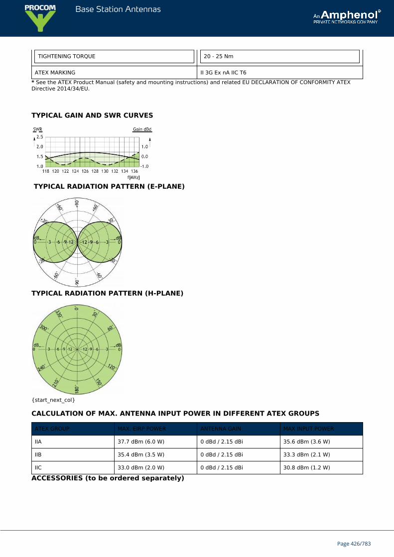
Base Station Antennas
TIGHTENING TORQUE 20 - 25 Nm
ATEX MARKING II 3G Ex nA IIC T6
* See the ATEX Product Manual (safety and mounting instructions) and related EU DECLARATION OF CONFORMITY ATEXDirective 2014/34/EU.
TYPICAL GAIN AND SWR CURVES
TYPICAL RADIATION PATTERN (E-PLANE)
TYPICAL RADIATION PATTERN (H-PLANE)
{start_next_col}
CALCULATION OF MAX. ANTENNA INPUT POWER IN DIFFERENT ATEX GROUPS
ATEX GROUP MAX. EIRP POWER ANTENNA GAIN MAX INPUT POWER
IIA 37.7 dBm (6.0 W) 0 dBd / 2.15 dBi 35.6 dBm (3.6 W)
IIB 35.4 dBm (3.5 W) 0 dBd / 2.15 dBi 33.3 dBm (2.1 W)
IIC 33.0 dBm (2.0 W) 0 dBd / 2.15 dBi 30.8 dBm (1.2 W)
ACCESSORIES (to be ordered separately)
Page 426/783

Base Station Antennas
Page 427/783
Base Station Antennas
CXL 130-1LW-SS-ExATEX certified, 0 dBd, Omnidirectional Base Station Antenna for theInternational AiMHz Band in Hazardousrcraft Band in Hazardous areas
CXL 130-1LW-SS-Ex is a 0 dBd, vertically polarized, omnidirectional base stationantenna witch covers the 118 - 137 MHz band in Hazardous areas.The antenna is specified as ATEX antenna for use in zone 2 in potentially explosiveareas.
DESCRIPTION
Before installing the antenna, read the ATEX Product Manual carefully.The antenna is suitable for use in gas groups IIA, IIB and IIC in zone 2.It’s only necessary to install a ATEX grounding Kit on the LW-SS-Ex bracket, when the point of installation has adifferent electrical potential than the system.The antenna is a broad-banded ½ λ dipole design.The accompanying U-bolts and fittings are made of stainless steel.The antenna element is sealed in high-quality glass fibre tube.All metal parts in the antenna are DC-grounded. Consequently, the antenna shows a DC-short across the coaxialcable.
ORDERING DESIGNATIONS
TYPE PRODUCT NO.
CXL 130-1LW-SS-Ex 115000001
ACCESSORIES
ATEX grounding kit 115000100
SPECIFICATIONS
ELECTRICAL
MODEL CXL 130-1LW-SS-Ex
ANTENNA TYPE ½ λ coaxial dipol, broad-banded
FREQUENCY 118 - 137 MHz wide frequency segments within ?-? MHZ.
IMPEDANCE Nom. 50 Ω
RADIATION Omnidirectional
POLARIZATION Vertical
GAIN 2 dBi 0 dBd
BANDWIDTH 19 MHz
SWR ≤ 1.75
MAX. RF INPUT POWER DUE TO MAX. EIRP IN ATEX ENVIRONMENT *
Page 428/783
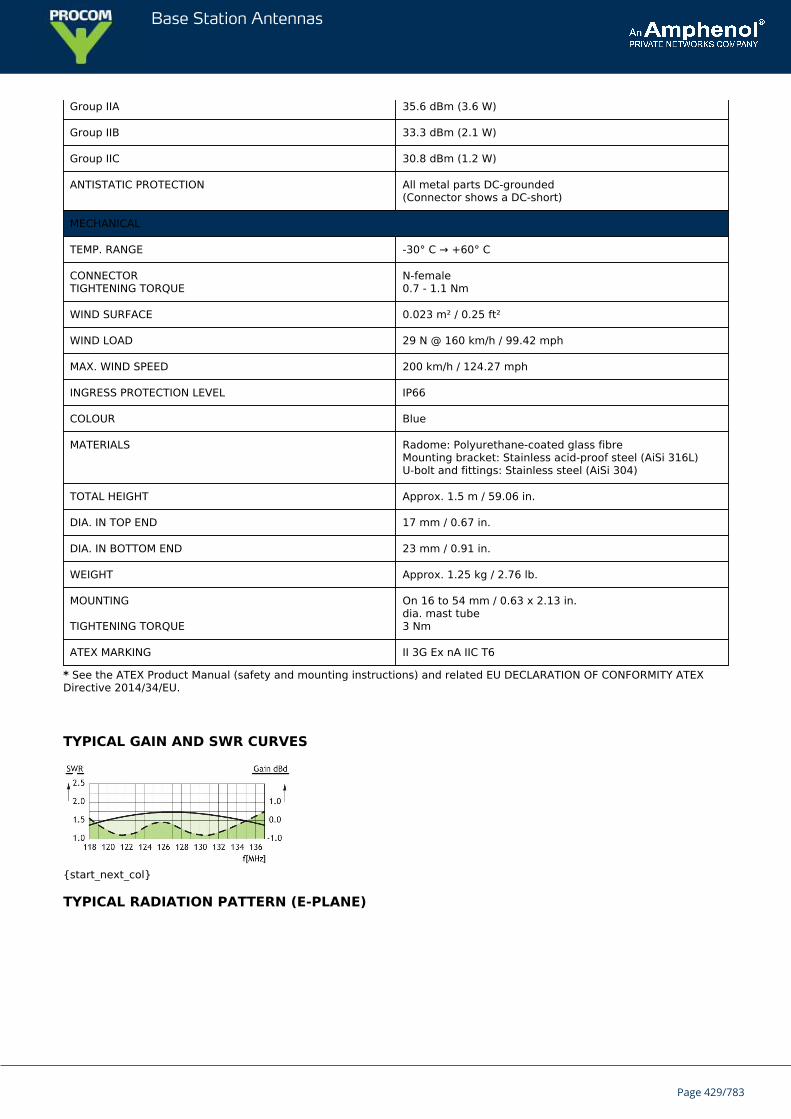
Base Station Antennas
Group IIA 35.6 dBm (3.6 W)
Group IIB 33.3 dBm (2.1 W)
Group IIC 30.8 dBm (1.2 W)
ANTISTATIC PROTECTION All metal parts DC-grounded(Connector shows a DC-short)
MECHANICAL
TEMP. RANGE -30° C → +60° C
CONNECTORTIGHTENING TORQUE
N-female0.7 - 1.1 Nm
WIND SURFACE 0.023 m² / 0.25 ft²
WIND LOAD 29 N @ 160 km/h / 99.42 mph
MAX. WIND SPEED 200 km/h / 124.27 mph
INGRESS PROTECTION LEVEL IP66
COLOUR Blue
MATERIALS Radome: Polyurethane-coated glass fibreMounting bracket: Stainless acid-proof steel (AiSi 316L)U-bolt and fittings: Stainless steel (AiSi 304)
TOTAL HEIGHT Approx. 1.5 m / 59.06 in.
DIA. IN TOP END 17 mm / 0.67 in.
DIA. IN BOTTOM END 23 mm / 0.91 in.
WEIGHT Approx. 1.25 kg / 2.76 lb.
MOUNTING
TIGHTENING TORQUE
On 16 to 54 mm / 0.63 x 2.13 in.dia. mast tube3 Nm
ATEX MARKING II 3G Ex nA IIC T6
* See the ATEX Product Manual (safety and mounting instructions) and related EU DECLARATION OF CONFORMITY ATEXDirective 2014/34/EU.
TYPICAL GAIN AND SWR CURVES
{start_next_col}
TYPICAL RADIATION PATTERN (E-PLANE)
Page 429/783
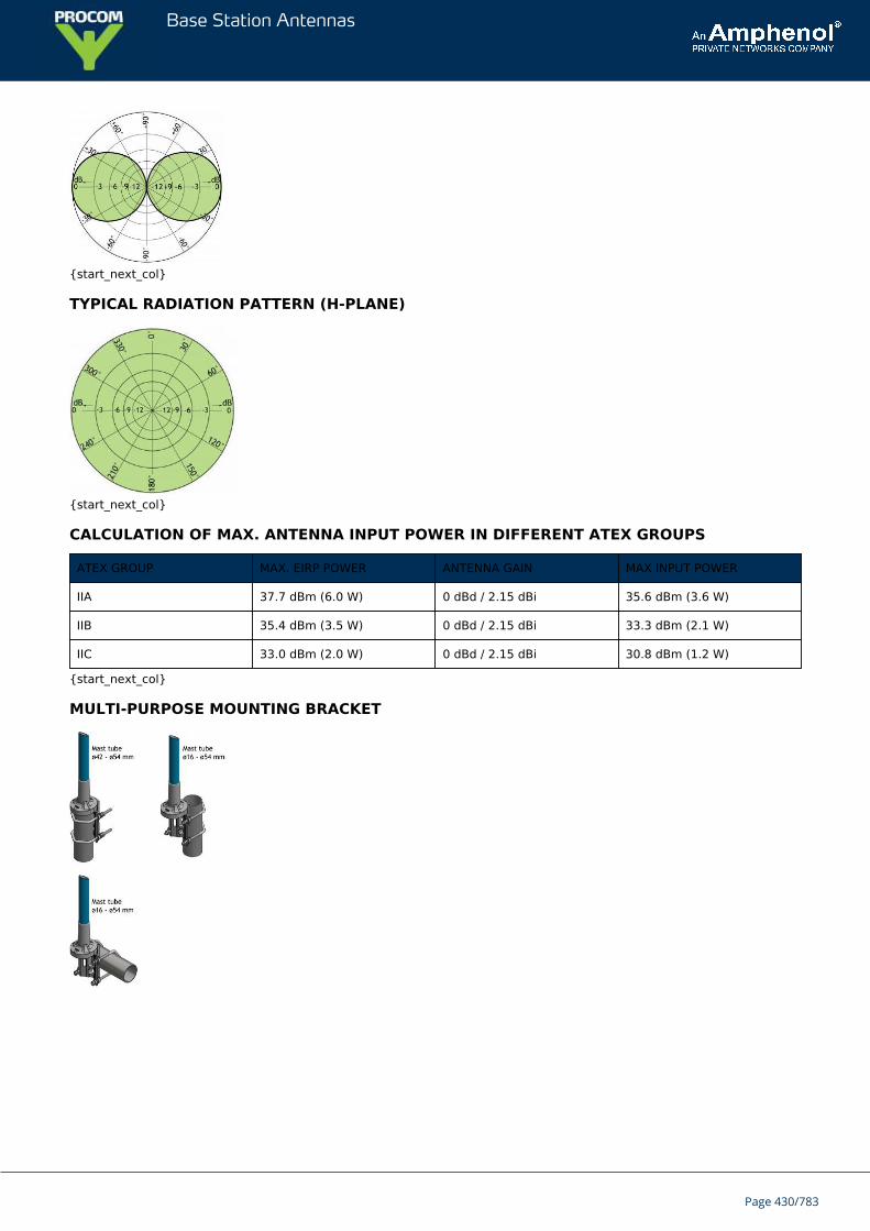
Base Station Antennas
{start_next_col}
TYPICAL RADIATION PATTERN (H-PLANE)
{start_next_col}
CALCULATION OF MAX. ANTENNA INPUT POWER IN DIFFERENT ATEX GROUPS
ATEX GROUP MAX. EIRP POWER ANTENNA GAIN MAX INPUT POWER
IIA 37.7 dBm (6.0 W) 0 dBd / 2.15 dBi 35.6 dBm (3.6 W)
IIB 35.4 dBm (3.5 W) 0 dBd / 2.15 dBi 33.3 dBm (2.1 W)
IIC 33.0 dBm (2.0 W) 0 dBd / 2.15 dBi 30.8 dBm (1.2 W)
{start_next_col}
MULTI-PURPOSE MOUNTING BRACKET
Page 430/783
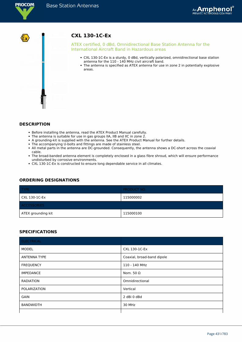
Base Station Antennas
CXL 130-1C-ExATEX certified, 0 dBd, Omnidirectional Base Station Antenna for theInternational Aircraft Band in Hazardous areas
CXL 130-1C-Ex is a sturdy, 0 dBd, vertically polarized, omnidirectional base stationantenna for the 110 - 140 MHz civil aircraft band.The antenna is specified as ATEX antenna for use in zone 2 in potentially explosiveareas.
DESCRIPTION
Before installing the antenna, read the ATEX Product Manual carefully.The antenna is suitable for use in gas groups IIA, IIB and IIC in zone 2.A grounding-kit is supplied with the antenna. See the ATEX Product Manual for further details.The accompanying U-bolts and fittings are made of stainless steel.All metal parts in the antenna are DC-grounded. Consequently, the antenna shows a DC-short across the coaxialcable.The broad-banded antenna element is completely enclosed in a glass fibre shroud, which will ensure performanceundisturbed by corrosive environments.CXL 130-1C-Ex is constructed to ensure long dependable service in all climates.
ORDERING DESIGNATIONS
TYPE PRODUCT NO.
CXL 130-1C-Ex 115000002
ACCESSORIES
ATEX grounding kit 115000100
SPECIFICATIONS
ELECTRICAL
MODEL CXL 130-1C-Ex
ANTENNA TYPE Coaxial, broad-band dipole
FREQUENCY 110 - 140 MHz
IMPEDANCE Nom. 50 Ω
RADIATION Omnidirectional
POLARIZATION Vertical
GAIN 2 dBi 0 dBd
BANDWIDTH 30 MHz
Page 431/783
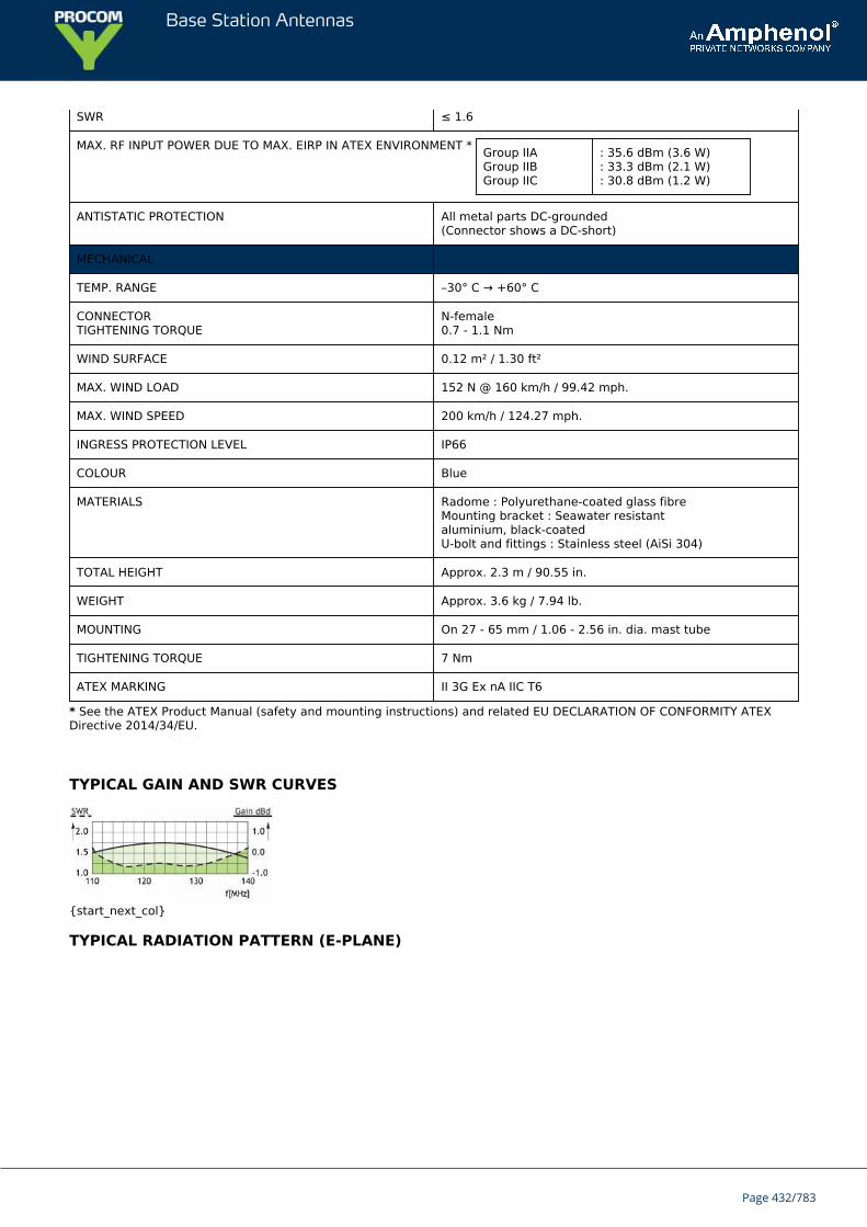
Base Station Antennas
SWR ≤ 1.6
MAX. RF INPUT POWER DUE TO MAX. EIRP IN ATEX ENVIRONMENT * Group IIAGroup IIBGroup IIC
: 35.6 dBm (3.6 W): 33.3 dBm (2.1 W): 30.8 dBm (1.2 W)
ANTISTATIC PROTECTION All metal parts DC-grounded(Connector shows a DC-short)
MECHANICAL
TEMP. RANGE –30° C → +60° C
CONNECTORTIGHTENING TORQUE
N-female0.7 - 1.1 Nm
WIND SURFACE 0.12 m² / 1.30 ft²
MAX. WIND LOAD 152 N @ 160 km/h / 99.42 mph.
MAX. WIND SPEED 200 km/h / 124.27 mph.
INGRESS PROTECTION LEVEL IP66
COLOUR Blue
MATERIALS Radome : Polyurethane-coated glass fibreMounting bracket : Seawater resistantaluminium, black-coatedU-bolt and fittings : Stainless steel (AiSi 304)
TOTAL HEIGHT Approx. 2.3 m / 90.55 in.
WEIGHT Approx. 3.6 kg / 7.94 lb.
MOUNTING On 27 - 65 mm / 1.06 - 2.56 in. dia. mast tube
TIGHTENING TORQUE 7 Nm
ATEX MARKING II 3G Ex nA IIC T6
* See the ATEX Product Manual (safety and mounting instructions) and related EU DECLARATION OF CONFORMITY ATEXDirective 2014/34/EU.
TYPICAL GAIN AND SWR CURVES
{start_next_col}
TYPICAL RADIATION PATTERN (E-PLANE)
Page 432/783
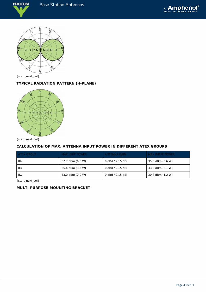
Base Station Antennas
{start_next_col}
TYPICAL RADIATION PATTERN (H-PLANE)
{start_next_col}
CALCULATION OF MAX. ANTENNA INPUT POWER IN DIFFERENT ATEX GROUPS
ATEX GROUP MAX. EIRP POWER ANTENNA GAIN MAX INPUT POWER
IIA 37.7 dBm (6.0 W) 0 dBd / 2.15 dBi 35.6 dBm (3.6 W)
IIB 35.4 dBm (3.5 W) 0 dBd / 2.15 dBi 33.3 dBm (2.1 W)
IIC 33.0 dBm (2.0 W) 0 dBd / 2.15 dBi 30.8 dBm (1.2 W)
{start_next_col}
MULTI-PURPOSE MOUNTING BRACKET
Page 433/783
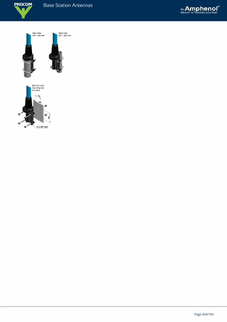
Base Station Antennas
Page 434/783
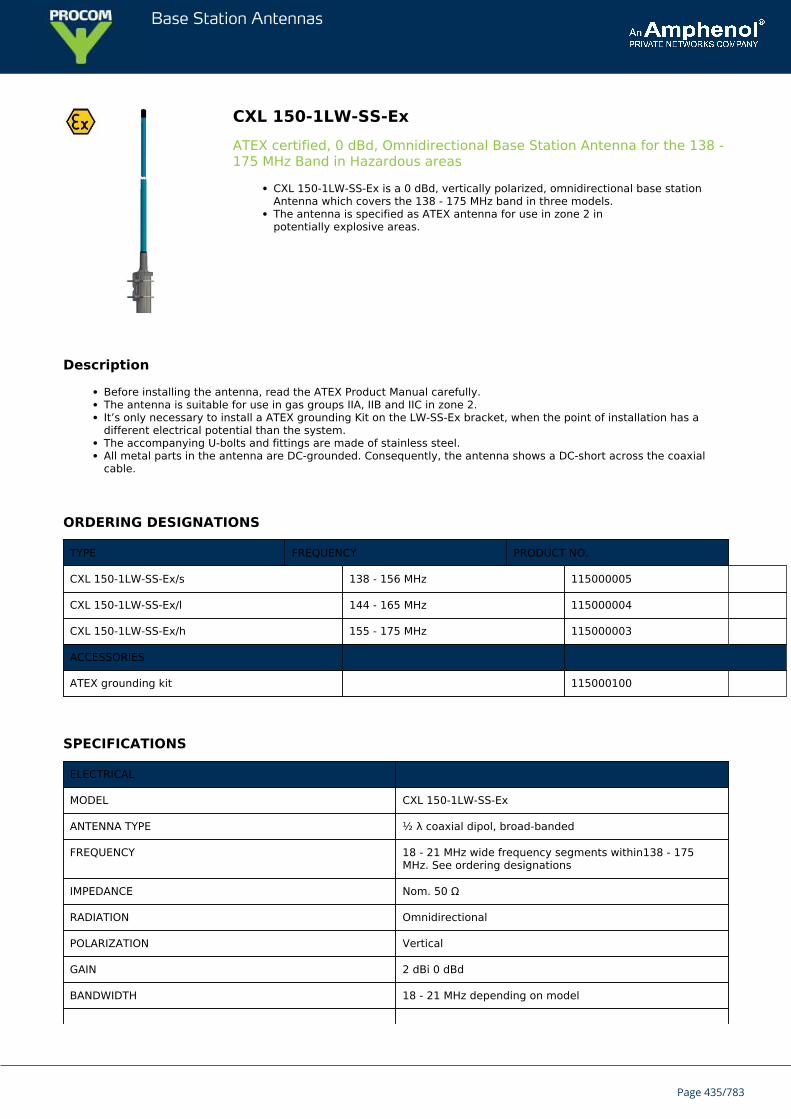
Base Station Antennas
CXL 150-1LW-SS-ExATEX certified, 0 dBd, Omnidirectional Base Station Antenna for the 138 -175 MHz Band in Hazardous areas
CXL 150-1LW-SS-Ex is a 0 dBd, vertically polarized, omnidirectional base stationAntenna which covers the 138 - 175 MHz band in three models.The antenna is specified as ATEX antenna for use in zone 2 inpotentially explosive areas.
Description
Before installing the antenna, read the ATEX Product Manual carefully.The antenna is suitable for use in gas groups IIA, IIB and IIC in zone 2.It’s only necessary to install a ATEX grounding Kit on the LW-SS-Ex bracket, when the point of installation has adifferent electrical potential than the system.The accompanying U-bolts and fittings are made of stainless steel.All metal parts in the antenna are DC-grounded. Consequently, the antenna shows a DC-short across the coaxialcable.
ORDERING DESIGNATIONS
TYPE FREQUENCY PRODUCT NO.
CXL 150-1LW-SS-Ex/s 138 - 156 MHz 115000005
CXL 150-1LW-SS-Ex/l 144 - 165 MHz 115000004
CXL 150-1LW-SS-Ex/h 155 - 175 MHz 115000003
ACCESSORIES
ATEX grounding kit 115000100
SPECIFICATIONS
ELECTRICAL
MODEL CXL 150-1LW-SS-Ex
ANTENNA TYPE ½ λ coaxial dipol, broad-banded
FREQUENCY 18 - 21 MHz wide frequency segments within138 - 175MHz. See ordering designations
IMPEDANCE Nom. 50 Ω
RADIATION Omnidirectional
POLARIZATION Vertical
GAIN 2 dBi 0 dBd
BANDWIDTH 18 - 21 MHz depending on model
Page 435/783
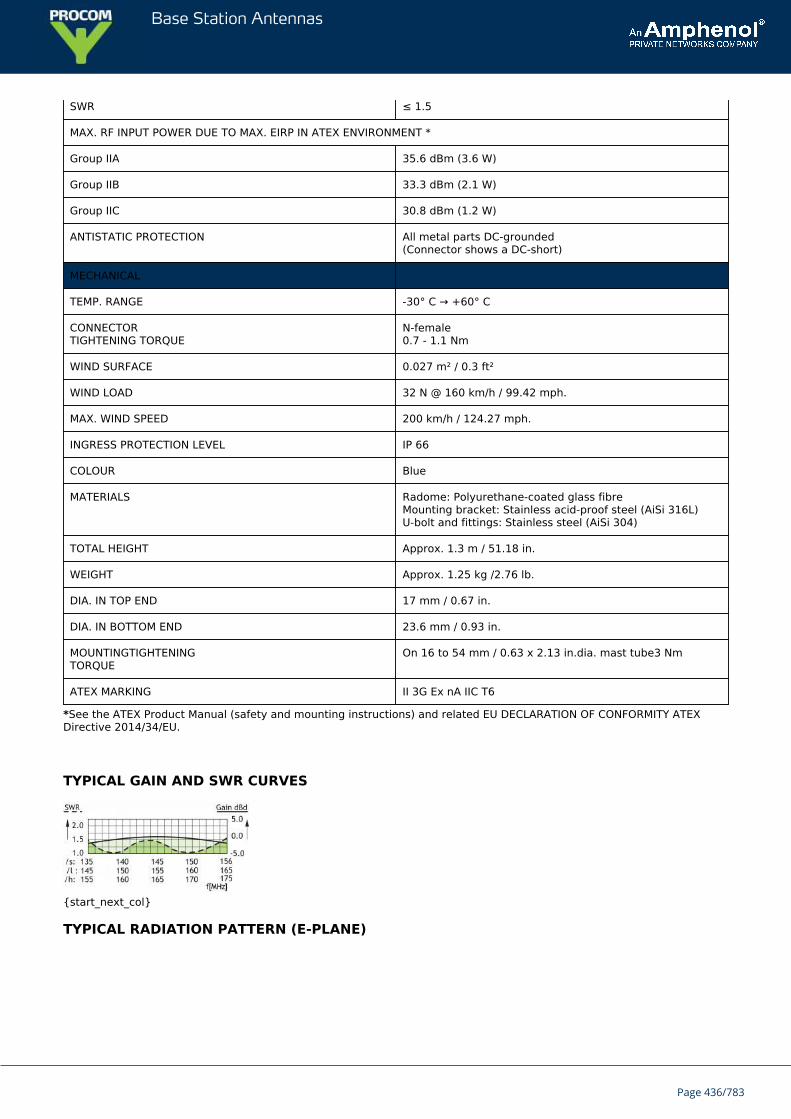
Base Station Antennas
SWR ≤ 1.5
MAX. RF INPUT POWER DUE TO MAX. EIRP IN ATEX ENVIRONMENT *
Group IIA 35.6 dBm (3.6 W)
Group IIB 33.3 dBm (2.1 W)
Group IIC 30.8 dBm (1.2 W)
ANTISTATIC PROTECTION All metal parts DC-grounded(Connector shows a DC-short)
MECHANICAL
TEMP. RANGE -30° C → +60° C
CONNECTORTIGHTENING TORQUE
N-female0.7 - 1.1 Nm
WIND SURFACE 0.027 m² / 0.3 ft²
WIND LOAD 32 N @ 160 km/h / 99.42 mph.
MAX. WIND SPEED 200 km/h / 124.27 mph.
INGRESS PROTECTION LEVEL IP 66
COLOUR Blue
MATERIALS Radome: Polyurethane-coated glass fibreMounting bracket: Stainless acid-proof steel (AiSi 316L)U-bolt and fittings: Stainless steel (AiSi 304)
TOTAL HEIGHT Approx. 1.3 m / 51.18 in.
WEIGHT Approx. 1.25 kg /2.76 lb.
DIA. IN TOP END 17 mm / 0.67 in.
DIA. IN BOTTOM END 23.6 mm / 0.93 in.
MOUNTINGTIGHTENINGTORQUE
On 16 to 54 mm / 0.63 x 2.13 in.dia. mast tube3 Nm
ATEX MARKING II 3G Ex nA IIC T6
*See the ATEX Product Manual (safety and mounting instructions) and related EU DECLARATION OF CONFORMITY ATEXDirective 2014/34/EU.
TYPICAL GAIN AND SWR CURVES
{start_next_col}
TYPICAL RADIATION PATTERN (E-PLANE)
Page 436/783
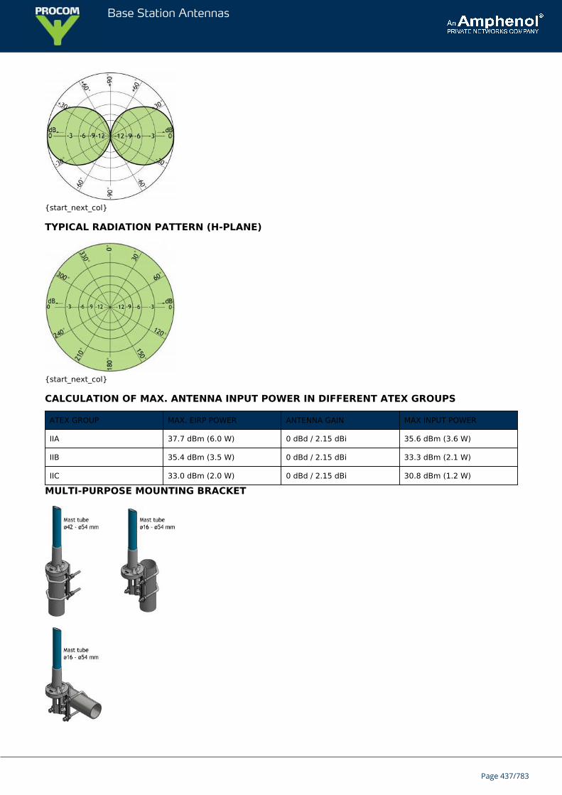
Base Station Antennas
{start_next_col}
TYPICAL RADIATION PATTERN (H-PLANE)
{start_next_col}
CALCULATION OF MAX. ANTENNA INPUT POWER IN DIFFERENT ATEX GROUPS
ATEX GROUP MAX. EIRP POWER ANTENNA GAIN MAX INPUT POWER
IIA 37.7 dBm (6.0 W) 0 dBd / 2.15 dBi 35.6 dBm (3.6 W)
IIB 35.4 dBm (3.5 W) 0 dBd / 2.15 dBi 33.3 dBm (2.1 W)
IIC 33.0 dBm (2.0 W) 0 dBd / 2.15 dBi 30.8 dBm (1.2 W)
MULTI-PURPOSE MOUNTING BRACKET
Page 437/783

Base Station Antennas
Page 438/783
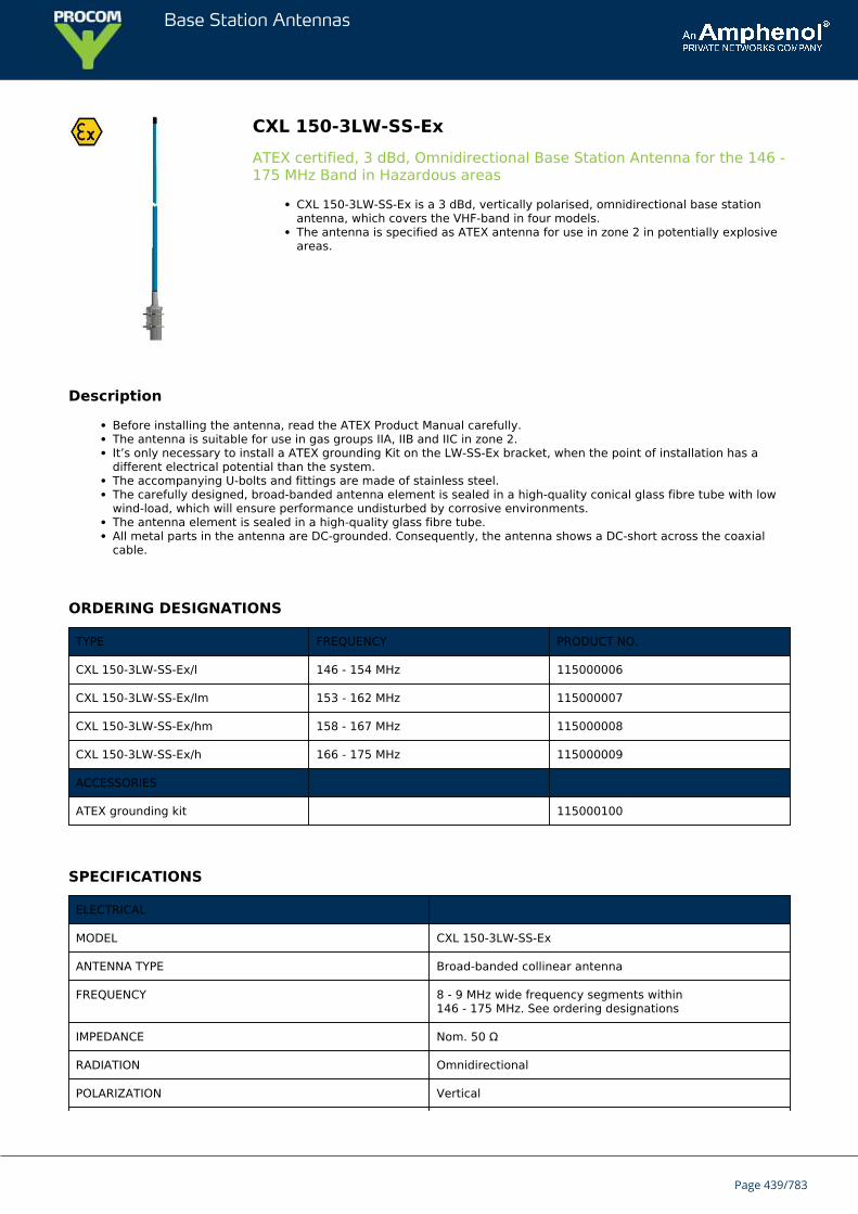
Base Station Antennas
CXL 150-3LW-SS-ExATEX certified, 3 dBd, Omnidirectional Base Station Antenna for the 146 -175 MHz Band in Hazardous areas
CXL 150-3LW-SS-Ex is a 3 dBd, vertically polarised, omnidirectional base stationantenna, which covers the VHF-band in four models.The antenna is specified as ATEX antenna for use in zone 2 in potentially explosiveareas.
Description
Before installing the antenna, read the ATEX Product Manual carefully.The antenna is suitable for use in gas groups IIA, IIB and IIC in zone 2.It’s only necessary to install a ATEX grounding Kit on the LW-SS-Ex bracket, when the point of installation has adifferent electrical potential than the system.The accompanying U-bolts and fittings are made of stainless steel.The carefully designed, broad-banded antenna element is sealed in a high-quality conical glass fibre tube with lowwind-load, which will ensure performance undisturbed by corrosive environments.The antenna element is sealed in a high-quality glass fibre tube.All metal parts in the antenna are DC-grounded. Consequently, the antenna shows a DC-short across the coaxialcable.
ORDERING DESIGNATIONS
TYPE FREQUENCY PRODUCT NO.
CXL 150-3LW-SS-Ex/l 146 - 154 MHz 115000006
CXL 150-3LW-SS-Ex/lm 153 - 162 MHz 115000007
CXL 150-3LW-SS-Ex/hm 158 - 167 MHz 115000008
CXL 150-3LW-SS-Ex/h 166 - 175 MHz 115000009
ACCESSORIES
ATEX grounding kit 115000100
SPECIFICATIONS
ELECTRICAL
MODEL CXL 150-3LW-SS-Ex
ANTENNA TYPE Broad-banded collinear antenna
FREQUENCY 8 - 9 MHz wide frequency segments within146 - 175 MHz. See ordering designations
IMPEDANCE Nom. 50 Ω
RADIATION Omnidirectional
POLARIZATION Vertical
Page 439/783
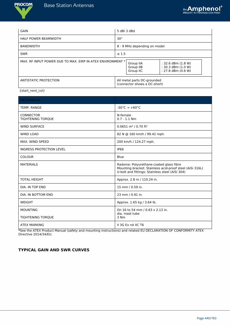
Base Station Antennas
GAIN 5 dBi 3 dBd
HALF POWER BEAMWIDTH 30°
BANDWIDTH 8 - 9 MHz depending on model
SWR ≤ 1.5
MAX. RF INPUT POWER DUE TO MAX. EIRP IN ATEX ENVIRONMENT * Group IIAGroup IIBGroup IIC
: 32.6 dBm (1.8 W): 30.3 dBm (1.0 W): 27.8 dBm (0.6 W)
ANTISTATIC PROTECTION All metal parts DC-grounded(connector shows a DC-short)
{start_next_col}
MECHANICAL
TEMP. RANGE -30°C → +60°C
CONNECTORTIGHTENING TORQUE
N-female0.7 - 1.1 Nm
WIND SURFACE 0.0651 m² / 0.70 ft²
WIND LOAD 82 N @ 160 km/h / 99.42 mph.
MAX. WIND SPEED 200 km/h / 124.27 mph.
INGRESS PROTECTION LEVEL IP66
COLOUR Blue
MATERIALS Radome: Polyurethane-coated glass fibreMounting bracket: Stainless acid-proof steel (AiSi 316L)U-bolt and fittings: Stainless steel (AiSi 304)
TOTAL HEIGHT Approx. 2.8 m / 110.24 in.
DIA. IN TOP END 15 mm / 0.59 in.
DIA. IN BOTTOM END 23 mm / 0.91 in.
WEIGHT Approx. 1.65 kg / 3.64 lb.
MOUNTING
TIGHTENING TORQUE
On 16 to 54 mm / 0.63 x 2.13 in.dia. mast tube3 Nm
ATEX MARKING II 3G Ex nA IIC T6
*See the ATEX Product Manual (safety and mounting instructions) and related EU DECLARATION OF CONFORMITY ATEXDirective 2014/34/EU.
TYPICAL GAIN AND SWR CURVES
Page 440/783
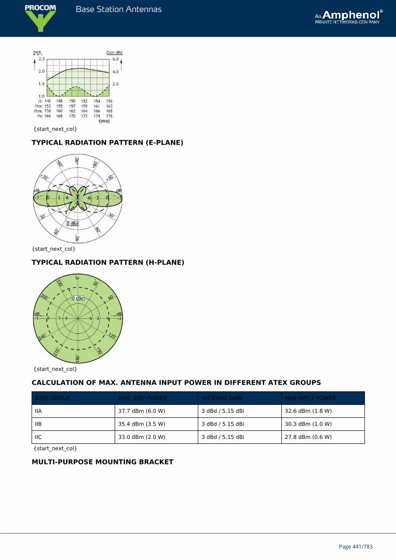
Base Station Antennas
{start_next_col}
TYPICAL RADIATION PATTERN (E-PLANE)
{start_next_col}
TYPICAL RADIATION PATTERN (H-PLANE)
{start_next_col}
CALCULATION OF MAX. ANTENNA INPUT POWER IN DIFFERENT ATEX GROUPS
ATEX GROUP MAX. EIRP POWER ANTENNA GAIN MAX INPUT POWER
IIA 37.7 dBm (6.0 W) 3 dBd / 5.15 dBi 32.6 dBm (1.8 W)
IIB 35.4 dBm (3.5 W) 3 dBd / 5.15 dBi 30.3 dBm (1.0 W)
IIC 33.0 dBm (2.0 W) 3 dBd / 5.15 dBi 27.8 dBm (0.6 W)
{start_next_col}
MULTI-PURPOSE MOUNTING BRACKET
Page 441/783

Base Station Antennas
Page 442/783
Base Station Antennas
CXL 150-1LW-SS-R/...Universal, Unity-Gain Base Station and Marine Antenna for the 160 MHzBand
This multi-purpose, omnidirectional, 0 dBd, rod-type base station and marineantenna covers the 160 MHz band in three models with 10 MHz overlap and can beused in a wide variety of applications.The antenna mount is made from a High Strength low Carbon Steel Alloy.
DESCRIPTION
The broad-banded ½ λ dipole antenna element is sealed in a high-quality conical glass fibre tube with low wind-load, which will ensure undisturbed performance by corrosive environments.The new LW-SS Mount is made from a High Strength low Carbon Steel Alloy well suited for extreme marineenvironments due to it's superior resistance to corrosion.The accompanying U-bolts and fittings are made of stainless steel.To be mounted on vertical or horizontal mast tubes, 16 to 54 mm in outer diameter.The cable can be led either on the outside or along the inside of the mast tube.Large bandwidth with respect to both SWR and gain.CXL 150-1LW-SS-R/… is DC-grounded to substantially reduce noise caused by atmospherical discharges andconsequently shows a DC-short across the coaxial cable.The CXL 150-1LW-SS-R/… is a vibration-proof, lightweight, slim-line, corrosion-resistant, modern style base stationand marine antenna.
ORDERING DESIGNATIONS
TYPE FREQUENCY PRODUCT NO.
CXL 150-1LW-SS-R/s 138 - 156 MHz 110000374
CXL 150-1LW-SS-R/l 146 - 165 MHz 110000375
CXL 150-1LW-SS-R/h 155 - 175 MHz 110000376
SPECIFICATIONS
ELECTRICAL
MODEL CXL 150-1LW-SS-R/...
ANTENNA TYPE ½ λ coaxial dipol, broad-banded
FREQUENCY:
CXL 150-1LW-SS-R/s: 138 - 156 MHz
CXL 150-1LW-SS-R/l: 146 - 165 MHz
CXL 150-1LW-SS-R/h: 155 - 175 MHz
IMPEDANCE Nom. 50 Ω
RADIATION Omnidirectional
POLARIZATION Vertical
Page 443/783
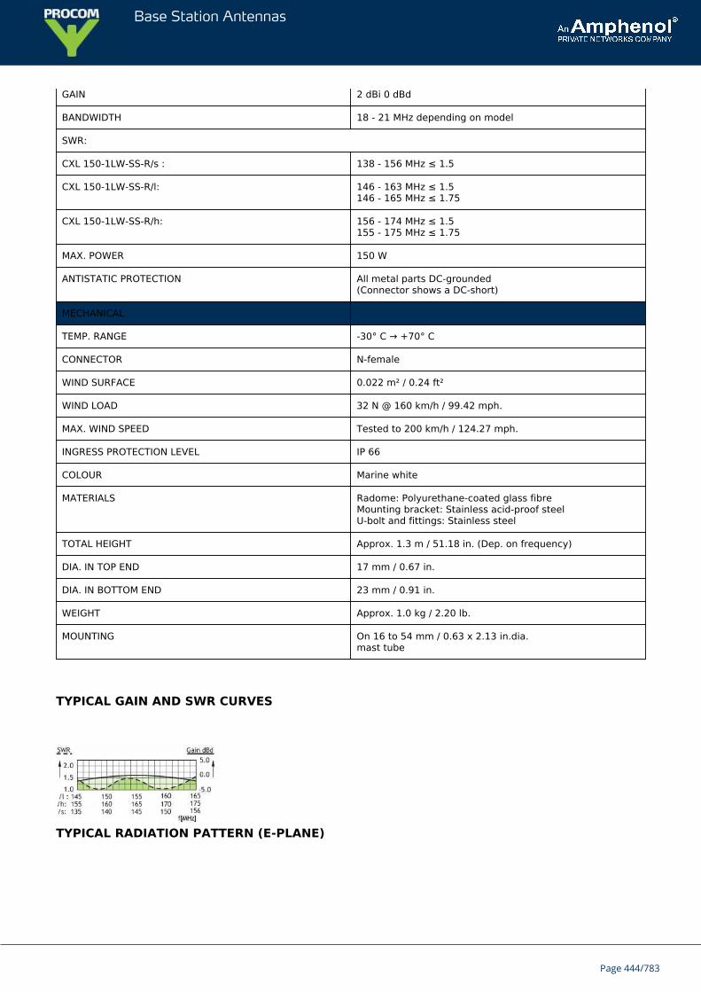
Base Station Antennas
GAIN 2 dBi 0 dBd
BANDWIDTH 18 - 21 MHz depending on model
SWR:
CXL 150-1LW-SS-R/s : 138 - 156 MHz ≤ 1.5
CXL 150-1LW-SS-R/l: 146 - 163 MHz ≤ 1.5146 - 165 MHz ≤ 1.75
CXL 150-1LW-SS-R/h: 156 - 174 MHz ≤ 1.5155 - 175 MHz ≤ 1.75
MAX. POWER 150 W
ANTISTATIC PROTECTION All metal parts DC-grounded(Connector shows a DC-short)
MECHANICAL
TEMP. RANGE -30° C → +70° C
CONNECTOR N-female
WIND SURFACE 0.022 m² / 0.24 ft²
WIND LOAD 32 N @ 160 km/h / 99.42 mph.
MAX. WIND SPEED Tested to 200 km/h / 124.27 mph.
INGRESS PROTECTION LEVEL IP 66
COLOUR Marine white
MATERIALS Radome: Polyurethane-coated glass fibre Mounting bracket: Stainless acid-proof steelU-bolt and fittings: Stainless steel
TOTAL HEIGHT Approx. 1.3 m / 51.18 in. (Dep. on frequency)
DIA. IN TOP END 17 mm / 0.67 in.
DIA. IN BOTTOM END 23 mm / 0.91 in.
WEIGHT Approx. 1.0 kg / 2.20 lb.
MOUNTING On 16 to 54 mm / 0.63 x 2.13 in.dia.mast tube
TYPICAL GAIN AND SWR CURVES
TYPICAL RADIATION PATTERN (E-PLANE)
Page 444/783
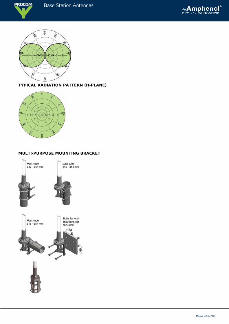
Base Station Antennas
TYPICAL RADIATION PATTERN (H-PLANE)
MULTI-PURPOSE MOUNTING BRACKET
Page 445/783

Base Station Antennas
PLEASE NOTE
The antenna is delivered with a DC-connection between the antenna element and the mounting bracket.
Page 446/783
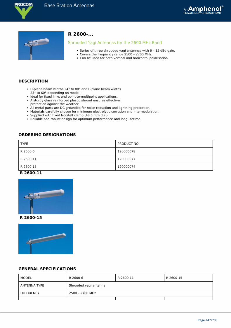
Base Station Antennas
R 2600-...Shrouded Yagi Antennas for the 2600 MHz Band
Series of three shrouded yagi antennas with 6 – 15 dBd gain.Covers the frequency range 2500 – 2700 MHz.Can be used for both vertical and horizontal polarisation.
DESCRIPTION
H-plane beam widths 24° to 80° and E-plane beam widths23° to 60° depending on model.Ideal for fixed links and point-to-multipoint applications.A sturdy glass reinforced plastic shroud ensures effectiveprotection against the weather.All metal parts are DC grounded for noise reduction and lightning protection.Materials carefully chosen for minimum electrolytic corrosion and intermodulation.Supplied with fixed Norstell clamp (48.5 mm dia.)Reliable and robust design for optimum performance and long lifetime.
ORDERING DESIGNATIONS
TYPE PRODUCT NO.
R 2600-6 120000078
R 2600-11 120000077
R 2600-15 120000074
R 2600-11
R 2600-15
GENERAL SPECIFICATIONS
MODEL R 2600-6 R 2600-11 R 2600-15
ANTENNA TYPE Shrouded yagi antenna
FREQUENCY 2500 – 2700 MHz
Page 447/783
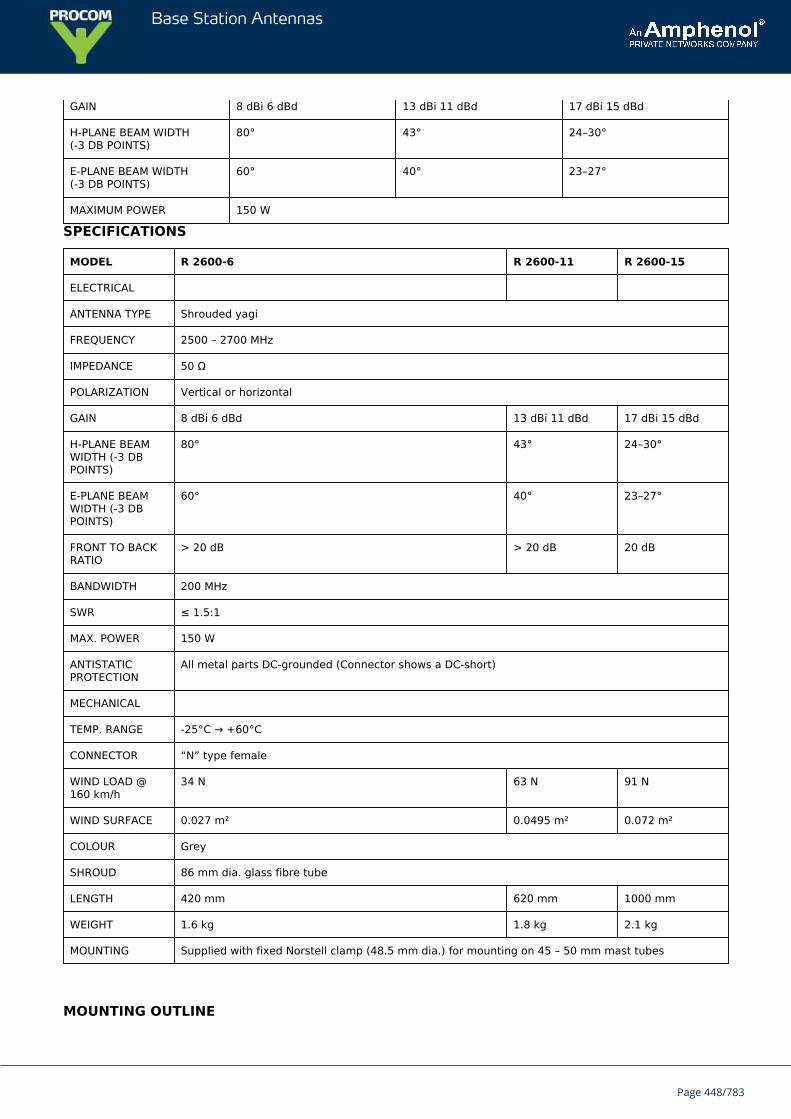
Base Station Antennas
GAIN 8 dBi 6 dBd 13 dBi 11 dBd 17 dBi 15 dBd
H-PLANE BEAM WIDTH(-3 DB POINTS)
80° 43° 24–30°
E-PLANE BEAM WIDTH(-3 DB POINTS)
60° 40° 23–27°
MAXIMUM POWER 150 W
SPECIFICATIONS
MODEL R 2600-6 R 2600-11 R 2600-15
ELECTRICAL
ANTENNA TYPE Shrouded yagi
FREQUENCY 2500 – 2700 MHz
IMPEDANCE 50 Ω
POLARIZATION Vertical or horizontal
GAIN 8 dBi 6 dBd 13 dBi 11 dBd 17 dBi 15 dBd
H-PLANE BEAMWIDTH (-3 DBPOINTS)
80° 43° 24–30°
E-PLANE BEAMWIDTH (-3 DBPOINTS)
60° 40° 23–27°
FRONT TO BACKRATIO
> 20 dB > 20 dB 20 dB
BANDWIDTH 200 MHz
SWR ≤ 1.5:1
MAX. POWER 150 W
ANTISTATICPROTECTION
All metal parts DC-grounded (Connector shows a DC-short)
MECHANICAL
TEMP. RANGE -25°C → +60°C
CONNECTOR “N” type female
WIND LOAD @160 km/h
34 N 63 N 91 N
WIND SURFACE 0.027 m² 0.0495 m² 0.072 m²
COLOUR Grey
SHROUD 86 mm dia. glass fibre tube
LENGTH 420 mm 620 mm 1000 mm
WEIGHT 1.6 kg 1.8 kg 2.1 kg
MOUNTING Supplied with fixed Norstell clamp (48.5 mm dia.) for mounting on 45 – 50 mm mast tubes
MOUNTING OUTLINE
Page 448/783
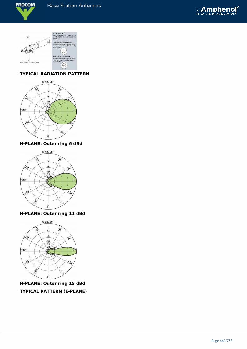
Base Station Antennas
TYPICAL RADIATION PATTERN
H-PLANE: Outer ring 6 dBd
H-PLANE: Outer ring 11 dBd
H-PLANE: Outer ring 15 dBd
TYPICAL PATTERN (E-PLANE)
Page 449/783
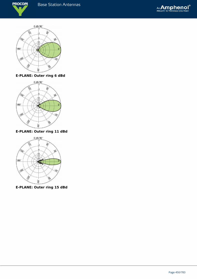
Base Station Antennas
E-PLANE: Outer ring 6 dBd
E-PLANE: Outer ring 11 dBd
E-PLANE: Outer ring 15 dBd
Page 450/783
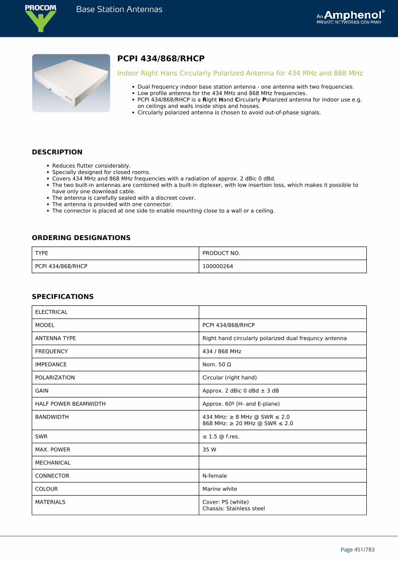
Base Station Antennas
PCPI 434/868/RHCPIndoor Right Hans Circularly Polarized Antenna for 434 MHz and 868 MHz
Dual frequency indoor base station antenna - one antenna with two frequencies.Low profile antenna for the 434 MHz and 868 MHz frequencies.PCPI 434/868/RHCP is a Right Hand Circularly Polarized antenna for indoor use e.g.on ceilings and walls inside ships and houses.Circularly polarized antenna is chosen to avoid out-of-phase signals.
DESCRIPTION
Reduces flutter considerably.Specially designed for closed rooms.Covers 434 MHz and 868 MHz frequencies with a radiation of approx. 2 dBic 0 dBd.The two built-in antennas are combined with a built-in diplexer, with low insertion loss, which makes it possible tohave only one downlead cable.The antenna is carefully sealed with a discreet cover.The antenna is provided with one connector.The connector is placed at one side to enable mounting close to a wall or a ceiling.
ORDERING DESIGNATIONS
TYPE PRODUCT NO.
PCPI 434/868/RHCP 100000264
SPECIFICATIONS
ELECTRICAL
MODEL PCPI 434/868/RHCP
ANTENNA TYPE Right hand circularly polarized dual frequncy antenna
FREQUENCY 434 / 868 MHz
IMPEDANCE Nom. 50 Ω
POLARIZATION Circular (right hand)
GAIN Approx. 2 dBic 0 dBd ± 3 dB
HALF POWER BEAMWIDTH Approx. 60º (H- and E-plane)
BANDWIDTH 434 MHz: ≥ 8 MHz @ SWR ≤ 2.0868 MHz: ≥ 20 MHz @ SWR ≤ 2.0
SWR ≤ 1.5 @ f.res.
MAX. POWER 35 W
MECHANICAL
CONNECTOR N-female
COLOUR Marine white
MATERIALS Cover: PS (white)Chassis: Stainless steel
Page 451/783
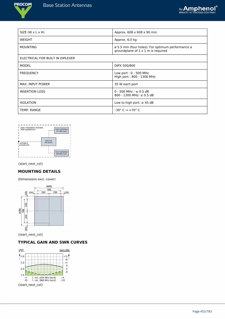
Base Station Antennas
SIZE (W x L x H) Approx. 608 x 608 x 90 mm
WEIGHT Approx. 6.0 kg
MOUNTING ø 5.5 mm (four holes). For optimum performance agroundplane of 1 x 1 m is required
ELECTRICAL FOR BUILT IN DIPLEXER
MODEL DIPX 500/800
FREQUENCY Low port : 0 - 500 MHzHigh port : 800 - 1300 MHz
MAX. INPUT POWER 35 W each port
INSERTION LOSS 0 - 500 MHz : ≤ 0.5 dB800 - 1300 MHz: ≤ 0.5 dB
ISOLATION Low to high port: ≥ 45 dB
TEMP. RANGE –30° C → +70° C
{start_next_col}
MOUNTING DETAILS
(Dimensions excl. cover)
{start_next_col}
TYPICAL GAIN AND SWR CURVES
{start_next_col}
Page 452/783
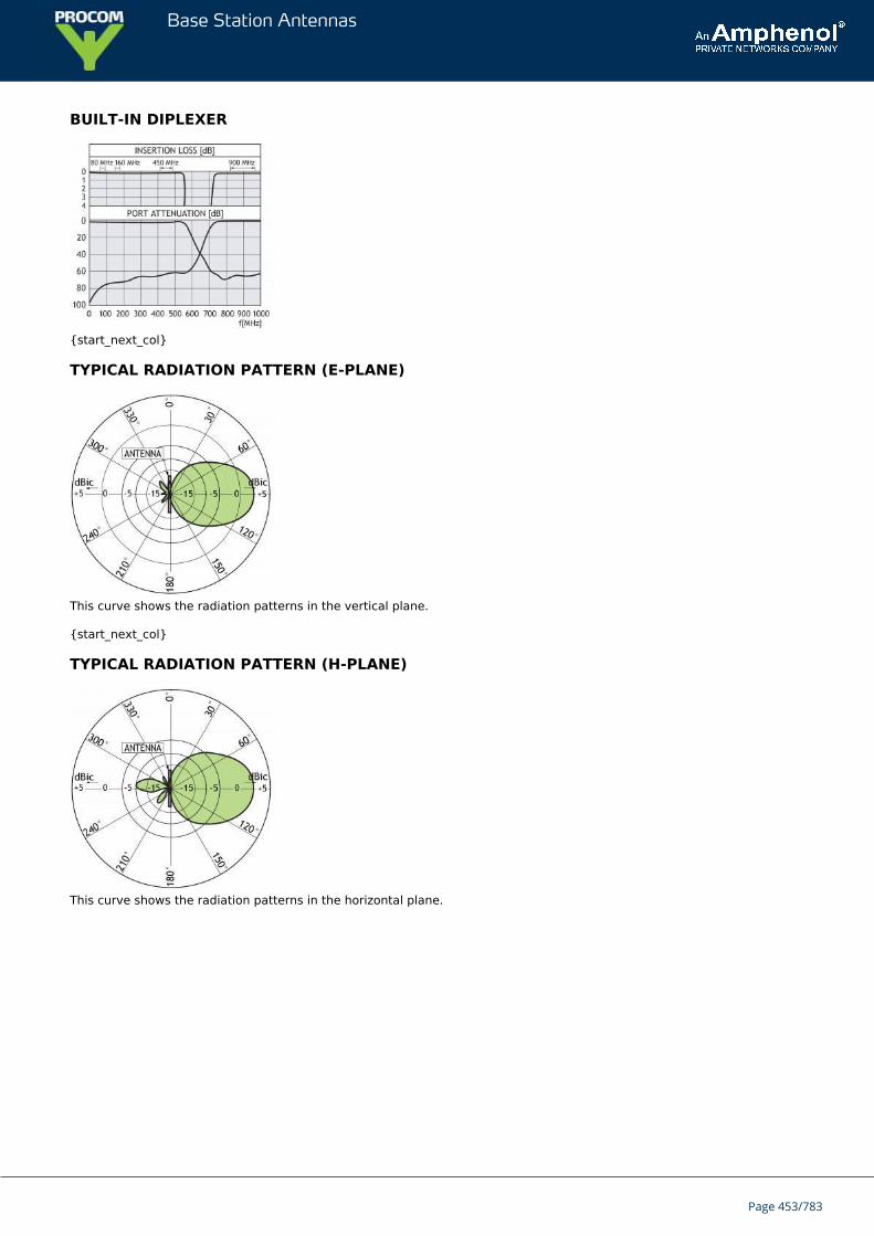
Base Station Antennas
BUILT-IN DIPLEXER
{start_next_col}
TYPICAL RADIATION PATTERN (E-PLANE)
This curve shows the radiation patterns in the vertical plane.
{start_next_col}
TYPICAL RADIATION PATTERN (H-PLANE)
This curve shows the radiation patterns in the horizontal plane.
Page 453/783
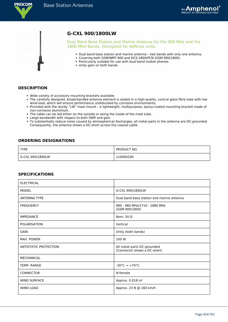
Base Station Antennas
G-CXL 900/1800LWDual Band Base Station and Marine Antenna for the 900 MHz and the1800 MHz Bands. Dersigned for defense units.
Dual band base station and marine antenna – two bands with only one antenna.Covering both GSM/NMT-900 and DCS-1800/PCN (GSM 900/1800).Particularly suitable for use with dual-band mobile phones.Unity gain on both bands.
DESCRIPTION
Wide variety of accessory mounting brackets available.The carefully designed, broad-banded antenna element is sealed in a high-quality, conical glass fibre tube with lowwind-load, which will ensure performance undisturbed by corrosive environments.Provided with the sturdy “LW” mast mount – a lightweight, multipurpose, epoxy-coated mounting bracket made ofnon-corrosive aluminium.The cable can be led either on the outside or along the inside of the mast tube.Large bandwidth with respect to both SWR and gain.To substantially reduce noise caused by atmospherical discharges, all metal parts in the antenna are DC-grounded.Consequently, the antenna shows a DC-short across the coaxial cable.
ORDERING DESIGNATIONS
TYPE PRODUCT NO.
G-CXL 900/1800LW 110000190
SPECIFICATIONS
ELECTRICAL
MODEL G-CXL 900/1800LW
ANTENNA TYPE Dual band base station and marine antenna
FREQUENCY 890 - 960 MHz/1710 - 1880 MHz(GSM 900/1800)
IMPEDANCE Nom. 50 Ω
POLARISATION Vertical
GAIN Unity (both bands)
MAX. POWER 100 W
ANTISTATIC PROTECTION All metal parts DC-grounded(Connector shows a DC-short)
MECHANICAL
TEMP. RANGE -30°C → +70°C
CONNECTOR N-female
WIND SURFACE Approx. 0.018 m²
WIND LOAD Approx. 23 N @ 160 km/h
Page 454/783
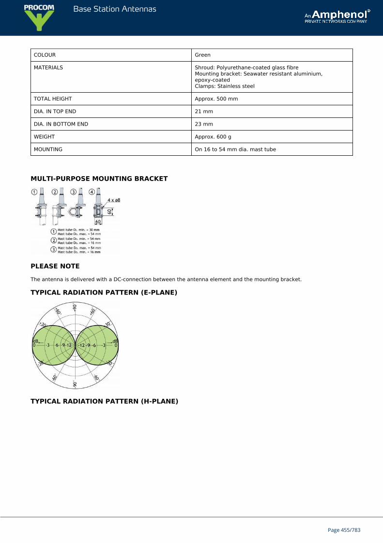
Base Station Antennas
COLOUR Green
MATERIALS Shroud: Polyurethane-coated glass fibreMounting bracket: Seawater resistant aluminium,epoxy-coatedClamps: Stainless steel
TOTAL HEIGHT Approx. 500 mm
DIA. IN TOP END 21 mm
DIA. IN BOTTOM END 23 mm
WEIGHT Approx. 600 g
MOUNTING On 16 to 54 mm dia. mast tube
MULTI-PURPOSE MOUNTING BRACKET
PLEASE NOTE
The antenna is delivered with a DC-connection between the antenna element and the mounting bracket.
TYPICAL RADIATION PATTERN (E-PLANE)
TYPICAL RADIATION PATTERN (H-PLANE)
Page 455/783
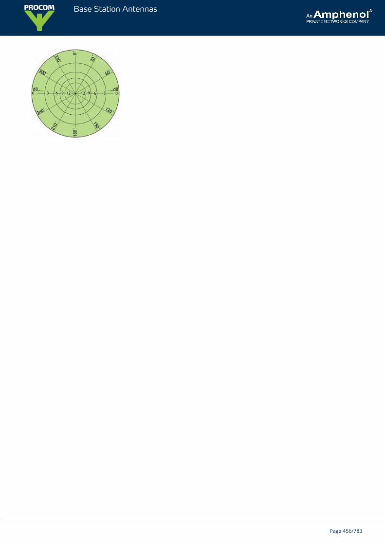
Base Station Antennas
Page 456/783
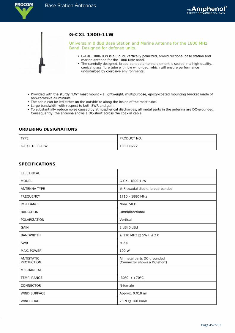
Base Station Antennas
G-CXL 1800-1LWUniversalm 0 dBd Base Station and Marine Antenna for the 1800 MHzBand. Designed for defense units.
G-CXL 1800-1LW is a 0 dBd, vertically polarized, omnidirectional base station andmarine antenna for the 1800 MHz band.The carefully designed, broad-banded antenna element is sealed in a high-quality,conical glass fibre tube with low wind-load, which will ensure performanceundisturbed by corrosive environments.
Provided with the sturdy “LW” mast mount – a lightweight, multipurpose, epoxy-coated mounting bracket made ofnon-corrosive aluminium.The cable can be led either on the outside or along the inside of the mast tube.Large bandwidth with respect to both SWR and gain.To substantially reduce noise caused by atmospherical discharges, all metal parts in the antenna are DC-grounded.Consequently, the antenna shows a DC-short across the coaxial cable.
ORDERING DESIGNATIONS
TYPE PRODUCT NO.
G-CXL 1800-1LW 100000272
SPECIFICATIONS
ELECTRICAL
MODEL G-CXL 1800-1LW
ANTENNA TYPE ½ λ coaxial dipole, broad-banded
FREQUENCY 1710 – 1880 MHz
IMPEDANCE Nom. 50 Ω
RADIATION Omnidirectional
POLARIZATION Vertical
GAIN 2 dBi 0 dBd
BANDWIDTH ≥ 170 MHz @ SWR ≤ 2.0
SWR ≤ 2.0
MAX. POWER 100 W
ANTISTATICPROTECTION
All metal parts DC-grounded(Connector shows a DC-short)
MECHANICAL
TEMP. RANGE -30°C → +70°C
CONNECTOR N-female
WIND SURFACE Approx. 0.018 m²
WIND LOAD 23 N @ 160 km/h
Page 457/783
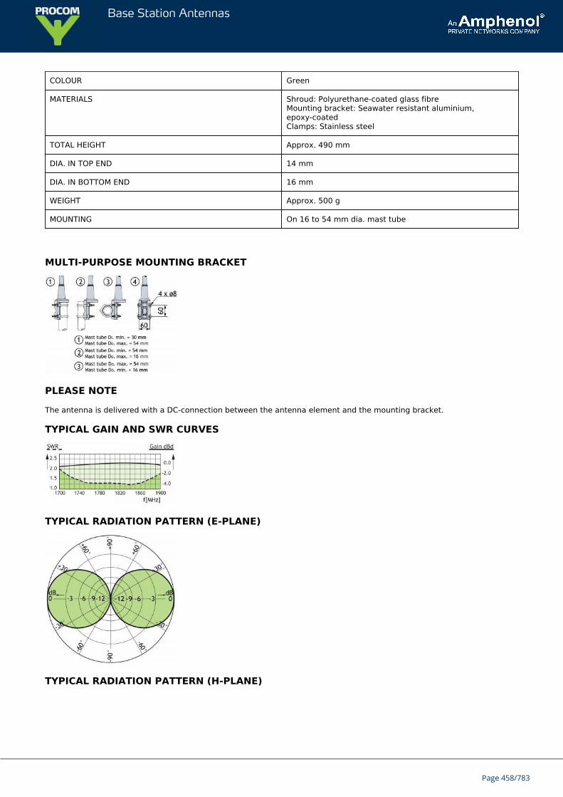
Base Station Antennas
COLOUR Green
MATERIALS Shroud: Polyurethane-coated glass fibreMounting bracket: Seawater resistant aluminium,epoxy-coatedClamps: Stainless steel
TOTAL HEIGHT Approx. 490 mm
DIA. IN TOP END 14 mm
DIA. IN BOTTOM END 16 mm
WEIGHT Approx. 500 g
MOUNTING On 16 to 54 mm dia. mast tube
MULTI-PURPOSE MOUNTING BRACKET
PLEASE NOTE
The antenna is delivered with a DC-connection between the antenna element and the mounting bracket.
TYPICAL GAIN AND SWR CURVES
TYPICAL RADIATION PATTERN (E-PLANE)
TYPICAL RADIATION PATTERN (H-PLANE)
Page 458/783

Base Station Antennas
Page 459/783
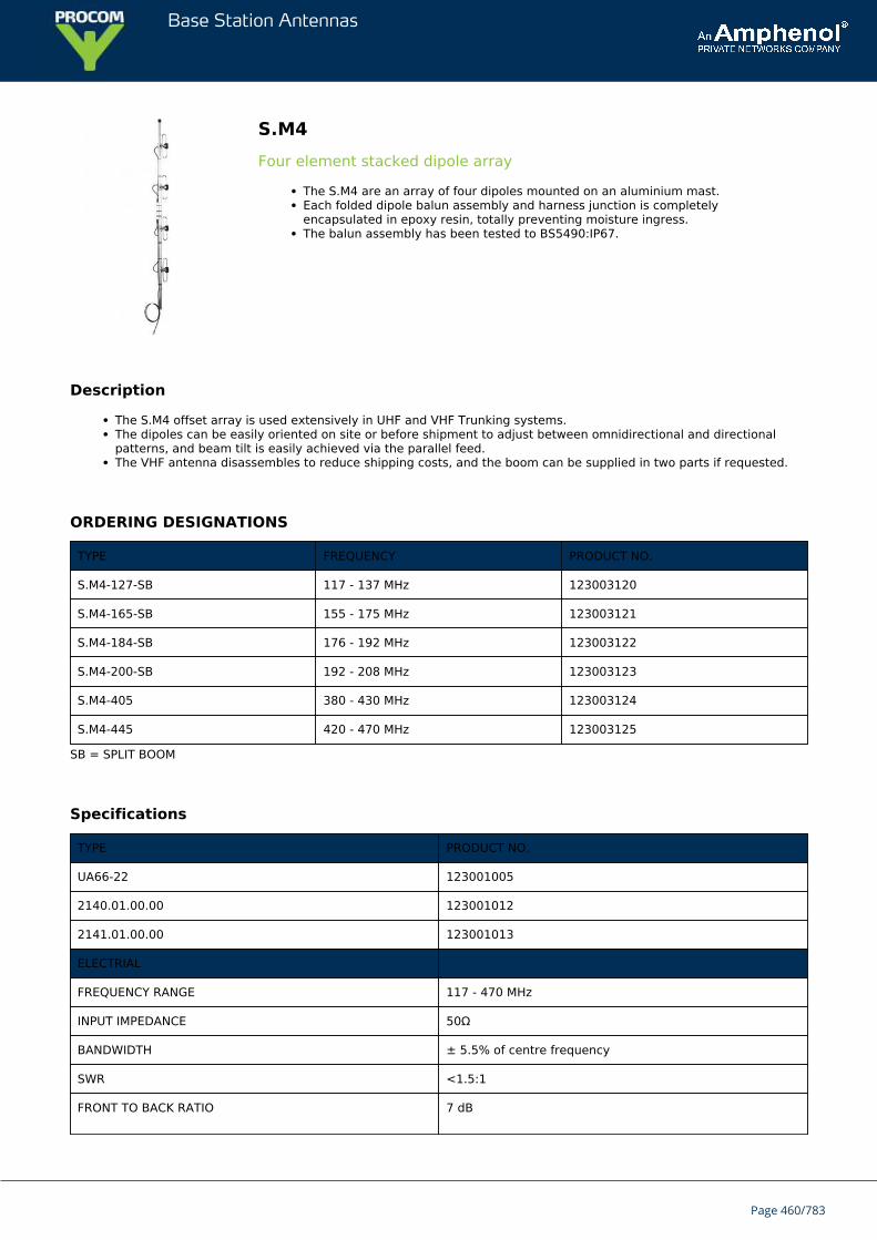
Base Station Antennas
S.M4Four element stacked dipole array
The S.M4 are an array of four dipoles mounted on an aluminium mast.Each folded dipole balun assembly and harness junction is completelyencapsulated in epoxy resin, totally preventing moisture ingress.The balun assembly has been tested to BS5490:IP67.
Description
The S.M4 offset array is used extensively in UHF and VHF Trunking systems.The dipoles can be easily oriented on site or before shipment to adjust between omnidirectional and directionalpatterns, and beam tilt is easily achieved via the parallel feed.The VHF antenna disassembles to reduce shipping costs, and the boom can be supplied in two parts if requested.
ORDERING DESIGNATIONS
TYPE FREQUENCY PRODUCT NO.
S.M4-127-SB 117 - 137 MHz 123003120
S.M4-165-SB 155 - 175 MHz 123003121
S.M4-184-SB 176 - 192 MHz 123003122
S.M4-200-SB 192 - 208 MHz 123003123
S.M4-405 380 - 430 MHz 123003124
S.M4-445 420 - 470 MHz 123003125
SB = SPLIT BOOM
Specifications
TYPE PRODUCT NO.
UA66-22 123001005
2140.01.00.00 123001012
2141.01.00.00 123001013
ELECTRIAL
FREQUENCY RANGE 117 - 470 MHz
INPUT IMPEDANCE 50Ω
BANDWIDTH ± 5.5% of centre frequency
SWR <1.5:1
FRONT TO BACK RATIO 7 dB
Page 460/783
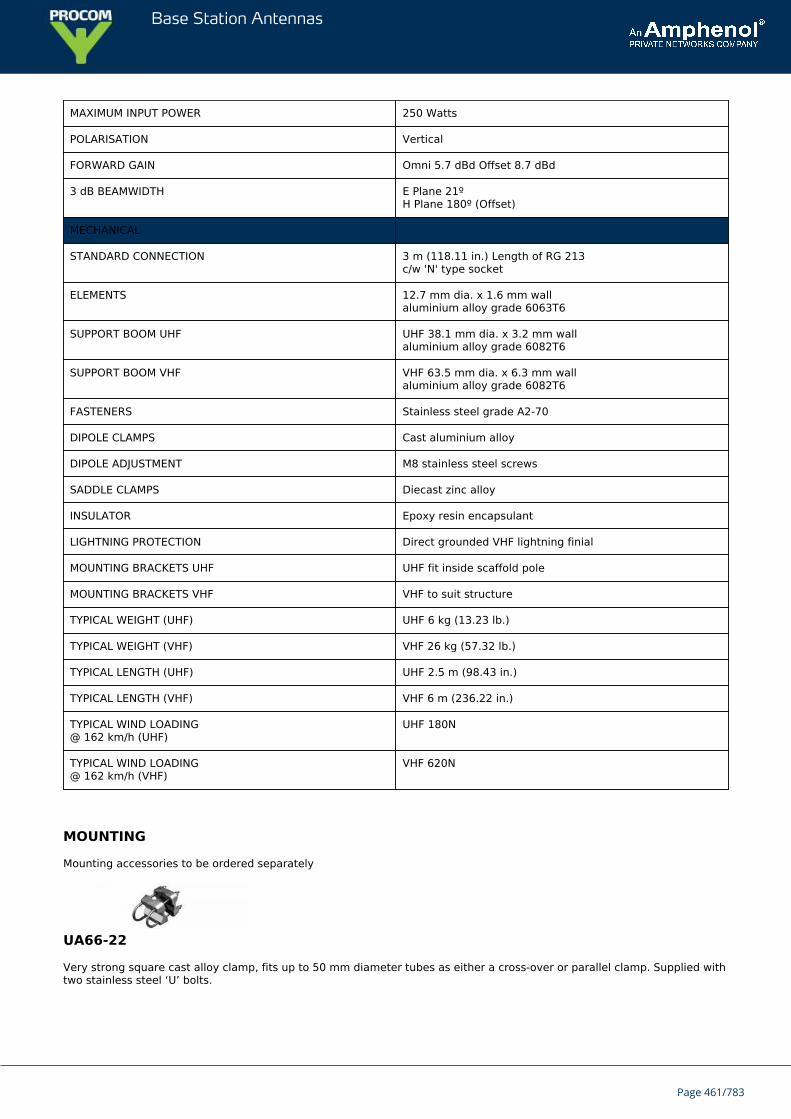
Base Station Antennas
MAXIMUM INPUT POWER 250 Watts
POLARISATION Vertical
FORWARD GAIN Omni 5.7 dBd Offset 8.7 dBd
3 dB BEAMWIDTH E Plane 21ºH Plane 180º (Offset)
MECHANICAL
STANDARD CONNECTION 3 m (118.11 in.) Length of RG 213c/w 'N' type socket
ELEMENTS 12.7 mm dia. x 1.6 mm wallaluminium alloy grade 6063T6
SUPPORT BOOM UHF UHF 38.1 mm dia. x 3.2 mm wallaluminium alloy grade 6082T6
SUPPORT BOOM VHF VHF 63.5 mm dia. x 6.3 mm wallaluminium alloy grade 6082T6
FASTENERS Stainless steel grade A2-70
DIPOLE CLAMPS Cast aluminium alloy
DIPOLE ADJUSTMENT M8 stainless steel screws
SADDLE CLAMPS Diecast zinc alloy
INSULATOR Epoxy resin encapsulant
LIGHTNING PROTECTION Direct grounded VHF lightning finial
MOUNTING BRACKETS UHF UHF fit inside scaffold pole
MOUNTING BRACKETS VHF VHF to suit structure
TYPICAL WEIGHT (UHF) UHF 6 kg (13.23 lb.)
TYPICAL WEIGHT (VHF) VHF 26 kg (57.32 lb.)
TYPICAL LENGTH (UHF) UHF 2.5 m (98.43 in.)
TYPICAL LENGTH (VHF) VHF 6 m (236.22 in.)
TYPICAL WIND LOADING@ 162 km/h (UHF)
UHF 180N
TYPICAL WIND LOADING@ 162 km/h (VHF)
VHF 620N
MOUNTING
Mounting accessories to be ordered separately
UA66-22
Very strong square cast alloy clamp, fits up to 50 mm diameter tubes as either a cross-over or parallel clamp. Supplied withtwo stainless steel ‘U’ bolts.
Page 461/783
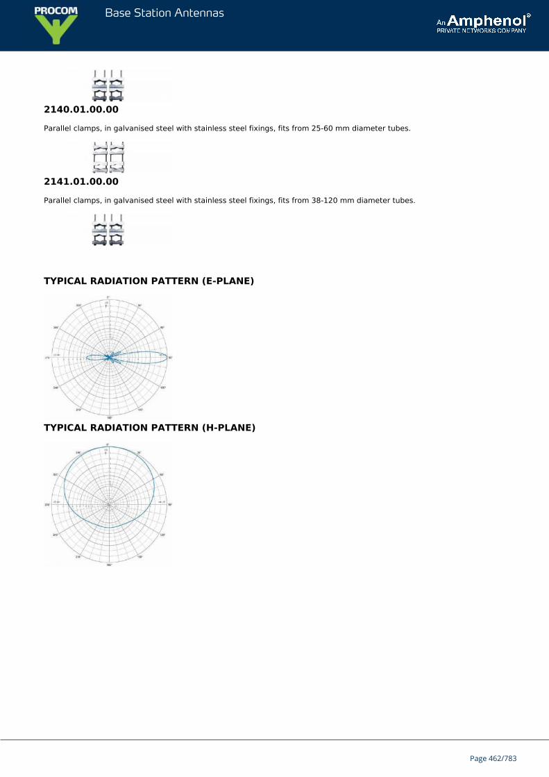
Base Station Antennas
2140.01.00.00
Parallel clamps, in galvanised steel with stainless steel fixings, fits from 25-60 mm diameter tubes.
2141.01.00.00
Parallel clamps, in galvanised steel with stainless steel fixings, fits from 38-120 mm diameter tubes.
TYPICAL RADIATION PATTERN (E-PLANE)
TYPICAL RADIATION PATTERN (H-PLANE)
Page 462/783
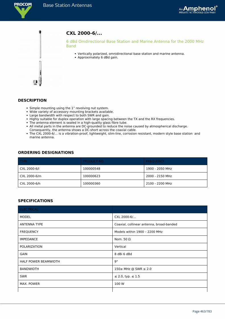
Base Station Antennas
CXL 2000-6/...6 dBd Omdirectional Base Station and Marine Antenna for the 2000 MHzBand
Vertically polarized, omnidirectional base station and marine antenna.Approximately 6 dBd gain.
DESCRIPTION
Simple mounting using the 1” revolving nut system.Wide variety of accessory mounting brackets available.Large bandwidth with respect to both SWR and gain.Highly suitable for duplex operation with large spacing between the TX and the RX frequencies.The antenna element is sealed in a high-quality glass fibre tube.All metal parts in the antenna are DC-grounded to reduce the noise caused by atmospherical discharge.Consequently, the antenna shows a DC-short across the coaxial cable.The CXL 2000-6/… is a vibration-proof, lightweight, slim-line, corrosion resistant, modern style base station andmarine antenna.
ORDERING DESIGNATIONS
TYPE PRODUCT NO. FREQUENCY
CXL 2000-6/l 100000548 1900 - 2050 MHz
CXL 2000-6/m 100000623 2000 - 2150 MHz
CXL 2000-6/h 100000360 2100 - 2200 MHz
SPECIFICATIONS
ELECTRICAL
MODEL CXL 2000-6/...
ANTENNA TYPE Coaxial, collinear antenna, broad-banded
FREQUENCY Models within 1900 – 2200 MHz
IMPEDANCE Nom. 50 Ω
POLARIZATION Vertical
GAIN 8 dBi 6 dBd
HALF POWER BEAMWIDTH 9°
BANDWIDTH 150≥ MHz @ SWR ≤ 2.0
SWR ≤ 2.0, typ. ≤ 1.5
MAX. POWER 100 W
Page 463/783
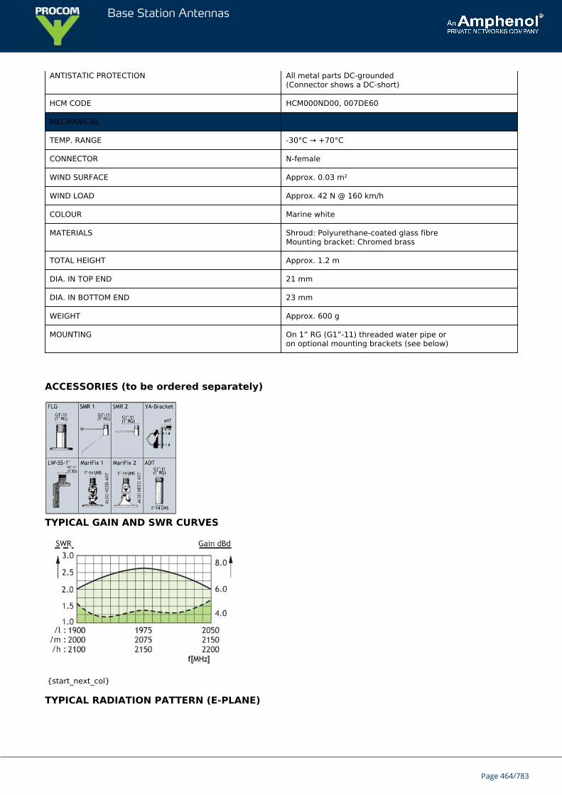
Base Station Antennas
ANTISTATIC PROTECTION All metal parts DC-grounded(Connector shows a DC-short)
HCM CODE HCM000ND00, 007DE60
MECHANICAL
TEMP. RANGE -30°C → +70°C
CONNECTOR N-female
WIND SURFACE Approx. 0.03 m²
WIND LOAD Approx. 42 N @ 160 km/h
COLOUR Marine white
MATERIALS Shroud: Polyurethane-coated glass fibreMounting bracket: Chromed brass
TOTAL HEIGHT Approx. 1.2 m
DIA. IN TOP END 21 mm
DIA. IN BOTTOM END 23 mm
WEIGHT Approx. 600 g
MOUNTING On 1” RG (G1”-11) threaded water pipe oron optional mounting brackets (see below)
ACCESSORIES (to be ordered separately)
TYPICAL GAIN AND SWR CURVES
{start_next_col}
TYPICAL RADIATION PATTERN (E-PLANE)
Page 464/783

Base Station Antennas
TYPICAL RADIATION PATTERN (H-PLANE),
Page 465/783
Base Station Antennas
CXL 2000-33 dBd Omnidirectional Base Station and Marine Antenna for the 2000 MHzBand
Vertically polarized, omnidirectional base station and marine antenna.Approximately 3 dBd gain.
DESCRIPTION
Simple mounting using the 1” revolving nut system.Wide variety of accessory mounting brackets available.Large bandwidth with respect to both SWR and gain.Highly suitable for duplex operation with large spacing between the TX and the RX frequencies.The antenna element is sealed in a high-quality, conical glass fibre tube.All metal parts in the antenna are DC-grounded to reduce the noise caused by atmospherical discharge.Consequently, the antenna shows a DC-short across the coaxial cable.The CXL 2000-3 is a vibration-proof, lightweight, slim-line, corrosion resistant, modern style base station and marineantenna.
ORDERING DESIGNATIONS
TYPE PRODUCT NO. FREQUENCY
CXL 2000-3 100000190 1900 – 2200 MHz
SPECIFICATIONS
ELECTRICAL
MODEL CXL 2000-3
ANTENNA TYPE Coaxial, collinear antenna, broad-banded
FREQUENCY 1900 – 2200 MHz
IMPEDANCE Nom. 50 Ω
POLARIZATION Vertical
GAIN 5 dBi 3 dBd
HALF POWER BEAMWIDTH 22°
BANDWIDTH ≥ 200 MHz @ SWR ≤ 2.0≥ 300 MHz @ SWR ≤ 2.5
SWR ≤ 2.5, typ. ≤ 2.0
MAX. POWER 100 W
ANTISTATIC PROTECTION All metal parts DC-grounded(Connector shows a DC-short)
Page 466/783
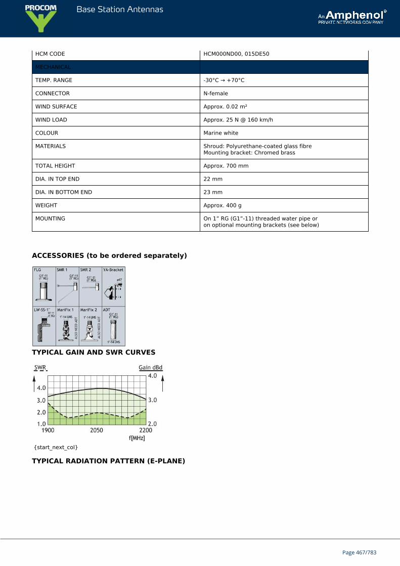
Base Station Antennas
HCM CODE HCM000ND00, 015DE50
MECHANICAL
TEMP. RANGE -30°C → +70°C
CONNECTOR N-female
WIND SURFACE Approx. 0.02 m²
WIND LOAD Approx. 25 N @ 160 km/h
COLOUR Marine white
MATERIALS Shroud: Polyurethane-coated glass fibreMounting bracket: Chromed brass
TOTAL HEIGHT Approx. 700 mm
DIA. IN TOP END 22 mm
DIA. IN BOTTOM END 23 mm
WEIGHT Approx. 400 g
MOUNTING On 1” RG (G1”-11) threaded water pipe oron optional mounting brackets (see below)
ACCESSORIES (to be ordered separately)
TYPICAL GAIN AND SWR CURVES
{start_next_col}
TYPICAL RADIATION PATTERN (E-PLANE)
Page 467/783
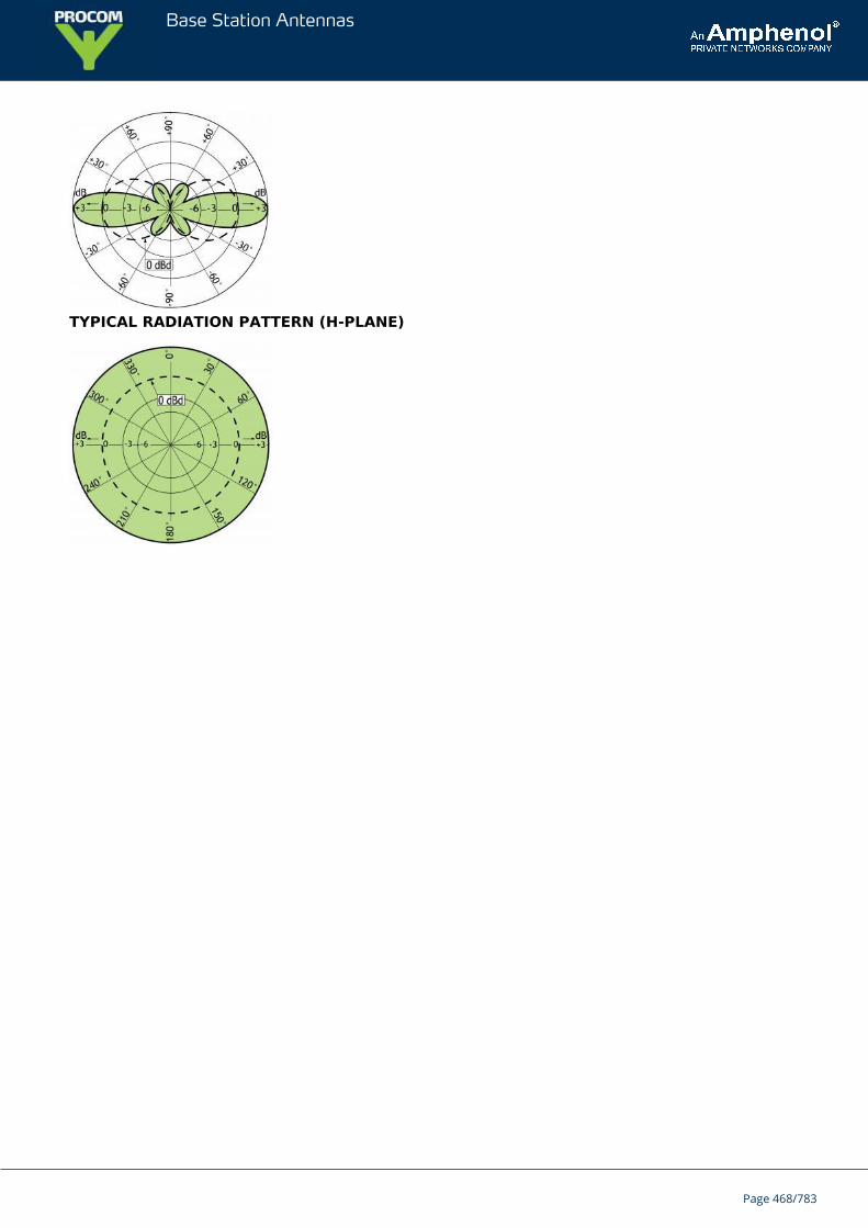
Base Station Antennas
TYPICAL RADIATION PATTERN (H-PLANE)
Page 468/783
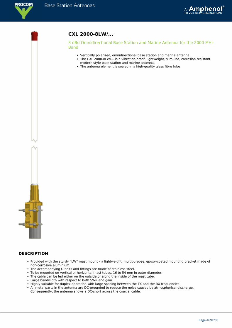
Base Station Antennas
CXL 2000-8LW/...8 dBd Omnidirectional Base Station and Marine Antenna for the 2000 MHzBand
Vertically polarized, omnidirectional base station and marine antenna.The CXL 2000-8LW/… is a vibration-proof, lightweight, slim-line, corrosion resistant,modern style base station and marine antenna.The antenna element is sealed in a high-quality glass fibre tube
DESCRIPTION
Provided with the sturdy “LW” mast mount – a lightweight, multipurpose, epoxy-coated mounting bracket made ofnon-corrosive aluminium.The accompanying U-bolts and fittings are made of stainless steel.To be mounted on vertical or horizontal mast tubes, 16 to 54 mm in outer diameter.The cable can be led either on the outside or along the inside of the mast tube.Large bandwidth with respect to both SWR and gain.Highly suitable for duplex operation with large spacing between the TX and the RX frequencies.All metal parts in the antenna are DC-grounded to reduce the noise caused by atmospherical discharge.Consequently, the antenna shows a DC-short across the coaxial cable.
Page 469/783
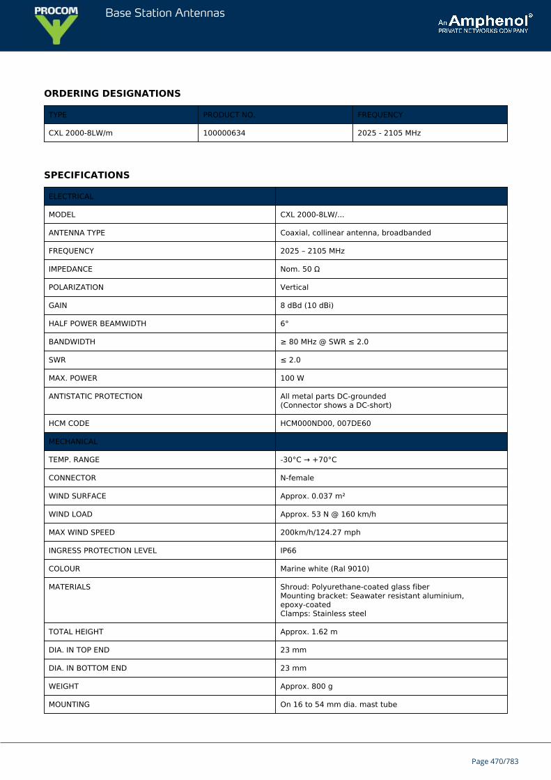
Base Station Antennas
ORDERING DESIGNATIONS
TYPE PRODUCT NO. FREQUENCY
CXL 2000-8LW/m 100000634 2025 - 2105 MHz
SPECIFICATIONS
ELECTRICAL
MODEL CXL 2000-8LW/...
ANTENNA TYPE Coaxial, collinear antenna, broadbanded
FREQUENCY 2025 – 2105 MHz
IMPEDANCE Nom. 50 Ω
POLARIZATION Vertical
GAIN 8 dBd (10 dBi)
HALF POWER BEAMWIDTH 6°
BANDWIDTH ≥ 80 MHz @ SWR ≤ 2.0
SWR ≤ 2.0
MAX. POWER 100 W
ANTISTATIC PROTECTION All metal parts DC-grounded(Connector shows a DC-short)
HCM CODE HCM000ND00, 007DE60
MECHANICAL
TEMP. RANGE -30°C → +70°C
CONNECTOR N-female
WIND SURFACE Approx. 0.037 m²
WIND LOAD Approx. 53 N @ 160 km/h
MAX WIND SPEED 200km/h/124.27 mph
INGRESS PROTECTION LEVEL IP66
COLOUR Marine white (Ral 9010)
MATERIALS Shroud: Polyurethane-coated glass fiberMounting bracket: Seawater resistant aluminium,epoxy-coatedClamps: Stainless steel
TOTAL HEIGHT Approx. 1.62 m
DIA. IN TOP END 23 mm
DIA. IN BOTTOM END 23 mm
WEIGHT Approx. 800 g
MOUNTING On 16 to 54 mm dia. mast tube
Page 470/783
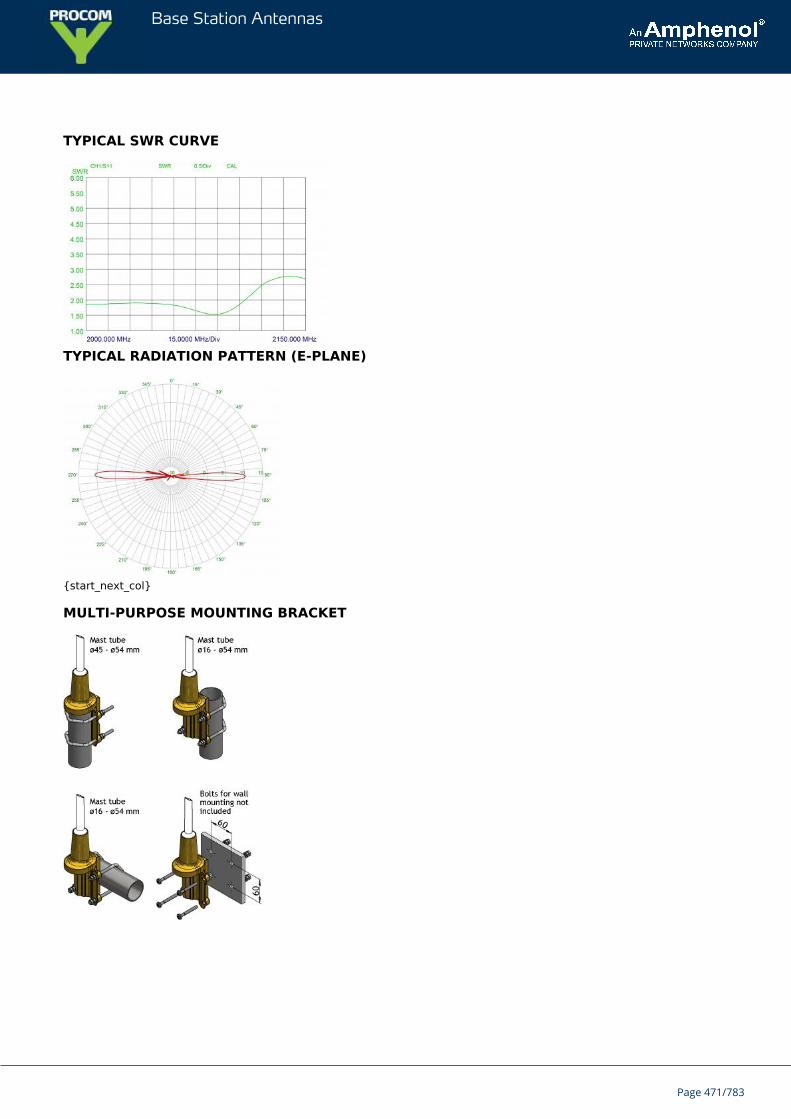
Base Station Antennas
TYPICAL SWR CURVE
TYPICAL RADIATION PATTERN (E-PLANE)
{start_next_col}
MULTI-PURPOSE MOUNTING BRACKET
Page 471/783
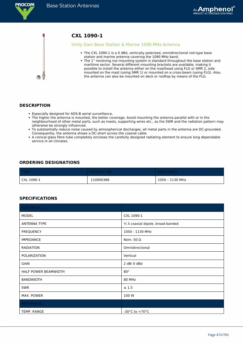
Base Station Antennas
CXL 1090-1Unity Gain Base Station & Marine 1090 MHz Antenna
The CXL 1090-1 is a 0 dBd, vertically polarized, omnidirectional rod-type basestation and marine antenna covering the 1090 MHz band.The 1” revolving nut mounting system is standard throughout the base station andmaritime sector. Several different mounting brackets are available, making itpossible to install the antenna either on the masthead using FLG or SMR 2, sidemounted on the mast (using SMR 1) or mounted on a cross-beam (using FLG). Also,the antenna can also be mounted on deck or rooftop by means of the FLG.
DESCRIPTION
Especially designed for ADS-B aerial surveillance.The higher the antenna is mounted, the better coverage. Avoid mounting the antenna parallel with or in theneighbourhood of other metal parts, such as masts, supporting wires etc., as the SWR and the radiation pattern mayotherwise be strongly influenced.To substantially reduce noise caused by atmospherical discharges, all metal parts in the antenna are DC-grounded.Consequently, the antenna shows a DC-short across the coaxial cable.A conical glass fibre tube completely encloses the carefully designed radiating element to ensure long dependableservice in all climates.
ORDERING DESIGNATIONS
TYPE PRODUCT NO. FREQUENCY
CXL 1090-1 110000386 1050 – 1130 MHz
SPECIFICATIONS
ELECTRICAL
MODEL CXL 1090-1
ANTENNA TYPE ½ λ coaxial dipole, broad-banded
FREQUENCY 1050 - 1130 MHz
IMPEDANCE Nom. 50 Ω
RADIATION Omnidirectional
POLARIZATION Vertical
GAIN 2 dBi 0 dBd
HALF POWER BEAMWIDTH 80°
BANDWIDTH 80 MHz
SWR ≤ 1.5
MAX. POWER 100 W
MECHANICAL
TEMP. RANGE -30°C to +70°C
Page 472/783
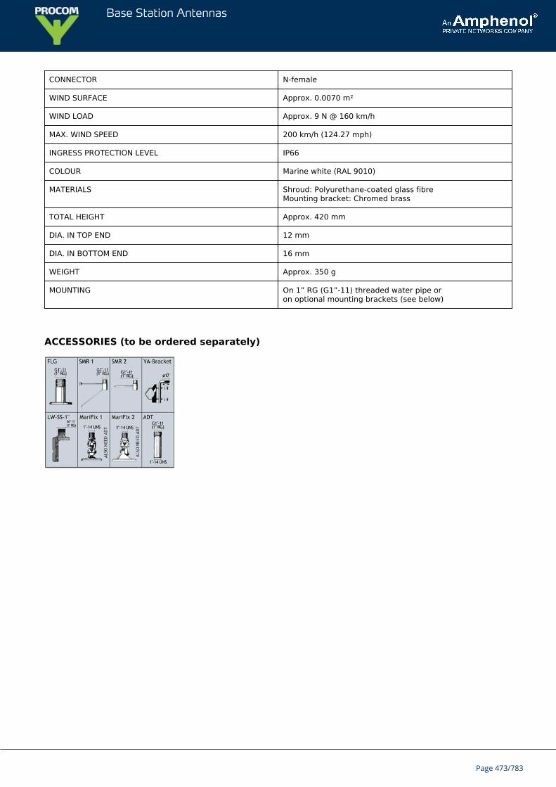
Base Station Antennas
CONNECTOR N-female
WIND SURFACE Approx. 0.0070 m²
WIND LOAD Approx. 9 N @ 160 km/h
MAX. WIND SPEED 200 km/h (124.27 mph)
INGRESS PROTECTION LEVEL IP66
COLOUR Marine white (RAL 9010)
MATERIALS Shroud: Polyurethane-coated glass fibre Mounting bracket: Chromed brass
TOTAL HEIGHT Approx. 420 mm
DIA. IN TOP END 12 mm
DIA. IN BOTTOM END 16 mm
WEIGHT Approx. 350 g
MOUNTING On 1” RG (G1”-11) threaded water pipe oron optional mounting brackets (see below)
ACCESSORIES (to be ordered separately)
Page 473/783
Base Station Antennas
CXL 1090-1LWUniversal, 0 dBd Base Station and Marine Antenna for the 1090 MHz Band
CXL 1090-1LW is a 0 dBd, vertically polarized, omnidirectional base station andmarine antenna, which covers the 1090 MHz band.Provided with the sturdy “LW” mast mount – a lightweight, multipurpose, epoxy-coated mounting bracket made of non-corrosive aluminium.
Description
Especially designed for ADS-B aerial surveillance.The accompanying U-bolts and fittings are made of stainless steel.To be mounted on vertical or horizontal mast tubes, 16 to 54 mm in outer diameter.The cable can be led either on the outside or along the inside of the mast tube.Large bandwidth with respect to both SWR and gain.The carefully designed, broad-banded antenna element is sealed in a high-quality, conical glass fibre tube with lowwind-load, which will ensure performance undisturbed by corrosive environments.To substantially reduce noise caused by atmospherical discharges, all metal parts in the antenna are DC-grounded.Consequently, the antenna shows a DC-short across the coaxial cable.The CXL 1090-1LW is a vibration-proof, lightweight, slim-line, corrosion resistant, modern style base station andmarine antenna.
ORDERING DESIGNATIONS
TYPE FREQUENCY PRODUCT NO.
CXL 1090-1LW 1050 – 1130 MHz 100000637
SPECIFICATIONS
ELECTRICAL
MODEL CXL 1090-1LW
ANTENNA TYPE ½ λ coaxial dipole, broad-banded
FREQUENCY 1050 - 1130 MHz
IMPEDANCE Nom. 50 Ω
RADIATION Omnidirectional
POLARIZATION Vertical
GAIN 2 dBi 0 dBd
HALF POWER BEAMWIDTH 80°
BANDWIDTH 80 MHz
SWR < 1.5
MAX. POWER 100 W
ANTISTATIC PROTECTION All metal parts DC-grounded
Page 474/783
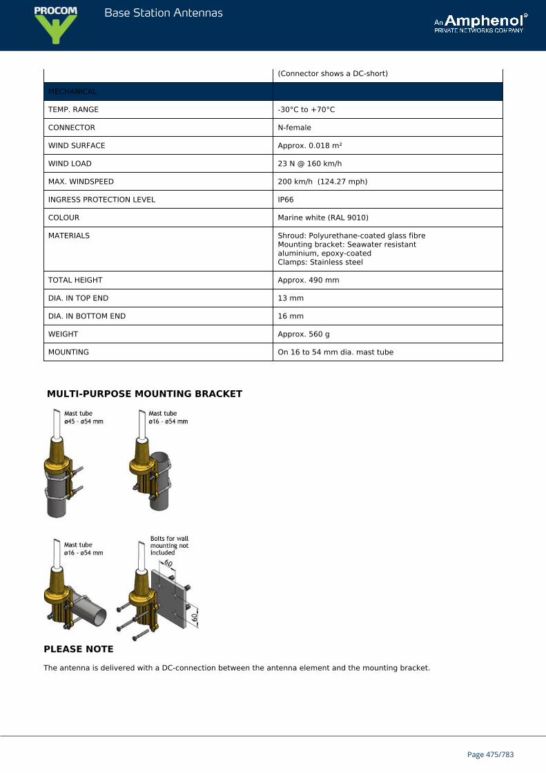
Base Station Antennas
(Connector shows a DC-short)
MECHANICAL
TEMP. RANGE -30°C to +70°C
CONNECTOR N-female
WIND SURFACE Approx. 0.018 m²
WIND LOAD 23 N @ 160 km/h
MAX. WINDSPEED 200 km/h (124.27 mph)
INGRESS PROTECTION LEVEL IP66
COLOUR Marine white (RAL 9010)
MATERIALS Shroud: Polyurethane-coated glass fibreMounting bracket: Seawater resistantaluminium, epoxy-coatedClamps: Stainless steel
TOTAL HEIGHT Approx. 490 mm
DIA. IN TOP END 13 mm
DIA. IN BOTTOM END 16 mm
WEIGHT Approx. 560 g
MOUNTING On 16 to 54 mm dia. mast tube
MULTI-PURPOSE MOUNTING BRACKET
PLEASE NOTE
The antenna is delivered with a DC-connection between the antenna element and the mounting bracket.
Page 475/783
Base Station Antennas
CXL 450-3LW-SS-ExATEX certified, 3 dBd, Omnidirectional Base Station Antenna for the 380 -470 MHz Band in Hazardous areas
CXL 450-3LW-SS-Ex is a 3 dBd, vertically polarized, omnidirectional base stationantenna which covers the 380 - 470 MHz band in four models with up to 10 MHzoverlap.The antenna is specified as ATEX antenna for use in zone 2 in potentially explosiveareas.
DESCRIPTION
Before installing the antenna, read the ATEX Product Manual carefully.The antenna is suitable for use in gas groups IIA, IIB and IIC in zone 2.It’s only necessary to install a ATEX grounding Kit on the LW-SS-Ex bracket, when the point of installation has adifferent electrical potential than the system.The carefully designed collinear antenna radiating parts elements is made of brass tube and sealed in a high-qualityconical glass fibre tube with low wind-load.The accompanying U-bolts and fittings are made of stainless steel.All metal parts in the antenna are DC-grounded. Consequently, the antenna shows a DC-short across the coaxialcable.
ORDERING DESIGNATIONS
TYPE FREQUENCY PRODUCT NO.
CXL 450-3LW-SS-Ex/s 380 - 410 MHz 115000013
CXL 450-3LW-SS-Ex/f 406 - 430 MHz 115000014
CXL 450-3LW-SS-Ex/l 420 - 450 MHz 115000015
CXL 450-3LW-SS-Ex/h 440 - 470 MHz 115000016
ACCESSORIES
ATEX grounding Kit 115000100
SPECIFICATIONS
ELECTRICAL
MODEL CXL 450-3LW-SS-Ex
ANTENNA TYPE ½ λ coaxial dipole, broad-banded
FREQUENCY 30 MHz wide frequency segments within380 - 470 MHz. See ordering designations
IMPEDANCE Nom. 50 Ω
RADIATION Omnidirectional
POLARIZATION Vertical
Page 476/783
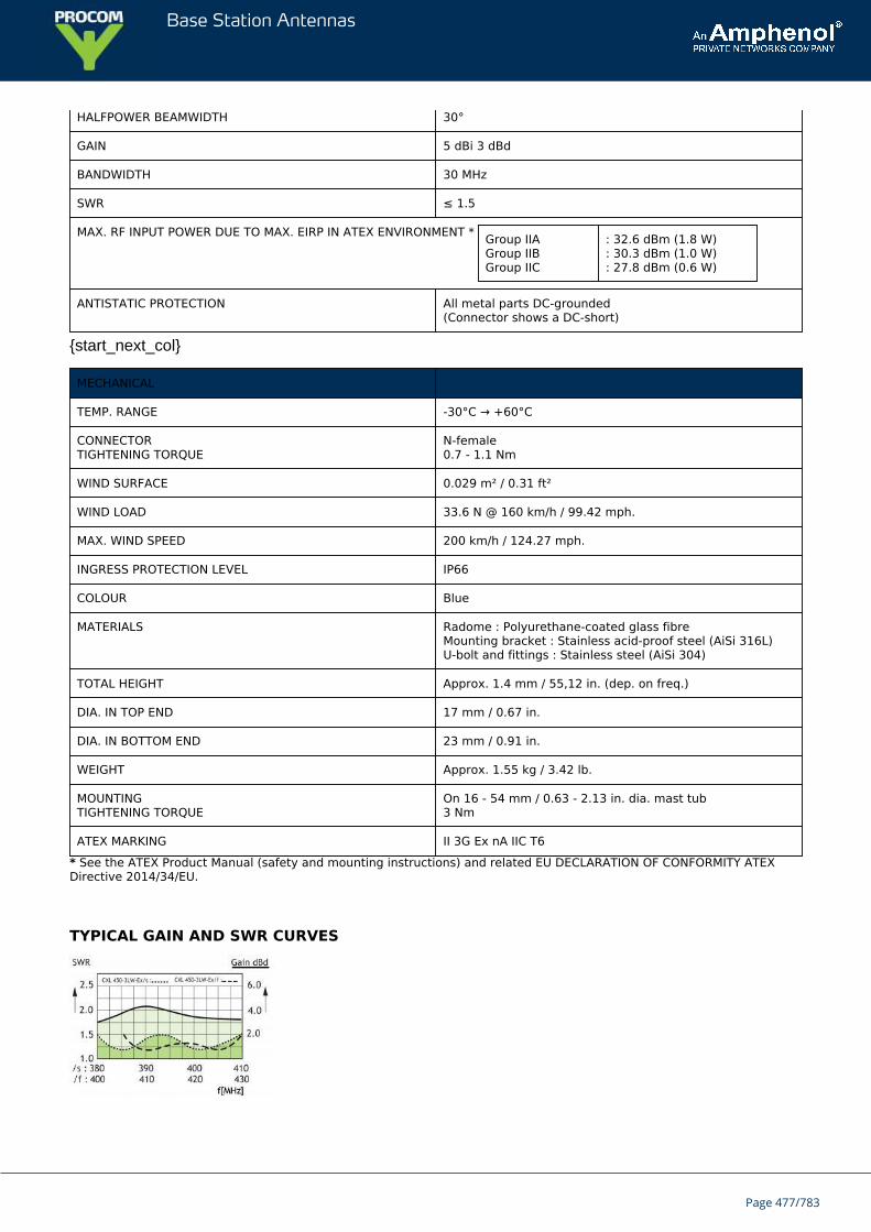
Base Station Antennas
HALFPOWER BEAMWIDTH 30°
GAIN 5 dBi 3 dBd
BANDWIDTH 30 MHz
SWR ≤ 1.5
MAX. RF INPUT POWER DUE TO MAX. EIRP IN ATEX ENVIRONMENT * Group IIAGroup IIBGroup IIC
: 32.6 dBm (1.8 W): 30.3 dBm (1.0 W): 27.8 dBm (0.6 W)
ANTISTATIC PROTECTION All metal parts DC-grounded(Connector shows a DC-short)
{start_next_col}
MECHANICAL
TEMP. RANGE -30°C → +60°C
CONNECTORTIGHTENING TORQUE
N-female0.7 - 1.1 Nm
WIND SURFACE 0.029 m² / 0.31 ft²
WIND LOAD 33.6 N @ 160 km/h / 99.42 mph.
MAX. WIND SPEED 200 km/h / 124.27 mph.
INGRESS PROTECTION LEVEL IP66
COLOUR Blue
MATERIALS Radome : Polyurethane-coated glass fibreMounting bracket : Stainless acid-proof steel (AiSi 316L)U-bolt and fittings : Stainless steel (AiSi 304)
TOTAL HEIGHT Approx. 1.4 mm / 55,12 in. (dep. on freq.)
DIA. IN TOP END 17 mm / 0.67 in.
DIA. IN BOTTOM END 23 mm / 0.91 in.
WEIGHT Approx. 1.55 kg / 3.42 lb.
MOUNTINGTIGHTENING TORQUE
On 16 - 54 mm / 0.63 - 2.13 in. dia. mast tub3 Nm
ATEX MARKING II 3G Ex nA IIC T6
* See the ATEX Product Manual (safety and mounting instructions) and related EU DECLARATION OF CONFORMITY ATEXDirective 2014/34/EU.
TYPICAL GAIN AND SWR CURVES
Page 477/783
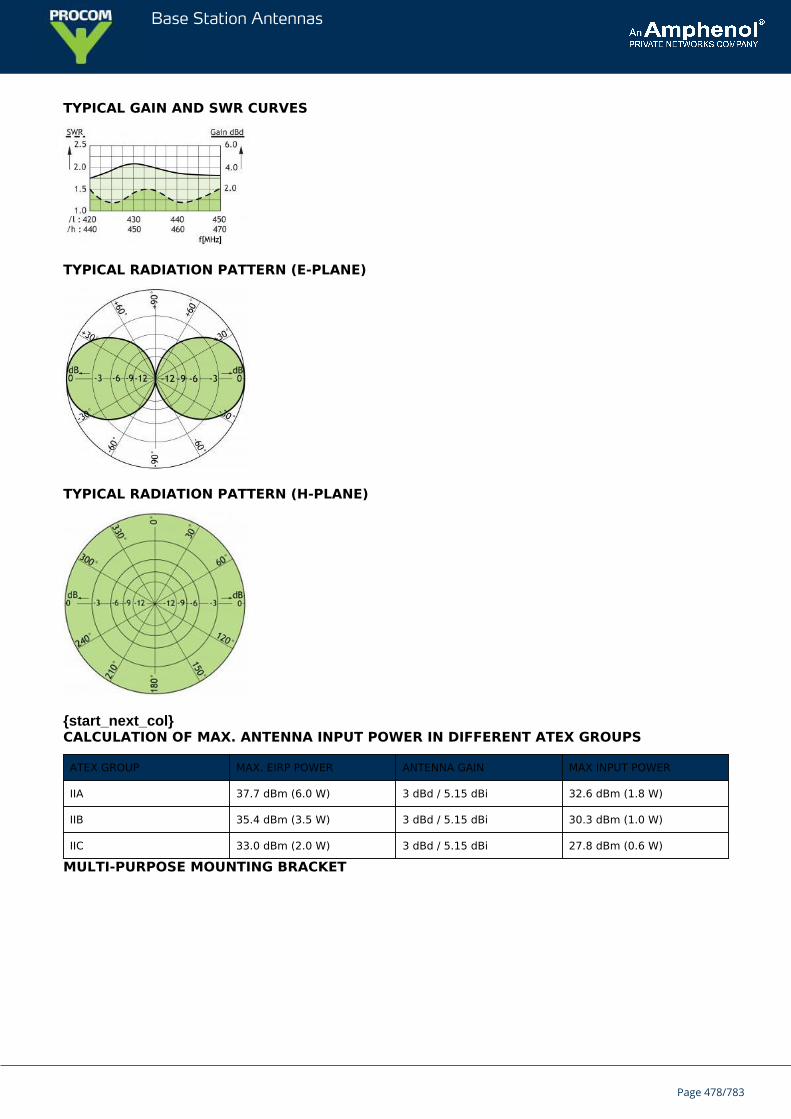
Base Station Antennas
TYPICAL GAIN AND SWR CURVES
TYPICAL RADIATION PATTERN (E-PLANE)
TYPICAL RADIATION PATTERN (H-PLANE)
{start_next_col}CALCULATION OF MAX. ANTENNA INPUT POWER IN DIFFERENT ATEX GROUPS
ATEX GROUP MAX. EIRP POWER ANTENNA GAIN MAX INPUT POWER
IIA 37.7 dBm (6.0 W) 3 dBd / 5.15 dBi 32.6 dBm (1.8 W)
IIB 35.4 dBm (3.5 W) 3 dBd / 5.15 dBi 30.3 dBm (1.0 W)
IIC 33.0 dBm (2.0 W) 3 dBd / 5.15 dBi 27.8 dBm (0.6 W)
MULTI-PURPOSE MOUNTING BRACKET
Page 478/783
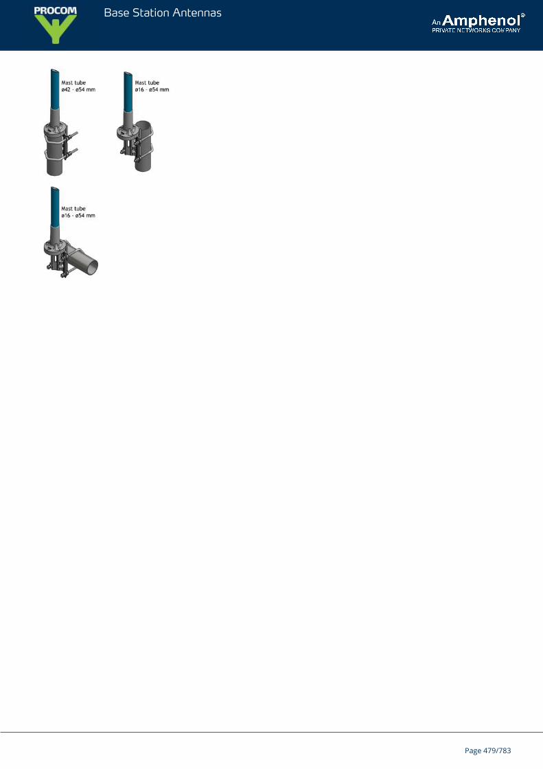
Base Station Antennas
Page 479/783
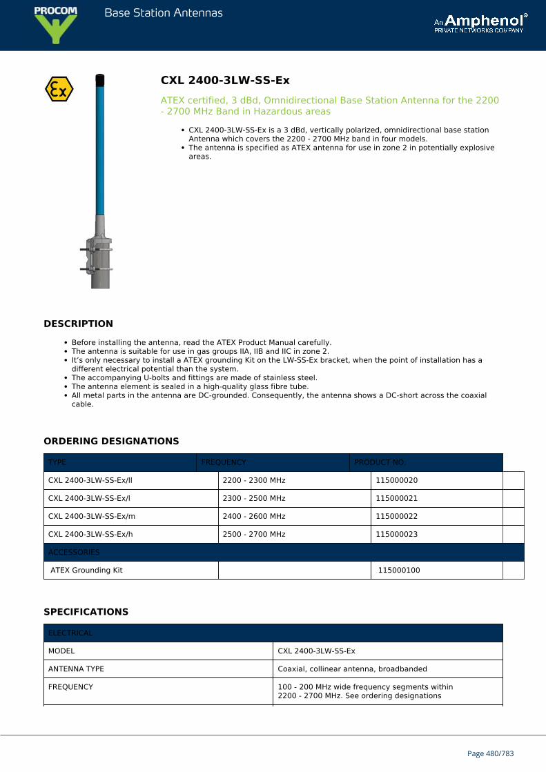
Base Station Antennas
CXL 2400-3LW-SS-ExATEX certified, 3 dBd, Omnidirectional Base Station Antenna for the 2200- 2700 MHz Band in Hazardous areas
CXL 2400-3LW-SS-Ex is a 3 dBd, vertically polarized, omnidirectional base stationAntenna which covers the 2200 - 2700 MHz band in four models.The antenna is specified as ATEX antenna for use in zone 2 in potentially explosiveareas.
DESCRIPTION
Before installing the antenna, read the ATEX Product Manual carefully.The antenna is suitable for use in gas groups IIA, IIB and IIC in zone 2.It’s only necessary to install a ATEX grounding Kit on the LW-SS-Ex bracket, when the point of installation has adifferent electrical potential than the system.The accompanying U-bolts and fittings are made of stainless steel.The antenna element is sealed in a high-quality glass fibre tube.All metal parts in the antenna are DC-grounded. Consequently, the antenna shows a DC-short across the coaxialcable.
ORDERING DESIGNATIONS
TYPE FREQUENCY PRODUCT NO.
CXL 2400-3LW-SS-Ex/ll 2200 - 2300 MHz 115000020
CXL 2400-3LW-SS-Ex/l 2300 - 2500 MHz 115000021
CXL 2400-3LW-SS-Ex/m 2400 - 2600 MHz 115000022
CXL 2400-3LW-SS-Ex/h 2500 - 2700 MHz 115000023
ACCESSORIES
ATEX Grounding Kit 115000100
SPECIFICATIONS
ELECTRICAL
MODEL CXL 2400-3LW-SS-Ex
ANTENNA TYPE Coaxial, collinear antenna, broadbanded
FREQUENCY 100 - 200 MHz wide frequency segments within2200 - 2700 MHz. See ordering designations
Page 480/783
Base Station Antennas
IMPEDANCE Nom. 50 Ω
POLARIZATION Vertical
GAIN 5 dBi 3 dBd
HALF POWER BEAMWIDTH 22°
BANDWIDTH For l, m and h models:≥ 200 MHz @ SWR ≤ 2.0For ll-model:≥ 100 MHz @ SWR ≤ 2.0
SWR ≤ 2.0, typ. ≤ 1.5
MAX. RF INPUT POWER DUE TO MAX. EIRP IN ATEX ENVIRONMENT *
Group IIA 32.6 dBm (1.8 W)
Group IIB 30.3 dBm (1.0 W)
Group IIC 27.8 dBm (0.6 W)
ANTISTATIC PROTECTION All metal parts DC-grounded(Connector shows a DC-short)
MECHANICAL
TEMP. RANGE -30°C → +60°C
CONNECTORTIGHTENING TORQUE
N-female0.7 - 1.1 Nm
WIND SURFACE Approx. 0.02 m² / 0.22 ft²
WIND LOAD Approx. 26 N @ 160 km/h / 99.42 mph.
MAX. WIND SPEED 200 km/h / 124.27 mph.
INGRESS PROTECTION LEVEL IP66
COLOUR Blue
MATERIALS Radome: Polyurethane-coated glass fibreMounting bracket: Stainless acid-proof steel (AiSi 316L)U-bolt and fittings: Stainless steel (AiSi 304)
TOTAL HEIGHT Approx. 700 mm / 27.56 in.
DIA. IN TOP END 22 mm / 0.87 in.
DIA. IN BOTTOM END 23 mm / 0.91 in.
WEIGHT Approx. 850 g / 1.87 lb.
MOUNTINGTIGHTENING TORQUE
On 16 to 54 mm / 0.63 - 2.13 in. dia. mast tube3 Nm
ATEX MARKING II 3G Ex nA IIC T6
* See the ATEX Product Manual (safety and mounting instructions) and related EU DECLARATION OF CONFORMITY ATEXDirective 2014/34/EU.
TYPICAL GAIN AND SWR CURVES
Page 481/783
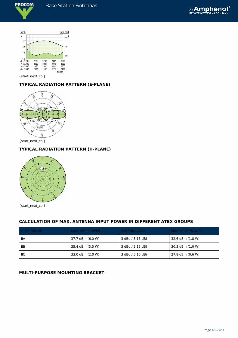
Base Station Antennas
{start_next_col}
TYPICAL RADIATION PATTERN (E-PLANE)
{start_next_col}
TYPICAL RADIATION PATTERN (H-PLANE)
{start_next_col}
CALCULATION OF MAX. ANTENNA INPUT POWER IN DIFFERENT ATEX GROUPS
ATEX GROUP MAX. EIRP POWER ANTENNA GAIN MAX INPUT POWER
IIA 37.7 dBm (6.0 W) 3 dBd / 5.15 dBi 32.6 dBm (1.8 W)
IIB 35.4 dBm (3.5 W) 3 dBd / 5.15 dBi 30.3 dBm (1.0 W)
IIC 33.0 dBm (2.0 W) 3 dBd / 5.15 dBi 27.8 dBm (0.6 W)
MULTI-PURPOSE MOUNTING BRACKET
Page 482/783

Base Station Antennas
Page 483/783
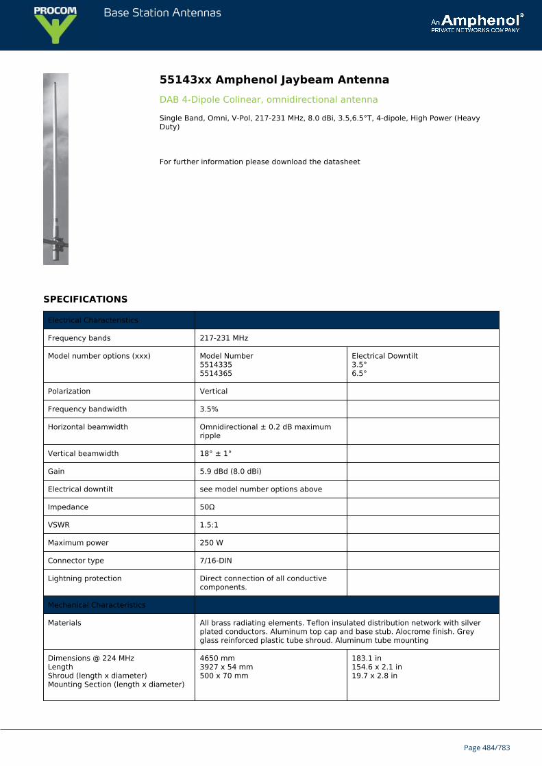
Base Station Antennas
55143xx Amphenol Jaybeam AntennaDAB 4-Dipole Colinear, omnidirectional antenna
Single Band, Omni, V-Pol, 217-231 MHz, 8.0 dBi, 3.5,6.5°T, 4-dipole, High Power (HeavyDuty)
For further information please download the datasheet
SPECIFICATIONS
Electrical Characteristics
Frequency bands 217-231 MHz
Model number options (xxx) Model Number55143355514365
Electrical Downtilt3.5°6.5°
Polarization Vertical
Frequency bandwidth 3.5%
Horizontal beamwidth Omnidirectional ± 0.2 dB maximumripple
Vertical beamwidth 18° ± 1°
Gain 5.9 dBd (8.0 dBi)
Electrical downtilt see model number options above
Impedance 50Ω
VSWR 1.5:1
Maximum power 250 W
Connector type 7/16-DIN
Lightning protection Direct connection of all conductivecomponents.
Mechanical Characteristics
Materials All brass radiating elements. Teflon insulated distribution network with silverplated conductors. Aluminum top cap and base stub. Alocrome finish. Greyglass reinforced plastic tube shroud. Aluminum tube mounting
Dimensions @ 224 MHzLengthShroud (length x diameter)Mounting Section (length x diameter)
4650 mm3927 x 54 mm500 x 70 mm
183.1 in154.6 x 2.1 in19.7 x 2.8 in
Page 484/783
Base Station Antennas
Lightning spike (extension from topcap)
148 mm 5.8 in
Weight without mounting brackets 10.0 kg 22.0 lbs
Wind load @ 161 km/hr (100 mph) 330 N 74.2 lbf
Mounting Options Part Number Fits Pipe Diameter
Pole mounting bracket kit 0900638/00 48-115 mm 1.9-4.5 in
Mounting clamps (twoclamp set)
0300235/00 48-75 mm mm 1.9-3.0 in
Page 485/783
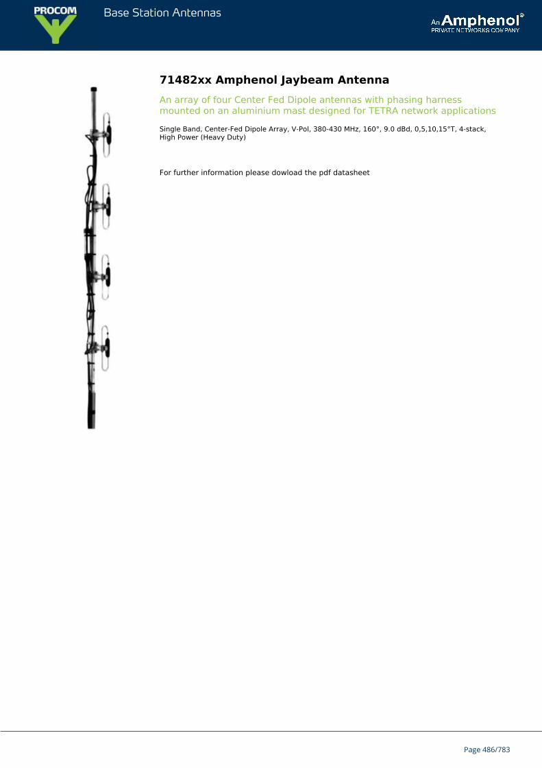
Base Station Antennas
71482xx Amphenol Jaybeam AntennaAn array of four Center Fed Dipole antennas with phasing harnessmounted on an aluminium mast designed for TETRA network applications
Single Band, Center-Fed Dipole Array, V-Pol, 380-430 MHz, 160°, 9.0 dBd, 0,5,10,15°T, 4-stack,High Power (Heavy Duty)
For further information please dowload the pdf datasheet
Page 486/783
Base Station Antennas
MA411D00 Amphenol Jaybeam AntennaA VHF Ground Plane antenna with integrated mount designed to attach tothe top of a 30-60 mm diameter mast
Single Band, Omni, Ground plane, V-Pol, 31-41 MHz, 0 dBd, High Power (Heavy Duty)
For further information please download the pdf datasheet
A VHF Ground Plane antenna with integrated mount designed to attach to the topof a 30-60 mm diameter mast. The active element is a folded monopole. Theground plane elements are user-tuned to achieve best performance at theoperating frequency. Tuning chart provided.
SPECIFICATIONS
Electrical Characteristics
Frequency band* 31-41 MHz
Bandwidth ±2% (typical)
Polarization Vertical
Horizontal beamwidth 360°
Vertical beamwidth 86°
Gain 0 dBd
Impedance 50Ω
VSWR <1.5:1
Maximum power 250 W
Connector type N-Female
Lightning protection DC grounded
Electrical Characteristics
Frequency band* 31-41 MHz
Bandwidth ±2% (typical)
Polarization Vertical
Horizontal beamwidth 360°
Vertical beamwidth 86°
Gain 0 dBd
Impedance 50Ω
VSWR <1.5:1
Maximum power 250 W
Connector type N-Female
Page 487/783
Base Station Antennas
Lightning protection DC grounded
* Tuning chart provided. Trim whips to achieve required center frequency.
Mechanical Characteristics
Materials Aluminium alloy, Glass fibre, and Stainless steel
Dimensions (WhipLength)
82 MHz: 990 mm 39.0 in
Weight with bracket 31 MHz: 82 MHz: 6.5 4.0 kg kg 14.3 lbs 8.8 lbs
Wind load @ 160km/hr (100 mph)
31 MHz: 82 MHz: 240 120 N N 54.0 lbf 27.0 lbf
Mounting Options
Mounting bracket Integral mounting bracket to fit on 30-60 mm dia. mast.
Page 488/783
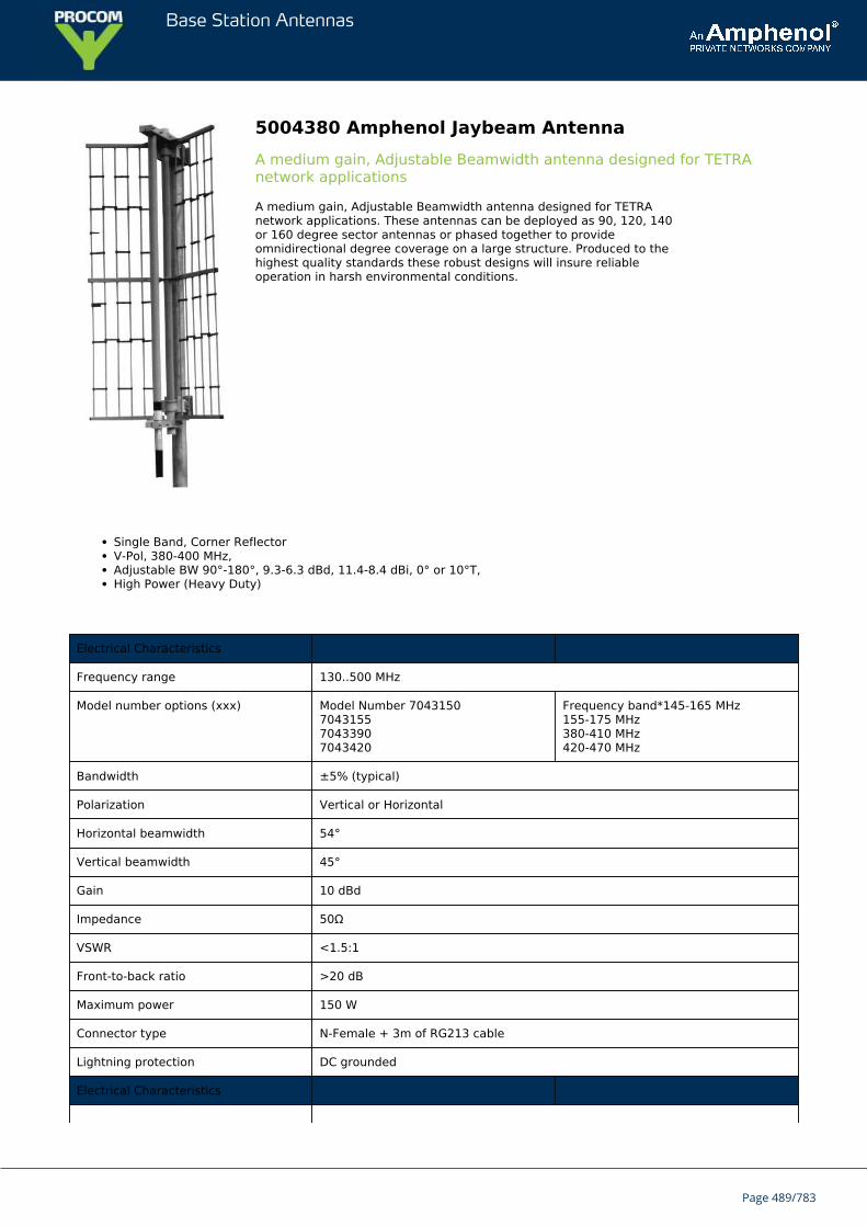
Base Station Antennas
5004380 Amphenol Jaybeam AntennaA medium gain, Adjustable Beamwidth antenna designed for TETRAnetwork applications
A medium gain, Adjustable Beamwidth antenna designed for TETRAnetwork applications. These antennas can be deployed as 90, 120, 140or 160 degree sector antennas or phased together to provideomnidirectional degree coverage on a large structure. Produced to thehighest quality standards these robust designs will insure reliableoperation in harsh environmental conditions.
Single Band, Corner ReflectorV-Pol, 380-400 MHz,Adjustable BW 90°-180°, 9.3-6.3 dBd, 11.4-8.4 dBi, 0° or 10°T,High Power (Heavy Duty)
Electrical Characteristics
Frequency range 130..500 MHz
Model number options (xxx) Model Number 7043150704315570433907043420
Frequency band*145-165 MHz155-175 MHz380-410 MHz420-470 MHz
Bandwidth ±5% (typical)
Polarization Vertical or Horizontal
Horizontal beamwidth 54°
Vertical beamwidth 45°
Gain 10 dBd
Impedance 50Ω
VSWR <1.5:1
Front-to-back ratio >20 dB
Maximum power 150 W
Connector type N-Female + 3m of RG213 cable
Lightning protection DC grounded
Electrical Characteristics
Page 489/783
Base Station Antennas
Frequency range 130..500 MHz
Model number options (xxx) Model Number 7043150704315570433907043420
Frequency band*145-165 MHz155-175 MHz380-410 MHz420-470 MHz
Bandwidth ±5% (typical)
Polarization Vertical or Horizontal
Horizontal beamwidth 54°
Vertical beamwidth 45°
Gain 10 dBd
Impedance 50Ω
VSWR <1.5:1
Front-to-back ratio >20 dB
Maximum power 150 W
Connector type N-Female + 3m of RG213 cable
Lightning protection DC grounded
* Other frequencies available upon request.
Mechanical Characteristics
Materials Boom, 32 mm dia., aluminium Elements, 12.7 mm dia., aluminium Balun, fully mouldedenclosure
Dimensions (Length) 155 MHz:300 MHz:
3410 mm2030 mm
134.3 in79.9 in
Weight without bracket 155 MHz:300 MHz:
6.0 kg4.5 kg
13.2 lbs 9.9 lbs
Wind load @ 160 km/hr(100 mph)
155 MHz:300 MHz:
250 N 140 N 56.2 lbf31.5 lbf
Mounting Options
Part Number
Mounting bracket 3202078/68 + 3201079/00
Alternate mounting brackets 0900912/00, 0302032/68, or 0300064/00+ U-bolts to match mounting pipe diameter
Please order Mounting Bracket separately.
Page 490/783
Base Station Antennas
MA411H02 Amphenol Jaybeam AntennaA VHF Ground Plane antenna with integrated mount designed to attach tothe top of a 30-60 mm diameter mast
Single Band, Omni, Ground plane, V-Pol, 82-88 MHz, 0 dBd, High Power (Heavy Duty)
For further information please dowload the pdf file.
A VHF Ground Plane antenna with integrated mount designed to attach to the topof a 30-60 mm diameter mast. The active element is a folded monopole. Theground plane elements are user-tuned to achieve best performance at theoperating frequency. Tuning chart provided.
SPECIFICATIONS
Electrical Characteristics
Frequency band* 82-88 MHz
Bandwidth ±2% (typical)
Polarization Vertical
Horizontal beamwidth 360°
Vertical beamwidth 86°
Gain 0 dBd
Impedance 50Ω
VSWR
Maximum power 250 W
Connector type N-Female
Lightning protection DC grounded
Electrical Characteristics
Frequency band* 82-88 MHz
Bandwidth ±2% (typical)
Polarization Vertical
Horizontal beamwidth 360°
Vertical beamwidth 86°
Gain 0 dBd
Impedance 50Ω
VSWR
Maximum power 250 W
Connector type N-Female
Page 491/783
Base Station Antennas
Lightning protection DC grounded
* Tuning chart provided. Trim whips to achieve required center frequency.
Mechanical Characteristics
Materials Aluminium alloy, Glass fibre, and Stainless steel
Dimensions (WhipLength)
82 MHz: 990 mm 39.0 in
Weight with bracket 31 MHz:82 MHz:
6.5 kg4.0 kg
14.3 lbs8.8 lbs
Wind load @ 160km/hr (100 mph)
31 MHz:82 MHz:
240 N120 N
54.0 lbf27.0 lbf
Mounting Options
Mounting bracket Integral mounting bracket to fit on 30-60 mm dia. mast.
Page 492/783
Base Station Antennas
MA412D00 Amphenol Jaybeam AntrennaA VHF Ground Plane antenna with integrated mount designed to attach tothe top of a 30-60 mm diameter mast
Single Band, Omni, Ground plane, V-Pol, 31-41 MHz, 0 dBd, UHF connector, High Power (HeavyDuty)
For further information please donwload the PDF datasheet
A VHF Ground Plane antenna with integrated mount designed to attach to the topof a 30-60 mm diameter mast. The active element is a folded monopole. Theground plane elements are user-tuned to achieve best performance at theoperating frequency. Tuning chart provided.
SPECIFICATIONS
Electrical Characteristics
Frequency band* 31..41 MHz
Bandwidth ±2% (typical)
Polarization Vertical
Horizontal beamwidth 360°
Vertical beamwidth 86°
Gain 0 dBd
Impedance 50Ω
VSWR <1.5:1
Maximum power 250 W
Connector type UHF (SO230) Female
Lightning protection DC grounded
Electrical Characteristics
Frequency band* 31..41 MHz
Bandwidth ±2% (typical)
Polarization Vertical
Horizontal beamwidth 360°
Vertical beamwidth 86°
Gain 0 dBd
Impedance 50Ω
VSWR <1.5:1
Maximum power 250 W
Page 493/783
Base Station Antennas
Connector type UHF (SO230) Female
Lightning protection DC grounded
* Tuning chart provided. Trim whips to achieve required center frequency.
Mechanical Characteristics
Materials Aluminium alloy, Glass fibre, and Stainless steel
Dimensions (Whip Length) 31 MHz: 2300 mm 90.6 in
Weight with bracket 31 MHz: 6.5 kg 14.3 lbs
Wind load @ 160 km/hr(100 mph)
31 MHz: 240 N 54.0 lbf
Mounting Options
Mounting bracket Integral mounting bracket to fit on 30-60 mm dia. mast.
Page 494/783
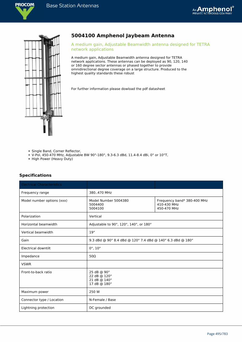
Base Station Antennas
5004100 Amphenol Jaybeam AntennaA medium gain, Adjustable Beamwidth antenna designed for TETRAnetwork applications
A medium gain, Adjustable Beamwidth antenna designed for TETRAnetwork applications. These antennas can be deployed as 90, 120, 140or 160 degree sector antennas or phased together to provideomnidirectional degree coverage on a large structure. Produced to thehighest quality standards these robust
For further information please dowload the pdf datasheet
Single Band, Corner Reflector,V-Pol, 450-470 MHz, Adjustable BW 90°-180°, 9.3-6.3 dBd, 11.4-8.4 dBi, 0° or 10°T,High Power (Heavy Duty)
Specifications
Electrical Characteristics
Frequency range 380..470 MHz
Model number options (xxx) Model Number 500438050044005004100
Frequency band* 380-400 MHz410-430 MHz450-470 MHz
Polarization Vertical
Horizontal beamwidth Adjustable to 90°, 120°, 140°, or 180°
Vertical beamwidth 19°
Gain 9.3 dBd @ 90° 8.4 dBd @ 120° 7.4 dBd @ 140° 6.3 dBd @ 180°
Electrical downtilt 0°, 10°
Impedance 50Ω
VSWR
Front-to-back ratio 25 dB @ 90°22 dB @ 120°21 dB @ 140°17 dB @ 180°
Maximum power 250 W
Connector type / Location N-Female / Base
Lightning protection DC grounded
Page 495/783
Base Station Antennas
Mechanical Characteristics
Materials Radiator element, sealed in glass fibre tube Reflectorassembly, polyester coated, Aluminium
Dimensions HxWxD 2600 x 800 x 400 mm 102.4 x 31.5 x 15.7 in
Weight without bracket 16 kg 35.3 lbs
Wind load @ 160 km/hr (100 mph) 800 N 180 lbf
Mounting Options
Mounting bracket 9250-318
Please order Mounting Bracket separately.
Page 496/783
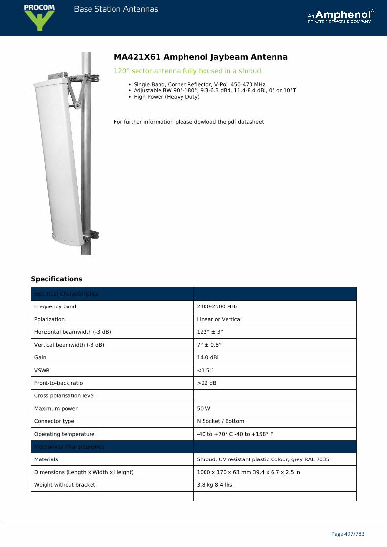
Base Station Antennas
MA421X61 Amphenol Jaybeam Antenna120° sector antenna fully housed in a shroud
Single Band, Corner Reflector, V-Pol, 450-470 MHzAdjustable BW 90°-180°, 9.3-6.3 dBd, 11.4-8.4 dBi, 0° or 10°THigh Power (Heavy Duty)
For further information please dowload the pdf datasheet
Specifications
Electrical Characteristics
Frequency band 2400-2500 MHz
Polarization Linear or Vertical
Horizontal beamwidth (-3 dB) 122° ± 3°
Vertical beamwidth (-3 dB) 7° ± 0.5°
Gain 14.0 dBi
VSWR <1.5:1
Front-to-back ratio >22 dB
Cross polarisation level
Maximum power 50 W
Connector type N Socket / Bottom
Operating temperature -40 to +70° C -40 to +158° F
Mechanical Characteristics
Materials Shroud, UV resistant plastic Colour, grey RAL 7035
Dimensions (Length x Width x Height) 1000 x 170 x 63 mm 39.4 x 6.7 x 2.5 in
Weight without bracket 3.8 kg 8.4 lbs
Page 497/783
Base Station Antennas
Maximum wind speed 200 km/hr 125 mph
Wind load @ 160 km/hr (100 mph) Front: 340 N Side: 128 N Front: 76.4 lbf Side: 28.8 lbf
Mounting Options
Mounting Wall mounting
Optional mounting Tube and cluster mounting
Page 498/783
Base Station Antennas
MA431E40 Amphenol Jaybeam AntennaA rugged and durable VHF End Fed Dipole antenna housed inside a high-strength, glassfibre shroud
Single Band, Omni, End-fed dipole, V-Pol, 39.2-40.8 MHz, 0 dBd, Low Power (Medium Duty)
For further information please dowload the pdf datasheet
A rugged and durable VHF End Fed Dipole antenna housed inside a high-strength,glassfibre shroud. Produced to the highest quality standards, these robust antennadesigns will insure reliable operation in harsh environmental conditions.Replace “xx” with desired model number option.
SPECIFICATIONS
Electrical Characteristics
Frequency range 34.3..40.8 MHz
Model number options (xx) Model NumberMA431E35MA431E40
Frequency band34.3-35.7 MHz39.2-40.8 MHz
Page 499/783
Base Station Antennas
Polarization Vertical
Horizontal beamwidth 360°
Vertical beamwidth 84°
Gain 0 dBd
Impedance 50Ω
VSWR <1.5:1
Maximum power 100 W
Connector type N Female
Lightning protection DC grounded
Mechanical Characteristics
Materials Glass fibre Aluminium mounting section
Dimensions (Length) 4950 mm 194.9 in
Weight without bracket 9.0 kg 19.8 lbs
Wind load @ 160 km/hr (100 mph) 540 N 121.4 lbf
Mounting Options
Mounting bracket 3 x MA621AZ00 clamps supplied to fit 50-70mm dia. mast.
Page 500/783
Base Station Antennas
MA431H00 Amphenol Jaybeam AntennaA rugged and durable Colinear antenna designed for VHF Trunked Radioapplications
Single Band, Omni, Colinear, V-Pol, 83.0-86.6 MHz, 1.5 dBd, 0°T, LowPower (Medium Duty)
For further information please dowload the pdf datasheet
A rugged and durable Colinear antenna designed for VHF Trunked Radioapplications. These antennas are housed inside a high-strength, glassfibre shroudand manufactured to the highest quality standards insuring long term, reliableoperation.
SPECIFICATIONS
Electrical Characteristics
Frequency band 83-86.6 MHz
Polarization Vertical
Horizontal beamwidth 360°
Vertical beamwidth 68°
Page 501/783
Base Station Antennas
Gain 1.5 dBd
Electrical downtilt 0°
Impedance 50Ω
VSWR
Maximum power 100 W
Connector type N Female
Lightning protection DC grounded
Mechanical Characteristics
Materials Glass fibre shroud Aluminium mounting section
Dimensions (Length) 3900 mm 153.5 in
Weight without bracket 4.0 kg 8.8 lbs
Wind load @ 160 km/hr (100 mph) 280 N 62.9 lbf
Mounting Options
Mounting bracket 2 x MA621AZ00 clamps supplied to fit 50-70mm dia. mast.
Page 502/783
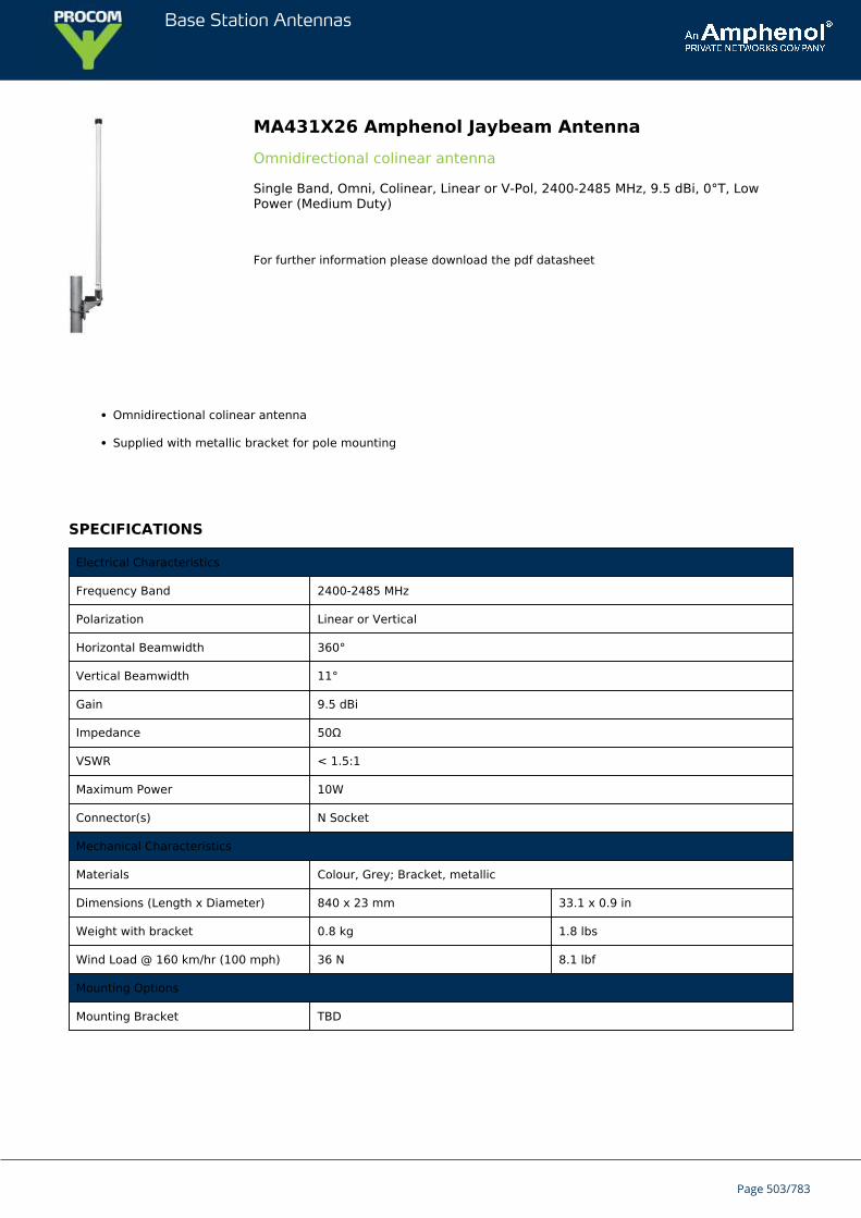
Base Station Antennas
MA431X26 Amphenol Jaybeam AntennaOmnidirectional colinear antenna
Single Band, Omni, Colinear, Linear or V-Pol, 2400-2485 MHz, 9.5 dBi, 0°T, LowPower (Medium Duty)
For further information please download the pdf datasheet
Omnidirectional colinear antenna
Supplied with metallic bracket for pole mounting
SPECIFICATIONS
Electrical Characteristics
Frequency Band 2400-2485 MHz
Polarization Linear or Vertical
Horizontal Beamwidth 360°
Vertical Beamwidth 11°
Gain 9.5 dBi
Impedance 50Ω
VSWR < 1.5:1
Maximum Power 10W
Connector(s) N Socket
Mechanical Characteristics
Materials Colour, Grey; Bracket, metallic
Dimensions (Length x Diameter) 840 x 23 mm 33.1 x 0.9 in
Weight with bracket 0.8 kg 1.8 lbs
Wind Load @ 160 km/hr (100 mph) 36 N 8.1 lbf
Mounting Options
Mounting Bracket TBD
Page 503/783
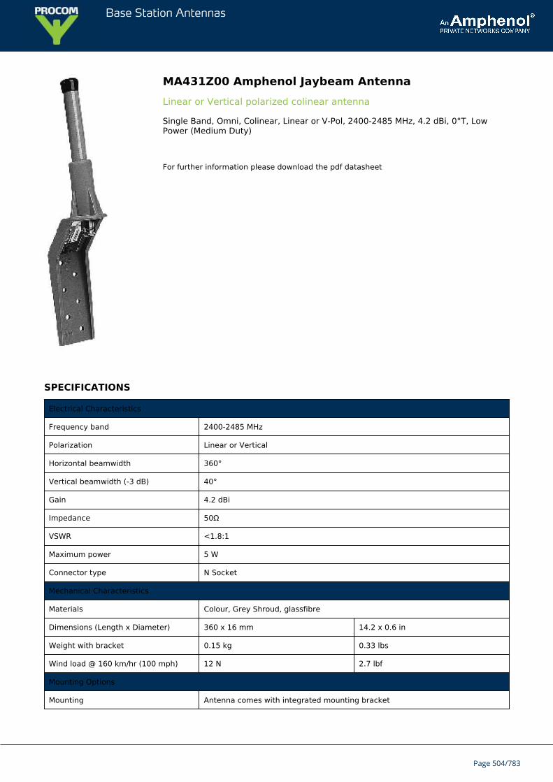
Base Station Antennas
MA431Z00 Amphenol Jaybeam AntennaLinear or Vertical polarized colinear antenna
Single Band, Omni, Colinear, Linear or V-Pol, 2400-2485 MHz, 4.2 dBi, 0°T, LowPower (Medium Duty)
For further information please download the pdf datasheet
SPECIFICATIONS
Electrical Characteristics
Frequency band 2400-2485 MHz
Polarization Linear or Vertical
Horizontal beamwidth 360°
Vertical beamwidth (-3 dB) 40°
Gain 4.2 dBi
Impedance 50Ω
VSWR <1.8:1
Maximum power 5 W
Connector type N Socket
Mechanical Characteristics
Materials Colour, Grey Shroud, glassfibre
Dimensions (Length x Diameter) 360 x 16 mm 14.2 x 0.6 in
Weight with bracket 0.15 kg 0.33 lbs
Wind load @ 160 km/hr (100 mph) 12 N 2.7 lbf
Mounting Options
Mounting Antenna comes with integrated mounting bracket
Page 504/783

Base Station Antennas
Page 505/783
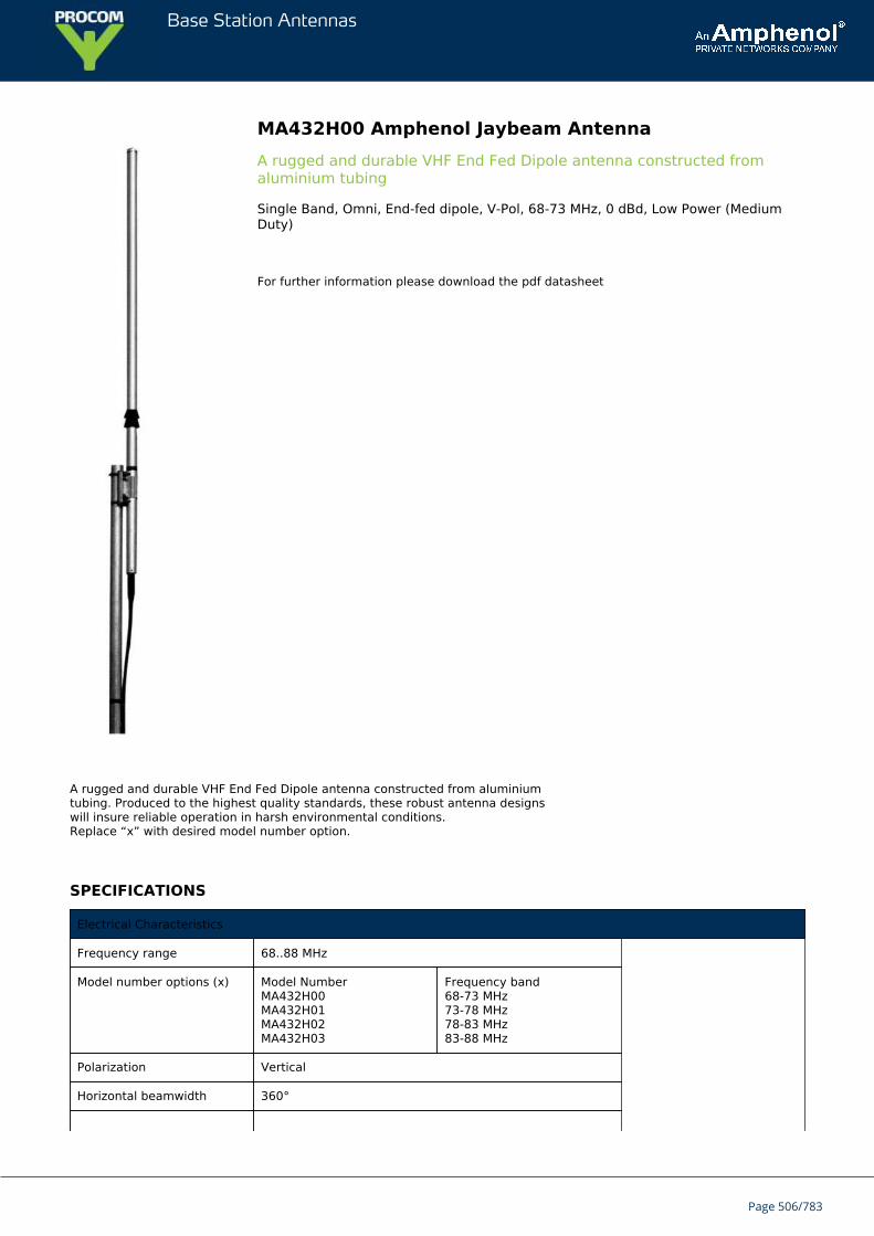
Base Station Antennas
MA432H00 Amphenol Jaybeam AntennaA rugged and durable VHF End Fed Dipole antenna constructed fromaluminium tubing
Single Band, Omni, End-fed dipole, V-Pol, 68-73 MHz, 0 dBd, Low Power (MediumDuty)
For further information please download the pdf datasheet
A rugged and durable VHF End Fed Dipole antenna constructed from aluminiumtubing. Produced to the highest quality standards, these robust antenna designswill insure reliable operation in harsh environmental conditions.Replace “x” with desired model number option.
SPECIFICATIONS
Electrical Characteristics
Frequency range 68..88 MHz
Model number options (x) Model NumberMA432H00MA432H01MA432H02MA432H03
Frequency band68-73 MHz73-78 MHz78-83 MHz83-88 MHz
Polarization Vertical
Horizontal beamwidth 360°
Page 506/783

Base Station Antennas
Vertical beamwidth 88°
Gain 0 dBd
Impedance 50Ω
VSWR <1.5:1
Maximum power 50 W
Connector type N Female
Mechanical Characteristics
Materials Aluminium dipole
Dimensions (Length) 80 MHz: 2400 mm 94.5 in
Weight withoutbracket
80 MHz: 2.5 kg 5.5 lbs
Wind load @ 160km/hr (100 mph)
80 MHz: 180 N 40.5 lbf
Mounting Options
Mounting bracket MA621AZ40 clamp supplied to fit 30-50mm dia. mast.
Page 507/783
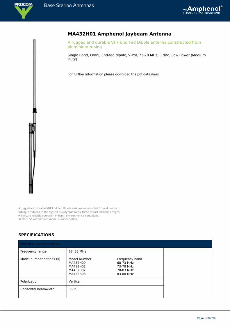
Base Station Antennas
MA432H01 Amphenol Jaybeam AntennaA rugged and durable VHF End Fed Dipole antenna constructed fromaluminium tubing
Single Band, Omni, End-fed dipole, V-Pol, 73-78 MHz, 0 dBd, Low Power (MediumDuty)
For further information please download the pdf datasheet
A rugged and durable VHF End Fed Dipole antenna constructed from aluminiumtubing. Produced to the highest quality standards, these robust antenna designswill insure reliable operation in harsh environmental conditions.Replace “x” with desired model number option.
SPECIFICATIONS
Electrical Characteristics
Frequency range 68..88 MHz
Model number options (x) Model NumberMA432H00MA432H01MA432H02MA432H03
Frequency band68-73 MHz73-78 MHz78-83 MHz83-88 MHz
Polarization Vertical
Horizontal beamwidth 360°
Page 508/783

Base Station Antennas
Vertical beamwidth 88°
Gain 0 dBd
Impedance 50Ω
VSWR <1.5:1
Maximum power 50 W
Connector type N Female
Mechanical Characteristics
Materials Aluminium dipole
Dimensions (Length) 80 MHz: 2400 mm 94.5 in
Weight withoutbracket
80 MHz: 2.5 kg 5.5 lbs
Wind load @ 160km/hr (100 mph)
80 MHz: 180 N 40.5 lbf
Mounting Options
Mounting bracket MA621AZ40 clamp supplied to fit 30-50mm dia. mast.
Page 509/783

Base Station Antennas
MA432H02 Amphenol Jaybeam AntennaA rugged and durable VHF End Fed Dipole antenna constructed fromaluminium tubing
Single Band, Omni, End-fed dipole, V-Pol, 78-83 MHz, 0 dBd, Low Power (MediumDuty)
For further information please download the pdf datasheet
A rugged and durable VHF End Fed Dipole antenna constructed from aluminiumtubing. Produced to the highest quality standards, these robust antenna designswill insure reliable operation in harsh environmental conditions.Replace “x” with desired model number option.
SPECIFICATIONS
Electrical Characteristics
Frequency range 68..88 MHz
Model number options (x) Model NumberMA432H00MA432H01MA432H02MA432H03
Frequency band68-73 MHz73-78 MHz78-83 MHz83-88 MHz
Polarization Vertical
Horizontal beamwidth 360°
Page 510/783
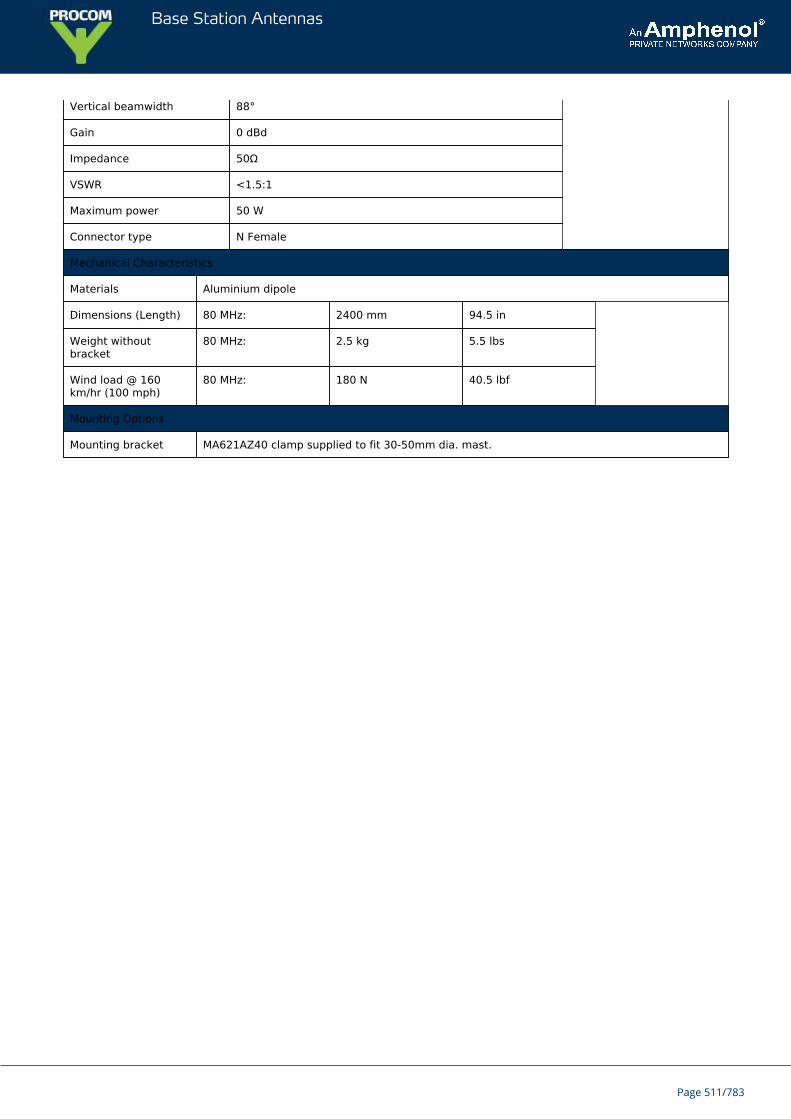
Base Station Antennas
Vertical beamwidth 88°
Gain 0 dBd
Impedance 50Ω
VSWR <1.5:1
Maximum power 50 W
Connector type N Female
Mechanical Characteristics
Materials Aluminium dipole
Dimensions (Length) 80 MHz: 2400 mm 94.5 in
Weight withoutbracket
80 MHz: 2.5 kg 5.5 lbs
Wind load @ 160km/hr (100 mph)
80 MHz: 180 N 40.5 lbf
Mounting Options
Mounting bracket MA621AZ40 clamp supplied to fit 30-50mm dia. mast.
Page 511/783

Base Station Antennas
MA432H03 Amphenol Jaybeam AntennaA rugged and durable VHF End Fed Dipole antenna constructed fromaluminium tubing
Single Band, Omni, End-fed dipole, V-Pol, 83-88 MHz, 0 dBd, Low Power (MediumDuty)
For further information please download the pdf datasheet
A rugged and durable VHF End Fed Dipole antenna constructed from aluminiumtubing. Produced to the highest quality standards, these robust antenna designswill insure reliable operation in harsh environmental conditions.Replace “x” with desired model number option.
SPECIFICATIONS
Electrical Characteristics
Frequency range 68..88 MHz
Model number options (x) Model NumberMA432H00MA432H01MA432H02MA432H03
Frequency band68-73 MHz73-78 MHz78-83 MHz83-88 MHz
Polarization Vertical
Horizontal beamwidth 360°
Page 512/783

Base Station Antennas
Vertical beamwidth 88°
Gain 0 dBd
Impedance 50Ω
VSWR <1.5:1
Maximum power 50 W
Connector type N Female
Mechanical Characteristics
Materials Aluminium dipole
Dimensions (Length) 80 MHz: 2400 mm 94.5 in
Weight withoutbracket
80 MHz: 2.5 kg 5.5 lbs
Wind load @ 160km/hr (100 mph)
80 MHz: 180 N 40.5 lbf
Mounting Options
Mounting bracket MA621AZ40 clamp supplied to fit 30-50mm dia. mast.
Page 513/783
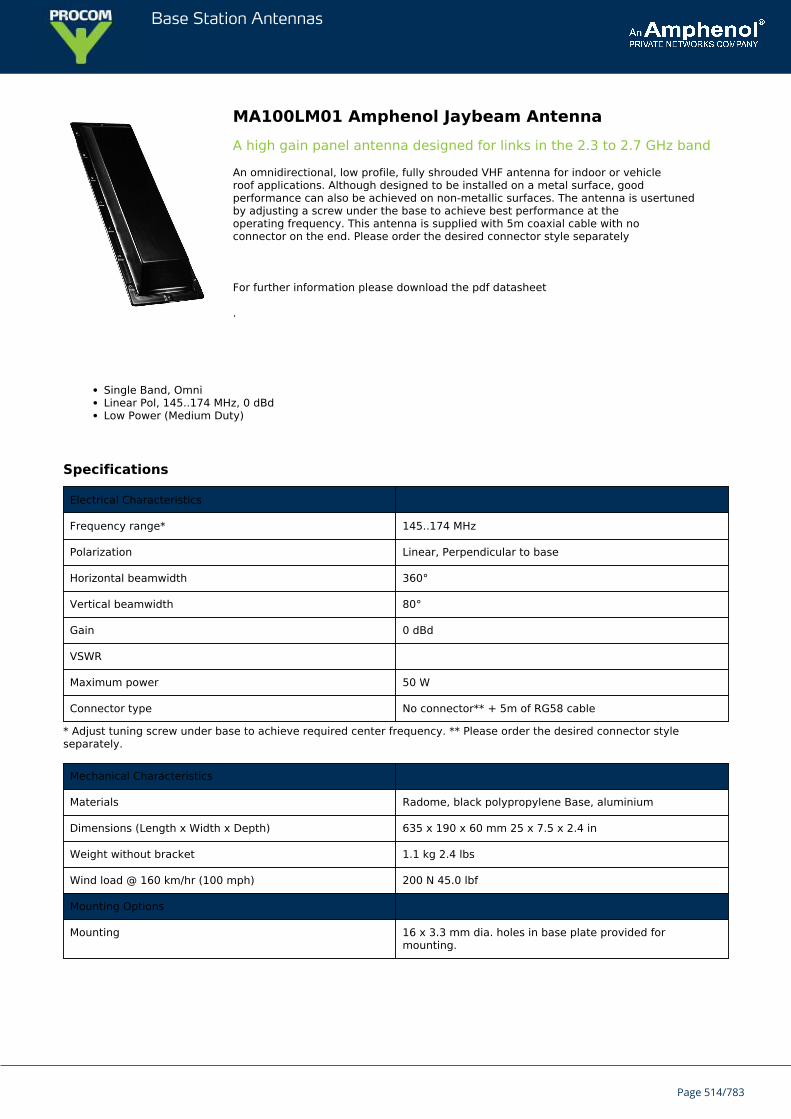
Base Station Antennas
MA100LM01 Amphenol Jaybeam AntennaA high gain panel antenna designed for links in the 2.3 to 2.7 GHz band
An omnidirectional, low profile, fully shrouded VHF antenna for indoor or vehicleroof applications. Although designed to be installed on a metal surface, goodperformance can also be achieved on non-metallic surfaces. The antenna is usertunedby adjusting a screw under the base to achieve best performance at theoperating frequency. This antenna is supplied with 5m coaxial cable with noconnector on the end. Please order the desired connector style separately
For further information please download the pdf datasheet
.
Single Band, OmniLinear Pol, 145..174 MHz, 0 dBdLow Power (Medium Duty)
Specifications
Electrical Characteristics
Frequency range* 145..174 MHz
Polarization Linear, Perpendicular to base
Horizontal beamwidth 360°
Vertical beamwidth 80°
Gain 0 dBd
VSWR
Maximum power 50 W
Connector type No connector** + 5m of RG58 cable
* Adjust tuning screw under base to achieve required center frequency. ** Please order the desired connector styleseparately.
Mechanical Characteristics
Materials Radome, black polypropylene Base, aluminium
Dimensions (Length x Width x Depth) 635 x 190 x 60 mm 25 x 7.5 x 2.4 in
Weight without bracket 1.1 kg 2.4 lbs
Wind load @ 160 km/hr (100 mph) 200 N 45.0 lbf
Mounting Options
Mounting 16 x 3.3 mm dia. holes in base plate provided formounting.
Page 514/783
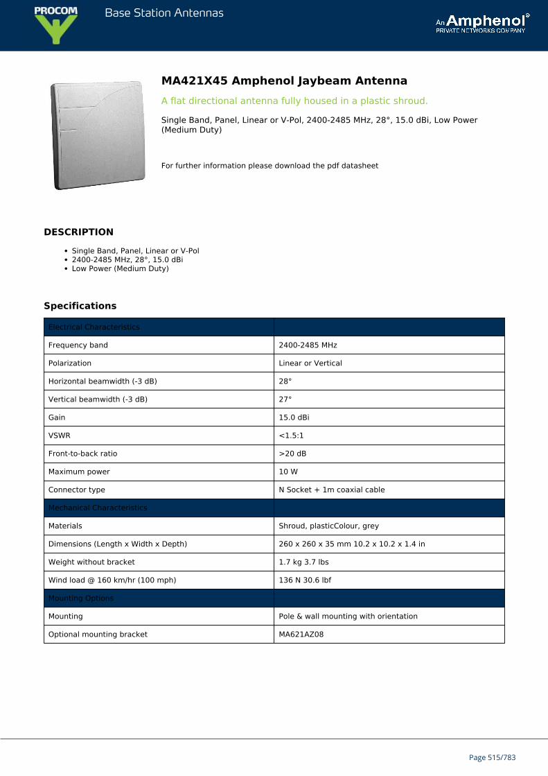
Base Station Antennas
MA421X45 Amphenol Jaybeam AntennaA flat directional antenna fully housed in a plastic shroud.
Single Band, Panel, Linear or V-Pol, 2400-2485 MHz, 28°, 15.0 dBi, Low Power(Medium Duty)
For further information please download the pdf datasheet
DESCRIPTION
Single Band, Panel, Linear or V-Pol2400-2485 MHz, 28°, 15.0 dBiLow Power (Medium Duty)
Specifications
Electrical Characteristics
Frequency band 2400-2485 MHz
Polarization Linear or Vertical
Horizontal beamwidth (-3 dB) 28°
Vertical beamwidth (-3 dB) 27°
Gain 15.0 dBi
VSWR <1.5:1
Front-to-back ratio >20 dB
Maximum power 10 W
Connector type N Socket + 1m coaxial cable
Mechanical Characteristics
Materials Shroud, plasticColour, grey
Dimensions (Length x Width x Depth) 260 x 260 x 35 mm 10.2 x 10.2 x 1.4 in
Weight without bracket 1.7 kg 3.7 lbs
Wind load @ 160 km/hr (100 mph) 136 N 30.6 lbf
Mounting Options
Mounting Pole & wall mounting with orientation
Optional mounting bracket MA621AZ08
Page 515/783
Base Station Antennas
7636000 Amphenol Jaybeam AntennaA high gain panel antenna designed for links in the 2.3 to 2.7 GHz band
Single band,vertically or horizontally polarized planarantenna with fixed electrical downtilt
For further information please download the pdf datasheet
Description
Single Band, Planar, V or H-Pol1350-1517 MHz, 23°, 17.0 dBiLow Power (Medium Duty)
Page 516/783
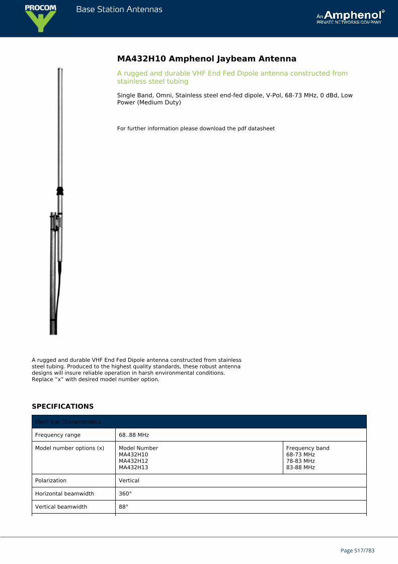
Base Station Antennas
MA432H10 Amphenol Jaybeam AntennaA rugged and durable VHF End Fed Dipole antenna constructed fromstainless steel tubing
Single Band, Omni, Stainless steel end-fed dipole, V-Pol, 68-73 MHz, 0 dBd, LowPower (Medium Duty)
For further information please download the pdf datasheet
A rugged and durable VHF End Fed Dipole antenna constructed from stainlesssteel tubing. Produced to the highest quality standards, these robust antennadesigns will insure reliable operation in harsh environmental conditions.Replace “x” with desired model number option.
SPECIFICATIONS
Electrical Characteristics
Frequency range 68..88 MHz
Model number options (x) Model NumberMA432H10MA432H12MA432H13
Frequency band68-73 MHz78-83 MHz83-88 MHz
Polarization Vertical
Horizontal beamwidth 360°
Vertical beamwidth 88°
Page 517/783

Base Station Antennas
Gain 0 dBd
Impedance 50Ω
VSWR <1.5:1
Maximum power 50 W
Connector type N Female
Mechanical Characteristics
Materials Stainless steel dipole
Dimensions (Length) 80 MHz: 2400 mm 94.5 in
Weight without bracket 80 MHz: 3.0 kg 6.6 lbs
Wind load @ 160 km/hr(100 mph)
80 MHz: 180 N 40.5 lbf
Mounting Options
Mounting bracket MA621AZ38 clamp supplied to fit 30-50mm dia. mast.
Page 518/783
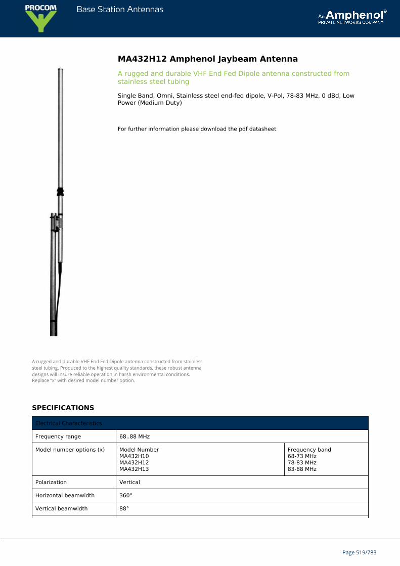
Base Station Antennas
MA432H12 Amphenol Jaybeam AntennaA rugged and durable VHF End Fed Dipole antenna constructed fromstainless steel tubing
Single Band, Omni, Stainless steel end-fed dipole, V-Pol, 78-83 MHz, 0 dBd, LowPower (Medium Duty)
For further information please download the pdf datasheet
A rugged and durable VHF End Fed Dipole antenna constructed from stainlesssteel tubing. Produced to the highest quality standards, these robust antennadesigns will insure reliable operation in harsh environmental conditions.Replace “x” with desired model number option.
SPECIFICATIONS
Electrical Characteristics
Frequency range 68..88 MHz
Model number options (x) Model NumberMA432H10MA432H12MA432H13
Frequency band68-73 MHz78-83 MHz83-88 MHz
Polarization Vertical
Horizontal beamwidth 360°
Vertical beamwidth 88°
Page 519/783
Base Station Antennas
Gain 0 dBd
Impedance 50Ω
VSWR <1.5:1
Maximum power 50 W
Connector type N Female
Mechanical Characteristics
Materials Stainless steel dipole
Dimensions (Length) 80 MHz: 2400 mm 94.5 in
Weight without bracket 80 MHz: 3.0 kg 6.6 lbs
Wind load @ 160 km/hr(100 mph)
80 MHz: 180 N 40.5 lbf
Mounting Options
Mounting bracket MA621AZ38 clamp supplied to fit 30-50mm dia. mast.
Page 520/783
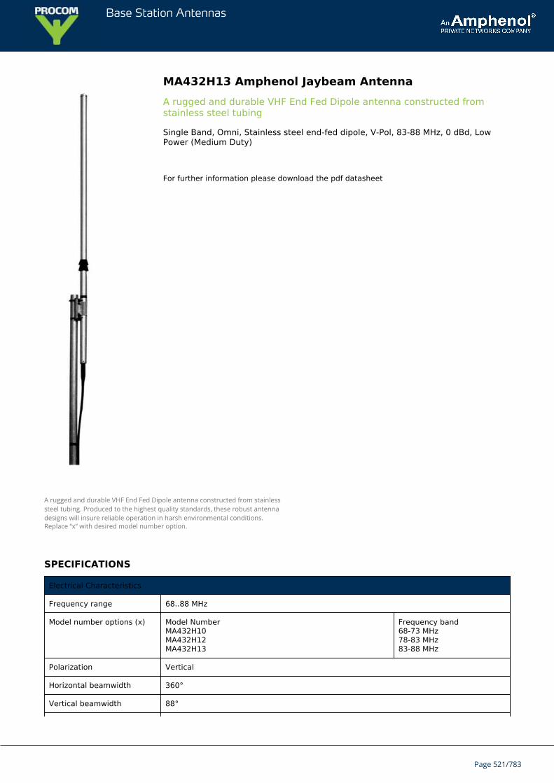
Base Station Antennas
MA432H13 Amphenol Jaybeam AntennaA rugged and durable VHF End Fed Dipole antenna constructed fromstainless steel tubing
Single Band, Omni, Stainless steel end-fed dipole, V-Pol, 83-88 MHz, 0 dBd, LowPower (Medium Duty)
For further information please download the pdf datasheet
A rugged and durable VHF End Fed Dipole antenna constructed from stainlesssteel tubing. Produced to the highest quality standards, these robust antennadesigns will insure reliable operation in harsh environmental conditions.Replace “x” with desired model number option.
SPECIFICATIONS
Electrical Characteristics
Frequency range 68..88 MHz
Model number options (x) Model NumberMA432H10MA432H12MA432H13
Frequency band68-73 MHz78-83 MHz83-88 MHz
Polarization Vertical
Horizontal beamwidth 360°
Vertical beamwidth 88°
Page 521/783

Base Station Antennas
Gain 0 dBd
Impedance 50Ω
VSWR <1.5:1
Maximum power 50 W
Connector type N Female
Mechanical Characteristics
Materials Stainless steel dipole
Dimensions (Length) 80 MHz: 2400 mm 94.5 in
Weight without bracket 80 MHz: 3.0 kg 6.6 lbs
Wind load @ 160 km/hr(100 mph)
80 MHz: 180 N 40.5 lbf
Mounting Options
Mounting bracket MA621AZ38 clamp supplied to fit 30-50mm dia. mast.
Page 522/783
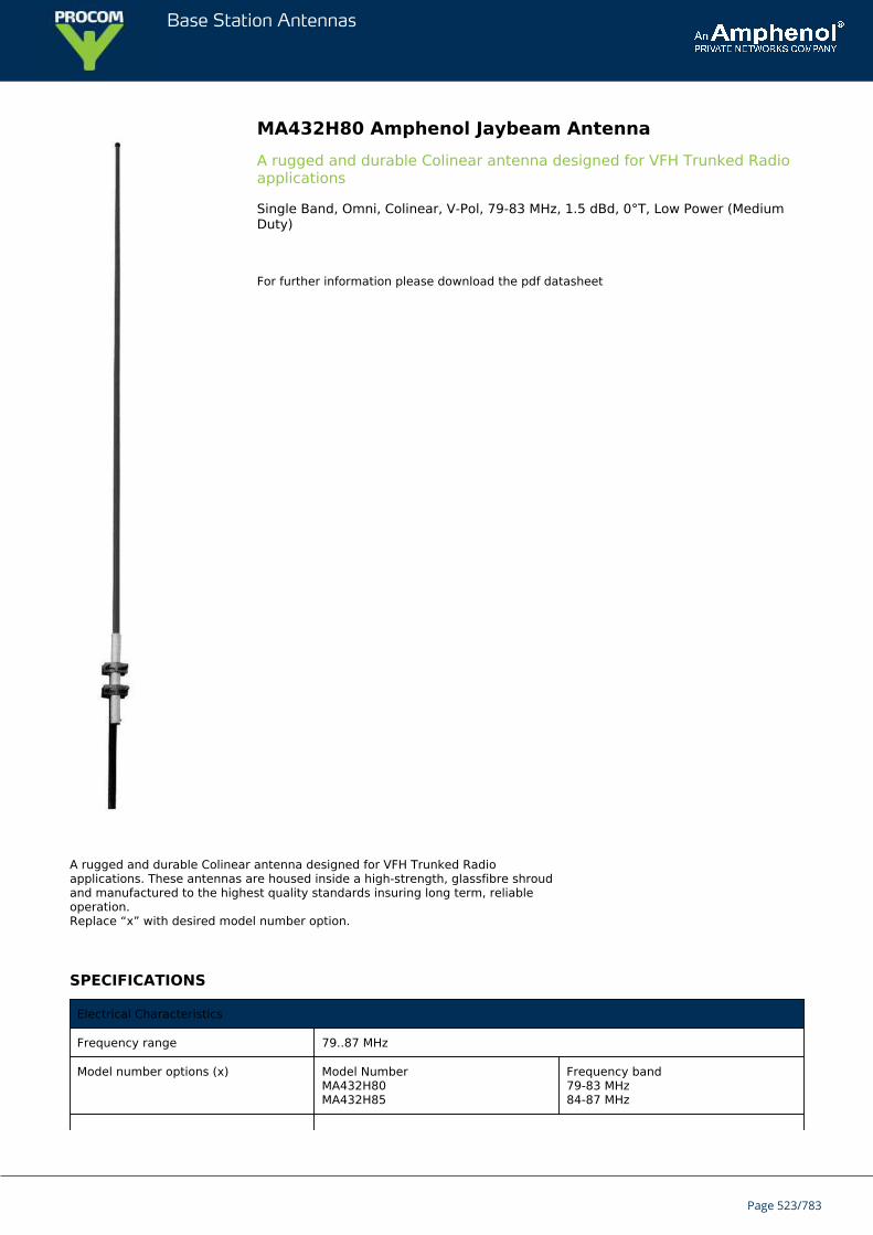
Base Station Antennas
MA432H80 Amphenol Jaybeam AntennaA rugged and durable Colinear antenna designed for VFH Trunked Radioapplications
Single Band, Omni, Colinear, V-Pol, 79-83 MHz, 1.5 dBd, 0°T, Low Power (MediumDuty)
For further information please download the pdf datasheet
A rugged and durable Colinear antenna designed for VFH Trunked Radioapplications. These antennas are housed inside a high-strength, glassfibre shroudand manufactured to the highest quality standards insuring long term, reliableoperation.Replace “x” with desired model number option.
SPECIFICATIONS
Electrical Characteristics
Frequency range 79..87 MHz
Model number options (x) Model NumberMA432H80MA432H85
Frequency band79-83 MHz84-87 MHz
Page 523/783

Base Station Antennas
Bandwidth ±1% (typical)
Polarization Vertical
Horizontal beamwidth 360°
Vertical beamwidth 68°
Gain 1.5 dBd
Electrical downtilt 0°
Impedance 50Ω
VSWR <1.5:1
Maximum power 100 W
Connector type N-Female
Lightning protection DC grounded
Mechanical Characteristics
Materials Glass fibre shroud Aluminium mounting section
Dimensions (Length) 3800 mm 149.6 in
Weight without bracket 4.0 kg 8.8 lbs
Wind load @ 160 km/hr (100 mph) 240 N 54.0 lbf
Mounting Options
Mounting bracket 2 x MA621AZ00 clamps supplied to fit 50-70mm dia. mast.
Page 524/783
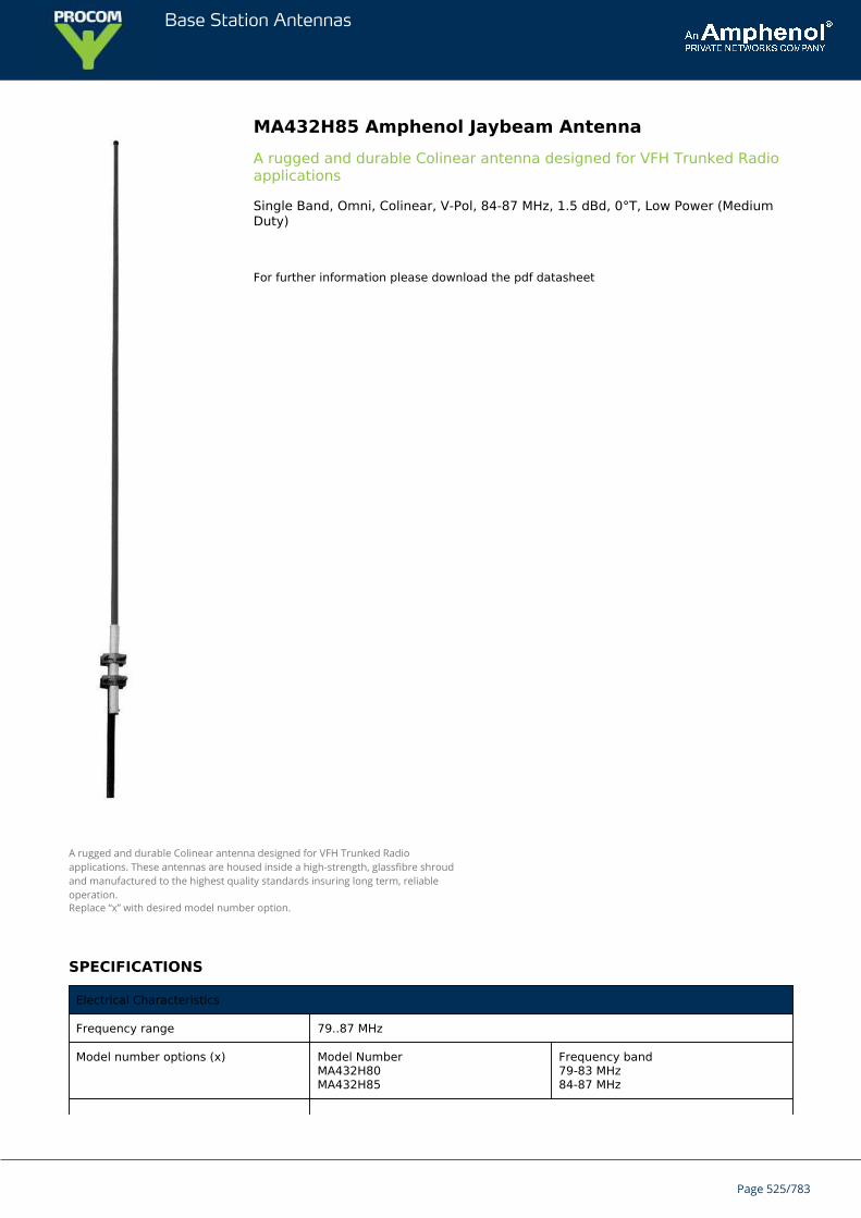
Base Station Antennas
MA432H85 Amphenol Jaybeam AntennaA rugged and durable Colinear antenna designed for VFH Trunked Radioapplications
Single Band, Omni, Colinear, V-Pol, 84-87 MHz, 1.5 dBd, 0°T, Low Power (MediumDuty)
For further information please download the pdf datasheet
A rugged and durable Colinear antenna designed for VFH Trunked Radioapplications. These antennas are housed inside a high-strength, glassfibre shroudand manufactured to the highest quality standards insuring long term, reliableoperation.Replace “x” with desired model number option.
SPECIFICATIONS
Electrical Characteristics
Frequency range 79..87 MHz
Model number options (x) Model NumberMA432H80MA432H85
Frequency band79-83 MHz84-87 MHz
Page 525/783
Base Station Antennas
Bandwidth ±1% (typical)
Polarization Vertical
Horizontal beamwidth 360°
Vertical beamwidth 68°
Gain 1.5 dBd
Electrical downtilt 0°
Impedance 50Ω
VSWR <1.5:1
Maximum power 100 W
Connector type N-Female
Lightning protection DC grounded
Mechanical Characteristics
Materials Glass fibre shroud Aluminium mounting section
Dimensions (Length) 3800 mm 149.6 in
Weight without bracket 4.0 kg 8.8 lbs
Wind load @ 160 km/hr (100 mph) 240 N 54.0 lbf
Mounting Options
Mounting bracket 2 x MA621AZ00 clamps supplied to fit 50-70mm dia. mast.
Page 526/783
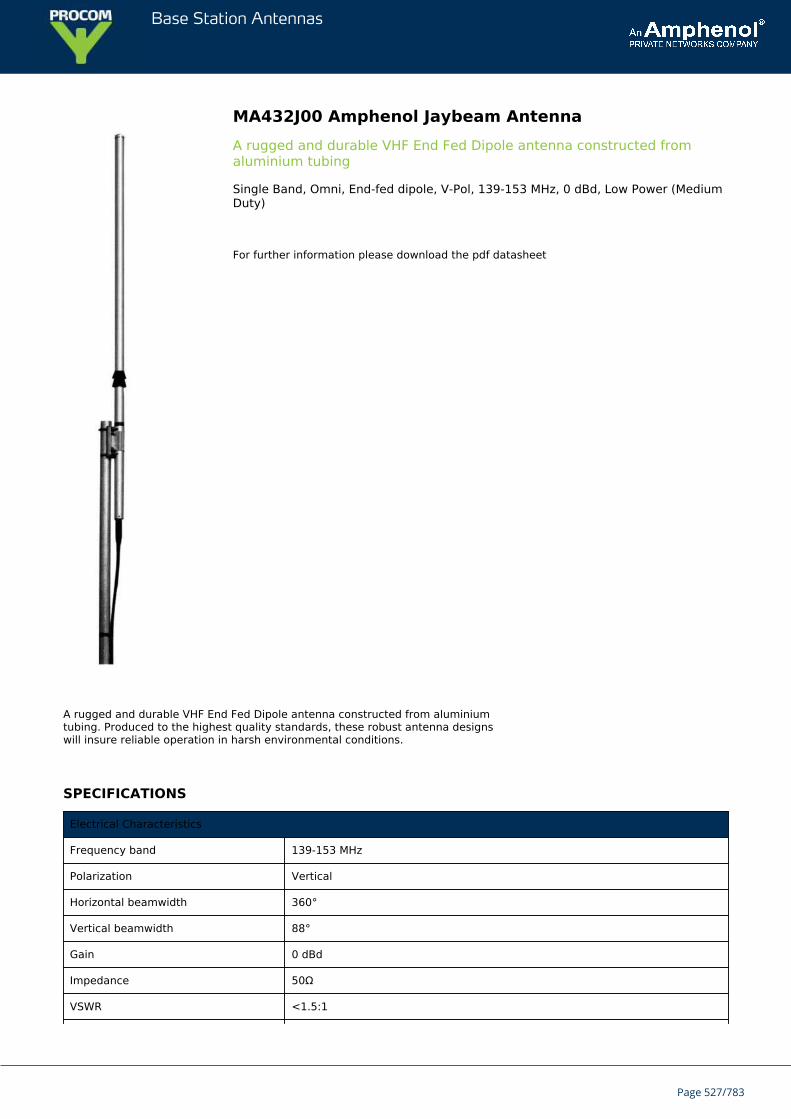
Base Station Antennas
MA432J00 Amphenol Jaybeam AntennaA rugged and durable VHF End Fed Dipole antenna constructed fromaluminium tubing
Single Band, Omni, End-fed dipole, V-Pol, 139-153 MHz, 0 dBd, Low Power (MediumDuty)
For further information please download the pdf datasheet
A rugged and durable VHF End Fed Dipole antenna constructed from aluminiumtubing. Produced to the highest quality standards, these robust antenna designswill insure reliable operation in harsh environmental conditions.
SPECIFICATIONS
Electrical Characteristics
Frequency band 139-153 MHz
Polarization Vertical
Horizontal beamwidth 360°
Vertical beamwidth 88°
Gain 0 dBd
Impedance 50Ω
VSWR <1.5:1
Page 527/783
Base Station Antennas
Maximum power 50 W
Connector type N-Female
Mechanical Characteristics
Materials Aluminium dipole
Dimensions (Length) 1400 mm 55.1 in
Weight without bracket 1.5 kg 3.3 lbs
Wind load @ 160 km/hr (100 mph) 120 N 27.0 lbf
Mounting Options
Mounting bracket MA621AZ40 clamp supplied to fit 30-50mm dia. mast.
Page 528/783
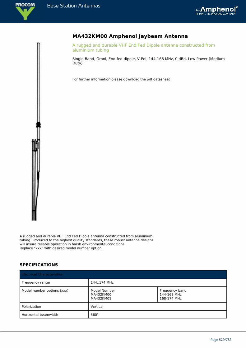
Base Station Antennas
MA432KM00 Amphenol Jaybeam AntennaA rugged and durable VHF End Fed Dipole antenna constructed fromaluminium tubing
Single Band, Omni, End-fed dipole, V-Pol, 144-168 MHz, 0 dBd, Low Power (MediumDuty)
For further information please download the pdf datasheet
A rugged and durable VHF End Fed Dipole antenna constructed from aluminiumtubing. Produced to the highest quality standards, these robust antenna designswill insure reliable operation in harsh environmental conditions.Replace “xxx” with desired model number option.
SPECIFICATIONS
Electrical Characteristics
Frequency range 144..174 MHz
Model number options (xxx) Model NumberMA432KM00MA432KM01
Frequency band144-168 MHz168-174 MHz
Polarization Vertical
Horizontal beamwidth 360°
Page 529/783
Base Station Antennas
Vertical beamwidth 88°
Gain 0 dBd
Impedance 50Ω
VSWR <1.5:1
Maximum power 50 W
Connector type N Female
Mechanical Characteristics
Materials Aluminium dipole
Dimensions (Length) 1380 mm 54.3 in
Weight without bracket 1.5 kg 3.3 lbs
Wind load @ 160 km/hr (100 mph) 120 N 27.0 lbf
Mounting Options
Mounting bracket MA621AZ40 clamp supplied to fit 30-50mm dia. mast.
Page 530/783
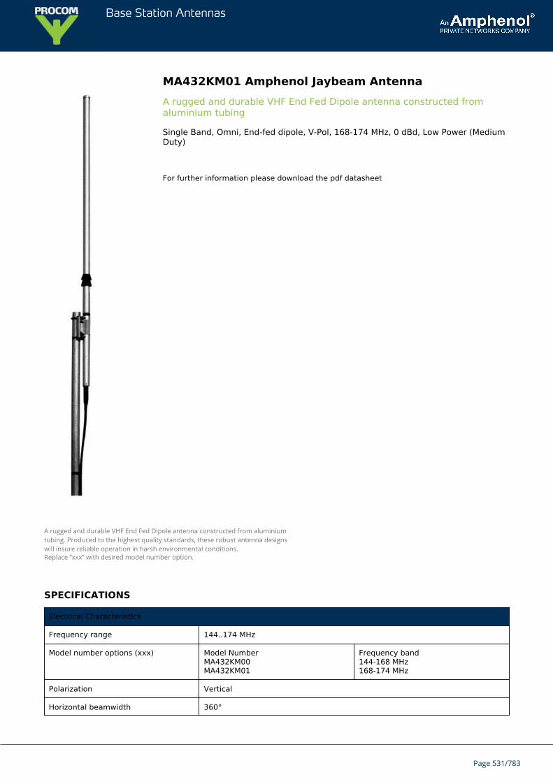
Base Station Antennas
MA432KM01 Amphenol Jaybeam AntennaA rugged and durable VHF End Fed Dipole antenna constructed fromaluminium tubing
Single Band, Omni, End-fed dipole, V-Pol, 168-174 MHz, 0 dBd, Low Power (MediumDuty)
For further information please download the pdf datasheet
A rugged and durable VHF End Fed Dipole antenna constructed from aluminiumtubing. Produced to the highest quality standards, these robust antenna designswill insure reliable operation in harsh environmental conditions.Replace “xxx” with desired model number option.
SPECIFICATIONS
Electrical Characteristics
Frequency range 144..174 MHz
Model number options (xxx) Model NumberMA432KM00MA432KM01
Frequency band144-168 MHz168-174 MHz
Polarization Vertical
Horizontal beamwidth 360°
Page 531/783
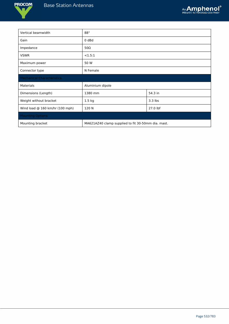
Base Station Antennas
Vertical beamwidth 88°
Gain 0 dBd
Impedance 50Ω
VSWR <1.5:1
Maximum power 50 W
Connector type N Female
Mechanical Characteristics
Materials Aluminium dipole
Dimensions (Length) 1380 mm 54.3 in
Weight without bracket 1.5 kg 3.3 lbs
Wind load @ 160 km/hr (100 mph) 120 N 27.0 lbf
Mounting Options
Mounting bracket MA621AZ40 clamp supplied to fit 30-50mm dia. mast.
Page 532/783
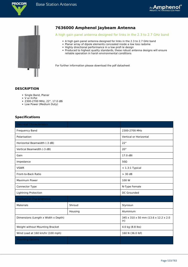
Base Station Antennas
7636000 Amphenol Jaybeam AntennaA high gain panel antenna designed for links in the 2.3 to 2.7 GHz band
A high gain panel antenna designed for links in the 2.3 to 2.7 GHz bandPlanar array of dipole elements concealed inside a low loss radomeHighly directional performance in a low profi le designProduced to highest quality standards, these robust antenna designs will ensurereliable operation in harsh environmental conditions
For further information please download the pdf datasheet
DESCRIPTION
Single Band, PlanarV or H-Pol2300-2700 MHz, 22°, 17.0 dBiLow Power (Medium Duty)
Specifications
Electrical Characteristics
Frequency Band 2300-2700 MHz
Polarisation Vertical or Horizontal
Horizontal Beamwidth (-3 dB) 22°
Vertical Beamwidth (-3 dB) 20°
Gain 17.0 dBi
Impedance 50Ω
VSWR < 1.3:1 Typical
Front-to-Back Ratio > 30 dB
Maximum Power 100 W
Connector Type N-Type Female
Lightning Protection DC Grounded
Mechanical Characteristics
Materials Shroud Styrosun
Housing Aluminium
Dimensions (Length x Width x Depth) 345 x 310 x 50 mm (13.6 x 12.2 x 2.0in)
Weight without Mounting Bracket 4.0 kg (8.8 lbs)
Wind Load at 160 km/hr (100 mph) 160 N (36.0 lbf)
Mounting Options
Page 533/783
Base Station Antennas
Mounting Bracket Integral mounting brackets to fit pipesup to 48 mm diameter, allowingmechanical tilt over ±8° to removetower rake
Mounting Option 0900996/00 - To fit pipes up to 115mm diameter in addition to theintegral mounting bracket
Page 534/783
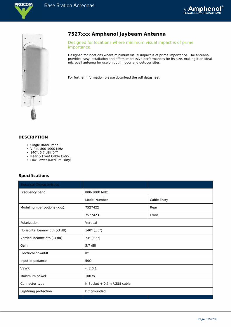
Base Station Antennas
7527xxx Amphenol Jaybeam AntennaDesigned for locations where minimum visual impact is of primeimportance.
Designed for locations where minimum visual impact is of prime importance. The antennaprovides easy installation and offers impressive performances for its size, making it an idealmicrocell antenna for use on both indoor and outdoor sites.
For further information please download the pdf datasheet
DESCRIPTION
Single Band, PanelV-Pol, 800-1000 MHz140°, 5.7 dBi, 0°TRear & Front Cable EntryLow Power (Medium Duty)
Specifications
Electrical Characteristics
Frequency band 800-1000 MHz
Model Number Cable Entry
Model number options (xxx) 7527422 Rear
7527423 Front
Polarization Vertical
Horizontal beamwidth (-3 dB) 140° (±5°)
Vertical beamwidth (-3 dB) 73° (±5°)
Gain 5.7 dBi
Electrical downtilt 0°
Input impedance 50Ω
VSWR < 2.0:1
Maximum power 100 W
Connector type N-Socket + 0.5m RG58 cable
Lightning protection DC grounded
Page 535/783
Base Station Antennas
Mechanical Characteristics
Materials Shroud, white UV resistant plastic
Dimensions Length 260 mm 10.2 in
Weight 0.6 kg 1.3 lbs
Wind load @ 160 km/hr (100 mph) 40 N 9.0 lbf
Mounting Options
Mounting 4 x 5 mm holes in corners of base plate spacing 200 x 60 mm
Page 536/783
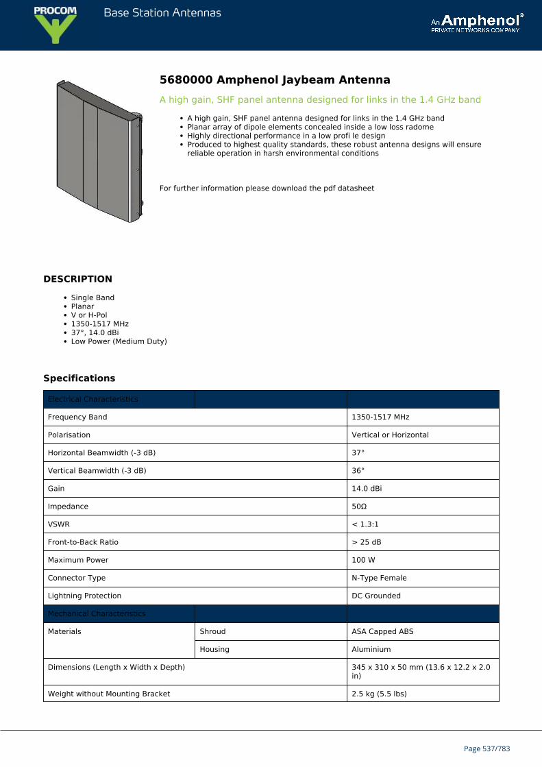
Base Station Antennas
5680000 Amphenol Jaybeam AntennaA high gain, SHF panel antenna designed for links in the 1.4 GHz band
A high gain, SHF panel antenna designed for links in the 1.4 GHz bandPlanar array of dipole elements concealed inside a low loss radomeHighly directional performance in a low profi le designProduced to highest quality standards, these robust antenna designs will ensurereliable operation in harsh environmental conditions
For further information please download the pdf datasheet
DESCRIPTION
Single BandPlanarV or H-Pol1350-1517 MHz37°, 14.0 dBiLow Power (Medium Duty)
Specifications
Electrical Characteristics
Frequency Band 1350-1517 MHz
Polarisation Vertical or Horizontal
Horizontal Beamwidth (-3 dB) 37°
Vertical Beamwidth (-3 dB) 36°
Gain 14.0 dBi
Impedance 50Ω
VSWR < 1.3:1
Front-to-Back Ratio > 25 dB
Maximum Power 100 W
Connector Type N-Type Female
Lightning Protection DC Grounded
Mechanical Characteristics
Materials Shroud ASA Capped ABS
Housing Aluminium
Dimensions (Length x Width x Depth) 345 x 310 x 50 mm (13.6 x 12.2 x 2.0in)
Weight without Mounting Bracket 2.5 kg (5.5 lbs)
Page 537/783
Base Station Antennas
Wind Load at 160 km/hr (100 mph) 160 N (36.0 lbf)
Mounting Options
Mounting Bracket Integral mounting brackets to fit pipesup to 48 mm diameter, allowingmechanical tilt over ±8° to removetower rake
Mounting Option 0900996/00 - To fit pipes up to 115mm diameter in addition to theintegral mounting bracket
Page 538/783
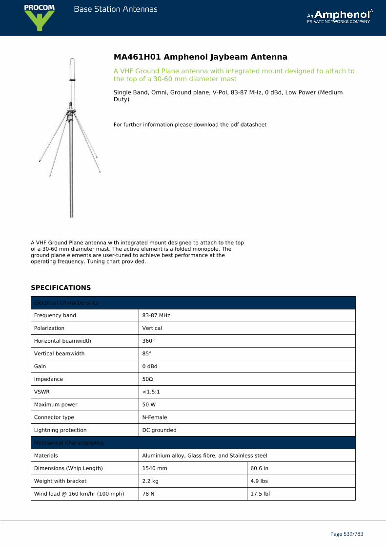
Base Station Antennas
MA461H01 Amphenol Jaybeam AntennaA VHF Ground Plane antenna with integrated mount designed to attach tothe top of a 30-60 mm diameter mast
Single Band, Omni, Ground plane, V-Pol, 83-87 MHz, 0 dBd, Low Power (MediumDuty)
For further information please download the pdf datasheet
A VHF Ground Plane antenna with integrated mount designed to attach to the topof a 30-60 mm diameter mast. The active element is a folded monopole. Theground plane elements are user-tuned to achieve best performance at theoperating frequency. Tuning chart provided.
SPECIFICATIONS
Electrical Characteristics
Frequency band 83-87 MHz
Polarization Vertical
Horizontal beamwidth 360°
Vertical beamwidth 85°
Gain 0 dBd
Impedance 50Ω
VSWR <1.5:1
Maximum power 50 W
Connector type N-Female
Lightning protection DC grounded
Mechanical Characteristics
Materials Aluminium alloy, Glass fibre, and Stainless steel
Dimensions (Whip Length) 1540 mm 60.6 in
Weight with bracket 2.2 kg 4.9 lbs
Wind load @ 160 km/hr (100 mph) 78 N 17.5 lbf
Page 539/783

Base Station Antennas
Mounting Options
Mounting bracket Integral mounting bracket to fit on 30-60 mm dia. mast.
Page 540/783
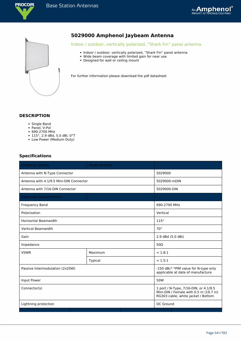
Base Station Antennas
5029000 Amphenol Jaybeam AntennaIndoor / outdoor, vertically polarized, “Shark Fin” panel antenna
Indoor / outdoor, vertically polarized, “Shark Fin” panel antennaWide beam coverage with limited gain for near useDesigned for wall or ceiling mount
For further information please download the pdf datasheet
DESCRIPTION
Single BandPanel, V-Pol690-2700 MHz115°, 2.9 dBd, 5.0 dBi, 0°TLow Power (Medium Duty)
Specifications
Ordering Options Model Number
Antenna with N-Type Connector 5029000
Antenna with 4.1/9.5 Mini-DIN Connector 5029000-mDIN
Antenna with 7/16-DIN Connector 5029000-DIN
Electrical Characteristics
Frequency Band 690-2700 MHz
Polarization Vertical
Horizontal Beamwidth 115°
Vertical Beamwidth 70°
Gain 2.9 dBd (5.0 dBi)
Impedance 50Ω
VSWR Maximum < 1.8:1
Typical < 1.5:1
Passive Intermodulation (2x20W) -150 dBc* *PIM value for N-type onlyapplicable at date of manufacture
Input Power 50W
Connector(s) 1 port / N-Type, 7/16-DIN, or 4.1/9.5Mini-DIN / Female with 0.5 m (19.7 in)RG303 cable, white jacket / Bottom
Lightning protection DC Ground
Page 541/783
Base Station Antennas
Mechanical Characteristics
Materials Base Aluminum
Radome / Color ABS / White
Dimensions (Length x Width x Depth) 282 x 85 x 182 mm 11.1 x 3.3 x 7.2 in
Weight 0.5 kg 1.1 lbs
Wind Load (160 km/hr or 100 mph) 70 N 15.7 lbf
Mounting Options
Mounting Screws supplied formounting on flat wall
Mounting Options
Mounting Screws supplied for mounting on flat wall
Page 542/783
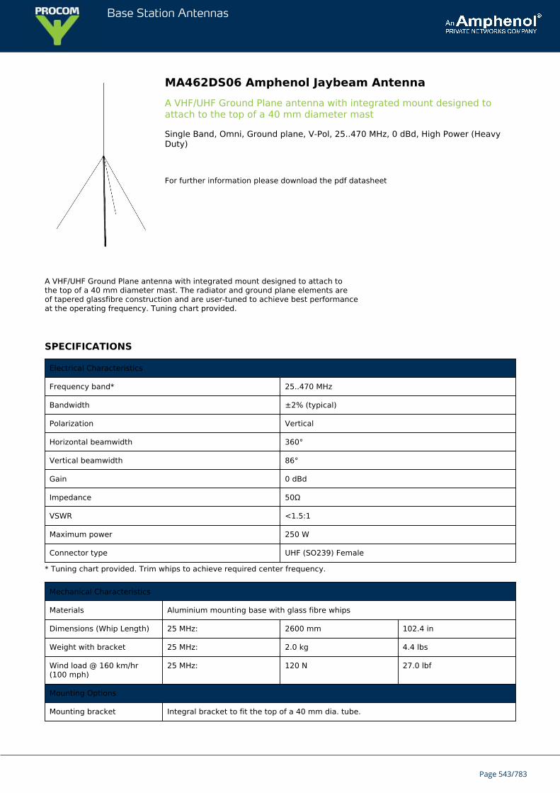
Base Station Antennas
MA462DS06 Amphenol Jaybeam AntennaA VHF/UHF Ground Plane antenna with integrated mount designed toattach to the top of a 40 mm diameter mast
Single Band, Omni, Ground plane, V-Pol, 25..470 MHz, 0 dBd, High Power (HeavyDuty)
For further information please download the pdf datasheet
A VHF/UHF Ground Plane antenna with integrated mount designed to attach tothe top of a 40 mm diameter mast. The radiator and ground plane elements areof tapered glassfibre construction and are user-tuned to achieve best performanceat the operating frequency. Tuning chart provided.
SPECIFICATIONS
Electrical Characteristics
Frequency band* 25..470 MHz
Bandwidth ±2% (typical)
Polarization Vertical
Horizontal beamwidth 360°
Vertical beamwidth 86°
Gain 0 dBd
Impedance 50Ω
VSWR <1.5:1
Maximum power 250 W
Connector type UHF (SO239) Female
* Tuning chart provided. Trim whips to achieve required center frequency.
Mechanical Characteristics
Materials Aluminium mounting base with glass fibre whips
Dimensions (Whip Length) 25 MHz: 2600 mm 102.4 in
Weight with bracket 25 MHz: 2.0 kg 4.4 lbs
Wind load @ 160 km/hr(100 mph)
25 MHz: 120 N 27.0 lbf
Mounting Options
Mounting bracket Integral bracket to fit the top of a 40 mm dia. tube.
Page 543/783

Base Station Antennas
Page 544/783
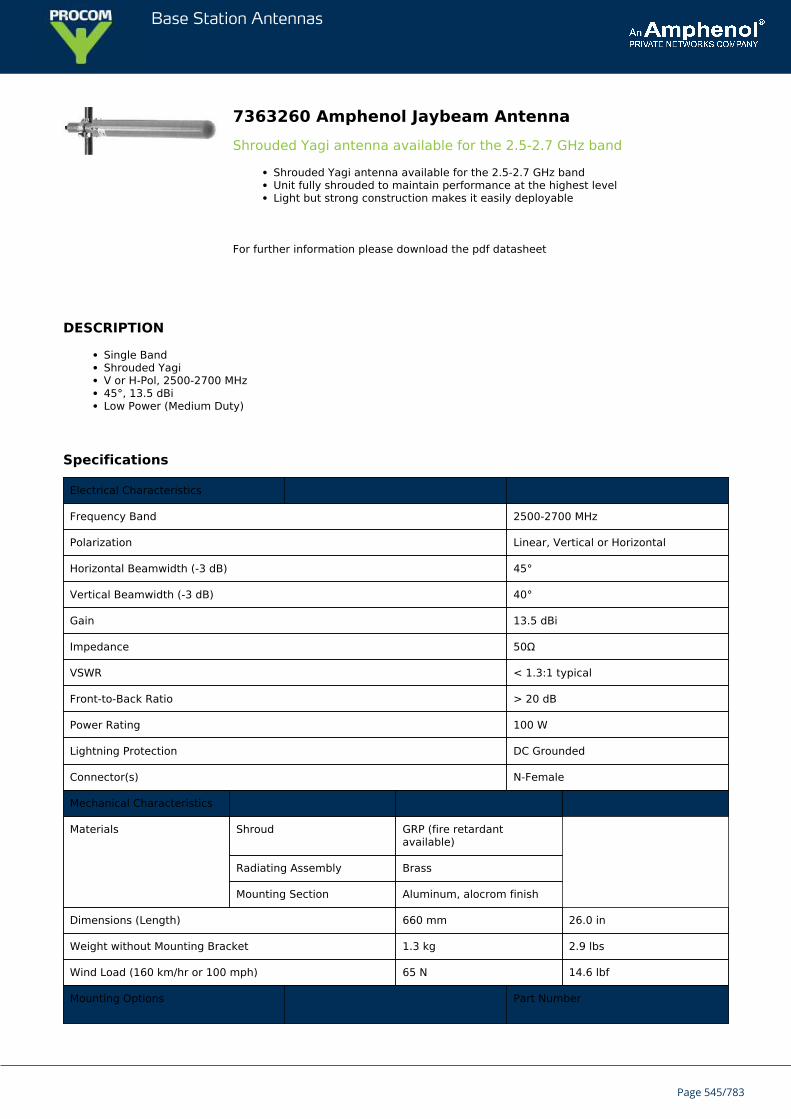
Base Station Antennas
7363260 Amphenol Jaybeam AntennaShrouded Yagi antenna available for the 2.5-2.7 GHz band
Shrouded Yagi antenna available for the 2.5-2.7 GHz bandUnit fully shrouded to maintain performance at the highest levelLight but strong construction makes it easily deployable
For further information please download the pdf datasheet
DESCRIPTION
Single BandShrouded YagiV or H-Pol, 2500-2700 MHz45°, 13.5 dBiLow Power (Medium Duty)
Specifications
Electrical Characteristics
Frequency Band 2500-2700 MHz
Polarization Linear, Vertical or Horizontal
Horizontal Beamwidth (-3 dB) 45°
Vertical Beamwidth (-3 dB) 40°
Gain 13.5 dBi
Impedance 50Ω
VSWR < 1.3:1 typical
Front-to-Back Ratio > 20 dB
Power Rating 100 W
Lightning Protection DC Grounded
Connector(s) N-Female
Mechanical Characteristics
Materials Shroud GRP (fire retardantavailable)
Radiating Assembly Brass
Mounting Section Aluminum, alocrom finish
Dimensions (Length) 660 mm 26.0 in
Weight without Mounting Bracket 1.3 kg 2.9 lbs
Wind Load (160 km/hr or 100 mph) 65 N 14.6 lbf
Mounting Options Part Number
Page 545/783
Base Station Antennas
Mounting brackets are ordered separately.
Mounting Bracket 3202078/68
Alternate Mounting Bracket 0300284/00 + U-bolts to matchmounting pipe diameter
Page 546/783
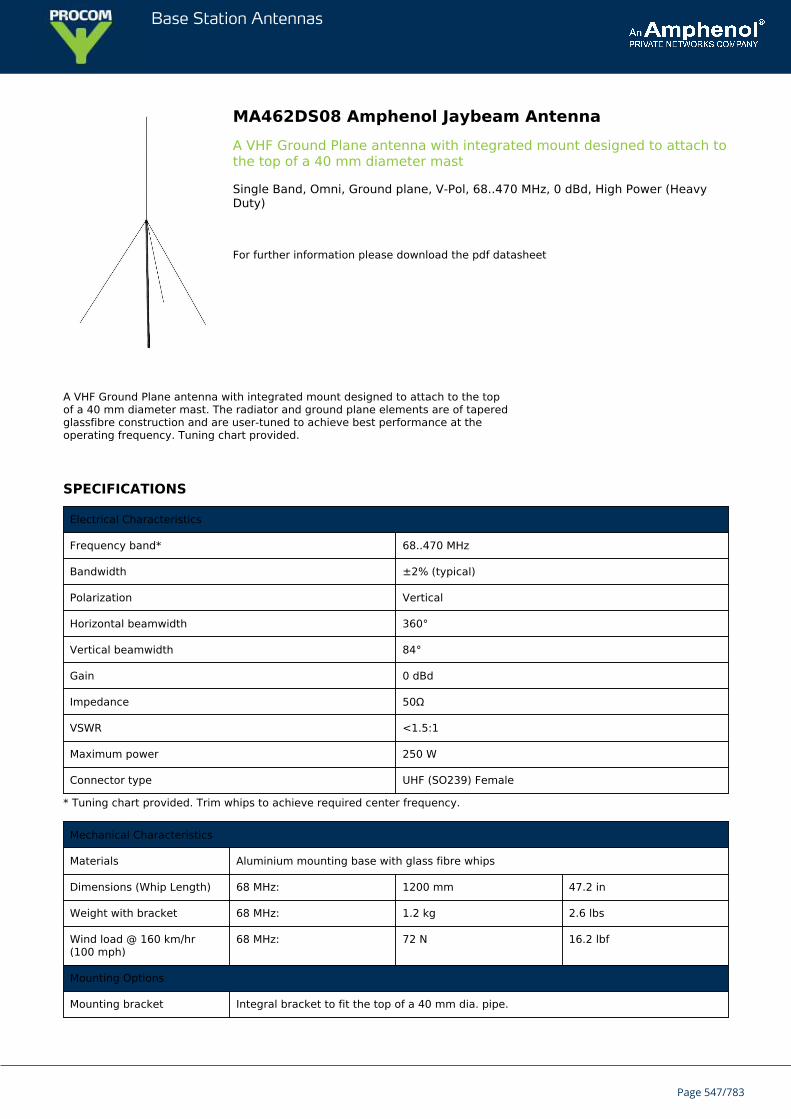
Base Station Antennas
MA462DS08 Amphenol Jaybeam AntennaA VHF Ground Plane antenna with integrated mount designed to attach tothe top of a 40 mm diameter mast
Single Band, Omni, Ground plane, V-Pol, 68..470 MHz, 0 dBd, High Power (HeavyDuty)
For further information please download the pdf datasheet
A VHF Ground Plane antenna with integrated mount designed to attach to the topof a 40 mm diameter mast. The radiator and ground plane elements are of taperedglassfibre construction and are user-tuned to achieve best performance at theoperating frequency. Tuning chart provided.
SPECIFICATIONS
Electrical Characteristics
Frequency band* 68..470 MHz
Bandwidth ±2% (typical)
Polarization Vertical
Horizontal beamwidth 360°
Vertical beamwidth 84°
Gain 0 dBd
Impedance 50Ω
VSWR <1.5:1
Maximum power 250 W
Connector type UHF (SO239) Female
* Tuning chart provided. Trim whips to achieve required center frequency.
Mechanical Characteristics
Materials Aluminium mounting base with glass fibre whips
Dimensions (Whip Length) 68 MHz: 1200 mm 47.2 in
Weight with bracket 68 MHz: 1.2 kg 2.6 lbs
Wind load @ 160 km/hr(100 mph)
68 MHz: 72 N 16.2 lbf
Mounting Options
Mounting bracket Integral bracket to fit the top of a 40 mm dia. pipe.
Page 547/783

Base Station Antennas
Page 548/783
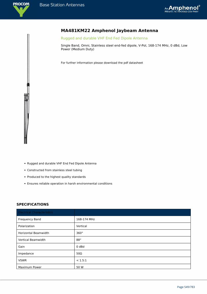
Base Station Antennas
MA481KM22 Amphenol Jaybeam AntennaRugged and durable VHF End Fed Dipole Antenna
Single Band, Omni, Stainless steel end-fed dipole, V-Pol, 168-174 MHz, 0 dBd, LowPower (Medium Duty)
For further information please download the pdf datasheet
Rugged and durable VHF End Fed Dipole Antenna
Constructed from stainless steel tubing
Produced to the highest quality standards
Ensures reliable operation in harsh environmental conditions
SPECIFICATIONS
Electrical Characteristics
Frequency Band 168-174 MHz
Polarization Vertical
Horizontal Beamwidth 360°
Vertical Beamwidth 88°
Gain 0 dBd
Impedance 50Ω
VSWR < 1.5:1
Maximum Power 50 W
Page 549/783
Base Station Antennas
Connector Type N Female
Mechanical Characteristics
Materials Stainless Steel Dipole
Dimensions (Length) 1360 mm 53.5 in
Weight without Mounting Brackets 2.0 kg 4.4 lbs
Wind Load @ 160 km/hr (100 mph) 120 N 27.0 lbf
Mounting Options
Mounting Bracket Kit MA621AZ38 clamp supplied to fit 30-50 mm diameter mast
Page 550/783
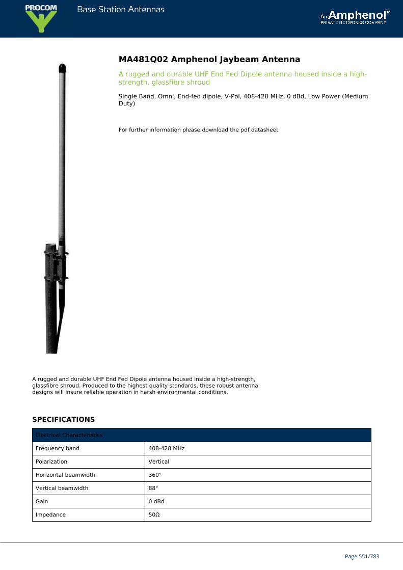
Base Station Antennas
MA481Q02 Amphenol Jaybeam AntennaA rugged and durable UHF End Fed Dipole antenna housed inside a high-strength, glassfibre shroud
Single Band, Omni, End-fed dipole, V-Pol, 408-428 MHz, 0 dBd, Low Power (MediumDuty)
For further information please download the pdf datasheet
A rugged and durable UHF End Fed Dipole antenna housed inside a high-strength,glassfibre shroud. Produced to the highest quality standards, these robust antennadesigns will insure reliable operation in harsh environmental conditions.
SPECIFICATIONS
Electrical Characteristics
Frequency band 408-428 MHz
Polarization Vertical
Horizontal beamwidth 360°
Vertical beamwidth 88°
Gain 0 dBd
Impedance 50Ω
Page 551/783
Base Station Antennas
VSWR <1.5:1
Maximum power 50 W
Connector type N-Female
Lightning protection DC grounded
Mechanical Characteristics
Materials Glass fibre shroud Aluminium mounting section
Dimensions (Length) 900 mm 35.4 in
Weight without bracket 0.7 kg 1.5 lbs
Wind load @ 160 km/hr (100 mph) 40 N 9.0 lbf
Mounting Options
Mounting bracket MA621AZ30 clamp supplied to fit 30-50 mm dia. mast.
Page 552/783
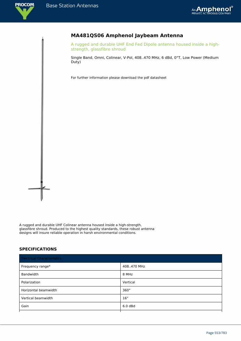
Base Station Antennas
MA481QS06 Amphenol Jaybeam AntennaA rugged and durable UHF End Fed Dipole antenna housed inside a high-strength, glassfibre shroud
Single Band, Omni, Colinear, V-Pol, 408..470 MHz, 6 dBd, 0°T, Low Power (MediumDuty)
For further information please download the pdf datasheet
A rugged and durable UHF Colinear antenna housed inside a high-strength,glassfibre shroud. Produced to the highest quality standards, these robust antennadesigns will insure reliable operation in harsh environmental conditions.
SPECIFICATIONS
Electrical Characteristics
Frequency range* 408..470 MHz
Bandwidth 8 MHz
Polarization Vertical
Horizontal beamwidth 360°
Vertical beamwidth 16°
Gain 6.0 dBd
Page 553/783
Base Station Antennas
Electrical downtilt 0°
Impedance 50Ω
VSWR <1.5:1
Maximum power 50 W
Connector type N-Female
Lightning protection DC grounded
* Specify center frequency at time of order.
Mechanical Characteristics
Materials Glass fibre shroud Aluminium mounting section
Dimensions (Length) 2400 mm 94.5 in
Weight without bracket 2.7 kg 6.0 lbs
Wind load @ 160 km/hr (100 mph) 80 N 18.0 lbf
Mounting Options
Mounting bracket MA621AZ30 clamp supplied to fit 30-50 mm dia. mast.
Page 554/783
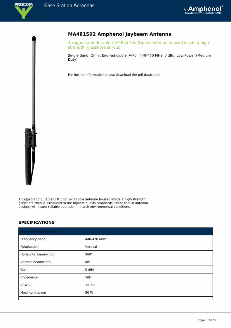
Base Station Antennas
MA481S02 Amphenol Jaybeam AntennaA rugged and durable UHF End Fed Dipole antenna housed inside a high-strength, glassfibre shroud
Single Band, Omni, End-fed dipole, V-Pol, 440-470 MHz, 0 dBd, Low Power (MediumDuty)
For further information please download the pdf datasheet
A rugged and durable UHF End Fed Dipole antenna housed inside a high-strength,glassfibre shroud. Produced to the highest quality standards, these robust antennadesigns will insure reliable operation in harsh environmental conditions.
SPECIFICATIONS
Electrical Characteristics
Frequency band 440-470 MHz
Polarization Vertical
Horizontal beamwidth 360°
Vertical beamwidth 88°
Gain 0 dBd
Impedance 50Ω
VSWR <1.5:1
Maximum power 50 W
Page 555/783
Base Station Antennas
Connector type N-Female
Lightning protection DC grounded
Mechanical Characteristics
Materials Glass fibre shroud Aluminium mounting section
Dimensions (Length) 900 mm 35.4 in
Weight without bracket 0.7 kg 1.5 lbs
Wind load @ 160 km/hr (100 mph) 40 N 9.0 lbf
Mounting Options
Mounting bracket MA621AZ30 clamp supplied to fit 30-50 mm dia. mast.
Page 556/783
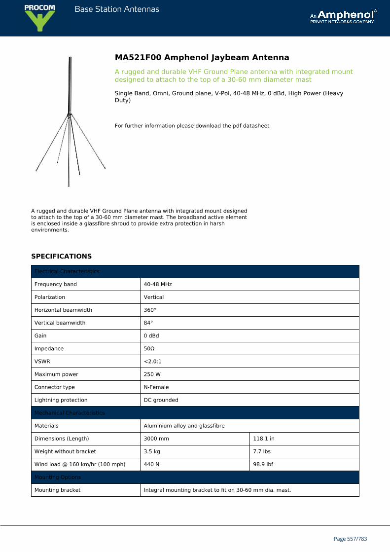
Base Station Antennas
MA521F00 Amphenol Jaybeam AntennaA rugged and durable VHF Ground Plane antenna with integrated mountdesigned to attach to the top of a 30-60 mm diameter mast
Single Band, Omni, Ground plane, V-Pol, 40-48 MHz, 0 dBd, High Power (HeavyDuty)
For further information please download the pdf datasheet
A rugged and durable VHF Ground Plane antenna with integrated mount designedto attach to the top of a 30-60 mm diameter mast. The broadband active elementis enclosed inside a glassfibre shroud to provide extra protection in harshenvironments.
SPECIFICATIONS
Electrical Characteristics
Frequency band 40-48 MHz
Polarization Vertical
Horizontal beamwidth 360°
Vertical beamwidth 84°
Gain 0 dBd
Impedance 50Ω
VSWR <2.0:1
Maximum power 250 W
Connector type N-Female
Lightning protection DC grounded
Mechanical Characteristics
Materials Aluminium alloy and glassfibre
Dimensions (Length) 3000 mm 118.1 in
Weight without bracket 3.5 kg 7.7 lbs
Wind load @ 160 km/hr (100 mph) 440 N 98.9 lbf
Mounting Options
Mounting bracket Integral mounting bracket to fit on 30-60 mm dia. mast.
Page 557/783

Base Station Antennas
Page 558/783
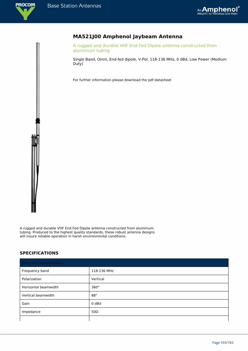
Base Station Antennas
MA521J00 Amphenol Jaybeam AntennaA rugged and durable VHF End Fed Dipole antenna constructed fromaluminium tubing
Single Band, Omni, End-fed dipole, V-Pol, 118-136 MHz, 0 dBd, Low Power (MediumDuty)
For further information please download the pdf datasheet
A rugged and durable VHF End Fed Dipole antenna constructed from aluminiumtubing. Produced to the highest quality standards, these robust antenna designswill insure reliable operation in harsh environmental conditions.
SPECIFICATIONS
Electrical Characteristics
Frequency band 118-136 MHz
Polarization Vertical
Horizontal beamwidth 360°
Vertical beamwidth 88°
Gain 0 dBd
Impedance 50Ω
Page 559/783
Base Station Antennas
VSWR <1.5:1
Maximum power 50 W
Connector type N-Female
Mechanical Characteristics
Materials Aluminium dipole
Dimensions (Length) 1510 mm 59.4 in
Weight without bracket 1.7 kg 3.7 lbs
Wind load @ 160 km/hr (100 mph) 133 N 30.0 lbf
Mounting Options
Mounting bracket MA621AZ40 clamp supplied to fit on 30-50 mm dia. mast.
Page 560/783
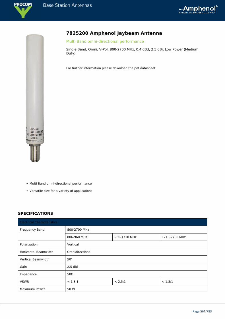
Base Station Antennas
7825200 Amphenol Jaybeam AntennaMulti Band omni-directional performance
Single Band, Omni, V-Pol, 800-2700 MHz, 0.4 dBd, 2.5 dBi, Low Power (MediumDuty)
For further information please download the pdf datasheet
Multi Band omni-directional performance
Versatile size for a variety of applications
SPECIFICATIONS
Electrical Characteristics
Frequency Band 800-2700 MHz
806-960 MHz 960-1710 MHz 1710-2700 MHz
Polarization Vertical
Horizontal Beamwidth Omnidirectional
Vertical Beamwidth 50°
Gain 2.5 dBi
Impedance 50Ω
VSWR < 1.8:1 < 2.5:1 < 1.8:1
Maximum Power 50 W
Page 561/783
Base Station Antennas
Connector(s) N-Female
Mechanical Characteristics
Materials Radome color, white
Dimensions (Length xDiameter)
175 x 28 mm 6.9 x 1.1 in
Weight withoutMounting Bracket
0.12 kg 0.26 lbs
Wind Load @ 160km/hr (100 mph)
11 N 2.5 lbf
Mounting Options Part Number Fits Pipe Diameter
Wall Mounting Kit XSL9254316 --
Wall or Pole Mounting XSL9254317 30-53 mm 1.2-2.0 in
Page 562/783
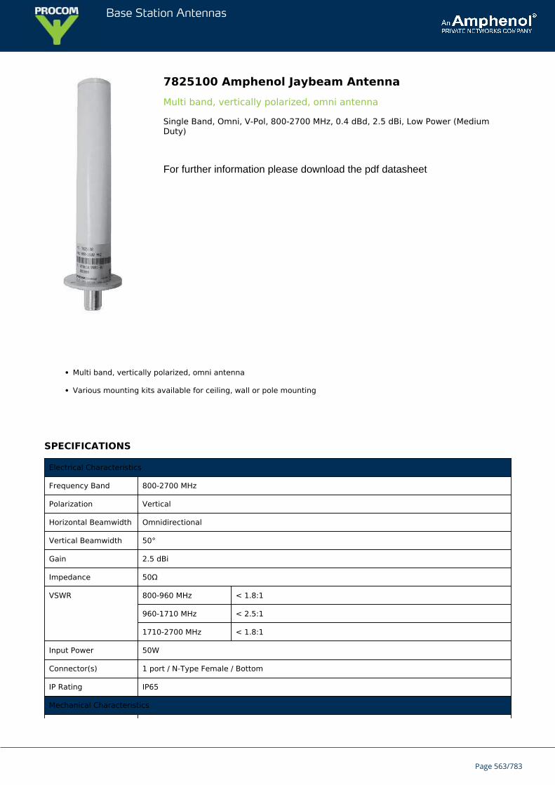
Base Station Antennas
7825100 Amphenol Jaybeam AntennaMulti band, vertically polarized, omni antenna
Single Band, Omni, V-Pol, 800-2700 MHz, 0.4 dBd, 2.5 dBi, Low Power (MediumDuty)
For further information please download the pdf datasheet
Multi band, vertically polarized, omni antenna
Various mounting kits available for ceiling, wall or pole mounting
SPECIFICATIONS
Electrical Characteristics
Frequency Band 800-2700 MHz
Polarization Vertical
Horizontal Beamwidth Omnidirectional
Vertical Beamwidth 50°
Gain 2.5 dBi
Impedance 50Ω
VSWR 800-960 MHz < 1.8:1
960-1710 MHz < 2.5:1
1710-2700 MHz < 1.8:1
Input Power 50W
Connector(s) 1 port / N-Type Female / Bottom
IP Rating IP65
Mechanical Characteristics
Page 563/783
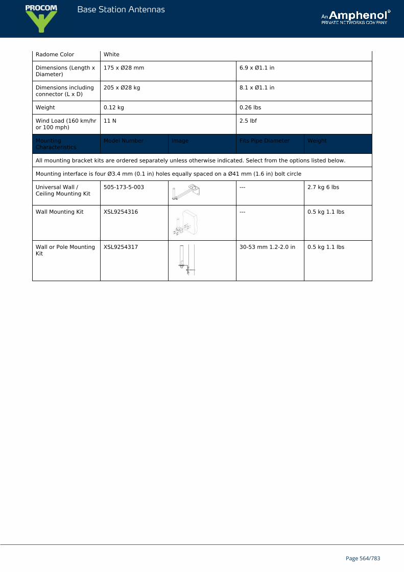
Base Station Antennas
Radome Color White
Dimensions (Length xDiameter)
175 x Ø28 mm 6.9 x Ø1.1 in
Dimensions includingconnector (L x D)
205 x Ø28 kg 8.1 x Ø1.1 in
Weight 0.12 kg 0.26 lbs
Wind Load (160 km/hror 100 mph)
11 N 2.5 lbf
MountingCharacteristics
Model Number Image Fits Pipe Diameter Weight
All mounting bracket kits are ordered separately unless otherwise indicated. Select from the options listed below.
Mounting interface is four Ø3.4 mm (0.1 in) holes equally spaced on a Ø41 mm (1.6 in) bolt circle
Universal Wall /Ceiling Mounting Kit
505-173-5-003 --- 2.7 kg 6 lbs
Wall Mounting Kit XSL9254316 --- 0.5 kg 1.1 lbs
Wall or Pole MountingKit
XSL9254317 30-53 mm 1.2-2.0 in 0.5 kg 1.1 lbs
Page 564/783
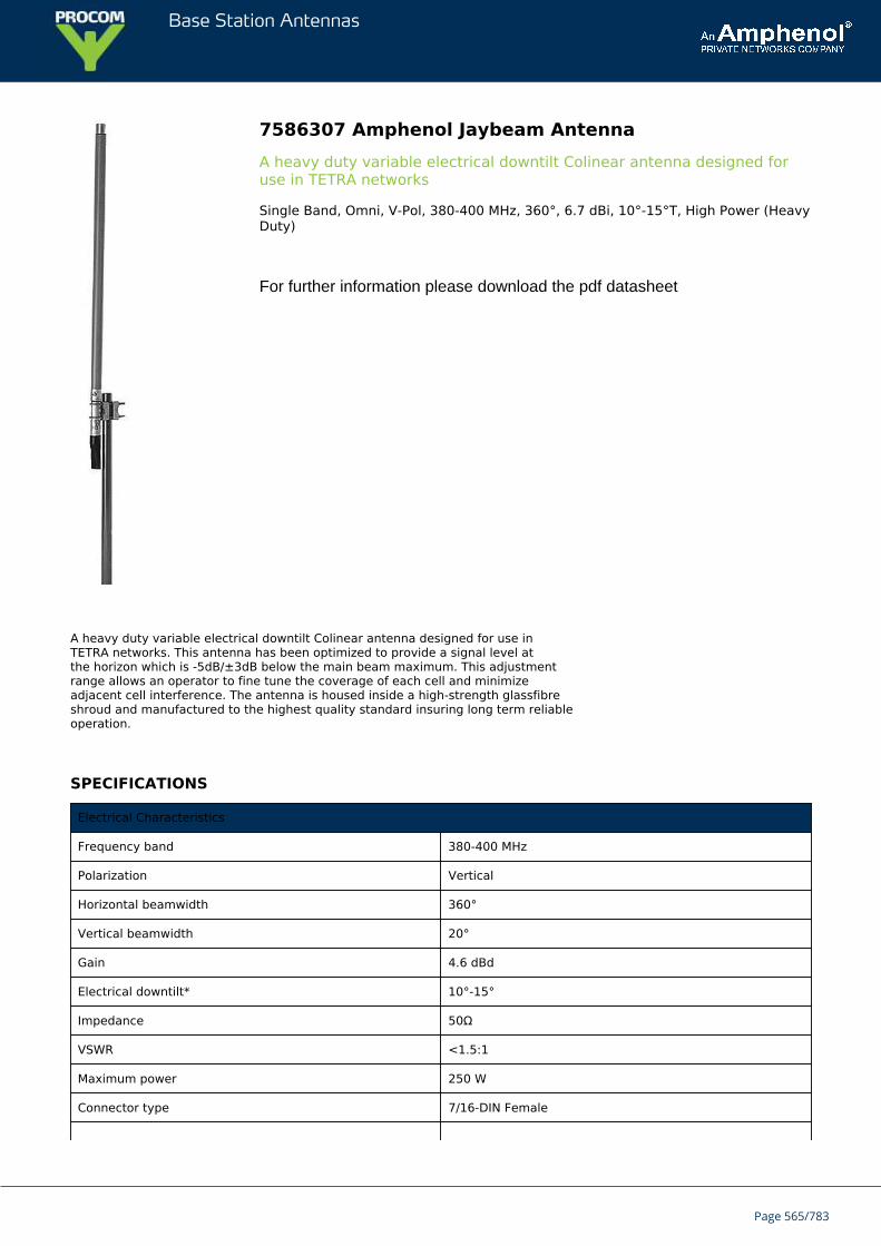
Base Station Antennas
7586307 Amphenol Jaybeam AntennaA heavy duty variable electrical downtilt Colinear antenna designed foruse in TETRA networks
Single Band, Omni, V-Pol, 380-400 MHz, 360°, 6.7 dBi, 10°-15°T, High Power (HeavyDuty)
For further information please download the pdf datasheet
A heavy duty variable electrical downtilt Colinear antenna designed for use inTETRA networks. This antenna has been optimized to provide a signal level atthe horizon which is -5dB/±3dB below the main beam maximum. This adjustmentrange allows an operator to fine tune the coverage of each cell and minimizeadjacent cell interference. The antenna is housed inside a high-strength glassfibreshroud and manufactured to the highest quality standard insuring long term reliableoperation.
SPECIFICATIONS
Electrical Characteristics
Frequency band 380-400 MHz
Polarization Vertical
Horizontal beamwidth 360°
Vertical beamwidth 20°
Gain 4.6 dBd
Electrical downtilt* 10°-15°
Impedance 50Ω
VSWR <1.5:1
Maximum power 250 W
Connector type 7/16-DIN Female
Page 565/783
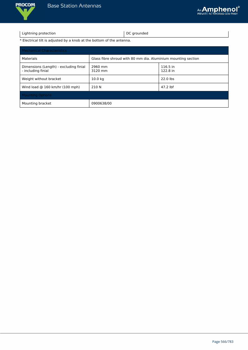
Base Station Antennas
Lightning protection DC grounded
* Electrical tilt is adjusted by a knob at the bottom of the antenna.
Mechanical Characteristics
Materials Glass fibre shroud with 80 mm dia. Aluminium mounting section
Dimensions (Length) - excluding finial- including finial
2960 mm3120 mm
116.5 in122.8 in
Weight without bracket 10.0 kg 22.0 lbs
Wind load @ 160 km/hr (100 mph) 210 N 47.2 lbf
Mounting Options
Mounting bracket 0900638/00
Page 566/783
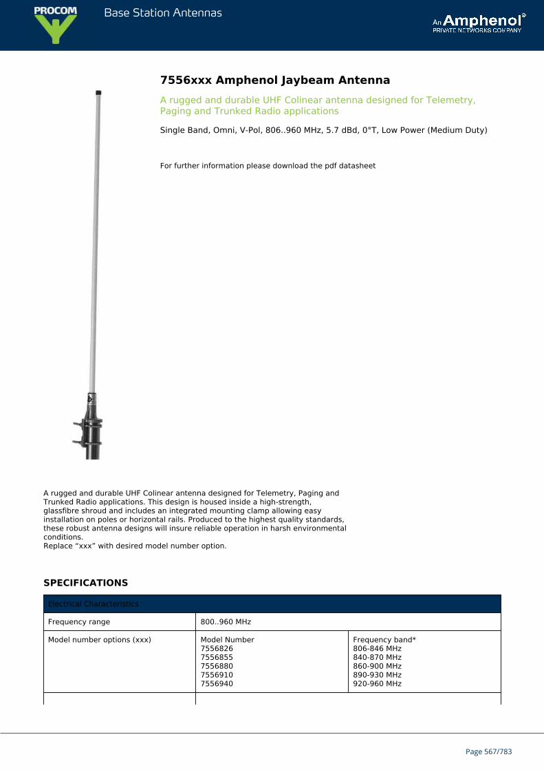
Base Station Antennas
7556xxx Amphenol Jaybeam AntennaA rugged and durable UHF Colinear antenna designed for Telemetry,Paging and Trunked Radio applications
Single Band, Omni, V-Pol, 806..960 MHz, 5.7 dBd, 0°T, Low Power (Medium Duty)
For further information please download the pdf datasheet
A rugged and durable UHF Colinear antenna designed for Telemetry, Paging andTrunked Radio applications. This design is housed inside a high-strength,glassfibre shroud and includes an integrated mounting clamp allowing easyinstallation on poles or horizontal rails. Produced to the highest quality standards,these robust antenna designs will insure reliable operation in harsh environmentalconditions.Replace “xxx” with desired model number option.
SPECIFICATIONS
Electrical Characteristics
Frequency range 800..960 MHz
Model number options (xxx) Model Number75568267556855755688075569107556940
Frequency band*806-846 MHz840-870 MHz860-900 MHz890-930 MHz920-960 MHz
Page 567/783
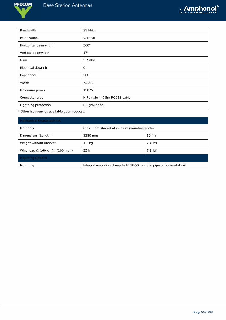
Base Station Antennas
Bandwidth 35 MHz
Polarization Vertical
Horizontal beamwidth 360°
Vertical beamwidth 17°
Gain 5.7 dBd
Electrical downtilt 0°
Impedance 50Ω
VSWR <1.5:1
Maximum power 150 W
Connector type N-Female + 0.5m RG213 cable
Lightning protection DC grounded
* Other frequencies available upon request.
Mechanical Characteristics
Materials Glass fibre shroud Aluminium mounting section
Dimensions (Length) 1280 mm 50.4 in
Weight without bracket 1.1 kg 2.4 lbs
Wind load @ 160 km/hr (100 mph) 35 N 7.9 lbf
Mounting Options
Mounting Integral mounting clamp to fit 38-50 mm dia. pipe or horizontal rail
Page 568/783
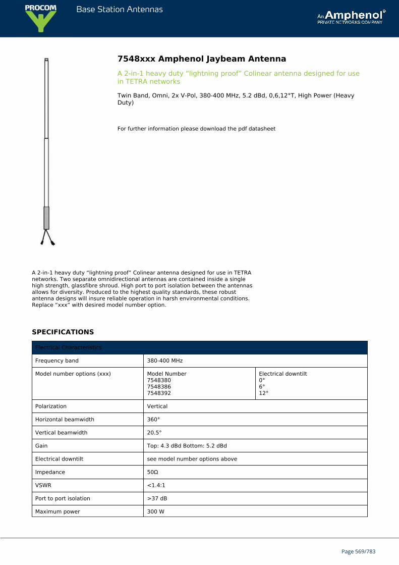
Base Station Antennas
7548xxx Amphenol Jaybeam AntennaA 2-in-1 heavy duty “lightning proof” Colinear antenna designed for usein TETRA networks
Twin Band, Omni, 2x V-Pol, 380-400 MHz, 5.2 dBd, 0,6,12°T, High Power (HeavyDuty)
For further information please download the pdf datasheet
A 2-in-1 heavy duty “lightning proof” Colinear antenna designed for use in TETRAnetworks. Two separate omnidirectional antennas are contained inside a singlehigh strength, glassfibre shroud. High port to port isolation between the antennasallows for diversity. Produced to the highest quality standards, these robustantenna designs will insure reliable operation in harsh environmental conditions.Replace “xxx” with desired model number option.
SPECIFICATIONS
Electrical Characteristics
Frequency band 380-400 MHz
Model number options (xxx) Model Number754838075483867548392
Electrical downtilt0°6°12°
Polarization Vertical
Horizontal beamwidth 360°
Vertical beamwidth 20.5°
Gain Top: 4.3 dBd Bottom: 5.2 dBd
Electrical downtilt see model number options above
Impedance 50Ω
VSWR <1.4:1
Port to port isolation >37 dB
Maximum power 300 W
Page 569/783
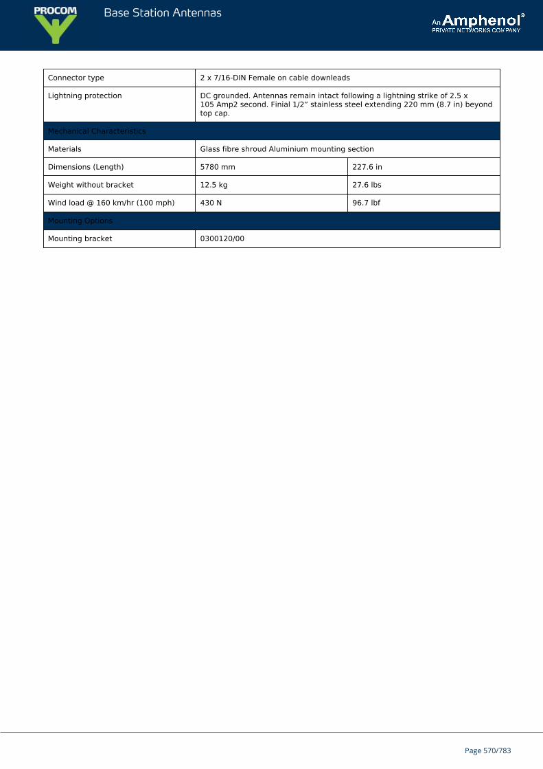
Base Station Antennas
Connector type 2 x 7/16-DIN Female on cable downleads
Lightning protection DC grounded. Antennas remain intact following a lightning strike of 2.5 x10⁵ Amp2 second. Finial 1/2” stainless steel extending 220 mm (8.7 in) beyondtop cap.
Mechanical Characteristics
Materials Glass fibre shroud Aluminium mounting section
Dimensions (Length) 5780 mm 227.6 in
Weight without bracket 12.5 kg 27.6 lbs
Wind load @ 160 km/hr (100 mph) 430 N 96.7 lbf
Mounting Options
Mounting bracket 0300120/00
Page 570/783
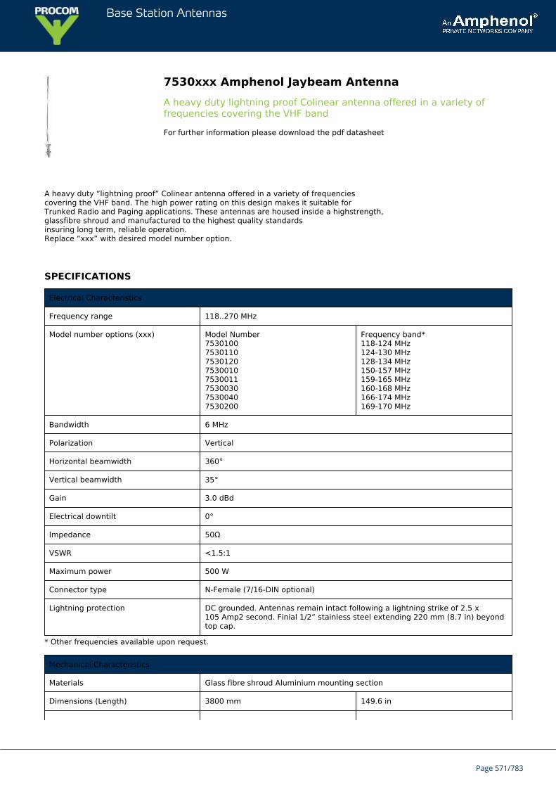
Base Station Antennas
7530xxx Amphenol Jaybeam AntennaA heavy duty lightning proof Colinear antenna offered in a variety offrequencies covering the VHF band
For further information please download the pdf datasheet
A heavy duty “lightning proof” Colinear antenna offered in a variety of frequenciescovering the VHF band. The high power rating on this design makes it suitable forTrunked Radio and Paging applications. These antennas are housed inside a highstrength,glassfibre shroud and manufactured to the highest quality standardsinsuring long term, reliable operation.Replace “xxx” with desired model number option.
SPECIFICATIONS
Electrical Characteristics
Frequency range 118..270 MHz
Model number options (xxx) Model Number75301007530110753012075300107530011753003075300407530200
Frequency band*118-124 MHz124-130 MHz128-134 MHz150-157 MHz159-165 MHz160-168 MHz166-174 MHz169-170 MHz
Bandwidth 6 MHz
Polarization Vertical
Horizontal beamwidth 360°
Vertical beamwidth 35°
Gain 3.0 dBd
Electrical downtilt 0°
Impedance 50Ω
VSWR <1.5:1
Maximum power 500 W
Connector type N-Female (7/16-DIN optional)
Lightning protection DC grounded. Antennas remain intact following a lightning strike of 2.5 x10⁵ Amp2 second. Finial 1/2” stainless steel extending 220 mm (8.7 in) beyondtop cap.
* Other frequencies available upon request.
Mechanical Characteristics
Materials Glass fibre shroud Aluminium mounting section
Dimensions (Length) 3800 mm 149.6 in
Page 571/783
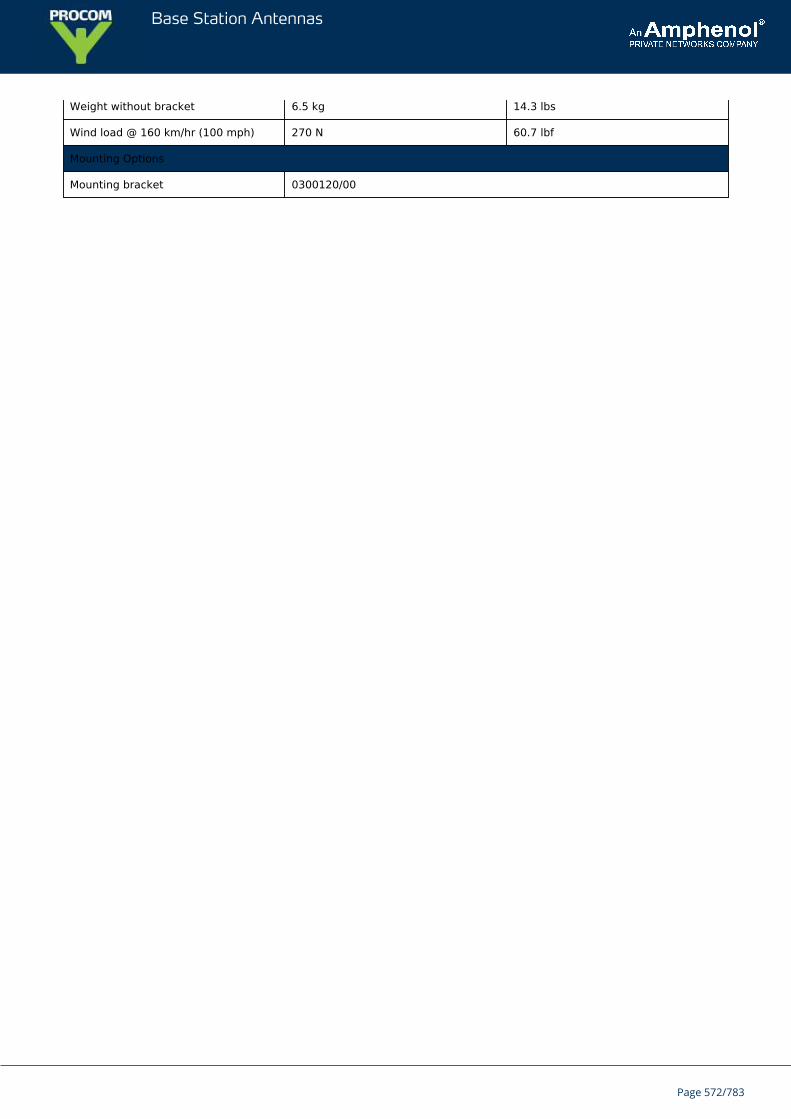
Base Station Antennas
Weight without bracket 6.5 kg 14.3 lbs
Wind load @ 160 km/hr (100 mph) 270 N 60.7 lbf
Mounting Options
Mounting bracket 0300120/00
Page 572/783
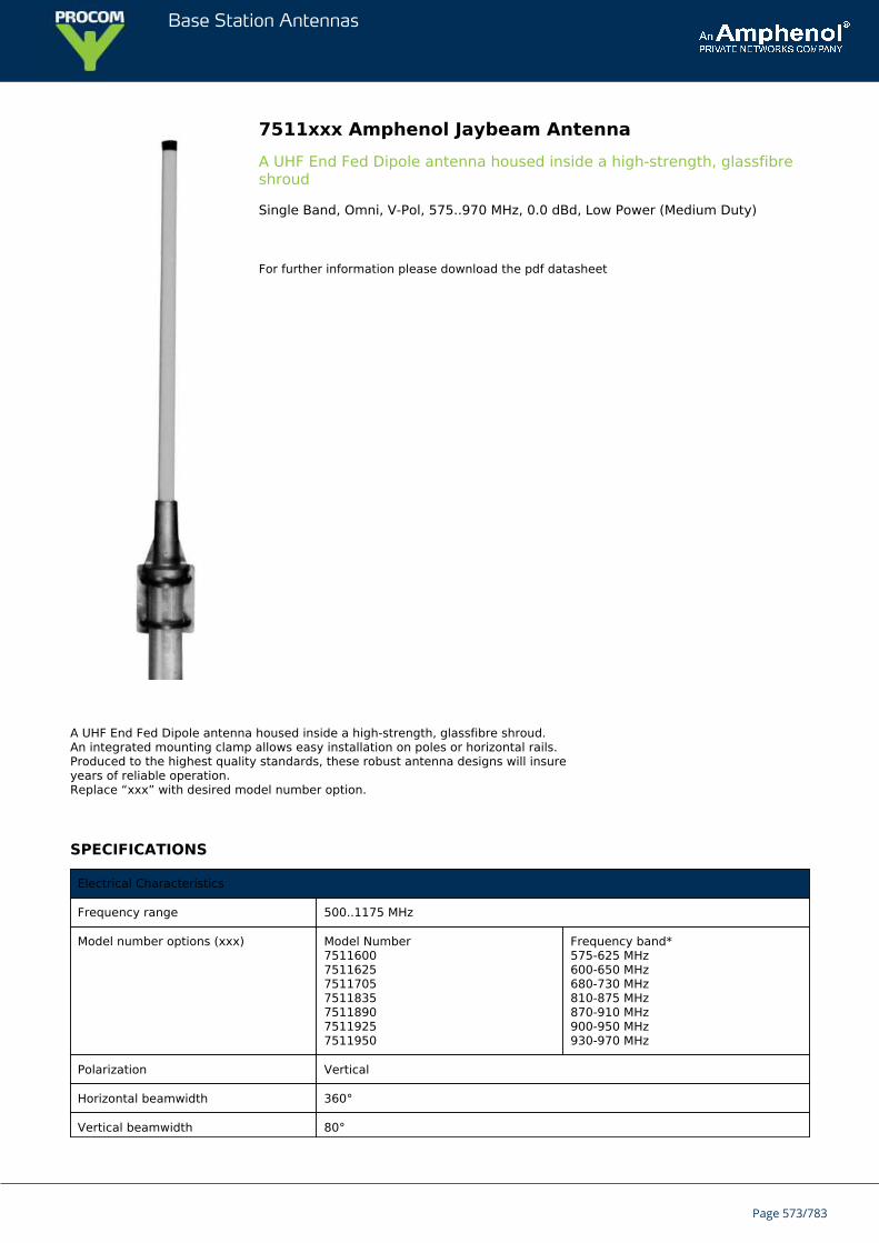
Base Station Antennas
7511xxx Amphenol Jaybeam AntennaA UHF End Fed Dipole antenna housed inside a high-strength, glassfibreshroud
Single Band, Omni, V-Pol, 575..970 MHz, 0.0 dBd, Low Power (Medium Duty)
For further information please download the pdf datasheet
A UHF End Fed Dipole antenna housed inside a high-strength, glassfibre shroud.An integrated mounting clamp allows easy installation on poles or horizontal rails.Produced to the highest quality standards, these robust antenna designs will insureyears of reliable operation.Replace “xxx” with desired model number option.
SPECIFICATIONS
Electrical Characteristics
Frequency range 500..1175 MHz
Model number options (xxx) Model Number7511600751162575117057511835751189075119257511950
Frequency band*575-625 MHz600-650 MHz680-730 MHz810-875 MHz870-910 MHz900-950 MHz930-970 MHz
Polarization Vertical
Horizontal beamwidth 360°
Vertical beamwidth 80°
Page 573/783
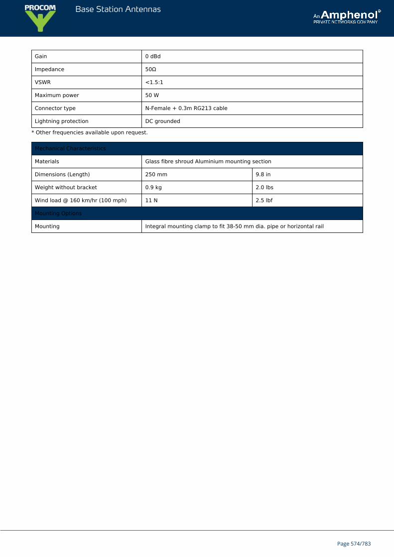
Base Station Antennas
Gain 0 dBd
Impedance 50Ω
VSWR <1.5:1
Maximum power 50 W
Connector type N-Female + 0.3m RG213 cable
Lightning protection DC grounded
* Other frequencies available upon request.
Mechanical Characteristics
Materials Glass fibre shroud Aluminium mounting section
Dimensions (Length) 250 mm 9.8 in
Weight without bracket 0.9 kg 2.0 lbs
Wind load @ 160 km/hr (100 mph) 11 N 2.5 lbf
Mounting Options
Mounting Integral mounting clamp to fit 38-50 mm dia. pipe or horizontal rail
Page 574/783
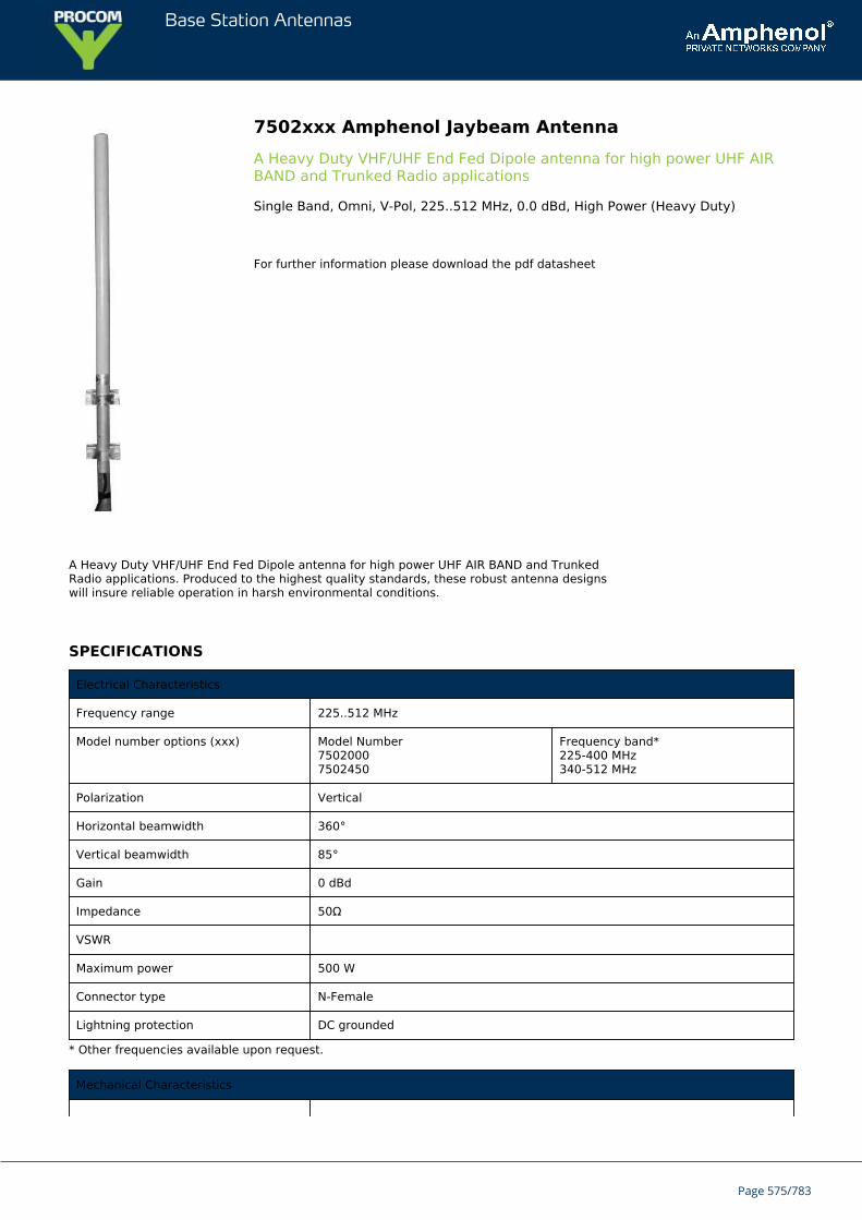
Base Station Antennas
7502xxx Amphenol Jaybeam AntennaA Heavy Duty VHF/UHF End Fed Dipole antenna for high power UHF AIRBAND and Trunked Radio applications
Single Band, Omni, V-Pol, 225..512 MHz, 0.0 dBd, High Power (Heavy Duty)
For further information please download the pdf datasheet
A Heavy Duty VHF/UHF End Fed Dipole antenna for high power UHF AIR BAND and TrunkedRadio applications. Produced to the highest quality standards, these robust antenna designswill insure reliable operation in harsh environmental conditions.
SPECIFICATIONS
Electrical Characteristics
Frequency range 225..512 MHz
Model number options (xxx) Model Number75020007502450
Frequency band*225-400 MHz340-512 MHz
Polarization Vertical
Horizontal beamwidth 360°
Vertical beamwidth 85°
Gain 0 dBd
Impedance 50Ω
VSWR
Maximum power 500 W
Connector type N-Female
Lightning protection DC grounded
* Other frequencies available upon request.
Mechanical Characteristics
Page 575/783
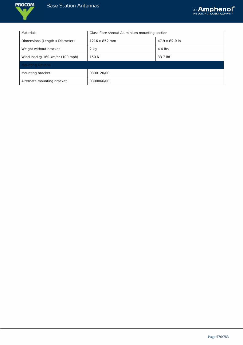
Base Station Antennas
Materials Glass fibre shroud Aluminium mounting section
Dimensions (Length x Diameter) 1216 x Ø52 mm 47.9 x Ø2.0 in
Weight without bracket 2 kg 4.4 lbs
Wind load @ 160 km/hr (100 mph) 150 N 33.7 lbf
Mounting Options
Mounting bracket 0300120/00
Alternate mounting bracket 0300066/00
Page 576/783
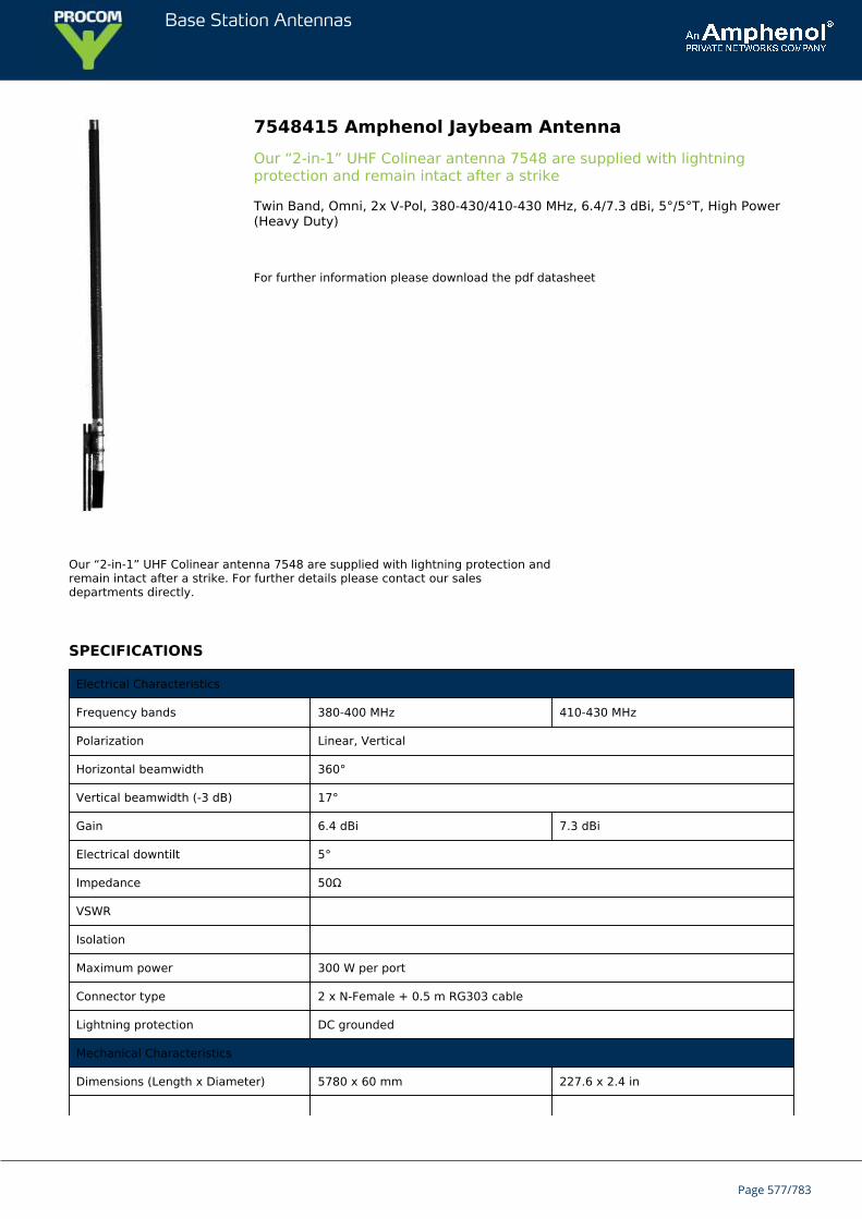
Base Station Antennas
7548415 Amphenol Jaybeam AntennaOur “2-in-1” UHF Colinear antenna 7548 are supplied with lightningprotection and remain intact after a strike
Twin Band, Omni, 2x V-Pol, 380-430/410-430 MHz, 6.4/7.3 dBi, 5°/5°T, High Power(Heavy Duty)
For further information please download the pdf datasheet
Our “2-in-1” UHF Colinear antenna 7548 are supplied with lightning protection andremain intact after a strike. For further details please contact our salesdepartments directly.
SPECIFICATIONS
Electrical Characteristics
Frequency bands 380-400 MHz 410-430 MHz
Polarization Linear, Vertical
Horizontal beamwidth 360°
Vertical beamwidth (-3 dB) 17°
Gain 6.4 dBi 7.3 dBi
Electrical downtilt 5°
Impedance 50Ω
VSWR
Isolation
Maximum power 300 W per port
Connector type 2 x N-Female + 0.5 m RG303 cable
Lightning protection DC grounded
Mechanical Characteristics
Dimensions (Length x Diameter) 5780 x 60 mm 227.6 x 2.4 in
Page 577/783

Base Station Antennas
Weight without bracket 12.5 kg 27.6 lbs
Wind load @ 160 km/hr (100 mph) 430 N 96.7 lbf
Mounting Options
Mounting bracket 0900638/00
Page 578/783
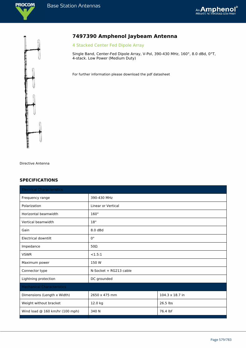
Base Station Antennas
7497390 Amphenol Jaybeam Antenna4 Stacked Center Fed Dipole Array
Single Band, Center-Fed Dipole Array, V-Pol, 390-430 MHz, 160°, 8.0 dBd, 0°T,4-stack. Low Power (Medium Duty)
For further information please download the pdf datasheet
Directive Antenna
SPECIFICATIONS
Electrical Characteristics
Frequency range 390-430 MHz
Polarization Linear or Vertical
Horizontal beamwidth 160°
Vertical beamwidth 18°
Gain 8.0 dBd
Electrical downtilt 0°
Impedance 50Ω
VSWR <1.5:1
Maximum power 150 W
Connector type N-Socket + RG213 cable
Lightning protection DC grounded
Mechanical Characteristics
Dimensions (Length x Width) 2650 x 475 mm 104.3 x 18.7 in
Weight without bracket 12.0 kg 26.5 lbs
Wind load @ 160 km/hr (100 mph) 340 N 76.4 lbf
Page 579/783
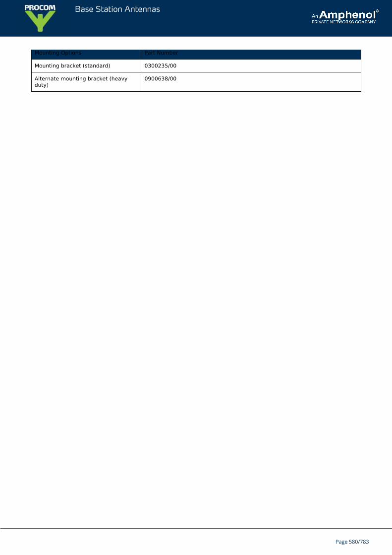
Base Station Antennas
Mounting Options Part Number
Mounting bracket (standard) 0300235/00
Alternate mounting bracket (heavyduty)
0900638/00
Page 580/783
Base Station Antennas
7437010 Amphenol Jaybeam AntennaA Wideband Discone antenna commonly used for ground-to-air andfrequency scanning applications
Single Band, Ground Plane Omni, V-Pol, 100-500 MHz, 0.0 dBd, High Power (HeavyDuty)
For further information please download the pdf datasheet
A Wideband Discone antenna commonly used for ground-to-air and frequencyscanning applications. The discone element design provides reliablecommunications over an extremely wide operating bandwidth. The 7437 model isa reinforced version of the popular 7177 model for high wind applications.
SPECIFICATIONS
Electrical Characteristics
Frequency band 100-500 MHz
Polarization Vertical
Horizontal beamwidth 360°
Vertical beamwidth 80°
Gain 0 dBd
Impedance 50Ω
VSWR
Maximum power 250 W
Connector N-Female + RG213 cable
Lightning protection DC grounded
Mechanical Characteristics
Materials Elements, solid aluminium rod Spine, aluminium tube Bracings, aluminium andPVC Finish, alochrome
Dimensions (Height x Diameter) 1170 x 1360 mm 46.1 x 53.5 in
Weight without bracket 5.0 kg 11.0 lbs
Wind load @ 160 km/hr (100 mph) 186 N 41.8 lbf
Mounting Options
Mounting bracket 0900964/00
Alternate mounting bracket 0300064/00 + U-Bolts to match mounting pipe diameter
Page 581/783
Base Station Antennas
7277010 Amphenol Jaybeam AntennaA rugged and durable Colinear antenna designed for VHF AIR BAND radiosystems
Single Band, Ground Plane Omni, V-Pol, 225-400 MHz, 0 dBd, High Power (HeavyDuty)
For further information please download the pdf datasheet
A rugged and durable Wideband Discone antenna for UHF AIR BAND applications.This design provides low VSWR and stable pattern performance over a wideoperating bandwidth. Produced to the highest quality standards, these robustantenna designs will insure reliable operation in harsh environmental conditions.
SPECIFICATIONS
Electrical Characteristics
Frequency band 225-400 MHz
Polarization Vertical
Horizontal beamwidth 360°
Vertical beamwidth 80°
Gain 0 dBd
Impedance 50Ω
VSWR
Maximum power 250 W
Connector type N-Female on RG213 coaxial downlead
Lightning protection DC grounded
Mechanical Characteristics
Materials Elements, solid aluminium Finish, alochrom
Dimensions (Height x Diameter) 590 x 730 mm 23.2 x 28.7 in
Weight without bracket 3.0 kg 6.6 lbs
Wind load @ 160 km/hr (100 mph) 91 N 20.5 lbf
Mounting Options
Mounting bracket 0900964/00
Alternate mounting bracket 0300066/00
Page 582/783
Base Station Antennas
7273xxx Amphenol Jaybeam AntennaA rugged and durable Colinear antenna designed for VHF AIR BAND radiosystems
Single Band, Omni, V-Pol, 120-124 MHz, 4.5 dBd, 0°T, High Power (Heavy Duty)
For further information please download the pdf datasheet
A rugged and durable Colinear antenna designed for VHF AIR BAND radiosystems. These antennas are housed inside a high-strength, glassfibre shroudand manufactured to the highest quality standards insuring long term, reliableoperation.Replace “xxx” with desired model number option.
SPECIFICATIONS
Electrical Characteristics
Frequency range 110..138 MHz
Model number options (xxx) Model Number72731227273126727312972731317273135
Frequency band*120-124 MHz124-126 MHz127-131 MHz130-133 MHz133-137 MHz
Bandwidth ±1% (typical)
Polarization Vertical
Horizontal beamwidth 360°
Vertical beamwidth 30°
Page 583/783
Base Station Antennas
Gain 4.5 dBd
Electrical downtilt 0°
Impedance 50Ω
VSWR <1.5:1
Maximum power 200 W
Connector type N-Female
Lightning protection DC grounded
* Other frequencies available upon request.
Mechanical Characteristics
Materials Glass fibre shroud Aluminium mounting section
Dimensions (Length) 5600 mm 220.5 in
Weight without bracket 7.0 kg 15.4 lbs
Wind load @ 160 km/hr (100 mph) 260 N 58.5 lbf
Mounting Options
Mounting bracket 0300120/00
Page 584/783
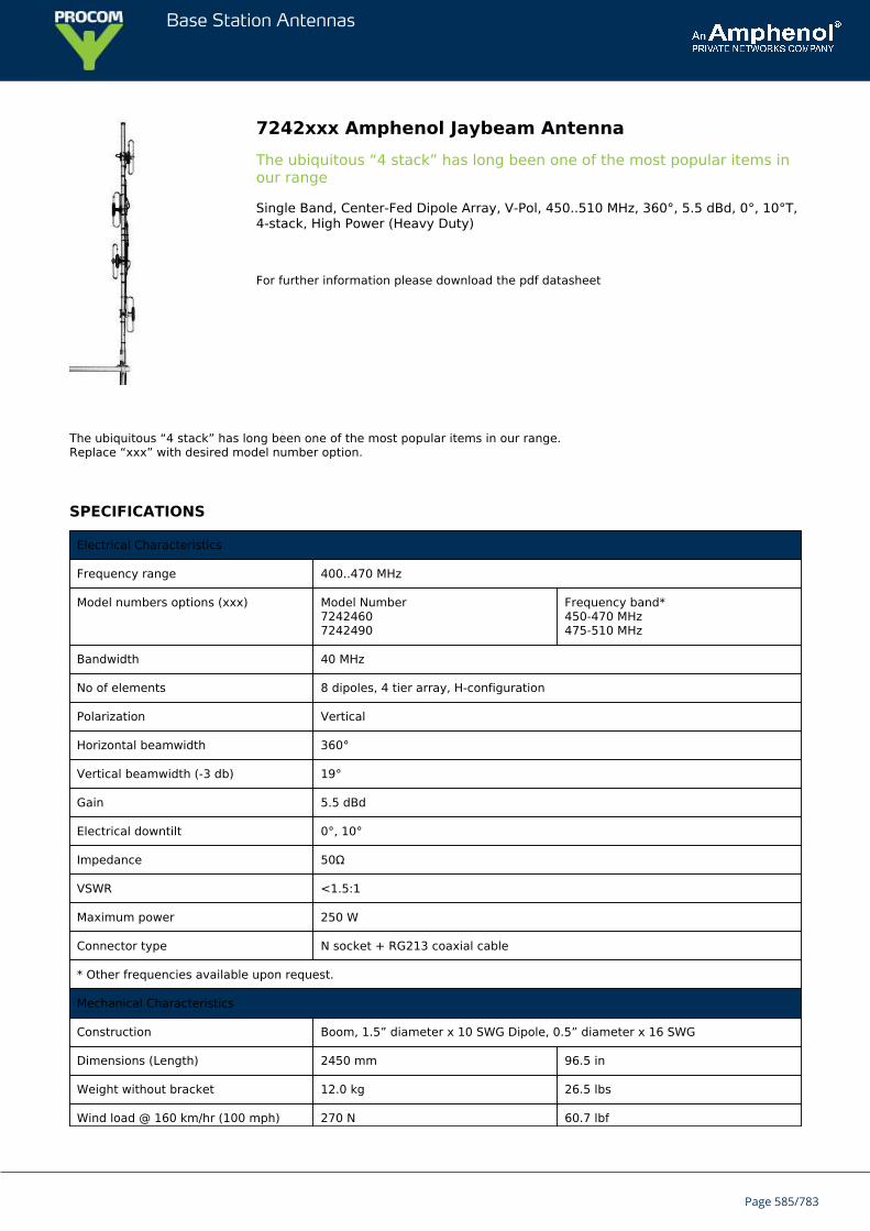
Base Station Antennas
7242xxx Amphenol Jaybeam AntennaThe ubiquitous “4 stack” has long been one of the most popular items inour range
Single Band, Center-Fed Dipole Array, V-Pol, 450..510 MHz, 360°, 5.5 dBd, 0°, 10°T,4-stack, High Power (Heavy Duty)
For further information please download the pdf datasheet
The ubiquitous “4 stack” has long been one of the most popular items in our range.Replace “xxx” with desired model number option.
SPECIFICATIONS
Electrical Characteristics
Frequency range 400..470 MHz
Model numbers options (xxx) Model Number72424607242490
Frequency band*450-470 MHz475-510 MHz
Bandwidth 40 MHz
No of elements 8 dipoles, 4 tier array, H-configuration
Polarization Vertical
Horizontal beamwidth 360°
Vertical beamwidth (-3 db) 19°
Gain 5.5 dBd
Electrical downtilt 0°, 10°
Impedance 50Ω
VSWR <1.5:1
Maximum power 250 W
Connector type N socket + RG213 coaxial cable
* Other frequencies available upon request.
Mechanical Characteristics
Construction Boom, 1.5” diameter x 10 SWG Dipole, 0.5” diameter x 16 SWG
Dimensions (Length) 2450 mm 96.5 in
Weight without bracket 12.0 kg 26.5 lbs
Wind load @ 160 km/hr (100 mph) 270 N 60.7 lbf
Page 585/783

Base Station Antennas
Mounting Options Part Number
Mounting bracket 0300235/00
Page 586/783
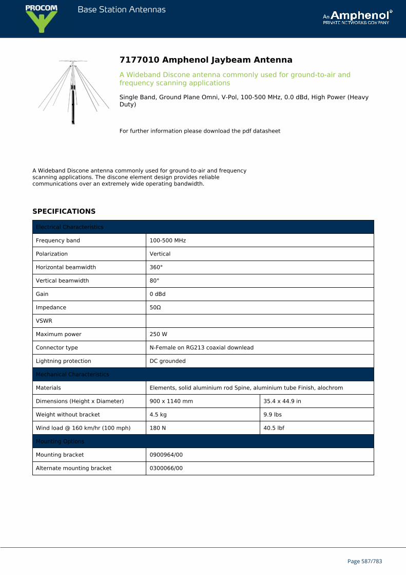
Base Station Antennas
7177010 Amphenol Jaybeam AntennaA Wideband Discone antenna commonly used for ground-to-air andfrequency scanning applications
Single Band, Ground Plane Omni, V-Pol, 100-500 MHz, 0.0 dBd, High Power (HeavyDuty)
For further information please download the pdf datasheet
A Wideband Discone antenna commonly used for ground-to-air and frequencyscanning applications. The discone element design provides reliablecommunications over an extremely wide operating bandwidth.
SPECIFICATIONS
Electrical Characteristics
Frequency band 100-500 MHz
Polarization Vertical
Horizontal beamwidth 360°
Vertical beamwidth 80°
Gain 0 dBd
Impedance 50Ω
VSWR
Maximum power 250 W
Connector type N-Female on RG213 coaxial downlead
Lightning protection DC grounded
Mechanical Characteristics
Materials Elements, solid aluminium rod Spine, aluminium tube Finish, alochrom
Dimensions (Height x Diameter) 900 x 1140 mm 35.4 x 44.9 in
Weight without bracket 4.5 kg 9.9 lbs
Wind load @ 160 km/hr (100 mph) 180 N 40.5 lbf
Mounting Options
Mounting bracket 0900964/00
Alternate mounting bracket 0300066/00
Page 587/783
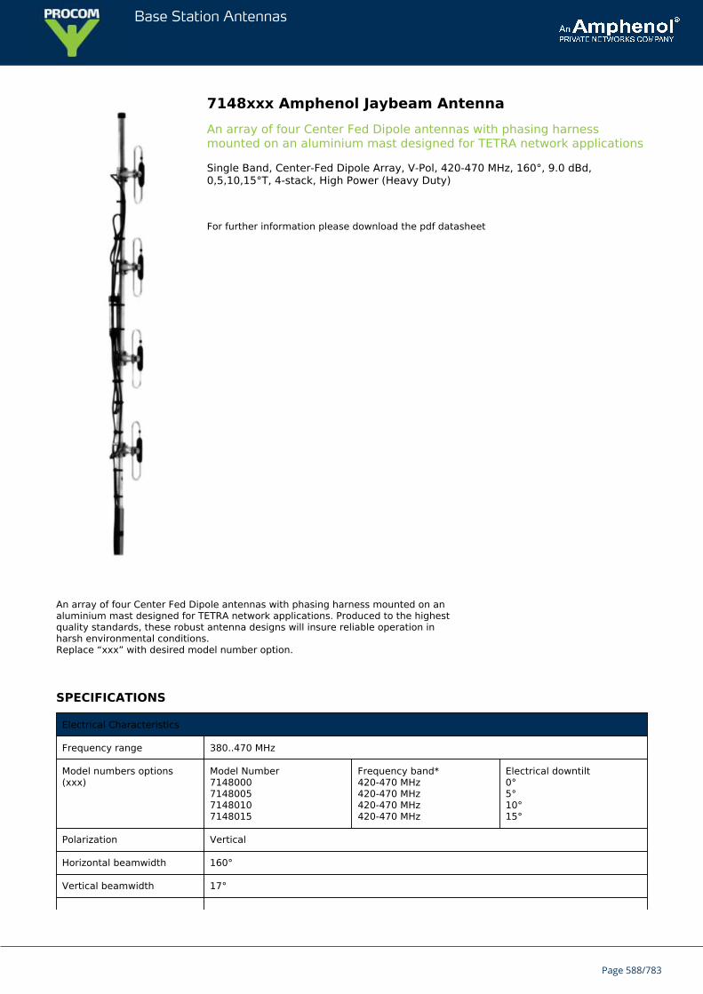
Base Station Antennas
7148xxx Amphenol Jaybeam AntennaAn array of four Center Fed Dipole antennas with phasing harnessmounted on an aluminium mast designed for TETRA network applications
Single Band, Center-Fed Dipole Array, V-Pol, 420-470 MHz, 160°, 9.0 dBd,0,5,10,15°T, 4-stack, High Power (Heavy Duty)
For further information please download the pdf datasheet
An array of four Center Fed Dipole antennas with phasing harness mounted on analuminium mast designed for TETRA network applications. Produced to the highestquality standards, these robust antenna designs will insure reliable operation inharsh environmental conditions.Replace “xxx” with desired model number option.
SPECIFICATIONS
Electrical Characteristics
Frequency range 380..470 MHz
Model numbers options(xxx)
Model Number7148000714800571480107148015
Frequency band*420-470 MHz420-470 MHz420-470 MHz420-470 MHz
Electrical downtilt0°5°10°15°
Polarization Vertical
Horizontal beamwidth 160°
Vertical beamwidth 17°
Page 588/783
Base Station Antennas
Gain 9.0 dBd
Electrical downtilt see model number options above
Impedance 50Ω
VSWR <1.5:1
Maximum power 200 W
Connector type N-Female + 3m of RG213 cable
Lightning protection DC grounded
Mechanical Characteristics
Construction Center fed folded dipoles (with baluns) fixed on a one piece vertical boom.
Dimensions LxWxD 2600 x 132 x 110 mm 102.4 x 5.2 x 4.3 in
Weight without bracket 7.0 kg 15.4 lbs
Wind load @ 160 km/hr (100 mph) 190 N 42.7 lbf
Mounting Options Part Number
Mounting bracket 0300120/00
Page 589/783
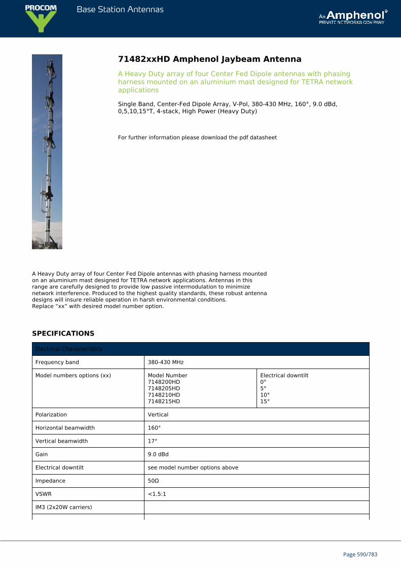
Base Station Antennas
71482xxHD Amphenol Jaybeam AntennaA Heavy Duty array of four Center Fed Dipole antennas with phasingharness mounted on an aluminium mast designed for TETRA networkapplications
Single Band, Center-Fed Dipole Array, V-Pol, 380-430 MHz, 160°, 9.0 dBd,0,5,10,15°T, 4-stack, High Power (Heavy Duty)
For further information please download the pdf datasheet
A Heavy Duty array of four Center Fed Dipole antennas with phasing harness mountedon an aluminium mast designed for TETRA network applications. Antennas in thisrange are carefully designed to provide low passive intermodulation to minimizenetwork interference. Produced to the highest quality standards, these robust antennadesigns will insure reliable operation in harsh environmental conditions.Replace “xx” with desired model number option.
SPECIFICATIONS
Electrical Characteristics
Frequency band 380-430 MHz
Model numbers options (xx) Model Number7148200HD7148205HD7148210HD7148215HD
Electrical downtilt0°5°10°15°
Polarization Vertical
Horizontal beamwidth 160°
Vertical beamwidth 17°
Gain 9.0 dBd
Electrical downtilt see model number options above
Impedance 50Ω
VSWR <1.5:1
IM3 (2x20W carriers)
Page 590/783
Base Station Antennas
Maximum power 200 W
Connector type 7/16-DIN Female + 4m of RG214 cable
Lightning protection DC grounded
* Other frequencies available upon request.
Mechanical Characteristics
Construction Center fed folded dipoles (with baluns) fixed on a one piece vertical boom.
Dimensions LxWxD 2600 x 132 x 110 mm 102.4 x 5.2 x 4.3 in
Weight without bracket 8.0 kg 17.6 lbs
Wind load @ 160 km/hr (100 mph) 180 N 40.5 lbf
Mounting Options Part Number
Mounting bracket 0300120/00
Page 591/783
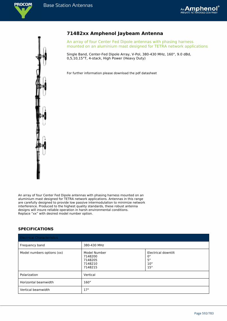
Base Station Antennas
71482xx Amphenol Jaybeam AntennaAn array of four Center Fed Dipole antennas with phasing harnessmounted on an aluminium mast designed for TETRA network applications
Single Band, Center-Fed Dipole Array, V-Pol, 380-430 MHz, 160°, 9.0 dBd,0,5,10,15°T, 4-stack, High Power (Heavy Duty)
For further information please download the pdf datasheet
An array of four Center Fed Dipole antennas with phasing harness mounted on analuminium mast designed for TETRA network applications. Antennas in this rangeare carefully designed to provide low passive intermodulation to minimize networkinterference. Produced to the highest quality standards, these robust antennadesigns will insure reliable operation in harsh environmental conditions.Replace “xx” with desired model number option.
SPECIFICATIONS
Electrical Characteristics
Frequency band 380-430 MHz
Model numbers options (xx) Model Number7148200714820571482107148215
Electrical downtilt0°5°10°15°
Polarization Vertical
Horizontal beamwidth 160°
Vertical beamwidth 17°
Page 592/783
Base Station Antennas
Gain 9.0 dBd
Electrical downtilt see model number options above
Impedance 50Ω
VSWR <1.5:1
IM3 (2x20W carriers)
Maximum power 200 W
Connector type 7/16-DIN Female + 4m of RG214 cable
Lightning protection DC grounded
* Other frequencies available upon request.
Mechanical Characteristics
Construction Center fed folded dipoles (with baluns) fixed on a one piece vertical boom.
Dimensions LxWxD 2600 x 132 x 110 mm 102.4 x 5.2 x 4.3 in
Weight without bracket 7.0 kg 15.4 lbs
Wind load @ 160 km/hr (100 mph) 190 N 42.7 lbf
Mounting Options Part Number
Mounting bracket 0300120/00
Page 593/783

Base Station Antennas
7074xxx Amphenol Jaybeam AntennaA rugged and durable Colinear antenna housed inside a high-strength,glassfibre shroud
Single Band, Omni, V-Pol, 158..172 MHz, 3.0 dBd, 0°T, High Power (Heavy Duty)
For further information please download the pdf datasheet
A rugged and durable Colinear antenna housed inside a high-strength, glassfibreshroud. Produced to the highest quality standards these robust antenna designswill insure reliable operation in harsh environmental condition.Replace “xxx” with desired model number option.
SPECIFICATIONS
Electrical Characteristics
Frequency range 130..175 MHz
Model number options (xxx) Model Number7074160707416370741667074170
Frequency band*158-162 MHz162-165 MHz164-168 MHz167.6-172.4 MHz
Bandwidth 3% (typical)
Polarization Vertical
Horizontal beamwidth 360°
Vertical beamwidth 31°
Gain 3.0 dBd
Page 594/783
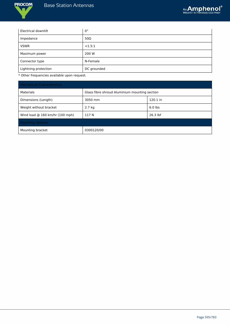
Base Station Antennas
Electrical downtilt 0°
Impedance 50Ω
VSWR <1.5:1
Maximum power 200 W
Connector type N-Female
Lightning protection DC grounded
* Other frequencies available upon request.
Mechanical Characteristics
Materials Glass fibre shroud Aluminium mounting section
Dimensions (Length) 3050 mm 120.1 in
Weight without bracket 2.7 kg 6.0 lbs
Wind load @ 160 km/hr (100 mph) 117 N 26.3 lbf
Mounting Options
Mounting bracket 0300120/00
Page 595/783
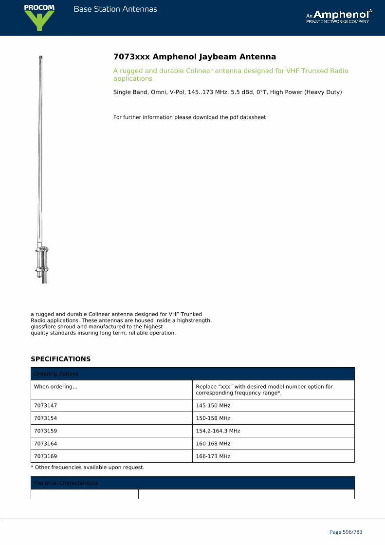
Base Station Antennas
7073xxx Amphenol Jaybeam AntennaA rugged and durable Colinear antenna designed for VHF Trunked Radioapplications
Single Band, Omni, V-Pol, 145..173 MHz, 5.5 dBd, 0°T, High Power (Heavy Duty)
For further information please download the pdf datasheet
a rugged and durable Colinear antenna designed for VHF TrunkedRadio applications. These antennas are housed inside a highstrength,glassfibre shroud and manufactured to the highestquality standards insuring long term, reliable operation.
SPECIFICATIONS
Ordering Options
When ordering... Replace “xxx” with desired model number option forcorresponding frequency range*.
7073147 145-150 MHz
7073154 150-158 MHz
7073159 154.2-164.3 MHz
7073164 160-168 MHz
7073169 166-173 MHz
* Other frequencies available upon request.
Electrical Characteristics
Page 596/783
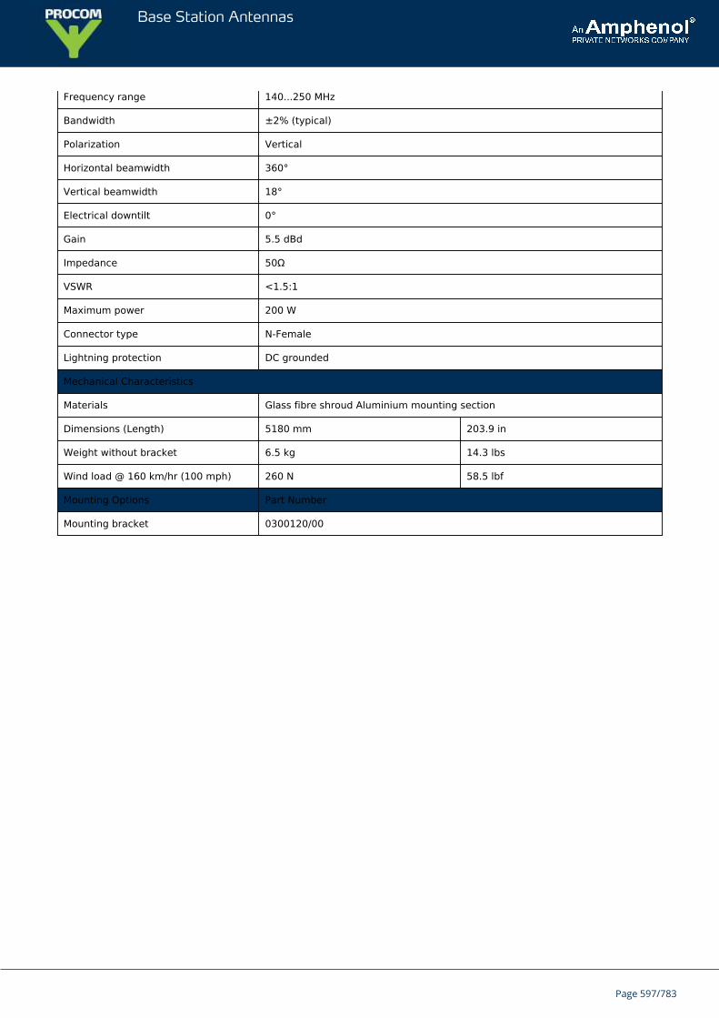
Base Station Antennas
Frequency range 140...250 MHz
Bandwidth ±2% (typical)
Polarization Vertical
Horizontal beamwidth 360°
Vertical beamwidth 18°
Electrical downtilt 0°
Gain 5.5 dBd
Impedance 50Ω
VSWR <1.5:1
Maximum power 200 W
Connector type N-Female
Lightning protection DC grounded
Mechanical Characteristics
Materials Glass fibre shroud Aluminium mounting section
Dimensions (Length) 5180 mm 203.9 in
Weight without bracket 6.5 kg 14.3 lbs
Wind load @ 160 km/hr (100 mph) 260 N 58.5 lbf
Mounting Options Part Number
Mounting bracket 0300120/00
Page 597/783
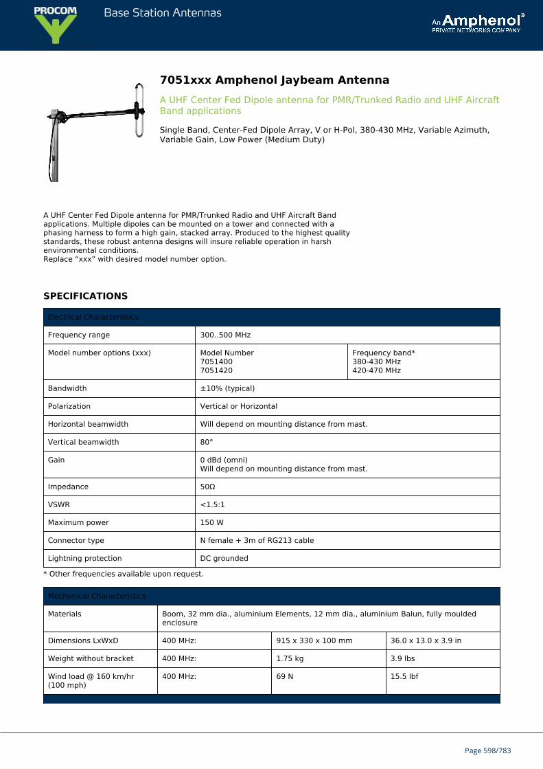
Base Station Antennas
7051xxx Amphenol Jaybeam AntennaA UHF Center Fed Dipole antenna for PMR/Trunked Radio and UHF AircraftBand applications
Single Band, Center-Fed Dipole Array, V or H-Pol, 380-430 MHz, Variable Azimuth,Variable Gain, Low Power (Medium Duty)
A UHF Center Fed Dipole antenna for PMR/Trunked Radio and UHF Aircraft Bandapplications. Multiple dipoles can be mounted on a tower and connected with aphasing harness to form a high gain, stacked array. Produced to the highest qualitystandards, these robust antenna designs will insure reliable operation in harshenvironmental conditions.Replace “xxx” with desired model number option.
SPECIFICATIONS
Electrical Characteristics
Frequency range 300..500 MHz
Model number options (xxx) Model Number70514007051420
Frequency band*380-430 MHz420-470 MHz
Bandwidth ±10% (typical)
Polarization Vertical or Horizontal
Horizontal beamwidth Will depend on mounting distance from mast.
Vertical beamwidth 80°
Gain 0 dBd (omni)Will depend on mounting distance from mast.
Impedance 50Ω
VSWR <1.5:1
Maximum power 150 W
Connector type N female + 3m of RG213 cable
Lightning protection DC grounded
* Other frequencies available upon request.
Mechanical Characteristics
Materials Boom, 32 mm dia., aluminium Elements, 12 mm dia., aluminium Balun, fully mouldedenclosure
Dimensions LxWxD 400 MHz: 915 x 330 x 100 mm 36.0 x 13.0 x 3.9 in
Weight without bracket 400 MHz: 1.75 kg 3.9 lbs
Wind load @ 160 km/hr(100 mph)
400 MHz: 69 N 15.5 lbf
Page 598/783
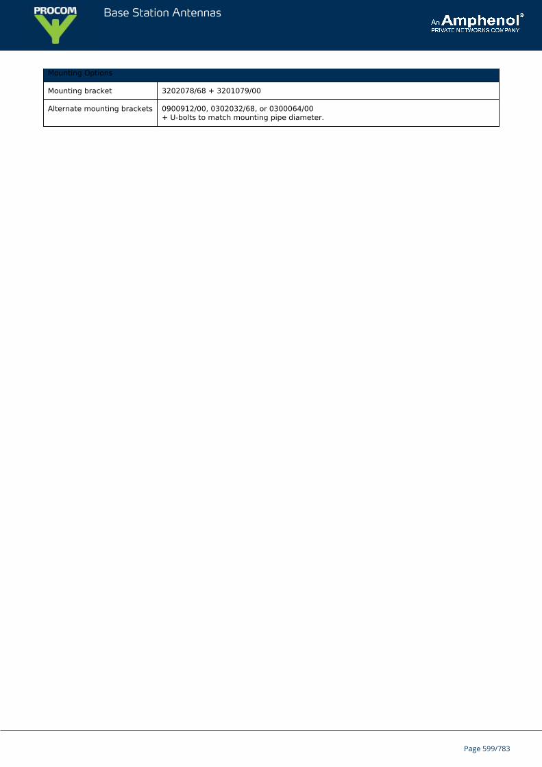
Base Station Antennas
Mounting Options
Mounting bracket 3202078/68 + 3201079/00
Alternate mounting brackets 0900912/00, 0302032/68, or 0300064/00+ U-bolts to match mounting pipe diameter.
Page 599/783
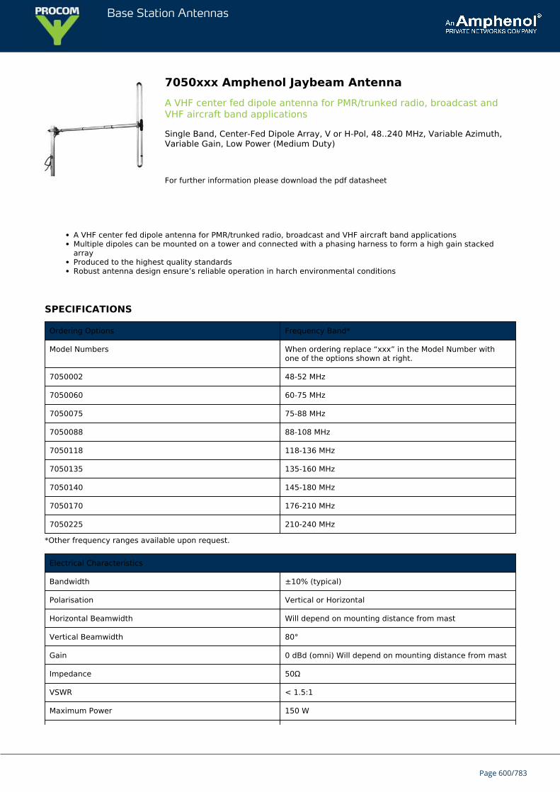
Base Station Antennas
7050xxx Amphenol Jaybeam AntennaA VHF center fed dipole antenna for PMR/trunked radio, broadcast andVHF aircraft band applications
Single Band, Center-Fed Dipole Array, V or H-Pol, 48..240 MHz, Variable Azimuth,Variable Gain, Low Power (Medium Duty)
For further information please download the pdf datasheet
A VHF center fed dipole antenna for PMR/trunked radio, broadcast and VHF aircraft band applicationsMultiple dipoles can be mounted on a tower and connected with a phasing harness to form a high gain stackedarrayProduced to the highest quality standardsRobust antenna design ensure’s reliable operation in harch environmental conditions
SPECIFICATIONS
Ordering Options Frequency Band*
Model Numbers When ordering replace “xxx” in the Model Number withone of the options shown at right.
7050002 48-52 MHz
7050060 60-75 MHz
7050075 75-88 MHz
7050088 88-108 MHz
7050118 118-136 MHz
7050135 135-160 MHz
7050140 145-180 MHz
7050170 176-210 MHz
7050225 210-240 MHz
*Other frequency ranges available upon request.
Electrical Characteristics
Bandwidth ±10% (typical)
Polarisation Vertical or Horizontal
Horizontal Beamwidth Will depend on mounting distance from mast
Vertical Beamwidth 80°
Gain 0 dBd (omni) Will depend on mounting distance from mast
Impedance 50Ω
VSWR < 1.5:1
Maximum Power 150 W
Page 600/783
Base Station Antennas
Lightning Protection DC Grounded
Connector(s) N-Type Female + 3m of RG213 cable
Mechanical Characteristics
Materials Boom 32 mm diameter, aluminium
Elements 19 mm diameter, aluminium
Balun Fully moulded enclosure
Dimensions (Length x Width x Depth at 80 MHz) 1700 x 1370 x 110 mm 66.9 x 53.9 x 4.3 in
Weight without Mounting Brackets (at 80 MHz) 2.8 kg 6.2 lbs
Wind Load (160 km/hr or 100 mph; at 80 MHz) 134 N 30.1 lbf
Mounting Options (ordered separately)
Mounting Bracket Kit 3202078/68 + 3201079/00
Alternate Mounting Brackets 0900912/00, 0302032/68 or 0300064/00+ U-bolts to match mounting pipe diameter
Page 601/783
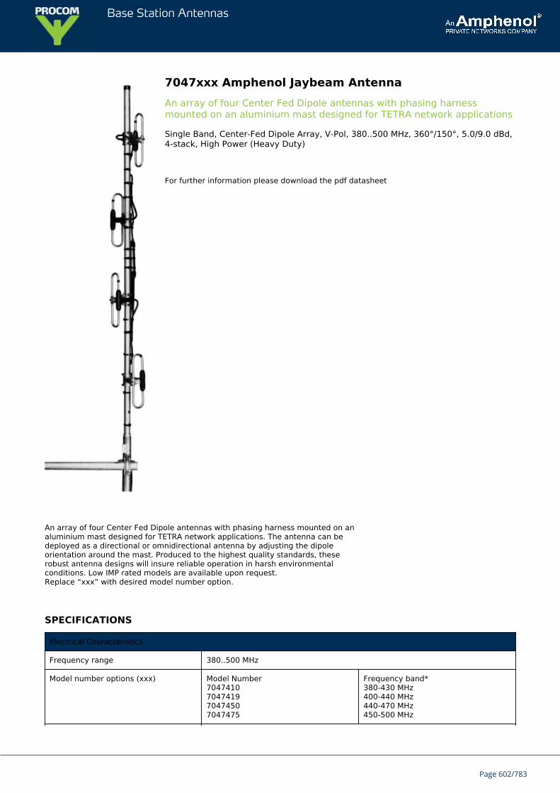
Base Station Antennas
7047xxx Amphenol Jaybeam AntennaAn array of four Center Fed Dipole antennas with phasing harnessmounted on an aluminium mast designed for TETRA network applications
Single Band, Center-Fed Dipole Array, V-Pol, 380..500 MHz, 360°/150°, 5.0/9.0 dBd,4-stack, High Power (Heavy Duty)
For further information please download the pdf datasheet
An array of four Center Fed Dipole antennas with phasing harness mounted on analuminium mast designed for TETRA network applications. The antenna can bedeployed as a directional or omnidirectional antenna by adjusting the dipoleorientation around the mast. Produced to the highest quality standards, theserobust antenna designs will insure reliable operation in harsh environmentalconditions. Low IMP rated models are available upon request.Replace “xxx” with desired model number option.
SPECIFICATIONS
Electrical Characteristics
Frequency range 380..500 MHz
Model number options (xxx) Model Number7047410704741970474507047475
Frequency band*380-430 MHz400-440 MHz440-470 MHz450-500 MHz
Page 602/783
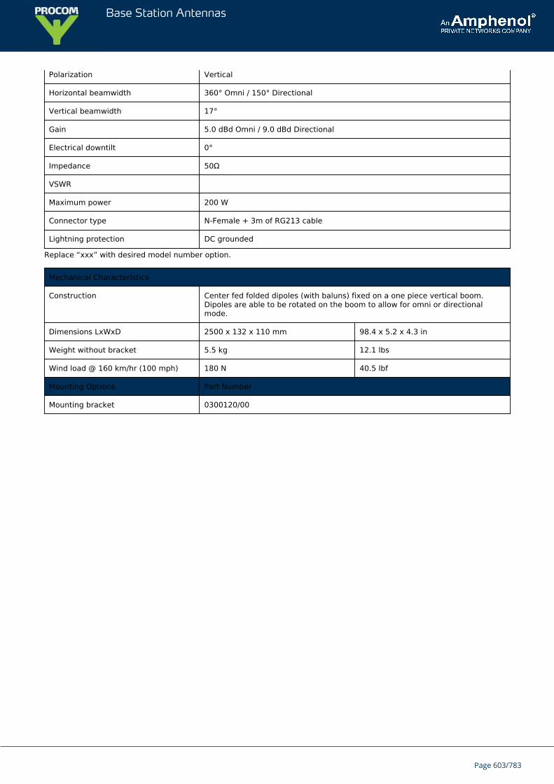
Base Station Antennas
Polarization Vertical
Horizontal beamwidth 360° Omni / 150° Directional
Vertical beamwidth 17°
Gain 5.0 dBd Omni / 9.0 dBd Directional
Electrical downtilt 0°
Impedance 50Ω
VSWR
Maximum power 200 W
Connector type N-Female + 3m of RG213 cable
Lightning protection DC grounded
Replace “xxx” with desired model number option.
Mechanical Characteristics
Construction Center fed folded dipoles (with baluns) fixed on a one piece vertical boom.Dipoles are able to be rotated on the boom to allow for omni or directionalmode.
Dimensions LxWxD 2500 x 132 x 110 mm 98.4 x 5.2 x 4.3 in
Weight without bracket 5.5 kg 12.1 lbs
Wind load @ 160 km/hr (100 mph) 180 N 40.5 lbf
Mounting Options Part Number
Mounting bracket 0300120/00
Page 603/783
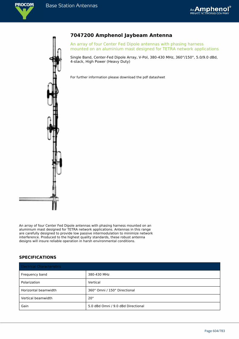
Base Station Antennas
7047200 Amphenol Jaybeam AntennaAn array of four Center Fed Dipole antennas with phasing harnessmounted on an aluminium mast designed for TETRA network applications
Single Band, Center-Fed Dipole Array, V-Pol, 380-430 MHz, 360°/150°, 5.0/9.0 dBd,4-stack, High Power (Heavy Duty)
For further information please download the pdf datasheet
An array of four Center Fed Dipole antennas with phasing harness mounted on analuminium mast designed for TETRA network applications. Antennas in this rangeare carefully designed to provide low passive intermodulation to minimize networkinterference. Produced to the highest quality standards, these robust antennadesigns will insure reliable operation in harsh environmental conditions.
SPECIFICATIONS
Electrical Characteristics
Frequency band 380-430 MHz
Polarization Vertical
Horizontal beamwidth 360° Omni / 150° Directional
Vertical beamwidth 20°
Gain 5.0 dBd Omni / 9.0 dBd Directional
Page 604/783
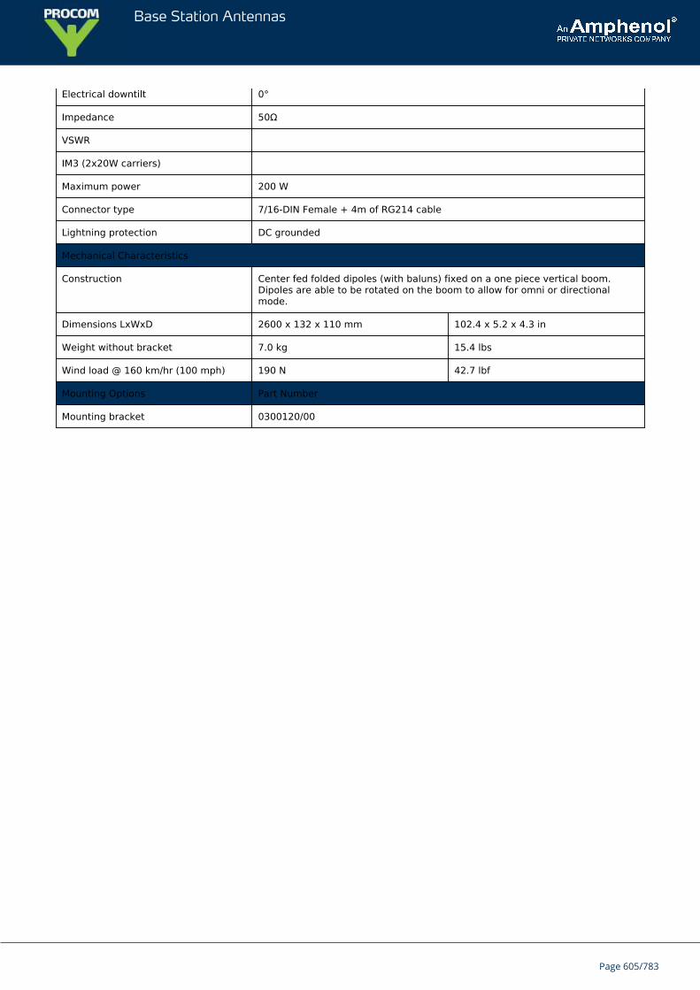
Base Station Antennas
Electrical downtilt 0°
Impedance 50Ω
VSWR
IM3 (2x20W carriers)
Maximum power 200 W
Connector type 7/16-DIN Female + 4m of RG214 cable
Lightning protection DC grounded
Mechanical Characteristics
Construction Center fed folded dipoles (with baluns) fixed on a one piece vertical boom.Dipoles are able to be rotated on the boom to allow for omni or directionalmode.
Dimensions LxWxD 2600 x 132 x 110 mm 102.4 x 5.2 x 4.3 in
Weight without bracket 7.0 kg 15.4 lbs
Wind load @ 160 km/hr (100 mph) 190 N 42.7 lbf
Mounting Options Part Number
Mounting bracket 0300120/00
Page 605/783
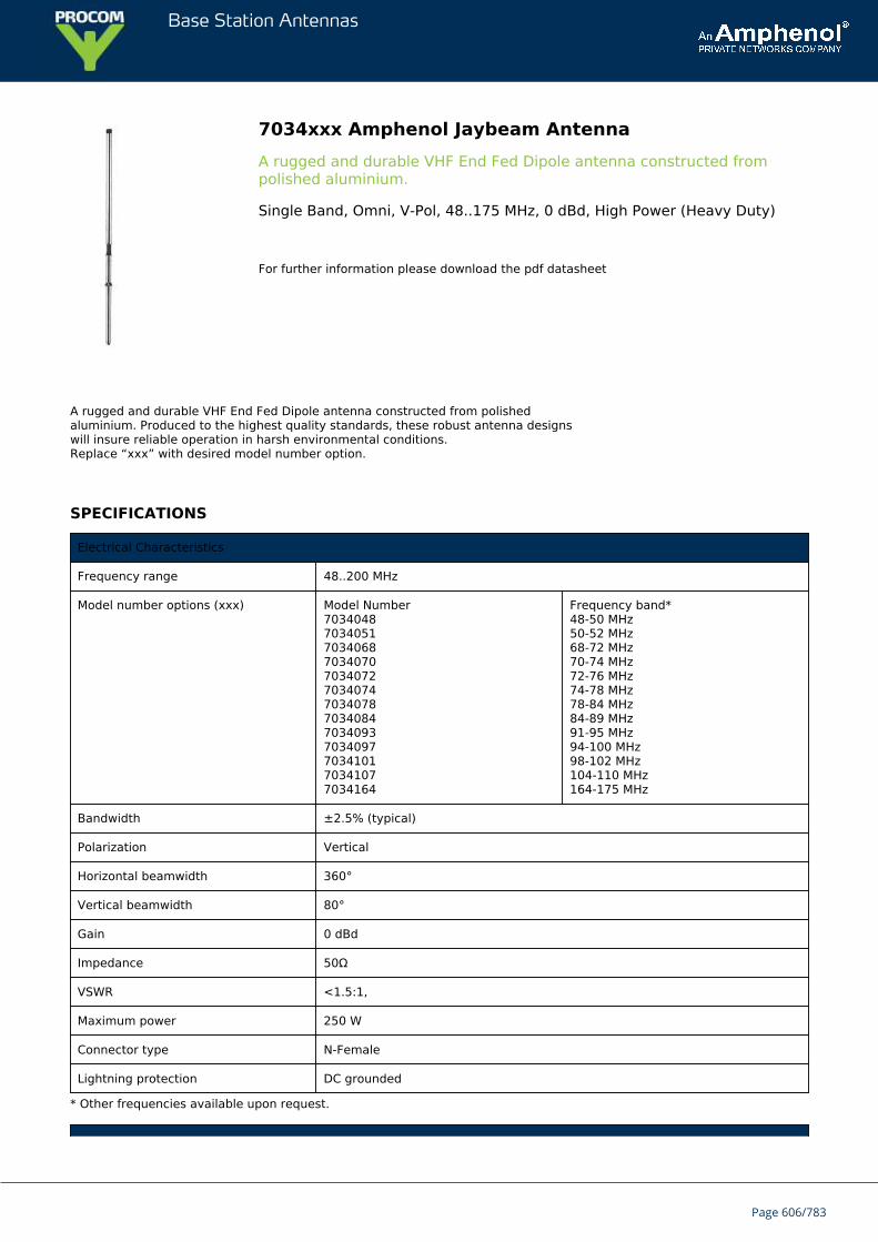
Base Station Antennas
7034xxx Amphenol Jaybeam AntennaA rugged and durable VHF End Fed Dipole antenna constructed frompolished aluminium.
Single Band, Omni, V-Pol, 48..175 MHz, 0 dBd, High Power (Heavy Duty)
For further information please download the pdf datasheet
A rugged and durable VHF End Fed Dipole antenna constructed from polishedaluminium. Produced to the highest quality standards, these robust antenna designswill insure reliable operation in harsh environmental conditions.Replace “xxx” with desired model number option.
SPECIFICATIONS
Electrical Characteristics
Frequency range 48..200 MHz
Model number options (xxx) Model Number7034048703405170340687034070703407270340747034078703408470340937034097703410170341077034164
Frequency band*48-50 MHz50-52 MHz68-72 MHz70-74 MHz72-76 MHz74-78 MHz78-84 MHz84-89 MHz91-95 MHz94-100 MHz98-102 MHz104-110 MHz164-175 MHz
Bandwidth ±2.5% (typical)
Polarization Vertical
Horizontal beamwidth 360°
Vertical beamwidth 80°
Gain 0 dBd
Impedance 50Ω
VSWR <1.5:1,
Maximum power 250 W
Connector type N-Female
Lightning protection DC grounded
* Other frequencies available upon request.
Page 606/783
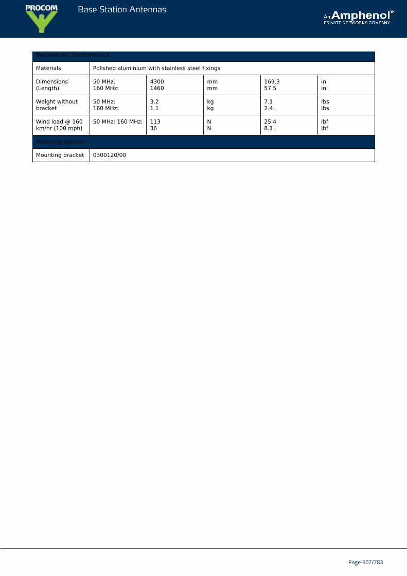
Base Station Antennas
Mechanical Characteristics
Materials Polished aluminium with stainless steel fixings
Dimensions(Length)
50 MHz:160 MHz:
43001460
mmmm
169.357.5
inin
Weight withoutbracket
50 MHz:160 MHz:
3.21.1
kgkg
7.12.4
lbslbs
Wind load @ 160km/hr (100 mph)
50 MHz: 160 MHz: 11336
NN
25.48.1
lbflbf
Mounting Options
Mounting bracket 0300120/00
Page 607/783
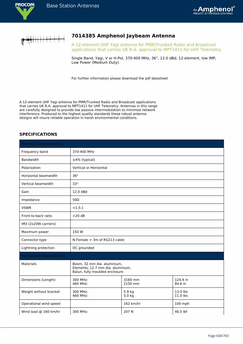
Base Station Antennas
7014385 Amphenol Jaybeam AntennaA 12-element UHF Yagi antenna for PMR/Trunked Radio and Broadcastapplications that carries UK R.A. approval to MPT1411 for UHF Telemetry
Single Band, Yagi, V or H-Pol, 370-400 MHz, 36°, 12.0 dBd, 12-element, low IMP,Low Power (Medium Duty)
For further information please download the pdf datasheet
A 12-element UHF Yagi antenna for PMR/Trunked Radio and Broadcast applicationsthat carries UK R.A. approval to MPT1411 for UHF Telemetry. Antennas in this rangeare carefully designed to provide low passive intermodulation to minimize networkinterference. Produced to the highest quality standards these robust antennadesigns will insure reliable operation in harsh environmental conditions.
SPECIFICATIONS
Electrical Characteristics
Frequency band 370-400 MHz
Bandwidth ±4% (typical)
Polarization Vertical or Horizontal
Horizontal beamwidth 36°
Vertical beamwidth 33°
Gain 12.0 dBd
Impedance 50Ω
VSWR <1.5:1
Front-to-back ratio >20 dB
IM3 (2x20W carriers)
Maximum power 150 W
Connector type N-Female + 3m of RG213 cable
Lightning protection DC grounded
Mechanical Characteristics
Materials Boom, 32 mm dia. aluminium,Elements, 12.7 mm dia. aluminium,Balun, fully moulded enclosure
Dimensions (Length) 300 MHz:460 MHz:
3160 mm2150 mm
124.4 in84.6 in
Weight without bracket 300 MHz:460 MHz:
5.9 kg5.0 kg
13.0 lbs11.0 lbs
Operational wind speed 162 km/hr 100 mph
Wind load @ 160 km/hr 300 MHz: 207 N 46.5 lbf
Page 608/783
Base Station Antennas
(100 mph) 460 MHz: 140 N 31.5 lbf
Mounting Options
Mounting bracket 3202078/68 + 3201079/00
Alternate mounting brackets 0900912/00, 0302032/68, or 0300064/00+ U-Bolts to match mounting pipe diameter
Mounting accessory(optional)
0900018/00 Trombone 2-point mount
Page 609/783
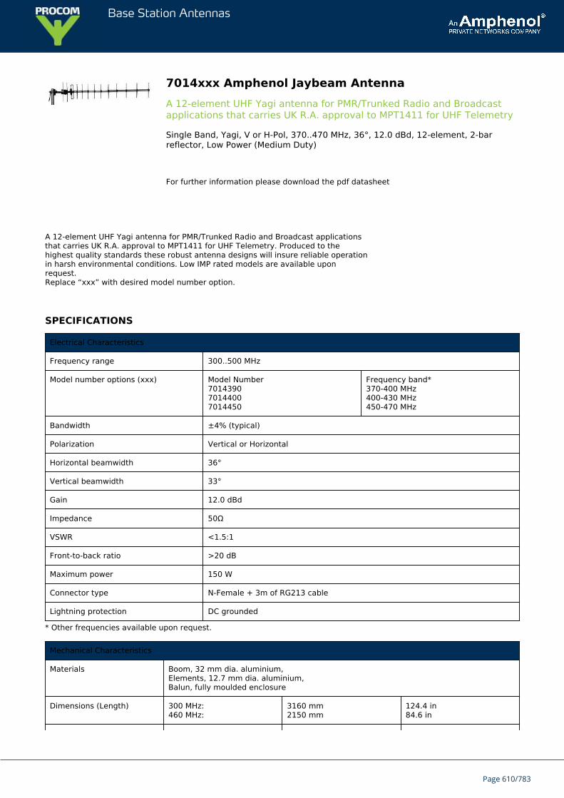
Base Station Antennas
7014xxx Amphenol Jaybeam AntennaA 12-element UHF Yagi antenna for PMR/Trunked Radio and Broadcastapplications that carries UK R.A. approval to MPT1411 for UHF Telemetry
Single Band, Yagi, V or H-Pol, 370..470 MHz, 36°, 12.0 dBd, 12-element, 2-barreflector, Low Power (Medium Duty)
For further information please download the pdf datasheet
A 12-element UHF Yagi antenna for PMR/Trunked Radio and Broadcast applicationsthat carries UK R.A. approval to MPT1411 for UHF Telemetry. Produced to thehighest quality standards these robust antenna designs will insure reliable operationin harsh environmental conditions. Low IMP rated models are available uponrequest.Replace “xxx” with desired model number option.
SPECIFICATIONS
Electrical Characteristics
Frequency range 300..500 MHz
Model number options (xxx) Model Number701439070144007014450
Frequency band*370-400 MHz400-430 MHz450-470 MHz
Bandwidth ±4% (typical)
Polarization Vertical or Horizontal
Horizontal beamwidth 36°
Vertical beamwidth 33°
Gain 12.0 dBd
Impedance 50Ω
VSWR <1.5:1
Front-to-back ratio >20 dB
Maximum power 150 W
Connector type N-Female + 3m of RG213 cable
Lightning protection DC grounded
* Other frequencies available upon request.
Mechanical Characteristics
Materials Boom, 32 mm dia. aluminium,Elements, 12.7 mm dia. aluminium,Balun, fully moulded enclosure
Dimensions (Length) 300 MHz:460 MHz:
3160 mm2150 mm
124.4 in84.6 in
Page 610/783
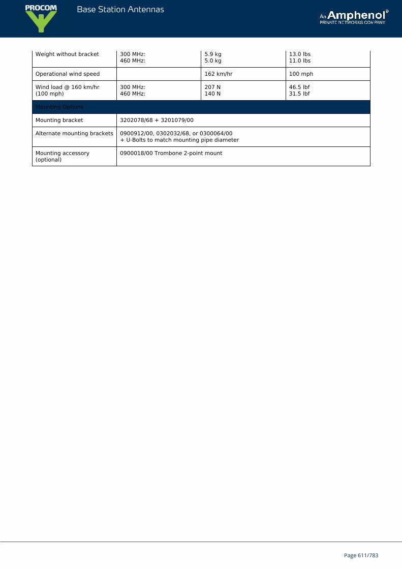
Base Station Antennas
Weight without bracket 300 MHz:460 MHz:
5.9 kg5.0 kg
13.0 lbs11.0 lbs
Operational wind speed 162 km/hr 100 mph
Wind load @ 160 km/hr(100 mph)
300 MHz:460 MHz:
207 N140 N
46.5 lbf31.5 lbf
Mounting Options
Mounting bracket 3202078/68 + 3201079/00
Alternate mounting brackets 0900912/00, 0302032/68, or 0300064/00+ U-Bolts to match mounting pipe diameter
Mounting accessory(optional)
0900018/00 Trombone 2-point mount
Page 611/783
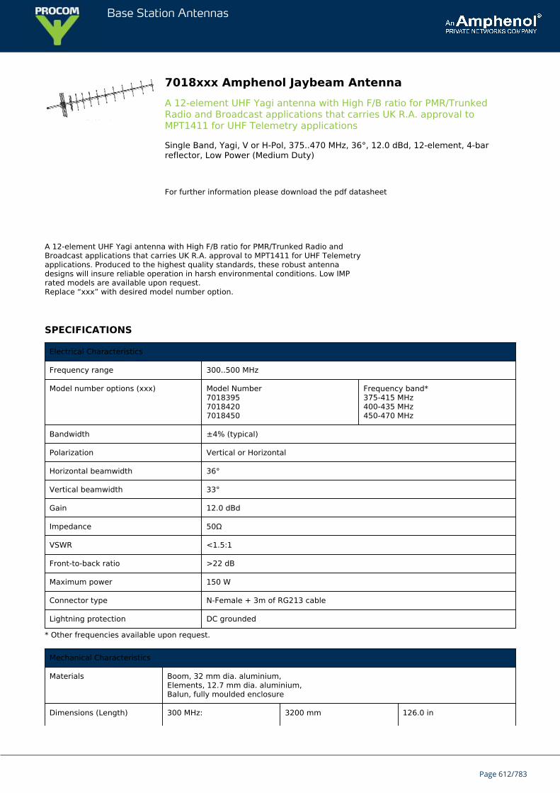
Base Station Antennas
7018xxx Amphenol Jaybeam AntennaA 12-element UHF Yagi antenna with High F/B ratio for PMR/TrunkedRadio and Broadcast applications that carries UK R.A. approval toMPT1411 for UHF Telemetry applications
Single Band, Yagi, V or H-Pol, 375..470 MHz, 36°, 12.0 dBd, 12-element, 4-barreflector, Low Power (Medium Duty)
For further information please download the pdf datasheet
A 12-element UHF Yagi antenna with High F/B ratio for PMR/Trunked Radio andBroadcast applications that carries UK R.A. approval to MPT1411 for UHF Telemetryapplications. Produced to the highest quality standards, these robust antennadesigns will insure reliable operation in harsh environmental conditions. Low IMPrated models are available upon request.Replace “xxx” with desired model number option.
SPECIFICATIONS
Electrical Characteristics
Frequency range 300..500 MHz
Model number options (xxx) Model Number701839570184207018450
Frequency band*375-415 MHz400-435 MHz450-470 MHz
Bandwidth ±4% (typical)
Polarization Vertical or Horizontal
Horizontal beamwidth 36°
Vertical beamwidth 33°
Gain 12.0 dBd
Impedance 50Ω
VSWR <1.5:1
Front-to-back ratio >22 dB
Maximum power 150 W
Connector type N-Female + 3m of RG213 cable
Lightning protection DC grounded
* Other frequencies available upon request.
Mechanical Characteristics
Materials Boom, 32 mm dia. aluminium,Elements, 12.7 mm dia. aluminium,Balun, fully moulded enclosure
Dimensions (Length) 300 MHz: 3200 mm 126.0 in
Page 612/783
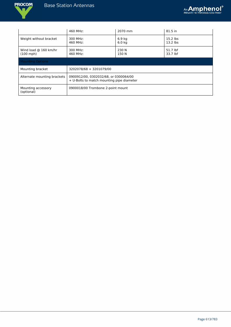
Base Station Antennas
460 MHz: 2070 mm 81.5 in
Weight without bracket 300 MHz:460 MHz:
6.9 kg6.0 kg
15.2 lbs13.2 lbs
Wind load @ 160 km/hr(100 mph)
300 MHz:460 MHz:
230 N150 N
51.7 lbf33.7 lbf
Mounting Options
Mounting bracket 3202078/68 + 3201079/00
Alternate mounting brackets 0900912/00, 0302032/68, or 0300064/00+ U-Bolts to match mounting pipe diameter
Mounting accessory(optional)
0900018/00 Trombone 2-point mount
Page 613/783
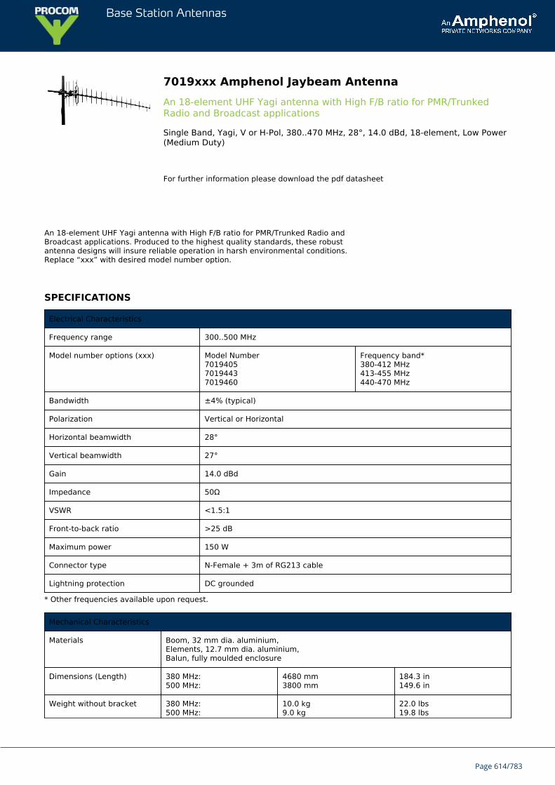
Base Station Antennas
7019xxx Amphenol Jaybeam AntennaAn 18-element UHF Yagi antenna with High F/B ratio for PMR/TrunkedRadio and Broadcast applications
Single Band, Yagi, V or H-Pol, 380..470 MHz, 28°, 14.0 dBd, 18-element, Low Power(Medium Duty)
For further information please download the pdf datasheet
An 18-element UHF Yagi antenna with High F/B ratio for PMR/Trunked Radio andBroadcast applications. Produced to the highest quality standards, these robustantenna designs will insure reliable operation in harsh environmental conditions.Replace “xxx” with desired model number option.
SPECIFICATIONS
Electrical Characteristics
Frequency range 300..500 MHz
Model number options (xxx) Model Number701940570194437019460
Frequency band*380-412 MHz413-455 MHz440-470 MHz
Bandwidth ±4% (typical)
Polarization Vertical or Horizontal
Horizontal beamwidth 28°
Vertical beamwidth 27°
Gain 14.0 dBd
Impedance 50Ω
VSWR <1.5:1
Front-to-back ratio >25 dB
Maximum power 150 W
Connector type N-Female + 3m of RG213 cable
Lightning protection DC grounded
* Other frequencies available upon request.
Mechanical Characteristics
Materials Boom, 32 mm dia. aluminium,Elements, 12.7 mm dia. aluminium,Balun, fully moulded enclosure
Dimensions (Length) 380 MHz:500 MHz:
4680 mm3800 mm
184.3 in149.6 in
Weight without bracket 380 MHz:500 MHz:
10.0 kg9.0 kg
22.0 lbs19.8 lbs
Page 614/783
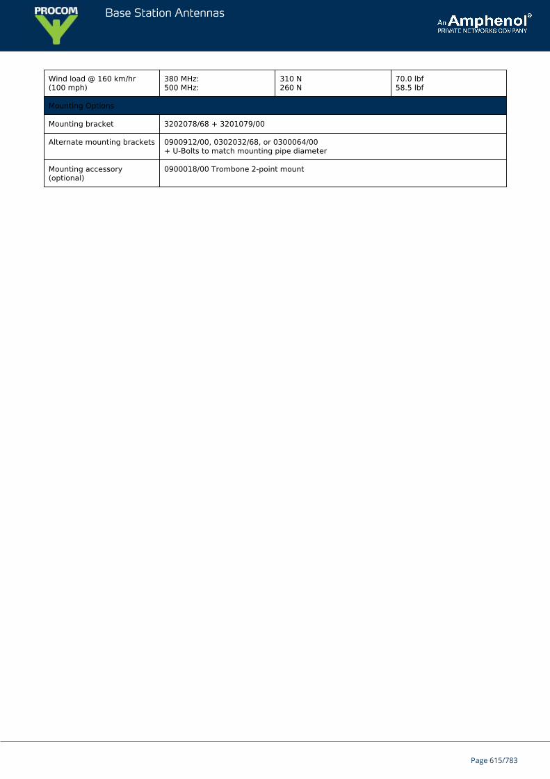
Base Station Antennas
Wind load @ 160 km/hr(100 mph)
380 MHz:500 MHz:
310 N260 N
70.0 lbf58.5 lbf
Mounting Options
Mounting bracket 3202078/68 + 3201079/00
Alternate mounting brackets 0900912/00, 0302032/68, or 0300064/00+ U-Bolts to match mounting pipe diameter
Mounting accessory(optional)
0900018/00 Trombone 2-point mount
Page 615/783
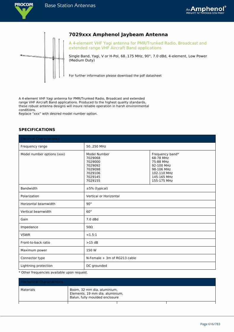
Base Station Antennas
7029xxx Amphenol Jaybeam AntennaA 4-element VHF Yagi antenna for PMR/Trunked Radio, Broadcast andextended range VHF Aircraft Band applications
Single Band, Yagi, V or H-Pol, 68..175 MHz, 90°, 7.0 dBd, 4-element, Low Power(Medium Duty)
For further information please download the pdf datasheet
A 4-element VHF Yagi antenna for PMR/Trunked Radio, Broadcast and extendedrange VHF Aircraft Band applications. Produced to the highest quality standards,these robust antenna designs will insure reliable operation in harsh environmentalconditions.Replace “xxx” with desired model number option.
SPECIFICATIONS
Electrical Characteristics
Frequency range 50..250 MHz
Model number options (xxx) Model Number7029068702900070290927029098702910670291457029155
Frequency band*68-78 MHz75-88 MHz92-100 MHz98-106 MHz102-110 MHz145-165 MHz155-175 MHz
Bandwidth ±5% (typical)
Polarization Vertical or Horizontal
Horizontal beamwidth 90°
Vertical beamwidth 60°
Gain 7.0 dBd
Impedance 50Ω
VSWR <1.5:1
Front-to-back ratio >15 dB
Maximum power 150 W
Connector type N-Female + 3m of RG213 cable
Lightning protection DC grounded
* Other frequencies available upon request.
Mechanical Characteristics
Materials Boom, 32 mm dia. aluminium,Elements, 19 mm dia. aluminium,Balun, fully moulded enclosure
Page 616/783
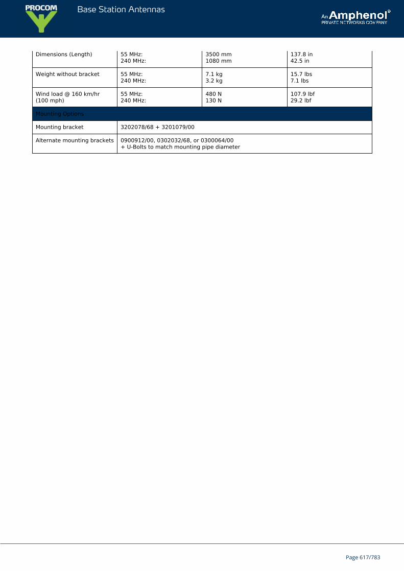
Base Station Antennas
Dimensions (Length) 55 MHz:240 MHz:
3500 mm1080 mm
137.8 in42.5 in
Weight without bracket 55 MHz:240 MHz:
7.1 kg3.2 kg
15.7 lbs7.1 lbs
Wind load @ 160 km/hr(100 mph)
55 MHz:240 MHz:
480 N130 N
107.9 lbf29.2 lbf
Mounting Options
Mounting bracket 3202078/68 + 3201079/00
Alternate mounting brackets 0900912/00, 0302032/68, or 0300064/00+ U-Bolts to match mounting pipe diameter
Page 617/783
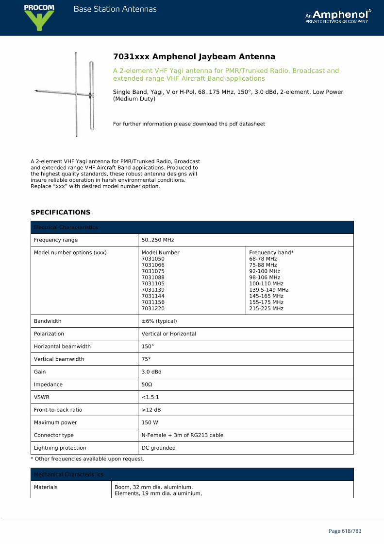
Base Station Antennas
7031xxx Amphenol Jaybeam AntennaA 2-element VHF Yagi antenna for PMR/Trunked Radio, Broadcast andextended range VHF Aircraft Band applications
Single Band, Yagi, V or H-Pol, 68..175 MHz, 150°, 3.0 dBd, 2-element, Low Power(Medium Duty)
For further information please download the pdf datasheet
A 2-element VHF Yagi antenna for PMR/Trunked Radio, Broadcastand extended range VHF Aircraft Band applications. Produced tothe highest quality standards, these robust antenna designs willinsure reliable operation in harsh environmental conditions.Replace “xxx” with desired model number option.
SPECIFICATIONS
Electrical Characteristics
Frequency range 50..250 MHz
Model number options (xxx) Model Number703105070310667031075703108870311057031139703114470311567031220
Frequency band*68-78 MHz75-88 MHz92-100 MHz98-106 MHz100-110 MHz139.5-149 MHz145-165 MHz155-175 MHz215-225 MHz
Bandwidth ±6% (typical)
Polarization Vertical or Horizontal
Horizontal beamwidth 150°
Vertical beamwidth 75°
Gain 3.0 dBd
Impedance 50Ω
VSWR <1.5:1
Front-to-back ratio >12 dB
Maximum power 150 W
Connector type N-Female + 3m of RG213 cable
Lightning protection DC grounded
* Other frequencies available upon request.
Mechanical Characteristics
Materials Boom, 32 mm dia. aluminium,Elements, 19 mm dia. aluminium,
Page 618/783
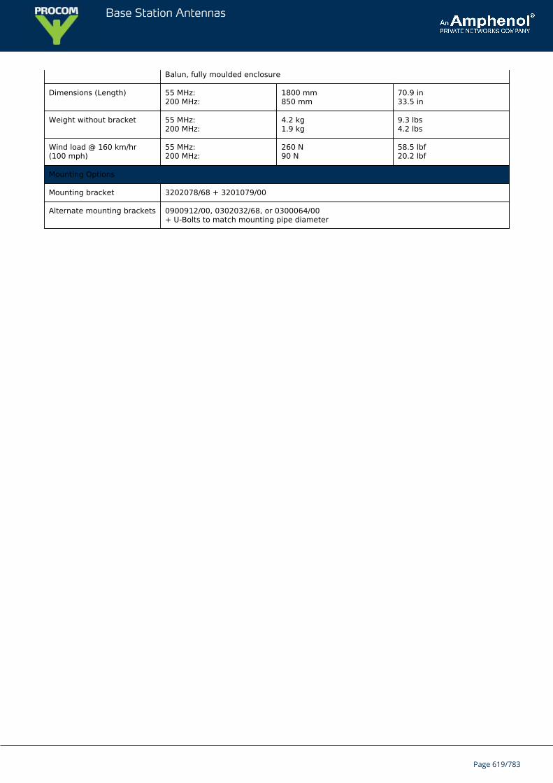
Base Station Antennas
Balun, fully moulded enclosure
Dimensions (Length) 55 MHz:200 MHz:
1800 mm850 mm
70.9 in33.5 in
Weight without bracket 55 MHz:200 MHz:
4.2 kg1.9 kg
9.3 lbs4.2 lbs
Wind load @ 160 km/hr(100 mph)
55 MHz:200 MHz:
260 N90 N
58.5 lbf20.2 lbf
Mounting Options
Mounting bracket 3202078/68 + 3201079/00
Alternate mounting brackets 0900912/00, 0302032/68, or 0300064/00+ U-Bolts to match mounting pipe diameter
Page 619/783
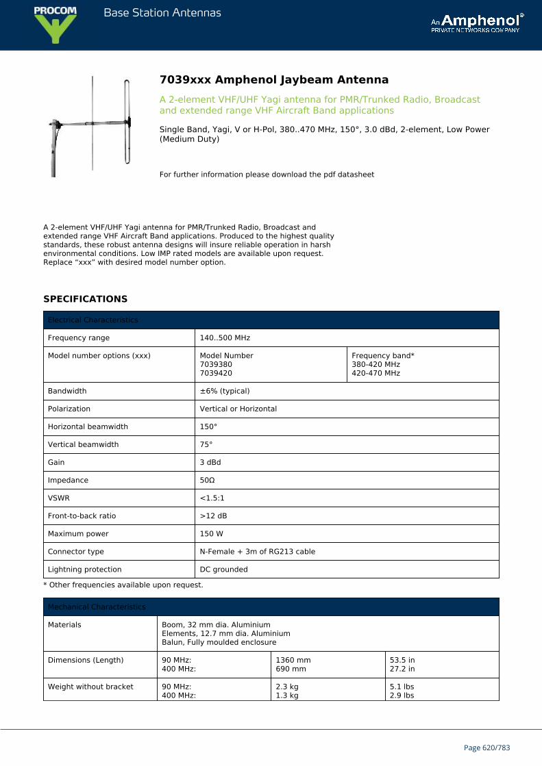
Base Station Antennas
7039xxx Amphenol Jaybeam AntennaA 2-element VHF/UHF Yagi antenna for PMR/Trunked Radio, Broadcastand extended range VHF Aircraft Band applications
Single Band, Yagi, V or H-Pol, 380..470 MHz, 150°, 3.0 dBd, 2-element, Low Power(Medium Duty)
For further information please download the pdf datasheet
A 2-element VHF/UHF Yagi antenna for PMR/Trunked Radio, Broadcast andextended range VHF Aircraft Band applications. Produced to the highest qualitystandards, these robust antenna designs will insure reliable operation in harshenvironmental conditions. Low IMP rated models are available upon request.Replace “xxx” with desired model number option.
SPECIFICATIONS
Electrical Characteristics
Frequency range 140..500 MHz
Model number options (xxx) Model Number70393807039420
Frequency band*380-420 MHz420-470 MHz
Bandwidth ±6% (typical)
Polarization Vertical or Horizontal
Horizontal beamwidth 150°
Vertical beamwidth 75°
Gain 3 dBd
Impedance 50Ω
VSWR <1.5:1
Front-to-back ratio >12 dB
Maximum power 150 W
Connector type N-Female + 3m of RG213 cable
Lightning protection DC grounded
* Other frequencies available upon request.
Mechanical Characteristics
Materials Boom, 32 mm dia. AluminiumElements, 12.7 mm dia. AluminiumBalun, Fully moulded enclosure
Dimensions (Length) 90 MHz:400 MHz:
1360 mm690 mm
53.5 in27.2 in
Weight without bracket 90 MHz:400 MHz:
2.3 kg1.3 kg
5.1 lbs2.9 lbs
Page 620/783
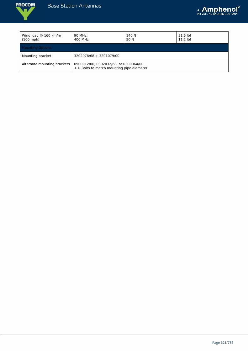
Base Station Antennas
Wind load @ 160 km/hr(100 mph)
90 MHz:400 MHz:
140 N50 N
31.5 lbf11.2 lbf
Mounting Options
Mounting bracket 3202078/68 + 3201079/00
Alternate mounting brackets 0900912/00, 0302032/68, or 0300064/00+ U-Bolts to match mounting pipe diameter
Page 621/783
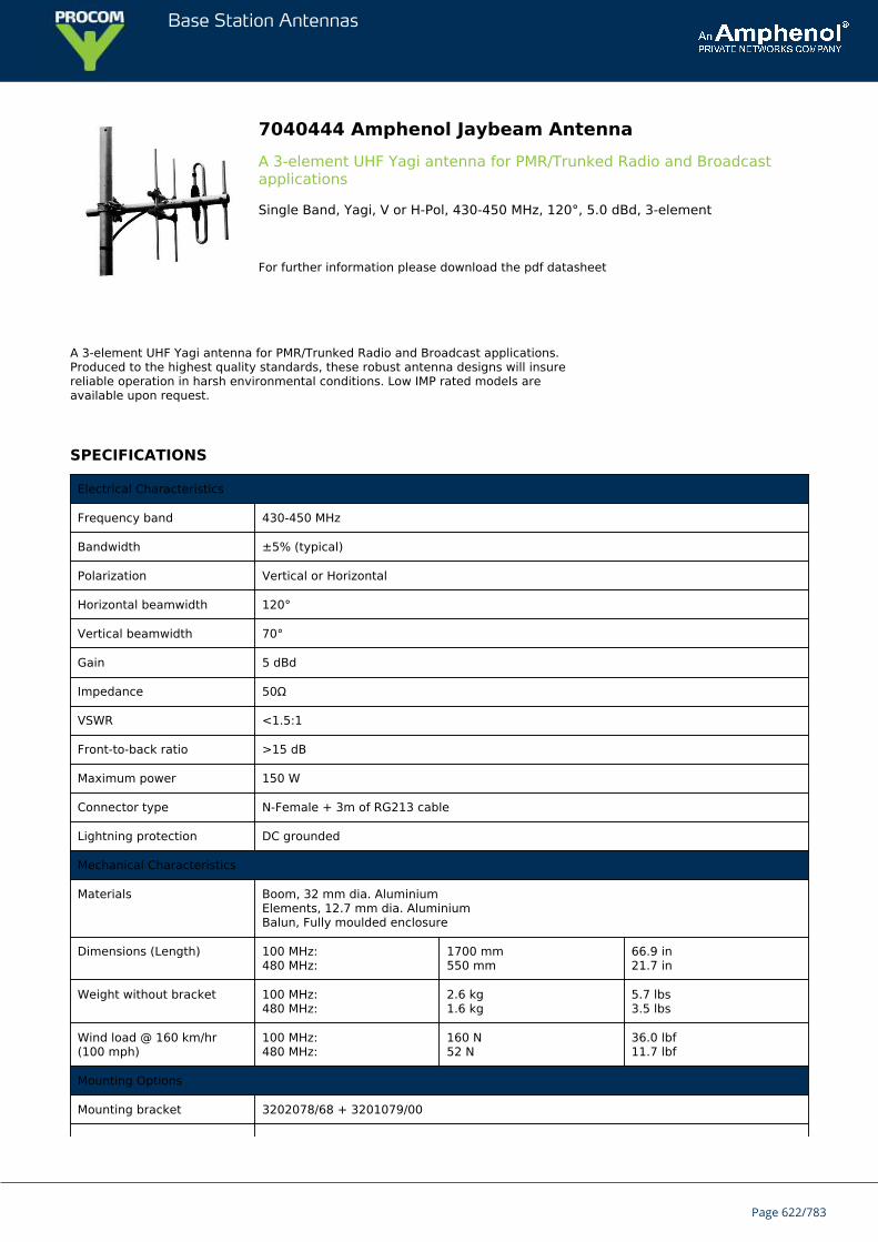
Base Station Antennas
7040444 Amphenol Jaybeam AntennaA 3-element UHF Yagi antenna for PMR/Trunked Radio and Broadcastapplications
Single Band, Yagi, V or H-Pol, 430-450 MHz, 120°, 5.0 dBd, 3-element
For further information please download the pdf datasheet
A 3-element UHF Yagi antenna for PMR/Trunked Radio and Broadcast applications.Produced to the highest quality standards, these robust antenna designs will insurereliable operation in harsh environmental conditions. Low IMP rated models areavailable upon request.
SPECIFICATIONS
Electrical Characteristics
Frequency band 430-450 MHz
Bandwidth ±5% (typical)
Polarization Vertical or Horizontal
Horizontal beamwidth 120°
Vertical beamwidth 70°
Gain 5 dBd
Impedance 50Ω
VSWR <1.5:1
Front-to-back ratio >15 dB
Maximum power 150 W
Connector type N-Female + 3m of RG213 cable
Lightning protection DC grounded
Mechanical Characteristics
Materials Boom, 32 mm dia. AluminiumElements, 12.7 mm dia. AluminiumBalun, Fully moulded enclosure
Dimensions (Length) 100 MHz:480 MHz:
1700 mm550 mm
66.9 in21.7 in
Weight without bracket 100 MHz:480 MHz:
2.6 kg1.6 kg
5.7 lbs3.5 lbs
Wind load @ 160 km/hr(100 mph)
100 MHz:480 MHz:
160 N52 N
36.0 lbf11.7 lbf
Mounting Options
Mounting bracket 3202078/68 + 3201079/00
Page 622/783

Base Station Antennas
Alternate mounting brackets 0900912/00, 0302032/68, or 0300064/00+ U-Bolts to match mounting pipe diameter
Page 623/783
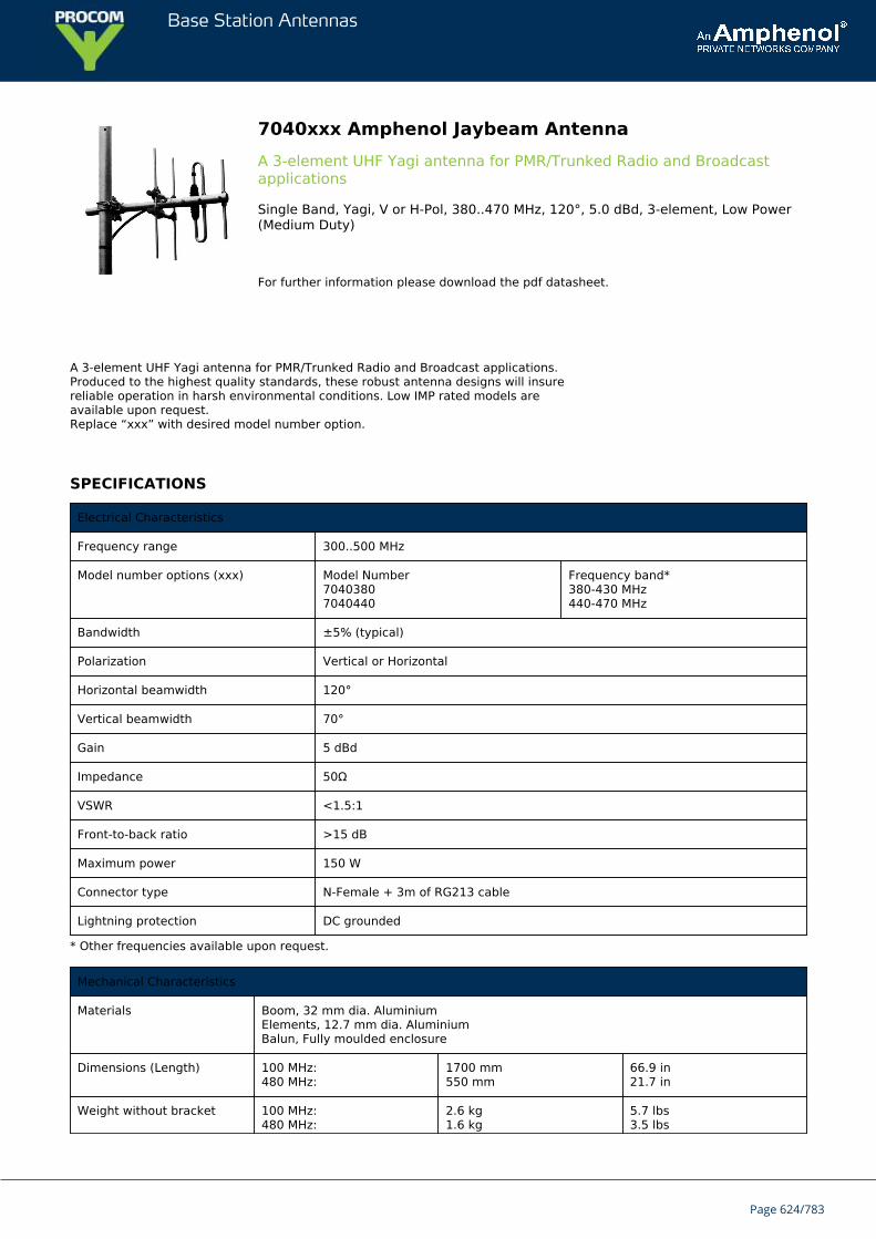
Base Station Antennas
7040xxx Amphenol Jaybeam AntennaA 3-element UHF Yagi antenna for PMR/Trunked Radio and Broadcastapplications
Single Band, Yagi, V or H-Pol, 380..470 MHz, 120°, 5.0 dBd, 3-element, Low Power(Medium Duty)
For further information please download the pdf datasheet.
A 3-element UHF Yagi antenna for PMR/Trunked Radio and Broadcast applications.Produced to the highest quality standards, these robust antenna designs will insurereliable operation in harsh environmental conditions. Low IMP rated models areavailable upon request.Replace “xxx” with desired model number option.
SPECIFICATIONS
Electrical Characteristics
Frequency range 300..500 MHz
Model number options (xxx) Model Number70403807040440
Frequency band*380-430 MHz440-470 MHz
Bandwidth ±5% (typical)
Polarization Vertical or Horizontal
Horizontal beamwidth 120°
Vertical beamwidth 70°
Gain 5 dBd
Impedance 50Ω
VSWR <1.5:1
Front-to-back ratio >15 dB
Maximum power 150 W
Connector type N-Female + 3m of RG213 cable
Lightning protection DC grounded
* Other frequencies available upon request.
Mechanical Characteristics
Materials Boom, 32 mm dia. AluminiumElements, 12.7 mm dia. AluminiumBalun, Fully moulded enclosure
Dimensions (Length) 100 MHz:480 MHz:
1700 mm550 mm
66.9 in21.7 in
Weight without bracket 100 MHz:480 MHz:
2.6 kg1.6 kg
5.7 lbs3.5 lbs
Page 624/783

Base Station Antennas
Wind load @ 160 km/hr(100 mph)
100 MHz:480 MHz:
160 N52 N
36.0 lbf11.7 lbf
Mounting Options
Mounting bracket 3202078/68 + 3201079/00
Alternate mounting brackets 0900912/00, 0302032/68, or 0300064/00+ U-Bolts to match mounting pipe diameter
Page 625/783
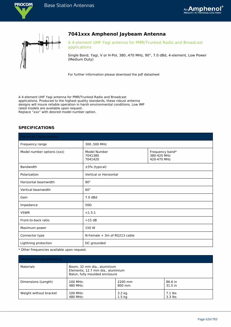
Base Station Antennas
7041xxx Amphenol Jaybeam AntennaA 4-element UHF Yagi antenna for PMR/Trunked Radio and Broadcastapplications
Single Band, Yagi, V or H-Pol, 380..470 MHz, 90°, 7.0 dBd, 4-element, Low Power(Medium Duty)
For further information please download the pdf datasheet
A 4-element UHF Yagi antenna for PMR/Trunked Radio and Broadcastapplications. Produced to the highest quality standards, these robust antennadesigns will insure reliable operation in harsh environmental conditions. Low IMPrated models are available upon request.Replace “xxx” with desired model number option.
SPECIFICATIONS
Electrical Characteristics
Frequency range 300..500 MHz
Model number options (xxx) Model Number70413807041420
Frequency band*380-420 MHz420-470 MHz
Bandwidth ±5% (typical)
Polarization Vertical or Horizontal
Horizontal beamwidth 90°
Vertical beamwidth 60°
Gain 7.0 dBd
Impedance 50Ω
VSWR <1.5:1
Front-to-back ratio >15 dB
Maximum power 150 W
Connector type N-Female + 3m of RG213 cable
Lightning protection DC grounded
* Other frequencies available upon request.
Mechanical Characteristics
Materials Boom, 32 mm dia., aluminiumElements, 12.7 mm dia., aluminiumBalun, fully moulded enclosure
Dimensions (Length) 100 MHz:480 MHz:
2200 mm800 mm
86.6 in31.5 in
Weight without bracket 100 MHz:480 MHz:
3.2 kg1.5 kg
7.1 lbs3.3 lbs
Page 626/783

Base Station Antennas
Wind load @ 160 km/hr(100 mph)
100 MHz:480 MHz:
204 N65 N
45.9 lbf14.6 lbf
Mounting Options Part Number
Mounting bracket 3202078/68 + 3201079/00
Alternate mounting brackets 0900912/00, 0302032/68, or 0300064/00+ U-bolts to match mounting pipe diameter
Page 627/783
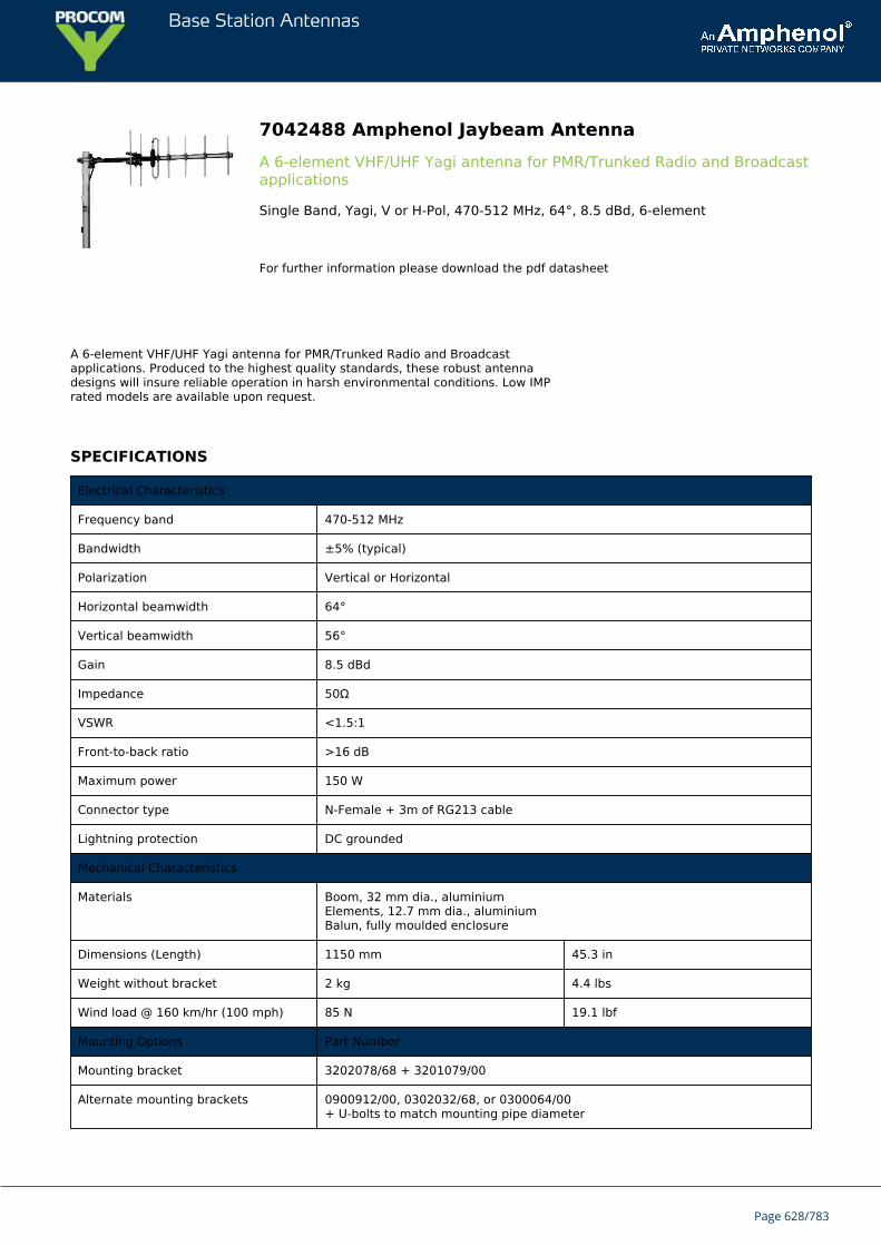
Base Station Antennas
7042488 Amphenol Jaybeam AntennaA 6-element VHF/UHF Yagi antenna for PMR/Trunked Radio and Broadcastapplications
Single Band, Yagi, V or H-Pol, 470-512 MHz, 64°, 8.5 dBd, 6-element
For further information please download the pdf datasheet
A 6-element VHF/UHF Yagi antenna for PMR/Trunked Radio and Broadcastapplications. Produced to the highest quality standards, these robust antennadesigns will insure reliable operation in harsh environmental conditions. Low IMPrated models are available upon request.
SPECIFICATIONS
Electrical Characteristics
Frequency band 470-512 MHz
Bandwidth ±5% (typical)
Polarization Vertical or Horizontal
Horizontal beamwidth 64°
Vertical beamwidth 56°
Gain 8.5 dBd
Impedance 50Ω
VSWR <1.5:1
Front-to-back ratio >16 dB
Maximum power 150 W
Connector type N-Female + 3m of RG213 cable
Lightning protection DC grounded
Mechanical Characteristics
Materials Boom, 32 mm dia., aluminiumElements, 12.7 mm dia., aluminiumBalun, fully moulded enclosure
Dimensions (Length) 1150 mm 45.3 in
Weight without bracket 2 kg 4.4 lbs
Wind load @ 160 km/hr (100 mph) 85 N 19.1 lbf
Mounting Options Part Number
Mounting bracket 3202078/68 + 3201079/00
Alternate mounting brackets 0900912/00, 0302032/68, or 0300064/00+ U-bolts to match mounting pipe diameter
Page 628/783

Base Station Antennas
Page 629/783
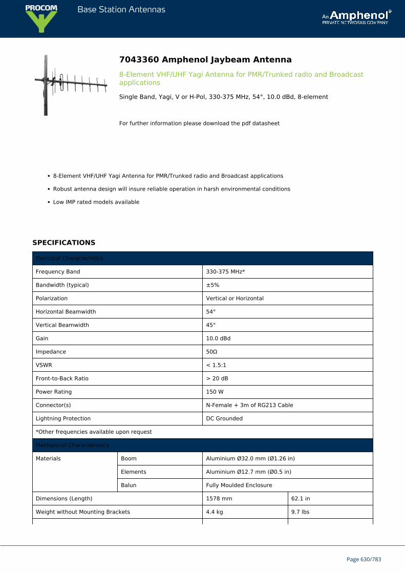
Base Station Antennas
7043360 Amphenol Jaybeam Antenna8-Element VHF/UHF Yagi Antenna for PMR/Trunked radio and Broadcastapplications
Single Band, Yagi, V or H-Pol, 330-375 MHz, 54°, 10.0 dBd, 8-element
For further information please download the pdf datasheet
8-Element VHF/UHF Yagi Antenna for PMR/Trunked radio and Broadcast applications
Robust antenna design will insure reliable operation in harsh environmental conditions
Low IMP rated models available
SPECIFICATIONS
Electrical Characteristics
Frequency Band 330-375 MHz*
Bandwidth (typical) ±5%
Polarization Vertical or Horizontal
Horizontal Beamwidth 54°
Vertical Beamwidth 45°
Gain 10.0 dBd
Impedance 50Ω
VSWR < 1.5:1
Front-to-Back Ratio > 20 dB
Power Rating 150 W
Connector(s) N-Female + 3m of RG213 Cable
Lightning Protection DC Grounded
*Other frequencies available upon request
Mechanical Characteristics
Materials Boom Aluminium Ø32.0 mm (Ø1.26 in)
Elements Aluminium Ø12.7 mm (Ø0.5 in)
Balun Fully Moulded Enclosure
Dimensions (Length) 1578 mm 62.1 in
Weight without Mounting Brackets 4.4 kg 9.7 lbs
Page 630/783
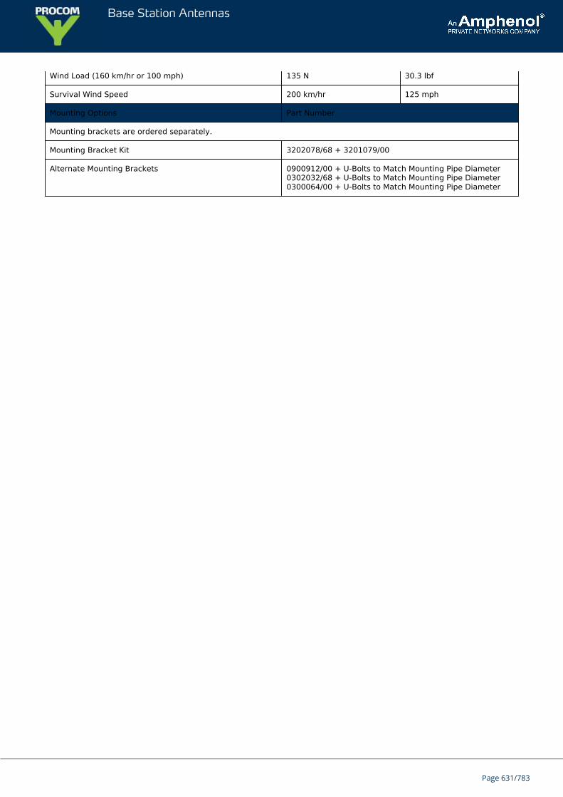
Base Station Antennas
Wind Load (160 km/hr or 100 mph) 135 N 30.3 lbf
Survival Wind Speed 200 km/hr 125 mph
Mounting Options Part Number
Mounting brackets are ordered separately.
Mounting Bracket Kit 3202078/68 + 3201079/00
Alternate Mounting Brackets 0900912/00 + U-Bolts to Match Mounting Pipe Diameter0302032/68 + U-Bolts to Match Mounting Pipe Diameter0300064/00 + U-Bolts to Match Mounting Pipe Diameter
Page 631/783
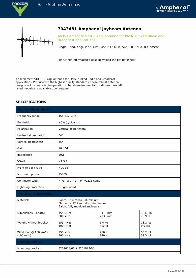
Base Station Antennas
7043481 Amphenol Jaybeam AntennaAn 8-element VHF/UHF Yagi antenna for PMR/Trunked Radio andBroadcast applications
Single Band, Yagi, V or H-Pol, 455-512 MHz, 54°, 10.0 dBd, 8-element
For further information please download the pdf datasheet
An 8-element VHF/UHF Yagi antenna for PMR/Trunked Radio and Broadcastapplications. Produced to the highest quality standards, these robust antennadesigns will insure reliable operation in harsh environmental conditions. Low IMPrated models are available upon request.
SPECIFICATIONS
Electrical Characteristics
Frequency range 455-512 MHz
Bandwidth ±5% (typical)
Polarization Vertical or Horizontal
Horizontal beamwidth 54°
Vertical beamwidth 45°
Gain 10 dBd
Impedance 50Ω
VSWR <1.5:1
Front-to-back ratio >20 dB
Maximum power 150 W
Connector type N-Female + 3m of RG213 cable
Lightning protection DC grounded
Mechanical Characteristics
Materials Boom, 32 mm dia., aluminiumElements, 12.7 mm dia., aluminiumBalun, fully moulded enclosure
Dimensions (Length) 155 MHz:300 MHz:
3410 mm2030 mm
134.3 in79.9 in
Weight without bracket 155 MHz:300 MHz:
6.0 kg4.5 kg
13.2 lbs9.9 lbs
Wind load @ 160 km/hr(100 mph)
155 MHz:300 MHz:
250 N140 N
56.2 lbf31.5 lbf
Mounting Options Part Number
Mounting bracket 3202078/68 + 3201079/00
Page 632/783

Base Station Antennas
Alternate mounting brackets 0900912/00, 0302032/68, or 0300064/00+ U-bolts to match mounting pipe diameter
Page 633/783
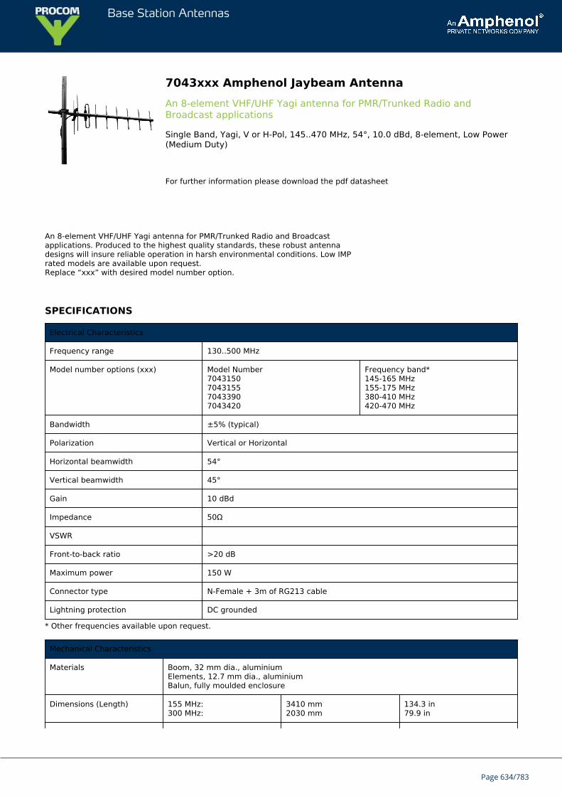
Base Station Antennas
7043xxx Amphenol Jaybeam AntennaAn 8-element VHF/UHF Yagi antenna for PMR/Trunked Radio andBroadcast applications
Single Band, Yagi, V or H-Pol, 145..470 MHz, 54°, 10.0 dBd, 8-element, Low Power(Medium Duty)
For further information please download the pdf datasheet
An 8-element VHF/UHF Yagi antenna for PMR/Trunked Radio and Broadcastapplications. Produced to the highest quality standards, these robust antennadesigns will insure reliable operation in harsh environmental conditions. Low IMPrated models are available upon request.Replace “xxx” with desired model number option.
SPECIFICATIONS
Electrical Characteristics
Frequency range 130..500 MHz
Model number options (xxx) Model Number7043150704315570433907043420
Frequency band*145-165 MHz155-175 MHz380-410 MHz420-470 MHz
Bandwidth ±5% (typical)
Polarization Vertical or Horizontal
Horizontal beamwidth 54°
Vertical beamwidth 45°
Gain 10 dBd
Impedance 50Ω
VSWR
Front-to-back ratio >20 dB
Maximum power 150 W
Connector type N-Female + 3m of RG213 cable
Lightning protection DC grounded
* Other frequencies available upon request.
Mechanical Characteristics
Materials Boom, 32 mm dia., aluminiumElements, 12.7 mm dia., aluminiumBalun, fully moulded enclosure
Dimensions (Length) 155 MHz:300 MHz:
3410 mm2030 mm
134.3 in79.9 in
Page 634/783

Base Station Antennas
Weight without bracket 155 MHz:300 MHz:
6.0 kg4.5 kg
13.2 lbs9.9 lbs
Wind load @ 160 km/hr(100 mph)
155 MHz:300 MHz:
250 N140 N
56.2 lbf31.5 lbf
Mounting Options Part Number
Mounting bracket 3202078/68 + 3201079/00
Alternate mounting brackets 0900912/00, 0302032/68, or 0300064/00+ U-bolts to match mounting pipe diameter
Page 635/783
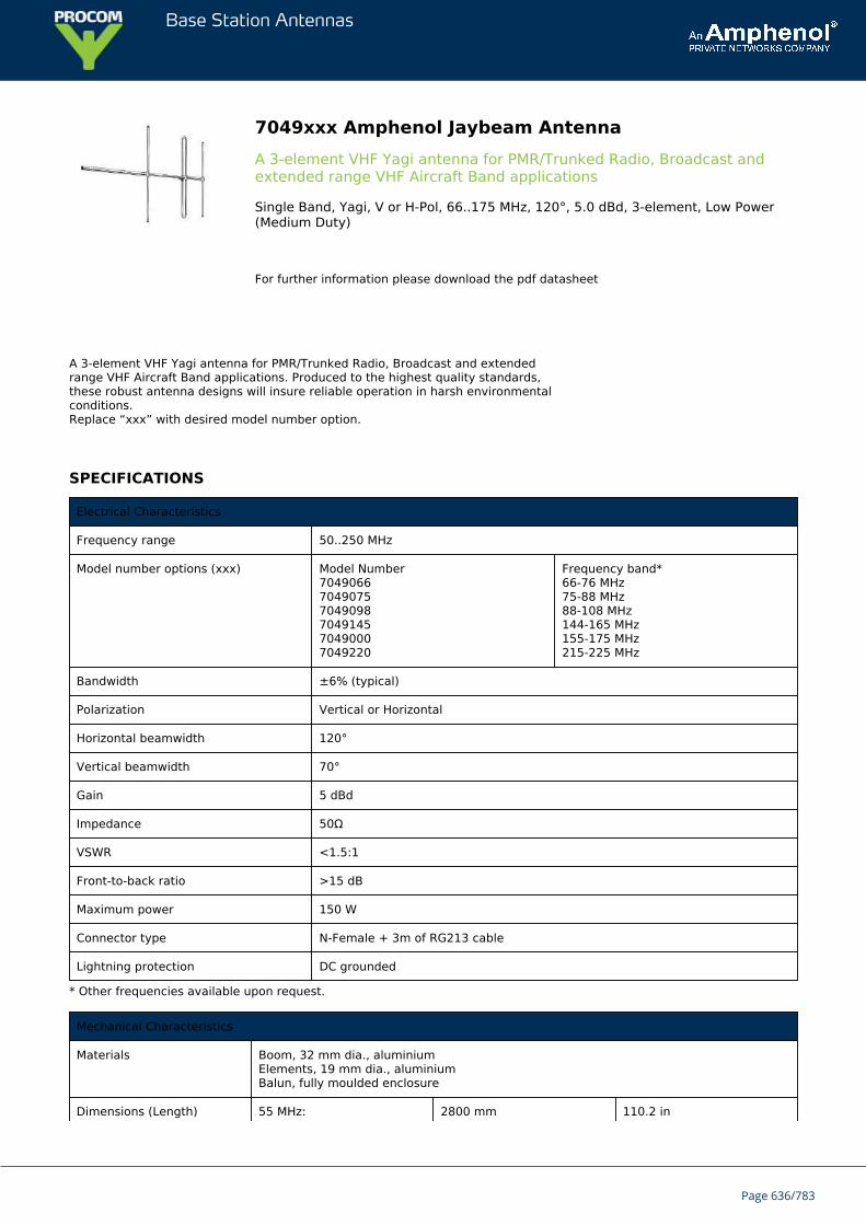
Base Station Antennas
7049xxx Amphenol Jaybeam AntennaA 3-element VHF Yagi antenna for PMR/Trunked Radio, Broadcast andextended range VHF Aircraft Band applications
Single Band, Yagi, V or H-Pol, 66..175 MHz, 120°, 5.0 dBd, 3-element, Low Power(Medium Duty)
For further information please download the pdf datasheet
A 3-element VHF Yagi antenna for PMR/Trunked Radio, Broadcast and extendedrange VHF Aircraft Band applications. Produced to the highest quality standards,these robust antenna designs will insure reliable operation in harsh environmentalconditions.Replace “xxx” with desired model number option.
SPECIFICATIONS
Electrical Characteristics
Frequency range 50..250 MHz
Model number options (xxx) Model Number704906670490757049098704914570490007049220
Frequency band*66-76 MHz75-88 MHz88-108 MHz144-165 MHz155-175 MHz215-225 MHz
Bandwidth ±6% (typical)
Polarization Vertical or Horizontal
Horizontal beamwidth 120°
Vertical beamwidth 70°
Gain 5 dBd
Impedance 50Ω
VSWR <1.5:1
Front-to-back ratio >15 dB
Maximum power 150 W
Connector type N-Female + 3m of RG213 cable
Lightning protection DC grounded
* Other frequencies available upon request.
Mechanical Characteristics
Materials Boom, 32 mm dia., aluminiumElements, 19 mm dia., aluminiumBalun, fully moulded enclosure
Dimensions (Length) 55 MHz: 2800 mm 110.2 in
Page 636/783
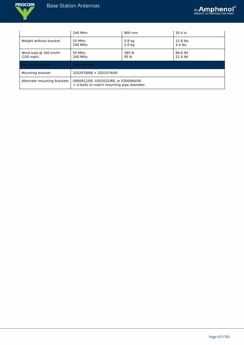
Base Station Antennas
240 MHz: 900 mm 35.4 in
Weight without bracket 55 MHz:240 MHz:
5.8 kg2.0 kg
12.8 lbs4.4 lbs
Wind load @ 160 km/hr(100 mph)
55 MHz:240 MHz:
385 N95 N
86.6 lbf21.4 lbf
Mounting Options Part Number
Mounting bracket 3202078/68 + 3201079/00
Alternate mounting brackets 0900912/00, 0302032/68, or 0300064/00+ U-bolts to match mounting pipe diameter
Page 637/783
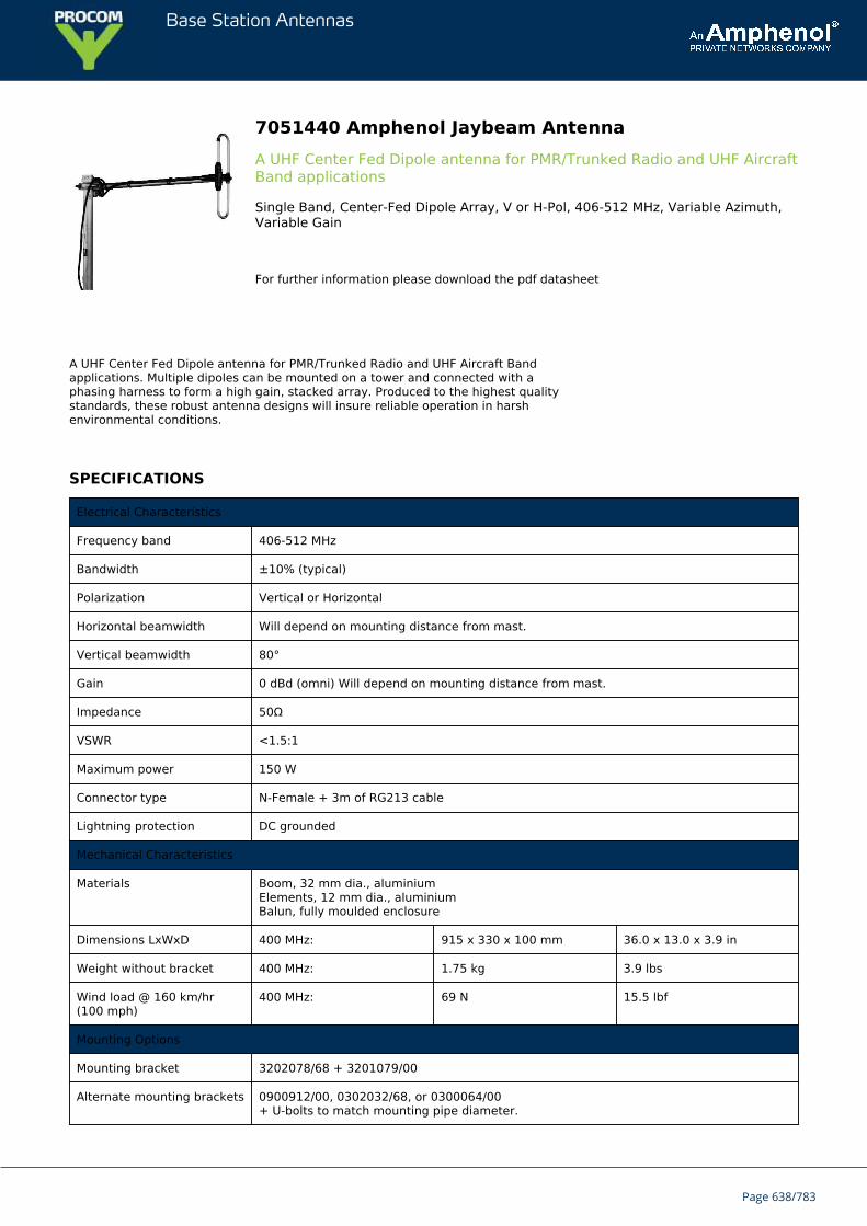
Base Station Antennas
7051440 Amphenol Jaybeam AntennaA UHF Center Fed Dipole antenna for PMR/Trunked Radio and UHF AircraftBand applications
Single Band, Center-Fed Dipole Array, V or H-Pol, 406-512 MHz, Variable Azimuth,Variable Gain
For further information please download the pdf datasheet
A UHF Center Fed Dipole antenna for PMR/Trunked Radio and UHF Aircraft Bandapplications. Multiple dipoles can be mounted on a tower and connected with aphasing harness to form a high gain, stacked array. Produced to the highest qualitystandards, these robust antenna designs will insure reliable operation in harshenvironmental conditions.
SPECIFICATIONS
Electrical Characteristics
Frequency band 406-512 MHz
Bandwidth ±10% (typical)
Polarization Vertical or Horizontal
Horizontal beamwidth Will depend on mounting distance from mast.
Vertical beamwidth 80°
Gain 0 dBd (omni) Will depend on mounting distance from mast.
Impedance 50Ω
VSWR <1.5:1
Maximum power 150 W
Connector type N-Female + 3m of RG213 cable
Lightning protection DC grounded
Mechanical Characteristics
Materials Boom, 32 mm dia., aluminiumElements, 12 mm dia., aluminiumBalun, fully moulded enclosure
Dimensions LxWxD 400 MHz: 915 x 330 x 100 mm 36.0 x 13.0 x 3.9 in
Weight without bracket 400 MHz: 1.75 kg 3.9 lbs
Wind load @ 160 km/hr(100 mph)
400 MHz: 69 N 15.5 lbf
Mounting Options
Mounting bracket 3202078/68 + 3201079/00
Alternate mounting brackets 0900912/00, 0302032/68, or 0300064/00+ U-bolts to match mounting pipe diameter.
Page 638/783

Base Station Antennas
Page 639/783
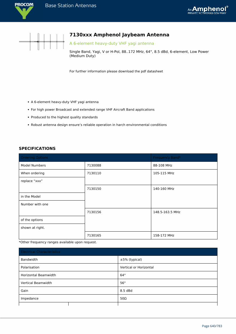
Base Station Antennas
7130xxx Amphenol Jaybeam AntennaA 6-element heavy-duty VHF yagi antenna
Single Band, Yagi, V or H-Pol, 88..172 MHz, 64°, 8.5 dBd, 6-element, Low Power(Medium Duty)
For further information please download the pdf datasheet
A 6-element heavy-duty VHF yagi antenna
For high power Broadcast and extended range VHF Aircraft Band applications
Produced to the highest quality standards
Robust antenna design ensure’s reliable operation in harch environmental conditions
SPECIFICATIONS
Ordering Options Frequency Band*
Model Numbers 7130088 88-108 MHz
When ordering 7130110 105-115 MHz
replace “xxx”
7130150 140-160 MHz
in the Model
Number with one
7130156 148.5-163.5 MHz
of the options
shown at right.
7130165 158-172 MHz
*Other frequency ranges available upon request.
Electrical Characteristics
Bandwidth ±5% (typical)
Polarisation Vertical or Horizontal
Horizontal Beamwidth 64°
Vertical Beamwidth 56°
Gain 8.5 dBd
Impedance 50Ω
Page 640/783
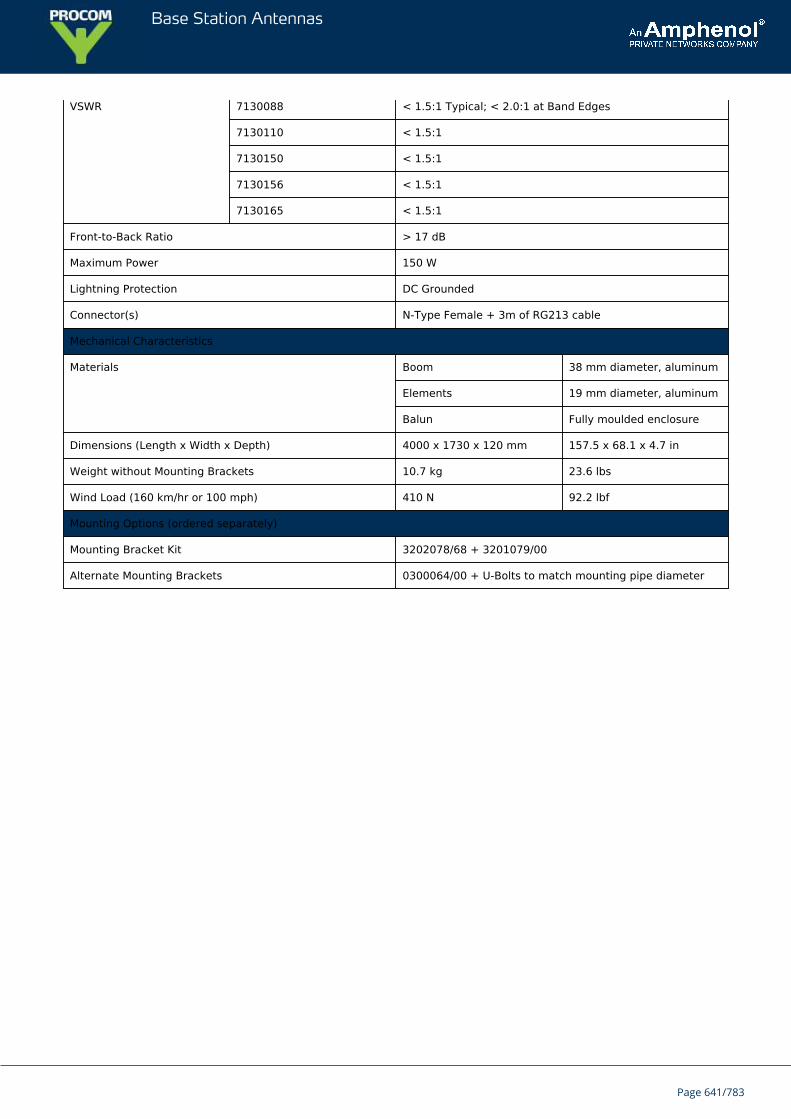
Base Station Antennas
VSWR 7130088 < 1.5:1 Typical; < 2.0:1 at Band Edges
7130110 < 1.5:1
7130150 < 1.5:1
7130156 < 1.5:1
7130165 < 1.5:1
Front-to-Back Ratio > 17 dB
Maximum Power 150 W
Lightning Protection DC Grounded
Connector(s) N-Type Female + 3m of RG213 cable
Mechanical Characteristics
Materials Boom 38 mm diameter, aluminum
Elements 19 mm diameter, aluminum
Balun Fully moulded enclosure
Dimensions (Length x Width x Depth) 4000 x 1730 x 120 mm 157.5 x 68.1 x 4.7 in
Weight without Mounting Brackets 10.7 kg 23.6 lbs
Wind Load (160 km/hr or 100 mph) 410 N 92.2 lbf
Mounting Options (ordered separately)
Mounting Bracket Kit 3202078/68 + 3201079/00
Alternate Mounting Brackets 0300064/00 + U-Bolts to match mounting pipe diameter
Page 641/783
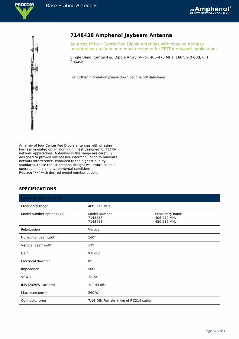
Base Station Antennas
7148438 Amphenol Jaybeam AntennaAn array of four Center Fed Dipole antennas with phasing harnessmounted on an aluminum mast designed for TETRA network applications
Single Band, Center-Fed Dipole Array, V-Pol, 406-470 MHz, 160°, 9.0 dBd, 0°T,4-stack
For further information please download the pdf datasheet
An array of four Center Fed Dipole antennas with phasingharness mounted on an aluminum mast designed for TETRAnetwork applications. Antennas in this range are carefullydesigned to provide low passive intermodulation to minimizenetwork interference. Produced to the highest qualitystandards, these robust antenna designs will insure reliableoperation in harsh environmental conditions.Replace “xx” with desired model number option.
SPECIFICATIONS
Electrical Characteristics
Frequency range 406..512 MHz
Model number options (xx) Model Number71484387148481
Frequency band*406-470 MHz450-512 MHz
Polarization Vertical
Horizontal beamwidth 160°
Vertical beamwidth 17°
Gain 9.0 dBd
Electrical downtilt 0°
Impedance 50Ω
VSWR <1.5:1
IM3 (2x20W carriers) < -143 dBc
Maximum power 200 W
Connector type 7/16-DIN Female + 4m of RG214 cable
Page 642/783

Base Station Antennas
Lightning protection DC grounded
* Other frequencies available upon request.
Mechanical Characteristics
Construction Center fed folded dipoles (with baluns) fixed on a one piece vertical boom
Dimensions (Length x Width x Depth) 2600 x 132 x 110 mm 102.4 x 5.2 x 4.3 in
Weight without bracket 7.0 kg 15.4 lbs
Wind load @ 160 km/hr (100 mph) 190 N 42.7 lbf
Mounting Options Part Number
Mounting bracket 0300120/00
Page 643/783
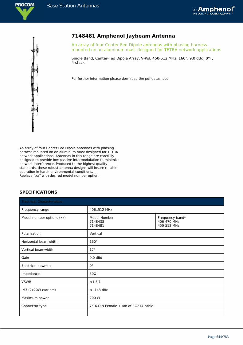
Base Station Antennas
7148481 Amphenol Jaybeam AntennaAn array of four Center Fed Dipole antennas with phasing harnessmounted on an aluminum mast designed for TETRA network applications
Single Band, Center-Fed Dipole Array, V-Pol, 450-512 MHz, 160°, 9.0 dBd, 0°T,4-stack
For further information please download the pdf datasheet
An array of four Center Fed Dipole antennas with phasingharness mounted on an aluminum mast designed for TETRAnetwork applications. Antennas in this range are carefullydesigned to provide low passive intermodulation to minimizenetwork interference. Produced to the highest qualitystandards, these robust antenna designs will insure reliableoperation in harsh environmental conditions.Replace “xx” with desired model number option.
SPECIFICATIONS
Electrical Characteristics
Frequency range 406..512 MHz
Model number options (xx) Model Number71484387148481
Frequency band*406-470 MHz450-512 MHz
Polarization Vertical
Horizontal beamwidth 160°
Vertical beamwidth 17°
Gain 9.0 dBd
Electrical downtilt 0°
Impedance 50Ω
VSWR <1.5:1
IM3 (2x20W carriers) < -143 dBc
Maximum power 200 W
Connector type 7/16-DIN Female + 4m of RG214 cable
Page 644/783
Base Station Antennas
Lightning protection DC grounded
* Other frequencies available upon request.
Mechanical Characteristics
Construction Center fed folded dipoles (with baluns) fixed on a one piece vertical boom
Dimensions (Length x Width x Depth) 2600 x 132 x 110 mm 102.4 x 5.2 x 4.3 in
Weight without bracket 7.0 kg 15.4 lbs
Wind load @ 160 km/hr (100 mph) 190 N 42.7 lbf
Mounting Options Part Number
Mounting bracket 0300120/00
Page 645/783
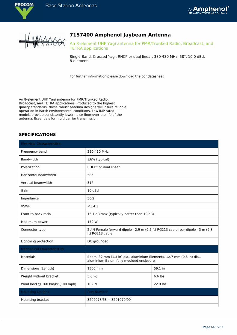
Base Station Antennas
7157400 Amphenol Jaybeam AntennaAn 8-element UHF Yagi antenna for PMR/Trunked Radio, Broadcast, andTETRA applications
Single Band, Crossed Yagi, RHCP or dual linear, 380-430 MHz, 58°, 10.0 dBd,8-element
For further information please download the pdf datasheet
An 8-element UHF Yagi antenna for PMR/Trunked Radio,Broadcast, and TETRA applications. Produced to the highestquality standards, these robust antenna designs will insure reliableoperation in harsh environmental conditions. Low IMP ratedmodels provide consistently lower noise floor over the life of theantenna. Essentials for multi carrier transmission.
SPECIFICATIONS
Electrical Characteristics
Frequency band 380-430 MHz
Bandwidth ±6% (typical)
Polarization RHCP* or dual linear
Horizontal beamwidth 58°
Vertical beamwidth 51°
Gain 10 dBd
Impedance 50Ω
VSWR <1.4:1
Front-to-back ratio 15.1 dB max (typically better than 19 dB)
Maximum power 150 W
Connector type 2 / N-Female forward dipole - 2.9 m (9.5 ft) RG213 cable rear dipole - 3 m (9.8ft) RG213 cable
Lightning protection DC grounded
Mechanical Characteristics
Materials Boom, 32 mm (1.3 in) dia., aluminium Elements, 12.7 mm (0.5 in) dia.,aluminium Balun, fully moulded enclosure
Dimensions (Length) 1500 mm 59.1 in
Weight without bracket 5.0 kg 6.6 lbs
Wind load @ 160 km/hr (100 mph) 102 N 22.9 lbf
Mounting Options Part Number
Mounting bracket 3202078/68 + 3201079/00
Page 646/783

Base Station Antennas
Alternate mounting brackets 0900912/00, 0302032/68, or 0300064/00+ U-bolts to match mounting pipe diameter
Page 647/783
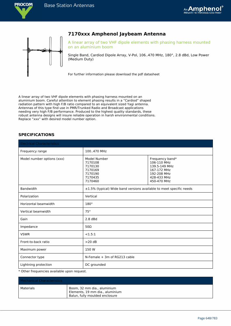
Base Station Antennas
7170xxx Amphenol Jaybeam AntennaA linear array of two VHF dipole elements with phasing harness mountedon an aluminium boom
Single Band, Cardiod Dipole Array, V-Pol, 106..470 MHz, 180°, 2.8 dBd, Low Power(Medium Duty)
For further information please download the pdf datasheet
A linear array of two VHF dipole elements with phasing harness mounted on analuminium boom. Careful attention to element phasing results in a “Cardiod” shapedradiation pattern with high F/B ratio compared to an equivalent sized Yagi antenna.Antennas of this type find use in PMR/Trunked Radio and Broadcast applicationsneeding very high F/B performance. Produced to the highest quality standards, theserobust antenna designs will insure reliable operation in harsh environmental conditions.Replace “xxx” with desired model number option.
SPECIFICATIONS
Electrical Characteristics
Frequency range 100..470 MHz
Model number options (xxx) Model Number717010871701307170169717019071704357170460
Frequency band*106-110 MHz139.5-149 MHz167-172 MHz192-208 MHz428-433 MHz450-470 MHz
Bandwidth ±1.5% (typical) Wide band versions available to meet specific needs
Polarization Vertical
Horizontal beamwidth 180°
Vertical beamwidth 75°
Gain 2.8 dBd
Impedance 50Ω
VSWR <1.5:1
Front-to-back ratio >20 dB
Maximum power 150 W
Connector type N-Female + 3m of RG213 cable
Lightning protection DC grounded
* Other frequencies available upon request.
Mechanical Characteristics
Materials Boom, 32 mm dia., aluminiumElements, 19 mm dia., aluminiumBalun, fully moulded enclosure
Page 648/783
Base Station Antennas
Dimensions LxWxD 150 MHz: 2100 x 900 x 100 mm 82.7 x 35.4 x 3.9 in
Weight without bracket 150 MHz: 5.5 kg 6.2 lbs
Wind load @ 160 km/hr(100 mph)
150 MHz: 190 N 30.1 lbf
Mounting Options
Mounting bracket 3202078/68 + 3201079/00
Alternate mounting brackets 0900912/00, 0302032/68, or 0300064/00+ U-bolts to match mounting pipe diameter.
Page 649/783
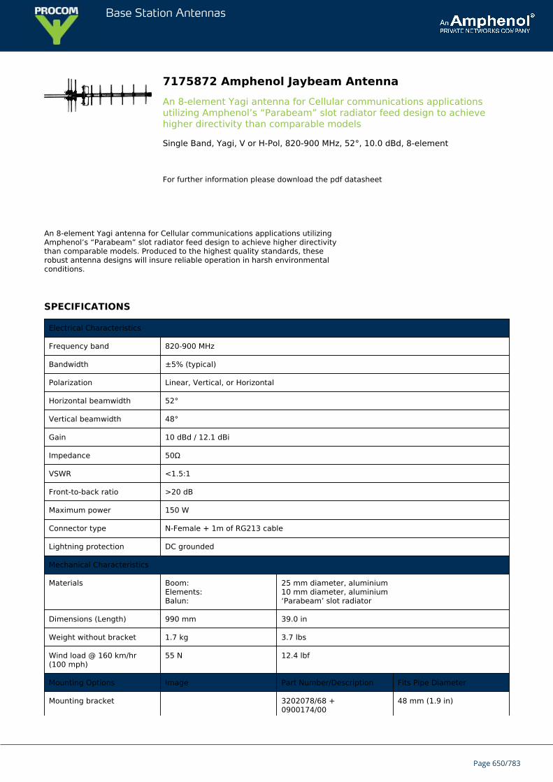
Base Station Antennas
7175872 Amphenol Jaybeam AntennaAn 8-element Yagi antenna for Cellular communications applicationsutilizing Amphenol’s “Parabeam” slot radiator feed design to achievehigher directivity than comparable models
Single Band, Yagi, V or H-Pol, 820-900 MHz, 52°, 10.0 dBd, 8-element
For further information please download the pdf datasheet
An 8-element Yagi antenna for Cellular communications applications utilizingAmphenol’s “Parabeam” slot radiator feed design to achieve higher directivitythan comparable models. Produced to the highest quality standards, theserobust antenna designs will insure reliable operation in harsh environmentalconditions.
SPECIFICATIONS
Electrical Characteristics
Frequency band 820-900 MHz
Bandwidth ±5% (typical)
Polarization Linear, Vertical, or Horizontal
Horizontal beamwidth 52°
Vertical beamwidth 48°
Gain 10 dBd / 12.1 dBi
Impedance 50Ω
VSWR <1.5:1
Front-to-back ratio >20 dB
Maximum power 150 W
Connector type N-Female + 1m of RG213 cable
Lightning protection DC grounded
Mechanical Characteristics
Materials Boom:Elements:Balun:
25 mm diameter, aluminium10 mm diameter, aluminium‘Parabeam’ slot radiator
Dimensions (Length) 990 mm 39.0 in
Weight without bracket 1.7 kg 3.7 lbs
Wind load @ 160 km/hr(100 mph)
55 N 12.4 lbf
Mounting Options Image Part Number/Description Fits Pipe Diameter
Mounting bracket 3202078/68 +0900174/00
48 mm (1.9 in)
Page 650/783
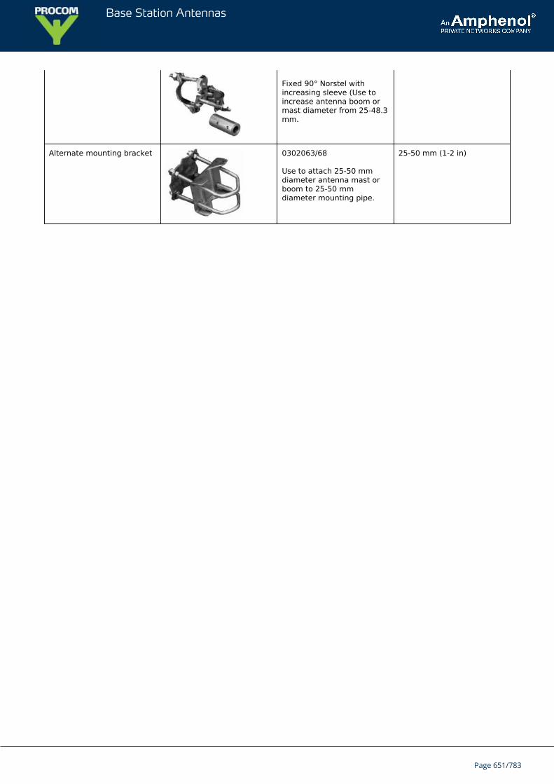
Base Station Antennas
Fixed 90° Norstel withincreasing sleeve (Use toincrease antenna boom ormast diameter from 25-48.3mm.
Alternate mounting bracket 0302063/68
Use to attach 25-50 mmdiameter antenna mast orboom to 25-50 mmdiameter mounting pipe.
25-50 mm (1-2 in)
Page 651/783

Base Station Antennas
7175890 Amphenol Jaybeam AntennaAn 8-element Yagi antenna for Cellular communications applicationsutilizing Amphenol’s “Parabeam” slot radiator feed design to achievehigher directivity than comparable models
Single Band, Yagi, V or H-Pol, 790-960 MHz, 52°, 10.0 dBd, 8-element
For further information please download the pdf datasheet
An 8-element Yagi antenna for Cellular communications applications utilizingAmphenol’s “Parabeam” slot radiator feed design to achieve higher directivitythan comparable models. Produced to the highest quality standards, theserobust antenna designs will insure reliable operation in harsh environmentalconditions.
SPECIFICATIONS
Electrical Characteristics
Frequency band 790-960 MHz
Bandwidth ±5% (typical)
Polarization Linear, Vertical, or Horizontal
Horizontal beamwidth 52°
Vertical beamwidth 48°
Gain 10 dBd / 12.1 dBi
Impedance 50Ω
VSWR <1.5:1
Front-to-back ratio >20 dB
Maximum power 150 W
Connector type N-Female + 1m of RG213 cable
Lightning protection DC grounded
Mechanical Characteristics
Materials Boom:Elements:Balun:
25 mm diameter, aluminium10 mm diameter, aluminium‘Parabeam’ slot radiator
Dimensions (Length) 970 mm 38.2 in
Weight without bracket 1.7 kg 3.7 lbs
Wind load @ 160 km/hr(100 mph)
55 N 12.4 lbf
Mounting Options Image Part Number/Description Fits Pipe Diameter
Mounting bracket 3202078/68 +0900174/00
48 mm (1.9 in)
Page 652/783

Base Station Antennas
Fixed 90° Norstel withincreasing sleeve (Use toincrease antenna boom ormast diameter from 25-48.3mm.
Alternate mounting bracket 0302063/68
Use to attach 25-50 mmdiameter antenna mast orboom to 25-50 mmdiameter mounting pipe.
25-50 mm (1-2 in)
Page 653/783
Base Station Antennas
7176xxx Amphenol Jaybeam Antenna18-element UHF Yagi antenna for broadcast, TETRA, and cellularcommunication applications
Single Band, Yagi, V or H-Pol, 471..960 MHz, 25°, 14.4 dBd, 18-element, Low Power(Medium Duty)
For further information please download the pdf datasheet
18-element UHF Yagi antenna for broadcast, TETRA, and cellular communication applications
Utilizes Amphenol’s “Parabeam” slot radiator feed design
Achieves higher directivity than comparable models
The robust antenna design insures reliable operation in harsh environmental conditions
Produced to the highest quality standards
SPECIFICATIONS
Frequency Range* Model Number
471-523 MHz 7176500
505-581 MHz 7176550
550-610 MHz 7176580
600-685 MHz 7176648
630-700 MHz 7176665
640-711 MHz 7176680
720-790 MHz 7176755
740-835 MHz 7176810
820-900 MHz 7176870
870-960 MHz 7176890
Mounting bracket kits and other accessories are ordered separately.
Electrical Characteristics
Frequency Bands (MHz) 470...960 MHz
Bandwidth (typical) ±5%
Polarization Vertical or Horizontal
Horizontal Beamwidth 25°
Vertical Beamwidth 23°
Page 654/783
Base Station Antennas
Gain 14.4 dBd
Impedance 50Ω
VSWR < 1.5:1
Front-to-Back Ratio > 20 dB
Maximum Input Power 150 W
Number of Connectors, Type 1 Connector / N Female with 3m (9.8 feet) of RG213 cable
Lightning Protection Direct Ground
Mechanical Characteristics
Materials Boom Aluminium; 25 mmdiameter
Elements Aluminium; 10 mmdiameter
Balun ‘Parabeam’ slot radiator
700 MHz Dimensions (Length) 2500 mm 98.4 in
Weight without MountingBrackets
3.3 kg 7.3 lbs
Wind Loads (160 km/hr or100 mph)
171 N 38.4 lbf
Mechanical Characteristics
Mounting Bracket 3202078/68 + 0900174/00
Alternate Mounting Brackets 3202063/68 + 0900174/00
3202032/68 + 0900174/00
Page 655/783
Base Station Antennas
7227000 Amphenol Jaybeam AntennaShrouded Yagi antenna avaliable for SHF Links in the 1.4 GHz band
Single Band, Shrouded Yagi, V or H-Pol, 1427-1530 MHz, 26°, 17 dBd, Low Power(Medium Duty)
For further information please download the pdf datasheet
Shrouded Yagi antenna avaliable for SHF Links in the 1.4 GHz band
All elements enclosed in a weather resistant, glassfibre shroud
Able to provide consistent, reliable performance in all weather conditions
SPECIFICATIONS
Electrical Characteristics
Frequency Band 1427-1530 MHz
Polarization Vertical or Horizontal
Horizontal Beamwidth 26°
Vertical Beamwidth 25°
Gain 17.0 dBd
Impedance 50Ω
VSWR <1.3:1
Front-to-Back Ratio > 25 dB
Power Rating 100 W
Lightning Protection DC Grounded
Connector(s) N-Female
Mechanical Characteristics
Materials Shroud GRP
Radiating Assembly Aluminum
Mounting Section (diameter) Aluminum, 50 mm (1.9 in) diameter
Dimensions (Length) 1360 mm 53.5 in
Weight without Mounting Bracket 3.0 kg 6.6 lbs
Wind Load (160 km/hr or 100 mph) 150 N 33.7 lbf
Mounting Options Part Number
Page 656/783

Base Station Antennas
Mounting brackets are ordered separately.
Mounting Bracket 3202078/68
Alternate Mounting Bracket 0300064/00 + U-bolts to match mounting pipe diameter
Page 657/783
Base Station Antennas
7249071 Amphenol Jaybeam Antenna3-Element Community BTS Yagi
Single Band, Yagi, V or H-Pol, 71.5-85 MHz, 130°, 4.5 dBd, 3-element, Low Power(Medium Duty)
For further information please download the pdf datasheet
A range of yagis meeting Radiocommunication Agency requirements forcommunity base station systems in the UK. Although they use a slightly lighterconstruction than our standard range, to allow for easier mounting, they retain highquality features to ensure reliable and dependable service.
SPECIFICATIONS
Electrical Characteristics
Frequency band 71.5-85 MHz
Polarization Vertical or Horizontal
Horizontal beamwidth (-3 dB) 130°
Vertical beamwidth (-3 dB) 70°
Gain 4.5 dBd
Impedance 50Ω
VSWR <1.5:1
Front-to-back ratio 14 dB typical
Maximum power 150 W
Connector type N-Socket + 1m of RG213 cable
Lightning protection DC grounded
Mechanical Characteristics
Dimensions (Length) 2000 mm 78.7 in
Weight without bracket 4.3 kg 9.5 lbs
Wind load @ 160 km/hr (100 mph) 190 N 33.7 lbf
Mounting Options Part Number
Mounting bracket (standard) 0302292/68, 0302032/68 , 0302063/68, or 0300066/00
Alternate mounting bracket (heavy duty) 3201079/00 + 3202078/68
Page 658/783
Base Station Antennas
7335000 Amphenol Jaybeam AntennaShrouded Yagi Antenna
Single Band, Shrouded Yagi, V or H-Pol, 1427-1530 MHz, 48°, 13 dBi, Low Power(Medium Duty)
For further information please download the pdf datasheet
Shrouded Yagi antennas avaliable for use in many communication systems
Robust antenna design will ensure reliable operation and excellent performance
SPECIFICATIONS
Electrical Characteristics
Frequency Band 1427-1530 MHz
Polarization Vertical or Horizontal
Horizontal Beamwidth (-3 dB) 48°
Vertical Beamwidth (-3 dB) 42°
Gain 13.0 dBi
Impedance 50Ω
VSWR <1.3:1
Power Rating 100 W
Lightning Protection DC Grounded
Connector(s) N-Socket
Mechanical Characteristics
Dimensions Length x Diameter 560 x 110 mm 22.0 x 4.3 in
Weight without Mounting Bracket 2.6 kg 5.7 lbs
Wind Load (160 km/hr or 100 mph) 105 N 23.6 lbf
Mounting Options Part Number
Mounting brackets are ordered separately.
Mounting Bracket 3202078/68
Page 659/783

Base Station Antennas
7356561 Amphenol Jaybeam AntennaAn 18-Element Yagi antenna of well proven design, available for UHF TVbands
Single Band, Yagi, V or H-Pol, 471-581 MHz, 25°, 14.4 dBd, 16.5 dBi, 18-element,Low Power (Medium Duty)
For further information please download the pdf datasheet
An 18-Element Yagi antenna of well proven design, available forUHF TV bands. Jaybeam’s famous ‘Parabeam’ slot radiator is usedgiving a performance advantage over similar sized antennas. Itslight but strong construction makes it easily deployable.Replace “xxx” with desired model number option.
SPECIFICATIONS
Electrical Characteristics
Frequency range 471..855 MHz
Model number options (xxx) Model Number735656173567107356825
Frequency band471-581 MHz615-733 MHz685-855 MHz
Channels21-3439-5347-68
Polarization Linear, Vertical, or Horizontal
Horizontal beamwidth (-3dB)
25°
Vertical beamwidth (-3 dB) 23°
Gain 16.5 dBi
Impedance 50Ω
VSWR <2.0:1
Front-to-back ratio 20 dB (typical)
Maximum power 150 W
Connector type N-Female on RG213 downlead (downlead fitted with protective sleeve)
Lightning protection DC grounded
Mechanical Characteristics
Materials Boom, 25 mm dia., aluminium tubeElements, 10 mm dia., solid aluminium‘Parabeam’ slot radiatorPolyester, powder coated finish is optional
Dimensions (Length) 2380 mm 93.7 in
Weight without bracket 4.5 kg 9.9 lbs
Wind load @ 160 km/hr(100 mph)
196 N 44.0 lbf
Page 660/783

Base Station Antennas
Mounting Options
Mounting bracket 0900174/00 + 3202078/68
Page 661/783
Base Station Antennas
7356710 Amphenol Jaybeam AntennaAn 18-Element Yagi antenna of well proven design, available for UHF TVbands
Single Band, Yagi, V or H-Pol, 615-733 MHz, 25°, 14.4 dBd, 16.5 dBi, 18-element,Low Power (Medium Duty)
For further information please download the pdf datasheet
An 18-Element Yagi antenna of well proven design, available forUHF TV bands. Jaybeam’s famous ‘Parabeam’ slot radiator is usedgiving a performance advantage over similar sized antennas. Itslight but strong construction makes it easily deployable.Replace “xxx” with desired model number option.
SPECIFICATIONS
Electrical Characteristics
Frequency range 471..855 MHz
Model number options (xxx) Model Number735656173567107356825
Frequency band471-581 MHz615-733 MHz685-855 MHz
Channels21-3439-5347-68
Polarization Linear, Vertical, or Horizontal
Horizontal beamwidth (-3dB)
25°
Vertical beamwidth (-3 dB) 23°
Gain 16.5 dBi
Impedance 50Ω
VSWR <2.0:1
Front-to-back ratio 20 dB (typical)
Maximum power 150 W
Connector type N-Female on RG213 downlead (downlead fitted with protective sleeve)
Lightning protection DC grounded
Mechanical Characteristics
Materials Boom, 25 mm dia., aluminium tubeElements, 10 mm dia., solid aluminium‘Parabeam’ slot radiatorPolyester, powder coated finish is optional
Dimensions (Length) 2380 mm 93.7 in
Weight without bracket 4.5 kg 9.9 lbs
Wind load @ 160 km/hr(100 mph)
196 N 44.0 lbf
Page 662/783

Base Station Antennas
Mounting Options
Mounting bracket 0900174/00 + 3202078/68
Page 663/783

Base Station Antennas
7356825 Amphenol Jaybeam AntennaAn 18-Element Yagi antenna of well proven design, available for UHF TVbands
Single Band, Yagi, V or H-Pol, 685-855 MHz, 25°, 14.4 dBd, 16.5 dBi, 18-element,Low Power (Medium Duty)
For further information please download the pdf datasheet
An 18-Element Yagi antenna of well proven design, available forUHF TV bands. Jaybeam’s famous ‘Parabeam’ slot radiator is usedgiving a performance advantage over similar sized antennas. Itslight but strong construction makes it easily deployable.Replace “xxx” with desired model number option.
SPECIFICATIONS
Electrical Characteristics
Frequency range 471..855 MHz
Model number options (xxx) Model Number735656173567107356825
Frequency band471-581 MHz615-733 MHz685-855 MHz
Channels21-3439-5347-68
Polarization Linear, Vertical, or Horizontal
Horizontal beamwidth (-3dB)
25°
Vertical beamwidth (-3 dB) 23°
Gain 16.5 dBi
Impedance 50Ω
VSWR <2.0:1
Front-to-back ratio 20 dB (typical)
Maximum power 150 W
Connector type N-Female on RG213 downlead (downlead fitted with protective sleeve)
Lightning protection DC grounded
Mechanical Characteristics
Materials Boom, 25 mm dia., aluminium tubeElements, 10 mm dia., solid aluminium‘Parabeam’ slot radiatorPolyester, powder coated finish is optional
Dimensions (Length) 2380 mm 93.7 in
Weight without bracket 4.5 kg 9.9 lbs
Wind load @ 160 km/hr(100 mph)
196 N 44.0 lbf
Page 664/783

Base Station Antennas
Mounting Options
Mounting bracket 0900174/00 + 3202078/68
Page 665/783
Base Station Antennas
7360010 Amphenol Jaybeam AntennaShrouded Yagi antenna for Links in the 2.1-2.3 GHz band
Single Band, Shrouded Yagi, V or H-Pol, 2100-2300 MHz, 27°, 17 dBi, Low Power(Medium Duty)
For further information please download the pdf datasheet
Shrouded Yagi antenna for Links in the 2.1-2.3 GHz band
All elements enclosed in a weather resistant, glassfibre shroud
Able to provide consistent, reliable performance in all weather conditions
SPECIFICATIONS
Electrical Characteristics
Frequency Band 2100-2300 MHz
Polarization Vertical or Horizontal
Horizontal Beamwidth 27°
Vertical Beamwidth 26°
Gain 17.0 dBi
Impedance 50Ω
VSWR < 1.5:1 (
Front-to-Back Ratio > 20 dB
Power Rating 100 W
Lightning Protection DC Grounded
Connector(s) N-Female
Mechanical Characteristics
Materials Shroud GRP
Radiating Assembly Brass
Mounting Section (diameter) Aluminum
50 mm 1.9 in
Dimensions (Length) 1090 mm 42.9 in
Weight without Mounting Bracket 1.6 kg 3.5 lbs
Wind Load (160 km/hr or 100 mph) 100 N 22.5 lbf
Page 666/783

Base Station Antennas
Mounting Options Part Number
Mounting brackets are ordered separately.
Mounting Bracket 3202078/68
Alternate Mounting Bracket 0300064/00 + U-bolts to match mounting pipe diameter
Page 667/783
Base Station Antennas
7360012 Amphenol Jaybeam AntennaShrouded Yagi antenna for Links in the 2.3-2.5 GHz band
Single Band, Shrouded Yagi, V or H-Pol, 2300-2500 MHz, 26°, 17 dBi, Low Power(Medium Duty)
For further information please download the pdf datasheet
Shrouded Yagi antenna for Links in the 2.3-2.5 GHz band
All elements enclosed in a weather resistant, glassfibre shroud
SPECIFICATIONS
Electrical Characteristics
Frequency Band 2300-2500 MHz
Polarization Vertical or Horizontal
Horizontal Beamwidth 26°
Vertical Beamwidth 24°
Gain 17.0 dBi
Impedance 50Ω
VSWR < 1.5:1
Front-to-Back Ratio > 20 dB
Power Rating 100 W
Lightning Protection DC Grounded
Connector(s) N-Female
Mechanical Characteristics
Materials Shroud GRP
Radiating Assembly Brass
Mounting Section (diameter) Aluminum
50 mm 1.9 in
Dimensions (Length) 1000 mm 39.4 in
Weight without Mounting Bracket 1.7 kg 3.7 lbs
Wind Load (160 km/hr or 100 mph) 91 N 20.5 lbf
Mounting Options Part Number
Page 668/783
Base Station Antennas
Mounting brackets are ordered separately.
Mounting Bracket 3202078/68
Alternate Mounting Bracket 0300064/00 + U-bolts to match mounting pipe diameter
Page 669/783
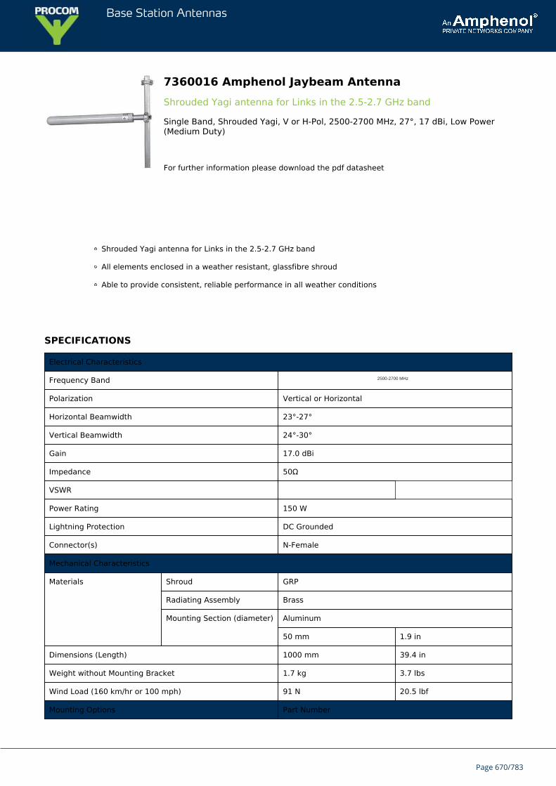
Base Station Antennas
7360016 Amphenol Jaybeam AntennaShrouded Yagi antenna for Links in the 2.5-2.7 GHz band
Single Band, Shrouded Yagi, V or H-Pol, 2500-2700 MHz, 27°, 17 dBi, Low Power(Medium Duty)
For further information please download the pdf datasheet
Shrouded Yagi antenna for Links in the 2.5-2.7 GHz band
All elements enclosed in a weather resistant, glassfibre shroud
Able to provide consistent, reliable performance in all weather conditions
SPECIFICATIONS
Electrical Characteristics
Frequency Band 2500-2700 MHz
Polarization Vertical or Horizontal
Horizontal Beamwidth 23°-27°
Vertical Beamwidth 24°-30°
Gain 17.0 dBi
Impedance 50Ω
VSWR
Power Rating 150 W
Lightning Protection DC Grounded
Connector(s) N-Female
Mechanical Characteristics
Materials Shroud GRP
Radiating Assembly Brass
Mounting Section (diameter) Aluminum
50 mm 1.9 in
Dimensions (Length) 1000 mm 39.4 in
Weight without Mounting Bracket 1.7 kg 3.7 lbs
Wind Load (160 km/hr or 100 mph) 91 N 20.5 lbf
Mounting Options Part Number
Page 670/783
Base Station Antennas
Mounting brackets are ordered separately.
Mounting Bracket 3202078/68
Alternate Mounting Bracket 0300064/00 + U-bolts to match mounting pipe diameter
Page 671/783

Base Station Antennas
7362240 Amphenol Jaybeam AntennaYagi antennas avaliable for use in many communication systems
Single Band, Shrouded Yagi, V or H-Pol, 2300-2500 MHz, 80°, 8.0 dBi, Low Power(Medium Duty)
For further information please download the pdf datasheet
Yagi antennas avaliable for use in many communication systems
Robust antenna design will ensure reliable operation and excellent performance
SPECIFICATIONS
Electrical Characteristics
Frequency Band 2300-2500 MHz
Polarization Vertical or Horizontal
Horizontal Beamwidth (-3 dB) 80°
Vertical Beamwidth (-3 dB) 60°
Gain 8.0 dBi
Impedance 50Ω
VSWR 100 MHz Center < 1.3:1
200 MHz Center < 1.5:1
Power Rating 150 W
Lightning Protection DC Grounded
Connector(s) N-Female
Mechanical Characteristics
Dimensions Length x Diameter 420 x 86 mm 16.5 x 3.4 in
Weight without Mounting Bracket 1.6 kg 3.5 lbs
Wind Load (160 km/hr or 100 mph) 34 N 7.6 lbf
Mounting Options Part Number
Mounting brackets are ordered separately.
Mounting Bracket 3202078/68
Page 672/783
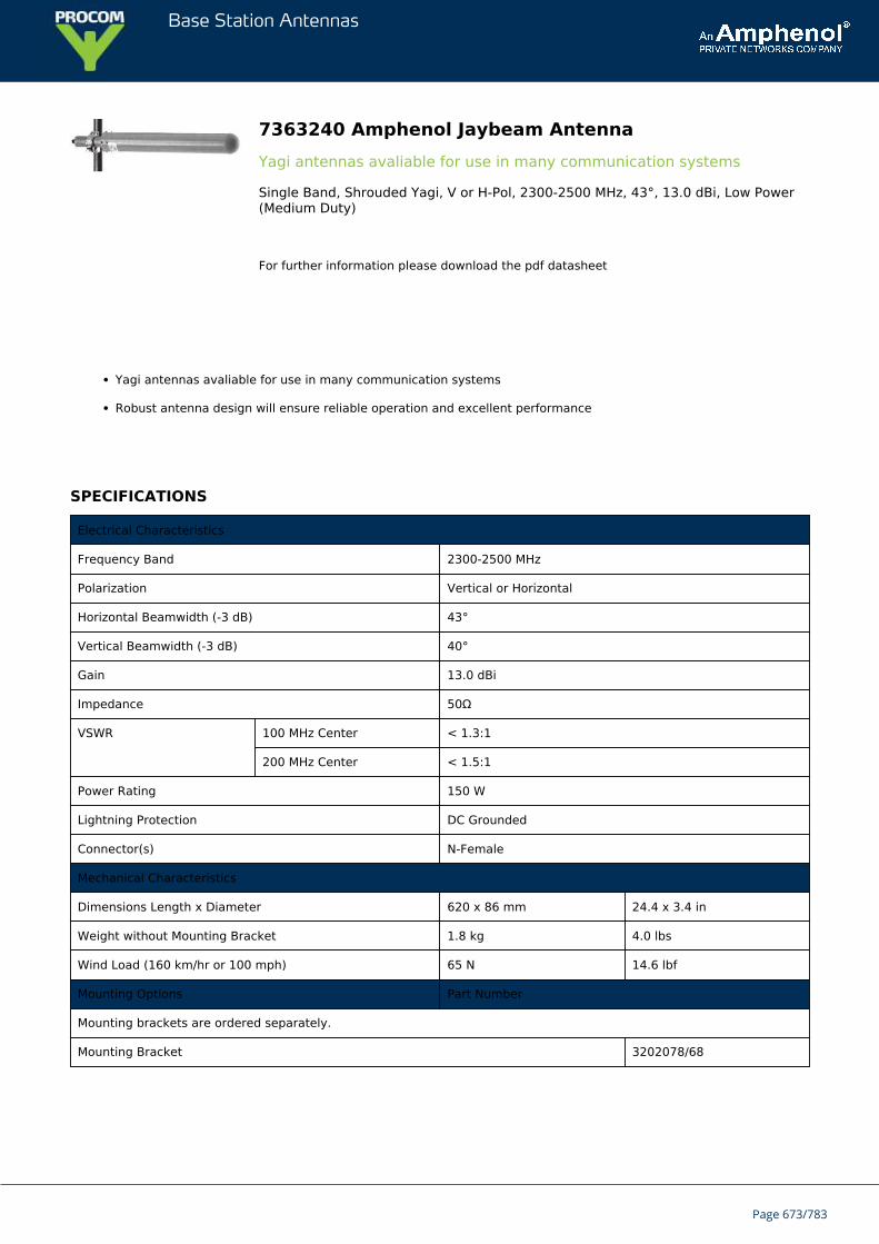
Base Station Antennas
7363240 Amphenol Jaybeam AntennaYagi antennas avaliable for use in many communication systems
Single Band, Shrouded Yagi, V or H-Pol, 2300-2500 MHz, 43°, 13.0 dBi, Low Power(Medium Duty)
For further information please download the pdf datasheet
Yagi antennas avaliable for use in many communication systems
Robust antenna design will ensure reliable operation and excellent performance
SPECIFICATIONS
Electrical Characteristics
Frequency Band 2300-2500 MHz
Polarization Vertical or Horizontal
Horizontal Beamwidth (-3 dB) 43°
Vertical Beamwidth (-3 dB) 40°
Gain 13.0 dBi
Impedance 50Ω
VSWR 100 MHz Center < 1.3:1
200 MHz Center < 1.5:1
Power Rating 150 W
Lightning Protection DC Grounded
Connector(s) N-Female
Mechanical Characteristics
Dimensions Length x Diameter 620 x 86 mm 24.4 x 3.4 in
Weight without Mounting Bracket 1.8 kg 4.0 lbs
Wind Load (160 km/hr or 100 mph) 65 N 14.6 lbf
Mounting Options Part Number
Mounting brackets are ordered separately.
Mounting Bracket 3202078/68
Page 673/783
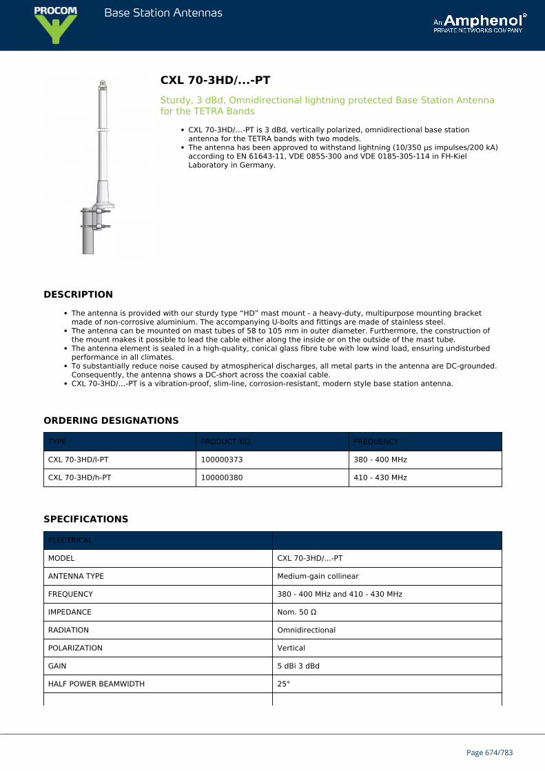
Base Station Antennas
CXL 70-3HD/...-PTSturdy, 3 dBd, Omnidirectional lightning protected Base Station Antennafor the TETRA Bands
CXL 70-3HD/…-PT is 3 dBd, vertically polarized, omnidirectional base stationantenna for the TETRA bands with two models.The antenna has been approved to withstand lightning (10/350 μs impulses/200 kA)according to EN 61643-11, VDE 0855-300 and VDE 0185-305-114 in FH-KielLaboratory in Germany.
DESCRIPTION
The antenna is provided with our sturdy type “HD” mast mount - a heavy-duty, multipurpose mounting bracketmade of non-corrosive aluminium. The accompanying U-bolts and fittings are made of stainless steel.The antenna can be mounted on mast tubes of 58 to 105 mm in outer diameter. Furthermore, the construction ofthe mount makes it possible to lead the cable either along the inside or on the outside of the mast tube.The antenna element is sealed in a high-quality, conical glass fibre tube with low wind load, ensuring undisturbedperformance in all climates.To substantially reduce noise caused by atmospherical discharges, all metal parts in the antenna are DC-grounded.Consequently, the antenna shows a DC-short across the coaxial cable.CXL 70-3HD/…-PT is a vibration-proof, slim-line, corrosion-resistant, modern style base station antenna.
ORDERING DESIGNATIONS
TYPE PRODUCT NO. FREQUENCY
CXL 70-3HD/l-PT 100000373 380 - 400 MHz
CXL 70-3HD/h-PT 100000380 410 - 430 MHz
SPECIFICATIONS
ELECTRICAL
MODEL CXL 70-3HD/...-PT
ANTENNA TYPE Medium-gain collinear
FREQUENCY 380 - 400 MHz and 410 - 430 MHz
IMPEDANCE Nom. 50 Ω
RADIATION Omnidirectional
POLARIZATION Vertical
GAIN 5 dBi 3 dBd
HALF POWER BEAMWIDTH 25°
Page 674/783
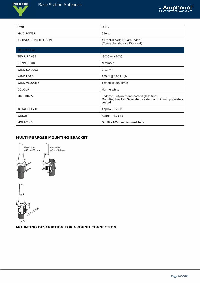
Base Station Antennas
SWR ≤ 1.5
MAX. POWER 250 W
ANTISTATIC PROTECTION All metal parts DC-grounded(Connector shows a DC-short)
MECHANICAL
TEMP. RANGE -30°C → +70°C
CONNECTOR N-female
WIND SURFACE 0.11 m²
WIND LOAD 139 N @ 160 km/h
WIND VELOCITY Tested to 200 km/h
COLOUR Marine white
MATERIALS Radome: Polyurethane-coated glass fibreMounting bracket: Seawater resistant aluminium, polyester-coated
TOTAL HEIGHT Approx. 1.75 m
WEIGHT Approx. 4.75 kg
MOUNTING On 58 - 105 mm dia. mast tube
MULTI-PURPOSE MOUNTING BRACKET
MOUNTING DESCRIPTION FOR GROUND CONNECTION
Page 675/783

Base Station Antennas
TYPICAL GAIN AND SWR CURVES
TYPICAL RADIATION PATTERN (E-PLANE)
TYPICAL RADIATION PATTERN (H-PLANE)
Page 676/783
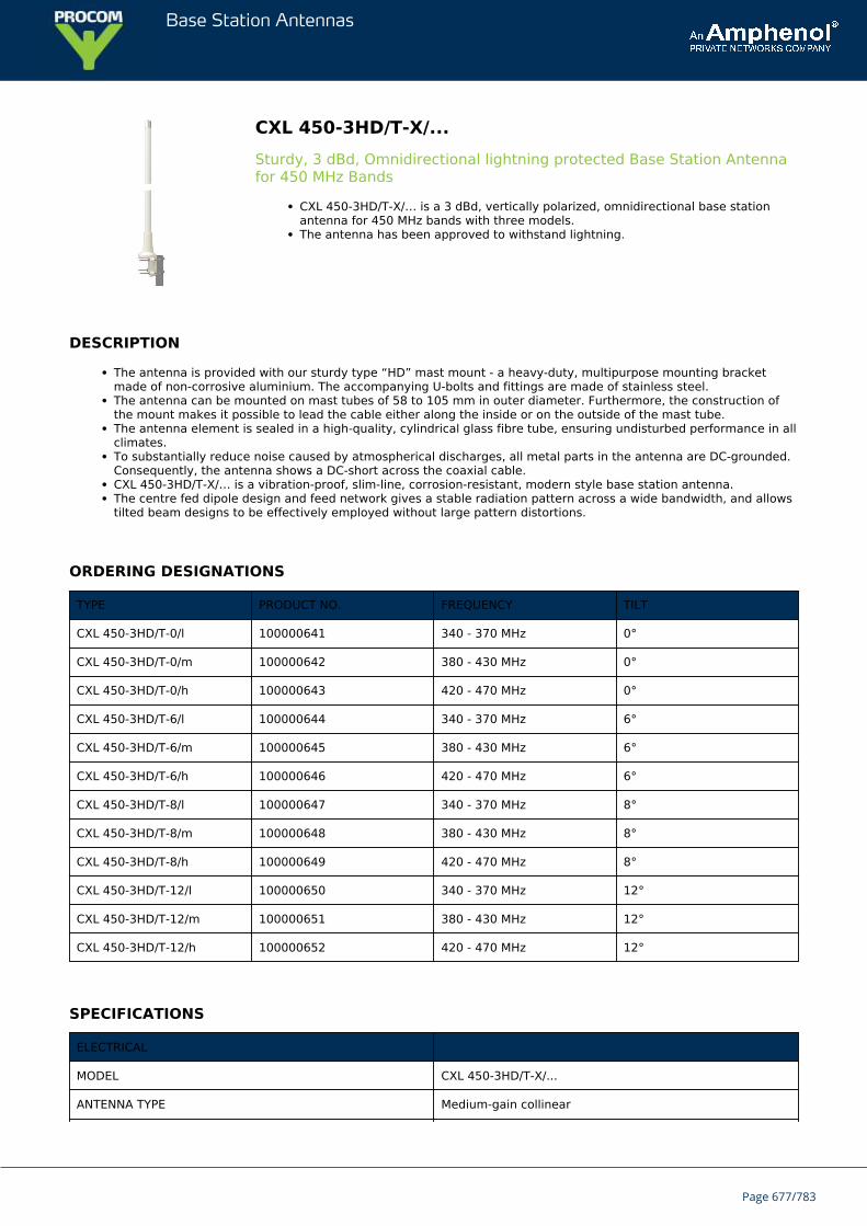
Base Station Antennas
CXL 450-3HD/T-X/...Sturdy, 3 dBd, Omnidirectional lightning protected Base Station Antennafor 450 MHz Bands
CXL 450-3HD/T-X/… is a 3 dBd, vertically polarized, omnidirectional base stationantenna for 450 MHz bands with three models.The antenna has been approved to withstand lightning.
DESCRIPTION
The antenna is provided with our sturdy type “HD” mast mount - a heavy-duty, multipurpose mounting bracketmade of non-corrosive aluminium. The accompanying U-bolts and fittings are made of stainless steel.The antenna can be mounted on mast tubes of 58 to 105 mm in outer diameter. Furthermore, the construction ofthe mount makes it possible to lead the cable either along the inside or on the outside of the mast tube.The antenna element is sealed in a high-quality, cylindrical glass fibre tube, ensuring undisturbed performance in allclimates.To substantially reduce noise caused by atmospherical discharges, all metal parts in the antenna are DC-grounded.Consequently, the antenna shows a DC-short across the coaxial cable.CXL 450-3HD/T-X/… is a vibration-proof, slim-line, corrosion-resistant, modern style base station antenna.The centre fed dipole design and feed network gives a stable radiation pattern across a wide bandwidth, and allowstilted beam designs to be effectively employed without large pattern distortions.
ORDERING DESIGNATIONS
TYPE PRODUCT NO. FREQUENCY TILT
CXL 450-3HD/T-0/l 100000641 340 - 370 MHz 0°
CXL 450-3HD/T-0/m 100000642 380 - 430 MHz 0°
CXL 450-3HD/T-0/h 100000643 420 - 470 MHz 0°
CXL 450-3HD/T-6/l 100000644 340 - 370 MHz 6°
CXL 450-3HD/T-6/m 100000645 380 - 430 MHz 6°
CXL 450-3HD/T-6/h 100000646 420 - 470 MHz 6°
CXL 450-3HD/T-8/l 100000647 340 - 370 MHz 8°
CXL 450-3HD/T-8/m 100000648 380 - 430 MHz 8°
CXL 450-3HD/T-8/h 100000649 420 - 470 MHz 8°
CXL 450-3HD/T-12/l 100000650 340 - 370 MHz 12°
CXL 450-3HD/T-12/m 100000651 380 - 430 MHz 12°
CXL 450-3HD/T-12/h 100000652 420 - 470 MHz 12°
SPECIFICATIONS
ELECTRICAL
MODEL CXL 450-3HD/T-X/...
ANTENNA TYPE Medium-gain collinear
Page 677/783
Base Station Antennas
FREQUENCY 340 - 470 MHz
IMPEDANCE Nom. 50 Ω
RADIATION Omnidirectional
POLARIZATION Vertical
GAIN 5 dBi 3 dBd
HALF POWER BEAMWIDTH 35°
SWR ≤ 1.5
MAX. POWER 300 W
ANTISTATIC PROTECTION All metal parts DC-grounded(Connector shows a DC-short)
AVAILABLE BEAMTILTS 0, 6, 8 and 12°
PIM -153 dBc @ 2x43 dBm
MECHANICAL
TEMP. RANGE -30°C to +70°C
CONNECTOR 7/16 DIN female
WIND SURFACE 0.09 m²
WIND LOAD 113 N @ 160 km/h
WIND VELOCITY Tested to 200 km/h
COLOUR Marine white
MATERIALS Radome: Polyurethane-coated glass fibreMounting bracket: Seawater resistant aluminium, polyester-coated
TOTAL HEIGHT Approx. 1.74 m / 68.5 in.
WEIGHT Approx. 6.35 kg / 14 Ib.
MOUNTING On 58 - 105 mm dia. mast tube
MULTI-PURPOSE MOUNTING BRACKET
Page 678/783
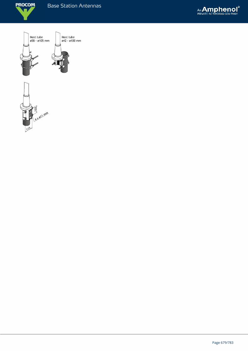
Base Station Antennas
Page 679/783
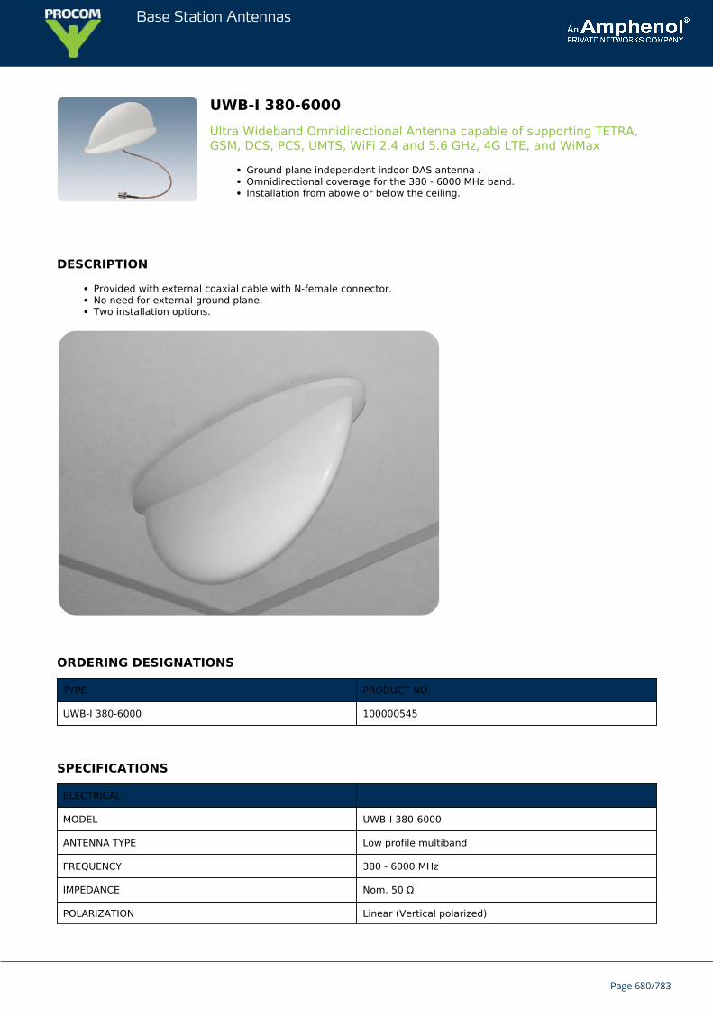
Base Station Antennas
UWB-I 380-6000Ultra Wideband Omnidirectional Antenna capable of supporting TETRA,GSM, DCS, PCS, UMTS, WiFi 2.4 and 5.6 GHz, 4G LTE, and WiMax
Ground plane independent indoor DAS antenna .Omnidirectional coverage for the 380 - 6000 MHz band.Installation from abowe or below the ceiling.
DESCRIPTION
Provided with external coaxial cable with N-female connector.No need for external ground plane.Two installation options.
ORDERING DESIGNATIONS
TYPE PRODUCT NO.
UWB-I 380-6000 100000545
SPECIFICATIONS
ELECTRICAL
MODEL UWB-I 380-6000
ANTENNA TYPE Low profile multiband
FREQUENCY 380 - 6000 MHz
IMPEDANCE Nom. 50 Ω
POLARIZATION Linear (Vertical polarized)
Page 680/783
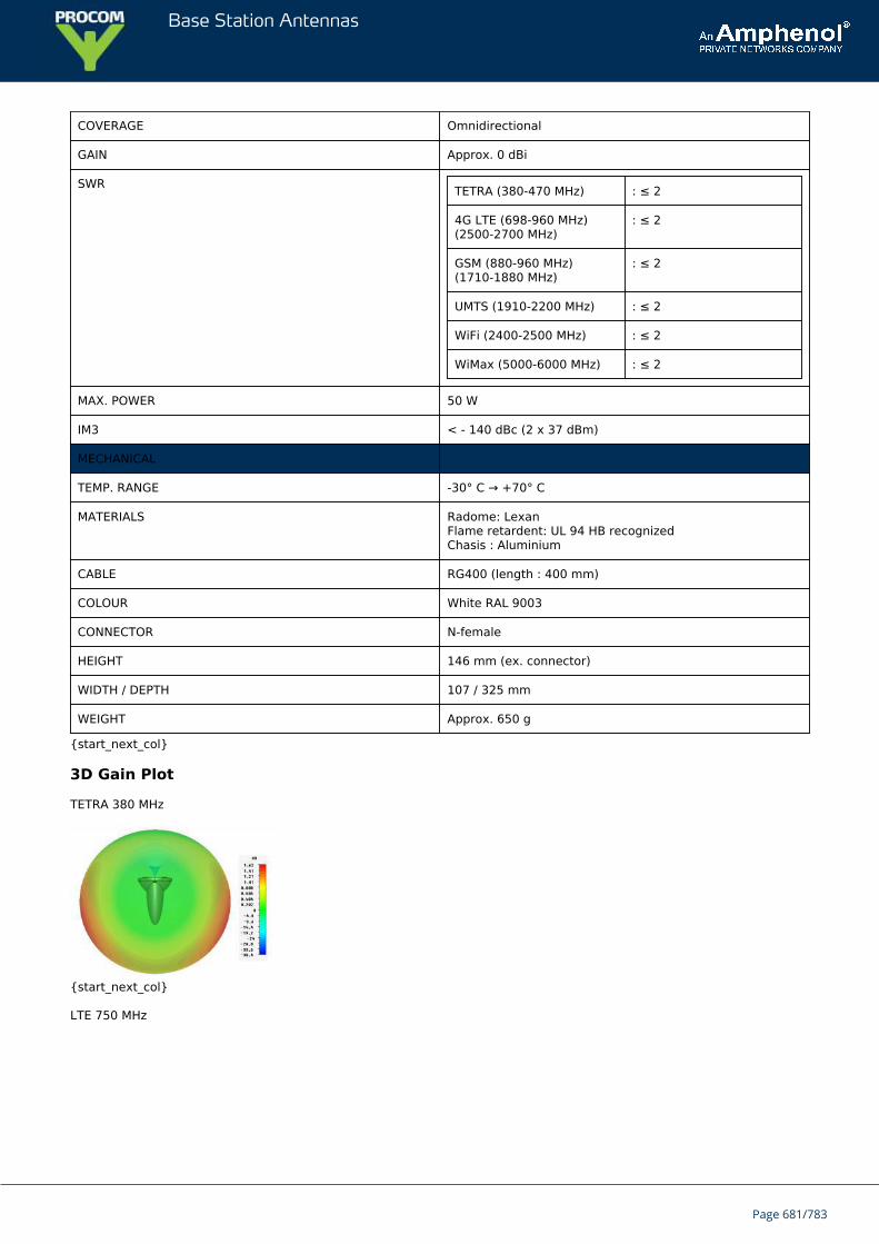
Base Station Antennas
COVERAGE Omnidirectional
GAIN Approx. 0 dBi
SWR TETRA (380-470 MHz) : ≤ 2
4G LTE (698-960 MHz)(2500-2700 MHz)
: ≤ 2
GSM (880-960 MHz)(1710-1880 MHz)
: ≤ 2
UMTS (1910-2200 MHz) : ≤ 2
WiFi (2400-2500 MHz) : ≤ 2
WiMax (5000-6000 MHz) : ≤ 2
MAX. POWER 50 W
IM3 < - 140 dBc (2 x 37 dBm)
MECHANICAL
TEMP. RANGE -30° C → +70° C
MATERIALS Radome: LexanFlame retardent: UL 94 HB recognizedChasis : Aluminium
CABLE RG400 (length : 400 mm)
COLOUR White RAL 9003
CONNECTOR N-female
HEIGHT 146 mm (ex. connector)
WIDTH / DEPTH 107 / 325 mm
WEIGHT Approx. 650 g
{start_next_col}
3D Gain Plot
TETRA 380 MHz
{start_next_col}
LTE 750 MHz
Page 681/783
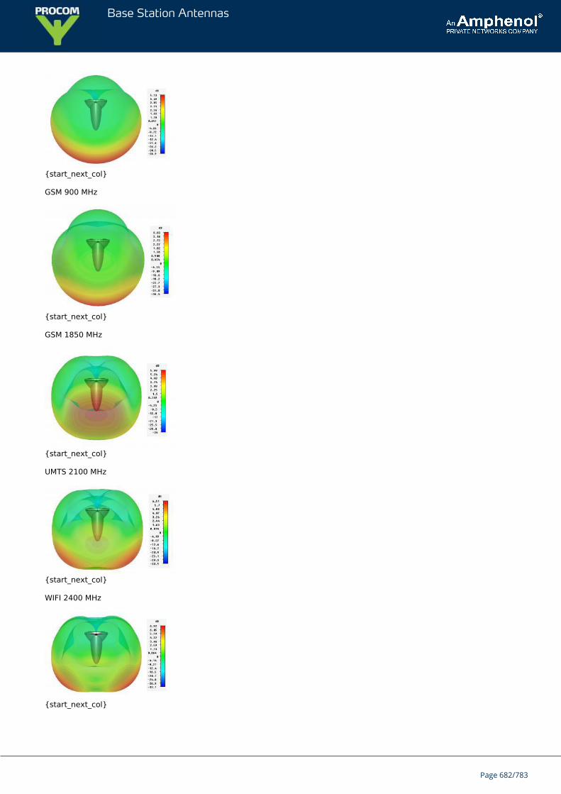
Base Station Antennas
{start_next_col}
GSM 900 MHz
{start_next_col}
GSM 1850 MHz
{start_next_col}
UMTS 2100 MHz
{start_next_col}
WIFI 2400 MHz
{start_next_col}
Page 682/783
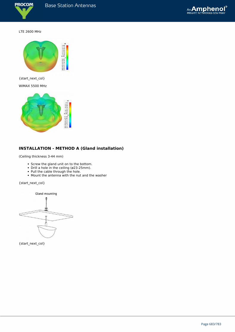
Base Station Antennas
LTE 2600 MHz
{start_next_col}
WIMAX 5500 MHz
INSTALLATION - METHOD A (Gland installation)
(Ceiling thickness 3-44 mm)
Screw the gland unit on to the bottom.Drill a hole in the ceiling (ø23-25mm).Pull the cable through the hole.Mount the antenna with the nut and the washer
{start_next_col}
{start_next_col}
Page 683/783
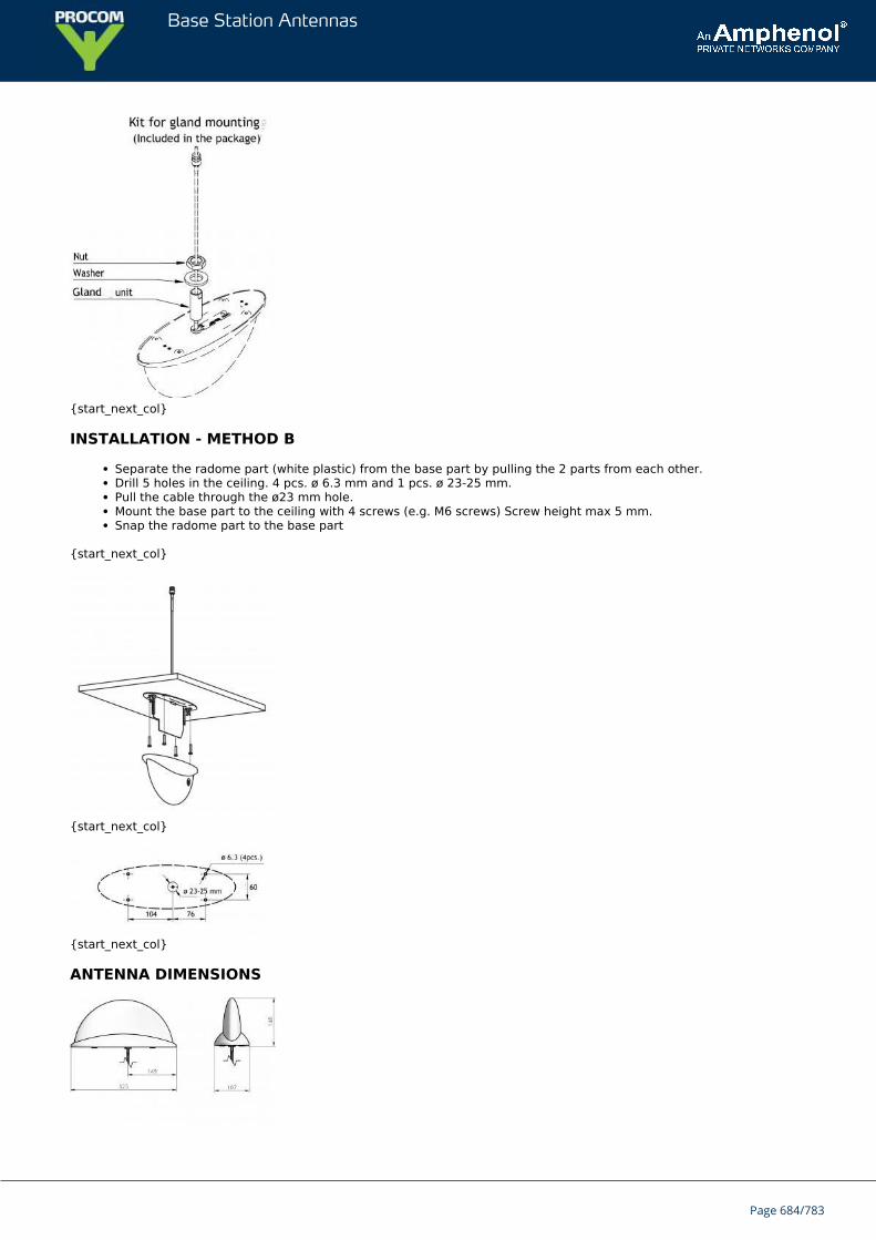
Base Station Antennas
{start_next_col}
INSTALLATION - METHOD B
Separate the radome part (white plastic) from the base part by pulling the 2 parts from each other.Drill 5 holes in the ceiling. 4 pcs. ø 6.3 mm and 1 pcs. ø 23-25 mm.Pull the cable through the ø23 mm hole.Mount the base part to the ceiling with 4 screws (e.g. M6 screws) Screw height max 5 mm.Snap the radome part to the base part
{start_next_col}
{start_next_col}
{start_next_col}
ANTENNA DIMENSIONS
Page 684/783
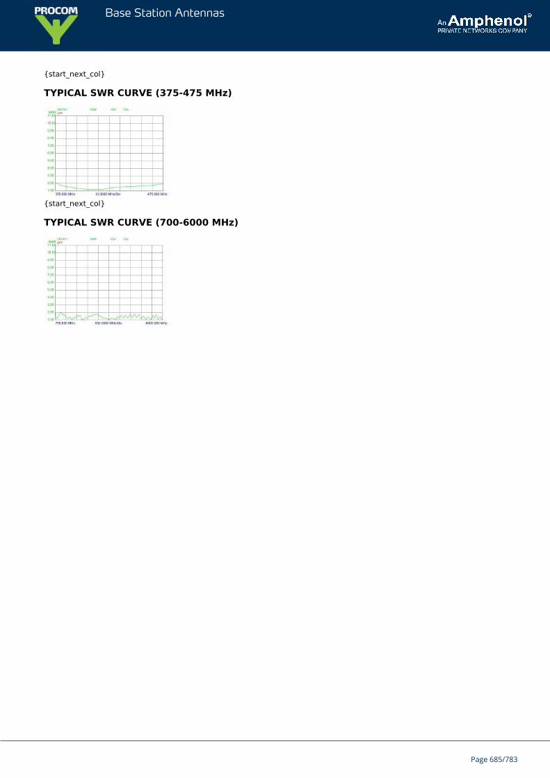
Base Station Antennas
{start_next_col}
TYPICAL SWR CURVE (375-475 MHz)
{start_next_col}
TYPICAL SWR CURVE (700-6000 MHz)
Page 685/783
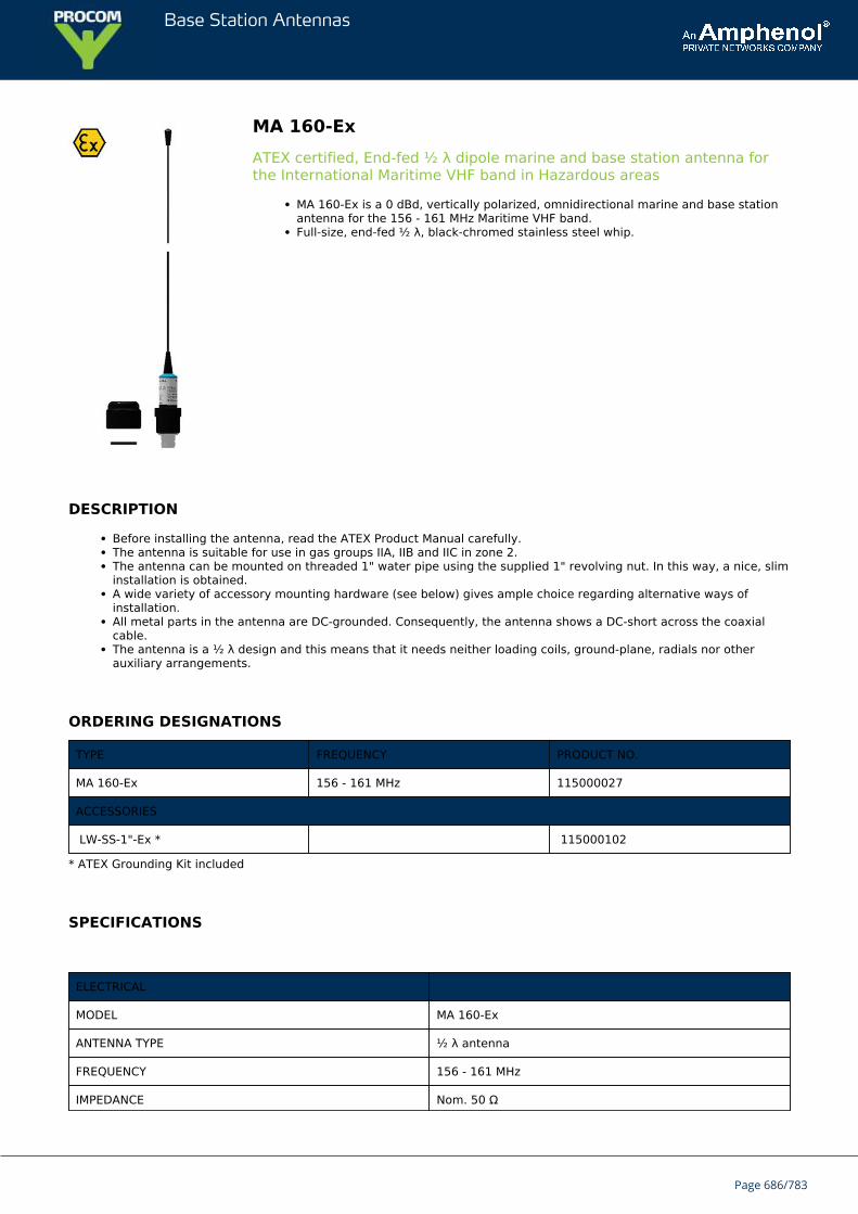
Base Station Antennas
MA 160-ExATEX certified, End-fed ½ λ dipole marine and base station antenna forthe International Maritime VHF band in Hazardous areas
MA 160-Ex is a 0 dBd, vertically polarized, omnidirectional marine and base stationantenna for the 156 - 161 MHz Maritime VHF band.Full-size, end-fed ½ λ, black-chromed stainless steel whip.
DESCRIPTION
Before installing the antenna, read the ATEX Product Manual carefully.The antenna is suitable for use in gas groups IIA, IIB and IIC in zone 2.The antenna can be mounted on threaded 1" water pipe using the supplied 1" revolving nut. In this way, a nice, sliminstallation is obtained.A wide variety of accessory mounting hardware (see below) gives ample choice regarding alternative ways ofinstallation.All metal parts in the antenna are DC-grounded. Consequently, the antenna shows a DC-short across the coaxialcable.The antenna is a ½ λ design and this means that it needs neither loading coils, ground-plane, radials nor otherauxiliary arrangements.
ORDERING DESIGNATIONS
TYPE FREQUENCY PRODUCT NO.
MA 160-Ex 156 - 161 MHz 115000027
ACCESSORIES
LW-SS-1"-Ex * 115000102
* ATEX Grounding Kit included
SPECIFICATIONS
ELECTRICAL
MODEL MA 160-Ex
ANTENNA TYPE ½ λ antenna
FREQUENCY 156 - 161 MHz
IMPEDANCE Nom. 50 Ω
Page 686/783
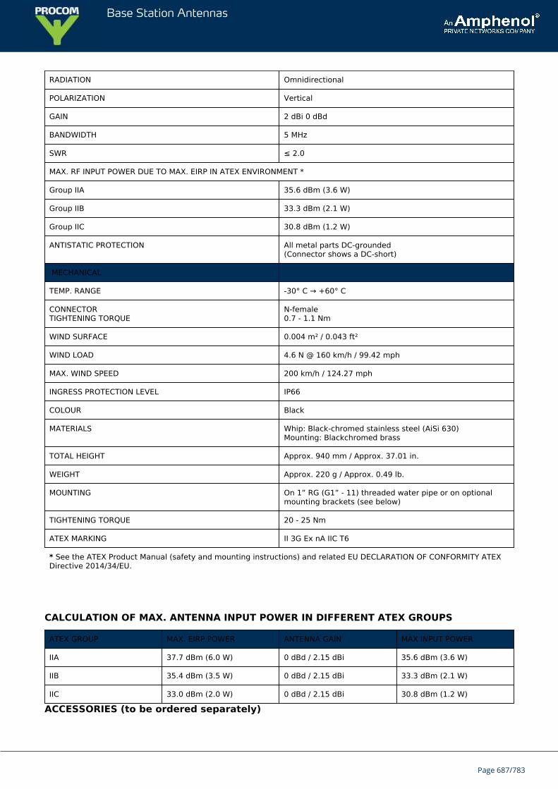
Base Station Antennas
RADIATION Omnidirectional
POLARIZATION Vertical
GAIN 2 dBi 0 dBd
BANDWIDTH 5 MHz
SWR ≤ 2.0
MAX. RF INPUT POWER DUE TO MAX. EIRP IN ATEX ENVIRONMENT *
Group IIA 35.6 dBm (3.6 W)
Group IIB 33.3 dBm (2.1 W)
Group IIC 30.8 dBm (1.2 W)
ANTISTATIC PROTECTION All metal parts DC-grounded(Connector shows a DC-short)
MECHANICAL
TEMP. RANGE -30° C → +60° C
CONNECTORTIGHTENING TORQUE
N-female0.7 - 1.1 Nm
WIND SURFACE 0.004 m² / 0.043 ft²
WIND LOAD 4.6 N @ 160 km/h / 99.42 mph
MAX. WIND SPEED 200 km/h / 124.27 mph
INGRESS PROTECTION LEVEL IP66
COLOUR Black
MATERIALS Whip: Black-chromed stainless steel (AiSi 630)Mounting: Blackchromed brass
TOTAL HEIGHT Approx. 940 mm / Approx. 37.01 in.
WEIGHT Approx. 220 g / Approx. 0.49 lb.
MOUNTING On 1” RG (G1” - 11) threaded water pipe or on optionalmounting brackets (see below)
TIGHTENING TORQUE 20 - 25 Nm
ATEX MARKING II 3G Ex nA IIC T6
* See the ATEX Product Manual (safety and mounting instructions) and related EU DECLARATION OF CONFORMITY ATEXDirective 2014/34/EU.
CALCULATION OF MAX. ANTENNA INPUT POWER IN DIFFERENT ATEX GROUPS
ATEX GROUP MAX. EIRP POWER ANTENNA GAIN MAX INPUT POWER
IIA 37.7 dBm (6.0 W) 0 dBd / 2.15 dBi 35.6 dBm (3.6 W)
IIB 35.4 dBm (3.5 W) 0 dBd / 2.15 dBi 33.3 dBm (2.1 W)
IIC 33.0 dBm (2.0 W) 0 dBd / 2.15 dBi 30.8 dBm (1.2 W)
ACCESSORIES (to be ordered separately)
Page 687/783
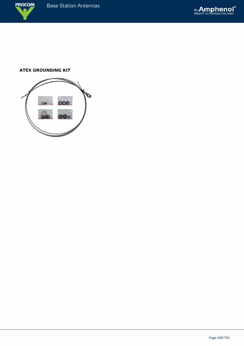
Base Station Antennas
ATEX GROUNDING KIT
Page 688/783
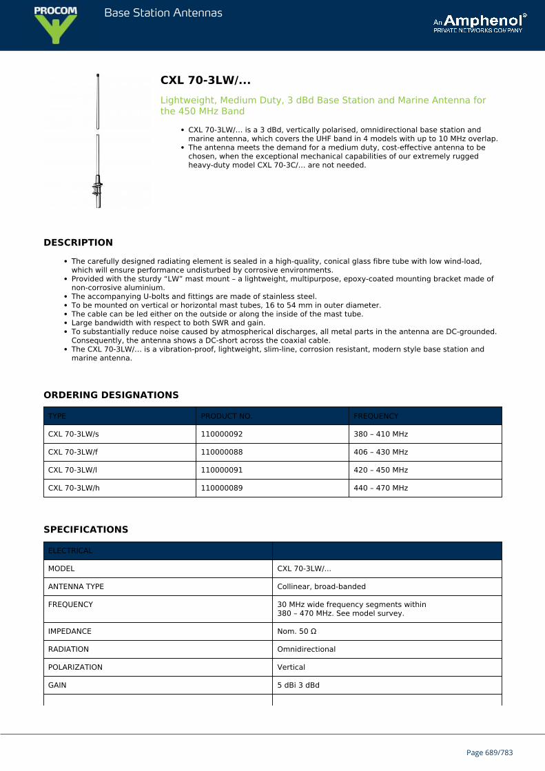
Base Station Antennas
CXL 70-3LW/...Lightweight, Medium Duty, 3 dBd Base Station and Marine Antenna forthe 450 MHz Band
CXL 70-3LW/… is a 3 dBd, vertically polarised, omnidirectional base station andmarine antenna, which covers the UHF band in 4 models with up to 10 MHz overlap.The antenna meets the demand for a medium duty, cost-effective antenna to bechosen, when the exceptional mechanical capabilities of our extremely ruggedheavy-duty model CXL 70-3C/… are not needed.
DESCRIPTION
The carefully designed radiating element is sealed in a high-quality, conical glass fibre tube with low wind-load,which will ensure performance undisturbed by corrosive environments.Provided with the sturdy “LW” mast mount – a lightweight, multipurpose, epoxy-coated mounting bracket made ofnon-corrosive aluminium.The accompanying U-bolts and fittings are made of stainless steel.To be mounted on vertical or horizontal mast tubes, 16 to 54 mm in outer diameter.The cable can be led either on the outside or along the inside of the mast tube.Large bandwidth with respect to both SWR and gain.To substantially reduce noise caused by atmospherical discharges, all metal parts in the antenna are DC-grounded.Consequently, the antenna shows a DC-short across the coaxial cable.The CXL 70-3LW/… is a vibration-proof, lightweight, slim-line, corrosion resistant, modern style base station andmarine antenna.
ORDERING DESIGNATIONS
TYPE PRODUCT NO. FREQUENCY
CXL 70-3LW/s 110000092 380 – 410 MHz
CXL 70-3LW/f 110000088 406 – 430 MHz
CXL 70-3LW/l 110000091 420 – 450 MHz
CXL 70-3LW/h 110000089 440 – 470 MHz
SPECIFICATIONS
ELECTRICAL
MODEL CXL 70-3LW/...
ANTENNA TYPE Collinear, broad-banded
FREQUENCY 30 MHz wide frequency segments within380 – 470 MHz. See model survey.
IMPEDANCE Nom. 50 Ω
RADIATION Omnidirectional
POLARIZATION Vertical
GAIN 5 dBi 3 dBd
Page 689/783
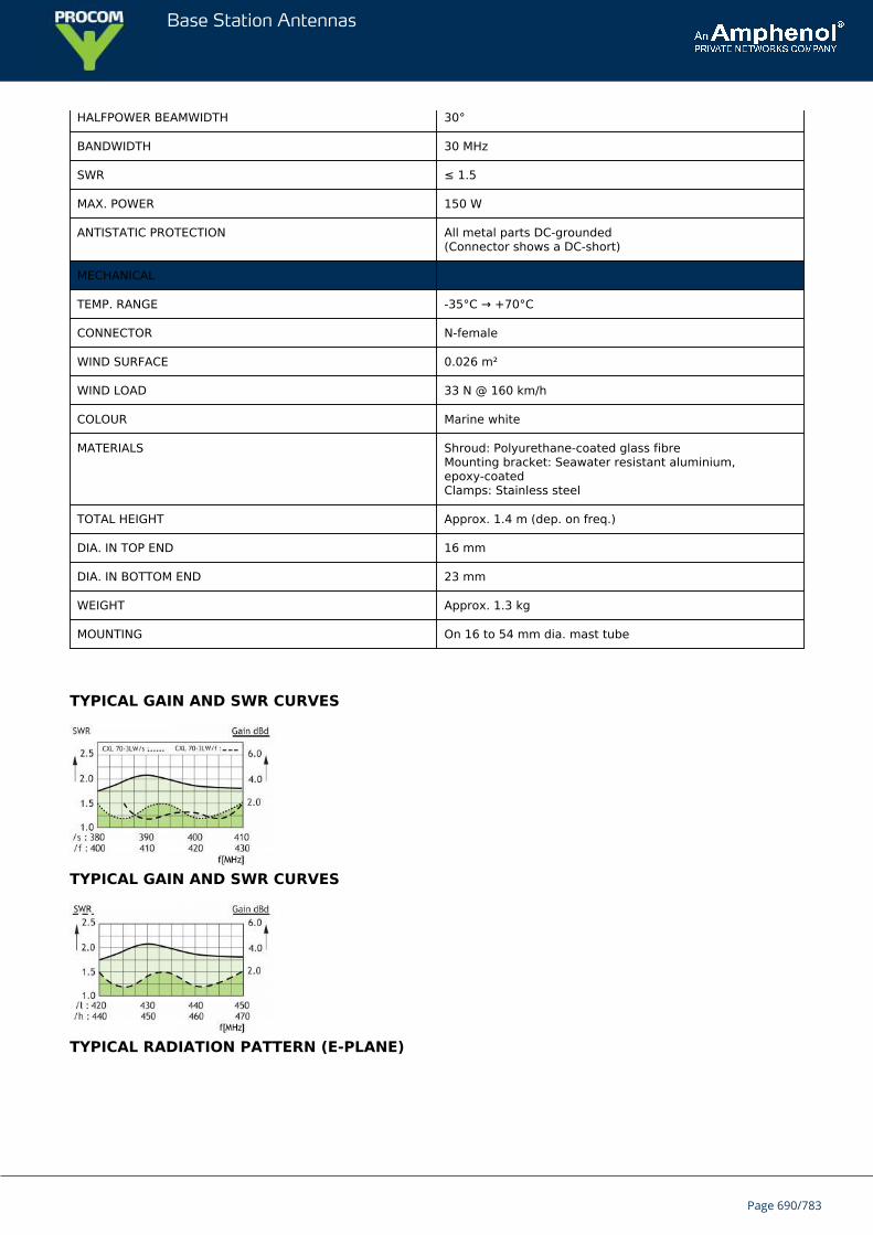
Base Station Antennas
HALFPOWER BEAMWIDTH 30°
BANDWIDTH 30 MHz
SWR ≤ 1.5
MAX. POWER 150 W
ANTISTATIC PROTECTION All metal parts DC-grounded(Connector shows a DC-short)
MECHANICAL
TEMP. RANGE -35°C → +70°C
CONNECTOR N-female
WIND SURFACE 0.026 m²
WIND LOAD 33 N @ 160 km/h
COLOUR Marine white
MATERIALS Shroud: Polyurethane-coated glass fibreMounting bracket: Seawater resistant aluminium,epoxy-coatedClamps: Stainless steel
TOTAL HEIGHT Approx. 1.4 m (dep. on freq.)
DIA. IN TOP END 16 mm
DIA. IN BOTTOM END 23 mm
WEIGHT Approx. 1.3 kg
MOUNTING On 16 to 54 mm dia. mast tube
TYPICAL GAIN AND SWR CURVES
TYPICAL GAIN AND SWR CURVES
TYPICAL RADIATION PATTERN (E-PLANE)
Page 690/783
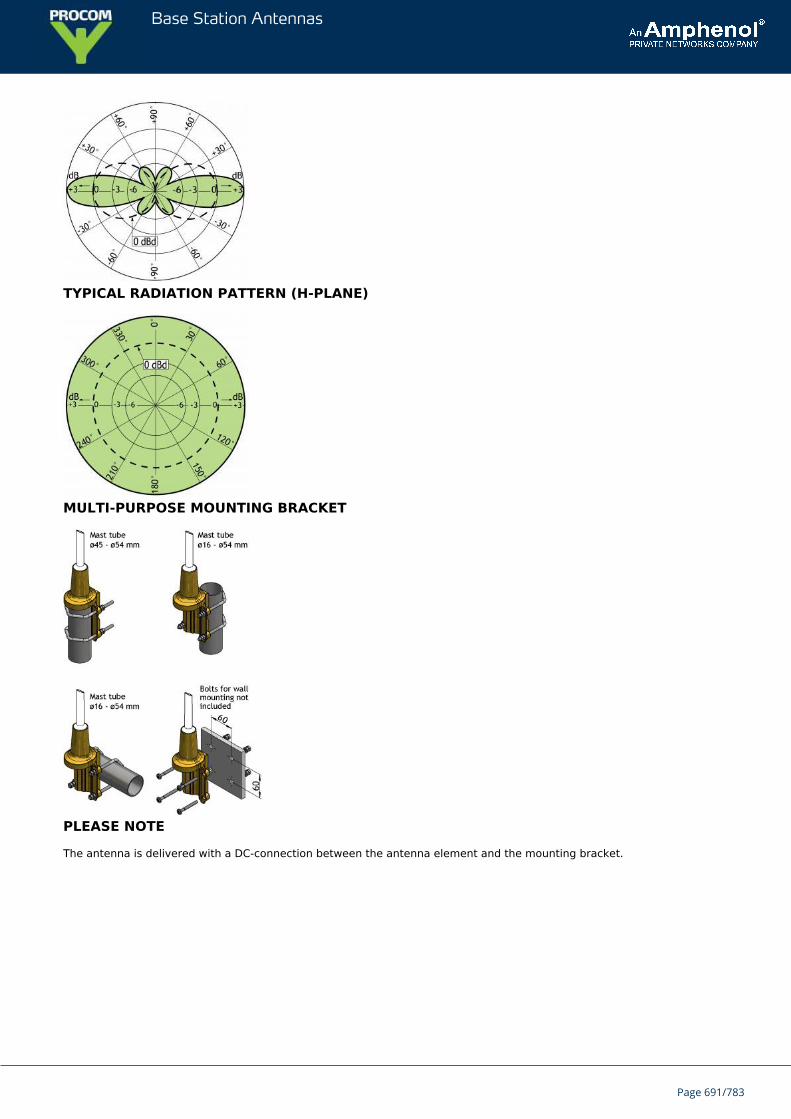
Base Station Antennas
TYPICAL RADIATION PATTERN (H-PLANE)
MULTI-PURPOSE MOUNTING BRACKET
PLEASE NOTE
The antenna is delivered with a DC-connection between the antenna element and the mounting bracket.
Page 691/783
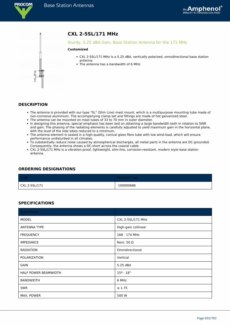
Base Station Antennas
CXL 2-5SL/171 MHzSturdy, 5.25 dBd Gain, Base Station Antenna for the 171 MHzCustomized
CXL 2-5SL/171 MHz is a 5.25 dBd, vertically polarized, omnidirectional base stationantenna.The antenna has a bandwidth of 6 MHz.
DESCRIPTION
The antenna is provided with our type "SL" (Slim Line) mast mount, which is a multipurpose mounting tube made ofnon-corrosive aluminium. The accompanying clamp set and fittings are made of hot galvanized steel.The antenna can be mounted on mast tubes of 33 to 70 mm in outer diameter.In designing this antenna, special emphasis has been laid on obtaining a large bandwidth both in relation to SWRand gain. The phasing of the radiating elements is carefully adjusted to yield maximum gain in the horizontal plane,with the level of the side lobes reduced to a minimum.The antenna element is sealed in a high-quality, conical glass fibre tube with low wind-load, which will ensureperformance undisturbed in all climates.To substantially reduce noise caused by atmospherical discharges, all metal parts in the antenna are DC-grounded.Consequently, the antenna shows a DC-short across the coaxial cable.CXL 2-5SL/171 MHz is a vibration-proof, lightweight, slim-line, corrosion-resistant, modern style base stationantenna.
ORDERING DESIGNATIONS
TYPE PRODUCT NO.
CXL 2-5SL/171 100000686
SPECIFICATIONS
ELECTRICAL
MODEL CXL 2-5SL/171 MHz
ANTENNA TYPE High-gain collinear
FREQUENCY 168 - 174 MHz
IMPEDANCE Nom. 50 Ω
RADIATION Omnidirectional
POLARIZATION Vertical
GAIN 5.25 dBd
HALF POWER BEAMWIDTH 15º - 18°
BANDWIDTH 6 MHz
SWR ≤ 1.75
MAX. POWER 500 W
Page 692/783
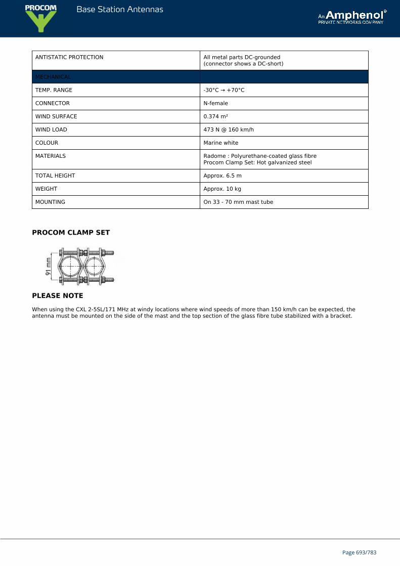
Base Station Antennas
ANTISTATIC PROTECTION All metal parts DC-grounded(connector shows a DC-short)
MECHANICAL
TEMP. RANGE -30°C → +70°C
CONNECTOR N-female
WIND SURFACE 0.374 m²
WIND LOAD 473 N @ 160 km/h
COLOUR Marine white
MATERIALS Radome : Polyurethane-coated glass fibreProcom Clamp Set: Hot galvanized steel
TOTAL HEIGHT Approx. 6.5 m
WEIGHT Approx. 10 kg
MOUNTING On 33 - 70 mm mast tube
PROCOM CLAMP SET
PLEASE NOTE
When using the CXL 2-5SL/171 MHz at windy locations where wind speeds of more than 150 km/h can be expected, theantenna must be mounted on the side of the mast and the top section of the glass fibre tube stabilized with a bracket.
Page 693/783
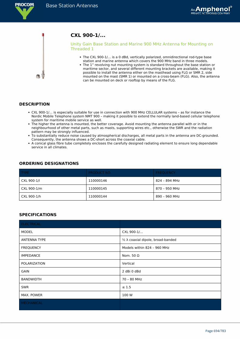
Base Station Antennas
CXL 900-1/...Unity Gain Base Station and Marine 900 MHz Antenna for Mounting onThreaded 1
The CXL 900-1/… is a 0 dBd, vertically polarized, omnidirectional rod-type basestation and marine antenna which covers the 900 MHz band in three models.The 1” revolving nut mounting system is standard throughout the base station ormaritime sector, and several different mounting brackets are available, making itpossible to install the antenna either on the masthead using FLG or SMR 2, sidemounted on the mast (SMR 1) or mounted on a cross-beam (FLG). Also, the antennacan be mounted on deck or rooftop by means of the FLG.
DESCRIPTION
CXL 900-1/… is especially suitable for use in connection with 900 MHz CELLULAR systems – as for instance theNordic Mobile Telephone system NMT 900 – making it possible to extend the normally land-based cellular telephonesystem for maritime mobile service as well.The higher the antenna is mounted, the better coverage. Avoid mounting the antenna parallel with or in theneighbourhood of other metal parts, such as masts, supporting wires etc., otherwise the SWR and the radiationpattern may be strongly influenced.To substantially reduce noise caused by atmospherical discharges, all metal parts in the antenna are DC-grounded.Consequently, the antenna shows a DC-short across the coaxial cable.A conical glass fibre tube completely encloses the carefully designed radiating element to ensure long dependableservice in all climates.
ORDERING DESIGNATIONS
TYPE PRODUCT NO. FREQUENCY
CXL 900-1/l 110000146 824 – 894 MHz
CXL 900-1/m 110000145 870 – 950 MHz
CXL 900-1/h 110000144 890 – 960 MHz
SPECIFICATIONS
ELECTRICAL
MODEL CXL 900-1/...
ANTENNA TYPE ½ λ coaxial dipole, broad-banded
FREQUENCY Models within 824 – 960 MHz
IMPEDANCE Nom. 50 Ω
POLARIZATION Vertical
GAIN 2 dBi 0 dBd
BANDWIDTH 70 – 80 MHz
SWR ≤ 1.5
MAX. POWER 100 W
MECHANICAL
Page 694/783
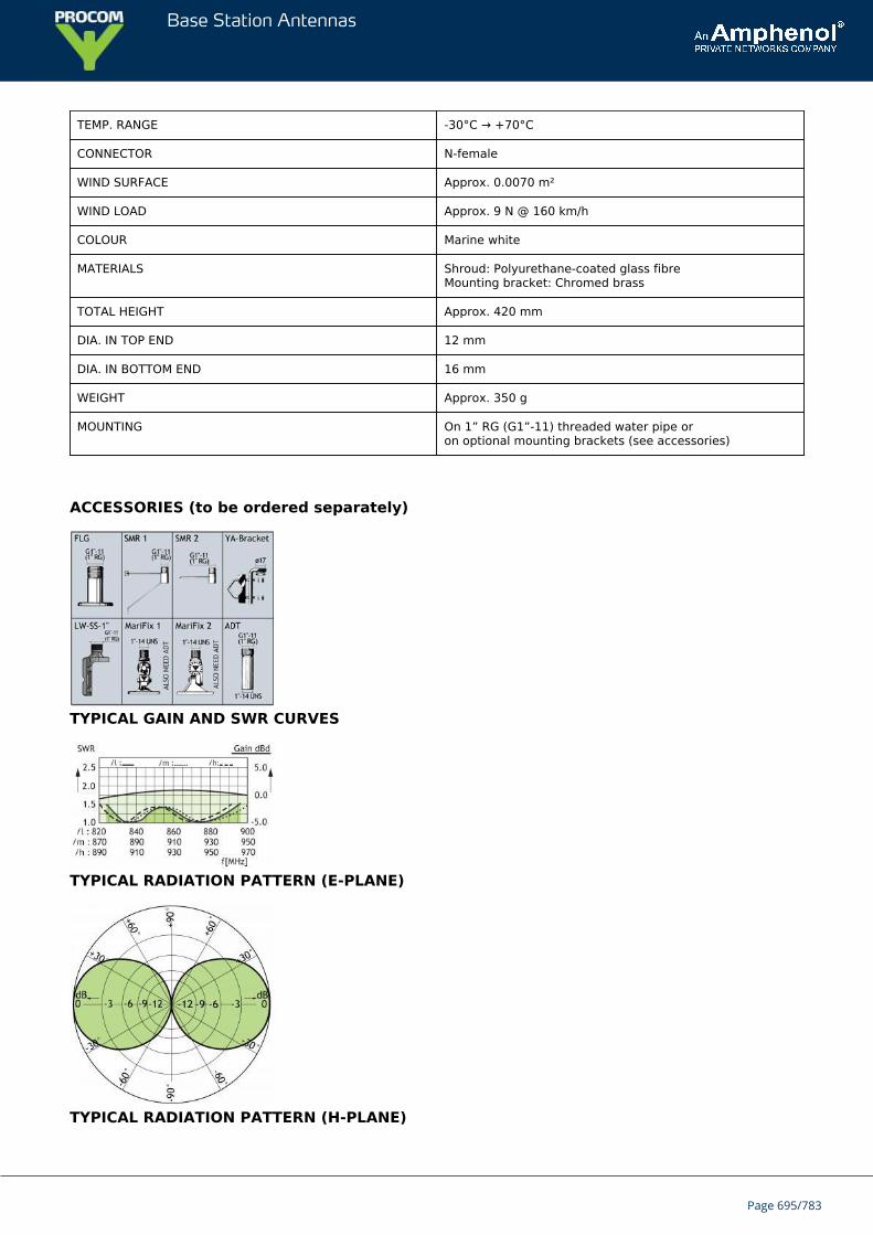
Base Station Antennas
TEMP. RANGE -30°C → +70°C
CONNECTOR N-female
WIND SURFACE Approx. 0.0070 m²
WIND LOAD Approx. 9 N @ 160 km/h
COLOUR Marine white
MATERIALS Shroud: Polyurethane-coated glass fibreMounting bracket: Chromed brass
TOTAL HEIGHT Approx. 420 mm
DIA. IN TOP END 12 mm
DIA. IN BOTTOM END 16 mm
WEIGHT Approx. 350 g
MOUNTING On 1” RG (G1”-11) threaded water pipe oron optional mounting brackets (see accessories)
ACCESSORIES (to be ordered separately)
TYPICAL GAIN AND SWR CURVES
TYPICAL RADIATION PATTERN (E-PLANE)
TYPICAL RADIATION PATTERN (H-PLANE)
Page 695/783

Base Station Antennas
Page 696/783
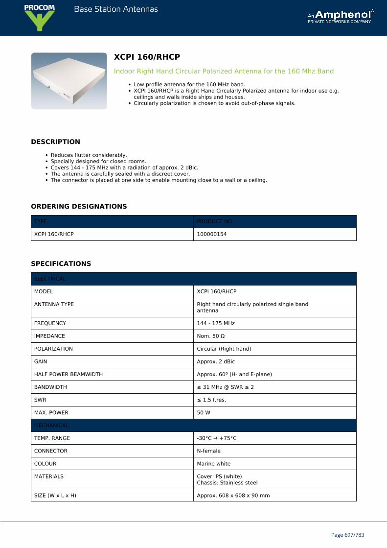
Base Station Antennas
XCPI 160/RHCPIndoor Right Hand Circular Polarized Antenna for the 160 Mhz Band
Low profile antenna for the 160 MHz band.XCPI 160/RHCP is a Right Hand Circularly Polarized antenna for indoor use e.g.ceilings and walls inside ships and houses.Circularly polarization is chosen to avoid out-of-phase signals.
DESCRIPTION
Reduces flutter considerably.Specially designed for closed rooms.Covers 144 - 175 MHz with a radiation of approx. 2 dBic.The antenna is carefully sealed with a discreet cover.The connector is placed at one side to enable mounting close to a wall or a ceiling.
ORDERING DESIGNATIONS
TYPE PRODUCT NO.
XCPI 160/RHCP 100000154
SPECIFICATIONS
ELECTRICAL
MODEL XCPI 160/RHCP
ANTENNA TYPE Right hand circularly polarized single bandantenna
FREQUENCY 144 - 175 MHz
IMPEDANCE Nom. 50 Ω
POLARIZATION Circular (Right hand)
GAIN Approx. 2 dBic
HALF POWER BEAMWIDTH Approx. 60º (H- and E-plane)
BANDWIDTH ≥ 31 MHz @ SWR ≤ 2
SWR ≤ 1.5 f.res.
MAX. POWER 50 W
MECHANICAL
TEMP. RANGE -30°C → +75°C
CONNECTOR N-female
COLOUR Marine white
MATERIALS Cover: PS (white)Chassis: Stainless steel
SIZE (W x L x H) Approx. 608 x 608 x 90 mm
Page 697/783
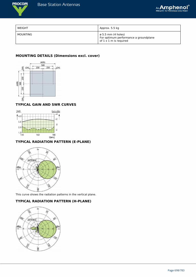
Base Station Antennas
WEIGHT Approx. 5.5 kg
MOUNTING ø 5.5 mm (4 holes)For optimum performance a groundplaneof 1 x 1 m is required
MOUNTING DETAILS (Dimensions excl. cover)
TYPICAL GAIN AND SWR CURVES
TYPICAL RADIATION PATTERN (E-PLANE)
This curve shows the radiation patterns in the vertical plane.
TYPICAL RADIATION PATTERN (H-PLANE)
Page 698/783

Base Station Antennas
This curve shows the radiation patterns in the horizontal plane (horizontal coverage).
Page 699/783
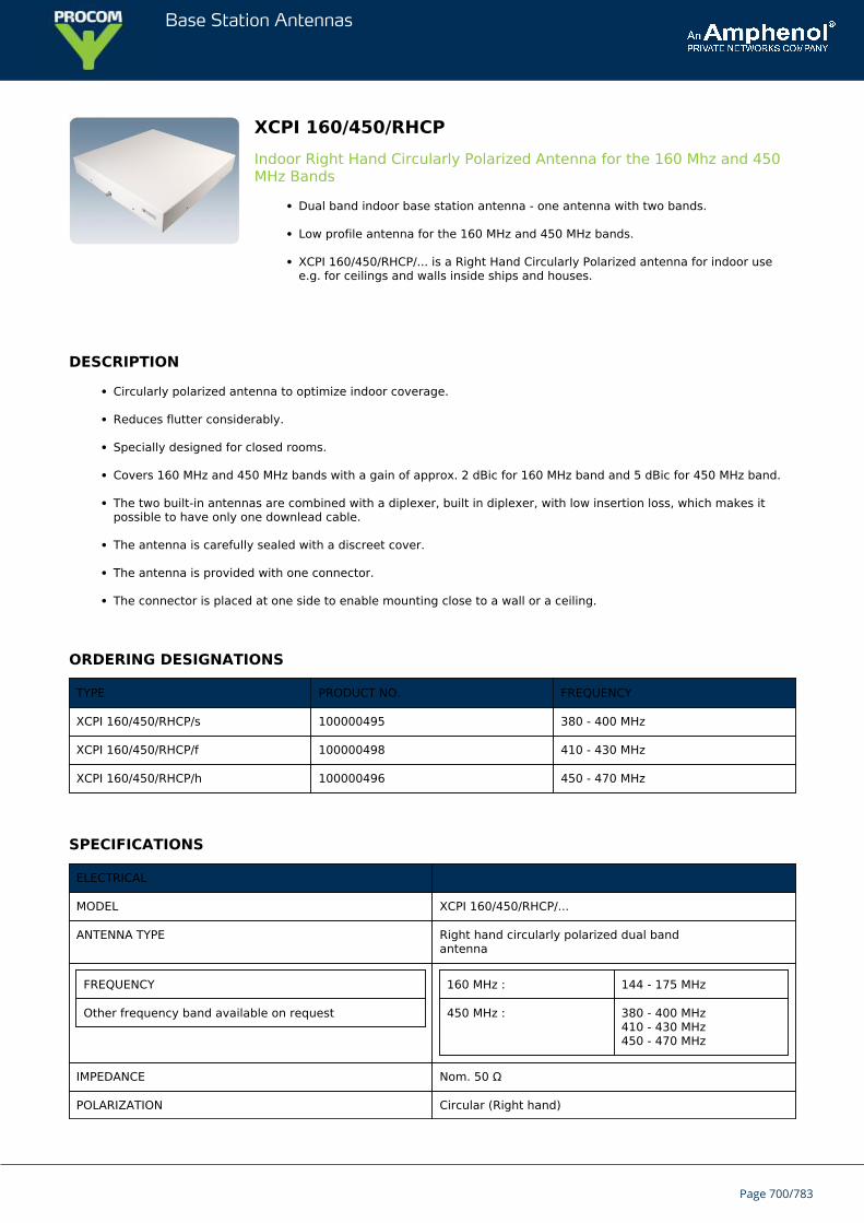
Base Station Antennas
XCPI 160/450/RHCPIndoor Right Hand Circularly Polarized Antenna for the 160 Mhz and 450MHz Bands
Dual band indoor base station antenna - one antenna with two bands.
Low profile antenna for the 160 MHz and 450 MHz bands.
XCPI 160/450/RHCP/... is a Right Hand Circularly Polarized antenna for indoor usee.g. for ceilings and walls inside ships and houses.
DESCRIPTION
Circularly polarized antenna to optimize indoor coverage.
Reduces flutter considerably.
Specially designed for closed rooms.
Covers 160 MHz and 450 MHz bands with a gain of approx. 2 dBic for 160 MHz band and 5 dBic for 450 MHz band.
The two built-in antennas are combined with a diplexer, built in diplexer, with low insertion loss, which makes itpossible to have only one downlead cable.
The antenna is carefully sealed with a discreet cover.
The antenna is provided with one connector.
The connector is placed at one side to enable mounting close to a wall or a ceiling.
ORDERING DESIGNATIONS
TYPE PRODUCT NO. FREQUENCY
XCPI 160/450/RHCP/s 100000495 380 - 400 MHz
XCPI 160/450/RHCP/f 100000498 410 - 430 MHz
XCPI 160/450/RHCP/h 100000496 450 - 470 MHz
SPECIFICATIONS
ELECTRICAL
MODEL XCPI 160/450/RHCP/...
ANTENNA TYPE Right hand circularly polarized dual bandantenna
FREQUENCY
Other frequency band available on request
160 MHz : 144 - 175 MHz
450 MHz : 380 - 400 MHz410 - 430 MHz450 - 470 MHz
IMPEDANCE Nom. 50 Ω
POLARIZATION Circular (Right hand)
Page 700/783
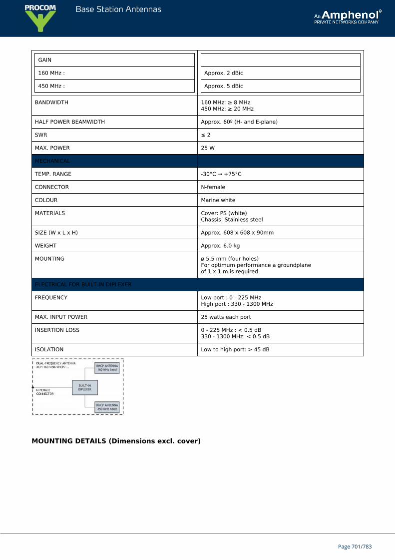
Base Station Antennas
GAIN
160 MHz :
450 MHz :
Approx. 2 dBic
Approx. 5 dBic
BANDWIDTH 160 MHz: ≥ 8 MHz450 MHz: ≥ 20 MHz
HALF POWER BEAMWIDTH Approx. 60º (H- and E-plane)
SWR ≤ 2
MAX. POWER 25 W
MECHANICAL
TEMP. RANGE -30°C → +75°C
CONNECTOR N-female
COLOUR Marine white
MATERIALS Cover: PS (white)Chassis: Stainless steel
SIZE (W x L x H) Approx. 608 x 608 x 90mm
WEIGHT Approx. 6.0 kg
MOUNTING ø 5.5 mm (four holes)For optimum performance a groundplaneof 1 x 1 m is required
ELECTRICAL FOR BUILT-IN DIPLEXER
FREQUENCY Low port : 0 - 225 MHzHigh port : 330 - 1300 MHz
MAX. INPUT POWER 25 watts each port
INSERTION LOSS 0 - 225 MHz : < 0.5 dB330 - 1300 MHz: < 0.5 dB
ISOLATION Low to high port: > 45 dB
MOUNTING DETAILS (Dimensions excl. cover)
Page 701/783
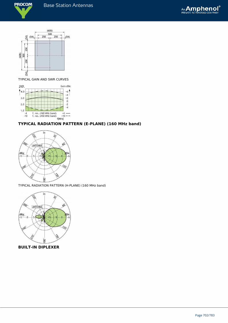
Base Station Antennas
TYPICAL GAIN AND SWR CURVES
TYPICAL RADIATION PATTERN (E-PLANE) (160 MHz band)
TYPICAL RADIATION PATTERN (H-PLANE) (160 MHz band)
BUILT-IN DIPLEXER
Page 702/783
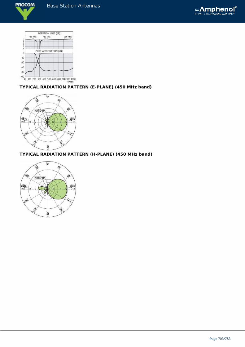
Base Station Antennas
TYPICAL RADIATION PATTERN (E-PLANE) (450 MHz band)
TYPICAL RADIATION PATTERN (H-PLANE) (450 MHz band)
Page 703/783
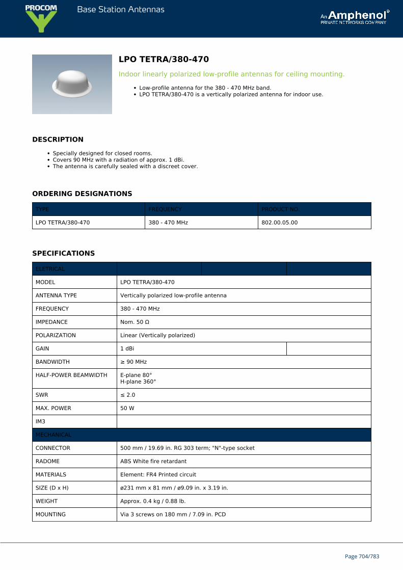
Base Station Antennas
LPO TETRA/380-470Indoor linearly polarized low-profile antennas for ceiling mounting.
Low-profile antenna for the 380 - 470 MHz band.LPO TETRA/380-470 is a vertically polarized antenna for indoor use.
DESCRIPTION
Specially designed for closed rooms.Covers 90 MHz with a radiation of approx. 1 dBi.The antenna is carefully sealed with a discreet cover.
ORDERING DESIGNATIONS
TYPE FREQUENCY PRODUCT NO.
LPO TETRA/380-470 380 - 470 MHz 802.00.05.00
SPECIFICATIONS
ELETRICAL
MODEL LPO TETRA/380-470
ANTENNA TYPE Vertically polarized low-profile antenna
FREQUENCY 380 - 470 MHz
IMPEDANCE Nom. 50 Ω
POLARIZATION Linear (Vertically polarized)
GAIN 1 dBi
BANDWIDTH ≥ 90 MHz
HALF-POWER BEAMWIDTH E-plane 80°H-plane 360°
SWR ≤ 2.0
MAX. POWER 50 W
IM3
MECHANICAL
CONNECTOR 500 mm / 19.69 in. RG 303 term; "N"-type socket
RADOME ABS White fire retardant
MATERIALS Element: FR4 Printed circuit
SIZE (D x H) ø231 mm x 81 mm / ø9.09 in. x 3.19 in.
WEIGHT Approx. 0.4 kg / 0.88 lb.
MOUNTING Via 3 screws on 180 mm / 7.09 in. PCD
Page 704/783
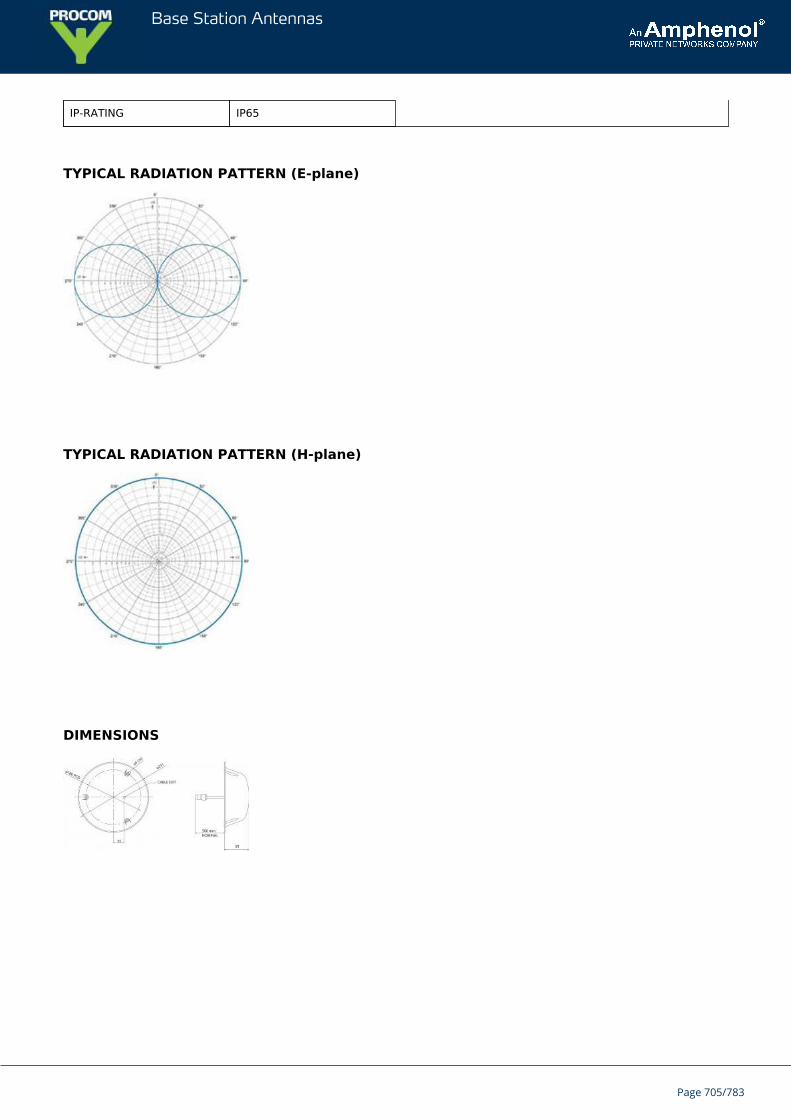
Base Station Antennas
IP-RATING IP65
TYPICAL RADIATION PATTERN (E-plane)
TYPICAL RADIATION PATTERN (H-plane)
DIMENSIONS
Page 705/783
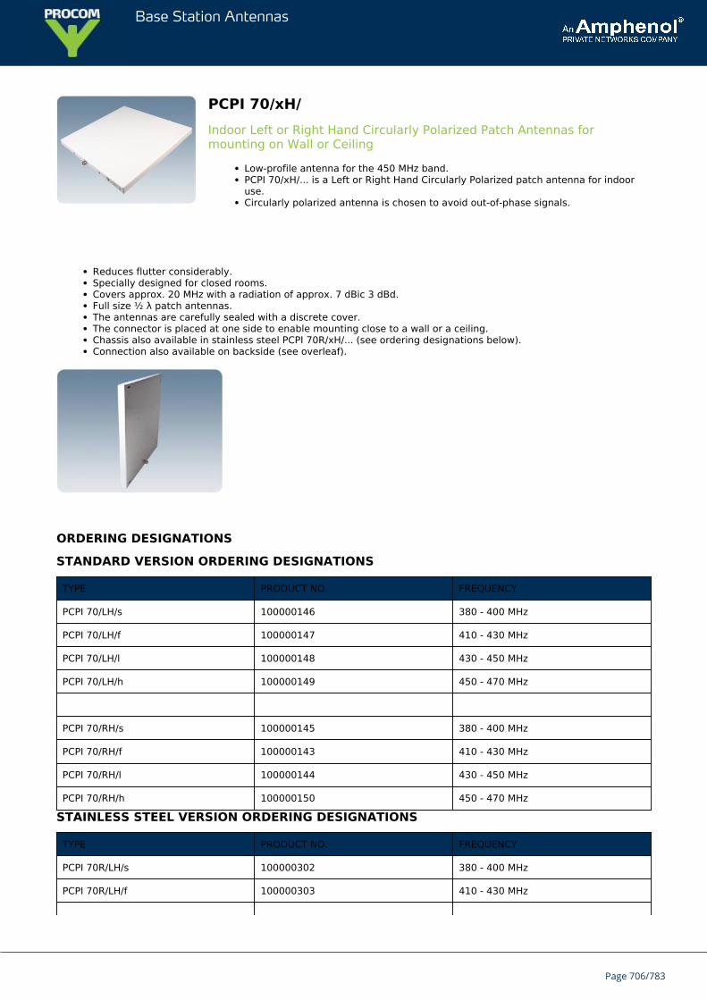
Base Station Antennas
PCPI 70/xH/Indoor Left or Right Hand Circularly Polarized Patch Antennas formounting on Wall or Ceiling
Low-profile antenna for the 450 MHz band.PCPI 70/xH/... is a Left or Right Hand Circularly Polarized patch antenna for indooruse.Circularly polarized antenna is chosen to avoid out-of-phase signals.
Reduces flutter considerably.Specially designed for closed rooms.Covers approx. 20 MHz with a radiation of approx. 7 dBic 3 dBd.Full size ½ λ patch antennas.The antennas are carefully sealed with a discrete cover.The connector is placed at one side to enable mounting close to a wall or a ceiling.Chassis also available in stainless steel PCPI 70R/xH/... (see ordering designations below).Connection also available on backside (see overleaf).
ORDERING DESIGNATIONS
STANDARD VERSION ORDERING DESIGNATIONS
TYPE PRODUCT NO. FREQUENCY
PCPI 70/LH/s 100000146 380 - 400 MHz
PCPI 70/LH/f 100000147 410 - 430 MHz
PCPI 70/LH/l 100000148 430 - 450 MHz
PCPI 70/LH/h 100000149 450 - 470 MHz
PCPI 70/RH/s 100000145 380 - 400 MHz
PCPI 70/RH/f 100000143 410 - 430 MHz
PCPI 70/RH/l 100000144 430 - 450 MHz
PCPI 70/RH/h 100000150 450 - 470 MHz
STAINLESS STEEL VERSION ORDERING DESIGNATIONS
TYPE PRODUCT NO. FREQUENCY
PCPI 70R/LH/s 100000302 380 - 400 MHz
PCPI 70R/LH/f 100000303 410 - 430 MHz
Page 706/783
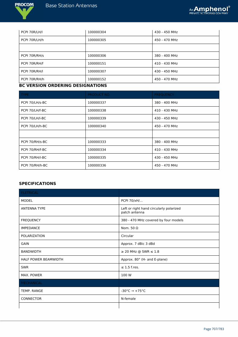
Base Station Antennas
PCPI 70R/LH/l 100000304 430 - 450 MHz
PCPI 70R/LH/h 100000305 450 - 470 MHz
PCPI 70R/RH/s 100000306 380 - 400 MHz
PCPI 70R/RH/f 100000151 410 - 430 MHz
PCPI 70R/RH/l 100000307 430 - 450 MHz
PCPI 70R/RH/h 100000152 450 - 470 MHz
BC VERSION ORDERING DESIGNATIONS
TYPE PRODUCT NO. FREQUENCY
PCPI 70/LH/s-BC 100000337 380 - 400 MHz
PCPI 70/LH/f-BC 100000338 410 - 430 MHz
PCPI 70/LH/l-BC 100000339 430 - 450 MHz
PCPI 70/LH/h-BC 100000340 450 - 470 MHz
PCPI 70/RH/s-BC 100000333 380 - 400 MHz
PCPI 70/RH/f-BC 100000334 410 - 430 MHz
PCPI 70/RH/l-BC 100000335 430 - 450 MHz
PCPI 70/RH/h-BC 100000336 450 - 470 MHz
SPECIFICATIONS
ELETRICAL
MODEL PCPI 70/xH/...
ANTENNA TYPE Left or right hand circularly polarizedpatch antenna
FREQUENCY 380 - 470 MHz covered by four models
IMPEDANCE Nom. 50 Ω
POLARIZATION Circular
GAIN Approx. 7 dBic 3 dBd
BANDWIDTH ≥ 20 MHz @ SWR ≤ 1.8
HALF POWER BEAMWIDTH Approx. 80° (H- and E-plane)
SWR ≤ 1.5 f.res.
MAX. POWER 100 W
MECHANICAL
TEMP. RANGE -30°C → +75°C
CONNECTOR N-female
Page 707/783
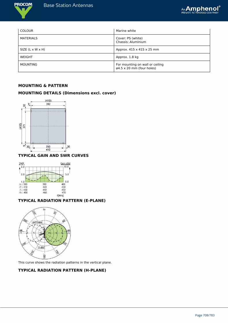
Base Station Antennas
COLOUR Marine white
MATERIALS Cover: PS (white)Chassis: Aluminium
SIZE (L x W x H) Approx. 415 x 415 x 25 mm
WEIGHT Approx. 1.8 kg
MOUNTING For mounting on wall or ceilingø4.5 x 20 mm (four holes)
MOUNTING & PATTERN
MOUNTING DETAILS (Dimensions excl. cover)
TYPICAL GAIN AND SWR CURVES
TYPICAL RADIATION PATTERN (E-PLANE)
This curve shows the radiation patterns in the vertical plane.
TYPICAL RADIATION PATTERN (H-PLANE)
Page 708/783
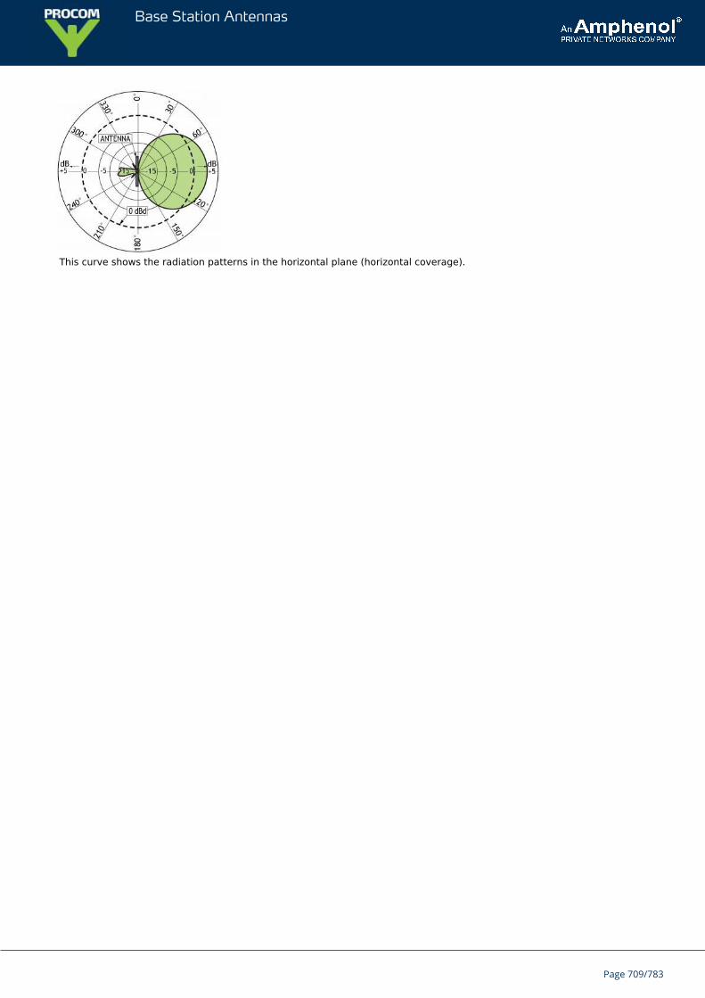
Base Station Antennas
This curve shows the radiation patterns in the horizontal plane (horizontal coverage).
Page 709/783
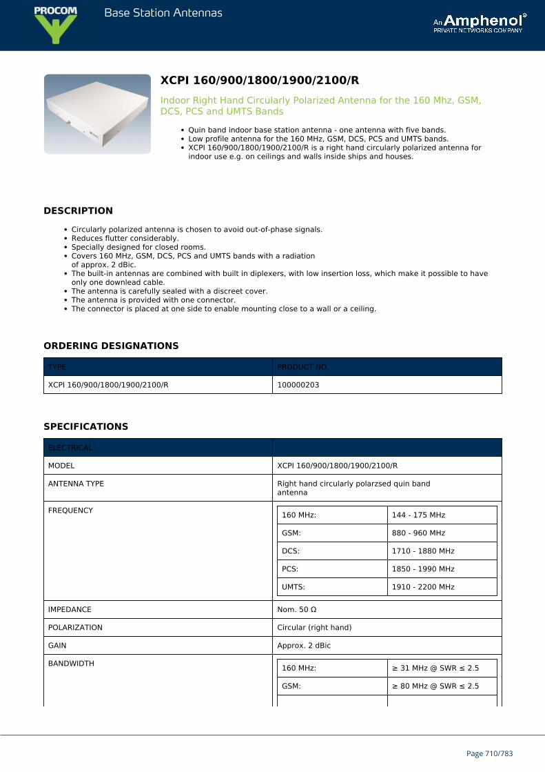
Base Station Antennas
XCPI 160/900/1800/1900/2100/RIndoor Right Hand Circularly Polarized Antenna for the 160 Mhz, GSM,DCS, PCS and UMTS Bands
Quin band indoor base station antenna - one antenna with five bands.Low profile antenna for the 160 MHz, GSM, DCS, PCS and UMTS bands.XCPI 160/900/1800/1900/2100/R is a right hand circularly polarized antenna forindoor use e.g. on ceilings and walls inside ships and houses.
DESCRIPTION
Circularly polarized antenna is chosen to avoid out-of-phase signals.Reduces flutter considerably.Specially designed for closed rooms.Covers 160 MHz, GSM, DCS, PCS and UMTS bands with a radiationof approx. 2 dBic.The built-in antennas are combined with built in diplexers, with low insertion loss, which make it possible to haveonly one downlead cable.The antenna is carefully sealed with a discreet cover.The antenna is provided with one connector.The connector is placed at one side to enable mounting close to a wall or a ceiling.
ORDERING DESIGNATIONS
TYPE PRODUCT NO.
XCPI 160/900/1800/1900/2100/R 100000203
SPECIFICATIONS
ELECTRICAL
MODEL XCPI 160/900/1800/1900/2100/R
ANTENNA TYPE Right hand circularly polarzsed quin bandantenna
FREQUENCY 160 MHz: 144 - 175 MHz
GSM: 880 - 960 MHz
DCS: 1710 - 1880 MHz
PCS: 1850 - 1990 MHz
UMTS: 1910 - 2200 MHz
IMPEDANCE Nom. 50 Ω
POLARIZATION Circular (right hand)
GAIN Approx. 2 dBic
BANDWIDTH 160 MHz: ≥ 31 MHz @ SWR ≤ 2.5
GSM: ≥ 80 MHz @ SWR ≤ 2.5
Page 710/783
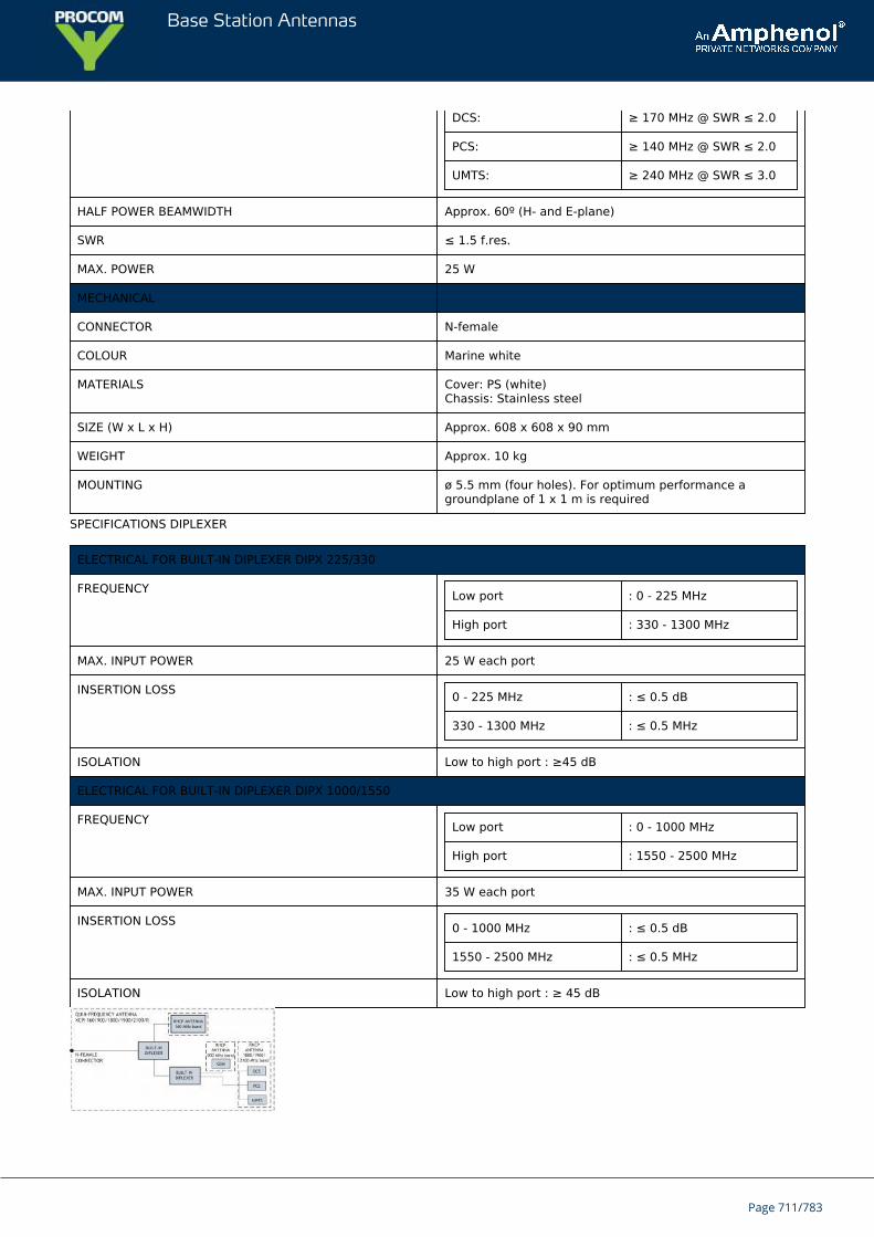
Base Station Antennas
DCS: ≥ 170 MHz @ SWR ≤ 2.0
PCS: ≥ 140 MHz @ SWR ≤ 2.0
UMTS: ≥ 240 MHz @ SWR ≤ 3.0
HALF POWER BEAMWIDTH Approx. 60º (H- and E-plane)
SWR ≤ 1.5 f.res.
MAX. POWER 25 W
MECHANICAL
CONNECTOR N-female
COLOUR Marine white
MATERIALS Cover: PS (white)Chassis: Stainless steel
SIZE (W x L x H) Approx. 608 x 608 x 90 mm
WEIGHT Approx. 10 kg
MOUNTING ø 5.5 mm (four holes). For optimum performance agroundplane of 1 x 1 m is required
SPECIFICATIONS DIPLEXER
ELECTRICAL FOR BUILT-IN DIPLEXER DIPX 225/330
FREQUENCY Low port : 0 - 225 MHz
High port : 330 - 1300 MHz
MAX. INPUT POWER 25 W each port
INSERTION LOSS 0 - 225 MHz : ≤ 0.5 dB
330 - 1300 MHz : ≤ 0.5 MHz
ISOLATION Low to high port : ≥45 dB
ELECTRICAL FOR BUILT-IN DIPLEXER DIPX 1000/1550
FREQUENCY Low port : 0 - 1000 MHz
High port : 1550 - 2500 MHz
MAX. INPUT POWER 35 W each port
INSERTION LOSS 0 - 1000 MHz : ≤ 0.5 dB
1550 - 2500 MHz : ≤ 0.5 MHz
ISOLATION Low to high port : ≥ 45 dB
Page 711/783
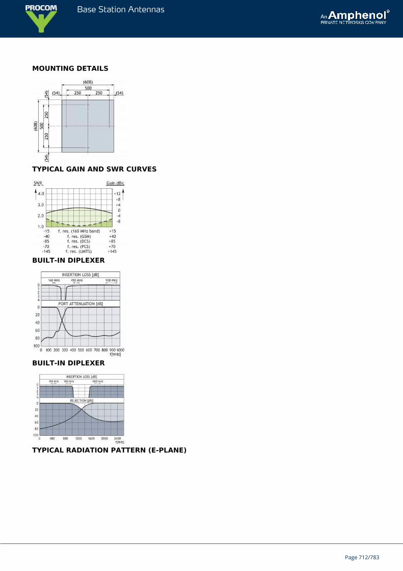
Base Station Antennas
MOUNTING DETAILS
TYPICAL GAIN AND SWR CURVES
BUILT-IN DIPLEXER
BUILT-IN DIPLEXER
TYPICAL RADIATION PATTERN (E-PLANE)
Page 712/783
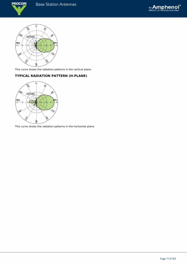
Base Station Antennas
This curve shows the radiation patterns in the vertical plane.
TYPICAL RADIATION PATTERN (H-PLANE)
This curve shows the radiation patterns in the horizontal plane.
Page 713/783
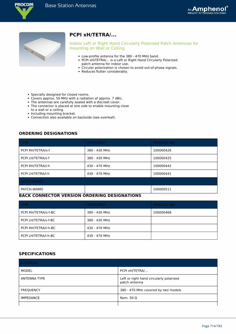
Base Station Antennas
PCPI xH/TETRA/...Indoor Left or Right Hand Circularly Polarized Patch Antennas formounting on Wall or Ceiling
Low-profile antenna for the 380 - 470 MHz band.PCPI xH/TETRA/... is a Left or Right Hand Circularly Polarizedpatch antenna for indoor use.Circular polarization is chosen to avoid out-of-phase signals.Reduces flutter considerably.
Specially designed for closed rooms.Covers approx. 50 MHz with a radiation of approx. 7 dBic.The antennas are carefully sealed with a discreet cover.The connector is placed at one side to enable mounting closeto a wall or a ceiling.Including mounting bracket.Connection also available on backside (see overleaf).
ORDERING DESIGNATIONS
TYPE FREQUENCY PRODUCT NO.
PCPI RH/TETRA/s-f 380 - 430 MHz 100000426
PCPI LH/TETRA/s-f 380 - 430 MHz 100000425
PCPI RH/TETRA/l-h 430 - 470 MHz 100000442
PCPI LH/TETRA/l-h 430 - 470 MHz 100000441
ACCESSORIES
PATCH-WAMO 100000511
BACK CONNECTOR VERSION ORDERING DESIGNATIONS
TYPE FREQUENCY PRODUCT NO.
PCPI RH/TETRA/s-f-BC 380 - 430 MHz 100000468
PCPI LH/TETRA/s-f-BC 380 - 430 MHz
PCPI RH/TETRA/l-h-BC 430 - 470 MHz
PCPI LH/TETRA/l-h-BC 430 - 470 MHz
SPECIFICATIONS
ELETRICAL
MODEL PCPI xH/TETRA/...
ANTENNA TYPE Left or right hand circularly polarizedpatch antenna
FREQUENCY 380 - 470 MHz covered by two models
IMPEDANCE Nom. 50 Ω
Page 714/783
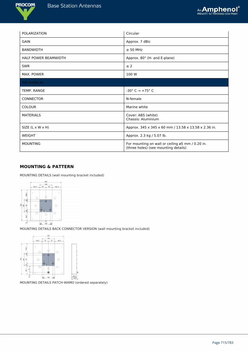
Base Station Antennas
POLARIZATION Circular
GAIN Approx. 7 dBic
BANDWIDTH ≥ 50 MHz
HALF POWER BEAMWIDTH Approx. 80° (H- and E-plane)
SWR ≤ 2
MAX. POWER 100 W
MECHANICAL
TEMP. RANGE -30° C → +75° C
CONNECTOR N-female
COLOUR Marine white
MATERIALS Cover: ABS (white)Chassis: Aluminium
SIZE (L x W x H) Approx. 345 x 345 x 60 mm / 13.58 x 13.58 x 2.36 in.
WEIGHT Approx. 2.3 kg / 5.07 lb.
MOUNTING For mounting on wall or ceiling ø5 mm / 0.20 in.(three holes) (see mounting details)
MOUNTING & PATTERN
MOUNTING DETAILS (wall mounting bracket included)
MOUNTING DETAILS BACK CONNECTOR VERSION (wall mounting bracket included)
MOUNTING DETAILS PATCH-WAMO (ordered separately)
Page 715/783
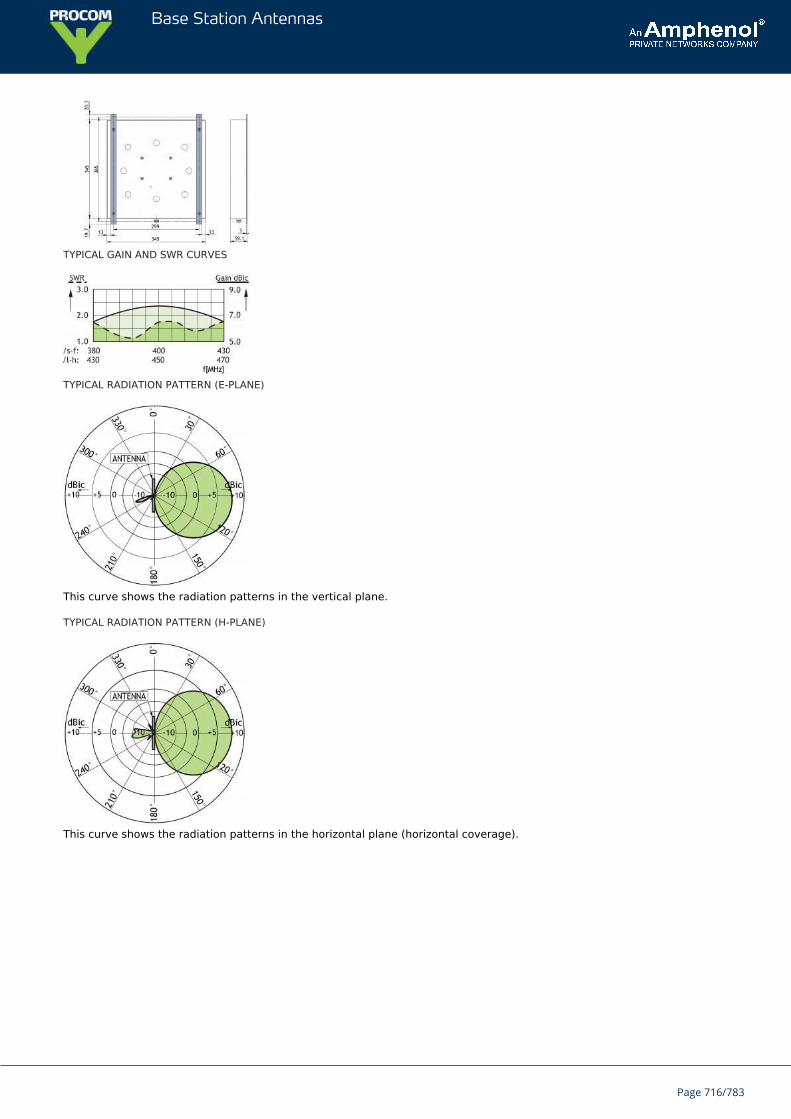
Base Station Antennas
TYPICAL GAIN AND SWR CURVES
TYPICAL RADIATION PATTERN (E-PLANE)
This curve shows the radiation patterns in the vertical plane.
TYPICAL RADIATION PATTERN (H-PLANE)
This curve shows the radiation patterns in the horizontal plane (horizontal coverage).
Page 716/783
Base Station Antennas
PCPO xH/TETRA/Outdoor Left or Right Hand Circularly Polarized Patch Antennas formounting on Wall or Mast
Low-profile antenna for the 380 - 470 MHz band.PCPO xH/TETRA/... is a Left or Right Hand Circularly Polarizedpatch antenna for outdoor use.Circular polarization is chosen to avoid out-of-phase signals.
Reduces flutter considerably.Covers approx. 50 MHz with a radiation of approx. 7 dBic.The antennas are carefully sealed with a discrete cover.The connector is placed at one side to enable mounting close to a wall.Including wall mounting bracket. PATCH-MAMO and PATCH/WAMOto be ordered separately.
ORDERING DESIGNATIONS
TYPE FREQUENCY PRODUCT NO.
PCPO RH/TETRA/s-f 380 - 430 MHz 100000428
PCPO LH/TETRA/s-f 380 - 430 MHz 100000427
PCPO RH/TETRA/l-h 430 - 470 MHz 100000443
PCPO LH/TETRA/l-h 430 - 470 MHz 100000444
ACCESSORIES
PATCH-MAMO 100000447
PATCH-WAMO 100000511
SPECIFICATIONS
ELETRICAL
MODEL PCPO xH/TETRA/...
ANTENNA TYPE Left or right hand circularly polarizedpatch antenna
FREQUENCY 380 - 470 MHz covered by two models
IMPEDANCE Nom. 50 Ω
POLARIZATION Circular
GAIN Approx. 7 dBic
BANDWIDTH ≥ 50 MHz
HALF-POWER BEAMWIDTH Approx. 80° (H- and E-plane)
SWR ≤ 2
MAX. POWER 100 W
Page 717/783
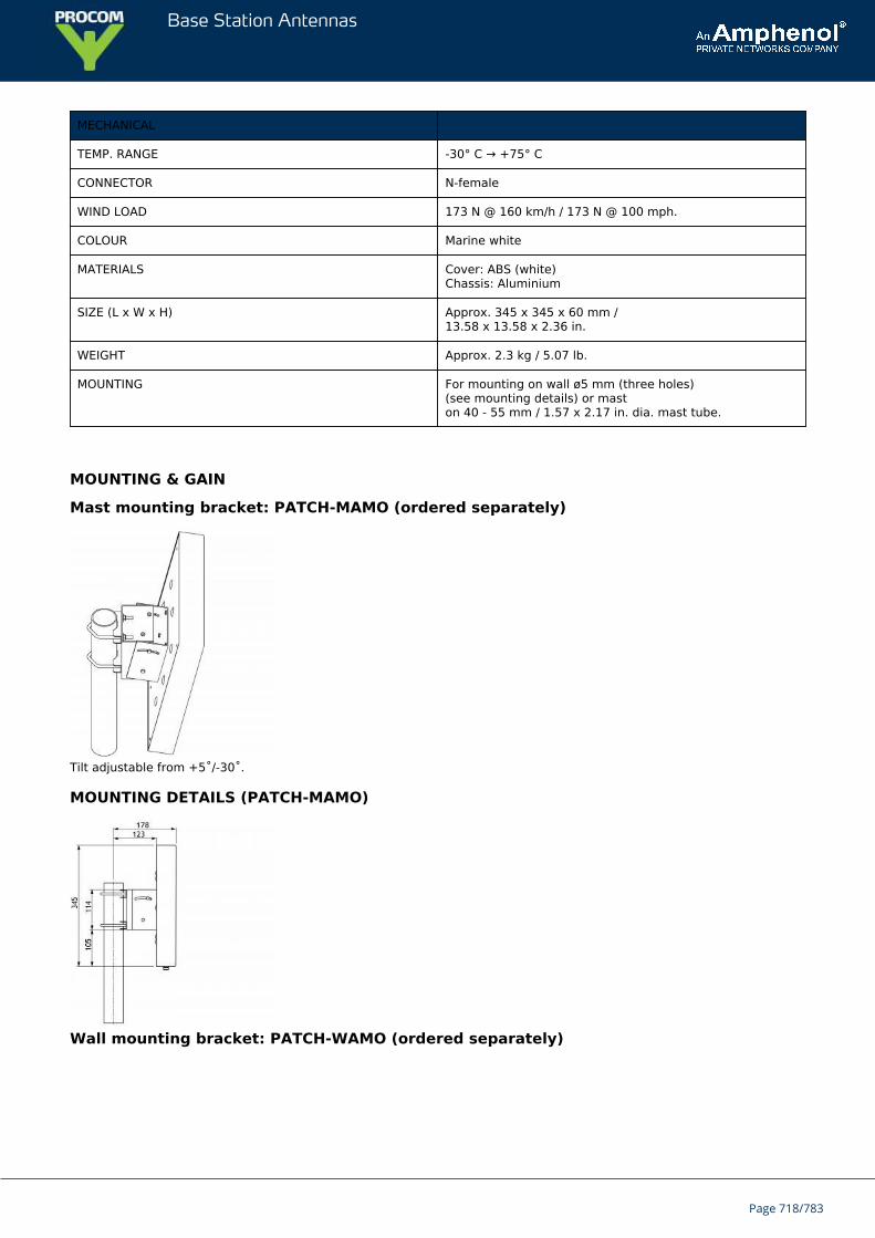
Base Station Antennas
MECHANICAL
TEMP. RANGE -30° C → +75° C
CONNECTOR N-female
WIND LOAD 173 N @ 160 km/h / 173 N @ 100 mph.
COLOUR Marine white
MATERIALS Cover: ABS (white)Chassis: Aluminium
SIZE (L x W x H) Approx. 345 x 345 x 60 mm /13.58 x 13.58 x 2.36 in.
WEIGHT Approx. 2.3 kg / 5.07 lb.
MOUNTING For mounting on wall ø5 mm (three holes)(see mounting details) or maston 40 - 55 mm / 1.57 x 2.17 in. dia. mast tube.
MOUNTING & GAIN
Mast mounting bracket: PATCH-MAMO (ordered separately)
Tilt adjustable from +5˚/-30˚.
MOUNTING DETAILS (PATCH-MAMO)
Wall mounting bracket: PATCH-WAMO (ordered separately)
Page 718/783
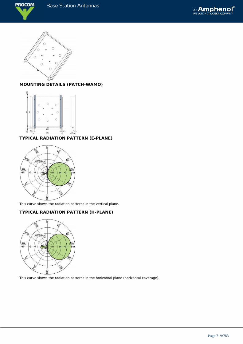
Base Station Antennas
MOUNTING DETAILS (PATCH-WAMO)
TYPICAL RADIATION PATTERN (E-PLANE)
This curve shows the radiation patterns in the vertical plane.
TYPICAL RADIATION PATTERN (H-PLANE)
This curve shows the radiation patterns in the horizontal plane (horizontal coverage).
Page 719/783
Base Station Antennas
PCPI TETRA/LTE 800/RHIndoor Right Hand Circularly Polarized Antenna for the TETRA and LTEBands
Dual-band low-profile antenna for indoor use.Right hand circulary polarized, 7 dBic antenna specially designed for closed rooms.For use e.g. on ceilings and walls inside ships and buildings.
Circular polarization is chosen to improve link quality.Built-in diplexers with low insertion loss make it possible to have only one connector.
ORDERING DESIGNATIONS
TYPE PRODUCT NO.
PCPI TETRA/LTE 800/RH 100000522
SPECIFICATIONS
ELECTRICAL
MODEL PCPI TETRA/LTE 800/RH
ANTENNA TYPE Right hand circularly polarized antenna
FREQUENCY TETRA: 380 - 430 MHz
LTE: 790 - 850 MHz
IMPEDANCE Nom. 50 Ω
POLARIZATION Circular (right hand)
GAIN Approx. 7 dBic
HALF POWER BEAMWIDTH Approx. 60º (H- and E-plane)
SWR ≤ 2
MAX. POWER 35 W
MECHANICAL
TEMP. RANGE -30°C → +75°C
CONNECTOR N-female
COLOUR Marine white
MATERIALS Cover: PS (white)Chassis: Aluminium
SIZE (L x W x H) Approx. 415 x 415 x 70 mm / 16.34 x 16.34 x 2.76 in.
WEIGHT Approx. 1.9 kg / 4.19 lb.
MOUNTING ø 4.5 mm (four holes)
Page 720/783
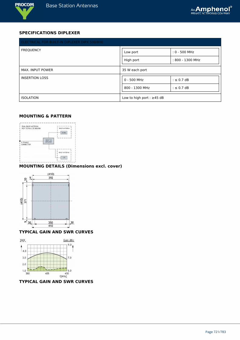
Base Station Antennas
SPECIFICATIONS DIPLEXER
ELECTRICAL FOR BUILT-IN DIPLEXER DIPX 500/800
FREQUENCY Low port : 0 - 500 MHz
High port : 800 - 1300 MHz
MAX. INPUT POWER 35 W each port
INSERTION LOSS 0 - 500 MHz : ≤ 0.7 dB
800 - 1300 MHz : ≤ 0.7 dB
ISOLATION Low to high port : ≥45 dB
MOUNTING & PATTERN
MOUNTING DETAILS (Dimensions excl. cover)
TYPICAL GAIN AND SWR CURVES
TYPICAL GAIN AND SWR CURVES
Page 721/783
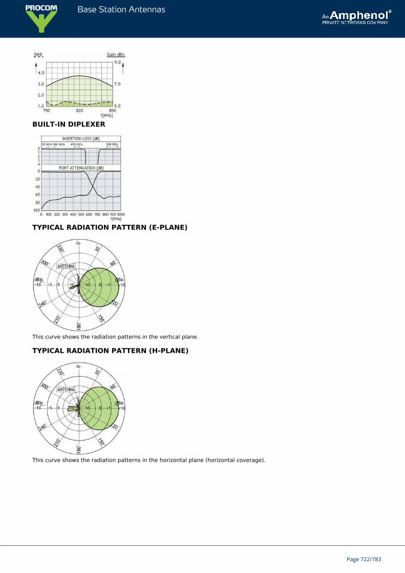
Base Station Antennas
BUILT-IN DIPLEXER
TYPICAL RADIATION PATTERN (E-PLANE)
This curve shows the radiation patterns in the vertical plane.
TYPICAL RADIATION PATTERN (H-PLANE)
This curve shows the radiation patterns in the horizontal plane (horizontal coverage).
Page 722/783
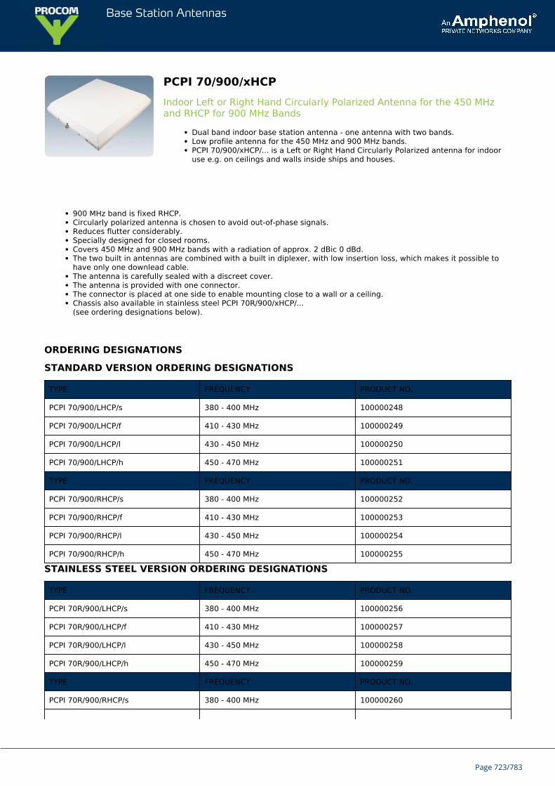
Base Station Antennas
PCPI 70/900/xHCPIndoor Left or Right Hand Circularly Polarized Antenna for the 450 MHzand RHCP for 900 MHz Bands
Dual band indoor base station antenna - one antenna with two bands.Low profile antenna for the 450 MHz and 900 MHz bands.PCPI 70/900/xHCP/... is a Left or Right Hand Circularly Polarized antenna for indooruse e.g. on ceilings and walls inside ships and houses.
900 MHz band is fixed RHCP.Circularly polarized antenna is chosen to avoid out-of-phase signals.Reduces flutter considerably.Specially designed for closed rooms.Covers 450 MHz and 900 MHz bands with a radiation of approx. 2 dBic 0 dBd.The two built in antennas are combined with a built in diplexer, with low insertion loss, which makes it possible tohave only one downlead cable.The antenna is carefully sealed with a discreet cover.The antenna is provided with one connector.The connector is placed at one side to enable mounting close to a wall or a ceiling.Chassis also available in stainless steel PCPI 70R/900/xHCP/...(see ordering designations below).
ORDERING DESIGNATIONS
STANDARD VERSION ORDERING DESIGNATIONS
TYPE FREQUENCY PRODUCT NO.
PCPI 70/900/LHCP/s 380 - 400 MHz 100000248
PCPI 70/900/LHCP/f 410 - 430 MHz 100000249
PCPI 70/900/LHCP/l 430 - 450 MHz 100000250
PCPI 70/900/LHCP/h 450 - 470 MHz 100000251
TYPE FREQUENCY PRODUCT NO.
PCPI 70/900/RHCP/s 380 - 400 MHz 100000252
PCPI 70/900/RHCP/f 410 - 430 MHz 100000253
PCPI 70/900/RHCP/l 430 - 450 MHz 100000254
PCPI 70/900/RHCP/h 450 - 470 MHz 100000255
STAINLESS STEEL VERSION ORDERING DESIGNATIONS
TYPE FREQUENCY PRODUCT NO.
PCPI 70R/900/LHCP/s 380 - 400 MHz 100000256
PCPI 70R/900/LHCP/f 410 - 430 MHz 100000257
PCPI 70R/900/LHCP/l 430 - 450 MHz 100000258
PCPI 70R/900/LHCP/h 450 - 470 MHz 100000259
TYPE FREQUENCY PRODUCT NO.
PCPI 70R/900/RHCP/s 380 - 400 MHz 100000260
Page 723/783
Base Station Antennas
PCPI 70R/900/RHCP/f 410 - 430 MHz 100000261
PCPI 70R/900/RHCP/l 430 - 450 MHz 100000262
PCPI 70R/900/RHCP/h 450 - 470 MHz 100000263
SPECIFICATIONS
ELECTRICAL
MODEL PCPI 70/900/xHCP/...
ANTENNA TYPE Left or right hand circularly polarized dual band antenna
FREQUENCY 450 MHz freq. to be stated within:380 - 470 MHz900 MHz freq. to be stated within:880 - 960 MHz
IMPEDANCE Nom. 50 Ω
POLARIZATION Circular
GAIN Approx. 2 dBic 0 dBd ± 3 dB
BANDWIDTH 450 MHz: ≥ 20 MHz @ SWR ≤ 2.0900 MHz: ≥ 80 MHz @ SWR ≤ 2.0
HALF POWER BEAMWIDTH Approx. 60º (H- and E-plane)
SWR ≤ 1.5 f.res.
MAX. POWER 35 W
MECHANICAL
CONNECTOR N-female
COLOUR Marine white
MATERIALS Cover: PS (white)Chassis: Aluminium
SIZE (W x L x H) Approx. 415 x 415 x 70 mm
WEIGHT Approx. 2.0 kg
MOUNTING For mounting on wall or ceiling ø4.5 x 20 mm (four holes)
ELECTRICAL FOR BUILT IN DIPLEXER
MODEL DIPX 500/800
FREQUENCY Low port : 0 - 500 MHzHigh port : 800 - 1300 MHz
MAX. INPUT POWER 35 W each port
INSERTION LOSS 0 - 500 MHz : ≤ 0.5 dB800 - 1300 MHz: ≤ 0.5 dB
ISOLATION Low to high port: ≥ 45 dB
TEMP. RANGE –30° C → +70° C
Page 724/783
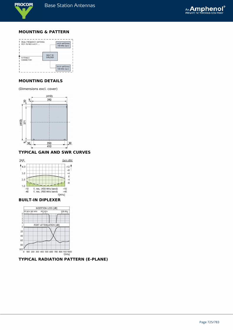
Base Station Antennas
MOUNTING & PATTERN
MOUNTING DETAILS
(Dimensions excl. cover)
TYPICAL GAIN AND SWR CURVES
BUILT-IN DIPLEXER
TYPICAL RADIATION PATTERN (E-PLANE)
Page 725/783
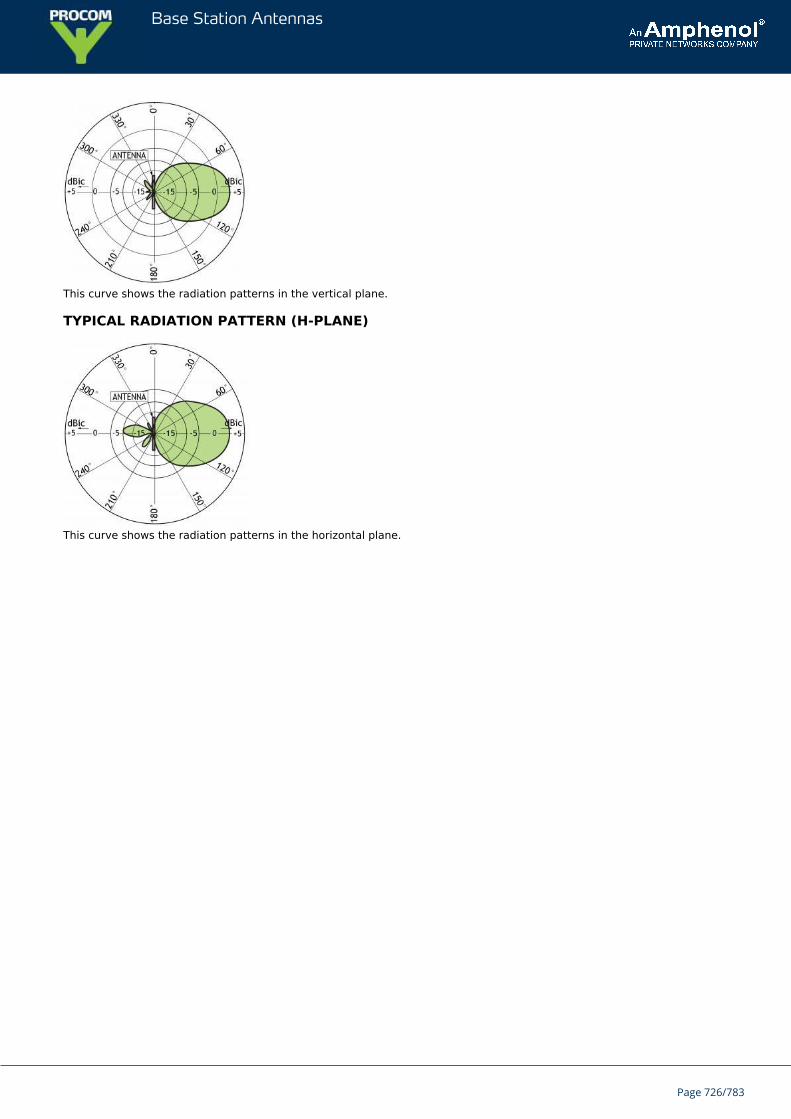
Base Station Antennas
This curve shows the radiation patterns in the vertical plane.
TYPICAL RADIATION PATTERN (H-PLANE)
This curve shows the radiation patterns in the horizontal plane.
Page 726/783
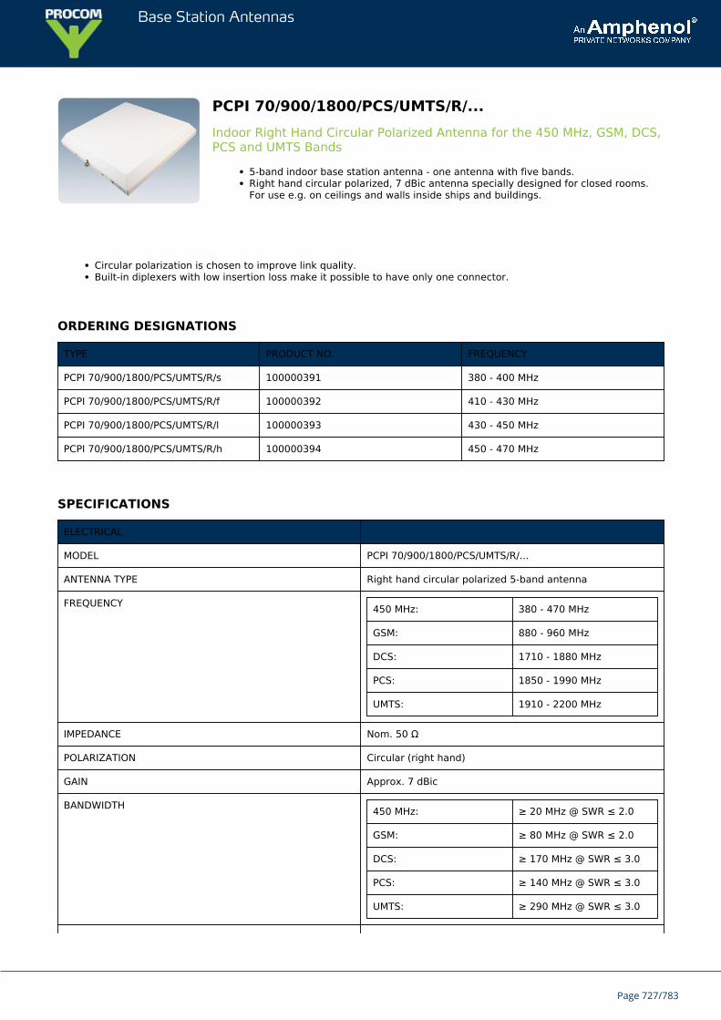
Base Station Antennas
PCPI 70/900/1800/PCS/UMTS/R/...Indoor Right Hand Circular Polarized Antenna for the 450 MHz, GSM, DCS,PCS and UMTS Bands
5-band indoor base station antenna - one antenna with five bands.Right hand circular polarized, 7 dBic antenna specially designed for closed rooms.For use e.g. on ceilings and walls inside ships and buildings.
Circular polarization is chosen to improve link quality.Built-in diplexers with low insertion loss make it possible to have only one connector.
ORDERING DESIGNATIONS
TYPE PRODUCT NO. FREQUENCY
PCPI 70/900/1800/PCS/UMTS/R/s 100000391 380 - 400 MHz
PCPI 70/900/1800/PCS/UMTS/R/f 100000392 410 - 430 MHz
PCPI 70/900/1800/PCS/UMTS/R/l 100000393 430 - 450 MHz
PCPI 70/900/1800/PCS/UMTS/R/h 100000394 450 - 470 MHz
SPECIFICATIONS
ELECTRICAL
MODEL PCPI 70/900/1800/PCS/UMTS/R/...
ANTENNA TYPE Right hand circular polarized 5-band antenna
FREQUENCY 450 MHz: 380 - 470 MHz
GSM: 880 - 960 MHz
DCS: 1710 - 1880 MHz
PCS: 1850 - 1990 MHz
UMTS: 1910 - 2200 MHz
IMPEDANCE Nom. 50 Ω
POLARIZATION Circular (right hand)
GAIN Approx. 7 dBic
BANDWIDTH 450 MHz: ≥ 20 MHz @ SWR ≤ 2.0
GSM: ≥ 80 MHz @ SWR ≤ 2.0
DCS: ≥ 170 MHz @ SWR ≤ 3.0
PCS: ≥ 140 MHz @ SWR ≤ 3.0
UMTS: ≥ 290 MHz @ SWR ≤ 3.0
Page 727/783
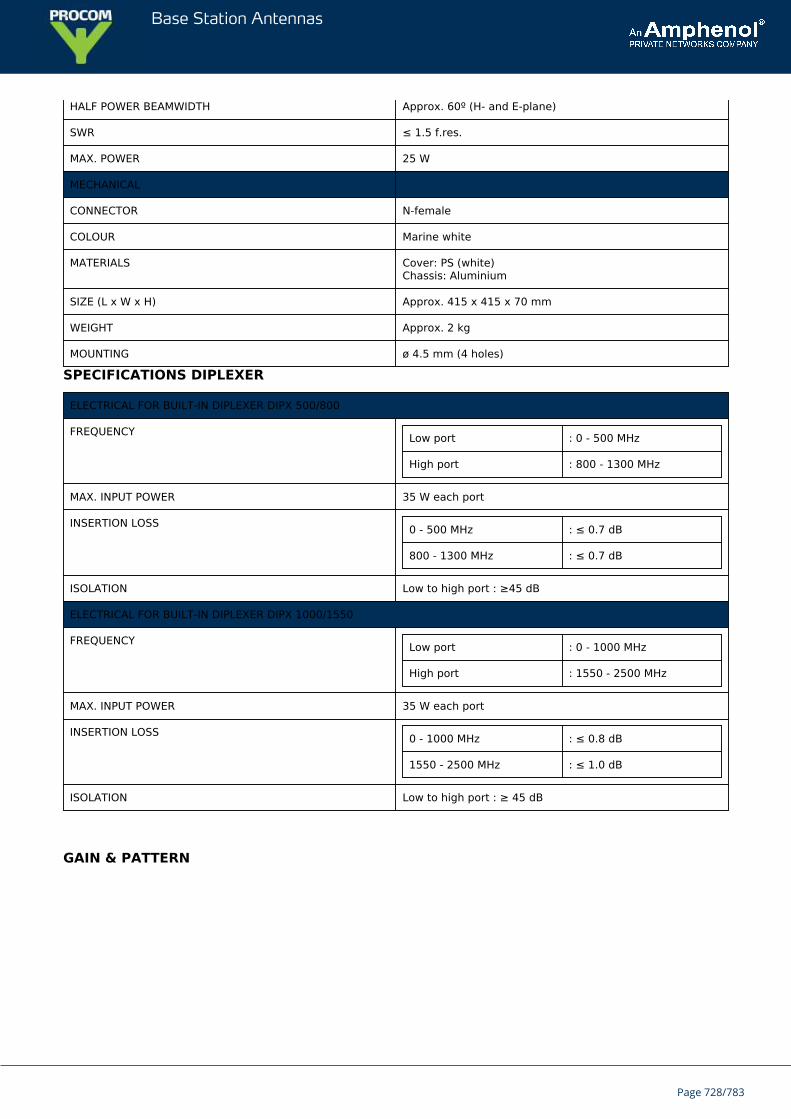
Base Station Antennas
HALF POWER BEAMWIDTH Approx. 60º (H- and E-plane)
SWR ≤ 1.5 f.res.
MAX. POWER 25 W
MECHANICAL
CONNECTOR N-female
COLOUR Marine white
MATERIALS Cover: PS (white)Chassis: Aluminium
SIZE (L x W x H) Approx. 415 x 415 x 70 mm
WEIGHT Approx. 2 kg
MOUNTING ø 4.5 mm (4 holes)
SPECIFICATIONS DIPLEXER
ELECTRICAL FOR BUILT-IN DIPLEXER DIPX 500/800
FREQUENCY Low port : 0 - 500 MHz
High port : 800 - 1300 MHz
MAX. INPUT POWER 35 W each port
INSERTION LOSS 0 - 500 MHz : ≤ 0.7 dB
800 - 1300 MHz : ≤ 0.7 dB
ISOLATION Low to high port : ≥45 dB
ELECTRICAL FOR BUILT-IN DIPLEXER DIPX 1000/1550
FREQUENCY Low port : 0 - 1000 MHz
High port : 1550 - 2500 MHz
MAX. INPUT POWER 35 W each port
INSERTION LOSS 0 - 1000 MHz : ≤ 0.8 dB
1550 - 2500 MHz : ≤ 1.0 dB
ISOLATION Low to high port : ≥ 45 dB
GAIN & PATTERN
Page 728/783
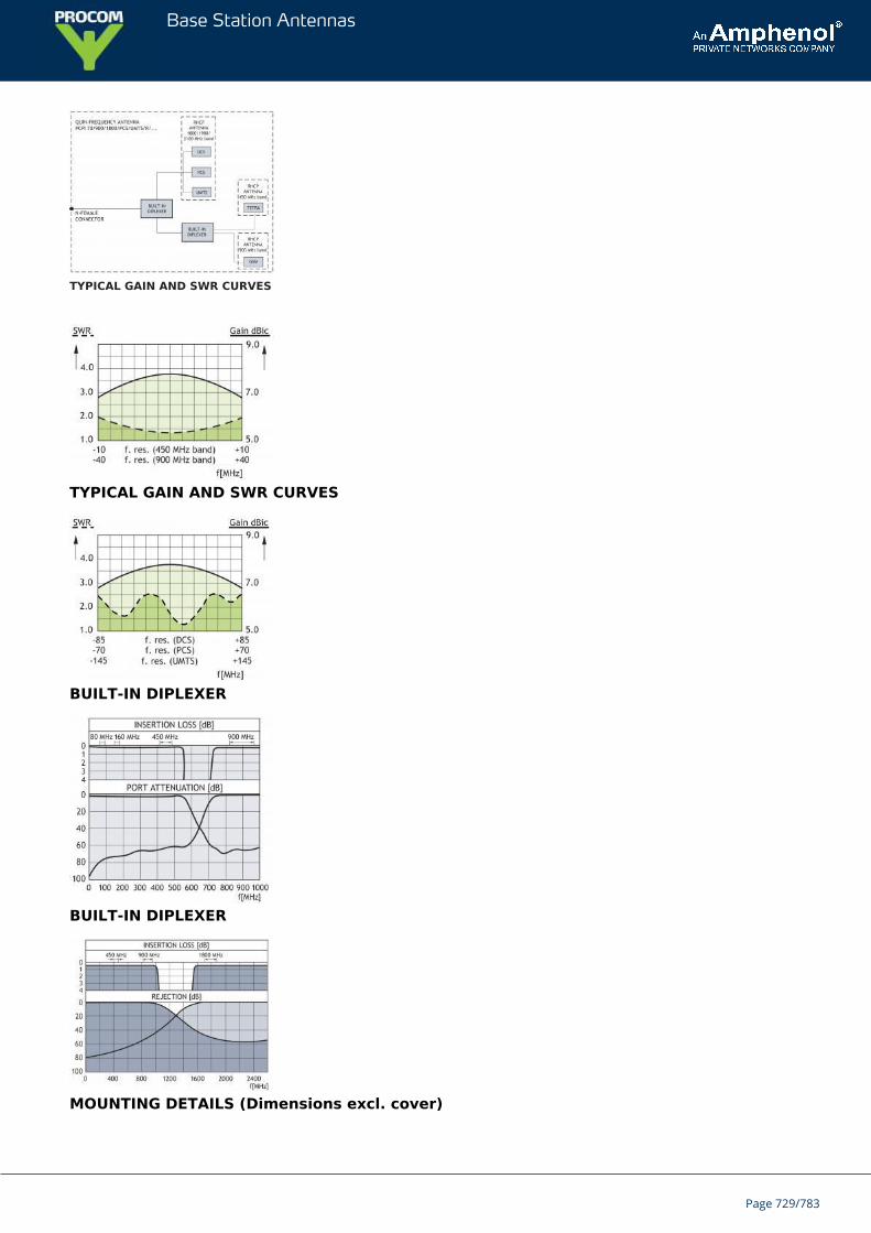
Base Station Antennas
TYPICAL GAIN AND SWR CURVES
TYPICAL GAIN AND SWR CURVES
BUILT-IN DIPLEXER
BUILT-IN DIPLEXER
MOUNTING DETAILS (Dimensions excl. cover)
Page 729/783
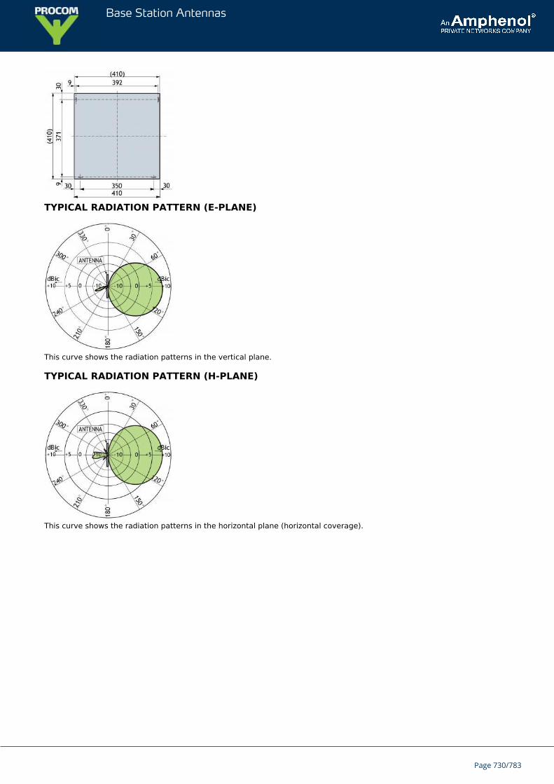
Base Station Antennas
TYPICAL RADIATION PATTERN (E-PLANE)
This curve shows the radiation patterns in the vertical plane.
TYPICAL RADIATION PATTERN (H-PLANE)
This curve shows the radiation patterns in the horizontal plane (horizontal coverage).
Page 730/783
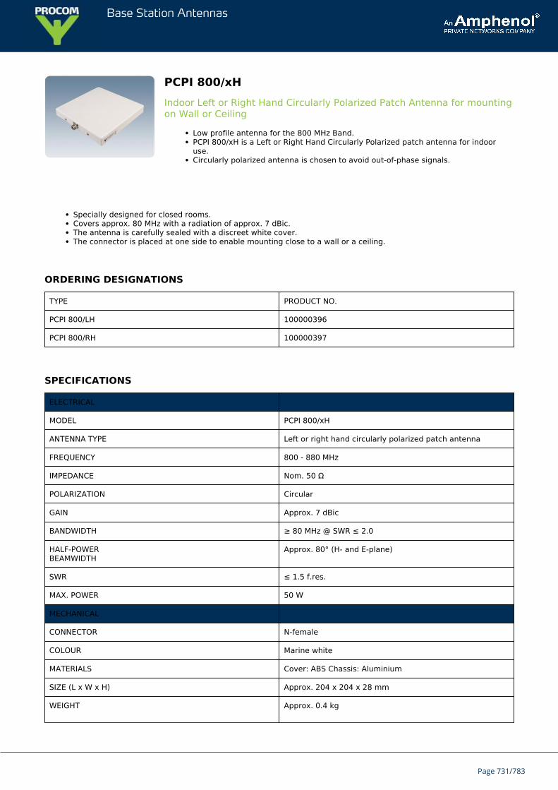
Base Station Antennas
PCPI 800/xHIndoor Left or Right Hand Circularly Polarized Patch Antenna for mountingon Wall or Ceiling
Low profile antenna for the 800 MHz Band.PCPI 800/xH is a Left or Right Hand Circularly Polarized patch antenna for indooruse.Circularly polarized antenna is chosen to avoid out-of-phase signals.
Specially designed for closed rooms.Covers approx. 80 MHz with a radiation of approx. 7 dBic.The antenna is carefully sealed with a discreet white cover.The connector is placed at one side to enable mounting close to a wall or a ceiling.
ORDERING DESIGNATIONS
TYPE PRODUCT NO.
PCPI 800/LH 100000396
PCPI 800/RH 100000397
SPECIFICATIONS
ELECTRICAL
MODEL PCPI 800/xH
ANTENNA TYPE Left or right hand circularly polarized patch antenna
FREQUENCY 800 - 880 MHz
IMPEDANCE Nom. 50 Ω
POLARIZATION Circular
GAIN Approx. 7 dBic
BANDWIDTH ≥ 80 MHz @ SWR ≤ 2.0
HALF-POWERBEAMWIDTH
Approx. 80° (H- and E-plane)
SWR ≤ 1.5 f.res.
MAX. POWER 50 W
MECHANICAL
CONNECTOR N-female
COLOUR Marine white
MATERIALS Cover: ABS Chassis: Aluminium
SIZE (L x W x H) Approx. 204 x 204 x 28 mm
WEIGHT Approx. 0.4 kg
Page 731/783
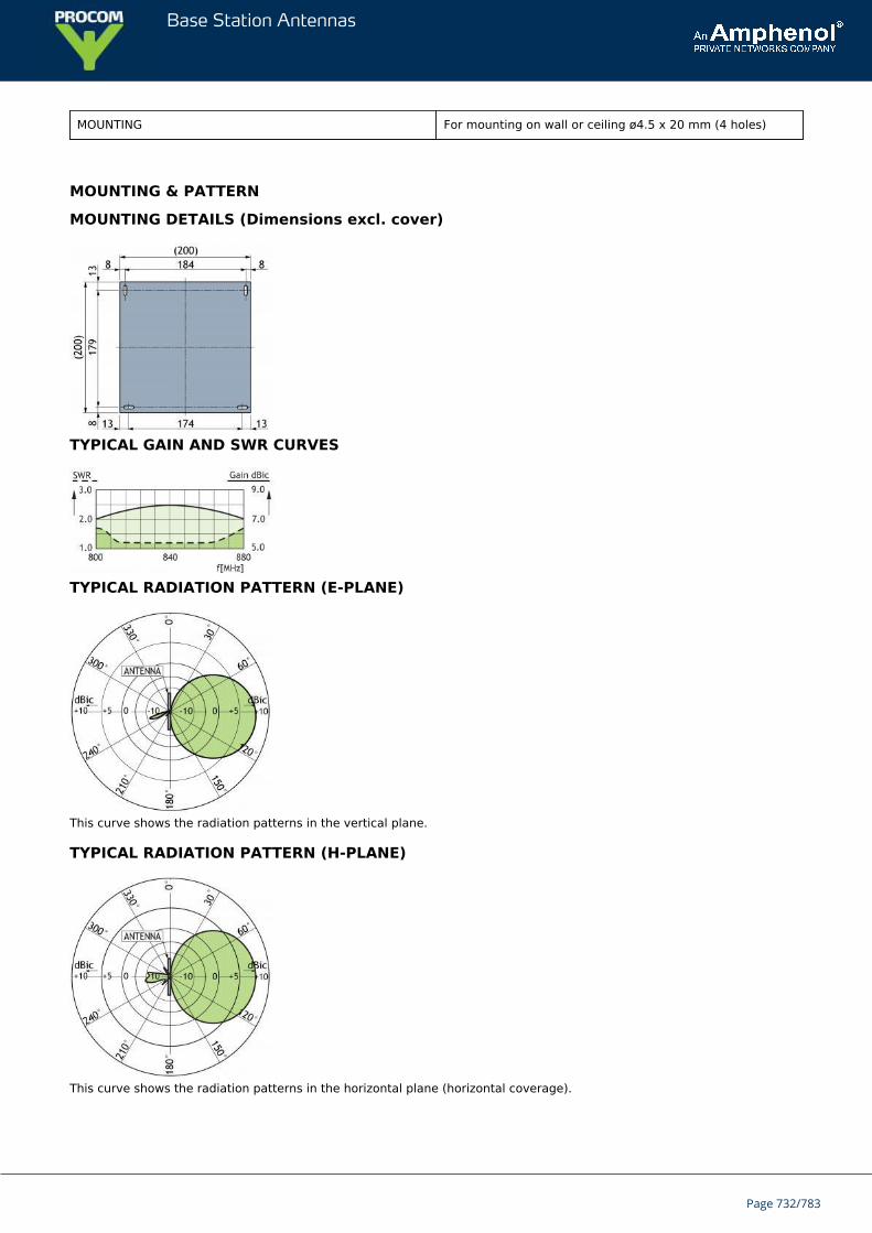
Base Station Antennas
MOUNTING For mounting on wall or ceiling ø4.5 x 20 mm (4 holes)
MOUNTING & PATTERN
MOUNTING DETAILS (Dimensions excl. cover)
TYPICAL GAIN AND SWR CURVES
TYPICAL RADIATION PATTERN (E-PLANE)
This curve shows the radiation patterns in the vertical plane.
TYPICAL RADIATION PATTERN (H-PLANE)
This curve shows the radiation patterns in the horizontal plane (horizontal coverage).
Page 732/783

Base Station Antennas
Page 733/783
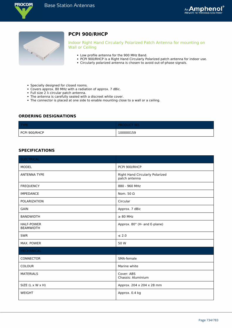
Base Station Antennas
PCPI 900/RHCPIndoor Right Hand Circularly Polarized Patch Antenna for mounting onWall or Ceiling
Low profile antenna for the 900 MHz Band.PCPI 900/RHCP is a Right Hand Circularly Polarized patch antenna for indoor use.Circularly polarized antenna is chosen to avoid out-of-phase signals.
Specially designed for closed rooms.Covers approx. 80 MHz with a radiation of approx. 7 dBic.Full size 2 λ circular patch antenna.The antenna is carefully sealed with a discreet white cover.The connector is placed at one side to enable mounting close to a wall or a ceiling.
ORDERING DESIGNATIONS
TYPE PRODUCT NO.
PCPI 900/RHCP 100000159
SPECIFICATIONS
ELECTRICAL
MODEL PCPI 900/RHCP
ANTENNA TYPE Right Hand Circularly Polarizedpatch antenna
FREQUENCY 880 - 960 MHz
IMPEDANCE Nom. 50 Ω
POLARIZATION Circular
GAIN Approx. 7 dBic
BANDWIDTH ≥ 80 MHz
HALF-POWERBEAMWIDTH
Approx. 80° (H- and E-plane)
SWR ≤ 2.0
MAX. POWER 50 W
MECHANICAL
CONNECTOR SMA-female
COLOUR Marine white
MATERIALS Cover: ABSChassis: Aluminium
SIZE (L x W x H) Approx. 204 x 204 x 28 mm
WEIGHT Approx. 0.4 kg
Page 734/783
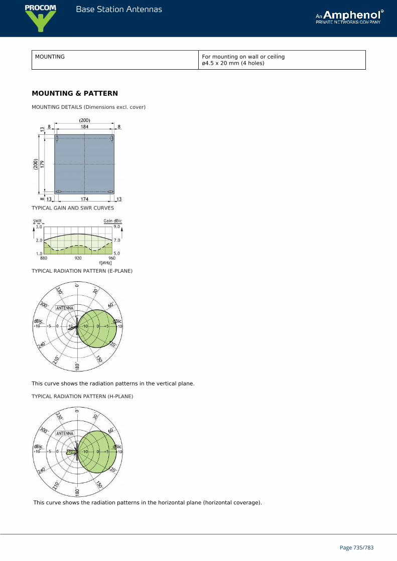
Base Station Antennas
MOUNTING For mounting on wall or ceilingø4.5 x 20 mm (4 holes)
MOUNTING & PATTERN
MOUNTING DETAILS (Dimensions excl. cover)
TYPICAL GAIN AND SWR CURVES
TYPICAL RADIATION PATTERN (E-PLANE)
This curve shows the radiation patterns in the vertical plane.
TYPICAL RADIATION PATTERN (H-PLANE)
This curve shows the radiation patterns in the horizontal plane (horizontal coverage).
Page 735/783

Base Station Antennas
Page 736/783
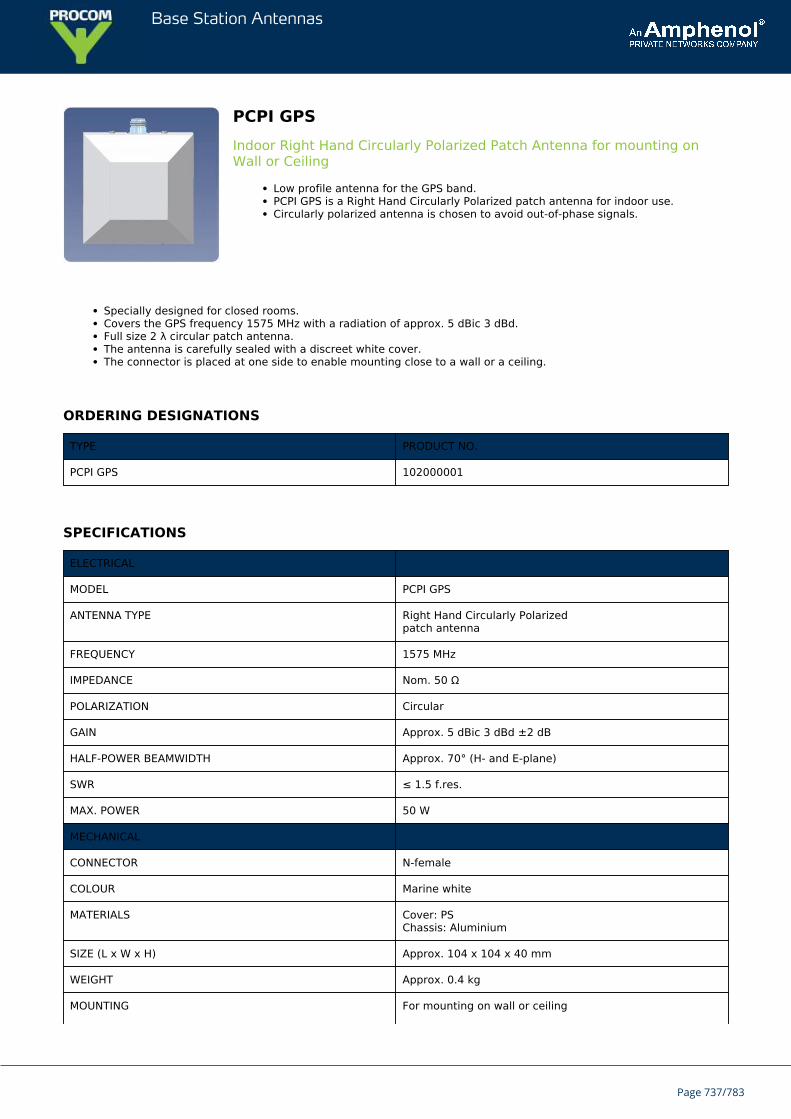
Base Station Antennas
PCPI GPSIndoor Right Hand Circularly Polarized Patch Antenna for mounting onWall or Ceiling
Low profile antenna for the GPS band.PCPI GPS is a Right Hand Circularly Polarized patch antenna for indoor use.Circularly polarized antenna is chosen to avoid out-of-phase signals.
Specially designed for closed rooms.Covers the GPS frequency 1575 MHz with a radiation of approx. 5 dBic 3 dBd.Full size 2 λ circular patch antenna.The antenna is carefully sealed with a discreet white cover.The connector is placed at one side to enable mounting close to a wall or a ceiling.
ORDERING DESIGNATIONS
TYPE PRODUCT NO.
PCPI GPS 102000001
SPECIFICATIONS
ELECTRICAL
MODEL PCPI GPS
ANTENNA TYPE Right Hand Circularly Polarizedpatch antenna
FREQUENCY 1575 MHz
IMPEDANCE Nom. 50 Ω
POLARIZATION Circular
GAIN Approx. 5 dBic 3 dBd ±2 dB
HALF-POWER BEAMWIDTH Approx. 70° (H- and E-plane)
SWR ≤ 1.5 f.res.
MAX. POWER 50 W
MECHANICAL
CONNECTOR N-female
COLOUR Marine white
MATERIALS Cover: PSChassis: Aluminium
SIZE (L x W x H) Approx. 104 x 104 x 40 mm
WEIGHT Approx. 0.4 kg
MOUNTING For mounting on wall or ceiling
Page 737/783

Base Station Antennas
ø4.5 x 10 mm (4 holes)
MOUNTING & PATTERN
MOUNTING DETAILS (Dimensions excl. cover)
TYPICAL GAIN AND SWR CURVES
TYPICAL RADIATION PATTERN (E-PLANE)
This curve shows the radiation patterns in the vertical plane.
TYPICAL RADIATION PATTERN (H-PLANE)
This curve shows the radiation patterns in the horizontal plane (horizontal coverage).
Page 738/783

Base Station Antennas
Page 739/783
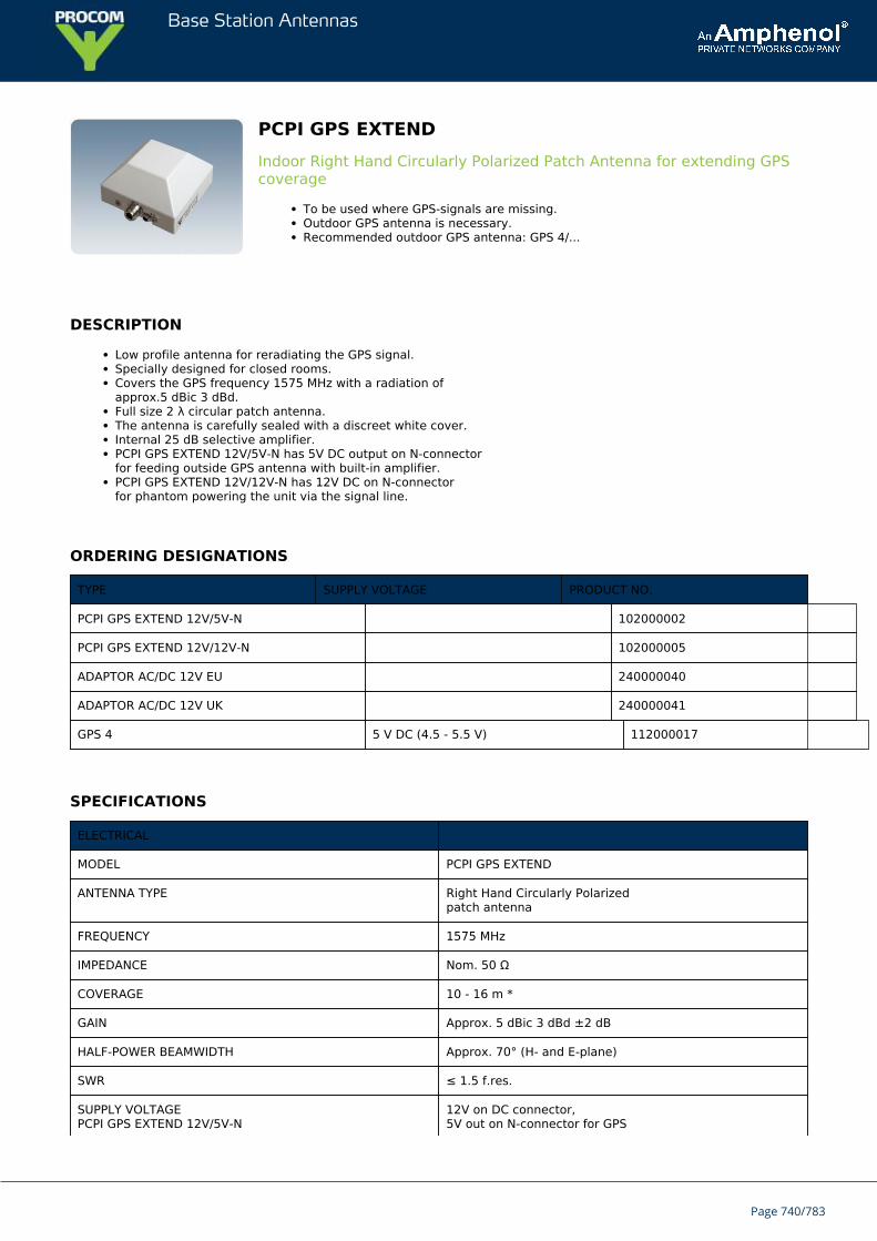
Base Station Antennas
PCPI GPS EXTENDIndoor Right Hand Circularly Polarized Patch Antenna for extending GPScoverage
To be used where GPS-signals are missing.Outdoor GPS antenna is necessary.Recommended outdoor GPS antenna: GPS 4/...
DESCRIPTION
Low profile antenna for reradiating the GPS signal.Specially designed for closed rooms.Covers the GPS frequency 1575 MHz with a radiation ofapprox.5 dBic 3 dBd.Full size 2 λ circular patch antenna.The antenna is carefully sealed with a discreet white cover.Internal 25 dB selective amplifier.PCPI GPS EXTEND 12V/5V-N has 5V DC output on N-connectorfor feeding outside GPS antenna with built-in amplifier.PCPI GPS EXTEND 12V/12V-N has 12V DC on N-connectorfor phantom powering the unit via the signal line.
ORDERING DESIGNATIONS
TYPE SUPPLY VOLTAGE PRODUCT NO.
PCPI GPS EXTEND 12V/5V-N 102000002
PCPI GPS EXTEND 12V/12V-N 102000005
ADAPTOR AC/DC 12V EU 240000040
ADAPTOR AC/DC 12V UK 240000041
GPS 4 5 V DC (4.5 - 5.5 V) 112000017
SPECIFICATIONS
ELECTRICAL
MODEL PCPI GPS EXTEND
ANTENNA TYPE Right Hand Circularly Polarizedpatch antenna
FREQUENCY 1575 MHz
IMPEDANCE Nom. 50 Ω
COVERAGE 10 - 16 m *
GAIN Approx. 5 dBic 3 dBd ±2 dB
HALF-POWER BEAMWIDTH Approx. 70° (H- and E-plane)
SWR ≤ 1.5 f.res.
SUPPLY VOLTAGEPCPI GPS EXTEND 12V/5V-N
12V on DC connector,5V out on N-connector for GPS
Page 740/783
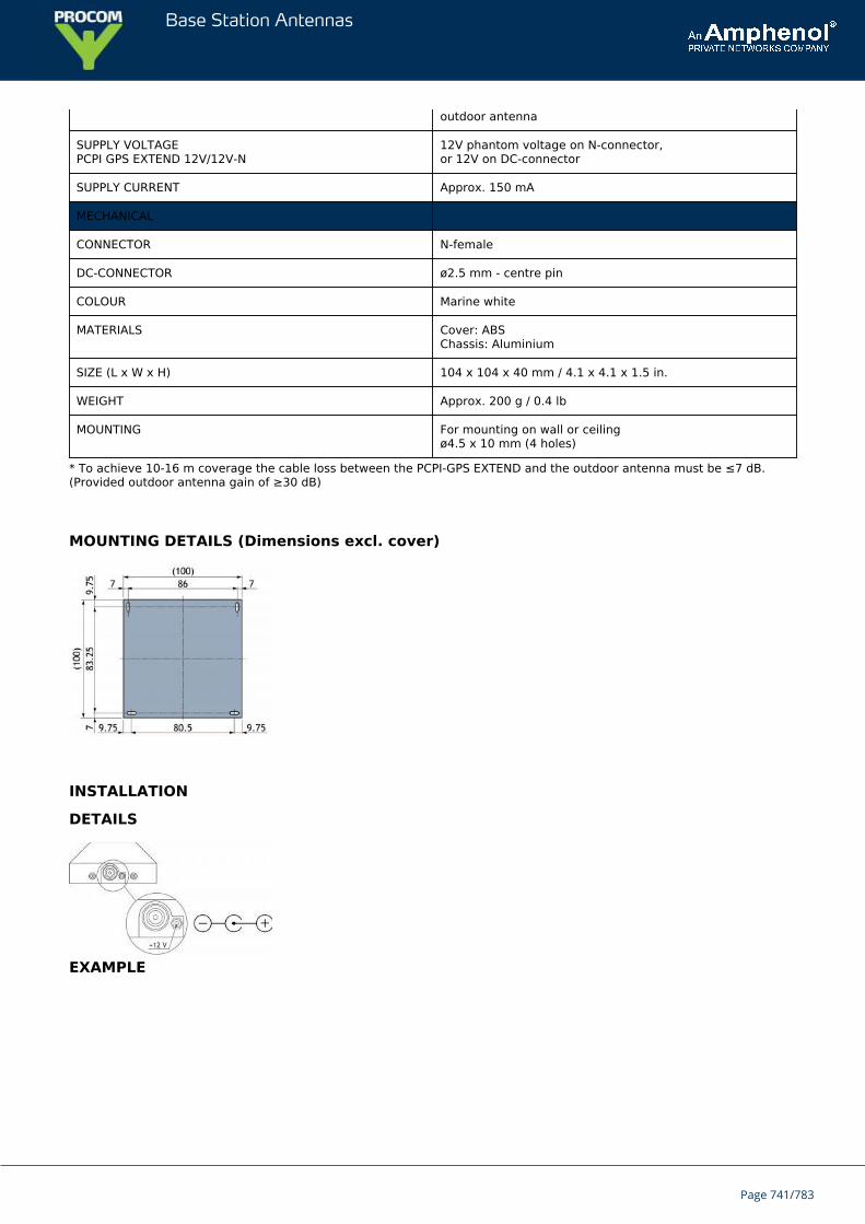
Base Station Antennas
outdoor antenna
SUPPLY VOLTAGEPCPI GPS EXTEND 12V/12V-N
12V phantom voltage on N-connector,or 12V on DC-connector
SUPPLY CURRENT Approx. 150 mA
MECHANICAL
CONNECTOR N-female
DC-CONNECTOR ø2.5 mm - centre pin
COLOUR Marine white
MATERIALS Cover: ABSChassis: Aluminium
SIZE (L x W x H) 104 x 104 x 40 mm / 4.1 x 4.1 x 1.5 in.
WEIGHT Approx. 200 g / 0.4 lb
MOUNTING For mounting on wall or ceilingø4.5 x 10 mm (4 holes)
* To achieve 10-16 m coverage the cable loss between the PCPI-GPS EXTEND and the outdoor antenna must be ≤7 dB.(Provided outdoor antenna gain of ≥30 dB)
MOUNTING DETAILS (Dimensions excl. cover)
INSTALLATION
DETAILS
EXAMPLE
Page 741/783
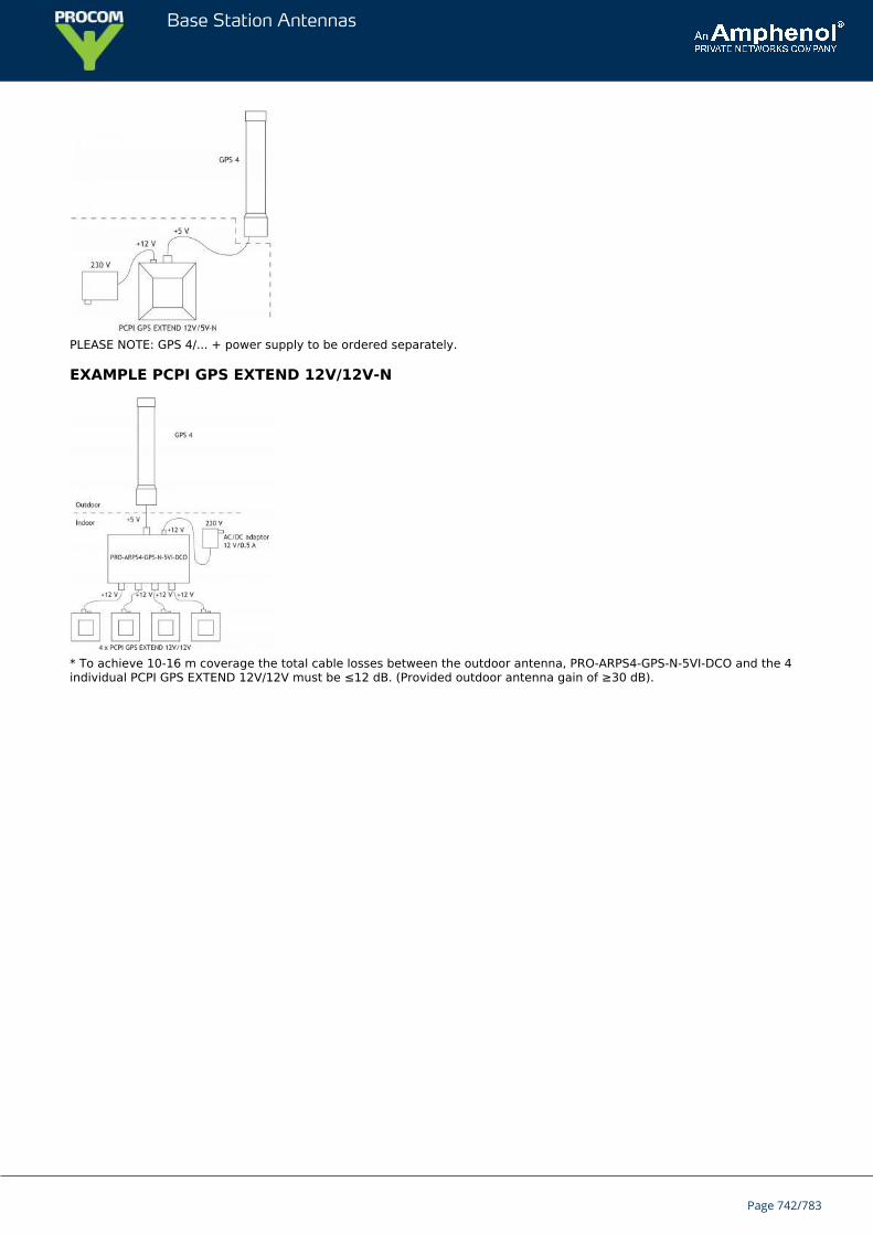
Base Station Antennas
PLEASE NOTE: GPS 4/... + power supply to be ordered separately.
EXAMPLE PCPI GPS EXTEND 12V/12V-N
* To achieve 10-16 m coverage the total cable losses between the outdoor antenna, PRO-ARPS4-GPS-N-5VI-DCO and the 4individual PCPI GPS EXTEND 12V/12V must be ≤12 dB. (Provided outdoor antenna gain of ≥30 dB).
Page 742/783
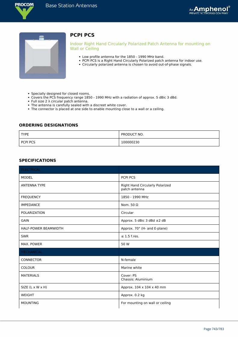
Base Station Antennas
PCPI PCSIndoor Right Hand Circularly Polarized Patch Antenna for mounting onWall or Ceiling
Low profile antenna for the 1850 - 1990 MHz band.PCPI PCS is a Right Hand Circularly Polarized patch antenna for indoor use.Circularly polarized antenna is chosen to avoid out-of-phase signals.
Specially designed for closed rooms.Covers the PCS frequency range 1850 - 1990 MHz with a radiation of approx. 5 dBic 3 dBd.Full size 2 λ circular patch antenna.The antenna is carefully sealed with a discreet white cover.The connector is placed at one side to enable mounting close to a wall or a ceiling.
ORDERING DESIGNATIONS
TYPE PRODUCT NO.
PCPI PCS 100000230
SPECIFICATIONS
ELECTRICAL
MODEL PCPI PCS
ANTENNA TYPE Right Hand Circularly Polarizedpatch antenna
FREQUENCY 1850 - 1990 MHz
IMPEDANCE Nom. 50 Ω
POLARIZATION Circular
GAIN Approx. 5 dBic 3 dBd ±2 dB
HALF-POWER BEAMWIDTH Approx. 70° (H- and E-plane)
SWR ≤ 1.5 f.res.
MAX. POWER 50 W
MECHANICAL
CONNECTOR N-female
COLOUR Marine white
MATERIALS Cover: PSChassis: Aluminium
SIZE (L x W x H) Approx. 104 x 104 x 40 mm
WEIGHT Approx. 0.2 kg
MOUNTING For mounting on wall or ceiling
Page 743/783

Base Station Antennas
ø4.5 x 10 mm (4 holes)
MOUNTING & PATTERN
MOUNTING DETAILS (Dimensions excl. cover)
TYPICAL GAIN AND SWR CURVES
TYPICAL RADIATION PATTERN (E-PLANE)
This curve shows the radiation patterns in the vertical plane.
TYPICAL RADIATION PATTERN (H-PLANE)
This curve shows the radiation patterns in the horizontal plane (horizontal coverage).
Page 744/783
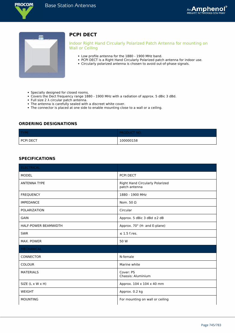
Base Station Antennas
PCPI DECTIndoor Right Hand Circularly Polarized Patch Antenna for mounting onWall or Ceiling
Low profile antenna for the 1880 - 1900 MHz band.PCPI DECT is a Right Hand Circularly Polarized patch antenna for indoor use.Circularly polarized antenna is chosen to avoid out-of-phase signals.
Specially designed for closed rooms.Covers the Dect frequency range 1880 - 1900 MHz with a radiation of approx. 5 dBic 3 dBd.Full size 2 λ circular patch antenna.The antenna is carefully sealed with a discreet white cover.The connector is placed at one side to enable mounting close to a wall or a ceiling.
ORDERING DESIGNATIONS
TYPE PRODUCT NO.
PCPI DECT 100000158
SPECIFICATIONS
ELECTRICAL
MODEL PCPI DECT
ANTENNA TYPE Right Hand Circularly Polarizedpatch antenna
FREQUENCY 1880 - 1900 MHz
IMPEDANCE Nom. 50 Ω
POLARIZATION Circular
GAIN Approx. 5 dBic 3 dBd ±2 dB
HALF-POWER BEAMWIDTH Approx. 70° (H- and E-plane)
SWR ≤ 1.5 f.res.
MAX. POWER 50 W
MECHANICAL
CONNECTOR N-female
COLOUR Marine white
MATERIALS Cover: PSChassis: Aluminium
SIZE (L x W x H) Approx. 104 x 104 x 40 mm
WEIGHT Approx. 0.2 kg
MOUNTING For mounting on wall or ceiling
Page 745/783
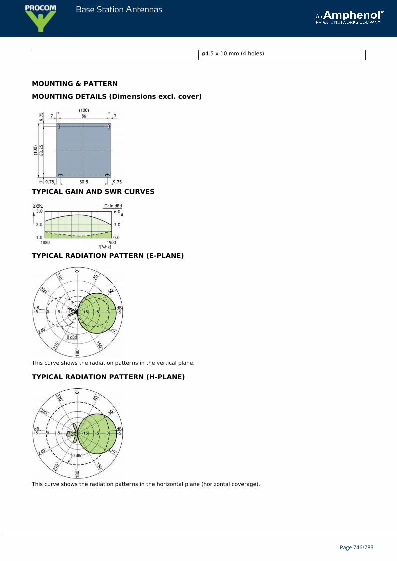
Base Station Antennas
ø4.5 x 10 mm (4 holes)
MOUNTING & PATTERN
MOUNTING DETAILS (Dimensions excl. cover)
TYPICAL GAIN AND SWR CURVES
TYPICAL RADIATION PATTERN (E-PLANE)
This curve shows the radiation patterns in the vertical plane.
TYPICAL RADIATION PATTERN (H-PLANE)
This curve shows the radiation patterns in the horizontal plane (horizontal coverage).
Page 746/783

Base Station Antennas
PCPI DCSIndoor Right Hand Circularly Polarized Patch Antenna for mounting onWall or Ceiling
Low profile antenna for the 1710 - 1880 MHz band.PCPI DCS is a Right Hand Circularly Polarized patch antenna for indoor use.Circularly polarized antenna is chosen to avoid out-of-phase signals.
Specially designed for closed rooms.Covers the DCS frequency range 1710 - 1880 MHz with a radiation of approx. 5 dBic 3 dBd.Full size 2 λ circular patch antenna.The antenna is carefully sealed with a discreet white cover.The connector is placed at one side to enable mounting close to a wall or a ceiling.
ORDERING DESIGNATIONS
TYPE PRODUCT NO.
PCPI DCS 100000229
SPECIFICATIONS
ELECTRICAL
MODEL PCPI DCS
ANTENNA TYPE Right Hand Circularly Polarizedpatch antenna
FREQUENCY 1710 - 1880 MHz
IMPEDANCE Nom. 50 Ω
POLARIZATION Circular
GAIN Approx. 5 dBic 3 dBd ±2 dB
HALF-POWER BEAMWIDTH Approx. 70° (H- and E-plane)
SWR ≤ 1.5 f.res.
MAX. POWER 50 W
MECHANICAL
CONNECTOR N-female
COLOUR Marine white
MATERIALS Cover: PSChassis: Aluminium
SIZE (L x W x H) Approx. 104 x 104 x 40 mm
WEIGHT Approx. 0.2 kg
MOUNTING For mounting on wall or ceiling
Page 747/783

Base Station Antennas
ø4.5 x 10 mm (4 holes)
MOUNTING & PATTERN
MOUNTING DETAILS (Dimensions excl. cover)
TYPICAL GAIN AND SWR CURVES
TYPICAL RADIATION PATTERN (E-PLANE)
This curve shows the radiation patterns in the vertical plane.
TYPICAL RADIATION PATTERN (H-PLANE)
This curve shows the radiation patterns in the horizontal plane (horizontal coverage).
Page 748/783

Base Station Antennas
PCPI UMTSIndoor Right Hand Circularly Polarized Patch Antenna for mounting onWall or Ceiling
Low profile antenna for the 1910 - 2200 MHz band.PCPI UMTS is a Right Hand Circularly Polarized patch antenna for indoor use.Circularly polarized antenna is chosen to avoid out-of-phase signals.
Specially designed for closed rooms.Covers the UMTS frequency range 1910 - 2200 MHz with a radiation of approx. 5 dBic 3 dBd.Full size 2 λ circular patch antenna.The antenna is carefully sealed with a discreet white cover.The connector is placed at one side to enable mounting close to a wall or a ceiling.
ORDERING DESIGNATIONS
TYPE PRODUCT NO.
PCPI UMTS 100000231
SPECIFICATIONS
ELECTRICAL
MODEL PCPI UMTS
ANTENNA TYPE Right Hand Circularly Polarizedpatch antenna
FREQUENCY 1910 - 2200 MHz
IMPEDANCE Nom. 50 Ω
POLARIZATION Circular
GAIN Approx. 5 dBic 3 dBd ±2 dB
HALF-POWER BEAMWIDTH Approx. 70° (H- and E-plane)
SWR ≤ 1.5 f.res.
MAX. POWER 50 W
MECHANICAL
CONNECTOR N-female
COLOUR Marine white
MATERIALS Cover: PSChassis: Aluminium
SIZE (L x W x H) Approx. 104 x 104 x 40 mm
WEIGHT Approx. 0.2 kg
MOUNTING For mounting on wall or ceiling
Page 749/783
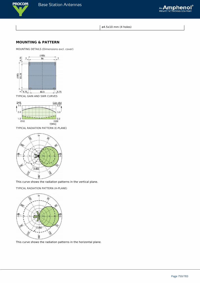
Base Station Antennas
ø4.5x10 mm (4 holes)
MOUNTING & PATTERN
MOUNTING DETAILS (Dimensions excl. cover)
TYPICAL GAIN AND SWR CURVES
TYPICAL RADIATION PATTERN (E-PLANE)
This curve shows the radiation patterns in the vertical plane.
TYPICAL RADIATION PATTERN (H-PLANE)
This curve shows the radiation patterns in the horizontal plane.
Page 750/783
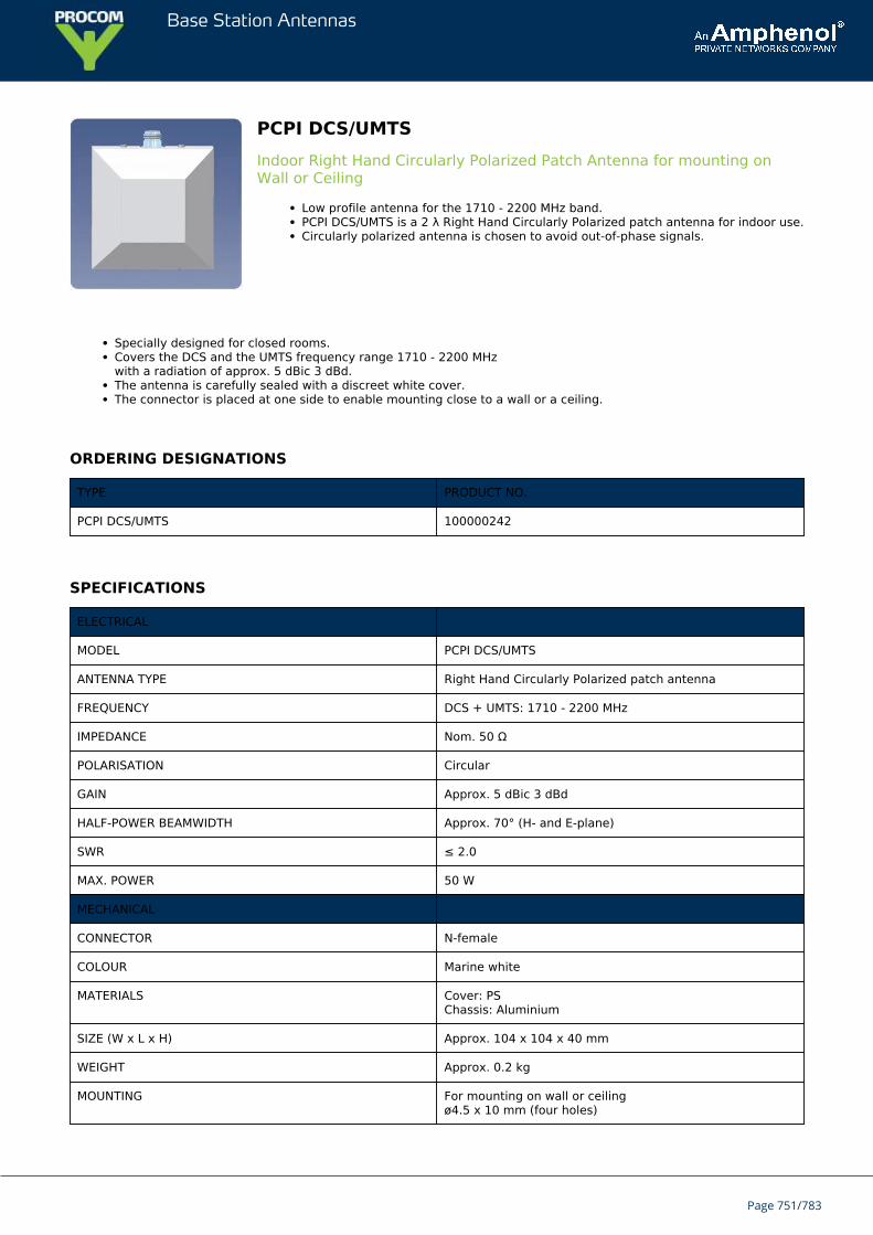
Base Station Antennas
PCPI DCS/UMTSIndoor Right Hand Circularly Polarized Patch Antenna for mounting onWall or Ceiling
Low profile antenna for the 1710 - 2200 MHz band.PCPI DCS/UMTS is a 2 λ Right Hand Circularly Polarized patch antenna for indoor use.Circularly polarized antenna is chosen to avoid out-of-phase signals.
Specially designed for closed rooms.Covers the DCS and the UMTS frequency range 1710 - 2200 MHzwith a radiation of approx. 5 dBic 3 dBd.The antenna is carefully sealed with a discreet white cover.The connector is placed at one side to enable mounting close to a wall or a ceiling.
ORDERING DESIGNATIONS
TYPE PRODUCT NO.
PCPI DCS/UMTS 100000242
SPECIFICATIONS
ELECTRICAL
MODEL PCPI DCS/UMTS
ANTENNA TYPE Right Hand Circularly Polarized patch antenna
FREQUENCY DCS + UMTS: 1710 - 2200 MHz
IMPEDANCE Nom. 50 Ω
POLARISATION Circular
GAIN Approx. 5 dBic 3 dBd
HALF-POWER BEAMWIDTH Approx. 70° (H- and E-plane)
SWR ≤ 2.0
MAX. POWER 50 W
MECHANICAL
CONNECTOR N-female
COLOUR Marine white
MATERIALS Cover: PSChassis: Aluminium
SIZE (W x L x H) Approx. 104 x 104 x 40 mm
WEIGHT Approx. 0.2 kg
MOUNTING For mounting on wall or ceilingø4.5 x 10 mm (four holes)
Page 751/783
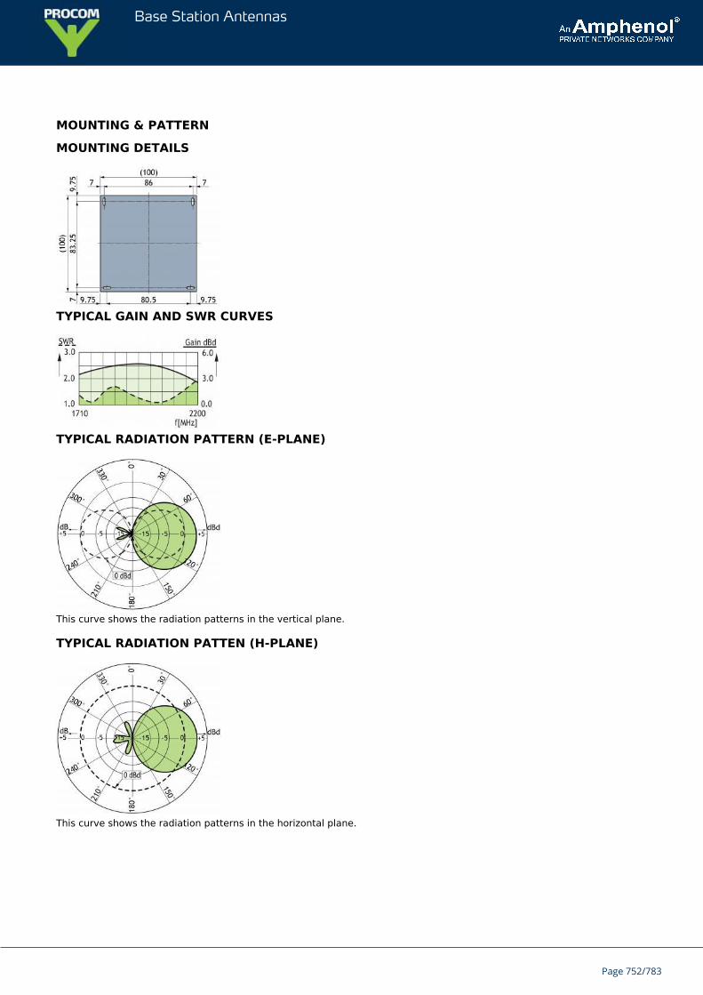
Base Station Antennas
MOUNTING & PATTERN
MOUNTING DETAILS
TYPICAL GAIN AND SWR CURVES
TYPICAL RADIATION PATTERN (E-PLANE)
This curve shows the radiation patterns in the vertical plane.
TYPICAL RADIATION PATTEN (H-PLANE)
This curve shows the radiation patterns in the horizontal plane.
Page 752/783
Base Station Antennas
PCPI WIFIIndoor Right Hand Circularly Polarized Patch Antenna for mounting onWall or Ceiling
Low profile antenna for the 2400 - 2500 MHz band.PCPI WIFI is a Right Hand Circularly Polarized patch antenna for indoor use.Circularly polarized antenna is chosen to avoid out-of-phase signals.
Specially designed for closed rooms.The antenna is carefully sealed with a discrete white cover.The connector is placed at one side to enable mounting close to a wall or a ceiling.
SPECIFICATIONS
ELECTRICAL
MODEL PCPI WIFI
ANTENNA TYPE Right Hand Circularly Polarizedpatch antenna
FREQUENCY 2400 - 2500 MHz
IMPEDANCE Nom. 50 Ω
POLARIZATION Circular
GAIN Approx. 5 dBic 3 dBd ±2 dB
HALF-POWER BEAMWIDTH Approx. 70° (H- and E-plane)
SWR ≤ 2
MAX. POWER 50 W
MECHANICAL
CONNECTOR N-female
COLOUR Marine white
MATERIALS Cover: PSChassis: Aluminium
SIZE (L x W x H) Approx. 104 x 104 x 40 mm
WEIGHT Approx. 0.2 kg
MOUNTING For mounting on wall or ceilingø4.5 x 10 mm (4 holes)
MOUNTING DETAILS (Dimensions excl. cover)
Page 753/783
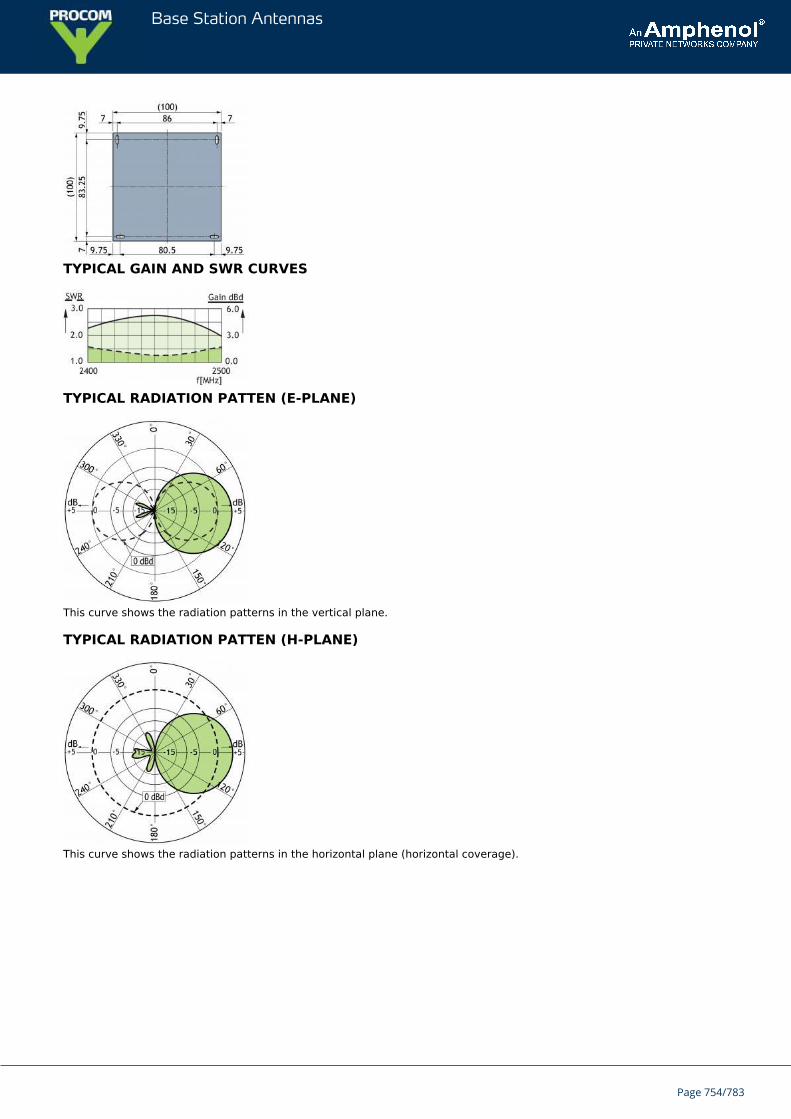
Base Station Antennas
TYPICAL GAIN AND SWR CURVES
TYPICAL RADIATION PATTEN (E-PLANE)
This curve shows the radiation patterns in the vertical plane.
TYPICAL RADIATION PATTEN (H-PLANE)
This curve shows the radiation patterns in the horizontal plane (horizontal coverage).
Page 754/783
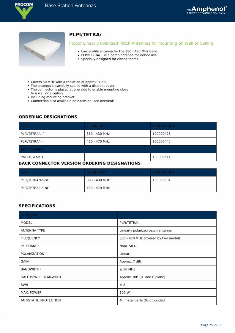
Base Station Antennas
PLPI/TETRA/Indoor Linearly Polarized Patch Antennas for mounting on Wall or Ceiling
Low-profile antenna for the 380 - 470 MHz band.PLPI/TETRA/... is a patch antenna for indoor use.Specially designed for closed rooms.
Covers 50 MHz with a radiation of approx. 7 dBi.The antenna is carefully sealed with a discreet cover.The connector is placed at one side to enable mounting closeto a wall or a ceiling.Including mounting bracket.Connection also available on backside (see overleaf).
ORDERING DESIGNATIONS
TYPE FREQUENCY PRODUCT NO.
PLPI/TETRA/s-f 380 - 430 MHz 100000423
PLPI/TETRA/l-h 430 - 470 MHz 100000445
ACCESSORIES
PATCH-WAMO 100000511
BACK CONNECTOR VERSION ORDERING DESIGNATIONS
TYPE FREQUENCY PRODUCT NO.
PLPI/TETRA/s-f-BC 380 - 430 MHz 100000581
PLPI/TETRA/l-h-BC 430 - 470 MHz
SPECIFICATIONS
ELETRICAL
MODEL PLPI/TETRA/...
ANTENNA TYPE Linearly polarized patch antenna
FREQUENCY 380 - 470 MHz covered by two models
IMPEDANCE Nom. 50 Ω
POLARIZATION Linear
GAIN Approx. 7 dBi
BANDWIDTH ≥ 50 MHz
HALF POWER BEAMWIDTH Approx. 80° (H- and E-plane)
SWR ≤ 2
MAX. POWER 100 W
ANTISTATIC PROTECTION All metal parts DC-grounded
Page 755/783
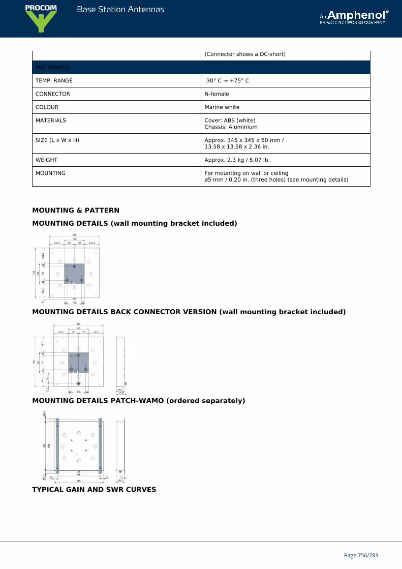
Base Station Antennas
(Connector shows a DC-short)
MECHANICAL
TEMP. RANGE -30° C → +75° C
CONNECTOR N-female
COLOUR Marine white
MATERIALS Cover: ABS (white)Chassis: Aluminium
SIZE (L x W x H) Approx. 345 x 345 x 60 mm /13.58 x 13.58 x 2.36 in.
WEIGHT Approx. 2.3 kg / 5.07 lb.
MOUNTING For mounting on wall or ceilingø5 mm / 0.20 in. (three holes) (see mounting details)
MOUNTING & PATTERN
MOUNTING DETAILS (wall mounting bracket included)
MOUNTING DETAILS BACK CONNECTOR VERSION (wall mounting bracket included)
MOUNTING DETAILS PATCH-WAMO (ordered separately)
TYPICAL GAIN AND SWR CURVES
Page 756/783
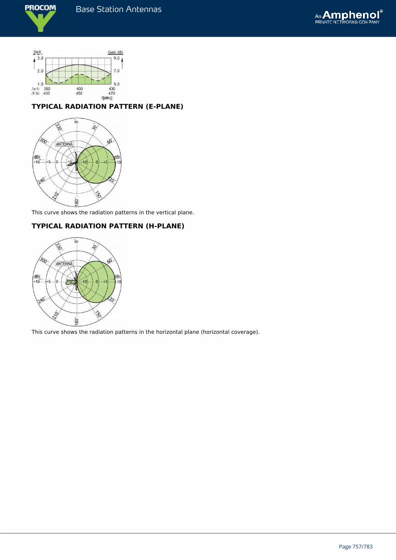
Base Station Antennas
TYPICAL RADIATION PATTERN (E-PLANE)
This curve shows the radiation patterns in the vertical plane.
TYPICAL RADIATION PATTERN (H-PLANE)
This curve shows the radiation patterns in the horizontal plane (horizontal coverage).
Page 757/783
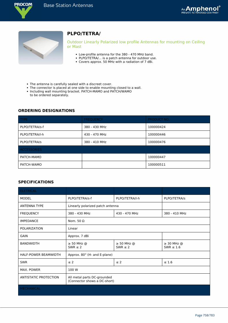
Base Station Antennas
PLPO/TETRA/Outdoor Linearly Polarized low profile Antennas for mounting on Ceilingor Mast
Low-profile antenna for the 380 - 470 MHz band.PLPO/TETRA/... is a patch antenna for outdoor use.Covers approx. 50 MHz with a radiation of 7 dBi.
The antenna is carefully sealed with a discreet cover.The connector is placed at one side to enable mounting closed to a wall.Including wall mounting bracket. PATCH-MAMO and PATCH/WAMOto be ordered separately.
ORDERING DESIGNATIONS
TYPE FREQUENCY PRODUCT NO.
PLPO/TETRA/s-f 380 - 430 MHz 100000424
PLPO/TETRA/l-h 430 - 470 MHz 100000446
PLPO/TETRA/s 380 - 410 MHz 100000476
ACCESSORIES
PATCH-MAMO 100000447
PATCH-WAMO 100000511
SPECIFICATIONS
ELETRICAL
MODEL PLPO/TETRA/s-f PLPO/TETRA/l-h PLPO/TETRA/s
ANTENNA TYPE Linearly polarized patch antenna
FREQUENCY 380 - 430 MHz 430 - 470 MHz 380 - 410 MHz
IMPEDANCE Nom. 50 Ω
POLARIZATION Linear
GAIN Approx. 7 dBi
BANDWIDTH ≥ 50 MHz @SWR ≤ 2
≥ 50 MHz @SWR ≤ 2
≥ 30 MHz @SWR ≤ 1.6
HALF-POWER BEAMWIDTH Approx. 80° (H- and E-plane)
SWR ≤ 2 ≤ 2 ≤ 1.6
MAX. POWER 100 W
ANTISTATIC PROTECTION All metal parts DC-grounded(Connector shows a DC-short)
MECHANICAL
Page 758/783
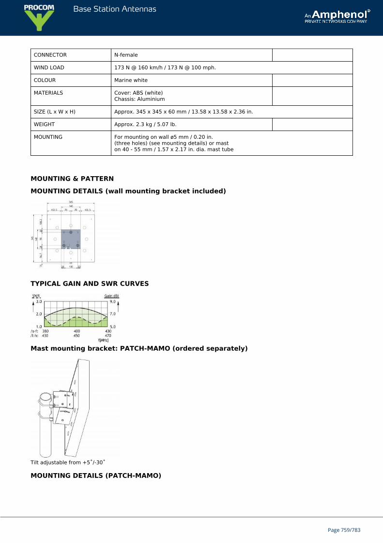
Base Station Antennas
CONNECTOR N-female
WIND LOAD 173 N @ 160 km/h / 173 N @ 100 mph.
COLOUR Marine white
MATERIALS Cover: ABS (white)Chassis: Aluminium
SIZE (L x W x H) Approx. 345 x 345 x 60 mm / 13.58 x 13.58 x 2.36 in.
WEIGHT Approx. 2.3 kg / 5.07 lb.
MOUNTING For mounting on wall ø5 mm / 0.20 in.(three holes) (see mounting details) or maston 40 - 55 mm / 1.57 x 2.17 in. dia. mast tube
MOUNTING & PATTERN
MOUNTING DETAILS (wall mounting bracket included)
TYPICAL GAIN AND SWR CURVES
Mast mounting bracket: PATCH-MAMO (ordered separately)
Tilt adjustable from +5˚/-30˚
MOUNTING DETAILS (PATCH-MAMO)
Page 759/783
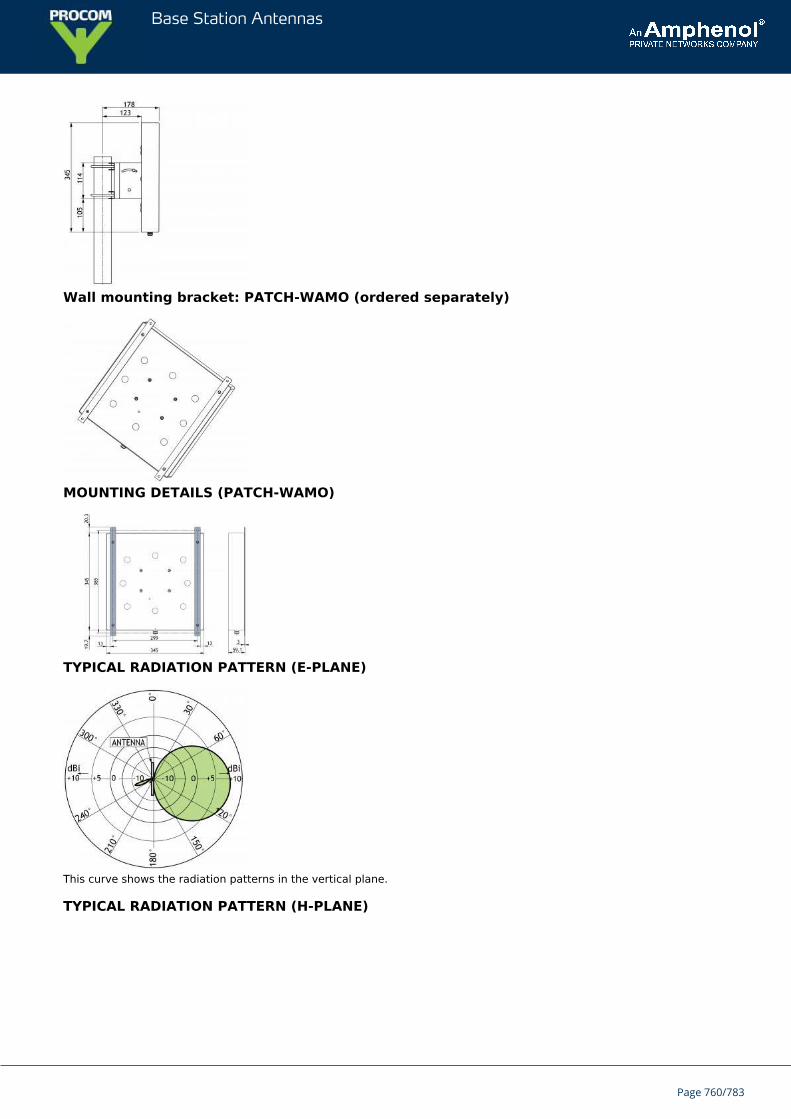
Base Station Antennas
Wall mounting bracket: PATCH-WAMO (ordered separately)
MOUNTING DETAILS (PATCH-WAMO)
TYPICAL RADIATION PATTERN (E-PLANE)
This curve shows the radiation patterns in the vertical plane.
TYPICAL RADIATION PATTERN (H-PLANE)
Page 760/783

Base Station Antennas
This curve shows the radiation patterns in the horizontal plane (horizontal coverage).
Page 761/783
Base Station Antennas
PLPI 900/1800Indoor dual Patch Antenna for mounting on Wall or Ceiling
Low profile antenna for the 900 and 1800 MHz Band.PLPI 900/1800 is a patch antenna for indoor use.Covers 80 MHz at 900 MHz and 170 MHz at 1800 MHz with a radiation of approx. 8dBi.
The antenna is carefully sealed with a discreet white cover.The two connectors are placed at one side to enable mounting close to a wall or a ceiling.
ORDERING DESIGNATIONS
TYPE PRODUCT NO.
PLPI 900/1800 100000322
SPECIFICATIONS
ELECTRICAL
MODEL PLPI 900/1800
ANTENNA TYPE Linearly Polarized patch antenna
FREQUENCY 880 - 960 MHz / 1710 - 1880 MHz
IMPEDANCE Nom. 50 Ω
POLARIZATION Linear
GAIN 8 dBi
BANDWIDTH 880 - 960 ≥ 80 MHz @ SWR ≤ 21710 - 1880 ≥ 170 MHz @ SWR ≤ 2
HALF-POWER BEAMWIDTH 65° - 85° in azimuth plane60° - 80° in elevation plane
SWR ≤ 2
MAX. POWER 100 W
MECHANICAL
CONNECTOR 2 x N-female
COLOUR Marine white
MATERIALS Cover: PSChassis: Aluminium
SIZE (L x W x H) Approx. 250 x 200 x 30 mm
WEIGHT Approx. 0.4 kg
MOUNTING For mounting on wall or ceilingø4.5 x 20 mm (four holes)
Page 762/783
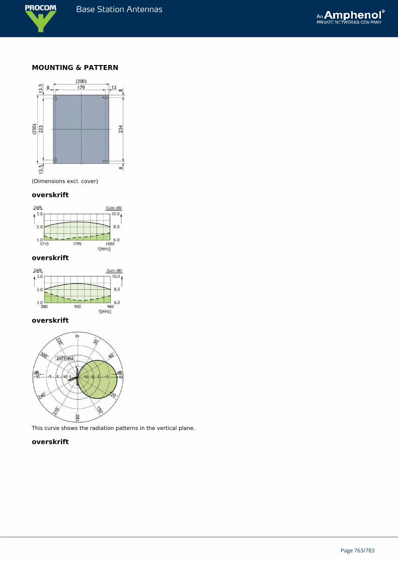
Base Station Antennas
MOUNTING & PATTERN
(Dimensions excl. cover)
overskrift
overskrift
overskrift
This curve shows the radiation patterns in the vertical plane.
overskrift
Page 763/783
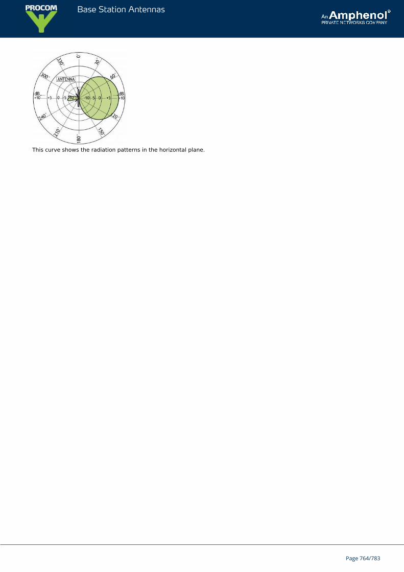
Base Station Antennas
This curve shows the radiation patterns in the horizontal plane.
Page 764/783
Base Station Antennas
PLPI UMTS 2100Indoor Linearly Polarized Patch Antenna for mounting on Wall or Ceiling
Low-profile antenna for the UMTS 2100 band.PLPI UMTS 2100 is a linear patch antenna for indoor use.
The antenna is carefully sealed with a discreet white cover.The connector is placed at one side to enable mounting close toa wall or a ceiling.
ORDERING DESIGNATIONS
TYPE PRODUCT NO.
PLPI UMTS 2100 100000323
SPECIFICATIONS
ELECTRICAL
MODEL PLPI UMTS 2100
ANTENNA TYPE Linearly polarized patch antenna
FREQUENCY 2110 - 2170 MHz
IMPEDANCE Nom. 50 Ω
POLARIZATION Linear
GAIN 6 - 9 dBi
BANDWIDTH ≥ 80 MHz @ SWR ≤ 2.0
HALF-POWER BEAMWIDTH Approx. 60° (H- and E-plane)
SWR 1.5 f.res.
MAX. POWER 25 W
MECHANICAL
CONNECTOR N-female
COLOUR Marine white
MATERIALS Cover: PSChassis: Aluminium
SIZE (L x W x H) Approx. 204 x 204 x 28 mm /8.03 x 8.03 x 1.10 in.
WEIGHT Approx. 0.4 kg / 0.88 lb.
MOUNTING For mounting on wall or ceilingø4.5 x 20 mm (4 holes)
Page 765/783
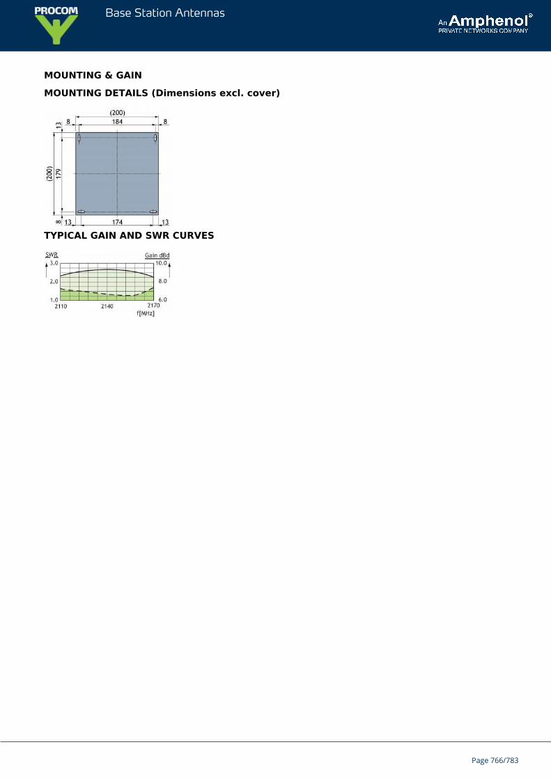
Base Station Antennas
MOUNTING & GAIN
MOUNTING DETAILS (Dimensions excl. cover)
TYPICAL GAIN AND SWR CURVES
Page 766/783
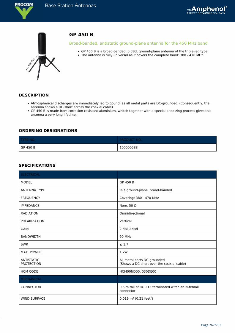
Base Station Antennas
GP 450 BBroad-banded, antistatic ground-plane antenna for the 450 MHz band
GP 450 B is a broad-banded, 0 dBd, ground-plane antenna of the triple-leg type.The antenna is fully universal as it covers the complete band: 380 - 470 MHz.
DESCRIPTION
Atmospherical discharges are immediately led to gound, as all metal parts are DC-grounded. (Consequently, theantenna shows a DC-short across the coaxial cable).GP 450 B is made from corrosion-resistant aluminium, whitch together with a special anodizing process gives thisantenna a very long lifetime.
ORDERING DESIGNATIONS
TYPE NO. PRODUCT NO.
GP 450 B 100000588
SPECIFICATIONS
ELECTRICAL
MODEL GP 450 B
ANTENNA TYPE ¼ λ ground-plane, broad-banded
FREQUENCY Covering: 380 - 470 MHz
IMPEDANCE Nom. 50 Ω
RADIATION Omnidirectional
POLARIZATION Vertical
GAIN 2 dBi 0 dBd
BANDWIDTH 90 MHz
SWR ≤ 1.7
MAX. POWER 1 kW
ANTISTATICPROTECTION
All metal parts DC-grounded(Shows a DC-short over the coaxial cable)
HCM CODE HCM00ND00, 030DE00
MECHANICAL
CONNECTOR 0.5 m tail of RG 213 terminated witch an N-femailconnector
WIND SURFACE 0.019 m² (0.21 feet2)
Page 767/783
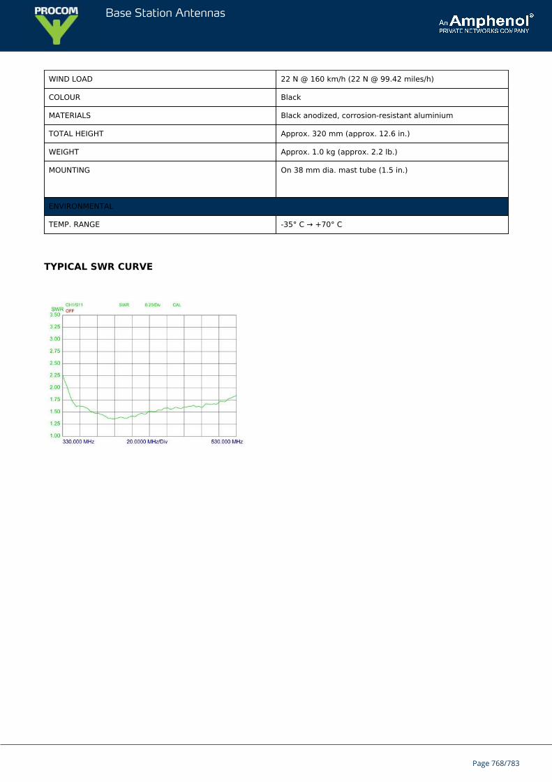
Base Station Antennas
WIND LOAD 22 N @ 160 km/h (22 N @ 99.42 miles/h)
COLOUR Black
MATERIALS Black anodized, corrosion-resistant aluminium
TOTAL HEIGHT Approx. 320 mm (approx. 12.6 in.)
WEIGHT Approx. 1.0 kg (approx. 2.2 lb.)
MOUNTING On 38 mm dia. mast tube (1.5 in.)
ENVIRONMENTAL
TEMP. RANGE -35° C → +70° C
TYPICAL SWR CURVE
Page 768/783
Base Station Antennas
CXL 150-1/...Base Station and Marine VHF Antenna
This base station and maritime VHF antenna is developed for use on board ships aswell as on masts and thanks to the 1” revolving nut mounting system it can bemounted in the mast, in the auxilliary mast as well as on the cross-beam. By meansof Procom’s flange mount it can also be mounted on deck or rooftop.
Page 769/783
Base Station Antennas
Page 770/783
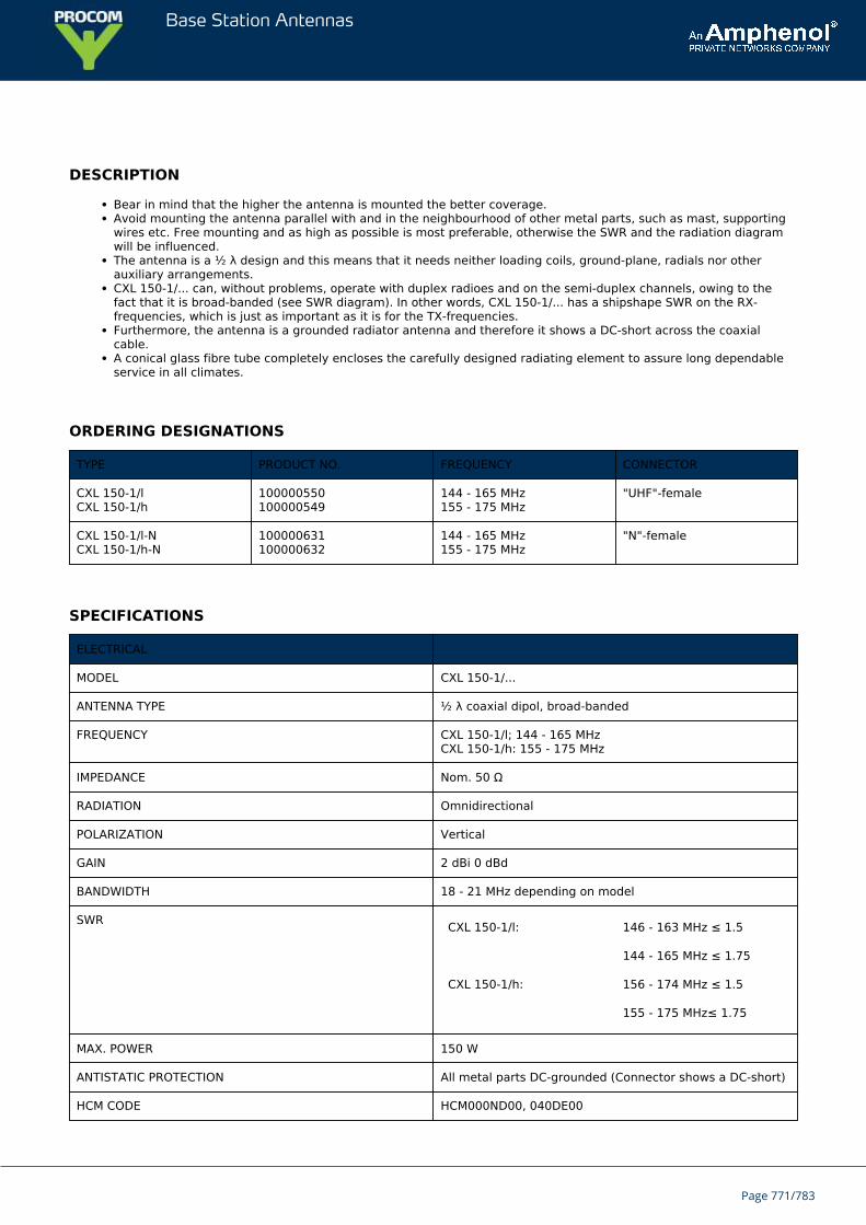
Base Station Antennas
DESCRIPTION
Bear in mind that the higher the antenna is mounted the better coverage.Avoid mounting the antenna parallel with and in the neighbourhood of other metal parts, such as mast, supportingwires etc. Free mounting and as high as possible is most preferable, otherwise the SWR and the radiation diagramwill be influenced.The antenna is a ½ λ design and this means that it needs neither loading coils, ground-plane, radials nor otherauxiliary arrangements.CXL 150-1/... can, without problems, operate with duplex radioes and on the semi-duplex channels, owing to thefact that it is broad-banded (see SWR diagram). In other words, CXL 150-1/... has a shipshape SWR on the RX-frequencies, which is just as important as it is for the TX-frequencies.Furthermore, the antenna is a grounded radiator antenna and therefore it shows a DC-short across the coaxialcable.A conical glass fibre tube completely encloses the carefully designed radiating element to assure long dependableservice in all climates.
ORDERING DESIGNATIONS
TYPE PRODUCT NO. FREQUENCY CONNECTOR
CXL 150-1/lCXL 150-1/h
100000550100000549
144 - 165 MHz155 - 175 MHz
"UHF"-female
CXL 150-1/l-NCXL 150-1/h-N
100000631100000632
144 - 165 MHz155 - 175 MHz
"N"-female
SPECIFICATIONS
ELECTRICAL
MODEL CXL 150-1/...
ANTENNA TYPE ½ λ coaxial dipol, broad-banded
FREQUENCY CXL 150-1/l; 144 - 165 MHzCXL 150-1/h: 155 - 175 MHz
IMPEDANCE Nom. 50 Ω
RADIATION Omnidirectional
POLARIZATION Vertical
GAIN 2 dBi 0 dBd
BANDWIDTH 18 - 21 MHz depending on model
SWR CXL 150-1/l: 146 - 163 MHz ≤ 1.5
144 - 165 MHz ≤ 1.75
CXL 150-1/h: 156 - 174 MHz ≤ 1.5
155 - 175 MHz≤ 1.75
MAX. POWER 150 W
ANTISTATIC PROTECTION All metal parts DC-grounded (Connector shows a DC-short)
HCM CODE HCM000ND00, 040DE00
Page 771/783
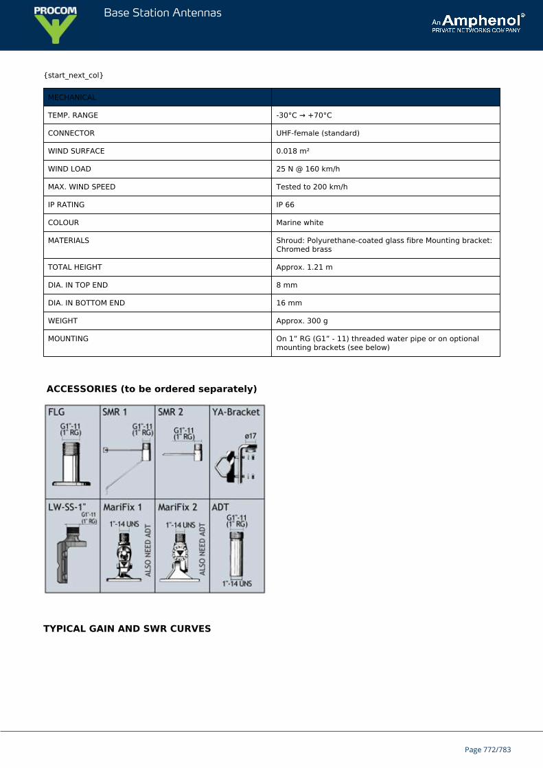
Base Station Antennas
{start_next_col}
MECHANICAL
TEMP. RANGE -30°C → +70°C
CONNECTOR UHF-female (standard)
WIND SURFACE 0.018 m²
WIND LOAD 25 N @ 160 km/h
MAX. WIND SPEED Tested to 200 km/h
IP RATING IP 66
COLOUR Marine white
MATERIALS Shroud: Polyurethane-coated glass fibre Mounting bracket:Chromed brass
TOTAL HEIGHT Approx. 1.21 m
DIA. IN TOP END 8 mm
DIA. IN BOTTOM END 16 mm
WEIGHT Approx. 300 g
MOUNTING On 1” RG (G1” - 11) threaded water pipe or on optionalmounting brackets (see below)
ACCESSORIES (to be ordered separately)
TYPICAL GAIN AND SWR CURVES
Page 772/783
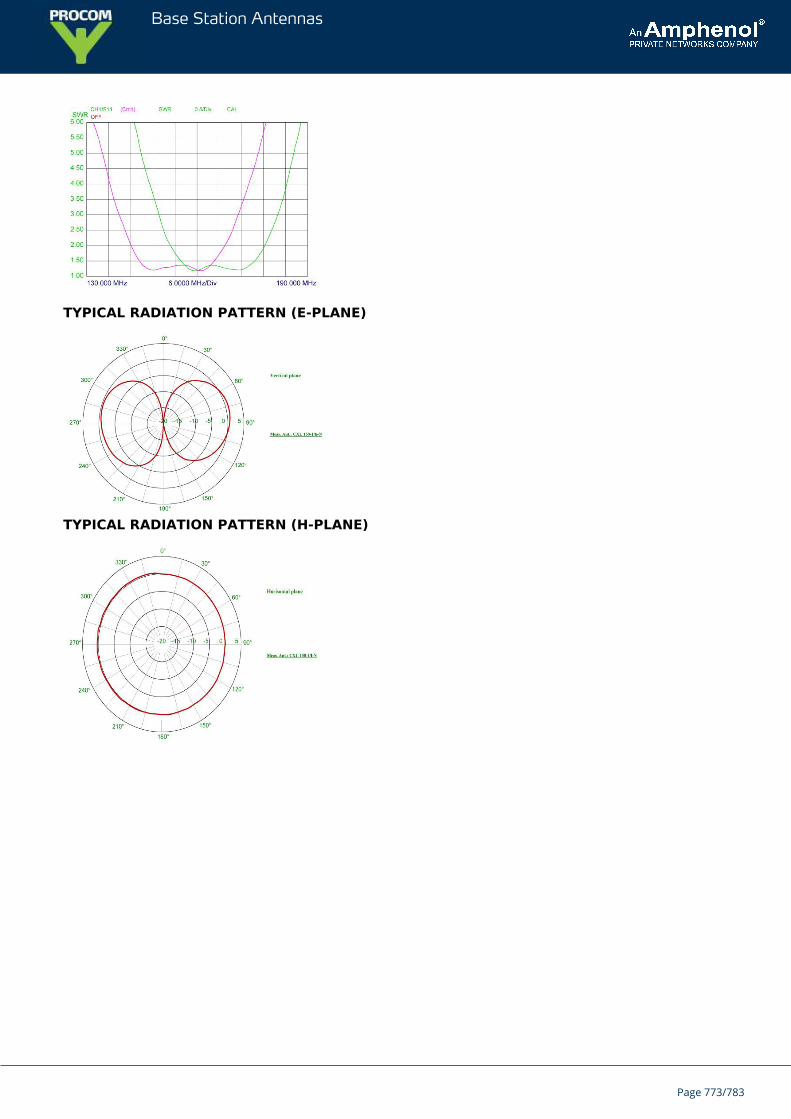
Base Station Antennas
TYPICAL RADIATION PATTERN (E-PLANE)
TYPICAL RADIATION PATTERN (H-PLANE)
Page 773/783
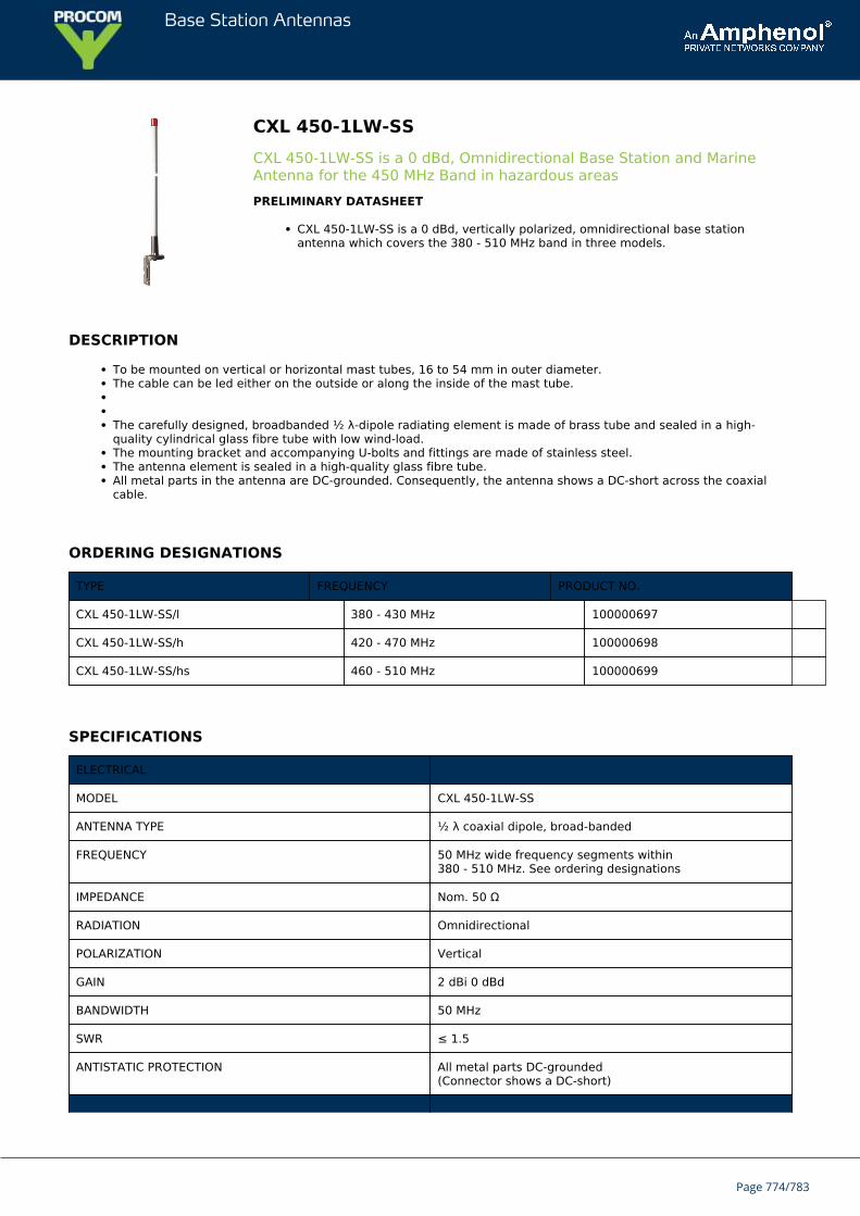
Base Station Antennas
CXL 450-1LW-SSCXL 450-1LW-SS is a 0 dBd, Omnidirectional Base Station and MarineAntenna for the 450 MHz Band in hazardous areasPRELIMINARY DATASHEET
CXL 450-1LW-SS is a 0 dBd, vertically polarized, omnidirectional base stationantenna which covers the 380 - 510 MHz band in three models.
DESCRIPTION
To be mounted on vertical or horizontal mast tubes, 16 to 54 mm in outer diameter.The cable can be led either on the outside or along the inside of the mast tube. The carefully designed, broadbanded ½ λ-dipole radiating element is made of brass tube and sealed in a high-quality cylindrical glass fibre tube with low wind-load.The mounting bracket and accompanying U-bolts and fittings are made of stainless steel.The antenna element is sealed in a high-quality glass fibre tube.All metal parts in the antenna are DC-grounded. Consequently, the antenna shows a DC-short across the coaxialcable.
ORDERING DESIGNATIONS
TYPE FREQUENCY PRODUCT NO.
CXL 450-1LW-SS/l 380 - 430 MHz 100000697
CXL 450-1LW-SS/h 420 - 470 MHz 100000698
CXL 450-1LW-SS/hs 460 - 510 MHz 100000699
SPECIFICATIONS
ELECTRICAL
MODEL CXL 450-1LW-SS
ANTENNA TYPE ½ λ coaxial dipole, broad-banded
FREQUENCY 50 MHz wide frequency segments within380 - 510 MHz. See ordering designations
IMPEDANCE Nom. 50 Ω
RADIATION Omnidirectional
POLARIZATION Vertical
GAIN 2 dBi 0 dBd
BANDWIDTH 50 MHz
SWR ≤ 1.5
ANTISTATIC PROTECTION All metal parts DC-grounded(Connector shows a DC-short)
Page 774/783
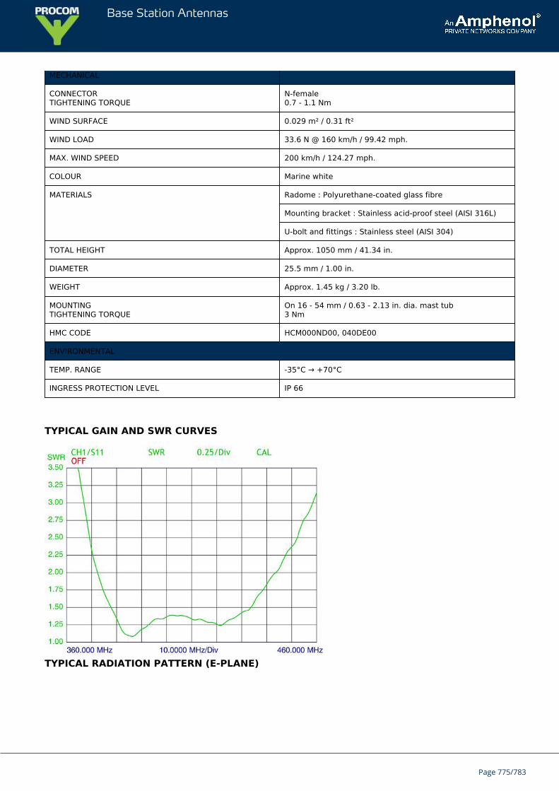
Base Station Antennas
MECHANICAL
CONNECTORTIGHTENING TORQUE
N-female0.7 - 1.1 Nm
WIND SURFACE 0.029 m² / 0.31 ft²
WIND LOAD 33.6 N @ 160 km/h / 99.42 mph.
MAX. WIND SPEED 200 km/h / 124.27 mph.
COLOUR Marine white
MATERIALS Radome : Polyurethane-coated glass fibre
Mounting bracket : Stainless acid-proof steel (AISI 316L)
U-bolt and fittings : Stainless steel (AISI 304)
TOTAL HEIGHT Approx. 1050 mm / 41.34 in.
DIAMETER 25.5 mm / 1.00 in.
WEIGHT Approx. 1.45 kg / 3.20 lb.
MOUNTINGTIGHTENING TORQUE
On 16 - 54 mm / 0.63 - 2.13 in. dia. mast tub3 Nm
HMC CODE HCM000ND00, 040DE00
ENVIRONMENTAL
TEMP. RANGE -35°C → +70°C
INGRESS PROTECTION LEVEL IP 66
TYPICAL GAIN AND SWR CURVES
TYPICAL RADIATION PATTERN (E-PLANE)
Page 775/783
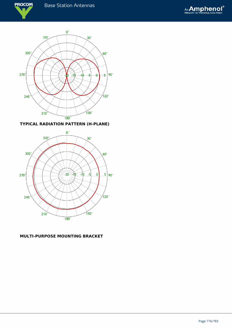
Base Station Antennas
TYPICAL RADIATION PATTERN (H-PLANE)
MULTI-PURPOSE MOUNTING BRACKET
Page 776/783
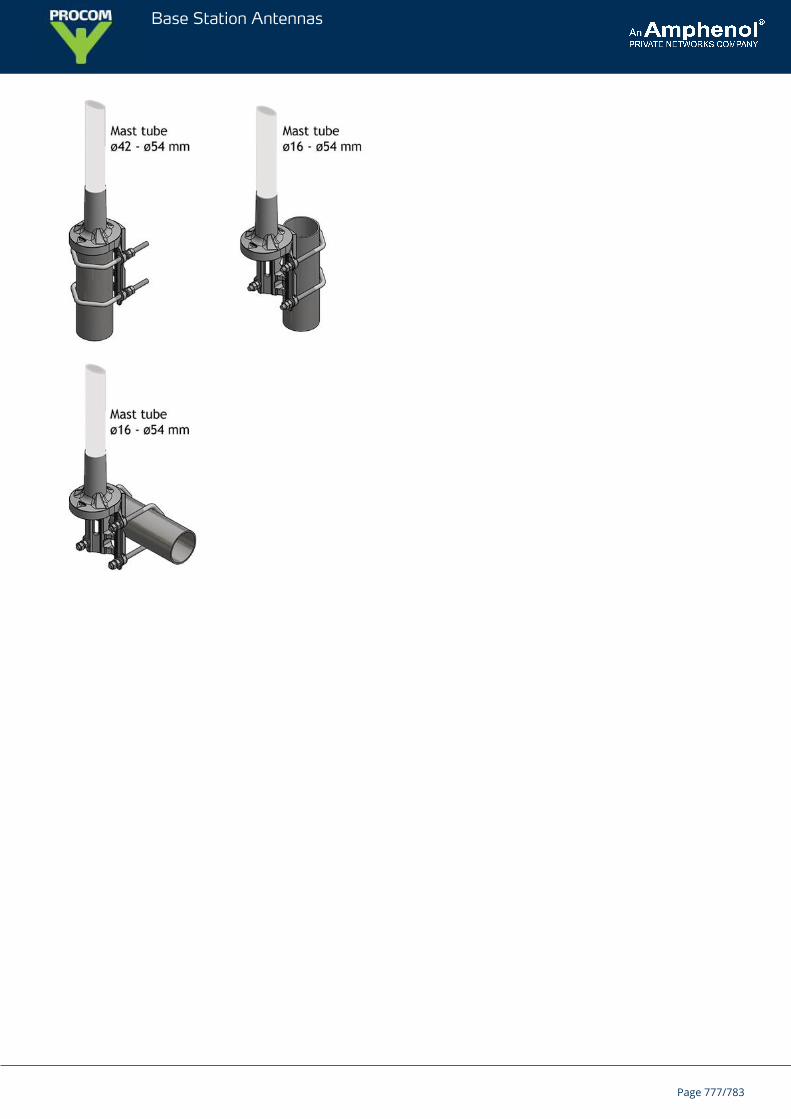
Base Station Antennas
Page 777/783
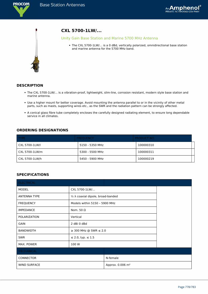
Base Station Antennas
CXL 5700-1LW/...Unity Gain Base Station and Marine 5700 MHz Antenna
The CXL 5700-1LW/… is a 0 dBd, vertically polarized, omnidirectional base stationand marine antenna for the 5700 MHz band.
DESCRIPTION
The CXL 5700-1LW/... is a vibration-proof, lightweight, slim-line, corrosion resistant, modern style base station andmarine antenna.
Use a higher mount for better coverage. Avoid mounting the antenna parallel to or in the vicinity of other metalparts, such as masts, supporting wires etc., as the SWR and the radiation pattern can be strongly affected.
A conical glass fibre tube completely encloses the carefully designed radiating element, to ensure long dependableservice in all climates.
ORDERING DESIGNATIONS
TYPE FREQUENCY PRODUCT NO.
CXL 5700-1LW/l 5150 - 5350 MHz 100000310
CXL 5700-1LW/m 5300 - 5500 MHz 100000311
CXL 5700-1LW/h 5450 - 5900 MHz 100000219
SPECIFICATIONS
ELECTRICAL
MODEL CXL 5700-1LW/...
ANTENNA TYPE ½ λ coaxial dipole, broad-banded
FREQUENCY Models within 5150 – 5900 MHz
IMPEDANCE Nom. 50 Ω
POLARIZATION Vertical
GAIN 2 dBi 0 dBd
BANDWIDTH ≥ 300 MHz @ SWR ≤ 2.0
SWR ≤ 2.0, typ. ≤ 1.5
MAX. POWER 100 W
MECHANICAL
CONNECTOR N-female
WIND SURFACE Approx. 0.006 m²
Page 778/783
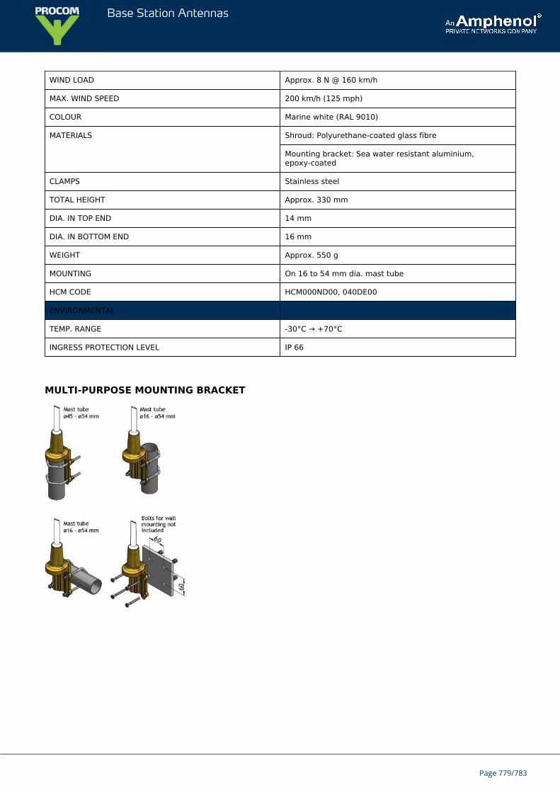
Base Station Antennas
WIND LOAD Approx. 8 N @ 160 km/h
MAX. WIND SPEED 200 km/h (125 mph)
COLOUR Marine white (RAL 9010)
MATERIALS Shroud: Polyurethane-coated glass fibre
Mounting bracket: Sea water resistant aluminium,epoxy-coated
CLAMPS Stainless steel
TOTAL HEIGHT Approx. 330 mm
DIA. IN TOP END 14 mm
DIA. IN BOTTOM END 16 mm
WEIGHT Approx. 550 g
MOUNTING On 16 to 54 mm dia. mast tube
HCM CODE HCM000ND00, 040DE00
ENVIRONMENTAL
TEMP. RANGE -30°C → +70°C
INGRESS PROTECTION LEVEL IP 66
MULTI-PURPOSE MOUNTING BRACKET
Page 779/783
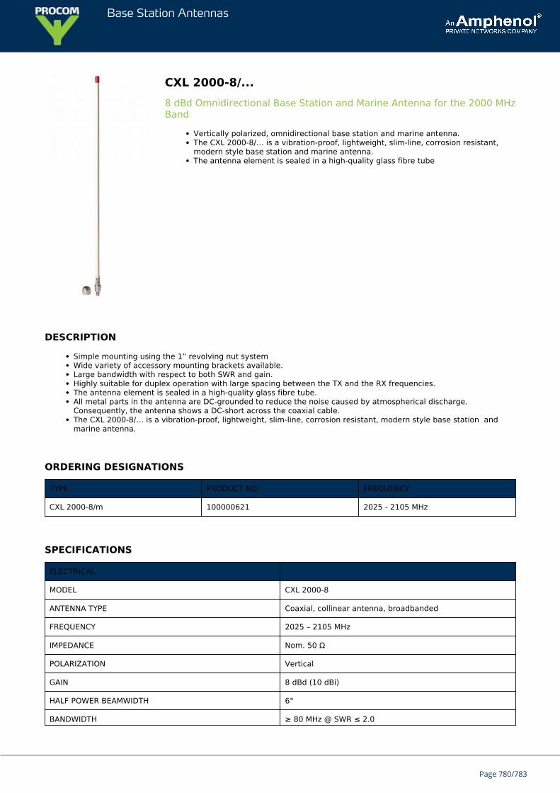
Base Station Antennas
CXL 2000-8/...8 dBd Omnidirectional Base Station and Marine Antenna for the 2000 MHzBand
Vertically polarized, omnidirectional base station and marine antenna.The CXL 2000-8/… is a vibration-proof, lightweight, slim-line, corrosion resistant,modern style base station and marine antenna.The antenna element is sealed in a high-quality glass fibre tube
DESCRIPTION
Simple mounting using the 1” revolving nut systemWide variety of accessory mounting brackets available.Large bandwidth with respect to both SWR and gain.Highly suitable for duplex operation with large spacing between the TX and the RX frequencies.The antenna element is sealed in a high-quality glass fibre tube.All metal parts in the antenna are DC-grounded to reduce the noise caused by atmospherical discharge.Consequently, the antenna shows a DC-short across the coaxial cable.The CXL 2000-8/… is a vibration-proof, lightweight, slim-line, corrosion resistant, modern style base station andmarine antenna.
ORDERING DESIGNATIONS
TYPE PRODUCT NO. FREQUENCY
CXL 2000-8/m 100000621 2025 - 2105 MHz
SPECIFICATIONS
ELECTRICAL
MODEL CXL 2000-8
ANTENNA TYPE Coaxial, collinear antenna, broadbanded
FREQUENCY 2025 – 2105 MHz
IMPEDANCE Nom. 50 Ω
POLARIZATION Vertical
GAIN 8 dBd (10 dBi)
HALF POWER BEAMWIDTH 6°
BANDWIDTH ≥ 80 MHz @ SWR ≤ 2.0
Page 780/783
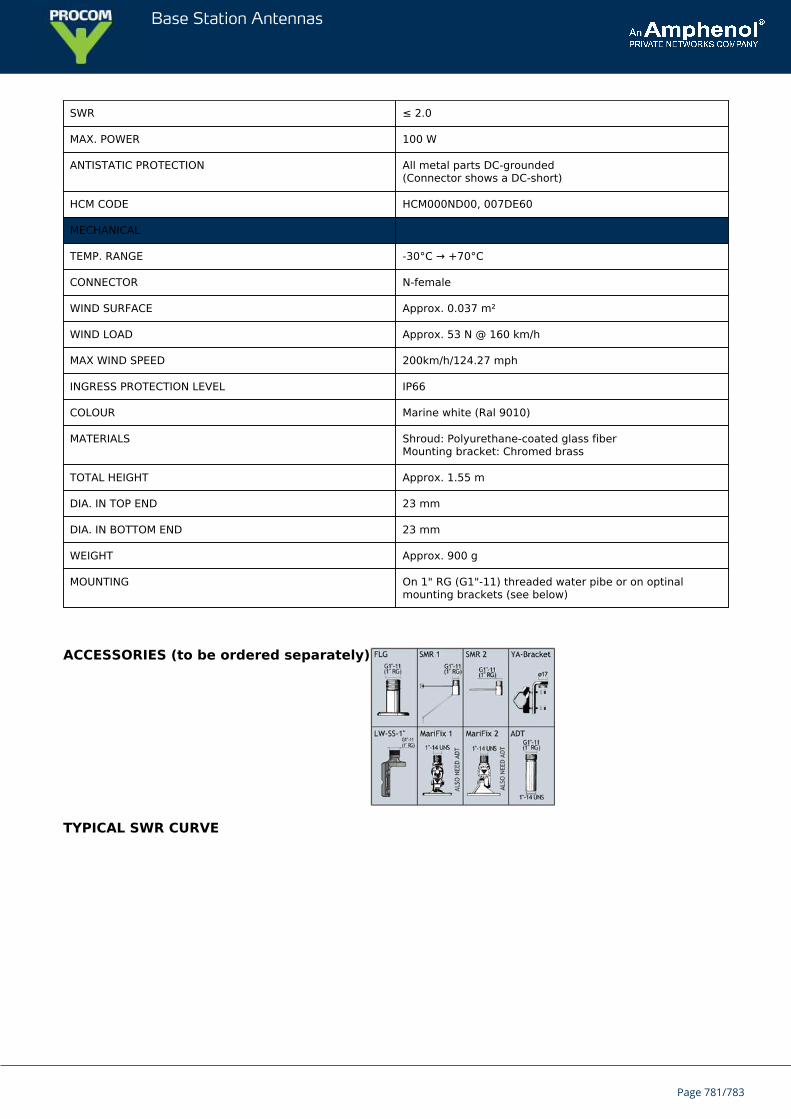
Base Station Antennas
SWR ≤ 2.0
MAX. POWER 100 W
ANTISTATIC PROTECTION All metal parts DC-grounded(Connector shows a DC-short)
HCM CODE HCM000ND00, 007DE60
MECHANICAL
TEMP. RANGE -30°C → +70°C
CONNECTOR N-female
WIND SURFACE Approx. 0.037 m²
WIND LOAD Approx. 53 N @ 160 km/h
MAX WIND SPEED 200km/h/124.27 mph
INGRESS PROTECTION LEVEL IP66
COLOUR Marine white (Ral 9010)
MATERIALS Shroud: Polyurethane-coated glass fiberMounting bracket: Chromed brass
TOTAL HEIGHT Approx. 1.55 m
DIA. IN TOP END 23 mm
DIA. IN BOTTOM END 23 mm
WEIGHT Approx. 900 g
MOUNTING On 1" RG (G1"-11) threaded water pibe or on optinalmounting brackets (see below)
ACCESSORIES (to be ordered separately)
TYPICAL SWR CURVE
Page 781/783
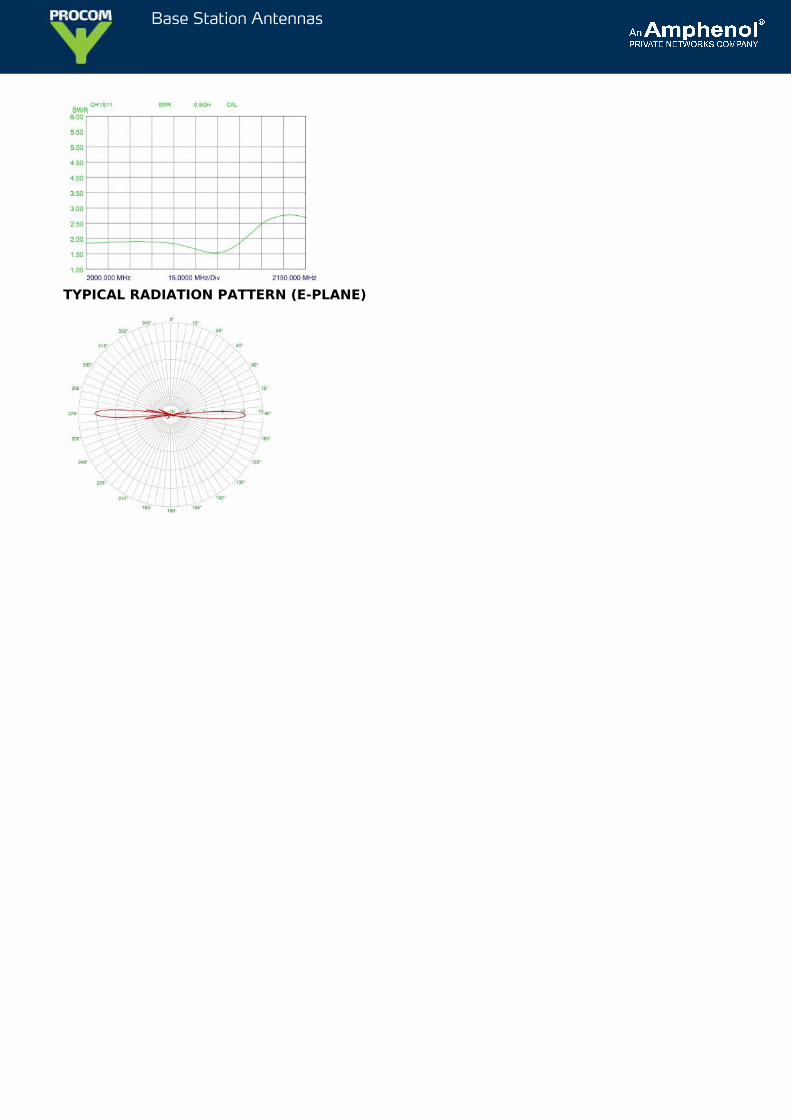
Base Station Antennas
TYPICAL RADIATION PATTERN (E-PLANE)
PROCOM A/S
Smedetoften 12, 3600Frederikssund, Denmark
PROCOM - Making the world smallerPROCOM A/SSmedetoften 123600 FrederikssundDenmark
Powered by TCPDF (www.tcpdf.org)
Page 783/783
Related Documents