ELS EVI E R Materials Science and EngineeringA225 (I997) 105-117 Processing-microstructure-property relationships in reaction • ] • • • hot-pressed MoS12 and MoS12/S1C p composites a:~ a a b R. Mitra ,', Y.R. Mahajan , N.E. Prasad , W.A. Chiou Defence Me allurgical Research Labtoratory , Kanchanbagh, Hyderabad 500 058, India b Materials Science and Engineering, ~ gorthwestern University, Evanston, IL 60208, USA Received 11 June 1996; revised 24 October 1996 Abstract Monolithic MoSi2 and MoSi,-20vol.%SiC composites have been prepared by reaction hot-pressing Mo and Si or Mo, Si and ~ I SiC powder mixtures in the range 1450-1500°C. As Si atoms diffuse into the Mo lattice under external pressure, a complete I . reaction takes place between Mo and Si leading to the formation of MoSia phase. The initial Mo particle size affects the grain size of the MoS1, that IS formed Grain boundaries and interfaces of MoSI2 with SIC were abrupt on the atomic scale, except for some MOS12/$1C boundaries, where a 5-8 nm thlck amorphous phase, beheved to be SiO2, could be seen. MoSi2 was also processed by vacuum hot-pressing MoSi2 powder at 1700°C for comparison. The composites show a moderate increase in flexural I strength and hardness over monolithic hot-pressed pol~crystalhne MoSi2. There is, however, a significant increase in the high-temperature compressive yield strength due to addition of SiC reinforcements. Grain sizes of the MoSi2 matrix strongly • I influence the fracture toughness and related mlcromechamsms. © 1997 Elsevier Science S.A. Keywords: Composite; Interfaces; Mechanical properties; MoSi2; Reaction hot-pressing 1. Introduction Molybdenum disilicide matrix composites offer s:g- nificant potential for high-temperature structural ap!cli- cations because of their high melting point (2030 °2) and ability to undergo plastic deformation above 1000°C. MoSi2 possesses outstanding oxidation resis- tance up to temperatures as high as 1700°C due to {he presence of a continuous and adhesive film of SiO21at the surface, which prevents further oxidation. Mo~i 2- based materials are also electrically conductive ahd I hence can be electro-discharge machined. However, .I there are problems related to the use of these materials which need to be addressed in detail, namely, pdor room-temperature fracture toughness and a steep de- crease in yield strength and creep resistance at tempeia- tures above l l00°C. Reinforcing the matrix with ceramic particles or whiskers significantly improves ~he fracture toughness at room temperature [1,2] as well i'as the yield strength and creep resistance at elevated tem- I i m * Corresponding author• Tel.: +91 040 218819; fax: +91 40 239683(218439; e-mail: [email protected]. ! 0921-5093/97/$17.00 © 1997 Elsevier Science S.A. All rights reseived. PII S0921-5093(96)10576-1 peratures [3,4]. MoSia possesses chemical compatibility with a large number of ceramic phases, e.g. SiC, Si3N4, TiC, TiB2, ZrOa, A1203, etc. [5]. The crystal structure, processing, microstructure and properties of MoSi2 have been recently reviewed by Jeng and Lavernia [6] and Petrovic [7]. MoSia has been extensively used for heating elements in furnaces. Other potential applications include power generation components, high-temperature heat ex- changers and filters, aircraft engine hot section compo- nents like turbine blades, vanes, combustors and nozzles, and automotive components such as tur- bocharger rotors and valves [7]. In the present work, MoSi2 and MoSiz-20vol.%SiC composite have been processed by the reaction hot- pressing (RHP) route to around 95 and 98%, respec- tively, of the theoretical density, and the microstructure and MoSijSiC interfaces have been comprehensively investigated. Some of the mechanical properties have also been examined. A preliminary report of this work was published in Ref. [8]. As the samples had more than 95% of the theoretical density, they did not show disintegration due to pesting even after 250 h of expo-

Welcome message from author
This document is posted to help you gain knowledge. Please leave a comment to let me know what you think about it! Share it to your friends and learn new things together.
Transcript
ELS EVI E R Materials Science and Engineering A225 (I997) 105-117
Processing-microstructure-property relationships in reaction • ] • • •
hot-pressed MoS12 and MoS12/S1C p composites a:~ a a b R. Mi t r a , ' , Y .R. M a h a j a n , N.E. P rasad , W.A. Ch iou
Defence Me allurgical Research Labtoratory , Kanchanbagh, Hyderabad 500 058, India b Materials Science and Engineering, ~ gorthwestern University, Evanston, IL 60208, USA
Received 11 June 1996; revised 24 October 1996
Abstract
Monolithic MoSi2 and MoSi,-20vol.%SiC composites have been prepared by reaction hot-pressing Mo and Si or Mo, Si and ~ I
SiC powder mixtures in the range 1450-1500°C. As Si atoms diffuse into the Mo lattice under external pressure, a complete I . reaction takes place between Mo and Si leading to the formation of MoSi a phase. The initial Mo particle size affects the grain
size of the MoS1, that IS formed Grain boundaries and interfaces of MoSI2 with SIC were abrupt on the atomic scale, except for some MOS12/$1C boundaries, where a 5-8 nm thlck amorphous phase, beheved to be SiO2, could be seen. MoSi2 was also processed by vacuum hot-pressing MoSi 2 powder at 1700°C for comparison. The composites show a moderate increase in flexural
I strength and hardness over monolithic hot-pressed pol~crystalhne MoSi 2. There is, however, a significant increase in the high-temperature compressive yield strength due to addition of SiC reinforcements. Grain sizes of the MoSi2 matrix strongly
• I
influence the fracture toughness and related mlcromechamsms. © 1997 Elsevier Science S.A.
Keywords: Composite; Interfaces; Mechanical properties; MoSi2; Reaction hot-pressing
1. Introduction
Molybdenum disilicide matrix composites offer s:g- nificant potential for high-temperature structural ap!cli- cations because of their high melting point (2030 °2) and ability to undergo plastic deformation above 1000°C. MoSi2 possesses outstanding oxidation resis- tance up to temperatures as high as 1700°C due to {he presence of a continuous and adhesive film of SiO21at the surface, which prevents further oxidation. Mo~i 2- based materials are also electrically conductive ahd
I
hence can be electro-discharge machined. However, .I there are problems related to the use of these materials
which need to be addressed in detail, namely, pdor room-temperature fracture toughness and a steep de- crease in yield strength and creep resistance at tempeia- tures above l l00°C. Reinforcing the matrix with ceramic particles or whiskers significantly improves ~he fracture toughness at room temperature [1,2] as well i'as the yield strength and creep resistance at elevated tem- I
i m
* Corresponding author• Tel.: +91 040 218819; fax: +91 40 239683(218439; e-mail: [email protected]. !
0921-5093/97/$17.00 © 1997 Elsevier Science S.A. All rights reseived.
PII S 0 9 2 1 - 5 0 9 3 ( 9 6 ) 1 0 5 7 6 - 1
peratures [3,4]. MoSia possesses chemical compatibility with a large number of ceramic phases, e.g. SiC, Si3N4, TiC, TiB2, ZrOa, A1203, etc. [5]. The crystal structure, processing, microstructure and properties of MoSi2 have been recently reviewed by Jeng and Lavernia [6] and Petrovic [7].
MoSia has been extensively used for heating elements in furnaces. Other potential applications include power generation components, high-temperature heat ex- changers and filters, aircraft engine hot section compo- nents like turbine blades, vanes, combustors and nozzles, and automotive components such as tur- bocharger rotors and valves [7].
In the present work, MoSi2 and MoSiz-20vol.%SiC composite have been processed by the reaction hot- pressing (RHP) route to around 95 and 98%, respec- tively, of the theoretical density, and the microstructure and MoSi jSiC interfaces have been comprehensively investigated. Some of the mechanical properties have also been examined. A preliminary report of this work was published in Ref. [8]. As the samples had more than 95% of the theoretical density, they did not show disintegration due to pesting even after 250 h of expo-
106 R. M#ra et al. / Materials Science and Eng#werO~g A225 (I997) t 0 5 - I 1 7
sure to 500°C in air, as has been previously inferred by Meschter [9]. Thus, the materials were worthy of fur- ther study with an emphasis on processing-microstruc- ture-proper ty relationships.
2. Processing
The reaction hot-pressing process has been developed to obtain MoSi 2 from an intimate mixture of Mo and Si elemental powders. Wet mixing was performed in the agate mill using methanol medium for 10 h followed by drying, sieving and limited dry mixing. The Mo powder (99.5% pure) used in the monolithic MoSi2 was ob- tained from Non-Ferrous Materials Technology Devel- opment Centre (NFTDC), Hyderabad, India, and had a particle size of about 3.0 I-tm, while the Mo powder used for the MoSi2-20vol.%SiC composite was ob- tained from Johnson Matthey, USA, and had an aver- age particle size of 33.0 btm. The Mo powders were 99.5% pure, with traces of Fe, Ti, V, Cr and Mn and were treated with hydrogen at around 1200°C to re- move oxygen. The choice of Mo particle size was based on availability of Mo powder type during processing. The Si powder, obtained from Johnson Matthey, USA, was 99.8% pure with traces of C, Fe and Mg as impurities, and had - 325 mesh (about 20 gm) particle size. The oxygen contents of the Mo and Si powders were also found using the vacuum fusion technique and these values were found to be 0.3 and 0.23 wt.%, respectively. The SiC powder was obtained from Nor- ton, USA, and had an average particle size of 1.9 gin. A measured quantity of SiC powder was blended with an M o - S i mixture to produce MoSi2-20vol.%SiC com- posites. The SiC powder was treated with 60% HF to remove SiO 2. It was further treated with dilute NaOH to neutralise the HF, and repeatedly washed in water. Further processing involved vacuum degassing at 800°C for 4 h and vacuum hot-pressing at 1500°C for 1 h using a pressure of 26 MPa. The heating rate was kept between 10-15°C min-~ to maintain temperature uni- formity and regulate the rate of reaction with respect to densification.
The hot-pressing temperature was in the range 1450- 1500°C, keeping in view (i) the presence of liquid Si phase (melting point: 1410°C), which assists in enhanc- ing the reaction rate with Mo and densification, and (ii) the favourable thermodynamic parameters [10] which drive the reaction to completion. The reaction taking place is:
Mo(s) + 2Si(1) + MoSiz(s) (1)
The free energy of formation is negative ( - 1 1 6 . 6 kJ tool - ~) and the heat evolved in the exothermic reaction also shows a sharp increase around the melting point of Si (heats of formation of MoSi2 are -120 .234 kJ
- 4 0 ~ t , / 2 Me + Si = I / 2 MoSi2
- 6 O ®
O
- 8 0 . "-3 5£
> ' - 1 0 0 -
c-
Lad
- 1 2 0 ~ a - ~ Free energy of fo rmat ]or o00ee Heat of format ion
- i 4 o . . . . . . . . . . . i b b ' o ' " i ' B b b ' " i b b b " T s o o
T e m p e r Q t u r e (K)
Fig. 1. Variation of free energy change and heat of reaction with temperature for the chemical reaction: (1/2)Mo + Si-+(l/2)MoSi 2.
m o I - ] at 1 6 0 0 K a n d - 2 2 0 . 8 7 7 k J m o l ~ at 1700K) [10]. Fig. 1 shows the variation of Gibbs flee energy change and heat of reaction (1) with temperature.
An earlier investigation [11] has shown that the reac- tion forming MoSi2 progresses as silicon diffuses through the successive silicide layers on the surface of Mo in a solid-solid Mo -S i mixture. Formation of MoSi2 is preceded by that of lower silicides such as:
Mo + Si ~ Mo3Si + Si --+ M%Si 3 + Si --, MoSi2 (2)
The depth of the reaction layers grow according to a parabolic law.
Deevi has shown that Si atoms diffuse through the Mo lattice and MoSi 2 forms in a one-step reaction in the combustion synthesis process [12]. This happens because the heating rate is very high and the diffusion time very short. In the present situation, the heating rate was slow and the formation of intermediate prod- ucts such as Mo3Si and M%Si3 is expected, as has been reported by Deevi in a detailed study of diffusional reactions in the M o - S i system [13], However, the diffu-
o
tad ~ e a . . . . , a ~ - ~ L3
2 : -~.-'2' =: . _ ' ~ m i7, ~ 13 i~ ~ =: "*
~0 3S 30 2~ 20 15 10
28 (DEGREES)
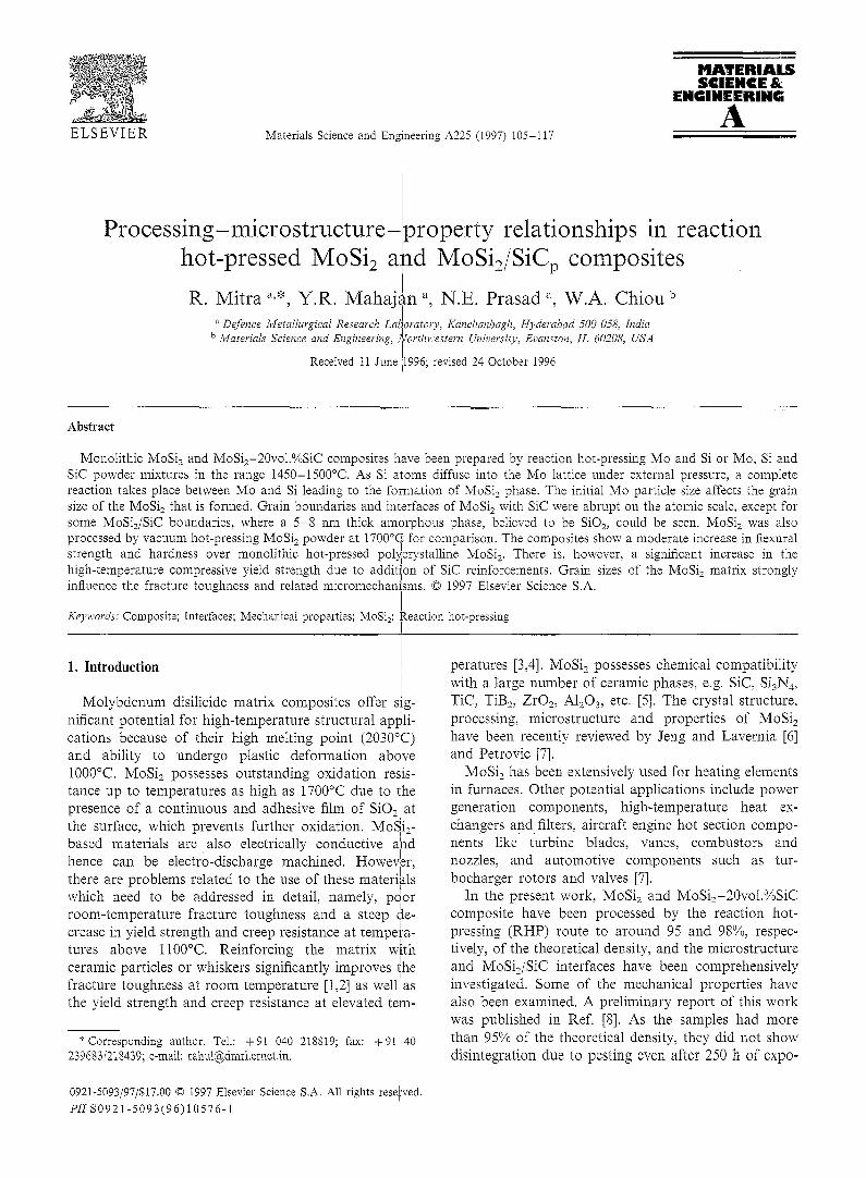
Fig. 2. X-ray (Mo K~,) diffraction pattern of RHP MoSi2/SiC com- posite.
R. Mitra et al. / Materials Science a~2d Engineering A225 (I997) 105- I 17 107
(a)
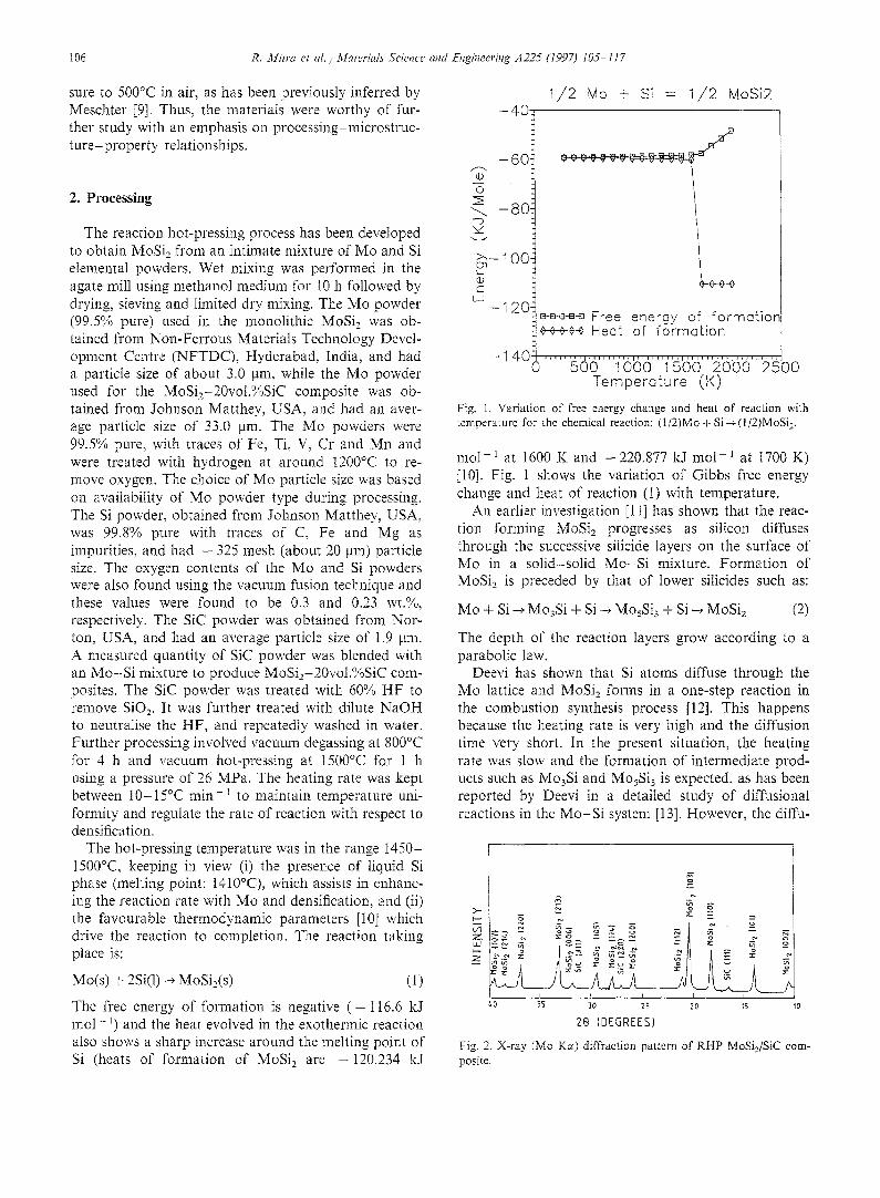
(b) Fig. 3. Polarised light optical micrographs of monolithic: (a) Starck MoSia (SiO 2 particles appear bright (shown with arrow); (b) Rt-/P MoSi2. [
sion rate in the reaction hot-pressing process at 1500~C is higher, because Si is in the liquid state, than the rate that can be expected in a solid-state reaction. The iSi and Mo particle sizes play an important role in the combustion synthesis process for the completion of the. chemical reaction. In the reaction hot-pressing process, Mo particle size appears to be more important, as the
/
reaction front proceeds from the surface to the centre I
of the particle. A larger particle size would mean i
smaller surface area to volume ratio and larger diffu- sion distance, resulting in an incomplete or partial
(R. Mitra, unpublished research, Defenlce reaction Metallurgical Research Laboratory, Hyderabad, India). As MoSi2 is the most stable phase among the Mo-iSi compounds at 1500°C and existing Mo/Si composition,' reaction (2) proceeds in the forward direction. Accord- ing to Deevi [13], the reaction takes place in two steps when the heating rate is slow (such as 15°C min-~), each step involving an exotherm. The first exotherm ris related to a solid silicon-solid molybdenum diffusional
• • • I reaction taking place at the Mo/S1 interface, leading to the MosSi 3 formation• The second exotherm is relat~d. to a liquid silicon-solid M%Si3-solid molybden~m diffusional reaction, leading to the formation of MoSi 2 and M%Si 3. The M%Si 3 phase then reacts with the
(a)
(b)
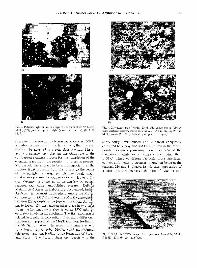
Fig. 4. Microstructm-e of MoSi2-20vol.%SiC composite: (a) EPMA back-scattered electron image showing SiC (S) and MosSi 3 (M') in MoSi: matrix (M); (b) polarised tight optical micrograph.
surrounding liquid silicon and is almost completely converted to MoSi2; this has been noticed in the Mo/Si powder compacts possessing more than 59% of the theoretical density or at temperatures higher than 1460°C. These conditions facilitate more interfacial contact and, hence, a stronger interaction between the reactant Mo and Si phases. In this case, application of external pressure increases the rate of reaction and
Fig. 5. Bright-field TEM image of a triple point formed by MoSi2 (M)/SiC (S)/MoSi 2 (M) interfaces.
I08 R. Mitra er al. / Materials Science and
densification through an enhanced rate of diffusion and mass transport. The temperature here is lower com- pared with that required for pressing MoSi2 powders, where hot-pressing temperatures are typically 1600- 1800°C [14]. The temperature of hot-pressing in this process cammt be arbitrarily increased beyond 1500°C, as liquid Si, having considerable fluidity, flows out under pressure and reacts with graphite die and ram, resulting in choking of the assembly. As Deevi has reported that a temperature of 1460°C or above is sufficient for the complete reaction for MoSi z forma- tion to take place, 1500°C is quite appropriate. The size of the Mo particles, concentration of Si at the reaction front, reaction temperature, heating rate and length of time at temperature appear to have a significant influ- ence on the kinetics, the course and the extent of the reaction.
For comparison, a potycrystalline MoSi 2 plate of 75 mm diameter and 5 mm height was processed by hot- pressing of high purity MoSi2 powder obtained from HG Starck, Germany, at I700°C for 1 h in vacuum. The powders were degassed at 1000°C for 2 h prior to hot-pressing. The Starck MoSi 2 powder having a parti- cle size of 5.5 ~tm, possessed traces of Fe and A1 as impurities. The oxygen content of the powder was found to be 1 wt.%.
3. Experimental procedure
Density measurements were carried out using Archimedes' principle. Sampies were metaIlographically polished for microstructurai observation. Microstruc- turaI characterisation was carried out using optical and scanning electron microscopy (SEM) as well as electron probe microanatysis (EPMA). X-ray diffraction (XRD) was also carried out on polished surfaces to identify the phases present. Further microstructural characterisa- tion has been carried out using transmission electron microscopy (TEM). TEM samples were prepared using mechanical thinning followed by ion milling and were studied using a Phillips 430T TEM operating at 300 kV. High-resolution transmission electron microscopy (HRTEM) was performed using a Hitachi H9000 HRTEM operating at 300 kV. Chemical analysis of samples for oxygen was determined using the vacuum fusion technique.
Hardness was measured on the metallographically polished specimens using Vicker's diamond indentor and loads of 20 mid 30 kgf. Lengths of the cracks formed at the corners of indentations were measured and used to estimate the indentation fracture toughness value, K~ using the equation proposed by Anstis et al. for median cracks [15]:
Engineer#~g A225 (1997) 105-t17
K~ = 0.016 × (3)
where E is the Young modulus, H is the hardness, c is the crack length and P is the external load applied. Hardness has also been measured at temperatures rang- ing fi'om 200 to 1300°C in vacuum (10 - s torr), using a Vicker's diamond indentor and a toad of 1 kgf. Mag- nified images of indentations could be observed imme- diately after their formation using a hot stage optical microscope, fitted to the chamber.
For room-temperature flexural strength, samples with a span (5') of 40 ram, a thickness (B) of 5.0 mm and a width (tU) of 5.0 mm were prepared by elec- trodischarge wire cutting, followed by polishing of faces and edges. Single edge notched bend (SENB) specimens [16] having dimensions S = 4 0 ram, B = 5 . 0 mm and W = 10.0 mm were used for fracture toughness mea- surements. Notch depth a was maintained at about 0.55W, and was machined using spark erosion cutting with a wire of 0.15 mm diameter. Fatigue precracking was not performed. It has been reported previously that fracture toughness of fatigue precracked and non-pre- cracked specimens of MoSi, materials did not show any significant difference [17]. Three-point bend tests were carried out using a loading rate of 0.5 mm min-~ on a screw-driven Instron 1185 machine. The flexural strength c~ in a three-point bend test is given by the expression:
3 P S o- 2B W 2 (4)
where P is the maximum load in the load-displacement curve.
The fracture toughness K e is given by [16]:
P e S .( a \
where
[1 .99 - (a/I~9
{( i - (a/W)}{2.15 - 3.93(a/I~ 0 + 2 . 7 ( a / I ; I 0 2 } ]
i [2{1 + (2at W ) } { 1 - (a / I ,V)}3"e]
For high-temperature compression tests, specimens of MoSi2/SiC composite of diameter 3 mm and height 6 ram, were machined using EDM. Compression tests were performed in air between temperatures of 1000 and 1300°C at a strain rate of 10 -4 s -~ using a servohydraulic MTS 880 test system equipped with SiC rams. The tests were discontinued after a crosshead displacement of 1.0 ram, which corresponds to around 15% compressive strain.
R. Mitra et al. / Materials Science and Engineering A225 (1997) 105- I 17 i09
4. Results and discussion
4.1. M i c r o s t r u c t u r a l a n d c h e m i c a l charac te r i sa t ion
Density measurements showed that the reaction hlot- pressed (RHP) MoSi= samples had 95% of the theordti- cal density, whereas MoSi2 prepared by vacu/m hot-pressing Starck MoSia powder (Starck MoSi=) a~nd RHP MoSi2-20vol.%SiC composite possessed more
I
than 98% of the theoretical density. The lower density . . . . I
of the RHP monohthic MoSi2 is posslbly due to the fact that the Mo particle size used in this study ~4as much finer compared with that used in the case of ~he MoSi=/SiC composite. While it can be concluded intu- itively that finer particle sizes should densify I more I readily during hot-pressing due to more homogeneous mixing, a higher driving force to reduce surface free
i
energy, and shorter diffusion distances for bdth Nabarro Herring and Coble creep deformation to occur I [18,19], it is also true that finer particle sizes are more difficult to compact at any temperature. This is so because higher pressure is needed to close the tiny po}es between fine particles than to close the larger pores between coarse particles [18]. The higher surface area! of finer particles would also result in a higher degree of adsorption of atmospheric gases on the powder particle surfaces, as the powder processing was performed I in air. Removal of the adsorbed gases is very difficult dnd not a "trivial matter in hot-pressing", according I to CoNe [20]. These gases remain entrapped in the fine pores and sharply limit the extent of densification [21,22]• Shorter diffusion distances can be effective in enhancing densification if, and only if, particle surfaces are clean and there are no other obstacles [18]. I~ is possible that higher pressure or temperature, or lon!ger time, could lead to higher densification. In the I present situation, due to the limitations of the graphite die material used in the vacuum hot-press, the pressure of 26 MPa was the maximum which could be applied. The
I
temperature could not be increased beyond 1500°CI as • I
has been explained previously. The increase in time of • o • . I soaking at 1500 C under pressure led to hnkmg i of
pores by diffusion of vacancies and cracking. The other option is processing of fine particle-size powders! in inert atmosphere, which is to be attempted in future.
The results of XRD (Fig. 2) and EPMA have coW, fi- rmed that reaction during hot-pressing is complete and-- MoSi2 forms. Magnified views of XRD patterns fr~om
I . MoSi2 and MoSi2/SiC composite do show Mo~S13 I
peaks. The results of chemical analysis showed ithe oxygen content to be about 600 wppm in MoSi2 and
0 2400 wppm in the MoSi2-20vol~/0SiC composite. The ,i
difference is believed to be due to different sources of Mo powders, and limited oxide formation on SiC p~rti- cles on exposure to air after HF treatment. Oxygen
• . . I
pick-up is also possible during powder mixing and
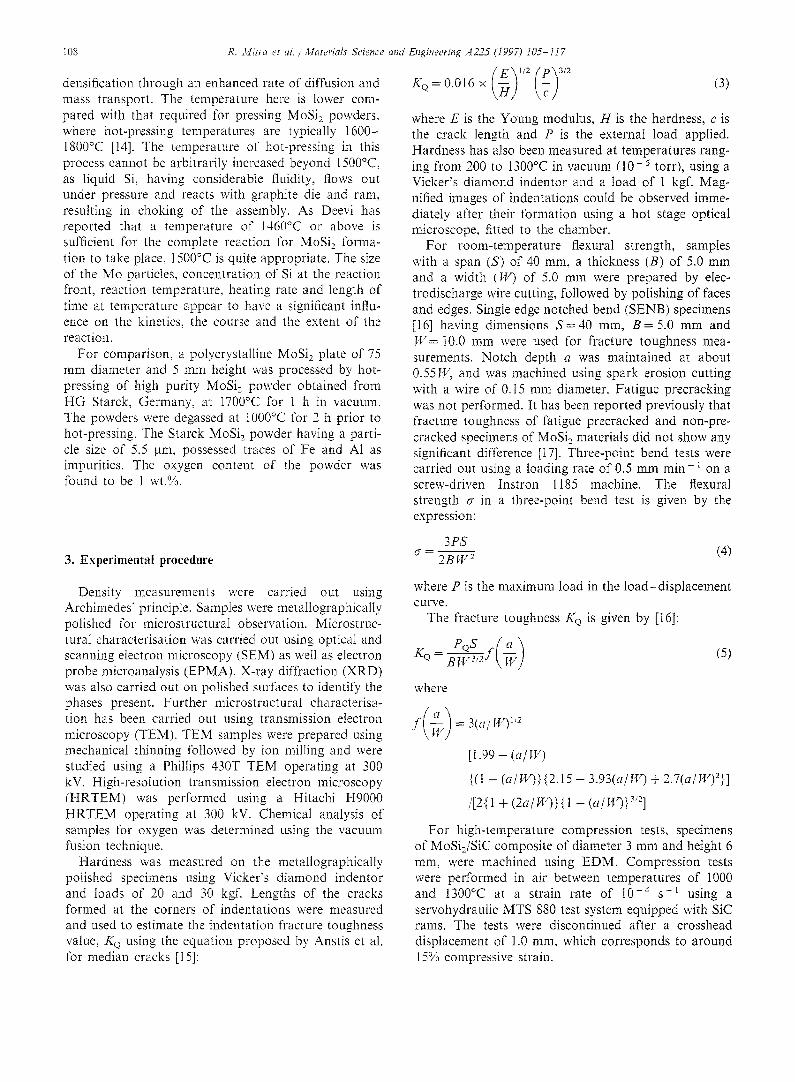
Fig. 6. HRTEM image of showing a 5-8 nm thick amorphous region (A) at the MoSi2 (M)/SiC (S) interface.
handling in both cases. The oxygen content is certainly much lower than that seen in the MoSi2 obtained by hot-pressing of Cerac MoSi2 powders (6500 wppm) [4] or mechanically alloyed Mo/Si mixture (1.2 wt.%) [21]. The oxygen content of Starck MoSi2 processed by vacuum hot-pressing of MoSi2 powders, containing 10 000 wppm oxygen, was found to be 8900 wppm, and this was present mostly as fine SiQ particles inside the MoSi2 grains or at the grain boundaries (Fig. 3(a)). The SiO2 phase can be identified from its high reflectivity, as a result of which it appears bright [22,23]. The fact that the oxygen content was low in the RHP MoSi2 and composites, even though the reactant powders con- tained more oxygen (mentioned above) and powder processing was done in air, is because in situ reaction processing is self-purifying when conducted in vacuum or an inert gas environment. The MoSia produced by Deevi [12] contained 2200 wppm of oxygen, whereas the Mo and Si powders used for the combustion syn- thesis process contained 4700 and 10000 wppm of oxygen, respectively. Fig. 3(a) also shows a wide varia- tion in the Starck MoSi 2 grain sizes, which are between 15 and 40 gin.
Fig. 3(b) is a polarised light optical micrograph of monolithic RHP MoSi2 showing the grain size as 5.0 ~tm. Fig. 4(a) is an EPMA back-scattered electron (BSE) micrograph of MoSia-20voI.%SiC composite, showing the presence of three phases, namely, MoSi2, SiC and MosSi3. It is believed that the larger size (33 /am) of Mo particles creates difficulties in achieving uniform distribution of SiC particles. A few bright- looking MosSi 3 grains can be observed in the back-scat- tered electron image of Fig. 4(a). The composition was determined using EPMA X-ray wavelength dispersive spectroscopy (WDS). The trace impurity elements in Mo such as Ti, Fe, Mn, Cr and V were in solid solution inside the MosSi 3. MoSi 2 does not show any solid
110 R. Mitra eta/ . /Materials Science and Engineer&g A225 (1997) I05-1f7
. . " "" - " " t 6 . e r , , a : " ' - ' , , : = : . . - , - , < ; ; .? ' ;
" ". " g t , , ' iT " ' , , ' : , " 1 '
'd
"-" q ,-'2 " "~ :d" "g. 7.*' "' =t'~
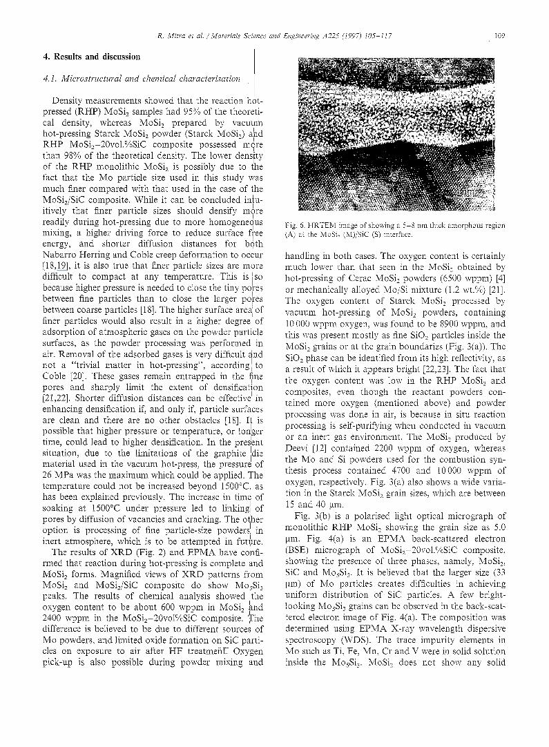
Fig. 7. HRTEM image of atomically abrupt MoSi2/SiC interface• Arrows indicate monatomic steps.
solubility. Fig. 4(b), an optical micrograph recorded using polarised illmnination, shows MoSi 2 grains in the MoSi2-20vol.%SiC composite. The grain size in the composite sample was found to be about 18 ~,tm. The differences in grain sizes between MoSi2 and the MoSi2/SiC composite come from the differences in the initial Mo particle sizes used. As the MoSi 2 grains form by diffusion-assisted reaction of Mo particles with molten Si, where the reaction front moves in from the surface to the interior as has been described above, it is obvious that Mo particle size strongly affects the sizes of the MoSi 2 grains formed. This was not the case with Starck MoSi2, in which the process- ing temperature was higher, and this might have re- sulted in some degree of grain growth and coarsening• The concentration of SlOg particles ob- setwed in the RHP samples using cross-polarised light micrographs is small. SiO 2 could be found for the most part at some of the particle-matrix interfaces as films, and inside some of the grains and at some MoSi 2 grain boundary/SiC triple points as particles.
Fig. 5 is a bright-field TEM micrograph of a MoSi 2 grain boundary/SiCp triple point junction, showing absence of porosity or amorphous SiO2 phase or reaction product. Dark-field imaging led to the same conclusion. SiC particles are highly faulted• Twin boundaries could be frequently observed in SiC
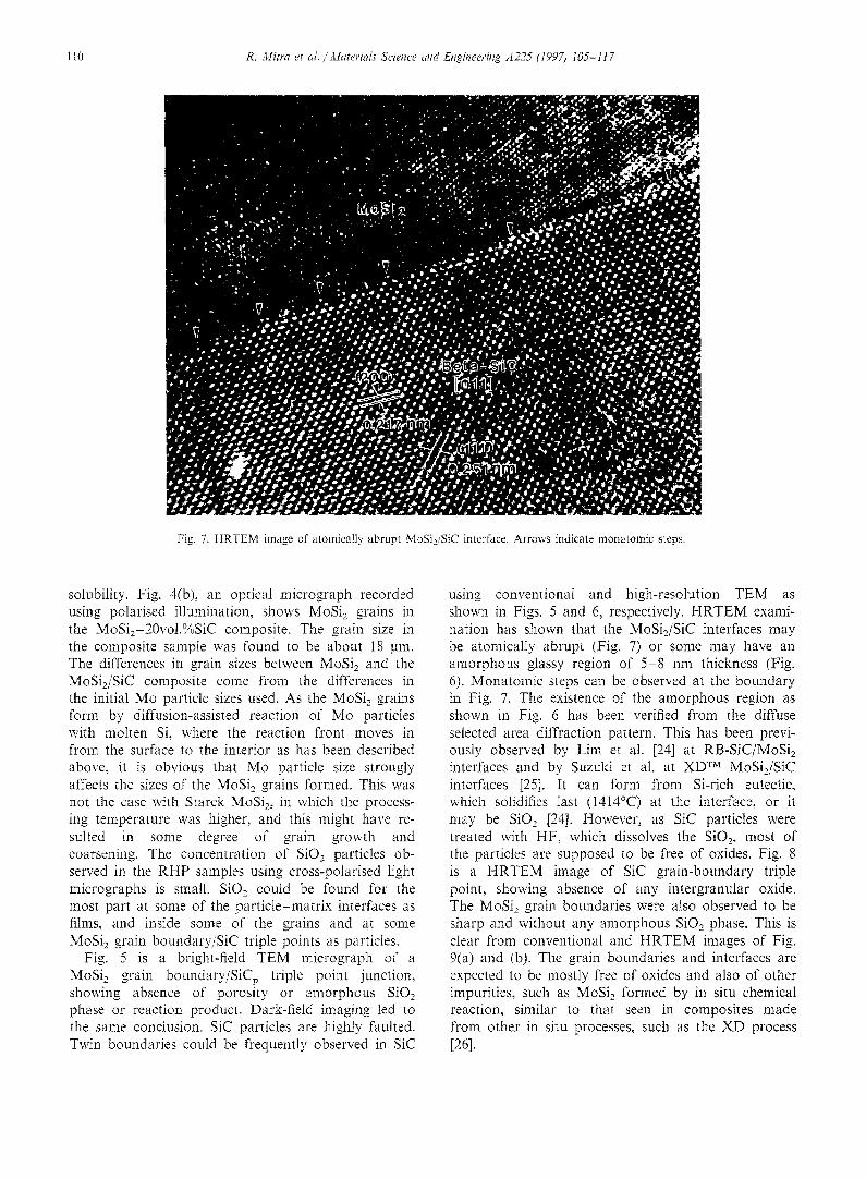
using conventional and high-resolution TEM as shown in Figs. 5 and 6, respectively• HRTEM exami- nation has shown that the MoSi2/SiC interfaces may be atomically abrupt (Fig. 7) or some may have an amorphous glassy region of 5-8 nm thickness (Fig. 6). Monatomic steps can be observed at the boundary in Fig. 7. The existence of the amorphous region as shown in Fig. 6 has been verified from the diffuse selected area diffraction pattern. This has been previ- ously observed by Lim et at. [24] at RB-SiC/MoSi2 interfaces and by Suzuki et al. at XD TM MoSi2/SiC interfaces [25]. It can form fi'om Si-rich eutectic, which solidifies last (1414°C) at the interface, or it may be SiO 2 [24]. However, as SiC particles were treated with HF, which dissolves the SiO2, most of the particles are supposed to be fi'ee of oxides. Fig. 8 is a HRTEM image of SiC grain-boundary triple point, showing absence of any intergranular oxide. The MoSi2 grain boundaries were also observed to be sharp and without any amorphous SiO2 phase. This is clear from conventional and HRTEM images of Fig. 9(a) and (b). The grain boundaries and interfaces are expected to be mostly free of oxides and also of other impurities, such as MoSi 2 formed by in situ chemical reaction, similar to that seen in composites made from other in situ processes, such as the XD process [26].
Sczence and Engineering A 2 2 5 (1997) I 0 5 - 1 1 7 III R. M~tra et a l . / Mater ia ls "'
Fig. 8. HRTEM micrograph showing
4.2. Mechanical properties
4.2. i. Room-temperature mechanical properties The room-temperature mechanical properties of
monolithic MoSi 2 and MoSi2-20vol.%SiC composite • . . I
are shown in Table 1. The composite is harder than the monolithic MoSi2 due to the presence of SiC reinforfce - ment. The Vlcker s hardness of Starck MoS1, is shghtly greater than that of the RHP MoSi2, due to higher density. [
The flexural strength and fracture toughness data presented in Table 1 is an average of results of a
• • I
minimum of three tests• Generally, the presence i of reinforcements leads to an increase in fracture tough- ness due to toughening mechanisms like crack deflec- tion and bridging [1,2,27,28]. However, it is interesting to note that in the present case, the monolithic RHP MoSi2 exhibited almost the same or slightly higher fracture toughness (4.8 MPa x/m) compared ,~!ith MoSi2-20vol.%SiC composite (4.6 MPa x/m), while the Starck MoSi2 shows the lowest fracture toughn~ess (4.3 MPa x/m). This is due to the fact that the average ~
• • , I
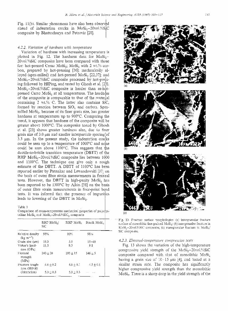
gram slze of the RHP MOS12 was much finer compared with that of the Starck MoSi2 and the MoSi2/SiC composite, and this has compensated for the absenc~ of any toughening second phase in the monolithic RHP MoSi2. The flexural strength of RHP MoSi2 is notice- ably higher than that of Starck MoSi2, also due to finer grain size. It is higher in the composite due to strengthening effect of SiC reinforcements. The effec~ grain size is reflected in the fracture surface morphol( of the samples. The fracture was fully intergranulai case of fine-grained monolithic MoSi2, whereas
grain boundaries in SiC, which are free of silica.
showed a mixture of transgranular and intergranular mode in the coarse-grained MoSi2/SiC composite• It has been shown by earlier investigators that finer grain sizes tend to produce intergranular fracture, whereas fracture becomes transgranular with increasing grain size. This trend is more often noticed in the case of anisotropic crystal structures [29] and has also been observed in the case of MoSi 2 [30]. Intergranular frac- ture in a fine-grained material leads to a more tortuous crack path than transgranular fracture and consumes more energy. Fig. 10(a)-(c) are SEM fractographs showing the intergranular fracture morphology of MoSi2, intergranular fracture surface of MoSi2/SiC composite, and a highly faceted transgranular cleavage fracture surface of a MoSia grain in the composite, respectively. Intergranular fracture appears to be ini- tiated at triple points containing micropores. Srinivasan and Schwarz [31] also found the fracture toughness of MoSi=, prepared by mechanical alloying and having a grain size of about 5.0 gm, to be between 4 and 4.8 MPa x/m. The fracture toughness of monolithic MoSi2 reported in the literature varies between 3.0 MPa x/m [7] and 5.3 MPa x/m [32]. Suryanarayanan et al. have shown that fracture toughness increases with relative density in hot isostatically pressed (HIPed) MoSi2, and the value is around 4.2 MPa x/m for densities above 95% [33]. Further improvement in room-temperature
Lhe bend strength and fracture toughness of the composite :he can be obtained with a more uniform distribution of of SiC particles or use of whiskers [27,32]. In a recent
~gy publication [7], Petrovic has reported average fracture in toughness values of 4.0 and 4.4 MPa x/m for MoSi2- it 20voi.%SiC particulate and whisker-reinforced corn-
i 12 R. Micra et al. / Materials Science and Eligineering A225 (1997) I05-1 t 7
(a)
(b)
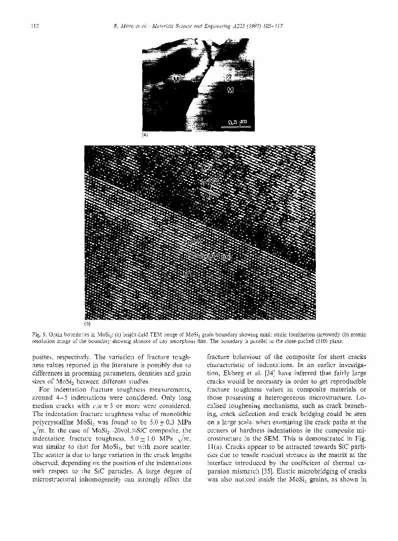
Fig, 9. Grain boundaries in MoSi2: (a) bright-field TEM image of N¢oSI 2 grain boundary showing misfit strain localisation (arrowed); (b) atomic resolution image of the boundary showing absence ot" any amorphous film. The boundary is parallel to the close-packed (110) plane.
posites, respectively. The variation of fracture tough- ness values reported in the literature is possibly due to differences in processing parameters, densities and grain sizes of MoSi2 between different studies.
For indentation fracture toughness measurements, around 4 - 5 indentations were considered. Only long median cracks with c / a ~ 3 or more were considered. The indentation fracture toughness value of monolithic polycrystalline MoSi 2 was found to be 5.0 + 0.3 MPa .,/m. In the case of MoSi2-20vol.%SiC composite, the indentation fracture toughness, 5.0_+ 1.0 MPa x//m, was similar to that for MoSi2, but with more scatter. The scatter is due to large variation in the crack lengths observed, depending on the position of the indentations with respect to the SiC particles. A large degree of microstructural inhomogeneity can strongly affect the
fracture behaviour of the composite for short cracks characteristic of indentations. In an earlier investiga- tion, Ekberg et al. [34] have inferred that fairly large cracks would be necessary in order to get reproducible fracture toughness values in composite materials or those possessing a heterogeneous microstructure. Lo- calised toughening mechanisms, such as crack branch- ing, crack deflection and crack bridging could be seen on a large scale, when examining the crack paths at the corners of hardness indentations in the composite mi- crostructure in the SEM. This is demonstrated in Fig. 1 l(a). Cracks appear to be attracted towards SiC parti- cles due to tensile residual stresses in the matrix at the interface introduced by the coefficient of thermal ex- pansion mismatch [35]. Elastic microbridging of cracks was also noticed inside the MoSi2 grains, as shown in
R. Blitra et al. / Materials Scilnce and Engineering ,4225 (1997) 105-117
f Fig. ll(b). Similar phenomena have also been observed
I
ahead of indentation cracks in MoSiz-20vo1.%SiC I
composite by Bhattacharya and Petrovic [28].
113
4.2.2. Variation of hardness with temperature Variation of hardness with increasing temperature,is
plotted in Fig. 12. The hardness data for MoSi!- 20vol.%SiC composite have been compared with thdse for: hot-pressed Cerac MoSi2; MoSiz with 2 wt.% car-" bon, prepared by hot-pressing [36]; mechanically al- loyed (spex-milled) and hot-pressed MoSi2 [22,37]; aiad MoSi2-20vol.%SiC composite processed by hot-press- ing followed by HIPing, and tested by Ghosh et al. [23]. MoSi2-20vol.%SiC composite is harder than as-hot- pressed Cerac MoSi2 at all temperatures. The hardness
I
of the composite is comparable to that of the material containing 2 wt.% C. The latter also contains Si~C, formed by reaction between SiO2 and carbon. Sp~x- milled MoSi2, because of its finer grain size, has greater hardness at temperatures up to 900°C. Comparing the trend, it appears that hardness of the composite will be greater above 1000°C. The composite tested by Ghdsh et al. [23] shows greater hardness also, due to finer
. J
grain size of 3.0 ~tm and smaller lnterparticle spacing !of • I
3.3 gm. In the present study, the indentation cracks could be seen up to a temperature of 1000°C and no,he could be seen above l l00°C. This suggests that the ductile-to-brittle transition temperature (DBTT) of {he RHP MoSi2-20vol.%SiC composite lies between 10100
I
and 1100°C. The technique can give only a rough estimate of the DBTT. A DBTT of l l00°C has bden f reported earlier by Patankar and Lewandowski [37] on
• • I the basis of outer fibre strain measurements an flexural tests. However, the DBTT in high-purity MoSi 2 has been reported to be 1300°C by Aikin [38] on the b~sis
• • • I of outer fibre strain measurements in four-point be~nd tests. It was inferred that the presence of impurities leads to lowering of the DBTT in MoSi 2. I
Table 1 r Comparison of room-temperature mechanical properties of polyc ys talline MoSi2 and MoSi2-20voI.%SiCp composite
RHP MoSi2/ R HP MoSi 2 Starck MoSi 2 SiC
Relative density 98% 95% 98% (kg m -3)
Grain size (lain) 18.0 5.0 15-40 Vicker's hard- 11.5 9.3 9.8
ness (GPa) Flexural 240 + 20 193 + 15 146 _+_ 5
strength (MPa)
Fracture tough- 4.6 + 0.2 4.8 _+ 0. I 4.3 _+ 0. I ness (SENB) (Identation) 5.0 + 0.3 5.0 +_ 0.3 --
(a)
(b)
(c)
Fig. 10. Fracture surface morphologies: (a) intergranular fracture surface of monolithic fine-grained MoSi2; (b) intergranular fracture in MoSi2-20vol.%SiC composite; (c) transgranular fracture in MoSiS SiC composite.
4.2..3. Elevated-temperature compression tests Fig. 13 shows the variation of the high-temperature
compressive yield strength of the MoSiz-20vol.%SiC composite compared with that of monolithic MoSi2 having a grain size of 10-15 ~m [4], and tested at a similar strain rate• The composite has significantly higher compressive yield strength than the monolithic MoSi 2. There is a sharp drop in the yield strength of the
I14 R. MRra et al. ,' Materials Science and Engineering A225 (1997) 105-117
composite between 1200 and 1300°C, where all the five slip systems are activated, leading to extensive deforma- tion, as has been reported by previous im, estigators [39,40]. The slip systems observed in deformation at 1200-1400°C are {001}{100), {001}(1t0), {1t0}l/ 2~111), {011}{100), etc. [39-41], depending on the orientation of the crystals [41]. A similar drop has also been noticed in the yield strength in bending by Gibbs et al. [42], and thedata have been reviewed by Meschter and Schwartz [5]. Aikin explained this behaviour on the basis of softening of silica particles at grain boundaries and triple points, when the hot-pressed monolithic MoSi 2 was tested in compression at 1300°C [4]. A similar phenomenon can be expected in the present situation, as the oxygen content is as high as 2400 wppm in the case of the composite, and this is present as SiO2 particles. In this investigation, further mi- crostructural studies were carried out to understand the deformation and failure mechanisms in the MoSi; ma- trix at 1300°C.
TEM examination of the sample tested at 1300°C reveals dislocation pile-ups at particle-matrix interfaces and at transgranular cracks, as shown in Fig. 14(a)-(c).
(a)
(b)
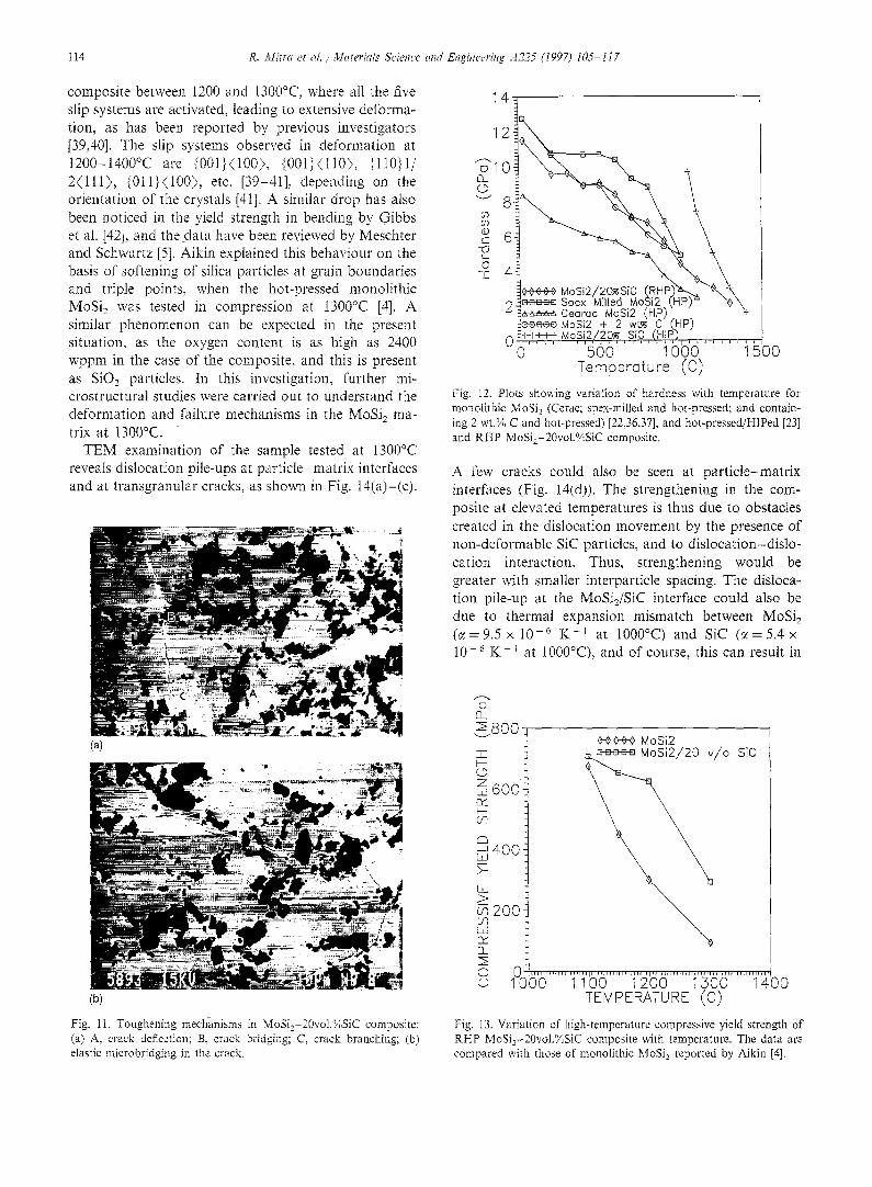
Fig. i1. Toughening mechanisms in MoSi2-20vol.%SiC composite: (a) A, crack deflection; B, crack bridging; C, crack branching; (b) elastic microbridging in the crack.
00000_ MoSi2f20~Si 9 _ ~ u m Spex 'M]llecl .Mo~i2 (HP) ~ "~'~ ~ . ~ a = a Cearoc MoSi2 (HP). . ~-
~eeeee MoSi2 + 2 wt~ C (HP) 0t } i - I ~}-MoSi2/20~ SiC (HIP),
0 500 1000 1500 Temperoture (C)
Fig. I2. Plots showing variation of hardness with temperature for monolithic MoSi~ (Cerac; spex-milled and hot-pressed; and contain- ing 2 wt.% C and hot-pressed) [22,36,37], and hot-pressed/HlPed [23] and RHP MoSi2-20vol.%SiC composite.
A few cracks could also be seen at part icle-matrix interfaces (Fig. 14(ct)). The strengthening in the com- posite at elevated temperatures is thus due to obstacles created in the dislocation movement by the presence of non-deformable SiC particles, and to dislocation-dislo- cation interaction. Thus, strengthening would be greater with smaller interparticle spacing. The disloca- tion pile-up at the MoSi,/SiC interface could also be due to thermal expansion mismatch between MoSi2 ( c ( = 9 . 5 x 10 -6 K - t at 1000°C) and SiC ( ~ = 5 . 4 x 10 .6 K-~ at 1000°C), and of course, this can result in
(3 EL
I 6oo-
MoSi2 • SiC /o
£:~ ~400: )-
> ~ 2 0 0 Lo rY fiL
O 0 LHI~UldJHlJ'H'~DL:JJiHH~HdJNH UH H'n'~H niIIH~i~H'I~H~il
© 1000 1100 1200 I 3 0 0 1400 TEMPERATURE (C)
Fig. 13. Variation of high-temperature compressive yield strength of RHP MoSi~-20vol.%SiC composite with temperature, The data are compared with those of monolithic MoSi 2 reported by Aikin [4].
R. Mitra et al. / Materials Science and Engineering A225 (I997) I05 -117 I I I
115
(a) (b)
(¢
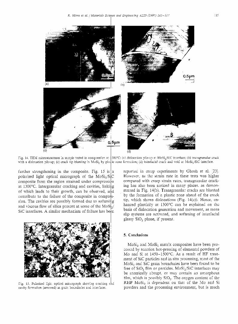
Fig. 14. TEM microstructures in sampIe tested in compression at 1300°C: (a) dislocation pile-up at MoSijSiC interface; (b) transgranular crack with a dislocation pile-up; (c) crack tip blunting in MoSi 2 by plastic zone formation; (d) interracial crack and void at MoSi2/SiC interface.
further strengthening in the composite. Fig. 15 i s a reported in creep experiments by Ghosh et al. [23]. polarised light optical micrograph of the MoSi2/SiC
.I composite from the region strained under compression . . . . . I
at I300°C. Intergranular cracking and cavmes, linking of whmh leads to their growth, can be observed, and I contribute to the failure of the composite in compres-
.I sion. The cavities are possibly formed due to softening /
and viscous flow of silica present at some of the MoSi2 / SiC interfaces. A similar mechanism of failure has been
However, as the strain rate in these tests was higher compared with creep strain rates, transgranular crack- ing has also been noticed in many places, as demon- strated in Fig. 14(b). Transgranular cracks are blunted by the formation of a plastic zone ahead of the crack tip, which shows dislocations (Fig. 14(c)). Hence, en- hanced plasticity at 1300°C can be explained on the basis of dislocation generation and movement, as more slip systems are activated, and softening of interfacial glassy SiO2 phase, if present.
Fig. I5. Polarised light optical micrograph showing cracking aid cavity formation (arrowed) at grain boundaries and interfaces.
5. Conclusions
MoSi2 and MoSi2 matrix composites have been pro- cessed by reaction hot-pressing of elemental powders of Mo and Si at 1450-1500°C. As a result of HF treat- ment of SiC particles and in situ processing, most of the MoSi2 and SiC grain boundaries have been found to be free of SiO2 film or particles. MoSi2/SiC interfaces may be atomically abrupt, or may contain an amorphous film, which is possibly SiO2. The oxygen content of the RHP MoSi2 is dependent on that of the Mo and Si powders and the processing environment, but is much
116 R. Mitra et a l . / Materials Science and Engineering A225 (1997) t05- I17
lower compared with the oxygen content of the elemen- tal powders, and of MoSi2 produced by mechanical alloying or hot-pressing of commercial Cerac or Starck MoSi2 powder. SiO2 particles could be frequently no- ticed inside and at the grain boundaries in Starck MoSi2.
The Mo particle size has a significant effect on the densification behaviour and the grain size of MoSi2, as the reaction takes place by diffusion of liquid Si into the Mo lattice. Higher pressure and temperature, in excess of 26 MPa and 1500°C, respectively, are needed for finer particle size. The finer grain size is obtained in MoSi2 by using Mo with a finer particle size in RHP. Grain size in the Starck MoSi2 was coarser and almost complete densification was achieved, even though the initial particle size was quite fine because higher tem- perature was used for vacuum hot-pressing. The grain size strongly affects the flexural strength, fracture toughness and the associated micromechanisms of de- formation and fracture.
The composite shows higher flexural and elevated- temperature compressive yield strength compared with monolithic MoSi2. The high-temperature hardness and yield strength appears to be dependent on the grain size and interparticle spacing in case of the composites. Dislocation-dislocation interaction is believed to be the strengthening mechanism in the composites, and is enhanced with decreasing interparticle spacing. Both transgranular and intergranular cracks could be seen in samples deformed at 1300°C. The ductile-to-brittle transition temperature in the MoSi2/SiC composite has been found to be between 1000 and 1100°C, from observation of indentation cracking behaviour at differ- ent temperatures.
Acknowledgements
The authors gratefully acknowledge the financial sup- port of the Defence Research and Development Organ- isation, India, and the Office of Naval Research, USA, through ONR Grant N00014-95-1-0132 for this work. The authors are grateful to Dr D. Banerjee, Associate Director, and S.L.N. Acharyulu, Director, D.M.R.L., for all the encouragement and support extended during the progress of this work. Gratitude is expressed to Mr Srinivasa Rao for technical assistance in vacuum hot- pressing, and to colleagues at Characterization Facili- ties, D.M,R.L. , for all their help. The authors sincerely thank Dr T.R.G. Kutty, Dr A.K. Sengupta and Mr Jarvis at Radiometallurgy Division, Bhabha Atomic Research Centre, Bombay, India, for assisting in hot hardness measurements, and Dr C. Ganguly, Head of the Division, for his kind permission. Thanks are also due to Dr Chao-Sung, Department of Materials Science and Engineering, Northwestern University, Evanston,
IL, USA, for enthusiastically helping in the tedious H R T E M work.
References
[1] J.J. Petrovic and R.E, Honnell, J. Mater. Sci., 25 (1990) 4453. [2] D.H. Carter, J. Petrovic, R.E, Hormetl and W.S. Gibbs, Ceram.
Eng. Sci. Proc., 10 (1989) 1121. [3] K. Sadananda, C.R. Feng, H. Jones and J. Petrovic, Mater. Sci.
Eng., A t55 (1992) 227. [4] R,M. Aikin, Jr., Ceram. Eng. Sci. Proe., I2 (9/10) (199l) 1643. [5] P.J. Meschter and D.S. Schwartz, J. Met., 4I (9) (1989) 52. [6] Y.-L. Jeng and E.J. Lavernia, J. Mater. Sci., 29 (1994) 2557. [7] J.J. Petrovic, Mater. Sei. Eng, At92/193 (1995) 31. [8] R. Mitra, Y.R. Mahajan, N.E. Prasad, W.A. Chiou and C.
Ganguly, Key Eng. Mater., 108- t t0 (1995) 11. [9] P.J. Meschter, MetalL Trans. A, 23 (1992) 1763.
[10] I. Barin, Thermochemical Data of Pure Substances, Vol. 2, VCH, Weinheim, Germany, 1989, p. 931.
[11] V.Y. Ivanov, Y.P. Nechiporenko and V.I. Zmiy, Fiz. Metal Metalloved., 17 (1964) 94.
[12] S.C. Deevi, J. Mater. Sci., 26 (1991) 3343. [13] S.C. Deevi, Mater. Sci. Eng., AI49 (1992) 241. [14] R.K. Wade and J.J. Petrovic, J. Am. Ceram. Sot., 75(11) (1992)
3160. [I5] G.R. Anstis, P. Chantikul, B.R. Lawn and D,B. Marshall, J,
Am. Ceram. Soc., 64 (9) (1981) 533. [16] ASTM Standard E399-83, Anmtat Book o f A S T M Standards,
Section 3, American Society for Testing and Materials, Philadel- phia, PA, USA, 1990, p. 500.
[17] D.S. Schwartz, Rep. No, MDC 92@0409, McDonell Douglas Aerospace, St. Louis, MO, USA, 1992.
[18] R.M. German, Powder Metallurgy Science, Metal Powder Indus- tries Federation, Princeton, N J, USA, 1984, pp. 131, 209.
[19] W.D. Kingery, H,K. Bowen and D.R, Uhtmann, Introduction to Ceramics, 2nd edn., Wiley, New York, 1976, pp. 477, 503-507.
[20] R i , CoNe, Powder Metall. Int., t0 (3) (1978) 128. [21] S.N. Patankar, S.-Q. Xiao, J.J. Lewandowski and A.H. Heuer, J.
Mater. Res., 8 (6) (1993) 1311, [22] D.A. Hardwick, P.L. Martin, S.N. Patankar and J.J.
Lewandowski, in R. Darolia, J.J. Lewandowski, C.T. Liu, P.L. Martin, D.B. Miracle and M.V. Nathal (eds.), Structural Inter- metallies, TMS-AIME, Warrendale, PA, USA, 1993, p. 665.
[23] A.K. Ghosh, A. Basu and H. Kung, Mater. Res. Soc. Syrup. Proc., 273 (i992) 259.
[24] C.B. Lira, T. Yano and T. Iseki, J. Mater, Sci., 24 (1989) 4144. [25] M. Suzuki, S.R. Nutt and R.M. Aikin, Jr., Mater. Sci. Eng.,
AI62 (1993) 73, [26] R, Mitra, W.A. Chiou, M.E. Fine and J.R. Weertman, Z Mater.
Res., 8 (9) (1993) 2380. [27] D.H. Carter and G.F. Hurley, J. Am. Ceram. Soc., 70 (4) (1987)
C-79. [28] A.K. Bhattacharya and J.J. Petrovic, J. Am. Ceram. Soe., 74
(199I) 2700. [29] R.W, Rice and S.W. Freiman, ,1. Am. Ceram. Soe., 64(6) (1981)
350, [30] J.D. Cotton, Y.S. Kim and M.J. Kaufman, Mater. Sci. Eng.,
A144 (1991) 287. [31] S.R. Srinivasan and R.B, Schwarz, in Novel Powder Processing:
Advances in Powder MetalhLrgy and Particulate Materials, Vol. 7, 1992, p. 345.
[32] F.D, Gac and J.J. Petrovic, & Am. Ceram. Soe., 68 (8) (1985) C-200.
[33] R. Suryanarayanan, S.M.L. Sastry and K.L. Jerina, Aeta Metalf. Mater., 42 (11) (1994) 3751.
R. Mitra et al . / Materials Science and Engineering A225 (i997) I03-117 !
[34] I.L. Ekberg, R. Lundberg, R. Warren and R. Carlsson, in A.M. I
Brandt and t.H. Marshall (eds.), Brittle Matrix Composites y, Elsevier Applied Science, New York, I989, p. 84. [
[35] K.T. Faber and A.G. Evans, Acta Metall., 31 (4) (1983) 565. [36] S.A. Maloy, J.J. Lewandowski, A.H. Heuer and J.J. Petrovi~c,
!
Mater. Sci. Eng., A155 (1992) 159. ] [37] S.N. Patankar and J.J. Lewandowski, in [. Baker R. Daroli~,
' I J.D. Whittenberger and M.H. Yoo (eds.), High Temperature Ordered Intermetallic Alloys V, Mater. Res. Soc. Syrup. Prob., VoI. 288, MRS, Pittsburgh, PA, USA, 1993, p. 829.
117
[38] R.M. Aikin, Jr., Scr. Metall. Mater., 26 (1992) 1025. [39] O. Unal, J.J. Petrovic, D. Carter and T.E. Mitchell, J. Am.
Ceram. Soc., 73 (1990) 1752. [40] Y. Umakoshi, T. Sakagami, T. Hirano and T. Yamane, Acta
Metall. Mater., 38 (6) (1990) 909. [411 S.A. Maloy, T.E. Mitchell, J.J. Petrovic, A.H. Heuer and
J.J. Lewandowski, Mater. Res. Soc. Syrup. Proc., 322 (1994) 21.
[42] W.S. Gibbs, J.J. Petrovic and R.E. I-Ionnelt, Ceram. Eng. Sci. Proc., 8 (I987) 645.
Related Documents