Processing, structure and properties of poly(ether ketone) grafted few wall carbon nanotube composite fibers Rahul Jain a, 1 , Young Ho Choi a , Yaodong Liu a , Marilyn L. Minus a, 2 , Han Gi Chae a, ** , Satish Kumar a, ** , Jong-Beom Baek a, b, * a School of Polymer, Textile and Fiber Engineering, Georgia Institute of Technology, Atlanta, GA 30332, USA b Interdisciplinary School of Green Energy/Institute of Advanced Materials & Devices, Ulsan National Institute of Science and Technology, Ulsan, 689-798, South Korea article info Article history: Received 5 February 2010 Received in revised form 2 June 2010 Accepted 22 June 2010 Available online 1 July 2010 Keywords: Carbon nanotube Poly(ether ketone) Nanocomposite abstract Poly(ether ketone) (PEK) was grafted onto few wall carbon nanotube (FWNT) using in-situ polymeri- zation of 4-phenoxybenzoic acid (4-PBA) in poly(phosphoric acid) (PPA), and fibers were processed using dry-jet wet-spinning. The PEK/FWNT weight ratio was in the range of 99/1 to 80/20. The fibers have been characterized for their morphology, structure, mechanical properties, as well as electrical conductivity. The toughness (work of rupture) of the PEK fibers, as measured from the area under the stressestrain curves, was as high as 130 J/g and often exceeded the toughness of the toughest synthetic fibers such as KevlarÔ (w45 J/g) and ZylonÔ (w50 J/g) and approached values closer to that of spider silk (w170 J/g). PEK and PEK-g-FWNT fibers exhibit good thermal stability with degradation onset of above 500 C under nitrogen environment, and possess high char yield (w50% for 5 wt% FWNT containing PEK fiber). PEK-g- FWNT fibers can be processed that exhibit good dimensional stability up to 300 C (coefficient of thermal expansion w1.2 10 5 / C) and the axial electrical conductivity was as high as 240 S/m at 20 wt% FWNT loading. Ó 2010 Elsevier Ltd. All rights reserved. 1. Introduction Poly(ether ketone) (PEK) is a promising engineering polymer with high thermal stability [1,2]. However, high melting tempera- ture (close to its degradation temperature) and high melt viscosity of PEK limits its processibility. In addition, the typical polymeriza- tion route for PEK has not allowed for the production of high molecular weight PEK, and this has also limited its use for high performance applications [1,2]. Despite this limitation, PEK has been studied for electrical, optical, and filtration applications [3e8]. Thin films processed from polyphosphoric acid (PPA) doped PEK have been studied for their opto-electronic as well as anti-piezo- electric effects [4,7,8]. Chemically modified PEK membranes exhibit both good selectivity and permeation flux for gases and liquids in ultra-filtration applications [3,5,6]. PEK hollow fibers have also been processed to be used for gas filtration applications [9]. More recently, poly(ether ether ketone) (PEEK)/carbon nanotube bulk composites are also processed, showing improved thermal stability and mechanical properties [3,10e14]. In this study, in-situ polymerization was used to graft PEK onto few wall carbon nanotube (FWNT) [15e17]. Using this approach, fibers with PEK/FWNT weight ratio in the range of 99/1 to 80/20, have been processed. The resulting composite fibers were charac- terized for their structure, mechanical and thermomechanical properties, and electrical conductivity. These fibers exhibit excep- tional toughness and good electrical conductivity, coupled with good thermal stability e thermal degradation onset temperature of above 500 C. 2. Experimental 2.1. Materials All reagents and solvents were purchased from SigmaeAldrich, Co. and used as received, unless otherwise mentioned. The monomer, 4-phenoxybenzoic acid (4-PBA), was purified by recrystallization from toluene/heptanes to give shiny colorless * Corresponding author. Interdisciplinary School of Green Energy/Institute of Advanced Materials & Devices, Ulsan National Institute of Science and Technology, Ulsan, 689-798, South Korea. Tel.: þ82 52 708 7034; fax: þ 82 52 708 7010. ** Corresponding authors. E-mail addresses: [email protected] (H.G. Chae), satish.kumar@ptfe. gatech.edu (S. Kumar), [email protected] (J.-B. Baek). 1 Current address: PTD Group, Intel Corporation, Hillsboro, OR 97124, USA. 2 Current address: Department of Mechanical and Industrial Engineering, Northeastern University, Boston, MA 02115, USA. Contents lists available at ScienceDirect Polymer journal homepage: www.elsevier.com/locate/polymer 0032-3861/$ e see front matter Ó 2010 Elsevier Ltd. All rights reserved. doi:10.1016/j.polymer.2010.06.034 Polymer 51 (2010) 3940e3947

Welcome message from author
This document is posted to help you gain knowledge. Please leave a comment to let me know what you think about it! Share it to your friends and learn new things together.
Transcript
lable at ScienceDirect
Polymer 51 (2010) 3940e3947
Contents lists avai
Polymer
journal homepage: www.elsevier .com/locate/polymer
Processing, structure and properties of poly(ether ketone) grafted few wall carbonnanotube composite fibers
Rahul Jain a,1, Young Ho Choi a, Yaodong Liu a, Marilyn L. Minus a,2, Han Gi Chae a,**, Satish Kumar a,**,Jong-Beom Baek a,b,*
a School of Polymer, Textile and Fiber Engineering, Georgia Institute of Technology, Atlanta, GA 30332, USAb Interdisciplinary School of Green Energy/Institute of Advanced Materials & Devices, Ulsan National Institute of Science and Technology, Ulsan, 689-798, South Korea
a r t i c l e i n f o
Article history:Received 5 February 2010Received in revised form2 June 2010Accepted 22 June 2010Available online 1 July 2010
Keywords:Carbon nanotubePoly(ether ketone)Nanocomposite
* Corresponding author. Interdisciplinary SchoolAdvanced Materials & Devices, Ulsan National InstituUlsan, 689-798, South Korea. Tel.: þ82 52 708 7034;** Corresponding authors.
E-mail addresses: [email protected] (H.Ggatech.edu (S. Kumar), [email protected] (J.-B. Baek)
1 Current address: PTD Group, Intel Corporation, H2 Current address: Department of Mechanical
Northeastern University, Boston, MA 02115, USA.
0032-3861/$ e see front matter � 2010 Elsevier Ltd.doi:10.1016/j.polymer.2010.06.034
a b s t r a c t
Poly(ether ketone) (PEK) was grafted onto few wall carbon nanotube (FWNT) using in-situ polymeri-zation of 4-phenoxybenzoic acid (4-PBA) in poly(phosphoric acid) (PPA), and fibers were processed usingdry-jet wet-spinning. The PEK/FWNT weight ratio was in the range of 99/1 to 80/20. The fibers have beencharacterized for their morphology, structure, mechanical properties, as well as electrical conductivity.The toughness (work of rupture) of the PEK fibers, as measured from the area under the stressestraincurves, was as high as 130 J/g and often exceeded the toughness of the toughest synthetic fibers such asKevlar� (w45 J/g) and Zylon� (w50 J/g) and approached values closer to that of spider silk (w170 J/g).PEK and PEK-g-FWNT fibers exhibit good thermal stability with degradation onset of above 500 �C undernitrogen environment, and possess high char yield (w50% for 5 wt% FWNT containing PEK fiber). PEK-g-FWNT fibers can be processed that exhibit good dimensional stability up to 300 �C (coefficient of thermalexpansionw�1.2 � 10�5/�C) and the axial electrical conductivity was as high as 240 S/m at 20 wt% FWNTloading.
� 2010 Elsevier Ltd. All rights reserved.
1. Introduction
Poly(ether ketone) (PEK) is a promising engineering polymerwith high thermal stability [1,2]. However, high melting tempera-ture (close to its degradation temperature) and high melt viscosityof PEK limits its processibility. In addition, the typical polymeriza-tion route for PEK has not allowed for the production of highmolecular weight PEK, and this has also limited its use for highperformance applications [1,2]. Despite this limitation, PEK hasbeen studied for electrical, optical, and filtration applications [3e8].Thin films processed from polyphosphoric acid (PPA) doped PEKhave been studied for their opto-electronic as well as anti-piezo-electric effects [4,7,8]. Chemically modified PEKmembranes exhibitboth good selectivity and permeation flux for gases and liquids in
of Green Energy/Institute ofte of Science and Technology,fax: þ 82 52 708 7010.
. Chae), [email protected], OR 97124, USA.and Industrial Engineering,
All rights reserved.
ultra-filtration applications [3,5,6]. PEK hollow fibers have alsobeen processed to be used for gas filtration applications [9]. Morerecently, poly(ether ether ketone) (PEEK)/carbon nanotube bulkcomposites are also processed, showing improved thermal stabilityand mechanical properties [3,10e14].
In this study, in-situ polymerization was used to graft PEK ontofew wall carbon nanotube (FWNT) [15e17]. Using this approach,fibers with PEK/FWNT weight ratio in the range of 99/1 to 80/20,have been processed. The resulting composite fibers were charac-terized for their structure, mechanical and thermomechanicalproperties, and electrical conductivity. These fibers exhibit excep-tional toughness and good electrical conductivity, coupled withgood thermal stability e thermal degradation onset temperature ofabove 500 �C.
2. Experimental
2.1. Materials
All reagents and solvents were purchased from SigmaeAldrich,Co. and used as received, unless otherwise mentioned. Themonomer, 4-phenoxybenzoic acid (4-PBA), was purified byrecrystallization from toluene/heptanes to give shiny colorless
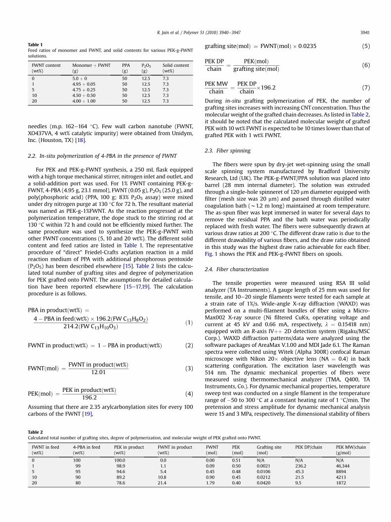
Table 1Feed ratios of monomer and FWNT, and solid contents for various PEK-g-FWNTsolutions.
FWNT content(wt%)
Monomer þ FWNT(g)
PPA(g)
P2O5
(g)Solid content(wt%)
0 5.0 þ 0 50 12.5 7.31 4.95 þ 0.05 50 12.5 7.35 4.75 þ 0.25 50 12.5 7.310 4.50 þ 0.50 50 12.5 7.320 4.00 þ 1.00 50 12.5 7.3
R. Jain et al. / Polymer 51 (2010) 3940e3947 3941
needles (m.p. 162e164 �C). Few wall carbon nanotube (FWNT,XO437VA, 4 wt% catalytic impurity) were obtained from Unidym,Inc. (Houston, TX) [18].
2.2. In-situ polymerization of 4-PBA in the presence of FWNT
For PEK and PEK-g-FWNT synthesis, a 250 mL flask equippedwith a high torque mechanical stirrer, nitrogen inlet and outlet, anda solid-addition port was used. For 1% FWNT containing PEK-g-FWNT, 4-PBA (4.95 g, 23.1 mmol), FWNT (0.05 g), P2O5 (25.0 g), andpoly(phosphoric acid) (PPA, 100 g; 83% P2O5 assay) were mixedunder dry nitrogen purge at 130 �C for 72 h. The resultant materialwas named as PEK-g-1%FWNT. As the reaction progressed at thepolymerization temperature, the dope stuck to the stirring rod at130 �C within 72 h and could not be efficiently mixed further. Thesame procedure was used to synthesize the PEK-g-FWNT withother FWNT concentrations (5, 10 and 20 wt%). The different solidcontent and feed ratios are listed in Table 1. The representativeprocedure of “direct” Friedel-Crafts acylation reaction in a mildreaction medium of PPA with additional phosphorous pentoxide(P2O5) has been described elsewhere [15]. Table 2 lists the calcu-lated total number of grafting sites and degree of polymerizationfor PEK grafted onto FWNT. The assumptions for detailed calcula-tion have been reported elsewhere [15e17,19]. The calculationprocedure is as follows.
PBA in productðwt%Þ ¼4� PBA in feedðwt%Þ � 196:2ðFW C13H8O2Þ
214:2ðFW C13H10O3Þð1Þ
FWNT in productðwt%Þ ¼ 1� PBA in productðwt%Þ (2)
FWNTðmolÞ ¼ FWNT in productðwt%Þ12:01
(3)
PEKðmolÞ ¼ PEK in productðwt%Þ196:2
(4)
Assuming that there are 2.35 arylcarbonylation sites for every 100carbons of the FWNT [19],
Table 2Calculated total number of grafting sites, degree of polymerization, and molecular weigh
FWNT in feed(wt%)
4-PBA in feed(wt%)
PEK in product(wt%)
FWNT in product(wt%)
0 100 100.0 0.01 99 98.9 1.15 95 94.6 5.410 90 89.2 10.820 80 78.6 21.4
grafting siteðmolÞ ¼ FWNTðmolÞ � 0:0235 (5)
PEK DPchain
¼ PEKðmolÞgrafting siteðmolÞ (6)
PEK MWchain
¼ PEK DPchain
�196:2 (7)
During in-situ grafting polymerization of PEK, the number ofgrafting sites increases with increasing CNTconcentration. Thus themolecular weight of the grafted chain decreases. As listed in Table 2,it should be noted that the calculated molecular weight of graftedPEKwith 10wt% FWNT is expected to be 10 times lower than that ofgrafted PEK with 1 wt% FWNT.
2.3. Fiber spinning
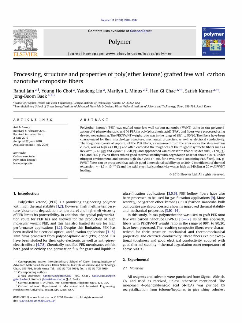
The fibers were spun by dry-jet wet-spinning using the smallscale spinning system manufactured by Bradford UniversityResearch, Ltd (UK). The PEK-g-FWNT/PPA solution was placed intobarrel (28 mm internal diameter). The solution was extrudedthrough a single-hole spinneret of 120 mm diameter equipped withfilter (mesh size was 20 mm) and passed through distilled watercoagulation bath (w1.2 m long) maintained at room temperature.The as-spun fiber was kept immersed in water for several days toremove the residual PPA and the bath water was periodicallyreplaced with fresh water. The fibers were subsequently drawn atvarious draw ratios at 200 �C. The different draw ratio is due to thedifferent drawability of various fibers, and the draw ratio obtainedin this study was the highest draw ratio achievable for each fiber.Fig. 1 shows the PEK and PEK-g-FWNT fibers on spools.
2.4. Fiber characterization
The tensile properties were measured using RSA III solidanalyzer (TA Instruments). A gauge length of 25 mm was used fortensile, and 10e20 single filaments were tested for each sample ata strain rate of 1%/s. Wide-angle X-ray diffraction (WAXD) wasperformed on a multi-filament bundles of fiber using a Micro-Max002 X-ray source (Ni filtered CuKa, operating voltage andcurrent at 45 kV and 0.66 mA, respectively, l ¼ 0.15418 nm)equipped with an R-axis IVþþ 2D detection system (Rigaku/MSCCorp.). WAXD diffraction patterns/data were analyzed using thesoftware packages of AreaMax V.1.00 and MDI Jade 6.1. The Ramanspectra were collected using Witek (Alpha 300R) confocal Ramanmicroscope with Nikon 20� objective lens (NA ¼ 0.4) in backscattering configuration. The excitation laser wavelength was514 nm. The dynamic mechanical properties of fibers weremeasured using thermomechanical analyzer (TMA, Q400, TAInstruments, Co.). For dynamic mechanical properties, temperaturesweep test was conducted on a single filament in the temperaturerange of �50 to 300 �C at a constant heating rate of 1 �C/min. Thepretension and stress amplitude for dynamic mechanical analysiswere 15 and 3 MPa, respectively. The dimensional stability of fibers
t of PEK grafted onto FWNT.
FWNT(mol)
PEK(mol)
Grafting site(mol)
PEK DP/chain PEK MW/chain(g/mol)
0.00 0.51 N/A N/A N/A0.09 0.50 0.0021 236.2 46,3440.45 0.48 0.0106 45.3 88940.90 0.45 0.0212 21.5 42131.79 0.40 0.0420 9.5 1872
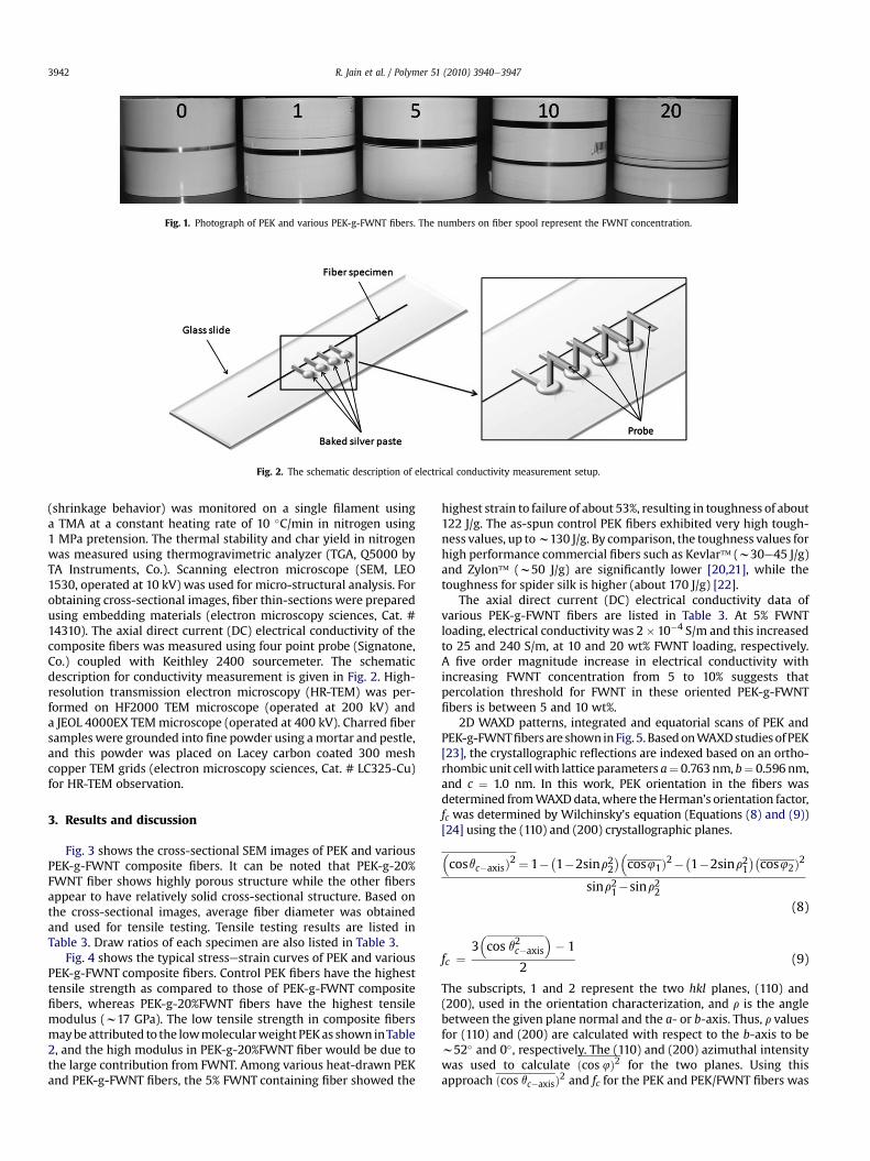
Fig. 2. The schematic description of electrical conductivity measurement setup.
Fig. 1. Photograph of PEK and various PEK-g-FWNT fibers. The numbers on fiber spool represent the FWNT concentration.
R. Jain et al. / Polymer 51 (2010) 3940e39473942
(shrinkage behavior) was monitored on a single filament usinga TMA at a constant heating rate of 10 �C/min in nitrogen using1 MPa pretension. The thermal stability and char yield in nitrogenwas measured using thermogravimetric analyzer (TGA, Q5000 byTA Instruments, Co.). Scanning electron microscope (SEM, LEO1530, operated at 10 kV) was used for micro-structural analysis. Forobtaining cross-sectional images, fiber thin-sections were preparedusing embedding materials (electron microscopy sciences, Cat. #14310). The axial direct current (DC) electrical conductivity of thecomposite fibers was measured using four point probe (Signatone,Co.) coupled with Keithley 2400 sourcemeter. The schematicdescription for conductivity measurement is given in Fig. 2. High-resolution transmission electron microscopy (HR-TEM) was per-formed on HF2000 TEM microscope (operated at 200 kV) anda JEOL 4000EX TEMmicroscope (operated at 400 kV). Charred fibersamples were grounded into fine powder using amortar and pestle,and this powder was placed on Lacey carbon coated 300 meshcopper TEM grids (electron microscopy sciences, Cat. # LC325-Cu)for HR-TEM observation.
3. Results and discussion
Fig. 3 shows the cross-sectional SEM images of PEK and variousPEK-g-FWNT composite fibers. It can be noted that PEK-g-20%FWNT fiber shows highly porous structure while the other fibersappear to have relatively solid cross-sectional structure. Based onthe cross-sectional images, average fiber diameter was obtainedand used for tensile testing. Tensile testing results are listed inTable 3. Draw ratios of each specimen are also listed in Table 3.
Fig. 4 shows the typical stressestrain curves of PEK and variousPEK-g-FWNT composite fibers. Control PEK fibers have the highesttensile strength as compared to those of PEK-g-FWNT compositefibers, whereas PEK-g-20%FWNT fibers have the highest tensilemodulus (w17 GPa). The low tensile strength in composite fibersmaybe attributed to the lowmolecularweight PEKas shown inTable2, and the high modulus in PEK-g-20%FWNT fiber would be due tothe large contribution from FWNT. Among various heat-drawn PEKand PEK-g-FWNT fibers, the 5% FWNT containing fiber showed the
highest strain to failure of about 53%, resulting in toughness of about122 J/g. The as-spun control PEK fibers exhibited very high tough-ness values, up tow130 J/g. By comparison, the toughness values forhigh performance commercial fibers such as Kevlar� (w30e45 J/g)and Zylon� (w50 J/g) are significantly lower [20,21], while thetoughness for spider silk is higher (about 170 J/g) [22].
The axial direct current (DC) electrical conductivity data ofvarious PEK-g-FWNT fibers are listed in Table 3. At 5% FWNTloading, electrical conductivity was 2� 10�4 S/m and this increasedto 25 and 240 S/m, at 10 and 20 wt% FWNT loading, respectively.A five order magnitude increase in electrical conductivity withincreasing FWNT concentration from 5 to 10% suggests thatpercolation threshold for FWNT in these oriented PEK-g-FWNTfibers is between 5 and 10 wt%.
2D WAXD patterns, integrated and equatorial scans of PEK andPEK-g-FWNTfibersare shown inFig. 5. BasedonWAXDstudiesofPEK[23], the crystallographic reflections are indexed based on an ortho-rhombic unit cellwith lattice parameters a¼ 0.763nm, b¼ 0.596nm,and c ¼ 1.0 nm. In this work, PEK orientation in the fibers wasdetermined fromWAXDdata,where theHerman’s orientation factor,fc was determined by Wilchinsky’s equation (Equations (8) and (9))[24] using the (110) and (200) crystallographic planes.
�cosqc�axisÞ2 ¼ 1��
1�2sinr22��
cos41Þ2��1�2sinr21
��cos42Þ2
sinr21�sinr22(8)
fc ¼3�cos q2c�axis
�� 1
2(9)
The subscripts, 1 and 2 represent the two hkl planes, (110) and(200), used in the orientation characterization, and r is the anglebetween the given plane normal and the a- or b-axis. Thus, r valuesfor (110) and (200) are calculated with respect to the b-axis to bew52� and 0�, respectively. The (110) and (200) azimuthal intensitywas used to calculate ðcos 4Þ2 for the two planes. Using thisapproach ðcos qc�axisÞ2 and fc for the PEK and PEK/FWNT fibers was
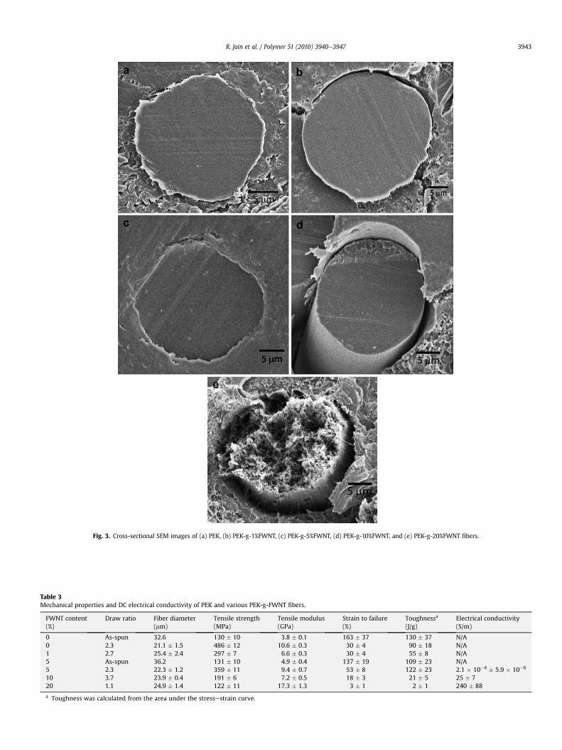
Table 3Mechanical properties and DC electrical conductivity of PEK and various PEK-g-FWNT fibers.
FWNT content(%)
Draw ratio Fiber diameter(mm)
Tensile strength(MPa)
Tensile modulus(GPa)
Strain to failure(%)
Toughnessa
(J/g)Electrical conductivity(S/m)
0 As-spun 32.6 130 � 10 3.8 � 0.1 163 � 37 130 � 37 N/A0 2.3 21.1 � 1.5 486 � 12 10.6 � 0.3 30 � 4 90 � 18 N/A1 2.7 25.4 � 2.4 297 � 7 6.6 � 0.3 30 � 4 55 � 8 N/A5 As-spun 36.2 131 � 10 4.9 � 0.4 137 � 19 109 � 23 N/A5 2.3 22.3 � 1.2 359 � 11 9.4 � 0.7 53 � 8 122 � 23 2.1 � 10�4 � 5.9 � 10�6
10 3.7 23.9 � 0.4 191 � 6 7.2 � 0.5 18 � 3 21 � 5 25 � 720 1.1 24.9 � 1.4 122 � 11 17.3 � 1.3 3 � 1 2 � 1 240 � 88
a Toughness was calculated from the area under the stressestrain curve.
Fig. 3. Cross-sectional SEM images of (a) PEK, (b) PEK-g-1%FWNT, (c) PEK-g-5%FWNT, (d) PEK-g-10%FWNT, and (e) PEK-g-20%FWNT fibers.
R. Jain et al. / Polymer 51 (2010) 3940e3947 3943
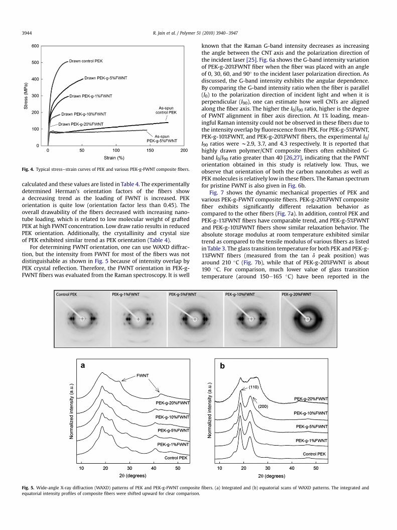
Fig. 4. Typical stressestrain curves of PEK and various PEK-g-FWNT composite fibers.
R. Jain et al. / Polymer 51 (2010) 3940e39473944
calculated and these values are listed in Table 4. The experimentallydetermined Herman’s orientation factors of the fibers showa decreasing trend as the loading of FWNT is increased. PEKorientation is quite low (orientation factor less than 0.45). Theoverall drawability of the fibers decreased with increasing nano-tube loading, which is related to low molecular weight of graftedPEK at high FWNT concentration. Low draw ratio results in reducedPEK orientation. Additionally, the crystallinity and crystal sizeof PEK exhibited similar trend as PEK orientation (Table 4).
For determining FWNT orientation, one can use WAXD diffrac-tion, but the intensity from FWNT for most of the fibers was notdistinguishable as shown in Fig. 5 because of intensity overlap byPEK crystal reflection. Therefore, the FWNT orientation in PEK-g-FWNT fibers was evaluated from the Raman spectroscopy. It is well
Fig. 5. Wide-angle X-ray diffraction (WAXD) patterns of PEK and PEK-g-FWNT compositeequatorial intensity profiles of composite fibers were shifted upward for clear comparison.
known that the Raman G-band intensity decreases as increasingthe angle between the CNT axis and the polarization direction ofthe incident laser [25]. Fig. 6a shows the G-band intensity variationof PEK-g-20%FWNT fiber when the fiber was placed with an angleof 0, 30, 60, and 90� to the incident laser polarization direction. Asdiscussed, the G-band intensity exhibits the angular dependence.By comparing the G-band intensity ratio when the fiber is parallel(I0) to the polarization direction of incident light and when it isperpendicular (I90), one can estimate how well CNTs are alignedalong the fiber axis. The higher the I0/I90 ratio, higher is the degreeof FWNT alignment in fiber axis direction. At 1% loading, mean-ingful Raman intensity could not be observed in these fibers due tothe intensity overlap by fluorescence from PEK. For PEK-g-5%FWNT,PEK-g-10%FWNT, and PEK-g-20%FWNT fibers, the experimental I0/I90 ratios were w2.9, 3.7, and 4.3 respectively. It is reported thathighly drawn polymer/CNT composite fibers often exhibited G-band I0/I90 ratio greater than 40 [26,27], indicating that the FWNTorientation obtained in this study is relatively low. Thus, weobserve that orientation of both the carbon nanotubes as well asPEKmolecules is relatively low in these fibers. The Raman spectrumfor pristine FWNT is also given in Fig. 6b.
Fig. 7 shows the dynamic mechanical properties of PEK andvarious PEK-g-FWNT composite fibers. PEK-g-20%FWNT compositefiber exhibits significantly different relaxation behavior ascompared to the other fibers (Fig. 7a). In addition, control PEK andPEK-g-1%FWNT fibers have comparable trend, and PEK-g-5%FWNTand PEK-g-10%FWNT fibers show similar relaxation behavior. Theabsolute storage modulus at room temperature exhibited similartrend as compared to the tensile modulus of various fibers as listedin Table 3. The glass transition temperature for both PEK and PEK-g-1%FWNT fibers (measured from the tan d peak position) wasaround 210 �C (Fig. 7b), while that of PEK-g-20%FWNT is about190 �C. For comparison, much lower value of glass transitiontemperature (around 150e165 �C) have been reported in the
fibers. (a) Integrated and (b) equatorial scans of WAXD patterns. The integrated and
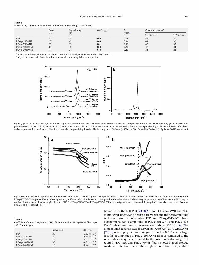
Fig. 6. (a)RamanG-band intensityvariationofPEK-g-20%FWNTcompositefiberasa functionof angle betweenfiberand laserpolarizationdirection inVVmodeand (b)Ramanspectrumofpristine FWNT. The spectra for 0, 30, and 60� in (a) were shifted upward for clear comparison. The VVmode represents that the direction of polarizer is parallel to the direction of analyzer,and 0� represents that the fiber axis direction is parallel to the polarizing direction. The intensity ratio of G-band (w1590 cm�1) to D-band (w1300 cm�1) of pristine FWNTwas about 6.
Table 4WAXD analysis results of drawn PEK and various drawn PEK-g-FWNT fibers.
Drawratio
Crystallinity(%)
ðcosqc�axisÞ2 fc(PEK)a
Crystal size (nm)b
(110)2qw18.5� (200)2qw22.5�
PEK 2.3 48 0.66 0.49 4.8 3.3PEK-g-1%FWNT 2.7 45 0.63 0.44 4.8 3.3PEK-g-5%FWNT 2.3 35 0.61 0.41 4.7 3.2PEK-g-10%FWNT 3.7 35 0.60 0.40 4.1 3.0PEK-g-20%FWNT 1.1 27 0.40 0.10 3.8 2.5
a PEK crystal orientation was calculated based on Wilchinsky’s equation as described in text.b Crystal size was calculated based on equatorial scans using Scherrer’s equation.
Fig. 7. Dynamic mechanical properties of drawn PEK and various drawn PEK-g-FWNT composite fibers. (a) Storage modulus and (b) tan d behavior as a function of temperature.PEK-g-20%FWNT composite fiber exhibits significantly different relaxation behavior as compared to the other fibers. It shows very large amplitude of loss factor, which may beattributed to the low molecular weight of grafted PEK. For PEK-g-5%FWNT and PEK-g-10%FWNT fibers, tan d peak is barely seen and the amplitude is weaker than those of controlPEK and PEK-g-1%FWNT fibers.
Table 5Coefficient of thermal expansion (CTE) of PEK and various PEK-g-FWNT fibers up to150 �C in nitrogen.
Draw ratio CTE (/�C)
PEK 2.3 �2.82 � 10�6
PEK-g-1%FWNT 2.7 �6.18 � 10�6
PEK-g-5%FWNT 2.3 �4.51 � 10�6
PEK-g-10%FWNT 3.7 �4.51 � 10�6
PEK-g-20%FWNT 1.1 �8.44 � 10�6
R. Jain et al. / Polymer 51 (2010) 3940e3947 3945
literature for the bulk PEK [23,28,29]. For PEK-g-5%FWNT and PEK-g-10%FWNT fibers, tan d peak is barely seen and the peak amplitudeis lower than that of control PEK and PEK-g-1%FWNT fibers.Furthermore, tan d amplitude of PEK-g-5%FWNT and PEK-g-10%FWNT fibers continue to increase even above 210 �C (Fig. 7b).Similar tan d behavior was observed for PAN/SWNTat 10wt% SWNT[26,30] where polymer was not grafted on to CNT. The very largeloss factor amplitude of PEK-g-20%FWNT fiber as compared to theother fibers may be attributed to the low molecular weight ofgrafted PEK. PEK and PEK-g-FWNT fibers showed good storagemodulus retention even above glass transition temperature
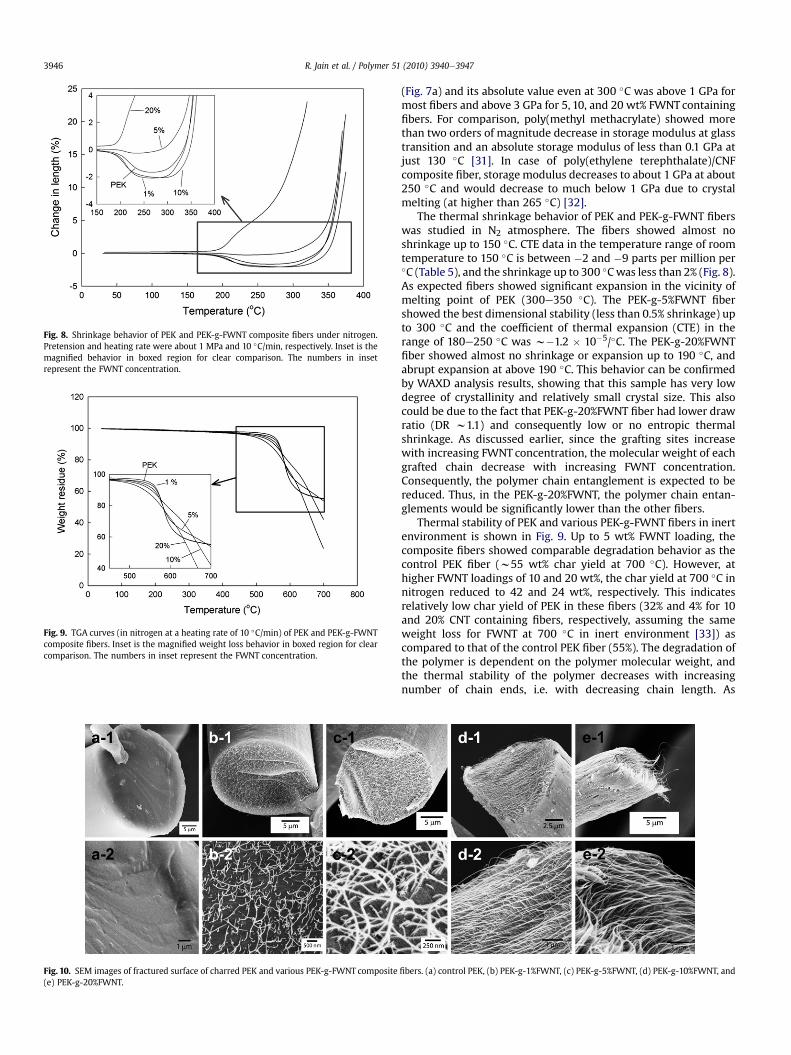
Fig. 8. Shrinkage behavior of PEK and PEK-g-FWNT composite fibers under nitrogen.Pretension and heating rate were about 1 MPa and 10 �C/min, respectively. Inset is themagnified behavior in boxed region for clear comparison. The numbers in insetrepresent the FWNT concentration.
Fig. 9. TGA curves (in nitrogen at a heating rate of 10 �C/min) of PEK and PEK-g-FWNTcomposite fibers. Inset is the magnified weight loss behavior in boxed region for clearcomparison. The numbers in inset represent the FWNT concentration.
Fig. 10. SEM images of fractured surface of charred PEK and various PEK-g-FWNT composite(e) PEK-g-20%FWNT.
R. Jain et al. / Polymer 51 (2010) 3940e39473946
(Fig. 7a) and its absolute value even at 300 �C was above 1 GPa formost fibers and above 3 GPa for 5, 10, and 20 wt% FWNT containingfibers. For comparison, poly(methyl methacrylate) showed morethan two orders of magnitude decrease in storage modulus at glasstransition and an absolute storage modulus of less than 0.1 GPa atjust 130 �C [31]. In case of poly(ethylene terephthalate)/CNFcomposite fiber, storagemodulus decreases to about 1 GPa at about250 �C and would decrease to much below 1 GPa due to crystalmelting (at higher than 265 �C) [32].
The thermal shrinkage behavior of PEK and PEK-g-FWNT fiberswas studied in N2 atmosphere. The fibers showed almost noshrinkage up to 150 �C. CTE data in the temperature range of roomtemperature to 150 �C is between �2 and �9 parts per million per�C (Table 5), and the shrinkage up to 300 �Cwas less than 2% (Fig. 8).As expected fibers showed significant expansion in the vicinity ofmelting point of PEK (300e350 �C). The PEK-g-5%FWNT fibershowed the best dimensional stability (less than 0.5% shrinkage) upto 300 �C and the coefficient of thermal expansion (CTE) in therange of 180e250 �C was w�1.2 � 10�5/�C. The PEK-g-20%FWNTfiber showed almost no shrinkage or expansion up to 190 �C, andabrupt expansion at above 190 �C. This behavior can be confirmedby WAXD analysis results, showing that this sample has very lowdegree of crystallinity and relatively small crystal size. This alsocould be due to the fact that PEK-g-20%FWNT fiber had lower drawratio (DR w1.1) and consequently low or no entropic thermalshrinkage. As discussed earlier, since the grafting sites increasewith increasing FWNT concentration, the molecular weight of eachgrafted chain decrease with increasing FWNT concentration.Consequently, the polymer chain entanglement is expected to bereduced. Thus, in the PEK-g-20%FWNT, the polymer chain entan-glements would be significantly lower than the other fibers.
Thermal stability of PEK and various PEK-g-FWNT fibers in inertenvironment is shown in Fig. 9. Up to 5 wt% FWNT loading, thecomposite fibers showed comparable degradation behavior as thecontrol PEK fiber (w55 wt% char yield at 700 �C). However, athigher FWNT loadings of 10 and 20 wt%, the char yield at 700 �C innitrogen reduced to 42 and 24 wt%, respectively. This indicatesrelatively low char yield of PEK in these fibers (32% and 4% for 10and 20% CNT containing fibers, respectively, assuming the sameweight loss for FWNT at 700 �C in inert environment [33]) ascompared to that of the control PEK fiber (55%). The degradation ofthe polymer is dependent on the polymer molecular weight, andthe thermal stability of the polymer decreases with increasingnumber of chain ends, i.e. with decreasing chain length. As
fibers. (a) control PEK, (b) PEK-g-1%FWNT, (c) PEK-g-5%FWNT, (d) PEK-g-10%FWNT, and
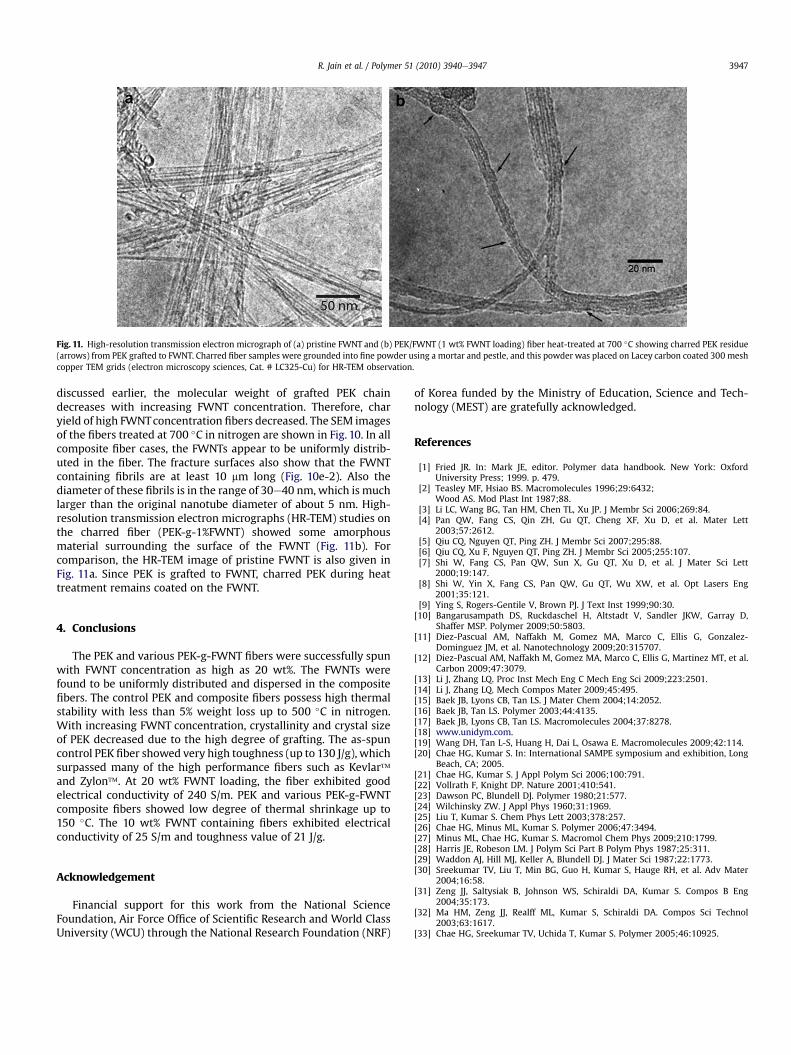
Fig. 11. High-resolution transmission electron micrograph of (a) pristine FWNT and (b) PEK/FWNT (1 wt% FWNT loading) fiber heat-treated at 700 �C showing charred PEK residue(arrows) from PEK grafted to FWNT. Charred fiber samples were grounded into fine powder using a mortar and pestle, and this powder was placed on Lacey carbon coated 300 meshcopper TEM grids (electron microscopy sciences, Cat. # LC325-Cu) for HR-TEM observation.
R. Jain et al. / Polymer 51 (2010) 3940e3947 3947
discussed earlier, the molecular weight of grafted PEK chaindecreases with increasing FWNT concentration. Therefore, charyield of high FWNTconcentration fibers decreased. The SEM imagesof the fibers treated at 700 �C in nitrogen are shown in Fig. 10. In allcomposite fiber cases, the FWNTs appear to be uniformly distrib-uted in the fiber. The fracture surfaces also show that the FWNTcontaining fibrils are at least 10 mm long (Fig. 10e-2). Also thediameter of these fibrils is in the range of 30e40 nm, which is muchlarger than the original nanotube diameter of about 5 nm. High-resolution transmission electron micrographs (HR-TEM) studies onthe charred fiber (PEK-g-1%FWNT) showed some amorphousmaterial surrounding the surface of the FWNT (Fig. 11b). Forcomparison, the HR-TEM image of pristine FWNT is also given inFig. 11a. Since PEK is grafted to FWNT, charred PEK during heattreatment remains coated on the FWNT.
4. Conclusions
The PEK and various PEK-g-FWNT fibers were successfully spunwith FWNT concentration as high as 20 wt%. The FWNTs werefound to be uniformly distributed and dispersed in the compositefibers. The control PEK and composite fibers possess high thermalstability with less than 5% weight loss up to 500 �C in nitrogen.With increasing FWNT concentration, crystallinity and crystal sizeof PEK decreased due to the high degree of grafting. The as-spuncontrol PEK fiber showed very high toughness (up to 130 J/g), whichsurpassed many of the high performance fibers such as Kevlar�and Zylon�. At 20 wt% FWNT loading, the fiber exhibited goodelectrical conductivity of 240 S/m. PEK and various PEK-g-FWNTcomposite fibers showed low degree of thermal shrinkage up to150 �C. The 10 wt% FWNT containing fibers exhibited electricalconductivity of 25 S/m and toughness value of 21 J/g.
Acknowledgement
Financial support for this work from the National ScienceFoundation, Air Force Office of Scientific Research and World ClassUniversity (WCU) through the National Research Foundation (NRF)
of Korea funded by the Ministry of Education, Science and Tech-nology (MEST) are gratefully acknowledged.
References
[1] Fried JR. In: Mark JE, editor. Polymer data handbook. New York: OxfordUniversity Press; 1999. p. 479.
[2] Teasley MF, Hsiao BS. Macromolecules 1996;29:6432;Wood AS. Mod Plast Int 1987;88.
[3] Li LC, Wang BG, Tan HM, Chen TL, Xu JP. J Membr Sci 2006;269:84.[4] Pan QW, Fang CS, Qin ZH, Gu QT, Cheng XF, Xu D, et al. Mater Lett
2003;57:2612.[5] Qiu CQ, Nguyen QT, Ping ZH. J Membr Sci 2007;295:88.[6] Qiu CQ, Xu F, Nguyen QT, Ping ZH. J Membr Sci 2005;255:107.[7] Shi W, Fang CS, Pan QW, Sun X, Gu QT, Xu D, et al. J Mater Sci Lett
2000;19:147.[8] Shi W, Yin X, Fang CS, Pan QW, Gu QT, Wu XW, et al. Opt Lasers Eng
2001;35:121.[9] Ying S, Rogers-Gentile V, Brown PJ. J Text Inst 1999;90:30.
[10] Bangarusampath DS, Ruckdaschel H, Altstadt V, Sandler JKW, Garray D,Shaffer MSP. Polymer 2009;50:5803.
[11] Diez-Pascual AM, Naffakh M, Gomez MA, Marco C, Ellis G, Gonzalez-Dominguez JM, et al. Nanotechnology 2009;20:315707.
[12] Diez-Pascual AM, Naffakh M, Gomez MA, Marco C, Ellis G, Martinez MT, et al.Carbon 2009;47:3079.
[13] Li J, Zhang LQ. Proc Inst Mech Eng C Mech Eng Sci 2009;223:2501.[14] Li J, Zhang LQ. Mech Compos Mater 2009;45:495.[15] Baek JB, Lyons CB, Tan LS. J Mater Chem 2004;14:2052.[16] Baek JB, Tan LS. Polymer 2003;44:4135.[17] Baek JB, Lyons CB, Tan LS. Macromolecules 2004;37:8278.[18] www.unidym.com.[19] Wang DH, Tan L-S, Huang H, Dai L, Osawa E. Macromolecules 2009;42:114.[20] Chae HG, Kumar S. In: International SAMPE symposium and exhibition, Long
Beach, CA; 2005.[21] Chae HG, Kumar S. J Appl Polym Sci 2006;100:791.[22] Vollrath F, Knight DP. Nature 2001;410:541.[23] Dawson PC, Blundell DJ. Polymer 1980;21:577.[24] Wilchinsky ZW. J Appl Phys 1960;31:1969.[25] Liu T, Kumar S. Chem Phys Lett 2003;378:257.[26] Chae HG, Minus ML, Kumar S. Polymer 2006;47:3494.[27] Minus ML, Chae HG, Kumar S. Macromol Chem Phys 2009;210:1799.[28] Harris JE, Robeson LM. J Polym Sci Part B Polym Phys 1987;25:311.[29] Waddon AJ, Hill MJ, Keller A, Blundell DJ. J Mater Sci 1987;22:1773.[30] Sreekumar TV, Liu T, Min BG, Guo H, Kumar S, Hauge RH, et al. Adv Mater
2004;16:58.[31] Zeng JJ, Saltysiak B, Johnson WS, Schiraldi DA, Kumar S. Compos B Eng
2004;35:173.[32] Ma HM, Zeng JJ, Realff ML, Kumar S, Schiraldi DA. Compos Sci Technol
2003;63:1617.[33] Chae HG, Sreekumar TV, Uchida T, Kumar S. Polymer 2005;46:10925.
Related Documents