Pressure measurement Process pressure/Hydrostatic VEGABAR 61 VEGABAR 63 VEGABAR 64 VEGABAR 65 Product Information

Welcome message from author
This document is posted to help you gain knowledge. Please leave a comment to let me know what you think about it! Share it to your friends and learn new things together.
Transcript
Pressure measurement
Process pressure/Hydrostatic
VEGABAR 61
VEGABAR 63
VEGABAR 64
VEGABAR 65
Product Information
Contents
2 Process pressure/Hydrostatic – Pressure measurement
Contents
1 Application, function, configuration . . . . . . . . . . . . . . . . . . . . . . . . . . . . . . . . . . . . . . . . . . . . . . . . . . . . . . . . . . . . . . 3
2 Type overview . . . . . . . . . . . . . . . . . . . . . . . . . . . . . . . . . . . . . . . . . . . . . . . . . . . . . . . . . . . . . . . . . . . . . . . . . . . . . . 7
3 Mounting instructions. . . . . . . . . . . . . . . . . . . . . . . . . . . . . . . . . . . . . . . . . . . . . . . . . . . . . . . . . . . . . . . . . . . . . . . . 10
4 Electrical connection
4.1 General requirements . . . . . . . . . . . . . . . . . . . . . . . . . . . . . . . . . . . . . . . . . . . . . . . . . . . . . . . . . . . . . . . . . . . . 114.2 Voltage supply . . . . . . . . . . . . . . . . . . . . . . . . . . . . . . . . . . . . . . . . . . . . . . . . . . . . . . . . . . . . . . . . . . . . . . . . . 114.3 Connection cable. . . . . . . . . . . . . . . . . . . . . . . . . . . . . . . . . . . . . . . . . . . . . . . . . . . . . . . . . . . . . . . . . . . . . . . . 114.4 Cable screening and grounding . . . . . . . . . . . . . . . . . . . . . . . . . . . . . . . . . . . . . . . . . . . . . . . . . . . . . . . . . . . . . 114.5 Wiring plan . . . . . . . . . . . . . . . . . . . . . . . . . . . . . . . . . . . . . . . . . . . . . . . . . . . . . . . . . . . . . . . . . . . . . . . . . . . . 12
5 Operation
5.1 Overview. . . . . . . . . . . . . . . . . . . . . . . . . . . . . . . . . . . . . . . . . . . . . . . . . . . . . . . . . . . . . . . . . . . . . . . . . . . . . . 135.2 Compatibility according to NAMUR NE 53. . . . . . . . . . . . . . . . . . . . . . . . . . . . . . . . . . . . . . . . . . . . . . . . . . . . . . 135.3 Adjustment with the indicating and adjustment module PLICSCOM. . . . . . . . . . . . . . . . . . . . . . . . . . . . . . . . . . . . 135.4 Adjustment with PACTware . . . . . . . . . . . . . . . . . . . . . . . . . . . . . . . . . . . . . . . . . . . . . . . . . . . . . . . . . . . . . . . . 135.5 Adjustment with other adjustment programs . . . . . . . . . . . . . . . . . . . . . . . . . . . . . . . . . . . . . . . . . . . . . . . . . . . . 14
6 Technical data . . . . . . . . . . . . . . . . . . . . . . . . . . . . . . . . . . . . . . . . . . . . . . . . . . . . . . . . . . . . . . . . . . . . . . . . . . . . . 15
7 Dimensions. . . . . . . . . . . . . . . . . . . . . . . . . . . . . . . . . . . . . . . . . . . . . . . . . . . . . . . . . . . . . . . . . . . . . . . . . . . . . . . . 24
8 Product code . . . . . . . . . . . . . . . . . . . . . . . . . . . . . . . . . . . . . . . . . . . . . . . . . . . . . . . . . . . . . . . . . . . . . . . . . . . . . . 30
Take note of safety instructions for Ex applications
Please note theEx specific safety informationwhich you can find on our homepagewww.vega.com\services\downloads and
which comes with every instrument. In hazardous areas you should take note of the appropriate regulations, conformity and
type approval certificates of the sensors and power supply units. The sensors must only be operated on intrinsically safe
circuits. The permissible electrical values are stated in the certificate.
29235-EN-081013
1 Application, function, configuration
Area of application
VEGABAR series 60 sensors are pressure transmitters with a
characteristicsdeviationof0.1%or0.075% for processpressure
and levelmeasurement.Theyare suitable for all applicationswith
gases, vapours and liquids in which medium-resistent sensors
and high accuracy are required. An IP 68 version is available for
extremely humid areas. The instruments are provided with op-
tions for comprehensive on-site (directly at the measurement
loop) as well as remote adjustment and indication. The elec-
tronics modules are available with analogue and digital signal
outputs4… 20mA, 4… 20mA/HART, ProfibusPA andFounda-
tionFieldbus.This enables theconfigurationof economical single
measurements as well as connection to DCS and PLC systems.
Special features of VEGABAR 61 are the isolating system, front-
flush process as well as hygienic fittings. This instrument mainly
coversapplicationsinhighlycorrosiveandhotproductsaswell as
high pressures.
VEGABAR 63 has a metal measuring cell with different sensor
elements. It offers a large selection of front-flush process fittings
with thread or in hygienic version. The instrument is particularly
suitable for viscous but also corrosive liquids, especially in the
food processing industry, in power stations and in the chemical
industry.
VEGABAR 64 with theCERTEC® measuring cell is available with
small process fittings from G½ A, front-flush process fittings as
well as a wide variety of threaded and flange fittings. It is thus
particularly suitable for applications in the paper, chemical and
pharmaceutical industries as well as in water/sewage water ap-
plications.
VEGABAR 64 4… 20mA/HART - climate compensated is a pres-
sure transmitter for use in the paper and food processing indus-
tries as well as in water/waste water applications under difficult
conditions (cold medium and warm humid environment).
VEGABAR 65withMETEC®measuring cell offers a large number
of hygienicfittings. It is thusparticularlysuitable for applications in
the chemical, food processing and pharmaceutical industries.
User advantages
l small deviation in characteristics< 0.1%, < 0.075%, optional
< 0.05%
l Up to 150-fold overload resistance
l Product temperature up to 400 °C
l Measuring ranges -1… 72 bar
l Completely flush process fittings
l Functional safety according to IEC 61508-4/61511 up toSIL3
l Exchangeable indicating and adjustment module
l Quick setup via easy menu guidance
l Comprehensive monitoring and diagnostics functions
Measuring principle
The process pressure causes via the diaphragm a change in an
electrical parameter of the measuring cell. This change is con-
verted into an appropriate output signal. Since the instruments
are all designed for specific application areas, different sensor
elements, i.e. measuring units, are used for detecting the pres-
sure.
VEGABAR 61
Thesensor element inVEGABAR61 is theCERTEC®measuring
cell with isolating system and metallic process diaphragm. A
strain gauge element is implemented for measuring ranges over
100 bar.
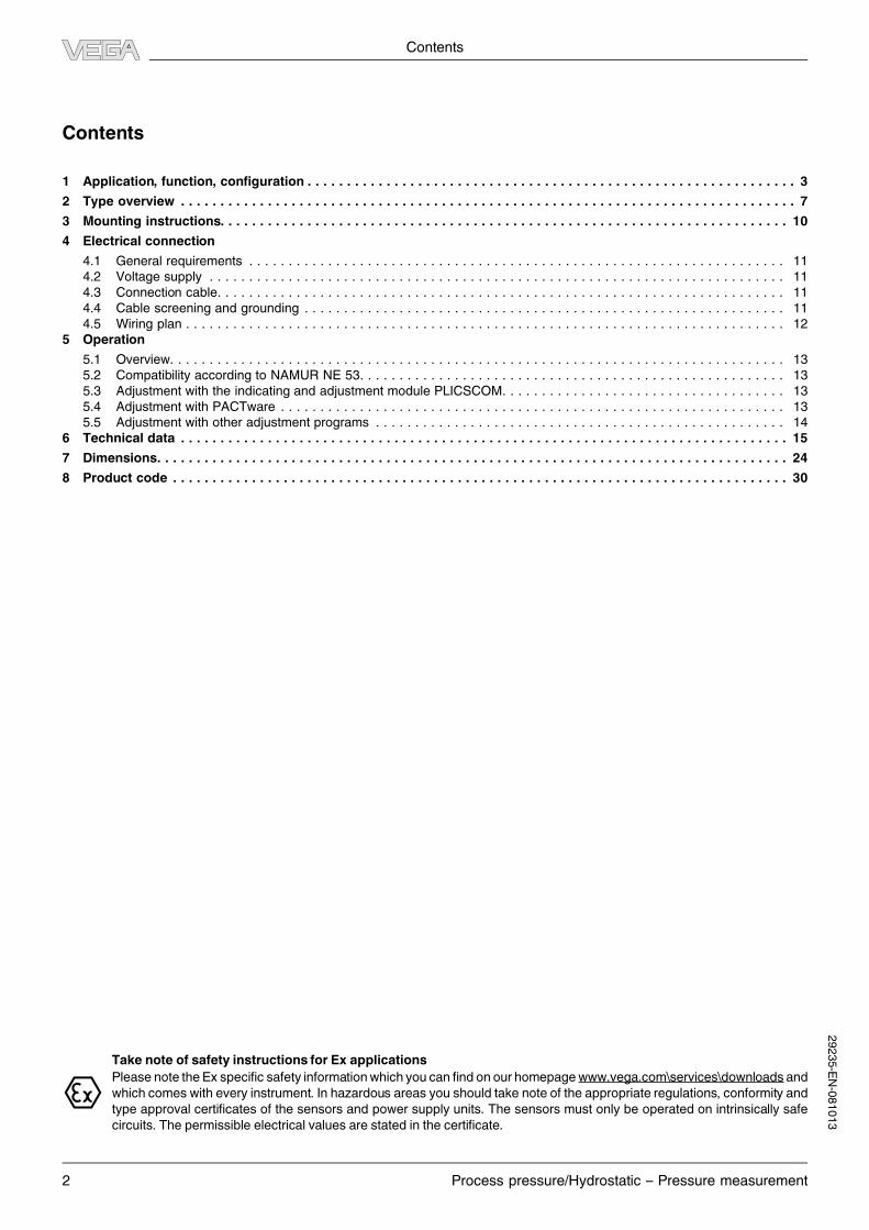
VEGABAR 63
WithVEGABAR 63, ameasuringcell with a piezoresistive sensor
element and internal transmission liquid is used for measuring
ranges up to 16 bar.
Formeasuring ranges above 25 bar, a dry strain gauge (DMS) on
the back side of the process diaphragm is implemented.
The process diaphragm consists of stainless steel.
1
4 3
2
Fig. 1: Configuration of the piezoresistive measuring cell in VEGABAR 63
1 Sensor element
2 Base element
3 Diaphragm
4 Silicone oil filling
The features of the piezoresistive measuring cell are:
l Elastomere-free
l Wetted parts of stainless steel
l Low hysteresis
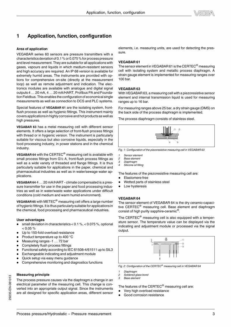
VEGABAR 64
The sensor element of VEGABAR 64 is the dry ceramic-capaci-
tive CERTEC® measuring cell. Base element and diaphragm
consist of high purity sapphire-ceramic®.
The CERTEC® measuring cell is also equipped with a temper-
ature sensor. The temperature value can be displayed via the
indicating and adjustment module or processed via the signal
output.
16 µ
m 1
2
3
Fig. 2: Configuration of the CERTEC® measuring cell in VEGABAR 64
1 Diaphragm
2 Soldered glass bond
3 Base element
The features of the CERTEC® measuring cell are:
l Very high overload resistance
l Good corrosion resistance
Application, function, configuration
Process pressure/Hydrostatic – Pressure measurement 3
29235-EN-081013
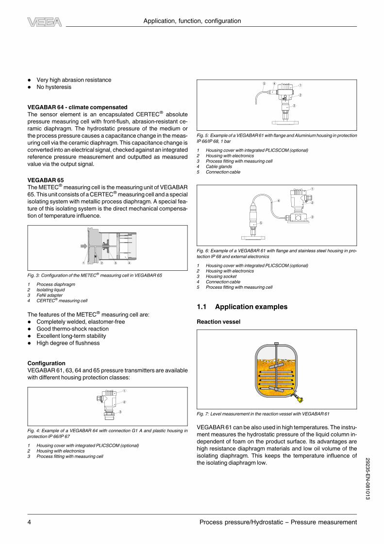
l Very high abrasion resistance
l No hysteresis
VEGABAR 64 - climate compensated
The sensor element is an encapsulated CERTEC® absolute
pressure measuring cell with front-flush, abrasion-resistant ce-
ramic diaphragm. The hydrostatic pressure of the medium or
the process pressure causes a capacitance change in themeas-
uring cell via the ceramic diaphragm. This capacitancechange is
converted into an electrical signal, checked against an integrated
reference pressure measurement and outputted as measured
value via the output signal.
VEGABAR 65
TheMETEC®measuring cell is the measuring unit of VEGABAR
65.This unit consists of aCERTEC®measuringcell anda special
isolating system with metallic process diaphragm. A special fea-
ture of this isolating system is the direct mechanical compensa-
tion of temperature influence.
4321
Fig. 3: Configuration of theMETEC® measuring cell in VEGABAR 65
1 Process diaphragm
2 Isolating liquid
3 FeNi adapter
4 CERTEC® measuring cell
The features of theMETEC® measuring cell are:
l Completely welded, elastomer-free
l Good thermo-shock reaction
l Excellent long-term stability
l High degree of flushness
Configuration
VEGABAR 61, 63, 64 and 65 pressure transmitters are available
with different housing protection classes:
1
2
3
Fig. 4: Example of a VEGABAR 64 with connection G1 A and plastic housing in
protection IP 66/IP 67
1 Housing cover with integrated PLICSCOM (optional)
2 Housing with electronics
3 Process fitting with measuring cell
1
2
3
45
Fig. 5: Example of a VEGABAR61with flange andAluminiumhousing in protection
IP 66/IP 68, 1 bar
1 Housing cover with integrated PLICSCOM (optional)
2 Housing with electronics
3 Process fitting with measuring cell
4 Cable glands
5 Connection cable
1
2
3
5
4
Fig. 6: Example of a VEGABAR 61 with flange and stainless steel housing in pro-
tection IP 68 and external electronics
1 Housing cover with integrated PLICSCOM (optional)
2 Housing with electronics
3 Housing socket
4 Connection cable
5 Process fitting with measuring cell
1.1 Application examples
Reaction vessel
Fig. 7: Level measurement in the reaction vessel with VEGABAR 61
VEGABAR 61 can be also used in high temperatures. The instru-
ment measures the hydrostatic pressure of the liquid column in-
dependent of foam on the product surface. Its advantages are
high resistance diaphragm materials and low oil volume of the
isolating diaphragm. This keeps the temperature influence of
the isolating diaphragm low.
Application, function, configuration
4 Process pressure/Hydrostatic – Pressure measurement
29235-EN-081013
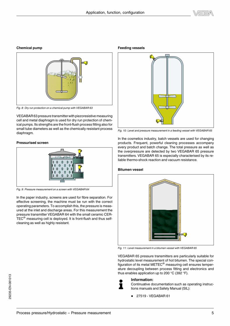
Chemical pump
Fig. 8: Dry run protection on a chemical pump with VEGABAR 63
VEGABAR63pressure transmitterwithpiezoresistivemeasuring
cell and metal diaphragm is used for dry run protection of chem-
ical pumps. Its strengths are the front-flush process fitting also for
small tube diameters as well as the chemically resistant process
diaphragm.
Pressurised screen
Fig. 9: Pressure measurement on a screen with VEGABAR 64
In the paper industry, screens are used for fibre separation. For
effective screening, the machine must be run with the correct
operating parameters. To accomplish this, the pressure is meas-
ured at the inlet and discharge areas. For this measurement the
pressure transmitter VEGABAR 64 with the small ceramic CER-
TEC® measuring cell is deployed. It is front-flush and thus self-
cleaning as well as highly resistant.
Feeding vessels
Fig. 10: Level and pressure measurement in a feeding vessel with VEGABAR 65
In the cosmetics industry, batch vessels are used for changing
products. Frequent, powerful cleaning processes accompany
every product and batch change. The total pressure as well as
the overpressure are detected by two VEGABAR 65 pressure
transmitters. VEGABAR 65 is especially characterised by its re-
liable thermo-shock reaction and vacuum resistance.
Bitumen vessel
Fig. 11: Level measurement in a bitumen vessel with VEGABAR 65
VEGABAR 65 pressure transmitters are particularly suitable for
hydrostatic level measurement of hot bitumen. The special con-
figuration of its metal METEC® measuring cell ensures temper-
ature decoupling between process fitting and electronics and
thus enables application up to 200 °C (392 °F).
Information:Continuative documentation such as operating instruc-
tions manuals and SafetyManual (SIL):
l 27519 - VEGABAR 61
Application, function, configuration
Process pressure/Hydrostatic – Pressure measurement 5
29235-EN-081013

l 32462 - VEGABAR 63
l 27525 - VEGABAR 64
l 27531 - VEGABAR 65
l 31637-SafetyManualVEGABAR50/60 -4…20mA/
HART
Application, function, configuration
6 Process pressure/Hydrostatic – Pressure measurement
29235-EN-081013
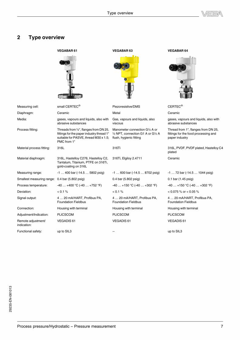
2 Type overview
VEGABAR 61 VEGABAR 63 VEGABAR 64
Measuring cell: small CERTEC®Piezoresistive/DMS CERTEC
®
Diaphragm: Ceramic Metal Ceramic
Media: gases, vapours and liquids, also with
abrasive substances
Gas, vapours and liquids, also
viscous
gases, vapours and liquids, also with
abrasive substances
Process fitting: Threads from½", flanges fromDN 25,
fittings for the paper industry thread 1"
suitable forPASVE, threadM30 x 1.5;
PMC from 1"
Manometer connectionG½ A or
½ NPT, connection G1 A or G½ A
flush, hygienic fitting
Thread from 1", flanges from DN 25,
fittings for the food processing and
paper industry
Material process fitting: 316L 316Ti 316L,PVDF,PVDF plated,HastelloyC4
plated
Material diaphragm: 316L, Hastelloy C276, Hastelloy C2,
Tantalum, Titanium, PTFE on 316Ti,
gold-coating on 316L
316Ti, Elgiloy 2.4711 Ceramic
Measuring range: -1 … 400 bar (-14.5 … 5802 psig) -1 … 600 bar (-14.5 … 8702 psig) -1 … 72 bar (-14.5… 1044 psig)
Smallest measuring range: 0.4 bar (5.802 psig) 0.4 bar (5.802 psig) 0.1 bar (1.45 psig)
Process temperature: -40… +400 °C (-40… +752 °F) -40… +150 °C (-40… +302 °F) -40… +150 °C (-40… +302 °F)
Deviation: < 0.1 % < 0.1 % < 0.075% or < 0.05%
Signal output: 4… 20mA/HART, Profibus PA,
Foundation Fieldbus
4… 20mA/HART, Profibus PA,
Foundation Fieldbus
4… 20mA/HART, Profibus PA,
Foundation Fieldbus
Connection: Housing with terminal Housing with terminal Housing with terminal
Adjustment/Indication: PLICSCOM PLICSCOM PLICSCOM
Remote adjustment/
indication:
VEGADIS 61 VEGADIS 61 VEGADIS 61
Functional safety: up to SIL3 -- up to SIL3
Type overview
Process pressure/Hydrostatic – Pressure measurement 7
29235-EN-081013

VEGABAR 64 - climate compen-
sated
VEGABAR 65
Measuring cell: CERTEC®
METEC®
Diaphragm: Ceramic Metal
Media: gases, vapours and liquids also with
higher temperatures
gases, vapours and liquids, also with
abrasive substances
Process fitting: Thread from1½", flanges fromDN 20,
fittings for the food processing
industry
Thread from1½", flanges fromDN 20,
fittings for the food processing
industry
Material process fitting: 316L, Hastelloy C276 316L, Hastelloy C276
Material diaphragm: Ceramic Hastelloy C276, gold-coated, gold/
rhodium-coated
Measuring range: -1 … 72 bar (-14.5… 1044 psig) -1 … 25 bar (-14.5… 363 psig)
Smallest measuring range: 0.2 bar (3 psig) 0.1 bar (1.45 psig)
Process temperature: -40… +150 °C (-40… +302 °F) -12… +200 °C (-10… +392 °F)
Deviation in characteristics: < (0.05 + 0.025 x TD)% < 0.075%
Signal output: 4… 20mA/HART, Profibus PA,
Foundation Fieldbus
4… 20mA/HART, Profibus PA,
Foundation Fieldbus
Connection: Housing with terminal Housing with terminal
Adjustment/Indication: PLICSCOM PLICSCOM
Remote adjustment/
indication:
VEGADIS 61 VEGADIS 61
Functional safety: - up to SIL3
Type overview
8 Process pressure/Hydrostatic – Pressure measurement
29235-EN-081013

Indicating and adjustment
module
PLICSCOM
Housing
Plastic Stainless steel AluminiumAluminium (double
chamber)
Electronics
4 … 20 mA/HART Profibus PA Foundation Field-
bus
Process fitting
Thread Flange Sanitary
Sensors
CERTEC® measur-
ing cell
METEC® measur-
ing cell
Piezoresistive
measuring cell
Approvals
SIL Overfill protection Gas explosion pro-
tectionDust-explosion pro-
tection
EHEDG Ship FMCSA
Type overview
Process pressure/Hydrostatic – Pressure measurement 9
29235-EN-081013

3 Mounting instructions
Mounting position
VEGABAR functions in any installation position. Depending on
the measuring system, the installation position can influence the
measurement. This can be compensated by a position correc-
tion.
For plics® instruments select an installation position you can
easily reach for mounting and connecting as well as later retrofit-
ting of an indicating and adjustmentmodule. The housing can be
rotated by 330° without the use of any tools. You can also install
the indicating and adjustment module in four different positions
(each displaced by 90°).
Mounting instructions
10 Process pressure/Hydrostatic – Pressure measurement
29235-EN-081013

4 Electrical connection
4.1 General requirements
The supply voltage range can differ depending on the instrument
version. You can find exact specifications in chapter "Technical
data".
The national installation standards as well as the valid safety
regulations and accident prevention rules must be observed.
In hazardous areas you should take note of the appro-
priate regulations, conformity and type approval certifi-
cates of the sensors and power supply units.
4.2 Voltage supply
In general
Depending on the version, the supply voltage and current signal
are carried on the same two-wire connection cable or over sep-
arate connectioncables. The requirementson the voltage supply
are specified in chapter "Technical data".
4… 20mA/HART two-wire
The VEGA power supply units VEGATRENN 149AEx, VEGAS-
TAB 690, VEGADIS 371 as well as VEGAMET signal condition-
ing instruments are suitable for power supply.When one of these
instruments is used, a reliable separation of the supply circuits
from the mains circuits according to DIN VDE 0106 part 101 is
ensured for the sensor.
Profibus PA
Power is supplied by a Profibus DP/PA segment coupler or a
VEGALOG 571 EP input card.
Fig. 12: Integrationof instruments in aProfibusPA system via segment couplerDP/
PA or data recording systems with Profibus PA input card
Foundation Fieldbus
Power supply via the H1 Fieldbus cable.
4.3 Connection cable
In general
The sensors are connected with standard cable without screen.
Anoutercablediameterof5…9mmensures theseal effectof the
cable entry.
4… 20mA/HART two-wire and four-wire
If electromagnetic interference is expected which is above the
test values of EN 61326 for industrial areas, screened cable
should be used. In HART multidrop mode the use of screened
cable is generally recommended.
Profibus PA, Foundation Fieldbus
The installation must be carried out according to the appropriate
bus specification. VEGABAR is connected appropriately with
screened cable according to the bus specification. Power supply
and digital bus signal are transmitted via the same two-wire con-
nection cable.Make sure that the bus is terminated via appropri-
ate terminating resistors.
In Ex applications, the corresponding installation regu-
lations must be noted for the connection cable.
4.4 Cable screening and grounding
If screened cable is necessary, the cable screen must be con-
nected on both ends to ground potential. If potential equalisation
currents are expected, the connection on the evaluation side
must be made via a ceramic capacitor (e.g. 1 nF, 1500 V).
Profibus PA, Foundation Fieldbus
In systems with potential separation, the cable screen is con-
nected directly to ground potential on the power supply unit, in
the connection box and directly on the sensor.
In systems without potential equalisation, connect the cable
screen directly to ground potential only at the power supply unit
and at the sensor - do not connect to ground potential in the
connection box or T-distributor.
Electrical connection
Process pressure/Hydrostatic – Pressure measurement 11
29235-EN-081013
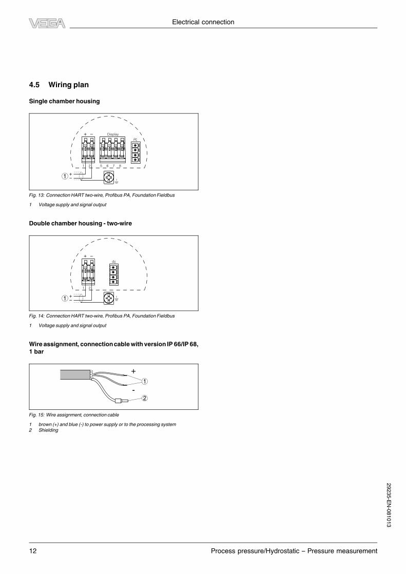
4.5 Wiring plan
Single chamber housing
I2C
Display
1
1 2 5 6 7 8
Fig. 13: ConnectionHART two-wire, Profibus PA, Foundation Fieldbus
1 Voltage supply and signal output
Double chamber housing - two-wire
I2C
1
1 2
Fig. 14: ConnectionHART two-wire, Profibus PA, Foundation Fieldbus
1 Voltage supply and signal output
Wire assignment, connectioncablewith version IP 66/IP 68,
1 bar
+
-
1
2
Fig. 15: Wire assignment, connection cable
1 brown (+) and blue (-) to power supply or to the processing system
2 Shielding
Electrical connection
12 Process pressure/Hydrostatic – Pressure measurement
29235-EN-081013

5 Operation
5.1 Overview
The sensors can be adjusted with the following adjustment me-
dia:
l with indicating and adjustment module
l anadjustmentsoftwareaccording toFDT/DTM standard,e.g.
PACTware and PC
and, depending on the signal output, also with:
l A HART handheld (4… 20mA/HART)
l The adjustment programAMS (4… 20mA/HART and Foun-
dation Fieldbus)
l The adjustment program PDM (Profibus PA)
l A configuration tool (Foundation Fieldbus)
The entered parameters are generally saved in the sensor, op-
tionally also in the indicating and adjustment module or in the
adjustment program.
5.2 Compatibility according to NAMUR NE 53
VEGABARmeetNAMUR recommendationNE 53. VEGA instru-
ments are generally upward and downward compatible:
l Sensor software for DTM VEGABAR HART, PA or FF
l DTM VEGABAR for adjustment software PACTware
l Indicating and adjustment module PLICSCOM for sensor
software
The parameter adjustment of the basic sensor functions is inde-
pendent of the software version. The range of available functions
dependson the respectivesoftware versionof the individualcom-
ponents.
5.3 Adjustment with the indicating and adjust-
ment module PLICSCOM
Setup and indication
PLICSCOM is a pluggable indication and adjustment module for
plics® sensors. It can be placed in four different positions on the
instrument (each displaced by 90°). Indication and adjustment
are carried out via four keys and a clear, graphic-capable dot
matrix display. The adjustment menu with language selection is
clearly structured and enables easy setup. After setup,
PLICSCOMservesas indicating instrument: throughthescrewed
cover with glass insert, measured values can be read directly in
the requested unit and presentation style.
The integratedbackground lightingof thedisplaycanbeswitched
on via the adjustment menu.1)
PLICSCOM adjustment
1.1
2
3
1
Fig. 16: Indicating and adjustment elements
1 LC display
2 Indication of the menu item number
3 Adjustment keys
Key functions
l [OK] key:
- Move to the menu overview
- Confirm selected menu
- Edit parameter
- Save value
l [->] key to select:
- menu change
- list entry
- Select editing position
l [+] key:
- Change value of the parameter
l [ESC] key:
- interrupt input
- jump to the next higher menu
5.4 Adjustment with PACTware
PACTware/DTM
Independent of the respective signal output 4 … 20 mA/HART,
ProfibusPA orFoundationFieldbus, the sensors canbe adjusted
with PACTware directly on site. The sensors with signal output
4 … 20 mA/HART can be also operated via the HART signal on
the signal cable.
A VEGACONNECT interface adapter as well as an instrument
driver for the respective sensor is necessary for adjustment with
PACTware.All currently availableVEGADTMs are includedas a
DTM Collection with the current PACTware version on a CD.
They can be purchased for a token fee from the responsible
VEGA agency. In addition, this DTM Collection incl. the basic
version of PACTware can be downloaded free of charge from
the Internet.
To use the entire range of functions of a DTM, incl. project doc-
umentation, a DTM licence is required for that particular instru-
Operation
Process pressure/Hydrostatic – Pressure measurement 13
1)For instruments with national approvals such as e.g. according to FM or CSA, only available at a later date.2
9235-EN-081013
ment family. This licence can be bought from the VEGA agency
serving you.
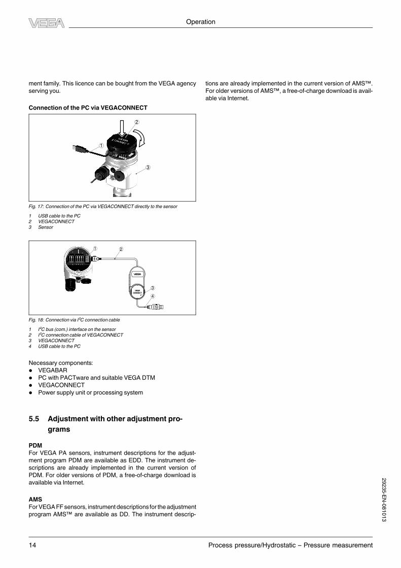
Connection of the PC via VEGACONNECT
3
1
2
Fig. 17: Connection of the PC via VEGACONNECT directly to the sensor
1 USB cable to the PC
2 VEGACONNECT
3 Sensor
1 2
3
4
OPEN
TWIST
USB
LOCK
Fig. 18: Connection via I²C connection cable
1 I²C bus (com.) interface on the sensor
2 I²C connection cable of VEGACONNECT
3 VEGACONNECT
4 USB cable to the PC
Necessary components:
l VEGABAR
l PC with PACTware and suitable VEGA DTM
l VEGACONNECT
l Power supply unit or processing system
5.5 Adjustment with other adjustment pro-
grams
PDM
For VEGA PA sensors, instrument descriptions for the adjust-
ment program PDM are available as EDD. The instrument de-
scriptions are already implemented in the current version of
PDM. For older versions of PDM, a free-of-charge download is
available via Internet.
AMS
ForVEGAFF sensors, instrumentdescriptions for theadjustment
program AMS™ are available as DD. The instrument descrip-
tions are already implemented in the current version of AMS™.
For older versions of AMS™, a free-of-charge download is avail-
able via Internet.
Operation
14 Process pressure/Hydrostatic – Pressure measurement
29235-EN-081013

6 Technical data
General data
Common data
316L corresponds to 1.4404 or 1.4435
Materials, non-wetted parts
- Electronics housing Plastic PBT (polyester), Alu die-casting powder-coated, 316L
- External electronics housing plastic PBT (Polyester)
- Socket, wall mounting plate external electronics housing plastic PBT (Polyester)
- Seal between housing socket and wall mounting plate TPE (fixed connected)
- Seal, housing cover NBR (stainless steel housing), silicone (Alu/plastic housing)
- Inspection window in housing cover for indicating and adjust-
ment module
Polycarbonate (UL-746-C listed)
- Ground terminal 316Ti/316L
- Connectionbetween IP 68 transmitter andexternal electronics
housing
PUR, FEP, PE
- Type plate support with IP 68 version on cable PE hard
VEGABAR 61
Materials, wetted parts
- Process fitting 316L
- Diaphragm 316L, Hastelloy C276, Hastelloy C2, Tantalum, Titanium, PTFE on 316Ti
(1.4571)
Weight approx. 0.8 … 8 kg (1.8… 17.6 lbs), depending on the housing material and
process fitting
VEGABAR 63
Materials, non-wetted parts
- Internal transmission liquid Synthetic oil, Halocarbon oil2)3)
Materials, wetted parts
- Process fitting 316Ti
- Diaphragm standard 316Ti
- Diaphragm frommeasuring range25bar,withnotflushversion Elgiloy 2.4711
- Seal ring, O-ring FKM (VP2/A), EPDM (A+P 75.5/KW75F), NBR (COG), FFKM (Chem-
raz 535)
Weight approx. 0.8 … 8 kg (1.8… 17.6 lbs), depending on the housing material and
process fitting
VEGABAR 64
Materials, wetted parts
- Process fitting 316L, PVDF, PVDF plated, Hastelloy C4 plated
- Diaphragm sapphire ceramic® (99.9 % oxide ceramic)
- Measuring cell seal FKM (VP2/A), FFKM (Kalrez 6375), EPDM (A+P 75.5/KW75F), FFKM
(Chemraz 535), FFKM (FDA/3A)
- Seal, process fitting thread G1½ A Klingersil C-4400
Weight approx. 0.8 … 8 kg (1.8… 17.6 lbs), depending on the housing material and
process fitting
VEGABAR 65
Materials, non-wetted parts
Isolating liquid Essomarcal (med. white oil, FDA-approved)
Materials, wetted parts
- Process fitting 316L
- Process diaphragm Hastelloy C276, gold-coated, gold/rhodium-coated
- Process seal other hygienic fittings EPDM: Version up to 140 °C (284 °F)
FKM (Viton): Version up to 180/200 °C (356/392 °F)
- Process seal hygienic fitting with compression nut FEP-O-Seal
- Seal, process fitting thread G1½ A Klingersil C-4400
Weight approx. 0.8 … 8 kg (1.8… 17.6 lbs), depending on the housing material and
process fitting
Technical data
Process pressure/Hydrostatic – Pressure measurement 15
2)Synthetic oil for measuring ranges up to 16 bar, FDA listed for the food processing industry. For measuring ranges up to 25 bar dry measuring
cell.3)
Halocarbon oil: Generally in oxygen applications, not with vacuum measuring ranges, not with absolute measuring ranges < 1 barabs.29235-EN-081013

Technical data
16 Process pressure/Hydrostatic – Pressure measurement
Output variable
4… 20mA/HART
Output signal 4… 20mA/HART
Signal resolution 1.6 µA
Failure signal Current output unchanged 20.5 mA, 22 mA, < 3.6 mA (adjustable)
Max. output current 22mA
Load see load diagram under Power supply
Damping 0… 999 s, adjustable
Step response or adjustment time 150ms (ti: 0 s, 0 … 100%)
Fulfilled NAMUR recommendations NE 43
Profibus PA
Output signal digital output signal, format according to IEEE-754
- Sensor address 126 (default setting)
Current value constantly 10 mA, ±1mA
Integration time 0… 999 s, adjustable
Foundation Fieldbus
Output
- Signal digital output signal, Foundation Fieldbus protocol
- Physical layer according to IEC 61158-2
Channel Numbers
- Channel 1 Primary Value
- Channel 2 Secondary Value 1
- Channel 3 Secondary Value 2
- Channel 4 Temperature Value
Current value 10mA, ±0.5 mA
Dynamic behaviour output
Run-up time approx. 10 s
90 %
100 %
10 %
t tT At
tS
21
Fig. 19: Sudden change of the process variable, dead time tT, rise time tA and step response time tS
1 Process variable
2 Output signal
Dead time ≤ 150ms
Rise time ≤ 100ms (10 … 90 %)
Step response time ≤ 250ms (ti: 0 s, 10 … 90%)
To this amounts the reaction time of the isolatng system. This time varies from values < 1 s with compact isolating diaphragms up to several
seconds with capillary systems.
Example: Flange isolating diaphragm DN 80, filling silicone oil KN 2.2, capillary length 10m,measuring range 1 bar
29235-EN-081013

Technical data
Process pressure/Hydrostatic – Pressure measurement 17
Process temperature Reaction time
40 °C approx. 2 s
20 °C approx. 3 s
-20 °C approx. 11 s
Damping (63% of the input variable) 0… 999 s, adjustable
Additional output variable, temperature (VEGABAR 64, 66)
Processing is made via HART multidrop, Profibus PA and Foundation Fieldbus
Range -50… +150 °C (-58… +302 °F)
Resolution 1 °C (1.8 °F)
Accuracy
- in the range of 0 … +100 °C (+32 … +212 °F) ±3 K
- in the range of -50… 0 °C (-58… +32 °F) and +100… +150 °C
(+212… +302 °F)
typ. ±4 K
Input variable
Measured value Process pressure
Measuring range see product code
Recommended max. turn down
- Standard version 1 : 10 (no limitation)
- Climate compensated version 1 : 5 (no limitation)
Reference conditions and actuating variables (similar to DIN EN 60770-1)
Reference conditions according to DIN EN 61298-1
- Temperature +18… +30 °C (+64 … +86 °F)
- Relative humidity 45… 75%
- Air pressure 860… 1060 mbar/86 … 106 kPa (12.5 … 15.4 psig)
Determination of characteristics limit point adjustment according to DIN 16086
Characteristics curve linear
Calibration position upright, diaphragm points downward
Influence of the installation position
- VEGABAR 66 < 0.2 mbar/20 Pa (0.003 psig)
- VEGABAR 67 < 5mbar/0.5 kPa (0.07 psig)
Deviation determined according to the limit point method according to IEC 607704)
Applies todigital interfaces (HART,ProfibusPA,FoundationFieldbus)aswell as toanalogue current output4…20mA.Specifications refer to
the set span. Turn down (TD) = nominal measuring range/set span.
VEGABAR 61
Deviation
- Turn down 1 : 1 up to 5 : 1 < 0.1 %
- Turn down > 5 : 1 < 0.02 % x TD
VEGABAR 63
Deviation
- Turn down 1 : 1 up to 5 : 1 < 0.1 %
- Turn down > 5 : 1 < 0.02 % x TD
VEGABAR 64
Deviation
- Turn down 1 : 1 up to 5 : 1 < 0.075%
- Turn down > 5 : 1 < 0.015% x TD
Deviation with absolutely flush process fittings EV, FT
- Turn down 1 : 1 up to 5 : 1 < 0.05 %
- Turn down > 5 : 1 < 0.01 % x TD
4)Incl. non-linearity, hysteresis and non-repeatability.2
9235-EN-081013

Technical data
18 Process pressure/Hydrostatic – Pressure measurement
VEGABAR 64 - climate compensated
Deviation < (0.05 + 0.025 x TD)%
VEGABAR 65
Deviation
- Turn down 1 : 1 up to 5 : 1 < 0.075%
- Turn down > 5 : 1 < 0.015% x TD
Influence of the product or ambient temperature VEGABAR 61, 63
Applies todigital interfaces (HART,ProfibusPA,FoundationFieldbus)aswell as toanalogue current output4…20mA.Specifications refer to
the set span. Turn down (TD) = nominal measuring range/set span.
Thermal change zero zignal, reference temperature 20 °C (68 °F):
- In the compensated temperature range 0 … +100 °C
(+32… +212 °F)
< 0.05 %/10 K
- Outside the compensated temperature range typ. < 0.05%/10 K
Applies also to the analogue 4 … 20 mA current output and refers to the set span.
Thermal change, current output < 0.15 % at -40… +80 °C (-40 … +176 °F)
Influence of the product or ambient temperature VEGABAR 64, 65
Applies todigital interfaces (HART,ProfibusPA,FoundationFieldbus)aswell as toanalogue current output4…20mA.Specifications refer to
the set span. Turn down (TD) = nominal measuring range/set span.
Thermal change zero signal and output span, reference temperature 20 °C (68 °F):
- In the compensated temperature range 0 … +100 °C
(+32… +212 °F)
< (0.05% + 0.1% x TD)
- Outside the compensated temperature range < (0.05% + 0.15% x TD)
Thermal change zero signal and output span with absolute pressure measuring range 0.1 bar, reference temperature 20 °C (68 °F):
- In the compensated temperature range 0 … +100 °C
(+32… +212 °F)
< (0.1 % + 0.1 % x TD)
- Outside the compensated temperature range < (0.15% + 0.15% x TD)
Applies also to the analogue 4 … 20 mA current output and refers to the set span.
Thermal change, current output < 0.15 % at -40… +80 °C (-40 … +176 °F)
Long-term stability (similar to DIN 16086, DINV 19259-1 and IEC 60770-1)
Applies todigital interfaces (HART,ProfibusPA,FoundationFieldbus)aswell as toanalogue current output4…20mA.Specifications refer to
the set span. Turn down (TD) = nominal measuring range/set span.
Long-term drift of the zero signal < (0.1 % x TD)/year
Ambient conditions
Ambient, storage and transport temperature
- without PLICSCOM -40… +80 °C (-40… +176 °F)
- with PLICSCOM -20… +70 °C (-4 … +158 °F)
- IP 66/IP 68 and IP 68 version with PE connection cable -40… +60 °C (-40… +140 °F)
29235-EN-081013
Technical data
Process pressure/Hydrostatic – Pressure measurement 19
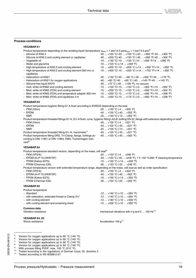
Process conditions
VEGABAR 61
Product temperature depending on the isolating liquid (temperature: pabs > 1 bar/14.5 psi/pabs < 1 bar/14.5 psi)5)
- silicone oil KN2.2 -40… +150 °C/-40 … +150 °C (-40… +302 °F/-40… +302 °F)
- Silicone oil KN2.2 and cooling element or capillaries -40… +200 °C/-40 … +150 °C (-40… +392 °F/-40… +302 °F)
- Vegetable oil -10… +130 °C/-10 … +130 °C (14… +266 °F/14… +266 °F)
- Water and glycerine -10… +120 °C (+14 … +248 °F)
- High temperature oil KN3.2 and cooling element -10… +200 °C/-10 … +200 °C (+14… +392 °F/+14… +392 °F)
- High temperature oil KN3.2 and cooling element 300mm or
capillaries
-10… +400 °C/-10 … +200 °C (+14… +752 °F/+14… +392 °F)
- Halocarbon oil KN21 -40… +150 °C/-40 … +80 °C (-40 … +302 °F/-40… +176 °F)
- Halocarbon oil KN21 for oxygen applications -40… +60 °C/-40… +60 °C (-40… +140 °F/-40 … +140 °F)
- Silicone-free liquid KN70 -40… +70 °C (-40… +158 °F), no vacuum
- med. white oil KN62 and cooling element -15… +150 °C/-15 … +150 °C (+5… +302 °F/+10 … +302 °F)
- Med. white oil KN62 (FDA) and cooling element -15… +200 °C/-15 … +150 °C (+5… +392 °F/+10 … +302 °F)
- Med. white oil KN62 (FDA) and temperature adapter 300mm -15… +250 °C/-15 … +170 °C (+5… +482 °F/+10 … +338 °F)
- Med. white oil KN62 (FDA) and capillaries 3 m -15… +250 °C/-15 … +170 °C (+5… +482 °F/+10 … +338 °F)
VEGABAR 63
Product temperature hygienic fittingG1 A flush according to EHEDG depending on the seal
- FKM (Viton) -20… +150 °C (-4… +302 °F)
- EPDM -40… +150 °C (-40… +302 °F)
- NBR -25… +150 °C (-13… +302 °F)
Product temperature threaded fittingsG1 A,G½ A flush, cone, hygienic fitting LA/LB, boltingDN 32, flange with extension depending on seal6)
- FKM (Viton) -20… +105 °C (-4… +221 °F)
- EPDM -40… +105 °C (-40… +221 °F)
- NBR -25… +105 °C (-13… +221 °F)
Product temperature threaded fittingG½ A, manometer7)
-40… +105 °C (-40… +221 °F)
Product temperature fitting DRD, Tri-Clamp, flange, boltings ac-
cording to DIN 11851 or DIN 11864, SMS, Tuchenhagen Vari-
vent8)
-40… +150 °C (-40… +302 °F)
VEGABAR 64
Product temperature standard version, depending on the meas. cell seal9)
- FKM (VP2/A) -20… +120 °C (-4… +248 °F)
- EPDM (A+P 75.5/KW75F) -40… +120 °C (-40… +248 °F), 1 h: 140 °C/284 °F cleaning temperature
- FFKM (Kalrez 6375) -10… +120 °C (+14 … +248 °F)
- FFKM (Chemraz 535) -30… +120 °C (-22… +248 °F)
Product temperature version with extended temperature range, depending on the meas. cell seal as well as order specification
- FKM (VP2/A) -20… +150 °C (-4… +302 °F)
- EPDM (A+P 75.5/KW75F) -40… +150 °C (-40… +302 °F)
- FFKM (Kalrez 6375) -10… +150 °C (+14 … +302 °F)
- FFKM (Chemraz 535) -30… +150 °C (-22… +302 °F)
VEGABAR 65
Product temperature
- Standard -12… +140 °C (+10 … +284 °F)
- with extenation, extended thread or Clamp 2½" -12… +140 °C (+10 … +284 °F)
- with cooling element -12… +180 °C (+10 … +356 °F)
- with cooling element and screening sheet -12… +200 °C (+10 … +392 °F)
Common data
Vibration resistance mechanical vibrations with 4 g and 5 … 100 Hz10)
VEGABAR 64, 65
Shock resistance Acceleration 100 g11)
5)Version for oxygen applications up to 60 °C (140 °F).
6)Version for oxygen applications up to 60 °C (140 °F).
7)Version for oxygen applications up to 60 °C (140 °F).
8)Version for oxygen applications up to 60 °C (140 °F).
9)With process fitting PVDF, max. 100 °C (212 °F).
10)Tested according to the regulations of German Lloyd, GL directive 2.
11)Tested according to EN 60068-2-27.2
9235-EN-081013
Technical data
20 Process pressure/Hydrostatic – Pressure measurement
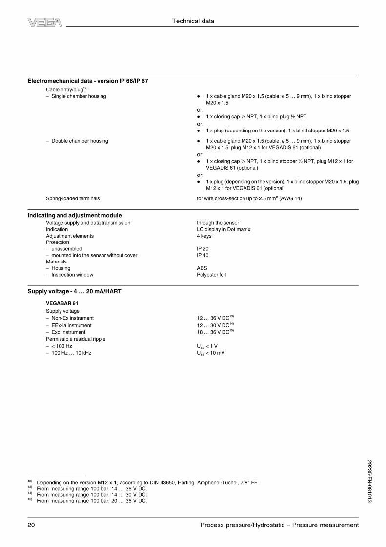
Electromechanical data - version IP 66/IP 67
Cable entry/plug12)
- Single chamber housing l 1 x cable glandM20 x 1.5 (cable: ø 5… 9 mm), 1 x blind stopper
M20 x 1.5
or:l 1 x closing cap½ NPT, 1 x blind plug½ NPT
or:l 1 x plug (depending on the version), 1 x blind stopperM20 x 1.5
- Double chamber housing l 1 x cable glandM20 x 1.5 (cable: ø 5… 9 mm), 1 x blind stopper
M20 x 1.5; plugM12 x 1 for VEGADIS 61 (optional)
or:l 1 x closing cap½ NPT, 1 x blind stopper½ NPT, plugM12 x 1 for
VEGADIS 61 (optional)
or:l 1 x plug (depending on the version), 1 x blind stopperM20 x 1.5; plug
M12 x 1 for VEGADIS 61 (optional)
Spring-loaded terminals for wire cross-section up to 2.5mm² (AWG 14)
Indicating and adjustmentmodule
Voltage supply and data transmission through the sensor
Indication LC display in Dot matrix
Adjustment elements 4 keys
Protection
- unassembled IP 20
- mounted into the sensor without cover IP 40
Materials
- Housing ABS
- Inspection window Polyester foil
Supply voltage - 4… 20mA/HART
VEGABAR 61
Supply voltage
- Non-Ex instrument 12… 36 V DC13)
- EEx-ia instrument 12… 30 V DC14)
- Exd instrument 18… 36 V DC15)
Permissible residual ripple
- < 100 Hz Uss < 1 V
- 100 Hz … 10 kHz Uss < 10mV
12)Depending on the version M12 x 1, according to DIN 43650, Harting, Amphenol-Tuchel, 7/8" FF.
13)From measuring range 100 bar, 14 … 36 V DC.
14)From measuring range 100 bar, 14 … 30 V DC.
15)From measuring range 100 bar, 20 … 36 V DC.
29235-EN-081013
Technical data
Process pressure/Hydrostatic – Pressure measurement 21
1000
750
500
250
12 181614 20 22 24 26 28 30 32 34 36
Ω
V
4
12
3
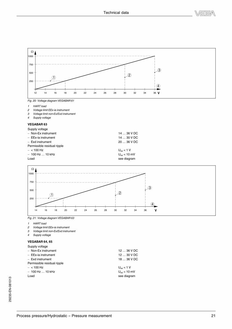
Fig. 20: Voltage diagram VEGABAR 61
1 HART load
2 Voltage limit EEx-ia instrument
3 Voltage limit non-Ex/Exd instrument
4 Supply voltage
VEGABAR 63
Supply voltage
- Non-Ex instrument 14… 36 V DC
- EEx-ia instrument 14… 30 V DC
- Exd instrument 20… 36 V DC
Permissible residual ripple
- < 100 Hz Uss < 1 V
- 100 Hz … 10 kHz Uss < 10mV
Load see diagram
1000
750
500
250
14 1816 20 22 24 26 28 30 32 34 36
Ω
V
4
12
3
Fig. 21: Voltage diagram VEGABAR 63
1 HART load
2 Voltage limit EEx-ia instrument
3 Voltage limit non-Ex/Exd instrument
4 Supply voltage
VEGABAR 64, 65
Supply voltage
- Non-Ex instrument 12… 36 V DC
- EEx-ia instrument 12… 30 V DC
- Exd instrument 18… 36 V DC
Permissible residual ripple
- < 100 Hz Uss < 1 V
- 100 Hz … 10 kHz Uss < 10mV
Load see diagram
29235-EN-081013

Technical data
22 Process pressure/Hydrostatic – Pressure measurement
1000
750
500
250
12 181614 20 22 24 26 28 30 32 34 36
Ω
V
4
12
3
Fig. 22: Voltage diagram VEGABAR 64, 65
1 HART load
2 Voltage limit EEx-ia instrument
3 Voltage limit non-Ex/Exd instrument
4 Supply voltage
Voltage supply - Profibus PA
Supply voltage
- Non-Ex instrument 9… 32 V DC
- EEx-ia instrument 9… 24 V DC
Power supply by/max. number of sensors
- DP/PA segment coupler max. 32 (max. 10 with Ex)
- VEGALOG 571 EP card max. 15 (max. 10 with Ex)
Power supply - Foundation Fieldbus
Supply voltage
- Non-Ex instrument 9… 32 V DC
- EEx-ia instrument 9… 24 V DC
Power supply by/max. number of sensors
- H1 Fieldbus cable/Voltage supply max. 32 (max. 10 with Ex)
Electrical protective measures
Protection
- Housing, standard IP 66/IP 6716)
- Aluminium and stainless housing (optionally available) IP 66/IP 68 (1 bar)17)
- Transmitter in IP 68 version IP 68
- External housing IP 65
Overvoltage category III
Protection class II
16)Instruments with gauge pressure measuring ranges cannot detect the ambient pressure when submerged, e.g. in water. This can lead to
falsification of the measured value.17)
Only with instruments with absolute pressure ranges.
29235-EN-081013

Technical data
Process pressure/Hydrostatic – Pressure measurement 23
Existing approvals or approvals applied for18)19)
Approvals
- ATEX ia ATEX II 1G, 1/2G, 2G EEx ia IIC T6
- ATEX ia, ATEX d ATEX II 1/2G, 2G EEx d ia IIC T6
- ATEX D ATEX II 1/2D, 2D IP6X T, ATEX II 1/2/-D IP6X T
- ATEX na ATEX 3G EEx na II T5 … T1 X
- FM NI FM(NI) CL I, Div2, GP ABCD (DIP)CL II, III, DIV1, GP EFG
- FM IS FM(IS) CL I, II, III, DIV1, GP ABCDEFGF
- FM XP-IS FM(XP-IS) CL I, II, III, DIV1, GP ABCDEFGFG
- CSA NI CSA(NI) CL I, Div2, GP ABCD (DIP)CL II, III, DIV1, GP EFG
- CSA IS CSA(IS) CL I, II, III, DIV1, GP ABCDEFGFG
- CSA XP-IS CSA(XP-IS) CL I, II, III, DIV1, GP ABCDEFGFG
- Ship approval GL, LRS, ABS, CCS, RINA, DNV
- Others WHG, VLAREM
CE conformity
2004/108/EG (EMC) EN 61326-1: 2006, Emission: Class A, susceptibility: Industrial areas
2006/95/EG (LVD) EN 61010-1: 2001
Functional safety (SIL)
You can find detailled information in the supplementary instructions manual "Functional safety VEGABAR series 50 and 60" or under www.
vega.com.
Functional safety according to IEC 61508-4/61511
- Single channel architecture (1oo1D) up to SIL2
- Double channel architecture (1oo2D) up to SIL3
Environmental instructions
VEGA environment management system certified according to DIN EN ISO 14001
You can find detailed information under www.vega.com.
18)Deviating data in Ex applications: see separate safety instructions.
19)Depending on order specification.2
9235-EN-081013

Dimensions
24 Process pressure/Hydrostatic – Pressure measurement
7 Dimensions
Housing in protection IP 66/IP 67
~ 69 mm
(2 23/32") ø 77 mm
(3 1/32")
11
2 m
m (
4 1
3/ 3
2")
M20x1,5/
½ NPT
~ 69 mm
(2 23/32")ø 77 mm
(3 1/32")
11
7 m
m (
4 3
9/ 6
4")
M20x1,5/
½ NPT
~ 87 mm (3 27/64")
M16x1,5
ø 84 mm
(3 5/16")
12
0 m
m (
4 2
3/ 3
2")
M20x1,5/
½ NPT
~ 116 mm (4 9/16")
ø 84 mm (3 5/16")
11
6 m
m (
4 9
/ 16")
M20x1,5M20x1,5/
½ NPT
~ 59 mm
(2 21/64")ø 80 mm
(3 5/32")
11
2 m
m (
4 1
3/ 3
2")
M20x1,5/
½ NPT
1 3 4
5
2
Fig. 23: Housing versions in protection IP 66/IP 67 (with integrated indicating and
adjustment module the housing is 9mm/0.35 in higher)
1 Plastic housing
2 Stainless steel housing
3 Special steel casting housing
4 Aluminium double chamber housing
5 Aluminium housing
Housing in protection IP 66/IP 68, 1 bar
11
7m
m (
4 3
9/ 6
4")
12
0m
m (
4 2
3/ 3
2")
~ 103mm
(4 1/16")~ 105mm (4 9/64")
ø 77mm
(3 1/32")
11
6m
m (
4 9
/ 16")
~ 150mm (5 29/32")
ø 84mm (3 5/16")
ø 84mm
(3 5/16")
~ 93 mm
(3 21/32")ø 80 mm
(3 5/32")
11
2 m
m (
4 1
3/ 3
2")
M20x1,5/
½ NPT
M20x1,5
M20x1,5/
½ NPT
M16x1,5
1 2 3
M20x1,5M20x1,5
4
Fig. 24: Housing versions in protection IP 66/IP 68, 1 bar (with integrated indicating
and adjustment module the housing is 9mm/0.35 in higher)
1 Stainless steel housing
2 Special steel casting housing
3 Aluminium double chamber housing
4 Aluminium housing
IP 68 version with external housing
1
2
65 mm
(2 9/16")
68
mm
(2 4
3/ 6
4")
92
mm
(3 5
/ 8")
42mm
(1 21/32")
40mm
(1 37/64")
90 mm (3 35/64")
110 mm (4 21/64")
~ 66 mm (2 19/32")
59
mm
(2
21/ 6
4")
Fig. 25: Transmitter and external housing with IP 68 version
1 Lateral cable outlet
2 Axial cable outlet
VEGABAR 61 - flange fitting
d2
d4 k D
f
EB, FR, FB, FC, FHF1, F5, FS
d5
RL
1
22
mm
FD, FE, FG, FJ, FK F7, FQ
51
b
12
2 m
m
6"
5"
6"
3 5/8"
7 1/2"
1/8"
1/8"
4xø 5/8"
4xø 5/8"
4 3/4"
6 6
3/4"
3 7/8" 1/8" 4xø 5/8" 3 7/8" 3/4"
3 5/8" 1/8"4xø 5/8"4 3/4"3/4"
3/4"
7 1/2" 1/8"4xø 5/8"6 63/4"
DN PN D k b
FR 25 40 115 22 85
FB 40 40 150 18 110
FC 50 40 165 20 125
d2
4xø14
4xø18
4xø18
d4
68
68
102
f
2
3
3
FK 80 40 200 24 160 8xø18 138 3
FD 50 40 165 20 125
FG 50 40 165 20 125
FH 80 40 200 24 160
4xø18
4xø18
8xø18
102
102
138
3
3
3
RL
-
-
-
100
50
200
-
d5
-
-
-
76
48,3
48,3
-
dM
-
-
-
72
F1 1" 150
FJ 80 40 200 24 160 8xø18 138 3 50 76 72
- - -
- - -
F5 2" 150
6" 3 5/8" 1/8"4xø 5/8"4 3/4"3/4"1/2"EB 1 150
" lbs D b k d2 d4 f RL d5 dM
- - -
F7 2" 150 2" 1,9" -
FS 3" 150 - - -
FQ 3" 150 6" 2,9" -
47
FE 50 40 165 20 125 4xø18 102 3 100 48,3 47
47
-
3
3 1
2
Fig. 26: VEGABAR 61 - flange version
1 Flange connection according to DIN 2501
2 Flange fitting according to ANSI B16.5
3 Diaphragm diameter
29235-EN-081013
Dimensions
Process pressure/Hydrostatic – Pressure measurement 25
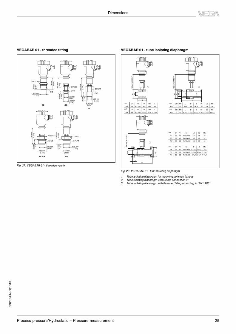
VEGABAR 61 - threaded fitting
SW32SW41
SW55 SW55
G¾B
G1B
1½”NPTG1½B
ø 22 mm
(0.87")
ø 32 mm
(1.26")
20
mm
(0.7
9")
~1
05
mm
(4.1
3")
~1
05
mm
(4.7
2")
~1
05
mm
(4.1
3")
~1
20
mm
(4.7
2")
ø 25 mm
(0.98")
ø 39 mm
(1.54")
28
mm
(1.1
")
ø 40 mm
(1.58")
ø 60 mm
(2.36")
30
mm
(1.1
8")
ø 40 mm
(1.58")
ø 60 mm
(2.36")
30
mm
(1.1
8")
GB
GC
GD/GF GN
SW 41 mm
G1B
76
mm
(2.9
9")
28
mm
(1.1
")
GE
ø 30 mm
(1.18")
Fig. 27: VEGABAR 61 - threaded version
VEGABAR 61 - tube isolating diaphragm
4 31/64" 1 13/16" 1 1/32"
5 33/64" 2 3/64" 1 17/64"
6 9/64" 2 3/4" 1 31/32"
DNmm PN G1 D2L2
RT 25 40 Rd52x1,6
Rd58x1,6
Rd78x1,6
G1
Rd52x1,6
Rd58x1,6
Rd78x1,6
114 46
Mb
26
RQ 32 40 140 52 32
RW 50 25 156 70 50
DNinch PN dD
RH 25 40
RH 32 40
RH 50 25
Mb
2 23/64"1 1/8"2 31/64"
DN PN D LMb
RA 25 6... 400
DNmm
inch
PN D LMb
RA 25 6…400 63 28,5 60
6 9/64" 2 33/64" 2 7/32" 2 13/64" 2 61/64" 1 57/64"
DNmm PN L dD
RH 2“ 40 156 64 56,3
D2D1
56 75
Mb
48
DNinch PN L dD
RH 2“ 40
D2D1 Mb
10
6 m
m (
4 1
1/6
4")
3
2
D Mb
L
D d Mb
D2
D1
L
Mb
D2
L2
g
G1
1
10
6 m
m (
4 1
1/6
4")
10
6 m
m (
4 1
1/6
4")
Fig. 28: VEGABAR 61 - tube isolating diaphragm
1 Tube isolating diaphragm for mounting between flanges
2 Tube isolating diaphragmwith Clamp connection 2"
3 Tube isolating diaphragmwith threaded fitting according to DIN 11851
29235-EN-081013
Dimensions
26 Process pressure/Hydrostatic – Pressure measurement
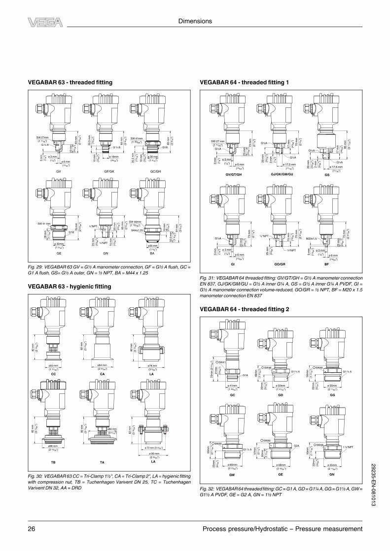
VEGABAR 63 - threaded fitting
23
mm
(29/ 3
2")G ½ A
G ½ B
63
mm
(2 3
1/ 6
4")
65
mm
(2 9
/ 16")
G1B
65
mm
(2 9
/ 16")
20
,5 m
m
(13/ 1
6")
10
mm
(25/ 6
4")
20
,5 m
m
(13/ 1
6")
10
mm
(25/ 6
4")
3 m
m
(1/ 8
") ø 3 mm
(1/8")ø 6 mm
(15/64")
ø 18mm
(45/64")
ø35 mm
(1 3/8")
½“NPT
¼“NPT
65
mm
(2 9
/ 16")
81
mm
(3 3
/ 16")
25
mm
(63/ 6
4")
15
mm
(19/ 3
2")
20
mm
(25/ 3
2")
32
,5 m
m
(1 9
/ 32")
10
mm
(25/ 6
4")SW 41 mm
G1BM44x1,257
6 m
m
(2 6
3/ 6
4")
28
mm
(1 7
/ 64")
ø 30 mm
(1 3/16")
GN BAGE
GV GF/GK GC/GH
SW 27mm
(1 1/16")SW 41mm
(1 39/64")
SW 46mm
(1 13/16")
ø 30mm
(1 3/16")
Fig. 29: VEGABAR 63GV =G½ Amanometer connection,GF =G½ A flush,GC =
G1 A flush, GS= G½ A outer, GN = ½ NPT, BA = M44 x 1.25
VEGABAR 63 - hygienic fitting
LA
ø78 mm
(3 5/64")
82
mm
(3 1
5/ 6
4")
LA
ø 90 mm
(3 35/64")
82
mm
(3 1
5/ 6
4")
CA
ø64 mm
(2 33/64")
ø84 mm
(3 5/16")
ø66 mm
(2 19/32")
82
mm
(3 1
5/ 6
4")
CC
TATB
ø50 mm
(1 31/32")
82
mm
(3 1
5/ 6
4")
82
mm
(3 1
5/ 6
4")
82
mm
(3 1
5/ 6
4")
ø 72 mm (3 53/64")
Fig. 30: VEGABAR63CC = Tri-Clamp 1½",CA = Tri-Clamp 2", LA = hygienic fitting
with compression nut, TB = Tuchenhagen Varivent DN 25, TC = Tuchenhagen
VariventDN 32, AA = DRD
VEGABAR 64 - threaded fitting 1
GI GO/GR
GV/GT/GH
BF
GSGJ/GK/GM/GU
G½A
G¼A
G½A
G¼A
G½A½"NPT
M20x1,5
SW 27 mm
(1 1/16")
G½A
23
mm
(29/ 3
2")
73
mm
(2 7
/ 8")
70
mm
(2 3
/ 4")
17
mm
(43/ 6
4")
85
mm
(3 1
1/ 3
2")
17
mm
(43/ 6
4")
3 m
m
(1/ 8
")
20
mm
(25/ 3
2")
15
mm
(19/ 3
2")
3 m
m
(1/ 8
")
20
mm
(25/ 3
2")
2 m
m
(5/ 6
4")
ø 3 mm
(1/8") ø 6 mm
(15/64")
25
mm
(63/ 6
4")
75
mm
(2 6
1/ 6
4")
5 m
m
(13/ 6
4")
ø 3 mm
(1/8") ø 6 mm
(15/64")
25
mm
(63/ 6
4")
73
mm
(2 7
/ 8")
75
mm
(2 6
1/ 6
4")
ø 3 mm
(1/8") ø 6 mm
(15/64")
ø 17,5 mm
(11/16")ø 17,5 mm
(11/16")
23
mm
(29/ 3
2")
3 m
m
(1/ 8
") ¼"NPT
Fig. 31: VEGABAR 64 threaded fitting: GV/GT/GH = G½ Amanometer connection
EN 837, GJ/GK/GM/GU = G½ A inner G¼ A, GS = G½ A inner G¼ A PVDF, GI =
G½ A manometer connection volume-reduced, GO/GR = ½ NPT, BF = M20 x 1.5
manometer connectionEN 837
VEGABAR 64 - threaded fitting 2
SW41
SW46
SW46SW55
G1A
G1 ½ AG1 ¼ A
1 ½”NPTG1 ½ A
G2A
21
mm
(53/ 6
4")
75
mm
(2
61/ 6
4")
50
mm
(1 3
1/ 3
2")
50
mm
(1 3
1/ 3
2")
55
mm
(2 1
1/ 6
4")
22
mm
(55/ 6
4")
SW46
48
mm
(1 5
7/ 6
4")
20
mm
(25/ 3
2")
22
mm
(55/ 6
4")
25
mm
(63/ 6
4")
ø 41mm
(1 39/64")
ø 55mm
(2 11/64")
ø 50mm
(1 31/32")
ø 55mm
(2 11/64")
SW60
57
mm
(2 1
/ 4")
30
mm
(1 3
/ 16")
ø 68mm
(2 43/64")
ø 60mm
(2 23/64")
GG
GE GN
GC GD
GW
Fig.32: VEGABAR64 threadedfitting:GC=G1A,GD=G1¼A,GG=G1½A,GW=
G1½ A PVDF, GE = G2 A, GN = 1½ NPT
29235-EN-081013
Dimensions
Process pressure/Hydrostatic – Pressure measurement 27
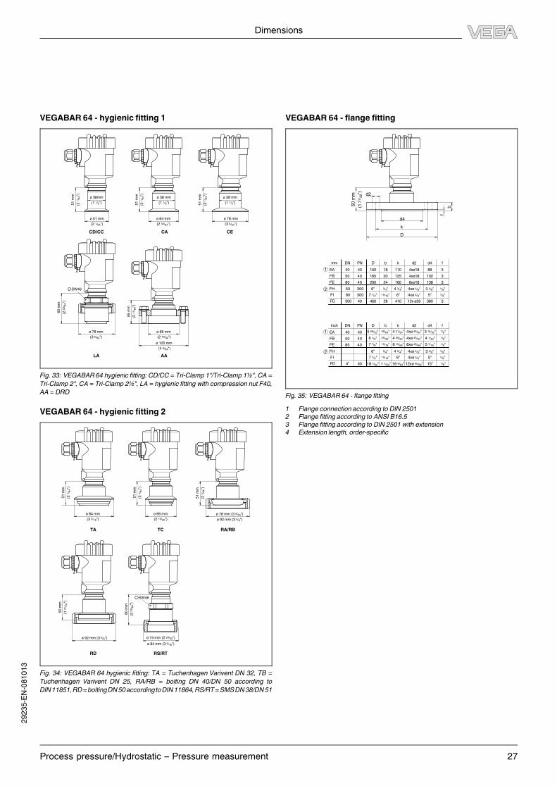
VEGABAR 64 - hygienic fitting 1
SW46
51
mm
(2 1
/ 64")
51
mm
(2 1
/ 64")
51
mm
(2 1
/ 64")
60
mm
(2 2
3/ 6
4")
ø 64 mm
(2 33/64")
ø 51 mm
(2 1/64")
ø 78 mm
(3 5/64")
ø 78 mm
(3 5/64")
55
mm
(2 1
1/ 6
4")
ø 66 mm
(2 19/32")
ø 105 mm
(4 9/64")
CACD/CC
AA
CE
LA
ø 38mm
(1 1/2")
ø 38 mm
(1 1/2")
ø 38 mm
(1 1/2")
Fig. 33: VEGABAR 64 hygienic fitting: CD/CC = Tri-Clamp 1"/Tri-Clamp 1½", CA =
Tri-Clamp 2", CA = Tri-Clamp 2½", LA = hygienic fitting with compression nut F40,
AA = DRD
VEGABAR 64 - hygienic fitting 2
SW46
50
mm
(1 3
1/ 3
2")
51
mm
(2 1
/ 64")
60
mm
(2 2
3/ 6
4")
51
mm
(2 1
/ 64")
51
mm
(2 1
/ 64")
ø 78 mm (3 5/64")
ø 92 mm (3 5/8")
ø 92 mm (3 5/8") ø 74 mm (2 29/32")
ø 84 mm (3 5/16")
ø 84 mm
(3 5/16")
ø 66 mm
(2 19/32")
TA TC RA/RB
RS/RTRD
Fig. 34: VEGABAR 64 hygienic fitting: TA = Tuchenhagen Varivent DN 32, TB =
Tuchenhagen Varivent DN 25, RA/RB = bolting DN 40/DN 50 according to
DIN11851,RD=boltingDN50accordingtoDIN11864,RS/RT=SMSDN38/DN51
VEGABAR 64 - flange fitting
3 15/32"
4 1/64"
5 7/16"
1/8"
1/8"
1/8"
4xø 45/64"
4xø 45/64"
8xø 45/64"
4 21/64"
4 59/64"
6 19/64"
5 29/32"
6 1/2"
7 7/8"
45/64"
25/32"
15/16"
15” 1/8"12xø 45/64"16 9/64"1 7/64"18 7/64"
DNmm PN D kb
EA 40 40 150 18 110
FB 50 40 165 20 125
d2
4xø18
4xø18
d4
88
102
f
3
3
FE
FH
FI
80 40 200 24 160 8xø18 138 3
80 300
50 300
1
2
7 1/2" 1/8"4xø 5/8"6“ 5“
3 5/8" 1/8"4xø 5/8"4 3/4"3/4"
15/16"
6"
FD 300 40 460 28 410 12x ø26 380 3
DNinch PN D kb
EA 40 40
FB 50 40
d2 d4 f
FE
FH
FI
80 40
1
2
7 1/2" 1/8"4xø 5/8"6“ 5“
3 5/8" 1/8"4xø 5/8"4 3/4"3/4"
15/16"
6"
FD 4” 40
d4
k
d2
D
f
b50
mm
(1 3
1/ 3
2")
Fig. 35: VEGABAR 64 - flange fitting
1 Flange connection according to DIN 2501
2 Flange fitting according to ANSI B16.5
3 Flange fitting according to DIN 2501 with extension
4 Extension length, order-specific
29235-EN-081013
Dimensions
28 Process pressure/Hydrostatic – Pressure measurement
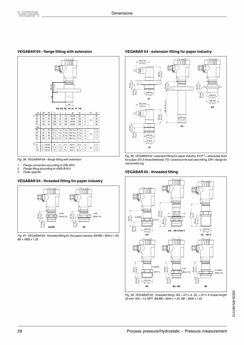
VEGABAR 64 - flange fitting with extensionR
L5
0 m
m
(1 3
1/ 3
2")
d5
7 1/2"
3 15/32"
4 1/64"
5 7/16"
1/8"
1/8"
1/8"
4xø 45/64"
4xø 45/64"
8xø 45/64"
4 21/64"
4 59/64"
6 19/64"
7 3/32"
5 29/32"
6 1/2"
7 7/8"
45/64"
25/32"
15/16"
EB 40 40
ED 50 40
EE 80 40
6 7/32" 1/8"8xø 45/64"8 21/32" 25/32"TK 100 16
1 1/2"
1 1/2"
1 1/2"
1 1/2"
1 1/2"
1 1/2"
1 1/2"
DNmm
inch
PN D kb d2 d4 f RL d5
EB 40 40 150 18 110
ED
EE
50 40 165 20 125
4xø18
4xø18
88
102
3
3
TK 100 16 220 20 180 8xø18 158 3
80 40 200 24 160 8xø18 138 3
38
38
38
38
1
3
3
IH
TW
2“ 150 lbs
4“ 150 lbs
TV 3“ 150 lbs
2
36 3/16"9" 1/8"4xø 3/4"
3 5/8" 1/8"4xø 3/4"4 3/4"3/4"
15/16"
7 1/2" 1/8"4xø 3/4"6“ 5“15/16"
6"
EB, ED, EE, TK, IH, TV, TW
Fig. 36: VEGABAR 64 - flange fitting with extension
1 Flange connection according to DIN 2501
2 Flange fitting according to ANSI B16.5
3 Order-specific
VEGABAR 64 - threaded fitting for paper industry
52
mm
(2 3
/ 64")
21
mm
(53/ 6
4")
46
M44x1,25
60
M56x1,25
52
mm
(2 3
/ 64")
21
mm
(53/ 6
4")
BA/BB BE
Fig. 37: VEGABAR64 - threaded fitting for the paper industry:BA/BB =M44 x 1.25;
BE =M56 x 1.25
VEGABAR 64 - extension fitting for paper industry
15
8 m
m (
6 7
/ 32")
40
mm
(1 3
7/ 6
4")
ø 38 mm
(1 1/2")
43
mm
(1 1
1/ 1
6")
23
mm
(29/ 3
2")
ø 48 mm
(1 57/64")
52
mm
(2 3
/ 64")
24
mm
(15/ 1
6")
ø 48 mm
(1 57/64")
ø 59 mm
(2 21/64")
68
mm
(2 4
3/ 6
4")
64,5 mm
(2 35/64")
43
mm
(1 1
1/ 1
6")
23
mm
(29/ 3
2")
ø 48 mm
(1 57/64")
50 mm
(1 31/32")
68
mm
(2 4
3/ 6
4")
64,5 mm
(2 35/64")
FG
FT
EV
EW
Fig. 38: VEGABAR64 - extensionfitting for paper industry:EV/FT = absolutelyflush
for pulper (EV2-times flattened),FG= extension for ball valve fitting,EW= flange for
manometer lug
VEGABAR 65 - threaded fitting
GG GL - 180°C
GN
GG - 180°C/200°C
BA / BB BE
78
mm
(3 5
/ 64") 11
8 m
m
(4 4
1/ 6
4")
46
mm
(1 1
3/ 1
6")
11
1 m
m
(4 3
/ 8")
55
mm
(2 1
1/ 6
4")
22
mm
(55/ 6
4")
ø 55 mm
(2 11/64")
ø 55 mm
(2 11/64")
78
mm
(3 5
/ 64")
22
mm
(55/ 6
4")
ø 55 mm
(2 11/64")
ø 84 mm
(3 5/16")
G1½A
SW46
SW46
NPT1½ M44x1,25
46
M56x1,25
SW60
78
mm
(3 5
/ 64")
21
mm
(53/ 6
4")
78
mm
(3 5
/ 64")
21
mm
(53/ 6
4")
Fig. 39: VEGABAR 65 - threaded fitting: GG = G1½ A, GL = G1½ A thread length
55mm, GN = 1½ NPT, BA/BB =M44 x 1.25; BE =M56 x 1.25
29235-EN-081013

Dimensions
Process pressure/Hydrostatic – Pressure measurement 29
VEGABAR 65 - hygienic fitting 1
78
mm
(3 5
/ 64")
78
mm
(3 5
/ 64")
ø 64 mm
(2 33/64")
78
mm
(3 5
/ 64")
ø 91 mm
(3 37/64")
ø 78 mm
(3 5/64") ø 85 mm
(3 11/32")
ø 73 mm
(2 7/8")
78
mm
(3 5
/ 64")
LA
CA/CF CB
SBSA
Fig. 40: VEGABAR65 - hygienic fitting:CA/CF = Tri-Clamp 2"/Tri-Clamp 2½",CB =
Tri-Clamp3",LA= hygienicfittingwith compressionnutF40,SA=SMSDN 38,SB=
SMS DN 51
VEGABAR 65 - hygienic fitting 2
78
mm
(3 5
/ 64")
78
mm
(3 5
/ 64")
78
mm
(3 5
/ 64")
78
mm
(3 5
/ 64")
ø 66 mm
(2 19/32")
ø 105 mm
(4 9/64")
ø 78 mm (3 5/64")
ø 92 mm (3 5/8")
ø 84 mm
(3 5/16")
ø 60 mm
(2 23/64")
78
mm
(3 5
/ 64")
ø 64 mm
(2 33/64")
AA
TA
KA TS
RV / RW
Fig. 41: VEGABAR65 - hygienicfitting: TA= TuchenhagenVariventDN 32,RV/RW
= bolting DN 40/DN 50 according to DIN 11851, AA = DRD, KA = conus DN 40
29235-EN-081013

Product code
30 Process pressure/Hydrostatic – Pressure measurement
8 Product code
VEGABAR 61
Approval
XX without
XM Ship approval
CX ATEX II 1G, 1/2G, 2G EEx ia IIC T6
CA ATEX II 1G, 1/2G, 2G EEx ia IIC T6 + WHG
CM ATEX II 1G, 1/2G, 2G EEx ia IIC T6 + Ship approval
DX ATEX II 1/2G, 2G EEx d ia IIC T6 1)
GX ATEX II 1/2D,2D IP6X T
UX FM(NI)CL I,DIV2,GP ABCD (DIP)CL II,III,DIV1,GP EFG
UF FM(IS)CL I,II,III, DIV 1,GP ABCDEF
Process fitting / Material
FR Flange DN25PN40 Form D, DIN2501 / 316L
FC Flange DN50PN40 Form D, DIN2501 / 316L
FD Flange DN50PN40 with extension 50mm/ø48.5 / 316L
FH Flange DN80PN40 Form D, DIN2501 / 316L
FJ Flange DN80PN40 with extension 50mm/ø74 / 316L
F1 Flange 1" 150lb RF, ANSI B16.5 / 316L
F5 Flange 2" 150lb RF, ANSI B16.5 / 316L
F7 Flange 2" 150lb RF, ANSI w. extension 2"/ø1.9" / 316L
FS Flange 3" 150lb RF, ANSI B16.5 / 316L
FQ Flange 3" 150lb RF, ANSI w.extens. 6"/ø2.9" / 316L
RA Tube isolator f.mounting betw.flanges DN25 / 316L
RH Tube isolator with clamp connector 2" / 316L
RT Bolting DN25PN40, DIN11851 / 316L
RQ Bolting DN32PN40, DIN11851 / 316L
RW Bolting DN50PN25, DIN11851 / 316L
Isolating liquid / Temperature
A Silicone oil KN2.2 / -40...150°C(Pabs <1bar-40...150°C)
C Silic. oil KN2.2+cool./-40..200°C(Pabs <1bar-40..150°C)
G High-temp.oil+cooling/-10..300°C(Pabs<1bar-10..+200°C)
H High-temp.oil+capil.1m/-10..400°C(Pabs<1bar-10..+200°C)
I Halocarbon oil / -40...150°C (Pabs<1bar -40...+80°C)
J Silicone-free liquid KN70 / -40...70°C (no vacuum)
M Med.white oil KN62/-15..150°C(Pabs<1bar-15..150°C)
R Med.white oil+cool.KN62 -15..200°C(Pabs<1bar-15..150°C)
Diaphragm material
1 316L
2 Hastelloy C276
5 Tantalum 2)
7 PTFE 3)
8 1.4435 with gold coating (25µm)
Pressure / Measuring range
C rel. / 0...0.4 bar (0...40 kPa)
D rel. / 0...1 bar (0...100 kPa)
E rel. / 0...2.5 bar (0...250 kPa)
W rel. / 0...100 bar (0...10000 kPa)
J rel. / 0...250 bar (0...10000 kPa)
F rel. / 0...5 bar (0...500 kPa)
G rel. / 0...10 bar (0...1000 kPa)
T rel. / 0...25 bar (0...2500 kPa)
N rel. / 0...60 bar (0...6000 kPa)
P rel. / -1...0 bar (-100...0 kPa)
Q rel. / -1...1.5 bar (-100...150 kPa)
R rel. / -1...5 bar (-100...500 kPa)
S rel. / -1...10 bar (-100...1000 kPa)
H rel. / -1...25 bar (-100...2500 kPa)
V rel. / -1...60 bar (-100...6000 kPa)
M rel. / -0.2...0.2 bar (-20...20 kPa)
O rel. / -0.5...0.5 bar (-50...50 kPa)
1 abs. / 0...1 bar (0...100 kPa) 4)
2 abs. / 0...2.5 bar (0...250 kPa) 4)
3 abs. / 0...5 bar (0...500 kPa) 4)
4 abs./ 0...10 bar (0...1000 kPa) 4)
5 abs. / 0...25 bar (0...2500 kPa) 4)
Electronics
H 4...20mA/HART®
P Profibus PA
F Foundation Fieldbus
Housing / Protection
K Plastic / IP66/IP67
A Aluminium / IP66/IP67
D Aluminium double chamber / IP66/IP67
8 Stainless steel (electropolished) 316L / IP66/IP68
T PE-cable axial IP68, ext. housing plastic IP65 5)
Cable entry / Plug connection
M M20x1.5 / without
N ½NPT / without
Indicating/adjustment module (PLICSCOM)
X Without
A Top mounted
BR61.
1)Only in conjunction with Housing / Protection "D"
2)Only with flange version
3)Max. product temperature 200°C
4)A vacuum service is carried out automatically for all absolute pressure measuring ranges
5)incl. wall and rail mounting set
VEGABAR 63
Approval
XX without
XM Ship approval
CX ATEX II 1G, 1/2G, 2G EEx ia IIC T6
CM ATEX II 1G, 1/2G, 2G EEx ia IIC T6 + ship approval
DX ATEX II 1/2G, 2G EEx d ia IIC T6 1)
GX ATEX II 1/2D,2D IP6X T
Process fitting / Material
GV G½A, manometer connection EN837 PN160 / 316L
GF G½A, front-flush / 316Ti with O-ring from 2.5bar
GC G1A, front-flush / 316Ti with O-ring up to 1.6bar
GN Thread ½NPT/316Ti
CC Tri-Clamp 1½" PN16 / 316L
CA Tri-Clamp 2" PN16 / 316L
LA Hyg. fitting with compression nut F40 PN40 / 316L
RA Bolting DN40PN40 DIN11851 / 316L
RC Bolting DN40PN40 DIN11864 / 316L
RB Bolting DN50PN25 DIN11851 / 316L
RD Bolting DN50PN25 Form A DIN11864 / 316L
AA DRD PN40 / 316L
EA Flange DN40PN40 Form C, DIN2501 / 316L
FB Flange DN50PN40 Form C, DIN2501 / 316L
FM Flange DN80PN64 Form C,DIN2501/316L
Seal
1 FKM (Viton) 2)
3 EPDM 2)
4 NBR 2)
X without
R Chemraz
Pressure / Meas. range
C rel. / 0...0.4bar (0...40kPa)
D rel. / 0...1.6bar (0...160kPa)
U rel. / 0...40.0bar (0...4000kPa)
W rel. / 0...100.0bar (0...10000kPa)
X rel. / 0...250.0bar (0...25000kPa)
R rel. / -1...0.0bar (-100...0kPa)
S rel. / -1...0.6bar (-100...60kPa)
O rel. / -1...3.0bar (-100...300kPa)
P rel. / -1...5.0bar (-100...500kPa)
Q rel. / -1...15.0bar (-100...1500kPa)
Z rel. / 0...600.0bar (0...60000kPa)
1 abs. / 0...0.4bar (0...40kPa)
2 abs. / 0...1.6bar (0...160kPa)
3 abs. / 0...6.0bar (0...600kPa)
4 abs. / 0...16.0bar (0...1600kPa)
Electronics
H 4...20mA/HART®
P Profibus PA
F Foundation Fieldbus
Housing / Protection
K Plastic / IP66/IP67
A Aluminium / IP66/IP67
D Aluminium double chamber / IP66/IP67
8 Stainless steel (electropolished) 316L / IP66/IP68
T PE-cable axial IP68, ext. housing plastic IP65 3)
Cable entry / Plug connection
M M20x1.5 / without
N ½NPT / without
Indicating/adjustment module (PLICSCOM)
X Without
A Top mounted
BR63.
1)Only in conjunction with Housing / Protection "D"
2)Only with front-flush threaded version
3)incl. wall and rail mounting set
29235-EN-081013

Process pressure/Hydrostatic – Pressure measurement 31
VEGABAR 64
Approval
XX without
XM Ship approval
CX ATEX II 1G, 1/2G, 2G EEx ia IIC T6
CA ATEX II 1G, 1/2G, 2G EEx ia IIC T6 + WHG
CM ATEX II 1G, 1/2G, 2G EEx ia IIC T6 + Ship approval
DX ATEX II 1/2G, 2G EEx d ia IIC T6 1)
GX ATEX II 1/2D,2D IP6X T
UX FM(NI)CL I,DIV2,GP ABCD (DIP)CL II,III,DIV1,GP EFG
UF FM(IS)CL I,II,III, DIV 1,GP ABCDEF
Process fitting / Material
GV G½A, manometer connection EN837 PN160 / 316L
GH G½A, manometer connection / Hastelloy
GJ G½A, inner G¼A, PN160 / 316L
GS G½A, inner G¼A, PN10 / PVDF
GM G½A,inner G¼A,PN160/Hastelloy C276
GG Thread G1½A PN60 / 316L
GW Thread G1½A PN10 / PVDF
GN Thread 1½NPT PN60 / 316L
GO ½NPT, inner ¼NPT, PN160 / 316L
GR ½NPT, inner ¼NPT, PN160 / Hastelloy
CA Tri-Clamp 2" PN16 / 316L
LA Hyg.connection w. compression nut F40 PN40 / 316L
TA Varivent N50-40 PN25 / 316L
RA Bolting DN40PN40 DIN11851 / 316L
RC Bolting DN40PN25 DIN11864 ZG2820/316L
RB Bolting DN50PN25 DIN11851 / 316L
RD Bolting DN50PN25 Form A DIN11864 / 316L
RS SMS DN38 PN40 / 316L
AA DRD PN40 / 316L
BA M44x1.25; pressure screw Alu PN25 / 316L
BB M44x1.25; pressure screw PN60 / 316L
SL Small flange DN10 PN1.5 DIN 28403-ISO2861/316L
EA Flange DN40PN40 Form C, DIN2501 / 316L
FW Flange DN50PN16 / PVDF
FB Flange DN50PN40 Form C,DIN2501 / 316L
TR Flange with extens.DN50PN40 ZG2659,316L
FE Flange DN80PN40 Form C, DIN2501 / 316L
FM Flange DN80PN64 Form C,DIN2501/316L
EV For headbox 2-fold flat-topped ZG2819/316L
FQ Flange 1½"150lb RF,ANSI B16.5/316L
FH Flange 2" 150lb RF, ANSI B16.5 / 316L
FI Flange 3" 150lb RF, ANSI B16.5 / 316L
Seal measuring cell / Process temperature
1 FKM (Viton)
2 Kalrez 6375
3 EPDM
R Chemraz 535
Pressure / Measuring range
A rel. / 0...0.1bar (0...10kPa)
B rel. / 0...0.2bar (0...20kPa)
C rel. / 0...0.4bar (0...40kPa)
D rel. / 0...1.0bar (0...100kPa)
E rel. / 0...2.5bar (0...250kPa)
F rel. / 0...5.0bar (0...500kPa)
G rel. / 0...10.0bar (0...1000kPa)
H rel. / 0...25.0bar (0...2500kPa)
U rel. / 0...60.0bar (0...6000kPa)
P rel. / -1...0.0bar (-100...0kPa)
Q rel. / -1...1.5bar (-100...150kPa)
R rel. / -1...5.0bar (-100...500kPa)
S rel. / -1...10.0bar (-100...1000kPa)
T rel. / -1...25.0bar (-100...2500kPa)
W rel. / -1...60.0bar (-100...6000kPa)
K rel. / -0.05...0.05bar (-5...5kPa)
L rel. / -0.1...0.1bar (-10...10kPa)
M rel. / -0.2...0.2bar (-20...20kPa)
O rel. / -0.5...0.5bar (-50...50kPa)
I abs. / 0...0,1bar (0...10kPa) 2)
1 abs. / 0...1.0bar (0...100kPa)
2 abs. / 0...2.5bar (0...250kPa)
3 abs. / 0...5.0bar (0...500kPa)
4 abs. / 0...10.0bar (0...1000kPa)
5 abs. / 0...25.0bar (0...2500kPa)
Electronics
H 4...20mA/HART®
P Profibus PA
F Foundation Fieldbus
Housing / Protection
K Plastic / IP66/IP67
A Aluminium / IP66/IP67
D Aluminium double chamber / IP66/IP67 .
8 Stainless steel (electropolished) 316L / IP66/IP68
T PE cable axial IP68, ext. housing plastic IP65 3)
Cable entry / Plug connection
M M20x1.5 / without
N ½NPT / without
Indicating/adjustment module (PLICSCOM)
X Without
A Top mounted
BR64.
1)Only in conjunction with Housing / Protection "D"
2)Deviation in characteristic 0.25%
3)incl. wall and rail mounting set
VEGABAR 65
Approval
XX without
XM Ship approval
CX ATEX II 1G, 1/2G, 2G EEx ia IIC T6
CA ATEX II 1G, 1/2G, 2G EEx ia IIC T6 + WHG
CM ATEX II 1G, 1/2G, 2G EEx ia IIC T6 + Ship approval
DX ATEX II 1/2G, 2G EEx d ia IIC T6 1)
GX ATEX II 1/2D,2D IP6X T
UX FM(NI)CL I,DIV2,GP ABCD (DIP)CL II,III,DIV1,GP EFG
UF FM(IS)CL I,II,III, DIV 1,GP ABCDEF
Process fitting / Material
FB Flange DN40PN40 Form C, DIN2501 / 316L
FC Flange DN50PN40 Form C, DIN2501 / 316L
TR Flange with extens.DN50PN40 ZG2873,316L
FH Flange DN80PN40 Form C, DIN2501 / 316L
F5 Flange 2" 150lb RF, ANSI B16.5 / 316L
GG Thread G1½A PN60 / 316L
GN Thread 1½NPT PN60 / 316L
CA Tri-Clamp 2" PN16 / 316L
LA Hygienic connec. w. compression nut F40PN40 / 316L
TA Varivent N50-40 PN25 / 316L
RV Bolting DN40PN40, DIN11851 / 316L
RW Bolting DN50PN25, DIN11851 / 316L
AA DRD PN40 / 316L
BB M44x1.25 with pressure screw 316L PN60 / 316L
SB SMS DN51 PN6 / 316L
Isolating liquid / Temperature
M Med.white oil/ -12...140°C (Pabs<1bar-12..130°C)
N Med.white oil/ -12...120°C (Pabs<1bar-12..1120°C )
S Med.w.oil,cool./-12..180°C(Pabs <1bar -12..130°C)
R Med.w.oil,cool./-12..200°C(Pabs <1bar -12..130°C)
Pressure / Measuring range
A rel. / 0...0.1bar (0...10kPa)
B rel. / 0...0.2bar (0...20kPa)
C rel. / 0...0.4bar (0...40kPa)
D rel. / 0...1.0bar (0...100kPa)
E rel. / 0...2.5bar (0...250kPa)
F rel. / 0...5.0bar (0...500kPa)
G rel. / 0...10.0bar (0...1000kPa)
T rel. / 0...25.0bar (0...2500kPa)
P rel. / -1...0.0bar (-100...0kPa)
Q rel. / -1...1.5bar (-100...150kPa)
R rel. / -1...5.0bar (-100...500kPa)
S rel. / -1...10.0bar (-100...1000kPa)
H rel. / -1...25.0bar (-100...2500kPa)
K rel. / -0.05...0.05bar (-5...5kPa)
L rel. / -0.1...0.1bar (-10...10kPa)
M rel. / -0.2...0.2bar (-20...20kPa)
O rel. / -0.5...0.5bar (-50...50kPa)
1 abs. / 0...1.0bar (0...100kPa)
2 abs. / 0...2.5bar (0...250kPa)
3 abs. / 0...5.0bar (0...500kPa)
4 abs. / 0...10.0bar (0...1000kPa)
5 abs. / 0...25.0bar (0...2500kPa)
Electronics
H 4...20mA/HART®
P Profibus PA
F Foundation Fieldbus
Housing / Protection
K Plastic / IP66/IP67
A Aluminium / IP66/IP67
D Aluminium double chamber / IP66/IP67
8 Stainless steel (electropolished) 316L / IP66/IP68
T PE-cable axial IP68, ext. housing plastic IP65 2)
Cable entry / Plug connection
M M20x1.5 / without
N ½NPT / without
Indicating/adjustment module (PLICSCOM)
X Without
A Top mounted
BR65.
1)Only in conjunction with Housing / Protection "D"
2)incl. wall and rail mounting set
29235-EN-081013
VEGA Grieshaber KG
Am Hohenstein 113
77761 Schiltach
Germany
Phone +49 7836 50-0
Fax +49 7836 50-201
E-Mail: [email protected]
www.vega.com
You can find at www.vega.com
downloads of the following
l operating instructions manuals
l menu schematics
l software
l certificates
l approvals
and much, much more
Subject to change without prior notice 29235-EN-081013
Related Documents