PROCESS MODELS FOR A NEW CONTROL EDUCATION LABORATORY P. Kl´ an *,1 , M. Hofreiter ** , J. Mach´ aˇ cek *** , O. Modrl´ ak **** , L. Smutn´ y † , V. Vaˇ sek ‡ * Institute of Computer Science, Pod vod´arenskou veˇ z´ ı 2, 182 07 Prague 8, Czech Rep. ** Czech Technical University – Fac. of Machinery, Technick´a 4, 166 07 Prague 6, Czech Rep. *** University of Pardubice – Fac. of Chemical Technology, N´am. ˇ Cs. legi´ ı 565, 532 10 Pardubice, Czech Rep. **** Technical University of Liberec – Fac. of Mechatronics, H´alkova 6, 461 17 Liberec, Czech Rep. † Technical University of Ostrava – Fac. of Mechanical engineering, 17. listopadu 15, 708 33 Ostrava, Czech Rep. ‡ University of T. Ba ˇ ta – Fac. of Technology, Mostn´ ı 5139, 762 72 Zlˇ ın, Czech Rep. Abstract: Process models for a new self–contained laboratory for training and education of control have been designed. Models are considered to be connected to the MATLAB through universal data acquisition instrument called CTRL. The latter was developed together with the models to enable realization of control experiments in a comfortable computer processing and visualization environment. The paper focuses on a short conceptual description of each model, together with the expected educational benefits. Furthermore, at the final part of the paper, the CTRL instrument is shortly presented. Copyright c 2005 IFAC Keywords: Process models; Laboratory equipment; Process control experiments; Control education 1. INTRODUCTION Control engineering is a wide range area that absorbs innovative approaches and methods (Dorf and Bishop 1998). Study of engineering systems requires to use a multidisciplinary approach. It often crosses the traditional boundaries of en- gineering. Control engineers have to understand engineering and scientific principles together with 1 Corresponding author. Tel.: +420-266053850; fax.: +420-286585789; e-mail: [email protected]. This research is supported by the Grant agency of the Czech rep. via project 102/03/0625 and via the institutional project AV0Z10300504. their application, experience and technological significance. It includes knowledge of modelling real processes as a prerequisite in design of control systems (Bissell 1998, Hor´aˇ cek 2000, Kheir 1996). Excellent laboratory systems are essential for the communication of this knowledge; both as a mech- anism and as an example to expand engineer- ing experience and an intuitive grasp of effective methods (P.L. Lee and Shastri 2003). Experimen- tal modelling in laboratories presents the most difficulties when first encountered with plenty of practical aspects (Jovan and Petrovcic 1996).

Welcome message from author
This document is posted to help you gain knowledge. Please leave a comment to let me know what you think about it! Share it to your friends and learn new things together.
Transcript

PROCESS MODELS FOR A NEW CONTROLEDUCATION LABORATORY
P. Klan ∗,1, M. Hofreiter ∗∗, J. Machacek ∗∗∗,O. Modrlak ∗∗∗∗, L. Smutny †, V. Vasek ‡
∗ Institute of Computer Science, Pod vodarenskou vezı 2,182 07 Prague 8, Czech Rep.
∗∗ Czech Technical University – Fac. of Machinery,Technicka 4, 166 07 Prague 6, Czech Rep.
∗∗∗University of Pardubice – Fac. of Chemical Technology,Nam. Cs. legiı 565, 532 10 Pardubice, Czech Rep.
∗∗∗∗ Technical University of Liberec – Fac. of Mechatronics,Halkova 6, 461 17 Liberec, Czech Rep.
† Technical University of Ostrava – Fac. of Mechanicalengineering, 17. listopadu 15, 708 33 Ostrava, Czech Rep.‡University of T. Bata – Fac. of Technology, Mostnı 5139,
762 72 Zlın, Czech Rep.
Abstract: Process models for a new self–contained laboratory for training andeducation of control have been designed. Models are considered to be connectedto the MATLAB through universal data acquisition instrument called CTRL. Thelatter was developed together with the models to enable realization of controlexperiments in a comfortable computer processing and visualization environment.The paper focuses on a short conceptual description of each model, together withthe expected educational benefits. Furthermore, at the final part of the paper, theCTRL instrument is shortly presented. Copyright c©2005 IFAC
Keywords: Process models; Laboratory equipment; Process control experiments;Control education
1. INTRODUCTION
Control engineering is a wide range area thatabsorbs innovative approaches and methods (Dorfand Bishop 1998). Study of engineering systemsrequires to use a multidisciplinary approach. Itoften crosses the traditional boundaries of en-gineering. Control engineers have to understandengineering and scientific principles together with
1 Corresponding author. Tel.: +420-266053850; fax.:+420-286585789; e-mail: [email protected]. This researchis supported by the Grant agency of the Czech rep.via project 102/03/0625 and via the institutional projectAV0Z10300504.
their application, experience and technologicalsignificance. It includes knowledge of modellingreal processes as a prerequisite in design of controlsystems (Bissell 1998, Horacek 2000, Kheir 1996).Excellent laboratory systems are essential for thecommunication of this knowledge; both as a mech-anism and as an example to expand engineer-ing experience and an intuitive grasp of effectivemethods (P.L. Lee and Shastri 2003). Experimen-tal modelling in laboratories presents the mostdifficulties when first encountered with plenty ofpractical aspects (Jovan and Petrovcic 1996).
Looking through the proceedings of IFAC Sym-posia concerning control education, one may wit-ness many changes but also similarities in buildingcontrol laboratories. There are rapid changes insoftware tools used for process monitoring, sim-ulation, control algorithm design and implemen-tation. More and more university and researchlaboratories use MATLAB. Much effort has beenspent in many labs over the world developing real–time software for enabling MATLAB to work inreal time and to have an access to the real world(Horacek 2000).
What does not change much, are the laboratoryexperiments or the experimental models in par-ticular. Moreover, although the present industrialcontrollers mostly use PI or PID control algo-rithms, experimental modelling gives chance forintroduction of recent results into real practice.Experimental models allow to train modern con-trol methods safely, and are not too far fromreal conditions. However, getting an experimentalmodel should be either long–term or expensivething.
Therefore, the authors have concatenated theirpotential by setting up an open scientific–researchconsortium. Principal task of each consortiummember is to design, develop and make one phys-ical model that reflects the reality of real pro-cesses given by static and dynamic characteristics.Contribution of this arrangement can be seen insubstantial savings of both time and money and inobtaining more experimental models at the sametime. Developed models allow us to introducemodern self–contained laboratories in locationswhere the authors work.
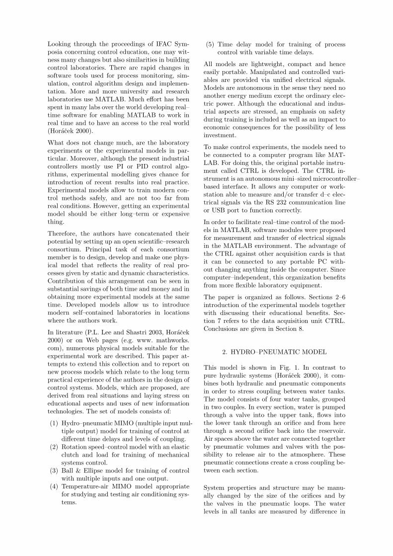
In literature (P.L. Lee and Shastri 2003, Horacek2000) or on Web pages (e.g. www. mathworks.com), numerous physical models suitable for theexperimental work are described. This paper at-tempts to extend this collection and to report onnew process models which relate to the long termpractical experience of the authors in the design ofcontrol systems. Models, which are proposed, arederived from real situations and laying stress oneducational aspects and uses of new informationtechnologies. The set of models consists of:
(1) Hydro–pneumatic MIMO (multiple input mul-tiple output) model for training of control atdifferent time delays and levels of coupling.
(2) Rotation speed–control model with an elasticclutch and load for training of mechanicalsystems control.
(3) Ball & Ellipse model for training of controlwith multiple inputs and one output.
(4) Temperature-air MIMO model appropriatefor studying and testing air conditioning sys-tems.
(5) Time delay model for training of processcontrol with variable time delays.
All models are lightweight, compact and henceeasily portable. Manipulated and controlled vari-ables are provided via unified electrical signals.Models are autonomous in the sense they need noanother energy medium except the ordinary elec-tric power. Although the educational and indus-trial aspects are stressed, an emphasis on safetyduring training is included as well as an impact toeconomic consequences for the possibility of lessinvestment.
To make control experiments, the models need tobe connected to a computer program like MAT-LAB. For doing this, the original portable instru-ment called CTRL is developed. The CTRL in-strument is an autonomous mini–sized microcontroller–based interface. It allows any computer or work-station able to measure and/or transfer d–c elec-trical signals via the RS 232 communication lineor USB port to function correctly.
In order to facilitate real–time control of the mod-els in MATLAB, software modules were proposedfor measurement and transfer of electrical signalsin the MATLAB environment. The advantage ofthe CTRL against other acquisition cards is thatit can be connected to any portable PC with-out changing anything inside the computer. Sincecomputer–independent, this organization benefitsfrom more flexible laboratory equipment.
The paper is organized as follows. Sections 2–6introduction of the experimental models togetherwith discussing their educational benefits. Sec-tion 7 refers to the data acquisition unit CTRL.Conclusions are given in Section 8.
2. HYDRO–PNEUMATIC MODEL
This model is shown in Fig. 1. In contrast topure hydraulic systems (Horacek 2000), it com-bines both hydraulic and pneumatic componentsin order to stress coupling between water tanks.The model consists of four water tanks, groupedin two couples. In every section, water is pumpedthrough a valve into the upper tank, flows intothe lower tank through an orifice and from herethrough a second orifice back into the reservoir.Air spaces above the water are connected togetherby pneumatic volumes and valves with the pos-sibility to release air to the atmosphere. Thesepneumatic connections create a cross coupling be-tween each section.
System properties and structure may be manu-ally changed by the size of the orifices and bythe valves in the pneumatic loops. The waterlevels in all tanks are measured by difference in

Fig. 1. Hydro–pneumatic model.
pressure sensors. Pressures in pneumatic volumes,atmospheric pressure and inlet water pressure aremeasured too.
The model as an object of control is sketched inFig. 2. It has two outputs (water levels in lowertanks - y1, y2) and three inputs (two valves forwater inlets u1, u2 and pump power u3). Blocksare organized as follows:
G1 – left–side upper water tank,G2 – right–side upper tank,G3 – left–side bottom water tank,G4 – right–side bottom water tank,G5 – upper pneumatic volume,G6 – bottom pneumatic volume,G7 – air chamber.
All blocks represent nonlinear behavior associatedwith nonlinear differential equations of the firstorder. Seven measured state variables (4 levels- x1, x2, x3 = y1, x4 = y2 and 3 pressures x5,x6, x7) are available for identification and controlpurposes. Relatively complicated inner structureof this system may be interpreted as two sym-metrical coupling loops with derivative behavior.Interactions between both hydraulic parts are pre-sented in transition states only. They are elimi-nated in the stable conditions.
It gives a variety of control possibilities for thismodel, for example:
• SISO control loops such as the control oflevel in lower tanks, left or right, with openpneumatic loops.
• MIMO control (three inputs, two outputs) oflevels in lower tanks, where the pneumaticloops are connected.
Fig. 2. Block diagram of the hydro-pneumaticsystem.
3. ROTATION SPEED–CONTROL MODEL
This model is shown in Fig. 3. It enables rotationspeed control of an industrial DC–motor with theload and elastic clutch. It consists of a DC–motorwith load and measuring devices. A dynamo, thatcan be brought into an effect, creates the loaddisturbance. The latter is signalized by lights. Theload is connected with the DC–motor by a clutchwhich can introduce elastic or coupling muff.There are possibilities to use two types of elasticclutches that differ in their static characteristics: aclutch with a watch spiral or with a rubber cable.The measure device is the speedometer which iscalibrated by an incremental speed sensor.
Fig. 3. Rotation speed–control model.
The system has approximately linear characteris-tics in the operating range with oscillating move-ment in output if the elastic clutch is used, orthe output is over damped, if the coupling muffis used. A block diagram of this system for thecontrol purposes is shown in Fig. 4.
Pedagogical facilities for control methods trainingwith this plant include:
• Creating a mathematical model of the plantbased on the physical analysis. Verification ofthis model.
• Design of rotation speed or position con-troller (PID, state–space and fuzzy control).
• Control and measure from a WWW basedremote computer.

Fig. 4. A block scheme of the Rotation speed–control model.
4. BALL & ELLIPSE
The laboratory model Ball & Ellipse is shown inFig. 5 in the form, which is lightweight, compactand hence easily portable. It consists of an ellipsepivoted in its center in such a way, that its tiltcan be controlled in two perpendicular directions.Two servomotors are used for tilting the ellipse.A steel ball rolls freely on two parallel tensionedresistance wires, which have an elliptic contour.The ball works as the sliding contact of a poten-tiometer. The position of the metal ball is sensedby a transducer.
Fig. 5. Ball & Ellipse model.
From a control point of view, the Ball & Ellipsesystem is a dynamic system with two inputs andone output as shown in Fig. 6. A basic goal is tocontrol positions of the ball rolling on the ellipserailway. In fact, it relates to control problemsassociated with unstable non–linear systems. Awide range of control experiments include:
• Direct derivation of a mathematical model ofthe apparatus using physical laws.
• Linearization and simplification of the math-ematical model for given control purposes.
• System identification and model validation.• Stabilization and trajectory tracking of the
ball position via PID controller design.• LQ/LQG controller design based on a state–
space model.
• Fuzzy, adaptive or nonlinear controller de-sign.
u1: position of servomotor 1 y: ball position
Laboratory model
“Ball & Ellipse”u2: position of servomotor 2
Fig. 6. Ball & Ellipse block configuration.
5. TEMPERATURE AIR MODEL
The model called Hot-Air Aggregate (HAA) isa physical model of air-conditioning as shownin Fig. 7. There are the source of heat air (thesmall bulb) with quick dynamic response and twoventilators as the sources of air flow. Together inthe model, there are six transducers measuringthe temperature of hot air flow at three differentpositions from the bulb, two flow meters (propellerturbine and thermo anemometer) for volume flowmeasurement and one photo resistor sensor ofbulb luminance.
The HAA model is a dynamic system with twoinputs and two outputs. The two basic controlledinputs (action values) are the power of the bulband other one power to the main fan (ventilator).Measured outputs there are a temperature fromone of the temperature transducers (by this posi-tion the time delay of the system is changed) byone of flow meters (with quick or slow response).As a disturbance it can use the secondary fan withopposite air flow direction (the complementaryaction value).
This HAA model is used to train:
• MIMO control (temperature and air flow)with adjusted disturbances.
• Robustness of control via changes in workingpoint. It influences time constants of tran-sient responses (typical control task takes 2or 3 minutes).
• Nonlinear control given by built in nonlinear-ities.
6. TIME DELAY MODEL
The model of a heat-interchanging system (shownin Fig. 8) serves for training of systems with a timedelay. The time delay is realized by measuringthe temperature of the media at several places inthe interconnecting pipeline. Maximal value of thetime delay is 7 minutes.
The model contains a safe hot water source withelectric heating and thermostat-based regulationin the range between 30 and 85◦C. Hot water istransported by a variable-speed pump into the in-terconnecting pipeline ending in a heat exchanger.

Fig. 7. Temperature air model of air-conditioning.
The pipeline is connected through an intercept-ing valve, where the flow is divided between thepipeline and a reversing coupler. The pipelineitself is composed of several meanders where itis possible to place thermometers and thus toobtain various values of the time delay. The timedelay can also be affected by changing the speedof the pump and position of the valve. The heatexchanger makes it possible to establish variableheat dissipation. It creates a disturbance.
Fig. 8. Time delay model.
A principal scheme of the plant with the time de-lay setting possibilities and general transfer func-tion is shown in Fig. 9. Algorithms for identifi-cation and control of the temperature in definedlocation (indicating different time delays) are welltrained using this model. It mainly includes:
• Control of processes with substantial timedelays.
• Robustness of control for variable time de-lays.
• Identification of time delays.
Fig. 9. Time delay model by a block scheme.
7. CTRL REAL–TIME INTERFACE
The CTRL instrument (as shown in Fig. 10)is a portable autonomous microcontroller–basedinterface giving any computer or workstation thepossibility of measuring and/or transferring d–celectrical signals via a serial line or the USB port.Since placed in a current serial connector, no cableis needed for the communication with a computer.
The CTRL instrument has the following parame-ters:
• Analogue inputs/outputs: 4/2 (0−10V range,9 bits resolution, output current in the range0 to 50mA)
• Logical inputs/outputs: 4/4• Serial input/output: RS 232 or USB• Direct connection of an 12V relay• Power supply: AC/DC adapter 12V/300mA• Dimensions: 60× 55× 15mm
The following CTRL scripts have been developedto support the basic data acquisition functions inMATLAB 6 or 7 environment:
Script Meanopen port() Opens port
get y() Measures inputsset u() Realizes outputsset t() Turns on real time
close port() Turns off port
They enable MATLAB users to provide currentcontrol tasks with above models in the real time.For example, it includes the measurement of stepresponses, SISO and/or MIMO control activities,comparative studies of different controller settingsetc.
Illustrate the use of the above CTRL scripts ina typical user’s script which realizes the measure-ment of a model transient response. For doing this,the user’s MATLAB script could be as follows:
% opens serial port com1s=open_port(’COM1’);% sets sampling period in secondsset_t(s,period);% sets voltage value (0-10V)

Fig. 10. Data acquisition interface CTRL V3.
0 200 400 600 800 1000 1200 1400 1600 1800 20001.5
2
2.5
3
3.5
4
4.5
5
5.5
time
proc
ess
outp
ut
Fig. 11. PI regulation responses: Ziegler–Nichols tuning(broken line), balanced tuning (solid line).
% on the CTRL output (0 or 1)set_u(s,output,value);% measures values of the% transient response from input (0-3)for i=1:number_of_samples
y[i]=get_y(s,input);end% makes a plotplot(i,y)% closes portclose_port(s);
It offers the powerful way for the realization ofpractical tasks including all types of control evenwith logical relationships. Moreover, MATLABgraphical tools allow us to visualize all measuredand/or computed responses as it is shown in Fig.11. Here, the CTRL was used to compare differentPI controllers at setpoint step in the water tanksmodel. There are responses for Ziegler–Nicholstuning (broken line) and the balanced tuning(solid line).
8. CONCLUSIONS
In this paper, the authors inform about a set ofnew experimental models including the hydro–pneumatic model, rotation speed–control model,ball & ellipse model, temperature air model andtime delay model. An emphasis has been stressedto connect them to the MATLAB environment. Alow cost unit called CTRL was developed for thispurpose.
It is always a task for a user to balance timespent in manufacturing, the setup in the univer-sity workshop and money spent for buying theequipment ready for use (Horacek 2000). The au-thors have solved this problem by composing aconsortium in which each member develops anoriginal experimental model with the ability toproduce this model for the other consortium mem-bers and also for other potential users.
REFERENCES
Bissell, C. (1998). Control engineering educationfor the information age. Measurement & Con-trol 31, 150–154.
Dorf, R.C. and R.H Bishop (1998). Modern Con-trol Systems. Addison–Wesley. Menlo ParkCa.
Horacek, P. (2000). Laboratory experiments forcontrol theory courses: A survey. Annual Re-views in Control 24, 151–162.
Jovan, J. and J. Petrovcic (1996). Process labo-ratory – a necessary resource in control en-gineering education. Computers & ChemicalEngineering 20, 1335–1340.
Kheir, N.A. (1996). Control systems engineeringeducation. Automatica 32, 147–166.
MathWorks (n.d.). MATLAB. Available fromwww.mathworks.com.
P.L. Lee, R.M. Allen, G.R.Cole and S.S. Shastri(2003). A modular laboratory for process con-trol and process engineering. Journal of Pro-cess Control 13, 283–289.
Related Documents