Process Control and Instrumentation Prof. D. Sarkar Department of Chemical Engineering Indian Institute of Technology, Kharagpur Lecture - 43 Pressure Measurement (Contd.) (Refer Slide Time: 00:30) Let us continue with our discussion on Elastic Pressure Transducers. In our previous class we talked about Bourdon Gauges. Today let us talk about the next Elastic Pressure Transducer. Let us say Bellows Pressure Gauge. A bellows element is a one piece expansible, collapsible, and axially flexible member. Bellows are essentially thin walled cylindrical shells with deep convolutions and are sealed at one end. The sealed end will undergo axial displacement when pressure is applied at the open end this is a schematic of bellows element. It is essentially a thin walled cylindrical shell with deep convolutions it is sealed at one end and the other end we can apply the process pressure. If, I apply pressure here the sealed end will undergo axial displacement which can be read by the deflection of the pointer against this scale. So, this essentially a collapsible member sealed at one end it has deep convolutions made of thin metallic shells. When I apply pressure at the free end the sealed end undergoes axial displacement and that displacement is a measure of the pressure being applied. This is a better representation of the bellows element, you have the bellows with deep convolutions it is spring loaded

Welcome message from author
This document is posted to help you gain knowledge. Please leave a comment to let me know what you think about it! Share it to your friends and learn new things together.
Transcript

Process Control and Instrumentation Prof. D. Sarkar
Department of Chemical Engineering Indian Institute of Technology, Kharagpur
Lecture - 43
Pressure Measurement (Contd.)
(Refer Slide Time: 00:30)
Let us continue with our discussion on Elastic Pressure Transducers. In our previous
class we talked about Bourdon Gauges. Today let us talk about the next Elastic Pressure
Transducer. Let us say Bellows Pressure Gauge. A bellows element is a one piece
expansible, collapsible, and axially flexible member. Bellows are essentially thin walled
cylindrical shells with deep convolutions and are sealed at one end. The sealed end will
undergo axial displacement when pressure is applied at the open end this is a schematic
of bellows element. It is essentially a thin walled cylindrical shell with deep convolutions
it is sealed at one end and the other end we can apply the process pressure.
If, I apply pressure here the sealed end will undergo axial displacement which can be
read by the deflection of the pointer against this scale. So, this essentially a collapsible
member sealed at one end it has deep convolutions made of thin metallic shells. When I
apply pressure at the free end the sealed end undergoes axial displacement and that
displacement is a measure of the pressure being applied. This is a better representation of
the bellows element, you have the bellows with deep convolutions it is spring loaded

inside. So, that the deflection can be controlled. And this deflection is red by this pointer
and scale mechanism.
So, we have Connecting Link and we have a Sector. And give an assembly sector and
Pinion assembly which helps this deflection to be read by the moment of the pointer
against this scale. Bellows are made of materials with good elastic property such as
brass, phosphor bronze, beryllium copper etcetera. They are all alloys. Stainless steel, is
also sometimes used although it is not highly elastic, but because of its good anti-
corrosive property we sometimes use stainless steel. Carbon steel is not a good choice
because, it gets easily corroded and it is also difficult to machine. Bellows elements are
Used for measuring lower pressure it is more sensitive then Bourdon tubes. The Nominal
range over which a bellows element can be used is about 5 inch of water to about 100
psi.
(Refer Slide Time: 04:19)
Bellows Pressure Gage can be used to measure gage pressure Differential pressure as
well as Absolute pressure. Let us look at this arrangement. We have two bellows
connected with each other and we have attached a pointer to the link that connects this
two bellows. Now, when this two bellows are connected to a differential pressure source
the combine movement of this the movement of the pointer against this Scale will be a
result of the combine motion of these two bellows.

So, in that case the movement of this pointer against this scale will be a measure of the
difference between P1 and P2 or the differential pressure. If, you one of this pressure
says atmospheric pressure it is measuring Gauge Pressure. If, I sealed one of this
Bellows and it is evacuated. So, there is 0 pressure inside in that case, the bellows
element will measure Absolute pressure. So, to measure absolute measure with help of a
bellows, what you will do is one of these bellows will be evacuated completely and
sealed. So, that it has 0 absolute pressure. So, in that case the pressure that is being
applied here will be will have a reference against 0 Absolute pressure. In other words we
can measure absolute pressure.
(Refer Slide Time: 06: 41)
Next, let us talk about another Elastic Pressure Transducer the Diaphragm Pressure
Gauge. Diaphragm Pressure Gauge is are based on the deflection of a flexible membrane
that is separates regions of different pressure. So, diaphragms are nothing, but are
flexible membrane. It can be made of metal it can be made of non metalize as well. The
deformation of a thin diaphragm is dependent on the difference in pressure between its
two faces. So, if I have a thin flexible membrane. Let us call it a diaphragm and two
different pressures are being applied on two faces then, the deformation or the deflection
of the thin diaphragm will be a measure of these two pressures, that are being applied on
its two faces. The amount of deflection is repeatable for known pressure. So, pressure
can be determined by using suitable calibration. Both metallic diaphragms and
nonmetallic diaphragms are used for pressure measurement.
(Refer Slide Time: 08:19)
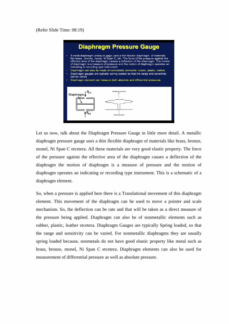
Let us now, talk about the Diaphragm Pressure Gauge in little more detail. A metallic
diaphragm pressure gauge uses a thin flexible diaphragm of materials like brass, bronze,
monel, Ni Span C etcetera. All these materials are very good elastic property. The force
of the pressure against the effective area of the diaphragm causes a deflection of the
diaphragm the motion of diaphragm is a measure of pressure and the motion of
diaphragm operates an indicating or recording type instrument. This is a schematic of a
diaphragm element.
So, when a pressure is applied here there is a Translational movement of this diaphragm
element. This movement of the diaphragm can be used to move a pointer and scale
mechanism. So, the deflection can be rate and that will be taken as a direct measure of
the pressure being applied. Diaphragm can also be of nonmetallic elements such as
rubber, plastic, leather etcetera. Diaphragm Gauges are typically Spring loaded, so that
the range and sensitivity can be varied. For nonmetallic diaphragms they are usually
spring loaded because, nonmetals do not have good elastic property like metal such as
brass, bronze, monel, Ni Span C etcetera. Diaphragm elements can also be used for
measurement of differential pressure as well as absolute pressure.
(Refer Slide Time: 10: 52)
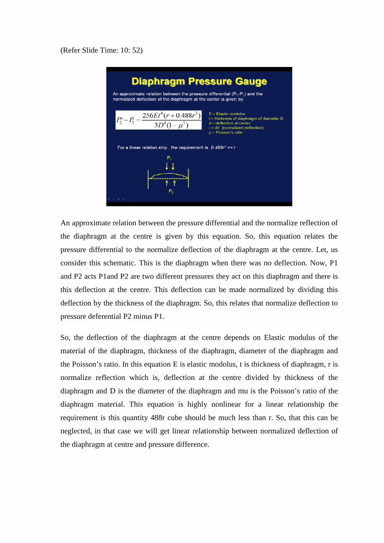
An approximate relation between the pressure differential and the normalize reflection of
the diaphragm at the centre is given by this equation. So, this equation relates the
pressure differential to the normalize deflection of the diaphragm at the centre. Let, us
consider this schematic. This is the diaphragm when there was no deflection. Now, P1
and P2 acts P1and P2 are two different pressures they act on this diaphragm and there is
this deflection at the centre. This deflection can be made normalized by dividing this
deflection by the thickness of the diaphragm. So, this relates that normalize deflection to
pressure deferential P2 minus P1.
So, the deflection of the diaphragm at the centre depends on Elastic modulus of the
material of the diaphragm, thickness of the diaphragm, diameter of the diaphragm and
the Poisson’s ratio. In this equation E is elastic modolus, t is thickness of diaphragm, r is
normalize reflection which is, deflection at the centre divided by thickness of the
diaphragm and D is the diameter of the diaphragm and mu is the Poisson’s ratio of the
diaphragm material. This equation is highly nonlinear for a linear relationship the
requirement is this quantity 488r cube should be much less than r. So, that this can be
neglected, in that case we will get linear relationship between normalized deflection of
the diaphragm at centre and pressure difference.
(Refer Slide Time: 14:06)
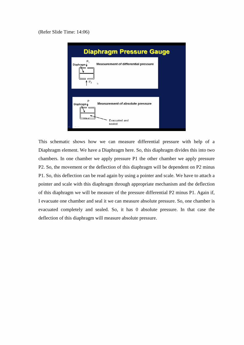
This schematic shows how we can measure differential pressure with help of a
Diaphragm element. We have a Diaphragm here. So, this diaphragm divides this into two
chambers. In one chamber we apply pressure P1 the other chamber we apply pressure
P2. So, the movement or the deflection of this diaphragm will be dependent on P2 minus
P1. So, this deflection can be read again by using a pointer and scale. We have to attach a
pointer and scale with this diaphragm through appropriate mechanism and the deflection
of this diaphragm we will be measure of the pressure differential P2 minus P1. Again if,
I evacuate one chamber and seal it we can measure absolute pressure. So, one chamber is
evacuated completely and sealed. So, it has 0 absolute pressure. In that case the
deflection of this diaphragm will measure absolute pressure.

(Refer Slide Time: 15:53)
Sometimes, we form a Capsule by joining two Diaphragm at the periphery. So, it takes
two metallic diaphragm and join them to form a capsule. The sensitivity of the pressure
gauge can be increased by cascading several capsules. So, we can form several such
capsules and cascade them. So, we will have a assembly of capsules when a pressure is
applied to the capsule assembly by an inlet pipe passing through the centre of all the
capsules the deflection of the gauge will be the sum of the individual capsules. One such
capsule is shown here, imagine several such capsules are stat and this inlet pipe passes
through the centre of all the capsules. Then, the pressure applied through the inlet pipe
will cause a very large deflection of the pressure gauge.
So, we can increase the sensitivity of the pressure gauge substantially. This equation an
empirical relation tells us how much deflections will there be if you have in capsules in
an assembly. This is an empirical relation which gives an estimate of the deflection of
the pressure gauge and it shows that it depends on number of capsules the pressure
differential, the diameter and the thickness. k is a constant for the gauge. For most
practical cases this exponent m and n are chosen as m equal to 4 and n equal to minus
1.5. So, if we increase the number of capsules there will be more deflection.

(Refer Slide Time: 19:37)
After, talking about pressure measuring measurements that are used for measurement of
moderate pressure, let us now talk about how we can measure Very High Pressure. We
are talking about pressures as I has 7000 bar. We can use an instrument call Wire coil in
bellows. Measurement of pressures above 7000 bar is normally carried out electrically by
monitoring the change of resistance of wires of special materials. So, to measure Very
High Pressure we monitor the change of resistance of wires of special materials with
pressure.
Materials having resistance pressure characteristics that are suitably linear and sensitive
include manganin and gold-chromium alloys. So, you use manganin or gold-chromium
alloys because, they have suitable resistance pressure characteristics. So, A coil of
manganin or gold-chromium alloys is enclosed in a sealed kerosene filled flexible
bellows. The unknown pressure is applied to one end of the bellows which transmits the
pressure to the coil. The magnitude of the applied pressure is then determined by
measuring the coil resistance. Pressures up to 30000 bar can be measured by devices like
the manganin-wire pressure sensor with a typical inaccuracy of plus minus 0.5 percent.
So, to measure Very High Pressure we take wires with good resistance pressure
characteristics such materials are manganin and gold-chromium alloys. A coil of such
wires is enclosed in a sealed kerosene filled flexible bellows. The unknown pressure is
applied to one end of the bellows and this pressure will be transmitted to the coil. So, the
coils resistance will change according to the magnitude of the pressure. Therefore, the
magnitude of the applied pressure can be determined by measuring the coil resistance.
We can measure pressures as I has 30,000 bar by devices like the manganin wire
pressure sensor.
(Refer Slide Time: 23:51)
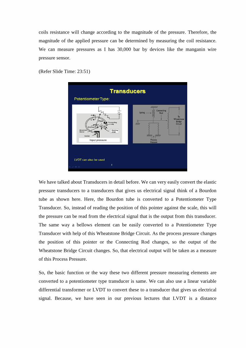
We have talked about Transducers in detail before. We can very easily convert the elastic
pressure transducers to a transducers that gives us electrical signal think of a Bourdon
tube as shown here. Here, the Bourdon tube is converted to a Potentiometer Type
Transducer. So, instead of reading the position of this pointer against the scale, this will
the pressure can be read from the electrical signal that is the output from this transducer.
The same way a bellows element can be easily converted to a Potentiometer Type
Transducer with help of this Wheatstone Bridge Circuit. As the process pressure changes
the position of this pointer or the Connecting Rod changes, so the output of the
Wheatstone Bridge Circuit changes. So, that electrical output will be taken as a measure
of this Process Pressure.
So, the basic function or the way these two different pressure measuring elements are
converted to a potentiometer type transducer is same. We can also use a linear variable
differential transformer or LVDT to convert these to a transducer that gives us electrical
signal. Because, we have seen in our previous lectures that LVDT is a distance

measuring transducer. So, the deflection of this pointer or this pointer or connecting rod
can also be converted to an electrical signal by using LVDT.
(Refer Slide Time: 27:29)
Let us now briefly talk about how we measure Pressure of Corrosive Fluid. When you
want to measure the pressure of a corrosive fluid it is necessary to protect the pressure
gauge form the effect of the corrosive fluid whose pressure is being measured. So, you
should avoid direct contact of pressure gauge and the corrosive fluid. We can make Use
of a diaphragm seal or liquid seal known as seal pot to avoid direct contact between the
pressure gauge and the corrosive fluid. This can be done as follows.

(Refer Slide Time: 28:29)
This is the Pressure gauge. And let say this is the Corrosive Fluid. We use a diaphragm
element here. It may be a thin metallic diaphragm or it may be made of say neoprene
etcetera. This interpret is filled with a sealing liquid. So, this is completely filled with a
sealing liquid it may be glycerin or some oil and this is the Corrosive Fluid, so now the
corrosive that I want to measure the pressure of this Corrosive Fluid. So, we have a
diaphragm here, which receives the pressure it reflects transmits this pressure to this
pressure gauge through this sealing liquid. So, the diaphragm element does not allow this
corrosive fluid to come in direct contact with the pressure gauge, but transmits the
pressure to the pressure gauge through this sealing liquid. So, that way we can protect
our pressure gauge. We can also make use of a seal pot or sealing liquid. So, we have a
sealing liquid you have a Seal Pot this is the sealing liquid this is the pressure gauge this
is the corrosive fluid.
So, again the corrosive fluid is not being allowed to come in direct contact with the
Pressure gauge. So, either with help of a diaphragm element or a liquid seal we, can
protect a pressure gauge when we use it for measurement of pressure of corrosive fluid.
(Refer Slide Time: 33:28)
Let us now talk about High Vacuum Measurement or measurement of very low pressure.
We have several instruments for measurement of very low pressures. So, we are talking
about pressures starting from say 1 Torr 2 up to 10 to the power 7 or 10 to the power
minus 10 Torr. The instruments commonly used for measurement of high vacuum or
extremely low pressures are Mcleod Gage which is essentially a modified manometer.
Ionization gage, Thermocouple gage, Pirani gage working principle of Thermocouple
gage Pirani gage are related together they can be clubbed as Thermal conductivity gage
and also Knudsen gage. This is not much used these days. But, these instruments are
widely used for measurement of very low pressure.

(Refer Slide Time: 35:11)
So, let us start our discussion with Macleod Gage. So, Mcleod Gage is essentially a
Modified Manometer. Let us draw the picture first. This is a Moveable reservoir. So, this
is Mercury. This is Capillary. Let, us indicated it by C. This is Bulb called B. Here, we
have an opening this called O and, this is the flexible tube which connects this to the
moveable reservoir. So, this is a Mcleod Gage which is nothing, but a Modified
Manometer. We have a scale attached here, we have scale here this is 0, 1, 2 and so on
and so forth. So, this is the 0, 0 reading this is the 0 of the scale.
So, let us say this is all filled with the mercury. So, this is the construction of a Mcleod
Gage. Which consist of a capillary a bulb and this is connected to a moveable reservoir.
It can we can bring it up or down the way to as follows, the moveable reservoir is lower
until the mercury column drops below the opening O. As we move this reservoir up or
down. The mercury the level of the mercury in this capillary bulb will, go up or come
down. So, the first step to pressure measurement is lower the moveable reservoir until
the mercury column drops below the opening o. So, when it drops below opening o. The
bulb B the Capillary C, are connected to the same pressure source as this. This one is
connected to the vacuum whose pressure I am going to measure.
So, this is To Vacuum let us call P. So, this is connected to the vacuum or low pressure
source whose pressure I am going to measure. So, first a lower the moveable reservoir
until the mercury column drops below point o. So, when it goes below point o this entire

thing is connected to the same low pressure source or same vacuum so that was first step.
In the second step the reservoir is raised until the mercury fills the bulb and rises in the
capillary to a point where the level in the reference capillary is located at 0 point. The
second step is the moveable reservoir is now raised and as we raised the moveable
reservoir the mercury level the mercury also goes up here and we stop when the mercury
column in this reference capillary call this reference capillary. We stop when the
mercury level touches the 0 of the scale in this reference capillary.
Imagine under such situation this measurement is y. Will now, see that from this y which
is the length of the capillary occupied by the gas the same gas whose pressure I am going
to measure will be used to compute the pressure. So, the measurement has two major
steps. In the first stage the moveable this is connected to vacuum or local the moveable
reservoir is lower such that the mercury level falls below point o, in that case the entire
capillary bulb the reference capillary etcetera is connected to the same pressure source.
In the second stage I raise the moveable reservoir. So, the mercury level stops coming
stops going up when it crosses the point o see that this part is now disconnected from the
low pressure source.
So, in fact the gas inside is being compressed. So, I continue to raise the moveable
reservoir until the mercury layer in this capillary reference capillary touches the 0 of the
scale. Under such situation let us consider the length of the gas in the capillary is y. So,
this length is y. Now let us see how we can calculate the pressure P from the
measurement of y. Let, us consider the Volume of capillary per unit length is a. So,
Volume of the gas in the capillary if you call it Vc should be equal to a into y. Because, a
is the volume of the capillary per unit length my length is y. So, the volume of the gas in
the capillary Vc is a times y. Let, us consider the volume of the capillary plus volume of
the blub and the volume of the tube down to point o opening O that means, this entire
part is VB.
So, let us denote the volume of the capillary, volume of the bulb and volume of the tube
up to point o is VB . So, when we start it raising the reservoir at second stage and when
we reached point o and got this part just got disconnected I have VB as the volume of the
gas. And I have now a times y as volume of gas when the reference when the mercury
rest at 0 in the reference capillary. So, initially I had a gas of these volumes with pressure
P now, I have a gas with this volume with some other pressure. If, we consider

isothermal compression of the gas in the capillary I can write pc Vc equal to p into VB .
Where, pc is the pressure of the gas in the capillary now after compression or, we can
write pc equal to p which is the unknown pressure VB by Vc. Now, the pressure
indicated by the capillary we can write as pc minus P equal to y.
Now, if I use this relationship and this relationship if we combine this three equations we
can write P the unknown pressure P equal to ay square by VB minus ay which, can also
be written as y Vc VB minus ay. Since, this volume is much less than this volume of this
capillary plus bulb and plus volume of the tube up to point o that means, since ay is
much, much less than VB we can write from this P equal to ay square by VB . Because,
we can safely neglect ay as this is much less than VB. So, finally, the pressure P is
related to this measurement y. For a given Mcleod Gage a and VB is fixed. So, P
depends only on y.
So, for measurement from the measurement of this y alone which represents the length of
the capillary or the length of the gas in the capillary I can measure the unknown pressure
or unknown vacuum P.We need to remember one thing here, that the Mcleod Gage is
sensitive to condensed vapors that may be present in the sample because they can
condense upon compression and then the relationship pc Vc equal to p VB may not be
valid. Because, the working of the Mcleod Gage depends on this relationship we should
ensure that this holds true. We can measure pressures up to 10 to the power minus 4 Torr
using Mcleod Gage; one important thing one important observation about the Mcleod
Gage we should know that the pressure is being measured from this dimension alone for
given Mcleod Gage. So, in the range up to 10 to the power minus 4 Torr the Mcleod
Gage is often used as a primary standard. We still have some other pressure measuring
instruments to discuss which are used for high vacuum namely ionized at namely
Ionization Gage and thermal conductivity gages such as Thermocouple Gage and Pirani
Gage.
Related Documents