Welcome message from author
This document is posted to help you gain knowledge. Please leave a comment to let me know what you think about it! Share it to your friends and learn new things together.
Transcript
Proceedings of the I#R#E
A Journal of Communications and Electronic Engineering (Including the WAVES AND ELECTRONS Section)
December, 1948 Volume 36 Number I 2
I'irott,.111•.) C
PRECISION AUTOGRAPH At the left, interference fringes from green radiation of natural mer-
cury: at the right, corresponding fringes from mercury 198, a man-made stable isotope produced by neutron bombardment of gold in an atomic pile. The mercury 198 spectral wavelengths may be accurate to one' part in a billion and thus become a new standard of length!
PROCEEDINGS OF THE I.R.E.
Digital Computer for Scientific Applications
Signal-to-Noise Ratio in AM Receivers
Rectification of Sirusoidally Modulated Carrier in the Presence of Noise
Ray Path and Wave Absorption in a Deviating Ionosphere Layer
Negative-Ion-Blemish Elimination
Slotted-Cylinder-Antenna Patterns
Swept-Frequency 3-Cm Impedance Indicator
Ultrasonic Interfero-neter with Resonant Liquid Column
Waves and Electrons Section
JTAC and the FCC Television Hearings
Electronics in Nuclear Physics
Design of a Universal Beacon System
Three-Dimensional CRT Representation
Single-Control Variable-Frequency Impedance-Transforming Network
Phase Difference Between Fields of Vertically Spaced Antennas
Abstracts and References
Annual Index
"I• %BT.', IIF C417\ \T , (1\% j'Ai,E 3
The Institute of Radio Engineers
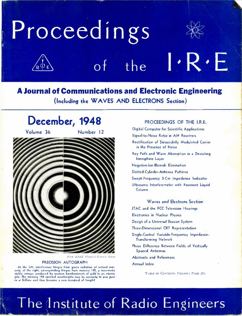
COMPONENTS FOR EVERY APPLICATION
LINE, F STANDARD High Rdelity Ideal
COMMERCIAL GRADE Industrial Dependability
VARIABL E INDUCTOR Adjust lie a Trimmer
PULSE UANSFORMERS For c I Services
VERT I :AL SHELLS Husky . . Inexpensive
I MMEMI
HIPERM ALLOY ULTRA COMPACT High Fidelity . . . Compact Portable . . . High Fidelity
SPECIAL SERIES Quality for the "Horn'
TOROID HIGH Q COILS Accuracy . . Stability
HERMETIC COMPONENTS Ceramic Terminals
REPLACEMENT Universal Mounting
POWER COMPONENTS Rugged . . . Dependable
TOROID FILTERS Any type to 300KC
HERMETIC COMPONENTS Glass Terminals
STEP-DOWN Up to 2500W . . . Stock
OUNCER Wide Range . . . 1 ounce
VARITRAN Voltage Adjustors
SUB OUNCER Weight 1/3 ounce
MODULATION UNITS One watt to 100KW
MU-CORE FILTERS EQUALIZERS Any type Y2 — 10,000 cyc. Broadcast & Sound
GRADE 3 JAN Components
LINE ADJUSTORS Match any line voltage
EXPORT DIVISION: 13 EAST 40th STRE ORK 16, N. V., CABLES: "ARLAB"
CABLE TYPE For mike cable line
CHANNEL FRAME Simple . . . Low cost
— 6P iniLIm
rf
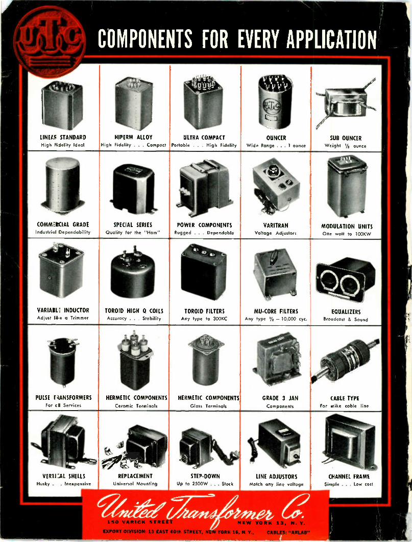
COMPONENTS
Hi-Q TEMPERATURE COMPENSATING CAPACITORS temperature compensating capacitors are available in three types. CN & SI types with
capacities from .25 mmf to 1830 mmf and CI types from .25 mmf to 595 mmf with a tempera-ture coefficient range from P 100 to N 1400. All of these He-Q styles are of tubular ceramic construction with pure silver electrodes precision coated. Style SI is insulated with a syn-thetic coating of Durez, style CN is of Styrene and CI is Steatite covered.
HI-Q GENERAL PURPOSE CERAMIC CAPACITORS He-C1 General Purpose Ceramic Capacitors readily replace mica and paper condensers of corresponding values. He-0 General Purpose Ceramic Capacitors should not be confused with the Hi-Q line of close tolerance temperature compensating units. He-0 General Purpose Ceramic Capacitors are available in capacity ratings from 5 mmf to 33,000 mmf.
Hi-Q FEED-THRU CAPACITORS
0=0
HI-Q STAND-OFF CAPACITORS He-0 "stand-off" capacitors are basically tubular with a screw fixture for mounting to the chassis or common ground. Close coupling and their unique construction make them an excel-lent choice for by-passing RF in the high frequencies. Standard capacity tolerances are + 10% and + 20% for "stand-off" capaci-tors and — 20% and + 30% for multiple tap units. Closer tol-erances available wherever economical manufacturing permits. All units flash tested for 1000 volts DC with power factor under 3% maximum and insulation resistance is above 10,000 megohms. All units stamped for capacity.
iii-Q "feed-thru" capacitors provide perfect transmission through the chassis or ground, as well as by-passing to ground. The high quality construction of He-Q "feed-thru" capacitors, is extremely rugged and will withstand severe vibration, making them ideal for use in mobile and aircraft applications.
HI-Q HIGH VOLTAGE CAPACITORS He-Q HV Capacitors are a sturdy unit, capable of withstanding high volt-ages, operating at extreme humidity and raised tem-peratures. They are a nat-ural television component. The basic dielectric is body 20, encased in a low loss, mineral filled bake-lite. Available in capacities 50 mmf to 1,000 mmf. Spec-ify desired capacity after type HV when ordering.
WRITE FOR
HI-0 DISC CAPACITORS Hs-Q Disc Capacitors are high die-lectric by-pass, blocking or coupling capacitors. Designed for application where its physical shape is more adaptable than tubular units. The placement of leads is such that close connections are easily made, thus reducing inductance to a mini-mum, a much desired feature in high frequency designs, such as television and FM. Available in three types: BPD-5: .005 MFD guar. min., BPD-10: .01 MFD guar. min. and BPD-1.5: .0015 MFD guar. min.
FREE CATAL OG
Elea/re:ea Readeigee FRA NKLINVILLE, N.Y.
eolft. Monts: FRANKLINVILLE, N. Y. —JESSUP, PA.
Sales Offices: NEW YORK. PHILADELPHIA, DETROIT, CHICAGO, LOS ANGELES
( PROCIIIIINGS o viz I.R.E., December, 1948, Vol. 36, No. 12. Published monthly in two sections by The Institute of Radio Engineers, Inc., at 1 East 79 Street, New York 21, N.Y. Price 82.25 per copy. Subscriptions: United States and Canada, $18.00 a year; foreign countries $19.00 a year. Enter,d as second class matters October 26, 1927, at the post office at Menasha, Wisconsin, under the act of March 3, 1879. Acceptance for mailing at a special rate of postage a provided for in the act of February 28, 1925, embodied in Paragraph 4, Section 412, P. L. and It., authorized October 26, 1927.
Table of contents will be found following page 32A
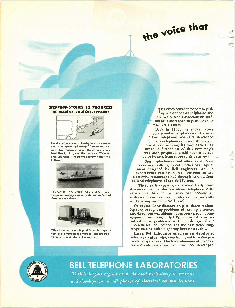
STEPPING-STONES TO PROGRESS
IN MARINE RADIOTELEPHONY
The first ship-to-shore radiotelephone communica-tions were established almost 30 years ago be-tween land stations at Green Harbor, Mass., and Deal Beach, N. J., and the steamers "Ontario" and "Gloucester," operating between Boston and Baltimore.
The "Leviathan" was the first ship to handle radio-telephone messages as a public service to and from land telephones.
This selector set made it possible to dial ships at sea, and eliminated the need for constant moni-toring by loudspeaker or headphones.
. • •
Ole voice that
Trs COMMONPLACE TODAY to pick up a telephone on shipboard and
talk to a business associate on land. But little more than 30 years ago, this was just a dream.
Back in 1915, the spoken voice could travel to far places only by wire. Then telephone scientists developed the radiotelephone, and soon the spoken word was winging its way across the ocean. A further use of this new magic was soon proposed: could not the human voice be sent from shore to ships at sea?
Soon sub-chasers and other small Navy craft were talking to each other over equip-ment designed by Bell engineers. And in experiments starting in 1919, the men on two coastwise steamers talked through land stations to land telephones of the Bell System.
These early experiments covered fairly short distances. But in the meantime, telephone calls across the Atlantic by radio had become an ordinary occurence. So ... why not 'phone calls to ships way out in mid-Atlantic?
Of course, long-distance ship-to-shore radiote-lephony brought up problems of varying distances and directions—problems not encountered in point-to-point transmission. Bell Telephone Laboratories solved these problems with the design of the "Leviathan's" equipment. For the first time, long-range marine radiotelephony became a reality.
Later, Bell Laboratories scientists developed selective ringing, which made it possible to dial par-ticular ships at sea. The basic elements of practical marine radiotelephony had now been developed.
BELL TELEPHONE LABORATORIES World's largest organization devoted exclusively to research
and development in all phases of electrical communications.
links the ship and the shore
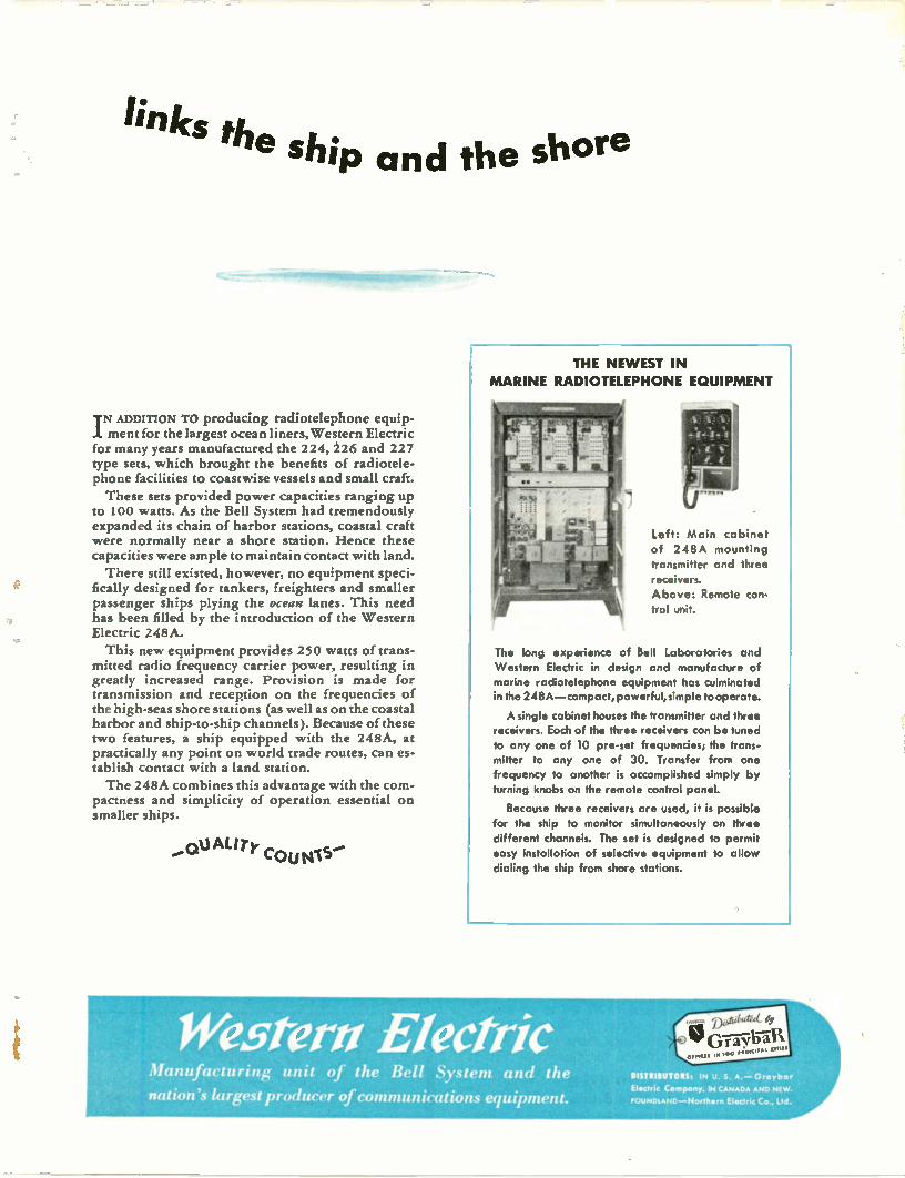
THE NE WEST IN
MARINE RADIOTELEPHONE EQUIPMENT
TN ADDITION To producing radiotelephone equip-1 ment for the largest ocean liners, Western Electric for many years manufactured the 224, 226 and 227 type sets, which brought the benefits of radiotele-phone facilities to coastwise vessels and small craft.
These sets provided power capacities ranging up to 100 watts. As the Bell System had tremendously expanded its chain of harbor stations, coastal craft were normally near a shore station. Hence these capacities were ample to maintain contact with land.
There still existed, however, no equipment speci-fically designed for tankers, freighters and smaller passenger ships plying the ocean lanes. This need has been filled by the introduction of the Western Electric 248A.
This new equipment provides 250 watts of trans-mitted radio frequency carrier power, resulting in greatly increased range. Provision is made for transmission and reception on the frequencies of the high-seas shore stations (as well as on the coastal harbor and ship-to-ship channels). Because of these two features, a ship equipped with the 248A, at practically any point on world trade routes, can es-tablish contact with a land station.
The 248A combines this advantage with the com-pactness and simplicity of operation essential on smaller ships.
.(3tu AL/Ty COUN-15
Left: Main cabinet of 248A mounting
transmitter and three
receivers.
Above: Remote con-trol unit.
The long experience of Bell Laboratories and
Western Electric in design and manufacture of
marine radiotelephone equipment has culminated
in the 248A —compact, powerful, simple tooperate.
A single cabinet houses the transmitter and three receivers. Each of the three receivers can be tuned
to any one of 10 pre-set frequencies; the trans-
mitter to any one of 30. Transfer from one
frequency to another is accomplished simply by turning knobs on the remote control panel.
Because three receivers are used, it is possible
for the ship to monitor simultaneously on three
different channels. The set is designed to permit
easy installation of selective equipment to allow
dialing the ship from shore stations.
Western Electric Manufacturing unit of the Bell System and the
nation's largest producer of communications equipment.
tak Grav iraii
011111C0 ,00
DISTRIBUTOItSt IN U. S. A. — Graybar
Ebectric Company. IN CANADA AND NE W.
FOUNDLAND —North•rn Vat-Pic Co., ltd.
THEY'RE BETTER BECAUSE...
44
ing
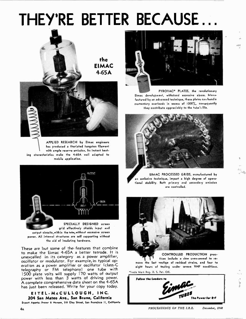
the EIMAC 4-65A
APPLIED RESEARCH by Eimac engineers has produced a thoriated tungsten filament with ample reserve emission. Its instant heat-
characteristics make the 4-65A well adapted to mobile application.
SPECIALLY DESIGNED screen grid effectively shields input and
output circuits,within the tube, without excessive screen power. All internal structures are self supporting without
the aid of insulating hardware.
These are but some of the features that combine to make the Eimac 4-65A a better tetrode. It is unexcelled in its category as a power amplifier, oscillator or modulator. For example, in typical op-eration as a power amplifier or oscillator (class-C telegraphy or FM telephony) one tube with 1500 plate volts will supply 170 watts of output power with less than 3 watts of driving power. A complete comprehensive data sheet on the 4-65A has just been released. Write for your copy today.
EI TEL- McC ULLOUG H, INC. 204 San Mateo Ave., San Bruno, California
Export Agents: Fraser & If , 310 Clay Street, San Francisco II, California
PYROVAC. PLATES, the revolutionary
Eimac development, withstand excessive abuse. Manu-factured by an advanced technique, these plates can handle momentary overloads in excess of 1000%, consequently
they contribute appreciably to the tube's life.
EIMAC PROCESSED GRIDS, manufactured by an exclusive technique, impart a high degree of opera-
tional stability. Both primary and secondary emission are controlled.
CONTROLLED PRODUCTION prac-tices include a slow oven-anneal to re-
move the last vestige of residual strains, and four to eight hours of testing under severe VHF conditions.
•Trade Mark Reg. U. S. Pat. Off.
4A PROCEEDINGS OF THE I.R.E. December, 1948
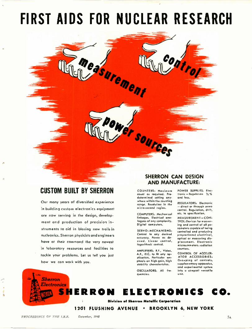
FIRST AIDS FOR NUCLEAR RESEARCH
116 CUSTOM BUILT BY SHERRON
Our many years of diversified experience
in building custom electronics equipment
are now serving in the design, develop-
ment and production of precision in-
struments to aid in blazing new trails in
nucleonics. Sherron physicists and engineers
have at their command the very newest
in laboratory resources and facilities to
tackle your problems. Let us tell you just
how we can work with you.
SHERRON CAN DESIGN AND MANUFACTURE:
COUNTERS: Maximum count as required. Pre-determined setting any-where within the counting range. Resolution in the micro-second region.
COMPUTERS: Mechanical linkages. Electrical ana-logues of any complexity. Digital computers.
SERVO- MECHANISMS: Control to any desired accuracy. Power as de-sired. Linear control, logarithmic control.
AMPLIFIERS: R.F., Video, AF., D.C. to fit any ap-plication. Particular em-phasis on high gain, high stability characteristics.
OSCILLATORS: All fre-quencies.
POWER SUPPLIES: Elec-tronic —Regulation y2 V.
and less.
REGULATORS: Electronic — direct or through servo control. Regulation, drift, etc. to specification.
MEASUREMENT — CON-TROL. Devices for measur-ing and control of all pa-rameters capable of being controlled and producing proportional electrical, optical or measuring dis-placement. Electronic microamm eters, radiation counters.
CONTROL OF ACCELER-ATOR ACCESSORIES: Grouping of controls, supplementary apparatus, and experimental system into a compact versatile unit.
SHERRON ELECTRONICS CO. Division of Sherron Metallic Corporation
416-
1201 FLUSHIN G AVE NUE • BR O OKLYN 6, NE W YORK
PROCEEDINGS OF THE I.R.E. lie,ember, 1941 5A
ELECTRONICS
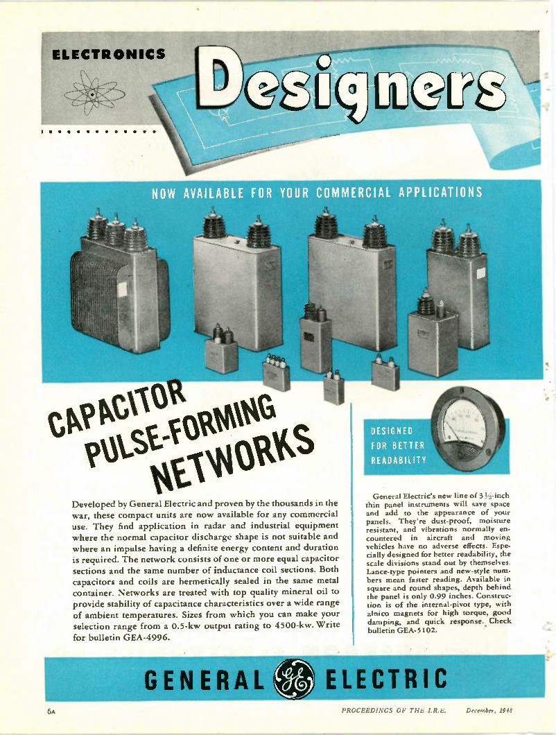
NOW AVAILABLE FOR YOUR COMMERCIAL APPLICATIONS
CP 1016 i*St-ViOtt*
tesooks Developed by General Electric and proven by the thousands in the war, these compact units are now available for any commercial use. They find application in radar and industrial equipment where the normal capacitor discharge shape is not suitable and where an impulse having a definite energy content and duration is required. The network consists of one or more equal capacitor sections and the same number of inductance coil sections. Both capacitors and coils are hermetically sealed in the same metal container. Networks are treated with top quality mineral oil to provide stability of capacitance characteristics over a wide range of ambient temperatures. Sizes from which you can make your selection range from a 0.5-kw output rating to 4500-kw. Write
for bulletin GEA-4996.
DESIGNED
FOR BETTER
READABILITY
General Electric's new line of 3 -inch thin panel instruments will save space and add to the appearance of your panels. They're dust-proof, moisture resistant, and vibrations normally en-countered in aircraft and moving vehicles have no adverse effects. Espe-cially designed for better readability, the scale divisions stand out by themselves. Lance-type pointers and new-style num-bers mean faster reading. Available in square and round shapes, depth behind the panel is only 0.99 inches. Construc-tion is of the internal-pivot type, with alnico magnets for high torque, good damping, and quick response. Check bulletin GEA-5102.
lour GENERAL ) ELECTRIC
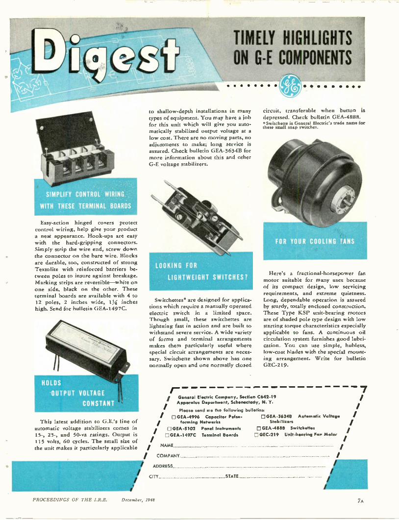
SIMPLIFY CONTROL WIRING
WITH THESE TERMINAL BOARDS
Easy-action hinged covers protect control wiring, help give your product a neat appearance. Hook-ups are easy with the hard-gripping connectors. Simply strip the wire end, screw down the connector on the bare wire. Blocks are durable, too, constructed of strong Textolite with reinforced barriers be-tween poles to insure against breakage. Marking strips are reversible—white on one side, black on the other. These terminal boards are available with 4 to 12 poles, 2 inches wide, 14 inches high. Send for bulletin GEA-1497C.
This latest addition to G.E.'s line of automatic voltage stabilizers comes in 15-, 25-, and 50-va ratings. Output is 115 volts, 60 cycles. The small size of the unit makes it particularly applicable
TIMELY HIGHLIGHTS ON G-E COMPONENTS
to shallow-depth installations in many types of equipment. You may have a job for this unit which will give you auto-matically stabilized output voltage at a low cost. There are no moving parts, no adjustments to make; long service is assured. Check bulletin GEA-3634B for more information about this and other G-E voltage stabilizers.
LOOKING FOR
LIGHTWEIGHT SWITCHES?
Switchettes" are designed for applica-tions which require a manually operated electric switch in a limited space. Though small, these switchettes are lightning fast in action and are built to withstand severe service. A wide variety of forms and terminal arrangements makes them particularly useful where special circuit arrangements are neces-sary. Switchette shown above has one normally open and one normally closed
r-
circuit, transferable when button is depressed. Check bulletin GEA-4888. *Switchette is General Electric's trade name for these small snap switches.
Here's a fractional-horsepower fan motor suitable for many uses because of its compact design, low servicing requirements, and extreme quietness. Long, dependable operation is assured by sturdy, totally enclosed construction. These Type KSP unit-bearing motors are of shaded pole type design with low starting torque characteristics especially applicable to fans. A continuous oil circulation system furnishes good lubri-cation. You can use simple, hubless, low-cost blades with the special mount-ing arrangement. Write for bulletin GEC-219.
General Electric Company, Section C642-19 Apparatus Department, Schenectady, N. Y.
Please send me the following bulletins:
GEA-4996 Capacitor Pulse-forming Networks
E GEA-5102 Panel Instruments
GEA-1 497C Terminal Boards
GEA-36348 Automatic Voltage Stabilizers
E GEA-4888 Switchettes
D GEC-219 Unit-bearing Far Motor
NAME
/ COMPANY
ADDRESS .................................... ............ ......... - - ---
CITY STATE
7
PROCEEDINGS OF THE I.R.E. Dcrember, 1948
OTHER STACK POLE PRODUCTS
PIXED AND VARIABLE RESISTORS
IRON CORES
PO WER %OBE ANODES
ELECTRICAL CONTACTS
CARBON PILE VOLTAGE REGULATOR DISCS
MICROPHONE CARBONS
SINTERED ALNICO II
PERMANENT MAGNETS
. . .aed doxens more
CONTACT CODE
POSITION I
POSITION 2 =
POSITION 3 =
POSITICN 4 • •
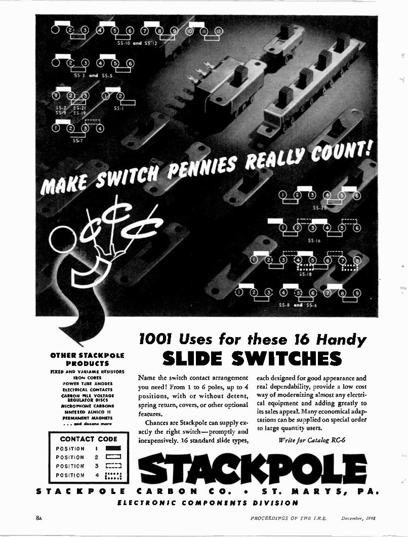
1001 Uses for these 16 Handy
SLIDE SWITCHES Name the switch contact arrangement
you need! From 1 to 6 poles, up to 4
positions, with or without detent, spring return, covers, or other optional
features. Chances are Stackpole can supply ex-
actly the right switch —promptly and
inexpensively. 16 standard slide types,
each designed for good appearance and real dependability, provide a low cost way of modernizing almost any electri-cal eqaipment and adding greatly to its sales appeal. Many economical adap-tations can be supplied on special order to large quantity users.
Write for Catalog RC-6
STACKPOL1E ST A C K P O L E C A R B O N C O. • ST. M A R T S, P A.
ELECTR ONIC CO MP ONE NTS DIVISIO N
8A PROCEED1P'GS 01.. Pi:
141
I N cox— vias suer- 'toe
a ,e of a xest eeatl' ...40 ytor tots
se ot a swat eci° ttle *Ixo( a 133
ao se oat vom
i3 ec de a bst- los t. *to
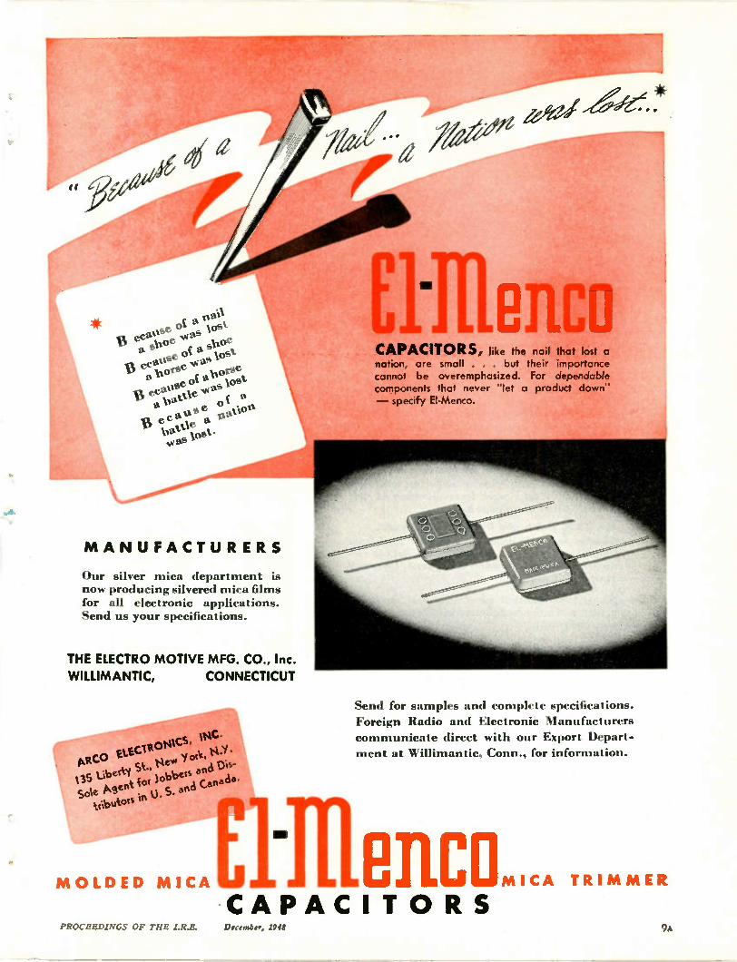
M A NUFACTURERS
Our silver mica department is now producing silvered mica films for all electronic applications. Send us your specifications.
THE ELECTRO MOTIVE MFG. CO., Inc.
WILLIMANTIC, CONNECTICUT
EM OLDED MICA
ARCO vi or ELE CIRONICS,
135 Liberty St., Ne k, 14.i •
Sole Ment cot lo'obets and Dis-tribatots O• S. and Canada.rn
Elflenco CAPACITORS, like the nail that lost a nation, are small . . . but their importance cannot be overemphasized. For dependable components that never "let a product down" — specify EI-Menco.
Send for samples and complete specifications.
Foreign Radio and Electronic Manufacturers communicate direct with our Export Depart-
ment at Willimantic, Conn., for information.
D ncl.. TRI M MER
•CAPACIT O RS PROCEEDINGS OF THE I.R.E. December, 1948 9a
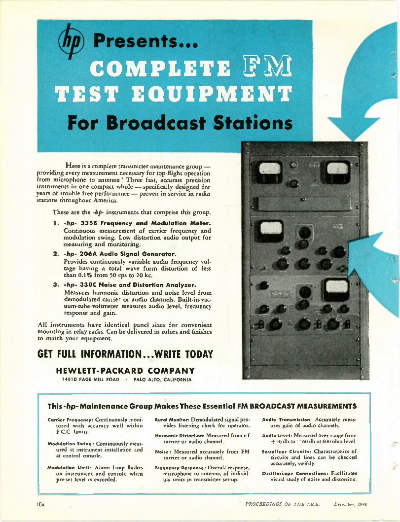
For Broadcast Stations
Here is a complete transmitter maintenance group — providing every measurement necessary for top-flight operation from microphone to antenna! Three fast, accurate precision instruments in one compact whole — specifically designed for years of trouble-free performance — proven in service in radio stations throughout America.
These are the -hp- instruments that comprise this group.
1. -hp- 335B Frequency and Modulation Meter. Continuous measurement of carrier frequency and modulation swing. Low distortion audio output for measuring and monitoring.
2. -hp- 206A Audio Signal Generator. Provides continuously variable audio frequency vol-tage having a total wave form distortion of less than 0.1% from 50 cps to 20 kc.
3. -hp- 330C Noise and Distortion Analyzer. Measures harmonic distortion and noise level from demodulated carrier or audio channels. Built-in-vac-uum-tube-voltmeter measures audio level, frequency response and gain.
All instruments have identical panel sizes for convenient mounting in relay racks. Can be delivered in colors and finishes to match your equipment.
GET FULL INFORMATION...WRITE TODAY
HE WLETT-PACKARD COMPANY 1481D PAGE MILL ROAD • PALO ALTO, CALIFORNIA
This -hp-Maintenance Group Makes These Essential FM BROADCAST MEASUREMENTS
Carrier Frequency: Continuously moni-tored with accuracy well within F.C.C. limits.
Modulation Swing: Continuously meas-ured at instrument installation and at control console.
Modulation Limit: Alarm lamp flashes on instrument and console when pre-set level is exceeded.
Aural Monitor: Demodulated signal pro-vides listening check for operator.
Harmonic Distortion: Measured from r-f carrier or audio channel.
Noise: Measured accurately from FM carrier or audio channel.
Frequency Response: Overall response, microphone to antenna, of individ-ual units in transmitter set-up.
Audio Transmission: Accurately meas-ures gain of audio channels.
Audio Level: Measured over range from + 50 db to — 60 db at 600 ohm level.
tqualizer Circuits: Characteristics of circuits and lines can be checked accurately, swiftly.
Oscilloscope Connections: Facilitates visual study of noise and distortion.
10A PROCEEDINGS OF THE IRE. December, 1948
BRIEF SPECIFICATIONS
Frequency Range: Any single frequency,
138 to 108 mc.
Deviation Range: + 3 kc to — 3 kc.
Accuracy: Better than ± 1000 cps.
Moculation Range: Modulation swing
100 kc. Scale calibrated 100% at 75 kc.
Audio Output: Supplied with 75 micro-second de-emphasis circuit, flat within 1/2 db of standard curve, 20 cps to
20 kc.
Monitoring Output: 1 milliwatt into 600 elms, balanced, at 100% modulation.
Size: Panel 101/2 "x 19". Depth 13".
BRIEF SPECIFICATIONS
Frequency Range: 20 cps to 20 kc, 3
bands.
Output: +15 dbm to matched resistive
loads. 10 volts available for open
circuit.
Output Impedance: 50, 130, 600 ohms center-tapped and balanced. 600 ohms
single-ended.
Frequency Response: Better than 0.2 db
beyond output meter at all levels.
Distortion: Less than 0.1 % above 50 cps. Less than 0.25% from 20 cps to 50 cps.
Hum Level: At least 70 db below output
signal, or more than 100 db below 0
level, whichever is larger.
Size: Panel 10 1/2 "x 19". Depth 13".
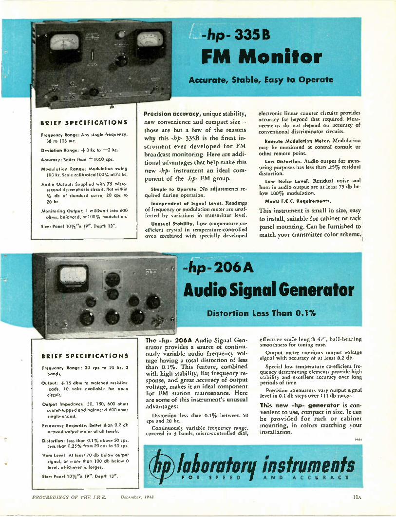
-hp- 335 B
FM Monitor Accurate, Stable, Easy to Operate ,
Precision accuracy, unique stability, new convenience and compact size—
those are but a few of the reasons
why this -bp- 335B is the finest in-strument ever developed for FM
broadcast monitoring. Here are addi-tional advantages that help make this new -bp- instrument an ideal com-ponent of the -bp- FM group.
Simple to Operate. No adjustments re-quired during operation.
Independent of Signal Level. Readings of frequency or modulation meter are unaf-fected by variations in transmitter level.
Unusual Stability. Low temperature co-efficient crystal in temperature-controlled oven combined with specially developed
electronic linear counter circuits provides accuracy far beyond that required. Meas-urements do not depend on accuracy of conventional discriminator circuits.
Remote Modulation Meter. Modulation may be monitored at control console or other remote point.
Low Distortion. Audio output for meas-uring purposes has less than .25% residual distortion.
Low Noise Level. Residual noise and hum in audio output are at least 75 db be-low 100% modulation.
Meets F.C.C. Requirements.
This instrument is small in size, easy to install, suitable for cabinet or rack panel mounting. Can be furnished to
match your transmitter color scheme.
-hp-206A
Audio Signal Generator Distortion Less Than 0.1%
The -hp- 206A Audio Signal Gen-erator provides a source of continu-ously variable audio frequency vol-tage having a total distortion of less than 0.1%. This feature, combined with high stability, flat frequency re-sponse, and great accuracy of output voltage, makes it an ideal component for FM station maintenance. Here are some of this instrument's unusual advantages:
Distortion less than 0.1% between 50 cps and 20 kc. Continuously variable frequency range,
covered in 3 bands, micro-controlled dial,
effective scale length 47", ball-bearing smoothness for tuning ease.
Output meter monitors output voltage signal with accuracy of at least 0.2 db.
Special low temperature co-efficient fre-quency determining elements provide high stability and excellent accuracy over long periods of time.
Precision attenuators vary output signal level in 0.1 db steps over 111 db range.
This new -hp- generator is con-venient to use, compact in size. It can be provided for rack or cabinet mounting, in colors matching your installation.
19.4orgtorq instrumE D A N D ents PROCEEDINGS OF THE I.R.E. December, 1948
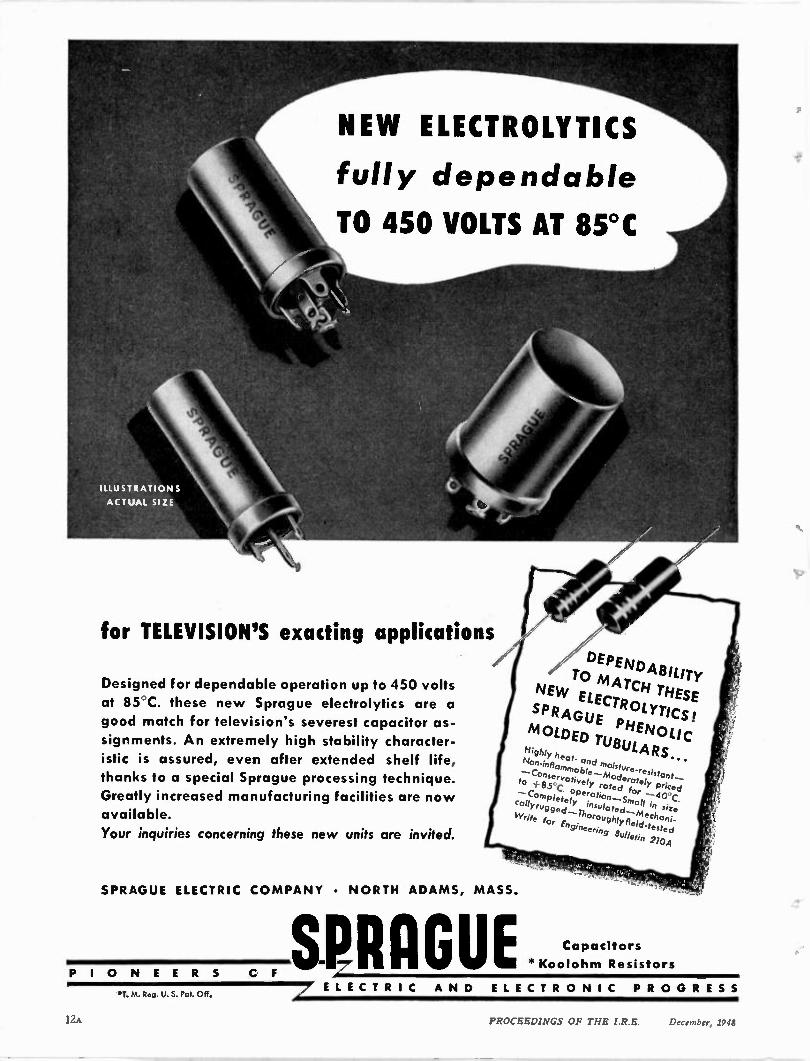
for TELEVISION'S exacting applications
NEW ELECTROLYTICS
fully dependable
TO 450 VOLTS AT 85°C
Designed for dependable operation up to 450 volts
at 85 C. these new Sprague electrolytics are a
good match for television's severest capacitor as-
signments. An extremely high stability character-
istic is assured, even after extended shelf life, thanks to a special Sprague processing technique.
Greatly increased manufacturing facilities are now
available.
Your ;nquiries concerning these new units are invited.
DEPENDABILITY • TO MATCH THESE
NEW ELECTROLYTICS!
SPRAGUE MOLDED TU PHENOL IC
BULARS... Highly heat- and tnoisture-resioont-- Non-inflammable—Moderately priced --Conservatively rated tor --40°C.
ted—M
to +85°C operation—Small in size —Completely insulo echoni-catty rug ged— Thoroughly field-tested
Write for Engineering Bulletin 210A
SPRAGUE ELECTRIC CO MPANY • NORTH ADAMS, MASS.
P I O N E E R S C F SPRAGUE *T. M. Reg. U. $. Pot. Off, / ELE CT RI C A N D ELE CT R O NI C PR O G R ES S
Capacitors
*Kooloh m Resistors
12A PROCEEDINGS OF THE I.R.E.
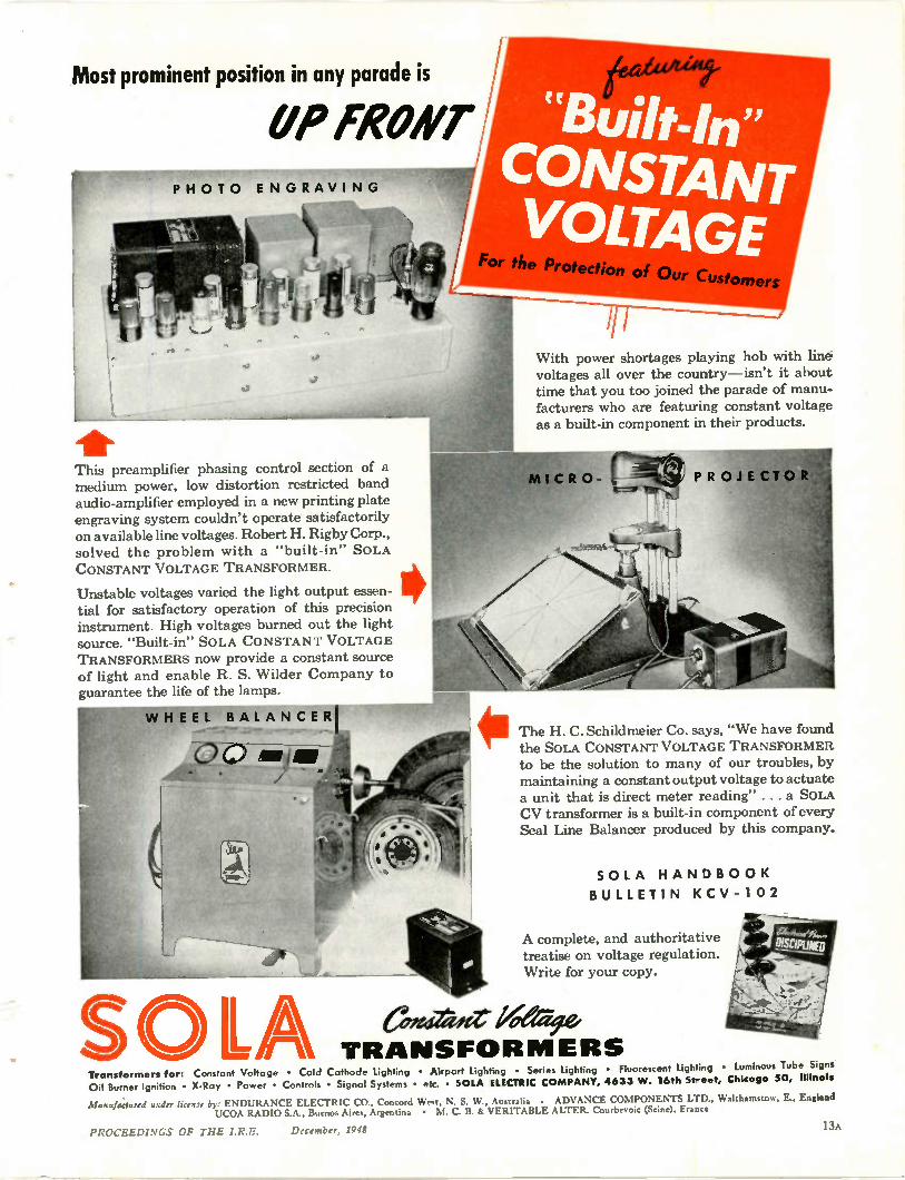
Most prominent position in any parade is
OP FRONT PH OT O EN GRAVI N G
5.9
• This preamplifier phasing control section of a medium power, low distortion restricted band audio-amplifier employed in a new printing plate engraving system couldn't operate satisfactorily on available line voltages. Robert H. Rigby Corp., solved the problem with a "built-in" SOLA CONSTANT VOLTAGE TRANSFORMER.
Unstable voltages varied the light output essen-tial for satisfactory operation of this precision instrument. High voltages burned out the light source. "Built-in" SOLA CONSTANT VOLTAGE TRANSFORMERS now provide a constant source of light and enable R. S. Wilder Company to guarantee the life of the lamps.
WHEEL BALANCER
.0.0 --‘tc
SO LA Transformers for: Constant Voltage • Cold Cathode Lighting • Airport Lighting • Series Lighting • Fluorescent Lighting • Luminous Tube Signs Oil Burner Ignition • X-Ray • Power • Controls • Signal Systems • etc. • SOLA ELECTRIC COMPANY, 4633 W. 16th Street, Chicago 50, Illinois
Manufactured under Ramie by: ENDURANCE ELECTRIC CO., Concord West, N. S. W.. Australia • ADVANCE COMPONENTS LTD., Walthamstow, E., England IJCOA RADIO S.A., Buenos Aires, Argentina • M. C. B. & VERITABLE ALTER. Courbevoic (Seine), Eraoce
PROCEEDINGS OF THE I.R.E. December, 1948 13A
omers
With power shortages playing hob with line voltages all over the country—isn't it about time that you too joined the parade of manu-facturers who are featuring constant voltage as a built-in component in their products.
The H. C. Schildmeier Co. says, "We have found the SOLA CONSTANT VOLTAGE TRANSFORMER to be the solution to many of our troubles, by maintaining a constant output voltage to actuate a unit that is direct meter reading" . .. a SOLA C V transformer is a built-in component of every Seal Line Balancer produced by this company.
SOLA HANDB O OK
BULLETIN KCV-102
A complete, and authoritative treatise on voltage regulation. Write for your copy.
efit4 ta4tr X aG A
TRANSFOR MERS
pito GRISoSti
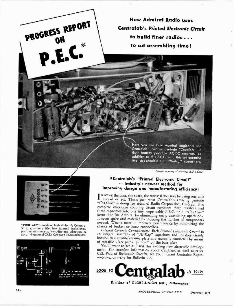
"COUPLATE" is made of high dielectric Ceramic-X to give long life, low internal inductance, positive resistance to humidity and vibration. A circuit diagram of CRL's Coup/ate is shown below.
El GRID GROUND
(Cen be h. d tied directly te ground ten.. be I it desired)
How Admiral Radio uses
Centralab's Printed Electronic Circuit
to build finer radios ...
to cut assembling time!
Here you see how Admiral engineers use Centralab's custom pentode "Couplate" in their battery portable AC-DC receiver. In addition to this P.E.C. unit, this set contains five dependable CRL "Hi-Kap" capacitors.
Chd. f f if courtesy of Admiral Radio Corp,
*Centralab's "Printed Electronic Circuit" — Industry's newest method for
improving design and manufacturing efficiency!
-IMAGINE the time, the space, the material you save by us ing one un it I instead of six. That's just what Centralab's amazing pentode "Coup/ate" is doing for Admiral Radio Corporation, Chicago. This complete interstage coupling circuit combines three resistors and three capacitors into one tiny, dependable P.E.C. unit. "Coup/ate" saves time for Admiral by eliminating many assembling operations. It saves space and material by reducing the number of components needed. What's more it improves performance by minimizing the chance of broken or loose connections. Integral Ceramic Construction: Each Printed Electronic Circuit is
an integral assembly of "Hi-Kap" capacitors and resistors closely bonded to a steatite ceramic plate and mutually connected by means of metallic silver paths "printed" on the base plate. You'll want to see and test this exciting new electronic develop-
ment. For complete information about Couplate, as well as other CRL Printed Electronic Circuits, see your nearest Centralab Repre-sentative, or write for Bulletin 999.
Division of GLOBE-UNION INC., Milwaukee
14A PROCEEDINGS OF THE LR.E. De, ember, 194d
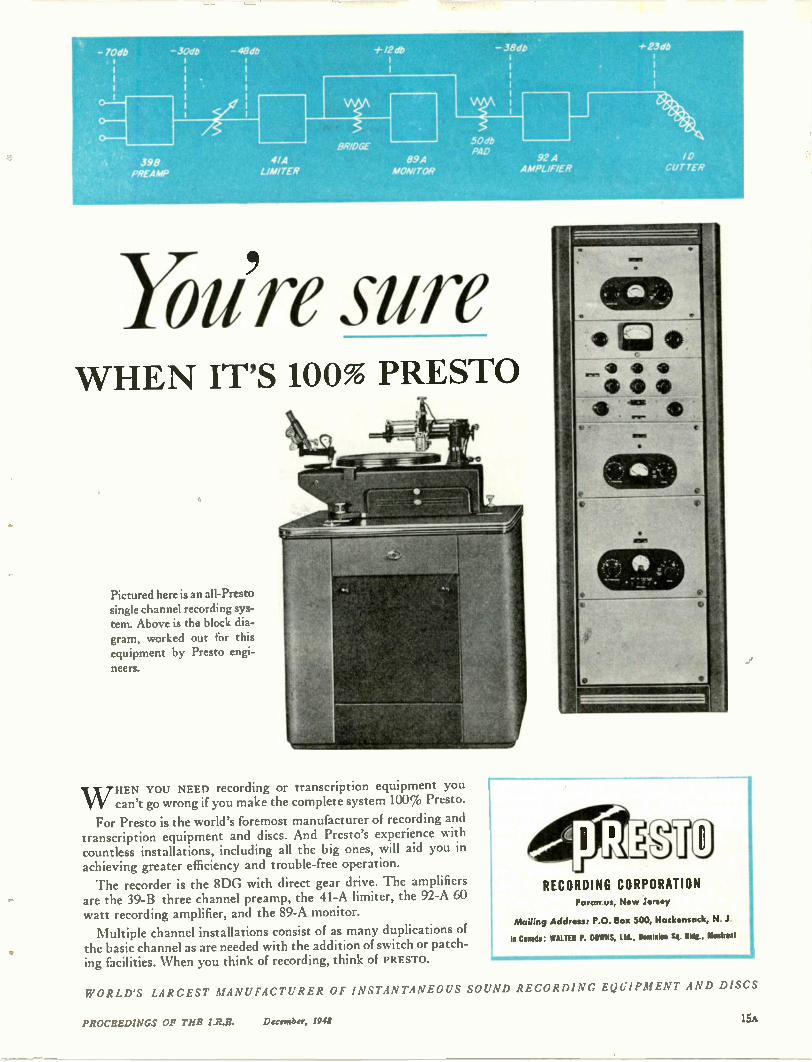
- 70db -.30db - 49db * 12 db - 38db 23db
398 PREAMP
4/A LIMITER
8R/DGE
89 A MONITOR
50db PAD
92 A AMPLIFIER
0,14,
•
/0 CUT TER
You're sure WHEN IT'S 100% PRESTO
Pictured here is an all-Presto single channel recording sys-tem. Above is the block dia-gram, worked out for this equipment by Presto engi-neers.
WHEN YOU NEED recording or transcription equipment you can't go wrong if you make the complete system 100% Presto.
For Presto is the world's foremost manufacturer of recording and transcription equipment and discs. And Presto's experience with countless installations, including all the big ones, will aid you in achieving greater efficiency and trouble-free operation.
The recorder is the 8DG with direct gear drive. The amplifiers are the 39-B three channel preamp, the 41-A limiter, the 92-A 60 watt recording amplifier, and the 89-A monitor.
Multiple channel installations consist of as many duplications of the basic channel as are needed with the addition of switch or patch-ing facilities. When you think of recording, think of PRESTO.
RECORDING CORPORATION Param us, New Jersey
Mailing Address: P.O. Box 500, Hackensack, N..1
In Canada: WALTER P. DOWNS, Ltd., Dominion Sq. Bldg., Montreal
WORLD'S LARGEST MANUFACTURER OF INSTANTANEOUS SOUND RECORDING EQUIPMENT AND DISCS
PROCEEDINGS OF THE I.R.S. 11 mambo; 1948 15A
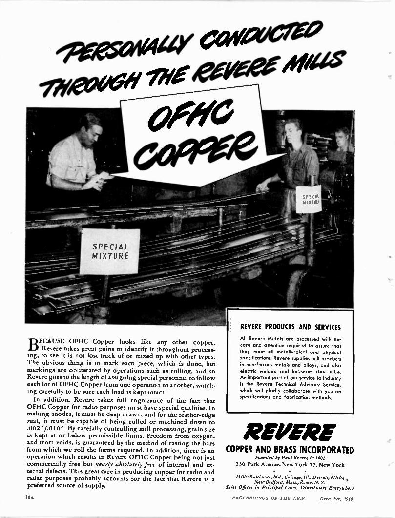
BECAUSE OFHC Copper looks like any other copper, Revere takes great pains to identify it throughout process-
ing, to see it is not lost track of or mixed up with other types. The obvious thing is to mark each piece, which is done, but markings are obliterated by operations such as rolling, and so Revere goes to the length of assigning special personnel to follow each lot of OFHC Copper from one operation to another, watch-ing carefully to be sure each load is kept intact.
In addition, Revere takes full cognizance of the fact that OFHC Copper for radio purposes must have special qualities. In making anodes, it must be deep drawn, and for the feather-edge seal, it must be capable of being rolled or machined down to .002"/.010". By carefully controlling mill processing, grain size is kept at or below permissible limits. Freedom from oxygen, and from voids, is guaranteed by the method of casting the bars from which we roll the forms required. In addition, there is an operation which results in Revere OFHC Copper being not just commercially free but nearly absolutely free of internal and ex-ternal defects. This great care in producing copper for radio and radar purposes probably accounts for the fact that Revere is a preferred source of supply.
REVERE PRODUCTS AND SERVICES
All Revere Metals are processed with the care and attention required to assure that they meet all metallurgical and physical specifications. Revere supplies mill products
in non-ferrous metals and alloys, and also electric welded and lockseam steel tube.
An important part of our service to industry is the Revere Technical Advisory Service, which will gladly collaborate with you on specifications and fabrication methods.
REPERE COPPER AND BRASS INCORPORATED
Pounded by l'au I Revere in 1801
230 Park Avenue, New York 17, New York
• • Mills:Baltimore, Md.; Chicago, Ill.; Detroit, Mich.;
New Bedford, Mass.; Rome, N. Y. Sales Offices in Principal Cities, Distributors Everywhere
16A PROCEEDINGS OF THE 1.R.E. December, 1948
TRADE MARK RECIStERED U 5 PATENT OFFICE
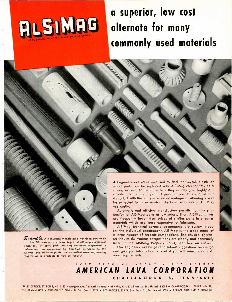
girtiOCAle: A manJfacturer replaced a machined port wnich
cost him 33 cents each with on improved AlSiMag component which cost 14 cents each. AlSiMog engineers cooperated in redesigning this component for maximum usefulness to the
customer and minimum production cost —That some engineering
cooperation is available to you on request.
.1 7 T H
a superior, low cost alternate for many commonly used materials
1.
111t4 "00
_1111 4 4 1 k
• Engineers are often surprised to find tFat metal, plastic or wood parts can be replaced with AlSiMag components at a saving in cost. At the same time they usually gain highly c e-sirable advantages in product performance. It is natural tt at a product with the many superior advantages of AlSiMag would be expec•ed to be expensive. The basic materials in AlSiMog are costly. Automatic and efficient manuf3cture permits quantity p-o-
duction of AlSiMag parts at low prices. Thus, AlSiMag prices are frequently lower than prices of similar parts in cheaper materials which are more expemive to fabricate. AlSiMag technical ceramic co -nponents are custom mace
for the individual requirement. AlSiMag is the trade name of a large number of ceramic compositions. The physical charac-teristics of the various compositions are clearly and accurately listed in the AlSiMag Property Chart, sent free on request. Our engineers will be glad to submit suggestions on design
and give you information on cost if you will submit details of your requirements.
Y E A R O F C E R A M I C L E A D E R S H I P
AMERICAN LAVA CORPORATION CH A T T A N O O G A 5, TE N N E S SE E
SALES OFFICES: ST. LOUIS, MO., 1123 Washington Ave.. Tel: Garfield 4959 • NEWARK, N. 1., 671 Broad St., Tel: Mitchell 2.8159 • CAMBRIDGE, Mass., MEI Wattle St..
Tel: Pirkland 4498 • CHICAGO, 9 S. Clinton St., Tel: Central 1721 • LOS ANGELES, 324 N. San Pedro St., Tel: Mutual 9079 • PHILADELPHIA, 1649 N. Broad St.
DU MONT
For wider frequency range.
increased brightness. • • it's
W # 419 Fe
•
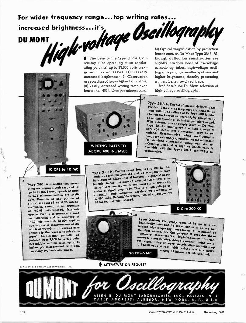
Type 280: A precision time-meas-uring oscillograph with range of 10 cps to 10 mc. Sweep speeds as high as 0.25 microsecond in. are avail-
able. Duration of any portion of signal measured on 0.25 micro-second in. sweep to an accuracy
of 0.01 microsecond. Intervals greater than 5 microseconds read
on calibrated dial to accuracy of
-1:1.1 microsecond. Ready applica-tion to precise measurement of du-
ration of waveform of various com-ponents in the composite television
signal. Accelerating potential ad-
justable from 7,000 to 12,000 volts.
Recordable writing rates up to 63 inches per microsecond, with com-
mercially available equipment.
..top writing rates...
0 54 00 f / 9 4
0 The basis is the Type 5RP-A Cath-ode-ray Tube operating at an acceler-
ating potential up to 29,000 volts maxi-mum. This achieves: (1) Greatly
increased brightness; (2) Observation
or recording of traces hitherto invisible;
(3) Vastly increased writing rates even
better than 400 inches per microsecond;
WRITING RATES TO
ABOVE 400 IN. MSEC.
(4) Optical magnification by projection
lenses such as Du Mont Type 2542. Al-
though deflection sensitivities are
slightly less than those of low-voltage
cathode-ray tubes, high-voltage oscil-
lographs produce smaller spot size and
higher brightness, thereby presenting
a finer, better resolved trace.
And here's the Du Mont selection of
high-voltage oscillographs:
Type 281-A: Devoid of internal deflection-am-
plifiers, there are no frequency response limita-
tions within the ratings of its Type 561P-A tube.
Phenomena have been recorded photographically at writing speeds of 85 inches per microsecond.
With external power supply (such as Du Mont
Type 286-A), photographic writing speeds of over 400 inches per microsecond may be ex-
amined. Recommended when oscillographic
needs are extremely specialized or too advanced for standard commercial equipment. An ac-
celerating potential as high as 29.000 volts is available w ith the Types 281-A and 286-A in combination.
Type 250-H: Covers range from d-c to 200 Ice. Po-tentials containing both d-c and a-c components may be examined. Many special features for general usage
include: linear time-base of unusual fiexibility; auto-
matic beam control on driven sweeps; internal cali-
brator of signal amplitude. This is a high-voltage os-cillograph with maximum accelerating potential of
13,000 volts. Recordable v:riting rate of approximately
40 inches per microsecond.
Type 248-A: Frequency range of 20 cps to 5 mc. Specifically intended for investigation of pulses con-taining high-frequency components of recurrent or transient nature. For this purpose it provides these
necessary characteristics: High-frequency recurrent
sweeps; short-duration driven sweeps; timing mark-
ers; signal delay network. Accelerating potentials up to 14,000 volts at recordable writing rate of approxi-
mately 69 inches per microsecond.
LITERATURE ON REQUEST
ALLE N B. DU M O NT LAB OR AT ORIES, INC , PASS AIC, N. J.
CA BLE A D DRESS ALBEE D U, NE W YO R K, N. Y., U.S. A otatek,7000"%rogloassre W
PROCEEDINGS OF THE I.R.E. December, 1948
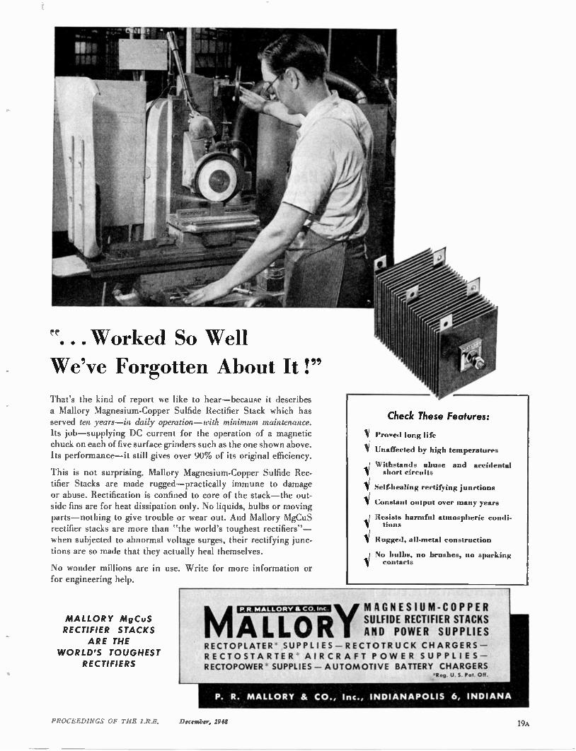
"... Worked So Well
We've Forgotten About It !"
That's the kind of report we like to hear—because it describes a Mallory Magnesium-Copper Sulfide Rectifier Stack which has served ten years—in daily operation—with minimum maintenance. Its job—supplying DC current for the operation of a magnetic chuck on each of five surface grinders such as the one shown above. Its performance—it still gives over 90% of its original efficiency.
This is not surprising. Mallory Magnesium-Copper Sulfide Rec-tifier Stacks are made rugged—practically immune to damage or abuse. Rectification is confined to core of the stack—the out-side fins are for heat dissipation only. No liquids, bulbs or moving parts—nothing to give trouble or wear out. And Mallory MgCuS rectifier stacks are more than "the world's toughest rectifiers"— when subjected to abnormal voltage surges, their rectifying junc-tions are so made that they actually heal themselves.
No wonder millions are in use. Write for more information or for engineering help.
MALL ORY MgCuS
RECTIFIER STACKS
ARE THE
W ORLD'S TOUGHEST
RECTIFIERS
Check These Features:
Proved long life
Unaffected by high temperatures
Withstands abuse and accidental short circuits
Self-healing rectifying junctions
Constant output over many years
Resists harm f111 atmospheric condi-tions
Rugged, all-metal construction
No bulbs, no brushes, no sparking contacts
MALLOR P. R. MALLORY & CO. Inc. MAGNESIUM-COPPER
SULFIDE RECTIFIER STACKS AND POWER SUPPLIES
RECTOPLATER SUPPLIES —RECT OTRUCK CH ARGERS — RECT OST ARTER AIR CR AFT PO WE R SUPPLIES —
RECTOPOWER SUPPLIES — AUTOMOTIVE BATTERY CHARGERS R . U. S. Pol. OR.
P. R. MALLORY & CO., Inc., INDIANAPOLIS 6, INDIANA
PROCEEDINGS OF THE I.R.E. December, 1948 19A
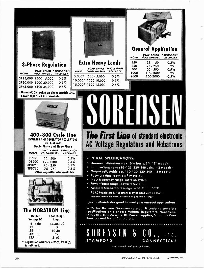
3-Phase Regulation LOAD RANGE 'REGULATION
MODEL VOLT-AMPERES ACCURACY
3P15,000 1500-15,000
3P30,000 3000-30,000
3P45,000 4500-45,000
0.5 %
0.5 %
0.5 %
Extra Heavy loads LOAD RANGE •4EGULATION
MODEL VOLT- AMPEF ES ACCURACY
5,000+ 500 - 5,000
10,000+ 1000-10,000
15,000+ 1500-15,030
• Harmonic Distortion on above models 3%. Lower capacities also available.
400-800 Cycle Line INVERTER AND GENERATOR REGULATORS
FOR AIRCRAFT. Single Phase and Three Phase
LOAD RANGE 'REGULATION MODEL VOLT-AMPERES ACCURACY
D500 50 - 500 0.5 % D1200 120-1200 0.5 % 3PD250 25 - 250 0.5 % 3PD750 75 - 750 0.5 %
Other capacities also available
Nwr—gasintimattsi The NOBATRON Line
Output Voltage DC
6 volts 12 " 28 " 48 " 125 "
Load Range Amps.
15-40-100 15
10-30 15 5-10
• Regulation Accuracy 0.25 % from 1/4 to full load.
0.5%
0.5%
0.5 %
General Application LOAD RANGE *REGULATION
MODEL VOLT-AMPERES ACCURACY
150 250
.L 500
1000 2000 -
25 - 150 25 - 250 50 - 500 100-1000 200-2000
0.5 % 0.2 % 0.5 % 0.2 %
SOBEIISE The First Line of standard electronic AC Voltage Regulators and Nobatrons
GENERAL SPECIFICATIONS:
• Harmon c distortion max. 5% basic, 2% "S" models
• Input vo tage tange 95-125: 220-240 volts (-2 models)
• Output cdjustable bet. 110-120: 220-240 (-2 models)
• Recovery time 6 cycles: 4' (9 cycles)
• Input frequency range: 50 to 65 cycles
• Power foctor range: down to 0.7 P.F.
• Ambient temperature range: —50 °C to • 50°C
All AC Regulators & Nobatrons may be used with no load.
*Models as °dab e with increased regulation accuracy.
Special Models designed to meet your unusual applications.
Write for the new Sorensen catalog. It contains complete specifications on standard Voltage Regulators, Nobatrons, Increvolts, Transformers, DC Power Supplies, Saturable Core Reactors and Meter Calibrators.
STA MF ORD CON NECTICUT
epresented in all principal cities
PROCEEDINGS OF THE I.R.E. December, 1948
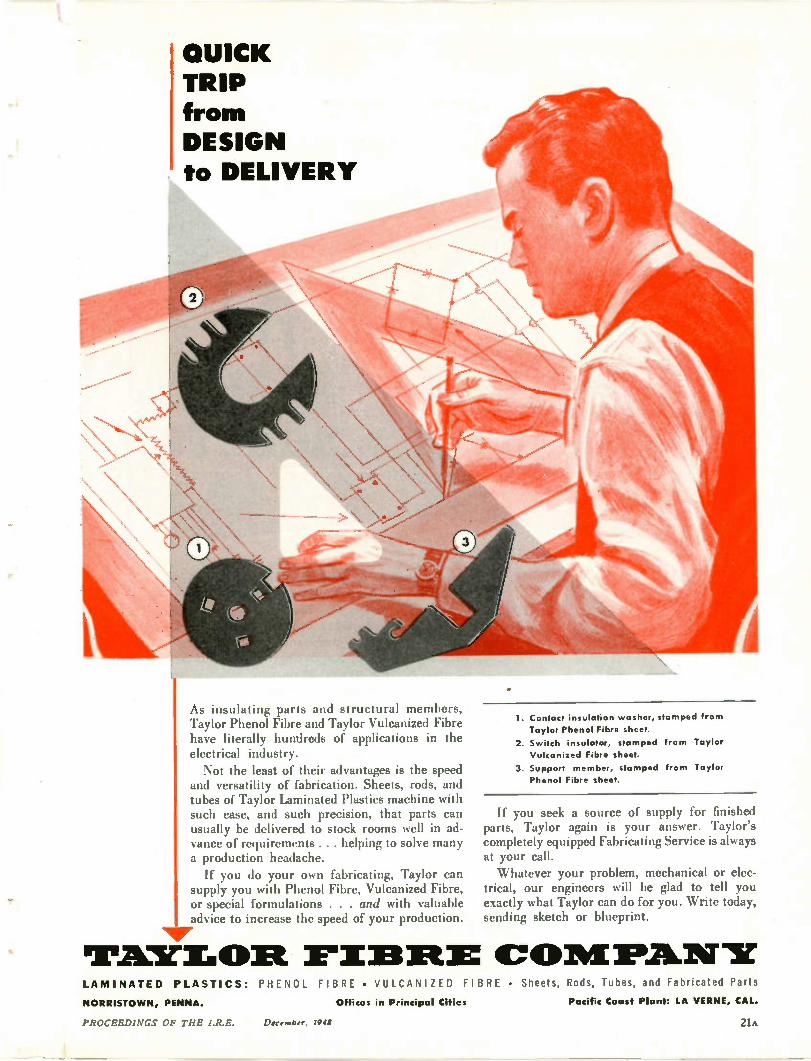
QUICK TRIP from DESIGN to DELIVERY
As insulating parts and structural members, Taylor Phenol Fibre and Taylor Vulcanized Fibre have literally hundreds of applications in the electrical industry. Not the least of their advantages is the speed
and versatility of fabrication. Sheets, rods, and tubes of Taylor Laminated Plastics machine with such ease, and such precision, that parts can usually be delivered to stock rooms well in ad-vance of requirements . . . helping to solve many a production headache. If you do your own fabricating, Taylor can
supply you with Phenol Fibre, Vulcanized Fibre, or special formulations . . . and with valuable advice to increase the speed of your production.
Nur WiEfuri• Olt r I33111: O 1 P AI N LAMINATED PLASTICS: PHENOL FIBRE • VULCANIZED FIBRE • Sheets, Rods, Tubes, and Fabricated Parts
1. Contact insulation washer, stamped from
Taylor Phenol Fibre sheet.
2. Switch insulator, stamped from Taylor
Vulcanized Fibre sheet.
3. Support member, stamped from Taylor
Phenol Fibre sheet.
If you seek a source of supply for finished parts, Taylor again is your answer. Taylor's completely equipped Fabricating Service is always at your call. Whatever your problem, mechanical or elec-
trical, our engineers will be glad to tell you exactly what Taylor can do for you. Write today, sending sketch or blueprint.
NORRISTO WN, PENNA. Offices in Principal Cities Pacific Coast Plant: LA VERNE, CAL.
PROCEEDINGS OF THE I.R.E. December, 1948 21A

77YERE:5 PROFIT FOR YOO /N
THE TIME 4410 410/YEY-54,14/6 Qa#1077e5 Of
PERMANENT MAGNETS
W&D 1298
Several avenues of profit are open to you in Arnold
Permanent Magnets. You can improve the performance and overall efficiency of equipment. You can increase production speed, and in many cases reduce both weight
and size. And most important, you can maintain these
advantages over any length of production run or period of time, because Arnold Permanent Magnets are com-
pletely quality-controlled through every step of manufac-ture—from the design board to final test and assembly. You'll find them unvaryingly uniform and reliable in
every magnetic and physical sense.
It's our job to help you discover and then fully attain these benefits. Arnold Products are available in all Alnico
grades and other types of magnetic materials —in cast or sintered forms, and in any size or shape required. Our
engineers are at your command—check with our Chicago headquarters, or with any Allegheny Ludlum branch office.
THE A R N OL D ENGINEERING CO. Subsidiary of ALLEGHENY LUDLUM STEEL CORPORATION
147 East Ontario Street, Chicago 11, Illinois
Specialists and Leaders in the Desian,Engineering and Manufacture of PERMANENT MAGNETS
_LA PROCFEDINC.0 nr: THE Li
Lib
It
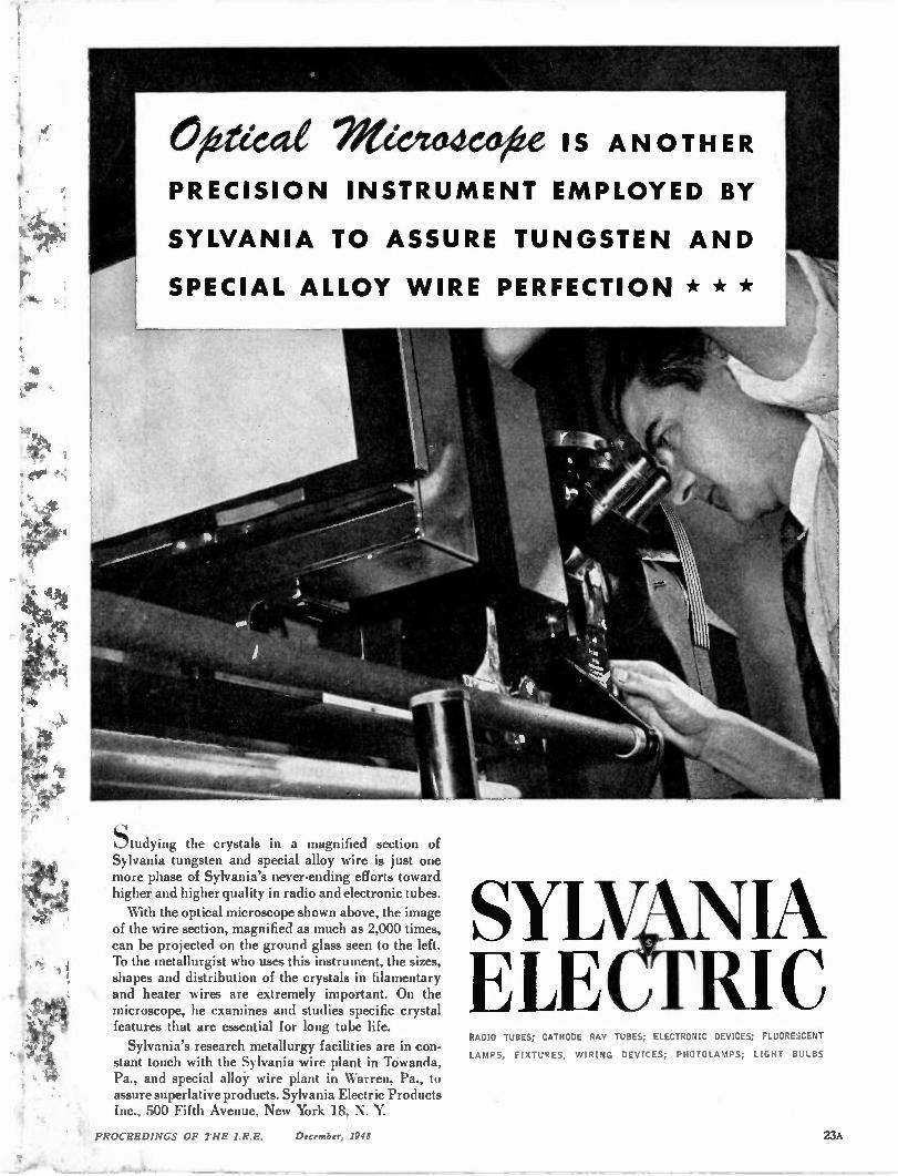
N eeittaCOAX IS ANOTHER
PRECISION INSTRU MENT EMPLOYED BY
SYLVANIA TO ASSURE TUNGSTEN AND
SPECIAL ALLOY WIRE PERFECTION * * *
Studying the crystals in a magnified section of Sylvania tungsten and special alloy wire is just one more phase of Sylvania's never-ending efforts toward highei and higher quality in radio and electronic tubes. With the optical microscope shown above, the image
of the wire section, magnified as much as 2,000 times, can be projected on the ground glass seen to the left. To the metallurgist who uses this instrument, the sizes, shapes and distribution of the crystals in filamentary and heater wires are extremely important. On the microscope, he examines and studies specific crystal features that are essential for long tube life. Sylvania's research metallurgy facilities are in con-
stant touch with the Sylvania wire plant in Towanda, Pa., and special alloy wire plant in Warren, Pa., to assure superlative products. Sylvania Electric Products Inc., 500 Fifth Avenue, New York 18, N. Y.
SUN NIA ELEGFRIC RADIO TUBES; CATHODE RAY TUBES; ELECTRONIC DEVICES; FLUORESCENT
LAMPS, FIXTURES, WIRING DEVICES; PHOTOLAMPS; LIGHT BULBS
PROCEEDINGS OF THE I.R.E. December, 1948 23A

• ..
AMONG radio engineers everywhere—there's a definite preference for Ohmite resistance products. These
men know—from experience—that Ohmite rheostats, resistors, and chokes provide long, trouble-free service. Here's the reason why you get extra performance. Every
Ohmite product is designed and constructed to stand up under severe operating conditions. Every unit is built to withstand the effects of shock, vibration, tem-perature extremes, altitude, and humidity. Make sure you get the benefit of this unfailing dependability. Ask for Ohmite products by name.
CLOSE CONTROL RHEOSTATS ilere 1, the most extensive line of rheostats offered today. • . 10 sizes, from 25 to 1000 watts, with many resistance values in each size. All-e,eramic construction. Windings are locked in vitreous enamel.
. .. . ....
•
.. . . •
DIVIDOHM ADJUSTABLE RESISTORS Used as multi-tap resit- •
ors or voltage dividers. •
Narrow strip of exposed winding •
provides contact surface for the
adjustable lug. Gives odd resistance values quickly. Seven ratings-10 to 200 watts.
VITREOUS ENAMELED RESISTORS Vi ire wound on a ceramic core , rigidly held in place. insulated and protected b‘
vitreous enamel. Even winding dissi
pates heat rapidly—prevents hot spots.
Many types, in ratings from S to 200 watts.
.. . . . . . . . . . . . . . . . . •
RADIO FREQUENCY PLATE CHOKES For covering higher frequencies. Single -layer wound on low power factor steatite or m olded plastic cores. Seven stock sizes, 3 to 520 megacycles. Two units rated 600 ma; all others 1000 ma.
7Vore.:te A1T e ae41119 40
OHMITE MANUFACTURING COMPANY • 4862
-6e Re:94e ead
Flournoy St., Chicago 44, III.
HMITE RHEOSTATS • RESISTORS • TAP SWITCHES • CHOKES • ATTENUATORS
24A PROCEEDINGS OF THE I.R.E. December, 1948
0 Cs 0
0/
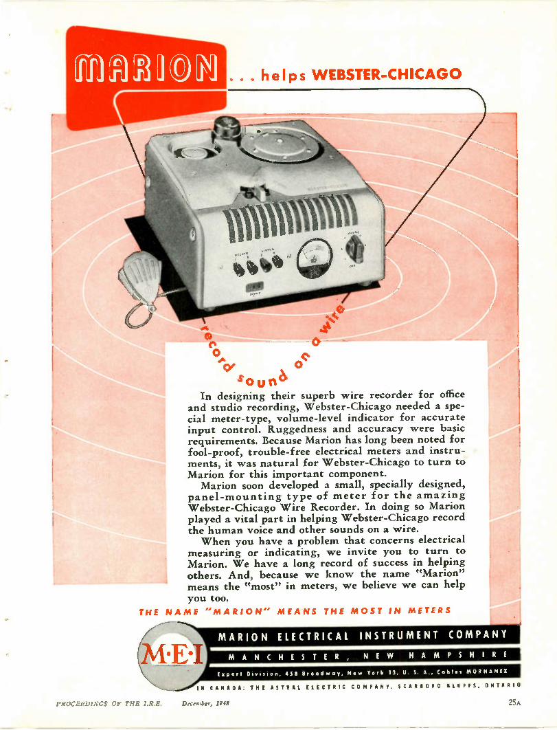
. . helps WEBSTER-CHICAGO
so ur6 In designing their superb wire recorder for office
and studio recording, Webster-Chicago needed a spe-cial meter-type, volume-level indicator for accurate input control. Ruggedness and accuracy were basic requirements. Because Marion has long been noted for fool-proof, trouble-free electrical meters and instru-ments, it was natural for Webster-Chicago to turn to Marion for this important component. Marion soon developed a small, specially designed,
panel-mounting type of meter for the amazing Webster-Chicago Wire Recorder. In doing so Marion played a vital part in helping Webster-Chicago record the human voice and other sounds on a wire. When you have a problem that concerns electrical
measuring or indicating, we invite you to turn to Marion. We have a long record of success in helping others. And, because we know the name "Marion" means the "most" in meters, we believe we can help you too.
THE NA ME ''M ARI O N" MEA NS THE M OST IN METERS
o(%
At%
MARION ELECTRICAL INSTRUMENT COMPANY
M A N C H E S T E R , NE W H A M P S H I R E
Export Division, 4511 Broad way, Ne w York 13, U. S. A., Cables MORHANEX
IN CANADA: THE ASTRAL ELECTRIC CO MPANY. SCARBORO BLUFFS. ONTARIO
PROCEEDINGS OF THE I.R.E. December, 1948
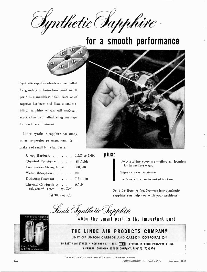
for a smooth performance
Synthetic sapphire wheels are unequalled
for grinding or burnishing small metal
parts to a matchless finish. Because of
superior hardness and dimensional sta-
bility, sapphire wheels will maintain
exact wheel form, eliminating any need
for machine adjustment.
LINDE synthetic sapphire has many
other properties to recommend it to
makers of small but vital parts:
Knoop Hardness 1,525 to 2,000
Chemical Resistance All Acids
Compressive Strength, psi . 300,000
Water Absorption 0.0
Dielectric Constant . 7.5 to 10
Thermal Conductivity 0.010 cal. sec.-1 cm.--1 deg. C.-1
at 300 deg. C.
Half•boules, weighing up to 150 carats
Rods, 0.065-in. to 0.125-in diameter
plus: Unicrvstalline structure —offers no location for immediate wear.
Superior wear resistance.
Extremely low coefficient of friction.
Send for Booklet No. 3A—see how synthetic
sapphire can help you with your problems.
when the small part is the important part
THE LINDE AIR PRODUCTS COMPANY UNIT OF UNI ON CARBIDE AND CARB ON CORP ORATI ON
30 FAST 42nd STREET • NEW YORK 17 • N.Y. Ri rl OFFICES IN OTHER PRINCIPAL CITIES
IN CANADA: DOMINION OXYGEN COMPANY, LIMITED, TORONTO
26 k
The wurd **Linde" is a trade-mark a The Linde Air Products Co sots.
PROCEEDINGS OF THE I.R.E. December, 1948
Type 0
CAN YOU USE. THIS
SPECIAL ,1)1,41DENSED CATALOG?
* THE RJC-2 SPECIAL CANNON ELEC-
TRIC Condensed Catalog covers the electrical connectors sold through our 300-odd regular radio parts dis-tributors for radio and sound appli-cations such as microphones, ampli-fiers, transmitters, receivers, etc. They include type series "P", "X", "XK" "XL", "TQ". Also shown in the same catalog are Sectional Cable Termi-nals, Laboratory & Switchboard Con-nectors and Bayonet Type Lamp Sockets. List prices are given on all items. Address Dept. L-377 for your free copy. SINCE 1915
U1111011i rac
Le400N -ay,wir
CANNON El CTPIC
3209 HUMBOLDT ST., LOS ANGELES 31, CALIF.
IN CANADA & BRITISH EMPIRE: CANNON ELECTRIC CO., LTD., TORONTO 13, ONT.
WORLD EXPORT (Excepting British Empire): FRAZAR & HANSEN, 301 CLAY ST., SAN FRANCISCO
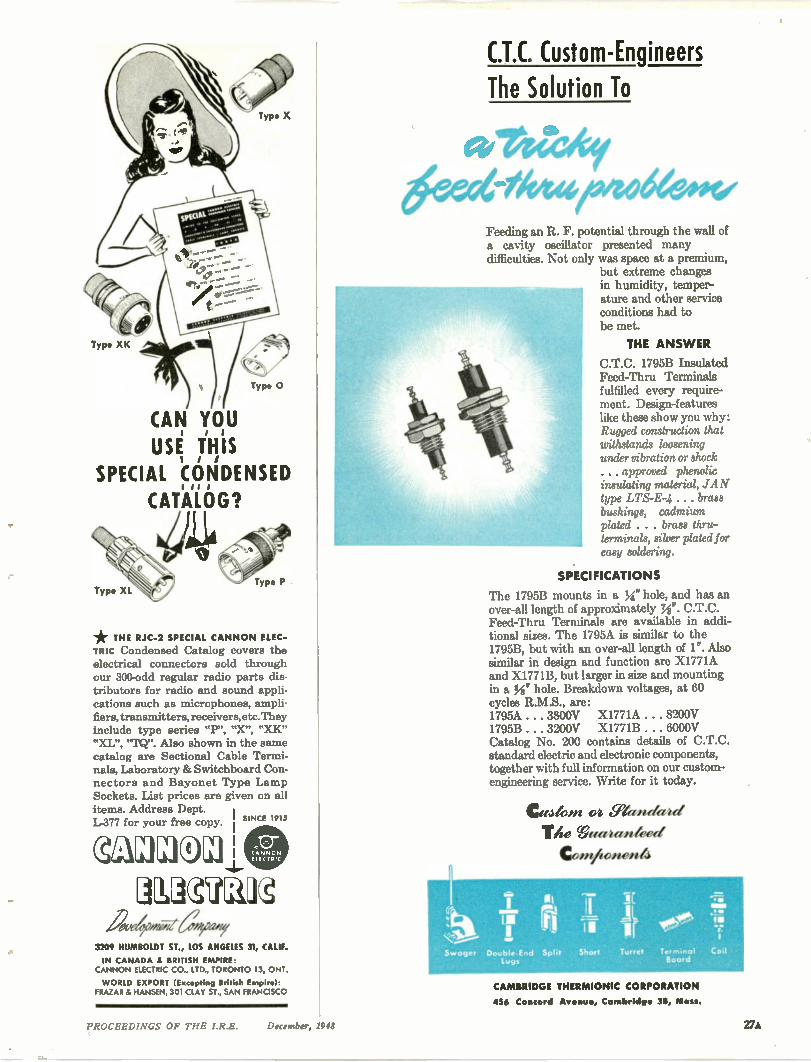
C.T.C. Custom-Engineers The Solution To
ge Welat 6exalktoproodeeow
Feeding an R. F. potential through the wall of a cavity oscillator presented many difficulties. Not only was space at a premium,
but extreme changes in humidity, temper-ature and other service conditions had to be met.
THE ANSWER
C.T.C. 1795B Insulated Feed-Thru Terminals fulfilled every require-ment. Design-features like these show you why: Rugged construction that withstands loosening under vibration or shock . .. approved phenolic insulating material, JAN type LTS-E-4 . . . brass bushings, cadmium plated . . . brass thru-terminals, silver plated for easy soldering.
SPECIFICATIONS
The 1795B mounts in a Ys," hole, and has an over-all length of approximately Ni". C.T.C. Feed-Thru Terminals are available in addi-tional sizes. The 1795A is similar to the 1795B, but with an over-all length of 1". Also similar in design and function are X1771A and X1771B, but larger in size and mounting in a MI" hole. Breakdown voltages, at 60 cycles R.M.S., are: 1795A . . . 3800V X1771A . . . 8200V 1795B . . . 3200V X1771B . . . 6000V Catalog No. 200 contains details of C.T.C. standard electric and electronic components, together with full information on our custom-engineering service. Write for it today.
Cu44in 494 gland-er a
The Weeemrrialeeet
Contlionen4
16:11114.
Stroger Double-End Lugs
leo Split Short Turret Terminal Coil
Board
CAMBRIDGE THERMIONIC CORPORATION
436 Concord A , Cambridge 38, Mass.
PROCEEDINGS OF THE I.R.E. December, 1948 VA

1054 II- telt O •% VALUE
r&
Oge
v BECAUSE OF MACHLETT EXPERIENCE, SKILL AND "SINCERITY OF SERVICE"
• For over a half century Machlett Laboratories has pio-
neered and made notable contributions to the development
of the electron tube art.
Today, through its modern plant, development laboratories
and skilled personnel, it provides the best in tubes and ser-
vice for Broadcasting and Industrial uses. No matter what
your purpose--Broadcasting, Communication or Industrial
electronics—you will find a Machlett tube to fill your needs
--and fill them well. And, no less important than the tube
itself, Machlett Service --valued by tube users for more
than 50 years— will give you a new sense of value to apply
to your tube procurement problem.
If you want better value—more satisfaction --try MACH-
LETT.
28A PROCEEDINGS OF TIIE I.R.E. December, 1948
Note to Broadcasters: Machlett Laboratories now produce for the
Western Electric Company its line of high power transmitting tubes
— so well known and respected by all broadcasting engineers.
Made by Machlett Laboratories in close collaboration with Bell
Telephone Laboratories, these tubes will continue to set the highest standard of performance in broadcast service. These tubes are
distributed exclusively for Western Electric by the Graybar Electric
Company in the U.S.A., and by the Northern Electric Company in
Canada and Newfoundland.
This new combination of Western Electric and Machlett—two pioneers in the electron tube field—is your best assurance of progress and
performance in the further development of better tubes to fill
your needs.
Equipment designers, broad-casters, operators of point-to-point services, and industrial users of power tubes are in-vited to write for complete in-formation.The Machlett Electron Tube Data Book will be sent on request.
Over 50 years of Electron Tube Experience
M A C HLETT LA B O R AT O RI E S, IN C.
Springdale, Connecticut
PROCEEDINGS OF THE I.R.E. December, 1948 29A
0 3 1.1 4 4 1 1
A ril) d is ed yl d
.1 14 P e
••••• f"
BLILEY TYPE 13116
APPROVED FOR
PRODUC'Il,01I
TECHNIQUALITY
CRYSTALS
Engineered to the "MUST" requi-ements of (went military and commercial communications
When you write Bliley Type BH6 into your specificaticm you meet all requiren-.ents, military or commer-cial . . . and you have simplified your design considerEtions ny the elimination of unnecessary multi-plier stages. Type B}{6 is available up to 100 MC. Write 'Is for oscilla-tor circu:t recommendations based on your particular requirements.
Sidle C/Z YSTAI LS
NE WS and NE W PRODUCTS These manufacturers have invited PROCEEDINGS readers to write for literature
and further technical information. Please mention your I.R.E. affiliation.
Microgroove This fall our industry has seen one
outstanding development in the home en-tertainment field, that interests all en-gineers conscious of their need to keep abreast of the radio field. The vast amount of interest in those markets where it has been shown, has caused many firms to an-nounce materials and accessories for the reproduction of the new long-playing Columbia Microgroove records. Changers, pick-ups, new cartridges, and similar ac-cessories are flooding the market, not to overlook the adaptation of this feature to the completed sets offered the buying pub-lic. When far enough along in the develop-ment work Columbia records asked the co-operation of Philco to make a player attachment, with slow speed motor and light crystal cartridge equipped playing arm. Since then many other manufac-turers have added these and other com-ponents to their lines.
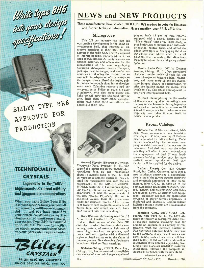
General Electric, Electronics Division, Electronics Park, Syracuse, N. Y., who caused the largest stir in the phonograph-reproducer field, by the introduction about 18 months back, of their DI RM 66 variable-reluctance cartridge, has en-tered the microgroove field with the an-nouncement of the MICRO-GROOVE MODEL featuring a 1-mil-radius stylus, low mass of the moving system, and high compliance, to meet the requirements of the new records. Physically, the unit is one-third smaller than the predecessor model for standard records. All of the sa-lient features such as quietness, absence of needle talk, long record life, etc., have been brought into this new design.
Gray Research & Development Co., 16 Arbor Street, Hartford 1, Conn., have in-troduced their version of the older GE cartridge, to which has been added a new moving system, of extreme lightness of mass, high tracking compliance, and proper stiffness, together with a diamond stylus of 1-mil radius to fit the shape of the new grooves. New damping blocks also have been fitted to Gray cartridge.
Webster-Chicago, 4245 N. Knox Ave., Chicago, Ill., has announced as available CWO models of a record changer capable of
playing both 33 and 78 rpm records, equipped with a special needle in their "Tilt-o-Matic" tone arm. These changers play both types of records on an automatic or manual control basis, and afford the added advantage of disengaging the driv-ing rubber idler wheels when in the off position, thus preventing the idlers from forming bumps or flats, and giving quieter operation.
Zenith Radio Corp., 6001 W. Dickens Avenue, Chicago 39, III., has announced that the console models of their fall line have microgroove feature added. Magna-vox, and many more of the set makers have jumped aboard the bandwagon, to offer the buying public the means with which to play this latest development, in the home entertainment field.
Without philosophizing on the merits of this new offering, it is interesting to see the way in which manufacturing ingenuity and speed of production can accrue to fill a market readymade for it, when some en-terprising firm takes it upon itself to pioneer a new product.
Recent Catalogs
National Co. 61 Sherman Street, Mal-den, Mass, announces a new television receiver, with 7' tube, covering all 13 chan-nels, scheduled for fall marketing. Tech-niques developed by this renowned com-pany in stable communication receiver de-velopment find their way into the video sets they will offer. A novel innovation is the employment of dual 6' oval loud-speakers flanking the video tube, for more realistic sound reproduction. Full par-ticulars will be supplied for the asking.
Lenkurt Electric Co., 1129 County Road, San Carlos, California, announce a new catalogue comprising a comprehen-sive listing of the carrier-current telephone and telegraph equipment of their manu-facture, form CX-42. In addition to the communication equipment described, ring-ing, dialing, and telemetering apparatus are covered, as well as selected test equip-ment, especially designed for operational servicing of carrier-current apparatus, is displayed and described. Comprehensive bulletins on each system are also available from the company.
Metalace Corp., 7101 Grand Con-course, New York 53, N. Y., have an-nounced through a descriptive sheet their all-purpose antenna mounting base for affixing an antenna to a chimney or roof parapet. With the increased number of FM and video antennas finding their way to the rooftops of apartment houses and rural homes, such an accessory will lend itself readily to the safe and workmanlike installation of the antenna supporting pole. Simple tools alone are needed to make the installation, following the complete in-structions furnished with the new stand.
(Continued on page 48A)
BLILEY ELECTRIC COMPANY
UNION STATION BLDG., ERI E, PA. L.
30A PROCEEDINGS OF THE I.R.E. December, 1948
UHF EQUIP MENT
DEVELOPED • DESIGNED • PRODUCED
DESELOPIAE.:131 , , trom concept ot idea to working model
t DESIGI4 • • • , , , by horoughly experi-ced 1.111E enginees
en eci
VilsaillfAC'Ti3RS • . using methods esp al-ly suited to 1.11-IF work
•
Spe6ctlized 131-1V knowledge, expetience and shop plactice enable Lavoie LaboTatoties to
handle every hase ot elect-tonic p-to
p duction
ticiently and eco et nonl ically. Pte cision and low xlnit cost ate based on
these tactots developed th.toticP -ye cas o w otk
t Vac-
tical specialization in this tield.
• • • LAVOIE PRODUCTS: Frequency Meters—Frequency nnas n
Standards - Receivers
--Transmitters — Ante ad Mounts.
c Detailed information and estimates of LAVOIE service are available promptly without cost or obligation.
Zcrecti2( Zdera bied, RADIO ENGINEERS AND MANUFACTURERS
MORGANVILLE, N. J.
Specialists in the Development and Manufacture of UHF Equipment
PROCEEDINGS OF THE I.R.E. December, 1948 31A
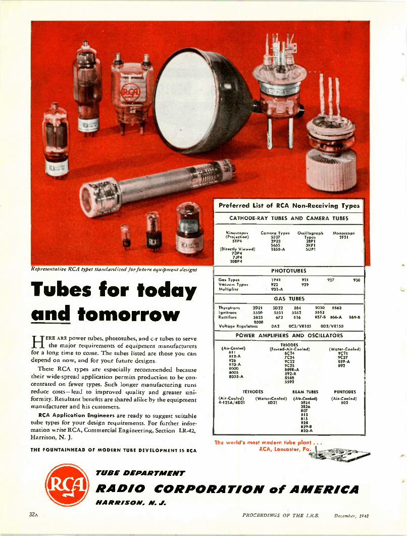
Representative RCA types standardized forjuture equipment designs
Tubes for today and tomorrow HERE ARE power tubes, phototubes, and c-r tubes to serve
the major requirements of equipment manufacturers for a long time to come. The tubes listed are those you can depend on now, and for your future designs.
These RCA types are especially recommended because their wide-spread application permits production to be con-centrated on fewer types. Such longer manufacturing runs reduce costs—lead to improved quality and greater uni-formity. Resultant benefits are shared alike by the equipment manufacturer and his customers.
RCA Application Engineers are ready to suggest suitable tube types for your design requirements. For further infor-mation write RCA, Commercial Engineering, Section LR-42, Harrison, N. J.
THE FOUNTAINHEAD or MODERN TUBE DEVELOPMENT IS RCA
TUBE D EPA RT ME NT
Gas Types 1P41 Vacuum Types 922 Multiplier 931-A
921 927 930
Preferred List of RCA Non-Receiving Types
CATHODE-RAY TUBES AND CAMERA TUBES
Kelre.cop. s Ca M OTO Types Oscillogroph Monoscop• Proiectton) 5527 Types 2F21 STP4 2P23 2BP1
5655 3KP1 Direct ly Vie Ned) 1850-A 5UP1
7DP4 704 108 P4
PHOTOTUBES
929
GAS TUBES
Thyratrons 2D21 3022 884 2050 5563 Ignitrons 5550 5551 5552 5553 Rectifiers 3825 673 816 857-8 866-A 869-8
8008 Voltage Regulators 0A2 0C3 VR105 003 VR150
POWER AMPLIFIERS AND OSCILLATORS
(Air-Cooled) 811 8I2-A 826 833-A 8000 8005 8025-A
TRIODES (Forced-Air-Cooled) (Water-Cooled
6C24 9C21 7C24 9C27 9C22 889-A 9C25 892 889R-A 892-R 5588 5592
TETRODES BEAM TUBES PENTODES
(Air-Cooled) (Water-Cooled) (Air-Cooled) (Air-Cooed 4-125A/4D21 8D21 2E24 802
2E26 807 813 815 828 829-B 832-A
The world's most modern tube plant ...
RCA, Lancaster, oeitior
RA DIO CORPORATIO N of A MERICA NA RN/SO N, N. J.
32A PROCEEDINGS OF THE I.R.E. December, 1948
BOARD OF DIRECTORS, 1948
Benjamin E. Shackelford President
R. L. Smith-Rose Vice-President
S. L. Bailey Treasurer
Haraden Pratt Secretary
Alfred N. Goldsmith Editor
Frederick B. Llewellyn Senior Past President
W. R. G. Baker Junior Past President
1948-1949
J. B. Coleman Murray G. Crosby Raymond A. Heising T. A. Hunter H. J. Reich F. E. Terman
1948-1950
J. E. Shepherd J. A. Stratton
1948
A. E. Cullum, Jr. Virgil M. Graham Raymond F. Guy Keith Henney J. V. L. Hogan F. S. Howes
J. A. Hutcheson I. J. Kaar D. B. Sinclair
• Harold R. Zeamans General Counsel
• George W. Bailey Executive Secretary
Laurence G. Cumming Technical Secretary
E. K. Gannett Assistant Secretary
•
BOARD OF EDITORS
Alfred N. Goldsmith Chairman
•
PAPERS REVIEW COMMITTEE
Murray G. Crosby Chairman
• PAPERS
PROCUREMENT COMMITTEE
John D. Reid General Chairman
PROCEEDINGS OF THE I.R.E.
(Including the WAVES AND ELECTRONS Section)
Published Monthly by
The Institute of Radio Engineers, Inc.
VOLUME 36 December, 1948 NUMBER I 2
PROCEEDINGS OF THE I.R.E. Frederic Stanley Howes, Director, 1948 Are You Satisfied? C W. Carnahan 3217. A Digital Computer for Scientific Applications
C F. West and J. E. DeTurk 3218. Signal-to-Noise Ratio in AM Receivers
Eugene G. Fubini and Donald C. Johnson 3219. Rectification of a Sinusoidally Modulated Carrier in the Presence
of Noise David Middleton 3220. An Approximate Solution of the Problem of Path and Absorption
of a Radio Wave in a Deviating Ionosphere Layer James E. Hacke, Jr. and John M. Kelso
3221. The Negative-Ion Blemish in a Cathode-Ray Tube and Its Elimi-nation R M Bowie
3222. The Patterns of Slotted-Cylinder Antennas George Sinclair 3223. A Swept-Frequency 3-Centimeter Impedance Indicator
Henry J. Riblet 3224. The Ultrasonic Interferometer with Resonant Liquid Column..
Francis E. Fox and Joseph L. Hunter Contributors to PROCEEDINGS OF THE I.R.E. Correspondence: 3057. "Multifrequency Bunching in Reflex Klystrons" ....Gunnar Hok 3099. "Modern Single-Sideband Equipment"...C. T. F. van der Wyck
1450 1451
1452
1461
1467
1477
1482 1487
1493
1500 1504
1505 1505
INSTITUTE NEWS AND RADIO NOTES SECTION 1949 IRE Convention Plans Under Way 1506 The IRE Professional Group System—A Status Report 1507 Industrial Engineering Notes 1508 Sections 1509 Books: 3225. "Microwave Transmission Design Data" by Theodore Moreno.
Reviewed by Seymour B. Cohn 1510 3226. "Microwave Duplexers" by L. D. Smullin and C. G. Montgom-
ery Reviewed by A. L. Samuel 1510 3227. "Microwave Transmission Circuits" edited by G. L. Ragan
Reviewed by Allen F. Pomeroy 1511 3228. "Antenna Manual" by Woodrow Smith
Reviewed by John D. Kraus 1511 IRE People 1511
WAVES AND ELECTRONS SECTION G. E. Van Spankernen and K. R. Patrick, Section Chairmen 3229. JTAC Requests Technical Co-operation in Connection with FCC
Television Hearings 3230. Electronics in Nuclear Physics W. E. Shoupp 3231. Considerations in the Design of a Universal Beacon System....
Ludlow B. Hallman, Jr. 3232. Three-Dimensional Representation on Cathode-Ray Tubes
Carl Berkley 3233. A Single-Control Variable-Frequency Impedance-Transforming
Network Andrew Bark 3234. Phase Difference Between the Fields of Two Vertically Spaced
Antennas E. W. Hamlin and A. W. Straiton Contributors to Waves and Electrons Section 3235. Abstracts and References News—New Products 30A Student Branch Meetings ... Section Meetings 34A Positions Open Membership 38A Positions Wanted
Advertising Index 66A
1514
1515 1518
1526
1530
1535
1538 1543 1544 37A 50A 55A
EDITORIAL DEPARTMENT
Alfred N. Goldsmith Editor
Clinton B. DeSoto Technical Editor
Mary L. Potter Assistant Editor
William C. Copp Advertising Manager
Lillian Petranek Assistant Advertising Manager
Responsibility for the contents of papers published in the
PROCEEDINGS OF THE I.R.E. rests upon the authors.
Statements made in papers are not binding on the Institute
or its members.
Changes of address (with ad-vance notice of fifteen days) and communications regarding sub-scriptions and payments should be mailed to the Secretary of the Institute, at 450 Ahnaip St., Menasha, Wisconsin, or 1 East 79 Street, New York 21, N. Y. All rights of republication, in-cluding translation into foreign languages, are reserved by the Institute. Abstracts of papers, with mention of their source, may be printed. Requests for republication privileges should be addressed to The Institute of Radio Engineers.
• Copyright 1948. by the !actuate of Radio Engineers,
1450 PROCEEDINGS OF THE I.R.E. December
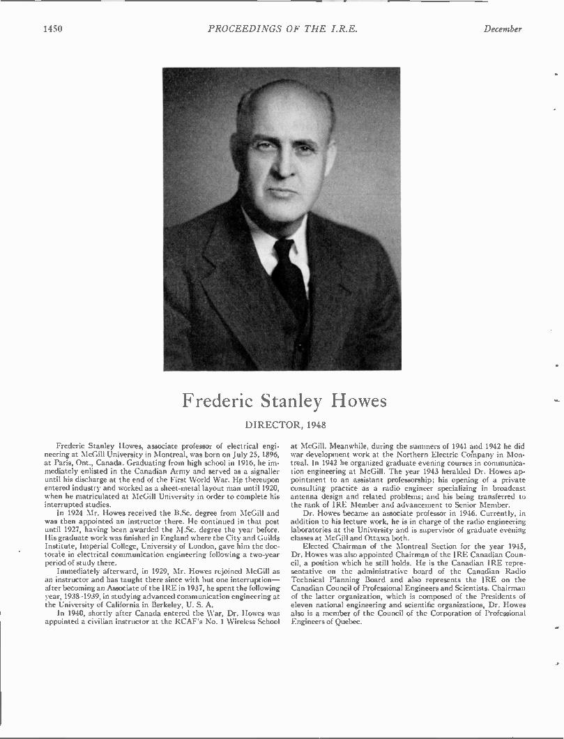
Frederic Stanley Howes DIRECTOR, 1948
Frederic Stanley Howes, associate professor of electrical engi-neering at McGill University in Montreal, was born on July 25,1896, at Paris, Ont., Canada. Graduating from high school in 1916, he im-mediately enlisted in the Canadian Army and served as a signaller until his discharge at the end of the First World War. He thereupon entered industry and worked as a sheet-metal layout man until 1920, when he matriculated at McGill University in order to complete his interrupted studies. In 1924 Mr. Howes received the BSc. degree from McGill and
was then appointed an instructor there. He continued in that post until 1927, having been awarded the M.Sc. degree the year before. His graduate work was finished in England where the City and Guilds Institute, Imperial College, University of London, gave him the doc-torate in electrical communication engineering following a two-year period of study there. Immediately afterward, in 1929, Mr. Howes rejoined McGill as
an instructor and has taught there since with but one interruption— after becoming an Associate of the IRE in 1937, he spent the following year, 1938-1939, in studying advanced communication engineering at the University of California in Berkeley, U. S. A. In 1940, shortly after Canada entered the War, Dr. Howes was
appointed a civilian instructor at the RCAF's No. 1 Wireless School
at McGill. Meanwhile, during the summers of 1941 and 1942 he did war development work at the Northern Electric Cornpany in Mon-treal. In 1942 he organized graduate evening courses in communica-tion engineering at McGill. The year 1943 heralded Dr. Howes ap-pointment to an assistant professorship; his opening of a private consulting practice as a radio engineer specializing in broadcast antenna design and related problems; and his being transferred to the rank of IRE Member and advancement to Senior Member. Dr. Howes became an associate professor in 1946. Currently, in
addition to his lecture work, he is in charge of the radio engineering laboratories at the University and is supervisor of graduate evening classes at McGill and Ottawa both. Elected Chairman of the Montreal Section for the year 1945,
Dr. Howes was also appointed Chairman of the IRE Canadian Coun-cil, a position which he still holds. He is the Canadian IRE repre-sentative on the administrative board of the Canadian Radio Technical Planning Board and also represents the IRE on the Canadian Council of Professional Engineers and Scientists. Chairman of the latter organization, which is composed of the Presidents of eleven national engineering and scientific organizations, Dr. Howes also is a member of the Council of the Corporation of Professional Engineers of Quebec.
1948 PROCEEDINGS OF THE I.R.E. 1451
There has been a wealth of sometimes heated argument as to the relative opportunities for engineers in private versus governmental employ. One side of this question is clearly and force-fully presented, with substantiating reasons, by the writer of the following guest editorial—a member of the IRE Board of Editors and a skilled communications engineer who, after seventeen years of experience in private industry, has joined the staff of the Sandia Base Branch of the Los Alamos Scientific Laboratory. —The Editor.
Are You Satisfied? C. W. CARNAHAN
To those radio engineers who are happy in their present work, this editorial can have little interest. It is addressed primarily to those who had real jobs to do during the war, and who now find their return to peacetime pursuits some-thing of a let-down. This group will remember that their war labors, while long and arduous, were vital and exciting, and that they
demanded the utmost of their skill and knowledge. Things were built in the way they should be built, neglected text books had to be dug into again, and sudden accretions of knowledge in entirely new fields had to be gained. Results were measured in terms of lives and victories, not in figures on a quarterly statement. Since the end of the war, however, many engineers have returned to their prewar occupations, where their technical
achievements now may consist of such exciting things as saving ten cents on that new receiver, or making a further compromise with quality to beat that other outfit. They have returned to the normal battle with the sales department, whose decisions and salaries invariably outrank their own. Many of them look back with longing to the days when vice-presidents made fair expediters, and sales departments, while drawing those fat salaries, of course, at least had to listen to the engineers without any backtalk. In their leisure, they now read in the PROCEEDINGS about a rapidly expanding art which is growing beyond them. Continued government spending in the postwar period has already had a considerable effect in those radio in-
dustries which existed before the war. The unfilled demand for engineers in government work has made more valuable commodities out of those still in private industry. This point management usually concedes with reluctance, being prone to indicate to dissatisfied engineers the horrors of governmental work, the insecurity, the red tape, bureaucracy, restriction of publications, and so forth. Those old timers who remember the security and other advantages offered by private industry in the thirties will be able to assess these arguments at their true worth. Financially, the average engineer will not be any more underpaid in government work than he is in private industry.
As for job security, there are more problems now than there are men to solve them, and new ones arise every day Furthermore, the advances in knowledge and new techniques resulting from this work will create new jobs in private industry for those who can fill them. There are publication restrictions, of course, but to compensate there are interest-ing, demanding work on the frontiers of radio knowledge, unlimited facilities to work with, and no sales department on the engineer's neck. What more can a good engineer want? So far, this has been an appeal to the self-interest of the individual engineer. There is, however, a larger side to this.
Good men must be found for the unfilled government jobs now available, if our stated objectives of national security are to be attained. If a fair percentage of those who performed so splendidly during the war will take up where they left off, this need will be met.
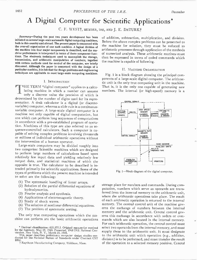
1452 PROCEEDINGS OF THE I.R.E. December
A Digital Computer for Scientific Applications* C. F. WESTt, MEMBER, IRE, AND J. E. DETURKt
Summary—During the past two years development has been initiated on several large-scale automatic digital computing machines, both in this country and abroad. The present paper is concerned with the over-all organization of one such machine. A logical division of the machine into four major components is described, and the ma-chine performance is interpreted in terms of these component func-tions. The electronic techniques used to accomplish the storage, transmission, and arithmetic manipulation of numbers, together with certain methods used for control of the computer, are briefly discussed. Although the paper is concerned with the design of a particular machine, it is felt that the design problems and engineering techniques are applicable to most large-scale computing machines.
I. INTRODUCTION
THE TERM "digital computer" applies to a ca lcu -lating machine in which a number can assume only a discrete value the precision of which is
determined by the number of digits used for its repre-sentation. A desk calculator is a digital (or discrete-variable) computer, whereas a slide rule is a continuous-variable computer. A large-scale digital computer is a machine not only capable of digital computation, but one which can perform long sequences of computations in accordance with a pre-established program of opera-tion. Machines of this type are also referred to as se-quence-controlled calculators. Such a computer is ca-pable of solving complex problems involving thousands or millions of individual arithmetic operations without the intervention of a human operator. Large-scale computers may be divided roughly into
two categories: Scientific machines which are designed to perform large numbers of calculations based upon relatively few input data and yielding relatively few output data, and statistical machines of which the opposite is true. The calculator to be described is in-tended primarily for scientific applications. Some of the types of problems which the present machine is intended to solve are the following:
(1) The systematic handling of linear arrays. (2) Solution of the partial differential equations of
hydrodynamics. Fourier analysis and synthesis. Applications of electromagnetic theory. Study of shock waves. The solution of nonlinear differential equations. The problem of systematic sorting.
(3) (4)
(5) (6)
(7)
The only true computing operations which the ma-chine can perform are the basic arithmetic operations
* Decimal classification: 621.375.2. Original manuscript received by the Institute, May 19, 1948. Presented, 1948 IRE National Con-vention, New York, N. Y., March 25, 1948. This paper describes preliminary computer design studies con-
ducted for the National Bureau of Standards under Contract CST 8092. t Raytheon Manufacturing Company, Waltham, Mass.
of addition, subtraction, multiplication, and division. Before the above complex problems can be presented to the machine for solution, they must be reduced to arithmetic processes through application of the methods of numerical analysis. These arithmetic routines•must then be expressed in terms of coded commands which the machine is capable of following.
II. MACHINE ORGANIZATION
Fig. 1 is a block diagram showing the principal com-ponents of a large-scale digital computer. The arithme-tic unit is the only true computing unit in the machine. That is, it is the only one capable of generating new numbers. The internal (or high-speed) memory is a
r i
CONTROL SIGNALS ,....,
CENTRAL CONTROL
(ORDERS)
ORDERS
L CONTRO( SIGNALS
PROBLEM PREPARATION
UNIT
HIGH SPEED MEMORY
NUMBERS a ORDERS)
UMBERS
a ORDERS
MAGNETIC TAPE MEMORY
(NumBERS a ORDERS)
f !
1 1
1 1 I i
ARITHMETIC UNIT
(NUMBERS a ORDERS)
I MAIN MACHINE f I AUXILIARY UNITS REELS OF
( PREPARED TAPE
L.. PRINTERS
Fig. 1—Block diagram of the digital computer.
storage place for numbers and commands. During com-putation, numbers which serve as operands are trans-ferred from the internal memory to the arithmetic unit, where the arithmetic operations take place. The result of each arithmetic operation is returned to the internal memory. The central control unit of the machine gov-erns the exchange of numbers between the internal memory and the arithmetic unit. Central control gov-erns this exchange in accordance with orders or com-mands which are also located in the internal memory. For each arithmetic operation, the central control must select two operands from the internal memory, and must supply these to the arithmetic unit. It must designate to the arithmetic unit which operation (e.g., addition, division) is to be performed, and must transfer the result of the operation to a selected memory position. Central
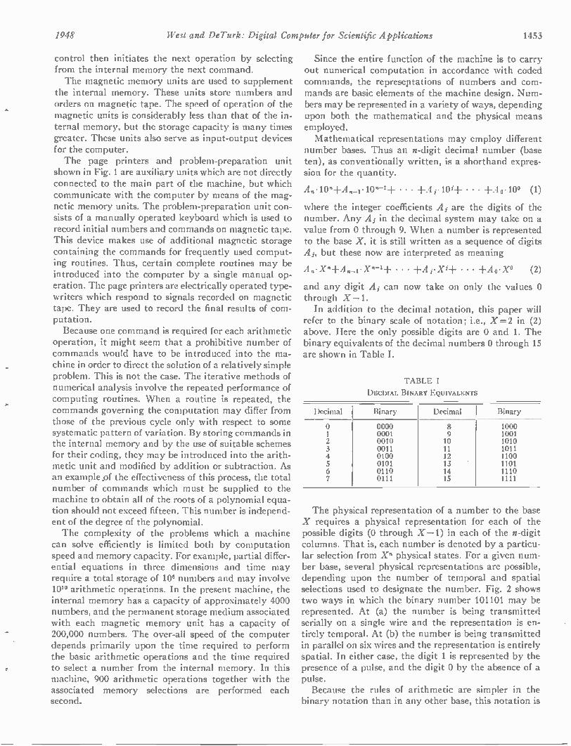
1948 West and DeTurk: Digital Computer for Scientific Applications 1453
control then initiates the next operation by selecting from the internal memory the next command. The magnetic memory units are used to supplement
the internal memory. These units store numbers and orders on magnetic tape. The speed of operation of the magnetic units is considerably less than that of the in-ternal memory, but the storage capacity is many times greater. These units also serve as input-output devices for the computer. The page printers and problem-preparation unit
shown in Fig. 1 are auxiliary units which are not directly connected to the main part of the machine, but which communicate with the computer by means of the mag-netic memory units. The problem-preparation unit con-sists of a manually operated keyboard which is used to record initial numbers and commands on magnetic tape. This device makes use of additional magnetic storage containing the commands for frequently used comput-ing routines. Thus, certain complete routines may be introduced into the computer by a single manual op-eration. The page printers are electrically operated type-writers which respond to signals recorded on magnetic tape. They are used to record the final results of com-putation. Because one command is required for each arithmetic
operation, it might seem that a prohibitive number of commands would have to be introduced into the ma-chine in order to direct the solution of a relatively simple problem. This is not the case. The iterative methods of numerical analysis involve the repeated performance of computing routines. When a routine is repeated, the commands governing the computation may differ from those of the previous cycle only with respect to some systematic pattern of variation. By storing commands in the internal memory and by the use of suitable schemes for their coding, they may be introduced into the arith-metic unit and modified by addition or subtraction. As an example pf the effectiveness of this process, the total number of commands which must be supplied to the machine to obtain all of the roots of a polynomial equa-tion should not exceed fifteen. This number is independ-ent of the degree of the polynomial. The complexity of the problems which a machine
can solve efficiently is limited both by computation speed and memory capacity. For example, partial differ-ential equations in three dimensions and time may require a total storage of 10° numbers and may involve 101° arithmetic operations. In the present machine, the internal memory has a capacity of approximately 4000 numbers, and the permanent storage medium associated with each magnetic memory unit has a capacity of 200,000 numbers. The over-all speed of the computer depends primarily upon the time required to perform the basic arithmetic operations and the time required to select a number from the internal memory. In this machine, 900 arithmetic operations together with the associated memory selections are performed each second.
Since the entire function of the machine is to carry out numerical computation in accordance with coded commands, the represeptations of numbers and com-mands are basic elements of the machine design. Num-bers may be represented in a variety of ways, depending upon both the mathematical and the physical means employed. Mathematical representations may employ different
number bases. Thus an n-digit decimal number (base ten), as conventionally written, is a shorthand expres-sion for the quantity.
A „• 10n + A „._1•10n-LF • • • + A r10i + • • • + A o•10° (1)
where the integer coefficients Ai are the digits of the number. Any A; in the decimal system may take on a value from 0 through 9. When a number is represented to the base X, it is still written as a sequence of digits A,, but these now are interpreted as meaning
An•Xn+A n_i•Xn-1 -1- • • • + A i• Xi+ • • • ±Ao•X° (2)
and any digit Ai can now take on only the values 0 through X-1. In addition to the decimal notation, this paper will
refer to the binary scale of notation; i.e., X=2 in (2) above. Here the only possible digits are 0 and 1. The binary equivalents of the decimal numbers 0 through 15 are shown in Table I.
TABLE I
DECIMAL BINARY EQUIVALENTS
Decimal Binary Decimal Binary
2 3 4 5 6 7
0000 0001 0010 0011 0100 0101 0110 0111
8 9 10 11 12 13 14 15
1000 1001 1010 1011 1100 1101 1110 1111
The physical representation of a number to the base X requires a physical representation for each of the possible digits (0 through X-1) in each of the n-digit columns. That is, each number is denoted by a particu-lar selection from X" physical states. For a given num-ber base, several physical representations are possible, depending upon the number of temporal and spatial selections used to designate the number. Fig. 2 shows two ways in which the binary number 101101 may be represented. At (a) the number is being transmitted serially on a single wire and the representation is en-tirely temporal. At (b) the number is being transmitted in parallel on six wires and the representation is entirely spatial. In either case, the digit 1 is represented by the presence of a pulse, and the digit 0 by the absence of a pulse. Because the rules of arithmetic are simpler in the
binary notation than in any other base, this notation is
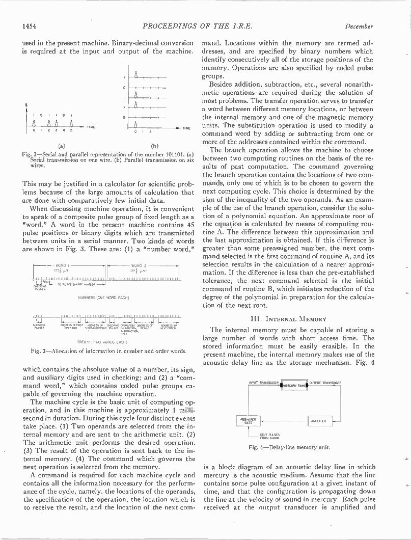
1454 PROCEEDINGS OF THE I.R.E. December
used in the present machine. Binary-decimal conversion is required at the input and output of the machine.
1 0 I 0
3 4
(a)
TIME
(b)
TI ME
Fig. 2—Serial and parallel representation of the number 101101. (a) Serial transmission on one wire. (b) Parallel transmission on six wires.
This may be justified in a calculator for scientific prob-lems because of the large amounts of calculation that are done with comparatively few initial data. When discussing machine operation, it is convenient
to speak of a composite pulse group of fixed length as a "word." A word in the present machine contains 45 pulse positions or binary digits which are transmitted between units in a serial manner. Two kinds of words are shown in Fig. 3. These are: (1) a "number word,"
WORD 1 WORD 2
(22 µ
Lis,c1,1,111111111.111111111111.111111111111, 1111 1 11111111111111111111111111111111111
35 PLACE BINARY NuMBER CRECAING PULSES
WECAIING PULSES
NUMBERS ONE WORD EACH)
1111111111111 11111111111 H 1111 111111 1111111111111_ 1111111111111
l.. I—I I. 4 ASERESSCA cR151 ADORESS OF CRECANG OPERATOR ADDRESS Of ADDRESS 0, OPERAND COND OPERAM) Put.SES I. ADO1 04. RESULT NE X1 URDU?
SuBTRACTION. ec 1
ORDER TWO WORDS EACH)
Fig. 3—Allocation of information in number and order words.
which contains the absolute value of a number, its sign, and auxiliary digits used in checking; and (2) a "com-mand word," which contains coded pulse groups ca-pable of governing the machine operation. The machine cycle is the basic unit of computing op-
eration, and in this machine is approximately 1 milli-second in duration. During this cycle four distinct events take place. (1) Two operands are selected from the in-ternal memory and are sent to the arithmetic unit. (2) The arithmetic unit performs the desired operation. (3) The result of the operation is sent back to the in-ternal memory. (4) The command which governs the next operation is selected from the memory. A command is required for each machine cycle and
contains all the information necessary for the perform-ance of the cycle, namely, the locations of the operands, the specification of the operation, the location which is to receive the result, and the location of the next com-
mand. Locations within the memory are termed ad-dresses, and are specified by binary numbers which identify consecutively all of the storage positions of the memory. Operations are also specified by coded pulse groups. Besides addition, subtraction, etc., several nonarith-
metic operations are required during the solution of most problems. The transfer operation serves to transfer a word between different memory locations, or between the internal memory and one of the magnetic memory units. The substitution operation is used to modify a command word by adding or subtracting from one or more of the addresses contained within the command. The branch operation allows the machine to choose
between two computing routines on the basis of the re-sults of past computation. The command governing the branch operation contains the locations of two com-mands, only one of which is to be chosen to govern the next computing cycle. This choice is determined by the sign of the inequality of the two operands. As an exam-ple of the use of the branch operation, consider the solu-tion of a polynomial equation. An approximate root of the equation is calculated by means of computing rou-tine A. The difference between this approximation and the last approximation is obtained. If this difference is greater than some preassigned number, the next com-mand selected is the first command of routine A, and its selection results in the calculation of a nearer approxi-mation. If the difference is less than the pre-established tolerance, the next command selected is the initial command of routine B, which initiates reduction of the degree of the polynomial in preparation for the calcula-tion of the next root.
III. INTERNAL MEMORY
The internal memory must be capable of storing a large number of words with short access time. The stored information must be easily erasible. In the present machine, the internal memory makes use of the acoustic delay line as the storage mechanism. Fig. 4
INPUT TRANSDUCER jli MERCURY TAMC 4 CUTPUT TRANSDUCER
RESHAPER GATE
M T PULSES FROM CLOCK
AMPUFIER
Fig. 4—Delay-line memory unit.
is a block diagram of an acoustic delay line in which mercury is the acoustic medium. Assume that the line contains some pulse configuration at a given instant of time, and that the configuration is propagating down the line at the velocity of sound in mercury. Each pulse received at the output transducer is amplified and
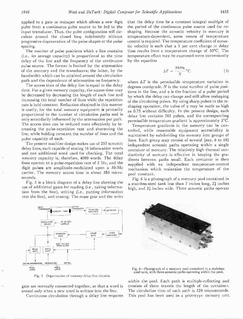
1948 West and DeTurk: Digital Computer for Scientific Applications 1455
applied to a gate or reshaper which allows a new digit pulse from a continuous pulse source to be fed to the input transducer. Thus, the pulse configuration will cir-culate around the closed loop indefinitely without progressive degeneration of the pulse shapes or the pulse spacing. The number of pulse positions which a line contains
(i.e., its storage capacity) is proportional to the time delay of the line and the frequency of the continuous pulse source. The former is limited by the attenuation of the mercury and the transducers; the latter, by the bandwidth which can be attained around the circulation path and the dependence of attenuation on frequency. The access time of the delay line is equal to the delay
time. For a given memory capacity, the access time may be decreased by decreasing the length of each line and increasing the total number of lines while the repetition rate is held constant. Reduction obtained in this manner is costly, for the total memory equipment is primarily proportional to the number of circulation paths and is only secondarily influenced by the attenuation per path. The access time can be reduced more effectively by in-creasing the pulse-repetition rate and shortening the line, while holding constant the number of lines and the pulse capacity of each. The present machine design makes use of 255 acoustic
delay lines, each capable of storing 16 information words and one additional word used for checking. The total memory capacity is, therefore, 4080 words. The delay lines operate at a pulse-repetition rate of 2 Mc, and the digit pulses are amplitude-modulated upon a 30-Mc carrier. The memory access time is about 380 micro-seconds. Fig. 5 is a block diagram of a delay line showing the
use of additional gates for reading (i.e., taking informa-tion from the line), writing (i.e., putting information into the line), and erasing. The erase gate and the write
TRANSDUCER II TRANSOUCER MERCURY TANK OUTPUT
INPUT
MODuLATOR 30 MC/SEC DRIVER I CARRIER
41. READ GATE
It
RESKAPER GATE
30 MG/SEC AMPLIFIER
DIGIT PULSES FROM CLOCK
WRITE J. GATE
G MAT , INFORMATIONv
READ WRITE LINES LINES
ERASE GATE
DETECTOR I---
VIDEO AMPLIFIER
Fig. 5—Organization of memory-delay-line circuits.
gate are normally connected together, so that a word is erased only when a new word is written into the line. Continuous circulation through a delay line requires
that the delay time be a constant integral multiple of the period of the continuous pulse source used for re-shaping. Because the acoustic velocity in mercury is temperature-dependent, some means of temperature control is required. The temperature coefficient of acous-tic velocity is such that a 1 per cent change in delay time results from a temperature change of 30°C. The temperature effect may be expressed more conveniently by the equation
3000n = (3)
where AT is the permissible temperature variation in degrees centigrade, N is the total number of pulse posi-tions in the line, and n is the fraction of a pulse period by which the delay can change and still allow reshaping of the circulating pulses. By using sharp pulses in the re-shaping operation, the value of n may be made as high as 0.75 without difficulty. In the present design, each delay line contains 765 pulses, and the corresponding permissible temperature gradient is approximately 3°C. Temperature gradients in the memory can be con-
trolled, while reasonable equipment accessibility is maintained by subdividing the memory into groups of lines. Each group may consist of several (say, 6 to 10) independent acoustic paths operating within a single container of mercury. The relatively high thermal con-ductivity of mercury is effective in keeping the gra-dients between paths small. Each container is then supplied with an independent temperature-control mechanism which maintains the temperature of the pool constant. Fig. 6 is a photograph of a mercury pool contained in
a stainless-steel tank less than 7 inches long, 2i inches high, and 21 inches wide. Three acoustic paths operate
Fig. 6—Photograph of a mercury pool contained in a stainless-steel tank, with three acoustic paths operating within the pool.
within the pool. Each path is multiple-reflecting and consists of three travels the length of the container. The circulation time of each path is 320 microseconds. This pool has been used in a prototype memory unit
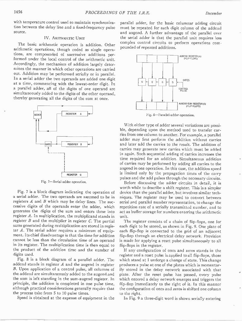
1456 PROCEEDINGS OF THE I.R.E. December
with temperature control used to maintain synchroniza-tion between the delay line and a fixed-frequency pulse source.
IV. ARITHMETIC UNIT
The basic arithmetic operation is addition. Other arithmetic operations, though coded as single opera-tions, are compounded of successive additions per-formed under the local control of the arithmetic unit. Accordingly, the mechanism of addition largely deter-mines the manner in which other operations are carried out. Addition may be performed serially or in parallel. In a serial adder the two operands are added one digit at a time, commencing with the lowest-order digit. In a parallel adder, all of the digits of one operand are simultaneously added to the digits of the other operand, thereby generating all the digits of the sum at once.
ADDER
- - GATE
REGISTER A
REGISTER B
REGISTER C
Fig. 7—Serial-adder operation.
Fig. 7 is a block diagram indicating the operation of a serial adder. The two operands are assumed to be in registers A and B which may be delay lines. The suc-cessive digits of the operands enter the adder, which generates the digits of the sum and enters these into register A. In multiplication, the multiplicand stands in register B and the multiplier in register C. The partial sums generated during multiplication are stored in regis-ter A. The serial adder requires a minimum of equip-ment. Its chief disadvantage is that the time for addition cannot be less than the circulation time of an operand in its register. The multiplication time is then equal to the product of the addition time and the number of digits used. Fig. 8 is a block diagram of a parallel adder. The
addend stands in register A and the augend in register B. Upon application of a control pulse, all columns of the addend are simultaneously added to the augend and the sum is left standing in the sum-augend register. In principle, the addition is completed in one pulse time, although practical considerations generally require that the process take from 5 to 10 pulse times. Speed is obtained at the expense of equipment in the
parallel adder, for the basic columnar adding circuit must be repeated for each digit column of the addend and augend. A further advantage of the parallel over the serial adder is that the parallel unit requires less complex control circuits to perform operations com-pounded of repeated additions.
ADDENO REGISTER (A) (FLIP-FLOPS)
GATES
CONTROL PULSE
AUGEND-SUM REGISTER (B) ( FUP-FLOPS)
Fig. 8—Parallel-adder operation.
With either type of adder several variations are possi-ble, depending upon the method used to transfer car-ries from one column to another. For example, a parallel adder may first perform the addition without carries and later add the carries to the result. The addition of carries may generate new carries which must be added in again. Such sequential adding of carries increases the time required for an addition. Simultaneous addition of carries may be performed by adding all carries to the augend in one operation. In this case, the addition speed is limited only by the propagation times of the carry pulses and the add pulses through the necessary circuits. Before discussing the adder circuits in detail, it is
worth while to describe a shift register. This is a simpler device than the parallel adder, but involves similar tech-niques. The register may be used to convert between serial and parallel number representation, to change the repetition rate of a serially transmitted number, and to act as buffer storage for numbers entering the arithmetic unit. The register consists of a chain of flip-flops, one for
each digit to be stored, as shown in Fig. 9. One plate of each flip-flop is connected to the grid of an adjacent flip-flop through an electrical delay network. Provision is made for applying a reset pulse simultaneously to all flip-flops in the register. If any configuration of ones and zeros stands in the
register and a reset pulse is applied to all flip-flops, those which stand at 1 undergo a change of state. This change produces a pulse at one of the plates which is momentar-ily stored in the delay network associated with that plate. After the reset pulse has passed, every pulse which entered a delay network emerges and triggers the flip-flop immediately to the right of it. In this manner the configuration of ones and zeros is shifted one column to the right. In Fig. 9 a three-digit word is shown serially entering
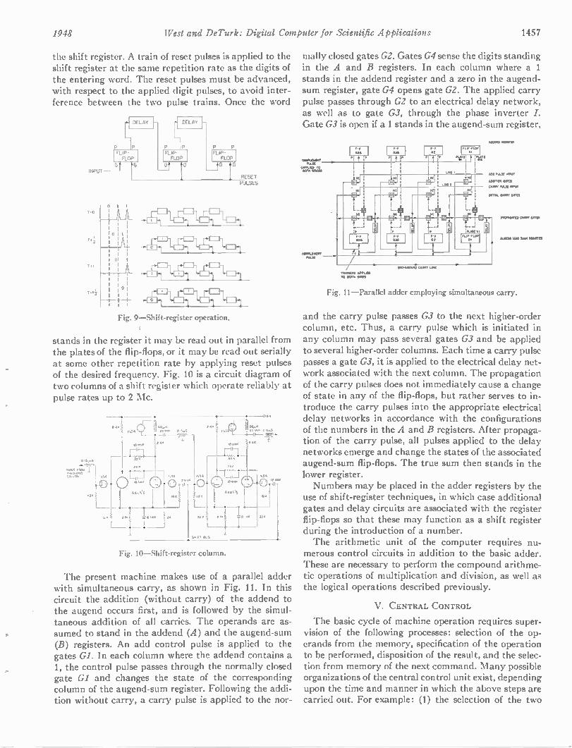
1948 West and De Turk: Digital Computer for Scientific Applications 1457
the shift register. A train of reset pulses is applied to the shift register at the same repetition rate as the digits of the entering word. The reset pulses must be advanced, with respect to the applied digit pulses, to avoid inter-ference between the two pulse trains. Once the word
INPUT
T*0
T*1
T*1
DELAY
P P LIP • FLOP
9- FT
I I
I I: I
I I I I t ° I I
I I
DELAY
P IP FLIP • FLOP
TT—ro-
FLIP - FLOP LA
RESET PULSES
,H-F4116,1=h,
Fig. 9—Shift-register operation.
stands in the register it may be read out in parallel from the plates of the flip-flops, or it may be read out serially at some other repetition rate by applying reset pulses of the desired frequency. Fig. 10 is a circuit diagram of two columns of a shift register which operate reliably at pulse rates up to 2 Mc.
0 if
.Nru, rt.C••
',our
2.*
• 1 0,mt
'L I
ri 000 0.5 ,
T *Iv
L
Fig. 10 —Shift-register column.
ix Po. 0 A..5
4 . II
..$ X • g 1..
0117
The present machine makes use of a parallel adder with simultaneous carry, as shown in Fig. 11. In this circuit the addition (without carry) of the addend to the augend occurs first, and is followed by the simul-taneous addition of all carries. The operands are as-sumed to stand in the addend (A) and the augend-sum (B) registers. An add control pulse is applied to the gates Gl. In each column where the addend contains a 1, the control pulse passes through the normally closed gate GI and changes the state of the corresponding column of the augend-sum register. Following the addi-tion without carry, a carry pulse is applied to the nor-
mally closed gates G2. Gates G4 sense the digits standing in the A and B registers. In each column where a 1 stands in the addend register and a zero in the augend-sum register, gate G4 opens gate GZ. The applied carry pulse passes through G2 to an electrical delay network, as well as to gate G3, through the phase inverter I. Gate G3 is open if a 1 stands in the augend-sum register,
= RO OT KILIC
W RAP TO prn SNOB)
TA .O.11 of. = TO OWN I MO
"at
O PANOLNO CABOT IOW
M VO MI MI
•00 "NT
RO W . 4.ffiES
C•11.• N OE NOVI
Fig. 11—Parallel adder employing simultaneous carry.
and the carry pulse passes G3 to the next higher-order column, etc. Thus, a carry pulse which is initiated in any column may pass several gates G3 and be applied to several higher-order columns. Each time a carry pulse passes a gate G3, it is applied to the electrical delay net-work associated with the next column. The propagation of the carry pulses does not immediately cause a change of state in any of the flip-flops, but rather serves to in-troduce the carry pulses into the appropriate electrical delay networks in accordance with the configurations of the numbers in the A and B registers. After propaga-tion of the carry pulse, all pulses applied to the delay networks emerge and change the states of the associated augend-sum flip-flops. The true sum then stands in the lower register. Numbers may be placed in the adder registers by the
use of shift-register techniques, in which case additional gates and delay circuits are associated with the register flip-flops so that these may function as a shift register during the introduction of a number. The arithmetic unit of the computer requires nu-
merous control circuits in addition to the basic adder. These are necessary to perform the compound arithme-tic operations of multiplication and division, as well as the logical operations described previously.
V. CENTRAL CONTROL
The basic cycle of machine operation requires super-vision of the following processes: selection of the op-erands from the memory, specification of the operation to be performed, disposition of the result, and the selec-tion from memory of the next command. Many possible organizations of the central control unit exist, depending upon the time and manner in which the above steps are carried out. For example: (1) the selection of the two
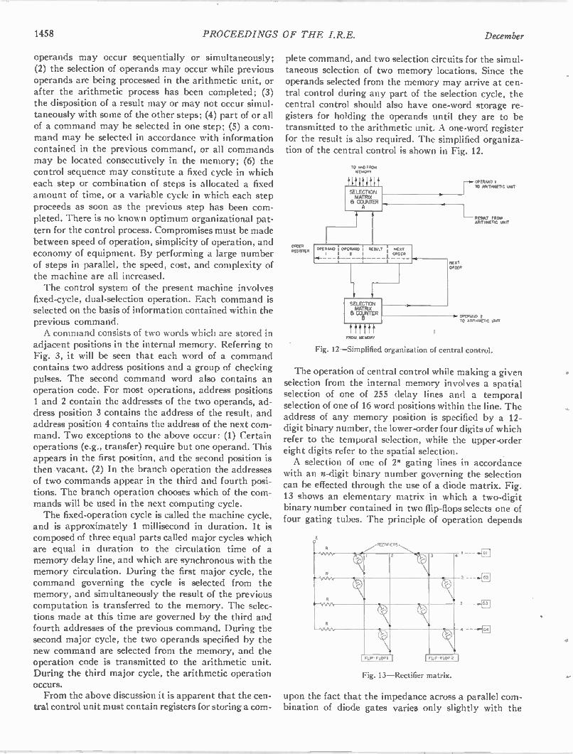
1458 PROCEEDINGS OF THE I.R.E. December
operands may occur sequentially or simultaneously; (2) the selection of operands may occur while previous operands are being processed in the arithmetic unit, or after the arithmetic process has been completed; (3) the disposition of a result may or may not occur simul-taneously with some of the other steps; (4) part of or all of a command may be selected in one step; (5) a com-mand may be selected in accordance with information contained in the previous command, or all commands may be located consecutively in the memory; (6) the control sequence may constitute a fixed cycle in which each step or combination of steps is allocated a fixed amount of time, or a variable cycle in which each step proceeds as soon as the previous step has been com-pleted. There is no known optimum organizational pat-tern for the control process. Compromises must be made between speed of operation, simplicity of operation, and economy of equipment. By performing a large number of steps in parallel, the speed, cost, and complexity of the machine are all increased. The control system of the present machine involves
fixed-cycle, dual-selection operation. Each command is selected on the basis of information contained within the previous command. A command consists of two words which are stored in
adjacent positions in the internal memory. Referring to Fig. 3, it will be seen that each word of a command contains two address positions and a group of checking pulses. The second command word also contains an operation code. For most operations, address positions 1 and 2 contain the addresses of the two operands, ad-dress position 3 contains the address of the result, and address position 4 contains the address of the next com-mand. Two exceptions to the above occur: (1) Certain operations (e.g., transfer) require but one operand. This appears in the first position, and the second position is then vacant. (2) In the branch operation the addresses of two commands appear in the third and fourth posi-tions. The branch operation chooses which of the com-mands will be used in the next computing cycle. The fixed-operation cycle is called the machine cycle,
and is approximately 1 millisecond in duration. It is composed of three equal parts called major cycles which are equal in duration to the circulation time of a memory delay line, and which are synchronous with the memory circulation. During the first major cycle, the command governing the cycle is selected from the memory, and simultaneously the result of the previous computation is transferred to the memory. The selec-tions made at this time are governed by the third and fourth addresses of the previous command. During the second major cycle, the two operands specified by the new command are selected from the memory, and the operation code is transmitted to the arithmetic unit. During the third major cycle, the arithmetic operation occurs. From the above discussion it is apparent that the cen-
tral control unit must contain registers for storing a corn-
plete command, and two selection circuits for the simul-taneous selection of two memory locations. Since the operands selected from the memory may arrive at cen-tral control during any part of the selection cycle, the central control should also have one-word storage re-gisters for holding the operands until they are to be transmitted to the arithmetic unit. A one-word register for the result is also required. The simplified organiza-tion of the central control is shown in Fig. 12.
ORDER REGISTER
TO AND FROM MEMORY
tit it It 1 t SELECTION MATRIX a COUNTER
A
PERAND , OPERAND A SULT I, NEXT I 2 I , ORDER
4-
SELECTION MATRIX a COUNTER
tftttf FROM MEMORY
ND, ORDER
OPERAND 1 ARITHMETIC UNIT
RESULT FROM ARITHMETIC UNIT
OPERAND 2 TO ARITHMETIC UNIT
Fig. 12—Simplified organization of central control.
The operation of central control while making a given selection from the internal memory involves a spatial selection of one of 255 delay lines and a temporal selection of one of 16 word positions within the line. The address of any memory position is specified by a 12-digit binary number, the lower-order four digits of which refer to the temporal selection, while the upper-order eight digits refer to the spatial selection. A selection of one of 2 gating lines in accordance
with an n-digit binary number governing the selection can be effected through the use of a diode matrix. Fig. 13 shows an elementary matrix in which a two-digit binary number contained in two flip-flops selects one of four gating tubes. The principle of operation depends
Fig. 13—Rectifier matrix.
upon the fact that the impedance across a parallel com-bination of diode gates varies only slightly with the
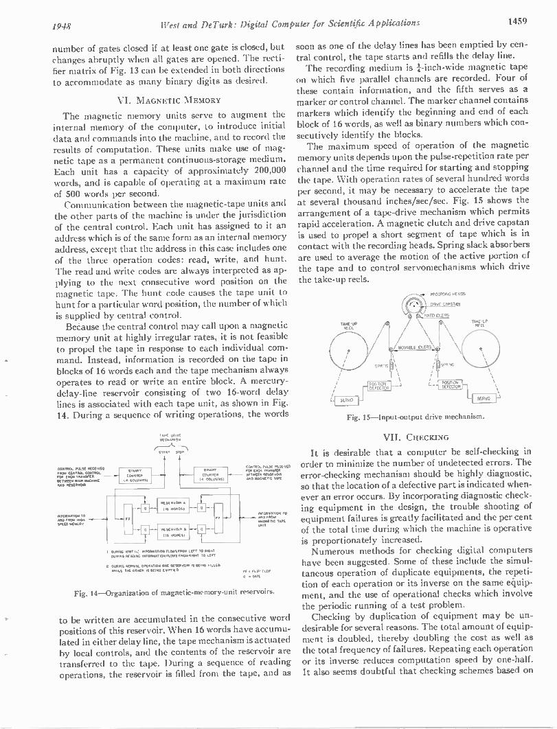
1948 West and DeTurk: Digital Computer for Scientific Applications 1459
number of gates closed if at least one gate is closed, but changes abruptly when all gates are opened. The recti-fier matrix of Fig. 13 can be extended in both directions to accommodate as many binary digits as desired.
VI. MAGNETIC MEMORY
The magnetic memory units serve to augment the internal memory of the computer, to introduce initial data and commands into the machine, and to record the results of computation. These units make use of mag-netic tape as a permanent continuous-storage medium. Each unit has a capacity of approximately 200,000 words, and is capable of operating at a maximum rate of 500 words per second. Communication between the magnetic-tape units and
the other parts of the machine is under the jurisdiction of the central control. Each unit has assigned to it an address which is of the same form as an internal memory address, except that the address in this case includes one of the three operation codes: read, write, and hunt. The read and write codes are always interpreted as ap-plying to the next consecutive word position on the magnetic tape. The hunt code causes the tape unit to hunt for a particular word position, the number of which is supplied by central control. Because the central control may call upon a magnetic
memory unit at highly irregular rates, it is not feasible to propel the tape in response to each individual com-mand. Instead, information is recorded on the tape in blocks of 16 words each and the tape mechanism always operates to read or write an entire block. A mercury-delay-line reservoir consisting of two 16-word delay lines is associated with each tape unit, as shown in Fig. 14. During a sequence of writing operations, the words
CONTROL PuLSE RECEIVED H BINARY
FROM CENTRAL CONTROL FOR EACH TRANSFER COUNTER BETWEEN MAIN MAG.)! 1• COLUMNS) AND RESERVOIR
INFC.)..TiON TO IWO FROM GM -4 - ••• SPEED MORON,
TAPE DRIVE MECRANISM
START STOP
CONTR.. RuLSE RECEIVED MUTANT FOR ERE. TRANSFER COuNTER BETWEEN REsERv0)11
14 COLUMNS, AND MAGNETIC TAPE
CURING NWT,: INFORMATION FLOWS FROM LEFT TO RIGHT W RING RE AINNG NFORMATION 'EONS FROM RICHT TO LEFT
6 WORDS)
DARING NORMAL OPERATION ONE RESERVOIR IS REINS FILLED
*NILE TOE W REN IS BEING EMPTIED
INFoRMATIOX TO AND FROM MAGNETIC TAPE WIT
FF • FLIP-FLOP
6 • GATE
Fig. 14 —Organization of magnetic-memory-unit reservoirs.
to be written are accumulated in the consecutive word positions of this reservoir. When 16 words have accumu-lated in either delay line, the tape mechanism is actuated by local controls, and the contents of the reservoir are transferred to the tape. During a sequence of reading operations, the reservoir is filled from the tape, and as
soon as one of the delay lines has been emptied by cen-tral control, the tape starts and refills the delay line. The recording medium is t-inch-wide magnetic tape
on which five parallel channels are recorded. Four of these contain information, and the fifth serves as a marker or control channel. The marker channel contains markers which identify the beginning and end of each block of 16 words, as well as binary numbers which con-secutively identify the blocks. The maximum speed of operation of the magnetic
memory units depends upon the pulse-repetition rate per channel and the time required for starting and stopping the tape. With operation rates of several hundred words per second, it may be necessary to accelerate the tape at several thousand inches/sec/sec. Fig. 15 shows the arrangement of a tape-drive mechanism which permits rapid acceleration. A magnetic clutch and drive capstan is used to propel a short segment of tape which is in contact with the recording heads. Spring slack absorbers are used to average the motion of the active portion of the tape and to control servomechanisms which drive the take-up reels.
Fig. 15 —Input-output drive mechanism.
VII. CHECKING
It is desirable that a computer be self-checking in order to minimize the number of undetected errors. The error-checking mechanism should be highly diagnostic, so that the location of a defective part is indicated when-ever an error occurs. By incorporating diagnostic check-ing equipment in the design, the trouble shooting of equipment failures is greatly facilitated and the per cent of the total time during which the machine is operative is proportionately increased. Numerous methods for checking digital computers
have been suggested. Some of these include the simul-taneous operation of duplicate equipments, the repeti-tion of each operation or its inverse on the same e4uip-ment, and the use of operational checks which involve the periodic running of a test problem. Checking by duplication of equipment may be un-
desirable for several reasons. The total amount of equip-ment is doubled, thereby doubling the cost as well as the total frequency of failures. Repeating each operation or its inverse reduces computation speed by one-half. It also seems doubtful that checking schemes based on
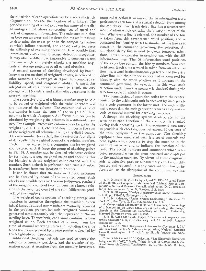
1460 PROCEEDINGS OF THE I.R.E. December
the repetition of each operation can be made sufficiently diagnostic to indicate the location of a failure. The periodic running of a test problem has many of the dis-advantages cited above concerning loss of speed and lack of diagnostic information. The existence of a time lag between an error and its detection makes it difficult to determine the exact point in the computing routine at which failure occurred, and consequently increases the difficulty of resuming operation. It is possible that intermittent errors might escape detection altogether. It may also be difficult or impossible to construct a test problem which completely checks the machine (e.g., tests all storage positions or all control circuits). A general system of checking developed by Bloch,'
known as the method of weighted counts, is believed to offer numerous advantages in regard to economy, re-liability, speed, and diagnostic ability. A particular adaptation of this theory is used to check memory storage, word transfers, and arithmetic operations in the present machine. The successive digits of a binary number may be said
to be valued or weighted with the value 2" where n is the number of the column. The conventional value of the number is then the sum of the weights of those columns in which l's appear. A different number can be obtained by weighting the columns in a different man-ner. For example, successive columns may be given the weights 1, 2, 4, 1, 2, 4, etc. The new number is the sum of the weights off all columns in which the digit 1 occurs. This new number (or rather, the lowest-order four digits of it) is called the weighted count of the original number. Each number stored in the computer has its weighted count stored with it (note the group of checking pulses in Fig. 3). A number can be checked whenever desired by formulating a new weighted count and checking this for identity with the weighted count carried with the number. Such a check is performed each time a number is transferred from one location to another. It can be shown that the basic arithmetic processes
can be checked by means of the weighted count. Such checks are possible because the sum (difference, product) of the weighted counts of two numbers has a known rela-tion to the weighted count of the sum (difference, prod-uct) of the numbers. The weighted-count system of checking storage and
transfers is operative throughout the machine. When initial input data and commands are manually recorded ,in the problem preparation unit, weighted counts are generated simultaneously with the depression of the re-cording keys. Thenceforth, each word contains its own -weighted count. Each transfer of a word from the time of manual recording up to and including the time -when results are printed by a page printer is checked by the weighted-count process. Additional checking methods are used to verify the
selection of memory positions, and the transfer of op-eration codes. A selection from the memory involves a
temporal selection from among the 16 information word positions in each line and a spatial selection from among the 255 delay lines. Each delay line has a seventeenth word position which contains the binary number of the line. Whenever a line is selected, the number of the line is taken from this seventeenth word position, and is compared for identity with the number of the line as it occurs in the command governing the selection. An additional delay line is used to check temporal selec-tions. This line operates in synchronism with the 255 information lines. The 16 information word positions of the extra line contain the binary numbers from zero to fifteen. Each time a word is taken from an informa-tion line, a word is simultaneously gated out of the extra delay line, and the number so obtained is compared for identity with the word position as it appears in the command governing the selection. In this way, each selection made from the memory is checked during the selection cycle in which it occurs. The transmission of operation codes from the central
control to the arithmetic unit is checked by incorporat-ing a code generator in the latter unit. For each arith-metic operation the code generator returns an operation code to central control for checking purposes. Although the checking system is elaborate, in the
sense that each function of the computer is checked during each operating cycle, the equipment necessary to provide such checking does not exceed 20 per cent of the total equipment in the computer. The checking equipment has associated with it a set of controls and neon lights which operate to stop the machine in the event of an error and to indicate the location of the fault. The actual numbers and commands which were being processed when the error occurred are displayed to the machine operator. By virtue of these diagnostic aids, a defective part or subassembly can be quickly located and replaced, in many cases without loss of in-formation or the disruption of the computing routine.
BIBLIOGRAPHY
1. R. M. Bloch, R. V. D. Campbell, and M. Ellis, "Logical Design of the Raytheon Computer," Mathematical Tables & Aids to Com-putation, National Research Council, Washington, D. C., scheduled for publication in vol. 3, no. 24, October, 1948, issue. 2. T. K. Sharpless, "Design of mercury delay lines," Ekaranics,
vol. 20, pp. 134-138; November, 1947. 3. L. N. Ridenour, "Radar System Engineering," McGraw-Hill
Book Co., New York, N. Y., 1948, pp. 632, 667-671. 4. Computation Laboratory of Harvard University, "Proceedings
of a Symposium on Large Scale Digital Calculating Machinery," Annals of the Computation Laboratory of Harvard University, Harvard University Press, vol. 16, 1946. 5. H. H. Aiken and G. M. Hopper, "The automatic sequence con-
trolled calculator I, II, III," Elec. Eng., vol. 65, no. 8-11; August-September, 1947. 6. F. L. Alt, "Bell Telephones Laboratories Computer I, II,"
Mathematical Tables & Aids to Computation, National Research Council, Washington, D. C., vol. 3, no. 21, 22; January and April, 1948. 7. A. Goldstine and H. H. Goldstine, "The Electronic Numerical
Integrator (ENIAC)," Math. Tables & Aids to Computation, Na-tional Research Council, Washington, D. C., vol. 2. no. 15, July, 1946.
1948 PROCEEDINGS OF THE I.R.E. 1461
Signal-to-Noise Ratio in AM Receivers* EUGENE G. FUBINIt, SENIOR MEMBER, IRE, AND DONALD C. JOHNSON$
Summary—Experimental tests have been made to determine the
effect of linear detectors upon the signal and the signal-to-noise ratio obtained from the demodulation of an rf carrier. The experi-mental data confirm theoretical results and indicate that:
1. The concept of excess noise figure must be used with care. It cannot be employed to calculate the noise at the output of a re-
ceiver unless due consideration is given to the presence of a non-linear device following the if stage. The reason for this is the effect of the presence of a carrier on the noise output of a detector. This noise increases when a carrier is present; the maximum increase is 4 to 7 db, depending upon the shape of the if filter. 2. For sine-wave amplitude modulation and if bandwidths at
least 3 or 4 times larger than the af bandwidth, a universal curve can be given that shows the relation between the signal-to-noise
ratio at the output and the carrier-to-noise ratio at the input of a
second detector. 3. If two AM carriers are simultaneously present at the input of
a linear second detector, this discriminates against the modulation of
the weaker carrier.
INTRODUCTION
THE INFLUENCE of the second detector on the performance of a system involving the use of
modulated radio frequencies is well known for the cases of frequency modulation and pulse modula-tion, while only recently has a substantial amount of work been done for the case of amplitude modulation. It has often been assumed, for instance, that an AM receiver will furnish at the output of its audio or video stage a signal-to-noise ratio that does not depend upon the bandwidth of the if stage; this assumption has led to the use of the AM receiver as a standard for the measurement of the "improvement" due to FM or other types of modulation. On the other hand, in some cases (radar receivers, for instance), the if bandwidth of AM receivers has been considered as one of the essential parameters that determine the performance of the set. It is also well known that FM systems discriminate against interfering signals in favor of the strongest sig-nal present, but it is seldom mentioned and often forgot-ten that a similar phenomenon may well occur in any nonlinear system. The so-called "linear detector" used in AM receivers is by definition a detecting—and, there-fore, a nonlinear—device; it is not surprising, therefore, to find that, as in FM, AM linear detectors do discrim-inate in favor of strong signals. It may be useful to consider in detail the very com-
mon assumption that the output signal-to-noise ratio of AM communication receivers is independent of the if bandwidth. Consider a linear detector that follows an
* Decimal classification: R261.51 X R361.211. Original manu-script received by the Institute, February 20, 1948; revised manu-script received, June 28, 1948. This work was done under Navy Contract N0a(s)-8575, under sponsorship of the Office of Naval Research.
f Airborne Instruments Laboratory, Inc., Mineola, L. I., N. Y. $ Formerly, Airborne Instruments Laboratory, Inc., Mineola,
L. I. N. Y.; now, Hazeltine Electronics Corp., Little Neck, L. I., N. V.
if stage and precedes an audio amplifier. At the input of the detector, there is a modulated carrier and some noise; at the output, there will be an af signal and some noise. If the carrier is strong, the spectrum of this noise is practically uniform because the beats between noise components are negligible when compared with the beats between the carrier and the noise, and the latter are uniformly distributed from zero cps to a frequency equal to half the if bandwidth.' Since af stages pass only part of this uniform spectrum, it is obvious that, when the carrier is strong, the noise at the output will depend only upon the bandwidth of the audio filter and upon the noise density; it will be independent of the if band-width. In low-frequency applications, the if bandwidth is
usually of the order of the bandwidth of the audio or video stage; for acceptable service, the signal at the output of the detector must be several db above the noise level. This condition usually requires that the carrier at the input of the detector be several db above the noise level. For this reason, the assumption that the signal-to-noise ratio at the output is independent of the if bandwidth holds in most of the low-frequency applications. At very high frequencies (around 100 Mc or more), however, the if bandwidth can well be 100 times wider than that of the audio or video stages, and the noise level at the input of the second detector will not necessarily be small compared with the signal, even when this is large enough for acceptable service. These questions then arise: How strong does the
signal need to be, as compared with the noise, in order to make the output signal-to-noise ratio independent of the if bandwidth, and what happens if the signal is not strong enough? This paper will deal first with the effect of the pres-
ence of an unmodulated carrier on the noise at the out-put (audio or video) of an AM receiver. Modulated carriers are then considered, and the amplitude of the signal and its relation to the noise level are discussed. The theory of detection of rf signals in the presence of
noise for different spectral shapes, percentages of modulation, and detector characteristics has been rigor-ously developed by Middleton.2
EFFECT OF AN UNMODULATED CARRIER ON THE OUTPUT NOISE
Consider a detector with a noise voltage applied at its input and consider the noise as a voltage caused by the presence of many components comparable in ampli-
1 These considerations are only qualitatively correct; they as-sume, for instance, a carrier centered with respect to a symmetrical and uniform (square) if filter.
2 David Middleton, "Rectification of a sinusoidally modulated carrier in the presence of noise," PROC. I.R.E., this issue, pp 1467-1477.
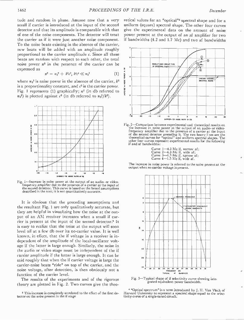
1462 PROCEEDINGS OF THE I.R.E. December
tude and random in phase. Assume now that a very small if carrier is introduced at the input of the second detector and that its amplitude is comparable with that of one of the noise components. The detector will treat the carrier as if it were just another noise component. To the noise beats existing in the absence of the carrier, new beats will be added with an amplitude roughly proportional to the carrier amplitude c. Since all these beats are random with respect to each other, the total noise power n2 in the presence of the carrier can be expressed as
n 2 = n 0 2 k2c 2, k2c2<< no2 (1)
where no2 is noise power in the absence of the carrier, le is a proportionality constant, and c2 is the carrier power. Fig. 1 represents (1) graphically; n2 (in db referred to no2) is plotted against c2 (in db referred to no2/k2).
Os
0.1
I 04
3 05
02
0.1
IS -10
CA MEO -30 -110101 RATIO IN no -•
Fig. 1—Increase in noise power at the output of an audio- or video-frequency amplifier due to the presence of a carrier at the input of the second detector. This curve is based on the broad assumptions described in the text; it is not quantitatively accurate.
It is obvious that the preceding assumptions and the resultant Fig. 1 are only qualitatively accurate, but they are helpful in visualizing how the noise at the out-put of an AM receiver increases when a small if car-rier is present at the input of the second detector.3 It is easy to realize that the noise at the output will soon level off at a few db over its no-carrier value. It is well known, in effect, that the if voltage in a receiver is in-dependent of the amplitude of the local-oscillator volt-age if the latter is large enough. Similarly, the noise in the audio or video stage must be independent of the if carrier amplitude if the latter is large enough. It can be said roughly that when the if carrier voltage is large the carrier-noise beats "ride" on top of the carrier, and the noise voltage, after detection, is then obviously not a function of the carrier level. The results of the experiments and of the rigorous
theory are plotted in Fig. 2. Two curves give the theo-
3 This increase is completely unrelated to the effect of the first de-tector on the noise present in the if stage
retical values for an "optical"' spectral shape and for a uniform (square) spectral shape. The other four curves give the experimental data on the amount of noise power present at the output of an af amplifier for two if bandwidths (4.2 and 1.7 Mc) and two af bandwidths
a
5
4
2
i
511/121.241.114ED
Of SPECTRAL M DR SHAPE
TYPE Z /
..--
-
2
/ //
/
/
-.
4
/
DI MON WIGTO N
M UNK / MOPE
/
/
, r
/
-DO -0 -0 0 3
CARRIER - TO-NOISE RATIO RI DO
oo 10 20
Fig. 2—Comparison between experimental and theoretical results on the increase in noise power at the output of an audio- or video-frequency amplifier due to the presence of a carrier at the input of the second detector preceding it. The two heavy I nes are the theoretical curves for "optical" and uniform spectral shapes. The other four curves represent experimental results for the following if and af bandwidths:
Curve 1-4.2-Mc if. narrow af; Curve 2-4.2-Mc if, wide af; Curve 3—I.7-Mc if, narrow af; Curve 4-1.7-Mc if, wide af.
The increase in noise power is referred to the noise present at the output when no carrier voltage is present.
a
•
14
2
21
50 •
PPEOUIDOGY
INTEGRATED PNWEll GAM
20 2 22 23 24 25 22 2? 20 111201.1111CY NC
TYPICAL IF DMIDPASS
21 30 31 52
Fig. 3—Typical shape of if selectivity curve showing inte-grated equivalent power bandwidth.
4 "Optical spectrum" is a term introduced by J. H. Van Vleck of Harvard University to represent a spectral shape equal to the selec-tivity curve of a single-tuned circuit.
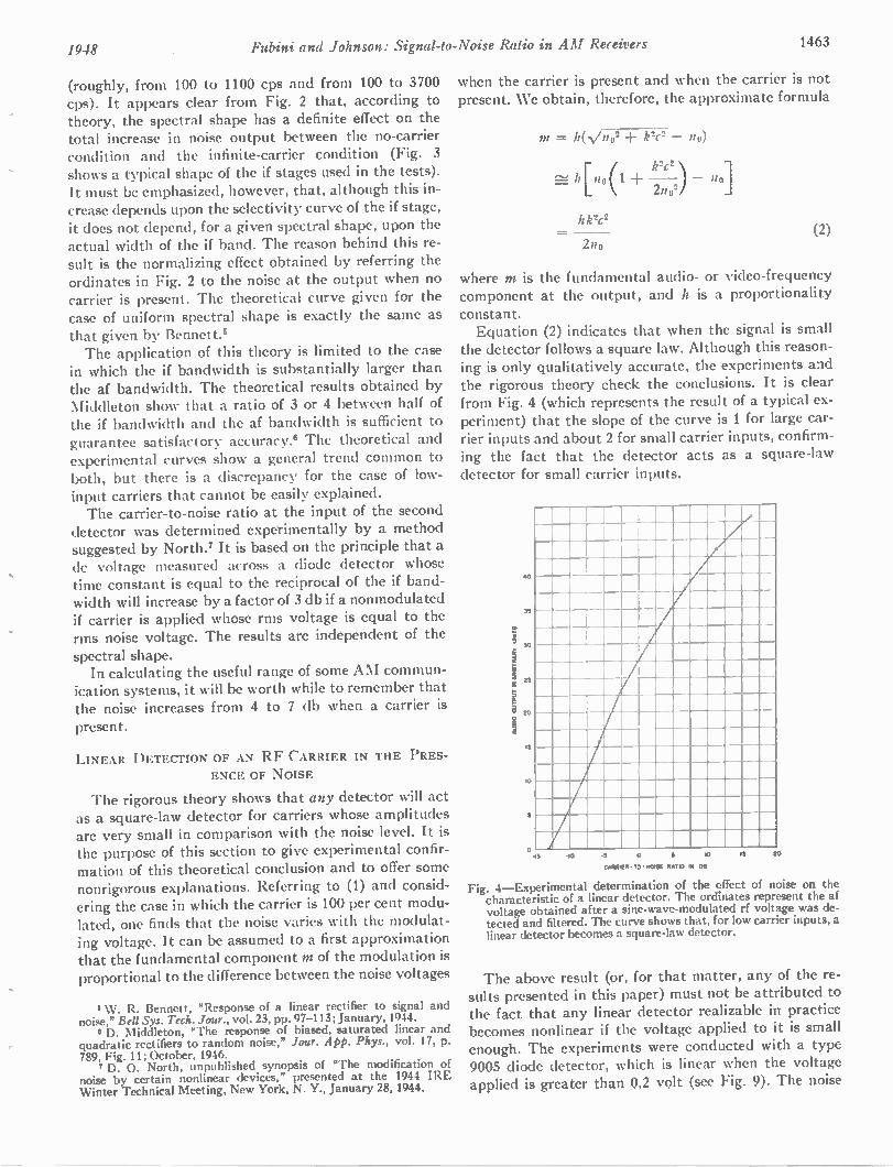
1948 Fubini and Johnson: Signal-to-Noise Ratio in AM Receivers 1463
(roughly, from 100 to 1100 cps and from 100 to 3700 cps). It appears clear from Fig. 2 that, according to theory, the spectral shape has a definite effect on the total increase in noise output between the no-carrier condition and the infinite-carrier condition (Fig. 3 shows a typical shape of the if stages used in the tests). It must be emphasized, however, that, although this in-crease depends upon the selectivity curve of the if stage, it does not depend, for a given spectral shape, upon the actual width of the if band. The reason behind this re-sult is the normalizing effect obtained by referring the ordinates in Fig. 2 to the noise at the output when no carrier is present. The theoretical curve given for the case of uniform spectral shape is exactly the same as that given by Bennett.' The application of this theory is limited to the case
in which the if bandwidth is substantially larger than the af bandwidth. The theoretical results obtained by Middleton show that a ratio of 3 or 4 between half of the if bandwidth and the af bandwidth is sufficient to guarantee satisfactory accuracy.' The theoretical and experimental curves show a general trend common to both, but there is a discrepancy for the case of low-input carriers that cannot be easily explained. The carrier-to-noise ratio at the input of the second
detector was determined experimentally by a method suggested by North.' It is based on the principle that a dc voltage measured across a diode detector whose time constant is equal to the reciprocal of the if band-width will increase by a factor of 3 db if a nonmodulated if carrier is applied whose rms voltage is equal to the rms noise voltage. The results are independent of the spectral shape. In calculating the useful range of some AM commun-
ication systems, it will be worth while to remember that the noise increases from 4 to 7 db when a carrier is
present.
LINEAR DETECTION OF AN RF CARRIER IN THE PRES-ENCE OF NOISE
The rigorous theory shows that any detector will act as a square-law detector for carriers whose amplitudes are very small in comparison with the noise level. It is the purpose of this section to give experimental confir-mation of this theoretical conclusion and to offer some nonrigorous explanations. Referring to (1) and consid-ering the case in which the carrier is 100 per cent modu-lated, one finds that the noise varies with the modulat-ing voltage. It can be assumed to a first approximation that the fundamental component in of the modulation is proportional to the difference between the noise voltages
6 W. R. Bennett, "Response of a linear rectifier to signal and noise," Bell Sys. Tech. Jour., vol. 23, pp. 97-113; January, 1944. • D. Middleton, "The response of biased, saturated linear and
quadratic rectifiers to random noise," Jour. App. Phys., vol. 17, p. 789, Fig. 11; October, 1946.
7 D. 0. North, unpublished synopsis of "The modification of noise by certain nonlinear devices," presented at the 1944 IRE Winter Technical Meeting, New York, N. Y., January 28,1944.
when the carrier is present and when the carrier is not present. We obtain, therefore, the approximate formula
m = h(s,,/no2 k2c2 — no)
k2c2 h[n 0(1 +
2n02)
hk2c2
2no
no]
(2)
where m is the fundamental audio- or video-frequency component at the output, and h is a proportionality constant. Equation (2) indicates that when the signal is small
the detector follows a square law. Although this reason-ing is only qualitatively accurate, the experiments and the rigorous theory check the conclusions. It is clear from Fig. 4 (which represents the result of a typical ex-periment) that the slope of the curve is 1 for large car-rier inputs and about 2 for small carrier inputs, confirm-ing the fact that the detector acts as a square-law detector for small carrier inputs.
40
35
30
25
20
15
10
0 -15 -10 -s
044111Elt -TO -NO = 114710 01 DB
eo 13 £0
Fig. 4—Experimental determination of the effect of noise on the characteristic of a linear detector. The ordinates represent the af voltage obtained after a sine-wave-modulated rf voltage was de-tected and filtered. The curve shows that, for low carrier inputs, a linear detector becomes a square-law detector.
The above result (or, for that matter, any of the re-sults presented in this paper) must not be attributed to the fact that any linear detector realizable in practice becomes nonlinear if the voltage applied to it is small enough. The experiments were conducted with a type 9005 diode detector, which is linear when the voltage applied is greater than 0.2 volt (see Fig. 9). The noise
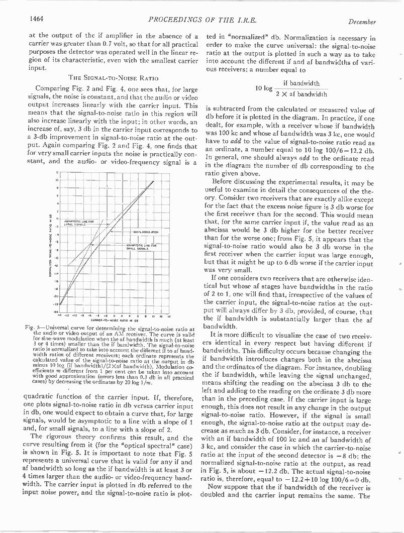
1464 PROCEEDINGS OF THE I.R.E. December
at the output of the if amplifier in the absence of a carrier was greater than 0.7 volt, so that for all practical purposes the detector was operated well in the linear re-gion of its characteristic, even with the smallest carrier input.
THE SIGNAL-TO-NOISE RATIO
Comparing Fig. 2 and Fig. 4, one sees that, for large signals, the noise is constant, and that the audio or video output increases linearly with the carrier input. This means that the signal-to-noise ratio in this region will also increase linearly with the input; in other words, an increase of, say, 3 db in the carrier input corresponds to a 3-db improvement in signal-to-noise ratio at the out-put. Again comparing Fig. 2 and Fig. 4, one finds that for very small carrier inputs the noise is practically con-stant, and the audio- or video-frequency signal is a
i2
10
a
4
2
0
22
-24
I
65.2PTOT ,G LARGE 5,GN2
L NE FOR / 5
_____ ._ _ _
10045MODULOVION
-1 r I LINE FOR
SIGNALS ASEMPTOT1C OFFALL
I
• - -I - -6 -4 -2 0 2 4 6 11 10 12 14
CARNIEN-T0-110612 2.1210 III DI
Fig. 5—Universal curve for determining the signal-to-noise ratio at the audio or video output of an AM receiver. The curve is valid for sine-wave modulation when the af bandwidth is much (at least 3 or 4 times) smaller than the if bandwidth. The signal-to-noise ratio is normalized to take into account the different if to af band-width ratios of different receivers; each ordinate represents the calculated value of the signal-to-noise ratio at the output in db minus 10 log (if bandwidth)/(2 Xaf bandwidth). Modulation co-efficients m different from 1 per cent can be taken into account with good approximation (errors less than 0.3 db in all practical cases) by decreasing the ordinates by 20 log 1/m.
quadratic function of the carrier input. If, therefore, one plots signal-to-noise ratio in db versus carrier input in db, one would expect to obtain a curve that, for large signals, would be asymptotic to a line with a slope of 1 and, for small signals, to a line with a slope of 2. The rigorous theory confirms this result, and the
curve resulting from it (for the "optical spectral" case) is shown in Fig. 5. It is important to note that Fig. 5 represents a universal curve that is valid for any if and af bandwidth so long as the if bandwidth is at least 3 or 4 times larger than the audio- or video-frequency band-width. The carrier input is plotted in db referred to the input noise power, and the signal-to-noise ratio is plot-
ted in "normalized" db. Normalization is necessary in order to make the curve universal: the signal-to-noise ratio at the output is plotted in such a way as to take into account the different if and af bandwidths of vari-ous receivers; a number equal to
if bandwidth 10 log
2 X af bandwidth
is subtracted from the calculated or measured value of db before it is plotted in the diagram. In practice, if one dealt, for example, with a receiver whose if bandwidth was 100 kc and whose af bandwidth was 3 kc, one would have to add to the value of signal-to-noise ratio read as an ordinate, a number equal to 10 log 100/6 =12.2 db. In general, one should always add to the ordinate read in the diagram the number of db corresponding to the ratio given above.
Before discussing the experimental results, it may be useful to examine in detail the consequences of the the-ory. Consider two receivers that are exactly alike except for the fact that the excess noise figure is 3 db worse for the first receiver than for the second. This would mean that, for the same carrier input if, the value read as an abscissa would be 3 db higher for the better receiver than for the worse one; from Fig. 5, it appears that the signal-to-noise ratio would also be 3 db worse in the first receiver when the carrier input was large enough, but that it might be up to 6 db worse if the carrier input was very small. If one considers two receivers that are otherwise iden-
tical but whose af stages have bandwidths in the ratio of 2 to 1, one will find that, irrespective of the values of the carrier input, the signal-to-noise ratios at the out-put will always differ by 3 db, provided, of course, that the if bandwidth is substantially larger than the af bandwidth.
It is more difficult to visualize the case of two receiv-ers identical in every respect but having different if bandwidths. This difficulty occurs because changing the if bandwidth introduces changes both in the abscissa and the ordinates of the diagram. For instance, doubling the if bandwidth, while leaving the signal unchanged, means shifting the reading on the abscissa 3 db to the left and adding to the reading on the ordinate 3 db more than in the preceding case. If the carrier input is large enough, this does not result in any change in the output signal-to-noise ratio. However, if the signal is small enough, the signal-to-noise ratio at the output may de-crease as much as 3 db. Consider, for instance, a receiver with an if bandwidth of 100 kc and an af bandwidth of 3 kc, and consider the case in which the carrier-to-noise ratio at the input of the second detector is —8 db; the normalized signal-to-noise ratio at the output, as read in Fig. 5, is about —12.2 db. The actual signal-to-noise ratio is, therefore, equal to —12.2+10 log 100/6 =0 db. Now suppose that the if bandwidth of the receiver is
doubled and the carrier input remains the same. The
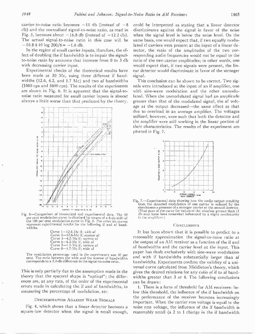
1948 Fubini and Johnson: Signal-to-Noise Ratio in AM Receivers 1465
: .-2
0 -
C' -2
carrier-to-noise ratio becomes —11 db (instead of —8 db) and the normalized signal-to-noise ratio, as read in Fig. 5, becomes about —16.8 db (instead of —12.2 db). The actual signal-to-noise ratio in this case will be —16.8+10 log 200/6 = —1.6 db. In the region of small carrier inputs, therefore, the ef-
fect of doubling the if bandwidth is to impair the signal-to-noise ratio by amounts that increase from 0 to 3 db with decreasing carrier input. Experimental checks of the theoretical results have
been made at 30 Mc, using three different if band-widths (12.6, 4.2, and 1.7 Mc) and two af bandwidths (1060 cps and 3600 cps). The results of the experiments are shown in Fig. 6. It is apparent that the signal-to-noise ratio measured for small carrier inputs is almost always a little worse than that predicted by the theory.
-
i0 -
a 6
,
4
- •
I
• ... .
-It - -
/ 14
113
-zo
-22
-24
26 14
,
I 414' /4
10 -2 -6 • 6 • 10 12 14
CAPP1F 2 NOME 164'10 N DS
Fig. 6—Comparison of theoretical and experimental data. The 50 per cent modulation curve is obtained by means of a 6-db shift of the 100 per cent modulation curve in Fig. 5. The other six curves represent experimental results for the following if and af band-widths:
Curve 1-12.6-Mc if; wide af Curve 2-12.6-Mc if; narrow af Curve 3-4.2-Mc if; narrow af Curve 4-4.2-Mc if; wide af Curve 5-1.7-Mc if; narrow af Curve 6-1.7-Mc if; wide af
The modulation percentage used in the experiments was 50 per cent. The ratio between the wide and the narrow af bandwidths corresponds to a 5.3-db difference in the signal-to-noise ratio.
This is only partially due to the assumption made in the theory that the spectral shape is "optical"; the differ-ences are, at any rate, of the order of the experimental errors made in calculating the if and af bandwidths, in measuring the percentage of modulation, etc.
DISCRIMINATION AGAINST WEAK SIGNALS
Fig. 4, which shows that a linear detector becomes a square-law detector when the signal is small enough,
could be interpreted as stating that a linear detector discriminates against the signal in favor of the noise when the signal level is below the noise level. On the same basis, one would expect that, if two equally modu-lated rf carriers were present at the input of a linear de-tector, the ratio of the amplitudes of the two cor-responding audio frequencies would not be equal to the ratio of the two carrier amplitudes; in other words, one would expect that, if two signals were present, the lin-ear detector would discriminate in favor of the stronger signal. This conclusion can be shown to be correct. Two sig-
nals were introduced at the input of an if amplifier, one with sine-wave modulation and the other unmodu-lated. When the unmodulated signal had an amplitude greater than that of the modulated signal, the af volt-age at the output decreased—the same effect as that due to overload in an average amplifier. The voltages utilized, however, were such that both the detector and the amplifier were still working in the linear portion of their characteristics. The results of the experiment are plotted in Fig. 7.
5
0 o 4 20
Fig. 7.—Experimental data showing how the audio output resulting from the detected modulation of one carrier is reduced by the simultaneous presence of a stronger carrier at the second detector. (That part of the curve for values of the abscissa greater than 12 db may have been somewhat influenced by a slight nonlinearity in the amplifiers.)
CONCLUSIONS
It has been shown that it is possible to predict to a reasonable approximation the signal-to-noise ratio at the output of an AM receiver as a function of the if and af bandwidths and the carrier level at the input. This paper has dealt exclusively with sine-wave modulation and with if bandwidths substantially larger than af bandwidths. Experiments confirm the validity of a uni-versal curve calculated from Middleton's theory, which gives the desired relations for any ratio of if to af band-widths greater than 3 or 4. The following conclusions can be drawn: 1. There is a form of threshold for AM receivers; be-
low this threshold, the influence of the if bandwidth on the performance of the receiver becomes increasingly important. When the carrier rms voltage is equal to the noise rms voltage, the influence of the if bandwidth is reasonably small (a 2 to 1 change in the if bandwidth
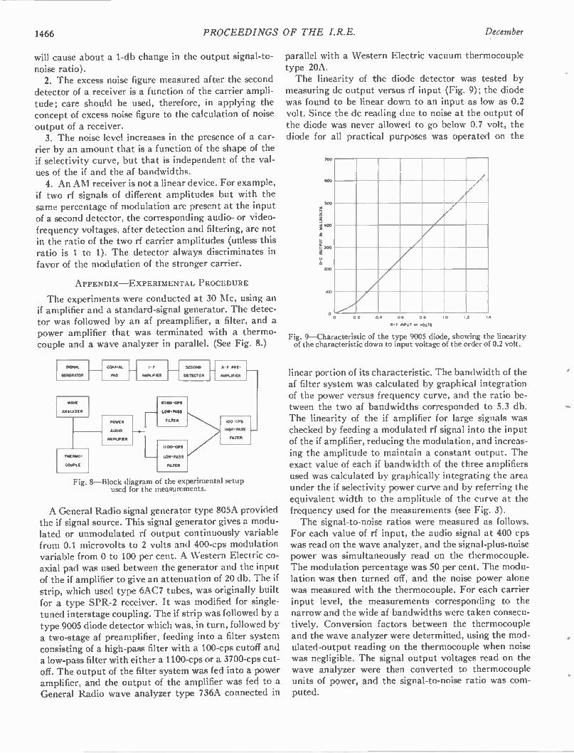
1466 PROCEEDINGS OF THE I.R.E. December
will cause about a 1-db change in the output signal-to-noise ratio). 2. The excess noise figure measured after the second
detector of a receiver is a function of the carrier ampli-tude; care should be used, therefore, in applying the concept of excess noise figure to the calculation of noise output of a receiver. 3. The noise level increases in the presence of a car-
rier by an amount that is a function of the shape of the if selectivity curve, but that is independent of the val-ues of the if and the af bandwidths. 4. An AM receiver is not a linear device. For example,
if two rf signals of different amplitudes but with the same percentage of modulation are present at the input of a second detector, the corresponding audio- or video-frequency voltages, after detection and filtering, are not in the ratio of the two rf carrier amplitudes (unless this ratio is 1 to 1). The detector always discriminates in favor of the modulation of the stronger carrier.
APPENDIX —EXPERIMENTAL PROCEDURE
The experiments were conducted at 30 Mc, using an if amplifier and a standard-signal generator. The detec-tor was followed by an af preamplifier, a filter, and a power amplifier that was terminated with a thermo-couple and a wave analyzer in parallel. (See Fig. 8.)
VENAL
GENERATOR
ANALYZER
COAXIAL
PAD
THERRO
COUPLE
ROWE:
AUDIO
NPUP R
I - F
MAPLWIER
SECOND
DETECTOR
1700 -CPS
LOW-PASS
FILTER
1100-CPS
LOW -PASS
FILTER
A-F PRE-
AMPLIFIER
100 GPO
WIN, PASS
FILTER
Fig. 8—Block diagram of the experimental setup used for the measurements.
r_
A General Radio signal generator type 805A provided the if signal source. This signal generator gives a modu-lated or unmodulated rf output continuously variable from 0.1 microvolts to 2 volts and 400-cps modulation variable from 0 to 100 per cent. A Western Electric co-axial pad was used between the generator and the input of the if amplifier to give an attenuation of 20 db. The if strip, which used type 6AC7 tubes, was originally built for a type SPR-2 receiver. It was modified for single-tuned interstage coupling. The if strip was followed by a type 9005 diode detector which was, in turn, followed by a two-stage af preamplifier, feeding into a filter system consisting of a high-pass filter with a 100-cps cutoff and a low-pass filter with either a 1100-cps or a 3700-cps cut-off. The output of the filter system was fed into a power amplifier, and the output of the amplifier was fed to a General Radio wave analyzer type 736A connected in
parallel with a Western Electric vacuum thermocouple type 20A. The linearity of the diode detector was tested by
measuring dc output versus rf input (Fig. 9); the diode was found to be linear down to an input as low as 0.2 volt. Since the dc reading due to noise at the output of the diode was never allowed to go below 0.7 volt, the diode for all practical purposes was operated on the
0 0 OR 0.4 0 S 0 S
F INPUT IN VOLTS
I 0 I.E I 4
Fig. 9—Characteristic of the type 9005 diode, showing the linearity of the characteristic down to input voltage of the order of 0.2 volt.
linear portion of its characteristic. The bandwidth of the af filter system was calculated by graphical integration of the power versus frequency curve, and the ratio be-tween the two af bandwidths corresponded to 5.3 db. The linearity of the if amplifier for large signals was checked by feeding a modulated rf signal into the input of the if amplifier, reducing the modulation, and increas-ing the amplitude to maintain a constant output. The exact value of each if bandwidth of the three amplifiers used was calculated by graphically integrating the area under the if selectivity power curve and by referring the equivalent width to the amplitude of the curve at the frequency used for the measurements (see Fig. 3). The signal-to-noise ratios were measured as follows.
For each value of rf input, the audio signal at 400 cps was read on the wave analyzer, and the signal-plus-noise power was simultaneously read on the thermocouple. The modulation percentage was 50 per cent. The modu-lation was then turned off, and the noise power alone was measured with the thermocouple. For each carrier input level, the measurements corresponding to the narrow and the wide af bandwidths were taken consecu-tively. Conversion factors between the thermocouple and the wave analyzer were determined, using the mod-ulated-output reading on the thermocouple when noise was negligible. The signal output voltages read on the wave analyzer were then converted to thermocouple units of power, and the signal-to-noise ratio was com-puted.
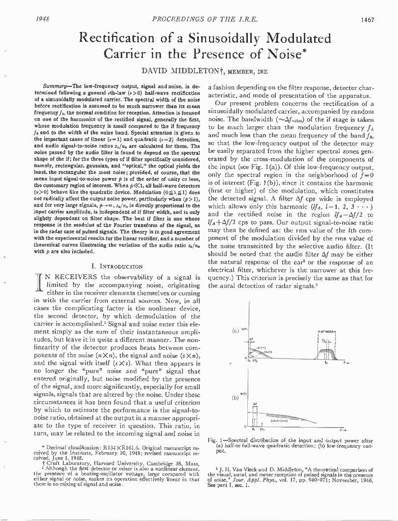
1948 PROCEEDINGS OF THE I.R.E. 1467
Rectification of a Sinusoidally Modulated Carrier in the Presence of Noise*
DAVID MIDDLETONt, MEMBER, IRE
Summary—The low-frequency output, signal and noise, is de-termined following a general pth-law (v >0) half-wave rectification of a sinusoidally modulated carrier. The spectral width of the noise before rectification is assumed to be much narrower than its mean frequency fo, the normal condition for reception. Attention is focused on one of the harmonics of the rectified signal, generally the first, whose modulation frequency is small compared to the if frequency fo and to the width of the noise band. Special attention is given to the important cases of linear (P = 1) and quadratic (v=2) detection, and audio signal-to-noise ratios soln are calculated for them. The noise passed by the audio filter is found to depend on the spectral shape of the if; for the three types of if filter specifically considered, namely, rectangular, gaussian, and "optical," the optical yields the least, the rectangular the most noise; provided, of course, that the mean input signal-to-noise power p is of the order of unity or less, the customary region of interest. When p<<1, all half-wave detectors (p > 0) behave like the quadratic device. Modulation (0 5 X 51) does not radically affect the output noise power, particularly when (p> 1), and for very large signals, p-,00, s./n is directly proportional to the input carrier amplitude, is independent of if filter width, and is only slightly dependent on filter shape. The best if filter is one whose response is the modulus of the Fourier transform of the signal, as in the radar case of pulsed signals. The theory is in good agreement with the experimental results for the linear rectifier, and a number of theoretical curves illustrating the variation of the audio ratio saln. with p are also included.
I. INTRODUCTION
IN RECEIVERS the observability of a signal is limited by the accompanying noise, originating either in the receiver elements themselves or coming
in with the carrier from external sources. Now, in all cases the complicating factor is the nonlinear device, the second detector, by which demodulation of the carrier is accomplished.' Signal and noise enter this ele-ment simply as the sum of their instantaneous ampli-tudes, but leave it in quite a different manner. The non-linearity of the detector produces beats between com-ponents of the noise (n X n), the signal and noise (s Xn), and the signal with itself (sX's). What then appears is no longer the "pure" noise and "pure" signal that entered originally, but noise modified by the presence of the signal, and more significantly, especially for small signals, signals that are altered by the noise. Under these circumstances it has been found that a useful criterion by which to estimate the performance is the signal-to-noise ratio, obtained at the output in a manner appropri-ate to the type of receiver in question. This ratio, in turn, may be related to the incoming signal and noise in
* Decimal classification: R134 X R161.6. Original manuscript re-ceived by the Institute, February 20, 1948; revised manuscript re-ceived, June 1, 1948.
Cruft Laboratory, Harvard University, Cambridge 38, Mass, 1 Although the first detector or mixer is also a nonlinear element.
the presence of a beating-oscillator voltage, large compared with either signal or noise, makes its operation effectively linear in that there is no mixing of signal and noise.
a fashion depending on the filter response, detector char-acteristic, and mode of presentation of the apparatus. Our present problem concerns the rectification of a
sinusoidally modulated carrier, accompanied by random noise. The bandwidth (---,Afool „.) of the if stage is taken to be much larger than the modulation frequency fA and much less than the mean frequency of the band fo, so that the low-frequency output of the detector may be easily separated from the higher spectral zones gen-erated by the cross-modulation of the components of the input (see Fig. 1(a)). Of this low-frequency output, only the spectral region in the neighborhood of f = 0 is of interest (Fig. 1 (b)), since it contains the harmonic (first or higher) of the modulation, which constitutes the detected signal. A filter btf cps wide is employed which allows only this harmonic (1f4, 1= 1, 2, 3 • • • ) and the rectified noise in the region IfA —4/2 to -1-4/2 cps to pass. Our output signal-to-noise ratio
may then be defined as: the rms value of the /th com-ponent of the modulation divided by the rms value of the noise transmitted by the selective audio filter. (It should be noted that the audio filter .aif may be either the natural response of the ear' or the response of an electrical filter, whichever is the narrower at this fre-quency.) This criterion is precisely the same as that for the aural detection of radar signals.2
(a)
Vilf)
(b) Af
r-11NOGEr
Fig. 1—Spectral distribution of the input and output power after (a) half-or full-wave quadratic detection; (b) low-frequency out-put.
J. H. Van Vleck and D. Middleton, "A theoretical comparison of the visual, aural, and meter reception of pulsed signals in the presence of noise," Jour. Appl. Ploys., vol. 17, pp. 940-971; November, 1946. See part I, sec. 1.
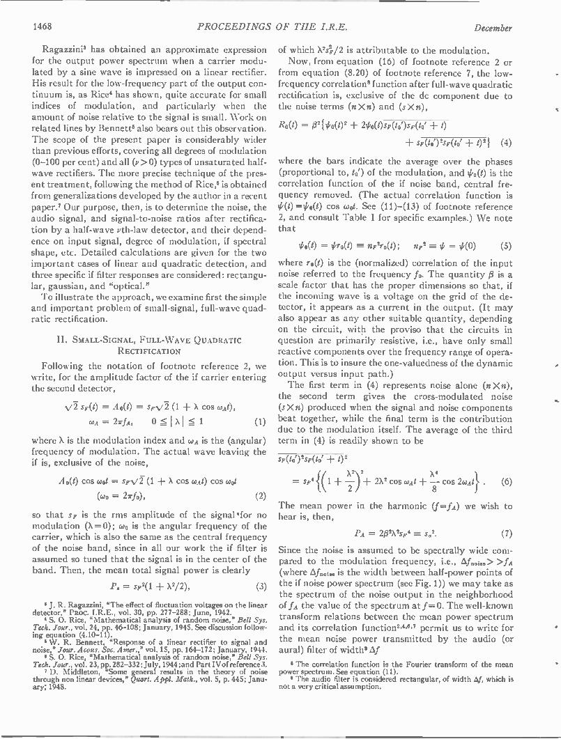
1468 PROCEEDINGS OF THE I.R.E. December
Ragazzinia has obtained an approximate expression for the output power spectrum when a carrier modu-lated by a sine wave is impressed on a linear rectifier. His result for the low-frequency part of the output con-tinuum is, as Rice' has shown, quite accurate for small indices of modulation, and particularly when the amount of noise relative to the signal is small. Work on related lines by Bennett' also bears out this observation. The scope of the present paper is considerably wider than previous efforts, covering all degrees of modulation (0-100 per cent) and all (v >0) types of unsaturated half-wave rectifiers. The more precise technique of the pres-ent treatment, following the method of Rice,' is obtained from generalizations developed by the author in a recent paper.7 Our purpose, then, is to determine the noise, the audio signal, and signal-to-noise ratios after rectifica-tion by a half-wave vth-law detector, and their depend-ence on input signal, degree of modulation, if spectral shape, etc. Detailed calculations are given for the two important cases of linear and quadratic detection, and three specific if filter responses are considered: rectangu-lar, gaussian, and "optical." To illustrate the approach, we examine first the simple
and important problem of small-signal, full-wave quad-ratic rectification.
II. SMALL-SIGNAL, FULL- WAVE QUADRATIC
RECTIFICATION
Following the notation of footnote reference 2, we write, for the amplitude factor of the if carrier entering the second detector,
sF(t) = A o(t) = sFv2 (1 + X cos coA0,
coA = 27fA, 0 I XI 1 (1)
where X is the modulation index and coA is the (angular) frequency of modulation. The actual wave leaving the if is, exclusive of the noise,
A 0(0 cos coot = spvi (1 + X cos coAt) cos coot
(coo = 2irfo), (2)
so that SF is the rms amplitude of the signal'for no modulation (X =0); coo is the angular frequency of the carrier, which is also the same as the central frequency of the noise band, since in all our work the if filter is assumed so tuned that the signal is in the center of the band. Then, the mean total signal power is clearly
P. = 4.2(1 -I- X2/2), (3)
3 J. R. Ragazzini, "The effect of fluctuation voltages on the linear detector,* PROC. I.R.E., vol. 30, pp. 277-288; June, 1942.
S. 0. Rice, "Mathematical analysis of random noise," Bell Sys. Tech. Jour., vol. 24, pp. 46-108; January, 1945. See discussion follow-ing equation (4.10-11).
W. R. Bennett, "Response of a linear rectifier to signal and noise," Jour. Acous. Soc. Amer.," vol. 15, pp. 164-172; January, 1944.
1 S. 0. Rice, "Mathematical analysis of random noise," Bell Sys. Tech. Jour., vol. 23, pp. 282-332; July, 1944; and Part IV of reference 3.
7 D. Middleton, "Some general results in the theory of noise through non linear devices," Quart. Appi. Math., vol. 5, p. 445; Janu-ary; 1948.
of which X24/2 is attributable to the modulation. Now, from equation (16) of footnote reference 2 or
from equation (8.20) of footnote reference 7, the low-frequency correlation' function after full-wave quadratic rectification is, exclusive of the dc component due to the noise terms (n X n) and (s X n),
R0(t) = #2{ 00(1)2 200(0sF(10')sF(to' + 0
sF(t0')2sF(to' + 02} (4)
where the bars indicate the average over the phases (Proportional to, to') of the modulation, and 00(t) is the correlation function of the if noise band, central fre-quency removed. (The actual correlation function is
=00(t) cos coot. See (11)—(13) of footnote reference 2, and consult Table I for specific examples.) We note that
,h(t) = iGro(0 np2ro(t); fly' = (5)
where ro(t) is the (normalized) correlation of the input noise referred to the frequency fo. The quantity [3 is a scale factor that has the proper dimensions so that, if the incoming wave is a voltage on the grid of the de-tector, it appears as a current in the output. (It may also appear as any other suitable quantity, depending on the circuit, with the proviso that the circuits in question are primarily resistive, i.e., have only small reactive components over the frequency range of opera-tion. This is to insure the one-valuedness of the dynamic output versus input path.) The first term in (4) represents noise alone (n X n),
the second term gives the cross-modulated noise (s Xn) produced when the signal and noise components beat together, while the final term is the contribution due to the modulation itself. The average of the third term in (4) is readily shown to be
Sp(t01)25F(10' + 1)2
x 2 X4
= sF4{(1 + —22) + 2X2 cos wilt — cos 20.1At} • (6) 8
The mean power in the harmonic (f=fA) we wish to hear is, then,
P it =__ 2/32x2sF 4 s. 2.
Since the noise is assumed to be spectrally wide com-pared to the modulation frequency, i.e., _Af i„o> >fA (where Ai. noise is the width between half-power points of the if noise power spectrum (see Fig. 1)) we may take as the spectrum of the noise output in the neighborhood of fA the value of the spectrum at f =O. The well-known transform relations between the mean power spectrum and its correlation function2.4,".7 permit us to write for the mean noise power transmitted by the audio (or aural) filter of width' Af
I The correlation function is the Fourier transform of the mean power spectrum. See equation (11). • The audio filter is considered rectangular, of width Af, which is
not a very critical assumption.
(7)
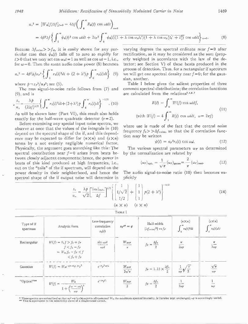
1948 Middleton: Rectification of Sinusoidally Modulated Carrier in Noise 1469
no2 = [Wo(JAilf-o= 44( f Ro(t) cos wtdt)
= O W{ f 00(0 2 cos cotdt 2sp2 f Ikt)(1 + X cos wAlo')(1 ± X cos WA Do' ± 11) cos cadt}.-o.
Because 4noise> >fA, it is easily shown for any par-ticular case that I'o(t) falls off to zero so rapidly for t> 0 that we may set cos coAt =1 as well as cos cot = 1, i.e., for co = 0. Then the mean audio noise power (8) becomes
n. 2 = 40 2Afnr c f ro(02dt + (2 + x2) .p f ro(t)dt} (9) 0 0
where p-----_sr2/np2; see (5). The rms signal-to-noise ratio follows from (7) and
(9), and is
sa xp 1 J ii,. (2f)" r N(0 2d1 -1- (2d- X2)P f ro(t)dt} . (10) = . 2 o
As will be shown later (Part VI), this result also holds exactly for the half-wave quadratic detector (v=2). Before examining any special input noise spectra, we
observe at once that the values of the integrals in (10) depend on the spectral shape of the if, and this depend-ence may be expected to differ for (nXn) and (sXn) terms by a not entirely negligible numerical factor. Physically, the argument goes something like this: The spectral contribution near f = 0 arises from beats be-tween closely adjacent components; hence, the power in beats of this kind produced at high frequencies, i.e., out on the "tails" of the if spectrum, will depend on the power density in their neighborhood, and hence the spectral shape of the if output noise will determine in
(8)
varying degrees the spectral ordinate near f = 0 after rectification, as it may be considered as the sum (prop-erly weighted in accordance with the law of the de-tector; see Section V) of these beats produced in the process of detection. Thus, for a rectangular if spectrum we will get one spectral density near f =0; for the gaus-sian, another. Table I below gives the salient properties of three
common spectral distributions; the correlation functions are calculated from the relationsLc6.7
00
R(t) = f W(f) cos wiry,
(with W(f) = f R(t) cos cadt, co= 21-f) 0
where use is made of the fact that the central noise frequency fo > > _ _fnoise, SO that the if correlation func-tion may be written
= np2r0(t) cos cot. (12)
The various spectral parameters co, as determined by the normalization are related by
1 2 (WF)opt. = (&-4')gauss = (WF)reet-
V (13)
The audio signal-to-noise ratio (10) then becomes ex-plicitly
N ri
Sc xp rop)opt• r { 1R/1 1 11 p(2 x2)}
/1, Af 1/2 1
(n X n) (s X n)
Type of if
spectrum
Rectangular
Gaussian
"Optical"* "
TABLE I
(14) 14)
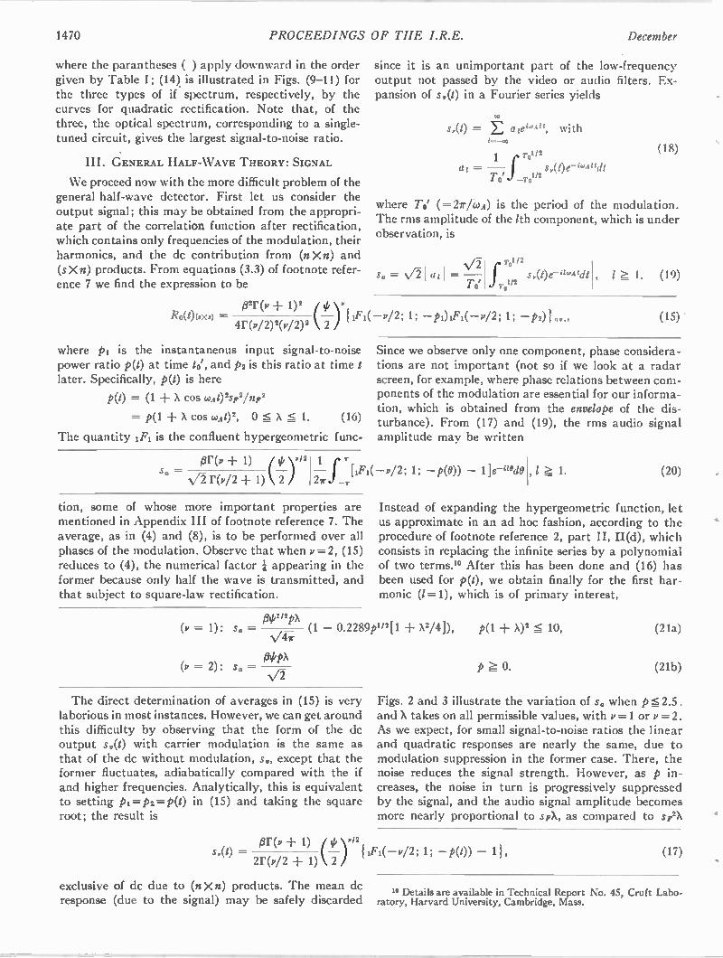
1470 PROCEEDINGS OF THE I.R.E. December
where the parantheses ( ) apply downward in the order given by Table I; (14) is illustrated in Figs. (9-11) for the three types of if spectrum, respectively, by the curves for quadratic rectification. Note that, of the three, the optical spectrum, corresponding to a single-tuned circuit, gives the largest signal-to-noise ratio.
III. GENERAL HALF-WAVE THEORY: SIGNAL
We proceed now with the more difficult problem of the general half-wave detector. First let us consider the output signal; this may be obtained from the appropri-ate part of the correlation function after rectification, which contains only frequencies of the modulation, their harmonics, and the dc contribution from (n X n) and (s X n) products. From equations (3.3) of footnote refer-ence 7 we find the expression to be
since it is an unimportant part of the low-frequency output not passed by the video or audio filters. Ex-pansion of s,(t) in a Fourier series yields
s,(t) = E aiei'A", with 10. -00
1 T o1/2
To' f_ro'12 al = — s,(t)e-iwAndt
(18)
where To' (=27r/coA) is the period of the modulation. The rms amplitude of the /th component, which is under observation, is
S0 = 01(111 = -
7'01
Tt /2
foT0112 s,(1)e-"Aidt ,l 1. (19)
Ro(I)UXs) )321'(v A— 1)2 ( y 1F1( V/2 ; 1; — P1)1F1( — P/2 ; 1; — P2)} ay. ,
4r(v/2)2(v/2)2 2
where pi is the instantaneous input signal-to-noise power ratio p(t) at time to', and Ps is this ratio at time t later. Specifically, p(t) is here
P(t) = (1 + X cos wAt) s2 F2/71F 2
= P( 1 ± X COS WAt) 2, 0 X :5- 1. (16)
The quantity 1F1 is the confluent hypergeometric func-
so = /3 * ± 1) 1// y 12
N/2 r(v/2 + 1) k 2 )
(15)
Since we observe only one component, phase considera-tions are not important (not so if we look at a radar screen, for example, where phase relations between com-ponents of the modulation are essential for our informa-tion, which is obtained from the envelope of the dis-turbance). From (17) and (19), the rms audio signal amplitude may be written
1 ir j J 1F1( -- P/2; 1; — p(0)) —
tion, some of whose more important properties are mentioned in Appendix III of footnote reference 7. The average, as in (4) and (8), is to be performed over all phases of the modulation. Observe that when v =2, (15) reduces to (4), the numerical factor appearing in the former because only half the wave is transmitted, and that subject to square-law rectification.
(v = 1): so =
, 1 1. (20)
Instead of expanding the hypergeometric function, let us approximate in an ad hoc fashion, according to the procedure of footnote reference 2, part II, II(d), which consists in replacing the infinite series by a polynomial of two terms." After this has been done and (16) has been used for p(t), we obtain finally for the first har-monic (1=1), which is of primary interest,
N 1/2pX
(1. — 0.2289p1/2[1 X2/4]),
NA G'
130 PX (v = 2): so =
The direct determination of averages in (15) is very laborious in most instances. However, we can get around this difficulty by observing that the form of the dc output s,(t) with carrier modulation is the same as that of the dc without modulation, so, except that the former fluctuates, adiabatically compared with the if and higher frequencies. Analytically, this is equivalent to setting pi= p2.= p(t) in (15) and taking the square root; the result is
P(1 + x)2 10,
p 0.
(21a)
(21b)
Figs. 2 and 3 illustrate the variation of so when p s 2.5. and X takes on all permissible values, with v =1 or v = 2. As we expect, for small signal-to-noise ratios the linear and quadratic responses are nearly the same, due to modulation suppression in the former case. There, the noise reduces the signal strength. However, as p in-creases, the noise in turn is progressively suppressed by the signal, and the audio signal amplitude becomes more nearly proportional to spX, as compared to sp2X
s,(t) = ftr(v 1) )P/2 11F1(—P/2; 1; — P(1)) — 11, 20,/2 + 1) k 2
exclusive of dc due to (nXn) products. The mean dc response (due to the signal) may be safely discarded
(17)
" Details are available in Technical Report No. 45, Cruft Labo-ratory, Harvard University, Cambridge, Mass.
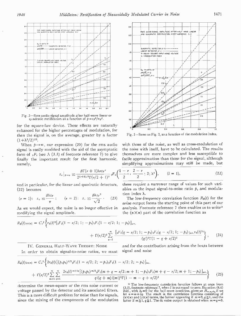
1948 Middleton: Rectification of Sinusoidally Modulated Carrier in Noise 1471
1.4
2i
20
IS
IS
10
Os
as
04
0
I I 1 PUS AND
Au0,0 3.0WA. OusORA
AmPLITDDE IC REcTincATIOR
AFTER HALF t F.ST HARRON,C
-WARE utast( 2(0 __________
/ /
/
S. IN LorSTS or
- -QUADRATIC DETECTOR. v• 2 e
4 44211 —LINEMI 001 005. P.1 /
/
/ /
A .,./ .
',to p% OS
-SODARIE st,1400LILAT(ON
Ispur NO.SE 1400
WILTAGE
e ' /
/
/ 'b.is ... ..•
/
/
........
/
/
/
p.A.ity
at 04 06 OS 1.0 LI IA LS ILO II 0.4
Fig. 2—Rms audio signal amplitude after half-wave linear or quadratic rectification as a function of p=sptinpt.
for the square-law device. These effects are naturally enhanced for the higher percentages of modulation, for then the signal is, on the average, greater by a factor (1_00/2)212.
When p—)00, our expression (20) for the rms audio signal is easily modified with the aid of the asymptotic form of IF1 (see A (3.3) of footnote reference 7) to give finally the important result for the first harmonic, namely,
24
2.2
20
1.6
4
r2
10
08
06
0.4
02
/1 /
RMS AUDIO
AND QUADRATIC
I SIGNAL AMPLITUDE
RECTIFICATION
1
AFTER
(FIRST
HALF
HARMONIC
-WANE L NEAR
/ /
/
/
//
QUADRAT
LINEAR DETECTOR
ST ( MEAN
1.. MODULATION
G DETECTOR.V
- SQUARE
INDEX
.2
V 1
/ /
/
/ / /
e /
INPUT NOISE VOLTAGE / /
/ /
•
/
/ /
/ /
/
Si IN UMTS
41,4 4„ V.2
iSVI friT, P M
/1 /
/ /
/ /
// ..0 "
CP
— . 414 v /
/ /
I
.1
/ /
P /
././
../ /
/ /
/ 7
/ /
/ 5
/ / /
/ /
20
/ /
/
/ /
/ / I
./ 1.5
1
-'. ...,
/
/ / / /
r / , c.c,
............-• ""...."
..........
...-
05
/ 0
/-/ ........."----
........"-
0.5
02 04 0.6 S 1.0
Fig. 3—Same as Fig. 2, as a function of the modulation index.
with those of the noise, as well as cross-modulation of the noise with itself, have to be calculated. The results themselves are more complex and less susceptible to facile approximation than those for the signal, although simplifying approximations may still be made, but
ttr(v + 1)Xvsy• 1 — v 2 — v
2("-amr(v/2 + 1)2 (
and in particular, for the linear and quadratic detectors, (22) becomes
fiXSF (v = 1): su •
fotsv2 (23) (v = 2): s" —
As we would expect, the noise is no longer effective in modifying the signal amplitude.
2 2 ; 2; X), (I = 1), (22)
these require a narrower range of values for such vari-ables as the input signal-to-noise ratio p, and modula-tion index A. The low-frequency correlation function R0(t) for the
noise output forms the starting point of this part of our analysis. Footnote reference 7 then enables us to write" the (n Xn) part of the correlation function as
Ro(t)(nx.) = C,2{ro(1)2[1F1(1 — v/2; 1; - v/2; 1; -Poi., [iFi(q — v/2; 1; — P/2 ; 1; P2) Jay.ro(1) 2q }
r (1/ / 2) 2 E (24) g-2 (02r(1 - q p12) 2
IV. GENERAL HALF- WAVE THEORY: NOISE
In order to obtain signal-to-noise ratios, we must
and for the contribution arising from the beats between signal and noise
Ro(t)(sxn) = C,2{2ro(t) [(PIP2)"21F1(1 — v/2; 2; — POIF1(1 — v/2; 2; P2)1ay.
2ro(t)m+2°[(PiP2) 1n12iFi(m q — v/2; m 1; —pi)IFi(m+ q — p12; m 1; — P2)]..} r(v/2) 2E E
(1 .1 q!(q m)1(m!)21' (1 — m — q v/2)2
determine the mean-square or the rms noise current or voltage passed by the detector and its associated filters. This is a more difficult problem for noise than for signals, since the mixing of the components of the modulation
(25)
11 The low-frequency correlation function follows at once from (3.3), footnote reference 7, when 1 is put equal to zero. Equation (4.4) ibid., with bo —0 for the half-wave condition, gives us 1/....+2,i if we let n =m-1-2q. The result is the correlation function consisting of (It X n) and (sX is) terms, the former appearing if m'0, q1, and the latter if m l,q 1.Thedc noise output is obtained when m =q =O.
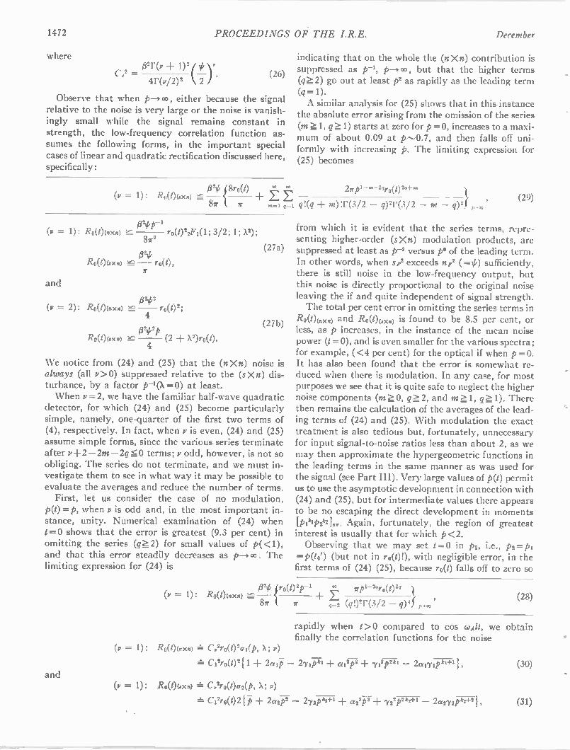
1472 PROCEEDINGS OF THE I.R.E. December
where
C.2 = 132r(v + •4r(v/2)2 \ 2 • (26)
Observe that when p—> , either because the signal relative to the noise is very large or the noise is vanish-ingly small while the signal remains constant in strength, the low-frequency correlation function as-sumes the following forms, in the important special cases of linear and quadratic rectification discussed here, specifically:
indicating that on the whole the (n n) contribution is suppressed as p-', p—>00, but that the higher terms (qL 2) go out at least p2 as rapidly as the leading term (q = 1).
A similar analysis for (25) shows that in this instance the absolute error arising from the omission of the series (m 1, qL1) starts at zero for p =0, increases to a maxi-mum of about 0.09 at p-0.7, and then falls off uni-formly with increasing p. The limiting expression for (25) becomes
1321,Tro(t) + L 27rp'- ni-2gro(t)2Q-Em (v = 1): Ro(1)(sx.) 8r r m1 q=1 q!(q m)!r(3/2 — q)2r(3/2 — m — q) 2}
024 1-1
(V = 1): Ro(/)(nXn) ro(1)27F7(1; 3/2; 1; X2); 87r2 g70
Ro(t)(sxn)
and
(v = 2): Ro(1)(oxn) p77.L7 r o(1)2' 4 0702p
Ro(t)(7xn) (2 + X2)ro(t). 4
(27a)
(27b)
We notice from (24) and (25) that the (n X n) noise is always (all v > 0) suppressed relative to the (sXn) dis-turbance, by a factor p--, (X =0) at least. When v =2, we have the familiar half-wave quadratic
detector, for which (24) and (25) become particularly simple, namely, one-quarter of the first two terms of (4), respectively. In fact, when v is even, (24) and (25) assume simple forms, since the various series terminate after v-F 2 —2m —2q 0 terms; v odd, however, is not so obliging. The series do not terminate, and we must in-vestigate them to see in what way it may be possible to evaluate the averages and reduce the number of terms. First, let us consider the case of no modulation,
p(t)=p, when v is odd and, in the most important in-stance, unity. Numerical examination of (24) when I = 0 shows that the error is greatest (9.3 per cent) in omitting the series (q 2) for small values of p(<1), and that this error steadily decreases as p— . The limiting expression for (24) is
and
(29)
from which it is evident that the series terms, repre-senting higher-order (sXn) modulation products, are suppressed at least as p-2 versus p° of the leading term. In other words, when sp2 exceeds np2 (=tk) sufficiently, there is still noise in the low-frequency output, but this noise is directly proportional to the original noise leaving the if and quite independent of signal strength. The total per cent error in omitting the series terms in
Ro(t)(wn) and Ro(1)(.0<n) is found to be 8.5 per cent, or less, as p increases, in the instance of the mean noise power (1=0), and is even smaller for the various spectra; for example, (<4 per cent) for the optical if when p=0. It has also been found that the error is somewhat re-duced when there is modulation. In any case, for most purposes we see that it is quite safe to neglect the higher noise components (m 0, qL 2, and m 1, qL. 1). There then remains the calculation of the averages of the lead-ing terms of (24) and (25). With modulation the exact treatment is also tedious but, fortunately, unnecessary for input signal-to-noise ratios less than about 2, as we may then approximate the hypergeometric functions in the leading terms in the same manner as was used for the signal (see Part III). Very large values of p(t) permit us to use the asymptotic development in connection with (24) and (25), but for intermediate values there appears to be no escaping the direct development in moments [p,kip,k2],„. Again, fortunately, the region of greatest interest is usually that for which p<2. Observing that we may set 1=0 in p2, i.e., p2=p,
=P0(1) (but not in ro(0!), with negligible error, in the first terms of (24) (25), because ro(t) falls off to zero so
trip{ro(t)2p-1 rp1-2pro(02q = 1): RO(1)(n X n) E
87r 7 4z2 (q!)21.(3/2 — q) 4 f p
rapidly when 1>0 compared to cos coA/t, we obtain finally the correlation functions for the noise
(v = 1): Ro(t)(nxn) = C,2ro(t)2cri(P, A; 1")
C127.0(021 1 + 2aii7 —
(v= 1): Ro(1)(7x0 C,2ro(t)a2(P. A; v)
Ci2r0(t)2 + 2a27
(28)
21,1pki al cp 71 2p2ki 2a m pkt-F1
— 272P k2+1 CE22P 3 ± 722P2k2÷I 2 a272P k2+2
(30)
(31)
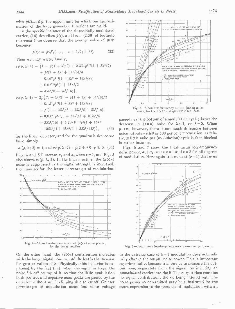
1948 Middleton: Rectification of Sinusoidally Modulated Carrier in Noise 1473
with p(t),,..p, the upper limit for which our approxi-mation of the hypergeometric functions are valid. In the specific instance of the sinusoidally modulated
carrier, (16) describes 0), and from (2.30) of footnote reference 7 we observe that the average value of kom becomes
p(om = — + 1/2; 1; X2). (32)
Then we may write, finally,
ai(p,X;1) = 11 — p(1 + X2/2) + 0.334p2/2(1 3X2/2)
▪ p 2(1 ± 3X2 3x4/8)/4
— 0.167p6/2(1 5X2 15X4/8)
▪ 0.0279p3(1 15X2/2
▪ 45X4/8 5X6/16) I ,
cr2(p, X; 1) = 2p{(1 + X2/2) — p(1 3X2 3X4/8)/2
▪ 0.131p312 (1 5X2 15X4/8)
• p2(1 15X2/2 45X4/8 5X6/16)
— 0.0327p5/2(1 21X2/2 105X4/8
▪ 35X6/16) 4.29.10-'1)3(1 14X2
105X4/4 35X6/4 35X8/128)1, (33)
for the linear detector, and for the quadratic device we have simply
0-1(p, X; 2) = 1, and a 2(P s X; 2) =P(2 + X2), p 0. (34) Figs. 4 and 5 illustrate al and (72 when v =1, and Fig. 5 also shows (72(P, X, 2). In the linear rectifier the (n Xn) noise is suppressed as the signal strength is increased, the more so for the lesser percentages of modulation.
100
90
00
70
60
50
So
50
20
IN Hill
• I
S OF p
I
IP.I.;VI
AFTER
• MODULATION
OR THE MEAN
HALF -WAVE
120OULATED
INDEX
LOW-FREQUENCY
LINEAR RECTIFICATION CARRIER
- 0,
POWER
SMLISEADALLT
NOISE -11- NOMA
OF A
X
\‘'.3...
X
CO 08
C• .... .... ..... ...... _
00
" OA
,____• _j • . .
P • A V2v
•
. .
, , , • .
-
OS LO 20 0.0 31
Fig. 4—Mean low-frequency output (n Xn) noise power, for the linear rectifier.
On the other hand, the (sXn) contribution increases with the larger signal powers, and the less is the increase for greater values of X. Physically, this behavior is ex-plained by the fact that, when the signal is large, the noise "rides" on top of it, so that for little modulation both positive and negative noise peaks are passed by the detector without much clipping due to cutoff. Greater percentages of modulation mean less noise voltage
2.0
22
2.0
IS
La
IA
10
Oa
OA
OA
02
I
I i /
.'i / LINEAR RECTIFIR IN UNITS OP /2.w/4w r I
s I - -- - -•- QUADRATIC RECTIFIER M DINTS OF ATII VA /
/ / //. • . •
c / 1.
. /
0 2
. . ,. ....- -" e
/./i.
•-• ...
... --
.- TT •.' .0 ...o
!
/ //
//
// // 1 ...
O. 6
i ll!
O . M U M
POSER AFTER
OR THE
HALF
MEAN
000E
LOW FREOUESCT
LINEAR
WORM.
CO OuADRATIC
-2.
RECTO-ICA-
NOISE
iii!
i Y
S. -710R 07 A st.",5w0ALL. NOWLATED CARRIER.
Al SIGNAL POWER a
!/ .51
0.11
p
• X. 140OULATiON
: ALI:.11441,70,.ugi
411022 POWE
OA
.0
P•Ag/tV
0 10 IS 20
Fig. 5—Mean low-frequency output (nXn) noise power, for the linear and quadratic rectifiers.
SS 3D
passed near the bottom of a modulation cycle; hence the decrease in (sXn) noise for or X=0. When p--÷ co , however, there is not much difference between noise outputs with 0 or 100 per cent modulation, as rela-tively little noise per (modulation) cycle is then blocked in either instance. Figs. 6 and 7 show the total mean low-frequency
noise power, 0-1-Fcr2, when v= 1 and v = 2 for all degrees of modulation. Here again it is evident (v = 1) that even
22
2 I
2 0
12
Is
IT
16
IS
I 2
1 2
— r-r--,
IN UNITS 07 /3.•/1112
A
I '''.
0 • 0.t
0.0
O.
I
°-
A
t 0
TO POWER 51120SOIDAL SY
P.
k
AL REAM LOro•sREOUERCY ASTER RECTA,
L.+ mODuL•TED A H•LF•ArAvE ',WAR
I: . REAR4°"°211 sIss ISIOCWL•TiON iN1.122
W ISE •TIOR OS A _
cARRAR RECTIFIER.
Rm. A _
0.A
0.2
a
.4
PRA../t•
0 S 0
Fig. 6—Total mean low-frequency noise power output, y=1•
in the extreme case of X=1 modulation does not radi-cally change the output noise power. This is important experimentally, because it allows us to measure the out-put noise separately from the signal, by injecting an unmodulated carrier into the if. The output then contains no signal contribution, the dc being filtered out. The noise power so determined may be substituted for the exact expression in the presence of modulation with an
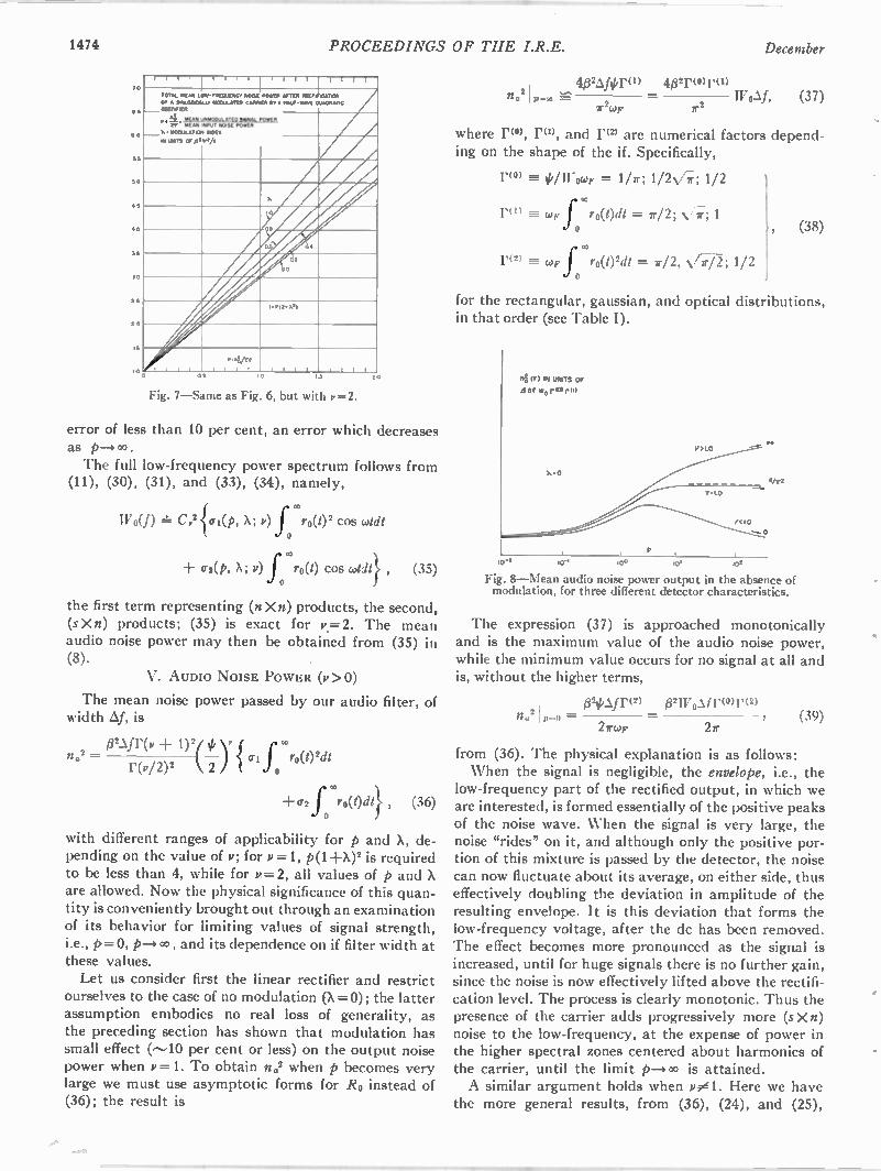
1474 PROCEEDINGS OF THE I.R.E. December
10
6 5
55
50
• 5
• 0
35
30
25
2 0
10 05 10 14
Fig. 7—Same as Fig. 6, but with v2.
r i r r r i l l I I I . ; I I I
RM .' i211
P.4 Z• MC .
X .100001.67rON
IN Wir5 prig
TOTAL oc•rd LOw
Cf • S•6,5004 , RM .' i211
P.4 Z• MC .
X .100001.67rON
IN Wir5 prig
- F1520v2,0C• NOISE 6100,.•rt1) CANNER
NOU, MO M Pcr•26 !NOV,
WI/,
POrt• OFTEN 1211, 121061,011 116 •61,- .6641 01./6066•10
a
lo
o•
. •
2
0
l•ra•x.)
t 1 , 1
•• 4/•••
1 1 1 1 1 1 1 1 i i r
20
error of less than 10 per cent, an error which decreases as The full low-frequency power spectrum follows from
(11), (30), (31), and (33), (34), namely,
W0(f) C,2 cri(P, X; v) f 'C0(0' cos whit
(r2(p, X; V) f ro(t) cos oddt} , (35)
the first term representing (n X n) products, the second, (sXn) products; (35) is exact for v.= 2. The mean audio noise power may then be obtained from (35) in (8).
V. AUDIO NOISE POWER (v>0)
The mean noise power passed by our audio filter, of width Af, is
na2 =02Afr(p+1)2(0),{ Grir ro(1)2clt
r(V/2) 2 k 2
+ (72 f roWdl} , (36)
with different ranges of applicability for p and X, de-pending on the value of v; for v =1, p(1 -FX)2 is required to be less than 4, while for v=2, all values of p and X are allowed. Now the physical significance of this quan-tity is conveniently brought out through an examination of its behavior for limiting values of signal strength, i.e., p= 0, and its dependence on if filter width at these values. Let us consider first the linear rectifier and restrict
ourselves to the case of no modulation (X =0); the latter assumption embodies no real loss of generality, as the preceding section has shown that modulation has small effect (---,10 per cent or less) on the output noise power when v=1. To obtain no' when p becomes very large we must use asymptotic forms for Ro instead of (36); the result is
402Afor(i) 42r(0)r(1) no 2
1r2WF 2
IV0Af, (37)
where 11(0) , Po, and 17(2) are numerical factors depend-ing on the shape of the if. Specifically,
r(o) //11-0(.0F = 1/7r; 1/2-V;; 1/2
ro) cop f ro(l)cll = 7r/2; N/77'; 1 , (38)
r(2) aw l ro(t)2dt = 7r/2, V7/2; 1/2
for the rectangular, gaussian, and optical distributions, in that order (see Table I).
nf, IF) IN UNITS OF
Wo rIO)rol
0
0
V:1 0
(<1 0
4/r2
otr, too .00
Fig. 8—Mean audio noise power output in the absence of modulation, for three different detector characteristics.
The expression (37) is approached monotonically and is the maximum value of the audio noise power, while the minimum value occurs for no signal at all and is, without the higher terms,
024,Afr(2) 02w0Af ro,r( 2) n.21p-o =
27rwp (39)
from (36). The physical explanation is as follows: When the signal is negligible, the envelope, i.e., the
low-frequency part of the rectified output, in which we are interested, is formed essentially of the positive peaks of the noise wave. When the signal is very large, the noise "rides" on it, and although only the positive por-tion of this mixture is passed by the detector, the noise can now fluctuate about its average, on either side, thus effectively doubling the deviation in amplitude of the resulting envelope. It is this deviation that forms the low-frequency voltage, after the dc has been removed. The effect becomes more pronounced as the signal is increased, until for huge signals there is no further gain, since the noise is now effectively lifted above the rectifi-cation level. The process is clearly monotonic. Thus the presence of the carrier adds progressively more (s X n) noise to the low-frequency, at the expense of power in the higher spectral zones centered about harmonics of the carrier, until the limit p,..0 is attained. A similar argument holds when v01. Here we have
the more general results, from (36), (24), and (25),
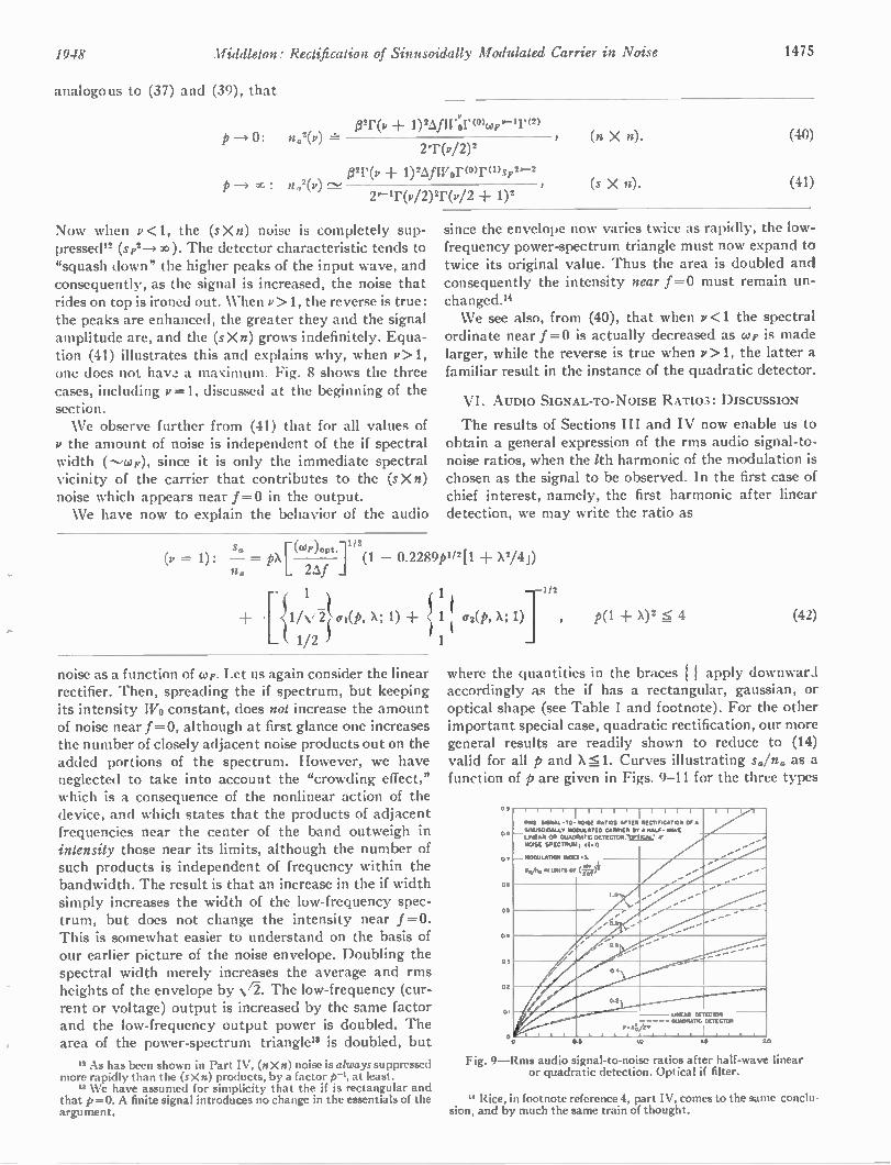
1948 Middleton: Rectification of Sinusoidally Modulated Carrier in Noise 1475
analogous to (37) and (39), that
p 0:
p oc :
B2 0, + 1)2 Af w'or (0),,F.--1r (2) n2(p) r-
2T(v/2)2
021,(v 1)2 4 Wor(0) r(1)3F 2r-2
n,42(v)
2 0-1 0 ,/ 2) 2 r (P / 2 + 1) 2
Now when v <1, the (sXn) noise is completely sup-pressed" (sF2-4 30). The detector characteristic tends to "squash down" the higher peaks of the input wave, and consequently, as the signal is increased, the noise that rides on top is ironed out. When v >1, the reverse is true: the peaks are enhanced, the greater they and the signal amplitude are, and the (s X n) grows indefinitely. Equa-tion (41) illustrates this and explains why, when v > 1, one does not have a maximum. Fig. 8 shows the three cases, including v =1, discussed at the beginning of the section. We observe further from (41) that for all values of
v the amount of noise is independent of the if spectral width (--,cop), since it is only the immediate spectral vicinity of the carrier that contributes to the (sXn) noise which appears near f=0 in the output. We have now to explain the behavior of the audio
(1, = 1):
(n X n). (40)
(s X n). (41)
since the envelope now varies twice as rapidly, the low-frequency power-spectrum triangle must now expand to twice its original value. Thus the area is doubled and consequently the intensity near 1=0 must remain un-changed." We see also, from (40), that when v <1 the spectral
ordinate near f=0 is actually decreased as cup is made larger, while the reverse is true when v > 1, the latter a familiar result in the instance of the quadratic detector.
VI. AUDIO SIGNAL-TO-NOISE RATIOS: DISCUSSION
The results of Sections III and IV now enable us to obtain a general expression of the rms audio signal-to-noise ratios, when the 1th harmonic of the modulation is chosen as the signal to be observed. In the first case of chief interest, namely, the first harmonic after linear detection, we may write the ratio as
Sa (COP)opt.1 "2
— = "Lna 24 _I (1 — 0.2289p112[1 X2/4j)
1 1/2
•[{1i ai(P, X; 1) + cr2(1), X ;
1
1/2 11 1
noise as a function of co,. Let us again consider the linear rectifier. Then, spreading the if spectrum, but keeping its intensity Wo constant, does not increase the amount of noise near f =0, although at first glance one increases the number of closely adjacent noise products out on the added portions of the spectrum. However, we have neglected to take into account the "crowding effect," which is a consequence of the nonlinear action of the device, and which states that the products of adjacent frequencies near the center of the band outweigh in intensity those near its limits, although the number of such products is independent of frequency within the bandwidth. The result is that an increase in the if width simply increases the width of the low-frequency spec-trum, but does not change the intensity near f = 0. This is somewhat easier to understand on the basis of our earlier picture of the noise envelope. Doubling the spectral width merely increases the average and rms heights of the envelope by N/2. The low-frequency (cur-rent or voltage) output is increased by the same factor and the low-frequency output power is doubled. The area of the power-spectrum triangle" is doubled, but
" As has been shown in Part IV, (nXn) noise is always suppressed more rapidly than the (sXn) products, by a factor p-1, at least. " We have assumed for simplicity that the if is rectangular and
that p =0. A finite signal introduces no change in the essentials of the argument.
p(1 X)2 6 4 (42)
where the quantities in the braces apply downward accordingly as the if has a rectangular, gaussian, or optical shape (see Table I and footnote). For the other important special case, quadratic rectification, our more general results are readily shown to reduce to (14) valid for all p and X 51. Curves illustrating sa/na as a function of p are given in Figs. 9-11 for the three types
09
Oa
Or
06
05
04
05
02
01
0 OS
i i
Amos 9.65•1- TO-NOISE
5....150.0ALLY IROOULATED UREA. OR OUADRAT,C NOISE SPECTRWA,
— 910012642109114349
I I I I I 1
RATIOS AFTER CARRIER Br
DETECTOR. VPTIC.44: (1.1)
• 1.
I
RECT.F.C.A,ON OF •
A HALF- HAVE IF
..."--..-....._ -
.....-..--
.....
-- ... ... ....-
.....
....
....
....
0.2
UNEAR DETECTOR .- - - -- QUADRATIC LETECTOR
. . . 0 .. Ai. tv . . . .
2.0
Fig. 9—Rms audio signal-to-noise ratios after half-wave linear or quadratic detection. Optical if filter.
" Rice, in footnote reference 4, part IV, comes to the same conclu-sion, and by much the same train of thought.
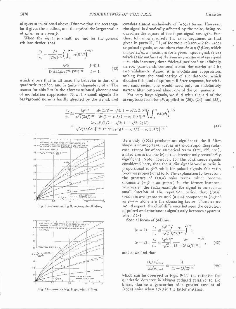
1476 PROCEEDINGS OF THE I.R.E. December
of spectra mentioned above. Observe that the rectangu-lar if gives the smallest, and the optical the largest value of so/no for a given P. When the signal is small, we find for the general
yth-law device that
S. PX r-ro(t)2dt)-112 na (26; n1/2 j 0
sF2x p 1, wo(244Fror(2))1/2 (43) = I,
which shows that in all cases the behavior is that of a quadratic rectifier, and is quite independent of v. The reason for this lies in the aforementioned phenomenon of modulation suppression. Now, for small signals the background noise is hardly affected by the signal, and
consists almost exclusively of (nXn) terms. However, the signal is drastically affected by the noise, being re-duced as the square of the input signal strength. Fur-ther, following precisely the same argument as that given in parts II, III, of footnote reference 2 for radar or pulsed signals, we can show that the best if filter, which makes so/no a maximum for a given input signal, is one which is the modulus of the Fourier transform of the signal —in this instance, three "delta-functions" or infinitely narrow pass-bands centered about the carrier and its two sidebands. Again, it is modulation suppression, arising from the nonlinearity of the detector, which dictates this kind of optimum if filter response, for with-out suppression one would need only an indefinitely narrow filter centered about one of the components. For very large signals, we find with the aid of the
asymptotic form for 1F1 applied to (20), (24), and (25),
s. Xp1/2
2r0 ro(t)dt /2 — v/2, 1 — w/2; 2; X2)( ) 1/2
na— V2(26,f) 112 2F1(1 — v, 3/2 — v; 1; x2)112 0
)tsr 2F1(1/2 — v/2; 1 — v/2; 2; X2) _
N/2(2An 1/2[Vor (1) W0 2F1(1 — 1/, 3/2 — v; 1; )2)}112
0.5
ON
0.5
04
03
02
SE
05
0
T 1 I I
RMS SoGNIM -TO-
_ SINUSO.DALLT MODULATED OR QUADRATIC DETECTOR
NIODuLATION INDEX
— s./n. IN UNITS 0
1 I I I I 1 I I I I I I I I I
NOISE RATIOS AFTER RECTIFICATION OF •
CARRIER ST A NALF•WAVE LINEAR RECTANDLILAR
• 1.
'
IF NOISE SPECTM.p•
(&or,u ,—)2
...••••••
X M O ..••• ...
..••• '''''
'
..ss
....
..••••
•P e. .., 4
,
02
UNEAR DE ECTOR
I Iss 4 011.40RATC DETECTOR t
s l i t i.5 20
Fig. 10—Same as Fig 9, rectangular if filter.
l i l t l j u l u u l i 1255 SIGNAL TO - NOISE RATIOS AFTER RECTIFICATION Of •
SINUSOIDALLE MODULATED CARRIER IT • RALF- RAVE
LINEAR OR QUADRATIC DETECTOR. fiaj aajAll IF NOISE
SPECTRUM.
Fig. 11—Same as Fig. 9, gaussian if filter.
— LINEAR BET CTOR
- - - QUADRATIC DETECTOR
I I I 5 S 0
(44)
Here only (sXn) products are significant, the if filter shape is unimportant, just as in the corresponding radar case, except for minor numerical terms (r(0), rm, etc.), and so also is the law (p) of the detector only secondarily significant. Note, however, for the continuous signals considered here, that the audio signal-to-noise ratio is proportional to p1/2, while for pulsed signals this ratio becomes proportional to p. The explanation follows from the presence of (sXn) noise terms, which become dominant (—p.--1 as p—)00) in the former instance, whereas in the radar example the signal is on such a small fraction of the repetition period that (sXn) products are ignorable and (n X n) components (--p-2 as alone are the obscuring factor. Thus, as we would expect, the chief difference between the detection of pulsed and continuous signals only becomes apparent when p>1. Special forms of (44) are
(v = 1):
(v — 2):
s. xp1/2 no — ) 1 1 2
s.,••••
2Afra)
sa xpi,2r 11 / 2
no L (2 + )'2)Afrod
and so we find that
(so/no),-2
= (1 ± )'2/2)I/2
, (45)
(46)
which can be observed in Figs. 9-11: the ratio for the quadratic detector is always reduced relative to the linear, due to a generation of a greater amount of (s X n) noise when X > 0 in the latter instance.
1948 PROCEEDINGS OF THE I.R.E. 1477
The results of this theory give a general picture of the relation between the signal at the output of a receiver as a function of the signal at the input of the if amplifier. For the purposes of making tests on the cor-relation between theory and experiment, it appears clear that the most useful type of detector, and therefore the one to be investigated, is the linear type.
1' E. G. Fubini and D. C. Johnson, "Signal-to-noise ratio in AM modulated receivers," PROC. I.R.E., vol. 36, pp. 1461-1467; this issue.
In the companion paper" by Fubini and Johnson, the results of the theory for sinusoidal modulation and linear detection have been tested. The curves given in their paper are a replot of those presented here with a change in scale from linear to logarithmic co-ordinates. It appears in their work that, despite all the approximations made as to shape of if filter, linearity of rectification, and the like, the correspondence between theory and experiment is satisfactory for most practical purposes.
An Approximate Solution of the Problem of Path and Absorption of a Radio Wave in a
Deviating Ionosphere Layer* JAMES E. HACKE, JR.t, AND JOHN M . KELSOt
Summary—A previously obtained double-parabola approxima-tion to a Chapman distribution is used to obtain approximate solu-tions for ray path and absorption of a radio wave incident obliquely on a deviating plane ionospheric layer from which the wave is "reflected." The solutions, expressed analytically and graphically, are valid when the earth's magnetic field and second-order absorption effects can be neglected.
INTRODUCTION
APREVIOUS PAPER' proposed a double-parabola approximation to the Chapman distribution2 which is generally accepted as representing
variation of ion density with height in the E and the F1 layers of the ionosphere. The paper also proposed a parabolic approximation for the product of ion density by electron-collision frequency as a function of height. By using these approximations, analytical solutions were obtained for "true" and apparent reflection height, and for absorption of a radio wave incident normally on the ionosphere. These solutions were also expressed in graphical form, and were compared with numerical results obtained by Pierces and by Jaeger.* The present paper extends the results of the previous
paper to oblique incidence while retaining the restric-tions that the wave frequency in the ionosphere be everywhere greater than the collisional frequency, that the effects of the earth's magnetic field be neglected, and that absorption per wavelength be small. These re-
* Decimal classification: R 112.62. Original manuscript received by the Institute, March 29, 1948. t The Pennsylvania State College, State College, Pa. 'J. E. Hacke, Jr., "An approach to the approximate solution of
the ionosphere absorption problem," PROC. I.R.E., vol. 36, pp. 724-727; June, 1948.
2 S. Chapman, 'The absorption and dissociative or ionizing effect of monochromatic radiation in an atmosphere on a rotating earth," Proc. Phys. Soc., vol. 43, pp. 26-45; January, 1931. 'J. A. Pierce, "The true height of an ionosphere layer," Phys.
Rev., vol. 71, pp. 698-706; May, 1947. ' J. C. Jaeger, "Equivalent path and absorption in an ionosphere
region," Proc. Phys. Soc., vol. 59, pp. 87-96; January, 1947.
strictions are met in practice for waves above about 1 Mc and correspond to consideration of the "ordinary" ray in quasi-transverse propagations.s Attention is con-fined to refraction and absorption in the deviating region (wave frequency insufficiently high to penetrate the layer) because an exact solution can be made of the problem when the ray penetrates the layer, at least if the ray can be considered as passing on essentially to infinity, and if the wave frequency is much greater than the critical frequency.
SUMMARY OF PREVIOUS RESULTS
In the previous paper' it was shown that the ion den-sity in a Chapman region is given by
N = NCh(x) (1)
where
N„, = \/(f3S,„, sec x)licHae)
Ch(x) = exp (1 — x — cl)/2 (2)
x = (h — ho)/ — ln sec x
a = the recombination coefficient in the iono-sphere
e = the base of Naperian logarithms = the ionization density produced by unit sur-face density of incident radiation
S.= the surface density of radiation incident on the ionosphere
H= the "scale height" of the atmosphere in the region where the ionization is produced; divi-sion by H yields distances in "scale units"
14= the height at which N is a maximum when x=0
' H. G. Booker, "Some general properties of the formula of the magneto-ionic theory," Proc. Phys. Soc., vol. 147, pp. 352-382; No-vember, 1934.
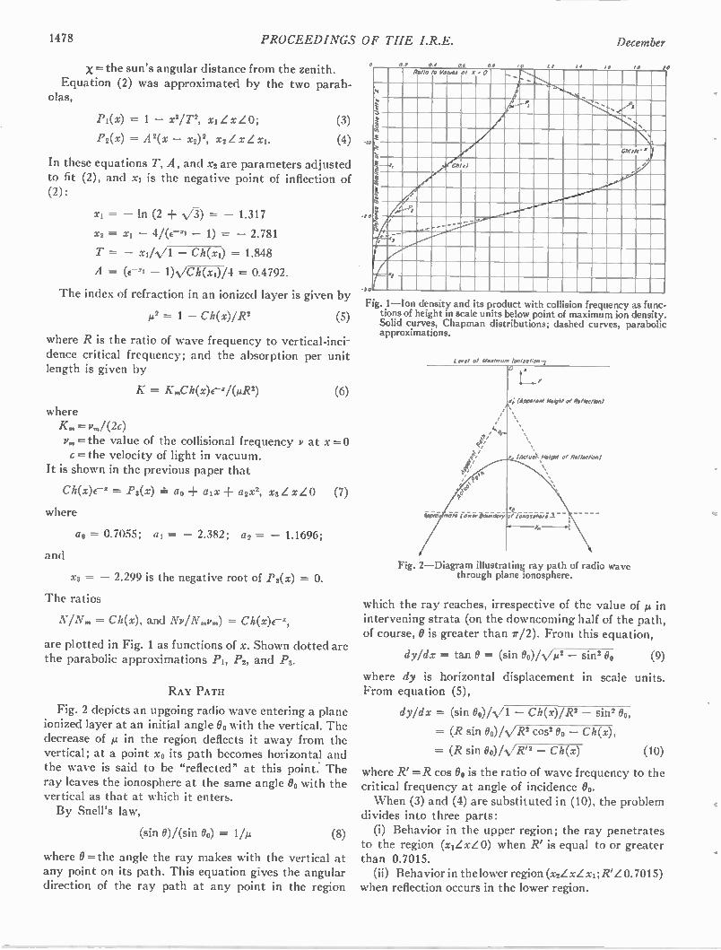
1478 PROCEEDINGS OF THE I.R.E. December
x = the sun's angular distance from the zenith. Equation (2) was approximated by the two parab-
olas,
Pi(x) = 1 — x2/ T2, xi x LO;
P2(x) = A2(x — x2)2, x2 x
In these equations T, A, and x2 are parameters adjusted to fit (2), and xi is the negative point of inflection of (2):
xi = — in (2 + N/-3-) = — 1.317
x2 = xi — 4/(e-zi — 1) = — 2.781
T = — xi/ N/1 — Ch(x2) = 1.848
A = (e-2. 1 — 1) /Ch(xi)/4 = 0.4792.
The index of refraction in an ionized layer is given by
1.1.2 = 1 — C h(X)/ R 2 (3)
where R is the ratio of wave frequency to vertical-inci-
dence critical frequency; and the absorption per unit length is given by
K = K„,Ch(x)e-V(AR2) (6)
where K„, = v,„/ (2c) Pm = the value of the collisional frequency v at x =-c = the velocity of light in vacuum.
It is shown in the previous paper that
Ch(x)e' = P3(x) = ao aix a2x2, x3.Z x 0
where
ao = 0.7055; al = — 2.382; a2 = — 1.1696;
and
(7)
x3 = — 2.299 is the negative root of P3(x) = 0.
The ratios
N / N„, = Ch(x), and Nv/N,„v„,) = Ch(x)ex,
are plotted in Fig. 1 as functions of x. Shown dotted are the parabolic approximations Pi, P2, and Pg.
RAY PATH
Fig. 2 depicts an upgoing radio wave entering a plane ionized layer at an initial angle 00 with the vertical. The decrease of µ in the region deflects it away from the vertical; at a point xo its path becomes horizontal and the wave is said to be "reflected" at this point. The ray leaves the ionosphere at the same angle 00 with the vertical as that at which it enters. By Snell's law,
(sin 0)/(sin 00) = 1/µ (8)
where 0 =the angle the ray makes with the vertical at any point on its path. This equation gives the angular direction of the ray path at any point in the region
60
Ratio o Valves 0 X • 0 .. ,. i A •
'N ,
...
, ,st „s. , ,_ le II
1h( v/'
4 , 4 '
Chi 01 ...'
Ii
.....................................„,,
/ ;—
o
‘0,
( ..„......„..„,......„....,,,....,.....-- .--
‘0,
F.g. 1—Ion density and ts product with collision frequency as func-tions of height in scale units below point of maximum ion density. Solid curves, Chapman distributions; dashed curves, parabolic approximations.
Level Cl Marimum Ionization
4 (Apparent Height of ReflectiOn)
(ActuoX,Helght 0 Reflechon)
ipp ro 07010 Lower Boundary •f IonospI:re
Fig. 2—Diagram illustrating ray path of radio wave through plane ionosphere.
which the ray reaches, irrespective of the value of µ in intervening strata (on the downcoming half of the path, of course, 0 is greater than 7r/2). From this equation,
dy/dx = ta,n 0 = (sin 00)/ W — sin2 00 (9)
where dy is horizontal displacement in scale units. From equation (5),
dy/dx = (sin 0)/../1 — Ch(x)/R2 — Sint 00,
= (R sin 00)/N/R2 cost 00 — Ch(x),
= (R sin 0o)/s,/R' — Ch(x) (10)
where R' =R cos 00 is the ratio of wave frequency to the critical frequency at angle of incidence 00. When (3) and (4) are substituted in (10), the problem
divides into three parts: (i) Behavior in the upper region; the ray penetrates
to the region (xIL xL 0) when R' is equal to or greater than 0.7015. (ii) Behavior in the lower region (x2L xL x1; R'L 0.7015)
when reflection occurs in the lower region.
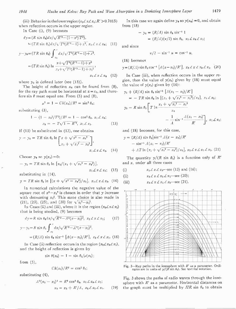
1948 Macke and Kelso: Ray Path and Wave Absorption in a Deviating Ionosphere Layer 1479
(iii) Behavior in the lower region (x2Z xL xi ;R' >0.7015) when reflection occurs in the upper region. In Case (i), (9) becomes
dy=(R sin 00)dx/VR"— (1— x2/T2),
••=: (TR sin 0o)dx/N/T2(R'2— 1)-F x2, xi Z xL xo; (11)
Y— Yo=(TR sin 00) f dx/N/T2(R'2— 1) +172,
xt
= (TR sin Bo) in x+ VT2(R"— 1) + x2
xi-l- VT2(R"— 1)-F xi2
xiL xL xo (12)
where yo is defined later (see (15)). The height of reflection xo can be found from (8),
for the ray path must be horizontal at x =xo, and there-fore sin 0 must equal one. From (5) and (8),
= 1 — Ch(x0)/R2 = sin200;
substituting (3),
1 — (1 — x02/T2)/R2 = 1 — cos' 00, xj L xo;
xo = — TN/1 — R'2, xi Z xo. (13)
If (13) be substituted in (12), one obtains
— Yo = TR sin 00 ln rx + V X2 — X02 1 Lx, + Yx12 — x02t
x zxzxo.
In this case we again define yo so y(xo) =0, and obtain from (18)
and since
Yo = (R/A) sin 00 sin-1 1
= (RI A)(712) sin 00, x2 Z xo Z xi;
r/2 — sin-1 u = cos-1 u,
(18) becomes
y= (RI A) sin 00 cos-1 [A (x— x2)/ R'], x2L xL xo Z xi. .(20)
In Case (iii), when reflection occurs in the upper re-gion, then the value of y(xi) given by (18) must equal the value of y(xi) given by (16):
Yo (R/A) sin Bo sin-, [A (xi — x2)/R1
= — TR sin 00 In [(xi -I- Yx12 — x02)/x0], xi Z xo;
xi + Vx12 — x02 yo = R sin 00 [T in
X0
1 A (xi — x2)] — sin-1 A R' , Z xo;
and (18) becomes, for this case,
y = (R/A) sin Oo[sin-i A(x — x2)/R'
— A(xi — x2)/R'
(14) + A T ln (xi + Vx12 — xo2)/xo], x2Z xL xiL xo. (21)
Choose yo so y(x0) = 0:
— yo = TR sin 00 ln [xo/(xi Vx12 — xo2)],
L x xo; (15) substituting in (14),
y = TR sin Oo in [(x s./x2 X02)/ X0], x1 L x L x0. (16)
In numerical calculations the negative value of the square root of x2—x02 is chosen in order that y increase with decreasing x02. This same choice is also made in (21), (23), (25), and (30) for /x12—x . In Cases (ii) and (iii), where it is the region (x2Z xL xi)
that is being studied, (9) becomes
dy=R sin 004x/VR'2—A 2(x— x2)2, x2Z xL xi; (17)
y— yo=R sin 00 f xdx/YR'2—A 2(x— X2) 2,
=(R/ A) sin Oo sin-s [A (x— x2)/R'], x2Z x Z xi. (18)
In Case (ii) reflection occurs in the region (x2ZxoL and the height of reflection is given by
sin 0(xo) = 1 = sin 00/A1(xo);
from (5),
2 = C052 00 ; C h(X0)/ R
substituting (4),
212(xo — x2) 2 = R2 cos2 00, x2 Z xo Z xi;
xo = x2 R' / A, x2L xo Z xi.
The quantity y/(R sin 0) and x, under all three cases
(i) xi x xo—see (13) and (16) ;
(ii) x2 L xL xo Z xi—see (20) ;
(iii) x2 x Z xi Z xo—see (21).
-3
is a function only of R'
, 0 - 4 . .
. iN RI ''‘'l 1 kl ,
"* Nh' 1 1
A W A I PA ./' - - , BArr 5,
/1/1 #31, - \\
Fg. 3—Ray paths in the ionosphere with R' as a parameter. Ordi-nates are in units of y/(R sin 00). See text for notation.
Fig. 3 shows the paths of radio waves through the iono-sphere with R' as a parameter. Horizontal distances on
(19) the graph must be multiplied by HR sin 00 to obtain
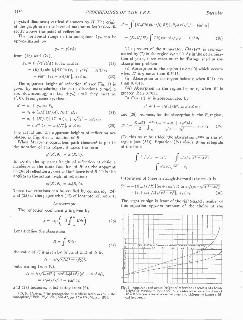
.1480 PROCEEDINGS OF THE I.R.E. December
physical distances; vertical distances by H. The origin of the graph is at the level of maximum ionization di-rectly above the point of reflection. The horizontal range in the ionosphere 2y,, can be
approximated by
Ym = Y(x2);
from (16) and (21),
y„, = (7/2)(RIA) sin 00, xo L xi; (22)
= (R/A) sin 00[A T in (xi + •Vx12 — x02)/xo
— sin-1 (xi — x2)/R1], xjLx0. (23)
The apparent height of reflection x' (see Fig. 2) is given by extrapolating the path directions (upgoing and downcoming) at (x2, ±y,) until they meet at x', 0). From geometry, then,
x' = X2 + y,n cot Bo,
Xi + (712)(k /A), Ho C
X2 + (R7A)[AT in (xi + Vx12 — x02)/xo
— sin-1 (xi — x2)/R1, xL xo.
(24)
(25)
The actual and the apparent heights of reflection are plotted in Fig. 4 as a function of R'. When Martyn's equivalent path theorem(' is put in
the notation of this paper, it takes the form
x'(R', 00) = x'(R, 0).
In words, the apparent height of reflection at oblique incidence is the same function of R' as the apparent height of reflection at vertical incidence is of R. This also applies to the actual height of reflection:
xo(R', 00) = xo(R, 0).
These two relations can be verified by comparing (24) and (25) of this paper with (17) of footnote reference 1.
ABSORPTION
The reflection coefficient p is given by
p = exp (-2 Kds). (26) zo
Let us define the absorption
S = f Kds;
the value of K is given by (6), and that of ds by
ds = IIN/(dx) 2 (dy)2.
Substituting from (9),
ds = HV(dx)2 sin2 00(dx )2/0.0 _ sin2 00,
S = f [K„,C h(x)e-x/(µR2)][1112dx/N/ — th],
= (K„,11/R2) f Ch(x)cidx/N/µ2 — sin2 0. (28)
The product of the numerator, Ch(x)e, is approxi-mated by (7) in the region x2L xL 0. As in the determina-tion of path, three cases must be distinguished in the absorption problem: (i) Absorption in the region (xiLxL 0) which occurs
when R' is greater than 0.7015. (ii) Absorption in the region below x1 when R' is less
than 0.7015. (iii) Absorption in the region below x1 when R' is
greater than 0.7015. In Case (i), 1.1.2 is approximated by
JA2 4= 1 — Pi(x)/R2, x xo;
and (28) becomes, for the absorption in the Pi region,
K„,HT (ao a2x2)dx S(i) — , xo. (29)
N/ x 2 — X02
(To this must be added the absorption Smo in the P g
region (see (32)). Equation (29) yields three integrals of the form
fdx/v/x2 — x02; f x!x h/x2 — xo2;
fx2dx/v/x2 — so2.
Integration of these is straightforward; the result is
S(0= —(K„,HT/R)Rao-Fa2x02/2) in x0/(xi-F.Vx12— xo2)
— (al+ a2x1/2)Vx12— xo21, x1 Z xo. (30)
The negative sign in front of the right-hand member of this equation appears because of the choice of the
(27) e
= I/Adz/ Y/22 — sin2 0;
and (27) becomes, substituting from (6),
D. F. Martyn, "The propagation of medium radio waves in the ionosphere," Proc. Phys. Soc., vol. 47, pp. 323-329; March, 1935.
t
I alio R ot Ware Frequency to Oat quo Incidence Critical Frequency
.S.
1 3';
CI
13 4
4—Apparent and actual height of reflection in sea e units below height of maximum ionization of a radio wave as a function of =R cos 00= ratio of wave frequency to oblique-incidence criti-
cal frequency.
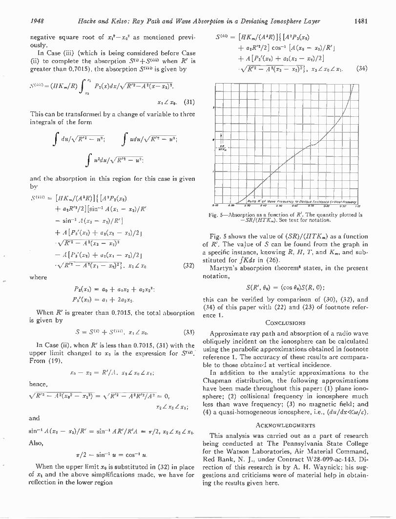
1948 Hacke and Kelso: Ray Path and Wave Absorption in a Deviating Ionosphere Layer 1481
negative square root of x12-x02 as mentioned previ-ously. In Case (iii) (which is being considered before Case
(ii) to complete the absorption S(i) +Su") when R' is greater than 0.7015), the absorption S(iio is given by
f 11
S(iii)=(HK„,/R) P3(x)dxIVR"-A 2(x- X2) 2 9
x1Lx0. (31)
This can be transformed by a change of variable to three integrals of the form
fdu/'s/R'2 - u2; f udu/N/R'2 - u2;
f242d241 V/V2 u2;
and the absorption in this region for this case is given by
S(iii) = [HK„,/(A 8R)] [212/33(x2)
▪ a2R'2/2] [sin-' A(xl - x2)/ R'
- A(x3- x2)/R']
where
▪ A[P3'(x2) a2(x3 - x2) /2j
• N/ R'2 - A2(x3 - x2)2
- A[P3'(x2) a2(xi - X2)/21
• R'2 - A2(xl - x2)21, xi xo
P3(x2) = at, aix2 + a2x22;
Ps'(x2) = al 2a2x2.
(32)
When R' is greater than 0.7015, the total absorption is given by
S = S(i) S(", xiZ xo. (33)
In Case (ii), when R' is less than 0.7015, (31) with the upper limit changed to xo is the expression for .510 . From (19),
X - X2 = R' / A , X2 Z X0 Z Xi;
hence,
N / Rt2 A 2( x0 2 x2 2) = V R72 A 2R72/A 2 = 0,
x2 Z so Z XI;
and
A(x0 - x2)/ R' = sin-, AR' / R'A = T/2, x2 Z xo Z xt.
Also,
T/2 - sin-' u = cos-' u.
When the upper limit xo is substituted in (32) in place of xs and the above simplifications made, we have for reflection in the lower region
S(ii) = [liK„,/(A3R)] { [A2P3(x2) ▪ a2R"12] cos-' [A (xs -
▪ A[P3'(x2) a2(x3 - x2)121
• R'2 - A2(x3 - x2) 21, X3 Z X0 Z xi. (34)
Rano P of Wove Frequency to Oblique incldence 0r/110. Frequency
0/0 0 SO 010 040 030 000 070 0-10 030 147
Fig. 5—Absorption as a function of R'. The quantity plotted is — SR /(HT K„,). See text for notation.
Fig. 5 shows the value of (SR)/ (HTK„,) as a function of R'. The va)ue of S can be found from the graph in a specific instance, knowing R, H, T, and K„„ and sub-stituted for fKds in (26). Martyn's absorption theoreme states, in the present
notation,
S(R', 00) = (cos 00)S(R, 0);
this can be verified by comparison of (30), (32), and (34) of this paper with (22) and (23) of footnote refer-ence 1.
CONCLUSIONS
Approximate ray path and absorption of a radio wave obliquely incident on the ionosphere can be calculated using the parabolic approximations obtained in footnote reference 1. The accuracy of these results are compara-ble to those obtainca at vertical incidence. In addition to the analytic approximations to the
Chapman distribution, the following approximations have been made throughout this paper: (1) plane iono-sphere; (2) collisional frequency in ionosphere much less than wave frequency; (3) no magnetic field; and (4) a quasi-homogeneous ionosphere, i.e., (du/dx<<co/c).
ACKNOWLEDGMENTS
This analysis was carried out as a part of research being conducted at The Pennsylvania State College for the Watson Laboratories, Air Material Command, Red Bank, N. J., under Contract W28-099-ac-143. Di-rection of this research is by A. H. Waynick; his sug-gestions and criticisms were of material help in obtain-ing the results given here.
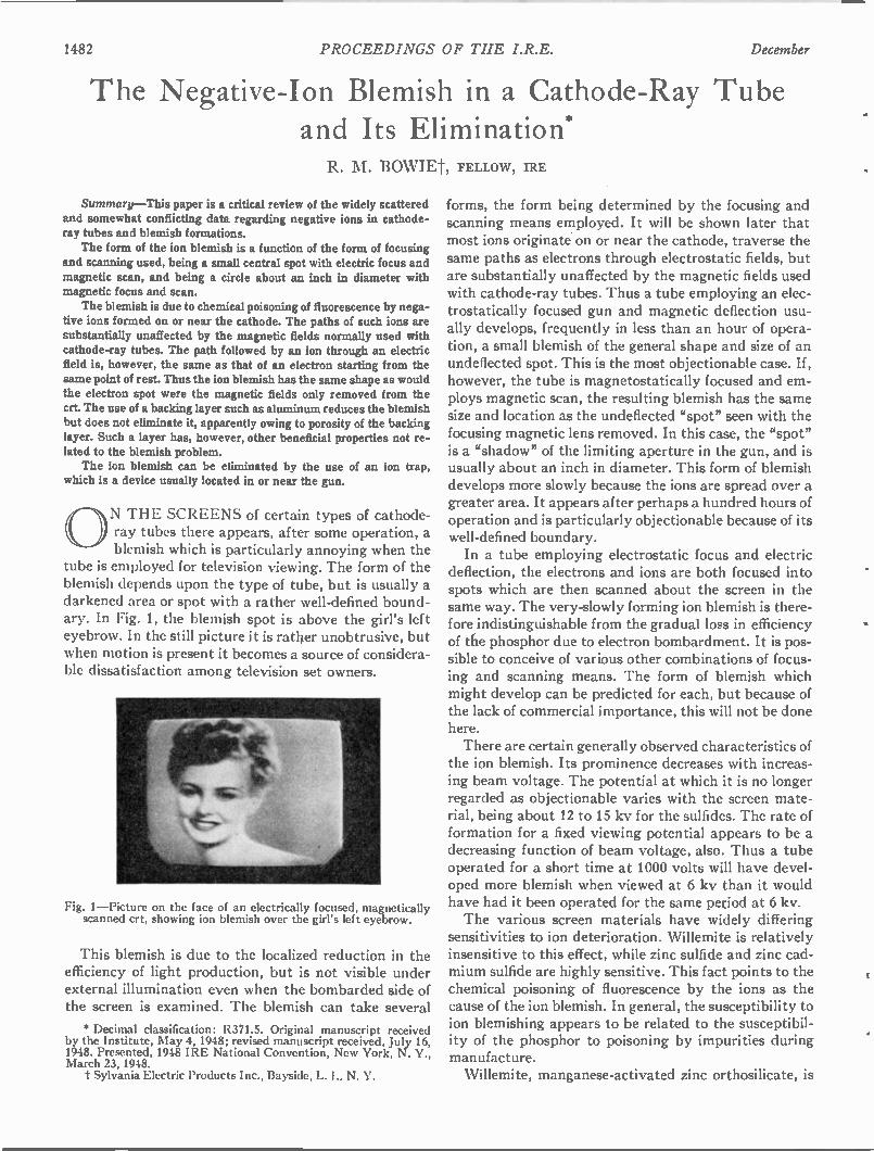
1482 PROCEEDINGS OF THE I.R.E. December
The Negative-Ion Blemish in a Cathode-Ray Tube and Its Elimination*
R. M. BOWIEt, FELLOW, IRE
Summary—This paper is a critical review of the widely scattered and somewhat conflicting data regarding negative ions in cathode-ray tubes and blemish formations. The form of the ion blemish is a function of the form of focusing
and scanning used, being a small central spot with electric focus and magnetic scan, and being a circle about an inch in diameter with magnetic focus and scan. The blemish is due to chemical poisoning of fluorescence by nega-
tive ions formed on or near the cathode. The paths of such ions are substantially unaffected by the magnetic fields normally used with cathode-ray tubes. The path followed by an ion through an electric field is, however, the same as that of an electron starting from the same point of rest. Thus the ion blemish has the same shape as would the electron spot were the magnetic fields only removed from the crt. The use of a backing layer such as aluminum reduces the blemish but does not eliminate it, apparently owing to porosity of the backing layer. Such a layer has, however, other beneficial properties not re-lated to the blemish problem. The ion blemish can be eliminated by the use of an ion trap,
which is a device usually located in or near the gun.
ON THE SCREENS of certain types of cathode-ray tubes there appears, after some operation, a blemish which is particularly annoying when the
tube is employed for television viewing. The form of the blemish depends upon the type of tube, but is usually a darkened area or spot with a rather well-defined bound-ary. In Fig. 1, the blemish spot is above the girl's left eyebrow. In the still picture it is rather unobtrusive, but when motion is present it becomes a source of considera-ble dissatisfaction among television set owners.
Fig. 1—Picture on the face of an electrically focused, magnetically scanned crt, showing ion blemish over the girl's left eyebrow.
This blemish is due to the localized reduction in the efficiency of light production, but is not visible under external illumination even when the bombarded side of the screen is examined. The blemish can take several
• Decimal classification: R371.5. Original manuscript received by the Institute, May 4, 1948; revised manuscript received, July 16, 1948. Presented, 1948 IRE National Convention, New York, N. Y., March 23, 1948. t Sylvania Electric Products Inc., Bayside, L. I.. N. Y.
forms, the form being determined by the focusing and scanning means employed. It will be shown later that most ions originate on or near the cathode, traverse the same paths as electrons through electrostatic fields, but are substantially unaffected by the magnetic fields used with cathode-ray tubes. Thus a tube employing an elec-trostatically focused gun and magnetic deflection usu-ally develops, frequently in less than an hour of opera-tion, a small blemish of the general shape and size of an undeflected spot. This is the most objectionable case. If, however, the tube is magnetostatically focused and em-ploys magnetic scan, the resulting blemish has the same size and location as the undeflected "spot" seen with the focusing magnetic lens removed. In this case, the "spot" is a "shadow" of the limiting aperture in the gun, and is usually about an inch in diameter. This form of blemish develops more slowly because the ions are spread over a greater area. It appears after perhaps a hundred hours of operation and is particularly objectionable because of its well-defined boundary. In a tube employing electrostatic focus and electric
deflection, the electrons and ions are both focused into spots which are then scanned about the screen in the same way. The very-slowly forming ion blemish is there-fore indistinguishable from the gradual loss in efficiency of the phosphor due to electron bombardment. It is pos-sible to conceive of various other combinations of focus-ing and scanning means. The form of blemish which might develop can be predicted for each, but because of the lack of commercial importance, this will not be done here. There are certain generally observed characteristics of
the ion blemish. Its prominence decreases with increas-ing beam voltage. The potential at which it is no longer regarded as objectionable varies with the screen mate-rial, being about 12 to 15 kv for the sulfides. The rate of formation for a fixed viewing potential appears to be a decreasing function of beam voltage, also. Thus a tube operated for a short time at 1000 volts will have devel-oped more blemish when viewed at 6 kv than it would have had it been operated for the same peziod at 6 kv. The various screen materials have widely differing
sensitivities to ion deterioration. Willemite is relatively insensitive to this effect, while zinc sulfide and zinc cad-mium sulfide are highly sensitive. This fact points to the chemical poisoning of fluorescence by the ions as the cause of the ion blemish. In general, the susceptibility to ion blemishing appears to be related to the susceptibil-ity of the phosphor to poisoning by impurities during manufacture. Willemite, manganese-activated zinc orthosilicate, is
1948 Bowie: Negative-Ion-Blemish Elimination 1483
a compound requiring a relatively large concentration of activator per cent) and being relatively insensitive to poisoning of fluorescence by impurities such as nickel. The sulfides, which are usually activated with silver or copper, require activator concentrations of 0.01 per cent or less and are correspondingly more susceptible to poi-soning of fluorescence by impurities. Although the ion blemish has been ascribed by Sharpe'
to the deposition of material on the surface of the phos-phor crystals, which material slows the impinging elec-trons, the poisoning theory is much more tenable. To re-duce the fluorescence the layer would have to have ap-preciable thickness. Data° reported for aluminum indi-cate that at 2 kv approximately 1000 molecular layers are required to reduce the beam power 20 per cent. If, as will be shown later, the ions are chiefly oxygen, it is dif-ficult to see how a sufficient thickness could be retained. Furthermore, Bachman and Carnahan' report that the negative ion blemish can be "developed" by immersing the face removed from a cathode-ray tube in photogra-pher's "hypo." This points to some sort of chemical change rather than to a film formation. It appears, how-ever, that no explanation has been advanced in terms of chemistry of the solid state.
Nature and Origin of the Ion Beam
Several notable papers " have appeared dealing with the nature and origin of the negative-ion beams. The in-vestigations reported involved mass-spectrographic analyses of crt beams. In two cases,8.4 standard or sub-stantially standard cathode-ray tubes were employed as mass spectrographs by replacing the customary scan-ning coil with a strong electromagnet, and using the poisoning effect of the negative ions upon the screen to produce the records. The combined findings appear in Table I. In properly processed tubes, the predominant ion is 02-. The two chlorine ions appear to be abundant also during early life, but substantially disappear in a few hours of operation. Both the origin of the ionizable material and the mech-
anism of ion formation are subject to some uncertainty. Three mechanisms appear to be involved, although sev-eral others have been considered and ruled out. These three are: (1) emission of ions as such from the cathode; (2) ejection of ions from the cathode and grid by impact of positive ions formed by the electron beams; and (3) ion formation by attachment of electrons from the beam to gas molecules.
1 j. Sharpe, "The ion trap in Cr tubes," Electronic Eng., (London) pp. 385-386, December, 1946.
D. W. Epstein and L. Pensak, "Improved cathode ray tubes with metal-backed luminescent screens," RCA Rev. Vol. 7, pp. 5-8; March, 1946. I C. H. Bachman, and C. W. Carnahan, "Negative ion compon-
ents in the cathode-ray beam," PROC. I.R.E., vol. 26, pp. 529-539; May, 1938.
4 L. F. Broadway, and A. F. Pearce, "Emission of negative ions from oxide cathodes," Proc. Phys. Soc., (London), vol. 51, pp. 335-348; 1939.
6 Von H. Schaefer, and W. Walcher, "Negative ions in braun tubes and their relation to the oxide cathode mechanism," Zeit. Phys., vol. 121, pp. 679-701; 1943.
I. EMISSION OF NEGATIVE IONS
With no exceptions, in a well-processed tube all nega-tive ions appear to have their origins at or very near the cathode (or grid),°-sas the ion blemishes are well focused in electrically focused tubes. In certain magnetically focused tubes it is possible, with the magnetic lens re-moved, to form an electron image of the cathode sur-face on the screen. In such a tube Liebman7 showed that this electron image agrees exactly in detail with the ion blemish, except for a few additional features. Schaefer and Walcher° conclude from such observa-
tions as the independence of the 02- ion current on gas pressure that oxygen is emitted as ions. Broadway and Pearce° observed, however, that 0- ion spot formation is reduced by reduction of oxygen pressure. This, and the relatively poorer focus of the 0- spot, they took as evi-dence that oxygen is not emitted as ions. Both may be right. The former had cathodes operated under adverse conditions with high electrolytic conduction, apparently conducive to a surface reaction leading to 02- emission. The well-formed cathodes of the latter apparently emit-ted uncharged oxygen which contributed to the gas even-tually ionized by electron attachment. Note that the oxygen ions reported are different in the two cases. Both papers agree, however, that chlorine is emitted as an ion. Regardless of the exact mechanism of ionization, how-
ever, oxygen appears to originate from the well-known slow decomposition of the oxides of the cathode during operation. Chlorine may originate as an impurity in the cathode materials, although recently Hamaker, Bruin-jug, and Aten° have reported evidence that it is due to the following chemical reaction in the glass during bak-ing on exhaust:
2NaC1 ± H20 + SiO2—) Na2SiO3 2HC1.
The NaCl is a common impurity, while H20 is always present in commercial glass. The HCI reacts with Ba0 to yield BaCl2 and H20. The former decomposes to yield Cl- ions.
II. NEGATIVE-ION FORMATION BY POSITIVE-ION BOMBARDMENT
It has been shown that positive-ion bombardment of a surface usually yields spectra of negative ions much like those observed in cathode-ray tubes."--14 Bachman'
° C. H. Bachman, "Ring focusing of negative ions in a cathode-ray beam," Jour. Appi. Phys., vol. 11, pp. 83-85; January, 1940.
7 G. Liebman, "Origin of ion burn in cathode-ray tubes," Nature, vol. 157, p. 228; February 23, 1946. Also, Ekc. Eng., vol. 18, pp. 289-290; September, 1946.
8 H. A. Barton, "Negative ion emission from oxide coated fila-ments," Phys. Rev., vol. 26, pp. 360-363; 1925. ' H. C. Hamaker, H. Bruining, and A. H. W. Aten, Jr., "On the
activation of oxide-coated cathodes." Philips Res. Rep., vol. 2, pp. 171-176; 1947.
1° J. S. Thompson, "A new method of producing negative ions,' Phys. Rev., vol. 38, p. 1389; October, 1931.
11 K. S. Woodcock, "The emission of negative ions under the bombardment of positive ions," Phys. Rev., vol. 38, pp. 1696-1703; November 1,1931.
1484 PROCEEDINGS OF THE I.R.E. December
was able to explain the ring-shaped spots previously ob-served' in certain purposely gassy tubes in terms of pos-itive-ion bombardment of the grid aperture. The result-ing negative-ion emission from the grid produced the ring-shaped ion blemishes observed for the oxygen. This theory was confirmed by notching the grid aperture and observing the "notch" in the ion-blemish circle, and also by noting grid-aperture erosion in dissected tubes. The heavy ions such as Ca0-, Ni, and Ba02- very possibly are due to positive-ion bombardment of the cathode sur-face.
III. NEGATIVE-ION FORMATION BY ELECTRON
ATTACHMENT
From gaseous-discharge research it is well known that electron attachment takes place only to electronegative molecules such as oxygen, and becomes relatively im-probable at electron velocities above those correspond-ing to a few volts. Hence, attachment must occur very near the cathode. Approximate calculations of ion cur-rent by this process" yield low values, but do not rule out the method. As attachment to molecular oxygen may result in dissociation into 0- and 0; the 0- found by Broadway and Pearce' very probably was produced by this attachment process. The organic-vapor ions may be attributed to the
breaking down of the cellulose-nitrate binder used in cathode preparation,' or to the presence bf grease vapor as evidenced by the great number of such ions found by Schaefer and Walcher,' whose tube could not be baked out and had greased joints.
BLEMISH ELIMINATION
It can be seen that the negative ions responsible for the blemish are chiefly 02- and Cl- originating at or near the cathode. They are undeflected by magnetic fields employed with cathode-ray tubes, and reduce the low-voltage ( <10,000 v) fluorescent efficiency of the screen material. To eliminate this defect, three approaches have been used. The first is to attempt to eliminate sub-stances likely to form negative ions from the important parts of the tube by special care in parts preparation, followed by rigorous exhaust. In some cases, "getters" activated during operation have been employed to take up gas which might form ions. A hot tantalum filament in parallel with the cathode heater, and zirconium on gun parts, have been employed. It has been the author's experience, however, that such methods merely shift the blemish from an item of manufacturing shrinkage to a field complaint.
U R. H. Sloane, and R. Press, "Formation of negative ions by positive ion impact on a surface," Proc. Roy. Soc., vol. A168, pp. 284-300; 1938.
U F. L. Arnot, and Clark Beckett, "A new process of negative-ion formation IV," Proc. Roy. Soc., vol. A168, pp. 103-122; 1938. " R. H. Sloane, and Eliza Cathcart, 'Formation of negative ions
by negative-ion bombardment of surfaces, a new process," Nature, vol. 143, pp. 474-475; March 18, 1939.
Backing Layer As Ion Filter
An interesting approach is to protect the screen with a filter relatively pervious to electrons, but impervious to ions. It is known" that the depth of penetration of a particle into a substance increases with particle velocity and decreases in proportion to particle mass. This indi-cates a strong discrimination by particle mass. The application of a thin metallic backing layer has
received considerable attention, primarily for three rea-sons other than the elimination of negative-ion blem-ishes."-2° First, an unbacked screen is brighter on the bombarded side because the light-producing interac-tions occur nearer that side. If a very thin metallic film is "stretched" relatively smoothly over the phosphor grains on the bombarded side of the screen, the bright-ness of the viewed side may be increased, provided that the loss of energy by the electrons in passing through the film is not too great. This is because the metal film re-flects the back-directed light. In practice, the anode po-tential at which the brightness of a backed screen just equals that of a similar but unbacked screen is a func-tion of backing-layer thickness and is of the order of a few kilovolts. Bachman" reports a value of 5 kv, which is presumed to apply for a tube intended for operation at 10 kv. The second reason for the backing is the improvement
of contrast by the elimination of the stray light from the bombarded side of the screen reflected from the inside walls of the tube. The third reason has to do with the provision of a conductive return path for the beam cur-rent; an unbacked screen relies upon secondary emis-sion from the screen material to provide the path for the electron current in the beam to the second anode. The screen will not operate at a potential above which the secondary-to-primary current ratio drops below unity, which frequently occurs below 15 kv. Means for obtaining backing layers are described by
Law,"." Schaefer," and Bromley?' The aluminum back-ing currently in commercial use, while providing the advantages mentioned above, appears only to reduce the rate of ion-blemish formation.
Negative-Ion Trap
The third approach to the elimination of the negative-ion blemish is the use of the negative-ion trap, which separates the negative ions from the electrons in the
Is Beth, Ann. der Phys. vol. 5, p. 374; 1930. " M. Von Ardenne, British Patent No. 402,411, accepted Novem-
ber 21, 1933. 12 Kurt Schlesinger, U. S. Patent No. 2,209,639, issued February
4, 1936. 18 C. H. Bachman, 'Image contrast in television," Gen. Elec. Rev.,
vol. 48, pp. 13-19; September, 1945. " R. R. Law, U. S. Patent No. 2,233,786, issued March 4, 1941. 2° Vincent J. Schaefer, U. S. Patent No. 2,374,311, issued April
24, 1945. n Art Bramley, "Aluminum backed phosphor screen in cathode
ray tubes," The Electrochemical Society Preprint 91-30; Meeting, April 9-11, 1947. n R. R. Law, U. S. Patent No. 2,303,563, issued December 1,
1942.
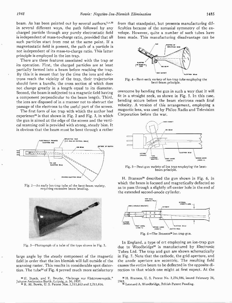
1948 Bowie: Negative-Ion-Blemish Elimination 1485
beam. As has been pointed out by several authors,8." in several different ways, the path followed by any charged particle through any purely electrostatic field is independent of mass-to-charge ratio, provided that all such particles start from rest at the same point. If a magnetostatic field is present, the path of a particle is not independent of its mass-to-charge ratio. This latter principle is employed in the ion trap. There are three features associated with the trap or
its operation. First, the charged particles are at least partially formed into a beam before reaching the trap. By this it is meant that by the time the ions and elec-trons reach the vicinity of the trap, their trajectories should form a bundle, the cross section of which does not change greatly in a length equal to its diameter. Second, the beam is subjected to a magnetic field having a component perpendicular to the beam length. Third, the ions are disposed of in a manner not to obstruct the passage of the electrons to the useful part of the screen. The first form of ion trap with which the author had
experience" is that shown in Fig. 2 and Fig. 3, in which the gun is aimed at the edge of the screen and the verti-cal scanning coil is provided with strong, steady bias. It is obvious that the beam must be bent through a rather
11.1011•GALI.V VOGESIO
ELECTING WAN
AND ELECTiloa NENE
DEILEGTEN TONE
(A G MAI ON VENT0GAL COLS)
Km MAY
[1.[C,11010 111 .
OUTSIDE Of MASTEN
Fig. 2—An early ion-trap tube of the bent-beam variety, requiring excessive beam bending.
Fig. 3—Photograph of a tube of the type shown in Fig. 2.
large angle by the steady component of the magnetic field in order that the ion blemish will fall outside of the scanning raster. This results in considerable spot distor-tion. The tube" of Fig. 4 proved much more satisfactory
" H. Busch, and E. Bruche, "Beitrage zur Elektronenoptik," Johann Ambrosius Barth; Leipzig, p. 34; 1937.
14 R. M. Bowie, U. S. Patent Nos. 2,211,613 and 2,211,614.
from that standpoint, but presents manufacturing dif-ficulties because of the nonaxial symmetry of the en-velope. However, quite a number of such tubes have been made. This manufacturing disadvantage can be
Fig. 4—Bent-neck variety of ion-trap tube employing the bent-beam principle.
overcome by bending the gun in such a way that it will fit in a straight neck, as shown in Fig. 5. In this case, bending occurs before the beam electrons reach final velocity. A version of this arrangement, employing a magnetic lens, was used by Philco Radio and Television Corporation before the war.
Fig. 5—Bent-gun variety of ion trap employing the bent-beam principle.
H. Branson" described the gun shown in Fig. 6, in which the beam is focused and magnetically deflected so as to pass through a slightly off-center hole in the end of the extended second-anode cylinder.
VANIAILE NEGATIVE )
CATITOCIE (GNOU10)
VIE W Alai (41OOG)
IDITENNAL MAINE = LEIS
ELECTIION KAM M ONO ANCOE (11000 V) .004.DIA HOLE
Fig. 6—The Branson si ion-trap gun.
In England, a type of crt employing an ion-trap gun due to Woodbridge" is manufactured by Electronic Tubes Ltd. The trap and gun are shown schematically in Fig. 7. Note that the cathode, the grid aperture, and the anode aperture are eccentric. The resulting field causes the entire beam to be deflected in the opposite di-rection to that which one might at first expect. At the
11 H. Branson, U. S. Patent No. 2,274,586, issued February 24, 1942. 2, Leonard A. Woodbridge, British Patent Pending.
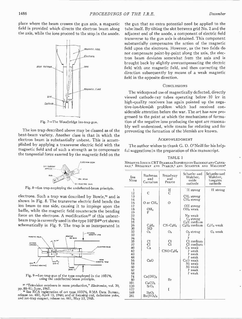
1486 PROCEEDINGS OF THE I.R.E. December
place where the beam crosses the gun axis, a magnetic field is provided which directs the electron beam along the axis, while the ions proceed to the stop in the anode.
Fig. 7—The Woodbridge ion-trap gun.
The ion trap described above may be classed as of the bent-beam variety. Another class is that in which the electron beam is substantially unbent. This is accom-plished by applying a transverse electric field with the magnetic field and of such a strength as to compensate the tangential force exerted by the magnetic field on the
DX CURRENT
APPLIED
GUN
ELECTRON BEAN
ION BEAN
" DC ELECTRIC BIAS
Fig. 8—Ion trap employing the undeflected-beam principle.
electrons. Such a trap was described by Bowie," and is shown in Fig. 8. The transverse electric field bends the ion beam to one side, causing it to impinge upon the baffle, while the magnetic field counteracts the bending force on the electrons. A modification" of this unbent-beam trap is currently used in the type 10PB428 crt shown schematically in Fig. 9. The trap is so incorporated in
himeatTic TACO
CATNODE (01101IND)
OMIT .1
( vAICAGLE AMAIN()
G. t (250 SI)
ION NAM
ANODE
0000 )
rIM MINIAL MA KETIC LENA
ELECTRON K AM
WEAN
MAGNETIC FIELD
Fig. 9—Ion-trap gun of the type employed in the 10BP4, using the undeflected-beam principle.
11 "Television receivers in mass production," Ekaronics, vol. 20, pp. 86-91; June, 1947.
25 See RCA registration of crt type 10BP4, RMA Data Bureau, release no. 482, April 15, 1946; and of focusing coil, deflection yoke, and ion-trap magnet, release no. 661, May 13, 1948.
the gun that no extra potential need be applied to the tube itself. By tilting the slot between grid No. 2 and the adjacent end of the anode, a component of electric field transverse to the gun axis is obtained. This component substantially compensates the action of the magnetic field upon the electrons. However, as the two fields do not compensate point-by-point along the axis, the elec-tron beam deviates somewhat from the axis and is brought back by slightly overcompensating the electric field with one magnetic field, and then correcting the direction subsequently by means of a weak magnetic field in the opposite direction.
CONCLUSIONS
The widespread use of magnetically deflected, directly viewed cathode-ray tubes operating below .10 kv in high-quality receivers has again pointed up the nega-tive-ion-blemish problem which had received con-siderable attention before the war. The art has now pro-gressed to the point at which the mechanisms of forma-tion of the negative ions producing the spot are reasona-bly well understood, while means for reducing and for preventing the formation of the blemish are known.
ACKNOWLEDGMENT
The author wishes to thank G. D. O'Neill for his help-ful suggestions in the preparation of this manuscript.
TABLE I
NEGATIVE IONS IN CRT BEAMS AS REPORTED BY BACHMAN AND CARNA-HAN, 3 BROAD WAY AND PEARCE,4 AND SCHAEFER AND W ALCHER3
Ion Mass
Bachman and
Carnahan
Broadway and Pearce
Schaefer and Walcher, oxide cathode
Schaefer and Walcher, tungsten cathode
12 13 14 16 0 or CH4 17 18 OH, 19 23 24 25 26 C2H2 30 NO 32 02 33 34 35 Cl 37 Cl 40 Ca 42 43 48 56 CaO 58 60 62 68 74 Ca (OH), 80 101 CaCO2 120 Sr02 127 169 BaO, 261 Ba(NO3)2
0
CN-C2H2
o,
Cl Cl
CNO-C2I-12
Br
H strong
CHI strong CHI strong
01-1 strong OH2 weak
Na weak C2 strong
C2H medium C2H2 medium
02 strong
Cl medium CI medium Ca weak / weak / weak ? weak
CaO weak Ni weak Ni weak ? weak 1 weak
H strong
C2H2 weak
02 weak
1948 PROCEEDINGS OF THE I.R.E. 1487
The Patterns of Slotted-Cylinder Antennas* GEORGE SINCLAIRt, SENIOR MEMBER, IRE
Summary—A method is described for calculating the patterns of arrays of axial-slot antennas mounted on the surface of a metallic cylinder. The method of calculation gives information on the relative phase of the radiated field in addition to the amplitude. Measure-ments have been made for certain of the antennas to verify the accuracy of the calculations. A number of calculated patterns are shown to indicate the extent of the control of the pattern which can be obtained by using arrays of slots on a cylinder.
INTRODUCTION ANTENNAS WHICH USE the radiating prop-erties of slots in the surface of a metal cylinder are being used to an increasing extent for vhf
and uhf applications. Slotted-cylinder antennas are particularly useful when it is desired to produce a hori-zontally polarized field with a horizontal pattern which is essentially circular. If the diameter of the cylinder is not too large, a single slot parallel to the axis produces a pattern which is usually sufficiently near a circle for most purposes. As the diameter of the cylinder is in-creased, the antenna becomes directional with a pattern which may have pronounced minima. While these direc-tional properties can sometimes be utilized to secure more advantageous coverage of a given area, they are generally undesirable. It is, therefore, important to be able to predict the amount by which the pattern de-parts from a true circle. As the number of stations using the higher fre-
quencies increases, it is to be expected that there will be an increased demand for antennas with controlled di-rectional patterns. Alford' has shown that a certain amount of control of the pattern of a slotted-cylinder antenna can be achieved by putting wings on the slots, but the amount of control which can be obtained is limited. Another method for modifying the pattern consists of using a number of slots spaced around the periphery of the cylinder. If the slots are equispaced around the periphery and fed in phase with equal amounts of power, the pattern can be made more nearly circular.' By feeding power of different amounts and different phases to the slots, a wide variety of patterns can be obtained.
• Decimal classification: R326.7. Original manuscript received by the Institute, May 10, 1948; revised manuscript received, July 19, 1948. Presented, National Electronics Conference, Chicago, Ill., November, 1947; and IRE Canadian Section Conference, Toronto, Canada, May 1, 1948. A co-operative research contribution of the United Broadcasting
Company, Cleveland, Ohio, and The Ohio State University Research Foundation, Columbus, Ohio. The research described was conducted in the Antenna Laboratory of the department of electrical engineer-ing, the Ohio State University. t Formerly, The Ohio State University Research Foundation;
now, University of Toronto, Toronto, Ontario, Canada. 1 A. Alford, "Long Slot Antennas," Proc. Not. Electronics Conf.,
Chicago, III., pp. 143-155; 1946. I H. J. Riblet, "Microwave omnidirectional antennas," PROC.
I.R.E., vol. 35, pp. 474-478; May, 1947.
Some data have been published on the patterns of slot antennas." However, in order to design antennas consisting of arrays of slots, it is necessary to have available information on the variations in phase of the radiated field, in addition to information on the ampli-tude of the field. While it is possible to obtain this in-formation from either full-scale or model measure-ments using well-known techniques, such a procedure is generally impractical because the necessary measuring equipment is not available to the antenna designer. Calculation of the pattern is a much more satisfactory procedure, and can be carried out quite readily.
CALCULATION OF THE PATTERNS OF SLOT ANTENNAS
The exact calculation of the field radiated by a slotted-cylinder antenna is a difficult boundary-value problem. However, the antenna designer is generally most interested in the horizontal pattern of a vertical slotted-cylinder antenna, and fortunately the calcula-tion of this pattern is a much simpler problem. It can be shown that, when the breadth of the slot is small in comparison with the wavelength, the horizontal pattern is independent of the axial distribution of the field along the slot. By assuming the simplest possible axial dis-tribution, namely, one in which the field is uniformly distributed in a slot which is infinitely long, an expres-sion for the pattern can be obtained in the form of a Fourier series.' In the following, only the horizontal patterns of
vertical slotted-cylinder antennas will be considered. However, it is also possible to make approximate calcu-lations of the vertical patterns, if certain simplifying assumptions are made."' Jordan and Miller' have shown that the vertical pattern of a vertical slotted-cylinder antenna is approximately the same as the corresponding pattern for a similar slot in a perfectly conducting plane sheet of infinite extent. This pattern can be approxi-mated by calculating the H-plane pattern of the field radiated from the open end of a rectangular waveguide."
PATTERN OF A SINGLE SLOT IN A CYLINDER
Fig. 1 shows the co-ordinate system employed in the calculation of the field, and also illustrates the notation used. The axis of the cylindrical surface coincides with the z axis of a cylindrical co-ordinate system. The slot is assumed to be parallel to the z axis, and located at
on the surface of a cylinder of diameter D =2a, a
3 E. C. Jordan and W. E. Miller, "Slotted-cylinder antennas," Electronics, vol. 20, pp. 90-93; February, 1947.
G. Sinclair, E. C. Jordan, and E. W. Vaughan, "Measurement of aircraft-antenna patterns using models," PROC. I.R.E., vol. 35, pp. 1451-1462; December, 1947.
6 S. A. Schelkunoff, "Electromagnetic Waves," D. Van Nostrand Co., Inc., New York, N. Y., 1943; p. 359.
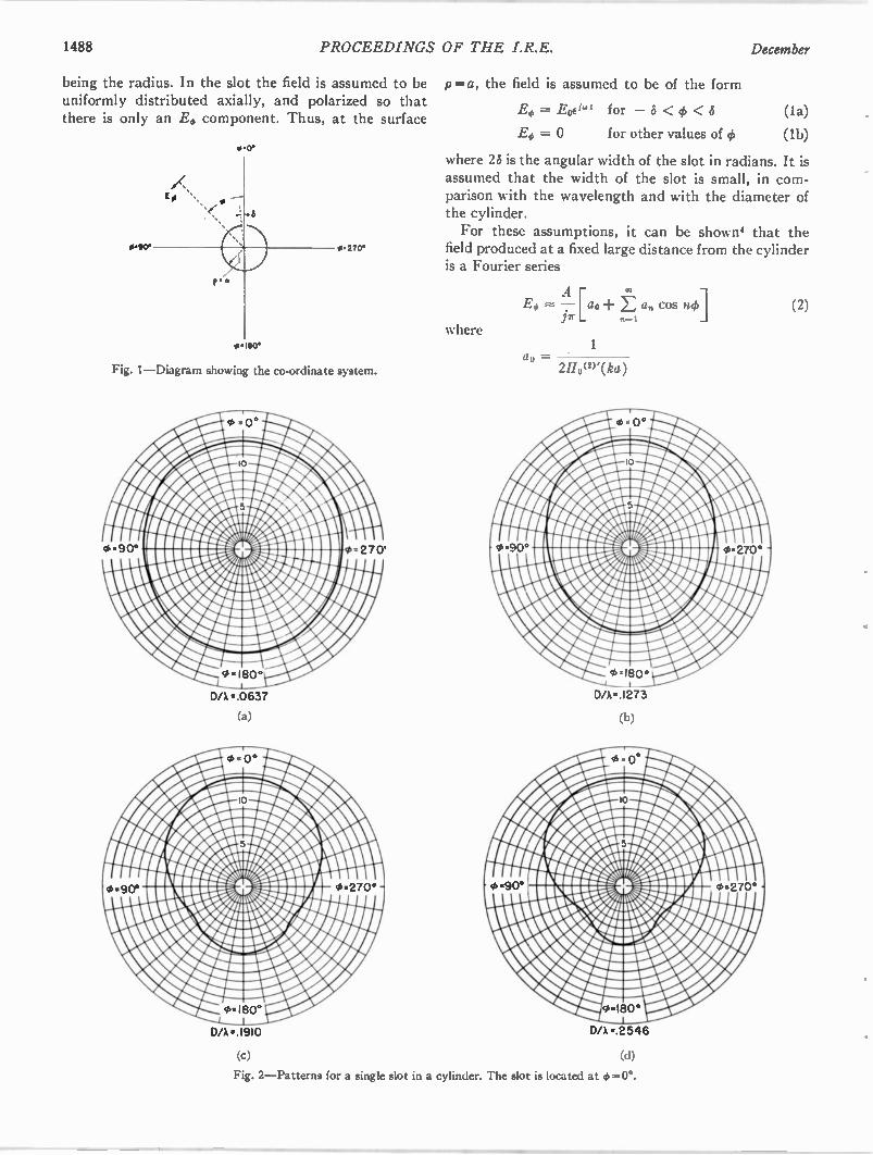
1488 PROCEEDINGS OF THE I.R.E. December
being the radius. In the slot the field is assumed to be uniformly distributed axially, and polarized so that there is only an .E0 component. Thus, at the surface
0.90'
• 0.
P*-0
p =a, the field is assumed to be of the form
E. = Eoeiwg
E. = 0
for — 6 < <
for other values of (6
(la)
(lb)
where 28 is the angular width of the slot in radians. It is assumed that the width of the slot is small, in com-parison with the wavelength and with the diameter of the cylinder. For these assumptions, it can be shown' that the
0 270* field produced at a fixed large distance from the cylinder is a Fourier series
where 0.180
Fig. 1—Diagram showing the co-ordinate system.
D/A • .0637
(a)
D/A =1910
(c)
A F0 T-[ao+ E a„ cos no]
.171" 1
1 = 2110(w(ka)
D/A•1273
(b)
D/A •.2546
(d)
Fig. 2—Patterns for a single slot in a cylinder. The slot is located at 0=0°.
(2)
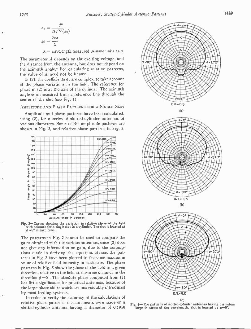
1948 Sinclair: Slotted-Cylinder Antenna Patterns 1489
in an —
11„(2)'(ka)
2ira ka = —
X
X = wavelength measured in same units as a.
The parameter A depends on the exciting voltage, and the distance from the antenna, but does not depend on the azimuth angle.' For calculating relative patterns, the value of A need not be known. In (2), the coefficients an are complex, to take account
of the phase variations in the field. The reference for phase in (2) is at the axis of the cylinder. The azimuth angle is measured from a reference line through the center of the slot (see Fig. 1).
AMPLITUDE AND PHASE PATTERNS FOR A SINGLE SLOT
Amplitude and phase patterns have been calculated, using (2), for a series of slotted-cylinder antennas of various diameters. Some of the amplitude patterns are shown in Fig. 2, and relative phase patterns in Fig. 3.
1
1
1
1
11
ei 1
0.
I IJ
D/1,..21165 >0
• 2546
10
10 D/A,22211
50 DA. 1910
20
D/ 4• .1592 I 0
)0 DIX. 1273
90
BO / D/I• 0955
70
/ 60
50 DA. 0637
40
30 D/1,0319
20 v.--
10
o 0 20 40 60 SO 100 120
Azimuth ongle in degrees
Fig. 3—Curves showing the variation in relative phase of the field with azimuth for a single slot in a cylinder. The slot is located at 0=0° in each case.
140 160 160
The patterns in Fig. 2 cannot be used to compare the gains obtained with the various antennas, since (2) does not give any information on gain, due to the assump-tions made in deriving the equation. Hence, the pat-terns in Fig. 2 have been plotted to the same maximum value of relative field intensity in each case. The phase patterns in Fig. 3 show the phase of the field in a given direction, relative to the field at the same distance in the direction ck =00. The absolute phase computed from (2) has little significance for practical antennas, because of the large phase shifts which are unavoidably introduced by most feeding systems. In order to verify the accuracy of the calculations of
relative phase patterns, measurements were made on a slotted-cylinder antenna having a diameter of 0.1910
D /X • 0.5
(a)
D/X • I .2 5
(b)
D/A. 8.0
(c) Fig. 4—The patterns of slotted-cylinder antennas having diameters large in terms of the wavelength. Slot is located at ••,O°.
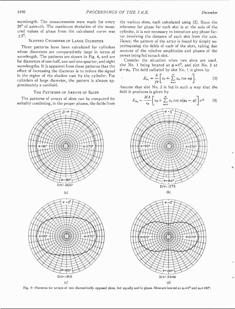
1490 PROCEEDINGS OF THE I.R.E. December
wavelength. The measurements were made for every 20° of azimuth. The maximum deviation of the meas-ured values of phase from the calculated curve was + 50.
SLOTTED CYLINDERS OF LARGE DIAMETER
Three patterns have been calculated for cylinders whose diameters are comparatively large in terms of wavelength. The patterns are shown in Fig. 4, and are for diameters of one-half, one and one-quarter, and eight wavelengths. It is apparent from these patterns that the effect of increasing the diameter is to reduce the signal in the region of the shadow cast by the cylinder. For cylinders of large diameter, the pattern is always ap-proximately a cardioid.
THE PATTERNS OF ARRAYS OF SLOTS
The patterns of arrays of slots can be computed by suitably combining, in the proper phases, the fields from
DA= .0637
(a)
(c)
the various slots, each calculated using (2). Since the reference for phase for each slot is at the axis of the cylinder, it is not necessary to introduce any phase fac-tor involving the distance of each slot from the axis. Hence, the pattern of the array is found by simply su-perimposing the fields of each of the slots, taking due account of the relative amplitudes and phases of the power being fed to each slot. Consider the situation when two slots are used,
slot No. 1 being located at ct) =0°, and slot No. 2 at (#) =02. The field radiated by slot No. 1 is given by
A = -[ao E a„ cos mki. Pr
ao
n-1
Assume that slot No. 2 is fed in such a way that the field it produces is given by
(3)
MA Eco, = — [ao E an cos n(02 — ct))] e14' (4)
n=1
D/X=.1273
(b)
DA•.2546
(d)
Fig. 5—Patterns for arrays of two diametrically opposed slots, fed equally and in phase. Slots are located at cbi =0° and 02=180°.
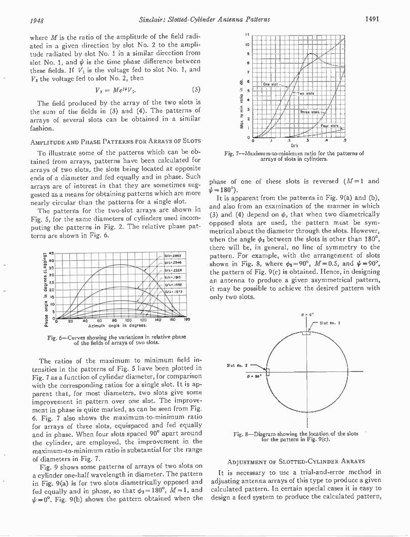
1948 Sinclair: Slotted-Cylinder Antenna Patterns 1491
where M is the ratio of the amplitude of the field radi-ated in a given direction by slot No. 2 to the ampli-tude radiated by slot No. 1 in a similar direction from slot No. 1, and 4/ is the time phase difference between these fields. If VI is the voltage fed to slot No. 1, and V2 the voltage fed to slot No. 2, then
V2 = Mei#Vi. (5)
The field produced by the array of the two slots is the sum of the fields in (3) and (4). The patterns of arrays of several slots can be obtained in a similar
fashion.
AMPLITUDE AND PHASE PATTERNS FOR ARRAYS OF SLOTS
To illustrate some of the patterns which can be ob-tained from arrays, patterns have been calculated for arrays of two slots, the slots being located at opposite ends of a diameter and fed equally and in phase. Such arrays are of interest in that they are sometimes sug-gested as a means for obtaining patterns which are more nearly circular than the patterns for a single slot. The patterns for the two-slot arrays are shown in
Fig. 5, for the same diameters of cylinders used incom-puting the patterns in Fig. 2. The relative phase pat-terns are shown in Fig. 6.
CP
_J
0
45
40
35
30
25
20
S 15
11; 10 5
2
a.
6/A:.2865
Ci/A; .2544
D/A • 2228
0 /k t• .1910
0/A• .1582
oo
D/ •.1273
20 40 GO 80 100 120 Azimuth angle in degrees.
140 160 180
Fig. 6—Curves showing the variations in relative phase of the fields of arrays of two slots.
The ratios of the maximum to minimum field in-tensities in the patterns of Fig. 5 have been plotted in Fig. 7 as a function of cylinder diameter, for comparison with the corresponding ratios for a single slot. It is ap-parent that, for most diameters, two slots give some improvement in pattern over one slot. The improve-ment in phase is quite marked, as can be seen from Fig. 6. Fig. 7 also shows the maximum-to-minimum ratio for arrays of three slots, equispaced and fed equally and in phase. When four slots spaced 90° apart around the cylinder, are employed, the improvement in the maximum-to-minimum ratio is substantial for the range of diameters in Fig. 7. Fig. 9 shows some patterns of arrays of two slots on
a cylinder one-half wavelength in diameter. The pattern in Fig. 9(a) is for two slots diametrically opposed and fed equally and in phase, so that 4,2=180°, M =1, and =0°. Fig. 9(b) shows the pattern obtained when the
II
10
.6 6 a
E 5
.2 t• 4
3 2
2 2
ME MIIM MIISIMI M MENIN
ME MIIMIIIMMU M MINEN 1111111111111 MINERI M MIIIEN
III M M11116W MIIM MI NIN
IM MINA MI11111 .!..,11.1•11
MIIINTA M MI MMIP M =INI MIII MIIIIME ME2 M111111E: 11In21111 M11111 MepiErmai m. 0 2 .3
DIA Fig. 7—Maximum-to-minimum ratio for the patterns of
arrays of slots in cylinders.
.4 .5
phase of one of these slots is reversed (M=1 and =180°). It is apparent from the patterns in Fig. 9(a) and (b),
and also from an examination of the manner in which (3) and (4) depend on 41, that when two diametrically opposed slots are used, the pattern must be sym-metrical about the diameter through the slots. However, when the angle 402 between the slots is other than 180°, there will be, in general, no line of symmetry to the pattern. For example, with the arrangement of slots shown in Fig. 8, where 41=90°, M=0.5, and 0=907, the pattern of Fig. 9(c) is obtained. Hence, in designing an antenna to produce a given asymmetrical pattern, it may be possible to achieve the desired pattern with only two slots.
Slot No. 2
4, - SOS
Fig. 8—Diagram showing the location of the slots for the pattern in Fig. 9(c).
ADJUSTMENT OF SLOTTED-CYLINDER ARRAYS
It is necessary to use a trial-and-error method in adjusting antenna arrays of this type to produce a given calculated pattern. In certain special cases it is easy to design a feed system to produce the calculated pattern,
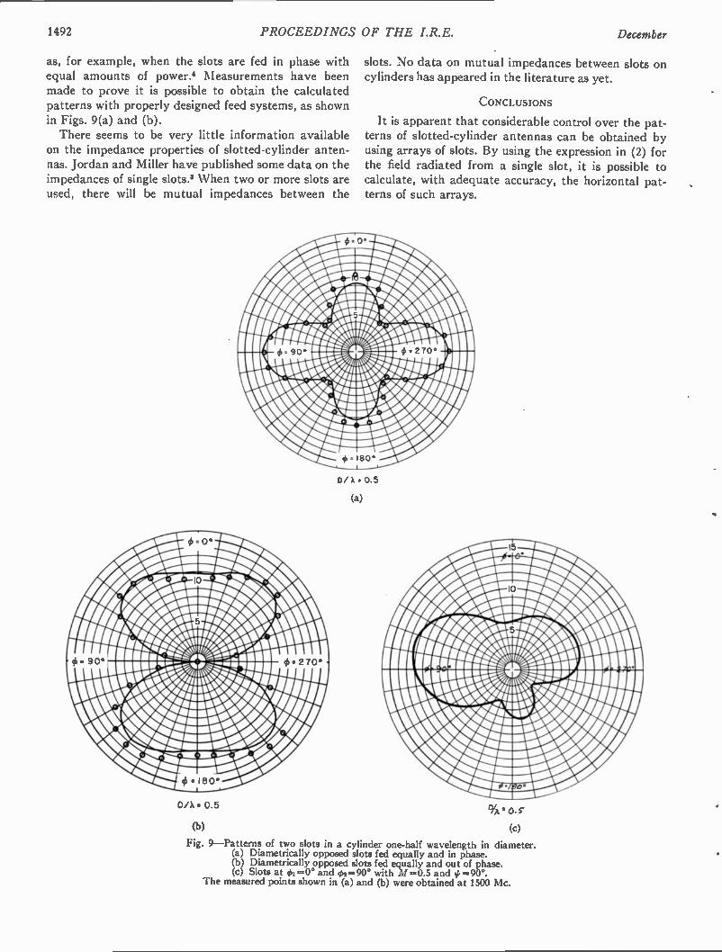
1492 PROCEEDINGS OF THE I.R.E. December
as, for example, when the slots are fed in phase with equal amounts of power.' Measurements have been made to prove it is possible to obtain the calculated patterns with properly designed feed systems, as shown in Figs. 9(a) and (b). There seems to be very little information available
on the impedance properties of slotted-cylinder anten-nas. Jordan and Miller have published some data on the impedances of single slots.' When two or more slots are used, there will be mutual impedances between the
D/ X • 0.5
(a)
D/A • 0.5
(b)
slots. No data on mutual impedances between slots on cylinders has appeared in the literature as yet.
CONCLUSIONS
It is apparent that considerable control over the pat-terns of slotted-cylinder antennas can be obtained by using arrays of slots. By using the expression in (2) for the field radiated from a single slot, it is possible to calculate, with adequate accuracy, the horizontal pat-terns of such arrays.
Fig. 9—Patterns of two slots in a cylinder one-half wavelength in diameter. (a) Diametrically opposed slots fed equally and in phase. (b) Diametrically opposed slots fed equally and out of phase. (c) Slots at 01=0° and 02=90° with M=0.5 and 0=90°.
The measured points shown in (a) and (b) were obtained at 1500 Mc.
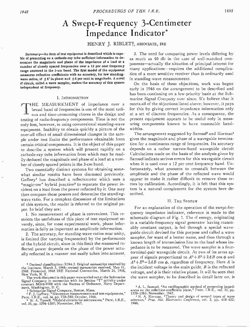
1948 PROCEEDINGS OF THE I.R.E. 1493
A Swept-Frequency 3-Centimeter Impedance Indicator* HENRY J. RIBLEM ASSOCIATE, IRE
Summary—An item of test equipment is described which is capa-ble of presenting on a cathode-ray tube sufficient information to de-termine the magnitude and phase of the impedance of a load at a number of closely spaced frequencies over a 12 per cent frequency range centered in the 3-cm band. The fist model of the equipment measures reflection coefficients with an accuracy, for low standing-wave ratios, of ± 4° in phase and ± 8 per cent in magnitude. A novel rf circuit, called a wave sampler, makes the accuracy of this system independent of frequency.
I. INTRODUCTION
rii HE MEASUREMENT of impedance over a broad band of frequencies is one of the most tedi-ous and time-consuming chores in the design and
testing of radio-frequency components. Time is not the only loss, however, in using conventional standing-wave equipment. Inability to obtain quickly a picture of the over-all effect of small dimensional changes in the sam-ple under test limits the performance obtainable from certain critical components. It is the object of this paper to describe a system which will present rapidly on a cathode-ray tube information from which may be read-ily deduced the magnitude and phase of a load at a num-ber of closely spaced points in the 3-cm band. Two essentially distinct systems for obtaining some-
what similar results have been discussed previously. Gaffney' has described a reflectometer which uses a "magic-tee" hybrid junction' to separate the power in-cident on a load from the power reflected by it. One may then compare these powers and determine the standing-wave ratio. For a complete discussion of the limitations of this system, the reader is eeferred to the original pa-per. In brief they are: 1. No measurement of phase is convenient. This re-
stricts the usefulness of this piece of test equipment se-verely, since, for most experimental work, phase infor-mation is fully as important as amplitude information. 2. The accuracy, for standing-wave ratios near unity,
is limited (for varying frequencies) by the performance of the hybrid circuit, since in this limit the measured re-flected power depends on the phase of the power actu-ally reflected in a manner not easily taken into account:
* Decimal classification: R244.3. Original manuscript received by the Institute, March 3, 1948; revised manuscript received, May 11, 1948. Presented, 1948 IRE National Convention, March 24, 1948, New York, N. Y. The work discussed in this paper was carried out at the Submarine
Signal Company in connection with its Section "T" activity under contract NOrd-9788 with the Bureau of Ordnance, Navy Depart-ment, Washington, D. C. t Submarine Signal Company, Boston, Mass. 1 F. J. Gaffney, "Microwave measurements and test equipments,'
PROC. I.R.E., vol. 34, pp. 778-780; October, 1946. 2 W. A. Tyrrell, "Hybrid circuits for microwaves," PROC. I.R.E.,
vol. 35, pp. 1294-1307; November, 1947.
3. The need for comparing power levels differing by as much as 40 db in the case of well-matched com-ponents—actually the situation of principal interest for many applications—requires the additional complica-tion of a more sensitive receiver than is ordinarily used in standing-wave measurements. On the basis of these objections, work was begun
early in 1946 on the arrangement to be described and has been. continuing on a low-priority basis at the Sub-marine Signal Company ever since. We believe that it meets all of the objections listed above; however, it pays for this by giving correct impedance information only at a set of discrete frequencies. As a consequence, the present equipment appears to be useful only in meas-uring components known to have reasonable band-widths. The arrangement suggested by Samuel' and Korman'
gives the magnitude and phase of a waveguide termina-tion for a continuous range of frequencies. Its accuracy depends on a rather narrow-band waveguide circuit Calculations made on the basis of the analysis given by Samuel indicate serious errors for this waveguide circuit when it is used over a 12 per cent frequency band. Un-fortunately, what amounts to crosstalk between the amplitude and the phase of the reflected wave would appear to make it rather difficult to remove these er-rors by calibration. Accordingly, it is felt that this sys-tem is a natural complement for the system here de-scribed.
II. THE SYSTEM
For an explanation of the operation of the swept-fre-quency impedance indicator, reference is made to the schematic diagram of Fig. 1. The rf energy, originating in a variable-frequency signal generator having reason-ably constant output, is fed through a special wave-guide circuit devised for this purpose and called a wave sampler, for want of a better name, and then through a known length of transmission line to the load whose im-pedance is to be measured. The wave sampler is a four-terminal-pair waveguide circuit. At two of its arms ap-pear rf signals proportional to 442-1-B2-1- 2AB cos 4, and A2i-B2— 2AB cos 4), regardless of frequency. Here A is the incident voltage in the main guide, B is the reflected voltage, and 4) is their relative phase. It will be seen that the wave sampler, to be described in detail later on, is
8 A. L. Samuel, "An oscillographic method of presenting imped-ances on the reflection-coefficient plane," PROC. I.R.E., vol. 35, pp. 1279-1283; November, 1947.
N. A. Korman, "Theory and design of several types of wave selectors," Proc. Nat. Electronics Conference, vol. 2, pp. 418-422; 1946.
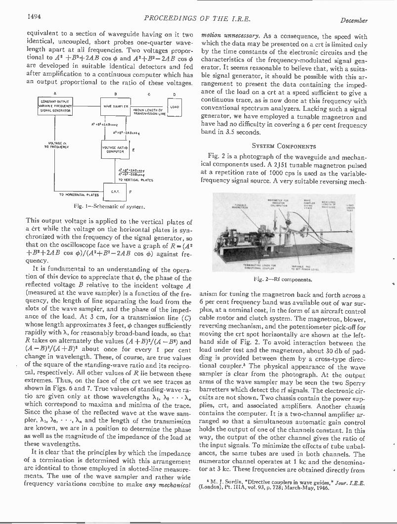
1494 PROCEEDINGS OF THE I.R.E. December
equivalent to a section of waveguide having on it two identical, uncoupled, short probes one-quarter wave-length apart at all frequencies. Two voltages propor-tional to A' -I-B2+2AB cos irk and A2-I-B2-2AB cos 4) are developed in suitable identical detectors and fed after amplification to a continuous computer which has an output proportional to the ratio of these voltages.
A
CONSTANT OUTPUT
VARIABLE FREQUENCY
SIGNAL GENERATOR
VOLTAGE cc TO FREQUENCY
WAVE SAMPLER KNOWN LENGTH OF TRANSMISSION LINE
•(1.+2ABcosli
+13. -2ABcos
VOLTAGE RATIO COMPUTER
AT OP +2ABcoi
At +13.-2A0cosy
TO VERTICAL PLATES
TO HORIZONTAL PLATES
Fig. 1—Schematic of system.
LOAD
This output voltage is applied to the vertical plates of a crt while the voltage on the horizontal plates is syn-chronized with the frequency of the signal generator, so that on the oscilloscope face we have a graph of R=(A 2 -FB2+2AB cos ck)/(A2-FB2-2AB cos 0) against fre-quency. It is fundamental to an understanding of the opera-
tion of this device to appreciate that 4), the phase of the reflected voltage B relative to the incident voltage A (measured at the wave sampler) is a function of the fre-quency, the length of line separating the load from the slots of the wave sampler, and the phase of the imped-ance of the load. At 3 cm, for a transmission line (C) whose length approximates 3 feet, 4) changes sufficiently rapidly with X, for reasonably broad-band loads, so that R takes on alternately the values (A - F B)2 / (A —B) and (A — B)2 / (A +B)2 about once for every 1 per cent change in wavelength. These, of course, are true values of the square of the standing-wave ratio and its recipro-cal, respectively. All other values of R lie between these extremes. Thus, on the face of the crt we see traces as shown in Figs. 6 and 7. True values of standing-wave ra-tio are given only at those wavelengths X X2 .-1, — • • Xn
which correspond to maxima and minima of the trace. Since the phase of the reflected wave at the wave sam-pler, Xi, X2, • • X. and the length of the transmission are known, we are in a position to determine the phase as well as the magnitude of the impedance of the load at these wavelengths. It is clear that the principles by which the impedance
of a termination is determined with this arrangement are identical to those employed in slotted-line measure-ments. The use of the wave sampler and rather wide frequency variations combine to make any mechanical
motion unnecessary. As a consequence, the speed with which the data may be presented on a crt is limited only by the time constants of the electronic circuits and the characteristics of the frequency-modulated signal gen-erator. It seems reasonable to believe that, with a suita-ble signal generator, it should be possible with this ar-rangement to present the data containing the imped-ance of the load on a crt at a speed sufficient to give a continuous trace, as is now done at this frequency with conventional spectrum analyzers. Lacking such a signal generator, we have employed a tunable magnetron and have had no difficulty in covering a 6 per cent frequency band in 3.5 seconds.
SYSTEM COMPONENTS
Fig. 2 is a photograph of the waveguide and mechan-ical components used. A 2J51 tunable magnetron pulsed at a repetition rate of 1000 cps is used as the variable-frequency signal source. A very suitable reversing mech-
. Zgt?,11.
SIDIMATIO TOP DIDIDATOIR CAL ,ORA1.00
MATE & WP M W O N vSOR
TE MA. , t DADS FOR DIRECTIONAL co , , MAM MA TAD
TO MIT DO WN CIVIL
Fig. 2—Rf components.
MEAEN SURED L O Or wart, D.DE
LOAD ukOl• TINY
anism for tuning the magnetron back and forth across a 6 per cent frequency band was available out of war sur-plus, at a nominal cost, in the form of an aircraft control cable motor and clutch system. The magnetron, blower, reversing mechanism, and the potentiometer pick-off for moving the crt spot horizontally are shown at the left-hand side of Fig. 2. To avoid interaction between the load under test and the magnetron, about 30 db of pad-ding is provided between them by a cross-type direc-tional coupler.' The physical appearance of the wave sampler is clear from the photograph. At the output arms of the wave sampler may be seen the two Sperry barretters which detect the rf signals. The electronic cir-cuits are not shown. Two chassis contain the power sup-plies, crt, and associated amplifiers. Another chassis contains the computer. It is a two-channel amplifier ar-ranged so that a simultaneous automatic gain control holds the output of one of the channels constant. In this way, the output of the other channel gives the ratio of the input signals. To minimize the effects of tube unbal-ances, the same tubes are used in both channels. The numerator channel operates at 1 kc and the denomina-tor at 3 kc. These frequencies are obtained directly from
• M . J. Surdin, "Directive couplers in wave guides," Jour. I.E.E. (London), Pt. IIIA, vol. 93, p. 728; March-May, 1946.
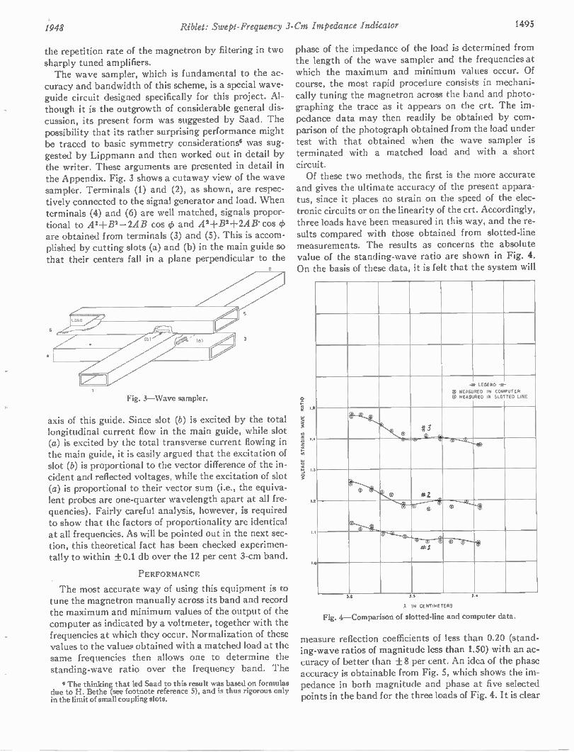
1948 Riblet: Swept-Frequency 3-Cm Impedance Indicator 1495
the repetition rate of the magnetron by filtering in two sharply tuned amplifiers. The wave sampler, which is fundamental to the ac-
curacy and bandwidth of this scheme, is a special wave-guide circuit designed specifically for this project. Al-though it is the outgrowth of considerable general dis-cussion, its present form was suggested by Saad. The possibility that its rather surprising performance might be traced to basic symmetry considerations' was sug-gested by Lippmann and then worked out in detail by the writer. These arguments are presented in detail in the Appendix. Fig. 3 shows a cutaway view of the wave sampler. Terminals (1) and (2), as shown, are respec-tively connected to the signal generator and load. When terminals (4) and (6) are well matched, signals propor-tional to A'-1-B2-2AB cos (1) and 442-FB2+2AB. cos 4) are obtained from terminals (3) and (5). This is accom-plished by cutting slots (a) and (b) in the main guide so that their centers fall in a plane perpendicular to the
2
Fig. 3— W a ve sa mpler.
axis of this guide. Since slot (b) is excited by the total longitudinal current flow in the main guide, while slot (a) is excited by the total transverse current flowing in the main guide, it is easily argued that the excitation of slot (b) is proportional to the vector difference of the in-cident and reflected voltages, while the excitation of slot (a) is proportional to their vector sum (i.e., the equiva-lent probes are one-quarter wavelength apart at all fre-quencies). Fairly careful analysis, however, is required to show that the factors of proportionality are identical at all frequencies. As will be pointed out in the next sec-tion, this theoretical fact has been checked experimen-tally to within ±0.1 db over the 12 per cent 3-cm band.
PERFORMANCE
The most accurate way of using this equipment is to tune the magnetron manually across its band and record the maximum and minimum values of the output of the computer as indicated by a voltmeter, together with the frequencies at which they occur. Normalization of these values to the values obtained with a matched load at the same frequencies then allows one to determine the standing-wave ratio over the frequency band. The
I T he thinking that led Saad to this result w as based on for mulas
due to H. B ethe (see footnote reference 5), and is thus rigorous only
in the li mit of s mall cou pling slots.
phase of the impedance of the load is determined from the length of the wave sampler and the frequencies at which the maximum and minimum values occur. Of course, the most rapid procedure consists in mechani-cally tuning the magnetron across the band and photo-graphing the trace as it appears on the crt. The im-pedance data may then readily be obtained by com-parison of the photograph obtained from the load under test with that obtained when the wave sampler is terminated with a matched load and with a short circuit. Of these two methods, the first is the more accurate
and gives the ultimate accuracy of the present appara-tus, since it places no strain on the speed of the elec-tronic circuits or on the linearity of the crt. Accordingly, three loads have been measured in this way, and the re-sults compared with those obtained from slotted-line measurements. The results as concerns the absolute value of the standing-wave ratio are shown in Fig. 4. On the basis of these data, it is felt that the system will
VOLTAGE STAN
e MEASURED 0 MEASURED
LEGEND -.-
IN COMPUTER IN SLOTTED LINE
it 3
st —ir, co-- --e „ .
® e * 2
41'.. 1 -- 14 „Ims
e ®
* t
D
3 33
IN CENTIMETERS
Fig. 4—Comparison of slotted-line and co mputer data.
measure reflection coefficients of less than 0.20 (stand-ing-wave ratios of magnitude less than 1.50) with an ac-curacy of better than ± 8 per cent. An idea of the phase accuracy is obtainable from Fig. 5, which shows the im-pedance in both magnitude and phase at five selected points in the band for the three loads of Fig. 4. It is clear
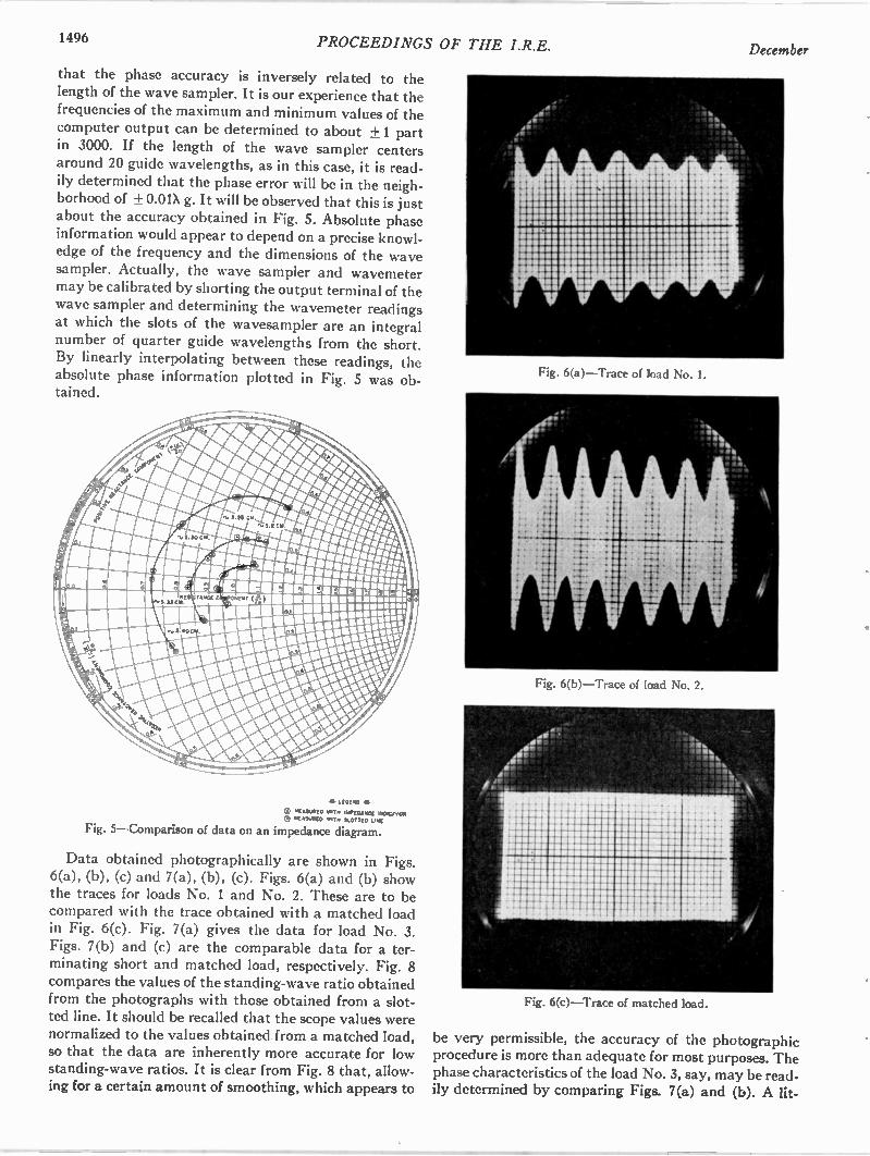
1496 PROCEEDINGS OF THE I.R.E.
that the phase accuracy is inversely related to the length of the wave sampler. It is our experience that the frequencies of the maximum and minimum values of the computer output can be determined to about ± 1 part in 3000. If the length of the wave sampler centers around 20 guide wavelengths, as in this case, it is read-ily determined that the phase error will be in the neigh-borhood of + 0.01X g. It will be observed that this is just about the accuracy obtained in Fig. 5. Absolute phase information would appear to depend on a precise knowl-edge of the frequency and the dimensions of the wave sampler. Actually, the wave sampler and wavemeter may be calibrated by shorting the output terminal of the wave sampler and determining the wavemeter readings at which the slots of the wavesampler are an integral number of quarter guide wavelengths from the short. By linearly interpolating between these readings, the absolute phase information plotted in Fig. 5 was ob-tained.
-. LEGEND 4,-e MESSEDDED WITH OTEIDE KE 'Koos,00
0 gESSOOED WITH SLOTTED Log
Fig. 5—Comparison of data on an impedance diagram.
Data obtained photographically are shown in Figs. 6(a), (b), (c) and 7(a), (b), (c). Figs. 6(a) and (b) show the traces for loads No. 1 and No. 2. These are to be compared with the trace obtained with a matched load in Fig. 6(c). Fig. 7(a) gives the data for load No. 3. Figs. 7(b) and (c) are the comparable data for a ter-minating short and matched load, respectively. Fig. 8 compares the values of the standing-wave ratio obtained from the photographs with those obtained from a slot-ted line. It should be recalled that the scope values were normalized to the values obtained from a matched load, so that the data are inherently more accurate for low standing-wave ratios. It is clear from Fig. 8 that, allow-ing for a certain amount of smoothing, which appears to
December
Fig. 6(a)—Trace of load No. 1.
Fig. 6(b)—Trace of load No. 2.
Fig. 6(c)—Trace of matched load.
be very permissible, the accuracy of the photographic procedure is more than adequate for most purposes. The phase characteristics of the load No. 3, say, may be read-ily determined by comparing Figs. 7(a) and (b). A lit-

1948 Riblet: Swept-Frequency 3-Cm Impedance Indicator 1497
Fig. 7(a) —Trace of load No. 3.
Fig. 7(b) —Trace of short circuit.
IFIR:111112 91•11 "111111111 '.'w..11.11 • MIN NIMMIIIIII•111111111111 MIllie 1111111BOM mmm
U. ••••1111111•11111111111111 SSSSSSSSSSSSSSSS RI M
IMESI nallealiMIMMULIMMA Y
Fig. 7(c) —Trace of matched load.
tie consideration will show that the impedance of this load moves about half way around the circle diagram over the frequency band involved. It will be observed that the data so far have been
limited to a 6 per cent frequency band. The reason for
X READ FROM PHOTOGRAPHS
3 2 3.3
A IN CENTIMETERS
Fig. 8—Comparison of slotted line and photographed data.
this is simply that this band is adequate for the pur-poses for which the equipment was constructed, while a wider band was rather awkward to obtain with the me-chanical reversing mechanism which was available. The only components of the system which in any way in-volve the frequency have, however, been tested over the 12 per cent band. The output of the tunable magnetron is, of course, constant over the band within 1 db. The items about which there remain some doubt are, then, the wave sampler and the barretters. The performance of these is shown in Fig. 9. The lower graph of this figure shows that the barretters are identical to within 0.1 db over the band. The signals out of the wave sampler, when terminated in a matched load, are the same within 0.2 db, as shown in the middle graph. The upper graph indicates that the combined unbalance of wave sampler and barretters taken together is less than 0.2 db over the 12 per cent band. Incidentally, the trace of Fig. 6(c) shows about this amount of 'variation for a matched load.
ACKNOWLEDGMENT
This development has required the co-operation of a number of persons, several of whom are no longer at the Submarine Signal Company. John Daspit designed and tested the ratio computer; Chester W. Young designed and tested the amplifier and indicator circuits; Charles Aker arranged the mechanical drive for the magnetron;
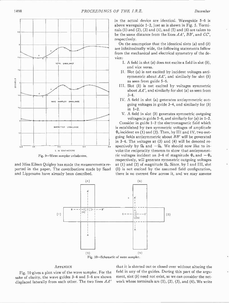
1498 PROCEEDINGS OF THE I.R.E. December
4.2
x
TOTAL UNBALANCE
x
2 4.- m,"........----
WAVE SAMPLER UNBALANCE
- m ..1 -
BARRETTER UNBALANCE
3.15 32 33
A IN CENTIMETERS
3.•
Fig. 9—Wave sampler unbalances.
35
and NI iss Eileen Quigley has made the measurements re-ported in the paper. The contributions made by Saad and Lippmann have already been described.
in the actual device are identical. Waveguide 5-6 is above waveguide 1-2, just as is shown in Fig. 5. Termi-nals (1) and (2), (3) and (4), and (5) and (6) are taken to be the same distance from the lines AA', BB', and CC', respectively. On the assumption that the identical slots (a) and (b)
are infinitesimally wide, the following statements follow from the mechanical and electrical symmetry of the de-vice:
I. A field in slot (a) does not excite a field in slot (b), and vice versa.
II. Slot (a) is not excited by incident voltages anti-symmetric about AA', and similarly for slot (b) as seen from guide 5-6.
III. Slot (b) is not excited by voltages symmetric about AA', and similarly for slot (a) as seen from 3-4.
IV. A field in slot (a) generates antisymmetric out-going voltages in guide 3-4, and similarly for (b) in 1-2.
V. A field in slot (b) generates symmetric outgoing voltages in guide 5-6, and similarly for (a) in 1-2.
Consider in guide 1-2 the electromagnetic field which is established by two symmetric voltages of amplitude cf.. incident on (1) and (2). Then, by III and IV, two out-going fields antisymmetric about BB' will be generated in 3-4. The voltages at (3) and (4) will be denoted re-spectively by 20 and — 20. We should now like to in-voke the reciprocity theorem to show that antisymmet-ric voltages incident on 3-4 of magnitude 43. and — respectively, will generate symmetric outgoing voltages at (1) and (2) of magnitude Slo. Since, by I and III, slot (b) is not excited by the assumed field configuration, there is no current flow across it, and we may assume
(4) (6)
A'
(a)
A'
III
W(0)
( 3 ) (5 )
Fig. 10—Schematic of wave sampler.
APPENDIX
Fig. 10 gives a plan view of the wave sampler. For the sake of clarity, the wave guides 3-4 and 5-6 are shown displaced laterally from each other. The two lines AA'
(2)
that it is shorted out or closed over without altering the field in any of the guides. During this part of the argu-
ment, slot (b) need not exist, so we can consider the net-work whose terminals are (1), (2), (3), and (4). We write
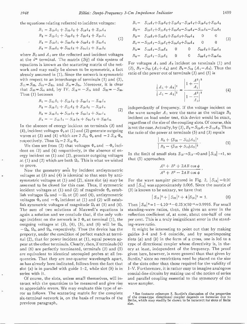
1948 Riblet: Swept-Frequency 3-Cm Impedance Indicator 1499
the equations relating reflected to incident voltages:
B1 = Suil ± SI2A 2 ± Sl3A 3 + Sl4A 4
B2 = S12A 1 S22A 2 + S23A 3 ± S24A 4
B3 = S13.41 + S2311 2 + S33A 3 + S34A 4
B4 = Sl4A 1 + S24A 2 + S34A 3 + S44A 4
(1)
where Bi and A i are the reflected and incident voltages at the Ph terminal. The matrix (Sij) of this system of equations is known as the scattering matrix of the net-work and may easily be shown to be symmetric, a fact already assumed in (1). Since the network is symmetric with respect to an interchange of terminals (1) and (2), Sii =S22, S13 = S23, and S14= S24. Moreover, it is clear that S33 = S44 and, by IV, S13 = S14 and S2g S24. Thus (1) becomes
B1 = 511A 1
B2 = S 12A
133 = S13.41
▪ Si2A 2
▪ SllA 2
▪ Sl3A 2
▪ SisA 3 - S13A 4
▪ SI3A 3 - Sl3A 4
S33A 3 + S34A 4 (2)
/34 = - S134 - S13.1 2 -I- S34A 3 + S33A
In the absence of energy incident on terminals (3) and (4), incident voltages 43. at (1) and (2) generate outgoing waves at (3) and (4) which are 2 S13 43. and - 2 S13 CI3e, respectively. Thus 120 = 2 S13 4'.. We then see from (2) that voltages 43. and - (1). inci-
dent on (3) and (4) respectively, in the absence of en-ergy incident on (1) and (2), generate outgoing voltages at (1) and (2) which are both 00. This is what we wished to prove. Now the geometry seen by incident antisymmetric
voltages at (3) and (4) is identical to that seen by anti-symmetric voltages at (1) and (2), since slot (a) may be assumed to be closed for this case. Thus, if symmetric incident voltages at (1) and (2) of magnitude I. estab-lish voltages SZo and - Clo at (3) and (4), antisymmetric voltages (13„ and - (13„ incident at (1) and (2) will estab-lish symmetric voltages of magnitude 20 at (5) and (6). The sum of two solutions of Maxwell's equations is again a solution and we conclude that, if the only volt-age incident on the network is 2 I. at terminal (1), the outgoing voltages at (3), (4), (5), and (6) will be go, OD, 123, and go, respectively. Thus the device has the
property, under the condition of perfect match at termi-nal (2), that for power incident at (1), equal powers ap-pear at the other terminals. Clearly, then, if terminals (4) and (6) are perfectly terminated, terminals (3) and (5) are equivalent to identical uncoupled probes at all fre-quencies. That they are one-quarter wavelength apart, as has already been indicated, follows from the fact that slot (a) is in parallel with guide 1-2, while slot (b) is in series with it. Of course, the slots, unless small themselves, will in-
teract with the quantities to be measured and give rise to appreciable errors. We may evaluate this type of er-ror as follows. The scattering matrix for the complete six-terminal network is, on the basis of remarks of the previous paragraph,
B1= S1124 1+512A 21-512,4 3- S 1221 4-1-S1[22'16+518A,
B2 - 512A 1+511A 2+S13A 3-513A 4-513A 5-513A5
B3 = 5.13,4 1+S1311 2+533A 3+S34A 4
B4= -513A 1 -513A 2+S34A +5.33A 4
B5= 513A 1-513A 2
B3= 513,41-Si3A2
0 0
0 0
0 0 S55A 5+556A 5
0 0 S56A 5-1,555A 6.
(3)
For voltages A1 and A3 incident on terminals (1) and (2), B3 = Sig t+ A2) and B6 =S13 (A 1-A 2). Thus the ratio of the power out of terminals (3) and (5) is
1 Al -1- A21 2
1 - A21 2
A2 2 1 + —
A1
A2 1 - —
A1
2 (4)
independently of frequency. If the voltage incident on the wave sampler A1 were the same as the voltage B3 incident on load under test, this device would be exact, regardless of the size of the coupling slots. Of course, this is not the case. Actually, by (3), B2 = Si2A 1-1-SiiA 2. Thus the ratio of the power at terminals (5) and (3) equals
1 B2 + (S12 - S 12) A2 12 I B2 - (S12 ± S11)A 2 12
(5)
In the limit of small slots S13-,S11-)0 and 1 S121 -*1, so that (5) approaches
A2 -I- B2 + 2AB cos
A' ± B2 - 2AB cos 4)
For the wave sampler pictured in Fig. 2, 1 Si 21 = 0.01 and 1 Si11 was approximately 0.005. Since the matrix of (3) is known to be unitary, we have that
1.5111 2 ± 1 SI2 12 + 4151,1 2 = 1. (6)
Then 1 Sil 2 = 1 -4.10 -0.25 X10⁻⁴ --=-• 0.9995. For small standing-wave ratios, thqn, this gives an error in the reflection coefficient of, at most, about one-half of one per cent. This is a truly insignificant error in the stand-ing-wave ratio. It might be interesting to point out that by making
guides 3-4 and 5-6 coincide, and by superimposing slots (a) and (b) in the form of a cross, one is led to a type of directional coupler whose directivity is, in the-ory at least, independent of the frequency. The proof given here, however, is more general than that given by Surdin,7 since no restrictions need be placed on the size of the slots other than those required for the validity of I-V. Furthermore, it is rather easy to imagine analogous coaxial-line circuits by making use of the notion of series and parallel coupling essential to the symmetry of the wave sampler.
7 See footnote reference 5. Surdin's discussion of the properties of the cross-type directional coupler depends on formulas due to Bethe, which may readily be shown to be incorrect for slots of finite size.
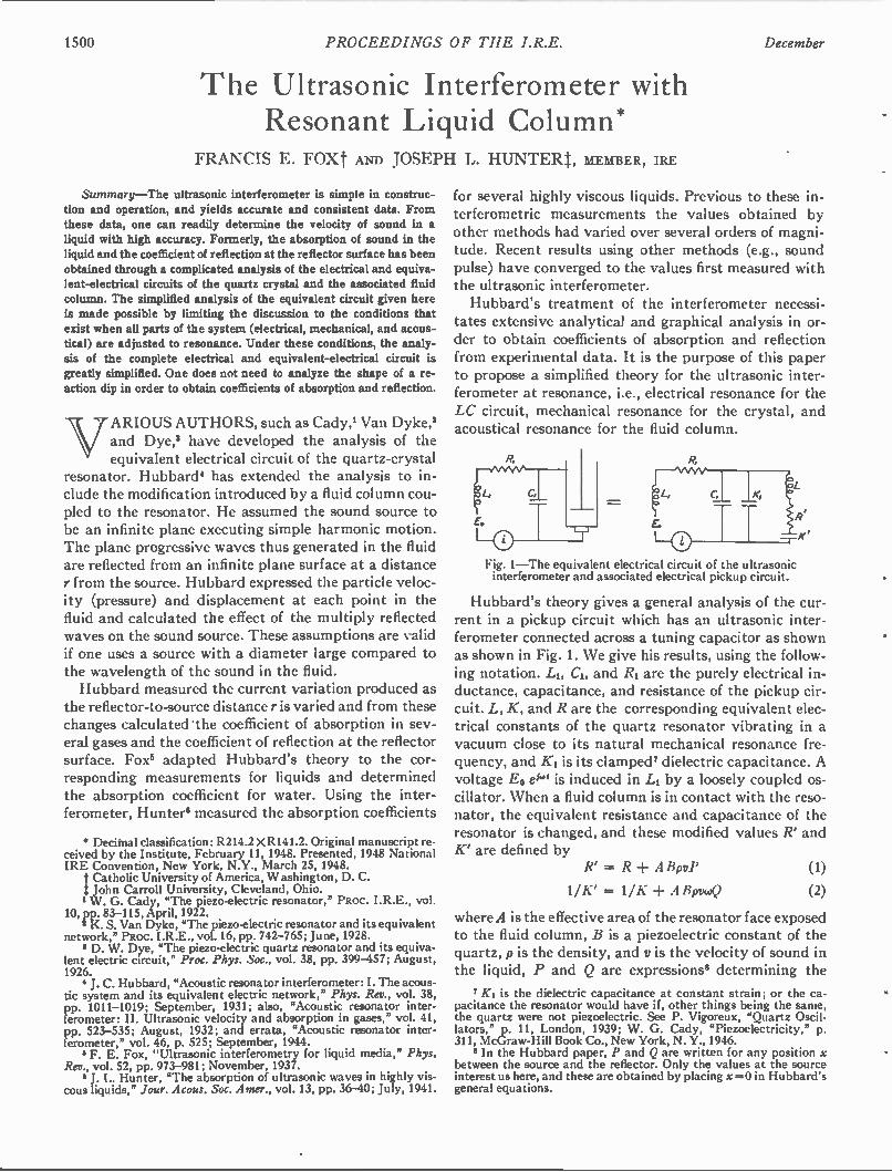
1500 PROCEEDINGS OF THE I.R.E.
The Ultrasonic Interferometer with Resonant Liquid Column*
FRANCIS E. FOXt AND JOSEPH L. HUNTERt, MEMBER, IRE
Summary—The ultrasonic interferometer is simple in construc-tion and operation, and yields accurate and consistent data. From these data, one can readily determine the velocity of sound in a liquid with high accuracy. Formerly, the absorption of sound in the liquid and the coefficient of reflection at the reflector surface has been obtained through a complicated analysis of the electrical and equiva-lent-electrical circuits of the quartz crystal and the associated fluid column. The simplified analysis of the equivalent circuit given here is made possible by limiting the discussion to the conditions that exist when all parts of the system (electrical, mechanical, and acous-tical) are adjusted to resonance. Under these conditions, the analy-sis of the complete electrical and equivalent-electrical circuit is greatly simplified. One does not need to analyze the shape of a re-action dip in order to obtain coefficients of absorption and reflection.
VARIOUS AUTHORS, such as Cady,' Van Dyke,' and Dye,' have developed the analysis of the equivalent electrical circuit of the quartz-crystal
resonator. Hubbard° has extended the analysis to in-clude the modification introduced by a fluid column cou-pled to the resonator. He assumed the sound source to be an infinite plane executing simple harmonic motion. The plane progressive waves thus generated in the fluid are reflected from an infinite plane surface at a distance r from the source. Hubbard expressed the particle veloc-ity (pressure) and displacement at each point in the fluid and calculated the effect of the multiply reflected waves on the sound source. These assumptions are valid if one uses a source with a diameter large compared to the wavelength of the sound in the fluid. Hubbard measured the current variation produced as
the reflector-to-source distance r is varied and from these changes calculated the coefficient of absorption in sev-eral gases and the coefficient of reflection at the reflector surface. Fox° adapted Hubbard's theory to the cor-responding measurements for liquids and determined the absorption coefficient for water. Using the inter-ferometer, Hunter' measured the absorption coefficients
• Decimal classification: R2I4.2 X R141.2. Original manuscript re-ceived by the Institute. February 11, 1948. Presented, 1948 National IRE Convention, New York, N.Y., March 25, 1948.
Catholic University of America, Washington, D. C. t John Carroll University, Cleveland, Ohio. 1 W . G. Cady, "The piezo-electric resonator," PROC. I.R.E., vol.
10, pp. 83-115, April, 1922. 2 K. S. Van Dyke, "The piezo-electric resonator and its equivalent
network," PROC. I.R.E., vol. 16, pp. 742-765; June, 1928. 3 D. W. Dye, "The piezo-electric quartz resonator and its equiva-
lent electric circuit," Proc. Phys. Soc., vol. 38, pp. 399457; August, 1926.
J. C. Hubbard, "Acoustic resonator interferometer: I. The acous-tic system and its equivalent electric network," Phys. Rev., vol. 38, pp. 1011-1019; September, 1931; also, "Acoustic resonator inter-ferometer: II. Ultrasonic velocity and absorption in gases," vol. 41, pp. 523-535; August, 1932; and errata, "Acoustic resonator inter-ferometer," vol. 46, p. 525; September, 1944. & F. E. Fox, "Ultrasonic interferometry for liquid media," Phys.
Rev., vol. 52, pp. 973-981; November, 1937. 6 J. I.. Hunter, "The absorption of ultrasonic waves in highly vis-
cous liquids," Jour. Acous. Soc. Amer., vol. 13, pp. 36-40; July, 1941.
December
for several highly viscous liquids. Previous to these in-terferometric measurements the values obtained by other methods had varied over several orders of magni-tude. Recent results using other methods (e.g., sound pulse) have converged to the values first measured with the ultrasonic interferometer. Hubbard's treatment of the interferometer necessi-
tates extensive analytical and graphical analysis in or-der to obtain coefficients of absorption and reflection from experimental data. It is the purpose of this paper to propose a simplified theory for the ultrasonic inter-ferometer at resonance, i.e., electrical resonance for the LC circuit, mechanical resonance for the crystal, and acoustical resonance for the fluid column.
Fig. 1—The equivalent electrical circuit of the ultrasonic interferometer and associated electrical pickup circuit.
Hubbard's theory gives a general analysis of the cur-rent in a pickup circuit which has an ultrasonic inter-ferometer connected across a tuning capacitor as shown as shown in Fig. 1. We give his results, using the follow-ing notation. LI, CI, and RI are the purely electrical in-ductance, capacitance, and resistance of the pickup cir-cuit. L, K, and R are the corresponding equivalent elec-trical constants of the quartz resonator vibrating in a vacuum close to its natural mechanical resonance fre-quency, and ICI is its clamped' dielectric capacitance. A voltage E0 el" is induced in LI by a loosely coupled os-cillator. When a fluid column is in contact with the reso-nator, the equivalent resistance and capacitance of the resonator is changed, and these modified values R' and K' are defined by
R' = R ABpvP (1)
1/K' = 11K ± ABpvc02 (2)
where A is the effective area of the resonator face exposed to the fluid column, B is a piezoelectric constant of the quartz, p is the density, and v is the velocity of sound in the liquid, P and Q are expressions' determining the
ICI is the dielectric capacitance at constant strain; or the ca-pacitance the resonator would have if, other things being the same, the quartz were not piezoelectric. See P. Vigoreux, "Quartz Oscil-lators," P. 11. London, 1939; W . G. Cady, "Piezoelectricity," p. 311, McGraw-Hill Book Co., New York, N. Y., 1946.
In the Hubbard paper, P and Q are written for any position x between the source and the reflector. Only the values at the source interest us here, and these are obtained by placing x =0 in Hubbard's general equations.
1948 Fox and Hunter: Ultrasonic Interferometer with Resonant Liquid Column 1501
acoustic resistance and reactance of the fluid column at the resonator surface. The current in the LiCI branch is i, and /0 is used to denote (E0/R1), the resonance current in the LICI branch when the interferometer is discon-nected and C1 readjusted to resonance. The current ra-tio (i//0) is designated by a. Then
a' =
where p = 1 — (CI+ ICI)L10)2
q = 1 — LK'w2; qo = 1 — LIC(.02
(1)1 = Ri(C1 -1- K
02 = R'K'co.
In interferometry the usual practice is to make cer-tain experimental adjustments that permit one to use a simplified form of (3). Thus, if the frequency of the os-cillator is adjusted, as described by Hubbard, to the re-sponse frequency of the quartz before it is modified by the loading of the liquid column, [go -I-IC/ WI -I-KO] is zero; if the LiCI circuit is adjusted to resonance9 at this same frequency, p is zero, and we have
ply when the absorption is large, and this can always be realized by working at sufficiently high frequencies. The method may be outlined as follows. At a dip minimum the liquid column is at resonance, and the equation for a at these positions assumes a very simple form. From a set of these a at dip minima together with values of a
C°2' C1- F
[Pq — (1 — Ki ]2+ [442P 4)1 ( CI + q + IC Ki )] 2 CI+
2 a — (1 + spy ± s2Q2
0 ± Sp + 52Q2
where" S=ABpv/R, and C is written for [Rcocki(Ci +KO ]-1, an expression containing only electrical and equivalent electrical constants unmodified by the fluid column. This is the fundamental equation of ultrasonic interferometry. It has been discussed at length by Hub-bard and Fox. In it P and Q are functions of the reflector positions. It is the variations of P and Q that produce the characteristic dips at odd quarter-wavelength set-tings of the reflector when liquids are used, or peaks at half-wavelength settings in gases. In order to obtain the coefficients of absorption and reflection, one must deter-mine the shape of a dip when the reflector is near the source, the successive dip minima, and the value of C. The calculations are involved, and graphical interpola-tion is used in the evaluation. A more serious difficulty comes from the fact that with many resonators the shape of the dip is distorted by the presence of "satellite" dips. Even if these are too small to appear separately, they may nevertheless distort the shape of the dip. It will be shown here that it is possible to avoid these
difficulties and obtain the acoustic coefficient quite sim-
These are the adjustments that insure a "symmetrical crevasse" when cr is plotted as a function of frequency.
1° S is the ratio of the equivalent resistance of an infinitely long fluid column to the equivalent resistance R of the unloaded quartz resonator. For columns of finite length, SP is the ratio of the resistive (real) part of the equivalent impedance due to the column to the equivalent resistance R, and SQ is the ratio of the equivalent reac-tance of the finite column to the equivalent resistance R.
(3)
found when the reflector is far enough away for the dips to disappear, and when the liquid is removed from the interferometer, one can plot a set of points that should lie on straight line with slope equal to the coefficient of absorption and a y intercept at r = 0 from which the coefficient of reflection can be determined. In (4), P and Q are defined:
P — 1 ,y2e-4ra
• + 72e-4ra 27e-2 " cos --V
Q =
2rw) 27e-2ra — sin (
v
1 ± 72e-ara _ 2-0-2 ra cos —
(5)
(6)
where co= 27 times the frequency of the driving voltage; a is the amplitude coefficient of absorption of the sound in the liquid; and 7 is the amplitude coefficient of reflec-tion." We write
and then" have
= e-s
2rot + = X
2rco 4rr = =
P —
-
For r = co, X =00 and
X
sinh X
cosh X — cos 5
sin 5
cosh X — cos 6
P = 1
Q = 0.
Whenever r =m X/4 where m is an integer, Q is zero and the liquid column is at resonance, having no acoustic reactance. These are the critical points in acoustic inter-
n The theoretical treatment of the coefficient of reflection has been developed by K. F. Herzfeld, "Reflection of sound," Phys. Rev., vol. 53, pp. 899-906; June, 1938.
The interpretation of the coefficients of reflection as measured in acoustic interferometry, following Herzfeld's theory, has been given by R. S. Alleman, "Dissipative acoustic reflection coefficients in gases by ultrasonic interferometry," Phys. Rev., vol. 55, pp. 87-93; January, 1939.
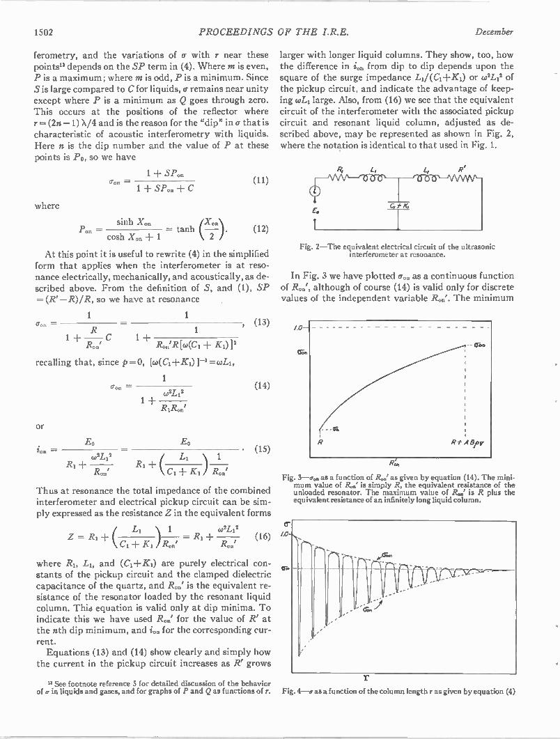
1502 PROCEEDINGS OF THE I.R.E. December
ferometry, and the variations of a with r near these points" depends on the SP term in (4). Where m is even, P is a maximum; where m is odd, P is a minimum. Since S is large compared to C for liquids, cr remains near unity except where P is a minimum as Q goes through zero. This occurs at the positions of the reflector where r = (2n —1) X/4 and is the reason for the "dip" in a that is characteristic of acoustic interferometry with liquids. Here n is the dip number and the value of P at these points is Po, so we have
a o n —
where
1 + SP.
1 + SP. + C
(X,2).) sinh X.. Pon cosh Xon + 1 — tanh . (12)
At this point it is useful to rewrite (4) in the simplified form that applies when the interferometer is at reso-nance electrically, mechanically, and acoustically, as de-scribed above. From the definition of S, and (1), SP =(R'—R)/R, so we have at resonance
1 1 = , (13) R 1
1 + — C 1 + R.' R.' R[w(C 1 + K O
recalling that, since p=o, mci-Fic,)]--i----coLi,
or
ion —
(rOn —
1 co2L 12
1 ± RIR.'
ED E0 - co2L12
R1 + R1 + ( L' \ 1 l'Zon 1 Cl ± KI ) R on,
(14)
(15)
Thus at resonance the total impedance of the combined interferometer and electrical pickup circuit can be sim-ply expressed as the resistance Z in the equivalent forms
1 w2L,2 Z = R1 + i L I \ = RI + (16)
CI ± Ki iRn.' R on'
where RI, LI, and (Cd-Ki) are purely electrical con-stants of the pickup circuit and the clamped dielectric capacitance of the quartz, and R..' is the equivalent re-sistance of the resonator loaded by the resonant liquid column. This equation is valid only at dip minima. To indicate this we have used R..' for the value of R' at the nth dip minimum, and ion for the corresponding cur-rent. Equations (13) and (14) show clearly and simply how
the current in the pickup circuit increases as R' grows
n See footnote reference 5 for detailed discussion of the behavior of a in liquids and gases, and for graphs of P and Q as functions of r.
larger with longer liquid columns. They show, too, how the difference in ion from dip to dip depends upon the square of the surge impedance Li/(Ci +KO or 0/4' of the pickup circuit, and indicate the advantage of keep-ing coLi large. Also, from (16) we see that the equivalent circuit of the interferometer with the associated pickup circuit and resonant liquid column, adjusted as de-scribed above, may be represented as shown in Fig. 2, where the notation is identical to that used in Fig. 1.
Fig. 2—The equivalent electrical circuit of the ultrasonic interferometer at resonance.
In Fig. 3 we have plotted (ron as a continuous function of R0', although of course (14) is valid only for discrete values of the independent variable R.0'. The minimum
Fig. 3—rron as a function of Ron' as given by equation (14). The mini-mum value of R,„.' is simply R, the equivalent resistance of the unloaded resonator. The maximum value of /2' is R plus the equivalent resistance of an infinitely long liquid column.
cr 1.0-N.,
1 ....., ,
r
r Fig. 4—cr as a function of the column length r as given by equation (4)
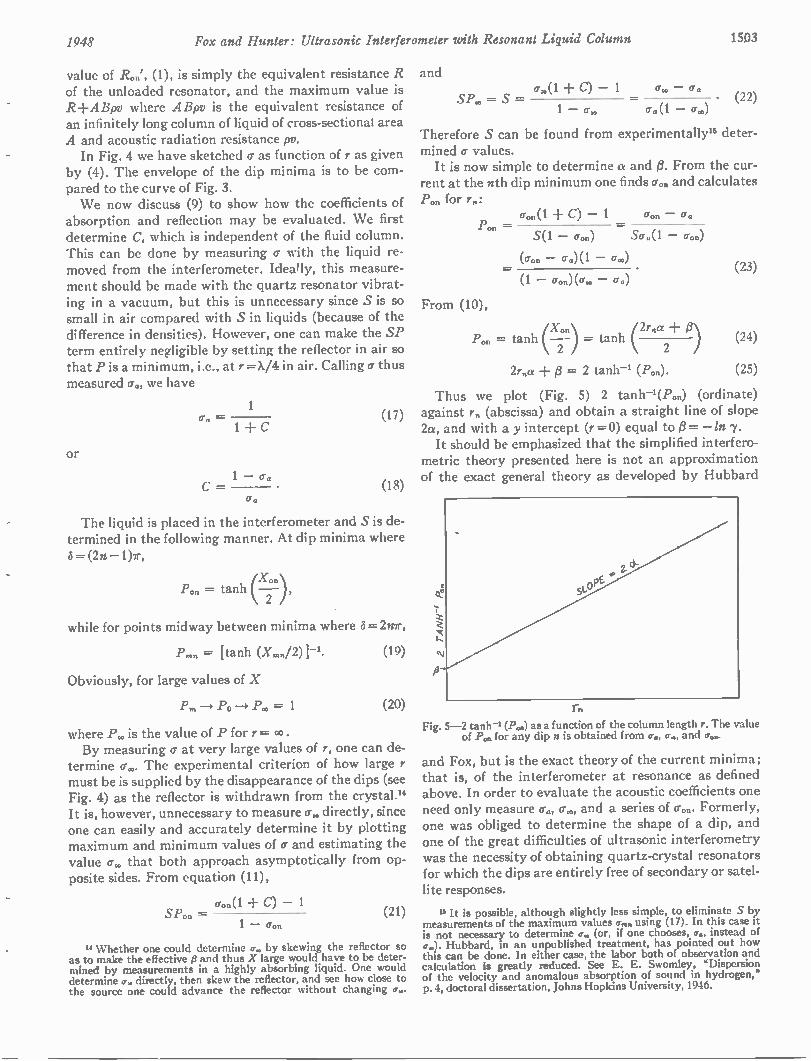
1948 Fox and Hunter: Ultrasonic Interferometer with Resonant Liquid Column 1503
value of R„„', (1), is simply the equivalent resistance R of the unloaded resonator, and the maximum value is R+ABpv where ABpv is the equivalent resistance of an infinitely long column of liquid of cross-sectional area A and acoustic radiation resistance pv. In Fig. 4 we have sketched a as function of r as given
by (4). The envelope of the clip minima is to be com-pared to the curve of Fig. 3. We now discuss (9) to show how the coefficients of
absorption and reflection may be evaluated. We first determine C, which is independent of the fluid column. This can be clone by measuring a with the liquid re-moved from the interferometer. Ideally, this measure-ment should be made with the quartz resonator vibrat-ing in a vacuum, but this is unnecessary since S is so small in air compared with S in liquids (because of the difference in densities). However, one can make the SP term entirely negligible by setting the reflector in air so that P is a minimum, i.e., at r =X/4 in air. Calling a thus measured a., we have
or
1
1 + C
1 — o. C=
(17)
(18)
The liquid is placed in the interferometer and S is de-termined in the following manner. At dip minima where S= (2n —1)7r,
X ork
Pon = tanh 2
while for points midway between minima where 5= 2n7r,
Pmn = [tanh
Obviously, for large values of X
Pm —4 P0-4 P.,, = 1
(19)
(20)
where Px, is the value of P for r = co . By measuring o- at very large values of r, one can de-
termine cr,.. The experimental criterion of how large r must be is supplied by the disappearance of the dips (see Fig. 4) as the reflector is withdrawn from the crystal." It is, however, unnecessary to measure a. directly, since one can easily and accurately determine it by plotting maximum and minimum values of a and estimating the value a. that both approach asymptotically from op-posite sides. From equation (11),
aon(1 C) — 1 SPon = (21)
1 — aon
14 Whether one could determine a,, by skewing the reflector so as to make the effective t3 and thus X large would have to be deter-mined by measurements in a highly absorbing liquid. One would determine a„ directly, then skew the reflector, and see how close to the source one could advance the reflector without changing a..
and
SPx, = S cro(1 — 1 —
(22)
Therefore S can be found from experimentally" deter-mined a values. It is now simple to determine a and 0. From the cur-
rent at the nth dip minimum one finds a.. and calculates for r.:
P on =
From (10),
cron(1 C) — 1 Cron —
S(1 — con) Sa„(1 — Cron)
(cron — cr.)(1 — a„)
(1 — cron) (a. — an) • (23)
X On
= tanh H= tanh (2rna + (3) (24) 2 2
2r„a + = 2 tanh' (P.n). (25)
Thus we plot (Fig. 5) 2 tanh—l(P..) (ordinate) against rn (abscissa) and obtain a straight line of slope 2a, and with a y intercept (r = 0) equal to 13= — In 7. It should be emphasized that the simplified interfero-
metric theory presented here is not an approximation of the exact general theory as developed by Hubbard
rn
Fig. 5-2 tanh-' (Pon) as a function of the column length r. The value of Pon for any dip n is obtained from cr., a., and aon.
and Fox, but is the exact theory of the current minima; that is, of the interferometer at resonance as defined above. In order to evaluate the acoustic coefficients one need only measure a., a., and a series of a... Formerly, one was obliged to determine the shape of a dip, and one of the great difficulties of ultrasonic interferometry was the necessity of obtaining quartz-crystal resonators for which the dips are entirely free of secondary or satel-lite responses.
u It is possible, although slightly less simple, to eliminate S by measurements of the maximum values cr„,n using (17). In this case it is not necessary to determine a., (or, if one chooses, a.„ instead of
Hubbard, in an unpublished treatment, has pointed out how this can be done. In either case, the labor both of observation and calculation is greatly reduced. See E. E. Swomley, "Dispersion of the velocity and anomalous absorption of sound in hydrogen," p. 4, doctoral dissertation, Johns Hopkins University, 1946.
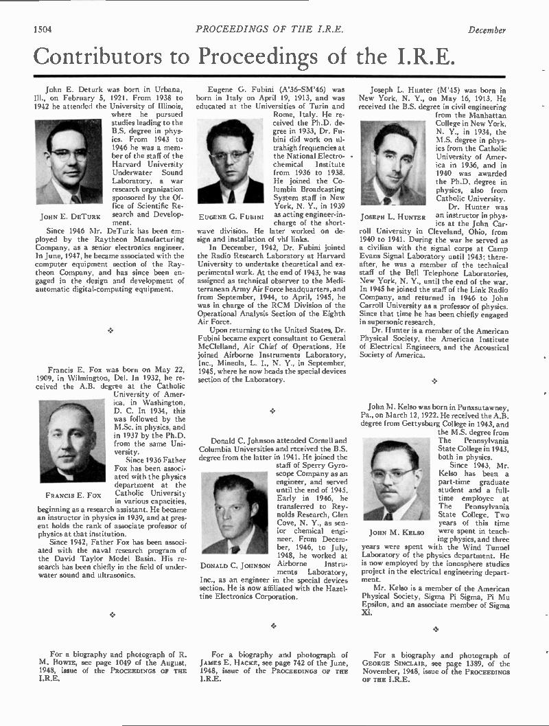
1504 PROCEEDINGS OF THE I.R.E. December
JOHN E. DETURK
Contributors to Proceedings of the I.R.E. John E. Deturk was born in Urbana,
Ill., on February 5, 1921. From 1938 to 1942 he attended the University of Illinois,
where he pursued studies leading to the B.S. degree in phys-ics. From 1943 to 1946 he was a mem-ber of the staff of the Harvard University Underwater Sound Laboratory, a war research organization sponsored by the Of-fice of Scientific Re-search and Develop-ment.
Since 1946 Mr. DeTurk has been em-ployed by the Raytheon Manufacturing Company, as a senior electronics engineer. In June, 1947, he became associated with the computer equipment section of the Ray-theon Company, and has since been en-gaged in the design and development of automatic digital-computing equipment.
Francis E. Fox was born on May 22, 1909, in Wilmington, Del. In 1932, he re-ceived the A.B. degree at the Catholic
University of Amer-ica, in Washington, D. C. In 1934, this was followed by the M.Sc. in physics, and in 1937 by the Ph.D. from the same Uni-versity. Since 1936 Father
Fox has been associ-ated with the physics department at the Catholic University in various capacities,
beginning as a research assistant. He became an instructor in physics in 1939, and at pres-ent holds the rank of associate professor of physics at that institution. Since 1942, Father Fox has been associ-
ated with the naval research program of the David Taylor Model Basin. His re-search has been chiefly in the field of under-water sound and ultrasonics.
FRANCIS E. Fox
For a biography and photograph of R. M. BOWIE, see page 1049 of the August, 1948, issue of the PROCEEDINGS OF THE I.R.E.
EUGENE G. FUBINI
Eugene G. Fubini (A'36-SM'46) was born in Italy on April 19, 1913, and was educated at the Universities of Turin and
Rome, Italy. He re-ceived the Ph.D. de-gree in 1933, Dr. Fu-bini did work on ul-trahigh frequencies at the National Electro-chemical Institute from 1936 to 1938. He joined the Co-lumbia Broadcasting System staff in New York, N. Y., in 1939 as acting engineer-in-charge of the short-
wave division. He later worked on de-sign and installation of vhf links. In December, 1942, Dr. Fubini joined
the Radio Research Laboratory at Harvard University to undertake theoretical and ex-perimental work. At the end of 1943, he was assigned as technical observer to the Medi-terranean Army Air Force headquarters, and from September, 1944, to April, 1945, he was in charge of the RCM Division of the Operational Analysis Section of the Eighth Air Force. Upon returning to the United States, Dr.
Fubini became expert consultant to General McClelland, Air Chief of Operations. He joined Airborne Instruments Laboratory, Inc., Mineola, L. I., N. Y., in September, 1945, where he now heads the special devices section of the Laboratory.
•
Donald C. Johnson attended Cornell and Columbia Universities and received the B.S. degree from the latter in 1941. He joined the
staff of Sperry Gyro-scope Company as an engineer, and served until the end of 1945. Early in 1946, he transferred to Rey-nolds Research, Glen Cove, N. Y., as sen-ior chemical engi-neer. From Decem-ber, 1946, to July, 1948, he worked at Airborne Instru-ments Laboratory,
Inc., as an engineer in the special devices section. He is now affiliated with the Hazel-tine Electronics Corporation.
DONALD C. JOHNSON
For a biography and photograph of JAMES E. HACKE, see page 742 of the June, 1948, issue of the PROCEEDINGS OF THE I.R.E.
Joseph L. Hunter (M'45) was born in New York, N. Y., on May 16, 1913. He received the B.S. degree in civil engineering
from the Manhattan College in New York, N. Y., in 1934, the M.S. degree in phys-ics from the Catholic University of Amer-ica in 1936, and in 1940 was awarded the Ph.D. degree in physics, also from Catholic University. Dr. Hunter was
an instructor in phys-ics at the John Car-
roll University in Cleveland, Ohio, from 1940 to 1941. During the war he served as a civilian with the signal corps at Camp Evans Signal Laboratory until 1943; there-after, he was a member of the technical staff of the Bell Telephone Laboratories, New York, N. Y., until the end of the war. In 1945 he joined the staff of the Link Radio Company, and returned in 1946 to John Carroll University as a professor of physics. Since that time he has been chiefly engaged in supersonic research. Dr. Hunter is a member of the American
Physical Society, the American Institute of Electrical Engineers, and the Acoustical Society of America.
JOSEPH L. HUNTER
John M. Kelso was born in Punxsutawney, Pa., on March 12, 1922. He received the A.B. degree from Gettysburg College in 1943, and
the M.S. degree from The Pennsylvania State College in 1943, both in physics. Since 1943, Mr.
Kelso has been a part-time graduate student and a full-time employee at The Pennsylvania State College. Two years of this time were spent in teach-ing physics, and three
years were spent with the Wind Tunnel Laboratory of the physics department. He is now employed by the ionosphere studies project in the electrical engineering depart-ment. Mr. Kelso is a member of the American
Physical Society, Sigma Pi Sigma, Pi Mu Epsilon, and an associate member of Sigma xi.
JOHN M. KELSO
For a biography and photograph of GEORGE SINCLAIR, see page 1389, of the November, 1948, issue of the PROCEEDINGS OF THE I.R.E.
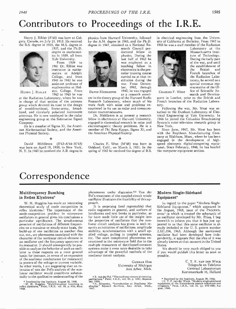
194S PROCEEDINGS OF THE I.R.E. 1505
Contributors to Proceedings of the I.R.E. Henry J. Riblet (A'45) was born at Cal-
gary, Canada, on July 21, 1913. He received the B.S. degree in 1935, the M.S. degree in
1937, and the Ph.D. degree in mathemat-ics in 1939, all from Yale University. From 1939 to
1941 Dr. Riblet was instructor in mathe-inatics at Adelphi College, and from 1941 to 1942 he was assistant professor of mathematics at Hof-stra College. From 1942 to 1945 he was
at the Radiation Laboratory, where he was in charge of that section of the antenna group which devoted its time to the design of omnidirectional, linear-array, broad-band, and circularly polarized microwave antennas. He is now employed in the radar engineering group at the Submarine Signal Company. He is a member of Sigma Xi, the Ameri-
can Mathematical Society, and the Ameri-can Physical Society.
HENRY J. R1BLET
David Middleton (S'42-A'44-M'45) was born on April 19, 1920, in New York, N. Y. In 1942 he received the A.B. degree in
physics from Harvard University, followed by the A.M. degree in 1945, and the Ph.D. degree in 1947, obtained as a National Re-
search Council pre-doctoral fellow in physics. During the last half of 1942 he was employed as a teaching fellow in electronics in the pre-radar training course carried on at that in-stitution during the war. From Decem-ber, 1942, through 1945, he was engaged as a research associ-
ate in the theory group of the Harvard Radio Research Laboratory, where much of his work dealt with noise and problems en-countered in its use as radar and communi-cation countermeasures. Dr. Middleton is at present a research
fellow in electronics at Harvard University, engaged in theoretical research in noise and electromagnetic theory problems. He is a member of Phi Beta Kappa, Sigma Xi, and the American Physical Society.
Charles F. West (M'48) was born in Oakland, Calif., on March 3, 1921. In the spring of 1942 he received the degree of B.S.
DAVID MIDDLETON
Correspondence
in electrical engineering from the Univer-sity of California at Berkeley. From 1942 to 1945 he was a staff member of the Radiation
Laboratory at the Massachusetts Insti-tute of Technology. During the early part of the war, and until the establishment of the British and French branches of the Radiation Labo-ratory, he served as a special overseas rep-resentative of the Of-fice of Scientific Re-search and Develop-
ment in London, prior to the British and French branches of the Radiation Labora-tory. Following the war, Mr. West was at-
tached to the Dunham Laboratory of Elec-trical Engineering at Yale University. In 1946 he joined the Columbia Broadcasting System's color-television research group in New York. Since June, 1947, Mr. West has been
with the Raytheon Manufacturing Com-pany at Waltham, Mass., where he has been engaged in the development of high-speed electronic digital-computing equip-ment. Since February, 1948, he has headed the computer equipment section.
CHARLES F. WEST
Multifrequency Bunching in Reflex Klystrons*
W. H. Huggins has made an interesting theoretical study of mode competition in reflex klystrons.' The importance of the mode-competition problem in microwave oscillators in general gives his conclusions a particular significance. The simultaneous presence of oscillations of different frequen-cies on a transient or steady-state basis, the build-up of one oscillation as another dies out, etc., are phenomena associated with the character of the nonlinear circuit element in an oscillator and the frequency spectrum of its resonator. It should consequently be pos-sible to analyze the behavior of such an oscil-lator in these respects on a more general basis; for instance, in terms of an expansion of the nonlinear conductance (or resistance) in powers of the voltage or current variable. In other words, I am suggesting that an ex-tension of van der Pol's analysis of the non-linear oscillator would contribute substan-tially to the qualitative understanding of the
• Received by the Institute, August 26. 1948. I W. H. Huggins. •Multifrequency bunching in
reflex klystrons," PROC. I.R.E. vol. 36. p. 624; May, 1948.
phenomena under discussion.'.' Van der Pol's treatment of the coupled-circuit triode oscillator illustrates the feasibility of this ap-proach. It is surprising (and regrettable) that
radio engineers in general, and authors of handbooks and text books in particular, so far have made little use of the insight into the properties of oscillators that the non-linear circuit analysis has given in such re-spects as initiation of oscillations, amplitude stability, synchronization with a small ap-plied voltage, pulling in coupled systems, etc. The more complicated phenomena en-countered in the microwave field due to the multiple resonances of distributed-constant systems make it even more desirable to take advantage of the powerful methods of the nonlinear circuit analysis.
GUNNAR HOK University of Michigan
Ann Arbor, Mich.
5 B. van der Pol. The nonlinear theory of electrica oscillations,' PR'OC. vol. 22. p. 1051; Septem-ber. 1934.
N. Minorsky, "Introduction to Nonlinear Me-chanics," Edward Brot hers, Ann Arbor. Mich., 1947.
Modern Single-Sideband Equipment*
In regard to the paper "Modern Single-Sideband Equipment," which appeared in the August, 1948, issue of the PROCEED-INGsti in which is treated the schematic of an oscillator developed by Mr. Prins, I beg herewith to inform you that it has just ap-peared to us that this same oscillator is al-ready included in the U. S. patent number 2,321,354, 1943. Although the mentioned oscillator had been developed here inde-pendently, it appears that the idea of it was already known at that moment in the United States. We should be very much obliged to you
if you would publish this letter as soon as possible.
C. T. F. VAN DER WYCH Telegrafie en Telefonie Centraal Laboratorium
Kortenaerkade II, Holland
• Received by the Institute. August 30, 1948. I C. T. F. van der Wyck. "Modern single-sideband
equipment of the Netherlands postals telephone and telegraph," PROC. I.R.E., vol. 36. pp. 970-980; Au-gust, 1948.
1506 PROCEEDINGS OF THE I.R.E. December
Institute News and Radio Notes
Board of Directors
At the Board of Directors' Meeting held at the Institute on September 9, Ralph Bown was elected winner of the 1949 Medal of Honor. The following 31 members will also receive fellow awards, effective January 1, 1949:
H. A. Affel K. C. Black J. E. Brown Cledo Brunetti W. L. Carlson P. S. Carter F. F. d'Humy J. N. Dyer L. A. Gebhard T. T. Goldsmith, Jr. F. W. Grover E. A. Guillemin
J. K. Johnson S. R. Kantebet W. B. Lodge K. A. Mackinnon H. F. Olson L. S. Payne L. M. Price H. J. Reich J. D. Reid Karl Spangenberg George Sterling 0. E. Strong
Ross Gunn Franz Tank A. V. Haeff Norris Tuttle L. C. Holmes I. R. Weir
George O'Neill
The Danish Academy of Technical Sci-ences requested in a letter to President Shackelford, dated May 18, 1948, that the Institute recommend a candidate to receive the Valdemar Poulsen Gold Medal for 1948. The medal is awarded once every year in principle—although in practice it may be awarded every two years—to a radio en-gineer who has contributed significantly to the science or art of radio communication. This person is selected from recommenda-tions made by "competent institutions in Denmark and abroad." Accordingly, the Institute Awards Committee suggested the name of G. W. Pierce.
The Institute was invited to send a representative to the inauguration reception for Dwight D. Eisenhower, new President of Columbia University. Dr. Goldsmith was asked to represent the Institute and ac-cepted.
Executive Committee
A regular meeting of the Executive Com-mittee was held at the Institute on Septem-ber 8. C. G. Mayer, RCA European Techni-cal Representative in London, was ap-pointed IRE Representative on the IRE-Al EE International Liaison Committee.
EMPORIUM SECTION CONVENES WITH CHEMISTS
The third joint dinner meeting of the Pennsylvania-New York Western Border Section of the American Chemical Society and the Emporium Section of the IRE was held in Emporium, Pa., on September 16. An audience of 120 heard Albert C. Walker present his paper on "The Development of Piezoelectric Crystals," after which they saw a motion picture "Crystal Clear," prepared by J. J. Harley to illustrate Dr. Walker's paper. The success of this meeting, as well as
of the previous joint meetings, indicates the potential value to small or geographically isolated sections of the Institute of combined meetings with related scientific groups in order to facilitate the presentation of im-portant developments by recognized au-thorities.
1949 IRE Convention Plans Under Way
AGREEMENT ON SCREW THREADS STANDARDS
A joint conference of representatives of government committees and ranking indus-trial standardization groups from Great Britain, Canada, and the United States is scheduled to meet within the next three months in order to make final agreements on common standards for screw threads used on most types of threaded fasteners, includ-ing bolts and nuts. It is planned to hold this conference at
the National Bureau of Standards, which has actively co-operated in the attainment of this objective over a period of many years. The purposes of the joint conference are to assure complete agreement on all funda-mentals and to celebrate the reaching of an agreement after years of negotiation.
Calendar of
COMING EVENTS
1948 Southwestern I.R.E. Conference Dallas, Tex., Dec. 10-11, 1948
AIEE Symposium on High-Frequency Measurements, Washington, D. C., Jan. 10-12, 1949
American Physical Society Meeting, New York City, Jan. 27-29, 1949
1949 IRE National Convention, New York City, March 7-10, 1949
RMA—IRE Spring Meeting, Phila-delphia, Pa., Apr., 25-27, 1949
Under the guidance of George W. Bailey, Chairman, and the 1949 Convention Com-mittee, arrangements for the 1949 IRE Na-tional Convention are moving ahead at top speed. All over the United States, Canada, and points even further distant, members are setting aside the second week in March of the new year for what promises to be one of the biggest and best conventions in the Institute's history. Indications show that the attendance should equal if not exceed that at the record 1948 convention. Again mem-bers are urged to make their hotel reserva-tions well in advance because, although the hotel situation in New York City is less serious than it was, there is still a seasonal shortage of rooms. Desirable accommoda-tions will be at a premium, and this is a con-vention no member will want to miss. In response to the December 1 deadline
set by D. B. Sinclair, Chairman of the Technical Program Committee, proposals for papers have been pouring in at a gratify-ing rate, and Dr. Sinclair assures members of a stimulating and varied papers program that will cover the entire gamut of subjects interesting to workers in the radio and elec-tronics and allied fields. The complete tech-nical program, including summaries of the
papers scheduled and dates of presentation, will be printed in the February, 1949, issue of the PROCEEDINGS. Dates have already been confirmed for
most of the social activities. The annual meeting of the Institute will start the Con-vention on Monday, March 7, at 10:30 A.M. Later in the day a cocktail party from six to eight P.M. arranged by Walter Knoop, Chairman of the Cocktail Party Committee, will give the members and their families an opportunity to become better acquainted with each other. A sections meeting will fol-low the party. The president's luncheon at 12:45 P.M.
on Tuesday planned by R. D. Chipp, Chair-man of that activity, will honor the incom-ing president, Stuart L. Bailey, who is him-self on the Convention Committee. Wedhes-day's highlight will be the annual banquet at 6:45 P.M. Raymond F. Guy, toastmaster, will introduce Frank Stanton, president of the Columbia Broadcasting System. Dr. Stanton's topic will be "Television Today." Karl Spangenberg has been invited to de-liver the speech of acceptance on behalf of the newly elected Fellows. Although plans for a program of Wom-
en's Activities have not yet been consoli-
dated, ladies who enjoyed themselves at previous Conventions can look forward to a program which bids fair to outdistance all the Institute's past successes. Ladies who have never before attended an IRE Conven-tion have a treat in store for them. Exhibit Manager William C. Copp has
reported that 140 exhibitors have already taken 80 per cent of the available space at Grand Central Palace in which to display the latest in radio and electronic devices. By the time arrangements are completed, the total number of exhibitors is expected to reach a figure close to two hundred. Among the special features contemplated for this year's exhibits is a center devoted entirely to nuclear instrumentation. Other members of the Convention Com-
mittee who are working along with Mr. Bailey in order to make this Convention an unforgettable one are Trevor H. Clark, Vice-Chairman; Austin Bailey, in charge of Finance; L. G. Cumming, Institute Activi-ties; Clinton B. DeSoto, Printed Program; E. K. Gannett, Facilities; Virgil M. Graham, Publicity; Roscoe Kent, Hospitality; J. Harold Moore, Registration; and Emily Sirjane, Secretary.
1948 Institute News and Radio Notes 1507
The IRE Professional Group System—A Status Report
IN THE May, 1948, issue of the PROCEED-INGS OF THE I.R.E., on page 570, plans for the inauguration of a Professional
Group System within the broad structure of The Institute of Radio Engineers were an-nounced. Now, nine months later, many of those plans have been fulfilled, and the IRE Professional Group System is substantially an accomplished fact. Indeed, insofar as its acceptance by the membership and the de-gree to which the mechanics for its future operation have been charted are concerned it is an accomplished fact. This seems an appropriate time, there-
fore, for a progress report directed to the Institute membership at large. At this writing the following steps, en-
visioned by the Board of Directors when it first formally adopted the Group principle of organization at its March 25. 1948, meet-ing, have been realized: (1) Necessary amend-ments to the Bylaws of the Institute to effectuate the Group system have been adopted. (2) A permanent Professional Groups Committee, replacing the original ad hoc committee which did the initial planning and promotion of the plan, has been established. (3) A model constitution and bylaws for individual Groups has been prepared, incorporating the requisite tenets with sufficient latitude in construction to allow of alteration to satisfy the specialized requirements of individual groups. (4) A detailed and highly informative Manual for the guidance of would-be Group promoters has been prepared and published, and is available upon request. (Requests should be directed to the Technical Secretary of IRE.) (5) Most importantly of all, two Groups have been actively organized, and more are in the process of formation. In accordance with the thoroughly demo-
cratic principles which were decreed for the Professional Group System from the time of its earliest inception in the minds of sev-eral IRE officials in 1947, the greatest part of this progress—and in particular all of the steps leading to the formation of the Groups so far established or in process—has sprung from the enthusiasm with which the membership at large greeted the original announcement. In this connection, it should be emphasized that, under the system as adopted, the promotion and organization of Groups is entirely a membership matter. Groups are organized by members; they are conducted by members; and their programs and activities are entirely guided by mem-bers. Once a group is established, any num-ber of members within a section or locality can hold Group meetings and carry on au-thorized activities—even if the number is as small as two!
Principle of Group Organization
The principle of Group organization should be clear to all. It is not an idea novel with IRE. Some of the older engineering or-ganizations have already adopted similar ar-rangements, as their fields of interest have enlarged with a rapidly expanding technol-ogy, and for them it has proved a successful mode of operation. The same problem that
faced these societies has in recent years in-creasingly faced The Institute of Radio Engineers. Time was when our scope was fully indicated by our name, and all mem-bers of the organization had an essentially equal interest in the activities of all others. But in the past decade or so, and particularly in the postwar epoch, the amoeba-like multi-plication of applications of radio and elec-tronics has led to a divergence of fields of interests so great that the broadcast engineer has in common with the computer engineer mainly only the fundamental phenomena of the electron tube—and even that interest is an indirect association maintained largely through the person of yet another specialist, the designer of electron tubes. Similarly, the analyst of wave propagation phenomena can apprehend the problems of the man working with industrial heating equipment only to the extent that one wants radiation to escape and the other does not, while the audio man and the microwave man are a billion cycles removed from each other. These are, admittedly, only arbitrary and singular examples; but they can be elaborated in manifold fashion, and they illustrate the problems of community of interest in our recently incredibly expanded art. The fundamental consideration, how-
ever, is that underneath it all each of these individual specialists is linked with each by his use of the same basic phenomena—elec-tronics and radiation. That underlying bind-ing force is the thing that is The Institute of Radio Engineers. It is essential to the self-interest of all that this force be maintained, that unity of purpose and of seeking shall be preserved, that research findings and design applications and, above all, professional zeal be sustained and disseminated and utilized to strengthen the whole, both in terms of or-ganization and in extension of common knowledge. The question is how to ac-complish this, and yet allow full exchange of mutual interest and information and en-thusiasm among those most intimately con-nected with specific phases of the specialized directions in which this broad art of ours is growing. To answer that question is the objective
of the Professional Groups System.
Progress in Group Organization
As was stated above, two Groups al-ready have been approved. The Audio Group was established on June 2, 1948, its purview being the "technology of communi-cation at audio frequencies and with the audio-frequency portion of radio systems." Those interested in this Group should com-municate with 0. L. Angevine, Jr., do Stromberg-Carlson Co., Rochester, N. Y. The second Group to be approved on
July 7, 1948, was the Broadcast Engineers Group, encompassing not only "engineers associated with individual radio stations, broadcast networks, operating companies and broadcast consultants," but also in-cluding "government engineers associated with broadcasting, and engineers in com-mercial and other laboratories and manu-facturing companies whose prime interest is in the development, design, production, op-
eration and maintenance of broadcast equip-ment used by the various classes of broad-cast stations." This professional group is in-tended to encompass the engineers of "any FM, AM, Facsimile, TV, International, Re-lay, Experimental, Emergency or any other associated class of broadcast stations." Those interested in this Group should com-municate with Orrin W. Towner, c/o Radio Station WHAS, Louisville, Ky. Other fields of activity in which interest
in the formation of Groups has been ex-pressed include wave propagation, antennas, telemetering, electronic computers, quality control, and standardization.
How to Organize a Group
For the benefit of those who are inter-ested in organizing Groups in their particular fields of interest, the following step-by-step procedure has been outlined by the Profes-sional Groups Committee. (Page numbers refer to the Group Manual.)
1. Write to the Executive Secretary of the Institute, for general information on the formation of Groups. (See page 1, Initial Inquiry, in the Manual.)
2. Communicate with others interested in the proposed field to get sufficient mem-bers willing to promote the Group and over 25 prepared to sign the petition. (See page 1, Promoting Petitioners.)
3. Prepare the petition. (See pages 1, 2, Pre-paring Petition, and pages 13, 22.)
4. Forward the petition to the Chairman, Committee on Professional Groups, through Institute Headquarters. (See page 2.)
5. Foward suggested names for the initial Administrative Committee to the Chair-man, Committee on Professional Groups, through Institute Headquarters. (See pages 2, 14.)
6. After notification by Institute Head-quarters of the appointment of the Administrative Committee by the Com-mittee on Professional Groups, the Ad-ministrative Committee elects a chair-man, notifies Institute Headquarters of the result of the election, and draws up a constitution. (See pages 2A, 15, and 19.)
7. Send the constitution to the Chairman, Committee on Professional Groups, through Institute Headquarters, for ap-proval by that Committee and by the Executive Committee of the Institute. (See page 2A.)
8. The Administrative Committee draws up bylaws and appoints committees. (See pages 2A, 15, 16, and 21.)
9. Forward a copy of the bylaws and names of officers and committee chairmen to the Executive Secretary for his information. (See page 21.)
Note particularly that, once a petition bearing 25 signatures has been filed and a national Group approved in any field of in-terest, any number of members of any sec-tion, however small, may join the Group and hold meetings. As few as two members might conceivably hold local meetings. The only restriction is that all meetings of all Groups must be open to all members of IRE.
1508 PROCEEDINGS OF THE I.R.E. December
Industrial Engineering Notes'
CONTINUED USE OF LORAN IN NORTHEAST ATLANTIC ASKED
The State Department has notified the International Telecommunica tion Union that aids to radio navigation which are suit-able for the Northeast Atlantic area and de-signed for operation in the allotted frequency bands under international regulations can-not be made available by July 1, 1949. The Department said that due to the great use now being made of loran in the area by both air and surface craft, it is the government's opinion that standard loran should be con-tinued in the Northeast Atlantic area until an acceptable substitute which can be agreed upon internationally is in operation.
NEW TRANSDUCER DEVELOPMENT
A highly sensitive mechano-electrical transducer, which transforms slight displace-ments into large changes of resistance, cur-rent, or voltage, is being developed by the Bureau of Standards. The active element of the device is a helical or conical spring wound in such a way that the initial tension varies slightly along its length. Thus, when the ends of the spring are pulled apart, the turns separate one by one, rather than simul-taneously. The October issue of the Technical New
Bulletin, Standards Bureau publication, has printed a description of the new develop-ment. Copies of this monthly magazine may be obtained at 10 cents each from the Superintendent of Documents, U. S. Gov-ernment Printing Office, Washington 25, D. C.
FCC ISSUES LIFE-SAVING REVISIONS
The FCC has issued a public notice (No. 27112) containing an outline of the revisions of the International Convention for the Safety of Life at Sea, 1929, which were adopted at London last June, and which become effective on January 1, 1951. Copies of the outline and further information on the radio aspects of the revised Convention may be obtained from the Secretary of the FCC, Washington 25, D. C.
TELEVISION AND RADIO PRODUCTION AND SALES RISE AS EXCISE TAX COLLECTIONS FALL
RMA member-companies manufactured 64,953 television receivers in August, thus setting up a new monthly record which represents an increase of almost 10,000 over the July output. FM-AM set production totalled 110,879 in August, the largest out-put of this type of receiver since last March. Radio receiver production of all types to-talled 870,044 in August as compared with 627,349 in July. Production of automobile and portable radios aggregated 256,594 and 178,323, respectively.
The data on which these NOTES are based were selected, by permission, from 'Industry Reports,' issues of September 17 and 24, and October 1, 11, and 15, published by the Radio Manufacturers' Associa-tion of America,• and from the September 14 issue of 'News," published by the Radio Manufacturers' Association of Canada. The helpful attitude of both of these organizations is hereby gladly acknowledged.
Indicative of the sharp increase in tele-vision receiver production during the first half of 1948, sales of cathode-ray tubes to set manufacturers rose more than 68 per cent during the second quarter over sales in the first quarter. During the first six months of 1948 cathode-ray tube sales to manufac-turers totalled 426,469, with a value of $10,250,218, as compared with sales during thewentire year of 1947 of 253,035 units, valued at $7,218,358. With U. S. goVvrnment purchases ac-
counting for 71 per cent of the total, sales of radio and television transmitting and com-munications equipment by RMA member-compan ies aggregated $50,318,006 during the second quarter of 1948, and brought sales of this type to $80,346,321 for the first six months of this year. August collections of the 10 per cent ex-
cise tax on radios and phonographs and cer-tain of their components dropped below the collections of both July, 1948, and August, 1947, the U. S. Bureau of Internal Revenue reported. Collections of the radio excise tax in August amounted to $3,927,009.08, as compared with $4,060,785.34 last July and $5,084,018 in August a year ago.
FM DEVELOPMENTS
The FCC has denied petitions presented by Major Edwin H. Armstrong and the FM Association, seeking to reopen the record in proceedings concerning the sharing of tele-vision channels. Major Armstrong's petition requested that the FCC order of May 5, 1948, be reconsidered "insofar as it denies requests made at the hearing that a portion of the 44- to 50-Mc band be allocated to FM broadcast relay purposes, and insofar as it required FM broadcast stations operating in the 44- to 50-Mc band to discontinue op-eration by December 31, 1948." The FM petition sought to extend the FCC proposed discontinuance date of FM operation in the 44- to 50-Mc band until December 31, 1950. Since the last issue of the PROCEEDINGS,
30 FM stations have gone on the air, bring-ing the total to 673 stations, which includes 24 noncommercial outlets. New stations have begun operation in the following states: Ala., Mobile (WMOB-FM), Montgom-
ery (WMGY-FM); Cal., San Diego (KFSD-FM); D. C., Washington (WOL-FM and WCFM); Ga., Atlanta (WSB-FM) and La Grange (WLAG-FM); Iowa, Des Moines (KCBC-FM); Ill., Chicago (WMAQ-FM) and Woodstock (WILA); hid., Warsaw (WRSW); Ky., Ashland (WCM I-FM) ; Md., Cumberland (WTBO-FM); Mass., Boston (WNAC-FM), Lowell (WLLH-FM), Lynn (WLYN-FM); N. Y., Endicott (WENE-FM), Massena (WMSA-FM), New Rochelle (WGNR), Troy (WEVR); Ohio, Canton (WAND-FM), Columbus (WHKC-FM); Pa., Uniontown (WNIQ); Tex., Longview (KLTI-FM); Wash., Tacoma (KTNT); W. Va., Parkersburgh (WPAR-FM); and Wis., Madison (WISC-FM), St. Cloud (KFAM-FM), and Wisconsin Rapids (WFHR-FM).
CANADIAN RADIO NEWS
The Canadian RMA Service Committee has published four bulletins for service
technicians: "The Treatment of Hum in Radio Receivers," "FM Servicing" (in two parts), "Capacitor Colour Coding," and "An-tennae." The earlier bulletin, "Trouble Shooting in Radio Receivers," has been re-printed, and the Committee is now prepar-ing bulletins on "Alignment" and "An Open Letter to Radio Service Technicians," the latter of which covers basic theory .... R. M. Brophy, Chairman of the Canadian RMA Industrial Mobilization Committee, has been requested by the Industrial De-fence Board and Canadian Ordnance Asso-ciation to organize and convene an Indus-trial Defence Preparedness Committee on Communications and Electronics. Its prin-cipal task will be to effect liaison among the Armed Services, the arsenals, and in-dustry.... Radio set sales in Canada have been dropping. Sales for the first seven months of this year totalled 224,762 units worth $20,069,485, as against 429,234 units worth $27,707,066 for the first seven months of 1947 .... Imports and exports also have been decreasing. During the first six months of this year, 17,800 sets valued at $206,988 were imported, as compared with 44,775 sets valued at $1,559,517 imported during the first half of 1947. Canada exported 441 sets worth $15,146 for the first six months of 1948; whereas she exported 21,597 sets worth $781,672 in the first half of 1947 ... . One hundred and twenty-five members and guests attended a joint IRE-Canadian RMA Golf Tournament and Dinner at the Cutten Fields Golf Club in Guelph, Ont., on September 17, J. R. Longstaffe, a member of both the RMA and the Toronto Section of the IRE, acted as master of ceremonies and presided at the dinner and evening pro-gram.
RMA HOLDS CONFERENCE; PUBLISHES RADIO BOOKLET
Aggressive action to develop television and to expedite the adoption by the govern-ment of a mobilization plan of the radio and electronics industry highlighted a three-day RMA fall conference from October 6 to 8, at the Roosevelt Hotel in New York City. Among the other matters on its agenda,
the Board of Directors authorized legal ac-tion to contest the validity of a Pennsyl-vania state license tax on taverns equipped with television receivers, established a spe-cial committee to confer with the FCC regarding pending study of future expansion of television services into the UHF band, authorized President Max F. Balcolm to set up a committee representing the Set, Tube, and Transmitter Divisions, and authorized the Engineering Department to work with the Export Committee in the promotion of American television standards and equip-ment in foreign countries. The RMA has published a booklet,
"Classroom Radio Receivers," which is being distributed to 45,000 educators throughout the country. The work of the U. S. Office of Education and the RMA Joint Committee on Specifications for School Audio Equipment, the pamphlet is the third in a series of such studies, the other two being "School Sound Systems" and "School Sound Recording and Playback Equip-ment."
1948 Institute News and Radio Notes 1509
Sections
Chairman
W. A. Edson Georgia School of Tech. Atlanta, Ga.
John Petkovsek 1015 Ave. E Beaumont, Texas
R. W. Hickman Cruft Laboratory Harvard University Cambridge, Mass.
G. E. Van Spankeren San Martin 379 Buenos Aires, Arg.
J. F. Myers 249 Linwood Ave. Buffalo 9, N. Y.
G. P. Hixenbaugh Radio Station W MT Cedar Rapids, Iowa
K. W. Jarvis 6058 W. Fullerton Ave. Chicago 39, III.
C. K. Gieringer 3016 Lischer Ave. Cincinnati, Ohio
F. B. Schramm 2403 Channing Way Cleveland 18, Ohio
Warren Bauer 376 Crestview Rd. Columbus 2, Ohio
S. E. Warner Aircraft Electronics As-soc.
1031 New Britain Ave. Hartford 10, Conn.
ATLANTA December 17
BALTIMORE
BEAUMONT -PORT ARTHUR
BOSTON
BUENOS AIRES
BUFFALO-NIAGARA December 15
CEDAR RAPIDS
CHICAGO December 17
CINCINNATI December 14
CLEVELAND December 23
COLUMBUS January 14
CONNECTICUT VALLEY
December 16
Secretary
M. S. Alexander 2289 Memorial Dr., S.E. Atlanta, Ga.
J. W. Hammond 4 Alabama Ct. Baltimore 28, Md.
C. E. Laughlin 1292 Liberty Beaumont, Texas
A. F. Coleman Mass. Inst. of Technology 77 Massachusetts Ave. Cambridge, Mass.
A. C. Cambre San Martin 379 Buenos Aires, Arg.
R. F. Blinzler 558 Crescent Ave. Buffalo 14, N. Y.
V. R. Hudek Collins Radio Co. Cedar Rapids, Iowa
Kipling Adams General Radio Co. 920 S. Michigan Ave. Chicago 5, Ill.
F. W. King RR 9 Box 263 College Hill Cincinnati 24, Ohio
J. B. Epperson Box 228 Berea, Ohio
George Mueller Electrical Eng. Dept. Ohio State University Columbus, Ohio
H. L. Krauss Dunham Laboratory Yale University New Haven, Conn.
J. G. Rountree DALLAS-FT. WORTH J. H. Homey 4333 South Western Blvd. Box 5238 Dallas 5, Texas Dallas, Texas
George Rappaport 132 East Court Harshman Homes Dayton .3, Ohio
C. F. Quentin Radio Station KRNT Des Moines 4, Iowa
A. Friedenthal 5396 Oregon Detroit 4, Mich.
E. F. Kahl Sylvania Electric Prod-ucts
Emporium, Pa.
W. H. Carter 1309 Marshall Ave. Houston 6, Texas
R. E. McCormick 3466 Carrollton Ave. Indianapolis, Ind.
Karl Troeglen KCMO Broadcasting Co. Commerce Bldg. Kansas City 6, Mo.
R. W. Wilton 71 Carling St. London, Ont., Canada
Walter Kenworth 1427 Lafayette St. San Gabriel, Calif.
DAYTON December 16
Des MomEs-AMES
DETROIT December 17
EMPORIUM
HOUSTON
INDIANAPOLIS
KANSAS CITY
C. J. Marshall 1 Twain Place Dayton 10, Ohio
F. E. Bartlett Radio Station KSO Old Colony Bldg. Des Moines 9, Iowa
N. C. Fisk 3005 W. Chicago Ave. Detroit 6, Mich.
R. W. Slinkman Sylvania Electric Prod-ucts
Emporium, Pa.
J. C. Robinson 1422 San Jacinto St. Houston 2, Texas
Eugene Pulliam 931 N. Parker Ave. Indianapolis, Ind.
Mrs. G. L. Curtis 6005 El Monte Mission, Kan.
LONDON, ONTARIO G. H. Hadden 35 Becher St. London, Ont., Canada
R. A. Monfort L. A. Times 202 W. First St. Lou Angeles 12, Calif.
Los ANGELES October 19
Chairman
0. W. Towner LOUISVILLE Radio Station W HAS Third & Liberty Louisville, Ky.
F. J. Van Zeeland MILWAUKEE Milwaukee School of Eng. 1020 N. Broadway Milwaukee, Wis.
K. R. Patrick RCA Victor Div. 1001 Lenoir St. Montreal, Canada
L. A. Hopkins, Jr. 1711 17th Loop Sandia Base Branch Albuquerque, N. M.
J. W. McRae Bell Telephone Labs. Murray Hill, N. J.
Secretary
D. C. Summerford Radio Station W KLO Henry Clay Hotel Louisville, Ky.
H. F. Loeffler Wisconsin Telephone Co. 722 N. Broadway Milwaukee 1, Wis.
MONTREAL, QUEBEC S. F. Knights January 12 Canadian Marconi Co.
P.O. Box 1690 Montreal, P. Q., Canada
NEw MExico T. S. Church 637 La Vega Rd. Albuquerque, N. M.
NEW YORK January 5
C. G. Brennecke NORTH CAROLINA-Dept. of Electrical Eng. VIRGINIA North Carolina State Col-lege
Raleigh, N. C.
W. L. Haney 117 Bourque St. Hull, P. Q.
A. N. Curtiss Radio Corp. of America Camden, N. J.
M. A. Schultz 635 Cascade Rd. Forest Hills Borough Pittsburgh, Pa.
0. A. Steele 1506 S.W. Montgomery St. Portland 1, Ore.
A. V. Bedford RCA Laboratories Princeton, N. J.
K. J. Gardner III East Ave. Rochester 4, N. Y.
E. S. Naschke 1073-57 St. Sacramento 16, Calif.
G. M. Cummings 7200 Delta Ave. Richmond Height 17, Mo.
C. L. Jeffers Radio Station WOAI 1031 Navarro St. San Antonio, Texas
R. D. Chipp DuMont Telev. Lab. 515 Madison Ave. New York, N. Y.
C. M. Smith Radio Station W M IT Winston-Salem, N. C.
OTTAWA, ONTARIO G. A. Davis November 16 78 Holland Ave.
Ottawa, Canada
PHILADELPHIA C. A. Gunther January 6 Radio Corp. of America
Front & Cooper Sts. Camden, N. J.
PITTSBURGH E. W. Marlowe January 10 Union Switch & Sig. Co.
Swissvale P.O. Pittsburgh 18, Pa.
F. E. Miller 3122 S.E. 73 Ave. Portland 6, Ore.
PRINCETON L. J. Giacoletto 9 Villa Pl. Eatontown, N. J.
ROCHESTER Gerrard Mountjoy Stromberg-Carlson Co. 100 Carlton Rd. Rochester, N. Y.
SACRAMENTO W. F. Koch 1340 33rd St. Sacramento 14, Calif.
C. E. Harrison 818 S. Kings Highway Blvd.
St. Louis 10, Mo.
SAN ANTONIO H. G. Campbell 233 Lotus Ave. San Antonio 3, Texas
PORTLAND
December 16
ST. LOUIS
C. N. Tirrell SAN DIEGO U. S. Navy Electronics January 4 Lab.
San Diego 52, Calif.
F. R. Brace 955 Jones St. San Francisco 9, Calif.
W. R. Hill SEATTLE University of Washington January 13 Seattle 5, Wash.
F. M. Deerhake 600 Oakwood St. Fayetteville, N. Y.
A. R. Bitter 4292 Monroe St. Toledo 6, Ohio
S. H. Sessions U. S. Navy Electronics Lab.
San Diego 52, Calif.
SAN FRANCISCO R. A. Isberg Radio Station KRON 901 Mission St. San Francisco 19, Calif.
W. R. Triplett 3840 -44 Ave. S. W. Seattle 6, Wash.
SYRACUSE S. E. Clements Dept. of Electrical Eng. Syracuse University Syracuse 10, N. Y.
J. K. Beins 435 Kenilworth Ave. Toledo 10, Ohio
TOLEDO
1510 PROCEEDINGS OF THE I.R.E. December
Sections Chairman
C. J. Bridgland 266 S. Kingsway Toronto, Ont., Canada
D. A. Murray Fed. Comm. Comm. 208 Uptown P.O. & Fed-eral Cts. Bldg.
Saint Paul, Minn.
Chairman H. R. Hegbar 2145 12th St. Cuyahoga Falls, Ohio
J. C. Ferguson Farnsworth Television & Radio Co.
3700 E. Pontiac St. Fort Wayne, Ind.
E. Olson 162 Haddon Ave., N Hamilton, Ont., Canada
A. M. Glover RCA Victor Div. Lancaster, Pa.
H. A. Wheeler Wheeler Laboratories 259-09 Northern Blvd. Great Neck, L. I., N. Y.
Secretary TORONTO, ONTARIO T. I. Millen
289 Runnymede Rd. Toronto 9, Ont., Canada
TWIN CITIES
AKRON (Cleveland Sub-
section) FORT WAYNE (Chicago Subsec-
tion)
HAMILTON (Toronto Sub-
section)
LANCASTER (Philadelphia Subsection)
LONG ISLAND (New York Subsection)
C. I. Rice Northwest Airlines, Inc. Holman Field Saint Paul 1, Minn.
Secretary
Chairman G. P. Adair 1833 "M" St. N.W. Washington, D. C.
J. C. Starks Box 307 Sunbury, Pa.
SUBSECTIONS
H. G. Shively 736 Garfield St. Akron, Ohio
S. J. Harris Farnsworth Television and Radio Co.
3702 E. Pontiac Fort Wayne 1, Ind. E. Ruse 195 Ferguson Ave., S. Hamilton, Ont., Canada
C. E. Burnett RCA Victor Div. Lancaster, Pa.
M. Lebenbaum Airborne Inst. Lab. 160 Old Country Rd. Box 111 Mineola, L. I., N. Y.
Chairman L. E. Hunt Bell Telephone Labs. Deal, N. J.
J. B. Minter Box 1 Boonton, N. J.
A. R. Kahn Electro-Voice, Inc. Buchanan, Mich.
R. M. Wainwright Elec. Eng. Department University of Illinois Urbana, Illinois
WASHINGTON
WILLIAMSPORT
MONMOUTH (New York Subsection)
NORTHERN N. J. (New York Subsection)
SOUTH BEND (Chicago Subsection)
December 16
URBANA (Chicago Subsection)
S. S. Stevens Trans Canada Airlines Box 2973 Winnipeg, Manit., Can-ada
Secretary H. W. Wells Dept. of Terrestrial Mag-netism
Carnegie Inst. of Wash-ington
Washington, D. C. R. G. Petts Sylvania Electric Prod. ucts, Inc.
1004 Cherry St. Montoureville, Pa.
Secretary G. E. Reynolds, Jr. Electronics Associates, Inc.
Long Branch, N. J.
A. W. Parkes, Jr. 47 Cobb Rd. Mountain Lakes, N. J.
A. M. Wiggins Electro-Voice, Inc. Buchanan, Mich.
M. H. Crothers Elec. Eng. Department University of Illinois Urbana, Illinois
WINNIPEG S. G. L. Horner (Toronto Subsection)Hudson's Bay Co.
BrandonAve. Winnipeg, Manit., Can-ada
Books Microwave Transmission Design Data, by Theodore Moreno
Published (1948) by the McGraw-Hill Book Co., Inc., 330 W. 42 St.. New York 18, N. Y., 241 pages, 6-page index, x pages, 92 figures. 61 X91. $4.00.
This volume, intended as a reference handbook for radio engineers working with microwave transmission lines and associated components, is a greatly revised version of a wartime confidential publication of the same title, put out in 1944 by the Sperry Gyroscope Co. Such matters as generation, reception, propagation, and measurement techniques are not included, but several chapters pertaining to elementary basic theory have been added, as well as consid-erable new technical information to bring the book up-to-date. On the other hand, some data have been left out, and all graphs have been reduced in size and redrawn with fewer co-ordinate lines. Perhaps the pub-lisher saved a few pages in this way, but he made the book a less useful tool. The principal subjects covered are trans-
mission-line relations and charts; general formulas for coaxial lines and waveguides; coaxial-line and waveguide obstacles, junc-tions, and other structures; and cavity resonators. The extensive tables listing the dimensions and properties of standard coaxial lines and waveguides, as well as the table giving the microwave properties of over a hundred dielectric materials, should prove very valuable to the practicing microwave engineer. The author has covered his topics well
and produced a text that is clearly written
and easily understandable. Although there are some typographical errors, very few should result in confusion. More confusing is the inconsistent use of units, which is particularly troublesome in the chapter on cavity resonators. The consistent use of mks units throughout the volume would have made it an even more useful guide.
SEYMOUR B. COHN Sperry Gyroscope Co. Great Neck. N. Y.
Microwave Duplexers, by Louis D. Smullin and Carol G. Montgomery
Published (1948) by the McGraw-Hill Book Co., Inc.. 330 W. 42 St., New York 18, N. Y. 430 pages, 7-page index, xiv pages, 392 figures. 61 X91. $6.50.
This is another of the MIT Radiation Laboratory series of books and, like the others, it attempts to summarize within the confines of a single volume the informa-tion accumulated at the Radiation Labora-tory during the war years. The rapid prog-ress made during this period, together with the emphasis on results rather than on understanding, inevitably lead to the ac-cumulation of engineering information rather than of scientific knowledge. This trend was particularly pronounced in the field of micro-wave duplexers, where the needs for operating devices were acute and where the poorly understood gaseous-discharge TR switch was found to be surprisingly effective. The authors are to be commended for the ex-cellent job which they have done in com-piling this information. It would be mani-festly unfair to criticize them personally for the rather unsatisfactory state of knowledge
which is thereby revealed. As a matter of fact, the advances made during the war years in the engineering applications of gas discharges were so substantial that a well-written summary such as this is a real aid to anyone wishing to conduct a more leisurely inquiry into the fundamental rea-sons for the observed effects. After an introductory chapter, the book
considers in turn the linear theory of high-Q TR tubes, the band-pass TR tubes and the characteristics of ATR switches at low levels. This is followed by a rather long chapter on microwave gas discharges which covers those scientific aspects of the TR switch which are characteristic of this de-vice and are not common to other microwave devices. Chapter six discusses the operation of TR and ATR tubes at high powers, and considers this subject largely from the user's point of view. The principles of branched duplex circuits are then discussed, using matrix notation. This chapter constitutes a worth-while contribution to the general solu-tion of complex branching circuits. The de-sign details of practical branched duplexers are next described, and some consideration given to balanced duplexers. The concluding chapter on measurement techniques is a good summary of some of the more impor-tant aspects of this problem. The joint effort of six contributing au-
thors, the volume inevitably is inconsistent in spots. Considering the fact that a whole chapter has already been devoted to the linear theory, the analysis starting on page 71 is surprisingly elementary. Furthermore,
1948 Institute News and Radio Notes 1511
the authors of chapter two and chapter three do not agree on the equivalence or lack of equivalence of different methods of defining Q, as may be seen by comparing the material on pages 10 and 72. Such incon-sistencies are more apparent in the earlier chapters of the book, where the chapter order makes it necessary to assume some knowledge of material which is not defined until a later chapter. There is also a certain amount of looseness in terminology to be noted, such as the frequent use of the word "susceptance" to mean "admittance." On the whole, however, the book is very
well written, and a high standard of ex-cellence in style, format, and typography is maintained throughout. The authors have been most fair in their assignment of credit to persons outside of the Radiation Labora-tory. Nevertheless, there is a certain lack of historical perspective evident in the book, and a persistent implication that the Radia-tion Laboratory was the fountainhead of all knowledge. But, with the few defects al-ready mentioned, the book is a "must" for anyone interested in the field.
A. L. SAMUEL University of Illinois
Urbana, Ill.
Microwave Transmission Circuits, edited by George L. Ragan
Published (1948) by the McGraw-Hill Book Co.. Inc., 330 W. 42 St., New York 18, N. Y. 624 figures, 45 tables, 716 pages, 9-page index, xvii pages. 6 X9 inches. $8.50.
This book, number nine in the Radiation Laboratory Series of 28 volumes, deals with the problems of power transmission from one place to another at microwave frequen-cies, and its contents are applicable to almost all of the problems that come up in the de-sign of microwave circuits. Seven authors have combined to produce a well-written and interesting volume, of value to both the scientist and the layman. Copious illustra-tions and tables supplement the text. Taking into consideration the amount of time be-tween the preparation of a book and its publication (about a year), the mathemati-cal treatment is up-to-date. In the first two chapters, Mr. Ragan
IRE People
defines the microwave region referred to in this volume as extending from 2 to 25 kM, and offers a discussion of elementary line theory. The second chapter is presented with especial clarity: after each step of new theory a short interpretation of the terms of the equations developed are given. Di-vided into four parts, the chapter includes conventional line theory; transmission lines as guides for electromagnetic waves; trans-mission-line charts and impedance-match-ing, and design procedure. R. M. Walker covers materials and con-
struction techniques in chapter three. He discusses metallic materials, finishes and electroplating, dielectric materials, and pres-surization problems. As far as this reviewer knows, a great deal of this material is com-pletely new, in that it has not been published before. In chapter four, Mr. Ragan and Mr.
Walker both discuss rigid transmission lines, covering coaxial lines; waveguide couplings; corners, circular bends and twists; imped-ance matching; pressurizing windows; and voltage breakdown. Chapter five is again presented by two
authors, F. E. Ehlers and F. P. Worrell, who give an up-to-date review of flexible coupling units and lines. In chapter six Mr. Ragan covers transi-
tion units, including transitions for one co-axial line to another, coaxial to waveguide, one waveguide to another, and one wave-guide mode to another. Mr. Ehlers and F. L. Neimann discuss approximately twelve dif-ferent kinds of motional joints in chapter seven; and in chapter eight Neimann and Ragan cover tuners, power dividers, and switches, describing about thirteen different kinds of tuners. The concluding two chapters by R. M.
Fano and A. W. Lawson discuss the theory of microwave filters and design of microwave filters, each of the chapters being followed by a bibliography. Using the information con-tained in these last chapters, the reader should be able to design microwave filters. The one significant defect in the book is
its inadequate index, in that the table of contents is the more complete reference.
Otherwise, it is an excellent and useful pre-sentation of the subject.
ALLEN F. POMEROY Bell Telephone Laboratories
New York 14, N. Y.
Antenna Manual, by Woodrow Smith
Published (1948) by Editors and Engineers, 1300 Kenwood Rd.. Santa Barbara, Calif. 301 pages. 5-page index, iii pages. 155 figures. 6i X91.
A clearly written, well-illustrated book, the "Antenna Manual" is couched in simple language manifestly addressed to the ama-teur experimenter. The first quarter of the book is devoted
to an elementary discussion of propagation, ionosphere reflection, and related subjects. Only about 40 per cent of the manual is actually devoted to antennas. This portion is a compilation of descriptive material on the construction and salient characteristics of antennas, most of which are varieties ap-pealing to the amateur. The antennas are classified into low, medium, high, very-high, and ultra-high-frequency types. No informa-tion is included on microwave antennas or wavegu ides. The remaining thirty-five per cent of the
book has chapters on transmission lines, coupling methods, and measurements. Throughout, the discussion is general, with the accent on the practical. Occasionally the explanations are over-simplified, and even such basic aids as transmission-line impedance charts are omitted. The book is nonmathematical, including
only four very simple equations, and con-tains only two references. It is regrettable that the author has used considerable mate-rial without indicating its source. As a re-sult, much of the data lacks authoritative-ness, and its value is depreciated in many instances. In spite of this minor deficiency, the
book fills a definite need, and is recom-mended for those desiring a readable, ele-mentary, and concise discussion of some of the more practical aspects of radio propaga-tion antennas.
JOHN D. KRAUS Ohio State University
Columbus. 0
William L. Everitt (A'25—M'29—F'38), one of America's foremost authorities on electronics, has been appointed Dean of the University of Illinois' College of Engineer-ing. The appointment will be effective on September 1, 1949. Born in Baltimore, Md., on April 14,
1900, Professor Everitt received the E.E. degree from Cornell University in 1922, acting meanwhile as instructor of electrical engineering during the last two years of his studies there. In 1922 he joined the North Electric Manufacturing Co. of Galion, Ohio, where he took charge of the design and de-velopment of their relay automatic public switchboard exchanges. Two years later he became an instructor in electrical engineer-ing at the University of Michigan, remaining there until he received the M.S. degree in 1926 when he went to Ohio State University to teach communication engineering. Ohio State awarded him the Ph.D. degree in
1933 and the following year promoted him to a full professorship. Meanwhile, during the summer vacations, from 1925 to 1930, he had served with the department of de-velopment and research of the American Telephone and Telegraph Co. and also acted as consultant for a number of broadcast stations and radio manufacturing com-panies. In 1942 Dr. Everitt was granted a leave
of absence from the University in order to act as Director of Operational Research with the U. S. Army Signal Corps. Three years later, while he was still working with the Army, he was appointed head of Ohio State's electrical engineering department in absentia. Upon the conclusion of the war he resumed his work with the University. Dr. Everitt is the author of a number of
texts and articles on electrical engineering. A former director of the Institute, and a member of numerous Committees, he was
President in 1945. He is a Fellow of the AIEE and a member of the National Coun-cil of Tau Beta Pi, Sigma Xi, and Eta Kappa Nu.
•
C. Russell Cox (A'29—SM'48), formerly sales manager and chief engineer of the Andrew Corp. in Chicago, has been chosen for the newly created office of director of sales and engineering. Born in Chicago, Ill., in 1916, Mr. Cox
attended the University of Chicago, from which he received the B.S. degree in 1937 and the M.S. degree in physics in 1939. The following year he joined the Andrew Corp. Mr. Cox is the author of numerous tech-
nical papers on coaxial transmission lines. He is a member of Phi Beta Kappa, and has served on the RMA subcommittees to de-velop standards on coaxial transmission lines.
1512 PROCEEDINGS OF THE I.R.E. December
A. Hoyt Taylor (M'16-F'30), one of the U. S. Government's most distinguished scien-tists, has retired after more than 31 years of continuous service to the Navy. In stepping down from the Naval Research Laboratory's top civilian position—Chief Consultant for Electronics—Dr. Taylor brings to a close a half-century devoted to research in radio. Dr.Taylor was born in Chicago on New
Year's Day in 1879. While in high school at Evanston, ill., he became interested in elec-trical engineering and decided to specialize in that field at Northwestern University, from which he received the B.S. degree in 1902. After graduation, he became an in-structor in physics, first at Michigan State College and later at the University of Wis-consin. In 1908 he returned to his studies, quali-
fying for the doctorate at Goettingen in Germany. The following year he joined the University of North Dakota as head of the physics department. He remained there for eight years, concentrating on experimental work in radio. When the entry of the United States in
the first World War seemed imminent, good radio engineers were at a premium. The Navy persuaded Dr. Taylor to apply for a Naval Reserve Commission and he was sworn in as a lieutenant shortly before war was declared. For almost five years he re-mained on active duty, advancing to the rank of commander. After the war he as-sumed direction of the U. S. Naval Aircraft-Radio Laboratory. When the Naval Research Laboratory
was established in 1923, the staff of its orig-inal radio division was formed by combining the Naval Aircraft Laboratory with two other experimental units then located in Washington. Dr. Taylor was appointed superintendent, and in this position sig-nificantly influenced the entire development of U. S. naval radio. It was largely as a re-sult of successful experiments and demon-strations carried out at the laboratory that the U. S. Navy led the world in adopting high frequencies for improving its communi-cation system. Dr. Taylor's own contribu-tions to radio include the development and the application of the propagation of high-frequency energy, the quartz crystal oscilla-tor, and high- and super-frequency radio communication systems. It is, however, for his share in the dis-
covery and development of radio-detection techniques now called radar that Dr. Taylor will probably be best remembered. Begin-ning as early as 1922, he and an assistant conducted a series of experiments which disclosed the amazing possibility of detect-ing and tracking targets by radio waves. Later the Naval Research Laboratory's radio engineers under Dr. Taylor's guidance perfected the weapon which was to have such a profound effect on U. S. Naval tactics in World War II. For this work he was awarded the U. S. Medal for Merit in 1944. Aside from his achievements for the
Navy, Dr. Taylor has won wide recognition in the world of science. In 1927 he was awarded the 1RE's Morris Liebmann Memorial Prize; in 1929 he was elected President of the Institute; in 1942 he received the IRE's Medal of Honor, and in the same year was selected to receive the Franklin
Institute's John Scott Medal. He is a fellow of the American Physical Society, the American Association for the Advancement of Science, and the AIEE; and a member of the Geophysical Society.
L. Grant Hector (A'26-SM'39) has been elected vice-president in charge of technical operations of the Sonotone Corp., where he has been employed as director of research since the end of the war. Dr. Hector was born on December 15,
1894, at Clarendon, Pa. In 1920 he received the A.B. degree from Oberlin College. While he was doing graduate work at Oberlin, Dr. Hector worked as a private research as-sistant to A. P. Wills, leaving in 1922, when he received the M.A. degree to become an instructor of physics at Oberlin. The follow-ing year he became Tyndall Fellow at Columbia and, upon being awarded the doctorate in 1924, he became an assistant professor of physics at the University of Buffalo. Three years later he was promoted to full professor. After engaging in the development of
the proximity fuze for the U. S. Govern-ment's Office of Scientific Research and De-velopment from 1941 to 1943, Dr. Hector jointed the National Union Radio Corp. as director of engineering. At the same time he worked as a dollar-a-year consultant on the production of subminiature radio tubes used in the radio proximity fuze for the War Production Board from 1943 to 1945. When the war was over, Dr. Hector joined the Sonotone Laboratories in Elmsford, N. Y. to work on the research and development of tiny vacuum tubes for peacetime use in hearing aids. Dr. Hector has written a number of
papers, articles, and books dealing with mag-netic, dielectric, and acoustical measure-ments by electronic techniques. Text books by Dr. Hector include "Modern Radio Re-ceiving" (1927), "Introductory Physics" (1933), and "Electronic Physics" (1943). His papers and articles have been delivered before the American Physical Society and the International Scientific Union and have been printed in the PROCEEDINGS OF THE I.R.E., Physical Review, and the Review of Scientific Instruments. He is a fellow of the American Physical Society and the Ameri-can Association for the Advancement of Science, a member of the Acoustical Society of America and of Sigma Xi.
Joseph P. Maxfield (SM'47) formerly as-sociated with the Bell Telephone Labora-tories for thirty-one years, has accepted the position of Superintending Scientist at the U. S. Navy Electronics Laboratory in San Diego, Calif., where he will be in charge of the laboratory's scientific and technical re-search in the field of radio, radar, and sonar. A distinguished pioneer in the field of
electronics, Mr. Maxfield has played a lead-ing role in the development of radio broad-casting, motion-picture sound systems, and record reproducing equipment. After receiv-ing the Bachelor of Science degree from the Massachusetts Institute of Technology in
1910, Mr. Maxfield taught there for four years. He then joined the engineering de-partment of the Western Electric Co. to engage in research work on the physical and electrical properties of microphone con-tacts. An outgrowth of this work was the "Maxfield Transmitter," one of the first microphones used in radio broadcasting. During the first World War, Mr. Max-
well helped develop methods for the acoustic detection of aircraft and the sound ranging of artillery, and resumed work on this prob-lem with a staff of twenty-five leading scientists and engineers at Duke University during World War II. From 1919 to 1926 he made significant contributions to the art of transmitting, recording, and reproducing high-quality sound. The techniques which he evolved as a result of this work have been applied directly to public-address systems, the design of broadcasting studios, the de-velopment of microphone techniques, and the adaptation of sound recording to motion pictures. In the field of home musical enter-tainment, Mr. Maxfield directed engineer-ing and research on the orthophonic phono-graph for the Victor Talking Machine Co. Upon his return to Bell in 1929, Mr.
Maxfield joined the Electrical Research Products, Inc., and made many contribu-tions which advanced the quality of sound motion pictures during the ensuing years. From 1936 to 1943 Mr. Maxfield was director of commercial engineering of ERPI and was responsible for developing equipment to measure, analyze, and record sound and vibration. He also was responsible for a study of airplane vibration and flutter, work re-quested for the Civil Aeronautics Authority, and he designed the acoustic treatment of several buildings at the New York World's Fair. In 1942 Mr. Maxfield returned to the
Bell Laboratories, but six months later was given a leave of absence to become director of the National Defense Research Com-mittee's Division of Physical Research at Duke University. There he and his staff made significant contributions to the prob-lem of sound ranging of artillery. Returning again to Bell Laboratories in 1944, this time as a member of the Acoustic Products Development Group, he worked with live-ness as related to sound-pickup techniques until his retirement in the fall of 1947. In 1948 he became associated with the Altec-Lansing Corp. as a consulting engineer. Mr. Maxfield is a Fellow of the American
Physical Society, and a member of the AIEE, the Acoustic Society of America, and the Society of Motion Picture Engineers. He is the author of numerous papers and articles on acoustics, electrochemistry, and physics, and the inventor of numerous de-vices used in telephony, radio broadcasting, and the electrical recording and reproduction of sound on film.
John S. Brown (A'44-M'45), former as-sistant chief engineer at the Andrew Corp., has been promoted to chief engineer. Asso-ciated with the company since 1943, Mr. Brown has been active in development and manufacturing design work on transmission lines and antenna equipment.
1948 Institute News and Radio Notes 1513
Louis Cohen, (F'15), distin-guished engineer, consultant, and in-ventor of many devices in radio and cable telegraphy, died recently of a heart attack. Born in Kiev, Russia, in 1876,
Dr. Cohen was brought to this coun-try as a boy. He studied at the Arm-our Institute of Technology in Chi-cago, receiving the B.Sc. degree in 1901, and subsequently attended the University of Chicago and Columbia University, the latter of which con-ferred the doctor's degree on him in 1905. That year he joined the staff of the U. S. Bureau of Standards and remained there until 1909 when he joined the Electrical Signaling Co., leaving four years later to open his own consulting practice. From 1916 on he also taught at George Wash-ington University. Over the years Dr. Cohen be-
came internationally known for his researches into radio and telegraphy. During the first World War he de-veloped for the Navy an instrument that became known as the Cohen re-ceiver. From 1920 to 1924 he acted as consulting engineer for the War Department. Later he served on sev-eral international communications commissions, and wrote technical books and papers in the general field of electricity. While practicing privately as a
consulting engineer, he accepted many public assignments. In 1921 he was a United States delegate to the International Conference on Electrical Communications in Paris. Later he served on an advisory board at the Washington Conference on Limitation of Armaments. From 1929 to 1931 he was a technical ex-pert with the German-Austrian Claim Commission.
Emanuel R. Piore (A'37-M'42-SM'43), director of the Physical Sciences Division of the Office of Naval Research, has been granted a ) ear's leave of absence in order to do research work at the Massachusetts In-stitute of Technology's Electronics Research Laboratory. An expert in electronics, composite sur-
face physics, and color television, Dr. Piore received the Ph.D. degree in physics from the University of Wisconsin in 1936. After working as a physicist in the RCA Elec-tronics Laboratory, he was placed in charge of the Columbia Broadcasting Co.'s Televi-sion Laboratories. From 1942 to 1946 he was a senior physicist for the Bureau of Ships, and served the Deputy Chief of Op-erations for Air as a specialist on guided missiles. Since 1946 Dr. More has directed the fundamental research program in the physical sciences sponsored by the Office of Naval Research.
Walter F. Kean (S'41-A'43), who has headed the Broadcast Consulting Division
of the Andrew Corp. since its formation in 1944, has becomes sales manager of the same company. Prior to joining Andrew, he was with the Western Electric Co. in Chicago.
George F. Callahan (A'39) has been ap-pointed division engineer of cathode-ray tubes in the General Electric Co.'s tube division. There he will assume the responsibility for all design and application engineering and standardizing activities relating to cathode-ray-tube product lines. A native of Elk Point, S. D., Mr. Calla-
han was graduated from the University of Nebraska with the B.S. degree in electrical engineering. Since 1924, he has been engaged in the design, development, and manufac-ture of lamps and electronic tubes. Joining the Ken-Rad Tube and Lamp Corp. at Owensboro, Ky., in 1939, he worked on the design of receiving tubes and served for four years as the works manager of that company's Bowling Green plant. When General Electric acquired Ken-Rad, it ac-quired Mr. Callahan along with it. Since that time he has been active in the develop-ment of new miniature and cathode-ray re-ceiving tubes.
William Roth Work (A'42), As-sistant Director of the Carnegie In-stitute of Technology's College of Engineering and Science, and one of the school's first faculty members, died recently. Dr. Work, who had been affili-
ated with Carnegie since 1905, was born in Steelton, Pa., on May 4, 1881. After attending Wittenberg Academy in Springfield, Ohio, he re-ceived the A.B. degree from Witten-berg College in 1902, and the Master of Engineering degree from Ohio State in 1905. Wittenberg awarded him the honorary degree of Doctor of Science in 1920. Associated with the Westing-
house Electric Corp. from 1905 to 1906, Dr. Work simultaneously served as a part-time instructor of mathematics at Carnegie. In 1906 he was appointed an instructor in elec-trical engineering on the CIT fac-ulty, and three years later he was named an assistant professor. While holding an associate professorship at Carnegie from 1915 to 1920, Dr. Work was also a member of the Com-mittee on Education and Special Training of the War Department General Staff during World War I. Subsequently he served as veterans' adviser for the school. Vitally interested in scientific
progress, Dr. Work was a Fellow of the AIEE, and a member of the American Society for Engineering Education, the Engineers' Society of Western Pennsylvania, and the American Association of University Professors, as well as belonging to a number of honorary fraternities.
Arnold Everett Bowen (S1'11'46), research engineer who contributed significantly to the development of radar, died recently following a brief illness. Mr. Bowen was born on October
21, 1900, in Lowell, Mass. Educated at the Sheffield Scientific School, Yale University, he received the Ph.B. degree, summa cum laude, in 1921. Later he attended the Yale Graduate School, where he served a-an assistant in the Department of Physics. In 1923 he joined the De-velopment and Research Depart-ment of the American Telephone and Telegraph Co., and, with the entire department, transferred to Bell Lab oratories in 1934, remaining with them until his death. Mr. Bowen did much of the pio-
neer work in developing a system for transmitting microwaves through hollow guides. This technique made possible new forms of radar, which were used extensively in World War II. His research work and his inven-tions also furthered the development of microwave devices now used in radio, telephone, and television transmission. In 1942 Mr. Bowen was commis-
sioned as a major in the Army and worked first on antisubmarine equip-ment. For a short while he was sta-tioned in Trinidad, and later served as a consultant at Langley Field. Fit • then returned to Bell Laboratories, but was commissioned again, and, a-a lieutenant-colonel, served in Wash ington as officer-in-charge of the Air Forces' Airborne Radar Equipment Board. Mr. Bowen was a member of tin
American Physical Society and at Sigma Xi, national science honorar% fraternity. Currently he was serving on the IRE Board of Editors.
Philips B. Patton (A'46) has joined the Lenkurt Electric Co. in San Carlos, Calif., as a field engineer in the carrier division. A native of California, Mr. Patton at-
tended the University of Maryland and San Francisco State College. He began his com-munications career with the Western Union Telegraph Co. in 1931. After eleven years, he joined Pan American Airways as flight radio officer. In 1942 he became associated with the Federal Communications Commis-sion, serving for the next two years and again from 1945 to 1946. In the inter-mediary period he returned to Pan American. While with the FCC, Mr. Patton served
with the Board of War Communications on telegraph and telephone operations, the San Francisco field office of the common-carrier division, and in 1946 was appointed acting chief of the radiotelephone and tele-graph section of the division's engineering department. Subsequently he joined the Farnsworth Corp. as technical co-ordinator for the Fort Wayne, Ind., division.
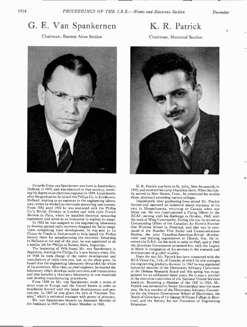
1514 PROCEEDINGS OF THE I.R.E. — Waves and Electrons Section December
G. E. Van Spankernen Chairman, Buenos Aires Section
Gerardo Evan van Spankernen was born in Amsterdam, Holland, in 1907, and was educated in that country, receiv-ing his degree as an electrical engineer in 1929. Immediately after his graduation he joined the Philips Co. in Eindhoven, Holland, starting as an assistant in the engineering labora-tory, where he worked on electronic measuring instruments. From 1932 until 1933 he was stationed with the Philips Co.'s British Division in London and with their French division in Paris, where he installed electrical measuring equipment and acted as an instructor to explain its usage. In 1933 he was assigned to the engineering laboratory
to develop special radio receivers designed for Swiss usage. Upon completing their development, he was sent to Le Chaux de Fonds in Switzerland to help install the Philips factory there for manufacturing the receivers. Returning to Holland at the end of the year, he was appointed to do a similar job for Philips in Buenos Aires, Argentina. The beginning of 1934 found Mr. van Spankernen in
Argentina, starting the Philips Co.'s new factory there. Un-til 1938 he took charge of the entire development and manufacture of radio receivers, but, as the plant grew, he found that the engineering laboratory demanded the whole of his attention. After that, as chief engineer, he headed the laboratory which develops radio receivers and transmitters and also includes a chemistry laboratory to test materials and develop manufacturing procedures. From 1938 on Mr. van Spankernen made a series of
short trips to Europe and the United States in order to familiarize himself with the latest developments and pro-cedures. In 1947 he was given the title of uGerente Tec-nico,” which is technical manager with power of attorney. Mr. van Spankernen became an Associate Member of
the Institute in 1939 and a Senior Member in 1945.
K. R. Patrick Chairman, Montreal Section
K. R. Patrick was born in St. John, New Brunswick, in 1915, and received his early education there. When his fam-ily moved to New Haven, Conn., he continued his studies there, afterward attending various colleges. Immediately after graduating from school Mr. Patrick
formed and operated an industrial sound company of his own in Massachusetts, returning to Canada when war broke out. He was commissioned a Flying Officer in the RCAF, serving until his discharge in October, 1945, with the rank of Wing Commander. During the war he served as Commanding Officer of the Canadian Air Force's Number One Wireless School in Montreal, and also was in com-mand of the Number Five Radar and Communications Station, the joint Canadian-American-British develop-ment and training organization at Clinton, Ont. He re-ceived the O.B.E. for his work in radar in 1943, and in 1945 the American Government presented him with the Legion of Merit in recognition of his services in the research and development of guided missiles. Since the war Mr. Patrick has been connected with the
RCA Victor Co., Ltd., of Canada, of which he now manages the engineering products division. In 1947 he was appointed industrial member of the Electronics Advisory Committee of the Defense Research Board and this spring was re-ap-pointed for an additional three years. He is also a member of the executive committee of the National United Services Institute. Becoming a Member of the IRE in 1943, Mr. Patrick was advanced to Senior Membership later the same year. He is a member of the Electronics Advisory Commit-tee for the Ontario Government School of Electronics, the Board of Governors of Sir George Williams College in Mon-treal, and the Society for the Promotion of Engineering Education.
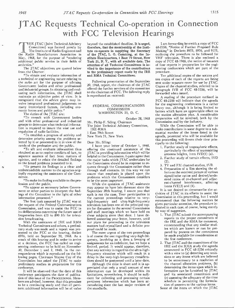
1948 JTAC Requests Co-operation in connection with FCC Hearings 1 5 1 5
JTAC Requests Technical Co-operation in Connection with FCC Television Hearings
ril HE JTAC (Joint Technical Advisory Committee) was formed jointly by The Institute of Radio Engineers and
the Radio Manufacturers Association in May, 1948, for the purpose of "rendering additional public service in their fields of activities." The JTAC objectives are quoted below
from the Charter: "To obtain and evaluate information of
a technical or engineering nature relating to the radio art for the purpose of advising Government bodies and other professional and industrial groups. In obtaining and eval-uating such information, the JTAC shall maintain an objective point of view. It is recognized that the advice given may in-volve integrated professional judgments on many interrelated factors, including eco-nomic forces and public policy." The duties of the JTAC are: "To consult with Government bodies
and with other professional and industrial groups to determine what technical informa-tion is required to insure the wise use and regulation of radio facilities. "To establish a program of activity and
determine priority among the problems se-lected by it or presented to it in view of the needs of the profession and the public. "To sift and evaluate information thus
obtained so as to resolve conflicts of fact, to separate matters of fact from matters of opinion, and to relate the detailed findings to the broad problems presented to it. "To present its findings in a clear and
understandable manner to the agencies orig-inally requesting the assistance of the Com-mittee. "To make its finding available to the pro-
fession and the public. "To appear as necessary before Govern-
ment or other parties to interpret the find-ings of the Committee in the light of other information presented." The first task assumed by JTAC was at
the request of the Federal Communications Commission, and was to assist the FCC in its deliberations concerning the future use of frequencies from 475 to 890 Mc for televi-sion broadcasting. With the assistance of IRE and RMA
Technical Committees and others, a prelimi-nary study was made and a report was pre-sented to the FCC at the hearing, docket 8976, held on September 20, 1948. As a result of this hearing and in order to arrive at a decision, the FCC has called an engi-neering conference to be held on November 30, December 1 and 2, 1948. In the cor-respondence which is reproduced on the fol-lowing pages, Chairman Wayne Coy of the Commission has asked the JTAC to make preliminary studies in preparation for this conference. It will be observed that the date of this
conference anticipates the date of publica-tion of this issue of the PROCEEDINGS. Me m-bers are advised, however, that this promises to be a continuing study and that all perti-nent additional information will be of value
beyond the established deadline. It is urged, therefore, that the membership of the Insti-tute co-operate in supplying the Secretary of the JTAC, L. G. Cumming, at the In-stitute Headquarters, 1 East 79 Street, New York 21, N. Y., with all available data. The attention of all Technical Committees is in-vited to the importance of the contributions to the preliminary report made by the IRE and RMA Technical Committees.
Following presentation of the September 20, 1948, report, the chairman of the JTAC offered the further services of the committee to the chairman of FCC. The following reply is reproduced as received:
FEDERAL COMMUNICATIONS COMM ISSION
WASHINGTON 25, D. C.
October 28, 1948 Mr. Philip F. Siling, Chairman The Joint Technical Advisory Committee, IRE-RMA
1 East 79th Street New York 21, New York
Dear Mr. Siling: I have your letter of October 1, 1948,
offering the continued assistance of the JTAC in providing information which will be helpful to the Commission. I quite agree that the major tasks which JTAC undertakes for the Commission should be in response to re-quests through the Commission rather than through staff contacts. In this way we can assure that emphasis is placed upon the problems which the Commission considers to be the more important. While the question of JTAC assistance
may appear to have lain dormant since the September 20th hearing, I assure you that such is not the case. Your participation in the current proceedings relative to very-high-frequency and ultra-high-frequency television has been one of the principal top-ics for discussion in the several Commission and staff meetings which we have held on these subjects since that date. I have de-ferred answering your letter, however, until our plans for proceeding in the television matters had crystallized and a definite pro-posal could be made. The more urgent of the two proceedings
is of course the one regarding very-high-fre-quency, involving as it does a freezing of assignments for an indefinite, but we hope a limited, period. It would appear, therefore, that any activity in regard to the ultra-high-frequency situation which will result in a delay in the very-high-frequency considera-tions should be postponed until a later date. Although the time is short and it is ap-
preciated that only a small amount of new information can be developed within its limitations, nevertheless, it should be suffi-cient for collecting and processing certain pertinent information which has been ac-cumulating since the last major revision of the standards.
I am forwarding herewith a copy of FCC 48-2256, "Notice of Further Proposed Rule Making" in Dockets 8975, 8976, and 9175, outlining the procedure to be followed for VHF television. There is also enclosed a copy of FCC 48-1966, the notice of issuance of four reports in preparation for the engi-neering conferences which are part of the procedure. Ten additional copies of the notices and
ten copies of each of the reports are being sent under separate cover for use by JTAC. Copies of the channel studies, referred to in paragraph IVB of FCC 48-2256, will be forwarded when issued. A reading of the procedure outlined in
FCC 48-2256 will indicate that the agenda for the engineering ccnferences is a rather heavy one, although it is being limited to factors which have an appreciable effect on the station allocation plan. A considerable preparation will be involved, both by the Commission and by the Industry. While the Commission will be able to
make contributions in some degree to a sub-stantial number of the items listed in the agenda, personnel who will be available for this proceeding will devote their time prin-cipally to the following: 1. Further study of tropospheric effects, particularly the effect of transmitting antenna heights, Item IVD(1) (a).
2. Further study of terrain effects, IVD (2).
3. TV and FM channel studies, IVB. 4. Preparation of a film showing the ef-fects on the received picture of various signal/noise ratios and desired/unde-sired ratios of co-channel and adjac-ent-channel interference, affecting items IVE(3) and (4).
It is not desired to circumscribe the ac-tivities of JTAC in its efforts to assist the Commission in this proceeding, but I would recommend that the following matters be given particular attention, the procedure in-dicated in each case, of course, being merely by way of suggestion. I. That JTAC submit the accompanying reports to the proper committees of the IRE and the RMA for comment, recommending that any similar stud-ies which are known or can be pre-pared by persons on the committees be made available for consideration at the first conference.
2. That JTAC and the committees of the IRE and the RMA study the agenda announced in FCC 48-2256 critically with a view to (a) detecting any omis-sions or any items which are believed to be unnecessary to a resolution of the channel allocation problems, (b) determining the items upon which in-formation can be furnished by JTAC and its associated committees and (c) assessing the adequacy of the time schedule in permitting the formula-tion of answers to the various items.
Some of the items on which the JTAC
1516 PROCEEDINGS OF THE I.R.E. — Waves and Electrons Section December
and its committees can be of particular as-sistance are the following: IVD(3) Antennas. In addition to trans-mitting antennas and the practicability of assuming directional operation in the allocation plan, practical receiving an-tennas and their directional effects should be considered. IVE(3) Re-examination of co-channel and adjacent-channel ratios, on the basis of test data to be furnished by the manufacturers of various commercial re-ceivers. IVE(4) Re-examination of contours in-volving: a. Noise and interference levels in urban and suburban areas at vari-ous frequencies.
b. Noise figures for commercial receiv-ers.
c. Acceptable signal/noise ratios. d. Typical receiving antennas and transmission lines.
IVE(6) & (7) Present capabilities of power generation for frequencies between 54 and 216 megacycles. The JTAC may desire to furnish answers
to items other than those which I have listed and should, of course, feel perfectly free to do so. Complete or partial answers to some of the items may be found in previous information furnished by JTAC, in which case the reply should so indicate, with ap-propriate references. Do not hesitate to call upon the Com-
mission if further details or clarification of our request is desired.
Sincerely yours, Wayne Coy, Chairman
Enclosures
The FCC Notice 48-2256 referred to above is here reproduced:
Received October 18, 1948 FCC 48-2256 27297
FEDERAL COMMUNICATIONS COMMISSION
Washington, D. C.
In the Matter of
Amendment of Section 3.606 of the Commission's Rules and Regulations
In the Matter of
Amendment of the Commis-sion's Rules, Regulations and Standards concerning the Television and Fre-quency Modulation Broad-casting Services.
Docket Nos. 8975 and 8736
Docket No. 9175
Notice of Further
Proposed Rule Making
I. Notice is hereby given of further pro-posed rule making in the above-entitled mat-ter. 11. During the hearing held by the Com-
mission in the above-entitled proceeding (Docket Nos. 8975 and 8736) to consider proposed revisions of the Commission's table
of television channel allocations, evidence was presented concerning (A) tropospheric interference to existing and proposed televi-sion stations, (B) the use of directional an-tennas, (C) the use of increased power, and (D) conflicting proposals for closer spacing and wider spacing between television sta-tions than is presently provided for by the Commission. In order to assure that the Commission's national television allocation plan should be based on the soundest engi-neering foundation, an Industry-Commis-sion Conference was held on September 13 and 14, 1948. The issues for decision at the Conference were: "1. Whether the Commission should initi-
ate proceedings to revise the televi-sion allocation rules and standards prior to final decision in Dockets 8975 and 8736.
2. If the standards are to be revised, what policy should be adopted with respect to applications now pending before the Commission.
3. What procedures should be adopted in order that the revised standards can be based on the best available engi-neering information."
III. At the conclusion of said Conference it was announced that the Commission would call an engineering conference to con-sider questions regarding revisions of the Commission's Rules, Regulations and Stand-ards with respect to the technical phases of television allocations. This Notice deals with issues "1" and "3" set forth above. On September 30, 1948, the Commission issued its Report and Order herein concerning issue number "2." Further, since the Frequency Modulation Broadcasting Service is directly affected by any action taken with respect to propagation in the VHF band, revisions of the Rules, Regulations and Standards of that service is made a part of this proceed-ing. IV. In order to facilitate and expedite
the promulgation of rules, regulations and standards herein, the following schedule will be followed: (A) On or about October 20, 1948, the
Commission will make public: (1) A report containing (a) a summary of
available measurements of tropo-spheric fields, (b)empirical method of treating measurements to formulate field intensity vs distance curves for various frequencies for various per-centages of the time and (c) repre-sentative tropospheric field intensity curves for antenna heights of 500 feet and 30 feet for various frequen-cies and percentages of time derived by the foregoing method.
(2) A study of the effects on service of the simultaneous fading of both the desired and undesired fields from tropospheric causes. A report on measurements made at Princeton, Southampton and Laurel on frequencies of 47.1, 106.5 and 700 Mc. radiated from transmitters in New York City.
(4) A study of the effects of terrain upon average signal levels as compared to smooth earth values and upon the variability of signal levels within limited areas.
(3)
(B) On or about November 15, 1948, the Commission will make public: (1) A TV channel study showing the ef-
fects of ground wave and tropo-spheric interference on representative service areas of stations allocated in accordance with the Commission's Notice herein of May 5, 1948, as amended in the Commission's Sup-plemental Notice of July 15, 1948.
(2) A TV channel study in a representa-tive area showing the effects of ground wave and tropospheric inter-ference on the service areas of pres-ently operating stations and CP's, but with other allocations spaced so as to protect the 500 u/m contours 90% of the time. (All allocations to be based on 50 kw/500 ft. in the center of the principal city).
(3) Channel study for FM showing the effects of ground wave and of tropo-spheric interference for 1% and 10% of the time on representative chan-nels.
(C) On or about November 30, 1948, December 1, 1948 and December 2, 1948, the Commission will hold a series of engineering conferences in Washington, D. G.1 All inter-ested persons are invited to attend said con-ferences, participate fully therein, and to submit written data, views, or arguments with respect thereto. To assist the Commis-sion in the expeditious conduct of said con-ferences, it is requested that persons who plan to participate therein file (by letter) notice of their intention to do so at least one week prior to the date of commencement of said conferences. Written statements may be filed on or before the dates of the respective conferences. (D) The first conference to be held on or
about November 30, 1948, will be on VHF propagation standards to arrive at standard methods of evaluating the effects upon propagation of the following factors: (1) Tropospheric effects—
(a) Variations with time in the field intensities to be expected at vari-ous distances from the transmit-ter, as functions of transmitting antenna height and of frequency.
(b) Range of diurnal variations. (c) Range of seasonal variations. (d) Effects on service of the simul-
taneous fading of both the de-sired and undesired signals.
(2) Terrain effects— (a) Shadows—relation of the aver-
age field intensity in a limited area or limited section of a radial to calculated values as a func-tion of the profile between the area and the transmitter.
(b) Urban field intensities—validity of the FCC standards on Ground Wave Signal Range charts for predicting near-in fields in city areas.
(c) Local terrain effects—variabil-ity of field intensities as com-pared to the average over a limited area or distance.
(d) Receiving antenna height-gain factor-validity of assuming a
The exact date and place of each conference w.11 be announced at a later date.
1948 JTAC Requests Co-operation in Connection with FCC Hearings 1517
(3)
uniform variation of field inten-sity with receiving antenna height for relating mobile measure-ments made at low antenna height to the standard receiving antenna height of 30 feet. Con-sideration of the alternative method of spot measurements at 30 feet height.
(e) Apparent transmitting antenna height—validity of the 2-10 mile rule for estimating the ap-parent height of the transmit-ting antenna. Validity of the method presently prescribed in the Commission's Standards for equalizing cover-age obtained by transmitters of varying antenna heights and power.
Antennas— (a) Practical limitations on vertical
and horizontal directivity of transmitting antennas.
(b) Methods for establishing and maintaining the performance of directional antennas.
(c) The engineering basis for utiliz-ing horizontal directivity in allo-cation problems.
(E) The second conference to be held on or about December 1, 1948, will consider the following items with respect to VHF televi-sion broadcasting: (1) Tropospheric effects:
(a) Specification of grade or grades of service resulting from varia-tions in the intensities of desired and undesired fields.
(b) Discussions of the effects of the specification of various grades of service on particular channel al-location plans.
(c) The development of standard tropospheric curves for various frequencies and antenna heights, calculated in accordance with methods approved at the propa-gation conference.
(2) Examination of current standards for the prediction of service areas to de-termine whether any modifications are dictated by the terrain effects considered in the propagation con-ference. Re-examination of co-channel and adjacent channel ratios at the re-ceiver terminals in the light of more
.(3)
(f)
recent information; and a determina-tion whether a terrain factor should be included in the field intensity ratios.
(4) Re-examination of the contours specified for protection and for recog-nized service levels at various fre-quencies. Re-examination of assumptions as to typical receiving antenna heights for urban and rural areas and of meth-ods of proving station performance by measurement of received fields at such heights.
(6) Examination of the effects of hori-zontal increases in power upon pro-tected contours in the channel allo-cation plans. Examination of the effects of differ-ential increases in power on the pro-tected contours and on the allocation plans. Examination of the effects of direc-tional antennas on allocation plans.
(F) The third conference to be held on or about December 2, 1948, will consider the following items with respect to FM broad-casting: (1) Tropospheric effects:
(a) Specification of grade or grades of service resulting from varia-tions in the intensities of desired and undesired fields.
(b) Study of the areas provided with various grades of service under the present channel assignments and under the tentative alloca-tion plan.
(c) The development of standard tropospheric curves for various antenna heights, calculated in accordance with methods ap-proved at the propagation con-ference.
(2) Examination of current standards for the prediction of service areas to de-termine whether any modifications are dictated by the terrain effects considered in the propagation con-ference. Re-examination of assumptions as to typical receiving antenna heights for urban and rural areas and of meth-ods of proving station performance by measurement of received fields at such heights.
V. Authority to issue amendments of the Commission's Rules, Regulations and
(5)
(7)
(8)
(3)
Standards with respect to the matters to be discussed at the conferences listed above is vested in the Commission by Sections 301, 303(b), (c), (d), (f), (h) and (r), and 4(i) of the Communications Act of 1934, as amended. VI. In accordance with the provisions
of Section 1.764 of the Commission's Rules and Regulations, an original and 14 copies of all written data, views, or arguments filed shall be furnished the Commission.
FEDERAL COMMUNICATIONS COMMISSION
T. J. Slowie, Secretary Adopted: October 14, 1948 Released: October 15, 1948
THE JOINT TECHNICAL ADVISORY COMMITTEE
THE INSTITUTE OF RADIO ENGINEERS, INC.
RADIO MANUFACTURERS ASSOCIATION
Pursuant to this letter, the chairman of JTAC addressed the following letter to the chairmen of all Technical Committees and other interested groups:
October 29, 1948 Dear Sir:
As you doubtless know, the FCC has scheduled tentatively a three-day engineer-ing conference for November 30, December 1 and 2. The schedule for this engineering con-ference is included in the attached FCC re-lease and requests information on propaga-tion and allied subjects in the vhf portion of the spectrum, particularly as it affects standards and allocation problems of the television and FM services. The Commission, through the letter copy
attached, has requested the JTAC to assist in the collection of information for this con-ference. Accordingly, JTAC is requesting the assistance of engineering groups within the RMA and IRE, as well as other industry groups. As Chairman of one of these groups, we urgently request that you read carefully the attached material from the FCC. The JTAC will greatly appreciate any
information, engineering data, and com-ments regarding these subjects that you may be able to submit by November fifteenth to the Office of the Secretary.
Sincerely, PHILIP F. SILING
Enclosures 2
1518 PROCEEDINGS OF THE I.R.E. — Waves and Electrons Section December
Electronics in Nuclear Physics W . E. SHOUPPt
The publication in the PROCEEDINGS OF THE I.R.E. of a series of papers on nuclear particles and phenomena, and on electronic in-strumentation and control of nuclear processes, continues through the presentation of the following paper. This paper clearly sets forth certain fundamental ndcleonic facts, their relationship to electronics, and some of the many and intriguing opportunities offered to the electronics expert who enters the nuclear field.—The Editor.
INTRODUCTION
/N AN EFFORT to determine where the science of electronics crosses the path of nucleonics and just what are the results when they meet, it will be
necessary to define reasonably well the two words "elec-tronics" and "nucleonics." The word "electronics" re-quires little discussion here; however, it may be inter-esting to try to put a definition into words. _ Generally speaking, electronics embraces all phe-
nomena associated with the passage of electric cur-rents through gases and high vacua.' Such phenomena may be utilized for many purposes, such as the genera-tion, amplification, and detection of high-frequency electrical oscillations, and the production of light from electric current, as well as the converse process. The propagation processes and the study of interstellar radiations are likewise included. Studies concerning the acceleration, generation, and use of atomic particles and radiations may also be included in electronics. Electronics may then be defined as that science, art,
and industry concerned with electrical phenomena in-volving electrically charged atomic particles outside of liquids and solids. Under this definition we have in-cluded phenomena other than those due to the action of electrons. Now, if we define nucleonics, we may see where the
two fields fit together or possibly overlap, and it may be possible to draw some conclusions as to their inter-action. The nucleus is supposed to be made up of parti-cles called "nucleons." Until recently it was supposed that protons and neutrons in combination make up all nuclei. In line with recent meson theory, this does not necessarily follow; however, the term nucleon will usually refer to a nuclear proton or neutron. Nucleonics, then, is the science dealing with the rearrangement, transformation, and utilization of the nucleons. This in-cludes nuclear synthesis, radioactivity, nuclear fission, and their applications. We will not expect interactions between electromagnetic waves of the microwave and radio spectrum and the fundamental nuclear particles and radiations because of the vast difference in wave-length. Electronics will, therefore, be of chief im-
• Decimal classification: 621.375 X539.7. Original manuscript re-ceived by the Institute, August 26, 1948. t Westinghouse Research Laboratories, East Pittsburgh, Pa. 1 E. U. Condon, Bull. Nat. Electronics Con.; 1946.
portance in observing the physical processes that occur in ordinary and induced nuclear phenomena. In fact, if electronics is to influence nucleonics, it must be in the course of the discovery, production, measurement, con-trol, use, or disposal of nuclear substances. The better to see just how this may come about, a brief discussion of some of the general properties of nuclei is necessary. Most radioactive substances that are generally avail-
able are generated in the nuclear reactor commonly called a "pile." After looking into the operation prin-ciples of the pile, the characteristics of its radiations, and its radioactive products, it will be possible to point out where electronics may contribute to the tech-nology of nuclear processes through the fabrication and location of the proper materials for pile construction, the control of the pile during operation, or the utilization of the products manufactured within the pile.
THE URANIUM PILE OR NUCLEAR REACTOR
The active ingredient of the pile is uranium, usually in the metallic form. The largest known deposit was discovered in Northern Canada, where it is found to exist in the form of the uranium-oxide complex U(U04)2. Already we have met electronics head-on, because our modern uranium prospector who made the discovery used a Geiger-counter radiation detector to find the ore, which is a radioactive material. The detector used here is not so complex as some other electronic equip-ment, but is a model of compactness, reliability, and clever electronic engineering. Detectors of this type haye been made that weigh less than four pounds and are sometimes powered by four flashlight cells. The uranium oxide, after being discovered and mined,
is reduced to pure metallic uranium and is found to have a specific gravity of 18.7, an atomic weight of 238.07, and a melting point of 1150°C. It is also known that 99.3 per cent of the metallic material is composed of the heavy isotope 92U and 0.7 per cent is 92U2 .
Suppose, now, that after considerable mining and chem-ical reduction we have accumulated sufficient uranium metal to set up a self-sustaining fission reaction in an assembly called a nuclear reactor or pile. The essential thing about the process of uranium
fission is that the uranium atom falls apart in such a way as to produce two more or less equal fragments— and to liberate several more free neutrons. It is this neu-
1948 Shoupp: Electronics in Nuclear Physics 1519
tron liberation that makes a self-maintaining process possible. The splitting requires a neutron to make it go; the splitting process itself acts as a source of neutrons which can cause more uranium atoms to split. Here is the basis for a chain reaction.' Why, then, does not ordinary uranium explode, or at
least "burn," in a nuclear sense? Since several neutrons are released at every fission, a chain reaction is possible. But one of the several neutrons released must actually produce another fission to keep the process going. If all the neutrons released produced more fissions,
the material would explode violently. Since the neu-trons move rather freely through matter (like X rays) many are lost by escaping through the surface. Conse-quently, it is necessary to use a big enough lump of fissionable material to get a smaller surface-to-volume ratio. In other words, unless the lump exceeds a cer-tain critical size, the chain reaction cannot proceed. Another complication is that impurities in the
uranium have a powerful effect on the neutron loss through absorption. This loss of neutrons is very diffi-cult to obviate, for appreciable losses result from the presence of only one part per million of some materials, and it is no easy matter to produce anything of that purity on an industrial scale. The worst complication of all is that uranium itself
absorbs neutrons in other ways than those that pro-duce fission. This phenomenon is both a blessing and a curse. It turns out, fortunately, that the over-all effect of this nonfission absorption of neutrons by uranium is sufficiently great to prevent the explosion of perfectly pure uranium, in normal isotopic abundance, even in so large a lump that escape of neutrons through the sur-face is negligible. Neutrons given out in the fission process are "fast";
that is, they possess speeds corresponding to several million electron volts of kinetic energy. Such fast neu-trons colliding with uranium atoms have a rather great chance of losing energy without being caught and with-out producing fission. On the other hand, neutrons of intermediate speed are unable to produce fission in Um. They can do so only in U2", which forms only 1/140 part of natural uranium. Neutrons of a particularly low energy (about 10 elec-
tron volts) are very like to be captured by U2" to form Us". This is very important! In fact, this happens so readily that so many neutrons are 'used up in this process that a chain reaction cannot be maintained in ordinary uranium alone. An uncaptured neutron continually loses energy by
colliding with atoms as it diffuses throughout any material, until its average energy is that of the heat motion of the atoms of the material. Neutrons of cer-tain extremely low energies are strongly captured by U235 to produce fission.
2 E. U. Condon, Westinghouse Eng., vol. 5, pp. 3,9; November, 1945.
To cause and maintain a chain reaction with ordinary -
pure metallic uranium, which contains all kinds of uranium atoms but is predominantly U 238 , the uranium is arranged in a lattice of small lumps so that many of the fast-moving neutrons diffuse out of the uranium into some surrounding material. Here many of them are slowed down before diffusing back into the uranium. Most neutrons thus escape being caught by Um until they have lost so much energy that capture by U23" is unlikely. Ultimately, unless the neutrons are lost in the surrounding medium, they return to the uranium lumps and are sufficiently reduced in speed to cause fission in U2", but have energies too low to be captured by U238 . In the technical vocabulary of nuclear engineering,
the material that temporarily traps the neutrons and helps them lose energy until they are safe from capture by U2" is called the "moderator." Evidently the moderator material must not absorb too many neu-trons itself, or the reaction will be stopped. Besides not absorbing neutrons, a desirable moderator has a low atomic weight. For, to be slowed most efficiently, the neutrons are allowed to collide elastically with the nuclei of the moderator material. More energy is given up at each impact if the two partners of the collision have nearly the same mass. The hydrogen content of ordinary water (H20) would
be ideal with respect to mass, but ordinary hydrogen absorbs too many neutrons. Heavy water (D20) is satisfactory from a neutron-absorption standpoint, but is not generally available in sufficient quantity. Metallic beryllium is a possibility, but is quite expensive. There-fore, specially purified graphite was finally adopted in the original piles constructed. In a typical graphite-moderated pile a neutron that has escaped from the uranium into the graphite travels roughly about 1 inch between collisions and makes, on an average, 200 elastic collisions before returning to the uranium, losing about of its energy in each collision. A chain reaction is then possible, but since the nuclear
fission process takes place in very short time and with considerable evolution of energy, how can the pile be kept from blowing up? If a pile is so arranged that, on the average, more than one fission results from the neutrons produced by each fission, then clearly the number of neutrons present, and the amount of heat generated, increase by the compound-interest law. If a great multiplication happens rapidly—say, in a small fraction of a second—then the phenomenon becomes an explosion. In short, we have an atomic bomb. Even if the reaction occurs slowly, the pile would soon be de-stroyed by melting if the multiplication were allowed to proceed. One way to control the pile' is to provide passage-
ways through it into which rods of material that strongly
$ H. D. Smyth, "Atomic Energy," Princeton University Press, 1945; p. 135.
1520 PROCEEDINGS OF THE I.R.E. — Waves and Electrons Section December
absorb neutrons can be placed. When these rods are all the way in, they absorb so many neutrons that the chain reaction is stopped. As they are slowly withdrawn, a point is reached at which the reaction is just able to proceed. If pulled out farther, the neutrons are able to multiply more rapidly and the pile operates at a higher power level. To stop the pile the absorbing rods are simply pushed back in farther. Cadmium and boron-containing steel are suitable materials for the control rods. We have so far assumed that the build-up time for
the chain reaction used in the pile is long enough for an operator to maintain control by manual operation of the rods or by usc of a similar slow-acting control mechanism. That is in fact the case, due to another fortunate phenomenon in the fundamental physics of fission—delayed neutrons. It was discovered in May, 1942, that not all neutrons
emitted in the fission process come out instantly. The uranium nuclei in splitting apart spill out most neutrons immediately. But the atomic fragments formed are also in a highly unstable condition and some of them throw out additional neutrons after a short time delay, amounting on the average to half a minute. It is the delayed ones that set the time scale on which the neutron multiplication in the pile builds up. They set it for such a long time that slow-acting controls are easily able to regulate the activity of the pile. In fact, 1 per cent of the neutrons are delayed by at least 0.01 second and 0.07 per cent are delayed by as much as a minute.' Here is an ideal chance for electronics to contribute.
The delayed neutrons do provide a bit of time to acti-vate controls, but sensing and control-activating meth-ods are necessary. It is presumably possible to measure the temperature within a pile by appropriate sensing elements such as bolometers or thermocouples, and to use the temperature level so measured properly to posi-tion the control rods. It would also seem feasible to measure the neutron intensity at some arbitrary point, and to use the signal thus obtained to operate the controls. In any event, electronic controls for the drive motors operating the control rods seems to be indicated. This is particularly true since operations of this sort probably require antihunting methods and accurate control. Since a nuclear reactor is a very valuable and ex-
pensive machine, it is likewise important that elaborate precautions be taken against operating the pile at such a high level that internal damage to the reactor might occur. Here, again, electronics has an ideal application. More or less standard methods are indicated for this job. There is, however, one missing link. How do we meas-
ure the level of neutron intensity so as to operate our controls and precautionary devices? We have seen that neutrons are nonionizing particles and for that reason we
cannot use exactly the same techniques that we apply to /3 rays, a particles, and the like. What is done is to cause the neutrons to produce an ionizing particle (usually an a particle) and to infer the neutron intensity by counting the number of particles produced. One of the best ways of doing this is to allow the neutron flux to fall upon a chamber, filled with boron-trifluoride gas (BF3) and surrounded by considerable hydrogeneous material, usually about 10-cm thickness of paraffin. The neutrons entering the paraffin will be slowed down by making elastic collisions with the hydrogen in the paraffin and then will become very active in causing the following nuclear reaction to occur:
5Blo + on' 3Li7 2He'. (1) In this reaction an a particle (2He') of 2.7 Mev is emitted and will produce either a pulse in an ionization chamber or will trigger a Geiger or proportional counter. We have here a means for generating electric pulses from neutrons, but electronics must supply all the tech-nology between the sensing element and the control activator. Various types of amplifiers and electronic circuitry are used for this service. It will be the task of succeeding papers by other authors in this series to describe this technology in detail. Suffice it to say that there is need for a vast array of fast and slow pulse amplifiers, dc amplifiers, coincidence circuits, dis-criminators, scaling circuits, and others too numerous to mention. Their use for this and similar applications forms one of the most interesting electronic fields of endeavor today. .Now let us return to the nuclear reactor and see
what else is going on. The first pile was built on the University of Chicago campus during the fall of 1942. It contained 12,400 pounds of uranium together with a graphite moderator. It was intended to be spherical in shape, but since the critical dimensions proved to be smaller than the original calculations indicated, the sphere was left incomplete, giving the actual pile the shape of a large inverted doorknob. It was first operated on December 2, 1942, at a
power level of watt, and on December 12 the power level was stepped up to 200 watts but the pile was not allowed to go higher because of inadequate provision for shielding the personnel. Further studies on piles were made by the construction of one in Tennessee de-signed for 1000-kw level of operation. Later a pile using heavy water instead of graphite as moderator was built. It should be remembered that, although a pile is built
with ordinary uranium, it is only the 0.7 per cent that represents active U2" metal. Most of the metal is Um and actually tends to stop the process. Only by an ingenious lattice arrangement for slowing neutrons in a moderator is the pile able to operate in spite of the presence of the more prevalent U238 . This means that, regarded as a fuel, only 1/140 of the
total weight of uranium is being directly used; the rest
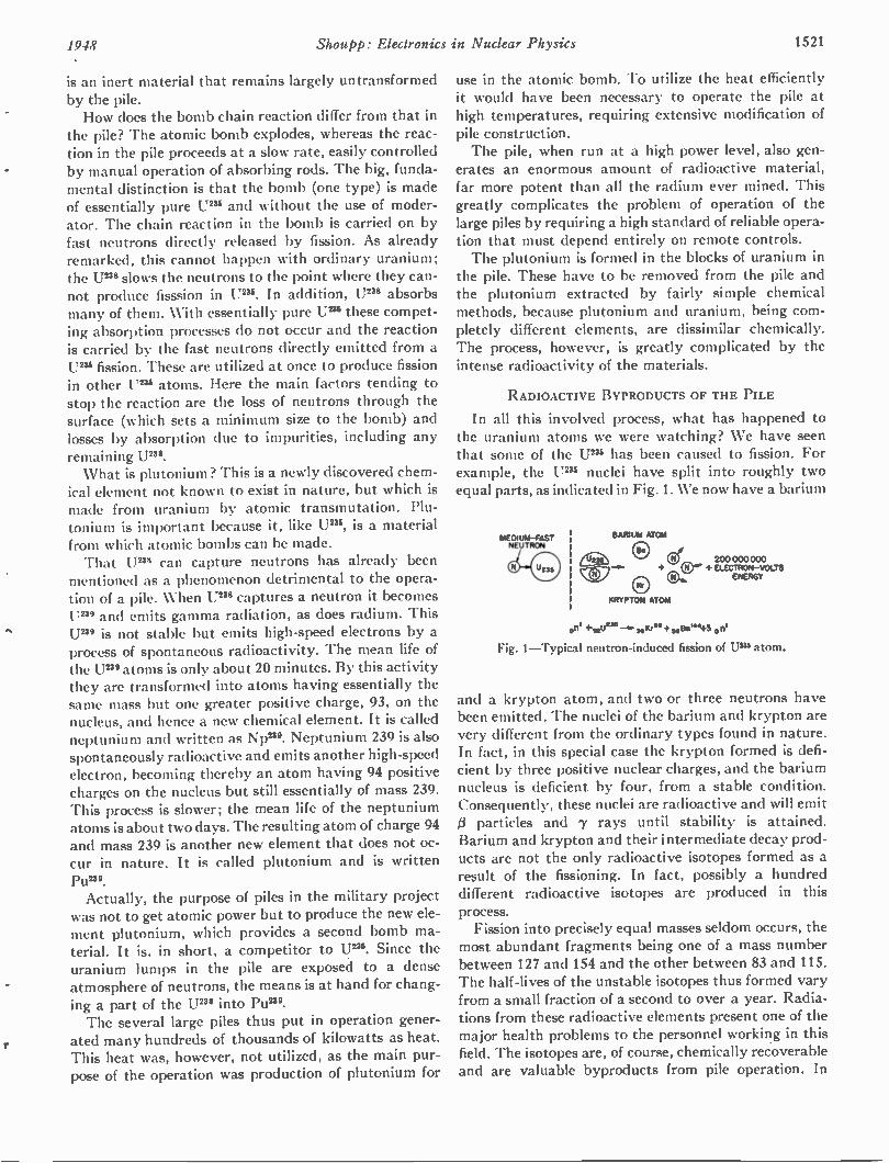
1948 Shoup!): Electronics in Nuclear Physics 1521
is an inert material that remains largely untransformed by the pile. How does the bomb chain reaction differ from that in
the pile? The atomic bomb explodes, whereas the reac-tion in the pile proceeds at a slow rate, easily controlled by manual operation of absorbing rods. The big, funda-mental distinction is that the bomb (one type) is made of essentially pure U238 and without the use of moder-ator. The chain reaction in the bomb is carried on by fast neutrons directly released by fission. As already remarked, this cannot happen with ordinary uranium; the U 239 slows the neutrons to the point where they can-not produce fisssion in U238 . In addition, U2" absorbs many of them. With essentially pure U238 these compet-ing absorption processes do not occur and the reaction is carried by the fast neutrons directly emitted from a U238 fission. These are utilized at once to produce fission in other U2" atoms. Here the main factors tending to stop the reaction are the loss of neutrons through the surface (which sets a minimum size to the bomb) and losses by absorption due to impurities, including any remaining U 238 .
What is plutonium? This is a newly discovered chem-ical element not known to exist in nature, but which is made from uranium by atomic transmutation. Plu-tonium is important because it, like U2", is a material from which atomic bombs can be made. That U2" can capture neutrons has already been
mentioned as a phenomenon detrimental to the opera-tion of a pile. When U2'8 captures a neutron it becomes U2" and emits gamma radiation, as does radium. This U2" is not stable but emits high-speed electrons by a process of spontaneous radioactivity. The mean life of the U 239 atoms is only about 20 minutes. By this activity they are transformed into atoms having essentially the same mass but one greater positive charge, 93, on the nucleus, and hence a new chemical element. It is called neptunium and written as NP"'. Neptunium 239 is also spontaneously radioactive and emits another high-speed electron, becoming thereby an atom having 94 positive charges on the nucleus but still essentially of mass 239. This process is slower; the mean life of the neptunium atoms is about two days. The resulting atom of charge 94 and mass 239 is another new element that does not oc-cur in nature. It is called plutonium and is written Pun'. Actually, the purpose of piles in the military project
was not to get atomic power but to produce the new ele-ment plutonium, which provides a second bomb ma-terial. It is, in short, a competitor to U238 . Since the uranium lumps in the pile are exposed to a dense atmosphere of neutrons, the means is at hand for chang-ing a part of the U 239 into Pu2". The several large piles thus put in operation gener-
ated many hundreds of thousands of kilowatts as heat. This heat was, however, not utilized, as the main pur-pose of the operation was production of plutonium for
use in the atomic bomb. To utilize the heat efficiently it would have been necessary to operate the pile at high temperatures, requiring extensive modification of pile construction. The pile, when run at a high power level, also gen-
erates an enormous amount of radioactive material, far more potent than all the radium ever mined. This greatly complicates the problem of operation of the large piles by requiring a high standard of reliable opera-tion that must depend entirely on remote controls. The plutonium is formed in the blocks of uranium in
the pile. These have to be removed from the pile and the plutonium extracted by fairly simple chemical methods, because plutonium and uranium, being com-pletely different elements, are dissimilar chemically. The process, however, is greatly complicated by the intense radioactivity of the materials.
RADIOACTIVE BYPRODUCTS OF THE PILE
In all this involved process, what has happened to the uranium atoms we were watching? We have seen that some of the U2" has been caused to fission. For example, the Um nuclei have split into roughly two equal parts, as indicated in Fig. 1. We now have a barium
MEDIUM-FAST NEUTRON
BARIUM ATOM
200 000 000 + 0 "" + ELECTRON-VOLTS
ENERGY
KRYPTON ATOM
„ni +mune—v.4.KM+ 0644+3 on'
Fig. 1—Typical neutron-induced fission of U 295 atom.
and a krypton atom, and two or three neutrons have been emitted. The nuclei of the barium and krypton are very different from the ordinary types found in nature. In fact, in this special case the krypton formed is defi-cient by three positive nuclear charges, and the barium nucleus is deficient by four, from a stable condition. Consequently, these nuclei are radioactive and will emit particles and 7 rays until stability is attained.
Barium and krypton and their intermediate decay prod-ucts are not the only radioactive isotopes formed as a result of the fissioning. In fact, possibly a hundred different radioactive isotopes are produced in this process. Fission into precisely equal masses seldom occurs, the
most abundant fragments being one of a mass number between 127 and 154 and the other between 83 and 115. The half-lives of the unstable isotopes thus formed vary from a small fraction of a second to over a year. Radia-tions from these radioactive elements present one of the major health problems to the personnel working in this field. The isotopes are, of course, chemically recoverable and are valuable byproducts from pile operation. In
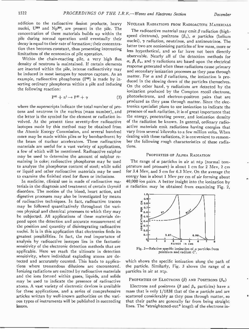
1522 PROCEEDINGS OF THE I.R.E.—Waves and Electrons Section December
addition to the radioactive fission products, heavy nuclei, Um and Np239 , are present in the pile. The concentration of these materials builds up within the pile during normal operation until eventually their decay is equal to their rate of formation; their concentra-tion then becomes constant, thus presenting interesting limitations of the economics of pile operation. Within the chain-reacting pile, a very high flux
density of neutrons is maintained. If certain elements are inserted within the pile, intense radioactivity may be induced in most isotopes by neutron capture. As an example, radioactive phosphorus (1332 ) is made by in-serting ordinary phosphorus within a pile and inducing the following reaction:
1331 ..f. ni 1332 + 7 (2)
where the superscripts indicate the total number of pro-tons and neutrons in the nucleus (mass number), and the letter is the symbol for the element or radiation in-volved. At the present time seventy-five radioactive isotopes made by this method may be obtained from the Atomic Energy Commission, and several hundred more may be made within piles or by bombardment by the beam of nuclear accelerators. These radioactive materials are useful for a vast variety of applications, a few of which will be mentioned. Radioactive sulphur may be used to determine the amount of sulphur re-maining in coke; radioactive phosphorus may be used to analyze the phosphorus content of steel; while solid or liquid and other radioactive materials may be used to examine the finished steel for flaws or inclusions. In medicine, clinical use in made of radioactive ma-
terials in the diagnosis and treatment of certain thyroid disorders. The motion of the blood, heart action, and digestive processes may also be investigated by means of radioactive techniques. In fact, radioactive tracers may be followed quantitatively throughout the vari-ous physical and chemical processes to which they may be subjected. All applications of these materials de-pend upon the detection and accurate measurement of the position and quantity of disintegrating radioactive nuclei. It is in this application that electronics finds its greatest possibilities. In fact, the real importance of analysis by radioactive isotopes lies in the fantastic sensitivity of the electronic detection methods that are applicable. Here we reach the ultimate in detection sensitivity, where individual exploding atoms are de-tected and accurately counted. This leads to applica-tions where tremendous dilutions are encountered. Ionizing radiations are emitted by radioactive materials and the ions formed within gases, liquids, and solids may be used to indicate the presence of radioactive atoms. A vast variety of electronic devices is available for these applications, and a series of comprehensive articles written by well-known authorities on the vari-ous types of instruments will be published in succeeding issues.
NUCLEAR RADIATIONS FROM RADIOACTIVE MATERIALS
The radioactive material may emit radiation (high-speed electrons), positrons (3+), a particles (helium nuclei), 7 radiation, neutrinos, and antineutrinos. The latter two are nonionizing particles of low mass, more or less hypothetical, and so far have not been directly observable. Nearly all of the detection methods for a, p,11+, and 7 radiations are based upon the electrical response generated when these radiations cause primary and secondary ionization processes as they pass through matter. For a and 0 radiations, the ionization is pro-duced in the slowing down of the particles themselves. On the other hand, 7 radiations are detected by the ionization produced by the Compton recoil electrons, photoelectrons, and electron-positron pairs that are produced as they pass through matter. Since the elec-tronics specialist plans to use ionization to indicate the presence of such radiation, it is of great importance that the energy, penetrating power, and ionization .density of the radiation be known. In general, ordinary radio-active materials emit radiations having energies that vary from several kilovolts to a few million volts. When dealing with these radiations, it is convenient to remem-ber the following rough characteristics of these radia-tions.
PROPERTIES OF ALPHA RADIATION
The range of a particles in air at ntp (normal tem-perature and pressure) is about 1 cm for 2 Mev, 2 cm for 3.4 Mev, and 5 cm for 6.3 Mev. On the average the energy loss is about 1 Mev per cm of air forming about 40,000 ion pairs. A better insight into the ionization by a radiation may be obtained from examining Fig. 2,
1.0
0.9 -Z 0.8 -
re 0 7 - la a. 0.6 -
z o 0.5
0.4 =
z- 0.3 - o - 0.2 -
0.1 -
2 6
Fig. 2—Relative specific ionization of a particles from polonium and radium C.
which shows the specific ionization along the path of the particle. Similarly, Fig. 3 shows the range of a particles in air at ntp.
PROPERTIES OF ELECTRONS (3) AND POSITRONS (0+)
Electrons and positrons (/3 and )3+ particles) have a mass that is only 1/1838 that of the a particle and are scattered considerably as they pass through matter, so that their paths are generally far from being straight lines. The "straightened-out" length of the electrons in-
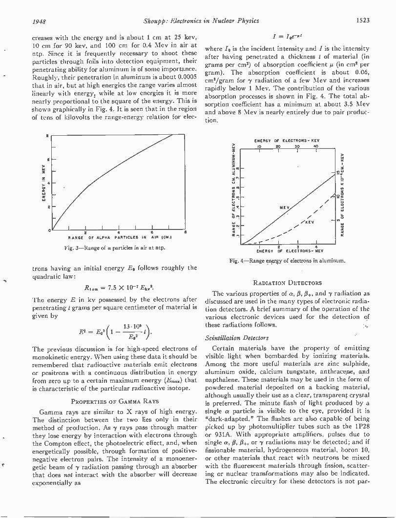
1948 Shoupp: Electronics in Nuclear Physics 1523
creases with the energy and is about 1 cm at 25 key, 10 cm for 90 key, and 100 cm for 0.4 Mev in air at ntp. Since it is frequently necessary to shoot these particles through foils into detection equipment, their penetrating ability for aluminum is of some importance. Roughly, their penetration in aluminum is about 0.0005 that in air, but at high energies the range varies almost linearly with energy, while at low energies it is more nearly proportional to the square of the energy. This is shown graphically in Fig. 4. It is seen that in the region of tens of kilovolts the range-energy relation for elec-
6
4
ta
2
0 2 4 6
RANGE OF ALPHA PARTICLES IN AIR (CM.)
Fig. 3—Range of a particles in air at ntp.
trons having an initial energy E0 follows roughly the quadratic law:
Ruin = 7.5 X 10⁻⁷ Ekv2.
The energy E in kv possessed by the electrons after penetrating t grams per square centimeter of material is given by
E2 = E02(1 13.105
E02
The previous discussion is for high-speed electrons of monokinetic energy. When using these data it should be remembered that radioactive materials emit electrons or positrons with a continuous distribution in energy from zero up to a certain maximum energy (Ems.) that is characteristic of the particular radioactive isotope.
PROPERTIES OF GAMMA RAYS
Gamma rays are similar to X rays of high energy. The distinction between the two lies only in their method of production. As 7 rays pass through matter they lose energy by interaction with electrons through the Compton effect, the photoelectric effect, and, when energetically possible, through formation of positive-negative electron pairs. The intensity of a monoener-getic beam of 7 radiation passing through an absorber that does not interact with the absorber will decrease exponentially as
/ = /0-0
where /0 is the incident intensity and I is the intensity after having penetrated a thickness t of material (in grams per cm2) of absorption coefficient µ (in cm2 per gram). The absorption coefficient is about 0.06, cm2/gram for 7 radiation of a few Mev and increases rapidly below 1 Mev. The contribution of the various absorption processes is shown in Fig. 4. The total ab-sorption coefficient has a minimum at about 3.5 Mev and above 8 Mev is nearly entirely due to pair produc-tion.
ENERGY OF ELECTRONS- REV
10 20 30 40
2 3 4 ENERGY OF ELECTRONS- MEV
Fig. 4—Range energy of electrons in aluminum.
RADIATION DETECTORS
The various properties of a, 13, 13+, and 7 radiation as discussed are used in the many types of electronic radia-tion detectors. A brief summary of the operation of the various electronic devices used for the detection of these radiations follows.
Scintillation Detectors
Certain materials have the property of emitting visible light when bombarded by ionizing materials. Among the more useful materials are zinc sulphide, aluminum oxide, calcium tungstate, anthraceine, apd napthalene. These materials may be used in the form of powdered material deposited on a backing material, although usually their use as a clear, transparent crystal is preferred. The minute flash of light produced by a single a particle is visible to the eye, provided it is "dark-adapted." The flashes are also capable of being picked up by photomultiplier tubes such as the 1P28 or 931A. With appropriate amplifiers, pulses due to single a, 13, 13+, or 7 radiations may be detected; and if fissionable material, hydrogeneous material, boron 10, or other materials that react with neutrons be mixed with the fluorescent materials through fission, scatter-ing or nuclear transformations may also be indicated. The electronic circuitry for these detectors is not par-
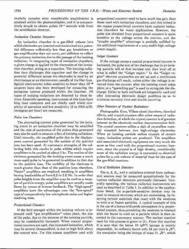
1524 PROCEEDINGS OF THE I.R.E.— Waves and Electrons Section December
ticularly complex since considerable amplification is attained within the photomultiplier, and it is compara-tively simple to obtain pulses 10-7 seconds wide from the scintillation detector.
Ionization Chamber Detectors
An ionization chamber is a gas-filled volume into which electrodes are inserted and maintained at a poten-tial difference sufficiently low that gas breakdown or gas amplification does not occur, yet sufficient to collect the primary ionization due to the passage of the ionizing radiation. In integrating types of ionization chambers, a given charge is applied to the electrodes of the ioniza-tion chamber, acting as a capacitor. The ionizing radia-tion then discharges this capacitor and the change in potential difference across the electrodes is read by an electroscope or an electrometer, usually of the filar type. Special electrometer tubes sensitive to lower than 10-'6 amperes have also been developed for measuring the ionization current produced within the chamber. All types of ionizing radiations are detected by these de-vices. Generally speaking, instruments of this type have long time constants and are chiefly used where sim-plicity of operation and low sensitivity (2 to 5000 milli-roentgens per hour) are measured.
Pulse Ion Chambers
The alternating-current pulse generated by the ioniz-ing event in an ionization chamber may be amplified and the rate of occurrence of the pulses thus generated may also be used to measure a flux of ionizing radiations. Until recently, the amplified pulse due to the displace-ment current generated by the motion of the positive ions has been used. At customary strengths of the col-lecting field, this results in pulse widths which require amplifiers to be peaked at about 1 kc. The motion of the electrons generated by the ionizing event cause a much more rapid pulse to be generated in addition to that due to the positive ions. The mobility of the electrons is much greater than that of the positive ions; therefore, "faster" amplifiers are required, resulting in amplifiers having bandwidths of from 0.2 to 2.0 Mc. In order that pulse heights from the amplifier may be used as a meas-ure of particle energy, pulse amplifiers are usually made linear by means of inverse feedback. The "high-speed" amplifiers have the advantages over the "low-speed" type of comparatively low microphonic noise and higher resolving time.
Proportional Counters
If the field strength within the ionizing volume is in-creased until "gas amplification" takes place, the size of the pulse, due to the traverse of the ionizing particle, may be considerably increased. When coaxial propor-tional counters are used, this increased ionization, which may be several thousandfold, is due to high field about the central wire. For this reason amplifiers used with
proportional counters need to have much less gain than those used with ionization chambers, and this indeed is the reason proportional counters have replaced ioniza-tion chambers for many applications. However, the pulse size obtained from proportional counters is quite sensitive to the voltage across the counter, and the "simpler amplifier" advantage is partially nullified by the additional requirement of a very stable high-voltage power supply.
Geiger Counters
If the voltage across a coaxial proportional counter is increased, the pulse size of the discharge due to an ioniz-ing particle will at first increase and then level off at what is called the "Geiger region." In the "Geiger re-gion" electron avalanches are set up and a continuous gas discharge will result, unless either the voltage is re-moved from the counter after the ionizing event takes place, or a "quenching gas" is used to extinguish the dis-charge. Either or both methods are frequently used and offer interesting electronic design problems so as to minimize recovery time and double counting.
Other Detectors of Nuclear Radiations
Photographic films, Wilson cloud chambers, chemical effects, and crystal counters offer other means of radia-tion detection, of which the crystal counter is of greatest interest to the electronic nuclear instrumentation field. The crystal counters utilize a slab of crystalline mate-rial mounted between two high-voltage electrodes. When an ionizing particle strikes crystals of certain types, ionization pulses are produced. The amplifiers and associated electronic equipment are very much the same as that used with the proportional counter; how-ever, since the crystal is of high density, considerably more of the radiation energy is converted to electrical pulses for a unit volume of material than for the case of the gas-filled counters.
Use of Radiation Detectors
The a, 0, /3+, and 7 radiations emitted from radioac-tive sources may be measured quantitatively by the various radiation detectors previously discussed. Gen-erally speaking, the various radiation instruments are used as described in Table I. In addition to the applica-tions listed, the a-particle-sensitive devices may be used to measure neutrons, which are nonionizing, by in-serting certain materials that react with the neutrons to emit a or fission particles. A typical example of this is the use of a boron-trifluoride atmosphere in a propor-tional counter, thus permitting the neutrons to interact with the boron to emit an a particle which is then re-corded in the customary manner. The nuclear reaction used for this process is given in (1). From this reaction it is seen that the boron 10 (613'°) isotope is mainly responsible. In ordinary boron only 18 per cent is 6B'°, the remainder being the isotope of mass 11, 6B", which
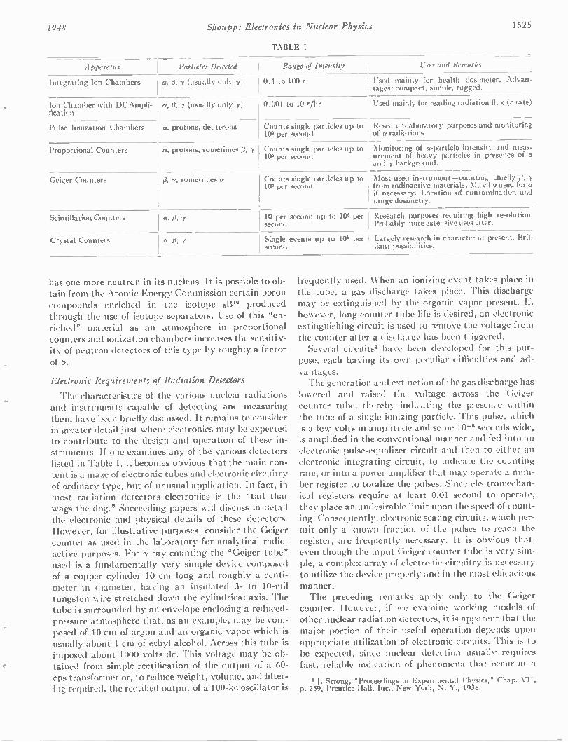
1948 Shoupp: Electronics in Nuclear Physics 1525
TABLE I
Apparatus Particles Detected
Integrating Ion Chambers a, d, 7 (usually only 7)
Ion Chamber with DC Ampli-fication
Pulse Ionization Chambers
a, d, 7 (usually only 7)
Range of Intensity Uses and Remarks
0.1 to 100 r Used mainly for health dosimeter. Advan-tages: compact, simple, rugged.
0.001 to 10 r/hr
a, protons, deuterons Counts single particles up to 10 per second
Proportional Counters
Used mainly for reading radiation flux (r rate)
Research-laboratory purposes and monitoring I of a radiations.
a, protons, sometimes 8, 7 Counts single particles up to 104 per second
' Monitoring of a-particle intensity and meas-urement of heavy particles in presence of ' and 7 background.
Geiger Counters -y, sometimes a Counts single particles up to 103 per second
Most-used in-trument —counting chiefly from radioactive materials. May be used for a if necessary. Location of contamination and range dosimetry.
Scintillation Counters a, 0, 7 10 per second up to 10° per second
Crystal Counters a, 0.
Research purposes requiring high resolution. Probably more extensive uses later.
Single events up to 10° per Largely research in character at present. Bril-second liant possibilities.
has one more neutron in its nucleus. It is possible to ob-tain from the Atomic Energy Commission certain boron compounds enriched in the isotope 513u) produced through the use of isotope separators. Use of this "en-riched" material as an atmosphere in proportional counters and ionization chambers increases the sensitiv-ity of neutron detectors of this type by roughly a factor of 5.
Electronic Requirements of Radiation Detectors
The characteristics of the various nuclear radiations and instruments capable of detecting and measuring them have been briefly discussed. It remains to consider in greater detail just where electronics may be expected to contribute to the design and operation of these in-struments. If one examines any of the various detectors listed in Table I, it becomes obvious that the main con-tent is a maze of electronic tubes and electronic circuitry of ordinary type, but of unusual application. In fact, in most radiation detectors electronics is the "tail that wags the dog." Succeeding papers will discuss in detail the electronic and physical details of these detectors. However, for illustrative purposes, consider the Geiger counter as used in the laboratory for analytical radio-active purposes. For 7-ray counting the "Geiger tube" used is a fundamentally very simple device composed of a copper cylinder 10 cm long and roughly a centi-meter in diameter, having an insulated 3- to 10-mil tungsten wire stretched down the cylindrical axis. The tube is surrounded by an envelope enclosing a reduced-pressure atmosphere that, as an example, may be com-posed of 10 cm of argon and an organic vapor which is usually about 1 cm of ethyl alcohol. Across this tube is imposed about 1000 volts dc. This voltage may be ob-tained from simple rectification of the output of a 60-cps transformer or, to reduce weight, volume, and filter-ing required, the rectified output of a 100-kc oscillator is
frequently used. When an ionizing event takes place in the tube, a gas discharge takes place. This discharge may be extinguished by the organic vapor present. if, however, long counter-tube life is desired, an electronic extinguishing circuit is used to remove the voltage from the counter after a discharge has been triggered. Several circuits' have been developed for this pur-
pose, each having its own peculiar difficulties and ad-vantages. The generation and extinction of the gas discharge has
lowered and raised the voltage across the Geiger counter tube, thereby indicating the presence within the tube of a single ionizing particle. This pulse, which is a few volts in amplitude and some 10-5 seconds wide, is amplified in the conventional manner and fed into an electronic pulse-equalizer circuit and then to either an electronic integrating circuit, to indicate the counting rate, or into a power amplifier that may operate a num-ber register to totalize the pulses. Since electromechan-ical registers require at least 0.01 second to operate, they place an undesirable limit upon the speed of count-ing. Consequently, electronic scaling circuits, which per-mit only a known fraction of the pulses to reach the register, are frequently necessary. It is obvious that, even though the input Geiger counter tube is very sim-ple, a complex array of electronic circuitry is necessary to utilize the device properly and in the most efficacious manner. The preceding remarks apply only to the Geiger
counter. However, if we examine working models of other nuclear radiation detectors, it is apparent that the major portion of their useful operation depends upon appropriate utilization of electronic circuits. This is to be expected, since nuclear detection usually requires fast, reliable indication of phenomena that occur at a
J. Strong, "Proceedings in Experimental Physics," Chap. VII, p. 259, Prentice-Hall, Inc., New York, N. Y., 1938.
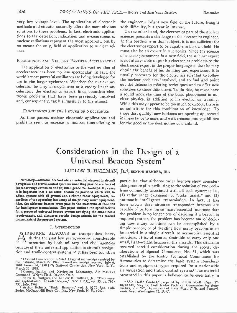
1526 PROCEEDINGS OF THE I.R.E. —Waves and Electrons Section December
very low voltage level. The application of electronic methods and circuits naturally offers the more obvious solutions to these problems. In fact, electronic applica-tions to the detection, indication, and measurement of nuclear radiations represent the most apparent, but by no means the only, field of application to nuclear sci-ence.
ELECTRONICS AND NUCLEAR PARTICLE ACCELERATORS
The application of electronics to the vast number of accelerators has been no less spectacular. In fact, the world's most powerful oscillators are being developed for use in the larger cyclotrons. Whether the nuclear ac-celerator be a synchrocyclotron or a cavity linear ac-celerator, the electronics expert finds countless elec-tronic problems that have been previously unsolved and, consequently, tax his ingenuity to the utmost.
ELECTRONICS AND THE FUTURE OF NUCLEONICS
As time passes, nuclear electronic applications and problems seem to increase in number, thus offering to
the engineer a bright new field of the future, fraught with difficulty, but great in interest. On the other hand, the electronics part of the nuclear
sciences presents a challenge to the electronics engineer. In this borderline or dual subject, it is not sufficient for the electronics expert to be capable in his own field. He must also be an expert in nucleonics. Since the science of nuclear phenomena is a new field, the nuclear expert is not always able to put his electronics problems to the electronics expert in the proper language so that he may obtain the benefit of his thinking and experience. It is usually necessary for the electronics scientist to follow the nuclear problems involved, and to find and point out the defects in existing techniques and to offer new solutions to these difficulties. To do this, he must have a sound understanding of the basic phenomena in nu-clear physics, in addition to his electronics training. While this may appear to be too much to expect, there is no substitute for this combination of knowledge. To those that qualify, new horizons are opening up, second in importance to none, and with tremendous capabilities for the good or the destruction of mankind.
Considerations in the Design of a Universal Beacon System*
LUDLOW B. HALLMAN, JR.t, SENIOR MEMBER, IRE
Summary—Airborne beacons are an essential element in aircraft navigation and traffic-control systems since they provide a means of (a) radar range extension and (b) intelligence transmission. However it is important that a universal beacon be provided which will, in effect, operate with all ground and airborne radar equipments, re-gardless of the operating frequency of the primary radar equipment. Also, the airborne beacon must provide the maximum of facilities for intelligence transmission. The paper outlines the specifications for a proposed universal beacon system satisfying the above basic requirements, and discusses certain design criteria for the several components of the proposed system.
I. INTRODUCTION
AIRBORNE BEACONS or transponders have, during the past few years, received considerable attention by both military and civil agencies
because of their universal application to aircraft naviga-tion and traffic-control systems.1.2 It has been found, in
* Decimal classification: R526.I. Original manuscript received by the Institute, March 22, 1948; revised manuscript received, July 6, 1948. Presented, 1948 IRE National Convention, New York, N. Y., March 22, 1948. t Communication and Navigation Laboratory, Air Materiel
Command, Wright Field, Dayton, Ohio. 1 Ralph D. Hultgren and Ludlow B. Hallman, Jr., "The theory
and application of the radar beacon," PROC. I.R.E., vol. 35, pp. 716-730; July, 1947.
2 Arthur Roberts, "Radar Beacons," vol. 3, MIT Rad. Lab. Series, McGraw-Hill Book Co., Inc., New York, N. Y., 1947.
particular, that airborne radar beacons show consider-able promise of contributing to the solution of two prob-lems commonly associated with all such systems; i.e., (1) radar range extension, or "radar assist," and (2) automatic intelligence transmission. In fact, it has been shown that airborne transponder beacons are capable of performing so many essential functions that the problem is no longer one of deciding if a beacon is required; rather, the problem has become one of decid-ing how many functions can be accomplished by a simple beacon, or of deciding how many beacons must be carried in a single aircraft to accomplish essential functions. It is, of course, desirable to carry only one small, light-weight beacon in the aircraft. This situation received careful consideration during the recent de-liberations of Special Committee No. 31, which was established by the Radio Technical Commission for Aeronautics to determine the basic system considera-tions and equipment types required for a nationwide air navigation and traffic-control system.' The material presented in this paper is believed to be essentially in
"Air Traffic Control," prepared by RTCA SC-31, Paper 27-48/D0-10, May 12, 1948, Radio Technical Commission for Aero-nautics, Rm. 597, Department of State Bldg., 17 St. and Pennsyl-vania Ave., Washington 25, D. C.
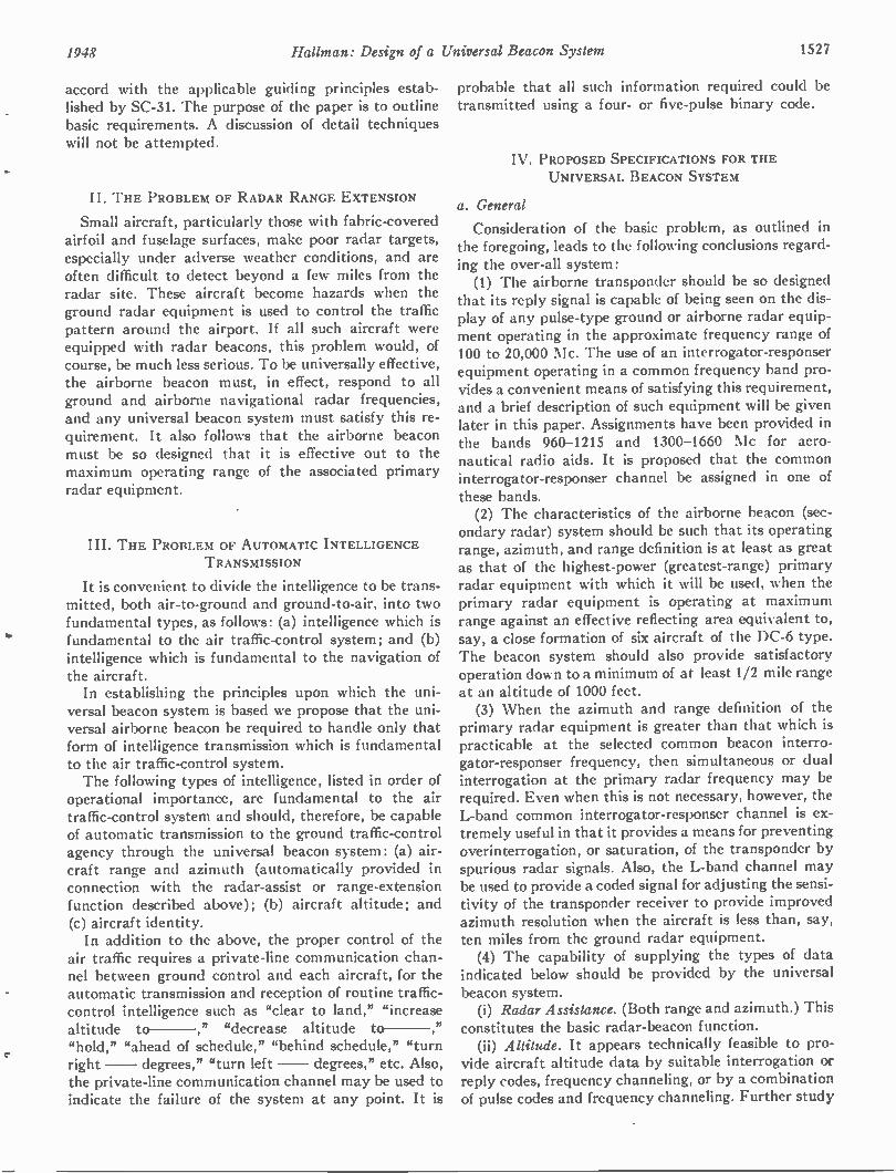
1948 Hallman: Design of a Universal Beacon System 1527
accord with the applicable guiding principles estab-lished by SC-31. The purpose of the paper is to outline basic requirements. A discussion of detail techniques will not be attempted.
II. THE PROBLEM OF RADAR RANGE EXTENSION
Small aircraft, particularly those with fabric-covered airfoil and fuselage surfaces, make poor radar targets, especially under adverse weather conditions, and are often difficult to detect beyond a few miles from the radar site. These aircraft become hazards when the ground radar equipment is used to control the traffic pattern around the airport. If all such aircraft were equipped with radar beacons, this problem would, of course, be much less serious. To be universally effective, the airborne beacon must, in effect, respond to all ground and airborne navigational radar frequencies, and any universal beacon system must satisfy this re-quirement. It also follows that the airborne beacon must be so designed that it is effective out to the maximum operating range of the associated primary radar equipment.
III. THE PROBLEM OF AUTOMATIC INTELLIGENCE TRANSMISSION
It is convenient to divide the intelligence to be trans-mitted, both air-to-ground and ground-to-air, into two fundamental types, as follows: (a) intelligence which is fundamental to the air traffic-control system; and (b) intelligence which is fundamental to the navigation of the aircraft. In establishing the principles upon which the uni-
versal beacon system is based we propose that the uni-versal airborne beacon be required to handle only that form of intelligence transmission which is fundamental to the air traffic-control system. The following types of intelligence, listed in order of
operational importance, are fundamental to the air traffic-control system and should, therefore, be capable of automatic transmission to the ground traffic-control agency through the universal beacon system: (a) air-craft range and azimuth (automatically provided in connection with the radar-assist or range-extension function described above); (b) aircraft altitude; and (c) aircraft identity. In addition to the above, the proper control of the
air traffic requires a private-line communication chan-nel between ground control and each aircraft, for the automatic transmission and reception of routine traffic-control intelligence such as "clear to land," "increase altitude to —," "decrease altitude to —," "hold," "ahead of schedule," "behind schedule," "turn right — degrees," "turn left — degrees," etc. Also, the private-line communication channel may be used to indicate the failure of the system at any point. It is
probable that all such information required could be transmitted using a four- or five-pulse binary code.
IV. PROPOSED SPECIFICATIONS FOR THE UNIVERSAL BEACON SYSTEM
a. General
Consideration of the basic problem, as outlined in the foregoing, leads to the following conclusions regard-ing the over-all system: (1) The airborne transponder should be so designed
that its reply signal is capable of being seen on the dis-play of any pulse-type ground or airborne radar equip-ment operating in the approximate frequency range of 100 to 20,000 Mc. The use of an interrogator-responser equipment operating in a common frequency band pro-vides a convenient means of satisfying this requirement, and a brief description of such equipment will be given later in this paper. Assignments have been provided in the bands 960-1215 and 1300-1660 Mc for aero-nautical radio aids. It is proposed that the common interrogator-responser channel be assigned in one of these bands. (2) The characteristics of the airborne beacon (sec-
ondary radar) system should be such that its operating range, azimuth, and range definition is at least as great as that of the highest-power (greatest-range) primary radar equipment with which it will be used, when the primary radar equipment is operating at maximum range against an effective reflecting area equivalent to, say, a close formation of six aircraft of the DC-6 type. The beacon system should also provide satisfactory operation down to a minimum of at least 1/2 mile range at an altitude of 1000 feet. (3) When the azimuth and range definition of the
primary radar equipment is greater than that which is practicable at the selected common beacon interro-gator-responser frequency, then simultaneous or dual interrogation at the primary radar frequency may be required. Even when this is not necessary, however, the L-band common interrogator-responser channel is ex-tremely useful in that it provides a means for preventing overinterrogation, or saturation, of the transponder by spurious radar signals. Also, the L-band channel may be used to provide a coded signal for adjusting the sensi-tivity of the transponder receiver to provide improved azimuth resolution when the aircraft is less than, say, ten miles from the ground radar equipment. (4) The capability of supplying the types of data
indicated below should be provided by the universal beacon system. (i) Radar Assistance. (Both range and azimuth.) This
constitutes the basic radar-beacon function. (ii) Altitude. It appears technically feasible to pro-
vide aircraft altitude data by suitable interrogation or reply codes, frequency channeling, or by a combination of pulse codes and frequency channeling. Further study
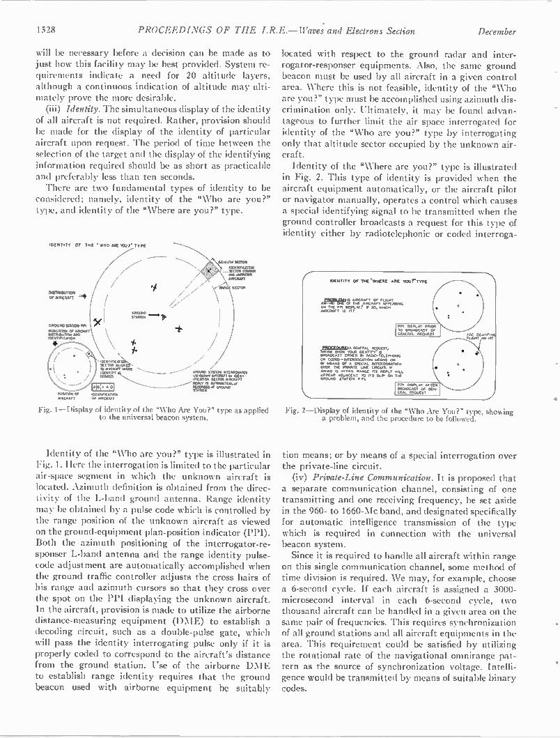
1528 PROCEEDINGS OF TIIE I.R.E. — Waves and Electrons Section December
will be necessary before a decision can be made as to just how this facility may be best provided. System re-quirements indicate a need for 20 altitude layers, although a continuous indication of altitude may ulti-mately prove the more desirable. (iii) Identity. The simultaneous display of the identity
of all aircraft is not required. Rather, provision should be made for the display of the identity of particular aircraft upon request. The period of time between the selection of the target and the display of the identifying information required should be as short as practicable and preferably less than ten seconds. There are two fundamental types of identity to be
considered; namely, identity of the "Who are you?" type, and identity of the "Where are you?" type.
IDENTITY
DISTRIBUTION
Of AIRCRAFT
GROUND STATION PPI
INDICAT OR OF APOLAFT DISTRIBUTION AND DC NOFICATION
OF THE "W 140 NIE IOU T. TYPE
(
X
0001110
WENTIFICAT.ON SECTOR * WACO TO AIRCRAFT %ROSE IDENTITY
20000 POSITION Of i0ENTIFICATION NRCRAFT Of emcnarr
"'\1;11AUTII sEcron /of NT, F iCAT SECTOR M ANN iNG UNAR M,. AIRCRAFT
z \cy RANGE SECTOR
/ X
GROuND STATION .NTERROGATES IINIPIOWS AJRCI WT II IDEAy• 'MEADOR SECTOR NRCRAFT REPLY IS 4/10AIATICALLY W ON = ff 6110UND STATION,
Fig. 1—Display of identity of the "Who Are You?" type as applied to the universal beacon system.
Identity of the "Who are you?" type is illustrated in Fig. 1. Here the interrogation is limited to the particular air-space segment in which the unknown aircraft is located. Azimuth definition is obtained from the direc-tivity of the L-band ground antenna. Range identity may be obtained by a pulse code which is controlled by the range position of the unknown aircraft as viewed on the ground-equipment plan-position indicator (PPI). Both the azimuth positioning of the interrogator-re-sponser L-band antenna and the range identity pulse-code adjustment are automatically accomplished when the ground traffic controller adjusts the cross hairs of his range and azimuth cursors so that they cross over the spot on the PPI displaying the unknown aircraft. In the aircraft, provision is made to utilize the airborne distance-measuring equipment (DM E) to establish a decoding circuit, such as a double-pulse gate, which will pass the identity interrogating pulse only if it is properly coded to correspond to the aircraft's distance from the ground station. Use of the airborne DM E to establish range identity requires that the ground beacon used with airborne equipment be suitably
located with respect to the ground radar and inter-rogator-responser equipments. Also, the same ground beacon must be used by all aircraft in a given control area. Where this is not feasible, identity of the "Who are you?" type must be accomplished using azimuth dis-crimination only. Ultimately, it may be found advan-tageous to further limit the air space interrogated for identity of the "Who are you?" type by interrogating only that altitude sector occupied by the unknown air-craft. Identity of the "Where are you?" type is illustrated
in Fig. 2. This type of identity is provided when the aircraft equipment automatically, or the aircraft pilot or navigator manually, operates a control which causes a special identifying signal to be transmitted when the ground controller broadcasts a request for this type of identity either by radiotelephonic or coded interroga-
pgre.namwt. GENERAL K outsr, "..*140 SMON /OUR °ENTITY. IS B ROADCAST EIT,CR NI RADIO-TELE...O W OR CODEO —INTERIM:CAT ON MEANS OR BY MEANS Of A SPECIAL INTERROGATION OVER TIC PRIMATE LINE CSICLAT. If A5140 IS WITHIN RANGE ITS REPLY WILL APPEAR ADJACENT TO ITS BLIP ON TIC GROU ND STATION PI:,
Fig. 2—Display of identity of the "Who Are You?" type, showing a problem, and the procedure to be followed.
tion means; or by means of a special interrogation over the private-line circuit. (iv) Private-Line Communication. It is proposed that
a separate communication channel, consisting of one transmitting and one receiving frequency, be set aside in the 960- to 1660-Mc band, and designated specifically for automatic intelligence transmission of the type which is required in connection with the universal beacon system. Since it is required to handle all aircraft within range
on this single communication channel, some method of time division is required. We may, for example, choose a 6-second cycle. If each aircraft is assigned a 3000-microsecond interval in each 6-second cycle, two thousand aircraft can be handled in a given area on the same pair of frequencies. This requires synchronization of all ground stations and all aircraft equipments in the area. This requirement could be satisfied by utilizing the rotational rate of the navigational omnirange pat-tern as the source of synchronization voltage. Intelli-gence would be transmitted by means of suitable binary codes.
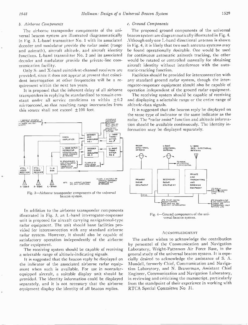
1948 Hallman: Design of a Universal Beacon System 1529
b. Airborne Components
The airborne transponder components of the uni-versal beacon system are illustrated diagrammatically in Fig. 3. L-band transmitter No. 1 with its associated decoder and modulator provide the radar assist (range and azimuth), aircraft altitude, and aircraft identity functions. L-band transmitter No. 2 and its associated decoder and modulator provide the private-line com-munication facility. Only S- and X-band coincident-channel receivers are
provided, since it does not appear at present that coinci-dent interrogation at other frequencies will be a re-quirement within the next ten years. It is proposed that the inherent delay of all airborne
transponders in replying be standardized to remain con-stant under all service conditions to within +0.2 microsecond, so that resulting range inaccuracies from this source shall not exceed +100 feet.
• MANUALLY OPERATED 1. /NTROL FOR TRANS MSS,ON
c-' WHERE ARE TCAI AA N RTC
XTAL -
VIDEO RECEIVER
X • SAND
XTA L -
VIDEO RECEIVER
T
lox
VIDEO
AMPLIFIER
L -SAND SUPER-
HETRODYN2
RECEIVER WITH GUANO CHANNELS AS REOu.RED
TO SYNCHRONIZER AND INTELLIGENCE SOURCE FOR TRANSMISSION OVER PRIVATE LINE
DECODER
AND
NOOULATOR
NO.1
TO DISPLAY OF ITITELLIGENCE FROM PRIVATE LINE
iLOmMIPENT TODISTANCE MEASURING
TOR"IMO ME 'OW IDENTITY
TO ANEROID ['APSLILE FOR I AkI*110E
L SATRANS
M1TTER
NO.1 *
L.- SAND TRANS -
NITTER
NO. 2
N.
N.
A A s_ SAND L- SAND
ROTC ALL AIRCRAFT ANTDINAS ARE OMNI. DIRECTIONAL
A. NOTE • MULTIPLE -ON VARIA OLE • PREOUENCT TRANSAIITTER MAY SIE REODIREO
Fig. 3—Airborne transponder components of the universal beacon system.
In addition to the airborne transponder components illustrated in Fig. 3, an L-band interrogator-responser unit is proposed for airci aft carrying navigational-type radar equipment. The unit should have facilities pro-vided for interconnection with any standard airborne radar system. However, it should also be capable of satisfactory operation independently of the airborne radar equipment. The receiving system should be capable of receiving
a selectable range of altitude-indicating signals. It is suggested that the beacon reply be displayed on
the indicator of the associated airborne radar equip-ment when such is available. For use in nonradar-equipped aircraft, a suitable display unit should be provided. The identity information could be displayed separately, and it is not necessary that the airborne equipment display the identity of all beacon replies.
c. Ground Components
The proposed ground components of the universal beacon system are diagrammatically illustrated in Fig. 4. Although only one L-band directional antenna is shown in Fig. 4, it is likely that two such antenna systems may be found operationally desirable. One would be used for continuous automatic azimuth tracking, the other would be rotated or controlled manually for obtaining aircraft identity without interference with the auto-matic-tracking function. Facilities should be provided for interconnection with
any standard ground radar system, though the inter-rogator-responser equipment should also be capable of operation independent of the ground radar equipment. The receiving system should be capable of receiving
and displaying a selectable range or the entire range of altitude-data signals. It is suggested that the beacon reply be displayed on
the same type of indicator or the same indicator as the radar. The "radar assist" function and altitude informa-tion should be available continuously. The identity in-formation may be displayed separately.
RADAR
DIRECTIONAL ANTENNA
SECONDARY
RADAR
011iPhiE NT
PRI MARY
RADAR
EQUIPMENT
I-eamo DIRECTIONAL ANTENNA
L- BAND
WAN, -DIRECTIONAL
ANTENNA
TO MANUAL OR AUTOMATIC SlEmING CONTROL
iTO PuLSE-CODING RANGE CONTROL FOR" wHO ARE YOU" IDENTITY INTERROGATION
PRIVATE
LINE
TRANSMITTING
AND
RECEIVING
EQUIPMENT
Fig. 4—Ground components of the uni-versal beacon system.
ACKNOWLEDGMENT
TO DispLA. OF INTS.LIGENCE FROM Am ur( LINE
tA TO SMICNRONIZER ND INTELLIGENCE SOURCE FOR TRANS MSSION OVER RIVATIE LINE
The author wishes to acknowledge the contribution by personnel of the Communication and Navigation Laboratory, Wright-Patterson Air Force Base, in the general study of the universal beacon system. It is espe-cially desired to acknowledge the assistance of S. A. Mundell, formerly Chief, Communication and Naviga-tion Laboratory, and N. Braverman, Assistant Chief Engineer, Communication and Navigation Laboratory, in reviewing and criticizing the manuscript, particularly from the standpoint of their experience in working with RTCA Special Committee No. 31.
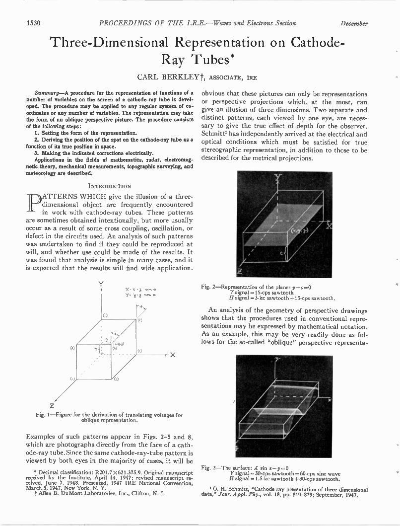
1530 PROCEEDINGS OF THE I.R.E. — Waves and Electrons Section December
Three-Dimensional Representation on Cathode-Ray Tubes*
CARL BERKLEYt, ASSOCIATE, IRE
Summary—A procedure for the representation of functions of a number of variables on the screen of a cathode-ray tube is devel-oped. The procedure may be applied to any regular system of co-ordinates or any number of variables. The representation may take the form of an oblique perspective picture. The procedure consists of the following steps: 1. Setting the form of the representation. 2. Deriving the position of the spot on the cathode-ray tube as a
function of its true position in space. 3. Making the indicated corrections electrically. Applications in the fields of mathematics, radar, electromag-
netic theory, mechanical measurements, topographic surveying, and meteorology are described.
INTRODUCTION
pATTERNS WHICH give the illusion of a three-dimensional object are frequently encountered in work with cathode-ray tubes. These patterns
are sometimes obtained intentionally, but more usually occur as a result of some cross coupling, oscillation, or defect in the circuits used. An analysis of such patterns was undertaken to find if they could be reproduced at will, and whether use could be made of the results. It was found that analysis is simple in many cases, and it is expected that the results will find wide application.
Fig. 1—Figure for the derivation of translating voltages for oblique representation.
Examples of such patterns appear in Figs. 2-5 and 8, which are photographs directly from the face of a cath-ode-ray tube. Since the same cathode-ray-tube pattern is viewed by both eyes in the majority of cases, it will be
Decimal classification: R201.7 X 621.375.9. Original manuscript received by the Institute, April 14, 1947; revised manuscript re-ceived, June 7, 1948. Presented, 1947 IRE National Convention, March 5, 1947, New York, N. Y. t Allen B. DuMont Laboratories, Inc., Clifton, N. J.
obvious that these pictures can only be representations or perspective projections which, at the most, can give an illusion of three dimensions. Two separate and distinct patterns, each viewed by one eye, are neces-sary to give the true effect of depth for the observer. Schmitt' has independently arrived at the electrical and optical conditions which must be satisfied for true stereographic representation, in addition to those to be described for the metrical projections.
Fig. 2—Representation of the plane: y-c =0 V signal =15-cps sawtooth H signal =3-kc sawtooth +15-cps sawtooth.
An analysis of the geometry of perspective drawings shows that the procedures used in conventional repre-sentations may be expressed by mathematical notation. As an example, this may be very readily done as fol-lows for the so-called "oblique" perspective representa-
Fig. 3—The surface: A sin s-y =0 V signal =30-cps sawtooth -60-cps sine wave H signal =1.5-kc sawtooth +30-cps sawtooth.
1 O. H. Schmitt, "Cathode ray presentation of three dimensional data," Jour. Appl. Phy., vol. 18, pp. 819-829; September, 1947.
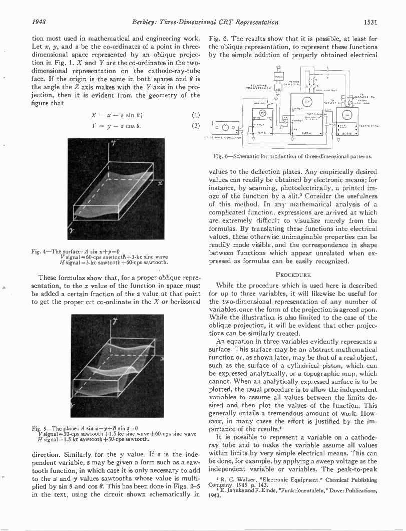
1948 Berkley: Three-Dimensional CRT Representation 1531
tion most used in mathematical and engineering work. Let x, y, and z be the co-ordinates of a point in three-dimensional space represented by an oblique projec-tion in Fig. 1. X and Y are the co-ordinates in the two-dimensional representation on the cathode-ray-tube face. If the origin is the same in both spaces and 0 is the angle the Z axis makes with the Y axis in the pro-jection, then it is evident from the geometry of the figure that
X = x — z sin 0]
Y = y — z cos 0.
Fig. 4—The surface: A sin x+y = 0 V signal =60-cps sawtoot11+3-kc sine wave H signal =3-kc sawtooth +60-cps sawtooth.
These formulas show that, for a proper oblique repre-sentation, to the x value of the function in space must be added a certain fraction of the z value at that point to get the proper crt co-ordinate in the X or horizontal
Fig. 5—The plane: A sin x—y+B sin z =0 V signal =30-cps sawtooth +1.5-kc sine wave +60-cps sine wave H signal =1.5-kc sawtooth +30-cps sawtooth.
direction. Similarly for the y value. If z is the inde-pendent variable, z may be given a form such as a saw-tooth function, in which case it is only necessary to add to the x and y values sawtooths whose value is multi-plied by sin 0 and cos 0. This has been done in Figs. 2-5 in the text, using the circuit shown schematically in
Fig. 6. The results show that it is possible, at least for the oblique representation, to represent these functions by the simple addition of properly obtained electrical
Fig. 6—Schematic for production of three-dimensional patterns.
values to the deflection plates. Any empirically desired values can readily be obtained by electronic means; for instance, by scanning, photoelectrically, a printed im-age of the function by a slit.' Consider the usefulness of this method. In any mathematical analysis of a complicated function, expressions are arrived at which are extremely difficult to visualize merely from the formulas. By translating these functions into electrical values, these otherwise unimaginable properties can be readily made visible, and the correspondence in shape between functions which appear unrelated when ex-pressed as formulas can be easily recognized.
PROCEDURE
While the procedure which is used here is described for up to three variables, it will likewise be useful for the two-dimensional representation of any number of variables, once the form of the projection is agreed upon. While the illustration is also limited to the case of the oblique projection, it will be evident that other projec-tions can be similarly treated. An equation in three variables evidently represents a
surface. This surface may be an abstract mathematical function or, as shown later, may be that of a real object, such as the surface of a cylindrical piston, which can be expressed analytically, or a topographic map, which cannot. When an analytically expressed surface is to be plotted, the usual procedure is to allow the independent variables to assume all values between the limits de-sired and then plot the values of the function. This generally entails a tremendous amount of work. How-ever, in many cases the effort is justified by the im-portance of the results.* It is possible to represent a variable on a cathode-
ray tube and to make the variable assume all values within limits by very simple electrical means. This can be done, for example, by applying a sweep voltage as the independent variable or variables. The peak-to-peak
I R. C. Walker, "Electronic Equipment," Chemical Publishing Company, 1945, p. 143.
3 E. Jahnke and F. Emde, "Funktionentafeln," Dover Publications, 1943.
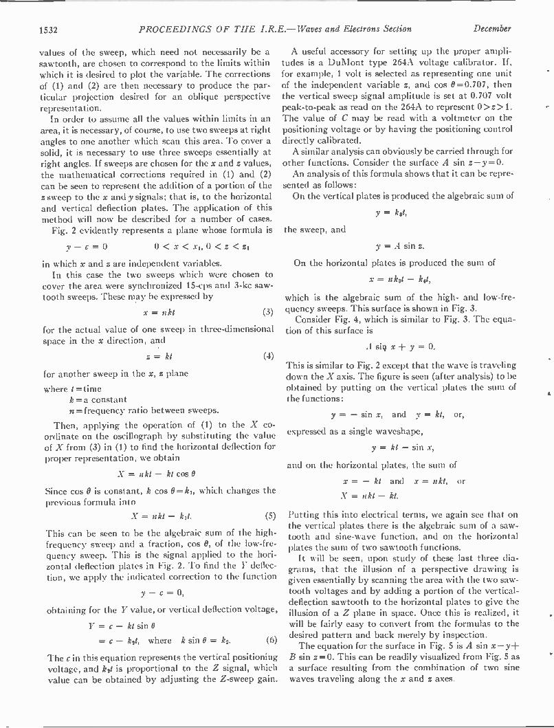
1532 PROCEEDINGS OF THE I.R.E.— Waves and Electrons Section December
values of the sweep, which need not necessarily be a sawtooth, are chosen to correspond to the limits within which it is desired to plot the variable. The corrections of (1) and (2) are then necessary to produce the par-ticular projection desired for an oblique perspective representation. In order to assume all the values within limits in an
area, it is necessary, of course, to use two sweeps at right angles to one another which scan this area. To cover a solid, it is necessary to use three sweeps essentially at right angles. If sweeps are chosen for the x and z values, the mathematical corrections required in (1) and (2) can be seen to represent the addition of a portion of the z sweep to the x and y signals; that is, to the horizontal and vertical deflection plates. The application of this method will now be described for a number of cases. Fig. 2 evidently represents a plane whose formula is
y — c = 0 0 < x < xi, 0 < < zi
in which x and z are independent variables. In this case the two sweeps which were chosen to
cover the area were synchronized 15-cps and 3-kc saw-tooth sweeps. These may be expressed by
x = nkt (3)
for the actual value of one sweep in three-dimensional space in the x direction, and
z = kt (4)
for another sweep in the x, z plane
where t =time k= a constant n =frequency ratio between sweeps.
Then, applying the operation of (1) to the X co-ordinate on the oscillograph by substituting the value of X from (3) in (1) to find the horizontal deflection for proper representation, we obtain
X = nkt — kt cos 0
Since cos 0 is constant, k cos O= k1, which changes the previous formula into
X = nkt — k11. (5)
This can be seen to be the algebraic sum of the high-frequency sweep and a fraction, cos 0, of the low-fre-quency sweep. This is the signal applied to the hori-zontal deflection plates in Fig. 2. To find the Y deflec-tion, we apply the indicated correction to the function
y — C = 0,
obtaining for the Y value, or vertical deflection voltage,
Y = c — kt sin 0
= c — k21, where k sin 0 = k2. (6)
The c in this equation represents the vertical positioning voltage, and k21 is proportional to the Z signal, which value can be obtained by adjusting the Z-sweep gain.
A useful accessory for setting up the proper ampli-tudes is a DuMont type 264A voltage calibrator. If, for example, 1 volt is selected as representing one unit of the independent variable z, and cos 0=0.707, then the vertical sweep signal amplitude is set at 0.707 volt peak-to-peak as read on the 264A to represent 0 > z > 1. The value of C may be read with a voltmeter on the positioning voltage or by having the positioning control directly calibrated. A similar analysis can obviously be carried through for
other functions. Consider the surface A sin z —y = O. An analysis of this formula shows that it can be repre-
sented as follows: On the vertical plates is produced the algebraic sum of
y = k31,
the sweep, and
y = A sin z.
On the horizontal plates is produced the sum of
x = nkst — k41,
which is the algebraic sum of the high- and low-fre-quency sweeps. This surface is shown in Fig. 3. Consider Fig. 4, which is similar to Fig. 3. The equa-
tion of this surface is
A si9 x y = 0.
This is similar to Fig. 2 except that the wave is traveling down the X axis. The figure is seen (after analysis) to be obtained by putting on the vertical plates the sum of the functions:
Y= — sin x, and y = kt, or,
expressed as a single waveshape,
y = kt — sin x,
and on the horizontal plates, the sum of
x = — kt and x = nkt, or
X = nkt — kt.
Putting this into electrical terms, we again see that on the vertical plates there is the algebraic sum of a saw-tooth and sine-wave function, and on the horizontal plates the sum of two sawtooth functions. It will be seen, upon study of these last three dia-
grams, that the illusion of a perspective drawing is given essentially by scanning the area with the two saw-tooth voltages and by adding a portion of the vertical-deflection sawtooth to the horizontal plates to give the illusion of a Z plane in space. Once this is realized, it will be fairly easy to convert from the formulas to the desired pattern and back merely by inspection. The equation for the surface in Fig. 5 is A sin x —y+
B sin z =O. This can be readily visualized from Fig. 5 as a surface resulting from the combination of two sine waves traveling along the x and z axes.
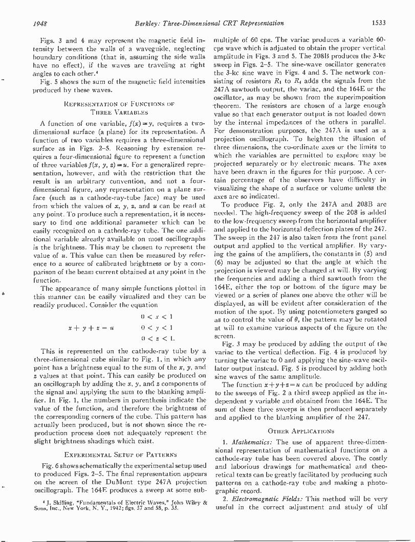
1948 Berkley: Three-Dimensional CRT Representation 1533
Figs. 3 and 4 may represent the magnetic field in-tensity between the walls of a waveguide, neglecting boundary conditions (that is, assuming the side walls have no effect), if the waves are traveling at right angles to each other.* Fig. 5 shows the sum of the magnetic field intensities
produced by these waves.
REPRESENTATION OF FUNCTIONS OF THREE VARIABLES
A function of one variable, f(x) =y, requires a two-dimensional surface (a plane) for its representation. A function of two variables requires a three-dimensional surface as in Figs. 2-5. Reasoning by extension re-quires a four-dimensional figure to represent a function of three variables f(x, y, z) =u. For a generalized repre-sentation, however, and with the restriction that the result is an arbitrary convention, and not a four-dimensional figure, any representation on a plane sur-face (such as a cathode-ray-tube face) may be used from which the values of x, y, z, and u can be read at any point. To produce such a representation, it is neces-sary to find one additional parameter which can be easily recognized on a cathode-ray tube. The one addi-tional variable already available on most oscillographs is the brightness. This may be chosen to represent the value of u. This value can then be measured by refer-ence to a source of calibrated brightness or by a com-parison of the beam current obtained at any point in the function. The appearance of many simple functions plotted in
this manner can be easily visualized and they can be readily produced. Consider the equation
0 < x < 1
x+y-l-z=u 0 < y < 1
0 < z < 1.
This is represented on the cathode-ray tube by a three-dimensional cube similar to Fig. 1, in which any point has a brightness equal to the sum of the x, y, and z values at that point. This can easily be produced on an oscillograph by adding the x, y, and z components of the signal and applying the sum to the blanking ampli-fier. In Fig. 1, the numbers in parenthesis indicate the value of the function, and therefore the brightness of the corresponding corners of the cube. This pattern has actually been produced, but is not shown since the re-production process does not adequately represent the slight brightness shadings which exist.
EXPERIMENTAL SETUP OF PATTERNS
Fig. 6 shows schematically the experimental setup used to produced Figs. 2-5. The final representation appears on the screen of the DuMont type 247A projection oscillograph. The 164E produces a sweep at some sub-
4 J. Skilling, "Fundamentals of Electric Waves," John Wiley & Sons, Inc., New York, N. Y., 1942; figs. 57 and 58, p. 33.
multiple of 60 cps. The variac produces a variable 60-cps wave which is adjusted to obtain the proper vertical amplitude in Figs. 3 and 5. The 208B produces the 3-kc sweep in Figs. 2-5. The sine-wave oscillator generates the 3-kc sine wave in Figs. 4 and 5. The network con-sisting of resistors R1 to R4 adds the signals from the 247A sawtooth output, the variac, and the 164E or the oscillator, as may be shown from the superimposition theorem. The resistors are chosen of a large enough value so that each generator output is not loaded down by the internal impedances of the others in parallel. For demonstration purposes, the 247A is used as a projection oscillograph. To heighten the illusion of three dimensions, the co-ordinate axes or the limits to which the variables are permitted to explore may be projected separately or by electronic means. The axes have been drawn in the figures for this purpose. A cer-tain percentage of the observers have difficulty in visualizing the shape of a surface or volume unless the axes are so indicated. To produce Fig. 2, only the 247A and 208B are
needed. The high-frequency sweep of the 208 is added to the low-frequency sweep from the horizontal amplifier and applied to the horizontal deflection plates of the 247. The sweep in the 247 is also taken from the front panel output and applied to the vertical amplifier. By vary-ing the gains of the amplifiers, the constants in (5) and (6) may be adjusted so that the angle at which the projection is viewed may be changed at will. By varying the frequencies and adding a third sawtooth from the 164E, either the top or bottom of the figure may be viewed or a series of planes one above the other will be displayed, as will be evident after consideration of the motion of the spot. By using potentiometers ganged so as to control the value of 0, the pattern may be rotated at will to examine various aspects of the figure on the screen. Fig. 3 may be produced by adding the output of the
variac to the vertical deflection. Fig. 4 is produced by turning the variac to 0 and applying the sine-wave oscil-lator output instead. Fig. 5 is produced by adding both sine waves of the same amplitude. The function x-Fy -Fz = u can be produced by adding
to the sweeps of Fig. 2 a third sweep applied as the in-dependent y variable and obtained from the 164E. The sum of these three sweeps is then produced separately and applied to the blanking amplifier of the 247.
OTHER APPLICATIONS
1. Mathematics: The use of apparent three-dimen-sional representation of mathematical functions on a cathode-ray tube has been covered above. The costly and laborious drawings for mathematical and theo-retical texts can be greatly facilitated by producing such patterns on a cathode-ray tube and making a photo-graphic record. 2. Electromagnetic Fields: This method will be very
useful in the correct adjustment and study of uhf
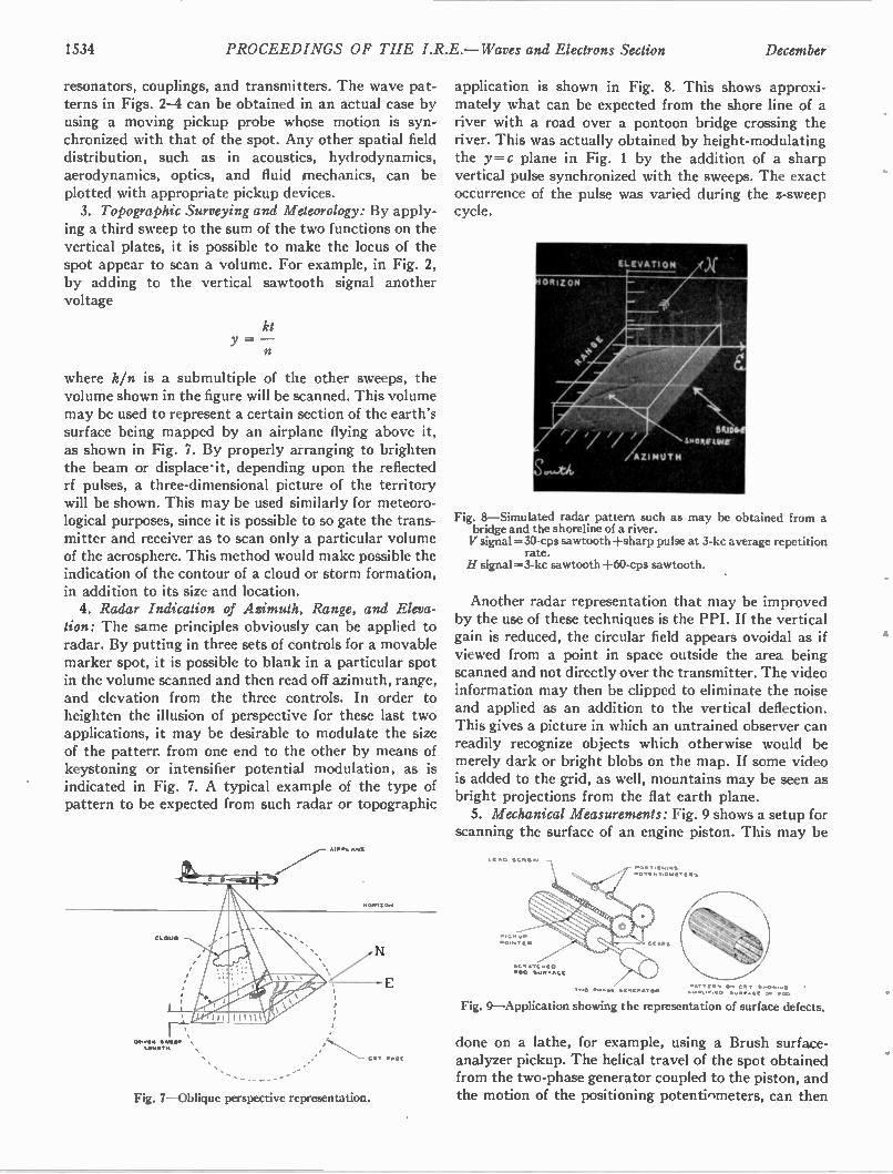
1534 PROCEEDINGS OF THE I.R.E.— Waves and Electrons Section December
resonators, couplings, and transmitters. The wave pat-terns in Figs. 2-4 can be obtained in an actual case by using a moving pickup probe whose motion is syn-chronized with that of the spot. Any other spatial field distribution, such as in acoustics, hydrodynamics, aerodynamics, optics, and fluid mechanics, can be plotted with appropriate pickup devices. 3. Topographic Surveying and Meteorology: By apply-
ing a third sweep to the sum of the two functions on the vertical plates, it is possible to make the locus of the spot appear to scan a volume. For example, in Fig. 2, by adding to the vertical sawtooth signal another voltage
where k/n is a submultiple of the other sweeps, the volume shown in the figure will be scanned. This volume may be used to represent a certain section of the earth's surface being mapped by an airplane flying above it, as shown in Fig. 7. By properly arranging to brighten the beam or displace•it, depending upon the reflected rf pulses, a three-dimensional picture of the territory will be shown. This may be used similarly for meteoro-logical purposes, since it is possible to so gate the trans-mitter and receiver as to scan only a particular volume of the aerosphere. This method would make possible the indication of the contour of a cloud or storm formation, in addition to its size and location. 4. Radar Indication of Azimuth, Range, and Eleva-
tion: The same principles obviously can be applied to radar. By putting in three sets of controls for a movable marker spot, it is possible to blank in a particular spot in the volume scanned and then read off azimuth, range, and elevation from the three controls. In order to heighten the illusion of perspective for these last two applications, it may be desirable to modulate the size of the pattern from one end to the other by means of keystoning or intensifier potential modulation, as is indicated in Fig. 7. A typical example of the type of pattern to be expected from such radar or topographic
aVIN Slkat.
C.T PAGE
.••
Fig. 7—Oblique perspective representation.
application is shown in Fig. 8. This shows approxi-mately what can be expected from the shore line of a river with a road over a pontoon bridge crossing the river. This was actually obtained by height-modulating the y=c plane in Fig. 1 by the addition of a sharp vertical pulse synchronized with the sweeps. The exact occurrence of the pulse was varied during the z-sweep cycle.
Fig. 8—Simulated radar pattern such as may be obtained from a bridge and the shoreline of a river. V signal = 30-cps sawtooth +sharp pulse at 3-kc average repetition
rate. H signal =3-kc sawtooth +60-cps sawtooth.
Another radar representation that may be improved by the use of these techniques is the PPI. If the vertical gain is reduced, the circular field appears ovoidal as if viewed from a point in space outside the area being scanned and not directly over the transmitter. The video information may then be clipped to eliminate the noise and applied as an addition to the vertical deflection. This gives a picture in which an untrained observer can readily recognize objects which otherwise would be merely dark or bright blobs on the map. If some video is added to the grid, as well, mountains may be seen as bright projections from the flat earth plane. 5. Mechanical Measurements: Fig. 9 shows a setup for
scanning the surface of an engine piston. This may be
SC•ATC.O0
P •s r
POTeiner CoW
....... C•T 11•0••••0 • ••••,•• • • Sump•ce ow vela
Fig. 9—Application showing the representation of surface defects.
done on a lathe, for example, using a Brush surface-analyzer pickup. The helical travel of the spot obtained from the two-phase generator coupled to the piston, and the motion of the positioning potentiometers, can then
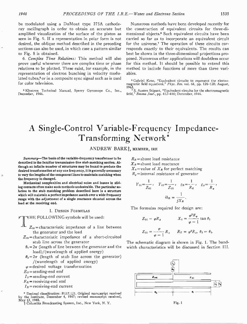
1948 PROCEEDINGS OF THE I.R.E.—Waves and Electrons Section 1535
be modulated using a DuMont type 275A cathode-ray oscillograph in order to obtain an accurate but amplified visualization of the surface of the piston as seen in Fig. 9. If a representation in polar form is not desired, the oblique method described in the preceding sections can also be used, in which case a pattern similar to Fig. 8 is obtained. 6. Complex Time Relations: This method will also
prove useful whenever there are complex time or phase relations to be plotted. These exist, for example, in the representation of electron bunching in velocity modu-lated tubes,' or in a composite sync signal such as is used for color television.
i Klystron Technical Manual, Sperry Gyroscope Co., Inc., December, 1944.
Numerous methods have been developed recently for the construction of equivalent circuits for three-di-mensional objects. ° Such equivalent circuits have been carried so far as to incorporate an equivalent circuit for the universe.7 The operation of these circuits cor-responds exactly to their equivalents. The results can best be shown in the three-dimensional projections pro-posed. Numerous other applications will doubtless occur for this method. It should be possible to extend this method to include functions of more than three vari-ables.
• Gabriel Kron, "Equivalent circuits to represent the electro-magnetic field equations," Phys. Rev. vol. 64, pp. 126-128; August, 1943.
7 S. Austen Stigant, "Equivalent circuits for the electromagnetic field," Beama Jour., pp. 412-416; December, 1944.
A Single-Control Variable-Frequency Impedance-Transforming Network*
ANDREW BARKt, MEMBER, IRE
Summary—The basis of the variable-frequency transformer to be described is the familiar transmission-line stub matching section. Al-though an infinite number of structures may be found to produce the desired transformation at any one frequency, it is generally necessary to vary the lengths of the component lines to maintain matching when the frequency is changed. Mechanical complexities and electrical noise and losses in slid-
ing contacts often make such methods undesirable. The particular so-lution to the stub matching problem described here is a structure which will maintain a perfect impedance match over a wide frequency range with the adjustment of a single reactance shunted across the load at the receiving end.
I. DESIGN FORMULAS
HE FOLLOWING symbols will be used: 1 7
Zoi= characteristic impedance of a line between the generator and the load
Z02 = characteristic impedance of a short-circuited stub line across the generator
01= 27r (length of line between the generator and the load)/(wavelength of applied energy)
02=27r (length of stub line across the generator) /(wavelength of applied energy)
9= desired voltage transformation Es = sending-end emf /s = sending-end current ER= receiving-end emf /R =receiving-end current
* Decimal classification: R117.121. Original manuscript received by the Institute, December 4, 1947; revised manuscript received, May 17, 1948. 1' Columbia Broadcasting System, Inc., New York, N. Y.
RR= shunt load resistance XR= shunt load reactance Xo = value of XR for perfect matching Rg= internal resistance of generator
1 1 1 1
Y01 = —„, ) YO2 = - ) gR= —.. , go=—, z 01 ZO2 AR R,
1 MR = .
jXR
The formulas required for design are:
Zoi = (1,1?„
v2R, Xo — tan 01
co — 1
Zo2= so R, RR = (p2Rg, 02 = 01. 49 — 1
The schematic diagram is shown in Fig. 1. The band-width characteristics will be discussed in Section III.
Fig. 1
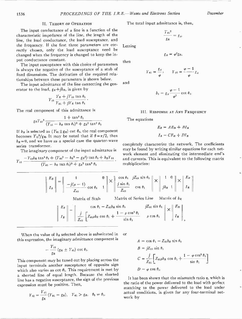
1536 PROCEEDINGS OF THE I.R.E. — Waves and Electrons Section December
II. THEORY OF OPERATION
The input conductance of a line is a function of the characteristic impedance of the line, the length of the line, the load conductance, the load susceptance, and the frequency. If the first three parameters are cor-rectly chosen, only the load susceptance need be changed when the frequency is changed to keep the in-put conductance constant. The input susceptance with this choice of parameters
is always the negative of the susceptance of a stub of fixed dimensions. The derivation of the required rela-tionships between these parameters is shown below. The input admittance of the line connecting the gen-
erator to the load, gR-1-jbR, is given by
YR + j Y01 tan 01 vol
Yoi jYR tan 01
The real component of this admittance is
1 + tan2 01 80'012
(1'01 — bR tan 002 + gR2 tan' 01
If bR is selected as ( Yoi +DO cot Oj, the real component becomes Yoil/gR. It may be noted that if 0=r/2, then bR =0, and we have as a special case the quarter-wave series transformer. The imaginary component of the input admittance is
— Yolbil tan2 01 ± — bR2 — gs2) tan 01 bRYOI vol
(Y01 — bs tan 0) 2 + gR2 tan2 01
Es
Is
Es
Is
1
—i(p — 1) Z01
0
cot 01 1
The total input admittance is, then,
Letting
then
and
gg
17 01
11)
17 2 01
= g.. gR
g = 0,2gRt
1702 =
so — 1 bo = gg cot 01.
III. RESPONSE AT ANY FREQUENCY
The equations
Es = A ER
18 = C ER ± D I R
completely characterize the network. The coefficients may be found by writing similar equations for each net-work element and eliminating the intermediate emf's and currents. This is equivalent to the following matrix multiplication:
cos 01 jZoi sin 01
j sin 01 cos 01
Matrix of Stub Matrix of Series Line
cos 01 — ZoibR sin 01
— P oipba cos 01 -I- 1 — p cos2 01
Zo1
When the value of bR selected above is substituted in this expression, the imaginary admittance component is
v ol , — — (gs ± Y01) cot 01. gR
This component may be tuned out by placing across the input terminals another susceptance of opposite sign which also varies as cot 01. This requirement is met by a shorted line of equal length. Because the shorted line has a negative susceptance, the sign of the previous expression must be positive. Then,
vol YO2 = 01 gR), Vol > gR, 02 = 01.
gR
sin 01
or
X
1 0
jbR 1
Matrix
jZoi sin 01
p cos 01
X
of bR
E R
X
/"R
A = cos 01 — ZoibR sin 01
B = jZot sin 01
L — PoipuR Z01
c=
D = so cos 01.
ER
IR
1 — 4, cos' 01 cos 01 ± ]
sin 01
It has been shown that the mismatch ratio n, which is the ratio of the power delivered to the load with perfect matching to the power delivered to the load under actual conditions, is given for any four-terminal net-work by
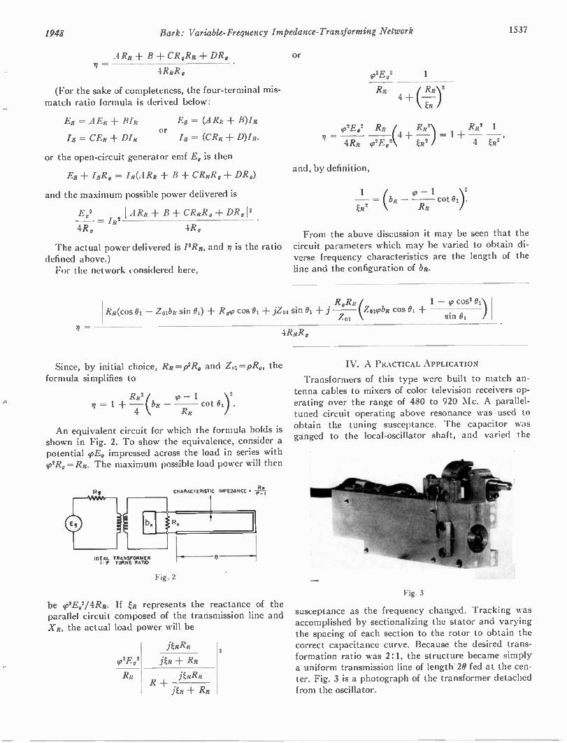
1948 Bark: Variable-Frequency Impedance-Transforming Network 1537
A RR B +CR,Rs + DR„ n =
4RsR,
(For the sake of completeness, the four-terminal mis-match ratio formula is derived below:
Es = AEI? BIs
Is = CE, DIR
Es = (ARR B)/R or
/8 = (CRR D)/R.
or the open-circuit generator emf E, is then
Es + IsR, = Is(ARs B CRsR,-1- DR„)
and the maximum possible power delivered is
E02 I A RR B CRs12,-1-• DR,I 2 = IR 2 4R, 4R,
The actual power delivered is /2RR, and ?I is the ratio defined above.) For the network considered here,
=
or
1
RR 4 + RRy k ER
= E 1,2 RR ( R R2 RR2 1 4 -I-
4RR ,p2E 92 ER2 4 ER2
and, by definition,
1 (bR
ER2 1 cot 01 ) 2.
RR
From the above discussion it may be seen that the circuit parameters which may be varied to obtain di-verse frequency characteristics are the length of the line and the configuration of bk.
R,Rs 1 — cos2 01) RR(cos 01 — ZoibR sin 01) R cos 01 ± iZ01 sin 01 + (ZoiiobR cos 01 -I-
Lo1 sin 01
4RRR,
Since, by initial choice, RR= P2Ro and Zo =pRo, the formula simplifies to
RR2 = 1
4
— 1 2 cot RR
An equivalent circuit for which the formula holds is shown in Fig. 2. To show the equivalence, consider a potential vE, impressed across the load in series with (p2R0 = RR. The maximum possible load power will then
IDEAL TRANSFORMER I f TURNS RATIO
CHARACTERISTIC IMPEDANCE • - - 4- I
Fig. 2
be 02Eg2/4RR. If ER represents the reactance of the parallel circuit composed of the transmission line and X R, the actual load power will be
2E 2 g
Rs
jERRR
jER + RR
Au & R
jER + RR
2
IV. A PRACTICAL APPLICATION
Transformers of this type were built to match an-tenna cables to mixers of color television receivers op-erating over the range of 480 to 920 Mc. A parallel-tuned circuit operating above resonance was used to obtain the tuning susceptance. The capacitor was ganged to the local-oscillator shaft, and varied the
Fig. 3
susceptance as the frequency changed. Tracking was accomplished by sectionalizing the stator and varying the spacing of each section to the rotor to obtain the correct capacitance curve. Because the desired trans-formation ratio was 2:1, the structure became simply a uniform transmission line of length 20 fed at the cen-ter. Fig. 3 is a photograph of the transformer detached from the oscillator.
1538 PROCEEDINGS OF THE I.R.E. — Waves and Electrons Section December
Phase Difference Between the Fields of Two Vertically Spaced Antennas*
E. W . HAMLINt, ASSOCIATE, IRE, AND A. W . STRAITONt, MEMBER, IRE
Summary—This paper discusses the phase differences between the fields of two vertically spaced antennas as a function of transmit-ter height, receiver height, and distance between transmitter and re-ceiver. The results are applicable to microwave propagation within the line-of-sight region when a direct wave and a ground-reflected wave are present, and have been useful in interpreting phase-differ-ence measurements made by the Electrical Engineering Research Laboratory of the University of Texas.1.1.1
INTRODUCTION
iN THE PAST two years, the University of Texas, investigating the angle of arrival of radio waves under a contract with the Office of Naval Research,
has made many measurements'.2 of phase difference between signals received at two identical antennas spaced a number of wavelengths apart. One of the pri-mary objects of the study was to determine how fast the angle of arrival might change. It. was this considera-tion which prompted the decision to use the phase-dif-ference method, and equipments was designed and put in operation which could record changes in phase of a few degrees taking place in a second. The work has been done entirely at a wavelength of 3.2 cm. Microwave angle-of-arrival measurements by the
maximum signal strength method have been reported by Sharpless.4 To measure horizontal angle, the two antennas are
placed at the same height above the ground, but spaced a known distance apart horizontally. For vertical-angle measurements, they are spaced vertically one above the other. In either case, if only one ray is received at the two antennas, the angle of arrival of the ray is directly proportional to the difference in phase of the signal received in the two antennas. Even in making horizontal measurements,2 however,
• Decimal classification: R248.14 X R115.4. Original manuscript received by the Institute, December 19, 1947; revised manuscript re-ceived, May 3, 1948.
Cornell University, Ithaca, N. Y. t University of Texas, Austin, Tex. 1 E. W. Hamlin, et al., "Preliminary Report on Phase Front
Measurements in Arizona During April, 1946," University of Texas, Electrical Engineering Research Laboratory, Report No. 6P, February, 1947. I A. W. Straiton and J. R. Gerhardt, "Results of horizontal micro-
wave angle-of-arrival measurements by phase-difference method," PROC. I.R.E., vol. 36, pp. 916-922; July, 1948.
1 F. E. Brooks, Jr. and C. W. Tolbert, "Equipment for Measuring Angle-of-Arrival by the Phase Difference Method," University of Texas, Electrical Engineering Research Laboratory, Report No. 2, May, 1946.
W . M. Sharpless, "Measurement of the angle-of-arrival of microwaves," PROC. I.R.E., vol. 34, pp. 837-845; November, 1946.
6 E. W. Hamlin and W. E. Gordon, "Comparison of calculated and measured phase difference at 3.2 centimeters wave length," PROC. I .R.E., vol. 36, pp. 1218-1224; October, 1948.
the effect of the ground-reflected component is notice-able. In making vertical phase-difference measurements, the effect of the reflected wave, even with low values of reflection coefficient, must be taken into account. A re-flected wave only 20 per cent as large as the direct can change the measured phase difference by + 20° from that for the direct wave alone. Since the resolution of the equipment is about ± 2°, it is essential to investigate this effect mathematically. The results of the analysis pre-sented in this paper have proved very useful in the study of field-measured phase-difference data.1.2.5 The present paper investigates this effect under the
simplest conditions. Two identical receiving antennas are spaced vertically in a plane perpendicular to the direction of propagation. Mutual coupling between the antennas is assumed to be negligible. The earth is as-sumed flat and two rays only are considered, a direct wave and one reflected from the ground. The reflected wave is assumed to suffer a complete phase reversal on reflection. For the horizontal polarization which has been used, and the high frequency at which the measure-ments were made, this latter assumption is very nearly true. Effects similar to those to be presented here may be expected under practical field conditions.
SYMBOLS AND DEFINITIONS
hl and h2= height of transmitting and receiving antennas, respectively
h2° = average height of two receiving an-tennas
d= horizontal distance between trans-mitter and receiver
dI and d2= distance from reflecting point to transmitter and receiver, respectively
X = wavelength LD and LR=length of path of direct and reflected
rays, respectively ch, Op and 4.)R=phase of resultance, direct and re-
flected rays with reference to the transmitter
0, OD and OR= phase difference between signal re-ceived at upper and lower horns for resultant, direct, and reflected waves, respectively
LOp = deviation in phase difference from that of direct wave only =0—Op
= deviation in phase from that of direct wave only = 41— OD
K =magnitude of reflected wave with re-spect to the direct
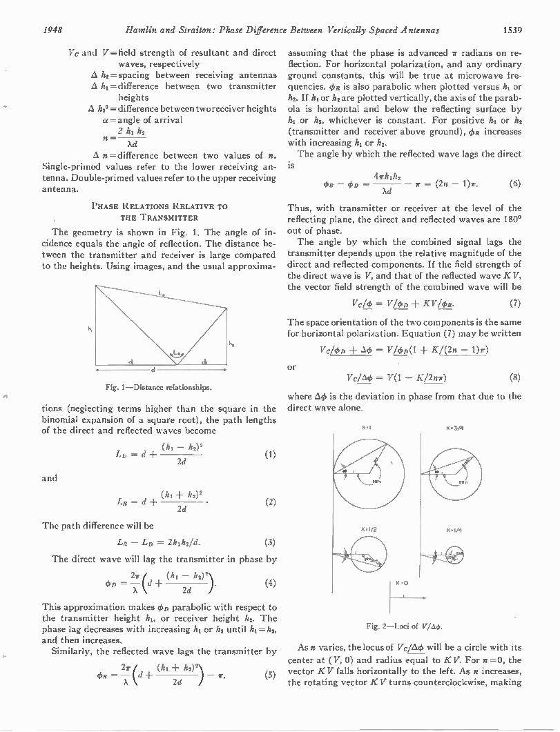
1948 Hamlin and Straiton: Phase Difference Between Vertically Spaced Antennas 1539
Vc and V= field strength of resultant and direct waves, respectively
A h2= spacing between receiving antennas A h1= difference between two transmitter
heights A h2° = difference between two receiver heights a =angle of arrival 2 h1 h2
n— Xd
A n = difference between two values of n. Single-primed values refer to the lower receiving an-tenna. Double-primed values refer to the upper receiving antenna.
PHASE RELATIONS RELATIVE TO THE TRANSMITTER
The geometry is shown in Fig. 1. The angle of in-cidence equals the angle of reflection. The distance be-tween the transmitter and receiver is large compared to the heights. Using images, and the usual approxima-
Fig. 1—Distance relationships.
tions (neglecting terms higher than the square in the binomial expansion of a square root), the path lengths of the direct and reflected waves become
and
(h1 h2) 2 LD = d
2d
LR = d + (hi 2d
The path difference will be
LR — LD = 2121122/d.
(1)
(2)
(3)
The direct wave will lag the transmitter in phase by
4iso = +(hi — h2)2 ). X \ 2d
(4)
This approximation makes OD parabolic with respect to the transmitter height h1, or receiver height h2. The phase lag decreases with increasing hi or h2 until hi =h2, and then increases. Similarly, the reflected wave lags the transmitter by
= — d 27 ( (h1 h2)2) X 2d r, (5)
assuming that the phase is advanced 71- radians on re-flection. For horizontal polarization, and any ordinary ground constants, this will be true at microwave fre-quencies. OR is also parabolic when plotted versus h1 or h2. If h1 or h2 are plotted vertically, the axis of the parab-ola is horizontal and below the reflecting surface by h1 or h2, whichever is constant. For positive h1 or h2 (transmitter and receiver above ground), OR increases with increasing h1 or h2. The angle by which the reflected wave lags the direct
is 47/012
— 410 = = (2n — 1)7. (6) Xd
Thus, with transmitter or receiver at the level of the reflecting plane, the direct and reflected waves are 180° out of phase. The angle by which the combined signal lags the
transmitter depends upon the relative magnitude of the direct and reflected components. If the field strength of the direct wave is V, and that of the reflected wave K V, the vector field strength of the combined wave will be
Vc/d) = V/OD + KV/OR. (7)
The space orientation of the two components is the same for horizontal polarization. Equation (7) may be written
Vc/OD + &S = V/c/n)(1 Kl(2n — 1)7)
or Vc/Ack = V(1 — K/2nr) (8)
where AO is the deviation in phase from that due to the direct wave alone.
K• I K • 3/4
Fig. 2—Loci of V/A4).
As n varies, the locus of Vc/Ack will be a circle with its
center at ( V, 0) and radius equal to K V. For n=0, the vector K V falls horizontally to the left. As n increases, the rotating vector K V turns counterclockwise, making
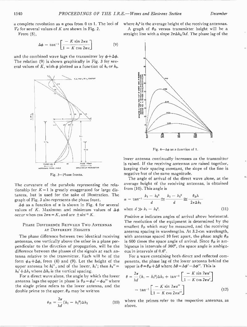
1540 PROCEEDINGS OF THE I.R.E.— Waves and Electrons Section December
a complete revolution as n goes from 0 to 1. The loci of Vc for several values of K are shown in Fig. 2. From (8),
— K sin 27n 1 = tan-' [
1 — K cos 22r d (9)
and the combined wave lags the transmitter by 0+,64. The relation (9) is shown graphically in Fig. 3 for sev-eral values of K, with 4) plotted as a function of h1 or h2.
PHASE FRONT
DINES ION Of PROPAGATION
AAAAA LAG.
INCREASING PHASE LOGIC
Fig. 3—Phase fronts.
The curvature of the parabola representing the rela-tionship for K=1 is greatly exaggerated for large dis-tances, but is used for the sake of illustration. The graph of Fig. 3 also represents the phase front. AO as a function of n is shown in Fig. 4 for several
values of K. Maximum and minimum values of AO occur when cos 27n =K, and are + sin-4 K.
PHASE DIFFERENCE BETWEEN Two ANTENNAS AT DIFFERENT HEIGHTS
The phase difference between two identical receiving antennas, one vertically above the other in a plane per-pendicular to the direction of propagation, will be the difference between the phases of the signals at each an-tenna relative to the transmitter. Each will be of the form cfiD-hai(1), from (4) and (9). Let the height of the upper antenna be hP , and of the lower, h2'; then h2" = h2'+Ah2 where Ah2 is the vertical spacing. For a direct wave alone, the angle by which the lower
antenna lags the upper in phase is OD = OD' —OD" where the single prime refers to the lower antenna, and the double prime to the upper. On may be written
27 OD = — h2°) 11 2
Xd (10)
where 1/2° is the average height of the receiving antennas. A graph of On versus transmitter height will be a
straight line with a slope 27,6ih2/Xd. The phase lag of the
Fig. 4—Aytt as a function of 1.
lower antenna continually increases as the transmitter is raised. If the receiving antennas are raised together, keeping their spacing constant, the slope of the line is negative but of the same magnitude. The angle of arrival of the direct wave alone, at the
average height of the receiving antennas, is obtained from (10). This angle is
hi — h2° 112 — 112° ODX a = tan-' ros,
d 276,h2
when d>> hi — 112°.
Positive a indicates angles of arrival above horizontal. The resolution of the equipment is determined by the smallest On which may be measured, and the receiving antenna spacing in wavelengths. At 3.2-cm wavelength, with antennas spaced 10 feet apart, the phase angle On is 600 times the space angle of arrival. Since On is am-biguous in intervals of 360°, the space angle is ambigu-ous in intervals of 0.6°. For a wave containing both direct and reflected com-
ponents, the phase lag of the lower antenna behind the upper is 0 = OD -FAO where AO =64' —AO". This is
27 [ — K sin 27n'l 0 = — (hi — 112°)Alt2 + tan-1
Xd 1 — K cos 22rn'
[ — K sin 27n" 1 — tan-' (12)
1 — K cos 27n"J
where the primes refer to the respective antennas, as above.
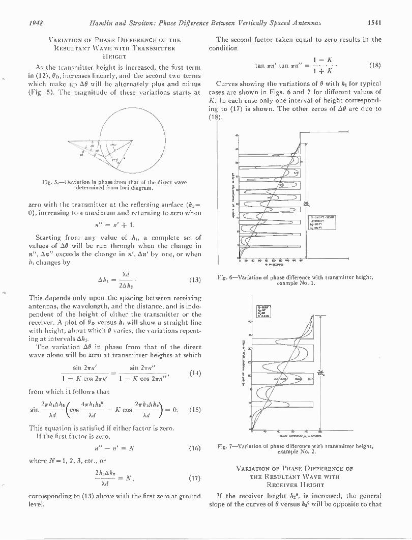
1948 Hamlin and Straiton: Phase Difierence Between Vertically Spaced Antennas 1541
VARIATION OF PHASE DIFFERENCE OF THE RESULTANT WAVE WITH TRANSMITTER
HEIGHT
As the transmitter height is increased, the first term in (12), OD, increases linearly, and the second two terms which make up AO will be alternately plus and minus (Fig. 5). The magnitude of these variations starts at
Fig. 5.—Deviation in phase from that of the direct wave determined from loci diagram.
zero with the transmitter at the reflecting surface (h1= 0), increasing to a maximum and returning to zero when
n" = n' -F 1.
Starting from any value of hl, a complete set of values of AO will be run through when the change in n", An" exceeds the change in n', An' by one, or when hl changes by
Xd Ahl= (13)
2A/72
This depends only upon the spacing between receiving antennas, the wavelength, and the distance, and is inde-pendent of the height of either the transmitter or the receiver. A plot of OD versus h1 will show a straight line with height, about which 0 varies, the variations repeat-ing at intervals Ahi. The variation AO in phase from that of the direct
wave alone will be zero at transmitter heights at which
sin 2rn' sin 2rn" (14)
1 — K cos 2rn' 1 — K cos 27n"
from which it follows that
27/hAh2( 47rhihz° 27rhiAh2) sin cos K cos — 0. (15)
Xd Xd Xd
This equation is satisfied if either factor is zero. If the first factor is zero,
n" — n' = N
where N =1, 2, 3, etc., or
2hiAh2
Xd
(16)
= N, (17)
The second factor taken equal to zero results in the condition
tan rte tan am" 1 — K
1+ K (18)
Curves showing the variations of 0 with hi for typical cases are shown in Figs. 6 and 7 for different values of K.1 In each case only one interval of height correspond-in to (17) is shown. The other zeros of AO are due to
(1 ).
0 ID 40 00 112 CO a 140 00 1140
• 41 _ MIS
hk.
11.00Sr, .32 ..
4.11020lT K;•0011
1.:,•1011
Fig. 6—Variation of phase difference with transmitter height, example No. 1.
11•434 0/10011104X,•. OH MS
Fig. 7—Variation of phase difference with transmitter height, example No. 2.
VARIATION OF PHASE DIFFERENCE OF THE RESULTANT WAVE WITH
RECEIVER HEIGHT
corresponding to (13) above with the first zero at ground If the receiver height h20, is increased, the general level, slope of the curves of 0 versus h24 will be opposite to that
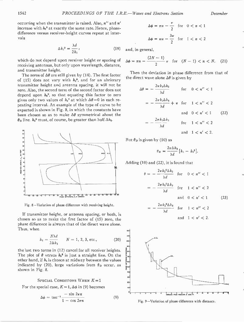
1542 PROCEEDINGS OF THE I.R.E.— Waves and Electrons Section December
occurring when the transmitter is raised. Also, n" and n' increase with h2" at exactly the same rate. Hence, phase-difference versus receiver-height curves repeat at inter-vals
Ad Alt2° = —
2 h1
(19)
which do not depend upon receiver height or spacing of receiving antennas, but only upon wavelength, distance, and transmitter height. The zeros of óO are still given by (14). The first factor
of (15) does not vary with h20, and for an abritrary transmitter height and antenna spacing, it will not be zero. Also, the second term of the second factor does not depend upon h20, so that equating this factor to zero gives only two values of 122" at which AO =0 in each re-peating interval. An example of the type of curve to be expected is shown in Fig. 8, in which the constants have been chosen so as to make AO symmetrical about the OD line. 12.2° must, of course, be greater than half Ah2.
•
- PFFEWPICE .0, F. MO MS
Fig. 8—Variation of phase difference with receiving height.
If transmitter height, or antenna spacing, or both, is chosen so as to make the first factor of (15) zero, the phase difference is always that of the direct wave alone. Thus, when
NXd hi = N = 1, 2, 3, etc., (20)
2h2
the last two terms in (12) cancel for all receiver heights. The plot of 0 versus h2° is just a straight line. On the other hand, if h1 is chosen at midway between the values indicated by (20), large variations from OD occur, as shown in Fig. 8.
SPECIAL CONDITIONS WHEN K=1
For the special case, K=1, AO in (9) becomes
— sin 2rn = tan--1
1 — cos 2rn (9)
for 0 < n < 1
for 1 < n < 2
and, in general,
(2N — 1) = rn 2 ir for (N — 1) < n < N. (21)
Then the deviation in phase difference from that of the direct wave alone AO is given by
274&z2 i10 = for 0 < n" < 1
Ad
2rhiAh2 + r for 1 < n" < 2
Ad
2r46,112
Ad
But OD is given by (10) as
and 0 < n' < 1 (22)
for 1 < n" < 2
and 1 < n' < 2.
2rAh2 OD — h2°].
Ad
Adding (10) and (22), it is found that
2rh?4,1h2 0 = for 0 < n" < 1
Ad
2rh2°,akhz for 1 < n" < 2 Ad
2rh2°,6kh2
Ad
and 0 < < 1 (23)
for 1 < n" < 2
and 1 < n' < 2.
W M = M e M U M PI Kee Ft
Fig. 9—Variation of phase difference with distance.
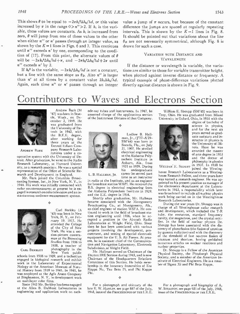
1948 PROCEEDINGS OF THE I.R.E.— Waves and Electrons Section 1543
CARL BERKLEY
ANDREW BARK
This shows 0 to be equal to —27rh2Mh2/Xd, or this value increased by 1r in the range 0 > n" >2. If h1 is the vari-able, these values are constants. As h1 is increased from zero, 0 will jump from one of these values to the other when either n" or n' passes through an integer value, as shown by the K=1 lines in Figs. 6 and 7. This continues until n" exceeds n' by one, corresponding to the condi-tion of (17). From this point, the alternate values of 0 will be —2/rh2Uh2/Xd-l-7, and —27rhaUht/Xd-F2ir until n" exceeds n' by 2. If hse is the variable, —27rh206,h2/Xd is not a constant,
but a line with the same slope as OD. Also n" is larger than n' at all times by a constant value 2hpAh2/Xd. Again, each time n" or n' passes through an integer
value a jump of 7 occurs, but because of the constant difference the jumps are spaced at regularly repeating intervals. This is shown by the K=1 lines in Fig. 8. It should be pointed out that variations about the line OD are not necessarily symmetrical, although Fig. 8 is drawn for such a case.
VARIATION WITH DISTANCE AND WAVELENGTH
If the distance or wavelength is variable, the varia-tions are similar to those for variable transmitter height, when plotted against inverse distance or frequency. A typical example of phase-difference variations plotted directly against distance is shown in Fig. 9.
Contributors to Waves and Electrons Section Andrew Bark (M
'47) was born in Seat-tle, Wash., on De-cember 2, 1919. He was graduated from the University of De-troit in 1942, with the B.E.E. degree, after working for three years at the Detroit Edison Com-pany Research Labo-ratories under a co-
operative system with the University of De-troit. After graduation, he went to the Radio Research Laboratory, at Harvard Univer-sity, as a research associate. He was a special representative of the Office of Scientific Re-search and Development in England. Mr. Bark joined the Columbia Broad-
casting System, Inc., in New York, N. Y., in 1944. His work was initially concerned with radar countermeasures; at present he is en-gaged in research on color television and an in-stantaneous audience-measurement system.
Carl Berkley (A '45) was born in New York, N. Y., on Feb-ruary 19, 1917. He attended the College of the City of New York. He was a mo-tion-picture camera-man at the Browning Studios from 1936 to 1938, a teacher of photography in the New York public
schools from 1938 to 1939, and a technician engaged in biological research and exhibit work in the Laboratory of Experimental Biology at the American Museum of Natu-ral History from 1939 to 1941. In 1941, he was employed at the Agfa Ansco Company at Binghamton, N. Y., in development work on multilayer color films. Since 1942 Mr. Berkley has been engaged
at the Allen B. DuMont Laboratories in engineering and application work on cath-
L. B. HALLMAN, JR.
ode-ray tubes and instruments. In 1947, he assumed charge of the applications section of the Instrument Division of that Company.
Ludlow B. Hall-man, Jr., (J'27-A'29-SM'44) was born in Sneads, Fla., on July 21, 1907. He studied electrical engineering at the Alabama Poly-technic Institute in Auburn, Ala., from 1925 to 1929. During his undergraduate career he served part time as an instructor
in radio at the Institute, and as an engineer for broadcast station WAPI. He received the B.S. degree in electrical engineering from the Alabama Polytechnic Institute in 1929, and the E.E. degree in 1934. Shortly after graduation, Mr. Hallman
became associated with the Montgomery Broadcasting Co., at Montgomery, Ala., as chief engineer of station WSFA. He con-tinued to work in the field of broadcast sta-tion engineering until 1936, when he ac-cepted a position in the Aircraft Radio Laboratories at Wright Field, Ohio. Since then he has been associated with various projects involving the development, pro-curement, and testing of special electronic equipment for the U. S. Air Forces. At pres-ent, he is assistant chief of the Communica-tion and Navigation Laboratory, Electronic Subdivision, at Wright Field. Mr. Hallman served as Chairman of the
Dayton IRE Section during 1945, and is now Chairman of the Headquarters Relations Committee of this Section. He holds mem-bership in the honorary fraternities of Eta Kappa Nu, Tau Beta Pi, and Phi Kappa Phi.
•
For a photograph and obituary of the late E. W. HAMLIN, see page 887 of the July, 1948, issue of the PROCEEDINGS OF THE I.R.E.
William E. Shoupp (SM'45) was born in Troy, Ohio. He was graduated from Miami University in Oxford, Ohio, in 1931 with the
degree of bachelor of science in physics, and for the next six years served as grad-uate assistant and in-structor in physics ir. the University of Illi-nois. Here he was awarded the master of arts degree in 1933 and the doctor of philosophy in physics in 1937. In 1938 he joined the Westing-
house Research Laboratories as a Westing-house Research Fellow, and three years later was named a research engineer. He was ap-pointed to his present position as manager of the electronics department at the Labora-tories in 1943, a responsibility which later was broadened to include all nuclear physics work being carried on in the Westinghouse Research Laboratories. During the war years Dr. Shoupp was in
charge of all Westinghouse radar research and development, which included the T-R tube, the resnatron, standard frequency cavity, the magnetron, and the crystal recti-fier. In the field of nuclear physics Dr. Shoupp has been associated with the dis-covery of photofission (the fission of uranium by gamma radiation) and with the discovery of the threshold of fast neutron fission of uranium and thorium, having published numerous articles on nuclear reactions and nuclear properties. Dr. Shoupp is a Fellow of the American
Physical Society, the Pittsburgh Physical Society, and a member of the American In-stitute of Electrical Engineers. He is a mem-ber of Sigma Xi and Phi Beta Kappa.
• W ILLIAM- E. SHOUPP
For a photograph and biography of A. W . STRAITON, see page 931 of the July, 1948, issue of the PROCEEDINGS OF THE I.R.E.
1544 PROCEEDINGS OF THE I.R.E. — Waves and Electrons Section December
Abstracts and References Prepared by the National Physical Laboratory, Teddington, England, Published by Arrangement
with the Department of Scientific and Industrial Research, England, and Wireless Engineer, London, England
NOTE: The Institute of Radio Engineers does not have available copies of the publications mentioned in these pages, nor does it have reprints of the articles abstracted. Correspondence regarding these articles and requests for their
procurement should be addressed to the individual publications and not to the IRE.
Acoustics and Audio Frequencies Antennas and Transmission Lines Circuits and Circuit Elements General Physics Geophysical and Extraterrestrial Phe-nomena
Location and Aids to Navigation Materials and Subsidiary Techniques Mathematics Measurements and Test Gear Other Applications of Radio and Elec-tronics
Propagation of Waves Reception Stations and Communication Systems Subsidiary Apparatus Television and Phototelegraphy Transmission Vacuum Tubes and Thermionics Miscellaneous
1544 1545 1545 1547
1548 1550 1550 1551 1551
1553 1553 1554 1555 1555 1555 1556 1556 1556
The number in heavy type at the upper left of each Abstract is its Universal Decimal Classi-fication number and is not to be confused with the Decimal Classification wed by the United States National Bureau of Standards. The number in heavy type at the top right is the serial number of the Abstract. DC numbers marked with a dagger (f) must be regarded as provisional.
ACOUSTICS AND AUDIO FREQUENCIES
534.21 2997 Directional Characteristic of a Cylindrical
Radiator with a Coaxial Conical Reflector— G. Bacchi. (Alta Frequenza, vol. 17, pp. 74 -78; April, 1948. In Italian with English, French,and German summaries.) Magnetostriction oscilla-tors of the above type, adapted for radial vi-bration, have radiation patterns with an abso-lute maximum along the axis. The wavelength is of the same order as the dimensions of the cylinder. The radiation pattern is calculated. With a 45° cone, the characteristic is repre-sented by the integral of Bessel's function of zero order.
534.242 2998 Formula Involving the Shape for Calculat-
ing the Resonance Frequency of Helmholtz Resonators —D. Chervet and J. Henry (Compt. Rend. Acad. Sci. (Paris), vol. 226, pp. 1891-1893; June 7, 1948.) Rayleigh's formula was established on the assumptions that the pres-sure inside the resonator is constant and that the resonator dimensions are small compared with the resonance wavelength. Measure-ments show that the pressure varies from point to point according to an exponential law, the maximum pressure being at the bottom of the resonator. From this a correction formula is derived which is not easy to use and can be re-placed by an empirical formula involving sim-ply the product of the resonator length L and the resonance frequency fo given by Rayleigh's formula. Experimental results for resonators of various shapes are tabulated, together with the frequencies calculated from Rayleigh's for-mula and the two correction formulas.
534.321.9 2999 Distortion of Progressive Ultrasonic Waves
—J. C. Hubbard, J. A. Fitzpatrick, B. T.
The Institute of Radio Engineers has made arrangements to have these Ab-stracts and References reprinted on suitable paper, on one side of the sheet only. This makes it possible for subscribers to this special service to cut and mount the individual Abstracts for cataloging or otherwise to file and refer to them. Subscrip-tions to this special edition will be accepted only from members of the IRE and subscribers to the Proc. I.R.E. at $15.00 per year. The Annual Index to these Ab-stracts and References, covering those published from February, 1947, through January, 1948, may be obtained for 2s. 8d. postage included from the Wireless Engineer, Dorset House, Stamford St., London S. E., England.
Kankovsky, and W. J. Thaler. (Phys. Rev., vol. 74, pp. 107-108; July 1, 1948.) Spark shad-ow photographs of ultrasonic waves in air, water, glycerine, and CCI4show definite changes of waveform into a type with steeper fronts and increased harmonic content.
534.321.9: 621.391.63 3000 Distortion in Light Modulation by an Ultra-
sonic Cell —D. Sette. (Alta Frequenza, vol. 17, pp. 51-68; April, 1948. In Italian with English, French, and German summaries.) Description of an 8-Mc cell similar to that of Giacomini (1847 of August). Frequency distortion in a modulated light beam transmitted through the cell is small even for comparatively high modu-lation frequencies. The low distortion and the high modulation factor possible are particular advantages of such a system.
53.321.9.001.8:614.8 3001 Notes on Using High-Power Ultrasonics —
(See 3195.)
534.75 3002 Audibility of High-Frequency Sounds—.
V. Gavreau. (Compt. Rend. Acad. Sci. (Paris), vol. 226, pp. 2053-2054; June 21, 1948.) It is found that sounds of frequencies from 17.5 kc to 26 kc are perfectly audible when sufficiently intense. When the intensity of such sounds is steadily increased, one or more sudden apparent changes of pitch, of about an octivae, are ob-served. These apparent changes of pitch may be due to abrupt changes in the order of the harmonic response of the resonators of the ear. Magnetostriction oscillators were used and gave sound powers up to 5 w.
534.756.1 3003 Phase Memory of the Ear: A Proof of the
Resonance Hypothesis—R. J. Pumphrey and T. Gold. (Nature (London), vol. 161, p. 640; April 24, 1948.) Two alternative trains of sine-wave pulses are used. Each pulse contains n cycles, the pulse separation being m cycles, where m and n are both integers. In one train, the phase of all pulses is the same, while in the other the phase of alternate pulses is reversed. The ear can differentiate between the two trains. It follows that the value of Q for the resonators of the ear must be at least 100 and is probably considerably higher. See also 8 of February.
534.83 3004 Acoustic Materials —(Electronics, Buyers'
Guide Issue, vol. 21, pp. M2-M3; June, 1948.) Noise reduction coefficients of various sound-absorbing materials are tabulated and com-pared with those of ordinary building mate-rials. Mountings used in sound absorption tests are discussed briefly.
534.839 3005 Methods for the Study of Noise —A. Moles.
(Radio Franc., pp. 9-15; June, 1948.) Subjec-tive and objective methods are discussed, the principal characteristics of various types of microphone are considered and a description of the General Radio decibel meter is given. Harmonic analyzers are also considered briefly.
53.851:621.395.813 3006 Measuring Wow —U. R. Furst. (FM and
Telev., vol. 8, pp. 30, 50; May, 1948.) Discus-sion of methods of measurement, and descrip-tion of a commercial type of meter.
534.861.1 : 621.316.345: 621.396.664 3007 Modern Design Features of CBS Studio
Audio Facilities—Monroe and Palinquist. (See 3241.)
534.861.1:621.396.712.3 3008 Speech-Input Equipment for New Oslo
Broadcasting House —E. Julsrud and G. Wie-der. (Elec. Commun., vol. 25, pp. 21-29; March, 1948.) An illustrated description, giving details of the facilities available. Easy, flexible, and reliable operation is ensured by extensive use of automatic switching.
621.395.623.7.015.3 3009 Study of Loudspeakers in the Transient
Regime —G. Guyot. (Rev. Gin. Elec., vol. 57, pp. 245-253; June, 1948.) Discussion of the response of loudspeakers to steady tones, with methods of obtaining the corresponding curves, and a detailed account of test methods and results for square-shape sine-wave signals and for pulse signals. Preliminary results indicate a correlation between the quality appreciated by the ear and the duration of the transient signal. For a loudspeaker 21 cm in diameter, signal quality was found to fall off if the duration of the pulse signal was below about 2.7 ms. Dis-cussion of the various methods of testing loud-speakers shows that transient tests cannot replace ordinary methods completely, but that they furnish valuable information as to loud-speaker quality.
621.395.625.3 3010 Two-Channel Two-Way-Drive Magnetic
Tape Recorder —R. E. Zenner and R. B. Vaile, Jr. (Audio Eng., vol. 32, pp. 11-15; April, 1948.) Designed for good performance at low tape speed.
621.395.625.3 3011 Test Characteristics of Recording Wire —
Carter and Koontz. (See 3149.)
621.395.625.6:621.317.75.015.3 3012 Sweeping Device for the Display of Tran-
sient Phenomena and Nonlinear Distortion - Meyer-Eppler. (See 3183.)
No reprints or preprints of these abstracts and references are available from the I.R.E.
1948 Abstracts and References 1545
ANTENNAS AND TRANSMISSION LINES
621.315 3013 Transmission Line Theory Simplified —
W. Redmayne. (Distrib. Elec., vol. 20, pp. 346-348, 350; April, 1948.) The general equations for voltage and current at any point of a dc transmission system are derived without using differential equations. Both loaded and un-loaded lines are considered. The equations can be easily adapted to the case of ac transmission.
621.315.2.017.71 3014 Heating of Radio-Frequency Cables —
W. W. Macalpine. (Elec. Commun., vol. 25, pp. 84-99; March, 1948.) Discussion with par-ticular reference to solid-dielectric coaxial ca-bles; only the simplest physical or mathematical assumptions are made.
621.315.23: 620.197.6 3015 Rubber Thermoplastic Jacket for Buried
Cable —C. V. Lundberg. (Bell Lab. Rec., vol. 26, pp. 148-151; April, 1948.) Protection of the lead casing of cables against corrosion is se-cured by two layers of a material made from reclaimed rubber, clay, resin, paraffin wax, and mineral rubber. A fabric tape, corrugated Cu sheath and bitumen layer are applied outside the rubber.
621.392.029.64 3016 Attenuation of the H10 Wave in a Rectangu-
lar Waveguide —N. N. Malov. (Zh. Tekh. Fiz., vol. 18, pp. 417-420; April, 1948. In Russian.) Discussion of a method based on an examina-tion of the multiple reflection of the transverse wave from the walls of the waveguide. It is shown that the H,,,o and Ho,, types of wave cannot be regarded as particular cases of the
type with m or a zero.
621.392.029.64 3017 The Excitation of a Rectangular Waveguide
through a Slot —I. I. Vol'man. (Radiotekhnika (Moscow), vol. 3, pp. 49-55; May and June, 1948. In Russian.) Methods are indicated for calculating the field produced between two parallel planes by energy supplied through an aperture. The results obtained can be applied in the theory of rectangular waveguides.
621.392.029.64 3018 Effect of Junctions on the Field in a Wave-
guide —H. Buchholz. (Arch. Elek. (Obertra-gung), vol. 2, pp. 14-22; January, 1948.) For-mulas are derived for the effect of a narrow cir-cumferential slot in the wall of a waveguide on the transmission of waves having an axial com-ponent of wall current.
621.392.029.64+621.396.611.41:621.3.015.3 3019
Study of the Transient Regimes in Wave-guides and Cavity Resonators —T. Kahan and S. Colombo. (Comp!. Rend. Acad. Sci. (Paris), vol. 226, pp. 2060-2061; June 21, 1948.) A method is given which enables formulas ap-plicable to the transient state to be derived from formulas established for the steady state m. ith frequency co/2r.
621.392.029.64:621.317.3 3020 On the Representation and Measurement
of Waveguide Discontinuities —N. Marcuvitz. (Pitoc. I.R.E., vol. 36, pp. 728-735; June, 1948.) The various equivalent circuit representations of a general 2N-terminal waveguide structure, obtained by selection of different terminal planes, are discussed and interrelated. A pre-cision method of measuring the circuit parame-ters of such structures is described. Weiss-floch's tangent relation for the input versus output behavior of a four-terminal waveguide structure is used.
621.392.029.64:621.396.67 3021 The Theory of the Ring Resonant Slot in a
Waveguide —M. L. Levin. (Zh. Tekh. Fiz., vol. 18, pp. 639-652; May, 1948. In Russian.) A theoretical analysis is given of a resonant slot antenna having the form of a narrow ring cut in the wall of a semi-infinite waveguide of circular cross section.
621.392.43:621.317.72 3022 A Modified Micromatch —Corfield and
Cragg. (See 3176.)
621.396.67 3023 Relations between the Transmitting and
Receiving Properties of Antennas —A. F. Ste-venson. (Quart. Appl. Math., vol. 5, pp. 369-384; January, 1948.) A rigorous mathematical dis-cussion. The parasitic and receiving properties of a perfectly conducting antenna can be de-rived from its transmitting properties under stated conditions. The particular case of a linear antenna in a homogeneous isotropic medium is considered in detail. A rigorous proof of Thevenin's theorem for antennas is given without any appeal to circuit theory. The polar diagram of an antenna used for transmis-sion is not in general identical with that of the same antenna used for reception, though these polar diagrams are approximately identical in practical cases. Reciprocal relations between two antennas are discussed. The case of an im-perfectly conducting antenna is also considered briefly.
621.396.67 3024 Calculation of the Field Strength Produced
by a Half-Wave Aerial at a Given Point above a Plane Earth as a Function of the Energy Supplied per Second: Part 1—K. F. Niessen. (Physica, 's Gray., vol. 7, pp. 586-602; July, 1940. In German.) Formulas are derived for the vertical field due to a X/2 antenna with its foot at a given distance above a plane earth, taking account of the energy absorbed in the earth. Numerical results are given for various as-sumed values of earth conductivity and dielec-tric constant. See also 3025 below.
621.396.67 3025 Electric Field Strength as a Function of the
Energy Supplied to the Aerial: Part 2—K. F. Niessen. (Physical's Gray., vol. 7, pp. 897-908; December, 1940. In German.) Calculations are made for the same wavelength and geometrical ratios as those of part 1 (3024 above), but for values of the earth conductivity p and dielectric constant a corresponding to dry ground. The re-sults are compared with those of part 1 and dis-cussed. Tables give the vertical field, due to a vertical X/2 antenna with its foot at a height of X/4 above a plane earth, at a distance of 5X and a height of X/4, for various values of e and p, and also the corresponding fields due to a dipole. For high values of p the corrected re-flection formula should be used, particularly when e is small; for low values of p, Sommer-feld's formula is preferable.
621.396.67 3026 The Cylindrical Antenna with Gap—
R. King and T. W. Winternitz. (Quart. Appl. Math., vol. 5, pp. 403-416; January, 1948.) The King-Middleton theory (1453 and 3547 of 1946) is generalized to show the effect of a finite gap on the current and the impedance of a cylindrical antenna with a gap of length 26 between the halves of the antenna. For small gaps, the impedance is not very sensitive to gap length, so that impedances calculated for zero gap are good approximations for antennas for which 2 Tai/X0<0.01, a being the radius of the conductors. For gap lengths not satisfying this inequality, correction curves are given for use with curves for resistance and reactance.
621.396.67 3027 The Field of a Dipole with a Tuned Parasite
at Constant Power —R. King. (Paoc. I.R.E., vol. 36, pp. 872-876; vol. 36, July, 1948.)
Theoretical curves are given for the electric field, in the forward and backward directions, of a center-driven X/2 dipole with a parallel cen-ter-tuned reflector of the same dimensions, for various values of antenna spacing and reflector impedance.
621.396.67: 517.392 3028 Concerning a New Transcendent, Its Tabu-
lation and Application in Antenna Theory — Bouwkamp. (See 3158.)
621.396.67: 517.512.2 3029 Fourier Transforms in Aerial Theory: Part
6—Ramsay. (See 3159.)
621.396.671 3030 The Radiation Resistance of End-Fire and
Collinear Arrays —C.H. Papas and R. King. (Paoc. I.R.E., vol. 36, pp. 736-741; June, 1948.) Formulas obtained for this resistance involve circular functions and can conveniently be used for computation. The only mathemati-cal approximation is a Fourier representation of the field of a single X/2 dipole, discussed in 3326 of 1941 (King). The new formulas are in satis-factory agreement with the results of Pistol-kora and Bontsch-Bruewitsch.
621.396.677 3031 Note on Practical Limitations in the Di-
rectivity of Antennas —R. M. Wilmotte. (Pa m. I.R.E., vol. 36, p. 878; July, 1948.) Discussion on 2731 of November (Riblet).
621.396.677 3032 Artificial Dielectric Lenses for Microwaves
— W. E. Kock. (Bell. Lab. Rec., vol. 26, pp. 145-147; April, 1948.) For a fuller account see 2176 of September.
CIRCUITS AND CIRCUIT ELEMENTS
621.3.015.3: [621.392.029.64+621.396.611.4 3033
Study of the Transient Regimes in Wave-guides and Cavity Resonators —Kahan and Colombo. (See 3019.)
621.314.2: [621.395.623.7 3034 Study of the Output Transformer for Feed-
ing Loudspeakers —L. Chretien. (TSF Pour Tous, vol. 24, pp. 185-188; July and August, 1948.) Discussion of the conditions which should be satisfied for optimum performance, with faithful reproduction of both high and low fre-quencies. Practical design details are considered briefly.
621.314.2:621.396.813 3035 Nonlinear Distortion in Low-Frequency
Transformers with Strong Premagnetization — F. Boucher. (Frequenz, vol. 2, pp. 140-143; May, 1948.) The distortion occurring in the load resistance is calculated under certain sim-plifying assumptions. The effective magnetiza-tion curve showing the relation between induc-tion and field strength, taking account of the airgap, is thereby replaced approximately by a parabola. Values are thus derived for the har-monic and combination tones of the quadratic distortion in the secondary load, when two sine-wave tones are applied to the transformer primary.
621.316.86 3036 Thermistors and Their Applications —B. S.
Sotskov. (Avtomatika i Telemekhanika, vol. 9, pp. 39-58; January and February, 1948. In Russian.) The properties of various types are tabulated, and discussed in detail under the fol-lowing headings: (a) main characteristics, (b) effect of size and shape on parameters, (c) determination of steady-state and transient regimes in thermistor circuits, and (d) applica-tions to (i) time delay relays, (ii) starting re-sistances for motors, (iii) shunting resistances for lamps and other current-carrying devices connected in series, (iv) voltage stabilizers, (v)
No reprints or preprints of these abstracts and references are available from the I.R.E.
1546 PROCEEDINGS OF THE I.R.E. — Waves and Electrons Section December
temperature measurements, (vi) gas and liquid flow measurements, (vii) bolometers and (viii) rheostats. See also 765 or 3552 of 1947 (Becker, Green, and Pearson), and 3044 of 1947 (Rosen-berg).
621.318.572:621.385.38 3037 A Fast, Noiseless Thyratron Switch —S. W.
Kitchen. (Rev. Sci. Instr., vol. 19, pp. 370-371; May, 1948.) The cathode resistor of a conven-tional thyratron switch is replaced by a capaci-tor and a resistor of only 100 fl is used in the anode circuit. With this arrangement, if the desired current drain through the switch is small compared with the rated average thyratron current, inherent noise is eliminated while fast action is retained.
621.392:518.4 3038 Design Curves for Parallel-T Network —
D. Espy. (Electronics, vol. 21, pp. 114-115; July, 1948.) Generalized curves from which transmissions at various deviations from reso-nant frequency can be read directly. Design equations are also given.
621.392:621.396.645.029.64 3039 Very-High-Frequency Triode Oscillator and
Amplifier Circuits —G. Lehmann. (Elec. Corn-man., vol. 25, pp. 50-61; March, 1948.) Trans-lation of paper abstracted in 368 of 1947.
621.392.011.2 3040 A Contribution to the Approximation
Problem [for impedance functional —R. F. Baum. (Pstoc. I.R.E., vol. 36, pp. 863-869; July, 1948.) An approximation to the curve of a given impedance function can be obtained by combining a finite number of "semi-infinite slopes," represented by Butterworth functions. The labor normally involved in the calculation of impedance zeros and poles is thus greatly reduced. Tschebyscheff functions are more ap-propriate for obtaining approximations to filter curves. Approximations to resistance, reac-tance, and phase curves can be obtained simi-larly.
621.392.088.7 3041 The Theory and Design of Thermal Com-
pensation of a Circuit for a Given Frequency Range —S. S. Arshinov. (Radiotekhnika (Mos-cow), vol. 3, pp. 21-39; March and April, 1948. In Russian.) The problem of reducing as much as possible the maximum value of the temperature coefficient for a given frequency range is a particular case of finding the beat ap-proximation to a continuous function. Condi-tions for optimum thermal compensation in simple and complex circuits are here derived from a formula due to Tchebyschev. Complete compensation is possible for the whole operat-ing range. A numerical example is given.
621.392.43:621.314.2 3042 Impedance Matching Half- Wave Trans-
former —H. E. Dinger and H. G. Paine. (Tele-Tech., vol. 7, part I, pp. 41-43, 77; May, 1948.) A transformer for matching a balanced load to an unbalanced source of the same im-pedance, using a X/2 coaxial line. Since such lines can be used at 20 per cent off resonance with an impedance change of only 5 per cent, continuous coverage for the frequency range 100 to 400 Mc is achieved with 4 interchange-able lines.
621.392.5:621.385.3:512.831 3043 The Application of Matrices to Vacuum-
Tube Circuits —J. S. Brown and F. D. Ben-nett. (Paoc. I.R.E., vol. 36, pp. 844-852; July, 1948.) The matrix equations for triode circuits are derived for linear operation with any one electrode grounded. A table relating matrix elements is calculated, allowing for the fact that the networks are not bilateral. For-mulas are obtained for the gain of an amplifier having m identical stages. Two examples show-
ing the advantages of the matrix method are included.
621.396.611:621.316.729 3044 Pseudosynchronization in Amplitude-Sta-
bilized Oscillators —P. R. Aigrain and E. M. Williams. (Psoc. I.R.E., vol. 36, pp. 800-801; June, 1948.) If a frequency f is injected into an amplitude-stabilized oscillator of frequency fo, then over a band of frequencies for which If —Is! is small, fo disappears and the system acts as a regenerative amplifier for the injected signal and "pulling" does not exist. These re-sults are contrasted with those of Adler (2522 of 1946).
621.396.611.015.4 3045 Notes on a Property of the Voltage Reso-
nance of an Oscillatory Circuit —E. Fromy. (Onde Elec., vol. 28, pp. 218-221; June, 1948.) Starting from the elementary equations of an oscillatory circuit fed by a sinusoidal source, it is shown that the terminal voltage can be re-garded as the sum of two voltages, whose am-plitudes are constant and equal to half the ter-minal voltage of the circuit at resonance; one voltage is of constant phase, while the phase of the other varies on either side of the phase at resonance, according to the value of the tuning capacitance. This property is quite general and is established without making any simpli-fying assumptions; it can have numerous prac-tical applications, particularly in the design of dephasing circuits.
621.396.611.1 3046 The Application of the Symbolic Method to
the Analysis of the Free Regime of Linear Sys-tems —A. A. Rizkin. (Radiorekhnika (Moscow) , vol. 3, pp. 56-63; May and June, 1948. In Rus-sian.) A general analytical method is proposed which is based on breaking the circuit under consideration at some point and determining the input impedance at this point. By equating this "characteristic" impedance to zero or in-finity (depending on the properties of the cir-cuit) a characteristic equation of the circuit is obtained. Five examples of the application of this method are given.
621.396.611.1 3047 The Starting of Oscillations in RC Gen-
erators—G. Gillard. (TSF Pour Tous, vol. 24, pp. 132-134; May, 1948.) A nonmathematical explanation.
621.396.611.21 3048 Series Mode Crystal Circuits —H. Goldberg
& E. L. Crosby, Jr. (Tele-Tech, vol. 7, part 1, pp. 24-27, 86; May, 1948) The equivalent circuit of a piezoelectric quartz crystal near resonance is considered; in a typical crystal, the series and parallel resonant frequencies are close together. A I18-Mc direct-operation cir-cuit including a 7F8 twin triode is described; the eleventh mechanical harmonic of the crystal is used. This circuit can be modified for use as a converter.
621.396.611.21 3049 On the Equivalent Circuit and Performance
of Plated Quartz Bars —J. K. Clapp. (Gen. Radio Exp., vol. 22, pp. 1-7; March and April, 1948.) The impedance and equivalent electric circuit are derived for a long bar. Both mechani-cal and electrical stability for low-frequency modes of vibration are improved by the use of tension mounting and by operation at the second harmonic. Zero temperature coeffi-cient can be obtained for a particular tempera-ture.
621.396.611.4 3050 On the Design of Circuits Equivalent to
Cavity Resonators —N. N. Malov. (Zh. Tekh. Fiz., vol. 18, pp. 421-430; April, 1948. In Rus-sian.) The conditions of equivalence are de-fined and a general design method is discussed; this is used to determine a circuit equivalent to
a cylindrical resonator in which a standing wave of the Hon type is present.
621.396.611.4 3051 A Method of Feeding Microwave Power Into
a Resonator Having a Fine Mode Structure — G. R. Newbery and W. E. Willshaw. (Nature (London), vol. 161, pp. 519-520; April 3, 1948.) Power was fed into a 24-cavity resonator 120 cm long, the frequency separation between the required mode of operation and the ad-jacent mode being only 0.2 per cent (6 Mc). The required mode had a phase difference of r between currents in adjacent cavities. A pulsed magnetron, Type E1944, was driven at 500 pulses per second, with 2 os pulses, by an Admiralty Type 277 modulator with a peak output of 1.25 Mw. An estimated peak power of 390 kw was fed into the resonator.
621.396.615 3052 Use of Ordinary Valves as Microwave Os-
cillators —G. Fonda-Bonardi. (Alta Frequensa, vol. 17, pp. 69-73; April, 1948. In Italian with English, French, and German summaries.) The power output of an oscillator using an ordinary tube becomes zero when the oscilla-tion frequency is so high that the electron tran-sit time is a substantial fraction of the oscilla-tion period. Oscillations can be obtained, how-ever, when the transit time is a multiple of the oscillation period. A circuit using a 6V6 tube with a Lecher-line oscillatory circuit is de-scribed, with which frequencies from 1000 Mc to 3000 Mc have been obtained.
621.396.615 3053 The Self-Modulation of Auto-Oscillations
in a Valve Oscillator with Automatic Biasing in the Cathode Circuit —N. A. Zheleztsov. (Zh. Tekh. Fiz., vol. 18, pp. 495-508; April, 1948. In Russian.) An analysis of the operation of the oscillator depicted in Fig. I, using simplified tube characteristics and the van der Pol meth-od of "abbreviated" equations. Methods are indicated for determining the amplitude of auto-oscillations and the conditions necessary for the appearance of self-modulation are found. Pho-tographs are shown of phase trajectories on the van der Pol plane obtained with a cro. The gradual appearance of self-modulation is thus confirmed experimentally.
621.396.615 3054 An Investigation of a Relaxation Oscillator
of the Tranaitron Type —V. V. Migulin and T. N. Yastrebtsova. (Zh. Tekh. Fiz., vol. 18, pp. 603-614; May, 1948. In Russian.) An ex-perimental investigation in which an external sinusoidal emf is applied to a RC oscillator op-erating in the regime of free auto-oscillations. Results are in good agreement with the theory of such oscillators, which is also discussed.
621.396.615.14:621.316.726.078.3 3055 Recent Developments in Frequency Sta-
bilization of Microwave Oscillators — W. G. Tuller, W. C. Galloway, and F. P. Zaffarano. (Pa m. I.R.E., vol. 36, pp. 794-800; June, 1948.) Pound's stabilizer (1690 of 1947 and 1311 of June) is discussed. The usable frequency range of the stabilizing circuit can be increased by changing the microwave circuit; this change is considered in detail and a graphical method of obtaining the frequency versus voltage charac-teristic is explained. The amount of harmonic distortion in the output of the stabilizing circuit is calculated for the case where the microwave oscillator has FM.
621.396.615.17 3056 Electrical Sawtooth Oscillations —H. Hert-
wig. (Funk und Ton, vol. 2, pp. 300-307; June, 1948.) Discussion of the conditions governing the rise and fall for both linear and exponential wave forms, with formulas for rise and fall times, frequency, and mean value of the cur-rent.
No reprints or preprints of these abstracts and references are available from the I.R.E.
1948 Abstracts and References 1547
621.396.619.16 3057 On Some Characteristic Pulse Circuits —
J. Moline. (Radio Franc., pp. 11-15; May, 1948.) Details of circuits for: (a) low-power pulses, using phasing or dephasing, (b) fre-quency multipliers and dividers, and (c) high-power pulses suitable for the modulation of high-frequency transmitters.
621.396.619.23:621.395.44 3058 Linear Theory of Bridge and Ring Modula-
tor Circuits —V. Belevitch. (Elec. Commun., vol. 25, pp. 62-73; March, 1948.) The question of impedance mismatch between filters and modu-lators, and the losses in CuO-rectifier type modulators, are considered with reference to single-sideband carrier telephone systems. With stated assumptions and approxima-tions, a simplified, practical theory is devel-oped for bridge and ring modulators working between various ideal filter terminations. The transmission loss of a bridge modulator is meas-ured experimentally under different terminating conditions approximating to those already as-sumed. Means of partially compensating for parasitic capacitance are described; these pro-vide a basis for verifying the theory. An ex-pression is given for the extra loss caused by the addition of capacitance to a capacitance-compensated modulator.
621.396.622.6:546.28 3059 The Silicon Crystal Detector —(Bell Lab.
Rec., vol. 26, pp. 152-155; April, 1948.) A short historical survey of development.
621.396.645 3060 The Use of Cathode Followers in the Penul-
timate Stage of Power Amplifiers —S. E. Glik-man. (Vestnik Svyazi, no. 6, pp. 9-11; 1948. In Russian.)
621.396.645 3061 A Low-Noise Amplifier —H. Wallman, A. B.
Macnee, and C. P. Gadsden. (PRoc. I.R.E., vol. 36, pp. 700-798; June, 1948.) The acas-code" amplifier consists of a grounded-cathode triode followed by a grounded-grid triode. The combination is noncritical and has the low noise factor of a triode with the amplification and stability of a pentode. Noise factors averaging 0.25 db at a carrier frequency of 6 Mc and 1.35 db at 30 Mc have been achieved. Typical cir-cuit details are given. Summary noted in 2475 of October.
621.396.645 3062 Time Response of an Amplifier of N Iden-
tical Stages —E. F. Grant. (PRoc. I.R.E., vol. 36, pp. 870-871; July, 1948.) The response to a unit-step voltage is calculated, assuming that the pass band is so narrow compared to the center frequency that a low-pass equivalent circuit will describe the behavior of the ampli-fier with sufficient accuracy.
621.396.645 3063 Amplifier Load Impedance Reduction —
B. M. Hadfield. (Tale-Tech, vol. 7, part 1, pp. 33-35, 82; May, 1948.) Design equations for amplifiers to deliver power into low-value load impedances over a wide range of frequencies, without the use of high-ratio output transform-ers. A specific example is considered in detail.
621.396.645: 518.3 3064 Exact Design and Analysis of Double- and
Triple-Tuned Band-Pass Amplifiers —M. Dis-hal. (Elec. Commun., vol. 25, pp. 100-102; March, 1948.) Reprint of discussion on 3065 of 1947 already noted in 1315 of June. Reprint of original paper noted in 2493 of October.
621.396.645:537.533.9 3065 Use of Photo-Conductive Semiconductors
as Amplifiers—E. S. Rittner. (Phys. Rev., vol. 73, pp. 1212-1213; May 15, 1948.) The ad-vantages of using a photoconductive semi-
conductor instead of an insulator as an amplifier are enumerated. Optimum results will probably be achieved with thin specimens of the same order of thickness as the penetration depth of the primary electron beam. Preliminary results for a polycrystalline layer of Se on glass are de-scribed. Further work on Se, Si, Ge, and PbS is in progress. See also 2757 of November.
621.396.645:539.16.08 3066 A Battery-Fed Amplifier for Counter Tubes
with Continuous Generation of the Counter-Tube Voltage from an Accumulator Battery — A. Flammersfeld. (Z. Naturf., vol. 1, pp. 168-170; March, 1946.) From the counter impulses the amplifier produces current pulses of con-stant length. The circuit is an improvement on that described by Neher (1697 of 1939). In the high-voltage generator, the tetrode anode cur-rent of a tetrode-triode sawtooth-wave gen-erator is used to feed the primary of an ordinary mains transformer, whose secondary gives a series of high-voltage peaks.
621.396.645: 621.396.822 3067 An Investigation of Amplifier Noise at Ul-
tra High Frequencies —V. I. Siforov. (Radio-tekhnika (Moscow), vol. 3, pp. 5-24; May and June, 1948. In Russian.) The theory of the one-stage amplifier is developed from consideration of an equivalent circuit consisting of a series of quadripoles in which an active noise-gen-erating quadripole is included. Conditions for obtaining the maximum signal-to-noise ratio are established. The necessary and sufficient conditions for neutralizing tube noise are de-rived. The fundamental noise relationships in a multistage amplifier are determined; the noise factor of the amplifier can be deduced.
621.396.662 (083.74) 3068 Standardization of Tuning Units and Os-
cillators, 1948 —Radionyme. (Tonic la Radio, vol. 15, pp. 190-193. June, 1948.) A general dis-cussion of the standards for 1939 and 1940 adopted by the Syndicat professionnel des In-dustries radioelectriques, with details of the standards proposed for 1948 by the SNIR (Syndicat national des Industries radioelec-triques), which has taken the place of the SPIR. The new standards include variable capacitors of 490 pF and 130+360 pF max. respectively, and 3- and 4-waveband tuning units for which suitable capacitance values are tabulated.
621.396.662.21 3069 Design Calculations for Short-Wave Band-
Spread Coils —J. Henry. (Radio Franc., pp. 4-10; May, 1949.) Detailed calculations are made for tapped coils for the band 7 to 7.3 Mc; general formulas applicable to the whole of the short-wave bands are given. Tapped coils en-able a single standard 460-pF capacitor to be used, and give a more linear spread than the series-capacitor method.
621.396.662.3 3070 An Experimental Investigation of the Wave-
Guiding Properties of Multi-Terminal Filters — V. V, Potemkin. (Zh. Tekh. Fiz., vol. 18, pp. 447-454; April, 1948. In Russian.) Experiments were carried out with the ladder-type filters depicted in Figs. 1 and 2, to verify theoretical conclusions regarding various phenomena oc-curring in them, such as the appearance of dif-ferent types of waves, dispersion of natural waves, band-pass filtering, and interruptions in the propagation of certain waves.
621.396.662.3 3071 Band Stoppers with Oscillating Crystals —
W. Herzog. (Arch. Elek. (Obertragung), vol. 2, pp. 22-38; January, 1948.) Theory is given and design formulas are derived for both nar-row- and broad-band stoppers. Suitable de-signs are given, with their functional character-istics, for (a) a broad-band stopper circuit using 2 crystals and 2 inductors, and (b) a
narrow-band stopper using 3 crystals and 2 inductors.
621.396.662.3:621.396.611.21 3072 Quartz Filter Crystals with Low Induct-
ance —J. J. Vormer. (PRoc. I.R.E., vol. 36, pp. 802-804; June, 1948.) English version of 388 of March.
621.396.662.3:621.396.645 3073 A 3-Stage Coupling Filter for Wide-Band
Amplifiers —P. G. Violet. (Funk und Ton, vol. 2, pp. 290-299; June, 1948.) Theory, design formulas, and practical details of a filter whose response curve shows three slight humps of equal height within the pass band, with rela-tively sharp cutoff at both limits.
621.396.665 3074 Adjustment Speed of Automatic-Volume-
Control Systems —A. W. Nolle. (PRoc. I.R.E., vol. 36, pp. 911-916; July, 1948.) The be-havior of an aye amplifier, following a sudden change of input level, is analyzed on the basis of certain assumptions which are usually justi-fied in practice. Equations are developed for the overload case and applied to a particular amplifier.
621.396.69:06.064 Paris 3075 Components, 1948 —G. Giniaux. (T.SF Pour
Tous, vol. 24, pp. 57-60, 92-96, and 142-143; March to May, 1948.) Discussion of the special features of the Paris exhibition. See also 1898 of August.
621.396.621.001.4+621.397.62.001.4 3076 Most-Often-Needed F.M. and Television
Servicing Information [Book Reviewl —M. N. Beitman. Supreme Publications, Chicago, 1948, 191 pp., $2.00. (PRoc. I.R.E., vol. 36, p. 884; July, 1948.)
GENERAL PHYSICS
53.081+621.3.081 3077 On Systems of Electrical Units —E. Brylin-
ski. (Rev. Gin. Elec., vol. 57, pp. 200-204; May, 1948.) The use of the absolute systems of elec-trical units leads to certain difficulties, which are discussed. It is considered preferable to abandon the absolute systems and adopt elec-trostatic and electromagnetic systems defined by the condition that the dielectric constant of a vacuum is the unit of dielectric constant, or that the permeability of a vacuum is the unit of magnetic permeability. These systems give the same numerical measures of electrical quan-tities as the absolute systems. See also 2504 of October (Dzung and Meldahl) and back refer-ences.
530.145 3078 On the Quantum Theory of Wave Fields —
F. J. Belinfante. (Physica, 's Gras., vol. 7, pp. 765-778; October, 1940. In English, with Ger-man summary.)
535.215.6: 621.383.5 3079 Theory of the Barrier-Layer Photoeffect —
K. Lehovec. (Z. Naturf., vol. I, pp. 258-264; May, 1946.) Differential equations are estab-lished involving the relation between photo-current and voltage, intensity of illumination, frequency of the light waves, the properties of the semiconductor and of the electrode, and the resistance of the external circuit. The properties of defect and excess semiconductors are discussed.
535.37 3080 Relation between Photoconduction and
Luminescence in Zinc Sulphide —M. H. F. Wilkins and G. F. J. Garlick. (Nature (Lon-don), vol. 161, pp. 565-566; April 10, 1948.)
537.213 : 517.1 : 532.58 3081 On the Harmonic and Biharmonic Problems
of a Region Bounded by a Circle and two Paral-
No reprints or preprints of these abstracts and references are available from the I.R.E.
1548 PROCEEDINGS OF THE I.R.E. — Waves and Electrons Section December
lel Lines —R. Westberg. (Ingen. Vetensk. Akad. Handl., no. 197, 66 pp.; 1948. In Eng-lish.) Analysis of the potential field of a circular cylinder between two parallel conducting planes, and also of the motion of a circular cylinder in a viscous fluid between two parallel planes.
537.228.1 3082 Equations of Piezoelectricity—R. K. Cook.
(Nature (London), vol. 161, pp. 524-525; April 3, 1948.) In Cady's book on piezoelec-tricity (2084 of 1947), some confusion between generalized co-ordinates and forces in the La-grange function results in erroneous piezoelec-tric equations. This gives rise to errors in the basically important linear equations which give the elastic stresses and electric field inten-sities as functions of the elastic strains and elec-tric displacements.
537.228.1+539.3): 512.9 3083 Applications of Tensor Analysis to Elas-
ticity and Piezoelectricity —J. H. Jurmain. (Jour. Frank. Inst., vol. 245, pp. 475-500; June, 1948.) A systematic theory of elasticity, based on tensor analysis, is developed and shown to give results consistent with those derived by other methods. The theory is extended to piezo-electricity and, if boundary conditions are care-fully selected, the general solutions obtained are applicable to practical problems. Examples are given.
537.312.62 3084 On the Theory of Superconductivity —F. J.
Wifiniewski. (Comp,. Rend. Acad. Sci. (Paris), vol. 226, pp. 1964-1965; June 14, 1948.) A pos-sible mechanism for superconductivity is de-scribed. The fundamental equation of London is deduced from the principles of mechanics.
537.52 3085 The Breakdown of Gases in High Frequency
Electrical Fields —D. H. Hale. (Phys. Rev., vol. 73, pp. 1046-1052; May 1, 1948.) "It is assumed that breakdown occurs when the electrical field and the frequency are such that an electron acquires the ionizing energy at the end of one mean free path. The field for break-down is thus a function of the frequency of the applied potential and the ionization potential and pressure of the gas. The fields for breakdown of argon and xenon are calculated and ex-pressed as functions of the frequency and the gas pressure." Good agreement between calcu-lated potentials and experimental results is found for frequencies >10 Mc.
537.523.5 3086 On the Theory of the High-Current Arc
Column —P. Schulz. (Z. Naturf., vol. 2a, pp. 662-666; November and December, 1947.)
537.533.9:621.396.645 3087 Use of Photo-Conductive Semiconductors
as Amplifiers —Rittner. (See 3065.)
538.1 3088 On the Current and the Density of the
Electric Charge, the Energy, the Linear Mo-mentum and the Angular Momentum of Ar-bitrary Fields —F. J. Belinfante. (Physica, 's Gray., vol. 7, pp. 449-474; May, 1940. In Eng-lish, with German summary.)
538.213 : 538.221 3089 Determination of Magnetic Permeability
from Resistance Measurements on Iron Wires of Different Structure at Frequencies of the order of 100 Mc/s, in relation to the Weiss Elementary Domains —M. J. 0. Strutt and K. S. Knol. (Physica, 's Gray., vol. 7, pp. 635-654; July, 1940. In German, with English summary.) The high-frequency permeability calculated from the ratio of the ac and dc re-sistances is practically constant at room tem-perature up to about 300 Mc, but shows a
marked decrease with increasing frequency at -183° C. An explanation of this is based on a simple model, which permits the determination of the order of magnitude of the Weiss domains for the different wires.
538.21 3090 Effect of Reversible and Irreversible Varia-
tions of Magnetization on the Thermoelectric Power of Ferromagnetic Materials —J. Bou-chard. (Comps. Rend. Acad. Sci. (Paris), vol. 226, pp. 1895-1897; June 7, 1948.)
538.23 3091 On the Effective Length of a Small Bark-
hausen Discontinuity —J. L. Snoek. (Physica, 's Gray., vol. 7, pp. 609-624; July, 1940. In English, with German summary.) The effective length is calculated for a wire of square cross section and found to be equal to the product of the reversible permeability and the wire thick-ness.
538.242 3092 On the Theory of Gyromagnetic Effects —
C. J. Gorter and B. Kahn. (Physica, 's Gray., vol. 7, pp. 753-764; October, 1940. In English, with French and German summaries.)
538.56+621.385.029.63/.64+621.384.6 3093 Waves and Electrons Traveling Together —
A Comparison between Traveling Wave Tubes and Linear Accelerators —L. Brillouin. (Phys. Rev., vol. 74, pp. 90-92; July 1, 1948.) Travel-ing-wave tubes operate with high space charge and weak waves of constant velocity, while "synchro-" devices use very low space charge and high-power waves whose velocity is progres-sively increased. In one case, there is an energy transfer from the electrons to the wave, which is strongly amplified; in the other case, energy is transferred from the wave to the particles, which are thereby accelerated. A general the-ory is needed that would include both extreme cases of traveling-wave amplifiers and linear accelerators without introducing any restric-tion on the magnitudes of either fields or space charge. A composite wave is considered which has discontinuities in the derivative of the longitudinal field distribution and represents a sort of electromagnetic shock wave. It yields a rigorous solution of the wave equation for the case of space charge, and represents a gen-eralization of the two extreme cases.
538.566 3094 Remarks on Spherical Electromagnetic
Waves —V. Sorokin. (Zh. Eksp. Ter. Fiz., vol. 18, pp. 228-235; February, 1948. In Rus-sian.) Using vectorial spherical functions, sim-ple formulas are derived for spherical electro-magnetic waves in vacuo and for electromag-netic fields of multipoles.
538.566 3095 A New Formula for Calculating the Phe-
nomena of Diffraction -E. Durand. (Compt. Rend. Acad. Sci. (Paris), vol. 226, pp. 1812-1814; May 31, 1948.)
538.566 • 3096 Electromagnetic Theory of Diffraction by
Black Screens —E. Durand. (Compt. Rend. Acad. Sci. (Paris), vol. 226, pp. 1972-1974; June 14, 1948.)
538.566:535.42 3097 Diffraction of Centimeter Electromagnetic
Waves at an Aperture in a Metal Sheet — H. Severin. (Z. Naturf., vol. 1, pp. 487-495; September, 1946.) The Huyghens-Fresnel prin-ciple, formulated for radio waves, is applied to the accurate quantitative determination of dif-fraction effects along the normal through the center of a circular aperture and also in the field near the aperture. Experiments with aper-tures of radius ranging from X/2 to 8X, and with wavelengths of 10 cm. and 6 cm, confirm the the-
ory, which is in agreement with Kirchhoff's dif-fraction theory and Maxwell's equations. See also 2326 of September (Tranter).
538.569.4: 535.61-15: 525.7 3098 Transmission of the Atmosphere in the 1-5
Micron Region —A. Elliott and G. G. Mac-Neice. (Nature (London), vol. 161, p. 516; April 3, 1948.) Details of equipment for meas-urements over a 600-yard path. A typical trans-mission curve shows high values between 3,(4 and 4µ, where transmission is comparable with that at 2.2p.
538.569.4:546.331.31-145.1 3099 Absorption of U.H.F. Waves in Salt Solu-
tions —S. K. Chatterjee and B. V. Sreekantan. (Indian Jour. Phys., vol. 22, pp. 229-242; May, 1948.) The absorption index is measured directly by a free-wave method at frequencies between 300 and 500 Mc for concentrations ranging from N/2 to N/16. Reflection coef-ficients at different frequencies are calculated; the values of ionic relaxation time, dielectric constant, and loss angle obtained are compared with theoretical values deduced from the Debye-Falkenhagen theory. The product of the wave-length for maximum absorption and the con-centration of the solution is approximately constant.
538.569.4.029.64:546.171.1 3100 Collision Broadening of the Ammonia In-
version Spectrum at High Pressures —B. Blea-ney and J. H. N. Loubser. (Nature (London), vol. 161, pp. 522-523; April 3, 1948.) Measure-ments have been extended over the frequency range 0.1 to 1.2 cm-I at pressures up to 6 at-mospheres. See also 1916 of August and back references.
GEOPHYSICAL AND EXTRATER-RESTRIAL PHENO MENA
523.53:621.396.96 3101 Velocity of Meteors Measured by Diffrac-
tion of Radio Waves from Trails during Forma-tion—C. D. Ellyett and J. G. Davies. (Nature (London), vol. 161, pp. 596-597; April 17, 1948.) The radiation scattered from the elec-tron trail was observed as the meteor crossed the antenna beam; the variation in received power is compared with Fresnel's integrals for diffraction at a straight edge. The mean geo-centric velocity deduced for the Geminid me-teors is 34.4 km, in good agreement with Whip-ple's value of 34.7 km obtained from photo-graphic measurements of visible meteors.
523.72+523.161:621.396.822 3102 Radio Noise of Extra-Terrestrial Origin and
Its Effect on Telecommunication Technique — G. Lehmann. (Onde Elect., vol. 28, pp. 164-172 and 200-205; April and May, 1948.) The present state of knowledge of cosmic noise is reviewed, reference being made to investiga-tions on wavelengths ranging from decame-ters to millimeters. The fundamental principles of thermodynamics necessary for the interpre-tation of the experimental results are recalled, receiver noise factor is defined and a method of measuring it is described. The performance of actual uhf receivers is compared with that which is theoretically possible.
523.72.029.63:523.746 3103 A Solar Noise Outburst at 600 Mc/s and
1200 Mc/s —F. J. Lehany and D. E. Yabsley. (Nature (London), vol. 161, pp. 645-646; April 24, 1948.) Bursts similar to those at 200 Mc described in 412 of March (McCready, Pawsey, and Payne-Scott) are not normally observed at 600 and 1200 Mc; noise level rises gradually as the sunspots appear, and shows correlation with sunspot area. On one occa-sion only, large bursts occurred at 600 and 1200 Mc, but not at 200 Mc.
No reprints or preprints of these abstracts and references are available from the I.R.E.
1948 Abstracts and References 1549
523.746 3104 Magneto-Hydrodynamic Waves and Sun-
spots: Part 3—H. Alfven. (Ark. Mat. Asir. Fys. vol. 34, part 4, section A, 20 pp.; April 13, 1948. In English.) The instability factor 6, is zero at the center of the sun, rises to a maximum as distance from the center is increased radially, and thereafter falls again to zero at the surface of the unstable core. A disturbance in the zone of maximum in-
stability in, say, the northern hemisphere gives rise to two hydrodynamic waves travel-ing in opposite directions parallel to the mag-netic field. One waves escapes into the stable zone and on reaching the surface of the sun gives rise to a spot. The other passes through the unstable core and is subject to an accelera-tion, which is a function of 0,, and is negligible until the southern zone of maximum instabil-ity is reached. Any acceleration of the wave results in a new disturbance and a new pair of waves having amplitudes proportional to the acceleration. Thus there are two strong waves emitted from this southern zone: one forms a spot in the southern hemisphere of the sun and the other retraces the path through the core. The process is repeated until it is attenuated to negligible proportions. We should thus ex-pect a harmonic process of period T, the time taken for the wave to cross the core. T can be shown to be about 11 years. The theory would also predict a correlation
between sunspot activity at a given latitude in one hemisphere at a given epoch of one cycle and that at the same latitude in the other hemisphere in adjacent cycles. Statistical analysis, noted in 3105 below, confirms this hypothesis. For previous parts see Mon. Not. R. Ast. Soc., vol. 105, pp. 3-16 and 382-394; 1945; abstracts of these will appear shortly. See also 2231 of September (Cowling) and back ref-erences.
523.746 : 519.251.8 3105 Statistical Tests of H. Alfven's Theory of
Sunspots —I. Galvenius and II. Wold. (Ark. Mat. Astr. Fys., vol. 34, part 4, section A, 9 pp.; April 13, 1948. In English.) See 3104 above.
523.746:621.396.11 3106 Sunspots and Radio Weather —A. Arzinger,
H. E. Hallborg, and J. II. Nelson. (RCA Rev., vol. 9, pp. 229-244; June, 1948.) The sunspots producing disturbance in high-frequency radio communication are found to lie mainly within a semicircle of about 26° radius in the eastern half of the solar disk; its center coincides with that of the disk. The spots have maximum effect when they cross either the circle or the central meridian. While they are within the semicircle they cause erratic conditions. Studies of the polarities of the spots show that, for the north-ern hemisphere, "reds" (positive) have a pre-ponderant effect and tend to lower frequencies, while "violets" (negative) tend to raise them. The reverse is true for the southern hem-isphere. These observations, in combination with Washington F-layer data, are applied to short-period radio-weather forecasting.
523.752 3107 A Chromospheric Eruption of Extraordinary
Size —A. Behr. (Z. Naturf., vol. I, pp. 537-539; September, 1946.) An account, with pho-tographs, of a very large eruption observed at the Fraunhofer Institute on July 25, 1946, and of simultaneous recording of the field strength of a London 9.66-Mc transmission. The field strength fell to a low value at the commence-ment and remained low for the duration of the eruption. About 26i hours after the start of the eruption, a geomagnetic storm was recorded at the Hamburg- Wingst observatory; this time lag corresponds to a velocity of the particle radia-tion from the sun of 1570 km. An aurora of medium brightness was observed for about an hour at Freiburg some 6 hours after the start
of the magnetic storm. This was also seen in Paris and in Switzerland.
538.12:521.15 3108 Blackett's Hypothesis of the Magnetic
Field of Rotating Bodies —N. Arley and J. Fuchs. (Nature (London), vol. 161, pp. 598-599; April 17, 1948.) Comment on 3112 of 1947 (Blackett). Difficulties involved in Blackett's interpretation are discussed by Arley and possi-ble experimental tests suggested, such as those of Barnett on gyromagnetic magnetization, and of Einstein and de Haas on the inverse effect of rotation by magnetization.
Fuchs interprets Blackett's constant of pro-portionality by expressing it in a dimensionless form valid for the nonrational electromagnetic system of units as well as the usual nonrational electrostatic system.
550.384:551.510.5:525.624 3109 A Possible Influence of the Moon on Re-
current Geomagnetic Activity —O. R. Wulf and S. B. Nicholson. (Phys. Rev., vol. 73, pp. 1204-1205; May 15, 1948.) Tidal air mounds due to the moon may be one of the factors which account for the observed 27-day period of geo-magnetic activity. See also 3900 of 1947.
550.384:551.510.535:523.7 3110 Evidence of a Solar Effect on the Ionized
Regions of the Upper Atmosphere —P. Lejay, A. Haubert, and J. Durand. (Compt. Rend. Acad. Sci. (Paris), vol. 226, pp. 1768-1770; May 31, 1948.) Comparison of continuous rec-ords of Fs-layer critical frequency variations and magnetic K-indexes for September 1946, reveals a definite correlation between the two. The variations corresponding to magnetic storms have, in general, the same sense at stations as far apart as Slough, England, and Washington, D. C. The fact that the observed variations are generally greatest in the middle of the day, when the sun is high, suggests a quasi-instantaneous action of the sun.
550.384.3 3111 Basis and Preparation of the Magnetic De-
viation Chart for the Epoch 1945 -0.-F. Bur-meister. (Beitr. Geophys., vol. 60, nos. 3 and 4, pp. 177-195; 1944.) Discussion of all the data, from various sources, on which the chart was based.
550.384.3 3112 A Contribution to the Knowledge of Mag-
netic Secular Variation —A. Kiskyras. (Beitr. Geophys., vol. 60, nos. 3 and 4, pp. 222-234; 1944.) Discussion based on the theory that the greater part of the secular variation is due to changes in the magnetization of the rocks in the upper 20 km of the earth's crust. Such changes are brought about by changes of tem-perature.
550.385 "1941.03.01" : 537.591 3113 Contribution to Material on the Effect of
the Magnetic Storm of 1st March 1941 on Cosmic Radiation —A. Sittkus. (Z. Naturf., vol. 1, pp. 204-208; April, 1946.) The results published by Kolhorster (12 of 1945) were ob-tained at Dahlem and Graz by coincidence methods. Ionization-chamber measurements at Freiburg i. Br. are here described and an es-timate is made of the temperature effect at all three stations. The effect of the magnetic storm was qualitatively similar for the three places, though the amplitudes of the fluctuations dif-fered.
551.510.53 (479) 3114 The Structure of the Upper Layers of the
Atmosphere as determined by Twilight Ob-servations—T. G. Megrelishvili and I. A. Khvustikov. (Comp!. Rend. Acad. Sci. (URSS), vol. 59, pp. 1283-1286; March 1, 1948. In Russian.) Values of upper-air density and pres-sure deduced from apectrophotometric observa-
tions have been obtained regularly since 1942 at Abbastuman observatory (South- West Caucasus) during morning and evening twilight. Results agree closely with those of other work-ers using different methods.
551.510.535 3115 An Approach to the Approximate Solution
of the Ionosphere Absorption Problems — J. E. Hacke, Jr. (Paoc. I.R.E., vol. 36, pp. 724-727; June, 1948.) A series of parabolic approxi-mations has been obtained for portions of the Chapman distribution and its product with the collisional frequency. By their use, an improved approximate solution has been found for the "true" and the group height of reflection, and for the absorption in the region, under condi-tions of (a) vertical incidence, (b) wave fre-quency greater than the maximum collision frequency and less than the critical frequency for the region, and (c) with the earth's magnetic field neglected. "These improved analytic approximations
are compared with the usual parabolic approxi-mation and with numerical approximations obtained by other workers."
551.510.535 3116 Electrical Conductivity of the Ionospheric
D-Layer—T. G. Cowling and R. Borger. (Na-ture (London), vol. 161, p. 515; April 3, 1948.) Martyn's suggestion (1024 of May), that elec-tric currents in the D layer must make a con-tribution to the solar and lunar geomagnetic variations roughly equal to that of the E and F layers, implies that the integral conductivity of the D layer must be as great as that of the E and F layers combined. Discussion shows this to be improbable.
551.510.535:621.396.11 3117 Upper-Atmosphere Circulation as Indicated
by Drifting and Dissipation of Intense Sporadic-E Clouds —O. P. Ferrell. (Puoc. I.R.E., vol. 36, pp. 879-880; July, 1948.) The motion of such clouds is illustrated by a series of maps for two recent occasions when the clouds were suf-ficiently intense to permit long-range communi-cation in the 50 to 54-Mc amateur band.
551.510.535:621.396.11 3118 Triple Splitting of Ionospheric Rays —Eck-
ersley. (See 3222.)
551.510.535:621.396.11 3119 Triple Splitting of Ionospheric Rays —
Meek. (See 3221.)
551.513 3120 Intensity of the Zonal Circulation in the
Atmosphere outside the Tropics —H. Flohn. (Beitr. Geophys., vol. 60, nos. 3 and 4, pp. 196-209; 1944.) From new circumpolar charts of the atmospheric temperature and pressure dis-tributions in the northern hemisphere, new mean values of the zonal component of the cur-rents at heights of 5, 11, 16, and 22 km in temperate latitudes are deduced. Marked dif-ferences are found between the continental and maritime sectors.
551.578.1:621.396.96 3121 Measurement of Rainfall by Radar —J. S.
Marshall, R. C. Langille and W. McK. Palmer. (J. Met., vol. 4, pp. 186-192; December, 1947. Reprint.) Experiments using 10-cm radar equipment have confirmed theoretical conclu-sions that the radiation reflected from rain is proportional to 2, the sum of the sixth powers of diameters of raindrops in a representative volume. Correlation of Z with rainfall intensity R at ground level suggests that Z00 R2, approxi-mately. It may be possible to determine rainfall intensity 100 km away by radar echo, since vertical scanning indicates that rain content varies only slightly with height. See also 2062 of August (Ryde) and back reference.
No reprints or preprints of these abstracts and references are available from the I.R.E.
1550 PROCEEDINGS OF THE I.R.E. —Waves and Electrons Section December
LOCATION AND AIDS TO NAVIGATION
621.396.93:551.594.6 3122 Distant Localization of Individual Atmos-
pherics with a Cathode-Ray Direction-Finder of Unidirectional Type —W. Stoffregen. (Ark. Mat. Asir. Fys., vol. 34, part 4, section A, 14 pp.; April 13, 1948. In English.) An improved form of cathode-ray direction finder is de-scribed in which a "sense antenna" eliminates an uncertainty of 180° by blacking out the nega-tive half-cycle. Radar technique is used to de-termine the range.
621.396.933 3123 C.A.A. V.H.F. Omnidirectional Range at
United Air Lines —F. J. Todd. (Communica-tions, vol. 28, pp. 10-11, 34; April, 1948.) The new system referred to as VOR (vhf omni-directional range) has the advantages of im-proved accuracy of indication, comparatively static-free operation, greater flexibility, and channel assignments adequate to accommo-date the needs of expanding air traffic. The sys-tem provides the information necessary to enable an aircraft to fly along a definite path with respect to the VOR station. The com-ponent parts of the equipment are described.
621.396.96 3124 Frequency-Modulated Radar Techniques —
I. Wolff and D. G. C. Luck. (RCA Rev., vol. 9, pp. 352-362; June, 1948.) Continuation of 2798 of November. Two superheterodyne systems, namely a sideband system and a signal-fol-lowing system, remove the transmitted modu-lation from the received if signal. An electro-mechanical device using a vibrating capacitor and an electronic device using a beam of elec-trons have proved useful for FM of radar oscil-lators. Several adaptations of the well-known cycle-rate counter for making use of beat-fre-quency data have made FM radar very useful where automatic indication of, or control by, the range and speed of a single target is needed. To be continued.
621.396.96 3125 Technique and Development of Radar —
Demanche. (Onde Elec., vol. 28, pp. 206-210; May, 1948.) Discussion of methods of elim-inating permanent echoes. See also 1366 of June.
MATERIALS AND SUBSIDIARY TECHNIQUES
535.5 3126 On the Theory of the Diffusion Pump —
R. Jaeckel. (Z. Naturf., vol. 2a, pp. 666-677; November and December, 1947.) The physical processes in the diffusion pump are treated theoretically and first- and second-approxi-mation formulas for quantitative calculation are derived. From these formulas the power of a diffusion pump or the design characteristics for a pump of given power can be determined.
535.37 3127 The Effect of Electron Distribution at
Localized Levels on the Course of Different Luminescence Processes in the CaS • SrS-Ce, Sm, La Phosphors and the Number of Re-peated Electron Localizations —V. L. Levshin. (Zh. Eksp. Teor. Fit., vol. 18, pp. 149-163; February, 1948. In Russian.) An experimental investigation which shows that the lumines-cence processes depend not only on the number of ionized centers and localized electrons but also on the electron distribution at localized levels. It is shown that the number of repeated localizations of electrons is not great. Repeated flashes and phosphorescence are examined in detail.
535.37 3128 The Nature of Centres of Luminescence in
Photochemically-Coloured Alkali-Halide Crys-tals—M. L. Katz. (Zh. Eksp. Teor. Fis., vol. 18, pp. 164-173; February, 1948. In Russian.)
535.37 3129 On a Group of Mixed Phosphors with Mixed
Activators —P. Brauer. (Z. Naturf., vol. I, pp. 70-78; February, 1946.) An investigation of the properties of mixed sulphides of the alkaline earths with Sm as one activator and either Ce, Pr, Eu, Mn, or Pb as the other. The behavior of SrS • Eu-Sm differs considerably from that of other members of the group, whose general properties can be explained on the assumption that Sm acts as a "killer" substance. See also 762 of 1940.
535.37: 535.61-31 3130 Miscellaneous Observations on the Rise
and Decay of the Luminescence of Various Phosphors —W. de Groot. (Physica, 's Gras., vol. 7, pp. 432-446; May, 1940. In English, with French and German summaries.) Results are given for periodic illumination of the fol-lowing substances by intense ultraviolet light: ZnS-Ag, ZnS-Cu, ZnSCdS-Ag, ZnSMnS, Ca W04-Sm, and Zn2SiO4-Mn.
535.37:621.385.832 3131 Fluorescent Corn pounds —(Electronics, Buy-
ers' Guide Issue, vol. 21, p. M17; June, 1948.) Colors, luminous efficiencies, and other char-acteristics are tabulated for various materials used for cathode-ray screens.
535.61-15:621.383.4 3132 Spectral Sensitivity of Lead Telluride Lay-
ers —T. S. Moss. (Nature (London), vol. 161, pp. 766-767; May 15, 1948.) Curves of relative sensitivity and wavelength are shown for tem-peratures of 195° K, 90° K and 20° K; the results differ considerably from those obtained by earlier workers. The threshold of sensitivity at 90° K is similar to that for PbSe but the PbTe layers are easier to produce and form efficient infra-red detectors for wavelengths up to 5 or 6 s at 20° K.
537.228.1+621.314.63 3133 Crystal —(Electronics, Buyers' Guide Issue,
vol. 21, pp. M14-M16; June, 1948.) Electrical characteristics of quartz, EDT, and DKT crystals, and of Si, Se, and CuO rectifiers are tabulated or shown graphically.
537.228.1 3134 Compressional Piezoelectric Coefficients of
Monoclinic Crystals —H. Jaffe. (Phys. Rev., vol. 73, p. 1467; June, 15, 1948.) Experimental values are given for the coefficients relating to fields parallel to the polar axis. The hydro-static piezoelectric effect for EDT appears to be much smaller than that derived from Ma-son's data (740 of April).
537.312.62 3135 Measurements of Radio Frequency Re-
sistance of a Piece of Columbium Nitride through the Transition [from the normal to the superconducting statel—J. V. Lebacqz. (Phys. Rev., vol. 73, p. 1476; June 15, 1948.) The meas-ured values for frequencies between 600 and 1000 kc were the same as the dc values at the same temperatures.
538.221:538.213 3136 On the Dispersion of Initial Permeability —
J. L. Snoek. (Physica, 's Gray., vol. 7, pp. 515-518; June, 1940. In German, with English summary.) Purified and annealed Fe has an initial permeability, at frequencies of the order of 1 cps, which is many times higher than the value determined from measurements of the skin effect at frequencies of 1 to 100 Mc. Present theories offer no explanation of this.
538.27 3137 The Effect of Premagnetization on the Com-
plex Permeability of Coil Cores —R. Feldt-keller and E. Stegmaier. (Frequent, vol. 2, pp. 121-130; May, 1948.) The laws connecting premagnetization with the complex permeabil-ity of Si-Fe and Ni-Fe sheet are reviewed, with
particular reference to curves relating the criti-cal value of the complex permeability to the frequency and amplitude of the ac induction. With constant ac induction, premagnetization has an effect on the eddy currents in the mate-rial. This effect is explained by the action of the premagnetization on the reversible perme-ability of the surface layers and of the interior of the sheet.
546.42/.43 482 3138 Barium Titanate and Barium Strontium
Titanate Resonators —H. L. Donley. (RCA Rev., vol. 9, pp. 218-228; June, 1948.) Values of the equivalent circuit elements are given for such resonators vibrating normal to the direc-tion of the polarizing and rf fields. An increase in the effective piezoelectric constant with increasing polarizing field is observed. At 25 v/mil an average piezoelectric constant of about 200X 10-8 electrostatic units, a Q, of 80 and an electromechanical coupling factor of 0.2 are found for BaTiO3 resonators. Lower ac-tivity, but higher Q, results with (Ba/Sr)TiO3 resonators. A frequency constant of 211 kc-cm is found for BaTiO3 resonators; for mixtures this rises to 275 kc-cm as the Sr content in-creases to 30 per cent. The piezoelectric activity ceases as the Curie temperature of a particular composition is approached. A large tempera-ture coefficient of frequency of 1 part in 400 per 1° C limits the use of BaTiO3 for resonators but it compares favorably with Rochelle salt, for use in pickups.
546.431.82:537.228.1/.2 3139 Piezoelectric or Electrostrictive Effect in
Barium Titanate Ceramics —W. P. Mason. (Phys. Rev., vol. 73, pp. 1398-1399; June 1, 1948.) Resonance effects in multicrystalline BaTiO3 ceramics are shown to be electro-strictive; they are analogous to magnetostric-tive effects in ferromagnetic materials and not to the "quadratic" piezoelectric effect dis-cussed by Mueller (2186 of 1940).
549.623.5(94): 621.315.613 3140 Australian Mica—(Engineering (London),
vol. 165, p. 379; April 16, 1948.) The output of high-grade mica could be increased to 250 tons per year, equivalent to 15 per cent of world production, by provision of improved equip-ment and amenities for workers.
621.3.015.5: 546.217 3141 Electrical Breakdown Strength of Air at
Ultra High Frequencies—J. A. Pim. (Nature (London), vol. 161, pp. 683-684; May 1, 1948.) A series of experiments in the frequency range 100 to 300 Mc, using cw throughout and an improved method of measuring the rf voltage at the point of breakdown. The relations obtained between the electrical breakdown stress and gap width, frequency and gas pressure suggest that with an alternAting field of a particular frequency, some charged particles, probably electrons, are unable to cross the gap before the field is reversed.
621.315.612+666 3142 Ceramics and Glass —(Electronics, Buyers'
Guide Issue vol. 21, pp. M4-M5; June, 1948.) Electrical, thermal, and mechanical properties are tabulated for various materials, with brief remarks about each.
621.315.615 3143 A Brief Outline of Insulating Oil Problems —
E. S. Lane. (Distrib. Elec., vol. 20, pp. 337-338; April, 1948.) Summary of paper read at an Australian Electricity Supply Engineers' Asso-ciation conference. The presence of oxygen causes acidity and sludging. Oxidation can be reduced by using inert gases, silica-gel, or con-servators.
621.315.616:533.5 3144 Vacuum Properties of Synthetic Dielec-
trics —B. G. Hogg and H. E. Duckworth.
No reprints or preprints of these abstracts and references are available from the I.R.E.
1948 Abstracts and References 1551
(Rev. Sci. Instr., vol. 19, pp. 331-332; May, 1948.) Wide differences of vapor pressure are found in vacuum tests on 28 commercial mate-rials. Many of these, such as polystyrene, te-flon, and mycalex, are particularly suitable for use in vacuum systems.
621.315.616:678 3145 Rubber Dielectrics —Some Chemical As-
pects —B. B. Evans. (Distrib. Elec., vol. 21, pp. 2-6; July, 1948.) Qualitative accelerated aging tests for the study of rubber dielectric deterioration are described. Vulcanizing processes are hastened by the use of organic accelerators, the desirable properties of which are discussed. Life can be increased by incor-porating small amounts of "anti-oxygen" or "disactivator" materials.
621.318.22+621.318.32 3146 Magnetic Materials—(Electronics, Buyers'
Guide Issue, vol. 21, pp. M20-M23; June, 1948. Characteristics are tabulated for materials used for laminated, solid, and powdered metal cores and for permanent magnets.
621.383 3147 On the Absorption, Light Sensitivity and
Electrical Conductivity of CdS Layers — K. Weiss. (Z. Naturf., vol. 2a, pp. 650-652; November and December, 1947). A short re-view of the properties of layers produced by a particular process. The sensitivity is 10-2 .4/lu-men and a light power of 10-low can be detected. Completely insulating layers of CdS, PbS and Sb2S3 have been produced.
621.383 : 546.817.221 3148 On the Effect of Gases, particularly of
Traces of Oxygen, on the Electrical Properties of Evaporated PbS Layers—H. Hinterberger. (Z. Natoli., vol. 1, pp. 13-17; January, 1946.) An investigation of the effect of N, Ar, 0, H, and air. N and Ar have no effect, but air and especially small traces of 0 have a marked effect, which is qualitatively the same as that of a sulphur treatment. Tempering in H in-creases the conductivity of PbS layers with excess Pb.
621.395.625.3 3149 Test Characteristics of Recording Wire —
G. S. Carter and R. Koontz. (Tele-Tech, vol. 7, part 1, pp. 38-40, 75; May, 1948.)
C69 3150 Metals and Alloys —(Electronics, Buyers'
Guide Issue, vol. 21, pp. M24-M29; June, 1948.) Brief details of various compositions used for solders, resistots, switches and contacts, ther-mocouples, and tube parts.
678.72 3151 New Synthetic Rubber Has High Oil and
Heat Resistance —( Malerials and Methods, vol. 27, pp. 72-74; June, 1948.) Discussion of a polyacrylic ester, commercially named Hycar P.A., which withstands dry heat to 400° F, has excellent resistance to deterioration by oils or sunlight, forms a good gas barrier and has a good flex life. Methods of preparing cured van-ties of varying hardness are described. The relative merits of Hycar P.A., Lactoprene EV and styrene rubber GE-S are discussed.
679.5 3152 Plastics —(Electronics, Buyers' Guide Issue,
vol. 21, pp. M30-M35; June, 1948.) Electrical and mechanical properties of moulding and casting compounds, laminated materials, and synthetic and natural rubbers.
679.5:620.193 3153 The Effect of Fungi and Humidity on Plas-
tics—J. Leutritz, Jr. (ASTM Bull., pp. 88-90; May, 1948.) Discussion of experimental results for various materials exposed to tropical conditions. Fungus without moisture is a fairly good insulator. Elimination or mitigation of
moisture difficulties 41 automatically control fungus and reduce insulation failures.
679.5:621:397.5: 535.88 3154 Plastic Lenses in Television Projection —
D. Starkie. (Jour. Telev. Soc., vol. 5, pp. 86-92; September, 1947. Discussion, p. 93.) The properties of suitable plastic optical materials are discussed, and a method of manufacturing lenses by a "surface-finishing" process is de-scribed. A preform plastic optical component is first moulded, using light polymerization. The preform is removed from the mould and annealed. Any departures from the form of the mould found after the annealing are corrected by casting a thin film of polymer on the surface of the preform.
679.5:621.793 3155 Metal-Coated Plastics Combine Advan-
tages of Both Materials —H. R. Clauser. (Materials and Methods, vol. 27, pp. 79-82; June, 1948.) Metal coatings can be applied by electro-plating, vacuum evaporation or metal spraying. The relative merits of these methods are discussed, and various practical applica-tions are mentioned. See also 2544 of October (Narcua).
679.5:681.42 3156 Plastics as Optical Materials —H. R. Moul-
ton. (ASTM Bull., pp. 75-77; March, 1948. Discussion, p. 77.) Discussion of: (a) properties of optical materials, (b) the relative merits of glass and plastics, (c) methods of processing plastics, (d) future possibilities of using complex mixtures.
533.5 3157 A Manual of Vacuum Practice [Book Re-
viewl —L. II. Martin and R. D. Hill. Mel-bourne University Press, Melbourne; Oxford University Press, London; 1947.120 pp., 10s.6d., (Nature (London, vol. 161, p. 665; May I, 1948.) "An excellent addition to the all too few modern books in the English language on vacu-um technique . . . the commercial apparatus referred to in the text includes both English and American types of the most modern pat-tern."
MATHEMATICS
517.392:621.396.67 3158 Concerning a New Transcendent, its Tabu-
lation and Application in Antenna Theory--C. J. Bouwkamp. (Quart. Appi. Math., vol. 5, pp. 394-402; January, 1948.) Some of the fea-tures of the function
E( z) = f lo(1 -e-4 ")ds dt/st are discussed with particular reference to Hal-len's antenna theory. A short table of numerical values is given.
517.512.2: 621.396.67 3159 Fourier Transforms in Aerial Theory: Part
6—J. F. Ramsay. (Marconi Rev., vol. 11, pp. 45-50; April to June, 1948.) Conclusion of 2270 of September. The earlier parts are summa-rized and further developments indicated. A classified bibliography of 82 references is in-cluded.
518.5 3160 The Univac —(Electronic Ind., vol. 2, pp. 9,
19; May, 1948.) Summary of IRE 1948 Con-vention paper noted in 2548 of October. A short description of a high-speed electronic digital computer. The method of storing 1000 12-digit numbers as supersonic pulses in Hg columns is described. Magnetic tape recording is used to pass controling instructions and data to and from the computer. Possible applications vary-ing from the solution of integral and partial differential equations to the classification of statistical information are discussed.
518.5 3161 Compact Analog Computer —S. Frost.
(Electronics, vol. 21, pp. 116-122; July, 1948.) A technical description of the Reeves Elec-tronic Analog Computer (REAC) together with circuit diagrams and photographs. The REAC comprises a computer unit, servomechanism unit, recorder unit, and associated power sup-plies. Solutions of both linear and nonlinear simultaneous differential equations, such as occur in design engineering, can be readily ob-tained.
518.61:621.396.611.1 3162 The Escalator Process for the Solution of
Damped Lagrangian Frequency Equations — J. Morris. (Phil. Mug., vol. 38, pp. 275-287; April, 1947.) Extension of 1636 of 1945 (Morris and Head) to equations of the Lagrangian type in which each element is a polynomial instead of merely a linear function of the un-known latent root. The "modes" of such equa-tions have orthogonal properties analogous to those for ordinary Lagrangian frequency equa-tions. See also 2167 of 1947.
518.61:621.396.611.1: 512.831 3163 Note on the Morris Escalator Process for
the Solution of Linear Simultaneous Equations —R. A. Frazer. (Phil. Mug., vol. 38, pp. 287-289; April, 1947.) The process described in 463 of 1947 (Morris) is here expressed in ma-trix form. See also 3162 above.
519.27: 530.16 3164 Distribution of the Sum of Randomly
Phased Components —W. R. Bennett. (Quart. Appl. Math., vol. 5, pp. 385-393; January, 1948.) A method of finding the distribution of the sum of n vectors with given moduli and ran-domly distributed arguments for values of n of the order of 10. A convergent Fourier-Bessel series is derived. The special case where all the vectors have equal moduli is used to il-lustrate the method, which is later extended to the general case. The envelope of a group of sine waves is discussed briefly.
MEASURE MENTS AND TEST GEAR
531.761 3165 A Portable Electronic Chronometer —G. T.
Baker. (Jour. Sci. Instr., vol. 25, pp. 194-198; June, 1948.) A crystal-controlled chronometer, which measures intervals up to 1 sec with an accuracy of 0.1 ms and can be used by a semi-skilled operator for measuring circuit tran-sients, operation times of relays, etc.
621.3.018.4(083.74) 3166 Two Portable Substandards of Frequency —
R. Terlecki and J. XV. Whitehead. (Jour. Sci. Instr., vol. 25, pp. 237-239; July, 1948.) De-tails of two instruments, using crystal-con-trolled multivibrators, which give spot fre-quencies (a) 10 kc, (b) 1 kc apart over the range 10 kc to 35 Mc. Check points are available at intervals of 1 Mc and 5 Mc and in the second instrument the output may be modulated.
621.3.018.4(083.74) 3167 Portable Crystal-Controlled Frequency
Standard —R. I. B. Cooper. (Elec. Commun., vol. 25, pp. 30-34; March, 1948.) Illustrations and performance details of a substandard using a 100-kc GT-cut crystal with plated electrodes, mounted in an evacuated bulb.
621.317.3:621.392.029.64 3168 On the Representation and Measurement of
Waveguide Discontinuities —Marcuvitz. (See 3020.)
621.317.3.011.5 3169 The Plate Method for Determining Dielec-
tric Constants and Loss Angles —I. A. El'tsin. (Zh. Tekh. Fiz., vol. 18, pp. 657-664; May, 1948. In Russian.) A rigorous theory is given of a method in which a thin plate of the material under investigation is placed at the middle of a tuned Lecher system. Formulas are derived
No reprints or preprints of these abstracts and references are available from the I.R.E.
1552 PROCEEDINGS OF THE I.R.E. — Waves and Electrons Section December
for calculating, from measurements at X 3.36 m, the dielectric constants and loss angles for various solid dielectrics.
621.317.336 3170 Accuracy of Impedance Measurements —
B. Seeker. (Elec. Commun., vol. 25, pp. 74-83; March, 1948.) Impedance-unbalance and pre-cise impedance measurement systems are con-sidered. Sources of errors in bridges of various types are discussed and comparisons made between different bridges for particular measure-ments. Curves show the limits of measure-ment of series- and parallel-resonance bridges; the fundamental balance conditions for differ-ent types of bridge are derived.
621.317.35 3171 A New Method in the Analysis of Complex
Electric Waves —W. E. Rogers (Rev. Sci. Instr., vol. 19, pp. 332-335; May, 1948.) A potentiometer method for direct measurement of the phase and amplitude of the harmonic components of complex waves. A known com-plex wave form having a periodic relationship with the wave to be analyzed is used as a reference and both waves are fed to a tunable, frequency-selective detector which acts as a null indicator. Comparison is made by adjust-ing the amplitude and phase of the reference wave.
621.317.44: 538.632 : 546 :289 3172 A Magnetic Field Strength Meter Employ-
ing the Hall Effect in Germanium —G. L. Pearson. (Rev. Sci. Instr., vol. 19, pp. 263-265; April, 1948.) The essential components include a small Ge probe and a microammeter which is calibrated directly in gauss. Accuracy is within 2 per cent for fields between 100 and 8000 gauss. At higher field strengths the readings are too low, the error being about 9 per cent at 20,000 gauss. Advantages are (a) small size and portability, (b) steady reading, (c) small nonmagnetic probe which can be used in very narrow gaps.
621.317.7 3173 New Long-Scale Instruments —R. M.
Rowell and N. P. Millar. (Gen. Elec. Rev., vol. 51, pp. 14-19; April, 1948.) Construction details of dc and ac ammeters and voltmeters, wattmeters, power-factor meters, and fre-quency meters with pointer movement of 250°.
621.317.715 3174 The Construction of Micro-Galvanometer
Systems—A. C. Downing. (Jour. Sci. Instr., vol. 25, pp. 230-231; July, 1948.) Systems of period 0.01 second, resistance 2012, 0.3 to 0.5 mm wide and weighing 3 to 5 mg are described, with methods of winding and inserting connect-ing tags. See also 3175 below.
621.317.715 3175 Moving-Coil Galvanometers of Short Pe-
riod and their Amplification—A. V. Hill. (Jour. Sci. Instr., vol. 25, pp. 225-229; July, 1948.) The design and performance of a short-period galvanometer and photoelectric amplifier are discussed. Potential changes of a few microvolts in a low-resistance circuit can be measured to within 0.5 per cent. See also 3174 above.
621.317.72: 621.392.43 3176 A Modified Micromatch —D. N. Corfield
and C. W. Cragg. (RSGB Bull., vol. 23, pp. 211-213; May, 1948.) An instrument similar to that described in 2853 and 3188 of 1947 (Jones and Sontheimer) but suitable for use at frequencies up to 60 Mc. Details of its construction and operation, and the selection of suitable com-ponents, are discussed.
621.317.723 3177 An Electrometer Tube Amplifier Circuit —
E. Lindholm and E. Hullegard. (Ark. Mat. Astr. Fys., vol. 34, part 4, section B, 5 pp.; April 13, 1948. In English.) A 2-tube circuit
which gives high stability and uses ordinary T114 tubes. The same battery is used for fila-ment current and anode voltage.
621.317.725 3178 Valve Voltmeter and Galvanometer with
D.C. Amplifier —R. L. Schupp and R. Mecke. (Funk und Ton, vol. 2, pp. 285-289; June, 1948.) A 3-stage amplifier with push-pull out-put stage is described which uses two Type EDDI1 double triodes. Stabilized supply voltages give good zero stability. With a 4000-fl meter the voltage sensitivity is 0.1 m y.
621.317.729: 537.58: 621.385.1 3179 Representation in the Electrolyte Tank of
the Effect of Space Charge in Valves—R. Mus-son-Genon. (Onde Elec., vol. 28, pp. 236-242; June, 1948.) An account of a method for deter-mining the distribution of potential, taking account of the space charge 6, LI(.4)= —47rp. The bottom of the tank is suitably contoured. The method involves successive approxima-tions which converge very rapidly, it can be ex-tended to the study of the functions =f(x, y, . . ). Examples of its use are given.
621.317.733 3180 Remarks on A. C. Wheatstone Bridges —
F. Perrier. (Comp!. Rend. Acad. Sci. (Paris), vol. 226, pp. 1806-1808; May 31, 1948.) Simple theory shows that maximum sensitivity is ob-tained when the bridge arm between the source and the impedance Z to be measured consists of an impedance whose modulus is equal to that of Z and whose argument differs from that of Z as much as possible.
621.317.733 3181 Capacitance Bridge with Mechanical Recti-
fier and Moving-Coil Galvanometer as Indi-cator—F. Koppelmann. (Frequenz, vol. 2, pp. 100-105; April, 1948.) Theory and description of a practical bridge of the Schering type. A mirror galvanometer gives greater sensitivity than is obtained with a vibration galvanometer as indicator. A disadvantage is the sensitivity to harmonics. The disturbing effect of any single harmonic can be eliminated by adjust-ment of the rectifier contacts, but other har-monics may still mask the balance to some ex-tent.
621.317.738 3182 Capacitance Meter with Neon-Lamp Indi-
cator—L. Grillet. (Comp'. Rend. Acad. Sci. (Paris), vol. 226, pp. 1968-1969; June 14, 1948.) Details of a method particularly suit-able for the comparison of capacitances less than 1000 pF. The resistor usually fitted in the neon lamp socket is removed and the lamp then serves as a very sensitive current indicator, becoming luminous for currents much less than 1 µamp.
621.317.75.015.3: 621.395.625.6 3183 Sweeping Device for the Display of Tran-
sient Phenomena and Nonlinear Distortion — W. Meyer-Eppler. (Arch. Elek. (Obertragung), vol. 2, pp. 1-14; January, 1948.) A photo-mechanical projection apparatus for either visual observation or photographic recording, and particularly suitable for use with sound films. See also 2854 of 1942.
621.317.755 3184 Multigun C.R. Oscillography —H. S. Bam-
ford. (Electronic Ind., vol. 2, pp. 10-13; May, 1948.) A description of cathode-ray tubes hav-ing up to ten complete gun and deflecting sys-tems mounted inside the same envelope. The methods of shielding each assembly and con-necting the deflecting plates by short leads to terminals spaced round the neck of the tube are illustrated. Individual assemblies can have either standard orthogonal deflecting systems or a radial deflecting system with two conical
electrodes. Possible applications in the fields of bio-electricity and color television are dis-cussed.
621.317.755: 531.767 3185 Measurement of Vs.] Spot Trace Speed —
C. Besle. (Rev. Gen. Elec., vol. 57, pp. 189-192; May, 1948.) A method is described in which the spot is made to describe a spiral with con-stant angular velocity. The maximum recording speed is found by noting, on the photographic record of the spiral, the point where the spot ceases to be visible.
621.317.761 3186 Direct-Reading Superheterodyne Fre-
quency Meter —L. M. Berman. (Tonic la Radio, vol. 15, pp. 176-178; June, 1948.) Details of an instrument, constructed by the Laboratoires Radioelectriques, which has defi-nite advantages as regards both sensitivity and selectivity over wavemeters using direct ampli-fication. Ranges are 550 kc to 5 Mc and 5 Mc to 30 Mc. The absolute accuracy of the quartz crystal reference frequency is within 1 part in 106 and the possible error in reading the dif-ference frequency directly can be reduced to 1 cps. A signal can be measured in the presence of an interfering signal of equal strength only 100 cps away. If the interfering signal is about 50 times as strong as the signal to be measured, a separation of 400 cps is necessary.
621.317.761: 621.385.38 3187 Study of the Discharge of a Capacitor
through a Thyratron. Application to the Study of the Operation of a Direct-Reading Valve Frequency Meter—R. Legros. (Rev. Gen. Elec., vol. 57, pp. 193-200; May, 1948.) The operational characteristics of thyratrons are reviewed; graphs show the theoretical varia-tions of thyratron current and voltage during the discharge. An expression is derived for the mean current registered by a thyratron/ca-pacitor type of frequency meter. Experimental data are in agreement with theory.
621.317.78 3188 Method of Measuring H.F. Power —
L. Liot. (Radio Franc., pp. 21-25; May, 1948.) Two methods are described, one using lamps with short straight filaments, the other using thermojunctions. One lamp is connected to a voltage source derived from the circuit to be measured; the second is fed from a dc source, which is adjusted till the two filaments are equally bright. An accuracy within about 10 per cent can be obtained at frequencies up to 1000 Mc for mean powers of about 20w. The thermojunction method gives comparable re-sults up to frequencies of the order of 300 Mc.
621.317.79: 621.396.822 3189 A Noise Meter for Broadcasting Stations —
M. A. Slutsker and M. A. Studitski. (Vestnik Svyazi, no. 6, pp. 12-13; 1948. In Russian.)
621.317.79:621.396.97 3190 CBS Transmission Measuring Set—
D. F. Maxwell. (Audio Eng., vol. 32, pp. 16-19, 46; April, 1948.) A new instrument designed for precision af testing in broadcast service. The set is a combination of calibrated attenuators, matching devices, and power-level indicators. Response/frequency measurements are ac-curate to within 0.1 db. Input and output power levels are given to within 0.2 db.
621.396.615.17 3191 A Precision Double-Pulse Generator—
D. J. Medley and H. D. Ratligeber. (Jour. Sci. Inst., vol. 25, pp. 234-236; July, 1948.) De-scription of an instrument for producing either single or repeated pairs of electrical pulses, similar to Geiger-counter discharges, separated by a time interval which is continuously adjust-able from 0 to 74 µ seconds.
No reprints or preprints of these abstracts and references are available from the I.R.E.
1948 Abstracts and References 1553
621.396.822:621.385.2 3192 [Diode] Noise Generator for Receiver Meas-
urements —P. G. Sulzer. (Electronics, vol. 21, pp. 96-98; July, 1948.) The receiver bandwidth need not be known and measurement is inde-pendent of the response curve of the receiver.
621.396.822:621.396.621 3193 The Estimation and Measurement of the
Sensitivity of Radio Receivers in Terms of kr Units —Slepyan. (See 3232.)
621.317.79:621.396.615 3194 Test Gear for Frequency Modulation and
Television [Book Noticel —B.I.O.S. Final Re-port No. 1269 and addendum. II. M. Stationery Office, London, February 6, 1947, 22 and 3 pp., 3s.6d. and is. Signal generators were the only forms of test equipment designed in Germany specifically for FM; they were conventional in design, as were the methods of modulation and demodulation. The addendum describes a test oscillator which may be swept cyclically over three frequency bands (0 to 8, 6 to 14, and 12 to 20 Mc) in order to measure the if charac-teristics of television receivers, the frequency response being displayed on a cathode-ray tube.
OTHER APPLICATIONS OF RADIO AND ELECTRONICS
534.321.9.001.8:614.8 3195 Notes on Using High-Power Ultrasonics —
S. Y. White. (Audio Eng., vol. 32, pp. 26-27, 37; April, 1948.) Discussion of possible dangers to health in high-intensity ultrasonic fields, and of the conditions necessary for ultrasonic coagu-lation of fine particles in air.
535.33:535.61-15 3196 Electronic Eyepiece for Spectroscopy of
Near Infra-Red —Z. V. Harvalik. (Rev. Sci. InAlr., vol. 19, pp. 254-257; April, 1948.)
539.16.08 3197 Self-Quenching Halogen-Filled Counters —
S. H. Liebson and H. Friedman. (Rev. Sci. Instr., vol. 19, pp. 303-306; May, 1948.) Counters filled with inert gases containing small amounts of one of the halogens are selfquench-ing and have an apparently unlimited life. Their characteristics are similar to those of counters with argon-alcohol filling.
539.16.08 3198 The Effect of the Composition of the Gas
Mixture in Self-Quenching Geiger- Mtiller Tubes on Their Plateau Characteristics —S. J. du Toit. (Phys. Rev., vol. 73, p. 1473; June 15, 1948.)
59.16.08 3199 Geometric Factors Underlying Coincidence
Counting with Geiger Counters —II. E. Newell, Jr. (Rev. Sci. Instr., vol. 19, pp. 384-389; June, 1948.) The coincidence rate of a per-fectly efficient 2-counter telescope embedded in an isotropic field of radiation is obtained in terms of the radiation intensity and the effec-tive dimensions and separation of the two coun-ters. The formulas determine the counting rate within limits which in most practical cases dif-fer by only a few per cent.
539.16.08 3200 Characteristics of the Parallel-Plate Coun-
ter —L. Madansky and R. W. Pidd. (Phys. Rev., vol. 73, pp. 1215-1216; May 15, 1948.)
615.84: 616.853 3201 The Electroshock —B. Roger. (Radio
Franc., pp. 37-40; May, 1948.) Some details of apparatus for producing shocks of various in-tensities for therapeutic purposes, particularly the treatment of epilepsy.
621.365:621.385.1 3202 Tube Trends in Field of Industrial Heating
— Doolittle and Steinberg. (See 3278.)
621.38.001.8: 786.6 3203 Design of Electronic Organs: Part 3—
W. Wells. (Audio Eng., vol. 32, pp. 24-25, 40; April, 1948.) A detailed discussion of the Ham-mond organ. The tone generator assembly contains 91 phonic wheels, gear-driven from a synchronous motor operated from ac mains, so that the instrument is always in tune. Manual and pedal contact troubles are avoided by using Pt-Ir and Pd for the switch contacts. The switch assembly is sealed in a metal housing. and requires neither cleaning nor adjustment. Novel tone controls are provided for addition of harmonics. See also 2583 of October (Long).
621.384.6+538.56+621.385.029.63/.64 3204 Waves and Electrons Traveling Together —
A Comparison between Traveling Wave Tubes and Linear Accelerators —Brillouin. (See 3093.)
621.384.6 3205 Effect of the Electron Beam on the Voltage
Distribution of a High-Voltage Multi-Stage Electron Accelerator —F. W. Waterton. (Na-ture (London), vol. 161, pp. 563-564; April 10, 1948.)
621.384.6 3206 A New Method for Displacing the Electron
Beam in a Betatron (Synchrotron) —R. Wi-deroe. (Rev. Sci. Instr., vol. 19, pp. 401-402; June, 1948.) Description of a method proposed in 1945 similar to that described in 832 of 1947 (Clark, Getting, and Thomas), and of an im-provement designed to reduce orbital instabil-ity.
621.384.6 3207 Investigations on a 15- MeV Betatron —
R. Kollath and G. Schumann. (Z. Nalurf., vol. 2a, pp. 634-642; November and December, 1947.) An account of its construction and opera-tion, and of tests regarding its X-ray output.
621.385.833 3208 Summarized Proceedings of Conference on
Electron Microscopy —Leeds, September, 1947 — V. E. Cosslett. (Jour. Sci. Instr., vol. 25, pp. 167-170; May, 1948.) Discussion of (a) bio-logical applications, (b) new instruments and technical methods. See also 1713 of July (Reed).
621.385.833 3209 The French Electrostatic Microscope —
P. Grivet. (Ann. Radioelec., vol. 3, pp. 144-145; April, 1948.) A review of its development and of relevant theory.
621.385.833:535.317.25 3210 A New Microscopic Principle —D. Gabor
(Nature (London), vol. 161, pp. 777-778; May 15, 1948.) A note giving a broad explana-tion of the principle which may enable the re-solving power of electron microscopes, at pres-ent limited by spherical aberration, to be in-creased by dispensing with the objective. Micro-graphs are obtained by electronic analysis fol-lowed by optical synthesis. The principle is used in the "X-ray microscope," but can be ap-plied much more generally. It has been tested by means of an optical model.
621.391.63:526.9 3211 Surveying with Pulsed-Light Radar —
W. W. Hansen. (Electronics, vol. 21, pp. 76-79; July, 1948.) An adaptation of radar tech-niques for surveying over inaccessible terrain. Light pulses from a flash lamp at one site are reflected back from the remote site by a sys-tem of mirrors. The reflected pulses operate a photo cell and produce pips on the trace of a cro. Distances and angles can be measured with an accuracy comparable to that of a third-class survey.
621.396.9 3212 Apparatus for Finding Pieces of Iron in
Timber —J. Hacks. (Z. Angew. Phys., vol. 1, pp. 11-19; January, 1948.) A permanent mag-
net carrying a multiturn search coil and com-pensating coil is used. Any iron near the search coil causes a variation in the pitch of the note given by an audio beat-frequency generator. A 2-cm shot can be detected at a distance of 25 cm and a 2-mm iron nut at 5.5 cm.
PROPAGATION OF WAVES
538.566 3213 Calculation of the Potential from the
Asymptotic Phase —C. E. Froberg. (Ark. Mal. Asir. Fys., vol. 34, part 4, section A, 16 pp.; April 13, 1948. In English.) Full paper. Sum-mary abstracted in 223 of February.
621.396.11 3214 Investigations on Short- Wave Echo Sig-
nals: Part 1—H. A. Hess. (Z. Nalurf., vol. 1, pp. 499-505; September, 1946.) Measurements for frequencies in the range 10 to 20 Mc give a value of 0.137788 second for the time of travel round the earth. This value appears to be independent of frequency, time of day and time of year, and for distances of over 1000 km gives distances correct to within about 25 km. The results in general favor the theory of guided propagation and not the theory of zigzag re-flection between the ionosphere and earth. For part 2 see 3215 below. See also 2889 of November.
621.396.11 3215 Investigations on Short- Wave Echo Sig-
nals: Part 2-11. A. Hess. (Z. Naiurf., vol. 2a, pp. 528-534; September, 1947.) An account of investigations for distances between transmit-ter and receiver less than 1000 km, where multi-path effects are pronounced. These may give rise to path time differences of several milli-seconds. The strength of the interfering echoes was found to depend on the directional charac-teristics of the receiving antenna and on the polarization of the incoming waves. The results are discussed. Part I: 3214 above.
621.396.11 3216 Long-Distance Propagation of Short Waves
—L. Hamberger and K. Rawer: II. A. Hess. (Z. Naturf., vol. 2a, pp. 521-527; September, 1947.) Hamberger and Rawer consider that the approximate constancy of the time taken for short-wave propagation right round the earth can be explained, contrary to the views of Hess (3214 above), by zigzag reflection between the ionosphere and the earth. The values given by Hess would correspond to 12 to 17 reflections.
Hess points out that the observed angle of arrival of waves which have traveled round the earth does not favor the zigzag reflection the-ory.
621.396.11:523.746 3217 Sunspots and Radio Weather —Arzinger,
Hallborg, and Nelson. (See 3106.)
621.396.11:551.510.535 3218 Upper-Atmosphere Circulation as Indicated
by Drifting and Dissipation of Intense Sporadic-E Clouds —Ferrell. (See 3117.)
621.396.11: 551.510.535 3219 A Study of the Interaction of Radio Waves
—J. A. Ratcliffe and I. J. Shaw. (Proc. Roy. Soc. A, vol. 193, pp. 311-343; July 2, 1948.) Experiments have been carried out to provide information about the mechanism by which modulation can be transferred from one wave to another during transmission through the ionosphere. Earlier theories, indicating that this phenomenon is due to nonlinear absorp-tion, are restated in current nomenclature and are shown to be confirmed by the experimental data. The results provide a measure of the heights at which absorption takes place at different frequencies and of the electron colli-sion frequency in the absorbing regions.
No reprints or preprints of these abstracts and references are available from the I.R.E.
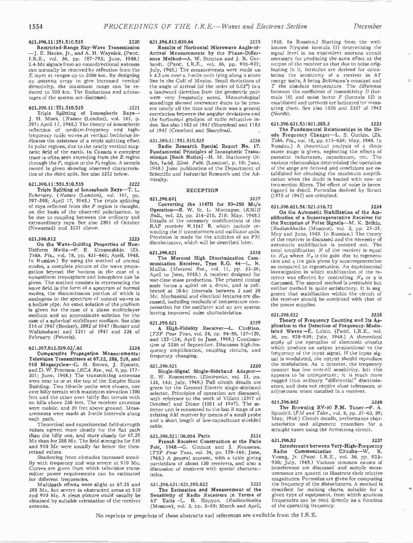
1554 PROCEEDINGS OF THE I.R.E. — Waves and Electrons Section December
621.396.11:551.510.535 3220 Restricted-Range Sky- Wave Transmission
—J. E. Hacke, Jr., and A. H. Waynick. (PRoc. I.R.E., vol. 36, pp. 787-793; June, 1948.) 2.4-Mc signals from an omnidirectional antenna can normally be received by reflection from the E layer at ranges up to 2000 km. By designing an antenna array to give increased vertical directivity, the maximum range can be re-duced to 500 km. The limitations and advan-tages of the system are discussed.
621.396.11: 551.510.535 3221 Triple Splitting of Ionospheric Rays —
J. H. Meek. (Nature (London), vol. 161, p. 597; April 17, 1948.) The theory of ionospheric reflection of medium-frequency and high-frequency radio waves at vertical incidence in-dicates the existence of a triple splitting effect in polar regions, due to the nearly vertical mag-netic field of the earth. In Canada a complete trace is often seen extending from the E region through the F1 region to the F2 region. A sample record is given showing observed characteris-tics of the third split. See also 3222 below.
621.396.11:551.510.535 3222 Triple Splitting of Ionospheric Rays —T. L.
Eckersley. (Nature (London), vol. 161, pp. 597-598; April 17, 1948.) The triple splitting of rays reflected from the F region is thought, on the basis of the observed polarization, to be due to coupling between the ordinary and extraordinary rays. See also 2595 of October (Newstead) and 3221 above.
621.396.812 3223 On the Wave-Guiding Properties of Non-
Uniform Media —P. E. Krasnushkin. (Zh. Tekh. Fis., vol. 18, pp. 431-446; April, 1948. In Russian.) By using the method of normal modes, a complete picture of the wave propa-gation beyond the horizon in the case of a nonuniform troposphere and ionosphere can be given. The method consists in representing the wave field in the form of a spectrum of normal modes, the discontinuous portion of which is analogous to the spectrum of normal waves in a hollow pipe. An exact solution of the problem is given for the case of a plane multiplayer medium and an approximate solution for the case of a spherical multilayer medium. See also 516 of 1947 (Booker), 2892 of 1947 (Booker and Walkinshaw) and 2211 of 1947 and 224 of February (Pekeris).
621.397.812.029.62/.63 3224 Comparative Propagation Measurements:
Television Transmitters at 67.25, 288, 510, and 910 Megacycles —G. H. Brown, J. Epstein, and D. W. Peterson. (RCA Rev., vol. 9, pp. 177-201; June, 1948.) The transmitting antennas were near to or at the top of the Empire State Building. Two 50-mile paths were chosen, one over hilly terrain with maximum elevation 1200 feet and the other over fairly flat terrain with no hills above 230 feet. The receiver antennas were mobile, and 30 feet above ground. Meas-urements were made at 2-mile intervals along each path.
Theoretical and experimental field-strength values agreed more closely for the flat path than the hilly one, and more closely for 67.25 Mc than for 288 Mc. The field strengths for 510 and 910 Mc were usually far below the theo-retical values. Shadowing from obstacles increased stead-
ily with frequency and was severe at 910 Mc. Curves are given from which television trans-mitter power requirements can be estimated for different frequencies.
Multipath effects were slight at 67.25 and 288 Mc, but severe in obstructed areas at 510 and 910 Mc. A clean picture could usually be obtained by suitable orientation of the receiver antenna.
621.396.812.029.64 3225 Results of Horizontal Microwave Angle-of-
Arrival Measurements by the Phase-Differ-ence Method —A. W. Straiton and J. R. Ger-hardt. (PRoc. I.R.E., vol. 36, pp. 916-922; July, 1948.) The measurements were made on X 3.2 cm over a 7-mile path lying along a shore line in the Gulf of Mexico. Small deviations of the angle of arrival (of the order of 0.02°) in a a landward direction from the geometric path were very frequently noted. Meteorological soundings showed overwater ducts to be pres-ent nearly all the time and there was a general correlation between the angular deviations and the horizontal gradient of radio refractive in-dex. See also 1182 of 1947 (Sharpless) and 1183 of 1947 (Crawford and Sharpless).
621.396.11:551.510.535 3226 Radio Research Special Report No. 17.
Fundamental Principles of Ionospheric Trans-. mission [Book Notice[ —H. M. Stationery Of-fice, 18.6d. (Govt. Publ. (London), p. 18; June, 1948.) Joint publication of the Department of Scientific and Industrial Research and the Ad-miralty.
RECEPTION
621.396.621 3227 Converting the 1147B for 50-250 M O
Operation —B. W. St. L. Montague. (RSGB Bull., vol. 23, pp. 214-216, 218; May, 1948.) Details of the necessary modifications of the RAF receiver R.1147 B, which include re-winding the if transformers and oscillator coils. Provision is made for the addition of an FM discriminator, which will be described later.
621.396.621 3228 The Marconi High Discrimination Com-
munication Receiver, Type R.G. 44 —L. R. Mullin. (Marconi Rev., vol. 11, pp. 33-38; April to June, 1948.) A receiver designed for war-time mass production. The printed tuning scale forms a spiral on a drum, and is cali-brated at 10-kc intervals between 2 and 20 Mc. Mechanical and electrical features are dis-cussed, including methods of temperature com-pensation for the oscillator and an avc system having improved noise characteristics.
621.396.621 3229 A High-Fidelity Receiver —L. Chretien.
(TSF Pour Tous, vol. 24, pp. 84-86, 127-129, and 152-154; April to June, 1948.) Continua-tion of 2336 of September. Discusses high-fre-quency amplification, coupling circuits, and frequency changing.
621.396.621 3230 Single-Signal Single-Sideband Adaptor —
E. W. Rosentreter. (Electronics, vol. 21, pp. 124, 143; July, 1948.) Full circuit details are given for the General Electric single-sideband selector. Principles of operation are discussed, with reference to the work of Villard (2597 of October) and Dome (1021 of 1947). The se-lector unit is connected to the last if stage of an existing AM receiver by means of a small probe and a short length of low-capacitance shielded cable.
621.396.621:06.064 Paris 3231 French Receiver Construction at the Paris
Fair, 1948 —G. Giniaux and J. Rousseau. (TSF Pour Tous, vol. 24, pp. 159-164; June, 1948.) A general account, with a table giving particulars of about 130 receivers, and also a discussion of receivers with special characte.-istics.
621.396.621:621.396.822 3232 The Estimation and Measurement of the
Sensitivity of Radio Receivers in Terms of kT Units—L. B. Slepyan. (Radiotekhnika (Moscow), vol. 3, pp. 3-10; March and April,
1948. In Russian.) Starting from the well-known Nyquist formula (1) determining the signal level in an equivalent antenna circuit necessary for producing the same effect at the output of the receiver as that due to noise orig-inating in it, formulas are derived for calcu-lating the sensitivity of a receiver in kT energy units, k being Boltmann's constant and T the absolute temperature. The difference between the coefficient of insensitivity D (for-mula 10) and noise factor F (formula 12) is established and methods are indicated for meas-uring them. See also 1656 and 2337 of 1942 (North).
621.396.621.53:621.385.2 3233 The Fundamental Relationships in the Di-
ode Frequency Changer —L. S. Gutkin. (Zh. Tekh. Fla., vol. 18, pp. 615-638; May, 1948. In Russian.) A theoretical analysis of a diode mixer stage is given, neglecting the effects of parasitic inductance, capacitance, etc. The various relationships determining the operation of the stage are derived and conditions ale es-tablished for obtaining the maximum amplifi-cation when the diode is loaded with one- or two-section filters. The effect of noise is inves-tigated in detail. Formulas derived by Strutt (1573 of 1947) are criticized.
621.396.621.54: 621.316.72 3234 On the Automatic Stabilization of the Am-
plification of a Superregenerative Receiver for the Reception of Pulse Signals —M. K. Belkin. (Radiotekhnika (Moscow), vol. 3, pp. 25-35; May and June, 1948. In Russian.) The theory of the receiver is discussed and the necessity of automatic stabilization is pointed out. The total amplification N of the receiver is equal to No where Ars, is the gain due to regenera-tion and q the gain given by superregeneration as compared to regeneration. An experimental investigation in which stabilization of the re-ceiver was effected by controlling N, or n is discussed. The second method is preferable but neither method is quite satisfactory. It is sug gested that stabilization within the circuit of the receiver should be combined with that of the power supplies.
621.396.622 3235 Theory of Frequency Counting and Its Ap-
plication to the Detection of Frequency-Modu-lated Waves—E. Labin. (PRoc. I.R.E., vol. 36, pp. 828-839; July, 1948.) A theoreitcal study of the operation of electronic circuits which produce an output proportional to the frequency of the input signal. If the input sig-nal is modulated, the output should reproduce the modulation. As a detector, the frequency counter has low over-all sensitivity, but this appears to be unimportant; it is much more rugged than ordinary "differential" discrimin-ators, and does not require close tolerances, or adjustment when installed in a receiver.
621.396.662 3236 The Browning RV-10 F. M. Tuner —F. A.
Spindell. (F M and Telev., vol. 8, pp. 37-40, 59; May, 1948.) Circuit details, performance char-acteristics and alignment procedure for a straight tuner using the Armstrong circuit.
621.396.82 3237 Interference between Very-High-Frequency
Radio Communication Circuits —W. R. Young, Jr. (PRoc. I.R.E., vol. 36, pp. 923-930; July, 1948.) Various common causes of interference are discussed and sample meas-urements are quoted to illustrate their relative magnitudes. Formulas are given for computing the frequency of the disturbances. A method is described for making charts, suitable for a given type of equipment, from which spurious frequencies can be read directly as a function of the operating frequency.
No reprints or preprints of these abstracts and references are available from the I.R.E.
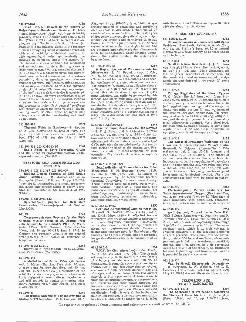
1948 Abstracts and References 1555
621.396.822 . 3238 Some General Results in the Theory of
Noise through Non-Linear Devices —D. Mid-dleton (Quart. Appl. Math., vol. 5, pp. 445-498; January, 1948.) The Fourier series method of Rice (2169 of 1945 and back references) is ap-plied to the following unsolved problems; (a) Passage of a modulaated signal in the presence of noise through a general nonlinear apparatus, with a sinusoidally modulated carrier, or with narrow-band noise, symmetrically dis-tributed in frequency about the carrier. (b) The biased A th-law rectifier, for modulated and unmodulated carriers; limiting cases of large noise or signal voltages are also discussed. (c) The case of a modulated signal and narrow-band noise, with a determination of the various probability densities associated with the en-velope of the wave. (d) The correlation function and mean power associated with the envelope of signal and noise. The low-frequency output of the half-wave th-law device is considered. (e) The µ th-law, half-wave rectification of noise alone. This is relevant to the measurement of noise and to the detection of pulse signals in the presence of noise. (f) A general "small-sig-nal" theory in which the peak values of the in-coming wave, whether noise or signal plus noise, are so small that overloading and cutoff do not occur.
621.396.822 3239 Thermal Noise in Resistors —S. Rodda:
D. A. Bell. Correction to 2072 of July. The paper by Bell there mentioned should have been 2780 of 1938. See also 1914 of 1939 (Moullin).
621.396.822 : 523.72+ 523.16 3240 Radio Noise of Extra-Terrestrial Origin
and its Effect on Telecommunication Tech-nique —Lehmann. (See 3102.)
STATIONS AND COM MUNICATION SYSTEMS
534.861.1:621.316.345:621.396.664 3241 Modern Design Features of CBS Studio
Audio Facilities —R. B. Monroe and C. A. Palmquist. (PRoc. I.R.E., vol. 36, pp. 778-786; June, 1948). Description of a small, space-sav-ing, single-unit console which is easily acces-qible for maintenance. See also 2316 of 1946 (Chinn).
534.861.1:621.396.712.3 3242 Speech-Input Equipment for New Oslo
Broadcasting House —Julsrud and Weider. (See 3008).
621.39 3243 Telecommunication Services for the Fifth
Olympic Winter Sports at St. Moritz, from 30th January to 8th February 1948 —A. Wett-stein. (Tech. Mitt. Schweiz. Telegr.-Teleph-Verw., vol. 26, pp. 99-115; June 1, 1948. In German and French.) Details of the general arrangements, with particular reference to telephone facilities.
621.391.63:534.321.9 3244 Distortion in Light Modulation by an Ultra-
sonic Cell —Sette. (See 3000.)
621.394.441 3245 A Multi-Channel Carrier Telegraph System
—A. L. Matte. (Bell Sys. Tech. Publ. Monogr. B-1529 4 pp; Railway Signaling, vol. 40, pp. 778-781; December, 1947.) Description of the 40AC1 voice-frequency system, which is specif-ically designed to meet railway requirements and will provide 12 duplex or simplex teleg-raphy channels on a 4-wire circuit, or 6 on a 2-wire circuit.
621.396.41 3246 Theoretical Analysis of Various Systems of
Multiplex Transmission—V. D. Landon. (RCA
Rev., vol. 9, pp. 287-351; June, 1948.) A sys-tematic method of classifying and specifying such systems is discussed. Definitions of 77 associated terms are included. The basic types of frequency division, time division, and triple modulation systems are considered in detail. Formulas for the signal-to-noise ratio for each system relative to that for single-channel AM are obtained and tabulated; due allowance is made for pre-emphasis. More detailed discus-sion of the relative merits of the systems will be given later.
621.396.41.029.64 3247 A Duplex System of Communications for
Microwaves —R. V. Pound. (PRoc. I.R.E., vol. 36, pp. 840-844; July, 1948.) A single os-cillator is used both as transmitter and as beat-ing oscillator of a superheterodyne receiver. The oscillator frequency is stabilized at the fre-quency of a high-Q cavity; FM takes place about this stabilization frequency. Duplex communication can easily be arranged by this method and an experimental set is described; the operator initiating communication can as-certain that his signals are being received. The application of the system to ground/aircraft communication and to a booster system for a relay link is discussed. See also 1690 of 1947 and 1311 of June.
621.396.61/.621.029.63 3248 Practical Experiments on 2350 Megacycles
— N. T. J. Bevan and L. Grimshaw. (RSGB Bull., vol. 24, pp. 2-4; July, 1948.) Construc-tion and brief performance details of the trans-ceivers used. An oscillator consisting of a type CV90 tube with the modified cavity of a Sutton tube forms the basis of the transmitter. Pro-vision is made for radio-telephone or mew operation. The associated receiver is superre-generative.
621.396.619.16(083.72) 3249 Standardization of Nomenclature for Pulse
Modulation —H. H. Heeroma. (Pnoc. I.R.E. vol. 36, p. 880; July, 1948.) Statement of terms proposed by the Netherlands Electro-technical Committee, for use internationally. Terms favored are: pulse-rate, pulse-width, pulse-position, pulse-height, pulse-slope, and pulse-code modulation. Terms deprecated are pulse-frequency, pulse-length, pulse-phase, pulse-displacement, pulse-time, pulse-delay, and pulse-amplitude modulation.
621.396.65.029.63 3250 S-T [studio-transmitted Link on 920 to 980
Mc/s —R. H. De Witt. (FM and Telev., vol. 8, pp. 22-25; May, 1948.) A radio link for use where wire lines are either lacking or uneconom-ic. Block diagrams, numerous illustrations, and a short description of the equipment are given, with performance details. Corner-re-flector antennas are used for line-of-sight dis-tances up to 12 miles. Paraboloids are necessary for greater distances up to the maximum of 35 miles.
621.396.933 3251 V.H.F. for Civil Aircraft—( Wireless World,
vol. 54, pp. 242-243; July, 1948.) The aircraft set weighs only 12 lb, takes 3.75 amp from a 12-v battery and delivers about 300 mw to the antenna. It comprises two crystal multiplier chains, two rf and frequency-changer chains, a common if amplifier with detector, agc and af stages, and a modulator chain. For airport control, a 5-w rack-mounted installation is provided, comprising two separate transmitters and receivers and their power supplies. All four are crystal-controlled and have provision for remote or local operation. The receiver used for direction-finding is very similar to the com-munication receiver. Two-way communication has been maintained at ranges up to 33 miles
with the aircraft at 2000 feet and up to 70 miles with the aircraft at 10,000 feet.
SUBSIDIARY APPARATUS
621-526:621.396 3252 Servomechanisms in Connection with Radio
Problems: Part 1—G. Lehmann. (Onde Elec., vol. 28, pp. 213-217; June, 1948.) A general discussion of a wide variety of applications in radio technique.
621.314.634 3253 Small Selenium Rectifiers —J. J. A. Ploos
van Amstel. (Philips Tech. Rev., vol. 9, no. 9, pp. 267-276; 1947 and 1948.) Discussion of: (a) the general properties of Se rectifiers, (b) the construction and measurement of the dy-namic characteristics of three types, (c) some applications.
621.316.722 3254 Voltage Regulators of the Shunt Type —
W. G. Hoyle. (Rev. Sci. Instr., vol. 19, pp. 244-246; vol. 19, April, 1948.) A general equation is derived, giving the relation between the nom-inal required input voltage and the maximum shunt regulating current for any variation of the input voltage and for any load. The neces-sary relation between the shunt regulating cur-rent and the output current for maximum elec-trical efficiency is obtained. For a fixed load, the maximum average efficiency of any shunt regulator is 1- 02)2, where k is the maximum variation, per unit, of the supply voltage.
621.316.722 3255 The Effect of Frequency Variations on the
Operation of Ferro-Resonant Voltage Stabi-lizers —B. V. Belyaev. (Avtomatika i Tele-mekhanika, vol. 9, pp. 59-73; January and February, 1948. In Russian.) The effects of various parameters of stabilizers, such as the inductance value, the capacitance of capacitors and the compensating coil, the value and type of the load resistance, etc., on the output volt-age variation with frequency are investigated by a graphical/analytical method. The main conclusions are confirmed by experimental re-sults.
621.316.722.1 3256 Electromagnetic Voltage Stabilizers for
Valve Apparatus —W. Geyger. (Funk and Ton, vol. 2, pp. 308-314; June, 1948.) Discussion of basic principles, with description, character-istics, and performance of some modern types.
621.316.722.1 3257 An Inductively Coupled Series Tube D.C.
High Voltage Regulator —R. Pepinsky and P. Jarmotz. (Rev. Sci. Instr., vol. 19, pp. 247-254; April, 1948.) A stabilizer operating in the range 5 to 50kv for currents up to 50 ma. The series regulator tube, which is at high voltage, is coupled inductively to the feedback amplifier at earth potential. The signal from the ampli-fier provides AM for a rf oscillator, whose out-put voltage is fed to a transformer, rectified, filtered, and then applied as a dc correcting signal to the grid of the series tube. Insulation between high-voltage and low-voltage circuits is provided in the rf transformer.
621.319.339 3258 Van de Graaff Electrostatic Generator —
J. M. Ferguson, E. W. Webster, and T. E. Calverley. (Elec. Times, vol. 113, pp. 575-579; May 13, 1948.) A short, illustrated description.
TELEVISION AND PHOTOTELEGRAPHY
621.397.331:513.3 3259 The Application of Projective Geometry to
the Theory of Color Mixture —F. J. Bingley. (Psoc. I.R.E., vol. 36, pp. 709-723; June,
No reprints or preprints of these abstracts and references are available from the I.R.E.
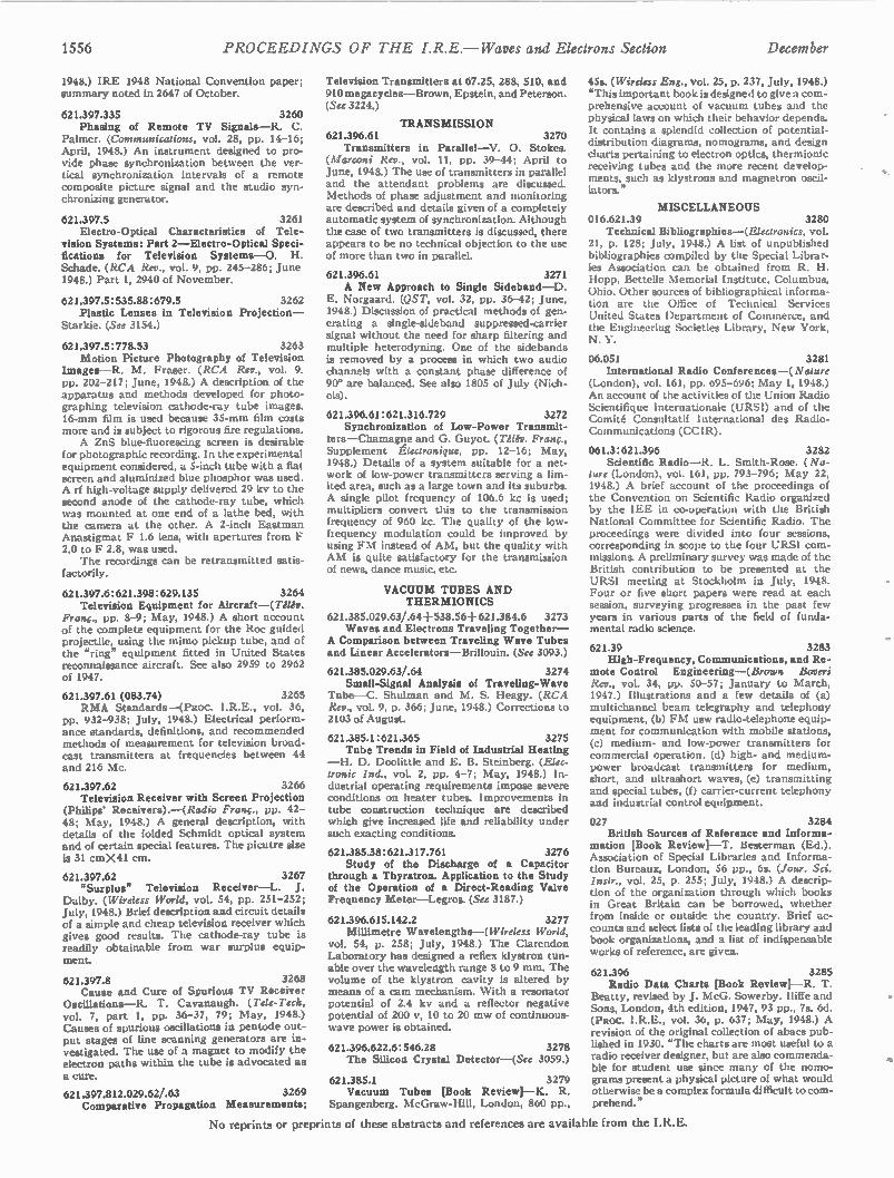
1556 PROCEEDINGS OF TIIE I.R.E. — Waves and Electrons Section December
1948.) IRE 1948 National Convention paper; summary noted in 2647 of October.
621.397.335 3260 Phasing of Remote TV Signals —R. C.
Palmer. (Communications, vol. 28, pp. 14-16; April, 1948.) An instrument designed to pro-vide phase synchronization between the ver-tical synchronization intervals of a remote composite picture signal and the studio syn-chronizing generator.
621.397.5 3261 Electro-Optical Characteristics of Tele-
vision Systems: Part 2—Electro-Optical Speci-fications for Television Systems —O. H. Schade. (RCA Rev., vol. 9, pp. 245-286; June 1948.) Part 1, 2940 of November.
621.397.5 : 535.88: 679.5 3262 Plastic Lenses in Television Projection —
Starkie. (See 3154.)
621.397.5:778.53 3263 Motion Picture Photography of Television
Images —R. M. Fraser. (RCA Rev., vol. 9. pp. 202-217; June, 1948.) A description of the apparatus and methods developed for photo-graphing television cathode-ray tube images. 16-mm film is used because 35-mm film costs more and is subject to rigorous fire regulations. A ZnS blue-fluorescing screen is desirable
for photographic recording. In the experimental equipment considered, a 5-inch tube with a flat screen and aluminized blue phosphor was used. A rf high-voltage supply delivered 29 kv to the second anode of the cathode-ray tube, which was mounted at one end of a lathe bed, with the camera at the other. A 2-inch i Eastman Anastigrnat F 1.6 lens, with apertures from F 2.0 to F 2.8, was used.
The recordings can be retransmitted satis-factorily.
621.397.6: 621.398 : 629.135 3264 Television Equipment for Aircraft —(Telev.
Franc., pp. 8-9; May, 1948.) A short account of the complete equipment for the Roc guided projectile, using the mimo pickup tube, and of the "ring" equipment fitted in United States reconnaissance aircraft. See also 2959 to 2962 of 1947.
621.397.61 (083.74) 3265 RMA Standards —(PRoc. 1.R.E., vol. 36,
pp. 932-938; July, 1948.) Electrical perform-ance standards, definitions, and recommended methods of measurement for television broad-cast transmitters at frequencies between 44 and 216 Mc.
621.397.62 3266 Television Receiver with Screen Projection
(Philips Receivers). —(Radio Franc., pp. 42-48; May, 1948.) A general description, with details of the folded Schmidt optical system and of certain special features. The picutre size is 31 cmX41 cm.
621.397.62 3267 "Surplus" Television Receiver —L. J.
Dalby. (Wireless World, vol. 54, pp. 251-252; July, 1948.) Brief description and circuit details of a simple and cheap television receiver which gives good results. The cathode-ray tube is readily obtainable from war surplus equip-ment.
621.397.8 3268 Cause and Cure of Spurious TV Receiver
Oscillations —R. T. Cavanaugh. (Tele-Tech, vol. 7, part 1, pp. 36-37, 79; May, 1948.) Causes of spurious oscillations in pentode out-put stages of line scanning generators are in-vestigated. The use of a magnet to modify the electron paths within the tube is advocated as
a cure.
621.397.812.029.62/.63 3269 Comparative Propagation Measurements;
Television Transmitters at 67.25, 288, 510, and 910 megacycles —Brown, Epstein, and Peterson. (See 3224.)
TRANS MISSION 621.396.61 3270
Transmitters in Parallel —V. 0. Stokes. (Marconi Rev., vol. 11, pp. 39 -44; April to June, 1948.) The use of transmitters in parallel and the attendant problems are discussed. Methods of phase adjustment and monitoring are described and details given of a completely automatic system of synchronization. Although the case of two transmitters is discussed, there appears to be no technical objection to the use of more than two in parallel.
621.396.61 3271 A New Approach to Single Sideband —D.
E. Norgaard. (QST, vol. 32, pp. 36-42; June, 1948.) Discussion of practical methods of gen-erating a single-sideband suppressed-carrier signal without the need for sharp filtering and multiple heterodyning. One of the sidebands is removed by a process in which two audio channels with a constant phase difference of 90° are balanced. See also 1805 of July (Nich-ols).
621.396.61:621.316.729 3272 Synchronization of Low-Power Transmit-
ters —Chainagne and G. Guyot. (Telev. Franc., Supplement glectronique, pp. 12-16; May, 1948.) Details of a system suitable for a net-work of low-power transmitters serving a lim-ited area, such as a large town and its suburbs. A single pilot frequency of 106.6 kc is used; multipliers convert this to the transmission frequency of 960 kc. The quality of the low-fiequency modulation could be improved by using FM instead of AM, but the quality with AM is quite satisfactory for the transmission of news, dance music, etc.
VACUU M TUBES AND THER MIONICS
621.385.029.63/.64+ 538.56+621.384.6 3273 Waves and Electrons Traveling Together —
A Comparison between Traveling Wave Tubes and Linear Accelerators —Brillouin. (See 3093.)
621.385.029.63/.64 3274 Small-Signal Analysis of Traveling- Wave
Tube —C. Shulman and M. S. Heagy. (RCA Rev., vol. 9, p. 366; June, 1948.) Corrections to 2103 of August.
621.385.1:621.365 3275 Tube Trends in Field of Industrial Heating
— H. D. Doolittle and E. B. Steinberg. (Elec-tronic Ind., vol. 2, pp. 4-7; May, 1948.) In-dustrial operating requirements impose severe conditions on heater tubes. Improvements in tube construction technique are described which give increased life and reliability under such exacting conditions.
621.385.38:621.317.761 3276 Study of the Discharge of a Capacitor
through a Thyratron. Application to the Study of the Operation of a Direct-Reading Valve Frequency Meter —Legros. (See 3187.)
621.396.615.142.2 3277 Millimetre Wavelengths--( Wireless World,
vol. 54, p. 258; July, 1948.) The Clarendon Laboratory has designed a reflex klystron tun-able over the wavelength range 8 to 9 mm. The volume of the klystron cavity is altered by means of a cam mechanism. With a resonator potential of 2.4 kv and a reflector negative potential of 200 v, 10 to 20 mw of continuous-wave power is obtained.
621.396.622.6:546.28 3278 The Silicon Crystal Detector —(See 3059.)
621.385.1 3279 Vacuum Tubes [Book Review[ —K. R.
Spangenberg. McGraw-Hill, London, 860 pp.,
45s. (Wireless Eng., vol. 25, p. 237, July, 1948.) "This important book is designed to give a com-prehensive account of vacuum tubes and the physical laws on which their behavior depends. It contains a splendid collection of potential-distribution diagrams, nomograms, and design charts pertaining to electron optics, thermionic receiving tubes and the more recent develop-ments, such as klystrons and magnetron oscil-lators."
MISCELLANEOUS 016.621.39 3280
Technical Bibliographies —(Electronics, vol. 21, p. 128; July, 1948.) A list of unpublished bibliographies compiled by the Special Librar-ies Association can be obtained from R. H. Hopp, Bettelle Memorial Institute, Columbus, Ohio. Other sources of bibliographical informa-tion are the Office of Technical Services United States Department of Commerce, and the Engineering Societies Library, New York, N. Y.
06.051 3281 International Radio Conferences —( Nature
(London), vol. 161, pp. 695-696; May 1, 1948.) An account of the activities of the Union Radio Scientifique Internationale (URSI) and of the Comite Consultatif International des Radio-Communications (CCIR).
061.3: 621.396 3282 Scientific Radio —R. L. Smith-Rose. (Na-
ture (London), vol. 161, pp. 793-796; May 22, 1948.) A brief account of the proceedings of the Convention on Scientific Radio organized by the IEE in co-operation with the British National Committee for Scientific Radio. The proceedings were divided into four sessions, corresponding in scope to the four URSI com-missions. A preliminary survey was made of the British contribution to be presented at the URSI meeting at Stockholm in July, 1948. Four or five short papers were read at each session, surveying progresses in the past few years in various parts of the field of funda-mental radio science.
621.39 3283 High-Frequency, Communications, and Re-
mote Control Engineering —(Brown Boveri Rev., vol. 34, pp. 50-57; January to March, 1947.) Illustrations and a few details of (a) multichannel beam telegraphy and telephony equipment, (b) FM usw radio-telephone equip-ment for communication with mobile stations, (c) medium- and low-power transmitters for commercial operation, (d) high- and medium-power broadcast transmitters for medium, short, and ultrashort waves, (e) transmitting and special tubes, (f) carrier-current telephony and industrial control equipment.
027 3284 British Sources of Reference and Informa-
mation [Book Reviewl —T. Besterman (Ed.). Association of Special Libraries and Informa-tion Bureaux, London, 56 pp., 6s. (Jour. Sci. Instr., vol. 25, p. 255; July, 1948.) A descrip-tion of the organization through which books in Great Britain can be borrowed, whether from inside or outside the country. Brief ac-counts and select lists of the leading library and book organizations, and a list of indispensable works of reference, are given.
621.396 3285 Radio Data Charts [Book Reviewi —R. T.
Beatty, revised by J. McG. Sowerby. Iliffe and Sons, London, 4th edition, 1947, 93 pp., 7s. 6d. (Pitoc. I.R.E., vol. 36, p. 637; May, 1948.) A revision of the original collection of abacs pub-lished in 1930. "The charts are most useful to a radio receiver designer, but are also commenda-ble for student use since many of the nomo-grams present a physical picture of what would otherwise be a complex formula difficult to com-prehend."
No reprints or preprints of these abstracts and references are available from the I.R.E.
BOARD OF DIRECTORS, 1948
Benjamin E. Shackelford President
R. L. Smith-Rose Vice-President
S. L. Bailey Treasurer
Haraden Pratt Secretary
Alfred N. Goldsmith Editor
Frederick B. Llewellyn Senior Past President
W. R. G. Baker Junior Past President
1948-1949
J. B. Coleman Murray G. Crosby Raymond A. Heisiniz
T. A. Hunter H. J. Reich F. E. Terman
1948-1950
J. E. Shepherd J. A. Stratton
1948
A. E. Cullum, Jr. Virgil M. Graham Raymond F. Guy Keith Henney J. V. L. Hogan F. S. Howes
J. A. Hutcheson I. J. Kaar D. B. Sinclair
• Harold R. Zeamans General Counsel
• George W. Bailey Executive Secretary
Laurence G. Cumming Technical Secretary
E. K. Gannett Assistant Secretary
•
BOARD OF EDITORS
Alfred N. Goldsmith Chairman
•
PAPERS REVIEW COMMITTEE
Murray G. Crosby Chairman
• PAPERS
PROCUREMENT COMMITTEE
John D. Reid General Chairman
PROCEEDINGS OF THE I.R.E.
(Including WAVES AND ELECTRONS Section)
Published Monthly by
The Institute of Radio Engineers, Inc.
Index to Volume 36-1948
Editorial Department
Alfred N. Goldsmith, Editor
Clinton B. DeSoto Mary L. Potter Technical Editor Assistant Editor
William C. Copp Lillian Petranek Advertising Manager Assistant Advertising Manager
The Institute of Radio Engineers, Inc. I East 79 Street
New York 21, N.Y.
Copyright, 1949, by The Institute of Radio Engineers, Inc.
•
NOTE The Journal of The Institute of Radio Engineers is officially known as the
PROCEEDINGS OF THE I.R.E. The WAVES AND ELECTRONS section is to be re-garded solely as a portion thereof, and not as a separate publication.
TABLE OF CONTENTS General Information Contents of Volume 36 Chronological Listing Index to Book Reviews Index to Authors Index to Subjects Nontechnical Index Awards Committees Constitution and Bylaws Conventions and Meetings Editorials Election of Officers Front Covers Frontispieces. Group Photographs Industrial Engineering Notes
Cover II Contents of Volume 36 (continued) 1 Nontechnical Index (continued) 1 Institute of Radio Engineers 19 7 IRE People 19 8 Laboratories 20 9 Miscellaneous 20 18 Obituaries 20 18 Report of Secretary-1946 20 18 Representatives in Colleges 20 18 Representatives on Other Bodies 20 18 Sections 20 18 Standards—IRE 20 18 Back Copies Cover III 19 Proceedings Binders Cover III 19 Membership Emblems Cover III 19 Current IRE Standards Cover IV 19 ASA Standards (Sponsored by the IRE) Cover IV
GENERAL INFORMATION The Institute
The Institute of Radio Engineers serves those inter-ested in radio and allied electronics and electrical-com-munication fields through the presentation and publica-tion of technical material. Membership has grown from a few dozen in 1912 to
approximately 23,000. There are several grades of mem-bership, depending on the qualifications of the appli-cant, with dues ranging from $3.00 per year for Students to $15.00 per year for Members, Senior Members, Fellows, and Associates of more than five years' standing. THE PROCEEDINGS is sent to members of record on
the date of publication. Standards Bulletins, as listed on Cover IV, are in stock and are available for those who wish to buy them at the cost shown opposite the name of the Standard.
The PROCEEDINGS The PROCEEDINGS has been published without inter-
ruption from 1913, when the first issue appeared. Over 3200 technical contributions have been included in its pages, portraying a currently written history of devel-opments in both theory and practice. The contents of
every paper published in the PROCEEDINGS are the re-sponsibility of the author and are not binding on the Institute or its members. Text material appearing in the PROCEEDINGS may be reprinted or abstracted in other publications on the express condition that specific reference shall be made to its original appearance in the PROCEEDINGS. Illustrations of any variety may not be reproduced, however, without specific permission from the Institute. The first issue of the PROCEEDINGS was published in
1913. Volumes 1, 2, and 3 comprise four issues each. Volume 4 through volume 14 contain six numbers each, and each succeeding volume is made up of twelve issues. In 1939, the name of the PROCEEDINGS of The Insti-
tute of Radio Engineers was changed to the PROCEED-INGS OF THE I.R.E. and the size of the magazine was en-larged from six by nine inches to eight and one-half by eleven inches.
Subscriptions Annual subscription rates for the United States of
America, its possessions, and Canada, $18.00; to college and public libraries when ordering direct, $13.50. Other countries, $1.00 additional for postage.
Contents of Volume 36-1948 Volume 36, Number 1, January, 1948
PROCEEDINGS OF THE I.R.E.
Cumulative Index Number
Benjamin E. Shackelford, President-Elect, 1948 Technical Journalism, Lewis Winner
2970. High-Frequency Plated Quartz Crystal Units, R. A Sykes
2971. The Ionospheric Eclipse of October 1, 1940, J. A. Pierce 2972. Theory of Amplitude-Stabilized Oscillators, Pierre R.
Aigrain and E. M. Williams 2973. Application of Velocity-Modulation Tubes for Reception
at U.H.F. and S.H.F., M. J. 0. StruIt and A. van der Ziel
2974. Phase and Amplitude Distortion in Linear Networks, M. J. Di Toro
2975. Design Principles of Amplitude-Modulated Subcarrier Telemeter Systems, Cecil K. Stedman
2976. Trigonometric Components of a Frequency-Modulated Wave, Enzo Cambi
2977. Class-A Push-Pull Amplifier Theory, Herbert L. Krauss 2978. Methods of Tuning Multiple-Cavity Magnetrons, R. B
Nelson 2979. Theory of the Circular Diffraction Antenna, A. A. Pis-
tolkors 2980. A New Type of Waveguide Directional Coupler, H. J
Riblet and T. S. Saad 2981. The Series Reactance in Coaxial Lines, Howard J. Row-
land Tracing of Electron Trajectories Using the Differential Ana-
lyzer 2982. Introduction, John P. Blewett 2983. Part I-Differential Analyzer Representation, Gabriel
Kron, F. J. Maginniss, and H. A. Peterson 2984. Part II-Electron Paths in Magnetrons, W. C. Hahn and
J. P. Blewett 2985. Part III -Study of Transit-Time Effects in Disk-Seal
Power-Amplifier Triodes, J. R. Whinnery and H. W. Jamieson
2828. Discussion on "Harmonic-Amplifier Design," by Rob-ert H. Brown, (August, 1947, p. 84); A. H. Sonnen-schein and Robert H. Brown
Contributors to PROCEEDINGS OF THE I.R.E. 2986. Correspondence: "Solar Intensity at 480 Mc." Grote
Reber "1 East 79 Street" National Electronics Conference Rochester Fall Meeting-1947 URSI -IRE 1948 IRE National Convention News Industrial Engineering Notes
2987. Book Review: "Wireless Direction Finding," by R. Keen (Reviewed by P. C. Sandretto)
2988. Book Review: "The Future of Television," by Orrin E Dunlap (Reviewed by John D. Reid)
Sections IRE People
Page 2 3
19
24
36
42 50
53
56
61
65
Volume 36, Number 2, February, 1948 PROCEEDINGS OF THE I.R.E.
Cumulative Index Number
R. L. Smith-Rose, Vice-President The Engineer's Role in Government, Donald McNicol
2993. The Visibility of Small Echoes on Radar PPI Displays Ruby Payne-Scott
4 2994. Results of Microwave Propagation Tests on a 40-Mile 8 Overland Path, A. L. Durkee
2995. Wavelength Lenses, Gillen Wilkes 16 2996. A Method of Determining and Monitoring Power and
Impedance at High Frequencies, J. F. Morrison and E. L. Younker
2997. Resistor-Transmission-Line Circuits, Paul I Richards.... 2998. Currents Excited on a Conducting Plane by a Parallel
Dipole, Beverly C. Dunn, Jr. and Ronold King 2999. Experimental Determination of Helical-Wave Properties
C. C. Cutler 3000. A Tunable Vacuum-Contained Triode Oscillator for
Pulse Service, C. E. Fay and J. E. Wolfe 3001. Correspondence: "Angular Frequency Shift," Sherman
Rigby 2808. Discussion on "Generalized Theory of Multitone Ampli-
tude and Frequency Modulation" by Lawrence J. Giacoletto, (July, 1947, pp. 240-243); A. S. Gladwin and Lawrence J. Giacoletto
Contributors to the PROCEEDINGS OF THE I.R.E. 1948 IRE National Convention News Sections IRE People Industrial Engineering Notes
3002. Book Review:"Elementary Nuclear Theory" by H. A. 69 Bethe, (Reviewed by J. B. H. Kuper)
3003. Book Review: "Principles and Practice of Electrical En-70 gineering," by Alexander Gray (Revised by G. A. Wal-
lace) Reviewed by Frederick W. Grover 3004. Book Review: "Sunspots in Action," by Harlan True
Stetson (Reviewed by George M. K. Baker) 3005. Book Review: "Patent Notes for Engineers," by Radio
Corp. of America (Reviewed by Alois W. Graf) 76 3006. Book Review: "Men and Volts at War," by John A. Mil-
ler (Reviewed by Donald McNicol) 3007. Book Review: "Tables of Integrals and Other Mathe-
84 matical Data," by Herbert B. Dwight (Reviewed by George H. Brown)
84 3008. Book Review: "Electronics and Their Application in In-dustry and Research," edited by B. Lovell (Reviewed by W. C. White)
74
88 89 101 102 103 104 106
110
110 111 112
WAVES AND ELECTRONS SECTION Jerry B. Minter, Chairman, IRE Subsection for North-ern New Jersey 113
The Knolls Atomic Power Laboratory 114 2989. Report of the Committee on Professional Status of the
Canadian Council of the IRE R. C. Poulter 115 2990. Frequency-Shift Radio Transmission, Lester E. Hatfield 116 2991. Printed-Circuit Techniques, Cledo Brunetti and R. W
Curtis 121 Contributors to Waves and Electrons Section 162
2992. Abstracts and References 163
WAVES AND ELECTRONS SECTION National Physical Laboratory J. W. McRae, Board of Editors
3009. Developments in Radio Sky-Wave Propagation Research and Applications During the War, J. H. Dellinger and Newbern Smith
3010. Alternating-Current Measurements of Magnetic Proper-ties, Horatio W. Lamson
3011. The Degenerative Positive-Bias Multivibrator, Sidney Bertram
3012. A Variable-Radio-Frequency-Follower System, R. F. Wild
3013. New Techniques in Glass-to-Metal Sealing, Joseph A. Pask
Contributors to Waves and Electrons Section 3014. Abstracts and References
Page 178 179
180
197 206
212 217
221
230
234
239
240 244 246 247 248 250
254
254
254
255
255
255
255
256 257
258
266
277
281
296 289 291
Volume 36, Number 3, March, 1948 PROCEEDINGS OF THE I.R.E.
James E. Shepherd, Board of Directors, 1948-1950 306 3015. The Theory of Wireless Telegraphy, John Stone Stone 307
Volume 36, Number 3, March, 1948 (Cont'd.) Cumulative Index Number Page 3016. A Proposed Loudness-Efficiency Rating for Loudspeak-
ers and the Determination of System Power Require-ments for Enclosures, H. F. Hopkins and N. R. Stryker 315
3017. Limiting Resolution in an Image-Orthicon-Type Pickup Tube, Henry B. DeVore 335
3018. Reflections of Very-High-Frequency Radio Waves from Meteoric Ionization, Edward W. Allen, Jr 346
3019. Rainfall Intensities and Attenuation of Centimeter Elec-tromagnetic Waves, Raymond Wexler and Joseph Weinstein 353
3020. An Inductance-Capacitance Oscillator of Unusual Fre-quency Stability, J. K. Clapp 356
3021. The Comb Antenna, Ralph Grimm 359 2856. Correspondence: "Low-Level Atmospheric Ducts," J. S
McPetrie and B. J. Starnecki 363 2788. Correspondence: "Radar Reflections from the Lower
Atmosphere," Millard W. Baldwin, Jr. 363 Contributors to the PROCEEDINGS OF THE I.R E 363 1948 IRE National Convention Program 365 Summaries of Technical Papers 367 Industrial Engineering Notes 381
3022. Book Review: "Radar Aids to Navigation," edited by John S. Hall, L. A. Turner, and R. M. Whitmer (Re-viewed by Peter C. Sandretto) 383
3023. Book Review: "Electronic Transformers and Circuits," by Reuben Lee (Reviewed by Knox McIlwain) 383
Sections 384 IRE People 385
WAVES AND ELECTRONS SECTION Robert G. Rowe, Chairman, Buffalo-Niagara Section 386 The Western Electrical Instrument Corporation 387
3024. Preparing the Oral Version of a Technical Paper, William J. Temple 388
3025. High-Power Ionosphere-Measuring Equipment, P. G Sulzer 389
Home Projection Television: 3026. Part I. Cathode-Ray Tube and Optical System,
H. Rinia, J. de Gier, and P. M. van Alphen 395 3027. Part II. Pulse-Type High-Voltage Supply, G. J. Siezen
and F. Kerkhof 401 3028. Part III. Deflection Circuits, J. Haantjes and F. Kerkhof 407 3029. A Developmental Pulse Triode for 200 Kw. Output at
600 Mc., L. S. Nergaard, D. G. Burnside, and R. P Stone 412
3030. Circle Diagrams for Cathode Followers, Joseph M. Dia-mond 416
3031. A Note on Frequency Transformations for Use with the Electrolytic Tank, W. H. Huggins 421
Contributors to Waves and Electrons Section 424 3032. Abstract and References 427
Volume 36, Number 4, April, 1948 PROCEEDINGS OF THE I.R.E.
Julius A. Stratton, Director, 1948-1950 442 • Hammond Vinton Hayes, Edward L. Bowles 443
3033. Noise-Suppression Characteristics of Pulse-Time Modu-lation, Sidney Moskowitz and Donald D. Greig 446
3034. Magnetoionic Multiple Refraction at High Latitudes, S. L. Seaton 450
3035. Solar Noise Observations on 10.7 Centimeters, A. E Covington 454
3036. An Analysis of the Intermodulation Method of Distor-tion Measurement, W. J. Warren and W. R. Hewlett 457
3037. Automatic Volume Control as a Feedback Problem. B. M. Oliver 466
3038. A Flat-Response Single-Tuned I. F. Amplifier, E. II. B Bastelink, J. Kahnke, and R. L. Walters 474
3039. The Radiation Resistance of an Antenna in an Infinite Array or Waveguide, Harold A. Wheeler 478
3040. Coupled Antennas, C. T. Tai 487 3041. Correspondence: "Continuous Tropospheric Soundings
by Radar," A. W. Friend 501 Contributors to PROCEEDINGS OF THE I.R.E. 503 Canadian IRE Convention 506
Volume 36, Number 4, April, 1948 (Cont'd.) Cumulative Index Number
Industrial Engineering Notes Sections
3042. Book Review: "Radio Engineering," Third Edition, by Frederick Emmons Terman (Reviewed by F. B. Llewel-lyn)
3043. Book Review: "Theory and Application of Microwaves," by A. B. Bronwell and R. E. Beam (Reviewed by Simon Ramo)
3044. Book Review: "FM Simplified," by Milton S. Kiver (Re-viewed by C. M. Jansky, Jr.)
IRE People
Page 507 510
511
512
512 513
WAVES AND ELECTRONS SECTION
Karl Kramer, Chairman, Chicago Section, 1947-1948 515 A Modern Telecommunications Laboratory 516
3045. Engineering Responsibilities in Today's Economy, E. Finley Carter 517
3046. Industrial Standards, C. H. Crawford 519 3047. Radio Progress During 1947 522 3048. The Duct Capacitor, Alan Walton, Jr 550
Contributors to Waves and Electrons Section 554 3049. Abstracts and References 555
Volume 36, Number 5, May, 1948 PROCEEDINGS OF THE I.R.E.
The Institute on the March 570 Science and Universal Military Training, Arthur Van Dyck. 571
3050. Influence of Reproducing System on Tonal-Range Pre-ferences, Howard A. Chinn and Philip Eisenberg 572
3051. Experimental Studies of a Remodulating Repeater, W M. Goodall 580
3052. A Negative-Current Voltage-Stabilization Circuit, Peilin Luo 583
3053. Some Fundamental Considerations Concerning Noise Reduction and Range in Radar and Communication, Stanford Goldman 584
3054. The Steady-State and Transient Analysis of a Feedback Video Amplifier, J. H. Mulligan, Jr. and L. Mautner 595
3055. 500-Mc. Transmitting Tetrode Design Considerations, Winfield G. Wagener 611
3056. Note on the Maximum Directivity of an Antenna, H. J Riblet 620
3057. Multifrequency Bunching in Reflex Klystrons, W. H Huggins 624
Contributors to the PROCEEDINGS OF THE I.R E 631 3058. Correspondence: "Conformal Mapping Transforma-
tions," D. R. Rhodes 632 2920. Correspondence: "E-Plane Bend," John W. Miles 632 2980. Correspondence: "Directional Couplers," W. H. Watson 632
Executive Committee 633 New England Radio Engineering Meeting 635 Petition for Amendment of Article II, Sections 1-c and 2-c, of the Constitution 636
Industrial Engineering Notes 637 Sections 641 IRE People 642
3059. Book Review: "Very High Frequency Techniques," Radio Research Laboratory Staff of Harvard Univer-sity (Reviewed by E. D. McArthur) 645
3060. Book Review: "Techniques of Microwave Measure-ments," edited by Carol G. Montgomery (Reviewed by Allen F. Pomeroy) 645
3061. Book Review: "Meteorological Factors in Radio- Wave Propagation" (Reviewed by Oliver P. Ferrell) 645
3062. Book Review: "Computing Mechanisms and Linkages," by A. Svoboda (Reviewed by Lotji A. Zadeh) 646
3063. Book Review: "Ionospheric Research at College, Alaska," by S. L. Seaton, H. W. Wells, and L. V. Berk-ner (Reviewed by Harold 0. Peterson) 646
Volume 36, Number 5, May, 1948 (Cont'd.) Volume 36, Number 6, June, 1948 (Cont'd.) Cumulative Index Number Page 3064. Book Review: "Auroral Research at College, Alaska,"
by S. L. Seaton and C. W. Malich (Reviewed by Har-old 0. Peterson) 646
3065. Book Review: "High Frequency Measuring Techniques Using Transmission Lines," by E. N. Phillips, W. G. Stearns, and N. J. Gamara (Reviewed by Seymour B Cohn) 646
3066. Book Review: "Understanding Vectors and Phase," by John F. Rider and Seymour D. Usland (Reviewed by Nathan Marchand) 646
3067. Book Review: "The Radio Handbook, Eleventh Edi-tion," by R. L. Dawley and Associates (Reviewed by Knox McDwain) 647
3068. Book Review: "Radio Data Charts," by R. T. Beatty, Revised by J. McG. Sowerby (Reviewed by Murray G Crosby) 647
3069. Book Review: "Electrochemical and Electroacoustical Analogies," by Bent Gehlshoj (Reviewed by John R Ragazzini) 647
WAVES AND ELECTRONS SECTION
William G. Hutton, Chairman, Cleveland Section and William H. Radford, Chairman, Boston Section 648
Sylvania Research Center 649 3070. Men in Research, Jesse E. Hobson 650 3071. Considerations of Moon-Relay Communication, D. D
Grief, S. Metzger, and R. Waer 652 3072. Statistical Methods in the Design and Development of
Electronic Systems, L. S. Schwartz 664 3073. Microwave Propagation Experiments, Leland E. Thomp-
son 671 3074. A Portable Microwave Communication Set, Chester E
Sharp and Raymond E. Lacy 676 Contributors to Waves and Electrons Section 681
3075. Abstracts and References 683
Volume 36, Number 6, June, 1948 PROCEEDINGS OF THE I.R.E.
Herbert J. Reich, Director, 1948-1949 The Great Opportunity, J. H. Dellinger
3076. A Low-Noise Amplifier, Henry Weinman, Alan B. Mac-nee, and C. P. Gadsden
3077. The Application of Projective Geometry to the Theory of Color Mixture, Frank J. Bingky
3078. An Approach to the Approximate Solution of the Iono-sphere Absorption Problem, James E. Hacke, Jr
3079. On the Representation and Measurement of Waveguide Discontinuities, Nathan Marcuvitz
3080. The Radiation Resistance of End-Fire and Colinear Arrays, Charles H. Papas and Ranold King
Contributors to PROCEEDINGS OF THE I.R.E. News and Notes Report of the Secretary-1947 Industrial Engineering Notes 1948 IRE National Convention Award Winners Technical Committees Sections
3081. Book Review: "Ultra and Extreme-Short Wave Recep-tion," by M. J. 0. Strutt (Reviewed by E. W. Herold)
3082. Book Review: "Nomography," by Alexander S. Levens (Reviewed by Ralph R. Batcher)
3083. Book Review: "High Vacua," by Swami Jnanananda (Reviewed by H. D. Doolittle)
3084. Book Review: "Theory of Servomechanisms," edited by Jubert M. James, Nathaniel B. Nichols, and Ralph S. Phillips (Reviewed by P. Le Corbelher)
3085. Book Review: "Magnetic Control of Industrial Motors," by G. W. Heumann (Reviewed by Ralph R. Batches).
3086. Book Review: "Frequenzmodulation," by Paul Guttinger (Reviewed by L. J. GiacoleUo)
3087. Book Review: "Automatic Record Changers for the Service Man," Compiled by Howard W. Sams and Company (Reviewed by Henry C. Forbes)
Cumulative Index Number Page 3088. Book Review: "Howard W. Sams Dial Cord Stringing
Guide," Compiled by Howard W. Sams and Company (Reviewed by Henry C. Forbes) 766
IRE People 767
WAVES AND ELECTRONS SECTION John F. Jordan, Chairman, Cincinnati Section, 1947-1948, and Fred W. Fischer, Chairman, Baltimore Sec-tion, 1947-1948 769
The New Naval Ordnance Laboratory at White Oak, Maryland 770
3089. Fundamental Problems of Radio Engineers and the F.C.C., Wayne Coy 771
3090. An Engineer in the Electronics Industry-Prospects-Preparation-Pay, H. B. Richmond 774
3091. Modern Design Features of CBS Studio Audio Facilities, R. B. Monroe and C. A. Palmquist 778
3092. Restricted-Range Sky-Wave Transmission, J. E. Hacke, Jr., and A. H. Waynick 787
3093. Recent Developments in Frequency Stabilization of Microwave Oscillators, W. G. Tulles, W. C. Galloway, and F. P. Zaffarano 794
3094. Pseudosynchronization in Amplitude-Stabilized Oscillat-ors, Pierre R. Aigrain and Everard M. Williams 800
3095. Quartz Filter Crystals with Low Inductance, J. J. Vormer 802
3096. Positive-Grid Characteristics of a Triode, George W Wood 804
Contributors to Waves and Electrons Section 809 3097. Abstracts and References 811
Volume 36, Number 7, July, 1948 PROCEEDINGS OF THE I.R.E.
William Wilson 826 The End Is in Sight, S. A. Schelkunoff 827
3098. Theory of Frequency Counting and its Application to the Detection of Frequency-Modulated Waves, Edouard
698 Labin 828 699 3099. A Duplex System of Communications for Microwaves,
R. V. Pound 840 700 3100. The Application of Matrices to Vacuum-Tube Circuits,
J. S. Brown and F. D. Bennett 844 709 3101. Field Theory of Traveling-Wave Tubes, L. J. Chu and
J. D. Jackson 853 724 3102. A Contribution to the Approximation Problem, Richard
F. Baum 863 728 3103. Time Response of an Amplifier of N Identical Stages,
E. F. Grant 870 736 3104. The Field of a Dipole with a Tuned Parasite at Constant 741 Power, Ronald King 872 743 Contributors to the PROCEEDINGS OF THE I.R.E. 876 745 3056. Correspondence: "Note on Practical Limitations in the 750 Directivity of Antennas," R. M. Wilmotte 878 754 3105. Correspondence: "Upper-Atmosphere Circulation as In-756 dicated by Drifting and Dissipation of Intense Spo-761 radic-E Clouds," Oliver P. Ferrell 879 763 3106. Correspondence: "Standardization of Nomenclature for
Pulse Modulation," H. H. Heeroma 880 764 2991. Correction, C. Wilson 880
Chicago IRE Conference 882 765 Industrial Engineering Notes 882
3107. Book Review: "Photofact Folders 1, 2, and 3," by How-765 ard W. Sams 884
3108. Book Review: "Directory of Engineering Sources," pub-lished by Southeastern Research Institute 884
765 3109. Book Review: "Practical Amplifier Diagrams," by Jack Robin and Chester E. Lipman 884
766 3110. Book Review: "Uber Synchronisierung von Rohrengene-ratoren durch modulierte Signale," by Fritz Diemer 884
766 3111. Book Review: "Radio Receiver Tube Placement Guide," by Howard W. Sams 884
3112. Book Review: "Most-Often-Needed F.NI. and Televi-766 sion Servicing Information," by M. N. Beitman 884
Volume 36, Number 7, July, 1948 (Cont'd.) Volume 36, Number 8, August, 1948 (Cont'd.) Cumulative Index Number Page 3113. Book Review: "Elements of Radio Servicing," by Wil-
liam Marcus and Alex Levy 886 Sections 885 IRE People 887 Long Island Subsection 890
WAVES AND ELECTRONS SECTION
Westinghouse Electric Corporation 891 3114. Greetings from England and the I.E.E., Willis Jackson 892 3115. The Radio Manufacturers Association Greets The In-
stitute of Radio Engineers, Max F. Balcon 892 3116. Speech of Acceptance for 1948 Fellows of the I.R.E ,
James E. Shepherd 893 3117. Radio and Electronic Frontiers, W. R. G. Baker 893 3118. The I.R.E. in 1948, Alfred N. Goldsmith 894 3119. Avenues of Improvement in Present-Day Television,
Donald G. Fink 896 3120. Electronic Instrumentation for Underwater Ordnance
Development and Evaluation, Ralph D. Bennett 906 3121. Adjustment Speed of Automatic-Volume-Control Sys-
tems, A. W. Nolle 911 3122. Results of Horizontal Microwave Angle-of-Arrival Mea-
surements by the Phase-Difference Method, A. W. Straiton and J. R. Gerhardt
3123. Interference Between Very-High-Frequency Radio Com-munication Circuits, W. Rae Young, Jr 923
Contributors to Waves and Electrons Section 930 3124. RMA Standards 932 3125. Abstracts and References 939
Volume 36, Number 8, August, 1948 PROCEEDINGS OF THE I.R.E.
John V. L. Hogan, Director Invention, Lloyd Espenschied
3126. Distributed Amplification, Edward L. Ginzton, William R. Hewlett, John H. Jasberg, and Jerre D. Noe
3127. Modern Single-Sideband Equipment of the Netherlands PostaIs Telephone and Telegraph, C. T. F. van der Wyck
3128. Investigations of High-Frequency Echoes, H. A. Hess 3129. Effect of Passive Modes in Traveling-Wave Tubes, J. R
Pierce 3130. Antennas for Circular Polarization, W. Sichak and S
Milazzo Contributors to the PROCEEDINGS OF THE I.R.E.
981. Correspondence: "Circuit Relations in Radiating Systems and Applications to Antenna Problems," W. A. Cole.
981. Correspondence: "Mr. Carter's Reply," P. S. Carter Board of Directors Industrial Engineering Notes Sections
3131. Book Review: "Russian-English Technical and Chem ical Dictionary," by Ludmilla Ignatiev Callaham (Re-viewed by R. M. Page and D. C. Harkin)
3132. Book Review: "Elementary Manual of Radio Propaga-tion," by Donald H. Menze (Reviewed by Harold 0. Peterson)
3133. Book Review: "Radar Beacons," edited by Arthur Rob-erts (Reviewed by Irving Wolff)
3134. Book Review: "Crystal Rectifiers," by Henry C. Torrey and Charles A. Whitmer (Reviewed by C. F. Edwards)
3135. Book Review: "The Radio Amateur's Handbook," by the American Radio Relay League (Reviewed by Har-old A. Wheeler)
3136. Book Review: "Fluorescent and Other Gaseous Dis-charge Lamps," by W. E. Forsythe and E. Q. Adams
3137. Book Review: "The American Year Book," edited by William M. Schuyler
IRE People
Cumulative Index Number Page
WAVES AND ELECTRONS SECTION
N. W. Mather, Past Chairman, Princeton Subsection, and A. V. Bedford, Current Chairman 1014
3138. Surveillance Radar Deficiencies and How They Can Be Overcome, J. Wesley Leas 1015
3139. A New Approach to Tunable Resonant Circuits for the 300- to 3000-Mc Frequency Range, Frank C. Isely 1017
3140. Spectral Power Distribution of Cathode-Ray Phosphors, R. M. Bowie and Alfred E. Martin 1023
3141. Megacycle Stepping Counter, C. B. Leslie 1030 3142. Cathode-Coupled Negative-Resistance Circuit, Peter
G. Sulzer 1034 3143. Microphonism in a Subminiature Triode, V. W. Cohen
and A. Bloom 1039 Contributors to Waves and Electrons Section 1049
-144. Abstracts and References 1051
Volume 36, Number 9, September, 1948 PROCEEDINGS OF THE I.R.E.
J. B. Coleman, Regional Director, 1948-1949 1066 Engineering Thinking and Human Progress, Haratlen Pratt 1067
916 3145. Atomic Structure, R. E. Lapp and H. L. Andrews 1068 3146. Theory of Frequency-Modulation Noise, F. L. H. M.
Stumpers. 1081 3147. A Note on a New Ionospheric-Meterological Correlation,
T. G. Mihran 1093 3148. A Phase-Shift Oscillator with Wide-Range Tuning, G.
Willoner and F. Tihelka 1096 3149. An Experimental Investigation of the Radiation Pat-
terns of Electromagnetic Horn Antennas, Donald R. Rhodes 1011
3150. Fields in Nonmetallic Wavegu ides, Robert M. Whilner 1105 3151. The Relationship Between the Emission Constant and
the Apparent Work Function for Various Oxide-954 Coated Cathodes, Harold Jacobs, George flees, and 955 Walter P. Crossley 1109
3152. Effects of Hydrostatic Pressure on Electron Flow in 956 Diodes, W. C. Hahn 1115
3153. Precision Measurement of Electrical Characteristics of Quartz-Crystal Units, W. D. George, M. C. Selby,
970 and R. Scolnik 1122 981 Contributors to PROCEEDINGS OF THE I.R.E. 1132
2208. Correspondence: "A Note on the Effect of a Capacitor 993 Shunting a High Impedance," K. Tomiyasu 1134
3056. Correspondence: "The Maximum Directivity of an An-997 tenna," D. A. Bell 1134 1002 3056. Correspondence: "A Discussion of the Maximum Direc-
tivity of an Antenna," Thomas T. Taylor 1135 1003 Executive Committee 1136 1003 Industrial Engineering Notes 1138 1004 Sections 1140 1006 3154. Book Review: "Loran: Long Range Navigation," edited 1008 by J. A. Pierce, A. A. McKenzie, and R. H. Woodward
(Reviewed by Stuart W. Seeley) 1141 3155. Book Review: "Microwave Receivers," edited by S. N.
1009 Van Voorhis (Reviewed by Karl G. Jansky) 1141 IRE People 1142
1009
1010
1010 WAVES AND ELECTRONS SECTION
John C. Petkovsek, Chairman, Beaumont-Port Arthur Section, and George P. Adair, Chairman, Washington
1010 Section 1143 3156. College Research to the Aid of "Small Business," Stan-
1010 ford C. Hooper 1144 3057. Correction, W. H. Huggins, May, 1948 1145
1010 3157. Technical Aspects of Experimental Public Telephone 1011 Service on Railroad Trains, N. Monk and S. B. Wright 1146
Volume 36, Number 9, September, 1948 (Cont'd.) Volume 36, Number 10, October, 1948 (Cont'd.)
Cumulative Index Number Page 3158. Television Antenna and RF Distribution Systems for
Apartment Houses, Heinz E. Kallmann 1153 3159. A Broad-Band High-Level Modulator, R. J. Rockwell 1160 3160. Simplified Automatic Stabilization of a Frequency-
Modulated Oscillator, J. L. Hollis 1164 3161. The Cathode-Coupled Clipper Circuit, L. A. Goldmuntz
and Herbert L. Krauss 1172 Contributors to Waves and Electrons Section 1177
3162. Abstracts and References 1179
Volume 36, Number 10, October, 1948 PROCEEDINGS OF THE I.R.E.
John A. Hutcheson, Director, 1947-1948 1194 The Dilemma of Specialization, G. M. K. Baker 1195
3163. Communication by Means of Reflected Power, Harry Stockman 1196
3164. Some Notes on Noise Figures, Harold Goldberg 1205 3165. Cosmic Static, Grote Reber 1215 3166. Comparison of Calculated and Measured Phase Differ-
ence at 3.2 Centimeters Wavelength, E. W. Hamlin and W. E. Gordon 1218
3167. The Chemistry of High-Speed Electrolytic Facsimile Recording, H. G. Greig 1224
3168. Helical Beam Antennas for Wide-Band Applications, J. D. Kraus 1236
3169. Antenna Design for Television and FM Reception, F. A Kolster 1242
3170. A Method of Measuring the Field Strength of High-Frequency Electromagnetic Fields, Rohn Truell 1249
3171. Mode Separation in Oscillators with Two Coaxial-Line Resonators, H. J. Reich 1252
3018. Discussion on "Reflection of VHF Radio Waves from Meteoric Ionization," by Edward W. Allen, Jr. (March 1948, pp. 346-353), Laurence A. Manning and Os-wald G. Villard, Jr. 1255
2943. Discussion on "The Distortion of Frequency-Modulated Waves by Transmission Networks," by A. S. Gladwin (December, 1947, pp. 1436-1445), F. L. H. M. Stump-ers and A. S. Gladwin 1257
Contributors to the PROCEEDINGS OF THE I.R E 1259 2687. Correspondence: "Minimum Detectable Radar Signal,"
V. Tiberio 1261 3020. Correspondence: "An Inductance-Capacitance Oscillator
of Unusual Frequency," W. A. Roberts 1261 3094. Correspondence: "Pseudosynchronization in Amplitude-
Stabilized Oscillators," D. G. Tucker 1262 Executive Committee 1263 Institute Committees-1948 1264 Technical Committees-1948-1949 1265 Special Committees 1266 Institute Representatives in Colleges and Other Bodies -1948 1267
Industrial Engineering Notes 1268 3172. Book Review: "Basic Mathematics for Radio," by
George F. Maedel 1269 3173. Book Review: "The Cathode-Ray Tube and Typical Ap-
plications," by Allen B. Du Mont Labs., 1269 3174. Book Review: "Nomograms of Complex Hyperbolic
Functions," by Jorgen Rybner 1271 3175. Book Review: "Ionospheric Research at Watheroo Ob-
servatory, Western Australia, June, 1938-June, 1946," by L. V. Berkner and H. W. Wells 1272
3176. Book Review: "Radar: What Radar Is and How It Works," by Orrin E. Dunlap, Jr. 1272
3177. Book Review: "Vacuum Tube Circuits," by Lawrence Baker Arguimbau 1272
3178. Book Review: "Industrial Project in Statistical Quality Control," by Edward A. and Gertrude M. Reynolds 1272
3179. Book Review: "Electronic Instruments," edited by Ivan A. Greenwood, Jr., J. Vance Holdam, Jr., and Duncan MacRae, Jr. 1273
3180. Book Review: "Power System Stability, Vol. 1," by Edward W. Kimbark 1273
Cumulative Index Number Page 3181. Book Review: "Frequency Modulation, Vol. 1," edited
by A. N. Goldsmith, A. F. Van Dyck, R. S. Burnap, E. T. Dickey, and G. M. K. Baker 1273
3182. Book Review: "Electricity," by C. A. Coulson 1273 3183. Book Review: "Television and FM Receiver Servicing,"
by Milton S. Kiver 1273 3184. Book Review: "Electrotecnica de la Alta Frecuencia," by
Rafael Pavon Isern 1273 Sections 1270 IRE People 1274
WAVES AND ELECTRONS SECTION William A. Edson, Chairman, Atlanta Section, and Wil-liam H. Carter, Jr., Chairman, Houston Section 1276
3185. Nuclear Reactions and Nuclear Energy, S. N. Van Voorhis 1277
3186. Wide-Deviation Frequency-Modulated Oscillators, Ever-ard M. Williams and Lucio Vallese 1282
3187. Frequency Measurement by Sliding Harmonics, J. K Clapp 1285
3188. Calculation of Doubly Curved Reflectors for Shaped Beams, A. S. Dunbar 1289
3189. A New 100-Watt Triode for 1000 Megacycles, W. P Bennett, E. A. Eshbach, C. E. Haller, and W. R. Keye 1296
3190. The Tapered Phase-Shift Oscillator, Peter G. Sulzer 1302 Contributors to Waves and Electrons Section 1306
3191. Abstracts and References 1307
Volume 36, Number 11, November, 1948 PROCEEDINGS OF THE I.R.E.
Theodore A. Hunter, Director, 1948-1949 1322 Electronics in Industry, Ralph R. Batcher 1323
3192. The Philosophy of PCM, B. M. Oliver, J. R. Pierce, and C. E. Shannon 1324
3193. Pentriode Amplifiers. H. M. Zeidler and J. D. Noe 1332 3194. Isotopes and Nuclear Structure, R. E. Lapp and H. L
Andrews 1339 3195. Duplex Tetrode UHF Power Tubes, Philip T. Smith
and Howard R. Hegbar 1348 3196. Electrostatically Focused Radial Beam Tube, A. M
Skellett 1354 3197. High-Power Interdigital Magnetrons, Joseph F. Hull
and Arthur W. Randals 1357 3198. Theory of Models of Electromagnetic Systems, George
Sinclair 1364 3199. High-Frequency Polyphase Transmission Line, C. T
Tai 1370 3200. Low-Pass Filters Using Coaxial Transmission Lines as
Elements, Douglas E. Mode 1376 3201. Parabolic Loci for Two Tuned Coupled Circuits, Sze-
Hon Chang 84 Contributors to PROCEEDINGS OF THE I.R.E. 113388
3119. Correspondence: "Avenues of Improvement in Present-Day Television," Scott Helt 1390
3030. Correspondence: "Cathode-Follower Oscillators," L Rosenthal 1390
Industrial Engineering Notes 1391 Sections 1393
3202. Book Review: "Microwave, Magnetrons," edited by George B. Collins (Reviewed by J. Ernest Smith) 1394
3203. Book Review: "The People and Practice of Wave Guides," by L. G. H. Huxley (Reviewed by Simon Ramo) 1395
3204. Book Review: "Vacuum Tubes," by Karl R. Spangen-berg (Reviewed by R. Al. Bowie). 1395
3205. Book Review: "Pulse Generators," edited by G. N. Glasoe and Jean V. Lebacqz (Reviewed by William L. Mraz) 1396
3206. Book Review: "Klystrons and Microwave Triodes," by Donald R. Hamilton, Julian K. Knipp, and J. B. H. Kuper, (Reviewed by A. E. Harrison) 1396
3207. Book Review: "Electronic Circuits and Tubes," by 1397 Cruft Laboratory (Reviewed by J. D. Ryder)
Volume 36, Number 11, November, 1948 (Cont'd.) Volume 36, Number 12, December, 1948 (Cont'd) Cumulative Index Number
3208. Book Review: "Elements of Acoustical Engineering," by Harry F. Olson (Reviewed by F. V. Hunt) ,
3209. Book Review: "Preparing for Federal Radio Operator Examinations," by Arnold Chostak (Reviewed by Neal McNaughten)
IRE People
Page
1397
1397 1398
WAVES AND ELECTRONS SECTION
W. Ryland Hill, Jr., Chairman, Seattle Section, and An-drew Friedenthal, Chairman, Detroit Section 1401
3210. Technical Problems of Military Radio Communications of the Future, John Hesse! 1402
3211. Telemetering Gu ided-Missile Performance, James C. Coe 1404 3212. A Waveguide Bridge for Measuring Gain at 4000 Mc,
A. L. Samuel and C. F. Crandell 1414 3213. A High-Level Single-Sideband Transmitter, Oswald G
Villard, Jr 1419 3214. An Antenna for Controlling the Nonfading Range of
Broadcasting Stations, Charles L. Jeffers 1426 3215. The Light-Pattern Meter, R. E. Santo 1431
Contributors to Waves and Electrons Section 1434 3216. Abstracts and References 1435
Volume 36, Number 12, December, 1948 PROCEEDINGS OF THE I.R.E.
Frederic Stanley Howes, Director, 1948 1450 Are You Satisfied?, C. W. Carnahan 1451
3217. A Digital Computer for Scientific Applications, C. F West and J. E. DeTurk 1452
3218. Signal-to-Noise Ratio in AM Receivers, Eugene G. Fu-bini and Donald C. Johnson 1461
3219. Rectification of a Sinusoidally Modulated Carrier in the Presence of Noise, David Middleton 1467
3220. An Approximate Solution of the Problem of Path and Absorption of a Radio Wave in a Deviating Ionosphere Layer, James E. Hacks, Jr., and John M. Kelso 1477
3221. The Negative-Ion Blemish in a Cathode-Ray Tube and its Elimination, R. M. Bowie 1482
Cumulative Index Number Page
3222. The Patterns of Slotted-Cylinder Antennas, George Sin-clair 1487
3223. A Swept-Frequency 3-Centimeter Impedance Indicator, Henry J. Riblet 1493
3224. The Ultrasonic Interferometer with Resonant Liquid Column, Francis E. Fox and Joseph L. Hunter 1500
Contributors to PROCEEDINGS OF THE I.R.E. 1504 3057. Correspondence: "Multifrequency Bunching in Reflex
Klystrons," Gunnar Hok 1505 3099. Correspondence: "Modern Single-Sideband Equipment,"
C. T. F. van der Wyck 1505 1949 IRE Convention Plans Under Way 1506 The IRE Professional Group System—A Status Report 1507 Industrial Engineering Notes 1508 Sections 1509
3225. Book Review: "Microwave Transmission Design Data," by Theodore Moreno (Reviewed by Seymour B. Cohn). 1510
3226. Book Review: "Microwave Duplexers," by L. D. Smullin and C. G. Montgomery (Reviewed by A. L. Samuel). . . 1510
3228. Book Review: "Antenna Manual," by Woodrow Smith (Reviewed by John D. Kraus) 1511
3227. Book Review: "Microwave Transmission Circuits," ed-ited by G. L. Ragan (Reviewed by Allen F. Pomeroy) 1511
IRE People 1511
WAVES AND ELECTRONS SECTION
G. E. Van Spankernen Chairman, Buenos Aires Section and K. R. Patrick, Chairman, Montrea l Section 1514
3229. JTAC Requests Technical Co-operation in Connection with FCC Television Hearings 5
3230. Electronics In Nuclear Physics, W. E. Shoupp 1155118 3231. Considerations in the Design of a Universal Beacon Sys-
tem, Ludlow B. Hallman, Jr 1526 3232. Three-Dimensional Representation on Cathode-Ray
Tubes, Carl Berkley 1530 3233. A Single-Control Variable-Frequency Impedance-Trans-
forming Network, Andrew Bark 1535 3234. Phase Difference Between the Fields of Two Vertically
Spaced Antennas, E. W. Hamlin and A. W. Straiton 1538 Contributors to Waves and Electrons Section 43
3235. Abstracts and References 115544
INDEX TO BOOK REVIE WS
American Year Book—A Record of Events and Progress, 1947, edited by William M. Schuyler: 3109
Antenna Manual, by Woodrow Smith (Re-viewed by John D. Kraus): 3227
Auroral Research at College, Alaska, 1941-1944, by S. L. Seaton and C. W. Malich (Reviewed by H. 0. Peterson): 3064
Automatic Record Changers for the Service Man, compiled by H. W. Sams and Co. (Reviewed by H. C. Forbes): 3087
Basic Mathematics for Radio, by G. F. Maedel, (Reviewed by F. W. Grover): 3172
The Cathode-Ray Tube and Typical Ap-plications, published by the Allen B. Du-Mont Laboratories: 3173
Computing Mechanisms and Linkages, by A. Svoboda (Reviewed by L. A. Zadeh): 3062
Crystal Rectifiers, by H. C. Torrey and C. A. Whit mer (Reviewed by C. F. Edwards): 3106
Directory of Engineering Sources, published by Southeastern Research Institute: 3108
Electricity, by C. A. Coulson: 3182 Electromechanical and Electroacoustical Analogies, by Bent Gehlshoj (Reviewed by J. R. Ragazzini): 3069
Electronic Circuits and Tubes, by the War Training Staff of the Cruft Laboratory, Harvard University (Reviewed by J. D. Ryder): 3207
Electronic Instruments, edited by I. A. Greenwood, Jr., J. Vance Holdam, Jr., and Duncan MacRae, Jr. (Reviewed by D. S. Bond): 3179
Electronics and Their Application in In-dustry and Research, edited by B. Lovell (Reviewed by W. C. White): 3008
Electronic Transformers and Circuits, by Reuben Lee (Reviewed by Knox Mc-I !wain ) : 3023
Electrotecnica de la Alta Frecuencia, by Rafael P. Isern: 3184
Elementary Manual of Radio Propagation, by D. H. Menzel (Reviewed by H. 0. Peterson): 3104
Elementary Nuclear Theory, by H. A. Bethe (Reviewed by J. B. H. Kuper): 3002
Elements of Acoustical Engineering, by H. F. Olson (Reviewed by F. V. Hunt): 3208
Elements of Radio Servicing, by William Marcus and Alex Levy (Reviewed by H. C. Forbes): 3113
Fluorescent and Other Gaseous Discharge Lamps, by W. E. Forsythe and E. Q. Adams: 3108
FM Simplifier, by M. S. Kiver (Reviewed by C. M. Jansky, Jr.): 3044
Frequency Modulation, Vol.. I, edited by A. N. Goldsmith, A. F. Van Dyck, R. S. Burnap, E. T. Dickey, and G. M. K. Baker (Reviewed by C. W. Carnahan): 3181
Frequenzmodulation, by Paul Guttinger (Reviewed by L. J. Giacoletto): 3086
The Future of Television, by 0. E. Dunlap (Reviewed by J. D. Reid): 2988
High Frequency Measuring Techniques Us-ing Transmission Lines, by E. N. Phillips,
W. G. Sterns, and N. J. Gamara (Re-viewed by S. B. Cohn): 3065
High Vacua, by Swami Jnanananda (Re-viewed by H. D. Doolittle): 3083
Industrial Project in Statistical Quality Control, by E. A. Reynolds and G. M. Reynolds: 3178
Ionospheric Research at College, Alaska, July, 1941-June, 1946, by S. L. Seaton, H. W. Wells, and L. V. Berkner (Re-viewed by H. 0. Peterson): 3063
Ionospheric Research at Watheroo Ob-servatory, Western Australia, June, 1938-June, 1946, by L. V. Berkner and H. W. Wells (Reviewed by J. C. Schelling): 3175
Klystrons and Microwave Triodes, by D. R. Hamilton, J. K. Knipp, and J. B. H. Kuper (Reviewed by A. E. Harrison): 3206
Loran: Long Range Navigation, edited by J. A. Pierce, A. A. McKenzie, and R. H. Woodward (Reviewed by S. W. Seeley): 3154
Magnetic Control of Industrial Motors, by G. W. Heumann (Reviewed by R. R. Batcher): 3085
Men and Volts at War, by J. A. Miller (Re-viewed by Donald McNicol): 3006
Meteorological Factors in Radio-Wave Pro-pagation, published by the Physical So-ciety (Reviewed by 0. P. Ferrell): 3061
Microwave Duplexers, by L. D. Smullin and C. G. Montgomery (Reviewed by A. L. Samuel): 3226
Microwave Magnetrons, edited by G. B. Collins (Reviewed by J. Ernest Smith): 3202
Microwave Receivers, edited by S. N. Van Voorhis (Reviewed by K. G. Jansky): 3155
Microwave Transmission Design Data, by Theodore Moreno (Reviewed by Sey-mour B. Cohn): 3225
Microwave Transmission Circuits, edited by G. L. Ragan (Reviewed by Allen F. Pome-roy): 3228
Most-Often-Needed F. M. and Television Servicing Information, by M. N. Beit-man: 3112
Nomograms of Complex Hyperbolic Func-tions, by Jorgen Rybner (Reviewed by L. S. Nergaard): 3174
Nomography, by A. S. Levens (Reviewed by R. R. Batcher): 3082
Patent Notes for Engineers, published by RCA, Princeton, N. J. (Reviewed by A. W. Graf): 3005
Photofact Folders 1, 2, and 3, by Howard W. Sams (Reviewed by L. M. Clement): 3107
Power System Stability, Vol. I, by E. W. Kimbark (Reviewed by F. W. Grover): 3180
Practical Amplifier Diagrams, by Jack Robin and C. E. Lipman: 3109
Preparing for Federal Radio Operator Ex-aminations, by Arnold Shostak (Reviewed by Neal McNaughten): 3209
Principles and Practice of Electrical Engin-eering, by Alexander Gray (revised by G. A. Wallace) (Reviewed by F. W. Grover): 3003
The Principles and Practice of Wave Guides, by L. G. H. Huxley (Reviewed by Simon Ftamo): 3203
Pulse Generators, edited by G. N. Glasoe and J. V. Lebacqz (Reviewed by W. L. Mraz): 3205
Radar Aids to Navigation, edited by J. S. Hall, L. A. Turner, and R. M. Whitmer (Reviewed by P. C. Sandretto): 3022
Radar Beacons, edited by Arthur Roberts (Reviewed by Irving Wolff): 3105
Radar: What Radar Is and How It Works, by 0. E. Dunlap, Jr. (Reviewed by R. M. Page): 3176
The Radio Amateur's Handbook, by Head-quarters Staff of the American Radio Relay League (Reviewed by H. A. Whee-ler): 3107
Radio Data Charts, by R. T. Beatty, Re-vised by J. McG. Sowerby, Fourth Edi-tion, Second Impression (Reviewed by M. G. Crosby): 3068
Radio Engineering, Third Edition, by F. E. Terman (Reviewed by F. B. Llewellyn): 3042.
The Radio Handbook, Eleventh Edition, by R. L. Dawley and Associates (Reviewed by Knox McIlwain): 3067
Radio Receiver Tube Placement Guide, by H. XV. Sams: 3111
Russian-English Technical and Chemical Dictionary, by Ludmilla I. Callaham (Reviewed by R. M. Page and D. C. Harkin): 3103
Howard W. Sams Dial Cord Stringing Guide, compiled by H. W. Sams and Co. (Re-viewed by H. C. Forbes): 3088
Sunspots in Action, by H. T. Stetson(Re-viewed by G. M. K. Baker): 3004
Tables of Integrals and Other Mathematical Data, revised edition by H. B. Dwight (Reviewed by G. H. Brown): 3007
Techniques of Microwave Measurements, edited by C. G. Montgomery (Reviewed by A. F. Pomeroy): 3060
Television and F. M. Receiver Servicing, by M. S. Kiver: 3183
Theory and Application of Microwaves, by A. B. Bronwell and R. E. Beam (Re-viewed by Simon Ramo): 3043
Theory of Servomechanisms, edited by J. M James, N. B. Nichols, and R. S. Phillips (Reviewed by P. Le Corbeiller): 3084
Uber Synchronisierung von Rohrengenera-toren durch Modulierte Signale, by Fritz Diemer: 3110
Ultra and Extreme-Short Wave Reception, by M. J. 0. Strutt (Reviewed by E. W. Herold): 3081
Understanding Vectors and Phase, by J. F. Rider and S. D. Usland (Reviewed by Nathan Marchand): 3066
Vacuum Tube Circuits, by L. B. Arguimbau (Reviewed by Knox McIlwain): 3177
Vacuum Tubes, by K. R. Spangenberg(Re-viewed by R. M. Bowie): 3204
Very High Frequency Techniques, compiled by the Staff of the Radio Research Lab-oratory of Harvard University, Volumes I and II (Reviewed by E. D. McArthur). 3059
Wireless Direction Finding, by R. Keen (Reviewed by P. C. Sandretto): 2987
INDEX TO AUTHORS Numbers refer to the chronological list. Light-face type indicates papers, bold-face type indicates discus-
sions and correspondence, and italics refer to books and book reviews.
A Aigrain, Pierre R., 2972, 3094 Allen, Edward W., Jr., 3018, 3018
Andrews, H. L., 3145, 3194
Baker, G. M. K., 3004 Baker, W. R. G., 3117 Balcom, Max F., 3115 Baldwin, Millard W., Jr., 2788 Bark, A., 3233 Bartelink, E. H. B., 3038 Batcher, R. R., 3082, 3085 Baum, Richard F., 3102 Bell, D. A., 3056 Bennett, F. D., 3100 Bennett, Ralph D., 3120 Bennett, W. P., 3189 Berkley, C., 3232 Bertram, Sidney, 3011 Bingley, Frank J., 3077 Blewett, John P., 2982, 2984 Bond, Donald S., 3179 Bowie, R. M., 3112, 3204,3221 Brown, George H., 3007 Brown, J. S., 3100 Brown, R. H., 2828 Brunetti, Cledo, 2991 Burnside, D. G., 3029
Cambi, Enzo, 2976 Carnahan, C. W., 3181 Carter, E. Finley, 3045 Chang, Sze-Hou, 3201 Chinn, Howard A., 3050 Chu, L. J., 3101 Clapp, J. K., 3020, 3187 Clement, Lewis M., 3107 Coe, James C., 3211 Cohn, Seymour B., 3065,3225 Covington, A. E., 3035 Coy, Wayne, 3089 Crandell, C. F., 3212 Crawford, C. H., 3046 Crosby, Murray G., 3068 Crossley, W. P., 3151 Curtis, R. W., 2991 Cutler, C. C., 2999
De Gier, J., 3026 Dellinger, J. H., 3009 De Turk, J. E., 3217 DeVore, Henry B., 3017 Diamond, Joseph M., 3030 Di Toro, M. J., 2974 Doolittle, H. D., 3083 Dunbar, A. S., 3188 Dunn, Beverly C., Jr., 2998 Durkee, A. L., 2994
Edwards, C. F., 3106 Eisenberg, Philip, 3050 Eshbach, E. A., 3189
Fay, C. E., 3000 Ferrell, Oliver, P., 3061, 3105 Fink, Donald G., 3119 Forbes, H. C., 3087, 3088, 3113 Fox, F. E., 3224 Friend, Albert W., 3041 Fubini, E. G., 3218
Gadsden, C. P., 3076 Galloway, W. C., 3093 George, W. D., 3153
Gerhardt, J. R., 3122 Giacoletto, L. J., 2808, 3086 Ginzton, Edward L., 3098 Gladwin, A. S., 2808, 2943 Goldberg, Harold, 3164 Goldman, Stanford, 3053 Goldmuntz, L. A., 3161 Goldsmith, A. N., 3118 Goodall, W. M., 3051 Gordon, W. E., 3166 Graf, Alois W., 3005 Grant, Eugene F., 3103 Grieg, Donald D., 3033, 3071 Grieg, H. G., 3167 Grimm, Ralph, 3021 Grover, F. W., 3003, 3172, 3180
Haantjes, J., 3028 Hacke, James E., Jr., 3078, 3092, 3220
Hahn, W. C., 2984, 3152 Haller, C. E., 3189 Hallman, L. B., Jr., 3231 Hamlin, E. W., 3166, 3234 Harkin, D. C., 3103 Harrison, A. E., 3206 Hatfield, L. E., 2990 Heeroma, H. H., 3106 Hees, G., 3151 Hegbar, Howard lc, 3195 Helt, Scott, 3119 Herold, E. W., 3081 Hess, H. A., 3100 Hesse!, John, 3210 Hewlett, W. R., 3036, 3098 Hobson, Jesse E., 3070 Hok, G., 3057 Hollis, J. L., 3160 Hooper, S. C., 3156 Hopkins, H. F., 3016 Huggins, W. H., 3031, 3057 Hull, Joseph F., 3197 Hunt, F. V., 3208 Hunter, J. L., 3224
Isely, Frank C., 3111
Jackson, J. D., 3101 Jackson, Willis, 3114 Jacobs, H., 3151 Jamieson, H. W., 2985 Jansky, C. M., Jr., 3044, 3154 Jasberg, John H., 3098 Jeffers, Charles L., 3214 Johnson, D. C., 3218
Kahnke, J., 3038 Kallmann, H. E., 3158 Kelso,J. M., 3220 Kerkhof, F., 3027, 3028 Keye, W. R., 3189 King, Ronald, 2998, 3080, 3104 Kolster, Frederick A., 3169 Kraus, John D., 3168, 3227 Krauss, Herbert L., 2977, 3161 Kron, Gabriel, 2983 Kuper, J. B. H., 3002
Labin, Edouard, 3098 Lacy, R. E., 3074 Lamson, Horatio-VV., 3010 Lapp, R. E., 3145, 3194 Leas, J. Wesley, 3110 Le Corbeiller, P., 3084 Leslie, C. B., 3113 Llewellyn, F. B., 3042 Luo, Peilin, 3052
Macnee, Alan B., 3076 Maginniss, F. J., 2983 Manning, Laurence A., 3018 Marchand, Nathan, 3066 Marcuvitz, Nathan, 3079 Martin, Alfred E., 3112 Mautner, L., 3054 McArthur, E. D., 3059 McIlwain, Knox, 3023, 3067, 3177
McNaughten, Neal, 3209 McNicol, Donald, 3006 McPetrie, J. S., 2856 Metzger, S., 3071 Middleton, D., 3219 Mihran, T. G., 3147 Mode, Douglas E., 3200 Monk, N., 3157 Monroe, R. B., 3091 Morrison, J. F., 2996 Moskowitz, Sidney, 3033 Mraz, William L., 3205 Mulligan, J. H., Jr., 3054
Nelson, R. B., 2978 Nergaard, L. S., 3029, 3174 Noe, J. D., 3193 Nolle, A. W., 3121
0 Oliver, B. M., 3037, 3192
Page, Robert M., 3103, 3176 Palmquist, C. A., 3091 Papas, Charles H. 3080 Pask, Joseph A., 3013 Payne-Scott, Ruby, 2993 Peterson, H. A., 2983 Peterson, Harold 0., 3063, 3064, 3104
Pierce, J. A., 2971 Pierce, J. R., 3101, 3192 Pistolkors, A. A., 2979 Pomeroy, Allen F., 3060,3228 Poulter, R. C., 2989 Pound, R. V., 3099
Ragazzini, John R., 3069 Ramo, Simon, 3043, 3203 Randals, Arthur W., 3197 Reber, Grote, 2986, 3165 Reich, Herbert J., 3171 Reid, John D., 2988 Rhodes, D. R., 3149 Riblet, H. J., 2980, 3056, 3223 Richards, Paul I., 2997 Richmond, H. B., 3090 Rigby, Sherman, 2896 Rinia, H., 3026 Roberts, W. A., 3020 Rockwell, R. J., 3159 Rosenthal, L., 3030 Rowland, Howard J., 2981 Ryder, J. D., 3207
Saad, T. S., 2980 Samuel, A. L., 3212, 3226 Sandretto, P. C., 2987, 3022 Santo, R. E., 3215 Schelling, J. C., 3175 Schwartz, L. S., 3072 Scolnik, R., 3153 Seaton, S. L., 3034 Seeley, S. W., 3154 Selby, M. C., 3153
Shannon, C. E., 3192 Sharp, C. E., 3074 Shepherd, James E., 3116 Shoupp, W. E., 3230 Sichak, W., 3102 Siezen, G. J., 3027 Sinclair, George, 3198, 3222 Skellett, A. M., 3196 Smith, J. Ernest, 3202 Smith, Newbern, 3009 Smith, Philip T., 3195 Sonnenschein, A. H., 2828 Starnecki, B. J., 2856 Stedman, Cecil K., 2975 Stockman, Harry, 3163 Stone, R. P., 3029 Straiton, A. W., 3122, 3234 Strutt, M. J. 0., 2973 Stryker, N. R., 3016 Stumpers, F. L. H. M., 2943, 3146
Sulzer, P. G., 3025, 3114, 3190 Sykes, R. A., 2970
Tai, C. T., 3040, 3199 Taylor, T. T., 3056 Temple, William J., 3024 Thompson, L. E., 3073 Tiberio, V., 2687 Tihelka, F., 3148 Tomiyasu, K., 2208 Truell, Rohn, 3170 Tucker, D. G., 3094 Tuller, W. G., 3093
Vallese, Lucio, 3186 van Alphen, P. M., 3026 van der Wyck, C.T.F., 3099, 3099 Van der Ziel, A., 2973 Van Voorhis, S. N., 3185 Villard, Oswald G., Jr., 3018, 3213
Vormer, J. J., 3095
Waer, R., 3071 Wagener, Winfield G., 3055 Wallman, Henry, 307C Warren, W. J., 3036 Watters, R. L., 3038 Watton, Alan, Jr., 3048 Waynick, A. H., 3092 Weinstein, Joseph, 3019 West, C. F., 3217 Wexler, Raymond, 3019 Wheeler, Harold A., 3039, 3107 Whinnery, J. R., 2985 White, W. C., 3008 Whitmer, R. M., 3150 Wild, R. F., 3012 Wilkes, Gilbert, 2995 Williams, Everard M., 2972, 3094, 3186
Willoner, G., 3148 Wilmotte, Raymond M., 3056 Wolfe, J. E., 3000 Wolff, Irving, 3105 Wood, George W., 3096 Wright, S. B., 3157
Young, W. Rae, 3123 Younker, E. L., 2996
Zadeh, Lofti A., 3062 Zaffarano, F. P., 3093 Zeidler, H. M., 3193
INDEX TO SUBJECTS This listing includes technical, sociological, economic, and general papers. Numbers refer to chronological list.
A
Accelerometer: 3120 Recording: 3120
Absorption, Ionosphere: 3078, 3220 Of a Radio Wave: 3220 Approximate Solution: 3220
Reflection: 3078 Apparent Height: 3078
Solution of Problem: 3078 Acoustics: 3047 Annual Review: 3047
Acoustic System: 3120 For Underwater Weapons: 3120 Hydrophone: 3120
Admittance: 3101 Radial: 3101
Aircraft: 3211 Pilotless: 3211
Air Traffic-Control System: 3138 Radar: 3138
Algebra, Matrix: 3100 Amplification: 3126 Distributed: 3126
Amplifiers: 2973, 2974, 2991, 2999, 3011, 3012, 3037, 3038, 3054, 3055, 3076, 3091, 3100, 3101, 3103, 3121, 3126, 3142, 3158, 3161, 3164, 3189, 3193, 3195,3212
Automatic-Volume-Control: 3121 Adjustment Speed: 3121
Bridge-Tee: 3126 Cathode-Coupled: 3142 Circuits: 3100 Application of Matrices: 3100
Clipper Circuit: 3161 Cathode-Coupled: 3161
Design: 3126 Distributed: 3126 Feedback Problem: 3037, 3054 Automatic Volume Control: 3037 Theory: 3037
Steady-State Analysis: 3054 Transient Analysis: 3054
4000 Mc: 3212 Gain of: 3212 Measuring: 3212
Phase Delay of: 3212 Measuring: 3212
Grounded-Cathode: 3076 Noise-Factor Analysis: 3076 Cascode Circuit: 3076
Grounded-Grid: 3076 Noise-Factor Analysis: 3076
Hearing-Aid Type: 2991 Printed on Ceramic Plate: 2991
Intermediate-Frequency: 3038 Flat-Response: 3038 Single-Tined: 3038
Low-Noise: 3076 Circuit Analysis: 3076
n Identical Stage: 3103 Time Response of: 3103
Noise Factor: 3126 Noise Figures: 3164 Of Multivibrator: 3011
Pentriode: 3193 Plug-In: 3091 Broadcasting Studio: 3091
Power: 3189, 3195
Amplifiers (Cont'd.) Tetrode: 3195 Duplex: 3195 Ultra-High-Frequency: 3189
Resistance-Coupled: 3011 Two-Stage: 3011
Single-Stage: 2991 Printed on Steatite Plates: 2991
Stagger-Tuned: 2974 Monotonic: 2974
Television Antenna Systems: 3158 Tetrodes: 3055 Transmitting: 3055 Design: 3055
Torque Type: 3012 Traveling-Wave: 2999 Traveling-Wave Tubes: 3101 Field Theory: 3101 Helix-Type: 3101
Two-Stage: 2991 Printed on Ceramic Plate: 2991 Encased in Resin: 2991
Velocity-Modulated: 2973 Video: 2974 Wallman: 3164 Wide-Band: 3126
Amplifier Theory: 2977 Class A: 2977 Push-Pull: 2977
Amplitude Bandwidth: 2974 Amplitude Distortion: 2974 Amplitude-Stabilized Oscillators: 2970, 2972 Analysis: 3054 Steady-State: 3054 Of Video Amplifier: 3054 Feedback: 3054
Transient: 3054 Of Video Amplifier: 3054 Feedback: 3054
Analyzer: 2982, 2983 Differential: 2982, 2983
Angle-of-Arrival: 3122 Microwave: 3122 Measurement of: 3122
Anharmonic Pencil: 3077 Construction of: 3077 Color Television: 3077
Annual Review: 3047 Antennas: 2979, 2991, 2998, 3021, 3039,
3040, 3047, 3056, 3073, 3092, 3104, 3130, 3149, 3157, 3158, 3163, 3168, 3169,3188,3198,3199,3214,3222,3234
Annual Review: 3047 Beacon: 3163 Broadcast: 3214 Nonfading Range: 3214 Models: 3214
Circular Diffraction: 2979 Theory: 2979
Circular Polarization: 3130 Comb: 3021 Power Gain: 3021 Radiation Resistance: 3021
Coupled: 3040, 3199 Antisymmetrically Driven: 3040 Integral Equation: 3040 Symmetrically Driven: 3040
Design: 3169 Television: 3169
Antennas (Cont'd.)
Directivity of: 3056 Practical Limitations: 3056
Frequency-Modulation: 3169 Gain: 3198 Using Models: 3198
Height: 3073 Propagation Tests: 3073
Helical Beam: 3168 Horn: 3149 Electromagnetic: 3149 Radiation Patterns: 3149
Infinite Strip: 3056 Linear: 3056 Loop: 2991 Die-Stamped: 2991
Maximum Directivity: 3056 Linear Current Distribution: 3056
Microwave: 3188 Model: 3214 Broadcast: 3214 Nonfading Range: 3214
n-Coupled Antennas: 3040 Integral equation: 3040
Parallel Dipole: 2998 Half-Wave: 2998
Parasitic: 3104 Radar: 3188 Airborne: 3188
Radiation Resistance: 3039 In Waveguides: 3039
Rectangular: 3056 Shaped-Beam: 3188 Slotted-Cylinder: 3222 Patterns of: 3222
Television: 3158, 3169 For Apartment Houses: 3158
Train Telephone Service: 3157 Transmitting: 3092 Sky-Wave Range: 3092 Restriction of: 3092
Turnstile: 3130 Vertically Spaced: 3234 Wide-Band: 3168
Approximation: 3102 By Butterworth Functions: 3102 By Tschebyscheff Functions: 3102
Arithmetic Operations: 3217 Automatic: 3217
Arrays: 3080, 3168 Broadside: 3168 Four-Helix: 3168
Collinear: 3080 Radiation Resistance: 3080
End-Fire: 3080 Radiation Resistance: 3080
Omnidirectional: 3168 Using Helical Beam Antennas: 3168
Arrays of Slots: 3222 Patterns of: 3222 Amplitude: 3222 Phase: 3222
Atomic Number: 3185 Atomic Structure: 3145, 3194 Alpha Particles: 3145 Bohr Theory: 3145 Deuterons: 3145 Electrons: 3145
Atomic Structure (Cont'd.)
Elements: 3145 Periodic Arrangement: 3145
Emission Spectra: 3145 Energy Levels: 3145 Isotopes: 3194 Molybdenum: 3194
Mesons: 3145 Large Mass: 3145 Small Mass: 3145
Neu trinos: 3145 Neutrons: 3145 Photons: 3145 Positrons: 3145 Protons: 3145 Scattering Experiment: 3145 Rutherford Model: 3145
Spectrograph: 3194 Spectroscopy: 3145
Atmospheric Attenuation: 3047 Annual Review: 3047
Attenuation: 3200 Calculated: 3200 Of Low-Pass Filters: 3200
Attenuation Distortion: 2974 Monotonic: 2974 Phase Bandwidth: 2974
Audio Frequency: 3091, 3148 Broadcasting: 3091 Studio Design: 3091
Oscillators: 3148 Phase-Shift: 3148 Tuning: 3148 Wide-Range: 3148
Automatic Tuning Systems: 3127 Automatic-Volume-Control: 3037, 3121 Adjustment Speed: 3121 Feedback Problem: 3037
Bandwidth: 2974 Amplitude: 2974 Phase: 2974
Barometric Pressure: 3147 Correlation: 3147 Meteorological-Ionospheric: 3147
Beacon System: 3231 Universal: 3231 Design of, 3231
Bent-Beam Ion Trap: 3221 In Cathode-Ray Tubes: 3221
Black Body: 3140 Black-Body Temperature: 3035 Solar Noise Observations: 3035
Black Level: 3119 Blemish: 3221 Negative-ion: 3221 In Cathode-Ray Tubes: 3221
Booster Station: 3099 Relay: 3099
Bridge Circuits: 3212 Waveguide: 3212 For Measuring Gain: 3212
Bridge-Stabilized Oscillators: 2970, 2972 Broadcasting: 3050 Tonal-Range Preferences: 3050 Compensated Systems: 3050 Experimental Procedure: 3050 Uncompensated Systems: 3050
Broadcasting Stations: 3214 Nonfading Range of: 3214 Controlling: 3214
Broadcasting Studio: 3091 Audio Facilities: 3091 Design: 3091
BT-Cut Crystals: 2970
Bunching, Multifrequency: 3057 In Reflex Klystrons: 3057
"Bursts": 3018 Meteoric Ionization: 3018
Butterworth Function: 3102 Approximation: 3102
Canadian Council: 2989 Report on Professional Status: 2989
Capacitor: 3048 Duct: 3048 Applications: 3048 Radio Interference: 3048
Construction: 3048 Performance: 3048
Carrier: 3219 Modulated: 3219 Sinusoidally: 3210 Rectification of: 3219
Cascode Circuit: 3076 Low-Noise: 3076 Analysis: 3076
Cathode Followers: 3030 Universal Circle Diagrams: 3030
Cathodes: 3151 Oxide-Coated: 3151 Emission Constant: 3151 Work Function of: 3151
Cathode-Ray Tubes: 2993, 3026, 3027, 3028 Plan-Position Indicator: 2993 Radar Displays: 2993 Television: 3026, 3027, 3028 Home Projection: 3026, 3027, 3028
Cavity Resonators: 3047 Annual Review: 3047
Chemical Deposition: 2991 Printed-Circuit: 2991
Chemistry: 3167 Of Facsimile Recording: 3167 Electrolytic: 3167 High-Speed: 3167
Circle Diagrams: 3030 For Cathode Followers: 3030
Circuit Analysis: 2974, 2976, 2990, 2991, 2996, 2997, 3011, 3012, 3020, 3025, 3027, 3028, 3031, 3033, 3037, 3038, 3052, 3054, 3055, 3076, 3079, 3098, 3121, 3126, 3141, 3142, 3148, 3153, 3159, 3160, 3161, 3164, 3190, 3193, 3200, 3201, 3212, 3213, 3215, 3217
Amplifiers: 2974, 2977, 3037, 3038, 3054, 3076, 3121, 3126, 3164, 3193
Automatic-Volume-Control: 3121 Bridge-Tee Connection:3126 Distributed: 3126 Feedback Problem: 3037 Intermediate-Frequency: 3038 Flat-Response: 3038 Single-Tuned:3038
Noise Figures: 3164 Pentriode: 3193 Push-Pull: 2977 Stagger-Tuned: 2974 Monotonic: 2974
Triodes: 3076 Low-Noise Factor:3076
Video: 2974, 3054 Wide-Band: 3126
Avc System: 3037 Feedback Problem: 3037
Bridge Circuits: 3212 Waveguide: 3212 For Measuring Gain: 3212
Cathode-Coupled: 3142 Clipper Circuit: 3161 Cathode-Coupled: 3161
Circuit Analysis (Cont'd.)
Computer: 3217 Digital: 3217
Counter: 3141 Megacycle: 3141 Stepping: 3141
Coupled: 3021 Tuned: 3201
Crystal Units: 3153 Electrical Characteristics: 3153 Measurement: 3153
Deflection Circuits: 3028 Projection Television: 3028
Determining Impedance: 2996 Determining Power: 2996 Digital Computer: 3217 Automatic: 3217
Discriminator: 3160 Frequency-Modulated: 3160
Dissipative: 2976 Distortion: 2974 Amplitude: 2974 Attenuation: 2974 In Linear Networks: 2974 Like-Degree: 2974 Phase: 2974
Electrolytic Tank: 3031 Exciter: 3160 Frequency-Modulated: 3160
Filters: 3200 Low-Pass: 3200 Transmission-Line: 3200
Frequency Counting: 3098 Of Frequency-Modulated Waves: 3098
Frequency Discriminator: 3012 Frequency-Shift Keying: 2990 Crystal-Controlled: 2990
Frequency Transformations: 3031 High-Voltage Supply: 3027 Projection Television: 3027
Ionosphere-Measuring Equipment: 3025 L-C Oscillator: 3020 Frequency Stabilized: 3020
Light-Pattern Meter: 3215 Limiters: 3033 Double-Gate: 3033 Noise Suppressor: 3033
Line-Resistor: 2997 Lumped-Constant: 2997 Meters: 3215 Light-Pattern: 3215
Modulators: 3159, 3213 Broad-Band: 3159 High-Level: 3159 Twin Balanced: 3213 High-Level: 3213
Monitoring Impedance: 2996 Monitoring Power: 2996 Multivibrator: 3011 Positive-Bias: 3011
Negative-Current: 3052 Negative-Resistance: 3142 Noise-Factor: 3076 Cascode: 3076
Nondissipative: 2976 Oscillators: 3148, 3160, 3190 Frequency-Modulated: 3160 Stabilized: 3160
Phase-Shift: 3148, 3190 Tapered: 3190 Wide-Range: 3148
Printed-Circuit Techniques: 2991 Pulse Synchronizer: 3141 Torque Amplifier: 3012 Transmitting Tetrode: 3055 Neutralized: 3055
Circuit Analysis (Cont'd.)
Transmitting Triodes: 3055 Neutralization: 3055
Transmitters: 3213 Single-Sideband: 3213
Voltage-Stabilization: 3052 Waveguide Structures: 3079 Four-Terminal: 3079 Six-Terminal: 3079
Circular Diffraction Antenna: 2979 Theory: 2979
Circular Polarization: 3130 Of Antennas: 3130
Circulating Signals: 3128 Clipper Circuit: 3161 Cathode-Coupled: 3161
Coaxial Lines: 2981, 2997, 2999 Power in Transmission Systems: 2999 Reactive Circuits: 2997 Series Reactance: 2981 Capacitive: 2981 Impedance-Matching Technique: 2981 In Hollow Dipoles: 2981
Coils: 2991 Printed: 2991
Colorimeter: 3140 Four-Filter: 3140
Color Mixture: 3077 Geometric Method: 3077 In Television: 3077 Theory: 3077
Color Specification: 3140 olpitts Oscillator: 2972 Communications: 3053, 3071, 3074, 3099,
3123, 3157, 3163, 3210 By Means of Reflected Power: 3163 Duplex System: 3099 Microwave: 3099
Fading-Free: 3163 Microwave: 3099 Duplex System: 3099
Military: 3210 Future: 3210 Technical Problems: 3210
Moon-Relay: 3071 Noise: 3053 Reduction: 3053
Point-to-Point: 3163 Portable Set: 3074 Microwave: 3074
Power: 3163 Reflected: 3163
Radio: 3210 Telephone Service: 3157 On Railroad Trains: 3157
Transmission: 3163 With Nonscattering Target: 3163
Very-High-Frequency: 3123 Computer: 3217 Digital: 3217 For Scientific Applications: 3217
Conducting Plane: 2998 Current Density: 2998 Magnetic Field: 2998 Graphical Results: 2998 Relative Amplitude: 2998 Relative Phase: 2998 Theory: 2998
Conformal Mapping Transformations: 3058 Control Rooms: 3091 Audio Facilities: 3091 Design: 3091
Convergence: 2997 Uniform: 2997
Correlation: 3147 Ionospheric-Meteorological: 3147 With Barometric Pressure: 3147
Cosmic Static: 3165 Counter: 3141 Megacycle: 3141 Stepping: 3141
Counting, Frequency: 3098 Coupled Circuits: 3201 Tuned: 3201 Parabolic Loci for: 3201
Cross Talk: 2975 Interchannel: 2975
Crystals: 2970, 2990, 3047, 3095, 3153 BT-Cut: 2970 Development: 2970 Wartime: 2970
Filter: 3095 Band-Pass: 3095
Frequency Adjustment: 2970 Using Evaporated Gold: 2970
Piezoelectric: 3047 Annual Review: 3047
Plated-Type: 2970 Quartz: 2970, 3095, 3153 Electrical Characteristics: 3153 Measurement of: 3153
High-Frequency: 2970 X-Cut: 3095
Current Distribution: 3056 Linear: 3056 Of an Antenna: 3056
Two-Dimensional: 3056 Of an Antenna: 3056
Deflection Circuits: 3028 Projection Television: 3028
Delay Lines: 2974 Distributed Type: 2974 Lumped-Type: 2974 Wide-Band: 2974
"Depth Charges": 3120 Electronic Instrumentation: 3120
Design: 3055, 3072, 3091, 3193, 3195, 3196, 3200, 3214, 3217, 3231
Amplifiers: 3193, 3195 Pentriode: 3193 Power: 3195 Television: 3195
Antenna: 3214 Broadcast: 3214 Nonfading Range: 3214
Beacon System: 3231 Universal: 3231
Broadcasting Studio: 3091 Control Rooms: 3091
Digital Computer: 3217 Filter: 3200 Low-Pass: 3200 Transmission-Line: 3200
Statistical Methods: 3072 Electronic Systems: 3072 Quality Control: 3072
Ultra-High-Frequency Tetrode: 3055 Transmitting: 3055
Vacuum Tube: 3196 Twelve-Anode: 3196 Radial-Beam: 3196
Detection: 3098 Frequency Modulation: 3098
Detectors: 3218, 3219, 3230 Half-Wave: 3219 Ionization Chamber: 3230 Linear: 3218 In AM Receivers: 3218
Radiation: 3230 Scintillation: 3230
Development: 3072 Statistical Methods: 3072 Electronic Systems: 3072 Quality Control: 3072
Diazotization: 3167 Electrolytic: 3167
Die-Stamping: 2991 Printed Circuit: 2991
Differential Analyzer: 2982, 2983 Electrostatic Fields: 2983 Magnetic Fields: 2983 Representation: 2983
Differentiators: 3033 Noise Suppressors: 3033 Pulse-Time Modulation: 3033
Diffraction Antenna: 2979 Admittance: 2979 Current Calculation: 2979 Directive Patterns: 2979 Electric Field: 2979 Magnetic Field: 2979 Radiated Power: 2979
Digital Computer: 3217 Automatic: 3217
Dipole: 3104 Center-Driven: 3104 Half-Wave: 3104 Theoretical Curves: 3104
Directional Coupler: 2980 Waveguide: 2980
Direction Finders: 3047 Annual Review: 3047
Directivity: 3056 Of Antennas: 3056 Practical Limitations: 3056
Directivity Index: 3016 Loudness: 3016 Loudspeaker: 3016
Discriminator: 3012, 3093, 3127, 3160 Balanced-Frequency: 3012 Crystal: 3160 Frequency: 3160
Equal-Arm: 3093 Waveguide: 3093
Disk-Seal Tube: 2985 Triodes: 2985
Dissipative Circuit: 2976 Distortion: 2974, 3036 Amplitude: 2974 In Linear Networks: 2974
Attenuation: 2974 Monotonic: 2974
Like-Degree: 2974 Measurement: 3036 Harmonic-Measurement Method: 3036 Intermodulation Method: 3036 Prediction: 3036
Phase: 2974 Distributed Amplifier: 3126 Duct Capacitor: 3048 Applications: 3048 Construction: 3048 Performance: 3048
Duplex System: 3099 Of Communications: 3099
Dusting: 2991 Printed Circuit: 2991
Echo Activity: 3128 Daily Variations: 3128 Inospheric Studies: 3128 Seasonal Variations: 3128
Echoes: 3128 High-Frequency: 3128
Eclipse: 2971 E-Layer Reflection: 2971
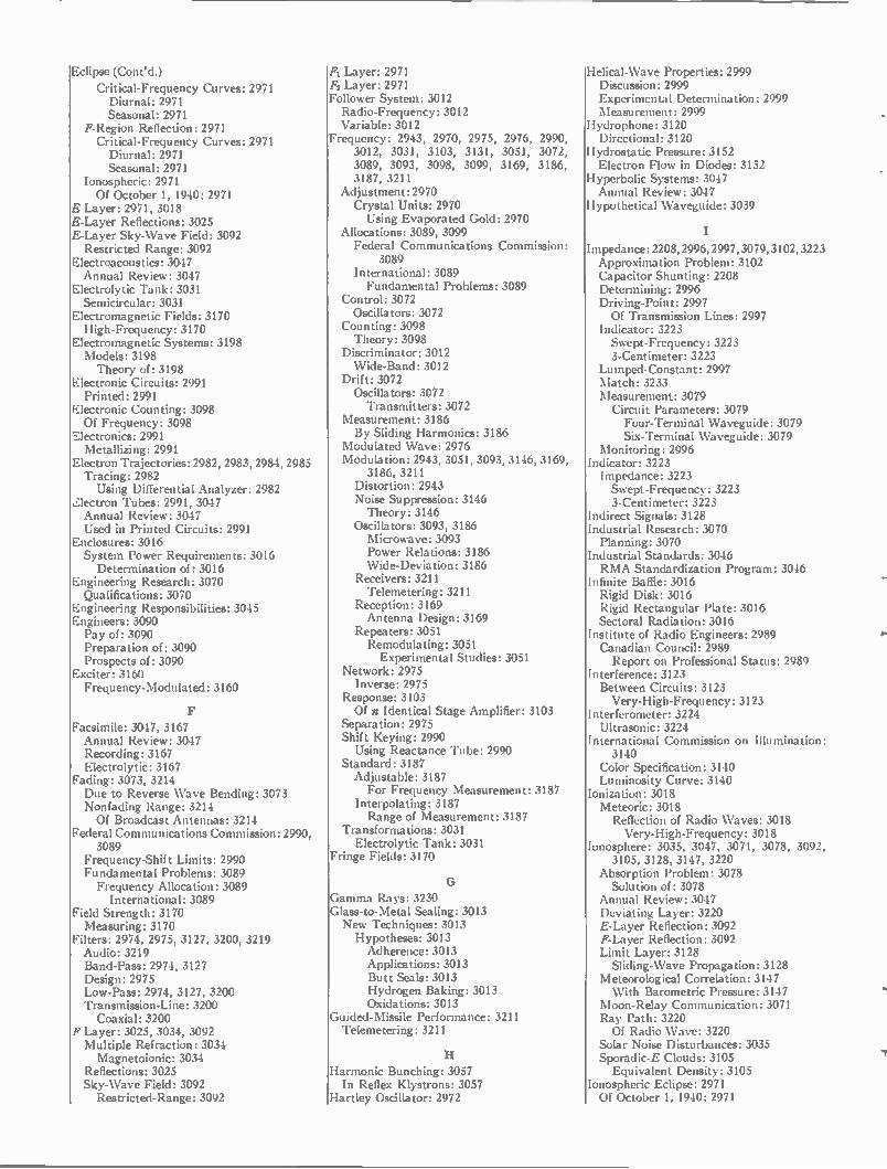
Eclipse (Cont'd.)
Critical-Frequency Curves: 2971 Diurnal: 2971 Seasonal: 2971
F-Region Reflection: 2971 Critical-Frequency Curves: 2971 Diurnal: 2971 Seasonal: 2971
Ionospheric: 2971 Of October 1, 1940: 2971
E Layer: 2971, 3018 E-Layer Reflections: 3025 E-Layer Sky-Wave Field: 3092 Restricted Range: 3092
Electroacoustics: 3047 Annual Review: 3047
Electrolytic Tank: 3031 Semicircular: 3031
Electromagnetic Fields: 3170 High-Frequency: 3170
Electromagnetic Systems: 3198 Models: 3198 Theory of: 3198
Electronic Circuits: 2991 Printed: 2991
Electronic Counting: 3098 Of Frequency: 3098
Electronics: 2991 Metallizing: 2991
Electron Trajectories: 2982, 2983, 2984, 2985 Tracing: 2982 Using Differential Analyzer: 2982
F.lectron Tubes: 2991, 3047 Annual Review: 3047 Used in Printed Circuits: 2991
Enclosures: 3016 System Power Requirements: 3016 Determination of: 3016
Engineering Research: 3070 Qualifications: 3070
Engineering Responsibilities: 3045 Engineers: 3090 Pay of: 3090 Preparation of: 3090 Prospects of: 3090
Exciter: 3160 Frequency-Modulated: 3160
Facsimile: 3047, 3167 Annual Review: 3047 Recording: 3167 Electrolytic: 3167
Fading: 3073, 3214 Due to Reverse Wave Bending: 3073 Nonfading Range: 3214 Of Broadcast Antennas: 3214
Federal Communications Commission: 2990, 3089
Frequency-Shift Limits: 2990 Fundamental Problems: 3089 Frequency Allocation: 3089 International: 3089
Field Strength: 3170 Measuring: 3170
Filters: 2974, 2975, 3127, 3200, 3219 Audio: 3219 Band-Pass: 2974, 3127 Design: 2975 Low-Pass: 2974, 3127, 3200 Transmission-Line: 3200 Coaxial: 3200
F Layer: 3025, 3034, 3092 Multiple Refraction: 3034 Magnetoionic: 3034
Reflections: 3025 Sky-Wave Field: 3092 Restricted-Range: 3092
F1 Layer: 2971 F2 Layer: 2971 Follower System: 3012 Radio-Frequency: 3012 Variable: 3012
Frequency: 2943, 2970, 2975, 2976, 2990, 3012, 3031, 3103, 3131, 3051, 3072, 3089, 3093, 3098, 3099, 3169, 3186, 3187, 3211
Adjustment: 2970 Crystal Units: 2970 Using Evaporated Gold: 2970
Allocations: 3089, 3099 Federal Communications Commission:
3089 International: 3089 Fundamental Problems: 3089
Control: 3072 Oscillators: 3072
Counting: 3098 Theory: 3098
Discriminator: 3012 Wide-Band: 3012
Drift: 3072 Oscillators: 3072 Transmitters: 3072
Measurement: 3186 By Sliding Harmonics: 3186
Modulated Wave: 2976 Modulation: 2943, 3051, 3093, 3146, 3169,
3186, 3211 Distortion: 2943 Noise Suppression: 3146 Theory: 3146
Oscillators: 3093, 3186 Microwave: 3093 Power Relations: 3186 Wide-Deviation: 3186
Receivers: 3211 Telemetering: 3211
Reception: 3169 Antenna Design: 3169
Repeaters: 3051 Remodulating: 3051 Experimental Studies: 3051
Network: 2975 Inverse: 2975
Response: 3103 Of a Identical Stage Amplifier: 3103
Separation: 2975 Shift Keying: 2990 Using Reactance Tube: 2990
Standard: 3187 Adjustable: 3187 For Frequency Measurement: 3187
Interpolating: 3187 Range of Measurement: 3187
Transformations: 3031 Electrolytic Tank: 3031
Fringe Fields: 3170
Gamma Rays: 3230 Glass-to-Metal Sealing: 3013 New Techniques: 3013 Hypotheses: 3013 Adherence: 3013 Applications: 3013 Butt Seals: 3013 Hydrogen Baking: 3013 Oxidations: 3013
Guided-Missile Performance: 3211 Telemetering: 3211
Harmonic Bunching: 3057 In Reflex Klystrons: 3057
Hartley Oscillator: 2972
Helical-Wave Properties: 2999 Discussion: 2999 Experimental Determination: 2999 Measurement: 2999
Hydrophone: 3120 Directional: 3120
Hydrostatic Pressure: 3152 Electron Flow in Diodes: 3152
Hyperbolic Systems: 3047 Annual Review: 3047
Hypothetical Waveguide: 3039
Impedance: 2208, 2996, 2997, 3079, 3102, 3223 Approximation Problem: 3102 Capacitor Shunting: 2208 Determining: 2996 Driving-Point: 2997 Of Transmission Lines: 2997
Indicator: 3223 Swept-Frequency: 3223 3-Centimeter: 3223
Lumped-Constant: 2997 Match: 3233 Measurement: 3079 Circuit Parameters: 3079 Four-Terminal Waveguide: 3079 Six-Terminal Waveguide: 3079
Monitoring: 2996 Indicator: 3223 Impedance: 3223 Swept-Frequency: 3223 3-Centimeter: 3223
Indirect Signals: 3128 Industrial Research: 3070 Planning: 3070
Industrial Standards: 3046 RMA Standardization Program: 3046
Infinite Baffle: 3016 Rigid Disk: 3016 Rigid Rectangular Plate: 3016 Sectoral Radiation: 3016
Institute of Radio Engineers: 2989 Canadian Council: 2989 Report on Professional Status: 2989
Interference: 3123 Between Circuits: 3123 Very-High-Frequency: 3123
Interferometer: 3224 Ultrasonic: 3224
International Commission on Illumination: 3140
Color Specification: 3140 Luminosity Curve: 3140
Ionization: 3018 Meteoric: 3018 Reflection of Radio Waves: 3018 Very-High-Frequency: 3018
Ionosphere: 3035, 3047, 3071, 3078, 3092, 3105, 3128, 3147, 3220
Absorption Problem: 3078 Solution of: 3078
Annual Review: 3047 Deviating Layer: 3220 E-Layer Reflection: 3092 F-Layer Reflection: 3092 Limit Layer: 3128 Sliding-Wave Propagation: 3128
Meteorological Correlation: 3147 With Barometric Pressure: 3147
Moon-Relay Communication: 3071 Ray Path: 3220 Of Radio Wave: 3220
Solar Noise Disturbances: 3035 Sporadic-E Clouds: 3105 Equivalent Density: 3105
Ionospheric Eclipse: 2971 Of October 1, 1940: 2971
Isotopic Weights. 3194 Of Elements: 3194
Keying: 2990 Frequency-Shift: 2990
Kovar: 3013 Used in Glass-to-Metal Sealing: 3013
Laboratories: 3156 College Research: 3156
Lenses, Wavelength: 2995 Light-Pattern Meter: 3215 Limiter Circuit: 3161 Cathode-Coupled: 3161
Limiters: 3033 Gate: 3033 Pulse-Time Modulation: 3033
Limiting Resolution: 3017 In Television Pickup Tube: 3017 Image Section: 3017 Illuminated Strip: 3017
Scanning Section: 3017 Kinescope Spot Size: 3017
Target: 3017 Potential Distribution: 3017
Limit Layer: 3128 Ionospheric: 3128
Line: 3139 Discontinuity: 3139 Distributed-Capacitance: 3139 Distributed-Inductance: 3139 Split-Stator: 3139
Linear Detectors: 3218 In AM Receivers: 3218
Linear Networks: 2974 Liquid Column: 3224 Resonant: 3224 In Interferometer: 3224 Ultrasonic: 3224
Listeners Tests: 3050 Tonal-Range Preferences: 3050 Compensated Systems: 3050 Uncompensated Systems: 3050
Loran: 3047 Annual Review: 3047
Loudspeakers: 3016 Loudness-Efficiency Rating: 3016 Proposed: 3016 Test Circuit: 3016 Theory: 3016
Test Sweep-Frequency Power: 3016 Determination of: 3016
Luminosity: 3077 In Color Television: 3077 Geometric Method: 3077
Magnetoionic Multiple Refraction: 3034 High Latitude: 3034
Magnetrons: 2978, 3197 Cavity Mode: 3197 Construction: 2978 Continuous-Wave: 2978 First-Order Mode: 3197 High-Power: 3197 Hole-and-Slot: 2978 Interdigital: 3197 Internal Tuning: 2978 Inductance-Capacitance: 2978
Methods of Tuning: 2978 Multiple-Cavity: 2978 Single-Disk Tuner: 2978
Mapping Transformations: 3058 Conformal: 3058
Matrix Equations: 3100 Application: 3100 To Vacuum-Tube Circuits: 3100
Meacham Oscillator: 2972 Measurements: 2996, 2999, 3010, 3016, 3025,
3036, 3047, 3079, 3122, 3128, 3151, 3153, 3163, 3166, 3169, 3170, 3187, 3198,3212,3215,3223,3224,3234
Angle-of-Arrival: 3234 Microwave: 3234
Antenna: 2999 Field Strength: 2999 Using Bolometer: 2999
Cathodes: 3151 Oxide-coated: 3151 Emission of: 3151
Crystal Units: 3153 Electrical Characteristics: 3153
Distance: 3128 Echo Signals: 3128
Distortion: 3036 Harmonic-Measurement Method: 3036 Analysis: 3036
Intermodulation Method: 3036 Analysis: 3036
Electrical Characteristics: 3153 Of Quartz-Crystal Units: 3153
Electromagnetic Fields: 3170 High-Frequency: 3170
Ferromagnetic Materials: 3010 Copper Loss: 3010 Core Loss: 3010 Harmonic Distortion: 3010 Hysteresis: 3010 Iron-Cored Inductor: 3010 Permeability: 3010
Field Pattern: 3169 Antenna: 3169
Field Strength: 3170 Frequency: 3187 By Sliding Harmonics: 3187
Fringe Fields: 3170 Gain: 3212 Helical-Wave Properties: 2999 Impedance: 2996 Impedance Indicator: 3223 Swept-Frequency: 3223 3-Centimeter: 3223
Ionosphere: 3025 High-Power: 3025
Loudness: 3016 Loudspeakers: 3016 Reference: 3016 Test: 3016
Loudness Judgment Tests: 3016 Magnetic Properties: 3010 Meter: 3215 Light-Pattern: 3215
Microwave: 3122, 3163 Angle-of-Arrival: 3122 Corner Reflectors: 3163 Phase-Difference Method: 3122
Models: 3198 Of Electromagnetic Systems: 3198
Phase Difference: 3166, 3234 Between Antennas: 3234
Power: 2996 Resonant Liquid Column: 3224 With Interferometer: 3224 Ultrasonic: 3224
Sound: 3047 Annual Review: 3047
Sound Pressure: 3016 Telegraph Signals: 3128 High-Frequency: 3128
Time-Interval: 3128 Transmitters: 3128 Echo Signals: 3128
Measurements (Cont'd.)
Wattmeter: 2996 Waveguide Discontinuities: 3079
Measuring: 3211 Guided-Missile: 3211
Memory Unit: 3217 Delay-Line: 3217 Magnetic: 3217
Meteoric Ionization: 3018 Meteoric Reflection: 3018 Meteorological Correlation: 3147 Ionospheric: 3147 With Barometric Pressure: 3147
Meteorological Equipment: 3122 Measurements: 3122 Microwave: 3122 Angle-of-Arrival: 3122
Meters: 3215 Light-Pattern: 3215
Microphones: 3047 Annual Review: 3047
Microphonism: 3143 In Subminiature Triode: 3143
Microwaves: 2980, 2985, 2994, 3041, 3051, 3073, 3074, 3093, 3099, 3122, 3163, 3212, 3057, 3234
Antennas: 3234 Vertically Spaced: 3234 Phase Difference of: 3234
Bridge Circuits: 3212 For Measuring Gain: 3212
Communications: 3099 Duplex System: 3099
Communication Set: 3074 Portable: 3074
Directional Coupler: 2980 Horizontal: 3122 Measurements: 3122 Angle-of-Arrival: 3122
Oscillators: 3093, 3057 Frequency Stabilized: 3093
Propagation Experiments: 3073 Fading: 3073
Propagation Tests: 2994 Relaying: 3163 Repeaters: 3051 Remodulating: 3051 Experimental Studies: 3051
Tropospheric Soundings: 3041 Continuous: 3041
Vacuum Tube: 2985 Triode: 2985 Power Amplifier: 2985
Military Radio Communications: 3210 Technical Problems: 3210 Future: 3210
Mobile Systems: 3123 Interference: 3123
Mobile Telephone Service: 3157 Model Antennas: 3214 Broadcast: 3214
Models: 3198 Of Electromagnetic Systems: 3198 Theory of: 3198
Mode Separation: 3171 In Oscillators: 3171
Modulation: 3033, 3071, 3160, 3163, 3192 Directional: 3163 Effects: 3071 Diffuse Moon: 3071 Smooth Moon: 3071
Frequency: 3160 Oscillators: 3160 Stabilized: 3160
Interference: 3163 Phase: 3163 Pulse Code: 3192
Modulation (Cont'd.)
Philosophy of: 3192 Theory: 3192
Pulse-Time: 3033 Variable-Damping: 3163
Modulation Index: 3219 Modulation Systems: 3047 Annual Review: 3047
Modulators: 3159, 3213 Broad-Band: 3159 High-Level: 3159 Twin Balanced: 3213
Monitoring: 2996 Impedance: 2996 Power: 2996
Moon-Relay Communication: 3071 Astronomical Aspects: 3071 Cosmic Noise: 3071 Doppler Effect: 3071
Multifrequency Bunching: 3057 Theory: 3057
Multiple-Cavity Magnetrons: 2978 Multiple Refraction: 3034 High Latitude: 3034
Multiplex: 2975 Frequency Separation: 2975 Time Separation: 2975
Multivibrators: 3011, 3033 Degenerative: 3011 Positive-Bias: 3011 Pulse-Time Modulation: 3033 Wave Shapes: 3011
Navigation: 3231 Aircraft: 3231 Using Beacon System: 3231
Negative-Ion Blemish: 3221 Elimination of: 3221
Neptunium: 3230 Netherlands PTT: 3127 Networks: 2943, 2974, 2997, 3079, 3100,
3190, 3233 Analysis: 3079 Waveguide Discontinuities: 3079
Cascaded: 2974 Distributed-Constant: 3079 Waveguides: 3079
Four-Terminal: 3100 Application of Matrices: 3100
Impedance-Transforming: 3233 Linear: 2974 Lumped-Constant: 3079 Low-Frequency: 3079
Lumped Resistors: 2997 Phase-Shift: 3190 Single-Control: 3233 Tapered: 3190 Transmission: 2943 Transmission Lines: 2997 Lossless: 2997
Variable-Frequency: 3233 Zero-Phase-Shift: 2974
Neutrons: 3230 Noise: 2973, 2975, 2993, 3009, 3033, 3035,
3047, 3053, 3071, 3076, 3126, 3146, 3164, 3192, 3218, 3219
Annual Review: 3047 Atmospheric: 3009 Cosmic: 3071 Cross Modulation: 2975 Factor: 3076 Triode Amplifier: 3076 Analysis: 3076
False Pulse: 3192 Of PCM Systems: 3192
Figure: 2973, 3164
Noise (Cont'd.)
Available Gain: 3164 Available Power: 3164
Fluctuation: 3033 Pulse-Time Modulation: 3033 Suppression: 3033
Frequency-Modulation: 3146 Theory: 3146
High-Frequency: 3126 Impulse: 3033 Pulse-Time Modulation: 3033 Suppression: 3033
In Distributed Amplifier: 3126 Thermal: 3126
Level: 3053 Probability Measure: 3053 Theory: 3053
Modulated Carrier: 3219 Sinusoidally: 3219 Rectification of: 3219
Moon-Radiated: 3071 Moon-Reflected: 3071 Power: 3218 Radar: 2993 Random: 3053 Ratio: 3218 Carrier-to-Noise: 3218 In AM Receivers: 3218
Signal-to-Noise: 3218 In AM Receivers: 3218
Reduction: 3053 Fundamental Considerations: 3053
Shot-Effect: 3126 Solar: 3035 On 10.7 Centimeters: 3035
Thermal-Agitation: 3033 Pulse-Time Modulation: 3033 Suppression: 3033
Thresholds of Detection: 3053 Voltage: 3146 Of FM Signal: 3146
Nondissipative Circuit: 2976 Nonlinearity: 2975 Nuclear Energy: 3185 Nuclear Particles: 3145 Nuclear Physics: 3230 Electronics in: 3230
Nuclear Reactions: 3185 Nuclear Reactor: 3230 Nuclear Structure: 3194
0
Ordnance: 3120 Underwater: 3120 Development of: 3120 Electronic Instrumentation: 3120
Oscillators: 2972, 3000, 3015, 3020, 3030, 3051, 3093, 3094, 3148, 3160, 3171, 3186, 3187, 3189, 3190, 3212
Amplitude-Stabilized: 2972, 3094 Regulating Elements: 2972
Bridge-Stabilized: 2972 Colpitts: 2972 Hartley: 2972 Meacham: 2972 Wien-Bridge: 2972
Cathode-Follower: 3030 Theory: 3030
Frequency-Modulated: 3160, 3186, 3212 Automatic Stabilization: 3160
Frequency-Stabilized: 3020 Hertz: 3015 Dumbbell: 3015
Inductance-Capacitance: 3020 Frequency-Stabilized: 3020
Interpolating: 3187 Microwave: 3093, 3171
Oscillators (Cont'd.)
Frequency Stabilization of: 3093 Development: 3093
Mode Separation in: 3171 Phase-Shift: 3148, 3190 With Wide-Range Tuning: 3148
Power Triode: 3189 Ultra-High-Frequency: 3189
Reflex: 3051 Microwave: 3051
Tapered: 3190 Transmitter: 3020 Tunable Triode: 3000 For Pulse Service: 3000 Vacuum-Contained: 3000
Vertical: 3015 Wide-Deviation: 3186
Overload Effects: 2975
Painting: 2991 Printed-Circuit: 2991
Paired Echoes: 2974 Parabolic Approximations: 3220 Of Ionosphere Layer: 3220
Parabolic Loci: 3201 For Two Coupled Circuits: 3201
Parasite: 3104 Tuned: 3104 Electric Field: 3104
Passive Modes: 3129 In Traveling-Wave Tubes: 3129
Patents: 3099 Oscillator: 3099
Patterns: 3188, 3222, 3232 Antenna: 3188, 3222 Slotted-Cylinder: 3222
Arrays of Slots: 3222 In Cylinders: 3222
Three-Dimensional: 3232 Cathode-Ray Tube: 3232
Pentriode Amplifiers: 3193 Phase Difference: 3166, 3234 Between Antennas: 3234 Calculated: 3166 Measured: 3166
Phase Distortion: 2974 P,hase-Shift Oscillator: 3148 Philosophy of PCM: 3192 Phosphors: 3140 Cathode-Ray: 3140 Power Distribution: 3140 Spectral: 3140
Photo Transmission: 2990 Physics: 3230 Nuclear: 3230 In Electronics: 3230
Piezoelectric Crystals: 2970, 3047 Annual Review: 3047 BT-Cut: 2970 Frequency Adjustment: 2970 Using Evaporated Gold: 2970
Pilotless Aircraft: 3211 Guided-Missile: 3211 Target-Type: 3211
Plan-Position Indicator: 2993 Displays: 2993 Intensity-Modulated: 2993 Visibility of Small Echoes: 2993
Plated-Type Crystals: 2970 Plug-In Units: 2291 Using Printed Circuits: 2991
Plutonium: 3230 Potentiometers: 3211 Microtorque: 3211 For Telemetering: 3211
Power: 2973, 2996, 3016, 3055, 3140, 3163. 3192, 3219
Amplifier: 3016 Loudspeaker: 3016
Determining: 2996 Devices: 2996 Method: 2996
Distribution: 3140 Spectral: 3140
Gain: 2973 Input: 3219 Monitoring: 2996 High-Frequency: 2996
Output: 3219 Reflected: 3163 Threshold: 3192 Of PCM: 3192
Transmitting: 3055 Uhf: 3055
Preamplifier: 2973 Velocity-Modulated: 2973
Premodulator: 3127 For Single-Sideband Transmitter: 3127 Testing Apparatus: 3127
Printed Circuits: 2991 Applications: 2991 Amplifiers: 2991 Electromechanical: 2991 Metallizing: 2991 Printed Plug-In Units: 2991 Receivers: 2991 Subassemblies: 2991 Transmitters: 2991
Chemical Deposition: 2991 Silvering Process: 2991
Die-Stamping: 2991 Dusting: 2991 Painting: 2991 Performance: 2991 Spraying: 2991 Techniques: 2991 Thermosetting Plastics: 2991
Vacuum Processes: 2991 Probability Measure: 3053 Of Noise: 3053
Professional Status: 2989 Canadian Council: 2989 Report of Committee: 2989
Progress in Radio: 3047 Projection Television: 3026, 3027, 3028 Projective Geometry: 3077 Application to Color Mixture: 3077 Theory: 3077
Propagation Tests: 2994 Microwave: 2994 Test Circuit: 2994
Proximity Fuze: 2991 Using Printed Circuits: 2991
Pseudosynchronization: 3094 In Amplitude-Stabilized Oscillators: 3094
Pulse Code Modulation: 3192 Philosophy of: 3192
Pulse Modulation: 3047, 3106 Annual Review: 3047 Standardization: 3106 Nomenclature: 3106
Pulse Synchronizer: 3141 Pulse-Time Modulation: 3033 Noise-Suppression Characteristics: 3033
Pulse Triode: 3029 Push-Pull Amplifiers: 3164 Push-Pull Operation: 2977 Equivalent Circuit: 2977 Theory: 2977
Quartz Crystals: 2970 High-Frequency: 2970
Radar: 2687, 2993, 3019, 3029, 3038, 3041, 3047, 3053, 3076, 3138, 3163, 3198, 3231
Amplifiers: 3038 Intermediate-Frequency: 3038 Flat-Response: 3038 Single-Tuned: 3038
Annual Review: 3047 Beacon System: 3231 Universal: 3231
Echoes: 3198 Simulation of: 3198
Noise: 3053 Reduction: 3053
Plan-Position Indicator: 2993 Visibility of Small Echoes: 2993 Theory: 2993
Pulse Triode: 3029 Receiver: 3076 Noise-Factor Analysis: 3076
Signal: 2687 Detectable: 2687 Minimum: 2687
Surveillance: 3138 Ground: 3138
Transmission: 3163 With Nonscattering Target: 3163
Tropospheric Soundings: 3041 "X"-Band: 3019 Rainfall Attenuations: 3019 Rainfall Intensities: 3019
Radiation: 3016 Loudspeakers: 3016 Baffled: 3016 Single Unit: 3016 Two Unit: 3016
Unbaffled: 3016 Radiation Patterns: 3149 Of Horn Antennas: 3149 Electromagnetic: 3149
Radioactive Materials: 3230 Radio Communications: 3210 Military: 3210 Technical Problems: 3210 Future: 3210
Radio Interference: 3048 Suppression: 3048 Using Duct Capacitor: 3048
Radio Progress: 3047 Radio Proximity Fuze: 2991 Printed Steatite Plate: 2991
Radio Transmission: 2990 Automatic: 2990 Frequency Shift: 2990
Ray Path: 3220 Ionospheric: 3220 Of Radio Wave: 3220
Rainfall Attenuation: 3019 Of Centimeter Electromagnetic Waves:
3019 Rainfall Intensities: 3019 Using Radar: 3019 "X"-Band: 3019
Receivers: 2991, 3012, 3026, 3027, 3028, 3047, 3119, 3123, 3127, 3157, 3158, 3211, 3218
AM: 3218 Carrier-to-Noise Ratio: 3218 Signal-to-Noise Ratio: 3218
Annual Review: 3047 FM: 3211 Telemetering: 3211
Interference: 3123 Remote-Plotting System: 3012 Single-Sideband: 3127 Television: 3026, 3027, 3028, 3119, 3158 Home Projection: 3026, 3027, 3028
Receivers (Cont'd.)
Train Telephone Service: 3157 Using Printed Circuits: 2991
Reception: 3169 Frequency-Modulation: 3169 Antenna Design: 3169
Television: 3169 Antenna Design: 3169
Super-High Frequency: 3169 Ultra-High Frequency: 3169
Rectifiers: 2975, 3027 Averaging: 2975 Pulse-Type: 3027 Projection Television: 3027
Recordings: 2975, 3047, 3128, 3167 Annual Review: 3047 Circulating Signals: 3128 Distance Measurements: 3128 Facsimile: 3167 Electrolytic: 3167 High-Speed: 3167
Remote: 2975 Rectification: 3219 Half-Wave: 3219 Quadratic: 3219 Full- Wave: 3219
Reflected Power: 3163 Reflection: 2971 E Layer: 2971 F Layer: 2971
Reflection Coefficient: 3078, 3130, 3223 Apparent Height: 3078 Ionospheric: 3078, 3220 Measurement of: 3223
Reflectors: 3163, 3188 Corner: 3163 Doubly Curved: 3188 Calculation of: 3188
Triple-Turret: 3163 Refraction: 3034 Magnetoionic Multiple: 3034 At High Latitudes: 3034
Remote Recording: 2975 Of Flight-Test Data: 2975
Repeaters: 3051 Experimental Studies: 3051 Remodulating: 3051
Reproducing System: 3050 Compensated: 3050 Tonal-Range Preferences: 3050 Uncompensated: 3050
Research: 3041, 3070, 3156, 3210 College: 3156 Aiding Small Business: 3156
Industrial: 3070 Radio Communications: 3210 Military: 3210 Future: 3210
Tropospheric Soundings: 3041 By Radar: 3041
Resistance: 3080 Radiation: 3080 Of Collinear Arrays: 3080 Of Bilateral Arrays: 3080 Of End-Fire Arrays: 3080 Of Broadside Array: 3080
Resolution: 3025 Ionosphere-Measuring Equipment: 3025
Resonances: 2976 Amplitude: 2976
Resonant Circuits: 3139 Tunable: 3139 300- to 3000-Mc: 3139
Resonators: 3171 Coaxial-Line: 3171
Response: 3123 Image: 3123
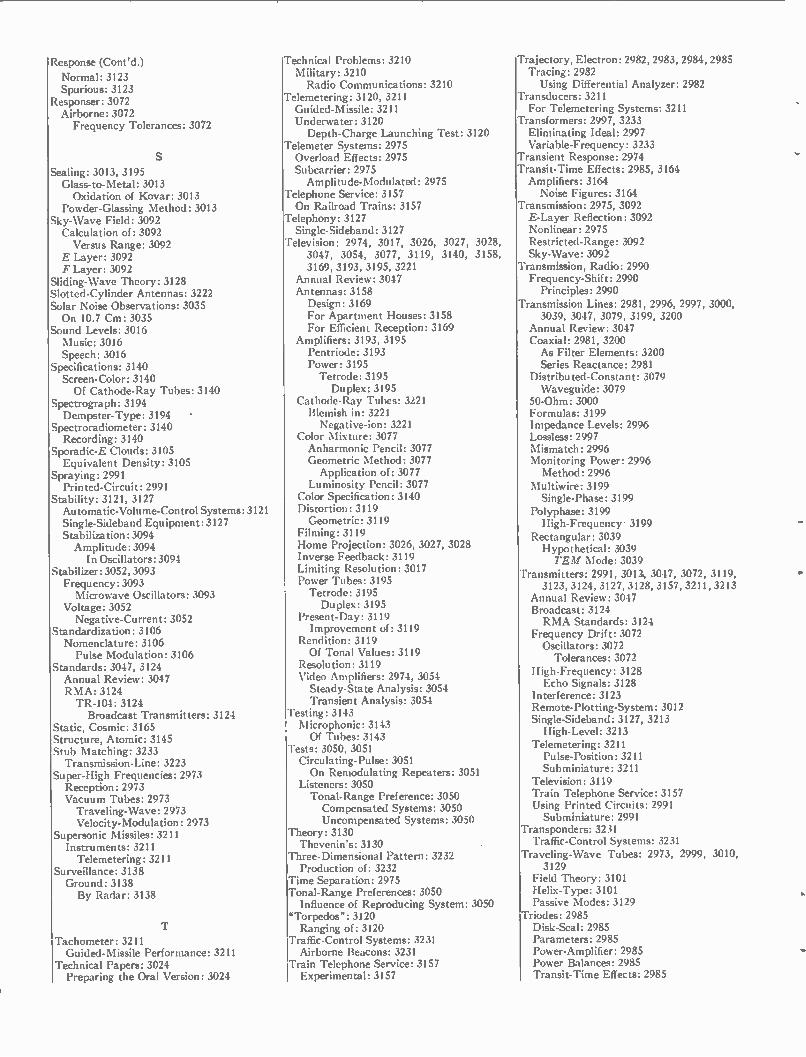
Response (Cont'd.)
Normal: 3123 Spurious: 3123
Responser: 3072 Airborne: 3072 Frequency Tolerances: 3072
Sealing: 3013, 3195 Glass-to-Metal: 3013 Oxidation of Kovar: 3013
Powder-Glassing Method: 3013 Sky-Wave Field: 3092 Calculation of: 3092 Versus Range: 3092
E Layer: 3092 F Layer: 3092
Sliding-Wave Theory: 3128 Slotted-Cylinder Antennas: 3222 Solar Noise Observations: 3035 On 10.7 Cm: 3035
Sound Levels: 3016 Music: 3016 Speech: 3016
Specifications: 3140 Screen-Color: 3140 Of Cathode-Ray Tubes: 3140
Spectrograph: 3194 Dempster-Type: 3194 •
Spectroradiometer: 3140 Recording: 3140
Sporadic-E Clouds: 3105 Equivalent Density: 3105
Spraying: 2991 Printed-Circuit: 2991
Stability: 3121, 3127 Automatic-Volume-Control Systems: 3121 Single-Sideband Equipment: 3127 Stabilization:3094 Amplitude: 3094 In Oscillators: 3094
Stabilizer: 3052, 3093 Frequency: 3093 Microwave Oscillators: 3093
Voltage: 3052 Negative-Current: 3052
Standardization: 3106 Nomenclature: 3106 Pulse Modulation: 3106
Standards: 3047, 3124 Annual Review: 3047 RMA: 3124 TR-104: 3124 Broadcast Transmitters: 3124
Static, Cosmic: 3165 Structure, Atomic: 3145 Stub Matching: 3233 Transmission-Line: 3223
Super-High Frequencies: 2973 Reception: 2973 Vacuum Tubes: 2973 Traveling-Wave: 2973 Velocity-Modulation: 2973
Supersonic Missiles: 3211 Instruments: 3211 Telemetering: 3211
Surveillance: 3138 Ground: 3138 By Radar: 3138
Tachometer: 3211 Guided-Missile Performance: 3211
Technical Papers: 3024 Preparing the Oral Version: 3024
Technical Problems: 3210 Military: 3210 Radio Communications: 3210
Telemetering: 3120, 3211 Guided-Missile: 3211 Underwater: 3120 Depth-Charge Launching Test: 3120
Telemeter Systems: 2975 Overload Effects: 2975 Subcarrier: 2975 Amplitude-Modulated: 2975
Telephone Service: 3157 On Railroad Trains: 3157
Telephony: 3127 Single-Sideband: 3127
Television: 2974, 3017, 3026, 3027, 3028, 3047, 3054, 3077, 3119, 3140, 3158, 3169, 3193, 3195, 3221
Annual Review: 3047 Antennas: 3158 Design: 3169 For Apartment Houses: 3158 For Efficient Reception: 3169
Amplifiers: 3193, 3195 Pentriode: 3193 Power: 3195 Tetrode: 3195 Duplex: 3195
Cathode-Ray Tubes: 3221 Blemish in: 3221 Negative-ion: 3221
Color Mixture: 3077 Anharmonic Pencil: 3077 Geometric Method: 3077 Application of: 3077
Luminosity Pencil: 3077 Color Specification: 3140 Distortion: 3119 Geometric: 3119
Filming: 3119 Home Projection: 3026, 3027, 3028 Inverse Feedback: 3119 Limiting Resolution: 3017 Power Tubes: 3195 Tetrode: 3195 Duplex: 3195
Present-Day: 3119 Improvement of: 3119
Rendition: 3119 Of Tonal Values: 3119
Resolution: 3119 Video Amplifiers: 2974, 3054 Steady-State Analysis: 3054 Transient Analysis: 3054
Testing: 3143 Microphonic: 3143 Of Tubes: 3143
Tests: 3050, 3051 Circulating-Pulse: 3051 On Remodulating Repeaters: 3051
Listeners: 3050 Tonal-Range Preference: 3050 Compensated Systems: 3050 Uncompensated Systems: 3050
Theory: 3130 Thevenin's: 3130
Three-Dimensional Pattern: 3232 Production of: 3232
Time Separation: 2975 Tonal-Range Preferences: 3050 Influence of Reproducing System: 3050
"Torpedos": 3120 Ranging of: 3120
Traffic-Control Systems: 3231 Airborne Beacons: 3231
Train Telephone Service: 3157 Experimental: 3157
Trajectory, Electron: 2982, 2983, 2984, 2985 Tracing: 2982 Using Differential Analyzer: 2982
Transducers: 3211 For Telemetering Systems: 3211
Transformers: 2997, 3233 Eliminating Ideal: 2997 Variable-Frequency: 3233
Transient Response: 2974 Transit-Time Effects: 2985, 3164 Amplifiers: 3164 Noise Figures: 3164
Transmission: 2975, 3092 E-Layer Reflection: 3092 Nonlinear: 2975 Restricted-Range: 3092 Sky-Wave: 3092
Transmission, Radio: 2990 Frequency-Shift: 2990 Principles: 2990
Transmission Lines: 2981, 2996, 2997, 3000, 3039, 3047, 3079, 3199, 3200
Annual Review: 3047 Coaxial: 2981, 3200 As Filter Elements: 3200 Series Reactance: 2981
Distribu ted-Constant : 3079 Waveguide: 3079
50-Ohm: 3000 Formulas: 3199 Impedance Levels: 2996 Lossless: 2997 Mismatch: 2996 Monitoring Power: 2996 Method: 2996
Multiwire: 3199 Single-Phase: 3199
Polyphase: 3199 High-Frequency • 3199
Rectangular: 3039 Hypothetical: 3039 TEM Mode: 3039
Transmitters: 2991, 3012, 3047, 3072, 3119, 3123,3124,3127,3128,3157,3211,3213
Annual Review: 3047 Broadcast: 3124 RMA Standards: 3124
Frequency Drift: 3072 Oscillators: 3072 Tolerances: 3072
High-Frequency: 3128 Echo Signals: 3128
Interference: 3123 Remote-Plotting-System: 3012 Single-Sideband: 3127, 3213 High-Level: 3213
Telemetering: 3211 Pulse-Position: 3211 Subminiature: 3211
Television: 3119 Train Telephone Service: 3157 Using Printed Circuits: 2991 Subminiature: 2991
Transponders: 3231 Traffic-Control Systems: 3231
Traveling-Wave Tubes: 2973, 2999, 3010, 3129
Field Theory: 3101 Helix-Type: 3101 Passive Modes: 3129
Triodes: 2985 Disk-Seal: 2985 Parameters: 2985 Power-Amplifier: 2985 Power Balances: 2985 Transit-Time Effects: 2985
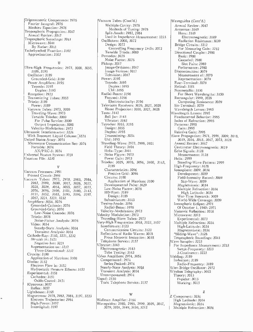
Trigonometric Components: 2976 Fourier Integral: 2976 Mathieu Equation: 2976
Tropospheric Propagation: 3047 Annual Review: 3047
Tropospheric Soundings: 3041 Microwave: 3041 By Radar: 3041
Tschebyscheff Function: 3102 Approximation: 3102
Ultra-High Frequencies: 2973, 3000, 3055, 3189, 3195
Oscillator: 3189 Grounded-Grid: 3189
Power Amplifiers: 3195 Tetrode: 3195 Duplex: 3195
Reception: 2973 Transmitting Tubes: 3055 Triode: 3189 Power: 3189
Vacuum Tubes: 2973, 3000 Traveling-Wave: 2973 Tunable Triodes: 3000 For Pulse Service: 3000 Output Impedance: 3000
Velocity-Modulation: 2973 Ultrasonic Interferometer: 3224 With Resonant Liquid Column: 3224
United States Army: 3074 Microwave Communication Set: 3074 Portable: 3074 AN/PRC-3: 3074
Universal Beacon System: 3231 Uranium Pile: 3230
Vacuum Processes: 2991 Printed Circuit: 2991
Vacuum Tubes: 2973, 2978, 2983, 2984, 2985, 2999, 3000, 3017, 3026, 3027, 3028, 3029, 3054, 3055, 3057, 3072, 3076, 3096, 3100, 3101, 3140, 3143, 3151, 3152, 3165, 3195, 3196, 3197, 3057, 3221, 3223, 3232
Amplifiers: 3054, 3076 Grounded-Cathode: 3076 Grounded-Grid: 3076 Low-Noise Cascode: 3076
Triode: 3076 Noise-Factor Analysis: 3076
Video: 3054 Steady-State Analysis: 3054 Transient Analysis: 3054
Cathode-Ray: 3140, 3221, 3232 Blemish in: 3221 Negative-Ion: 3221
Representation on: 3232 Three-Dimensional: 3232
Circuits: 3100 Application of Matrices: 3100
Diodes: 3152 Electron Flow in: 3152 Hydrostatic Pressure Effects: 3152
Experimental: 3151 Cathodes: 3151 Oxide-Coated: 3151
Klystrons: 3057 Reflex: 3057
Lighthouse: 3165 Magnetrons: 2978, 2983, 2984, 3197, 3223 Electron Trajectories: 2984 High-Power: 3197 Interdigital: 3197
Vacuum Tubes (Cont'd.) Multiple-Cavity: 2978 Methods of Tuning: 2978
Split-Anode: 2983, 2984 Used in Impedance Measurement: 3223
Oscillators: 3000, 3072 Design: 3072 Controlling Frequency Drift: 3072
Tunable Triode: 3000 Pentodes: 3076 Noise Factor: 3076
Pickup: 3017 Image-Orthicon: 3017 Image-Vericon: 3017 Television: 3017
Power: 3195 Tetrode: 3195 Duplex: 3195 Uhf: 3195
Radial-Beam: 3196 Focused: 3196 Electrostatically: 3196
Television Receivers: 3026, 3027, 3028 Home Projection: 3026, 3027, 3028
Tests: 3143 Bell Jar: 3143 Vibrator: 3143
Tetrodes: 3055, 3195 Design: 3055 Duplex: 3195 Transmitting: 3054 Uhf: 3195
Traveling-Wave: 2973, 2999, 3101 Field Theory: 3101 Helix-Type: 3101
• Noise Figure: 2973 Power Gain: 2973
Triodes: 3029, 3076, 3096, 3100, 3143, 3189
Characteristics: 3096 Positive-Grid: 3096
Circuits: 3100 Application of Matrices: 3100
Developmental Pulse: 3029 Low-Noise Factor: 3076 100-Watt: 3189 Design: 3189
Subminiature: 3143 Twelve-Anode: 3196 Radial-Beam: 3196
Velocity-Modulation: 2973 Velocity Modulation: 2973 Traveling-Wave Tubes: 2973
Very-High Frequencies: 3018, 3123, 3157 Interference: 3123 Communication Circuits: 3123
Reflections of Radio Waves: 3018 From Meteoric Ionization: 3018
Telephone Service: 3157 Vibrator: 3143 Electromagnetic: 3143 Tube Testing: 3143
Video Amplifiers: 2974, 3054 Compensated: 2974 Series-Peaked: 2974
Steady-State Analysis: 305,4 Transient Analysis: 3054 Uncompensated: 2974
Vogad: 3156 Train Telephone Service: 3157
Wallman Amplifier: 3164 Waveguides: 2980, 2995, 2999, 3039, 3047,
3079, 3101, 3149, 3150, 3212
Waveguides (Cont'd.)
Annual Review: 3047 Antennas: 3149 Horn: 3149 Electromagnetic: 3149
Radiation Resistance: 3039 Bridge Circuits: 3212 For Measuring Gain: 3212
Directional Coupler: 2980 Basic: 2980 Cascaded: 2980 Slot Pairs: 2980
Performance: 2980 Discontinuities: 3079 Measurement of: 3079 Representation: 3079
Four-Terminal: 3079 Helical: 3101 Nonmetallic: 3150 For Short Wavelengths: 3150
Rectangular: 2999, 3039 Computing Resistance: 3039
Six-Terminal: 3079 Wavelength Lenses: 2995
Wavelength Lenses: 2995 Fundamental Behavior: 2995 Index of Refraction: 2995 Patterns: 2995 Gain: 2995
Relative Gain: 2995 Wave Propagation: 2971, 2999, 3009, 3018,
3019, 3034, 3041, 3047, 3073, 3128 Annual Review: 3047 Centimeter Electromagnetic: 3019 Echo Signals: 3128 Measurement: 3128
Helix: 2999 Standing-Wave Pattern: 2999
High-Frequency: 3128 Ionosphere: 3009, 3034 Development: 3009 Field-Intensity Record: 3009 Sky-Wave: 3009
Magnetoionic: 3034 Multiple Refraction: 3034 High Latitude: 3034
War-Time Research: 3009 World-Wide Coverage: 3009
Ionospheric Eclipse: 2971 Of October 1, 1940: 2971
Meteoric Reflection: 3018 Microwave: 3073 Experimental: 3073
Multiple Refraction: 3034 High-Latitude: 3034 Magnetonionic: 3034
"Sliding-Wave": 3128 Tropospheric Soundings: 3041
Wave Sampler: 3223 For Impedance Measurement: 3223 Swept-Frequency: 3223 3-Centimeter: 3223
Welding: 3189 Induction: 3189 Radio-Frequency: 3189
Wien-Bridge Oscillator: 2972 Wireless Telegraphy: 3015 Theory: 3015 Popular: 3015 Working: 3015
Z Component: 3034 High Latitude: 3034 Magnetoionic: 3034 Multiple Refraction: 3034
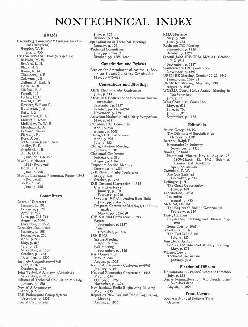
NONTECHNICAL INDEX Awards
BROWDER J. THOMPSON MEMORIAL AWARD-1948 (Recipient)
Huggins, W. H. June, p. 756
FELLOW AWARDS-1948 (Recipients) Baldwin, M. W. Bedford, L. H. Black, H. S. Bowie, R. M. Chambers, D. E. Coleman, J. B. Cullum, A. Earl, Jr. Dome, R. B. Ellefson, B. S. Farrell, J. J. Forbes, H. C. Herold, E. W. Hewlett, William R. Hutcheson, J. A. Keto, J. E. Lindenblad, N. E. McIlwain, Knox McKinley, D. W. R. Meacham, L. A. Packard, David Pierce, J. R. Rose, Albert Schleimann-Jensen, Arne Shelby, R. E. Shepherd, J. E. Smith, D. B. June, pp. 756-759
MEDAL OF HONOR 1948 (Recipient)
Hone, L. C. F. June, p. 756
MORRIS LIEBMANN MEMORIAL PRIZE-1948 (Recipient)
Seeley, S. W. June, p. 756
Committees
Board of Directors January, p. 105 February, p. 250 April, p. 505 June, pp. 743-744 August, p. 1004 December, p. 1506
Executive Committee January, p. 105 February, p. 250 April, p. 505 May, p. 633 July, p. 881 September, p. 1136 October, p. 1263 December, p. 1506
Institute Committees-1948 June, p. 760 October, p. 1264
Joint Technical Advisory Committee September, p. 1136
Minutes of Technical Committee Meeting January, p. 106
New ASA Committee April, p. 505
IRE Professional Group System December, p. 1507
Special Committees
June, p. 762 October, p. 1266
Specialization in Technical Meetings January, p. 106
Technical Committees June, pp. 761-762 October, pp. 1265-1266
Constitution and Bylaws
Petition for Amendment of Article II, Sec-tions 1-c and 2-c, of the Constitution
May, pp. 636-637
Conventions and Meetings
AIEE Electron-Tube Conference June, p. 744
AIEE-IRE Conference on Electronic Instru-mentation
September, p. 1137 October, pp. 1263-1264 November, p. 1391
American Mathematical Society Symposium May, p. 637
Canadian IRE Convention April, p. 506 August, p. 1005
Chicago IRE Conference April, p. 506 July, p. 882
Chicago Section Meeting January, p. 105
Cincinnati Conference February, p. 250 August, p. 1004
Emponum Section Meeting December, p. 1506
IRE Electron-Tube Conference May, p. 634 October, p. 1263
IRE National Convention-1948 Convention News January, p. 104 February, p. 246
Greatest IRE Convention Ever Held June, pp. 754-755
Program, Committee Meetings, and Sum-maries
March, pp. 365-380 IRE National Convention-1949 Papers September, p. 1137
Plans December, p. 1506
IRE-RMA Spring Meeting April, p. 506
Fall Meeting September, p. 1136
NAB Convention May, p. 634 August, p. 1005
National Electronics Conference-1947 January, p. 101
National Electronics Conference-1948 May, p. 634 October, p. 1263 November, p. 1391
New England Radio Engineering Meeting May, p. 635
Report on New England Radio Engineering Meeting
August, p. 1006
RMA Meetings May, p. 640 June, p. 753
Rochester Fall Meeting September, p. 1136 October, p. 1320
Second Joint IRE-URSI Meeting, October 7-9,1948
September, p. 1137 Southwestern IRE Conference November, p. 1391
URSI-IRE Meeting, October 20-22,1947 January, pp. 103-104
URSI-IRE Meeting, May 3-5,1948 August, p. 1005
WCEMA Board Holds Annual Meeting in San Francisco
July, p. 881 West Coast IRE Convention May, p. 634 June, p. 750 July, p. 881 September, p. 1138
Editorials Baker, George M. K. The Dilemma of Specialization October, p. 1195
Batcher, Ralph R. Electronics In Industry November, p. 1323
Bowles, Edward L. Hammond Vinton Hayes, August 28,
1860-March 22, 1947, Scientist, Pioneer, and Benefactor
April, pp. 443-445 Carnahan, C. W. Are You Satisfied December, p. 1451
Dellinger, J. H. The Great Opportunity June, p. 699
Espenschied, Lloyd Invention August, p. 955
McNicol, Donald The Engineer's Role in Government February, p. 179
Pratt, Haraden Engineering Thinking and Human Prog-
ress September, p. 1067
Schelkunoff, S. A. The End Is In Sight July, p. 827
Van Dyck, Arthur Science and Universal Military Training May, p. 571
Winner, Lewis Technical Journalism January, p. 3
Election of Officers Nominations- 1949, for Officers and Directors July, p. 881
Single Nominations for IRE President and Vice-President
August, p. 1004
Front Covers Accurate Study of Delicate Tints October
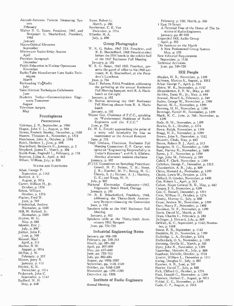
Aircraft-Antenna Pattern Measuring Sys-tem
February Walter R. G. Baker, President, 1947, and
Benjamin E. Shackelford, President, 1948
January Macro-Optical Elements September
Microwave Radio-Relay Station April
Precision Autograph December
Public Education in Nuclear Operations November
Radio-Tube Manufacture Uses Radio Tech-niques
March Railroading VialRadio July
Sister Electric Techniques Collaborate June
Students Today—Communications Engi-neers Tomorrow
August Television Asepsis May
Frontispieces PROCEEDINGS
Coleman, J. B., September, p. 1066 Hogan, John V. L., August, p. 954 Howes, Frederic Stanley, December, p. 1450 Hunter, Theodore A., November, p. 1322 Hutcheson, John A., October, p. 1194 Reich, Herbert J., June, p. 698 Shackelford, Benjamin E., January, p. 2 Shepherd, James E., March, p. 306 Smith-Rose, Reginald L., February, p. 178 Stratton, Julius A., April, p. 442 Wilson, William, July, p. 826
WAVES AND ELECTRONS
Adair, George P. September, p. 1143
Bedford, A. V. August, p. 1014
Carter, William H., Jr. October, p. 1276
Edson, William October, p. 1276
Fischer, Fred W. June, p. 769
Friedenthal, Andrew November, p. 1401
Hill, W. Ryland, Jr. November, p. 1401
Hutton, W. G. May, p. 648
Isbister, Eric J. July, p. 890
Jordan, John F. June, p. 769
Kramer, Karl April, p. 515
Mather, N. W. August, p. 1014
McRae, J. W. February, p. 257
Minter, Jerry B. January, p. 113
Patrick, K. R. December, p. 1514
Petkovsek, John C. September, p. 1143
Radford, W. H. May, p. 648
Rowe, Robert G. March, p. 386
Sparkerner, C. E. Van December, p. 1514
Wheeler, H. A. July, p. 890
Group Photographs W. R. G. Baker, 1947 IRE President, and
B. E. Shackelford, 1948 President-elect before the IRE booth in the exhibit hall of the 1947 Rochester Fall Meeting
January, p. 102 W. R. G. Baker, 1947 IRE President, pre-
sents the gavel of office to his 1948 suc-cessor, B. E. Shackelford, at the Presi-dent's Luncheon
June, p. 754 Max F. Balcom, RMA President, addressing
the gathering at the annual Rochester Fall Meeting banquet, with R. A. Hack-busch at the right
January, p. 102 Dr. Barton receiving the 1947 Rochester
Fall Meeting plaque from R. A. Hack-busch
January, p. 102 Wayne Coy, Chairman of F.C.C., speaking
on "Fundamental Problems of Radio Engineers and the F.C.C."
June, p. 754 Dr. W. L. Everitt approaching the point of
a story told inimitably by him as toastmaster at the Annual Banquet
June, p. 755 Virgil Graham, Chairman, Rochester Fall
Meeting Committee; E. F. Carter, who spoke on "Engineering Responsibility in Today's Economy", and B. S. Ellefson, Monday afternoon sessions chairman
January, p. 102 JETEC Committee on Sampling Procedure:
Gowell, N. P.; Nelson, T. H.; Steen, J. R.; Koechel, W. P.; Romig, H. G.; Cherry, S. J.; Heitner, A. J.; Hackley, G. E.; and Rupp, W. B.
July, p. 887 National Electronics Conference-1947,
Edgewater Beach Hotel, Chicago January, p. 101
Dr. B. E. Schackelford, President, 1948, addressing the Thirty-Sixth Anniver-sary Banquet climaxing the Convention
June, p. 755 Speakers table at the 1947 Rochester Fall
Meeting January, p. 102
Speakers table at the Thirty-Sixth Anni-versary IRE Banquet
June, pp. 754-755
Industrial Engineering Notes January, pp. 106-109 February, pp. 250-253 March, pp. 381-382 April, pp. 507-509 May, pp. 637-640 June, pp. 750-753 July, pp. 882-884 August, pp. 1006-1007 September, pp. 1138-1139 October, pp. 1268-1269 November, pp. 1391-1392 December, pp. 1508
Institute of Radio Engineers Annual Meeting
February, p. 250; March, p. 366 1 East 79 Street A Pictorial Tour of the Home of The In-stitute of Radio Engineers
January, pp. 89-100 Expanded IRE Audio Group April, p. 505
The Institute on the March A New Professional Group System May, p. 570
New Editorial Requirement September, p. 1138
Technical Activities June, pp. 749-750
IRE People Abajian, H. B., November, p. 1399 Acheson, Marcus A., August, p. 1013 Adair, George P., April, p. 514 Ahern, W. R., September, p. 1142 Alexanderson, E. F. W., May, p. 642 Atchley, Dana W., Jr., May, p. 644 Atwood, Newell A., February, p. 249 Bailey, George W., November, p. 1399 Barrow, W. L., November, p. 1399 Benning, H. H., November, p. 1399 Beverage, Harold H., November, p. 1399 Black, K. C., June, p. 768; November, 1:). 1399
Bode, H. W., November, p. 1399 Bowles, E. L., October, p. 1274 Bown, Ralph, November, p. 1399 Bragg, H. E., November, p. 1399 Brown, John S., December, p. 1512 Brunetti, Cledo, May, p. 642 Brunn, Robert B. J., April, p. 513 Busignies, H. G., November, p. 1399 Butt, Harvey R., November, p. 1400 Byrne, J. F., November, p. 1399 Cage, John M., February, p. 249 Cahill, F. Clark, November, p. 1399 Callahan, George F., December, p. 1513 Chamberlain, A. B., July, p. 889 Chinn, Howard A., November, p. 1399 Chubb, Lewis W., October, p. 1274 Clifford, D. Gordon, November, p. 1400 Coe, Robert L., April, p. 513 Colton, Major General R. B., May, p. 643 Cooper, F. S., November, p. 1399 Cox, C. Russell, December, p. 1511 Crew, William H., October, p. 1274 Crosby, Murray G., July, p. 888 Cruse, Andrew W., November, p. 1399 Dart, Harry F., November, p. 1400 Davidson, W. F., November, p. 1399 Davis, David M., March, p. 385 Dean, Charles E., February, p. 248 Dellinger, J. Howard, July, p. 889 DeWalt, K. C., September, p. 1142; Novem-ber, p. 1398
Dome, R. B., September, p. 1142 Doolittle, H. D., November, p. 1399 DuBridge, L. A., October, p. 1274 Duffendack, 0. S., November, p. 1399 Dunning, Orville M., March, p. 385 Dyer, John N., November, p. 1399 Easterday, Malcolm R., July, p. 888 Eastham, Melville, October, p. 1274 Everitt, William L., December p. 1511 Ewing, Douglas H., July, p. 887 Fancher, A. B., June, p. 767 Ferrier, David T., July, p. 888 Fick, Clifford G., October, p. 1274 Fink, Donald G., November, p. 1399 Florence, Herbert C., August, p. 1011 Fubini, E. G., November, p. 1399 Gade, C. P., August, p. 1013
Gamble, Edward H. May, p. 642 Garman, R. L., November, p. 1399 Geddes, L. A., September, p. 1142 Getting, I. A., October, p. 1274 Gilles, Joseph H., May, p. 643 Ginzton, Edward L., November, p. 1400 Goetter, W. F., September, p. 1142 Goldstein, M. K., September, p. 1142 Goodwin, W. Nelson, Jr., November, p. 1399 Graham, Virgil M., May, p. 643 Graner, L. Peter, January, p. 112 Greene, Irving, September, p. 1142 Grimditch, William H., April, p. 514 Gustafson, Gilbert E., November, p. 1398 Hackbusch, R. A., October, p. 1275 Haller, Cecil E., October, p. 1274 Hansen, William W., November, p. 1400 Harnett, Daniel E., June, p. 768 Harris, Donald B., June, p. 768 Harrison, Arthur E., October, p. 1275 Havens, B. L., November, p. 1399 Hector, L. Grant, November, p. 1399; December, p. 1512
Heller, Joseph I., October, p. 1275 Henyan, George W., November, p. 1398 Hickman, C. N., October, p. 1274 Hirsch, Charles J., April, p. 514 Hitchcock, Richard C., November, p. 1399 Hobson, Jesse E., July, p. 888 Hodges, Albert R., February, p. 248 Hooper, Stanford C., May, p. 643 Howard, Thomas E., May, p. 644 Huntoon, Robert D., October, p. 1274 Israel, B. F. N., September, p. 1142 Jacocks, Thomas B., August, p. 1012 Kean, Walter F., December, p. 1513 Keister, J. E., June, p. 767 Kell, Ray Davis, November, p. 1400 Kelley, M. J., October, p. 1275 Konkle, Philip J., May, p. 644 Lack, Frederick R., April, p. 513 Larsen, Paul J., January, p. 112 Larson, Gilbert C., May, p. 643 Lebedeff, George M., October, p. 1275 Leedy, Haldon A., July, p. 888 Levinthal, Elliott, November, p. 1400 Libby, Lester L., August, p. 1012 Liimatainen, Toivo M., November, p. 1400 Lodge, William B., October, p. 1274 Loomis, A. L., October, p. 1274 Loughren, Arthur V., April, p. 514 Ludwig, James H., October, p. 1275 McAllister, John F., August, p. 1012 McClintock, Raymond K., August, p. 1013 McIlwain, Knox, February, p. 249 McNaughton, Neal, June, p. 767 MacDonald, William A., February, p. 249 Marble, Frank G., August, p. 1013 Marrison, Warren A., February, p. 248 Martin, W. H., November, p. 1399 Marx, Frank, June, p. 768 Maxfield, Joseph P., May, p. 644; Decem-ber, p. 1512
Melloch, Arthur W., April, p. 514 Merchant, William J., October, p. 1275 Mills, John, August, p. 1011 Miner, C. R., June, p. 767 Moore, J. H., November, p. 1399 Morlack, W. J., July, p. 889 Morris, Robert M., August, p. 1013 Osborne, Harold S., January, p. 112 Parkes, Allan W., Jr., June, p. 768 Patton, Phillips B., December, p. 1513 Peteason, E. F., November, p. 1398 Pike, Otis W., August, p. 1013; November, p. 1398
Piore, Emanuel R., December, p. 1513 Platts, G. F., September, p. 1142
Pollack, Dale, August, p. 1012 Pratt, Haraden, November, p. 1399 Pugsley, Donald W., June, p. 768 Rajchman, Jan A., October, p. 1275 Richmond, H. B., October, 1274 Rudolph, Richard H., June, p. 767 Robinson, Robert B., July, p. 887 Rosen, C. A., September, p. 1142 Schaefer, Harold W., November, p. 1400 Schelling, John C., November, p. 1399 Schwartz, H. H., September, p. 1142 Shofstall, N. F., July, p. 887 Short, W. P., November, p. 1399 Skellet, A. M., August, p. 1011 Skitter, H. R., November, p. 1399 Smith, Alva Edward, November, p. 1400 Smith, C. Ronald, July, p. 889 Smith, H. W., September, p. 1142 Sobel, A. D., October, p. 1275 Spangenberg, Karl, August, p. 1011 Sprinkle, Melvin C., July, p. 889 Stearns, H. Myrl, November, p. 1400 Sterling, George E., March, p. 385 Stone, Ellery W., November, p. 1398 Stromeyer, Charles F., October, p. 1275 Strutt, Max J. 0., May, p. 644 Summerford, D. C., October, p. 1275 Tatum, Finley W., November, p. 1399 Taylor, A. Hoyt, December, p. 1512 Terman, F. E., October, 1274 Thomas, H. P., September, p. 1142 Towner, 0. W., November, p. 1399 Tyson, Benjamin F., April, p. 513 Van Deusen, George L., February, p. 249 Varian, Russell H., November, p. 1400 Warner, Kenneth B., November, p. 1398 Weber, Ernst, November, p. 1399 Weir, Irvin R., August, p. 1012 Wheeler, Harold A., April, p. 514 Willinbecher, James F., April, p. 513 Zarem, A. M., November, p. 1400 Zworykin, V. K., November, p. 1399
Laboratories
Federal Telecommunications Laboratories, Nutley, N. J.
April, p. 516 The Knolls Atomic Power Laboratory January, p. 114
The National Physical Laboratory, Ted-dington, Middlesex, England
February, p. 256 The New Naval Ordnance Laboratory,
White Oak, Md. June, p. 770
Sylvania Research Center, Bayside, L. I., N. Y., May, p. 649
Westinghouse Research Laboratories, East Pittsburgh, Pa.
July, p. 891 Weston Opens New Engineering and Admin-
istration Building, Newark, N. J. March, p. 387
Miscellaneous
Agreement on Screw Threads Standards December, p. 1506
Australian-American Reprint Plan September, p. 1137
Automotive Report May, p. 633
Changes in Standard Frequency Broadcasts April, p. 506
Electronic Computer Group August, p. 1006
Ionospheric Radio Propagation September, p. 1138
New ASA Standard January, p. 106
New Table of Coefficients August, p. 1006
Publications on Nuclear Physics and Radio-isotopes
May, p. 634 Radio Progress During 1947 April, pp. 522-550
Specialization in Technical Meetings January, p. 106
. Television Test Films May, p. 633
University of Illinois Engineering Openings January, p. 104
University of Michigan Student Branch Field Trip
August, p. 1006 Utilization of 475- to 890-Mc Band for Tele-
vision Broadcasting September, p. 1137
Obituaries
Bowen, Arnold E., December, p. 1513 Cohen, Louis, December, p. 1513 Diamond, Harry, August, p. 1011 Graner, L. Peter, January, p. 112 Haller, Cecil E., October, p. 1274 Hamlin, Edwin W., July, p. 887 Hayes, Hammond Vinton, April, pp. 443-445
Mills, John, August, p. 1011 Rieber, Frank, September, p. 1142 Taussig, Charles William, July, p. 887 Warner, Kenneth B., November, p. 1398 Work, William Roth, December, p. 1513
Report of the Secretary
June, pp. 745-750
Representatives in Colleges June, p. 762 October, p. 1267
Representatives on Other Bodies October, pp. 1267-1268
Sections Chairmen and Secretaries January, pp. 111-112 February, pp. 247-248 March, pp. 384-385 April, pp. 510-511 May, pp. 641-642 June, pp. 763-764 July, pp. 885-886 August, pp. 1008-1009 September, pp. 1140-1141 October, pp. 1270-1271 November, pp. 1393-1394 December, pp. 1509-1510
Section Activities June, p. 749
Standards Abbreviations, Graphical Symbols, Letter
Symbols, and Mathematical Signs August, p. 1105 October, p. 1263
Antennas, Modulation Systems, and Trans-mitters: Definitions of Terms
August, p. 1105 October, p. 1263
Television Methods of Testing Television Receivers August, p. 1105 October, p. 1263
Back Copies The Institute endeavors to keep on hand a supply of
back copies of the PROCEEDINGS for sale for the con-venience of those who do not have complete files. How-ever, some issues are out of print and cannot be pro-vided.
All available back issues of the PROCEEDINGS OF THE
1913 Vol. 1 January (a reprint)
1916 Vol. 4 1917 Vol. 5 1918 Vol. 6 1919 Vol. 7 1920 Vol. 8 1921 Vol. 9
1927 Vol. 15 1928 Vol. 16 1929 Vol. 17 1930 Vol. 18 1931 Vol. 19 1932 Vol. 20
I.R.E. are priced at $2.25 per copy to individual non-members; $1.65 per copy to 'public libraries, colleges, and subscription agencies; and $1.00 per copy to Insti-tute members. Price includes postage in the United States and Canada; postage to other countries is ten cents per copy additional.
1913-1915 Volumes 1-3 Quarterly
1914 Vol. 2 No copies in stock 1915 Vol. 3 No copies in stock
1916-1926 No copies in stock No copies in stock No copies in stock No copies in stock April, June, August, October, December All 6 issues
1927-1938 May, June, July, October, December February to December, inc. April, May, June, November April to December, inc. January to November, inc. January, March to December, inc.
Volumes 4-14 Bimonthly
1922 Vol. 10 All 6 issues 1923 Vol. 11 February, April, August, October, December 1924 Vol. 12 August, October, December 1925 Vol. 13 April, June, August, October, December 1926 Vol. 14 All 6 issues
Volumes 15-26 Monthly 1933 Vol. 21 1934 Vol. 22 1935 Vol. 23 1936 Vol. 24 1937 Vol. 25 1938 Vol. 26
All 12 issues All 12 issues All 12 issues January to March, inc. February to December, inc. All 12 issues
1939-1947 Volumes 27-35 Monthly
New Format —Large Size 1939 Vol. 27 January to March, inc., May, December 1943 Vol. 31 February to December, inc. 1940 Vol. 28 All 12 issues 1944 Vol. 32 lanuary, August to December, inc. 1941 Vol. 29 All 12 issues 1945 Vol. 33 February to March, inc., May, June 1942 Vol. 30 January, October to December, inc. 1946 Vol. 34 February, May to December, inc.
1947 Vol. 35 January to May, inc., November, December 1948 Vol. 36 January to December, inc.
A Cumulative Index covering the periods 1913-1942 and 1943-1947 are available at the same prices as issues of PROCEEDINGS.
Proceedings Binders Sturdy binders of blue Spanish-grain fabricoid with
gold lettering, which will serve either as temporary transfers or as permanent holders for the PROCEEDINGS, may be obtained in the large size only (1939 to date) at
back
the following prices: $2.50 for plain; $3.00 for Vol. No. or year, or your name imprinted; $3.50 for Vol. No. and name imprinted. Postage is prepaid in United States or Canada; postage to other countries, 50 cents additional.
Membership Emblems
The IRE emblem is available to members in three useful forms; the lapel button, the pin, and the watch charm. Each is of 14-karat gold, enameled in color to designate the grade of membership.
Grade Background Color Fellow Gold Senior Member Dark Blue Member Light Blue Associate Maroon Student Green
The lapel button has a screw back with jaws which grip the cloth of the coat. These are priced at $3.00 each. The pin, at $3.50 each, is provided with a safety catch. The watch charm, enameled on both sides and equipped with a suspension ring for attaching to a watch charm or fob, is $5.50. Prices on emblems are the same for all grades of
membership and include Federal tax, postage, and insurance or registered-mail fee.
Remittance should accompany your order. Please do not send cash except by registered mail.
THE INSTITUTE OF RADIO ENGINEERS, INC. 1 East 79 Street, New York 21, New York
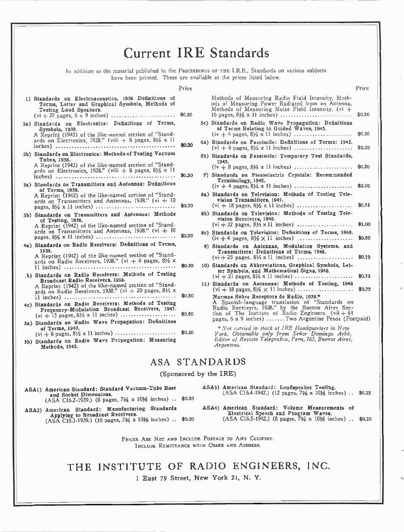
Current IRE Standards In addition to the material published in the PROCEEDINGS OF THE IRE., Standards on various subjects
have been printed. These are available at the prices listed below.
1)
Price
Standards on Electroacoustics, 1938 Definitions of Terms, Letter and Graphical Symbols, Methods of Testing Loud Speakers.
(vi -I- 37 pages, 6 x 9 inches) $0.50
2a) Standards on Electronics: Definitions of Terms, Symbols, 1938.
A Reprint (1943) of the like-named section of "Stand-ards on Electronics, 1938." (viii 8 pages, 81/2 x 11 inches) 80.20
2b) Standards on Electronics: Methods of Testing Vacuum Tubes, 1938.
A Reprint (1943) of the like-named section of "Stand-ards on Electronics, 1938." (viii + 8 pages, 81/2 x 11 inches)
3a) Standards on Transmitters and Antennas: Definitions of Terms, 1938.
A Reprint (1942) of the like-named section of "Stand-ards on Transmitters and Antennas, 1938." (vi + 10 pages, 81/2 x 11 inches)
3b) Standards on Transmitters and Antennas: Methods of Testing, 1938.
A Reprint (1942) of the like-named section of "Stand-ards on Transmitters and Antennas, 1938." (vi 10 pages, 8% x 11 inches)
4a) Standards on Radio Receivers: Definitions of Terms, 1938.
A Reprint (1942) of the like-named section of "Stand-ards on Radio Receivers, 1938." (vi 6 pages, 81/2 x 11 inches)
b) Standards on Radio Receivers: Methods of Testing Broadcast Radio Receivers, 1938.
A Reprint (1942) of the like-named section of "Stand-ards on Radio Receivers, 1938." (vi 20 pages, 8,/2 x 11 inches)
4c) Standards on Radio Receivers: Methods of Testing Frequency-Modulation Broadcast Receivers, 1947.
(vi + 15 pages, 8% x 11 inches)
5a) Standards on Radio Wave Propagation: Definitions of Terms, 1942.
(vi + 8 pages, 8% x 11 inches)
5b) Standards on Radio Wave Propagation: Measuring Methods, 1942.
Methods of Measuring Radio Field Intensity, Meth-ods of Measuring Power Radiated from an Antenna, Methods of Measuring Noise Field Intensity. (vi + 16 pages, 8% x 11 inches)
5c) Standards on Radio Wave Propagation: Definitions of Terms Relating to Guided Waves, 1945.
(iv + 4 pages, 8% x 11 inches)
6a) Standards on Facsimile: Definitions of Terms: 1942. (vi + 6 pages, 81/2 x 11 inches)
6b) Standards on Facsimile: Temporary Test Standards, 1943.
(iv + 8 pages, 81/2 x 11 inches)
Price
$0.50
$0.20
$0.20
$0.20
$0.50 7) Standards on Piezoelectric Crystals: Recommended Terminology, 1945.
(iv + 4 pages, 81/2 x 11 inches) $0.20
8a) Standards on Television: Methods of Testing Tele-vision Transmitters, 1947.
$0.20 (vi + 18 pages, 8% x 11 inches) $0.75
8b) Standards on Television: Methods of Testing Tele-vision Receivers, 1948.
(vi + 32 pages, 8% x 11 inches) $1.00
8c) Standards on Television: Definitions of Terms, 1948. (iv -I- 4 pages, 81/4 x 11 inches) $0.50
9) Standards on Antennas, Modulation Systems, and Transmitters: Definitions of Terms, 1948.
(vi -I- 25 pages, 81/4 x 11 inches) $0.75
$0.20 10) Standards on Abbreviations, Graphical Symbols, Let-ter Symbols, and Mathematical Signs, 1948.
(vi + 21 pages, 81/2 x 11 inches) 11) Standards on Antennas: Methods of Testing, 1948 $0.75
(vi + 18 pages, 81/2 X 11 inches) 80.75
0.50 Normas Sobre Receptors de Radio, 1938.* A Spanish-language translation of "Standards on Radio Receivers, 1938," by the Buenos Aires Sec-
$0.50 tion of The Institute of Radio Engineers. (vii + 64 pages, 6 x 9 inches) Two Argentine Pesos (Postpaid)
* Not carried in stock at IRE Headquarters in New $0.20 York. Obtainable only from Senor Domingo Arbo,
Editor of Revista Telegrafica, Peru, 165, Buenos Aires, Argentina.
$0.50
ASA STANDARDS (Sponsored by the IRE)
ASA1) American Standard: Standard Vacuum-Tube Base and Socket Dimensions.
(ASA C16.2-1939.) (8 pages, 74,i x 108i inches) .. $0.20
ASA2) American Standard: Manufacturing Standards Applying to Broadcast Receivers.
(ASA C16.3-1939.) (16 pages, 734 x 10% inches) ..
ASA3) American Standard: Loudspeaker Testing. (ASA C16.4-1942.) (12 pages, 734 x 10% inches) .. $0.25
ASA4) American Standard: Volume Measurements of Electrical Speech and Program Waves.
$0.20 (ASA C16.5-1942.) (8 pages, 734 x 10% inches) .. $0.20
PRICES ARE NET AND INCLUDE POSTAGE TO ANY COUNTRY.
INCLUDE REMITTANCE WITH ORDER AND ADDRESS.
THE INSTITUTE OF RADIO ENGINEERS, INC. 1 East 79 Street, New York 21, N. Y.
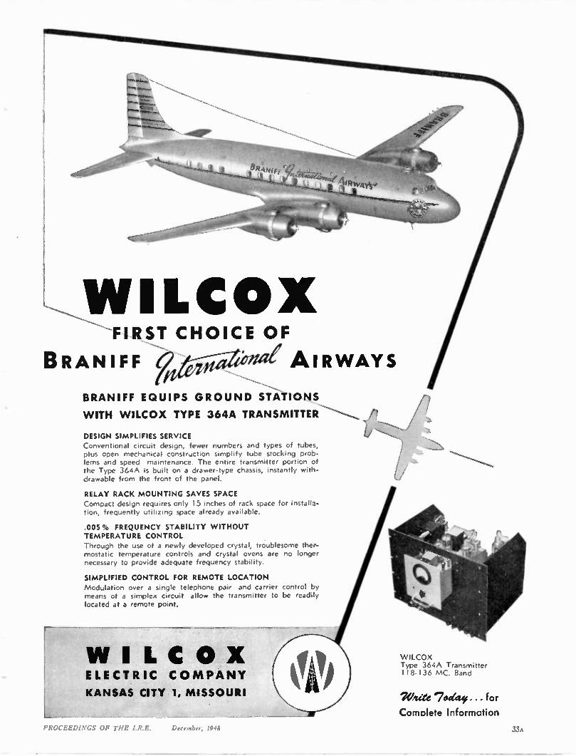
WILCOX 'FIRST CHOICE OF
BRANIFF AIRWAYS
BRANIFF EQUIPS GROUND STATIONS
WITH WILCOX TYPE 364A TRANSMITTER
DESIGN SIMPLIFIES SERVICE Conventional circuit design, fewer numbers and types of tubes, plus open mechanical construction simplify tube stocking prob-lems and speed maintenance. The entire transmitter portion of the Type 364A is built on a drawer-type chassis, instantly with-drawable from the front of the panel.
RELAY RACK MOUNTING SAVES SPACE
Compact design requires only 15 inches of rack space for installa-tion, frequently utilizing space already available.
.005° FREQUENCY STABILITY WITHOUT TEMPERATURE CONTROL Through the use of a newly developed crystal, troublesome ther-mostatic temperature controls and crystal ovens are no longer necessary to provide adequate frequency stability.
SIMPLIFIED CONTROL FOR REMOTE LOCATION Modulation over a single telephone pair and carrier control by means of a simplex circuit allow the transmitter to be readily located at a remote point.
WI L C O X ELECTRIC CO MPANY
KANSAS CITY 1, MISSOURI
WILCOX Type 364A Transmitter 118-136 MC. Band
7V/rite 7 odety . . for Complete Information
PROLI,i,1;12,.0S '1. ilk.: I ssslci, ls ;
COSMALITE*
COIL FORMS
Each specially designed and produced
by us to give exceptional perform-
ance, and at a saving in cost to this
country's leading manufacturers of
radio and television receivers.
Your specifications as to punch-
ing, threading, notching and
grooving are followed with the
most exacting care. Ask about
our many stock punching dies
available to you.
Mae
Are you familiar with our :.-_-96
COSMALITE for coil forms in
all standard broadcast receiving
sets; SLF COSMALITE for per-
meability tuners; COSMALITE
deflection yoke shells, cores and
rings?
Spirally wound kraft and fish
paper Coil Forms and Condenser
Tubes.
"Reg. U.S. Pat. Off.
Tic CLEVELAND CONTAINER a. 6201 BARBERTON AVE. CLEVELAND 2, OHIO • Al --71bre Can. • Co mbination Metal and Paper Cans • Sr irelly 1Aou lc Tubes and Cores for all Purposes • Pl 1! tic arid Combination Paper and Plastic Ite ms
*RIO CT IN PI ANTS a-so at yr out Wist ,OgderisburtN Y, Chicago,111 Detrollilich .lameSbusg,5.1. PLASTICS IIVISICN A Plymouth. Wisc. • ABRASIVE 0105105 al [Toulon& Moo
:ALE! OF cis Room Os.. at Control text. Bldg ,Net Vora I?, N also 617 Mato St., Hartford, Cant. CANADI I PE NI Do Civilian Cootillor WAIL Lid., Prescott, Ontario
ATLANTA
"Railroad Radio Communication Equipment,'
by H. B. Hildreth, Central of Georgia Railroad; June 25. 1948.
'Installation and Equipment of WSB New TV Station." by C. F. Daugherty, Station WSB; Sep-
tember 17, 1948. BALTIMORE
'Columbia Long-Playing Microgroove Re-cording System,' by P. C. Goldmark. Columbia Broadcasting Company; September 28, 1948.
BUFFALO-NIAGARA
"Horizontal Deflection and High Voltage in Television Receivers," by H. R. Shaw. Colonial Radio Corporation; September 15, 1948.
CLEVELAND
'Television Studio Lighting," by R. Blount. General Electric Company; September 23, 1948.
D ALLAS-FORT W ORTH
"Some Problems of Television," by B. E. Shackelford, President, The Institute of Radio Engineers; October11. 1948.
H OUSTON
'Printed Circuits, Subminiature Radio Trans-mitters. and Receivers," by C. Brunetti, National Bureau of Standards; September 20, 1948.
'Recent Developments in Semi-Conductors and the Transitor,' by J. A. Becker, Bell Telephone
Laboratory; September 20, 1948. 'Basic and General Problems of Television as a
Service,' by B. E. Shackelford, President. The In-stitute of Radio Engineers; October 8. 1948.
K ANSAS CITY
'Magnetic Recording," by C. G. Barker. Magnecord, Inc.; September 20, 1948.
N E W M EXICO
'Some Problems of Teleivision,' by B. E. Shackelford. President, The Institute of Radio Engi-neers; October 5, 1948.
N ORTH CAROLINA- VIRGINIA
'Detection by Heat Radiation," by N. C. Jamison, Phillips Laboratories; May 14. 1948.
'Electronic Computers." by C. N. Hoyler. Radio Corporation of America; September 10. 1948.
PHILADELPHIA
'A New Long-Playing Disk Recording Sys-tem." by P. C. Goldmark, Columbia Broadcasting Company; October 7, 1948.
ST. LOUIS
'Sound Level Measurements." by J. L. Glaser, Washington University; September 23. 1948.
SAN ANTONIO
'Radar Reflections from the Lower Atmos-phere." by W. E. Gordon, University of Texas; May 26. 1948.
"The Electron Microscope," by L. L. Antes. University of Texas; June 24. 1948.
SAN FRANCISCO
"The Measurement of Faint Light by Photo-electric Methods," by G. E. Kron, Lick Observa-tory; September 8, 1948.
SEATTLE
"Cathode-Ray Sweep Circuits." by M. A. Starr, University of Portland; June IL 1948.
'Problems in Development of Television,' by B. E. Shackelford, President. The Institute of Radio Engineers; September 24, 1948.
(Continued on page 37A)
34A PROCEEDINGS OF THE I.R.E. December, 1948
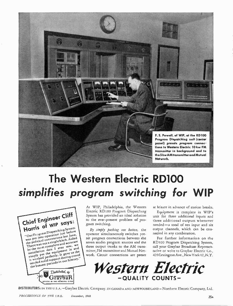
F. S. Powell, of WIP, at the RD100
Program Dispatching unit (center
panel) presets program connec-
tions to Western Electric 10 kw FM
transmitter in background and to
the 5 kw AM transmitter and Mutual
Network.
The Western Electric RD100 simplifies program switching for WIP
kChiel,.Engineer Cliff \ Harris oi NNW says: .. OurProgramDispatching System
as put into operation just before the po cal conventions last June. w not a single hitch. Aided
br the most complete and accurat There was
e
installation data 1 ever saw, we
simply put the equ e us the
ipment in and
it worked perfectly. It gav neecled solid support during one of the busiest periods in our history."
V I D A tatae, ey
j G T M 7 R OFFICES IN 100 PRINCIPAL CITIES
At WIP, Philadelphia, the W estern Electric R D100 Program Dispatching System has provided an ideal solution to the ever-present problem of pro-gram switching.
By simply pushing one button, the operator simultaneously switches pre-set program connections between the seven studio program sources and the three output trunks to the AM trans-mitter, FM transmitter and Mutual Net-work. Circuit connections are preset
at leisure in advance of station breaks.
Equipment is complete in WIP's unit for three additional inputs and three additional outputs whenever needed —a total of ten input and six output channels, which can be con-nected in any combination.
For further information on the RD100 Program Dispatching System, call your Graybar Broadcast Represen-tative or write to Graybar Electric Co., 420 Lexington Ave., New York 17, N.Y.
Western Electric —QUALITY COUNTS—
DISTRIBUTORS: IN THEU.S.A. — Graybar Electric Company. IN CANADA AND NEWFOUNDLAND — Northern Electric Company, Ltd.
DROCEEOrNGS OF THE I.R.E. December, 1941 35A
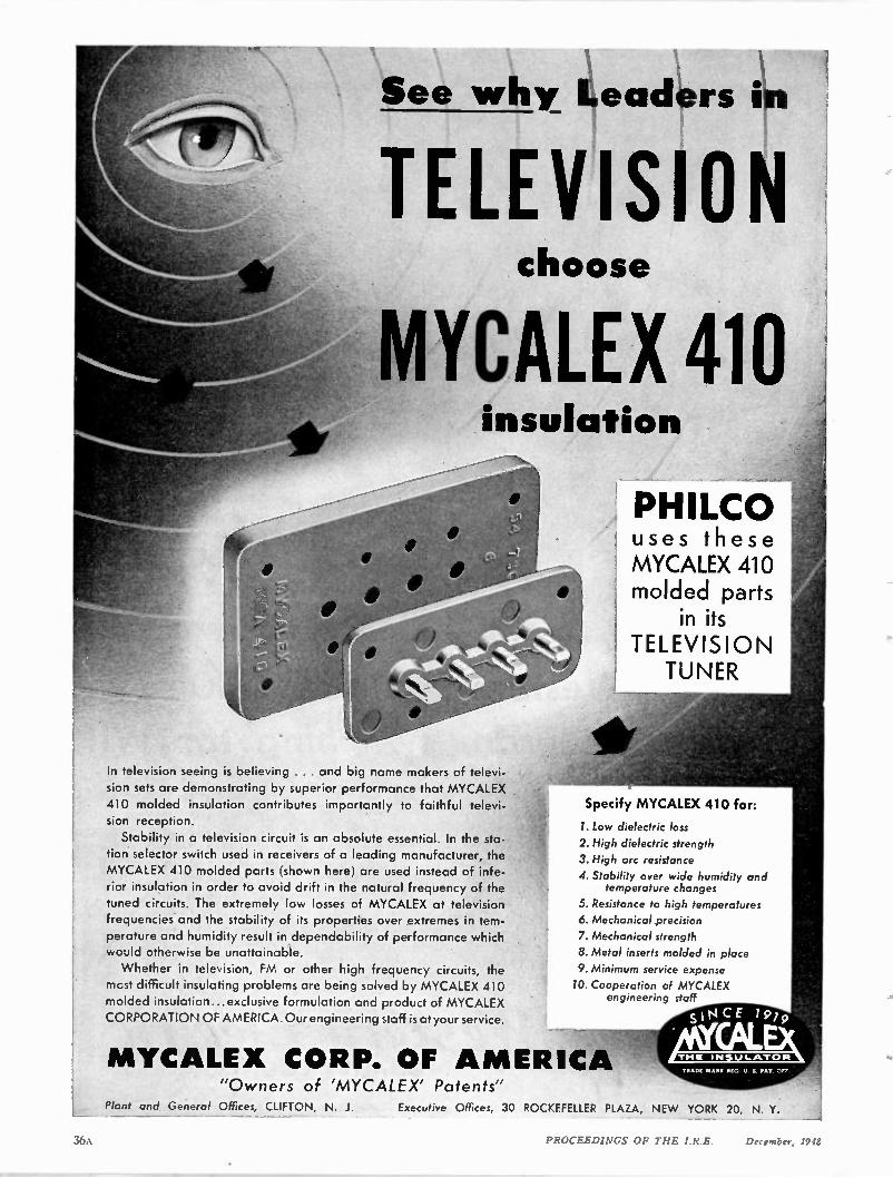
See why 4ea 4rs i.
TELEVISION choose
MYCALEX 410 insulation
In television seeing is believing . . . and big name makers of televi-sion sets are demonstrating by superior performance that MYCALEX 410 molded insulation contributes importantly to faithful televi-sion reception.
Stability in a television circuit is an absolute essential. In the sta-tion selector switch used in receivers of a leading manufacturer, the MYCALEX 410 molded parts (shown here) are used instead of infe-rior insulation in order to avoid drift in the natural frequency of the tuned circuits. The extremely low losses of MYCALEX at television frequencies and the stability of its properties over extremes in tem-perature and humidity result in dependability of performance which would otherwise be unattainable. Whether in television, FM or other high frequency circuits, the
mcst difficult insulating problems are being solved by MYCALEX 410 molded insulation...exclusive formulation and product of MYCALEX CORPORATION OF AMERICA. Our engineering staff is at your service.
fag
, PHILCO uses these MYCALEX 410 molded parts
in its TELEVISION TUNER
Specify MYCALEX 410 for:
1. Low dielectric loss 2. High dielectric strength 3. High arc resistance 4. Stability over wide humidity and
temperature changes 5. Resistance to high temperatures 6. Mechanical precision 7. Mechanical strength 8. Metal inserts molded in place 9. Minimum service expense 10. Cooperation of MYCALEX
engineering staff
MYCALEX CORP. OF A MERIC "Owners of 'MYCALEX' Patents"
Plant and General Offices, CLIFTON, N. J. Executive Offices, 30 ROCKEFELLER PLAZA, NEW YORK 20, N. Y. _
36A PROCEEDINGS OF THE I.R.E. December, 1948
(Continued from page 34A)
SYRACUSE
'Nuclear Power Production.' by H. Stevens.
General Electric Company; October 7, 1948.
TOLEDO
'Microwave Communication." by J. W. Mc-Rae, Bell Telephone Laboratories, Inc.; September 16, 1948.
TORONTO
"The Design and Installation of a 5-Kw High-
Channel Television Transmitter." by R. E. Fisk, General Electric Company; October 4. 1948.
TWIN CITIES
"Television —Its Mechanism and Promise," by
W. Lawrence, Radio Corporation of America; September 21. 1948.
WASHINGTON
'Magnetic Tape Recording," by R. H. Ranger. Rangertone. Inc.; September 211, 1948.
SUB-SECTIONS
NORTHERN NEW JERSEY
"The WATV Television Station," by T. M.
Gluyas, Radio Corporation of America, and F. Bremer, Bremer Broadcasting Company; September 15, 1948.
UNIVERSITY OF ARIZONA —IRE-AIEE BRANCH
Election of Officers; September 15, 1948.
"Grand Coulee Power Project." by J. H. Pfeiffer, Student. University of Arizona; October 6, 1948.
UNIVERSITY OF CALIFORNIA —IRE-AIEE BRANCH
'The Engineering Industry Looks at the Col-ege Graduate," by M. P. O'Brien. University of California; October 5, 1948.
"Advantages of Membership in a Professional Society," by J. R. Whinnery, University of Cali-fornia; October 5. 1948.
"The Plans for the New Electrical Engineering Building," by T. C. McFarland, University of California; October 5, 1948.
CARNEGIE INSTITUTE OF TECHNOLOGY — IRE-AIEE BRANCH
'Carnegie Tech Cyclotron,' by H. E. DeBolt and L. Johnson, Graduate Students. Carnegie In-stitute of Technology; October 11, 1948.
CITY COLLEGE OF NEW YORK —IRE BRANCH
'Student Activity in the Institute of Radi 0 Engineers,' by E. K. Gannett, The Institute of Radio Engineers; September 28. 1948.
'Co-ordination of Student Branches in the Metropolitan Area.' by S. G. Lutz, New York Uni-versity; September 28, 1948.
UNIVERSITY OF FLORIDA —IRE-AIEE BRANCH
'Our Institute." by E. S. Lee. President, AIEE; September 29, 1948.
(Continued on page 38A)
An Important Statement
by
MYCALEX CORPORATION OF AMERICA
As illustrated on the opposite page. PHILCO uses Mycalex 410 (glass bonded mica) molded parts in its tele-vision receiver tuner — to avoid fre-quency drift of tuned circuits.
You' ..Ittention is also called to the Mycalex 410 advertisement which appeared on pages 30 and 31 of the October 1948 issue of Proc. of I.R.E.
Constant research, improved technics, advances in the art, new, modern plant expansion, improved engineering, more efficient manufacturing equipment— now permit us to make available in increased quantities—Mycalex 410— molded—at prices comparable to other less efficient molded insulations.
MYCALEX 410 is now priced to meet rigid economy requirements
Any interest evidenced on your part in Mycalex products and services—will receive the prompt, courteous and intelligent attention of a competent Mycalex sales engineer. He will receive the fullest backing and cooperation from other factory executives— to serve you promptly — with a quality product and at an econom-ical and fair price.
PROCEEDINGS OF THE I.R.E. December, 1948 37A
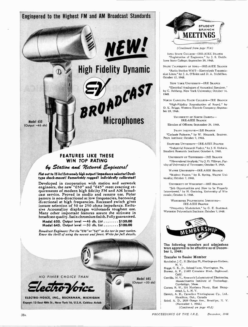
Engineered to the Highest FM and AM Broadcast Standards
N E
/ High Fidelity Dynamic do 4
Model 650 (Output —46 db)
BRO /1 Microphones
pOST
FEATURES LIKE THESE WIN TOP RATING
4 Seeteidg awd 11,ereco4 ggefiwevull Flat out to 15 kcl Extremely high output! Impedance selector! Dual-type shock-mount I Remarkably rugged! Individually calibrated!
Developed in cooperation with station and network engineers, the new "650" and "645" meet exacting re-quirements of modern high fidelity FM and AM broad-cast service. Proved in studio and remote use. Polar pattern is non-directional at low frequencies, becoming directional at high frequencies. Recessed switch gives instant selection of 50 or 250 ohms impedance. Exclu-sive Acoustalloy diaphragm withstands toughest use. Many other important features assure the ultimate in broadcast quality. Satin chromium finish. Fully guaranteed.
Model 650. Output level —46 db. List $150.00 Model 645. Output level —50 db. List $100.00
Broadcast Engineers: Put the "650"or "645" to the test in your station. Know the thrill of using the newest and finest. Write for full details.
N O FINER CH OICE THAN
gler reficz, ELECTRO-VOICE, INC., BUCHANAN, MICHIGAN
Export: 13 East 40th St., New York 16, U.S.A. Cables: A rlab
Model 645 (Output —50 db)
0 1116 \
(Continued from page 37A)
IOWA STATE COLLEGE —IRE-AIEE BRANCH "Registration of Engineers," by J. S. Dodds.
Iowa State College; September 29, 1948.
STATE UNIVERSITY OF IOWA —IRE-AIEE BRANCH
'Radio Station W MT —Electrolysis Transmis-sion Lines." by J. A. O'Brien and D. A. McMillon. October 13, 1948.
NEW YORK UNIVERSITY —IRE BRANCH
'Electrical Analogues of Acoustical Speakers." by C. Rehberg. New York University; October 14. 1948.
NORTH CAROLINA STATE COLLEGE —IRE BRANCH
'High-Fidelity Reproduction of Sound,' by D. K. Briggs, Western Electric Company; Septem-ber 29, 1948.
UNIVERSITY OF NORTH DAKOTA — IRE-AIEE BRANCH
Election of Officers; September 29, 1948.
PRATT INSTITUTE —IRE BRANCH
'Cathode Follower,' by W. Heacock, Student. Pratt Institute; October 7, 1948.
STANFORD UNIVERSITY —IRE-AIEE BRANCH
'Industrial Research Today." by J. E. Hobson. Stanford Research Institute; October 6, 1948.
UNIVERSITY OF TENNESSEE —IRE BRANCH
'Dimensional Analysis." by J. D. Tillman. Fac-ulty of University of Tennessee; October 5, 1948.
W AYNE UNIVERSITY —IRE-AIEE BRANCH
'Student Papers,' by E. Spring, Wayne Uni-versity; October 7, 1948.
UNIVERSITY OF W ISCONSIN —IRE BRANCH
'Job Opportunities and How to be Properly Interviewed,' by H. Goehring, University of Wis-consin; October 5. 1948.
W ORCESTER POLYTECHNIC INSTITUTE — IRE-AIEE BRANCH
'Frequency Modulation,' by G. E. Stannard Worcester Polytechnic Institute; October 7. 1948.
The following transfers and admissions were approved to be effective as of Decem-ber 1, 1948:
Transfer to Senior Member Batchelor. J. C.. 31 Sheldon Pl., Hastings-on-Hudson.
N. Y. Beggs, G. E., Jr.. School Lane, Warrington. Pa. Brewer, A. F., 11605 Crenshaw Blvd., Ingle‘sood,
Calif. Cerrillo. M. Y., Research Laboratory of Electronics.
Massachusetts Institute of Technology Cambridge. Mass.
Comes, R. W., 231 Northern Pkwy.. East Hemp-stead, L. I., N. Y.
Sievert, A. H., Canadian Westinghouse Co.. Ltd., Hamilton. Ont., Canada
Sobel, A. D.. 2939 Ocean Ave., Brooklyn, N. V. (November 1. 1948.)
(Continued on page 40A)
PROCEEDINGS OF THE I.R.E. December, 1948
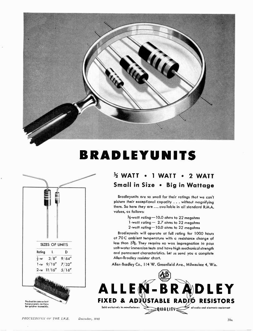
BRADLEYUNITS
Rating
3„ 8" 9, 64"
1-w 9/16" 7/32"
2-w 11/16" 5'16"
Pocked in convenient honeycomb cartons for quicker assembly.
1/2 WATT • 1 WATT • 2 WATT
Small in Size • Big in Wattage
Bradleyunits are so small for their ratings that we can't
picture their exceptional capacity . . . without magnifying
them. So here they are... available in all standard R.M.A.
values, as follows:
1/2 -watt rating -10.0 ohms to 22 megohms
1-watt rating — 2.7 ohms to 22 megohms
2-watt rating -10.0 ohms to 22 megohms
Bradleyunits will operate at full rating for 1000 hours
at 70 C ambient temperature with a resistance change of
less than 5%. They require no wax impregnation to pass salt-water immersion tests and have high mechanical strength
and permanent characteristics. Let us send you a complete
Allen-Bradley resistor chart.
Allen-Bradley Co., 1 14 W. Greenfield Ave., Milwaukee 4, Wis.
FIXED & AD
ALLE 1-131 DLEY ,
Sold exclusively to manufacturers
STABLE RAD RESISTORS Qt1 A LI T II Y of radio and electronic equipment
PROCEEDINGS OF THE I.R.E. December, 1948
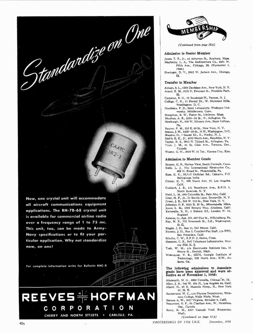
all aircraft communications equipment
applications. The RH-78-68 crystal unit
is available for commercial airline radio
over a frequency range of 1 to 75 mc.
This unit, too, can be made to Army-
Navy specifications or par-
ticular application. Why not standardize
40A
(Continued from page RA)
Admission to Senior Member
Jones, T. F., Jr., 41 Atherton St., Roxbury, Mass. Mayberry, L. A.. The Hallicrafters Co., 4401 W.
Fifth Ave., Chicago, Ill. (November 1. 1948.)
Sinninger. D. V., 2662 W. Jarlath Ave.. Chicago, IlL
Transfer to Member
Abbott, S. L., 1929 Davidson Ave., New York, N. Y. Aran& E. M., 3125 N. Emerson St.. Franklin Park.
Cameron. E. G., 10 Randolph' Pl., Verona, N. J. College. C. H., 11 Duvall Dr., W. Moreland Hills,
Washington, D. C. Goodman. P. D., Scott Laboratory. Wesleyan Uni-
versity. Middletown. Conn. Houghton. R. W., Foster St., Littleton, Mass. Moulton, A. B.. 2534-24 St.. N.. Arlington. Va. Newburgh. H., 610 W. Nittany Ave., State College,
Pa. Raycer, P. M., 333 E. 69 St., New York. N. Y. Seaton. J. W., 3430-39 St., N W., Washington, D.C. Shapiro, 0., 7 Sunset Dr.. E., Nutley, N. J. Smith, E. K.. Jr., 4313 Ninth Ave., Brooklyn, N. Y. Taylor, R. S., 2012 N. Upland St.. Arlington, Va. Toye. J. M., 51 St. Clair Ave.. Toronto, Ont..
Canada Waster, G. W., 3018 W. Si Ter.. Kansas City, Kan.
Admission to Member Grade
Benson, K. B., Harbor View. South Norwalk, Conn. Bobb, L. J., The International Electronics Co..
808 N. Broad St.. Philadelphia, Pa. Bose. K. K., 28/1/3 Gariahat Rd., Calcutta, P.O.
Ballygunge. India Corner, K. T., 108 North Ave. 19, Los Angeles,
Calif. Coullard. J. B., 111 Hazelhurst Ave.. R.F.D. 1,
North Syracuse. N. Y. Field, L. M., 695 Columbia St., Palo Alto. Calif. Gray, H. F., Jr., 21 Stuao Lane, Bronzville. N. Y. Green, J. R., 535 W. 110 St., New York, N. Y. Johnston, 0. B., 1012 E. 35 St.. Minneapolis, Minn. Jones, L. M.. 1092 Beverly Way, Altadena, Calif. Keravralla. R. D.. 6 Elsham Rd., London \V. 14.
England Ralston, G., Apt. 201, 607 Hay St., Wilkinsburg, Pa. Ray, H. B., 223 Newcomb St.. SE., Washington.
D. C. Riggin, J. D., Box II, Del Monte, Calif. Rooney. J. D., Box 3, ComServPac Staff. c/o FPO.
San Francisco, Calif. Schultz, C. W., R.F.D. 2, Storrs, Conn. Shannon, C. E., Bell Telephone Laboratories, Mur-
ray Hill, N. J. Tosh, W. M., c/o Electronics Institute Inc., 21
Henry St., Detroit. Mich. Widerquist, V. R.. SEES, Georgia Institute of
Technology, 225 North Ave., N W.. At-
lanta, Ga.
The following admissions to Associate grade have been approved and were ef-fective as of November 1, 1948:
Ainsworth, M. G., 4803 Cornelia, Chicago-41, Ill. Allen, J. R., 746 W. 104 Pl.. Los Angeles 44. Calif. Alpert, N., 55 E. Mosholu Pkwy., N., New York
67, N. Y. Backstrand, W. C., c/o Physics Department, Whit-
man Csllege, Walla Walla, Wash. Barnes, A. W., 1917 Virginia, Berkeley 9. Calif. Beaumont, G. F., 91 Charlton Ave., W., Hamilton,
Ont., Canada Berry, R. M., 2307 Cascade Trail, Bremerton.
(Continued on page 42A)
PROCEEDINGS OF THE I.R.E. December, 1948
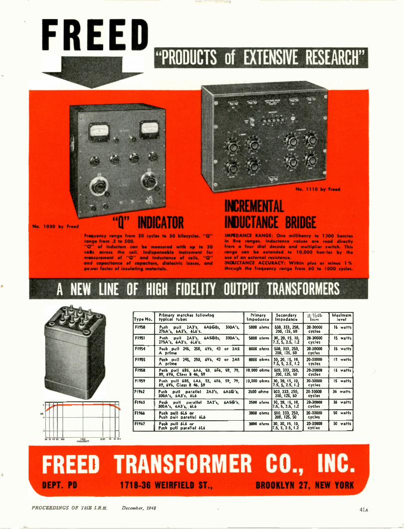
FREED
by Freed
"PRODUCTS of EXTENSIVE RESEARCH"
Frequency range from 20 cycles to 50 kilocycles. "0"
range from .5 to 500.
"CT" of inductors can be measured with up to 50
vets across the coil. Indispensable Instrument for
measurement of "0" and inductance of coils, "0"
en 1 capacitance of capacitors, dialectric
po or factor of insulating materials.
• -- -
IMPEDANCE RANGE: One millihenry to 1200 henries
In Ave ranges. Inductance values are read directly
hors a four dial decade and multiplier switch. This
range can be extended to 10,000 henies by the
use of an external resistance.
INDUCTANCE ACCURACY: Within plus or minus 1%
thrcugh the frequency range from 60 to 1000 cycles.
A NEW LINE OF HIGH FIDELITY OUTPUT TRANSFORMERS
ar • AO ICC 1000 r.1,3L 0e ,
101(r 10 1 PK
Primary matches following Primary Secondary - ' ,db Maximum Type No. typical tubes Impedance Impedance from level
FI950 Push pull 2A3's, 6A5G8s, 300A's, 5000 ohms 500, 333, 250, 20-30000 IS watts 275A's, 6A3's, 6L6's. 200, 125, 50 cycles
FI951 Push pull 2A3's, 6A5G8s, 300A's, 5000 ohms 30, 20, 15, 10, 20-30000 15 watts 275A's, 6A3's, 6L6's. 7.5, 5, 2.5, 1.2 cycles
F1954 Push pull 245, 250, 6V6, 42 or 2A5 8000 ohms 500, 333, 250, 20-30000 15 watts A prime 200, 125, 50 cycles
FI955 Push pull 245, 250, 6V6, 42 or 2A5 8000 ohms 30, 20, 15, 10, 20-30000 IS watts A prim. 7.5, 5, 2.5, 1.2 cycles
F1958 Push pull 685, 6A6, 53, 6F6, 59, 79, 10,000 ohms SCO, 333, 250, 20-30000 IS watts 89, 6V6, Class B 46, 59 200, 125, 50 cycles
FI959 Push pull 6135, 6A6, 53, 6F6, 59, 79, 10,000 ohms 30, 20, IS, 10, 20-30000 15 watts 89, 6V6, Class B 46, 59 7.5, 5, 2.5, 1.2 cycles
FI962 Push pull parallel 2A3's, 6A5G's, 2500 ohms SCO, 333, 250, 20-30000 36 watts 300A's, 6A3's, 6L6 200, 125, SO cycles
FI963 Push pull parallel 2A3's, 6AEG's, 2500 ohms 30, 20, 15, 10, 20-30000 36 wafts 300A's, 6A3's, 6L6 7.5, 5, 2.5, 1.2 cycles
FI966 Push pull 6L6 or 3800 ohms 5CO, 333, 250, 20-30000 SO watts Push pull parallel 6L6 200, 125, 50 cycles
FI967 Push pull 6L6 or 3800 ohms 30' 20 IS, 10, 20-30000 50 wafts Push pull parallel 6L6 7.5, 5:2.5, 1.2 cycles
FREED TRANSFO EPIC PD
Lit 1718-36 WEIRF1ELD ST. ROOKLYN 27, NEW _yo
PROCEEDINGS OF M E I.R.E. Dr ron1 f 11A
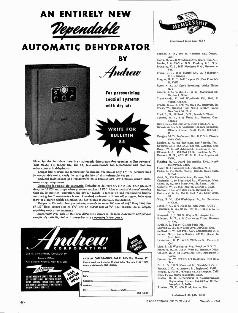
AN ENTIRELY NE W
Otveif4elay AUTOMATIC DEHYDRATOR
For pressurizing
coaxial systems
with dry air
WRITE FOR
BULLETIN
85
Now, for the first time, here is an automatic dehydrator that operates at line pressure!
This means, (1) longer life, and (2) less maintenance and replacement cost than any
other automatic dehydrator.
Longer life because the compressor diaphragm operates at only 1/3 the pressure used
in comparable units, vastly increasing the life of this vulnerable key part.
Reduced maintenance and replacement costs because new low pressure design elimi-
nates many components.
Operation is completely automatic. Dehydrator delivers dry air to line when pressure
drops to 10 PSI and stops when pressure reaches 15 PSI. After a total of 4 hours' running
time on intermittent operation, the dry air supply is turned off and reactivation begins,
continuing for 2 consecutive hours. Absorbed moisture is driven off as steam. Indicators
show at a glance which operation the dehydrator is currently performing.
Output is 11/4 cubic feet per minute, enough to serve 700 feet of 61/4 " line; 2500 feet
of 31/4 " line; 10,000 feet of 11/4 " line or 40,000 feet of 7/2" line. Installation is simple,
requiring only a few moments.
Important! Not only is ibis new differently designed Andrew Automatic Dehydrator
completely reliable, but it is available at a surprisingly low price.
C O R P O R A T I O N
363 E 75th STREET, CHICAGO 19
Eastern Office:
421 Seventh Avenue, New York City
ANDRE v' TRANSMISSION LINES FOR AM, FM, IV. DIRECTIONAL ANTENNA EQUIP. NEST ANTENNA IUNING UNITS TOWEI LIGHTING EQUIPMENT. CONSULTING ENGINEERING SERVICE.
ANDREW CORPORATION, 363 E. 75th St., Chicago 19
Please send me Bulletin 85 describing the new Type 1900 Andrew Automatic Dehydrator.
Nam*
Till*
Company
Address
City Zone State IRE 12-43
(Continued from page 40A)
Beymer, E. H., 605 R. Anacada Dr.. Oxnard. Calif.
Bluhm, R. W., 32 Woodcrest Ave.. Short Hills, N. J. Bombe, A. A., 29-01 -159 St., Flushing, L. I., N. V. Browning, C. L., 3617 Montrose Blvd., Houston 6.
Tex. Brown, T. J., 1542 Marine Dr., W. Vancouver.
B. C., Canada Burgess, H. R. C.. 2621 Laguna St., San Francisco
23, Calif. Byers, A. E., 50 North Broadway, White Plains.
N. Y. Carney. J. J., Y. M.C.A., 117 W. Monument St.,
Dayton 2, Ohio Chamberlain, E.. 102 Woodlands Rd.. Hull, E.
Yorks. England Chapin, E. L., Jr.. 4711 W. Main St., Belleville. Ill.
Chase, W., Barnard Hall, North Brother Island. New York 54, N. Y.
Clark, L. G., 6227 -21, N.E., Seattle 5, Wash. Corbett, H. L., 124; Percy St., Ottawa. Ont..
Canada 1Daleo, S. L., 198 First Ave., New York 3. DeVoe, W. D., 3312 Technical Training Squadron,
Officers Comm.. Scott Field, Belleville.
Douglas, M. D.. 76 Concord Rd., R.F.D. 3, Chagrin Falls, Ohio
Dunlap, R. H., 408 Baltimore, San Antonio, Tex. Edwards, M. J., R.F.D. 3, Box 483, Glendale, Ariz.
Eisner, W. K., 486 Ashford St., Brooklyn. N. Y. Elikann, L. S., 1439 East 19 St.. Brooklyn. N. Y. Favreau, R. R., 6765 W. 86 Pl., Los Angeles 45.
Calif. Fielding, B. L., 5019; Lankershim Blvd., North
Hollywood, Calif. Fisher, S., 11 Westcott Rd.. Princeton, N. J. Froke. L. C.. Radio Station KELO. Sioux Falls.
S. Dal‘ Gold, M., 254 Fountain Ave., Dayton. Ohio Goldstein, 1., 80 Brantwood Rd., Worcester, Mass. Gones, R. D., 4568 Mary Ave., St. Louis 7. Mo. Gudaitis, \V. V., 1617 Morrell. Detroit 9, Mich. Harpole J. L., Live Oak Plant. Ravenel S. C. Holmquist W. L. 116 E. Park Ave., Libertyville.
Horn. R. H., 1370 Washington St., San Francisco 9, Calif.
Jones. H. G., 3776 Milan St., San Diego 7, Calif. Jorgensen, S. W., 88-36 -187 St., Hollis 7, L. 1..
N. Y. ICasparek, J. J., 309 N. Wayne St.. Angola, Ind. Kliopera, M. F., 3221 Charleston Circle, Houston
4, Tex. Kreis, R. J. Box 97. College Park. Md. Lanwell, L. W., 313; Main Ave.. McCook. Neb. Lapidos, R. W., 134 Penn Ave.. Collingswood, N. J. Larsen, N. J., Radio Station KM MJ, Grand is-
land. Neb. Lauterbach. R. E., 845 S. Williams St.. Denver 0,
Col. Lidz, S., 451 Washington Ave., Brooklyn 5. N. Y. Munn, E. H., Jr., 306 N. West St., Hillsdale. Olander, R. 0., 64 Homestead Ave., Bridgeport 3.
Conn. Osteyee, W. W., QTRS. 349 Doniphan, Fort Bliss.
Tex. Ott, L. 0., 220 S. Kenwood St., Glendale 5, Calif. Parode, L. C.. 711 Stepney St., Inglewood, Calif. Pellock, J., 10745 Channock Rd., Los Angeles. Calif. Petit, F. W., North Woodbury. Conn. Prabhu, K. S., Department of Communication
Engineering, Indian Institute of Science. Bangalore 3. India
Pritchett, W. C., 400 E. 32, Austin, Tex.
(Continued on page 46A)
42 PROCEEDINGS OF THE I.R.E. December, 1948
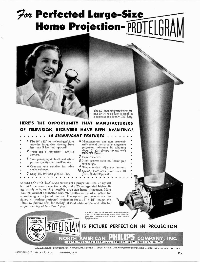
7yt Perfected Large-Size
Home Projection- pRoTELGRAM
The 23:" magnetic projection tri-ode 3NP4 has a face as small as a compact and is only 10g" long.
HERE'S THE OPPORTUNITY THAT MANUFACTURERS
OF TELEVISION RECEIVERS HAVE BEEN AWAITING!
10 SIGNIFICANT FEATURES
/ Flat 16" x 12- non-rellecting picture provides fatigueless viewing from less than 5 feet and upward!
2 Wide-angle visibility — square corners.
3 'rrue photographic black and white picture quality—no discoloration.
4 Compact unit—suitable for table model cabinets.
5 Long-life, low-cost picture tube. . .
6
7
9 10
Manuf flamers call most economi-cally extend their product range into projection television by adapting their 10" EM chassis for use with PROTELGRANI. Easy to service. High contrast ratio and broad gray tone range. Simple optical adjustment system. Quality built after more than 10 years of development.
NORELCO PROTELGRAM consists of a projection tube, an optical box with focus and deflection coils, and a 25 kv regulated high-volt-age supply unit, making possible large-size home projection. More than ten years of exhaustive research resulted in this ideal system for reproducing a projected picture. The optical components are de-signed to produce perfected projection for a 16" x 12" image, the optimum picture size for steady, distant observation and also for proper viewing at less than 5 feet.
Other NORELCO products include stand-ard 10" direct-viewing tubes and special-purpose cathode-ray tubes for many applications.
•
IS PICTURE PERFECTION IN PROJECTION
DEPT. TP12, 11)0 LAS N PHILIPS MPANY, INC.
9 STREET. NE W YORK IT, N. Y.
IN CANADA. PHILIP'S INDUSTRIES LTD., 1203 PHILIPS SQUARE, MONTREAL * EXPORT REPRESENTATIVE PHILIPS EXPORT CORPORATION, 100 EAST 42ND STREET, NEW YORK 17, N. Y.
PROCEEDINGS OF THE I.R.E. December, 1948 43A
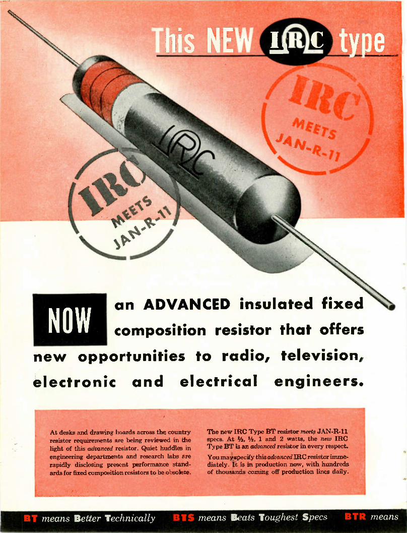
NOW
NEL LiAf. type
cIL
an ADVANCED insulated fixed
composition resistor that offers
new opportunities to radio, television,
electronic and electrical engineers.
At desks and drawing boards across the country resistor requirements are being reviewed in the light of this advanced resistor. Quiet huddles in engineering departments and research labs are rapidly disclosing present performar.ce stand-ards for fixed composition resistors to ba obsolete.
The new IRC Type BT resistor meets JAN-R-11 specs. At. 1/3, 1/2 , 1 and 2 watts, the new IRC Type BT is ar advanced resistor in every respect.
You may s7ecify thisadvancediRC resister imme-diately. Is is in production now, with hundreds of thousa:-.ds coming off production
4
.41
means Better Technically means Beats Toughest Specs means
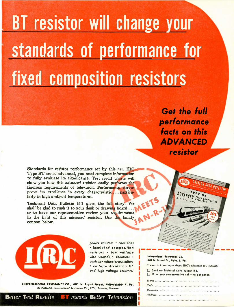
BT resistor will change your
standards of performance for
fixed composition resistors
• li• •••••• •• •
Standards for resistor performance set by this net;o:ellropmell Type BT are so advanced, you need complete infor ot to fully evaluate its significance. Test result charts wit show you how this advanced resistor easily pe orms the rigorous requirements of television. Perform cp curves. prove its excellence in every characteristi larly in high ambient temperatures.
Technical Data Bulletin B-1 gives the shall be glad to rush it to your desk or dra or to have our representative review your r in the light of this advanced resistor. Use coupon below.
power resistors • precision: • insulated composition resistors • low wattage wire wounds • rheostats controls•voltmetermultipliers • voltage dividers • HF and high voltage resistors.
INTERNATIONAL RESISTANCE CO., 401 N. Broad Street, Philadelphia 8, Pc.
IN CANADA: International Resistance Co., LTD, Toronto, Licensee
Better Test Results means Better Television
Get the full performance facts on this ADVANCED resistor
International Resistance Co.
401 N. Broad St., Phila. 8, Pa
I want to know more about IRC's advanced BT Resistor:
D Send me Technical Data Bulletin B-1. Have your representative call —no obligation.
Name
Title
Company
Address
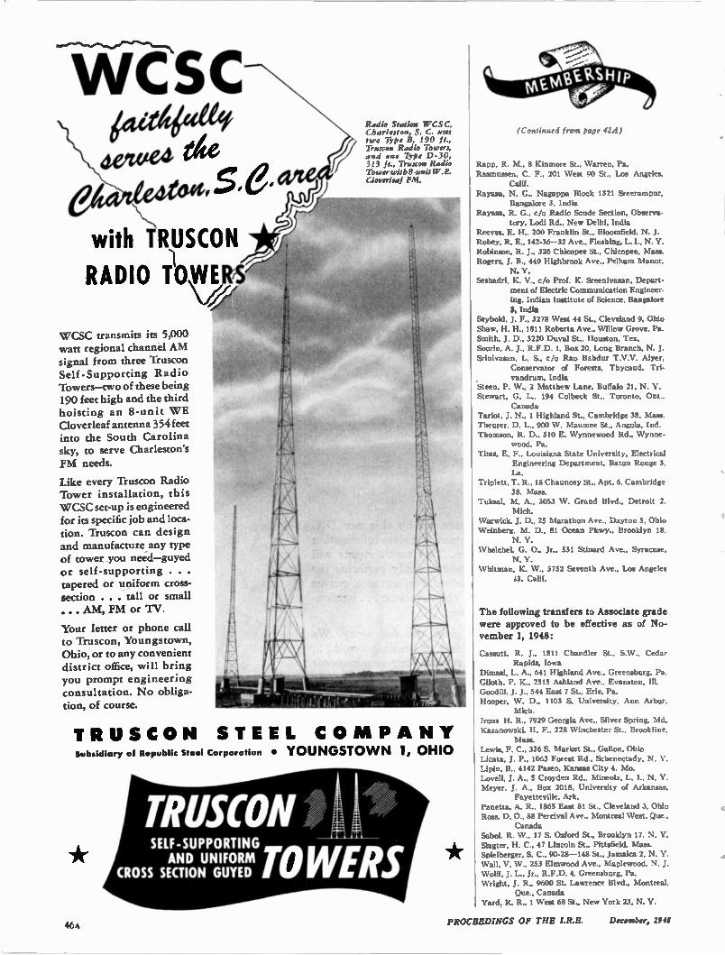
1- CSC 644 4€444, dewed vvw
SIes \
with TRUSCON ,,
RADIO TIOWERS ,
\
WCSC transmits its 5,000 watt regional channel AM signal from three Truscon Self -Supporting Radio Towers—two of these being 190 feet high and the third hoisting an 8-unit WE Cloverleaf antenna 354 feet into the South Carolina sky, to serve Charleston's FM needs.
Like every Truscon Radio Tower installation, this WCSC set-up is engineered for its specific job and loca-tion. Truscon can design and manufacture any type of tower you need—guyed or self-supporting . . . tapered or uniform cross-section . . . tall or small ... AM, FM or TV.
Your letter or phone call to Truscon, Youngstown, Ohio, or to any convenient district office, will bring you prompt engineering consultation. No obliga-tion, of course.
Radio Station WCSC, Charleston, S. C. uses two Type B, 190 ft., Truscon Radio Towers, and one Type D-30, 313 ft., Truscon Radio Tower with 8-unit W .E. Cloverleaf FM.
TRUSC O N STEEL CO MP A N Y Subsidiary of Republic Steel Corporation • YOUNGSTO WN 1, OHIO
TRUSCON SELF-SUPPORTING AND UNIFORM CROSS SECTION GUYED TOWERS
(Continued front page 424)
Rapp, R. M., 8 Kinmore St., Warren, Pa. Rasmussen, C. F., 201 %Vest 90 St., Los Angeles,
Calif. Ftayasa, N. G., Nagappa Block 1321 Sreerampur.
Bangalore 3, India Ra mat, R. G., c/o Radio Sonde Section. Observa-
tory, Lodi Rd., New Delhi, India Reeves, E. H., 200 Franklin St., Bloomfield, N. J. Robey, R. E., 142-36-32 Ave., Flushing, L. I., N. V. Robinson. R. J., 326 Chicopee St.. Chicopee, Mass. Rogers, J. B., 449 Highbrook Ave.. Pelham Manor.
N. Y. Seshadri, K. V., c/o Prof. K. Sreenivasan. Depart-
ment of Electric Communication Engineer-ing, Indian Institute of Science, Bangalore
3, India Seybold, J. F., 3278 West 44 St., Cleveland 9. Ohio Shaw. H. H., 1811 Roberta Ave., Willow Grove. Pa. Smith. J. D., 3220 Duval St.. Houston, Tex. Soorin. A. J., R.F.D. I, Box 20, Long Branch. N. J. Srinivasan, L. S.. c/o Rao Bandur T.V.V. Aiyer.
Conservator of Forests. Thycaud, Tri-vandrum, India
Steen, P. W., 2 Matthew Lane, Buffalo 21, N. Y. Stewart, G. L., 194 Colbeck St., Toronto, Ont.,
Canada Tariot, J. N., I Highland St., Cambridge 38, Mass. Theurer. D. L.. 900 W. Maumee St.. Angola, Ind. Thomson, R. D., 510 E. Wynnewood Rd., Wynne-
wood, Pa. Tims, E. F.. Louisiana State University, Electrical
Engineering Department, Baton Rouge 3. La.
Triplett, T. R.. 18 Chauncey St.. Apt. 6, Cambridge 38, Mass.
Tuksal, M. A., 3053 W. Grand Blvd.. Detroit 2, Mich.
Warwick, J. D., 25 Marathon Ave., Dayton 5, Ohio Weinberg. M. D., 81 Ocean Pkwy.. Brooklyn 18.
N. Y. Whelchel, G. 0., Jr., 531 Stinard Ave.. Syracuse,
N. Y. Whitman, K. W., 5752 Seventh Ave., Los Angeles
13, Calif.
The following transfers to Associate grade were approved to be effective as of No-vember 1, 1948:
Cassutt, R. J., 1811 Chandler St.. S.W., Cedar Rapids, Iowa
Dimasi, L. A., 641 Highland Ave., Greensburg, Pa. Giloth, P. K., 2515 Ashland Ave., Evanston. III. Goodin, J. J., 544 East 7 St.. Erie, Pa. Hooper, W. D., 1103 S. University. Ann Arbor.
Mich. Irons H. R., 7929 Georgia Ave., Silver Spring, Md. Kazanowski. H. F., 228 Winchester St.. Brookline,
Mass. Lewis, F. C., 336 S. Market St., Galion, Ohio Licata, J. P.. 1063 Forest Rd., Schenectady, N. Y. Lipin, B., 4142 Paseo. Kansas City 4, Mo. Lovell, J. A., 5 Croyden Rd., Mineola, L. I., N. Y.
Meyer, J. A., Box 2018, University of Arkansas, Fayetteville, Ark.
Panetta, A. R., 1865 East 81 St., Cleveland 3, Ohio Ross, D. 0., 88 Percival Ave., Montreal West, Que.,
Canada Sabot, R. %V., 17 S. Oxford St., Brooklyn 17, N. Y.
Slagter, H. C.. 47 Lincoln St., Pittsfield, Mass. Spielberger, S. C., 90-28 -148 St.. Jamaica 2, N. Y. Wall. V. W., 253 Elmwood Ave., Maplewood, N. J. Wolff, J. L.. Jr., R.F.D. 4, Greensburg, Pa. Wright. J. R., 9600 St. Lawrence Blvd., Montreal,
Que., Canada Yard. R. R., 1 West 68 St., New York 23, N. Y.
46A PROCEEDINGS OF THE December, 1948
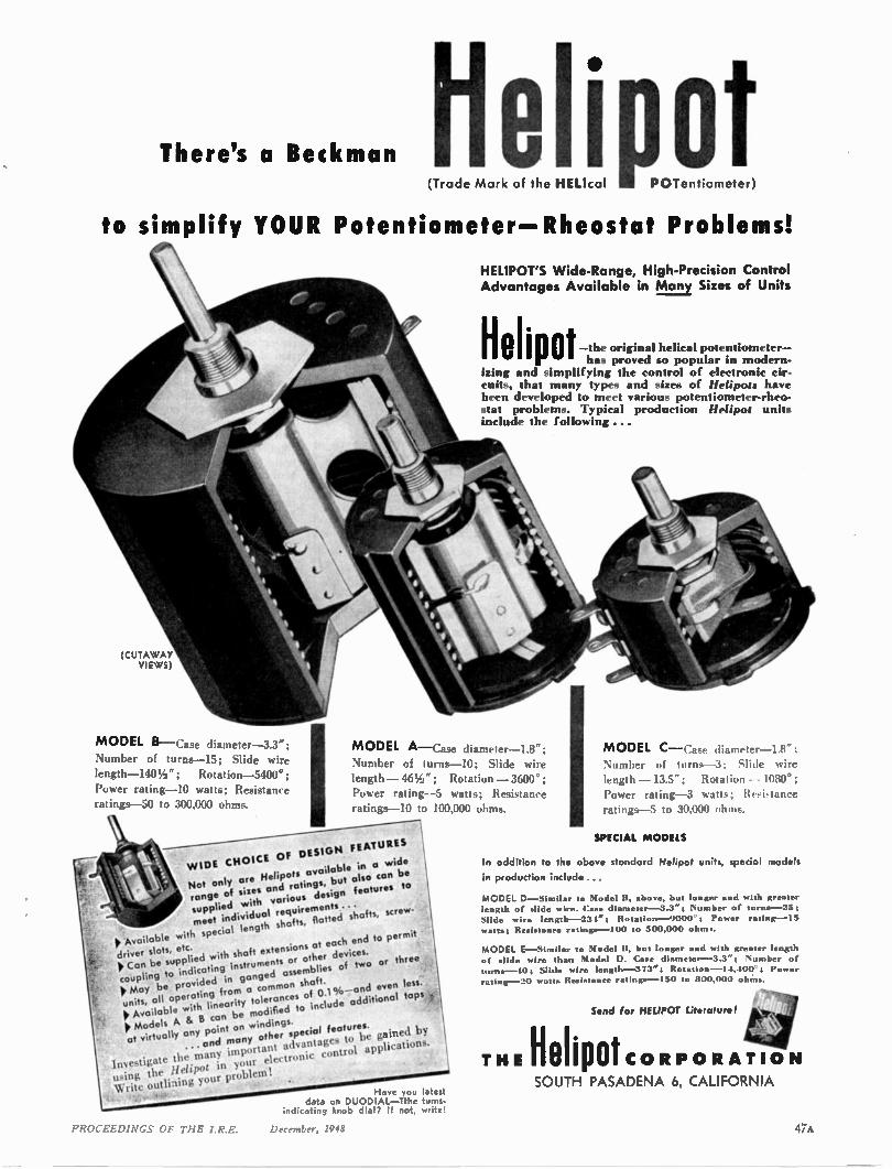
There's a Beckman (Trade Mark of the HELIcal elipot
POTentiometer)
to simplify YOUR Potentiometer—Rheostat Problems!
(CUTA WAY VIE WS)
MODEL B— Case diameter-3.3"; Number of turns-15; Slide wire length-1401/2 "; Rotation-5400°; Power rating-10 watts; Resistance ratings-50 to 300,000 ohms.
HELIPOT'S Wide-Range, High-Precision Control Advantages Available in Many Sizes of Units
iie i p a t —the original helical potentiometer— has proved so popular in modern-
izing and simplifying the control of electronic cir-cuits, that many types and sizes of Helipots have been developed to meet various potentiometer-rheo-stat problems. Typical production Helipof units include the f ollowing ...
MODEL A— Case diameter-1.8"; Number of turns-10; Slide wire length -461/2 "; Rotation —3600°; Power rating-5 watts; Resistance ratings-10 to 100,000 ohms.
WIDE CHOICE Of DESIGN FEATURES
Not only are Helipots available in a wide range of sixes and ratings, but also can be supplied with various design features to meet individual requirements . • •
II, Available with special length shafts, (lotted shafts, screw.
ll Can be supplied with shaft extensions at each end to permit driver slots, etc.
coupling to indicating instruments or other devices. IlMoy be provided in ganged assemblies of two or three .
units, all operating from a common shaft. It Available with linearity tolerances of 0.1 %—and even less. It Models A & B can be modified to include additional tapvit:
at virtually any point on windings. X. ...and many other special features.
Investigate the many important advantages to be gained by using the Helipot in your electronic control applications.
Write outlirting your problem! Have you latest
data on DUODIAL—Tthe turns. indicating knob dial? If not, write!
MODEL C—Case diameter-1.8"; Number of turns-3; Slide wire length -13.5"; Rotation —1080*; Power rating-3 watts; Resi•tance ratings-5 to 30,000 ohms.
SPECIAL MODELS
In addition to the above standard Helipot units, special models
in production include...
MODEL D —SImIlar to Model It, above, but longer and with greeter length of slide wire. Case dismeter -3.3"; Number of turns -25; Slide wire length -231"; Rotation -9000'; Power ratings -15
watts; Resistance ratings —I00 to 500,000 ohm..
MODEL E —Similar to Model It, but longer and with g length of slide wire than Model D. Case diameter-3.3"; Number of
turts•--10; Slide wire length -373"t Rot•tion -1.1,100*; Power rating -20 watts Resistance ratings —I50 to 800,000 ohms.
Send for HELIPOT Literature!
TH. Helipot CORP ORATI ON SOUTH PASADENA 6, CALIFORNIA
PROCEEDINGS OF THE I.R.E. December, 1948 47A
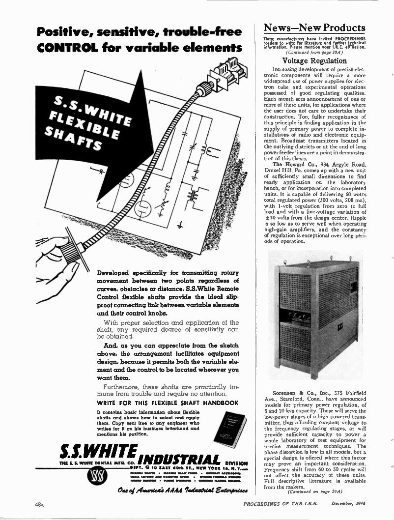
Positive, sensitive, trouble-free CONTROL for variable elements
Developed specifically for transmitting rotary
movement between two points regardless of
curves, obstacles or distance, S.S. White Remote
Control flexible shafts provide the ideal slip-
proof connecting link between variable elements
and their control knobs.
With proper selection and application of the shaft, any required degree of sensitivity can be obtained. And, as you can appreciate from the sketch
above, the arrangement facilitates equipment
design, because it permits both the variable ele-
ment and the control to be located wherever you
want them.
Furthemore, these shafts are practically im-mune from trouble and require no attention. WRITE FOR THIS FLEXIBLE SHAFT HANDBOOK
It contrvins basic information about flexible shafts and shows how to select and apply them. Copy sent free to any engineer who writes for it on his business letterhead and mentions his position.
S.S.WHITE INDUSTRIALTHE S. S. WHITE DENTAL MFG. CO. DIVISION DEPT. G 10 EAST •011. ST., NEW TORE 16, N. T..m.•
lea nt • •11.11.11 . M IL O 10011 • ALMICIIAIT •CC/$40.11•11t
M A " CU UIWO AMID G• ', WP M V0 011 • SPICIALIn 001.111Ut• Swi ngs
0 01.04.0 INSIS10111 • PLAS M SPO WITIMI • CAORIU KI PLAPICS MIX11140.111
Oat oi iilateatitatCt .4 AAA Tgetaaval EgtoTiosaee
News—New Products These manufacturers have invited PROCEEDINGS readers to write for literature and further technical information. Please mention your I.R.E. affiliation.
(Continued from page 304)
Voltage Regulation Increasing development of precise elec-
tronic components will require a more widespread use of power supplies for elec-tron tube and experimental operations possessed of good regulating qualities. Each month sees announcement of one or more of these units, for applications where the user does not care to undertake their construction. Too, fuller recognizance of this principle is finding application in the supply of primary power to complete in-stallations of radio and electronic equip-ment. Broadcast transmitters located in the outlying districts or at the end of long power feeder lines are a point in demonstra-tion of this thesis. The Howard Co., 934 Argyle Road,
Drexel Hill, Pa. comes up with a new unit of sufficiently small dimensions to find ready application on the laboratory bench, or for incorporation into completed units. It is capable of delivering 60 watts total regulated power (300 volts, 200 ma), with 1-volt regulation from zero to full load and with a line-voltage variation of ± 10 volts from the design center. Ripple is so low as to serve well when operating high-gain amplifiers, and the constancy of regulation is exceptional over long peri-ods of operation.
Sorensen & Co., Inc., 375 Fairfield Ave., Stamford, Conn., have announced models for primary power regulation, of 5 and 10 Icva capacity. These will serve the low-power stages of a high-powered trans-mitter, thus affording constant voltage to the frequency regulating stages, or will provide sufficient capacity to power a whole laboratory of test equipment for precise measurement techniques. The phase distortion is low in all models, but a special design is offered where this factor may prove an important consideration. Frequency shift from 60 to 50 cycles will not affect the accuracy of these units. Full descriptive literature is available from the makers.
(Continued on page 594)
PROCEEDINGS OF THE I.R.E. December, 1941
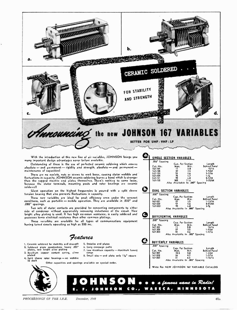
0
the new JOHNSON 167 VARIABLES BETTER FOR UHF - VHF - LF
With the introduction of this new line of air variables, JOHNSON brings you many important design advantages never before available.
Outstanding of these is the use of perfected ceramic soldering which assures absolute - and permanent - rigidity and strength, absolute - and permanent - maintenance of capacities!
There are no eyelets, nuts or screws to work loose, causing stator wobble and fluctuations in capacity. JOHNSON ceramic soldering leaves a bond which is stronger than the rugged steatite end plates themselves. There•s nothing to come loose, because the stator terminals, mounting posts and rotor bearings are ceramic soldered!
Silent operation on the highest frequencies is assured with a split sleeve tension bearing that also prevents fluctuations in capacity.
These new variables are ideal for peak efficiency even under the severest conditions, such as portable - mobile operation. They are available in .030" and .080" spacings.
Two sets of stator contacts are provided for connecting components to either side of condenser without appreciably increasing inductance of the circuit. New bright alloy plating is used. It has high corrosion resistance, is easily soldered and possesses lower electrical resistance than other common plating:.
These variables are available for all types of communications equipment having tuned circuits operating as high as 500 mc.
eateeited. 1. Ceramic soldered for stability and strength 2. Soldered plate construction, heavy .020" plates, new bright alloy plating
3. Beryllium copper contact spring, silver plated
4. Split sleeve rotor bearings - no wobble to shalt
Other capacities and spacings
S. Steatite end plates
6. Long creepage paths
7. Low minimum capacity - maximum tuning range
B. Small size - end plate only 1%" square
available on special order.
SINGLE SECTION VARIABLES .030" Spacing
Cap. Per Section Length Cat. No. Max. Min. Behind Panel 167-101 11 2.8 15/16 167-102 27 3.5 1-9/64 167-103 51 4.6 1-7/16 167-104 75 5.7 167-151 99 68 2-7/32 167-152 202 11.6 3-33/64
Also Available In .080" Spacing
DUAL SECTION VARIABLES .030" Spacing
Cap. Per Section Cat. No. Max. Min. 167-501 27 3.5 167-502 51 4.6 167-503 99 6.8
Also Available In .080" Spacing
DIFFERENTIAL VARIABLES .030" Spacing
Cat. No. 167-301 167-302 167-303
Cap. Per Section Max. Min. 11 2.8 27 3.5 •
Length Behind Panel 1-13/16 2-27/64 3-%
Length Behind Panel
15/16 1-9/64 1-7/16
Also Available In .080" Spacing
BUTTERFLY VARIABLES .030" Spacing
Cap. Per Section Length Cat. No. Max. Mix. Behind Panel 167-201 10.5 2.8 1-3/64 167-202 26 4.3 1-7/16 167-203 51 6.5 1-15/16
Also Available In .080" Spacing
Write For NE W JOHNSON 167 VARIABLE CATALOG
JOHNSON • • • a Atoiciaa waste ea M'ordeol E. F. JO H N S O N C O., W A SE C A, MI N N ES O T A
PROCEEDINGS OF THE I.R.E. December, 1948 49.
gnveitigatethu Oppottunity
To join the staff of one of the largest research organizations in the country devoted exclusively to
VACUUM TUBE RESEARCH
Working conditions are ideal in these laboratories which are located in the New York Suburb of Orange, New Jersey. Your associates will include men of many years experience in vacuum tube research and development.
This rapidly expanding organization is devoted to both commercial and military research. It is a division of one of the oldest vacuum tube manu-facturers in America. Security and stability for the years to come are assured. You will have an opportunity to gain experience with the different kinds of vacuum tubes, receiving, power, cathode ray, sub-miniature, micro-wave, radial beam and various special types.
If you can qualify as a
PHYSICIST ELECTRICAL ENGINEER CIRCUIT TECHNICIAN VACUUM TUBE TECHNICIAN
write at once to
RESEARCH DIVISION
NATIONAL UNION RADIO CORPORATION
350 Scotland Rd. Orange, New Jers•y
PHILCO To maintain the PhiIco tradition of progressive research
and development in the electronic field an ever increasing
staff of engineers and physicists has been employed over
the last two decades. Continuing expansion of PhiIco's
engineering and research activities is producing excellent
opportunities for engineers and physicists.
The scope of the work in the PhiIco laboratories includes
basic research on the theory of semiconductors; vacuum
tube research and design, including cathode ray tubes;
and the design of special circuits, radio, television, television
relay and radar systems.
IF YOU ARE INTERESTED IN YOUR OPPORTUNITY AT PHILCO,
WRITE ... Engineering Personnel Director
PhiIco Corporation
Philadelphia 34, Pa.
The following positions of interest to I.R.E. members have been reported as open. Apply in writing, addressing reply to company mentioned or to Box No. .. .
The Institute reserves the right to refuse any announcement without giving a reason for the refusal.
PROCEEDINGS of the I.R.E. I East 79th St., New York 21, N.Y.
ELECTRONIC ENGINEERS—ELECTRONIC TECHNICIANS
Men with production, inspection or re-design experience preferred. Direct in-quiries to SLX-1, P.O. Box 5800, Albu-querque, New Mexico.
TELEVISION ENGINEERS Well established electronics manufac-
turer, located in suburban New York City area needs high grade television development engineers. Company is ex-panding its television activities and seeks capable men with background sufficiently complete to merit responsible positions. Send details to Chief Engineer, Box 536.
PROJECT ENGINEER Stamford firm engaged in development
and research work with government agen-cies requires project engineer with tech-nical and practical background in UHF radar work. Salary open depending upon background. Company is young and grow-ing with promising future for able engi-neers in this kind of work. Box 538.
ELECTRONIC ENGINEERS College graduates with 3-5 years of de-
velopment engineering experience in cir-cuit design. Well versed in magnetic cir-cuits, non-linear circuit operation and electronic theory. Send resume and all particulars to Personnel Department, General Precision Laboratory, Inc., Pleas-antville, New York.
RESEARCH AND DEVELOPMENT ENGINEERS
Engineers with considerable experi-ence in RF and UHF circuits wanted by large, well established radio company in New York area. Send resume of educa-tion and experience to Box 530.
GRADUATE PHYSICIST Graduate physicist or electronic engi-
neer with good background in gaseous conduction wanted by established New England radio tube manufacturer, for de-velopment work on gas filled tubes. Box 540.
MATHEMATICIANS, ENGINEERS, PHYSICISTS
Men to train in oil exploration for op-eration of seismograph instruments, com-puting seismic data, and seismic survey-ing. Beginning salary $250.00 to $300.00 per month depending upon background. Excellent opportunity for advancement determined by ingenuity and ability. The work requires changes of address each year; work indoors and out; general loca-tion in oil producing locations. Send resume and include snapshot to National Geophysical Co., Inc., 8800 Lemmon Ave., Dallas 9, Texas.
(Cont,nued on page 524)
PROCEEDINGS OF THE I.R.E. December, 1948
Your enjoyment climbs to new altitudes through radio and television achievements of RCA
Radio and Radar Development and Design Engineers
RCA Victor Division has openings for men with experience in:
• Mobile Transmitters
• Radar
• Audio Communications and Supersonics
- Please furnish complete resume of experience to:
Employment Manager Camden Personnel Division
RCA Victor Division Camden, New Jersey
PROCEEDINGS OF THE 1.R.E. December, 1948 51A
WANTED SENIOR
ENGINEERS, PHYSICISTS
Key positions open for top flight
electronic men with 5 or more years
experience in theoretical analysis
of:
• RADAR SYSTE MS
• MISSILES
• MICRO WAVES
• CO MPUTERS
• CO M MUNICATIONS
send resume or
phone Personnel
Manager
THE W. L. MAXSON CORP. 460 W. 34th St. N.Y.C.
LOngacre 3-2500
"Where
Professional
Radiomen
Study"
WANTED PHYSICISTS ENGINEERS Engineering laboratory of precision
instrument manufacturer has interest-
ing opportunities for graduate engi-
neers with research, design and/or
development experience on radio com-
munications systems, Servomechanisms
(closed loop). electronic & mechanical
aeronautical navigation instruments
and ultra-high frequency & microwave
technique.
WRITE FULL DETAILS
TO
EMPLOYMENT SECTION
SPERRY GYROSCOPE
COMPANY DIVISION OF SPERRY CORP. Marcus Ave. 1 Lakeville Rd.
Lake Success. LI.
CAPITOL RADIO ENGINEERING INSTITUTE
An Accredited Technical lnstirure 16th and Park Rd., N. W., Dept. P11-12
Washington 10, D.C.
_r
iii rj....!..111,4
Advanced Home Study and Residence Courses in Practical Radio-Electronics and Television.
Approved for Veteran Training
ENGINEERS - ELECTRONIC Senior and _junior, outstanding opportunity, progressive company.
Forward complete resumes giving education, experience and salary
requirements to Personnel Department
M EI-PA R, EVC.
452 Swann Avenue
Alexandria, Virginia
(Continued from page 50A)
ELECTRONICS ENGINE Well known, 40 year old manu.
of electrical and electronic instruments wants research engineer experienced in design of radio electronic apparatus at high frequencies, for the development of military and civilian test equipment. Box 542.
PHYSICISTS—ENGINEERS Opportunities for physicists and elec-
tronic engineers at the Naval Ordnance Test Station, P.O. China Lake, Cali-fornia. Applicants should have college degree or equivalent, plus professional ex-perience. Especially desired are applica-tions from persons with experience in design and development of microwave radar components. Send application form 57 to Placement Officer U.S.N.O.T.S., Inyokem, P.O. China Lake, California.
ENGINEERS A young rapidly expanding mid-west-
ern research laboratory has openings for the following types of personnel: (1) ELECTRONIC DESIGN ENGI-NEERS—Experience circuit design en-ginees wanted for indicator timing circuit development. (2) SERVO DESIGN ENGINEERS OR PHYSICISTS—Experience required for the development airborne computor equipment. Top pay offered to those capable of
project responsibility. Local university offers graduate courses in servo and computer design, and applied mathemat-ics. Send complete resume. Our Engineer-ing Dept. knows of this announcement. Box 544.
ELECTRONIC ENGINEERS—PHYSICISTS A leading electronics company in Los
Angeles, California offers permanent em-ployment to persons experienced in ad-vanced research and development. State qualifications fully. Box 545.
ELECTRONIC ENGINEER An opportunity for a man with con-
siderable experience to head a small de-velopment and engineering group in a growing company located in Chicago. Pulse experience a necessity and a back-ground of work with nuclear radiation instruments and nuclear detectors very de-sirable. Please give full details. Box 546.
RADIO AND TELEVISION ENGINEERS The Industry Service Laboratory (for-
merly License Laboratory), New York, has several positions open for Senior and Junior engineers having qualifications for development and consultation work in television and radio. Good technical edu-cation and some experience required. In-teresting work, broadening experience, and wide contacts. Write fully to Di-rector, Industry Service Lab., RCA Laboratory Division, 711 Fifth Ave., New York 22, N.Y.
CRYSTAL ENGINEER Manufacturer of Piezo electric crystals
desires experienced engineer familiar with quartz oscillating crystals and their applications to radio frequency control. Write full details. Box 548.
PROCEEDINGS OF THE I.R.E. December, 1948

0 it Eit S E
with outstanding outstanding academic and
practical experience and execu-
tive ability in the field of cath-
ode ray tube display and indi-
cators for radar systems,
wanted by long established cor-
poration. Knowledge of all
types of projection systems and
present types of service equip-
ment desirable. Write, giving
resume of education, experi-
ence, age and salary.
FREED RADIO CORPORATION
200 Hudson Street, New York, N.Y.
WANTED ELECTRONIC ENGINEERS
AND
PHYSICISTS Excellent opportunities for grad-uates with research, design, and/or de%elopmont experience in Communications and aerial navigation systems including di-rection finders, radar, FM, tele-vision, micro-wave.
Write complete details regarding education, experience and salary desired.
To Personnel manager
Federal Telecommunication
Laboratories
500 Washington Ave.
Nutley, New Jersey
RESEARCH AND DEVELOPMENT ENGINEERS
Wanted for advanced research and de-velopment. Should have extensive ex-perience on analysis of electronics sys-tems in the fields of microwaves, mis-siles, radar, servomechanisms communica-tions, navigational devices. Outstanding ability in E.E. or physics required. Please furnish complete resume, salary require-ments and availability to: Personnel Manager, W. L. Maxson Corporation, 460 West 34th Street, New York, N.Y.
ELECTRICAL ENGINEER Nationally known Chicago company is
in need of high grade, experienced elec-trical engineer. Must be a college gradu-ate with either a B.S. or E.E. degree, with high scholastic record. Should have from 2 to 5 years experience in elec-tronics, preferably with a minimum of two years in the design of audio ampli-fiers. In reply give all particulars and state expected salary. Address Box 549.
DESIGN AND DEVELOPMENT ENGINEER Design and development engineer to
take charge of engineering and develop-ment of receiving antennae and associated equipment. U.H.F. experience desirable. Upstate New York manufacturer. Reply giving age and qualifications to Box 450.
(Continued on page 54.4)
ZENITH RADIO CORPORATION
needs
Research and Development
Engineers and Physicists
Project, senior and junior engi-
neers and physicists are required
for prosecution of several very in-
teresting developments. Openings
exist for men experienced in vari-
ous aspects of radio and television
receiver and transmitter develop-
ment, in radar, and in applications
of electronics to ordnance problems.
Salaries commensurate with expe-
rience and ability.
WRITE: Director of Research
Zenith Radio Corp.
6001 W. Dickens Ave.
Chicago 39, Illinois
Seeet/rogic E0t9igeer4 BENDIX RADIO DIVISION
Baltimore, Maryland
manufacturer of
RADIO AND RADAR EQUIPMENT
requires:
PR OJECT ENGINEERS
Five or more years experience in the design and development, for production, of major components in radio and radar equipment.
ASSISTANT PR OJECT ENGINEERS
Two or more years experience in the development, for production, of components in radio and radar equipment. Capable of designing components under supervision of project engineer.
Well equipped laboratories in modern radio plant . . . Excellent opportunity . . . advancement on individual merit.
Baltimore Has Adequate Housing
Arrangements will be made to contact personally all applicants who submit satisfactory resumes. Send resume to Mr. John Siena:
BENDIX RADIO DIVISION BENDIX AVIATION CORPORATION
Baltimore 4, Maryland
Wanted Design Engineers Physicists
Men with a college degree and
two to four years design experi-
ence should investigate the oppor-
tunities offered by the Collins Ra-
dio Company. This well-recog-
nized manufacturer of radio equip-
ment has a limited number of po-
sitions available for qualified en-
gineers and physicists. These men
will work on the design and devel-
opment of broadcast, communica-
tions, radar, and electronic cir-
cuits in the design and research
departments. Give present posi-
tion, nature of work, experience,
and education in first letter.
ADDRESS DEPARTMENT EP
COLLINS RADIO COMPANY
CEDAR RAPIDS, IO WA
PROCEEDINGS OF THE I.R.E. December, 1948
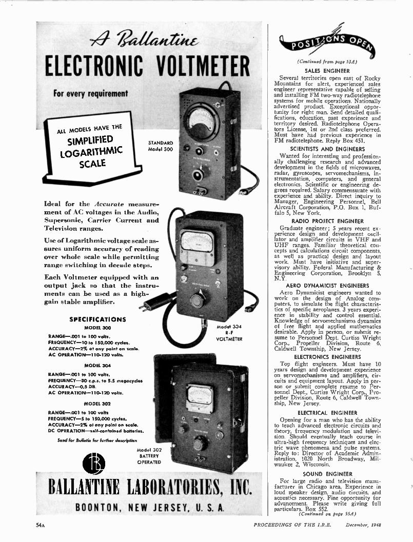
74 v.v./trot, ELECTRONIC VOLTMETER For every requirement
ALL MODELS HAVE THE
SIMPLIFIED LOGARITHMIC
SCALE
STANDARD
Model 300
Ideal for the Accurate measure-ment of AC voltages in the Audio, Supersonic, Carrier Current and Television ranges.
Use of Logarithmic voltage scale as-sures uniform accuracy of reading over whole scale while permitting range switching in decade steps.
Each Voltmeter equipped with an output jack so that the instru-ments can be used as a high-gain stable amplifier.
SPECIFICATIONS
MODEL 300
RANGE —.001 to 100 volts.
FREQUENCY -10 to 150,000 cycles.
ACCURACY -2% at any point on scale.
AC OPERATION -110-120 volts.
MODEL 304
RANGE —.001 to 100 volts.
FREQUENCY -30 c.p.s. to 5.5 megacycles
ACCURACY -0.5 DR.
AC OPERATION -110-120 volts.
MODEL 302
RANGE —.001 to 100 volts
FREQUENCY -5 to 150,000 cycles.
ACCURACY -2% at any point on scale.
DC OPERATION —self-contained batteries.
Send for Bulletin for further description
Model 302
BATTERY
OPERATED
Model 334
R .F
VOLTME-ER
BALLANTINE LABORATORIES, INC. BOONTON, NEW JERSEY, U. S. A.
(Continued from page 534)
SALES ENGINEER Several territories open east of Rocky
Mountains for alert, experienced sales engineer representative capable of selling and installing FM two-way radiotelephone systems for mobile operations. Nationally advertised product. Exceptional oppor-tunity for right man. Send detailed quali-fications, education, past experience and territory desired. Radiotelephone Opera-tors License, 1st or 2nd class preferred. Must have had previous experience in FM radiotelephone. Reply Box 451.
SCIENTISTS AND ENGINEERS Wanted for interesting and profession-
ally challenging research and advanced development in the fields of microwaves, radar, gyroscopes, servomechanisms, in-strumentation, computers, and general electronics. Scientific or engineering de-grees required. Salary commensurate with experience and ability. Direct inquiry to Manager, Engineering Personnel, Bell Aircraft Corporation, P.O. Box 1, Buf-falo 5, New York.
RADIO PROJECT ENGINEER Graduate engineer; 5 years recent ex-
perience design and development oscil-lator and amplifier circuits in VHF and UHF ranges. Familiar theoretical con-cepts and calculations circuit components, as well as practical design and layout work. Must have initiative and super-visory ability. Federal Manufacturing & Engineering Corporation, Brooklyn 5, N.Y.
AERO DYNAMICIST ENGINEERS Aero Dynamicist engineers wanted to
work on the design of Analog com-puters, to simulate the flight characteris-tics of specific aeroplanes. 3 years experi-ence in stability and control essential. Knowledge of servomechanisms dynamics of free flight and applied mathematics desirable. Apply in person, or submit re-sume to Personnel Dept. Curtiss Wright Corp., Propeller Division, Route 6, Caldwell Township, New Jersey.
ELECTRONICS ENGINEERS Top flight engineers. Must have 10
years design and development experience on servomechanisms and amplifiers, cir-cuits and equipment layout. Apply in per-son or submit complete resume to Per-sonnel Dept., Curtiss Wright Corp., Pro-peller Division, Route 6, Caldwell Town-ship, New Jersey.
ELECTRICAL ENGINEER Opening for a man who has the ability
to teach advanced electronic circuits and theory, frequency modulation and televi-sion. Should eventually teach course in ultra-high frequency techniques and elec-tric wave phenomena and pulse systems. Reply to: Director of Academic Admin-istration, 1020 North Broadway, Mil-waukee 2, Wisconsin.
SOUND ENGINEER For large radio and television manu-
facturer in Chicago area. Experience in loud speaker design, audio circuits, and acoustics necessary. Fine opportunity for advancement. Please write giving full particulars. Box 552.
(Continued on page 55A)
54A PROCEEDINGS OF THE IR E. December, 1948
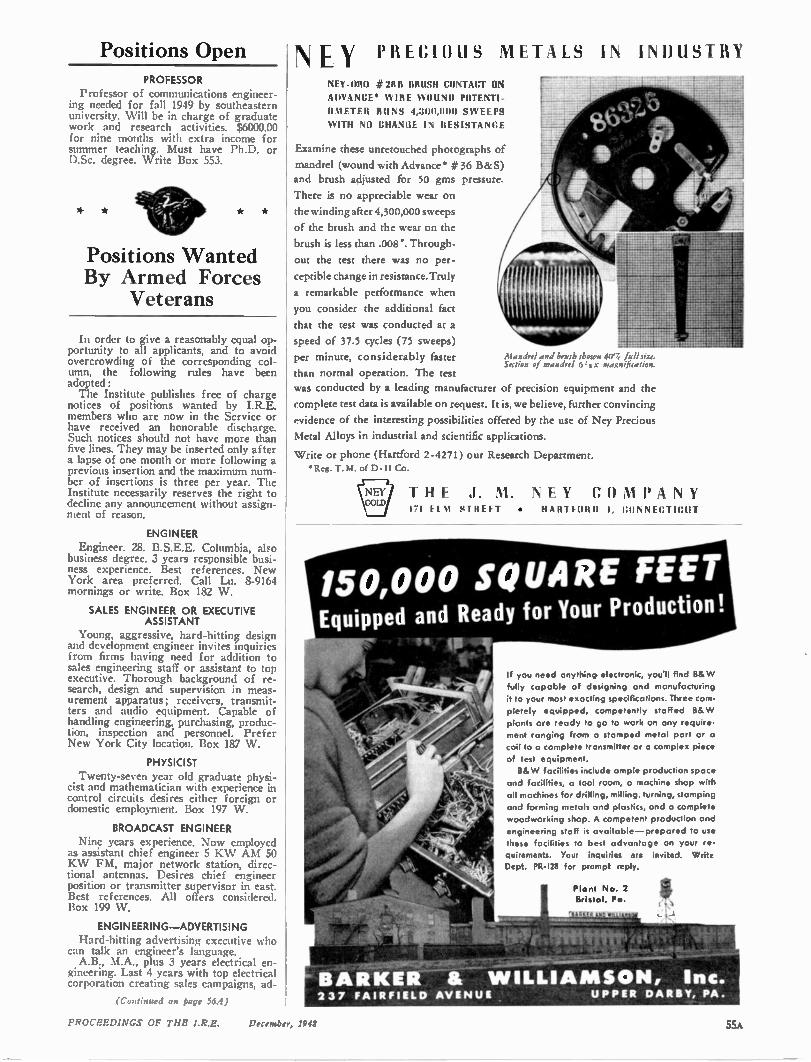
Positions Open N Y PRECIOUS METALS IN INDUSTRY
PROFESSOR Professor of communications engineer-
ing needed for fall 1949 by southeastern university. Will be in charge of graduate work and research activities. $6000.00 for nine months with extra income for summer teaching. Must have Ph.D. or D.Sc. degree. Write Box 553.
* * * *
Positions Wanted By Armed Forces
Veterans
In order to give a reasonably equal op-portunity to all applicants, and to avoid overcrowding of the corresponding col-umn, the following rules have been adopted: The Institute publishes free of charge
notices of positions wanted by I.R.E. members who are now in the Service or have received an honorable discharge. Such notices should not have more than five lines. They may be inserted only after a lapse of one month or more following a previous insertion and the maximum num-ber of insertions is three per year. The Institute necessarily reserves the right to decline any announcement without assign-ment of reason.
ENGINEER Engineer. 28. B.S.E.E. Columbia, also
business degree. 3 years responsible busi-ness experience. Best references. New York area preferred. Call Lu. 8-9164 mornings or write. Box 182 W.
SALES ENGINEER OR EXECUTIVE ASSISTANT
Young, aggressive, hard-hitting design and development engineer invites inquiries from firms having need for addition to sales engineering staff or assistant to top executive. Thorough background of re-search, design and supervision in meas-urement apparatus; receivers, transmit-ters and audio equipment. Capable of handling engineering, purchasing, produc-tion, inspection and personnel. Prefer New York City location. Box 187 W.
PHYSICIST Twenty-seven year old graduate physi-
cist and mathematician with experience in control circuits desires either foreign or domestic employment. Box 197 W.
BROADCAST ENGINEER Nine years experience. Now employed
as assistant chief engineer 5 KW AM 50 KW FM, major network station, direc-tional antennas. Desires chief engineer position or transmitter supervisor in east. Best references. All offers considered. Box 199 W.
ENGINEERING—ADVERTISING Hard-hitting advertising executive who
can talk an engineer's language. A.B., M.A., plus 3 years electrical en-
gineering. Last 4 years with top electrical corporation creating sales campaigns, ad-
(Continued an page 56.4)
NEY-ORO #2811 BRUSH CONTACT ON
ADVANCE* WIRE WOUND POTENTI-
OMETER RUNS 4,31111,11011 SWEEPS
WITH NO CHANCE IN RESISTANCE
Examine these unretouched photographs of mandrel (wound with Advance #36 B&S)
and brush adjusted for 50 gms pressure.
There is no appreciable wear on
the winding after 4,300,000 sweeps
of the brush and the wear on the
brush is less than .008". Through-
out the test there was no per-
ceptible change in resistance. Truly
a remarkable performance when
you consider the additional fact
that the rest was conducted at a
speed of 37.5 cycles (75 sweeps)
per minute, considerably faster
than normal operation. The test
was conducted by a leading manufacturer of precision equipment and the
complete test data is available on request. It is, we believe, further convincing
evidence of the interesting possibilities offered by the use of Ney Precious
Metal Alloys in industrial and scientific applications.
Write or phone (Hartford 2-4271) our Research Department. *Reg. T. M. of D-H Co.
* Mandrel and brush shown 40'4 full I iZt Section of mandrel 6:3 X magnification.
THE .1. M. NEY CO MPA NY 171 Ft '11 SI RIFT • HARTFORD I, CONNECTICUT
150,000 SQUARE FEET Equipped and Ready for Your Production!
- *
tir.Zmr
If you need anything electronic, you'll find B& W
fully capable of designing and manufacturing
it to your most exacting specifications. Three com-pletely equipped, competently staffed B& W
plants are ready to go to work on any require-
ment ranging from a stamped metal part or a
coil to a complete transmitter or a complex piece
of test equipment.
B& W facilities include ample production space
and facilities, a tool room, a machine shop with
all machines for drilling, milling, turning, stamping
and forming metals and plastics, and a complete
woodworking shop. A competent production and
engineering staff is available —prepared to use
these facilities to best advantage on your re-
quirements. Your inquiries are invited. Write Dept. PR-I28 for prompt reply.
Plant No. 2 Bristol, Pa.
BARKER & WILLIA MSON, Inc. 237 FAIRFIELD AVENUE UPPER DARBY, PA.
PROCEEDINGS OF THE I.R.E. December, 1948 55A
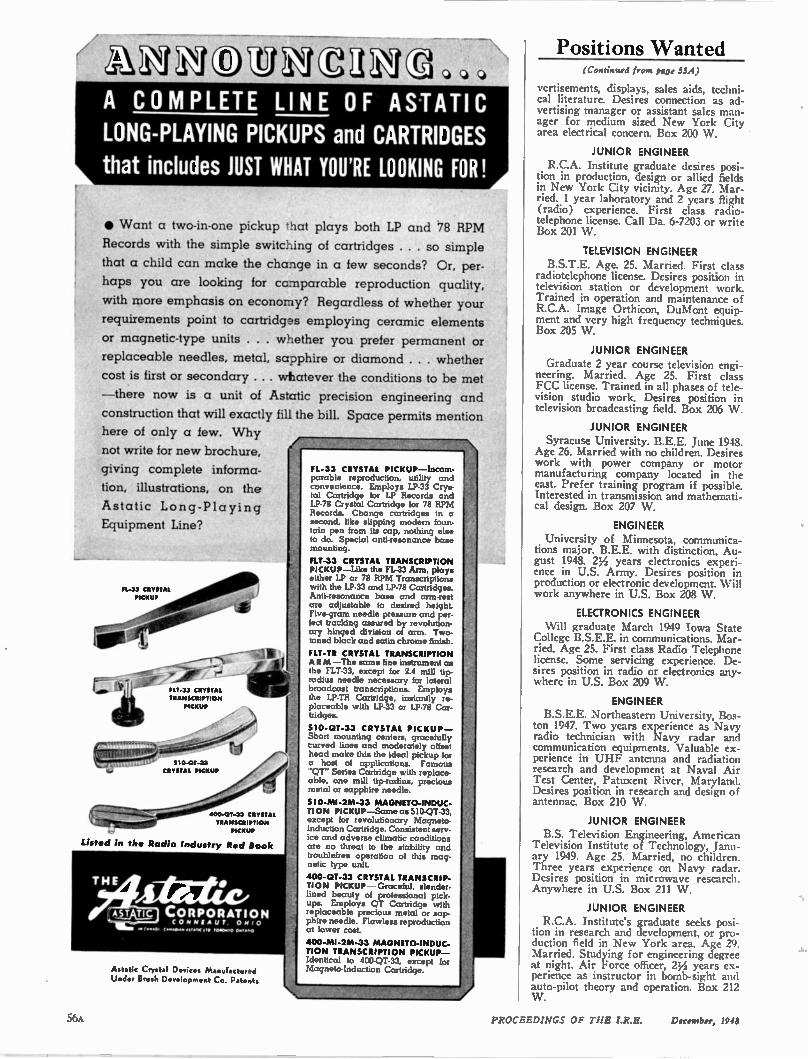
hAINOVA IA8,„, A COMPLETE LINE OF ASIATIC LONG-PLAYING PICKUPS and CARTRIDGES
that includes JUST WHAT YOU'RE LOOKING FOR!
• Want a two-in-one pickup that plays both LP and 78 RPM
Records with the simple switching of cartridges . . . so simple
that a child can make the change in a few seconds? Or, per-
haps you are looking for comparable reproduction quality,
with more emphasis on economy? Regardless of whether your
requirements point to cartridges employing ceramic elements
or magnetic-type units . . . whether you prefer permanent or
replaceable needles, metal, sapphire or diamond . . . whether
cost is first or secondary . .. whatever the conditions to be met
—there now is a unit of Astcrtic precision engineering and
construction that will exactly fill the bill. Space permits mention here of only a few. Why
not write for new brochure,
giving complete informa-
tion, illustrations, on the
Astatic Long-Playing
Equipment Line?
PL-33 CR AAAAA PICKUP
a,
FLT-33 CRYSTAL TRANSCRIPTION
PICKUP
310-01-33 CRYSTAL PICKUP
400-0T-33 CRYSTAL TRANSCRIPTION
PICKUP
Listed in the Radio Industry Red Book
THE 4 41 E tite "
4.5.1)a_ CORPORATION CO M MIA UT. OHI O
(••••• ,,,,, O P ITN eal 0
Astatic Crystal Devices Manufactured Under Brush Development Co. Patents
FL-33 CRYSTAL PICKUP—Incom-parable reproduction, utility and convenience. Employs LP-33 Crys-tal Cartridge for LP Records and LP-78 Crystal Cartridge for 78 RPM Records. Change cartridges in a second, like slipping modern foun-tain pen from its cap, nothing else to do. Special anti-resonance base mounting.
FLT-33 CRYSTAL TRANSCRIPTION PICKUP—Like the FL-33 Arm, plays either LP or 78 RPM Transcriptions with the 12-33 and 12-78 Cartridges. Anti-resonance base and arm-rest are adjustable to desired height. Five-gram needle pressure and per-fect tracking assured by revolution-ary hinged division of arm. Two-toned black and satin chrome finish.
FLT-TR CRYSTAL TRANSCRIPTION ARM —The same fine instrument as the FLT-33, except for 2.4 mill tip. radius needle necessary for lateral broadcast transcriptions. Employs the LP-TR Cartridge, instantly re-placeable with LP-33 or LP-78 Car-tridges.
510-OT-33 CRYSTAL PICKUP— Short mounting centers, gracefully curved lines and moderately offset head make this the ideal pickup for a host of applications. Famous "QT" Series Cartridge with replace-able, one mill tip-radius, precious metal or sapphire needle.
510-MI-2M-33 MAGNETO-INDUC-TION PICKUP—Same as 510-QT-33, except for revolutionary Magneto-Induction Cartridge. Consistent serv-ice and adverse climatic conditions are no threat to the stability and troublefree operation of this mag-netic type unit.
400-0T-33 CRYSTAL TRANSCRIP-TION PICKUP —Graceful. slender-lined beauty of professional pick-ups. Employs QT Cartridge with replaceable precious metal or sap-phire needle. Flawless reproduction at lower cost.
400-MI-2M-33 MAGNETO-INDUC-TION TRANSCRIPTION PICKUP— Identical to 400-QT-33, except for Magneto-Induction Cartridge.
Positions Wanted (Continued from gage 55A)
vertisements, displays, sales aids, techni-cal literature. Desires connection as ad-vertising manager or assistant sales man-ager for medium sized New York City area electrical concern. Box 200 W.
JUNIOR ENGINEER R.C.A. Institute graduate desires posi-
tion in production, design or allied fields in New York City vicinity. Age 27. Mar-ried. 1 year laboratory and 2 years flight (radio) experience. First class radio-telephone license. Call Da. 6-7203 or write Box 201 W.
TELEVISION ENGINEER B.S.T.E. Age. 25. Married. First class
radiotelephone license. Desires position in television station or development work. Trained in operation and maintenance of R.C.A. Image Orthicon, DuMont equip-ment and very high frequency techniques. Box 205 W.
JUNIOR ENGINEER Graduate 2 year course television engi-
neering. Married. Age 25. First class FCC license. Trained in all phases of tele-vision studio work. Desires position in television broadcasting field. Box 206 W.
JUNIOR ENGINEER Syracuse University. B.E.E. June 1948.
Age 26. Married with no children. Desires work with power company or motor manufacturing company located in the east. Prefer training program if possible. Interested in transmission and mathemati-cal design. Box 207 W.
ENGINEER University of Minnesota, communica-
tions major. B.E.E. with distinction, Au-gust 1948. 2Y2 years electronics experi-ence in U.S. Army. Desires position in production or electronic development. Will work anywhere in U.S. Box 208 W.
ELECTRONICS ENGINEER Will graduate March 1949 Iowa State
College B.S.E.E. in communications. Mar-ried. Age 25. First class Radio Telephone license. Some servicing experience. De-sires position in radio or electronics any-where in U.S. Box 209 W.
ENGINEER B.S.E.E. Northeastern University, Bos-
ton 1947. Two years experience as Navy radio technician with Navy radar and communication equipments. Valuable ex-perience in UHF antenna and radiation research and development at Naval Air Test Center, Patuxent River, Maryland. Desires position in research and design of antennae. Box 210 W.
JUNIOR ENGINEER B.S. Television Engineering, American
Television Institute of Technology, Janu-ary 1949. Age 25. Married, no children. Three years experience on Navy radar. Desires position in microwave research. Anywhere in U.S. Box 211 W.
JUNIOR ENGINEER R.C.A. Institute's graduate seeks posi-
tion in research and development, or pro-duction field in New York area. Age 29. Married. Studying for engineering degree at night. Air Force officer, 27/2 years ex-perience as instructor in bomb-sight and auto-pilot theory and operation. Box 212 W.
56A PROCEEDINGS OF TIIE LR.E. December, 1948
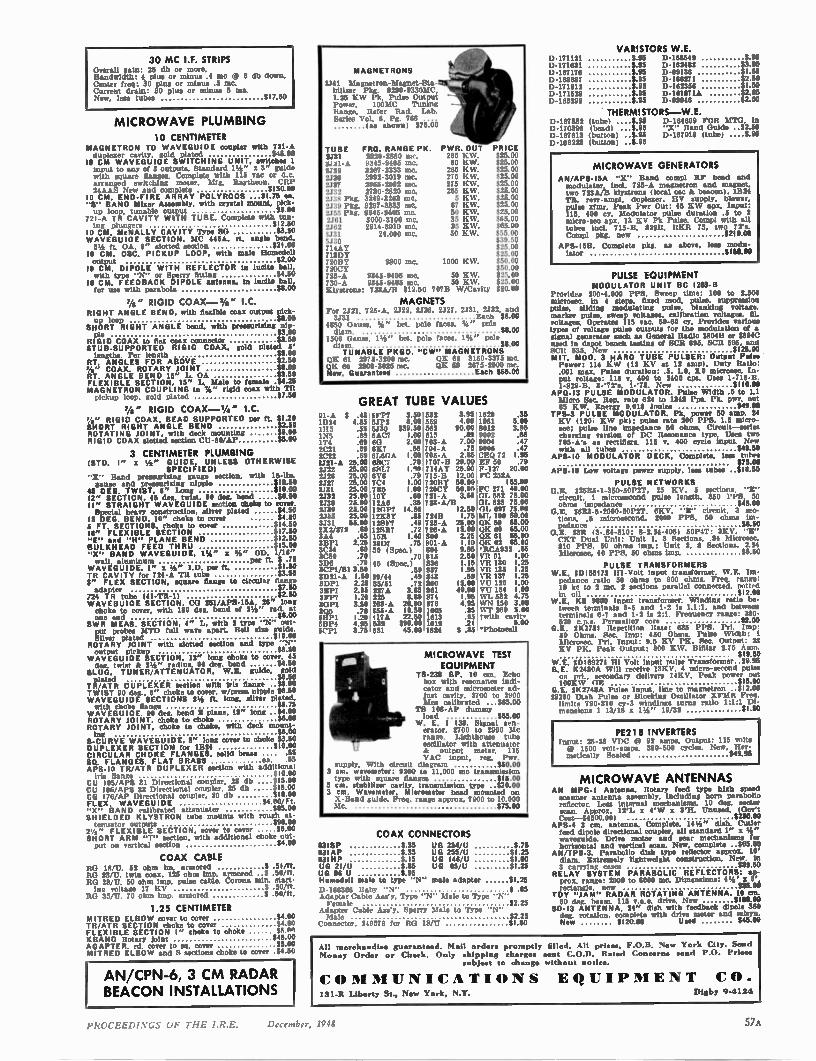
30 MC I.F. STRIPS Overall gain: 25 db or more. Bandwidth: 4 PIUS or minus .4 mc 4, 3 db down. Center freq: 30 plus or minus .5 me. Current drain: 30 plus or minus 5 ma. New. less tubes $17.50
MICROWAVE PLUMBING 10 CENTIMETER
MAGNETRON TO WAVEGUIDE coupler with 721-A dopiezer cavity, gold plated $45.00
10 CM WAVEGUIDE SWITCHING UNIT. switches 1 input to any llf 3 outputs. Standard 11/2 " x 3" guide with square flanges. Complete with 115 vac or d.c. arranged I.WitChillg motor. Mfg. Raytheon. CRP 24AAS New and complete $150.00
10 CM. END-FIRE ARRAY POLYRODS ...$1.75 es. BAND Mixer Assembly, with crystal mount. Ilek -
up loop. tunable output $3.00 721-A TR CAVITY WITH TUBE. Complete with tun-ing plungers e12.50
10 CM. McNALLY CAVITY Type SO $3.50 WAVEGUIDE SECTION. MC 445A. it. angle bend. 51/2 ft. OA. 8" slotted section $21.00
10 CM. OSC. PICKUP LOOP, with male Home &II output $2.00 10 CM, DIPOLE WITH REFLECTOR in Welts ball. with type "N" or Sperry fitting $4.50
II CM. FEEDBACK DIPOLE antenna. In Incite ball. for use with parabola $8.00
Vs" RIGID COAX - 1/4 " I.C. RIGHT ANGLE BEND. with flexible coax output pick-up loop $8.00
SHORT RIGHT ANGLE bend, with pressurizing nip-ple $3.00
RIGID COAX to flex coax connector $3.50 STUB-SUPPORTED RIGID COAX, gold plated 5' lengths Per length $5.00
RT. ANGLES FOR ABOVE $2.50 7/s" COAX. ROTARY JOINT $8.00 RT. ANGLE BEND 15" L. OA $3.50 FLEXIBLE SECTION. 15" L. Male to female 114-25 MAGNETRON COUPLING to 7,a" rigid coax with Tit pickup loop, gold plated $7.50
'A" RIGID COAX - 1/4 " I.C. 1/2 " RIGID COAX. BEAD SUPPORTED per ft. $1.20 SHORT RIGHT ANGLE BEND $2.50 ROTATING JOINT, with deck mounting RIGID COAX slotted section CU-60/AP $$65..0000
3 CENTIMETER PLUMBING (STD. I" a 1/2 " GUIDE. UNLESS OTHERWISE
SPECIFIED) hand pressurizing gauge section, with 15-lbe
gauge and pressurizing nipple $15.50 45 DEG. TWIST. 6" Long $10.00 12" SECTION. 45 deg. twist. 90 deg. bend $6.00 II" STRAIGHT WAVEGUIDE section choke to cover. Special heavy construction, silver plated $4.50
15 DEG. BEND. 10" choke to cover $4.50 $ FT. SECTIONS. choke to cover $14.50 18" FLEXIBLE SECTION $17.50 "E" ead "H" PLANE BEND $12.50 BULKHEAD FEED THRU "X" BAND WAVEGUIDE. 11/2 " x %" OD. 1/16" wall, aluminum per ft. $ .75
WAVEGUIDE. I" x 1/2 " I.D. per ft. SI.50 TR CAVITY for 724-A TR tube 3" FLEX SECTION. square flange to circular flange adapter
$527..5506 724 TR tube (41-TR-11 WAVEGUIDE SECTION, CO 2.51/•PS-15A, 26" long choke to cover, with 180 dee. bend of 21/2 " rad, at one end $8.00
SWR MEAS. SECTION, 4" L, with 2 type "N" out-put probes 14TD full wave apart. Bell size guide. Silver plated $10.00
ROTARY JOINT with slotted section and type -N" output pickup
WAVEGUIDE SECTION, 12" long choke to cove 56.5045 der. twigt k 21/2 " radius. 90 deg. bend $4.50
SLUG. TUNER/ATTENUATOR, W.E. guide, gold plated $6.50
TR/ATR DUPLEXER section with iris flange $13.00 TWIST 90 dee.. 5" choke to cover, w/prees nipple $6.50 WAVEGUIDE SECTIONS 21/2 ft. long, silver plated with choke flange $5.75
WAVEGUIDE. 90 dee. bend 1 plane, 18" long S4.00 ROTARY JOINT, choke to choke $6.00 ROTARY JOINT, choke to choke, with deck !mend-ing $6.00
S-CURVE WAVEGUIDE. 8" long cover to choke $3.50 DUPLEXER SECTION for 11124 $10.00 CIRCULAR CHOKE FLANGES, solid brass .... .55 SQ. FLANGES. FLAT BRASS ea. .55 APS-I0 TR/ATR DUPLEXER section with additional iris flange $10.00
CU 105/APS 31 Directional coupler. 25 db $15.00 CU I06'APS 33 Directional coupler. 25 db $15.00 CG I76/AP Directional coupler, 20 db $18.00 FLEX. WAVEGUIDE $4.00/Ft. "X" BAND calibrated attenuator SHIELDED KLYSTRON tube mounts with rough 85 k0t! tenuator outputs $90.00
21/2 " FLEXIBLE SECTION, cover to cover $5.00 SHORT ARM "T" section, with additional choke out-put on vertical section $4.00
COAX CABLE Ito 1R/U. 52 ohm irn. armored $ .51/ft. RO 23/U, twin coax. 125 ohm imp. armored .3 .50/ft. RO 28/U. 50 ohm imp, pulse cable. Corona min. start-ing voltage 17 KV $ .50/ft.
RG 35/U. 70 ohm imp. armored $ .50/ft.
1.25 CENTIMETER MITRED ELBO W rover to cover $4.00 TR/ATR SECTION choke to cover $4.00 FLEXIBLE SECTION I" choke to choke W W1 KBAND Rotary joint $45.00 ADAPTER. rd rover to sq. cover $5.00 MITRED ELBO W and S sections choke to corer $4.50
AN/CPN-6, 3 CM RADAR BEACON INSTALLATIONS
MAGNETRONS
2.141 Magnetron- Magnet-Sta-bilizer Pkg. 9290-9330MC, 1.25 KW Pk. Pulse Output Power. 100151C Tuning Range. Refer Rad. Lab. Series Vol. 6. Pg. 766 .... (as shown) $75.00
TUBE FRG. RANGE PK. PWR. OUT PRICE 2731 1820-2860 ow. 265 K W. $25.00 2.121-A 9345-9405 me. 50 K W. $25.00 2.122 3267-3733 me. 265 K W. $25.00 2426 2992-3019 mc. 275 K W. $25.00 2.127 2965-2992 mc. 275 K W. $25.00 2.132 2780-2820 mc. 285 K W. $25.00 2138 Pkg. 3249-3263 me. 5 K W. $25.00 2.139 Pkg. 3267-3333 mc. 87 K W. $25.00 2155 Pkg. 9345-9405 mc. 50 K W. $25.00 2.161 3000-3100 me. 35 K W. $65.00 2.162 2914-3010 me. 35 K W. $65.00 1731 24.000 me, 50 K W. $55.00 5230 $39.50 714AY $25.00 718DY $25.00 72011Y 2800 me. 1000 K W. $50.00 720C1C $50.00 725-A 9345-9405 mc. 50 K W. $25.00 730-A 9345-9405 me. 50 K W. $25.00 Klystrons: 723A/14 $12.50 7078 W/Cavity $20.00
MAGNETS For 2721, 725-A, 2.122, 2.126, 2.127. 2.131, 2.132, and 3731 Each $8.00
4850 Gauss. %" bet, pole faces, 51" pole diem. $8.00
1500 Gauss. 11/2 " bet, pole faces. 1%" pole diam. woo TUNABLE PKGD. "CW" MAGNETRONS
OK 61 2075-3200 nic. QK 62 3150-3375 me. (.)K 60 2800-3025 inc. QK 59 2675-2900 sic. New, Guaranteed Each $65.01)
GREAT TUBE VALUES 01-A $ .45 5F1' 3.95 1629 7 3.50 532 .35
1824 4.85 .5.11.2 8.00 559 4.00 1961 5.00 1115 .55 6130 $39.50 562 90.00 8012 3.95 .89 9002
:669° 60 1N5 . 615 .5.3 IT4 2.00 703-A 7.00 9004 .47 .69 6K7 2C21 .55 704-A .75 9006 .47 2(22 .69 (GAGA 1.00 705-A 2.8$ CEO 72 1.95 2.121-A 25.00 65(7 .70 9707-B 20.00 EF 50 .79 1322 25.00 651.7 1.110 714AY 25.00 F-127 20.00 2.126 25.00 6V6 .79 715-11 12.00 FC 2.78A 2.127 25.00 7C4 1.00 72011Y 50.00 165.00 2431 25.00 7115 2.132 25.00 10Y 1.00 720CY 50.011 FC 271 49.00
.60 721-A 3.50 (11, 562 75.00 2.138 25.00 12A6 .35 723 -A/It 01, 623 75.00 2739 25.00 1201•7 14.95 12.50 01. 607 75.00 2.155 25 ..6005 1125KB RY .65 7248 1.7$ NIL 100 60.00 4.131 55.00 1241,7 .49 725-A 25.00 QK 59 65.00 2X2/879 .69 12557 1..4022 782060-A 15.00 QK 60 65.00 3A4 2.25 QK 61 65.00 311P1 2.25 20177 .75 R01-A 1.10 QK 62 65.00 33(426 (S pec,) 4 .60 30 (S c.) 804 .70 9.95 •RCA932 .65 3 2.59 VII 91 1.00 3D6 .70 815
.10 ° 45 (Spec.) 836 1.15 Vii 130 1.25 3CP1/51 3 3D21-A 1.50 39/44 :4519 894337 1.95 VII 1.25 .59 VIt 137 1.25 3DP1 2.25 35/51 .72 860 15.00 1,'U 120 1.00 311.1 2.95 227A 3.85 861 40.00 VU 134 1.00 3 r 1 i 1.20 225 8.80 874 1.95 WI, 532 4.75 30P1 3.50 2611-A 20.00 876 4.95 WN 150 3.00 3Q5 .79 355-A 19.50 100.5 .35 syr 260 5.00 5111•1 1.20 417A 22.50 1613 .95 twith cavity 5111.4 4.95 530 $90.00 1619 .21 5.00 5CP1 3.75 531 45.00 1624 $ .85 •Photocell
MICROWAVE TEST EQUIPMENT
TS.238 GP. 10 cm. Echo box with resonance indi-cator and micrometer ad-just cavity. 2700 to 2900 Mc,. calibrated ...$85.00
TN 108-Al' dummy load $65.00
W. E. I 138. Signal gen-erator. 2700 to 2900 Mc range. Lighthouse tube oscillator with attenuator & output meter. 115 VAC input, reg. Pier.
supply. With circuit diagram 3 cm. wavemeter: 9200 to 11.000 mc transtn5571.n0n0
type with square flanges 3 cm, stabilizer cavity, transmission type -$251 05. 0°0°
3 cm. Wavemeter. Micrometer head mounted on X -Hand guide. Freq, range approx. 7900 to 10.000 Mc $75.00
83113P 83IAP 83IHP UG 2I/U
COAX CONNECTORS $ 35 UG 254/U 575 $ 35 UG 255'U $1.25 $15 UG I46'U $1.00 $ 85 UG 85 U $1.25 $ 95
Hemedell male to type "N" male adapter $1.25
1) 166366 Baby "N" $ .85 Adapter Cable Ase'e. Type "N" Male to Type "N" Female $2.25
Adapter Cable Ass'y, Sperry Male to Type "N" Male $2.25
Connector. 51979 for 110 I0/U $1.80
VARISTORS W.E. D-171121 $ 95 D-168549 is D-171631 $ 95 D-162482 Ito. D-167176 $ 95 D-99136 1.65 D-168687 $ 95 D-166271 $2.50 D-171812 5.95 D-1623513 $1.50 D-171528 $ 95 D-161871A $2.115 D-163298 $ 95 17-99946 $2.00
. THERMISTORS--W.E. 1)-167332 (tube) -.5.95 D-164699 FOR MT13. in D-170396 (bead) ...$.95 -X" Band Guide .32.60 1)-167613 (button) ..5 95 D-167018 (tube) - 3.96 U-166228 (button) .3.95
MICROWAVE GENERATORS AN/APS-I5A "X" Band comet R' head and modulator. inel. 725-A magnetron and magnet, two 723A/8 klystrons (local ore & beacon). 11124 TR, rem-a wl. duplexer. IIV 6upplY, blower, pulse ifmr. l'esk Pwr Out: 45 K W apx. Input: 115. 400 cy. Modulator pulse duration .5 to 2 micro-sec apx. 13 KV Pk Pulse. Compi with all tubs-a Ind. 715-11. 82911, ItKlt 73, two 72's Comet pkg. new $210.00
APS.1513. Complete pkg. as above, ler modu-lator $150.00
PULSE EQUIPMENT MODULATOR UNIT BC 1203•B
Providta 200-4,000 PPS. Sweep time: 100 to 2,500 microsec. in 4 steps, fixed mod, pulse. suppression pulse, sliding modulating pulse, blanking voltage, marker pulse, sweep voltages. calibration voltages. 01. voltages. Operates 115 vac. 50-60 eY. Provides various types of voltage pulse outputs for the modulation o' a signal generator such an General Radio 180413 or :804C used in depot bench testing of SCR 695, SCIt 595, and SCR 535. New $125.00 MIT. MOD. 3 HARD TUBE PULSER: Output Pulse Power: 114 K W (12 KV at 12 amp). Duty Ratio: .001 max. Pulse duration: .5, 1.0, 2.0 mierosec. In-put voltage: 115 v. 400 to 2400 cps. Uses 1-715-11. 1-829-11. 3-'72's. 1-'73. New $
APQ-13 PULSE MODULATOR, Pulse Width 5t110°° o1.1 Micro Sec. Rep. rate 624 to 1346 Pps. Pk, pwr. out 35 K W. Enerey 0.018 Joules $49.00
TPS-3 PULSE MODULATOR. Pk. power 50 amp. 24 KV (120. KW pki: pulse rate 200 PI'S. 1.5 micro-sec: pubes line impedance 50 ohms. Circuit--series charging version of DC Resonance type. Uses two 705-A's as rectifiers. 115 v. 400 cycle input. New with all tithes $49.50
APS•10 MODULATOR DECK. Complete, less tidies $75.00
APS-10 Low voltage power supply, less tubes -518.50
PULSE NET WORKS G.E. :25E5-1-350-50P2T, 25 KV, 5 sections. "1" circuit. 1 microsecond pulse length, 350 PPS. 50 ohms impedance 545.00
G.E. 0613-5-2000-50P2T. 6KV. "1" circuit, 3 sec-tion-4, .5 microsecond. 2000 PPS, 50 ohms lin-
RedE strE (3-.94-R10: 8-2.24-4051 50P4T: 3KV. 5'6'11° G. CKT Dual Unit: Unit 1, 3 Sections, 84 Microsec. 810 PPS, 50 ohms imp.: Unit 2, 8 Sections. 2.24 Micro-sec. 40 PPS, 50 ohms 'nip. $65.50
PULSE TRANSFORMERS W.E. ED166173 III-Volt input transformer. W.E. im-pedance ratio 50 ohms to 900 °lints. Freq. range: 10 kc to 2 me. 2 sections parallel connected, potted in oil
W.E. KS 9800 Input transformer. Winding rati5o12 ° be-tween terminals 3-5 and 1-2 is 1.1:1, and between terminals 6-7 and 1-2 is 2:1, Frequency range: 380- 520 c.ti s. Permalioy core $2.00
G.E. 2K2731 Repetition Rate: 633 PPS. Pd. imp: 50 Ohms. Sec. Imp: 430 Ohmic Pulse Width: 1 Micro-ific. Pd. Input: 9.5 KY PK. Sec. thitin$It1:9. 2450 KV UK. Peak Output: 800 K W, BM W 2.75 Amn,
W.E. 21:7 169271 111 Volt input pulse Transformer. $9.95 G.E. K2450A Will receive 13KV. 4 micro-second pulse on pri., secondary delivers 14KV. Peak power mit 100K W
G.E. 21(2748A Pulse intuit. line to magnetron ..551125..0000 20280 Utah Pulse or Blocking Oscillator XEMIt Freq. limits 790-810 cy-3 windings turns ratio 1:1:1 Di-mensions 1 13/16 x 11/2 " 19/32 21.50
PE218 INVERTERS Input: 25-28 'PDC @ 92 amps. Output: 115 volts la 1500 volt-ampe. 380-500 cycles. New, Her-metical)y Sealed 649.95
MICROWAVE ANTENNAS AN MPG•I Antenna. Rotary feed type high speed scanner antenna assembly, Including horn parabolic reflector. Leas internal mechanisms. 10 dec. sector scan. Approx. 12'I. x 4' W x 3'11. Unused. (Gov't Cost -14500.00) 5250.00
APS.4 3 cm. antenna, Complete. 14 1/2 " dish Cutler feed dipole directional coupler, all standard 1" x 94" waveguide. Drive motor and gear mechanisms for horizontal and vertical scan. New, complete .365.00
AN/TPS•3. Parabolic dish type reflector approx. 10 ' diam. Extremely lightweight construction. New. in 3 carninv $89.50
RELAY SYSTEM PARABOLIC REFLECTORS: ap-prox. range: 2000 to 6000 me. Dimensions: 41/2 ' x 3' rectangle. new $15.00
TDY "JAM" RADAR ROTATING ANTENNA, 18 an. 30 deg. beam. 115 v.a.e. drive. New $100.00
SO-13 ANTENNA. 24" dish with feedback dipole NO deg. rotation, complete with drive motor and selsyn. New $120.00 Used $45.00
All merchandise guaranteed. Mail orders promptly filled. All prices, r.o.n. New York City. Send Money Order or Cheek. Only shipping charges sent C.O.D. Rated Con send P.O. Prices
subject to change without notice.
C O M M U NI C A TI O NS E Q UI P M E N T CO. 131-11 Liberty St., New York, N.Y. Digby 9-4124
PROCEEDINGS OF THE IRE. December, 1948 57A
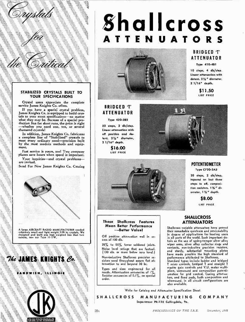
STABILIZED CRYSTALS BUILT TO YOUR SPECIFICATIONS
Crystal users appreciate the complete service James Knights Co. offers.
If you have a special crystal problem, James Knights Co. is equipped to build crys-tals to your exact specifications —no matter what they may be. Because of a special pro-duction line for short runs, the price is right —whether you need one, ten, or several thousand crystals!
In addition, James Knights Co. fabricates a complete line of "Stabilized" crystals to meet every ordinary need —precision built by the most modern methods and equip-ment. Fast service is yours, too! Two company
planes save hours when speed is important.
Your inquiries —and crystal problems — are invited. Send For New James Knights Co. Catalog
A large AIRCRAFT RADI O M ANUFACTURER needed extre mely small and light weight 3105 kc crystals. We designed and built one that weighed less than two ounces, now our Type H-17 W.
4e JAMES KNIGHTS
SAND WICH, ILLIN OIS
halicross ATTE N U AT O R S
BRIDGED 'T' ATTENUATOR
Type 420-282
20 steps, 2 db/step. Linear attenuation with off position and de-tent. 2 Vs " diameter, 2 1 /1 6" depth.
$16.00 LIST PRICE
POTENTIOMETER
These Shallcross Features
Mean Better Performance — Better Value!
Off position attenuation well in ex-cess of 100 db.
25% to 50% fewer soldered joints. Noise level ratings that are factual. (130 db. or more below zero level.)
Non-inductive Shallcross precision re-sistors used throughout assure flat at-tenuation to and beyond 30 kc.
Types and sizes engineered for all needs. Attentuation accuracies of 1%. Resistor accuracies of 0.1%, on special order.
SH
58A
BRIDGED 'T' ATTENUATOR Type 41 0-461
10 steps, 4 db/step.
Linear attenuation with
detent. 21/6" diameter,
2 1/16" depth.
$11.50 LIST PRICE
Type C720-2A3
20 steps, 2 db/step, tapered on last three steps to off, composi-tion resistors. 1 3/4 " di-ameter, 1 3/4" depth.
$8.00 LIST PRICE
SHALLCROSS ATTENUATORS
Shallcross variable attenuators have proved their remarkable quietness and serviceability in dozens of applications for leading users in all parts of the world. Such important de-tails as the use of spring-temper silver alloy wiper arms, silver alloy collector rings and contacts, non-inductive precision resistors, and sturdy, substantial mounting plates have made possible the high standard of performance attributed to Shallcross. Standard types include ladder and bridged T mixer controls, bridged T and straight T master gain controls and V.U. meter multi-pliers, wirewound and composition potenti-ometers for grid control. Cueing attenua-tors, and fixed pads, both composition and wirewound, in all circuit configurations are also available.
Write for Catalog and Attenuator Specification Sheet
ALL C R O S S M A N U F A C T U RI N G C O M P A N Y
Department PR-128 Collingdale, Pa.
PROCEEDINGS OF THE 1.R.E. December, 1948
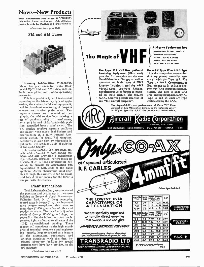
News-New Products These manufacturers have invited PROCEEDINGS information. Please mention your I.R.E. affiliation. readers to write for literature and further technical
(Continued from rage 43.4)
FM and AM Tuner
Browning Laboratories, Winchester, Mass., has just announced their latest model RJ-20 FM and AM tuner, with in-built preamplifier and tone-compensating networks. This is a precision type of instrument
appealing to the laboratory type of appli-cation, the custom builder of equipment, and for broadcast monitoring of program content and station performance. Two separate tuners are mounted on one chassis, the AM section incorporating a set of band-expanding if transformers, with an 8-kc and 18-kc bandwidth posi-tion, controlled from a panel switch. The FM section empinys separate oscillator and mixer triode tubes, dual limiters and discriminator in a fully licensed Arm-strong circuit, for finest FM reception. Sensitivity is such that 10 microvolts in-put signal will produce 32 db of quieting at full audio fidelity. The audio amplifier is a two-stage cas-
cade unit, common to both tuning sec-tions, and also providing a phonograph input channel. Between the two tubes are a series of R-C tone compensating net-works, to provide for attenuation and equalization of both ends of the audio spectrum. As the phonograph input oper-ates through this system, it can be equal-ized too. A power supply for the tuner is integral with the chassis.
Plant Expansions Tech Laboratories, Inc., has announced
the purchase and occupancy of their own building at Bergen & Edsall Boulevards, Palisades Park, N. J. Long occupying rented space in Jersey City, their increased sales volume necessitated this move to more than 17,000 square feet of office and production space. The location is 1 miles south of George Washington bridge, on route S-1. On the hilltop location, unob-structed light is afforded to all areas of the 100% air-conditioned building. These factors will contribute to the high stand-ards of technical excellence and engineer-ing integrity long recognized as a feature of the attenuators, resistances, and switches associated with this firm. In-creased laboratory facilities for special contract work have been provided in the new quarters.
(Continued on page 614)
•
1 The Magic ofyHF % Th. Type 15A VHF Navigational
Receiving Equipment (illustrated) provides for reception on the new Omni-Directional Ranges as well as operation on both types of VHF Runway Localizers, and the VHF Visual-Aural Airways Ranges. Simultaneous voice feature is includ-ed on these ranges. The iunable A.R.C. Receiver permits selection of any VHF aircraft frequency.
Airborne Equipment for; OMNI-DIRECTIONAL RANGES
RUNWAY LOCALIZE'S VISUAL-AURAL RANGES SIMULTANEOUS VOICE GCA VOICE RECEPTION
The A.R.C. Type 17 or A.R.C. Type
18 is the companion communica-tion equipment normally asso-ciated with the Type i5A. The Type 17 VHF Communication Equipment adds independent two-way VHF communication fa-cilities. The Type 18 adds VHF Transmitting Equipment only. All Type 17 and 18 units are type-certificated by the CAA.
The dependability and performance of these VHF Com-munication and Navigation Systems spells increased safety in flight. Specify A.R.C. for your next installation.
Aircraft Radio Corporation BOONTON NEW JERSEY
DEPENDABLE ELECTRONIC EQUIPMENT SINCE 1928
0/0
THE LO WEST EVER CAPACITANCE OR ATTENU ATI ON
airtspaced articulated R.F. CABLES
We are specially organised to handle direct enquiries from overseas and can give
/MMED/ATE 011/#7.9/151VAP MINT
AvvTea•cable 152r Iota shoes clea'eni-uvistl; tokt 37:94,40;v7 of Wiwi* ale, riseme cl RE arbier
TRANSRADIO LTD CONTRACTORS TO RI.N1. GOVERNMEN
138A CROMWELL ROAD•LONDON SW7 ENGLAND C4291t1 TRANJRAD
LOW ATTE* Tills
Al 74
Paten?, gOycl. jet,*
AT M LOADING db1004 a/COO Atti 1.7 1.3 0.6
0.11 0.24 1.5
0 0"
0.36 0.44 0.88
A2 A34
74
73
LOW CAPAC TYPES
CAPAC WEED OWLS
ATTEN 10"5.4.dkWOft 0 D.
C I 7.3 130 2.5 3.1
0.36
0.36
0.36 0.44 0.44 0.64
044
1.03
PC 40.2 6.3
6.3 5.5 5.4 4.8
132 173 CII 3.2
2.15
2.8 1.9
2.4
2.1
C 2 C22 C 3
C33 C44
171 184 497
220
252 4.1
t very ioirCe acitorne coe/e
HIGH POWER FLEXIB LE
PHOTOCELL CABLE
PROCEEDINGS OF THE I. RE. December, 1948 Fri),
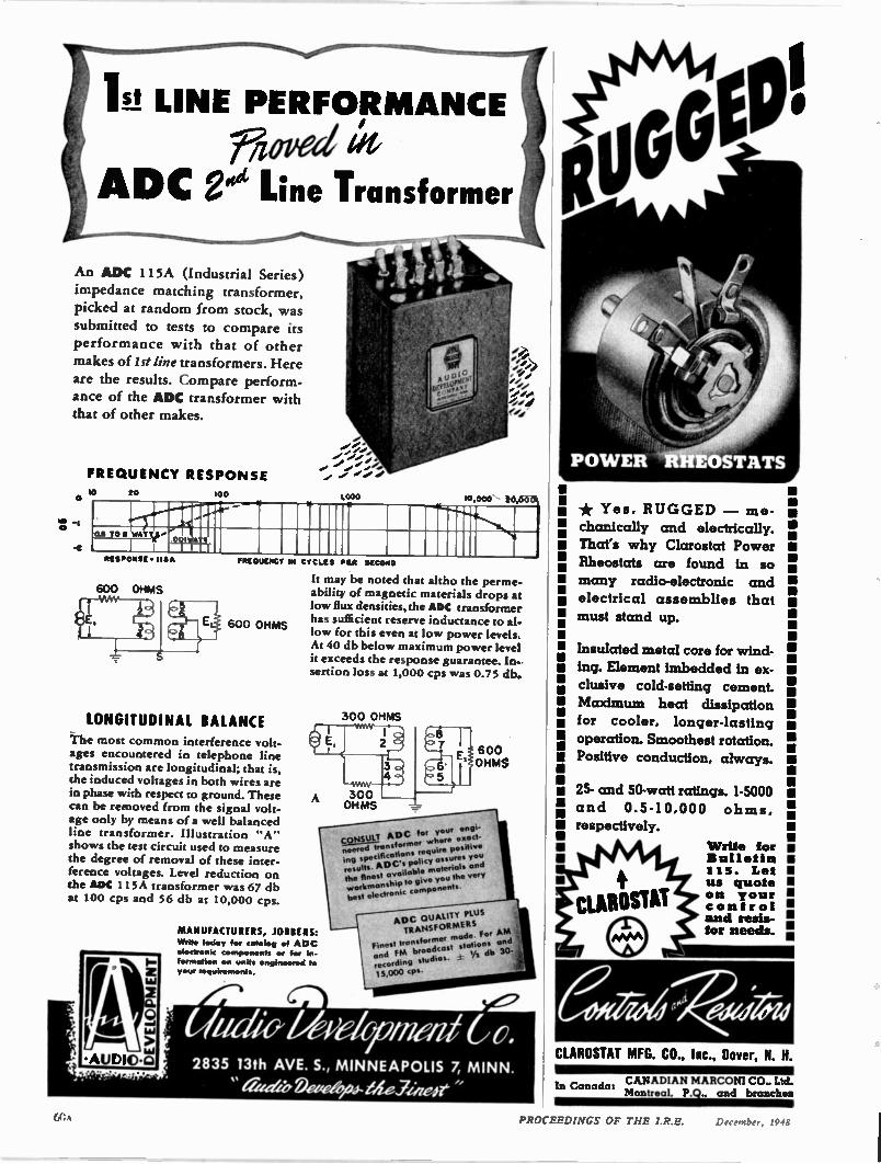
nitrous!' • 115A
ig LINE PERFORMANCE Fifoped
ADC ggs Line Transformer
An ADC 115A (Industrial Series) impedance matching transformer, picked at random from stock, was submitted to tests to compare its performance with that of other
makes of 1st line transformers. Here are the results. Compare perform-ance of the ADC transformer with that of other makes.
FRE QUENCY RESPONSE
20
600 OHMS
1.000 t6,6613%
rataucacr IN CYCLES PIA M ONO
600 OHMS
LONGITUDINAL BALANCE
The most common interference volt-ages encountered in telephone line transmission are longitudinal; that is, the induced voltages in both wires are in phase with respect to ground. These can be removed from the signal volt-age only by means of a well balanced line transformer. Illustration "A" shows the test circuit used to measure the degree of removal of these inter-ference voltages. Level reduction on the ADC 115A transformer was 67 db at 100 cps and 56 db at 10,000 cps.
It may be noted that altho the perme-ability of magnetic materials drops at low flux densities, the ADC transformer has sufficient reserve inductance to al-low for this even at low power levels, At 40 db below maximum power level it exceeds the response guarantee. In. sertion loss at 1,000 cps was 0.75 db.
MANUFACTURERS, JOIBE RS: Write today for catalog of ADC electronic components or for in-formation on units engineered to your requirements.
300 OHMS
600 OHMS
CONSULT ADC for your engi-neered transformer where exact-ing specifications require positive results. ADC's policy assures you the finest available materials and workmanship to give you the very
best electronic components.
ADC OLIALITY PLUS TRANSFOR MERS
or AM Finest transformer made. F and stations and FM broadcast '/ • recording studios. db 30-
15,000 cps.
U 11 44.0' U a d ri fi al f t o. • 2835 13th AVE. S., MINNEAPOLIS 7, MINN.
• "a u4e Deze ari- bite,ZheJe
CUROSTAT MFG. CO., Inc., Dover, N. H.
* Yes, RUGGED — me-chanically and electrically.
That's why Clarostat Power Rheostats are found in so
many radio-electronic and electrical assemblies that must stand up.
Insulated metal core for wind-ing. Element imbedded in ex-
clusive cold-setting cement. Maximum heat dissipation for cooler, longer-lasting operation. Smoothest rotation.
Positive conduction, always.
25- and 50-watt ratings. 1-5000 and 0.5-10,000 ohms, respectively.
Write for Bulletin 115. Let us quote on your control and resis-tor needs.
CANADIAN MARCONI CO.. Ltd. :n Canada: Montreal. P.Q., and brancheal
PROCEEDINGS OF THE I.R.E. December, 1948
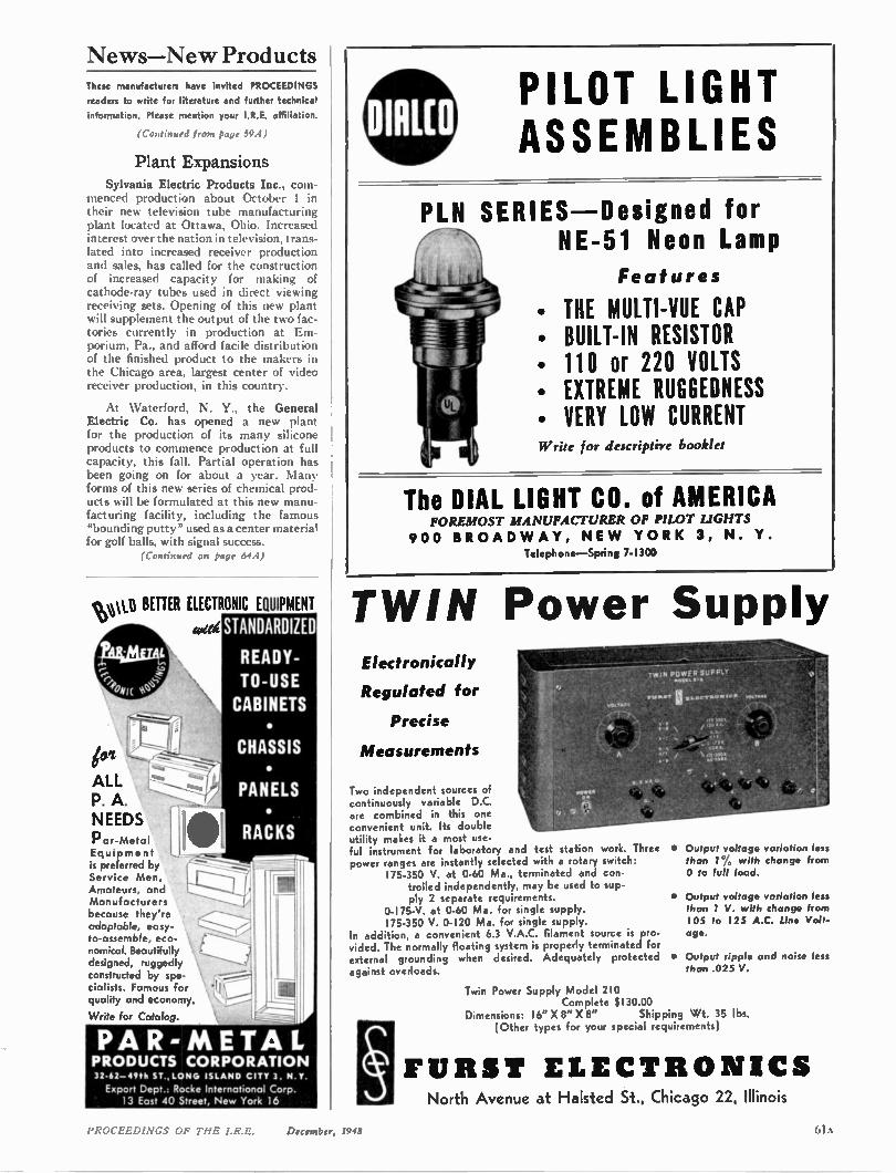
News—New Products These manufacturers have invited PROCEEDINGS
readers to write for literature and further technical
information. Please mention your I.R.E. affiliation.
(Continued from page 59A)
Plant Expansions Sylvania Electric Products Inc., com-
menced production about October I in their new television tube manufacturing plant located at Ottawa, Ohio. Increased interest over the nation in television, trans-lated into increased receiver production and sales, has called for the construction of increased capacity for making of cathode-ray tubes used in direct viewing receiving sets. Opening of this new plant will supplement the output of the two fac-tories currently in production at Em-porium, Pa., and afford facile distribution of the finished product to the makers in the Chicago area, largest center of video receiver production, in this country.
At Waterford, N. Y., the General Electric Co. has opened a new plant for the production of its many silicone products to commence production at full capacity, this fall. Partial operation has been going on for about a year. Many forms of this new series of chemical prod-ucts will be formulated at this new manu-facturing facility, including the famous "bounding putty" used as a center material for golf balls, with signal success.
(Continued on page 64,4)
PILOT LIGHT ASSEMBLIES
RIES —Designed for NE-51 Neon Lamp
Features
• THE MULTI-VUE CAP • BUILT-IN RESISTOR • 110 or 220 VOLTS • EXTREME RUGGEDNESS • VERY LOW CURRENT Write for descriptive booklet
The DIAL LIGHT CO. of AMERICA FOREMOST MANUFA CTURER OF PILOT LIGHTS
90 0 BR OAD W AY, NE W YORK 3, N. Y. Telephone —Spring 7-1300
sv\v(1 BETTER ELECTRONIC EQUIPMENT TWIN Power S wit4 Plat
ALL P. A. NEEDS Par-Metal Equipment k preferred by Service Men, Amateurs, and Manufacturers because they're . adaptable, easy-to-assemble, eco-nomical. Beautifully designed, ruggedly constructed by spe-cialists. Famous for quality and economy.
Write for Catalog.
STANDARDIZED
READY-TO-USE CABINETS
Ito
•
CHASSIS •
PANELS •
RACKS
PAR- METAL PRODUCTS CORPORATION 32.62-495h ST ,LONG ISLAND CITY 3, N Y.
Export Dept.: Rocke Internateonal Corp. 13 East 40 Street, New York 16
Electronically
Regulated for
Precise
Measurements
Two independent sources of continuously variable D.C. are combined in this one convenient unit. Its double utility makes it a most use-ful instrument for laboratory and test station work. Three power ranges are instantly selected with a rotary switch:
175-350 V. at 0-60 Ma., terminated and con-trolled independently, may be used to sup-ply 2 separate requirements.
0-175-V. at 0-60 Ma. for single supply. 175-350 V. 0-120 Ma. for single supply.
In addition, a convenient 6.3 V.A.C. filament source is pro-vided. The normally floating system is properly terminated for external grounding when desired. Adequately protected against overloads.
upply TWIN POWER SUPPLY
osec.x.•
• Output voltage variation less than 1% with change from 0 to full load.
• Output voltage variation less than 1 V. with change from 105 to 125 A.C. line Volt-age.
• Output ripple and noise less than .025 V.
Twin Power Supply Model 210 Complete $130.00
Dimensions: 16" X 8" X 8" Shipping Wt. 35 lbs. (Other types for your special requirements)
FURST ELECTRO NICS North Avenue at Halsted St., Chicago 22, Illinois
PROCEEDINGS OF THE I.R.E. December, 1948
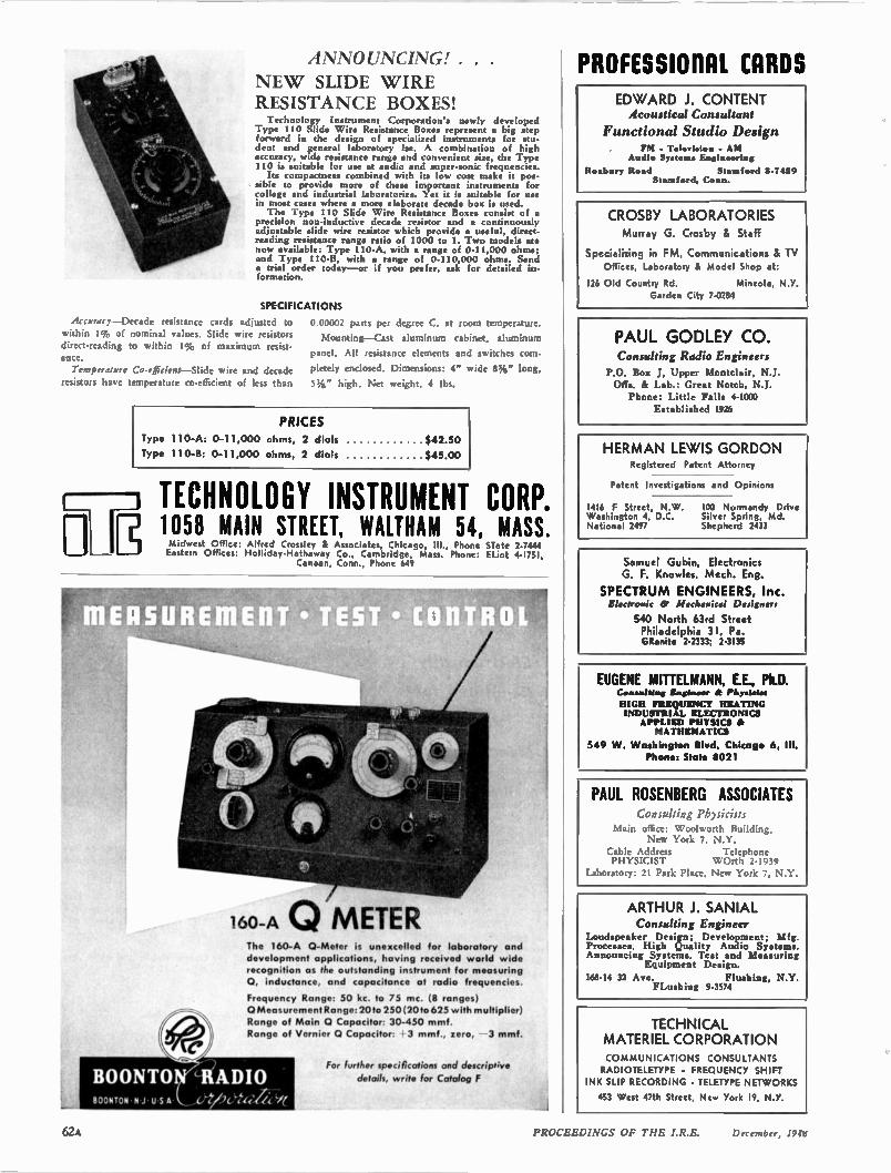
ANNOUNCING!. .
NE W SLIDE WIRE RESISTANCE BOXES! Technology Instrument Corporation's newly developed
Type 110 Slide Wire Resistance Boxes represent a big step forward in the design of specialized instruments for stu-dent and general laboratory Ise. A combination of high accuracy, wide resistance range and convenient size, the Type 110 is suitable for use at audio and super-sonic frequencies. Its compactness combined with its low cost make it pos.
sible to provide more of these important instruments for college and industrial laboratories. Yet it is suitable for use in most cases where a more elaborate decade box is used. The Type 110 Slide Wire Resistance Boxes consist of a
precision non-inductive decade resistor and a continuously adjustable slide wire resistor which provide • useful, direct-reading resistance range ratio of 1000 to I. Two models are now available: Type 110-A, with a range of 0-11,000 ohms; and Type 110-B, with a range of 0-110,000 ohms. Send a trial order today —or if you prefer, ask for detailed in-formation.
SPECI F I CAT I ONS
Accuracy—Decade resistance cards adjusted to within 1% of nominal values. Slide wire resistors
direct-reading to within 1% of maximum resist-ance. Temperature Co-efficient—Slide wire and decade
resistors have temperature co-efficient of less than
0.00002 parts per degree C. at room temperature
Mounting —Cast aluminum cabinet, aluminum
panel. All resistance elements and switches com-
pletely enclosed. Dimensions: 4" wide 85/8"' long,
1,/g" high. Net weight, 4 lbs.
PRICES Type 1 10-A: 0-1 1,000 ohms, 2 dials $42.50
Type I 10-B: 0-1 1 ,000 ohms, 2 dials $45.00
TECHNOLOGY INSTRUMENT CORP. 1058 MAIN STREET WALTHAM 54 MASS * Midwest Office: Alfred Crossley & Associa tes, Chicago , Ill., Phone Siete 2-7444 Eastern Offices: Holliday-Hathaway Co., Cambridge, Mass. Phone: ELiot 4-1751,
Canaan, Conn., Phone 649
160—A CIO METER The 160-A 0-Meter is unexcelled for laboratory and development applications, having received world wide recognition as the outstanding instrument for measuring 0, inductance, and capacitance at radio frequencies.
Frequency Range: 50 kc. to 75 mc. (8 ranges) 0 Measurement Range: 2010 250 (20to 625 with multiplier) Range of Main 0 Capacitor: 30-450 mmf. Range of Vernier 0 Capacitor: 3 mmf., zero, 3 mmf.
For further specifications and descriptive
details, write for Catalog F
PROFESSIORAL CARDS ED WARD J. CONTENT Acoustical Consultant
Functional Studio Design FM . Telerl•lon - AM
Audio System• Engineering
Roxbury Road Stamford 8-7 l59 Stamford, Conn.
CROSBY LABORATORIES Murray G. Crosby & Staff
Specializing in FM, Communications & TV
Offices, Laboratory Li Model Shop at:
126 Old Country Rd. Mineola, N.Y. Garden City 7-0284
PAUL GODLEY CO. Consulting Radio Engineers
P.O. Box L Upper Montclair, N.J. Offs. & Lab.: Great Notch, N.J. Phone: Little Falls 4-1000
Established 1926
HERMAN LEWIS GORDON Registered Patent Attorney
Patent Investigations and Opinions
1416 F Street, N.W. 100 Normandy Drive Washington 4, D.C. Silver Spring, Md. National 2497 Shepherd 2433
Samuel Gubin, Electronics G. F. Knowles, Mech. Eng.
SPECTRU M EN GINEERS, Inc. Electronic 60 Mechanical Designers
540 North 63rd Street Philadelphia 31. Pa. GRanite 2-2333; 2-3135
EUGENE MITTELMANN, E.E., Ph.D. C•nswiting Engineer & rhysleies HIGH FRIEQUENCY HEATING INDUSTRIAL ELECTRONICS APPLIED PHYSICS & MATHEMATICS
549 W. Washington Blvd. Chicago 6, III. Phone: State 8021
PAUL ROSENBERG ASSOCIATES consahing ph)sicisti
Main office: Woolworth Building, New York 7, N.Y.
Cable Address Telephone PHYSICIST WOrth 2-19in
Laboratory: 21 Park Place. New York 7, N.Y.
ARTHUR J. SANIAL Consulting Engineer
Loudspeaker Design; Development; Mfg. Processes. High Quality Audio Systems. Announcing Systems. Test and Measuring
Equipment Design.
168-14 32 Ave. Flushing, N.Y. FLushing 9-3574
TECHNICAL MATERIEL CORPORATION COMMUNICATIONS CONSULTANTS RADIOTELETYPE - FREQUENCY SHIFT
INK SLIP RECORDING • TELETYPE NETWORKS
453 West 47th Street, New York 19, N.Y.
I PROCEEDINGS OF TFIE I.R.E. December, 19fg
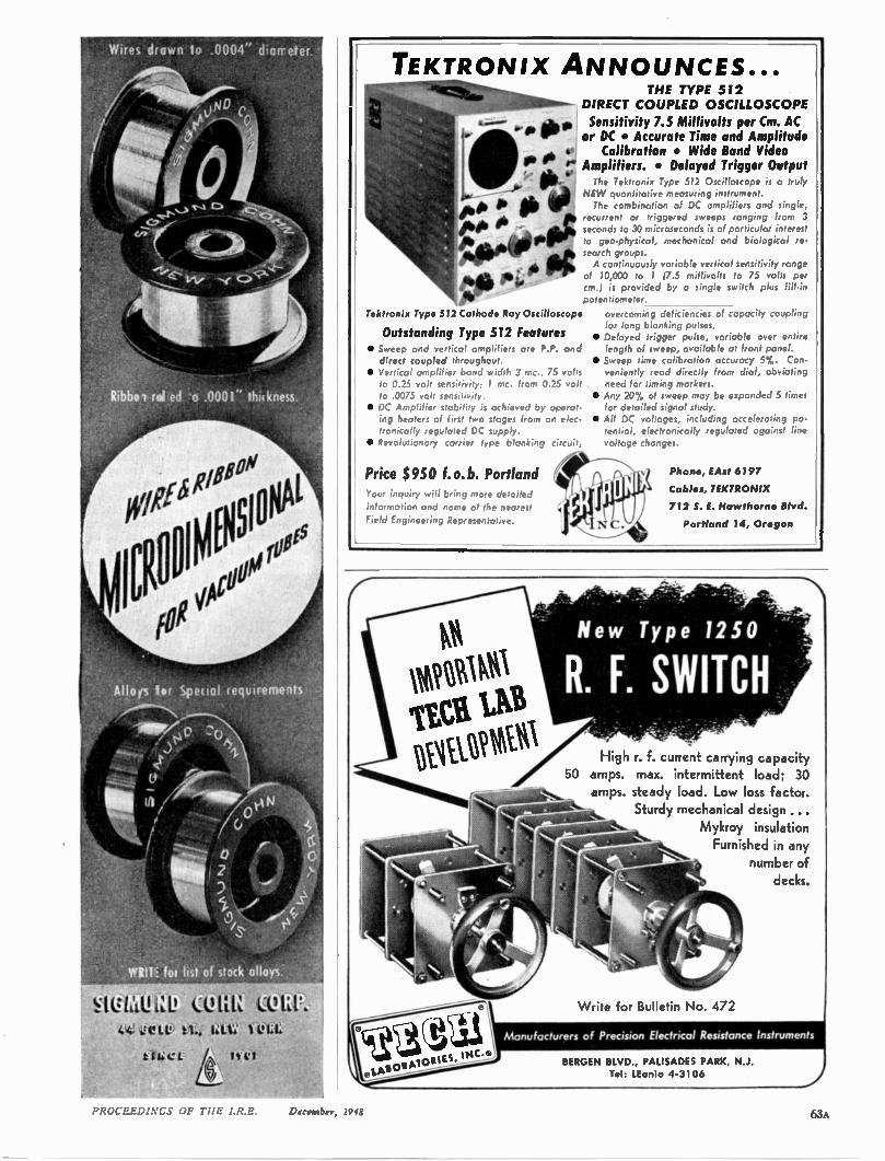
ed -o .0001" thilkness
Willi tot list of stock alloys.
F.IVIa!1:11 441 ,geLe) tt, ULU' 1 CIL
titict l CI
TEKTRONIX ANNOUNCES... THE TYPE 512
DIRECT COUPLED OSCILLOSCOPE
Sensitivity 7.5 Millivolts per Cm. AC or DC • Accurate Time and Amplitude Calibration • Wide Band Video
Amplifiers. • Delayed Trigger Output The Tektronix Type 512 Oscilloscope is a truly
NEW quantitative meosuring instrument. The combination of DC amplifiers and single,
recurrent or triggered sweeps ranging from 3 seconds to 30 microseconds is of particular interest to geo-physical, mechanical and biological re-search groups. A continuously variable vertical sensitivity range
of 10,000 to 1 (7.5 millivolts to 75 volts per cm.) is provided by a single switch plus fill-in potentiometer.
Tektronix Type 512 Cathode Ray Oscilloscope
Outstanding Type 512 Features • Sweep ond vertical ompi.t s's ure P.P. and direct coupled throughout.
• Vertical amplifier band width 3 mc., 75 volts to 0.25 volt sensitivity; 1 mc. from 0.25 volt to .0075 volt sensitivity.
• DC Amplifier stability is achieved by operat-ing heaters of first two stages from an elec-tronically regulated DC supply.
• Revoluionory carrier ,ype blanking circuit,
Price $950 f.o.b. Portland Your inquiry will bring more delo,led information and name of the nearest
Field Engineering Representative.
overcoming deficiencies of capacity coupling for long blanking pulses.
• Delayed trigger pulse, variable over entire length of sweep, available at front panel.
• Sweep time calibration accuracy 5%. Con-veniently read directly from dial, obviating need for timing markers.
• Any 20% of sweep may be expanded 5 times for detailed signal study.
• All DC voltages, including accelerating po-tential, electronically regulated against line voltage changes.
Phone, EAst 6197
Cables, TEKTRONIX
712 S. E. Hawthorne Blvd.
Portland 14, Oregon
New Type 1250
R. F. SWITCH High r. f. current carrying capacity
50 amps. max. intermittent load; 30 amps. steady load. Low loss factor.
Sturdy mechanical design ... Mykroy insulation Furnished in any
number of decks.
Write for Bulletin No. 472
Manufacturers of Precision Electrical Resistance instruments
BERGEN BLVD., PALISADES PARK, N.J. Tel: LEonia 4-3106
!HT I R.1? 1)c.-etnber, 1948 63A
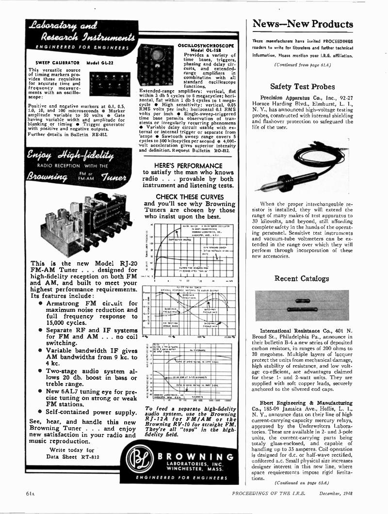
News—New Products
SWEEP CALIBRATOR Model GL-22
This versatile source of timing markers pro-vides these requisites for accurate time and frequency measure-ments with an oscillo-scope:
Positive and negative markers at 0.1, 0.5, 1.0, 10, and 100 microseconds • Marker amplitude variable to 50 volts • Gate having variable width and amplitude for blanking or timing • Trigger generator with positive and negative outputs.
Further details in Bulletin RE-812,
RADIO RECEPTION WITH THE
This is the new Model RJ-20 FM-AM Tuner . . . designed for high-fidelity reception on both FM and AM, and built to meet your highest performance requirements. Its features include: • Armstrong FM cir.uit for maximum noise reduction and full frequency response to 15,000 cycles.
• Separate RF and IF systems for FM and AM . . . no coil switching.
• Variable bandwidth IF gives AM bandwidths from 9 kc. to 4 kc.
• Two-stage audio system al-lows 20 db. boost in bass or treble range.
• New 6AL7 tuning eye for pre-cise tuning on strong or weak FM stations.
• Self-contained power supply.
See, hear, and handle this new Browning Tuner . . . and enjoy new satisfaction in your radio and music reproduction.
Write today for Data Sheet RT-812
OSCILLOSYNCHROSCOPE Model OL-1511
Provides a variety of time bases, triggers, phasing and delay cir-cuits, and extended-range amplifiers in combination with all standard oscilloscope functions.
Extended-range amplifiers: vertical, flat within 3 db 5 cycles to 6 megacycles; hori-zontal, flat within 1 db 5 cycles to 1 mega-cycle • High sensitivity: vertical, 0.05 RMS volts per inch; horizontal 0.1 RMS volts per inch • Single-sweep-triggered time base permits observation of tran-sients or irregularly recurring phenomena • Variable delay circuit usable with ex-ternal or internal trigger or separate from 'scope • Sawtooth sweep range covers 5 cycles to 500 kilocycles per second • 4,000-volt acceleration gives superior intensity and definition. Request Bulletin RO-812.
HERE'S PERFORMANCE to satisfy the man who knows radio . . . provable by both instrument and listening tests.
CHECK THESE CURVES and you'll see why Browning Tuners are chosen by those who insist upon the best.
112
;
I
a 10
14 V-20 V .2. .I 0.-.0 W M . Oflilk•lt•
1 M . . L•100.200.11. ..2.
• ..0.21.1. Y U . y 1.
201.2001.0.C• R ...
....1. 011•0•10 (W M
S. 0. LL L LID ill
10• 21 1,
14 ,210 104 001.112010 2200;
W O WS arT19 .11... 0.0.
•ri I i
• •I•
1 11
0
10 1
11 -
1 ,7 fm• “ 10. •
W O. " •21•0•11 . ..... 20 av0.0 O V .
. NIN ;: „" %:•, ;:f4
1
1:;::; 7••• 17.11, N ' . ? ....: ' •-1 061,-
•-,
•• 110.00.
..... 0 .0
•Na.
f " *
°
ye
a
4 ,4. • ••• 0 01.1.4 I W U • . .. 021.,
0. V 40 01. 4.1.00.0•21
1
_., / ,';• 0. ••••• .0.V.41 ..t.•••
' N \ cN ....._ 10 00 20. 0-.11 ...0 21
I I I I
vi•-•0.10 .015" . 3.• I .....,
To feed a separate high-fidelity audio system, use the Browning 121-12A for FM/A M or the Browning RV-10 for straight FM. They're all "tops" in the high-fidelity field.
RO W NI N G LABORATORIES, INC. WINCHESTER, MASS.
These manufacturers have invited PROCEEDINGS
readers to write for literature and further technical
information. Please mention your I.R.E. affiliation.
(Continued from page 61A)
Safety Test Probes
Precision Apparatus Co., Inc., 92-27 Horace Harding Blvd., Elmhurst, L. I., N. Y., has announced high-voltage testing probes, constructed with internal shielding and flashover protection to safeguard the life of the user.
When the proper interchangeable re-sistor is installed, they will extend the range of many makes of test apparatus to 30 kilovolts, and beyond, still affording complete safety in the hands of the operat-ing personnel. Sensitive test instruments and vacuum-tube voltmeters can be ex-tended in the range over which they will perform through incorporation of these new accessories.
Recent Catalogs
International Resistance Co., 401 N. Broad St., Philadelphia Pa., announce in their bulletin B-4 a new series of deposited carbon resistors, in ranges of 200 ohms to 20 megohms. Multiple layers of lacquer protect the units from mechanical damage, high stability of resistance, and low volt-age co-efficient, are advantages claimed for these 1- and 2-watt units. They are supplied with soft copper leads, securely anchored to the silvered end caps.
Ebert Engineering & Manufacturing Co., 185-09 Jamaica Ave., Hollis, L. I., N. Y., announce data on their line of high current-carrying-capacity mercury relays, approved by the Underwriters Labora-tories. These are available in 2- and 3-pole units, the current-carrying parts being totaly glass-enclosed, and capable of handling up to 35 amperes. Coil operation is designed for d.c. or half-wave rectified, unfiltered ac. Small physical size increases designer interest in this new line, where space requirements impose rigid limita-tions.
(Continued on Page 65A)
61 PROCEEDINGS OF THE I.R.E. December, 1948
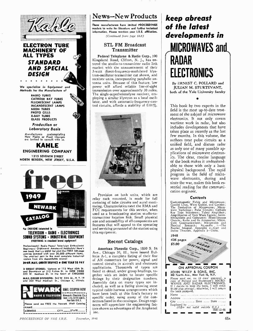
ELECTRON TUBE MACHINERY OF ALL TYPES
STANDARD AND SPECIAL DESIGN
We specialize in Equipment and Methods for the Manufacture of
RADIO TUBES CATHODE RAY TUBES FLUORESCENT LAMPS INCANDESCENT LAMPS NEON TUBES PHOTO CELLS X-RAY TUBES GLASS PRODUCTS
Production or Laboratory Basis
Manufacturers contemplating New Plants or Plant Changes are invited to consult with us.
KAHLE ENGINEERING COMPANY
1315 SEVENTH STREET NORTH BERGEN, NE W JERSEY, U.S.A.
free
Fol EVERYONE interested In
TELEVISION • RADIO • ELECTRONICS SOUND SYSTEMS • INDUSTRIAL EQUIPMENT
EVERYTHING in standard brand equipment!
Professionals! Radio Hams! Television Enthusiastst Beginners! Oldtimers1 Amateurs! Hobbyists! Here's one book that's a MUST for yowl Our FREE 148 page catalog jammed with over 20,000 different items. The smallest part to th• most complete industrial system from one dependable source!
2414R.MAIL ORDER SERVICE • ONE YEAR TO PAY
3 GREAT STORES: Uptown at 115 West 45th St. and Downtown at 212 Fulton St. in NEW YORK 323 W Madison St in the heart of CHICAGO
MAIL ORDER DIVISIONS: 242 W. 55th St., N. Y. 19 and 323 West Madison St , Chicago 6, Illinois
NEWARK RADIO aTEEEVISION
MAIL COUPON NOW
Newark Electric Co. Dept.1-23.242 W 55th St. New York 19 N.Y.
;Please send me FREE the Newark 1949 Catalog I NAME
!ADDRESS CITY STATE
News—Ne w Products These manufacturers have invited PROCEEDINGS readers to write for literature and further technical information. Please mention your I.R.E. affiliation.
(Continued from page 64A)
STL FM Broadcast Transmitter
Federal Telephone & Radio Corp., 100 Kingsland Road, Clifton, N. J., has en-tered the studio-to-transmitter radio link market with the announcement of their 3-watt direct-frequency-modulated klys-tron-oscillator transmitter cut shown, and receiver units, incorporating parabolic an-tenna units. Because of this feature, low power will afford reliable line-of-sight transmission over approximately 30 miles. The single-superheterodyne receiver, em-ploying a similar klystron as a local oscil-lator, and with automatic-frequency-con-trol circuits, affords a stability of 0.01 %.
Provision on both units, which are relay rack mounted, is made for full metering of tube circuits and aural moni-toring. Characteristics meet the RMA and FCC requirements for this service, when used as a broadcasting station studio-to-transmitter location link. Small physical size and accessibility of all components are features that will appeal to the operating and servicing personnel of the station using this equipment.
Recent Catalogs
American Phenolic Corp., 1830 S. 54 Ave., Chicago 50, Ill., have issued Bul-letin A-1, a complete listing of their line of AN connectors for power, signal and control circuits in aircraft and electronic applications. Thousands of types are listed in detail, under group headings, to-gether with an index to locate specific fittings by their designation numbers. Assembly data on many types are in-cluded, as well as a listing showing some typical cable-harness arrangements which have been built at this firm's factory to specific order, using many of the con-nectors listed in the catalogue. Design engi-neers will appreciate the engineering fac-tors shown as advantages of the Amphenol ine
keep abreast of the latest developments in
MICROWAVES and, r RADAR ELECTRONICS By ERNEST C. POLLARD and JULIAN M. STURTEVANT,
both of the Yale University faculty
•
This book by two experts in the field is the most up-to-date treat-ment of the subject of microwave electronics. It not only covers wartime work in radar, but also includes developments that have taken place as recently as the last few months. In this volume, the authors treat pulse circuits as a unified field, and discuss radar as only one of many possible ap-plications of microwave electron-ics. The clear, concise language of the book makes it understand-able to those with only a basic physical background. The rapid progress in the field of micro-wave electronics, during and since the war, makes this book es-sential reading for the communi-cation engineer.
Contents Electromagnetic Fields and Microwaves; Coaxial Lines, Wave Guides, and Cavities; The Production of Microwaves; Micro-wave Technique; Pulse Circuits; Cathode Ray Tube Indicators; Tubed Amplifiers; Amplification of Very Weak Signals; Servo-mechanisms and Computers; Miscellaneous Circuits; Radar and Its Accessories; Micro-wave Communications; Microwaves and Physical Research ; Ar endix 1—The Fourier Integral. Appendix 2—Curl and Stokes Theorem. Appendix 3—Units,
1948 426 pages c•,p. cs,gy , $5.00 4?-1, 4ear 0.44.
'Pc>
r ON APPROVAL COUPON
I JOHN WILEY & SONS, INC. 440 Fourth Ave., New York 16, N.Y. Please send me, on 10 days' approval, a Icopy of Pollard and Sturtevant's MICRO- I WAVES AND RADAR ELECTRONICS. If I decide to keep the book, I will remit I$5.00 plus postage; otherwise, I will return I the book postpaid.
I Name i Address
City Zone I . State Employed by
(Offer not valid outride U.S.) IRE-12-413
PROCEEDINGS OF THE I.R.E. December, 1948 65A
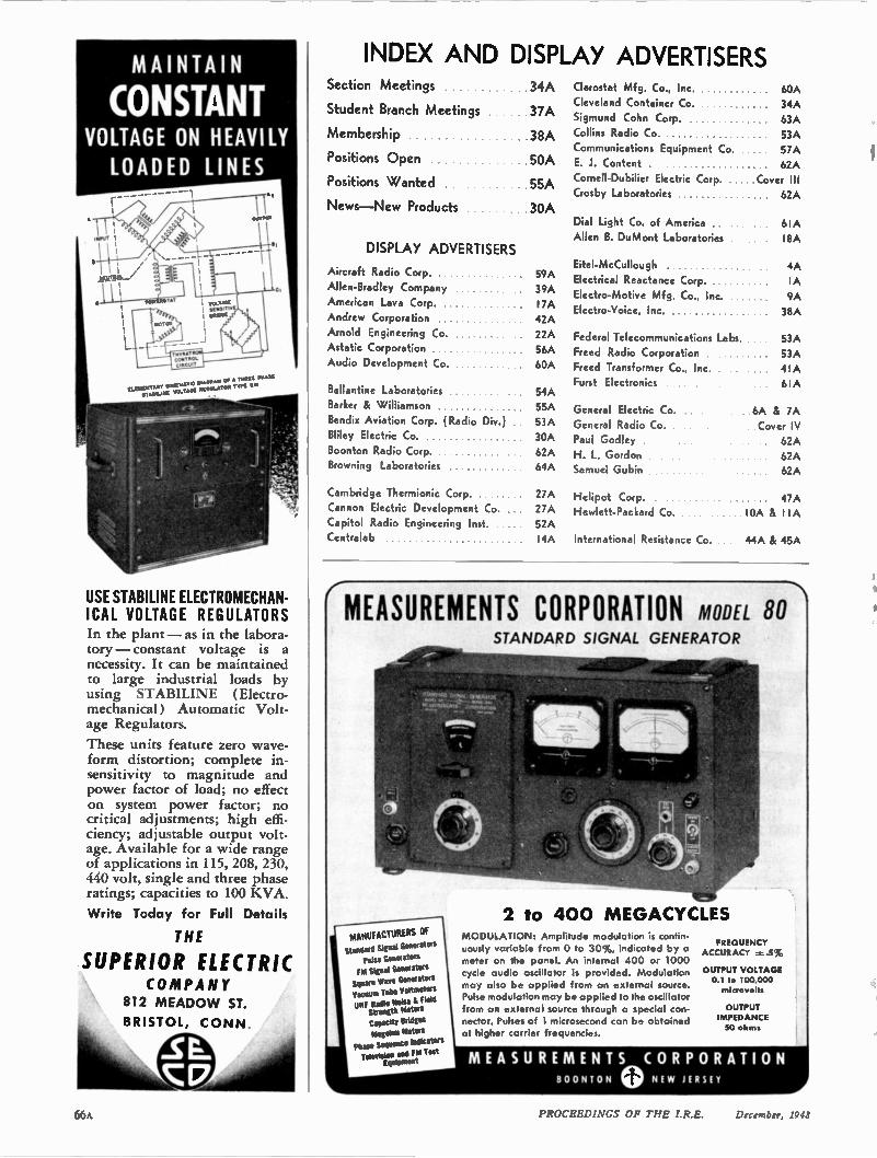
MAINTAIN INDEX AND DISPLAY ADVERTISERS
CONSTANT VOLTAGE ON HEAVILY LOADED LINES
MAW I
-----------
KAKAS
--TWILILT cgmT1101. uretert
I await I MAN I -
moor IIC KIAATC A M MI A or A P.AS un t STAIMLI K VOLTASt IMOULATOA TYP1 IC
.1.
01114
USE STABILINE ELECTROMECHAN-ICAL VOLTAGE REGULATORS In the plant —as in the labora-tory — constant voltage is a necessity. It can be maintained to large industrial loads by using STABILINE (Electro-mechanical) Automatic Volt-age Regulators.
These units feature zero wave-form distortion; complete in-sensitivity to magnitude and power factor of load; no effect on system power factor; no critical adjustments; high effi-ciency; adjustable output volt-age. Available for a wide range of applications in 115, 208, 230, 440 volt, single and three phase ratings; capacities to 100 KVA.
Write Today for Full Details
THE
SUPERIOR ELECTRIC CO MPANY
812 MEADO W ST.
BRISTOL, CONN.
Section Meetings
Student Branch Meetings
Membership
Positions Open
Positions Wanted
News —New Products
DISPLAY ADVERTISERS
Aircraft Radio Corp.
Allen-Bradley Company
American Lava Corp. Andrew Corporation
Arnold Engineering Co.
Astatic Corporation Audio Development Co.
Ballantine Laboratories
Barker & Williamson
Bendix Aviation Corp. (Radio Div.) Bliley Electric Co.
Boonton Radio Corp. Browning Laboratories
Cambridge Thermionic Corp. Cannon Electric Development Co. Capitol Radio Engineering Inst. Centralab
. 34A
37A
38A
50A
55A
30A
59A 39A I7A
42A 22A
56A 60A
54A 55A
53A 30A 62A 64A
27A 27A 52A
I4A International Resistance Co. 44A & 45A
Clarostat Mfg. Co., Inc. 60A Cleveland Container Co. 34A Sigmund Cohn Corp. 63A
Collins Radio Co. 53A
Communications Equipment Co. 57A E. J. Content 62A
Cornell-Dubilier Electric Corp. .Cover III Crosby Laboratories 62A
Dial Light Co. of America . 6IA
Allen B. DuMont Laboratories I8A
Eitel-McCullough 4A
Electrical Reactance Corp. IA Electro-Motive Mfg. Co., Inc. 9A Electro-Voice, Inc. 38A
Federal Telecommunications Labs. 53A
Freed Radio Corporation 53A Freed Transformer Co., Inc. 41 A
Furst Electronics 6IA
General Electric Co. 6A & 7A General Radio Co. Cover IV Paul Godley 62A H. L. Gordon 62A Samuel Gubin 62A
Helipot Corp. 47A Hewlett-Packard Co. 10A & I IA
MEASUREMENTS CORPORATION
2 to 400 MEGACYCLES MANUFACTURERS OF
Standard Signal GenefeCOS Pulse Gene' ators M Signal Generators
Square Wave Generators
Vacuum Tube Voltmeters UHF Radio Noise L held Strength Meters Capacity BrldRes Megohm Meters
Phase Sequence indicators Television and EM Test
Equipment
STANDARD SIGNAL
MODEL GENERATOR
MODULATION: Amplitude modulation is contin-
uously variable from 0 to 30%, indicated by a meter on the panel. An internal 400 or 1000
cycle audio oscillator is provided. Modulation
may also be applied from an external source. Pulse modulation may be applied to the oscillator
from an external source through a special con-nector. Pulses of 1 microsecond can be obtained at higher carrier frequencie3.
80 1
FREQUENCY ACCURACY .5%
OUTPUT VOLTAGE 0.1 to 100,000 microvolts
OUTPUT IMPEDANCE 50 ohms
MEASUREMENTS CORPORATION BOONTON 0 NE W JERSEY
Or, \ PROCEEDINGS OF THE December, 1948
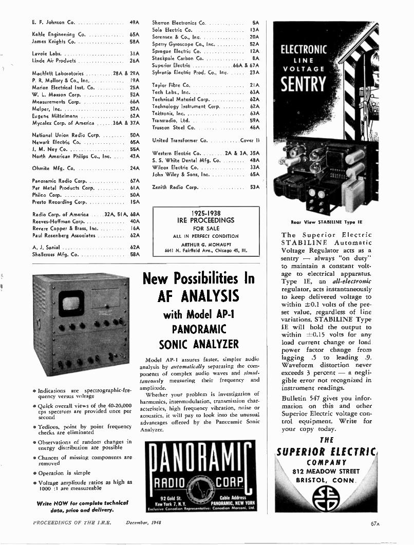
E. F. Johnson Co.
Kahle Engineering Co.
James Knights Co.
Lavoie Labs. Linde Air Products
49A Sherron Electronics Co. 5A Sola Electric Co. I 3A
65A Sorensen & Co., Inc. 20A 58A Sperry Gyroscope Co., Inc. 52A
Sprague Electric Co. I2A Stackpole Carbon Co. 8A
Superior Electric 66A & 67A Sylvania Electric Prod. Co., Inc. 23A
Taylor Fibre Co. 2IA
Tech Labs., Inc. 63A Technical Materiel Corp. 62A Technology Instrument Corp. 62A
Tektronix, Inc. 63A Transradio, Ltd. 59A Truscon Steel Co. 46A
United Transformer Co. Cover II
Western Electric Co. 2A & 3A, 35A
S. S. White Dental Mfg. Co. 48A
24A Wilcox Electric Co. 33A John Wiley & Sons, Inc. 65A
53A
3IA 26A
Machlett Laboratories 28A & 29A
P. R. Mallory & Co., Inc. I9A Marion Electrical Inst. Co. 25A W. L. Maxson Corp. Measurements Corp.
Melpar, Inc.
Eugene Mittelmann Mycalex Corp. of America 36A & 37A
52A 66A
52A 62A
National Union Radio Corp. 50A Newark Electric Co. 65A J. M. Ney Co. 55A North American Philips Co., Inc. 43A
Ohmite Mfg. Co.
Panoramic Radio Corp. 67A Par Metal Products Corp. 6IA
Philco Corp. .... 50A Presto Recording Corp. I5A
Radio Corp. of America 32A, 5IA, 68A
Reeves-Hoffman Corp. . 40A Revere Copper & Brass, Inc. I6A Paul Rosenberg Associates 62A
A. J. Sanial Shallcross Mfg. Co.
62A 58A
• Indications are spectrographic-fre-quency. versus voltage
• Quick overall views of the 40-20,000 cps spectrum are provided once per second
• Tedious, point by point frequency checks are eliminated
• Observations of random changes in energy distribution are possible
• Chances of missing components are removed
• Operation is simple
• Voltage amplitude ratios as high as 1000 :I are measureable
Write NOW for complete technical data, price and delivery.
Zenith Radio Corp.
1925-1938 IRE PROCEEDINGS
FOR SALE
ALL IN PERFECT CONDITION
ARTHUR G. MOHAUPT 6641 N. Fairfield Ave., Chicago 45, III.
New Possibilities In AF ANALYSIS with Model AP-1 PANORAMIC
SONIC ANALYZER Model AP-1 assures faster, simpler audio
analysis by automatically, separating the com-ponents of complex audio waves and simul-taneously measuring their frequency and
amplitude. Whether your problem is investigation of
harmonics, intermodulation, transmission char-acteristics, high frequency vibration, noise or acoustics, it will pay to look into the unusual advantages offered by the Panoramic Sonic
Analyzer.
RADIO CORP ANOHAMI[ 92 Gold St. Cable Address
New York 7, N.Y. PANORAMIC. NEW YORK Exclusive Canadian Representative: Canodo' Mv,rov. lid
Rear View STABILINE Type IE
ELECTRONIC LINE
VOLTAGE
The Superior Electric STABILI NE Automatic Voltage Regulator acts as a sentry — always "on duty" to maintain a constant volt-age to electrical apparatus. Type IE, an all-electronic regulator, acts instantaneously to keep delivered voltage to within -±0.1 volts of the pre-set value, regardless of line variations. STABILINE Type IE will hold the output to within ±-0.15 volts for any load current change or load power factor change from lagging .5 to leading .9. Waveform distortion never exceeds 3 percent — a negli-gible error not recognized in instrument readings.
Bulletin 547 gives you infor-mation on this and other Superior Electric voltage con-trol equipment. Write for your copy today.
THE
SUPERIOR ELECTRIC, COMPANY
812 MEADOW STREET
BRISTOL, CONN.
PROCEEDINGS OF THE I.R.E. December, 1945 67A
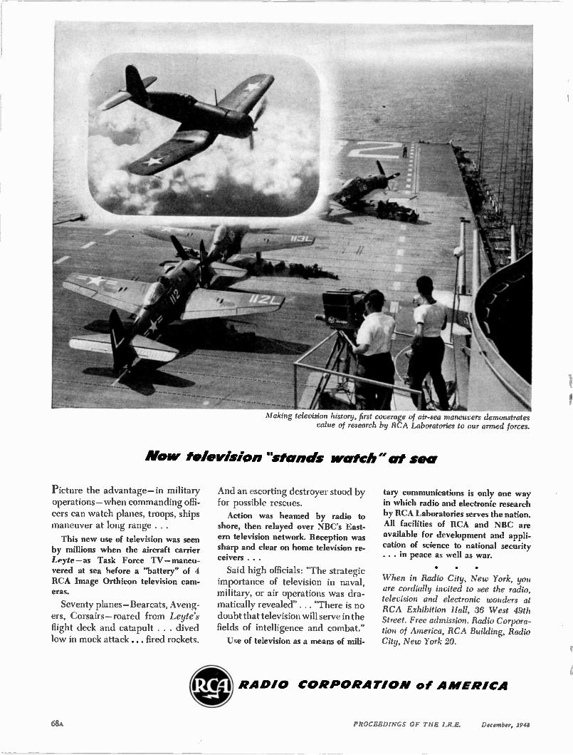
Making television history, first coverage of air-sea maneuvers demon qrates value of research by RCA Laboratories to our armed forces.
Now television "stands watch" at sea
Picture the advantage—in military operations —when commanding offi-cers can watch planes, troops, ships maneuver at long range . . .
This new use of television was seen by millions when the aircraft carrier Leyte—as Task Force TV—maneu-vered at sea before a "battery" of 4 RCA Image Orthicon television cam-eras.
Seventy planes—Bearcats, Aveng-ers, Corsairs — roared from Leyte's flight deck and catapult . . . dived low in mock attack ... fired rockets.
And an escorting destroyer stood by for possible rescues. Action was beamed by radio to
shore, then relayed over NBC's East-ern television network. Reception was sharp and clear on home television re-ceivers . . .
Said high officials: "The strategic importance of television in naval, military, or air operations was dra-matically revealed" . . . "There is no doubt that television will serve in the fields of intelligence and combat."
Use of television as a means of mili-
tary communications is only one way in which radio and electronic research by RCA Laboratories serves the nation. All facilities of RCA and NBC are available for development and appli-cation of science to national security . . . in peace as well as war.
• • •
When in Radio City, New York, you are cordially invited to see the radio, television and electronic wonders at RCA Exhibition Hall, 36 West 49th Street. Free admission. Radio Corpora-tion of America, RCA Building, Radio City, New York 20.
0 O ft RA DIO CO R PO RATIO N of A MERICA
v liF
68A PROCEEDINGS OF THE I.R.E. December, 2948
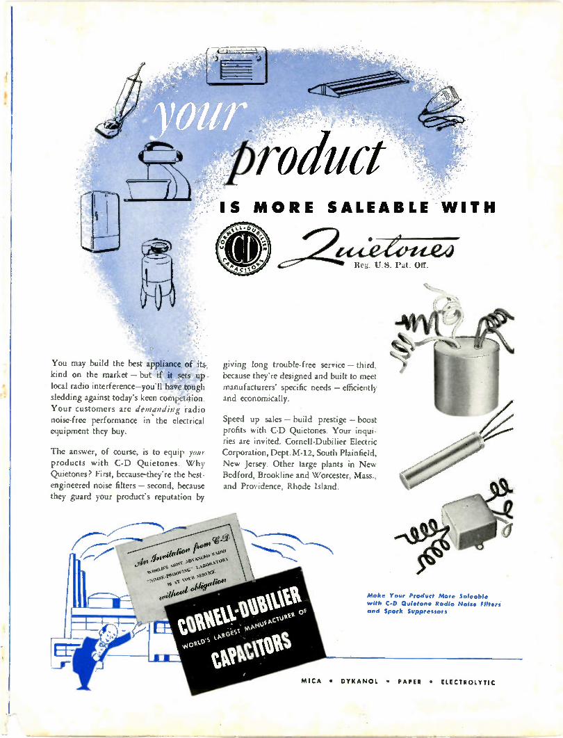
You may build the best appliance of its; kind on the market — but if it sets up - local radio interference—you'll bro, tough sledding against today's keen cottkpkition. Your customers are demanding radio noise-free performance in the electrical equipment they buy.
The answer, of course, is to equip your products with C-D Quietones. Why Quietones? First, because-they're the best-engineered noise filters — second, because they guard your product's reputation by
IS
roduct M ORE SALEABLE WITH
Itt. U.S. it. Off.
giving long trouble-free service — third,
because they're designed and built to meet manufacturers' specific needs — efficiently and economically.
Speed up sales — build prestige — boost profits with C-D Quietones. Your inqui-ries are invited. Cornell-Dubilier Electric Corporation, Dept. M-12, South Plainfield,
New Jersey. Other large plants in New Bedford, Brookline and Worcester, Mass., and Providence, Rhode Island.
Make Your Product More Saleable
with C-D Quietone Radio Noise Filters and Spark Suppressors
MICA • DYKANOL • PAPER • ELECTR OLYTIC
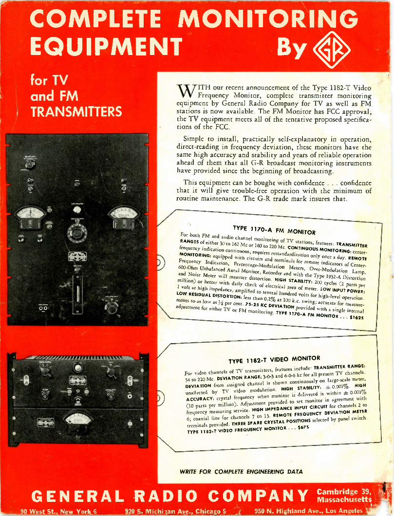
• ALLE M/11.1,1 MV W11111• •
• 4ts
•
•
•
COMPLETE MONITORING EQUIPMENT By for TV and FM TRANSMITTERS
4. 64 4.-.1
113 1‘ ••••••
0
Alb\ •
W ITH our recent announcement of the Type 1182-T Video Frequency Monitor, complete transmitter monitoring
equipment by General Radio Company for TV as well as FM stations is now available. The FM Monitor has FCC approval; the TV equipment meets all of the tentative proposed specifica-tions of the FCC.
Simple to install, practically self-explanatory in operation, direct-reading in frequency deviation, these monitors have the same high accuracy and stability and years of reliable operation ahead of them that all G-R broadcast monitoring instruments have provided since the beginning of broadcasting.
This equipment can be bought with confidence . . . confidence that it will give trouble-free operation with the minimum of routine maintenance. The G-R trade mark insures that.
TYPE 1170-A FM MONITOR
For both FM and audio channel monitoring of TV stations, features: TRANSMITTER RANGES of either 30 to 162 Mc or 160 to 220 Mc. CONTINUOUS MONITORING: center.
frequency indication continuous; requires restandardization only once a day. REMOTE MONITORING: equipped with circuits and terminals for remote indicators of Center. Frequency Indication, Percentage-Modulation Meters, Over-Modulation Lamp,
600-Ohm Unbalanced Aural Monitor, Recorder and with the Type 1932-A Distortion and Noise Meter vill measure distortion. NIGH STABILITY: 200 cycles (2 parts per million) or better with daily check of electrical zero of meter. LOW INPUT POWER: 1 volt at high impedance, amplified to several hundred volts for high-k5 el operation. LOW RESIDUAL DISTORTION: less than 0.2% at 100 k.c. swing; accurate for measure-ments to as low as ,1,4:1 per cent. 75-25 KC DEVIATION provided with a single internal
adjustment for either TV or FM monitoring. TYPE 1170-A FM MONITOR .. . $1625
TYPE 1182-1 VIDEO MONITOR
For video channels of TV transmitters, features include; TRANSMITTER RANGE: 54 to 220 Mc. DEVIATION RANGE: 3-0-3 and 6-0-6 kc for all present TV channels. DEVIATION from assigned channel is shown continuously on large-scale meter,
unaffected by TV video modulation. HIGH STABILITY: ± 0.001%. HIGH ACCURACY: crystal frequency when monitor is delivered is within ± 0.001% (10 parts per million). Adjustment provided to set monitor in agreement with frequency measuring service. HIGH IMPEDANCE INPUT CIRCUIT for channels 2 to
6; coaxial line for channels 7 to 1) REMOTE FREQUENCY DEVIATION METER
terminals provided THREE SPARE CRYSTAL POSITIONS selected by panel switch.
TYPE 1182-T VIDEO FREQUENCY MONITOR . . $675
WRITE FOR COMPLETE ENGINEERING DATA
Cambridge 39, GENERAL RADIO CO MPANY !).' Massachusetts
90 West St. New Yor 6 920 S. Michilan Ave. Chicago 5 950 N. Highland Ave., Los Angeles
Related Documents