Proceedings of the 7th Annual Conference on Composites and Advanced Ceramic Materials Joseph J. Gebhardt Program Chairman A Collection of Papers Presented at the 7th Annual Conference on Composites and Advanced Ceramic Materials Sponsored by the Ceramic-Metal Systems Division The American Ceramic Society January 16-19, 1983 Holiday Inn of Cocoa Beach Cocoa Beach, Florida ISSN 0196-6219 Published by The American Ceramic Society, Inc 65 Ceramic Drive Columbus, Ohio 43214 @The American Ceramic Society, 1983

Welcome message from author
This document is posted to help you gain knowledge. Please leave a comment to let me know what you think about it! Share it to your friends and learn new things together.
Transcript

Proceedings of the 7th Annual Conference on
Composites and Advanced Ceramic Materials
Joseph J. Gebhardt Program Chairman
A Collection of Papers Presented at the 7th Annual Conference on
Composites and Advanced Ceramic Materials Sponsored by the
Ceramic-Metal Systems Division The American Ceramic Society
January 16-19, 1983 Holiday Inn of Cocoa Beach
Cocoa Beach, Florida
ISSN 0196-6219
Published by The American Ceramic Society, Inc
65 Ceramic Drive Columbus, Ohio 43214
@The American Ceramic Society, 1983

The page is intensily left blank
Proceedings of the 7th Annual Conference on
Composites and Advanced Ceramic Materials
Joseph J. Gebhardt Program Chairman
A Collection of Papers Presented at the 7th Annual Conference on
Composites and Advanced Ceramic Materials Sponsored by the
Ceramic-Metal Systems Division The American Ceramic Society
January 16-19, 1983 Holiday Inn of Cocoa Beach
Cocoa Beach, Florida
ISSN 0196-6219
Published by The American Ceramic Society, Inc
65 Ceramic Drive Columbus, Ohio 43214
@The American Ceramic Society, 1983

Executive Director & Publisher Arthur L. Friedberg
Director of Publications Donald C . Snyder
Editor William J . Smothers
Cochran, Jr ; Robert J . Eagan; Thomas D. McGee; Edwin Ruh; Minoru Tomozawa. ex oficio; William J . Smothers, ex oflcio; Arthur L. Friedberg. ex oflcio
Editorial Aduisory Board: Minoru Tomozawa. Chairman; John W. Halloran; Cameron G . Harman, Ian J . Hastings; You Song Kim; Ira 0. Knickerbocker; Norman L. Peterson; Thomas F . Root; Robert 0. Russell; Liselotte J . Schioler; James M . Stubbs, Jr.; Douglas N . Winslow. Editorial and Subscription Oflces: 65 Ceramic Drive, Columbus, Ohio 43214. Subscription $60 a year; single copies $12 (postage outside U.S. $2 additional). Published bimonthly. Printed in the United States of America. Allow six weeks for address changes. Missing copies will be replaced only if valid claims are received within six months from date of mailing. Replacements will not be allowed if the subscriber fails to notify the Society of a change of ad- dress. CESPDK Vol. 4 , NO. 9-10, pp. 695-917, 1983
Associate Editor
Graphic Production
Circulation Manager
Stephen C. Robb
Elizabeth A. Gilbert
Gary W. Panek
The American Ceramic Society assumes n o responsibility for the state- ments and opinions advanced by the contributors to its publications, or by the speakers at its programs.

Preface
Interest in the field of high temperature composites and advanced ceramic materials continues to grow, as evidenced by the numerous papers and active
participation of attendees at the 7th Annual Conference. I wish to thank all of the session chairmen, authors, and participants for making it possible to achieve the principal conference goal of providing a forum for discussion of materials developments, requirements, and applications. In particular, I wish to thank Jerome Persh and James 1. Mueller for arranging the plenary sessions on materials policy, engineering education, and research funding requirements for the future. These continue to be a unique and valuable aspect of this series of conferences. In addition, the efforts of members of the Department of Materials Science and Engineering of the University of Florida and the NASA- Kennedy Space Center in providing for a smooth and efficient conference are gratefully acknowledged.
Joseph J. Gebhardt Conference Chairman
Ceramic-Metal Systems Division American Ceramic Society
[Editor's Note: Proceedings of the 7th Annual Conference on Composites and Ad- vanced Ceramic Materials appear in both this issue and in Ceramic Engineering and Science Proceedings, volume 4, number 7-8.1
... 111

The page is intensily left blank

Table of Contents
Processinq and Processing Effects
Cermet Fabrication by Thermal Spraying and Hot Isostatic Pressing . . 695 James E. Sheehan
Carbon-Containing Monolithic Glasses via the Sol-Gel Process ...... 704 Frank K. Chi
Inorganic Modification of Glass Powder Surfaces for Improved Polymeric Composites ..................................... 718
Cheng T. Lee, David E. Clark, Keith S. Shih, and Charles L. Beatty
The Processing and Environmental Behavior of a 20-mol% Na20-80-mol% (20N) SiO, Gel-Glass ......................... 732
Larry L. Hench, S. Wallace, S. Wang, and M. Prassas
Effects of Atmosphere and Dew Point on the Wetting Characteristics of a Glass-Ceramic on Two Nickel-Based Superalloys ............................... 740
Daniel P. Kramer and N. R. Osborne
Control of Metal-Oxygen-Hydrogen Composition ................. 751 Jurgen Hauck
Processing of Fused Silicide Coatings for Carbon-Based Materials. . . . 757 James L. Smialek
Coatins Properties
Phase Analysis of Plasma-Sprayed Zirconia-Yttria Coatings ........ 784 N. Ravi Shankar, Chris C. Berndt, and Herbert Herman
Anisotropic Thermal Expansion Effects in
Chris C. Berndt and Herbert Herman Plasma-Sprayed Zr02-8%-Y,0, Coatings ...................... 792
Residual Stress in Plasma-Sprayed Ceramic Turbine Tip and Gas-Path Seal Specimens ............................... 802
Robert C. Hendricks, Glenn McDonald, and Robert L. Mullen
Correlation of Compressive and Shear Stress with Spalling of Plasma-Sprayed Ceramic Materials .................. 810
Robert L. Mullen, Glenn McDonald, Robert C. Hendricks, and Mary M. Hofle
The Effect of Annealing on the Creep of Plasma-Sprayed Ceramics ... 819 Robert C. Hendricks, Glenn McDonald, and Robert L. Mullen
V

Mechanical and Physical Properties of Plasma-Sprayed Stabilized Zirconia ........................................ 828
f Paul A. Siemers and Richard L. Mehan
Fracture and Touqhness of Particulate Ceramic Composites
Material Improvement Through Iterative Process Development . . . . . . 841 David W. Richerson, Jay R. Smyth, and Karsten H. Styhr
Indentation Fracture Testing of Ceramics ....................... 853 Srinivasa G. Sheshadri, Makuteswaran Srinivasan, and Larry King
The High Temperature Fracture Toughness of SiAlON ............ 864 Minyoung Lee, Milivoj K. Brun, and Tseng-Ying Tien
Cyclic Mechanical Fatigue in Ceramic-Ceramic Composites- AnUpdate ............................................... 874
David Lewis 111
NDE and Analvtical Methods
Coprecipitated Materials: Analytical Techniques for Evaluation ...... 882 Ronald P. Anjard. Sr., and Kenneth Kirschenman
Analysis of Grain Boundary Phase Devitrification of Y,O,- and Al,O,-Doped Si,N, ................................ 896
Larry L. Hench and P. N. Vaidyanathan
Grain-Boundary Phases in Hot-Pressed Silicon Nitride Containing Y,O, and CeO, Additives. . . . . . . . . . . . . . . 901
Jyoti P. Guha and Larry L. Hench
Compositional Effects on Si,N, Fracture Surfaces . . . . . . . . . . . . . . . . 907 Larry L. Hench, F. Ohuchi, P. N. Vaidyanathan, and Sunil Dutta
vi

Cermet Fabrication by Thermal Spraying and Hot Isostatic Pressing
JAMES E. SHEEHAN
Fiber Materials, Inc. Biddeford Industrial Park, Biddeford, ME 04005
T h e purpose of the present work was to determine the feasibility of fabricating high integrity cermets by thermal spraying and hot isostatic pressing. These
materials are of interest because they have potential as erosion-resistant gun- tube liners which are free of strategic elements such as cobalt and chromium.
The approach was to fabricate AlZ0,-28-vol%-Ni disks and cylinders by plasma spraying and hot isostatic pressing. Hot isostatic pressing was carried out at 1350°C and 103 MPa. All of the samples were characterized by im- mersion density measurements and microstructure analysis, and specimens machined from the disks were used for thermal- and mechanical-properties tests. The cylinders were made to demonstrate the shape capability pertinent to gun-tube liners and to provide specimens for test firing. Thermal properties were comparable to well-developed cermet systems, but moduli and strengths were lower due to residual pores, high metal content, and a coarse microstruc- ture.
Experimental The cermet disks were made by plasma spraying onto 76.2-mm-diameter
brass-plate substrates. The disks separated from the edge of the brass before the final thickness of 2.54 mm was achieved. When this happened, the disks were removed and coated on the reverse side to minimize dishing.
The cermet cylinders were made by spraying onto 9.14-mm-diameter by 127-mm-long rotating mandrels. Mandrel materials which were tried included graphite, 430 stainless steel, nickel, brass, and aluminum. Aluminum was the only material which produced crack-free cermet cylinders. This was presum- ably due to the high thermal-expansion coefficient of aluminum which allowed the mandrel to shrink away from the cermet on cooling. The cermet cylinders were removed from the mandrels by cooling in liquid nitrogen.
The metal-substrate surfaces were prepared by light grit blasting and smoothing with emery cloth. Before spraying, the metal substrates were pre- heated to 200"-300°C with the plasma gun. Spraying was done at a distance of x 127 mm using a commercial AlzO,-Ni-composite spray powder. The pro- cedure was to build up the cermet by interrupting the spraying every 0.25-0.50 mm of thickness to let the part cool. Using this technique, the 2.54-mm-thick disks and cylinders required x 0 . 5 h each for fabrication.
Hot isostatic pressing of the 76.2-mm-diameter cermet disks was carried out with the disks individually contained in sealed, 0.89-mm-thick nickel cans as shown in Fig. 1. Inside the cans the disks were positioned between 6.35- mm-thick nickel plates to minimize distortion during pressing. All surfaces
695

contacting the cermet were coated with a BN spray to prevent sticking. The procedure was to arc-weld the can covers to the cans and then evacuate the cans through a stem on the covers with a helium leak detector. A helium probe was then used to check for leaks. After leaktightness was verified, the stem was hot forged for closure. A final leak check was done by pressurizing the cans in helium at 0.7 MPa and probing the cans for helium release immediately after removal from the pressure vessel.
Hot isostatic pressing of the cermet cylinders was carried out with the cylinders contained in 1.57-mm-thick nickel sleeves with caps at each end as shown in Fig. 2. A nickel mandrel was used inside the cylinders to minimize distortion during pressing. All surfaces contacting the cermet were coated with BN spray. The procedure was to electron-beam weld the end caps to the sleeve in vacuum. Leak checking was done by pressurizing the sealed container in helium at 0.7 MPa and probing for helium release immediately after removal from the pressure vessel.
The hot isostatic pressing was performed in argon gas at 1350°C and 103 MPa. Heating was accomplished in = 1 h at a pressure of x 10.3 MPa. After temperature equilibration, the full pressure was applied and held for 2 h. Pressure and temperature were decreased together over a period of 5-6 h.
The hot-isostatically-pressed cermet material was characterized by mi- crography, immersion density measurements, hardness and flexure tests, and thermal-properties measurements. Flexure strengths were measured at room temperature in three-point bending. The specimens were 50.8 mm long by 6.35 mm wide and varied in thickness from 1.12-1.79 mm. Diamond grinding was done in the long direction, and the edges were slightly beveled. Loading was done midway between 4 1.15-mm-spaced supports at a crosshead speed of 0.5 1 mm/min. Continuous plots of midpoint deflection vs load were recorded using a linear variable differential transformer to calculate elastic modulus.
Specific-heat values were measured using a differential scanning calorim- eter. Thermal-diffusivity measurements were made on 12.7-mm-diameter by 1 .OZmm-thick disks by the laser-flash method. Thermal-expansion measure- ments were made on specimens of the same dimensions as the flexure specimens using a quartz dilatometer.
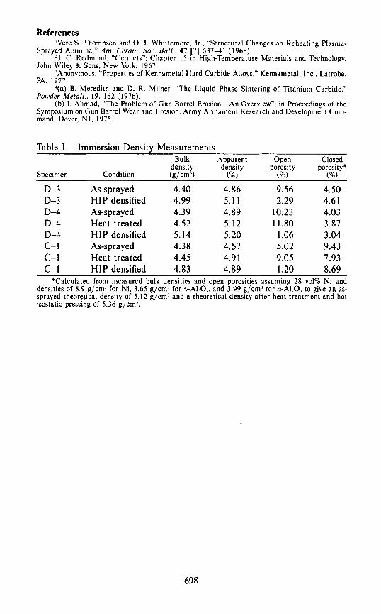
Results and Discussion The results of immersion density measurements on samples which were
successfully densified are listed in Table I. In calculating the closed porosity it was assumed that the A1,0, present after spraying was all metastable y- A120, and that heating produced a-A1203.' Although the as-sprayed bulk den- sities of the two disks and the cylinder were essentially the same, Table I shows the closed porosity in the cylinder was more than double that of the disks. This is a concern because, as Table I shows, the hot isostatic pressing which was effective in eliminating open pores did not eliminate the gas-filled, closed pores.
In an effort to produce a more open pore structure, one disk and the cylinder were heat treated at 1350°C in a vacuum of 0.0007 cPa (0.0005 torr). Table I shows that the heat treatment used was not successful and that sig- nificant levels of closed porosity were retained after hot isostatic pressing.
Figures 3 and 4 show polished-section scanning electron micrographs of one of the cermet disks and a cermet cylinder as-sprayed and after hot isostatic
696

pressing. Both figures show the sinuous laminar nature of the Ni in the as- sprayed microstructures. The Ni stringers were parallel to the plane of the disks and circumferential in the cylinders. Large pores are also evident in both.
After hot isostatic pressing, both structures were more equiaxed. The disk specimen of Fig. 3 had a total residual porosity of -4% after pressing, while the porosity in the cylinder of Fig. 4 was ~ 1 0 % . The difference was the high level of closed pores in the cylinder which were not eliminated by hot isostatic pressing. Comparing Figs. 3 and 4 it is obvious that the disk had the denser microstructure. Both microstructures were rather coarse with some features >50 pm.
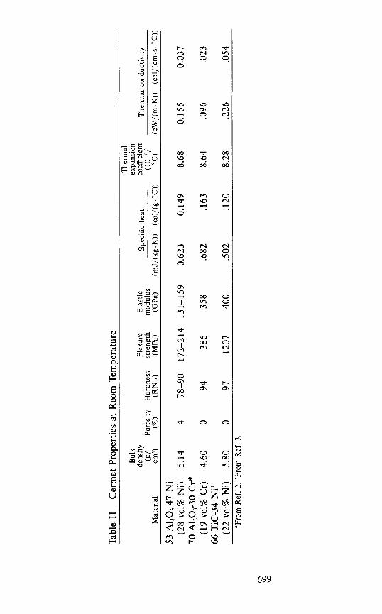
Table I1 compares the thermal- and mechanical-property data obtained on specimens cut from the A1,03-28-vol%-Ni plates in the present study with the properties of two cermet materials of comparable metal content which have been developed over the past 20 yr. The A1,O3-19-vol%-Cr material was made by hot pressing the mixed constituents, and the TiC-22-vol%-Ni material is a commercial cemented carbide made by liquid-phase ~ in te r ing .~ .~
Table I1 shows that the more fully developed materials essentially lack porosity and have metal contents somewhat lower than the A1203-Ni cermet fabricated in the present work. These factors account for the lower hardness and elastic modulus of the AI,O,-Ni and, along with the coarse microstructure, also account for the lower strength. The constituents in the A120,-Cr material were (10 pm in size and formed a finely textured microstructure compared to the coarse A120,-Ni structures shown in Figs. 3 and 4. It is likely that strengths approaching the Al,03-Cr value could be achieved in the A1203-Ni cermet with reduced metal content, elimination of the residual porosity, and a refined microstructure. The very strong bonding established by liquid-phase sintering in the Tic-Ni system is well-known and accounts for the outstanding strength of this material. However, Ni and T i c form a eutectic at 1280°C which most likely precludes use of this material for erosion-resistant gun-tube liners.J
The specific-heat values shown in Table I1 correlate well with the nature and concentrations of the cermet constituents. Thermal-expansion behavior at the relatively low metal contents is close to that of the ceramic phase in all cases. The thermal conductivity of the A1203-Ni material was calculated from measured values of thermal diffusivity, heat capacity, and density. A higher metal content produced the higher conductivity compared to the A120,-Cr cermet in spite of the pores present in the A1203-Ni material.
Conclusions and Recommendations The present work has shown the feasibility of fabricating high integrity
cermets by thermal spraying and hot isostatic pressing. Mechanical properties would be improved by reducing the metal content to x 2 0 vol%, eliminating the residual porosity, and refining the microstructure. Future work should focus on methods of thermal spraying which minimize gas-filled, closed pores and produce finer microstructures.
Acknowledgment This work was funded by the Department of Defense Small Business
Advanced Technology Program under Contract No. DAAK10-82-C-0056 and was monitored by the Army Armament Research and Development Command.
697
References ’Vere S. Thqfnpson and 0. J . Whittemore, Jr., “Structural Changes on Reheating Plasma-
Sprayed Alumina, Am. Ceram. SOC. Bull., 47 [7] 637-41 (1968). *J. C. Redmond, “Cermets”; Chapter 15 in High-Temperature Materials and Technology.
John Wiley & Sons, New York, 1967. ’Anonymous, “Properties of Kennametal Hard Carbide Alloys,” Kennametal, Inc., Latrobe,
PA, 1977. 4(a) B. Meredith and D. R. Milner, “The Liquid Phase Sintering of Titanium Carbide,”
Powder Metall., 19, 162 (1976). (b) 1. Ahmad, “The Problem of Gun Barrel Erosion-An Overview”; in Proceedings of the
Symposium on Gun Barrel Wear and Erosion. Army Armament Research and Development Com- mand, Dover, NJ, 1975.
Table I. Immersion Density Measurements Bulk Apparent
density density Specimen Condition (s/cm’) (”/.I
D-3 D-3 D-4 D-4 D-4 c- 1 c-1 c- 1
As-s prayed HIP densified As-spray ed Heat treated HIP densified As-sprayed Heat treated HIP densified
4.40 4.99 4.39 4.52 5.14 4.38 4.45 4.83
4.86 5.1 1 4.89 5.12 5.20 4.57 4.91 4.89
Open Closed porosity porosity*
(%) (”lo)
9.56 4.50 2.29 4.6 1
10.23 4.03 11.80 3.87
1.06 3.04 5.02 9.43 9.05 7.93 1.20 8.69
*Calculated from measured bulk densities and open porosities assuming 28 vol% Ni and densities of 8.9 g/cm’ for Ni, 3.65 g/cmJ for y-A120,, and 3.99 g/cm’ for a-A120, to give an as- sprayed theoretical density of 5.12 g/cm’ and a theoretical density after heat treatment and hot isostatic pressing of 5.36 g/cm’.
698
Tab
le 1
1.
Cer
met
Pro
Der
ties
at R
oom
Tem
Der
atur
e T
herm
al
Bul
k ex
pans
ion
dens
ity
Flex
ure
Ela
stic
Sp
ecif
ic h
eat
coef
fici
ent
The
rmal
con
duct
ivit
y (g
/ Po
rosi
ty
Har
dnes
s st
reng
th
mod
ulus
(1
0-6/
M
ater
ial
cm3)
(la)
(RN
,,)
(MP
a)
(GP
a)
(mJ/
(kg.
K))
(c
al/(
g."C
))
"C)
(cW
/(m
.K))
(c
al/(
cm.s
."C
))
53 A
I2O
3-47
Ni
70 A
1,0,
-30
Cr*
66 T
ic-3
4 N
it
(28
vol%
Ni)
5.
14
4 78
-90
172-
214
131-
159
0.62
3 0.
149
8.68
0.
155
0.03
7
(19
vol%
Cr)
4.
60
0 94
38
6 35
8 .6
82
.163
8.
64
.096
.0
23
(22
vol%
Ni)
5.
80
0
97
1207
40
0 .5
02
.I20
8.
28
.226
.0
54
*Fro
m R
ef. 2
. 'F
rom
R
ef.
3.
76.2mm CEIUIET 6.35mm THICK PLATE
\ 0.89mm THICK Ni CAN
Fig. 1. assembly for cermet disks.
Schematic diagram (A) and photograph (B) of hot- isostatic-pressing
700

8.89mm Ni PIANDREL
ELECTRON BEAM WELD /
N i END CAP
+ 15.24m INSIDE DIAMETER 1.57mm THICK N i SLEEVE
- 76.2mm LONG CERMET CYLINDER
Fig. 2. assembly for cermet cylinders.
Schematic diagram (A) and photograph (B) of hot-isostatic-pressing
70 1

Fig. 3. sprayed; (B) after hot isostatic pressing (bars = 50 pm; 400 x ) .
Cermet disk polished section scanning electron micrographs: (A) as
702

Fig. 4 . Cermet cylinder polished section scanning electron photomicrographs: (A) as sprayed; (B) after hot isostatic pressing (bars = 50 pm; 4 0 0 ~ ) .
703
Carbon-Containing Monolithic Glasses via the Sol-Gel Process
FRANK K. CHI
Dow Corning Corp. 2200 Salzburg Rd., Midland, MI 48640
Carbon-containing monolithic glasses were prepared by the inert atmospheric pyrolysis of glass precursors (dry gels) made from methyltrimethoxysilane and colloidal silica via the sol-gel process. These glasses have mechanical and thermal properties com- parable to those of fused quartz but with lower volume resistivity and a low tendency toutard devitrification. Characterization of a glass made from MeSiO,,-SiO, (5545 by weight} indicated that the glass has an empirical formula ofSiO,,&. The bulk density, porosity, and pore size of the glass are 1.8 g/cm3, 20%. and <5OOO nm, respectively.
I. Introduction Ceramic and glassy materials have been produced by various gel methods for
some time. Roy prepared powders of molecular level homogeneity from inorganic salts for phase study.' Mazdiyasni et al. carried out an extensive study of high yield and high purity submicrometer-size powders prepared from organometallic compounds via the sol-gel process.? These powders, however, eventually must be subjected to high temperature sintering to form nonpar- ticulate bodies. Therefore, the subsequent development of a process which produced monolithic pieces of amorphous oxides directly from the gel at low temperature was a significant step forward in ceramic and glass processing technology.
In the last 10 yr many researchers have prepared monolithic oxide glasses by using the low temperature sol-gel process. Yoldas has prepared a transparent, monolithic alumina glass from colloidal A100H334 and an Al,O,-SiO, binary glass from aluminum sec-butoxide and tetraethyl~ilicate.~ Yamane, Aso, and Sakaino have synthesized silica gel from tetramethylsilicate and have studied the properties of the gel as a SiOz glass precursor.6 They then made a monolithic silica glass by pyrolyzing the silica gel.7 Their SiO, glass made from the gel at 1070°C has optical and mechanical properties similar to that of commercial SiO, glass fabricated at >1700°C. Kamiya and Sakka have also prepared Ti0,-Si02 binary glass from titanium tetraisopropoxide and silicon tetra- ethoxide,* and ZrOz-SiOz glass fibers from silicon tetraethoxide and zirconium tetrapr~poxide.~ All these glasses described above were obtained by firing dry gel precursors in vacuum, dry air, or oxygen at 1000°C. They contained oxides of Si, Ti, Al, or Zr. The size of these monolithic glasses was small. None of these researchers used alkyltrialkoxy silanes, and none of the glasses contained a significant amount of carbon. The presence of carbon in oxide glass can significantly reduce the tendency of glass toward devitrification.I0
704
Reported here is the preparation of glass precursors from alkyl silicon trialkoxides with metal alkoxides or colloidal metal oxides via a sol-gel process and the subsequent pyrolysis of the precursors to monolithic glassy bodies in an inert atmosphere such as argon, nitrogen, or helium. The present paper covers the dry gel (glass precursor) systems containing RSiO,,, and SiO, where R is a methyl and/or a phenyl group, the pyrolysis of these dry gels, char- acterization of the dry gels and their fired counterparts, and physical properties of the glasses produced from the dry gels.
11. Experimental A. Chemical
Colloidal silica* with pH=3.2, a particle size of 2000 nm, and a con- centration of 34 wt%, or colloidal alumina monohydratet with a pH=4.0, a particle size =500-600 nm, and a concentration of 20 wt% was employed as reinforcing fillers. Methyltrimethoxysilanei was used to prepare the hydroly- zate (glass precursor).
B. Procedure for Gel Preparation The preparation of a gel generally involved hydrolyzing 1 mol of MeSi(OMe),
with 6 mol of H,O. The pH of the solution or dispersion was then adjusted to 6.5-7.5. A clear white gel was formed within 5 h to 3 d. After proper drying at room and elevated temperature (1 50"-2OO0C), a white translucent, brittle but crack-free dried gel was obtained.
C. Firing Procedure The conversion of the gel to glass normally involves firing a monolithic
dry gel to 1200°C in the presence of argon or helium in a graphite resistance furnaceh or in a three-zone furnace.11 The firing rate was based on TGA and DTA analyses of the dry gel. A low heating rate (2"C/min) was used for temperature ranges where the most weight loss and a large exotherm took place. Total firing time was x 6 h.
D. Characterization Methods Infrared, transmission electron microscopy, and BET (surface area) work
were performed," carbon and oxygen analyses were done,* * silicon analysis was carried out,tt and mercury porosimetry was performed."
111. Results and Discussion A. Eflect of p H on the Gelation of Hydrolyzate
The glassy ceramic materials were prepared by firing the glass precursor (a dry gel). The first precursor was obtained by hydrolyzing MeSi(OMe)3 using an acid such as acetic or hydrochloric to catalyze the hydrolysis.
When using a dilute solution of ammonium hydroxide to adjust the pH of the hydrolyzate to 5 , 6 , 7, or 8, the hydrolyzate gelled uniformly to lose mobility in a few minutes to several hours. The gelation rate is dependent on pH, i.e., the higher the pH value the shorter the gel time. At high pH, hy- drolysis of SiOMe groups in methyltrimethoxysilane and condensation of SiOH groups in the hydrolyzate are substantially facilitated. Consequently, a gel network is readily formed. However, if pH>7.0, cracking in the gel would result, possibly due to the premature loss of the liquid phase in the gel network.
705
B. Effect of H20/MeSi(OMe)3 Ratio on Dry Gel The water/methyltrimethoxysilane mole ratio has a profound effect on
the quality of the final dry gel. Two hydrolyzates at pH = 7 were prepared in the presence of methanol at H,O/methyltrimethoxysilane mole ratios of 3 and 6 . The dry gel obtained from the former hydrolyzate was transparent and had many cracks; the dry gel prepared from the latter hydrolyzate was translucent and had very little or no cracking. The translucence of the dry gel is probably due to the presence of many pores in the dry gel. The pores are formed during the drying of the gels. When the size of the pores is large enough (one-tenth of the wavelength of visible light or greater) the air in the pores scatters visible light. The difference in refractive index between the dry gel and air is m0.4.
The transparency of the dry gels does not necessarily reflect the absence of pores. It may be that the pores are extremely small <<50 nm (<<500 A)) and, therefore, the scattering caused by air in the pores is insignificant., Under the same drying or evaporation conditions, the transparent dry gels fractured severely, but this did not occur with the translucent counterparts. This is probably because it is much easier for the liquid (mainly MeOH) to leave larger open pores than smaller pores in a gel network. Therefore, less stress is present in the gels having larger pores. The fracture of gels with smaller pores may also be due in part to the larger surface energy associated with the small pores.
C. Eflect of MeOH and Colloidal SiOl on Dry Gel Dry gels made from MeSi(OMe), hydrolyzate were often fractured during
liquid evaporation. Attempts were made to improve the fracture problem by introducing methanol in the initial stage of the hydrolysis and by incorporating an acidic colloidal silica in the hydrolyzate."
Fracturing is most likely caused by excessive and rapid shrinkage of the gel. Addition of methanol slows the rate of gel shrinkage. It was observed that the introduction of methanol in the initial stage of the hydrolysis resulted in a large volume shrinkage during the transformation of sol (hydrolyzate) to dry gel, although no fracture was observed in most of the dry gels. However, severe large cracks were observed after the dry gel was subsequently fired to 1200°C in argon.
Colloidal silica strengthens the gel structure by significantly reducing the shrinkage of the gel. A monolithic ceramic body with no observable cracks was often obtained when dry gel containing an appropriate amount of colloidal silica was fired under the same conditions. An MeSiO,,,-SiO, (55:45 by weight) gel before and after being fired to 1200°C in argon is shown in Fig. 1. No apparent cracks were observed in the fired gel, and the shape retention was excellent. It is clearly shown in Table I that linear and volume shrinkages as well as weight loss have been significantly reduced on incorporation of colloidal silica. The calculated percentages of shrinkage and weight loss for the MeSiO&iOz gel after firing are in good agreement with the experimental results. These calculated values were obtained by assuming the complete re- tention of volume and weight for SiO, after firing and by using the observed percentage of volume shrinkage, weight loss, and bulk density of the MeSiO,,, gel.
Colloidal alumina monohydrate was also incorporated into MeSiO,,, gel in the manner described for 50,. However, it was difficult to dry the gels
706
without cracking. One of the better MeSi0,/2-A120, (30:70 by weight) gels after being fired to 1200°C in argon is shown in Fig. 2. Unlike the fired MeSiO,,,-SO, gel (55:45 by weight, essentially a black glass), the fired MeSiO3,,-Al2O3 (30:70 by weight) gel is translucent and has a very light gray color. The lighter color is most likely attributed to the lower MeSiO,/, content in the precursor gel which results in a lower amount of Si-C or free carbon in the glass.
D. Pyrolysis of MeSiO,,,-SiO, Dry Gel The results of thermogravimetric analysis (TGA) of the MeSiO,/,-SiO,
(55:45 by weight) dry gel in argon indicated that weight loss began at = 100°C and ended at 900°C (Fig. 3). The major weight loss ( ~ 1 0 % ) occurred between 600" and 700°C. At 450"C, a white powder began to condense on cold parts of the furnace when firing the dry gel in argon. The powder was identified by infrared spectroscopy as a low molecular weight polymeric (CH3Si03/,),, spe- cies. The translucent dry gel (at room temperature) turned to deep brown at 750°C and to black at 1200°C in argon.
No effort was made to collect and analyze the gaseous decomposition products. However, they are expected to be mainly methane and hydrogen. Andrianov er al.'? observed the evolution of CH, and H, between 700"-900°C when methylsilsesquioxane was heated to 1000°C under vacuum. These au- thors proposed that the pyrolysis products should consist of networks of sil- oxane, Si-C, and C-C bonds.
A translucent dry gel of MeSiO,/,:SiO, (55:45 by weight) did not turn to a brown color but disintegrated when it was pyrolyzed in oxygen instead of argon to 500°C. The absence of the brown color and the disintegration of the dry gel are believed to be due to the oxidation of the methylsilsesquioxane (MeSiOl,,).
E. Characterization of the UnJred and Fired Dry Gels Infrared spectra of the unfired and fired (to 1200°C in Ar) dry gel
(MeSi0,,,:Si02= 55:45 by weight) are shown in Fig. 4. The characteristic absorption bands due to MeSiO,,> are present at 2965, 1270, 1130-1000, and 785 mm; those due to SiOz are observed at 1100, 800, and 470 mm. It is evident from Fig. 4 that the methyl group has disappeared and the silanol group has been reduced significantly in concentration on firing. No apparent absorption band due to silicon carbide was observed in the fired gel. In fact, the infrared spectrum of the fired gel is identical to that of amorphous silica.
Transmission electron microscopy (TEM) was used to characterize the microstructure of the dry gels. A micrograph of the MeSiO,/, gel shows a somewhat rough surface consisting of many pores (Fig. 5). The pores appear as a dark, somewhat circular area with a lighter area in the center and are marked with arrows in the figure. The average pore size is ~ 5 0 nm ( ~ 5 0 0 A). The micrograph of the MeSi03,,:Si02 (55:45 by weight) gel shows a very rough surface with little, if any, evidence of pores (Fig. 6 ) . The magnification factor of both micrographs is 58 410.
Samples of the fired gels (to 1200°C in Ar) were also examined by trans- mission electron microscopy. A micrograph (Fig. 7) of the fired MeSiO,,> gel shows a smooth surface consisting of many large pores averaging 100 to 135 nm (1000 to 1350 A) in diameter. Microstructure of the fired MeSiO,,,-SiO,
707

(55:45 by weight) gel is somewhat different from that of the fired MeSi03i2 gel. The pore size of the fired MeSiO,,,-SiO, gel is much smaller, ( 5 0 nm ((500 A), as shown in Fig. 8. Comparing Figs. 5 and 7 with Figs. 6 and 8, it is apparent that the texture of the fractured surface becomes coarse and that the pore size also increases to some extent on firing the gels.
Density (true and bulk), surface area, pore volume, and porosity of the MeSiO,,: and MeSi03,z-Si0, (55:45 by weight) dry gels and their fired coun- terparts are shown in Table 11. Percent porosity was estimated from true and bulk densities of the samples. A porosity of 20% to 30% was found in both fired and unfired samples. The true density of the fired samples is similar to that of fused quartz, 2.2 g/cm3. The surface area of the dry gels is similar to that of fume silica, 250-300 cm2/g. The decrease in surface area by a factor of four to five on firing the dry gels, but without apparent change in pore volume, seems to agree with the TEM results which show the increase of pore size.
The weight percentages of carbon, oxygen, and silicon in the fired gel samples are listed in Table 111. The accuracy and repeatability of carbon, oxygen, and silicon analyses are both estimated to be 5% (relative). As ex- pected, the results in Table I11 indicate that there is a significant decrease in the percentage of carbon and an increase in the percentage of oxygen in the fired gels as the percentage of SiO, increases in MeSiO,,,-SiO, gel.
The mole ratios of silicon, oxygen, and carbon for the unfired and fired gels are presented in Table IV. The mole ratios for the unfired gels were calculated from the gel compositions (the second column in Table 111). For the fired gels, the mole ratios were obtained from the carbon, oxygen, and Si analyses (the third, fourth, and fifth columns, respectively, in Table 111).
The comparison of the mole ratios of the unfired and fired gels in Table IV indicates that the gel samples, on firing, have resulted in a major loss of carbon (40-50 mol%) and a minor loss of oxygen ( t 5 mol%), with the ex- ception of Sample 1. Major losses both in carbon and oxygen were observed in Sample 1. The gel samples should only show a loss in hydrogen and a decrease in carbon via the formation of CH, and H2.I2 There is a possibility, however, that some of the oxygen is lost via the SiO,,,,+C,,,+SiO,,,+CO!,, reaction, although the AG (172.63 kJ/mol (41.26 kcal/mol) at 1200°C) is high. The AG was calculated from the JANAF Tables.I3
E Physical Properties of the Black Glass (Fired Gel) The physical properties of the black glass prepared by firing the
MeSi03,2-Si02 (55:45 by weight) gel to 1200°C in argon were measured and are shown on Table V.
A three-point flexure testI4 was carried out on two black glass rods 0.71 cm (0.28 in.) in diameter and 5.1 cm (2.0 in.) in length. A 2.5-cm (1.0-in.) span was used in the test. The average modulus of rupture (MOR) of the two black glass rods was 124 000 kPa (1 8 000 psi). A modulus of rupture of 90 000 kPa (1 3 000 psi) was obtained on a 3.8-by-l.3-by-O.lO-cm (1.5-by-0.5-by- 0.04-in.) fused quartz p1ate.Q A compressive testI5 was performed on a piece of the black glass 1.5 cm (0.6 in.) in diameter and 1 .O cm (0.4 in.) high. The compressive strength was 179 000 kPa (26 000 psi) vs 276 000 kPa (40 000 psi) reported for the fused quartz. The bulk density of the black glass (1.8 g / cm’) is slightly lower than that reported for the fused quartz (2.2 g/cm’). The
708

Mohs hardness of the fused quartz is six. Since the black glass can scratch the fused quartz easily, the black glass was judged to have a Mohs hardness of 4 7 .
The thermal expansion coefficient of the black glass ( 1 . 0 ~ 1 0 - ~ / ” C ) is fairly low and is similar to that of fused quartz (0.55 x 10⁻⁶/oC). The volume resistivity of the black glass ( 6 ~ 1 0 ’ ~ R.cm) is much lower than that of fused quartz ( 1 0 ~ 1 0 ’ ~ Q-cm). The low volume resistivity is probably due to the presence of free carbon in the black glass.
G. Heat Stability of the Black Glass No change in shape or weight was observed on further firing the black
glass in argon at 1250°C for 6 h. However, surface roughness due to pitting was observed. The same heat treatment completely devitrified the fused quartz to cristobalite. The samples of the black glass and transparent fused quartz before heat treatment are shown at the top right and at the center, respectively, of Fig. 9. The black glass with the rough surface, at the top left of Fig. 9, had been heat-treated, and the shining surface was revealed by fracture after heat treatment. The remaining two white pieces are devitrified quartz. A charred and deformed black glass was obtained when it was fired at 1450°C for 5 h in argon. X-ray analysis results indicate that, aside from an amorphous phase, the sample contains &Sic and cristobalite.
An oxidation resistance study was carried out by heating the black glass in air for 6 h at 1200°C. Cristobalite powder was observed only at the ends of the sample but not on the remaining surface. No apparent roughness due to pitting was observed on the remaining surface. Both ends of the sample were subjected to mechanical stress (machining) before heating in air. The mechanical stress may provide the free energy for devitrification.
IV. Conclusions It has been demonstrated that oxide glass precursors (dry gels) can be
prepared by the hydrolysis of methyltrimethoxysilane with silica or alumina sols. The best monolithic glass pieces were obtained from the MeSiO,,,-SiO, gel system.
It has also been demonstrated that carbon-containing monolithic glasses having properties comparable to those of fused quartz, but with a lower volume resistivity and a lower tendency toward devitrification at high temperature, can be made from their gel precursors. The gel can be shaped at room tem- perature, and the glass can be formed at 1200°C in an inert atmosphere.
References ‘R. Roy, “Aids in Hydrothermal Experimentation: 11, Methods of Making Mixtures for Both
‘Dry’ and ‘Wet’ Phase Equilibrium Studies,” J . Ant. Ceram. SOC., 38 [4] 145-46 (1956). - K . S. Mazdiyasni, C . T. Lynch, and J . S. Smith, “Preparation and Properties of Refractory
Oxides from Metal-Organic Compounds.“ Tech. Rept. A70-1989, Technical Information Service, American Institute of Aeronautics and Astronautics, 1970.
3B. E. Yoldas, “A Transparent Porous Alumina,” An?. Ceram. SOC. Bull., 54 [3] 286-88 (1975).
4B. E. Yoldas, “Transparent Activated Nonparticulate Alumina and Method of Preparing Same,” U.S. Pat. 3,944.658. March 16, 1976.
’B. E. Yoldas, “Microstructure of Monolithic Materials Formed by Heat Treatment of Chem- ically Polymerized Precursors in the AI,O,-SiO, Binary,” Am. Ceram. SOC. Bull. , 59 [4] 479-83 ( I 980).
OM. Yamane, S. Aso, and T. Sakaino, “Preparation of a Gel from Metal Alkoxide and Its Properties as a Precursor of Oxide Glass,” J . Muter. Sci., 13 [4] 865-70 ( I 978).
709

’M. Yamane. S. Aso, S. Okano, and T. Sakaino, “Low Temperature Synthesis of a Monolithic
nKK. Kamiya and S. Sakka, “TiO,-SiO, Glass Prepared from Metal Alkoxides,” ibid., 15 [ 111
”K. Kamiya and S. Sakka, “Preparation of Glass Fibers of the Zr02-Si02 System from Metal Alcoholates,” Yogyo Kyokai Shi, 85 [2] 64-65 (1977).
‘OT. H. Elmer and H. E. Meissner, “Increase of Annealing Point of 96% SiO, Glass on Incorporation of Carbon,” J . Am. Ceram. SOC., 59 [5-61 206-09 (1976).
“H. A. Clark, “Pigment Free Coating Compositions,” US. Pat. 3,986,997. 1976. ‘:K. A. Andrianov et al., “Thermal Degradation of Crosslinked Polyorganosiloxanes,” Polym.
Sri. USSR (Engl. Trans.), A15, 2981-89 (1973). ”D. R. Stull and H. Prophet er al., JANAF Thermochemical Tables, 2d ed. NSRDS-NBS
37, National Bureau of Standards, Washington, DC. ‘‘“Flexural Properties of Unreinforced and Reinforced Plastics and Electrical Insulating
Materials,” ASTM Designation D 790. 1982 Book of ASTM Standards, Part 35, pp. 344-56. American Society for Testing and Materials, Philadelphia, PA.
”“Compressive Properties of Rigid Plastics”; ibid., pp. 291-98.
Silica Glass by the Pyrolysis of a Silica Gel,” ibid., 14 [3] 607-1 I (1979).
2937-39 ( I 980).
*Nalcoag 1041, Nalco Chemical Co., Oak Brook, IL. ‘Obtained from Nyacol, Inc., Ashland, MA. tZ-6070, Dow Corning Corp., Midland, MI. !Of type manufactured by Astro Industries, Inc., Santa Barbara, CA. Of type manufactured by Lindberg Corp., Chicago, 11.
$By Dow Corning Corp., Midland, MI. **By LECO Corp., St. Joseph, MI. “By Galbraith Labs, Knoxville, TN. irBy Micromeritics, Norcross, GA. $$Of type manufactured by Quartz Scientific, Inc., Fairport Harbor, OH.
Table I. Comparison of Gels Fired to 1200°C in Argon
Gel (%) (%) (nm) (A) Pore size Linear Volume Weight
shrinkage shrinkage loss
MeSiO,,, (observed) 30 70 35 100-135 1000-1350 MeSi0,,,-Si02 (55 :45)
Observed 20 50 20 (50 < 500 Calculated 21 49 19
Table 11. Density. Surface Area, and Pore Volume Pore Surface
True density* Bulk density area Volume Porosity Sample ID Wcm’) (g/cm‘) (m*/g) (cm’/g) (%)
MeSiO,,,-SiO, (55:45) 1.610 1.09 240k10 0.14 ~ 3 0
Fired MeSiO,,,-SiO,
MeSiO,,? 1.335 1.06 270-t 10 0.07 20
Fired MeSiO,,, 2.129 1.70 56.6+3 0.07 20
(5545) 2.284 1.80 45.6a3 0.10 =20 *True density tests of the glasses were performed by Micromeritrics, Norcross, Ga. All other
tests were done by Dow Corning Corp.’s Analytical Lab, Midland, MI.
710
Related Documents