Proceedings of DETC’04 ASME 2004 Design Engineering Technical Conferences and Computers and Information in Engineering Conference September 28-October 2, 2004, Salt Lake City, Utah USA DETC2004-57443 A STUDY OF THE MECHANICAL DESIGNER’S STRATEGIES AND TACTICS DURING THE LATER PHASES OF THE ENGINEERING DESIGN PROCESS Damien Motte Per-Erik Andersson Robert Bjärnemo Lund Institute of Technology at Lund University Division of Machine Design at the Department of Design Sciences P.O. Box 118 SE-221 00 LUND, Sweden Tel: +46 (0) 46 2228513 Fax: +46 (0) 46 2228060 Email: [email protected] ABSTRACT This paper presents the results of an explorative study on the strategies and tactics applied by the mechanical designer during the later phases of the design process. The method cho- sen for this study is experiment-based, which is appropriate for an in-depth examination of the designer’s activities. Six ex- periments have been run based on three dimensions: 1) the carrying out of basic design tasks consisting of the designer’s strategies and tactics; 2) use of rules, principles and guidelines; and 3) consideration of additional factors. The analysis of the experiments is based on the verbal protocol analysis method. Although the designers individually showed different ap- proaches, the strategies adopted by the experts presented a similar pattern. Some powerful tactics but also some weak- nesses have been identified: the experts reasoned very early in the process in terms of concrete parts and components and thus rapidly solved interface problems; on the other hand, the evaluation and check activities were often considered as secon- dary. Keywords: design process, embodiment design, detail de- sign, designer’s behavior, verbal protocol analysis. 1. INTRODUCTION The later phases of the mechanical engineering design process (called hereafter design process for short) traditionally consist of the embodiment design phase (or system-level design phase) followed by the detail design phase. They cover all the design activities following the conceptual design phase: archi- tecture and embodiment of the product; development of the different product chunks and parts; prototyping; adaptation to production; final specifications; documentation. Numerous tools and techniques — most often computer-based — have been developed that have made the realization of these actual design activities more and more time and cost effective. On the other hand, few changes have been made concerning the design process itself. Most of the existing methods are often structured around the “concretization” of the product during the design process: an iterative refinement and improvement of the fea- tures of the product until production launch. Thus the de- signer’s way of working has to be adapted to the different de- grees of concretization of the product. Other methods present a set of more general design activities, but leave the designer to structure his or her own work. Our hypothesis is that the design process can be refined with a designer-centered approach. Many methods concerning the conceptual design phase already take into account the de- signer’s skills, competencies and limitations as a human being. For the generation and development of concepts, many meth- ods, based on creative problem-solving techniques, collabora- tive work, etc. are integrated into design methodologies. The need for extensive creativity and the degree of freedom during the later phases of the design process might be somewhat re- duced — constrained by the product specifications — but still, it is obvious that there is a manifold of possibilities for further developing a concept, and this relies largely, if not exclusively, on the designer. Our overall goal, of which this paper is a part, is to con- tribute to the development, improvement and refinement of the later phases of the process design by adopting a designer- centered perspective. This should eventually lead to a better design process, ensuring in turn more time and cost effective activities and hopefully a better product quality. This presup- poses, however, knowledge of the designer’s activities, strate- gies and the tactics he or she is really applying during the de- sign process. While the designer’s activities in the field are extensively documented regarding the conceptual design phase, data are missing when dealing with the design phases that fol- 1 Copyright © 2004 by ASME

Welcome message from author
This document is posted to help you gain knowledge. Please leave a comment to let me know what you think about it! Share it to your friends and learn new things together.
Transcript
Proceedings of DETC’04 ASME 2004 Design Engineering Technical Conferences and
Computers and Information in Engineering Conference September 28-October 2, 2004, Salt Lake City, Utah USA
DETC2004-57443
A STUDY OF THE MECHANICAL DESIGNER’S STRATEGIES AND TACTICS DURING THE LATER PHASES OF THE ENGINEERING DESIGN PROCESS
Damien Motte Per-Erik Andersson Robert Bjärnemo
Lund Institute of Technology at Lund University Division of Machine Design at the Department of Design Sciences
P.O. Box 118 SE-221 00 LUND, Sweden
Tel: +46 (0) 46 2228513 Fax: +46 (0) 46 2228060 Email: [email protected]
ABSTRACT
This paper presents the results of an explorative study on the strategies and tactics applied by the mechanical designer during the later phases of the design process. The method cho-sen for this study is experiment-based, which is appropriate for an in-depth examination of the designer’s activities. Six ex-periments have been run based on three dimensions: 1) the carrying out of basic design tasks consisting of the designer’s strategies and tactics; 2) use of rules, principles and guidelines; and 3) consideration of additional factors. The analysis of the experiments is based on the verbal protocol analysis method.
Although the designers individually showed different ap-proaches, the strategies adopted by the experts presented a similar pattern. Some powerful tactics but also some weak-nesses have been identified: the experts reasoned very early in the process in terms of concrete parts and components and thus rapidly solved interface problems; on the other hand, the evaluation and check activities were often considered as secon-dary.
Keywords: design process, embodiment design, detail de-sign, designer’s behavior, verbal protocol analysis.
1. INTRODUCTION
The later phases of the mechanical engineering design process (called hereafter design process for short) traditionally consist of the embodiment design phase (or system-level design phase) followed by the detail design phase. They cover all the design activities following the conceptual design phase: archi-tecture and embodiment of the product; development of the different product chunks and parts; prototyping; adaptation to production; final specifications; documentation. Numerous tools and techniques — most often computer-based — have been developed that have made the realization of these actual design activities more and more time and cost effective. On the
other hand, few changes have been made concerning the design process itself. Most of the existing methods are often structured around the “concretization” of the product during the design process: an iterative refinement and improvement of the fea-tures of the product until production launch. Thus the de-signer’s way of working has to be adapted to the different de-grees of concretization of the product. Other methods present a set of more general design activities, but leave the designer to structure his or her own work.
Our hypothesis is that the design process can be refined with a designer-centered approach. Many methods concerning the conceptual design phase already take into account the de-signer’s skills, competencies and limitations as a human being. For the generation and development of concepts, many meth-ods, based on creative problem-solving techniques, collabora-tive work, etc. are integrated into design methodologies. The need for extensive creativity and the degree of freedom during the later phases of the design process might be somewhat re-duced — constrained by the product specifications — but still, it is obvious that there is a manifold of possibilities for further developing a concept, and this relies largely, if not exclusively, on the designer.
Our overall goal, of which this paper is a part, is to con-tribute to the development, improvement and refinement of the later phases of the process design by adopting a designer-centered perspective. This should eventually lead to a better design process, ensuring in turn more time and cost effective activities and hopefully a better product quality. This presup-poses, however, knowledge of the designer’s activities, strate-gies and the tactics he or she is really applying during the de-sign process. While the designer’s activities in the field are extensively documented regarding the conceptual design phase, data are missing when dealing with the design phases that fol-
1 Copyright © 2004 by ASME

low. Thus our approach, de facto empirical, consists first and foremost in a descriptive study of the designer at work.
This paper presents the second study of a three-stage inves-tigation of the designer’s activities. These stages are: 1) the problem-solving activities which represent the operational level of the design activity — this first part has been presented else-where [1]; 2) the strategies and tactics applied during the design activity of embodiment design and detail design (presented here); and 3) the designer placed in his or her work environ-ment (to be carried out).
This article is structured as follows. The first section pre-sents the background of the study: a survey of previous re-search that focuses on the late design phases of the design proc-ess and the level-based model of the designer’s activities. The second section describes the method chosen for the present study. Finally, the results are presented and discussed.
2. BACKGROUND 2.1. Embodiment design and detail design phases in general
The methods that describe the later phases of the design process are largely based on the product concretization process. Nevertheless, these methods often present elements that are oriented towards the designer’s knowledge and skills. These elements serve as a basis for our study.
One of the most detailed processes of the later design phases is the one described in Pahl & Beitz [2]. They organized the embodiment design phase in 15 steps and the detail design phase in 5 steps. This logically encourages the practitioner to begin with the most important parts of the product (“the main function carriers”) and to iteratively refine and improve the layouts and form designs until the final designs are produced. The detail design phase deals partly with the finalization of the details of the product, controlling of standards, etc. and partly with the integration of all the documentation for production and archiving. In order to help the designer, a checklist is added to the process. The designer is encouraged to check systematically for a number of factors that have to be taken into consideration during the process. Accumulated experience and practice have led to the application of some basic rules, such as simplicity, clarity and safety. Pahl & Beitz emphasize their use at any step of the embodiment design and detail design phases. Moreover, the design process works together with a certain number of principles and guidelines that help the designer in dealing with specific aspects and related problems of the design activity. Finally, there is one step in the process presented by Pahl & Beitz that concerns the designer rather than the product: the “check for errors” step, where the designer is encouraged to check for possible design faults.
The theory of technical systems is central to Hubka’s work (see [3]). The procedural model of the design process is struc-tured around the concretization of the technical system (see [4], p. 34). The steps are similar to Pahl & Beitz’ process, even if some of their embodiment design tasks are carried out in the detail design phase by Hubka (e.g. establishment of tolerances and surface properties). The structural model of the design process ([5], p. 135) is the hierarchical decomposition of the design activities. Below the level of three main design phases (conceptual design, embodiment design and detail design), the design activities are arranged in four levels, with respect to their complexity. Each activity of a lower level contributes to a higher-level activity. The second level, design operations, gath-
ers all activities dedicated to the realization of the technical system, irrespective of the design phase. The third level con-tains the problem-solving process activities, and the fourth and fifth levels contain activities and actions that are independent of the design activity (e.g. “experiment” or “sketch”). There are not, however, any structure or priorities in the progress of the activities within each level. Finally, a chapter is dedicated to the designer in Hubka [5], but more as a description of what a designer should be, rather than about the designer’s actions and their consequences for the design process.
In Ulrich & Eppinger’s [6] product development process, the later phases of the design process are denoted as system-level design and detail design. The former focuses on the prod-uct architecture, while the later actually deals with the em-bodiment and the detailing of the product part. The system-level design process guides a designer through the particular problem of product architecture. The process of the detail de-sign phase is partly presented.
Pugh, in Total Design [7], regroups the later design phases into one single phase, detail design. Unlike the other ap-proaches, the process is not decomposed into a sequence of activities. Indeed, there is not even an imposed frontier between the conceptual design phase and the detail design phase. The designer may need to “jump” from one phase to another de-pending on his or her needs. Thus, a step is made towards the exploitation of the designer’s skills and knowledge. The de-signer’s degree of freedom is also emphasized. Instead of a process, two checklists are given, concerning general points and component design specification elements. This is com-pleted, as in Pahl & Beitz [2] with a selection of principles and guidelines. The simplicity rule is also well emphasized here.
Like Pugh, Ullman in The Mechanical Design Process [8] regroups the later design phases into the “product design” phase. The model of this phase is structural like Hubka’s model, with activities that are not sequenced. Even more, it is asserted that most of these activities are simultaneous.
2.2. Studies of the designers’ tactics and strategies
Studies of design activity in the later phases of the design process are relatively sparse in the literature. Indeed, most of the studies concern the observation of the conceptual design phase. This may be due to the fact that at the conceptual level the problems presented to the designers are ill defined and susceptible to adding considerable biases to the process of find-ing a solution. This is also due to the intensive need of creativ-ity and the effort made to understand it. Finally, the decisions taken at this phase are crucial to the further development of a product, although the later phases of a product design are still important concerning the time they take, the consequences they have on the subsequent production of the product, and the ex-tensive costs they involve. Because of the nature of the differ-ent phases of the design process, the findings of the studies of the conceptual design stage can hardly be extrapolated to em-bodiment design and detail design.
In a previous literature survey, described in Motte & Bjärnemo [9], a set of sixty papers and books concerning the cognitive activities of (conceptual) design were selected. This set has been used once again to find studies related to the goal of this paper. In addition, the last conference proceedings of ICED and DTM (ICED’01, ICED’03, DTM’03) have been
2 Copyright © 2004 by ASME
screened. The studies that addressed the goal of this paper are presented below.
Based on past studies of mechanical designers, Ullman [10] stressed the importance of sketching. He showed that if the designers often begin with the product architecture and then add details about “shape and fit” (2002, p. 57), these three as-pects are strongly correlated. Moreover, the elements related to the design activity that the designers handle most — at a tacti-cal and strategic level — are 1) manufacturing and assembly, and materials; 2) costs; and 3) requirements.
The study by Lewis et al. [11] covered both the conceptual design phase and the embodiment design phase. Experts and students were asked to solve the same task and enter their proc-ess in a logbook. All three professional designers reported that they had used their own method, developed over the years. What they described may roughly reflect what they did, but Visser [12], in an earlier study, showed that the plans the de-signers described are generally not applied in integrality. They serve as “triggers of action”, as guidelines, but “as soon as other actions are more interesting, [the designer] abandons his plan to proceed with these actions” (1990, p. 247). Visser’s method was observation with simultaneous verbalization. The important point of that study is that a clear design process, followed or not, clarifies the situation and helps the designer through his design process.
Eisentraut and Günther [13] studied four experts whose task was to solve an adaptive design problem: modify the height and inclination adjustment of a writing table. The de-signer who had the best solution was the only one who docu-mented his process exhaustively. He analyzed his solutions in concrete, but incomplete, sketches, and combined the good ones. In a further paper, Eisentraut [14] showed that the indi-vidual problem-solving process the designers developed through education and practice determined the way they organ-ized their design process.
2.3. The different levels of study of the designer’s activities
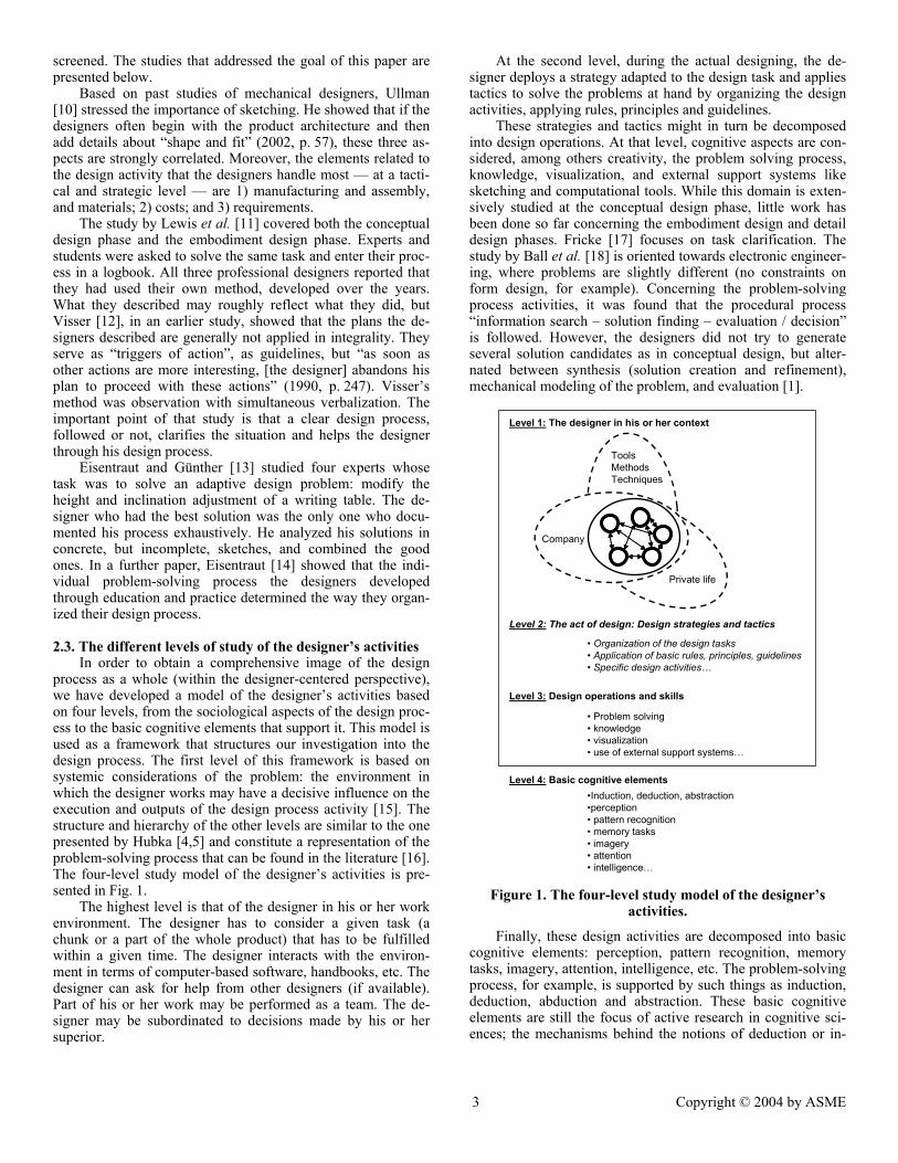
In order to obtain a comprehensive image of the design process as a whole (within the designer-centered perspective), we have developed a model of the designer’s activities based on four levels, from the sociological aspects of the design proc-ess to the basic cognitive elements that support it. This model is used as a framework that structures our investigation into the design process. The first level of this framework is based on systemic considerations of the problem: the environment in which the designer works may have a decisive influence on the execution and outputs of the design process activity [15]. The structure and hierarchy of the other levels are similar to the one presented by Hubka [4,5] and constitute a representation of the problem-solving process that can be found in the literature [16]. The four-level study model of the designer’s activities is pre-sented in Fig. 1.
The highest level is that of the designer in his or her work environment. The designer has to consider a given task (a chunk or a part of the whole product) that has to be fulfilled within a given time. The designer interacts with the environ-ment in terms of computer-based software, handbooks, etc. The designer can ask for help from other designers (if available). Part of his or her work may be performed as a team. The de-signer may be subordinated to decisions made by his or her superior.
At the second level, during the actual designing, the de-signer deploys a strategy adapted to the design task and applies tactics to solve the problems at hand by organizing the design activities, applying rules, principles and guidelines.
These strategies and tactics might in turn be decomposed into design operations. At that level, cognitive aspects are con-sidered, among others creativity, the problem solving process, knowledge, visualization, and external support systems like sketching and computational tools. While this domain is exten-sively studied at the conceptual design phase, little work has been done so far concerning the embodiment design and detail design phases. Fricke [17] focuses on task clarification. The study by Ball et al. [18] is oriented towards electronic engineer-ing, where problems are slightly different (no constraints on form design, for example). Concerning the problem-solving process activities, it was found that the procedural process “information search – solution finding – evaluation / decision” is followed. However, the designers did not try to generate several solution candidates as in conceptual design, but alter-nated between synthesis (solution creation and refinement), mechanical modeling of the problem, and evaluation [1].
Level 3: Design operations and skills
Level 1: The designer in his or her context
• Organization of the design tasks• Application of basic rules, principles, guidelines• Specific design activities…
Company
Private life
Tools MethodsTechniques
Level 4: Basic cognitive elements
• Problem solving• knowledge• visualization• use of external support systems…
•Induction, deduction, abstraction •perception• pattern recognition• memory tasks• imagery• attention• intelligence…
Level 2: The act of design: Design strategies and tactics
Figure 1. The four-level study model of the designer’s
activities.
Finally, these design activities are decomposed into basic cognitive elements: perception, pattern recognition, memory tasks, imagery, attention, intelligence, etc. The problem-solving process, for example, is supported by such things as induction, deduction, abduction and abstraction. These basic cognitive elements are still the focus of active research in cognitive sci-ences; the mechanisms behind the notions of deduction or in-
3 Copyright © 2004 by ASME

duction, for example, are still far from established (see Bisanz et al. [19] and Rips [20]). Note that these elements are not spe-cific to design activities. Moreover, the evolution of these basic elements is the result of a life-long process and can hardly be taught and changed in a simple and rapid manner. However, studies of the basic elements might reveal additional differ-ences between experts and novices, and they could also partly explain creativity. Studies concerning these basic cognitive activities are, for example, Lin & Wang [21], who studied ab-duction in an industrial design problem, and Kavakli & Gero [22,23], who analyzed sketching as a mental imagery process.
The level of elementary cognitive elements, which is the concern of the design theory field, is beyond the scope of the study reported here. Our study is limited to the three highest levels, of which this paper addresses the second level.
3. METHOD 3.1. Verbal Protocol Analysis (VPA)
VPA is a well-suited method for an in-depth study of hu-man-specific tasks and activities. VPA is based on the “think-aloud” technique. The subject is asked, during an experiment that varies from one to four hours, to think aloud, i.e. to de-scribe aloud what he or she is thinking while solving a design problem [24]. The experiment is recorded on videotape, the audio portion of which is later transcribed. The verbal protocol is then analyzed through a coding scheme, which is a set of categories that represent a cognitive activity or a basic design step. The coding scheme is developed based on former ones or, as with the interview technique (e.g. [25]), based on a pre-analysis of the verbal protocol that will iteratively lead to the discovery and organization of the categories. As in ethnogra-phy, the experimenter directly observes the design process. As designers are used to working alone at the later phases of the design process, the framework of a controlled experiment has a little influence on the design process itself. The design process is isolated from external factors, and hence the third and the fourth levels of activity are separated.
3.2. Description of the experiment procedure
The experiment procedure has been described elsewhere [1] and is only briefly summarized below.
The subjects selected for the experiments were three stu-dents and three experts (more than ten years of experience in mechanical design). The three students all came from Lund University, and have all followed the product development–mechanical design syllabus within mechanical engineering.
The experiment, for each of the subjects, lasted for two hours. Each experiment took place in an isolated room. The subject was face-to-face with an experimenter. To the left of the subject, a video camera, manipulated by a second experimenter, recorded the sequence, following the focus and the actions of the subject.
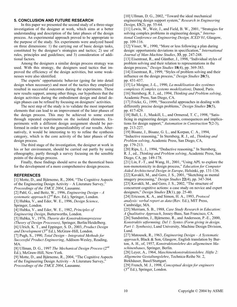
After a short exercise in practicing thinking aloud, the mis-sion statement was delivered to the designer. The subject had to design and dimension a support device for a hydraulic piston that had to be fixed to the ground. The piston, guided laterally, had to resist an axial force of 90 kN. Under the piston, an in-stallation was located on the ground. The support was to be located by the side of this installation (see Fig. 2). The specifi-cations of the piston were given in the assignment. This design task, then, was relatively well defined, and should correspond
to what can be expected from a similar case in industry. Inten-tionally, the form-giving aspect was not very complex, so that the subjects had time for both synthesis and dimensioning. The designers were expected to produce a final sketch of the techni-cal system. Finally, there was a short interview in which the subjects were asked to evaluate their design and the experi-ment.
The assignment has most of the characteristics of an em-bodiment and detail design task, in the sense that the designer has “to fulfill a given function with appropriate layout, compo-nent shapes and materials” ([2], p. 205). It takes into account most of the factors affecting embodiment design and detail design phases listed in Pahl & Beitz [2] (reported in Table 2). This ensures that the strategies and tactics deployed by the designers have a high probability of generalization. Experi-ments with a slightly different design task should nevertheless be carried out to confirm this point.
Hydraulic piston
1100
Hydraulic piston
Ground
450
400
F = 90 kN
Installation
Figure 2. Sketch of the problem delivered with the assignment [1]
3.3. The elements of the study From the literature review, three dimensions were consid-
ered important for the study of the designer’s second-level activities. First, we studied the design process itself by decom-posing the actual process into single steps. Then it was checked to see if the designer applied the basic rules (clarity, simplicity and safety), or any other principles or guidelines. Finally, we checked if the designer, during the design process, was aware of other factors concerning the product life cycle (e.g. produc-tion, transport, recycling). 3.3.1. The basic design tasks of the design process
Initially, a set of categories representing the basic design steps or tasks performed by the designer during the embodi-ment design and detail design phases was developed. These steps, or more precisely the way they appear and are structured during the experiments, serve as a basis for the analysis of the strategies and tactics applied during design. The categories are presented in Table 1.
4 Copyright © 2004 by ASME
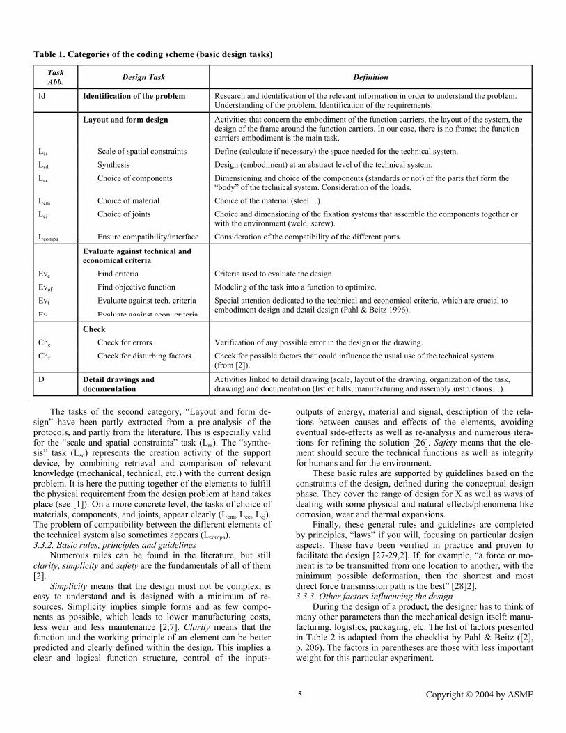
Table 1. Categories of the coding scheme (basic design tasks)
Task Abb. Design Task Definition
Id Identification of the problem Research and identification of the relevant information in order to understand the problem. Understanding of the problem. Identification of the requirements.
Layout and form design Activities that concern the embodiment of the function carriers, the layout of the system, the design of the frame around the function carriers. In our case, there is no frame; the function carriers embodiment is the main task.
Lss Scale of spatial constraints Define (calculate if necessary) the space needed for the technical system. Lsd Synthesis Design (embodiment) at an abstract level of the technical system. Lcc Choice of components Dimensioning and choice of the components (standards or not) of the parts that form the
“body” of the technical system. Consideration of the loads. Lcm Choice of material Choice of the material (steel…). Lcj Choice of joints Choice and dimensioning of the fixation systems that assemble the components together or
with the environment (weld, screw). Lcompa Ensure compatibility/interface Consideration of the compatibility of the different parts.
Evaluate against technical and economical criteria
Evc Find criteria Criteria used to evaluate the design. Evof Find objective function Modeling of the task into a function to optimize. Evt Evaluate against tech. criteria
Eve Evaluate against econ criteria
Special attention dedicated to the technical and economical criteria, which are crucial to embodiment design and detail design (Pahl & Beitz 1996).
Check Che Check for errors Verification of any possible error in the design or the drawing. Chf Check for disturbing factors Check for possible factors that could influence the usual use of the technical system
(from [2]).
D Detail drawings and documentation
Activities linked to detail drawing (scale, layout of the drawing, organization of the task, drawing) and documentation (list of bills, manufacturing and assembly instructions…).
The tasks of the second category, “Layout and form de-sign” have been partly extracted from a pre-analysis of the protocols, and partly from the literature. This is especially valid for the “scale and spatial constraints” task (Lss). The “synthe-sis” task (Lsd) represents the creation activity of the support device, by combining retrieval and comparison of relevant knowledge (mechanical, technical, etc.) with the current design problem. It is here the putting together of the elements to fulfill the physical requirement from the design problem at hand takes place (see [1]). On a more concrete level, the tasks of choice of materials, components, and joints, appear clearly (Lcm, Lcc, Lcj). The problem of compatibility between the different elements of the technical system also sometimes appears (Lcompa). 3.3.2. Basic rules, principles and guidelines
Numerous rules can be found in the literature, but still clarity, simplicity and safety are the fundamentals of all of them [2].
Simplicity means that the design must not be complex, is easy to understand and is designed with a minimum of re-sources. Simplicity implies simple forms and as few compo-nents as possible, which leads to lower manufacturing costs, less wear and less maintenance [2,7]. Clarity means that the function and the working principle of an element can be better predicted and clearly defined within the design. This implies a clear and logical function structure, control of the inputs-
outputs of energy, material and signal, description of the rela-tions between causes and effects of the elements, avoiding eventual side-effects as well as re-analysis and numerous itera-tions for refining the solution [26]. Safety means that the ele-ment should secure the technical functions as well as integrity for humans and for the environment.
These basic rules are supported by guidelines based on the constraints of the design, defined during the conceptual design phase. They cover the range of design for X as well as ways of dealing with some physical and natural effects/phenomena like corrosion, wear and thermal expansions.
Finally, these general rules and guidelines are completed by principles, “laws” if you will, focusing on particular design aspects. These have been verified in practice and proven to facilitate the design [27-29,2]. If, for example, “a force or mo-ment is to be transmitted from one location to another, with the minimum possible deformation, then the shortest and most direct force transmission path is the best” [28]2]. 3.3.3. Other factors influencing the design
During the design of a product, the designer has to think of many other parameters than the mechanical design itself: manu-facturing, logistics, packaging, etc. The list of factors presented in Table 2 is adapted from the checklist by Pahl & Beitz ([2], p. 206). The factors in parentheses are those with less important weight for this particular experiment.
5 Copyright © 2004 by ASME

Table 2. The factors influencing the design
Factors Description
Safety Component reliability Functional reliability Operational safety Operator safety Environment safety
(Ergonomics) Interaction with users Manufacturing / As-sembly
Manufacturing of the product Assembly of the product
(Quality control) Consideration of quality control during production
Transport Transport, packaging Operation Noise, vibration under operational state Recycling Recycling of the product (Maintenance) Easy maintenance of the product Costs Design costs
Production costs (Use costs)
(Dismantling) Dismantling of the product (Re-use) Re-use of the product Schedules Production launch
Delivery of the product
3.4. The protocol analysis process The verbal protocol was structured as shown in Table 3.
Apart from the dimensions described above (design tasks, use of rules, principles and guidelines, and consideration of addi-tional factors), attention was directed to the social behaviors that could bias the designer’s problem solving process. The next three columns are the protocol itself, written from the tapes, which concern the verbal exchange between the subject and the first experimenter and the subject’s actions and focus. The last column, “others”, contains remarks concerning the experiment and possible improvements that were reported dur-ing the experiment.
The analysis was executed concurrently by two analysts. The attribution of one category to one episode (one action) was subordinated to the acceptance of this category by both ana-lysts.
4. RESULTS AND DISCUSSION
Even under the conditions of a controlled experiment, the data collected are qualitatively very rich. The results: specific activities, the later phases of the design process, the strategies and tactics interpreted from the analysis of the protocols of the students and the experts among the different dimensions are presented in section 4.1. The quality of the results and the ex-periment is then discussed in section 4.2. Finally a synthesis of
the strategies, tactics but also weaknesses of the design proc-esses carried out by the designers are presented in section 4.3.
4.1. Analysis of the designers’ behavior
The three dimensions (1) design tasks, consisting of the de-signer’s strategies and tactics, 2) use of rules, principles and guidelines, and 3) consideration of additional factors) are suc-cessively analyzed. The contrast between experts and students helped to differentiate their respective behaviors. The experts and the students have been arbitrarily denoted as A, B, C and 1, 2, 3 respectively, corresponding to the order in which they carried out the experiment. 4.1.1. Description of the design processes
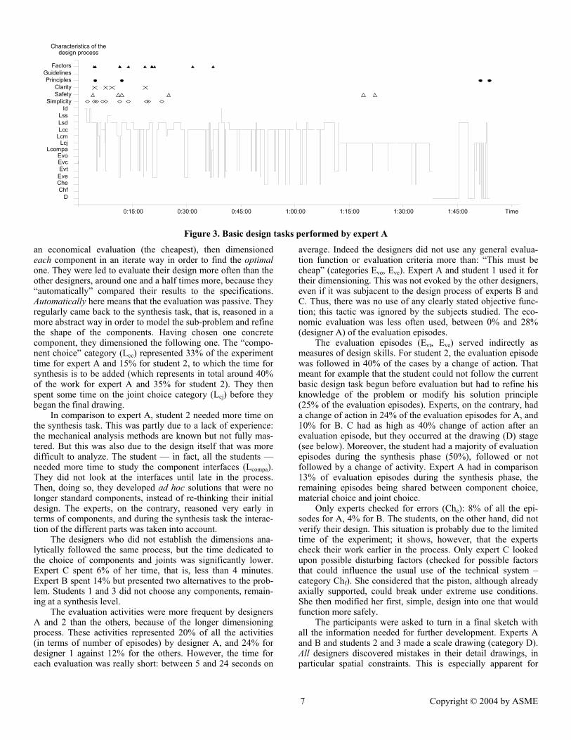
With the coding of the experiments, it was possible to rep-resent the design process of the designer through time. The design processes along the three dimensions used for this study are represented in Fig. 3 for expert A. This designer was chosen because his design process is representative of most of the designers studied.
The designers adopted different strategies: expert A and student 2 performed regular mechanical analyses, based on design principles, in order to establish the dimensions of the support, while the other experts established their dimensions purely on the basis of experience. The other two students did not embark upon dimensioning the support during the time of the experiment. Thus the time and energy dedicated to most design tasks varies greatly.
It did not take the designers long to understand the problem (category Id) — between 1½ and 3 minutes, regardless of the time they took to solve the problem. Most of this time was spent at the beginning of the task, but also occurred at different points throughout the task execution (these figures correspond to the accumulated spent time). Neither the students nor the experts asked questions beyond the scope of the actual task. They did not question the relevance of the task, the working environment of the technical system, nor the means of produc-tion; they just directly started working on the task assignment.
The solution principle chosen by the designers determined the time used for the second category, “scale of spatial con-straints”. Amazingly, all the experts designed a support device that had the shape of an arm taking the flexion created by the force (see Fig. 2), while the students preferred a solution that took the force directly, by means of a beam. Thus they needed to place it as near as possible to the equipment below the pis-ton. They had to come back several times to this activity and spent more time: experts A and B needed less than one minute and no iteration while the students needed several minutes and iterations, alternating with evaluation tasks. Designer C needed extra time when she changed her design for safety reasons (see section 4.1.2).
The designers who performed mechanical analysis in order to dimension their technical system had slightly the same pat-tern of behaviors (in order not to call it a strategy). They de-fined a rough layout by synthesis, chose the material based on
Table 3. Protocol table
Time Tasks in embodiment design and detail design
Basic Rules Principles Guidelines
Other factors considered
Social behavior Verbal protocol Motor
activities Focus Others
6 Copyright © 2004 by ASME
IdLssLsdLcc
LcmLcj
LcompaEvoEvcEvt
EveCheChf
D
Ola
0:15:00 0:30:00 0:45:00 1:00:00 1:15:00 1:30:00 1:45:00 Time
FactorsGuidelinesPrinciples
ClaritySafety
Simplicity
Characteristics of the design process
Figure 3. Basic design tasks performed by expert A
an economical evaluation (the cheapest), then dimensioned each component in an iterate way in order to find the optimal one. They were led to evaluate their design more often than the other designers, around one and a half times more, because they “automatically” compared their results to the specifications. Automatically here means that the evaluation was passive. They regularly came back to the synthesis task, that is, reasoned in a more abstract way in order to model the sub-problem and refine the shape of the components. Having chosen one concrete component, they dimensioned the following one. The “compo-nent choice” category (Lcc) represented 33% of the experiment time for expert A and 15% for student 2, to which the time for synthesis is to be added (which represents in total around 40% of the work for expert A and 35% for student 2). They then spent some time on the joint choice category (Lcj) before they began the final drawing.
In comparison to expert A, student 2 needed more time on the synthesis task. This was partly due to a lack of experience: the mechanical analysis methods are known but not fully mas-tered. But this was also due to the design itself that was more difficult to analyze. The student — in fact, all the students — needed more time to study the component interfaces (Lcompa). They did not look at the interfaces until late in the process. Then, doing so, they developed ad hoc solutions that were no longer standard components, instead of re-thinking their initial design. The experts, on the contrary, reasoned very early in terms of components, and during the synthesis task the interac-tion of the different parts was taken into account.
The designers who did not establish the dimensions ana-lytically followed the same process, but the time dedicated to the choice of components and joints was significantly lower. Expert C spent 6% of her time, that is, less than 4 minutes. Expert B spent 14% but presented two alternatives to the prob-lem. Students 1 and 3 did not choose any components, remain-ing at a synthesis level.
The evaluation activities were more frequent by designers A and 2 than the others, because of the longer dimensioning process. These activities represented 20% of all the activities (in terms of number of episodes) by designer A, and 24% for designer 1 against 12% for the others. However, the time for each evaluation was really short: between 5 and 24 seconds on
average. Indeed the designers did not use any general evalua-tion function or evaluation criteria more than: “This must be cheap” (categories Evo, Evc). Expert A and student 1 used it for their dimensioning. This was not evoked by the other designers, even if it was subjacent to the design process of experts B and C. Thus, there was no use of any clearly stated objective func-tion; this tactic was ignored by the subjects studied. The eco-nomic evaluation was less often used, between 0% and 28% (designer A) of the evaluation episodes.
The evaluation episodes (Evt, Eve) served indirectly as measures of design skills. For student 2, the evaluation episode was followed in 40% of the cases by a change of action. That meant for example that the student could not follow the current basic design task begun before evaluation but had to refine his knowledge of the problem or modify his solution principle (25% of the evaluation episodes). Experts, on the contrary, had a change of action in 24% of the evaluation episodes for A, and 10% for B. C had as high as 40% change of action after an evaluation episode, but they occurred at the drawing (D) stage (see below). Moreover, the student had a majority of evaluation episodes during the synthesis phase (50%), followed or not followed by a change of activity. Expert A had in comparison 13% of evaluation episodes during the synthesis phase, the remaining episodes being shared between component choice, material choice and joint choice.
Only experts checked for errors (Che): 8% of all the epi-sodes for A, 4% for B. The students, on the other hand, did not verify their design. This situation is probably due to the limited time of the experiment; it shows, however, that the experts check their work earlier in the process. Only expert C looked upon possible disturbing factors (checked for possible factors that could influence the usual use of the technical system – category Chf). She considered that the piston, although already axially supported, could break under extreme use conditions. She then modified her first, simple, design into one that would function more safely.
The participants were asked to turn in a final sketch with all the information needed for further development. Experts A and B and students 2 and 3 made a scale drawing (category D). All designers discovered mistakes in their detail drawings, in particular spatial constraints. This is especially apparent for
7 Copyright © 2004 by ASME

expert C, who began the scale drawing activity early in the process and went back and forth from synthesis to choice of components in order to fulfill “demands” illustrated in the drawing (which also explains the great number of changes of action after the evaluation episodes following the drawing ac-tivities). 4.1.2. Basic rules
The basic rules of simplicity, safety, clarity, were studied parallel to the single design process activities. As in the last section, the rules have been interpreted by the designers’ de-scriptions of their actions.
It is visible in the figures representing the design process for experts A and C and student 2 that the application of the basic rules occurs early in the process, and almost exclusively during the synthesis activity. This is when the designers de-velop the rough layout of the solution and give form to the parts. Expert C applied these rules at the end of the design process because of the need of refining the support device cre-ated by the final drawing activity. The students applied the rules in a somewhat more dispersed way, along with new in-sights of their designs.
Simplicity is, among other things, the use of standard com-ponents and simple forms. This has been fairly well understood by the students who began by trying to make their designs sim-ple at the beginning. Simplicity is mentioned by both experts and students on average 5 times per hour during the design process. But if there is a need of modification, the way the students proceed is by locally acting on the problem, and with-out applying the simplicity rule. This often led to the design of unique parts and complication of the overall design. The sim-plicity rule gave successful solutions on the experts’ side. The designs are minimalist, the need for manufacturing operation is very limited, and a majority of components are standardized.
The safety rule is used relatively more often by the experts than by the students (evoked on average 5 times per hour). Nevertheless, the students mostly considered component reli-ability, and sometimes the functional reliability, while 2 experts even considered the operator safety (chamfers to prevent injury during manipulation). Expert C paid attention to the functional safety: she took into account that the hydraulic cylinder could break under use and designed an additional support part to preclude this eventuality.
The clarity rule was the rule that the students applied least, and this made the greatest difference between the students and the experts. As a result, students’ designs were difficult to ana-lyze, and the force flows were difficult to establish. However, the experts did not apply it systematically either. Both experts A and C felt some difficulties with some particular elements of their design, but their first reaction was to try to analyze the problem in depth instead of searching for clearer solutions. They eventually did so, earlier than the students, but this shows that the rule of clarity, though powerful, is not a natural princi-ple. 4.1.3. Principles/Guidelines
The observation of the activities of the designer and of their designs served as the basis for the analysis of this dimen-sion.
The students more often applied principles and guidelines than the experts. They applied the principle of force transmis-sion (principle of uniform strength and principle of direct and
short force transmission path, [2], p 239-241) (a beam transmit-ted the force applied to the piston directly to the ground), and the principle of stability. Students 1 and 3 applied the principle of self-help: a second beam positioned symmetrically to the first prevented buckling. Nevertheless, if these solutions were clever on an abstract level, their embodiment was considerably more difficult. It resulted in complications in the product layout and form and in the design of the unique parts. The experts were more pragmatic in their approach and tried to apply prin-ciples only in concrete cases.
Student 2 was the only subject that used guidelines: one for the dimensioning of a beam with consideration of buckling and one for the calculation of welding joints. 4.1.4. Other factors
The subjects were considered to be taking care of factors other than those directly concerned, when they explicitly re-ferred to them: to choose between bolts or welding joints was an explicit reference to the factor “manufacturing/assembly”.
The factors “costs” and “manufacturing/assembly” were the ones most considered. The experts evoked them more often than did the students (8 times versus 4 times on average). Moreover, expert A thought about the possibility of disman-tling, while expert B thought about the durability of the prod-uct.
Amazingly, no one evoked the problem of transport (most of the designed support devices weighed more than 100 kg), of control, of maintenance or of recycling. This was perhaps of minor importance in the frame of this experiment, but it tends to show that factors other than “costs” and “manufactur-ing/assembly” are considered secondary by designers and are not yet fully and naturally integrated in the design process.
4.2. Quality of the results and of the experiments
The quality of the results concerns the reliability of the data, the reliability of the interpretation (the results presented in 4.1), and the validity of the results.
The reliability of the data depends on their collection and on the methods that are applied. The VPA method has been widely used in the field of cognitive psychology, and more than a hundred studies in mechanical engineering are based on it. Early experiments have shown that the think-aloud process has the side effect of slowing down the thinking process, but not its efficiency [24]. The data are then recorded on videotape, so there is no loss of data during collection.
The discontinuities that can be observed in the charts (see e.g. Fig. 3) correspond to events that occurred during the ex-periments and were not related to the design problem. The subject, for example, sometimes began a discussion with one of the experimenters on another subject than the design problem. This was often the first sign of fatigue and was a way of relax-ing. On other occasions, the designer felt himself obliged to justify why he or she had made a calculation error. Finally, some episodes could not be coded, because the designer re-mained silent for some time or was inaudible. These non-coded episodes represent 2%-3% of the total amount of episodes, that is, one or two episodes of each of the experiments. The discon-tinuities represent between 4.5% and 8.5% of the experiment time; thus they do not interfere with the subjects’ overall proc-ess of design.
8 Copyright © 2004 by ASME
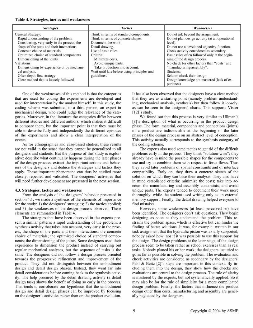
Table 4. Strategies, tactics and weaknesses
Strategies Tactics Weaknesses
General Strategy: Rapid understanding of the problem. Considering, very early in the process, the shape of the parts and their interactions. Concrete choice of materials. Optimized choice of standard components. Dimensioning of the joints.
Variations: Dimensioning by experience or by mechani-cal analysis. Often depth-first strategy. Clear method that is loosely followed.
Think in terms of standard components. Think in terms of concrete shapes. Document the work. Detail drawing. Use of basic rules. Criteria:
Minimize costs. Avoid unique parts. Take production into account.
Wait until late before using principles and guidelines.
Do not ask beyond the assignment. Do not plan design activity (at an operational level). Do not use a developed objective function. Check activity considered as secondary. Basic rules often followed only at the begin-ning of the design process. No check for other factors than “costs” and “manufacturing/assembly”. Students:Seldom check their design Design knowledge not mastered (lack of ex-perience)
One of the weaknesses of this method is that the categories
that are used for coding the experiments are developed and used for interpretation by the analyst himself. In this study, the coding scheme was submitted to a third person, an expert in mechanical design, who could judge the relevance of the cate-gories. Moreover, in the literature the categories differ between different studies and different authors, which makes it difficult to compare them, but the important point is that they must be able to describe fully and independently the different episodes of the experiments and allow a clear interpretation of the events.
As for ethnographies and case-based studies, these results are not valid in the sense that they cannot be generalized to all designers and students. But the purpose of this study is explor-ative: describe what continually happens during the later phases of the design process, extract the important actions and behav-iors of the designers and deduce the strategies and tactics they apply. These important phenomena can thus be studied more closely, repeated and validated. The designers’ activities that will need further development are presented in the next section.
4.3. Strategies, tactics and weaknesses
From the analysis of the designers’ behavior presented in section 4.1, we made a synthesis of the elements of importance for the study: 1) the designers’ strategies; 2) the tactics applied; and 3) the weaknesses of the design process observed. These elements are summarized in Table 4.
The strategies that have been observed in the experts pre-sent a similar pattern: a rapid understanding of the problem; a synthesis activity that takes into account, very early in the proc-ess, the shape of the parts and their interactions; the concrete choice of materials; the optimized choice of standard compo-nents; the dimensioning of the joints. Some designers used their experience to dimension the product instead of carrying out regular mechanical analyses, but the sequence of tasks is the same. The designers did not follow a design process oriented towards the progressive refinement and improvement of the product. They did not distinguish between the embodiment design and detail design phases. Instead, they went far into detail considerations before coming back to the synthesis activ-ity. The help procured by the detail drawing activity (a detail design task) shows the benefit of doing so early in the process. That tends to corroborate our hypothesis that the embodiment design and detail design phases can be improved by focusing on the designer’s activities rather than on the product evolution.
It has also been observed that the designers have a clear method that they use as a starting point (namely problem understand-ing, mechanical analysis, synthesis) but then follow it loosely, as can be seen in the designers’ charts. This supports Visser [12]’s study.
We found out that this process is very similar to Ullman’s [8]’s description of what is occurring in the product design phase. The form, material, components and connections (joints) of a product are indissociable at the beginning of the later phases of the design process on an abstract level of conception. This activity actually corresponds to the synthesis category of the coding scheme.
The experts also used some tactics to get rid of the difficult problems early in the process. They think “solution-wise”: they already have in mind the possible shapes for the components to use and try to combine them with respect to force flows. Thus they avoid later problems of spatial constraints and of interface compatibility. Early on, they draw a concrete sketch of the solution on which they can base their analysis. They also have in mind established criteria: minimize the costs; take into ac-count the manufacturing and assembly constraints; and avoid unique parts. The experts tended to document their work more thoroughly, while the student used writing only as an external memory support. Finally, the detail drawing helped everyone to find mistakes.
However, some weaknesses (at least perceived so) have been identified. The designers don’t ask questions. They begin designing as soon as they understand the problem. This re-strains the problem space, which is effective but can hinder the finding of better solutions. It was, for example, written in our task assignment that the hydraulic piston was axially supported; nobody asked how, nor if it was possible to use this support for the design. The design problems at the later stage of the design process seem to be taken rather as school exercises than as real tasks. Nobody planed his or her work; the designers just tried to go as far as possible in solving the problem. The evaluation and check activities are considered as secondary by the designers. Pahl & Beitz [2]’s steps are important in this context. By in-cluding them into the design, they show how the checks and evaluations are central to the design process. The rule of clarity is mastered by the experts, but not systematically applied. So it may also be for the rule of simplicity for a more complicated design problem. Finally, the factors that influence the product design other than costs, manufacturing and assembly are gener-ally neglected by the designers.
9 Copyright © 2004 by ASME
5. CONCLUSION AND FUTURE RESEARCH
In this paper we presented the second study of a three-stage investigation of the designer at work, which aims at a better understanding and description of the later phases of the design process. An experimental approach proved to be appropriate to the purpose of the study. Six experiments were analyzed based on three dimensions: 1) the carrying out of basic design tasks, constituted by the designer’s strategies and tactics; 2) use of rules, principles and guidelines; and 3) consideration of addi-tional factors.
Among the designers a similar design process strategy was used. With this strategy, the designers used tactics that im-proved the efficiency of the design activities, but some weak-nesses were also identified.
The experts’ opportunistic behavior (going far into detail design when necessary) and most of the tactics they employed resulted in successful outcomes during the experiments. These new results support, among other things, our hypothesis that the design activities during the embodiment design and detail de-sign phases can be refined by focusing on designers’ activities.
The next step of the study is to validate the most important elements that can lead to an improvement of the later phases of the design process. This may be achieved to some extent through repeated experiments on the isolated elements. Ex-periments with a different design assignment should be per-formed in order to test the generalizability of our results. Alter-natively, it would be interesting to try to refine the synthesis category, which is the core activity of the later phases of the design process.
The third stage of the investigation, the designer at work in his or her environment, should be carried out partly by using ethnography, partly through a survey focusing on the sensible points of the design process.
Finally, these findings should serve as the theoretical basis for the development of a more comprehensive design process.
REFERENCES [1] Motte, D., and Bjärnemo, R., 2004, “The Cognitive Aspects of the Engineering Design Activity – A Literature Survey,” Proceedings of the TMCE 2004, Lausanne. [2] Pahl, G., and Beitz, W., 1996, Engineering Design – A systematic approach (2nd Rev. Ed.), Springer, London. [3] Hubka, V., and Eder, W. E., 1996, Design Science, Springer, London. [4] Hubka, V., and Eder, W. E., 1982, Principles of Engineering Design, Butterworths, London. [5] Hubka, V., 1976, Theorie der Konstruktionsprozesse (Theory of Design Processes), Springer, Berlin/Heidelberg. [6] Ulrich, K. T., and Eppinger, S. D., 2003, Product Design and Development (3rd Ed.), McGraw-Hill, London. [7] Pugh, S., 1990, Total Design – Integrated Methods for Successful Product Engineering, Addison-Wesley, Reading, MA. [8] Ullman, D. G., 1997 The Mechanical Design Process (2nd Ed.), McGraw-Hill, New-York. [9] Motte, D., and Bjärnemo, R., 2004, “The Cognitive Aspects of the Engineering Design Activity – A Literature Survey,” Proceedings of the TMCE 2004, Lausanne.
[10] Ullman, D. G., 2002, “Toward the ideal mechanical engineering design support system,” Research in Engineering Design, 13(2), pp. 55-64. [11] Lewis, W., Weir, J., and Field, B. W., 2001, “Strategies for solving complex problems in engineering design,” Interna-tional Conference on Engineering Design, ICED’01, Glasgow, pp. 109-116. [12] Visser, W., 1990, “More or less following a plan during design: opportunistic deviations in specification,” International Journal of Man-Machine Studies, 33, pp. 247-248. [13] Eisentraut, R., and Günther, J., 1998, “Individual styles of problem solving and their relation to representations in the design process,” Design Studies 18(4), pp. 369-383. [14] Eisentraut, R., 1999, “Styles of problem solving and their influence on the design process,” Design Studies 20(5), pp. 431-437. [15] Le Moigne, J.-L., 1990, La modélisation des systèmes complexes (Complex systems modelization), Dunod, Paris. [16] Sternberg, R. J., ed., 1994, Thinking and Problem solving, Academic Press, San Diego, CA. [17] Fricke, G., 1999, “Successful approaches in dealing with differently precise design problems,” Design Studies 20(5), pp. 417-429. [18] Ball, L. J., Maskill, L., and Ormerod, T. C., 1998, “Satis-ficing in engineering design: causes, consequences and implica-tions for design support,” Automation in Construction 7(2-3), pp. 213-227. [19] Bisanz, J., Bisanz, G. L., and Korpan, C. A., 1994, “Inductive reasoning,” In Sternberg, R. J., ed., Thinking and Problem solving, Academic Press, San Diego, CA, pp. 179-213. [20] Rips, L. J., 1994, “Deductive reasoning,” In Sternberg, R. J., ed., Thinking and Problem solving, Academic Press, San Diego, CA, pp. 149-178. [21] Lin, F.-T., and Wang, H., 2001, “Using APL to explore the non-monotonicity in design process,” Education for Computer Aided Architectural Design in Europe, Helsinki, pp. 131-136. [22] Kavakli, M., and Gero, J. S., 2001, “Sketching as mental imagery processing,” Design Studies 22(4), pp. 347-364. [23] Kavakli, M., and Gero, J. S., 2002, “The structure of concurrent cognitive actions: a case study on novice and expert designers,” Design Studies 23(1), pp. 25-40. [24] Ericsson, K. A., and Simon, H. A., 1993, Protocol analysis: verbal report as data (Rev. Ed.), MIT Press, Cambridge, MA. [25] Merriam, S. B., 1988, Case Study Research in Education: A Qualitative Approach, Jossey-Bass, San Francisco, CA. [26] Sundström, J., Bjärnemo, R., and Andersson, P.-E., 2000, Konstruktiv utformning. Del 1: Syntes (Form giving in design. Part 1: Synthesis), Lund University, Machine Design Division, Lund. [27] Matousek, R., 1963, Engineering Design – A Systematic approach, Black & Son, Glasgow, English translation by Bur-ton, A. H., of, 1957, Konstruktionslehre des allgemeinen Ma-schinenbaues, Springer, Berlin. [28] Leyer, A., 1964, Maschinenkonstruktionslehre. Häfte 2: Allgemeine Gestaltungslehre, Technica-Reihe Nr. 2, Birkhäuser, Basel/Stuttgart. [29] French, M. J., 1998, Conceptual design for engineers (3rd Ed.), Springer, London.
10 Copyright © 2004 by ASME
Related Documents