Laser Ground System for Communication Experiments with ARTEMIS Volodymyr Kuzkov, Dmytro Volovyk, Sergii Kuzkov Laboratory for Laser Observations Main Astronomical Observatory of NAS of Ukraine Kyiv, Ukraine [email protected] Vincenzo Caramia Redu Space Services S.A. European Space Agency Redu, Belgium [email protected] Zoran Sodnik European Space Research and Technology Centre European Space Agency Noordwijk, the Netherlands [email protected] Sergii Pukha Special Design Bureau “Storm” National Technical University of Ukraine Kyiv, Ukraine [email protected] Abstract—The ARTEMIS satellite with the OPALE laser communication terminal onboard was launched on 12 July, 2001. 1789 laser communications sessions were performed between ARTEMIS and SPOT-4 (PASTEL) from 01 April 2003 to 09 January 2008 with total duration of 378 hours. Regular laser communication experiments between ESA’s Optical Ground Station (OGS) and ARTEMIS in various atmosphere conditions were also performed. The Japanese Space Agency (JAXA) launched the KIRARI (OICETS) satellite with a laser communication terminal called LUCE. Laser communication links between KIRARI and ARTEMIS were successfully realized and international laser communications experiments from the KIRARI satellite were also successfully performed with optical ground stations located in the USA (JPL), Spain (ESA OGS), Germany (DLR), and Japan (NICT). The German Space Agency (DLR) performed laser communication tests between two LEO satellites (TerraSAR-X and NFIRE), demonstrating data transfer rates of 5.6Gbit/s and also performed laser communication experiments between the satellites and ESA’s optical ground station. In 2002, the Main Astronomical Observatory (MAO) started the development of its own laser communication system to be installed into the Cassegrain focus of its 0.7m AZT-2 telescope, located in Kyiv. The work was supported by the National Space Agency of Ukraine and by ESA. MAO developed a precise tracking system for AZT-2 telescope (weighing more than 2 tons) using micro-step motors. The software developed for computerized telescope tracking of the ARTEMIS satellite’s orbit achieved a tracking accuracy of 0.6 arcsec. A compact instrument for Laser Atmosphere and Communication Experiments with Satellites (LACES) has been developed. The LACES instrument includes: A CMOS camera of the pointing subsystem, a CCD camera of the tracking subsystem, an avalanche photodiode receiver module with thermoelectric cooling, a laser transmitter module with thermoelectric temperature control, a tip/tilt atmospheric turbulence compensation subsystem with movable mirrors, a four-quadrant photo-detector, a bit error rate tester module and other optical and electronic components. The principal subsystems and optical elements are mounted on a platform (mass < 20kg), which is located in the Cassegrain focus of the telescope. All systems were tested with ARTEMIS. The telemetry and dump buffer information from OPALE received by the control center in Redu (Belgium) was analyzed. During the beacon scan, the acquisition phase of laser link between OPALE laser terminal of ARTEMIS and LACES laser terminal started and laser signals from AZT-2 were detected by acquisition and tracking CCD sensors of OPALE. Some of the tests were performed in cloudy conditions. A description of our laser ground system and the experimental results will be presented in the report. Keywords—optical ground station; laser communications; satellite tracking; acquisition; laser experiments; clouds I. INTRODUCTION Since launch of the first satellite optical telescopes have traditionally performed photometric and orbital position measurements. For many years ESA has been developing SILEX, the semiconductor laser inter-satellite communication experiment to demonstrate a pre-operational optical data-relay service between two satellites SPOT-4 and ARTEMIS. The laser communication terminals were named PASTEL and OPALE respectively and they performed the world-first inter-satellite laser communication link [1]. Starting in 1993, ESA also build an Optical Ground Station (OGS) to test and commission the SILEX terminals in space. Laser communication equipment was installed at the Coudé focus of its 1m Carl Zeiss telescope and laser communication experiments between the OGS and the ARTEMIS satellite in different atmosphere conditions were performed [2-6]. A laser communication terminal (named LUCE) had been tested at ESA’s OGS before it was launched onboard of KIRARI (OICETS) satellite [7,8]. Laser communication experiments from the KIRARI satellite were also successfully performed within an optical ground stations located in the U.S. (JPL), Spain (ESA OGS), Germany (DLR), and Japan (NICT) [9,10]. Proc. International Conference on Space Optical Systems and Applications (ICSOS) 2012, 3-2, Ajaccio, Corsica, France, October 9-12 (2012) Copyright (c) ICSOS 2012. All Rights Reserved.

Welcome message from author
This document is posted to help you gain knowledge. Please leave a comment to let me know what you think about it! Share it to your friends and learn new things together.
Transcript

Laser Ground System for Communication Experiments with ARTEMIS
Volodymyr Kuzkov, Dmytro Volovyk, Sergii KuzkovLaboratory for Laser Observations
Main Astronomical Observatory of NAS of UkraineKyiv, Ukraine
Vincenzo CaramiaRedu Space Services S.A.European Space Agency
Redu, [email protected]
Zoran SodnikEuropean Space Research and Technology Centre
European Space AgencyNoordwijk, the Netherlands
Sergii PukhaSpecial Design Bureau “Storm”
National Technical University of UkraineKyiv, Ukraine
Abstract—The ARTEMIS satellite with the OPALE laser communication terminal onboard was launched on 12 July, 2001. 1789 laser communications sessions were performed between ARTEMIS and SPOT-4 (PASTEL) from 01 April 2003 to 09 January 2008 with total duration of 378 hours. Regular laser communication experiments between ESA’s Optical Ground Station (OGS) and ARTEMIS in various atmosphere conditions were also performed. The Japanese Space Agency (JAXA) launched the KIRARI (OICETS) satellite with a laser communication terminal called LUCE. Laser communication links between KIRARI and ARTEMIS were successfully realized and international laser communications experiments from the KIRARI satellite were also successfully performed with optical ground stations located in the USA (JPL), Spain (ESA OGS), Germany (DLR), and Japan (NICT). The German Space Agency (DLR) performed laser communication tests between two LEO satellites (TerraSAR-X and NFIRE), demonstrating data transfer rates of 5.6Gbit/s and also performed laser communication experiments between the satellites and ESA’s optical ground station.
In 2002, the Main Astronomical Observatory (MAO) started the development of its own laser communication system to be installed into the Cassegrain focus of its 0.7m AZT-2 telescope, located in Kyiv. The work was supported by the National Space Agency of Ukraine and by ESA. MAO developed a precise tracking system for AZT-2 telescope (weighing more than 2 tons) using micro-step motors. The software developed for computerized telescope tracking of the ARTEMIS satellite’s orbit achieved a tracking accuracy of 0.6 arcsec. A compact instrument for Laser Atmosphere and Communication Experiments with Satellites (LACES) has been developed. The LACES instrument includes: A CMOS camera of the pointing subsystem, a CCD camera of the tracking subsystem, an avalanche photodiode receiver module with thermoelectric cooling, a laser transmitter module with thermoelectric temperature control, a tip/tilt atmospheric turbulence compensation subsystem with movable mirrors, a four-quadrant photo-detector, a bit error rate tester module and other optical and electronic components. The principal subsystems and optical elements are mounted on a platform (mass < 20kg), which is located in the Cassegrain focus
of the telescope. All systems were tested with ARTEMIS. The telemetry and dump buffer information from OPALE received by the control center in Redu (Belgium) was analyzed. During the beacon scan, the acquisition phase of laser link between OPALE laser terminal of ARTEMIS and LACES laser terminal started and laser signals from AZT-2 were detected by acquisition and tracking CCD sensors of OPALE. Some of the tests were performed in cloudy conditions. A description of our laser ground system and the experimental results will be presented in the report.
Keywords—optical ground station; laser communications; satellite tracking; acquisition; laser experiments; clouds
I. INTRODUCTION
Since launch of the first satellite optical telescopes have traditionally performed photometric and orbital position measurements.
For many years ESA has been developing SILEX, the semiconductor laser inter-satellite communication experiment to demonstrate a pre-operational optical data-relay service between two satellites SPOT-4 and ARTEMIS. The laser communication terminals were named PASTEL and OPALE respectively and they performed the world-first inter-satellite laser communication link [1]. Starting in 1993, ESA also build an Optical Ground Station (OGS) to test and commission the SILEX terminals in space. Laser communication equipment was installed at the Coudé focus of its 1m Carl Zeiss telescope and laser communication experiments between the OGS and the ARTEMIS satellite in different atmosphere conditions were performed [2-6].
A laser communication terminal (named LUCE) had been tested at ESA’s OGS before it was launched onboard of KIRARI (OICETS) satellite [7,8]. Laser communication experiments from the KIRARI satellite were also successfully performed within an optical ground stations located in the U.S. (JPL), Spain (ESA OGS), Germany (DLR), and Japan (NICT) [9,10].
Proc. International Conference on Space Optical Systems and Applications (ICSOS) 2012, 3-2, Ajaccio, Corsica, France, October 9-12 (2012)
Copyright (c) ICSOS 2012. All Rights Reserved.
The German Space Agency (DLR) and the Tesat-Spacecom developed space laser communication terminals using BPSK modulation [11], established laser communication links between LEO satellites TerraSAR-X and NFIRE (achieving data transfer rates of 5.6Gbit/s) [12] and performed laser communication experiments between the satellites and ESA’s OGS.
To reduce the influence of weather conditions on laser communication between satellites and ground stations, a network of optical ground stations situated in regions of uncorrelated climate and atmosphere conditions is required.
In 2001, the workgroup of the Main Astronomical Observatory of Ukraine (MAO) performed the first feasibility studies for join the laser communication experiments with the ARTEMIS satellite. A meeting took place in 2002, where the technical aspects were discussed with ESA and MAO started the development of its own laser communication system for the Cassegrain focus of its 0.7m AZT-2 telescope (Fe = 10.5m), located in Kyiv, 190 meters above sea level [13,14]. The interest was to compare the influence of the atmosphere in different climatic regions on laser beam transmission and the work was supported by the National Space Agency of Ukraine and by ESA.
Comparative investigations of atmospheric turbulence were carried out and a set of observations of stars in different positions of the sky was performed via AZT-2 of MAO and ESA’s OGS. Short exposures (40 ms) were taken with CCD cameras with appropriate filters were used [15]. The correlation between the components of the double star α Gem was also investigated. The value of an angular distance between the components (4.8") roughly corresponds to the point ahead angle for laser communications experiments with ARTEMIS [16].
II. MODEL OF TRACKING OF ARTEMIS SATELLITE
A. Characteristics of ARTEMIS Orbit
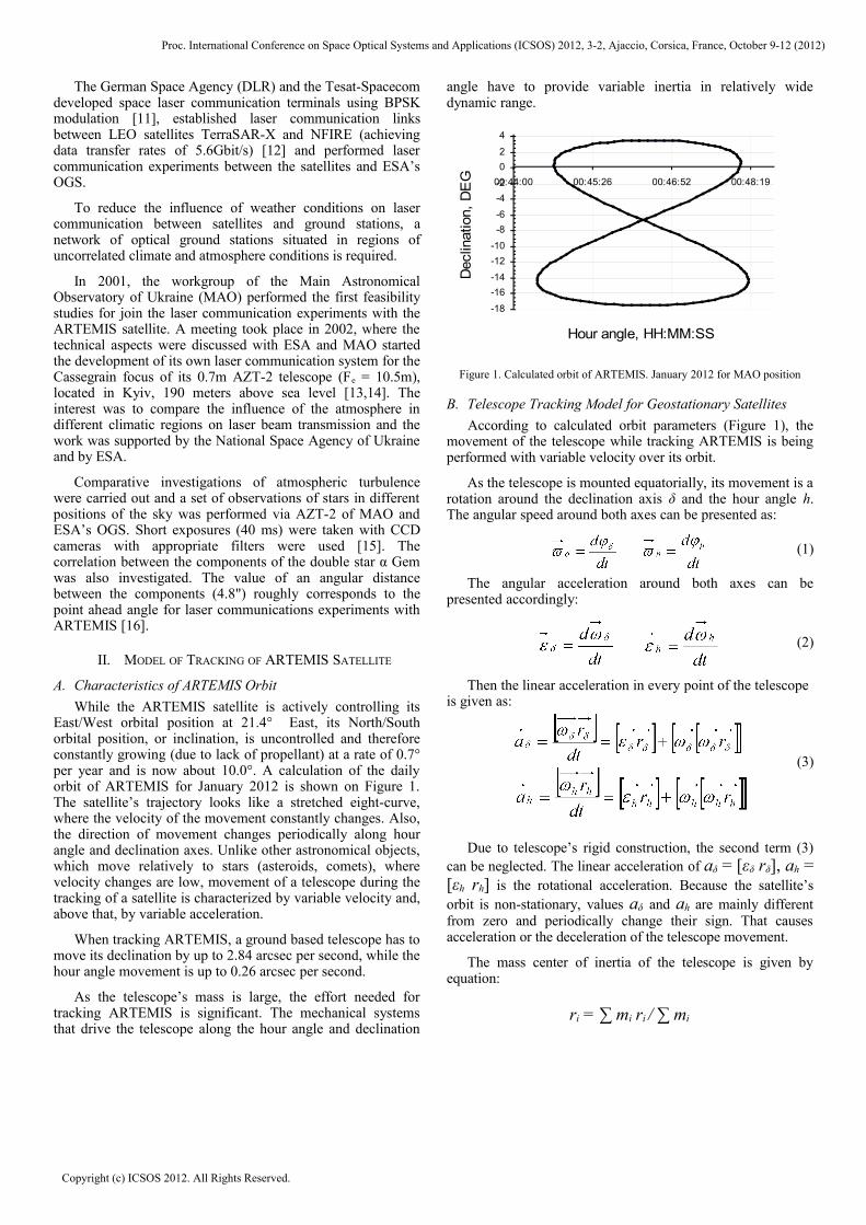
While the ARTEMIS satellite is actively controlling its East/West orbital position at 21.4° East, its North/South orbital position, or inclination, is uncontrolled and therefore constantly growing (due to lack of propellant) at a rate of 0.7° per year and is now about 10.0°. A calculation of the daily orbit of ARTEMIS for January 2012 is shown on Figure 1. The satellite’s trajectory looks like a stretched eight-curve, where the velocity of the movement constantly changes. Also, the direction of movement changes periodically along hour angle and declination axes. Unlike other astronomical objects, which move relatively to stars (asteroids, comets), where velocity changes are low, movement of a telescope during the tracking of a satellite is characterized by variable velocity and, above that, by variable acceleration.
When tracking ARTEMIS, a ground based telescope has to move its declination by up to 2.84 arcsec per second, while the hour angle movement is up to 0.26 arcsec per second.
As the telescope’s mass is large, the effort needed for tracking ARTEMIS is significant. The mechanical systems that drive the telescope along the hour angle and declination
angle have to provide variable inertia in relatively wide dynamic range.
-18
-16
-14
-12
-10
-8
-6
-4
-2
0
2
4
00:44:00 00:45:26 00:46:52 00:48:19
Hour angle, HH:MM:SS
Dec
linat
ion,
DE
G
Figure 1. Calculated orbit of ARTEMIS. January 2012 for MAO position
B. Telescope Tracking Model for Geostationary Satellites
According to calculated orbit parameters (Figure 1), the movement of the telescope while tracking ARTEMIS is being performed with variable velocity over its orbit.
As the telescope is mounted equatorially, its movement is a rotation around the declination axis δ and the hour angle h. The angular speed around both axes can be presented as:
(1)
The angular acceleration around both axes can be presented accordingly:
(2)
Then the linear acceleration in every point of the telescope is given as:
(3)
Due to telescope’s rigid construction, the second term (3) can be neglected. The linear acceleration of aδ = [εδ rδ], ah = [εh rh] is the rotational acceleration. Because the satellite’s orbit is non-stationary, values aδ and ah are mainly different from zero and periodically change their sign. That causes acceleration or the deceleration of the telescope movement.
The mass center of inertia of the telescope is given by equation:
ri = ∑ mi ri / ∑ mi
Proc. International Conference on Space Optical Systems and Applications (ICSOS) 2012, 3-2, Ajaccio, Corsica, France, October 9-12 (2012)
Copyright (c) ICSOS 2012. All Rights Reserved.

For each telescope the center of inertia is given by its particular design features. For AZT-2, it is considered that the main weight is concentrated in the nodes of the primary and secondary mirrors, while the tube’s weight is allocated proportionally over its entire length. Proceeding from this, the following assumptions are made: rδ ≈ 1m and mδ ≈ 1.1 tons. Taking into account that the mass of the counterweight of the telescope will take rh ≈ 1.5m and mh ≈ 2.2 tons.
According to calculated orbital parameters, the velocity of the coordinate movement varies in the range of 0 – 2.8 arcsec per second of time. Moments of force, externally applied to the axes of the telescope, are determined by the expression:
Mδ = mδ [rδ aδ] Mh = mh [rh ah] (4)
It is also necessary to take the moment of inertia into account. In case of ARTEMIS the following applies:
Jδ = (rδ)2 mδ Jh = (rh)2 mh (5)
According to orbital data the moment of inertia around the declination axis δ of the telescope reaches Jδ = 1.1×10³ m2 kg, and around the hour angle h reaches Jh = 4.95×10³ m2 kg.
For an accurate tracking of ARTEMIS the angular momentum of the tracking motors must significantly exceed the values defined by (4). During satellite tracking the moments of inertia of the telescope around its axes (5) must also be taken into account.
III. POINTING AND TRACKING SUBSYSTEMS
A. Remote Computer Control of the Telescope
ARTEMIS has an orbital position of 21.4º East and its orbital inclination is currently 10.0º. A precise tracking system for AZT-2 telescope, which uses micro-step motor and a special correction module, has been constructed (Figure 2). The stepper motors work in the micro-step mode and the signals for the stepper motors are generated by microprocessor located in the correction module. The stepper motor resolution is 0.0003 arcsec per second and the range of speed correction can be varied from 0 to 4 arcsec per second. The correction module is located beside the telescope. The correction speed can be specified directly by the correction module or remotely by using special software via RS-485 interface.
An overview of the remote control scheme of the telescope and of the tracking equipment is shown in Figure 2.
All computers are connected in a local area network via Ethernet 100 Base-TX and via a ZyXEL Ethernet 100 Base-FX switch to the head office server that has external bandwidth of 10 Gbps.
Figure 2. Scheme of remote control of the telescope and tracking equipment
Computer 1 performs the remote control of Computer 3. Computer 2 is connected to a TV CCD camera via a monitor and it also serves as NTP time server. The TV CCD is attached to the guide telescope, while computer 3 operates all other CCD cameras that are attached to the main telescope. Computer 1 is also connected to the Correction Module via USB/RS485 interface and performs programming control of hour angle and declination (h, δ ) step motors. Special software provides computer control of the telescope and performs all necessary calculations of orbit data. For this purpose, the geocentric elements of orbit are used. The average precision of the h, δ coordinate calculations is in the order of several arc seconds.
B. Pointing and Tracking Subsystems
For pointing and tracking of the satellite two digital cameras are implemented into the technology platform. They are connected to the Cassegrain focus of AZT-2 telescope and a computer correction system is activated before the satellite is detected.
An acquisition camera works with a focal reducer (focal length reduction from 10m to 5m) and has a CMOS sensor with 2000x3000 pixels. The camera’s field of view is 10.6x16 arcmin and it can operate with time exposure times from 1/1000 up to 30 seconds and more. The focal reducer for the Cassegrain focus was constructed and integrated into the technology platform. Figure 3 shows a fragment of the camera image of ARTEMIS together with star trails.
Proc. International Conference on Space Optical Systems and Applications (ICSOS) 2012, 3-2, Ajaccio, Corsica, France, October 9-12 (2012)
Copyright (c) ICSOS 2012. All Rights Reserved.

As the primary mechanical pointing accuracy of the telescope in hour angle and declination (h, δ) is 2 arcmin, this camera is used for initial search of the satellite.
Figure 3. Image of ARTEMIS and star tracks during of pointing
Another small digital (CCD 2) camera (16 bit ADC) for satellite tracking works without a focal reducer. CCD2 has a thermoelectric cooling of its sensor (596x795 pixels with pixel size 8.3 µm x 8.6 µm), its field of view is 1.6x2.3 arcmin, the noise level is 0.02 e-/ pixel/second and exposures are from 1/1000 second up to several hours.
After the image is placed into the center of CCD1 camera, it is intercepted by CCD2. Both cameras can be operated remotely via USB interface. Testing of the first camera pointing system was carried out on various astronomical objects (satellites, faint stars). The test results showed that the sensitivity of the CCD1 camera is about 17th stellar magnitude with a signal/noise ratio equal to 2 and a 30 second exposure. The sensitivity is limited by the sky background, but not by camera noises. Figure 4 shows an image of ARTEMIS (in reflected sunlight).
Figure. 4. Tracking of ARTEMIS in reflected sunlight
Figure 5 shows the angular distribution of ARTEMIS beacon detections during the first beacon scan. The mean angular deviation of the beacon is X(h) = 0.56 arcsec and Y(δ) = 0.69 arcsec.
-3
-2
-1
0
1
2
3
-3 -2 -1 0 1 2 3
Deviation X, arc sec
De
via
tion
Y, a
rc s
ec
Figure 5. Deviation of position of ARTEMIS during the first beacon scan. Photometric centers of 236 images from 22:00 UTC. August 11, 2008
IV. LASER TERMINAL FOR CASSEGRAIN FOCUS
AZT-2 is a reflector-type telescope. The primary telescope mirror has a diameter of 700 mm and the diameter of secondary hyperbolic mirror of the Cassegrain system is 215 mm. The effective focal length is 10500 mm. The telescope is equipped with a refractive guide telescope with an aperture diameter of 200 mm and a focal length of 2500 mm. A compact terminal for Laser Atmosphere and Communication Experiments with Satellite (LACES) has been developed and the main components of LACES were implemented into a technology platform connected to Cassegrain focus. An addition moving platform near the telescope is used for electronic equipment [17,18].
The technological platform as connected to the telescope’s Cassegrain focus is shown in Figure 6.
Figure 6. AZT-2 telescope with technological platform in its Cassegrain focus
A. Optical Design of the LACES Terminal
Basic elements of the optical and mechanical design are shown in Figure 7. CCD1 camera with a focal reducer (FR) is part of the pointing subsystem, while CCD2 is a part of tracking subsystem. A movable mirror (MM) switches the beam coming from the telescope between the pointing and tracking cameras. The focal length of L4 is f = 100 mm.
Proc. International Conference on Space Optical Systems and Applications (ICSOS) 2012, 3-2, Ajaccio, Corsica, France, October 9-12 (2012)
Copyright (c) ICSOS 2012. All Rights Reserved.

Figure 7. Optical scheme of LACES terminal
The beam splitter BS3 is a mirror diaphragm with a small hole in its centre that is equivalent to the field of view on the sky of 40 arcsec. CCD3 camera is used for acquisition purposes, while CCDS is a supporting camera used for adjustment. QPD is a quadrant photo-detector module. LD is a laser diode module, APD is an avalanche photodetector module and FPM is a fine pointing mirror module. BS1, BS4, BS5 are beam splitters, BS2 is a beam splitter with a laser optical isolation function, L1, L2, L3, L4, L5, L6, L7 are lenses and F1, F2, F3, F4 are filters.
B. Avalanche Photodiode Receiver with Thermoelectric Cooling
According to our calculations and data provided by ESA, the power density of a laser communication signal coming from the satellite to the Earth's surface (taking into account the standard absorption in the atmosphere at an angle of 60°) is about 35 nW/m2 in a spectral range of 816 to 823 nm. The downlink data transmission rate is 2.048 Mbps.
The receiver module is implemented into the technology platform. It uses an avalanche photo detector (APD) cooled to a temperature of 4 °C and low noise electronic amplifiers. The sensitivity of APD system is 0.15 nW in a bandwidth of 8 MHz [14]. Deeper cooling allows reducing the noise of the detector and improves the threshold characteristics for the receiving system.
C. Laser Transmitting Module
The laser transmitter system aiming the ARTEMIS from the ground requires a modulation data rate of 49.392 Mbit/s in a spectral range of 843 – 852 nm, ensuring a radiant flux density of more than 90 nW/m2 at the geostationary satellite.
The laser transmitting system uses a laser diode module that is thermoelectrically stabilized within an external temperature range between –5° and +30 °C. The laser power is
150 mW and its wavelength is 851 nm. The wavelength can be tuned by changing the stabilization temperature and laser modulation is possible with data rates up to 50 Mbps. An electronic module for power and thermoelectric stabilization is located outside of the technology platform. We use a thermoelectric cooler with a maximum thermal power equal to 33.3 W for rapid cooling of the laser. The laser module and the electronic module for power and temperature stabilization are presented in Figure 8.
To transform the linear polarisation of the laser module into left hand circular polarisation (LHCP) we use a λ/4 wave plate, which is achromatic in 840 – 855 nm range. The measured polarisation of our laser beam is 98.2% LHCP.
Figure 8. Laser module and electronic module of power and temperature
stabilization
Direct measurements of the intensity of the left hand circular polarisation of laser beam were performed by rotating polarizer. The results are presented in Figure 9. “I” is the intensity on photodetector.
Dep.Ratio = P(RHCP)/P(LHCP). Our Dep.Ratio = 0.017 or 1.7 %. According to the specification of OPALE, Dep.Ratio has to be less than 2.5 %.
Proc. International Conference on Space Optical Systems and Applications (ICSOS) 2012, 3-2, Ajaccio, Corsica, France, October 9-12 (2012)
Copyright (c) ICSOS 2012. All Rights Reserved.

7,55
7,56
7,57
7,58
7,59
7,6
0 100 200 300
Angle, deg
ln (
I) P
D
Figure 9. Deviations of circular polarization
D. Fine Pointing and Atmosphere Turbulence Compensation Subsystem
The system for fine pointing and turbulence compensation consists of multi-element photodetector (QPD) module, a fast pointing mirror (FPM) and an electronic module for precise pointing and turbulence compensation. The compact QPD module includes the multi-element photodetector, preamplifiers and differential amplifiers. The electronic module includes a power source, biasing schemes and amplifiers (Figure 10, 11, 12). The biaxial fast moving mirror is equipped with electromagnetic drives.
Figure 10. Scheme of multi-element photodetector
Figure 11. Multi-element photodetector, QPD module and Electronic module
Figure 12. Biaxial fast moving mirror module
E. Bit Error Testing Module
To generate 49.3724 Mbps, two microcircuits were purchased. First one was a 100 MHz oscillator with temperature stability < 5 ppm in range from –10 °C to +60 °C, second one was a digital synthesizer. Using these components we achieve the required bit rate of 49.3724 Mbps. Figure 13 shows the design of the modulation PRBS-15 (Pseudo Random Bit Sequence) for 215–1 coding and BER testing system at 2.048 Mbps.
Figure 13. Scheme of modulation 49.3724 Mbps, PRBS-15 for 215–1 coding and BER testing system at 2.048 Mbps
The measured frequency is 49372320 Hz and the deviation from the nominal frequency is 80 Hz, which is equivalent to 1.6 ppm and acceptable for the communication link. The BER testing scheme for receiving and testing of 2.048 Mbps laser signals from OPALE is located in the same electronics box (Figure 14).
Figure 14. Electronic module for PRBS-15 modulation and BER testing
Proc. International Conference on Space Optical Systems and Applications (ICSOS) 2012, 3-2, Ajaccio, Corsica, France, October 9-12 (2012)
Copyright (c) ICSOS 2012. All Rights Reserved.

V. THE ACQUISITION PHASE
A. OPALE Beacon Test. Photometric Beacon Data
The acquisition scenario consists of the following steps:
• OPALE points its telescope towards the optical ground station (MAO OGS).
• OGS starts tracking the ARTEMIS satellite.
• OPALE beacon starts scanning its uncertainty cone and upon detection by the OGS, the OGS points its laser beam towards OPALE.
• If the laser beam from OGS is received by OPALE within 0.75 seconds and if the received signal exceeds the detection threshold on the OPALE acquisition sensor, OPALE stops its beacon scan and acquisition is accomplished.
• During a period of 27 seconds after acquisition phase starts, OPALE and OGS keep centering their telescopes on the targets after which communication starts.
At a programmed time the OPALE beacon starts the scan. Scan is performed spirally twice (3m16s+3m16s) during each session. Two beacon scans for November 8, 2009, 21 UTC were recorded. The brightness of ARTEMIS (in stellar magnitudes) during the first scan is shown in Figure 15. The first maximum of beacon signal was received 15 seconds after the beacon was turned on. The second maximum was seen 19 seconds after the beacon was turned on. The same scenario repeated during the second scan after 3 minutes.
We started the observation of ARTEMIS before the start of the beacon scan with 0.05 second exposure and observed bright beacon peaks and small peaks when the beacon passed overhead. We could see the images of ARTEMIS during the whole scan, as well as before and after the beacon was turned on.
The ARTEMIS beacon beam divergence is 750 μrad, which makes the diameter of the beacon beam on the Earth’s surface at a distance of 38000 km to 28.5 km.
0
2
4
6
8
10
12
14
1 21 41 61 81 101 121 141 161 181 201 221
Images, exp.0.05 s, cycle 0.75 s
Sta
r m
ag
nitu
de
, m
Figure 15. Brightness of ARTEMIS in stellar magnitudes
The power density of the OPALE beacon on the ground is, approximately, 6 nW/m2 [4]. Our estimation of the maximum power of beacon signal on the tracking CCD is 2 nW. From known stellar magnitudes, it is possible to calculate the beacon signal level during the whole scan period. Before the beacon was turned on, the photometric brightness of ARTEMIS (in reflected sunlight) was 3.4×10⁻⁵ nW, while when the beacon was turned on the brightness increased to 1.3×10⁻³ nW. When the beacon passed across our observatory the brightness increased up to 2 nW.
Figure 16 shows the brightness of the beacon during the first scan. We also could see similar beacon peaks of lower brightness when the beacon was close to us.
Figure 16. Brightness of ARTEMIS during a single beacon scan
B. OPALE Telemetry Analysis
The telemetry and the dump buffer information from OPALE received by Redu control center were analyzed. It was shown that the acquisition phase between OPALE and LACES laser terminal had started. Laser signals from AZT-2 were detected by the acquisition and tracking sensors of OPALE. The “OPALE DUMP ANALYSIS TOOL” and “ODR DATA FROM PTL TO OGS” were used.
We performed a basic analysis for the Session #3 of 11 August 2010. Using “OPALE DUMP ANALYSIS TOOL, MAO, Kiev, TEST SESSION-3, 22:00 UTC 11, August 2010” file that was obtained from Redu station and we performed an analysis of ASVMAX signal of the OPALE acquisition sensor.
The ASVMAX signal has 256 levels. Its input threshold for registration is 16 levels. The time distribution of the signal is presented in Figure 16.
After the beacon scan stopped, OPALE and MAO OGS kept centering their telescopes on the targets. The maximum signal was achieved on level #26 which is equal to 0.204 V or 10% of maximum level on acquisition sensor.
Proc. International Conference on Space Optical Systems and Applications (ICSOS) 2012, 3-2, Ajaccio, Corsica, France, October 9-12 (2012)
Copyright (c) ICSOS 2012. All Rights Reserved.

16
17
18
19
20
21
22
23
24
25
26
27
70 80 90 100 110 120 130 140 150 160 170 180 190 200 210 220 230 240 250 260 270 280 290 300
Time, seconds
Inte
nsity x
0.0
0784, V
Figure 17. Distribution of ASVMAX signal in time
Figure 17 shows 9 OPALE detections and thus attempts to complete the acquisition phase and to start the tracking phase. The duration of the fourth set is 4.84 s. The tracking errors took place when OPALE and MAO OGS attempted to center their telescopes on each other. The telemetry file “ODR DATA FROM PTL TO OGS 20100811 Session3” contains the signal levels at the OPALE tracking sensor. OPALE uses a tracking chip with 14×14 pixels and tracks on the four central pixels of the tracking sensor area in a quadrant sensor type fashion. The signal obtained from these four pixels is equal to G299-G302 parameters of the telemetry file. The G800-G803 parameters are equal to peripheral pixels of tracking sensor and they measure the background signal. According to telemetry data, background level was 0.09412 V during the session and the maximum signal on tracking sensor was 0.10980 V, which exceeds background level 1.17 times.
VI. TESTS IN CLOUDY CONDITIONS
As laser link sessions have to be programmed at least one week in advance it is quite difficult to get precise weather forecast. Usually, we calculate the ARTEMIS ephemeris, enter the data into computer and perform a programmed tracking of the satellite before, during and some time after the sessions. In cloudy weather conditions, we make a call to Redu station and stop the onboard program to save resources on the satellite.
During the sessions of 26 October 2011 (19:00 UTC, 20:00 UTC, 21:00 UTC) the sky was partly clouded. Weather conditions were unstable and we recorded these sessions automatically but we thought they were unsuccessful. Some weeks later we were browsing the images of those sessions and found that the beacon was visible through clouds.
A row of images taken with 2s exposure and 2x2 pixel binning is presented in Figure 18. The first image “art3253” (session 20:00 UTC) was obtained at 23h 00m 04s (local time), after which the cloudy conditions started.
The first beacon peak (file“art3307”) was observed through the clouds at 23h 03m 37s, the second one could be seen 5s later.
The sky clouded over completely after that. The set of images was calculated by Maxim DL Pro 5 software.
The satellite’s camera positions (file “art3253”) before the cloudy period are: X = 198.182 pixels, Y = 146.062 pixels. Beacon positions (“art3308”) are: X = 167.272 pixels, Y = 146.268 pixels. The difference between the positions is: ΔX = 30.91 pixels × 0.169 = 5.22 arcsec, ΔY = 0.206 pixels × 0.163 = 0.034 arcsec.
Figure 18. Images of OPALE beacon through the clouds
The results of the photometry measurements of “art3253” file show that ARTEMIS has 11.757 stellar magnitudes while beacon in cloudy conditions has 6.753 stellar magnitudes. The difference between intensities is about 5 stellar magnitudes or, approximately, 102 times. It can be seen from Figure 16, that the difference of intensity between sun reflected light from the satellite and the beacon in normal weather conditions is approximately 105. As the result, the attenuation of beacon caused by clouds was equal to 103.
By this means, it is possible to observe the beacon through the clouds and, accordingly, laser communication link through thin clouds can also be established. A simple way to improve the link quality in cloudy weather conditions is increasing of laser power and decreasing of noise of receiving detector.
Proc. International Conference on Space Optical Systems and Applications (ICSOS) 2012, 3-2, Ajaccio, Corsica, France, October 9-12 (2012)
Copyright (c) ICSOS 2012. All Rights Reserved.

Figure 19. Photometric measurements of the beacon
Receiving electronic circuits usually have noises of passive and active elements. These noises ordinarily can be reduced by cooling. There are different types of noises (a thermal noise, a flicker noise, a noise caused by semiconductor defects and others), but only thermal noise is unavoidable. It is proportional to a square root of a temperature and frequency band. Cooling of receiving detector from 273 K to 77 K causes a reduction of thermal noise in 1.88 times. Cooling from 273 K to 4.2 K leads to reducing in 8.1 times. By using additional increasing of laser power from 150 mW to 1.5 W one can reduce the influence of clouds on laser communication in 81 times. At low temperatures superconducting detectors can also be used [19, 20].
VII. CONCLUSIONS
A laser communication system was developed for space to ground laser communication experiments between the ARTEMIS satellite and an Optical Ground Station in Kyiv. Key elements of the system were implemented into the technology platform located at the Cassegrain focus of its 0.7m astronomical telescope. A precise telescope tracking system was developed. Laser acquisition experiments with the ARTEMIS satellite were performed. Beacon laser signals from the OPALE terminal onboard ARTEMIS were observed through clouds. The attenuation of the beacon caused by clouds was equal to 103. To reduce the influence of the atmosphere on space to ground laser communication links one needs to reduce the noise of the receiver by additional cooling of the detector and in addition increasing of laser transmitting power is required.
ACKNOWLEDGEMENT
We appreciate ESA, ESTEC and Redu Station for their support and for the possibilities to perform experiments with ARTEMIS satellite. We also thank National Space Agency of Ukraine for financial support during laser system development.
REFERENCES
[1] Tolker-Nielsen T., Oppenhauser G., “In-orbit test result of an operational optical inter satellite link between ARTEMIS and SPOT4, SILEX”. ,Proc. SPIE, 2002, vol. 4635, pp.1–15.
[2] Reyes M., Sodnik Z., Lopez P., Alonso A., Viera T., Oppenhauser G., “Preliminary results of the in-orbit test of ARTEMIS with the Optical Ground Station”, Proc. SPIE, 2002, vol. 4635, pp. 38–49.
[3] Alonso A, Reyes M, Sodnik Z.,“Performance of satellite-to-ground communications link between ARTEMIS and the Optical Ground Station”, Proc. SPIE, 2004, vol. 5572, p. 372.
[4] Jose Romba, Zoran Sodnik, Marcos Reyes, Angel Alonso, Aneurin Bird, “ESA’s Bidirectional Space-to-Ground Laser Communication Experiments”. Proc. SPIE, 2004 , vol. 5550, pp. 287- 298.
[5] M. Reyes, A. Alonso., S. Chueca, J. Fuensalida, Z. Sodnik, V. Cessa, A. Bird, “Ground to space optical communication characterization”, Proc. SPIE, 2005, vol. 5892, pp. 589202-1– 589202-16.
[6] Zoran Sodnik, Bernhard Furch, Hanspeter Lutz., “The ESA Optical Ground Station – Ten Years Since First Light”, ESA bulletin 132, November 2007, pp. 34 – 40.
[7] Toyoshima M., Yamakawa S.,Yamawaki T., Arai K., Reyes M., Alonso A., Sodnik Z., Demelenne B., “Ground-to-satellite optical link tests between the Japanese laser communication terminal and the European geostationary satellite ARTEMIS”, Proc. SPIE, 2004, vol. 5338A.
[8] M. Toyoshima, S. Yamakawa, T. Yamawaki, K. Arai, M. Reyes, A. Alonso, Z. Sodnik, and B. Demelenne, “Long-term statistics of laser beam propagation in an optical ground-to-geostationary satellite communications link,” IEEE Trans. on Antennas and Propagation, 2005, vol. 53, no. 2, pp. 842–850.
[9] T. Jono, Y. Takayama, N. Kura, K. Ohinata, Y. Koyama, K. Shiratama, Z. Sodnik, B. Demelenne, A. Bird, and K. Arai, “OICETS on-orbit laser communication experiments,” Proc. SPIE, 2006, vol. 6105, pp. 13–23.
[10] M. Toyoshima, H. Takenaka, C. Schaefer, N. Miyashita, Y. Shoji, Y. Takayama, Y. Koyama, H. Kunimori, S. Yamakawa, and E. Okamoto, “Results from phase-4 Kirari optical communication demonstration experiments with the NICT optical ground station (KODEN),” 26th International Communications Satellite Systems Conference of AIAA, AIAA-2009-3.4.2, Edinburgh, June 2009.
[11] Lange R., Smutny B., “Homodyne BPSK-based optical inter-satellite communication links”, Proc. SPIE, 2007, Vol. 6457, p. 645703.
[12] Smutny B., Kaempfner H., Muehlnikel G., et al, “5.6 Gbps optical inter-satellite communication link” Proc. of SPIE, 2009, Vol. 7199, p.719906
[13] Kuz'kov V.P., Peretyatko N.N, Medvedskii M.M., Suberlyak V.R., Glushchenko Yu.M.,Yatskiv D.Ya., Eremenko N.A.,Nedashkovsky V.N “Preparation for optical Communication Experiments with ARTEMIS satellite. (Satellite as a guide star)”, Poster. NATO/ASI Summer School "Optics in Astrophysics", Cargase, France, Sept. 15-27, 2002.
[14] Kuz’kov V.P., Nedashkovskii V.N. “A Receiver with an Avalanche Photodiode for the Optical Communication Channel from a Geostationary Satellite”, Instruments and Experimental Techniques, 2004, vol. 47, n. 4, pp. 513–515.
[15] Vladimir Kuz'kov, Vitaliy Andruk, Yuri Sizonenko, Zoran Sodnik. “Investigation of Atmospheric Instability for Communication Experiments with ESA's Geostationary Satellite ARTEMIS”. Kinematics and Physics of Celestial Bodies, Supl., 2005, n 5, pp. 561-565.
[16] Kuz’kov V., Andruk V., Sodnik Z., Sizonenko Yu., Kuz’kov S. “Investigating the correlation between the motions of the images of close stars for laser communications experiments with the Artemis satellite”, Kinematics and Physics of Celestial Bodies. 2008, vol. 24, Issue 1, p. 56 – 62.
[17] V.Kuz’kov, Z.Sodnik, S.Kuz’kov, D.Volovyk, S.Pukha, ”Laser communication experiments with a geostationary satellite from a ground telescope”, Space Science and Technology (ISSN 1561-8889), 2008, vol. 14, n 2, pp. 51-55.
[18] Kuz’kov V., Volovyk D., Kuzkov S., Sodnik Z., Pukha S. “Realization of laser experiments with ESA’s geostationary satellite ARTEMIS”, Space Science and Technology (ISSN 1561-8889), 2010, vol. 16, n. 2, pp. 65-69.
[19] Kuz'kov V.P., Kudelja A.M., Larkin S.Y. “Multichannel System for Infrared and MM Wave Synchronized Observations”. Proc. ESA Symp. "The Far Infrared and Submilimetre Universe", Grenoble, France, April 1997, p.293 – 296.
[20] N. Rando, S. Andersson, B. Collaudin*, F. Favata, P. Gondoin, A. Peacock, M. Perryman, J. Verveer, “S-Cam: A Technology Demonstrator for the Astronomy of the Future”, ESA bulletin n. 98, June 1999.
Proc. International Conference on Space Optical Systems and Applications (ICSOS) 2012, 3-2, Ajaccio, Corsica, France, October 9-12 (2012)
Copyright (c) ICSOS 2012. All Rights Reserved.
Related Documents


