Problem 2: Thermal Solidification of a Casting University of Puerto Rico at Mayagüez Department of Mechanical Engineering Modified by (2008): Dr. Vijay K. Goyal Associate Professor, Department of Mechanical Engineering University of Puerto Rico at Mayagüez Thanks to UPRM students enrolled in INME 4058 sections 2006-08

Problem 2: Thermal Solidification of a Casting University of Puerto Rico at Mayagüez Department of Mechanical Engineering Modified by (2008): Dr. Vijay.
Dec 30, 2015
Welcome message from author
This document is posted to help you gain knowledge. Please leave a comment to let me know what you think about it! Share it to your friends and learn new things together.
Transcript
Problem 2:Thermal Solidification
of a Casting
University of Puerto Rico at Mayagüez Department of Mechanical Engineering
Modified by (2008): Dr. Vijay K. GoyalAssociate Professor, Department of Mechanical EngineeringUniversity of Puerto Rico at Mayagüez
Thanks to UPRM students enrolled in INME 4058 sections 2006-08
Workshop
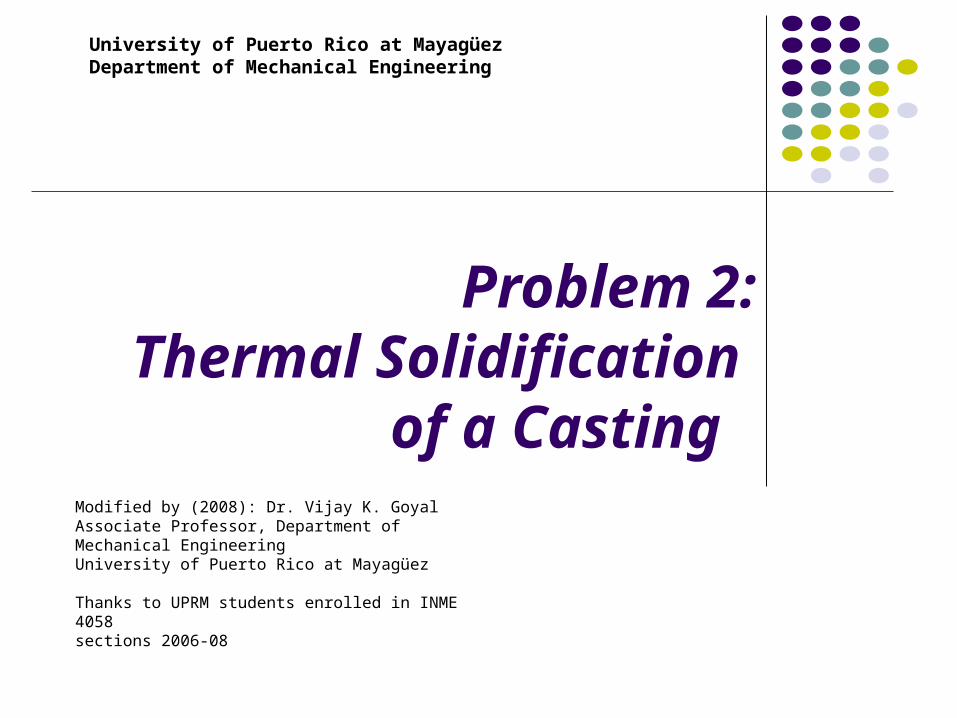
This is the
10.0 ANSYS
Product Launcher
main window. Select the Working
Directory and type
the name of work
shop on Job Name.
Workshop
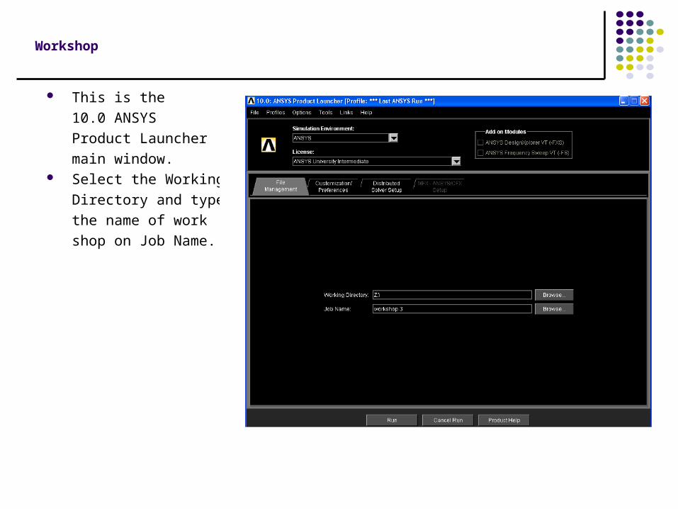
Click the button Customization/
Preferences. On the item of Use custom
memory settings type 128
on Total Workspace (MB):
and type 64 on
Database (MB):. Then click the Run
bottom.

Workshop
This is the main window of ANSYS University Intermediate Utility Menu.
Chapter 3. Thermal Solidification of a Casting
Problem Description
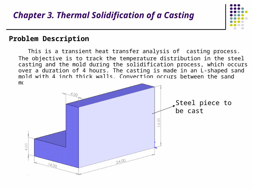
This is a transient heat transfer analysis of casting process. The objective is to track the temperature distribution in the steel casting and the mold during the solidification process, which occurs over a duration of 4 hours. The casting is made in an L-shaped sand mold with 4 inch thick walls. Convection occurs between the sand mold and the ambient air.
Steel piece to be cast

Chapter 3. Thermal Solidification of a Casting
Given:Material Properties for Sand
Conductivity (KXX) 0.025 Btu/(hr-in-oF)
Density (DENS) 0.054 lb/in3
Specific heat (C) 0.28 Btu/(lb-oF)
Conductivity (KXX) for Steel
at 0oF 1.44 Btu/(hr-in-oF)
at 2643oF 1.54
at 2750oF 1.22
at 2875oF 1.22
Enthalpy (ENTH) for Steel
at 0oF 0.0 Btu/in3
at 2643oF 128.1
at 2750oF 163.8
at 2875oF 174.2
Initial Conditions
Temperature of steel 2875 oF
Temperature of sand 80 oF
Convection Properties
Film coefficient 0.014 Btu/(hr-in2-oF)
Ambient temperature 80 oF
Approach and Assumptions
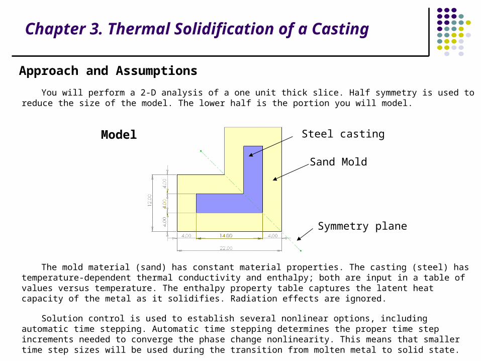
You will perform a 2-D analysis of a one unit thick slice. Half symmetry is used to reduce the size of the model. The lower half is the portion you will model.
The mold material (sand) has constant material properties. The casting (steel) has temperature-dependent thermal conductivity and enthalpy; both are input in a table of values versus temperature. The enthalpy property table captures the latent heat capacity of the metal as it solidifies. Radiation effects are ignored.
Solution control is used to establish several nonlinear options, including automatic time stepping. Automatic time stepping determines the proper time step increments needed to converge the phase change nonlinearity. This means that smaller time step sizes will be used during the transition from molten metal to solid state.
Chapter 3. Thermal Solidification of a Casting
Steel casting
Sand Mold
Model
Symmetry plane

Chapter 3. Thermal Solidification of a Casting
Thermal Analysis
Step 1: Change the title of the work:
Click File \ Change Title \ click.
On the new window enter the new name of the work “Thermal steady state analysis of a composite slab” then click OK

Chapter 3. Thermal Solidification of a Casting
Step 2: Set preferences. 1. Main Menu > Preferences
2. (check) “Individual discipline(s) to show in the GUI” = Thermal
3. [OK]
1
2
3
Chapter 3. Thermal Solidification of a Casting
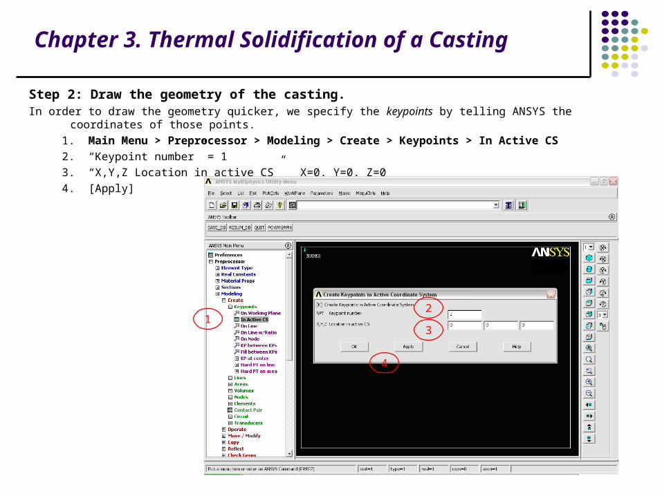
Step 2: Draw the geometry of the casting.In order to draw the geometry quicker, we specify the keypoints by telling ANSYS the coordinates of those points.
1. Main Menu > Preprocessor > Modeling > Create > Keypoints > In Active CS
2. “Keypoint number” = 1
3. “X,Y,Z Location in active CS” X=0, Y=0, Z=0
4. [Apply]
12
3
4

Chapter 3. Thermal Solidification of a Casting
Repeat the same procedure for keypoints 2, 3, 4, 5, 6, 7, and 8.
Keypoint # X Y Z
2 0 12 0
3 10 12 0
4 22 0 0
5 4 4 0
6 4 8 0
7 14 8 0
8 18 4 0

Chapter 3. Thermal Solidification of a Casting
After entering all keypoints your drawing should look like this:

Chapter 3. Thermal Solidification of a Casting
Step 3: Define the mold area.In order to define the areas. We have to tell ANSYS that the keypoints 1, 2, 3, 7, 6, 5, 8, 4 define a closed loop of the
vertex AREA 1. For this: 1. Main Menu > Modeling > Create > Areas > Arbitrary > Through KPs 2. Write the keypoints numbers separated by comas = 1, 2, 3, 7, 6, 5, 8, 4 3. [OK]
12
3

Chapter 3. Thermal Solidification of a Casting
Step 4: Define the cast area.
In order to define AREA 2, do the same as for AREA 1. Now, the area has as vertex the keypoints 5, 6, 7, and 8.
1. Main Menu > Modeling > Create > Areas > Arbitrary > Through KPs
2. Write the keypoints numbers separated by comas = 5, 6, 7, 8
3. [OK]
12
3

Chapter 3. Thermal Solidification of a Casting
Step 5: Show area numbers.
1. Utility Menu > PlotCtrls > Numbering
1
Chapter 3. Thermal Solidification of a Casting
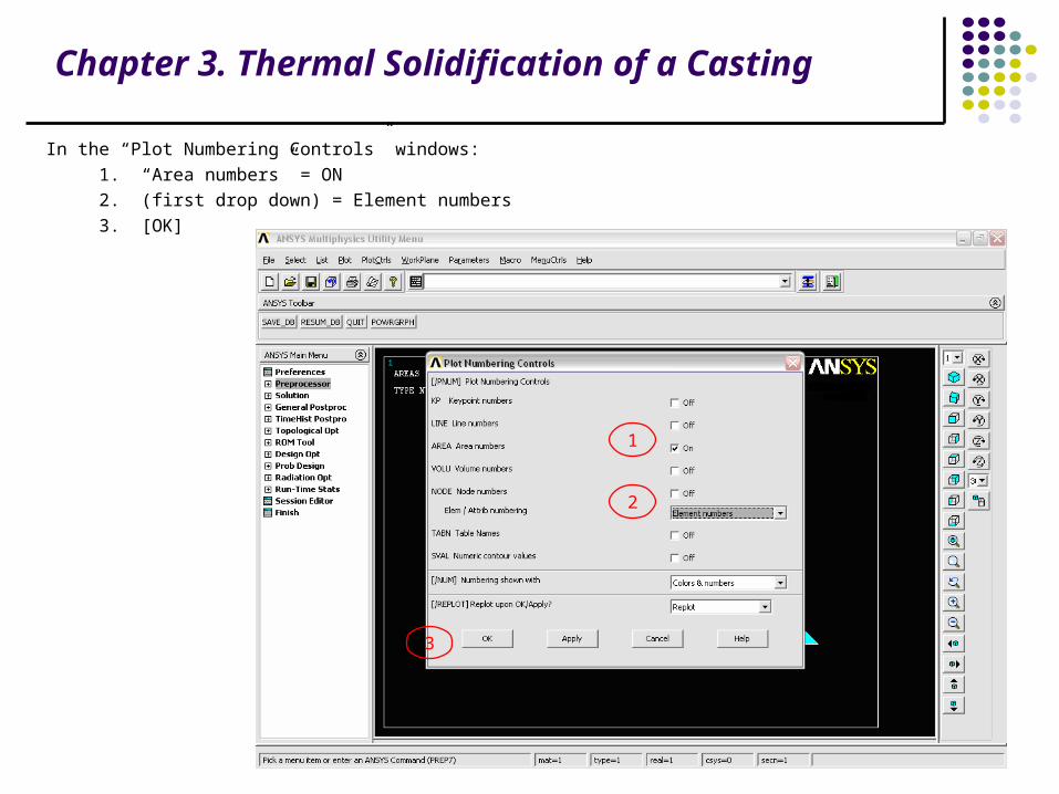
In the “Plot Numbering Controls” windows:
1. “Area numbers” = ON
2. (first drop down) = Element numbers
3. [OK]
1
2
3
Chapter 3. Thermal Solidification of a Casting
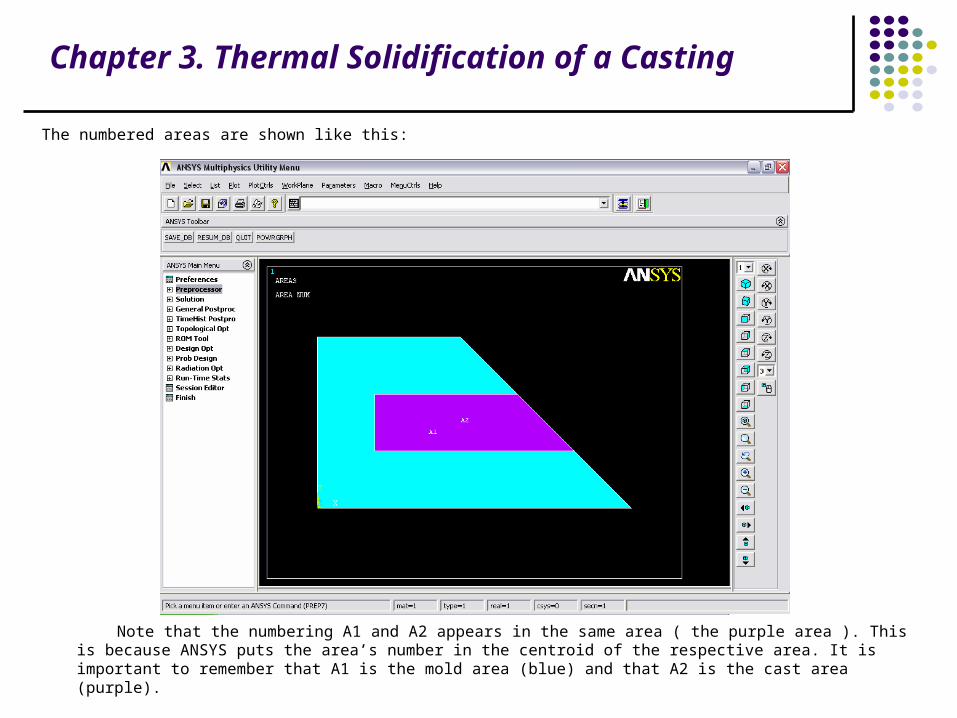
The numbered areas are shown like this:
Note that the numbering A1 and A2 appears in the same area ( the purple area ). This is because ANSYS puts the area’s number in the centroid of the respective area. It is important to remember that A1 is the mold area (blue) and that A2 is the cast area (purple).

Chapter 3. Thermal Solidification of a Casting
Step 6: Define mold material properties.Define the sand mold material properties as material NUMBER 1. These are not functions of temperature. 1. Main Menu> Preprocessor> Material Props> Material Models 2. (double-click) “Thermal”, then “Conductivity”, then “Isotropic” 3. “KXX” = 0.025 4. [OK]
1
2
3
4
Chapter 3. Thermal Solidification of a Casting
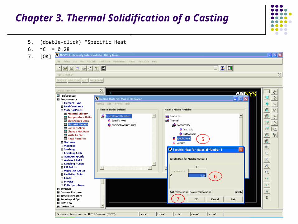
5. (double-click) “Specific Heat”
6. “C” = 0.28
7. [OK]
5
6
7
Chapter 3. Thermal Solidification of a Casting
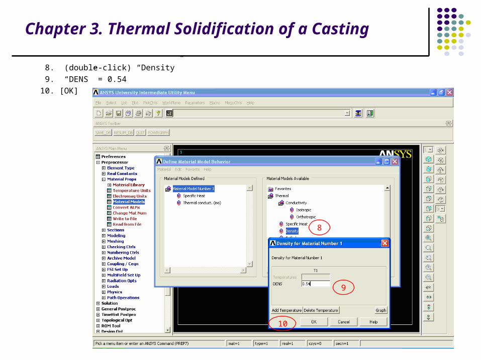
8. (double-click) “Density”
9. “DENS” = 0.54
10. [OK]
8
9
10

Chapter 3. Thermal Solidification of a Casting
Step 7: Define cast material properties.
The metal casting is defined as material number 2. These properties change significantly as the metal cools down
from the liquid phase to the solid phase. Therefore, they are entered in a table of properties versus temperature.
1. Material> New Model
2. “Define Material ID” = 2
3. [OK]
1
2
3
Chapter 3. Thermal Solidification of a Casting
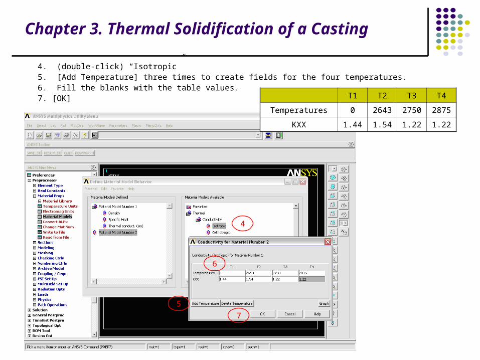
4. (double-click) “Isotropic” 5. [Add Temperature] three times to create fields for the four temperatures. 6. Fill the blanks with the table values. 7. [OK] T1 T2 T3 T4
Temperatures 0 2643 2750 2875
KXX 1.44 1.54 1.22 1.22
7
5
6
4

Chapter 3. Thermal Solidification of a Casting
Next, define the temperature dependent enthalpy. 8. (double-click) “Enthalpy” 9. [Add Temperature] three times to create fields for the four temperatures. 10. Fill the blanks with the table values. 11. [OK] T1 T2 T3 T4
Temperatures 0 2643 2750 2875
ENTH 0 128.1 163.8 174.2
8
9
10
11

Chapter 3. Thermal Solidification of a Casting
Step 8: Plot material properties vs. temperature.We now want to see how varies the conductivity of Material 2 vs. temperature. For this: 1. (double-click) “Thermal conduct. (iso)” under Material Model Number 2. 2. [Graph] 3. [OK]
Graph will look like this:
1
2
3

Chapter 3. Thermal Solidification of a Casting
We now want to see how varies the enthalpy of Material 2 vs. temperature. For this: 4. (double-click) “Enthalpy” under Material Model Number 2. 5. [Graph] 6. [OK]
Graph will look like this:
Then: Material> Exit
4
5
6
Chapter 3. Thermal Solidification of a Casting
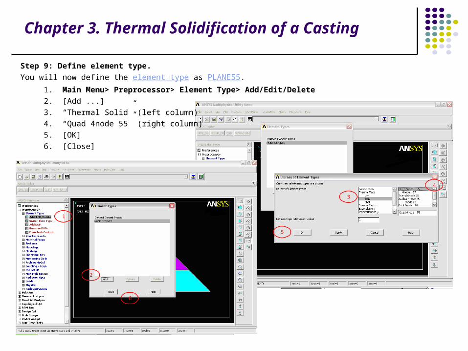
Step 9: Define element type.
You will now define the element type as PLANE55.
1. Main Menu> Preprocessor> Element Type> Add/Edit/Delete
2. [Add ...]
3. “Thermal Solid” (left column)
4. “Quad 4node 55” (right column)
5. [OK]
6. [Close]
1
2
3
4
5
6
Chapter 3. Thermal Solidification of a Casting
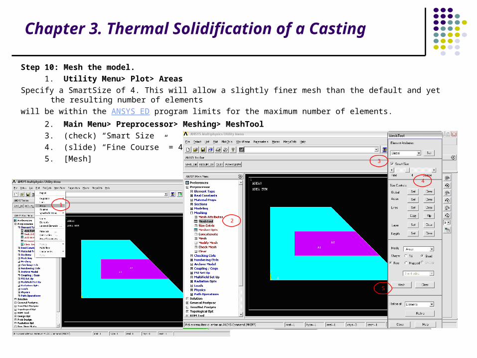
Step 10: Mesh the model.
1. Utility Menu> Plot> Areas
Specify a SmartSize of 4. This will allow a slightly finer mesh than the default and yet the resulting number of elements
will be within the ANSYS ED program limits for the maximum number of elements.
2. Main Menu> Preprocessor> Meshing> MeshTool
3. (check) “Smart Size”
4. (slide) “Fine Course” = 4
5. [Mesh]
1
2
3
4
5

Chapter 3. Thermal Solidification of a Casting
Mesh the mold area first. Note that the material attribute reference number defaults to 1 and there is no need to set
attributes before meshing the area.
6. Pick the mold area A1 (Hint: Place the mouse cursor on top of the A1 label when you pick -- this is the picking "hot spot," based on the centroid of the area.).
7. [OK]
6
7

Chapter 3. Thermal Solidification of a Casting
Before meshing the casting area, set the material attribute to that of steel (material 2).
8. (drop down in MeshTool) “Element Attributes” = Global, then [Set]
9. (drop down) “Material number” = 2
10. [OK]
8
9
10

Chapter 3. Thermal Solidification of a Casting
11. Utility Menu> Plot> Areas
11
Chapter 3. Thermal Solidification of a Casting
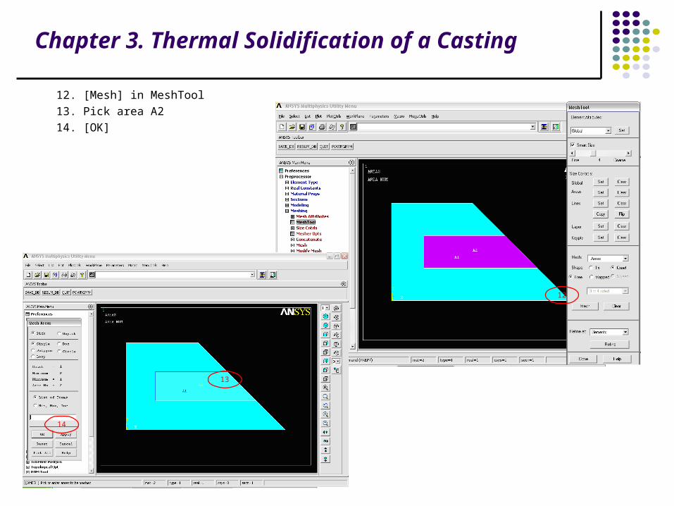
12. [Mesh] in MeshTool
13. Pick area A2
14. [OK]
12
13
14

Chapter 3. Thermal Solidification of a Casting
15. [Close] in MeshTool
16. Utility Menu> Plot> Elements
15
16
Chapter 3. Thermal Solidification of a Casting
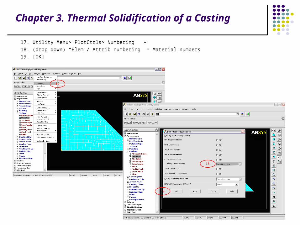
17. Utility Menu> PlotCtrls> Numbering
18. (drop down) “Elem / Attrib numbering” = Material numbers
19. [OK]
17
18
19

Chapter 3. Thermal Solidification of a Casting
Note that the elements of material 1 form the sand mold. The elements of material 2 form the steel casting. You can
also plot the elements showing materials in different colors without displaying the associated material numbers.
Chapter 3. Thermal Solidification of a Casting
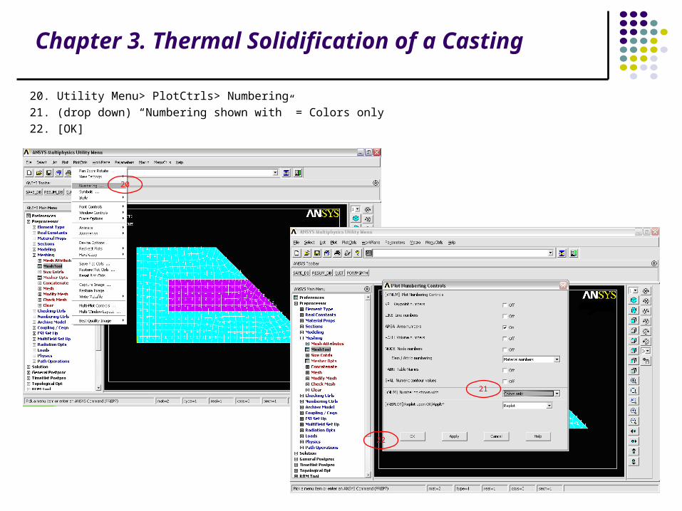
20. Utility Menu> PlotCtrls> Numbering
21. (drop down) “Numbering shown with” = Colors only
22. [OK]
20
21
22

Chapter 3. Thermal Solidification of a Casting
Step 11: Apply convection loads on the exposed boundary lines.
Apply the convection to the lines of the solid model. Loads applied to solid modeling entities are automatically
transferred to the finite element model during solution.
1. Utility Menu> Plot> Lines
1
Chapter 3. Thermal Solidification of a Casting
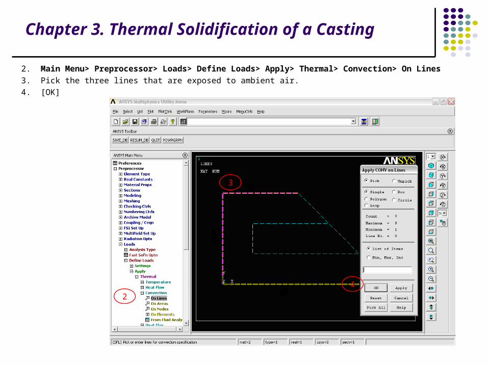
2. Main Menu> Preprocessor> Loads> Define Loads> Apply> Thermal> Convection> On Lines
3. Pick the three lines that are exposed to ambient air.
4. [OK]
2
3
4

Chapter 3. Thermal Solidification of a Casting
5. “Film coefficient” = 0.014
6. “Bulk temperature” = 80
7. [OK]
5
6
7
Chapter 3. Thermal Solidification of a Casting
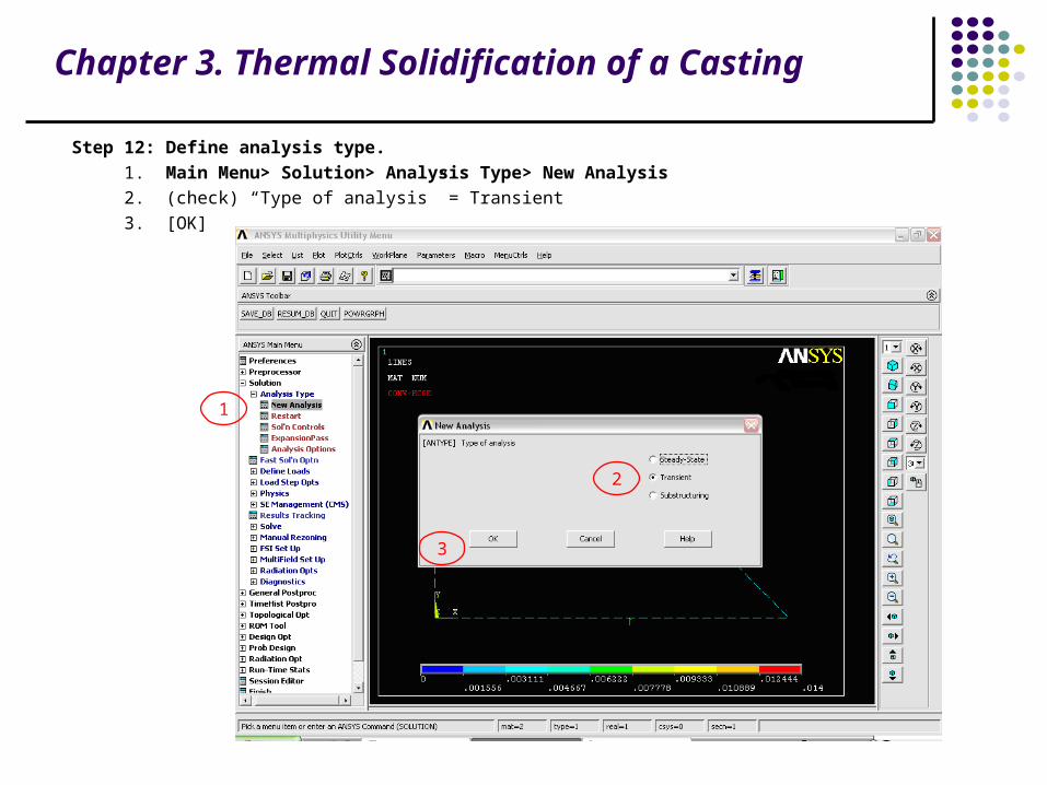
Step 12: Define analysis type.
1. Main Menu> Solution> Analysis Type> New Analysis
2. (check) “Type of analysis” = Transient
3. [OK]
2
1
3
Chapter 3. Thermal Solidification of a Casting
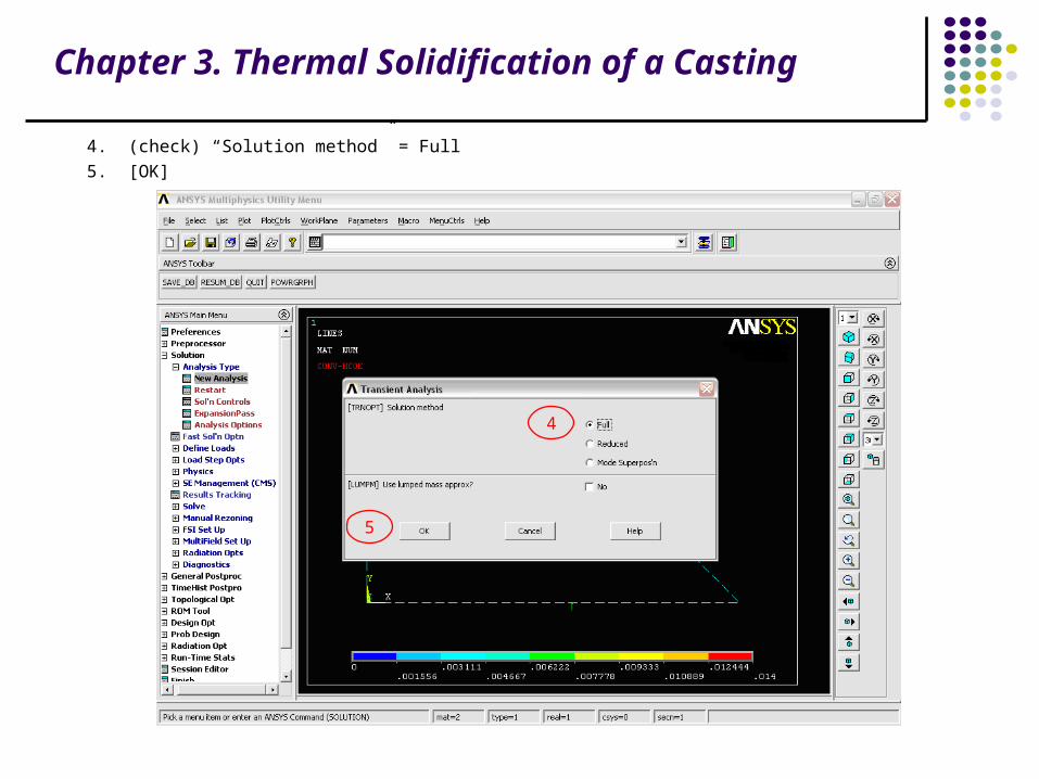
4. (check) “Solution method” = Full
5. [OK]
4
5

Chapter 3. Thermal Solidification of a Casting
Step 13: Specify initial conditions for the transient.The mold is initially at an ambient temperature of 80oF and the molten metal is at 2875oF. Use select entities to obtain the correct set of nodes on which to apply the initial temperatures. First select the casting area, then select the nodes within that area and apply the initial molten temperature to those nodes. Next, invert the selected set of nodes and apply the ambient temperature to the mold nodes. 1. Utility Menu> Plot> Areas 2. Utility Menu> Select> Entities
1
2
Chapter 3. Thermal Solidification of a Casting
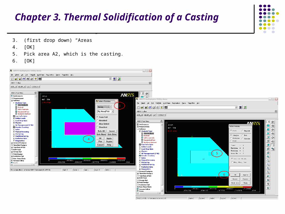
3. (first drop down) “Areas”
4. [OK]
5. Pick area A2, which is the casting.
6. [OK]
3
4
5
6

Chapter 3. Thermal Solidification of a Casting
7. Utility Menu> Select> Everything Below> Selected Areas
8. Utility Menu> Plot> Nodes
7
8

Chapter 3. Thermal Solidification of a Casting
9. Main Menu> Solution> Define Loads> Apply> Initial Condit'n> Define
10. [Pick All] to use selected nodes.
11. (drop down) “DOF to be specified” = TEMP
12. “Initial value of DOF” = 2875
13. [OK]
9
10
11
12
13
Chapter 3. Thermal Solidification of a Casting
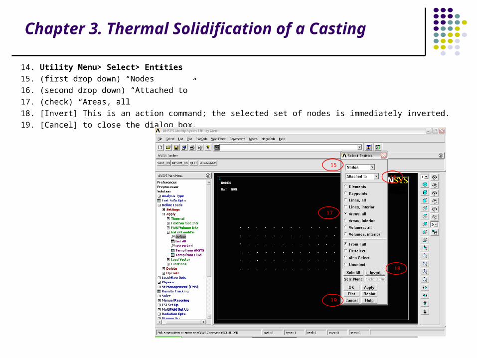
14. Utility Menu> Select> Entities
15. (first drop down) “Nodes”
16. (second drop down) “Attached to”
17. (check) “Areas, all”
18. [Invert] This is an action command; the selected set of nodes is immediately inverted.
19. [Cancel] to close the dialog box.
15
16
17
18
19
Chapter 3. Thermal Solidification of a Casting
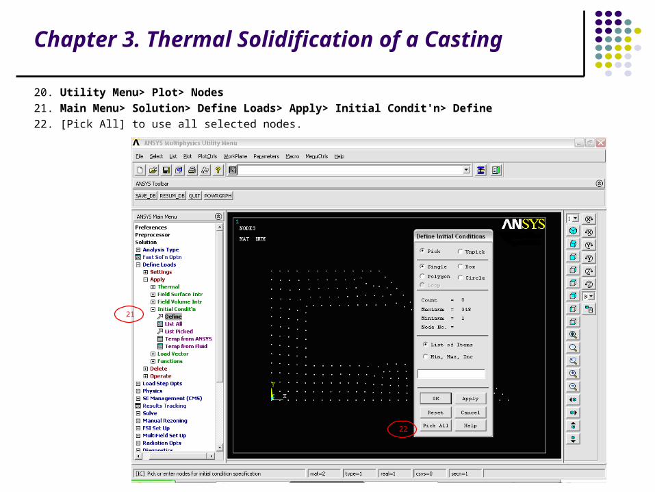
20. Utility Menu> Plot> Nodes
21. Main Menu> Solution> Define Loads> Apply> Initial Condit'n> Define
22. [Pick All] to use all selected nodes.
21
22
Chapter 3. Thermal Solidification of a Casting
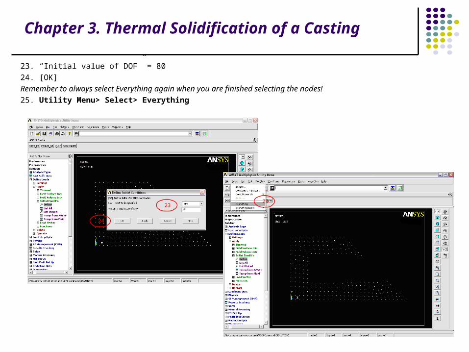
23. “Initial value of DOF” = 80
24. [OK]
Remember to always select Everything again when you are finished selecting the nodes!
25. Utility Menu> Select> Everything
23
24
25
Chapter 3. Thermal Solidification of a Casting
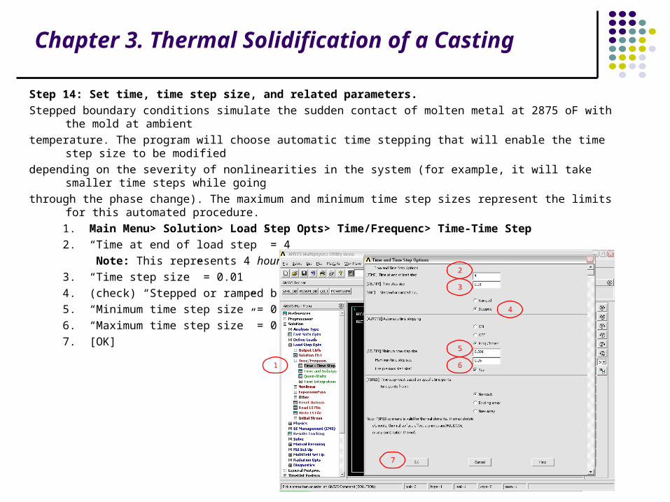
Step 14: Set time, time step size, and related parameters.
Stepped boundary conditions simulate the sudden contact of molten metal at 2875 oF with the mold at ambient
temperature. The program will choose automatic time stepping that will enable the time step size to be modified
depending on the severity of nonlinearities in the system (for example, it will take smaller time steps while going
through the phase change). The maximum and minimum time step sizes represent the limits for this automated procedure.
1. Main Menu> Solution> Load Step Opts> Time/Frequenc> Time-Time Step
2. “Time at end of load step” = 4
Note: This represents 4 hours.
3. “Time step size” = 0.01
4. (check) “Stepped or ramped b. c.” = Stepped
5. “Minimum time step size” = 0.001
6. “Maximum time step size” = 0.25
7. [OK]
1
2
3
4
5
6
7

Chapter 3. Thermal Solidification of a Casting
Step 15: Set output controls.
1. Main Menu> Solution> Load Step Opts> Output Ctrls> DB/Results File
2. (check) “File write frequency” = Every substep
3. [OK]
1
2
3

Chapter 3. Thermal Solidification of a Casting
Step 16: Solve.
1. Main Menu> Solution> Solve> Current LS
2. Review the information in the status window.
3. [OK] to initiate the solution.
1
2
3

Chapter 3. Thermal Solidification of a Casting
4. [Close] when the solution is done.
4
Chapter 3. Thermal Solidification of a Casting
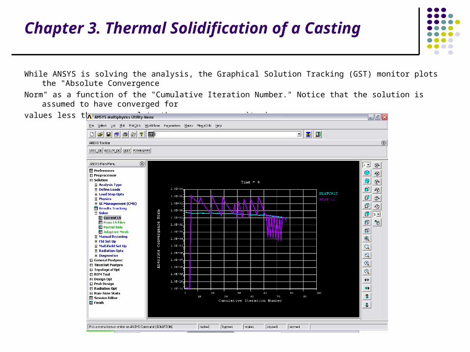
While ANSYS is solving the analysis, the Graphical Solution Tracking (GST) monitor plots the "Absolute Convergence
Norm" as a function of the "Cumulative Iteration Number." Notice that the solution is assumed to have converged for
values less than or equal to the convergence criteria.

Chapter 3. Thermal Solidification of a Casting
Review Results
Related Documents