Problem 1.1 An imaging lens in a digital camera has a focal length of 6 cm. How far should the lens be from the camera’s CCD array to focus on an object (a) 12 cm in front of the lens? (b) 15 cm in front of the lens? Solution: (a) The lens equation (Eq. (1.1)) is 1 do + 1 d i = 1 f . Here, f = 6 cm and d o = 12 cm, so d i = 12 cm . (b) The lens equation (Eq. (1.1)) is 1 do + 1 d i = 1 f . Here, f = 6 cm and d o = 15 cm, so d i = 10 cm .

Welcome message from author
This document is posted to help you gain knowledge. Please leave a comment to let me know what you think about it! Share it to your friends and learn new things together.
Transcript

Problem 1.1 An imaging lens in a digital camera has a focal length of 6 cm. How far should thelens be from the camera’s CCD array to focus on an object
(a) 12 cm in front of the lens?(b) 15 cm in front of the lens?
Solution:
(a) The lens equation (Eq. (1.1)) is 1do
+ 1di
= 1f .
Here, f = 6 cm and do = 12 cm, so di = 12 cm .
(b) The lens equation (Eq. (1.1)) is 1do
+ 1di
= 1f .
Here, f = 6 cm and do = 15 cm, so di = 10 cm .

Problem 1.2 An imaging lens in a digital camera has a focal length of 4 cm.
How far should the lens be from the camera’s CCD array to focus on an object
(a) 12 cm in front of the lens;(b) 8 cm in front of the lens.
Solution:
(a) The lens equation (Eq. (1.1)) is 1do
+ 1di
= 1f .
Here, f = 4 cm and do = 12 cm, so di = 6 cm .
(b) The lens equation (Eq. (1.1)) is 1do
+ 1di
= 1f .
Here, f = 4 cm and do = 8 cm, so di = 8 cm .

Problem 1.3 The following program loads an image stored in clown.mat as Io(x, y), passes itthrough an imaging system with the PSF given by Eq. (1.6), and displays Io(x, y) and Ii(x, y).Parameters ∆, D, di, and λ (all in mm) are specified in the program’s first line.
clear;Delta=0.0002;D=0.03;lambda=0.0000005;di=0.003;T=round(0.01/Delta);
for I=1:T;for J=1:T;x2y2(I,J)=(I-T/2).*(I-T/2)+(J-T/2).*(J-T/2);end;end;
gamma=pi*D/lambda*sqrt(x2y2./(x2y2+di*di/Delta/Delta));
h=2*besselj(1,gamma)./gamma;
h(T/2,T/2)=(h(T/2+1,T/2)+h(T/2-1,T/2)+h(T/2,T/2+1)+h(T/2,T/2-1))/4;
h=h.*h;H=h(T/2-5:T/2+5,T/2-5:T/2+5);load clown.mat;Y=conv2(X,H);
figure,imagesc(X),axis off,colormap(gray),figure,imagesc(Y),axis off,colormap(gray)
Run the program and display Io(x, y) (input) and Ii(x, y) (output).
Solution: Io(x, y) is at left and Ii(x, y) is at right.
The image formed by the optical system is blurred, as expected.

Problem 1.4 Compare the azimuth resolution of a real-aperture radar with that of a synthetic-aperture radar, with both pointed at the ground from an aircraft at a range R = 5 km. Bothsystems operate at λ = 3 cm and utilize a 2-m-long antenna.
Solution: For the real-aperture radar,
∆Y ′
min =λR
ly=
3 × 10−2 × 5 × 103
2= 75 m.
For the SAR,
∆Y ′
min =ly2
=2
2= 1 m.

Problem 1.5 A 2-m-long antenna is used to form a synthetic-aperture radar from a range of 100 km.What is the length of the synthetic aperture?
Solution: Scaling the range in Fig. 1-21 from 400 km down to 100 km leads to a syntheticaperture shorter by the same factor. Hence, the synthetic aperture is of length 8 km/4 = 2 km.
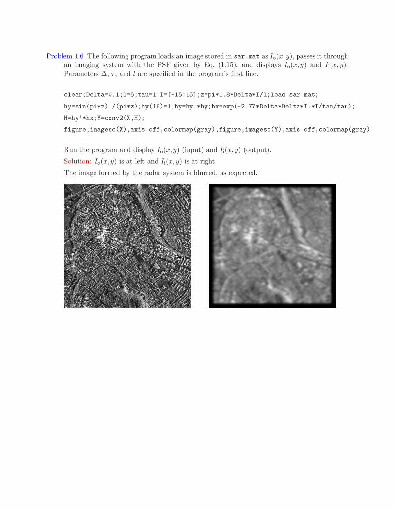
Problem 1.6 The following program loads an image stored in sar.mat as Io(x, y), passes it throughan imaging system with the PSF given by Eq. (1.15), and displays Io(x, y) and Ii(x, y).Parameters ∆, τ , and l are specified in the program’s first line.
clear;Delta=0.1;l=5;tau=1;I=[-15:15];z=pi*1.8*Delta*I/l;load sar.mat;
hy=sin(pi*z)./(pi*z);hy(16)=1;hy=hy.*hy;hx=exp(-2.77*Delta*Delta*I.*I/tau/tau);
H=hy’*hx;Y=conv2(X,H);
figure,imagesc(X),axis off,colormap(gray),figure,imagesc(Y),axis off,colormap(gray)
Run the program and display Io(x, y) (input) and Ii(x, y) (output).
Solution: Io(x, y) is at left and Ii(x, y) is at right.
The image formed by the radar system is blurred, as expected.

Problem 1.7 (This problem assumes prior knowledge of the 1-D Fourier transform (FT)). The basicCT problem is to reconstruct α(ξ, η) in Eq. (1.18) from p(r, θ). One way to do this is as follows:
(a) Take the FT of Eq. (1.18), transforming r to f . Define p(−r, θ) = p(r, θ + π).(b) Define and substitute µ = f cos θ and ν = f sin θ in this FT.(c) Show that the result defines 2 FTs, transforming ξ to µ and η to ν, and that A(µ, ν) =
P(f, θ). Hence, α(ξ, η) is the inverse FT of P(f, θ).
Solution:
(a) The FT of Eq. (1.18) taking r to f is
P(f, θ) = FFF{p(r, θ)} =
∫∞
−∞
∫∞
−∞
α(ξ, η) e−j2πf(ξ cos θ+η sin θ) dξ dη.
(b) Substituting gives
P(f, θ) =
∫∞
−∞
∫∞
−∞
α(ξ, η) e−j2πµξe−j2πνη dξ dη.
(c) P(f, θ) = FFFξ→µ{FFFη→ν{α(ξ, η)}} = A(µ, ν),

Problem 1.8 The following program loads an image stored in mri.mat as Io(x, y), passes it throughan imaging system with the PSF given by Eq. (1.20), and displays Io(x, y) and Ii(x, y).Parameters ∆, N , and dk are specified in the program’s first line.
clear;N=16;Delta=0.01;dk=1;I=[-60:60];load mri.mat;
h=dk*sin(pi*N*dk*I*Delta)./sin(pi*dk*I*Delta);h(61)=N;H=h’*h;Y=conv2(X,H);
figure,imagesc(X),axis off,colormap(gray),figure,imagesc(Y),axis off,colormap(gray)
Run the program and display Io(x, y) (input) and Ii(x, y) (output).
Solution: Io(x, y) is at left and Ii(x, y) is at right.
The image formed by the MRI system is blurred, as expected.

Problem 1.9 This problem shows how beamforming works on a linear array of transducers, asillustrated in Fig. 1-35, in a medium with a wave speed of 1540 m/s. We are given a lineararray of transducers located 1.54 cm apart along the x axis, with the nth transducer locatedat x = 1.54n cm. Outputs {yn(t)} from the transducers are delayed and summed to producethe signal y(t) =
∑n yn(t−0.05n). In what direction (angle from perpendicular to the array)
is the array focused?
Solution: Consider a plane wave (impulse in space and time) δ(t − x sin θ − y cos θ) arrivingat the array from a direction θ (angle from perpendicular to the array). The plane wave hitsthe nth transducer at t = n sin(θ) 1.54 cm
1540 m/s = 0.1n sin θ. Setting the delay between tranducers
0.05n = 0.1n sin θ gives θ = 30◦ .

Problem 2.1 Compute the following convolutions:
(a) e−t u(t) ∗ e−2t u(t)
(b) e−2t u(t) ∗ e−3t u(t)
(c) e−3t u(t) ∗ e−3t u(t)
Solution:
The convolution of two causal signals is y(t) = u(t)∫ t0 h(τ) x(t − τ) dτ .
(a): e−t u(t) ∗ e−2t u(t) = u(t)∫ t0 e−τe−2(t−τ) dτ = e−2t u(t)
∫ t0 eτ dτ = e−2t u(t) [et − 1] =
e−t u(t) − e−2t u(t)
(b): e−2t u(t) ∗ e−3t u(t) = u(t)∫ t0 e−2τe−3(t−τ) dτ = e−3t u(t)
∫ t0 eτ dτ = e−3t u(t) [et − 1] =
e−2t u(t) − e−3t u(t)
(c): e−3t u(t) ∗ e−3t u(t) = u(t)∫ t0 e−3τe−3(t−τ) dτ = e−3t u(t)
∫ t0 dτ = te−3t u(t)

Problem 2.2 Show that the spectrum of sin(20πt)πt
sin(10πt)πt is zero for |f | > 15 Hz.
Solution:
Using the Fourier transform property F[x(t)y(t)] = X(f) ∗ Y(f),
and the property that the width of a convolution is the sum of the widths,
the bandwidth of the product of two signals is the sum of their bandwidths.
F
[
sin(20πt)
πt
]
=
{
1, |f | < 10 Hz0, |f | > 10 Hz
and
F
[
sin(10πt)
πt
]
=
{
1, |f | < 5 Hz0, |f | > 5 Hz.
Hence,
F
[
sin(20πt)
πt
sin(10πt)
πt
]
= 0 for |f | > 15 Hz.

Problem 2.3 Using only Fourier transform properties, show that
sin(10πt)
πt[1 + 2 cos(20πt)] =
sin(30πt)
πt.
Solution:
F
[
sin(10πt)πt
]
=
{
1, |f | < 50, |f | > 5
Using the modulation property:
F[x(t) cos(2πf0t)] =1
2X(f − f0) +
1
2X(f + f0),
we have
F
[
sin(10πt)
πtcos(20πt)
]
=
{
12 , 5 Hz < |f | < 15 Hz,0, otherwise.
Adding the first equation to double the second equation gives
F
[
sin(10πt)
πt(1 + 2 cos(20πt))
]
=
{
1, |f | < 5 Hz0, |f | > 5 Hz
+
{
1, 5 Hz < |f | < 15 Hz,0, otherwise
=
{
1, |f | < 15 Hz,0, |f | > 15 Hz.
The inverse Fourier transform of this result is sin(30πt)πt .
The sum of this lowpass filter and bandpass filter is another lowpass filter:
- f (Hz)–15 –5 5 15
Related Documents


