PRO-TOE ® C2 Hammertoe Fixation System SURGICAL TECHNIQUE

Welcome message from author
This document is posted to help you gain knowledge. Please leave a comment to let me know what you think about it! Share it to your friends and learn new things together.
Transcript

PRO-TOE® C2Hammertoe Fixation System
SURGIC AL TECHNIQUE

Contents
Product Information
Device Description
Indications
Contraindications
Surgical Technique
Post-Operative Protocol
Explant Information
Ordering Information
Notes
Chapter 1 3
3
4
4
Chapter 2 5
11
11
Chapter 3 12
Appendix A 13
Proper surgical procedures and techniques are the responsibility of the medical professional. The following guidelines are furnished for information purposes only as techniques used by the design surgeons. Each surgeon must evaluate the appropriateness of the procedures based on his or her personal medical training and experience. Prior to use of the system, the surgeon should refer to the product package insert for complete warnings, precautions, indications, contraindications and adverse effects. Package inserts are also available by contacting Wright Medical Technology, Inc. Contact information can be found on the back of this surgical technique, and the package insert is available at www.wmt.com.
Please contact your local Wright representative for product availability.

1chapte
r
3
Headline Headline
Chapter 1 Product Information
1ProductInformation
DescriptionPRO-TOE® C2 Hammertoe Fixation System provides versatility addressing 2 common indications of the lesser toes - hammertoe correction and MTP joint instability correction. The unique insertion method allows for compression of the proximal interphalangeal joint (PIPJ) while maintaining the integrity of the distal interphalangeal (DIP) joint. Utilizing differential thread pitches, the PRO-TOE® C2 provides a compression ratio of 1.75mm:1mm per revolution.
Implant options include solid or cannulated dependent on diameter. To accommodate all the lesser digits, and various patient anatomy and bone quality, the system is offered in 4 diameters in either 13mm and/or 16mm lengths. Implants are offered in stainless steel.
The instrumentation is streamlined and simple. The PRO-TOE® C2 tray is provided non-sterile and includes implants and instruments. The tray has been designed to promote ease-of-use by color-coding implants to drills. A reference chart is also provided on the side of the tray.
3.0 x 13 and 16mmCannulated
2.4 x13mm Solid
4mm
6mm
4mm
6mm
4mm
6mm
3.5 x 13 and 16mmCannulated
2.0 x13mm Solid
4mm
6mm
4 Chapter 2 Surgical Technique
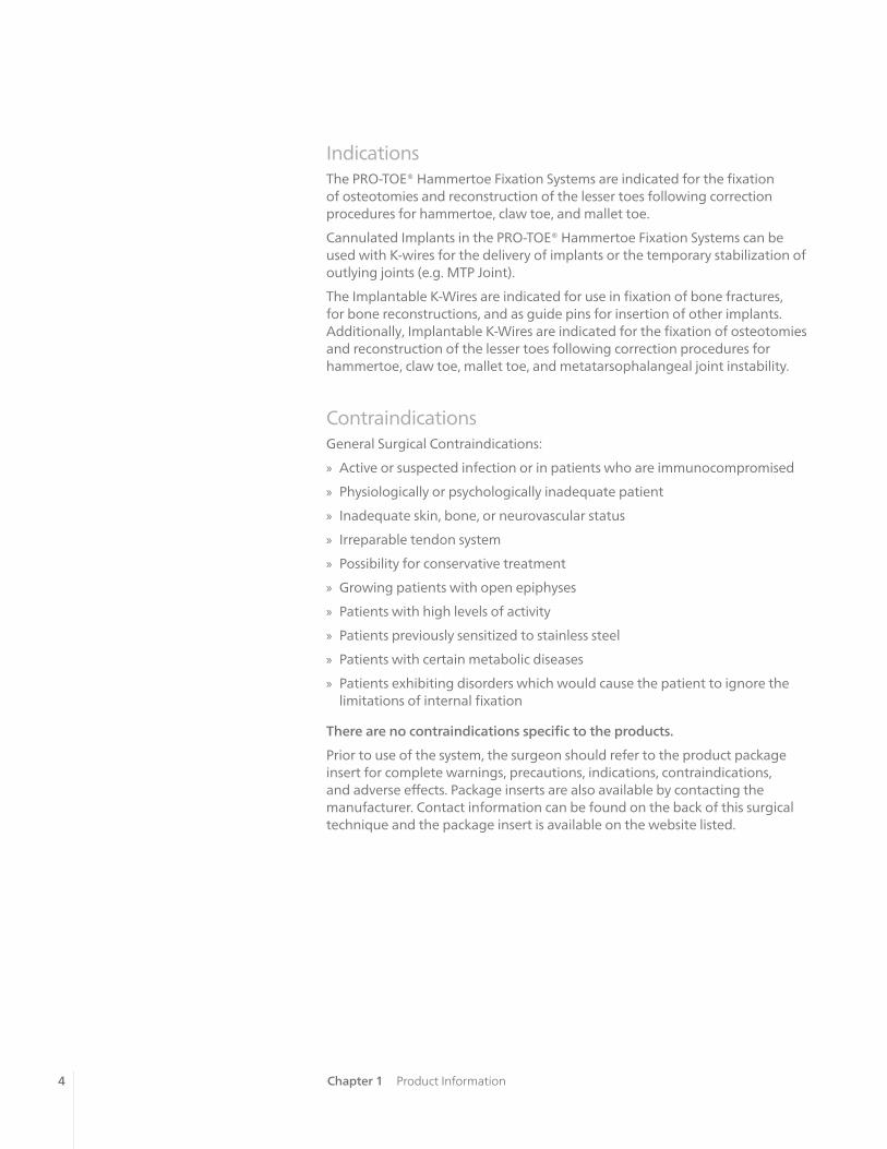
IndicationsThe PRO-TOE® Hammertoe Fixation Systems are indicated for the fixation of osteotomies and reconstruction of the lesser toes following correction procedures for hammertoe, claw toe, and mallet toe.
Cannulated Implants in the PRO-TOE® Hammertoe Fixation Systems can be used with K-wires for the delivery of implants or the temporary stabilization of outlying joints (e.g. MTP Joint).
The Implantable K-Wires are indicated for use in fixation of bone fractures, for bone reconstructions, and as guide pins for insertion of other implants. Additionally, Implantable K-Wires are indicated for the fixation of osteotomies and reconstruction of the lesser toes following correction procedures for hammertoe, claw toe, mallet toe, and metatarsophalangeal joint instability.
ContraindicationsGeneral Surgical Contraindications:
» Active or suspected infection or in patients who are immunocompromised
» Physiologically or psychologically inadequate patient
» Inadequate skin, bone, or neurovascular status
» Irreparable tendon system
» Possibility for conservative treatment
» Growing patients with open epiphyses
» Patients with high levels of activity
» Patients previously sensitized to stainless steel
» Patients with certain metabolic diseases
» Patients exhibiting disorders which would cause the patient to ignore the limitations of internal fixation
There are no contraindications specific to the products.
Prior to use of the system, the surgeon should refer to the product package insert for complete warnings, precautions, indications, contraindications, and adverse effects. Package inserts are also available by contacting the manufacturer. Contact information can be found on the back of this surgical technique and the package insert is available on the website listed.
Chapter 1 Product Information

1chapte
r
5
Headline Headline
Chapter 1 Product InformationChapter 2 Surgical Technique
Incision and Proximal Phalanx Resection
In preparation for the implantation of the PRO-TOE® C2 implant, an elliptical or longitudinal incision is created dorsally over the proximal PIPJ.
NOTE: The procedure for soft tissue exposure is under the discretion of the surgeon.
Resect the head of the proximal phalanx using a sagittal saw.
NOTE: It is not recommended to use a sagittal saw on the middle phalanx
Proximal Phalanx Preparation
Insert the K-wire (PN45750001 or 45750003) into the center of the proximal phalanx.
NOTE: Two K-wire sizes are available in the kit. Selection of K-wire size is under the discretion
of the surgeon. Consideration should include, but not limited to, implant size selection and
patient bone quality. (Table A, pg 6)
Attach the appropriate Cannulated Drill (PN45810003 or 45810004) to the AO Cannulated Handle (PN45765001) (Table A, pg 6). Insert over the K-wire and Drill by hand to the appropriate laser mark depending on implant length selection. The first laser mark is 13mm and the second laser mark is 16mm.
NOTE: When preparing the proximal phalanx for the 2.0mm and 2.4mm solid implants, care
should be taken to ensure the K-wire is driven to a minimum depth of 13mm. This may be
verified under fluoroscopy.
Surgical Technique 2
PN 45750001 K-Wire 1.1mm
PN 45750003 K-Wire 1.6mm
PN 45810003 Drill 2.2mm
PN 45810004 Drill 2.6mm
PN 45765001 AO Cannulated Handle
6 Chapter 2 Surgical TechniqueChapter 2 Surgical Technique
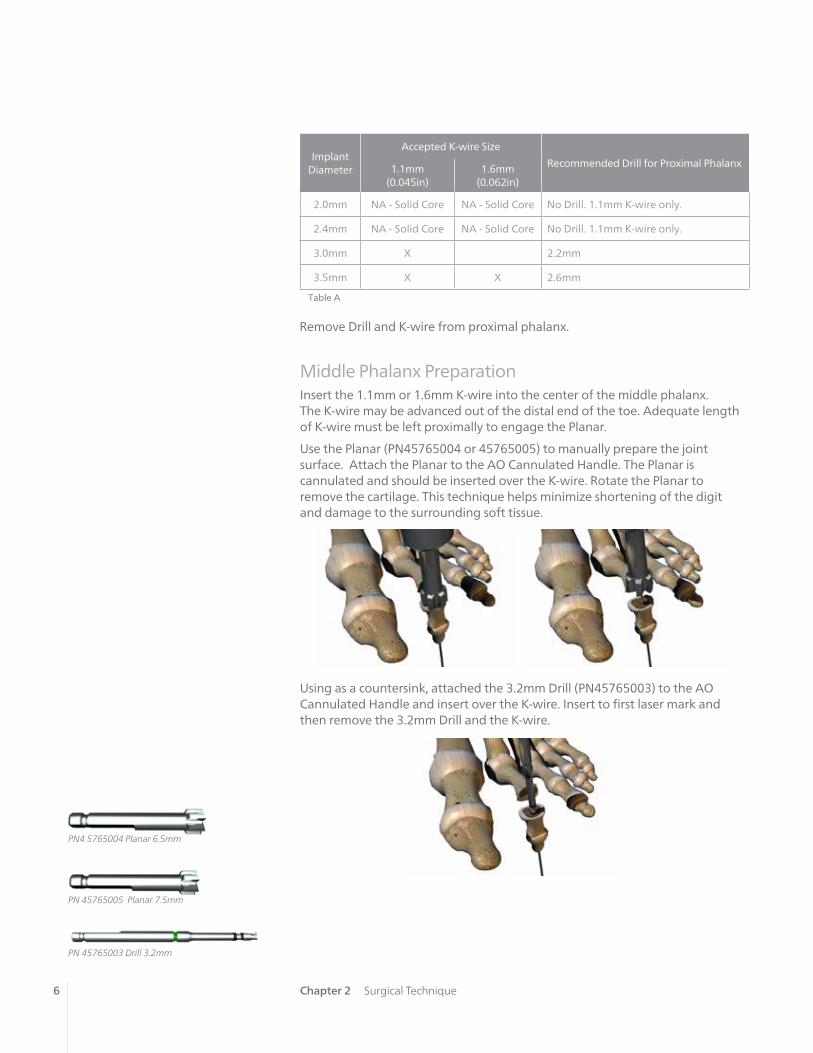
Middle Phalanx PreparationInsert the 1.1mm or 1.6mm K-wire into the center of the middle phalanx. The K-wire may be advanced out of the distal end of the toe. Adequate length of K-wire must be left proximally to engage the Planar.
Use the Planar (PN45765004 or 45765005) to manually prepare the joint surface. Attach the Planar to the AO Cannulated Handle. The Planar is cannulated and should be inserted over the K-wire. Rotate the Planar to remove the cartilage. This technique helps minimize shortening of the digit and damage to the surrounding soft tissue.
Using as a countersink, attached the 3.2mm Drill (PN45765003) to the AO Cannulated Handle and insert over the K-wire. Insert to first laser mark and then remove the 3.2mm Drill and the K-wire.
Remove Drill and K-wire from proximal phalanx.
Table A
Implant Diameter
Accepted K-wire Size
Recommended Drill for Proximal Phalanx1.1mm (0.045in)
1.6mm (0.062in)
2.0mm NA - Solid Core NA - Solid Core No Drill. 1.1mm K-wire only.
2.4mm NA - Solid Core NA - Solid Core No Drill. 1.1mm K-wire only.
3.0mm X 2.2mm
3.5mm X X 2.6mm
PN 45765003 Drill 3.2mm
PN 45765005 Planar 7.5mm
PN4 5765004 Planar 6.5mm

7Chapter 2 Surgical Technique
Implant Insertion - Proximal PhalanxAttach the Driver (PN45805002) to the Mini QC Handle (PN45805001) and select the appropriate implant size. To attach the Mini QC Handle to the Driver, align the laser mark on the Mini QC Handle with the flat of the trocar end of the Driver. (Figure 1A)
Fully seat the implant into the proximal phalanx. (Figure 1B)
Remove the Driver from the Mini QC Handle.
PN 45805001 Mini QC Handle
PN 45805002 Driver
NOTE: Diameter of Driver is 2.5mm
Figure 1A
Figure 1B

8 Chapter 2 Surgical Technique
Implant Insertion –Middle PhalanxLoad the hexalobe end of the Driver into the wire driver. Drive the trocar end of the Driver distally into the middle phalanx until the hexalobe reaches the joint surface. (Figure 2)
Figure 2
Reattach the Driver to the Mini QC Handle and dock the distal portion of the implant onto the hexalobe and close the joint. While applying slight forward pressure, turn the Mini QC Handle 3 revolutions counter clockwise. (Figure 3)
Figure 3PN 45805003 T8 Hex Driver
NOTE: An extra T8 Hex Driver (PN 45805003) has been provided in case the implant needs
adjusted in the proximal phalanx.

9
NOTE: It is recommended to view under fluoroscopy after 3 revolutions while
the Driver is engaged.
NOTE: 1-2 additional turns may be required to help dock the middle phalanx onto the distal
end of the implant.
CAUTION: After the distal portion of the implant is in the middle phalanx, the joint can only
be compressed by driving the implant distally (i.e. counterclockwise) Once the distal threads
are engaged in the middle phalanx, distraction of the joint may occur if the implant
is driven proximally (i.e. clockwise).
NOTE: The procedure for soft tissue repair is under the discretion of the surgeon.
Chapter 2 Surgical Technique
Manually remove driver out distal end of toe.
10 Chapter 2 Surgical Technique
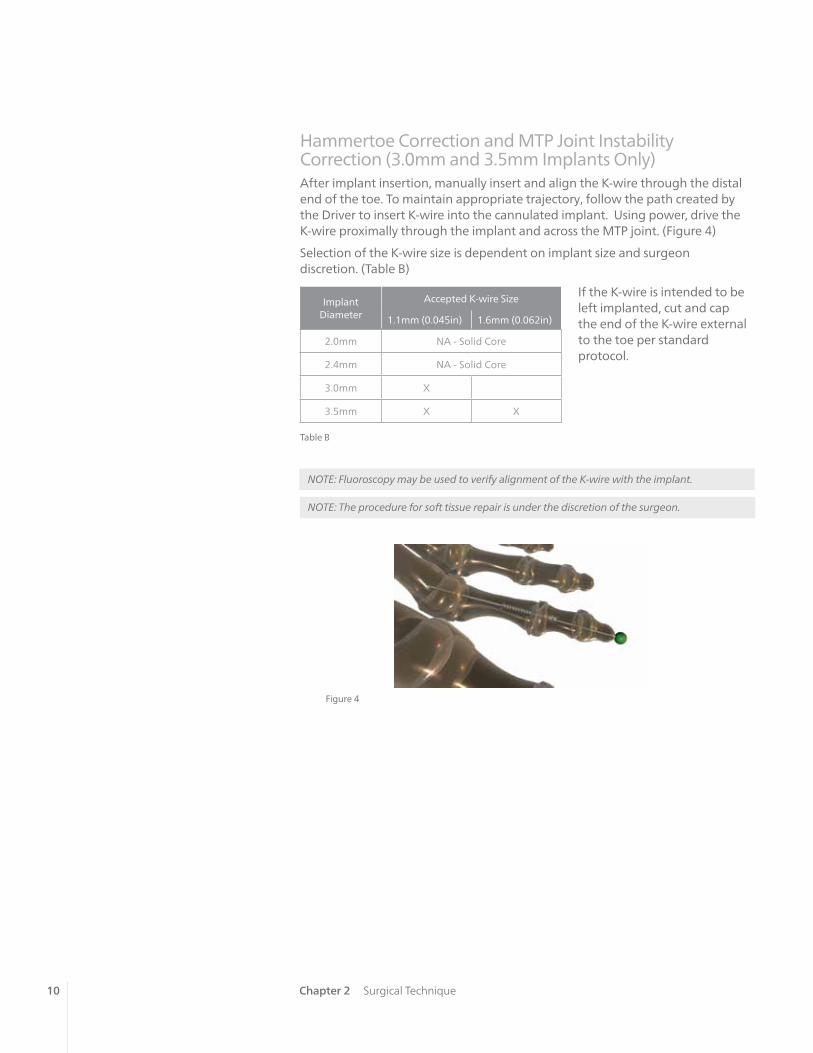
NOTE: Fluoroscopy may be used to verify alignment of the K-wire with the implant.
NOTE: The procedure for soft tissue repair is under the discretion of the surgeon.
Figure 4
Hammertoe Correction and MTP Joint Instability Correction (3.0mm and 3.5mm Implants Only)After implant insertion, manually insert and align the K-wire through the distal end of the toe. To maintain appropriate trajectory, follow the path created by the Driver to insert K-wire into the cannulated implant. Using power, drive the K-wire proximally through the implant and across the MTP joint. (Figure 4)
Selection of the K-wire size is dependent on implant size and surgeon discretion. (Table B)
If the K-wire is intended to be left implanted, cut and cap the end of the K-wire external to the toe per standard protocol.
Implant Diameter
Accepted K-wire Size
1.1mm (0.045in) 1.6mm (0.062in)
2.0mm NA - Solid Core
2.4mm NA - Solid Core
3.0mm X
3.5mm X X
Table B

11Chapter 2 Surgical Technique
Post-Operative ProtocolPost-operative protocol is under the discretion of the surgeon and may be dictated by adjunct procedures. Typical protocols recommend protected weight-bearing in a post-operative shoe or fracture boot for approximately 4-6 weeks. This applies to procedures performed in isolation.
Explant InformationThe need for implant removal should be exceedingly rare, but there may be instances when it is necessary or desired (e.g. deep infection). In these cases, the dorsal incision is re-created to allow access to the PIPJ. If the implant is loose, it may be possible to distract the toe and dislocate the PIPJ exposing the distal end of the implant. The implant can then be backed out using the Driver.
In the event there is solid arthrodesis and it is necessary to remove the implant, a corticotomy will be needed at the level of the original PIPJ. The corticotomy is carried down to the implant and a small section of bone is removed exposing the implant. This technique requires re-insertion of the hexalobe end of the Driver through the distal end of the toe. Once engaged with the implant, turn the handle clockwise to distract the joint.
Another option is to use a Steinmann pin cutter through the resected joint line cutting the implant into two halves. At this point, manually back out each half of the implant.
If the removal of the implant is required due to revision or failure of the device, the surgeon should contact the manufacturer using the contact information located on the back cover of this surgical technique to receive instructions for returning the explanted device to the manufacturer for investigation.
NOTE: Removal of the implant is under the discretion of the surgeon.

chap
ter
12
Headline Headline
Chapter 1 Description of ChapterChapter 3 Ordering Information
Ordering Information 3Implants
Non-Sterile, Stainless Steel Part Number
2.0x13mm 45802013
2.4x13mm 45802413
3.0x13mm 45803013
3.0x16mm 45803016
3.5x13mm 45803513
3.5x16mm 45803516
Implantable K-wiresNon-Sterile, Stainless Steel Part Number
1.1x150mm 45750001
1.6x150mm 45750003
InstrumentsDescription Part Number
Mini QC Handle 45805001
Driver (with trocar) 45805002
T8 Hex Driver 45805003
Driver Handle AO (Cannulated) 45765001
Drill 2.2mm 45810003
Drill 2.6mm 45810004
Drill 3.2mm 45765003
Planar 6.5mm (Cannulated 1.6mm) 45765004
Planar 7.5mm (Cannulated 1.6mm) 45765005

13
AP
PE
ND
IX
Headline Headline
CROSSCHECK® Plating System
3
Appendix A NOTES
Notes
AP
PE
ND
IX B

™Trademarks and ®Registered marks of Wright Medical Technology, Inc. ©2015 Wright Medical Technology, Inc.All Rights Reserved.
012674B_23-Sep-2015
Wright Medical Technology, Inc.1023 Cherry RoadMemphis, TN 38117800 238 7117901 867 9971www.wright.com
Wright Medical EMEAAtlas Arena, Australia BuildingHoogoorddreef 71101 BA Amsterdamthe Netherlands011 31 20 565 9060
Wright Medical UK Ltd.Unit 1, Campus FiveLetchworth Garden CityHertfordshire SG6 2JF United Kingdom011 44 (0)845 833 4435
Related Documents
![Pro 360%c2%b0 project management competence development mco[1]](https://static.cupdf.com/doc/110x72/55830b9cd8b42a50628b4e7c/pro-360c2b0-project-management-competence-development-mco1.jpg)