Prism-assisted inclined UV lithography for 3D microstructure fabrication This article has been downloaded from IOPscience. Please scroll down to see the full text article. 2012 J. Micromech. Microeng. 22 085022 (http://iopscience.iop.org/0960-1317/22/8/085022) Download details: IP Address: 129.171.217.74 The article was downloaded on 10/07/2012 at 14:14 Please note that terms and conditions apply. View the table of contents for this issue, or go to the journal homepage for more Home Search Collections Journals About Contact us My IOPscience

Welcome message from author
This document is posted to help you gain knowledge. Please leave a comment to let me know what you think about it! Share it to your friends and learn new things together.
Transcript

Prism-assisted inclined UV lithography for 3D microstructure fabrication
This article has been downloaded from IOPscience. Please scroll down to see the full text article.
2012 J. Micromech. Microeng. 22 085022
(http://iopscience.iop.org/0960-1317/22/8/085022)
Download details:
IP Address: 129.171.217.74
The article was downloaded on 10/07/2012 at 14:14
Please note that terms and conditions apply.
View the table of contents for this issue, or go to the journal homepage for more
Home Search Collections Journals About Contact us My IOPscience

IOP PUBLISHING JOURNAL OF MICROMECHANICS AND MICROENGINEERING
J. Micromech. Microeng. 22 (2012) 085022 (8pp) doi:10.1088/0960-1317/22/8/085022
Prism-assisted inclined UV lithographyfor 3D microstructure fabricationGuomin Jiang, Sarfaraz Baig and Michael R Wang
Department of Electrical and Computer Engineering, University of Miami, 1251 Memorial Dr,Coral Gables, FL 33146, USA
E-mail: [email protected]
Received 11 May 2012, in final form 30 May 2012Published 9 July 2012Online at stacks.iop.org/JMM/22/085022
AbstractA prism-assisted inclined ultraviolet (UV) lithography technique is introduced for thefabrication of three-dimensional (3D) microstructures. Slanted structures with exposure anglesranging from 0◦ to 60◦ in SU-8 photoresist have been easily achieved without immersion in theindex matching liquid. The fabrication process of multidirectional slanted structures can besimplified by one-step UV exposure using a prism with multidirectional side surfaces. Acorner prism and a cone prism have been used in our experiment to demonstrate this concept.Upside-down tripod structures and horn structures have been fabricated in one-step exposures.The effective exposure area as one key parameter of the one-step exposure is analyzed forpractical applications. Examples of various 3D microstructures fabricated by this method arepresented.
(Some figures may appear in colour only in the online journal)
1. Introduction
Inclined ultraviolet (UV) lithography has been used for thefabrication of three-dimensional (3D) microstructures [1–5].Along with sample/mask plate rotation, the inclined UVlithography has demonstrated effective production of 3Dpatterns for various practical applications, such as inclinedsurfaces for the optical pick-up head [6] and embeddedwaveguide mirror [7], V-grooves for fiber holder [8], meshstructure for microfilter [9], pyramid array for optical display[2, 10] and some more complex microstructure for micromixer[11, 12] and drug delivery [13, 14]. However, the limitedexposure angle and complicated multi-step rotation processrestrict the widespread use of the inclined UV lithography inthe fabrication of 3D microstructures.
Microstructures with large side surface angles measuredfrom the normal direction of the resin surface are necessaryfor many devices, such as optical pick-up heads [6], embeddedwaveguide mirror [7] and sharped microneedles [14]. Whenexposing directly to air, the exposure angle in the lithographicresin is limited by the refractive beam path bending associatedwith the large index mismatch between the resin and air. It isthus difficult to realize microstructures with large side surfaceangles. Immersion of lithographic resin in an index matching
liquid, such as water, heptane or glycerol, has been foundeffective in minimizing light beam path bending for expandingthe exposure angle in the resin [6–8, 14]. However, it demandsa sample settlement time in the index matching liquid to avoidbubble formation and uneven liquid surface. The presence ofsome index matching liquid such as water may affect the UVexposure properties of the resin.
In this paper, we report our exploitation of prism-assisted inclined UV lithography for the fabrication of 3Dmicrostructures in SU-8 photoresist. A prism is used todeflect the incident UV light and control the exposure beamsdirections in the SU-8 resin. Slanted structures with exposureangles ranging from 0◦ to 60◦ can be easily achieved withoutimmersing the sample in an index matching liquid. Thesample internal surface reflection of the exposing UV lightcan be further utilized for the fabrication of symmetricstructures. A prism with multidirectional side surfaces can beused to facilitate simplified one-step exposure fabrication ofmultidirectional slanted structures. A corner prism and a coneprism have been used to demonstrate this concept. This prism-assisted UV lithography technique should ease the fabricationof certain complex slanted 3D microstructures.
0960-1317/12/085022+08$33.00 1 © 2012 IOP Publishing Ltd Printed in the UK & the USA
J. Micromech. Microeng. 22 (2012) 085022 G Jiang et al
(a) (b)
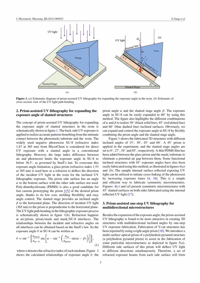
Figure 1. (a) Schematic diagram of prism-assisted UV lithography for expanding the exposure angle in the resin. (b) Schematic ofcross-section view of the UV light path bending.
2. Prism-assisted UV lithography for expanding theexposure angle of slanted structures
The concept of prism-assisted UV lithography for expandingthe exposure angle of slanted structures in the resin isschematically shown in figure 1. The back-side UV exposure isapplied to realize accurate patterns benefiting from the intimatecontact between the photomask/substrate and the resin. Thewidely used negative photoresist SU-8 (refractive index1.67 at 365 nm) from MicroChem is considered for directUV exposure with a slanted angle in a conventionallithography. However, the large index difference betweenair and photoresist limits the exposure angle in SU-8 tobelow 36.5◦, as governed by Snell’s law. To overcome thisexposure angle limitation, a glass prism (refractive index 1.53at 365 nm) is used here as a refractor to deflect the directionof the incident UV light in the resin for the inclined UVlithographic exposure. The prism side surface has an angleα to the bottom surface with the other side surface not used.Poly-dimethysiloxane (PDMS) is also a good candidate forfast custom prototyping the prism [15] of the desired prismangle, thanks to its low cost, molding flexibility and easyangle control. The slanted stage provides an inclined angleβ to the horizontal plane. The direction of incident UV light(365 nm) to the prism is perpendicular to the horizontal plane.The UV light path bending in the lithographic exposure processis schematically shown in figure 1(b). Refraction happensat air/prism, prism/mask and mask/SU-8 interfaces. Therelationships between the incident and refractive angles onall interfaces can be obtained based on the Snell’s law. So theexposure angle θ in SU-8 can be written as
θ = sin−1
{nprism
nsu−8sin
[α − sin−1
(nair
nprismsin(α − β)
)]},
(1)
where n denotes the refractive index of each medium. Figure 2shows the calculated relationships of exposure angle θ , the
prism angle α and the slanted stage angle β. The exposureangle in SU-8 can be easily expanded to 60◦ by using thismethod. The figure also highlights the different combinationsof α and β to realize 30◦ (black solid line), 45◦ (red dotted line)and 60◦ (blue dashed line) inclined surfaces. Obviously, wecan expand and control the exposure angle in SU-8 by flexiblycombining the prism angle and the slanted stage angle.
Figure 3 shows the fabricated 3D structures with differentinclined angles of 15◦, 30◦, 45◦ and 60◦. A 45◦ prism isapplied in the experiment, and the slanted stage angles areset to 0◦, 27◦, 54◦ and 85◦, respectively. A thin PDMS film hasbeen added between the glass prism and the mask/substrate toeliminate a potential air gap between them. Some functionalinclined structures with 45◦ exposure angles have also beeneasily fabricated using this method, as illustrated in figures 4(a)and (b). The sample internal surface reflected exposing UVlight can be utilized to initiate cross-linking of the photoresistby increasing exposure times [4, 16]. This is a simpleand efficient way to fabricate symmetric microstructures.Figures 4(c) and (d) present symmetric microstructures with45◦ slanted surfaces on both sides fabricated using the internalreflected UV light [17].
3. Prism-assisted one-step UV lithography formultidirectional microstructures
Besides the expansion of the exposure angle, the prism-assistedUV lithography is found to be more attractive in creating 3Dstructures with multidirectional inclined angles by one-stepUV exposure fabrication. Fabrication of V-cut structures hasbeen reported by using a right angle prism [18]. We introduce amulti-surface optical prism of a polyhedron pyramid structure(a polyhedron pyramid prism) to assist in the fabrication ofsome particular microstructures as depicted in figure 5(a).Different side surfaces of this prism will deflect UV lightto different directions simultaneously. Therefore, a set ofrefracted exposure beams from each side surface will form
2

J. Micromech. Microeng. 22 (2012) 085022 G Jiang et al
Figure 2. Exposure angle θ in SU-8 as the function of the prism angle α and slanted stage angle β.
(a) (b)
(c) (d )
Figure 3. SEM images of the fabricated 3D inclined structures with exposure angles of 15◦, 30◦, 45◦ and 60◦.
3
J. Micromech. Microeng. 22 (2012) 085022 G Jiang et al
(a) (b)
(c) (d )
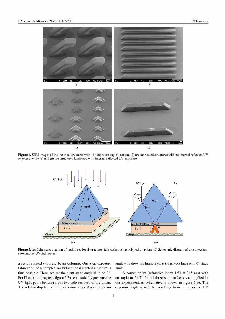
Figure 4. SEM images of the inclined structures with 45◦ exposure angles. (a) and (b) are fabricated structures without internal reflected UVexposure while (c) and (d) are structures fabricated with internal reflected UV exposure.
(a) (b)
Figure 5. (a) Schematic diagram of multidirectional structures fabrication using polyhedron prism. (b) Schematic diagram of cross-sectionshowing the UV light paths.
a set of slanted exposure beam columns. One step exposurefabrication of a complex multidirectional slanted structure isthus possible. Here, we set the slant stage angle β to be 0◦.For illustration purpose, figure 5(b) schematically presents theUV light paths bending from two side surfaces of the prism.The relationship between the exposure angle θ and the prism
angle α is shown in figure 2 (black dash-dot line) with 0◦ stageangle.
A corner prism (refractive index 1.53 at 365 nm) withan angle of 54.7◦ for all three side surfaces was applied inour experiment, as schematically shown in figure 6(a). Theexposure angle θ in SU-8 resulting from the refracted UV
4
J. Micromech. Microeng. 22 (2012) 085022 G Jiang et al
(a) (b)
(c) (d )
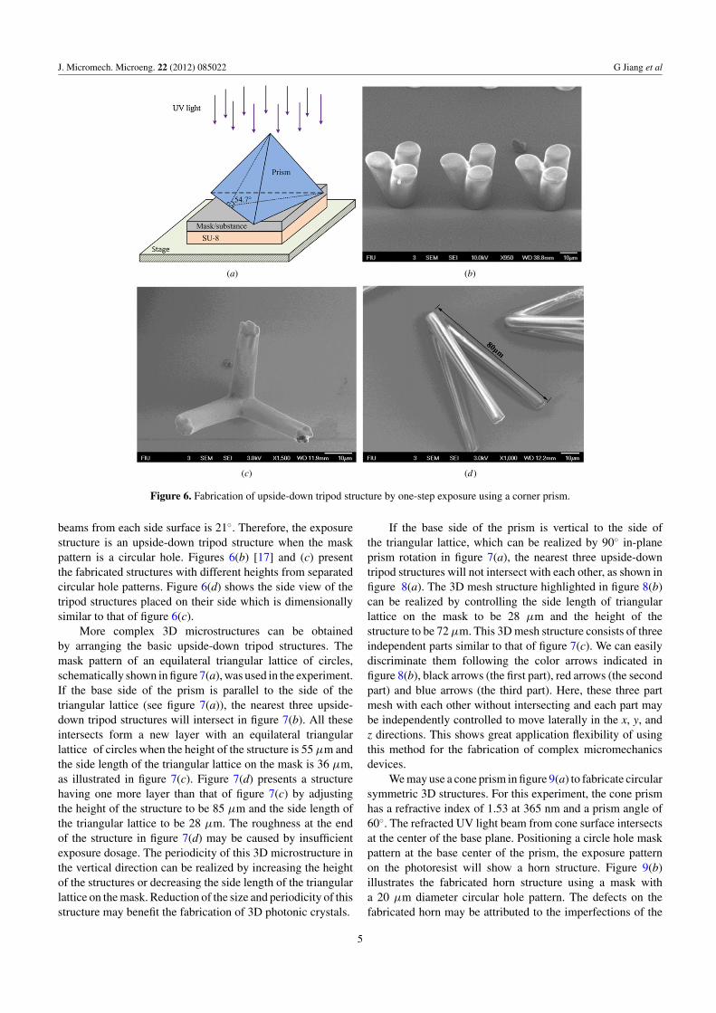
Figure 6. Fabrication of upside-down tripod structure by one-step exposure using a corner prism.
beams from each side surface is 21◦. Therefore, the exposurestructure is an upside-down tripod structure when the maskpattern is a circular hole. Figures 6(b) [17] and (c) presentthe fabricated structures with different heights from separatedcircular hole patterns. Figure 6(d) shows the side view of thetripod structures placed on their side which is dimensionallysimilar to that of figure 6(c).
More complex 3D microstructures can be obtainedby arranging the basic upside-down tripod structures. Themask pattern of an equilateral triangular lattice of circles,schematically shown in figure 7(a), was used in the experiment.If the base side of the prism is parallel to the side of thetriangular lattice (see figure 7(a)), the nearest three upside-down tripod structures will intersect in figure 7(b). All theseintersects form a new layer with an equilateral triangularlattice of circles when the height of the structure is 55 μm andthe side length of the triangular lattice on the mask is 36 μm,as illustrated in figure 7(c). Figure 7(d) presents a structurehaving one more layer than that of figure 7(c) by adjustingthe height of the structure to be 85 μm and the side length ofthe triangular lattice to be 28 μm. The roughness at the endof the structure in figure 7(d) may be caused by insufficientexposure dosage. The periodicity of this 3D microstructure inthe vertical direction can be realized by increasing the heightof the structures or decreasing the side length of the triangularlattice on the mask. Reduction of the size and periodicity of thisstructure may benefit the fabrication of 3D photonic crystals.
If the base side of the prism is vertical to the side ofthe triangular lattice, which can be realized by 90◦ in-planeprism rotation in figure 7(a), the nearest three upside-downtripod structures will not intersect with each other, as shown infigure 8(a). The 3D mesh structure highlighted in figure 8(b)can be realized by controlling the side length of triangularlattice on the mask to be 28 μm and the height of thestructure to be 72 μm. This 3D mesh structure consists of threeindependent parts similar to that of figure 7(c). We can easilydiscriminate them following the color arrows indicated infigure 8(b), black arrows (the first part), red arrows (the secondpart) and blue arrows (the third part). Here, these three partmesh with each other without intersecting and each part maybe independently controlled to move laterally in the x, y, andz directions. This shows great application flexibility of usingthis method for the fabrication of complex micromechanicsdevices.
We may use a cone prism in figure 9(a) to fabricate circularsymmetric 3D structures. For this experiment, the cone prismhas a refractive index of 1.53 at 365 nm and a prism angle of60◦. The refracted UV light beam from cone surface intersectsat the center of the base plane. Positioning a circle hole maskpattern at the base center of the prism, the exposure patternon the photoresist will show a horn structure. Figure 9(b)illustrates the fabricated horn structure using a mask witha 20 μm diameter circular hole pattern. The defects on thefabricated horn may be attributed to the imperfections of the
5

J. Micromech. Microeng. 22 (2012) 085022 G Jiang et al
(a) (b)
(c) (d )
Figure 7. Fabrication of complex 3D microstructures by one-step exposure using a corner prism when the base side of the prism is parallelto the side of the triangular lattice on the mask.
(a) (b)
Figure 8. Fabrication of complex 3D microstructures by one-step exposure using a corner prism when the base side of the prism is verticalto the side of the triangular lattice on the mask.
cone prism and/or the misalignment between the center ofcircle pattern and the base center of prism.
When using a polyhedron pyramid prism for one-stepUV lithographic fabrication of 3D multidirectional slantedstructures, attention should be paid on the effective exposurearea of the prism. Each side surface has its own projectedexposure area (the projection of the side surface to the prismbase). The total effective exposure area is the common areaof these projected exposure areas. Considering a rotationally
symmetric polyhedron pyramid prism, the effective exposurearea is highly restricted by the slanted angle α of prism,the number of side surfaces n and the circumradius r of thepolygonal base. Figure 10(a) shows the calculated results aboutthe variation of effective exposure area and its percentage onthe base area as a function of the number of side surfaces,with α = 60◦ and r = 25 mm. The effective exposure areaand its percentage decrease quickly when the number of theside surfaces increase. When the number of the side surfaces
6
J. Micromech. Microeng. 22 (2012) 085022 G Jiang et al
(a) (b)
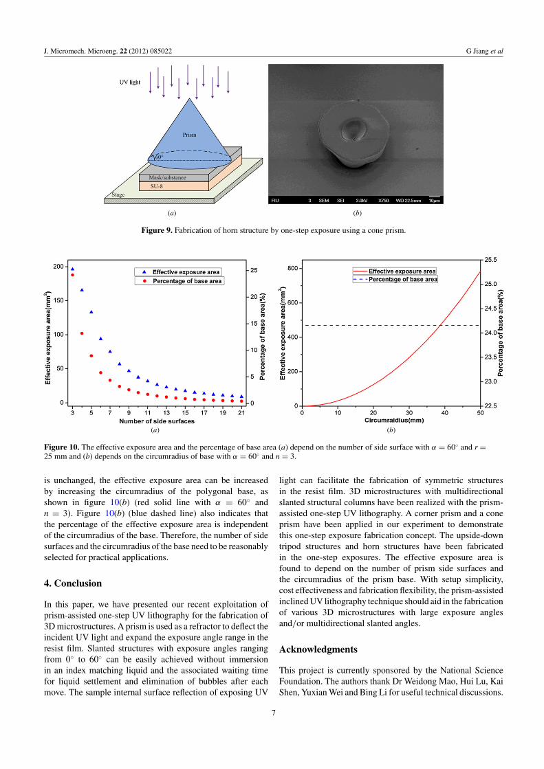
Figure 9. Fabrication of horn structure by one-step exposure using a cone prism.
(a) (b)
Figure 10. The effective exposure area and the percentage of base area (a) depend on the number of side surface with α = 60◦ and r =25 mm and (b) depends on the circumradius of base with α = 60◦ and n = 3.
is unchanged, the effective exposure area can be increasedby increasing the circumradius of the polygonal base, asshown in figure 10(b) (red solid line with α = 60◦ andn = 3). Figure 10(b) (blue dashed line) also indicates thatthe percentage of the effective exposure area is independentof the circumradius of the base. Therefore, the number of sidesurfaces and the circumradius of the base need to be reasonablyselected for practical applications.
4. Conclusion
In this paper, we have presented our recent exploitation ofprism-assisted one-step UV lithography for the fabrication of3D microstructures. A prism is used as a refractor to deflect theincident UV light and expand the exposure angle range in theresist film. Slanted structures with exposure angles rangingfrom 0◦ to 60◦ can be easily achieved without immersionin an index matching liquid and the associated waiting timefor liquid settlement and elimination of bubbles after eachmove. The sample internal surface reflection of exposing UV
light can facilitate the fabrication of symmetric structuresin the resist film. 3D microstructures with multidirectionalslanted structural columns have been realized with the prism-assisted one-step UV lithography. A corner prism and a coneprism have been applied in our experiment to demonstratethis one-step exposure fabrication concept. The upside-downtripod structures and horn structures have been fabricatedin the one-step exposures. The effective exposure area isfound to depend on the number of prism side surfaces andthe circumradius of the prism base. With setup simplicity,cost effectiveness and fabrication flexibility, the prism-assistedinclined UV lithography technique should aid in the fabricationof various 3D microstructures with large exposure anglesand/or multidirectional slanted angles.
Acknowledgments
This project is currently sponsored by the National ScienceFoundation. The authors thank Dr Weidong Mao, Hui Lu, KaiShen, Yuxian Wei and Bing Li for useful technical discussions.
7
J. Micromech. Microeng. 22 (2012) 085022 G Jiang et al
References
[1] Beuret C, Racine G A, Gobet J, Luthier R and de Rooij N F1994 Microfabrication of 3D multidirectional inclinedstructures by UV lithography and electroplating Proc. IEEEInt. Conf. on Micro Electro Mechanical Syst. (MEMS 1994)pp 81–85
[2] Yoon Y-K, Park J-H and Allen M G 2006 Multidirectional UVlithography for complex 3D MEMS structures IEEE J.Microelectromech. Syst. 15 1121–30
[3] Han M, Lee W, Lee S-K and Lee S S 2004 3Dmicrofabrication with inclined/rotated UV lithographySensors Actuators A 111 14–20
[4] del Campo A and Arzt E 2008 Fabrication approaches forgenerating complex micro- and nanopatterns on polymericsurfaces Chem. Rev. 108 911–45
[5] del Campo A and Greiner C 2007 SU-8 a photoresist forhigh-aspect-ratio and 3D submicron lithographyJ. Micromech. Microeng. 17 R81–95
[6] Hung K Y, Hu H T and Tseng F G 2004 Application of 3Dglycerol-compensated inclined-exposure technology to anintegrated optical pick-up head J. Micromech. Microeng.14 975–83
[7] Dou X, Wang X, Huang H, Lin X, Ding D, Pan D Z andChen R T 2010 Polymeric waveguides with embeddedmicromirrors formed by metallic hard mold Opt. Express18 378–85
[8] Ling Z and Lian K 2007 SU-8 3D microoptic componentsfabricated by inclined UV lithography in water Microsyst.Technol. 13 245–51
[9] Sato H, Kakinuma T, Go J S and Shoji S 2004 In-channel 3Dmicromesh structures using maskless multi-angle exposuresand their microfilter application Sensors Actuators A111 87–92
[10] Shieh H-P D, Huang Y-P and Chien K-W 2005 Micro-opticsfor liquid crystal displays applications IEEE/OSA J. Disp.Technol. 1 62–76
[11] Baek S and Song S A 2011 A one-step photolithographymethod for fabrication of a staggered herringbone mixerusing inclined UV lithography J. Micromech. Microeng.21 077001
[12] Sato H, Yagyu D, Ito S and Shoji S 2006 Improved inclinedmulti-lithography using water as exposure medium and its3D mixing microchannel application Sensors Actuators A128 183–90
[13] Yoon Y-K, Park J-H, Lee J-W, Prausnitz M R and Allen M G2011 A thermal microjet system with tapered micronozzlesfabricated by inclined UV lithography for transdermal drugdelivery J. Micromech. Microeng. 21 025014
[14] Han M, Hyun D-H, Park H-H, Lee S S, Kim C-Hand Kim C G 2007 A novel fabrication process forout-of-plane microneedle sheets of biocompatible polymerJ. Micromech. Microeng. 17 1184–91
[15] Kang W-J, Rabe E, Kopetz S and Neyer A 2006 Novelexposure methods based on reflection and refraction effectsin the field of SU-8 lithography J. Micromech. Microeng.16 821–31
[16] Zhu Z, Zhou Z-F, Huang Q-A and Li W-H 2008 Modeling,simulation and experimental verification of inclined UVlithography for SU-8 negative thick photoresistsJ. Micromech. Microeng. 18 125017
[17] Jiang G, Baig S and Wang M R 2012 3D microstructuresfabricated by prism assisted inclined UV lithography Proc.SPIE 8249 82490L
[18] Huang Y-J, Chang T-L, Chou H-P and Lin C-H 2008 A novelfabrication method for forming inclined groove-basedmicrostructures using optical elements Japan. J. Appl. Phys.47 5287–90
8
Related Documents