Colorado Department of Transportation 2017 Pavement Design Manual 196 PRINCIPLES OF DESIGN FOR FLEXIBLE PAVEMENT 6.1 Introduction Design of flexible pavement structures involves the consideration of numerous factors, the most important are truck volume, weight and distribution of axle loads, HMA, underlying material properties, and the supporting capacity of the subgrade soils. Typical reconstruction projects should have a design life of 20 years for reconstructions and 10 years for rehabilitations unless mitigating circumstances exist. Methods are presented in this section for the design of the flexible pavement structure with respect to thickness of the subbase, base, surface courses, and the quality and strength of the materials in place. Interaction between pavement materials and climate is evaluated as part of the M-E Design process. 6.2 M-E Design Methodology for Flexible Pavement M-E Design uses an iterative process. The key steps in the design process include the following: 1. Select a Trial Design Strategy 2. Select Appropriate Performance Indicator Criteria for the Project: Establish criteria for acceptable pavement performance (i.e. distress/IRI) at the end of the design period. Performance criteria were established to reflect different magnitudes of key pavement distresses which trigger major rehabilitation or reconstruction. CDOT criteria for acceptable performance is based on highway functional class and location. 3. Select Appropriate Reliability Level for the Project: The reliability is in essence a factor of safety that accounts for inherent variations in construction, materials, traffic, climate, and other design inputs. The level of reliability selected should be based on the criticality of the design and selected for each individual performance indicator. CDOT criteria for a desired reliability is based on highway functional class and location. 4. Assemble All Inputs for the Pavement Trial Design Under Consideration: Define subgrade support, asphalt concrete and other paving material properties, traffic loads, climate, pavement type and design, and construction features. The inputs required to run the M-E Design program may be obtained using one of three hierarchical levels and need not be consistent for all inputs in a given design. The hierarchical level for a given input is selected based on the importance of the project, input, and resources at the disposal of the user. 5. Run the M-E Design Software: The software calculates changes in layer properties, damage, key distresses, and IRI over the design life. The key steps include:

Welcome message from author
This document is posted to help you gain knowledge. Please leave a comment to let me know what you think about it! Share it to your friends and learn new things together.
Transcript

Colorado Department of Transportation
2017 Pavement Design Manual
196
PRINCIPLES OF DESIGN FOR FLEXIBLE PAVEMENT
6.1 Introduction
Design of flexible pavement structures involves the consideration of numerous factors, the most
important are truck volume, weight and distribution of axle loads, HMA, underlying material
properties, and the supporting capacity of the subgrade soils. Typical reconstruction projects
should have a design life of 20 years for reconstructions and 10 years for rehabilitations unless mitigating circumstances exist.
Methods are presented in this section for the design of the flexible pavement structure with respect
to thickness of the subbase, base, surface courses, and the quality and strength of the materials in
place. Interaction between pavement materials and climate is evaluated as part of the M-E Design
process.
6.2 M-E Design Methodology for Flexible Pavement
M-E Design uses an iterative process. The key steps in the design process include the following:
1. Select a Trial Design Strategy
2. Select Appropriate Performance Indicator Criteria for the Project: Establish
criteria for acceptable pavement performance (i.e. distress/IRI) at the end of the design
period. Performance criteria were established to reflect different magnitudes of key
pavement distresses which trigger major rehabilitation or reconstruction. CDOT
criteria for acceptable performance is based on highway functional class and location.
3. Select Appropriate Reliability Level for the Project: The reliability is in essence a
factor of safety that accounts for inherent variations in construction, materials, traffic,
climate, and other design inputs. The level of reliability selected should be based on
the criticality of the design and selected for each individual performance indicator.
CDOT criteria for a desired reliability is based on highway functional class and
location.
4. Assemble All Inputs for the Pavement Trial Design Under Consideration: Define
subgrade support, asphalt concrete and other paving material properties, traffic loads,
climate, pavement type and design, and construction features. The inputs required to
run the M-E Design program may be obtained using one of three hierarchical levels
and need not be consistent for all inputs in a given design. The hierarchical level for a
given input is selected based on the importance of the project, input, and resources at
the disposal of the user.
5. Run the M-E Design Software: The software calculates changes in layer properties,
damage, key distresses, and IRI over the design life. The key steps include:

Colorado Department of Transportation
2017 Pavement Design Manual
197
a) Processing input to obtain monthly values of traffic, seasonal variations of
material, and climatic inputs needed in design evaluations for the entire design
period.
b) Computing structural responses (stresses and strains) using multilayer elastic
theory or finite element based pavement response models for each axle type
and load and each damage-calculation increment throughout the design
period.
c) Calculating accumulated distress at the end of each analysis period for the
entire design period.
d) Predicting key distresses (rutting, bottom-up/top-down fatigue cracking, and
thermal cracking) at the end of each analysis period throughout the design life
using calibrated mechanistic-empirical performance models.
e) Predicting IRI as a function of initial IRI, distresses accumulating over time,
and site factors at the end of each analysis increment.
6. Evaluate Adequacy of the Trial Design: The trial design is considered “adequate”
if none of the predicted distresses/IRI exceed the performance indicator criteria at the
design reliability level chosen for the project. If any criteria has been exceeded, one
must determine how the deficiency can be remedied by altering material types,
properties, layer thicknesses, or other design features.
7. Revise the Trial Design, as Needed: If the trial design is deemed “inadequate”, one
must revise the inputs and re-run the program until all performance criteria have been
met. Once met, the trial design becomes a feasible design alternative.
Design alternatives that satisfy all performance criteria are considered feasible from a structural
and functional viewpoint and may be considered for other evaluations, such as life cycle cost
analysis. Consultation of the mix design(s) with the RME shall occur. A detailed description of
the design process is presented in the interim edition of the AASHTO Mechanistic-Empirical
Pavement Design Guide Manual of Practice, AASHTO 2008.
6.3 Select a Trial Design Strategy
6.3.1 Flexible Pavement Design Types
Figure 6.1 Asphalt Concrete Pavement Layer Systems illustrates well known CDOT
combinations of asphalt concrete structural pavement layers. Designers can select from among
several flexible pavement options as shown below:
Conventional Flexible Pavements: Flexible pavements consisting of a relatively thin
asphalt concrete layer placed over an unbound aggregate base layer and subgrade.
Deep-Strength AC Pavements: Flexible pavements consisting of a relatively thick
asphalt concrete layer placed over an unbound aggregate base layer and subgrade.

Colorado Department of Transportation
2017 Pavement Design Manual
198
Full-Depth AC Pavements: Asphalt concrete layers placed directly over the subgrade.
Figure 6.1 Asphalt Concrete Pavement Layer Systems
The asphalt concrete layer in Figure 6.1 Asphalt Concrete Pavement Layer Systems may be
comprised of several layers of asphalt concrete courses to include a surface course, intermediate
or binder course, and a base course (see Figure 6.2 Structural Layers). The surface, binder, and
base courses are typically different in composition and are placed in separate construction
operations (3).
Surface Course: The surface course normally contains the highest quality materials.
It provides characteristics such as friction, smoothness, noise control, rut and shoving
resistance, and drainage. It also serves to prevent the entrance of excessive quantities
of surface water into the underlying HMA courses, bases, and subgrade.
Intermediate/Binder Course: The intermediate course, sometimes called binder
course, consists of one or more lifts of structural HMA placed below the surface course.
Its purpose is to distribute traffic loads so stresses transmitted to the pavement
foundation will not result in permanent deformation to the course. It also facilitates the
construction of the surface course.
Base Course: The base course consists of one or more HMA lifts located at the bottom
of the structural HMA course. Its major function is to provide the principal support of
the pavement structure. The base course should contain durable aggregates that will
not be damaged by moisture or frost action.

Colorado Department of Transportation
2017 Pavement Design Manual
199
Figure 6.2 Structural Layers
6.3.2 Concept of Perpetual Pavements
A perpetual pavement is defined as an asphalt pavement designed and built to last longer than 50
years without requiring major structural rehabilitation or reconstruction, and needing only periodic
surface renewal in response to distresses confined to the top of the pavement (6). Full depth and
deep-strength asphalt pavement structures have been constructed since the 1960s. Full-depth
pavements are constructed directly on subgrade soils and deep-strength sections are placed on
relatively thin (4 to 6 inches) granular base courses. A 20-year traffic design period is to be used
for the traffic loading. One of the chief advantages of these pavements is that the overall section
of the pavement is thinner than those employing thick granular base courses. Such pavements
have the added advantage of significantly reducing the potential for fatigue cracking by
minimizing the tensile strains at the bottom of the asphalt layer (7) (see Figure 6.1 Asphalt
Concrete Pavement Layer Systems). An asphalt perpetual pavement structure is designed with
a durable, rut and wear resistant top layer with a rut resistant intermediate layer and a fatigue
resistant base layer (see Figure 6.3 Perpetual Pavement Design Concept)
Rigid Foundation
Natural Subgrade
Compacted Subgrade
Unbound Subbase
Unbound Base
Asphalt Base
Asphalt Binder
Asphalt Surface
Asphalt Concrete
Layer
Unbound Layer
Subgrade
Road bed

Colorado Department of Transportation
2017 Pavement Design Manual
200
Figure 6.3 Perpetual Pavement Design Concept
This concept may be used in conventional, deep strength, or full depth asphalt structural layering.
In mechanistic design, the principles of physics are used to determine a pavement’s reaction to
loading. Knowing the critical points in the pavement structure, one can design against certain
types of failure or distress by choosing the right materials and layer thicknesses (7). Therefore,
the uppermost structural layer resists rutting, weathering, thermal cracking, and wear. SMAs or
dense-graded SuperPave mixtures provide these qualities. The intermediate layer provides rutting
resistance through stone-on-stone contact and durability is imparted by the proper selection of
materials. Resistance to bottom-up fatigue cracking is provided by the lowest asphalt layer having
a higher binder content or by the total thickness of pavement reducing the tensile strains in this
layer to an insignificant level (6).
6.3.3 Establish Trial Design Structure
The designer must establish a trial design structure (combination of material types and
thicknesses). This is done by first selecting the pavement type of interest (see Figure 6.5 M-E
Design Software Screenshot Showing General Information (left), Performance Criteria and
Reliability (right)). M-E Design automatically provides the top layers of the selected pavement
type. The designer may add or remove pavement structural layers and/or modify the layer material
type and thickness as appropriate. Figure 6.4 M-E Design Software Screenshot of Flexible
Pavement Trial Design Structure shows an example of flexible pavement trial design with
pavement layer configuration on the left and layer properties of the AC surface course on the right.
Asphalt Surface
Intermediate Layer
Asphalt Base
Subgrade or
Unbound Base
Zone of High
Compression
(4 to
6 inches)
Max Tensile
Strain
Temperature
Dep
th
Change in Temperature
High Quality HMA or SMA
High Performance PG Binder
High Modulus, Rut Resistant
High-Temp PG Binder (same as surface)
Low-Temp PG Binder (+1 temp grade
higher than surface)
Flexible, Fatigue Resistant
High-Temp PG Binder (appropriate
or depth)
Low-Temp PG Binder (+1 temp grade
higher than surface)
Recommended
Thickness
Mixture Type
and Binder Grade
1 ½ to 3 inches
4 to 7 inches
3 to 4 inches

Colorado Department of Transportation
2017 Pavement Design Manual
201
Figure 6.4 M-E Design Software Screenshot of Flexible Pavement Trial Design Structure
6.4 Select the Appropriate Performance Indicator Criteria for the Project
Table 2.4 Recommended Threshold Values of Performance Criteria for New Construction
or Reconstruction Projects presents recommended performance criteria for flexible pavement
design. The designer should enter the appropriate performance criteria based on functional class.
An appropriate initial smoothness (IRI) is also required, For new flexible pavements, the
recommended initial IRI is 50 inches/mile.
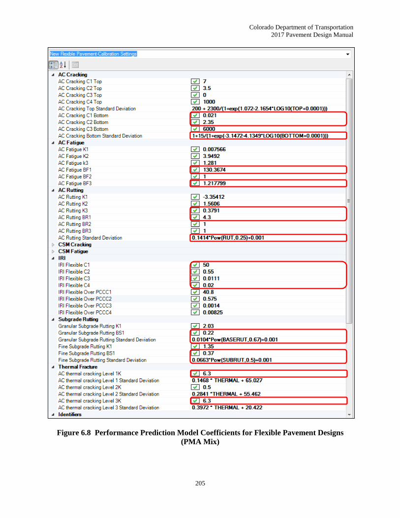
Figure 6.5 M-E Design Software Screenshot Showing General Information (left)
Performance Criteria and Reliability (right) shows performance criteria for a sample flexible
pavement trial design. The coefficients of performance prediction models considered in the design
of a new flexible pavement are shown in Figure 6.6 Performance Prediction Model Coefficients
for Flexible Pavement Designs (Marshall Mix) through Figure 6.8 Performance Prediction
Model Coefficients for Flexible Pavement Designs (PMA Mix). The value of AC rutting
coefficient (BR1) is based on the type of HMA

Colorado Department of Transportation
2017 Pavement Design Manual
202
Figure 6.5 M-E Design Software Screenshot Showing General Information (left),
Performance Criteria and Reliability (right)

Colorado Department of Transportation
2017 Pavement Design Manual
203
Figure 6.6 Performance Prediction Model Coefficients for Flexible Pavement Designs
(Marshall Mix)

Colorado Department of Transportation
2017 Pavement Design Manual
204
Figure 6.7 Performance Prediction Model Coefficients for Flexible Pavement Designs
(Superpave Mix)
Colorado Department of Transportation
2017 Pavement Design Manual
205
Figure 6.8 Performance Prediction Model Coefficients for Flexible Pavement Designs
(PMA Mix)

Colorado Department of Transportation
2017 Pavement Design Manual
206
6.5 Select the Appropriate Reliability Level for the Project
Recommended reliability levels for flexible pavement designs are located in Table 2.3 Reliability
(Risk). The designer should select an appropriate reliability level based on highway functional
class and location. Figure 6.5 M-E Design Software Screenshot Showing General Information
(left), Performance Criteria and Reliability (right) shows design reliability values for a sample
flexible pavement trial design.
6.6 Assemble M-E Design Software Inputs
6.6.1 General Information
6.6.1.1 Design Period
The design period for new flexible pavement construction and reconstruction is at least 20 years.
For special designs, the designer may use a different design period as appropriate.
6.6.1.2 Construction Dates and Timeline
The following inputs are required to specify the construction dates and timeline (see Figure 6.5
M-E Design Software Screenshot Showing General Information (left), Performance Criteria
and Reliability (right)):
Base/subbase construction month and year
Pavement construction month and year
Traffic open month and year
The designer may select the most likely month and year for construction completion of the key
activities listed above. Selection is based on the designer’s experience, agency practices, or
estimated from the planned construction schedule. For large projects that extend into different
paving seasons, it is suggested each paving season be evaluated separately and the designer judge
the acceptability of the trial design based on the more conservative situation. The M-E Design
software does not consider staged construction events, nor does it consider the impact of
construction traffic on damage computations.
Note: The pavement performance predictions begin from the month the pavement is open to
traffic. The changes to pavement material properties due to time and environmental conditions are
calculated beginning from the month and year the material was placed.
6.6.1.3 Identifiers
Identifiers are helpful in documenting the project location and recordkeeping. M-E Design allows
designers to enter site or project identification information such as the location of the project (route
signage, jurisdiction, etc.), identification numbers, beginning and ending milepost, direction of
traffic, and date.

Colorado Department of Transportation
2017 Pavement Design Manual
207
6.6.2 Traffic
Several inputs are required for characterizing traffic for the M-E Design software and are described
in detail in Section 3.1 Traffic.
6.6.3 Climate
The climate input requirements for the M-E Design software are described in detail in Section 3.2
Climate.
6.6.4 Pavement Layer Characterization
As shown in Figure 6.2 Structural Layers, a typical flexible pavement design comprises of the
following pavement layers: asphalt concrete, unbound aggregate base layers, and subgrade. The
inputs required by M-E Design for characterizing these layers are described in the following
sections.
6.6.4.1 Asphalt Concrete Characterization
Asphalt concrete types used in Colorado include:
Hot Mix Asphalt (HMA): Composed of aggregates with an asphalt binder and certain
anti-stripping additives.
Stone Matrix Asphalt (SMA): Gap-graded HMA that maximizes rutting resistance
and durability with a stable stone-on-stone skeleton held together by a rich mixture of
AC, filler, and stabilizing agents.
The designers should apply the following guidelines when defining an asphalt concrete layer:
As much as possible and as appropriate, the asphalt concrete layers must be combined
into three layers: surface, intermediate and base. Asphalt layers with similar HMA
mixtures may be combined into a single layer.
When multiple layers are combined, the properties of the combined layer should be the
weighted average of the individual layers.
The M-E Design software does not consider very thin layers (thickness less than 1.5
inches).
Weakly stabilized asphalt materials (i.e. sand-asphalt) should not be considered an
asphalt concrete layer.
M-E Design models layer by layer rutting. Table 6.1 Layered Rut Distribution
shows the percentages used for calculating the final rutting in Colorado.

Colorado Department of Transportation
2017 Pavement Design Manual
208
Table 6.1 Layered Rut Distribution
Layer Colorado
Percent Distribution
Global
Percent Distribution
Hot Mix Asphalt 60 80
Aggregate Base Course 10 5
Subgrade 30 15
Designers are required to input volumetric properties such as air voids, effective asphalt content
by volume, aggregate gradation, mix density, and asphalt binder grade (see Figure 6.9 Asphalt
Concrete Layer and Material Properties in M-E Design). The designers are also required to
input the engineering properties such as the dynamic modulus, creep compliance, indirect tensile
strength of HMA materials, and the viscosity versus temperature properties of rolling thin film
oven (RTFO) aged asphalt binders. These inputs can be obtained following the input hierarchy
levels depending on the criticality of the project. The volumetric properties entered into the
program need to be representative of the in-place asphalt concrete mixture. The project-specific
in-place mix properties will not be available at the design stage. The designer should use typical
values available from previous construction records or target values from the project
specifications.
Figure 6.9 Asphalt Concrete Layer and Material Properties in M-E Design

Colorado Department of Transportation
2017 Pavement Design Manual
209
Table 6.2 Input Properties and Recommendations for HMA Material Characterization presents the HMA input requirements of the M-E Design Method and recommendations for
obtaining inputs at each hierarchical input level. The designer may use Level 1 inputs of typical
CDOT HMA mixtures for Level 2 and 3 inputs. See APPENDIX F and Table 2.6 Selection of
Input Hierarchical Level for selection of an appropriate hierarchical level for HMA
characterization. For new construction (i.e. new HMA) the designer should always click “True”
for the Possion’s Ratio (currently the default value is “False”).
Table 6.2 Input Properties and Recommendations for HMA Material Characterization
Input Property Level 1 Level 2 Level 3
Dynamic Modulus (E*)
Mix specific E*
and/or AASHTO
TP62 test results
Gradation (APPENDIX E)
Asphalt Binder Properties Binder properties from laboratory testing
of HMA using AASHTO T315
Binder grade
(APPENDIX E)
Tensile Strength 1 at 14 oF AASHTO T322
test results
Use tensile strength and creep compliance
(APPENDIX E) Creep Compliance
Poisson’s Ratio M-E Design software option
(Is Poisson's ratio calculated?) Use 0.35
Air Voids Use air voids (APPENDIX E)
Volumetric Asphalt
Content Use volumetric asphalt content (APPENDIX E)
Total Unit Weight Use total unit weight (APPENDIX E)
Surface Shortwave
Absorptivity Use 0.85
Coefficient of Thermal
Contraction of the Mix
1.3E-05 in./in./°F (mix CTE)
and 5.0 E-06 in./in./°F (aggregate CTE)
Thermal Conductivity 0.67 Btu/(ft)(hr)(oF)
Heat Capacity 0.23 BTU/lb.- ˚F
Reference Temperature 70 ˚F
Note: 1 The designer should use Level 1 Inputs. The Level 3 Inputs for tensile strength are much smaller which will
cause more thermal cracking and greater creep compliance.
6.6.4.2 Unbound Layers and Subgrade Characterization
Refer to Section 5.3.1 Unbound Layer Characterization in M-E Design for unbound aggregate
base layer characterization. Refer to Section 4.4 Subgrade Characterization for M-E Design
for subgrade characterization.

Colorado Department of Transportation
2017 Pavement Design Manual
210
6.7 Run M-E Design Software
Designers should examine all inputs for accuracy and reasonableness prior to running the M-E
Design software. Next, one should run the software to obtain outputs required to determine if the
trial design is adequate. After a trial run has been successfully completed, M-E Design will
generate a report in form of a PDF and/or Microsoft Excel file, refer to Figure 6.10 Sample
Flexible Pavement Trial Design PDF Output Report. The output report has input information,
reliability of design, material properties, and predicted performance. It also includes the month to
month estimates of material properties over the entire design period in either tabular or graphical
form. For a flexible pavement trial design, the report provides the following:
Monthly estimates of HMA dynamic modulus for each sublayer
Monthly estimates of resilient modulus of unbound layers and subgrade
Monthly estimates of AADTT
Monthly estimates of climate parameters
Cumulative trucks (FHWA Class 4 through 13) over the design period
Cumulative ESALs over the design period (an intermediate file in the project folder)
After the trial run is complete, the designer should re-examine all inputs and outputs for accuracy
and reasonableness before accepting a trial design as complete.
Figure 6.10 Sample Flexible Pavement Trial Design PDF Output Report

Colorado Department of Transportation
2017 Pavement Design Manual
211
6.8 Evaluate the Adequacy of the Trial Design
The output report of a flexible pavement trial design includes the monthly accumulation of the
following key distress types at their mean values and chosen reliability for the entire design period:
Alligator Fatigue Cracking: Traditional wheel path cracking that initiates at the
bottom of the HMA layer and propagates to the surface under repeated load
applications. Beyond a critical threshold, the rate of cracking accelerates and may
require significant repairs and lane closures. Fatigue cracking is highly dependent on
the effective asphalt content by volume and air voids.
Transverse Cracking: Thermal cracks typically appear as transverse cracks on the
pavement surface due to low temperatures, hardening of the asphalt, and/or daily
temperature cycles. Excessive transverse cracking may adversely affect ride quality.
The designer should examine the results to evaluate if the performance criteria for each of the
above-mentioned indicators are met at the desired reliability. If alligator fatigue cracking or
transverse cracking criteria have not been met, the trial design is deemed unacceptable and
revised accordingly to produce a satisfactory design.
The output report also includes the monthly accumulation of the following secondary distress types
and smoothness indicators at their mean values and chosen reliability for the entire design period:
Permanent Deformation: The report includes HMA rutting and total permanent
deformation (includes rutting on unbound layers and subgrade). Excessive rutting may
cause safety concerns.
Surface-Initiated Fatigue Cracking or Longitudinal Cracking: These load-related
cracks appear at the HMA surface and propagate downwards. Beyond a critical
threshold, the rate of cracking accelerates and may require significant repairs and lane
closures.
IRI: The roughness index represents the profile of the pavement in the wheel paths.
Higher IRI indicates unacceptable ride quality.
The designer should examine the results to evaluate if the performance criteria for
permanent deformation, surface-initiated fatigue cracking or longitudinal cracking, and IRI
meet the minimum of 12 years at the desired reliability. If any of the criteria have not been
met, the trial design is deemed unacceptable and revised accordingly to produce a satisfactory
design.
Another important output is the reliability level of each performance indicator at the end of the
design period. If the reliability value predicted for the given performance indicator is greater than
the target/desired value, the trial design passes for that indicator. If the reverse is true, then the
trial design fails to provide the desired confidence and the performance indicator will not reach the

Colorado Department of Transportation
2017 Pavement Design Manual
212
critical value during the pavement’s design life. In such an event, the designer needs to alter the
trial design to correct the problem.
The strategies for modifying a trial design are discussed in Section 6.9 Modifying Trial Designs.
The designer can use a range of thicknesses to optimize the thickness of the trial design to make it
more acceptable. In addition, the software allows the designer to perform a sensitivity analysis on
the key inputs. The results of the sensitivity analysis can be used to further optimize the trial
design if modifying AC thickness alone does not produce a feasible design alternative. A detail
description of thickness optimization procedure and sensitivity analysis is provided in the Software
HELP Manual.
6.9 Modifying Trial Designs
An unsuccessful trial design may require revisions to ensure all performance criteria are satisfied.
The trial design is modified by systematically revising the design inputs. In addition to layer
thickness, many other design factors influence performance predictions. The design acceptance is
distress-specific; in other words, the designer needs to first identify the performance indicator that
failed to meet the performance target and modify one or more design inputs that has a significant
impact on the given performance indicator. The impact of design inputs on performance indicators
is typically obtained by performing a sensitivity analysis. Strategies used to produce a satisfactory
design by modifying design inputs can be broadly categorized into to following:
Pavement layer considerations
Increasing layer thickness
Modifying layer type and layer arrangement
Foundation improvements (i.e. stabilize the upper subgrade soils)
Pavement material improvements:
Use of higher quality materials (i.e. use of polymer modified asphalt, crushed
stones)
Material design modifications (i.e. increase asphalt content, reduce amount of
fines, modify gradations etc.)
Construction quality (i.e. reduce HMA air voids, increase compaction density,
decrease as-constructed pavement smoothness)
Once again, when modifying the design inputs, the designer needs to be aware of the sensitivity
of these inputs to various distress types. Changing a single input to reduce one distress may result
in an increase in another distress. For example, the designer may consider using a harder asphalt
to reduce HMA rutting, but that will likely increase the predicted transverse cracking. Table 6.3
Modifying Flexible Pavement Trial Designs presents a summary of inputs that may be modified
to optimize trial designs and produce a feasible design alternative.

Colorado Department of Transportation
2017 Pavement Design Manual
213
Table 6.3 Modifying Flexible Pavement Trial Designs
Distress/IRI Design Inputs that Impact
AC Rutting
Use a polymer modified asphalt for the HMA surface layer
Increase the dynamic modulus of the HMA mixture(s)
Reduce the asphalt content in the HMA mixture(s)
Increase the amount of crushed aggregate
Increase the amount of manufactured fines in the HMA mixture
Transverse
Cracking
Decrease the stiffness of the AC surface mix
Use a softer asphalt
Increase asphalt binder
Increase indirect tensile strength
Reduce creep compliance
Increase AC layer thickness
Alligator
Cracking
Increase HMA layer thickness
Increase HMA dynamic modulus for HMA layers thicker than 5 inches
and decrease HMA dynamic modulus for HMA layers thinner than 3
inches
Revise the mixture design of the HMA base layer
Increase asphalt binder content
Achieve higher density and lower air voids during compaction
Use harder asphalt/polymer modified asphalt but ensure good
compaction is achieved
Increase percent manufactured fines, and/or percent crushed
aggregates
Reduce stiffness gradients between upper and lower layers
Using a higher quality/stiffer HMA layer on top of poor
quality/low resilient modulus granular base or foundation tends to
increase fatigue cracking
Increase the thickness or stiffness of a high quality unbound base layer
and/or use a stabilized layer
Unbound Base
Rutting
Increase the resilient modulus of the aggregate base
Increase the density of the aggregate base
Stabilize the upper foundation layer for weak, frost susceptible, or
swelling soils
Place a layer of select embankment material with adequate compaction
Increase the HMA or granular layer thickness
Address drainage related issues to protect from the detrimental effects
of moisture
Subgrade
Rutting
Increase the layer stiffness and layer thickness of any layers above the
subgrade layers:
Increase HMA and/or unbound layer thickness or stiffness
Include a stabilized drainable base

Colorado Department of Transportation
2017 Pavement Design Manual
214
Distress/IRI Design Inputs that Impact
Improve the engineering properties of the subgrade material:
Increase the stiffness (modulus) of the subgrade layer(s) itself
through the use of lime stabilized subgrade
Effective use of subsurface drainage systems, geotextile fabrics,
and impenetrable moisture barrier wraps to protect from the
detrimental effects of moisture
Increase the grade elevation to increase the distance between the
subgrade surface and ground water table
IRI
Reduce initial IRI (achieving smoother as-constructed pavement
surface through more stringent smoothness criteria)
Improve roadbed foundation (replace frost susceptible or expansive
subgrade with non-frost susceptible or stabilized subgrade materials)
Place subsurface drainage system to remove ground water
Figure 6.11 Sensitivity of HMA Alligator Cracking to Truck Volume through Figure 6.32
Sensitivity of HMA IRI to Base Thickness. Figure 6.30 Sensitivity of HMA IRA to AC
Thickness presents sensitivity plots of a sample flexible pavement trial design showing the effects
of key inputs, such as traffic volume, asphalt binder content, asphalt binder grade, air voids, base
type, base thickness, and climate on key distresses/IRI. Note: The plots do not exhaustively cover
the effects of all key factors on flexible pavement performance; other significant factors are not
shown herein.
Figure 6.11 Sensitivity of HMA Alligator Cracking to Truck Volume

Colorado Department of Transportation
2017 Pavement Design Manual
215
Figure 6.12 Sensitivity of HMA Alligator Cracking to AC Thickness
Figure 6.13 Sensitivity of HMA Alligator Cracking to Asphalt Binder Content

Colorado Department of Transportation
2017 Pavement Design Manual
216
Figure 6.14 Sensitivity of HMA Alligator Cracking to Air Voids
Figure 6.15 Sensitivity to HMA Alligator Cracking to Base Type

Colorado Department of Transportation
2017 Pavement Design Manual
217
Figure 6.16 Sensitivity of HMA Alligator Cracking to Base Thickness
Figure 6.17 Sensitivity of HMA Alligator Cracking to Climate

Colorado Department of Transportation
2017 Pavement Design Manual
218
Figure 6.18 Sensitivity of Total Rutting to Truck Volume
Figure 6.19 Sensitivity of Total Rutting to AC Thickness

Colorado Department of Transportation
2017 Pavement Design Manual
219
Figure 6.20 Sensitivity of Total Rutting to Asphalt Binder Grade
Figure 6.21 Sensitivity of Total Rutting to Air Voids
Colorado Department of Transportation
2017 Pavement Design Manual
220
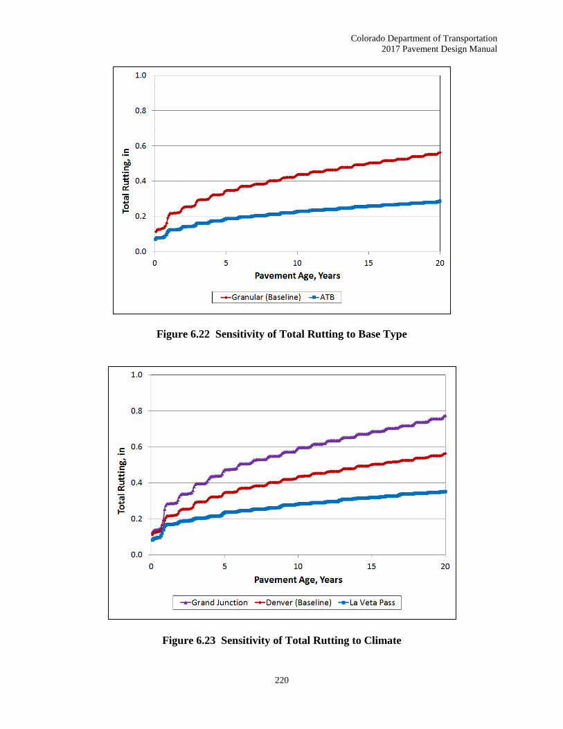
Figure 6.22 Sensitivity of Total Rutting to Base Type
Figure 6.23 Sensitivity of Total Rutting to Climate

Colorado Department of Transportation
2017 Pavement Design Manual
221
Figure 6.24 Sensitivity of HMA Transverse Cracking to Thickness
Figure 6.25 Sensitivity of HMA Transverse Cracking to Asphalt Binder Grade

Colorado Department of Transportation
2017 Pavement Design Manual
222
Figure 6.26 Sensitivity of HMA Transverse Cracking to Asphalt Binder Content
Figure 6.27 Sensitivity of HMA Transverse Cracking to Base Type

Colorado Department of Transportation
2017 Pavement Design Manual
223
Figure 6.28 Sensitivity of HMA Transverse Cracking to Climate
Figure 6.29 Sensitivity of HMA IRI to Truck Volume

Colorado Department of Transportation
2017 Pavement Design Manual
224
Figure 6.30 Sensitivity of HMA IRI to AC Thickness
Figure 6.31 Sensitivity of HMA IRI to Asphalt Binder Grade

Colorado Department of Transportation
2017 Pavement Design Manual
225
Figure 6.32 Sensitivity of HMA IRI to Base Thickness
6.10 HMA Thickness with ABC
As a minimum, the designer should include 4 inches of ABC for any thickness of HMA when
the design truck traffic is less than 1,000 trucks per day. Six inches of ABC should be used
for any thickness of HMA when the design truck traffic is greater than 1,000 trucks per day.
6.11 Required Minimum Thickness of Pavement Layer
Compaction of a hot mix asphalt pavement during its construction is the single most important
factor affecting the ultimate performance of the pavement. Achieving adequate compaction
increases pavement performance by decreasing rutting, reducing damage due to moisture and
oxidation, and increasing the stability of the mix. Factors affecting the cooling rate of the mat
include the layer thickness, the temperature of the mix when placed, ambient temperature,
temperature of the base, and wind conditions. Layer thickness is the single most important variable
in the cooling rate of an asphalt mat, especially for thin layers. This is especially true in cool
weather because thin layers of an asphalt mat have less capacity to retain heat than thicker lifts of
pavement. The thicker layers of an asphalt mat help to maintain the temperature at a workable
level, thus increasing the time available for compaction. Because of the increased difficulty in
achieving density and the importance of achieving compaction, a minimum layer thickness for
construction of HMA pavement is two inches. A designer of special mixes, such as stone matrix

Colorado Department of Transportation
2017 Pavement Design Manual
226
asphalt or thin lift HMA should look at minimum thickness requirements of the particular product.
The minimum thickness of these special mixes is likely to be a dimension other than two inches.
6.12 Asphalt Materials Selection
6.12.1 Aggregate Gradation
Definitions of Aggregate Size:
Nominal Maximum Aggregate Size (NMAS): The size of aggregate of the smallest
sieve opening through which the entire amount of aggregate is permitted to pass.
Note: For Item 403 - HMA and SMA, the Nominal Maximum Size is defined
as one sieve size larger than the first sieve to retain more than ten percent of the
aggregate.
Maximum Aggregate Size is defined as one size larger than nominal maximum size.
The flexible pavement usually consists of ¾ inch nominal maximum aggregate size
(NMAS) in the lower layers, with a hot mix asphalt (HMA) Grading S. The top surface
layer, should be either stone matrix asphalt (SMA) or a Grading SX. SMA mixes are
often used in areas expected to experience extreme traffic loading. When low to high
traffic loads are expected, a ½ inch NMAS, Grading SX should be used.
CDOT uses the No. 30 sieve as one of the job-mix formula tolerance sieves. Table 6.4 Master
Range Table for Stone Mix Asphalt. is based (with some exceptions) on NCHRP No. 4 and 3/8
inch and AASHTO ½ inch and ¾ inch SMA gradations ranges, where the No. 30 sieve range is
included in the ½ inch and ¾ inch gradations.
SMA Gradation Nomenclature Example:
The ¾ inch (19.0 mm) gradation is named the ¾ inch Nominal Maximum Aggregate Size gradation
because the first sieve that retains more than 10 percent is the ½ inch sieve, and the next sieve
larger is the ¾ inch sieve, refer to Table 6.4 Master Range Table for Stone Mix Asphalt.
A CDOT study (1) found less thermal segregation in the top lift when Grading SX mixes were
used. HMA Grading SX can also be used where layers are very thin or where the pavement must
taper into an existing pavement. A study from Auburn University (2) found little difference in the
stability or rutting of ¾ inch and ½ inch NMAS mixes. CDOT cost data for 2005 showed a slight
increase in the cost per ton of Grading SX mixes as compared to Grading S mixes with the same
bid quantities.
HMA with a 1-inch NMAS, Grading SG, should not be used in the surface layer. Although
Grading SG mixes have been used in specialized situations, they are not currently used or accepted
on a regular basis for pavement mixes. CDOT has found that the production and placement of
Grading SG mixes are prone to segregation and the use should be discouraged.

Colorado Department of Transportation
2017 Pavement Design Manual
227
Table 6.4 Master Range Table for Stone Matrix Asphalt
Sieve Size
Percent by Weight Passing Square Mesh Sieves
#4
(4.75 mm)
Nominal
Maximum
3/8”
(9.5 mm)
Nominal
Maximum
1/2”
(12.5 mm)
Nominal
Maximum
3/4”
(19.0 mm)
Nominal
Maximum
1 “ (25 mm) - - - 100
¾” (19.0 mm) - - 100 90-100
½” (12.5 mm) 100 100 90-100 50-88 3/8” (9.5 mm) 100 90-100 50-80 25-60
#4 (4.75 mm) 90-100 26-60 20-35 20-28
#8 (2.36 mm) 28-65 20-28 16-24 16-24
#16 (1.18mm) 22-36 - - -
#30 (600 µm) 18-28 12-18 12-18 12-18
#50 (300 µm) 15-22 10-15 - -
#100 (150 µm) - - - -
#200 (75 µm) 12-15 8-12 8-11 8-11
For structural overlays, the minimum allowed layer thickness will be 2 inches. For functional
overlays used in preventive maintenance or other treatments, thinner lifts are allowed.
Table 6.5 HMA Grading Size and Location Application and Table 6.6 HMA Grading Size
and Layer Thickness gives guidance for mix selection and recommended layer thicknesses for
various layers and nominal maximum aggregate sizes.
Table 6.5 HMA Grading Size and Location Application
CDOT
HMA Grade
Nominal
Maximum
Aggregate
Size (NMAS)
Application
SF No. 4 sieve Leveling course, rut filling, scratch course, etc.
ST 3/8 inch Thin lifts and patching
SX ½ inch Top layer (preferred)
S ¾ inch Top layer, layers below the surface, patching
SG 1 inch Layers below the surface, deep patching

Colorado Department of Transportation
2017 Pavement Design Manual
228
Table 6.6 HMA Grading Size and Layer Thickness
CDOT
HMA Grade
Nominal
Maximum
Aggregate Size
(NMAS)
Structural/Overlay
Layer Thickness (inches)
Minimum Maximum
SX ½ inch 2.00 3.00
S ¾ inch 2.25 3.50
SG 1 inch 3.00 4.00
Functional Overlay
Layer Thickness (Inches)
SF No. 4 sieve 0.751 1.50
ST 3/8 inch 1.125 2.50
Note: 1 Layers of SF mixes may go below 1 inch as needed to taper thin lift
to site conditioning (i.e. rut filling).
6.12.2 Selection of SuperPaveTM Gyratory Design
To choose the appropriate number of revolutions of a SuperPave™ gyratory asphalt mix design
on a particular project, determining the design 18k ESALs and the high temperature environment
for the project is necessary. The following steps should be followed to determine the proper
SuperPave™ gyratory design revolutions for a given project:
Step 1. Determine 18k ESALs: In order to obtain the correct SuperPave™ gyratory compaction
effort (revolutions), the 18k ESALs must be a 20-year cumulative 18k ESAL of the design
lane in one direction. The compaction effort simulates the construction compaction roller
to obtain the correct voids properties to resist the intended traffic in the design lane. The
department’s traffic analysis unit of the Division of Transportation Development (DTD)
automatically provides an ESAL calculator. One must use a 20-year design, appropriate
number of lanes, and a specified flexible pavement. Even a 10-year asphalt overlay must
use a 20-year cumulative 18k ESAL number for the design lane.
Step 2. Reliability for the 7-Day Average Maximum Air Temperature: The next decision is
to determine the type of project being designed. For new construction or reconstruction,
asphalt cement with 98 percent reliability for low and high temperature properties is
recommended. For overlays, asphalt cement with 98 percent reliability for high
temperature properties (rutting resistance) and 50 percent reliability for low temperature
properties (cracking resistance) is recommended. Asphalt cements with lower than 98
percent reliability against rut resistance should not be specified. In the SuperPave™
system, anything between 50 percent and 98 percent reliability is considered 50 percent
reliability for the purpose of binder selection. The low temperatures are specified at a
lower reliability for overlays because of reflection cracking.

Colorado Department of Transportation
2017 Pavement Design Manual
229
Step 3. Determine Weather Data for the Project: Obtain the highest 7-day average maximum
air temperature, based on weather data in the project area from the computer program
LTPPBind 3.1 (beta). Refer to Section 6.12.3 Binder Selection for a further explanation
of LTPPBind 3.1 (beta). From the appropriate high temperature, find the environmental
category for the project from Table 6.7 Environmental Categories. The Environmental
Categories are from CDOT Pavement Management Program’s Environmental Zones.
The Environmental Zones (Categories) are one of four pavement groupings used to group
pavements into families that have similar characteristics.
Table 6.7 Environmental Categories
Highest 7-Day Average Air
Temperature
High Temperature
Category
> 97°F
(> 36°C)
Hot
(southeast and west)
> 88° to 97°F
(> 31° to 36°C)
Moderate
(Denver, plains and west)
81° to 88°F
(27° to 31°C)
Cool
(mountains)
< 81°F
(< 27°C)
Very Cool
(high mountains)
Step 4. Selection of the Number of Design Gyrations (NDES): Select the NDES from Table 6.8
Recommended SuperPaveTM Gyratory Design Revolution (NDES). For example,
Table 6.7 shows that for 5,000,000 18k ESALs and a high temperature category of
“Cool”, the design revolutions should be 75.
Table 6.8 Recommended SuperPaveTM Gyratory Design Revolution (NDES)
CDOT Pavement
Management System
Traffic Classification
(20 Year Design ESAL)
20 Year Total
18k ESAL in the Design
Lane
High Temperature Category
Very Cool Cool Moderate Hot
Low < 100,000 50 50 50 50
100,000 to < 300,000 50 75 75 75
Medium 300,000 to < 1,000,000 75 75 75 75
1,000,000 to < 3,000,000 75 75 75 100
High 3,000,000 to < 10,000,000 75 75 100 100
Very High 10,000,000 to < 30,000,000 --- --- 100 ---
Very Very High ≥ 30,000,000 --- --- 125 ---
Note: Based on Standard Practice for SuperPave™ Volumetric Design for Hot-Mix Asphalt (HMA), AASHTO
Designation R 35-04.

Colorado Department of Transportation
2017 Pavement Design Manual
230
6.12.3 Binder Selection
Performance graded (PG) binders have two numbers in their designation, such as PG 58-34. Both
numbers describe the pavement temperatures in degrees Celsius at which the pavement must
perform. The first number (58 in the example) is the high temperature standard grade for the
pavement, and the second number (minus 34 in the example) is the low temperature standard grade.
PG 64-28 (rubberized) or PG 76-28 (polymerized) or bituminous mixtures should only be placed
directly on an existing pavement or milled surface that does not show signs of stripping or severe
raveling. Cores should be taken to determine if stripping is present. Because of a limited number
of tanks, Colorado local suppliers only have the capacity to supply a limited number of asphalt
cement grades. Table 6.9 Available Asphalt Cement Grades in Colorado shows available
grades that maybe used and/or available on CDOT projects.
Table 6.9 Available Asphalt Cement Grades in Colorado
Polymer Modified Unmodified
PG 76-28
PG 70-28
PG 64-28
PG 58-34
PG 64-22
PG 58-28
Note: The Region Materials Engineer may select a different gyratory design
revolution for the lower HMA lifts.
LTPPBind 3.1 (beta) is a working version, dated September 15, 2005. Beta only means it is going
through the 508-compliance process for the visually disabled users as required by the Federal
Government. The computer program may be obtained from the following web address:
http://www.fhwa.dot.gov/pavement/ltpp/ltppbind.cfm
The program allows the user to select the asphalt binder grade for the appropriate project site
conditions. In the Preferences under the File menu, use 12.5mm ( ½ inch) for the CDOT target rut
depth default value. The computer program has a help menu to assist the user and supporting
technical information regarding the computation of design temperatures required for the selection
of the asphalt binder grade as provided in the Climatic Data and Algorithms sections. The
algorithms are broken down under four subsections. Each algorithm equation is shown and briefly
explained for high temperature, low temperature, PG with depth, and PG grade bumping.
High Temperature: The high temperature is based on a rutting damage model. The
LTPP high temperature model was not used in this version since it provided very
similar results to the SHRP Model at 98 percent reliability. Initially, the user must
select a preference for a target rut depth, but they have the option to change the target
rut depth. The default is 12.5 mm (½ inches).
Low Temperature: The low temperature is based on LTPP climatic data using air
temperature, latitude, and depth to surface.

Colorado Department of Transportation
2017 Pavement Design Manual
231
PG with Depth: LTPP pavement temperature algorithms were used to adjust the PG
for a depth into the pavement. The LTPP algorithms are empirical models developed
from seasonal monitoring data.
PG Grade Bumping: PG grade bumping was based on the rutting damage concept
for high temperature adjustments. Adjustments were developed as the difference
between PG for standard traffic conditions (ESAL of 3 million and high speed) and
site conditions. 187 sites throughout the U.S. for five target rut depths were analyzed.
The PG adjustments were then averaged by various ESAL ranges, traffic speeds, and
Base PG.
The following steps should be followed to determine the proper SuperPave™ asphalt cement grade
for a given project:
Step 1. Determine Proper Reliability to Satisfy Pavement Temperature Property
Requirements: The first step is to determine what type of project is being designed.
For new construction or reconstruction, asphalt cement with 98 percent reliability
for both low and high pavement temperature properties is recommended.
For overlays, asphalt cement with 98 percent reliability for high pavement
temperature properties (rutting resistance) and 50 percent reliability for low
pavement temperature properties (cracking resistance) are recommended.
Asphalt cements with lower than 98 percent reliability against rut resistance should
not be specified.
In the SuperPave™ system, anything between 50 and 98 percent reliability is
considered 50 percent reliability for the purpose of binder selection.
The low pavement temperatures are specified at a lower reliability for overlays
because of reflection cracking.
Refer to Figure 6.33 PG Binder Grades for a graphical representation of
reliability.

Colorado Department of Transportation
2017 Pavement Design Manual
232
Figure 6.33 PG Binder Grades
Step 2. Determine Weather Data for the Project: Obtain the SuperPave™ recommended
asphalt cement grade, based on weather data and traffic in the project area.
Recommendations on 98 percent reliability high and low pavement temperature weather
stations are found in Figure 6.34 Colorado 98 Percent Reliability LTPP High
Pavement Temperature Weather Station Models and Figure 6.35 Colorado 98
Percent Reliability LTPP Low Pavement Temperature Weather Station Models,
neither of which accounts for grade bumping. The program also calculates the reliability
of various asphalt cements for a given location. This source will yield the 98 and 50
percent reliability asphalt cement for a project area with a free flowing traffic condition,
which is described in Step 3. For example, when the recommendations call for a PG
58-22 for a given project, due to the available binder grades in Colorado, a PG 64-22
would be specified. This selection provides for rut resistance while preserving the same
level of resistance to cracking. Because of the danger of rutting, in no case should the
recommended high temperature requirements be lowered based on availability. Each
RME has a copy of this program.
Step 3. Select Location of Roadway: Place the cross hair on the location of area of interest in
the weather data program LTPP Bind. The program selects five weather stations
surrounding the area of interest. The designer has the option to use any number of
weather stations representative of the climate at the area of interest.
Step 4. Adjust HMA Performance Grade Binder to Meet Layer Depth, Traffic Flow and
Loading Requirements: SuperPave™ high temperature reliability factors are based on
historical weather data and algorithms to predict pavement temperature. At a depth layer
of 1 inch or more below the surface, high temperature recommendations are changed
because of the depth and temperatures at that depth.

Colorado Department of Transportation
2017 Pavement Design Manual
233
For pavements with multiple layers a lesser grade may be specified for lower layers based
on the amount of material needed and other economical design decisions. In many cases,
the requirements for lower layers might be obtained with an unmodified or more
economical grade of asphalt cement. It is recommended that at least 10,000 tons of mix
in the lower layer is needed before a separate asphalt cement is specified for the lower
layer.
Adjustments can be made to the base high temperature binder through the ‘PG Binder
Selection’ screen. Adjustments to reliability, depth of layer, traffic loading, and traffic
speed (fast and slow) will be required. These adjustments are called grade bumping.
Additional grade bumping may be performed for stop and go traffic characteristics such
as intersections. This extra grade bump may be applied, but is suggested the designer
have prior regional experience on doing such.
6.12.3.1 Example
Example: A new roadway project will be constructed near Sugarloaf Reservoir. It will have two
lanes per direction and a traffic characteristic of slow moving because it is a winding mountain
road. Find the appropriate binder grade. NDES for the surface layer is obtained in the same manner
as the previous example and has a design revolution of 75.
Step 1. Determine 18k ESAL: Design Lane ESALs = 4,504,504 from DTD web site (20 year
18k ESAL in the design lane).
Step 2. Use LTPP Software Database: Use LTPPBind software database to obtain the data from
the nearest weather station, Sugarloaf Reservoir. Appropriate weather stations can be
determined from information on state, county, coordinates, location, and/or station ID.
Figure 6.36 LTPP Interface Form for Weather Station Selection (Version 3.1) is
where the cross hair is placed for the new roadway project. Figure 6.37 LTPP Weather
Station Output Data (Version 3.1) shows the data at the weather station Sugarloaf
Reservoir.
Step 3. Select the Desired Weather Stations: The LTPPBind software gives the option to select
the weather stations that provide the best weather data at the project location (see the upper
table in Figure 6.38 LTPP PG Binder Selection at 98 Percent Reliability). Check the
first three weather stations. Uncheck the two weather stations furthest from the project,
these stations are too far from the site and not representative of site conditions.
Step 4. Select the Temperature Adjustments: Because this is a principal arterial and a new
construction project, 98 percent reliability is chosen with a layer depth of zero (0) for the
surface layer (see Figure 6.38 LTPP PG Binder Selection at 98 Percent Reliability).
Step 5. Select the Traffic Adjustments for High Temperature: Select the appropriate traffic
loading and traffic speed. The design lane ESALs are 4,504,504 and the traffic speed is
slow. Grade bumping is automatic and is demonstrated by toggling in appropriate cells.

Colorado Department of Transportation
2017 Pavement Design Manual
234
The following data summarized in Table 6.10 SuperPaveTM Weather Data Summary
are obtained from Steps 1 through 5.
Step 6. Select Final Binder: Table 6.8 Available Asphalt Cement Grades in Colorado lists
the binder grades available in Colorado. A PG 58-28 (unmodified) is available, but it does
not meet the low temperature requirement. The lowest temperature binders available in
Colorado can meet is -34 C. This is available in PG 58-34 (polymer modified).
Therefore, at 98 percent reliability use PG 58-34.
Step 7. Find the Temperature that Falls into the Environmental Category: Use Table 6.10
Environmental Categories (restated) to obtain the highest 7-day average air
temperature, 24.3°C. Table 6.11 Environmental Categories (restated) shows the
temperature falls into the category ‘Very Cool’ (high mountains).
Step 8 Select the Gyratory Design Revolution (NDES): Table 6.11 Recommended
SuperPaveTM Gyratory Design Revolution (NDES) shows at 4,504,504 18k ESAL and
a high temperature category of “Very Cool” the design revolutions should be 75.

Colorado Department of Transportation
2017 Pavement Design Manual
235
Figure 6.34 Colorado 98 Percent Reliability LTPP High Pavement Temperature Weather Station Models

Colorado Department of Transportation
2017 Pavement Design Manual
236
Figure 6.35 Colorado 98 Percent Reliability LTPP Low Pavement Temperature Weather Station Models

Colorado Department of Transportation
2017 Pavement Design Manual
237
Figure 6.36 LTPP Interface Form for Weather Station Selection (Version 3.1)
Figure 6.37 LTPP Weather Station Output Data (Version 3.1)

Colorado Department of Transportation
2017 Pavement Design Manual
238
Table 6.10 SuperPaveTM Weather Data Summary
98 Percent Reliability
Depth of Layer 0 mm
Traffic Loading and Speed Adjustment 10.3°C (slow)
PG Binder Grade 52 -34
Table 6.11 Environmental Categories (restated)
Highest 7-Day Average Air
Temperature
High Temperature
Category
> 97°F
(> 36°C)
Hot
(southeast and west)
> 88° to 97°F
(> 31° to 36°C)
Moderate
(Denver, plains and west)
81° to 88°F
(27° to 31°C)
Cool
(mountains)
< 81°F
(< 27°C)
Very Cool
(high mountains)
Table 6.12 Recommended SuperPaveTM Gyratory Design Revolution (NDES) (restated)
CDOT Pavement
Management System
Traffic Classification
(20 Year Design ESAL)
20 Year Total
18k ESAL in the Design
Lane
High Temperature Category
Very
Cool Cool Moderate Hot
Low < 100,000 50 50 50 50
100,000 to < 300,000 50 75 75 75
Medium 300,000 to < 1,000,000 75 75 75 75
1,000,000 to < 3,000,000 75 75 75 100
High 3,000,000 to < 10,000,000 75 75 100 100
Very High 10,000,000 to < 30,000,000 --- --- 100 ---
Very Very High ≥ 30,000,000 --- --- 125 ---
Note: Based on Standard Practice for SuperPave™ Volumetric Design for Hot-Mix Asphalt (HMA), AASHTO
Designation R 35-04.

Colorado Department of Transportation
2017 Pavement Design Manual
239
6.12.4 Asphalt Binder Characterization for M-E Design
For flexible pavement design using M-E Design, the viscosity of the asphalt binder is a critical
input parameter to incorporate the viscoelastic response (i.e. time-temperature dependency) of
asphalt concrete mixtures. The asphalt binder viscosity is used in the calculations of dynamic
modulus values of asphalt mixtures for aged and unaged conditions. The key input parameters
that define the viscosity temperature relationship are the slope (A) and intercept (VTS) resulting
from a regression of the asphalt binder viscosity values measured or estimated at different
temperatures.
Laboratory testing of asphalt binders is required to develop viscosity temperature relationships at
the Level 1 input hierarchy. For performance grade binders, the asphalt binder viscosity values
can be estimated from the dynamic shear rheometer test data conducted in accordance with
AASHTO T 315, Determining the Rheological of Asphalt Binder Using a Dynamic Shear
Rheometer (DSR). Alternatively, for conventional grade binders (i.e. penetration grade or
viscosity grade), the asphalt binder viscosity values can be obtained from a series of conventional
tests, including absolute and kinematic viscosities, specific gravity, softening point, and
penetrations. At the hierarchical input Level 3, the default values of A-VTS parameters included
in M-E Design are based on the asphalt binder grade selection.
For flexible pavement rehabilitation designs, the age-hardened binder properties can be determined
using asphalt binder extracted from field cores of asphalt pavement layers that will remain in place
after rehabilitation. For projects where asphalt is not extracted, historical information and data
may be used. Table 6.13 Recommended Sources of Inputs for Asphalt Binder
Characterization presents recommended sources for asphalt binder characterization at different
hierarchical input levels. Refer to the AASHTO Intrim MEPDG Manual of Practice and MEPDG
Documentation for more information.
Table 6.13 Recommended Sources of Inputs for Asphalt Binder Characterization
Materials
Category Measured Property
Recommended
Test Protocol
Hierarchical Input
Level
3 2 1
Asphalt
Binder
Asphalt binder complex shear modulus (G*)
and phase angle (δ); at 3 test temperatures, or
AASHTO T 315
Conventional binder test data: Penetration, or AASHTO T 49
Ring and ball softening point
Absolute viscosity
Kinematic viscosity
Specific gravity, or
AASHTO T 53
AASHTO T 202
AASHTO T 201
AASHTO T 228
Brookfield viscosity AASHTO T 316
Asphalt binder grade: PG grade, or AASHTO M 320
Viscosity grade, or AASHTO M 226
Penetration grade AASHTO M 20
Rolling thin film oven aging AASHTO T 315

Colorado Department of Transportation
2017 Pavement Design Manual
240
6.13 Asphalt Mix Design Criteria
6.13.1 Fractured Face Criteria
CDOT’s aggregate fractured face criteria requires the aggregate retained on the No. 4 sieve must
have at least two mechanically induced fractured faces (2) (see Table 6.14 Fracture Face
Criteria).
Table 6.14 Fractured Face Criteria
Percent Fractured Faces
of 20 Year 18k ESAL
in Design Lane
SF ST SX S SG SMA
Non-Interstate Highways
or
Pavements with
< 10,000,000 Total 18K ESALs
60% 60% 60% 60% 90% 90%
Interstate Highways
or
Pavements with
> 10,000,000 Total 18K ESALs
70% 70% 70% 70% 90% 90%
6.13.2 Air Void Criteria
A design air void range of 3.5 to 4.5 percent with a target of 4.0 percent will be used on all SX, S,
SG, and ST mixes. A design air void range of 4.0 to 5.0 percent with a target of 4.5 percent will
be used on all SF Mixes. Refer to Table 6.15 Minimum VMA Requirements for design air voids
and minimum VMA requirements and criteria for voids at NDES. The air void criteria will be
applied to the approved design mix. The nominal maximum size is defined as one size larger than
the first sieve to retain more that 10 percent. The designer should interpolate specified VMA
values for design air voids between those listed in the table. All mix designs shall be run with a
gyratory compactor angle of 1.25 degrees. CDOT Form #43 will establish construction targets for
asphalt cement and all mix properties at air voids up to 1.0 percent below the mix design optimum.
The designer should extrapolate VMA values for production (CDOT Form 43) air voids beyond
those listed in Table 6.15 Minimum VMA Requirements.

Colorado Department of Transportation
2017 Pavement Design Manual
241
Table 6.15 Minimum VMA Requirements
Nominal Maximum Size1
mm (in)
Design Air Voids 2, 3
3.5% 4.0% 4.5% 5.0%
37.5 (11/2”) 11.6 11.7 11.8
N/A 25.0 (1”) 12.6 12.7 12.8
19.0 (3/4”) 13.6 13.7 13.8
12.5 (1/2”) 14.6 14.7 14.8
9.5 (3/8”) 15.6 15.7 15.8 16.9
Note: 1 The nominal maximum size defined as one size larger than the first sieve to retain more than 10%. 2 Interpolate specified VMA values for design air voids between those listed. 3 Extrapolate specified VMA values for production air voids between those listed.
6.13.3 Criteria for Stability
Criteria for stability and voids filled with asphalt (VFA) are shown in Table 6.16 Criteria for
Stability and Voids Filled with Asphalt (VFA).
Table 6.16 Criteria for Stability and Voids Filled with Asphalt (VFA)
SuperPave™ Gyratory
Revolutions (NDES)
Hveem Minimum
Stability* VFA (%)
125 30 65-75
100 30 65-75
75 28 65-80
50 ** 70-80
Note: 1-inch mix (CDOT Grade SG) has no stability requirements.
* Hveem Stability criteria for mix design approval and for field verification.
** Hveem Stability is not a criterion for mixes with a NDES of 50.
6.13.4 Moisture Damage Criteria
Moisture damage criteria are shown in Table 6.17 Moisture Damage Criteria.
Table 6.17 Moisture Damage Criteria
Characteristic Value
Minimum dry split tensile strength, (psi) 30
Minimum tensile strength ratio, CP-L 5109, (%) 80
Minimum tensile strength ratio, CP-L 5109, SMA, (%) 70

Colorado Department of Transportation
2017 Pavement Design Manual
242
6.14 Effective Binder Content (By Volume)
Effective binder content (Pbe) is the amount of binder not absorbed by the aggregate, i.e. the amount
of binder that effectively forms a bonding film on the aggregate surfaces. Effective binder content
is what the service performance is based on and is calculated based on the aggregate bulk specific
gravity (Gsb) and the aggregate effective specific gravity (Gse). The higher the aggregate
absorption, the greater the difference between Gse and Gsb. The effective binder content by volume
is the effective binder content (Pbe) times the ratio of the bulk specific gravity of the mix (Gmm)
and the specific gravity of the binder (Gb). The formula is:
Pbe (by volume) = Pbe * (Gmm /Gb)
Where
Pbe = effective asphalt content, percent by total weight of mixture
Gmm = bulk specific gravity of the mix
Gb = specific gravity of asphalt (usually 1.010)
Pbe is determined as follows:
Pbe = Pb – (Pba/100) * Ps
Where
Pb = asphalt, percent by total weight of mixture
Pba = absorbed asphalt, percent by total weight of aggregate
Ps = aggregate, percent by total weight of mixture
Pba is determined as follows:
Pba = 100 ((Gse – Gsb)/ (Gsb *Gse)) *Gb
Where
Pba = absorbed asphalt, percent by total weight of aggregate
Gse = effective specific gravity of aggregate
Gsb = bulk specific gravity of aggregate
6.15 Rumble Strips
When Rumble Strips are installed, they shall be of the style and location as shown on CDOT’s
Standard Plans, M & S Standards, July 2012 Plan Sheet No. M-614-1, Rumble Strips.

Colorado Department of Transportation
2017 Pavement Design Manual
243
References
1. Gilbert, K., Thermal Segregation, 2005, CDOT Report No. CDOT-DTD-R-2005-16.
http://www.coloradodot.info/programs/research/pdfs/2005/thermalsegregation.pdf..
2. Brown, E.R. and Bassett, C.E. Effects of Maximum Aggregate Size on Rutting Potential
and Other Properties of Asphalt-Aggregate Mixtures 1990. Transportation Research
Record 1259, TRB, National Research Council, Washington, D.C., 1990, pp. 107-119.
3. HMA Pavement Mix Type Selection Guide, FHWA Information Series 128, Federal
Highway Administration, 400 7th Street S.W., Washington, DC 20590 and National
Asphalt Pavement Association (NAPA), 5100 Forbes Blvd, Lanham, MD 20706, January
2001.
4. Guide for Mechanistic-Empirical Design, Final Report, NCHRP Project 1-37A, National
Cooperative Highway Research Program, Transportation Research Board, National
Research Council, Submitted by ARA, INC., ERES Consultants Division, Champaign, IL,
March 2004.
5. Locander, Robert, Analysis of Using Reclaimed Asphalt Pavement (RAP) as a Base
Material, Final Report, CDOT Report No. CDOT-2009-5, Colorado Department of
Transportation, February 2009.
6. Perpetual Pavements - A Synthesis. Asphalt Pavement Alliance, 5100 Forbes Boulevard,
Lanham, MD 20706 : Asphalt Pavement Alliance, 1/2002. Synthesis.
7. Perpetual Bituminous Pavements. Transportation Research Board (TRB). 2101
Constitution Avenue, NW, Washington, DC 20418 : Transportation Research Board,
National Research Center, December 2001. Research Circular. TRB Committee on
General Issues in Asphalt Technology (A2D05). Number 503, ISSN 0097-8515.
8. AASHTO Mechanistic-Empirical Pavement Design Guide, A Manual of Practice, Interim
Edition, July 2008, American Association of State Highway and Transportation Officials,
Washington, DC, 2008.
Related Documents