Principles for Tunnel Design 20th to 21st April 2017– Kuala Lumpur Settlement prediction and control in urban tunneling Dr. Noppadol Phien-wej Asian Institute of Technology & Thailand Underground & Tunnelling Group

Welcome message from author
This document is posted to help you gain knowledge. Please leave a comment to let me know what you think about it! Share it to your friends and learn new things together.
Transcript

Principles for Tunnel Design
20th to 21st April 2017– Kuala Lumpur
Settlement prediction and control in urban tunneling Dr. Noppadol Phien-wej
Asian Institute of Technology & Thailand Underground & Tunnelling Group

Contents
• Urban tunnelling
• Construction methods
• Characteristics of ground movement
• Prediction methods • Empirical Gaussian method • Numerical methods
• Responses of buildings to ground movements & damage level
• Handling of potential impacts of tunnel ground movements in tunnelling project
• Case studies
Principles for Tunnel Design 20th to 21st April 2017– Kuala Lumpur

Principles for Tunnel Design 20th to 21st April 2017– Kuala Lumpur

Characteristics
• Shallow depth tunnelling • Soft ground tunnelling • Ground water • Work in limited spaces • Existing surface and subsurface structures & Utilities •Potential damages to third parties
Geotechnical Aspects
• Excavation method and support design • Maintain stability during excavation • Minimize ground movements & impacts on existing structures
Urban Tunnelling
Principles for Tunnel Design 20th to 21st April 2017– Kuala Lumpur

Methods of Tunnel Construction in Soft Ground
• Cut & Cover Construction
• Tunnelling • Shield Tunnelling
• Conventional Tunnelling –
Shotcrete & steel arch (NATM)

Principles for Tunnel Design 20th to 21st April 2017– Kuala Lumpur

Principles for Tunnel Design 20th to 21st April 2017– Kuala Lumpur

Ground Movements and Instability in Urban Tunnelling
Principles for Tunnel Design 20th to 21st April 2017– Kuala Lumpur
Principles for Tunnel Design 20th to 21st April 2017– Kuala Lumpur

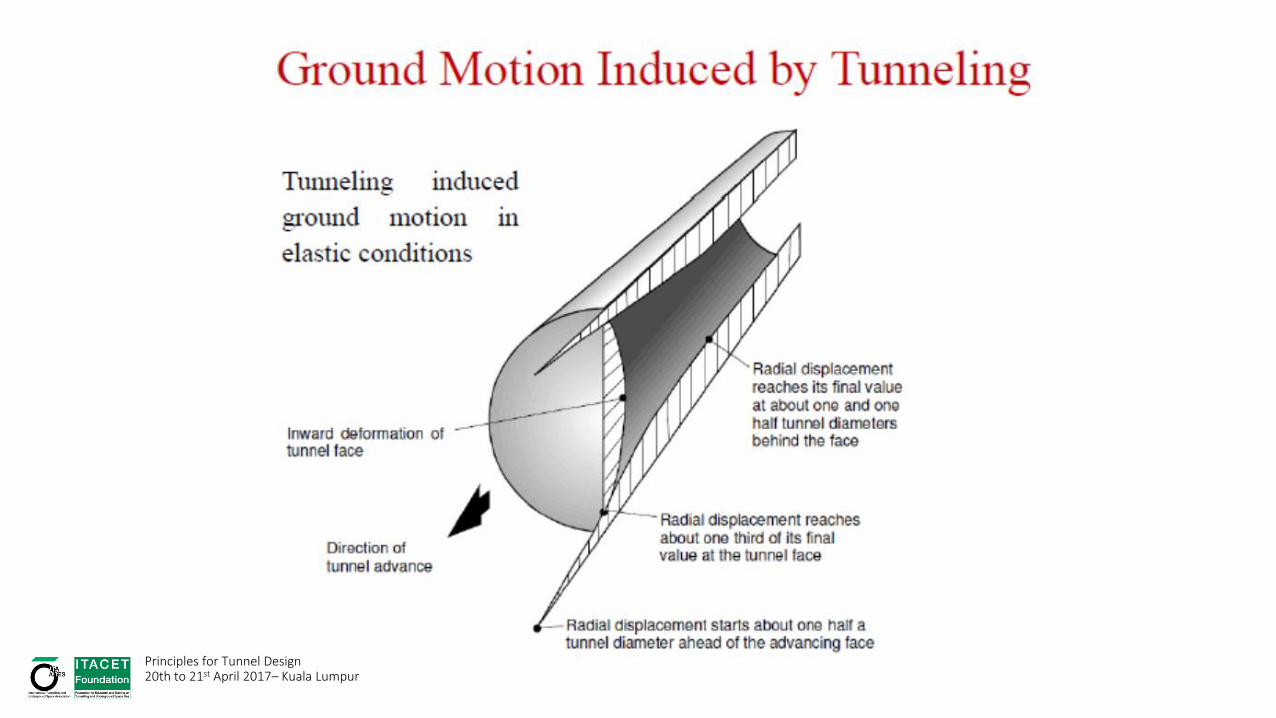
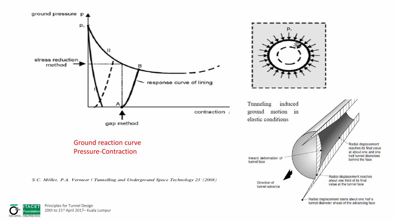
Tunnel Induced Ground Movement
10
15
20
25
30
x
-20
-10
0
10
20
y
-0.03
-0.02
-0.01
0
Settlement,HmL
-0.03
-0.02
-0.01
0
Settlement,HmL
Surface Settlement Trough
Principles for Tunnel Design 20th to 21st April 2017– Kuala Lumpur

Ground movement vectors induced by tunnel excavation (Physical Models)
Wide Narrow
Principles for Tunnel Design 20th to 21st April 2017– Kuala Lumpur
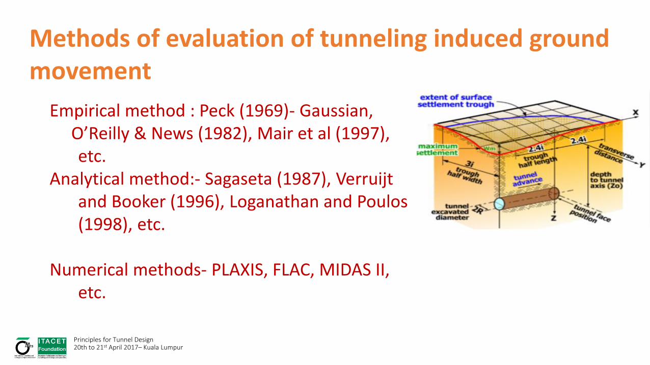
Methods of evaluation of tunneling induced ground movement
Empirical method : Peck (1969)- Gaussian, O’Reilly & News (1982), Mair et al (1997),
etc. Analytical method:- Sagaseta (1987), Verruijt
and Booker (1996), Loganathan and Poulos (1998), etc.
Numerical methods- PLAXIS, FLAC, MIDAS II,
etc.
Principles for Tunnel Design 20th to 21st April 2017– Kuala Lumpur

Empirical methods
Analytical methods
Loganathan & Poulos (1998)

Principles for Tunnel Design 20th to 21st April 2017– Kuala Lumpur
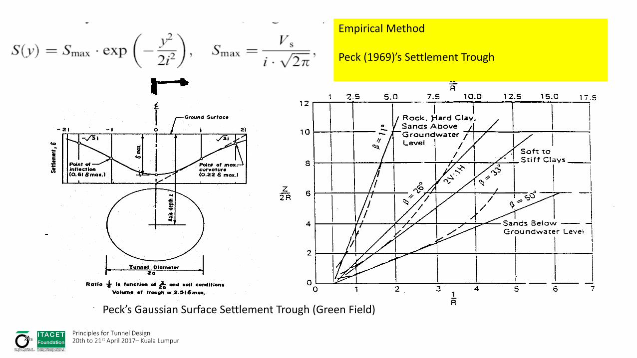
Peck’s Gaussian Surface Settlement Trough (Green Field)
Empirical Method Peck (1969)’s Settlement Trough
Principles for Tunnel Design 20th to 21st April 2017– Kuala Lumpur

Idealized transverse surface settlement trough profile (after O’Reilly & New 1982)
Principles for Tunnel Design 20th to 21st April 2017– Kuala Lumpur

Movement and volume of ground loss( Uriel,1989)
VL = volume of ground loss
For undrained ground, Vs ≈ VL
Principles for Tunnel Design 20th to 21st April 2017– Kuala Lumpur

O’Rielly and New (1982)
Principles for Tunnel Design 20th to 21st April 2017– Kuala Lumpur

GROUND LOSS

20
Ground movement induced by tunneling
TBM
ab
cd
e
segmental lining
Set
tlem
ents
a. ahead and above the head
b. along the TBM
c. induced at the tail void
d. due to lining deflection
e. due to long term settlement
Principles for Tunnel Design 20th to 21st April 2017– Kuala Lumpur

Load factor =gh/5c
Principles for Tunnel Design 20th to 21st April 2017– Kuala Lumpur

Numerical Analysis
• FEM, FDA, BEM
• 2D versus 3D
Principles for Tunnel Design 20th to 21st April 2017– Kuala Lumpur

Principles for Tunnel Design 20th to 21st April 2017– Kuala Lumpur
Ground reaction curve Pressure-Contraction

Applied pressure method (Moller, 2006) Stress reduction method
Plaxis 2D : Input methods of simulating tunnel excavation - Line contraction method - Stress reduction method -Applied pressure method
Line contraction method
Principles for Tunnel Design 20th to 21st April 2017– Kuala Lumpur

Hardening-soil model
Mohr-Coulomb model
Principles for Tunnel Design 20th to 21st April 2017– Kuala Lumpur

After PLAXIS Traning Principles for Tunnel Design 20th to 21st April 2017– Kuala Lumpur
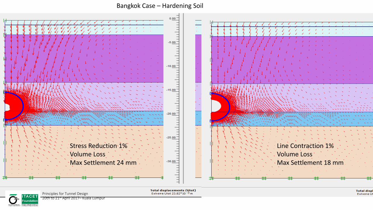
Line Contraction 1% Volume Loss Max Settlement 18 mm
Stress Reduction 1% Volume Loss Max Settlement 24 mm
Bangkok Case – Hardening Soil
Principles for Tunnel Design 20th to 21st April 2017– Kuala Lumpur

After PLAXIS Training Principles for Tunnel Design 20th to 21st April 2017– Kuala Lumpur

M4 metroline in Shanghai Grand Duomo-Milan
Responses of Structures to Ground Movement From Tunnelling
Principles for Tunnel Design 20th to 21st April 2017– Kuala Lumpur
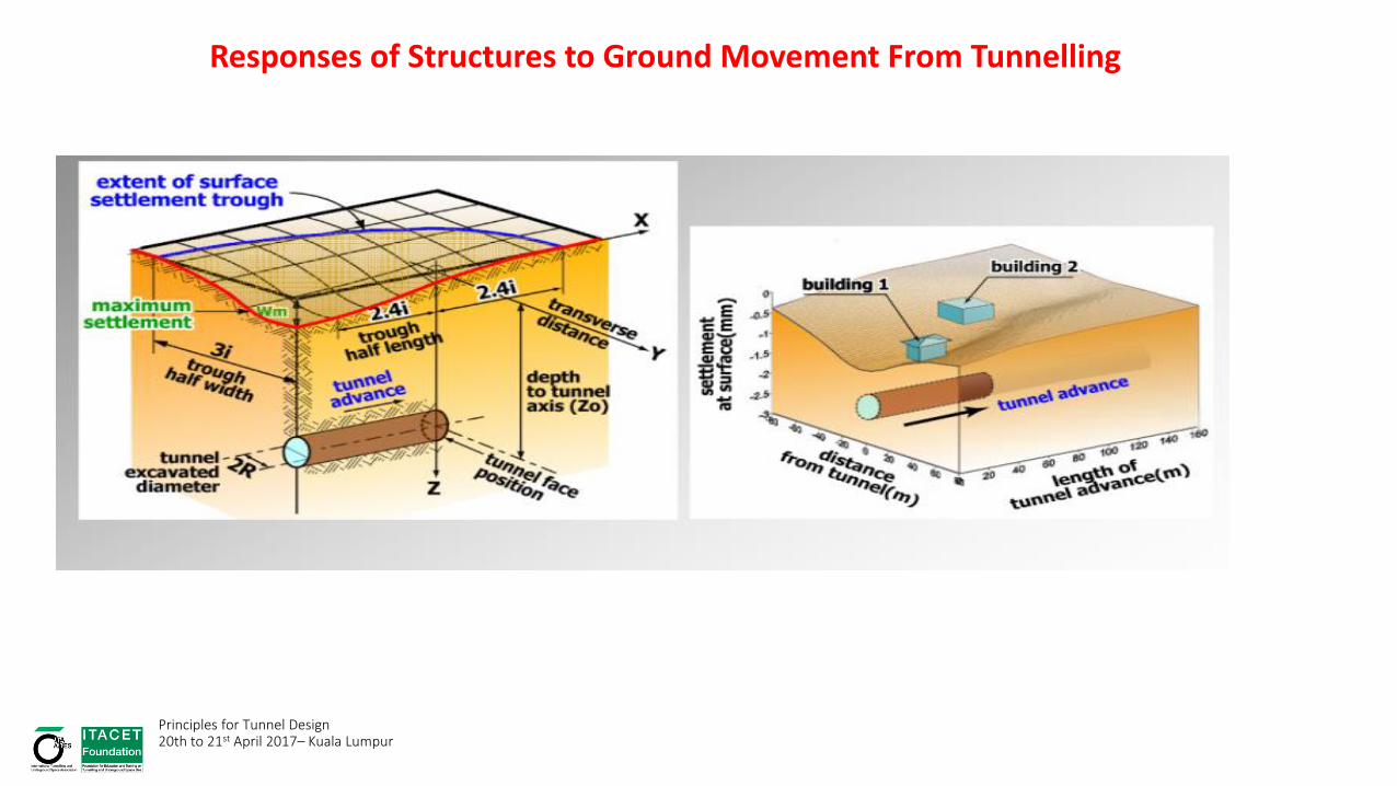
Responses of Structures to Ground Movement From Tunnelling
Principles for Tunnel Design 20th to 21st April 2017– Kuala Lumpur

Building Distortion induced by
Tunneling
Principles for Tunnel Design 20th to 21st April 2017– Kuala Lumpur

Principles for Tunnel Design 20th to 21st April 2017– Kuala Lumpur

Damage criteria for Brick Wall Building Cording (1981)

Damage criteria for Brick Wall Building
Burland (1997)

BULIDING DAMAGE CLASSIFICATION OF BRICK BUILDING
(after Burland et al, 1997)
Description of Typical Damage Approx. Crack Width
(mm)
From Excavation & Tunnelling Degree of Damage Risk Category
Max. Tensile Strain % Settlement Ratio
S / L
Hairline cracks - Less than 0.05 < 1:1000 Negligible 0
Fine cracks easily treated during normal redecoration.
Perhaps isolated slight fracture in building. Crack in
exterior brickwork visible upon close inspection
0.1 to 1.0 0.05 to 0.075 1:1000 to 1:500 Very slight 1
Crack easily filled. Redecoration probably required.
Several slight fractures inside the building. Exterior
cracks visible. Some repairing may be required for
weather tightness. Door and windows may be stick
slightly.
1.0 to 5.0 0.05 to 0.15 1:500 to 1:300 Slight 2
Cracks may require cutting out and patching. Recurrent
cracks can be masked by suitable linings. Tuck-
pointing and possible replacement of small amount
exterior brickwork may be required. Doors and
windows sticking. Utility services may be interrupted.
Weathered tightness after impaired.
5.0 to 15.0 or a number
of cracks grater than 3.0
0.15 to 0.3 1:300 to 1:200 Moderate 3
Extensive repair involving removal and replacement of
sections of walls, especially over doors and windows
required. Windows and doors frames distorted. Floor
slopes noticeably. Some loss of bearing in beams.
Utility services disrupted.
15.0 to 25.0 (depend on
number of cracks also)
Greater than 0.3 1:200 to 1:100 Severe 4
Major repair required involving partial or complete
reconstruction. Beams lose bearing, walls lean badly
and require shoring. Windows broken by distortion.
Danger of instability.
> 25.0 (depend on
number of cracks also)
- > 1:200
> 1:100
Very Severe 5
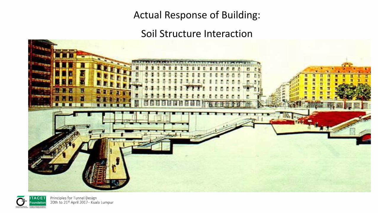
Actual Response of Building:
Soil Structure Interaction

Effect of Width of Building on Responses
Principles for Tunnel Design 20th to 21st April 2017– Kuala Lumpur
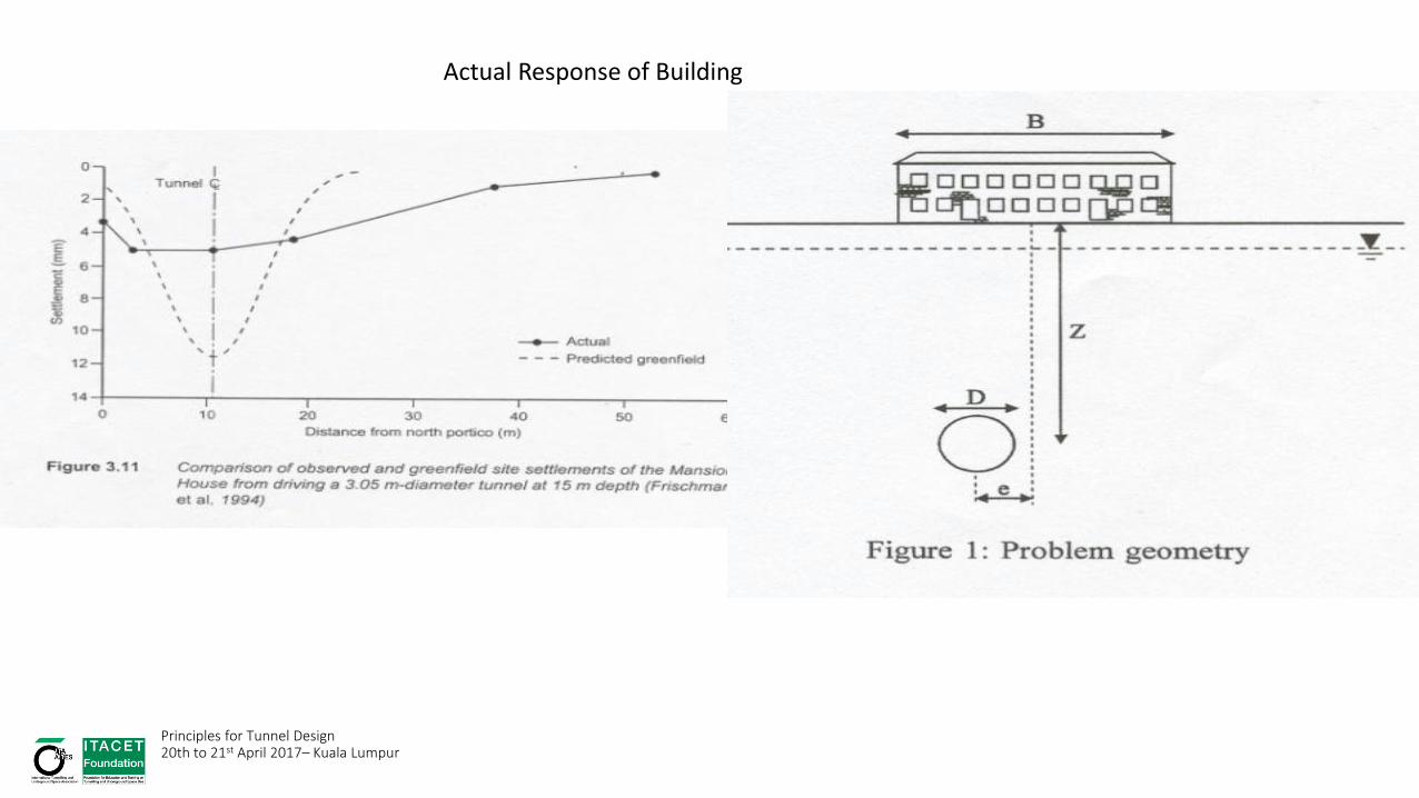
Actual Response of Building
Principles for Tunnel Design 20th to 21st April 2017– Kuala Lumpur

Principles for Tunnel Design 20th to 21st April 2017– Kuala Lumpur

TUNNELLING NEAR TO PILE FOUNDATION
Piles
Pile cap
Building
Columns
Tunnelling in progress
Downdrag
Soil movementNSF
Resisting
force
Lateral
deflection
Negative skin
friction (NSF)
After Yong (2004)

RESPONSE OF PILE FOUNDATION TO TUNNELLING
• Pile lateral deflection and bending moment • Transversely (Perpendicular to tunnel advancing direction)
• Longitudinally (Parallel to tunnel advancing direction)
• Tensile force in pile • Possible near pile head depending on the type of restraint
• Dragload (additional axial force) in pile • Above tunnel springline or invert level
• Pile settlement • Due to downdrag
• The type of response depends on the tunnel-pile relative position

www.ait.ac.th
Bangkok MWA G-MC-7: Section 10+100
2D Analysis
3D Analysis
Soil movement trajectories
Greenfield
With Piles
Pile-equivalent wall in 2D blocking ground movement
Analysis of Piled Foundation Responses – 3D Numerical Analysis

Mesh
3D: 15 Node wedge element
2D: 15 Node Triangular element
Soil Model
Linear perfectly plastic-The Mohr Coulomb model
Analysis type – Undrained effective stress analysis using effective strength parameters
The at-rest coefficient of earth pressure Ko was set as 0.5
2D mesh
3D mesh
Principles for Tunnel Design 20th to 21st April 2017– Kuala Lumpur

Ground Movement Trajectory around a Tunnel Principles for Tunnel Design 20th to 21st April 2017– Kuala Lumpur

Principles for Tunnel Design 20th to 21st April 2017– Kuala Lumpur

MRT NORTH-EAST LINE C704 - Singapore GEOLOGY AND GROUND CONDITIONS
• Contract 704 package includes • 1.9km long viaduct bridge
• 2 abutments and 39 piers
• Supported on pile foundation
• Parallel to twin tunnel configuration
• Piles location in between twin tunnels
• Geological profile • Residual soil (Bukit Timah Granite)
• Reddish brown, sandy silty Clay
• SPT-N ranging from 20 to 50 in the tunnelling zone
Residual soil (SPT-N <15)
Clayey Silt and Silty Clay
(Top 1.5m consist of fill)
Residual soil
(SPT-N 15 to 30)
Clayey Silt and Silty Clay
Completely weathered Granite
(SPT-N 30 to 50)
Clayey Silt and Silty Clay
Completely weathered Granite
(SPT-N 50 to 100)
Clayey Silt and Silty Clay
PILE
GROUP
TUNNEL
44m
62m
21m
30m
0m
3m
16m
PIER 20
After Yong (2004)
Principles for Tunnel Design 20th to 21st April 2017– Kuala Lumpur

MRT NORTH-EAST LINE C704 MONITORING SCHEME AND LAYOUT
• Pile foundation • Bored pile with base grouting • 1.2m diameter • Lp up to 60m length • 4 piles/group
• Tunnel • EPB shield machine • Diameter : 6.5m • h = 16 to 25m.b.g.l.
• Tunnel-pile position • Clear dist. = 1.6 to 4.4m • Lp/h ratio = 1.3 to 2.9
• Instrumentations • Six instrumented sections • Two instrumented piles in each section • VW strain gauge (in-pile) • Inclinometer • Magnetic extensometer • Settlement marker • Piezometer PIER 20
After Yong (2004)

FIELD MONITORING RESULTS AT PIER 20
• Development of axial force in piles • Max. dragload due to SB = 3400kN (front pile) and 2600kN (rear pile)
• Dragload increasing with depth up to tunnel level
Axial force vs. time for pile P1 (front pile)
Variation of axial force with depth
-ve denotes compressive force
After Yong (2004) Principles for Tunnel Design 20th to 21st April 2017– Kuala Lumpur

THREE-DIMENSIONAL FINITE ELEMENT MESH
• ABAQUS 6.31 (2001)
• Continuum 20-noded element
• No. of element = 4774
• No. of node = 20275
• Pore pressure element (Coupled consolidation analysis)
• Assumed half mesh (symmetrical)
• Boundary = 62m (10D) x 62m (10D) x 90m (15D)
• Four soil layers: G4a, G4b, G4c and G4d
• Simulation of shield, over-cut, grout and lining elements
• Step by step excavation up to 60m
1.5m
60.5m
5.3m 5.3m
Lining
Shield machine
Over-cut
Grouting
Soil
74m
62m 90m
G4d
G4a
G4b
G4c
After Yong (2004)

RESULTS OF TYPICAL ANALYSIS
• Axial response of piles
0
10
20
30
40
50
60
70
-5000-4000-3000-2000-10000
Axial force (kN)
Dep
th (m
)
Measured (Pile P1)
Measured (Pile P2)Pile P1
Pile P2
Tunnnel springline
Axial force Pile settlement After Yong. (2004)

PILE GROUP DEFORMATION DUE TO TUNNELLING
+18m +6m 0m -6m -18m -27m (+3D) (+1D) (0D) (-1D) (-3D) (-4.5D)
Tunnel-pile relative
position
View in
transverse
direction
View in
longitudinal
direction
Magnified scale - 1500 times After Yong (2004)
Principles for Tunnel Design 20th to 21st April 2017– Kuala Lumpur

Assessment of Risk of Damages due to Tunnelling Induced Ground Movement
• Level of Risk
• Preliminary Assessment – Greenfield
• Second-stage Assessment – Soil Structure interaction based on previous works (charts)
• Detailed Evaluation • Sequence & method of excavation
• Structural continuity – Brick, RC, Steel frame etc.
• Foundation – Spread, Strip, Raft, Pile. Etc.
• Orientation of Buildings • Soil Structure Interaction Analysis
• Previous Movements
Principles for Tunnel Design 20th to 21st April 2017– Kuala Lumpur

Example of Adjacent Building Damage Risk Management Associated Tunnelling in Bangkok Bluel Line MRTA
Principles for Tunnel Design 20th to 21st April 2017– Kuala Lumpur
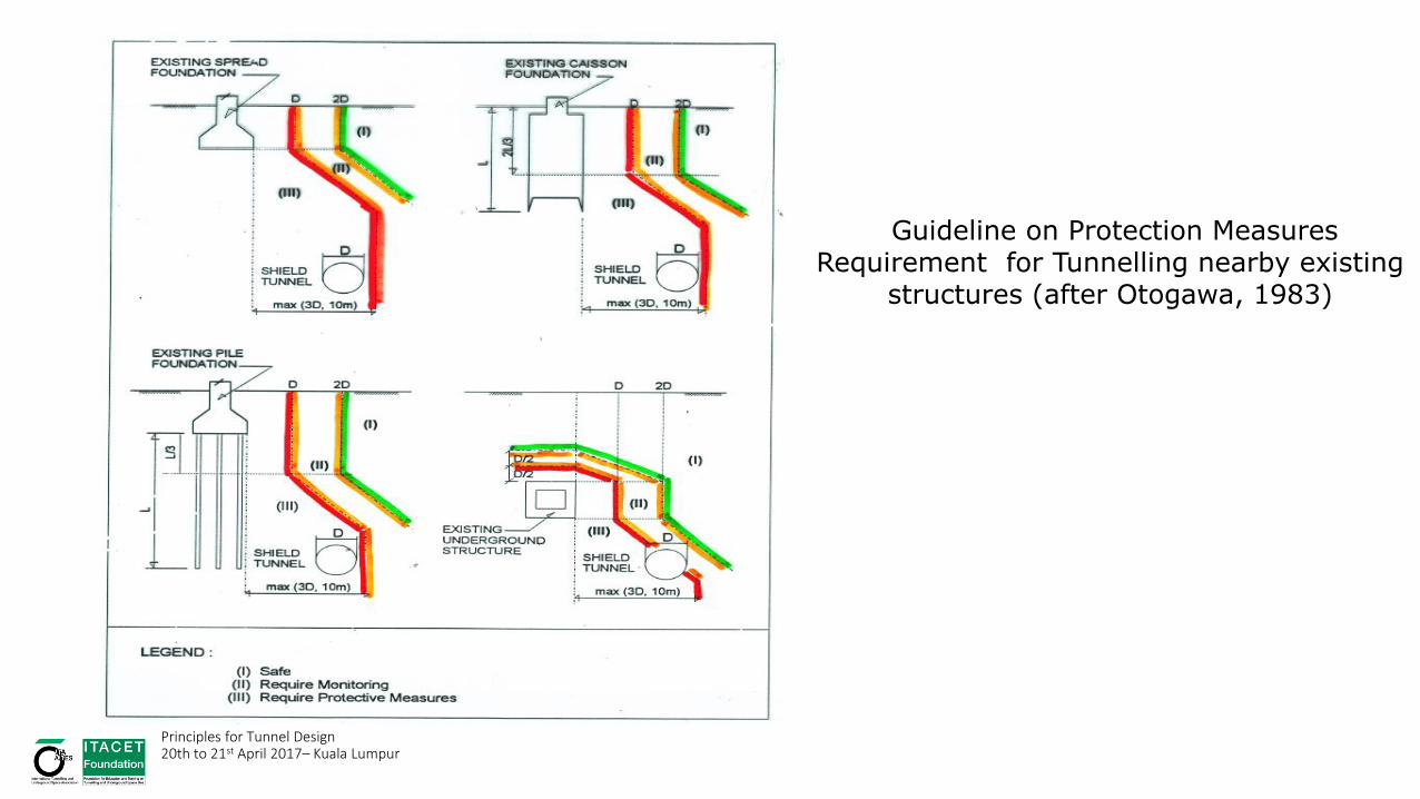
Guideline on Protection Measures Requirement for Tunnelling nearby existing
structures (after Otogawa, 1983)
Principles for Tunnel Design 20th to 21st April 2017– Kuala Lumpur

STAGED ASSESSMENT • Building Condition Survey:-Check all buildings in influence zone
• No further check if predicted settlement < 10 mm & ground slope <1/500
• Check damage level using the limiting tensile strain approach (Burland et al & Boscardin and Cording)
• Structures placed in Category 3 of damage classification (moderate) or above need further assessment (detailed analyses)
• Establish protective measures requirement
• Monitoring (till 3 months after movement stops)
Principles for Tunnel Design 20th to 21st April 2017– Kuala Lumpur

Observational Method and Instrumentation
Principles for Tunnel Design 20th to 21st April 2017– Kuala Lumpur

0
10
20
30
40
50
60
DE
PTH
BE
LOW
GR
OU
ND
LE
VE
L (m
)
0
10
20
30
40
50
60
20+000 21+000 22+000 23+000 24+000 25+000 26+000 27+000 28+000 29+000 30+000
TUNNELING HORIZON
MADE GROUND
BANGKOK SOFT CLAY
1ST STIFF CLAY
VERY STIFF CLAY
MEDIUM DENSE CLAYEY SAND
DENSE SAND
HARD CLAY
DARK GREY CLAY
MADE GROUND
BANGKOK SOFT CLAY
1ST STIFF CLAY
VERY STIFF CLAY
DENSE SAND
HARD CLAY
0
60
20
40
80
100
0
60
20
40
80
100
THIAM RUAM MITPRACHARAT
BAMPHENSUTTHISAN
RATCHADALAT PHRAO
PHAHONYOTHIN MO CHIT
KAMPHEANG
PHETBANG SUE
SURFACE SETTLEMENT AND SOIL PROFILE IN NORTH CONTRACTS
UR
FAC
E S
ETT
LEM
EN
T (m
m)
NORTH BOUND
SOUTH BOUND
HARD CLAY
DENSE SAND
VERY STIFF CLAY

HUA LAMPONG SAM YAN SILOM LUMPHINI BONKAI SIRIKIT CENTER SUKHUMVIT PETCHABURI RAMA IX
0
10
20
30
40
50
60
0
10
20
30
40
50
60
DE
PTH
BE
LOW
GR
OU
ND
LE
VE
L (m
)
10+050 11+000 12+000 13+000 14+000 15+000 16+000 17+000 18+000 19+000
MADE GROUND
BANGKOK SOFT CLAY
1ST STIFF CLAY
VERY STIFF CLAY
MEDIUM DENSE CLAYEY SAND
HARD CLAY
DARK GREY CLAY
TUNNELING HORIZON
NORTH BOUND
SOUTH BOUND
MADE GROUND
BANGKOK SOFT CLAY
1ST STIFF CLAY
DENSE SAND
VERY STIFF CLAY
HARD CLAY
SURFACE SETTLEMENT AND SOIL PROFILE IN SOUTH CONTRACT
DENSE SAND
0
60
20
40
80
100
0
60
20
40
80
100
SU
RFA
CE
SE
TTLE
ME
NT
(mm
)
NORTH BOUND
SOUTH BOUND
DENSE SAND
HARD CLAY
HARD CLAY
Principles for Tunnel Design 20th to 21st April 2017– Kuala Lumpur

-180.0
-160.0
-140.0
-120.0
-100.0
-80.0
-60.0
-40.0
-20.0
0.0
10.000 12.000 14.000 16.000 18.000 20.000 22.000 24.000 26.000 28.000 30.000Station, Km
Settle
ment,
mm
Side-by-Side TunnelsStacked Tunnels
SURFACE SETTLEMENT
South Contract North Contract
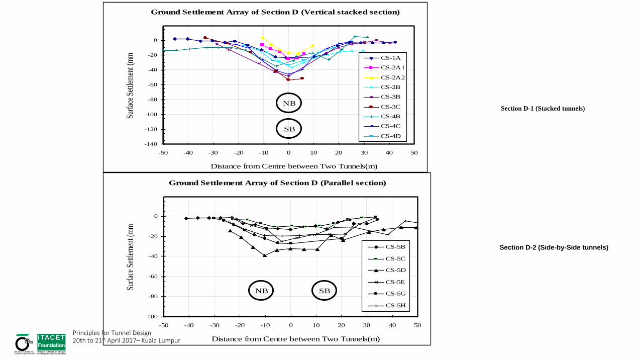
Ground Settlement Array of Section D (Vertical stacked section)
-140
-120
-100
-80
-60
-40
-20
0
-50 -40 -30 -20 -10 0 10 20 30 40 50
Distance from Centre between Two Tunnels(m)
Surf
ace
Settl
emen
t (m
m)
CS-1A
CS-2A1
CS-2A2
CS-2B
CS-3B
CS-3C
CS-4B
CS-4C
CS-4D
NB
SB
Ground Settlement Array of Section D (Parallel section)
-100
-80
-60
-40
-20
0
-50 -40 -30 -20 -10 0 10 20 30 40 50
Distance from Centre between Two Tunnels(m)
Surf
ace
Settl
emen
t (m
m)
CS-5B
CS-5C
CS-5D
CS-5E
CS-5G
CS-5H
NB SB
Section D-1 (Stacked tunnels)
Section D-2 (Side-by-Side tunnels)
Principles for Tunnel Design 20th to 21st April 2017– Kuala Lumpur

0.00
2.00
4.00
6.00
8.00
10.00
12.00
0.00 1.00 2.00 3.00 4.00 5.00 6.00
i/R
Z/2R
Single tunnel
Twin Tunnel
Soft to Stiff clay
Rock, Hard Clays,
Sand above
groundwater level
Sand below
groundwater level
0
5
10
15
20
25
30
35
40
0 5 10 15 20
Trough width parameter, i (m)
Dep
th, Z
(m)
Single tunnel
Twin tunnel i = 0.3Z i = 0.4Z i = 0.5Zi = 0.6Z
Width of Settlement Trough
Principles for Tunnel Design 20th to 21st April 2017– Kuala Lumpur

Principles for Tunnel Design 20th to 21st April 2017– Kuala Lumpur

Correlation between Volume Loss and Ratio of Face Pressure to Overburden Pressure
0.0
1.0
2.0
3.0
0.0 0.2 0.4 0.6 0.8 1.0
Gro
und
loss
,VL
(%)
Ratio of EPB face pressure to overburden pressure
Side by side Tunnels
Stacked Tunnels
Ground Loss versus Face Pressure Principles for Tunnel Design 20th to 21st April 2017– Kuala Lumpur
-70
-60
-50
-40
-30
-20
-10
0
-120 -100 -80 -60 -40 -20 0 20 40 60 80 100 120 140 160 180 200
Surf
ace
sett
lem
ent (
mm
)
Longitudinal distance to tunnel face (m)
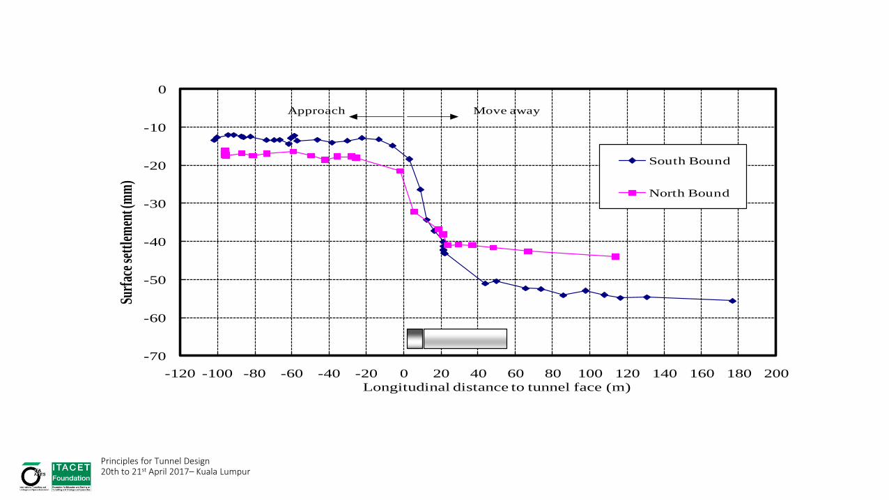
Figure 4.56 Ground movement with tunnel face advancement section AR-26-001
South Bound
North Bound
Approach Move away
Principles for Tunnel Design 20th to 21st April 2017– Kuala Lumpur
-50
-40
-30
-20
-10
0
10
0 180 360 540 720
Surfa
ce S
ettle
men
t, m
m
Elapsed time, Days
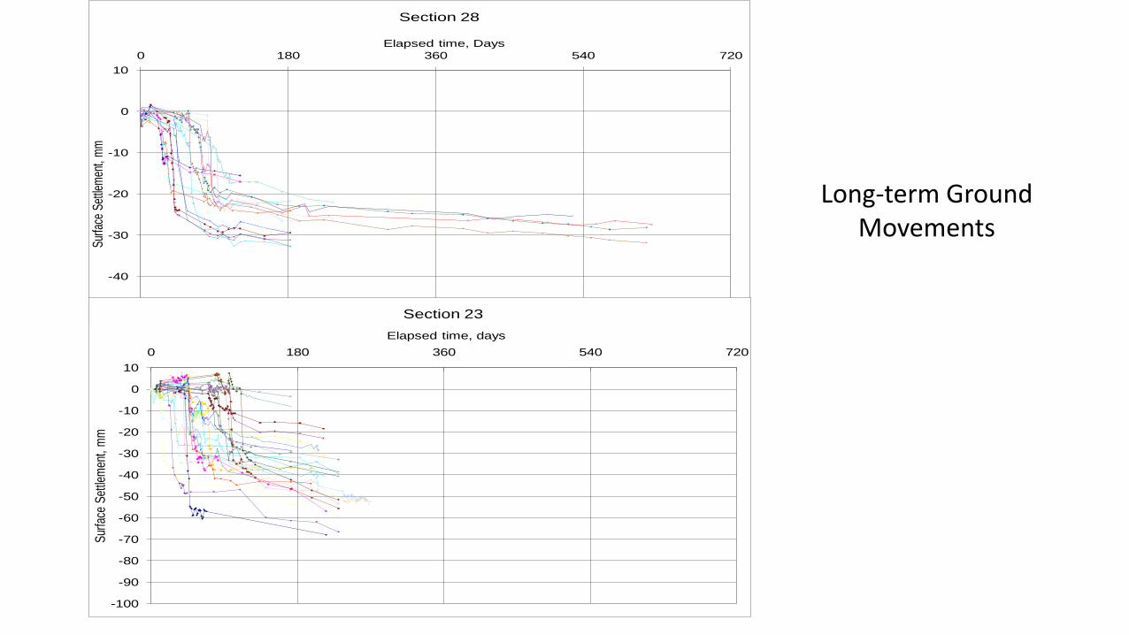
Section 28
-100
-90
-80
-70
-60
-50
-40
-30
-20
-10
0
10
0 180 360 540 720
Sur
face
Set
tlem
ent,
mm
Elapsed time, days
Section 23
Long-term Ground Movements

Bangkok MRTA Blue Line – Settlement of Nearby Buildings

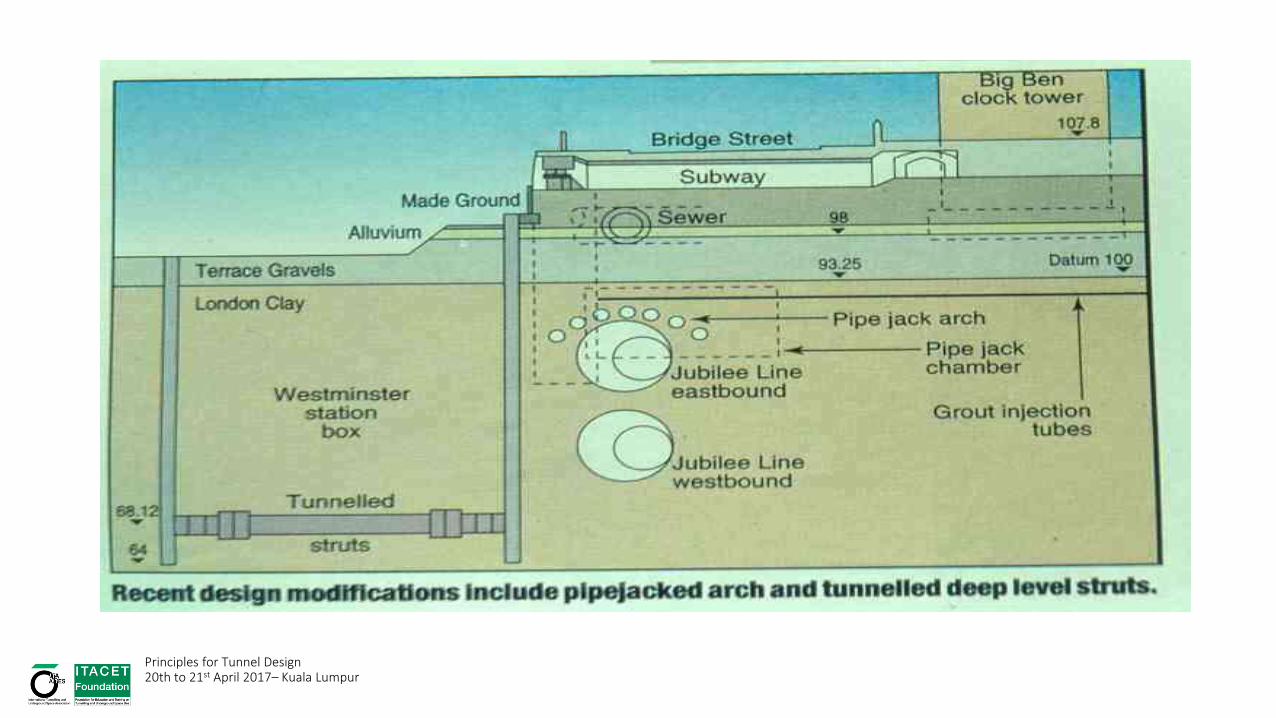
Case Example: London Underground Extension
Principles for Tunnel Design 20th to 21st April 2017– Kuala Lumpur

Principles for Tunnel Design 20th to 21st April 2017– Kuala Lumpur

Compensation Grouting
Principles for Tunnel Design 20th to 21st April 2017– Kuala Lumpur

Thank You
• Principles for Tunnel Design 20th to 21st April 2017– Kuala Lumpur

Principles for Tunnel Design 20th to 21st April 2017– Kuala Lumpur

Disclaimer a) The speakers are presenting their own personal views and are not expressing the view of the Foundation. b) Papers and documents displayed or handed out during the Event are copyrighted. The participants must observe and comply with all applicable law regulations concerning the copyright.
Principles for Tunnel Design
20th to 21st April 2017– Kuala Lumpur
Related Documents