© SICK, Inc., USA. All rights, including changes to technical specifications and or to the equipment without prior notification, are reserved. C - 0 Safety laser scanners 7024240 Principle of operation of laser scanners Laser scanners are compact systems that scan their surround- ings with a beam (“optical radar”). If the emitted light pulses hit an object, the light is reflected and detected in the laser scan- ner’s receiver. The time between the emission of a light pulse and the reception of the reflection represents the distance between the laser scanner and object (light time-of-flight meas- urement). An internal rotating mirror “moves” the light pulses in a circle to produce 2-dimensional scanning. So-called monitored areas can be defined within the field of view (scanning angle) and the device-specific scanning range of a laser scanner. If an object is detected in a monitored area, this situation is indicated by the laser scanner using 2 switching out- puts (safe “stop” signal to the machine). Laser scanner principle of operation Fan-shaped scanning of the surroundings Use of laser scanners Laser scanners are used for area monitoring (hazardous area protection), hazardous point protection and access protection. A differentiation is made between: ■ Stationary applications ■ Horizontal applications: e.g. pipe bending machines, machining centres, robot cells, press return area, etc. ■ Vertical applications: Entry/Exit, hand protection ■ Mobile applications ■ Monitoring the movement of AGVs (automated guided vehi- cles), narrow aisle stackers, etc. Advantages of the SICK safety laser scanners Additional functions for plant and machine control ■ Switchable monitored areas in accordance with the current process phase ■ Monitoring external switching elements/contactors (EDM) saves costs and effort in the machine control ■ High-current outputs for directly operated switching elements (contactors), making conversion of the switching signals using relay interfaces, etc. unnecessary ■ Measured data on the surroundings as well as reflector detec- tion to support vehicle steering (AGV). Only one sensor for safety and control ■ Integrated restart interlock (RES) minimises the effort in the machine control Product range ■ A very wide range of application requirements can be addressed with a compatible product family, thus minimising stock-keeping and investment costs. Experience ■ Proven in use ■ The highest quality standards guarantee stable serial produc- tion ■ Consultation and service expertise Safety services With services tailored specifically to your needs, SICK offers all- embracing support for the safety of your machine or system. Address productivity and cost-effectiveness from the start: From selection and planning, through commissioning and inspection, to maintenance and modernisation. Receiver R Sender S rotating mirror s t S R t Object Scanner ➜ For information about the services please refer to chapter A

Welcome message from author
This document is posted to help you gain knowledge. Please leave a comment to let me know what you think about it! Share it to your friends and learn new things together.
Transcript

© SICK, Inc., USA. All rights, including changes to technical specifications and or to the equipment without prior notification, are reserved.C - 0
Safety laser scanners
7024240
Principle of operation of laser scannersLaser scanners are compact systems that scan their surround-ings with a beam (“optical radar”). If the emitted light pulses hit an object, the light is reflected and detected in the laser scan-ner’s receiver. The time between the emission of a light pulse and the reception of the reflection represents the distance between the laser scanner and object (light time-of-flight meas-urement). An internal rotating mirror “moves” the light pulses in
a circle to produce 2-dimensional scanning.So-called monitored areas can be defined within the field of view (scanning angle) and the device-specific scanning range of a laser scanner. If an object is detected in a monitored area, this situation is indicated by the laser scanner using 2 switching out-puts (safe “stop” signal to the machine).
Laser scanner principle of operation
Fan-shaped scanning of the surroundings
Use of laser scannersLaser scanners are used for area monitoring (hazardous area protection), hazardous point protection and access protection.
A differentiation is made between:■ Stationary applications
■ Horizontal applications: e.g. pipe bending machines, machining centres, robot cells, press return area, etc.
■ Vertical applications: Entry/Exit, hand protection■ Mobile applications
■ Monitoring the movement of AGVs (automated guided vehi-cles), narrow aisle stackers, etc.
Advantages of the SICK safety laser scannersAdditional functions for plant and machine control■ Switchable monitored areas in accordance with the current
process phase■ Monitoring external switching elements/contactors (EDM)
saves costs and effort in the machine control■ High-current outputs for directly operated switching elements
(contactors), making conversion of the switching signals using relay interfaces, etc. unnecessary
■ Measured data on the surroundings as well as reflector detec-tion to support vehicle steering (AGV). Only one sensor for safety and control
■ Integrated restart interlock (RES) minimises the effort in the machine control
Product range■ A very wide range of application requirements can be
addressed with a compatible product family, thus minimising stock-keeping and investment costs.
Experience■ Proven in use■ The highest quality standards guarantee stable serial produc-
tion ■ Consultation and service expertise
Safety servicesWith services tailored specifically to your needs, SICK offers all-embracing support for the safety of your machine or system.
Address productivity and cost-effectiveness from the start: From selection and planning, through commissioning and inspection, to maintenance and modernisation.
Receiver R
Sender S
rotating mirror
s t
S
R
t
Object
Scanner
➜ For information about the services please refer to chapter A

ABCDEFGHIJKLMNOPQ
R© SICK, Inc., USA. All rights, including changes to technical specifications
and or to the equipment without prior notification, are reserved. C - 1
Safety laser scanners
7024240
Safety laser scanners
1) Field set comprising of protective field and warning field2) Special features of the S3000 product family on page C-23) S3000 Remote can only be used in conjunction with another S3000 or a UE100 series safety controller
Functions
Exte
rnal
dev
ice
mon
itorin
g (E
DM
)
Hos
t/gu
est o
pera
tion
Safe
inte
rfac
e to
bus
sys
tem
s
Refle
ctor
mar
k de
tect
ion
and
expa
nded
mea
sure
d da
ta in
put
Mea
sure
d da
ta o
utpu
t via
R
S-42
2 in
terf
ace
aaaa
aaaa
aaaa
aaaa
a
Safety application
Scanning range(m)
Scanning angle
(°)
Switch-able field
sets 1)
Incremental encoder
connections
Static control inputs Product Page
4 / 5.5 / 7 190
8 2 4 ✔ ✔ ✔ — ✔ S3000 Professional 2) C-3
4 — 2 ✔ ✔ ✔ — ✔ S3000 Advanced 2) C-10
1 — — ✔ ✔ ✔ — ✔ S3000 Standard 2) C-17
8 — — ✔ ✔ ✔ — ✔ S3000 Remote 2) 3) C-24
8 2 4 ✔ ✔ ✔ ✔ ✔ S3000 Professional CMS 2) C-31
2 270
4 2 2 ✔ ✔ ✔ — ✔ S300 Professional C-38
2 — 1 ✔ ✔ ✔ — — S300 Advanced C-48
1 — — ✔ ✔ ✔ — — S300 Standard C-57
1.5 270 1 — — ✔ — — — — S200 C-65

ABCDEFGHIJKLMNOPQ
R© SICK, Inc., USA. All rights, including changes to technical specifications and or to the equipment without prior notification, are reserved.C - 2
Safety laser scanners
7024240
Special features of the safety laser scanners
S3000 - the modular system
■ Modular concept■ S3000 solutions grow with your needs■ Security of investment due to configurable variants■ Easy to service
■ Largest achievable scanning range is 7 m for safety applica-tions
■ Configuration memory in the system plug■ Selectable resolution makes it possible to adapt the devices
to a very wide range of application requirements■ Certified for vertical use for access control or entry/exit appli-
cations, as well as hand protection■ 7-segment display■ Integrated external device monitoring (EDM)■ Safe integration in bus systems■ Up to 8 switchable protective/warning fields (field sets)■ Formation of host/guest systems with S3000/S300 ■ Direct connection of incremental encoders■ Certified according to IEC/EN 61496-3 (type 3) and
IEC/EN 61508 (SIL2)■ Measured data output via RS-422 interface■ Reflector mark detection
Modular concept
S300/S200 — Compact. Flexible. Intelligent.
■ Extremely compact■ S300 is the smallest laser scanner in the world■ S200 — the first laser scanner for cat. 2 applications■ Easy to service
■ 8 m warning field and 2 m protective field■ Superior 270° scan angle■ Configuration memory in the system plug■ Selectable resolution makes it possible to adapt the devices
to a very wide range of application requirements■ Certified for vertical use for access control or entry/exit appli-
cations, as well as hand protection■ 7-segment display■ Integrated external device monitoring (EDM)■ Safe integration in bus systems■ Up to 4 switchable protective/warning fields (field sets)■ Formation of host/guest systems with S300/S3000■ Direct connection of incremental encoders■ Adjustable object resolution■ Stand-by input■ RS-422 data interface

ABCDEFGHIJKLMNOPQ
R© SICK, Inc., USA. All rights, including changes to technical specifications
and or to the equipment without prior notification, are reserved. C - 3
S3000 Professional Safety laser scanner
7024240
■ Modular concept■ Scanning range 4 m, 5.5 m
or 7 m■ Configuration memory■ Selectable resolution■ Certified for vertical use■ 7-segment display■ Integrated external device
monitoring (EDM)
✓✓✓IEC 61508Compliant
Further information Page
➜ Ordering information C-4
➜ Technical specifications C-4
➜ Dimensional drawings C-6
➜ Connection diagrams C-7
➜ Accessories C-8
➜ Services A-2
Overview of technical specifications
Protective field range (depending on type) 4 m / 5.5 m / 7 m
Warning field range 49 m (20 m at 20 % reflectivity)
Number of field sets 8
Scan angle 190°
Resolution 30 mm, 40 mm, 50 mm, 70 mm, 150 mm, selectable
Response time 60 ms, 120 ms
Type Type 3 (IEC/EN 61496-3)
Safety integrity level SIL2 (IEC/EN 61508)
Product descriptionThe S3000 Professional can be used for a wide range of applications for the protec-tion of machines and systems. The field sets can be conveniently defined using a PC or laptop.■ For complex applications with up to
8 protective fields/warning fields
■ Static and dynamic protective field switching
■ Incremental encoder connections■ Possibility of connecting two S3000 units
to form a single system■ New uniform "Configuration & Diagnostic
Software" CDS
In-system added value■ Supports integration with multiple safety control solutions
➜ For safety system combinations, see appendix "Sensor systems and safe control solutions from SICK"
Applications
➜ You can find more applications using the application finder at www.sickusa.com/applications
■ Freely moving transport vehicles■ Production lines■ Machining centres
■ Entry/Exit stations (gates)■ Robot cells■ Narrow corridor vehicles
Velocity-dependent vehicle monitoring Vertical access protection (entry/exit) with "con-tour as reference"
WS/WE 12-2

ABCDEFGHIJKLMNOPQ
R© SICK, Inc., USA. All rights, including changes to technical specifications and or to the equipment without prior notification, are reserved.C - 4
S3000 Professional Safety laser scanner
7024240
Ordering informationDelivery S3000 systems:■ Sensor head with I/O module mounted■ Operating instructions and CDS (Configuration & Diganostic Software) on CD-ROM■ Adhesive label "Important information"The system plug has to be ordered separately!
➜ Ordering information for system plug and accessories, see page C-8
System part Protective field range Type Part number
Sensor head with I/O module
4 m S30A-4011DA 1028936
5.5 m S30A-6011DA 1019600
7 m S30A-7011DA 1023892
Sensor head
4 m Sensor head short range 2034999
5.5 m Sensor head medium range 2022972
7 m Sensor head long range 2026747
I/O module — I/O module Professional 2022872
Detailed technical specifications
General data
Laser protection class 1 (21 CFR 1040.10 and 1040.11, DIN EN 60825:2001)
Enclosure rating IP 65 (EN 60529)
Protection class 2 (DIN VDE 0160, DIN EN 50178)
Type Type 3 (IEC/EN 61496-3)
Safety integrity level SIL2 (IEC/EN 61508)
Ambient operating temperature from ... to –10 °C ... +50 °C
Type of light Pulsed laser diode
Wave length 905 nm
Housing colour RAL 1021
Housing material Aluminium die-cast
Front screen material Polycarbonate
Front screen surface finish Outside with scratch-resistant coating
System plug With ESD protected configuration memory
Dimensions (W x H x D) 155 mm x 185 mm x 160 mm
Weight 3.3 kg
➜ Additional technical information is described in operating instructions, which are available to download at www.sickusa.com/literature

ABCDEFGHIJKLMNOPQ
R© SICK, Inc., USA. All rights, including changes to technical specifications
and or to the equipment without prior notification, are reserved. C - 5
S3000 Professional Safety laser scanner
7024240
Functional data
Scan angle 190°
Protective field range (depending on type) 4 m / 5.5 m / 7 m
Reflectivity Reflectors 1.8 % ... >1000 %
Response time 60 ms, 120 ms 1)
Resolution 30 mm, 40 mm, 50 mm, 70 mm, 150 mm, selectable
Angular resolution 0.5°/0.25° (depending on range and resolution)
Protective field supplement 100 mm
Warning field range 49 m (20 m at 20 % reflectivity)
Distance measuring range 49 m
Number of mulitple samplings 2 ... 16, configurable via CDS
Reset time 2 s ... 60 s, configurable1) Depending on basic response time, resolution, maximum protective field range, multiple sampling and type of outputs
Electrical data
Connection type Plug-in connection housing with screw
Connector technology Screw-type terminals
Supply voltage Vs 24 V DC (16.8 V DC ... 28.8 V DC)
Power consumption 0.8 A (24 V DC)
Power consumption 2.3 A 1)
Number of inputsEDM
Restart/ResetStatic switching signals
Dynamic encoder signals (incremental encoder)
112, 42
Number of safety capable outputsSafety outputs (OSSD)
Output for warning fieldDiagnostic output
Restart/reset required
2 x 500 mA1 x 100 mA1 x 100 mA1 x 100 mA
Configuration and diagnostics interfaceTransmission rate
RS-2329.6 kBaud, 19.2 kBaud, 38.4 kBaud
Data interface RS-422 (≤500 kBaud)
EFI – safe SICK device communicationTransmission rate
Cable lengthConnection conductor cross-section
≤500 kBaud50 m0.34 mm²
1) Including maximum output load

ABCDEFGHIJKLMNOPQ
R© SICK, Inc., USA. All rights, including changes to technical specifications and or to the equipment without prior notification, are reserved.C - 6
S3000 Professional Safety laser scanner
7024240
147M8x9
Area to be keptclear duringinstallation ofthe scanner
M13.5
23
77.5
92.5
15565.227.8
93160
Axis of rotation of motor
136.8
55
211
185
78.5
53
.2
63
120M
6x8
Con
nect
or r
ange
appr
ox. 2
70
211
185
155
Refe
renc
epo
ints
for
mou
ntin
g
31.7
63
Bea
m d
iam
eter
Send
er =
15
Bea
m d
iam
eter
Rece
iver
= 4
4
35
31.7
Dimensional drawings
Dimensions in mm

ABCDEFGHIJKLMNOPQ
R© SICK, Inc., USA. All rights, including changes to technical specifications
and or to the equipment without prior notification, are reserved. C - 7
S3000 Professional Safety laser scanner
7024240
Protective field switching with four static inputs
■ S3000 Professional in conjunction with relays/contactors■ Operating mode: with restart interlock and external device
monitoring (EDM)
■ Static protective field switching by means of the control inputs A, B, C and D
Connection diagrams
➜ You can find connection diagrams at www.sickusa.com/connectiondiagrams
Protective field switching with static and dynamic inputs
■ S3000 Professional in conjunction with relays/contactors■ Operating mode: without restart interlock with external device
monitoring (EDM)
■ Dynamic protective field switching using B1 and B2 as well as static protective field switching using the control inputs A and B

ABCDEFGHIJKLMNOPQ
R© SICK, Inc., USA. All rights, including changes to technical specifications and or to the equipment without prior notification, are reserved.C - 8
S3000 Professional Safety laser scanner
7024240
AccessoriesMounting systems
Description Type Part number
Mounting bracket for direct mounting at the rear on wall or machine. No adjustment facility
Mounting kit 1 2015623
Bracket only in conjunction with mounting kit 1. Mounting at the rear on wall or machine. Longitudinal and cross-wise adjustment possible
Mounting kit 2 2015624
Bracket only in conjunction with mounting kit 1 and 2. Mounting at the rear or below on wall, floor or machine. Longitudinal and cross-wise adjustment possible
Mounting kit 3 2015625
Mounting bracket, rugged design, with protective cover. Floor mounting. Height adjustment possible
Mounting bracket 7087514
1
2
3
Product group ApplicationsFurther
information
Safety relays Safety relays allow simple integration of safety components into machinery or plant. Page N-0
Safety controllers
Safety controllers are utilized when the safety function (e.g. switching off a dangerous movement) is to be accomplished in a flexible way by logical combination of safety relevant signals. Operation of machinery becomes more flexible and generation of machine variants becomes easier.
Page O-0
Safety fieldbus solutions
Safety fieldbus solutions are utilized in plants and machinery of larger scale. This saves cabling and enables modular design of the safety automation. Potential errors or faults can be easily identified via the comprehensive diagnostics functions. That significantly reduces machine down times. SICK offers solutions for the open automation standards: AS-i Safety at Work, DeviceNet Safety and PROFIsafe.
Safe control solutions
System plugs
Direction of cable outlet Usage Connection type Number of cores Cable length Type Part number
Upward
Not for use with incremental encoders
Without cable — — SX0A-A0000B 2023797
Pre-assembled 17
5 m SX0A-B1705B 2027174
10 m SX0A-B1710B 2027175
20 m SX0A-B1720B 2027816
For use with incremental encoders
Without cable — — SX0A-A0000D 2023310
Pre-assembled 135 m SX0A-B1305D 2027176
10 m SX0A-B1310D 2027177

ABCDEFGHIJKLMNOPQ
R© SICK, Inc., USA. All rights, including changes to technical specifications
and or to the equipment without prior notification, are reserved. C - 9
S3000 Professional Safety laser scanner
7024240
Connection cables
Type Number of cores Cable length Part number
Connection cable13 100 m 6025729
17 100 m 6025730
EFI connection cable — 50 m 6026675
Cable gland
Usage Size of the cable gland Part number
For EFI connections M12 5308757
Configuration connection cables
Note Connection type Cable length Part number
For connecting the configuration connection to the PC M8 x 4, SUB-D 9-pol2 m 6021195
8 m 2027649
SDL connection cables
Note Direction of cable outlet Connection type Number of cores Cable length Part number
For the connection of safety bus modules to S3000 Straight Interconnectron plug
M23 x 12 12
2.5 m 2029337
5 m 2029338
10 m 2029339
15 m 2029340
Configuration software
Type Description Part number
CDS CDS (Configuration & Diagnostic Software) on CD-ROM including online documentation and operating instructions in all available languages 2032314
Power supply units
Input voltage Output voltage Maximum output current Part number
100 V AC, 240 V AC
24 V DC
2.1 A 7028789
3.9 A 7028790
120 V AC, 230 V AC2.5 A 6010361
4 A 6010362
Miscellaneous
Type Description Part number
Front screen Spare parts set for front screen with replacement seal and screws 2027180
Plastic cleaner Plastic cleaner and care product, anti-static 5600006
Lens cloth Cloth for cleaning the front screen 4003353

ABCDEFGHIJKLMNOPQ
R© SICK, Inc., USA. All rights, including changes to technical specifications and or to the equipment without prior notification, are reserved.C - 10
S3000 Advanced Safety laser scanner
7024240
■ Modular concept■ Scanning range 4 m, 5.5 m
or 7 m■ Configuration memory■ Selectable resolution■ Certified for vertical use■ 7-segment display■ Integrated external device
monitoring (EDM)
✓✓✓IEC 61508Compliant
Further information Page
➜ Dimensional drawings C-13
➜ Connection diagrams C-14
➜ Accessories C-15
➜ Services A-2
Overview of technical specifications
Protective field range (depending on type) 4 m / 5.5 m / 7 m
Warning field range 49 m (20 m at 20 % reflectivity)
Number of field sets 4
Scan angle 190°
Resolution 30 mm, 40 mm, 50 mm, 70 mm, 150 mm, selectable
Response time 60 ms, 120 ms
Type Type 3 (IEC/EN 61496-3)
Safety integrity level SIL2 (IEC/EN 61508)
Product descriptionS3000 Advanced safety laser scanners are used for the horizontal and vertical protec-tion of hazardous areas, hazardous points and accesses.■ For complex applications with up to
4 protective fields/warning fields
■ Static protective field switching■ Possibility of connecting two S3000
units to form a single system■ New uniform "Configuration & Diagnostic
Software" CDS
In-system added value■ Supports integration with multiple safety control solutions
➜ For safety system combinations, see appendix "Sensor systems and safe control solutions from SICK"
■ Freely moving transport vehicles■ Production lines■ Machining centres
■ Entry/Exit stations (gates)■ Robot cells■ Narrow corridor vehicles
Access protection on a robot cell with several working areas with "contour as reference"
Protection of two separate working areas with one S3000 and a SICK safety controller
Applications
➜ You can find more applications using the application finder at www.sickusa.com/applications
WS/WE 12-2

ABCDEFGHIJKLMNOPQ
R© SICK, Inc., USA. All rights, including changes to technical specifications
and or to the equipment without prior notification, are reserved. C - 11
S3000 Advanced Safety laser scanner
7024240
Ordering informationDelivery S3000 systems:■ Sensor head with I/O module mounted■ Operating instructions and CDS (Configuration & Diganostic Software) on CD-ROM■ Adhesive label "Important information"The system plug has to be ordered separately!
➜ Ordering information for system plug and accessories, see page C-15
System part Protective field range Type Part number
Sensor head with I/O module
4 m S30A-4011CA 1028935
5.5 m S30A-6011CA 1023547
7 m S30A-7011CA 1023891
Sensor head
4 m Sensor head short range 2034999
5.5 m Sensor head medium range 2022972
7 m Sensor head long range 2026747
I/O module — I/O module Advanced 2026802
Detailed technical specifications
General data
Laser protection class 1 (21 CFR 1040.10 and 1040.11, DIN EN 60825:2001)
Enclosure rating IP 65 (EN 60529)
Protection class 2 (DIN VDE 0160, DIN EN 50178)
Type Type 3 (IEC/EN 61496-3)
Safety integrity level SIL2 (IEC/EN 61508)
Ambient operating temperature from ... to –10 °C ... +50 °C
Type of light Pulsed laser diode
Wave length 905 nm
Housing colour RAL 1021
Housing material Aluminium die-cast
Front screen material Polycarbonate
Front screen surface finish Outside with scratch-resistant coating
System plug With ESD protected configuration memory
Dimensions (W x H x D) 155 mm x 185 mm x 160 mm
Weight 3.3 kg
Continued on next page
➜ Additional technical information is described in operating instructions, which are available to download at www.sickusa.com/literature

ABCDEFGHIJKLMNOPQ
R© SICK, Inc., USA. All rights, including changes to technical specifications and or to the equipment without prior notification, are reserved.C - 12
S3000 Advanced Safety laser scanner
7024240
Functional data
Scan angle 190°
Protective field range (depending on type) 4 m / 5.5 m / 7 m
Reflectivity Reflectors 1.8 % ... >1000 %
Response time 60 ms, 120 ms 1)
Resolution 30 mm, 40 mm, 50 mm, 70 mm, 150 mm, selectable
Angular resolution 0.5°/0.25° (depending on range and resolution)
Protective field supplement 100 mm
Warning field range 49 m (20 m at 20 % reflectivity)
Distance measuring range 49 m
Number of mulitple samplings 2 ... 16, configurable via CDS
Reset time 2 s ... 60 s, configurable1) Depending on basic response time, resolution, maximum protective field range, multiple sampling and type of outputs
Electrical data
Connection type Plug-in connection housing with screw
Connector technology Screw-type terminals
Supply voltage Vs 24 V DC (16.8 V DC ... 28.8 V DC)
Power consumption 0.8 A (24 V DC)
Power consumption 2.3 A 1)
Number of inputsEDM
Restart/ResetStatic switching signals
112
Number of safety capable outputsSafety outputs (OSSD)
Output for warning fieldDiagnostic output
Restart/reset required
2 x 500 mA1 x 100 mA1 x 100 mA1 x 100 mA
Configuration and diagnostics interfaceTransmission rate
RS-2329.6 kBaud, 19.2 kBaud, 38.4 kBaud
Data interface RS-422 (≤500 kBaud)
EFI – safe SICK device communicationTransmission rate
Cable lengthConnection conductor cross-section
≤500 kBaud50 m0.34 mm²
1) Including maximum output load

ABCDEFGHIJKLMNOPQ
R© SICK, Inc., USA. All rights, including changes to technical specifications
and or to the equipment without prior notification, are reserved. C - 13
S3000 Advanced Safety laser scanner
7024240
147M8x9
Area to be keptclear duringinstallation ofthe scanner
M13.5
23
77.5
92.5
15565.227.8
93160
Axis of rotation of motor
136.8
55
211
185
78.5
53
.2
63
120M
6x8
Con
nect
or ra
nge
appr
ox. 2
70
211
185
155
Refe
renc
epo
ints
for
mou
ntin
g
31.7
63
Bea
m d
iam
eter
Send
er =
15
Bea
m d
iam
eter
Rece
iver
= 4
4
35
31.7
Dimensional drawings
Dimensions in mm

ABCDEFGHIJKLMNOPQ
R© SICK, Inc., USA. All rights, including changes to technical specifications and or to the equipment without prior notification, are reserved.C - 14
S3000 Advanced Safety laser scanner
7024240
Protective field switching with two static inputs
■ S3000 Advanced in conjunction with relays/contactors■ Operating mode: with restart interlock and external device
monitoring (EDM)
■ Protective field switching by means of control inputs A and B
Connection diagrams
➜ You can find connection diagrams at www.sickusa.com/connectiondiagrams
Protective field switching between two S3000 with static inputs
32
6
7
49
8
13
1011
1214
15
15
0V
K1 K2 H8
+24V
k2
INA
k1
3
K3H2 K4
k1 k3
k4k2z1 z2
x1 y1
k1 k2x1 y1
z1
k3
1)x2 y2
x2k4
y2
z2
2
k4
INB
k3
6
7
49
8
13
1011
1214
15
15
■ S3000 Advanced with S3000 Advanced in conjunction with relays/contactors
■ Operating mode: without restart interlock with external device monitoring (EDM)
■ Protective field switching by means of control input A and con-trol input B on separate OSSD pairs (simultaneous monitor-ing)

ABCDEFGHIJKLMNOPQ
R© SICK, Inc., USA. All rights, including changes to technical specifications
and or to the equipment without prior notification, are reserved. C - 15
S3000 Advanced Safety laser scanner
7024240
AccessoriesMounting systems
Product group ApplicationsFurther
information
Safety relays Safety relays allow simple integration of safety components into machinery or plant. Page N-0
Safety controllers
Safety controllers are utilized when the safety function (e.g. switching off a dangerous movement) is to be accomplished in a flexible way by logical combination of safety relevant signals. Operation of machinery becomes more flexible and generation of machine variants become easier.
Page O-0
Safety fieldbus solutions
Safety fieldbus solutions are utilized in plants and machinery of larger scale. This saves cabling and enables modular design of the safety automation. Potential errors or faults can be easily identified via the comprehensive diagnostics functions. That significantly reduces machine down times. SICK offers solutions for the open automation standards: AS-i Safety at Work, DeviceNet Safety and PROFIsafe.
Safe control solutions
Description Type Part number
Mounting bracket for direct mounting at the rear on wall or machine. No adjustment facility
Mounting kit 1 2015623
Bracket only in conjunction with mounting kit 1. Mounting at the rear on wall or machine. Longitudinal and cross-wise adjustment possible
Mounting kit 2 2015624
Bracket only in conjunction with mounting kit 1 and 2. Mounting at the rear or below on wall, floor or machine. Longitudinal and cross-wise adjustment possible
Mounting kit 3 2015625
Mounting bracket, rugged design, with protective cover. Floor mounting. Height adjustment possible
Mounting bracket 7087514
1
2
3
System plugs
Direction of cable outlet Usage Connection type Number of cores Cable length Type Part number
Upward Not for use with incremental encoders
Without cable — — SX0A-A0000B 2023797
Pre-assembled 13
5 m SX0A-B1305B 2027172
10 m SX0A-B1310B 2027173
20 m SX0A-B1320B 2027815

ABCDEFGHIJKLMNOPQ
R© SICK, Inc., USA. All rights, including changes to technical specifications and or to the equipment without prior notification, are reserved.C - 16
S3000 Advanced Safety laser scanner
7024240
Connection cables
Type Number of cores Cable length Part number
Connection cable 13 100 m 6025729
EFI connection cable — 50 m 6026675
Cable gland
Usage Size of the cable gland Part number
For EFI connections M12 5308757
Configuration connection cables
Note Connection type Cable length Part number
For connecting the configuration connection to the PC M8 x 4, SUB-D 9-pol2 m 6021195
8 m 2027649
SDL connection cables
Note Direction of cable outlet Connection type Number of cores Cable length Part number
For the connection of safety bus modules to S3000 Straight Interconnectron plug
M23 x 12 12
2.5 m 2029337
5 m 2029338
10 m 2029339
15 m 2029340
Configuration software
Type Description Part number
CDS CDS (Configuration & Diagnostic Software) on CD-ROM including online documentation and operating instructions in all available languages 2032314
Power supply units
Input voltage Output voltage Maximum output current Part number
100 V AC, 240 V AC
24 V DC
2.1 A 7028789
3.9 A 7028790
120 V AC, 230 V AC2.5 A 6010361
4 A 6010362
Miscellaneous
Type Description Part number
Front screen Spare parts set for front screen with replacement seal and screws 2027180
Plastic cleaner Plastic cleaner and care product, anti-static 5600006
Lens cloth Cloth for cleaning the front screen 4003353

ABCDEFGHIJKLMNOPQ
R© SICK, Inc., USA. All rights, including changes to technical specifications
and or to the equipment without prior notification, are reserved. C - 17
S3000 Standard Safety laser scanner
7024240
■ Modular concept■ Scanning range 4 m, 5.5 m
or 7 m■ Configuration memory■ Selectable resolution■ Certified for vertical use■ 7-segment display■ Integrated external device
monitoring (EDM)
✓✓✓IEC 61508Compliant
Further information Page
➜ Ordering information C-18
➜ Technical specifications C-18
➜ Dimensional drawings C-20
➜ Connection diagrams C-21
➜ Accessories C-22
➜ Services A-2
Overview of technical specifications
Protective field range (depending on type) 4 m / 5.5 m / 7 m
Warning field range 49 m (20 m at 20 % reflectivity)
Number of field sets 1
Scan angle 190°
Resolution 30 mm, 40 mm, 50 mm, 70 mm, 150 mm, selectable
Response time 60 ms, 120 ms
Type Type 3 (IEC/EN 61496-3)
Safety integrity level SIL2 (IEC/EN 61508)
Product descriptionS3000 Standard safety laser scanners are used for the horizontal and vertical protec-tion of hazardous areas, hazardous points and accesses as well as to protect automa-ted guided vehicles.
■ 1 protective and warning field■ Possibility of connecting two S3000 units
to form a single system■ New uniform "Configuration & Diagnostic
Software" CDS
In-system added value■ Supports integration with multiple safety control solutions
➜ For safety system combinations, see appendix "Sensor systems and safe control solutions from SICK"
■ Freely moving transport vehicles■ Production lines■ Machining centres
■ Entry/Exit stations (gates)■ Robot cells■ Narrow corridor vehicles
Hazardous area protection on an AGV with one direction of travel
Hazardous area protection on a robot cell
Applications
➜ You can find more applications using the application finder at www.sickusa.com/applications
WS/WE 12-2

ABCDEFGHIJKLMNOPQ
R© SICK, Inc., USA. All rights, including changes to technical specifications and or to the equipment without prior notification, are reserved.C - 18
S3000 Standard Safety laser scanner
7024240
Ordering informationDelivery S3000 systems:■ Sensor head with I/O module mounted■ Operating instructions and CDS (Configuration & Diganostic Software) on CD-ROM■ Adhesive label "Important information"The system plug has to be ordered separately!
➜ Ordering information for system plug and accessories, see page C-22
System part Protective field range Type Part number
Sensor head with I/O module
4 m S30A-4011BA 1028934
5.5 m S30A-6011BA 1023546
7 m S30A-7011BA 1023890
Sensor head
4 m Sensor head short range 2034999
5.5 m Sensor head medium range 2022972
7 m Sensor head long range 2026747
I/O module — I/O module Standard 2026801
Detailed technical specifications
General data
Laser protection class 1 (21 CFR 1040.10 and 1040.11, DIN EN 60825:2001)
Enclosure rating IP 65 (EN 60529)
Protection class 2 (DIN VDE 0160, DIN EN 50178)
Type Type 3 (IEC/EN 61496-3)
Safety integrity level SIL2 (IEC/EN 61508)
Ambient operating temperature from ... to –10 °C ... +50 °C
Type of light Pulsed laser diode
Wave length 905 nm
Housing colour RAL 1021
Housing material Aluminium die-cast
Front screen material Polycarbonate
Front screen surface finish Outside with scratch-resistant coating
System plug With ESD protected configuration memory
Dimensions (W x H x D) 155 mm x 185 mm x 160 mm
Weight 3.3 kg
➜ Additional technical information is described in operating instructions, which are available to download at www.sickusa.com/literature

ABCDEFGHIJKLMNOPQ
R© SICK, Inc., USA. All rights, including changes to technical specifications
and or to the equipment without prior notification, are reserved. C - 19
S3000 Standard Safety laser scanner
7024240
Functional data
Scan angle 190°
Protective field range (depending on type) 4 m / 5.5 m / 7 m
Reflectivity Reflectors 1.8 % ... >1000 %
Response time 60 ms, 120 ms 1)
Resolution 30 mm, 40 mm, 50 mm, 70 mm, 150 mm, selectable
Angular resolution 0.5°/0.25° (depending on range and resolution)
Protective field supplement 100 mm
Warning field range 49 m (20 m at 20 % reflectivity)
Distance measuring range 49 m
Number of mulitple samplings 2 ... 16, configurable via CDS
Reset time 2 s ... 60 s, configurable1) Depending on basic response time, resolution, maximum protective field range, multiple sampling and type of outputs
Electrical data
Connection type Plug-in connection housing with screw
Connector technology Screw-type terminals
Supply voltage Vs 24 V DC (16.8 V DC ... 28.8 V DC)
Power consumption 0.8 A (24 V DC)
Power consumption 2.3 A 1)
Number of inputsEDM
Restart/Reset11
Number of safety capable outputsSafety outputs (OSSD)
Output for warning fieldDiagnostic output
Restart/reset required
2 x 500 mA1 x 100 mA1 x 100 mA1 x 100 mA
Configuration and diagnostics interfaceTransmission rate
RS-2329.6 kBaud, 19.2 kBaud, 38.4 kBaud
Data interface RS-422 (≤500 kBaud)
EFI – safe SICK device communicationTransmission rate
Cable lengthConnection conductor cross-section
≤500 kBaud50 m0.34 mm²
1) Including maximum output load

ABCDEFGHIJKLMNOPQ
R© SICK, Inc., USA. All rights, including changes to technical specifications and or to the equipment without prior notification, are reserved.C - 20
S3000 Standard Safety laser scanner
7024240
147M8x9
Area to be keptclear duringinstallation ofthe scanner
M13.5
23
77.5
92.5
15565.227.8
93160
Axis of rotation of motor
136.8
55
211
185
78.5
53
.2
63
120M
6x8
Con
nect
or r
ange
appr
ox. 2
70
211
185
155
Refe
renc
epo
ints
for
mou
ntin
g
31.7
63
Bea
m d
iam
eter
Send
er =
15
Bea
m d
iam
eter
Rece
iver
= 4
4
35
31.7
Dimensional drawings
Dimensions in mm

ABCDEFGHIJKLMNOPQ
R© SICK, Inc., USA. All rights, including changes to technical specifications
and or to the equipment without prior notification, are reserved. C - 21
S3000 Standard Safety laser scanner
7024240
With restart interlock and external device monitoring
■ S3000 Standard in conjunction with relays/contactors■ Operating mode: with restart interlock and external device
monitoring (EDM)
Connection diagrams
➜ You can find connection diagrams at www.sickusa.com/connectiondiagrams
Restart interlock and external device monitoring (EDM) with safety relay UE10-3OS
■ S3000 Standard in conjunction with UE10-3OS■ Operating mode: with restart interlock and external device
monitoring (EDM)

ABCDEFGHIJKLMNOPQ
R© SICK, Inc., USA. All rights, including changes to technical specifications and or to the equipment without prior notification, are reserved.C - 22
S3000 Standard Safety laser scanner
7024240
AccessoriesMounting systems
Product group ApplicationsFurther
information
Safety relays Safety relays allow simple integration of safety components into machinery or plant. Page N-0
Safety controllers
Safety controllers are utilized when the safety function (e.g. switching off a dangerous movement) is to be accomplished in a flexible way by logical combination of safety relevant signals. Operation of machinery becomes more flexible and generation of machine variants becomes easier.
Page O-0
Safety fieldbus solutions
Safety fieldbus solutions are utilized in plants and machinery of larger scale. This saves cabling and enables modular design of the safety automation. Potential errors or faults can be easily identified via the comprehensive diagnostics functions. That significantly reduces machine down times. SICK offers solutions for the open automation standards: AS-i Safety at Work, DeviceNet Safety and PROFIsafe.
Safe control solutions
Description Type Part number
Mounting bracket for direct mounting at the rear on wall or machine. No adjustment facility
Mounting kit 1 2015623
Bracket only in conjunction with mounting kit 1. Mounting at the rear on wall or machine. Longitudinal and cross-wise adjustment possible
Mounting kit 2 2015624
Bracket only in conjunction with mounting kit 1 and 2. Mounting at the rear or below on wall, floor or machine. Longitudinal and cross-wise adjustment possible
Mounting kit 3 2015625
Mounting bracket, rugged design, with protective cover. Floor mounting. Height adjustment possible
Mounting bracket 7087514
1
2
3
System plugs
Direction of cable outlet Usage Connection type Number of cores Cable length Type Part number
Upward Not for use with incremental encoders
Without cable — — SX0A-A0000B 2023797
Pre-assembled 9
5 m SX0A-B0905B 2027170
10 m SX0A-B0910B 2027171
20 m SX0A-B0920B 2027814

ABCDEFGHIJKLMNOPQ
R© SICK, Inc., USA. All rights, including changes to technical specifications
and or to the equipment without prior notification, are reserved. C - 23
S3000 Standard Safety laser scanner
7024240
Connection cables
Type Number of cores Cable length Part number
Connection cable 9 100 m 6022651
EFI connection cable — 50 m 6026675
Cable gland
Usage Size of the cable gland Part number
For EFI connections M12 5308757
Configuration connection cables
Note Connection type Cable length Part number
For connecting the configuration connection to the PC M8 x 4, SUB-D 9-pol2 m 6021195
8 m 2027649
SDL connection cables
Note Direction of cable outlet Connection type Number of cores Cable length Part number
For the connection of safety bus modules to S3000 Straight Interconnectron plug
M23 x 12 12
2.5 m 2029337
5 m 2029338
10 m 2029339
15 m 2029340
Configuration software
Type Description Part number
CDS CDS (Configuration & Diagnostic Software) on CD-ROM including online documentation and operating instructions in all available languages 2032314
Power supply units
Input voltage Output voltage Maximum output current Part number
100 V AC, 240 V AC
24 V DC
2.1 A 7028789
3.9 A 7028790
120 V AC, 230 V AC2.5 A 6010361
4 A 6010362
Miscellaneous
Type Description Part number
Front screen Spare parts set for front screen with replacement seal and screws 2027180
Plastic cleaner Plastic cleaner and care product, anti-static 5600006
Lens cloth Cloth for cleaning the front screen 4003353

ABCDEFGHIJKLMNOPQ
R© SICK, Inc., USA. All rights, including changes to technical specifications and or to the equipment without prior notification, are reserved.C - 24
S3000 Remote Safety laser scanner
7024240
■ Supports integration with multiple safety control solutions
➜ For safety system combinations, see appendix "Sensor systems and safe control solutions from SICK"
■ Modular concept■ Scanning range 4 m, 5.5 m
or 7 m■ Configuration memory■ Selectable resolution■ Certified for vertical use■ 7-segment display■ Integrated external device
monitoring (EDM)
✓✓✓IEC 61508Compliant
Further information Page
➜ Dimensional drawings C-27
➜ Connection diagrams C-28
➜ Accessories C-29
➜ Services A-2
Overview of technical specifications
Note: S3000 Remote can only be used in conjunction with another S3000 or a UE100 series safety controller
Protective field range (depending on type) 4 m / 5.5 m / 7 m
Warning field range 49 m (20 m at 20 % reflectivity)
Number of field sets 8, the number of field sets is dependent on the S3000 variant to which the S3000 Remote is connected
Scan angle 190°
Resolution 30 mm, 40 mm, 50 mm, 70 mm, 150 mm, selectable
Response time 60 ms, 120 ms
Type Type 3 (IEC/EN 61496-3)
Safety integrity level SIL2 (IEC/EN 61508)
Product descriptionAutonomous vehicle systems can be pro-tected cost-effectively to suit the specific case using S3000 Remote.■ Up to 8 protective/warning fields■ For complex applications with host/guest
combinations
■ For 2 directions of travel■ New uniform "Configuration & Diagnostic
Software" CDS
In-system added value
■ Freely moving transport vehicles■ Production lines■ Machining centres
■ Entry/Exit stations (gates)■ Robot cells■ Narrow corridor vehicles
S3000 Professional and S3000 Remote: complex application with bidirectional travel (velocity- dependent protective field/warning field switching using incremental encoders)
Applications
➜ You can find more applications using the application finder at www.sickusa.com/applications
WS/WE 12-2

ABCDEFGHIJKLMNOPQ
R© SICK, Inc., USA. All rights, including changes to technical specifications
and or to the equipment without prior notification, are reserved. C - 25
S3000 Remote Safety laser scanner
7024240
Ordering informationDelivery S3000 systems:■ Sensor head with I/O module mounted■ Operating instructions and CDS (Configuration & Diganostic Software) on CD-ROM■ Adhesive label "Important information"The system plug has to be ordered separately!
➜ Ordering information for system plug and accessories, see page C-29
System part Protective field range Type Part number
Sensor head with I/O module
4 m S30A-4011EA 1028938
5.5 m S30A-6011EA 1023548
7 m S30A-7011EA 1023893
Sensor head
4 m Sensor head short range 2034999
5.5 m Sensor head medium range 2022972
7 m Sensor head long range 2026747
I/O module — I/O module Remote 2026803
Detailed technical specifications
General data
Laser protection class 1 (21 CFR 1040.10 and 1040.11, DIN EN 60825:2001)
Enclosure rating IP 65 (EN 60529)
Protection class 2 (DIN VDE 0160, DIN EN 50178)
Type Type 3 (IEC/EN 61496-3)
Safety integrity level SIL2 (IEC/EN 61508)
Ambient operating temperature from ... to –10 °C ... +50 °C
Type of light Pulsed laser diode
Wave length 905 nm
Housing colour RAL 1021
Housing material Aluminium die-cast
Front screen material Polycarbonate
Front screen surface finish Outside with scratch-resistant coating
System plug With ESD protected configuration memory
Dimensions (W x H x D) 155 mm x 185 mm x 160 mm
Weight 3.3 kg
Continued on next page
➜ Additional technical information is described in operating instructions, which are available to download at www.sickusa.com/literature

ABCDEFGHIJKLMNOPQ
R© SICK, Inc., USA. All rights, including changes to technical specifications and or to the equipment without prior notification, are reserved.C - 26
S3000 Remote Safety laser scanner
7024240
Functional data
Scan angle 190°
Protective field range (depending on type) 4 m / 5.5 m / 7 m
Reflectivity Reflectors 1.8 % ... >1000 %
Response time 60 ms, 120 ms 1)
Resolution 30 mm, 40 mm, 50 mm, 70 mm, 150 mm, selectable
Angular resolution 0.5°/0.25° (depending on range and resolution)
Protective field supplement 100 mm
Warning field range 49 m (20 m at 20 % reflectivity)
Distance measuring range 49 m
Number of mulitple samplings 2 ... 16, configurable via CDS
Reset time 2 s ... 60 s, configurable1) Depending on basic response time, resolution, maximum protective field range, multiple sampling and type of outputs
Electrical data
Connection type Plug-in connection housing with screw
Connector technology Screw-type terminals
Supply voltage Vs 24 V DC (16.8 V DC ... 28.8 V DC)
Power consumption 0.8 A (24 V DC)
Power consumption 2.3 A 1)
Number of inputsEDM
Restart/Reset11
Number of safety capable outputsSafety outputs (OSSD)
Output for warning fieldDiagnostic output
Restart/reset required
2 x 500 mA1 x 100 mA1 x 100 mA1 x 100 mA
Configuration and diagnostics interfaceTransmission rate
RS-2329.6 kBaud, 19.2 kBaud, 38.4 kBaud
Data interface RS-422 (≤500 kBaud)
EFI – safe SICK device communicationTransmission rate
Cable lengthConnection conductor cross-section
≤500 kBaud50 m0.34 mm²
1) Including maximum output load

ABCDEFGHIJKLMNOPQ
R© SICK, Inc., USA. All rights, including changes to technical specifications
and or to the equipment without prior notification, are reserved. C - 27
S3000 Remote Safety laser scanner
7024240
147M8x9
Area to be keptclear duringinstallation ofthe scanner
M13.5
23
77.5
92.5
15565.227.8
93160
Axis of rotation of motor
136.8
55
211
185
78.5
53
.2
63
120M
6x8
Con
nect
or r
ange
appr
ox. 2
70
211
185
155
Refe
renc
epo
ints
for
mou
ntin
g
31.7
63
Bea
m d
iam
eter
Send
er =
15
Bea
m d
iam
eter
Rece
iver
= 4
4
35
31.7
Dimensional drawings
Dimensions in mm

ABCDEFGHIJKLMNOPQ
R© SICK, Inc., USA. All rights, including changes to technical specifications and or to the equipment without prior notification, are reserved.C - 28
S3000 Remote Safety laser scanner
7024240
Protective field switching between two S3000 with static and dynamic inputs
■ S3000 Professional (left) and Remote (right) in conjunction with relays/contactors
■ Operating mode: without restart interlock with external device monitoring (EDM)
■ Direction of travel-dependent dynamic protective field switch-ing by means of B1 and B2 as well as static protective field switching by means of the control inputs A and B with sensor communication via EFI
Connection diagrams
➜ You can find connection diagrams at www.sickusa.com/connectiondiagrams
Product group ApplicationsFurther
information
Safety relays Safety relays allow simple integration of safety components into machinery or plant. Page N-0
Safety controllers
Safety controllers are utilized when the safety function (e.g. switching off a dangerous movement) is to be accomplished in a flexible way by logical combination of safety relevant signals. Operation of machinery becomes more flexible and generation of machine variants becomes easier.
Page O-0
Safety fieldbus solutions
Safety fieldbus solutions are utilized in plants and machinery of larger scale. This saves cabling and enables modular design of the safety automation. Potential errors or faults can be easily identified via the comprehensive diagnostics functions. That significantly reduces machine down times. SICK offers solutions for the open automation standards: AS-i Safety at Work, DeviceNet Safety and PROFIsafe.
Safe control solutions

ABCDEFGHIJKLMNOPQ
R© SICK, Inc., USA. All rights, including changes to technical specifications
and or to the equipment without prior notification, are reserved. C - 29
S3000 Remote Safety laser scanner
7024240
AccessoriesMounting systems
Description Type Part number
Mounting bracket for direct mounting at the rear on wall or machine. No adjustment facility
Mounting kit 1 2015623
Bracket only in conjunction with mounting kit 1. Mounting at the rear on wall or machine. Longitudinal and cross-wise adjustment possible
Mounting kit 2 2015624
Bracket only in conjunction with mounting kit 1 and 2. Mounting at the rear or below on wall, floor or machine. Longitudinal and cross-wise adjustment possible
Mounting kit 3 2015625
Mounting bracket, rugged design, with protective cover. Floor mounting. Height adjustment possible
Mounting bracket 7087514
1
2
3
System plugs
Direction of cable outlet Usage Connection type Number of cores Cable length Type Part number
Upward Not for use with incremental encoders
Without cable — — SX0A-A0000B 2023797
Pre-assembled 9
5 m SX0A-B0905B 2027170
10 m SX0A-B0910B 2027171
20 m SX0A-B0920B 2027814
Connection cable
Type Cable length Part number
EFI connection cable 50 m 6026675
Cable gland
Usage Size of the cable gland Part number
For EFI connections M12 5308757
Configuration connection cables
Note Connection type Cable length Part number
For connecting the configuration connection to the PC M8 x 4, SUB-D 9-pol2 m 6021195
8 m 2027649

ABCDEFGHIJKLMNOPQ
R© SICK, Inc., USA. All rights, including changes to technical specifications and or to the equipment without prior notification, are reserved.C - 30
S3000 Remote Safety laser scanner
7024240
SDL connection cables
Note Direction of cable outlet Connection type Number of cores Cable length Part number
For the connection of safety bus modules to S3000 Straight Interconnectron plug
M23 x 12 12
2.5 m 2029337
5 m 2029338
10 m 2029339
15 m 2029340
Configuration software
Type Description Part number
CDS CDS (Configuration & Diagnostic Software) on CD-ROM including online documentation and operating instructions in all available languages 2032314
Power supply units
Input voltage Output voltage Maximum output current Part number
100 V AC, 240 V AC
24 V DC
2.1 A 7028789
3.9 A 7028790
120 V AC, 230 V AC2.5 A 6010361
4 A 6010362
Miscellaneous
Type Description Part number
Front screen Spare parts set for front screen with replacement seal and screws 2027180
Plastic cleaner Plastic cleaner and care product, anti-static 5600006
Lens cloth Cloth for cleaning the front screen 4003353

ABCDEFGHIJKLMNOPQ
R© SICK, Inc., USA. All rights, including changes to technical specifications
and or to the equipment without prior notification, are reserved. C - 31
S3000 Professional CMS Safety laser scanner
7024240
■ Modular concept■ Scanning range 4 m, 5.5 m
or 7 m■ Configuration memory■ Selectable resolution■ Certified for vertical use■ 7-segment display■ Integrated external device
monitoring (EDM)
✓✓✓IEC 61508Compliant
Further information Page
➜ Ordering information C-32
➜ Technical specifications C-32
➜ Dimensional drawings C-34
➜ Connection diagrams C-35
➜ Accessories C-36
➜ Services A-2
Overview of technical specifications
Protective field range (depending on type) 4 m / 5.5 m / 7 m
Warning field range 49 m (20 m at 20 % reflectivity)
Number of field sets 8
Scan angle 190°
Resolution 30 mm, 40 mm, 50 mm, 70 mm, 150 mm, selectable
Response time 60 ms, 120 ms
Type Type 3 (IEC/EN 61496-3)
Safety integrity level SIL2 (IEC/EN 61508)
Product descriptionWith S3000 Professional CMS (Contour Measurement and Safety) it is possible for the first time to combine the protection of people and the acquisition of surrounding contours. This system opens up new ways of productively achieving your objectives in the logistics and materials handling sector.■ Personnel protection and acquisition of
the surrounding contour in one scanner■ Measured data output via RS-422 inter-
face in real-time
■ Reflector mark detection up to 30 m■ Velocity transfer for odometry■ 8 switchable protective/warning fields■ Static and dynamic protective field
switching■ Incremental encoder connections■ Possibility of connecting two S3000 units
to form a single system■ New uniform "Configuration & Diagnostic
Software" CDS
In-system added value■ Supports integration with multiple safety control solutions■ Safe integration to bus systems
➜ For safety system combinations, see appendix "Sensor systems and safe control solutions from SICK"
■ Freely moving transport vehicles
Personnel protection and acquisition of the sur-rounding contour with integrated reflector detec-tion
Applications
➜ You can find more applications using the application finder at www.sickusa.com/applications
WS/WE 12-2

ABCDEFGHIJKLMNOPQ
R© SICK, Inc., USA. All rights, including changes to technical specifications and or to the equipment without prior notification, are reserved.C - 32
S3000 Professional CMS Safety laser scanner
7024240
Ordering informationDelivery S3000 systems:■ Sensor head with I/O module mounted■ Operating instructions and CDS (Configuration & Diganostic Software) on CD-ROM■ Adhesive label "Important information"The system plug has to be ordered separately!
➜ Ordering information for system plug and accessories, see page C-36
System part Protective field range Type Part number
Sensor head with I/O module
4 m S30A-4011DB 1028939
5.5 m S30A-6011DB 1026401
7 m S30A-7011DB 1026402
Sensor head
4 m Sensor head short range 2034999
5.5 m Sensor head medium range 2022972
7 m Sensor head long range 2026747
I/O module — I/O module Professional CMS 2030915
Detailed technical specifications
General data
Laser protection class 1 (21 CFR 1040.10 and 1040.11, DIN EN 60825:2001)
Enclosure rating IP 65 (EN 60529)
Protection class 2 (DIN VDE 0160, DIN EN 50178)
Type Type 3 (IEC/EN 61496-3)
Safety integrity level SIL2 (IEC/EN 61508)
Ambient operating temperature from ... to –10 °C ... +50 °C
Type of light Pulsed laser diode
Wave length 905 nm
Housing colour RAL 1021
Housing material Aluminium die-cast
Front screen material Polycarbonate
Front screen surface finish Outside with scratch-resistant coating
System plug With ESD protected configuration memory
Dimensions (W x H x D) 155 mm x 185 mm x 160 mm
Weight 3.3 kg
➜ Additional technical information is described in operating instructions, which are available to download at www.sickusa.com/literature

ABCDEFGHIJKLMNOPQ
R© SICK, Inc., USA. All rights, including changes to technical specifications
and or to the equipment without prior notification, are reserved. C - 33
S3000 Professional CMS Safety laser scanner
7024240
Functional data
Scan angle 190°
Protective field range (depending on type) 4 m / 5.5 m / 7 m
Reflectivity Reflectors 1.8 % ... >1000 %
Response time 60 ms, 120 ms 1)
Resolution 30 mm, 40 mm, 50 mm, 70 mm, 150 mm, selectable
Angular resolution 0.5°/0.25° (depending on range and resolution)
Protective field supplement 100 mm
Warning field range 49 m (20 m at 20 % reflectivity)
Distance measuring range 49 m
Number of mulitple samplings 2 ... 16, configurable via CDS
Reset time 2 s ... 60 s, configurable1) Depending on basic response time, resolution, maximum protective field range, multiple sampling and type of outputs
Electrical data
Connection type Plug-in connection housing with screw
Connector technology Screw-type terminals
Supply voltage Vs 24 V DC (16.8 V DC ... 28.8 V DC)
Power consumption 0.8 A (24 V DC)
Power consumption 2.3 A 1)
Number of inputsEDM
Restart/ResetStatic switching signals
Dynamic encoder signals (incremental encoder)
112, 42
Number of safety capable outputsSafety outputs (OSSD)
Output for warning fieldDiagnostic output
Restart/reset required
2 x 500 mA1 x 100 mA1 x 100 mA1 x 100 mA
Configuration and diagnostics interfaceTransmission rate
RS-2329.6 kBaud, 19.2 kBaud, 38.4 kBaud
Data interface RS-422 (≤500 kBaud)
EFI – safe SICK device communicationTransmission rate
Cable lengthConnection conductor cross-section
≤500 kBaud50 m0.34 mm²
1) Including maximum output load

ABCDEFGHIJKLMNOPQ
R© SICK, Inc., USA. All rights, including changes to technical specifications and or to the equipment without prior notification, are reserved.C - 34
S3000 Professional CMS Safety laser scanner
7024240
147M8x9
Area to be keptclear duringinstallation ofthe scanner
M13.5
23
77.5
92.5
15565.227.8
93160
Axis of rotation of motor
136.8
55
211
185
78.5
53
.2
63
120M
6x8
Con
nect
or ra
nge
appr
ox. 2
70
211
185
155
Refe
renc
epo
ints
for
mou
ntin
g
31.7
63
Bea
m d
iam
eter
Send
er =
15
Bea
m d
iam
eter
Rece
iver
= 4
4
35
31.7
Dimensional drawings
Dimensions in mm

ABCDEFGHIJKLMNOPQ
R© SICK, Inc., USA. All rights, including changes to technical specifications
and or to the equipment without prior notification, are reserved. C - 35
S3000 Professional CMS Safety laser scanner
7024240
Protective field switching with static and dynamic inputs
■ S3000 Professional CMS in conjunction with relays/contac-tors
■ Operating mode: without restart interlock with external device monitoring (EDM)
■ Dynamic protective field switching using B1 and B2 as well as static protective field switching using the control inputs A and B
Connection diagrams
➜ You can find connection diagrams at www.sickusa.com/connectiondiagrams
Product group ApplicationsFurther
information
Safety relays Safety relays allow simple integration of safety components into machinery or plant. Page N-0
Safety controllers
Safety controllers are utilized when the safety function (e.g. switching off a dangerous movement) is to be accomplished in a flexible way by logical combination of safety relevant signals. Operation of machinery becomes more flexible and generation of machine variants becomes easier.
Page O-0
Safety fieldbus solutions
Safety fieldbus solutions are utilized in plants and machinery of larger scale. This saves cabling and enables modular design of the safety automation. Potential errors or faults can be easily identified via the comprehensive diagnostics functions. That significantly reduces machine down times. SICK offers solutions for the open automation standards: AS-i Safety at Work, DeviceNet Safety and PROFIsafe.
Safe control solutions

ABCDEFGHIJKLMNOPQ
R© SICK, Inc., USA. All rights, including changes to technical specifications and or to the equipment without prior notification, are reserved.C - 36
S3000 Professional CMS Safety laser scanner
7024240
AccessoriesMounting systems
Description Type Part number
Mounting bracket for direct mounting at the rear on wall or machine. No adjustment facility
Mounting kit 1 2015623
Bracket only in conjunction with mounting kit 1. Mounting at the rear on wall or machine. Longitudinal and cross-wise adjustment possible
Mounting kit 2 2015624
Bracket only in conjunction with mounting kit 1 and 2. Mounting at the rear or below on wall, floor or machine. Longitudinal and cross-wise adjustment possible
Mounting kit 3 2015625
Mounting bracket, rugged design, with protective cover. Floor mounting. Height adjustment possible
Mounting bracket 7087514
1
2
3
System plugs
Direction of cable outlet Usage Connection type Number of cores Cable length Type Part number
Upward
Not for use with incremental encoders
Without cable — — SX0A-A0000B 2023797
Pre-assembled 17
5 m SX0A-B1705B 2027174
10 m SX0A-B1710B 2027175
20 m SX0A-B1720B 2027816
For use with incremental encoders
Without cable — — SX0A-A0000D 2023310
Pre-assembled 135 m SX0A-B1305D 2027176
10 m SX0A-B1310D 2027177
Connection cables
Type Number of cores Cable length Part number
Connection cable13 100 m 6025729
17 100 m 6025730
EFI connection cable — 50 m 6026675
Cable gland
Usage Size of the cable gland Part number
For EFI connections M12 5308757
Configuration connection cables
Note Connection type Cable length Part number
For connecting the configuration connection to the PC M8 x 4, SUB-D 9-pol2 m 6021195
8 m 2027649

ABCDEFGHIJKLMNOPQ
R© SICK, Inc., USA. All rights, including changes to technical specifications
and or to the equipment without prior notification, are reserved. C - 37
S3000 Professional CMS Safety laser scanner
7024240
SDL connection cables
Note Direction of cable outlet Connection type Number of cores Cable length Part number
For the connection of safety bus modules to S3000 Straight Interconnectron plug
M23 x 12 12
2.5 m 2029337
5 m 2029338
10 m 2029339
15 m 2029340
Configuration software
Type Description Part number
CDS CDS (Configuration & Diagnostic Software) on CD-ROM including online documentation and operating instructions in all available languages 2032314
Power supply units
Input voltage Output voltage Maximum output current Part number
100 V AC, 240 V AC
24 V DC
2.1 A 7028789
3.9 A 7028790
120 V AC, 230 V AC2.5 A 6010361
4 A 6010362
Miscellaneous
Type Description Part number
Front screen Spare parts set for front screen with replacement seal and screws 2027180
Plastic cleaner Plastic cleaner and care product, anti-static 5600006
Lens cloth Cloth for cleaning the front screen 4003353

ABCDEFGHIJKLMNOPQ
R© SICK, Inc., USA. All rights, including changes to technical specifications and or to the equipment without prior notification, are reserved.C - 38
S300 Professional Safety laser scanner
7024240
■ Extremely compact design■ Scanning angle 270°■ Selectable resolution■ Certified for vertical and
horizontal use■ 7-segment display■ Integrated external device
monitoring (EDM)■ Stand-by input
✓✓✓IEC 61508Compliant
Further information Page
➜ Dimensional drawings C-41
➜ Connection diagrams C-43
➜ Accessories C-45
➜ Services A-2
Overview of technical specifications
Protective field range 2 m
Warning field range 8 m (at 30 % reflectivity)
Number of field sets 4
Scan angle 270°
Resolution 30 mm, 40 mm, 50 mm, 70 mm, selectable
Response time 80 ms
Type Type 3 (IEC/EN 61496-3)
Safety integrity level SIL2 (IEC/EN 61508)
Product descriptionSmall but refined-, the safety laser scanner for mobile use.The S300 provides optimal protection for small, free-moving transport systems and service robots, specifically when protective fields must be easily adjusted to different velocities.■ 4 switchable protective/warning fields
■ Adjustable object resolution■ Facility for connecting incremental
encoder■ Measured data output over RS-422 data
interface■ EFI – safe SICK device communication■ New multi-system "Configuration & Diag-
nostic Software" CDS
In-system added value■ Supports integration with multiple safety control solutions
➜ For safety system combinations, see appendix "Sensor systems and safe control solutions from SICK"
■ Freely moving transport vehicles■ Production lines■ Machining centres
■ Entry/Exit stations■ Robot cells■ Overhead monorail transport systems
All-round protection on an AGV Hazardous area protection on an electrical over-head conveyor
Applications
➜ You can find more applications using the application finder at www.sickusa.com/applications
WS/WE 12-2

ABCDEFGHIJKLMNOPQ
R© SICK, Inc., USA. All rights, including changes to technical specifications
and or to the equipment without prior notification, are reserved. C - 39
S300 Professional Safety laser scanner
7024240
Ordering informationDelivery S300■ Safety laser scanner■ Operating instructions and CDS (Configuration & Diagnostic Software) on CD-ROM■ Adhesive label "important information"The system plug has to be ordered separately!
➜ Ordering information for system plug and accessories, see page C-45
Type Part number
S30B-2011DA 1026822
Detailed technical specifications
General data
Laser protection class 1 (21 CFR 1040.10 und 1040.11, IEC 60825-1:2001)
Enclosure rating IP 65 (EN 60529)
Protection class 2 (DIN VDE 0160, DIN EN 50178)
Type Type 3 (IEC/EN 61496-3)
Safety integrity level SIL2 (IEC/EN 61508)
Ambient operating temperature from ... to –10 °C ... +50 °C
Type of light Pulsed laser diode
Wave length 905 nm
Housing colour RAL 1021
Housing material Aluminium die-cast
Optics cover material Polycarbonate
Optics cover surface finish Outside with scratch-resistant coating
System plug With ESD protected configuration memory
Dimensions (W x H x D) 102 mm x 152 mm x 105 mm
Weight 1.2 kg
Functional data
Scan angle 270°
Protective field range 2 m
Reflectivity Reflectors 1.8 % ... >1000 %
Response time 80 ms
Resolution 30 mm, 40 mm, 50 mm, 70 mm, selectable
Angular resolution 0.5°
Protective field supplement 100 mm
Warning field range 8 m (at 30 % reflectivity)
Distance measuring range 30 m
Number of mulitple samplings 2 ... 16, configurable via CDS
Reset time 2 s ... 60 s, configurable
➜ Additional technical information is described in operating instructions, which are available to download at www.sickusa.com/literature
Continued on next page

ABCDEFGHIJKLMNOPQ
R© SICK, Inc., USA. All rights, including changes to technical specifications and or to the equipment without prior notification, are reserved.C - 40
S300 Professional Safety laser scanner
7024240
Electrical data
Connection type Plug-in connection housing with screw
Connector technology Screw-type terminals
Supply voltage Vs 24 V DC (16.8 V DC ... 30 V DC)
Power consumption 0.33 A (24 V DC)
Power consumption 1.65 A 1)
Number of inputsEDM
Restart/ResetStatic switching signals or dynamic encoder signals
Standby
112, dual-channel1
Number of safety capable outputsSafety outputs (OSSD)
Output for warning fieldDiagnostic output
Restart/reset required
2 x 250 mA1 x 100 mA1 x 100 mA1 x 100 mA
Configuration and diagnostics interfaceTransmission rate
RS-23238.4 kBaud
Data interface RS-422 (500 kBaud)
EFI – safe SICK device communicationTransmission rate
Cable lengthConnection conductor cross-section
500 kBaud50 m0.22 mm²
1) Including maximum output load

ABCDEFGHIJKLMNOPQ
R© SICK, Inc., USA. All rights, including changes to technical specifications
and or to the equipment without prior notification, are reserved. C - 41
S300 Professional Safety laser scanner
7024240
Dimensional drawings
79.3 25
M5 x 7.5
10.5
49
5
± 0.
2
2454
.5
106
M5
x 7.
5
Ø 94
102
79.3
116
152
36.5
73
S300
Dimensions in mm
ABCDEFGHIJKLMNOPQ
R© SICK, Inc., USA. All rights, including changes to technical specifications and or to the equipment without prior notification, are reserved.C - 42
S300 Professional Safety laser scanner
7024240
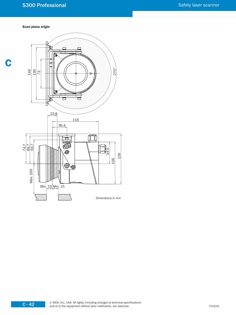
Scan plane origin
73130
146
270°
23.8
11636.4
74.7
69.7
59.7
Max
. 200
Min. 15 Min. 15
54.5
106 12
6
Dimensions in mm

ABCDEFGHIJKLMNOPQ
R© SICK, Inc., USA. All rights, including changes to technical specifications
and or to the equipment without prior notification, are reserved. C - 43
S300 Professional Safety laser scanner
7024240
Protective field switching with two static inputs
2)
■ S300 Professional in conjunction with relays/contactors■ Operating mode: with restart interlock and external device
monitoring (EDM)■ Protective field switching using control input IN A and IN BComments1) Output circuits: These contacts are to be connected to the
controller such that, with the output circuit open, the dange-rous state is disabled. For categories 4 and 3, the integration
must be dual-channel (x/y paths). Single-channel integration in the control (z path) is only possible with a single-channel control and taking the risk analysis into account.
2) Functional earth (FE): To achieve the specified EMC safety, the functional earth (FE) must be connected (e.g. to the cen-tral earth star point on the vehicle or the system).
Connection diagrams
➜ You can find connection diagrams at www.sickusa.com/connectiondiagrams

ABCDEFGHIJKLMNOPQ
R© SICK, Inc., USA. All rights, including changes to technical specifications and or to the equipment without prior notification, are reserved.C - 44
S300 Professional Safety laser scanner
7024240
Protective field switching between two S300 with static and dynamic inputs
2)2)
■ S300 Professional with S300 Professional in master/slave connection with relays/contactors
■ Operating mode: with restart interlock and external device monitoring
■ Dynamic protective field switching by the incremental enco-ders A and B on the master
■ Static protective field switching using the control input IN C on the master
■ The protective fields affect the related OSSDs on master or slave
Comments1) Output circuits: These contacts are to be connected to the
controller such that, with the output circuit open, the dange-rous state is disabled. For categories 4 and 3, the integration must be dual-channel (x/y paths). Single-channel integration in the control (z path) is only possible with a single-channel control and taking the risk analysis into account.
2) Functional earth (FE): To achieve the specified EMC safety, the functional earth (FE) must be connected (e.g. to the cen-tral earth star point on the vehicle or the system).
ABCDEFGHIJKLMNOPQ
R© SICK, Inc., USA. All rights, including changes to technical specifications
and or to the equipment without prior notification, are reserved. C - 45
S300 Professional Safety laser scanner
7024240
Connection cables
Type Number of cores Cable length Part number
Connection cable 15 100 m 6030795
EFI connection cable — By the meter 6029448
AccessoriesMounting systems
Type Mounting Adjustment Note Part number
Mounting kit 1a Mounting bracket for mounting at the rear on wall or machine — — 2034324
Mounting kit 1bMounting bracket for rear mounting on wall or machine with protection of optics cover
— — 2034325
Mounting kit 2Mounting bracket
Cross-wise adjustment possible Only in conjunction with mounting kit 1a or 1b 2039302
Mounting kit 3 Longitudinal adjustment possible Only in conjunction with mounting kit 2 2039303
➜ Dimensional drawings for mounting accessories, see page C-46
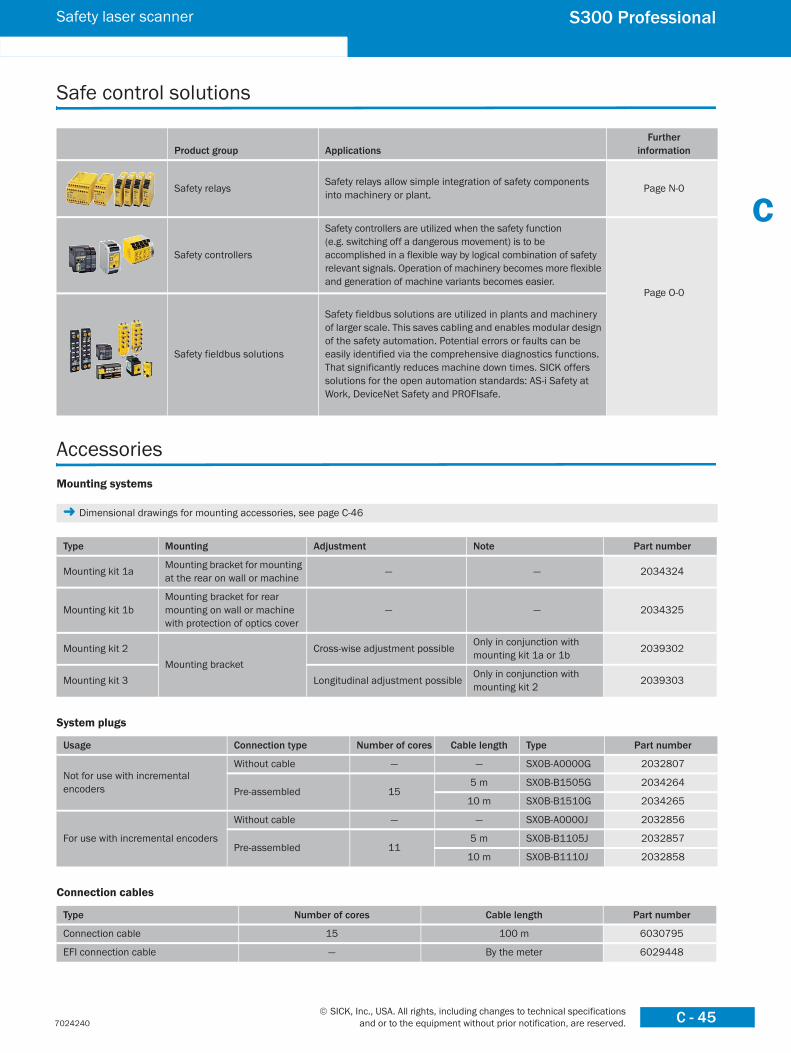
Product group ApplicationsFurther
information
Safety relays Safety relays allow simple integration of safety components into machinery or plant. Page N-0
Safety controllers
Safety controllers are utilized when the safety function (e.g. switching off a dangerous movement) is to be accomplished in a flexible way by logical combination of safety relevant signals. Operation of machinery becomes more flexible and generation of machine variants becomes easier.
Page O-0
Safety fieldbus solutions
Safety fieldbus solutions are utilized in plants and machinery of larger scale. This saves cabling and enables modular design of the safety automation. Potential errors or faults can be easily identified via the comprehensive diagnostics functions. That significantly reduces machine down times. SICK offers solutions for the open automation standards: AS-i Safety at Work, DeviceNet Safety and PROFIsafe.
Safe control solutions
System plugs
Usage Connection type Number of cores Cable length Type Part number
Not for use with incremental encoders
Without cable — — SX0B-A0000G 2032807
Pre-assembled 155 m SX0B-B1505G 2034264
10 m SX0B-B1510G 2034265
For use with incremental encoders
Without cable — — SX0B-A0000J 2032856
Pre-assembled 115 m SX0B-B1105J 2032857
10 m SX0B-B1110J 2032858

ABCDEFGHIJKLMNOPQ
R© SICK, Inc., USA. All rights, including changes to technical specifications and or to the equipment without prior notification, are reserved.C - 46
S300 Professional Safety laser scanner
7024240
Dimensional drawings mounting accessories
Mounting kit 1a
73
DIN74-F5
110.2
15.9
16
21.9
4915.7
74.7
4
37.9
Mounting kit 1b
Ø 100
48
73
109.6
4
15.9
74.7
49 15.7
16
21.9
78
102.
5
110.2
DIN74-F5Dimensions in mm
Cable gland
Usage Size of the cable gland Part number
For EFI connections M12 5308757
Configuration connection cables
Description Connection type Cable length Part number
For connecting the configuration connection to the PC M8 x 4, SUB-D 9-pol2 m 6021195
8 m 2027649
Configuration software
Type Description Part number
CDS CDS (Configuration & Diagnostic Software) on CD-ROM including online documentation and operating instructions in all available languages 2032314
Power supply units
Input voltage Output voltage Maximum output current Part number
100 V AC, 240 V AC
24 V DC
2.1 A 7028789
3.9 A 7028790
120 V AC, 230 V AC2.5 A 6010361
4 A 6010362
Miscellaneous
Type Description Part number
Optic cover Spare parts set for optic cover with replacement seal and screws 2039248
Plastic cleaner Plastic cleaner and care product, anti-static 5600006
Lens cloth Cloth for cleaning the front screen 4003353

ABCDEFGHIJKLMNOPQ
R© SICK, Inc., USA. All rights, including changes to technical specifications
and or to the equipment without prior notification, are reserved. C - 47
S300 Professional Safety laser scanner
7024240
Mounting kit 231
.7
33.4 18
19.7
19.7
18
4
78.240.7
139.4
130
118.5
Mounting kit 3
158.8
150
130
5
20.5
41
Dimensions in mm

ABCDEFGHIJKLMNOPQ
R© SICK, Inc., USA. All rights, including changes to technical specifications and or to the equipment without prior notification, are reserved.C - 48
S300 Advanced Safety laser scanner
7024240
■ Extremely compact design■ Scanning angle 270°■ Selectable resolution■ Certified for vertical and
horizontal use■ 7-segment display■ Integrated external device
monitoring (EDM)■ Stand-by input
✓✓✓IEC 61508Compliant
Further information Page
➜ Dimensional drawings C-51
➜ Connection diagrams C-53
➜ Accessories C-54
➜ Services A-2
Overview of technical specifications
Protective field range 2 m
Warning field range 8 m (at 30 % reflectivity)
Number of field sets 2
Scan angle 270°
Resolution30 mm, 40 mm, 50 mm, 70 mm, selectable
Response time 80 ms
Type Type 3 (IEC/EN 61496-3)
Safety integrity level SIL2 (IEC/EN 61508)
Product descriptionCompact safety laser scanner for complete safety.The S300 Advanced is the system of choice particularly for applications with changing operating positions, e.g. insertion stations, robots, moving workbenches and more.
■ 2 protective/warning fields■ Possibility of connecting two S300 units
to form a single system■ Static protective field switching■ New multi-system "Configuration & Diag-
nostic Software" CDS
In-system added value■ Supports integration with multiple safety control solutions
➜ For safety system combinations, see appendix "Sensor systems and safe control solutions from SICK"
■ Freely moving transport vehicles■ Production lines■ Machining centres
■ Entry/Exit stations■ Robot cells■ Overhead monorail transport systems
Hazardous area protection on an AGV with one direction of travel
Hazardous area protection on a robot cell with two operating areas
Overview of technical specifications
Protective field range 2 m
Warning field range 8 m (at 30 % reflectivity)
Number of field sets 2
Scan angle 270°
Resolution 30 mm, 40 mm, 50 mm, 70 mm, selectable
Response time 80 ms
Type Type 3 (IEC/EN 61496-3)
Safety integrity level SIL2 (IEC/EN 61508)
Applications
➜ You can find more applications using the application finder at www.sickusa.com/applications
Hazardous area protection on an AGV with one direction of travel
WS/WE 12-2

ABCDEFGHIJKLMNOPQ
R© SICK, Inc., USA. All rights, including changes to technical specifications
and or to the equipment without prior notification, are reserved. C - 49
S300 Advanced Safety laser scanner
7024240
Ordering informationDelivery S300■ Safety laser scanner■ Operating instructions and CDS (Configuration & Diagnostic Software) on CD-ROM■ Adhesive label "important information"The system plug has to be ordered separately!
➜ Ordering information for system plug and accessories, see page C-54
Type Part number
S30B-2011CA 1026821
Detailed technical specifications
General data
Laser protection class 1 (21 CFR 1040.10 und 1040.11, IEC 60825-1:2001)
Enclosure rating IP 65 (EN 60529)
Protection class 2 (DIN VDE 0160, DIN EN 50178)
Type Type 3 (IEC/EN 61496-3)
Safety integrity level SIL2 (IEC/EN 61508)
Ambient operating temperature from ... to –10 °C ... +50 °C
Type of light Pulsed laser diode
Wave length 905 nm
Housing colour RAL 1021
Housing material Aluminium die-cast
Optics cover material Polycarbonate
Optics cover surface finish Outside with scratch-resistant coating
System plug With ESD protected configuration memory
Dimensions (W x H x D) 102 mm x 152 mm x 105 mm
Weight 1.2 kg
Functional data
Scan angle 270°
Protective field range 2 m
Reflectivity Reflectors 1.8 % ... >1000 %
Response time 80 ms
Resolution 30 mm, 40 mm, 50 mm, 70 mm, selectable
Angular resolution 0.5°
Protective field supplement 100 mm
Warning field range 8 m (at 30 % reflectivity)
Distance measuring range 30 m
Number of mulitple samplings 2 ... 16, configurable via CDS
Reset time 2 s ... 60 s, configurable
➜ Additional technical information is described in operating instructions, which are available to download at www.sickusa.com/literature
Continued on next page

ABCDEFGHIJKLMNOPQ
R© SICK, Inc., USA. All rights, including changes to technical specifications and or to the equipment without prior notification, are reserved.C - 50
S300 Advanced Safety laser scanner
7024240
Electrical data
Connection type Plug-in connection housing with screw
Connector technology Screw-type terminals
Supply voltage Vs 24 V DC (16.8 V DC ... 30 V DC)
Power consumption 0.33 A (24 V DC)
Power consumption 1.65 A 1)
Number of inputsEDM
Restart/ResetStatic switching signals
Standby
111, dual-channel1
Number of safety capable outputsSafety outputs (OSSD)
Output for warning fieldDiagnostic output
Restart/reset required
2 x 250 mA1 x 100 mA1 x 100 mA1 x 100 mA
Configuration and diagnostics interfaceTransmission rate
RS-23238.4 kBaud
EFI – safe SICK device communicationTransmission rate
Cable lengthConnection conductor cross-section
500 kBaud50 m0.22 mm²
1) Including maximum output load

ABCDEFGHIJKLMNOPQ
R© SICK, Inc., USA. All rights, including changes to technical specifications
and or to the equipment without prior notification, are reserved. C - 51
S300 Advanced Safety laser scanner
7024240
Dimensional drawings
79.3 25
M5 x 7.5
10.5
49
5
± 0.
2
2454
.5
106
M5
x 7.
5
Ø 94
102
79.3
116
152
36.5
73
Dimensions in mm
S300

ABCDEFGHIJKLMNOPQ
R© SICK, Inc., USA. All rights, including changes to technical specifications and or to the equipment without prior notification, are reserved.C - 52
S300 Advanced Safety laser scanner
7024240
Scan plane origin
73130
146
270°
23.8
11636.4
74.7
69.7
59.7
Max
. 200
Min. 15 Min. 15
54.5
106 12
6
Dimensions in mm

ABCDEFGHIJKLMNOPQ
R© SICK, Inc., USA. All rights, including changes to technical specifications
and or to the equipment without prior notification, are reserved. C - 53
S300 Advanced Safety laser scanner
7024240
Protective field switching with one pair of static inputs
UE10-3OS
2)
■ S300 Advanced in conjunction with UE10-3OS■ Operating mode: with restart interlock and external device
monitoring (EDM)■ Protective field switching by means of control input IN AComments1) Output circuits: These contacts are to be connected to the
controller such that, with the output circuit open, the dange-rous state is disabled. For categories 4 and 3, the integration
must be dual-channel (x/y paths). Single-channel integration in the control (z path) is only possible with a single-channel control and taking the risk analysis into account.
2) Functional earth (FE): To achieve the specified EMC safety, the functional earth (FE) must be connected (e.g. to the cen-tral earth star point on the vehicle or the system).
Connection diagrams
➜ You can find connection diagrams at www.sickusa.com/connectiondiagrams

ABCDEFGHIJKLMNOPQ
R© SICK, Inc., USA. All rights, including changes to technical specifications and or to the equipment without prior notification, are reserved.C - 54
S300 Advanced Safety laser scanner
7024240
Accessories
Product group ApplicationsFurther
information
Safety relays Safety relays allow simple integration of safety components into machinery or plant. Page N-0
Safety controllers
Safety controllers are utilized when the safety function (e.g. switching off a dangerous movement) is to be accomplished in a flexible way by logical combination of safety relevant signals. Operation of machinery becomes more flexible and generation of machine variants becomes easier.
Page O-0
Safety fieldbus solutions
Safety fieldbus solutions are utilized in plants and machinery of larger scale. This saves cabling and enables modular design of the safety automation. Potential errors or faults can be easily identified via the comprehensive diagnostics functions. That significantly reduces machine down times. SICK offers solutions for the open automation standards: AS-i Safety at Work, DeviceNet Safety and PROFIsafe.
Safe control solutions
Connection cables
Type Number of cores Cable length Part number
Connection cable 15 100 m 6030795
EFI connection cable — By the meter 6029448
Mounting systems
Type Mounting Adjustment Note Part number
Mounting kit 1a Mounting bracket for mounting at the rear on wall or machine — — 2034324
Mounting kit 1bMounting bracket for rear mounting on wall or machine with protection of optics cover
— — 2034325
Mounting kit 2Mounting bracket
Cross-wise adjustment possible Only in conjunction with mounting kit 1a or 1b 2039302
Mounting kit 3 Longitudinal adjustment possible Only in conjunction with mounting kit 2 2039303
➜ Dimensional drawings for mounting accessories, see page C-55
System plugs
Connection type Number of cores Cable length Type Part number
Without cable — — SX0B-A0000G 2032807
Pre-assembled 155 m SX0B-B1505G 2034264
10 m SX0B-B1510G 2034265

ABCDEFGHIJKLMNOPQ
R© SICK, Inc., USA. All rights, including changes to technical specifications
and or to the equipment without prior notification, are reserved. C - 55
S300 Advanced Safety laser scanner
7024240
Dimensional drawings mounting accessories
Mounting kit 1a
73
DIN74-F5
110.2
15.9
16
21.9
4915.7
74.7
4
37.9
Mounting kit 1b
Ø 100
48
73
109.6
4
15.9
74.7
49 15.7
16
21.9
78
102.
5
110.2
DIN74-F5Dimensions in mm
Cable gland
Usage Size of the cable gland Part number
For EFI connections M12 5308757
Configuration connection cables
Description Connection type Cable length Part number
For connecting the configuration connection to the PC M8 x 4, SUB-D 9-pol2 m 6021195
8 m 2027649
Configuration software
Type Description Part number
CDS CDS (Configuration & Diagnostic Software) on CD-ROM including online documentation and operating instructions in all available languages 2032314
Power supply units
Input voltage Output voltage Maximum output current Part number
100 V AC, 240 V AC
24 V DC
2.1 A 7028789
3.9 A 7028790
120 V AC, 230 V AC2.5 A 6010361
4 A 6010362
Miscellaneous
Type Description Part number
Optic cover Spare parts set for optic cover with replacement seal and screws 2039248
Plastic cleaner Plastic cleaner and care product, anti-static 5600006
Lens cloth Cloth for cleaning the front screen 4003353

ABCDEFGHIJKLMNOPQ
R© SICK, Inc., USA. All rights, including changes to technical specifications and or to the equipment without prior notification, are reserved.C - 56
S300 Advanced Safety laser scanner
7024240
Mounting kit 2
31.7
33.4 18
19.7
19.7
18
4
78.240.7
139.4
130
118.5
Mounting kit 3
158.8
150
130
5
20.5
41
Dimensions in mm

ABCDEFGHIJKLMNOPQ
R© SICK, Inc., USA. All rights, including changes to technical specifications
and or to the equipment without prior notification, are reserved. C - 57
S300 Standard Safety laser scanner
7024240
■ Extremely compact design■ Scanning angle 270°■ Selectable resolution■ Certified for vertical and
horizontal use■ 7-segment display■ Integrated external device
monitoring (EDM)■ Stand-by input
✓✓✓IEC 61508Compliant
Further information Page
➜ Ordering information C-58
➜ Technical specifications C-58
➜ Dimensional drawings C-59
➜ Connection diagrams C-61
➜ Accessories C-62
➜ Services A-2
Overview of technical specifications
Protective field range 2 m
Warning field range 8 m (at 30 % reflectivity)
Number of field sets 1
Scan angle 270°
Resolution 30 mm, 40 mm, 50 mm, 70 mm, selectable
Response time 80 ms
Type Type 3 (IEC/EN 61496-3)
Safety integrity level SIL2 (IEC/EN 61508)
Product descriptionHigh-end safety at entry level priceThe low-cost solution for simple require-ments with one protective field and war-ning field.Ideal for the horizontal and vertical protec-tion of hazardous areas and areas of access.
With adjustable object resolution as well as configurable "contour as reference."■ 1 protective and warning field■ New multi-system "Configuration & Diag-
nostic Software" CDS
In-system added value■ Supports integration with multiple safety control solutions
➜ For safety system combinations, see appendix "Sensor systems and safe control solutions from SICK"
■ Freely moving transport vehicles■ Production lines■ Machining centres
■ Entry/Exit stations■ Robot cells■ Overhead monorail transport systems
Hazardous area protection on an AGV with one direction of travel
Hazardous area protection on a robot cell
Applications
➜ You can find more applications using the application finder at www.sickusa.com/applications
WS/WE 12-2

ABCDEFGHIJKLMNOPQ
R© SICK, Inc., USA. All rights, including changes to technical specifications and or to the equipment without prior notification, are reserved.C - 58
S300 Standard Safety laser scanner
7024240
Ordering informationDelivery S300■ Safety laser scanner■ Operating instructions and CDS (Configuration & Diagnostic Software) on CD-ROM■ Adhesive label "important information"The system plug has to be ordered separately!
➜ Ordering information for system plug and accessories, see page C-62
Type Part number
S30B-2011BA 1026820
Detailed technical specifications
General data
Laser protection class 1 (21 CFR 1040.10 und 1040.11, IEC 60825-1:2001)
Enclosure rating IP 65 (EN 60529)
Protection class 2 (DIN VDE 0160, DIN EN 50178)
Type Type 3 (IEC/EN 61496-3)
Safety integrity level SIL2 (IEC/EN 61508)
Ambient operating temperature from ... to –10 °C ... +50 °C
Type of light Pulsed laser diode
Wave length 905 nm
Housing colour RAL 1021
Housing material Aluminium die-cast
Optics cover material Polycarbonate
Optics cover surface finish Outside with scratch-resistant coating
System plug With ESD protected configuration memory
Dimensions (W x H x D) 102 mm x 152 mm x 105 mm
Weight 1.2 kg
Functional data
Scan angle 270°
Protective field range 2 m
Reflectivity Reflectors 1.8 % ... >1000 %
Response time 80 ms
Resolution 30 mm, 40 mm, 50 mm, 70 mm, selectable
Angular resolution 0.5°
Protective field supplement 100 mm
Warning field range 8 m (at 30 % reflectivity)
Distance measuring range 30 m
Number of mulitple samplings 2 ... 16, configurable via CDS
Reset time 2 s ... 60 s, configurable
➜ Additional technical information is described in operating instructions, which are available to download at www.sickusa.com/literature

ABCDEFGHIJKLMNOPQ
R© SICK, Inc., USA. All rights, including changes to technical specifications
and or to the equipment without prior notification, are reserved. C - 59
S300 Standard Safety laser scanner
7024240
Electrical data
Connection type Plug-in connection housing with screw
Connector technology Screw-type terminals
Supply voltage Vs 24 V DC (16.8 V DC ... 30 V DC)
Power consumption 0.33 A (24 V DC)
Power consumption 1.65 A 1)
Number of inputsEDM
Restart/ResetStandby
111
Number of safety capable outputsSafety outputs (OSSD)
Output for warning fieldDiagnostic output
Restart/reset required
2 x 250 mA1 x 100 mA1 x 100 mA1 x 100 mA
Configuration and diagnostics interfaceTransmission rate
RS-23238.4 kBaud
1) Including maximum output load
Dimensional drawings
79.3 25
M5 x 7.5
10.5
49
5
± 0.
2
2454
.5
106
M5
x 7.
5
Ø 94
102
79.3
116
152
36.5
73
Dimensions in mm
S300

ABCDEFGHIJKLMNOPQ
R© SICK, Inc., USA. All rights, including changes to technical specifications and or to the equipment without prior notification, are reserved.C - 60
S300 Standard Safety laser scanner
7024240
Scan plane origin
73130
146
270°
23.8
11636.4
74.7
69.7
59.7
Max
. 200
Min. 15 Min. 15
54.5
106 12
6
Dimensions in mm

ABCDEFGHIJKLMNOPQ
R© SICK, Inc., USA. All rights, including changes to technical specifications
and or to the equipment without prior notification, are reserved. C - 61
S300 Standard Safety laser scanner
7024240
Connection diagrams
➜ You can find connection diagrams at www.sickusa.com/connectiondiagrams
With restart interlock and external device monitoring
2)
■ S300 Standard in conjunction with relays/contactors■ Operating mode: with restart interlock and external device
monitoring (EDM)Comments1) Output circuits: These contacts are to be connected to the
controller such that, with the output circuit open, the dange-rous state is disabled. For categories 4 and 3, the integration
must be dual-channel (x/y paths). Single-channel integration in the control (z path) is only possible with a single-channel control and taking the risk analysis into account.
2) Functional earth (FE): To achieve the specified EMC safety, the functional earth (FE) must be connected (e.g. to the cen-tral earth star point on the vehicle or the system).

ABCDEFGHIJKLMNOPQ
R© SICK, Inc., USA. All rights, including changes to technical specifications and or to the equipment without prior notification, are reserved.C - 62
S300 Standard Safety laser scanner
7024240
Product group ApplicationsFurther
information
Safety relays Safety relays allow simple integration of safety components into machinery or plant. Page N-0
Safety controllers
Safety controllers are utilized when the safety function (e.g. switching off a dangerous movement) is to be accomplished in a flexible way by logical combination of safety relevant signals. Operation of machinery becomes more flexible and generation of machine variants becomes easier.
Page O-0
Safety fieldbus solutions
Safety fieldbus solutions are utilized in plants and machinery of larger scale. This saves cabling and enables modular design of the safety automation. Potential errors or faults can be easily identified via the comprehensive diagnostics functions. That significantly reduces machine down times. SICK offers solutions for the open automation standards: AS-i Safety at Work, DeviceNet Safety and PROFIsafe.
Safe control solutions
Accessories
Connection cable
Type Number of cores Cable length Part number
Connection cable 15 100 m 6030795
Mounting systems
Type Mounting Adjustment Note Part number
Mounting kit 1a Mounting bracket for mounting at the rear on wall or machine — — 2034324
Mounting kit 1bMounting bracket for rear mounting on wall or machine with protection of optics cover
— — 2034325
Mounting kit 2Mounting bracket
Cross-wise adjustment possible Only in conjunction with mounting kit 1a or 1b 2039302
Mounting kit 3 Longitudinal adjustment possible Only in conjunction with mounting kit 2 2039303
➜ Dimensional drawings for mounting accessories, see page C-63
System plugs
Connection type Number of cores Cable length Type Part number
Without cable — — SX0B-A0000G 2032807
Pre-assembled 11
5 m SX0B-B1105G 2032859
10 m SX0B-B1110G 2032860
20 m SX0B-B1120G 2032861

ABCDEFGHIJKLMNOPQ
R© SICK, Inc., USA. All rights, including changes to technical specifications
and or to the equipment without prior notification, are reserved. C - 63
S300 Standard Safety laser scanner
7024240
Dimensional drawings mounting accessories
Mounting kit 1a
73
DIN74-F5
110.2
15.9
16
21.9
4915.7
74.7
4
37.9
Mounting kit 1b
Ø 100
48
73
109.6
4
15.9
74.7
49 15.7
16
21.9
78
102.
5
110.2
DIN74-F5Dimensions in mm
Configuration connection cables
Description Connection type Cable length Part number
For connecting the configuration connection to the PC M8 x 4, SUB-D 9-pol2 m 6021195
8 m 2027649
Configuration software
Type Description Part number
CDS CDS (Configuration & Diagnostic Software) on CD-ROM including online documentation and operating instructions in all available languages 2032314
Power supply units
Input voltage Output voltage Maximum output current Part number
100 V AC, 240 V AC
24 V DC
2.1 A 7028789
3.9 A 7028790
120 V AC, 230 V AC2.5 A 6010361
4 A 6010362
Miscellaneous
Type Description Part number
Optic cover Spare parts set for optic cover with replacement seal and screws 2039248
Plastic cleaner Plastic cleaner and care product, anti-static 5600006
Lens cloth Cloth for cleaning the front screen 4003353

ABCDEFGHIJKLMNOPQ
R© SICK, Inc., USA. All rights, including changes to technical specifications and or to the equipment without prior notification, are reserved.C - 64
S300 Standard Safety laser scanner
7024240
Mounting kit 2
31.7
33.4 18
19.7
19.7
18
4
78.240.7
139.4
130
118.5
Mounting kit 3
158.8
150
130
5
20.5
41
Dimensions in mm

ABCDEFGHIJKLMNOPQ
R© SICK, Inc., USA. All rights, including changes to technical specifications
and or to the equipment without prior notification, are reserved. C - 65
S200 Safety laser scanner
7024240
■ Extremely compact design■ Scanning angle 270°■ Selectable resolution■ Certified for vertical and
horizontal use■ 7-segment display■ Integrated external device
monitoring (EDM)
✓✓✓IEC 61508Compliant
Further information Page
➜ Ordering information C-66
➜ Technical specifications C-66
➜ Dimensional drawings C-68
➜ Connection diagrams C-70
➜ Accessories C-71
➜ Services A-2
Overview of technical specifications
Protective field range 1.5 m
Warning field range 8 m (at 30 % reflectivity)
Number of field sets 1
Scan angle 270°
Resolution 30 mm, 40 mm, 50 mm, 70 mm, selectable
Response time 80 ms
Type Type 2 (IEC/EN 61496-1)
Safety integrity level SIL1 (IEC/EN 61508)
Product descriptionState-of-the-art Type 2 solution.Finally a system that meets the require-ments of Type 2 in accordance with IEC/EN 61496 at the highest technical level and at astoundingly low cost.The S200 is flexible and easy to integrate, can be used horizontally and vertically, and
impresses with its adjustable object resolu-tion as well as the contour as reference function.■ 1 protective/warning field (field set)■ New uniform "Configuration & Diagnostic
Software" CDS
In-system added value■ Supports integration with multiple safety control solutions
➜ For safety system combinations, see appendix "Sensor systems and safe control solutions from SICK"
■ Machining centres■ Entry/Exit stations
■ Robot cells■ Overhead monorail transport systems
Point-of-operation guarding on a robot cell using S200 in conjunction with safety light curtain
Hazardous point protection on a small automatic placement machine
Applications
➜ You can find more applications using the application finder at www.sickusa.com/applications
WS/WE 12-2

ABCDEFGHIJKLMNOPQ
R© SICK, Inc., USA. All rights, including changes to technical specifications and or to the equipment without prior notification, are reserved.C - 66
S200 Safety laser scanner
7024240
Ordering informationDelivery S200■ Safety laser scanner■ Operating instructions and CDS (Configuration & Diagnostic Software) on CD-ROM■ Adhesive label "important information"The system plug has to be ordered separately!
➜ Ordering information for system plug and accessories, see page C-71
Type Part number
S20B-1011BA 1026823
Detailed technical specifications
General data
Laser protection class 1 (21 CFR 1040.10 und 1040.11, IEC 60825-1:2001)
Enclosure rating IP 65 (EN 60529)
Protection class 2 (DIN VDE 0160, DIN EN 50178)
Type Type 2 (IEC/EN 61496-1)
Safety integrity level SIL1 (IEC/EN 61508)
Ambient operating temperature from ... to –10 °C ... +50 °C
Type of light Pulsed laser diode
Wave length 905 nm
Housing colour RAL 1021
Housing material Aluminium die-cast
Optics cover material Polycarbonate
Optics cover surface finish Outside with scratch-resistant coating
Dimensions (W x H x D) 102 mm x 152 mm x 105 mm
Weight 1.2 kg
Functional data
Scan angle 270°
Protective field range 1.5 m
Reflectivity Reflectors 1.8 % ... >1000 %
Response time 80 ms
Resolution 30 mm, 40 mm, 50 mm, 70 mm, selectable
Angular resolution 0.5°
Protective field supplement 100 mm
Warning field range 8 m (at 30 % reflectivity)
Distance measuring range 30 m
Number of mulitple samplings 2 ... 16, configurable via CDS
Reset time 2 s ... 60 s, configurable
➜ Additional technical information is described in operating instructions, which are available to download at www.sickusa.com/literature

ABCDEFGHIJKLMNOPQ
R© SICK, Inc., USA. All rights, including changes to technical specifications
and or to the equipment without prior notification, are reserved. C - 67
S200 Safety laser scanner
7024240
Electrical data
Connection type Plug-in connection housing with screw
Connector technology Screw-type terminals
Supply voltage Vs 24 V DC (16.8 V DC ... 30 V DC)
Power consumption 0.33 A (24 V DC)
Power consumption 1.65 A 1)
Number of inputsEDM
Restart/ResetStandby
111
Number of safety capable outputsSafety outputs (OSSD)
Output for warning fieldDiagnostic output
Restart/reset required
2 x 250 mA1 x 100 mA1 x 100 mA1 x 100 mA
Configuration and diagnostics interfaceTransmission rate
RS-23238.4 kBaud
1) Including maximum output load

ABCDEFGHIJKLMNOPQ
R© SICK, Inc., USA. All rights, including changes to technical specifications and or to the equipment without prior notification, are reserved.C - 68
S200 Safety laser scanner
7024240
Dimensional drawings
79.3 25
M5 x 7.5
10.5
49
5
± 0.
2
2454
.5
106
M5
x 7.
5
Ø 94
102
79.3
116
152
36.5
73
Dimensions in mm
S200

ABCDEFGHIJKLMNOPQ
R© SICK, Inc., USA. All rights, including changes to technical specifications
and or to the equipment without prior notification, are reserved. C - 69
S200 Safety laser scanner
7024240
Scan plane origin
73130
146
270°
23.8
11636.4
74.7
69.7
59.7
Max
. 200
Min. 15 Min. 15
54.5
106 12
6
Dimensions in mm

ABCDEFGHIJKLMNOPQ
R© SICK, Inc., USA. All rights, including changes to technical specifications and or to the equipment without prior notification, are reserved.C - 70
S200 Safety laser scanner
7024240
Connection diagrams
➜ You can find connection diagrams at www.sickusa.com/connectiondiagrams
With restart interlock and external device monitoring
2
2)
■ S200 in conjunction with relays/contactors■ Operating mode: with restart interlock and external device
monitoring (EDM)Comments1) Output circuits: These contacts are to be connected to the
controller such that, with the output circuit open, the dange-rous state is disabled. For categories 4 and 3, the integration
must be dual-channel (x/y paths). Single-channel integration in the control (z path) is only possible with a single-channel control and taking the risk analysis into account.
2) Functional earth (FE): To achieve the specified EMC safety, the functional earth (FE) must be connected (e.g. to the cen-tral earth star point on the vehicle or the system).

ABCDEFGHIJKLMNOPQ
R© SICK, Inc., USA. All rights, including changes to technical specifications
and or to the equipment without prior notification, are reserved. C - 71
S200 Safety laser scanner
7024240
Product group ApplicationsFurther
information
Safety relays Safety relays allow simple integration of safety components into machinery or plant. Page N-0
Safety controllers
Safety controllers are utilized when the safety function (e.g. switching off a dangerous movement) is to be accomplished in a flexible way by logical combination of safety relevant signals. Operation of machinery becomes more flexible and generation of machine variants becomes easier.
Page O-0
Safety fieldbus solutions
Safety fieldbus solutions are utilized in plants and machinery of larger scale. This saves cabling and enables modular design of the safety automation. Potential errors or faults can be easily identified via the comprehensive diagnostics functions. That significantly reduces machine down times. SICK offers solutions for the open automation standards: AS-i Safety at Work, DeviceNet Safety and PROFIsafe.
Safe control solutions
Connection cable
Type Number of cores Cable length Part number
Connection cable 15 100 m 6030795
Mounting systems
Type Mounting Adjustment Note Part number
Mounting kit 1a Mounting bracket for mounting at the rear on wall or machine — — 2034324
Mounting kit 1bMounting bracket for rear mounting on wall or machine with protection of optics cover
— — 2034325
Mounting kit 2Mounting bracket
Cross-wise adjustment possible Only in conjunction with mounting kit 1a or 1b 2039302
Mounting kit 3 Longitudinal adjustment possible Only in conjunction with mounting kit 2 2039303
➜ Dimensional drawings for mounting accessories, see page C-72
System plugs
Connection type Number of cores Cable length Type Part number
Without cable — — SX0B-A0000G 2032807
Pre-assembled 11
5 m SX0B-B1105G 2032859
10 m SX0B-B1110G 2032860
20 m SX0B-B1120G 2032861
Accessories

ABCDEFGHIJKLMNOPQ
R© SICK, Inc., USA. All rights, including changes to technical specifications and or to the equipment without prior notification, are reserved.C - 72
S200 Safety laser scanner
7024240
Dimensional drawings mounting accessories
Mounting kit 1a
73
DIN74-F5
110.2
15.9
16
21.9
4915.7
74.7
4
37.9
Mounting kit 1b
Ø 100
48
73
109.6
4
15.9
74.7
49 15.7
16
21.9
78
102.
5
110.2
DIN74-F5Dimensions in mm
Configuration connection cables
Description Connection type Cable length Part number
For connecting the configuration connection to the PC M8 x 4, SUB-D 9-pol2 m 6021195
8 m 2027649
Configuration software
Type Description Part number
CDS CDS (Configuration & Diagnostic Software) on CD-ROM including online documentation and operating instructions in all available languages 2032314
Power supply units
Input voltage Output voltage Maximum output current Part number
100 V AC, 240 V AC
24 V DC
2.1 A 7028789
3.9 A 7028790
120 V AC, 230 V AC2.5 A 6010361
4 A 6010362
Miscellaneous
Type Description Part number
Optic cover Spare parts set for optic cover with replacement seal and screws 2039248
Plastic cleaner Plastic cleaner and care product, anti-static 5600006
Lens cloth Cloth for cleaning the front screen 4003353

ABCDEFGHIJKLMNOPQ
R© SICK, Inc., USA. All rights, including changes to technical specifications
and or to the equipment without prior notification, are reserved. C - 73
S200 Safety laser scanner
7024240
Mounting kit 231
.7
33.4 18
19.7
19.7
18
4
78.240.7
139.4
130
118.5
Mounting kit 3
158.8
150
130
5
20.5
41
Dimensions in mm
Related Documents


