PreView ® PVST4000 Service Tool Operating Manual

Welcome message from author
This document is posted to help you gain knowledge. Please leave a comment to let me know what you think about it! Share it to your friends and learn new things together.
Transcript

PreView® PVST4000 Service Tool
Operating Manual
Contents
Part Numbers .........................................................................1
Features.................................................................................3
Connections ...........................................................................4
Networks ................................................................................6
System Power-up ....................................................................8
System Navigation ..................................................................9
Device Settings..................................................................... 10
Sensor Settings ................................................................. 11
Display/VideoLink Settings ................................................ 13
Diagnostics .......................................................................... 15
Sensor/Network Diagnostics.............................................. 15
Display/VideoLink Diagnostics ........................................... 17
Diagnostics Report ............................................................ 18
Service Tool Setup and Maintenance ..................................... 18
Error Messages .................................................................... 19
Warranty Information ............................................................ 20
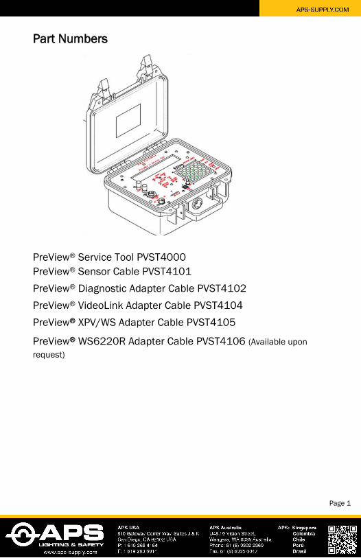
Part Numbers
PreView® Service Tool PVST4000 PreView® Sensor Cable PVST4101 PreView® Diagnostic Adapter Cable PVST4102 PreView® VideoLink Adapter Cable PVST4104 PreView® XPV/WS Adapter Cable PVST4105
PreView® WS6220R Adapter Cable PVST4106 (Available upon request)
Page 1
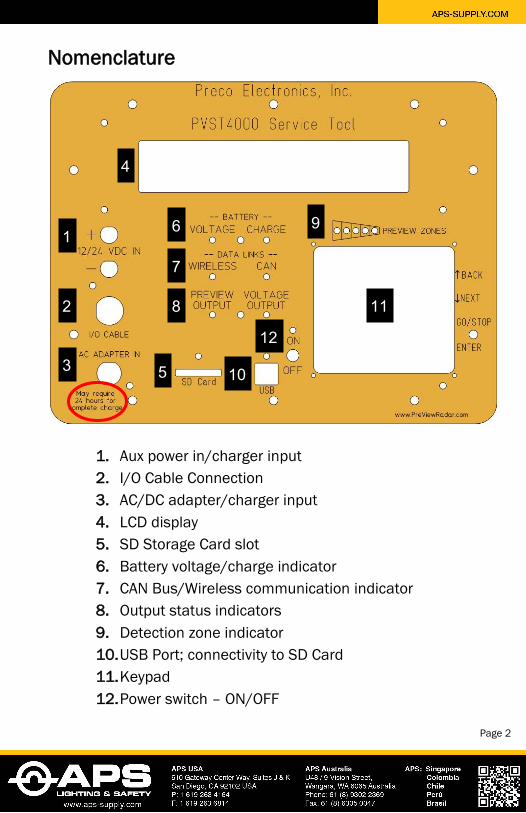
Nomenclature
1. Aux power in/charger input2. I/O Cable Connection3. AC/DC adapter/charger input4. LCD display5. SD Storage Card slot6. Battery voltage/charge indicator7. CAN Bus/Wireless communication indicator8. Output status indicators9. Detection zone indicator10. USB Port; connectivity to SD Card11. Keypad12. Power switch – ON/OFF
1
2
3
4
5
6
7
8
9
10
11
12
Page 2
Features
The Service Tool is used to view or adjust settings in the SentryTM (ST), Xtreme (XPV), High Resolution, WorkSight® (WS), WorkZone Sensors (WZ), CD6102 Display(s), and VideoLink units. It is also used to test and troubleshoot any of these same systems.
Features include:
Adjusting sensor range and other settings
Configure/modify sensor networks (XPV/WS/ST PreView®)
Configure/modify audible warning
Configure/modify visual warning
System/Network diagnostics and troubleshooting
The Service Tool is equipped with a built in rechargeable 7.2 watt*hour battery. The internal battery can be recharged using the AC/DC (120-240VAC) adapter or using a 12-24 volt auxiliary power input.
Prior to using the Service Tool, make sure the battery is fully charged for 24 hours. Expected battery life is variable depending on the task, but life can be up to 8+ hours and battery can be charging while in use via the AC/DC or auxiliary power inputs.
Note: ‘Battery Charge’ indicator will stay lit the entire time the battery is
plugged into a charging source and the charger will enter trickle mode once
the battery is fully charged.
Page 3
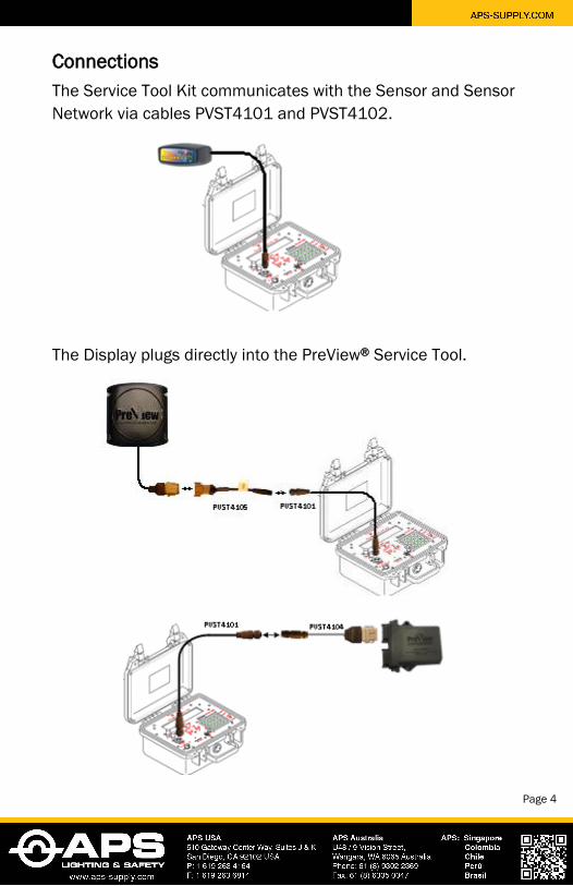
Connections The Service Tool Kit communicates with the Sensor and Sensor Network via cables PVST4101 and PVST4102.
The Display plugs directly into the PreView® Service Tool.
Page 4
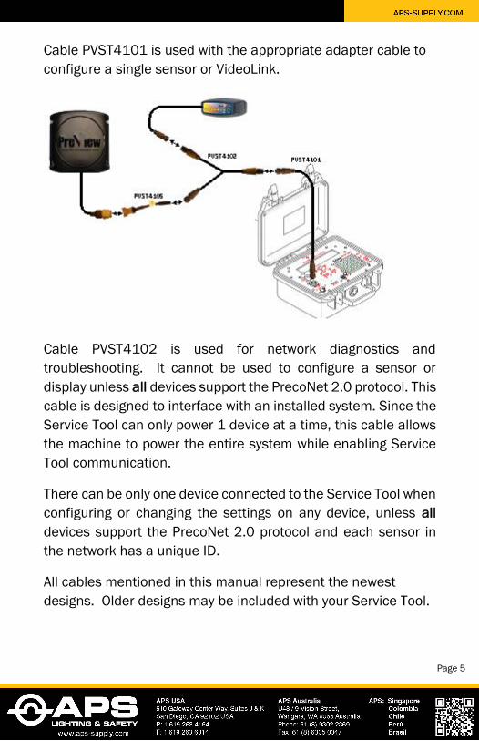
Cable PVST4101 is used with the appropriate adapter cable to configure a single sensor or VideoLink.
Cable PVST4102 is used for network diagnostics and troubleshooting. It cannot be used to configure a sensor or display unless all devices support the PrecoNet 2.0 protocol. This cable is designed to interface with an installed system. Since the Service Tool can only power 1 device at a time, this cable allows the machine to power the entire system while enabling Service Tool communication.
There can be only one device connected to the Service Tool when configuring or changing the settings on any device, unless all devices support the PrecoNet 2.0 protocol and each sensor in the network has a unique ID.
All cables mentioned in this manual represent the newest designs. Older designs may be included with your Service Tool.
Page 5
Networks
A network consists of a single or multiple (up to twenty-four) sensors communicating with one PreView® Display or VideoLink unit.
A sensor network must be configured correctly in order to communicate with the display or VideoLink.
The user must configure the display or VideoLink for the correct number of sensors and the assigned identification number of each sensor.
Each sensor must be assigned a unique ID ranging from 1 to 253. For ease of diagnostics it is recommended that a networkscheme be established prior to configuring any network.
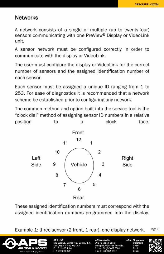
The common method and option built into the service tool is the “clock dial” method of assigning sensor ID numbers in a relative position to a clock face.
These assigned identification numbers must correspond with the assigned identification numbers programmed into the display.
Example 1: three sensor (2 front, 1 rear), one display network.
Vehicle
Front
11 1
2
3
5
Rear
4
9
10
8
12
6 7
Left Side
Right Side
Page 6
Sensor Settings: Front Left Sensor, sensor ID 11
Front Right Sensor, sensor ID 1
Rear Sensor, sensor ID 6
Display/VideoLink settings: Max sensors =3,
Sensor ID 11
Sensor ID 1
Sensor ID 6
Alternatively, the sensor IDs may just follow numerical order.
Example 2: three sensor (2 front, 1 rear), one display network.
Sensor Settings: Front Left Sensor, sensor ID 1
Front Right Sensor, sensor ID 2
Rear Sensor, sensor ID 3
Display/VideoLink settings: Max sensors =3,
Sensor ID 1
Sensor ID 2
Sensor ID 3
Page 7

System Power-up
The Service Tool is powered-up by switching the power switch into the “On” position. Both the “Battery Voltage” and “On” LEDs should be lit. If either LED is not lit, then it is likely that the battery requires additional charge.
The Service Tool can provide power for a single display or sensor. When connected to a single display or sensor examine the “Voltage Output” LED to ensure that the device is powered. If the service tool is turned on and a device is connected appropriately, then the “Voltage Output” LED should be lit. If the LED is not lit, then there is a possible problem with the connection or the battery requires additional charge.
The first line in the initial power up screen indicates the service tool version.
This screen also provides the user with the ability to adjust the LCD contrast or turn on backlight for night time or low light use. The backlight will turn off automatically after 10 seconds if it is not selected. If selected, the backlight will remain on while the service tool is in use. However, the backlight will enter power save mode after 2 minutes of inactivity.
Page 8
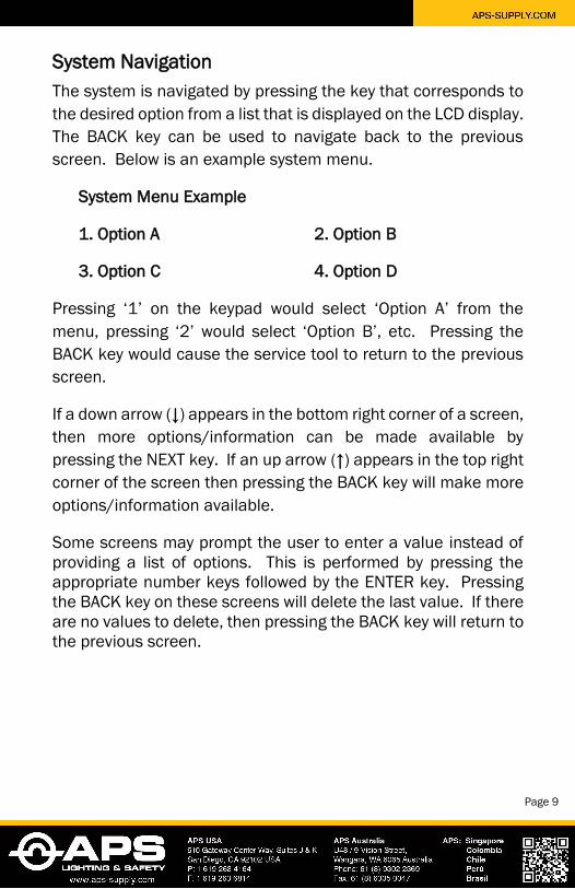
System Navigation The system is navigated by pressing the key that corresponds to the desired option from a list that is displayed on the LCD display. The BACK key can be used to navigate back to the previous screen. Below is an example system menu.
System Menu Example
1. Option A 2. Option B
3. Option C 4. Option D
Pressing ‘1’ on the keypad would select ‘Option A’ from the menu, pressing ‘2’ would select ‘Option B’, etc. Pressing the BACK key would cause the service tool to return to the previous screen.
If a down arrow (↓) appears in the bottom right corner of a screen, then more options/information can be made available by pressing the NEXT key. If an up arrow (↑) appears in the top right corner of the screen then pressing the BACK key will make more options/information available.
Some screens may prompt the user to enter a value instead of providing a list of options. This is performed by pressing the appropriate number keys followed by the ENTER key. Pressing the BACK key on these screens will delete the last value. If there are no values to delete, then pressing the BACK key will return to the previous screen.
Page 9
Device Settings There are two methods to access device settings: change the settings manually or read previously saved settings from a file on an SD card and write them to a device.
To change/view device settings manually, connect the device to the service tool using the appropriate cable as shown in the Connections section of this manual. Turn on Service Tool and navigate to the “Device Menu” screen then select the option to change/view settings. The service tool will then scan for a device and a menu screen will appear that allows for viewing or changing the device settings.
To save/load settings using an SD card, place an SD card into the SD card slot and navigate to the “Device Menu” screen as described above, but instead select the option to load/save settings.
To save device settings, select the option to save settings. The service tool will scan for the device and then write the device settings to a file on the SD card. This file is assigned a default filename; however, the operator may later rename it using any SD card reader or the service tool can function as an SD card reader when connected to a PC with a USB cable. The name must be a valid 8 character filename (not including the .set file extension).
To load device settings, select the option load settings. Next select the desired device to be configured followed by the file to use. Once a file is selected, the settings may be previewed and then written directly to the device.
The following sections include a list of available sensor and display/ VideoLink settings. Please note that older versions of the product may not have all these settings available. Page 10
Sensor Settings Sensor range: Indicates the furthest distance that the sensor will report a detection – maximum range available is 100ft (30m) for
SentryTM PreView®, 33ft (10m) for Xtreme PreView®, 20ft (6m) for
High Resolution PreView® and WorkSight PreView®, and 10ft
(3m) for WorkZone PreView®. (Toggle ‘GO/STOP’ to change between Meters and Feet).
Trigger Output Range: Indicates the distance at which output trigger is activated upon detection – distance cannot be greater
than Sensor Range. (Toggle ‘GO/STOP’ to change between Meters and Feet).
Sensor ID: Identifies a sensor within a network; each sensor in the network must be assigned a unique ID between 1-253 – there can be up to twenty-four (24) sensors in one network.
Sensor Type: Can be Rear, Right, Left or Front and must match the display/VideoLink type. Rear type requires connection to reverse circuit for audible display warning.
Fixed Object Cal (not available for Sentry™ PreView®): Used to configure sensor to ignore small, fixed objects in the radar path (i.e. ladders, booms, pulleys.) Note: this feature is intended for
small incidental objects only as large objects can obstruct the
radar signal and could adversely affect the detection area. Once initiated, the detection zone must remain free of intrusion until process is complete. Value will be automatically set to a range between 0 -10 ft.
Zone 1 Range: Indicates the distance at which zone 1 (closest detection zone) will become active – distance cannot be greater
than Sensor Range. (Toggle ‘GO/STOP’ to change between Meters and Feet).
Announce (not available with Xtreme PreView® or Sentry™ PreView®): When enabled the sensor will provide a 2 second trigger output whenever power is first applied to the sensor. This feature can act as a reverse announce when the sensor is powered by the reverse signal.
Page 11
Reverse Mode (For Xtreme and WorkSight PreView®):
1. Reverse only: System will only provide trigger outputwhen vehicle is in reverse and a target is detected.
2. Reverse and Announce: System will provide a 2second trigger output announcing when the vehicle isin reverse in addition to providing a trigger outputwhen the vehicle is in reverse and a target is detected.
3. Forward/Reverse: System will provide trigger outputwhen a target is detected regardless of vehiclereverse status.
Reverse Mode (For Sentry™ PreView®)
1. Rev/Input: Reverse signal is provided as a separateinput.
2. No Rev/Input: Reverse signal is not provided asseparate input (i.e. radar is powered via reverse).
Ignore Range (Sentry™ PreView® Only): Indicates the distance through which the system will not report a detection. Used to ignore small or fixed stationary objects in the radar path (i.e. tires, ladders, booms, pulleys, etc…). The starting base distance is zero ft/m and the range can be set up to the Sensor range. Ignore Range cannot be greater than the set Sensor Range. (Toggle ‘GO/STOP’ to change between Meters and Feet).
Width (Sentry™ PreView®Only): Indicates the total horizontal width of the radar path. The width must be no less than 2ft (or 1m when using meter mode) and no more than 200ft (60m). For example, a width of 50ft (15m) means that each side (from center), left and right is set to 25ft (7m) each, for a total width of 50ft (15m). The system will round any odd number entered down to the nearest even number. (Toggle ‘GO/STOP’ to change between Meters and Feet).
Page 12
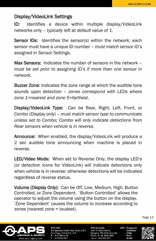
Display/VideoLink Settings ID: Identifies a device within multiple display/VideoLink networks only – typically left at default value of 1.
Sensor IDs: Identifies the sensor(s) within the network; each sensor must have a unique ID number – must match sensor ID’s
assigned in Sensor Settings.
Max Sensors: Indicates the number of sensors in the network – must be set prior to assigning ID’s if more than one sensor in
network.
Buzzer Zone: Indicates the zone range at which the audible tone sounds upon detection – zones correspond with LEDs where
zone 1=nearest and zone 5=farthest.
Display/VideoLink Type: Can be Rear, Right, Left, Front, or Combo (Display only) – must match sensor type to communicate
unless set to Combo; Combo will only indicate detections from
Rear sensors when vehicle is in reverse.
Announce: When enabled, the display/VideoLink will produce a 2 sec audible tone announcing when machine is placed in reverse.
LED/Video Mode: When set to Reverse Only, the display LED’s (or detection icons for VideoLink) will indicate detections only when vehicle is in reverse; otherwise detections will be indicated regardless of reverse status.
Volume (Display Only): Can be Off, Low, Medium, High, Button Controlled, or Zone Dependent. ‘Button Controlled’ allows the operator to adjust the volume using the button on the display. ‘Zone Dependent’ causes the volume to increase according to zones (nearest zone = loudest).
Page 13
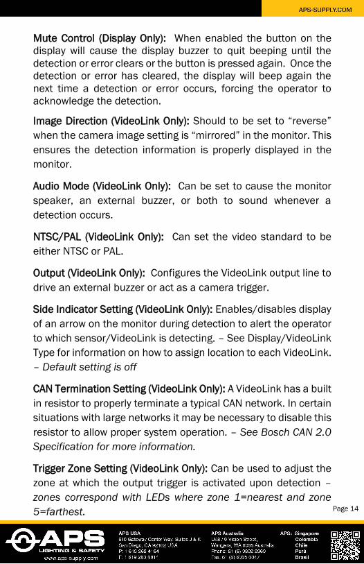
Mute Control (Display Only): When enabled the button on the display will cause the display buzzer to quit beeping until the detection or error clears or the button is pressed again. Once the detection or error has cleared, the display will beep again the next time a detection or error occurs, forcing the operator to acknowledge the detection.
Image Direction (VideoLink Only): Should to be set to “reverse” when the camera image setting is “mirrored” in the monitor. This ensures the detection information is properly displayed in the monitor.
Audio Mode (VideoLink Only): Can be set to cause the monitor speaker, an external buzzer, or both to sound whenever a detection occurs.
NTSC/PAL (VideoLink Only): Can set the video standard to be either NTSC or PAL.
Output (VideoLink Only): Configures the VideoLink output line to drive an external buzzer or act as a camera trigger.
Side Indicator Setting (VideoLink Only): Enables/disables display of an arrow on the monitor during detection to alert the operator to which sensor/VideoLink is detecting. – See Display/VideoLink Type for information on how to assign location to each VideoLink. – Default setting is off
CAN Termination Setting (VideoLink Only): A VideoLink has a built in resistor to properly terminate a typical CAN network. In certain situations with large networks it may be necessary to disable this resistor to allow proper system operation. – See Bosch CAN 2.0
Specification for more information.
Trigger Zone Setting (VideoLink Only): Can be used to adjust the zone at which the output trigger is activated upon detection – zones correspond with LEDs where zone 1=nearest and zone
5=farthest. Page 14
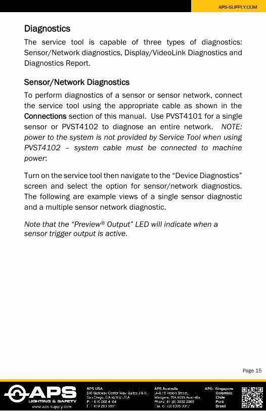
Diagnostics The service tool is capable of three types of diagnostics: Sensor/Network diagnostics, Display/VideoLink Diagnostics and Diagnostics Report.
Sensor/Network Diagnostics To perform diagnostics of a sensor or sensor network, connect the service tool using the appropriate cable as shown in the Connections section of this manual. Use PVST4101 for a single sensor or PVST4102 to diagnose an entire network. NOTE:
power to the system is not provided by Service Tool when using
PVST4102 – system cable must be connected to machine
power:
Turn on the service tool then navigate to the “Device Diagnostics” screen and select the option for sensor/network diagnostics. The following are example views of a single sensor diagnostic and a multiple sensor network diagnostic.
Note that the “Preview® Output” LED will indicate when a
sensor trigger output is active.
Page 15
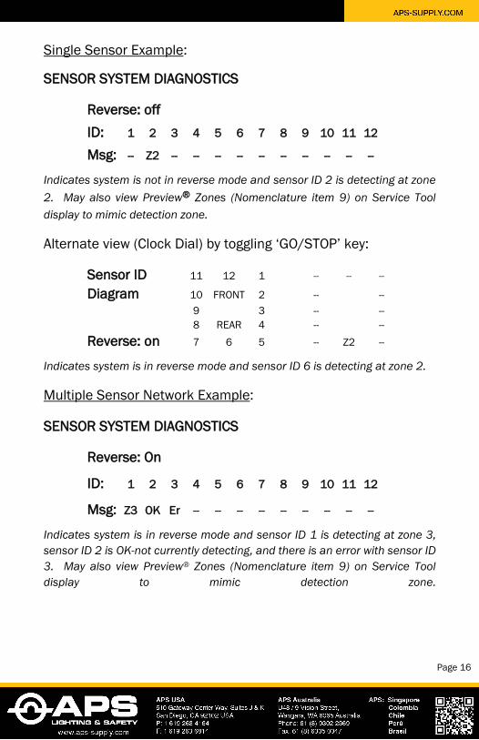
Single Sensor Example:
SENSOR SYSTEM DIAGNOSTICS
Reverse: offID: 1 2 3 4 5 6 7 8 9 10 11 12
Msg: -- Z2 -- -- -- -- -- -- -- -- -- --
Indicates system is not in reverse mode and sensor ID 2 is detecting at zone
2. May also view Preview® Zones (Nomenclature item 9) on Service Tool
display to mimic detection zone.
Alternate view (Clock Dial) by toggling ‘GO/STOP’ key:
Sensor ID 11 12 1 -- -- --
Diagram 10 FRONT 2 -- -- 9 3 -- -- 8 REAR 4 -- --
Reverse: on 7 6 5 -- Z2 --
Indicates system is in reverse mode and sensor ID 6 is detecting at zone 2.
Multiple Sensor Network Example:
SENSOR SYSTEM DIAGNOSTICS
Reverse: On
ID: 1 2 3 4 5 6 7 8 9 10 11 12
Msg: Z3 OK Er -- -- -- -- -- -- -- -- --
Indicates system is in reverse mode and sensor ID 1 is detecting at zone 3,
sensor ID 2 is OK-not currently detecting, and there is an error with sensor ID
3. May also view Preview® Zones (Nomenclature item 9) on Service Tool
display to mimic detection zone.
Page 16
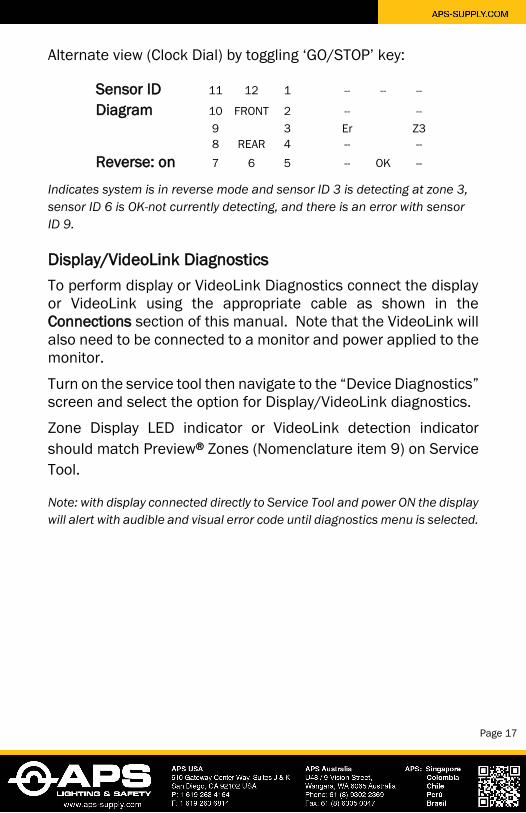
Alternate view (Clock Dial) by toggling ‘GO/STOP’ key:
Sensor ID 11 12 1 -- -- --
Diagram 10 FRONT 2 -- -- 9 3 Er Z3 8 REAR 4 -- --
Reverse: on 7 6 5 -- OK --
Indicates system is in reverse mode and sensor ID 3 is detecting at zone 3,
sensor ID 6 is OK-not currently detecting, and there is an error with sensor
ID 9.
Display/VideoLink Diagnostics To perform display or VideoLink Diagnostics connect the display or VideoLink using the appropriate cable as shown in the Connections section of this manual. Note that the VideoLink will also need to be connected to a monitor and power applied to the monitor.
Turn on the service tool then navigate to the “Device Diagnostics” screen and select the option for Display/VideoLink diagnostics.
Zone Display LED indicator or VideoLink detection indicator should match Preview® Zones (Nomenclature item 9) on Service Tool.
Note: with display connected directly to Service Tool and power ON the display
will alert with audible and visual error code until diagnostics menu is selected.
Page 17
Diagnostics Report The service tool provides the option to create a diagnostics report and store in a log file on an SD storage card. Before selecting this option, be sure to insert an SD card into the SD card slot.
Further options are available to connect to the service tool via USB cable and read these reports stored on the SD storage card using a standard text editor (like Notepad).
Service Tool Setup and Maintenance The setup and maintenance menu allows for adjusting contrast and brightness, turning the backlight on or off, and updating the service tool firmware.
Updating Service Tool Firmware
NOTE: To update service tool firmware an SD card with a valid
firmware update file located at the root directory is required.
Contact www.preco.com for the latest updates.
Place the SD card into the SD card slot and turn on the service tool then navigate to the “Service Tool Maintenance and Set Up” screen and select the option for updating the service tool firmware.
Next, select a file to use for the update. If no files are found, then connect the service tool to a PC using a USB cable and select the option to browse files on the SD card. This will allow the service tool to function as an SD card reader. (Optionally, a generic SD card reader may be used.) Once the contents of the SD card are visible in a Window’s Explorer window, place a valid service tool update file at the root directory of the SD card.
Page 18
Once a valid file has been selected, select the option to update the service tool firmware. The firmware update may take a few minutes to complete. Once the firmware update is complete the main power-up screen will appear.
Note: Power should not be turned off until the update is complete.
Error Messages TARGET DEVICE NOT RESPONDING
No communication between device and Service Tool Check cable connection Check power connection if connected to network
system Check ‘Voltage Output’ LED to ensure device is
powered Verify Service Tool is fully charged
WRONG DEVICE CLASS DETECTED Incompatible device
FEATURE NOT SUPPORTED That version of the device does not support that feature
Contact www.preco.com for list of updates
MULTIPLE DEVICES CONNECTED Only one device may be connected when attempting to change settings
Disconnect from network and connect to devicedirectly
SD CARD PROBLEM
The SD card is not inserted properly or it is not functional
USB NOT DETECTED The USB cable is not connected properly
Page 19

Warranty Information MANUFACTURER LIMITED WARRANTY AND LIMITATION OF LIABILITY
Manufacturer warrants that on the Date of Purchase this Product will conform to Manufacturer's published specifications for the product, which are available from Manufacturer on request, and Manufacturer warrants that the product is free from defects in materials and workmanship. This Limited Warranty extends for twenty-four (24) months from the date of shipment. Manufacturer will, at its option, repair or replace any product found by Manufacturer to be defective and subject to this Limited Warranty.
This Limited Warranty does not apply to parts or products that are misused; abused; modified; damaged by accident, fire or other hazard; improperly installed or operated; or not maintained in accordance with the maintenance procedures set forth in Manufacturer's Installation and Operating Instructions.
To obtain warranty service, you must ship the product(s) to the specified Manufacturer location within thirty (30) days from expiration of the warranty period. To obtain warranty service, call PRECO Electronics® Customer Service at +1.866.977.7236 or +1.208.323.1000, or fax your request to +1.208.323.1034. Customer Service will issue warranty authorization and further instructions. You must prepay shipping charges and use the original shipping container or equivalent.
EXCLUSION OF OTHER WARRANTIES: MANUFACTURER MAKES NO OTHER WARRANTIES, EXPRESSED, IMPLIED OR STATUTORY. THE IMPLIED WARRANTIES FOR MERCHANTABILITY AND FITNESS FOR A PARTICULAR PURPOSE ARE HEREBY EXCLUDED AND SHALL NOT APPLY TO THE PRODUCT. BUYER'S SOLE AND EXCLUSIVE REMEDY IN CONTRACT, TORT OR UNDER ANY OTHER THEORY AGAINST MANUFACTURER RESPECTING THE PRODUCT AND ITS USE SHALL BE THE REPLACEMENT OR REPAIR OF THE PRODUCT AS DESCRIBED ABOVE. LIMITATION OF LIABILITY: IN THE EVENT OF LIABILITY FOR DAMAGES ARISING OUT OF THIS LIMITED WARRANTY OR ANY OTHER CLAIM RELATED TO MANUFACTURER'S PRODUCTS, MANUFACTURER'S LIABILITY FOR DAMAGES SHALL BE LIMITED TO THE AMOUNT PAID FOR THE PRODUCT AT THE TIME OF ORIGINAL PURCHASE. IN NO EVENT SHALL MANUFACTURER BE LIABLE FOR LOST PROFITS, THE COST OF SUBSTITUTE EQUIPMENT OR LABOR, PROPERTY DAMAGE, OR OTHER SPECIAL, CONSEQUENTIAL OR INCIDENTAL DAMAGES BASED UPON ANY CLAIM FOR BREACH OF CONTRACT, NEGLIGENCE OR OTHER CLAIM, EVEN IF MANUFACTURER OR A MANUFACTURER'S REPRESENTATIVE HAS BEEN ADVISED OF THE POSSIBILITY OF SUCH DAMAGES.
Manufacturer shall have no further obligation or liability with respect to the product or its sale, operation and use, and Manufacturer neither assumes nor authorizes the assumption of any other obligation or liability in connection with such product.
This Limited Warranty gives you specific legal rights, and you may also have other legal rights, which vary, from state to state. Some states do not allow the exclusion or limitation of incidental or consequential damages, so the above exclusion or limitation may not apply to you.
Any oral statements or representations about the product, which may have been made by salesmen or Manufacturer representatives, do not constitute warranties. This Limited Warranty may not be amended, modified or enlarged, except by a written agreement signed by an authorized official of Manufacturer that expressly refers to this Limited Warranty.
Page 20

Proudly developed by
Related Documents