PRESTRESSED CONCRETE STRUCTURES Amlan K. Sengupta, PhD PE Department of Civil Engineering, Indian Institute of Technology Madras Module – 9: Special Topics Lecture – 40: Circular Prestressing, Conclusion Welcome back to prestressed concrete structures. This is the sixth lecture of the ninth module on special topics. This is the concluding lecture of this course. (Refer Slide Time 01:30) First, we shall learn about circular prestressing. After the introduction, we shall study the general analysis and design. We shall then study specifically about prestressed concrete pipes, liquid storage tanks and ring beams. Finally, we shall conclude.

Welcome message from author
This document is posted to help you gain knowledge. Please leave a comment to let me know what you think about it! Share it to your friends and learn new things together.
Transcript

PRESTRESSED CONCRETE STRUCTURES
Amlan K. Sengupta, PhD PE
Department of Civil Engineering,
Indian Institute of Technology Madras
Module – 9: Special Topics
Lecture – 40: Circular Prestressing, Conclusion
Welcome back to prestressed concrete structures. This is the sixth lecture of the ninth
module on special topics. This is the concluding lecture of this course.
(Refer Slide Time 01:30)
First, we shall learn about circular prestressing. After the introduction, we shall study the
general analysis and design. We shall then study specifically about prestressed concrete
pipes, liquid storage tanks and ring beams. Finally, we shall conclude.
(Refer Slide Time 01:48)
When the prestressed members are curved, in the direction of prestressing, the
prestressing is called circular prestressing. For example, circumferential prestressing in
pipes, tanks, silos, containment structures and similar structures is a type of circular
prestressing. In these structures, there can be prestressing in the longitudinal direction
(which is parallel to axis) as well. Circular prestressing is also applied in domes, shells
and folded plates.
If a tendon has a curved profile within a linear member, then it is not termed as circular
prestressing. The member itself has to be curved to term the prestressing as circular
prestressing.

(Refer Slide Time 02:57)
The circumferential prestressing resists the hoop tension generated due to the internal
pressure. The prestressing is done by wires or tendons placed spirally or over sectors of
the circumference of the member. The wires or tendons lie outside the concrete core.
Hence, the centre of the prestressing steel, which we shall denote as CGS, is outside the
core concrete section.
The hoop compression generated is considered to be uniform across the thickness of a
thin shell. Hence, the pressure line or C-line lies at the centre of the core concrete section,
which we shall denote as CGC.
Thus, in circumferential prestressing, the prestressing wires or tendons lie outside a
concrete core shell. It creates a hoop compression to resist the hoop tension that generates
due to internal pressure. The CGS, that is the centroid of the prestressing steel lies outside
the concrete section. For a thin shell, the stress across the thickness of the shell is
considered to be uniform. Thus, the hoop compression that is generated coincides with
the center of the concrete section.
(Refer Slide Time 04:30)
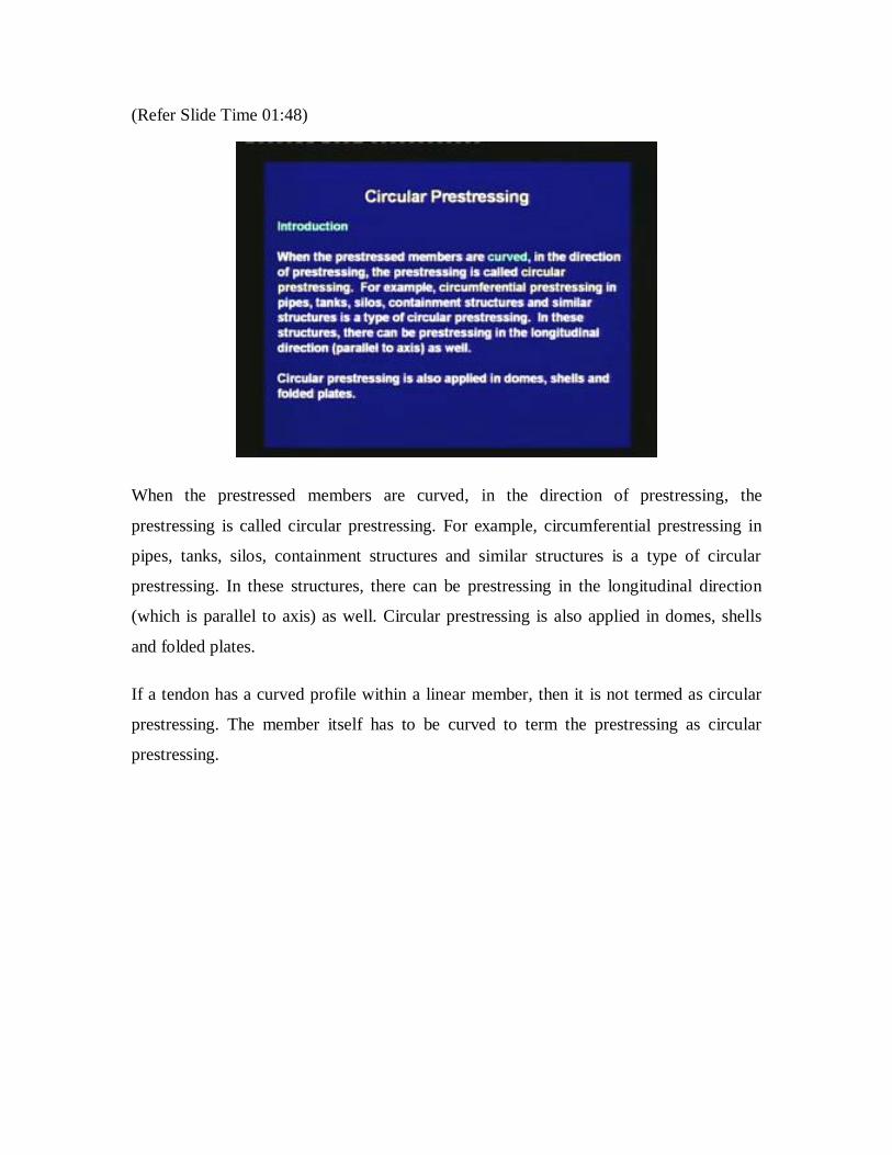
The sketch shows the internal forces under service conditions. The analysis is done for a
slice of unit length along the longitudinal direction, which is parallel to the axis of the
member. In this sketch, the prestressing tendon is lying outside the shell. It is creating a
hoop compression, where the compression is lying at the mid-plane of the shell, which is
the CGC. Due to the internal pressure P, there is hoop tension which is also lying at the
centre of the section.
(Refer Slide Time 05:20)

To reduce the loss of prestress due to friction, the prestressing can be done over sectors of
the circumference. Buttresses are used for the anchorage of the tendons. The following
sketch shows the buttresses along the circumference.
(Refer Slide Time 05:40)
Here, you can see that the prestressing tendon is not continuous throughout the
circumference. It has been broken up into sectors, and it has been anchored in these
buttresses. This reduces the friction loss that occurs during the circumferential
prestressing. A closer view of buttresses shows that one tendon is anchored at the left
end, which can be the dead end and the other tendon is anchored at the right end, which
can be the stretching end.
Next, we move on to the analysis and design under circumferential prestressing for a
general condition.

(Refer Slide Time 06:32)
The basics of analysis and design for circumferential prestressing are provided for a
general understanding. Specific applications such as pipes, liquid storage tanks and ring
beams will be explained later.
(Refer Slide Time 06:48)
First is the analysis at transfer. The compressive stress can be calculated from the
compression C that generates due to the prestressing force. From equilibrium, C is equal

to P0, where P0 is the prestress at transfer after short-term losses. The compressive stress
fc is given as follows.
fc = ‒P0/A
Here, A is the area of the longitudinal section of the slice. The permissible prestress is
determined based on fc within the allowable stress at transfer, which can be denoted as
fcc,all. Thus, assuming the hoop compression is uniform across the thickness, we are able
to find out an expression of the compressive stress that generates due to the
circumferential prestressing. At transfer, this stress has to be less than the corresponding
allowable compressive stress in the concrete.
(Refer Slide Time 07:57)
Next, we move on to analysis at service loads. The tensile stress due to the internal
pressure p can be calculated from the tension T. From equilibrium of half of the slice, T =
pR where, R is the radius of the mid-surface of the cylinder. The resultant stress fc due to
the effective prestress (which is denoted as Pe) and internal pressure, is given as follows:
fc = ‒Pe/A + pR/At

Here, At is the area of the transformed longitudinal section of the slice. The value of fc
should be compressive and within the allowable stress at service loads, which we are
denoting as fcc,all.
Thus, under service conditions the hoop tension adds up to the hoop compression. The
total stress has two components: one due to the prestressing force, which is compressive
and another due to the internal pressure, which is tensile. The resultant stress should be
compressive and it should be within the allowable compressive value for service loads.
(Refer Slide Time 09:28)
In the previous equation, since Pe = pR and At is greater than A, fc is always negative.
Thus, the concrete will be under compression. To meet the safety standards, a factor of
safety can be further introduced.

(Refer Slide Time 10:30)
The internal pressure p and the radius R are given variables. It is assumed that the
prestressing steel alone carries the hoop tension due to internal pressure, that is Pe = Apfpe
= pR. Thus in design, first we assume that the internal pressure is resisted by the
prestressing force alone. The design steps are as follows.
1. Calculate the area of prestressing steel from the equation Ap = pR/fpe. Thus, given
the condition that Pe = pR, we find out the amount of prestressing steel required in
the unit length of the slice.
2. Calculate the prestress at transfer from an estimate of the initial prestress fp0,
using the equation P0 = Apfp0. Thus, once we have calculated Ap, we know how
much prestress to apply initially. From that we can calculate the total loss to get
the effective prestress Pe.

(Refer Slide Time 12:36)
3. Calculate the thickness of the concrete shell from the following equation.
A = P0/fcc,all
Here, fcc,all is the allowable compressive stress at transfer. Thus, the thickness
should be adequate to resist the compressive stress that is generated after the
transfer of prestress to the shell.
4. Calculate the resultant stress fc at the service conditions using Eq. (9f-2). The
value of fc should be within fcc,all, the allowable stress at service conditions. Thus,
once we have designed the section and the prestressing steel, we need to check the
stress under service conditions, and make sure that this stress is within the
allowable value for the service conditions.
With this general introduction, we are moving on to specific applications. First we shall
study about prestressed concrete pipes.

(Refer Slide Time 14:00)
The prestressed concrete pipes are suitable when the internal pressure is within 0.5 to 2.0
N/mm2. There are 2 types of prestressed concrete pipes: first the cylinder type and second
the non-cylinder type. A cylinder type pipe has a steel cylinder core, over which the
concrete is cast and prestressed. A non-cylinder type of pipe is made of prestressed
concrete alone.
(Refer Slide Time 14:53)

IS: 784 - 2001 (Prestressed Concrete Pipes (Including Specials) – Specification),
provides guidelines for the design of prestressed concrete pipes, with the internal
diameter ranging from 200 mm to 2500 mm. The pipes are designed to withstand the
combined effect of internal pressure and external loads. The minimum grade of concrete
in the core should be M40 for non-cylinder type pipes. Thus, there are some guidelines
given in IS: 784 for the design of prestressed concrete pipes, which we select depending
upon the type of pipe.
(Refer Slide Time 15:52)
First, the core is cast either by the centrifugal method or by the vertical casting method.
In the centrifugal method the mould is subjected to spinning, till the concrete is
compacted to a uniform thickness throughout the length of the pipe. In the vertical
casting method, concrete is poured in layers up to a specified height. Thus, the casting
process of concrete itself can be of two types.

(Refer Slide Time 16:58)
After adequate curing of concrete, first the longitudinal wires are prestressed.
Subsequently, the circumferential prestressing is done by the wire wound around the core
in a helical form. The wire is wound using a counter weight or a die. Finally a coat of
concrete or rich cement mortar is applied over the wire to prevent from corrosion. For
cylinder type pipes, first the steel cylinder is fabricated and tested. Then the concrete is
cast around it. Thus, depending upon the type of the prestressed concrete cylinder, we
select the manufacturing process. The process has to be strictly controlled for quality to
get the required properties of the pipes.
(Refer Slide Time 18:00)
Next, we move to analysis and design of prestressed concrete pipes which consider the
stresses due to the following actions. A horizontal layout of the pipe is considered to
illustrate them.
(Refer Slide Time 18:17)
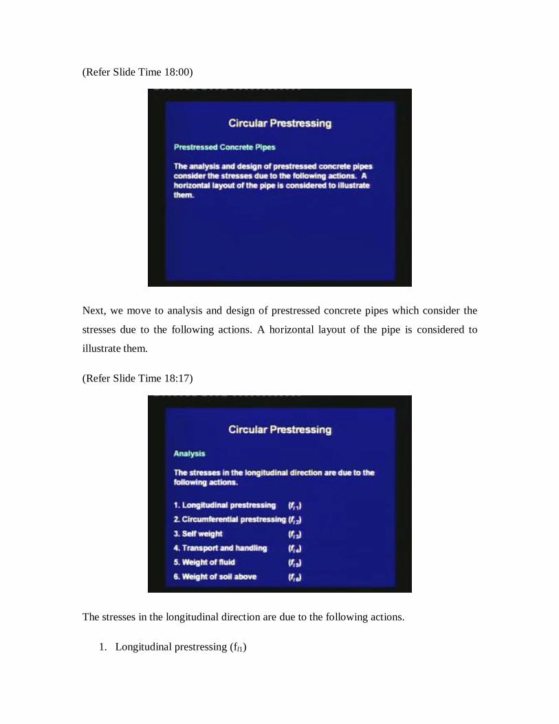
The stresses in the longitudinal direction are due to the following actions.
1. Longitudinal prestressing (fl1)
2. Circumferential prestressing (fl2)
3. Self weight (fl3)
4. Transport and handling (fl4)
5. Weight of fluid inside the pipe (f15)
6. Weight of soil above in case of pipes embedded in ground (fl6)
(Refer Slide Time 19:00)
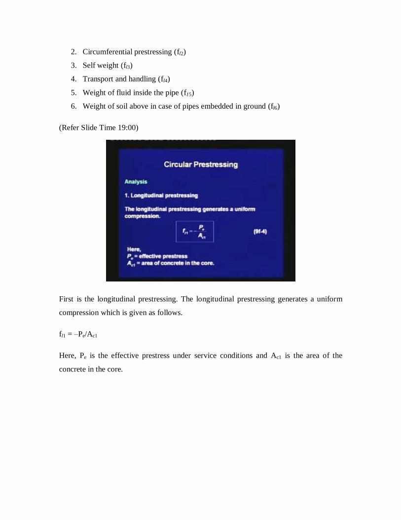
First is the longitudinal prestressing. The longitudinal prestressing generates a uniform
compression which is given as follows.
fl1 = ‒Pe/Ac1
Here, Pe is the effective prestress under service conditions and Ac1 is the area of the
concrete in the core.

(Refer Slide Time 19:26)
Second is the circumferential prestressing. Due to the Poisson’s effect, the
circumferential prestressing generates longitudinal tensile stress. It is given as follows.
fl2 = 0.284 Pe/Ac
(Refer Slide Time 19:48)

Third is due to the self weight. If the pipe is not continuously supported, then a varying
longitudinal stress generates due to the moment due to self weight, which we shall denote
as Msw.
fl3 = ± Msw/Zl
Here, Zl is the section modulus about the centroidal axis.
(Refer Slide Time 20:16)
Fourth is transport and handling. A varying longitudinal stress generates due to the
moment during transport and handling, which is denoted as Mth. Mth can be determined
based on the support points of the pipe. Thus, once Mth is determined we can find out the
stress.
fl4 = ±Mth/Zl

(Refer Slide Time 20:48)
Fifth is the weight of fluid. Similar to self weight, the moment due to weight of the fluid
inside, which is denoted as Mf, generates varying longitudinal stress.
fl5 = ±Mf/Zl
(Refer Slide Time 21:11)
Finally, the weight of the soil above is considered to be an equivalent distributed load.
The expression of stress fl6 is similar to that for the weight of the fluid.

(Refer Slide Time 21:25)
The longitudinal stresses are combined based on the following diagram. On the left hand
side, we are having a section of the pipe laid horizontally. The stresses fl1 and fl2 are
uniform throughout the section. The varying stresses are due to the moments due to the
several causes. All these should be considered to calculate the resultant stress due to
flexure of the pipe.
(Refer Slide Time 22:30)

The stresses in the circumferential direction are due to the following actions.
1. Circumferential prestressing (fh1)
2. Self weight (fh2)
3. Weight of the fluid inside the pipe (fh3)
4. Weight of soil above (fh4)
5. Live load (fh5)
6. Internal pressure (fh6)
(Refer Slide Time 23:00)
First is the circumferential prestressing. The compressive hoop stress is given as follows.
fh1 = ‒Ps/Ac2 = ‒Ps/1tc
Here, Ps is the tensile force in spiral wire in unit length of pipe. Note that this is different
from the longitudinal prestressing. Ac2 is the area of longitudinal section of unit length,
which is equal to 1 times tc, the thickness of the core. Thus, given the circumferential
prestressing, we can find out what is the stress generated in the circumferential direction.

(Refer Slide Time 23:47)
For the Cases 2 to 5, we should understand that due to a vertical load, a thrust and a
moment is generated in the circumferential direction. For each of these actions, first the
vertical load per unit length, which is denoted as W, is calculated. The moment M and
thrust T develop due to W across the thickness, as shown in the sketch. This is due to the
distortion of the pipe cross-section.
(Refer Slide Time 25:09)

There are expressions to get the moment and the thrust depending on the value of W. The
hoop stress at a point is calculated by the following equation.
fh = ± M/Zh + T/A
The expressions of M and T due to W are as follows.
M = CMWr
T = CTW
The coefficients CM and CT are tabulated in the code. Thus, we can calculate the moment
and the thrust that generate due to the vertical load. From the moment and the thrust, we
can find out the circumferential stress.
(Refer Slide Time 25:41)
In the previous equation, CM is the moment coefficient, CT is the thrust coefficient, W is
the vertical load per unit length, r is the mean radius of pipe, A is the area of longitudinal
section for unit length of pipe, Zh is the section modulus for hoop stress for the same
length which is given as (1/6) t2 1000 mm
3/m, and t is the total thickness of core and
coat. The values of CM and CT are tabulated in the code.

(Refer Slide Time 26:25)
Finally, we come to the internal pressure. The expression of the hoop stress is same as
given in Eq. 9f-2.
fh6 = pR/At
Here, p is the internal pressure and R is the mean radius.
(Refer Slide Time 26:46)
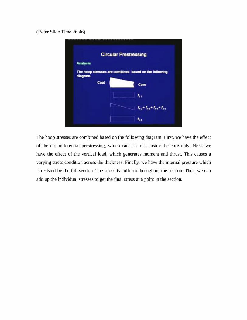
The hoop stresses are combined based on the following diagram. First, we have the effect
of the circumferential prestressing, which causes stress inside the core only. Next, we
have the effect of the vertical load, which generates moment and thrust. This causes a
varying stress condition across the thickness. Finally, we have the internal pressure which
is resisted by the full section. The stress is uniform throughout the section. Thus, we can
add up the individual stresses to get the final stress at a point in the section.
(Refer Slide Time 27:56)
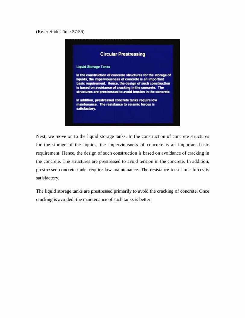
Next, we move on to the liquid storage tanks. In the construction of concrete structures
for the storage of the liquids, the imperviousness of concrete is an important basic
requirement. Hence, the design of such construction is based on avoidance of cracking in
the concrete. The structures are prestressed to avoid tension in the concrete. In addition,
prestressed concrete tanks require low maintenance. The resistance to seismic forces is
satisfactory.
The liquid storage tanks are prestressed primarily to avoid the cracking of concrete. Once
cracking is avoided, the maintenance of such tanks is better.

(Refer Slide Time 28:54)
Prestressed concrete tanks are used in water treatment and distribution systems, waste
water collection and treatment system and storm water management. Other applications
are liquefied natural gas (LNG) containment structures, large industrial process tanks and
bulk storage tanks. Thus, liquid storage tanks have wide application.
(Refer Slide Time 29:37)
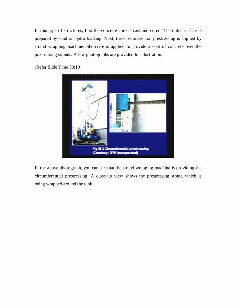
In this type of structures, first the concrete core is cast and cured. The outer surface is
prepared by sand or hydro-blasting. Next, the circumferential prestressing is applied by
strand wrapping machine. Shotcrete is applied to provide a coat of concrete over the
prestressing strands. A few photographs are provided for illustration.
(Refer Slide Time 30:10)
In the above photograph, you can see that the strand wrapping machine is providing the
circumferential prestressing. A close-up view shows the prestressing strand which is
being wrapped around the tank.

(Refer Slide Time 30:48)
Next, a shotcrete machine is used to provide a coat of concrete over the prestressing
strands, which checks corrosion of the strands.
(Refer Slide Time 31:18)
IS: 3370 – 1967 (Code of Practice for Concrete Structures for the Storage of Liquids)
provide guidelines for the analysis and design of liquid storage tanks. The four section of
the code are titled as follows.

Part 1: General Requirement
Part 2: Reinforced Concrete Structures
Part 3: Prestressed Concrete Structures
Part 4: Design Tables
Thus, IS: 3370-1967 Part 3 is specifically for the prestressed concrete liquid storage
tanks.
(Refer Slide Time 32:00)
The analysis of liquid storage tanks can be done by IS: 3370-1967, Part 4, or by the finite
element method. The code provides coefficients for bending moment, shear and hoop
tension for cylindrical tanks, which were developed from the theory of plates and shells.
In Part 4, both rectangular and cylindrical tanks are covered. Since, circular prestressing
is applied to cylindrical tanks, only this type of tank is covered in this module.

(Refer Slide Time 33:02)
The following types of boundary conditions are considered in the analysis of the
cylindrical wall.
1. For base: fixed or hinged
2. For top: free or hinged or framed
The applicability of each boundary condition is explained next.
(Refer Slide Time 33:23)

For the base of wall: when the wall is built continuous with its footing, then the base can
be considered to be fixed as the first approximation. If the sub-grade is susceptible to
settlement, then a hinged base is a conservative assumption. Since the actual rotational
restraint from the footing is somewhere in between fixed and hinged, a hinged base can
be assumed. The base can be made sliding with appropriate polyvinyl chloride (PVC)
water-stops for liquid tightness.
(Refer Slide Time 34:26)
Next, for the top of wall: the top of the wall is considered free when there is no restraint
in expansion. When the top is connected to the roof slab by dowels for shear transfer, the
boundary condition can be considered to be hinged. Finally, when the top of the wall and
roof slab are made continuous with moment transfer, the top is considered to be framed.
Thus, depending upon the connections between the wall and the footing or roof slab, we
have to judge the boundary conditions at the bottom and top.

(Refer Slide Time 35:12)
The hydrostatic pressure on the wall increases linearly from the top to the bottom of the
liquid of maximum possible depth. If the vapour pressure in the free board is negligible,
then the pressure at the top is 0. Else, it is added throughout the depth of the pressure of
the liquid. The forces generated in the tank due to circumferential prestress are opposite
in nature to that due to hydrostatic pressure. If the tank is built underground, then the
earth pressure needs to be considered.
Thus, hoop tension generates due to the hydrostatic pressure from the liquid stored in the
tank. The design is based on the maximum liquid that can be stored in the tank. The
triangular hydrostatic pressure is used to calculate the hoop stress. If there is vapour
pressure above the liquid free board, then that has also be included. Finally, if the tank is
buried under ground, then the earth pressure also has to be included.
The most severe condition should be used to design the tank. Whether the empty
condition or whether the full condition, all the combinations have to be checked to find
out the design stresses.

(Refer Slide Time 36:49)
The hoop tension in the wall, generated due to triangular hydrostatic pressure is given as
follows.
T = CT wHR
The bending moment in the vertical direction is given as follows.
M = CM wH3
The shear at the base is given by the following expression.
V = CV wH2

(Refer Slide Time 37:17)
In the previous equations, the notations used are as follows.
CT = coefficient for hoop tension
CM = coefficient for bending moment
Cv = coefficient for shear
w = unit weight of liquid
H = height of the liquid
R = inner radius of the wall.
Thus, the analysis is based on the coefficient, that is given in IS: 3370 Part 4. These
coefficients are developed from the theory of plates and shells. Once the coefficient is
known, we can calculate the hoop tension, the moment and shear that generates in the
section of the tank.

(Refer Slide Time 38:14)
The values of the coefficient are tabulated in IS: 3370-1967, Part 4 for various values of
H2/Dt, at different depths of the liquid. D and t represent the inner diameter and the
thickness of the wall, respectively. The typical variations of CT and CM with depth, for
two sets of boundary conditions are illustrated.
(Refer Slide Time 38:45)
In this sketch, the tank section is fixed at the bottom and free to slide at the top. The
hydrostatic pressure, if the tank is completely full, is triangular. Then, the variations of
the coefficients for the hoop tension and the moment along the vertical direction are as
shown. Thus, at the base we have a negative moment, whereas beyond that we have
positive moment. The hoop tension also achieves maximum value at an intermediate
height.
The second case is for a hinged base, where the foundation may tilt; the top is free to
slide. Due to the triangular hydrostatic pressure, we have the tabulated values of CT and
CM. Note that in this case there is no negative moment at the base, and the wall is always
under positive moment.
(Refer Slide Time 40:07)
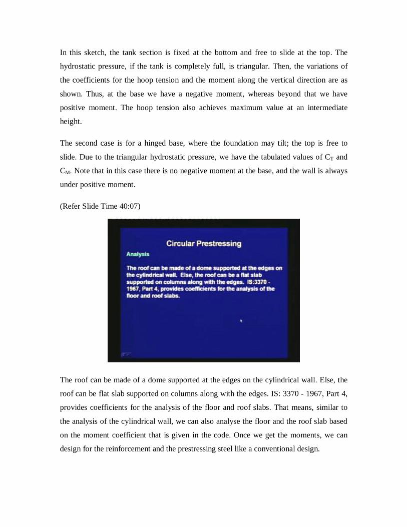
The roof can be made of a dome supported at the edges on the cylindrical wall. Else, the
roof can be flat slab supported on columns along with the edges. IS: 3370 - 1967, Part 4,
provides coefficients for the analysis of the floor and roof slabs. That means, similar to
the analysis of the cylindrical wall, we can also analyse the floor and the roof slab based
on the moment coefficient that is given in the code. Once we get the moments, we can
design for the reinforcement and the prestressing steel like a conventional design.
(Refer Slide Time 41:08)
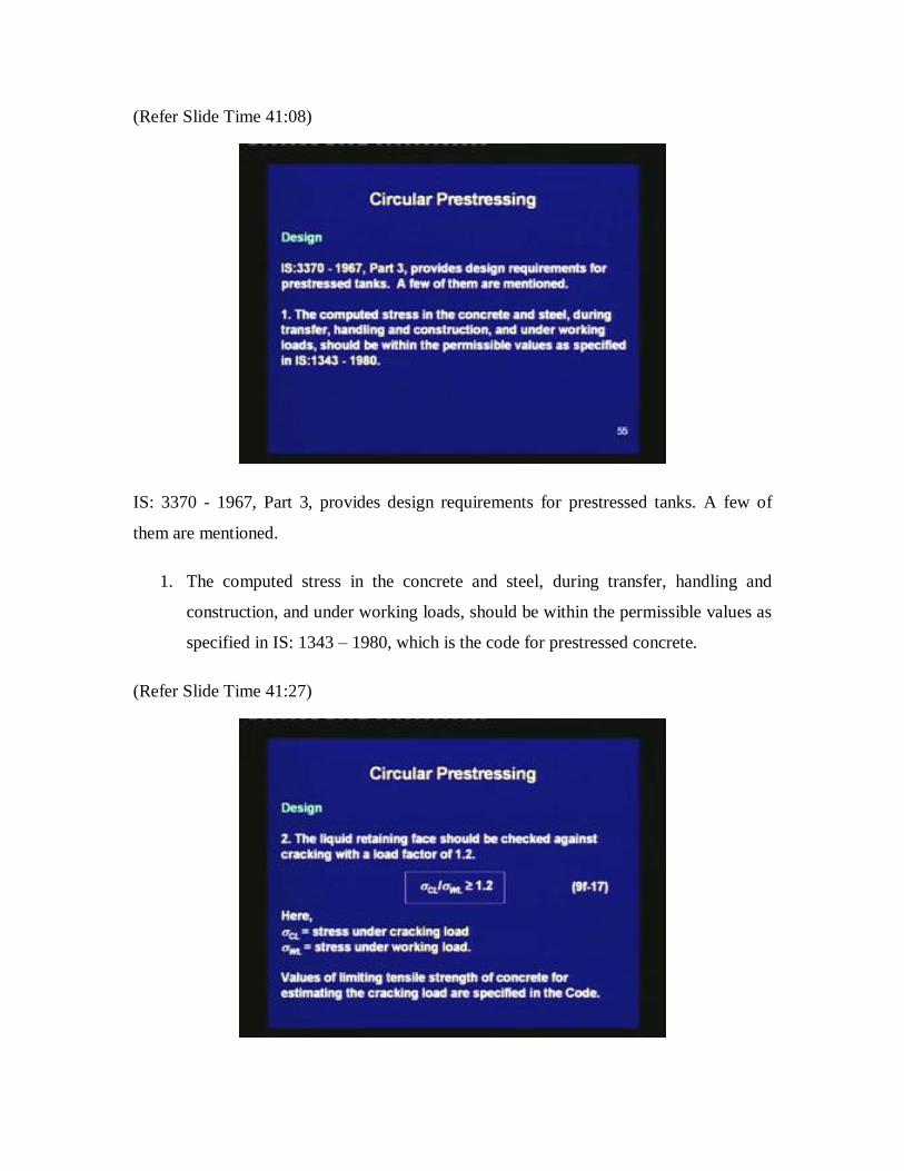
IS: 3370 - 1967, Part 3, provides design requirements for prestressed tanks. A few of
them are mentioned.
1. The computed stress in the concrete and steel, during transfer, handling and
construction, and under working loads, should be within the permissible values as
specified in IS: 1343 – 1980, which is the code for prestressed concrete.
(Refer Slide Time 41:27)

2. The liquid retaining face should be checked against cracking with a load factor of
1.2.
CL/WL ≥ 1.2
Here, CL is the stress under cracking load, and WL is the stress under working
load. Values of limiting tensile strength of concrete for estimating the cracking
load are specified in the code.
(Refer Slide Time 42:04)
3. The ultimate load at the failure should not be less than twice the working load.
4. When the tank is full, there should be compression in the concrete at all points of
at least 0.7 N/mm2. When the tank is empty, there should not be tensile stress
greater than 1.0 N/mm2.

(Refer Slide Time 42:42)
5. There should be provision to allow for elastic distortion of the structure during
prestressing. Any restraint that may lead to the reduction of the prestressing force
should be considered.
Thus, IS: 3370 Part 3 gives guidelines specifically for prestressed concrete tanks. These
guidelines should be used during the design of such tanks.
(Refer Slide Time 43:07)

IS: 3370, Part 3 also provides detailing requirements. The cover requirement is as
follows.
The minimum cover to the prestressing wires should be 35 mm on the liquid face. For
faces away from the liquid, the cover requirements are as per IS: 1343. Other
requirements from IS: 1343 are also applicable.
(Refer Slide Time 44:00)
Next, we move on to the analysis of ring beams. The ring beams are used in presence of
domes. We are showing this for a typical nuclear containment structure. In this sketch,
the dome is the circular member at the top and this is supported on the ring beam. Then
we have the cylindrical wall and this is supported on a raft foundation. Thus, ring beams
support domes in buildings, tanks, silos and nuclear containment structures. Circular
prestressing is applied on dome by a grid of tendons. The cylindrical wall is prestressed
circumferentially as well as vertically. The ring beam is circumferentially prestressed.
Thus in a nuclear containment structure, the dome, the ring beam, the cylindrical wall are
all prestressed, and even the raft foundation may be prestressed.

(Refer Slide Time 44:54)
This sketch shows some details of the prestressing tendons at the junction of the dome
and the ring beam. The dome is circularly prestressed by tendons, which are first
anchored. Then the cylindrical wall is prestressed in the vertical direction; the wall is also
prestressed by tendons in the circumferential direction. The ring beam, which is at the
base of this dome, is also circumferentially prestressed.
(Refer Slide Time 45:37)
This figure shows a containment structure from the Kaiga Atomic Power Plant. Here you
can see that the dome is supported on a ring beam, and then the cylindrical wall is
supported on the raft foundation.
(Refer Slide Time 46:02)
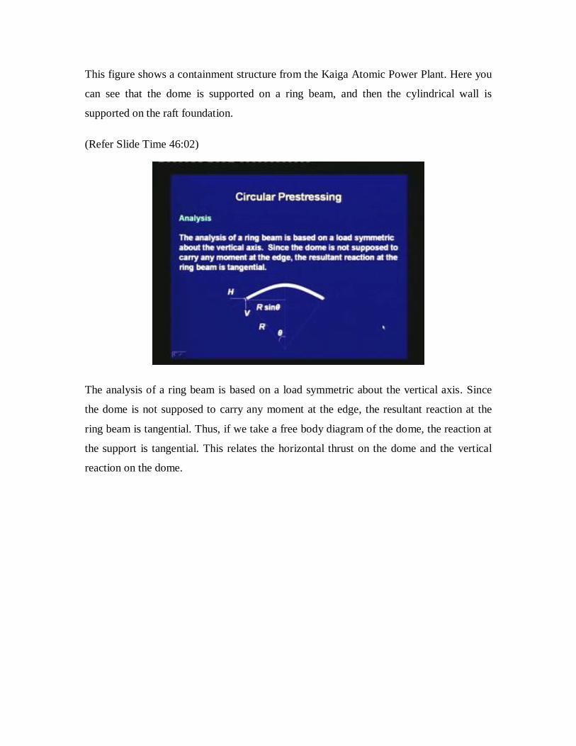
The analysis of a ring beam is based on a load symmetric about the vertical axis. Since
the dome is not supposed to carry any moment at the edge, the resultant reaction at the
ring beam is tangential. Thus, if we take a free body diagram of the dome, the reaction at
the support is tangential. This relates the horizontal thrust on the dome and the vertical
reaction on the dome.
(Refer Slide Time 46:38)
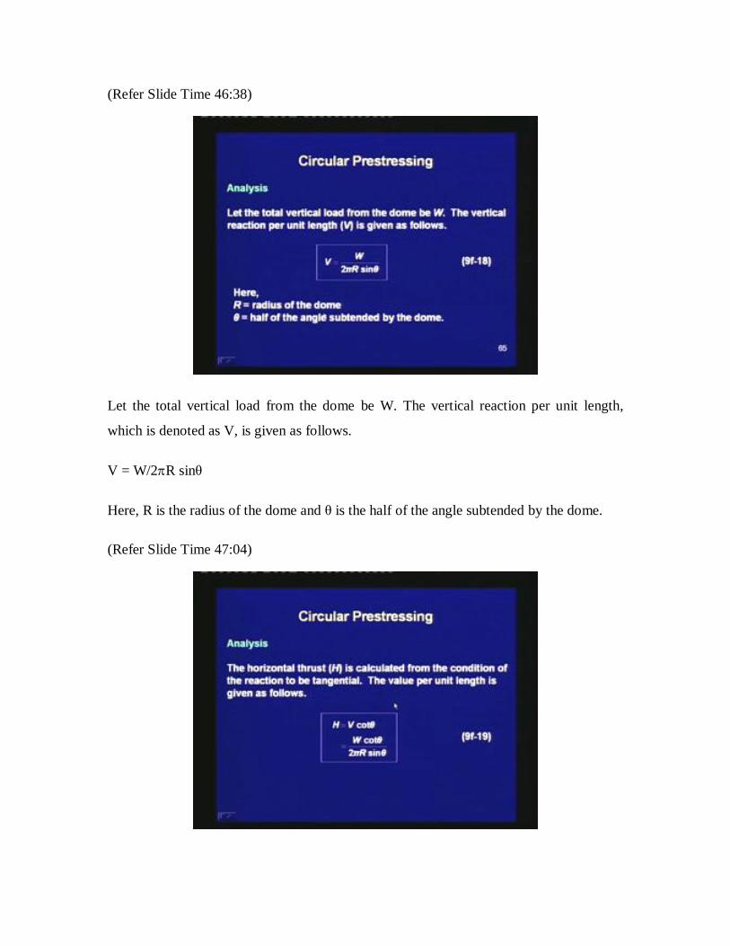
Let the total vertical load from the dome be W. The vertical reaction per unit length,
which is denoted as V, is given as follows.
V = W/2R sinθ
Here, R is the radius of the dome and θ is the half of the angle subtended by the dome.
(Refer Slide Time 47:04)
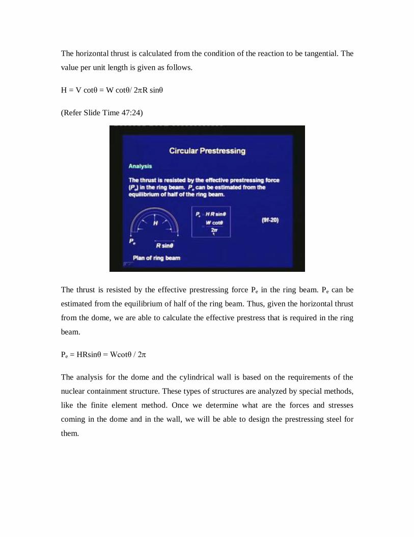
The horizontal thrust is calculated from the condition of the reaction to be tangential. The
value per unit length is given as follows.
H = V cotθ = W cotθ/ 2R sinθ
(Refer Slide Time 47:24)
The thrust is resisted by the effective prestressing force Pe in the ring beam. Pe can be
estimated from the equilibrium of half of the ring beam. Thus, given the horizontal thrust
from the dome, we are able to calculate the effective prestress that is required in the ring
beam.
Pe = HRsinθ = Wcotθ / 2
The analysis for the dome and the cylindrical wall is based on the requirements of the
nuclear containment structure. These types of structures are analyzed by special methods,
like the finite element method. Once we determine what are the forces and stresses
coming in the dome and in the wall, we will be able to design the prestressing steel for
them.

(Refer Slide Time 49:19)
Finally, today we are concluding this prestressed concrete course. Prestressed concrete is
observed in other types of structural elements, such as bridge decks, shells and folded
plates, off shore concrete gravity structures and raft foundations.
The analysis of special structure is based on advanced theory of structural analysis or the
finite element method. After the analysis, the design of such structures follows the basic
principles of prestressed concrete design. It is expected that in future, further innovations
in structural form, prestressing systems and construction technology will promote the
application of prestressed concrete.
Thus, what we covered in this course gives you a beginner’s knowledge of prestressed
concrete. We studied the material properties and about the losses in prestress. We
covered axially loaded members, then we moved on to flexure, shear and torsion. We
looked into the design of the end zone of prestressed members.
Finally, we moved on to the special topics. We studied about the composite construction,
one-way and two-way slabs, compression members and circular prestressing. Thus, the
application of prestressed concrete is wide. In future, with the development of different
prestressing systems, structural forms and bold design, we are expected to see more
applications of prestress concrete.

A few photos of recent applications of prestressed concrete are shown.
(Refer Slide Time 52:46)
In this photograph, you can see a cement silo. This is a shell type of structure which
stores cement. Similar type of silos can be used for storing food grains or any other
granular material. This industrial structure can be analysed either by a conventional
analysis or by the finite element method. Once we analyze the shell, then we can design
the prestressed concrete section, as per the fundamental principles that we have learnt in
this course.

(Refer Slide Time 53:32)
This figure is that of a curved box-girder bridge. We have discussed about the application
of prestressed concrete in bridges. Although, in this course we have studied only
prismatic and straight I-girders, prestressed concrete is also used in curved box-girder
decks. This type of box-girders needs special analysis, and we need to consider the
effects of torsion and distortion of the section. The curved box-girders are very elegant
and they are signature transportation structures in a metropolitan environment.

(Refer Slide Time 54:59)
The codes related to prestressed concrete that are published by the Bureau of Indian
Standards are as follows.
1. IS: 784 – 2001 Prestressed Concrete Pipes (including fittings) ‒ Specifications
2. IS: 1343 – 1980 Code of Practice for Prestressed Concrete. This is the code we
followed mostly in this course.
3. IS: 1678 – 1998 Specification for Prestressed Concrete Poles for Overhead
Power, Traction and Telecommunication Lines
(Refer Slide Time 55:24)
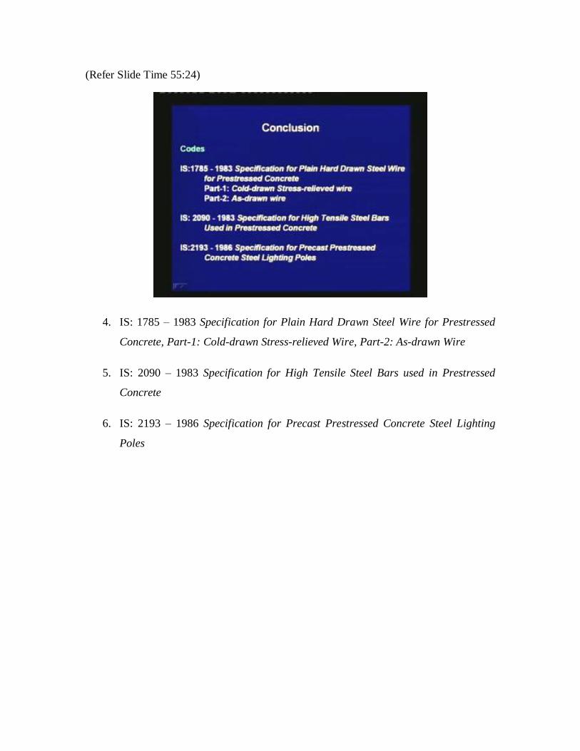
4. IS: 1785 – 1983 Specification for Plain Hard Drawn Steel Wire for Prestressed
Concrete, Part-1: Cold-drawn Stress-relieved Wire, Part-2: As-drawn Wire
5. IS: 2090 – 1983 Specification for High Tensile Steel Bars used in Prestressed
Concrete
6. IS: 2193 – 1986 Specification for Precast Prestressed Concrete Steel Lighting
Poles

(Refer Slide Time 55:56)
7. IS: 3370 – 1967 Code of Practice for Concrete Structures for Storage of Liquids,
Part-3: Prestressed Concrete Structures
8. IS: 6003 – 1983 Specification for Intended Wire for Prestressed Concrete
9. IS: 6006 ‒ 1983 Specification for Uncoated Stress Relieved Strand for
Prestressed Concrete

(Refer Slide Time 56:58)
10. IS: 6461 – 1973 Glossary of Terms Relating to Cement Concrete, Part-11:
Prestressed Concrete
11. IS: 10790 – 1984 Methods of Sampling of Steel for Prestressed and Reinforced
Concrete, Part-1: Prestressing Steel, Part-2: Reinforcing Steel

(Refer Slide Time 57:01)
12. IS: 13158 – 1991 Specification for Prestressed Concrete Circular Spun Poles for
Overhead Power, Traction and Telecommunication Lines
13. IS: 14268 – 1995 Specification for Uncoated Stress Relieved Low Relaxation
Seven Ply Strand for Prestressed Concrete

(Refer Slide Time 57:31)
The following code related with prestressed concrete is published by the Indian Roads
Congress.
IRC: 18 ‒ 2000 Design Criteria for Prestressed Concrete Bridges (Post-tensioned
Concrete)
There are other codes published by the Indian Road Congress which are related to the
analysis and design of road bridges. When you are moving into a professional career, you
have to learn the use of these codes.

(Refer Slide Time 58:19)
In today’s lecture, we first had an introduction of circular prestressing. We understood
the necessity of circumferential prestressing. Then we learnt the general analysis and
design principles for circumferential prestressing. Next, we studied some special
applications. First, we studied prestressed concrete pipes; next, we studied liquid storage
tanks and finally, we studied ring beams. We got familiar with the codes that are related
to prestressed concrete structures.
Thank you.
Related Documents