
Welcome message from author
This document is posted to help you gain knowledge. Please leave a comment to let me know what you think about it! Share it to your friends and learn new things together.
Transcript

• Pressurized boiler
• Heat output: 59 - 256 kW
Re
me
ha
P
2
00
Remeha P 200Technical information
3
Preface 4
1 Description of the unit 41.1 General 41.2 Burners 4
2 Construction data 42.1 General 42.2 Sections 42.3 Casing 4
3 Technical data and dimensions 53.1 Dimensions 53.2 Technical data 53.3 Quotation specifications 6
4 Output data 64.1 Boiler efficiency 64.2 Combustion efficiency 6
5 Application data 75.1 L.P.H.W. version 7
5.1.1 Water temperature 75.1.2 Water pressure 75.1.3 Flow rate 75.1.4 Water treatment 7
5.2 Economisers 75.3 Flue gas discharge 75.4 Noise production 8
6 Installation requirements 86.1 Installation recommendations in the boiler house 8
7 Assembly guidelines and installation requirements 9
7.1 General 97.2 Water connections 97.3 Delivery in individual parts 9
7.3.1 General 97.3.2 Boiler assembly 9
7.4 Delivery assembled (4 to 7 sections only) 9
8 Instrument panels 118.1 Equipment contents 118.2 Instrument panel High/Low with hours run meters 118.3 Wiring diagram instrument panel High/Low with hours run meters 1 12
9 Commissioning 139.1 Pressurized boiler with gas burner 13
9.1.1 Commissioning procedure 139.1.2 Putting out of operation 13
9.2 Pressurized boiler with oil burner 139.2.1 Commissioning procedure 139.2.2 Putting out of operation 13
10 Fault finding 13
11 Maintenance recommendations 1411.1 General 1411.2 Maintenance instructions 14
TABLE OF CONTENT
4
Remeha P 200
PREFACE
These technical instructions contain useful and impor-tant information for the correct operation and maintenan-ce of the Remeha boiler, model P200Read these instructions carefully before putting the boi-ler into operation, familiarise yourself with it’s control functions and operation, strictly observing the instructi-ons given. Failure to do so may invalidate warranty or prevent the boiler from operating.The installation and commissioning of the boiler must be carried out by a competent Engineer, with the relevant certification i.e.: CORGI, ACOPS, IEE regs. etc. On completion a copy of the boiler log / commissioning sheet should be returned to Broag Ltd for record purpo-ses.
If you have any questions, or if you need more informa-tion about specific subjects relating to this boiler, or it’s installation please do not hesitate to contact us.The data published in these technical instructions is based on the latest information (at date of publication) and may be subject to revisions.We reserve the right to continuous development in both design and manufacture, therefore any changes to the technology employed may not be retrospective nor may we be obliged to adjust earlier supplies accordingly.
1 DESCRIPTION OF THE UNIT
1.1 GeneralHigh efficiency pressurized boiler, suitable for use with natural gas and light oil, by means of a pressure jet burner. Also available with a condensing unit (ECO) (for natural gas only).Up to 141 kW (7 sections) the Remeha P 200 can be delivered assembled (except for casing and instrument panel).The boiler meets the requirements of the CE regulations in the following directives:- Gas appliance directive no. 90/396/EEC- Electrical low voltage directive no. 73/23/EEC- E.M.C. directive no. 89/336/EEC- Efficiency directive no. 92/42/EEC.Classification type for evacuation of the combustion pro-ducts: B23.
1.2 BurnersIn principle all CE-approved pressure jet burners are sui-table, subject to prior adjustment to the boiler capacity and boiler construction. The individual boiler satisfies inspection requirement for central heating boilers.
2 CONSTRUCTION DATA
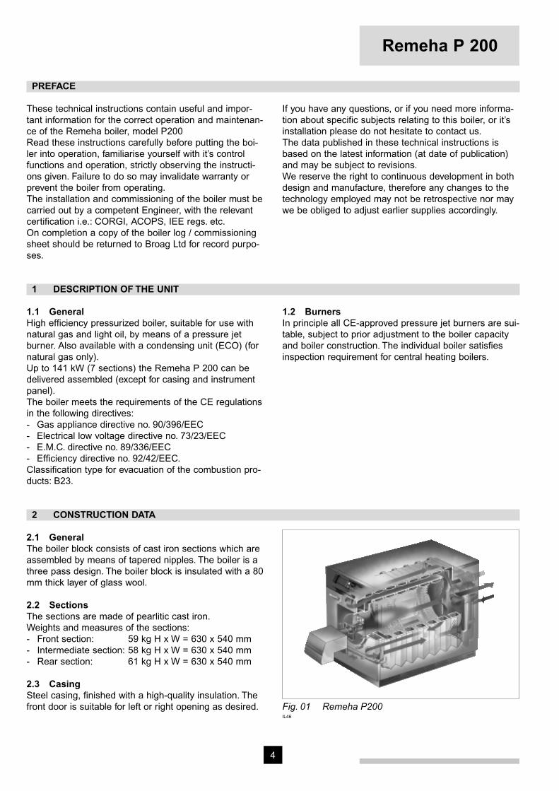
2.1 GeneralThe boiler block consists of cast iron sections which are assembled by means of tapered nipples. The boiler is a three pass design. The boiler block is insulated with a 80 mm thick layer of glass wool.
2.2 SectionsThe sections are made of pearlitic cast iron.Weights and measures of the sections:- Front section: 59 kg H x W = 630 x 540 mm- Intermediate section: 58 kg H x W = 630 x 540 mm - Rear section: 61 kg H x W = 630 x 540 mm
2.3 CasingSteel casing, finished with a high-quality insulation. The front door is suitable for left or right opening as desired. Fig. 01 Remeha P200
IL46
5
3 TECHNICAL DATA AND DIMENSIONS
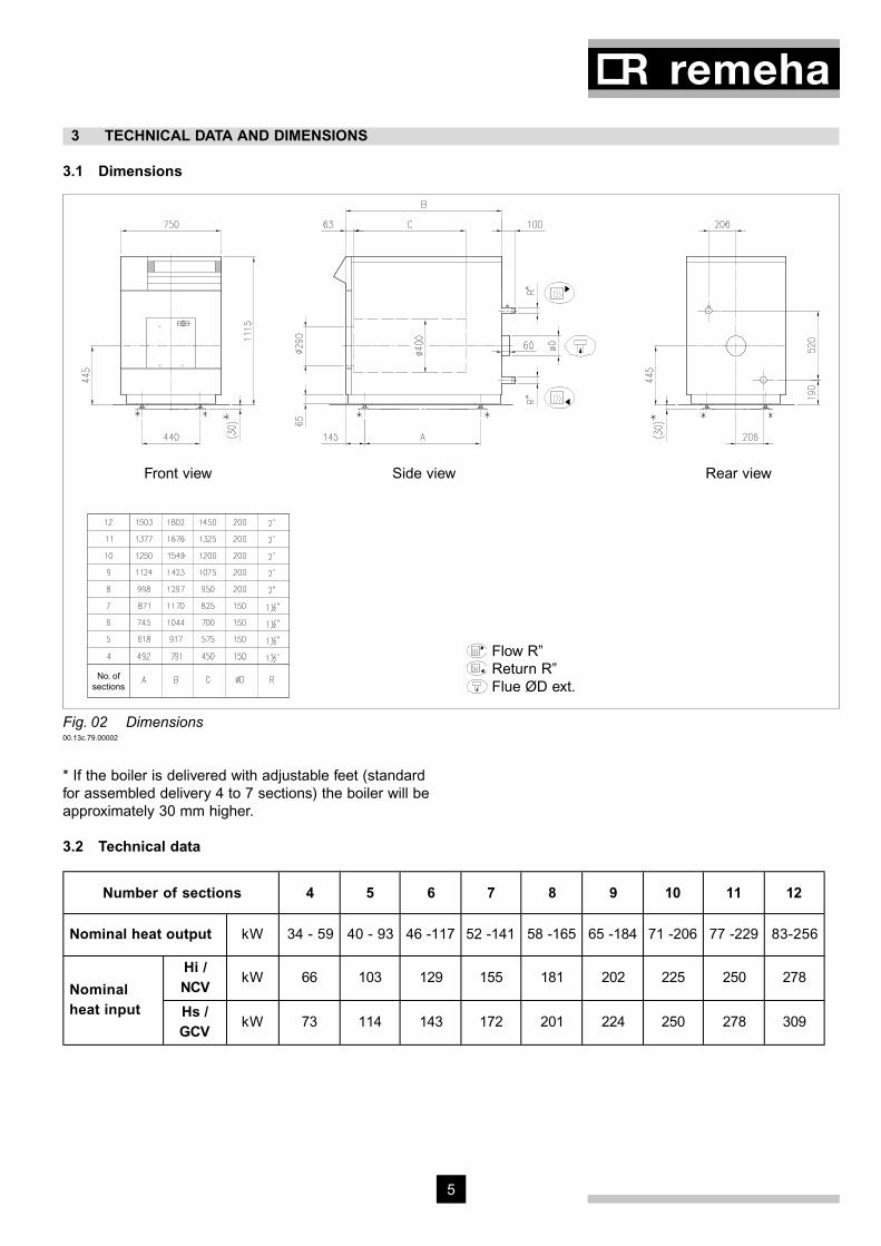
3.1 Dimensions
Front view Rear viewSide view
Flow R” Return R” Flue ØD ext.
No. ofsections
Fig. 02 Dimensions00.13c.79.00002
* If the boiler is delivered with adjustable feet (standard for assembled delivery 4 to 7 sections) the boiler will be approximately 30 mm higher.
3.2 Technical data
Number of sections 4 5 6 7 8 9 10 11 12
Nominal heat output kW 34 - 59 40 - 93 46 -117 52 -141 58 -165 65 -184 71 -206 77 -229 83-256
Hi /NCV
kW 66 103 129 155 181 202 225 250 278Nominalheat input Hs /
GCVkW 73 114 143 172 201 224 250 278 309

6
Remeha P 200
A mm 492 618 745 871 998 1124 1250 1377 1503
B mm 791 917 1044 1170 1297 1423 1549 1676 1802
C mm 450 575 700 825 950 1075 1200 1325 1450
ØD mm 150 150 150 150 200 200 200 200 200
Dimensions
R “ 1½" 1½" 1½" 1½" 2" 2" 2" 2" 2"
∆ t =
10°Cmbar 9 22 34 48 67 84 103 127 158
Waterresistance ∆ t =
20°Cmbar 2 5 8 12 17 21 26 32 39
Water contents litre 24 29 34 39 44 49 54 59 64
Boiler weight (dry) kg 365 425 485 545 605 665 725 775 835
Combustion chamberresistance1) mbar 0.1 0.3 0.6 1.0 1.2 1.6 1.4 1.8 2.1
Combustion gas side
contentm3 0.08 0.11 0.13 0.16 0.18 0.21 0.23 0.26 0.28
Flue gas flow rate kg/h 103 161 201 242 282 315 351 390 434
Table 01 Technical data1) Determined with 20 % excess air.
3.3 Quotation specifications- Heat exchanger manufactured from corrosion resi-
stant “pearlite” cast iron- Maximum operating pressure of 6 bar- Maximum operating temperature of 95°C- Sectional design with three passes for max efficiency
(gross 83%) and a generously sized combustion chamber for minimising NOx production
- Water cooled base and rear sections- Large insulated door (hinged left or right) allowing
easy access for service operations- Supplied in broken down form for ease of delivery and
site access
- Powder coated enamel steel casing- 80 - 100 mm thick glass wool insulation- Suitable for use with a Natural gas, and/or 35 sec oil
fired pressure jet burner (matched with most popular burner manufacturers)
- Supplied as standard with on/off switch, temperature indication, control and high limit thermostats
- Efficiency 83% (Hs - GCV)- Manufactured to ISO 9001- CE approved.
4 OUTPUT DATA
4.1 Boiler efficiencyUp to 91.7 % at Hi (82.6 % at Hs) at full load and up to 93.2 % at Hi (84.0 % at Hs) at part load.Average water temperature 70°C (80/60°C).
4.2 Combustion efficiencyUp to 93.0 % at Hi (83.8 % at Hs) at full load and up to 95.5 % at Hi (86.0 % at Hs) at part load.
Note: Hi = NCV ; Hs = GCV
7
5 APPLICATION DATA
5.1 L.P.H.W. version
5.1.1 Water temperatureMaximum water temperature is 110°C.The minimum acceptable return water temperature is, for gas fired boilers 45°C and for oil fired boilers 40°C, at aflow rate corresponding to a ∆t of 20°C at nominal heat output.
5.1.2 Water pressureMaximum pressure 6 bar.The boiler is suitable for open and sealed systems up to a maximum pressure of 6 bar and a minimum pres-sure of 0.8 bar. The boiler is suitable for installation in basement or rooftop boiler houses.
5.1.3 Flow rateThe minimum flow rate through the boiler is obtained from the following formula:
nominal heat output (kW) = m3/h70
This minimum flow must be maintained for 5 minutes after the burner stops firing to avoid high temperature shut-down due to residual heat gain. Due to the design and manufacture of the boiler no specific minimum water flow requirement exists other than for over-temperature protection.
5.1.4 Water treatmentThe system should be filled with mains cold water (for the UK this will usually have a pH of between 7 and 8).Pressurised installations with a boiler/system content ratio of 1:10 or less should not require water treatment, provided that the following conditions apply:1. The system is flushed thoroughly to remove all fluxes
and debris and then filled completely once.2. Make up water is limited to 5 % per annum.3. The hardness of the water does not exceed 360 ppm
(20°D). All scale deposits will reduce the efficiency of the boiler and should be prevented. However provided the above is complied with any scale produced will not be too detrimental to the boiler efficiency and will not reduce the anticipated life expectancy of the boiler.
NOTE: Scale deposits in excess of 3 to 5 mm will reduce boiler efficiency and greatly increase the risk of premature casting failure.
As most systems contain a variety of metals which can react with each other to cause corrosion. It is con-sidered good practice to provide some form of water treatment (especially in open vented systems) in order to prevent or reduce the following:- Metallic corrosion;- Formation of scale and sludge;- Microbiological contamination;- Chemical changes in the untreated system water.
Suitable chemicals and their use should be discussed with a specialist water treatment company prior to car-rying out any work. The specification of the system and manufacturers recommendations must be taken into account, along with the age and condition of the system. New systems should be flushed thoroughly to remove all traces of flux, debris, grease and metal swarf generated during installation. Care to be taken with old systems to ensure any black metallic iron oxide sludge and other corrosive residues are removed, again by thoroughly flushing, ensuring that the system is drained completely from all low points.
NOTE: Please ensure that the new boiler plant is not in circuit when the flushing takes place, especially if cleansing chemicals are used to assist the process.
Under no circumstances is the boiler to be operated with cleaning chemicals in the system.
To summarise:- Minimise water loss;- Prevent pumping over in open vented systems;- Provide adequate air venting at all high points;- Keep pH level between 7 - 9 when using additives;- Maximum chlorine content of 200 mg/l;- Take advice on the suitability of inhibitors.
5.2 EconomisersECO’s can be delivered upon request (for natural gas only).
5.3 Flue gas dischargeFor the discharge of the flue gases, chimney draught is not required.Tests have shown that very good combustion results are obtained with zero draught at the boiler outlet.
8
Remeha P 200
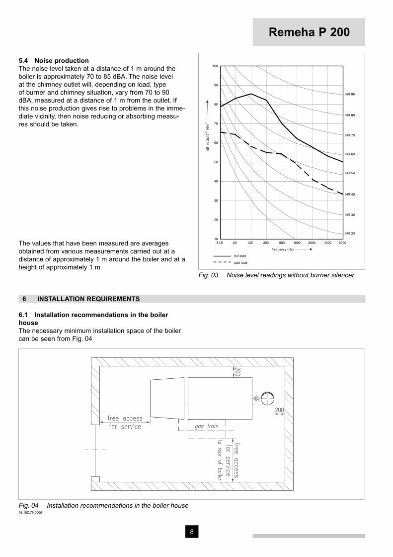
5.4 Noise productionThe noise level taken at a distance of 1 m around the boiler is approximately 70 to 85 dBA. The noise level at the chimney outlet will, depending on load, type of burner and chimney situation, vary from 70 to 90 dBA, measured at a distance of 1 m from the outlet. If this noise production gives rise to problems in the imme-diate vicinity, then noise reducing or absorbing measu-res should be taken.9
10
20
30
40
50
60
70
80
90
100
31,5 63 125 250 500 1000 2000 4000 8000
NR 20
NR 30
NR 40
NR 50
NR 60
NR 70
NR 80
NR 90
frequency (Hz)
dB r
e 2x
10-5
N/m
2
full load
part load
Fig. 03 Noise level readings without burner silencer
The values that have been measured are averages obtained from various measurements carried out at a distance of approximately 1 m around the boiler and at a height of approximately 1 m.
6 INSTALLATION REQUIREMENTS
6.1 Installation recommendations in the boiler houseThe necessary minimum installation space of the boiler can be seen from Fig. 04
Fig. 04 Installation recommendations in the boiler house04.15D.79.00001
9
7 ASSEMBLY GUIDELINES AND INSTALLATION REQUIREMENTS
7.1 GeneralThe Remeha boilers P 200 - 4 to 7 sections can be delivered in individual parts or assembled. The Remeha boilers P 200 - 8 to 12 sections are delive-red in individual parts.
7.2 Water connectionsThe water connections are at the rear of the boiler.The flow and return connections consist of threaded male connections:- 4 - 7 sections 1 ½” BSP- 8 - 12 sections 2” BSPFlange connections in accordance with DIN 2633 can be delivered on request (Ø 70 mm ID). The return con-nection is provided with a G ¾” threaded hole in which a drain off cock is fitted.At the front of the boiler a flange is provided with 3 x G ½” threaded holes for the fitting of the thermostatpockets.
7.3 Delivery in individual parts
7.3.1 GeneralThe sizes of the boiler parts are such that they all can enter the boiler house through a normal entrance.The casing and equipment parts are delivered in pac-kaged units. If necessary, the boiler can be put into operation without casing. The casing can be added at a later stage without dismantling the water connections.On request the boiler can be delivered with adjustable boiler feet (standard for assembled delivery 4 to 7 secti-ons).
7.3.2 Boiler assemblyAssembly and installation of a boiler delivered in indivi-dual parts should only be undertaken by a recognized and approved engineer and in accordance with the assembly manual. Local regulations laid down by the relevant authorites must be adhered to.
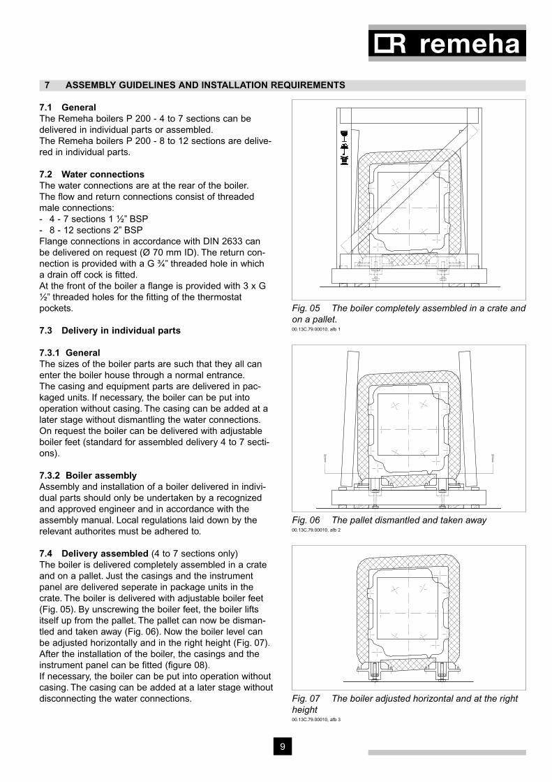
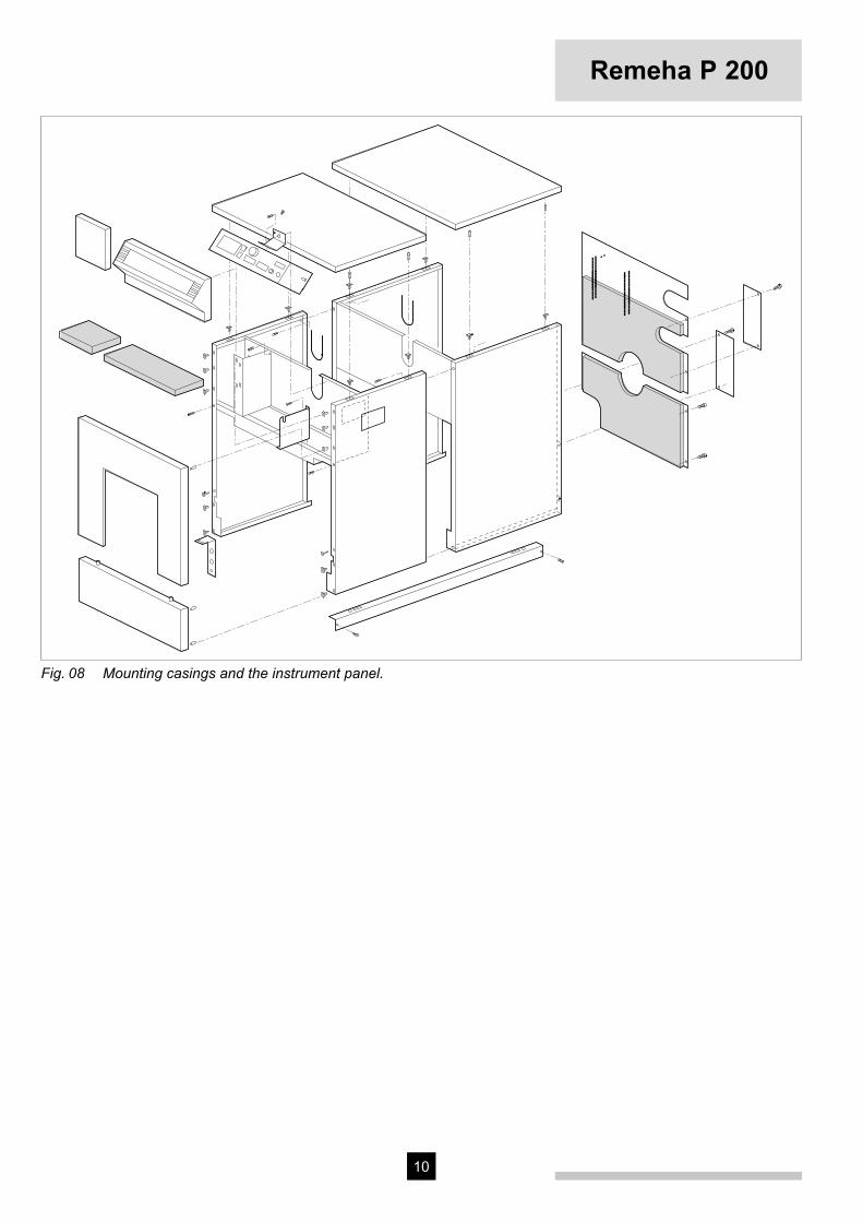
7.4 Delivery assembled (4 to 7 sections only)The boiler is delivered completely assembled in a crate and on a pallet. Just the casings and the instrument panel are delivered seperate in package units in the crate. The boiler is delivered with adjustable boiler feet (Fig. 05). By unscrewing the boiler feet, the boiler lifts itself up from the pallet. The pallet can now be disman-tled and taken away (Fig. 06). Now the boiler level can be adjusted horizontally and in the right height (Fig. 07). After the installation of the boiler, the casings and the instrument panel can be fitted (figure 08).If necessary, the boiler can be put into operation without casing. The casing can be added at a later stage withoutdisconnecting the water connections.
Fig. 05 The boiler completely assembled in a crate and on a pallet.00.13C.79.00010, afb 1
Fig. 06 The pallet dismantled and taken away00.13C.79.00010, afb 2
Fig. 07 The boiler adjusted horizontal and at the right height 00.13C.79.00010, afb 3
10
Remeha P 200
Fig. 08 Mounting casings and the instrument panel.
11
8 INSTRUMENT PANELS
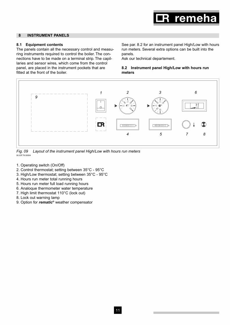
8.1 Equipment contentsThe panels contain all the necessary control and measu-ring instruments required to control the boiler. The con-nections have to be made on a terminal strip. The capil-laries and sensor wires, which come from the control panel, are placed in the instrument pockets that are fitted at the front of the boiler.
See par. 8.2 for an instrument panel High/Low with hours run meters. Several extra options can be built into the panels.Ask our technical departement.
8.2 Instrument panel High/Low with hours run meters
Fig. 09 Layout of the instrument panel High/Low with hours run meters00.03F.79.00004
1. Operating switch (On/Off)2. Control thermostat; setting between 35°C - 95°C3. High/Low thermostat; setting between 35°C - 95°C4. Hours run meter total running hours5. Hours run meter full load running hours6. Analoque thermometer water temperature7. High limit thermostat 110°C (lock out)8. Lock out warning lamp 9. Option for rematic® weather compensator
1 2 3 6
4 5 7 8
9

12
Remeha P 200
8.3 Wiring diagram instrument panel High/Low with hours run meters 1
3
1.) E
xternal control.
rem
ove link; insert control pair (230 V)
2.) E
xternal control High/Low
.
rem
ove link; insert control pair (230 V).1
Fig. 10 Wiring diagram instrument panel High/Low with hours run meters

13
9 COMMISSIONING
Note:Commissioning to only be carried out by a qualified engineer with the relevant training and certification i.e. Acops-Corgi and a commissioning data sheet completed on site for issue to owner.
9.1 Pressurized boiler with gas burner
9.1.1 Commissioning procedureIf the boiler is to be put into operation again following a period of non-use, then the following procedure must be carried out :- Open the main gas cock.- Switch the weather-compensator (if fitted) over to
manual operation (h).- Turn the thermostats to their highest setting.- Switch on the circulation pump.- Switch on the main switch.- Switch on the operation switch in the instrument
panel.- Consult burner manufacturers commissioning details.
WarningIf the instrument panel is fitted with a weather compen-sator, set the programm switch to ‘manual’ position (h). The following will now take place:- The gas burner fan will start running so that during
the purging time the combustion chamber will be ven-tilated with the air damper fully opened.
- The air damper will then go into start position. - Ignition flame lights up and is checked. - Then the control box gives the all clear signal for the
burner to switch over to full load.
9.1.2 Putting out of operationIt is sufficient to switch off the operation switch on the instrument panel. It is important that in the event of work being carried out on the burner, the boiler/burner unit must be completely electricaly isolated and the main gas cock must be shut.
9.2 Pressurized boiler with oil burner
9.2.1 Commissioning procedureIf the boiler is to be put into operation again following a period of non-use, then the following procedure must be carried out :- Open the main oil cock.- Switch the weather-compensator (if fitted) over to
manual operation ( h).- Turn the thermostat to their highest setting.- Switch on the circulation pump.- Switch on the main switch.- Switch on the operation switch in the instrument
panel.- Consult burner manufacturer commissioning details.
WarningIf the instrument panel is fitted with a weather compen-sator, set the programm switch to ‘manual’ position (h). The following will now take place:- The oil burner fan will start running so that during the
purging time the combustion chamber will be ventila-ted with the air damper fully opened.
- The air damper will then go into start position.- Ignition flame lights up and is checked.- Then the control box gives the all clear signal for the
burner to switch over to full load.
9.2.2 Putting out of operationIt is sufficient to switch off the operation switch on the instrument panel. It is important that in the event of work being carried out on the burner, the boiler/burner unit must be completely electricaly isolated and the main oil cock must be shut.
10 FAULT FINDING
High Limit thermostat lock out:- Check the water circulation (circulation pump). Reset
the High Limit thermostat (Reset button is on the instrument panel under the cover cap of the High Limit thermostat).
- Advise the installer in the event of continued lock outs.
14
Remeha P 200
11 MAINTENANCE RECOMMENDATIONS
11.1 GeneralDepending on the operational conditions, the block and the burner must be checked and cleaned at least once a year for gas and at least twice a year for oil.
11.2 Maintenance instructionsCleaning of the boiler:- Put boiler out of operation.- Open the front door, if necessary after dismantling the
burner.- Remove the retarders (only for the 4 - 9 sections).- Clean the combustion chamber and flue passes using
a suitable brush.- Clean the removed retarders (4 - 9 sections).- Remove the rear panel of the boiler and remove the
cleaning cover (underneath the smoke box).- Vacuum clean the boiler and the combustion cham-
ber.- Renew the front door seals after cleaning the boiler.- Re-assemble the removed parts and close the front
door.- Re-assemble the burner (if dismantled).- Check the boiler combustion side for leakage.- Check the equipment for proper functioning and if
necessary re-adjust the control and safety equipment.- Carry out combustion analysis.- Check the water connections.

16
© Copyright
All technical and technological infor-mation contained in these technical instructions,
as well as any drawings and technical descriptions furnished by us remain our property
and shall not be copied in part or whole without our prior consent in writing.
Subject to alterations52988/1000/0202/Ips.
Broag Ltd.
Head office
Remeha house
Molly Millars Lane
Wokingham,
Berkshire RG41 2QP
Tel.: 0118 978 3434
Fax: 0118 978 6977
E-mail address:
Branch office
Unit 3, Kestrel Close,
Quarry Hill ind. Estate,
Ilkeston
Derbyshire DE7 4RD
Tel.: 0115 944 0778
Fax: 0115 944 0588
Re
me
ha
P
20
0

Remeha P 300
• Pressurized boiler
• Heat output: 278 - 709 kW
Technical Information
Re
me
ha
P
3
00
Remeha P 300
2 3
CONTENTS
Preface 3
1 Description of the unit 3 1.1 General 3 1.2 Burners 3
2 Construction data 3 2.1 General 3 2.2 Sections 3 2.3 Casing 3
3 Technical data and dimensions 4 3.1 Dimensions 4 3.2 Technical data 5 3.3 Quotation specifications 5
4 Output data 5 4.1 Boiler efficiency 5 4.2 Combustion efficiency 5
5 Application data 6 5.1 Hot water version 6 5.1.1 Water temperature 6 5.1.2 Water pressure 6 5.1.3 Flow rate 6 5.1.4 Water treatment 6 5.2 Economisers 6 5.3 Flue gas discharge 6 5.4 Noise production 7
6 Installation requirements 7 6.1 Installation recommendations in the boiler house 7 6.2 Base details 7
7 Assembly guidelines and installation requirements 8 7.1 General 8 7.2 Boiler assembly 8 7.3 Water connections 8
8 Instrument panel 8 8.1 Equipment contents 8 8.2 Lay out of the instrument panel 8 8.3 Wiring diagram instrument panel 9
9 Commissioning 10 9.1 Pressurized boiler with gas burner 10 9.1.1 Commissioning procedure 10 9.1.2 Putting out of operation 10 9.2 Pressurized boiler with oil burner 10 9.2.1 Commissioning procedure 10 9.2.2 Putting out of operation 10
10 Fault finding 11 10.1 High Limit thermostat lockout 11
11 Maintenance recommendations 11 11.1 General 11 11.2 Maintenance instructions 11
Remeha P 300
2 3
1 DESCRIPTION OF THE UNIT
2 CONSTRUCTION DATA
PREFACE
These technical instructions contain useful and impor-tant information for the correct operation and mainte-nance of the Remeha boiler, model P 300.Read these instructions carefully before putting the boiler into operation; familiarise yourself with its control functions and operation, strictly observing the instruc-tions given. Failure to do so may invalidate warranty or prevent the boiler from operating.A competent Engineer, with the relevant certification (i.e. CORGI, ACOPS, IEE regs. etc) must carry out the installation and commissioning of the boiler.On completion a copy of the boiler log / commissioning
sheet should be returned to Broag Ltd for record pur-poses.If you have any questions, or if you need more informa-tion about specific subjects relating to this boiler, or it's installation please do not hesitate to contact us.The data published in these technical instructions is based on the latest information (at date of publication) and may be subject to revisions.We reserve the right to continuous development in both design and manufacture, therefore any changes to the technology employed may not be retrospective nor may we be obliged to adjust earlier supplies accordingly.
1.1 GeneralHigh efficiency pressurised boiler, suitable for use with natural gas and light oil, by means of a pressure jet bur-ner. Also available with a condensing unit (ECO) (for natural gas only).The boiler meets the requirements of the CE regulations in the following directives:- Gas appliance directive no. 90/396/EEC- Electrical low voltage directive no. 73/23/EEC- E.M.C. directive no. 89/336/EEC- Efficiency directive no. 92/42/EEC.Classification type for evacuation of the combustion pro-ducts: B23.
1.2 BurnersIn principle all pressure jet burners are suitable, subject to prior adjustment to the boiler capacity and boiler con-struction.The individual boiler satisfies inspection requirement for central heating boilers.
2.1 GeneralThe boiler block consists of cast iron sections which are assembled by means of tapered nipples. The boiler is designed on the basis of the triple pass principle. The boiler block is insulated with a 100 mm thick layer of glass wool.
2.2 SectionsThe sections are made of pearlitic cast iron. Weights and measures of the sections:
Section Measures
(H x W) mm
Weights
kg
Front 1026 x 630 93
Intermediate 1026 x 640 106
Rear 1026 x 630 114
2.3 CasingSteel casing, finished with a high quality insulation. The front door is suitable for left or right opening as desired.4
Remeha P 300
4 5
3 TECHNICAL DATA AND DIMENSIONS
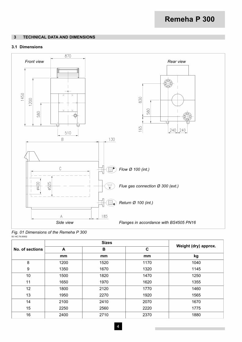
3.1 Dimensions
Fig. 01 Dimensions of the Remeha P 30000.14C.79.00002
Rear view Front view
Sizes
A B CWeight (dry) approx.
No. of sections
mm mm mm kg
8
9
1200
1350
1520
1670
1170
1320
1040
1145
10
11
1500
1650
1820
1970
1470
1620
1250
1355
12
13
1800
1950
2120
2270
1770
1920
1460
1565
14
15
2100
2250
2410
2560
2070
2220
1670
1775
16 2400 2710 2370 1880
Flow Ø 100 (int.)
Flue gas connection Ø 300 (ext.)
Return Ø 100 (int.)
Flanges in accordance with BS4505 PN16Side view

Remeha P 300
4 5
3.2 Technical data
* Determined with 20% excess air** G20 (NGA) = 34,0 MJ/m3 NCV
3.3 Quotation specifications- Heat exchanger manufactured from corrosion resi-
stant "pearlite" cast iron- Maximum operating pressure of 6 bar- Maximum operating temperature of 95°C- Sectional design with three passes for max efficiency
and a generously sized combustion chamber for mini-mising NOX production
- Water cooled base and rear sections- Large insulated door (hinged left or right) allowing
easy access for service operations- Supplied in broken down form for ease of delivery
and site access- Powder coated enamel steel casing- 80 - 100 mm thick glass wool insulation- Suitable for use with a Natural gas, and/or 35 sec oil
fired pressure jet burner (matched with most popular burner manufacturers)
- Supplied as standard with on/off switch, temperature indication, control and high limit thermostats
- Manufactured to ISO 9001- CE approved.
4 OUTPUT DATA54.1 Boiler efficiencyUp to 82.2% at Hs (91.3% at Hi) at full load and upto 87.0% at Hs (96.7% at Hi), at part load.Average water temperature 70°C (80/60°C).
4.2 Combustion efficiencyUp to 82.6% at Hs (91.8% at Hi) at full load and 88.1% at Hs (97.9% at Hi) at part load.
Note: Hi = NCV; Hs = GCV
WaterresistanceOutput Nominal heatinput
Combustionchamber
resistance*
Combustiongas sidecontents
Gasrate** T=20°C T=10°C
Watercontents
Fluegasflowrate
No. ofsections
kW kW-GCV
kW-NCV
mbar m3 m3/h mbar mbar liters kg/h
8
9
106 - 278
128 - 331
345
410
311
369
1.1
1.4
0.43
0.48
33
39
11
14
45
56
146
163
485
576
10
11
149 - 383
170 - 437
473
538
425
484
1.9
2.4
0.53
0.58
45
51
18
22
72
88
180
197
663
756
12
13
192 - 491
210 - 543
603
665
542
598
3.4
4.0
0.63
0.68
57
63
27
34
108
136
214
231
846
933
14
15
233 - 596
255 - 651
728
794
655
714
4.5
4.8
0.73
0.78
69
76
42
50
168
200
248
265
1022
1115
16 278 - 709 862 775 5.0 0.83 82 57 228 282 1210
Remeha P 300
6 7
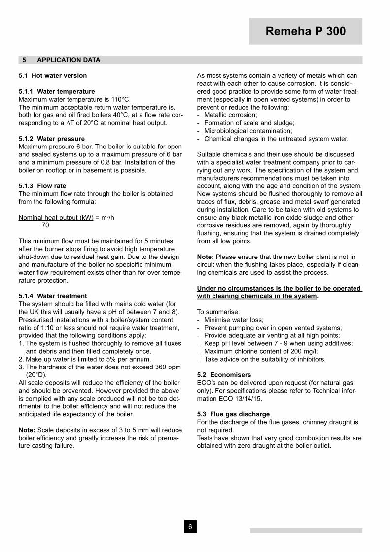
5 APPLICATION DATA
5.1 Hot water version
5.1.1 Water temperatureMaximum water temperature is 110°C.The minimum acceptable return water temperature is, both for gas and oil fired boilers 40°C, at a flow rate cor-responding to a ∆T of 20°C at nominal heat output.
5.1.2 Water pressureMaximum pressure 6 bar. The boiler is suitable for open and sealed systems up to a maximum pressure of 6 bar and a minimum pressure of 0.8 bar. Installation of the boiler on rooftop or in basement is possible.
5.1.3 Flow rateThe minimum flow rate through the boiler is obtained from the following formula:
Nominal heat output (kW) = m3/h70
This minimum flow must be maintained for 5 minutes after the burner stops firing to avoid high temperature shut-down due to residuel heat gain. Due to the design and manufacture of the boiler no specicific minimum water flow requirement exists other than for over tempe-rature protection.
5.1.4 Water treatmentThe system should be filled with mains cold water (for the UK this will usually have a pH of between 7 and 8).Pressurised installations with a boiler/system content ratio of 1:10 or less should not require water treatment, provided that the following conditions apply:1. The system is flushed thoroughly to remove all fluxes
and debris and then filled completely once.2. Make up water is limited to 5% per annum.3. The hardness of the water does not exceed 360 ppm
(20°D). All scale deposits will reduce the efficiency of the boiler and should be prevented. However provided the above is complied with any scale produced will not be too det-rimental to the boiler efficiency and will not reduce the anticipated life expectancy of the boiler.
Note: Scale deposits in excess of 3 to 5 mm will reduce boiler efficiency and greatly increase the risk of prema-ture casting failure.
As most systems contain a variety of metals which can react with each other to cause corrosion. It is consid-ered good practice to provide some form of water treat-ment (especially in open vented systems) in order to prevent or reduce the following:- Metallic corrosion;- Formation of scale and sludge;- Microbiological contamination;- Chemical changes in the untreated system water.
Suitable chemicals and their use should be discussed with a specialist water treatment company prior to car-rying out any work. The specification of the system and manufacturers recommendations must be taken into account, along with the age and condition of the system. New systems should be flushed thoroughly to remove all traces of flux, debris, grease and metal swarf generated during installation. Care to be taken with old systems to ensure any black metallic iron oxide sludge and other corrosive residues are removed, again by thoroughly flushing, ensuring that the system is drained completely from all low points.
Note: Please ensure that the new boiler plant is not in circuit when the flushing takes place, especially if clean-ing chemicals are used to assist the process.
Under no circumstances is the boiler to be operated with cleaning chemicals in the system.
To summarise:- Minimise water loss;- Prevent pumping over in open vented systems;- Provide adequate air venting at all high points;- Keep pH level between 7 - 9 when using additives;- Maximum chlorine content of 200 mg/l;- Take advice on the suitability of inhibitors.
5.2 EconomisersECO's can be delivered upon request (for natural gas only). For specifications please refer to Technical infor-mation ECO 13/14/15.
5.3 Flue gas dischargeFor the discharge of the flue gases, chimney draught is not required.Tests have shown that very good combustion results are obtained with zero draught at the boiler outlet.
Remeha P 300
6 7
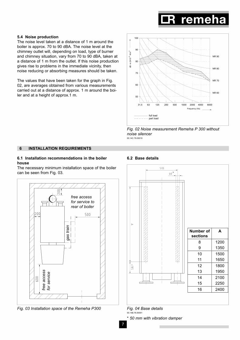
5.4 Noise productionThe noise level taken at a distance of 1 m around the boiler is approx. 70 to 90 dBA. The noise level at the chimney outlet will, depending on load, type of burner and chimney situation, vary from 70 to 90 dBA, taken at a distance of 1 m from the outlet. If this noise production gives rise to problems in the immediate vicinity, then noise reducing or absorbing measures should be taken.
(zonder geluiddempkap)
Remeha P300 met Monarch-brander
800025031,5
part load
125
full load
63 500 1000 40002000
50
60
70
80
90
100
NR 60
NR 70
NR 80
NR 90
dBre2X10
N/m
-52
Frequency (Hz)
Fig. 02 Noise measurement Remeha P 300 without noise silencer00.14C.79.00010
The values that have been taken for the graph in Fig. 02, are averages obtained from various measurements carried out at a distance of approx. 1 m around the boi-ler and at a height of approx.1 m.
6 INSTALLATION REQUIREMENTS
6.1 Installation recommendations in the boiler houseThe necessary minimum installation space of the boiler can be seen from Fig. 03.
6.2 Base details
Fig. 04 Base details00.14B.78.00001
Fig. 03 Installation space of the Remeha P300
* 50 mm with vibration damper
gas
train
free accessfor service to rear of boiler
fre
e a
ccess
for
serv
ice
Number of sections
A
89
12001350
1011
15001650
1213
18001950
1415
21002250
16 2400
Remeha P 300
8 9
7 ASSEMBLY GUIDELINES AND INSTALLATION REQUIREMENTS
7.1 GeneralThe Remeha P 300 boiler is delivered in individual sec-tions. The sizes are such that all parts can enter the boi-ler house through a normal door entrance. The casing and equipment parts are delivered in packaged units. If necessary, the boiler can be put into operation without casing. The casing can be added at a later stage wit-hout disconnecting the water connections.
7.2 Boiler assemblyAssembly and installation of the boiler may only be car-ried out by a recognised and approved engineer and in accordance with the assembly manual. Local regulations laid down by the relevant authorities must be adhered to.
7.3 Water connectionsThe water connections are at the rear of the boiler. The flow and return connections consist of flanged connec-tions in accordance with DIN 2633. The top flange at the front of the boiler is provided with 3 x R 1⁄2” threaded holes for the fitting of the thermostat pockets. The return connection is provided with a R 3⁄4” threaded hole in which a drain off cock is fitted.
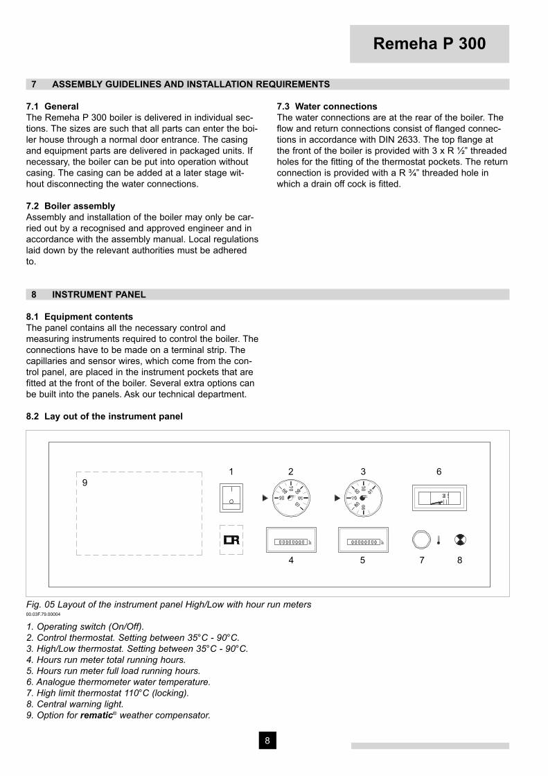
8 INSTRUMENT PANEL
8.1 Equipment contentsThe panel contains all the necessary control and measuring instruments required to control the boiler. The connections have to be made on a terminal strip. The capillaries and sensor wires, which come from the con-trol panel, are placed in the instrument pockets that are fitted at the front of the boiler. Several extra options can be built into the panels. Ask our technical department.
8.2 Lay out of the instrument panel
Fig. 05 Layout of the instrument panel High/Low with hour run meters00.03F.79.00004
1. Operating switch (On/Off).2. Control thermostat. Setting between 35°C - 90°C.3. High/Low thermostat. Setting between 35°C - 90°C.4. Hours run meter total running hours.5. Hours run meter full load running hours.6. Analogue thermometer water temperature.7. High limit thermostat 110°C (locking).8. Central warning light.9. Option for rematic® weather compensator.9
9
7 85
62 3
4
1
Remeha P 300
8 9
8.3 Wiring diagram instrument panel
Fig. 06 Wiring diagram instrument panel04.13C.SC.00004
1
4B
S5
4-9
3435
TR
1CT
1-2
1-3
230V
-50H
z
L
F2 6,3A
T
F1
6,3A
T
1
BS
T
3
4-4
2 41
4-2
32
11 1210
2-1
2-2
9-1
7-4
6-2
7-3
96-
3
9-4
4-1
(CA
)36
Tm
x1
2
37L1
T1
N
1412
A1
A2
1.)
P1
21
h
26H
2.)
3-2K
1k1
11
29P2
T1 C
24 25
2-3
4-8
1.)
14 13
2019
2-4
18
16 1517
9-6
9-11
BM
TR
2
9-8
3-1
3-4
2.)
3-3
3-5
2322
9-17
9-18
9-16
B4
T2
S3
T7 bl
T6
T8
br
28274-
7
BM
9-15B5
9-2
9-13
9-10
Pow
er s
uppl
y
Con
nect
or b
urne
r lo
w
ye/g
nbk
6bk
5bk
1
Ext
erna
l sig
nal o
n-of
fE
xter
nal s
igna
l hig
h-lo
w
low
bk4
bk2
bk3
Con
nect
or b
urne
r hi
gh
bk2
high
bk1
5-4
5-5
DS
FBM
BS
CA
..Tm
xT
R
H K P
Ope
ratin
g si
gnal
s (V
olt f
ree)
Wat
er le
vel s
witc
hG
ener
al w
arni
ng s
igna
lsB
urne
r sw
itch
Will
not
be
supp
lied
(opt
iona
l)C
onne
ctor
Fus
e
Dis
turb
ance
ligh
t bur
ner
lock
edA
uxila
iry r
elay
Hou
r ru
n co
unte
rH
igh
limit
ther
mos
tat
Cor
d co
lor/
num
ber
Con
trol
ther
mos
tat
DS T 2
3
1
1-1
N
CA
3
CA
1
L1 N
Ter
min
al s
trip
04.1
3C.S
C.0
0004
.
*
h
*O
ptio
nal
CA
4-5
CA
4
1.)
Ext
ern
al C
ontr
ol O
N/O
FF
Rem
ove
link;
inse
rt c
ontr
ol p
air (
230
V)
* O
ptio
nal
2.)
Ext
ern
al c
ontr
ol H
/L
Rem
ove
link;
inse
rt c
ontr
ol p
air (
230V
)

Remeha P 300
10 11
9 COMMISSIONING
Note: Commissioning to only be carried out by a quali-fied engineer with the relevant training and certification i.e. Acops - Corgi and a commissioning data sheet com-pleted on site for issue to owner
9.1 Pressurized boiler with gas burner
9.1.1 Commissioning procedureIf the boiler is to be put into operation again following a period of non-use, then the following procedure must be carried out:- Open the main gas cock.- Switch the weather-compensator (if fitted) over to
manual operation (h).- Turn the thermostats to their highest setting.- Switch on the circulation pump.- Switch on the main switch.- Switch on the operation switch in the instrument
panel.- Consult burner manufacturers commissioning details.
Warning:If the instrument panel is fitted with a weather compen-sator, set the program switch to ‘manual’ position (h). The following will now take place:- The gas burner fan will start running so that during
the purging time the combustion chamber will be ven-tilated with the air damper fully opened.
- The air damper will then go into start position. - Ignition flame lights up and is checked. - Then the control box gives the all clear signal for the
burner to switch over to full load.
9.1.2 Putting out of operationIt is sufficient to switch off the operation switch on the instrument panel. It is important that in the event of work being carried out on the burner, the boiler/burner unit must be completely electrically isolated and the main gas cock must be shut.5
9.2 Pressurized boiler with oil burner
9.2.1 Commissioning procedureIf the boiler is to be put into operation again following a period of non-use, then the following procedure must be carried out:- Open the main oil cock.- Switch the weather-compensator (if fitted) over to
manual operation (h).- Turn the thermostat to their highest setting.- Switch on the circulation pump.- Switch on the main switch.- Switch on the operation switch in the instrument
panel.- Consult burner manufacturer commissioning details.
Warning:If the instrument panel is fitted with a weather compen-sator, set the program switch to ‘manual’ position (h). The following will now take place:- The oil burner fan will start running so that during the
purging time the combustion chamber will be ventila-ted with the air damper fully opened.
- The air damper will then go into start position.- Ignition flame lights up and is checked.- Then the control box gives the all clear signal for the
burner to switch over to full load.
9.2.2 Putting out of operationIt is sufficient to switch off the operation switch on the instrument panel. It is important that in the event of work being carried out on the burner, the boiler/burner unit must be completely electrically isolated and the main oil cock must be shut.
Remeha P 300
10 11
10 FAULT FINDING11Faul10.1 High Limit thermostat lockout- Check the water circulation (circulation pump). Reset
the High Limit thermostat (‘reset’ button is on the instrument panel under the cover cap of the High Limit thermostat).
- Advise the installer in the event of continued lock outs.
11 MAINTENANCE RECOMMENDATIONS
11.1 GeneralDepending on the operating conditions, the block and the burner must be checked and cleaned one or more times a year.
11.2 Maintenance instructions- Cleaning of the boiler: - Put boiler out of operation. - Open the front door, if necessary after dismantling the burner. - Remove the retarders. - Clean the combustion chamber and flue passes using a suitable brush. - Clean the removed retarders. - Remove the rear panel of the boiler and
remove the cleaning cover (underneath the smoke box).
- Vacuum clean the boiler and the combustion chamber.
- Renew the front door seals after cleaning the boiler.
- Re-assemble the removed parts and close the front door.
- Re-assemble the burner (if dismanteld).- Check the boiler combustion side for leakage.- Check the equipment for proper functioning and if
necessary re-adjust the gas control and safety equipment.
- Check combustion by means of combustion gas analyses.
- Check the water connections.

12
Re
me
ha
P
3
00
© CopyrightAll technical and technological information contained in these technical instructions,as well as any drawings and technical descriptions supplied, remain ourproperty and shall not be multiplied without our prior consent in writing.
Ours is a policy of continuous development. We reserve the right to alterspecifications without prior notification.
Subject to alterations52754/1000/0402/Ip.
Broag Ltd.
Head office
Remeha house,
Molly Millars Lane,
Wokingham,
Berkshire RG41 2QP.
Tel. 0118 9783434
Fax 0118 9786977
E-mail: [email protected]
Internet: uk.remeha.com
Branch office
Unit 3, Kestrel Close,
Quarry Hill Ind. Estate,
Ilkeston
Derbyshire DE7 4RD
Tel. 0115 9440778
Fax 0115 9440588

Remeha P 500
• Pressurized boiler
• Heat output: 635 - 1900 kW
Technical information
Re
me
ha
P
50
0
Remeha P 500
2
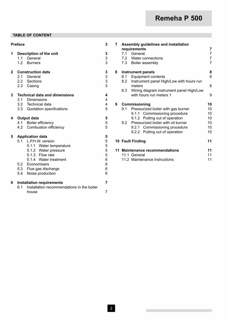
Preface 3
1 Description of the unit 31.1 General 31.2 Burners 3
2 Construction data 32.1 General 32.2 Sections 32.3 Casing 3
3 Technical data and dimensions 43.1 Dimensions 43.2 Technical data 43.3 Quotation specifi cations 5
4 Output data 54.1 Boiler effi ciency 54.2 Combustion effi ciency 5
5 Application data 55.1 L.P.H.W. version 5
5.1.1 Water temperature 55.1.2 Water pressure 55.1.3 Flow rate 55.1.4 Water treatment 6
5.2 Economisers 65.3 Flue gas discharge 65.4 Noise production 6
6 Installation requirements 76.1 Installation recommendations in the boiler house 7
7 Assembly guidelines and installation requirements 7
7.1 General 77.2 Water connections 77.3 Boiler assembly 7
8 Instrument panels 88.1 Equipment contents 88.2 Instrument panel High/Low with hours run meters 88.3 Wiring diagram instrument panel High/Low with hours run meters 1 9
9 Commissioning 109.1 Pressurized boiler with gas burner 10
9.1.1 Commissioning procedure 109.1.2 Putting out of operation 10
9.2 Pressurized boiler with oil burner 109.2.1 Commissioning procedure 109.2.2 Putting out of operation 10
10 Fault Finding 11
11 Maintenance recommendations 1111.1 General 1111.2 Maintenance instructions 11
TABLE OF CONTENT

3
PREFACE
These technical instructions contain useful and impor-tant information for the correct operation and maintenan-ce of the Remeha boiler, model P200Read these instructions carefully before putting the boi-ler into operation; familiarise yourself with its control functions and operation, strictly observing the instructi-ons given. Failure to do so may invalidate warranty or prevent the boiler from operating.A competent Engineer, with the relevant certifi cation (i.e. CORGI, ACOPS, IEE regs. etc) must carry out the instal-lation and commissioning of the boiler.On completion a copy of the boiler log / commissioning sheet should be returned to Broag Ltd for record purpo-ses.
If you have any questions, or if you need more informa-tion about specifi c subjects relating to this boiler, or it’s installation please do not hesitate to contact us.The data published in these technical instructions is based on the latest information (at date of publication) and may be subject to revisions.We reserve the right to continuous development in both design and manufacture, therefore any changes to the technology employed may not be retrospective nor may we be obliged to adjust earlier supplies accordingly.
1 DESCRIPTION OF THE UNIT
1.1 GeneralHigh effi ciency pressurised boiler, suitable for use with natural gas and light oil, by means of a pressure jet burner. Also available with a condensing unit (ECO) (for natural gas only).The boiler meets the requirements of the CE regulations in the following directives:- Gas appliance directive no. 90/396/EEC- Electrical low voltage directive no. 73/23/EEC- E.M.C. directive no. 89/336/EEC- Effi ciency directive no. 92/42/EEC.Classifi cation type for evacuation of the combustion pro-ducts: B23.
1.2 BurnersIn principle all CE-approved pressure jet burners are sui-table, subject to prior adjustment to the boiler capacity and boiler construction. The individual boiler satisfi es inspection requirement for central heating boilers.
2 CONSTRUCTION DATA
2.1 GeneralThe boiler block consists of cast iron sections, which are assembled by means of tapered nipples. The boiler is a three-pass design. The boiler block is insulated with a 100-mm thick layer of glass wool.
2.2 SectionsThe sections are made of pearlitic cast iron.Weights and measures of the sections:- Front section: 220 kg H x W = 1252 x 1130mm- Intermediate section: 250 kg H x W = 1238 x 1130 mm - Rear section: 250 kg H x W = 1238 x 1130 mm
2.3 CasingSteel casing, fi nished with a high-quality insulation. The front door is suitable for left or right opening as desired.
Fig. 01 Remeha P500IL50
Remeha P 500
4
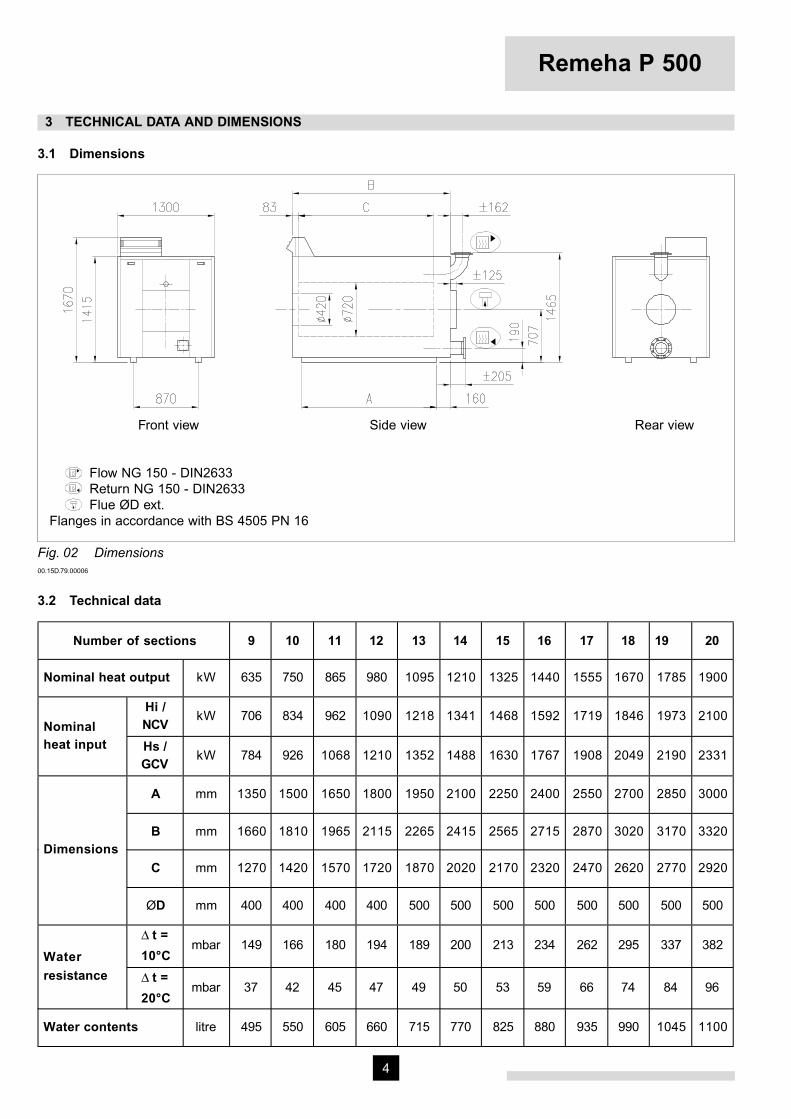
3 TECHNICAL DATA AND DIMENSIONS
3.1 Dimensions
Front view Side view Rear view
Flow NG 150 - DIN2633 Return NG 150 - DIN2633 Flue ØD ext. Flanges in accordance with BS 4505 PN 16
Fig. 02 Dimensions00.15D.79.00006
3.2 Technical data
Number of sections 9 10 11 12 13 14 15 16 17 18 19 20
Nominal heat output kW 635 750 865 980 1095 1210 1325 1440 1555 1670 1785 1900
Hi /NCV
kW 706 834 962 1090 1218 1341 1468 1592 1719 1846 1973 2100Nominalheat input Hs /
GCVkW 784 926 1068 1210 1352 1488 1630 1767 1908 2049 2190 2331
A mm 1350 1500 1650 1800 1950 2100 2250 2400 2550 2700 2850 3000
B mm 1660 1810 1965 2115 2265 2415 2565 2715 2870 3020 3170 3320
C mm 1270 1420 1570 1720 1870 2020 2170 2320 2470 2620 2770 2920Dimensions
ØD mm 400 400 400 400 500 500 500 500 500 500 500 500
∆ t =
10°Cmbar 149 166 180 194 189 200 213 234 262 295 337 382
Waterresistance ∆ t =
20°Cmbar 37 42 45 47 49 50 53 59 66 74 84 96
Water contents litre 495 550 605 660 715 770 825 880 935 990 1045 1100
5
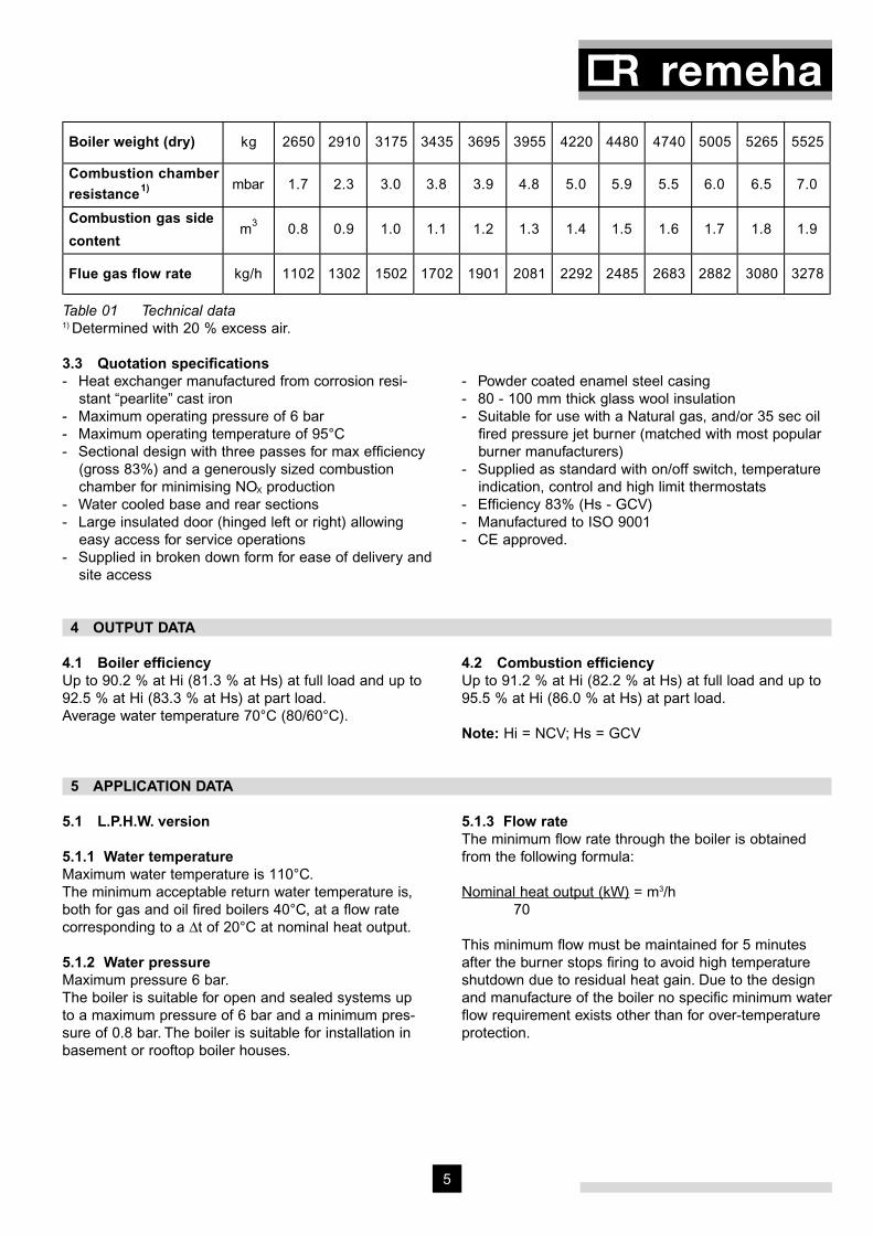
Boiler weight (dry) kg 2650 2910 3175 3435 3695 3955 4220 4480 4740 5005 5265 5525
Combustion chamberresistance1) mbar 1.7 2.3 3.0 3.8 3.9 4.8 5.0 5.9 5.5 6.0 6.5 7.0
Combustion gas side
contentm3 0.8 0.9 1.0 1.1 1.2 1.3 1.4 1.5 1.6 1.7 1.8 1.9
Flue gas flow rate kg/h 1102 1302 1502 1702 1901 2081 2292 2485 2683 2882 3080 3278
Table 01 Technical data1) Determined with 20 % excess air.
3.3 Quotation specifi cations- Heat exchanger manufactured from corrosion resi-
stant “pearlite” cast iron- Maximum operating pressure of 6 bar- Maximum operating temperature of 95°C- Sectional design with three passes for max effi ciency
(gross 83%) and a generously sized combustion chamber for minimising NOX production
- Water cooled base and rear sections- Large insulated door (hinged left or right) allowing
easy access for service operations- Supplied in broken down form for ease of delivery and
site access
- Powder coated enamel steel casing- 80 - 100 mm thick glass wool insulation- Suitable for use with a Natural gas, and/or 35 sec oil
fi red pressure jet burner (matched with most popular burner manufacturers)
- Supplied as standard with on/off switch, temperature indication, control and high limit thermostats
- Effi ciency 83% (Hs - GCV)- Manufactured to ISO 9001- CE approved.
4 OUTPUT DATA
4.1 Boiler effi ciencyUp to 90.2 % at Hi (81.3 % at Hs) at full load and up to 92.5 % at Hi (83.3 % at Hs) at part load.Average water temperature 70°C (80/60°C).
4.2 Combustion effi ciencyUp to 91.2 % at Hi (82.2 % at Hs) at full load and up to 95.5 % at Hi (86.0 % at Hs) at part load.
Note: Hi = NCV; Hs = GCV
5 APPLICATION DATA
5.1 L.P.H.W. version
5.1.1 Water temperatureMaximum water temperature is 110°C.The minimum acceptable return water temperature is, both for gas and oil fi red boilers 40°C, at a fl ow rate corresponding to a ∆t of 20°C at nominal heat output.
5.1.2 Water pressureMaximum pressure 6 bar.The boiler is suitable for open and sealed systems up to a maximum pressure of 6 bar and a minimum pres-sure of 0.8 bar. The boiler is suitable for installation in basement or rooftop boiler houses.
5.1.3 Flow rateThe minimum fl ow rate through the boiler is obtained from the following formula:
Nominal heat output (kW) = m3/h70
This minimum fl ow must be maintained for 5 minutes after the burner stops fi ring to avoid high temperature shutdown due to residual heat gain. Due to the design and manufacture of the boiler no specifi c minimum water fl ow requirement exists other than for over-temperature protection.
Remeha P 500
6
5.1.4 Water treatmentThe system should be fi lled with mains cold water (for the UK this will usually have a pH of between 7 and 8).Pressurised installations with a boiler/system content ratio of 1:10 or less should not require water treatment, provided that the following conditions apply:1. The system is fl ushed thoroughly to remove all fl uxes
and debris and then fi lled completely once.2. Make up water is limited to 5 % per annum.3. The hardness of the water does not exceed 360 ppm
(20°D). All scale deposits will reduce the effi ciency of the boiler and should be prevented. However provided the above is complied with any scale produced will not be too detrimental to the boiler effi ciency and will not reduce the anticipated life expectancy of the boiler.
NOTE: Scale deposits in excess of 3 to 5 mm will reduce boiler effi ciency and greatly increase the risk of premature casting failure.
As most systems contain a variety of metals which can react with each other to cause corrosion. It is consid-ered good practice to provide some form of water treat-ment (especially in open vented systems) in order to prevent or reduce the following:- Metallic corrosion;- Formation of scale and sludge;- Microbiological contamination;- Chemical changes in the untreated system water.
Suitable chemicals and their use should be discussed with a specialist water treatment company prior to car-rying out any work. The specifi cation of the system and manufacturers recommendations must be taken into account, along with the age and condition of the system. New systems should be fl ushed thoroughly to remove all traces of fl ux, debris, grease and metal swarf generated during installation. Care to be taken with old systems to ensure any black metallic iron oxide sludge and other corrosive residues are removed, again by thoroughly fl ushing, ensuring that the system is drained completely from all low points.
NOTE: Please ensure that the new boiler plant is not in circuit when the fl ushing takes place, especially if cleansing chemicals are used to assist the process.
Under no circumstances is the boiler to be operated with cleaning chemicals in the system.
To summarise:- Minimise water loss;- Prevent pumping over in open vented systems;- Provide adequate air venting at all high points;- Keep pH level between 7 - 9 when using additives;- Maximum chlorine content of 200 mg/l;- Take advice on the suitability of inhibitors.
5.2 EconomisersECO’s can be delivered upon request (for natural gas only). For specifi cations please refer to Technical infor-mation ECO 13/14/15.
5.3 Flue gas dischargeFor the discharge of the fl ue gases, chimney draught is not required.Tests have shown that very good combustion results are obtained with zero draught at the boiler outlet.
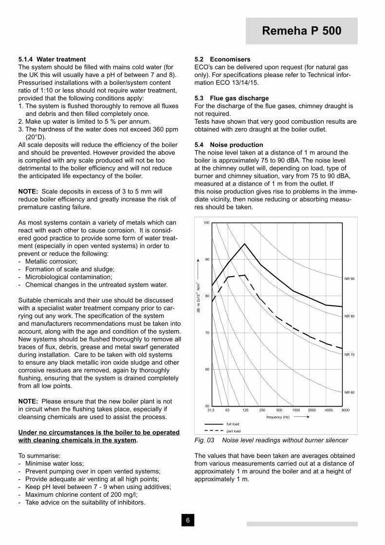
5.4 Noise productionThe noise level taken at a distance of 1 m around the boiler is approximately 75 to 90 dBA. The noise level at the chimney outlet will, depending on load, type of burner and chimney situation, vary from 75 to 90 dBA, measured at a distance of 1 m from the outlet. If this noise production gives rise to problems in the imme-diate vicinity, then noise reducing or absorbing measu-res should be taken.
50
60
70
80
90
100
31,5 63 125 250 500 1000 2000 4000 8000
NR 60
NR 70
NR 80
NR 90
frequency (Hz)
dB r
e 2x
10-5
N/m
2
full load
part load9Fig. 03 Noise level readings without burner silencer
The values that have been taken are averages obtained from various measurements carried out at a distance of approximately 1 m around the boiler and at a height of approximately 1 m.

7
6 INSTALLATION REQUIREMENTS
6.1 Installation recommendations in the boiler houseThe necessary minimum installation space of the boiler can be seen from Fig. 04.
Fig. 04 Installation recommendations in the boiler house04.15D.79.00001
H = 80mm without vibration damper H = 120mm with vibrationdamper
Fig. 05 Base details00.15A.78.00001
7 ASSEMBLY GUIDELINES AND INSTALLATION REQUIREMENTS
7.1 GeneralThe Remeha boiler P 500 is delivered in individual parts. The sizes of the boiler parts are such that they all can enter the boiler house through a normal entrance.The casing and equipment parts are delivered in pac-kaged units. If necessary, the boiler can be put into operation without casing. The casing can be added at a later stage without dismantling the water connections.
7.2 Water connectionsThe water connections are at the rear of the boiler.The fl ow and return connections consist of a fl anged fl ow elbow and a fl anged return connection in accor-dance with DIN 2633. The return connection is provided with a G ¾” threaded hole in which a drain off cock is fi tted.
At the front of the boiler a fl ange is provided with 2 x G ½” threaded holes for the fi tting of the thermostat pockets.
7.3 Boiler assemblyAssembly and installation of a boiler delivered in indivi-dual parts should only be undertaken by a recognised and approved engineer and in accordance with the assembly manual. Local regulations laid down by the relevant authorities must be adhered to.
Numberof
sections
A
mm
9 1350
10 1500
11 1650
12 1800
13 1950
14 2100
15 2250
16 2400
17 2550
18 2700
19 2850
20 3000
Remeha P 500
8
8 INSTRUMENT PANELS
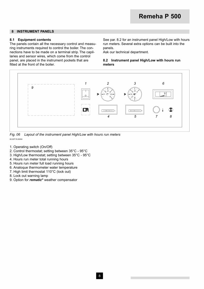
8.1 Equipment contentsThe panels contain all the necessary control and measu-ring instruments required to control the boiler. The con-nections have to be made on a terminal strip. The capil-laries and sensor wires, which come from the control panel, are placed in the instrument pockets that are fi tted at the front of the boiler.
See par. 8.2 for an instrument panel High/Low with hours run meters. Several extra options can be built into the panels.Ask our technical department.
8.2 Instrument panel High/Low with hours run meters
Fig. 06 Layout of the instrument panel High/Low with hours run meters00.03F.79.00004
1. Operating switch (On/Off)2. Control thermostat; setting between 35°C - 95°C3. High/Low thermostat; setting between 35°C - 95°C4. Hours run meter total running hours5. Hours run meter full load running hours6. Analoque thermometer water temperature7. High limit thermostat 110°C (lock out)8. Lock out warning lamp9. Option for rematic® weather compensator
1 2 3 6
4 5 7 8
9
9
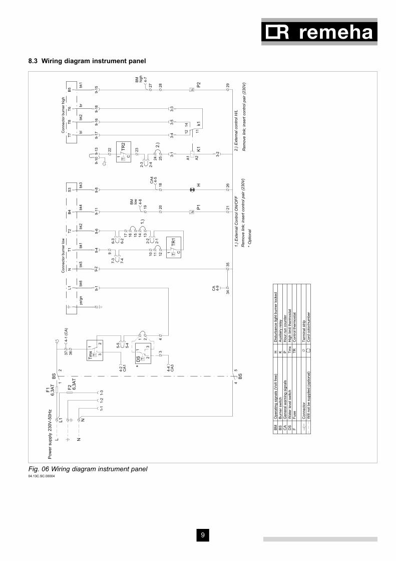
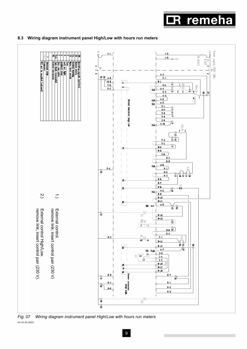
8.3 Wiring diagram instrument panel High/Low with hours run meters 13
Fig. 07 Wiring diagram instrument panel High/Low with hours run meters04.13C.SC.00001
1.) E
xternal control.
rem
ove link; insert control pair (230 V)
2.) E
xternal control High/Low
.
rem
ove link; insert control pair (230 V).1

Remeha P 500
10
9 COMMISSIONING
Note:Commissioning to only be carried out by a qualifi ed engineer with the relevant training and certifi cation i.e. Acops-Corgi and a commissioning data sheet completed on site for issue to owner.
9.1 Pressurized boiler with gas burner
9.1.1 Commissioning procedureIf the boiler is to be put into operation again following a period of non-use, then the following procedure must be carried out :- Open the main gas cock.- Switch the weather-compensator (if fi tted) over to
manual operation (h).- Turn the thermostats to their highest setting.- Switch on the circulation pump.- Switch on the main switch.- Switch on the operation switch in the instrument
panel.- Consult burner manufacturers commissioning details.
WarningIf the instrument panel is fi tted with a weather compen-sator, set the program switch to ‘manual’ position (h). The following will now take place:- The gas burner fan will start running so that during
the purging time the combustion chamber will be ven-tilated with the air damper fully opened.
- The air damper will then go into start position. - Ignition fl ame lights up and is checked. - Then the control box gives the all clear signal for the
burner to switch over to full load.
9.1.2 Putting out of operationIt is suffi cient to switch off the operation switch on the instrument panel. It is important that in the event of work being carried out on the burner, the boiler/burner unit must be completely electrically isolated and the main gas cock must be shut.5
9.2 Pressurized boiler with oil burner
9.2.1 Commissioning procedureIf the boiler is to be put into operation again following a period of non-use, then the following procedure must be carried out :- Open the main oil cock.- Switch the weather-compensator (if fi tted) over to
manual operation (h).- Turn the thermostat to their highest setting.- Switch on the circulation pump.- Switch on the main switch.- Switch on the operation switch in the instrument
panel.- Consult burner manufacturer commissioning details.
WarningIf the instrument panel is fi tted with a weather compen-sator, set the program switch to ‘manual’ position (h). The following will now take place:- The oil burner fan will start running so that during the
purging time the combustion chamber will be ventila-ted with the air damper fully opened.
- The air damper will then go into start position.- Ignition fl ame lights up and is checked.- Then the control box gives the all clear signal for the
burner to switch over to full load.
9.2.2 Putting out of operationIt is suffi cient to switch off the operation switch on the instrument panel. It is important that in the event of work being carried out on the burner, the boiler/burner unit must be completely electrically isolated and the main oil cock must be shut.

11
10 FAULT FINDING
High Limit thermostat lock out:- Check the water circulation (circulation pump). Reset
the High Limit thermostat (Reset button is on the instrument panel under the cover cap of the High Limit thermostat).
- Advise the installer in the event of continued lockouts.
11 MAINTENANCE RECOMMENDATIONS
11.1 GeneralDepending on the operational conditions, the block and the burner must be checked and cleaned at least once a year for gas and at least twice a year for oil.
11.2 Maintenance instructionsCleaning of the boiler:- Put boiler out of operation.- Open the front door, if necessary after dismantling the
burner.- Remove the retarders (only for the 9 - 16 sections).- Clean the combustion chamber and fl ue passes using
a suitable brush.- Clean the removed retarders ( 9 - 16 sections).- Remove the rear panel of the boiler and remove the
cleaning cover (underneath the smoke box).
- Vacuum clean the boiler and the combustion cham-ber.
- Renew the front door seals after cleaning the boiler.- Re-assemble the removed parts and close the front
door.- Re-assemble the burner (if dismantled).- Check the boiler combustion side for leakage.- Check the equipment for proper functioning and if
necessary re-adjust the control and safety equipment.- Carry out combustion analysis.- Check the water connections.

12
© Copyright
All technical and technological information contained in these technical instructions,
as well as any drawings and technical descriptions furnished by us remain our
property and shall not be copied in part or whole without our prior consent in writing.
Subject to alterations52881/1000/0202/Ips.
Broag Ltd.
Head office
Remeha house
Molly Millars Lane
Wokingham,
Berkshire RG41 2QP
Tel.: 0118 978 3434
Fax: 0118 978 6977
E-mail address:
Branch office
Unit 3, Kestrel Close,
Quarry Hill ind. Estate,
Ilkeston
Derbyshire DE7 4RD
Tel.: 0115 944 0778
Fax: 0115 944 0588
Re
me
ha
P
50
0
Related Documents


