CHOOSE EXPERTS, FIND PARTNERS PRESSUREMETER TEST Study case: Rhone Valley – Power Plant Presentation for SBGIMR / BVGIRM P. Debauche & S. Basire

Welcome message from author
This document is posted to help you gain knowledge. Please leave a comment to let me know what you think about it! Share it to your friends and learn new things together.
Transcript

CHOOSE EXPERTS, FIND
PARTNERS
PRESSUREMETER TEST
Study case: Rhone Valley – Power Plant
Presentation for SBGIMR / BVGIRM
P. Debauche & S. Basire
2
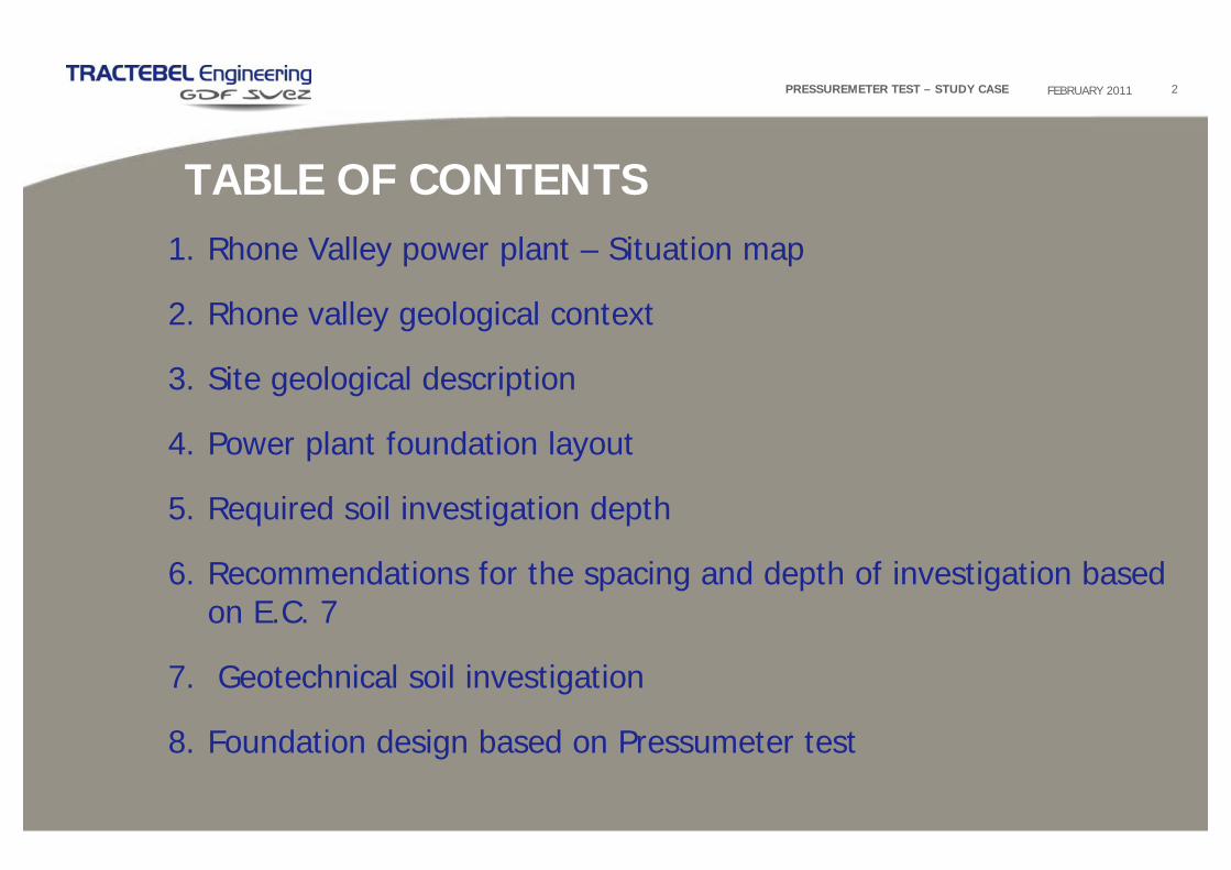
1. Rhone Valley power plant – Situation map
2. Rhone valley geological context
3. Site geological description
4. Power plant foundation layout
5. Required soil investigation depth
6. Recommendations for the spacing and depth of investigation basedon E.C. 7
7. Geotechnical soil investigation
8. Foundation design based on Pressumeter test
TABLE OF CONTENTS
FEBRUARY 2011PRESSUREMETER TEST – STUDY CASE
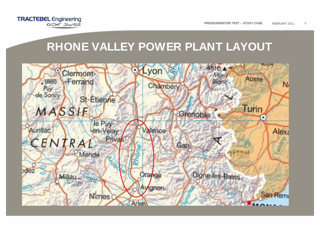
RHONE VALLEY POWER PLANT LAYOUT
3FEBRUARY 2011PRESSUREMETER TEST – STUDY CASE

RHONE VALLEY GEOLOGICAL CONTEXT
4FEBRUARY 2011PRESSUREMETER TEST – STUDY CASE

SITE GEOLOGICAL DESCRIPTION
21/02/2011 5WINDTURBINE FOUNDATION

6
POWER PLANT FOUNDATION LAYOUT
FEBRUARY 2011PRESSUREMETER TEST – STUDY CASE
Foundation slab height ~ 5 m
Foundation slab diameter ~ 65 m3300 m²

7
REQUIRED SOIL INVESTIGATION DEPTH
FEBRUARY 2011PRESSUREMETER TEST – STUDY CASE
Superficial foundation

8
RECOMMENDATIONS FOR THE SPACING AND DEPTH OF INVESTIGATIONS BASED ON E.C. 7
FEBRUARY 2011PRESSUREMETER TEST – STUDY CASE
• For high-rise & industrial structures : grid pattern with points at 15 m to 40 m distance;
• For special structures (e.g. machinery foundations, etc) : 2 to 6 investigation points per foundation.
• For high-rise structures : investigation depth ≥ 3*bf ;
Spacing
• For raft foundations with several foundation elements whose effects in deeper strata are superimposed on each other : investigation depth ≥ 1.5*bB.
Depth

13
15
17
19
21
23
25
27
29
31
33
35
37
39
41
43
45
47
49
51
0 2 4 6 8 10 12
Niveau NGF MPaPression de f luage pf Pression limite Pl*
13
15
17
19
21
23
25
27
29
31
33
35
37
39
41
43
45
47
49
51
0 200 400 600
Niveau NGF MPaModule pressiométrique Em
13
15
17
19
21
23
25
27
29
31
33
35
37
39
41
43
45
47
49
51
0 200 400 600 800 1000 1200 1400
Niveau NGF MPaModule de Young E (dilatomètre)
Module de Coulomb G (dilatomètre)
GEOTECHNICAL SOIL INVESTIGATION
9FEBRUARY 2011PRESSUREMETER TEST – STUDY CASE
NO DATA WITH CPT
PreDrilling 9m
3 m
PRESSIOMETER DILATOMETERCPT
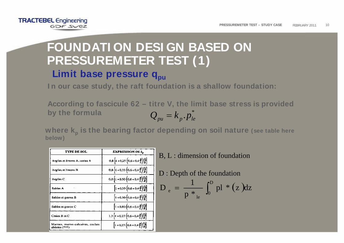
FOUNDATION DESIGN BASED ON PRESSUREMETER TEST (1)
10FEBRUARY 2011PRESSUREMETER TEST – STUDY CASE
In our case study, the raft foundation is a shallow foundation:
According to fascicule 62 – titre V, the limit base stress is provided by the formula *. leppu pkQ =
where kp is the bearing factor depending on soil nature (see table here below)
Limit base pressure qpu
B, L : dimension of foundation
D : Depth of the foundation
( )∫=D
0le
e dzz*pl*p1D

11FEBRUARY 2011PRESSUREMETER TEST – STUDY CASE
FOUNDATION DESIGN BASED ON PRESSUREMETER TEST (2)
p*le : the soil equivalent net limit pressure under the foundation
•In the case of a shallow foundation established on homogeneous soil
layers with a thickness of at least 1.5. B below the base of foundation:
P*le = pl* Net limit pressure value prevailing at a thickness of 1.5 B
•In the case of a shallow foundation on no homogeneous soil layers
between depths D and D +1.5 B :.
Net limit pressure value in the layers located on D to D +1.5 Bn
nllle plppp **.** 21 ⋅⋅⋅=

In order to calculate the bearing capacity of a shallow foundation, the limit values for the base Qpu have to be multiplied by the following reducing factors, depending on the limit state considered:
12
FOUNDATION DESIGN BASED ON PRESSUREMETER TEST (3)
FEBRUARY 2011PRESSUREMETER TEST – STUDY CASE
Serviceability Limit State (SLS) Ultimate Limit State (ULS)
Base strength Qpu 0.33 0.5

FOUNDATION DESIGN BASED ON PRESSUREMETER TEST (4)
13FEBRUARY 2011PRESSUREMETER TEST – STUDY CASE
The calculation of settlement by the pressuremeter method defined in French code (Fascicule 62 Titre V or DTU 13.12) is not applicable for of large dimensions of rafts. Settlement by the pressumerter method is limited to the soles of small sizes (3m x 3m).
For raft foundation, finite element model must be performed. In finite element model, Young modulus must be determinate.
In this studies case Ey is determinated by Dilatometer test and pressiometer test with correlation.

FOUNDATION DESIGN BASED ON PRESSUREMETER TEST (5)
14FEBRUARY 2011PRESSUREMETER TEST – STUDY CASE
The relationship usually used :
Young modulus correlation with pressumeter test
Depth (m) Lithology Geotechnical behavior αM
14 - 20 Marls Natural Rock 1/2
20 - 40 Sandy Marls Normally consolidated Sand 1/3
40 - 80 Marls Natural Rock 1/2
80 - 100 Sandy Marls Normally consolidated Sand 1/3
Selection of rheological coefficient of soil αM:
( )( )( )
M
M
M
EyE
oedEyE
oedEME
α
ννν
α
74.0
'1'21'1
=
−−+=
=
With ν’, Poisson coefficient = 0.3

0
5
10
15
20
25
30
35
40
45
50
55
60
65
70
75
80
85
90
95
100
0 200 400 600 800 1000 1200 1400Niveau MPa
Young Modulus
Module de Young Ey (dilatomètre)Module de Young Ey modélisé selon la formule : Ey=0.74EM/aModule pressiométrique
FOUNDATION DESIGN BASED ON PRESSUREMETER TEST (6)
15FEBRUARY 2011PRESSUREMETER TEST – STUDY CASE
Young modulus correlation with pressumeter test
Significant difference between Young's modulus measured by the dilatometer tests and Young's modulus deducted by the pressuremeter tests :
- Limits of correlations ?
See article O. Combarieux in “Revue française de la géotechnique N° 114”:
« L’usage des modules de déformation en géotechnique »
He defied for circular slab the following relationship
Where :R is the radius of the foundation = 32.5 mR0 = 0.3

0
5
10
15
20
25
30
35
40
45
50
55
60
65
70
75
80
85
90
95
100
0 200 400 600 800 1000 1200 1400Niveau MPa
Young Modulus
Module de Young Ey (dilatomètre)Module de Young Ey modélisé selon la formule : Ey=0.74EM/aModule pressiométrique
0
5
10
15
20
25
30
35
40
45
50
55
60
65
70
75
80
85
90
95
100
0 200 400 600 800 1000 1200 1400Niveau MPa
Young Modulus O.COMBARIEUX MethodModule de Young Ey (dilatomètre)
Module de Young Ey modélisé selon la formule : Ey=0.32((R/R0)̂ (1-a)+a/2) où a=1 et 2/3
Module de Young Ey modélisé selon la formule : Ey=0.32((R/R0)̂ (1-a)+a/2) où a=1/2 et 1/3
FOUNDATION DESIGN BASED ON PRESSUREMETER TEST (7)
16FEBRUARY 2011PRESSUREMETER TEST – STUDY CASE
Young modulus correlation with pressumeter test
- Problematic of choice of rheological soil parameters α
With the “O. Combarieux method”for the correlation the coefficient α=1 (behaviour of an over consolidated clay) α=2/3 (behaviour of a consolidated clay)
Same differences at great deep with this 2 method of correlation :
Limit of validity of the results of pressuremeter tests at great depth?

FOUNDATION DESIGN BASED ON PRESSUREMETER TEST (7)
17FEBRUARY 2011PRESSUREMETER TEST – STUDY CASE
Calculation of settlement with finite element model (SAP)
Estimation of settlement with load uniformly distributed over the raft of 6.3 Bar, is equal to 7.8 cm at the center of the raft
Flexible Model

THANKS FOR YOUR ATTENTION.
18FEBRUARY 2011PRESSUREMETER TEST – STUDY CASE
Related Documents