UNESCO – EOLSS SAMPLE CHAPTERS PRESSURE VESSELS AND PIPING SYSTEMS – Background to Procedures in Section XI of the ASME Code for Evaluation of Flaws in Nuclear Piping – Douglas A.Scarth ©Encyclopedia of Life Support Systems (EOLSS) BACKGROUND TO PROCEDURES IN SECTION XI OF THE ASME CODE FOR EVALUATION OF FLAWS IN NUCLEAR PIPING Douglas A. Scarth Kinectrics, Inc. Toronto, Ontario, Canada Keywords: ASME, Section XI, nuclear, pipe, flaw, evaluation Contents 1. Introduction 2. Overview of ASME Section XI for Pipe Flaw Evaluation 3. Flaw Acceptance Standards 4. Evaluation Procedures and Acceptance Criteria Based on Failure Mode Determination 5. Evaluation Procedures and Acceptance Criteria Based on a Failure Assessment Diagram 6. Evaluation Procedures and Acceptance Criteria for Wall Thinning in Piping 7. Evaluation Procedures and Acceptance Criteria for Temporary Acceptance of Flaws in Moderate Energy Class 2 and 3 Piping 8. Future Developments 9. Summary and Conclusions 10. Acknowledgements Glossary Bibliography Biographical Sketch Summary Section XI of the American Society of Mechanical Engineers (ASME) Boiler and Pressure Vessel Code provides requirements for maintaining pressure boundary integrity of components, piping, and equipment during the life of a nuclear power plant. Evaluation procedures and acceptance criteria for the evaluation of flaws in nuclear piping in Section XI of the ASME Code were first published in 1983. Committees under Section XI update Acceptance Standards and evaluation procedures on an ongoing basis in response to industry needs. This article provides an overview of the procedures and acceptance criteria for pipe flaw evaluation in Section XI. Both planar and nonplanar flaws are addressed by Section XI. The evaluation procedures and acceptance criteria cover failure by plastic collapse as characterized by limit load analysis, fracture due to ductile tearing prior to attainment of limit load as characterized by elastic-plastic fracture mechanics (EPFM) analysis, and brittle fracture as characterized by linear elastic fracture mechanics (LEFM) analysis. A major revision to the evaluation procedures and acceptance criteria was published in the 2002 Addenda to Section XI. Evaluation procedures and acceptance criteria in the 2001 Edition, as well as the revisions in the 2002 Addenda, are described in this article. Code Cases that address evaluation of wall thinning in piping systems, as well as temporary acceptance of flaws

Welcome message from author
This document is posted to help you gain knowledge. Please leave a comment to let me know what you think about it! Share it to your friends and learn new things together.
Transcript
UNESCO – EOLS
S
SAMPLE C
HAPTERS
PRESSURE VESSELS AND PIPING SYSTEMS – Background to Procedures in Section XI of the ASME Code for Evaluation of Flaws in Nuclear Piping – Douglas A.Scarth
©Encyclopedia of Life Support Systems (EOLSS)
BACKGROUND TO PROCEDURES IN SECTION XI OF THE ASME CODE FOR EVALUATION OF FLAWS IN NUCLEAR PIPING Douglas A. Scarth Kinectrics, Inc. Toronto, Ontario, Canada Keywords: ASME, Section XI, nuclear, pipe, flaw, evaluation Contents 1. Introduction 2. Overview of ASME Section XI for Pipe Flaw Evaluation 3. Flaw Acceptance Standards 4. Evaluation Procedures and Acceptance Criteria Based on Failure Mode Determination 5. Evaluation Procedures and Acceptance Criteria Based on a Failure Assessment Diagram 6. Evaluation Procedures and Acceptance Criteria for Wall Thinning in Piping 7. Evaluation Procedures and Acceptance Criteria for Temporary Acceptance of Flaws in Moderate Energy Class 2 and 3 Piping 8. Future Developments 9. Summary and Conclusions 10. Acknowledgements Glossary Bibliography Biographical Sketch Summary Section XI of the American Society of Mechanical Engineers (ASME) Boiler and Pressure Vessel Code provides requirements for maintaining pressure boundary integrity of components, piping, and equipment during the life of a nuclear power plant. Evaluation procedures and acceptance criteria for the evaluation of flaws in nuclear piping in Section XI of the ASME Code were first published in 1983. Committees under Section XI update Acceptance Standards and evaluation procedures on an ongoing basis in response to industry needs. This article provides an overview of the procedures and acceptance criteria for pipe flaw evaluation in Section XI. Both planar and nonplanar flaws are addressed by Section XI. The evaluation procedures and acceptance criteria cover failure by plastic collapse as characterized by limit load analysis, fracture due to ductile tearing prior to attainment of limit load as characterized by elastic-plastic fracture mechanics (EPFM) analysis, and brittle fracture as characterized by linear elastic fracture mechanics (LEFM) analysis. A major revision to the evaluation procedures and acceptance criteria was published in the 2002 Addenda to Section XI. Evaluation procedures and acceptance criteria in the 2001 Edition, as well as the revisions in the 2002 Addenda, are described in this article. Code Cases that address evaluation of wall thinning in piping systems, as well as temporary acceptance of flaws
UNESCO – EOLS
S
SAMPLE C
HAPTERS
PRESSURE VESSELS AND PIPING SYSTEMS – Background to Procedures in Section XI of the ASME Code for Evaluation of Flaws in Nuclear Piping – Douglas A.Scarth
©Encyclopedia of Life Support Systems (EOLSS)
in moderate energy piping systems are also described. 1. Introduction Section XI of the American Society of Mechanical Engineers (ASME) Boiler and Pressure Vessel Code provides requirements for maintaining pressure boundary integrity of components, piping, and equipment during the life of a nuclear power plant. Pressure boundary integrity includes prevention of leakage from the reactor coolant system, as well as structural integrity in terms of prevention of rupture or burst of the pressure boundary. Section XI provides specific rules for evaluating flaw indications that may be detected during the service life of a nuclear component. Flaw evaluation procedures for austenitic piping were developed in direct response to an industry need to address pipe cracking events occurring in the mid-to-late 1970’s. Specifically, the initial pipe cracking events that led to the development of flaw evaluation procedures for austenitic piping were the increasing incidents of stress corrosion cracking in Boiling Water Reactor (BWR) Class 1 piping. Flaw evaluation procedures for austenitic piping were introduced into Section XI with the Winter 1983 Addendum. Flaw evaluation procedures for ferritic piping were subsequently introduced into Section XI with the Winter 1989 Addendum. Committees under Section XI update Acceptance Standards and evaluation procedures on an ongoing basis in response to industry needs. Both planar and nonplanar flaws are addressed by Section XI. The evaluation procedures and acceptance criteria cover failure by plastic collapse as characterized by limit load analysis, fracture due to ductile tearing prior to attainment of limit load as characterized by elastic-plastic fracture mechanics (EPFM) analysis, and brittle fracture as characterized by linear elastic fracture mechanics (LEFM) analysis. The flaw evaluation procedures include subcritical crack growth due to fatigue and stress corrosion cracking. The evaluation procedures are based on synthesis of, and validation against, experimental results. The purpose of this article is to provide an overview of the procedures and acceptance criteria in Section XI for evaluation of in-service flaws in nuclear piping. The general approach in Section XI for pipe flaw evaluation is first described. A major revision to the evaluation procedures and acceptance criteria was published in the 2002 Addenda to Section XI. Evaluation procedures and acceptance criteria in the 2001 Edition, as well as the revisions in the 2002 Addenda, are described. The recent focus of activities in Section XI has been to address Primary Water Stress Corrosion Cracking (PWSCC) in Alloy 600 components and Alloy 82, 182 and 132 dissimilar metal welds in piping in Pressurized Water Reactor (PWR) coolant environments. A number of revisions and on-going activities related to PWSCC in piping are described in this article. Evaluation procedures and acceptance criteria that are an alternative to those in the main body of Section XI are provided in Code Cases. Code Cases that address evaluation of wall thinning in piping systems, as well as temporary acceptance of flaws in moderate energy piping systems, are described. Finally, planned future developments in Section XI for pipe flaw evaluation are described. Changes to the pipe flaw evaluation procedures in Section XI are supported by technical basis documents, and a number of these documents are listed in the references for this article.
UNESCO – EOLS
S
SAMPLE C
HAPTERS
PRESSURE VESSELS AND PIPING SYSTEMS – Background to Procedures in Section XI of the ASME Code for Evaluation of Flaws in Nuclear Piping – Douglas A.Scarth
©Encyclopedia of Life Support Systems (EOLSS)
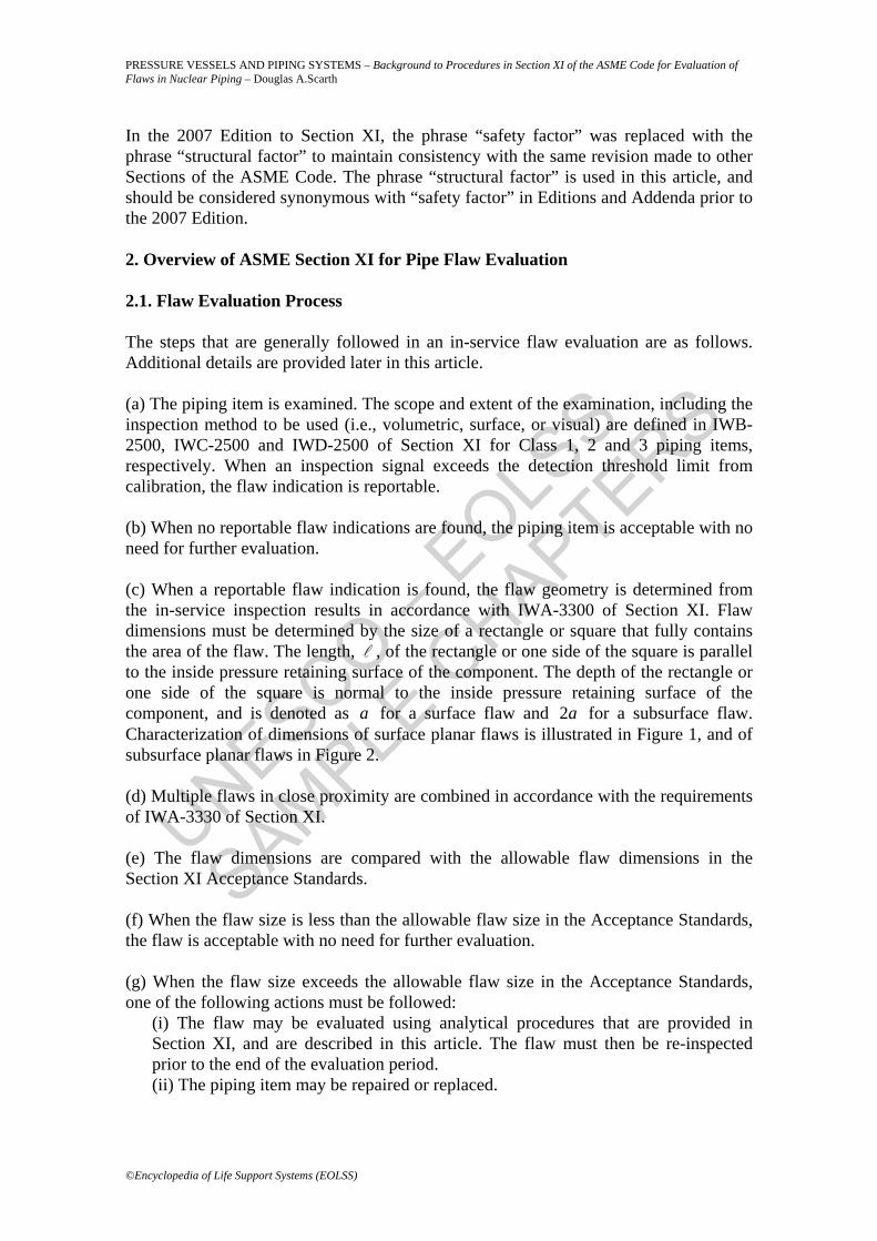
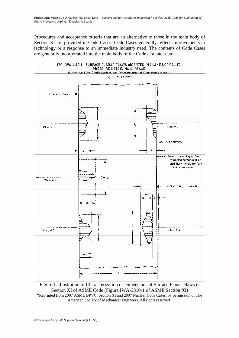
In the 2007 Edition to Section XI, the phrase “safety factor” was replaced with the phrase “structural factor” to maintain consistency with the same revision made to other Sections of the ASME Code. The phrase “structural factor” is used in this article, and should be considered synonymous with “safety factor” in Editions and Addenda prior to the 2007 Edition. 2. Overview of ASME Section XI for Pipe Flaw Evaluation 2.1. Flaw Evaluation Process The steps that are generally followed in an in-service flaw evaluation are as follows. Additional details are provided later in this article. (a) The piping item is examined. The scope and extent of the examination, including the inspection method to be used (i.e., volumetric, surface, or visual) are defined in IWB-2500, IWC-2500 and IWD-2500 of Section XI for Class 1, 2 and 3 piping items, respectively. When an inspection signal exceeds the detection threshold limit from calibration, the flaw indication is reportable. (b) When no reportable flaw indications are found, the piping item is acceptable with no need for further evaluation. (c) When a reportable flaw indication is found, the flaw geometry is determined from the in-service inspection results in accordance with IWA-3300 of Section XI. Flaw dimensions must be determined by the size of a rectangle or square that fully contains the area of the flaw. The length, , of the rectangle or one side of the square is parallel to the inside pressure retaining surface of the component. The depth of the rectangle or one side of the square is normal to the inside pressure retaining surface of the component, and is denoted as a for a surface flaw and 2a for a subsurface flaw. Characterization of dimensions of surface planar flaws is illustrated in Figure 1, and of subsurface planar flaws in Figure 2. (d) Multiple flaws in close proximity are combined in accordance with the requirements of IWA-3330 of Section XI. (e) The flaw dimensions are compared with the allowable flaw dimensions in the Section XI Acceptance Standards. (f) When the flaw size is less than the allowable flaw size in the Acceptance Standards, the flaw is acceptable with no need for further evaluation. (g) When the flaw size exceeds the allowable flaw size in the Acceptance Standards, one of the following actions must be followed:
(i) The flaw may be evaluated using analytical procedures that are provided in Section XI, and are described in this article. The flaw must then be re-inspected prior to the end of the evaluation period. (ii) The piping item may be repaired or replaced.
UNESCO – EOLS
S
SAMPLE C
HAPTERS
PRESSURE VESSELS AND PIPING SYSTEMS – Background to Procedures in Section XI of the ASME Code for Evaluation of Flaws in Nuclear Piping – Douglas A.Scarth
©Encyclopedia of Life Support Systems (EOLSS)
Procedures and acceptance criteria that are an alternative to those in the main body of Section XI are provided in Code Cases. Code Cases generally reflect improvements to technology or a response to an immediate industry need. The contents of Code Cases are generally incorporated into the main body of the Code at a later date.
Figure 1. Illustration of Characterization of Dimensions of Surface Planar Flaws in
Section XI of ASME Code (Figure IWA-3310-1 of ASME Section XI) “Reprinted from 2007 ASME BPVC, Section XI and 2007 Nuclear Code Cases, by permission of The
American Society of Mechanical Engineers. All rights reserved”
UNESCO – EOLS
S
SAMPLE C
HAPTERS
PRESSURE VESSELS AND PIPING SYSTEMS – Background to Procedures in Section XI of the ASME Code for Evaluation of Flaws in Nuclear Piping – Douglas A.Scarth
©Encyclopedia of Life Support Systems (EOLSS)
Figure 2. Illustration of Characterization of Dimensions of Subsurface Planar Flaws in
Section XI of ASME Code (Figure IWA-3320-1 of ASME Section XI) “Reprinted from 2007 ASME BPVC, Section XI and 2007 Nuclear Code Cases, by permission of The
American Society of Mechanical Engineers. All rights reserved” 2.2. Approach for Analytical Evaluation of a Flaw in a Piping Item
UNESCO – EOLS
S
SAMPLE C
HAPTERS
PRESSURE VESSELS AND PIPING SYSTEMS – Background to Procedures in Section XI of the ASME Code for Evaluation of Flaws in Nuclear Piping – Douglas A.Scarth
©Encyclopedia of Life Support Systems (EOLSS)
The analytical evaluation procedures and acceptance criteria are currently applicable to nominal pipe sizes DN 100 (NPS 4 in.) or greater. The analytical procedures are generally applicable to straight pipe and portions of pipes and fittings within a distance of ( )1/2
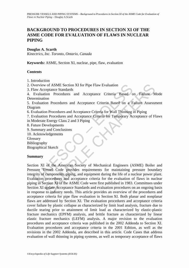
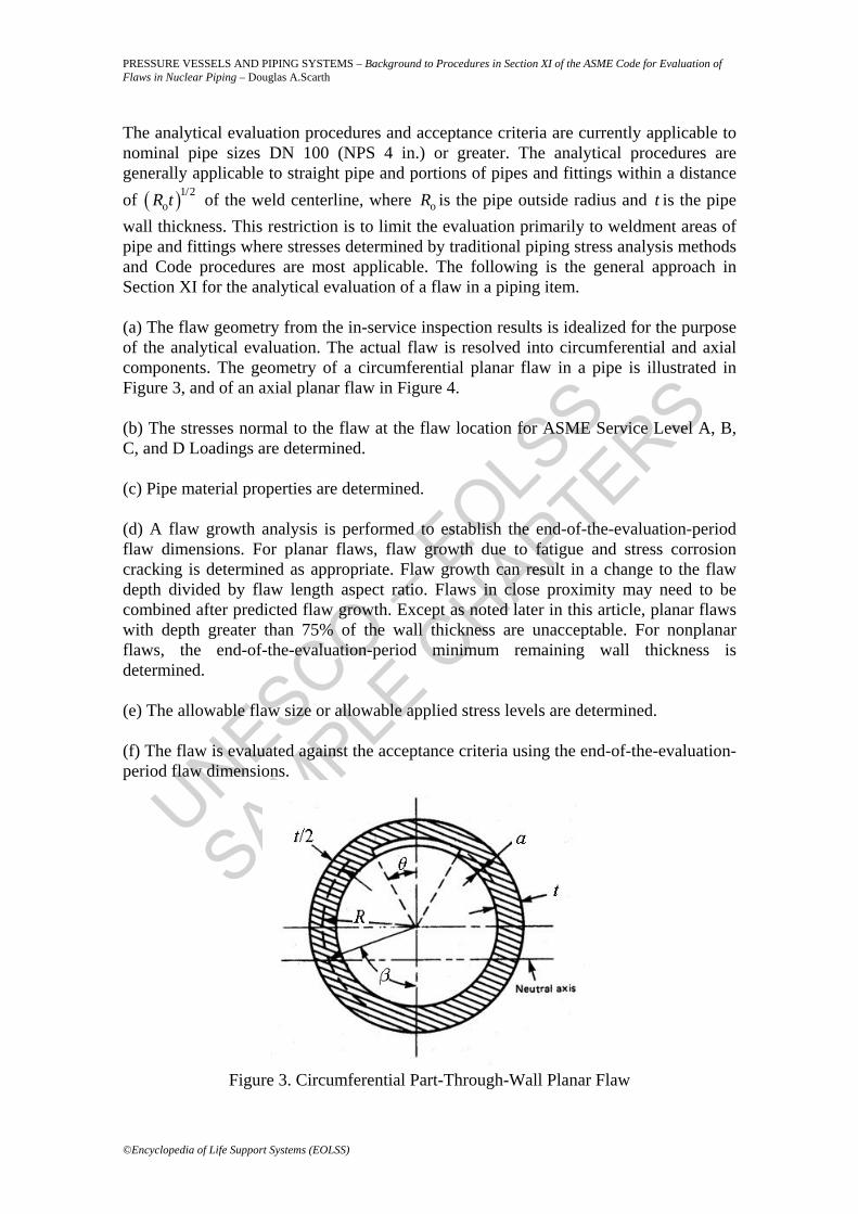
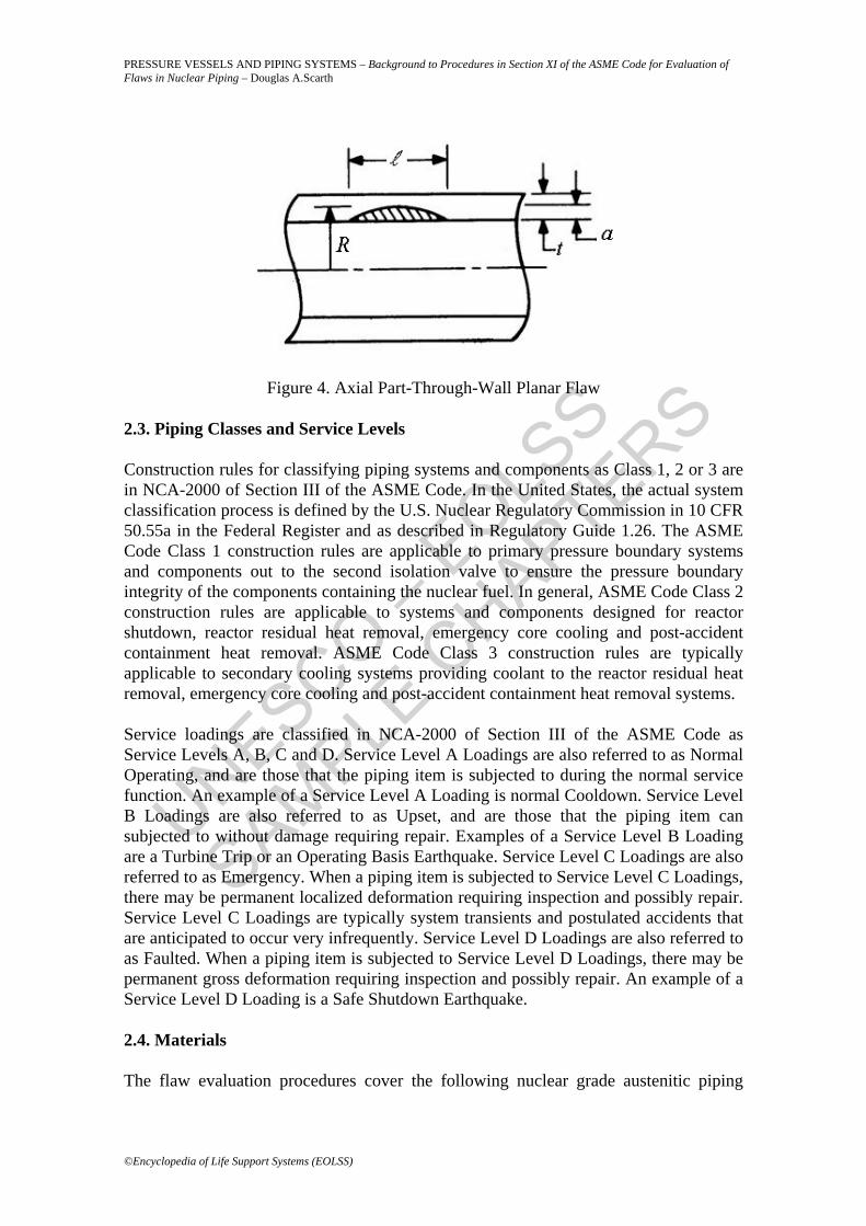
oR t of the weld centerline, where oR is the pipe outside radius and t is the pipe wall thickness. This restriction is to limit the evaluation primarily to weldment areas of pipe and fittings where stresses determined by traditional piping stress analysis methods and Code procedures are most applicable. The following is the general approach in Section XI for the analytical evaluation of a flaw in a piping item. (a) The flaw geometry from the in-service inspection results is idealized for the purpose of the analytical evaluation. The actual flaw is resolved into circumferential and axial components. The geometry of a circumferential planar flaw in a pipe is illustrated in Figure 3, and of an axial planar flaw in Figure 4. (b) The stresses normal to the flaw at the flaw location for ASME Service Level A, B, C, and D Loadings are determined. (c) Pipe material properties are determined. (d) A flaw growth analysis is performed to establish the end-of-the-evaluation-period flaw dimensions. For planar flaws, flaw growth due to fatigue and stress corrosion cracking is determined as appropriate. Flaw growth can result in a change to the flaw depth divided by flaw length aspect ratio. Flaws in close proximity may need to be combined after predicted flaw growth. Except as noted later in this article, planar flaws with depth greater than 75% of the wall thickness are unacceptable. For nonplanar flaws, the end-of-the-evaluation-period minimum remaining wall thickness is determined. (e) The allowable flaw size or allowable applied stress levels are determined. (f) The flaw is evaluated against the acceptance criteria using the end-of-the-evaluation-period flaw dimensions.
Figure 3. Circumferential Part-Through-Wall Planar Flaw
UNESCO – EOLS
S
SAMPLE C
HAPTERS
PRESSURE VESSELS AND PIPING SYSTEMS – Background to Procedures in Section XI of the ASME Code for Evaluation of Flaws in Nuclear Piping – Douglas A.Scarth
©Encyclopedia of Life Support Systems (EOLSS)
Figure 4. Axial Part-Through-Wall Planar Flaw
2.3. Piping Classes and Service Levels Construction rules for classifying piping systems and components as Class 1, 2 or 3 are in NCA-2000 of Section III of the ASME Code. In the United States, the actual system classification process is defined by the U.S. Nuclear Regulatory Commission in 10 CFR 50.55a in the Federal Register and as described in Regulatory Guide 1.26. The ASME Code Class 1 construction rules are applicable to primary pressure boundary systems and components out to the second isolation valve to ensure the pressure boundary integrity of the components containing the nuclear fuel. In general, ASME Code Class 2 construction rules are applicable to systems and components designed for reactor shutdown, reactor residual heat removal, emergency core cooling and post-accident containment heat removal. ASME Code Class 3 construction rules are typically applicable to secondary cooling systems providing coolant to the reactor residual heat removal, emergency core cooling and post-accident containment heat removal systems. Service loadings are classified in NCA-2000 of Section III of the ASME Code as Service Levels A, B, C and D. Service Level A Loadings are also referred to as Normal Operating, and are those that the piping item is subjected to during the normal service function. An example of a Service Level A Loading is normal Cooldown. Service Level B Loadings are also referred to as Upset, and are those that the piping item can subjected to without damage requiring repair. Examples of a Service Level B Loading are a Turbine Trip or an Operating Basis Earthquake. Service Level C Loadings are also referred to as Emergency. When a piping item is subjected to Service Level C Loadings, there may be permanent localized deformation requiring inspection and possibly repair. Service Level C Loadings are typically system transients and postulated accidents that are anticipated to occur very infrequently. Service Level D Loadings are also referred to as Faulted. When a piping item is subjected to Service Level D Loadings, there may be permanent gross deformation requiring inspection and possibly repair. An example of a Service Level D Loading is a Safe Shutdown Earthquake. 2.4. Materials The flaw evaluation procedures cover the following nuclear grade austenitic piping
UNESCO – EOLS
S
SAMPLE C
HAPTERS
PRESSURE VESSELS AND PIPING SYSTEMS – Background to Procedures in Section XI of the ASME Code for Evaluation of Flaws in Nuclear Piping – Douglas A.Scarth
©Encyclopedia of Life Support Systems (EOLSS)
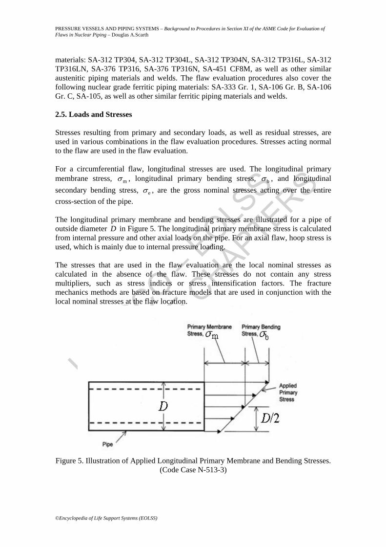
materials: SA-312 TP304, SA-312 TP304L, SA-312 TP304N, SA-312 TP316L, SA-312 TP316LN, SA-376 TP316, SA-376 TP316N, SA-451 CF8M, as well as other similar austenitic piping materials and welds. The flaw evaluation procedures also cover the following nuclear grade ferritic piping materials: SA-333 Gr. 1, SA-106 Gr. B, SA-106 Gr. C, SA-105, as well as other similar ferritic piping materials and welds. 2.5. Loads and Stresses Stresses resulting from primary and secondary loads, as well as residual stresses, are used in various combinations in the flaw evaluation procedures. Stresses acting normal to the flaw are used in the flaw evaluation. For a circumferential flaw, longitudinal stresses are used. The longitudinal primary membrane stress, mσ , longitudinal primary bending stress, bσ , and longitudinal secondary bending stress, eσ , are the gross nominal stresses acting over the entire cross-section of the pipe. The longitudinal primary membrane and bending stresses are illustrated for a pipe of outside diameter D in Figure 5. The longitudinal primary membrane stress is calculated from internal pressure and other axial loads on the pipe. For an axial flaw, hoop stress is used, which is mainly due to internal pressure loading. The stresses that are used in the flaw evaluation are the local nominal stresses as calculated in the absence of the flaw. These stresses do not contain any stress multipliers, such as stress indices or stress intensification factors. The fracture mechanics methods are based on fracture models that are used in conjunction with the local nominal stresses at the flaw location.
Figure 5. Illustration of Applied Longitudinal Primary Membrane and Bending Stresses.
(Code Case N-513-3)
UNESCO – EOLS
S
SAMPLE C
HAPTERS
PRESSURE VESSELS AND PIPING SYSTEMS – Background to Procedures in Section XI of the ASME Code for Evaluation of Flaws in Nuclear Piping – Douglas A.Scarth
©Encyclopedia of Life Support Systems (EOLSS)
- - -
TO ACCESS ALL THE 46 PAGES OF THIS CHAPTER, Visit: http://www.eolss.net/Eolss-sampleAllChapter.aspx
Bibliography Ainsworth R.A. (1984). The Assessment of Defects in Structures of Strain Hardening Material. Engineering Fracture Mechanics, Vol. 19. [This provides a description of a revision to the R6 Failure Assessment Diagram procedure for evaluation of flaws in structures, where the effects of strain hardening of the material are taken into account, as opposed to assuming an elastic-perfectly plastic stress-strain curve].
Anonymous. Section II Materials, Part D - Properties, Various Editions and Addenda, ASME Boiler and Pressure Vessel Code, American Society of Mechanical Engineers. [This provides material properties and allowable stresses for design of power plant components].
Anonymous. Rules for Construction of Nuclear Power Plant Components, Section III, Division 1, Various Editions and Addenda, ASME Boiler and Pressure Vessel Code, American Society of Mechanical Engineers. [This provides requirements for design and construction of nuclear power plant components].
Anonymous. Rules for inservice Inspection of Nuclear Power Plant Components, Section XI, Division 1, Various Editions and Addenda, ASME Boiler and Pressure Vessel Code, American Society of Mechanical Engineers. [This provides requirements for in-service inspection and evaluation of nuclear pressure boundary components].
Anonymous. Case N-494-4: Pipe Specific Evaluation Procedures and Acceptance Criteria for Flaws in Piping that Exceed the Acceptance Standards, Section XI, Division 1, Approval Date: January 12, 2005, ASME Boiler and Pressure Vessel Code, American Society of Mechanical Engineers. [This Code Case contains procedures and acceptance criteria for evaluation of flaws in steel piping in nuclear power plants. The procedures and acceptance criteria are based on the Failure Assessment Diagram approach that covers the range of fracture modes of brittle fracture, ductile fracture and plastic collapse].
Anonymous. Case N-513-3: Evaluation Criteria for Temporary Acceptance of Flaws in Moderate Energy Class 2 or 3 Piping, Section XI, Division 1, Approval Date: January 26, 2009, ASME Boiler and Pressure Vessel Code, American Society of Mechanical Engineers. [This Code Case contains procedures and acceptance criteria for evaluation for temporary acceptance of flaws, including through-wall leaking flaws, in moderate energy Class 2 or 3 piping in nuclear power plants].
Anonymous. Case N-597-2: Requirements for Analytical Evaluation of Pipe Wall Thinning, Section XI, Division 1, Approval Date: November 18, 2003, ASME Boiler and Pressure Vessel Code, American Society of Mechanical Engineers. [This Code Case contains procedures and acceptance criteria for evaluation of steel piping in nuclear power plants subjected to wall thinning due to flow-accelerated corrosion].
ASME Section XI Task Group for Piping Flaw Evaluation. (1986). Evaluation of Flaws in Austenitic Steel Piping. ASME Journal of Pressure Vessel Technology, Vol. 108, pp. 352-366. [This provides the technical basis for procedures and acceptance criteria in Section XI of the ASME Boiler and Pressure Vessel Code for evaluation of flaws in austenitic steel piping in nuclear power plants].
Bamford W.H., Cipolla R.C., Rudland D. and DeBoo G.H. (2008). Technical Basis for Revisions to Section XI Appendix C for Alloy 600/82/182/132 Flaw Evaluation in both PWR and BWR Environments. Proceedings of 2008 ASME Pressure Vessels and Piping Conference, Chicago, Illinois,
UNESCO – EOLS
S
SAMPLE C
HAPTERS
PRESSURE VESSELS AND PIPING SYSTEMS – Background to Procedures in Section XI of the ASME Code for Evaluation of Flaws in Nuclear Piping – Douglas A.Scarth
©Encyclopedia of Life Support Systems (EOLSS)
July 27-31, 2008, PVP2008-61840. [This provides the technical basis for procedures in Appendix C of Section XI of the ASME Boiler and Pressure Vessel Code for evaluation of flaws in Alloy 600 base material, and Alloy 82, 182 and 132 weld materials, in piping in nuclear power plants that were first published in the 2009 Addenda to Section XI].
Bloom J.M. (1985). Deformation Plasticity Failure Assessment Diagram. Elastic Plastic Fracture Mechanics Technology, ASTM STP 896, J.C. Newman, Jr. and F.J. Loss Eds., American Society for Testing and Materials, Philadelphia, PA, 1985, pp. 114-127. [This provides the technical basis for procedures and acceptance criteria for evaluation of flaws in ferritic steel piping in nuclear power plants based on the Failure Assessment Diagram approach that covers the range of fracture modes of brittle fracture, ductile fracture and plastic collapse].
Cipolla R.C., Scarth D.A., Wilkowski G.M. and Zilberstein V.A. (2001). Technical Basis for Proposed Revision to Acceptance Criteria for ASME Section XI Pipe Flaw Evaluation. Proceedings of 2001 ASME Pressure Vessels and Piping Conference, Atlanta, Georgia, PVP-Vol. 422, pp. 31-51. [This provides the technical basis for the revised procedures and acceptance criteria for evaluation of flaws in steel piping in nuclear power plants that were first published in the 2002 Addenda to Section XI of the ASME Boiler and Pressure Vessel Code].
Deardorff A., Goyette L., Krishnaswamy P. and Kupinski M. (1999). ASME Section XI Evaluation Methods and Acceptance Criteria for Analytical Evaluation of Wall Thinning Due to Flow Accelerated Corrosion (FAC). Proceedings of 1999 ASME Pressure Vessels and Piping Conference, Boston, Massachusetts, PVP-Vol. 392, pp. 187-206. [This contains the technical basis for procedures and acceptance criteria that are in Code Case N-597 of Section XI of the ASME Boiler and Pressure Vessel Code for evaluation of steel piping in nuclear power plants subjected to wall thinning due to flow-accelerated corrosion].
McGill R.O., Cofie N.G., Cipolla R.C. and DeBoo G. (2006). Technical Basis for Proposed Revisions to ASME Code Case N-513 and Some Applications to Moderate Energy Piping. Proceedings of 2006 ASME Pressure Vessels and Piping Conference, Vancouver, British Columbia, July 23-27, 2006, PVP2006-ICPVT-11-93428. [This provides the technical basis for revisions to procedures and acceptance criteria that are in Code Case N-513 of Section XI of the ASME Boiler and Pressure Vessel Code for evaluation for temporary acceptance of flaws, including through-wall leaking flaws, in moderate energy Class 2 or 3 piping in nuclear power plants].
Miyazaki K., Hasegawa K., Miura N., Kashima K. and Scarth D.A. (2007). Technical Basis of Proposed New Acceptance Standards for Class 1, 2 and 3 Piping. Proceedings of 2007 ASME Pressure Vessels and Piping Conference, San Antonio, Texas, July 22-26, 2007, PVP2007-26124. [This provides the technical basis for revised allowable flaw sizes in the Acceptance Standards for nuclear piping in Tables IWB-3514-1 and IWC-3514-1 of Section XI of the ASME Boiler and Pressure Vessel Code that were first published in the 2009 Addenda to Section XI].
Scarth D.A., Miyazaki K., Hasegawa K. and Bamford W.H. (2009). Technical Basis for Revisions to ASME Section XI Acceptance Standards for Surface Flaws in Piping in Stress Corrosion Cracking Susceptible Materials. Proceedings of 2009 ASME Pressure Vessels and Piping Conference, Prague, Czech Republic, July 26-30, 2009, PVP2009-77824. [This provides the technical basis for revised requirements in the Acceptance Standards for stress corrosion cracking susceptible materials in nuclear piping in Section XI of the ASME Boiler and Pressure Vessel Code that were first published in the 2009 Addenda to Section XI].
Wilkowski G.M., Xu H., Shim D.-J. and Rudland D. (2007). Determination of the Elastic-Plastic Fracture Mechanics Z-factor for Alloy 182 Weld Metal Flaws for Use in the ASME Section XI Appendix C Flaw Evaluation Procedures. Proceedings of 2007 ASME Pressure Vessels and Piping Conference, San Antonio, Texas, July 22-26, 2007, PVP2007-26733. [This provides the technical basis for the Z-factor equations in Appendix C of Section XI of the ASME Boiler and Pressure Vessel Code for evaluation of flaws in Alloy 600 base material, and Alloy 82, 182 and 132 weld materials, in piping in nuclear power plants that were first published in the 2009 Addenda to Section XI].
Zahoor A. and Gamble R.M. (1988). Evaluation of Flaws in Ferritic Piping, EPRI Report No. NP-6045, Electric Power Research Institute, Palo Alto, CA. [This provides the technical basis for procedures and acceptance criteria in Section XI of the ASME Boiler and Pressure Vessel Code for evaluation of flaws in
UNESCO – EOLS
S
SAMPLE C
HAPTERS
PRESSURE VESSELS AND PIPING SYSTEMS – Background to Procedures in Section XI of the ASME Code for Evaluation of Flaws in Nuclear Piping – Douglas A.Scarth
©Encyclopedia of Life Support Systems (EOLSS)
ferritic steel piping in nuclear power plants].
Biographical Sketch Douglas A. Scarth, Education: received a Ph.D. in Materials Science from the University of Manchester in 2002. He is with Kinectrics, Inc., Toronto, Ontario, Canada, as Technical Director - Fracture Programs. Dr. Scarth performed structural integrity evaluations of nuclear and fossil plant components containing flaws. He is involved in development of improved methodologies for evaluating flaws. He participated in development of engineering codes and standards for fitness for service assessments of plant components, including activities of Canadian Standards Association, and Section XI of the ASME Boiler and Pressure Vessel Code. Also he is a participant in the ASME Pressure Vessels and Piping Division.
Related Documents