Welcome message from author
This document is posted to help you gain knowledge. Please leave a comment to let me know what you think about it! Share it to your friends and learn new things together.
Transcript

Title: PRESSURE VESSEL SPECIFICATION
Uncontrolled When Printed DRIMs#3124353 Rev -
Date Printed 03/10/06 Page 2 of 48
DOCUMENT DISTRIBUTION
Copy No. Name Hard Copy Electronic Copy
00 Document Control
01 G Howard (OZE4)
02 G Mathwin (KEH)
03
04
05
06
07
08
09
10
Title: PRESSURE VESSEL SPECIFICATION
Uncontrolled When Printed DRIMs#3124353 Rev -
Date Printed 03/10/06 Page 3 of 48
PREFACE Woodside Energy Ltd. (WEL) has developed a suite of Engineering and Technical Standards and Guidelines. It is intended that these reflect the most suitable engineering practices for use on all new WEL facilities as well as the modification of existing facilities. The application of the Standards is mandatory. The application of Guidelines is to support the implementation of the Standards, and are considered best practice, but are not mandatory. The Standards are based on the experience acquired by WEL personnel and contractors during WEL’s involvement with the design, construction, operation and maintenance of WEL processing units and facilities. Where appropriate, the Standards are based on or make reference to national and international standards and codes of practice. The objective of this publication is to ensure the overall integrity of engineering design and to achieve maximum technical and economic benefits through the standardisation of engineering and technical practices. The use by WEL contractors or manufacturers/suppliers of the Engineering and Technical Standards contained in this publication does not relieve them of any responsibility whatsoever for the quality of design, materials and workmanship that they have been engaged to provide. Where the standards to be used for a certain application are not provided for in this publication, WEL expects that the standards that are used will achieve the same level of integrity as reflected in this publication. If WEL contractors or manufacturers/suppliers have any doubt as to the relevant standard to use, then they must consult WEL, however they will remain responsible at all times for the use of the most appropriate standard. Specific requirements may be added as an addendum to these Standards and Guidelines for various projects. Project specific requirements must not depart from the requirements of the Engineering and Technical Standards contained in this publication. Where changes or additions to these Standards are required, they must be raised as a deviation and presented to the WEL Technical Authority for consideration. WEL grants the right to use these Standards and Guidelines to WEL’s consultants, contractors and suppliers who are contractually authorised to do so and to any tier of contractor to its consultants, contractors and suppliers who are contractually required to comply with them. DISCLAIMER WEL and its joint venture partners disclaim any liability of whatsoever nature for any damage (including injury or death) suffered by any company or person whomsoever as a result of or in connection with the use, application or implementation of any standard, combination of standards or any part thereof contained in this publication.
Woodside Energy Ltd. (Woodside) owns or is responsible for the copyright in this document. All rights reserved. Neither the whole nor any part of this document may be reproduced, stored in or transmitted in any form by any means (electronic, mechanical, reprographic, recording or otherwise) without the prior written consent of Woodside.
Page 4 of 48
Uncontrolled when printed, unless stamped in Red to the contrary.
TABLE OF CONTENTS
1 INTRODUCTION ................................................................................ 7 1.1 Scope .......................................................................................................... 7 1.2 Definitions .................................................................................................. 7 1.3 Abbreviations ............................................................................................. 7 1.4 Units 8 1.5 Language .................................................................................................... 8
2 CODES, STANDARDS AND PROJECT SPECIFICATIONS ............ 9 2.1 Project / Company Standards ................................................................... 9 2.2 Shell Standard Drawings........................................................................... 9 2.3 Codes and Standards ................................................................................ 9
2.3.1 Australian Standards.................................................................................... 9 2.3.2 ASME (American Society of Mechanical Engineers) ................................. 10 2.3.3 ASTM (American Society for Testing and Materials) ................................. 10 2.3.4 BSI (British Standards Institution) .............................................................. 10 2.3.5 Welding Research Council......................................................................... 11 2.3.6 ISO............................................................................................................. 11
2.4 Order of Precedence................................................................................ 11 2.5 Vessels to be installed within Australia or Australian Territories ....... 11 2.6 Vessels to be installed outside Australia or Australian Territories ..... 12
3 HSEQ REQUIREMENTS ................................................................. 13 3.1 General...................................................................................................... 13 3.2 Inspection and Testing ............................................................................ 13
3.2.1 Non Destructive Testing............................................................................. 13 3.3 Quality Records ....................................................................................... 13 3.4 Material Certification & Traceability Requirements .............................. 14
3.4.1 Certification Requirements......................................................................... 14 3.4.2 Traceability Requirements ......................................................................... 14
3.5 Marking for Identification and Traceability ............................................ 14
4 GENERAL REQUIREMENTS .......................................................... 16 4.1 Scope of Work.......................................................................................... 16 4.2 Design Life................................................................................................ 16 4.2 Transportation.......................................................................................... 16 4.3 Weight Control ......................................................................................... 16
5 TECHNICAL REQUIREMENTS....................................................... 17 5.1 General...................................................................................................... 17 5.2 Materials ................................................................................................... 17
5.2.1 Carbon and Carbon-Manganese Steels..................................................... 17

Title: PRESSURE VESSEL SPECIFICATION
Uncontrolled When Printed DRIMs#3124353 Rev -
Date Printed 03/10/06 Page 5 of 48
5.2.2 Duplex Stainless Steels ............................................................................. 18 5.2.3 Clad Steel Vessels ..................................................................................... 18
5.3 Non-Destructive Testing of Materials..................................................... 18 5.4 Nozzle Loads ............................................................................................ 19 5.5 Specific Design Requirements ............................................................... 19
5.5.1 Design Loadings ........................................................................................ 19 5.5.2 Acceptable Weld Joint Details.................................................................... 20 5.5.3 Nozzles and Flanges.................................................................................. 20 5.5.4 Attachment Loadings ................................................................................. 22 5.5.5 Fixed Internals............................................................................................ 22 5.5.6 Vessel Supports ......................................................................................... 22 5.5.7 Bolting ........................................................................................................ 23 5.5.8 Tolerances ................................................................................................. 23 5.5.9 Corrosion Allowances ................................................................................ 23
5.6 Electrical Requirements .......................................................................... 24 5.6.1 Earth Bonding ............................................................................................ 24
5.7 Lifting Attachments ................................................................................. 24 5.8 Fabrication and Manufacture .................................................................. 24
5.8.1 General ...................................................................................................... 24 5.8.2 Forming ...................................................................................................... 25
6 WELDING......................................................................................... 26 6.1 Welding Procedures and Qualification .................................................. 26 6.2 Qualification Testing of Welding Procedures for Duplex Stainless
Steel 26 6.3 Qualification Testing of Welding Procedures for Clad Steel Vessels .27 6.4 Welder Qualifications .............................................................................. 27 6.5 Consumable Control................................................................................ 27 6.6 Production Welding ................................................................................. 27
6.6.1 General ...................................................................................................... 27 6.6.2 Clad Steel Vessels ..................................................................................... 28
6.7 Post Weld Cleaning of Non-Ferritic Vessels.......................................... 29
7 INSPECTION AND TEST................................................................. 30 7.1 Pressure Tests ......................................................................................... 30 7.2 Non Destructive Examination ................................................................. 30
7.2.1 NDE Procedures ........................................................................................ 30 7.2.2 NDE Personnel .......................................................................................... 30 7.2.3 NDE During Production.............................................................................. 30 7.2.4 Storage of Radiographs ............................................................................. 31
7.3 Heat Treatment......................................................................................... 31 7.4 Cleaning of Vessels ................................................................................. 31
8 NAMEPLATE ................................................................................... 32
9 COATINGS AND EXTERNAL MARKING ....................................... 33
10 SPARES AND SPECIAL TOOLS .................................................... 34 10.1 Spares ....................................................................................................... 34 10.2 Special Tools............................................................................................ 34
Title: PRESSURE VESSEL SPECIFICATION
Uncontrolled When Printed DRIMs#3124353 Rev -
Date Printed 03/10/06 Page 6 of 48
11 PACKAGING FOR TRANSPORT.................................................... 35
12 DOCUMENTATION.......................................................................... 36
APPENDIX A - Additional Requirements for Vessels Constructed Of Material with Corrosion Resistant Cladding ........................... 37
APPENDIX B - External Nozzle Loads (from A1800RM13887) ........ 40
APPENDIX C - Vessel Tolerances..................................................... 43
APPENDIX D - Vessel Nameplate Details......................................... 47
Title: PRESSURE VESSEL SPECIFICATION
Uncontrolled When Printed DRIMs#3124353 Rev -
Date Printed 03/10/06 Page 7 of 48
1 INTRODUCTION
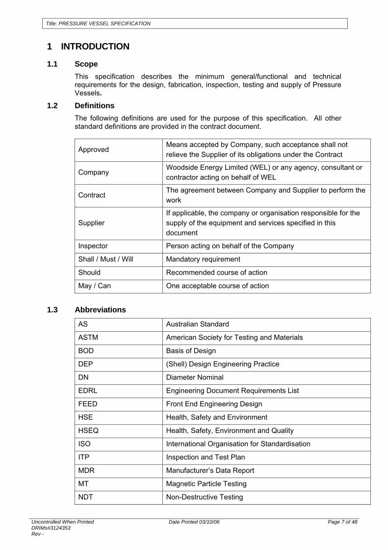
1.1 Scope This specification describes the minimum general/functional and technical requirements for the design, fabrication, inspection, testing and supply of Pressure Vessels.
1.2 Definitions The following definitions are used for the purpose of this specification. All other standard definitions are provided in the contract document.
Approved Means accepted by Company, such acceptance shall not relieve the Supplier of its obligations under the Contract
Company Woodside Energy Limited (WEL) or any agency, consultant or contractor acting on behalf of WEL
Contract The agreement between Company and Supplier to perform the work
Supplier If applicable, the company or organisation responsible for the supply of the equipment and services specified in this document
Inspector Person acting on behalf of the Company
Shall / Must / Will Mandatory requirement
Should Recommended course of action
May / Can One acceptable course of action
1.3 Abbreviations
AS Australian Standard
ASTM American Society for Testing and Materials
BOD Basis of Design
DEP (Shell) Design Engineering Practice
DN Diameter Nominal
EDRL Engineering Document Requirements List
FEED Front End Engineering Design
HSE Health, Safety and Environment
HSEQ Health, Safety, Environment and Quality
ISO International Organisation for Standardisation
ITP Inspection and Test Plan
MDR Manufacturer’s Data Report
MT Magnetic Particle Testing
NDT Non-Destructive Testing

Title: PRESSURE VESSEL SPECIFICATION
Uncontrolled When Printed DRIMs#3124353 Rev -
Date Printed 03/10/06 Page 8 of 48
PT Dye Penetrant Testing
PWHT Post Weld Heat Treatment
RT Radiographic Testing
SDS Supplier Document Schedule
UT Ultrasonic Testing
1.4 Units Units shall be in accordance with referenced Standard AS1000 except that pressure shall be expressed as MegaPascals (gauge) (MPa(g)).
1.5 Language All documentation and correspondence shall be in the English language.
Title: PRESSURE VESSEL SPECIFICATION
Uncontrolled When Printed DRIMs#3124353 Rev -
Date Printed 03/10/06 Page 9 of 48
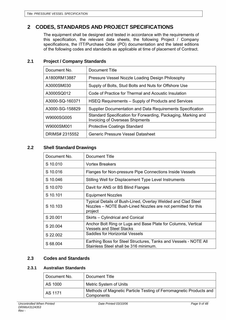
2 CODES, STANDARDS AND PROJECT SPECIFICATIONS The equipment shall be designed and tested in accordance with the requirements of this specification, the relevant data sheets, the following Project / Company specifications, the ITT/Purchase Order (PO) documentation and the latest editions of the following codes and standards as applicable at time of placement of Contract.
2.1 Project / Company Standards
Document No. Document Title
A1800RM13887 Pressure Vessel Nozzle Loading Design Philosophy
A3000SM030 Supply of Bolts, Stud Bolts and Nuts for Offshore Use
A3000SQ012 Code of Practice for Thermal and Acoustic Insulation
A3000-SQ-160371 HSEQ Requirements – Supply of Products and Services
A3000-SG-158829 Supplier Documentation and Data Requirements Specification
W9000SG005 Standard Specification for Forwarding, Packaging, Marking and Invoicing of Overseas Shipments
W9000SM001 Protective Coatings Standard
DRIMS# 2315552 Generic Pressure Vessel Datasheet
2.2 Shell Standard Drawings
Document No. Document Title
S 10.010 Vortex Breakers
S 10.016 Flanges for Non-pressure Pipe Connections Inside Vessels
S 10.046 Stilling Well for Displacement Type Level Instruments
S 10.070 Davit for ANS or BS Blind Flanges
S 10.101 Equipment Nozzles
S 10.103 Typical Details of Bush-Lined, Overlay Welded and Clad Steel Nozzles – NOTE Bush-Lined Nozzles are not permitted for this project
S 20.001 Skirts – Cylindrical and Conical
S 20.004 Anchor Bolt Ring or Lugs and Base Plate for Columns, Vertical Vessels and Steel Stacks
S 22.002 Saddles for Horizontal Vessels
S 68.004 Earthing Boss for Steel Structures, Tanks and Vessels - NOTE All Stainless Steel shall be 316 minimum.
2.3 Codes and Standards
2.3.1 Australian Standards
Document No. Document Title
AS 1000 Metric System of Units
AS 1171 Methods of Magnetic Particle Testing of Ferromagnetic Products and Components
Title: PRESSURE VESSEL SPECIFICATION
Uncontrolled When Printed DRIMs#3124353 Rev -
Date Printed 03/10/06 Page 10 of 48
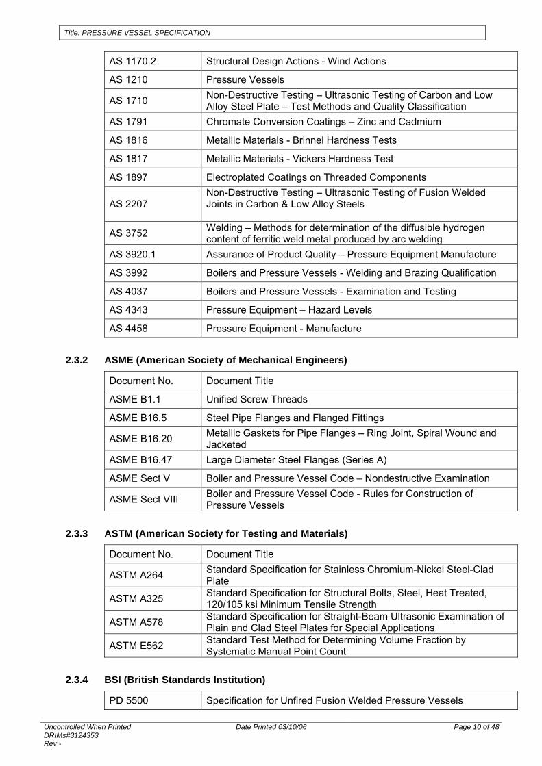
AS 1170.2 Structural Design Actions - Wind Actions
AS 1210 Pressure Vessels
AS 1710 Non-Destructive Testing – Ultrasonic Testing of Carbon and Low Alloy Steel Plate – Test Methods and Quality Classification
AS 1791 Chromate Conversion Coatings – Zinc and Cadmium
AS 1816 Metallic Materials - Brinnel Hardness Tests
AS 1817 Metallic Materials - Vickers Hardness Test
AS 1897 Electroplated Coatings on Threaded Components
AS 2207 Non-Destructive Testing – Ultrasonic Testing of Fusion Welded Joints in Carbon & Low Alloy Steels
AS 3752 Welding – Methods for determination of the diffusible hydrogen content of ferritic weld metal produced by arc welding
AS 3920.1 Assurance of Product Quality – Pressure Equipment Manufacture
AS 3992 Boilers and Pressure Vessels - Welding and Brazing Qualification
AS 4037 Boilers and Pressure Vessels - Examination and Testing
AS 4343 Pressure Equipment – Hazard Levels
AS 4458 Pressure Equipment - Manufacture
2.3.2 ASME (American Society of Mechanical Engineers)
Document No. Document Title
ASME B1.1 Unified Screw Threads
ASME B16.5 Steel Pipe Flanges and Flanged Fittings
ASME B16.20 Metallic Gaskets for Pipe Flanges – Ring Joint, Spiral Wound and Jacketed
ASME B16.47 Large Diameter Steel Flanges (Series A)
ASME Sect V Boiler and Pressure Vessel Code – Nondestructive Examination
ASME Sect VIII Boiler and Pressure Vessel Code - Rules for Construction of Pressure Vessels
2.3.3 ASTM (American Society for Testing and Materials)
Document No. Document Title
ASTM A264 Standard Specification for Stainless Chromium-Nickel Steel-Clad Plate
ASTM A325 Standard Specification for Structural Bolts, Steel, Heat Treated, 120/105 ksi Minimum Tensile Strength
ASTM A578 Standard Specification for Straight-Beam Ultrasonic Examination of Plain and Clad Steel Plates for Special Applications
ASTM E562 Standard Test Method for Determining Volume Fraction by Systematic Manual Point Count
2.3.4 BSI (British Standards Institution)
PD 5500 Specification for Unfired Fusion Welded Pressure Vessels
Title: PRESSURE VESSEL SPECIFICATION
Uncontrolled When Printed DRIMs#3124353 Rev -
Date Printed 03/10/06 Page 11 of 48
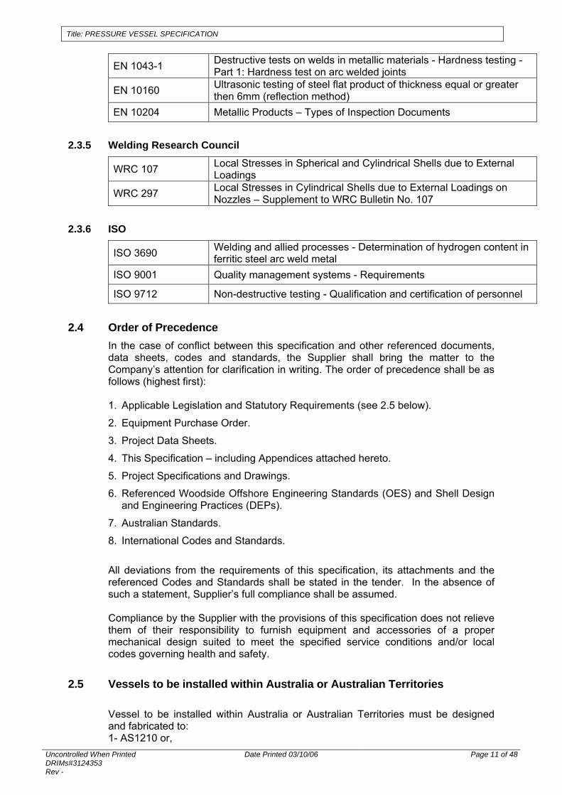
EN 1043-1 Destructive tests on welds in metallic materials - Hardness testing - Part 1: Hardness test on arc welded joints
EN 10160 Ultrasonic testing of steel flat product of thickness equal or greater then 6mm (reflection method)
EN 10204 Metallic Products – Types of Inspection Documents
2.3.5 Welding Research Council
WRC 107 Local Stresses in Spherical and Cylindrical Shells due to External Loadings
WRC 297 Local Stresses in Cylindrical Shells due to External Loadings on Nozzles – Supplement to WRC Bulletin No. 107
2.3.6 ISO
ISO 3690 Welding and allied processes - Determination of hydrogen content in ferritic steel arc weld metal
ISO 9001 Quality management systems - Requirements
ISO 9712 Non-destructive testing - Qualification and certification of personnel
2.4 Order of Precedence In the case of conflict between this specification and other referenced documents, data sheets, codes and standards, the Supplier shall bring the matter to the Company’s attention for clarification in writing. The order of precedence shall be as follows (highest first): 1. Applicable Legislation and Statutory Requirements (see 2.5 below).
2. Equipment Purchase Order.
3. Project Data Sheets.
4. This Specification – including Appendices attached hereto.
5. Project Specifications and Drawings.
6. Referenced Woodside Offshore Engineering Standards (OES) and Shell Design and Engineering Practices (DEPs).
7. Australian Standards.
8. International Codes and Standards.
All deviations from the requirements of this specification, its attachments and the referenced Codes and Standards shall be stated in the tender. In the absence of such a statement, Supplier’s full compliance shall be assumed.
Compliance by the Supplier with the provisions of this specification does not relieve them of their responsibility to furnish equipment and accessories of a proper mechanical design suited to meet the specified service conditions and/or local codes governing health and safety.
2.5 Vessels to be installed within Australia or Australian Territories
Vessel to be installed within Australia or Australian Territories must be designed and fabricated to: 1- AS1210 or,
Title: PRESSURE VESSEL SPECIFICATION
Uncontrolled When Printed DRIMs#3124353 Rev -
Date Printed 03/10/06 Page 12 of 48
2- designed and fabricated to an equivalent code such as ASME VIII or PD 5500, provided the design is verified to AS1210 by an independent third party approved by the Company
2.6 Vessels to be installed outside Australia or Australian Territories Vessels to be installed outside Australian or Australian Territories shall be design and fabricated to either AS1210 or a code as comparable to AS1210 approved by the Company. The following codes are considered comparable: ASME VIII PD5500

Title: PRESSURE VESSEL SPECIFICATION
Uncontrolled When Printed DRIMs#3124353 Rev -
Date Printed 03/10/06 Page 13 of 48
3 HSEQ REQUIREMENTS
3.1 General The Supplier shall develop and implement HSEQ management systems for the works which shall meet the requirements of Company document No: A3000-SQ-160371. Quality Assurance management systems shall be in accordance with AS/NZS ISO 9001:2000. Documents and data formats are defined in Company document No: A3000-SG-158829.
3.2 Inspection and Testing The Supplier shall perform inspection and testing activities in accordance with the requirements of this specification and Company approved Inspection and Test Plan (ITP). The ITP shall be submitted to the Company for approval as defined in the EDRL attached to the Material Requisition. The Supplier shall provide Company access to Supplier/sub-suppliers premises at any time.
3.2.1 Non Destructive Testing NDT shall be carried out in accordance with the requirements of the relevant Code and with this Specification. The proposed extent of the NDT, governing procedures, techniques and acceptance criteria shall be detailed on the Supplier’s Inspection and Test Plan.
3.3 Quality Records The Supplier shall generate quality records from the inspection and test activities listed in this specification and in accordance with the approved inspection and test plan(s). Documents and drawings shall be submitted as agreed in the Supplier’s Supplier Document Schedule (SDS). The records shall be compiled and reviewed by the Supplier following the completion of each inspection and test. Quality Records to be included in the Manufacturer's Data Report (MDR) are nominated in the EDRL contained within the Material Requisition. Those records not nominated for inclusion in the MDR shall be available for Company review throughout the contract period and thereafter retained in accordance with industry standards. The MDR shall be compiled as inspection and testing progresses. Quality records requiring Company review and or endorsement shall be forwarded to the Company progressively throughout the contract period.
Quality records requiring traceability as detailed in the Material Requisition shall bear an identical marking to the item inspected or tested.
Title: PRESSURE VESSEL SPECIFICATION
Uncontrolled When Printed DRIMs#3124353 Rev -
Date Printed 03/10/06 Page 14 of 48
3.4 Material Certification & Traceability Requirements
3.4.1 Certification Requirements Material Certification for the project shall be in accordance with EN 10204, Metallic Products – Types of Inspection Documents. The Certification Requirements defined within the Material Requisition are the minimum Certificate types for the specific components.
3.4.2 Traceability Requirements Two categories of traceability are utilised for the project, Full Traceability and Purchase Order Compliance. The required category for various pressure vessel components is defined within the Material Requisition. The Supplier shall demonstrate the existence of, and compliance with, a formalised procedure which shall be used to ensure that the correct materials have been used and that the following requirements are met by the Supplier, manufacturer or vendor.
Full Traceability The Supplier shall maintain a traceability system which ensures that all materials used can be positively identified back to original manufacturers' certificates. As a minimum this procedure shall include the following actions:
• Materials shall be checked on receipt against accompanying original manufacturers' certificates for compliance with specified requirements.
• Material batch, specification and grade details shall be positively identified (by permanent marking wherever possible) throughout manufacture.
• Transfer of material identification shall be witnessed and documented by the Supplier's inspector.
• Records of material location shall be maintained.
• Before the application of the surface treatment a complete record of material location shall be compiled for incorporation into the Manufacturing Data Records.
• Construction records shall contain material location records and original manufacturers' certificates.
• As-built records shall be maintained.
Purchase Order Compliance The Supplier shall maintain a system that whereby auditing of the system can verify compliance with purchase order requirements. As a minimum this system shall include the following actions:
• Materials shall be checked on receipt for compliance with purchase order requirements.
• The Supplier shall, for materials that are issued with lot or batch traceable certification (eg. welding consumables, etc.), maintain batch or lot segregation up to the point of use.
3.5 Marking for Identification and Traceability The Supplier shall mark items for identification and traceability in accordance with the following requirements.
Title: PRESSURE VESSEL SPECIFICATION
Uncontrolled When Printed DRIMs#3124353 Rev -
Date Printed 03/10/06 Page 15 of 48
• Markings to facilitate identification and traceability during processing shall be maintained throughout the manufacture and fabrication stages. The Supplier shall propose the method for identification marking during processing for Company approval.
• Markings covered in final assembly and/or coating shall be first transferred to as-built traceability quality records. The transfer of markings to traceability quality records may be subject to Company verification.
• Markings to facilitate permanent identification and traceability shall be in accordance with the Material Requisition and shall remain visible for the life of the item.
Title: PRESSURE VESSEL SPECIFICATION
Uncontrolled When Printed DRIMs#3124353 Rev -
Date Printed 03/10/06 Page 16 of 48
4 GENERAL REQUIREMENTS
4.1 Scope of Work
• Supplier’s scope includes design calculations, drawings and documentation, provision of all materials, manufacture, inspection, non-destructive examination, trial assembly, testing, painting and delivery as defined in the Material Requisition.
• The Supplier should draw upon their existing pre-engineered or standard designs as far as is practicable in order to satisfy the functional and technical requirements described within this specification and referenced documentation.
4.2 Design Life The pressure vessels shall be designed for continuous service at the conditions specified in the data sheets for a life of 30 years minimum unless otherwise specified in Datasheet.
4.2 Transportation All equipment for the shall be specified and designed to withstand concurrent dynamic and static loading and transportation accelerations as defined within the referenced Site Data Sheet to supplied by the Company.
4.3 Weight Control The Supplier shall exercise an active weight control system throughout the design and fabrication of the Equipment. The Supplier shall submit an Equipment Weight Data Sheet with weight and centre of gravity information.

Title: PRESSURE VESSEL SPECIFICATION
Uncontrolled When Printed DRIMs#3124353 Rev -
Date Printed 03/10/06 Page 17 of 48
5 TECHNICAL REQUIREMENTS
5.1 General The Supplier shall comply with the Design Verification and Fabrication Inspection requirements of AS 3920.1. These requirements are based upon the vessel Hazard Level as calculated in accordance with the requirements of AS 4343, and the status of the Designers Quality System. This Hazard Level will be defined within the vessel data sheet. For columns with height to diameter ratio equal or greater than 10:1 the design shall consider vibration and the critical wind velocity, the allowable deflection at the top shall not exceed 1/200th of the total height. Supplier shall provide full service bolting and a service gasket for all manholes, hand-holes, and other flanges for which a blind flange or mating flange is provided by Supplier. Unless specifically defined otherwise on the relevant Data Sheet, all vessels operate under steady state pressure and temperature. Supplier shall design and provide bracing as required to protect the vessel and internals during shipment. Temporary welding to the vessel will not be permitted. Supplier shall design, supply and install all lifting and tailing lugs, clips, attachments, and other members that are welded or attached to the outside or inside surface of the vessel or to the vessel supports. Wherever possible attachments shall be via full penetration butt welds. If the datasheet indicates that the vessel will be in cyclic operation, all attachment welds shall be located as remote as practicable from gross structural discontinuities and other welds.
5.2 Materials Material specification shall be as defined on the Vessel Data Sheet unless specific written approval is obtained from the Company, any Supplier proposal for substitution of materials shall include ASTM/ASME or AS designations and any relevant Code cases.
5.2.1 Carbon and Carbon-Manganese Steels The following requirements apply:
• Maximum Carbon content shall be 0.23% for plate and piping material.
• Maximum Carbon content shall be 0.25% for forged material.
• Maximum Niobium content shall be 0.05%.
• Boron shall not be intentionally added to the steel and as a trace element it shall not exceed 0.0005%.
• The total content of micro-alloying elements shall be limited as follows:
• (Nb+V+Ti) ≤0.08%
• The Carbon Equivalent shall satisfy one of the following requirements:
Title: PRESSURE VESSEL SPECIFICATION
Uncontrolled When Printed DRIMs#3124353 Rev -
Date Printed 03/10/06 Page 18 of 48
• Ceq = C + Mn/6 ≤ 0.42 (may only be used where the material specification defines C and Mn only)
• Ceq = C + Mn/6 +(Cr + Mo + V)/5 + (Cu + Ni)/15 ≤ 0.43
• If not already specified in the relevant material specification, the analysis for plate shall include: Cu, Ni, V, Mo, Nb, Ti, B.
5.2.2 Duplex Stainless Steels All Duplex Stainless Steel (DSS) material shall have a minimum Nitrogen content of 0.15%, regardless of the requirements of the material specification. All DSS material shall have a minimum pitting resistance equivalent number (PREN) of 35, calculated as per the following equation: PREN = wt % Cr + (3.3 x wt % Mo) + (16 x wt % N). The volume fraction of ferrite and austenite shall be determined by the point count technique of ASTM E562 by examination of a micro section for each heat of DSS material. The ferrite content shall be in the range 40% to 60%.
5.2.3 Clad Steel Vessels See Appendix A.
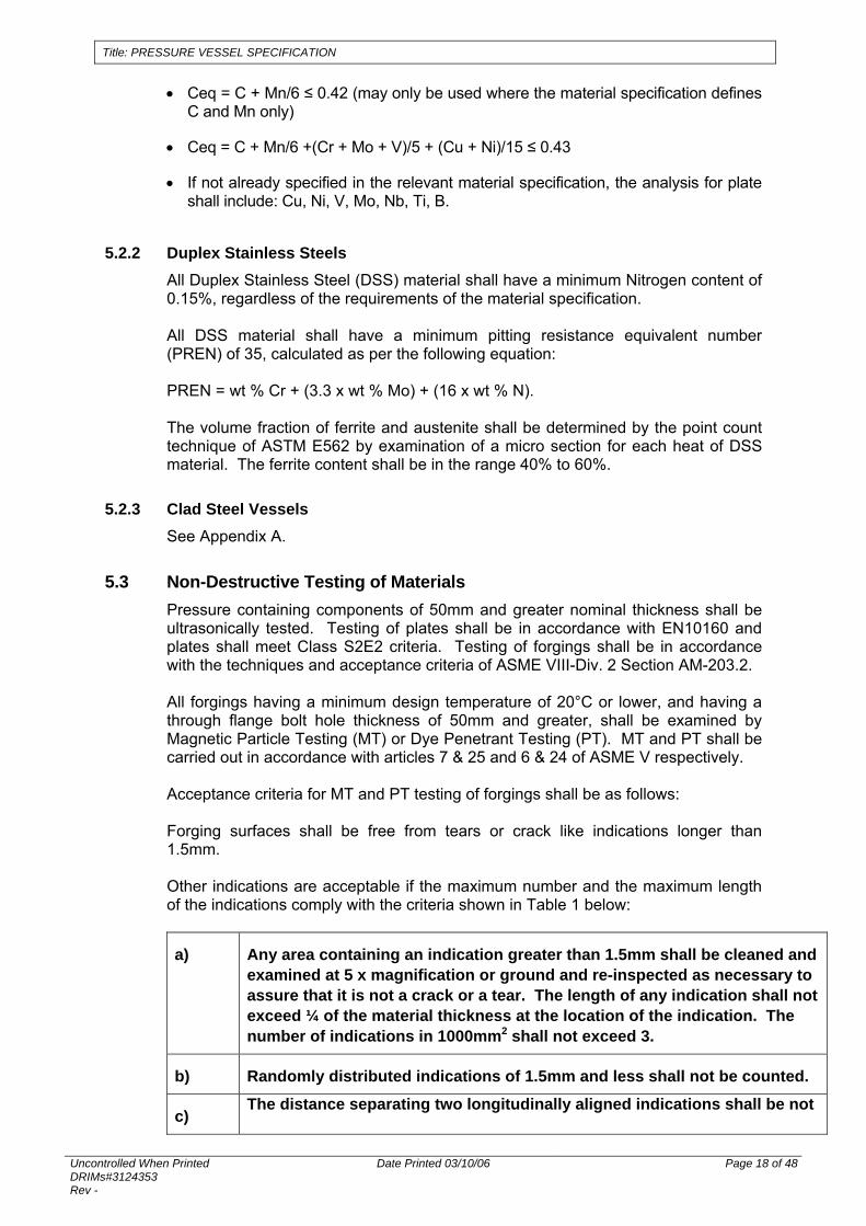
5.3 Non-Destructive Testing of Materials Pressure containing components of 50mm and greater nominal thickness shall be ultrasonically tested. Testing of plates shall be in accordance with EN10160 and plates shall meet Class S2E2 criteria. Testing of forgings shall be in accordance with the techniques and acceptance criteria of ASME VIII-Div. 2 Section AM-203.2. All forgings having a minimum design temperature of 20°C or lower, and having a through flange bolt hole thickness of 50mm and greater, shall be examined by Magnetic Particle Testing (MT) or Dye Penetrant Testing (PT). MT and PT shall be carried out in accordance with articles 7 & 25 and 6 & 24 of ASME V respectively. Acceptance criteria for MT and PT testing of forgings shall be as follows: Forging surfaces shall be free from tears or crack like indications longer than 1.5mm. Other indications are acceptable if the maximum number and the maximum length of the indications comply with the criteria shown in Table 1 below:
a) Any area containing an indication greater than 1.5mm shall be cleaned and examined at 5 x magnification or ground and re-inspected as necessary to assure that it is not a crack or a tear. The length of any indication shall not exceed ¼ of the material thickness at the location of the indication. The number of indications in 1000mm2 shall not exceed 3.
b) Randomly distributed indications of 1.5mm and less shall not be counted.
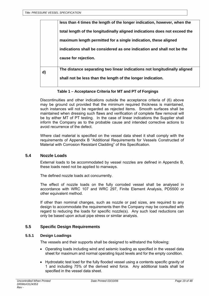
c) The distance separating two longitudinally aligned indications shall be not
Title: PRESSURE VESSEL SPECIFICATION
Uncontrolled When Printed DRIMs#3124353 Rev -
Date Printed 03/10/06 Page 19 of 48
less than 4 times the length of the longer indication, however, when the
total length of the longitudinally aligned indications does not exceed the
maximum length permitted for a single indication, these aligned
indications shall be considered as one indication and shall not be the
cause for rejection.
d) The distance separating two linear indications not longitudinally aligned
shall not be less than the length of the longer indication.
Table 1 – Acceptance Criteria for MT and PT of Forgings
Discontinuities and other indications outside the acceptance criteria of (6) above may be ground out provided that the minimum required thickness is maintained, such instances will not be regarded as rejected items. Smooth surfaces shall be maintained when dressing such flaws and verification of complete flaw removal will be by either MT of PT testing. In the case of linear indications the Supplier shall inform the Company as to the probable cause and intended corrective actions to avoid recurrence of the defect. Where clad material is specified on the vessel data sheet it shall comply with the requirements of Appendix B “Additional Requirements for Vessels Constructed of Material with Corrosion Resistant Cladding” of this Specification.
5.4 Nozzle Loads External loads to be accommodated by vessel nozzles are defined in Appendix B, these loads need not be applied to manways. The defined nozzle loads act concurrently. The effect of nozzle loads on the fully corroded vessel shall be analysed in accordance with WRC 107 and WRC 297, Finite Element Analysis, PD5500 or other equivalent method. If other than nominal changes, such as nozzle or pad sizes, are required to any design to accommodate the requirements then the Company may be consulted with regard to reducing the loads for specific nozzle(s). Any such load reductions can only be based upon actual pipe stress or similar analysis.
5.5 Specific Design Requirements
5.5.1 Design Loadings The vessels and their supports shall be designed to withstand the following:
• Operating loads including wind and seismic loading as specified in the vessel data sheet for maximum and normal operating liquid levels and for the empty condition.
• Hydrostatic test load for the fully flooded vessel using a contents specific gravity of 1 and including 75% of the derived wind force. Any additional loads shall be specified in the vessel data sheet.
Title: PRESSURE VESSEL SPECIFICATION
Uncontrolled When Printed DRIMs#3124353 Rev -
Date Printed 03/10/06 Page 20 of 48
• Blast Load: The blast load resistance requirements of each pressure vessel where required shall be specified on the vessel datasheet on a project specific basis.
• Other loads specified on the Vessel Datasheet.
5.5.2 Acceptable Weld Joint Details For vessels designed and fabricated to AS1210, only the following figures of joint details are acceptable:
• Fig. 3.5.1.5. (A) a, b, f, g, j, k, l, m and n.
• Fig. 3.5.1.5. (B) a, b, c, e and f.
• Fig. 3.5.1.5. (C) a, c, f, g and h – for details (a) and (c) Backing Strips shall not be used.
For vessels designed and fabricated to codes other than AS1210, joint designs shall be selected to match as closely as possible those listed above (no permanent backing strips, no partial penetration butt welds). Wherever possible attachment welds shall be full penetration butts. Where fillet welds are permitted for internal and external attachments they shall be continuous welds. Brazed and/or soldered joints shall not be used. For attachment of Unstayed Flat Ends and Covers only the following joint arrangements are acceptable:
• Fig. 3.15.1 a, b-1, b-2, d, g, k, l, m and p. The minimum distance between the edges of adjacent welds shall be 50mm or twice the thickness of the pressure part, whichever is greater. If this cannot be achieved in the case of a pad attachment weld adjacent to a pressure part weld then the pad attachment shall cross the pressure part weld completely by 50mm or twice the pressure part thickness, whichever is greater. Prior to welding the attachment the pressure part weld shall be dressed (to facilitate “snug” fitting of the attachment) and shall be subjected to NDE as specified in AS 4037 Table 7.1. Longitudinally welded joints shall not be located behind any plate or obstruction that prevents inspection of the weld on the inside of the vessel. Circumferentially welded joints shall clear any support ring welds by at least 25 mm.
5.5.3 Nozzles and Flanges Nozzle flanges shall be in accordance with ASME B16.5. Flanges larger than the scope of ASME B16.5 shall be in accordance with ASME B16.47 Series A. Gaskets shall be 316 spiral wound graphite filled with inner and outer support rings unless otherwise specified on the vessel data sheet. Other standard flanges (e.g. API, DIN or JIS) can only be used will approval of the Company unless otherwise specified on the vessel data sheet. Non standard flanges (as defined above) shall be designed in accordance with AS1210 and shall include a detailed FEA analysis of the joint with consideration of the gasket. The analysis must consider all loads likely to be seen during both testing and operation of the joint.

Title: PRESSURE VESSEL SPECIFICATION
Uncontrolled When Printed DRIMs#3124353 Rev -
Date Printed 03/10/06 Page 21 of 48
Where vessel shell thickness is equal to or greater than 100mm, nozzles shall be of the forged saddle type. Where the vessel datasheet specifies cyclic operation welded reinforcement pads are not permitted. Any reinforcement shall be integral to the nozzle or vessel. Studded pad type nozzles or manholes are not permitted. Where nozzle reinforcing pads are permitted their thickness shall not exceed 40mm or the vessel wall thickness, whichever is smaller. Reinforcing pads of DN250 and smaller nozzles shall have one 6mm tell-tale hole. Pads for nozzles greater than DN250 shall have two ¼” NPT tell-tale holes provided at 180° spacing. All tell-tale holes shall be plugged with heavy grease after pneumatic test. Minimum manway size shall be DN600 unless specifically shown otherwise on the vessel data sheet. Only the following joint arrangements are acceptable:
• Figure 3.19.3 (A) a, b, c, d, e, f, g,
• Fig. 3.19.3. (B) f, g, h, j, and k.
• Fif. 3.19.3. (C) a, b, c (for non-cyclic service only)
• Fig. 3.19.3. (D) a, b, c, e, f and g.
• Fig. 3.19.9. b, c, d, e and f. Screwed and socket welded connections are not permitted. The reinforcing fillet of the nozzle attachment welds shall blend smoothly into the vessel and into the nozzle wall without any notch, sharp corner or undercut. Nozzles shall have a 6mm radius applied to the inside edge. Unless otherwise specified, flanges shall be weld neck or long weld neck type. Slip-on type flanges or nozzles are not permitted. Bolt holes shall straddle natural centre lines. Davits shall be provided for all Manholes. Manholes shall be provided with handgrips inside the vessel and, when located more than one metre above the base of the vessel, shall have internal ladder rungs. Handhole covers heavier than 15 kg shall be provided with either davits or hinges. In addition to the requirements of AS1210, openings shall also comply with the requirements of ASME Section VIII Division 1 Appendix 1 Para 1-7 where size of opening exceeds the following: For vessels 1520 mm inside diameter and less, the lesser of one-half the vessel diameter or 508 mm (nozzle inside diameter). For vessels over 1520 mm inside diameter, the lesser of one-third the vessel diameter or 1000 mm (nozzle inside diameter).
Title: PRESSURE VESSEL SPECIFICATION
Uncontrolled When Printed DRIMs#3124353 Rev -
Date Printed 03/10/06 Page 22 of 48
5.5.4 Attachment Loadings External loads to be accommodated by vessel attachments are defined on the vessel data sheet. The effect of attachment loads on the fully corroded vessel shall be analysed in accordance with WRC 107 and WRC 297 or other detailed analysis such as FEA. Pressure shall be included where applicable. If changes are required to any design to accommodate external loads then the Company shall be consulted with regard to reducing the loads for specific attachments. All attachments shall be designed to provide easy access for maintenance and surface coating. Sharp corners shall be a 25mm minimum radius to prevent injury.
5.5.5 Fixed Internals Fixed internal piping ≤DN200 with no pressure differential shall be 3mm minimum thickness before corrosion allowance is added, fixed piping >DN200 shall be 6mm minimum before corrosion allowance is added. Corrosion allowance on non-removable internal parts shall be the same as the vessel corrosion allowance and shall be applied to all exposed surfaces, including attachment fillet welds. Bolting of internals shall be securely tightened a second nut or suitable adhesive. All internal crevices where supports and fixed internals are welded to the shell or heads shall be seal welded to exclude process fluids. All seal welds shall have the specified corrosion allowance added to the throat thickness.
5.5.6 Vessel Supports For vessel support design 50% of the defined nozzle load for each nozzle shall be considered to be acting on the nozzles. Load directions shall be based upon the most conservative support design, i.e. the “worst case” nozzle load summation. Nozzle loads may be assumed to be acting at the vessel Centre of Gravity for the purpose of support design. Support design shall take loading during hydrostatic testing into consideration. Horizontal vessels shall be provided with two support saddles. One support shall allow for horizontal thermal expansion, with the expansion slot length equal to twice the differential expansion between the maximum and minimum vessel design temperature plus the slot width plus 10mm. For vertical vessels where a skirt support is used, the mean diameter of the skirt shall coincide with the mean diameter of the vessel at the point of attachment. For vertical vessels with a full skirt support, an access opening(s) shall be provided to allow access for inspection of the shell. The vessel support(s) shall consider blast loads when specified on the vessel datasheet
Title: PRESSURE VESSEL SPECIFICATION
Uncontrolled When Printed DRIMs#3124353 Rev -
Date Printed 03/10/06 Page 23 of 48
5.5.7 Bolting Flange bolting, stud bolts and nuts shall comply with the requirements of specification A3000SM030. Bolting materials shall be as specified on the relevant vessel data sheet. Bolting for internals shall be ISO Metric Coarse thread form. External bolting for covers, blind flanges, and shell flanges shall be stud bolt, with 2 heavy hex nuts each. For sizes 1¼" and greater, stud lengths shall be increased by a minimum of one nut thickness to allow the use of hydraulic tensioning equipment. Nuts shall be impact tested to the same values as their corresponding studs.
5.5.8 Tolerances See Appendix C.
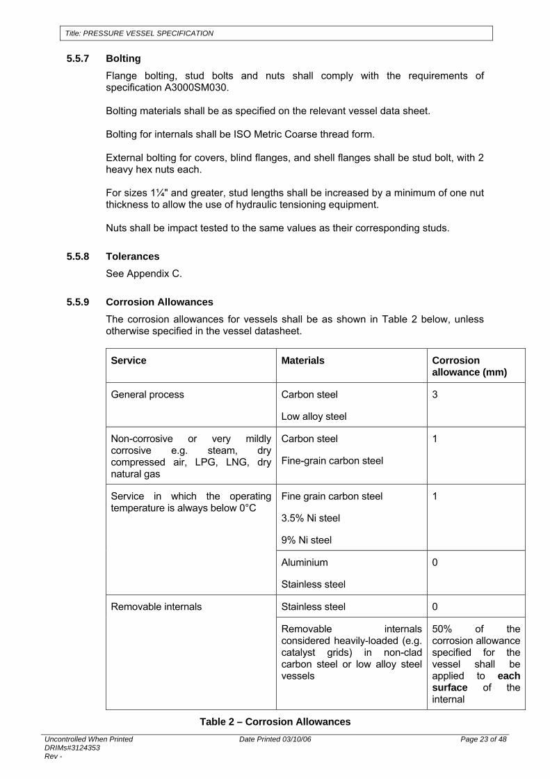
5.5.9 Corrosion Allowances The corrosion allowances for vessels shall be as shown in Table 2 below, unless otherwise specified in the vessel datasheet.
Service Materials Corrosion allowance (mm)
General process Carbon steel
Low alloy steel
3
Non-corrosive or very mildly corrosive e.g. steam, dry compressed air, LPG, LNG, dry natural gas
Carbon steel
Fine-grain carbon steel
1
Fine grain carbon steel
3.5% Ni steel
9% Ni steel
1 Service in which the operating temperature is always below 0°C
Aluminium
Stainless steel
0
Stainless steel 0 Removable internals
Removable internals considered heavily-loaded (e.g. catalyst grids) in non-clad carbon steel or low alloy steel vessels
50% of the corrosion allowance specified for the vessel shall be applied to each surface of the internal
Table 2 – Corrosion Allowances

Title: PRESSURE VESSEL SPECIFICATION
Uncontrolled When Printed DRIMs#3124353 Rev -
Date Printed 03/10/06 Page 24 of 48
5.6 Electrical Requirements
5.6.1 Earth Bonding All vessels shall be provided with two earthing connections approximately 180° apart, welded to the skirt or two opposing support legs or one on each saddle support web.
5.7 Lifting Attachments Lifting attachments shall be designed and verified by qualified experienced engineers working for a body that holds ISO 9001 certification. Should the design body not hold an ISO 9001 certificate then the design shall be certified by a classification society, i.e. Lloyds, DNV etc. Design calculations shall also be submitted to the Company for review. The vessel fabricator shall be experienced and competent in the fabrication of such items and shall hold an ISO 9001 certificate (or Company approved equivalent). Adequate lifting lugs/trunnions shall be provided to allow safe lifting of the vessels. Lifting point location shall be selected to ensure that lifting slings do not bear upon the vessel or its protective packing. The lug locations shall ensure that the vessel is "suspended level", within a tolerance of two percent of the total lifted vessel length. 100 % of the load for two, three and four point lifts shall be assumed to be taken by two of the slings. Total lift loads for the design of lifting lugs/trunnions shall include the dead weight of the vessel plus the weight of packaging materials attached to the vessel during shipment. Lifting lugs/trunnions shall be designed using an impact factor of 2.0. Lifting attachments shall be full penetration butt welded subjected to 100% NDE.
5.8 Fabrication and Manufacture
5.8.1 General All plates shall be laid out so that there will be a minimum of welded seams. Thermally cut edges shall be dressed back to the greater of 1mm or as per Table 5.1 of AS4458 by machining or grinding. Sheared edges between 11 and 25mm thickness shall be dressed back at least 3mm by machining or grinding. Weld metal shall not be used to build up the edges of plates that are too short or those that contain large cavities without prior approval of Company. Welded joints in horizontal vessels shall not interfere with supports. All support saddles and bearing plates shall be continuously welded to the vessel and provided with a 6mm tell tale vent hole which shall be plugged with heavy grease after coating. Manufacture involving welding shall not be sublet to others without the prior written approval of the Company.
Title: PRESSURE VESSEL SPECIFICATION
Uncontrolled When Printed DRIMs#3124353 Rev -
Date Printed 03/10/06 Page 25 of 48
5.8.2 Forming Prior to the forming of stainless steel plates, the working surfaces of the rolls or tools shall be completely free of ferrous chips, scale, dirt and other foreign materials. All plates which have been cold rolled into cylinders with an internal diameter less than 20 times the plate thickness or cold formed into dished ends or where the forming generates more than 5% extreme fibre strain shall be stress relieved. Austenitic stainless steels shall be solution annealed after hot forming. Cold formed austenitic and duplex stainless steels, where extreme fibre strains exceed 10%, shall be subjected to a post forming heat treatment. Prior to fabrication the Supplier shall demonstrate by simulated heat treatment on test pieces that any component subject to heat treatment will retain the minimum specified mechanical or other properties specified for the parent material after the heat treatment. This shall include all heat treatments such as normalising, quenching and/or tempering and post-weld heat treatment. All such tests shall be recorded and documented and included in the Manufacturer’s Data Report (MDR). Normalising shall be performed separately, not as part of the hot forming operation, and shall be recorded and documented on temperature recording chart. Supplier shall submit, for Company review, detailed procedures for all proposed heat treatments. Hot formed sections of shells and heads shall have the scale removed after forming by grit blasting or pickling.
Title: PRESSURE VESSEL SPECIFICATION
Uncontrolled When Printed DRIMs#3124353 Rev -
Date Printed 03/10/06 Page 26 of 48
6 WELDING
6.1 Welding Procedures and Qualification Documentation of welding procedures and qualifications, including weld repair procedures and qualifications, shall be submitted as follows:
• Welding Procedure Specifications (WPSs) shall be submitted for review prior to the start of Procedure Qualification. Submissions shall include a brief summary of the application of each welding procedure with respect to the type of joint and material, the qualified range of each welding parameter and a Weld Map which identifies the usage of the WPS. Upon Company approval of the WPS the Supplier may proceed with the Procedure Qualification.
• Full Procedure Qualification Record Packages (PQRs), including running sheets, NDT reports, mechanical test reports, PWHT chart if applicable, material and consumable certificates, shall be submitted for review, and shall be approved by the Company, prior to the start of any welding utilising the subject WPS.
• Pre-qualified procedures in accordance with AS3992 Section 2 may be submitted for review.
• Previously qualified procedures may be submitted for review.
• For bare wire consumables (GTAW, GMAW, SAW), change of brand or product name is not considered an essential variable, provided the wire used for production welding is of the same classification (e.g. AWS A5.9: E316L) as that used for procedure qualification.
• For fluxed consumables (SMAW, FCAW, SAW flux), brand substitution is not permitted, and both WPS and PQR running sheet must clearly specify brand, product name and classification of consumables. Change of brand, product name or classification requires re-qualification of the welding procedure.
• All fluxed consumables shall be capable of depositing low hydrogen (<10 mls/100g weld metal) weld metal, and handling and storage procedures shall be in place to ensure that these low hydrogen levels are attained and maintained throughout use.
• Welding Procedure Specifications shall reference this standard.
• Use of permanent backing is prohibited.
6.2 Qualification Testing of Welding Procedures for Duplex Stainless Steel The volume fraction of ferrite and austenite in the weld metal and the HAZ shall be determined on a micro-section in accordance with the principles outlined in ASTM E562-83. A photograph of the microstructure shall be produced. The ferrite proportion in the microstructure shall be in the range 30 to 70%. A micro-section of the weld shall be taken with etching and magnification appropriate to the detection of sigma, chi and any other brittle intermetallic precipitation. Undesirable precipitates shall be reported. The maximum permissible amount of sigma phase is 2%.

Title: PRESSURE VESSEL SPECIFICATION
Uncontrolled When Printed DRIMs#3124353 Rev -
Date Printed 03/10/06 Page 27 of 48
6.3 Qualification Testing of Welding Procedures for Clad Steel Vessels Corrosion resistant weld overlays used in the restoration of, or in place of, cladding, shall be a minimum of two layers. Ferrite content of austenitic stainless steel overlay welds shall be tested using a ferrite scope. For procedures subject to post Weld Heat Treatment (PWHT), the ferrite content of the weld overlay shall be between 3-8% delta ferrite. For procedures not subject to PWHT, the ferrite content of the weld overlay shall be between 3-10%. Ferrite content shall be measured on the welding procedure qualification and production test plate. The supplier shall demonstrate via macro and micro examination of sections taken from the relevant welding procedure qualification testpiece(s) that undesirable metallurgical structures are not produced as a result of dilution during weld cladding.
6.4 Welder Qualifications Welder qualification records including a register shall be available for review at the works. No welder shall be employed for vessel fabrication until the relevant qualification records have been accepted by the Company Inspector. All welders shall be qualified in accordance with the applicable code. An existing welder qualification is acceptable provided that the Supplier shows that the qualification complies with all technical details and the welder has welded within the limits of the qualification in the preceding six months. The Supplier shall ensure suitable recording of the qualification validity for each welder and this record shall be available for review at the works and acceptance by the Company Inspector.
6.5 Consumable Control Welding consumables shall be stored and conditioned in accordance with the manufacturer’s recommendations. Procedures for receiving, storing, conditioning and issuing consumables shall be submitted for Company approval prior to commencement of the work. No electrodes shall be re-dried more than three times.
6.6 Production Welding
6.6.1 General Care shall be taken to ensure that electrodes are struck either in the weld groove or on dummy material outside the proper material to be welded. If arc strikes occur outside the weld groove, the area shall be ground and subjected to non-destructive testing to ensure that no cracks have resulted. Temporary attachment welds on pressure retaining parts shall be removed to within 5 mm of the parent shell plate, then ground flush. The surface under such welds, and backing rings, which have been removed, shall be examined either by magnetic particle Inspection (MT) or dye-penetrant (PT) testing to ensure removal of unacceptable surface discontinuities. Welds with defective areas shall have:
• The defects removed.
• Confirmation of defect removal by MT, or if the material is non ferritic, by dye-penetrant testing.
• Repair welding using approved qualified procedures.
Title: PRESSURE VESSEL SPECIFICATION
Uncontrolled When Printed DRIMs#3124353 Rev -
Date Printed 03/10/06 Page 28 of 48
• The excavation for the repair weld shall be a minimum of 75 mm length.
• The finished weld repair shall, as a minimum, be subjected to the NDE required for the original weld. In addition the surface shall be re-examined by MT or PT testing.
• If the repair involves serious alterations or repair to already repaired defects, approval of Company shall be obtained before proceeding with the repair.
• All repair welding, inspection and testing shall be fully recorded and documented
• Injurious defects identified during the course of fabrication either visually or by inspection techniques shall not be repaired unless authorised by the Company.
• Welders causing an excessive proportion of unsound welds, e.g. 10% or greater shall be identified and diverted from this work.
Welding outside the confines of the fabrication shop shall not be permitted. In exceptional circumstances, such welding may be permitted after review of the reason and planned arrangements to protect the welding from weather conditions. This shall include protection from wind, rain and run-off. All welding and NDT operations shall be completed before PWHT, pressure testing and coating. To this end a hold point shall be designated on the ITP to provide assurance that all welding, NDT and associated documentation are completed before these operations. NDT shall be repeated after hydrotest and/or PWHT as prescribed by AS 4037 Section 6.
6.6.2 Clad Steel Vessels When depositing weld overlay to reinstate cladding at butt welds during vessel manufacture, the following sequence and precautions shall be observed:
• After stripping back the cladding, all the edges of the parent material that are prepared for welding, the base material and cladding shall be subjected to dye penetrant testing.
• Any defect or remnant stainless steel detected shall be removed by grinding or machining. Elimination of the defect or remnant stainless cladding shall be confirmed by dye penetrant testing / copper sulphate swab.
• The weld seam in the substrate shall be ground flush before depositing the weld overlay.
• Clad surfaces shall be protected at all times from physical damage and surface contamination from iron dust particles, weld spatter, etc.
• Contaminated clad surfaces shall be chemically cleaned such that the finish required by the material specification, against which it was furnished, is restored.
• Where attachments are to be welded to clad materials, the WPS to be used shall be submitted to the Company for review and approval.
• Fit-up devices shall not be welded to the cladding.

Title: PRESSURE VESSEL SPECIFICATION
Uncontrolled When Printed DRIMs#3124353 Rev -
Date Printed 03/10/06 Page 29 of 48
6.7 Post Weld Cleaning of Non-Ferritic Vessels Non-ferritic (austenitic and duplex stainless steels, titanium, nickel alloy) shall be free of iron contamination and oxide scale discolouration. After the completion of welding operations, all welds and discoloured or contaminated surfaces shall be pickled, passivated and thoroughly washed, all in accordance with a Company approved procedure.
Title: PRESSURE VESSEL SPECIFICATION
Uncontrolled When Printed DRIMs#3124353 Rev -
Date Printed 03/10/06 Page 30 of 48
7 INSPECTION AND TEST
7.1 Pressure Tests Vessels shall be tested at the test pressure specified by the design Code for a period of not less than 30 minutes in the presence of the Company's Inspector. The testing shall be carried out in accordance with AS4037. The test medium for hydrostatic testing shall be potable water unless otherwise approved by the Company. For stainless steel or stainless steel clad vessels, the water shall not contain chlorides in excess of 200ppm and a water analysis certificate shall be provided confirming compliance. External attachment pads shall be tested with soapy water and air at 100 kPag prior to PWHT and the final hydrostatic test. Horizontal vessels shall be tested on permanent support saddles and not otherwise supported. After hydrostatic test, all water shall be completely removed and vessel interior shall be thoroughly dried. The vessel shall be re-checked for distortion within the limits provided by AS4458. After completion of the vessel pressure test, welding on the pressure-containing portion of the vessel is not permitted without prior approval by the Company.
7.2 Non Destructive Examination An NDE schedule shall be submitted to the Company prior to manufacture. The schedule identifies for each type of joint the method, sensitivity, amount and stage of test. (An example of reporting format is contained in AS 4037, Appendix E). The Principal shall review the schedule to assess whether it provides optimum detection of imperfections requiring assessment. The schedule shall include in-process NDE used to detect and remove defects prior to post weld heat treatment.
7.2.1 NDE Procedures NDE procedures shall be submitted to the Company for review before the commencement of any examination.
7.2.2 NDE Personnel Non-destructive testing personnel shall be qualified in the technique being used, in accordance with ISO 9712. Ultrasonic inspection shall be performed by a Level II or III technician. A Level II or III technician is also required for interpretation of radiographs. All NDE reports shall be reviewed and endorsed by a Level III technician.
7.2.3 NDE During Production Where heads are to be formed from more than one plate, weld seams are to be fully tested AFTER forming. Ultrasonic examination shall include weld scanning for transverse indications. Visual inspection reports shall include observations on any evidence of oxidation associated with stainless steel welding and the effectiveness of subsequent cleaning operations.

Title: PRESSURE VESSEL SPECIFICATION
Uncontrolled When Printed DRIMs#3124353 Rev -
Date Printed 03/10/06 Page 31 of 48
All overlay deposited onto girth and seam welds shall be 100% dye penetrant tested after welding to ensure that deposits are free from cracks and other unacceptable imperfections. The surface examination shall be repeated after PWHT, to demonstrate that cracks or other unacceptable imperfections have not developed. The ferrite content of production overlay welds shall be tested using a ferrite scope. The extent of testing shall be:
• A minimum of five readings per course.
• A minimum of five readings per head.
• A minimum of one reading per nozzle. The acceptance levels shall be 3-8% ferrite for PWHT vessels and 3-10% ferrite for non-PWHT vessels.
7.2.4 Storage of Radiographs The NDT Contractor shall retain all exposed radiographic films on file for a period of five years from the date of issue of the relevant test report.
7.3 Heat Treatment Supplier shall submit a detailed procedure for Company approval for all proposed PWHT operations, subsequent heat treatment shall be strictly in accordance with the approved procedure.
7.4 Cleaning of Vessels Each vessel shall be thoroughly cleaned inside and outside and shall be free from grease, weld spatter, scale, slag, rust, and any other foreign matter.
Title: PRESSURE VESSEL SPECIFICATION
Uncontrolled When Printed DRIMs#3124353 Rev -
Date Printed 03/10/06 Page 32 of 48
8 NAMEPLATE A 316L stainless steel nameplate shall be fixed to each vessel. The attachment shall be to a bracket which extends a minimum of 50mm beyond the specified insulation thickness. In addition to Code requirements the nameplate shall provide the following data:
• Client name.
• Project name.
• PO number.
• Equipment title.
• Equipment tag number.
• Supplier’s name.
• Serial number.
• Date of manufacture.
Appendix D shows further detail of nameplate and bracket dimensions and layout.

Title: PRESSURE VESSEL SPECIFICATION
Uncontrolled When Printed DRIMs#3124353 Rev -
Date Printed 03/10/06 Page 33 of 48
9 COATINGS AND EXTERNAL MARKING Vessels that are specified as requiring external coating shall have all exterior surfaces coated, including the inside of skirts, the exterior of the bottom head for vertical vessels and the inside of flange bolt holes. Surface preparation and coating for both internal and external surfaces shall be in accordance with the requirements of specification W9000SM001. The required coating system will be defined upon the respective data sheet. Painting shall be performed after completion of all testing. Vessels shall be clearly identified by painting or dye stencilling the vessel equipment number with lettering of minimum 200mm high in a conspicuous location on the shell, head, or support. Vertical vessels shall be marked on the base and first 300mm of skirt, indicating the North, South, East, and West axes. The co-ordinates shall be indicated with a painted line and letter for each, according to the orientation shown on the vessel drawings. The markings shall be made on the shell near the bottom tangent line if the vessel does not have a skirt. Horizontal vessels shall have one head marked North, South, East, or West as shown on the vessel drawings. The colour of paint for marking and lettering shall conspicuously contrast with the vessel surface. The centre of gravity shall be included on vessel general arrangement drawings and shall be marked on all vessels by painting a continuous 75mm wide circumferential stripe. The letters C-G and shipping weight in tonnes shall be painted at 2 locations diametrically opposite and adjacent to the stripe. Vessels or vessel parts that have been subjected to PWHT shall be clearly marked "POSTWELD HEAT TREATED - DO NOT FLAME CUT OR WELD THIS VESSEL." The above requirements shall be clearly marked on the vessel exterior in block letters 75mm high in a contrasting colour and shall be clearly visible. Clad vessels shall be clearly marked with type and thickness of cladding provided, on the vessel exterior in block letters 75mm high in a contrasting colour and shall be clearly visible.
Title: PRESSURE VESSEL SPECIFICATION
Uncontrolled When Printed DRIMs#3124353 Rev -
Date Printed 03/10/06 Page 34 of 48
10 SPARES AND SPECIAL TOOLS
10.1 Spares The Supplier shall provide the following items:
• Two spare gaskets for all manholes, nozzles with blinds and internal flanges (where at least one of each pair of mating internal flanges has been provided by the vessel Supplier).
• 10% spare studs and nuts (with a minimum quantity of 2 of each size) for all manholes, nozzles with blinds and internal flanges (where at least one of each pair of mating internal flanges has been provided by the vessel Supplier).
The Supplier shall provide a recommended list of the following spares:
• Pre-commissioning, commissioning and start-up spares.
• Recommended spares list for two years operation. The Company shall agree pre-commissioning, commissioning, and start-up spares to be included in Purchase Order. All spare parts furnished by the Supplier shall be clearly marked as ‘Spare Parts’, packaged separately and wrapped and packed to preserve items as new condition under normal storage conditions. The same parts shall be properly tagged so that later identification as to their intended usage will be facilitated. Packing lists shall be furnished complete and in detail so that parts can be handled without unpacking.
10.2 Special Tools The Supplier shall identify all necessary special tools required to perform routine maintenance and any other recommended tools for specialised procedures. The Company shall agree all special tools which will be included in the Purchase Order.
Title: PRESSURE VESSEL SPECIFICATION
Uncontrolled When Printed DRIMs#3124353 Rev -
Date Printed 03/10/06 Page 35 of 48
11 PACKAGING FOR TRANSPORT Unless stated otherwise in the equipment data sheet, all equipment must be preserved and packaged suitable for 12 months outdoor storage in tropical marine conditions. All equipment and materials shall be properly protected from damage for sea freight. The Supplier shall comply with the general requirements of Company Specification W9000-SG-005 Standard Specification for Forwarding, Packaging, Marking and Invoicing of Shipments. Machined surfaces and all threads shall be protected. Unless otherwise specified, flange faces (other than those furnished with permanent blinds) shall be protected either by a steel plate with gasket, not smaller than the flange outside diameter, secured with a minimum of 4 bolts and sealed with waterproof tape. Welding stub ends shall be provided with steel or plastic weld bevel protectors. Internal and external parts and piping assembled with the vessel shall be suitably supported and braced to prevent damage during handling and transportation. For vertical vessels, or where the permanent saddles of horizontal vessels cannot be utilised for shipping, separate steel shipping saddles shall be provided, these shall provide a 75mm clearance between any nozzle and the ground. Supplier shall provide a drawing showing the vessel rigging and temporary saddle arrangement for Company review. A horizontal vessel may use its permanent welded on saddles for transport during shipment. If a boot or nozzle projection extends below the saddle baseplates, then steel saddle extensions shall be secured to the saddles to provide a 75mm minimum ground clearance for the protruding part. Temporary shipping saddles and/or saddle extensions shall be secured to the vessel such that these items will remain attached to the vessel during lifting operations. The Supplier shall propose the methods and submit detailed procedures for approval that address the protection, preservation, packaging and shipment marking for each item in the scope of supply. The Supplier shall be aware of the stringent nature of the Australian quarantine regulations in regard to fumigation/treatment of packing timbers and the schedule constraints associated with the fumigation process. These requirements are outlined in Appendix 2 of W9000-SG-005.
Title: PRESSURE VESSEL SPECIFICATION
Uncontrolled When Printed DRIMs#3124353 Rev -
Date Printed 03/10/06 Page 36 of 48
12 DOCUMENTATION The Supplier shall provide documentation in accordance with the Supplier Document Requirements Specification A3000-SG-158829 and as specified in the Engineering Document Requirements List (EDRL) included within the Material Requisition.

Title: PRESSURE VESSEL SPECIFICATION
Uncontrolled When Printed DRIMs#3124353 Rev -
Date Printed 03/10/06 Page 37 of 48
APPENDIX A - Additional Requirements for Vessels Constructed Of Material with Corrosion Resistant Cladding

Title: PRESSURE VESSEL SPECIFICATION
Uncontrolled When Printed DRIMs#3124353 Rev -
Date Printed 03/10/06 Page 38 of 48
Appendix A - Additional Requirements for Vessels Constructed Of Material with Corrosion Resistant Cladding
1.0 GENERAL 1.1 The thickness of the cladding (integrally clad or weld overlay) or lining shall not
be included as part of the required wall thickness.
1.2 The Supplier shall ensure that the design of the vessel and cladding or lining takes account of the differential thermal expansion between base and cladding materials. Cladding or lining shall have sufficient ductility to accommodate any strain likely to be imposed during service.
1.3 Tray support rings, downcomer and bolting bars, may be welded to the cladding.
1.4 Major support beams for internals shall be designed/fabricated using the following method of construction:
Integral cladding shall be stripped back.
The removed cladding shall be replaced with weld overlay.
A bracket matching the weld overlay material shall then be welded to the weld overlay.
1.5 The corrosion resistance of any internal permanent attachment to the vessel shall be not less than that of the inner lining of the vessel in the area of the attachment.
1.6 Thickness of cladding shall be as specified on the vessel data sheet. Initial thickness of plates shall be adequate to give the required minimum thickness of cladding and base metal after forming.
2.0 MATERIALS 2.1 Integrally clad plates shall be of the homogeneously clad type as obtained by roll
cladding or explosive cladding. The clad plates shall conform to ASTM A263, A264 and A265 as applicable, irrespective of the design calculation method used.
2.2 Linings other than those obtained by using integrally clad plate or overlay weld deposits shall not be used without prior approval of the Company.
3.0 CONNECTIONS, NOZZLES AND FLANGES 3.1 The nozzles in clad vessels shall have a weld overlay applied to all surfaces in
contact with the process liquid and to the gasket face. Prior to applying the weld overlay, the nozzle shall be machined such that when the weld overlay is applied and machined the final required internal diameter is achieved. The weld overlay on the flange face shall be machined to the specified finish, corners of nozzles where overlay is applied shall be machined to a 3mm radius or mitre.
3.2 Nozzles shall be designed in the following order of preference:
Integrally clad with cladding as for the shell.
Weld overlay
Solid alloy nozzles, only subject to Company approval.

Title: PRESSURE VESSEL SPECIFICATION
Uncontrolled When Printed DRIMs#3124353 Rev -
Date Printed 03/10/06 Page 39 of 48
4.0 FABRICATION 4.1 Welds in the base material of clad steel vessels shall have a similar composition,
as deposited, to the parent material. The use of high alloy welding material for this purpose is not permitted.
5.0 TESTING OF CLAD PLATES AND FABRICATIONS 5.1 A shear test in accordance with ASME A263/A264/A265 as applicable shall be
undertaken for each clad plate.
5.2 Before vessel fabrication integrally clad plate shall be ultrasonically tested from the clad side to check the quality of the bond in accordance with the requirements of ASTM A578, acceptance Level shall be S6 for plates less than 100mm thick and S8 for plates greater than 100mm thick. In addition, the following limitations shall apply:
Any unbonded areas shall be smaller than 10cm2
The total of the unbonded areas shall not exceed 100cm2 per square metre surface area of plate. Unbonded areas of less than 1cm2 shall be ignored.
The same criteria shall be applied to cladding applied to products by weld overlay.
5.3 Cut edges of integrally clad plate shall be 100% ultrasonically tested over a band width not less than 75mm wide and within this band there shall be no defects.
5.4 Integrally clad plates formed into dished ends shall always be ultrasonically tested for soundness of bonding after forming, acceptance criteria shall be as defined above.
5.5 Integrally clad plates formed into dished ends shall be ultrasonically tested after forming to confirm that the cladding thickness has not been reduced below the minimum specified value during the forming operation.
5.6 Integrally clad plates and weld overlay fabrications which will be heat treated during vessel fabrication, including PWHT, shall be checked for sensitivity to embrittlement before fabrication. A test specimen shall be subjected to a simulated vessel heat treatment, after which a side bend test shall be performed in accordance with AS3992 Clause 7.6. Cracking and/or breaking loose of the cladding or weld deposit from the base plate is not acceptable.

Title: PRESSURE VESSEL SPECIFICATION
Uncontrolled When Printed DRIMs#3124353 Rev -
Date Printed 03/10/06 Page 40 of 48
APPENDIX B - External Nozzle Loads (from A1800RM13887)

Title: PRESSURE VESSEL SPECIFICATION
Uncontrolled When Printed DRIMs#3124353 Rev -
Date Printed 03/10/06 Page 41 of 48
Appendix B - External Nozzle Loads The nozzle loads given below are intended to provide nominal values to allow pressure vessel design and piping design to proceed independently. If in order to accommodate the nozzle loads significant changes are required to the vessel (e.g. shell / head wall thickness increases) then the Company shall be consulted with regard to reducing the loads for specific nozzle(s). Any such load reduction will be based upon actual pipe stress analysis results and there is no Company commitment to reduce the problematical loads. The table below specifies external nozzle load design values of Forces (F), and Moments (M), as a function of size (NPS) and AMSE flange class.
• Axial Force (Fa): unless otherwise specified on the vessel datasheet, the design value shall be force ‘F’ read from the table for the appropriate nozzle size / pressure class. This force which acts along the nozzle axis, may be either + or – in sign.
• Circumferential & Longitudinal Shear Forces (Fsc, Fsl): unless otherwise specified on the vessel datasheet, no externally applied Shear Forces need be used in the nozzle design.
• Circumferential Moment (Mc): unless otherwise specified on the vessel datasheet, the design value shall be moment ‘M’ read from the table for the appropriate nozzle size / pressure class. This moment shall be taken to act at the vessel flange, or at the vessel shell where there the pipe is connected directly to the vessels, and may be either + or – in sign.
• Longitudinal Moment (Ml): unless otherwise specified on the vessel datasheet, the design value shall be moment ‘M’ read from the table for the appropriate nozzle size / pressure class. This moment shall be taken to act at the vessel flange, or at the vessel shell where there the pipe is connected directly to the vessels, and may be either + or – in sign.
• Torsional Moment (Mt): unless otherwise specified on the vessel datasheet, no externally applied Torsional Moments need be used in the nozzle design.
Nozzle(NPS) F M F M F M F M F M F M
(kN) (kN.m) (kN) (kN.m) (kN) (kN.m) (kN) (kN.m) (kN) (kN.m) (kN) (kN.m)50 2.73 0.43 3.61 0.44 5.03 0.46 6.45 0.48 9.29 0.53 14.02 0.6080 4.66 0.84 5.96 0.89 8.08 0.98 10.20 1.06 14.43 1.23 21.48 1.51100 6.01 1.17 7.58 1.27 10.14 1.43 12.70 1.59 17.82 1.91 26.35 2.45150 9.56 2.15 11.79 2.47 15.39 2.99 19.01 3.51 26.23 4.56 38.27 6.30200 13.31 3.38 16.16 4.12 20.77 5.32 25.38 6.52 34.61 8.93 49.98 12.93250 17.23 4.86 20.67 6.28 26.24 8.57 31.82 10.87 42.97 15.47 61.55 23.12300 21.27 6.64 25.29 9.04 31.79 12.93 38.31 16.83 51.33 24.62 73.03 37.61350 25.44 8.72 30.02 12.48 37.43 18.56 44.86 24.66 59.70 36.84 84.44 57.16400 29.71 11.14 34.84 16.67 43.14 25.64 51.46 34.62 68.09 52.56 95.80 82.48450 34.07 13.92 39.74 21.71 48.92 34.32 58.11 46.96 76.49 72.21 107.12 114.31500 38.52 17.09 44.72 27.67 54.76 44.79 64.81 61.94 84.91 96.22 118.41 153.36600 47.64 24.73 54.88 42.68 66.60 71.73 78.34 100.84 101.81 159.00 140.93 255.95
P vs # 19.6 barg 51.1 barg 102.1 barg 153.2 barg 255.3 barg 425.5 barg
Note:
Units:
2500#Nozzle Rating
1500#150# 300# 600# 900#
M = 1.75xD1.4 + 5x10⁻⁶xPxD2.9F = 20xD1.2 + PxD0.85
1000 1000"F" in kN, "M" in kN.m, "D" (nominal) in mm, "P" in barg
All externally applied forces and moments shall be considered to act simultaneously, and all can be either + or – in sign. The worst case combination of +/- Fa, +/- Fsc (if non-zero), +/- Fsl (if non-zero), +/- Mc, +/- Ml, and +/- Mt (if non-zero), shall determined and applied by the vessel designer/verifier. The nozzle axial pressure force is not included in the axial force Fa and needs to be considered in the analysis.
Title: PRESSURE VESSEL SPECIFICATION
Uncontrolled When Printed DRIMs#3124353 Rev -
Date Printed 03/10/06 Page 42 of 48
Instrument Nozzles: unless otherwise specified in the vessel datasheet, the following nominal design values shall be applied in lieu of those in specified in the Table above: Fa = 1.5 kN and Mc = Ml = 0.5 kNm. Man-ways: unless external loads exist, a manway shall be considered to have Fa = Fsc = Fsl = 0 kN and Mc= Ml = Mt = 0 kNm. Inspection/Access Nozzles: as for man-ways. Fatigue Loading Fatigue loading shall be considered where nominated on the vessel datasheet. A nominal fatigue load of 70% of the loads given in the table above shall be applied to the nozzles. The resulting stresses generated by the fatigue loads in the nozzle shall be assessed to ensure that the vessel has an infinite fatigue life. Note the maximum loads experienced by the nozzle are those given in the table above and not 170% of the values in the table. Methods that can be used for the fatigue assessment include those given in AS1210 and/or EN13445. As mentioned above, if in order to accommodate the nozzle loads significant changes are required to the vessel (e.g. shell / head wall thickness increases) then the Purchaser shall be consulted with regard to reducing the loads for specific nozzle(s). Any such load reduction will be based upon actual pipe stress analysis results and there is no Purchaser commitment to reduce the problematical loads.

Title: PRESSURE VESSEL SPECIFICATION
Uncontrolled When Printed DRIMs#3124353 Rev -
Date Printed 03/10/06 Page 43 of 48
APPENDIX C - Vessel Tolerances

Title: PRESSURE VESSEL SPECIFICATION
Uncontrolled When Printed DRIMs#3124353 Rev -
Date Printed 03/10/06 Page 44 of 48
Appendix C - Vessel Tolerances 1. VESSELS WITH INTERNALS
If vessels are to be fitted with special screens or filters which require a more precise fitting the tolerances shall be in accordance with the screen/filter manufacturer's recommendation and be specified on the data/requisition sheets.
2. LENGTH Tolerance on overall length measured between the tangent lines shall be in accordance with the following table:
Length L (mm)
Tolerance (mm)
L ≤ 1000 ± 2.0
1 000 < L ≤ 4000 ± 4.0
4 000 < L ≤ 10 000 ± 8.0 L > 10 000
and all vessels having a wall thickness > 70 mm
± 13.0
Note: Tangent lines shall be punch-marked on the dished heads, both externally and internally at the intersection of the knuckle with the cylindrical section.
3. ATTACHMENTS Tolerances for attachments are given below. The alphabetic coding is given in Figure 1 at the end of this Appendix.
3.1 NOZZLES IN SHELLS AND DOMED ENDS (EXCEPT FOR NOZZLES FOR LEVEL INSTRUMENTS, INSPECTION OPENINGS/MANHOLES)
a. Position measured from tangent line: ± 6 mm
b. Projection for nozzles on shell measured from shell curvature, and for nozzles on domes measured from tangent line: ± 6 mm
c. Alignment of nozzle flange face with the indicated plane: maximum 0.5° in any direction.
d. Radial orientation, measured from reference centre line to centre line of nozzle: ±1°, with a maximum circumferential tolerance of 15 mm.
e. Bolt hole orientation: maximum rotation 1.5 mm measured at bolt circle.
f. Deviation of nozzle centre line in head not to exceed 3 mm
3.2 NOZZLES FOR LEVEL INSTRUMENTS g. Distance measured from centre to centre: � 1.5 mm
h. Projection difference for each pair of flanges, measured from shell curvature: 1.0 mm.
i. Alignment of nozzle flange face with the indicated plane: maximum 0.25° in any direction.
Further tolerances for level instrument nozzles shall be in accordance with 3.1 a, b and e.

Title: PRESSURE VESSEL SPECIFICATION
Uncontrolled When Printed DRIMs#3124353 Rev -
Date Printed 03/10/06 Page 45 of 48
3.3 INSPECTION OPENINGS/MANHOLES j. Position measured from bottom tangent line: ± 12 mm.
Further tolerances for manholes shall be in accordance with 3.1 d and e.
k. Height measured from shell curvature: � 12 mm.
l. Alignment of flange face: maximum 1° in any direction.
3.4 VESSEL SUPPORTS m. Support height
Distance H from lower tangent line to base or support (mm)
Tolerance (mm)
H ≤ 1000 ± 2.0
1000 < H ≤ 4000 ± 4.0
4000 < H ≤ 10000 ± 8.0 n. Base ring or support out of levelness: 0.2% of nominal diameter with a
maximum of 12 mm.
o. Foundation bolt pitch circle:
− for vessel with ID ≤ 2100 mm: ± 3 mm
− for vessel with ID > 2100 mm: ± 6 mm. p. Distance between legs (horizontal vessel): � 3 mm.
q. Height of leg (horizontal vessel): � 5 mm.
3.5 TRAY SUPPORTS r. Tray support ring levelness, measured as greatest difference all around: �
0.15% of the outside tray diameter, with a maximum of 4 mm.
s. Tray support ring position - distance of tray support ring to lower tangent line: � 6 mm.
t. Distance between two adjacent tray support rings (and from tray support ring to centre of adjacent nozzle or instrument connection): � 3 mm, except for the distance of a draw-off tray support ring to the centre of the corresponding nozzle, for which the tolerance is � 2 mm.
u. Distance of vertical downcomer plate to vessel axis: � 3 mm
v. Height of fixed weir above tray support ring: � 3 mm.
w. Distance from downcomer bottom to tray support: � 3 mm.
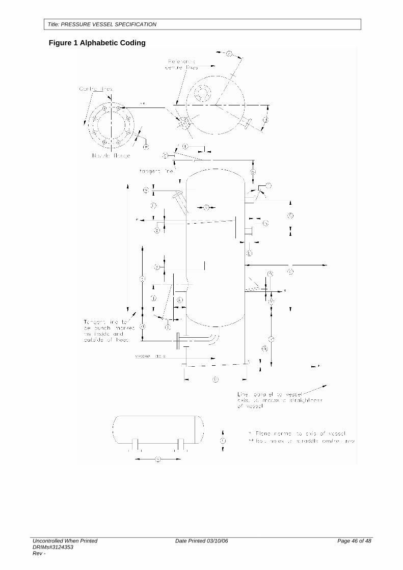
Title: PRESSURE VESSEL SPECIFICATION
Uncontrolled When Printed DRIMs#3124353 Rev -
Date Printed 03/10/06 Page 46 of 48
Figure 1 Alphabetic Coding

Title: PRESSURE VESSEL SPECIFICATION
Uncontrolled When Printed DRIMs#3124353 Rev -
Date Printed 03/10/06 Page 47 of 48
APPENDIX D - Vessel Nameplate Details
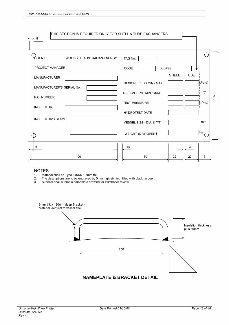
Title: PRESSURE VESSEL SPECIFICATION
Uncontrolled When Printed DRIMs#3124353 Rev -
Date Printed 03/10/06 Page 48 of 48
CLIENT WOODSIDE AUSTRALIAN ENERGY
PROJECT MANAGER
MANUFACTURER
TAG No.
MANUFACTURER'S SERIAL No.
P.O. NUMBER
DESIGN PRESS MIN / MAX kPa(g)
TEST PRESSURE
HYDROTEST DATE
kPa(g)
DESIGN TEMP MIN / MAX °C
CODE CLASS
INSPECTOR
INSPECTOR'S STAMP VESSEL SIZE - DIA. & T/T mm
kg
WEIGHT (DRY/OPER)
SHELL TUBE
THIS SECTION IS REQUIRED ONLY FOR SHELL & TUBE EXCHANGERS
100 50 22 22
3 10 6
8
18
155
NOTES: 1. Material shall be Type 316SS 1.5mm thk. 2. The descriptions are to be engraved by 5mm high etching, filled with black lacquer. 3. Supplier shall submit a nameplate drawing for Purchaser review.
NAMEPLATE & BRACKET DETAIL
6mm thk x 180mm deep Bracket - Material identical to vessel shell
250
Insulation thickness plus 50mm
Related Documents