K 666 -^-""'^i^^iiiiiSf^-* f^ ^f4 Technical Report PRESSURE VESSEL CONCEPTS Exploratory Evaluation of Stacked-Ring and Segmented-Wall Designs With Tie-Rod End-Closure Restraints MWMiiiiM^ March 1970 :j:|:;:|:|:;:|:|:i:j:;:|:;x;:j:i:i:i:; Sponsored by i::-:!:-:-:-:!;^^^^^^^^^ NAVAL FACILITIES ENGINEERING COMMAND NAVAL CIVIL ENGINEE.RING LABORATORY Port Hueneme, California This document has been approved for public release and sale; Its distribution Is unlimited.

Welcome message from author
This document is posted to help you gain knowledge. Please leave a comment to let me know what you think about it! Share it to your friends and learn new things together.
Transcript

K 666
-^-""'^i^^iiiiiSf^-*
f^^f4
Technical Report PRESSURE VESSEL CONCEPTS
Exploratory Evaluation of Stacked-Ring
and Segmented-Wall Designs With Tie-Rod
End-Closure Restraints
MWMiiiiM^ March 1970
:j:|:;:|:|:;:|:|:i:j:;:|:;x;:j:i:i:i:;Sponsored by
i::-:!:-:-:-:!;^^^^^^^^^NAVAL FACILITIES ENGINEERING COMMAND
NAVAL CIVIL ENGINEE.RING LABORATORY
Port Hueneme, California
This document has been approved for public
release and sale; Its distribution Is unlimited.

PRESSURE VESSEL CONCEPTS
Exploratory Evaluation of Stacked-Ring
and Segmented-Wali Designs With Tie-Rod
End-Closure Restraints
Technical Report R-666
Y-R009-03-01-004
by
J. D. Stachiw
ABSTRACT
An exploratory experimental study was conducted to evaluate the
stacked-ring and segmented-wall pressure vessel concepts. The evaluation
consisted of (1) testing to destruction stacked-ring and segmented-wall pres-
sure vessel models with tie-rod end-closure restraints and (2) evaluating a
series of seal designs utilized in the sealing of the joints between the pressure
vessel end closures and the cylindrical pressure vessel body. The test results
indicate that the stacked-ring pressure vessel design is approximately 50%
heavier than a multilayered pressure vessel of same internal diameter, length,
material, and pressure capability. The segmented-wall pressure vessel design
is approximately 8 to 9 times heavier than a multilayered pressure vessel of
same diameter, length, material, and pressure capability. The free-floating,
self-energizing radial seal system provided the most reliable and extrusion-
proof sealing for vessels with considerable radial dilation and axial end-closure
movement.
This document has been approved for public release and sale: its distribution is unlimited.
Each transmittal of this document outside the agencies of the U. S. Government
must have prior approval of the Naval Civil Engineering Laboratory.
CONTENTSpage
INTRODUCTION 1
Statement of the Problem 1
Background Information 1
Objective 3
Scope of Investigation 3
DISCUSSION OF CONCEPTS 5
Stacked-Ring Pressure Vessel 5
Radial Restraint 5
Axial Restraint 5
Construction 8
Assembly 12
Inspection and Safety 13
Segmented-Wall Pressure Vessel 14
EXPERIMENTAL STUDY DESIGN 17
General 17
Design 19
Fabrication 19
Instrumentation 20
Testing 27
Stacked Ring 27
Segmented Wall 28
FINDINGS 28
Stacked-Ring Vessel 28
Segmented-Wall Vessel 32
DISCUSSION OF FINDINGS 33
D D3Q1 0040404 2

page
CONCLUSIONS 40
ACKNOWLEDGMENT 40
APPENDIXES
A — Summary of NCEL Study Group Report on
Pressure Vessel Concepts and Implosion Effect
B — Experimental Evaluation of Radial End-Closure
Seals
41
63
76C - Photoelastic Investigation of Stress Concentrations . .
REFERENCES 90

INTRODUCTION
Statement of the Problem
The Navy deep-submergence effort requires well-equipped deep-ocean
simulation test facilities with pressure vessels of sufficient size to accommo-
date at least the largest single component of any deep-submergence vehicle or
habitat. This represents only the minimum requirement, while a more desirable
requirement would be to be able to test any full-size deep-submergence vehicle
or habitat to its design depth in a pressure vessel, so that the whole system
receives a thorough proof test.
The current Navy's research and development program requires pressure
vessels with an operational capability of 13,500 psi and at least 120 inches in
inside diameter and 360 inches in internal length. Such a pressure vessel could
test to collapse the structure of an average-sized construction vehicle, or scale
model of a habitat to the limit of its 1.5 safety factor for a 20,000- foot depth.
But the size of the above-mentioned pressure vessel is not the ultimate in
projected pressure vessel requirements. Larger pressure vessels will be required
as the size of the deep-submergence manned vehicle and habitat hulls increases.
In addition, more emphasis will be placed on proof-testing complete deep-
submergence vehicle and habitat systems in controlled laboratory environment
rather than in the ocean environment, where even the slightest malfunctioning
of a system component spells irretrievable loss of the vehicle or habitat and of
its crew.
To meet these future pressure vessel requirements, the exploratory
hydrostatic pressure vessel study was conducted by NCEL under NAVFACsponsorship. Its results are presented in this report.
Background Information
As indicated in Appendix A, traditional construction techniques are
hard put to satisfy the operational requirements of the new generation of
pressure vessels that are not only much larger in diameter, but also operate
at higher pressures than earlier pressure vessels. For many years prior to the
invention and successful use of the multilayer construction technique the
single-wall welded or forged monolithic construction of pressure vessels was
the only technique available for their fabrication. When single-wall thicknesses
of more than 2 inches were required for vessels fabricated from welded plate,
a point of diminishing returns was reached, as the tensile strength properties of
rolled alloy steel plate began to decrease with further increase in plate thickness.
The introduction of the multilayer pressure vessel construction
technique overcame this wall thickness limitation. This technique permitted
thick pressure vessel walls to be built up from thin sheets or plates, thus
obtaining thick walls with material properties equal to those found in thin
sheets or plates. Because of this, the multilayer construction technique has
been widely accepted and remains today the most reliable and proven technique
for fabricating large-diameter, high-pressure vessels.
There are, however, two shortcomings inherent in the multilayer
construction technique that become more and more pronounced as the sizes
and operational pressures of the pressure vessels increase. The first shortcoming
is the reliance on longitudinal and circumferential welds for joining the many
layers in the wall. Since reliable welding methods as a rule lag behind the
development of new steel alloys, reliance on welding forces the multilayer
fabricators to use generally only lower strength alloys for which reliable welding
techniques have been already developed. At a first glance this does not seem
to be much of a disadvantage, as instead of the thin vessel walls of new, higher
strength alloys, the old, lower strength alloys could be utilized in thicker vessel
walls. Such a substitution would be quite acceptable if the distribution of
stresses in the vessel wall remained the same regardless of wall thickness.
Unfortunately, this is not the case; the distribution of stresses becomes less
and less uniform as the wall-thickness-to-vessel-diameter ratio increases
(Figure 1 ), making thick-wall vessels uneconomical in terms of their internal
pressure capability (Figure 2).
Jhe second shortcoming of the layered pressure vessel construction
is its monolithic mass that makes it impossible to transport such a vessel by
land if its dimensions are large and its pressure capability is high. There is a
limited solution to this problem whereby the individual vessel layers are welded
on site, and the finished assembly is never moved again from its foundations.
This solution is acceptable, but the welding and stress relieving is done under
conditions less than ideal and future removal of the vessel for repair or main-
tenance is extremely difficult and expensive.
Although the two above-mentioned shortcomings of layered vessel
construction are not serious enough to preclude its use for pressure vessels of
any size or pressure capability, they are grave enough to warrant investigation
of other types of vessel construction. I n the previous survey of pressure vessel
construction conducted at NCEL (Appendix A), all the available and proposed
methods of vessel construction were reviewed. Only two were found to merit

a = tensile hoop stress
p. = inside pressure
= outside pressure
Thick Cylinder
Figure 1. Distribution of stresses in
thick-walled and thin-walled
cylinders under internal
hydrostatic pressure.
further study for application to
steel vessels of more than 10-foot
diameter and with operational
pressure in excess of 10,000 psi.
The two pressure vessel construc-
tion techniques which are considered
to be at least on par with multi-
layered construction so far as
their applicability to large high-
pressure steel vessels is concerned
are the stacked-ring and segmented-
wall module construction techniques.
This report deals with the explor-
atory evaluation of these concepts
from economical, engineering,
design, construction, and operational
viewpoints.
Objective
The objective of the study
was to experimentally investigate
the stacked-ring and segmented-wall
modular concepts for internal pressure vessels. In addition, seal systems
required for such pressure vessel designs were to be explored and evaluated.
This study is an exploratory evaluation of pressure-containing capability
of stacked-ring and segmented-wall designs for pressure vessels of equal interior
dimensions. The experimental evaluation of the two pressure vessel concept
designs, together with the discussion of economical and operational consider-
ations, will be useful in determining the desirability of these concepts when
selection of a design for large pressure vessels required in future hydrospace
simulation facilities is made. The experimental evaluation of the many avail-
able seal designs for large pressure vessels provides a brief overview of available
seal systems for high-pressure vessels and their sealing capability.
Scope of Investigation
The study was limited both in scoipe and deptli. In scope the study
was limited to only two types of pressure vessel design concepts—the stacked-
ring and the segmented-wall modular concepts with tie-rod end-closure restraints.
This scope was set by a preceding study (Appendix A) which briefly reviewed
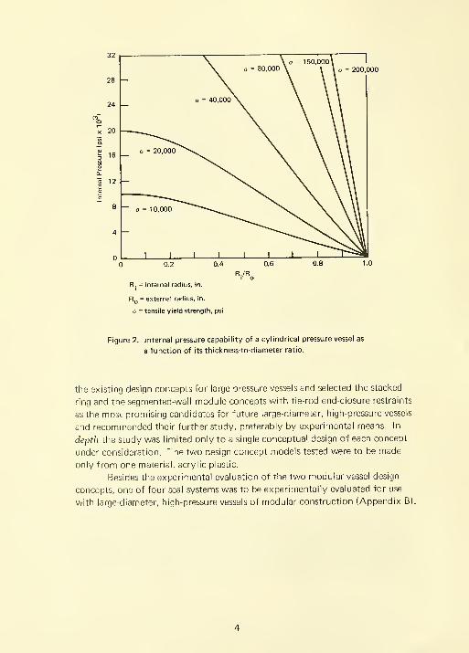
o = 200,000
R. = internal radius, in.
Rq = external radius, in.
a = tensile yield strength, psi
Figure 2. Internal pressure capability of a cylindrical pressure vessel as
a function of its thickness-to-diameter ratio.
the existing design concepts for large pressure vessels and selected the stacked-
ring and the segnnented-wall module concepts with tie-rod end-closure restraints
as the most promising candidates for future large-diameter, high-pressure vessels
and recommended their further study, preferably by experimental means. In
depth the study was limited only to a single conceptual design of each concept
under consideration. The two design concept models tested were to be made
only from one material, acrylic plastic.
Besides the experimental evaluation of the two modular vessel design
concepts, one of four seal systems was to be experimentally evaluated for use
with large-diameter, high-pressure vessels of modular construction (Appendix B).
DISCUSSION OF CONCEPTS
Stacked-Ring Pressure Vessel
The stacked-ring pressure vessel is a very simple concept'' which relies
for its strength on two separate sets of structural members—one set for
carrying the axial stresses, the other for carrying the circumferential stresses.
Radial Restraint. The set of structural members for giving the vessel
strength to resist radial forces generated by hydrostatic pressure consists of a
series of rings stacked upon each other and a liner inserted inside these rings
for sealing the joints between individual rings. Since the rings are only required
to carry circumferential stresses, no welding or mechanical bolting is required
between individual rings to hold them together. The minimum dimensions of
a ring for a given vessel diameter are determined by two parameters: ( 1 ) the
hoop and radial stresses inside the ring and (2) the twisting moment imposed
on the ring by the radial hydrostatic pressure. The maximum dimensions of
a ring are on the other hand determined by the forging capability of U. S.
industry and the weight handling capability of the crane at the pressure vessel
assembly place.
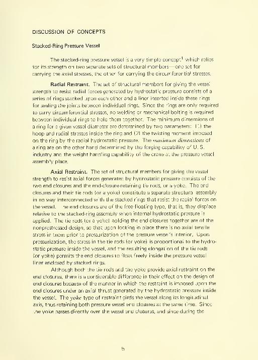
Axial Restraint. The set of structural members for giving the vessel
strength,to resist axial forces generated by hydrostatic pressure consists of the
two end closures and the end-closure-retaining tie rods, or a yoke. The end
closures and their tie rods (or a yoke) constitute a separate structural assembly
in no way interconnected with the stacked rings that resist the radial forces on
the vessel. The end closures are of the free-floating type, that is, they displace
relative to the stacked-ring assembly when internal hydrostatic pressure is
applied. The tie rods (or a yoke) holding the end closures together are of the
nonprestressed design, so that upon locking in place there is no axial tensile
stress in them prior to pressurization of the pressure vessel's interior. Upon
pressurization, the stress in the tie rods (or yoke) is proportional to the hydro-
static pressure inside the vessel, and the resulting elongation of the tie rods
(or yoke) permits the end closures to float freely inside the pressure vessel
liner enclosed by stacked rings.
Although both the tie rods and the yoke provide axial restraint on the
end closures, there is a considerable difference in their effect on the design of
end closures because of the manner in which the restraint is imposed upon the
end closures under an axial thrust generated by the hydrostatic pressure inside
the vessel. The3;ofee type of restraint girds the vessel along its longitudinal
axis, thus retaining both pressure vessel end closures at the same time. Since
the yoke passes directly over the vessel end closures, and since during the
bearing block
bearing blocl<
Figures. Engineering concept of a
stack ed-ring cylindrical
pressure vessel with continuous-
yoke end-closure restraint.
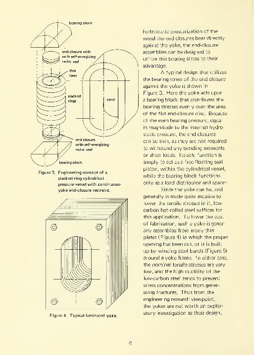
Figure 4. Typical laminated yoke.
hydrostatic pressurization of the
vessel the end closures bear directly
against the yoke, the end-closure
assemblies can be designed to
utilize this bearing stress to their
advantage.
A typical design that utilizes
the bearing stress of the end closure
against the yoke is shown in
Figures. Here the yoke acts upon
a bearing block that distributes the
bearing stresses evenly over the area
of the flat end-closure disc. Because
of the even bearing pressure, equal
in magnitude to the internal hydro-
static pressure, the end closures
can be thin, as they are not required
to withstand any bending moments
or shear loads. Its sole function is
simply to act as a free-floating seal
piston, within the cylindrical vessel,
while the bearing block functions
only as a load distributor and spacer.
Since the yoke can be, and
generally is made quite massive to
lower the tensile stresses in it, low-
carbon hot-rolled steel suffices for
this application. To lower the cost
of fabrication, such a yoke is gener-
ally assembled from many thin
plates (Figure 4) in which the proper
opening has been cut, or it is built
up by winding steel bands (Figure 5)
around a yoke frame. In either case,
the nominal tensile stresses are very
low, and the high ductility of the
low-carbon steel tends to prevent
stress concentrations from gener-
ating fractures. Thus from the
engineering research viewpoint,
the yokes are not worth an explor-
atory investigation as their design,
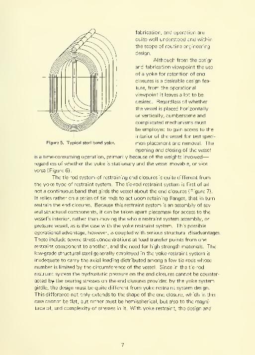
Figure 5. Typical steel band yoke.
fabrication, and operation are
quite well understood and within
the scope of routine engineering
design.
Although from the design
and fabrication viewpoint the use
of a yoke for retention of end
closures is a desirable design fea-
ture, from the operational
viewpoint it leaves a lot to be
desired. Regardless of whether
the vessel is placed horizontally
or vertically, cumbersome and
complicated mechanisms must
be employed to gain access to the
interior of the vessel for test speci-
men placement and removal. The
opening and closing of the vessel
is a time-consuming operation, primarily because of the weights involved
—
regardless of whether the yoke is stationary and the vessel movable, or vice
versa (Figure 6).
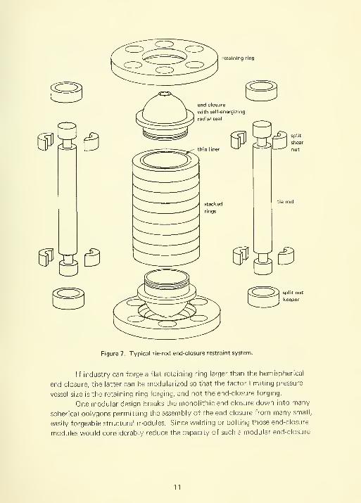
The tie-rod system of restraining end closures is quite different from
the yoke type of restraint system. The tie-rod restraint system is first of all
not a continuous band that girds the vessel about the end closures (Figure 7).
It relies rather on a series of tie rods to act upon retaining flanges, that in turn
restrain the end closures. Because this restraint system is an assembly of sev-
eral structural components, it can be taken apart piecemeal for access to the
vessel's interior, rather than moving the whole restraint system assembly, or
pressure vessel, as is the case with the yoke restraint system. This possible
operational advantage, however, is coupled with serious structural disadvantages.
These include severe stress concentrations at load transfer points from one
restraint component to another, and the need for high-strength materials. The
low-grade structural steel generally employed in the yoke-restraint system is
inadequate to carry the axial loading distributed among a few tie rods whose
number is limited by the circumference of the vessel. Since in the tie-rod
restraint system the hydrostatic pressure on the end closures cannot be counter-
acted by the bearing stresses on the end closures provided by the yoke system
girdle, the design must be quite different from yoke restraint system design.
This difference not only extends to the shape of the end closure, which in this
case cannot be flat, but rather must be hemispherical, but also to the magni-
tude of, and complexity of stresses in it. With yoke restraint, the design and

calculation of stresses in the flat end closure and bearing pad are rather routine;
in the case of tie-rod restraint the calculations are difficult because there are
stress concentrations whose magnitude nnust be both analytically and experi-
mentally determined during the design phase.
Because ( 1 ) very little was known about design and operation of vessels
with tie-rod end restraints at the beginning of this exploratory study while the
design of yoke restraints and associated end closures was quite well understood,
and (2) the application of yoke restraint severely handicaps the access to vessels'
interiors and slows down the use of such vessels for hydrostatic tests, it was
decided to explore experimentally only the tie-rod restraint system. (The
tie-rod restraint system promises to alleviate those difficulties.) It was felt that
by exploring it experimentally ( 1 ) some design and stress distribution data
would be generated where none was available before, and (2) some experience
would be gained in the operation of the tie-rod restraint system that would
permit rational comparison between the operational desirabilities of tie-rod-
and yoke-restrained systems. After selection of the tie-rod restraint for
investigation within the objective and scope of this exploratory study, no
further discussion of the yoke-restraint subsystem will be made until the section
on conclusions and recommendations.
Construction. The fact that the stacked-ring pressure vessel relies for
its strength not on any welds, but on isotropic homogeneous forgings permits
the use of high-strength steel alloys for which the welding techniques have not
yet been developed, or are only in the development stage. Specifically speaking,
it permits the construction of a pressure vessel from structural components
forged from maraging steels with yield points of up to 250,000 psi.
Although the stacked-ring pressure vessel design and fabrication technique
permits the assembly of rather large high-pressure-capacity pressure vessels
from smaller structural components, there is a limit to how large a pressure
vessel can be assembled in such a manner. This limit on the size of a stacked-ring
pressure vessel is determined by the forging capability of the steel industry.
The largest structural components in a stacked-ring pressure vessel are the
retaining rings and the end closures; therefore the maximum size of these com-
ponents that can be forged by the steel industry will determine the maximum
diameter and pressure capability of a stacked-ring pressure vessel. To determine
the largest retaining ring or end closure the industry can forge at any given date
is almost impossible without a detailed survey of each forging press in the world.
A limited inquiry has shown, however, that the steel industry can easily forge
structural components of such size as to permit the assembly of pressure vessels
with an operational pressure of about 13,500 psi, a 10-foot internal diameter,
and a 30-to-40-foot length.

(a) Yoke is stationary. (b) Vessel is stationary.
Vessel in Horizontal Position
(c) Vessel is stationary. (d) Yoke is stationary. (e) Vessel is stationary.
Vessel in Vertical Position
Figure 6. Mechanisms for operating vessels equipped with yokes.

split nut
keeper
Figure 7. Typical tie-rod end-closure restraint system.
If industry can forge a flat retaining ring larger than the hemispherical
end closure, the latter can be modularized so that the factor limiting pressure
vessel size is the retaining ring forging, and not the end-closure forging.
One modular design breaks the monolithic end closure down into many
spherical polygons permitting the assembly of the end closure from many small,
easily forgeable structural modules. Since welding or bolting those end-closure
modules would considerably reduce the capacity of such a modular end-closure
11
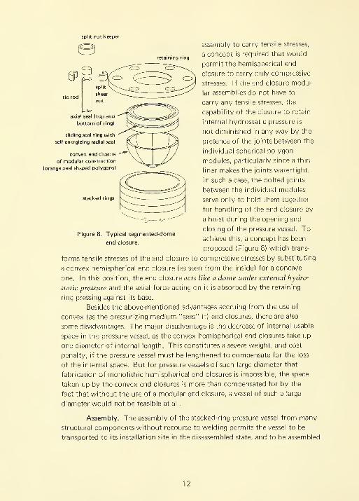
retaining ring
sliding seal ring with
self-energizing radial seal
convex end closure
of modular construction
(orange peel shaped polygons)
stacked rings
split nut l<eeper
assembly to carry tensile stresses,
a concept is required that would
pernnit the hemispherical end
closure to carry only compressive
stresses. If the end-closure modu-
lar assemblies do not have to
carry any tensile stresses, the
capability of the closure to retain
internal hydrostatic pressure is
not diminished in any way by the
presence of the joints between the
individual spherical polygon
modules, particularly since a thin
liner makes the joints watertight.
In such a case, the bolted joints
between the individual modules
serve only to hold them together
for handling of the end closure by
a hoist during the opening and
closing of the pressure vessel. To
achieve this, a concept has been
proposed (Figure 8) which trans-
forms tensile stresses of the end closure to compressive stresses by substituting
a convex hemispherical end closure (as seen from the inside) for a concave
one. In this position, the end closure acts like a dome under external hydro-
static pressure and the axial force acting on it is absorbed by the retaining
ring pressing against its base.
Besides the above-mentioned advantages accruing from the use of
convex (as the pressurizing medium "sees" it) end closures, there are also
some disadvantages. The major disadvantage is the decrease of internal usable
space in the pressure vessel, as the convex hemispherical end closures take up
one diameter of internal length. This constitutes a severe weight, and cost
penalty, if the pressure vessel must be lengthened to compensate for the loss
of the internal space. But for pressure vessels of such large diameter that
fabrication of monolithic hemispherical end closures is impossible, the space
taken up by the convex end closures is more than compensated for by the
fact that without the use of a modular end closure, a vessel of such a large
diameter would not be feasible at all.
Assembly. The assembly of the stacked-ring pressure vessel from many
structural components without recourse to welding permits the vessel to be
transported to its installation site in the disassembled state, and to be assembled
Figures. Typical segnnented-clonne
end closure.
12
on site with tine lioists or cranes used for the removal of end closures or
placennent of test objects during the regular operation of the pressure vessel
after assembly. Because of this, even the heaviest stacked-ring pressure vessel
component weighs less than 20% of the total pressure vessel weight. The
economies accruing from transporting and placing such a pressure vessel are
considerable. Instead of having to transport the complete pressure vessel by
barge or ship, when its assembled weight is over 250 tons, the vessel compo-
nents can be shipped to its permanent location by rail or truck. At the
permanent location, the many vessel components are then easily placed
sequentially into the vessel pit without recourse to special hoisting equipment.
For the assembly of a stacked-ring pressure vessel, only an overhead crane is
required that later, after the assembly is completed, becomes part of the pres-
sure test facility. Pressure vessels that must be lowered fully assembled into a
pit require a group of specialized hoists and cranes. This requirement becomes
more stringent when the weight of the assembly exceeds 250 tons. This
weight is generally exceeded by pressure vessels 10 feet in diameter or larger,
with an operational pressure of 13,500 psi.
Inspection and Safety. The additional desirable features of a stacked-
ring pressure vessel design during its operational life are the ease of inspection
of the load-carrying structural members, and the ease with which they can be
individually replaced in case of actual or incipient failure. In the stacked-ring
pressure vessel, every component, except the liner, is removable and replaceable
without cutting or welding. This ease of maintenance is bound to save many
dollars over the life of the vessel, which because of this component replace-
ability feature, is much longer than for monolithic vessels. The inspection of
individual structural components for incipient cracks is relatively easy, as the
individual tie rods, end closures, and retaining rings are easily accessible for
inspection on all of their surfaces. The stacked rings are accessible only from
the external surface, but because of their homogeneity and isotropic character,
accessibility from one surface is sufficient for ultrasonic or radiographic
investigation to locate incipient cracks.
There is one further facet of vessel operation that is not often discussed,
but merits further investigation: the stacked-ring design is safer than multi-
layer or unilayer design. Although pressure vessels are designed with safety
factors to prevent failure in service under load, they nevertheless do fail once
in a while; when failure occurs, damage to equipment and injury to personnel
is extensive. The safety feature of stacked-ring pressure vessel design lies in
the separateness of each load-carrying structural member. Since it is quite
unlikely that an incipient crack would become self-propagating in more than
one structural member at the same time, the internal hydrostatic pressure will
13

be relieved by failure of only one ring member. Thus the failure of any of
the individual stacked rings is a local failure, and not a general catastrophic
failure. The same applies in a limited measure to the end-closure tie rods.
If failure in one of the rods occurs, then only one or two more rods will fail
with it before the pressure inside the pressure vessel is relieved. Because of
this, the damage to the vessel, as well as to the facility, will be slight and the
vessel can be easily repaired. The failure of the end closure, or of the end-
closure retaining ring, needless to say, will be just as disastrous as in a
multilayer or unilayer vessel, but much easier to repair than in such vessels.
The top closure is replaceable in all types of pressure vessels, but the retaining
flanges and the bottom closure are not. The stacked-ring pressure vessel does
permit, however, the replacement of these structural components also.
Segmented-Wall Pressure Vessel
Although the stacked-ring pressure vessel concept alleviates most of
the fabrication and handling problems associated with large monolithic or
layered high internal pressure vessels, it does not eliminate them completely.
The limitation on the diameter of the vessel for stacked-ring vessel design
still remains the forging capability of the steel industry. To be sure, this
limitation is less severe for forging rings than for forging monolithic cylinders,
but it is nevertheless severe enough to make the stacked-ring construction
somewhat less than an optimum solution to the problem of large pressure
vessel construction. The sizes of forged rings that industry will produce in
the near future will, of course, increase from year to year, but even so it is
doubtful whether thick-walled rings of larger than 20-foot diameter and 1-foot
thickness will be feasible to fabricate. Consequently the segmented-wall module
design has been proposed for the fabrication of high-pressure vessels with
diameters beyond the capability of the stacked-ring fabrication technique.^
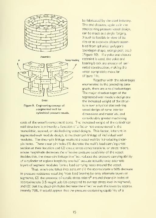
The basic attractiveness of the segmented-wall module design lies in
its reliance on small segmentlike modules for the construction of the cylin-
drical vessel wall. The segments, held together by shear pins extending the
length of the cylinder, permit the assembly of very large diameter thick-walled
pressure vessels from relatively small interchangeable structural modules
(Figure 9) that are easy to fabricate, transport, and assemble at the pressure
vessel installation site. In this type of design as with the stacked-ring design,
the axial loads on the end closure are carried by a series of tie rods or by an
external yoke. One further advantage of the segmented-wall design is that a
modular design can also be applied to the end-closure retaining rings, if a
tie-rod end-closure restraint system is used, eliminating size and weight of the
end closure as the limitation on the maximum diameter of vessel that could
14
Assembly
hoop loading
be fabricated by the steel industry.
The end closures, again as in the
stacked-ring pressure vessel design,
can be made as a single forging,
if such is feasible in view of its
size or as a convex closure assem-
bled from spherical polygons
(pentagon shape, orange peel, etc.)
(Figure 10). If a yoke end-closure
restraint is used, the yoke and
bearing block are already of lami-
nated construction, making the
vessel completely modular
(Figure 1 1 ).
Together with the advantages
enumerated in the preceding para-
graph, there are also disadvantages.
The major disadvantages of the
segmented-wall module design are
the increased weight of the struc-
ture over a typical stacked-ring
vessel design of same interior
dimensions and materials, and
considerably greater machining
costs of the vessel's component parts. The increased weight of the cylindrical
wall structure is primarily a function of a factor not encountered in the
monolithic, layered, or stacked-ring vessel designs. This factor, inherent in
segmented-wall module design, is the shear-pin linkage of individual wall
modules. The shear-pin linkage weakens a vessel wall by introducing shear-
pin holes. These shear-pin holes ( 1 ) decrease the wall's load-carrying cross
section at their location and (2) create stress concentrations, or stress raisers,
whose magnitude decreases the effective pressure capability of the vessel.
Besides this, the shear-pin linkage in effect reduces the pressure-carrying ability
of a cylinder of a given length by one-half because actually only alternate
layers of segment modules form a load-carrying hoop around the vessel.
Thus, when one takes into account ( 1 ) the approximately 50% decrease
in pressure resistance resulting from load bearing by only alternate layers of
segments, (2) the presence of tensile stress raisers'^ around shear-pin holes of
approximately 3.5 magnitude (as compared to average stress level in segment),
and (3) that the shear-pin holes decrease the effective wall thickness by approx-
imately 25%, it would appear that the pressure-containing capability of a
Figure 9. Engineering concept of
a segmented wall for
cylindrical pressure vessels.
15
^ split
shear
^ split
shear
segmented-wall module design is
only one-eighth to one-ninth of
a stacked-ring wall of equal internal
dimensions and overall weight.
However, because of the many
unknowns present, it is impossible
to postulate with reasonable
accuracy what the internal pressure
capability of such a vessel would
be without constructing a model
of it and pressurizing it to failure.
One further disadvantage
of a segmented-wall vessel is that
all the areas on modules and shear
pins where stress raisers may initiate
fracture cannot be inspected satis-
factorily without disassembly. Of
course, if the fracture does take
place, the failure of the vessel will
be local, similar to that of a stacked-
ring vessel and easily repaired. The
number of shrapnel fragments will
be somewhat larger than in the
stacked-ring vessel because each
module is a potential projectile,
but with proper precautions
(for example, placing the vessel in
a pit) this hazard can be virtually
eliminated.
The construction of the
cylindrical portion of the pressure
vessel from modules permits the
assembly of the cylinder from
easily manufactured, transported,
and assembled segment modules.
This, however, does not make the
size of the segment module forging the sole factor limiting the cylinder's diam-
eter, for the end-closure retaining flanges and the end closure itself are generally
substantial forgings, similar to those found in the stacked-ring assembly vessel
and much larger than the individual segment module. Clearly, to eliminate the
forging of the end-closure retaining flange or of the end closure itself as the
factors limiting the vessel's size, it is necessary to make them modular also, or
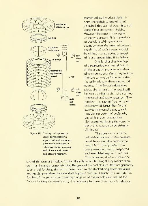
Figure 10. Concept of a pressure
vessel composed of a
segmented-wall cylinder,
segmented end-closure
retaining flange, modular
end closure and tie-rod
end-closure restraint.
16

to gird the whole vessel with a yoke restraint of laminar construction. The
end-closure flanges could be modularized by assemblmg them from segments
similar to those found in the cylindrical section of the vessel.
The end closure also could be assembled from some smaller modules
as it was already proposed for the end closure on the stacked-ring pressure
vessel.
The assembly of end closures from modules makes the modularization
of a pressure vessel complete, since the external tie rods that hold the end
flanges together can be considered modules. If the vessel is completely modu-
larized, the internal diameter of the vessel can be increased by a factor of 2
to 5 over that of a stacked-ring pressure vessel, and 5 to 1 times over a mono-
lithic pressure vessel of 13,500-psi pressure capability. It would thus appear
that if the pressure vessel designs are ranked according to their adaptability
for constructing pressure vessels over 10 feet in diameter, the segmented design
with modularized retaining flanges and end closures (or laminated yoke and
bearing blocks) is the more adaptable. When ranked in terms of overall weight
and cost for a vessel diameter size that can be built either by the segmented
or stacked-ring method, the stacked-ring structure weighs and costs consider-
ably less. The real advantage of the segmented vessel design lies simply in the
fact that by using that particular design approach, pressure vessels of much
larger diameter can be built for the same pressure than by using the stacked-
ring design.
EXPERIMENTAL STUDY DESIGN
General
Since the experimental study on the evaluation of stacked-ring and
segmented-wall pressure vessel designs was only exploratory, most of the
effort was devoted to evaluating a selected vessel design rather than studying
structural parameters that control the structural integrity of such vessels. In
other words, the approach was to ( 1 ) design and fabricate a stacked-ring and
a segmented-wall pressure vessel of comparable size without taking the stress
raisers into consideration and (2) pressurize the vessels to failure to determine
deviation from the predicted failure pressure, which was selected to be the
same for both. The difference between the predicted and experimental perfor-
mance of the vessels would serve as a good indicator of the magnitude of stress
raisers in the structure, while the comparison of experimental failure pressures
from the stacked-ring and segmented-wall vessels would show which is more
economical on the basis of psi/lb of structure weight. Also, if time permitted,
some exploratory investigations could be undertaken into structural details
that could have contributed to the early failure of the model vessels.
17

Figure 1 1 . Concept of a pressure vessel composed of a segmented-wall
cylinder, laminated bearing block, flat end closure, and
laminated yoke end-closure restraint.

Design
The stacked-ring and the segmented-wall pressure vessel models
(Figures 12 and 13) were designed to represent in 1:10 scale the full scale
10-foot-diameter, 10,000-psi vessels (operating pressure) made from maraging
steel. Since little was known on the magnitude of stress concentrations in
such vessels, they were designed on the basis of ordinary engineering calcula-
tions. It was calculated that the failure of a given structural member was
initiated when the maximum tensile stress in the member became equal to the
ultimate tensile stress of the material under uniaxial tension, without taking
the stress raisers into consideration. Since the distribution of forces acting
on individual members of the vessel was not completely understood in many
cases, engineering assumptions were made in their place.
The two vessels were designed to fail at 40,000 psi if they were
constructed from maraging steel with 300,000-psi ultimate tensile strength.
A design failure pressure of 40,000 psi would give the vessels an apparent safety
factor of 4 based on an operating pressure of 10,000 psi while the use of
300,000-psi steel would give the vessel the lightest structure made possible by
existing steel alloys applicable to construction of 10-foot-diameter pressure
vessels.
Fabrication
Although the actual dimensioning of vessels was based on the 300,000-
psi steel, the material selected for actual fabrication of models was not maraging
steel, but acrylic plastic. The reasons for using plastic material were twofold.
First, small forgings of 18% nickel maraging steel were not available at reasonable
cost; and second, fabrication of the models from a material that had half the
ductility of maraging steel would make the model much more sensitive to stress
concentrations, causing it to fail when the stresses in the material at the stress
raiser reached its ultimate strength. If the model was made from steel, it
would probably only yield locally at the stress raiser without any external indi-
cations of yielding. Yet, in full-scale vessels, local yielding would in many cases
cause the vessel to fail at lower cyclic pressure than predicted on the basis of
static failure pressure.
Since acrylic plastic has a tensile strength of about 9,000 psi, while that
of 18% nickel maraging steel is about 300,000 psi, the failure pressure of the
model is scaled down to 1 ,200 psi in direct proportion to the lower tensile
strength. The operational pressure of the acrylic vessel would be 300 psi instead
of the 10,000-psi value for a steel vessel.
19

The structural components of the stacked-ring model vessels were
machined from commercially available acrylic stock (Figures 14 and 15).
The rings, and the end-closure retaining flanges, were turned from flat acrylic
plates of 1 and 4 inches thickness, respectively.
The tie rods were turned from 2-1/4-inch-diameter acrylic rods, while
the hemispherical end closures were contour-machined from 14-inch-diameter
by 12-inch-long custom acrylic castings. For the fabrication of modules for
the segmented-wall vessel, 1/4-inch-diameter rods were used for shear pins and
1/16-inch and 1/2-inch sheets for wall and retaining flange segments (Figures
16 through 20). Test specimens were taken from the commercial acrylic
stock to check on its conformance to the required 9,000-psi tensile strength.
Without exception, they have met this requirement by failing in the 9,200-to-
9,500-psi tensile-stress range.
Instrumentation
Instrumentation of the models tested to destruction under internal
hydrostatic pressure consisted of pressure gages and electrical-resistance strain
gages. The pressure gages were used with all of the vessels, while the electrical-
resistance strain gages were only used on the stacked-ring pressure vessel.
The reasons for limiting the strain-gage instrumentation to the
stacked-ring pressure vessel were as follows:
( 1 ) Since both the stacked-ring and the segmented-wall vessel models
utilized the same tie-rod system and hemispherical end closures, there was no
need to instrument them twice, as the strains measured during pressurization
of the stacked-ring model would be the same as during pressurization of the
segmented-wall model.
(2) Only in the stacked-ring model was it possible to measure the actual
strains on the end-closure retaining flange and on the rings. In the segmented-
wall vessel, the failure of the end-closure retaining flange was predicted to be
due to rupturing of pins in that flange, and the failure of the wall segments by
shearing of pins and rupturing of segments. In neither case would it be possible
to attach strain gages to those structural members at the points of high stress
concentration and measure the actual strains.
The actual strain gage installation on the stacked-ring pressure vessel
consisted of 15 rosettes placed on major structural components of the pressure
vessel model (Figure 21 ). Six of the rosettes were placed on the end closure, five
on the end-closure retaining ring, two on the tie rods, and two on the rings. Only
two rosettes, those at a penetration in the end closure, were sufficiently close
enough to a stress raiser to measure maximum stresses at a stress concentration.
The other rosettes simply measured the general stress level in the structural part
of which they were located.
20

-1
\
L{
r "]
.- ^*fe •
-'.-. .,-'
1
i .\
i
1
\ n
u
t \
I 'h\-j
1 s" "
-fl
___^Vl '^''i^ ^i
Figure 12, Acrylic model of a maraging steel stackedring p
120-inch internal diameter for 10,000-psi pressi
|b| assembled.
; (a) disassembled,

"^I
'''"^-r-,^i..--
t~~
<!'*Ci,^'* ***^ff^ •
Figure 13. Acrylic model of a maraging steel segmented-wall pressure vessel with
120-Jnch internal diameter for 10,000-psi pressure service; (a) disassembled,
(b) assembled.

Figure 14. The stacked-ring acrylic pressure vessel model, assembled.
23

24

Figure 16. Assembling the segmented-wall pressure vessel from mass-
produced 0.067-inch-thick acrylic segments.
Figure 17. Assembled segmented-wall cylinder.
25
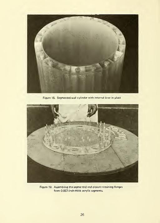
Figure 18. Segmented-wall cylinder with internal liner in place
Figure 19. Assembling the segmented end-closure retaining flanges
from 0.067-inch-thick acrylic segments.
26
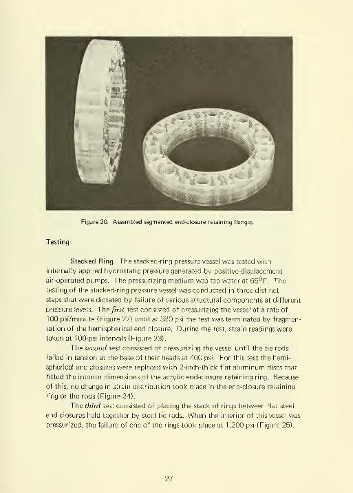
Figure 20. Assembled segmented end-closure retaining flanges.
Testing
Stacked Ring. The stacked-ring pressure vessel was tested with
internally applied hydrostatic pressure generated by positive-displacement
air-operated pumps. The pressurizing medium was tap water at 65°F. The
testing of the stacked-ring pressure vessel was conducted in three distinct
steps that were dictated by failure of various structural components at different
pressure levels. The first test consisted of pressurizing the vessel at a rate of
100 psi/minute (Figure 22) until at 380 psi the test was terminated by fragmen-
tation of the hemispherical end closure. During the test, strain readings were
taken at 100-psi intervals (Figure 23).
The second test consisted of pressurizing the vessel until the tie rods
failed in tension at the base of their heads at 400 psi. For this test the hemi-
spherical end closures were replaced with 2-inch-thick flat aluminum discs that
fitted the interior dimensions of the acrylic end-closure retaining ring. Because
of this, no change in strain distribution took place in the end-closure retaining
ring or the rods (Figure 24).
The third test consisted of placing the stack of rings between flat steel
end closures held together by steel tie rods. When the interior of this vessel was
pressurized, the failure of one of the rings took place at 1,200 psi (Figure 25).
27

1-9
10
11
12
13
14
15
Gage Type
AR-7-2 (45°l
AFX7AFX7AFX7A-1
A-19
A-19
10
J 11
J 12
Segmented Wall. The
segmented-wall vessel was tested
with internally applied hydrostatic
pressure in the same manner and
at the same temperature as the
stacked-ring pressure vessel (Figure 26).
The testing of this vessel took place
in two steps that were also dictated
by the failure of structural compo-
nents at different pressure levels.
The first test consisted of
pressurizing the segmented vessel
(Figure 27) until the test was termi-
nated at 140 psi by the tensile failure
of the shear pins holding the laminated
end-closure retaining ring together.
The second test consisted
of pressurizing the segmented wall
to destruction at 180 psi of internal
hydrostatic pressure (Figure 28).
For this test, the segmented-wall
cylinder was positioned between
two flat steel end plates held
together by steel tie rods. The setup
was identical to the one used for
testing a stacked-ring cylinder to
destruction.
Figure 21. Location of electrical
resistance strain gages
on the stacked-ring
pressure vessel model.
FINDINGS
Stacked- Ring Vessel
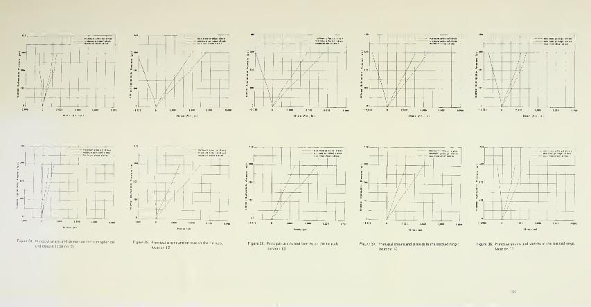
1 . The highest principal stresses
were measured on the surface of
the hemispherical end closures.
Since the highest principal stress was recorded in meridional direction at
rosette 4, while the hoop stress at rosette 4 was no larger than at rosettes 3,
2 and 1 , it appears that considerable flexural stress exists at the base of the
hemispherical dome in meridional plane (Figures 23 through 34).
28
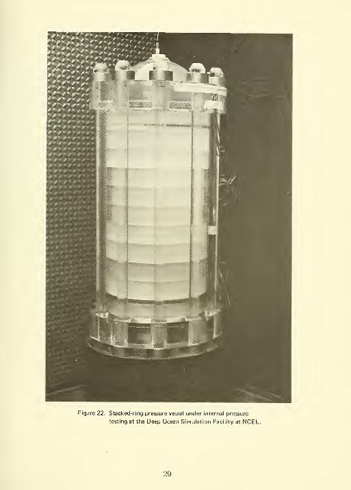
Figure 22. Stacked-ring pressure vessel under internal pressure
testing at the Deep Ocean Simulation Facility at NCEL.
29

Figure 23. Failed end closure from
the stacked-ring pressure
vessel. Note the circum-
ferential fracture which
caused the end closure
to separate from its flange.
split shear nut
split nut keeper
retaining flange
stacked rings
Note: All structural components
are of acrylic plastic except
the aluminum end closure
and split nut keepers.
Figure 24. Test arrangement for
hydrostatically testing
tie rods to failure.
2. Principal stresses of almost the
same magnitude as on the hemi-
spherical end closures were measured
on the tie rods in axial directions.
Since rosettes 12 and 13 were located
away from the rod heads, the stresses
indicated by them represent the
average stress in the tie rods (Figures
35 and 36).
3. The principal stresses on stacked
rings in the hoop direction were
next in magnitude. The absence of
tensile stress in the axial direction
indicated that the stacked ring, as
postulated, did resist only radial
forces exerted by the internal hydro-
static pressure in the vessel (Figures
37 and 38).
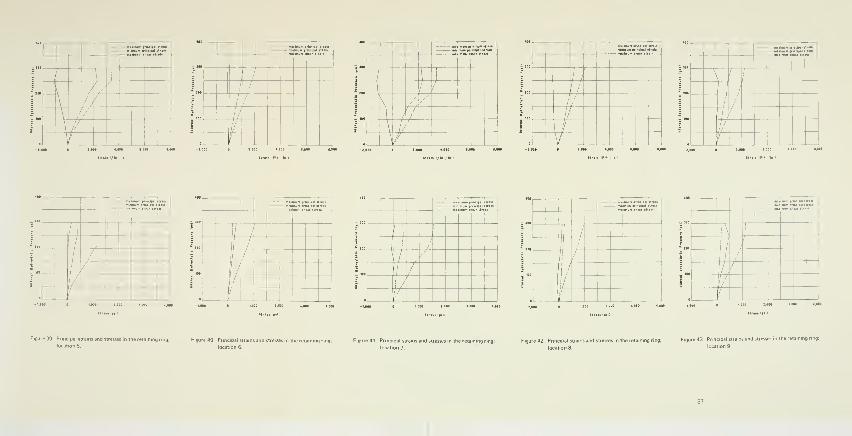
4. The principal stresses on the
monolithic end-closure retaining
ring were the least in magnitude,
indicating that unless the magnitude
of stress raisers at the root of the
flange instep was high, the failure
of the vessel would probably not
be initiated in this structural compo-
nent of the vessel (Figures 39
through 43).
5. Fracture of the structural compo-
nents generally took place either in
locations where stress raisers were
either known or surmised to exist
(Appendix C). Thus, it was surmised
prior to the destructive testing that
the failure of the hemisphere would
take place in equatorial plane some-
what above the flange on the
hemispherical end closure. The
failure that did take place there was
30

1-1/2-in. steel
tie rods -
stacked rings
Figure 25. Test arrangement for
hydrostatically testing
stacked-ring cylinder to
failure.
forecast by rosette 4 located
approximately 1 inch above frac-
ture plane. This rosette had shown
that the maximum principal stress
was oriented along the hemisphere's
meridian and that it was approxi-
mately 50% higher than the hoop
membrane stresses measured at
other locations on the end closure.
Since rosette 4 was 1 inch away
from the fracture plane, it did not
show the actual stress at the fracture
plane that caused the failure. Some
exploratory investigations of this
tensile stress concentration con-
ducted subsequently have shown
that its magnitude in the meridi-
onal plane is approximately 3.3
(Appendix C).
6. The failure of the rods was not forecast by the strain gages as they were not
located in areas of the highest stress on the rods. The tie rods failed in tension
at the very base of their heads where the abrupt change in cross section acted
as a stress raiser of unknown magnitude. The failure that took place at approx-
imately 1/3 of calculated failure pressure in the vessel indicated that there must
exist in the tie rod at the base of the rod head a stress approximately 3 times
higher than the average tensile stress in the middle of the rod's length. Some
exploratory investigations of this stress concentration conducted subsequently
have to a large measure confirmed this (Appendix C).
7. The fracture of the stacked rings at 1 ,200 psi showed that the rings were
free of stress raisers as they were the only structural components of the vessel
to fail at design failure pressure based on the approximately 9,000-psi tensile
strength of acrylic. Thus, it appears that the ring is the only structural compo-
nent of the stacked-ring pressure vessel whose failure can be truly determined
on the basis of engineering calculations that do not take stress raisers into
consideration. For the other structural components, combinations of stresses
and stress raisers must be taken into consideration at otherwise the actual
strength of the structural members will be considerably below the calculated
one.
31
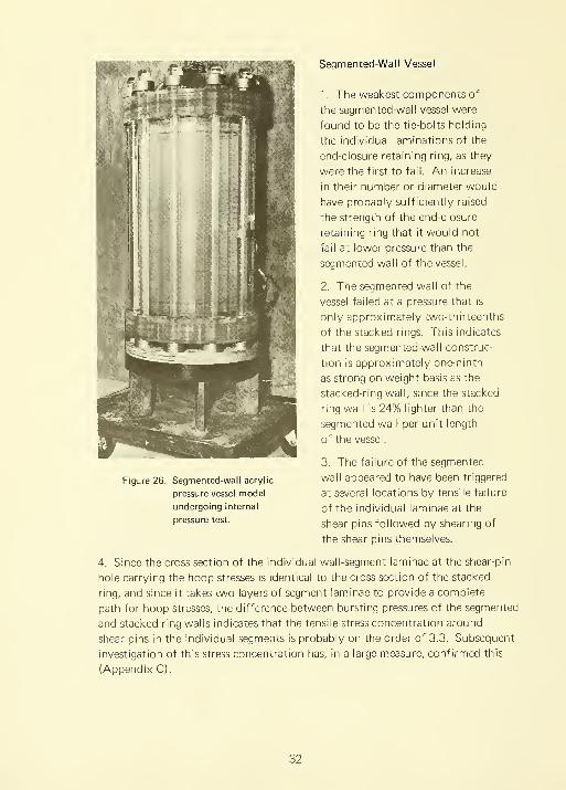
Figure 26. Segmented-wall acrylic
pressure vessel model
undergoing internal
pressure test.
Segmented-Wall Vessel
1. The weakest components of
the segmented-wall vessel were
found to be the tie-bolts holding
the individual laminations of the
end-closure retaining ring, as they
were the first to fail. An increase
in their number or diameter would
have probably sufficiently raised
the strength of the end-closure
retaining ring that it would not
fail at lower pressure than the
segmented wall of the vessel.
2. The segmented wall of the
vessel failed at a pressure that is
only approximately two-thirteenths
of the stacked rings. This indicates
that the segmented-wall construc-
tion is approximately one-ninth
as strong on weight basis as the
stacked-ring wall, since the stacked-
ring wall is 24% lighter than the
segmented wall per unit length
of the vessel.
3. The failure of the segmented
wall appeared to have been triggered
at several locations by tensile failure
of the individual laminae at the
shear pins followed by shearing of
the shear pins themselves.
4. Since the cross section of the individual wall-segment laminae at the shear-pin
hole carrying the hoop stresses is identical to the cross section of the stacked
ring, and since it takes two layers of segment laminae to provide a complete
path for hoop stresses, the difference between bursting pressures of the segmented
and stacked-ring walls indicates that the tensile stress concentration around
shear pins in the individual segments is probably on the order of 3.3. Subsequent
investigation of this stress concentration has, in a large measure, confirmed this
(Appendix C).
32

Figure 27. Failed segmented end-closure retaining ring.
DISCUSSION OF FINDINGS
Although the structural components of the acrylic stacked-ring and
segmented-wall pressure vessels failed at different pressures, and in many cases
below their expected load-carrying capacity, several generalizations can be
made about the behavior of these two different vessel designs.
First, it appears that the stacked-ring modules are the only structural
components in the two vessel designs that; ( 1 ) possess no stress raisers,
(2) can be stress-analyzed reliably, (3) have a failure stress level independent
of their fit with other structural components, or machining tolerances, and
(4) have the optimized shape for carrying the loading imposed on them.
Therefore, they should be utilized in the construction of ocean-environment
simulators as large in diameter and high in pressure capability as the fabrication
capability of the steel industry permits. In cases where the material properties
of thick high-strength forgings are well known, forgings are to be preferred
over laminated rings, as both the stress analysis and quality control are well
understood. Where a sufficiently thick ring forging cannot be made, or the
properties of thick forgings are uncertain, welded concentric laminations can
be used for individual stacked-ring fabrication.
33
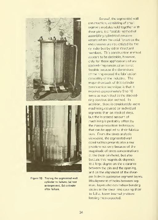
Figure 28. Testing the segmented-wall
cylinder to failure; (a) test
arrangement, (b) cylinder
after failure.
Second, the segmented-wall
construction, consisting of small
segment modules held together with
shear pins, is a feasible m'ethod of
assembling cylindrical pressure
vessels where the axial forces on the
end closures are not resisted by the
cylinder but by other structural
members. This construction method
appears to be desirable, however,
only for those applications where
stacked-ring construction is not
feasible because the dimensions
of the ring exceed the fabrication
capability of the industry. The
major drawback of this cylinder
construction technique is that it
requires approximately 9 to 1
times as much steel as the stacked-
ring construction method. In
addition, there is considerably more
machining required on individual
segments than on stacked rings,
but the increased amount of
machining is probably offset by
the mass-production techniques
that can be applied to their fabrica-
tion. From the stress analysis
viewpoint, the segmented-wall
construction presents also a real
problem not only because of the
magnitude of stress concentrations
at the shear-pin holes, but also
because this magnitude depends
to a large degree on the clearance
between the pin and the opening,
and on the alignment of the shear-
pin holes in successive segment layers.
Misalignment of holes between seg-
ment layers also can induce bending
strains in the shear pins causing them
to fail at lower internal pressure
loading than expected.
34

#St"^^: .IT, Inolpll .V™."
1
i
l!
i ki //
/
=^^:"i':rK:i;:i:i;'.',:
//
j
/1
//
/
//
/''
jil-clpU !;'!:
1
1
/
I /// /
//'/
n'"ssr ttralB
r\ A
, /
'l1
II
1
/'
zz.-Z 'ZZ\ is:i 1"".
i_ i»
1
zzz._:;.mm prlnclMl r
// /'-'
/ //
/'
/ /
/,'
/\ /J
—-:r rs.r I'-m
1'"
1
:,"™ ,"".;;;;' ';s
1
//1 /
'
/
/'
1 / /
///
1 /'
/ /.'
// 1/'
t_ £^
==^~,'™:4MH>n
\ V
\/|
/I
\
\i<!
Figure 29, Principal strains and stresses on the hemispherical Figure 30- Principal strains and stresses on the hemispherical Figure 31 . Principal strains and stresses on the hemispherical Figure 32, Principal strains and s
closure; location 3.
Figure 33, Principal strains and stresses on the hemispheric
end closure; location 14.
^^^iVSTpSS'=
/
;
\
1
zz--ZZ :::; InGlplI r.i:
/ /
'
\ / /
''
\/ /
\ /./
\
\ I'
=^^:r::; s:i r,".'.;
i
1
ii:—
"
s:; ndiil ini;
1
1
::::^-:i::K:rr:
\ / ,/
,
'
\;
/
/'-' ,/
//
\ / // /
\ //
\ / // // \
1
///
\1,
if
\ //_ /' _ L^
11--".s:; nclpil r
! /
/'
//
//
//1
f
—™;™::; '"Sx 1"."
/ /
/ /1
/ /
1
1
/.'
' —-
—
fl
mlT.",', S:;' ,r
I /
1 // /
'
/ /'
t_
'=i^:riT;;i3:i"™
, /
/
'
/ /
/ /
SIT,',S'.r
\
'
\
\1
/
1
''
If
/''
Figure 34. Principal strains and stresses on the hemispheri
end closure; location 15.
Figure 35. Principal strains and stresses on the tie rods;
location 12.
Figure 37. Principal stra
location 10.
s and stresses in the stacked rings; Figure 38. Principal strains and stresses in the stacked rings;
—-"J. 'HZi 'SS! ,r
J...
::;;; :",l"i",«".S'.""l."
1
1
iMilmiini p Inclpll';;,';
\
1
1 / I.
J
//
/ //
/..'
// \ /:/
//1
//
1/ /,' \
1'
1
/'
\/ 1
".ILT.". ncliwl "r
\
!l :'js "^i:
/,
^
\
1
\' ;'
i
//
//
// (/'
//
\/ \
::::ir rr.",':.K' r
/),/ // /
/ /
/y
III-:;; :::;; :r: z
j//
j|
1/
//
/
.
/
— :"':.•.'; s:i r.:;
'
I\
(
i 1
\ / y/ 1
1 /
//
p IE— Z r.' srs
1
n nulnvmRTss:r
! / !\ 1
i
;1
/
fi
—
/ /
/,'—
/li
1/
'__1
; in the reiainrng ring;


Tiiird, the use of tie rods and retaining flanges for restraining the
hemispherical end closure proved to be feasible. As anticipated, this restraint
was easy to operate in opening and closing the vessel. However, from the
structural viewpoint, this restraint left much to be desired as the stress level in
the structural components was higher than calculated. The high level resulted
from stress concentrations introduced by the geometry as well as by the
machining tolerances. This was shown quite clearly by the failure of tie rods
and segmented retaining flanges at hydrostatic pressures considerably lower
than those for the stacked rings. The stress concentration in the tie rods
appeared to have a magnitude of 3 based on the comparison of hydrostatic
pressure, at which tie rods and stacked rings failed. In view of this, it would
appear that in order for tie-rod restraint to operate properly, the nominal
stress level in the tie rods would have to be decreased by a factor of 3 through
enlargement of the tie-rod diameter, or the tie-rod head would have to be
redesigned so that the stress raiser effect is considerably decreased.
The same applies to the hemispherical end closure that failed at
approximately one-third of its predicted failure pressure. There the problem
can also be resolved either by lowering the average stress level in the end closure
by a factor of 3 through increase in thickness of the hemisphere, or the transition
zone between the end-closure flange and the hemisphere would have to be
redesigned. In either case, it appears that the design of the hemispherical end
closure with the tie-rod restraint system requires more than nominal engineering
stress calculations, and that the weight of this system would have to be increased
considerably.
Fourth, in view of the previous discussion, it appears that the tie-rod
restraint system with hemispherical end closures, even though proven to be
successful operationally, leaves a lot to be desired from the structural viewpoint.
It appears, therefore, that the tie-rod restraint system with which the stacked-
ring and segmented-wall vessel designs were equipped is less desirable and
structurally safe than the continuous-yoke system with bearing blocks and flat
end closures discussed earlier in this report.
Fifth, the radial seals utilized on the end closures of the stacked-ring
and segmented-wall vessel designs performed satisfactorily without any leakage
during all of the hydrostatic tests to which the acrylic models were subjected.
For higher pressures, such as those that would be encountered in the steel
vessels, the self-energizing radial seals experimented with in this study should
be utilized (Appendix C). Thus, it appears that radial seal designs experimented
with in this study adequately meet the operational needs of large vessels with
10,000-psi or higher operational pressure.
39

CONCLUSIONS
1. Both the stacked-ring and the segmented-wall cylindrical pressure vessel
concepts are technologically and operationally feasible for construction of
large-diameter, high-pressure cylinders without recourse to welding. The
stacked ring is more economical and structurally sound than the segmented
wall, in which stress concentrations dictate the use of thicker walls and also
serve as potential sources of fracture. However, when interior size and pressure
capabilities are the only considerations, the segmented-wall concept permits
construction of considerably larger cylindrical pressure vessels than the stacked-
ring concept.
2. The tie-rod end-closure restraint system is technologically and operationally
feasible and can be used with stacked-ring or segmented-wall pressure vessels,
but it is structurally less sound than the continuous laminated-yoke system
because of the many stress concentrations inherent in this concept.
3. When a laminated-yoke end-closure restraint system is mated with a stacked-
ring cylinder, it results in an economical and structurally sound pressure vessel
for diameters and pressures in excess of 10 feet and 10,000 psi, respectively.
ACKNOWLEDGMENT
The pressure vessel models tested in this study were designed by
Mr. R. 0. Doty and Mr. B. M. Merrill of NCEL's Design Division, and the
photoelastic analysis of structural components was performed by Mr. J. R. Keeton
of the Material Sciences Division.
40
Appendix A
SUMMARY OF NCEL STUDY GROUP REPORT* ONPRESSURE VESSEL CONCEPTS AND IMPLOSION EFFECT
Study Group Members;
J. Brahtz
R. Craig
P. Holmes
J. Jordaan
J. Quirk
J. Stachiw
The original letter report was prepared on 24 August 1964 and submitted to NAVFACfor their consideration in response to their request for methods of constructing a 10-foot-
diameter vessel for 10,000-psi internal pressure operation.
41
Distribution of Hoop Stress
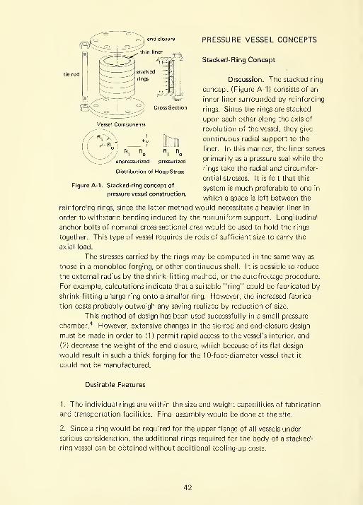
Figure A-1 . Stacked-ring concept of
pressure vessel construction.
PRESSURE VESSEL CONCEPTS
Stacked-Ring Concept
Discussion. The stacked-ring
concept (Figure A-1) consists of an
inner liner surrounded by reinforcing
rings. Since the rings are stacked
upon each other along the axis of
revolution of the vessel, they give
continuous radial support to the
liner. In this manner, the liner serves
prinnarily as a pressure seal while the
rings take the radial and circumfer-
ential stresses. It is felt that this
system is much preferable to one in
which a space is left between the
reinforcing rings, since the latter method would necessitate a heavier liner in
order to withstand bending induced by the nonuniform support. Longitudinal
anchor bolts of nominal cross-sectional area would be used to hold the rings
together. This type of vessel requires tie rods of sufficient size to carry the
axial load.
The stresses carried by the rings may be computed in the same way as
those in a monobloc forging, or other continuous shell. It is possible to reduce
the external radius by the shrink-fitting method, or the autofrettage procedure.
For example, calculations indicate that a suitable "ring" could be fabricated by
shrink-fitting a large ring onto a smaller ring. However, the increased fabrica-
tion costs probably outweigh any saving realized by reduction of size.
This method of design has been used successfully in a small pressure
chamber.'* However, extensive changes in the tie-rod and end-closure design
must be made in order to (1) permit rapid access to the vessel's interior, and
(2) decrease the weight of the end closure, which because of its flat design
would result in such a thick forging for the 10-foot-diameter vessel that it
could not be manufactured.
Desirable Features
1. The individual rings are within the size and weight capabilities of fabrication
and transportation facilities. Final assembly would be done at the site.
2. Since a ring would be required for the upper flange of all vessels under
serious consideration, the additional rings required for the body of a stacked-
ring vessel can be obtained without additional tooling-up costs.
42

3. If desirable, an extra ring could be fabricated for use in metallurgical tests
and test of fabrication suitability.
4. No welding would be required on the shell body. Thus, fabrication costs
are reduced and reliability is enhanced.
5. Failure of the liner would result in loss of water from the tank, but would
not cause failure of the rings. Even if one ring were to fail, the cost of repair
would be much less than the cost of replacement of the entire tank. The
facilities available for handling the closure would be adequate to disassemble
the vessel ring by ring and replace the damaged ring.
6. Analysis of the ring behavior is fairly straightforward since the end closures
are not attached to the shell body and each ring behaves in approximately the
same manner.
Undesirable Features
1. The total weight of steel used in the construction will be at least 50% greater
than in a multilayer construction because a separate system of structural mem-
bers must be employed to restrain the end closure.
2. Design of the end closures and of the discontinuous tie-rod restraint systems
will be difficult as little is known about them.
Conclusions. From the standpoint of feasibility of fabrication, cost of
fabrication, reliability (including inherent safety, ease of inspection, etc.), ease
of operation, and maintenance, the stacked-ring concept rates very high. An
independent device (yoke or tie rods) is required for taking the axial load, but
such a device appears to be desirable regardless of the type of tank employed.
Recomnnendations. It is recommended that an exploratory design be
made according to this concept in order to obtain firm cost estimates for
fabrication of a stacked-ring pressure vessel.
Multilayer* Concept
Discussion. A multilayer pressure vessel is made up of a number of
concentric cylindrical shells. Construction of a multilayer vessel begins with
rolling and welding of the vessel's inner cylindrical shells, which may be made
A. 0. Smith trademark.
43
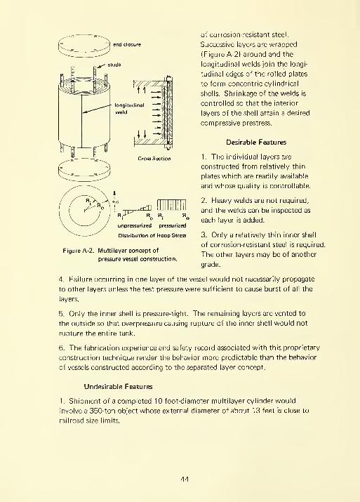
pUP=^ R R. RI o I a
unpressurized pressurized
Distribution of Hoop Stress
Figure A-2. Multilayer concept of
pressure vessel construction.
of corrosion-resistant steel.
Successive layers are wrapped
(Figure A-2) around and the
longitudinal welds join the longi-
tudinal edges of the rolled plates
to form concentric cylindrical
shells. Shrinkage of the welds is
controlled so that the interior
layers of the shell attain a desired
compressive prestress.
Desirable Features
1. The individual layers are
constructed from relatively thin
plates which are readily available
and whose quality is controllable.
2. Heavy welds are not required,
and the welds can be inspected as
each layer is added.
3. Only a relatively thin inner shell
of corrosion-resistant steel is required.
The other layers may be of another
grade.
4. Failure occurring in one layer of the vessel would not necessarily propagate
to other layers unless the test pressure were sufficient to cause burst of all the
layers.
5. Only the inner shell is pressure-tight. The remaining layers are vented to
the outside so that overpressure causing rupture of the inner shell would not
rupture the entire tank.
6. The fabrication experience and safety record associated with this proprietary
construction technique render the behavior more predictable than the behavior
of vessels constructed according to the separated layer concept.
Undesirable Features
1. Shipment of a completed 10-foot-diameter multilayer cylinder would
involve a 350-ton object whose external diameter of about 13 feet is close to
railroad size limits.
44

2. Replacement of any portion of the vessel would require costly repair
procedures. The installed laboratory lifting facilities would not be sufficient
to assist in any disassembly.
3. Welds, although made on relatively thin individual layers, except for the
end-closure flanges, would nevertheless be an added source of uncertainty
with regard to behavior under impact loading, cyclic stressing, etc.
4. The fabrication is restricted to basically one company due to the proprietary
nature of this concept.
Conclusions. The multilayer method has been sucessfully used in
some previous applications with operational pressures of 10,000 psi and could
be extended, with reasonable surety, to the 10-foot size required for the present
application.
Recommendations. Acomplete design and cost estimate
should be obtained from the fabri-
cators.
ndividual vessels
i //////A^/)^ i
I ^)/////////. W
Pi>Pk>Po
Pi" 2 p.
R. R R: RI o I o
unpressurized pressurized
Distribution of Hoop Stress
Figure A-3. Separated layer concept of
pressure vessel construction.
Separated Layer Concept
The separated layer concept
consists of fabricating a vessel from
a series of individual shells (Figure A-3)
separated by annular fluid spaces. Twosystems have been briefly considered,
one allowing for continuous control
of the annular space pressures and
the other providing the initial pres-
surization to some prescribed values
with the subsequent magnitude of the
annular space pressures being deter-
mined by the deformation of the
vessels and the compressibility of the
fluid.
A separated layer vessel theory
has been developed which assumes
that the maximum shear stress, T „,max
at the interior of each layer, has the
same value.
45
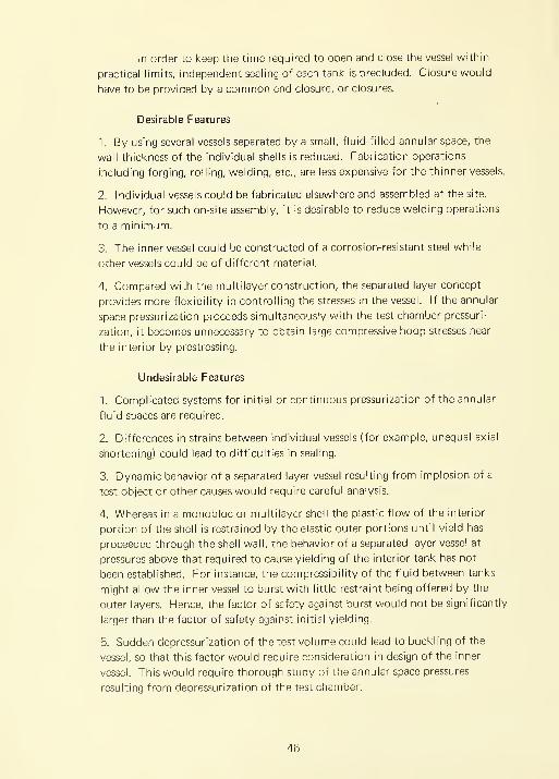
In order to keep the time required to open and close the vessel within
practical limits, independent sealing of each tank is precluded. Closure would
have to be provided by a common end closure, or closures.
Desirable Features
1. By using several vessels separated by a small, fluid-filled annular space, the
wall thickness of the individual shells is reduced. Fabrication operations
including forging, rolling, welding, etc., are less expensive for the thinner vessels.
2. Individual vessels could be fabricated elsewhere and assembled at the site.
However, for such on-site assembly, it is desirable to reduce welding operations
to a minimum.
3. The inner vessel could be constructed of a corrosion-resistant steel while
other vessels could be of different material.
4. Compared with the multilayer construction, the separated layer concept
provides more flexibility in controlling the stresses in the vessel. If the annular
space pressurization proceeds simultaneously with the test chamber pressuri-
zation, it becomes unnecessary to obtain large compressive hoop stresses near
the interior by prestressing.
Undesirable Features
1. Complicated systems for initial or continuous pressurization of the annular
fluid spaces are required.
2. Differences in strains between individual vessels (for example, unequal axial
shortening) could lead to difficulties in sealing.
3. Dynamic behavior of a separated layer vessel resulting from implosion of a
test object or other causes would require careful analysis.
4. Whereas in a monobloc or multilayer shell the plastic flow of the interior
portion of the shell is restrained by the elastic outer portions until yield has
proceeded through the shell wall, the behavior of a separated layer vessel at
pressures above that required to cause yielding of the interior tank has not
been established. For instance, the compressibility of the fluid between tanks
might allow the inner vessel to burst with little restraint being offered by the
outer layers. Hence, the factor of safety against burst would not be significantly
larger than the factor of safety against initial yielding.
5. Sudden depressurization of the test volume could lead to buckling of the
vessel, so that this factor would require consideration in design of the inner
vessel. This would require thorough study of the annular space pressures
resulting from depressurization of the test chamber.
46
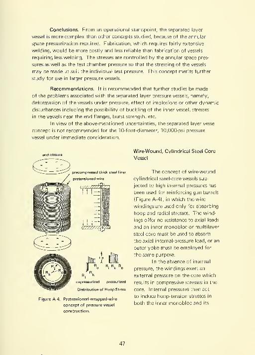
Conclusions. From an operational standpoint, the separated layer
vessel is more complex than other concepts studied, because of the annular
space pressurization required. Fabrication, which requires fairly extensive
welding, would be more costly and less reliable than fabrication of vessels
requiring less welding. The stresses are controlled by the annular space pres-
sures as well as the test chamber pressure so that the stressing of the vessels
may be made to suit the individual test pressure. This concept merits further
study for use in larger pressure vessels.
Recommendations. It is recommended that further studies be made
of the problems associated with the separated layer pressure vessels, namely,
deformation of the vessels under pressure, effect of implosions or other dynamic
disturbances including the possibility of buckling of the inner vessel, stresses
in the vessels near the end flanges, burst strength, etc.
In view of the above-mentioned uncertainties, the separated layer vessel
concept is not recommended for the 10-foot-diameter, 10,000-psi pressure
vessel under immediate consideration.
precom pressed thick steel liner
pretensioned wire
WZZZZZ^Z.
+ o I
R_ R. R,
R. kI
unpressurized pressurized
Distribution of Hoop Stress
Figure A-4. Pretensioned-wrapped-wire
concept of pressure vessel
construction.
Wire-Wound, Cylindrical Steel-Core
Vessel
The concept of wire-wound
cylindrical steel-core vessels sub-
jected to high internal pressures has
been used for reinforcing gun barrels
(Figure A-4), in which the wire
windings are used only for absorbing
hoop and radial stresses. The wind-
ings offer no resistance to axial loads
and an inner monobloc or multilayer
steel core must be used to absorb
the axial internal-pressure load, or an
outer yoke must be employed for
the same purpose.
In the absence of internal
pressure, the windings exert an
external pressure on the core which
results in compressive stresses in the
core. Internal pressures then act
to induce hoop-tension stresses in
both the inner monobloc and its
47

wire windings. Thus, under operating conditions the inner core may be
considered to have both internal and external pressures acting upon it and
the windings to have induced stresses resulting from the winding tension and
the internal pressure.
Acceptable design procedures are available for wire-wound cylindrical
shells, which are based on the allowable stress in the inner core. Further
investigation is required to determine the benefits of applying the windings
at a variable tension to produce a constant tension under operating conditions.
It has not been possible to obtain any information on companies
which currently undertake wire winding of cylinders of the size contemplated.
It is not likely that such companies exist within the United States. It is felt
that should this concept be accepted, a considerable amount of time, and
therefore expense, will be involved in setting up a facility whereby the fabri-
cation could be accomplished, particularly for the preferable on-site fabrication.
Desirable Features
1. Imposition of prestress on the inner vessel shell by tensioned wires makes
thinner vessel walls feasible than in stacked-ring or monobloc vessels.
2. Wire utilizes steel with strength in excess of 250,000 psi that is not available
for multilayer or monobloc vessels. This permits further reduction in vessel
thickness as compared to multilayer vessels.
3. Fracture crack propagation will be arrested at the inner vessel—wire layer
interface.
Undesirable Features
1. Retaining the wire windings at each end of the vessel may be difficult.
2. Yielding the wire in one or more places during winding could occur without
the fabricator's knowledge.
3. Abrasion and friction would occur between the wires in loading and unload-
ing cycles.
4. Redistribution of tensions within the winding due to creep may occur.
5. Early fatigue failure of wires in cyclic loading may result from stress raisers
in the form of localized abrasion and corrosion.
6. The expense involved in setting up an on-site winding facility will far exceed
the transportation costs of a large vessel based on alternative concepts.
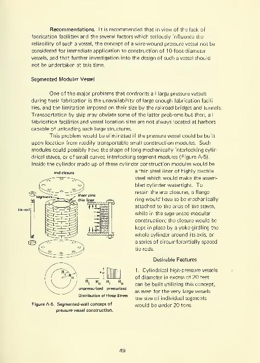
Recommendations, it is recommended that in view of the lack of
fabrication facilities and the several factors which seriously influence the
reliability of such a vessel, the concept of a wire-wound pressure vessel not be
considered for immediate application to construction of 10-foot-diameter
vessels, and that further investigation into the design of such a vessel should
not be undertaken at this time.
Segmented Modular Vessel
One of the major problems that confronts all large pressure vessels
during their fabrication is the unavailability of large enough fabrication facili-
ties, and the limitation imposed on their size by the railroad bridges and tunnels.
Transportation by ship may obviate some of the latter problems but then, all
fabrication facilities and vessel location sites are not always located at harbors
capable of unloading such large structures.
This problem would be eliminated if the pressure vessel could be built
upon location from readily transportable small construction modules. Such
modules could possibly have the shape of long mechanically interlocking cylin-
drical staves, or of small curved interlocking segment modules (Figure A-5).
Inside the cylinder made up of these cylinder construction modules would be
end closure ^ ^^^^ Steel liner of highly ductile
steel which would make the assem-
bled cylinder watertight. To
retain the end closures, a flange
ring would have to be mechanically
attached to the ends of the staves,
while in the segmented modular
construction; the closure would be
kept in place by a yoke girdling the
whole cylinder around its axis, or
a series of circumferential ly spaced
tie rods.
Desirable Features
1. Cylindrical high-pressure vessels
of diameter in excess of 20 feet
' ° i ° can be built utilizing this concept,unpressurized pressurized . ,
, ,
as even for the very large vesselsDistribution of Hoop Stress ^, j: i- •
i i
the size of individual segmentsFigure A-5. Segmented-wall concept of would be under 20 tons.
pressure vessel constructnan.
49
2. High-strength nonweldable materials can be utilized, as no welding is
required in this vessel. To a large extent, the use of high-strength materials
can compensate for the need for additional wall thickness to accommodate
stress concentrations around shear pins.
3. Individual segments can be transported by common commercial carriers
without any trouble.
4. At the erection site only the hoists associated with the pressure vessel
test facility need be employed in the assembly of the vessel.
5. The assembly of the vessel can take place after the test facility building
has been completed, since individual segments can easily pass through the
doors of the facility. Because of this, the overall construction time of the
facility may be reduced, as the vessel does not have to be fabricated and
installed before the building can be built.
Undesirable Features
1
.
This construction concept is very new and a very extensive R&D program
will have to be conducted to develop safe design and fabrication techniques.
2. This vessel will probably require 5 to 1 times as much steel as a multilayer
vessel of same material because of the stress concentrations in modules and
due to extra material needed for a yoke or tie-rod end-closure restraint system.
3. Machining of modules for a segmented vessel will require at least 100 times
more machine shop time than for a multilayer vessel.
4. The assembly time of such a vessel in situ is longer than for welding a multi-
layer vessel in the shop, or in situ.
Conclusion. The construction of pressure vessels by the segmented
modular method is a new concept that has not been extensively applied. If
practive proves it successful, it will mean a breakthrough in the technology of
fabricating large, high-pressure metallic vessels.
Recommendation. The segmented vessel construction concept is not
recommended for immediate consideration in the construction of large pres-
sure vessels because of complete absence of design or experimental data.
However, a study should be immediately initiated to explore this vessel concept.
Prestressed Concrete
The possibility of using prestressed concrete as material for constructing
a deep-sea-pressure simulation vessel appears attractive and competitive with
other fabrication methods. Prestressed concrete is quite commonly used for
50

liquid containers such as storage tanks and elevated tanks, and for much larger
structures—powerhouses, penstocks, pressure pipelines, etc. In the case under
consideration, there are no restrictions on size and weight if the vessel is built
on site; whereas, size and weight considerations become restrictive for a shop-
fabricated vessel transported by rail or water to the site. There are other
advantages in the prestressed-concrete concept, the most important being that
the vessel and building foundations may be integrally designed for more useful
load bearing and distribution capacity. The handling equipment for installing
and removing a prefabricated vessel (500 tons plus), unless a modular steel con-
struction is used, is dispensed with.
Work on prestressed-concrete design aspects and dynamic action of
reinforced concrete structures to shock loads has been underway at NCEL for
the past 14 years. With the concentration of talent in this field it appears likely
that a design could be evolved.
This method has been applied by
NAVFACasfar backas 1941
for a water storage tank, and the
first prestressed-concrete barge
manufactured in the United States
for the Navy is still in service.
The principle of prestressed-
concrete pressure vessels (Figure A-6)
is that the hoop stresses are assisted
by high-strength steel wires under
full load and under no load the
tensile stress in steel places the con-
crete in compression. Longitudinal
tension to retain the end closure
is resisted by means of high-strength
pretensioned
circumferential
rods
pretensioned
circumferential
rod
pretensioned tensile bars or studs going the full
height of the vessel and which are
anchored in the bottom slab. Aninner liner of steel or some resilient
material is recommended.
concrete
unpressurized pressurized
Distribution of Hoop Stress
Figure A-6. Prestressed-concrete concept
of pressure vessel construction.
Desirable Features
1 . Internal pressure vessels of almost
any size can be erected in place using
this concept.
51

2. Several vessels of this concept have been built with diameters in excess of
10 feet, and have been found to perform successfully.
3. Cost of building the vessel in situ is less than the cost of any other vessel
concept of similar pressure capability, diameter, and length.
4. This vessel is safe in operation as the propagation of a fracture crack in the
wall is not accompanied by fragmentation. As soon as the overpressure relieves
itself through the crack in the concrete, the pretensioned wires and rods in the
vessel close the crack.
Undesirable Features
1. Internal pressure rating of the vessel depends on the compressive strength
of the concrete. Since currently the strength of concrete is less than 10,000
psi, the highest internal pressure that such a vessel can contain is also less than
10,000 psi.
2. No design data is available on the incorporation of rapid opening end-closure
mechanism into a concrete pressure vessel.
3. The information on behavior of concrete under cyclic loading in triaxial
stress field is at best fragmentary and inadequate.
4. Inspection of the vessel during service for incipient failure is very difficult.
Conclusions. The prestressed-concrete pressure vessel concept will
permit with reasonable confidence the construction of pressure vessels with
pressures less than 5,000 psi and large enough for testing assembled fleet
submarines. This pressure vessel concept is at the present time not applicable
with currently commercially available Portland cements to the construction
of the 10-foot-diameter, 10,000-psi pressure vessel. If cements with compressive
strength in excess of 15,000 psi become commercially available prestressed-
concrete pressure vessels should be considered for such an application.
Recommendations. The prestressed-concrete pressure vessel should
not be considered for the immediate construction of the 1 0,000-psi, 1 0-foot
(internal diameter) pressure vessel. If requirements arise for construction of
very large (10 feet < diameter < 100 feet) vessels with less than 5,000-psi
pressure requirements, the prestressed-concrete pressure vessel concept should
receive first consideration. In the meantime, experimental studies are recom-
mended for development of concrete pressure vessel technology to meet such
requirements.
52
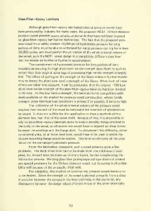
Glass-Fiber—Epoxy Laminate
Although glass-fiber—epoxy laminated internal pressure vessels have
been produced by industry for many years, the proposed NCEL 10-foot-diameter
pressure vessel presents severe structural demands that have not been imposed
on glass-fiber—epoxy lamination technology. The fact that the proposed pres-
sure vessel must safely contain 10,000 psi of hydrostatic pressure for long
periods of time, must be able to withstand full-range pressure cycling for at least
20,000 cycles, and must permit the utilization of the whole internal volume of
the vessel, puts the NCEL vessel design in a completely different class from
that for missile air bottles or hydraulic accumulators.
The containment of hydrostatic pressure for long periods of time
necessitates derating the high short-term tensile strength glass fibers to such an
extent that their original advantage of possessing high tensile strength is largely
lost. The effect of cycling on the strength of the fibers makes it further manda-
tory to derate the short-term tensile strength of the fibers. When both of these
effects are taken into account, it can be postulated that the original +100 kpsi
short-term tensile strength of the glass-fiber—epoxy laminate has been derated
to 30 kpsi. At this low tensile strength, the laminate is not competitive with
steels available on the market for pressure vessel construction, whose tensile
strength under identical load conditions is at least 2 or possibly 3 times as high.
The utilization of the whole internal volume of the pressure vessel
requires that one end of the vessel be removable for insertion of specimens to
be tested. It does not suffice for this application to have a manhole with a
diameter less than that of the vessel itself. Because of this, it is impossible to
rely on glass-fiber—epoxy laminate alone to keep a metallic flange attached to
the body of the vessel, as otherwise one would have to depend on shear forces
between the windings and the flange skirt. To circumvent this difficulty, either
an external yoke, or an inner steel liner, would have to be used to which the
closure mounting flange would be welded. This liner would carry all the axial
thrust on the contained hydrostatic pressure.
From the fabrication viewpoint, such a vessel presents quite a few
problems. The thick inner liner cannot be made from one thickness of steel
plate, but instead must be made up of many layers, further complicating the
fabrication process. Winding glass-fiber preimpregnated tape does not present
any special problems for the 10-foot-diameter vessel, but its curing in all proba-
bility will because of the unusually thick wall.
For reliability, this method of constructing pressure vessels leaves a lot
to be desired. Since the strength of the vessel is derived primarily from a close
interaction between the stresses in the liner and those in the overwrap, any
discrepancy between the design values of strain in one or the other drastically
53

thick steel liner
glass fiber epoxy laminate
decreases the pressure-containing capability of such a vessel. When one considers
that in a multilayer lining ( 1 ) some layers are already in compression while
others are in tension, and (2) that the amount of prestress to be expected from
very heavy overwrap is not a precisely predictable quantity, it must be concluded
that the interaction between the strains in the multilayer liner and the overwrap
will be unpredictable.
The cost of a steel—fiber glass laminate vessel has been estimated to be
in the $5 to $10 per pound range. The rather high cost of such a construction
can be traced to the fact that there are two different fabrication processes
involved, each one of them requiring a different fabricator. Each fabricator's
profits, overhead, and transportation charges will make such a tank more
expensive than it would be if only one fabricator was involved. Furthermore,
quality glass-fiber—epoxy laminate is an expensive material, justifiable only
where rigidity or weight reduction
is desirable. When to the already
high cost is added the premium
that the fabricator of the overwrap
will demand to cover uncertainties
of the process when applied to a
large vessel, the price of a pressure
vessel constructed in this manner
probably becomes uncompetitive
with other fabrication processes.
The composite vessel
consisting of a compressed steel
liner with a pretensioned glass-
fiber—epoxy laminate overwrap
(Figure A-7) can be fabricated
today if modifications are made
to existing glass-fiber wrapping
and curing facilities. The 10- foot
internal diameter is already pushing
existing facilities to the limit, and
if there were a requirement for a
40-foot-diameter vessel, it would
necessitate the erection of new
fabrication facilities located in a
place from where the vessel could
be transported by ship to its loca-
tion in some seashore installation.
\///////ff;W^
unpressurized pressurized
Distribution of Hoop Stress
Figure A-7. Pretensioned-glass-fiber—epoxy-
laminate concept of pressure
vessel construction.
54
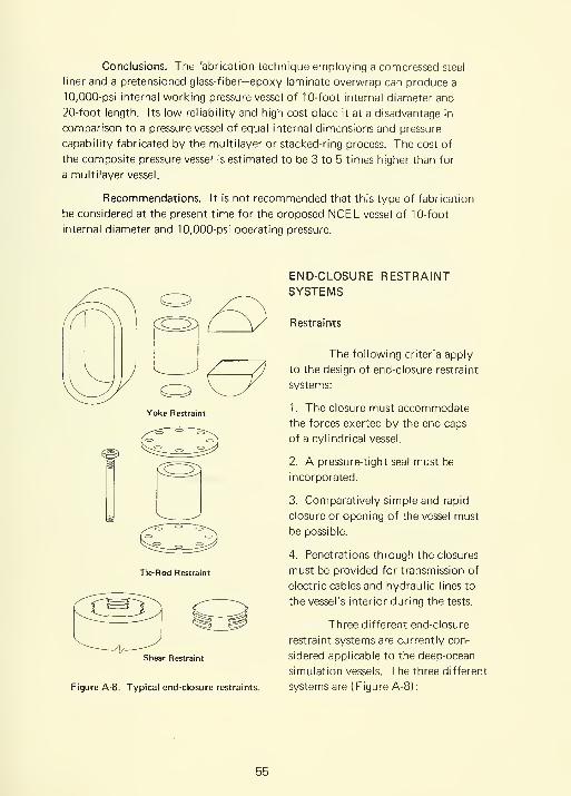
Conclusions. The fabrication technique employing a compressed steel
liner and a pretensioned glass-fiber—epoxy laminate overwrap can produce a
10,000-psi internal working pressure vessel of 10-foot internal diameter and
20-foot length. Its low reliability and high cost place it at a disadvantage in
comparison to a pressure vessel of equal internal dimensions and pressure
capability fabricated by the multilayer or stacked-ring process. The cost of
the composite pressure vessel is estimated to be 3 to 5 times higher than for
a multilayer vessel.
Recommendations. It is not recommended that this type of fabrication
be considered at the present time for the proposed NCEL vessel of 10-foot
internal diameter and 10,000-psi operating pressure.
Tie-Rod Restraint
Shear Restraint
Figure A-8. Typical end-closure restraints.
END-CLOSURE RESTRAINTSYSTEMS
Restraints
The following criteria apply
to the design of end-closure restraint
systems:
1. The closure must accommodate
the forces exerted by the end caps
of a cylindrical vessel.
2. A pressure-tight seal must be
incorporated.
3. Comparatively simple and rapid
closure or opening of the vessel must
be possible.
4. Penetrations through the closures
must be provided for transmission of
electric cables and hydraulic lines to
the vessel's interior during the tests.
Three different end-closure
restraint systems are currently con-
sidered applicable to the deep-ocean
simulation vessels. The three different
systems are (Figure A-8):
55
1. Continuous- or interrupted-thread and shear-block systems
2. Continuous external-yoke system
3. Tie-rod system
Of these three end-closure restraint systems, the threaded and shear-block
restraint systems are the most limited in terms of internal pressure and size
because of the small shear surface engagement in the end flange. The contin-
uous yoke will operate at the highest pressure limitation, while the tie-rod
system occupies a middle position with respect to pressure limits.
The three different end-closure restraint systems provide different
degrees of accessibility to the vessel interior via feedthroughs in the end closures.
The threaded and shear-block restraint systems provide maximum accessibility
to the end closure for installation of feedthrough, while the continuous-yoke
closure provides minimum or complete absence of accessibility. Here again the
tie-rod restraint system is midway between the two others. It provides less
accessibility to the end closures than the threaded and shear-block system, but
more than the continuous-yoke system.
The end-closure restraint systems also vary in the ease of opening and
closing the vessel at the beginning and end of each test program. The continuous-
yoke system is here the most cumbersome and requires a very expensive and
elaborate opening and closing mechanism to perform a reasonably speedy open-
ing or closing operation. Threaded and shear-block restraint systems can be
easily mechanized, resulting in very fast opening and closing operations. The
tie-rod system is less cumbersome than the continuous yoke, but still more so
than the threaded and shear-block systems. It has the potential, however, of
resulting in an efficient system if an R&D effort is devoted to it.
Conclusions. Tie-rod and continuous-yoke restraint systems are superior
to interrupted-threaded and shear-block systems for 10-foot-diameter pressure
vessels of 10,000-psi pressure service because the small shear surfaces of the
latter make them inadequate for high pressure.
Recommendations. It is recommended that the tie-rod end-closure
restraint system be investigated further as there is less known about it than the
continuous-yoke system. It promises to be more efficient in operation than
the continuous-yoke system, if a successful design is found for it.
56
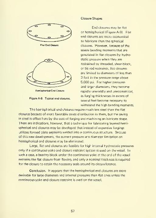
Flat End Closure
Closure Shapes
End closures may be flat
or hemispherical (Figure A-9). Flat
end closures are more economical
to fabricate than the spherical
closures. However, because of the
severe bending moments that are
generated in flat closures by hydro-
static pressure when they are
restrained by threaded, shear-block,
or tie-rod restraints, flat closures
are limited to diameters of less than
3 feet in the pressure range above
5,000 psi. For higher pressures
and larger diameters, they become
rapidly unwieldly and uneconomical,
as forging thicknesses in excess of
several feet become necessary to
withstand the high bending moments.
The hemispherical end closures require much less steel than the flat
closures because of more favorable stress distribution in them, but the saving
in steel is offset here by the cost of forging and machining an intricate shape.
There are indications, however, that a technique for fabricating layered hemi-
spherical end closures may be developed that instead of expensive forgings
utilizes formed plate segments welded into a continuous structure. Because
of this new development, the current pressure and diameter limitation on
hemispherical end closures may be eliminated.
Large, flat end closures are feasible for high internal hydrostatic pressures
only if a continuous-yoke end-closure restraint system is used on the vessel. In
such a case, a bearing block under the continuous yoke at the end of the vessel
restrains the flat closure from flexing, and only a nominal thickness is required
for the closure to retain the necessary seals around its circumference.
Conclusion. It appears that the hemispherical end closures are more
desirable for large diameters and internal pressures than flat ones unless the
continuous-yoke end-closure restraint is used on the vessel.
Hemispherical End Closure
Figure A-9. Typical end closures.
57

Recommendation. There is no requirement for thicl<, flat end closures
for large vessels, since with the continuous-yoke restraint system, a thin end
closure suffices. Investigations into economical end closures for large-diameter
vessels need to be concentrated on hemispherical shapes, particularly of layered,
welded construction.
Seals
High-pressure seals should be;
1. Simple to assemble
2. Self-energizing (sealing ability increases with pressure)
3. Unlikely to jam
4. Easy to install
Although a host of proven seal designs is commercially available, none
of them are ideally suited to large-diameter vessels for high internal pressure.
Their shortcomings lie principally in their requirement for either a high precom-
pression or fine dimensional tolerances between seal surfaces for proper sealing.
Those seals that can tolerate rough sealing surfaces and loose dimensional
tolerances on the vessel flange require such a high precompression to seal effec-
tively at 10,000-psi hydrostatic pressure that they are inapplicable to high
pressure vessels of 10-foot diameter. Almost all the axial compression seals
(Figure A-10) fall in this category. Those seals, on the other hand, that do not
require axial precompression to seal properly at 10,000-psi hydrostatic pressure
require such fine finish and dimensional tolerances on the internal diameter of
the vessel that it cannot be satisfied with ordinary machining tolerances for
cylinder openings of 10 feet. Only by premium surface finishing techniques
and meticulous attention to diameter tolerances on the internal surface of the
vessel can those seals be made to work successfully at 10,000 psi. Most radial
compression seals fall into this category.
Conclusions. It appears that no currently available sealing system is
ideally suited for 10-foot-diameter vessels with 10,000-psi hydrostatic pressure
where repeated removal of end closure is required. However, of the two classes
of seals available, the radial compression seals are more applicable. It is not
feasible to mechanically apply sufficient pretensioning to the end-closure
restraint system to insure sufficient compression of axial seals to seal at 10,000-
psi operational pressure unless the very cumbersome thermal shrink technique
is applied.
58

Axial Seal Radial Seal
Figure A-10. Typical end-closure seals.
Recommendation. It is recommended that experimental investigations
be initiated for development of an improved self-energizing radial seal suited for
10-foot-diameter vessels and 10,000-psi operational pressure.
IMPLOSION LOADING OF PRESSURE VESSELS
Past experience at laboratories equipped with internal pressure test
vessels* has shown that when implosion of models occurs, a severe shock wave
is generated which causes the test vessel to be moved laterally or vertically,
damaging in the process auxiliary equipment attached rigidly to the pressure
chamber. Although there is no record of a pressure vessel rupturing because
of an implosion inside of it, this can be attributed in a large extent to the high
safety factor of 4 used under the ASME code, the very ductile materials employed,
and the low hydrostatic pressures involved in the testing. With the present
trend in test vessel design aimed at larger vessels, higher working pressures,
materials with higher yield-points but lower ductility, and reduced safety factors,
it is only a matter of time before a catastrophic failure of a vessel will occur
because of an imploding test object.
* For example, the Southwest Research Institute, San Antonio, Texas; the Ordnance
Research Laboratory, State College, Pennsylvania; the Navy Ordnance Laboratory,
White Oaks, Maryland; the Navy Underwater Test Station, Newport, Rhode Island;
the David Taylor Model Basin, Carderock, Maryland.
59

Conclusion
To forestall this type of failure, information must be made available
to the vessel designers, and safe vessel operation techniques must be taught to
the pressure vessel operators. Such information to be of real value as a design
guide must constitute a theoretically postulated and experimentally verified
series of equations.
Recommendation
In order to obtain the needed information to design vessels resistant
to implosion damage, and to insure the safe operation of vessels already in
existence, a program must be initiated to investigate the effect of implosions
on pressure vessel life. Such a program should consist of experimental and
analytical studies running concurrently. Only from the continual cross-referencing
of experimental and analytical work will biable design criteria emerge from
such a program.
SELECTION OF SAFETY FACTOR
The safety factor for pressure-vessel operation generally is based on
four considerations. These are:
1. Foreseeable inaccuracies in the stress analysis during design on the vessel
2. Predictable discrepancies between the properties of the material samples,
and the actual properties of the material in the vessel
3. Unforeseen loads that will act on the vessel while under maximum working
pressure
4. Number of pressure cycles to which vessel will be subjected during its life
In the proposed pressure test facility, only items 2, 3, and 4 are decisive,
if a vessel construction concept with known design criteria is chosen. The
discrepancy between the properties of the specified material and those actually
found in the vessel structure will be very large since the construction of the
proposed vessel requires that very thick forgings be employed for the closures
and flanges. The actual magnitude of discrepancy is not known since very little
is known about this subject for very heavy forgings. The same may be said of
our knowledge in the generation of shock loads in pressure vessels by implosion
of test models. That large shock waves are triggered by implosion is well known.
60

but how high the dynamic stresses in the vessel actually are is only a calculated
guess. The fact that those dynamic stresses also fatigue the vessel material
only further complicates the matter. This fatigue effect, when added to the
fatigue caused by static pressure cycling, makes it necessary to reduce consid-
erably the safe stress level that can be tolerated by the vessel material during
a projected 20-year lifetime.
Conclusion
A safety factor of 2 based on yield of the material is considered
inadequate. A safety factor of at least 3, and preferably 4, should be used.
The safety factor should be based on yield of the vessel's material under static
pressure loading to insure not only a statically safe vessel but also a long cyclic
life at pressures equal to static pressure.
Recommendation
A minimum safety factor of 3, and preferably 4, based on the yield
strength of the material, should be applied in the design of the proposed pres-
sure vessel.
OVERALL CONCLUSIONS AND RECOMMENDATIONS
Conclusions
1. The group concurs that at the present time the stacked-ring or multilayer
construction concepts are the most feasible concepts for the construction of
a 10-foot-diameter deep-ocean simulation vessel with a 10,000-psi operating
pressure. Of the two, the stacked-ring concept possesses the added advantages
of in-situ assembly, interchangeability and replaceability of individual con-
struction modules, and absence of welds.
2. The most promising closure system for the stacked-ring concept from the
viewpoint of accessibility to penetrations, speed of operation, ease of manu-
facture, and cost, appears to be composed of tie rods and hemispherical end
closures. Although it is a promising system, very little design experience is
available for its design.
3. The projected types of tests that will take place in the vessel and the impact
on the national deep-submergence effort that the loss of such a vessel would
create, make a safety factor of 2 inadequate. A minimum safety factor of 3,
or preferably 4, based on yield of material, should be utilized.
61

4. There are no quantitative or analytical data that could be applied to the
design of the pressure vessel facilities to eliminate the possibility of vessel
failure because of internal implosion. Qualitative observations of implosions,
however, have shown that the shock waves unleashed by implosions are of
such magnitude that they must be considered in safe vessel design.
Recommendations
1
.
Conceptual designs of the stacked-ring and multilayer vessels should be
prepared and quotations on their fabrication should be solicited. The stacked-
ring and multilayer vessel concepts are in the opinion of the study group the
leading candidates at the present time for the construction of a 10- foot-diameter,
10,000-psi vessel.
2. The segmented and the stacked-ring vessel concepts should be further
explored and refined, as they have great potential for construction of pressure
vessels with diameters and pressures in excess of 10 feet and 10,000 psi, respec-
tively.
3. An exploratory study of the implosion effects inside pressure vessels should
be immediately initiated. The analytical and experimental data gathered by
such study will be of importance in the design of future pressure vessels.
62

Appendix B
EXPERIMENTAL EVALUATION OF RADIAL END-CLOSURE SEALS
BACKGROUND
For successful operation each pressure vessel requires seals at joints
between removable pressure vessel connponents. Since seals at best are poten-
tial sources of leakage, a concentrated effort is generally made to minimize
their number. Such a minimum is represented by a single 0-ring in the upper
removable closure. No way has been found to eliminate it from a pressure
vessel because access to the interior is mandatory for the insertion of test
specimens. In the case of stacked-ring or segmented modular design, in which
both the upper and lower head closures are removable, the irreducible minimum
of seals is two 0-rings, one in the top and one in the bottom closure, sealing
the joint between the closures and the walls of the vessel. Naturally, more
than two 0-rings may be and generally are used even with such a design. The
additional 0-ring seals however, are only a convenient substitute for some
other type of seal, for example, threaded pipe fittings.
EXPERIMENTAL DESIGN
To evaluate some of the large variety of existing, or feasible joint seals
for high pressure vessels, a small pressure vessel was designed in which seals of
varying design could be tested between the closures and vessel body (Figures B-la
and B-lb). In order to simulate the problems that will be encountered in the
operation of the full-sized stacked-ring or segmented pressure vessel, the seal
test vessel was also designed with free-floating end closures. In this design, the
end closures were permitted some vertical motion when internal hydrostatic
pressure was applied. In the seal test vessel, the end closures were affixed to
the pressure vessel by means of tie rods, which extended only a known and
limited amount when the interior of the vessel was pressurized. Although this
vertical movement of the end closures was very small (on the order of a 1/32
of an inch at pressures of 10,000 psi), it was sufficient for the end closures to
be free floating. The fact that the end closure was free floating made it impos-
sible to utilize with it any of the seals associated with nonfloating end closures.
Such seals generally rely on the wedging action between the end closure and the
vessel body to squeeze the seal so that it forms a watertight barrier. With free-
floating closures, seals must be employed that do not lose their sealing action
because of the upward movement of the end closure under load.
63
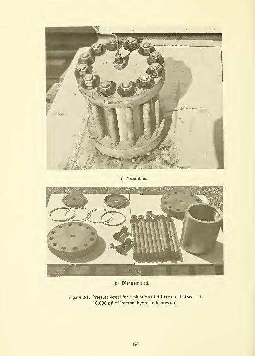
(a) Assembled.
(b) Disassembled.
Figure B-1. Pressure vessel for evaluation of different radial seals at
10,000 psi of internal hydrostatic pressure.
64

The seals associated with the free-floating end closures generally rely
for their sealing action on radial compression of the seal body between the
end closure and the interior of the vessel body. The design ingenuity of such
seals lies primarily in the provision for sealing the increasingly wider gap between
the end closure and the interior of the vessel as the vessel expands radially under
the internal hydrostatic pressure. Without provision for this gap during the
pressurization of the vessel, the seal will extrude into the gap and out of the
vessel, losing all of its sealing ability. For this discussion, it is obvious that an
ordinary 0-ring under radial compression would retain its sealing ability under
very low hydrostatic pressure only, as the presence of a gap of several thousands
of an inch would make it impossible to retain pressures of even 2,000-to-3,000-psi
magnitude. Obviously, other approaches to the seal design besides an ordinary
0-ring in radial compression had to be sought and evaluated.
The seal designs that were evaluated in the seal-test vessel (Figure B-2)
were the wedge ring seal, 0-ring with continuous antiextrusion wedge ring,
0-ring with a split antiextrusion wedge ring, and twin 0-ring seal in a self-energized
elastic follower ring (Figure B-3). Each of these seal designs was thought to be
promising and worthy of investigation; the most desirable one was to be selected
on the basis of its performance under hydrostatic pressure in the vessel.
Figure B-2. Location of seals
in the pressure
vessel during their
evaluation under
hydrostatic pressure.
65
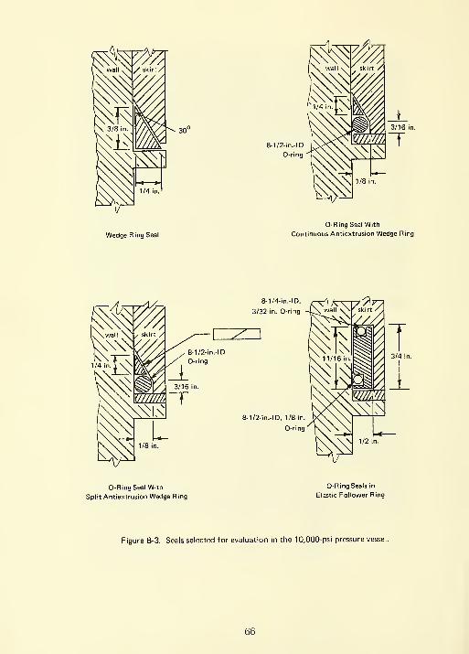
Wedge Ring Seal
0-RingSeal With
Continuous Antiextrusion Wedge Ring
3/4 in.
\ 1/2 in.
O-RingSeal With
Split Antiextrusion Wedge Ring
0-Ring Seals in
Elastic Follower Ring
Figure B-3. Seals selected for evaluation in the 10,000-psi pressure vessel,
66
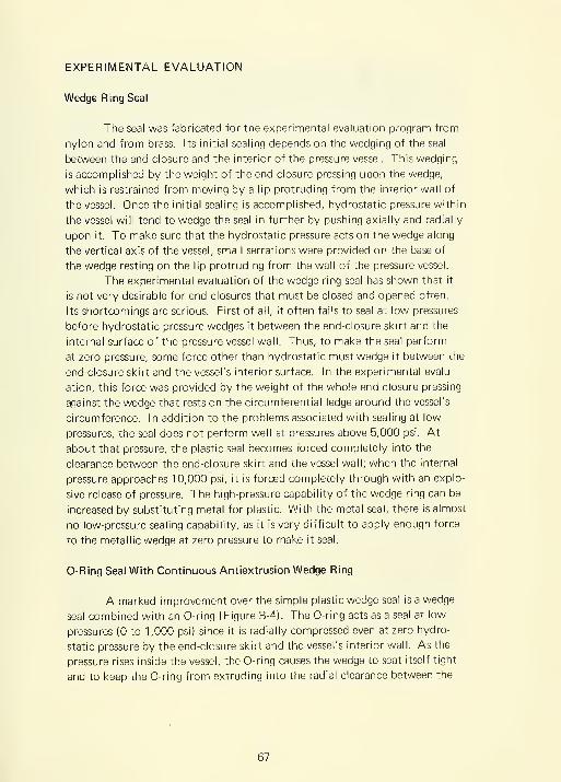
EXPERIMENTAL EVALUATION
Wedge Ring Seal
The seal was fabricated for the experimental evaluation program from
nylon and from brass. Its initial sealing depends on the wedging of the seal
between the end closure and the interior of the pressure vessel. This wedging
is accomplished by the weight of the end closure pressing upon the wedge,
which is restrained from moving by a lip protruding from the interior wall of
the vessel. Once the initial sealing is accomplished, hydrostatic pressure within
the vessel will tend to wedge the seal in further by pushing axially and radially
upon it. To make sure that the hydrostatic pressure acts on the wedge along
the vertical axis of the vessel, small serrations were provided on the base of
the wedge resting on the lip protruding from the wall of the pressure vessel.
The experimental evaluation of the wedge ring seal has shown that it
is not very desirable for end closures that must be closed and opened often.
Its shortcomings are serious. First of all, it often fails to seal at low pressures
before hydrostatic pressure wedges it between the end-closure skirt and the
internal surface of the pressure vessel wall. Thus, to make the seal perform
at zero pressure, some force other than hydrostatic must wedge it between the
end-closure skirt and the vessel's interior surface. In the experimental evalu-
ation, this force was provided by the weight of the whole end closure pressing
against the wedge that rests on the circumferential ledge around the vessel's
circumference. In addition to the problems associated with sealing at low
pressures, the seal does not perform well at pressures above 5,000 psi. At
about that pressure, the plastic seal becomes forced completely into the
clearance between the end-closure skirt and the vessel wall; when the internal
pressure approaches 10,000 psi, it is forced completely through with an explo-
sive release of pressure. The high-pressure capability of the wedge ring can be
increased by substituting metal for plastic. With the metal seal, there is almost
no low-pressure sealing capability, as it is very difficult to apply enough force
to the metallic wedge at zero pressure to make it seal.
0-Ring Seal With Continuous Antiextrusion Wedge Ring
A marked improvement over the simple plastic wedge seal is a wedge
seal combined with an 0-ring (Figure B-4). The 0-ring acts as a seal at low
pressures (0 to 1,000 psi) since it is radially compressed even at zero hydro-
static pressure by the end-closure skirt and the vessel's interior wall. As the
pressure rises inside the vessel, the 0-ring causes the wedge to seat itself tight
and to keep the 0-ring from extruding into the radial clearance between the
67

end-closure skirt and the vessel wall. However, when the internal pressure
approaches 10,000 psi, this plastic wedge, like the preceding seal type,
plastically extrudes and releases compressed water (Figure B-5).
This seal represents a marked improvement over the preceding seal
type, as with this type no sealing difficulties are encountered at low pressures,
and it is only in the 5,000-to-10,000-psi range that this seal fails by extruding.
Both these seal arrangements have an unlimited capability to follow axial
displacement of the end closure, but only very limited capability to follow
the vessel's radial dilation. Both seal arrangements should have a plastic
rather than a metallic continuous wedge ring as otherwise the seals will not
follow the radially dilating vessel wall with sufficient compliance to assure
a continuous seal.
0-Ring Seal With Split Antiextrusion Wedge Ring
This seal arrangement is basically the same as that of the preceding
seal except that a split metallic ring has been substituted for the plastic contin-
uous ring. With this arrangement, the 0-ring seals well at zero and low pressures,
while at high pressures the metallic wedge ring is much more difficult to extrude
than the plastic wedge ring described above. However, if the clearance between
the end-closure skirt and the vessel wall became of the same magnitude as the
width of the wedge, it would be forced into that space by the hydrostatic
forces acting on the 0-ring. Once the metallic wedge was lost into the space
between the vessel wall and the end-closure skirt, it would cause the end closure
to jam and might prevent the removal of the end closure.
This seal arrangement, like the preceding seal arrangements, can follow
any axial displacement of the end closure. It has only limited ability to follow
the radial dilation of the vessel, and the magnitude of radial dilation of the
vessel that this seal can compensate for is determined by the width of the split
metallic antiextrusion ring.
Although this seal arrangement has overcome the shortcoming of the
first seal of not sealing properly at zero internal pressure, and the shortcoming
of the second seal of not sealing at pressures in the 5,000-to-10,000-psi range,
it had not overcome the single shortcoming common to ail; incapability to
compensate for large radial dilation of the vessel wall. Thus another seal arrange-
ment was conceived with the objective to seal well at zero pressure, at high
pressure of any magnitude, and to follow axial displacement of the end closure
and any magnitude of radial dilation of the vessel wall. Furthermore, to make
the seal installation simple and inexpensive, it was to utilize only commercially
readily available 0-rings and a minimum of custom machined parts.
68
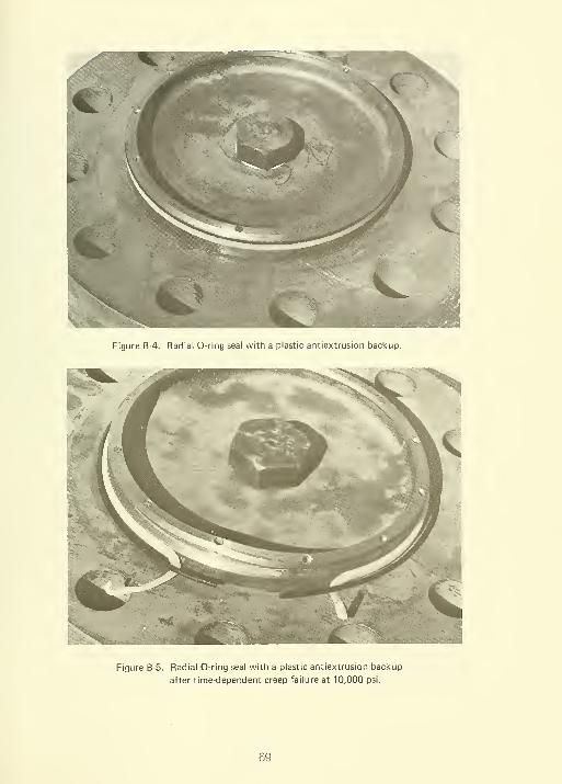
Figure B-4. Radial 0-ring seal with a plastic antiextrusion backup.
Figure B-5. Radial 0-ring seal with a plastic antiextrusion backup
after time-dependent creep failure at 10,000 psi.
69

Figure B-6. Self-energizing radial 0-ring seal for high pressures in internally
pressurized vessels.
0-Ring Seals in Elastic Follower Ring
The experimental evaluation of this seal arrangement has shown it to
be markedly superior to all the other seal arrangements experimented with
previously in this study. The superiority of this seal (Figure B-6) lies in its
ability to seal out low and high pressures, as well as to follow the axial and
radial dilation of the vessel without any loss in sealing ability. Its ability to
accomplish all this lies in its use of hydrostatic pressure contained inside the
pressure vessel to expand and translate the elastic follower ring so that it follows
the radially dilating wall of the vessel and the axially displacing end closure.
This self-energizing feature causes the seal to press harder against the end
closure and wall as the pressure is raised. In this manner, it is assured that
regardless of the magnitude of internal pressure or radial and axial displacement
of vessel's interior surfaces, no extrusion will take place in 0-rings even though
they are soft elastomers.
Because of the self-energized elastic follower ring in which the 0-rings
are contained, no extrusion of the 70 shore-hardness 0-rings took place even
though the total radial clearance between the interior vessel wall and the end-
closure skirt was more than 0.032 inch at 20,000 psi of internal hydrostatic
pressure. When the internal pressure was released, the elastic follower ring
70

returned to its original dimensions and no difficulty was encountered in
removing the end closure. Upon examination of the 0-rings, it was found
that they were ready to be used again as a seal. The design and fabrication
of the self-energized 0-ring seal in the elastic follower ring is rather simple.
These three elements are required:
(a) Two 0-rings. One 0-ring under radial and one under axial compres-
sion are required. The elastic follower ring must be so dimensioned that the
0-rings are under sufficient compression at zero internal pressure to constitute
a low-pressure radial and axial 0-ring seal. The radially compressed 0-ring
must seal the inevitable small clearance between the vessel wall and the
external radius of the elastic follower ring, while the axially compressed
0-ring seals the clearance between the bottom of the vessel end closure and
the top of the elastic follower ring. The radial 0-ring is compressed at zero
hydrostatic pressure by the close fit between the exterior surface of the elastic
follower ring and the interior surface of the pressure vessel. The axial 0-ring
is compressed at zero pressure by bolts pushing a retainer ring against the
elastic follower ring. When the pressure is raised inside the pressure vessel, it
acts axially and radially upon the elastic follower causing it to push harder
against the end closure and the cylinder, thus achieving zero clearance between
the follower ring and the seal surfaces.
(b) An elastic follower ring. A ring sufficiently elastic to expand
across the gap between the head and the vessel and subsequently to follow
the radially dilating pressure vessel is required. For this application, the
follower ring must be less stiff than the vessel wall whose dilating it is following.
This is accomplished by making the follower ring either from material with a
very low modulus of elasticity or by making it from the same material as the
pressure vessel wall, but considerably thinner. Regardless of what material
the follower ring is made, it must not yield during its radial dilation, or deform
due to shearing stresses imposed on it while it is bridging the gap between the
vessel end closure and the wall of the vessel. If either one occurred, the follower
ring would have to be replaced after each pressurization, making this type
seal uneconomical.
To provide sufficient radial and axial forces on the follower ring to
maintain zero clearance between the ring and the seal surfaces on the end
closure, the 0-ring grooves (Figure B-7) must be machined at such locations
in the follower ring that hydrostatic pressure causes radial and axial movement
of the follower ring.
71

F = Total force >—^y*" = Direction of force
a = Unit stress ^a) = Type of stress (compression, tension)
Note: Se<f-energizing seal worl<s only wheng)>Qand@>Qresulting in radial dilation of elastic
follower ring and compression
and (oo j' "vhere (o/\ > (a
because of ring's resistance to3ilation.
radial dilation
of vessel under
pressure
Figure B-7. Forces acting on the elastic follower ring containing the radial
and axial 0-rings.
(c) Radial precompression. The only shortcoming of the self-energized
radial seal is its requirement for sufficiently close (0.010 to < 0.020 inch) radial
fit between the external radius of the follower ring and of the interior surface
of the vessel to provide the initial compression of the radial 0-ring so that it
seals at low pressure and thus permits the self-energizing mechanism to function
with increase in internal pressure. In its requirement for close radial fit, this
seal is no different from the other seals investigated experimentally in this study.
It appears, however, that modifying this design (Figure B-8) may permit greater
clearance between the external radius of the follower ring and the vessel wall
at zero pressure. Such a development would, of course, ( 1 ) make the fabrication
72

-V-
Step 2 - p. >0, bui Pg = 0' While pressure
hydraulic circuit has been raised b'
follower ring has dilated radially t<
Step 4 — The interior of the vessel is depre
0= type of stress (c.
of resulting fore
Figure B-8. Self-energizing radial 0-ring seal with e

of large-diameter vessels more economical, as tight machining tolerances of
the radial seal surfaces on the follower ring and the interior of the vessel could
be relaxed, and (2) facilitate opening and closing the end closure, since insert-
ing the end closure with the elastic follower into the vessel would require less
care.
CONCLUSIONS
The self-energizing radial seal from all the seals evaluated appears to
be the most desirable seal from technological and operational viewpoint for
containment of pressures in excess of 10,000 psi in vessels with diameters in
excess of 120 inches.
RECOMMENDATIONS
The proposed modification of the self-energizing radial seal should be
experimentally evaluated for possible incorporation into deep-ocean simulation
chambers currently in construction or design stages. This modification mayresult in appreciable economies in fabrication and operation of large-diameter
pressure vessels for containment of high pressures.
75
Appendix C
PHOTOELASTIC INVESTIGATION OF STRESS CONCENTRATIONS
INTRODUCTION
Since both the stacked-ring and the segmented-wall pressure vessel
models failed at lower internal hydrostatic pressures than could be predicted
by the nominal stress magnitude, it appeared desirable to investigate the mag-
nitude of stress concentrations at locations where failures were initiated. To
accomplish this, the magnitude of stresses and stress concentrations in these
vessels had to be determined before meaningful recommendations could be
formulated for redesigning the vessels. Two approaches were available: the
analytical and the experimental. Although these approaches complement
each other, the limited funding and time available for the determination of
stress concentrations in the stacked-ring and structural-module (segmented-
wall) vessels made two simultaneous investigations unfeasible. The experimental
approach was chosen because it was felt that with the limited time and funding
allowed for the hydrostatic pressure vessel study, experimentation would yield
more exploratory engineering design data than would analysis.
BACKGROUND INFORMATION
Although many different methods are available for the measurement
of strains in a structure with stress raisers, only one of them lends itself easily
to quantitative interpretation. This method is the photoelastic strain-measuring
technique.* Ideally, a three-dimensional photoelastic frozen-strain technique
supplies the most detailed and accurate strain information for every part of a
stressed structure. It is a cumbersome and expensive method requiring for its
success not only an epoxy model of the vessel but also an oven for heating the
vessel while it is internally pressurized. In addition, extremely fine slices must
be taken out of the epoxy model after the strains have been frozen in; these
slices are, after precision machining to a uniform thickness and polishing for
uniform light transmissivity, photoelastically investigated under transmitted
polarized light. The advantage of the frozen strain technique is, of course, its
ability to present visually the distribution magnitude and orientation of strains
* For brevity, the materials, coatings, and techniques are all described as "photoelastic'
76

in every part of the structure, no matter where this part may be located on
the structure, or how complex it may be. Because of the expensive model
and equipment and the time required for machining of slices, it was decided
instead to apply the two-dimensional photoelastic strain-investigation technique.
The two-dimensional photoelastic strain-investigation technique
requires either photoelastic coatings on structural members under investigation,
or biaxially loaded transparent structural members with surface boundaries
at right angles to the polarized light source. In the first case, polarized light
is reflected from the backside of the photoelastic coating, while in the second,
light is transmitted through the structural member. In both cases, a camera
records the number and location of photoelastic fringes in the photoelastically
active material while it is stressed. The only severe limitation on the use of
two-dimensional photoelastic technique is that it only provides information
on the biaxial strains located in a plane perpendicular to the path of polarized
light. This technique is incapable of detecting strains parallel to the light path
and thus is somewhat limited in the evaluation of three-dimensional strains in
a pressure vessel. It was felt, however, that by placement of photoelastic coat-
ings on two-dimensional models of three-dimensional structural parts suspected
of having stress concentrations, enough information could be obtained to alert
the design engineer to the magnitude of stress concentrations that may be
encountered in the vessel structure.
EXPERIMENTAL PROCEDURE
The two-dimensional photoelastic strain investigations were all conducted
with reflected polarized light, but two kinds of test models were employed. The
models consisted either of an epoxy-coated metallic shape, representing the cross
section of the actual part, or of the actual structural part made out of epoxy
painted on one side with a reflecting paint. The decision on whether to use the
coatings on metallic models or actual structural parts made out of epoxy for
investigation of strains in a particular part of the vessel structure was based
primarily on the ease with which the particular structural part could be loaded
sufficiently to generate a high number of photoelastic fringes to make the photo-
elastic analysis more reliable.
The structural parts of the vessel that lent themselves to the two-
dimensional modeling without much trouble were the end-closure tie rods and
flanges. For the strain investigation of the tie rods, special two-dimensional
metallic models were made which represented the longitudinal cross section
of the tie rod (Figure C-1 ). Since many different tie-rod heads can be used in
pressure vessel fabrication, several kinds of heads were investigated besides the
77
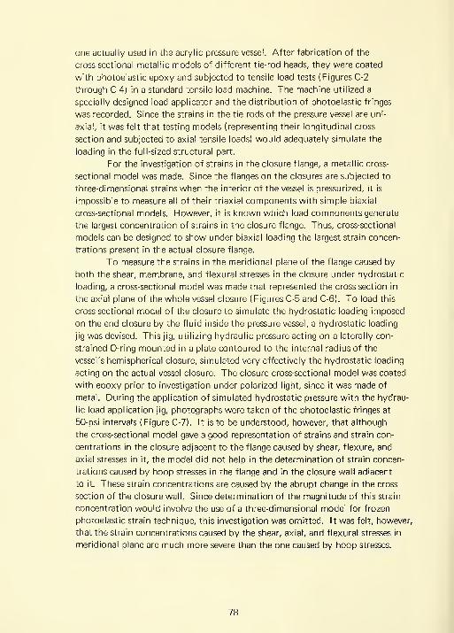
one actually used in the acrylic pressure vessel. After fabrication of the
cross-sectional metallic models of different tie-rod heads, they were coated
with photoelastic epoxy and subjected to tensile load tests (Figures C-2
through C-4) in a standard tensile load machine. The machine utilized a
specially designed load applicator and the distribution of photoelastic fringes
was recorded. Since the strains in the tie rods of the pressure vessel are uni-
axial, it was felt that testing models (representing their longitudinal cross
section and subjected to axial tensile loads) would adequately simulate the
loading in the full-sized structural part.
For the investigation of strains in the closure flange, a metallic cross-
sectional model was made. Since the flanges on the closures are subjected to
three-dimensional strains when the interior of the vessel is pressurized, it is
impossible to measure all of their triaxial components with simple biaxial
cross-sectional models. However, it is known which load components generate
the largest concentration of strains in the closure flange. Thus, cross-sectional
models can be designed to show under biaxial loading the largest strain concen-
trations present in the actual closure flange.
To measure the strains in the meridional plane of the flange caused by
both the shear, membrane, and flexural stresses in the closure under hydrostatic
loading, a cross-sectional model was made that represented the cross section in
the axial plane of the whole vessel closure (Figures C-5 and C-6). To load this
cross-sectional model of the closure to simulate the hydrostatic loading imposed
on the end closure by the fluid inside the pressure vessel, a hydrostatic loading
jig was devised. This jig, utilizing hydraulic pressure acting on a laterally con-
strained 0-ring mounted in a plate contoured to the internal radius of the
vessel's hemispherical closure, simulated very effectively the hydrostatic loading
acting on the actual vessel closure. The closure cross-sectional model was coated
with epoxy prior to investigation under polarized light, since it was made of
metal. During the application of simulated hydrostatic pressure with the hydrau-
lic load application jig, photographs were taken of the photoelastic fringes at
50-psi intervals (Figure C-7). It is to be understood, however, that although
the cross-sectional model gave a good representation of strains and strain con-
centrations in the closure adjacent to the flange caused by shear, flexure, and
axial stresses in it, the model did not help in the determination of strain concen-
trations caused by hoop stresses in the flange and in the closure wall adjacent
to it. These strain concentrations are caused by the abrupt change in the cross
section of the closure wall. Since determination of the magnitude of this strain
concentration would involve the use of a three-dimensional model for frozen
photoelastic strain technique, this investigation was omitted. It was felt, however,
that the strain concentrations caused by the shear, axial, and flexural stresses in
meridional plane are much more severe than the one caused by hoop stresses.
78
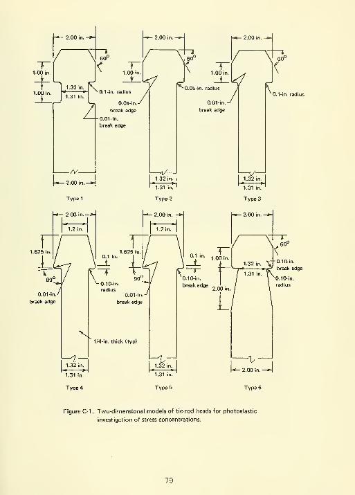
/ \ 60° / \ 60° / \l 60°
1.00 in. ^ 1.00 in. ^ 1.00 in. ^ ^
_i_L J _i_l</ J jlJ\^ Jt 1.32 in. \ / ^0.05-in. radius / \
^•°9'"-"lsi in.'
°-1-'"- '•^'l'"^ / / ^0.1-in
—
1
j—>^
^1 0.01-in.^ 0.01-ln.-^
/ break edae break edgebreak edge
^ |-0.01-in.
break edge
Figure C-1 . Two-dimensional models of tie-rod heads for photoelastic
investigation of stress concentrations.
79

0.50-in. thick
/0.5 in.
±0.010
->^
/0.10-in.
radius
For this reason, no further efforts
were made to determine the strain
concentrations in the closure wall
and flange caused by hoop stresses
in the flange and adjacent closure
wall.
The reflected light technique
was also employed to measure the
strains and strain concentrations in
the segmented-vessel wall laminae,
but instead of preparing a cross-
sectional model for the determination
of strains, scale segmented-vessel
wall laminae were used (Figure C-8).
To simulate the hydrostatic loading
on a typical segmented-vessel wall
laminae, several of them were assem-
bled into a ring which was then
placed over a hydraulic loading jig,
similar to the one used in testing
the vessel head flange (Figures C-9
andC-10). The modules in the top
layer of the ring were made from
epoxy sheets with a silvered back
surface, and reflected circularly
polarized light was used to deter-
mine the number and distribution
of photoelastic fringes (Figure C-1 1).
To observe the stress concentration
better around the shear-pin holes,
the nuts were removed for the test at locations where the fringes were to be
photographed. The laminae in the other layers of the ring were fabricated from
acrylic resin, a more economical and workable material. Since the modulus of
elasticity of epoxy is comparable to that of acrylic resin, the distribution and
magnitude of strains in the epoxy and acrylic resin laminae were approximately
the same. The photoelastic fringes in the segment laminae were photographed
at 50-psi load-level intervals until failure of the photoelastic model took place
at slightly more than 220 psi (Figures C-1 2 and C-1 3).
Although both the stacked-ring vessel and the segmented vessel are
known to possess other structural components in which strain concentrations
occur that could not be analytically explored, it was impossible to evaluate
them experimentally by means of reflected polarized light because of lack of
time and funding.
Figure C-2. Tensile load applicator for
two-dimensional tie-rod
head models investigated
photoelastically for stress
concentrations.
80

Figure C-3. Experimental setup for tensile testing of two-dimensional
tie-rod head models.
FINDINGS
Tie-Rod Models
The exploratory analysis of the two-dimensional tie-rod models,
coated with a photoelastically sensitive epoxy coating, indicates that the
stress concentration (as compared to the average stress level that was observed
in the tie rods) at the base of the tie-rod head was approximately 3 (model 2)
based on the calculated nominal stresses at the smallest cross section of the
tie rod. The stress concentrations in the other models representing feasible
alternatives to the tie-rod head configuration used in the acrylic pressure vessel
were 5 (model 1-2.1, model 3-2.0, model 4-3, model 5-2.5, and model 6-3.1).
It appears that if the model 1 or 3 configuration had been substituted for the
one used in this study, the stress raiser effect could have been substantially
decreased.
81

Figure C-4. Typical birefringence in
photoelastic coating on
two-dimensional nnodel
of tie-rod head under a
3,000-pound tensile load.
End-Closure Model
The two-dimensional
model of the end closure and
end-closure flange when subjected
to simulated hydrostatic pressure
with the hydraulic loading jig
indicated that a serious stress
concentration does exist in the
meridional plane of the end
closure. The progress of the
photoelastic fringes across the
thickness of the model during
loading indicates that the local
stress concentration is caused
primarily by flexure of the end
closure at its flange. The magni-
tude of the stress concentration,
based on the average membrane
stress present in the model at
locations distant from the stress
raiser, is approximately 3.3 to
3.5.
Segmented-Wall Model
The testing of the segmented-
wall laminae fabricated from
photoelastically active epoxy
showed that as previously predicted a serious stress concentration is generated
by the presence of the stress raiser in the form of the shear pin holding the
segmented-wall laminae together. Since the fit of the pins in the holes and the
distance between holes in each individual segment laminae influence to a large
degree the magnitude of stress concentrations both in the pin and in the segment
laminae, the experimentally determined value of the stress concentration can
be considered only a representative value. The magnitude of tensile stress
concentration in the segment laminae around the shear-pin hole was found to
be approximately 3.5, while the compressive stress concentration caused by
the pin bearing against the edge of the hole was found to be approximately
6.5 in comparison to the nominal tensile stress in the narrowest cross section
of the segment.
82

0.25-in. NPT for black
hawk 1/4-in. bantam
speedee coupler
-J—
C
1.00 In.
—H h-0.37 In.
Top View
1/8-ln. nylon liner
^1/4-ln. speedee hydraulic coupling
section of load
applicator
^0.25 in.
II t 0.24 In.
n^T"
2.5-in.-ODI
nominal 0.25-ln. 0-rlng
Figure C-5. Test assembly composed of two-dimensional model of hemispherical
end closure mounted on hydraulic load applicator.
83

Figure C-6. Two-dimensional model of end closures and hydraulic
load applicator.
CONCLUSIONS
Serious stress concentrations inave been found ( 1 ) at tlie base of tlie
heads of tie rods, (2) in the shape transition zone at the end-closure flange,
and (3) around the shear-pin holes in the segmented-wall laminae. These
stress concentrations occur at locations where failure was previously initiated
in the acrylic pressure vessel models during hydrostatic testing. If full-scale
pressure vessels of design similar to that of the models tested are built, these
stress concentrations must be either eliminated or their severity taken into
consideration during the vessel design.
84
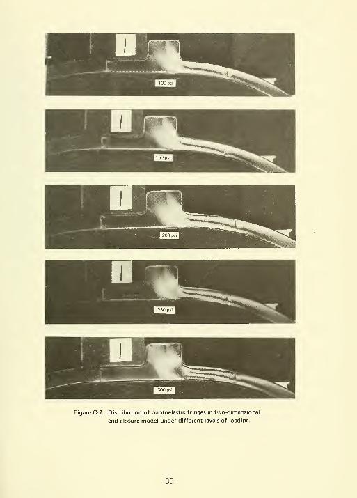
Figure C-7. Distribution of photoelastic fringes in two-dimensional
end-closure model under different levels of loading.
85
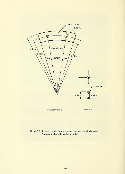
.062-in. thick
0.25 in.
Segment Module
Figure C-8. Typical module from segmented pressure vessel fabricated
from photoelastically active material.
86

hydraulic fluid inlet
nylon liner 0.12-in. thick
• 0-ring ^^-^
- 0.25 speedee hydraulic coupling
- section of load applicator
.fV^.rSL
I I
3 0.61 in.
^^^^-o^r
Side View
^=e^^^
Figure C-9. Test assembly composed of five layers of segment modules
mounted on hydraulic load applicator.
Figure C-10. Typical assembly of segment modules and the hydraulic
load applicator. Only the segment modules in the top
layer of segmented-wall assembly are of photoelastic
material.
87
Figure C-1 1 . Test setup for measurement of photoelastic fringes in the
segment modules around shear pins.

Figure C-12. Typical distribution of photoelastic fringes in tine segment
modules at different hydraulic loadings.
Figure C-13. Segmented-wall model after failure at 220 psi of hydraulic loading.
89

REFERENCES
1. Redstone Scientific Information Center. Report RSIC-173; Design,
performance, fabrication, and material considerations for high-pressure vessels,
by E. J. Mills, etal. Redstone Arsenal, Ala., Mar. 1964. (Contract
DA-01-021-AMC-203(Z) (AD 603694)
2. A. Zeitlin. "High pressure technology," Scientific American, vol. 212,
no. 5, May 1965, pp. 38-46.
3. C. Lipson, G. C. Noll, and L. S. Clock. Stress and strength of manufactured
parts. New York, McGraw-Hill, 1950.
4. A. A. Semerchan, N. Z. Shiskov, and V. K. Isaikov. "Large volume equipment
for high-pressure investigations," Instruments and Experimental Techniques,
no. 4, July-Aug. 1963, pp. 744-746. (English translation of; Pribory i Tekhnika
Eksperimenta)
90

DISTRIBUTION LIST
SNDL No. of Total
Code Activities Copies
-1 20
FKAIC 1 10
FKNI 13 13
FKN5 9 9
FA25 1 1
14 14
Defense Documentation Center
Naval Facilities Engineering Command
NAVFAC Engineering Field Divisions
Public Works Centers
Public Works Center
RDT&E Liaison Officers at NAVFACEngineering Field Divisions and
Construction Battalion Centers
300 300 NCEL Special Distribution List No. 9
for persons and activities interested in
reports on Deep Ocean Studies
91


r ~ " ' "
^" ~
** — ~~ -ng +2
Dc _ _ D 6 S .1 c _ _ 2^ c q J»i c -D
2 2 1c
3£ ^?s c ;^ 2 1 CO |-£ 3 ? i c c
C3
oco
3oCJ
D §ooo
C
c
D
3
•D
O
C
,c ia
c
£
^
g E1
S S Q.
'oi ^1 '1
1
CO
_3
cc
3
8
CO
0c
-a
3 en
II"O t.
g
c 2
0.5 Q.
£ X)
£ ™ 2
g ^ 1
g >
£ 3
|ii" °-
'n01 ^
"oj «
LU
>O
•DcLU
oo
oC5
cj)oo
>JZ
1
3
9.
61J3
r 1- fe
3 >£^|illB °- m
>
c
>LU
>cLU
•Den
§OC
> ^
'^3 3
2 2>- "6— c
ill^ 3 E2 2™
c 21- fc
2-1
tjj >
C
oa: £
_3
o"D0 ]5 1
i sIE ^
3II
•£25 II 1 1
1
a Px: i 1
S^s:. S " *" ^
a i-> 1 £ fc
C £LU h- > " £ H LU +-•
i^ 1- > 1-
o
S
1
tLU
1c
O
DO
O
cg
1a>c>T3lisgam
2-
!5
9.c
5)3
>
LU
ic01
iin
. s
III
3 *-
a a '3
Q.
Cg3
o CJ OJ 3 LC5 "c ^ (0 CJ a 3 ^ — LO D £
2 oo
Q
1
DO
_3
> E 1 i>
a
•D
1>
3zCJ
Q15 g
3DC 5E1- 1 || s.i
a. X
XJ
c0)
E
5
1oi
- _JLU
-61
d ci X 1
c3 IFa . CO
g>f-E
3
i
Cc _j
LU-6
1d c
i ^ s.E2iXI 3 •-
N S
£oJ 1
c'oic
COLU>
c
1
CO
d-o
>
Q.
>
3 3
iD.
a•Dc
z E
2 1 cLU
c
CO
•DC
c
CO
d
0)
a >-XI3 . CO
5 .>
aXJc
5 E
3UJ
b
1
LUDC3O)
LUOC
CO
•DC
ciZ
CD
£
3ao
i
(U
E
a
co
5
i
1a
16
_0)
C2
1
iE
"D
6c
LU
CJ
1«
LUDCDCOCOLUDC
XI
cu.
CO
£
3D
1
0)
COJ
E
a1
1
c - -
- JxjS 1) "a;
c 2-. i
E D-CO 0.
XJ ™
2mE
E
XI
XJc
Z . £ H St>
c v^ Si 1^1 jf ;dX z Q. £ 1- V) > ^
01 c ":£ 12 .£ XJX
> >. D<D -0 61 '> • > ^
ilO-D g a '> X
£ oE Q)
c£ £ g.
c c2 0)^0 "
§1 1c
32?
"^K 3 0) 'S
a c 3 OJ 0)OJ 'w Q. c
1 C^ aa
-DC E
3 11^i
E ,0
a5-s— c .i §
i
E2
,0
CDi Ol c =:>£ S > '5
^ 5 a E S > '5'"
C D cra D 1 S ? '5 5 ""
c -6 .9 s s '6 5 ra
< C 6 _D C 6 £E
S ^ <II ^ g* 2
E3> ?
> CD _ D _ 3
1 ^<^ 1 s •5
Q)
I2 - "1 ^ i 5 OJ
f *- 5 > t> > Q.XI —1- -
> D. ~XI
"7"
1D <2 T3 c _ - t s c _ _ a^ c ,0 0
ill^ c X! "> s
2 '^ c3 c c
s 2 1 1 g 3^5 § a c
to
cg
a:
Oo
C so
9
T3C
C
6
3
1
iCl
ra ^2 Sa g 3^ E g
c
x:
5
CO
c.0
cc
_gCJ
c S
9
"DC
f6
3 en
0 2
2 £
2I2Q, *- aCD 2 XJ-c CD j;
0 >
g 3'5i£
2: 1a
COo ,C0) c '5
c ™ »§ Si i ^ 8 C £c ^ 1
1-
» sCO>LU
>
6cLU o
en
8DC
11)
2
3
-6c
1J3
!5 1- a!
^11
>>LU
>
DcLU
8DC
2^ 3
2 5*" XJ
^11oic
>
01O o (J) > — *2 _c a> >- ^ ~ c +2 2 *o
n;^ .c
o i -C3 D i
c
161
s CC
6 ^^ "2 °
c « c2 1
aX
i-
i >CD
10)
*^ to
S " ^ ^"0 a
Xi-
§ > .2 .1
I" cu f c £lU 4^
f
1- '5 £ -c H LU s- 1- > 2 x: 1-
o
1
0.
1c D
C
cq
1>
ro 3 '-
,2-
Q.
Cg
>-i
a. i§5c ig i2
11^ Q. ra
>-
Q.
LU n Jr S 5 3 LU CD XI
c -^3 3
1 o CJ in ^ -c a 3
11g — ID 1-
1 zoo
Q uX)c _3 1 0) S >-5 S
a X c 1
"^ ZCJ
3X!C ?; 8 >• CO 8
0.c
_l =g
o> E 4- > 2-5 E
"•D
i
1 -J 3 § g^ -C CD OJ
s'.i m X)0)
E
11
"'
_lLU D
£ d c1
(U
i •D = .12^2e2CL . 00
.2 c 2
&--ES 2 S-D « 2— E a
lit
3c(0 -
LU TJ2d
(3) i 111S S^ a|3 - ra
c .y -
!ii°XJ §S ra
<i>
OJ CJJ
|o.00
t-c 2-. E
11is
3OJ
c
1 cLU
">
1 ^
1 ^
COCOu>LU<r
D1^LUccQ.
C0)
E
CO
-ac
O)c£
0?
d
Cil
5
ID
£t-
3
1
>D3
C
1aX
H
Q.
i
s
>
>
3
a
10
c
0)
'+-
3
C
a
Dc">-
s:
0)
a.
•D
E
1 ^
t> °
E-6OJ '^
SL ^"g 'x
<o
cO)
1 c1
^1>
1
"
1 i1 Z
LU>LUIT
DCOCOLUDCa.
C
cS
•DC
£
to
d
>•n5
LL
en
<D
£
•0
3XI
i
>-T33«
c
1a0)
h- >
g-
1
IIs i
> 2u c
CU
Q.
XIc
!§
2
E
X3.CO
2ts
E0)
XI
E
23SVC
X
>^ 3
•AE
ac fli 2 c !> § T3
c> >
1 E1
1
c 1XJc
3o
"H «2? c Qj S Q. c 1 2
a
^ S
.= "5 C3>
S a cs
(f
oaX
c<
a.
1
DC
cn
Si
c
3
III 1
E
> '6
2
1 S. 1 P
2
1> s
*~ g to DC
-6 £
'€
1 '•D <6.C
111S 5"o 2
'•6
E1 •5
ID 0) _ 3 E > -r. 2 _ 3E Ji
i! s ^ 0) gi 2'5 1" "So 8 S 5 '6 0)
1S fiCN 5 K > Q.
"5 S ^1
S ^ S § S § S. __l1 ^ _ _ __ —— — J —— — --^^ - — - -

3 U
2 ^ ^Q. H ra
J] £ ^
S3].?o o S^ Z Q 3
-18 1.1=
c _l
o WlU"O
LU_ UJ
E
S to> 5 T, -°
,
" w Sol15 ''^ m ™ '
I ii^" •-
I
J5 CC - M
> s.
o 1-
1" mn^ zo
u 3
CI
c J g ^ a.
^ otf]
T—
^ CO a
'?> E Ci
Z 0. CC _ H
V c -D 5
2 >
I m 01 ™ s
? ""S E s ££ ra 2 OJ S „.
y 5 SJ a-J
£ "O ^ Q, -D "QJ .= — £ •l' f^
" o ^ S >™ S I
^ i -^ = 1 1 °^ ii->Sioc22;.^ £ = I a - CO Q-
?• !S = m m ft-? c
,~- E
5 ra
^ E -6
00 3 0) „,QJ w +i> O^ S.E;n
E-g
c o c
~. °- cS I
.2
iff"c 15 .2
E - E
•- C '^ r iZ ? fSo>c c
Dj/1 V, *- i;i
> N
tn c 1^ P lii c0)
^J
?c T3
O i £o
•DsS
c01
J)£ c 0) c D >-o! D » V,
?>
1^ wo
a
(n ^ H (1) i_
£ P JD 33E 2- J c
3oD "S
C]5 5 ^ D.
Ed>
i
> iV£
1-.5; ^ r 1-
oo
o -J Q.
DCo
1m >DO^ s *>
> co
-I
DC D o 0) !S
>- <5 s & X rb E
£ >
1Xo
.i2 £ b
i1-
•&•D
E
Olc
Ol
o I XI§F
i
C
c/i
a
o
3
1a
c
XI
1
Q.a
c
oo
>
i
-ac
ilE -6
b 5i > n o o 2 ^ (U
a >a b a
a b^ x
>o
3
i 1o a
c>
T3
c c§Q.
•DC
oa D iii 8 C •D a; E g
n mo
0) lii1)
Em .i!i
aC b
m> o
< _3T3C
-?; "o
-a
Fs
ID
'1-J
f s £i i K > a oT3
1
T
t
c ~ o T3jz "oJ 'S
2 S**- C
CO |l D 1 gf§"D 3 s "? > N
(U "o <3-C
c5i s 0) ^ Q) '5l -C
OCJ
c o9o
C
-D
oo
a ^g E
3 OJ ~S c 5
0.^ "gCOo 0)
.c t
g »> '^ -0 " s
-6c
enoo51
3if 1-3
£ cS >
LU o DC OJ -° 1 E > i2 (0^
•D r^ ^ •u*- *-> - O)
O CT> > *^ ^-' c ^ £ ro~
li
"
ml
"
CC
i>
oa i
s: i S i 1 .2 fe" s^§
M- H -c H "
1O c
o -C . S 3 *^9-
a 01 > -c S fe > cc c
og ^? sS a > .- .2
CD ^ ^ (U 3 3« D OJ _ in T3 £ CD "-
Qg^
DCo
_3
> E ^1^ >CD
"^
„ D. X
Ea,"
i !E d c jg
(U
S) - £'X CD
2 E
||
,^ 3 CO6
c
E
CO
d
5
3
g>3
\-
Q.
>
3
i
D 3
3 —
0^ w>
S £ZCO °..2
il5CO
c
>CD
E5
c o Q.
lli15 ^ 1
E 5g§1
XI a> ° ra -^
ci:
S)a s
1s S s ^ |e^
£ K > a -
> > 3
1 1
°^ > —" £ 2
s. o s ^£ c c c
(3) OJ ^3
£ oa
Q. 0C
3 fe
a; .E
Q. 0)
illQ) gC
ra EC CD
c ra -D — en > '5 16< ^ c
C D 0 £|^> —E J^ s s •gl " S .2
Sra
.'^. i£ ^ "D
ao S
o S^ 2 Q «
£8 Ig=-
c _j ^ -g a'Z uj "D fo ^-
SgS f co"'
o,- |d
.2 -) -D -O
I
CJ u5C _;CD
1 m " cS<D cc •= IT ocZ D. OC t H
i t m .Q
n^ CO 01
^ g a
D *^ £ "^.2
5 c°O j: £
I 2'"
i
'^ ^ H;= ° •
|.^ oi>. 5 C T!
; ^ — °i2 CO n
E >|
illO O)
1- L> C
> £ -F:E1-
E5
3 i2
Q. 015 TJ
< ?
1_
CD 01
^ ^
1 cm > 1
XWi
« CN
- "5 ECO .- •-
,i2<3)
2 £°
Q. . CO&- >u> c ""I Qj ro
"Z-.i0) x
u S 2
> — "£ £ §,
OJ .? "S
a <i>"5
o) E SC (0 O).- w >
•6 *o S?0) _ 3^ QJ «(0 (A O
£ c i3 CO gM 0) o"IEa^ a.
g £ 3""SO7= o "" Et)2 »> SCD ^ _e:S-2V 0) X
j= -a CD
ro'> -acog- °- nS E.2
E- S


Unclas?:ififirl
DOCUMENT CONTROL DATA R&D
Naval Civil Engineering Laboratory
Port Hueneme, Calif. 93041
Unclassified
PRESSURE VESSEL CONCEPTS—Exploratory Evaluation of Stacked-Ring and
Segmented-Wall Designs With Tie-Rod End-Closure Restraints
SCBIPTIVE NOTES (Type of report and Inclusive datee)
Final; October 1964-October 1965TH0RI51 (FIrtI neme, middle Inlllel. leal name)
J. D. Stachiw
March 1970 91
Y-R009-03-0 1-004 TR-666
I (Any other nuTr\bera that
This document has been approved for public release and sale; its distribution is unlimited.
Naval Facilities Engineering CommandWashington, D. C. 20390
An exploratory experimental study was conducted to evaluate the stacked-ring
and segmented-wall pressure vessel concepts. The evaluation consisted of (1 ) testing to
destruction stacked-ring and segmented-wall pressure vessel models with tie-rod end-closure
restraints and (2) evaluating a series of seal designs utilized in the sealing of the joints
between the pressure vessel end closures and the cylindrical pressure vessel body. The test
results indicate that the stacked-ring pressure vessel design is approximately 50% heavier than
a multilayered pressure vessel of same internal diameter length, material, and pressure capability.
The segmented-wall pressure vessel design is approximately 8 to 9 times heavier than a
multilayered pressure vessel of same diameter, length, material, and pressure capability. The
free-floating, self-energizing radial seal system provided the most reliable and extrusion-proof
sealing for vessels with considerable radial dilation and axial end-closure movement.
DD .1473 (PAGE I)
S/N 0101.807-6801
UnclassifiedSecurity Classifii

llnrlassifiedSecurity Classifi<
Pressure vessels
Internal pressure
Stacked ring
Segmented design
Circular polygon segments
Tie-rod end closure
Maraging steel
Dome-shaped end closure
Shear-pin holes
Stress raisers
DD ,?o''v"..1473 BACK)
(PAGE 2)UnclassifiedSecurity Classific


Related Documents