ADCA PRESSURE REDUCING VALVE RP45 (EN) CE MARKING – GROUP 2 (PED – European Directive) PN 16 PN 40 Category DN 15 to 50 DN 15 to 32 SEP DN 65 to 150 DN 40 to 100 1 (CE marked) – DN 125 to 150 2 (CE marked) The ADCA RP45 series pressure reducing valves are single seated, bellows sealed controllers that operate without auxiliary energy. Designed for use with steam, compressed air, and other gases compatible with the construction. They are particularly suitable for reducing steam pressure in all energy and process systems where pressures must be kept under control. Specially designed high durability bellows, providing pressure balancing and frictionless plug stem. Robust construction (fit-and-forget). Suitable for use with high pressure turndowns. Interchangeable actuators. OPTIONS: USE: AVAILABLE MODELS: SIZES: CONNECTIONS: AVAILABLE ACTUATORS: INSTALLATION: Soft sealing version in PTFE/GR for use with steam. Nitrile rubber soft sealing version for air and gas applications, where tight shut-off is required. Low-noise flow divider. Sensing pipe on body. Steam, compressed air and other gases compatible with the construction. Limited use with liquids. Consult manufacturer before installing the valve with liquids. RP45G and RP45GT or N – PN 16 SG iron. RP45S and RP45ST or N – PN 16 cast steel. RP45S and RP45ST or N – PN 40 cast steel. RP45i and RP45iT or N – stainless steel (all wetted parts free of ferrous metal or in stainless steel. Only available from DN 15 to DN 100). Suffix T: soft sealed with PTFE/GR. Suffix N: soft sealed with nitrile rubber. DN 15 to DN 150. RP45G – Flanged EN 1092-2 PN 16. RP45S and RP45i – Flanged EN 1092-1 PN 16 or PN 40. Standard PN 16 DN 65 flanges are supplied with 4 holes. 8 holes, according to EN 1092-1/-2 on request. A1, A10, A11, A12, A3, A4, B1, B3, B4 and C11 – carbon steel. A2, A21, B2 and B21 – SG iron or carbon steel. A1i, A10i, A11i, A12i, A2i, A21i, A3i and A4i – stainless steel. See IMI – Installation and maintenance instructions. RP45 DN 15 to DN 100 RP45i DN 15 to DN 100 with sensing pipe on body RP45i DN 15 to DN 100 RP45 DN 125 to DN 150 MAIN FEATURES DESCRIPTION VALSTEAM ADCA We reserve the right to change the design and material of this product without notice. IS RP45.12 E 03.20

Welcome message from author
This document is posted to help you gain knowledge. Please leave a comment to let me know what you think about it! Share it to your friends and learn new things together.
Transcript
ADCAPRESSURE REDUCING VALVE
RP45(EN)
CE MARKING – GROUP 2 (PED – European Directive)
PN 16 PN 40 CategoryDN 15 to 50 DN 15 to 32 SEP
DN 65 to 150 DN 40 to 100 1 (CE marked)
– DN 125 to 150 2 (CE marked)
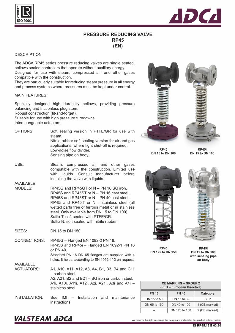
The ADCA RP45 series pressure reducing valves are single seated, bellows sealed controllers that operate without auxiliary energy. Designed for use with steam, compressed air, and other gases compatible with the construction.They are particularly suitable for reducing steam pressure in all energy and process systems where pressures must be kept under control.
Specially designed high durability bellows, providing pressure balancing and frictionless plug stem.Robust construction (fit-and-forget).Suitable for use with high pressure turndowns.Interchangeable actuators.
OPTIONS:
USE:
AVAILABLE MODELS:
SIZES:
CONNECTIONS:
AVAILABLE ACTUATORS:
INSTALLATION:
Soft sealing version in PTFE/GR for use with steam.Nitrile rubber soft sealing version for air and gas applications, where tight shut-off is required.Low-noise flow divider.Sensing pipe on body.
Steam, compressed air and other gases compatible with the construction. Limited use with liquids. Consult manufacturer before installing the valve with liquids.
RP45G and RP45GT or N – PN 16 SG iron.RP45S and RP45ST or N – PN 16 cast steel.RP45S and RP45ST or N – PN 40 cast steel.RP45i and RP45iT or N – stainless steel (all wetted parts free of ferrous metal or in stainless steel. Only available from DN 15 to DN 100).Suffix T: soft sealed with PTFE/GR.Suffix N: soft sealed with nitrile rubber.
DN 15 to DN 150.
RP45G – Flanged EN 1092-2 PN 16.RP45S and RP45i – Flanged EN 1092-1 PN 16 or PN 40.Standard PN 16 DN 65 flanges are supplied with 4 holes. 8 holes, according to EN 1092-1/-2 on request.
A1, A10, A11, A12, A3, A4, B1, B3, B4 and C11 – carbon steel.A2, A21, B2 and B21 – SG iron or carbon steel.A1i, A10i, A11i, A12i, A2i, A21i, A3i and A4i – stainless steel.
See IMI – Installation and maintenance instructions.
RP45DN 15 to DN 100
RP45iDN 15 to DN 100
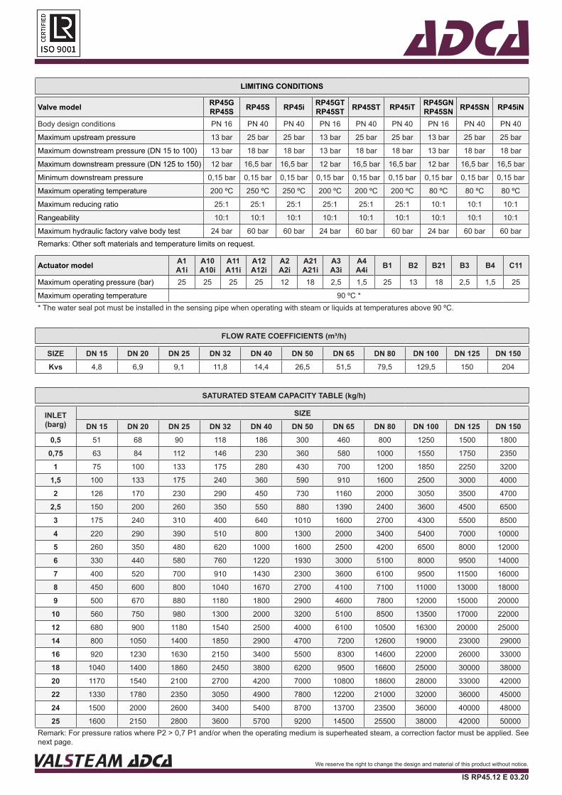
with sensing pipeon body
RP45iDN 15 to DN 100
RP45DN 125 to DN 150
MAIN FEATURES
DESCRIPTION
VALSTEAM ADCA We reserve the right to change the design and material of this product without notice.
IS RP45.12 E 03.20
ADCALIMITING CONDITIONS
Valve model RP45GRP45S RP45S RP45i RP45GT
RP45ST RP45ST RP45iT RP45GNRP45SN RP45SN RP45iN
Body design conditions PN 16 PN 40 PN 40 PN 16 PN 40 PN 40 PN 16 PN 40 PN 40
Maximum upstream pressure 13 bar 25 bar 25 bar 13 bar 25 bar 25 bar 13 bar 25 bar 25 bar
Maximum downstream pressure (DN 15 to 100) 13 bar 18 bar 18 bar 13 bar 18 bar 18 bar 13 bar 18 bar 18 bar
Maximum downstream pressure (DN 125 to 150) 12 bar 16,5 bar 16,5 bar 12 bar 16,5 bar 16,5 bar 12 bar 16,5 bar 16,5 bar
Minimum downstream pressure 0,15 bar 0,15 bar 0,15 bar 0,15 bar 0,15 bar 0,15 bar 0,15 bar 0,15 bar 0,15 bar
Maximum operating temperature 200 ºC 250 ºC 250 ºC 200 ºC 200 ºC 200 ºC 80 ºC 80 ºC 80 ºC
Maximum reducing ratio 25:1 25:1 25:1 25:1 25:1 25:1 10:1 10:1 10:1
Rangeability 10:1 10:1 10:1 10:1 10:1 10:1 10:1 10:1 10:1
Maximum hydraulic factory valve body test 24 bar 60 bar 60 bar 24 bar 60 bar 60 bar 24 bar 60 bar 60 barRemarks: Other soft materials and temperature limits on request.
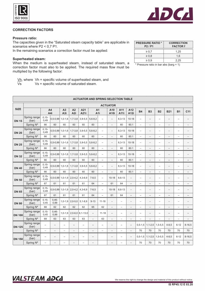
SATURATED STEAM CAPACITY TABLE (kg/h)
INLET(barg)
SIZEDN 15 DN 20 DN 25 DN 32 DN 40 DN 50 DN 65 DN 80 DN 100 DN 125 DN 150
0,5 51 68 90 118 186 300 460 800 1250 1500 1800
0,75 63 84 112 146 230 360 580 1000 1550 1750 2350
1 75 100 133 175 280 430 700 1200 1850 2250 3200
1,5 100 133 175 240 360 590 910 1600 2500 3000 4000
2 126 170 230 290 450 730 1160 2000 3050 3500 4700
2,5 150 200 260 350 550 880 1390 2400 3600 4500 6500
3 175 240 310 400 640 1010 1600 2700 4300 5500 8500
4 220 290 390 510 800 1300 2000 3400 5400 7000 10000
5 260 350 480 620 1000 1600 2500 4200 6500 8000 12000
6 330 440 580 760 1220 1930 3000 5100 8000 9500 14000
7 400 520 700 910 1430 2300 3600 6100 9500 11500 16000
8 450 600 800 1040 1670 2700 4100 7100 11000 13000 18000
9 500 670 880 1180 1800 2900 4600 7800 12000 15000 20000
10 560 750 980 1300 2000 3200 5100 8500 13500 17000 22000
12 680 900 1180 1540 2500 4000 6100 10500 16300 20000 25000
14 800 1050 1400 1850 2900 4700 7200 12600 19000 23000 29000
16 920 1230 1630 2150 3400 5500 8300 14600 22000 26000 33000
18 1040 1400 1860 2450 3800 6200 9500 16600 25000 30000 38000
20 1170 1540 2100 2700 4200 7000 10800 18600 28000 33000 42000
22 1330 1780 2350 3050 4900 7800 12200 21000 32000 36000 45000
24 1500 2000 2600 3400 5400 8700 13700 23500 36000 40000 48000
25 1600 2150 2800 3600 5700 9200 14500 25500 38000 42000 50000Remark: For pressure ratios where P2 > 0,7 P1 and/or when the operating medium is superheated steam, a correction factor must be applied. See next page.
Actuator model A1A1i
A10A10i
A11A11i
A12A12i
A2A2i
A21A21i
A3A3i
A4A4i B1 B2 B21 B3 B4 C11
Maximum operating pressure (bar) 25 25 25 25 12 18 2,5 1,5 25 13 18 2,5 1,5 25
Maximum operating temperature 90 ºC ** The water seal pot must be installed in the sensing pipe when operating with steam or liquids at temperatures above 90 ºC.
VALSTEAM ADCA We reserve the right to change the design and material of this product without notice.
IS RP45.12 E 03.20
FLOW RATE COEFFICIENTS (m³/h)
SIZE DN 15 DN 20 DN 25 DN 32 DN 40 DN 50 DN 65 DN 80 DN 100 DN 125 DN 150Kvs 4,8 6,9 9,1 11,8 14,4 26,5 51,5 79,5 129,5 150 204
ADCACORRECTION FACTORS
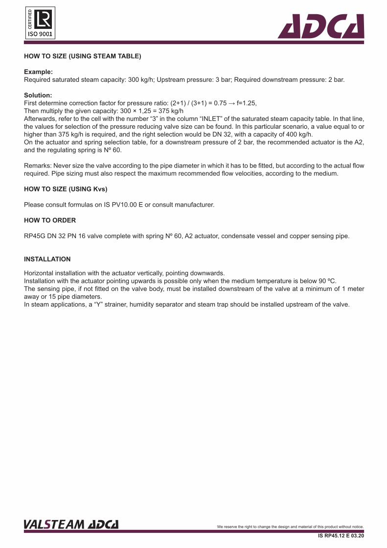
Pressure ratio:The capacities given in the “Saturated steam capacity table” are applicable in scenarios where P2 < 0,7 P1. In the remaining scenarios a correction factor must be applied:
Superheated steam:When the medium is superheated steam, instead of saturated steam, a correction factor must also to be applied. The required mass flow must be multiplied by the following factor:
Vh, where Vh = specific volume of superheated steam, and Vs Vs = specific volume of saturated steam.
PRESSURE RATIO *P2 / P1
CORRECTION FACTOR f
≥ 0,7 1,25≥ 0,8 1,6≥ 0,9 2,25
* Pressure ratio in bar abs (barg + 1)
ACTUATOR AND SPRING SELECTION TABLE
SIZEACTUATOR
A4A4i
A3A3i
A2A2i
A21A21i
A1A1i
A10A10i
A11A11i
A12A12i B4 B3 B2 B21 B1 C11
DN 15Spring range
(bar)0,15-0,49 0,5-0,99 1,0-1,6 1,7-3,8 3,9-5,5 5,6-8,2 – – 8,3-13 10-18 – – – – – –
Spring Nº 66 60 60 60 60 60 – – 60 60.1 – – – – – –
DN 20Spring range
(bar)0,15-0,49 0,5-0,99 1,0-1,6 1,7-3,8 3,9-5,5 5,6-8,2 – – 8,3-13 10-18 – – – – – –
Spring Nº 66 60 60 60 60 60 – – 60 60.1 – – – – – –
DN 25Spring range
(bar)0,15-0,49 0,5-0,99 1,0-1,6 1,7-3,8 3,9-5,5 5,6-8,2 – – 8,3-13 10-18 – – – – – –
Spring Nº 66 60 60 60 60 60 – – 60 60.1 – – – – – –
DN 32Spring range
(bar)0,15-0,49 0,5-0,99 1,0-1,6 1,7-3,8 3,9-5,5 5,6-8,2 – – 8,3-13 10-18 – – – – – –
Spring Nº 66 60 60 60 60 60 – – 60 60.1 – – – – – –
DN 40Spring range
(bar)0,15-0,49 0,5-0,99 1,0-1,6 1,7-3,8 3,9-5,5 5,6-8,2 – – 8,3-13 10-18 – – – – – –
Spring Nº 66 60 60 60 60 60 – – 60 60.1 – – – – – –
DN 50Spring range
(bar)0,15-0,49 0,5-0,99 1,0-1,9 2,0-4,2 4,3-6,9 7-8,5 – 10-18 8,6-13 – – – – – – –
Spring Nº 67 61 61 61 61 64 – 61 64 – – – – – – –
DN 65Spring range
(bar)0,15-0,49 0,5-0,99 1,0-1,9 2,0-4,2 4,3-6,9 7-8,5 – 10-18 8,6-13 – – – – – – –
Spring Nº 67 61 61 61 61 64 – 61 64 – – – – – – –
DN 80Spring range
(bar)0,15-0,45
0,46-0,99 1,0-1,9 2,0-5,0 5,1-8,9 9-13 11-18 – – – – – – – – –
Spring Nº 68 62 62 62 62 65 62 – – – – – – – – –
DN 100Spring range
(bar)0,15-0,45
0,46-0,99 1,0-1,9 2,0-6,0 6,1-13,0 – 11-18 – – – – – – – – –
Spring Nº 69 63 63 63 63 – 63 – – – – – – – – –
DN 125Spring range
(bar) – – – – – – – – – – 0,5-1,5 1,1-2,5 1,5-5,5 4-8,5 6-12 8-16,5
Spring Nº – – – – – – – – – – 70 70 70 70 70 70
DN 150Spring range
(bar) – – – – – – – – – 0,5-1,5 1,1-2,5 1,5-5,5 4-8,5 6-12 8-16,5
Spring Nº – – – – – – – – – 70 70 70 70 70 70
VALSTEAM ADCA We reserve the right to change the design and material of this product without notice.
IS RP45.12 E 03.20
VALSTEAM ADCA We reserve the right to change the design and material of this product without notice.
IS RP45.12 E 03.20
ADCAHOW TO SIZE (USING STEAM TABLE)
Example:Required saturated steam capacity: 300 kg/h; Upstream pressure: 3 bar; Required downstream pressure: 2 bar.
Solution: First determine correction factor for pressure ratio: (2+1) / (3+1) = 0.75 → f=1.25, Then multiply the given capacity: 300 × 1,25 = 375 kg/hAfterwards, refer to the cell with the number “3” in the column “INLET” of the saturated steam capacity table. In that line, the values for selection of the pressure reducing valve size can be found. In this particular scenario, a value equal to or higher than 375 kg/h is required, and the right selection would be DN 32, with a capacity of 400 kg/h. On the actuator and spring selection table, for a downstream pressure of 2 bar, the recommended actuator is the A2, and the regulating spring is Nº 60.
Remarks: Never size the valve according to the pipe diameter in which it has to be fitted, but according to the actual flow required. Pipe sizing must also respect the maximum recommended flow velocities, according to the medium.
HOW TO SIZE (USING Kvs)
Please consult formulas on IS PV10.00 E or consult manufacturer.
HOW TO ORDER
RP45G DN 32 PN 16 valve complete with spring Nº 60, A2 actuator, condensate vessel and copper sensing pipe.
VALSTEAM ADCA We reserve the right to change the design and material of this product without notice.
IS RP45.12 E 03.20
INSTALLATION
Horizontal installation with the actuator vertically, pointing downwards. Installation with the actuator pointing upwards is possible only when the medium temperature is below 90 ºC. The sensing pipe, if not fitted on the valve body, must be installed downstream of the valve at a minimum of 1 meter away or 15 pipe diameters. In steam applications, a “Y” strainer, humidity separator and steam trap should be installed upstream of the valve.
ADCA
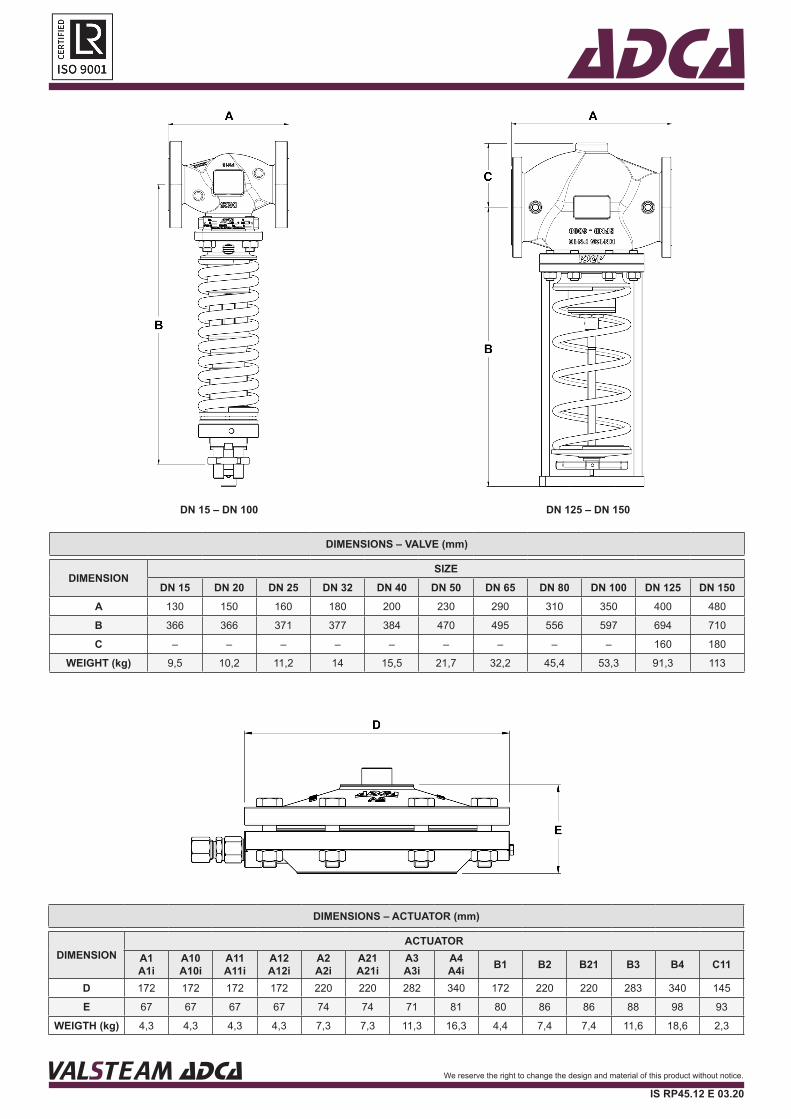
DIMENSIONS – VALVE (mm)
DIMENSIONSIZE
DN 15 DN 20 DN 25 DN 32 DN 40 DN 50 DN 65 DN 80 DN 100 DN 125 DN 150A 130 150 160 180 200 230 290 310 350 400 480
B 366 366 371 377 384 470 495 556 597 694 710
C – – – – – – – – – 160 180
WEIGHT (kg) 9,5 10,2 11,2 14 15,5 21,7 32,2 45,4 53,3 91,3 113
DIMENSIONS – ACTUATOR (mm)
DIMENSIONACTUATOR
A1A1i
A10A10i
A11A11i
A12A12i
A2A2i
A21A21i
A3A3i
A4A4i B1 B2 B21 B3 B4 C11
D 172 172 172 172 220 220 282 340 172 220 220 283 340 145
E 67 67 67 67 74 74 71 81 80 86 86 88 98 93
WEIGTH (kg) 4,3 4,3 4,3 4,3 7,3 7,3 11,3 16,3 4,4 7,4 7,4 11,6 18,6 2,3
VALSTEAM ADCA We reserve the right to change the design and material of this product without notice.
IS RP45.12 E 03.20
VALSTEAM ADCA We reserve the right to change the design and material of this product without notice.
IS RP45.12 E 03.20
DN 15 – DN 100 DN 125 – DN 150
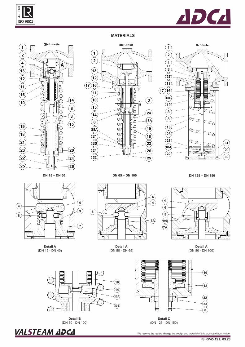
ADCAMATERIALS
8
7
9
64
8
7A
46
7A
10B
5
6
4
14
10A
10B
10
8
33
32
12
10
Detail A(DN 15 - DN 40)
Detail A(DN 50 - DN 65)
Detail A(DN 80 - DN 100)
Detail C(DN 125 - DN 150)
Detail B(DN 80 - DN 100)
DN 15 – DN 50 DN 65 – DN 100 DN 125 – DN 150
VALSTEAM ADCA We reserve the right to change the design and material of this product without notice.
IS RP45.12 E 03.20
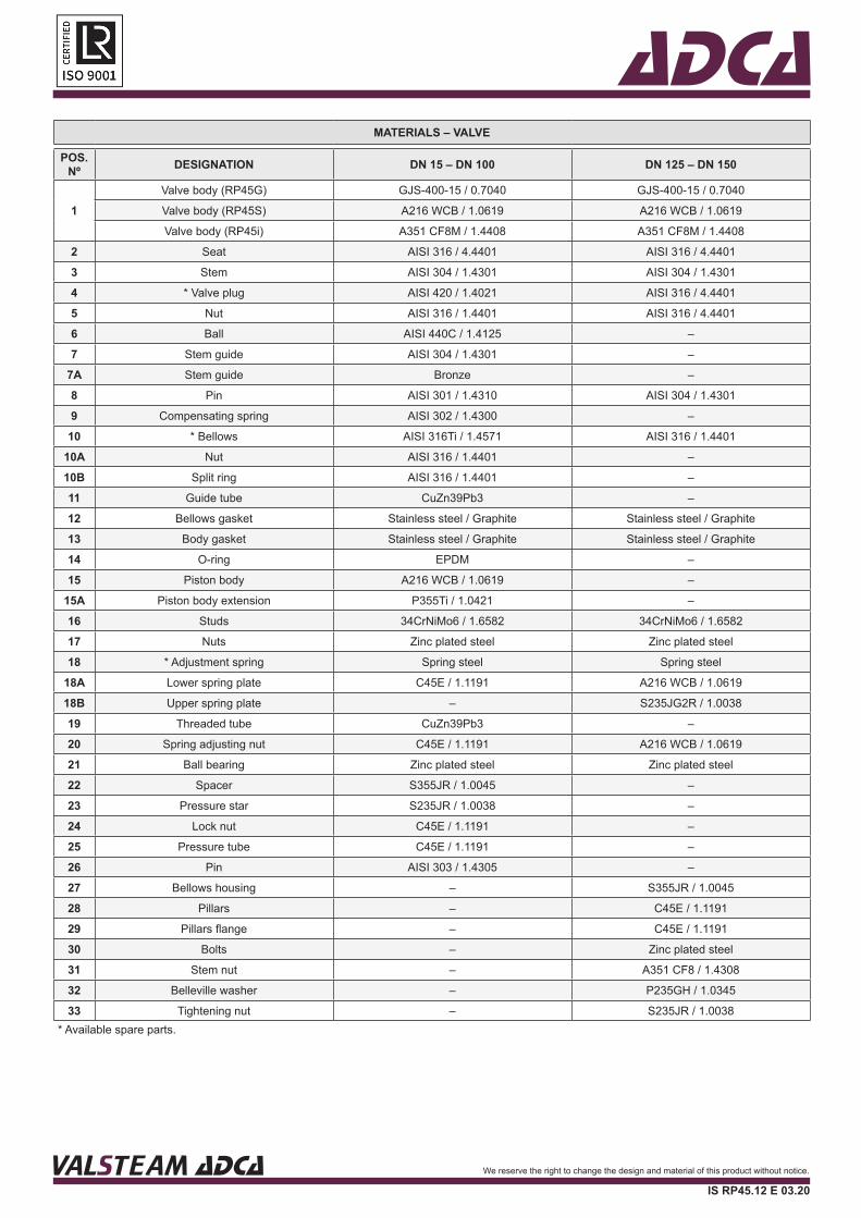
ADCAMATERIALS – VALVE
POS. Nº DESIGNATION DN 15 – DN 100 DN 125 – DN 150
1Valve body (RP45G) GJS-400-15 / 0.7040 GJS-400-15 / 0.7040
Valve body (RP45S) A216 WCB / 1.0619 A216 WCB / 1.0619
Valve body (RP45i) A351 CF8M / 1.4408 A351 CF8M / 1.4408
2 Seat AISI 316 / 4.4401 AISI 316 / 4.4401
3 Stem AISI 304 / 1.4301 AISI 304 / 1.4301
4 * Valve plug AISI 420 / 1.4021 AISI 316 / 4.4401
5 Nut AISI 316 / 1.4401 AISI 316 / 4.4401
6 Ball AISI 440C / 1.4125 –
7 Stem guide AISI 304 / 1.4301 –
7A Stem guide Bronze –
8 Pin AISI 301 / 1.4310 AISI 304 / 1.4301
9 Compensating spring AISI 302 / 1.4300 –
10 * Bellows AISI 316Ti / 1.4571 AISI 316 / 1.4401
10A Nut AISI 316 / 1.4401 –
10B Split ring AISI 316 / 1.4401 –
11 Guide tube CuZn39Pb3 –
12 Bellows gasket Stainless steel / Graphite Stainless steel / Graphite
13 Body gasket Stainless steel / Graphite Stainless steel / Graphite
14 O-ring EPDM –
15 Piston body A216 WCB / 1.0619 –
15A Piston body extension P355Ti / 1.0421 –
16 Studs 34CrNiMo6 / 1.6582 34CrNiMo6 / 1.6582
17 Nuts Zinc plated steel Zinc plated steel
18 * Adjustment spring Spring steel Spring steel
18A Lower spring plate C45E / 1.1191 A216 WCB / 1.0619
18B Upper spring plate – S235JG2R / 1.0038
19 Threaded tube CuZn39Pb3 –
20 Spring adjusting nut C45E / 1.1191 A216 WCB / 1.0619
21 Ball bearing Zinc plated steel Zinc plated steel
22 Spacer S355JR / 1.0045 –
23 Pressure star S235JR / 1.0038 –
24 Lock nut C45E / 1.1191 –
25 Pressure tube C45E / 1.1191 –
26 Pin AISI 303 / 1.4305 –
27 Bellows housing – S355JR / 1.0045
28 Pillars – C45E / 1.1191
29 Pillars flange – C45E / 1.1191
30 Bolts – Zinc plated steel
31 Stem nut – A351 CF8 / 1.4308
32 Belleville washer – P235GH / 1.0345
33 Tightening nut – S235JR / 1.0038* Available spare parts.
VALSTEAM ADCA We reserve the right to change the design and material of this product without notice.
IS RP45.12 E 03.20
VALSTEAM ADCA We reserve the right to change the design and material of this product without notice.
IS RP45.12 E 03.20
ADCA
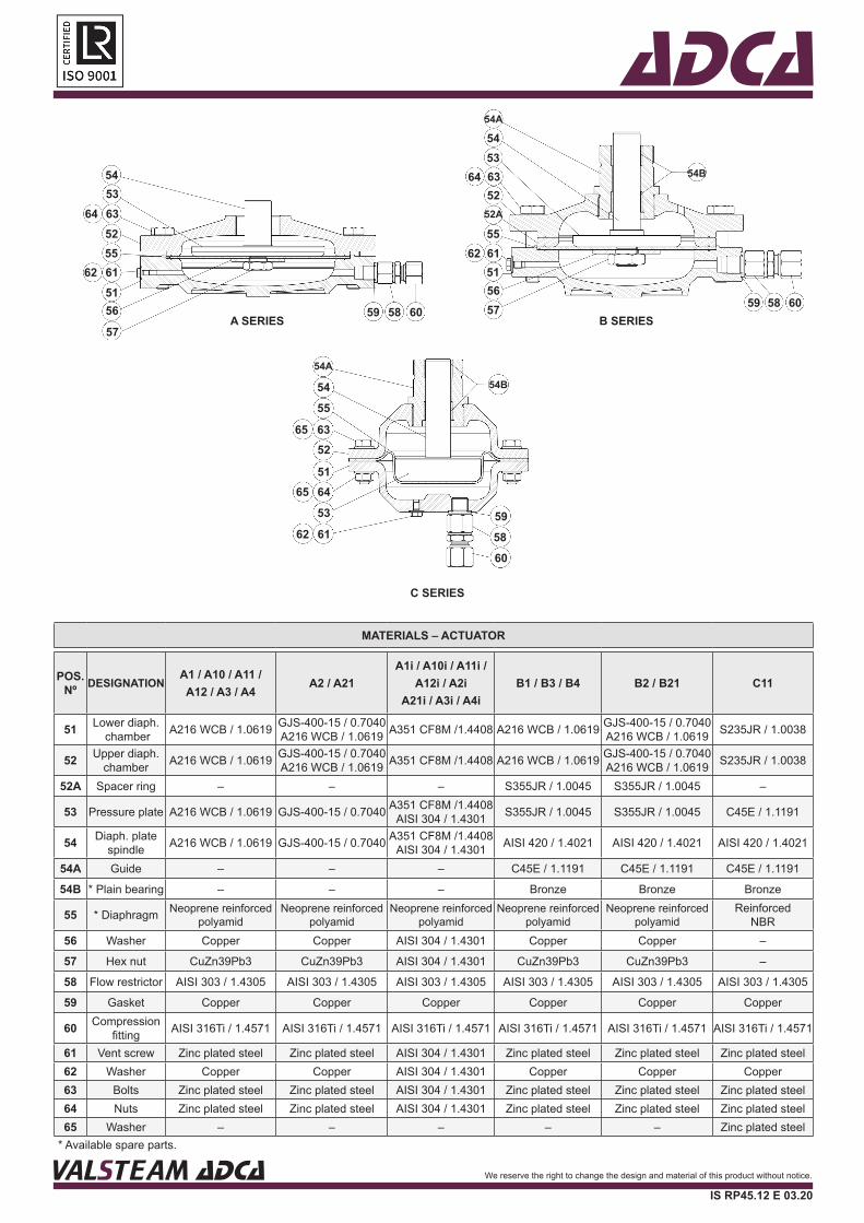
MATERIALS – ACTUATOR
POS. Nº DESIGNATION
A1 / A10 / A11 / A12 / A3 / A4
A2 / A21A1i / A10i / A11i /
A12i / A2i A21i / A3i / A4i
B1 / B3 / B4 B2 / B21 C11
51 Lower diaph. chamber A216 WCB / 1.0619 GJS-400-15 / 0.7040
A216 WCB / 1.0619 A351 CF8M /1.4408 A216 WCB / 1.0619 GJS-400-15 / 0.7040 A216 WCB / 1.0619 S235JR / 1.0038
52 Upper diaph. chamber A216 WCB / 1.0619 GJS-400-15 / 0.7040
A216 WCB / 1.0619 A351 CF8M /1.4408 A216 WCB / 1.0619 GJS-400-15 / 0.7040 A216 WCB / 1.0619 S235JR / 1.0038
52A Spacer ring – – – S355JR / 1.0045 S355JR / 1.0045 –
53 Pressure plate A216 WCB / 1.0619 GJS-400-15 / 0.7040 A351 CF8M /1.4408 AISI 304 / 1.4301 S355JR / 1.0045 S355JR / 1.0045 C45E / 1.1191
54 Diaph. plate spindle A216 WCB / 1.0619 GJS-400-15 / 0.7040 A351 CF8M /1.4408
AISI 304 / 1.4301 AISI 420 / 1.4021 AISI 420 / 1.4021 AISI 420 / 1.4021
54A Guide – – – C45E / 1.1191 C45E / 1.1191 C45E / 1.1191
54B * Plain bearing – – – Bronze Bronze Bronze
55 * Diaphragm Neoprene reinforced polyamid
Neoprene reinforced polyamid
Neoprene reinforced polyamid
Neoprene reinforced polyamid
Neoprene reinforced polyamid
Reinforced NBR
56 Washer Copper Copper AISI 304 / 1.4301 Copper Copper –
57 Hex nut CuZn39Pb3 CuZn39Pb3 AISI 304 / 1.4301 CuZn39Pb3 CuZn39Pb3 –
58 Flow restrictor AISI 303 / 1.4305 AISI 303 / 1.4305 AISI 303 / 1.4305 AISI 303 / 1.4305 AISI 303 / 1.4305 AISI 303 / 1.4305
59 Gasket Copper Copper Copper Copper Copper Copper
60 Compression fitting AISI 316Ti / 1.4571 AISI 316Ti / 1.4571 AISI 316Ti / 1.4571 AISI 316Ti / 1.4571 AISI 316Ti / 1.4571 AISI 316Ti / 1.4571
61 Vent screw Zinc plated steel Zinc plated steel AISI 304 / 1.4301 Zinc plated steel Zinc plated steel Zinc plated steel62 Washer Copper Copper AISI 304 / 1.4301 Copper Copper Copper63 Bolts Zinc plated steel Zinc plated steel AISI 304 / 1.4301 Zinc plated steel Zinc plated steel Zinc plated steel64 Nuts Zinc plated steel Zinc plated steel AISI 304 / 1.4301 Zinc plated steel Zinc plated steel Zinc plated steel65 Washer – – – – – Zinc plated steel
* Available spare parts.
5453
645263
52A
6151
5562
5657 59 58 60
54A
54B
B SERIES
5455
65 63
62
52
60
6451
65
53
615958
54A
54B
C SERIES
54
645363
6251
57
6155
56
52
605859A SERIES
VALSTEAM ADCA We reserve the right to change the design and material of this product without notice.
IS RP45.12 E 03.20
Related Documents