Pressure Pipe and Fittings Installation Guide Suitable for Pressure Applications

Welcome message from author
This document is posted to help you gain knowledge. Please leave a comment to let me know what you think about it! Share it to your friends and learn new things together.
Transcript
Pressure Pipe and FittingsInstallation GuideSuitable for Pressure Applications


PRESSURE PIPE AND FITTINGS
INSTALLATION GUIDE
Introduction
Receiving
Unloading
Storage
Handling
Pipe Installation Instructions
Angular Deflection Procedures
Fittings Installation Instructions
Thrust Restraints
Bulldog™ Installation Instructions
Cobra Lock® Installation Instructions
Inspection and Testing
Service Connections and Tapping
Safety Precautions
Pipe Dimensions
Conversion Chart
4
5
6
7
8
9-15
16-17
18-19
20-21
22-23
24-25
26
27-28
29
30
31

This guide is intended for use by installers, supervisors, and inspectors responsible for the installation of NAPCO PVC Pressure Pipe and Fittings. It is not a design manual. Rather, it is intended as a guide for the proper receiving, handling and installation of PVC pressure pipe and fittings. If used properly, the information in this booklet can help maximize product performance.
This booklet is not intended to assume the authority of the Design Engineer. System requirements and actual field conditions will vary significantly. The sole responsibility for all design and installation decisions lies with the Design Engineer.
All Local Health and Safety Regulations must be followed.
INTRODUCTION
4 napcopipe.com
This booklet is also available electronically on the NAPCO's website, www.napcopipe.com.
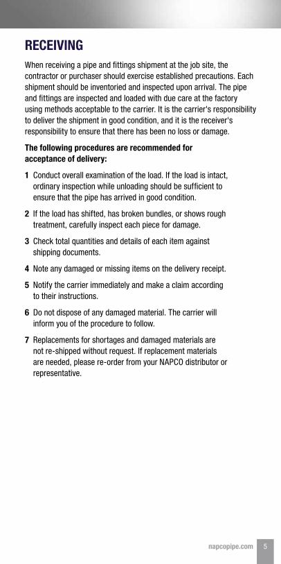
When receiving a pipe and fittings shipment at the job site, the contractor or purchaser should exercise established precautions. Each shipment should be inventoried and inspected upon arrival. The pipe and fittings are inspected and loaded with due care at the factory using methods acceptable to the carrier. It is the carrier's responsibility to deliver the shipment in good condition, and it is the receiver's responsibility to ensure that there has been no loss or damage.
The following procedures are recommended for acceptance of delivery:
1 Conduct overall examination of the load. If the load is intact, ordinary inspection while unloading should be sufficient to ensure that the pipe has arrived in good condition.
2 If the load has shifted, has broken bundles, or shows rough treatment, carefully inspect each piece for damage.
3 Check total quantities and details of each item against shipping documents.
4 Note any damaged or missing items on the delivery receipt.
5 Notify the carrier immediately and make a claim according to their instructions.
6 Do not dispose of any damaged material. The carrier will inform you of the procedure to follow.
7 Replacements for shortages and damaged materials are not re-shipped without request. If replacement materials are needed, please re-order from your NAPCO distributor or representative.
RECEIVING
5napcopipe.com

The following recommendations should be followed:
1 Remove restraints from the bundles. These may be straps, ropes, or chains with padding.
2 Remove any boards on the top or sides of the load that are not part of the pipe/fittings packaging.
3 When unloading fittings use industry-accepted means. Use extreme caution when unloading fittings with any type of machinery, as fittings may be fiberglass wrapped for added strength. Damage to wrapping could reduce strength of fabricated fitting. Do not drop or throw fittings into trench. NAPCO is not responsible for damage to mishandled fittings.
4 Using a forklift (or a front-end loader equipped with forks), remove the top bundles of pipe, one at a time from the truck.
5 If a forklift is not available, use a spreader bar with fabric straps capable of carrying the load. Space straps approximately 2.4m (8ft) apart. Loop straps under the load.
6 During the removal and handling, ensure that the bundles do not impact anything (especially in cold weather).
7 Place pipe bundles on level ground.
8 Do not handle bundles with individual chains or single cables, even if padded.
9 Do not attach lifting cables to bundles or bands.
10 Do not stack bundles more than 2.4m (8ft) high.
11 Protect bundles with packing materials the same way they were protected while on the truck.
12 To unload lower bundles, repeat the unloading process described above.
13 Do not unload pipe bundles by hand.
14 If unloading equipment is not available, pipe may be unloaded by removing individual pieces. Care should be taken to ensure that pipe is not dropped or damaged.
UNLOADINGThe means by which pipe and fittings are unloaded in the field is the decision and the responsibility of the receiver.
6 napcopipe.com
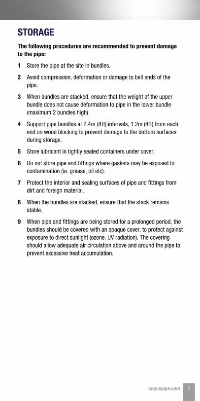
1 Store the pipe at the site in bundles.
2 Avoid compression, deformation or damage to bell ends of the pipe.
3 When bundles are stacked, ensure that the weight of the upper bundle does not cause deformation to pipe in the lower bundle (maximum 2 bundles high).
4 Support pipe bundles at 2.4m (8ft) intervals, 1.2m (4ft) from each end on wood blocking to prevent damage to the bottom surfaces during storage.
5 Store lubricant in tightly sealed containers under cover.
6 Do not store pipe and fittings where gaskets may be exposed to contamination (ie. grease, oil etc).
7 Protect the interior and sealing surfaces of pipe and fittings from dirt and foreign material.
8 When the bundles are stacked, ensure that the stack remains stable.
9 When pipe and fittings are being stored for a prolonged period, the bundles should be covered with an opaque cover, to protect against exposure to direct sunlight (ozone, UV radiation). The covering should allow adequate air circulation above and around the pipe to prevent excessive heat accumulation.
STORAGEThe following procedures are recommended to prevent damage to the pipe:
7napcopipe.com
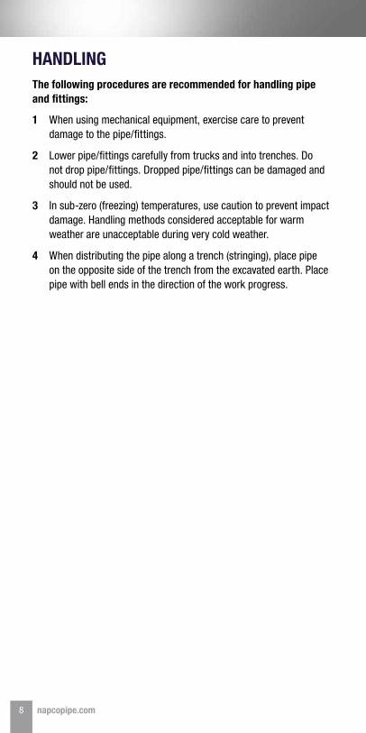
1 When using mechanical equipment, exercise care to prevent damage to the pipe/fittings.
2 Lower pipe/fittings carefully from trucks and into trenches. Do not drop pipe/fittings. Dropped pipe/fittings can be damaged and should not be used.
3 In sub-zero (freezing) temperatures, use caution to prevent impact damage. Handling methods considered acceptable for warm weather are unacceptable during very cold weather.
4 When distributing the pipe along a trench (stringing), place pipe on the opposite side of the trench from the excavated earth. Place pipe with bell ends in the direction of the work progress.
HANDLINGThe following procedures are recommended for handling pipe and fittings:
8 napcopipe.com
Alignment and Grade
All pipe should be laid to, and maintained at required lines and grades established by the pipe system Design Engineer. Fittings, valves, air vents and hydrants should be installed at the required locations with valve and hydrant stems plumb.
Trench Width
Trench width at the ground surface may vary with and depend upon the depth, type of soils, and the position of the surface structures. The minimum clear width of the trench, measured at the spring line of the pipe should be 300mm (1ft) greater than the outside diameter of the pipe. The maximum clear width of the trench at the top of the pipe should not exceed a width equal to the pipe diameter plus 600mm (2ft). If the above defined trench widths must be exceeded, or if the pipe is installed in a compacted embankment, the pipe embedment should be compacted to a point of at least 2.5 pipe diameters from the pipe on both sides of the pipe or to the trench wall, whichever is less.
Preparation of Trench Bottom
• The trench bottom should be constructed to provide firm, stable and uniform support for the full length of the pipe.
• Bell holes should be provided at each joint to permit proper joint assembly and pipe support. Any part of the trench bottom excavated below grade should be backfilled to grade and should be compacted as required to provide firm pipe support.
• When an unstable sub-grade condition which will provide inadequate pipe support is encountered, additional trench depth should be excavated and refilled with a suitable foundation material as recommended by the project's Geotechnical Engineer. Ledge rock, boulders and large stones should be removed to provide 100mm (4") of soil cushion on all sides of the pipe and accessories.
PIPE INSTALLATION INSTRUCTIONS
9napcopipe.com
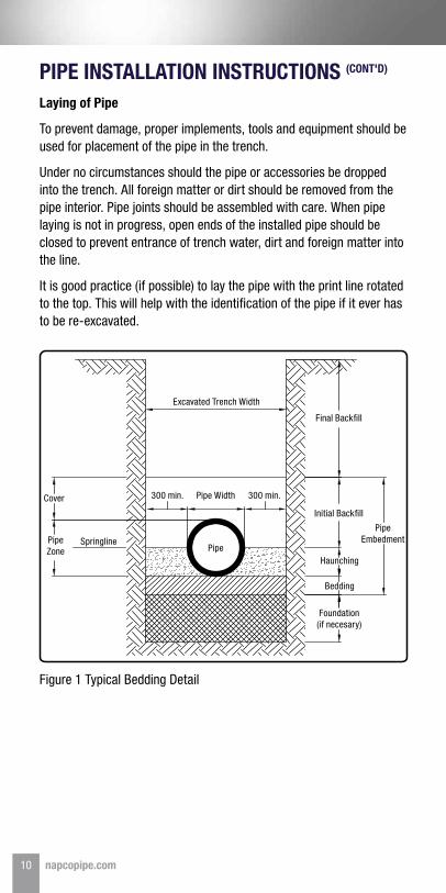
Figure 1 Typical Bedding Detail
PIPE INSTALLATION INSTRUCTIONS (CONT'D)
Laying of Pipe
To prevent damage, proper implements, tools and equipment should be used for placement of the pipe in the trench.
Under no circumstances should the pipe or accessories be dropped into the trench. All foreign matter or dirt should be removed from the pipe interior. Pipe joints should be assembled with care. When pipe laying is not in progress, open ends of the installed pipe should be closed to prevent entrance of trench water, dirt and foreign matter into the line.
It is good practice (if possible) to lay the pipe with the print line rotated to the top. This will help with the identification of the pipe if it ever has to be re-excavated.
Excavated Trench Width
Final Backfill
Initial Backfill
HaunchingPipe
Pipe Width300 min.Cover
SpringlinePipe Zone
300 min.
Bedding
Foundation (if necesary)
Pipe Embedment
10 napcopipe.com
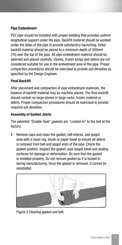
Figure 2 Cleaning gasket and bell.
Pipe Embedment
PVC pipe should be installed with proper bedding that provides uniform longitudinal support under the pipe. Backfill material should be worked under the sides of the pipe to provide satisfactory haunching. Initial backfill material should be placed to a minimum depth of 300mm (1ft) over the top of the pipe. All pipe embedment material should be selected and placed carefully. Stones, frozen lumps and debris are not considered suitable for use in the embedment area of the pipe. Proper compaction procedures should be exercised to provide soil densities as specified by the Design Engineer.
Final Backfill
After placement and compaction of pipe embedment materials, the balance of backfill material may be machine placed. The final backfill should contain no large stones or large rocks, frozen material or debris. Proper compaction procedures should be exercised to provide required soil densities.
Assembly of Gasket Joints
The patented “Double-Seal" gaskets are “Locked-In" to the bell at the factory.
1 Remove caps and clean the gasket, bell interior, and spigot area with a clean rag, brush or paper towel to ensure all debris is removed from bell and spigot ends of the pipe. Check the gasket position. Inspect the gasket, pipe spigot bevel and sealing surfaces for damage or deformation. Be sure that the gasket is installed properly. Do not remove gasket as it is locked in during manufacturing. Once the gasket is removed, it cannot be reinstalled.
11napcopipe.com

Figure 3 Apply lubricant.
PIPE INSTALLATION INSTRUCTIONS (CONT'D)
Assembly of Gasket Joints Continued
Over-Insertion can cause leaks and/or breakage of the pipe bell.When unable to assemble using the bar and block method, then another mechanical method such as a come-along or an eagle claw should be used. If the backhoe bucket is used to assemble the pipe, extra care must be taken to ensure the pipe is not assembled beyond the second insertion line.
2 Use only NAPCO recommended lubricant supplied with the pipe. Apply lubricant to the gasket and spigot from the chamfer to 75mm (3") from the face of the spigot. Use of non-approved lubricants may promote bacterial growth and cause damage to the gaskets or pipe, as well as void the manufacturer's warranty.
3 After lubrication, the pipe is ready to be joined. Good alignment of the pipe is essential for ease of assembly. Align the spigot and the bell, and insert the spigot into the bell until it contacts the gasket uniformly. Do not suspend the pipe and “stab" it onto the bell. Ensure that the spigot does not touch bedding during installation. The spigot end of the pipe will be marked by NAPCO to indicate the minimum and the maximum depth of insertion. The first insertion line should be pushed all the way in and the second insertion should be exposed in front of the face of the bell. “Bury one - Show one".
12 napcopipe.com
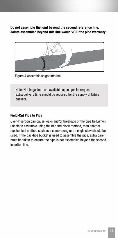
Figure 4 Assemble spigot into bell.
Do not assemble the joint beyond the second reference line. Joints assembled beyond this line would VOID the pipe warranty.
Note: Nitrile gaskets are available upon special request. Extra delivery time should be required for the supply of Nitrile gaskets.
Field-Cut Pipe to Pipe
Over-Insertion can cause leaks and/or breakage of the pipe bell.When unable to assemble using the bar and block method, then another mechanical method such as a come-along or an eagle claw should be used. If the backhoe bucket is used to assemble the pipe, extra care must be taken to ensure the pipe is not assembled beyond the second insertion line.
13napcopipe.com
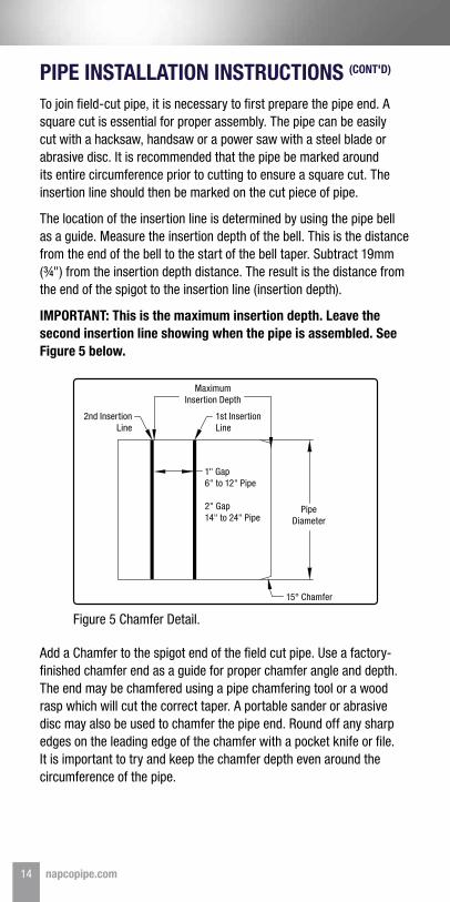
To join field-cut pipe, it is necessary to first prepare the pipe end. A square cut is essential for proper assembly. The pipe can be easily cut with a hacksaw, handsaw or a power saw with a steel blade or abrasive disc. It is recommended that the pipe be marked around its entire circumference prior to cutting to ensure a square cut. The insertion line should then be marked on the cut piece of pipe.
The location of the insertion line is determined by using the pipe bell as a guide. Measure the insertion depth of the bell. This is the distance from the end of the bell to the start of the bell taper. Subtract 19mm (¾") from the insertion depth distance. The result is the distance from the end of the spigot to the insertion line (insertion depth).
IMPORTANT: This is the maximum insertion depth. Leave the second insertion line showing when the pipe is assembled. See Figure 5 below.
PIPE INSTALLATION INSTRUCTIONS (CONT'D)
Add a Chamfer to the spigot end of the field cut pipe. Use a factory-finished chamfer end as a guide for proper chamfer angle and depth. The end may be chamfered using a pipe chamfering tool or a wood rasp which will cut the correct taper. A portable sander or abrasive disc may also be used to chamfer the pipe end. Round off any sharp edges on the leading edge of the chamfer with a pocket knife or file. It is important to try and keep the chamfer depth even around the circumference of the pipe.
Figure 5 Chamfer Detail.
2nd Insertion Line
1st Insertion Line
Maximum Insertion Depth
Pipe Diameter
15° Chamfer
1" Gap 6" to 12" Pipe
2" Gap 14" to 24" Pipe
14 napcopipe.com
Designed Changes in Alignment
Ideally all changes in alignment should be designed and accomplished with the proper use of fittings. Either push on PVC Fittings (injection moulded or fabricated) or Ductile Iron fittings (MJ or Push On) can be used.
The use of a fitting provides for straight insertion of the spigot into the joint, allowing the directional change (horizontal or vertical) to be made quickly and easily during construction. Since different fitting types have different insertion requirements always check bell depth of fitting and if necessary re-mark spigot, to ensure the correct insertion depth is achieved. NAPCO recommends that all detailed design incorporate the use of fittings. Other methods of changing the alignment are available to be used in the field in order to accommodate very minor changes in alignment as they come up during the construction process.
PVC Fittings
100mm - 200mm (4" - 8“) fittings are injection molded to CSA B137.2 and AWWA C907 – For these sizes the standard angles are 11¼˚, 22½˚, 45˚ and 90˚ degrees.
250mm (10") and larger, are fabricated to CSA B137.3. These fittings are available in standard configurations and bend angles. In addition, custom bend angles and configurations can be special ordered. Keep in mind that delivery for custom orders may take a few days longer than standard bends.
NAPCO also produce 5˚ Radius bends – For minor changes in alignment. The radius shape of the 5˚ bend affords virtually no axial forces; therefore, they can be installed without need for joint restraint.
MJ or Push on DI fittings
Ductile Iron fittings Mechanical Joint (MJ) or Push On in either compact (AWWA C153) or long body (AWWA C110) can be used with PVC pipe. See the fitting manufacturer's recommendations for alignment changes and deflections available with this type of fitting.
Field Changes in Alignment
A – Angular Deflection in the Joint – This should be used only in the field, when minor directional changes are required during construction. This method should be done with extreme caution and care. This technique should not be used during engineering design.
15napcopipe.com
For reference purposes 1˚ of joint deflection is equal to a 100mm (4") offset for a 6.1m (20ft) piece of pipe.
ANGULAR DEFLECTION PROCEDURE1 Under – insert spigot into bell; stop inserting when the first
insertion line is even with the face of the bell. If you have a field cut spigot this is 25mm (1") closer to edge of the spigot than insertion line that you have just marked on the pipe.
2 Check to ensure that spigot is in straight alignment with the bell.
3 Manually, move the other end, bell end to achieve required offset.
4 Place and consolidate haunching and initial backfill along the barrel, leaving the previous joint exposed.
5 After under-inserting the next spigot, go to the previous joint and check to ensure that cascading of this joint has not occurred. (Cascading occurs when the spigot of the previous joint inserts further into the bell, than was originally intended.)
As this technique requires extra time and diligence by inspection and construction, it is recommended for only very minor field adjustments of maximum 2° on 100mm (4") to 300mm (12") and 1° on 350mm (14") to 600mm (24").
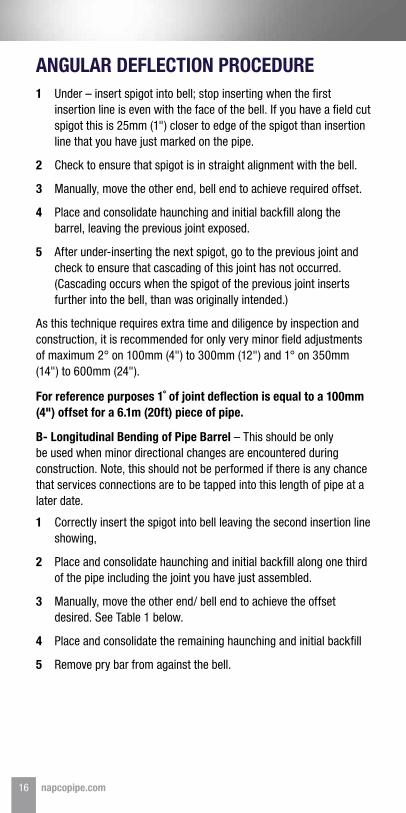
B- Longitudinal Bending of Pipe Barrel – This should be only be used when minor directional changes are encountered during construction. Note, this should not be performed if there is any chance that services connections are to be tapped into this length of pipe at a later date.
1 Correctly insert the spigot into bell leaving the second insertion line showing,
2 Place and consolidate haunching and initial backfill along one third of the pipe including the joint you have just assembled.
3 Manually, move the other end/ bell end to achieve the offset desired. See Table 1 below.
4 Place and consolidate the remaining haunching and initial backfill
5 Remove pry bar from against the bell.
16 napcopipe.com
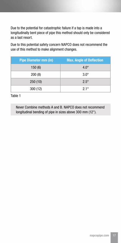
Table 1
Never Combine methods A and B. NAPCO does not recommend longitudinal bending of pipe in sizes above 300 mm (12").
Due to the potential for catastrophic failure if a tap is made into a longitudinally bent piece of pipe this method should only be considered as a last resort.
Due to this potential safety concern NAPCO does not recommend the use of this method to make alignment changes.
150 (6)
200 (8)
250 (10)
300 (12)
4.0°
3.0°
2.5°
2.1°
Pipe Diameter mm (in) Max. Angle of Deflection
17napcopipe.com
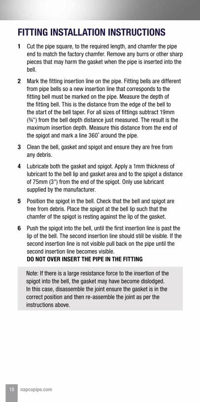
FITTING INSTALLATION INSTRUCTIONS1 Cut the pipe square, to the required length, and chamfer the pipe
end to match the factory chamfer. Remove any burrs or other sharp pieces that may harm the gasket when the pipe is inserted into the bell.
2 Mark the fitting insertion line on the pipe. Fitting bells are different from pipe bells so a new insertion line that corresponds to the fitting bell must be marked on the pipe. Measure the depth of the fitting bell. This is the distance from the edge of the bell to the start of the bell taper. For all sizes of fittings subtract 19mm (¾") from the bell depth distance just measured. The result is the maximum insertion depth. Measure this distance from the end of the spigot and mark a line 360˚ around the pipe.
3 Clean the bell, gasket and spigot and ensure they are free from any debris.
4 Lubricate both the gasket and spigot. Apply a 1mm thickness of lubricant to the bell lip and gasket area and to the spigot a distance of 75mm (3") from the end of the spigot. Only use lubricant supplied by the manufacturer.
5 Position the spigot in the bell. Check that the bell and spigot are free from debris. Place the spigot at the bell lip such that the chamfer of the spigot is resting against the lip of the gasket.
6 Push the spigot into the bell, until the first insertion line is past the lip of the bell. The second insertion line should still be visible. If the second insertion line is not visible pull back on the pipe until the second insertion line becomes visible. DO NOT OVER INSERT THE PIPE IN THE FITTING
Note: If there is a large resistance force to the insertion of the spigot into the bell, the gasket may have become dislodged. In this case, disassemble the joint ensure the gasket is in the correct position and then re-assemble the joint as per the instructions above.
18 napcopipe.com
• Never push directly against the pipe by any mechanical means (pry bar, hook, etc.). Always place a block of wood between the face of the pipe bell and the bar. This will protect the pipe from damage and help to ensure even distribution of the force pushing the pipe.
• Any means of assembly must allow for straight alignment of the bell and pipe during assembly. Pushing or pulling on one side of the pipe, causing misalignment of the pipe and bell, is not acceptable.
• Smaller diameters of pipe and fittings can generally be assembled by hand. Larger diameters of pipe may be assembled using a come-along or jacks and pulleys. A backhoe should never be used to assemble pipe to pipe or pipe to fittings.
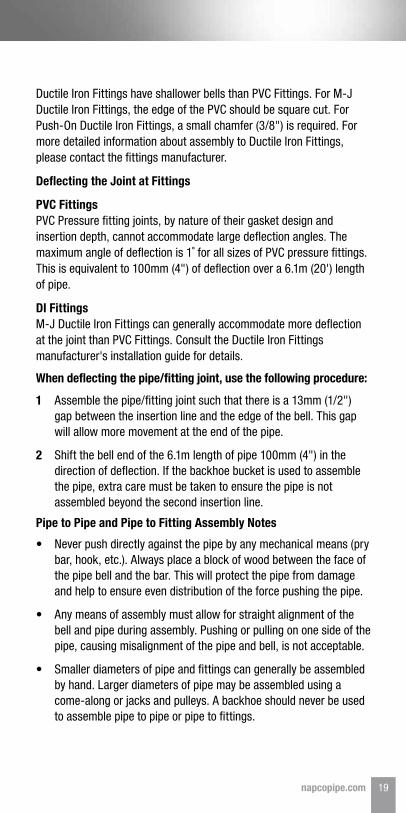
Ductile Iron Fittings have shallower bells than PVC Fittings. For M-J Ductile Iron Fittings, the edge of the PVC should be square cut. For Push-On Ductile Iron Fittings, a small chamfer (3/8") is required. For more detailed information about assembly to Ductile Iron Fittings, please contact the fittings manufacturer.
Deflecting the Joint at Fittings
PVC Fittings PVC Pressure fitting joints, by nature of their gasket design and insertion depth, cannot accommodate large deflection angles. The maximum angle of deflection is 1˚ for all sizes of PVC pressure fittings. This is equivalent to 100mm (4") of deflection over a 6.1m (20') length of pipe.
DI Fittings M-J Ductile Iron Fittings can generally accommodate more deflection at the joint than PVC Fittings. Consult the Ductile Iron Fittings manufacturer's installation guide for details.
Pipe to Pipe and Pipe to Fitting Assembly Notes
1 Assemble the pipe/fitting joint such that there is a 13mm (1/2") gap between the insertion line and the edge of the bell. This gap will allow more movement at the end of the pipe.
2 Shift the bell end of the 6.1m length of pipe 100mm (4") in the direction of deflection. If the backhoe bucket is used to assemble the pipe, extra care must be taken to ensure the pipe is not assembled beyond the second insertion line.
When deflecting the pipe/fitting joint, use the following procedure:
19napcopipe.com
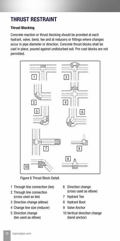
1 Through line connection (tee)
2 Through line connection (cross used as tee)
3 Direction change (elbow)
4 Change line size (reducer)
5 Direction change (tee used as elbow)
6 Direction change (cross used as elbow)
7 Hydrant Tee
8 Hydrant Boot
9 Valve Anchor
10 Vertical direction change (bend anchor)
Figure 6 Thrust Block Detail.
THRUST RESTRAINTThrust Blocking
Concrete reaction or thrust blocking should be provided at each hydrant, valve, bend, tee and at reducers or fittings where changes occur in pipe diameter or direction. Concrete thrust blocks shall be cast in place, poured against undisturbed soil. Pre-cast blocks are not permitted.
1 2
3 4
5 6
7 8
9
10
20 napcopipe.com
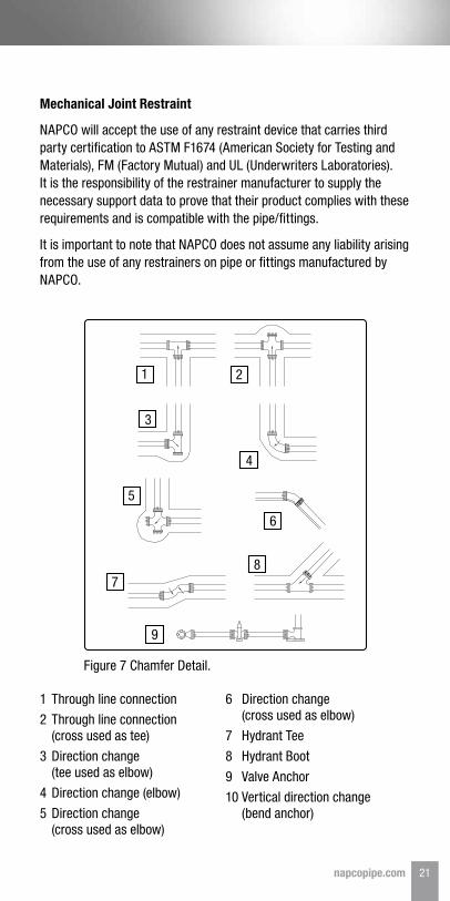
1 Through line connection
2 Through line connection (cross used as tee)
3 Direction change (tee used as elbow)
4 Direction change (elbow)
5 Direction change (cross used as elbow)
6 Direction change (cross used as elbow)
7 Hydrant Tee
8 Hydrant Boot
9 Valve Anchor
10 Vertical direction change (bend anchor)
Figure 7 Chamfer Detail.
Mechanical Joint Restraint
NAPCO will accept the use of any restraint device that carries third party certification to ASTM F1674 (American Society for Testing and Materials), FM (Factory Mutual) and UL (Underwriters Laboratories). It is the responsibility of the restrainer manufacturer to supply the necessary support data to prove that their product complies with these requirements and is compatible with the pipe/fittings.
It is important to note that NAPCO does not assume any liability arising from the use of any restrainers on pipe or fittings manufactured by NAPCO.
1 2
3
4
5
6
78
9
21napcopipe.com
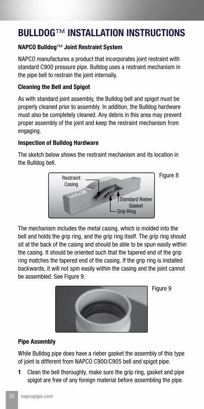
Figure 8
Figure 9
BULLDOG™ INSTALLATION INSTRUCTIONSNAPCO Bulldog™ Joint Restraint System
NAPCO manufactures a product that incorporates joint restraint with standard C900 pressure pipe. Bulldog uses a restraint mechanism in the pipe bell to restrain the joint internally.
Cleaning the Bell and Spigot
As with standard joint assembly, the Bulldog bell and spigot must be properly cleaned prior to assembly. In addition, the Bulldog hardware must also be completely cleaned. Any debris in this area may prevent proper assembly of the joint and keep the restraint mechanism from engaging.
Inspection of Bulldog Hardware
The sketch below shows the restraint mechanism and its location in the Bulldog bell.
The mechanism includes the metal casing, which is molded into the bell and holds the grip ring, and the grip ring itself. The grip ring should sit at the back of the casing and should be able to be spun easily within the casing. It should be oriented such that the tapered end of the grip ring matches the tapered end of the casing. If the grip ring is installed backwards, it will not spin easily within the casing and the joint cannot be assembled. See Figure 9.
Pipe Assembly
While Bulldog pipe does have a rieber gasket the assembly of this type of joint is different from NAPCO C900/C905 bell and spigot pipe.
1 Clean the bell thoroughly, make sure the grip ring, gasket and pipe spigot are free of any foreign material before assembling the pipe.
Restraint Casing
Standard Rieber Gasket
Grip Ring
22 napcopipe.com

2 Lubrication is also very important. Only lubricate the gasket in the bell. Do not lubricate the Bulldog grip ring or the spigot of the pipe. Lube can be applied sparingly to the chamfer or bevel of the pipe.
3 Joint alignment is critically important for Bulldog. The pipe must be in straight alignment. Misaligned pipe requires a much higher force to complete the assembly. Properly aligned, the Bulldog joint can be assembled manually using a prybar, come-along or Eagle Claw tool.
4 Once aligned a force pushes the chamfer through the bell lip and the bevel enters the grip ring. By slowly applying force the bevel will centre the grip ring inside the casing and the grip ring will expand slightly.
5 The grip ring is pushed to the back of the casing and butts up against the back of the casing. The spigot then moves on to the lip of the rieber gasket until it comes into contact with the gasket.
6 The spigot continues past the gasket until the first insertion line is past the lip of the bell. The second insertion line should still be visible in front of the bell lip.
Figure 10
For open-cut Bulldog installations an initial pressurization will set the joints and may cause some minor expansion of the system that will require make up water prior to performing the actual pressure test. It is a good idea to pressurize the system up to the test pressure for a period of one (1) hour then remove the pressure and add any makeup water before beginning the actual final pressure test.
Assembly of the joint can under certain circumstances cause the over-insertion of previously assembled joints. Backfilling the pipe prior to joint assembly can prevent over-insertion of previous joints. Also, embedment material can be used to centre load the pipe and prevent movement. See Figure 10.
For directional drilling applications, Bulldog Joints must be set prior to being pulled into the bore. The joint is set by applying a back pressure of 2 to 3 times the assembly force used to put the pipe together. When using Bulldog in a directional drilling application please first consult with the NAPCO Engineering Team for additional guidance.
Centre Load PipeAssembly
ForcePipe 3 Pipe 2 Pipe 1
Joint Currently Being Assembled (B)
Joint Currently Being Assembled (A)
23napcopipe.com
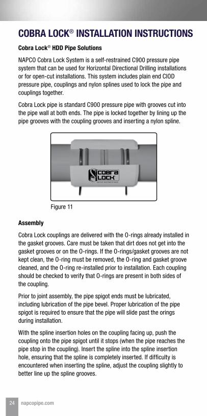
Figure 11
COBRA LOCK® INSTALLATION INSTRUCTIONSCobra Lock® HDD Pipe Solutions
NAPCO Cobra Lock System is a self-restrained C900 pressure pipe system that can be used for Horizontal Directional Drilling installations or for open-cut installations. This system includes plain end CIOD pressure pipe, couplings and nylon splines used to lock the pipe and couplings together.
Cobra Lock pipe is standard C900 pressure pipe with grooves cut into the pipe wall at both ends. The pipe is locked together by lining up the pipe grooves with the coupling grooves and inserting a nylon spline.
Assembly
Cobra Lock couplings are delivered with the O-rings already installed in the gasket grooves. Care must be taken that dirt does not get into the gasket grooves or on the O-rings. If the O-rings/gasket grooves are not kept clean, the O-ring must be removed, the O-ring and gasket groove cleaned, and the O-ring re-installed prior to installation. Each coupling should be checked to verify that O-rings are present in both sides of the coupling.
Prior to joint assembly, the pipe spigot ends must be lubricated, including lubrication of the pipe bevel. Proper lubrication of the pipe spigot is required to ensure that the pipe will slide past the orings during installation.
With the spline insertion holes on the coupling facing up, push the coupling onto the pipe spigot until it stops (when the pipe reaches the pipe stop in the coupling). Insert the spline into the spline insertion hole, ensuring that the spline is completely inserted. If difficulty is encountered when inserting the spline, adjust the coupling slightly to better line up the spline grooves.
24 napcopipe.com
H D D P I P E S O L U T I O N S B Y N A P C O
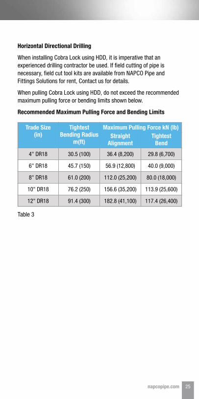
Table 3
Horizontal Directional Drilling
When installing Cobra Lock using HDD, it is imperative that an experienced drilling contractor be used. If field cutting of pipe is necessary, field cut tool kits are available from NAPCO Pipe and Fittings Solutions for rent, Contact us for details.
When pulling Cobra Lock using HDD, do not exceed the recommended maximum pulling force or bending limits shown below.
Recommended Maximum Pulling Force and Bending Limits
4" DR18
6" DR18
8" DR18
10" DR18
12" DR18
36.4 (8,200)
56.9 (12,800)
112.0 (25,200)
156.6 (35,200)
182.8 (41,100)
30.5 (100)
45.7 (150)
61.0 (200)
76.2 (250)
91.4 (300)
29.8 (6,700)
40.0 (9,000)
80.0 (18,000)
113.9 (25,600)
117.4 (26,400)
Trade Size (in)
Maximum Pulling Force kN (lb)Straight
AlignmentTightest
Bend
Tightest Bending Radius
m(ft)
25napcopipe.com
INSPECTION AND TESTINGGood practice dictates pressure testing portions of lines as they are completed in advance of the entire system. Before testing, the pipeline must be backfilled and braced sufficiently to prevent movement under pressure.
The following three points should be considered when testing:
Pressure and Leakage Test
A combined pressure and leakage test is recommended. The test pressure and duration shall be as specified by the Design Engineer. The test pressure should never exceed the pressure rating of the pipe being tested.
Relieving Air From Pipe Line
The pipeline should be filled as slowly as possible (not more than 1 ft/sec) to avoid any unnecessary surges and entrapment of air. Venting air from the line is of utmost importance. Pressure pipe is seldom laid to flat grade, so there are high and low sections along the line. If the high section elevation is above the low part of the line, a larger amount of air will be trapped. Corporation stops or automatic air relief valves should be installed at these points. Air can be blown from hydrants in pipe sizes up to 200mm (8"). In larger diameter pipes, air will not enter the hydrant branch, therefore it will be necessary to install air release valves at high points.
The line should be filled slowly with water to static pressure, and all air vents opened to allow air to escape. The line should be filled at a rate that allows air to leave the line at the same rate. It is recommended practice to let the line remain under static pressure for at least 15 minutes. All air vents should then be opened again to allow any remaining air to be released from the line, after which the line may be brought up to full test pressure. The leakage shall not exceed that specified by the Design Engineer. Test pressure should never exceed the pressure rating on the pipe being tested.
1 The pipe to be tested must be sufficiently backfilled to prevent movement while under test pressure.
2 Thrust restraint at fittings should be permanent and constructed to withstand test pressure. If concrete thrust blocks are used, sufficient time must be allowed before testing to permit the concrete to cure.
3 Test ends should be capped and braced to withstand the thrusts that are developed under test pressure.
Note: Air pressure testing of installed PVC Pressure Pipe is expressly prohibited for safety reasons.
26 napcopipe.com
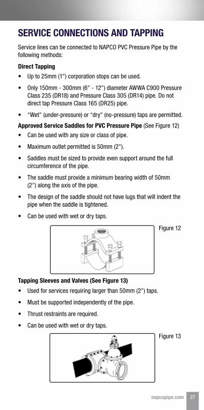
Figure 12
Figure 13
SERVICE CONNECTIONS AND TAPPINGService lines can be connected to NAPCO PVC Pressure Pipe by the following methods:
Direct Tapping
Approved Service Saddles for PVC Pressure Pipe (See Figure 12)
Tapping Sleeves and Valves (See Figure 13)
• Up to 25mm (1") corporation stops can be used.
• Only 150mm - 300mm (6" - 12") diameter AWWA C900 Pressure Class 235 (DR18) and Pressure Class 305 (DR14) pipe. Do not direct tap Pressure Class 165 (DR25) pipe.
• “Wet" (under-pressure) or “dry" (no-pressure) taps are permitted.
• Can be used with any size or class of pipe.
• Maximum outlet permitted is 50mm (2").
• Saddles must be sized to provide even support around the full circumference of the pipe.
• The saddle must provide a minimum bearing width of 50mm (2") along the axis of the pipe.
• The design of the saddle should not have lugs that will indent the pipe when the saddle is tightened.
• Can be used with wet or dry taps.
• Used for services requiring larger than 50mm (2") taps.
• Must be supported independently of the pipe.
• Thrust restraints are required.
• Can be used with wet or dry taps.
27napcopipe.com
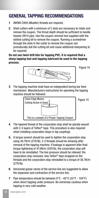
Figure 14
Figure 15
GENERAL TAPPING RECOMMENDATIONS1 AWWA C800 (Mueller) threads are required.
2 Shell cutters with a minimum of 2 slots are necessary to retain and remove the coupon. The throat depth should be sufficient to handle heavier DR14 pipe. Use the coupon removal tool supplied with the slotted cutting bit to remove the coupon. Running a screwdriver through the slots in the cutter to remove the coupon can prematurally dull the cutting bit and cause additional sharpening to be required.
Do not use twist drill bits for tapping PVC. It is required that a sharp tapping tool and tapping lubricant be used in the tapping process.
3 The tapping machine shall have an independent boring bar feed mechanism. Manufacturers instructions for operating the tapping machine should be followed.
4 The tapered thread of the corporation stop shall be spirally wound with 2-3 layers of Teflon® tape. This procedure is also required when installing corporation stops in tap couplings.
5. A torque wrench should be used to tighten the corporation stop using 36.7N/m (27ft/lb), 2-3 threads should be showing after removal of the tapping machine. If leakage is apparent after final torque tightening of 47.6N/m (35ft/lb), the corporation stop will have to be reinstalled. The line pressure should be relieved; the corporation stop removed; new Teflon® tape wrapped on the threads and the corporation stop reinstalled to a torque of 36.7N/m (27ft/lb).
6 Horizontal goose-necks of the service line are suggested to allow the expansion and contraction of the service line.
7 Pipe temperature should be between 0°C - 40°C (32°F - 104°F) when direct tapping under pressure. Be extremely cautious when tapping in very cold weather.
Clean Edge Means Cutting Action is Good
This is a sample of a Proper Tapping Coupon
28 napcopipe.com
8 When making more than one tap on a length of pipe, the tap locations should be staggered (circumferentially) and at least 450mm (18") apart, longitudinally.
9 Do not tap closer than 600mm (2ft) from both the back of the bell and the spigot insertion line.
10 Never direct tap in an area of the pipe that has been bent.
Basic Safety Precautions
When drilling or tapping any pressurized water pipe, basic safety precautions are advised to assure personal safety of the workers in the event of a sudden and unexpected pipe failure.
All local Health and Safety Regulations must be followed.
Although such failures are extremely infrequent, the following safety practices are recommended.
• A second worker or supervisor should always be present in the immediate vicinity when making “wet" taps. In addition, workers should be positioned at isolation valves.
• Protective clothing: including hard hat, safety shoes, goggles or face mask, should be worn. Means of quick egress from the trench must be available.
• A heavy protective blanket, 1.2m x 1.8m (4ft x 6ft) should be used to cover the exposed pipe in the area of the tap. The blanket should have a hole in the center permitting access and operation of the drilling and tapping machine.
29napcopipe.com
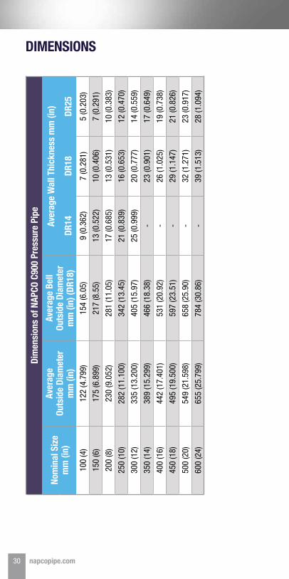
DIMENSIONS
30 napcopipe.com
Dim
ensi
ons
of N
APCO
C90
0 Pr
essu
re P
ipe
Nom
inal
Siz
em
m (i
n)
Aver
age
Outs
ide
Diam
eter
m
m (i
n)
Aver
age
Bell
Outs
ide
Diam
eter
m
m (i
n) (D
R18)
Aver
age
Wal
l Thi
ckne
ss m
m (i
n)
DR14
DR18
DR25
100
(4)
122
(4.7
99)
154
(6.0
5)9
(0.3
62)
7 (0
.281
)5
(0.2
03)
150
(6)
175
(6.8
99)
217
(8.5
5)13
(0.5
22)
10 (0
.406
)7
(0.2
91)
200
(8)
230
(9.0
52)
281
(11.
05)
17 (0
.685
)13
(0.5
31)
10 (0
.383
)
250
(10)
282
(11.
100)
342
(13.
45)
21 (0
.839
)16
(0.6
53)
12 (0
.470
)
300
(12)
335
(13.
200)
405
(15.
97)
25 (0
.999
)20
(0.7
77)
14 (0
.559
)
350
(14)
389
(15.
299)
466
(18.
38)
-23
(0.9
01)
17 (0
.649
)
400
(16)
442
(17.
401)
531
(20.
92)
-26
(1.0
25)
19 (0
.738
)
450
(18)
495
(19.
500)
597
(23.
51)
-29
(1.1
47)
21 (0
.826
)
500
(20)
549
(21.
598)
658
(25.
90)
-32
(1.2
71)
23 (0
.917
)
600
(24)
655
(25.
799)
784
(30.
86)
-39
(1.5
13)
28 (1
.094
)
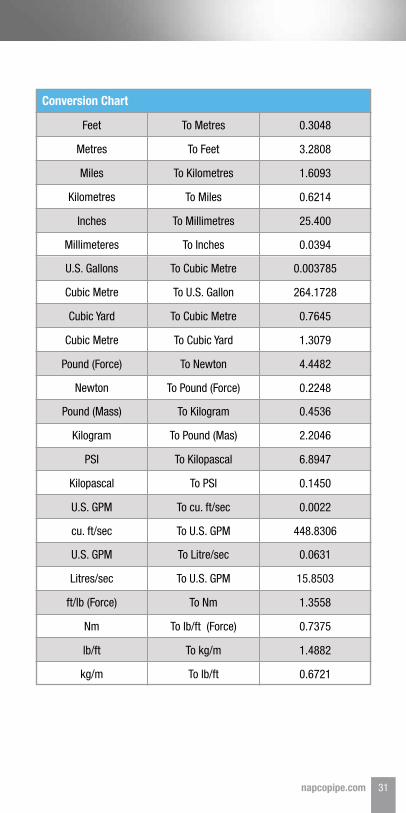
Feet
U.S. Gallons
Pound (Mass)
U.S. GPM
To Metres
To Cubic Metre
To Kilogram
To Litre/sec
0.3048
0.003785
0.4536
0.0631
Metres
Cubic Metre
Kilogram
Litres/sec
To Feet
To U.S. Gallon
To Pound (Mas)
To U.S. GPM
3.2808
264.1728
2.2046
15.8503
Miles
Cubic Yard
PSI
ft/lb (Force)
To Kilometres
To Cubic Metre
To Kilopascal
To Nm
1.6093
0.7645
6.8947
1.3558
Kilometres
Cubic Metre
Kilopascal
Nm
Millimeteres
Newton
cu. ft/sec
kg/m
To Miles
To Cubic Yard
To PSI
To lb/ft (Force)
To Inches
To Pound (Force)
To U.S. GPM
To lb/ft
0.6214
1.3079
0.1450
0.7375
0.0394
0.2248
448.8306
0.6721
Inches
Pound (Force)
U.S. GPM
lb/ft
To Millimetres
To Newton
To cu. ft/sec
To kg/m
25.400
4.4482
0.0022
1.4882
Conversion Chart
31napcopipe.com
1.855.624.7473 | napcopipe.com
NAPCO2801 Post Oak Blvd., Suite 600
Houston, TX 77056
©2019 NAPCO, a Westlake company All rights reserved MU-IG-022-CA-EN-0119.4
Our various pipe and fittings solutions have been manufactured to meet the need of our customers and their applications. Contact one of the Sales Centres for more information:
Langley, BC, CanadaT/F 1.800.663.0696F 1.800.663.6564
Woodbridge, ON, CanadaT/F 1.866.769.7473F 905.856.3986
Laval, QC, CanadaT/F 1.800.465.9754F 450.688.6624
Calgary, AB, CanadaT/F 1.800.663.0696F 1.800.663.6564
Winnipeg, MB, CanadaT/F 1.800.663.0696F 1.800.663.6564
Sales & Distribution Centres:
Distribution Centres:
Related Documents