INSTRUCTION MANUAL STRENGTH TRAINING SYSTEM Press PRO 78600A Bodycraft is a division of Recreation Supply Inc. 7699 Green Meadows Dr Lewis Center, OH 43035 QUESTION? As a quality home gym supplier we are committed to your complete satisfaction. If you have questions, or find missing or damaged parts, we will guarantee your complete satisfaction through our authorized dealer service centers or our home office customer service department. Please call your local dealer for assistance or BodyCraft at 800-990-5556 (9:00 AM - 5:00 PM). Our trained technicians will provide immediate assistance to you, free of charge.

Welcome message from author
This document is posted to help you gain knowledge. Please leave a comment to let me know what you think about it! Share it to your friends and learn new things together.
Transcript

INSTRUCTION MANUALSTRENGTH TRAINING SYSTEMPress
PRO
78600A
Bodycraft is a division of Recreation Supply Inc.7699 Green Meadows DrLewis Center, OH 43035
QUESTION?
As a quality home gym supplier we are committed to your complete satisfaction. If you havequestions, or find missing or damaged parts, we will guarantee your complete satisfaction throughour authorized dealer service centers or our home office customer service department. Please callyour local dealer for assistance or BodyCraft at 800-990-5556 (9:00 AM - 5:00 PM). Our trainedtechnicians will provide immediate assistance to you, free of charge.
1
BEFORE YOU BEGINCongratulations and thank you gor selecting the BODYCRAFTstrength training system. The BODYCRAFT offers an impressivearray of strength training exercises to develop every major muscle group ofthe body. Whether your goal is cardiovascular fitness, a shapely, toned bodyor dramatic muscle size and strength, the BODYCRAFT Press will helpyou achieve the specific results you want.For your safety and benefit, read this manual and the accompanying literaturebefore using the BODYCRAFT Press . Keep this manual for future reference.If you have additional questions, please call your local BODYCRAFT dealer orour customer service department at 800-990-5556 Monday through Friday,9 a.m. until 5 p.m. Eastern Time.
IMPORTANT SAFETY NOTESThere is a risk assumed by individuals who use this type of equipment.Before beginning this or any other exercise program consult your physician.This is especially important for individuals over the age of 35 or personswith pre-existing health problems. Recreation Supply, Inc. assumes noresponsibility for personal injury or property damage sustained by orthrough use of this product.
1.&This product must be assembled on a flat, level surface to assure itsproper function.
2.&Clean pads and frame on a regular basis. We recommend warm,soapy water. Do not use harsh or abrasive chemicals.
3.&Inspect and tighten all parts before every use. Replace any wornparts immediately. Failure to do so may result in serious injury.
4.&Keep children away from the BODYCRAFT Press at all times.5.&Keep your hands away from cables and pulleys during operation.
Keep your hands away from moving parts other than the designatedhandles.
6.&When adjusting the seat, make sure the spring pin is fully engaged.If not, the seat may slip and cause serious injury.
7.&Make certain all cables are seated within the pulleys before every use.8.&Exercise with care to avoid injury.9.&If unsure about the proper use of the BODYCRAFT Press strength
training system call your local BODYCRAFT dealer or our customerservice department at 800-990-5556.
PressPRO
PressPRO
PRO
PRO
PRO
PRO

2
91
75
75
45
45
71
72
61
71
99
5656
50
15
46
46
9
48
48
31 89
9898
88
75
6018
60
9R
9L
75
99
2371
71
74
23
77
76
44
99 17
75
91
91
91
88 8888
66
66
5191
25
90
91
9127
26
4
90
9061
61
61
61
61
9391
61
6161
61
61
61
61
61
6191
64
89
64
6161
9059
91
5A
93
92
92
1619 88
57
59
84
4242
43
9898
5729
61 618
51
4141
70
70
13
65
108 85
85
94
94
40
33 5311
97
55
87
91
97
62
34
34
91
91
4096
91
70
73
73
6152
32
22
9691
39
37 39
38
88
8624
24
4936
68
5499
9936
49
24
93
916191
95
91
24
4747
88
95
61
61
38
62 34
37
3535
48
48
10
75
45
71
21
61
2152
20
71
107114
119
12R
12L107
82A
82A
125
103124
103
105
101
101
20A 107101
101
101
101
101
102
95
67
6928
28
95
6363
95
1
83
83
102109
107
102
107
101
101107
107
107107
108
107
107 124
125
107108
12
14 98
97
70
50
30
58
58
119
118
118
107
112
31A
101
101
101
101
106
106
101
101
101101
107
101
101
107
107
107
107
107
10727A
107
107
107
107
107
101
101
106
106
101
107
101
101107106
101
101
110
110
101
101
107
107
101
123
123
122
122120
121
121
101
101
107
101
101107
85A
85A107
107
102
102
104115
104
102
95
85
8989
4747
4185
102
102
61
107 107
107
107
101
107
101
100 100
106106
95
40
40
88 88
2
3
66
7
5
102
101
112
112
11245A
45A
117
117
117
117
117
117
116
116
45116
45116
45
116
45A
75A
75A
75A
11675A
75A
75A
45A
45A
101
101
45A
101
101
41A
41A
34
114
88
100
100
91
61
OVERVIEW
127
127
126
128
101
101
107128
128
107128
126
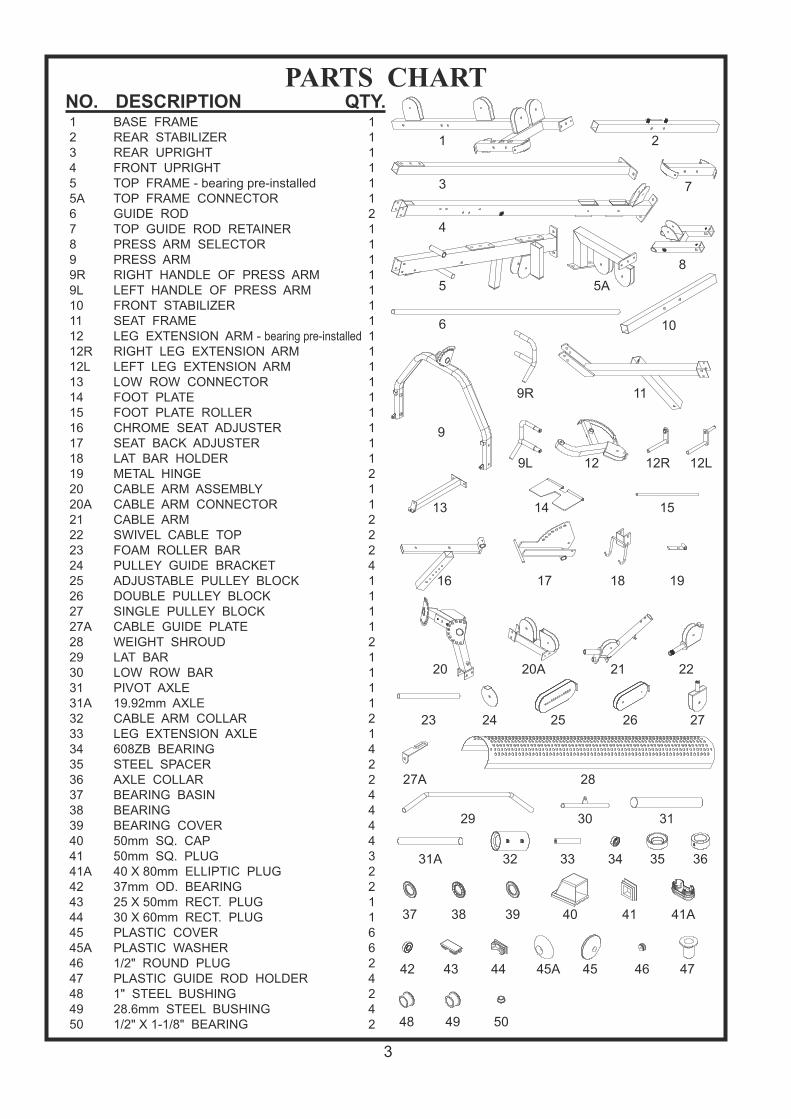
PARTS CHARTNO. DESCRIPTION QTY.123455A67899R9L10111212R12L131415161718192020A2122232425262727A2829303131A3233343536373839404141A4243444545A4647484950
111111211111111111111112112224111121111214224444322116624242
BASE FRAMEREAR STABILIZERREAR UPRIGHTFRONT UPRIGHTTOP FRAME - bearing pre-installedTOP FRAME CONNECTORGUIDE RODTOP GUIDE ROD RETAINERPRESS ARM SELECTORPRESS ARMRIGHT HANDLE OF PRESS ARMLEFT HANDLE OF PRESS ARMFRONT STABILIZERSEAT FRAMELEG EXTENSION ARM - bearing pre-installedRIGHT LEG EXTENSION ARMLEFT LEG EXTENSION ARMLOW ROW CONNECTORFOOT PLATEFOOT PLATE ROLLERCHROME SEAT ADJUSTERSEAT BACK ADJUSTERLAT BAR HOLDERMETAL HINGECABLE ARM ASSEMBLYCABLE ARM CONNECTORCABLE ARMSWIVEL CABLE TOPFOAM ROLLER BARPULLEY GUIDE BRACKETADJUSTABLE PULLEY BLOCKDOUBLE PULLEY BLOCKSINGLE PULLEY BLOCKCABLE GUIDE PLATEWEIGHT SHROUDLAT BARLOW ROW BARPIVOT AXLE19.92mm AXLECABLE ARM COLLARLEG EXTENSION AXLE608ZB BEARINGSTEEL SPACERAXLE COLLARBEARING BASINBEARINGBEARING COVER50mm SQ. CAP50mm SQ. PLUG40 X 80mm ELLIPTIC PLUG37mm OD. BEARING25 X 50mm RECT. PLUG30 X 60mm RECT. PLUGPLASTIC COVERPLASTIC WASHER1/2" ROUND PLUGPLASTIC GUIDE ROD HOLDER1" STEEL BUSHING28.6mm STEEL BUSHING1/2" X 1-1/8" BEARING
3
1 2
3
4
11
16 17 18
20 20A 21 22
19
12 12R 12L
13 14 15
28
24 2523 26 27
27A
31
31A 32
29 30
33 34 35 36
37 38 39
48 49
42
50
40 41 41A
43 44 45A 45 46 47
5 5A
6
7
8
9
9R
9L
10

PARTS CHARTNO. DESCRIPTION QTY.5152535455565758596061626364656667686970717273747575A7677787980818282A83848585A8687888990919293949596979899100
2211122222
31222121
191461216611111112424211
1344
21244823454
RED POP PINCLUTCH LEVER OF CABLE ARMSPRING KNOBMAGMETIC SELECTOR PINL PIN3/4" BUSHING1" X 200mm HAND GRIP1" X 140mm HAND GRIP1" X 70mm PRESS ARM STOPPERGRIP OF LAT BAR HOLDER (95mm)BIG PULLEYSMALL PULLEY OF SWIVEL ARMRUBBER DONUTADJUSTABLE STOPPER1/2" STOPPERBACK BRACKET STOPPERTOP PLATE10 LB. PLATESELECTOR RODNON SLIPSNAP HOOKLOW ROW CHAINHAND GRIP OF CABLE ARMNEW AB CRUNCHFOAM PAD WITH VINYL COVERCOVER OF FOAM PADBACK PADSEAT PADAB CRUNCH CABLECABLE ARM CONNECTING CABLETOP CABLECABLE ARM CABLEHEAD OF CABLE ARM CABLECLUTCH CABLEBINDING OF WEIGHT SHROUD1/2" X 4" HEX HEAD BOLT1/2" X 3" HEX HEAD BOLT1/2" X 1-1/4" HEX HEAD BOLT3/8" X 5-3/4" HEX HEAD BOLT3/8" X 4-1/2" HEX HEAD BOLT3/8" X 3" HEX HEAD BOLT3/8" X 2-3/4" HEX HEAD BOLT3/8" X 2-1/2" HEX HEAD BOLT3/8" X 1-3/4" HEX HEAD BOLT3/8" X 1-3/4" HEX HEAD BOLT (ALL)3/8" X 1" HEX HEAD BOLT (ALL)3/8" X 1/2" ROUND BOLT5/16" X 1/2" HEX HEAD BOLT (ALL)5/16" X 1-1/2" HEX BOLT5/16" X 5/8" INNER HEX SCREW3/8" X 5/8" SET SCREW5/16" X 1/4" SET SCREW1/2" WASHER
4
0 1/4(inch)
1" 2" 3"1/2 3/4 1/2 1/2 1/2 4" 1/2 5" 1/2 6"
7879
8282A 83
86
80
76
74
77
6967 68
75 75A
81
87
85 85A84
72 737170
63 64 65 666261
90 918988
94 959392
100
96 97
98 99
56 57 58 59 60
51 52 53 54 55
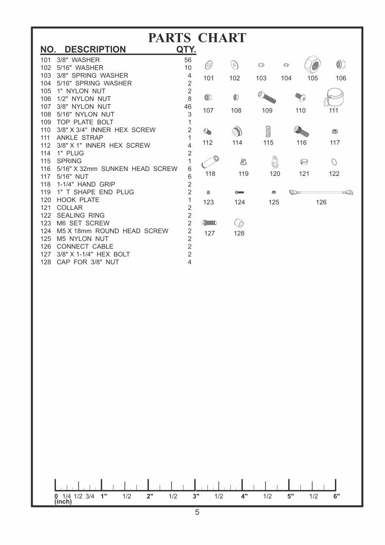
PARTS CHARTNO. DESCRIPTION QTY.101 3/8" WASHER102 5/16" WASHER103 3/8" SPRING WASHER104 5/16" SPRING WASHER105 1" NYLON NUT106 1/2" NYLON NUT107 3/8" NYLON NUT108 5/16" NYLON NUT109 TOP PLATE BOLT110 3/8" X 3/4" INNER HEX SCREW111112114115116117118119120121122123124125126127128
5610
4228
4631214216622122222224
ANKLE STRAP3/8" X 1" INNER HEX SCREW1" PLUGSPRING5/16" X 32mm SUNKEN HEAD SCREW5/16" NUT1-1/4" HAND GRIP1" T SHAPE END PLUGHOOK PLATECOLLARSEALING RINGM6 SET SCREWM5 X 18mm ROUND HEAD SCREWM5 NYLON NUTCONNECT CABLE3/8" X 1-1/4" HEX BOLTCAP FOR 3/8" NUT
5
0 1/4(inch)
1" 2" 3"1/2 3/4 1/2 1/2 1/2 4" 1/2 5" 1/2 6"
105 106
107 108 109
116 117
118 119 120 121 122
123 124 125
114 115
101 102 103 104
110
112
126
128127
111

1
4
5
3
7
2
4615
46
85
85 10
40
40
88
88
40
40
54
8888
69
47
84 8441
5A
85
8543
8989
67
68
63
6
6
47
13
14
98
106106
100100
101
106 106
101
100107
85A
106
107
107
107101
101
109
101
101101
101
101
106
106
ST E P 1 ASSE M BL E M AI N FR AM E
6
To ease the assembly process, do not tighten bolts until instructed.1. Attach Rear Stabilizer(2) to Base Frame(1) using two 3/8"X3" Bolts(88), four 3/8" Washers(101) and
two 3/8" Nuts(107). Attach Front Stabilizer(10) and Low Row Connector(13) to Base Frame(1) usingtwo 1/2"X3" Bolts(85) and two 1/2" Nuts(106). Cap Rear Stabilizer(2) and Front Stabilizer(10) with four50mm SQ. Caps(40).
2. Attach the Foot Plate(14) to Low Row Connector(13) by aligning the holes and inserting Foot PlateRoller(15). Insert two 1/2" Round Plugs(46) into the Foot Plate Roller(15).
3. Attach Rear Upright(3) to Rear Stabilizer(2) using two 1/2" Washers(100) and two 1/2" Nuts(106).4. Attach Front Upright(4) to Base Frame(1) using two 3/8"X3" Bolts(88), four 3/8" Washers(101) and
two 3/8" Nuts (107).5. Attach Top Frame(5) to Front Upright(4) using two 1/2"X4" Bolts(84) and two 1/2" Nuts(106). Attach
Top Frame(5) to Rear Upright(3) using two 1/2"X3" Bolts(85) and two 1/2" Nuts(106).6. Insert four Plastic Guide Rod Holders(47) into Base Frame(1) and Top Guide Rod Retainer(7) as
shown. Slide a Rubber Donut(63) onto one end of each Guide Rod(6) and then insert the GuideRods(6) into the Plastic Guide Rod Holders(47) in Base Frame(1) as shown.
7. Slide each 10 Lb. Plate(68) over Guide Rods(6). Make certain that each plate is oriented withselector hole on bottom and facing forward. Attach Top Plate(67) to Selector Rod(69) using TopPlate Bolt(109). Slide Top Plate(67) and Selector Rod(69) onto Guide Rods(6).
8. Attach the Top Frame Connector(5A) to the Top Frame(5) using two 1/2"X1-1/4" Bolts(85A) and two1/2" Washers(100). Slide the Top Guide Rod Retainer(7) over top of the Guide Rods(6) and thenattach the Top Guide Rod Retainer(7) to the Top Frame Connector(5A) using two 3/8"X2-3/4"Bolts(89), four 3/8" Washers(101), and two 3/8" Nuts(107). Attach a 50mm SQ. Plug(41) to the topof the Rear Upright(3), and a 25X50mm RECT. Plug(43) to the rear of the Top Frame(5).
31
98
98
88
98
18
9
5
8
4
1
4141
3535
36
99
88
93
88
3699
20
21
21
81
101101
107
41A
41A
107
20A
101
101
107
31A
101
101
10193
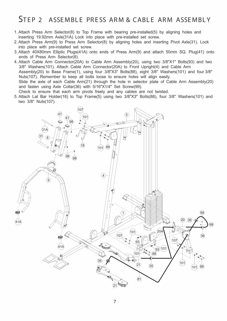
ST E P 2 ASSE MBL E PR E SS AR M & CABL E AR M ASSE MBL Y
7
1. Attach Press Arm Selector(8) to Top Frame with bearing pre-installed(5) by aligning holes andinserting 19.92mm Axle(31A). Lock into place with pre-installed set screw.
2. Attach Press Arm(9) to Press Arm Selector(8) by aligning holes and inserting Pivot Axle(31). Lockinto place with pre-installed set screw.
3. Attach 40X80mm Elliptic Plugs(41A) onto ends of Press Arm(9) and attach 50mm SQ. Plug(41) ontoends of Press Arm Selector(8).
4. Attach Cable Arm Connector(20A) to Cable Arm Assembly(20), using two 3/8"X1" Bolts(93) and two3/8" Washers(101). Attach Cable Arm Connector(20A) to Front Upright(4) and Cable ArmAssembly(20) to Base Frame(1), using four 3/8"X3" Bolts(88), eight 3/8" Washers(101) and four 3/8"Nuts(107). Remember to keep all bolts loose to ensure holes will align easily.Slide the axle of each Cable Arm(21) through the hole in selector plate of Cable Arm Assembly(20)and fasten using Axle Collar(36) with 5/16"X1/4" Set Screw(99).Check to ensure that each arm pivots freely and any cables are not twisted.
5. Attach Lat Bar Holder(18) to Top Frame(5) using two 3/8"X3" Bolts(88), four 3/8" Washers(101) andtwo 3/8" Nuts(107).

28
87
45
97
23
4
9716
88
99
99
55 10288
44
17
93
932375
66
45
12
11
33
92
99
28
1
7
95
95101
101
101
104
102
66
104101
107
115
107
101101
116
101
101
113
107
12L45A
75A
45A75A
45A
45A
75A
45A75A
45A
12R
116 102
102
95
95102
102
77
76
75
19
45
45
110
45116
45116
110
116
116
ST E P 3 ASSE MBL E SE AT FR AME AND SE AT BACK
8
1. Attach Seat Frame(11) to Front Upright(4) using two 3/8"X3" Bolts(88), four 3/8" Washers(101) and two3/8" Nuts(107). Attach Seat Frame(11) to Base Frame(1) using 3/8"X4-1/2" Bolt(87), two 3/8"Washers(101) and one 3/8" Nut(107).
2. Attach Leg Extension Arm with bearing pre-installed(12) to Seat Frame(11) by aligning holes and theninserting Leg Extension Axle(33). Fasten Leg Extension Axle(33) using two 5/16" Spring Washers(104),two 5/16" Washers(102) and two 5/16"X5/8" Set Screws(97). Check to ensure that Leg ExtensionArm(12) pivots freely. Attach the Right and Left Leg Extension Arms(12R & 12L) to the Leg ExtensionArm(12) by 5/16"X1/2" Set Screw(113). Moisten the center of two Cover of Foam Pads(75A) and slideonto each end of the Right and Left Leg Extension Arms(12R & 12L). Attach Plastic Washer (45A) atboth side of Cover of Foam Pad(75A) and secure the pads with 5/16"x32mm Sunken Head Screw(116).Note: The L Pin(55) is used to lock the Leg Extension Arm(12) into place when using the low cable for exercises such as arm curls, leg kicks, upright rows, etc. Remove the L Pin(55) when performing leg extensions and leg curls.
3. Insert Foam Roller Bar(23) into hole in Chromed Seat Adjuster(16). Moisten Foam Pad(75) with waterand slide onto each end of Foam Rollers Bar(23). Attach Plastic Washer(45A) to both side of Cover ofFoam Pad(75A) and secure the Pads with 5/16"X32mm Sunken Head Screw(116).
4. Attach Seat Pad(77) to Chromed Seat Adjuster(16) using two 3/8" Washers(101) and two 3/8"X1-3/4"Bolts(92). Attach 25X50mm Plug(44) to Chromed Seat Adjuster(16) and 50mm SQ. Plug(41) to SeatFrame(11). Insert Chromed Seat Adjuster(16) into Seat Frame(11) and lock into place with Pop Pin(53)with Spring(115).
5. Attach Seat Back Adjuster(17) to Front Upright(4) using one 3/8"X3" Bolt(88), two 3/8" Washers(101)and 3/8" Nut(107). It may be necessary to tighten this bolt, then lossen just enough to let Seat BackAdjuster(17) pivot freely. Attach Pop Pin(53) for Seat Back Adjuster(17) to Front Upright(4). Attach twoMetal Hinges(19) to top of Seat Back Adjuster(17), then attach Back Pad(76) to Metal Hinges(19) usingtwo 3/8"X1-3/4" Bolts(93) and two 3/8" Washers(101). Insert Foam Roller Bar(23) into hole in SeatBack Adjuster(17). Moisten two Foam Pads(75) with water and slide onto each end of Foam Roller(23),then attach Plastic Washer(45A) at both side of Cover of Foam Pads(75A) and secure pads with5/16"x32mm Sunken Head Screw(116). Lock into place with pre-installed Set Screw.
6. Attach Weight Shroud(28) to Base Frame(1) and Top Guide Rod Retainer(7) using four 5/16"X1/2"Bolts(95) and four 5/16" Washers(102).
Tighten all the bolts and nuts gradually.

FIG 10
FIG 1
FIG 6FIG 7 FIG 8
FIG 3FIG 5FIG 2
FIG 4
FIG 9
FIG 980
69
FIG 10
8071
29
FIG 1
61
101
101
107
90
80
5
FIG 2
80
61
101
101
107
90
5 FIG 2
FIG 3
STP 1
4
58
FIG 3
STP 2
FIG 6
80
6161
89
1075
FIG 4
61
101
101
90
107
4
80
T OP CABL E
9
Assemble cables and pulleys simultaneously. Insert threaded end of Top Cable(80) into the slot in front of Top Frame(5)(Fig 1) and route over top oftwo pulleys mounted in Top Frame(5)(Fig 1, 2), over left side (as if sitting on seat) pulley in Press Arm Selector(8)(Fig 3, Step 1), under pulley mounted in Front Upright(4), over right side pulley in Press Arm Selector(8)(Fig 3, Step 2), then over pulley mounted in Front Upright(4)(Fig 3, Fig 4), down to topDouble Pulley Block(26)(Fig 5), up and over left side pulley on Top Frame(5)(Fig 6), down and aroundtop pulley in Adjustable Pulley Block(25)(Fig 7), up and over two Top Frame(5)(Fig 8)pulleys leading toweight stack. Screw cable end into Selector Rod(69)(Fig 9). Attach Lat Bar 29 as shown in Fig 10.
FIG 7
80
61
25
91
107
FIG 5
107
61 64
5
80
26
91
FIG 8
61 91
107
5
80

Route the AB Crunch Cable(78) through slot and over pulley on Front Upright(4)(Fig 1), down to thefront pulley on top of Cable Arm Assembly(20)(Fig 2), then up to lower pulley on Double PulleyBlock(26)(Fig 3), down through the rear pulley on Cable Arm Assembly(20)(Fig 4) to pulley on BaseFrame(1)(Fig 2), then forward toward Leg Extension Arm(12). Route AB Crunch Cable(78) underboth pulleys on Base Frame(1) and under pulley on Leg Extension Arm(12).
61
9178
12
107
FIG 7
30
71
72
71
78FIG 8
FIG 3
FIG 9
FIG 1
FIG 6FIG 7
FIG 8
FIG 5
FIG 2
FIG 4
61
91 1
78
10761
91
FIG 5,6
FIG 5
FIG 6
74
7871
FIG 9
61
7891
107
20A
FIG 4
AB CR UNCH CABL E
10
61
91
107 20A
FIG 2
61
78
26
91
107
FIG 3
64
5
61
89
78
107101
101
FIG 1
4

Attach pulley on Base Frame(1) near weight stack as shown Fig 1 with ball end of cable towardweight stack. Route cable up to low pulley of Adjustable Pulley Block(25)(Fig 2), then down topulley on Base Frame(1)(Fig 3), up to right side pulley in Top Frame(5)(Fig 4) and thread intothe Single Pulley Block(27)(Fig 5).
79
61
25
91
107
FIG 2
5
79
61
61
89
107
FIG 4
27
79FIG 5
FIG 4
FIG 2
FIG 5
FIG 3
FIG 1
CABL E AR M CONNE CT I NG CABL E
11
6179
91 1
107
FIG 1
79
1
61
91
107
FIG 3

Attach pulley and Pulley Guide Bracket(24) to Cable Arm Assembly(20) as shown in Fig 3 andFig 4, Be certain that, when tightened, the Pulley Guide Brackets(24) do not interfere with thecable movement. Route Cable Arm Cable(81) around these pulleys as shown and around pulley in the Single PulleyBlock(27)(Fig 5).
CABL E AR M CABL E
12
24
24
86
61
61 107
101
101
FIG 4,6
27
79 79
81
6191
107
27A
FIG 5
81 71 73
FIG 10
FIG 5
FIG 9
FIG 10
FIG 10FIG 2
FIG 8
FIG 3
FIG 1
FIG 4
FIG 6
FIG 7
FIG 1,9 61
32
91
81
107
36
20 35 2181
6199
91
107
FIG 2,8
61
20
91
24
107107FIG 3,7
24 61

a. The Cables should be tightened to the point just before the Top Plate lifts off the stack. Inother words, if the Top Plate is not resting on the stack, you will need to add length, or, if thereis slack in the cables, you will need to shorten the cables. There are several adjustmentpoints. If only minor adjustments need to be made, you can adjust the Screw ends on the TopCable (at the Top Plate), the Low Cable (where it screws into the Pulley Block), or the BenchPress Cable (where it screws into the Pulley Block with Stopper). These ends of thesecables must be screwed in at least 1/3 of their length for safety purposes. Once you aredone with these adjustments, lock them into place using the jam nuts.
b. Broader adjustments are made at the Floating Pulley Block (25). Moving the bottom pulleytoward the center decreases length (takes up slack). Conversely, moving the bottom pulleyoutward gains cable length.
c. Once the cables have been adjusted to remove all slack, adjust the Adjustable Stoppers in theTop Frame to where they just touch the Floating Pulley Block (25), and the Pulley Block (26).The Adjustable Stoppers welded on top frame aid in the function of the gym by eliminating theneed to engage all cables in any given exercise routine.
Step 12 The Cable Adjustment of X Press Pro
2625
13

14
Assembly is complete! Please take the following steps before using the gym:
Thank you for purchasing the Bodycraft X Press Home Gym. If You have any questions, please call your local BodyCraft dealer or call our customer service department at 800-990-5556
1.2.
3. 4. 5. 6. 7.
Make certain all bolts are tightened securely. Make certain all cables are seated into all pulley grooves. A cable rubbingagainst steel will peel the nylon coating, voiding warranty and resulting in aneed for replacement.Pre-stretch the cables. Put the Weight Selector Pin (54) in the bottom hole onthe weight stack. Pull on the cables with great force, helping remove anykinks and providing any initial cable stretch.Be aware the cables can loosen and slightly stretch upon initial use.The cables should be adjusted as tight as possible, but no so tight as to liftthe Top Plate (67) above the weight stack. Be certain to secure the jam nutsafter adjustments are made.For better performance, apply a household lubricant (such as silicone) to any adjustable areas and to the Guide Rods (6).Enjoy many years of a Fit Lifestyle.
Related Documents