Microwave Measurements Waveguide Dept. of Electrical, Computer and Biomedical Engineering, University of Pavia e-mail: [email protected] web: microwave.unipv.it 1 Microwave Measurements, L. Silvestri

Welcome message from author
This document is posted to help you gain knowledge. Please leave a comment to let me know what you think about it! Share it to your friends and learn new things together.
Transcript
Microwave MeasurementsWaveguide
Dept. of Electrical, Computer and Biomedical Engineering,University of Pavia
e-mail: [email protected]: microwave.unipv.it
1Microwave Measurements, L. Silvestri
2Microwave Measurements, L. Silvestri
Outline• Common types of waveguides
• Standards for rectangular waveguides
• Attenuation
• Flanges
• Waveguide/coaxial cable transitions
3Microwave Measurements, L. Silvestri
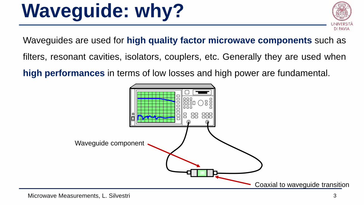
Waveguide: why?Waveguides are used for high quality factor microwave components such as
filters, resonant cavities, isolators, couplers, etc. Generally they are used when
high performances in terms of low losses and high power are fundamental.
Coaxial to waveguide transition
Waveguide component
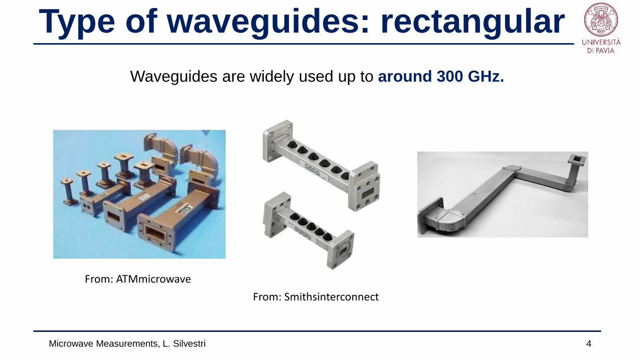
Type of waveguides: rectangularWaveguides are widely used up to around 300 GHz.
Microwave Measurements, L. Silvestri 4
From: ATMmicrowaveFrom: Smithsinterconnect
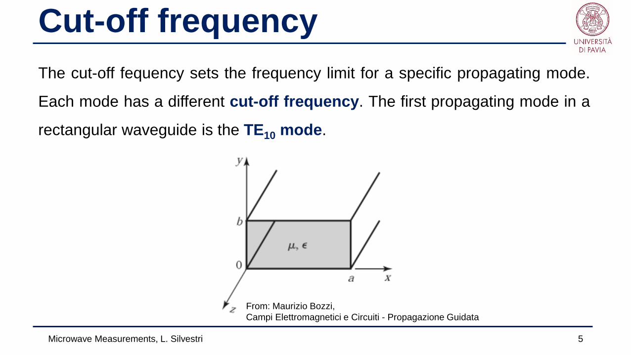
Cut-off frequencyThe cut-off fequency sets the frequency limit for a specific propagating mode.
Each mode has a different cut-off frequency. The first propagating mode in a
rectangular waveguide is the TE10 mode.
Microwave Measurements, L. Silvestri 5
From: Maurizio Bozzi, Campi Elettromagnetici e Circuiti - Propagazione Guidata
Cut-off frequency
Microwave Measurements, L. Silvestri 6
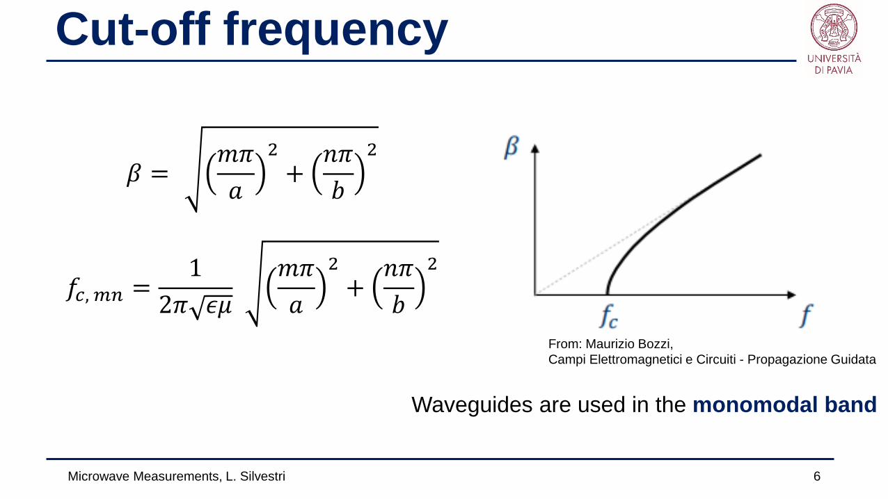
𝛽𝛽 =𝑚𝑚𝜋𝜋𝑎𝑎
2+
𝑛𝑛𝜋𝜋𝑏𝑏
2
𝑓𝑓𝑐𝑐, 𝑚𝑚𝑚𝑚 =1
2𝜋𝜋 𝜖𝜖𝜖𝜖𝑚𝑚𝜋𝜋𝑎𝑎
2+
𝑛𝑛𝜋𝜋𝑏𝑏
2
From: Maurizio Bozzi, Campi Elettromagnetici e Circuiti - Propagazione Guidata
Waveguides are used in the monomodal band
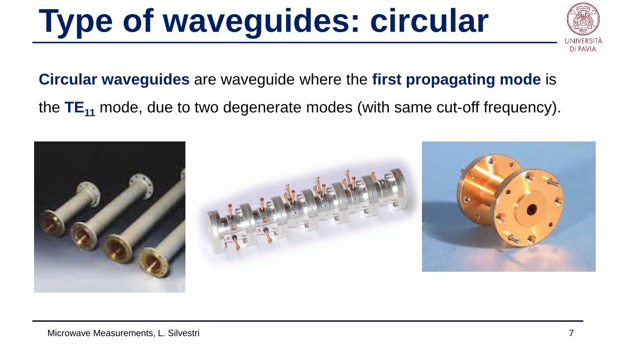
Type of waveguides: circularCircular waveguides are waveguide where the first propagating mode is
the TE11 mode, due to two degenerate modes (with same cut-off frequency).
Microwave Measurements, L. Silvestri 7
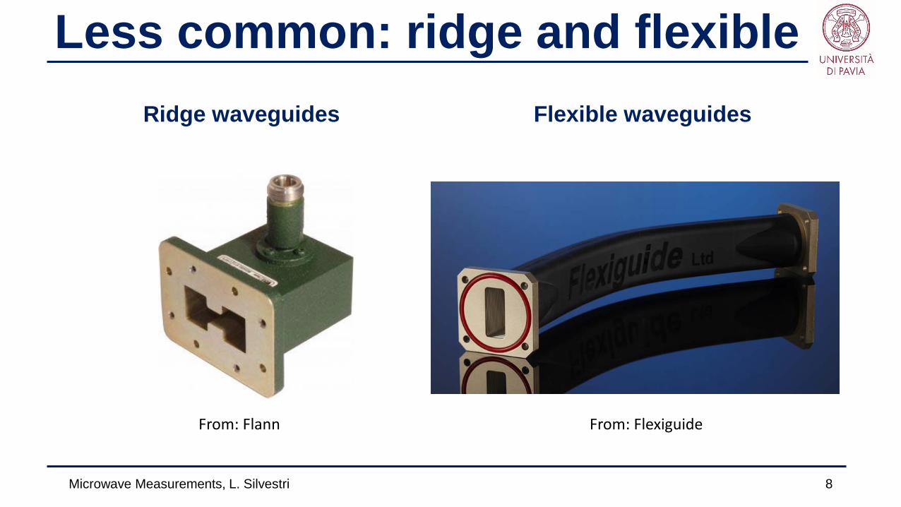
Less common: ridge and flexibleRidge waveguides
Microwave Measurements, L. Silvestri 8
Flexible waveguides
From: Flann From: Flexiguide

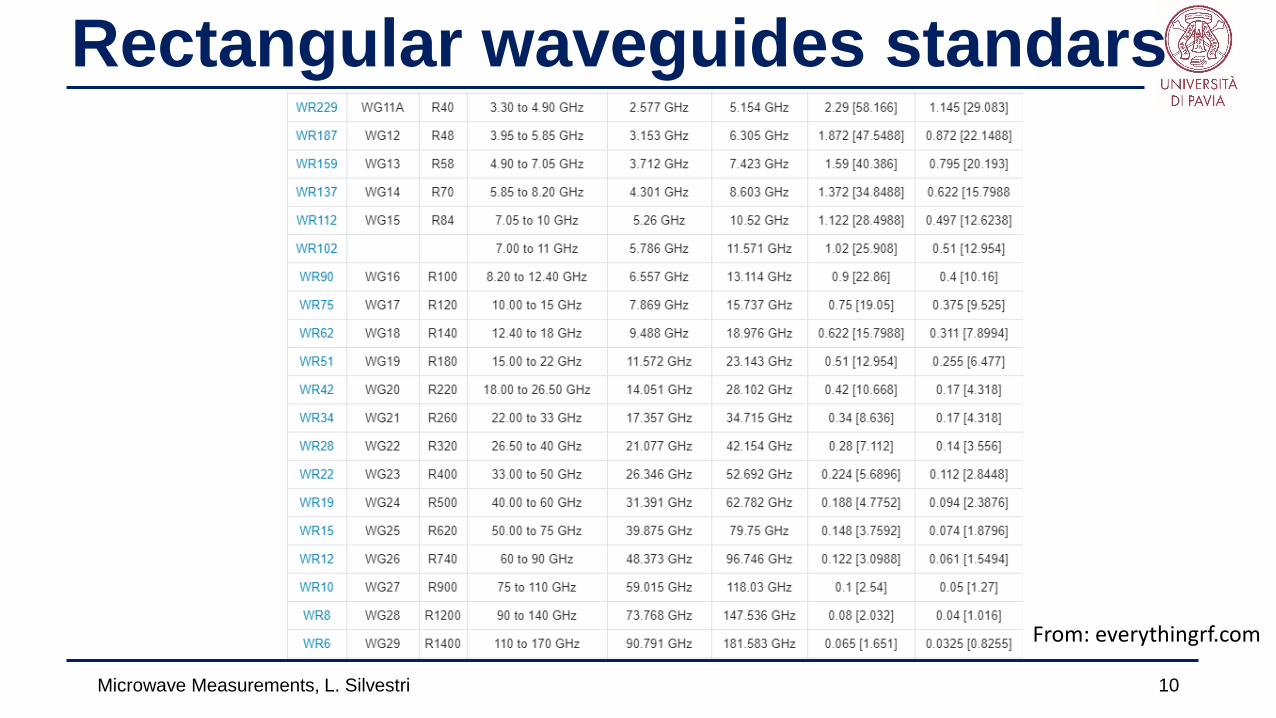
Rectangular waveguides standars
Microwave Measurements, L. Silvestri 9
From: everythingrf.com
EIA:US standard,The name is related to the a dimensions in inches.
RCSC:Uk standardIt uses increasingnumbers as the cut-off frequency increases.
IEC:International ElectrotechnicalCommission.Not very common.
Microwave Measurements, L. Silvestri 10
From: everythingrf.com
Rectangular waveguides standars
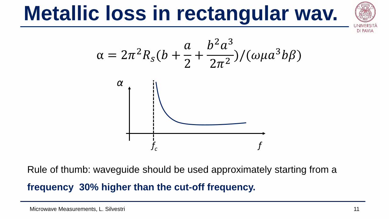
Metallic loss in rectangular wav.
Microwave Measurements, L. Silvestri 11
α = 2𝜋𝜋2𝑅𝑅𝑠𝑠(𝑏𝑏 +𝑎𝑎2
+𝑏𝑏2𝑎𝑎3
2𝜋𝜋2)/(𝜔𝜔𝜖𝜖𝑎𝑎3𝑏𝑏𝛽𝛽)
f
α
fc
Rule of thumb: waveguide should be used approximately starting from a
frequency 30% higher than the cut-off frequency.
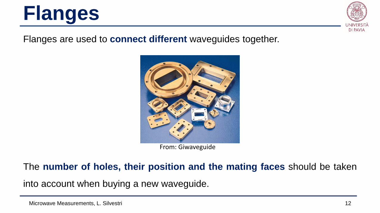
FlangesFlanges are used to connect different waveguides together.
The number of holes, their position and the mating faces should be taken
into account when buying a new waveguide.
Microwave Measurements, L. Silvestri 12
From: Giwaveguide

Flange terminology
Microwave Measurements, L. Silvestri 13
Considering the mating faces different flanges can be choosen:
Plain face:The simplest of all, it can be mated with the o-ring or the choke.
O-ring:There is a groove in the face where an O-ring is placed. Not to be used withanother O-ring.
Choke:Two grooves with the outermost dedicated to the housing of the O-ring andthe innermost for a choke.
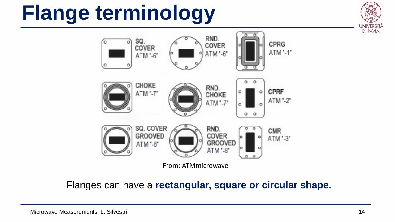
Flange terminology
Microwave Measurements, L. Silvestri 14
From: ATMmicrowave
Flanges can have a rectangular, square or circular shape.
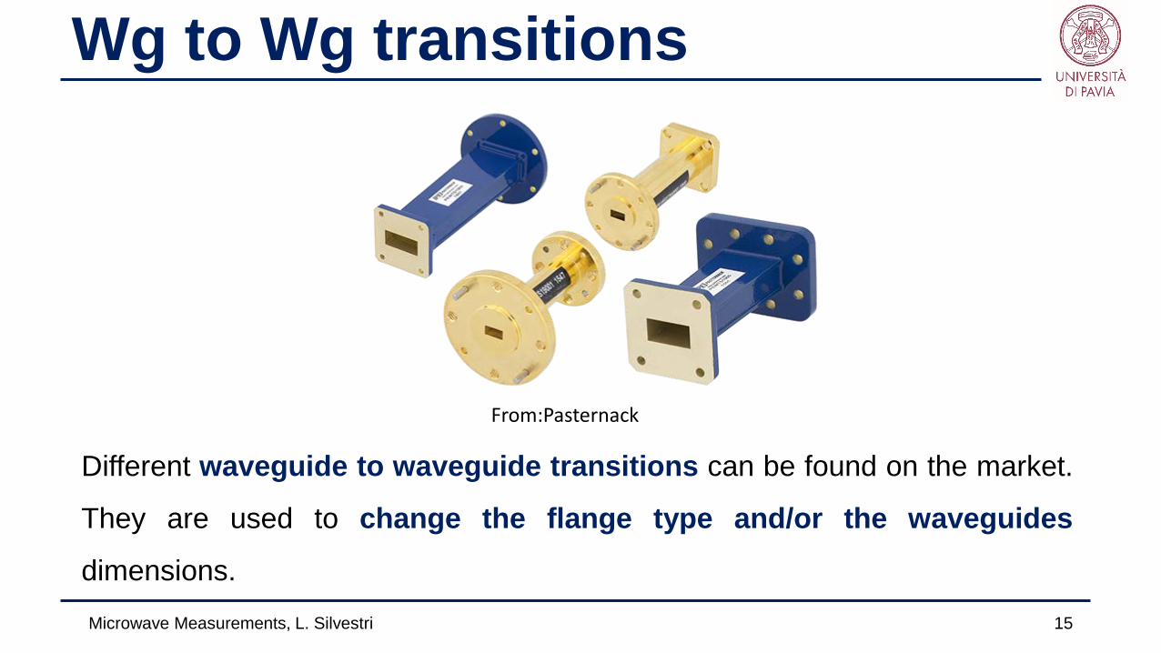
Wg to Wg transitions
Microwave Measurements, L. Silvestri 15
From:Pasternack
Different waveguide to waveguide transitions can be found on the market.
They are used to change the flange type and/or the waveguides
dimensions.

Wg to Wg transitions: example
Microwave Measurements, L. Silvestri 16
From:Pasternack

Wg to coaxial cable transitions
Microwave Measurements, L. Silvestri 17
From: Quinstar
Different connectors can be installed, in relation with the operational
frequency and the environment they will be used in.
Alignment pin

Wg to coax transition: E-plane
Microwave Measurements, L. Silvestri 18
Side
TE10
D
Front
Front

Wg to coax transition: H-plane
Microwave Measurements, L. Silvestri 19
Side
D≈λ/4
Front
Front
D
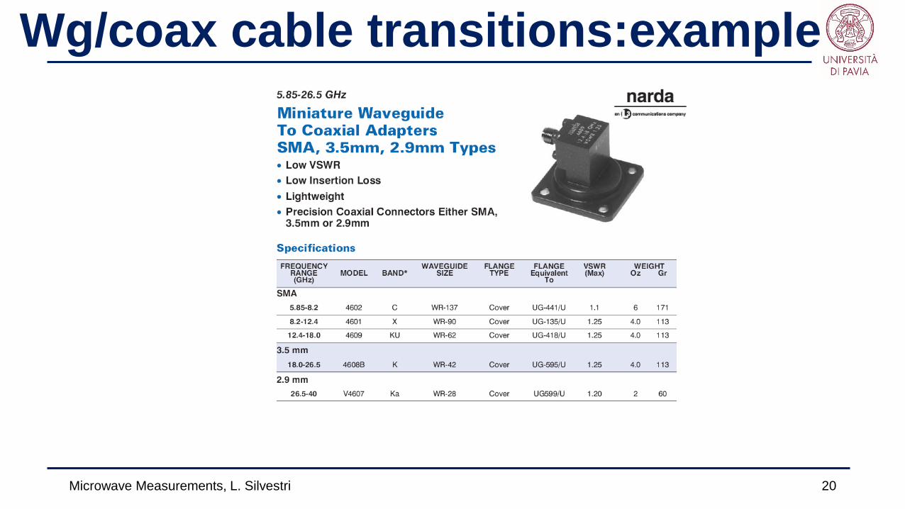
Wg/coax cable transitions:example
Microwave Measurements, L. Silvestri 20
Related Documents