22 Presentation of the range The RXM miniature relay range comprises: 1 12 A relays with 2 C/O contacts, 10 A relays with 3 C/O contacts, 6 A relays with 4 C/O contacts and 3 A “low level” relays with 4 C/O contacts. All these relays have the same dimensions. 2 Sockets with mixed or separate contact terminals. 3 Protection modules (diode, RC circuit or varistor). All these modules are common to all sockets. 4 A metal maintaining clamp for all sockets. 5 A plastic maintaining clamp for all sockets. 6 A 2-pole bus jumper that can be used on sockets with separate contact terminals in order to simplify cabling when creating an equipotential link between the coil terminals. 7 Clip-in legends for all the sockets except RXZ E2M114. Relay description 1 Spring return pushbutton for testing the contacts (green: c, red: a). 2 Mechanical “relay status” indicator. 3 Removable lock-down door enabling forced maintaining of the contacts for test sequences or maintenance purposes. During operation, this lock-down door must always be in the closed position. 4 LED (depending on version) indicating the relay status. 5 Removable legend for relay identification. 6 Four notches for rail mounting adapter or panel mounting adapter with fixing lugs. 7 Eight, eleven or fourteen Faston type pins. 8 Area by which the product can be easily gripped. 9 Mounting adapter enabling direct mounting of the relay on a panel. 10 Mounting adapter enabling direct mounting of the relay on a 5 rail. Socket description Sockets with mixed contact terminals (1) 1 Connection by screw clamp terminals or screw connector. 2 Fourteen female contacts for the relay pins. 3 Location for protection modules. 4 Locking components for plastic and metal maintaining clamps. 5 Locating slot for mounting on 5 rail with its compression spring or fixing clip. 6 Two or four fixing holes for panel mounting. Sockets with separate contact terminals (2) 1 Connection by screw connector. 2 Eight, eleven or fourteen female contacts for the relay pins. 3 Location for protection modules. 4 Locking components for plastic and metal maintaining clamps. 5 Locating slot for mounting on 5 rail with its compression spring or fixing clip. 6 Two fixing holes for panel mounting. 7 Location for bus jumpers (see mounting on sockets on page 2). (1) The inputs are mixed with the relay's supply, with the outputs being located on the opposite side of the socket. (2) The inputs and outputs are separated from the relay supply. 524766 7 6 2 1 5 3 4 or 524766 7 6 2 1 5 3 4 or 106557 1 2 7 3 4 5 6 8 106557 1 2 7 3 4 5 6 8 106660 9 106660 9 106661 9 106661 9 106662 10 106662 10 106014 1 2 3 4 5 Outputs Inputs Relay supply 5 6 106014 1 2 3 4 5 Outputs Inputs Relay supply 5 6 106015 1 6 2 3 4 5 7 Outputs Inputs Relay supply 5 106015 1 6 2 3 4 5 7 Outputs Inputs Relay supply 5 Zelio Relay - plug-in relays RXM miniature relays Presentation Presentation : page 22 Characteristics : pages 23 and 24 References : pages 25 and 26 Dimensions : pages 27 and 2 Schemes : page 29 Presentation : page 22 Characteristics : pages 23 and 24 References : pages 25 and 26 Dimensions : pages 27 and 2 Schemes : page 29 1 2 3 4 5 6 7 8 9 10

Welcome message from author
This document is posted to help you gain knowledge. Please leave a comment to let me know what you think about it! Share it to your friends and learn new things together.
Transcript
22
Presentation of the range The RXM miniature relay range comprises: 1 12 A relays with 2 C/O contacts, 10 A relays with 3 C/O contacts, 6 A relays with
4 C/O contacts and 3 A “low level” relays with 4 C/O contacts. All these relays have the same dimensions.
2 Sockets with mixed or separate contact terminals.3 Protection modules (diode, RC circuit or varistor). All these modules are common
to all sockets.4 A metal maintaining clamp for all sockets.5 A plastic maintaining clamp for all sockets.6 A 2-pole bus jumper that can be used on sockets with separate contact terminals
in order to simplify cabling when creating an equipotential link between the coil terminals.
7 Clip-in legends for all the sockets except RXZ E2M114.
Relay description 1 Spring return pushbutton for testing the contacts (green: c, red: a). 2 Mechanical “relay status” indicator.3 Removable lock-down door enabling forced maintaining of the contacts for test
sequences or maintenance purposes. During operation, this lock-down door must always be in the closed position.
4 LED (depending on version) indicating the relay status.5 Removable legend for relay identification.6 Four notches for rail mounting adapter or panel mounting adapter with fixing lugs.7 Eight, eleven or fourteen Faston type pins.8 Area by which the product can be easily gripped.9 Mounting adapter enabling direct mounting of the relay on a panel.10 Mounting adapter enabling direct mounting of the relay on a 5 rail.
Socket description Sockets with mixed contact terminals (1)
1 Connection by screw clamp terminals or screw connector.2 Fourteen female contacts for the relay pins.3 Location for protection modules.4 Locking components for plastic and metal maintaining clamps.5 Locating slot for mounting on 5 rail with its compression spring or fixing clip.6 Two or four fixing holes for panel mounting.
Sockets with separate contact terminals (2)1 Connection by screw connector. 2 Eight, eleven or fourteen female contacts for the relay pins.3 Location for protection modules.4 Locking components for plastic and metal maintaining clamps.5 Locating slot for mounting on 5 rail with its compression spring or fixing clip.6 Two fixing holes for panel mounting.7 Location for bus jumpers (see mounting on sockets on page 2�).
(1) The inputs are mixed with the relay's supply, with the outputs being located on the opposite side of the socket.
(2) The inputs and outputs are separated from the relay supply.
5247
66 7
6
2
1
5
3
4or
5247
66 7
6
2
1
5
3
4or
1065
57 12
7
3
4
56
8
1065
57 12
7
3
4
56
8
1066
60 9
1066
60 9
1066
61 9
1066
61 9
1066
62 10
1066
62 10
1060
14 1
2
3
4
5
Outputs
Inputs
Relay supply5
6
1060
14 1
2
3
4
5
Outputs
Inputs
Relay supply5
6
1060
15 16
2
3
4
5 7
Outputs
Inputs
Relay supply5
1060
15 16
2
3
4
5 7
Outputs
Inputs
Relay supply5
Zelio Relay - plug-in relaysRXM miniature relays
Presentation
Presentation :page 22
Characteristics :pages 23 and 24
References :pages 25 and 26
Dimensions :pages 27 and 2�
Schemes :page 29
Presentation :page 22
Characteristics :pages 23 and 24
References :pages 25 and 26
Dimensions :pages 27 and 2�
Schemes :page 29
1
2
3
4
5
6
7
8
9
10

23
General characteristicsConforming to standards IEC/EN 61�10-1 (iss. 2), UL 50�, CSA C22-2 n° 14Product certifications UL, CSAAmbient air temperature around the device
Storage °C - 40… + �5Operation °C - 40… + 55
Vibration resistanceconforming to IEC/EN 6006�-2-6
In operation 3 gn (10...150 Hz/± 1 mm / 5g/5 cycles)Not operating 5 gn (10...150 Hz/± 1 mm / 5g/5 cycles)
Degree of protection Conforming to IEC/EN 60529 IP 40Shock resistanceconforming to IEC/EN 6006�-2-27
Opening 15 gnClosing 15 gn
Protection category RT IMounting position Any
Insulation characteristicsRated insulation voltage (Ui) V 250 (IEC), 300 (UL, CSA)Rated impulse withstand voltage (Uimp) kV 4 (1.2/50 ms)Dielectric strength(rms voltage)
Between coil and contact a V 1550Between poles a V 1550Between contacts a V 1500
Contact characteristicsRelay type RXM 2ABppp RXM 3ABppp RXM 4ABppp RXM 4GBppp
Number and type of contacts 2 C/O 3 C/O 4 C/O 4 C/O low levelContact materials AgNi AgAu - bifurcatedConventional thermal current (Ith)
For ambient temperature y 55 °C
A 12 10 6 3
Rated operational current in utilisation categories AC-1 and DC-1
Conforming to IEC "C" 12 10 6 2“O” 6 5 3 1
Conforming to UL 12 10 6 3Switching current Minimum mA 10 3Switching voltage Maximum V a/c 250 (IEC)
Minimum V 17 5Nominal load (resistive) A 12 / 250 a V 10 / 250 a V 6 / 250 a V 3 / 250 a V
A 12 / 2� c V 10 / 2� c V 6 / 2� c V 3 / 2� c VSwitching capacity Maximum a VA 3000 2500 1500 750
c W 336 2�0 16� �4Minimum mW 170 15
Maximum operating rateIn operating cycles
No-load 1� 000Under load 1200
Utilisation coefficient 20 %Mechanical durability In millions of operating cycles 10
Electrical durabilityIn millions of operating cycles
Resistive load 0.1Inductive load See curves below
Electrical durability of contacts Resistive load a
Reduction coefficient for inductive load a (depending on power factor cos j)
Maximum switching capacity on resistive load c
A RXM 2ABppp B RXM 3ABppp C RXM 4ABppp D RXM 4GBppp
Durability (inductive load) = durability (resistive load) x reduction coefficient.
105
106
107
2 30 1
A BDC
Dur
abili
ty (N
umbe
r of o
pera
ting
cycl
es)
Switching capacity (kVA)
105
106
107
2 30 1
A BDC
Dur
abili
ty (N
umbe
r of o
pera
ting
cycl
es)
Switching capacity (kVA)
0,3
0,5
0,61 0,4 0,2
0,4
0,60,�
1
Red
uctio
n co
effic
ient
(A)
0,3
0,5
0,61 0,4 0,2
0,4
0,60,�
1
Red
uctio
n co
effic
ient
(A)
0,1
1
200 2500 5028 100 150
10
3
6
CDBA
Cur
rent
c
Voltage c
0,1
1
200 2500 5028 100 150
10
3
6
CDBA
Cur
rent
c
Voltage c
Zelio Relay - plug-in relaysRXM miniature relays
Characteristics
1
2
3
4
5
6
7
8
9
10

24
Coil characteristicsAverage consumption a VA 1.2
c W 0.9Drop-out voltage threshold a u 0.15 Uc
c u 0.1 UcOperating time(response time)
Between coil energisation and making of the On-delay contact
a ms 20c ms 20
Between coil de-energisation and making of the Off-delay contact
a ms 20c ms 20
Control circuit voltage Uc V 12 24 48 110 120 125 220 230 240Relay control voltage codes JD BD ED FD – GD MD – –
d.c. supply Average resistance at 20 °C ± 10% W 160 650 2600 11 000 – 11 000 14 000 – –Operating voltage limits Min. V 9.6 19.2 3�.4 �� – 100 176 – –
Max. V 13.2 26.4 52.� 121 – 13� 242 – –Relay control voltage codes – B7 E7 F7 – – P7 U7
a.c. supply Average resistance at 20 °C ± 15% W – 1�0 770 – 4430 – – 15 000 15 500Operating voltage limits Min. V – 19.2 3�.4 – 96 – – 1�4 192
Max. V – 26.4 52.� – 132 – – 253 264
Socket characteristicsSocket type RXZ E2S108M RXZ E2S111M RXZ E2S114M RXZ E2M114M RXZ E2M114Relay types used RXM 2ppppp RXM 3ppppp RXM 4ppppp RXM 2ppppp (1)
RXM 4pppppRXM 2ppppp (1)RXM 4ppppp
Contact terminal arrangement Separate MixedWire connection method Connector Screw clamp
terminalsProduct certifications UL, CSAConforming to standards IEC 619�4, e
Electrical characteristicsConventional thermal current (Ith) A 12 10Maximum operating voltage V 250 (IEC)
Insulation characteristicsBetween adjacent output contacts Vrms 2500Between input and output contacts Vrms 2500Between contacts and 5 rail Vrms 2500
General characteristicsAmbient air temperaturearound the device
Operation °C - 40…+ 55Storage °C - 40…+ �5
Degree of protection Conforming to IEC/EN 60529 IP 20Cabling Solid cable
without cable end
1 conductor 0.5…2.5 mm2 - AWG 20…AWG 14 0.5… 1.5 mm2 AWG 20…AWG 16
2 conductors 0.5…1.5 mm2 - AWG 20…AWG 16Flexible cable with cable end
1 conductor 0.25…2.5 mm2 - AWG 22…AWG 14 0.25…1 mm2
AWG 22…AWG 172 conductors 0.25…1 mm2 - AWG 22…AWG 17
Maximum tightening torque / Screw size Nm 1 / M3 screwMounting On 35 mm 5 rail / on panelFixing on 5 rail By red plastic clip By metal
compression spring
By red plastic clip
Terminal referencing IEC, NEMABus jumper (Ith: 5 A) Yes NoCompatibility with the plastic maintaining clamp YesCompatibility with the metal maintaining clamp YesProtection module All RXM 040W, RXM 041pp, RXM 021pp
Clip-in legends Yes NoWire connection method Screw connector Screw clamp
terminals
(1) When mounting relay RXM 2ppppp on socket RXZ E2Mpppp, the thermal current must not exceed 10 A.
Zelio Relay - plug-in relaysRXM miniature relays
Characteristics (continued)
Presentation :page 22
Characteristics :pages 23 and 24
References :pages 25 and 26
Dimensions :pages 27 and 2�
Schemes :page 29
Presentation :page 22
Characteristics :pages 23 and 24
References :pages 25 and 26
Dimensions :pages 27 and 2�
Schemes :page 29
1
2
3
4
5
6
7
8
9
10

25
Miniature relays without LED (sold in lots of 10) Control circuit voltage
Number and type of contacts - Thermal current (Ith)2 C/O - 12 A 3 C/O - 10 A 4 C/O - 6 AUnit reference
Weight Unit reference
Weight Unit reference
Weight
V kg kg kgc 12 RXM 2AB1JD 0.037 RXM 3AB1JD 0.037 RXM 4AB1JD 0.037c 24 RXM 2AB1BD 0.037 RXM 3AB1BD 0.037 RXM 4AB1BD 0.037c 4� RXM 2AB1ED 0.037 RXM 3AB1ED 0.037 RXM 4AB1ED 0.037c 110 RXM 2AB1FD 0.037 RXM 3AB1FD 0.037 RXM 4AB1FD 0.037c 220 – – – – RXM 4AB1MD 0.037
a 24 RXM 2AB1B7 0.037 RXM 3AB1B7 0.037 RXM 4AB1B7 0.037a 4� RXM 2AB1E7 0.037 RXM 3AB1E7 0.037 RXM 4AB1E7 0.037a 120 RXM 2AB1F7 0.037 RXM 3AB1F7 0.037 RXM 4AB1F7 0.037a 230 RXM 2AB1P7 0.037 RXM 3AB1P7 0.037 RXM 4AB1P7 0.037a 240 – – – – RXM 4AB1U7 0.037
Miniature relays with LED (sold in lots of 10) c 12 RXM 2AB2JD 0.037 RXM 3AB2JD 0.037 RXM 4AB2JD 0.037c 24 RXM 2AB2BD 0.037 RXM 3AB2BD 0.037 RXM 4AB2BD 0.037c 4� RXM 2AB2ED 0.037 RXM 3AB2ED 0.037 RXM 4AB2ED 0.037c 110 RXM 2AB2FD 0.037 RXM 3AB2FD 0.037 RXM 4AB2FD 0.037c 125 – – – – RXM 4AB2GD 0.037
a 24 RXM 2AB2B7 0.037 RXM 3AB2B7 0.037 RXM 4AB2B7 0.037a 4� RXM 2AB2E7 0.037 RXM 3AB2E7 0.037 RXM 4AB2E7 0.037a 120 RXM 2AB2F7 0.037 RXM 3AB2F7 0.037 RXM 4AB2F7 0.037a 230 RXM 2AB2P7 0.037 RXM 3AB2P7 0.037 RXM 4AB2P7 0.037
Miniature relays with low level contacts, without LED (sold in lots of 10) Control circuit voltage
Number and type of contacts Thermal current (Ith)4 C/O - 3 AUnit reference
Weight
V kgc 12 RXM 4GB1JD 0.037c 24 RXM 4GB1BD 0.037c 4� RXM 4GB1ED 0.037c 110 RXM 4GB1FD 0.037
a 24 RXM 4GB1B7 0.037a 4� RXM 4GB1E7 0.037a 120 RXM 4GB1F7 0.037a 230 RXM 4GB1P7 0.037
Miniature relays with low level contacts, with LED (sold in lots of 10) c 12 RXM 4GB2JD 0.037c 24 RXM 4GB2BD 0.037c 4� RXM 4GB2ED 0.037c 110 RXM 4GB2FD 0.037
a 24 RXM 4GB2B7 0.037a 4� RXM 4GB2E7 0.037a 120 RXM 4GB2F7 0.037a 230 RXM 4GB2P7 0.037a 240 RXM 4GB2U7 0.037
RXM pAB1F7
1066
5�
RXM pAB1F7
1066
5�
RXM pAB2F7
1066
57
RXM pAB2F7
1066
57
RXM 4GB1F7
1065
5�
RXM 4GB1F7
1065
5�
RXM 4GB2F7
1066
57
RXM 4GB2F7
1066
57
Zelio Relay - plug-in relaysRXM miniature relays
References
1
2
3
4
5
6
7
8
9
10
26
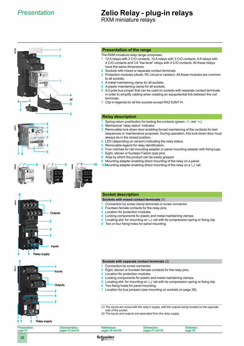
Miniature relays without LED (sold in lots of 100)Control circuit voltage
Number and type of contacts - Thermal current (Ith)2 C/O - 12 A 4 C/O - 6 AUnit reference
Weight Unit reference
Weight
V kg kgc 12 – – RXM 4AB1JDTQ 0.036c 24 RXM 2AB1BDTQ 0.037 RXM 4AB1BDTQ 0.036c 4� – – RXM 4AB1EDTQ 0.036c 110 – – RXM 4AB1FDTQ 0.036c 220 – – RXM 4AB1MDTQ 0.036
a 24 RXM 2AB1B7TQ 0.037 RXM 4AB1B7TQ 0.036a 4� – – RXM 4AB1E7TQ 0.036a 120 RXM 2AB1F7TQ 0.037 RXM 4AB1F7TQ 0.036a 230 RXM 2AB1P7TQ 0.037 RXM 4AB1P7TQ 0.036
Miniature relays with LED (sold in lots of 100)c 24 – – RXM 4AB2BDTQ 0.036a 24 RXM 2AB2B7TQ 0.037 RXM 4AB2B7TQ 0.036a 230 RXM 2AB2P7TQ 0.037 RXM 4AB2P7TQ 0.036
SocketsContact terminal arrangement
Connection Relay type Sold in lots of
Unit reference
Weightkg
Mixed Screw clamp terminals RXM 2pppp (3)RXM 4pppp
10 RXZ E2M114 (1) 0.04�
Screw connector RXM 2pppp (3)RXM 4pppp
10 RXZ E2M114M (1) 0.056
Separate Screw connector RXM 2pppp 10 RXZ E2S108M (2) 0.05�RXM 3pppp 10 RXZ E2S111M (1) 0.066RXM 4pppp 10 RXZ E2S114M (1) 0.070
Protection modulesDescription Voltage For
use withSold in lots of
Unit reference
Weight
V kgDiode c 6...250 All sockets 20 RXM 040W 0.003
RC circuit a 24...60 All sockets 20 RXM 041BN7 0.010a 110...240 All sockets 20 RXM 041FU7 0.010
Varistor a/c 6...24 All sockets 20 RXM 021RB 0.030a/c 24...60 All sockets 20 RXM 021BN 0.030a/c 110...240 All sockets 20 RXM 021FP 0.030
Timing relaysDescription For
use withUnit reference
Weightkg
2 or 4 timed C/O contacts (function A)
Sockets RXZ Eppppp RE XL2pp (4) –RE XL4pp (4) –
AccessoriesDescription For
use withSold in lots of
Unit reference
Weightkg
Metal maintaining clamp All sockets 10 RXZ 400 0.001Plastic maintaining clamp All sockets 10 RXZ R335 0.005Bus jumper 2-pole (Ith: 5 A) All sockets with separate contacts 10 RXZ S2 0.005
Mounting adapter for 5 rails (5)
All relays 10 RXZ E2DA 0.004
Mounting adapter with fixing lugs for panel
All relays 10 RXZ E2FA 0.002
Clip-in legends All relays (sheet of 10� legends) 10 RXZ L520 0.0�0All sockets except RXZ E2M114 10 RXZ L420 0.001
(1) Thermal current Ith: 10 A(2) Thermal current Ith: 12 A(3) When mounting relay RXM 2ppppp on socket RXZ E2Mpppp, the thermal current must not exceed 10 A. (4) Please consult the "Zelio Time timing relays" catalogue.(5) Test button becomes inaccessible.
RXZ E2M114M + Relais RXM 4AB2F7
1060
16
RXZ E2M114M + Relais RXM 4AB2F7
1060
1610
6017
RXZ E2S114M + Relais RXM 4AB2F7
1060
17
RXZ E2S114M + Relais RXM 4AB2F7
1060
1�
RXM 041pp7
1060
1�
RXM 041pp7
5351
95
RE XL4pp
5351
95
RE XL4pp
5364
�4
RXZ 400
5364
�4
RXZ 400
Presentation :page 22
Characteristics :pages 23 and 24
References :pages 25 and 26
Dimensions :pages 27 and 2�
Schemes :page 29
Presentation :page 22
Characteristics :pages 23 and 24
References :pages 25 and 26
Dimensions :pages 27 and 2�
Schemes :page 29
Zelio Relay - plug-in relaysRXM miniature relays
References (continued)
1
2
3
4
5
6
7
8
9
10

27
DimensionsMiniature relaysRXM pppppp RXM 2 RXM 3 RXM 4
Common view Pin side view
SocketsRXZ E2M114 RXZ E2M114M
Common side view RXZ E2S108M RXZ E2S111M RXZ E2S114M
(1) Relays(2) Protection module(3) Maintaining clamp(4) 2 elongated holes Ø 3.5 x 6.5(5) 2 bus jumpers
(1)
(2)(3)
25,5
347
A214
A113
246
448
145
12
1
11
9
21
10
31
11
41
12
22
2
32
3
42
4
(4)19
40
309
232130
697
39,5
61
3,5
79
(4)
(1)
(2)(3)
25,5
347
A214
A113
246
448
145
12
1
11
9
21
10
31
11
41
12
22
2
32
3
42
4
(4)19
40
309
232130
697
39,5
61
3,5
79
(4)
17
43
23,550
27677
40
80
44
8
34
7
24
6
14
5
42
4
32
3
22
2
12
1
A1
13
A2
1441
12
31
11
21
10
11
9
(3)
(1)
(2)
17
43
23,550
27677
40
80
44
8
34
7
24
6
14
5
42
4
32
3
22
2
12
1
A1
13
A2
1441
12
31
11
21
10
11
9
(3)
(1)
(2)
19
61
2923
707
3,5
79
(3) (2)
(1)
(5)
19
61
2923
707
3,5
79
(3) (2)
(1)
(5)23,5
27
38
41
12
11
9
44
8
14
5
A1
13
A2
14
42
4
12
1
23,5
27
38
41
12
11
9
44
8
14
5
A1
13
A2
14
42
4
12
1
23,5
27
38
319
346
A1
13
A2
14
32
3
218
245
22
2
117
144
12
1
23,5
27
38
319
346
A1
13
A2
14
32
3
218
245
22
2
117
144
12
1
23,5
27
38
41
12
31
11
21
10
11
944
8
34
7
24
6
14
542
4
32
3
22
2
12
1
A1
13
A2
14
23,5
27
38
41
12
31
11
21
10
11
944
8
34
7
24
6
14
542
4
32
3
22
2
12
1
A1
13
A2
14
Zelio Relay - plug-in relaysRXM miniature relays
Dimensions
40 21
27
9 6 2,5 2,521
6,3
6,3
4,2
4,2
13,22,5 2,5 4,4
21
13,2
6,6 6,6
2,5 2,513,2
4,4 4,44,4
1
2
3
4
5
6
7
8
9
10
2�
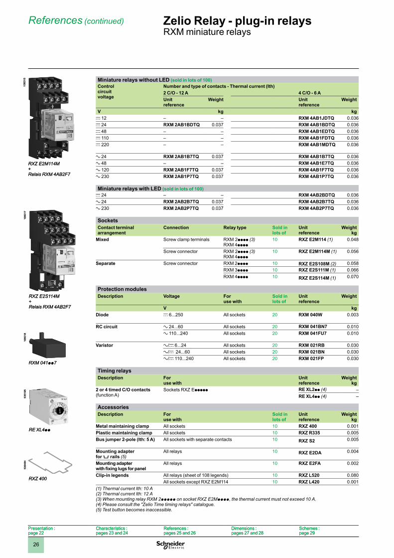
Dimensions (continued)Plastic clamp and clip-in legendsRXZ R335 RXZ L420 Mounting on all sockets (1)
(1) Clip-in legends for all sockets except RXZ E2M114
Bus jumper Metal clampRXZ S2 Mounting on sockets with separate contacts
(view from below)RXZ 400
Example of bus jumper mounting on sockets
(1) 2 bus jumpers (polarity A2)(2) 2 bus jumpers (polarity A1)
Mounting adapter for rails (1) Mounting adapter for panelRXZ E2DA RXZ E2FA
(1) Test button becomes inaccessible
57
27
57
27
12
14,2
26,5
12
14,2
26,5
81
94,5
(1)
81
94,5
(1)
2,2 7,
3
25
22
2,3
2,2 7,
3
25
22
2,3(1)(1)
(2)(2)
(1)(1)
(2)(2)
22
42
0,�
22
42
0,�
38
6 424
348
23
51
38
6 424
348
23
51
48 49
3,5
43 38
4
24
3,5
48 49
3,5
43 38
4
24
3,5
Presentation :page 22
Characteristics :pages 23 and 24
References :pages 25 and 26
Dimensions :pages 27 and 2�
Schemes :page 29
Presentation :page 22
Characteristics :pages 23 and 24
References :pages 25 and 26
Dimensions :pages 27 and 2�
Schemes :page 29
Zelio Relay - plug-in relaysRXM miniature relays
Dimensions (continued)
1
2
3
4
5
6
7
8
9
10
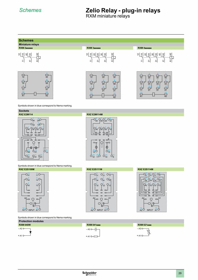
29
SchemesMiniature relaysRXM 2ppppp RXM 3ppppp RXM 4ppppp
Symbols shown in blue correspond to Nema marking.
Sockets RXZ E2M114 RXZ E2M114M
347
14A2 A1
13
246
844 14
5
1
119
2110
3111
4112
2312223242
4
448
347
246
145
12312223242
4
14A2 A1
13
14 13
1021
9
9
5
1
111131
1241
Symbols shown in blue correspond to Nema marking.RXZ E2S108M RXZ E2S111M RXZ E2S114M
1241 11
9
844 14
5
A1
13
A2
A1A214
424
121
INPUT
A1
13
A2
A1A214
319
346
3
218
245
2
117
144
32 22 121
INPUT
A1
13
A2
A1A214
4112
3111
2110
119
448
347
246
145
424
323
222
121
INPUT
Symbols shown in blue correspond to Nema marking.Protection modules RXM 040W RXM 041ppp RXM 021ppp
– A2
+ A1
– A2
+ A1
– A2
+ A1
A2
A1
414442
111412
1
125
149
11
4
428
4412
4113
A1
14
A2
A2
A1
414442
111412
1
125
149
11
4
428
4412
4113
A1
14
A2
A2
A1
313432
212422
111412
1
12
4
147
11
2
22
5
248
21
3
32
6
349
3113
A1
14
A2
A2
A1
313432
212422
111412
1
12
4
147
11
2
22
5
248
21
3
32
6
349
3113
A1
14
A2
A2
A1
414442
212422
313432
111412
1
125
149
11
4
428
4412
41
2
226
2410
21
3
327
3411
3113
A1
14
A2
A2
A1
414442
212422
313432
111412
1
125
149
11
4
428
4412
41
2
226
2410
21
3
327
3411
3113
A1
14
A2
Zelio Relay - plug-in relaysRXM miniature relays
Schemes
1
2
3
4
5
6
7
8
9
10
Related Documents