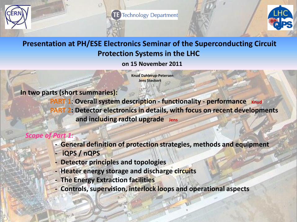
Presentation at PH/ESE Electronics Seminar of the Superconducting Circuit Protection Systems in the LHC on 15 November 2011 Knud Dahlerup-Petersen Jens Steckert 1 In two parts (short summaries): PART 1: Overall system description - functionality - performance Knud PART 2: Detector electronics in details, with focus on recent developments and including radtol upgrade Jens Scope of Part 1: - General definition of protection strategies, methods and equipment - iQPS / nQPS - Detector principles and topologies - Heater energy storage and discharge circuits - The Energy Extraction facilities - Controls, supervision, interlock loops and operational aspects

Welcome message from author
This document is posted to help you gain knowledge. Please leave a comment to let me know what you think about it! Share it to your friends and learn new things together.
Transcript
Presentation at PH/ESE Electronics Seminar of the Superconducting Circuit Protection Systems in the LHC
on 15 November 2011
Knud Dahlerup-Petersen Jens Steckert
1
In two parts (short summaries): PART 1: Overall system description - functionality - performance Knud
PART 2: Detector electronics in details, with focus on recent developments and including radtol upgrade Jens
Scope of Part 1: - General definition of protection strategies, methods and equipment - iQPS / nQPS - Detector principles and topologies - Heater energy storage and discharge circuits - The Energy Extraction facilities - Controls, supervision, interlock loops and operational aspects
2
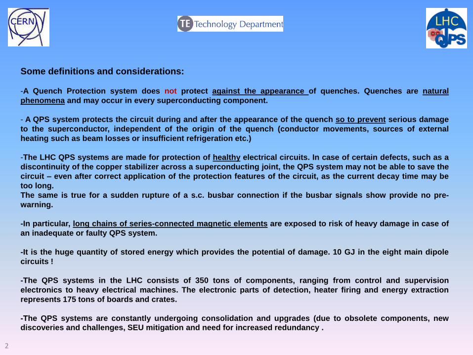
Some definitions and considerations:
-A Quench Protection system does not protect against the appearance of quenches. Quenches are natural
phenomena and may occur in every superconducting component.
- A QPS system protects the circuit during and after the appearance of the quench so to prevent serious damage
to the superconductor, independent of the origin of the quench (conductor movements, sources of external
heating such as beam losses or insufficient refrigeration etc.)
-The LHC QPS systems are made for protection of healthy electrical circuits. In case of certain defects, such as a
discontinuity of the copper stabilizer across a superconducting joint, the QPS system may not be able to save the
circuit – even after correct application of the protection features of the circuit, as the current decay time may be
too long.
The same is true for a sudden rupture of a s.c. busbar connection if the busbar signals show provide no pre-
warning.
-In particular, long chains of series-connected magnetic elements are exposed to risk of heavy damage in case of
an inadequate or faulty QPS system.
-It is the huge quantity of stored energy which provides the potential of damage. 10 GJ in the eight main dipole
circuits !
-The QPS systems in the LHC consists of 350 tons of components, ranging from control and supervision
electronics to heavy electrical machines. The electronic parts of detection, heater firing and energy extraction
represents 175 tons of boards and crates.
-The QPS systems are constantly undergoing consolidation and upgrades (due to obsolete components, new discoveries and challenges, SEU mitigation and need for increased redundancy .
3
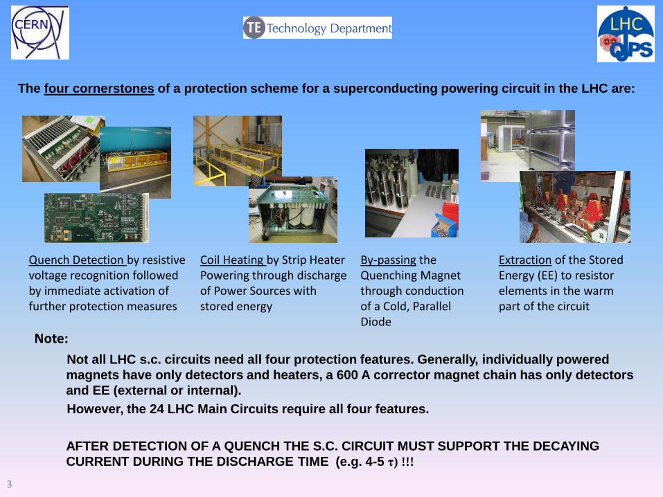
Not all LHC s.c. circuits need all four protection features. Generally, individually powered
magnets have only detectors and heaters, a 600 A corrector magnet chain has only detectors
and EE (external or internal).
However, the 24 LHC Main Circuits require all four features.
AFTER DETECTION OF A QUENCH THE S.C. CIRCUIT MUST SUPPORT THE DECAYING
CURRENT DURING THE DISCHARGE TIME (e.g. 4-5 τ) !!!
The four cornerstones of a protection scheme for a superconducting powering circuit in the LHC are:
Quench Detection by resistive voltage recognition followed by immediate activation of further protection measures
Coil Heating by Strip Heater Powering through discharge of Power Sources with stored energy
By-passing the Quenching Magnet through conduction of a Cold, Parallel Diode
Extraction of the Stored Energy (EE) to resistor elements in the warm part of the circuit
Note:
4
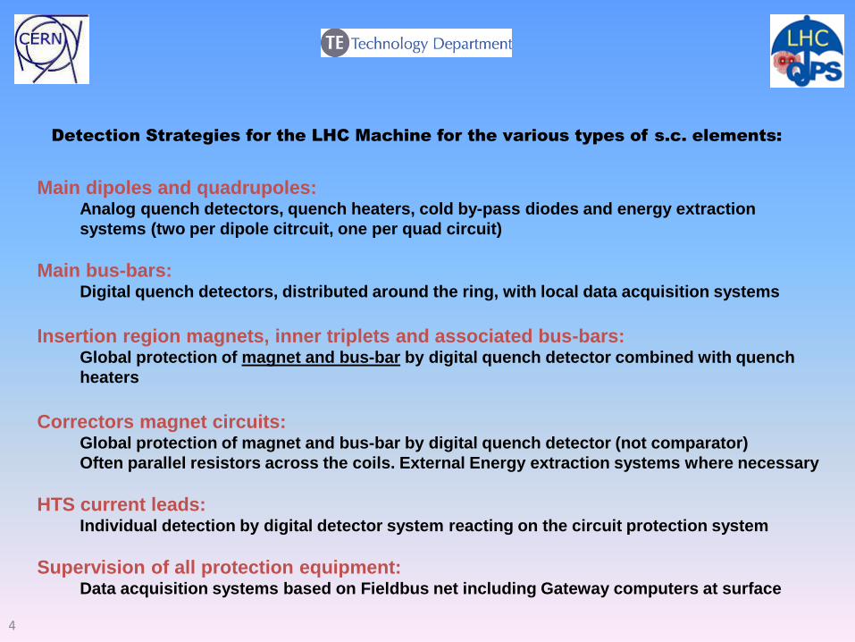
Main dipoles and quadrupoles: Analog quench detectors, quench heaters, cold by-pass diodes and energy extraction
systems (two per dipole citrcuit, one per quad circuit)
Main bus-bars: Digital quench detectors, distributed around the ring, with local data acquisition systems
Insertion region magnets, inner triplets and associated bus-bars: Global protection of magnet and bus-bar by digital quench detector combined with quench
heaters
Correctors magnet circuits: Global protection of magnet and bus-bar by digital quench detector (not comparator)
Often parallel resistors across the coils. External Energy extraction systems where necessary
HTS current leads: Individual detection by digital detector system reacting on the circuit protection system
Supervision of all protection equipment: Data acquisition systems based on Fieldbus net including Gateway computers at surface
Detection Strategies for the LHC Machine for the various types of s.c. elements:
5
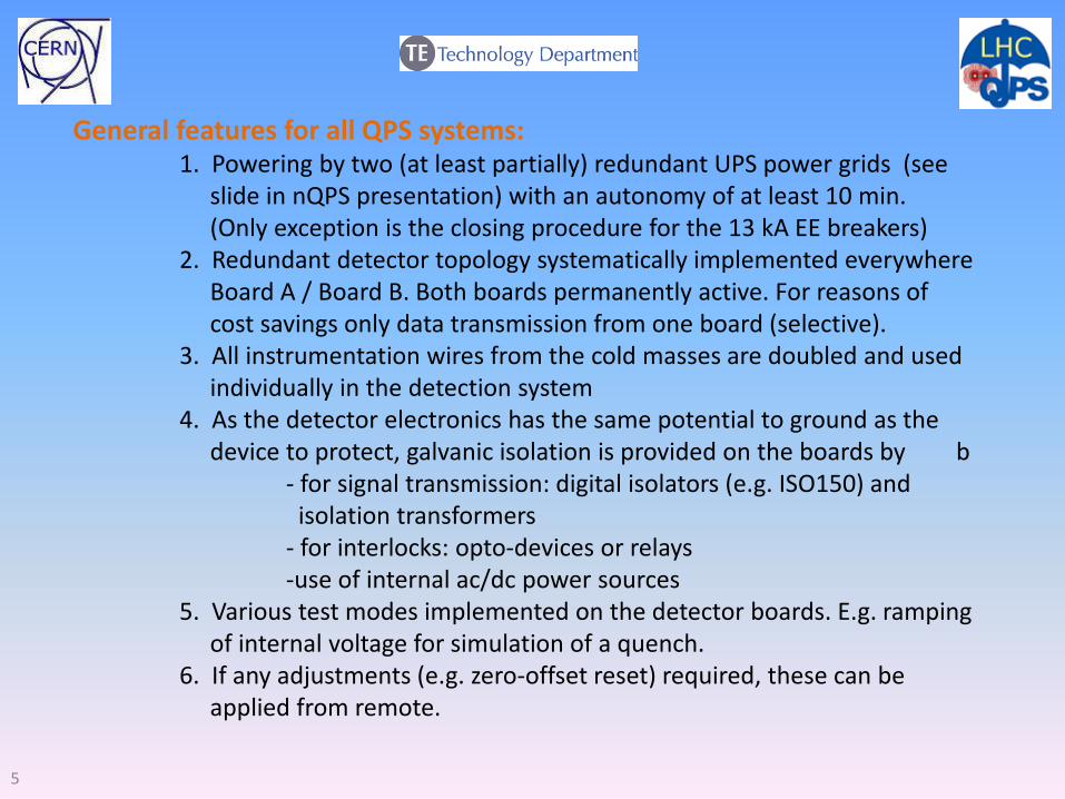
General features for all QPS systems: 1. Powering by two (at least partially) redundant UPS power grids (see slide in nQPS presentation) with an autonomy of at least 10 min. (Only exception is the closing procedure for the 13 kA EE breakers) 2. Redundant detector topology systematically implemented everywhere Board A / Board B. Both boards permanently active. For reasons of cost savings only data transmission from one board (selective). 3. All instrumentation wires from the cold masses are doubled and used individually in the detection system 4. As the detector electronics has the same potential to ground as the device to protect, galvanic isolation is provided on the boards by b - for signal transmission: digital isolators (e.g. ISO150) and isolation transformers - for interlocks: opto-devices or relays -use of internal ac/dc power sources 5. Various test modes implemented on the detector boards. E.g. ramping of internal voltage for simulation of a quench. 6. If any adjustments (e.g. zero-offset reset) required, these can be applied from remote.
6
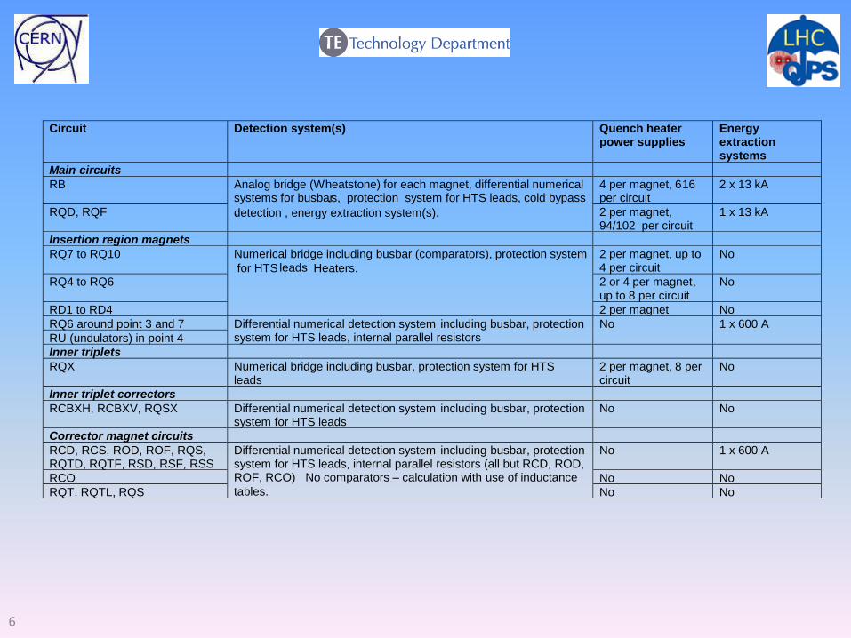
Circuit Detection system(s) Quench heater power supplies
Energy extraction systems
Main circuits
RB 4 per magnet, 6 16 per circuit
2 x 13 kA
RQD, RQF
Analog bridge (Wheatstone) for each magnet, differential numerical
detection , energy extraction system(s).
systems for busbar ,s, protection system for HTS leads, cold bypass
. 2 per magnet, 94/102 per circuit
1 x 13 kA
Insertion region magnets
RQ7 to RQ10 2 per magnet, up to 4 per circuit
No
RQ4 to RQ6 2 or 4 per magnet , up to 8 per circuit
No
RD1 to RD4
Numerical bridge including busbar (comparators), protection system
for HTS Heaters. leads
2 per magnet No
RQ6 around point 3 and 7
RU (undulators) in point 4
D ifferential numerical detection system including busbar, protection system for HTS leads , internal parallel resistors
No 1 x 600 A
Inner tripl ets
RQX Numerical bridge including busbar, protection system for HTS leads
2 per magnet, 8 per circuit
No
Inner triple t correctors
RCBXH, RCBXV, RQSX D ifferential numerical detection system including busbar , protection system for HTS leads
No No
Corrector magnet circuits
RCD, RCS, ROD, ROF, RQS, RQTD, RQTF, RSD, RSF, RSS
No 1 x 600 A
RCO No No
RQT, RQTL, RQS
D ifferential numerical detection system including busbar , protection system for HTS leads, internal parallel resistors (all but RCD, ROD, ROF, RCO) No comparators – calculation with use of inductance
tables.
No No
7
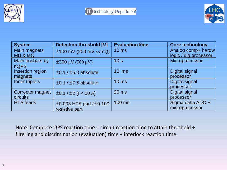
System Detection threshold [V] Evaluation time Core technology Main magnets MB & MQ
± 100 mV (200 mV symQ) 10 ms Analog comp+ hardw logic / dig.processor
Main busbars by
nQPS
± 300 μV (500 μV) 10 s Microprocessor
Insertion region magnets
± 0.1 / ± 5.0 absolute 10 ms Digital signal pr ocessor
Inner triplets ± 0.1 / ± 7.5 absolute 10 ms Digital signal processor
Corrector magnet circuits
± 0.1 / ± 2 (I < 50 A) 20 ms Digital signal processor
HTS leads ± 0.003 HTS part / ± 0.100 resistive part
100 ms Sigma delta ADC + microprocessor
Note: Complete QPS reaction time = circuit reaction time to attain threshold + filtering and discrimination (evaluation) time + interlock reaction time.
8
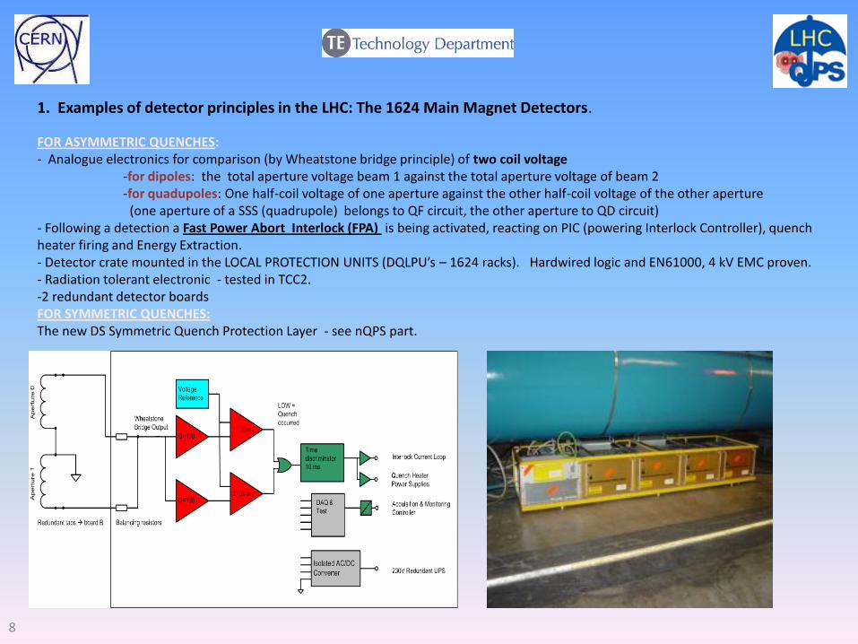
1. Examples of detector principles in the LHC: The 1624 Main Magnet Detectors.
FOR ASYMMETRIC QUENCHES: - Analogue electronics for comparison (by Wheatstone bridge principle) of two coil voltage -for dipoles: the total aperture voltage beam 1 against the total aperture voltage of beam 2 -for quadupoles: One half-coil voltage of one aperture against the other half-coil voltage of the other aperture (one aperture of a SSS (quadrupole) belongs to QF circuit, the other aperture to QD circuit) - Following a detection a Fast Power Abort Interlock (FPA) is being activated, reacting on PIC (powering Interlock Controller), quench heater firing and Energy Extraction. - Detector crate mounted in the LOCAL PROTECTION UNITS (DQLPU’s – 1624 racks). Hardwired logic and EN61000, 4 kV EMC proven. - Radiation tolerant electronic - tested in TCC2. -2 redundant detector boards FOR SYMMETRIC QUENCHES: The new DS Symmetric Quench Protection Layer - see nQPS part.
9
U_RES U_HTS
U_RES U_HTS
U_RES U_HTS
U_1_B1
U_2_B1
U_1_B2
U_2_B2
+
U_RES = U_1 + U_2
Quench heater Quench heater
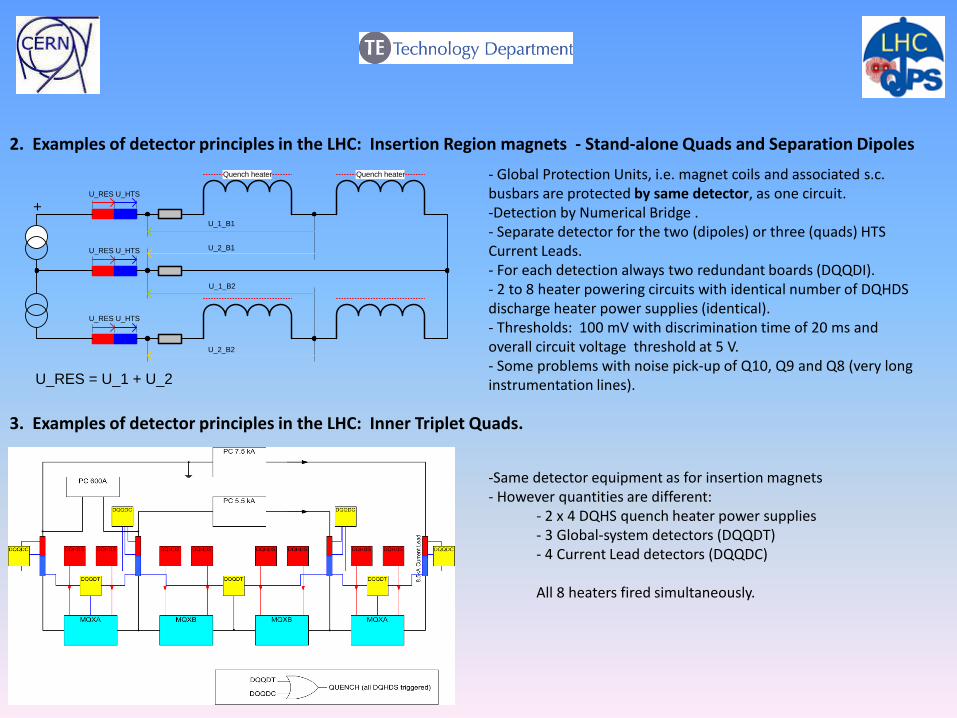
2. Examples of detector principles in the LHC: Insertion Region magnets - Stand-alone Quads and Separation Dipoles
- Global Protection Units, i.e. magnet coils and associated s.c. busbars are protected by same detector, as one circuit. -Detection by Numerical Bridge . - Separate detector for the two (dipoles) or three (quads) HTS Current Leads. - For each detection always two redundant boards (DQQDI). - 2 to 8 heater powering circuits with identical number of DQHDS discharge heater power supplies (identical). - Thresholds: 100 mV with discrimination time of 20 ms and overall circuit voltage threshold at 5 V. - Some problems with noise pick-up of Q10, Q9 and Q8 (very long instrumentation lines).
3. Examples of detector principles in the LHC: Inner Triplet Quads.
-Same detector equipment as for insertion magnets - However quantities are different:
- 2 x 4 DQHS quench heater power supplies - 3 Global-system detectors (DQQDT) - 4 Current Lead detectors (DQQDC)
All 8 heaters fired simultaneously.
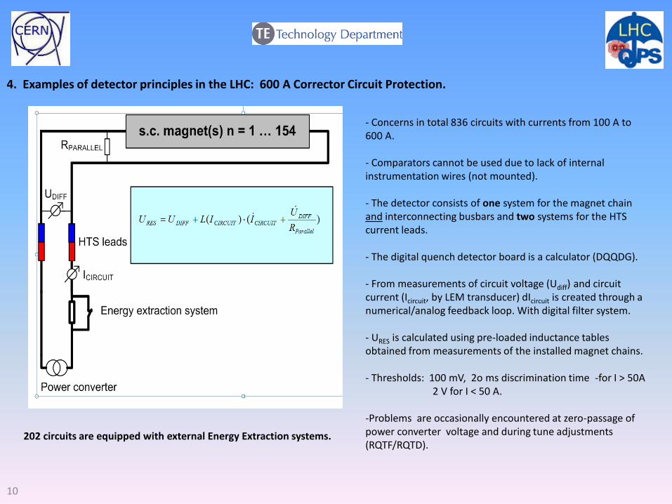
4. Examples of detector principles in the LHC: 600 A Corrector Circuit Protection.
10
- Concerns in total 836 circuits with currents from 100 A to 600 A. - Comparators cannot be used due to lack of internal instrumentation wires (not mounted). - The detector consists of one system for the magnet chain and interconnecting busbars and two systems for the HTS current leads. - The digital quench detector board is a calculator (DQQDG). - From measurements of circuit voltage (Udiff) and circuit current (Icircuit, by LEM transducer) dIcircuit is created through a numerical/analog feedback loop. With digital filter system. - URES is calculated using pre-loaded inductance tables obtained from measurements of the installed magnet chains.
- Thresholds: 100 mV, 2o ms discrimination time -for I > 50A 2 V for I < 50 A. -Problems are occasionally encountered at zero-passage of power converter voltage and during tune adjustments (RQTF/RQTD).
202 circuits are equipped with external Energy Extraction systems.
11
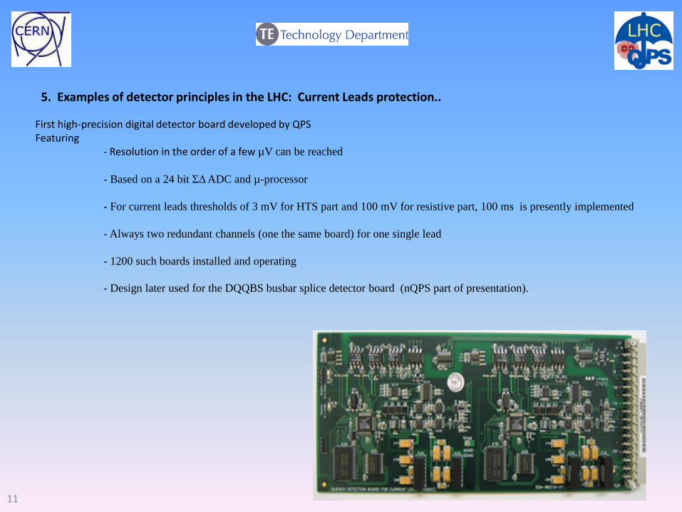
5. Examples of detector principles in the LHC: Current Leads protection..
First high-precision digital detector board developed by QPS Featuring - Resolution in the order of a few µV can be reached
- Based on a 24 bit ΣΔ ADC and µ-processor
- For current leads thresholds of 3 mV for HTS part and 100 mV for resistive part, 100 ms is presently implemented
- Always two redundant channels (one the same board) for one single lead
- 1200 such boards installed and operating
- Design later used for the DQQBS busbar splice detector board (nQPS part of presentation).
12
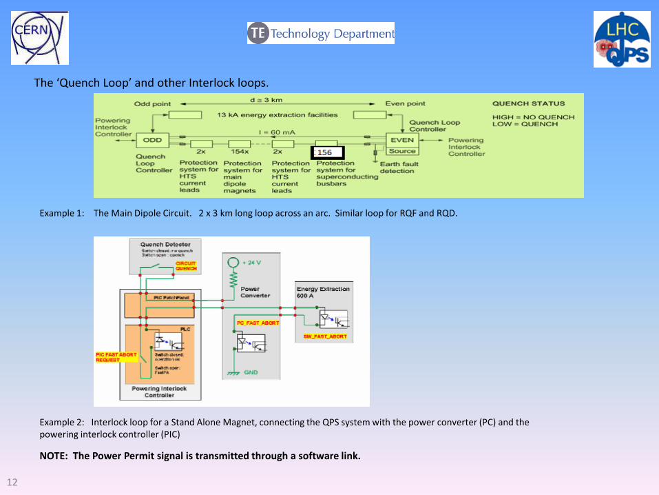
The ‘Quench Loop’ and other Interlock loops.
Example 1: The Main Dipole Circuit. 2 x 3 km long loop across an arc. Similar loop for RQF and RQD.
Example 2: Interlock loop for a Stand Alone Magnet, connecting the QPS system with the power converter (PC) and the powering interlock controller (PIC)
NOTE: The Power Permit signal is transmitted through a software link.
13
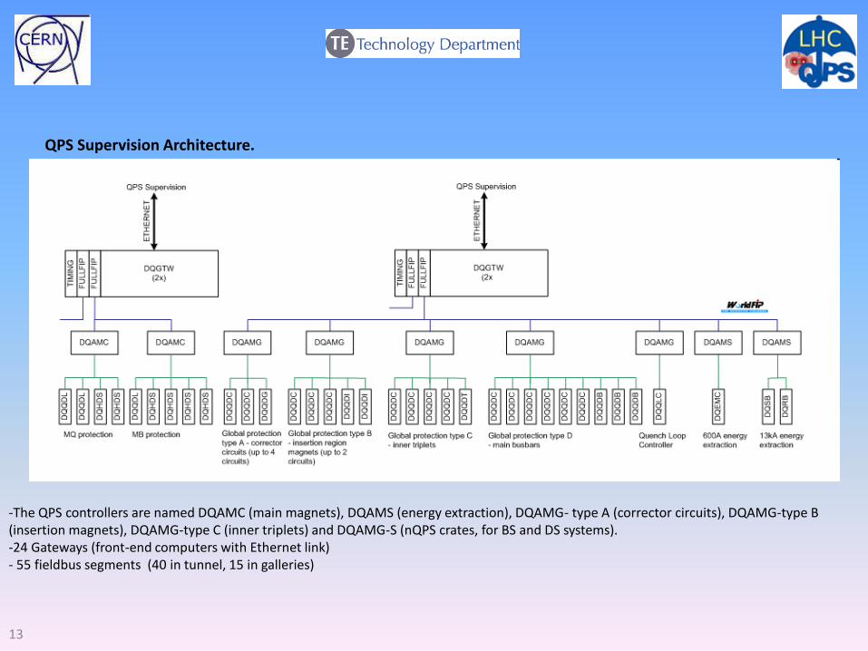
QPS Supervision Architecture.
-The QPS controllers are named DQAMC (main magnets), DQAMS (energy extraction), DQAMG- type A (corrector circuits), DQAMG-type B (insertion magnets), DQAMG-type C (inner triplets) and DQAMG-S (nQPS crates, for BS and DS systems). -24 Gateways (front-end computers with Ethernet link) - 55 fieldbus segments (40 in tunnel, 15 in galleries)
14
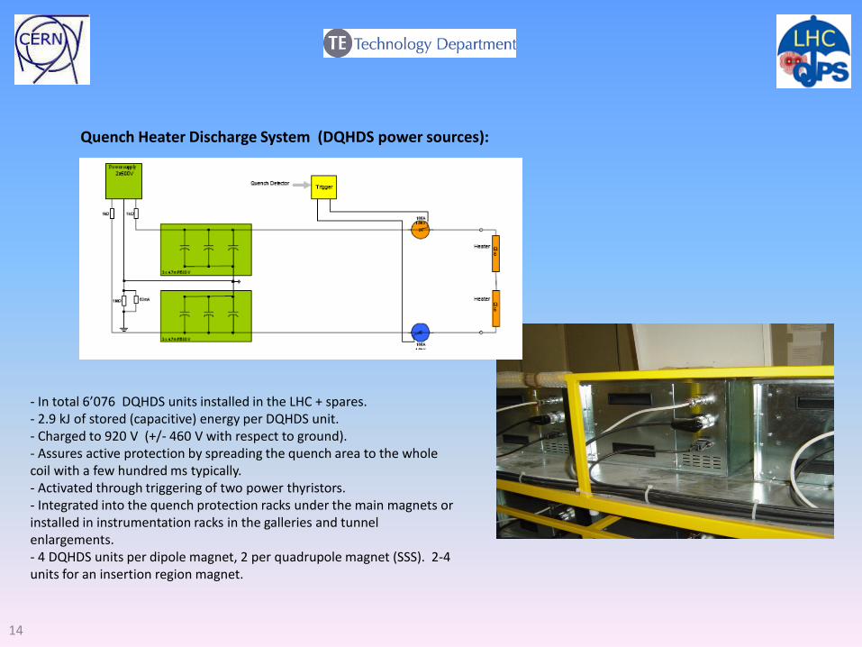
Quench Heater Discharge System (DQHDS power sources):
- In total 6’076 DQHDS units installed in the LHC + spares. - 2.9 kJ of stored (capacitive) energy per DQHDS unit. - Charged to 920 V (+/- 460 V with respect to ground). - Assures active protection by spreading the quench area to the whole coil with a few hundred ms typically. - Activated through triggering of two power thyristors. - Integrated into the quench protection racks under the main magnets or installed in instrumentation racks in the galleries and tunnel enlargements. - 4 DQHDS units per dipole magnet, 2 per quadrupole magnet (SSS). 2-4 units for an insertion region magnet.
15
Energy Extraction in the LHC Powering Circuits
Purpose:
-For the Main Dipole and Quadrupole circuits:
Rapid current decay (still within the limits of quench-back) with external energy deposit is
required to prevent destruction by overheating of the by-pass diodes and associated
copper busbars and the quenching s.c. busses
-For the corrector circuits:
In the absence of heaters EE is vital for energy absorption and for obtaining the short
discharge time which will prevent overheating of busbars, current leads and coils.
Note: De-excitation by inversion (-10 A/s), with reversed energy flow to EdF grid, is applied
in the RB circuit (thyristor converter) whenever possible (no circuit faults, no quenches,
when Mains grid is available).
16
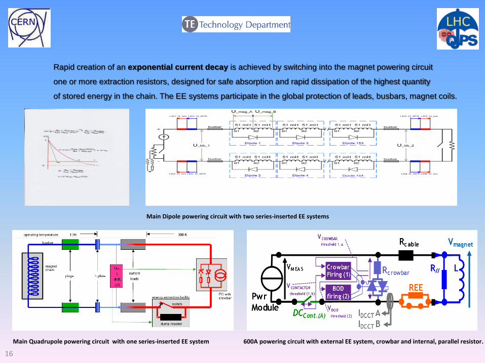
Rapid creation of an exponential current decay is achieved by switching into the magnet powering circuit
one or more extraction resistors, designed for safe absorption and rapid dissipation of the highest quantity
of stored energy in the chain. The EE systems participate in the global protection of leads, busbars, magnet coils.
Main Dipole powering circuit with two series-inserted EE systems
Main Quadrupole powering circuit with one series-inserted EE system 600A powering circuit with external EE system, crowbar and internal, parallel resistor.
18
• Components of an EE system: Extraction switches - powering and control electronics - a current distribution system - the extraction resistors - their supervision electronics - their cooling facility - an Interlock and alarm system - the system Interface and Data Acquisition electronics - various auxiliary systems (e.g. arc detectors, over-current detectors, snubber capacitor banks and their electrical protection equipment, sound shields). • Basic Requirements: Reliability of the release systems - availability - low losses and radiation tolerance. When paralleling of switches are used each individual switch shall be capable of interrupting the full-system current ! • Some Key Figures:
• The 232 EE facilities in the LHC represent 310 tons of equipment. • Basically all components are tailor-made to the application, off-the-shelf equipment did not meet the CERN specification. • 89% of the equipment is procured as in-kind contributions from Non-Member States • The total reference cost of the systems was 19 MCHF. CERN paid 7 MCHF plus installation cost.
• Stored Energy: • In each circuit:
•RB: 1’236 MJ at ultimate current (sufficient to heat and melt 2.2 tons of copper) •RQF/RQD: 24 MJ at ultimate current. •600 A corrector circuits: up to 108 kJ
• Locations: • Even points: all eight UA galleries (RB, QF/QD, correctors) • Odd points: all six RR tunnel extensions (RB, correctors), tunnel (RB power systems in R34, R37), UJ33 (RB controls, correctors).
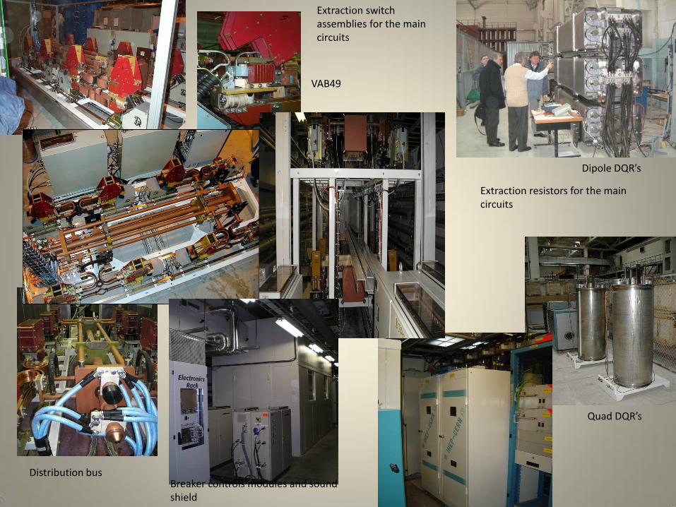
Extraction switch assemblies for the main circuits
Extraction resistors for the main circuits
Distribution bus Breaker controls modules and sound shield
VAB49
Quad DQR’s
Dipole DQR’s
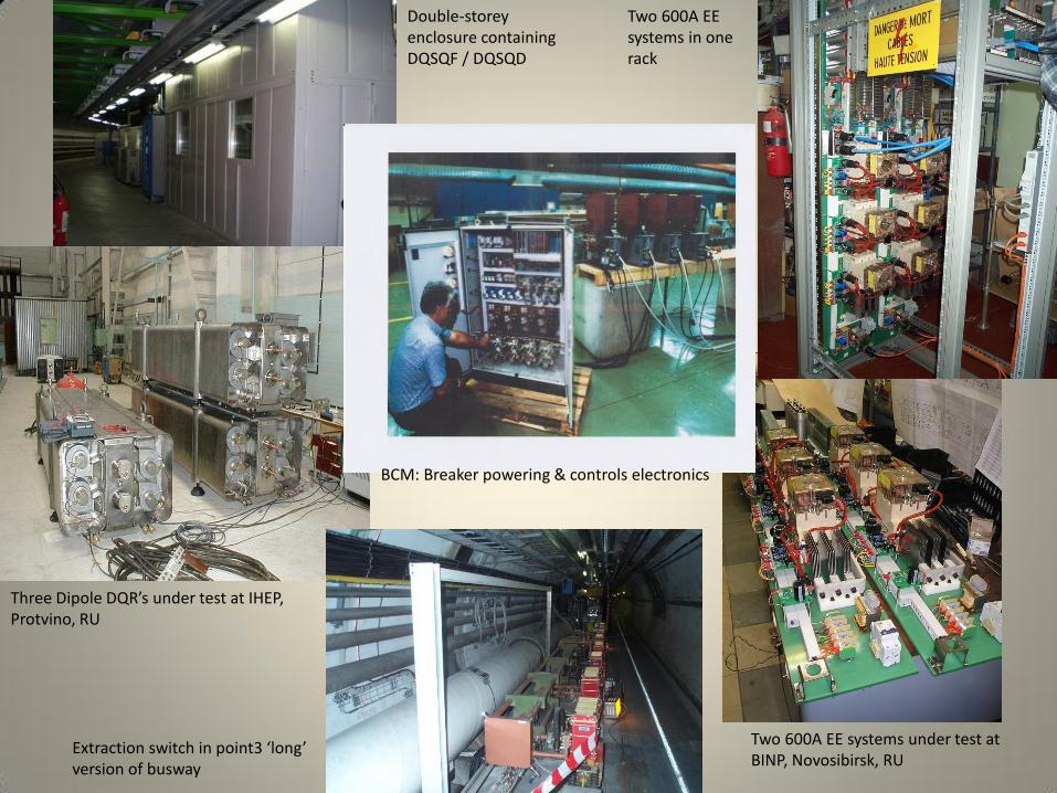
Three Dipole DQR’s under test at IHEP, Protvino, RU
Double-storey enclosure containing DQSQF / DQSQD
Two 600A EE systems in one rack
Extraction switch in point3 ‘long’ version of busway
Two 600A EE systems under test at BINP, Novosibirsk, RU
BCM: Breaker powering & controls electronics
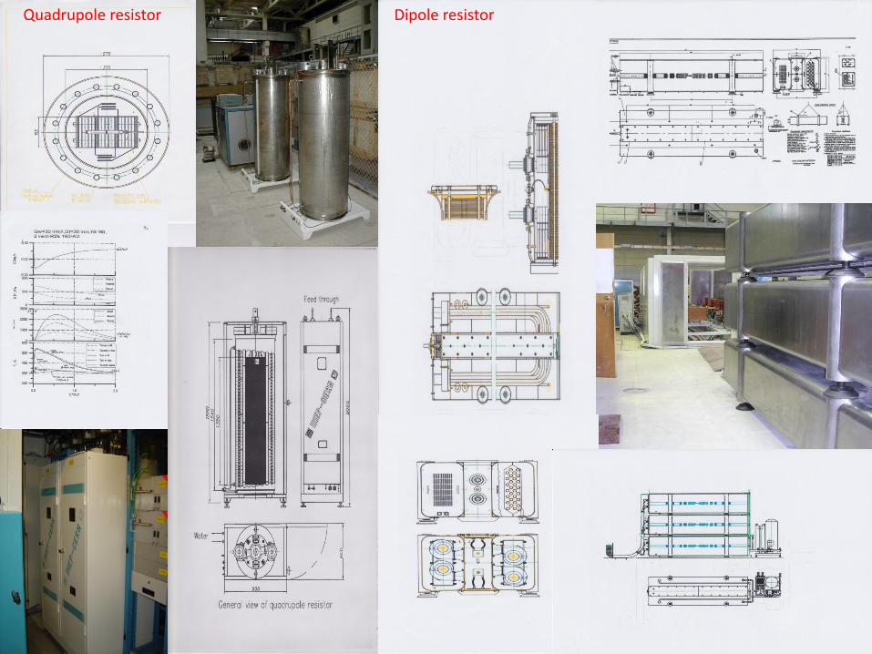
Quadrupole resistor Dipole resistor
22
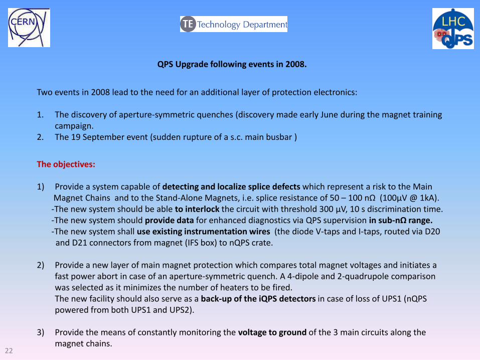
QPS Upgrade following events in 2008.
Two events in 2008 lead to the need for an additional layer of protection electronics: 1. The discovery of aperture-symmetric quenches (discovery made early June during the magnet training
campaign. 2. The 19 September event (sudden rupture of a s.c. main busbar )
The objectives: 1) Provide a system capable of detecting and localize splice defects which represent a risk to the Main Magnet Chains and to the Stand-Alone Magnets, i.e. splice resistance of 50 – 100 nΩ (100µV @ 1kA). -The new system should be able to interlock the circuit with threshold 300 µV, 10 s discrimination time. -The new system should provide data for enhanced diagnostics via QPS supervision in sub-nΩ range. -The new system shall use existing instrumentation wires (the diode V-taps and I-taps, routed via D20 and D21 connectors from magnet (IFS box) to nQPS crate. 2) Provide a new layer of main magnet protection which compares total magnet voltages and initiates a
fast power abort in case of an aperture-symmetric quench. A 4-dipole and 2-quadrupole comparison was selected as it minimizes the number of heaters to be fired.
The new facility should also serve as a back-up of the iQPS detectors in case of loss of UPS1 (nQPS powered from both UPS1 and UPS2).
3) Provide the means of constantly monitoring the voltage to ground of the 3 main circuits along the magnet chains.
23
24
25
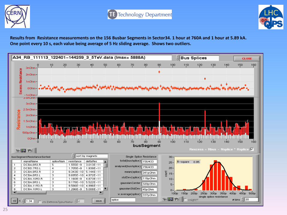
Results from Resistance measurements on the 156 Busbar Segments in Sector34. 1 hour at 760A and 1 hour at 5.89 kA. One point every 10 s, each value being average of 5 Hz sliding average. Shows two outliers.
26
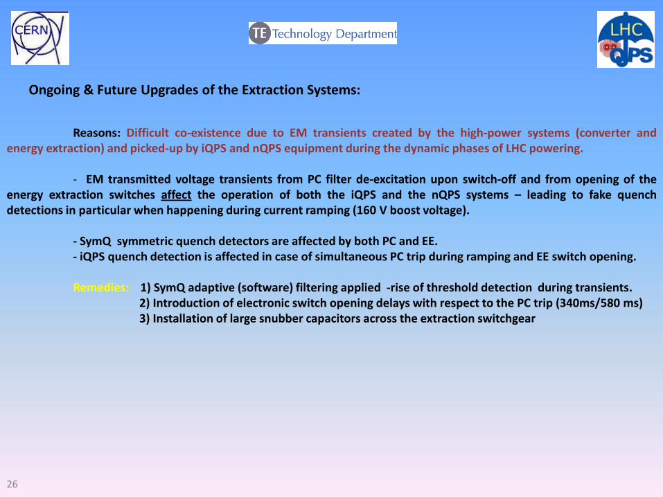
Reasons: Difficult co-existence due to EM transients created by the high-power systems (converter and energy extraction) and picked-up by iQPS and nQPS equipment during the dynamic phases of LHC powering. - EM transmitted voltage transients from PC filter de-excitation upon switch-off and from opening of the energy extraction switches affect the operation of both the iQPS and the nQPS systems – leading to fake quench detections in particular when happening during current ramping (160 V boost voltage). - SymQ symmetric quench detectors are affected by both PC and EE. - iQPS quench detection is affected in case of simultaneous PC trip during ramping and EE switch opening. Remedies: 1) SymQ adaptive (software) filtering applied -rise of threshold detection during transients. 2) Introduction of electronic switch opening delays with respect to the PC trip (340ms/580 ms) 3) Installation of large snubber capacitors across the extraction switchgear
Ongoing & Future Upgrades of the Extraction Systems:
27
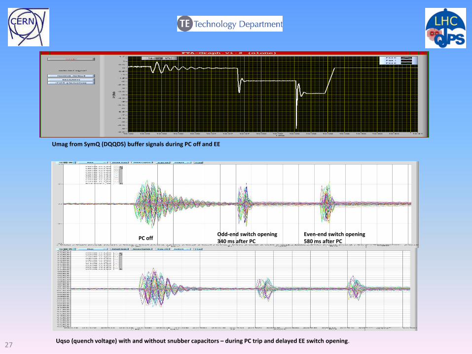
Umag from SymQ (DQQDS) buffer signals during PC off and EE
Uqso (quench voltage) with and without snubber capacitors – during PC trip and delayed EE switch opening.
PC off Odd-end switch opening 340 ms after PC
Even-end switch opening 580 ms after PC
28
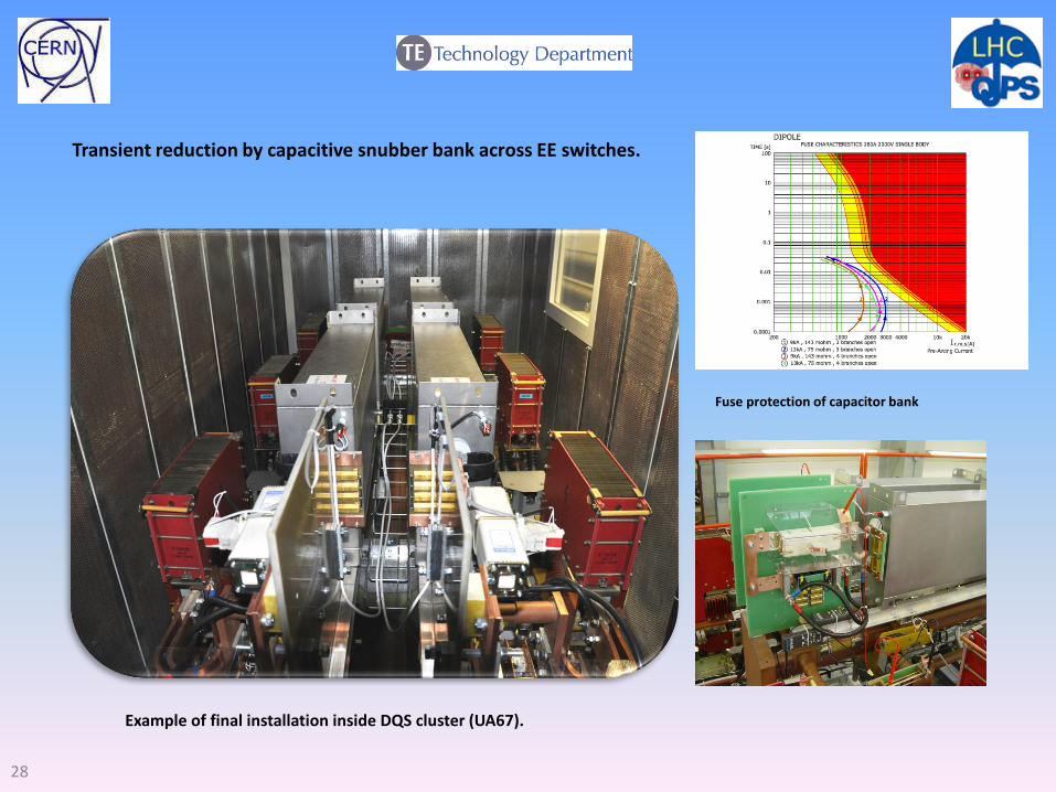
Example of final installation inside DQS cluster (UA67).
Fuse protection of capacitor bank
Transient reduction by capacitive snubber bank across EE switches.

29
Thank you for your patience
Related Documents