94335 (SJO8R369) nb Copyright 2008 Kleinfelder Prepared for Target Corporation DRAFT GEOTECHNICAL INVESTIGATION PROPOSED TARGET STORE LA MADRONA DRIVE AND SILVERWOOD DRIVE SCOTTS VALLEY, CALIFORNIA September 16, 2008 File No.: 94335 This document was prepared for use only by the client, only for the purposes stated, and within a reasonable time from issuance, but in no event later than three years from the date of the report. Non-commercial, educational, and scientific use of this report by regulatory agencies is regarded as a “fair use” and not a violation of copyright. Regulatory agencies may make additional copies of this document for internal use. Copies may also be made available to the public as required by law. The reprint must acknowledge the copyright and indicate that permission to reprint has been received.

Welcome message from author
This document is posted to help you gain knowledge. Please leave a comment to let me know what you think about it! Share it to your friends and learn new things together.
Transcript

94335 (SJO8R369) nb Copyright 2008 Kleinfelder
Prepared for Target Corporation
DRAFT GEOTECHNICAL INVESTIGATION
PROPOSED TARGET STORE LA MADRONA DRIVE AND
SILVERWOOD DRIVE SCOTTS VALLEY, CALIFORNIA
September 16, 2008 File No.: 94335
This document was prepared for use only by the client, only for the purposes stated, and within a reasonable time from issuance, but in no event later than three years from the date of the report. Non-commercial, educational, and scientific use of this report by regulatory agencies is regarded as a “fair use” and not a violation of copyright. Regulatory agencies may make additional copies of this document for internal use. Copies may also be made available to the public as required by law. The reprint must acknowledge the copyright and indicate that permission to reprint has been received.
94335 (SJO8R369) nb Page 1 of 1 September 16, 2008 Copyright 2008 Kleinfelder
2011 N Capitol Avenue San Jose, CA
95138
p| 408-586-7611 f| 408-586-7688
Kleinfelder.com
September 16, 2008 Project No. 94335 Mr. John Dewes submitted via e-mail [email protected] Target Corporation 1000 Nicolett Mall, TPN-12I Minneapolis, Minnesota 55403 SUBJECT: Draft Geotechnical Investigation Report for Proposed Target Store, La
Madrona Drive and Silverwood Drive, Scotts Valley, California Dear Mr. Dewes: Kleinfelder is pleased to present this draft report summarizing our preliminary geotechnical investigation report for the proposed Target store located northwest of the intersection of La Madrona Drive and Silverwood Drive in Scotts Valley, California. The enclosed report provides a description of the investigation performed and our geotechnical recommendations for the project. Our services were provided in accordance with our proposal dated May 2, 2008, File No. 01201PROP (SJO8P104). Our investigation and this report have been prepared in accordance with the Target Developer Guide, Edition 2.8, dated January 1, 2008. We appreciate the opportunity of providing our services to you on this project and trust this report meets your needs at this time. As a draft, we have also provided a copy to Loren Braun directly as well. We await comments and any questions you or Loren may have. If you have any questions concerning the information presented, please contact this office at (408) 586-7611, or Mark Klaver at (916) 366-1701 Sincerely, KLEINFELDER WEST, INC. Draft Draft David C. Seymour, C.E.G. #1574 Parham Khoshkbari C.E.#71168 Senior Engineering Geologist Project Engineer
Draft Catherine Ellis, C.E., G.E. # 2650 GeoSciences Group Manager Copy: Loren Braun, Braun Intertec Corporation ([email protected]) Reviewed by:
Draft Mark Klaver, REA I, RG # 4907 Senior Client Manager.
94335 (SJO8R369) nb Page i of iii September 16, 2008 Copyright 2008 Kleinfelder
DRAFT GEOTECHNICAL INVESTIGATION PROPOSED TARGET STORE LA MADRONA DRIVE AND
SILVERWOOD DRIVE SCOTTS VALLEY, CALIFORNIA
TABLE OF CONTENTS
Section Page
1 EXECUTIVE SUMMARY...................................................................................... 1 1.1. PROJECT DESCRIPTION .........................................................................................1 1.2. SUBSURFACE CONDITIONS .....................................................................................2 1.3. KEY CONCLUSIONS AND RECOMMENDATIONS..........................................................2
2 INTRODUCTION .................................................................................................. 5 2.1. SITE DESCRIPTION.................................................................................................5 2.2. PROJECT DESCRIPTION .........................................................................................6 2.3. PURPOSE AND SCOPE OF SERVICES .......................................................................7 2.4. PREVIOUS GEOTECHNICAL STUDIES .......................................................................8
3 SITE INVESTIGATION......................................................................................... 9 3.1. FIELD INVESTIGATION.............................................................................................9 3.2. SOIL BORINGS .......................................................................................................9
3.2.1. Bucket Auger Borings.............................................................................10 3.2.2. Test Pits .................................................................................................12 3.2.3. Seismic Refraction Survey .....................................................................12
3.3. EXPLORATION BY OTHERS ...................................................................................13 3.4. LABORATORY TESTING.........................................................................................14 3.5. CORROSION TESTING ..........................................................................................14
4 GEOLOGY ......................................................................................................... 15 4.1. REGIONAL GEOLOGY ...........................................................................................15 4.2. LOCAL GEOLOGY AND SUBSURFACE CONDITIONS..................................................16 4.3. LANDSLIDES ........................................................................................................18 4.4. GROUNDWATER...................................................................................................19 4.5. FAULTS AND SEISMICITY ......................................................................................20
5 CONCLUSIONS AND RECOMMENDATIONS.................................................. 22 5.1. CONCLUSIONS.....................................................................................................22 5.2. 2007 CBC SEISMIC PARAMETERS ........................................................................22 5.3. LIQUEFACTION.....................................................................................................24 5.4. POTENTIAL FOR DIFFERENTIAL SETTLEMENT .........................................................24 5.5. BEDROCK HARDNESS AND RIPPABILITY.................................................................25 5.6. SLOPE STABILITY.................................................................................................27
5.6.1. Soil Strength Parameters .......................................................................27 5.6.2. Static Analysis ........................................................................................28 5.6.3. Pseudo-Static (Seismic) Analyses ..........................................................29
94335 (SJO8R369) nb Page ii of iii September 16, 2008 Copyright 2008 Kleinfelder
DRAFT GEOTECHNICAL INVESTIGATION PROPOSED TARGET STORE LA MADRONA DRIVE AND
SILVERWOOD DRIVE SCOTTS VALLEY, CALIFORNIA
TABLE OF CONTENTS
(CONTINUED) 5.6.4. Keyways and Slope Surface Compaction...............................................30 5.6.5. Footing Setback from Descending Slope Surface...................................31
5.7. GROUNDWATER AND SUBDRAINAGE .....................................................................32 5.8. LANDSLIDES AND BUILDING CLEARANCE FROM ASCENDING SLOPES .......................32 5.9. SITE DEMOLITION ................................................................................................33
5.9.1. Existing Improvements ...........................................................................33 5.9.2. Existing Utilities ......................................................................................33 5.9.3. Monitoring Well Abandonment................................................................34 5.9.4. Existing Vegetation.................................................................................34 5.9.5. Bucket Auger Backfill..............................................................................34
5.10. EARTHWORK .......................................................................................................34 5.10.1. Site Preparation, Remedial Removals and Fill Placement ......................35 5.10.2. Benching ................................................................................................36 5.10.3. Fill Material.............................................................................................36 5.10.4. Weather/Moisture Considerations...........................................................37 5.10.5. Excavation, Backfill, and Utility Trenches ...............................................37
5.11. BUILDING FOUNDATIONS ......................................................................................38 5.11.1. Estimated Settlements............................................................................39 5.11.2. Lateral Resistance..................................................................................40
5.12. SLABS-ON-GRADE ...............................................................................................40 5.12.1. Interior....................................................................................................40 5.12.2. Exterior...................................................................................................41 5.12.3. Floor Subdrain........................................................................................41
5.13. CORROSION ........................................................................................................42 5.14. RETAINING WALLS ...............................................................................................43
5.14.1. Seismic-Induced Wall Pressures ............................................................44 5.14.2. Additional Surcharge Loads ...................................................................44 5.14.3. Wall Foundations....................................................................................45 5.14.4. Wall Drainage.........................................................................................45
5.15. CONCRETE PAVEMENT.........................................................................................46 5.16. PAVEMENTS ........................................................................................................48
6 ADDITIONAL SERVICES .................................................................................. 50 7 LIMITATIONS..................................................................................................... 51 8 REFERENCES................................................................................................... 53

94335 (SJO8R369) nb Page iii of iii September 16, 2008 Copyright 2008 Kleinfelder
PLATES Plate 1 Site Vicinity Map Plate 2 Preliminary Geotechnical Map Plate 3 Geologic Cross-Sections A-A’, B-B’, C-C’, and D-D’ Plate 4 Seismic Refraction Cross-Section
APPENDICES
Appendix A Logs of Exploration Borings Appendix B Logs of Test Pits Appendix C Logs of Exploration Borings (By Others) Appendix D Laboratory Test Data Appendix E Corrosivity Results Appendix F Slope Stability Analyses Appendix G Standard Grading Details Appendix H Exhibit 1, Summary of Compaction Recommendations
94335 (SJO8R369) nb Page 1 of 55 September 16, 2008 Copyright 2008 Kleinfelder
1 EXECUTIVE SUMMARY
Kleinfelder West, Inc. (Kleinfelder) has completed a subsurface exploration and geotechnical report for use in design and construction of the proposed Scotts Valley Target store to be located at the northwest corner of the intersection of La Madrona Drive and Silverwood Drive in Scotts Valley, California. This site is shown on the Site Vicinity Map, Plate 1. Our geotechnical investigation and this report were conducted and prepared in accordance with the Target Developer Guide, Ed. 2.8, dated January 1, 2008. A total of twenty-nine borings, five test pits and a seismic refraction survey were completed as part of our investigation.
Based on the results of our study, the site is geotechnically suitable for the proposed construction subject to our recommendations. Key design items are summarized below, and are discussed in greater detail in the body of this report.
1.1. PROJECT DESCRIPTION
Based on the preliminary design drawings, the project will include construction of a regular Target store (Type P09), covering approximately 150,000 square feet, a two-level parking structure, and tiered retaining walls varying from 8 to 12 feet in height. The split-level parking structure will include construction of a 12 feet high retaining structure near the middle of the parking area. Tiered retaining wall systems with up to four walls are planned for the proposed slopes along the western, eastern, and southern perimeters of the project. Other proposed improvements include a depressed loading dock, and two driveways.
According to the Grading & Drainage Plan prepared by C2G/Civil Consultants Group, dated November 12, 2007, the preliminary design plans call for significant grading of the site with cuts and fills on the order of 25 to 30 feet (see Plate 2). Grading of the site will create a cut-to-fill transition beneath the building pad that will require fills of up to 25 feet beneath the eastern portion of the store. Cut and fill slopes in the range of 20 to 45 feet in height are also planned and will include tiered retaining wall systems. The highest cut slope, up to 45 feet in height, is planned along the base of the western natural slope
94335 (SJO8R369) nb Page 2 of 55 September 16, 2008 Copyright 2008 Kleinfelder
that ascends almost 175 feet from the design pad grade to the crest of an adjacent ridgeline. The finish floor elevation of the store and the upper parking level will lie at an elevation of approximately 618 feet. The lower parking level will rest at an elevation of approximately 606 feet.
1.2. SUBSURFACE CONDITIONS
The proposed Target Store will be constructed on an undeveloped parcel located in the central portion of the Santa Cruz Mountains. Geologic conditions in the local area are often complex, created by movement associated with the San Andreas fault system over the last 25 million years. The site is underlain by surficial soils and three geologic formations including the Santa Cruz Mudstone, Santa Margarita Sandstone, and quartz diorite bedrock. The surficial soils are typically only a few feet thick, but can be over 10 feet thick in localized areas. Along the western portion of the site, a few shallow debris flow deposits are present along the steeper portions of the natural slope. Santa Margarita Sandstone underlies most of the site and is composed of permeable poorly-graded sand that is mined in the local area for construction purposes and also acts as an aquifer in other parts of the surrounding region. The sandstone overlies quartz diorite bedrock, which is an intrusive igneous rock that is closely related to granite. The quartz diorite is relatively impermeable, and is very hard. Groundwater is present within the sandstone in a perched condition where it overlies the underlying impermeable bedrock.
1.3. KEY CONCLUSIONS AND RECOMMENDATIONS
The primary geotechnical concerns for this site are:
1) the potential for differential settlement;
The proposed grading will create a cut-to-fill transition beneath the proposed building. This transition, if not taken into consideration, can create intolerable amounts of differential settlement beneath the building pad. In order to lessen the impact that differential settlement may have, we recommend that a minimum of 3 feet of engineered fill be placed beneath the foundation and slab of the proposed building.
2) the rippability of the underlying bedrock (quartz diorite);
94335 (SJO8R369) nb Page 3 of 55 September 16, 2008 Copyright 2008 Kleinfelder
The underlying bedrock (quartz diorite) is very hard, and based on the results of our seismic refraction (rippability) survey is non-rippable and may require blasting or the use of special excavation equipment, where encountered above proposed grades. We identified an area in the northwest portion of the project, where non-rippable bedrock may be encountered above the proposed grade of the upper level parking lot and possibly the adjacent slope.
3) the stability of the proposed slopes and tiered retaining wall systems;
Based on the results of our slope stability analyses, the proposed slope and retaining wall systems are globally stable if recommendations discussed in this report are utilized. All retaining wall systems should include a keyway system as recommended in this report and as shown on Plates G -1 and G -2. Kleinfelder should be involved with future design efforts including review of future retaining wall plans. Please note that installation of subdrainage is vital for long-term performance of these walls, and should be incorporated to future designs and plans.
4) the control of perched groundwater conditions;
Perched groundwater is present in the subsurface and will require some form of control in order to reduce future seepage from occurring during the lifetime of the development. In an effort to mitigate this problem, we recommend installation of subdrain along the sandstone and bedrock contact during grading and installation of subdrains beneath the building pad, and possibly the lower level parking area.
5) the debris flow potential of the western slope and related building clearance.
Based on the current grading plan, the northeast corner of the store (adjacent to the main entrance) does not meet the building setback requirements of Section 1805.3.2 of the 2007 California Building Code (CBC). In order to comply with this section of the CBC, the building foundation will have to be embedded at least 10 feet below the current pad elevation of about 618 feet. Detailed structural engineering and geotechnical analyses will be required to design foundations and retaining structures for this portion of the building. A variance from this section of the code could be requested from the governing agency, but will require our review of future foundation and retaining
94335 (SJO8R369) nb Page 4 of 55 September 16, 2008 Copyright 2008 Kleinfelder
wall plans and calculations. We should review the design of future retaining wall designs for this area. Please note that installation of subdrainage is vital for long-term performance of these walls, and should be incorporated to future designs and plans.
Based on the current design, the distance between the western building wall and the toe of the adjacent proposed slope and retaining wall varies from 8 to 10 feet. This distance is less than that required by Section 1805.3.1 and Figure 1805.3.1 of the 2007 CBC. According to Section 1805.3.1, the building should be setback 15 feet from the base of the proposed slope. A variance from the code to alter the setback and clearance distance can normally be requested from the governing agency. This typically requires a letter or report from a geotechnical consultant regarding the stability of the design and its long term performance. One of the main issues regarding long term performance is the impact that surface drainage and slope movement may have on the building. In this regard, the upper portions of the western slope have a low potential for generating shallow slope failures, or debris flows. As such, we would recommend that mitigation measures, such as deflection walls or reinforced debris fences, be placed along the top of the proposed slope.
This is an executive summary of findings and should not be relied upon without consulting the attached report for a more detailed description of the geotechnical evaluation performed by Kleinfelder, Inc. for Target Corporation. It is subject to the limitations included in Section 5 of our report.
94335 (SJO8R369) nb Page 5 of 55 September 16, 2008 Copyright 2008 Kleinfelder
2 INTRODUCTION
Kleinfelder was retained by Target Corporation to conduct a geotechnical investigation at the site for the proposed Target Store development in Scotts Valley, California. The proposed store will be located at the northwest corner of La Madrona Drive and Silverwood Drive. A site vicinity map is presented on Plate 1. Our services were provided in accordance with our proposal dated May 2, 2008, File No. 01201PROP(SJO8P104) and conducted in accordance with the Target Developer Guide, Edition 2.8, dated January 1, 2008.
2.1. SITE DESCRIPTION
The proposed Target Store will be constructed on an undeveloped parcel that encompasses approximately 17 acres in the central portion of the Santa Cruz Mountains. According to development plans, approximately 10 acres of the site will be used for the proposed store and adjacent parking areas. The site is bounded on the north by a Hilton Hotel, La Madrona Drive to the east, Silverwood Drive to the south, and an undeveloped ridgeline to the west. The majority of the site is covered with various types of grasses and brush along with small groves of trees. The ridgeline area, which is located outside the planned development area, is covered with thick groves of trees and underbrush. Notable man-made features within the limits of the proposed development include a concrete pad and scattered piles of debris, which are both located in the southeast portion of the site.
The surface of the site slopes downward to the east toward La Madrona Drive at slight to moderate gradients that vary from about 10% to 45% (approximately 10Horizontal:1Vertical to 2H:1V). The steeper slopes occur along the western limit of the site where they ascend toward the adjacent ridgeline. Site elevations within the limits of the proposed development vary from approximately 590 feet along the east to 660 feet along the west. The crest of the western ridgeline, which is located outside the limits of the proposed development, reaches an elevation of approximately 790 feet.
94335 (SJO8R369) nb Page 6 of 55 September 16, 2008 Copyright 2008 Kleinfelder
2.2. PROJECT DESCRIPTION
Based on the preliminary design drawings, the project will include construction of a regular Target store (Type P09), covering approximately 150,000 square feet, a two-level parking structure, and tiered retaining walls varying from 8 to 12 feet in height. The split-level parking structure will include construction of a 12 feet high retaining structure near the middle of the parking area. Tiered retaining wall systems with up to four walls are planned for the proposed slopes along the western, eastern, and southern perimeters of the project. Other proposed improvements include a depressed loading dock, and two driveways.
According to the Grading & Drainage Plan prepared by C2G/Civil Consultants Group, dated November 12, 2007, the preliminary design plans call for significant grading of the site with cuts and fills on the order of 25 to 30 feet (see Plate 2). Grading of the site will create a cut-to-fill transition beneath the building pad that will require fills of up to 25 feet beneath the eastern portion of the store. Cut and fill slopes in the range of 20 to 45 feet in height are also planned and will include tiered retaining wall systems. The highest cut slope, up to 45 feet in height, is planned along the base of the western natural slope that ascends almost 175 feet from the design pad grade to the crest of the ridgeline. The finish floor elevation of the store and the upper parking level will lie at an elevation of approximately 618 feet. The lower parking level will rest at an elevation of approximately 606 feet.
Based on the Target Developer Guide, Edition 2.8 and considering California climate typical interior column loads of 80 kips (dead plus half live loads) are anticipated, with maximum column loads of 140 kips. Typical perimeter wall loads of 2.1 kips per lineal foot (D.L.+L.L./2) with maximum bearing wall loads of 3.1 kips per lineal foot (D.L.+L.L./2) are also anticipated. Concrete floors will be designed to support a load of 125 pounds per square foot (psf), with intermediate point loads of up to 60 kips. Pavement is anticipated to be asphalt concrete with a 10-year to 20-year design life, corresponding to traffic indices of 4.5, 5.5 and 6.3. The proposed building location is illustrated on Plate 2.
94335 (SJO8R369) nb Page 7 of 55 September 16, 2008 Copyright 2008 Kleinfelder
Information for the construction of the project was based on a review of the 2008 Target Developer Guide (Edition 2.8) and preliminary information and plans prepared by DES Architects/Engineers of Redwood City, California, which included the Grading and Drainage Plan prepared by C2G/Civil Consultants Group, dated November 12, 2007. Additional details of the planned construction, including architectural details, particular structural details, and retaining wall plans or specifications, were not available at the time of our investigation.
The above is our understanding of the project. Should the actual project differ from that described above, we will need to review our report recommendations for applicability.
2.3. PURPOSE AND SCOPE OF SERVICES
The purpose of our geotechnical investigation was to explore and evaluate the subsurface soil and groundwater conditions at the location of the proposed Target Store site.. This information was then used to develop geotechnical recommendations for site design including seismic site conditions. The information contained in this report is intended to be used by the project design team to evaluate the structural and civil engineering implications posed by the geotechnical constraints. Kleinfelder’s investigation included obtaining information to address the potential corrosivity of the near-surface soils and earthwork construction considerations.
Kleinfelder’s scope of our services for this project was presented in our proposal dated
May 2, 2008, File No. 01201PROP(SJO8P104). A summary description of the scope of
work performed for this investigation is presented below:
• Twenty-nine (29) Soil Borings – Twenty-seven small diameter (27) and two large diameter borings were drilled, with fifteen (15) within in the proposed Target store area
• Five (5) test pits • A seismic refraction (rippability) survey • Laboratory testing • Design analysis, including slope stability • Preparation of this written report regarding the Target Store

94335 (SJO8R369) nb Page 8 of 55 September 16, 2008 Copyright 2008 Kleinfelder
2.4. PREVIOUS GEOTECHNICAL STUDIES
A previous geotechnical study was performed for the site by Treadwell & Rollo (T&R) in 2001. Their study was conducted for a proposed office building and included seven small diameter borings varying from approximately 9 to 24 feet in depth. Two of the borings are located within the limits of the proposed Target Store. Piezometers were installed in three of the borings by T&R and were recently accessed by LFR, Inc. Groundwater level measurements were recorded by LFR, Inc. and submitted to us for our review.
94335 (SJO8R369) nb Page 9 of 55 September 16, 2008 Copyright 2008 Kleinfelder
3 SITE INVESTIGATION
3.1. FIELD INVESTIGATION
Prior to the start of our field investigation, Underground Services Alert (USA) was contacted to locate utilities within the pertinent street rights-of-way adjacent to the site. As required by local ordinance, a drilling permit was obtained from the Scotts Valley Water District (Permit No. 06062008). Excess soil cuttings generated during our drilling operations were left on-site adjacent to the borings. Boreholes were backfilled in accordance with the permit requirements. Prior to field exploration we performed daily on-site safety meetings that included all field personnel present.
The boring, test pit and seismic survey locations were estimated by our field professional based on visual sightings and/or measurements from existing site features. The elevations of the borings were estimated based on existing grading plans by C2G/Civil Consultants Group. As such, the locations and elevations of the borings, test pits and seismic survey should be considered accurate only to the degree implied by the methods used. The approximate location of the borings, test pits and seismic survey are depicted on the Preliminary Geotechnical Map (Plate 2).
3.2. SOIL BORINGS
The auger borings were performed by Britton Exploration of Los Gatos, California using a rubber track-mounted limited access drill rig capable of utilizing up to 8-inch diameter hollow-stem continuous flight augers and smaller 4-inch solid flight augers. Due to the stiff soil and rock conditions, solid 4-inch diameter flight augers were used for most of the borings. The twenty-seven borings (designated B-1 through B-27) were drilled at the approximate locations shown on the accompanying grading plan, Plate 2. They ranged from approximately 5 to 30 feet in depth below the existing ground surface. Our project geologist and engineer selected the specific boring locations, boring depths, and sampling intervals.
The borings were logged by our field geologist on a full-time basis and soil and rock samples were obtained from the borings at selected intervals. The soil and rock
94335 (SJO8R369) nb Page 10 of 55 September 16, 2008 Copyright 2008 Kleinfelder
encountered in each boring was visually classified in the field, and a continuous log was recorded for each boring. Soil and rock classifications made in the field from auger cuttings and samples were modified in the laboratory, if needed, after further examination and testing. Soil and bedrock materials were classified in general accordance with the Unified Soil Classification System and the Engineering Geology Field Manual by the U.S. Department of the Interior, Bureau of Reclamation, respectively (see Plate A-1). Logs of the borings are presented on Plates A-2 through A-28 (Appendix A). Groundwater levels were measured at each boring location during or immediately after drilling.
Relatively undisturbed samples of the subsurface materials were obtained using 3-inch outside diameter (O.D.) and 2.5-inch inside diameter (I.D.) California sampler and disturbed samples were obtained using a 2-inch O.D. and 1.375-inch I.D. Standard Penetration Sampler (SPT). The samplers were driven 18 inches using a 140-pound hammer falling 30 inches operated using a semi-automatic trip-hammer. The blow counts were recorded for successive 6-inch penetration intervals. The number of blows required to drive the last 12 inches at each depth sampled was recorded as the Penetration Resistance (blows/foot) on the boring logs. After the samplers were withdrawn from the test borings, the sampler tubes or samples were removed, examined for logging purposes, labeled, and sealed to retain the natural moisture content for laboratory testing. Prior to sealing the samples, strength characteristics of the cohesive soil samples recovered were evaluated using a hand-held pocket penetrometer. The results of these tests are shown adjacent to the samples on the boring logs.
3.2.1. Bucket Auger Borings
Two large-diameter bucket auger borings were performed by Tri-Valley Drilling of Ventura, California using a truck-mounted bucket auger drill rig capable of drilling borings from 12- to 30-inch in diameter. Borings for this project were approximately 24-inch diameter and drilled to depths of approximately 24 to 37 feet.
The borings were logged at the surface by our field geologist on a full-time basis and soil and rock samples were obtained from the borings at selected intervals. The soil

94335 (SJO8R369) nb Page 11 of 55 September 16, 2008 Copyright 2008 Kleinfelder
and rock encountered in each boring was visually classified in the field, and a continuous log was recorded for each boring. Soil and rock classifications made in the field from auger cuttings and samples were modified in the laboratory, if needed, after further examination and testing. Soil and bedrock materials were classified in general accordance with the Unified Soil Classification System and the Engineering Geology Field Manual by the U.S. Department of the Interior, Bureau of Reclamation, respectively (see Plate A-1). Logs of the borings are presented on Plates A-29 and A-30 (Appendix A). Groundwater levels were measured at each boring location during or immediately after drilling.
Relatively undisturbed samples of the subsurface materials were obtained using 3-inch outside diameter (O.D.) and 2.5-inch inside diameter (I.D.) split-spoon sampler. The samplers were driven approximately 12 inches by the Kelly bar, which is a telescoping bar used to perform the normal drilling operations. Driving weights varied depending upon depth. Driving weights of 3450 and 2050 pounds were used for samples collected in the upper 30 feet and from 30 to 60 feet, respectively. The number of blows required to drive the 12 inches at each depth sampled was recorded on the boring logs. After the samplers were withdrawn from the test borings, the sampler tubes or samples were removed, examined for logging purposes, labeled, and sealed to retain the natural moisture content for laboratory testing. Prior to sealing the samples, strength characteristics of the cohesive soil samples recovered were evaluated using a hand-held pocket penetrometer. The results of these tests are shown adjacent to the samples on the boring logs.
Upon completion of surface logging and sampling, each boring was downhole logged in order to directly observe the subsurface geologic conditions. Each boring was downhole logged by a Geologist with training in Confined Space Entry in accordance with CalOSHA Regulations. Downhole logging procedures were performed in accordance with CalOSHA requirements and Kleinfelder’s downhole logging procedures manual. Structural and lithologic characteristics of the underlying soil and bedrock units were measured and described, and recorded on the boring logs. These data were used in our evaluation and engineering analyses, and our depicted on the Preliminary Geotechnical Map (Plate 2) and Geologic Cross-Sections (Plate 3).
94335 (SJO8R369) nb Page 12 of 55 September 16, 2008 Copyright 2008 Kleinfelder
3.2.2. Test Pits
Five test pits were excavated along the western portion of the site using a rubber-tired backhoe. Keith’s Excavating Company of Gilroy, California excavated the test pits using a rubber-tired backhoe. Test pits were excavated with a 3-foot wide bucket to a depth of about 5 feet and varied in length from about 20 to 40 feet. Each test pit was logged by our field geologist. Soil and bedrock materials were classified in general accordance with the Unified Soil Classification System and the Engineering Geology Field Manual by the U.S. Department of the Interior, Bureau of Reclamation, respectively. Upon the completion of logging, each test pit was backfilled with the materials removed during excavation. These materials were tamped back into place and wheel-rolled, but were not compacted. The test pits are located in proposed areas of deep cuts. As such, the backfill placed in them will be exhumed during future grading operations. Logs of each test pit are presented on Plates B-1 though B- 3 (Appendix B).
3.2.3. Seismic Refraction Survey
To evaluate rock rippability for the proposed Target store, we conducted a seismic refraction survey consisting of two 220-foot-long geophone lines (SR-1 and SR-2). The location of the seismic-refraction survey lines are depicted as one continuous line on Plate 2. Graphic interpretation of the seismic-refraction analyses is presented on Plate 4.
The two seismic-refraction lines were laid out near the southwestern portion of the property where the deeper cuts are planned. In the area of the survey, the ground surface slopes gently to the south toward La Madrona Drive. The geophysical survey was conducted using a 12-channel seismograph and geophone array. Each of the two seismic-refraction lines consisted of an array of twelve, 14 Hz vertical geophones equally spaced over a spread of 220 feet. The two lines were laid consecutively with overlap to cover a distance of 420 feet. The recording instrument was a 12-channel, Geometrics S-12 seismograph. Energy was applied to the earth along a five-point shot array at each line with a ten-pound sledgehammer fitted with a trigger mechanism that actuated the seismograph-receiving window. Surface profiles along the seismic lines were derived from the grading plan (see Plate 2). Data were reduced using “SeisImage,” a software program developed by Geometrics Inc. of San Jose, California.
94335 (SJO8R369) nb Page 13 of 55 September 16, 2008 Copyright 2008 Kleinfelder
A seismic refraction survey consists of inducing shear waves from an energy source such as an explosive shot or sledgehammer blow into the earth along an array of signal receivers (geophones). The shock waves enter the earth at the shot point as omni-directional P-waveforms. The velocity with which the waves move through the earth is dependent on the density and strength parameters of the earth materials it encounters. Shallow, relatively slow velocity soil and weathered or fractured rock will transmit the wave to the closest geophones first. Waves within faster and deeper velocity materials will overtake waves in slower materials and register at geophones farther away from the shot point before the slower waves arrive. Interpreting the resulting shear wave’s first arrival times is used to develop a numerical and graphic model of subsurface conditions. The “layers” shown on Plate 4 are velocity layers and reflect interpreted zones of relatively consistent velocities and may not represent actual rock contacts or other physical features.
3.3. EXPLORATION BY OTHERS
A previous geotechnical study was performed for the site by Treadwell & Rollo (T&R) in 2001. Their study was conducted for a proposed office building and included seven 6-inch diameter hollow-stem auger borings, which were drilled by Exploration Geoservices, Inc. on April 30 and May 1, 2001. The borings varied in depth from approximately 9 to 24 feet. Two of the borings were drilled within the footprint of the proposed Target Store. Logs of these borings are presented in Appendix C.
According to Treadwell & Rollo (2001), piezometers were installed in three of the borings, which are depicted as TR-2P, TR-5P and TR-6P on the accompanying Preliminary Geotechnical Map (Plate 2). Materials used to construct the piezometers included 2-inch diameter PVC well casing, with slotted casing extending from approximately 5 feet below the ground surface to near the bottom of the boring. Solid casing was used in the upper 5 feet. The annulus between the slotted casing and the borehole was backfilled with No. 2/12 sand, which was capped with approximately 1-foot of bentonite. The remaining annulus near the surface was backfilled with neat cement and capped with a 3-foot “stovepipe” well box (Treadwell & Rollo, 2001). Groundwater level measurements were recorded by T&R and presented in their report.
94335 (SJO8R369) nb Page 14 of 55 September 16, 2008 Copyright 2008 Kleinfelder
These measurements, in addition to more recent measurements recorded by LFR, Inc., were reviewed during our evaluation.
3.4. LABORATORY TESTING
Laboratory tests were performed on selected soil samples to evaluate some of their physical characteristics. As mentioned above, initial classifications made in the field were changed as appropriate, based on the laboratory test results. The description of the subsurface conditions and classifications presented on the boring logs reflect the changes made as a result of the laboratory tests.
The laboratory testing program included the measurement of moisture content and dry density, Atterberg Limits, particle size analyses, Resistance Values (R-values), direct shear, one dimensional swell, Unconsolidated-Undrained triaxial, unconfined compressive strength, and maximum dry density and optimum moisture content (Proctors) on selected samples. The laboratory test results are presented on the individual boring logs. In addition, the Atterberg Limit chart, particle size analyses, triaxial compression, unconfined compression, direct shear, one-dimensional swell, compaction, and (R)-value tests are presented in graphical format on Plates D-1 through D-14 in Appendix D.
3.5. CORROSION TESTING
Corrosion testing was performed on three samples of the subsurface soils from borings
B-10, B-14, and B-21 to assist in evaluating the corrosive potential of the soil. The
corrosivity testing and evaluation were performed by CERCO Analytical of Pleasanton,
California using ASTM test methods, as described in CERCO Analytical’s report and
results presented in Appendix E.

94335 (SJO8R369) nb Page 15 of 55 September 16, 2008 Copyright 2008 Kleinfelder
4 GEOLOGY
4.1. REGIONAL GEOLOGY
The site is located in the central portion of the Santa Cruz Mountains, which are part of the Coast Range geomorphic province of California. The Coast Ranges are a series of discontinuous northwest trending mountain ranges, ridges, and intervening valleys characterized by complex folding and faulting. One of the major structural features within the Coast Ranges is the Salinian Block, which extends about 400 miles from Ventura County to Bodega Bay. The general geologic framework of this portion of the Santa Cruz Mountains is illustrated in studies by Brabb (1997), as well as in studies by Stanley (1985), Clark (1981), Pulver (1979), and Clark and Rietman (1973).
Geologic and geomorphic structures within the Santa Cruz Mountains are dominated by the San Andreas fault (SAF), a right-lateral strike-slip fault that extends from the Gulf of California in Mexico, to Cape Mendocino, on the Coast of Humboldt County in northern California. Movement along the SAF system has been ongoing for about the last 25 million years. In the San Francisco Bay Area, movement across this plate boundary is concentrated on the SAF; however, it is also distributed, to a lesser extent across a number of other faults that include the Hayward, Calaveras, and San Gregorio among others. Together, these faults are referred to as the SAF system.
Basement rocks west of the SAF are generally granitic, while to the east they consist of a chaotic mixture of highly deformed marine sedimentary, submarine volcanic and metamorphic rocks of the Franciscan Complex. Both are typically Jurassic to Cretaceous in age (205-65 million years old). Overlying the basement rocks are Cretaceous (about 140 to 65 million years old) marine, as well as Tertiary (about 65 to 1.8 million years old) marine and non-marine sedimentary rocks with some continental volcanic rock. The inland valleys, as well as the structural depression within which the San Francisco Bay is located, are filled with unconsolidated to semi-consolidated deposits of Quaternary age (about the last 1.8 million years). Continental surficial deposits (alluvium, colluvium, and landslide deposits) consist of unconsolidated to semi-
94335 (SJO8R369) nb Page 16 of 55 September 16, 2008 Copyright 2008 Kleinfelder
consolidated sand, silt, clay, and gravel while the Bay deposits typically consist of very soft organic rich silt and clay (Bay Mud) or sand.
4.2. LOCAL GEOLOGY AND SUBSURFACE CONDITIONS
The site is situated within Scotts Valley, which is located along the western side of the rugged Santa Cruz Mountains. The San Andreas fault zone cuts through this portion of the Santa Cruz Mountains, and separates the range into distinct structural blocks underlain by various types of basement rocks. Southwest of the San Andreas, where the site is located, the basement rocks in the local area are composed of Cretaceous age granitic rocks that are overlain by younger Tertiary sedimentary rocks and Quaternary age surficial deposits.
Various structural blocks are recognized in this portion of the Santa Cruz Mountains, including the La Honda Basin (Stanley, 1985), which is a small part of the much larger Salinian Block. The La Honda Basin, which lies on the northern portion of the Salinian Block, is also bounded by faults and extends about 70 miles from San Juan Bautista north to Montara Mountain. Notable faults within the La Honda Basin include the east bounding San Andreas Fault, the Zayante-Vergeles Fault, the Ben Lomond Fault, the Butano Fault, and the San Gregorio Fault on the west. The 1989 Loma Prieta earthquake occurred about eight miles east of the site along a strand of the San Andreas fault system, between the Zayante-Vergeles and San Andreas fault.
The site is underlain by five main geologic units, which include three bedrock units and two surficial soil units. Quartz diorite of Cretaceous age (Brabb, 1997) is the oldest bedrock unit and underlies the entire site at varies depths. It is overlain by Miocene age sandstone of the Santa Margarita Sandstone along the eastern two-thirds of the site. Along the western portion of the site, the quartz diorite is overlain by Quaternary age colluvial soil. The Santa Margarita Sandstone is overlain by Quaternary age slopewash deposits, which for this study are defined as a combination of colluvial soils and debris flow deposits shed from the steeper slopes bounding the western portion of the property. The Miocene age Santa Cruz Mudstone overlies the Santa Margarita Sandstone along the very western perimeter of the site and underlies the adjoining ridgeline. The approximate distribution of these units are shown on Plate 2 (attached),
94335 (SJO8R369) nb Page 17 of 55 September 16, 2008 Copyright 2008 Kleinfelder
the Preliminary Geotechnical Map. The general subsurface conditions underlying the proposed improvements are depicted on our geologic cross-sections (Plate 3). Following are brief descriptions of these units:
Colluvial Soil (Map Symbol: Qcol): The colluvial soils mantle the eastern one-half of the site along the more gently sloping portions of the ground surface. For the most part, these soils directly overlie the quartz diorite bedrock, but also mantle the easterly extent of the Santa Margarita Sandstone. The colluvial soils are composed of dense, brown to dark brown clayey sand with variable amounts of silt and gravel. The upper few inches of the soils are loose and dry and prone to erosion by wind and water when lacking vegetation. This soil layer varies from about 2 to 4 feet in thickness where observed in our borings.
Slopewash (Map Symbol: Qsw): The slopewash deposits are defined as a combination of colluvial soils and debris flow deposits shed from the steeper slopes bounding the western portion of the property. These deposits mantle the western half of the site where they directly overlie the Santa Margarita Sandstone. These deposits are composed of layers of clayey sand, lean clay, and clayey gravel with angular to subangular clasts varying from about ½-inch to 3 inches, with occasional larger clasts up to 10 inches. The deposits vary from about 3 feet to up to 13 feet in thickness. The majority of this unit is located within the cut portion of the site and will be removed by grading.
Santa Cruz Mudstone (Map Symbol: Tsc): The Santa Cruz Mudstone is the youngest of the bedrock units and conformably overlies the Santa Margarita Sandstone. Where exposed, the mudstone appears to be relatively flat lying, dipping only a few degrees to the north. This unit is composed of poorly bedded, weak, yellowish brown mudstone with closely spaced fractures. We anticipate that this unit will be exposed along the western perimeter of the site near the top of the proposed cut slope.
Santa Margarita Sandstone (Map Symbol: Tsm): This sandstone unit underlies about two-thirds of the site and overlies the quartz diorite. The contact between the sandstone and quartz diorite is classified as a nonconformable contact that represents a significant hiatus on the order of 90 million years between the formation of the quartz
94335 (SJO8R369) nb Page 18 of 55 September 16, 2008 Copyright 2008 Kleinfelder
diorite bedrock and the deposition of the overlying sandstone. The contact between these two units is undulatory and varies in depth across the site. The sandstone is friable and classified as a very weak rock based on its lack of cement. For the purposes of this report, the sandstone has been described as a soil and is classified as a dense to very dense poorly graded sand with variable amounts of clay and gravel. The sandstone is massive, obtains a maximum thickness of about 40 feet and pinches out along the eastern portion of the site. In the Scotts Valley area, the sand is mined for construction purposes and also acts as a groundwater aquifer. The sand is permeable and perched groundwater was observed near the lower portions of the unit in some areas. In localized areas, the perched groundwater seeps through this unit and near the ground surface.
Quartz Diorite (Map Symbol: Kqd): The bedrock underlying the site is composed of quartz diorite, which is a type of intrusive igneous rock closely related to granite. The rock is moderately weathered near the surface, but becomes slightly weathered and very strong within the upper one to two feet. For the most part, the top of the bedrock lies below the proposed pad grade elevation of 618 feet. However, it was encountered above this elevation in the northwestern portion of the site (see Plate 2).
4.3. LANDSLIDES
Landslides are deposits that involve the movement of a mass of soil and/or rock and debris down slope. Landslides are generally classified by the type of movement and type of material (Cruden and Varnes, 1996). Landslides are also commonly divided into surficial and deep-seated types of deposits, where surficial landslides incorporate the surficial soils and near-surface weathered rock, and deep-seated slides involve larger masses that fail along planes of weakness at greater depths. Evidence for deep-seated landslides was not observed at the site, and regional landslide maps (Pulver, 1979) do not show any landslides within the site boundaries. However, signs of surficial landslide deposits, which normally encompass the upper 5 feet of the surficial soils, are present. Shallow near vertical scarps from 1 to 3 feet high occur in some areas along the upper portions of the western perimeter slope. These scarps are commonly associated with shallow debris flow deposits, probably on the order of 5 feet in thickness. The
94335 (SJO8R369) nb Page 19 of 55 September 16, 2008 Copyright 2008 Kleinfelder
slopewash deposits encountered along the western boundary appear to be associated with previous debris flow activity.
Debris flows commonly occur in mountainous areas during the rainy season, especially during seasons with above average rainfall. Regional landslide studies by Nilsen et al. (1976) and Ellen and Wieczorek (1988) conducted during seasons with above average rainfall, indicate that the site was not impacted by debris flows during the rainy seasons of 1968-69, 1972-73 and 1982. A possible debris flow was observed in historical aerial photographs, dated October 18, 1989, along the western slope below the tree line in the area of the proposed cut slope. This particular feature appeared to be a few feet wide, extending downslope on the order of about 20 to 30 feet.
4.4. GROUNDWATER
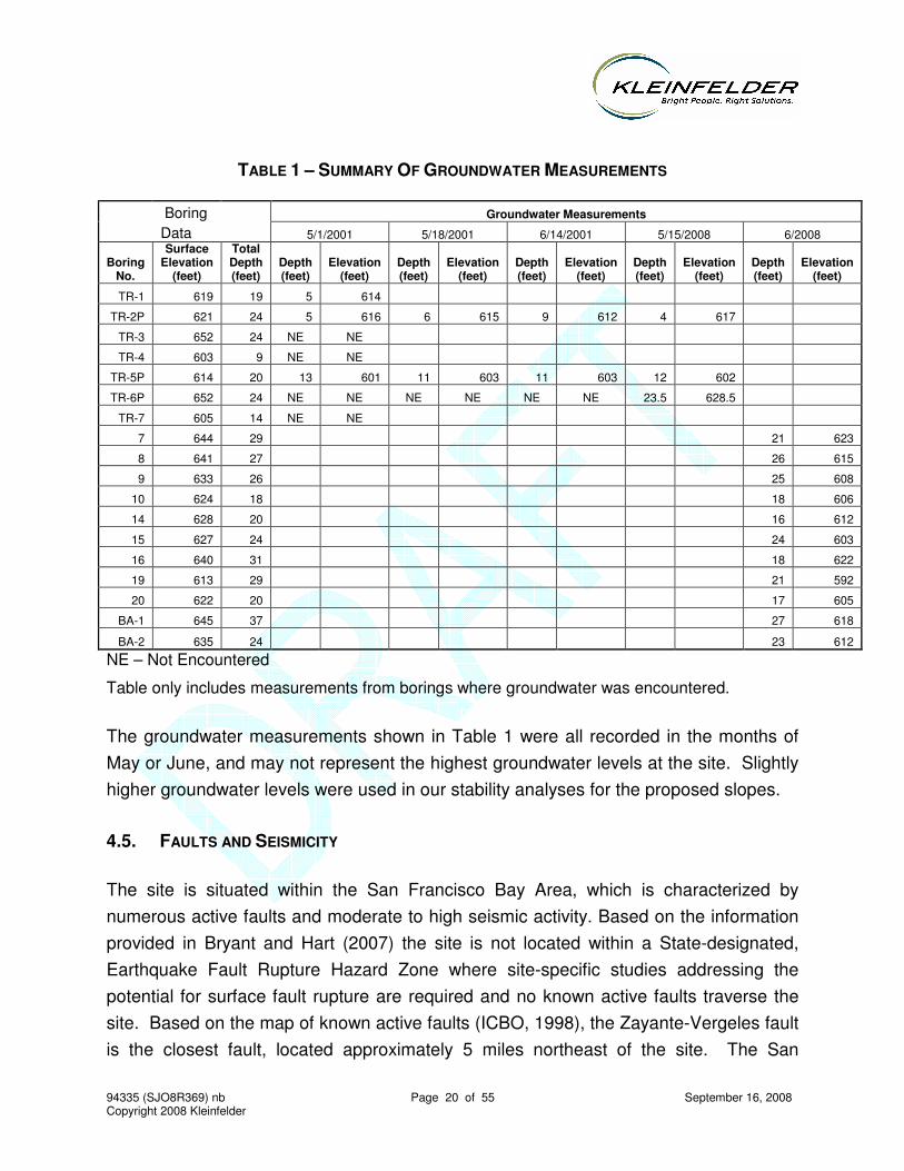
Groundwater was observed in eleven of our exploratory borings during our investigation and in three of the borings during the Treadwell & Rollo investigation in 2001. In general, groundwater was encountered within the underlying sandstone, commonly near the base of the contact between the sandstone and underlying quartz diorite. Groundwater found within the sandstone is considered to be in a perched condition, as it is underlain by relatively impermeable bedrock.
Recorded groundwater elevations from the two studies vary from approximately 592 to 628 feet and are summarized in Table 1. The highest recorded elevation of 628 feet is from a measurement taken from TR-6P on May 15, 2008. This reading from the piezometer in TR-6P, however, is in question as the measured depth is only 6 inches above the bottom of the boring. As noted in Table 1, groundwater was not encountered in TR-6P when it was drilled and was not recorded during subsequent measurements until 2008. It’s quite possible that the 2008 reading encountered water that accumulated in the bottom of the piezometer’s PVC casing over the last seven years. Assuming this to be the case, then the highest recorded elevation would be 623 feet, which is still above the elevation of the proposed building pad.
94335 (SJO8R369) nb Page 20 of 55 September 16, 2008 Copyright 2008 Kleinfelder
TABLE 1 – SUMMARY OF GROUNDWATER MEASUREMENTS
Boring Groundwater Measurements
Data 5/1/2001 5/18/2001 6/14/2001 5/15/2008 6/2008
Boring No.
Surface Elevation
(feet)
Total Depth (feet)
Depth (feet)
Elevation (feet)
Depth (feet)
Elevation (feet)
Depth (feet)
Elevation (feet)
Depth (feet)
Elevation (feet)
Depth (feet)
Elevation (feet)
TR-1 619 19 5 614
TR-2P 621 24 5 616 6 615 9 612 4 617
TR-3 652 24 NE NE
TR-4 603 9 NE NE
TR-5P 614 20 13 601 11 603 11 603 12 602
TR-6P 652 24 NE NE NE NE NE NE 23.5 628.5
TR-7 605 14 NE NE
7 644 29 21 623
8 641 27 26 615
9 633 26 25 608
10 624 18 18 606
14 628 20 16 612
15 627 24 24 603
16 640 31 18 622
19 613 29 21 592
20 622 20 17 605
BA-1 645 37 27 618
BA-2 635 24 23 612
NE – Not Encountered
Table only includes measurements from borings where groundwater was encountered.
The groundwater measurements shown in Table 1 were all recorded in the months of May or June, and may not represent the highest groundwater levels at the site. Slightly higher groundwater levels were used in our stability analyses for the proposed slopes.
4.5. FAULTS AND SEISMICITY
The site is situated within the San Francisco Bay Area, which is characterized by numerous active faults and moderate to high seismic activity. Based on the information provided in Bryant and Hart (2007) the site is not located within a State-designated, Earthquake Fault Rupture Hazard Zone where site-specific studies addressing the potential for surface fault rupture are required and no known active faults traverse the site. Based on the map of known active faults (ICBO, 1998), the Zayante-Vergeles fault is the closest fault, located approximately 5 miles northeast of the site. The San
94335 (SJO8R369) nb Page 21 of 55 September 16, 2008 Copyright 2008 Kleinfelder
Andreas fault is located approximately 8 miles northeast of the site. This portion of the San Andreas fault ruptured during the 1906 earthquake. Numerous other faults associated with the greater San Andreas fault system lie within 62 miles (100 kilometers) of the site and include the Sargent, Monterey Bay, San Gregorio, Monte Vista-Shannon, Hayward, Calaveras, Great Valley, and Concord fault zones. Other notable faults located near the site include the Ben Lomond and Butano faults, which are located approximately 1-1/2 and 7-1/2 miles to the southwest and northeast, respectively. The Ben Lomond Fault is considered inactive, while the activity of the Butano Fault is somewhat in question.
The project site and its vicinity are located in an area traditionally characterized by moderate to high seismic activity. A number of large earthquakes have occurred in the greater Bay Area during historic time (since 1800). Some of the significant regional earthquake events include: the 1906 (M7.9) San Francisco earthquake, the 1989 (M6.9) Loma Prieta earthquake, the 1838 (M7.0) San Francisco Peninsula earthquake, the 1911 (M6.5) Calaveras fault earthquake, the 1868 (M7.0) Hayward earthquake, the 1858 (M6.3) San Jose earthquake, and the 1980 (M5.9) Livermore earthquake. The epicenter for the 1989 Loma Prieta earthquake occurred less than 10 miles from the site.
A recent publication prepared by the U.S. Geological Survey regarding earthquake probabilities in the Bay Area (Working Group on California Earthquake Probabilities, 2003) concludes that there is a 62 percent chance that one of the major faults within the Bay Area will experience a major (M6.7+) earthquake during the period of 2003-2032. As has been demonstrated recently by the 1989 M6.9 Loma Prieta earthquake, the 1994 M6.7 Northridge earthquake, and the 1995 M6.9 Kobe earthquake, earthquakes of this magnitude range can cause severe ground shaking and significant damage to modern urban areas. Seismic design criteria for building design are presented in Section 5 of this report.
94335 (SJO8R369) nb Page 22 of 55 September 16, 2008 Copyright 2008 Kleinfelder
5 CONCLUSIONS AND RECOMMENDATIONS
5.1. CONCLUSIONS
Based on the results of our investigation, it is our opinion that development of the site is geotechnically feasible with respect to the site-specific geotechnical issues. This conclusion is based on the assumption that the recommendations presented in this report will be incorporated in the design and during construction of this project. The primary geotechnical concerns for this site are: 1) the potential for differential settlement; 2) the rippability of the underlying bedrock (quartz diorite); 3) the stability of the proposed slopes and tiered retaining wall systems; 4) the control of perched groundwater conditions; and 5) the debris flow potential of the western slope and related building clearance. Subsequent sections of this report evaluate these and other geotechnical issues and provide preliminary development recommendations.
It should be noted that soil and groundwater conditions can deviate from those conditions encountered at the exploration locations. If significant variations in the subsurface conditions are encountered during construction, it may be necessary for Kleinfelder to review the recommendations presented herein, and recommend adjustments as necessary.
5.2. 2007 CBC SEISMIC PARAMETERS
Based on the subsurface conditions, the site is classified as Site Class C as presented in Table 1613.5.2 and Section 1613.5.5 of the 2007 CBC. Site Class C is defined as very dense soil and soft rock with shear wave velocities between 1,200 feet/sec and 2,500 feet/sec, SPT-N > 50 blows/foot, or Su > 2,000 psf for the upper 100 feet. This site class is equivalent to Soil Profile Type SC according to Table 16-J of the 2001 CBC.
The Maximum Considered Earthquake (MCE) mapped spectral accelerations for 0.2 second and 1 second periods (SS and S1) were estimated using Section 1613.5 of 2007
94335 (SJO8R369) nb Page 23 of 55 September 16, 2008 Copyright 2008 Kleinfelder
California Building Code (CBC) and the ground motion parameter calculator developed by the U.S. Geological Survey (USGS, 2007)
1. The site coordinates are
Latitude: 37.0335 N Longitude: 122.0236 W
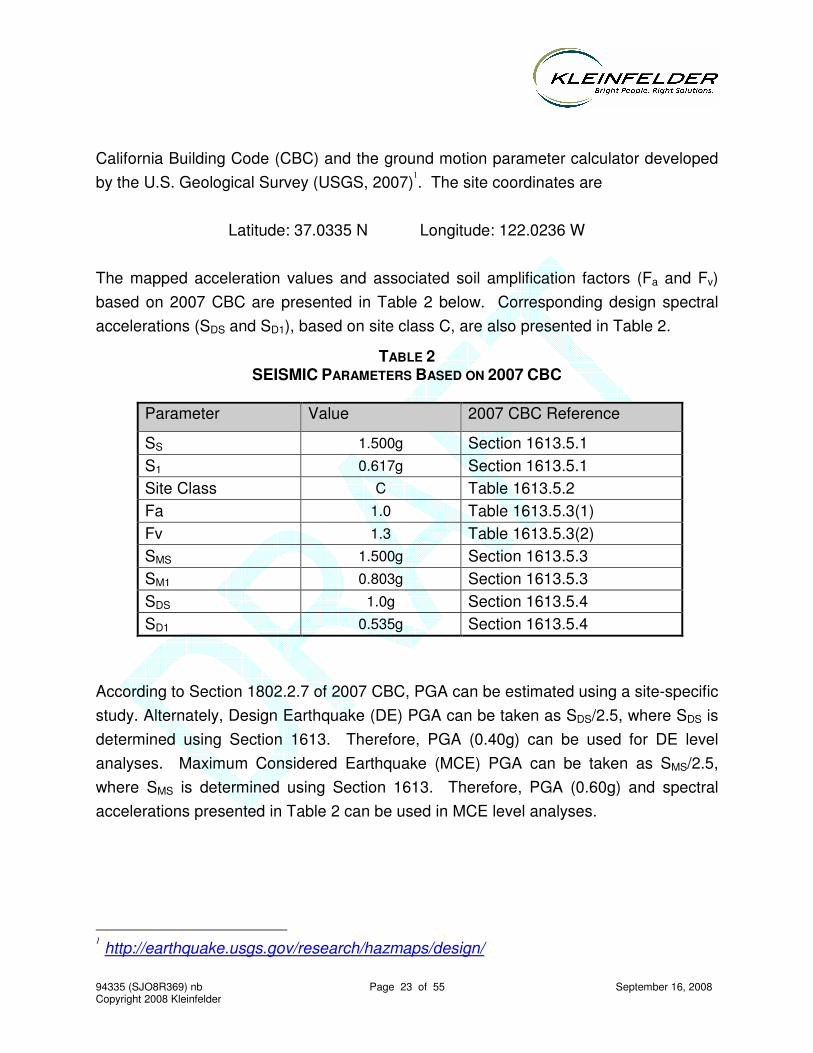
The mapped acceleration values and associated soil amplification factors (Fa and Fv) based on 2007 CBC are presented in Table 2 below. Corresponding design spectral accelerations (SDS and SD1), based on site class C, are also presented in Table 2.
TABLE 2 SEISMIC PARAMETERS BASED ON 2007 CBC
Parameter Value 2007 CBC Reference
SS 1.500g Section 1613.5.1 S1 0.617g Section 1613.5.1 Site Class C Table 1613.5.2 Fa 1.0 Table 1613.5.3(1) Fv 1.3 Table 1613.5.3(2) SMS 1.500g Section 1613.5.3 SM1 0.803g Section 1613.5.3 SDS 1.0g Section 1613.5.4 SD1 0.535g Section 1613.5.4
According to Section 1802.2.7 of 2007 CBC, PGA can be estimated using a site-specific study. Alternately, Design Earthquake (DE) PGA can be taken as SDS/2.5, where SDS is determined using Section 1613. Therefore, PGA (0.40g) can be used for DE level analyses. Maximum Considered Earthquake (MCE) PGA can be taken as SMS/2.5, where SMS is determined using Section 1613. Therefore, PGA (0.60g) and spectral accelerations presented in Table 2 can be used in MCE level analyses.
1 http://earthquake.usgs.gov/research/hazmaps/design/
94335 (SJO8R369) nb Page 24 of 55 September 16, 2008 Copyright 2008 Kleinfelder
5.3. LIQUEFACTION
Soil liquefaction is a phenomenon in which saturated, generally granular soils undergo a
substantial loss in strength due to excess build-up of pore water pressure during cyclic
loading such as that induced by earthquakes. The primary factors affecting the
liquefaction potential of soil include: (1) intensity and duration of seismic shaking, (2) soil
type and relative density, (3) overburden pressure, and (4) depth to water. Soils most
susceptible to liquefaction are generally clean, loose, fine-grained sands that are
saturated and uniformly graded. Under certain seismic shaking conditions, silty and
clayey soils of low plasticity have also been known to liquefy. The occurrence of
liquefaction is generally limited to saturated (submerged) soils located within about 50
feet of the ground surface.
The site lies within the USGS Felton quadrangle, which has not been mapped by the
California Geologic Survey as part of its ongoing effort to map landslide and liquefaction
related hazards throughout the San Francisco Bay Area. The site is underlain by medium
dense clayey sand surficial soils that overlie dense to very dense poorly graded sand
(sandstone) and quartz diorite bedrock. Perched groundwater conditions are present in
localized areas at depths varying from about 5 to 25 feet. Based on these subsurface
conditions the potential for liquefaction is considered low at this site due mainly to the
very dense nature of the underlying sandstone.
5.4. POTENTIAL FOR DIFFERENTIAL SETTLEMENT
According to the proposed grading plan, the Target store building and parking garage will be constructed over a cut-to-fill transition. Based on these conditions, there is a potential for unacceptable differential settlement between foundations in rock versus engineered fill in the building and garage areas. This potential differential settlement can be mitigated by overexcavating the surficial soils and bedrock materials and placing a minimum of three (3) feet of engineered fill beneath the foundation and slab areas. Details for overexcavation are provided in the Earthwork section of this report.
94335 (SJO8R369) nb Page 25 of 55 September 16, 2008 Copyright 2008 Kleinfelder
5.5. BEDROCK HARDNESS AND RIPPABILITY
The bedrock materials underlying the project site are composed of hard quartz diorite. Exploratory excavations in this material encountered refusal in the upper few feet. Based on the information obtained from on-site borings, hard bedrock will be encountered in the cut portions of the project. In particular, two borings (B-17 and B-18) encountered bedrock at elevations above 618 feet, which is the proposed pad grade. Other areas not covered by our exploration may also encounter bedrock during grading.
In order to address the rippability of the bedrock, we conducted a seismic refraction survey along the southwestern portion of the site. A seismic refraction survey consists of inducing shear waves from an energy source such as an explosive shot or sledgehammer blow into the earth along an array of signal receivers (geophones). The speed with which rock transmits these waves is controlled by its strength and degree of consolidation. These characteristics also materially affect the rock’s rippability. Conditions that are favorable for seismic-wave transmission and therefore unfavorable for rippability include:
• Massive or homogeneous rock units
• Absence of planes of structural weakness
• High degree of cementation
• High compressive strength
• High rock quality designation (RQD)
Rock conditions that are favorable for rippability include:
• Presence of fractures, faults, and planes of weakness
• Weathering
• Brittleness
• High degree of stratification or lamination
• Loose cementation
• Low compressive strength
• Low rock quality designation (RQD)
94335 (SJO8R369) nb Page 26 of 55 September 16, 2008 Copyright 2008 Kleinfelder
In evaluating the seismic-refraction velocities with respect to rippability, we used Caterpillar Tractor Company, Handbook of Rippability for heavy-duty ripper performance. The table provided by Caterpillar Tractor Company (see Plate 4) is for a large track bulldozer (D9) with a single ripper hook. This rippability rating is used as an indicator of the relative difficulty anticipated in excavating rock at the site and should be adjusted based on the equipment selected by the contractor for this project. It should be expected that even where rocks at this site are within the rippable range shown on the seismic profile and chart using the D9 described above, harder areas may be encountered.
The seismic velocity-layer profile (Plate 4) shows a thin layer of slow-transmission (300 ft/sec and easily excavatable) soil along the upper portion of the section. Below the soil veneer more dense material is encountered. The velocity of this material suggests that it is not saturated (below the water table) but may be moist. This material should also be easily excavatable with conventional earth-moving equipment. The irregular and undulatory velocity contact with the lower layer suggests an irregular bedrock contact. However, because groundwater is encountered at differing depths in the exploratory borings, it is inferred that some of the water is held in perched layers. The varying water content of the material near the lower velocity contact may be partially responsible for the irregular surface. The rock that lies below the lower velocity contact (greater than 11,000 ft/sec) is, according to the Caterpillar chart, not rippable. Equipment heavier that a single-ripper D9 or blasting may be needed to excavate rock associated with the high velocity layer near the bottom of the seismic profile.
It is important to note that the operator’s experience, working condition of excavation equipment and the selection of excavation tools used will be critical factors in the excavatability of rock. During construction, modifications to tool selection or replacement of equipment being used may be necessary to improve performance and production rates. It is recommended that the contractor who uses the rippability data in this report visit the site to observe soil and bedrock conditions. It is recommended that the contractor have options available in order to deal with differing soil and bedrock conditions.
94335 (SJO8R369) nb Page 27 of 55 September 16, 2008 Copyright 2008 Kleinfelder
5.6. SLOPE STABILITY
Slope stability analyses were performed to evaluate the global stability of the proposed cut and fill slopes and associated tiered retaining wall systems. This means that the combined geometry of the slopes and walls were evaluated and not the independent stability of the retaining wall structures. Additional stability analyses will be required by the wall designer in order to assess the stability of the retaining structures.
As part of our analyses, geologic cross-sections were developed through selected portions of the slopes and were used to evaluate their stability. The Factor of Safety determined by slope stability analyses relies heavily upon the geologic model used in the analyses and the strength parameters of the various geologic units. The elevation of the groundwater table is also a critical factor. Variations in these factors were considered during our analyses.
We analyzed the stability of the proposed slope and wall configurations for both static and seismic conditions. Our slope stability analysis also included developing representative soil-strength parameters and subsurface cross-sections under static and pseudo-static (seismic-load) conditions utilizing horizontal seismic coefficients. We also modeled the temporary cut (backcut) during the construction phase under static condition for the western perimeter slope. A brief discussion of these items is presented below.
5.6.1. Soil Strength Parameters
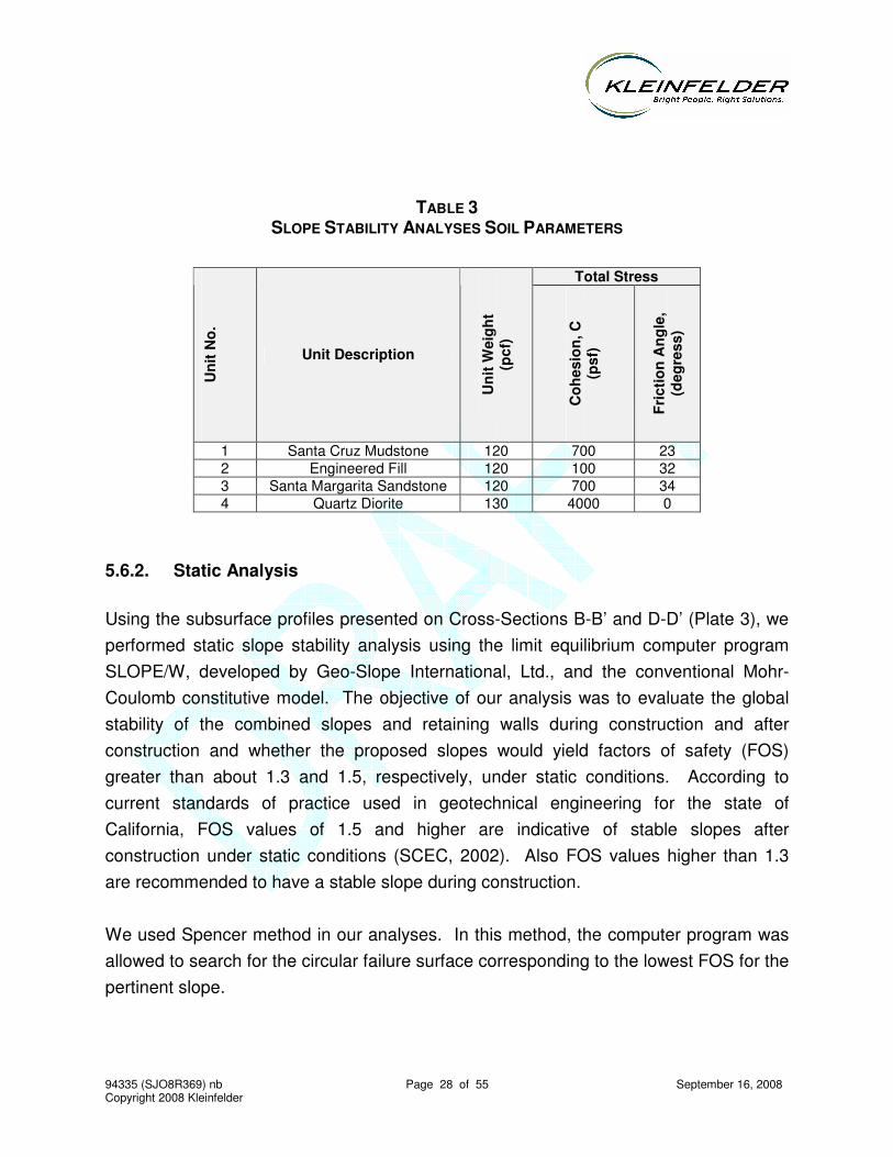
Our slope stability analysis utilized four different soil and rock units. These soil and rock units used in our model include engineered fill, Santa Cruz Mudstone, Santa Margarita Sandstone, and Quartz Diorite. Subsurface Cross-Sections B-B’ and D-D’ were used in our slope stability analyses (see Plate 3). In our opinion, these cross-sections represent portions of the proposed design where critical design and subsurface conditions are present. The strength parameters used in our slope stability analyses are shown in Table 3 below, and on the individual stability runs presented in Appendix F. The strength parameters were selected based on laboratory test data, and our engineering judgment.
94335 (SJO8R369) nb Page 28 of 55 September 16, 2008 Copyright 2008 Kleinfelder
TABLE 3 SLOPE STABILITY ANALYSES SOIL PARAMETERS
Total Stress
Uni
t No.
Unit Description
Uni
t Wei
ght
(pcf
)
Coh
esio
n, C
(p
sf)
Fric
tion
Ang
le,
(deg
ress
)
1 Santa Cruz Mudstone 120 700 23 2 Engineered Fill 120 100 32 3 Santa Margarita Sandstone 120 700 34 4 Quartz Diorite 130 4000 0
5.6.2. Static Analysis
Using the subsurface profiles presented on Cross-Sections B-B’ and D-D’ (Plate 3), we performed static slope stability analysis using the limit equilibrium computer program SLOPE/W, developed by Geo-Slope International, Ltd., and the conventional Mohr-Coulomb constitutive model. The objective of our analysis was to evaluate the global stability of the combined slopes and retaining walls during construction and after construction and whether the proposed slopes would yield factors of safety (FOS) greater than about 1.3 and 1.5, respectively, under static conditions. According to current standards of practice used in geotechnical engineering for the state of California, FOS values of 1.5 and higher are indicative of stable slopes after construction under static conditions (SCEC, 2002). Also FOS values higher than 1.3 are recommended to have a stable slope during construction.
We used Spencer method in our analyses. In this method, the computer program was allowed to search for the circular failure surface corresponding to the lowest FOS for the pertinent slope.
94335 (SJO8R369) nb Page 29 of 55 September 16, 2008 Copyright 2008 Kleinfelder
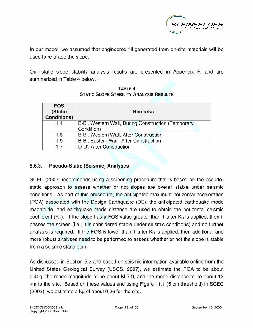
In our model, we assumed that engineered fill generated from on-site materials will be used to re-grade the slope.
Our static slope stability analysis results are presented in Appendix F, and are summarized in Table 4 below.
TABLE 4 STATIC SLOPE STABILITY ANALYSIS RESULTS
FOS
(Static Conditions)
Remarks
1.4 B-B’, Western Wall, During Construction (Temporary Condition)
1.6 B-B’, Western Wall, After Construction 1.9 B-B’, Eastern Wall, After Construction 1.7 D-D’, After Construction
5.6.3. Pseudo-Static (Seismic) Analyses
SCEC (2002) recommends using a screening procedure that is based on the pseudo-static approach to assess whether or not slopes are overall stable under seismic conditions. As part of this procedure, the anticipated maximum horizontal acceleration (PGA) associated with the Design Earthquake (DE), the anticipated earthquake mode magnitude, and earthquake mode distance are used to obtain the horizontal seismic coefficient (KH). If the slope has a FOS value greater than 1 after KH is applied, then it passes the screen (i.e., it is considered stable under seismic conditions) and no further analysis is required. If the FOS is lower than 1 after KH is applied, then additional and more robust analyses need to be performed to assess whether or not the slope is stable from a seismic stand point.
As discussed in Section 5.2 and based on seismic information available online from the United States Geological Survey (USGS, 2007), we estimate the PGA to be about 0.40g, the mode magnitude to be about M 7.9, and the mode distance to be about 13 km to the site. Based on these values and using Figure 11.1 (5 cm threshold) in SCEC (2002), we estimate a KH of about 0.26 for the site.
94335 (SJO8R369) nb Page 30 of 55 September 16, 2008 Copyright 2008 Kleinfelder
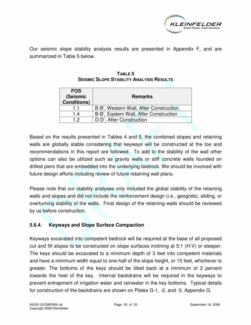
Our seismic slope stability analysis results are presented in Appendix F, and are summarized in Table 5 below.
TABLE 5 SEISMIC SLOPE STABILITY ANALYSIS RESULTS
FOS
(Seismic Conditions)
Remarks
1.1 B-B’, Western Wall, After Construction 1.4 B-B’, Eastern Wall, After Construction 1.2 D-D’, After Construction
Based on the results presented in Tables 4 and 5, the combined slopes and retaining walls are globally stable considering that keyways will be constructed at the toe and recommendations in this report are followed. To add to the stability of the wall other options can also be utilized such as gravity walls or stiff concrete walls founded on drilled piers that are embedded into the underlying bedrock. We should be involved with future design efforts including review of future retaining wall plans.
Please note that our stability analyses only included the global stability of the retaining walls and slopes and did not include the reinforcement design (i.e., geogrids), sliding, or overturning stability of the walls. Final design of the retaining walls should be reviewed by us before construction.
5.6.4. Keyways and Slope Surface Compaction
Keyways excavated into competent bedrock will be required at the base of all proposed cut and fill slopes to be constructed on slope surfaces inclining at 5:1 (H:V) or steeper. The keys should be excavated to a minimum depth of 3 feet into competent materials and have a minimum width equal to one-half of the slope height, or 15 feet, whichever is greater. The bottoms of the keys should be tilted back at a minimum of 2 percent towards the heel of the key. Internal backdrains will be required in the keyways to prevent entrapment of irrigation water and rainwater in the key bottoms. Typical details for construction of the backdrains are shown on Plates G-1, -2, and -3, Appendix G.
94335 (SJO8R369) nb Page 31 of 55 September 16, 2008 Copyright 2008 Kleinfelder
The finish surfaces of all fill slopes should be compacted to a minimum relative compaction of 90 percent. Final surface compaction should be achieved by overfilling the slopes during construction, backrolling the overfilled slope surfaces at vertical intervals not exceeding 4 to 5 feet, and then trimming the slopes back to the compacted inner core. Where this procedure may not be practical, surface compaction should be obtained by backrolling during construction to achieve at least 90 percent relative compaction within 6 to 8 inches of the finish surfaces. This initial back-rolling should be performed at vertical intervals not exceeding 4 to 5 feet. Final surface compaction should then be achieved by rolling the slope surface with a cable-lowered sheepsfoot and then re-rolling with a grid roller. During final surface compaction, it is critical that the moisture content of the surface soils be maintained at near optimum moisture content or slightly higher.
5.6.5. Footing Setback from Descending Slope Surface
According to the grading plan, the proposed building foundation will be located from 8 to 10 feet from the top of the uppermost retaining wall along the eastern and southern sides of the building. The proposed height of the descending southern slope varies from approximately 20 to 26 feet in height and for the descending eastern slope from approximately 9 to 26 feet. According to Section 1805.3.2 and Figure 1805.3.1 of the 2007 CBC, the horizontal distance between the footing and top of the adjacent slope should be one-third the height of the slope. Based on the maximum proposed slope height of 26 feet, the building should be setback a minimum of 8 feet from the top of the descending slope. However, Section 1805.3.2 also stipulates that “Where the slope is steeper than 1 unit vertical in 1 unit horizontal (100-percent slope), the required setback shall be measured from an imaginary plane 45 degrees (0.79 rad) to the horizontal, projected upward from the toe of the slope.” These criteria are met for most of the building’s foundation except for the northeast corner (see Cross-Section D-D’). In this area, the building foundation will need to be embedded a minimum of approximately 10 feet below the proposed grade.
94335 (SJO8R369) nb Page 32 of 55 September 16, 2008 Copyright 2008 Kleinfelder
5.7. GROUNDWATER AND SUBDRAINAGE
Perched groundwater is present in localized areas across the site and will require control during and after construction. Our investigation was performed after a two year period of successive drought conditions, and as such, it’s quite likely that groundwater levels across the site are typically higher during seasons of average or higher rainfall. In addition, significant portions of the underlying sandstone will be left-in-place after grading and will continue to accumulate moisture overtime. This moisture will perch on top of the underlying bedrock and migrate through the sandstone, eventually finding avenues to the surface within the developed area.
To mitigate the potential build-up of hydrostatic pressures below compacted fills due to infiltration of surface waters, subdrains should be installed along the exposed contact between the sandstone and quartz diorite bedrock. The approximate location of this subdrain is shown on Plate 2. The actual location of the subdrain and outlet(s) will be based on the exposed field conditions. Subdrains should be constructed in accordance with Plate G-3, Appendix G.
We also recommend installation of subslab drainage systems beneath the proposed store and the lower level of the proposed parking area, and that all retaining structures be provided with drainage systems.
5.8. LANDSLIDES AND BUILDING CLEARANCE FROM ASCENDING SLOPES
Based on our evaluation, it appears that shallow debris flows have occurred along the western perimeter slope in the past. Factors that influence the occurrence of debris flows in a given area are the steepness (gradient) of the slope, the type of soils and rock underlying the slope, and the physical characteristics of the slope face (Hollingsworth and Kovacs, 1981). Based on a simplified method of predicting debris flow occurrence by Hollingsworth and Kovacs (1981), it is our opinion that the western perimeter slope has a low potential for generating debris flows. This is mostly due to the lack of swales and gullies on the slope that tend to concentration surficial water flow during periods of heavy rain.
94335 (SJO8R369) nb Page 33 of 55 September 16, 2008 Copyright 2008 Kleinfelder
Although the potential for debris flows to impact the western slope and the proposed store is considered low, we suggest that some form of debris flow mitigation be considered due to the fact that the western building wall is proposed to be only 8 to 10 feet from the toe of the proposed slope. This distance is less than that required by Section 1805.3.1 and Figure 1805.3.1 of the 2007 CBC. According to Section 1805.3.1, the building should be setback 15 feet from the base of the proposed slope. Possible mitigation options include deflection walls and debris fences along the top of the proposed cut slope. Additional geotechnical studies in this area may be necessary to assist project designers.
5.9. SITE DEMOLITION
Existing structures located on the site will have to be demolished prior to construction. In addition to removal of existing structures, the following items should be considered.
5.9.1. Existing Improvements
As part of the demolition process, any existing foundations should be removed. Excavations from removal of foundations, underground utilities or other below ground obstructions should be cleaned of loose soil and deleterious material, and backfilled with compacted engineered fill. All fills should be compacted per the recommendations in Exhibit 1 of Appendix H.
5.9.2. Existing Utilities
Active or inactive utilities within the construction area should be protected, relocated, or abandoned. Pipelines 2 inches in diameter or less may be left in place beneath the planned building. Pipelines between 2 and 6 inches in diameter may be left in place within the limits of the building provided they are filled with sand/cement slurry and capped at both ends. Pipelines larger than 6 inches in diameter within the planned building should be removed. Active utilities to be reused should be carefully located and protected during demolition and during construction.
94335 (SJO8R369) nb Page 34 of 55 September 16, 2008 Copyright 2008 Kleinfelder
5.9.3. Monitoring Well Abandonment
The three monitoring wells installed by Treadwell & Rollo should be abandoned in accordance with local and state regulations prior to earthwork construction. The Scotts Valley Water District is the local agency that oversees well installation and destruction, and should be contacted for applicable abandonment procedures.
5.9.4. Existing Vegetation
Roots over 1 inch in diameter and over 3 feet in length should be removed within the building footprints and areas for planned improvements and exported offsite.
5.9.5. Bucket Auger Backfill
The two bucket auger borings (BA-1 and BA-2) drilled for the project, were backfilled with concrete in accordance with local permit requirements. These borings are approximately 26 inches in diameter and vary from 24 to 37 feet in depth. The approximate locations of these borings are shown on Plate 2 and should be marked in the field prior to the commencement of grading. Concrete exhumed from the borings should be either disposed of offsite or crushed into particles with a maximum size of 3 inches and mixed with on-site materials prior to placement in engineered fills.
5.10. EARTHWORK
All earthwork and grading should be performed in accordance with the following recommendations prepared by this firm as well as all applicable requirements of the City of Scotts Valley. Grading should also be performed in accordance with applicable provisions of the attached “Standard Grading Specifications” prepared by this firm (see Appendices G and H).
Site preparation and grading for this project should be performed in accordance with the site specific recommendations provided herein. A summary of soil compaction recommendations for this project is presented in Exhibit 1, Appendix H. Additional earthwork recommendations are presented in related sections of this report.
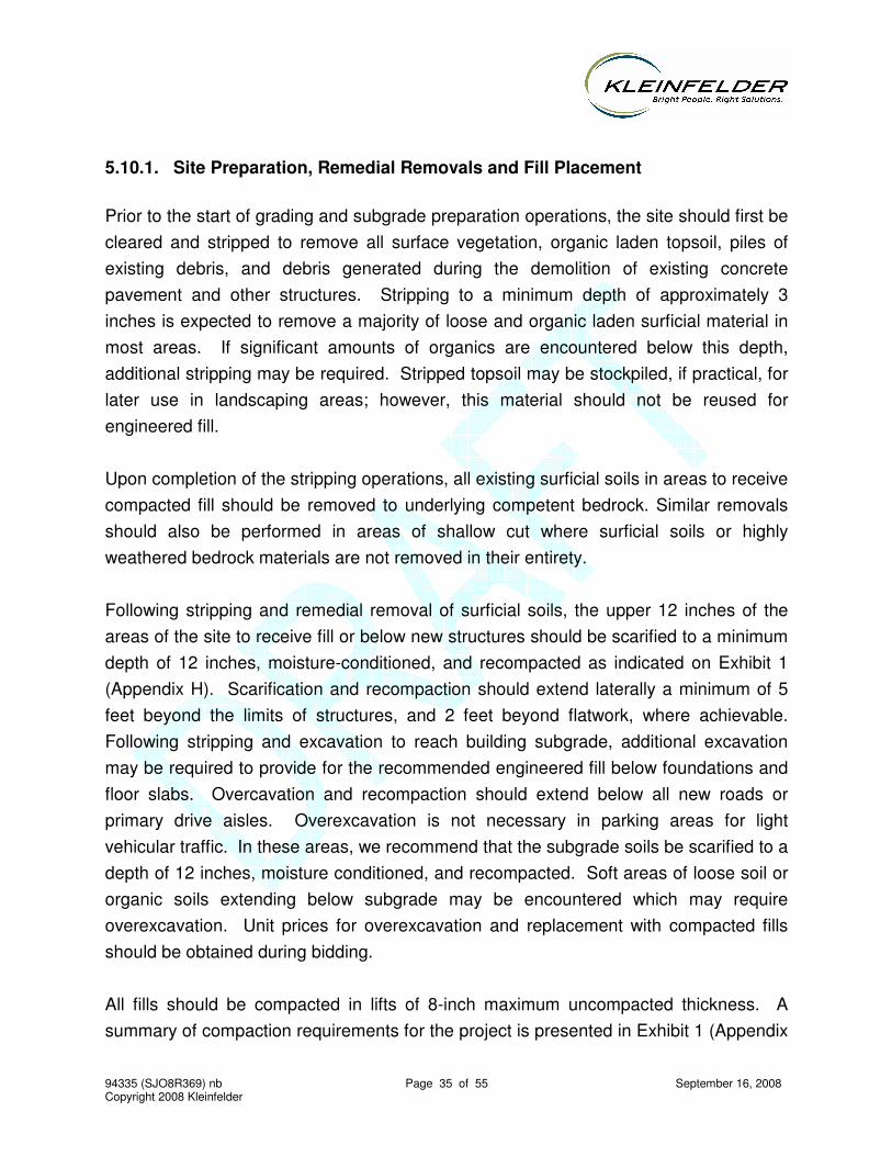
94335 (SJO8R369) nb Page 35 of 55 September 16, 2008 Copyright 2008 Kleinfelder
5.10.1. Site Preparation, Remedial Removals and Fill Placement
Prior to the start of grading and subgrade preparation operations, the site should first be cleared and stripped to remove all surface vegetation, organic laden topsoil, piles of existing debris, and debris generated during the demolition of existing concrete pavement and other structures. Stripping to a minimum depth of approximately 3 inches is expected to remove a majority of loose and organic laden surficial material in most areas. If significant amounts of organics are encountered below this depth, additional stripping may be required. Stripped topsoil may be stockpiled, if practical, for later use in landscaping areas; however, this material should not be reused for engineered fill.
Upon completion of the stripping operations, all existing surficial soils in areas to receive compacted fill should be removed to underlying competent bedrock. Similar removals should also be performed in areas of shallow cut where surficial soils or highly weathered bedrock materials are not removed in their entirety.
Following stripping and remedial removal of surficial soils, the upper 12 inches of the areas of the site to receive fill or below new structures should be scarified to a minimum depth of 12 inches, moisture-conditioned, and recompacted as indicated on Exhibit 1 (Appendix H). Scarification and recompaction should extend laterally a minimum of 5 feet beyond the limits of structures, and 2 feet beyond flatwork, where achievable. Following stripping and excavation to reach building subgrade, additional excavation may be required to provide for the recommended engineered fill below foundations and floor slabs. Overcavation and recompaction should extend below all new roads or primary drive aisles. Overexcavation is not necessary in parking areas for light vehicular traffic. In these areas, we recommend that the subgrade soils be scarified to a depth of 12 inches, moisture conditioned, and recompacted. Soft areas of loose soil or organic soils extending below subgrade may be encountered which may require overexcavation. Unit prices for overexcavation and replacement with compacted fills should be obtained during bidding.
All fills should be compacted in lifts of 8-inch maximum uncompacted thickness. A summary of compaction requirements for the project is presented in Exhibit 1 (Appendix

94335 (SJO8R369) nb Page 36 of 55 September 16, 2008 Copyright 2008 Kleinfelder
H). Laboratory maximum dry density and optimum moisture content relationships should be evaluated based on ASTM Test Designation D 1557 (latest edition).
All site preparation and fill placement should be observed by a Kleinfelder representative. It is important that during the stripping and scarification process our representative be present to observe whether any undesirable material is encountered in the construction area and whether exposed soils are similar to those encountered during our field investigation.
5.10.2. Benching
Fills placed against natural slope surfaces inclining at 5:1, horizontal to vertical or steeper, and against temporary backcut slopes associated with construction of stabilization fills or retaining structures should be placed on a series of level benches excavated into competent bedrock. These benches should be provided at vertical intervals of approximately 3 to 5 feet. Typical benching details are shown on Plate G-1, Appendix G.
5.10.3. Fill Material
Except for organic laden soil, the on-site soil is suitable for use as general engineered fill if it is free of deleterious matter. Maximum particle size for fill material should be limited to 3 inches, with at least 90 percent by weight passing the 1-inch sieve. Where imported material is required, it is recommended that it be granular in nature, adhere to the above gradation recommendations and conform to the following minimum criteria:
Plasticity Index 15 or less Liquid Limit less than 30% Percent Soil Passing #200 Sieve 8% to 40%
All on-site or import fill material should be compacted to the recommendations provided for engineered fill in Exhibit 1.
94335 (SJO8R369) nb Page 37 of 55 September 16, 2008 Copyright 2008 Kleinfelder
5.10.4. Weather/Moisture Considerations
Based on our experience in the area, grading during the rainy season may be difficult due to the type of soil at the site. If earthwork operations and construction for this project are scheduled to be performed during the rainy season or in areas containing saturated soils, provisions may be required for drying of soil or providing admixtures to the soil prior to compaction. If desired, we can provide recommendations for wet weather earthwork and alternatives for drying the soil prior to compaction. Conversely, additional moisture may be required during dry months. Water trucks should be made available in sufficient numbers to provided adequate water during earthwork operations.
It is also recommended that any landscape watering in the area, if present, be stopped at least two weeks prior to the start of grading activities at the site. If site grading is performed during the rainy months, the site soils could become very wet and difficult to compact without undergoing significant drying. This may not be feasible without delaying the construction schedule. For this reason, drier import soils could be required or lime treating may be needed if construction takes place during winter months.
5.10.5. Excavation, Backfill, and Utility Trenches
We anticipate that excavation for foundations and utility trenches can be made with either a backhoe or trencher, or similar earthwork equipment. Excavations deeper than 4 feet deep should be sloped back at 1:1 (horizontal to vertical) or be shored or braced for safety. Excavations should not extend below a 1:1 (horizontal to vertical) plane extending down from any adjacent footings. All excavations should be checked by our representative during construction to allow any modifications.
During wet weather, earthen berms or other methods should be used to prevent runoff water from entering all excavations. Runoff water and/or groundwater encountered within excavations should be collected and disposed outside the construction limits.
Utility excavations should be located such that a 2:1 (H to V) line extended up from the pipe does not pass below a foundation element. This is recommended to reduce the risk of undermining foundation support if future excavation and repair is needed.
94335 (SJO8R369) nb Page 38 of 55 September 16, 2008 Copyright 2008 Kleinfelder
All excavations must comply with applicable local, state, and federal safety regulations including the current OSHA Excavation and Trench Safety Standards. Construction site safety generally is the sole responsibility of the Contractor, who shall also be solely responsible for the means, methods, and sequencing of construction operations. We are providing this information solely as a service to our client. Under no circumstances should the information provided be interpreted to mean that Kleinfelder is assuming responsibility for construction site safety or the Contractor's activities; such responsibility is not being implied and should not be inferred.
The Contractor should be aware that slope height, slope inclination, or excavation depths (including utility trench excavations) should in no case exceed those specified in local, state, and/or federal safety regulations (e.g., OSHA Health and Safety Standards for Excavations, 29 CFR Part 1926, or successor regulations).
At the time of this geotechnical investigation, groundwater was encountered as shallow as 5 feet below the ground surface. However, the actual depth at which groundwater may be encountered in trenches and excavations may vary. As a minimum, provisions should be made to ensure that conventional sump pumps used in typical trenching and excavation projects are available during construction in case groundwater is found to be higher than observed during our investigation, and/or if substantial runoff water accumulates within the excavations as a result of wet weather conditions.
5.11. BUILDING FOUNDATIONS
Based on our investigation, the loads for the proposed building can be supported by isolated or continuous shallow footings. Footings should be supported on 3 feet of engineered fill where the bottom 1 foot should be scarified and recompacted in place. The recommended allowable soil bearing pressures, depth of embedment, and width of footings are presented in Table 5.
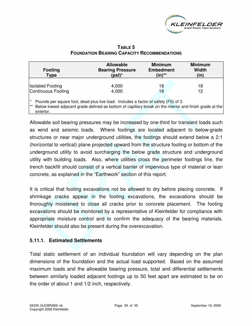
94335 (SJO8R369) nb Page 39 of 55 September 16, 2008 Copyright 2008 Kleinfelder
TABLE 5 FOUNDATION BEARING CAPACITY RECOMMENDATIONS
Allowable Minimum Minimum Footing Bearing Pressure Embedment Width Type (psf)* (in)** (in) Isolated Footing 4,000 18 18 Continuous Footing 4,000 18 12 * Pounds per square foot, dead plus live load. Includes a factor of safety (FS) of 3. ** Below lowest adjacent grade defined as bottom of capillary break on the interior and finish grade at the exterior.
Allowable soil bearing pressures may be increased by one-third for transient loads such as wind and seismic loads. Where footings are located adjacent to below-grade structures or near major underground utilities, the footings should extend below a 2:1 (horizontal to vertical) plane projected upward from the structure footing or bottom of the underground utility to avoid surcharging the below grade structure and underground utility with building loads. Also, where utilities cross the perimeter footings line, the trench backfill should consist of a vertical barrier of impervious type of material or lean concrete, as explained in the “Earthwork” section of this report.
It is critical that footing excavations not be allowed to dry before placing concrete. If shrinkage cracks appear in the footing excavations, the excavations should be thoroughly moistened to close all cracks prior to concrete placement. The footing excavations should be monitored by a representative of Kleinfelder for compliance with appropriate moisture control and to confirm the adequacy of the bearing materials. Kleinfelder should also be present during the overexcavation.
5.11.1. Estimated Settlements
Total static settlement of an individual foundation will vary depending on the plan dimensions of the foundation and the actual load supported. Based on the assumed maximum loads and the allowable bearing pressure, total and differential settlements between similarly loaded adjacent footings up to 50 feet apart are estimated to be on the order of about 1 and 1/2 inch, respectively.

94335 (SJO8R369) nb Page 40 of 55 September 16, 2008 Copyright 2008 Kleinfelder
5.11.2. Lateral Resistance
Lateral load resistance may be derived from passive resistance along the vertical sides of the footings, friction acting at the base of the footing, or a combination of the two. An allowable passive earth pressure of 400 psf per foot of depth may be used for design. A coefficient of friction value of 0.4 between the base of the footings and the engineered fill soils can be used for sliding resistance using the dead load forces. Friction and passive resistance may be combined without reduction. We recommend that the first foot of soil cover be neglected in the passive resistance calculations if the ground surface is not protected from erosion or disturbance by a slab, pavement or in some similar manner.
5.12. SLABS-ON-GRADE
5.12.1. Interior
Concrete slabs-on-grade will include building interior floor slabs. All interior slabs should be supported on a minimum of 12 inches of engineered fill over properly prepared subgrade soils, as described in the “Earthwork” section of this report.
Where the risk of moisture penetration through interior floor slabs is to be reduced, the slab should be constructed on a layer of capillary break material covered by a continuous impermeable membrane vapor barrier. The capillary break material should be at least 4 inches thick, and should consist of free-draining crushed rock or gravel graded such that 100 percent will pass the 1-inch sieve and none will pass the No. 4 sieve. The impermeable membrane should consist of a 20-mil polyethylene sheeting or similar moisture barrier. Lapped joints and perforations in the vapor barrier should be kept to a minimum, and should be sealed. To provide protection for the membrane during construction, Target may elect to place 2 inches of slightly moistened clean fine sand on top of the membrane prior to placement of the floor slab concrete. This protective sand layer must not be allowed to become saturated with water prior to placement of the concrete to reduce the potential for future slab moisture transmission concerns. Where crushed rock is used as the capillary break material, seating of the
94335 (SJO8R369) nb Page 41 of 55 September 16, 2008 Copyright 2008 Kleinfelder
rock with a vibratory plate compactor may aid in reducing the potential for damage to the vapor barrier as the reinforcing steel and the concrete are placed.
It should be emphasized that we are not floor moisture proofing experts. While the current industry standard is to place a vapor barrier over a gravel layer as described above, this system may not be completely effective in preventing floor slab moisture problems. These systems typically will not necessarily assure that floor slab moisture transmission rates will meet floor-covering manufacturing standards and that indoor humidity levels be appropriate to inhibit mold growth. The design and construction of such systems are totally dependent on the proposed use and design of the proposed building. All elements of building design and function should be considered in the slab-on-grade floor design. Building design and construction may have a greater role in perceived moisture problems since sealed buildings/rooms or inadequate ventilation may produce excess moisture in a building and affect indoor air quality.
5.12.2. Exterior
Where exterior flatwork is to be constructed, it should be supported on a minimum of 12 inches of engineered fill on properly prepared subgrade. The subgrade should be prepared by scarifying the surface to a minimum depth of 12 inches. The scarified soil should then be moisture conditioned and recompacted as specified in the “Earthwork” section of this report. For more uniform support, 4 inches of sand or gravel can be used beneath the flatwork. Where exterior flatwork will be subjected to vehicle loading, a minimum of 6 inches of Caltrans Class 2 Aggregate Base should be placed beneath the flatwork. Flatwork should not be attached to the building as cracking could result in the event of differential movement between the building and the flatwork.
5.12.3. Floor Subdrain
The perched groundwater conditions at the site could allow groundwater to accumulate
and pond beneath the proposed building pad and floor over time. In order to mitigate this
condition, we recommend the installation of an under slab subdrain system. This
subdrain system would be installed after the building pad has been brought to grade, but
before construction of the concrete building slab. The subdrain system should consist of
94335 (SJO8R369) nb Page 42 of 55 September 16, 2008 Copyright 2008 Kleinfelder
trench drains spaced approximately 40 feet on-center, generally parallel to La Madrona
Dive. Each trench drain should be a minimum of 18 inches deep, 12 inches wide, and
consist of a 4-inch diameter perforated pipe surrounded by 4 inches of Class 2 permeable
or ¾ inch drain rock wrapped with filter fabric. The drains should be tied into the area
drain system along the building perimeter. �
5.13. CORROSION
The corrosivity testing and evaluation was performed by CERCO Analytical of Pleasanton, California using ASTM test methods, as described in CERCO Analytical’s report and results presented in Appendix E.
Based upon the resistivity measurement, the samples tested are classified as “moderately corrosive” by CERCO Analytical. They recommend that all buried iron, steel, cast iron, ductile iron, galvanized steel, and dielectric coated steel or iron should be properly protected against corrosion depending upon the critical nature of the structure. All buried metallic pressure piping such as ductile iron firewater pipelines should be protected against corrosion. Since we are not corrosion specialists, a corrosion testing firm should be contacted for specific design details, if necessary.
The above are general discussions. A more detailed corrosion investigation may include more or fewer concerns, and should be directed by a corrosion expert. Soils actually in contact with concrete should be sampled and tested for sulfate content during construction and the concrete mixes used should comply with the requirements of the 2007 California Building Code (CBC) based on these results. Consideration should also be given to soils in contact with concrete that will be imported to the site during construction, such as topsoil and landscaping materials. For instance, any imported soil materials should not be any more corrosive than the on-site soils and should not be classified more corrosive than “moderately corrosive.” Also, on-site cutting and filling may result in soils contacting concrete that were not anticipated at the time of this investigation.
94335 (SJO8R369) nb Page 43 of 55 September 16, 2008 Copyright 2008 Kleinfelder
5.14. RETAINING WALLS
Retaining walls should be designed to resist lateral pressures caused by water, soil and external surface loads. The magnitude of the lateral pressures will depend on whether or not the walls will be allowed to move, the type of backfill and its method of placement (retaining walls), excavation and shoring procedures, the magnitude of external loads, the design water level elevation, and back drainage provisions.
In addition to the static loading of the walls due to earth and surcharge pressures, the retaining walls will be subjected to short-term lateral loading during a seismic event. The structural engineer should check the structural integrity of the retaining walls for a combination of static and seismic (as required by code) lateral loading. The average total (moist) unit weight of the backfill soil may be assumed to be 120 pounds per cubic foot.
For design of unrestrained (yielding) walls, where the backfill is level or inclined and composed of on-site soils, an equivalent fluid pressure as shown in Table 7 can be used:

94335 (SJO8R369) nb Page 44 of 55 September 16, 2008 Copyright 2008 Kleinfelder
TABLE 7 SOIL PRESSURE (UNRESTRAINED WALLS)
Backfill Inclination Equivalent Fluid Pressure
(psf)
0 40
4:1 45
3:1 50
2:1 55
5.14.1. Seismic-Induced Wall Pressures
For flexible retained heights, the seismic pressure distribution may be considered to be rectangular. The resultant of this force may be assumed to be at 1/2 the height of the wall. For level backfill conditions, a maximum pressure of 8H pounds per square foot for flexible walls and 18 H for stiff walls, where H is the height of the wall in feet may be used for design for engineered backfill. These pressures have been obtained by using a seismic coefficient equal to ½ PGA. This pressure is in addition to the static pressures presented above and may be considered as an ultimate load in design.
5.14.2. Additional Surcharge Loads
For surcharge loads imposed on the wall(s), a rectangular distribution with a uniform pressure equal to one-third of the surcharge pressure should be used for unrestrained wall(s) (active earth pressure condition). Additional analyses during design may be needed to evaluate the effects of non-uniform surcharge loads such as point loads, line loads, or other such presently undefined surcharge loads. In that case, we should be consulted for supplemental geotechnical recommendations.
Care must be taken during the compaction operation not to over stress the wall. Heavy construction equipment should be maintained a distance of at least 3 feet away from the walls while the backfill is being placed. Hand-operated compaction equipment should be used to compact the backfill soils within a 3-foot-wide zone adjacent to the walls.
94335 (SJO8R369) nb Page 45 of 55 September 16, 2008 Copyright 2008 Kleinfelder
Kleinfelder should be contacted when development plans are finalized so we can review wall and backfill conditions.
5.14.3. Wall Foundations
Wall foundations should be designed in accordance with the building foundation design recommendations presented in this report and reinforced in accordance with local codes and structure considerations. Lateral resistance will depend on the wall foundations, as discussed previously.
5.14.4. Wall Drainage
Water pressures can accumulate behind walls in response to shallow groundwater table, irrigation, rainfall and runoff or other factors. If retaining walls do not include full wall drainage, hydrostatic pressures should be included in the design. Walls may be designed without hydrostatic pressures if they are fully drained. Wall drainage should consist of either a prefabricated drainage material or a layer of drain rock. With either system, a mechanism (such as a drain pipe) should be installed to move the water from behind the wall to a storm drain system.
Prefabricated drainage material (such as Miradrain® or an approved alternate) may be used behind retaining walls. Prefabricated drainage material should be installed in accordance with the manufacturer's recommendations.
As an alternative to prefabricated drainage material, a drain rock layer may be used. The drain rock layer should 1 to 2 feet thick and extend to within 1 foot of the ground surface. Four-inch diameter perforated plastic pipe should be installed (with the perforations facing down) along the base of the walls on a 4 inch thick bed of drain rock. The pipe should be sloped to drain by gravity to a sump or other drainage facility. Weep holes may also be used. The weep holes should be a minimum of 3 inches in diameter located at no more then 10 feet apart, and a screen placed at the back of the holes if drain rock is used.
94335 (SJO8R369) nb Page 46 of 55 September 16, 2008 Copyright 2008 Kleinfelder
Drain rock should conform to Caltrans Class 2 permeable material. Alternatively, locally available, clean, 1/2 to 3/4-inch maximum size crushed rock or gravel could be used, provided it is encapsulated in a non-woven geotextile filter fabric, such as Mirafi® 140N or an approved alternative. A 1-foot thick cap of clayey soil should be placed over the drain rock to inhibit surface water infiltration.
Even with the back drain system, localized wet spots may occur in the walls. If this is undesirable, then the wall should be waterproofed. If this is a concern, consideration should be given to consulting with a waterproofing expert.
5.15. CONCRETE PAVEMENT
Portland cement concrete pavements are typically better able to resist the intense stresses induced in pavements by the turning motions of vehicles - particularly delivery and garbage trucks. Concrete pavements should be used in areas frequented by such vehicles as well as in driveway and entry aprons. Concrete pavement sections presented in the table below are based on current Portland Cement Association (PCA) design procedures and the assumptions listed below. These assumptions should be reviewed by the project Owner, Architect, and/or Civil Engineer to evaluate their suitability for this project. Changes in the assumptions will affect the corresponding pavement section.
• Modulus of subgrade reaction = 150 psi/in
• Modulus of rupture of concrete = 550 psi
• Aggregate Interlock Joints
• No concrete shoulders
• 20-year design life
• Load Safety Factor = 1.0

94335 (SJO8R369) nb Page 47 of 55 September 16, 2008 Copyright 2008 Kleinfelder
TABLE 8 RECOMMENDED PORTLAND CEMENT CONCRETE PAVEMENT SECTIONS
Proposed
Use
Average
Daily Truck
Traffic
Portland Cement
Concrete
Aggregate
Base
(ADTT) (feet) (inches) (feet) (inches)
Light Duty 15 0.55 7.0 0.50 6.0
Heavy Duty 30 0.65 7.5 0.50 6.0
Portland cement concrete pavement sections provided above are contingent on the following recommendations being implemented during construction.
• All pavement subgrades should be prepared as recommended in the SITE
PREPARATION and ENGINEERED FILL sections of this report.
• Adequate drainage (both surface and subsurface) should be provided such that
the subgrade soils are not allowed to become wet.
• Concrete pavement should have a minimum 28 day compressive strength of
4,000 psi. Concrete slumps should be from 3 to 4 inches. The concrete should
be properly cured in accordance with PCA recommended procedures and
vehicular traffic should not be allowed for 3 days (automobile traffic) or 7 days
(truck traffic).
• To help offset plastic shrinkage, concrete pavement may be reinforced with at
least No. 3 bars, 24 inches on-center, each way or 6x6-W2.9xW2.9 wire mesh
(located 1/3 of the slab thickness from the top of the slab).
• Construction and/or control joint spacing should not exceed 12 feet.
• Thickened edges should be used along outside edges of concrete pavements.
Edge thickness should be at least 2 inches greater than the concrete pavement
thickness and taper to the actual concrete pavement thickness 36 inches inward
from the edge. Integral curbs may be used in lieu of thickened edges.
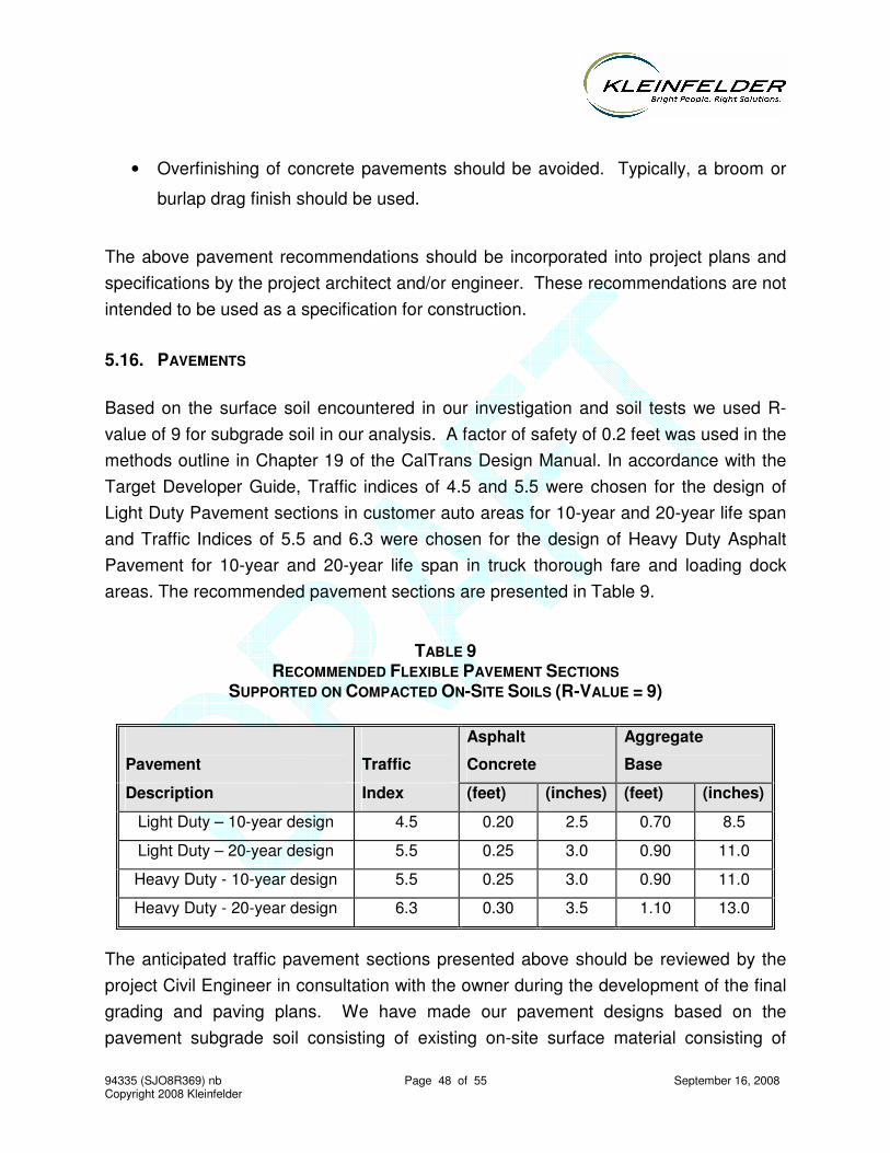
94335 (SJO8R369) nb Page 48 of 55 September 16, 2008 Copyright 2008 Kleinfelder
• Overfinishing of concrete pavements should be avoided. Typically, a broom or
burlap drag finish should be used.
The above pavement recommendations should be incorporated into project plans and specifications by the project architect and/or engineer. These recommendations are not intended to be used as a specification for construction.
5.16. PAVEMENTS
Based on the surface soil encountered in our investigation and soil tests we used R-value of 9 for subgrade soil in our analysis. A factor of safety of 0.2 feet was used in the methods outline in Chapter 19 of the CalTrans Design Manual. In accordance with the Target Developer Guide, Traffic indices of 4.5 and 5.5 were chosen for the design of Light Duty Pavement sections in customer auto areas for 10-year and 20-year life span and Traffic Indices of 5.5 and 6.3 were chosen for the design of Heavy Duty Asphalt Pavement for 10-year and 20-year life span in truck thorough fare and loading dock areas. The recommended pavement sections are presented in Table 9.
TABLE 9
RECOMMENDED FLEXIBLE PAVEMENT SECTIONS SUPPORTED ON COMPACTED ON-SITE SOILS (R-VALUE = 9)
Pavement
Traffic
Asphalt
Concrete
Aggregate
Base
Description Index (feet) (inches) (feet) (inches)
Light Duty – 10-year design 4.5 0.20 2.5 0.70 8.5
Light Duty – 20-year design 5.5 0.25 3.0 0.90 11.0
Heavy Duty - 10-year design 5.5 0.25 3.0 0.90 11.0
Heavy Duty - 20-year design 6.3 0.30 3.5 1.10 13.0
The anticipated traffic pavement sections presented above should be reviewed by the project Civil Engineer in consultation with the owner during the development of the final grading and paving plans. We have made our pavement designs based on the pavement subgrade soil consisting of existing on-site surface material consisting of
94335 (SJO8R369) nb Page 49 of 55 September 16, 2008 Copyright 2008 Kleinfelder
gravelly/sandy clay. If site grading exposes soil other than that utilized in our analysis, we should perform additional tests to confirm or revise the recommended pavement sections to reflect the actual field conditions.
Subgrade preparation should extend a minimum of 2 feet laterally beyond the face of the curb (or edge of pavement if there is no curb) and consist of scarifying, moisture conditioning, and compacting as recommended in Exhibit 1. Compacted pavement subgrade should be non-yielding. Removal and subsequent replacement of some material (i.e., areas of excessively wet materials, unstable subgrade, or pumping soils) may be required to obtain the minimum compaction to the recommended depth.
Asphalt concrete should comply with the specifications presented in Section 39 of the CalTrans Standard Specifications, latest edition. Class 2 Aggregate Base materials should conform with Section 26 of the CalTrans Standard Specifications, latest edition. ASTM test procedures should be used to assess the percent relative compaction of the pavement subgrade soils, aggregate base and asphalt concrete.
Pavement surface should be sloped at a minimum of 2 percent and drainage gradients maintained to carry all surface water off the site due to the slightly porous or permeable nature of asphalt concrete. Surface water ponding should not be allowed anywhere on the site during or after construction.
94335 (SJO8R369) nb Page 50 of 55 September 16, 2008 Copyright 2008 Kleinfelder
6 ADDITIONAL SERVICES
The review of plans and specifications and field observations and testing performed during construction by Kleinfelder are an integral part of the conclusions and recommendations made in this report. If Kleinfelder is not retained for these services, the client will be assuming Kleinfelder's responsibility for any potential claims that may arise during or after construction. The required tests, observations, and consultation by Kleinfelder prior to and during construction include, but are not limited to:
• Review of plans and specifications, especially those for retaining walls;
• Observations of site grading, including stripping, removal of existing materials, and engineered fill construction;
• Geologic mapping during construction, especially in areas of proposed slopes in order to compare the assumed conditions presented in this report with the exposed field conditions;
• Observations of site improvement operations and testing to evaluate adequacy of improvement; and
• In-place density testing of fills, backfills, and finished subgrades.
94335 (SJO8R369) nb Page 51 of 55 September 16, 2008 Copyright 2008 Kleinfelder
7 LIMITATIONS
The services provided under this contract as described in this report include professional opinions and judgments based on the data collected. These services have been performed according to generally accepted geotechnical engineering practices that exist in the San Francisco Bay Area at the time the report was written. No other warranty is expressed or implied. This report is issued with the understanding that the owner chooses the risk he wishes to bear by the expenditures involved with the construction alternatives and scheduling that is chosen.
The conclusions and recommendations of this report are for the proposed new Target store project at Scotts Valley, California, as described in the text of this report. The conclusions and recommendations in this report are invalid if:
• The proposed project, as described, changes;
• The proposed building is relocated;
• The report is used for adjacent or other property;
• The Additional Services section of this report is not followed;
• If changes of grades occur between the issuance of this report and construction; or
• Any other change is implemented that materially alters the project from that proposed at the time this report was prepared.
The conclusions and recommendations presented in this report are based on information obtained from the following:
• The subsurface explorations performed for this investigation.
• The observations of our geologist and geotechnical engineer.
• The results of laboratory tests.
• Our experience in the area.
The boring logs do not provide a warranty as to the conditions that may exist at the entire site. The extent and nature of subsurface soil, bedrock and groundwater variations may not become evident until construction begins. It is possible that
94335 (SJO8R369) nb Page 52 of 55 September 16, 2008 Copyright 2008 Kleinfelder
variations in soil and bedrock conditions between borings could exist between or beyond the points of exploration or that groundwater elevations may change, both of which may require additional studies, consultation, and possible design revisions. If conditions are encountered in the field during construction which differ from those described in this report, our firm should be contacted immediately to provide any necessary revisions to these recommendations.
It is the client's responsibility to see that all parties to the project including the designer, contractor, subcontractors, etc., are made aware of this report in its entirety, including the Additional Services and Limitations sections.
94335 (SJO8R369) nb Page 53 of 55 September 16, 2008 Copyright 2008 Kleinfelder
8 REFERENCES
Brabb, E.E., 1997, Geologic map of Santa Cruz County, California: A digital database prepared by S. Graham, C. Wentworth, D. Knifong, R. Graymer and J. Blissenbach: U.S. Geological Survey Open-File Report 97-489, map scale 1:62,500.
Bryant, W.A. and Hart, E.W., (2007), Fault-Rupture Hazard Zones in California: California Division of Mines and Geology, Special Publication 42, 2007 revised edition.
California Building Code (2007), California Building Standards Commission.
California Building Standards Commission (1998), California Code of Regulations, Title 24, California Building Standards Code.
California Department of Conservation Division of Mines and Geology (1997), Guidelines for Evaluating and Mitigating Seismic Hazards in California: DMG Special Publication 117.
Clark, J.C., 1981, Stratigraphy, paleontology, and geology of the central Santa Cruz Mountains, California Coast Ranges: U.S. Geological Survey Professional Paper 1168, 51 p., map scale 1:24,000.
Clark, J.C. and Rietman, J.D., 1973, Oligocene stratigraphy, tectonics, and paleogeography southwest of the San Andreas fault, Santa Cruz Mountains and Gabilan Range, California Coast Ranges: U.S. Geological Survey Professional Paper 783, 18 p., map scale 1:125,000.
Cruden, D.M and Varnes, D.J., 1996, Landslide Types and Processes: in eds. Turner, A.K and Schuster, R.L., Landslides Investigation and Mitigation: Transportation Research Board, Special Report 247, National Academy Press, Washington, D.C., pp. 36-75.
Ellen, S.D. and Wieczorek, G.F., 1988, Landslides, floods, and marine effects of the storm of January 3-5, 1982, in the San Francisco Bay Region, California: U.S. Geological Survey Professional Paper 1434, 310 p.
Hollingsworth, R. and Kovacs, G.S., 1981, Soil Slumps and Debris Flows: Prediction and Protection: Bulletin of the Association of Engineering Geologists, Vo. 18, No. 1, pp. 17-28.
Holzer, T.L. (1998), The Loma Prieta, California, Earthquake of October 17, 1989 – Liquefaction: U.S. Geological Survey Professional Paper 1551-B.
94335 (SJO8R369) nb Page 54 of 55 September 16, 2008 Copyright 2008 Kleinfelder
International Conference of Building Officials (ICBO), 1998, Maps of Known Active Fault Near-Source Zones in California and Adjacent Portions of Nevada – To Be Used with the 1997 Uniform Building Code: California Department of Conservation, Division of Mines and Geology in Cooperation with the Structural Engineers Association of California – Seismology Committee.
Ishihara, K. (1985), Stability of Natural Deposits During Earthquakes: Proc. 11th International Conference on Soil Mechanics and Foundation Engineering, San Francisco, Vol. 2, pp. 321-376.
Martin, G. R. and Lew, M. (1999), Recommended Procedures for Implementation of DMG Special Publication 117 – Guidelines for Analyzing and Mitigating Liquefaction in California, Southern California Earthquake Center, March.
Nilsen, T.H., Taylor, F.A., and Dean, R.M. (1976), Natural Conditions that Control Landsliding in the San Francisco Bay Region- An Analysis Based on Data From the 1968-69 and 1972-73 Rainy Seasons: U.S. Geological Survey Bulletin 1424.
Pulver, B.S., 1979, Geology and landslides of the Felton 7.5’ Quadrangle, California: California Department of Forestry, Title II Data Compilation Project, scale 1:24,000.
Southern California Earthquake Center (SCEC), 2002, Recommended Procedures for Implementation of DMG Special Publication 117, Guidelines for Analyzing and Mitigating Landslide Hazards in California.
Stanley, R.G. (1985), Middle Tertiary Sedimentation and Tectonics of the La Honda Basin, Central California: U.S. Geological Survey Open-File Report 85-596.
Stanley, R.G. and McCaffrey, R. (1983), Extent and Offset History of the Ben Lomond Fault, Santa Cruz County, California: in eds. Anderson, D.W and Rymer, M.J., Tectonics and Sedimentation Along Faults of the San Andreas System, Pacific Section of the Society of Economic Paleontologists and Mineralogists, pp. 79-90.
Treadwell & Rollo (2001), Draft Report, Geotechnical Investigation, Gateway South Development, Scotts Valley, California, Project No. 3119.01, dated June 29, 2001.
United States Geological Survey (USGS) (2007), Seismic Hazards Curves and Uniform Hazard Response Spectra, Version 5.0.7, available at http://earthquake.usgs.gov/research/hazmaps/design/.
Wentworth, C.M., Blake, M.C., McLaughlin, R.J., and Graymer, R.W. (1999), Preliminary Geologic Map of the San Jose 30 x 60-Minute Quadrangle, California: U.S. Geological Survey Open-File Report 98-795, scale 1:100,000.
94335 (SJO8R369) nb Page 55 of 55 September 16, 2008 Copyright 2008 Kleinfelder
Witter, R.C., Knudsen, K.L., Sowers, J.M., Wentworth, C.M., Koehler, R.D., Randolph, C.E., Brooks, S.K., and Gans, K.D. (2006), Maps of Quaternary Deposits and Liquefaction Susceptibility in the Central San Francisco Bay Region, California: U.S. Geological Survey Open-File Report 06-1037 (http://pubs.usgs.gov/of/2006/1037).
Working Group on California Earthquake Probabilities (2003), Earthquake Probabilities in the San Francisco Bay Region: 2002-2031 U.S. Geological Survey, Open File Report 03-214.
Youd, et al. (2001), Liquefaction Resistance of Soils: Summary Report from the 1996 NCEER and 1998 NCEER/NSF Workshops on Evaluation of Liquefaction Resistance of Soils, ASCE, Journal of Geotechnical and Geoenvironmental Engineering, vol. 127, no. 10, pp. 817-833.
Youd, T.L. and Hoose, S.N. (1978), Historic Ground Failures in Northern California Triggered by Earthquakes: U.S. Geological Survey Professional Paper 993.
Historical Aerial Photographs
Source: Pacific Aerial Surveys
Date Flight No. Line No. Photo No.
07-07-1992 AV4230 21 106, 107
10-18-1989 AV3661 21 5, 6
02-04-1982 AV2050 11 40, 41
11-12-1975 AV1215 11 40, 41
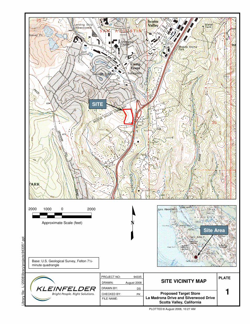
1
PLATE
Libr
ary
file:
L:\2
008\
libra
ry\p
roje
cts\
9433
5\*.
ppt
SITE VICINITY MAP
Proposed Target StoreLa Madrona Drive and Silverwood Drive
Scotts Valley, California
DRAWN: August 2008
CHECKED BY:
PROJECT NO: 94335
FILE NAME:
PLOTTED:8 August 2008, 10:27 AM
DSDRAWN BY:
PK
20002000
Approximate Scale (feet)
1000
N
0
Site Area
SITE
Base: U.S. Geological Survey, Felton 7½-minute quadrangle

TR-2P
TR-5P
TR-7TR-4
TR-1
TR-6PTR-3
B-1
B-2
B-13
B-3
B-12
B-11B-4
B-5 B-10
B-6 B-7
B-8
B-9
B-14
B-15
B-16
B-17
B-19
B-21
B-20
B-23
B-22
B-24
B-25
B-26
BA-2
BA-1
Tsc
Tsm
Qsw
Qcol
Kqd
Tsm
Tsc
Kqd
Tsm
Tsm
Qsw
Qcol
QcolQsw
Tsm
QswB-18
Tsc
Qsw
Qcol
TP-1
TP-2TP-3
TP-4
TP-5
N80
W 2
N15E15
A
A’
B’
B
C’
C
Concrete Pad
589
592
600
603
606
618 615
614
612
608
606
603
602
597 592
598
603
605
603
610
612
604
610
622
585
600
625
593
589
591
588
594
EXPLANATION
N80W2
B-27
TR-7
BA-2
TP-5
EARTH UNITS
Colluvial Soil (Quaternary)
Slopewash (Quaternary)
Santa Cruz Mudstone (Miocene)(Circled Where Buried)
Santa Margarita Sandstone (Miocene)(Circled Where Buried)
Quartz Diorite (Cretaceous)(Circled Where Buried)
GEOLOGIC SYMBOLS
Geologic Contact (Approximate Location,Queried Where Uncertain, Dotted Where Buried)
Bedding Attitude (Dashed Where Subsurface)
A
A’
Tsc
Qsw
Qcol
MAP SYMBOLS
Exploratory Boring – Approximate Location(Kleinfelder – This Investigation)
Exploratory Bucket Auger Boring – Approximate Location(Kleinfelder – This Investigation)
Exploratory Boring – Approximate Location(Previous Investigation by Treadwell & Rollo)
Exploratory Test Pit(Kleinfelder – This Investigation)
Seismic Refraction Line – Approximate Location(Kleinfelder – This Investigation – Showing Shot Locations)
Geologic Cross-Section
Approximate Elevation to Top of Quartz Diorite (Bedrock)In Feet
Cut/Fill Line
Proposed Subdrain (Actual Location to Be Determined in Field)
Tsm
Kqd
602
4040
Approximate Scale (feet)
20 0 8080
B-27591
D’
D
2PLATE
Proposed Target StoreLa Madrona Drive and
Silverwood DriveScotts Valley, California
DRAWN:
CHECKED BY:
PROJECT NO: 94335
FILE NAME:
PLOTTED:25 August 2008, 10:27 AM
DSDRAWN BY:
PK
August 2008PRELIMINARY
GEOTECHNICAL MAP
The information included on this graphic representation has been compiled from a variety of sources and is subject to change without notice. Kleinfelder makes no representations or warranties, express or implied, as to accuracy, completeness, timeliness, or rights to the use of such information. This document is not intended for use as a land survey product nor is it designed or intended as a construction design document. The use or misuse of the information contained on this graphic representation is at the sole risk of the party using or misusing the information.
Base Map: Grading and Drainage Plan, Prepared by DES Architects/Engineers, dated November 12, 2007.
? ?
?
?
?
?
?
?
? ?
?
?
?
?
?
?
CF
CF
CF
CF
CF
CF
CF
?
CF
DebrisPile
Bulk #8
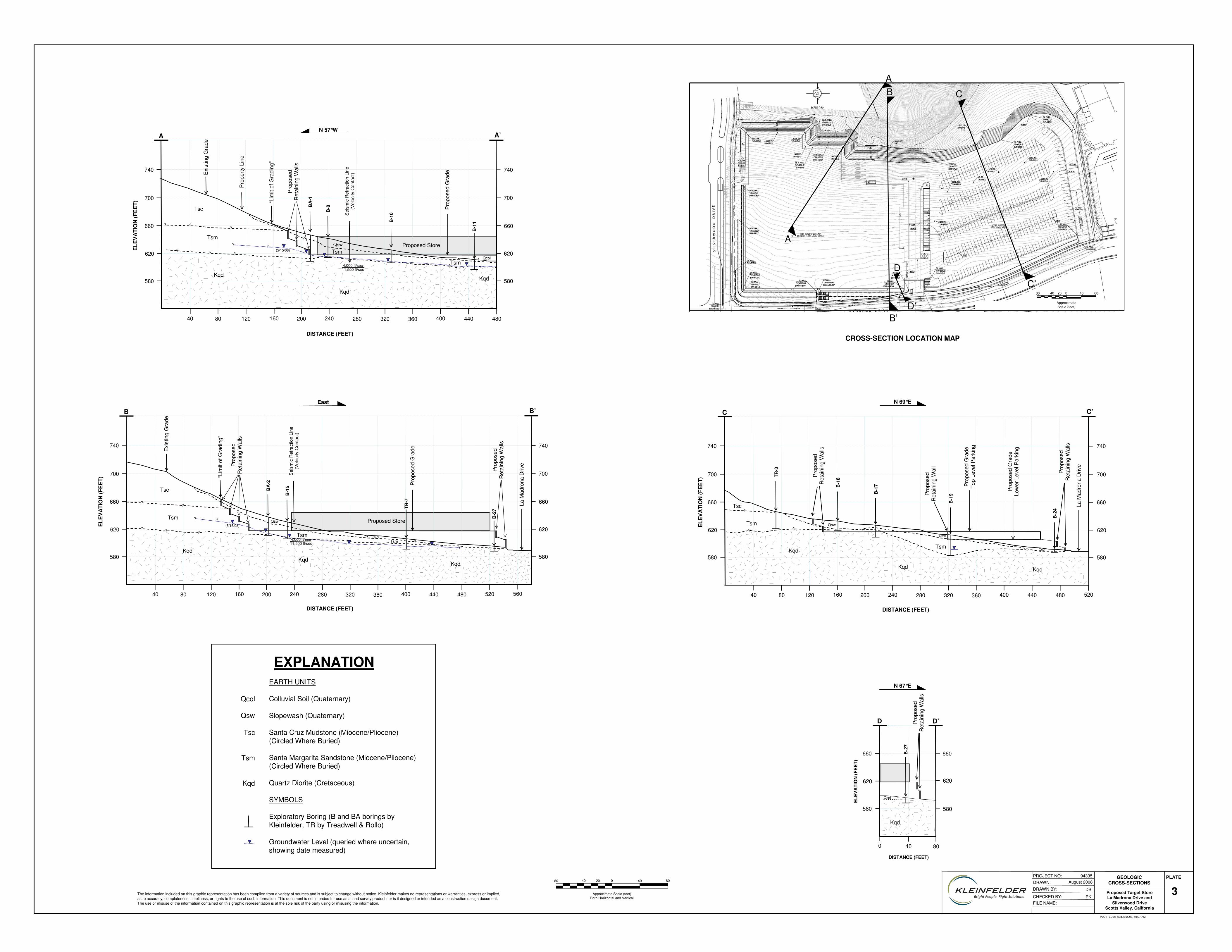
4040
Approximate Scale (feet)Both Horizontal and Vertical
20 0 8080
3PLATE
Proposed Target StoreLa Madrona Drive and
Silverwood DriveScotts Valley, California
DRAWN:
CHECKED BY:
PROJECT NO: 94335
FILE NAME:
PLOTTED:25 August 2008, 10:27 AM
DSDRAWN BY:
PK
August 2008GEOLOGIC
CROSS-SECTIONS
The information included on this graphic representation has been compiled from a variety of sources and is subject to change without notice. Kleinfelder makes no representations or warranties, express or implied, as to accuracy, completeness, timeliness, or rights to the use of such information. This document is not intended for use as a land survey product nor is it designed or intended as a construction design document. The use or misuse of the information contained on this graphic representation is at the sole risk of the party using or misusing the information.
740
700
660
620
40 80 120 160 200 240 280 320 360 400
DISTANCE (FEET)
ELE
VA
TIO
N (F
EE
T)A
480440
580
BA
-1
B-1
0
B-1
1
B-8Tsc
Tsm
Kqd
Kqd
Kqd
TsmQsw
Tsm
Pro
pose
dR
etai
ning
Wal
ls
Pro
pose
d G
radeE
xist
ing
Gra
de
Pro
perty
Lin
e
“Lim
it of
Gra
ding
”
Sei
smic
Ref
ract
ion
Line
(Vel
ocity
Con
tact
)
4,000 ft/sec11,500 ft/sec
Proposed Store??
?
??
?
?
(5/15/08)
740
700
660
620
580
A’
? ?
?
Qcol
EXPLANATIONEARTH UNITS
Colluvial Soil (Quaternary)
Slopewash (Quaternary)
Santa Cruz Mudstone (Miocene/Pliocene)(Circled Where Buried)
Santa Margarita Sandstone (Miocene/Pliocene)(Circled Where Buried)
Quartz Diorite (Cretaceous)
SYMBOLS
Exploratory Boring (B and BA borings byKleinfelder, TR by Treadwell & Rollo)
Groundwater Level (queried where uncertain,showing date measured)
Tsc
Qsw
Qcol
Tsm
Kqd
40 80
DISTANCE (FEET)
D
ELE
VA
TIO
N (F
EE
T)
Kqd
Pro
pose
dR
etai
ning
Wal
ls
660
620
580
D’
660
620
580
Qcol
B-2
7
0
B’
B
D’
D
C’
C
4040
Approximate Scale (feet)
20 0 8080
A’
A
CROSS-SECTION LOCATION MAP
N 57°W
N 67°E
40 80 120 160 200 240 280 320 360 400
DISTANCE (FEET)
C C’
520480440
ELE
VA
TIO
N (F
EE
T)
B-1
7B-1
8
B-1
9
B-2
4
TR-3
Tsc
Tsm
Kqd
Qsw
Qsw
TsmQcol
Pro
pose
d G
rade
Top
Leve
l Par
king
La M
adro
naD
rive
Pro
pose
d G
rade
Low
er L
evel
Par
king
Pro
pose
dR
etai
ning
Wal
l
Pro
pose
dR
etai
ning
Wal
ls
??
Kqd Kqd
?
740
700
660
620
580
740
700
660
620
580
N 69°E
Pro
pose
dR
etai
ning
Wal
ls740
700
660
620
40 80 120 160 200 240 280 320 360 400
DISTANCE (FEET)
B
480440
580
BA
-2
TR-7
B-2
7
B-1
5Tsc
Tsm
Kqd
KqdKqd
Tsm
Qsw
Tsm
Pro
pose
dR
etai
ning
Wal
ls
Pro
pose
d G
radeE
xist
ing
Gra
de
“Lim
it of
Gra
ding
”
Sei
smic
Ref
ract
ion
Line
(Vel
ocity
Con
tact
)
Proposed Store
???
?
?
(5/15/08)
?
?
4,000 ft/sec11,500 ft/sec
520 560
740
700
660
620
580
B’
Qcol
La M
adro
naD
rive
?
?
ELE
VA
TIO
N (F
EE
T)
East
Pro
pose
dR
etai
ning
Wal
ls
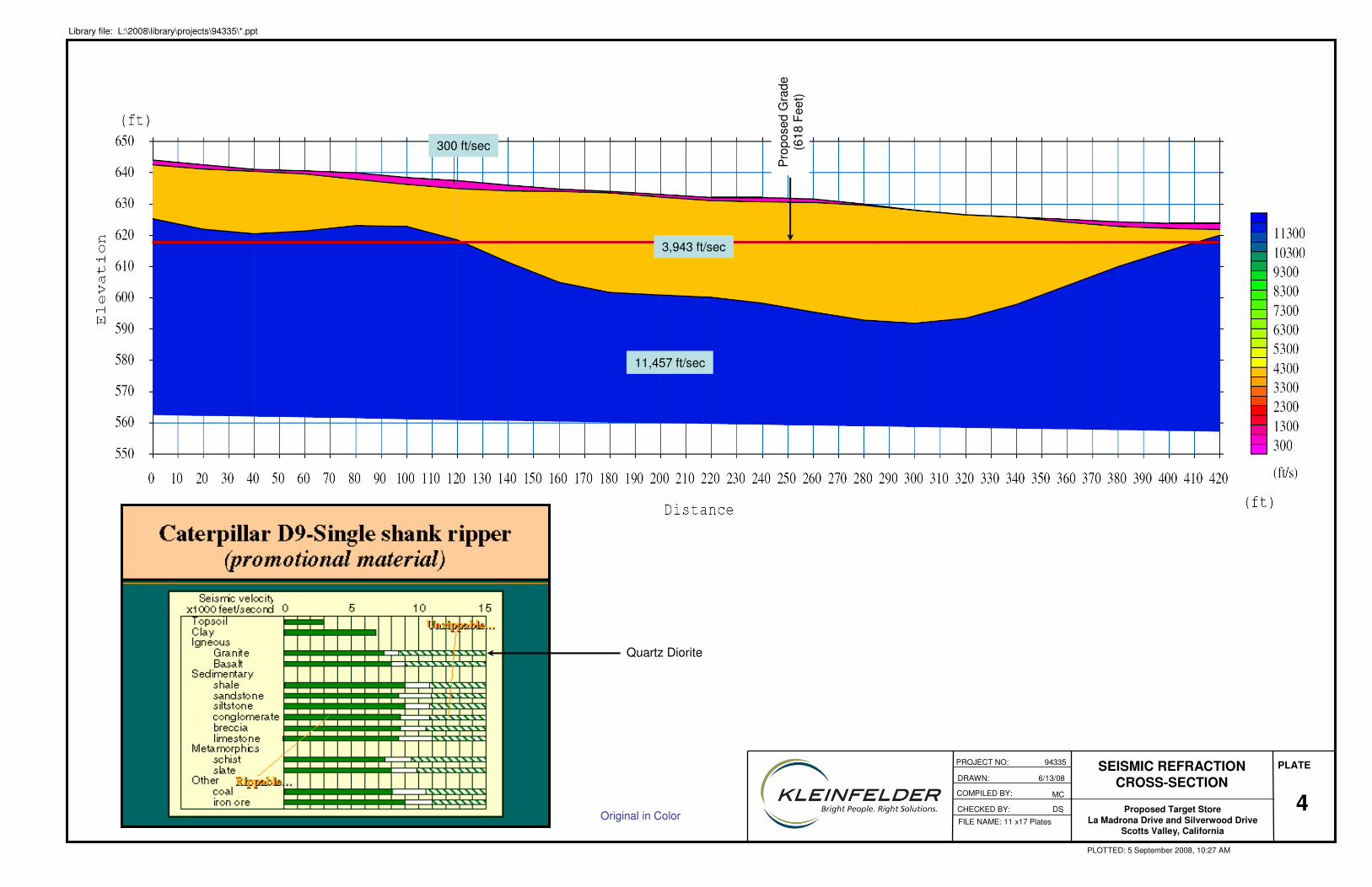
4
PLATE
Library file: L:\2008\library\projects\94335\*.ppt
SEISMIC REFRACTION CROSS-SECTION
Proposed Target StoreLa Madrona Drive and Silverwood Drive
Scotts Valley, California
PROJECT NO: 94335
FILE NAME: 11 x17 Plates
PLOTTED: 5 September 2008, 10:27 AM
MC
.Original in Color
DRAWN: 6/13/08
CHECKED BY: DS
COMPILED BY:
11,457 ft/sec
300 ft/sec
3,943 ft/sec
Pro
pose
d G
rade
(618
Fee
t)
Quartz Diorite
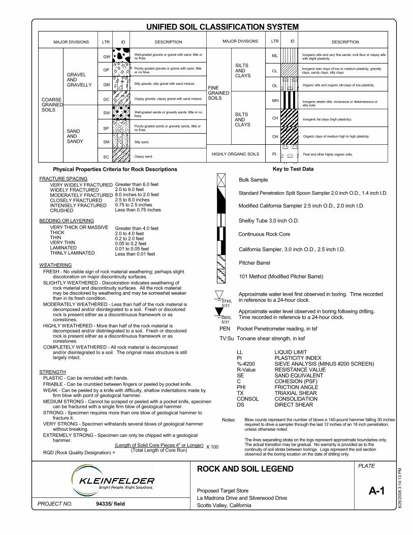
Modified California Sampler 2.5 inch O.D., 2.0 inch I.D.
Inorganic fat clays (high plasticity).
Notes:
The lines separating strata on the logs represent approximate boundaries only.The actual transition may be gradual. No warranty is provided as to thecontinuity of soil strata between borings. Logs represent the soil sectionobserved at the boring location on the date of drilling only.
Blow counts represent the number of blows a 140-pound hammer falling 30 inchesrequired to drive a sampler through the last 12 inches of an 18 inch penetration,unless otherwise noted.
LLPI%-#200R-ValueSECPHITXCONSOLDS
Inorganic elastic silts, micaceous or diatomaceous orsilty soils.
Greater than 6.0 feet2.0 to 6.0 feet8.0 inches to 2.0 feet2.5 to 8.0 inches0.75 to 2.5 inchesLess than 0.75 inches
Silty gravels, silty gravel with sand mixture.
Standard Penetration Split Spoon Sampler 2.0 inch O.D., 1.4 inch I.D.
California Sampler, 3.0 inch O.D., 2.5 inch I.D.
GC
Key to Test Data
PEN
TV:Su
94335/ field
0745,5/31
HIGHLY ORGANIC SOILS
SILTSANDCLAYS
PROJECT NO.
PLATE
BEDDING OR LAYERINGVERY THICK OR MASSIVETHICKTHINVERY THINLAMINATEDTHINLY LAMINATED
8/26
/200
8 3:
14:1
3 P
M
Well-graded gravels or gravel with sand, little orno fines.
Poorly-graded gravels or gravel with sand, littleor no fines.
Bulk Sample
SILTSANDCLAYS
COARSEGRAINEDSOILS
Physical Properties Criteria for Rock Descriptions
A-1
SC
ID
Silty sand.
SW
Proposed Target StoreLa Madrona Drive and Silverwood DriveScotts Valley, California
Clayey gravels, clayey gravel with sand mixture.
ML
Pocket Penetrometer reading, in tsf
Torvane shear strength, in ksf
DESCRIPTION
GRAVELANDGRAVELLY
IDLTRMAJOR DIVISIONS
Clayey sand.
101 Method (Modified Pitcher Barrel)
LIQUID LIMITPLASTICITY INDEXSIEVE ANALYSIS (MINUS #200 SCREEN)RESISTANCE VALUESAND EQUIVALENTCOHESION (PSF)FRICTION ANGLETRIAXIAL SHEARCONSOLIDATIONDIRECT SHEAR
Approximate water level observed in boring following drilling.Time recorded in reference to a 24-hour clock.
Approximate water level first observed in boring. Time recordedin reference to a 24-hour clock.
GM Organic silts and organic silt-clays of low plasticity.
Inorganic silts and very fine sands, rock flour or clayey siltswith slight plasticity.
Inorganic lean clays of low to medium plasticity, gravellyclays, sandy clays, silty clays.
WEATHERINGFRESH - No visible sign of rock material weathering; perhaps slight
discoloration on major discontinuity surfaces.SLIGHTLY WEATHERED - Discoloration indicates weathering of
rock material and discontinuity surfaces. All the rock materialmay be discolored by weathering and may be somewhat weakerthan in its fresh condition.
MODERATELY WEATHERED - Less than half of the rock material isdecomposed and/or disintegrated to a soil. Fresh or discoloredrock is present either as a discontinuous framework or ascorestones.
HIGHLY WEATHERED - More than half of the rock material isdecomposed and/or distintegrated to a soil. Fresh or discoloredrock is present either as a discontinuous framework or ascorestones.
COMPLETELY WEATHERED - All rock material is decomposedand/or disintegrated to a soil. The original mass structure is stilllargely intact.
CL
OL
Greater than 4.0 feet2.0 to 4.0 feet0.2 to 2.0 feet0.05 to 0.2 feet0.01 to 0.05 feetLess than 0.01 feet
GP
X 100
VERY WIDELY FRACTUREDWIDELY FRACTUREDMODERATELY FRACTUREDCLOSELY FRACTUREDINTENSELY FRACTUREDCRUSHED
FRACTURE SPACING
Organic clays of medium high to high plasticity.
DESCRIPTIONMAJOR DIVISIONS
PLASTIC - Can be remolded with hands.FRIABLE - Can be crumbled between fingers or peeled by pocket knife.WEAK - Can be peeled by a knife with difficulty, shallow indentations made by
firm blow with point of geological hammer.MEDIUM STRONG - Cannot be scraped or peeled with a pocket knife, specimen
can be fractured with a single firm blow of geological hammer.STRONG - Specimen requires more than one blow of geological hammer to
fracture it.VERY STRONG - Specimen withstands several blows of geological hammer
without breaking.EXTREMELY STRONG - Specimen can only be chipped with a geological
hammer.
RQD (Rock Quality Designation) =
STRENGTH
MH
SANDANDSANDY
Peat and other highly organic soils.
UNIFIED SOIL CLASSIFICATION SYSTEM
Shelby Tube 3.0 inch O.D.
GW
Pitcher Barrel
Continuous Rock Core
ROCK AND SOIL LEGEND
SP Poorly-graded sands or gravelly sands, little orno fines.
Well-graded sands or gravelly sands, little or nofines.
FINEGRAINEDSOILS
(Length of Solid Core Pieces 4" or Longer)(Total Length of Core Run)
CH
OH
Pt
SM
0800,5/31
LTR
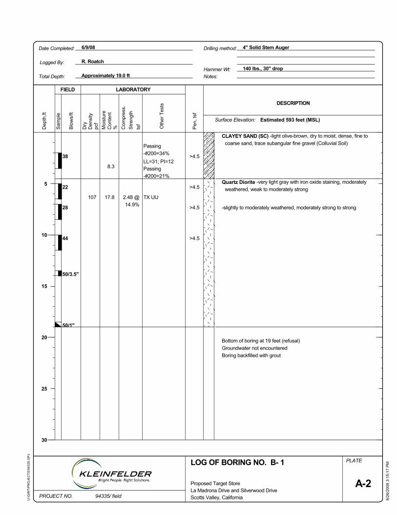
Oth
er T
ests
50/3.5"
50/1"
2.48 @14.9%
Passing-#200=34%LL=31; PI=12Passing-#200=21%
TX UU
PLATE
Pen
, tsf
22
tsf
FIELD
Sam
ple
8/26
/200
8 3:
15:1
7 P
M
Dry
Stre
ngth
pcf
-slightly to moderately weathered, moderately strong to strong
44
Quartz Diorite -very light gray with iron oxide staining, moderatelyweathered, weak to moderately strong
28
Bottom of boring at 19 feet (refusal)Groundwater not encounteredBoring backfilled with grout
>4.5
>4.5
>4.5
>4.5
8.3
17.8107
38
CLAYEY SAND (SC) -light olive-brown, dry to moist, dense, fine tocoarse sand, trace subangular fine gravel (Colluvial Soil)
6/9/08
PROJECT NO.
Dep
th,ft
Surface Elevation:
DESCRIPTION
La Madrona Drive and Silverwood Drive94335/ field
Hammer Wt: 140 lbs., 30" dropApproximately 19.0 ft
Proposed Target Store
LABORATORY
Moi
stur
e
Date Completed: 4" Solid Stem Auger
U:\G
INT\
PR
OJE
CTS
\943
35.G
PJ
Notes:
Drilling method:
LOG OF BORING NO. B- 1
Blo
ws/
ft
Scotts Valley, California
Total Depth:
Logged By:
Estimated 593 feet (MSL)
5
10
15
20
25
30
Den
sity
R. Roatch
A-2
Con
tent
% Com
pres
s.
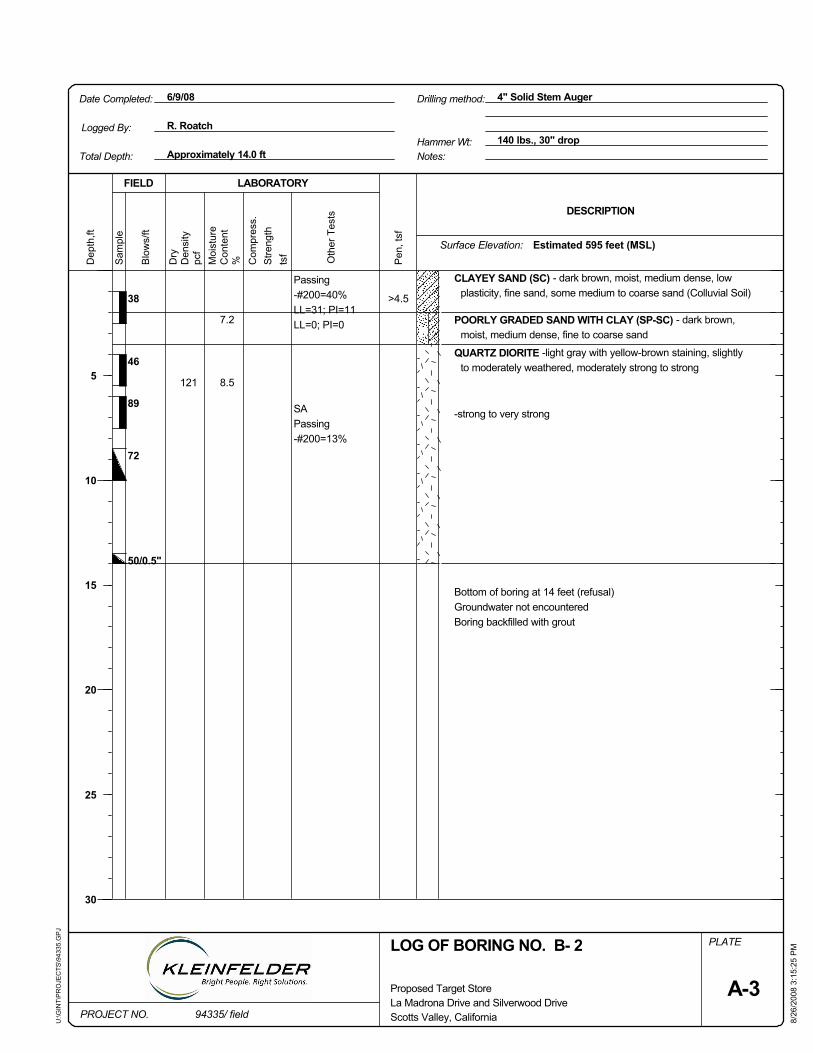
Oth
er T
ests
72
50/0.5"
Passing-#200=40%LL=31; PI=11LL=0; PI=0
SAPassing-#200=13%
PLATE
Pen
, tsf
38ts
f
FIELD
Sam
ple
8/26
/200
8 3:
15:2
5 P
M
Dry
Stre
ngth
pcf
CLAYEY SAND (SC) - dark brown, moist, medium dense, lowplasticity, fine sand, some medium to coarse sand (Colluvial Soil)
89
46
POORLY GRADED SAND WITH CLAY (SP-SC) - dark brown,moist, medium dense, fine to coarse sand
QUARTZ DIORITE -light gray with yellow-brown staining, slightlyto moderately weathered, moderately strong to strong
-strong to very strong
Bottom of boring at 14 feet (refusal)Groundwater not encounteredBoring backfilled with grout
>4.5
7.2
8.5121
6/9/08
PROJECT NO.
Surface Elevation:
DESCRIPTION
La Madrona Drive and Silverwood Drive94335/ field
Hammer Wt:
Dep
th,ft
140 lbs., 30" dropApproximately 14.0 ft
Proposed Target Store
LABORATORY
Moi
stur
e
Date Completed: 4" Solid Stem Auger
U:\G
INT\
PR
OJE
CTS
\943
35.G
PJ
Estimated 595 feet (MSL)
LOG OF BORING NO. B- 2
Logged By:
Blo
ws/
ft
Scotts Valley, California
Drilling method:
Notes:
R. Roatch
A-3
Den
sity
Total Depth:
5
10
15
20
25
30
Con
tent
% Com
pres
s.
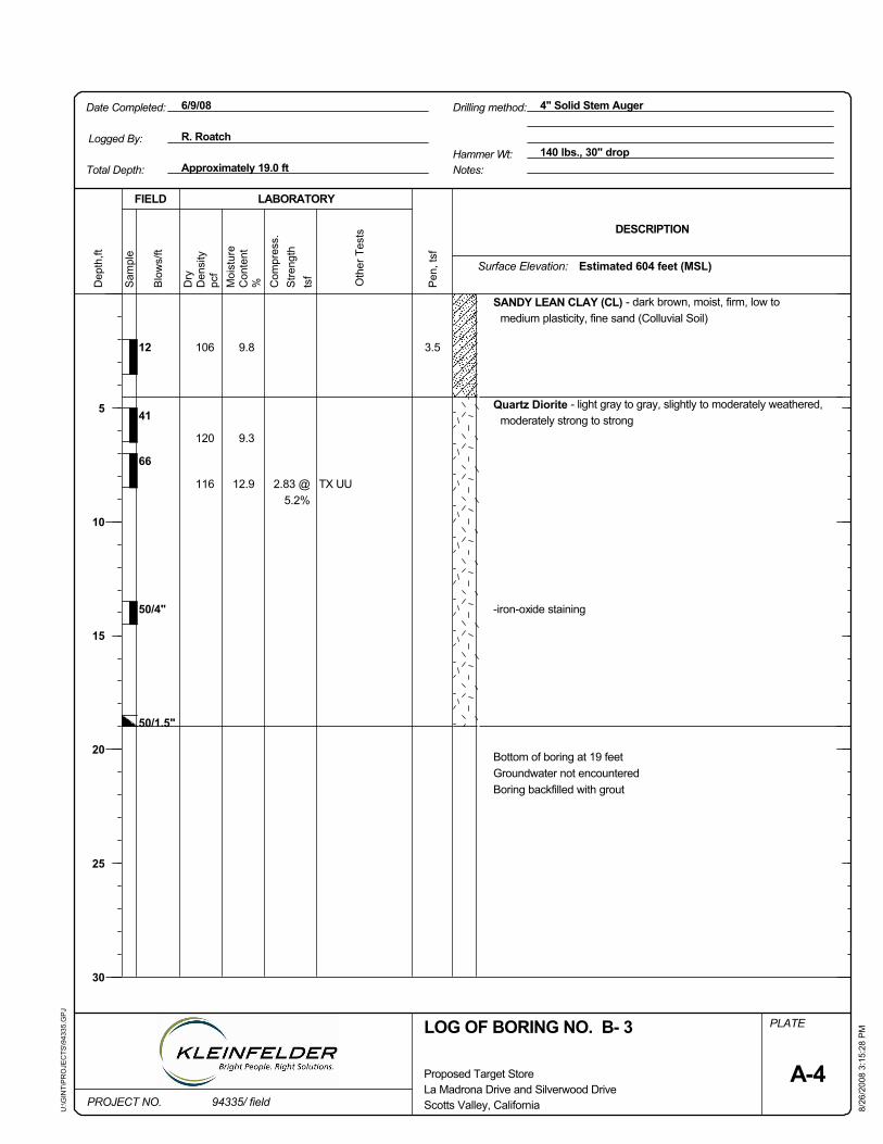
50/1.5"
2.83 @5.2%
TX UU
PLATE
Pen
, tsf
pcf
Oth
er T
ests
LOG OF BORING NO. B- 3
41
FIELD
Sam
ple
Stre
ngth
8/26
/200
8 3:
15:2
8 P
M
Surface Elevation:
Scotts Valley, California
tsf
Bottom of boring at 19 feetGroundwater not encounteredBoring backfilled with grout
SANDY LEAN CLAY (CL) - dark brown, moist, firm, low tomedium plasticity, fine sand (Colluvial Soil)
50/4" -iron-oxide staining
66
3.59.8
9.3
12.9
106
120
116
12
Quartz Diorite - light gray to gray, slightly to moderately weathered,moderately strong to strong
140 lbs., 30" drop
PROJECT NO.
Dep
th,ft
Dry
DESCRIPTION
La Madrona Drive and Silverwood Drive
6/9/08
Approximately 19.0 ft
Proposed Target Store
LABORATORY
Moi
stur
e
Date Completed: 4" Solid Stem Auger
U:\G
INT\
PR
OJE
CTS
\943
35.G
PJ
Hammer Wt:
Com
pres
s.
Logged By:
Drilling method:
R. Roatch
Notes:Total Depth:
94335/ field
Blo
ws/
ft
Estimated 604 feet (MSL)
Den
sity
%
5
10
15
20
25
30
A-4
Con
tent
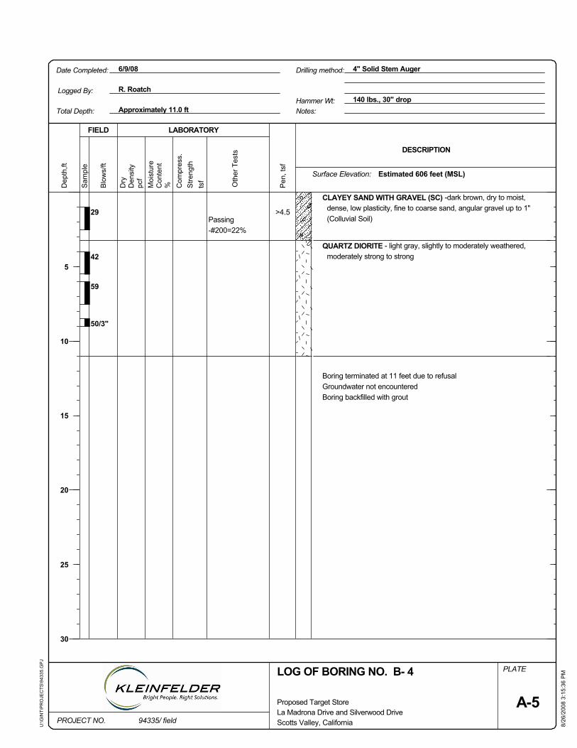
Stre
ngth
Oth
er T
ests
tsf
FIELD
Sam
ple
Dry
Pen
, tsf
Surface Elevation:
LOG OF BORING NO. B- 4
8/26
/200
8 3:
15:3
6 P
M
Drilling method:
Boring terminated at 11 feet due to refusalGroundwater not encounteredBoring backfilled with grout
pcf
QUARTZ DIORITE - light gray, slightly to moderately weathered,moderately strong to strong
>4.529
42
59
50/3"
Passing-#200=22%
PLATE
CLAYEY SAND WITH GRAVEL (SC) -dark brown, dry to moist,dense, low plasticity, fine to coarse sand, angular gravel up to 1"(Colluvial Soil)
Approximately 11.0 ft
Dep
th,ft
DESCRIPTION
Scotts Valley, California
Hammer Wt:
PROJECT NO.
140 lbs., 30" drop
Proposed Target Store
LABORATORY
Moi
stur
e
Date Completed: 4" Solid Stem Auger
U:\G
INT\
PR
OJE
CTS
\943
35.G
PJ
6/9/08
A-5
Estimated 606 feet (MSL)
Total Depth:
R. RoatchLogged By:
La Madrona Drive and Silverwood Drive
%
Notes:
Com
pres
s.
5
10
15
20
25
30
Den
sity
Blo
ws/
ft
94335/ field
Con
tent
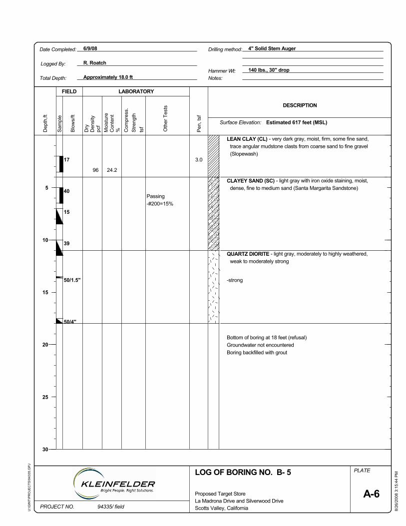
Scotts Valley, California
39
50/1.5"
50/4"
Passing-#200=15%
PLATE
Pen
, tsf
pcf
40
tsf
17
FIELD
8/26
/200
8 3:
15:4
4 P
M
Stre
ngth
Surface Elevation:
Oth
er T
ests
15
Dry
LEAN CLAY (CL) - very dark gray, moist, firm, some fine sand,trace angular mudstone clasts from coarse sand to fine gravel(Slopewash)
CLAYEY SAND (SC) - light gray with iron oxide staining, moist,dense, fine to medium sand (Santa Margarita Sandstone)
QUARTZ DIORITE - light gray, moderately to highly weathered,weak to moderately strong
-strong
Bottom of boring at 18 feet (refusal)Groundwater not encounteredBoring backfilled with grout
3.0
24.296
140 lbs., 30" drop
PROJECT NO.
Dep
th,ft
LOG OF BORING NO. B- 5
Sam
ple
La Madrona Drive and Silverwood Drive
6/9/08
Approximately 18.0 ft
Proposed Target Store
LABORATORY
Moi
stur
e
Date Completed: 4" Solid Stem Auger
U:\G
INT\
PR
OJE
CTS
\943
35.G
PJ
Hammer Wt:Logged By: R. Roatch
Drilling method:
Total Depth:
DESCRIPTION
94335/ field
Estimated 617 feet (MSL)
Notes:
5
10
15
20
25
30
Blo
ws/
ft
Den
sity
Com
pres
s.
A-6
Con
tent
%
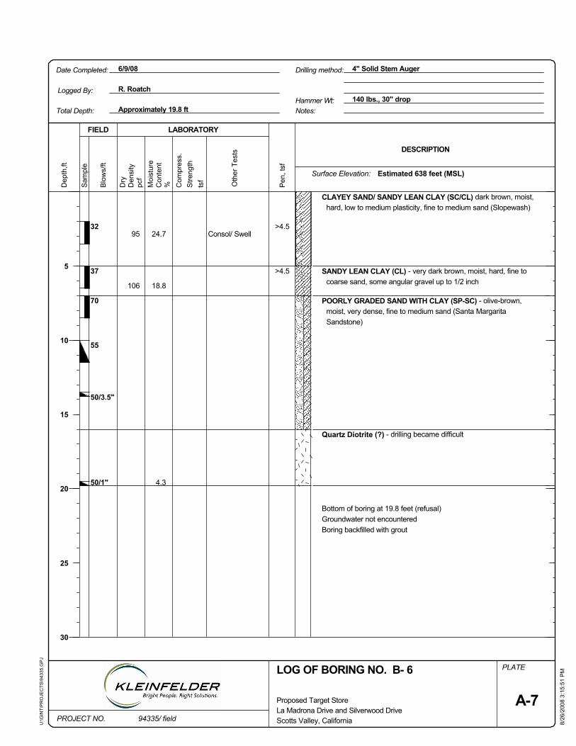
4.3
95
106
32
37
70
55
50/3.5"
50/1"
Consol/ Swell24.7
Pen
, tsf
>4.5
pcf
Oth
er T
ests
8/26
/200
8 3:
15:5
1 P
M
FIELD
Sam
ple
Dry
Stre
ngth
PLATE
18.8
CLAYEY SAND/ SANDY LEAN CLAY (SC/CL) dark brown, moist,hard, low to medium plasticity, fine to medium sand (Slopewash)
SANDY LEAN CLAY (CL) - very dark brown, moist, hard, fine tocoarse sand, some angular gravel up to 1/2 inch
POORLY GRADED SAND WITH CLAY (SP-SC) - olive-brown,moist, very dense, fine to medium sand (Santa MargaritaSandstone)
Quartz Diotrite (?) - drilling became difficult
Bottom of boring at 19.8 feet (refusal)Groundwater not encounteredBoring backfilled with grout
>4.5
6/9/08
94335/ fieldPROJECT NO.
Dep
th,ft
tsf
DESCRIPTION
La Madrona Drive and Silverwood Drive
Blo
ws/
ftHammer Wt: 140 lbs., 30" drop
Approximately 19.8 ft
Proposed Target Store
LABORATORY
Moi
stur
e
Date Completed: 4" Solid Stem Auger
U:\G
INT\
PR
OJE
CTS
\943
35.G
PJ
LOG OF BORING NO. B- 6
Scotts Valley, California
R. Roatch
Surface Elevation:
Drilling method:
Total Depth:
Logged By:
Den
sity
5
10
15
20
25
30
A-7
Notes:
Con
tent
% Com
pres
s.Estimated 638 feet (MSL)
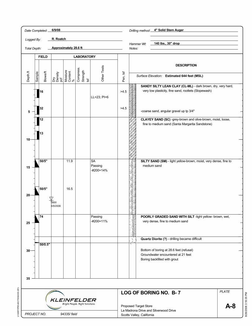
LL=23; PI=6
08006/9/2008
>4.5
>4.5
11.9
16.5
16
32
12
13
50/5"
50/5"
FIELD
Pen
, tsf
tsf Oth
er T
ests
74
50/0.5"8/
26/2
008
3:16
:35
PM
Passing-#200=11%
SAPassing-#200=14%
pcf
SANDY SILTY LEAN CLAY (CL-ML) - dark brown, dry, very hard,very low plasticity, fine sand, rootlets (Slopewash)
PLATE
Bottom of boring at 28.6 feet (refusal)Groundwater encountered at 21 feetBoring backfilled with grout
Quartz Diorite (?) - drilling became difficult
POORLY GRADED SAND WITH SILT -light yellow- brown, wet,very dense, fine to medium sand
SILTY SAND (SM) - light yellow-brown, moist, very dense, fine tomedium sand
-coarse sand, angular gravel up tp 3/4"
CLAYEY SAND (SC) -grey-brown and olive-brown, moist, loose,fine to medium sand (Santa Margarita Sandstone)
DESCRIPTION
PROJECT NO. 94335/ field
Blo
ws/
ft
LABORATORY
U:\G
INT\
PR
OJE
CTS
\943
35.G
PJ
4" Solid Stem AugerDate Completed:
La Madrona Drive and Silverwood Drive
Dep
th,ft
Proposed Target Store
Approximately 28.6 ft140 lbs., 30" drop
6/9/08
Hammer Wt:
Moi
stur
e
LOG OF BORING NO. B- 7
Dry
Stre
ngth
Den
sity
Drilling method:
Surface Elevation:
Scotts Valley, California
5
10
15
20
25
30
35
A-8
Con
tent
% Com
pres
s.
Logged By:
Estimated 644 feet (MSL)
Notes:Total Depth:
R. RoatchS
ampl
e
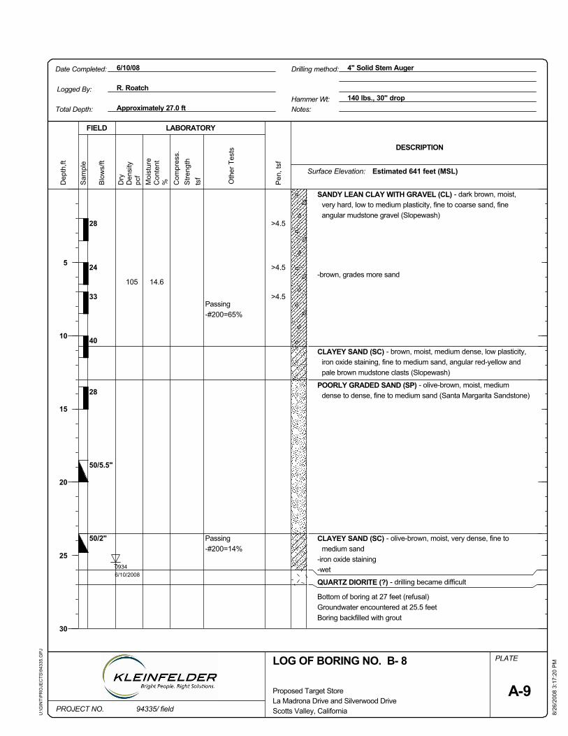
50/2"
09346/10/2008
>4.5
>4.5
>4.5
14.6105
28
24
33
40
FIELD
8/26
/200
8 3:
17:2
0 P
M
tsf Oth
er T
ests
28
50/5.5"
PLATE
Passing-#200=14%
Passing-#200=65%
Bottom of boring at 27 feet (refusal)Groundwater encountered at 25.5 feetBoring backfilled with grout
pcf
-brown, grades more sandP
en, t
sf
QUARTZ DIORITE (?) - drilling became difficult
-wet-iron oxide staining
CLAYEY SAND (SC) - olive-brown, moist, very dense, fine tomedium sand
CLAYEY SAND (SC) - brown, moist, medium dense, low plasticity,iron oxide staining, fine to medium sand, angular red-yellow andpale brown mudstone clasts (Slopewash)
SANDY LEAN CLAY WITH GRAVEL (CL) - dark brown, moist,very hard, low to medium plasticity, fine to coarse sand, fineangular mudstone gravel (Slopewash)
POORLY GRADED SAND (SP) - olive-brown, moist, mediumdense to dense, fine to medium sand (Santa Margarita Sandstone)
DESCRIPTION
94335/ field
Blo
ws/
ft
Dep
th,ft
LABORATORY
U:\G
INT\
PR
OJE
CTS
\943
35.G
PJ
4" Solid Stem AugerDate Completed:
La Madrona Drive and Silverwood DrivePROJECT NO.
Proposed Target Store
Approximately 27.0 ft140 lbs., 30" drop
6/10/08
Hammer Wt:
Moi
stur
e
Scotts Valley, California
Dry
Drilling method:
Den
sity
Stre
ngth
Surface Elevation:
LOG OF BORING NO. B- 8
5
10
15
20
25
30
A-9
Con
tent
% Com
pres
s.
Sam
ple
Estimated 641 feet (MSL)
Notes:Total Depth:
R. RoatchLogged By:
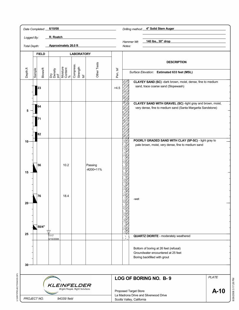
Pen
, tsf
Stre
ngth
10.2
18.4
23
64
71
82
56
76
50/4"
Passing-#200=11%
11176/10/2008
PLATE
pcf
tsf
8/26
/200
8 3:
17:2
8 P
M
FIELD
Sam
ple
Dry
>4.5
CLAYEY SAND (SC) -dark brown, moist, dense, fine to mediumsand, trace coarse sand (Slopewash)
CLAYEY SAND WITH GRAVEL (SC) -light gray and brown, moist,very dense, fine to medium sand (Santa Margarita Sandstone)
POORLY GRADED SAND WITH CLAY (SP-SC) - light gray topale brown, moist, very dense, fine to medium sand
-wet
QUARTZ DIORITE - moderately weathered
Bottom of boring at 26 feet (refusal)Groundwater encountered at 25 feetBoring backfilled with grout
6/10/08
94335/ fieldPROJECT NO.
Dep
th,ft
Oth
er T
ests DESCRIPTION
La Madrona Drive and Silverwood Drive
Blo
ws/
ftHammer Wt: 140 lbs., 30" drop
Approximately 26.0 ft
Proposed Target Store
LABORATORY
Moi
stur
e
Date Completed: 4" Solid Stem Auger
U:\G
INT\
PR
OJE
CTS
\943
35.G
PJ
Total Depth:
R. Roatch
Surface Elevation:
Logged By:
Scotts Valley, California
LOG OF BORING NO. B- 9
Drilling method:
Den
sity
5
10
15
20
25
30
A-10
Con
tent
% Com
pres
s.Estimated 633 feet (MSL)
Notes:
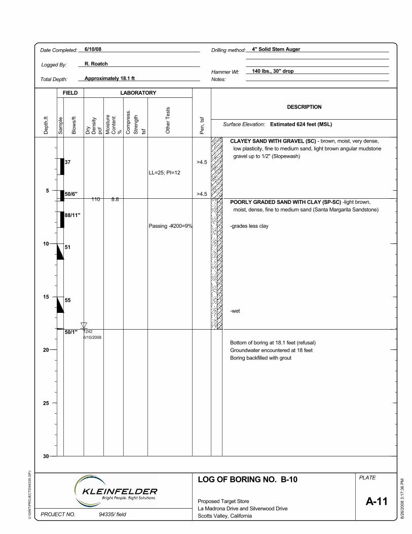
Scotts Valley, California
50/1"
LL=25; PI=12
Passing -#200=9%
PLATE
Pen
, tsf
pcf
51
tsf
88/11"
FIELD
8/26
/200
8 3:
17:3
6 P
M
Stre
ngth
Surface Elevation:
Oth
er T
ests
-grades less clay
55
POORLY GRADED SAND WITH CLAY (SP-SC) -light brown,moist, dense, fine to medium sand (Santa Margarita Sandstone)
Dry
-wet
Bottom of boring at 18.1 feet (refusal)Groundwater encountered at 18 feetBoring backfilled with grout
12426/10/2008
>4.5
>4.58.8110
37
50/6"
CLAYEY SAND WITH GRAVEL (SC) - brown, moist, very dense,low plasticity, fine to medium sand, light brown angular mudstonegravel up to 1/2" (Slopewash)
140 lbs., 30" drop
PROJECT NO.
Dep
th,ft
LOG OF BORING NO. B-10
Sam
ple
La Madrona Drive and Silverwood Drive
6/10/08
Approximately 18.1 ft
Proposed Target Store
LABORATORY
Moi
stur
e
Date Completed: 4" Solid Stem Auger
U:\G
INT\
PR
OJE
CTS
\943
35.G
PJ
Hammer Wt:
Drilling method:
Logged By: R. Roatch
DESCRIPTION
94335/ field
Estimated 624 feet (MSL)
Total Depth:B
low
s/ft
Notes:
Com
pres
s.
5
10
15
20
25
30
A-11
Con
tent
%Den
sity
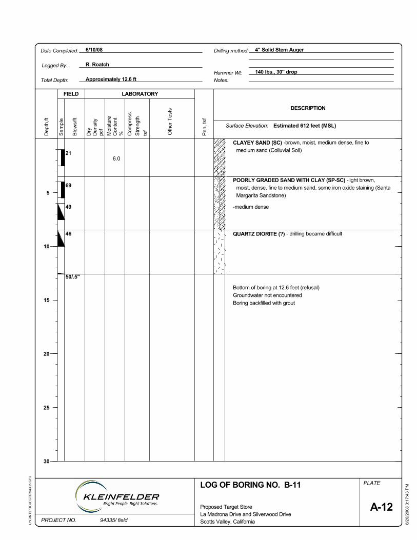
50/.5"
PLATE
Pen
, tsf
pcf
Oth
er T
ests
tsf
FIELD
69
Sam
ple
Dry
8/26
/200
8 3:
17:4
3 P
M
Surface Elevation:
Scotts Valley, California
LOG OF BORING NO. B-11
46
49
CLAYEY SAND (SC) -brown, moist, medium dense, fine tomedium sand (Colluvial Soil)
POORLY GRADED SAND WITH CLAY (SP-SC) -light brown,moist, dense, fine to medium sand, some iron oxide staining (SantaMargarita Sandstone)
-medium dense
QUARTZ DIORITE (?) - drilling became difficult
Bottom of boring at 12.6 feet (refusal)Groundwater not encounteredBoring backfilled with grout
6.021
140 lbs., 30" drop
PROJECT NO.
Dep
th,ft
Stre
ngth
La Madrona Drive and Silverwood Drive
6/10/08
Approximately 12.6 ft
Proposed Target Store
LABORATORY
Moi
stur
e
Date Completed: 4" Solid Stem Auger
U:\G
INT\
PR
OJE
CTS
\943
35.G
PJ
Hammer Wt:
%
Logged By:
Total Depth: Notes:
Drilling method:
DESCRIPTION
R. Roatch
Com
pres
s.
94335/ field
Blo
ws/
ft
Den
sity
Estimated 612 feet (MSL)
5
10
15
20
25
30
A-12
Con
tent
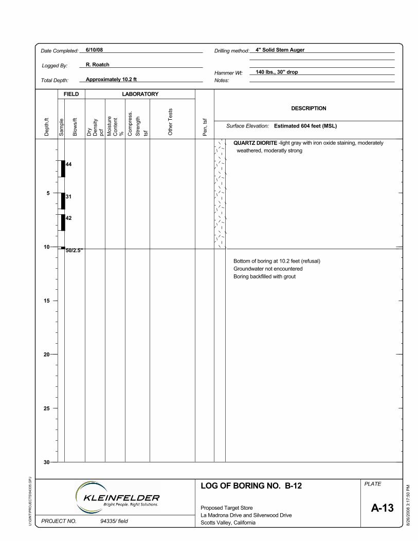
Surface Elevation:
R. Roatch
FIELD
Sam
ple
Dry
Stre
ngth
tsf
Scotts Valley, California
LOG OF BORING NO. B-12
Drilling method:
8/26
/200
8 3:
17:5
0 P
M
Logged By:
31
QUARTZ DIORITE -light gray with iron oxide staining, moderatelyweathered, moderatly strong
Bottom of boring at 10.2 feet (refusal)Groundwater not encounteredBoring backfilled with grout
44
42
50/2.5"
PLATE
Pen
, tsf
pcf
Oth
er T
ests
Total Depth:
La Madrona Drive and Silverwood Drive
Hammer Wt:
6/10/08
Approximately 10.2 ft
DESCRIPTION
Proposed Target Store
LABORATORY
Moi
stur
e
Date Completed: 4" Solid Stem Auger
U:\G
INT\
PR
OJE
CTS
\943
35.G
PJ
140 lbs., 30" dropNotes:
Estimated 604 feet (MSL)C
ompr
ess.
%Con
tent
Dep
th,ft
A-13
5
10
15
20
25
30
Den
sity
Blo
ws/
ft
94335/ fieldPROJECT NO.
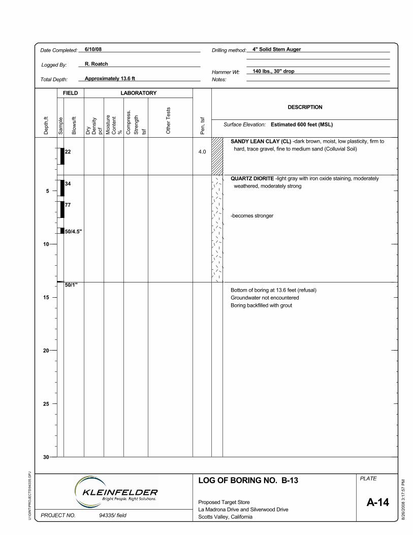
Dry
pcf
Oth
er T
ests
tsf
FIELD
Drilling method:
Stre
ngth
Surface Elevation:
8/26
/200
8 3:
17:5
7 P
MLOG OF BORING NO. B-13
Sam
ple
-becomes stronger
Pen
, tsf
QUARTZ DIORITE -light gray with iron oxide staining, moderatelyweathered, moderately strong
PLATE
Bottom of boring at 13.6 feet (refusal)Groundwater not encounteredBoring backfilled with grout
4.022
34
77
50/4.5"
50/1"
Scotts Valley, California
SANDY LEAN CLAY (CL) -dark brown, moist, low plasticity, firm tohard, trace gravel, fine to medium sand (Colluvial Soil)
Approximately 13.6 ft
Dep
th,ft
DESCRIPTION
Hammer Wt:
PROJECT NO.
140 lbs., 30" drop
Proposed Target Store
LABORATORY
Moi
stur
e
Date Completed: 4" Solid Stem Auger
U:\G
INT\
PR
OJE
CTS
\943
35.G
PJ
6/10/08
Total Depth:
Estimated 600 feet (MSL)
R. RoatchLogged By:
La Madrona Drive and Silverwood Drive
Notes:
Con
tent
Com
pres
s.
94335/ field
Blo
ws/
ft
%
A-14
Den
sity
5
10
15
20
25
30
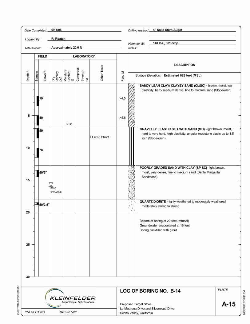
pcf
35.8
19
40
59
78
50/5"
50/2.5"
LL=62; PI=21
PLATE
08056/11/2008
Oth
er T
ests
tsf
8/26
/200
8 3:
18:0
5 P
M
Sam
ple
Dry
Stre
ngth
Pen
, tsf
>4.5
>4.5
SANDY LEAN CLAY/ CLAYEY SAND (CL/SC) - brown, moist, lowplasticity, hard/ medium dense, fine to medium sand (Slopewash)
GRAVELLY ELASTIC SILT WITH SAND (MH) -light brown, moist,hard to very hard, high plasticity, angular mudstone clasts up to 1.5inch (Slopewash)
POORLY GRADED SAND WITH CLAY (SP-SC) -light brown,moist, very dense, fine to medium sand (Santa MargaritaSandstone)
QUARTZ DIORITE -highly weathered to moderately weathered,moderately strong to strong
Bottom of boring at 20 feet (refusal)Groundwater encountered at 16 feetBoring backfilled with grout
FIELD
6/11/08
PROJECT NO.
Dep
th,ft
DESCRIPTION
La Madrona Drive and Silverwood Drive94335/ field
Hammer Wt: 140 lbs., 30" dropApproximately 20.0 ft
Proposed Target Store
LABORATORY
Moi
stur
e
Date Completed: 4" Solid Stem Auger
U:\G
INT\
PR
OJE
CTS
\943
35.G
PJ
Surface Elevation:
Drilling method:
Logged By:
LOG OF BORING NO. B-14
Blo
ws/
ftTotal Depth:
Scotts Valley, California
Notes:
R. Roatch
A-15
Den
sity
5
10
15
20
25
30
Estimated 628 feet (MSL)
Con
tent
% Com
pres
s.
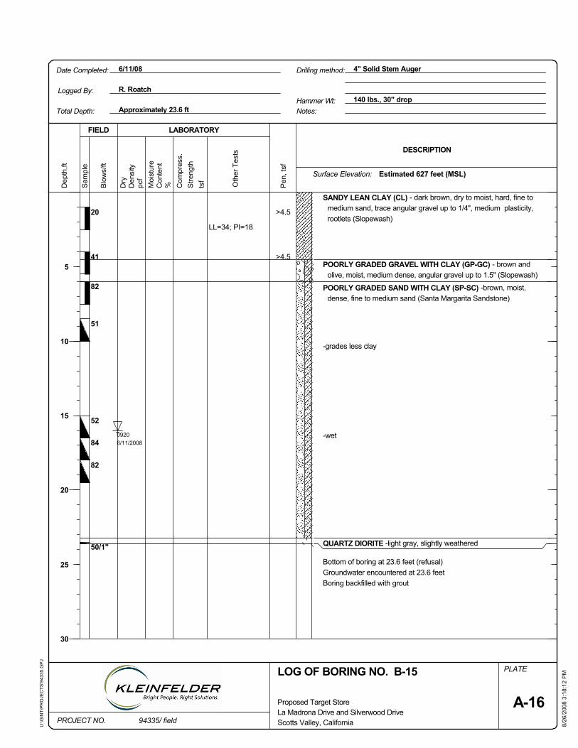
PLATE
09206/11/2008
>4.5
>4.5
20
41
82
51
52
84
82
50/1"
LL=34; PI=18
Dry
Pen
, tsf
8/26
/200
8 3:
18:1
2 P
M
tsf
FIELD
Sam
ple
SANDY LEAN CLAY (CL) - dark brown, dry to moist, hard, fine tomedium sand, trace angular gravel up to 1/4", medium plasticity,rootlets (Slopewash)
POORLY GRADED GRAVEL WITH CLAY (GP-GC) - brown andolive, moist, medium dense, angular gravel up to 1.5" (Slopewash)
POORLY GRADED SAND WITH CLAY (SP-SC) -brown, moist,dense, fine to medium sand (Santa Margarita Sandstone)
-grades less clay
-wet
QUARTZ DIORITE -light gray, slightly weathered
Bottom of boring at 23.6 feet (refusal)Groundwater encountered at 23.6 feetBoring backfilled with grout
Oth
er T
ests
Hammer Wt:B
low
s/ft
94335/ fieldPROJECT NO.
Dep
th,ft
Stre
ngth
pcf
La Madrona Drive and Silverwood Drive
6/11/08
140 lbs., 30" dropApproximately 23.6 ft
Proposed Target Store
LABORATORY
Moi
stur
e
Date Completed: 4" Solid Stem Auger
U:\G
INT\
PR
OJE
CTS
\943
35.G
PJ
DESCRIPTION
R. RoatchLogged By:
Surface Elevation:
Total Depth:
Scotts Valley, California
LOG OF BORING NO. B-15
Drilling method:
%Den
sity
5
10
15
20
25
30
A-16
Con
tent
Com
pres
s.Estimated 627 feet (MSL)
Notes:
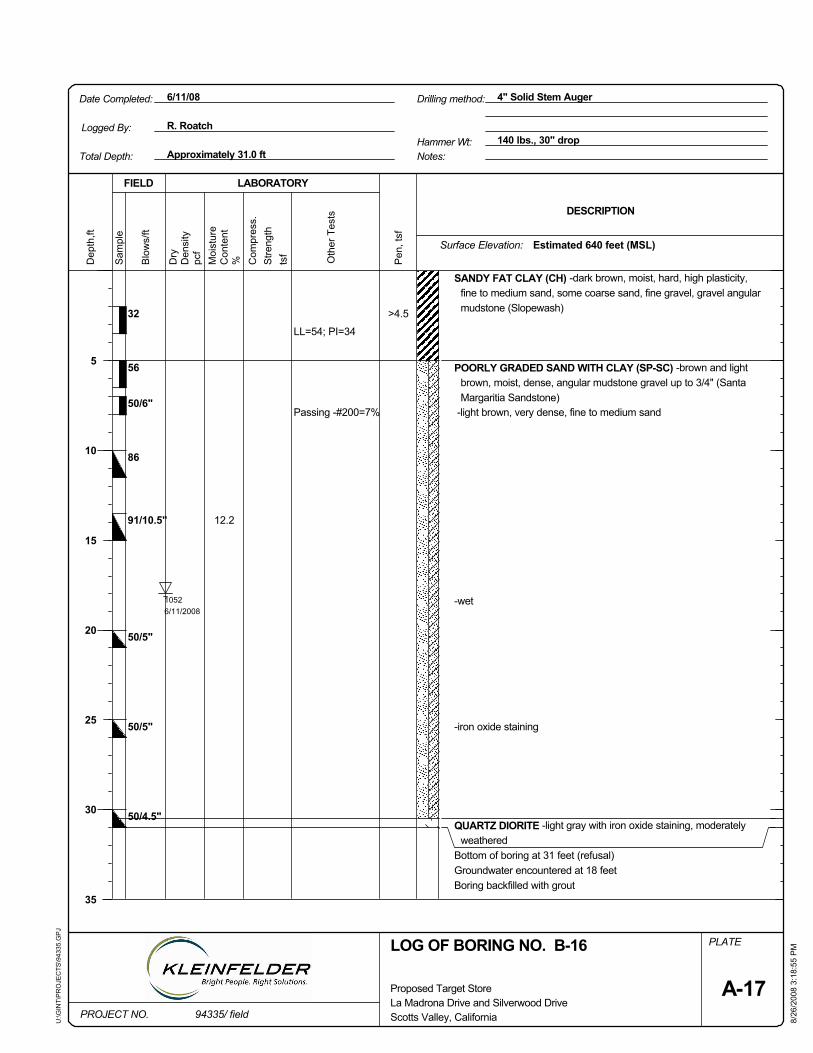
56
50/6"
86
91/10.5"
50/5"
50/5"
50/4.5"
LL=54; PI=34
Passing -#200=7%
12.2
Pen
, tsf
>4.5
pcf
tsf
8/26
/200
8 3:
18:5
5 P
M
FIELD
Sam
ple
Dry
Stre
ngth
PLATE
32
SANDY FAT CLAY (CH) -dark brown, moist, hard, high plasticity,fine to medium sand, some coarse sand, fine gravel, gravel angularmudstone (Slopewash)
POORLY GRADED SAND WITH CLAY (SP-SC) -brown and lightbrown, moist, dense, angular mudstone gravel up to 3/4" (SantaMargaritia Sandstone)
-light brown, very dense, fine to medium sand
-wet
-iron oxide staining
QUARTZ DIORITE -light gray with iron oxide staining, moderatelyweathered
Bottom of boring at 31 feet (refusal)Groundwater encountered at 18 feetBoring backfilled with grout
10526/11/2008
6/11/08
94335/ fieldPROJECT NO.
Dep
th,ft
Oth
er T
ests
La Madrona Drive and Silverwood Drive
Blo
ws/
ftHammer Wt: 140 lbs., 30" drop
Approximately 31.0 ft
Proposed Target Store
LABORATORY
Moi
stur
e
Date Completed: 4" Solid Stem Auger
U:\G
INT\
PR
OJE
CTS
\943
35.G
PJ
Drilling method:
DESCRIPTION
LOG OF BORING NO. B-16
Scotts Valley, California
R. Roatch
Surface Elevation:
Total Depth:
Logged By:
Den
sity
A-17
Con
tent
% Com
pres
s.Estimated 640 feet (MSL)
Notes:
5
10
15
20
25
30
35
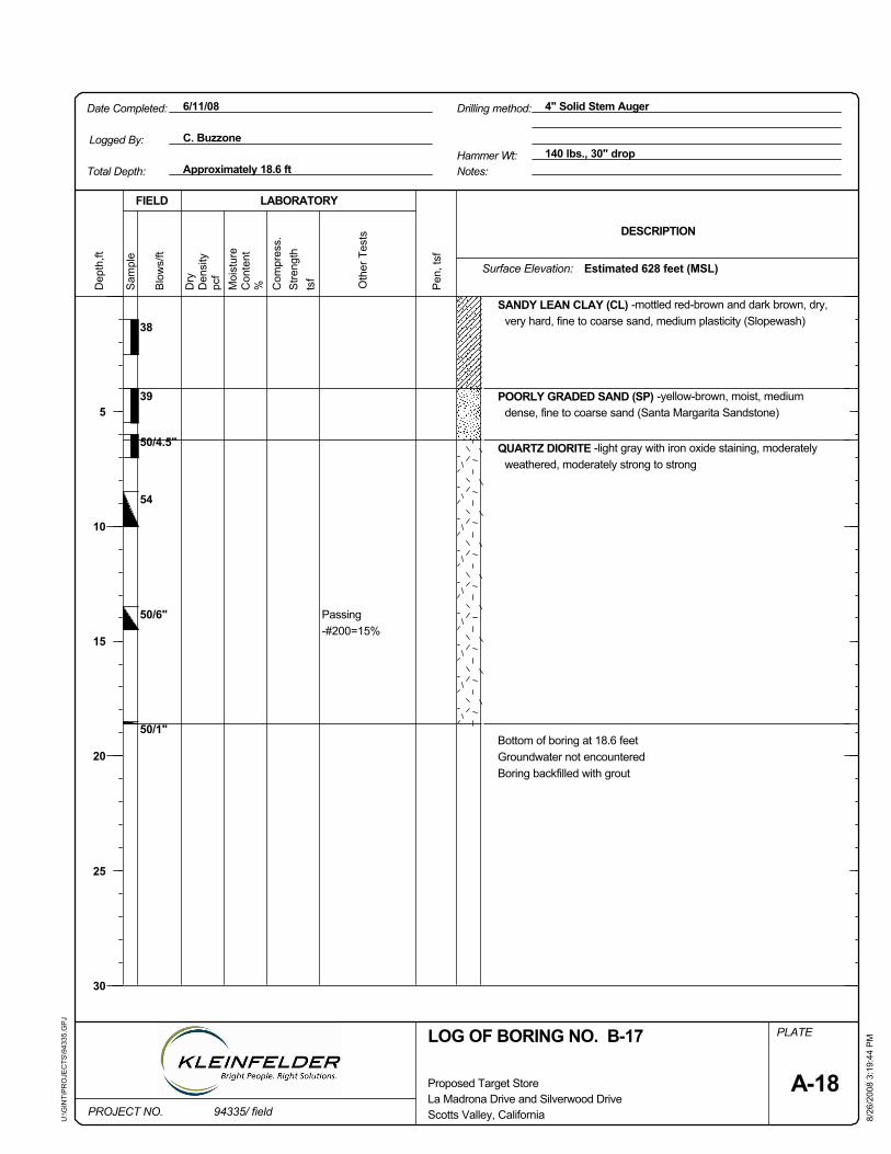
FIELD
Passing-#200=15%
PLATE
Pen
, tsf
pcf
Oth
er T
ests
tsf
50/6"
54
Sam
ple
Stre
ngth
8/26
/200
8 3:
19:4
4 P
M
Surface Elevation:
Scotts Valley, California
LOG OF BORING NO. B-17
50/1"
SANDY LEAN CLAY (CL) -mottled red-brown and dark brown, dry,very hard, fine to coarse sand, medium plasticity (Slopewash)
POORLY GRADED SAND (SP) -yellow-brown, moist, mediumdense, fine to coarse sand (Santa Margarita Sandstone)
QUARTZ DIORITE -light gray with iron oxide staining, moderatelyweathered, moderately strong to strong
Bottom of boring at 18.6 feetGroundwater not encounteredBoring backfilled with grout
38
39
50/4.5"
140 lbs., 30" drop
PROJECT NO.
Dep
th,ft
DESCRIPTION
Dry
6/11/08
Approximately 18.6 ft
Proposed Target Store
LABORATORY
Moi
stur
e
Date Completed: 4" Solid Stem Auger
U:\G
INT\
PR
OJE
CTS
\943
35.G
PJ
Hammer Wt:Total Depth:
C. BuzzoneLogged By:
Notes:
Estimated 628 feet (MSL)
La Madrona Drive and Silverwood Drive
Drilling method:
Com
pres
s.
94335/ field
Blo
ws/
ft
Den
sity
%
5
10
15
20
25
30
A-18
Con
tent

pcf
42
43
57
52
50/0.5"
LL=23; PI=8Passing-#200=29%
PLATE
Oth
er T
ests
tsf
FIELD
8/26
/200
8 3:
19:5
1 P
M
Sam
ple
Dry
Stre
ngth
Pen
, tsf
SILTY SAND (SM) -light brown, dry, loose, fine sand (Slopewash)
CLAYEY SAND (SC) -mottled red and dark brown, dry, dense, lowplasticity, fine to coarse sand
-mottled gray and yellow, trace fine gravel
POORLY GRADED SAND WITH CLAY (SP-SC) -mottled lightbrown and yellow-brown, dry, dense, fine to medium sand
POORLY GRADED SAND WITH CLAY (SP-SC) -mottled grayand yellow-brown, moist, dense, fine to coarse sand, fine gravelcomposed of angular mudstone clasts, coarse gravel and cobblequartz diorite clasts (Slopewash)
QUARTZ DIORITE -light gray with iron oxide staining, moderatelyto slightly weathered, moderately strong to strong
Bottom of boring at 13.6 feet (refusal)Groundwater not encounteredBoring backfilled with grout
6/11/08
PROJECT NO.
Dep
th,ft
DESCRIPTION
La Madrona Drive and Silverwood Drive94335/ field
Hammer Wt: 140 lbs., 30" dropApproximately 13.6 ft
Proposed Target Store
LABORATORY
Moi
stur
e
Date Completed: 4" Solid Stem Auger
U:\G
INT\
PR
OJE
CTS
\943
35.G
PJ
Estimated 635 feet (MSL)
Drilling method:
Logged By: C. Buzzone
LOG OF BORING NO. B-18
Blo
ws/
ftNotes:
Scotts Valley, California
Total Depth:
A-19
Den
sity
5
10
15
20
25
30
Surface Elevation:
Con
tent
% Com
pres
s.

63
14306/11/2008
13.7
10.8
116
113
17
34
62
50
FIELD
Pen
, tsf
tsf Oth
er T
ests
56
50/6"
8/26
/200
8 3:
20:3
3 P
M
Passing-#200=25%
50/6" QUARTZ DIORITE -light gray, moderately weathered
pcf
SILTY LEAN CLAY WITH SAND (CL-ML) -light brown, dry, hard,fine sand
PLATE
-wet
-light brown, grades more coarse sand
-yellow-brown to light brown, very dense
POORLY GRADED SAND (SP) -light brown, moist, dense, fine tomedium sand
SANDY LEAN CLAY (CL) -red-brown, dry, hard, fine to mediumsand, fine gravel composed of angular mudstone (Slopewash)
Bottom of boring at 29 feetGrounwater encountered at 21 feetBoring backfilled with grout
CLAYEY SAND (SC) -light brown, moist, dense, fine to mediumsand (Santa Margarita Sandstone)
DESCRIPTION
PROJECT NO. 94335/ field
Blo
ws/
ft
LABORATORY
U:\G
INT\
PR
OJE
CTS
\943
35.G
PJ
4" Solid Stem AugerDate Completed:
La Madrona Drive and Silverwood Drive
Dep
th,ft
Proposed Target Store
Approximately 29.0 ft140 lbs., 30" drop
6/11/08
Hammer Wt:
Moi
stur
e
LOG OF BORING NO. B-19
Dry
Stre
ngth
Den
sity
Drilling method:
Surface Elevation:
Scotts Valley, California
5
10
15
20
25
30
35
A-20
Con
tent
% Com
pres
s.
Logged By:
Estimated 613 feet (MSL)
Notes:Total Depth:
C. BuzzoneS
ampl
e
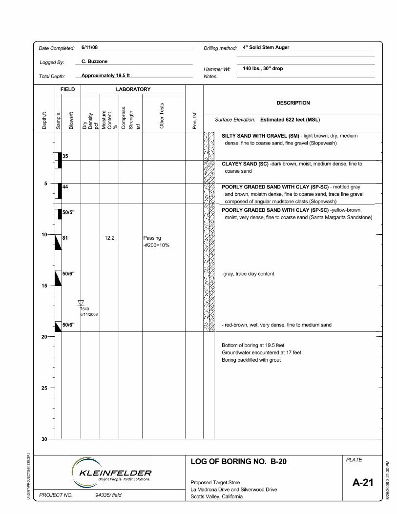
pcf
12.2
35
44
50/5"
81
50/6"
50/6"
Passing-#200=10%
PLATE
Oth
er T
ests
tsf
8/26
/200
8 3:
21:3
0 P
M
Sam
ple
Dry
Stre
ngth
Pen
, tsf
15406/11/2008
SILTY SAND WITH GRAVEL (SM) - light brown, dry, mediumdense, fine to coarse sand, fine gravel (Slopewash)
CLAYEY SAND (SC) -dark brown, moist, medium dense, fine tocoarse sand
POORLY GRADED SAND WITH CLAY (SP-SC) - mottled grayand brown, moistm dense, fine to coarse sand, trace fine gravelcomposed of angular mudstone clasts (Slopewash)
POORLY GRADED SAND WITH CLAY (SP-SC) -yellow-brown,moist, very dense, fine to coarse sand (Santa Margarita Sandstone)
-gray, trace clay content
- red-brown, wet, very dense, fine to medium sand
Bottom of boring at 19.5 feetGroundwater encountered at 17 feetBoring backfilled with grout
FIELD
6/11/08
PROJECT NO.
Dep
th,ft
DESCRIPTION
La Madrona Drive and Silverwood Drive94335/ field
Hammer Wt: 140 lbs., 30" dropApproximately 19.5 ft
Proposed Target Store
LABORATORY
Moi
stur
e
Date Completed: 4" Solid Stem Auger
U:\G
INT\
PR
OJE
CTS
\943
35.G
PJ
Surface Elevation:
Drilling method:
Logged By:
LOG OF BORING NO. B-20
Blo
ws/
ftTotal Depth:
Scotts Valley, California
Notes:
C. Buzzone
A-21
Den
sity
5
10
15
20
25
30
Estimated 622 feet (MSL)
Con
tent
% Com
pres
s.
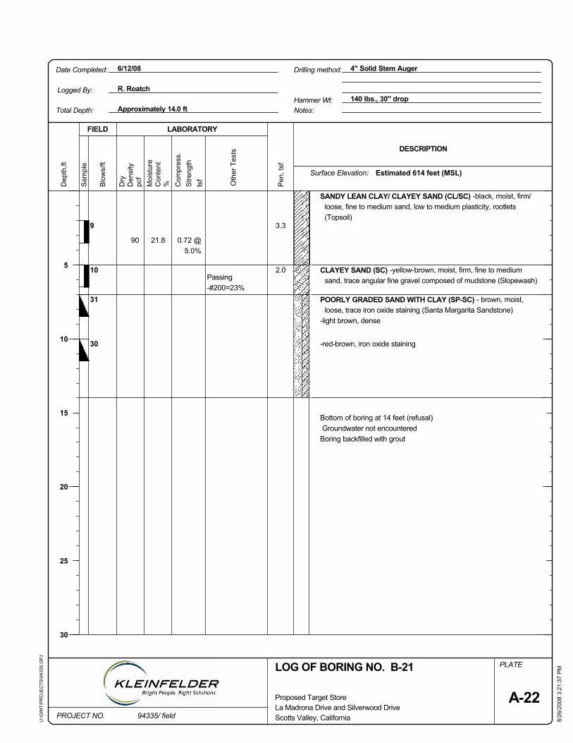
31
30
0.72 @5.0%
Passing-#200=23%
PLATE
Pen
, tsf
pcf
Scotts Valley, California
tsf
90
FIELD
Sam
ple
Stre
ngth
8/26
/200
8 3:
21:3
7 P
M
Surface Elevation:
Oth
er T
ests
CLAYEY SAND (SC) -yellow-brown, moist, firm, fine to mediumsand, trace angular fine gravel composed of mudstone (Slopewash)
10
SANDY LEAN CLAY/ CLAYEY SAND (CL/SC) -black, moist, firm/loose, fine to medium sand, low to medium plasticity, rootlets(Topsoil)
9
POORLY GRADED SAND WITH CLAY (SP-SC) - brown, moist,loose, trace iron oxide staining (Santa Margarita Sandstone)
-light brown, dense
-red-brown, iron oxide staining
Bottom of boring at 14 feet (refusal)Groundwater not encounteredBoring backfilled with grout
3.3
2.0
21.8
140 lbs., 30" drop
PROJECT NO.
LOG OF BORING NO. B-21
Dry
DESCRIPTION
La Madrona Drive and Silverwood Drive
6/12/08D
epth
,ft
Approximately 14.0 ft
Proposed Target Store
LABORATORY
Moi
stur
e
Date Completed: 4" Solid Stem Auger
U:\G
INT\
PR
OJE
CTS
\943
35.G
PJ
Hammer Wt:
Drilling method:
Logged By: R. Roatch
94335/ field
Estimated 614 feet (MSL)
Total Depth:B
low
s/ft
Den
sity
Notes:
Com
pres
s.
5
10
15
20
25
30
A-22
Con
tent
%
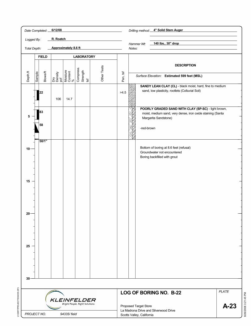
Dry
pcf
Oth
er T
ests
tsf
FIELD
Drilling method:
Stre
ngth
Scotts Valley, California 8/26
/200
8 3:
21:4
5 P
M
Sam
ple
Bottom of boring at 8.6 feet (refusal)Groundwater not encounteredBoring backfilled with grout
SANDY LEAN CLAY (CL) - black moist, hard, fine to mediumsand, low plasticity, rootlets (Colluvial Soil)
Pen
, tsf
-red-brown
PLATE
>4.5
14.7106
22
83
58
50/1"
LOG OF BORING NO. B-22
POORLY GRADED SAND WITH CLAY (SP-SC) - light brown,moist, medium sand, very dense, iron oxide staining (SantaMargarita Sandstone)
Approximately 8.6 ft
Dep
th,ft
Surface Elevation:
La Madrona Drive and Silverwood Drive
Hammer Wt:
PROJECT NO.
140 lbs., 30" drop
Proposed Target Store
LABORATORY
Moi
stur
e
Date Completed: 4" Solid Stem Auger
U:\G
INT\
PR
OJE
CTS
\943
35.G
PJ
6/12/08
A-23
Notes:
R. RoatchLogged By:
Estimated 599 feet (MSL)
DESCRIPTION
%
Total Depth:
Com
pres
s.
5
10
15
20
25
30
Den
sity
Blo
ws/
ft
94335/ field
Con
tent
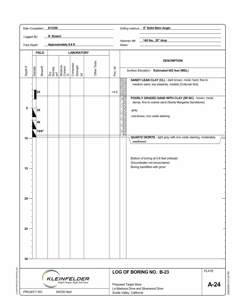
Sam
ple
PLATE
Pen
, tsf
pcf
Oth
er T
ests
tsf
29
Dry
Stre
ngth
8/26
/200
8 3:
21:5
3 P
M
Scotts Valley, California
LOG OF BORING NO. B-23
FIELD
SANDY LEAN CLAY (CL) - dark brown, moist, hard, fine tomedium sand, low plasticity, rootlets (Colluvial Soil)
76/9"
46
POORLY GRADED SAND WITH CLAY (SP-SC) - brown, moist,dense, fine to coarse sand (Santa Margarita Sandstone)
-gray
-red-brown, iron oxide staining
QUARTZ DIORITE - light gray with iron oxide staining, moderatelyweathered
Bottom of boring at 9.8 feet (refusal)Groundwater not encounteredBoring backfilled with grout
>4.525
Surface Elevation:
Approximately 9.8 ft
PROJECT NO.
Dep
th,ft
La Madrona Drive and Silverwood Drive
Hammer Wt: 140 lbs., 30" drop
Proposed Target Store
LABORATORY
Moi
stur
e
Date Completed: 4" Solid Stem Auger
U:\G
INT\
PR
OJE
CTS
\943
35.G
PJ
6/12/08
Con
tent
Total Depth:
Logged By:
Notes:
Estimated 602 feet (MSL)
DESCRIPTION
Drilling method:
R. Roatch
%
94335/ field
Blo
ws/
ft
Com
pres
s.
Den
sity
5
10
15
20
25
30
A-24
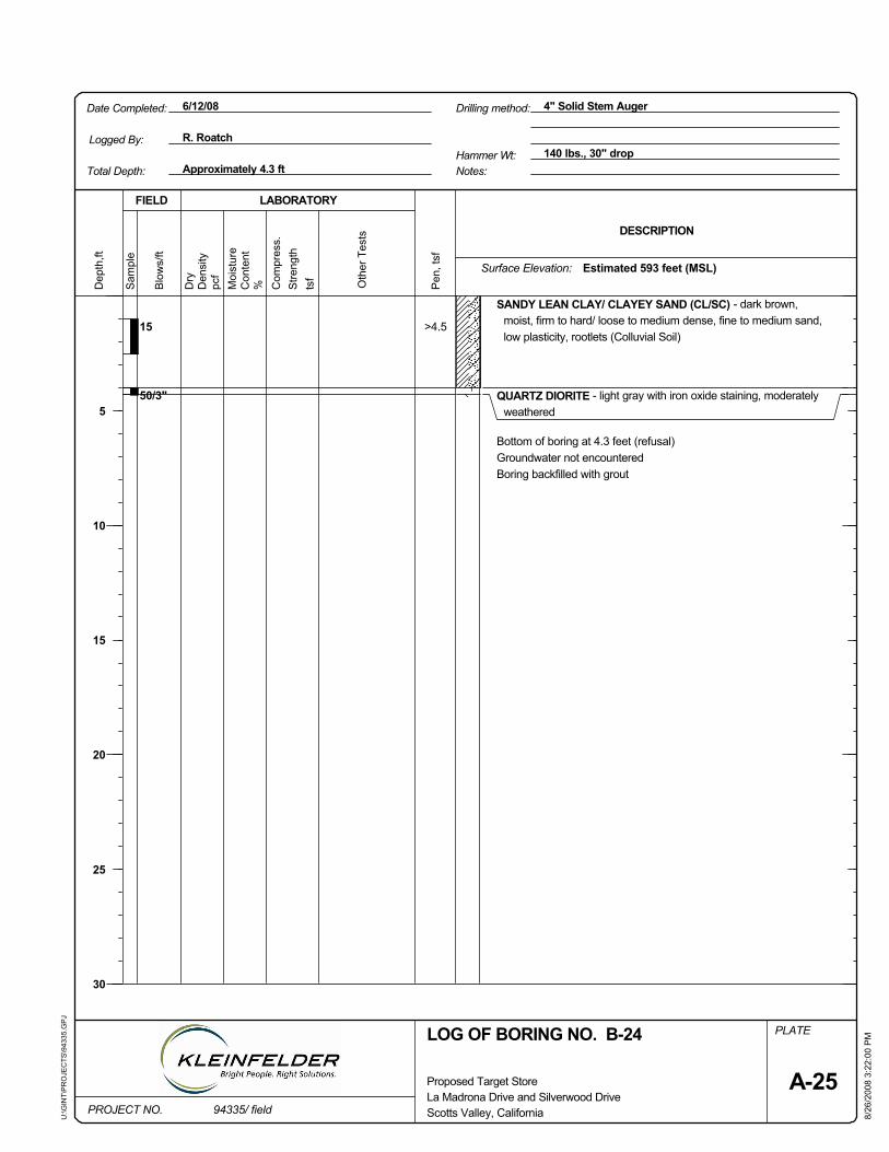
FIELD
Sam
ple
Dry
Stre
ngth
Logged By:
Surface Elevation:
Scotts Valley, California
LOG OF BORING NO. B-24
8/26
/200
8 3:
22:0
0 P
M
SANDY LEAN CLAY/ CLAYEY SAND (CL/SC) - dark brown,moist, firm to hard/ loose to medium dense, fine to medium sand,low plasticity, rootlets (Colluvial Soil)
QUARTZ DIORITE - light gray with iron oxide staining, moderatelyweathered
tsf Oth
er T
ests
>4.515
50/3"
PLATE
Pen
, tsf
pcf
Bottom of boring at 4.3 feet (refusal)Groundwater not encounteredBoring backfilled with grout
R. Roatch
Drilling method:
La Madrona Drive and Silverwood Drive
Hammer Wt:
6/12/08D
epth
,ft
Approximately 4.3 ft
Proposed Target Store
LABORATORY
Moi
stur
e
Date Completed: 4" Solid Stem Auger
U:\G
INT\
PR
OJE
CTS
\943
35.G
PJ
140 lbs., 30" drop
A-25
Total Depth: Notes:
Estimated 593 feet (MSL)C
ompr
ess.
%
DESCRIPTION
PROJECT NO.
5
10
15
20
25
30
Blo
ws/
ft
Den
sity
Con
tent
94335/ field
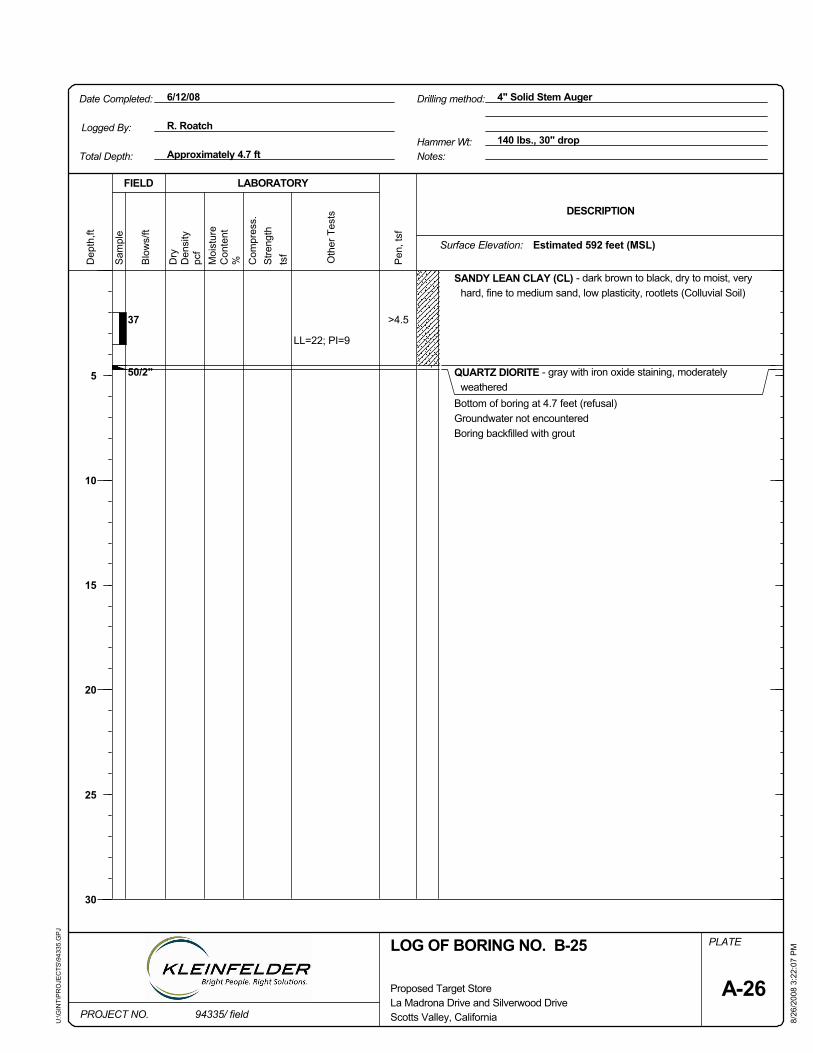
Logged By:
FIELD
Sam
ple
Dry
Stre
ngth
Oth
er T
ests
Surface Elevation:
Scotts Valley, California
LOG OF BORING NO. B-25
Drilling method:
8/26
/200
8 3:
22:0
7 P
M
SANDY LEAN CLAY (CL) - dark brown to black, dry to moist, veryhard, fine to medium sand, low plasticity, rootlets (Colluvial Soil)
QUARTZ DIORITE - gray with iron oxide staining, moderatelyweathered
tsf
>4.537
50/2"
LL=22; PI=9
PLATE
Pen
, tsf
pcf
Bottom of boring at 4.7 feet (refusal)Groundwater not encounteredBoring backfilled with grout
R. Roatch
La Madrona Drive and Silverwood Drive
Hammer Wt:
6/12/08D
epth
,ft
Approximately 4.7 ft
Proposed Target Store
LABORATORY
Moi
stur
e
Date Completed: 4" Solid Stem Auger
U:\G
INT\
PR
OJE
CTS
\943
35.G
PJ
140 lbs., 30" drop
A-26
Total Depth: Notes:
Estimated 592 feet (MSL)C
ompr
ess.
%
DESCRIPTION
PROJECT NO.
5
10
15
20
25
30
Blo
ws/
ft
Den
sity
Con
tent
94335/ field
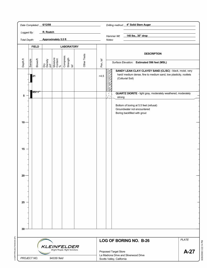
FIELD
Sam
ple
Dry
Stre
ngth
Logged By:
Surface Elevation:
Scotts Valley, California
LOG OF BORING NO. B-26
8/26
/200
8 3:
22:1
4 P
M
SANDY LEAN CLAY/ CLAYEY SAND (CL/SC) - black, moist, veryhard/ medium dense, fine to medium sand, low plasticity, rootlets(Colluvial Soil)
QUARTZ DIORITE - light gray, moderately weathered, moderatelystrong
tsf Oth
er T
ests
>4.521
85/11"
PLATE
Pen
, tsf
pcf
Bottom of boring at 5.5 feet (refusal)Groundwater not encounteredBoring backfilled with grout
R. Roatch
Drilling method:
La Madrona Drive and Silverwood Drive
Hammer Wt:
6/12/08D
epth
,ft
Approximately 5.5 ft
Proposed Target Store
LABORATORY
Moi
stur
e
Date Completed: 4" Solid Stem Auger
U:\G
INT\
PR
OJE
CTS
\943
35.G
PJ
140 lbs., 30" drop
A-27
Total Depth: Notes:
Estimated 596 feet (MSL)C
ompr
ess.
%
DESCRIPTION
PROJECT NO.
5
10
15
20
25
30
Blo
ws/
ft
Den
sity
Con
tent
94335/ field
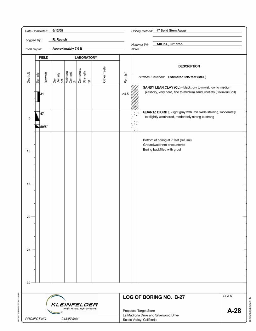
tsf
FIELD
Sam
ple
Dry
pcf Surface Elevation:
Scotts Valley, California
LOG OF BORING NO. B-27
8/26
/200
8 3:
22:2
2 P
M
Stre
ngth
SANDY LEAN CLAY (CL) - black, dry to moist, low to mediumplasticity, very hard, fine to medium sand, rootlets (Colluvial Soil)
Oth
er T
ests
Bottom of boring at 7 feet (refusal)Groundwater not encounteredBoring backfilled with grout
Drilling method:
>4.531
47
50/5"
PLATE
Pen
, tsf
QUARTZ DIORITE - light gray with iron oxide staining, moderatelyto slightly weathered, moderately strong to strong
Logged By:
La Madrona Drive and Silverwood Drive
Hammer Wt:
6/12/08D
epth
,ft
Approximately 7.0 ft
Proposed Target Store
LABORATORY
Moi
stur
e
Date Completed: 4" Solid Stem Auger
U:\G
INT\
PR
OJE
CTS
\943
35.G
PJ
140 lbs., 30" drop
Con
tent
R. Roatch
Total Depth: Notes:
Estimated 595 feet (MSL)C
ompr
ess.
DESCRIPTION
%
PROJECT NO.
A-28
Blo
ws/
ft
Den
sity
5
10
15
20
25
30
94335/ field
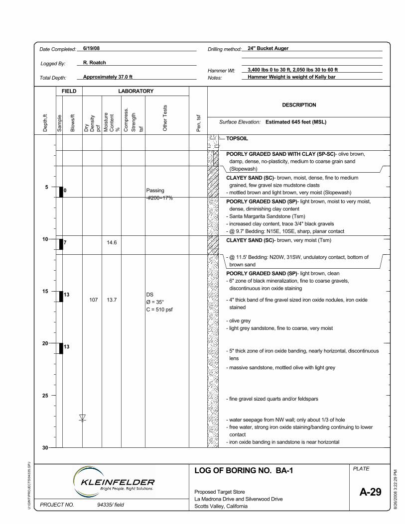
- iron oxide banding in sandstone is near horizontal
107
14.6
tsf
7
- free water, strong iron oxide staining/banding continuing to lowercontact
- water seepage from NW wall; only about 1/3 of hole
- fine gravel sized quarts and/or feldspars
- massive sandstone, mottled olive with light grey
- 5" thick zone of iron oxide banding, nearly horizontal, discontinuouslens
- light grey sandstone, fine to coarse, very moist
C = 510 psf
Oth
er T
ests
pcf
8/26
/200
8 3:
22:2
9 P
MPLATE
13.7
0
Ø = 35°DS
Passing-#200=17%
13
13
- 6" zone of black mineralization, fine to coarse gravels,discontinuous iron oxide staining
- olive grey
- mottled brown and light brown, very moist (Slopewash)P
en, t
sf
POORLY GRADED SAND (SP)- light brown, clean
- @ 11.5' Bedding: N20W, 31SW, undulatory contact, bottom ofbrown sand
CLAYEY SAND (SC)- brown, very moist (Tsm)
- @ 9.7' Bedding: N15E, 10SE, sharp, planar contact- increased clay content, trace 3/4" black gravels
POORLY GRADED SAND (SP)- light brown, moist to very moist,dense, diminishing clay content
- 4" thick band of fine gravel sized iron oxide nodules, iron oxidestained
CLAYEY SAND (SC)- brown, moist, dense, fine to mediumgrained, few gravel size mudstone clasts
POORLY GRADED SAND WITH CLAY (SP-SC)- olive brown,damp, dense, no-plasticity, medium to coarse grain sand(Slopewash)
TOPSOIL
- Santa Margarita Sandstone (Tsm)
Dep
th,ft
PROJECT NO.La Madrona Drive and Silverwood Drive
Blo
ws/
ft
Den
sity
Proposed Target Store
U:\G
INT\
PR
OJE
CTS
\943
35.G
PJ
24" Bucket AugerDate Completed:
Moi
stur
eDESCRIPTION
LABORATORY
94335/ field
Approximately 37.0 ft3,400 lbs 0 to 30 ft, 2,050 lbs 30 to 60 ft
6/19/08
Hammer Wt:
Sam
ple
FIELD
LOG OF BORING NO. BA-1
Scotts Valley, California
Surface Elevation:
Stre
ngth
Dry
Hammer Weight is weight of Kelly bar
5
10
15
20
25
30
A-29
Con
tent
% Com
pres
s.Estimated 645 feet (MSL)
Notes:Total Depth:
R. RoatchLogged By:
Drilling method:

Moi
stur
e
94335/ field
Sam
ple
pcf
Scotts Valley, California
Den
sity
Con
tent
Proposed Target Store
PROJECT NO.
PLATE
% Com
pres
s.S
treng
th
DESCRIPTION
FIELD LABORATORY
A-29
tsf
(cont'd)
(Continued from previous plate)Blo
ws/
ft
Dry
35
40
45
50
55
60
Dep
th,ft
Pen
, tsf
LOG OF BORING NO. BA-1
La Madrona Drive and Silverwood Drive
U:\G
INT\
PR
OJE
CTS
\943
35.G
PJ
- @ 33' Contact between sandstone and quartz diorite, irregular andundulatory.
Oth
er T
ests
- materials becomes hard to drill
8/26
/200
8 3:
22:2
9 P
M
QUARTZ DIORITE (Kqd)- slightly to moderately weathered quartzdiorite
Notes:
- downhole logged to 34 feet
- backfilled with concrete
15 - granite rip-up clasts
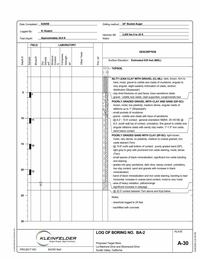
12
- area of heavy oxidation, yellow/orange- significant increase in seepage- @ 22.5' contact between Tsm above and Kqd below
Notes:
- downhole logged to 24 feet
- backfilled with concrete
3
Sam
ple
10
- small specks of black mineralization, significant iron oxide bandingand staining
PLATE
Pen
, tsf
pcf
Oth
er T
ests
8/26
/200
8 3:
22:3
8 P
M
FIELD
11
- band of black mineralization and iron oxide staining, banding is nearhorizontal, increase in coarse sand content, moist to very moist
- gravel - cobble size clasts, clast supported, conglomerate bed
tsf
- @ 10.6' north wall bottom of contact: poorly graded sand (SP),light grey to grey with prominent iron oxide staining, moist, dense(Tsm)
POORLY GRADED SAND WITH CLAY (SP-SC)- light brown,moist, very dense, no plasticity, medium to coarse grained, ironoxide stained (Tsm)
- @ 8.2' - 10.6' contact: general orientation N68W, 35~45 NE @8.2', south wall top of contact, undulatory, fine gravel to cobble sizeangular siltstone clasts with sandy clay matrix, 1"-1.5" iron oxide,band below contact
- gravel - cobble size clasts with trace of sandstone
POORLY GRADED GRAVEL WITH CLAY AND SAND (GP-GC)-brown, moist, low plasticity, medium dense, angular clasts ofsiltstone up to 1" (Slopewash)
- clay lined fractures on ped faces, trace sandstone clasts
SILTY LEAN CLAY WITH GRAVEL (CL-ML)- dark, brown, firm tohard, moist, gravel to cobble size clasts of mudstone, angular tovery angular, slight easterly imbrication of clasts, randomdistribution (Slopewash)
TOPSOIL
- grades into grey sandstone, dark olive, wavey contact, undulatory,low clay content, sand and gravels with increase in blackmineralization,
- small pockets of mudstone
Hammer Wt:B
low
s/ft
94335/ field
Dep
th,ft
DESCRIPTION
La Madrona Drive and Silverwood Drive
LABORATORY
U:\G
INT\
PR
OJE
CTS
\943
35.G
PJ
24" Bucket AugerDate Completed:
Proposed Target Store
Approximately 24.0 ft3,450 lbs 0 to 30 ft
6/20/08
Moi
stur
e
Dry
Stre
ngth
Drilling method:
LOG OF BORING NO. BA-2
Scotts Valley, California
Surface Elevation:
PROJECT NO.
%Den
sity
5
10
15
20
25
30
A-30
Con
tent
Logged By:
Com
pres
s.Estimated 635 feet (MSL)
Notes:Total Depth:
R. Roatch
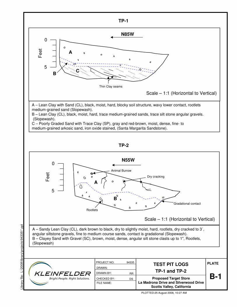
B-1
PLATE
Libr
ary
file:
L:\2
008\
libra
ry\p
roje
cts\
9433
5\*.
ppt
TEST PIT LOGSTP-1 and TP-2
Proposed Target StoreLa Madrona Drive and Silverwood Drive
Scotts Valley, California
DRAWN:
CHECKED BY:
PROJECT NO: 94335
FILE NAME:
PLOTTED:25 August 2008, 10:27 AM
RRDRAWN BY:
DS
A – Lean Clay with Sand (CL), black, moist, hard, blocky soil structure, wavy lower contact, rootletsmedium-grained sand (Slopewash).B – Lean Clay (CL), black, moist, hard, trace medium-grained sands, trace silt stone angular gravels.(Slopewash).C – Poorly Graded Sand with Trace Clay (SP), gray and red-brown, moist, dense, fine- to medium-grained arkosic sand, iron oxide stained, (Santa Margarita Sandstone).
A – Sandy Lean Clay (CL), dark brown to black, dry to slightly moist, hard, rootlets, dry cracked to 3´, angular siltstone gravels, fine to medium course sands, contact is gradational (Slopewash). B – Clayey Sand with Gravel (SC), brown, moist, dense, angular silt stone clasts up to 1", Rootlets, (Slopewash)
0
5
Feet
0
5
Feet A
CB
N85W
Thin Clay seams
TP-1
A
B
N55W
Rootlets
Gradational contact
Dry cracking
Animal Burrow
TP-2
Scale – 1:1 (Horizontal to Vertical)
Scale – 1:1 (Horizontal to Vertical)
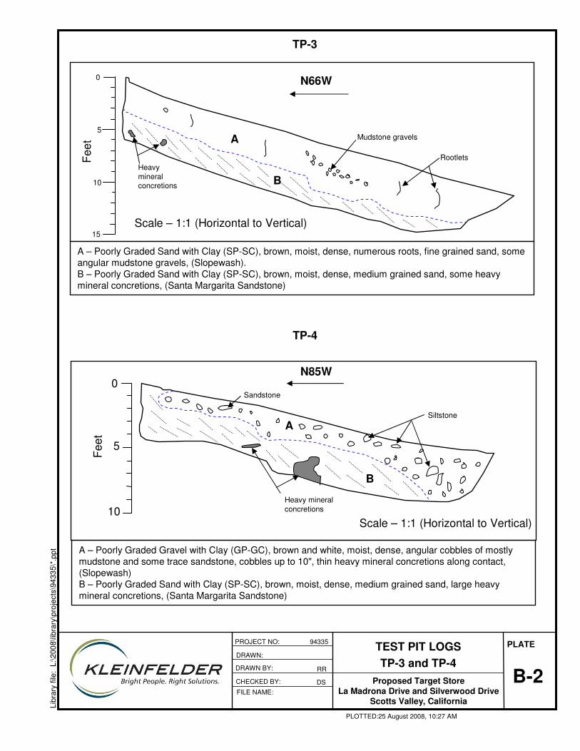
B-2
PLATE
Libr
ary
file:
L:\2
008\
libra
ry\p
roje
cts\
9433
5\*.
ppt
TEST PIT LOGSTP-3 and TP-4
Proposed Target StoreLa Madrona Drive and Silverwood Drive
Scotts Valley, California
DRAWN:
CHECKED BY:
PROJECT NO: 94335
FILE NAME:
PLOTTED:25 August 2008, 10:27 AM
RRDRAWN BY:
DS
A – Poorly Graded Sand with Clay (SP-SC), brown, moist, dense, numerous roots, fine grained sand, some angular mudstone gravels, (Slopewash).B – Poorly Graded Sand with Clay (SP-SC), brown, moist, dense, medium grained sand, some heavy mineral concretions, (Santa Margarita Sandstone)
A – Poorly Graded Gravel with Clay (GP-GC), brown and white, moist, dense, angular cobbles of mostly mudstone and some trace sandstone, cobbles up to 10", thin heavy mineral concretions along contact,(Slopewash) B – Poorly Graded Sand with Clay (SP-SC), brown, moist, dense, medium grained sand, large heavy mineral concretions, (Santa Margarita Sandstone)
TP-3
0
5
10
15
Heavy mineral concretions
Rootlets
A
B
Mudstone gravels
N66W
TP-4
Heavy mineral concretions
Sandstone
A
B
0
5
10
N85W
Siltstone
Scale – 1:1 (Horizontal to Vertical)
Scale – 1:1 (Horizontal to Vertical)
Feet
Feet
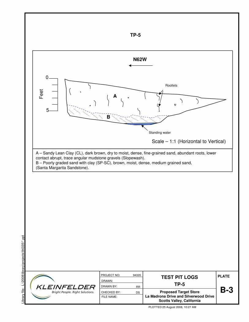
B-3
PLATE
Libr
ary
file:
L:\2
008\
libra
ry\p
roje
cts\
9433
5\*.
ppt
TEST PIT LOGSTP-5
Proposed Target StoreLa Madrona Drive and Silverwood Drive
Scotts Valley, California
DRAWN:
CHECKED BY:
PROJECT NO: 94335
FILE NAME:
PLOTTED:25 August 2008, 10:27 AM
RRDRAWN BY:
DS
A – Sandy Lean Clay (CL), dark brown, dry to moist, dense, fine-grained sand, abundant roots, lower contact abrupt, trace angular mudstone gravels (Slopewash). B – Poorly graded sand with clay (SP-SC), brown, moist, dense, medium grained sand, (Santa Margarita Sandstone).
A
B
Standing water
Rootlets
TP-5
N62W
0
Feet
5
Scale – 1:1 (Horizontal to Vertical)
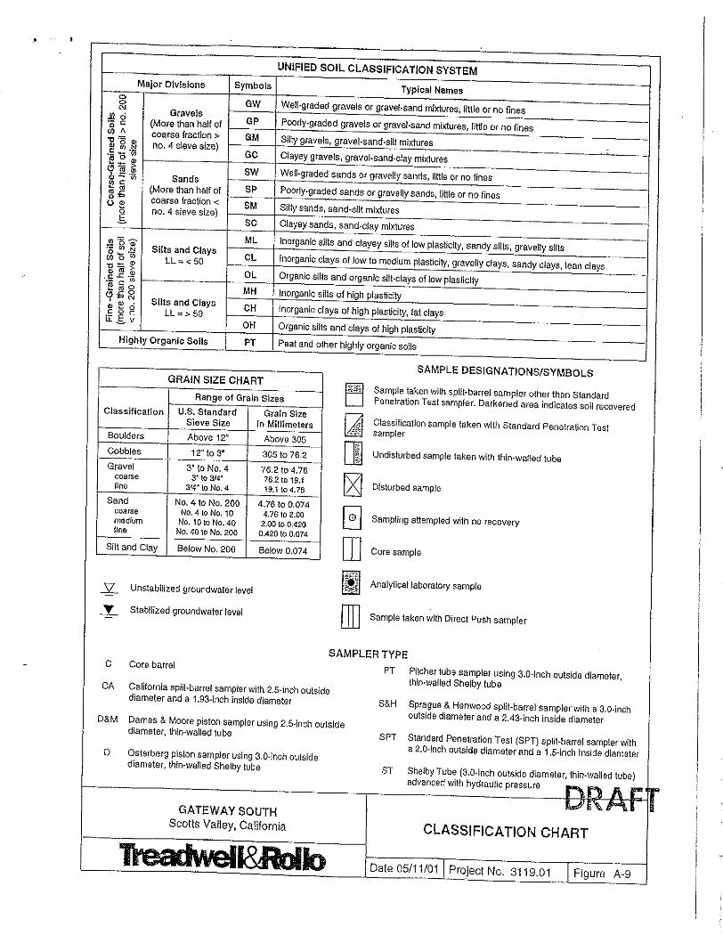
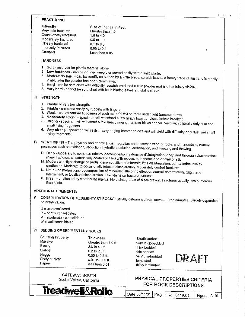
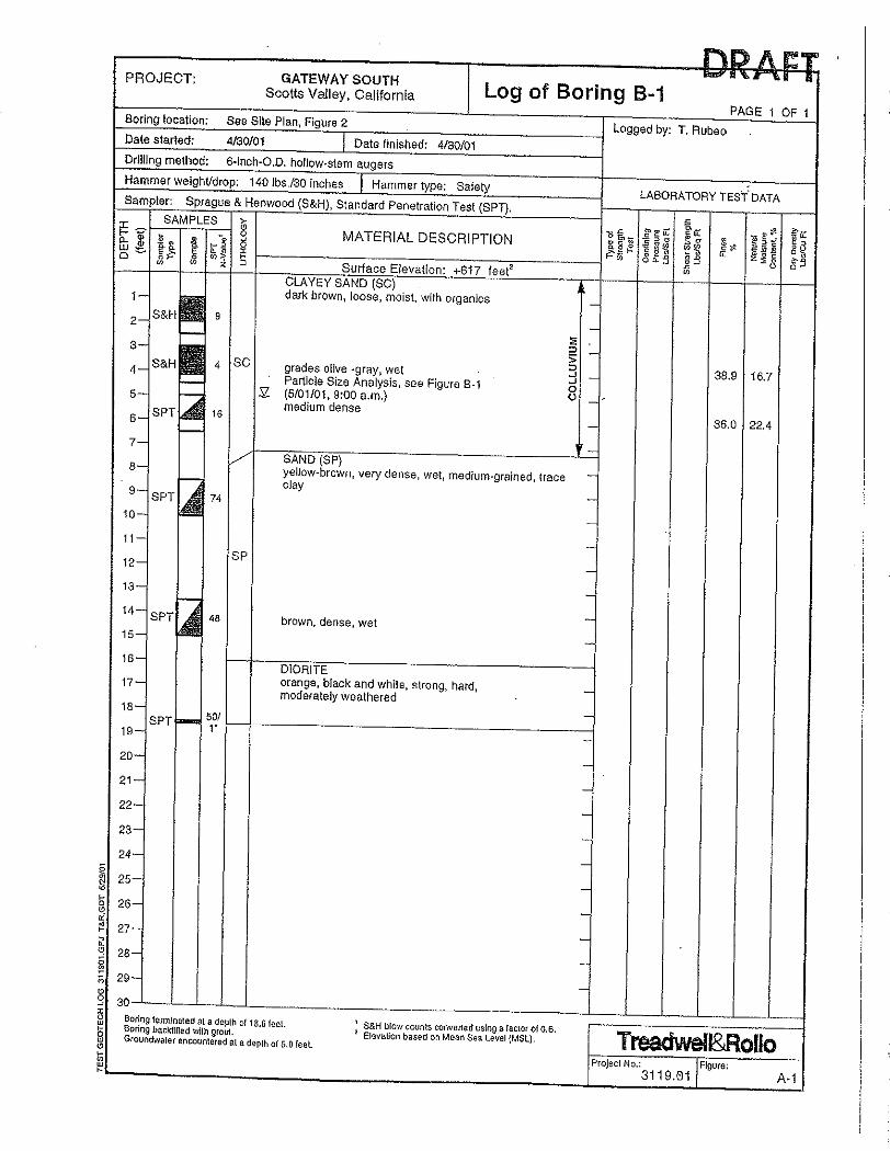
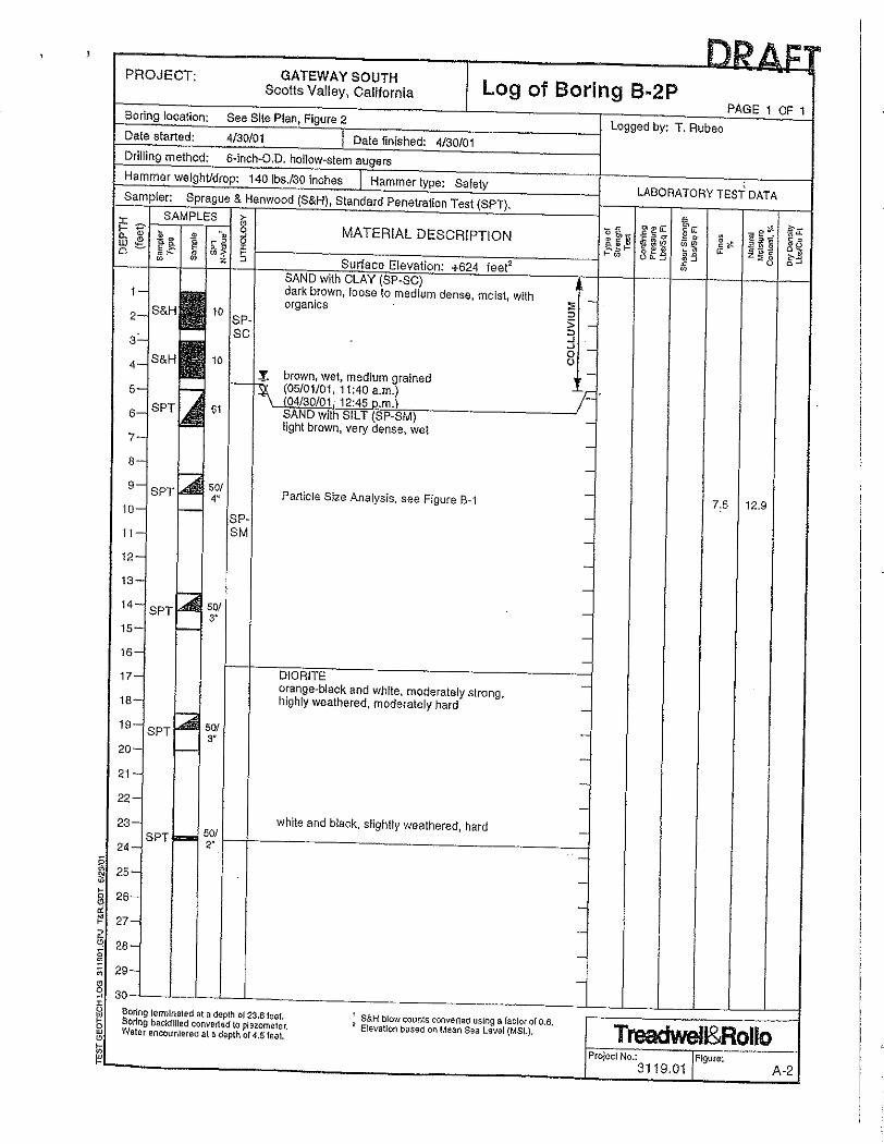
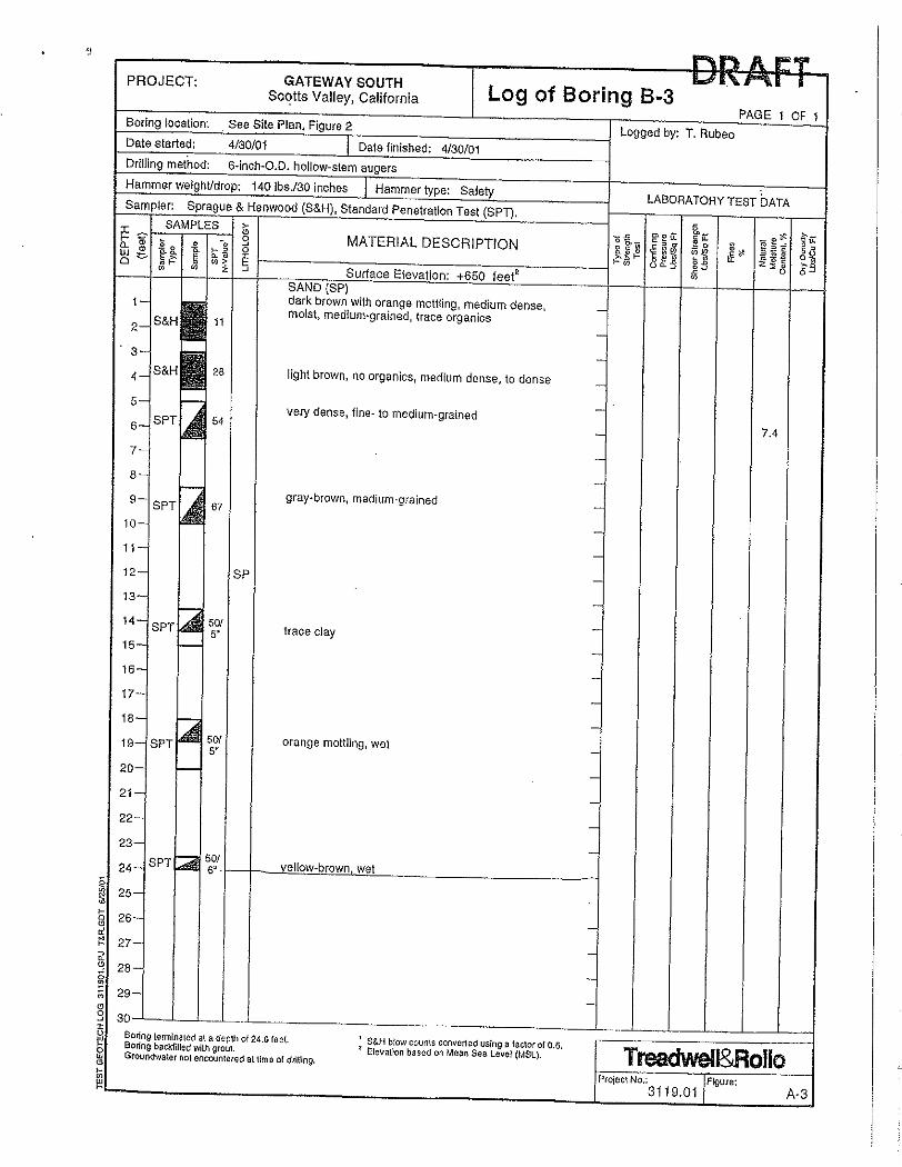
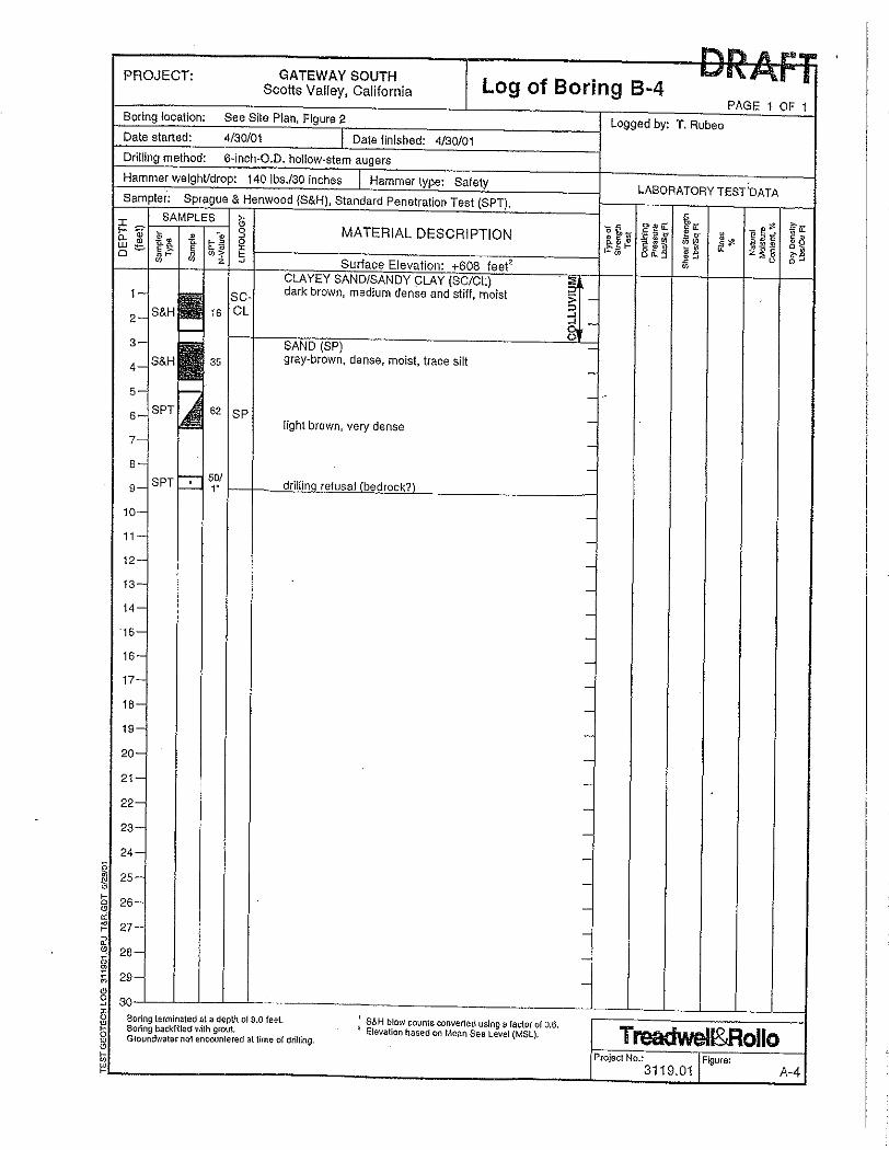
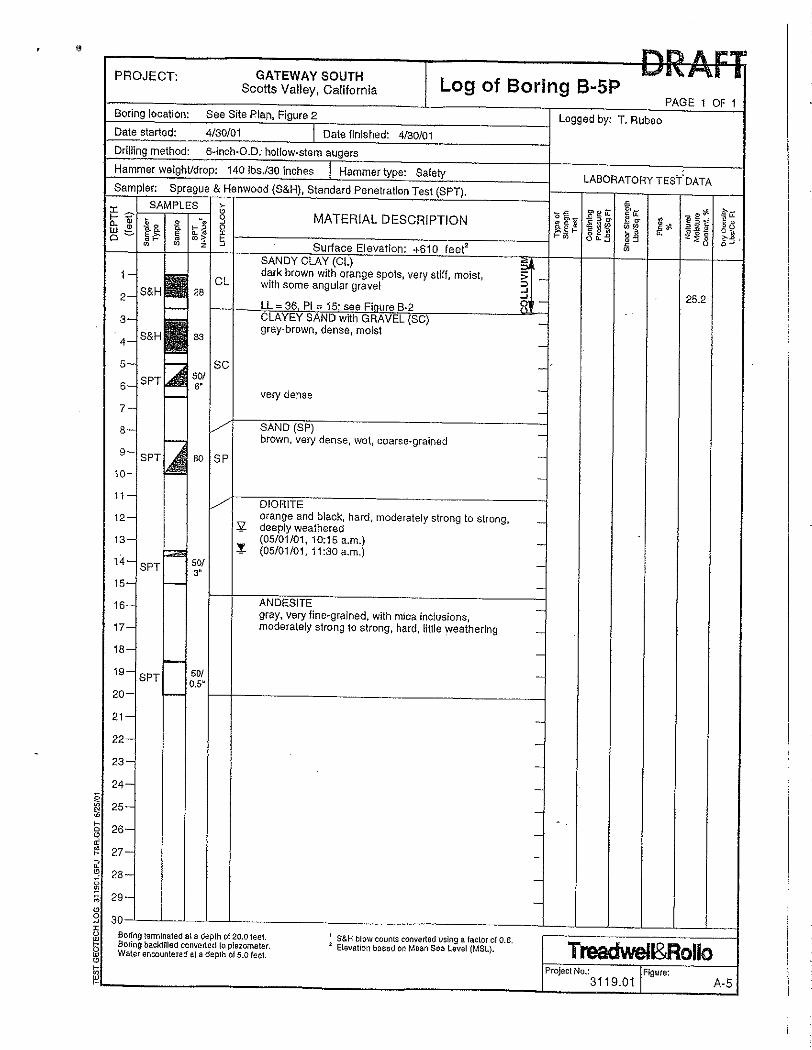
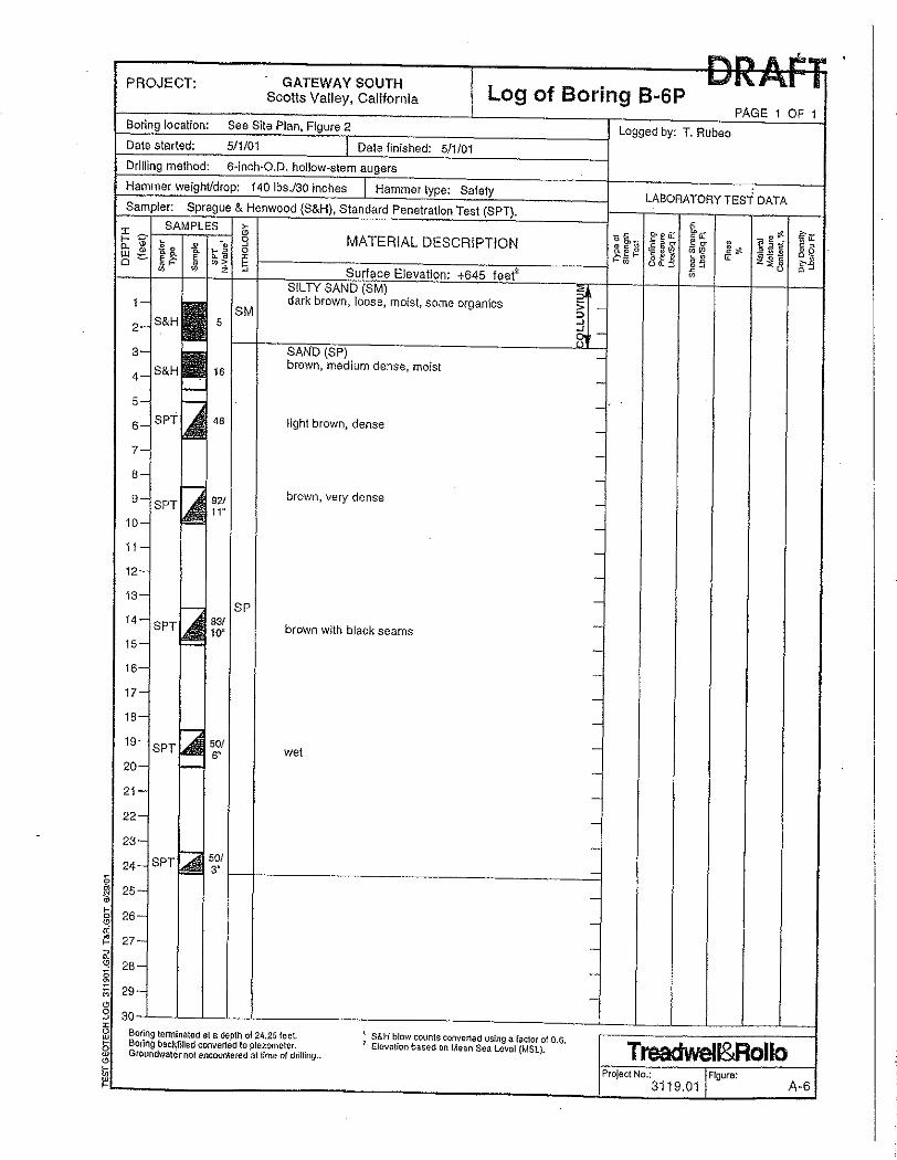
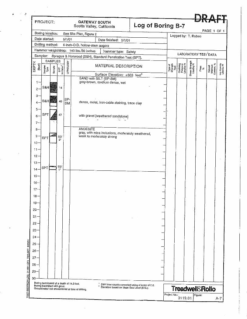

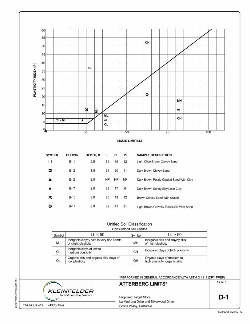
D-1Scotts Valley, CaliforniaLa Madrona Drive and Silverwood DriveProposed Target Store
Unified Soil Classification
Dark Brown Poorly Graded Sand With Clay
CH
Dark Brown Clayey Sand
Dark Brown Sandy Silty Lean Clay
Brown Clayey Sand With Gravel
Light Brown Gravelly Elastic Silt With Sand
SAMPLE DESCRIPTIONPLLL
31
31
Light Olive-Brown Clayey Sand
35
60
55
0 25 50 75
25
50
40
30
25
20
15
10
5
0100
45
of slight plasticity
Symbol Symbol
CL
MH
or
OH
Fine Grained Soil Groups
LL > 50
MH
CH
OH high plasticity, organic silts
of high plasticity
Organic silts and organic silty clays of
12
U:\G
INT\
PR
OJE
CTS
\943
35.G
PJ
LL < 50
Organic clays of medium to
NP
Inorganic silts and clayey silts
PI
*PERFORMED IN GENERAL ACCORDANCE WITH ASTM D 4318 (DRY PREP)
BORING
41
13
17
NP
MLorOL
19
SYMBOL
CL - ML
21
12
6
NP
11
low plasticity
20
DEPTH, ft
94335/ field
B-14
B-10
B- 7
B- 2
Inorganic clays of high plasticity
B- 1
8.0
3.0
2.0
2.0
1.5
2.5
62
B- 2
PLA
STIC
ITY
IND
EX (P
I)
medium plasticityInorganic clays of low to
Inorganic clayey silts to very fine sandsML
CL
OL
ATTERBERG LIMITS*
8/26/2008 3:28:52 PM
LIQUID LIMIT (LL)
PLATE
PROJECT NO.
23
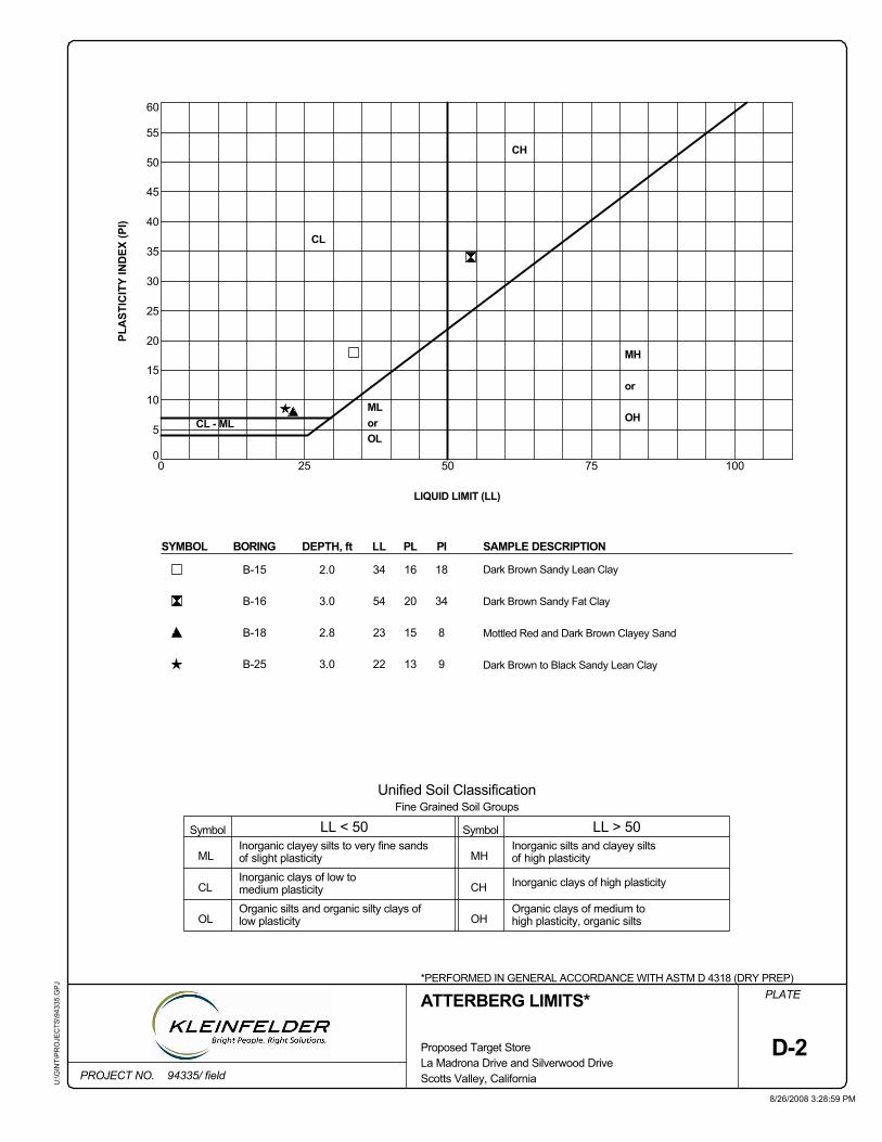
CH
Dark Brown to Black Sandy Lean Clay
Mottled Red and Dark Brown Clayey Sand
Dark Brown Sandy Fat Clay
Dark Brown Sandy Lean Clay
SAMPLE DESCRIPTION
Unified Soil Classification
D-2Scotts Valley, California
Proposed Target Store
50
La Madrona Drive and Silverwood Drive
30
0
5
10
15
100
25
35
40
45
50
55
60
0 25
34
75
20MH
or
OH
Fine Grained Soil Groups
LL > 50
MH
CH
OH high plasticity, organic silts
Inorganic silts and clayey siltsof high plasticityof slight plasticity
MLorOL
U:\G
INT\
PR
OJE
CTS
\943
35.G
PJ
LL < 50
Organic clays of medium to
PL
Organic silts and organic silty clays of
*PERFORMED IN GENERAL ACCORDANCE WITH ASTM D 4318 (DRY PREP)
BORING
13
15
20
CL
PI
Symbol Symbol
CL - ML
9
8
34
18
SYMBOL
low plasticity
16
3.0
94335/ field
B-25
B-18
B-16
Inorganic clays of high plasticity
DEPTH, ft
2.8
3.0
2.0
22
23
54
B-15
LIQUID LIMIT (LL)
medium plasticityInorganic clays of low to
Inorganic clayey silts to very fine sandsML
CL
OL
ATTERBERG LIMITS*
8/26/2008 3:28:59 PM
PLA
STIC
ITY
IND
EX (P
I)
PLATE
PROJECT NO.
LL
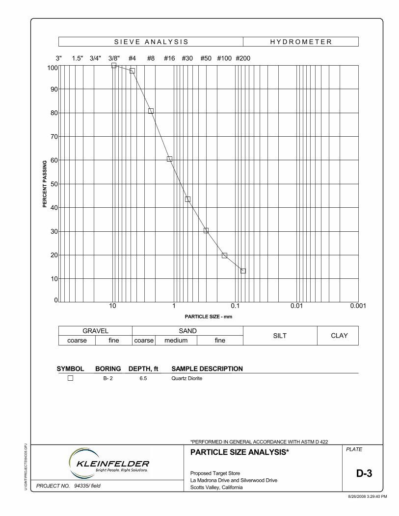
10
DEPTH, ft SAMPLE DESCRIPTIONQuartz Diorite6.5B- 2
0.0010.01
SYMBOL
1
*PERFORMED IN GENERAL ACCORDANCE WITH ASTM D 422
PARTICLE SIZE ANALYSIS*
PER
CEN
T PA
SSIN
G
0.1
20
BORING
10
#30
30
40
50
60
70
80
90
100
PARTICLE SIZE - mm
0
3"
U:\G
INT\
PR
OJE
CTS
\943
35.G
PJ
PLATE
PROJECT NO.La Madrona Drive and Silverwood Drive
medium
H Y D R O M E T E R
#50 #100 #200
coarse fineSILT
fineCLAY
D-3Proposed Target Store
#16#43/8"3/4"1.5"
S I E V E A N A L Y S I S
SAND
Scotts Valley, California
8/26/2008 3:29:40 PM
94335/ field
coarseGRAVEL
#8
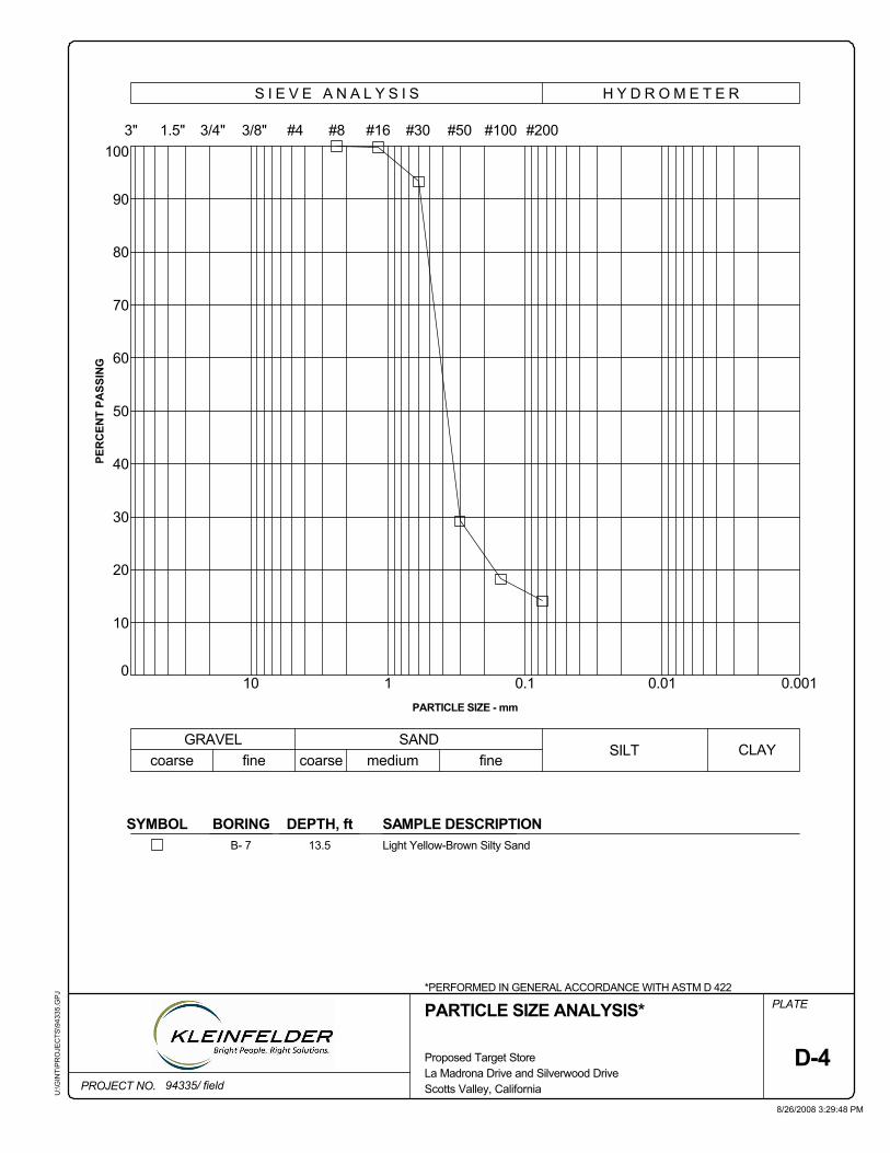
SAMPLE DESCRIPTIONLight Yellow-Brown Silty Sand13.5B- 7
0.0010.010.110
SYMBOL
PARTICLE SIZE ANALYSIS*
PER
CEN
T PA
SSIN
G
medium
1
40
0
10
DEPTH, ft
30
BORING
50
60
70
80
90
100
PARTICLE SIZE - mm
*PERFORMED IN GENERAL ACCORDANCE WITH ASTM D 422
#16
20
3"
GRAVEL
PLATE
PROJECT NO.La Madrona Drive and Silverwood Drive
U:\G
INT\
PR
OJE
CTS
\943
35.G
PJ
H Y D R O M E T E R
8/26/2008 3:29:48 PM
#50 #100 #200
coarse fineSILT
fineCLAY
94335/ field
Proposed Target Store
#43/8"3/4"1.5"
S I E V E A N A L Y S I S
SAND
#8
D-4
#30
coarse
Scotts Valley, California

1.0
5.5
5.0
4.5
4.0
3.5
3.0
2.5
6.0
2.0
1.5
0.0
0.5
8
MAXIMUM DEVIATOR STRESS= 4.97 ksf at
17.8DEPTH - ft
D-5
AXIAL STRAIN - %
DEV
IATO
R S
TRES
S -
ksf
*PERFORMED IN GENERAL ACCORDANCE WITH ASTM D 2850
B- 1
4
14.9 % STRAIN
94335/ field
Very Light Gray Quartz Diorite
0.7
UNCONSOLIDATED-UNDRAINED TRIAXIALCOMPRESSION*
SAMPLEDESCRIPTIONCONFININGSTRESS - ksf
6.0
U:\G
INT\
PR
OJE
CTS
\943
35.G
PJ
2 6 10 12 14 16
107
PROJECT NO. Scotts Valley, California
Proposed Target StoreLa Madrona Drive and Silverwood Drive
PLATE
DRY DENSITY - pcfWATER CONTENT - %
8/26/2008 3:32:31 PM
BORING NO.
0
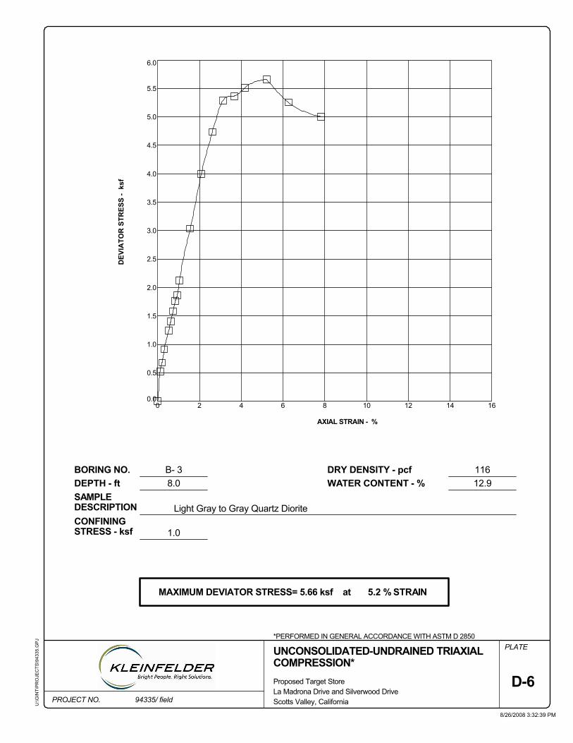
2
2.5
0
6.0
5.5
5.0
4.5
4.0
3.5
3.0
0.0
0.5
1.0
1.5
2.0
12
MAXIMUM DEVIATOR STRESS= 5.66 ksf at
DEPTH - ft
D-6
AXIAL STRAIN - %
DEV
IATO
R S
TRES
S -
ksf
*PERFORMED IN GENERAL ACCORDANCE WITH ASTM D 2850
B- 3
8
5.2 % STRAIN
94335/ field
Light Gray to Gray Quartz Diorite
1.0
UNCONSOLIDATED-UNDRAINED TRIAXIALCOMPRESSION*
SAMPLEDESCRIPTIONCONFININGSTRESS - ksf
8.0
PROJECT NO.
6 10 14 16
12.9116
Scotts Valley, California
Proposed Target StoreLa Madrona Drive and Silverwood Drive
PLATE
DRY DENSITY - pcfWATER CONTENT - %
8/26/2008 3:32:39 PM
BORING NO.
4
U:\G
INT\
PR
OJE
CTS
\943
35.G
PJ
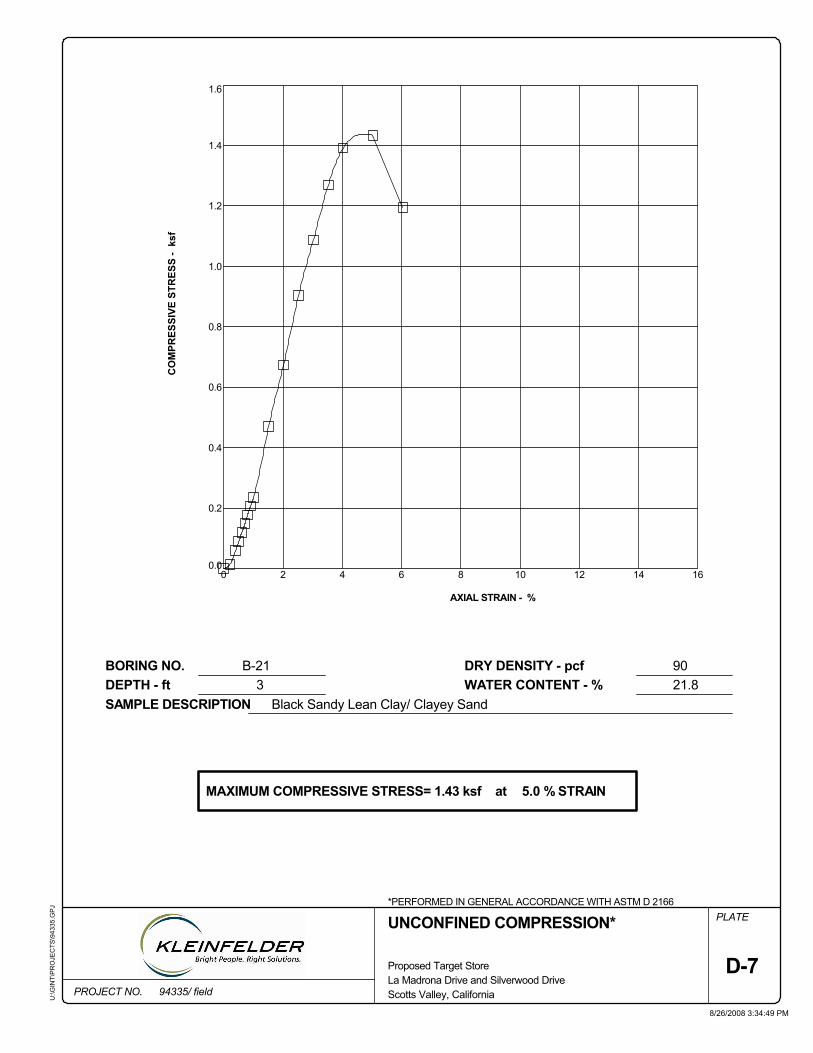
16
0.4
0.6
0.8
1.0
1.2
1.4
0.0
Black Sandy Lean Clay/ Clayey Sand
UNCONFINED COMPRESSION*
WATER CONTENT - %DRY DENSITY - pcf
0
1.6
0.2
6
3
PROJECT NO.
PLATE
BORING NO.DEPTH - ft
2
94335/ field
Proposed Target StoreLa Madrona Drive and Silverwood DriveScotts Valley, California
D-7
21.8
8/26/2008 3:34:49 PM
90B-21
AXIAL STRAIN - %
8 10 12 14
U:\G
INT\
PR
OJE
CTS
\943
35.G
PJ
SAMPLE DESCRIPTION
*PERFORMED IN GENERAL ACCORDANCE WITH ASTM D 2166
5.0 % STRAINMAXIMUM COMPRESSIVE STRESS= 1.43 ksf at
CO
MPR
ESSI
VE S
TRES
S -
ksf
4

1.0
0.5
0.0
1.5
5.0
D-8La Madrona Drive and Silverwood DriveProposed Target Store
2.5
4.03.02.01.00.0
107
3.0
18
3.5
4.0
4.5
5.0
2.0
FINAL WATER CONTENT - %
SAMPLE DESCRIPTION: Light Brown Poorly Graded Sand
NORMAL STRESS - psf 2000 4000
14
1850MAXIMUM SHEAR - psf
TEST TYPE: CD/WET/STAGED
RATE OF SHEAR: .004 in/min.
COHESION= 0.51 ksf
DIRECT SHEAR*
Scotts Valley, California
BORING NO: BA-1
DEPTH: 15.5 ft
3345
SHEA
R S
TRES
S - k
sf
NORMAL STRESS - ksf
FRICTION ANGLE = 35 degrees
*PERFORMED IN GENERAL ACCORDANCE WITH ASTM D 3080 (MODIFIED FORSTAGED TEST)
94335/ field
8/26/2008 3:35:28 PM
PLATE
INITIAL WATER CONTENT - %
DRY DENSITY - pcf
U:\G
INT\
PR
OJE
CTS
\943
35.G
PJ
PROJECT NO.
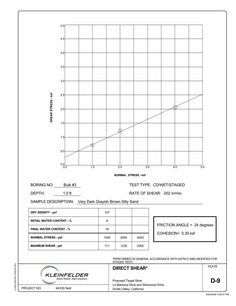
1.0
0.5
0.05.0
D-9La Madrona Drive and Silverwood DriveProposed Target Store
2.0
4.03.02.01.00.0
2.5
SHEA
R S
TRES
S - k
sf
3.0
3.5
4.0
4.5
5.0
1.5
MAXIMUM SHEAR - psf
SAMPLE DESCRIPTION: Very Dark Grayish Brown Silty Sand
NORMAL STRESS - psf 1000 2000 4000
9
711
107
2062
DRY DENSITY - pcf
TEST TYPE: CD/WET/STAGED
RATE OF SHEAR: .002 in/min.
COHESION= 0.30 ksf
DIRECT SHEAR*
Scotts Valley, California
BORING NO: Bulk #3
DEPTH: 1.0 ft
1230
NORMAL STRESS - ksf
FRICTION ANGLE = 24 degrees
*PERFORMED IN GENERAL ACCORDANCE WITH ASTM D 3080 (MODIFIED FORSTAGED TEST)
94335/ field
8/26/2008 3:36:07 PM
PLATE
FINAL WATER CONTENT - %
INITIAL WATER CONTENT - %
U:\G
INT\
PR
OJE
CTS
\943
35.G
PJ
PROJECT NO.
16
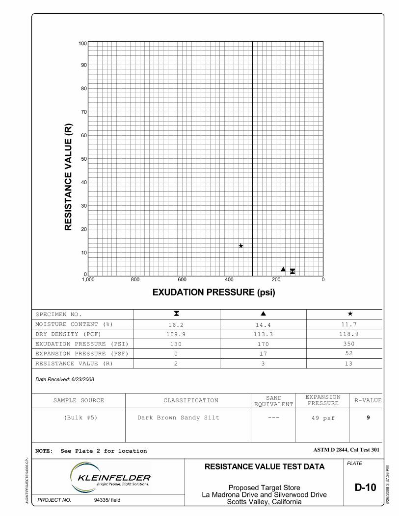
11.7
Date Received: 6/23/2008
PROJECT NO.
U:\G
INT\
PR
OJE
CTS
\943
35.G
PJ
118.9EXUDATION PRESSURE (PSI) 170
113.3
EXPANSION
130
RESISTANCE VALUE (R)
(Bulk #5)
2
D-10
109.9
EXPANSION PRESSURE (PSF)
NOTE: See Plate 2 for location
RES
ISTA
NC
E VA
LUE
(R)
90
0
10
20
30
40
50
60
---
80
3
100
Scotts Valley, CaliforniaLa Madrona Drive and Silverwood Drive
Proposed Target Store
RESISTANCE VALUE TEST DATA
9
PLATE
0
49 psf
13
70
PRESSURE
8/26
/200
8 3:
37:3
6 P
M
94335/ field
R-VALUE
Dark Brown Sandy Silt
52350
SPECIMEN NO.
ASTM D 2844, Cal Test 301
17
EXUDATION PRESSURE (psi)
CLASSIFICATION EQUIVALENTSAND
DRY DENSITY (PCF)MOISTURE CONTENT (%)
02004006008001,000
14.416.2
SAMPLE SOURCE
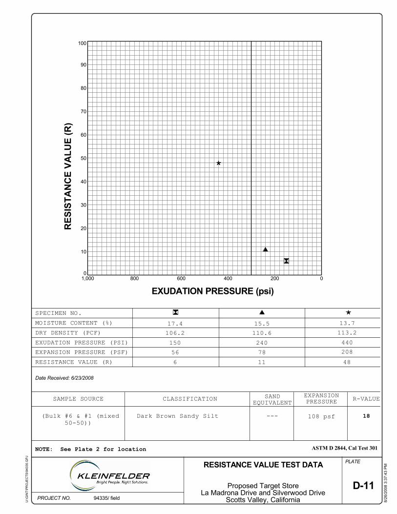
13.7
Date Received: 6/23/2008
PROJECT NO.
U:\G
INT\
PR
OJE
CTS
\943
35.G
PJ
113.2EXUDATION PRESSURE (PSI) 240
110.6
EXPANSION
150
RESISTANCE VALUE (R)
(Bulk #6 & #1 (mixed50-50))
6
D-11
106.2
EXPANSION PRESSURE (PSF)
NOTE: See Plate 2 for location
RES
ISTA
NC
E VA
LUE
(R)
90
0
10
20
30
40
50
60
---
80
11
100
Scotts Valley, CaliforniaLa Madrona Drive and Silverwood Drive
Proposed Target Store
RESISTANCE VALUE TEST DATA
18
PLATE
56
108 psf
48
70
PRESSURE
8/26
/200
8 3:
37:4
3 P
M
94335/ field
R-VALUE
Dark Brown Sandy Silt
208440
SPECIMEN NO.
ASTM D 2844, Cal Test 301
78
EXUDATION PRESSURE (psi)
CLASSIFICATION EQUIVALENTSAND
DRY DENSITY (PCF)MOISTURE CONTENT (%)
02004006008001,000
15.517.4
SAMPLE SOURCE
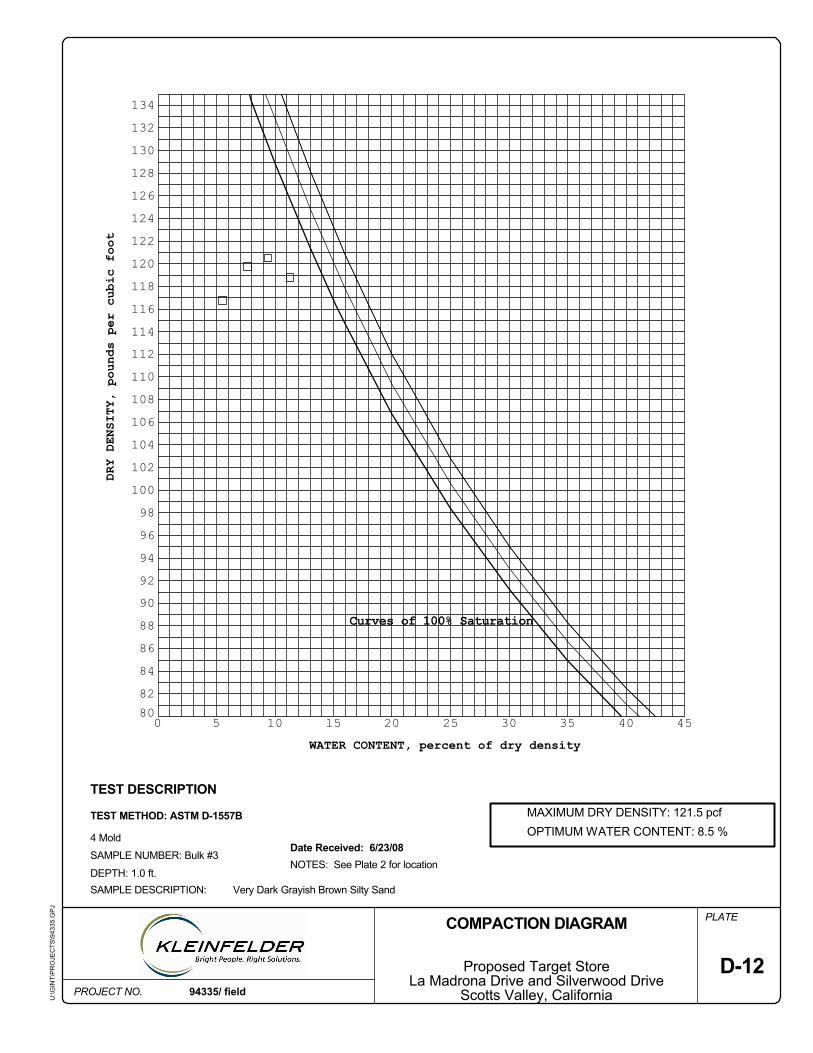
104
110108106
114
92
116118120122124126128130132134
Curves of 100% Saturation
D-12
112
82
86
80
88
96
102
NOTES: See Plate 2 for location
90
84
94
98100
5
OPTIMUM WATER CONTENT: 8.5 %
DRY DENSITY, pounds per cubic foot
0
PROJECT NO.
10 15 20 25 30 35 40 45
TEST DESCRIPTION
Scotts Valley, CaliforniaLa Madrona Drive and Silverwood Drive
Proposed Target Store
Date Received: 6/23/08
SAMPLE DESCRIPTION:DEPTH: 1.0 ft.
SAMPLE NUMBER: Bulk #3
TEST METHOD: ASTM D-1557B
COMPACTION DIAGRAM
WATER CONTENT, percent of dry density
Very Dark Grayish Brown Silty Sand
MAXIMUM DRY DENSITY: 121.5 pcf
U:\G
INT\
PR
OJE
CTS
\943
35.G
PJ
94335/ field
PLATE
4 Mold

APPENDIX E
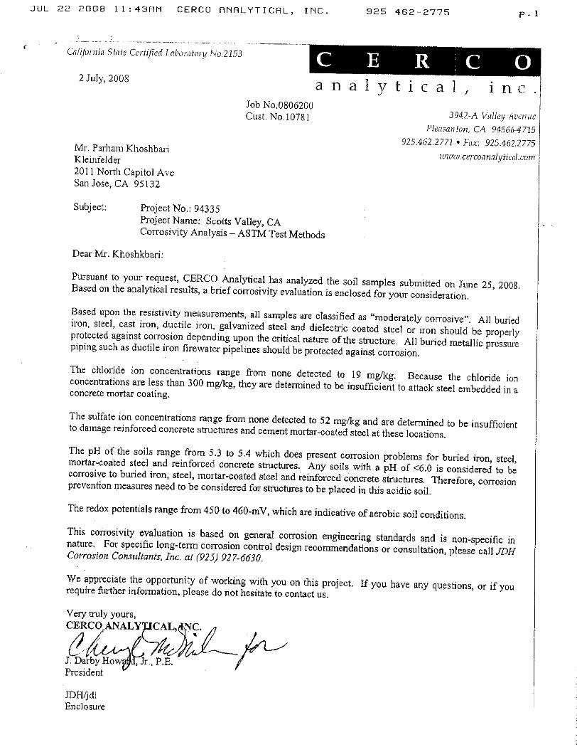
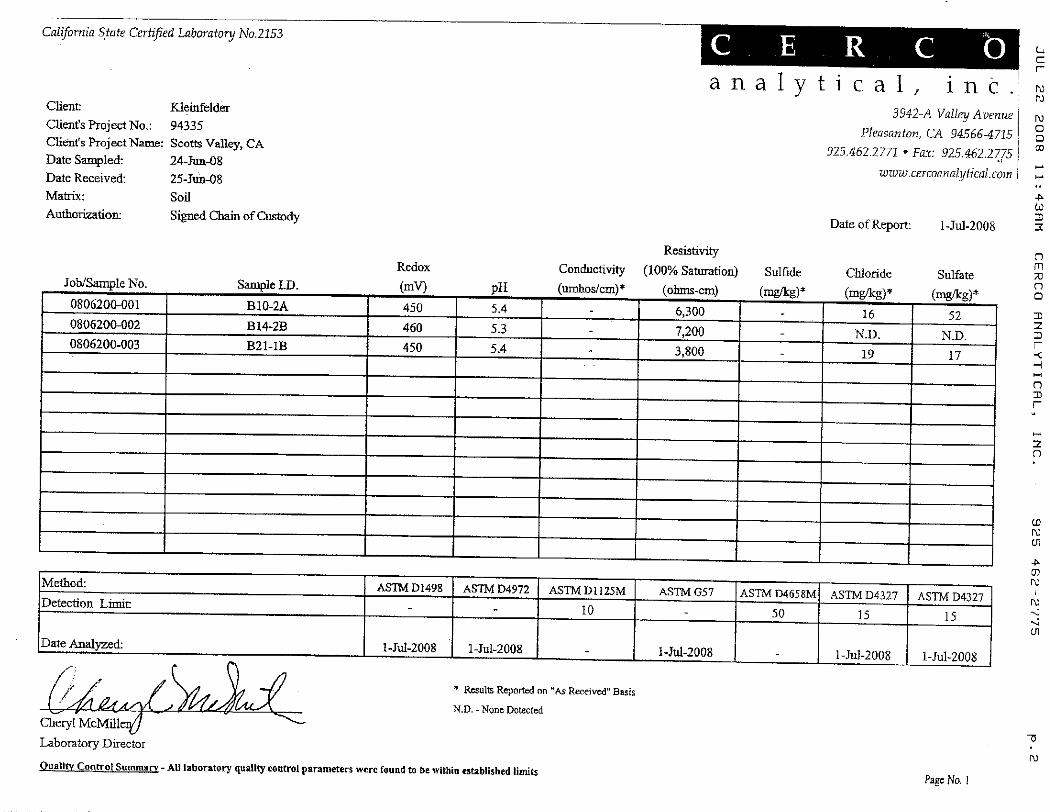

APPENDIX F
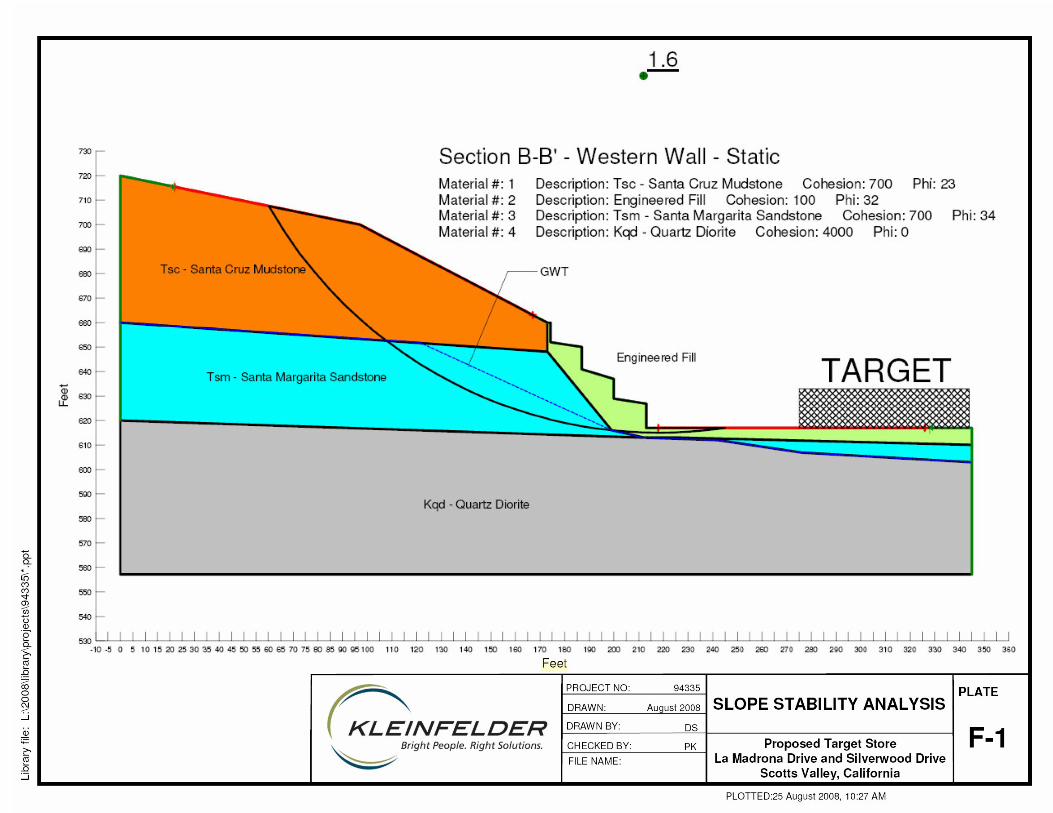
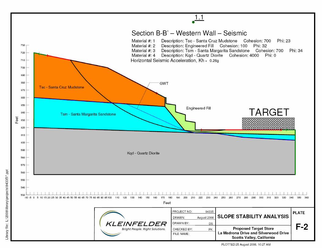
0.26g
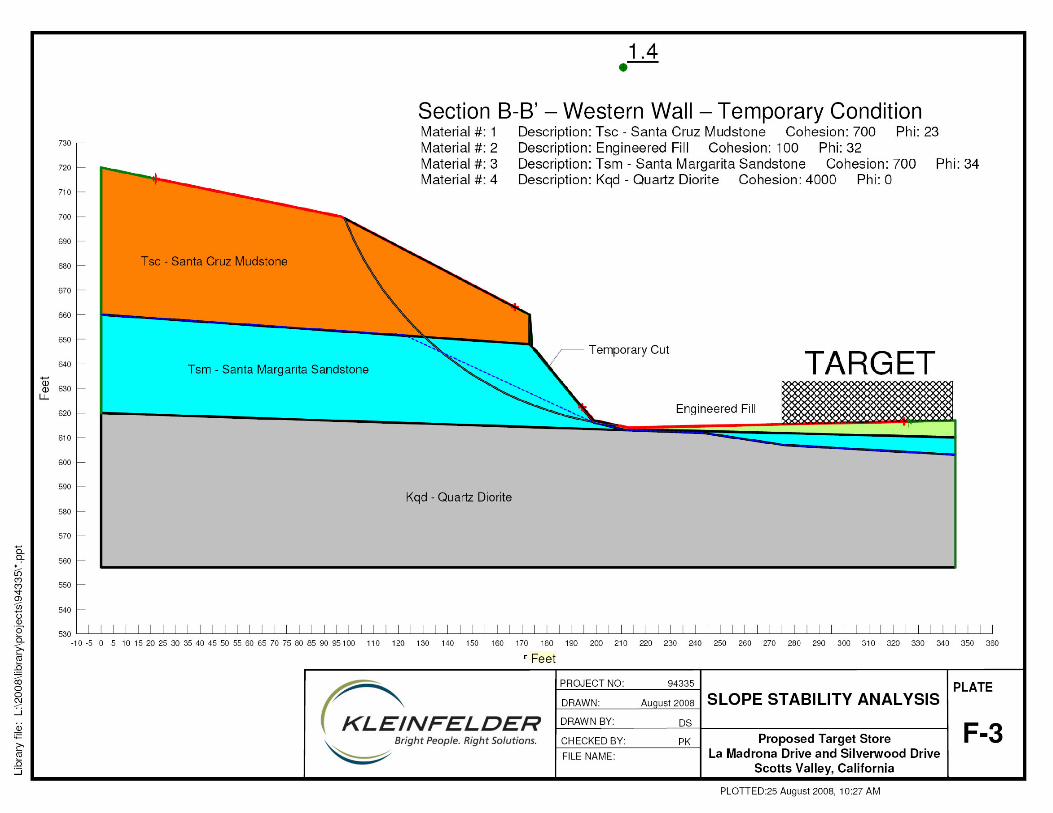
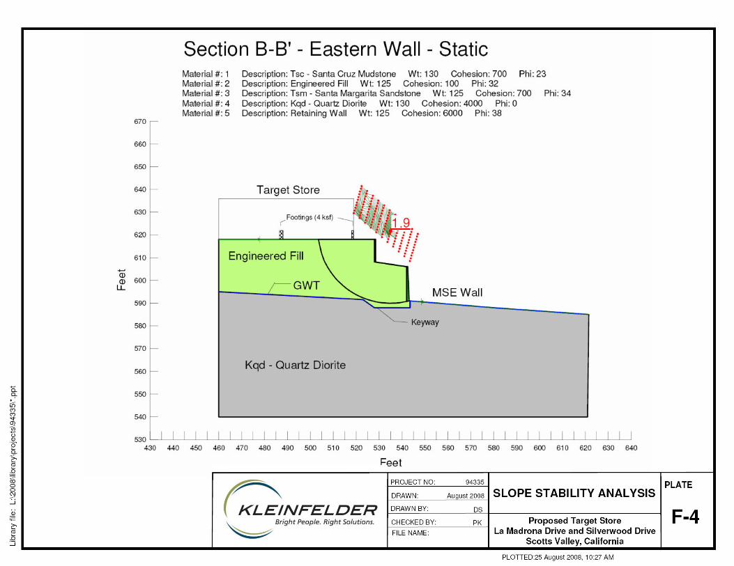

0.26g

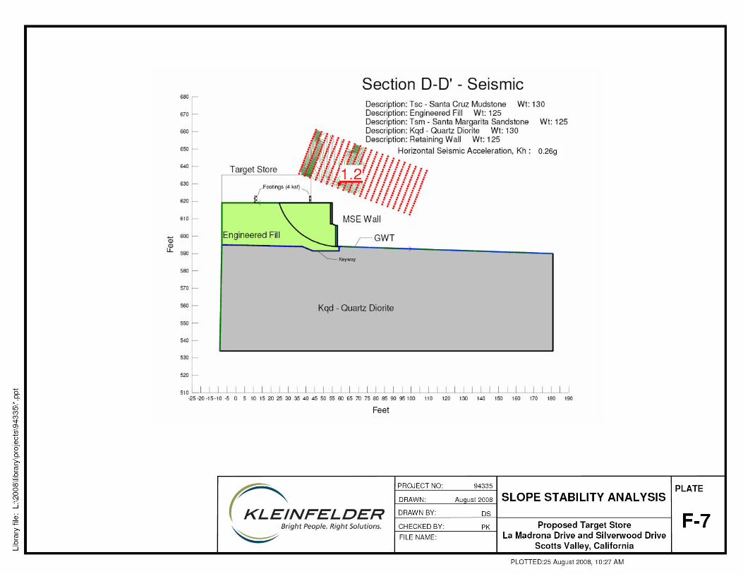
0.26g

APPENDIX G
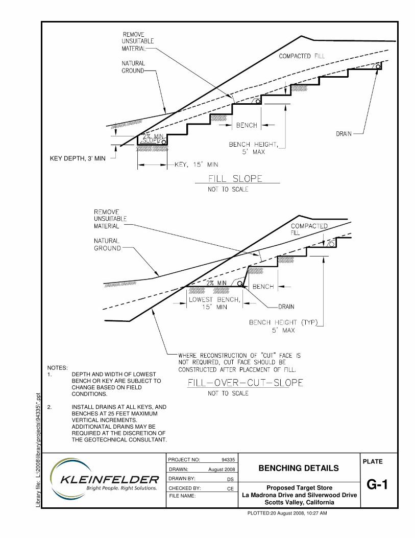
G-1
PLATE
Libr
ary
file:
L:\2
008\
libra
ry\p
roje
cts\
9433
5\*.
ppt
BENCHING DETAILS
Proposed Target StoreLa Madrona Drive and Silverwood Drive
Scotts Valley, California
CHECKED BY:
PROJECT NO: 94335
FILE NAME:
PLOTTED:20 August 2008, 10:27 AM
DSDRAWN BY:
NOTES:1. DEPTH AND WIDTH OF LOWEST
BENCH OR KEY ARE SUBJECT TO CHANGE BASED ON FIELD CONDITIONS.
2. INSTALL DRAINS AT ALL KEYS, AND BENCHES AT 25 FEET MAXIMUM VERTICAL INCREMENTS. ADDITIONATAL DRAINS MAY BE REQUIRED AT THE DISCRETION OF THE GEOTECHNICAL CONSULTANT.
KEY DEPTH, 3’ MIN
DRAWN: August 2008
CE

15 FT MIN
SLOPES OVER 30 FT HIGH MUST HAVE 6-FOOT WIDE DRAINAGE TERRACES AT 25-FOOT VERTICAL INTERNALS
G-2
PLATE
Libr
ary
file:
L:\2
008\
libra
ry\p
roje
cts\
9433
5\*.
ppt
TYPICAL KEYWAY AND BUTTRESS FILL DETAIL
Proposed Target StoreLa Madrona Drive and Silverwood Drive
Scotts Valley, California
CHECKED BY:
PROJECT NO: 94335
FILE NAME:
PLOTTED:20 August 2008, 10:27 AM
DSDRAWN BY:
NOTES:1. DRAWING NOT TO SCALE.2. FINAL BENCHING AND KEYWAY EXCAVATION DEPTHS AND DETAILS
SUBJECT TO EVAULATION OF FIELD CONDITIONS.3. DIMENSIONS AND LOCATIONS OF DRAINAGE TERRACES ARE
APPROXIMATE. ACTUAL LOCATIONS TO BE BASED ON LOCAL ORDINANCES.
4. V-DITCH SPECIFICATIONS TO BE BASED ON LOCAL ORDINANCES.5. DRAIN PIPES AND V-DITCHES TO DRAIN TO AN APPROPRIATE
DISCHARGE FACILITY.6. INSTALL CLEANOUTS AT BOTH ENDS AND A MINIMUM OF 400 FEET,
IF PRACTICAL.
DRAWN: August 2008
CE
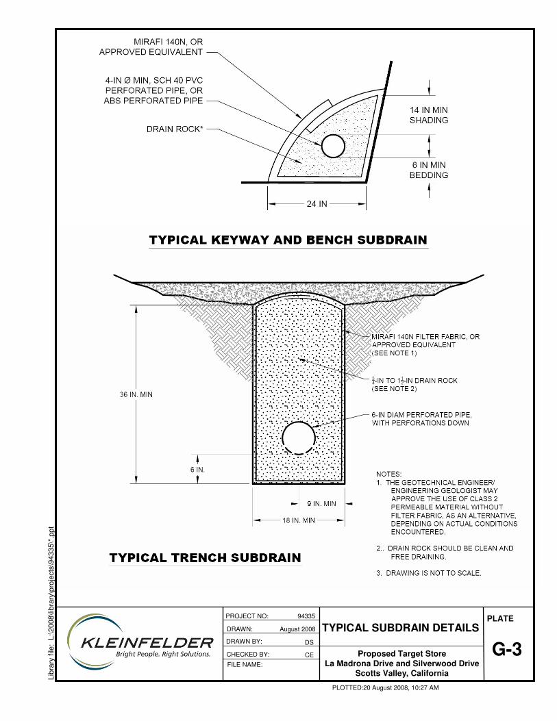
G-3
PLATE
Libr
ary
file:
L:\2
008\
libra
ry\p
roje
cts\
9433
5\*.
ppt
TYPICAL SUBDRAIN DETAILS
Proposed Target StoreLa Madrona Drive and Silverwood Drive
Scotts Valley, California
CHECKED BY:
PROJECT NO: 94335
FILE NAME:
PLOTTED:20 August 2008, 10:27 AM
DSDRAWN BY:
CE
DRAWN: August 2008

APPENDIX H
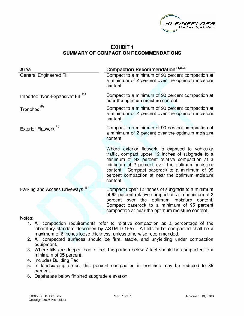
94335 (SJO8R369) nb Page 1 of 1 September 16, 2008 Copyright 2008 Kleinfelder
EXHIBIT 1 SUMMARY OF COMPACTION RECOMMENDATIONS
Area
Compaction Recommendation (1,2,3)
General Engineered Fill Compact to a minimum of 90 percent compaction at a minimum of 2 percent over the optimum moisture content.
Imported “Non-Expansive” Fill (4)
Compact to a minimum of 90 percent compaction at near the optimum moisture content.
Trenches (5) Compact to a minimum of 90 percent compaction at
a minimum of 2 percent over the optimum moisture content.
Exterior Flatwork (6) Compact to a minimum of 90 percent compaction at
a minimum of 2 percent over the optimum moisture content. Where exterior flatwork is exposed to vehicular traffic, compact upper 12 inches of subgrade to a minimum of 92 percent relative compaction at a minimum of 2 percent over the optimum moisture content. Compact baserock to a minimum of 95 percent compaction at near the optimum moisture content.
Parking and Access Driveways (6) Compact upper 12 inches of subgrade to a minimum of 92 percent relative compaction at a minimum of 2 percent over the optimum moisture content. Compact baserock to a minimum of 95 percent compaction at near the optimum moisture content.
Notes: 1. All compaction requirements refer to relative compaction as a percentage of the
laboratory standard described by ASTM D-1557. All lifts to be compacted shall be a maximum of 8 inches loose thickness, unless otherwise recommended.
2. All compacted surfaces should be firm, stable, and unyielding under compaction equipment.
3. Where fills are deeper than 7 feet, the portion below 7 feet should be compacted to a minimum of 95 percent.
4. Includes Building Pad 5. In landscaping areas, this percent compaction in trenches may be reduced to 85
percent. 6. Depths are below finished subgrade elevation.
Related Documents