PREPARED BY, Mrs.C.RADHA, ASSOCIATE PROFESSOR/MCA, MEC. MCA – SEMESTER – I REGULATION 2019

Welcome message from author
This document is posted to help you gain knowledge. Please leave a comment to let me know what you think about it! Share it to your friends and learn new things together.
Transcript
PREPARED BY,
Mrs.C.RADHA,
ASSOCIATE PROFESSOR/MCA,
MEC.
MCA – SEMESTER – I REGULATION 2019
20MC102 / COMPUTER ORGANIZATION AND
ARCHITECTURE
Objectives:
To impart the knowledge in the field of digital electronics
To impart knowledge about the various components of a computer
and its internals.
To design and realize the functionality of the computer hardware with
basic gates and other components using combinational and sequential
logic.
To understand the importance of the hardware-software interface
UNIT-I DIGITAL FUNDAMENTALS
Number Systems and Conversions – Boolean Algebra and Simplification
– Minimization of Boolean Functions – Karnaugh Map, Logic Gates –
NAND – NOR Implementation.
UNIT-II COMBINATIONAL AND SEQUENTIAL CIRCUITS
Design of Combinational Circuits – Adder - Subtractor – Encoder –
Decoder – MUX - DEMUX – Comparators, Flip Flops – Triggering
– Master – Slave Flip Flop – State Diagram and Minimization –
Counters – Registers.
UNIT-III BASIC STRUCTURE OF COMPUTERS
Functional units – Basic operational concepts – Bus structures –
Performance and Metrics – Instruction and Instruction sequencing –
Addressing modes – ALU Design – Fixed point and Floating point
operations.
UNIT-IV PROCESSOR DESIGN
Processor basics – CPU Organization – Data path design – Control
design – Basic concepts – Hardwired control – Micro programmed
control – Pipeline control – Hazards – Super scalar operations.
UNIT-V MEMORY, I/O SYSTEM AND PARALLEL
PROCESSING
Memory technology – Memory systems – Virtual memory –
Caches – Design methods – Associative memories – Input/output
system – Programmed I/O – DMA and Interrupts – I/O Devices
and Interfaces - Multiprocessor Organization – Symmetric
multiprocessors – Cache Coherence.
Outcomes:
Able to design digital circuits by simplifying the Boolean functions
Able to Understand the organization and working principle of
computer hardware components
Able to understand mapping between virtual and physical memory
Acquire knowledge about multiprocessor organization and parallel
processing
Able to trace the execution sequence of an instruction through the
processor
TEXT BOOKS :
1. Morris Mano, “Digital Design”, Prentice Hall of India, Fourth Edition
2010.
2. Carl Hamacher, Zvonko Vranesic, SafwatZaky and
Naraig Manjikian, “Computer organization and Embedded Systems”,
Sixth Edition, Tata McGraw Hill, 2012.
3. William Stallings, “Computer Organization & Architecture–
Designing for Performance” 9th Edition 2012.
REFERENCES:
1. Charles H. Roth, Jr., “Fundamentals of Logic
Design” , Jaico Publishing House, Mumbai, Fourth Edition, 2002.
2. David A. Patterson and John L. Hennessy, “Computer
Organization and Design: The Hardware/Software Interface”, Fourth
Edition, Morgan Kaufmann /Elsevier,2009.
3. John P. Hayes, “Computer Architecture and Organization”, Third
Edition, Tata McGraw Hill, 2000
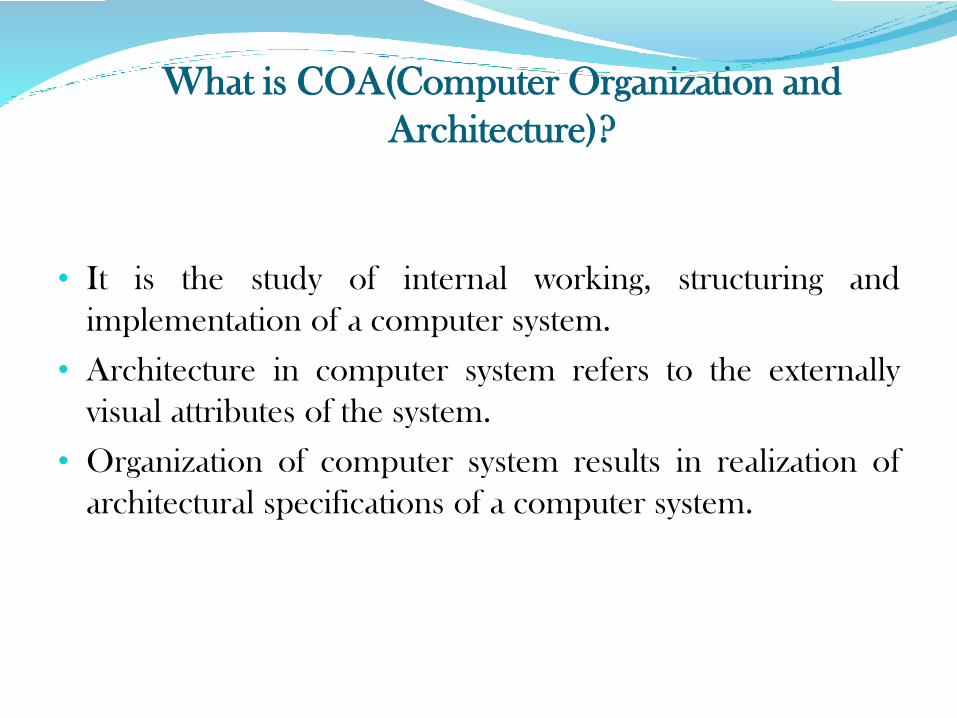
What is COA(Computer Organization and
Architecture)?
• It is the study of internal working, structuring and
implementation of a computer system.
• Architecture in computer system refers to the externally
visual attributes of the system.
• Organization of computer system results in realization of
architectural specifications of a computer system.
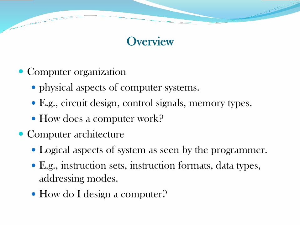
Overview
Computer organization
physical aspects of computer systems.
E.g., circuit design, control signals, memory types.
How does a computer work?
Computer architecture
Logical aspects of system as seen by the programmer.
E.g., instruction sets, instruction formats, data types,
addressing modes.
How do I design a computer?
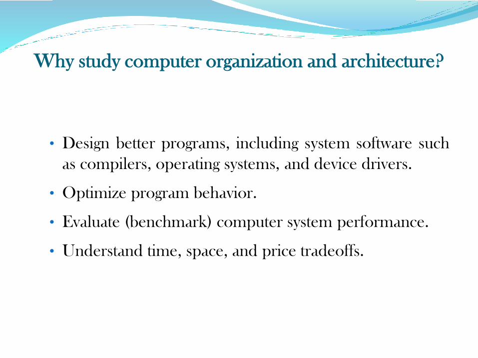
Why study computer organization and architecture?
• Design better programs, including system software such
as compilers, operating systems, and device drivers.
• Optimize program behavior.
• Evaluate (benchmark) computer system performance.
• Understand time, space, and price tradeoffs.
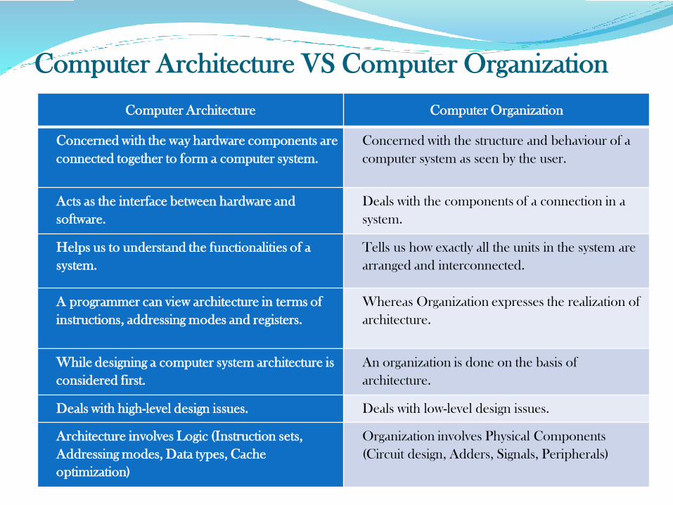
Computer Architecture VS Computer Organization
Computer Architecture Computer Organization
Concerned with the way hardware components are
connected together to form a computer system.
Concerned with the structure and behaviour of a
computer system as seen by the user.
Acts as the interface between hardware and
software.
Deals with the components of a connection in a
system.
Helps us to understand the functionalities of a
system.
Tells us how exactly all the units in the system are
arranged and interconnected.
A programmer can view architecture in terms of
instructions, addressing modes and registers.
Whereas Organization expresses the realization of
architecture.
While designing a computer system architecture is
considered first.
An organization is done on the basis of
architecture.
Deals with high-level design issues. Deals with low-level design issues.
Architecture involves Logic (Instruction sets,
Addressing modes, Data types, Cache
optimization)
Organization involves Physical Components
(Circuit design, Adders, Signals, Peripherals)
NUMBER SYSTEM
It is defined as a system of writing to express numbers.
It is the mathematical notation for representing numbers of
a given set by using digits or other symbols in a consistent
manner.
The value of any digit in a number can be determined by:
The digit
Its position in the number
The base of the number system
Characteristics of Numbering Systems
1) The digits are consecutive.
2) The number of digits is equal to the size of the base.
3) Zero is always the first digit.
4) The base number is never a digit.
5) When 1 is added to the largest digit, a sum of zero and a carry of one results.
6) Numeric values are determined by the implicit positional values of the digits.
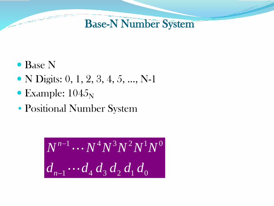
Base-N Number System
Base N
N Digits: 0, 1, 2, 3, 4, 5, …, N-1
Example: 1045N
• Positional Number System
1 4 3 2 1 0
1 4 3 2 1 0
n
n
N N N N N N
d d d d d d
• Digit do is the least significant digit (LSD).
• Digit dn-1 is the most significant digit (MSD).
• The most common number systems used in digital
technology. They are,
Decimal number system
Binary number system
Octal number system
Hexadecimal number system
Decimal Number System
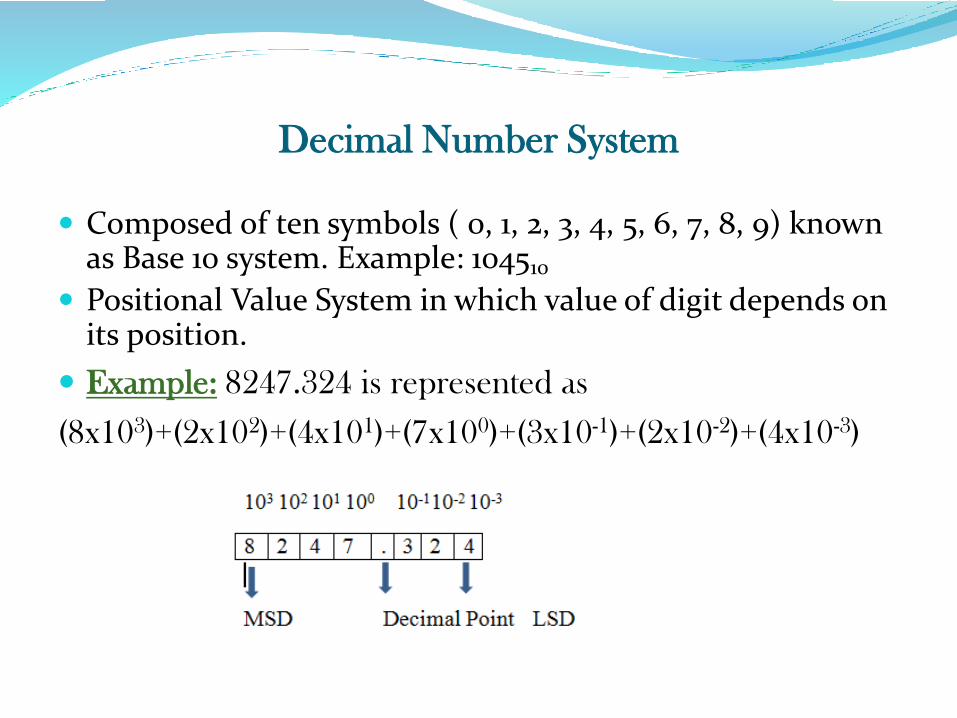
Composed of ten symbols ( 0, 1, 2, 3, 4, 5, 6, 7, 8, 9) known as Base 10 system. Example: 104510
Positional Value System in which value of digit depends on its position.
Example: 8247.324 is represented as
(8x10³)+(2x10²)+(4x101)+(7x100)+(3x10⁻¹)+(2x10⁻²)+(4x10⁻³)
Binary Number System
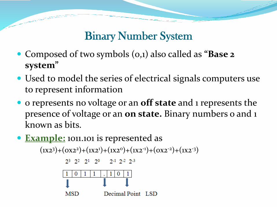
Composed of two symbols (0,1) also called as “Base 2 system”
Used to model the series of electrical signals computers use to represent information
0 represents no voltage or an off state and 1 represents the presence of voltage or an on state. Binary numbers o and 1 known as bits.
Example: 1011.101 is represented as(1x23)+(0x22)+(1x21)+(1x20)+(1x2-1)+(0x2-2)+(1x2-3)
Octal Number System
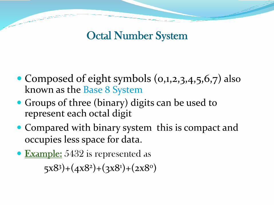
Composed of eight symbols (0,1,2,3,4,5,6,7) also known as the Base 8 System
Groups of three (binary) digits can be used to represent each octal digit
Compared with binary system this is compact and occupies less space for data.
Example: 5432 is represented as
5x83)+(4x82)+(3x81)+(2x80)
Hexa Decimal Number System
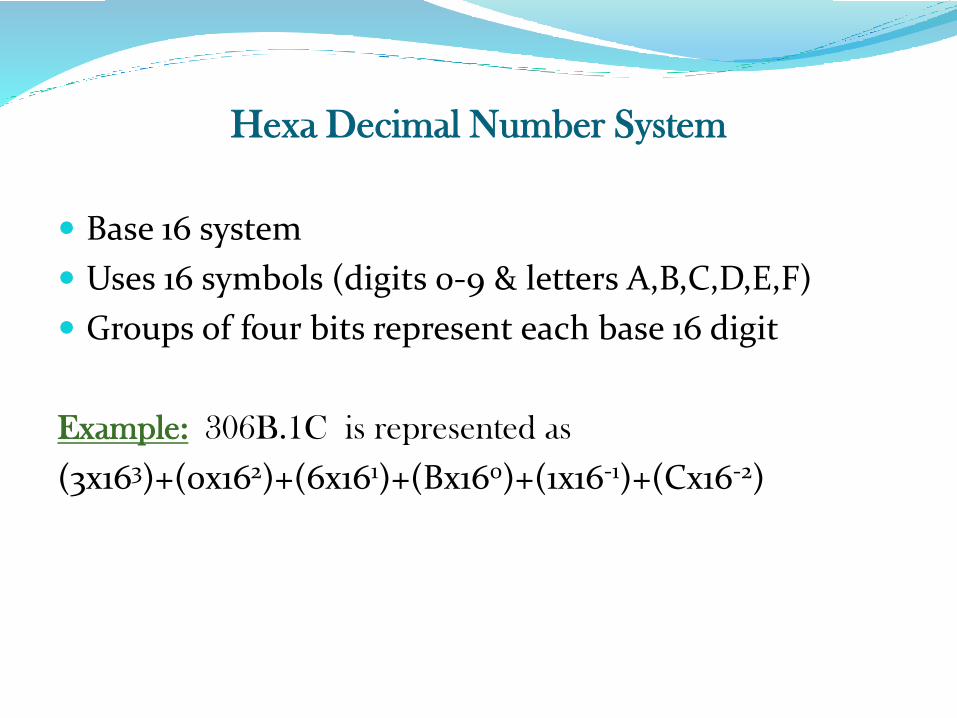
Base 16 system
Uses 16 symbols (digits 0-9 & letters A,B,C,D,E,F)
Groups of four bits represent each base 16 digit
Example: 306B.1C is represented as
(3x163)+(0x162)+(6x161)+(Bx160)+(1x16-1)+(Cx16-2)
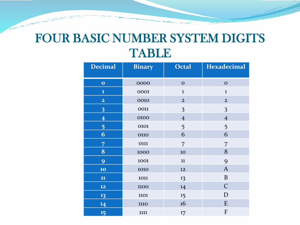
FOUR BASIC NUMBER SYSTEM DIGITS
TABLEDecimal Binary Octal Hexadecimal
0 0000 0 0
1 0001 1 1
2 0010 2 2
3 0011 3 3
4 0100 4 4
5 0101 5 5
6 0110 6 6
7 0111 7 7
8 1000 10 8
9 1001 11 9
10 1010 12 A
11 1011 13 B
12 1100 14 C
13 1101 15 D
14 1110 16 E
15 1111 17 F
CONVERSIONS
Conversion of a number system are, decimal to anybase , any base to decimal, binary to any base, any baseto binary, octal to hexa, hexa to octal.
Decimal to any base conversion
a) Decimal to binary conversion
i) Converting a decimal number by 2 until quotient ofo is obtained.
ii) Binary number is obtained by taking reminder aftereach division in reverse order. (double-dabblemethod)
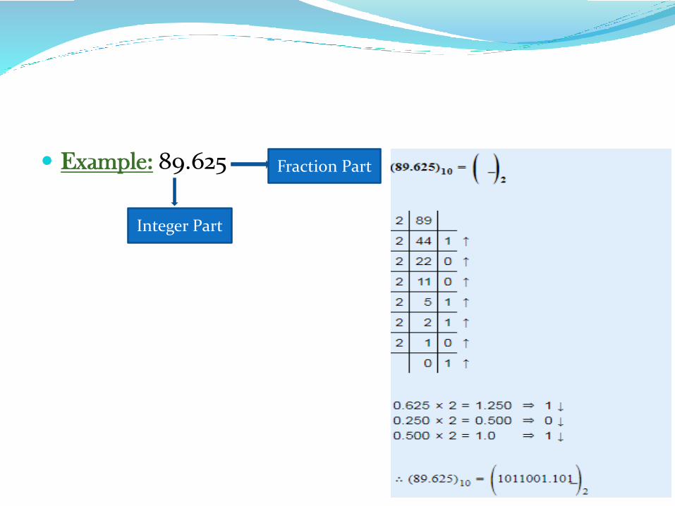
Example: 89.625 Fraction Part
Integer Part
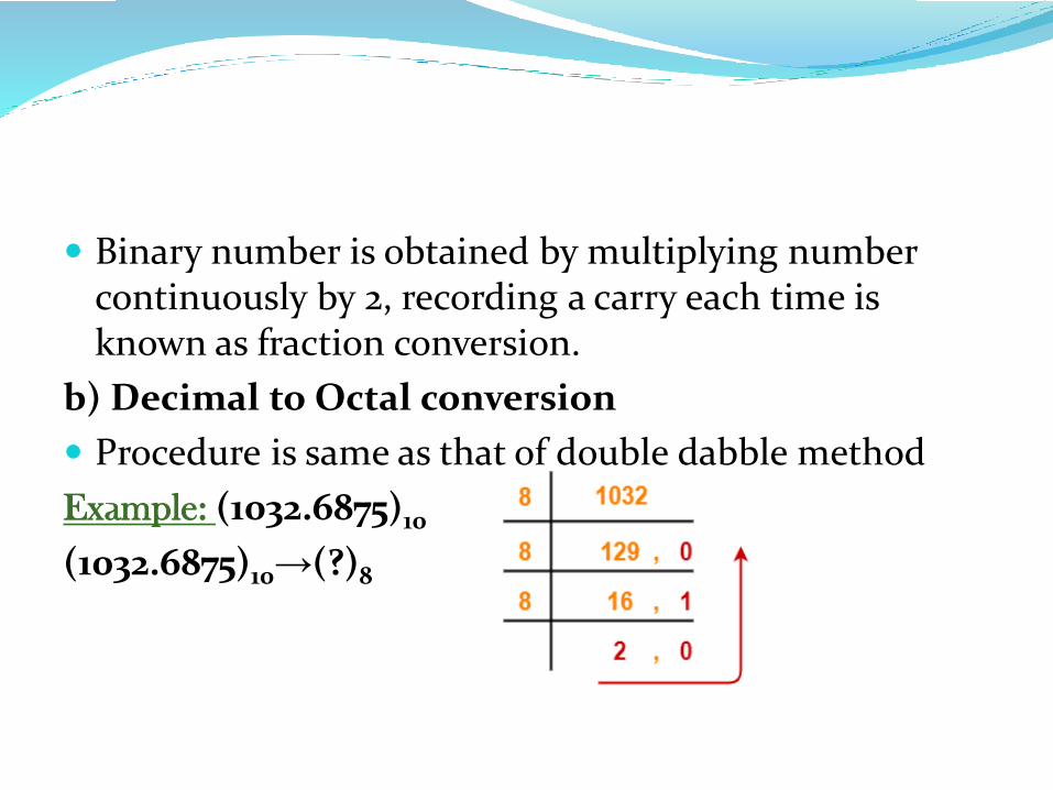
Binary number is obtained by multiplying number continuously by 2, recording a carry each time is known as fraction conversion.
b) Decimal to Octal conversion
Procedure is same as that of double dabble method
Example: (1032.6875)10
(1032.6875)10→(?)8
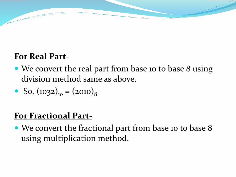
For Real Part-
We convert the real part from base 10 to base 8 using division method same as above.
So, (1032)10 = (2010)8
For Fractional Part-
We convert the fractional part from base 10 to base 8 using multiplication method.
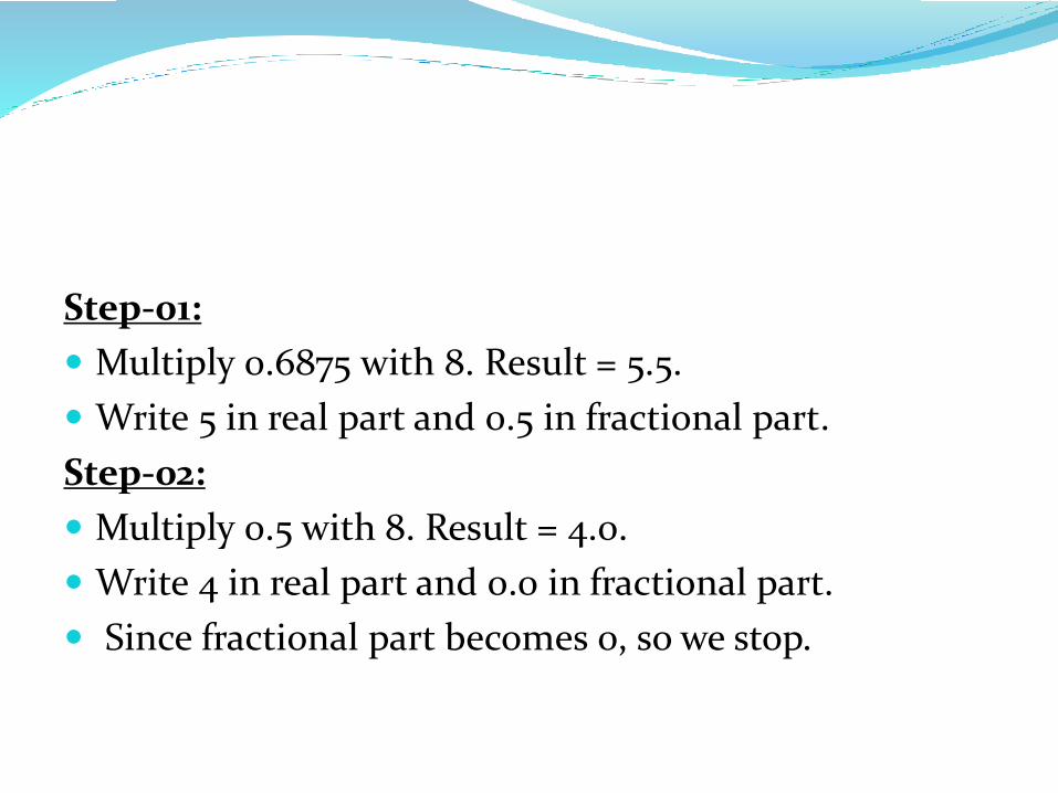
Step-01:
Multiply 0.6875 with 8. Result = 5.5.
Write 5 in real part and 0.5 in fractional part.
Step-02:
Multiply 0.5 with 8. Result = 4.0.
Write 4 in real part and 0.0 in fractional part.
Since fractional part becomes 0, so we stop.
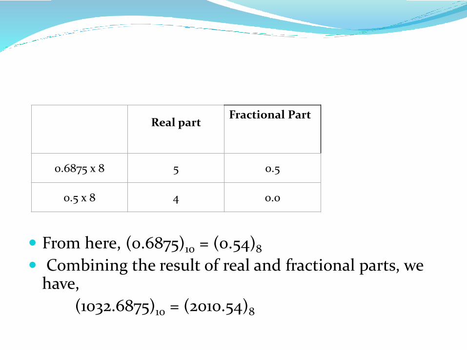
From here, (0.6875)10 = (0.54)8
Combining the result of real and fractional parts, we have,
(1032.6875)10 = (2010.54)8
Real partFractional Part
0.6875 x 8 5 0.5
0.5 x 8 4 0.0
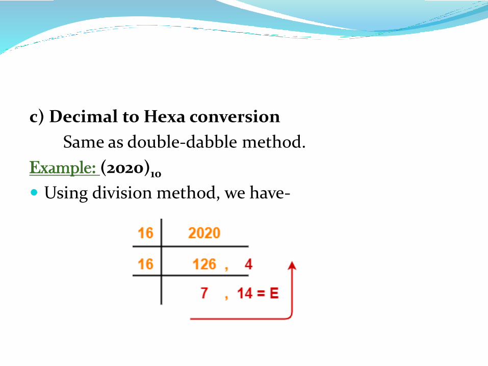
c) Decimal to Hexa conversion
Same as double-dabble method.
Example: (2020)10
Using division method, we have-
Any base to Decimal conversion
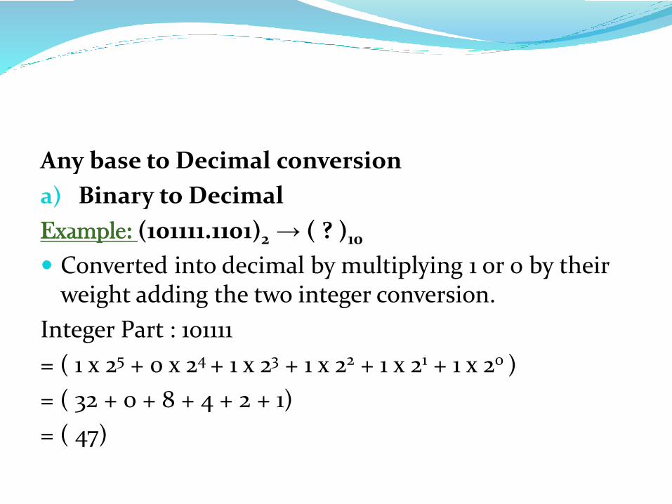
a) Binary to Decimal
Example: (101111.1101)2 → ( ? )10
Converted into decimal by multiplying 1 or 0 by their weight adding the two integer conversion.
Integer Part : 101111
= ( 1 x 25 + 0 x 24 + 1 x 23 + 1 x 22 + 1 x 21 + 1 x 20 )
= ( 32 + 0 + 8 + 4 + 2 + 1)
= ( 47)
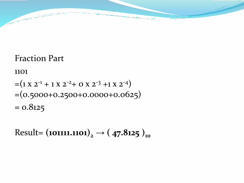
Fraction Part
1101
=(1 x 2-1 + 1 x 2-2+ 0 x 2-3 +1 x 2-4) =(0.5000+0.2500+0.0000+0.0625)
= 0.8125
Result= (101111.1101)2 → ( 47.8125 )10
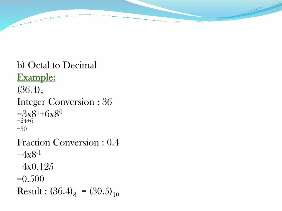
b) Octal to Decimal
Example:
(36.4)8
Integer Conversion : 36
=3x81+6x80
=24+6
=30
Fraction Conversion : 0.4
=4x8-1
=4x0.125
=0.500
Result : (36.4)8 = (30.5)10
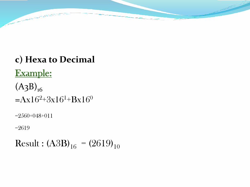
c) Hexa to Decimal
Example:
(A3B)16
=Ax162+3x161+Bx160
=2560+048+011
=2619
Result : (A3B)16 = (2619)10
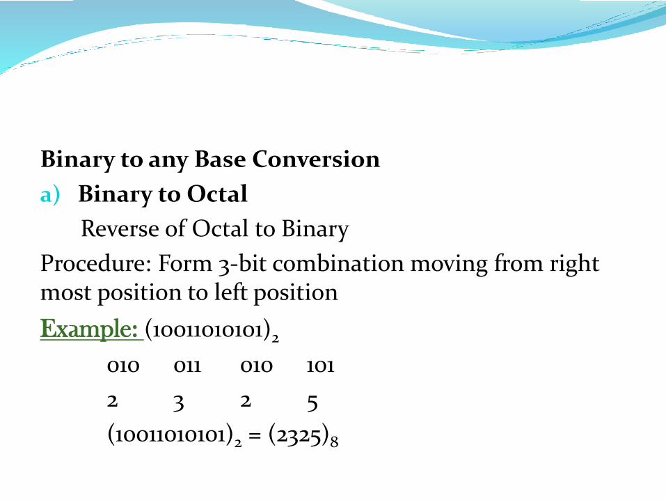
Binary to any Base Conversion
a) Binary to Octal
Reverse of Octal to Binary
Procedure: Form 3-bit combination moving from right most position to left position
Example: (10011010101)2
010 011 010 101
2 3 2 5
(10011010101)2 = (2325)8
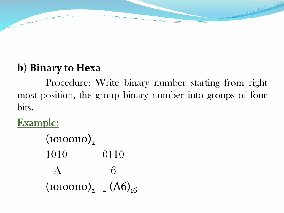
b) Binary to Hexa
Procedure: Write binary number starting from right
most position, the group binary number into groups of four
bits.
Example:
(10100110)2
1010 0110
A 6
(10100110)2 = (A6)16
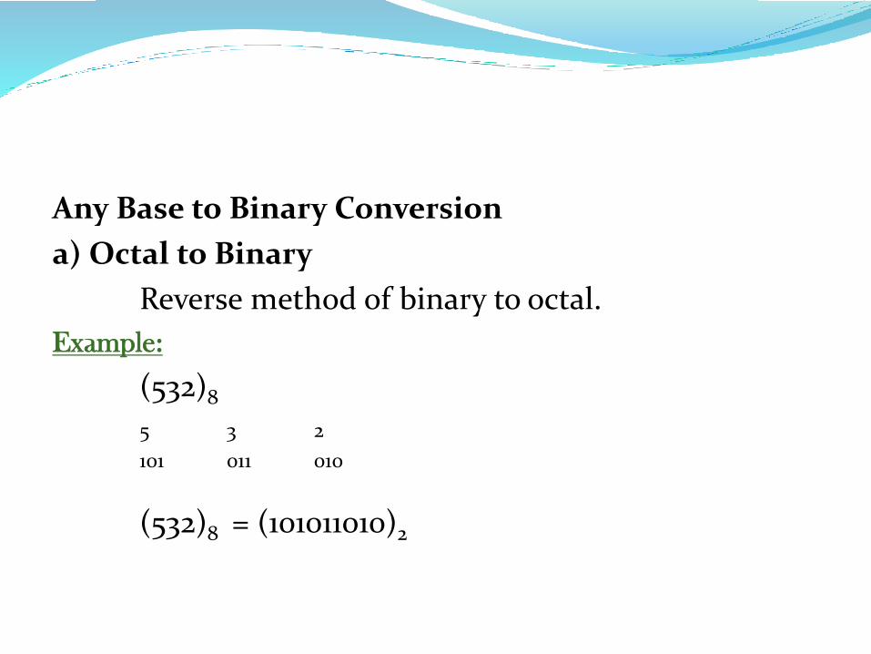
Any Base to Binary Conversion
a) Octal to Binary
Reverse method of binary to octal.
Example:
(532)8
5 3 2
101 011 010
(532)8 = (101011010)2
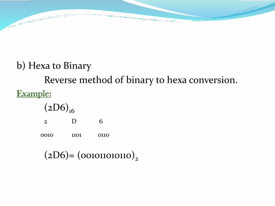
b) Hexa to Binary
Reverse method of binary to hexa conversion.
Example:
(2D6)16
2 D 6
0010 1101 0110
(2D6)= (001011010110)2
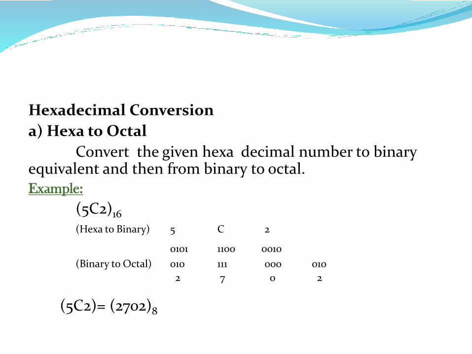
Hexadecimal Conversion
a) Hexa to Octal
Convert the given hexa decimal number to binary equivalent and then from binary to octal.Example:
(5C2)16
(Hexa to Binary) 5 C 2
0101 1100 0010
(Binary to Octal) 010 111 000 010
2 7 0 2
(5C2)= (2702)8
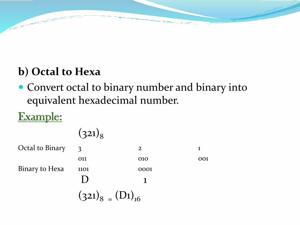
b) Octal to Hexa
Convert octal to binary number and binary into equivalent hexadecimal number.
Example:
(321)8
Octal to Binary 3 2 1
011 010 001
Binary to Hexa 1101 0001
D 1
(321)8 = (D1)16
BOOLEAN ALGEBRA
The boolean algebra is used to simplify the design the logic circuits and involves lengthy mathematical operations.
Binary logic deals with two values 0 and 1.(0-False, 1-True)
Karnaugh Map- Simplification of boolean equation upto four equations. (Difficult if more than five input variables).
Quine Mcclusky method- Tabular method of minimization(reduces the requirement of hardware)
Boolean Logic Operations
Boolean Function- Algebraic expression formed using constant, binary variables and basic logic operation symbols.
Logical Operation
AND (Multiplication)
OR (Addition)
NOT (Logical Complementation)
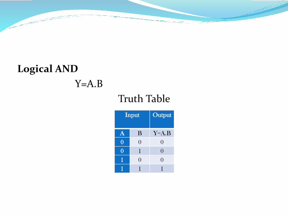
Logical AND
Y=A.B
Truth Table
Input Output
A B Y=A.B
0 0 0
0 1 0
1 0 0
1 1 1
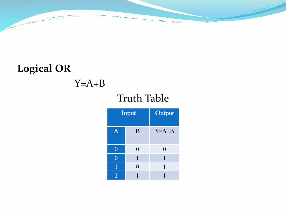
Logical OR
Y=A+B
Truth Table
Input Output
A B Y=A+B
0 0 0
0 1 1
1 0 1
1 1 1
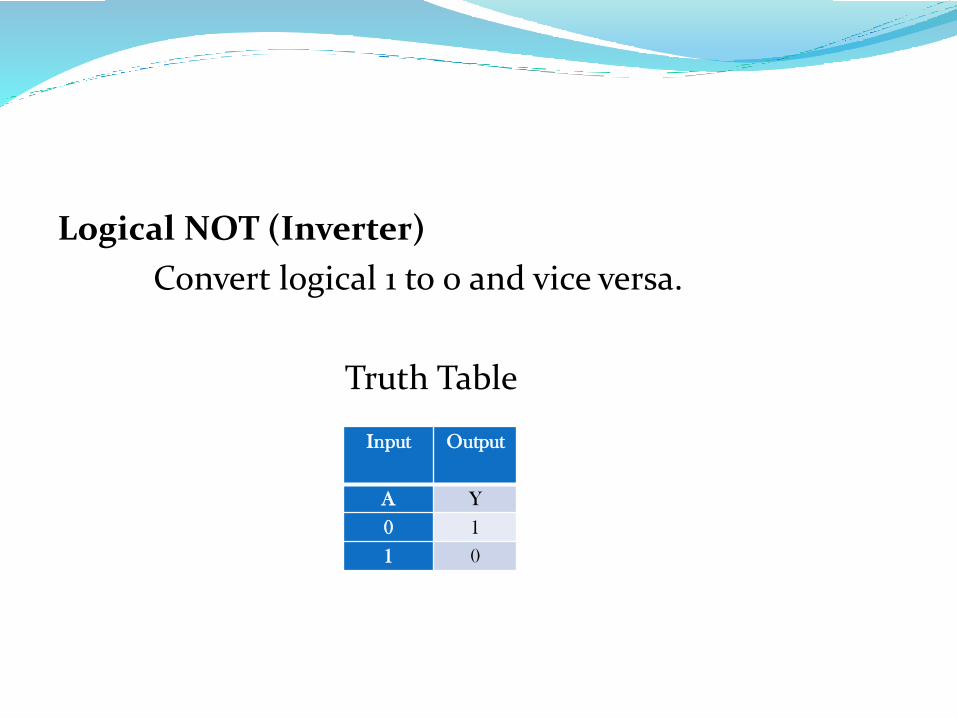
Logical NOT (Inverter)
Convert logical 1 to 0 and vice versa.
Truth Table
Input Output
A Y
0 1
1 0
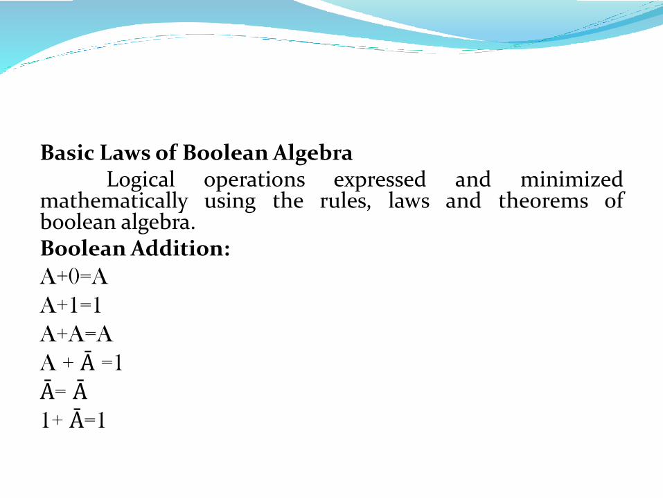
Basic Laws of Boolean AlgebraLogical operations expressed and minimized
mathematically using the rules, laws and theorems ofboolean algebra.Boolean Addition:
A+0=A
A+1=1
A+A=A
A + Ā =1
Ā= Ā1+ Ā=1
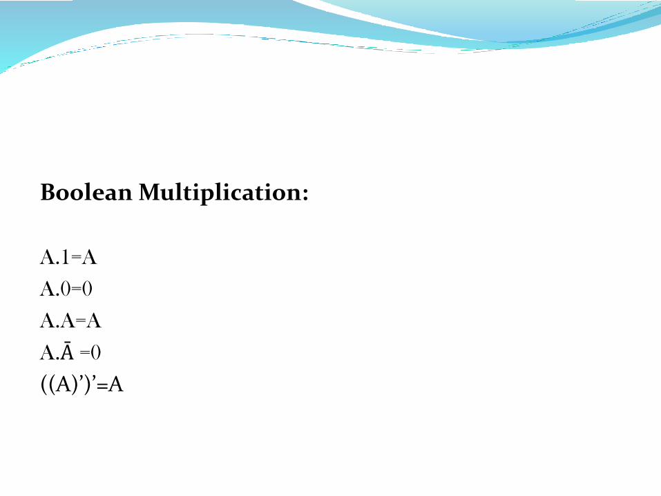
Boolean Multiplication:
A.1=A
A.0=0
A.A=A
A.Ā =0
((A)’)’=A
Properties of Boolean Algebra
Commutative Properties
Associative Properties
Idempotent Properties
Identity Properties
Null Properties
Distributive Properties
Negation Properties
Double Negation Properties
Absorption Properties
Demorgan’s Theorem
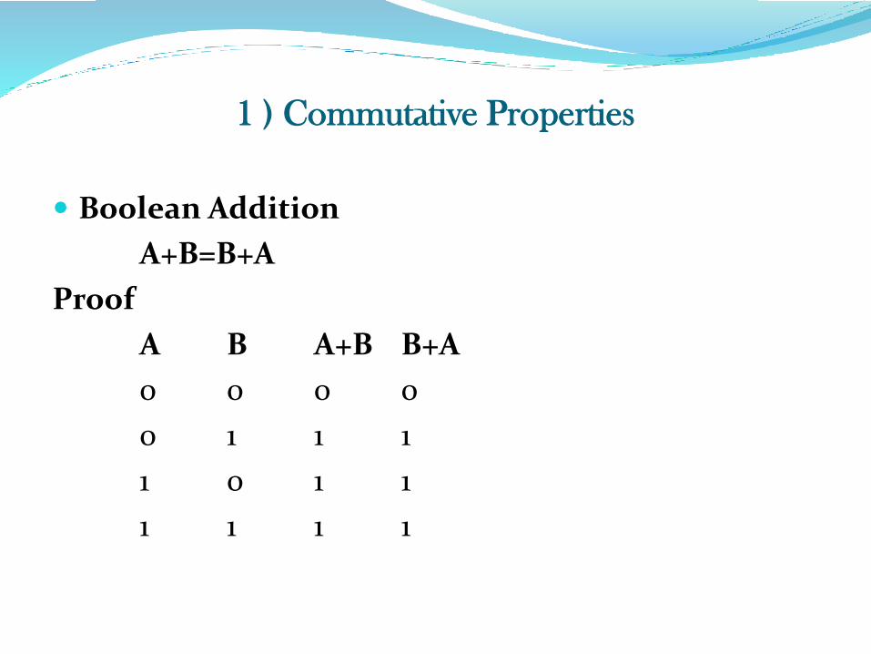
1 ) Commutative Properties
Boolean Addition
A+B=B+A
Proof
A B A+B B+A
0 0 0 0
0 1 1 1
1 0 1 1
1 1 1 1
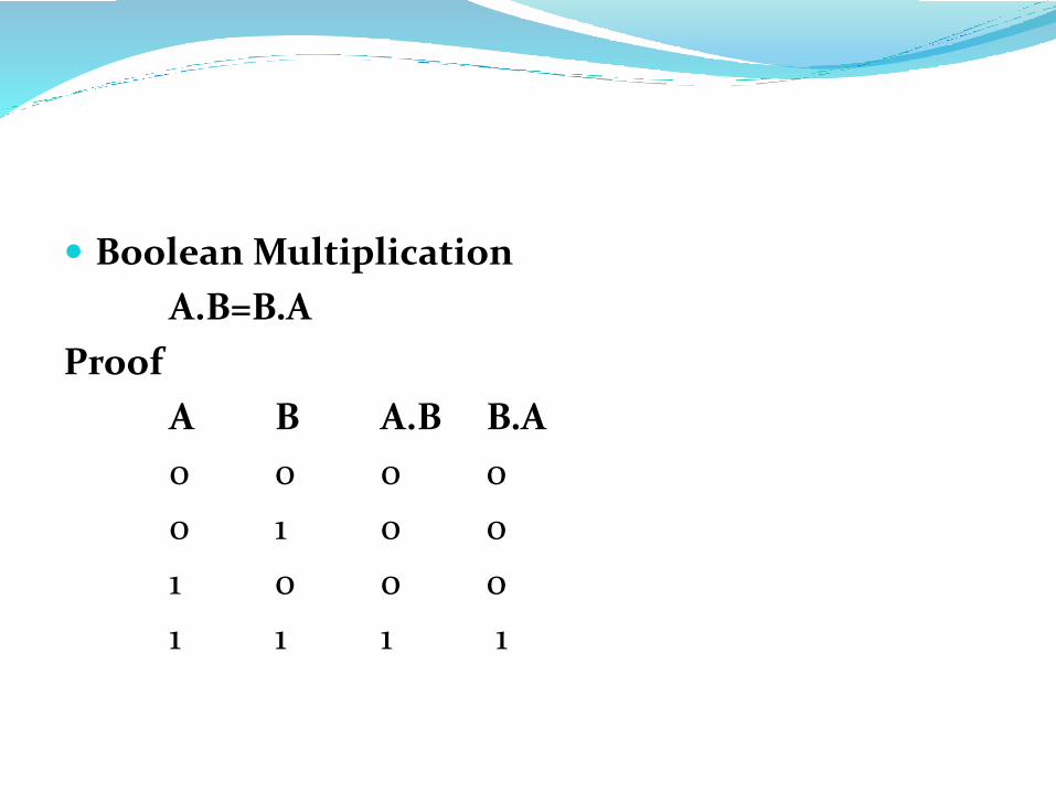
Boolean Multiplication
A.B=B.A
Proof
A B A.B B.A
0 0 0 0
0 1 0 0
1 0 0 0
1 1 1 1
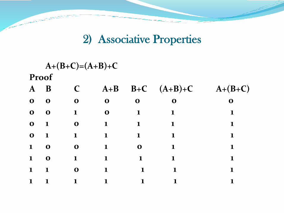
2) Associative Properties
A+(B+C)=(A+B)+C
Proof
A B C A+B B+C (A+B)+C A+(B+C)
0 0 0 0 0 0 0
0 0 1 0 1 1 1
0 1 0 1 1 1 1
0 1 1 1 1 1 1
1 0 0 1 0 1 1
1 0 1 1 1 1 1
1 1 0 1 1 1 1
1 1 1 1 1 1 1
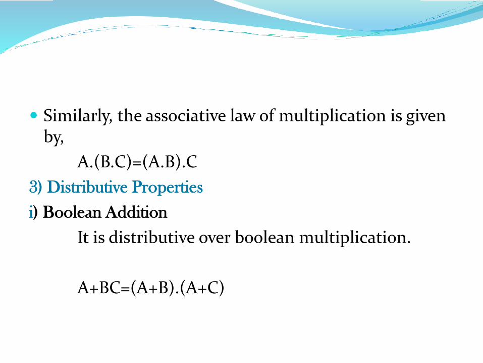
Similarly, the associative law of multiplication is given by,
A.(B.C)=(A.B).C
3) Distributive Properties
i) Boolean Addition
It is distributive over boolean multiplication.
A+BC=(A+B).(A+C)
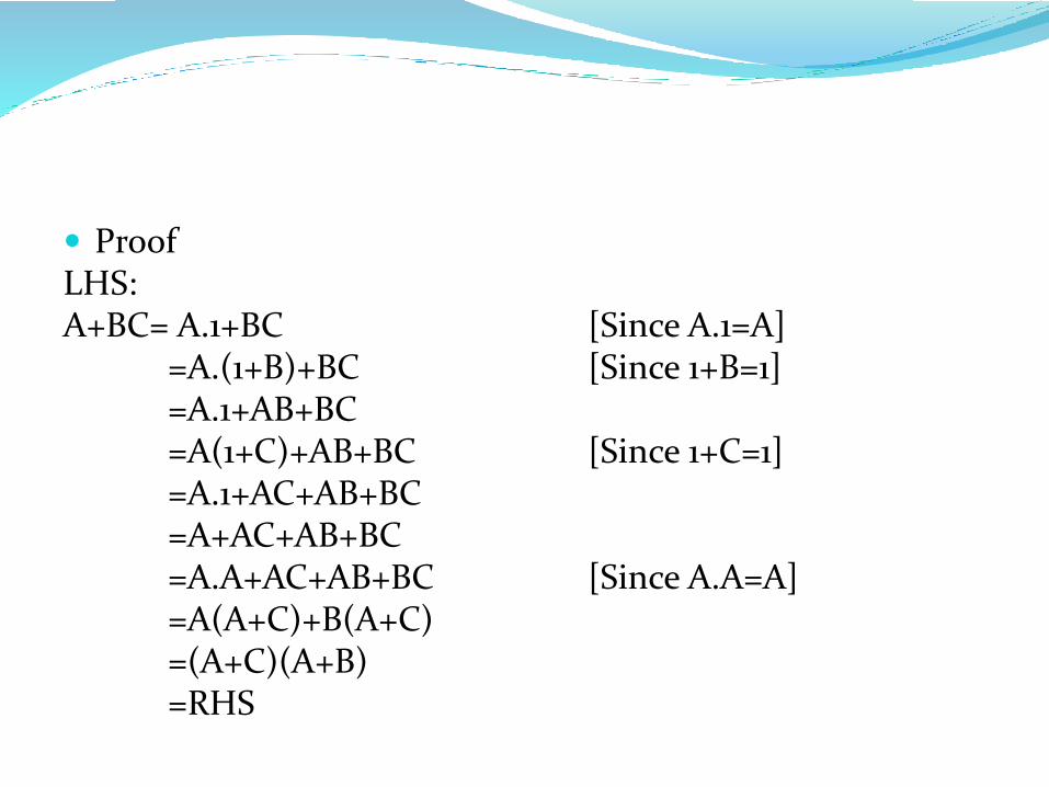
ProofLHS:A+BC= A.1+BC [Since A.1=A]
=A.(1+B)+BC [Since 1+B=1]=A.1+AB+BC=A(1+C)+AB+BC [Since 1+C=1]=A.1+AC+AB+BC=A+AC+AB+BC=A.A+AC+AB+BC [Since A.A=A]=A(A+C)+B(A+C)=(A+C)(A+B)=RHS
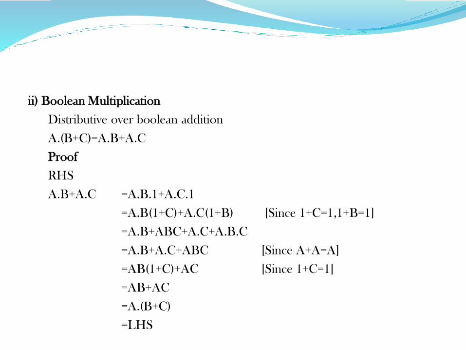
ii) Boolean Multiplication
Distributive over boolean addition
A.(B+C)=A.B+A.C
Proof
RHS
A.B+A.C =A.B.1+A.C.1
=A.B(1+C)+A.C(1+B) [Since 1+C=1,1+B=1]
=A.B+ABC+A.C+A.B.C
=A.B+A.C+ABC [Since A+A=A]
=AB(1+C)+AC [Since 1+C=1]
=AB+AC
=A.(B+C)
=LHS
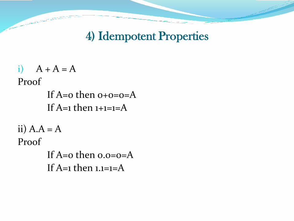
4) Idempotent Properties
i) A + A = A
Proof
If A=0 then 0+0=0=A
If A=1 then 1+1=1=A
ii) A.A = A
Proof
If A=0 then 0.0=0=A
If A=1 then 1.1=1=A
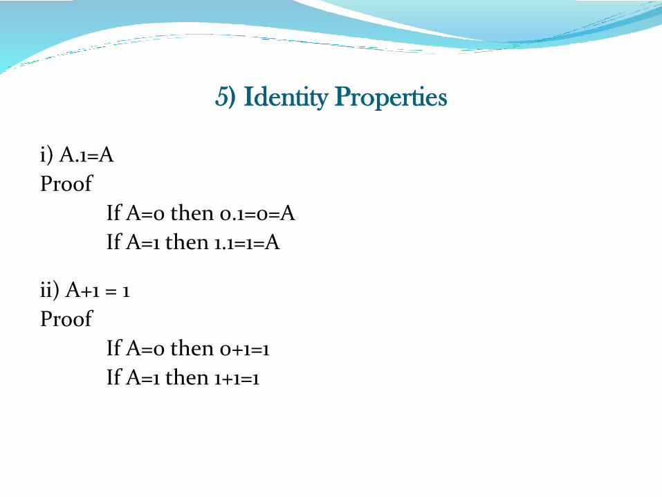
5) Identity Properties
i) A.1=A
Proof
If A=0 then 0.1=0=A
If A=1 then 1.1=1=A
ii) A+1 = 1
Proof
If A=0 then 0+1=1
If A=1 then 1+1=1
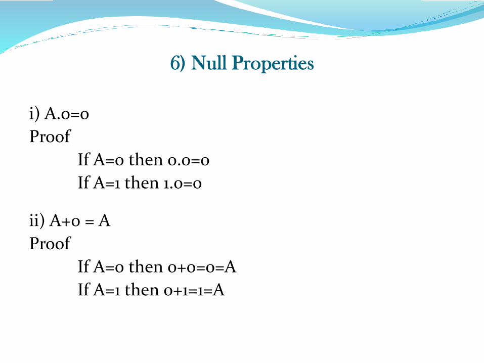
6) Null Properties
i) A.0=0
Proof
If A=0 then 0.0=0
If A=1 then 1.0=0
ii) A+0 = A
Proof
If A=0 then 0+0=0=A
If A=1 then 0+1=1=A
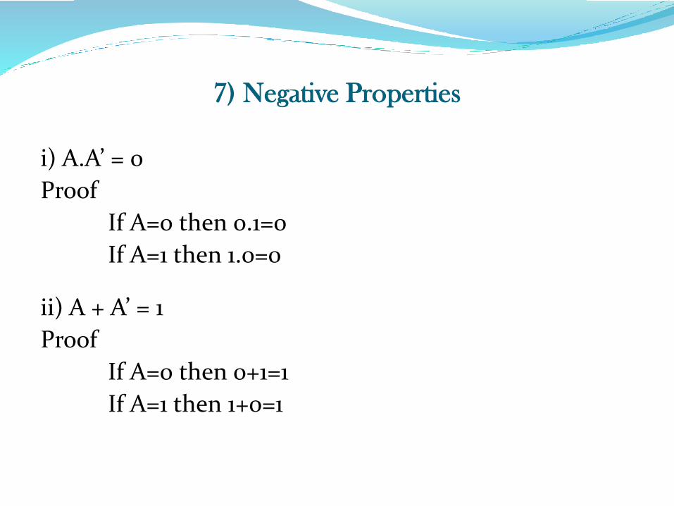
7) Negative Properties
i) A.A’ = 0
Proof
If A=0 then 0.1=0
If A=1 then 1.0=0
ii) A + A’ = 1
Proof
If A=0 then 0+1=1
If A=1 then 1+0=1
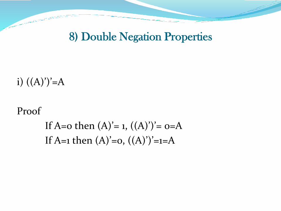
8) Double Negation Properties
i) ((A)’)’=A
Proof
If A=0 then (A)’= 1, ((A)’)’= 0=A
If A=1 then (A)’=0, ((A)’)’=1=A
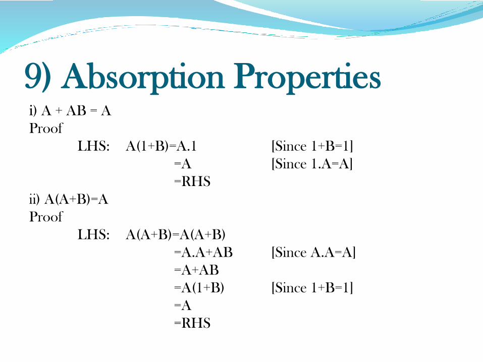
9) Absorption Propertiesi) A + AB = A
Proof
LHS: A(1+B)=A.1 [Since 1+B=1]
=A [Since 1.A=A]
=RHS
ii) A(A+B)=A
Proof
LHS: A(A+B)=A(A+B)
=A.A+AB [Since A.A=A]
=A+AB
=A(1+B) [Since 1+B=1]
=A
=RHS
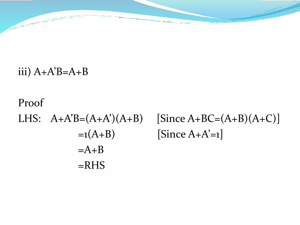
iii) A+A’B=A+B
Proof
LHS: A+A’B=(A+A’)(A+B) [Since A+BC=(A+B)(A+C)]
=1(A+B) [Since A+A’=1]
=A+B
=RHS
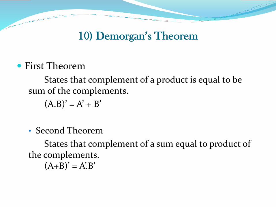
10) Demorgan’s Theorem
First Theorem
States that complement of a product is equal to be sum of the complements.
(A.B)’ = A’ + B’
• Second Theorem
States that complement of a sum equal to product of the complements.
(A+B)’ = A’.B’
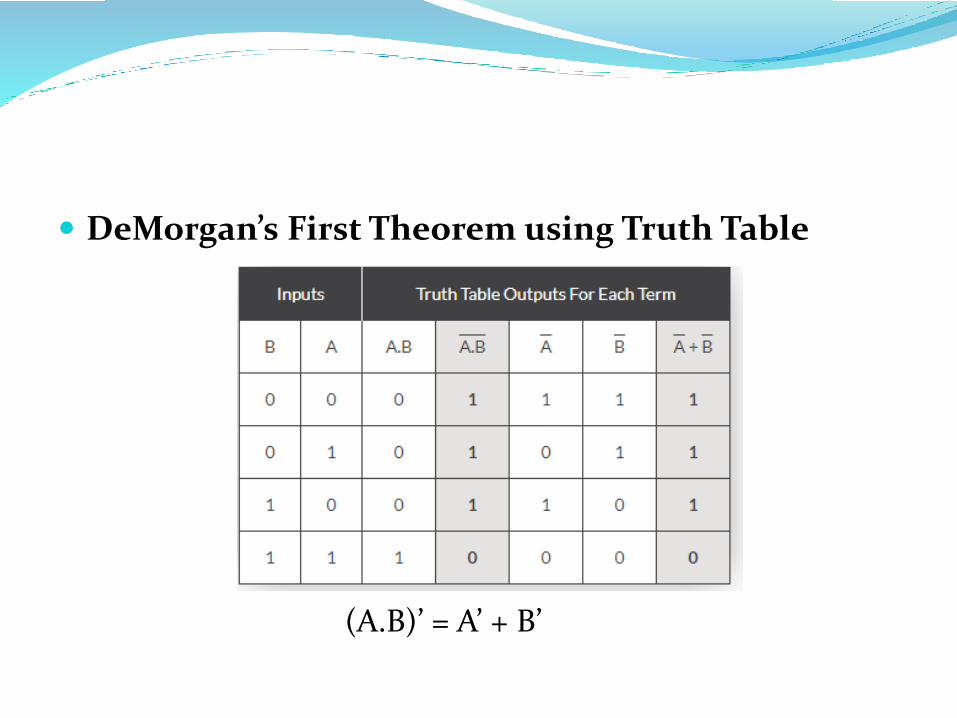
DeMorgan’s First Theorem using Truth Table
(A.B)’ = A’ + B’
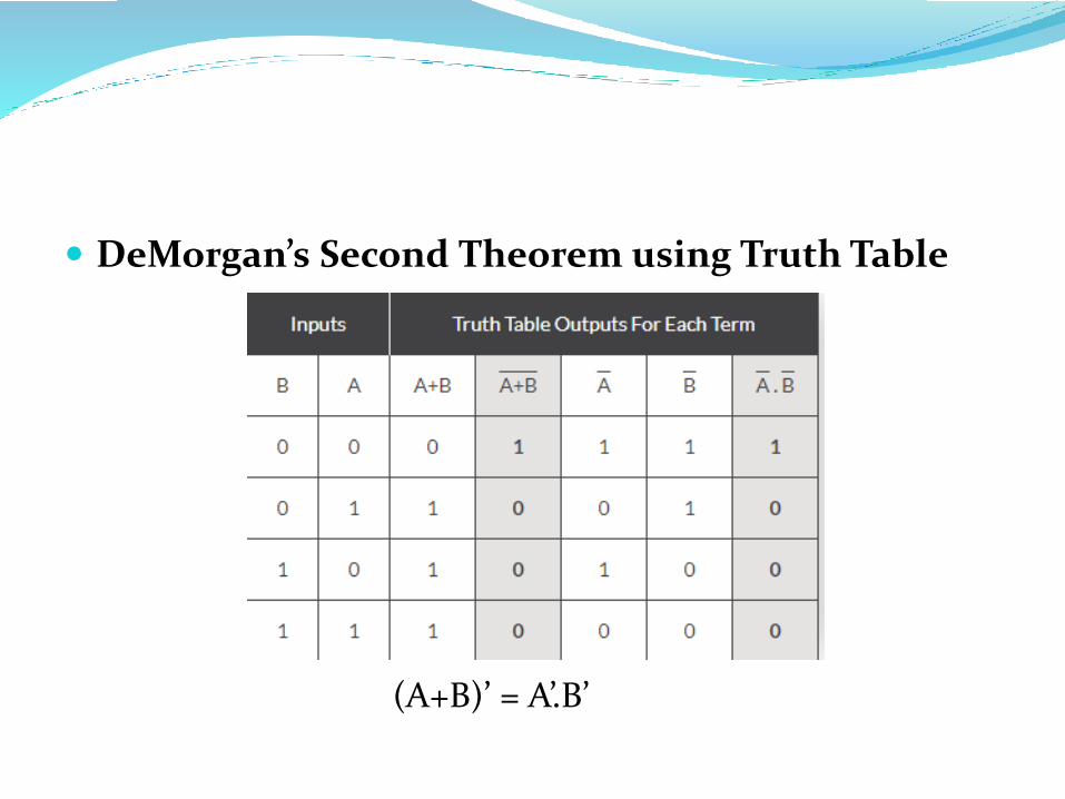
DeMorgan’s Second Theorem using Truth Table
(A+B)’ = A’.B’
Related Documents