SENER Ingeniería y Sistemas S.A. - India 2013 The information contained in this document is confidential and restricted, and is to be used only for the purposes established in the document. No modification, exploitation, reproduction, communication to any third party, dissemination or distribution of the whole or any part of the document is permitted without the prior written consent of SENER Ingeniería y Sistemas, S.A.. Failure to respond to any request for such consent shall in no way be construed as authorization for use. PREPARATION OF TECHNICAL FEASIBILITY STUDY AND MASTER PLAN FOR DEVELOPMENT OF BIJWASAN NEW DELHI RAILWAY STATION OF THE INDIAN RAILWAY NETWORK KD4 – FINAL CONCEPT, MASTER PLAN AND FEASIBILITY REPORT (COMPLETE) WWW.SENER.ES

Welcome message from author
This document is posted to help you gain knowledge. Please leave a comment to let me know what you think about it! Share it to your friends and learn new things together.
Transcript
SENER Ingeniería y Sistemas S.A. - India 2013
The information contained in this document is confidential and restricted, and is to be used only for the purposes established in the document. No modification, exploitation, reproduction, communication to any third party, dissemination or distribution of the whole or any part of the document is permitted without the prior written consent of SENER Ingeniería y Sistemas, S.A.. Failure to respond to any request for such consent shall in no way be construed as authorization for use.
PREPARATION OF TECHNICAL FEASIBILITY STUDY AND MASTER PLAN FOR DEVELOPMENT OF BIJWASAN NEW DELHI RAILWAY STATION OF THE INDIAN RAILWAY NETWORK
KD4 – FINAL CONCEPT, MASTER PLAN AND FEASIBILITY REPORT (COMPLETE)
WWW.SENER.ES
SENER Doc. P210G04-01-KD4-SR-RP-0002
Rev. 3
2017/02/10 Page 2 of 162
KD4- Final Concept, Master Plan and Feasibility Report (Complete)
SENER Ingeniería y Sistemas S.A. - India 2014
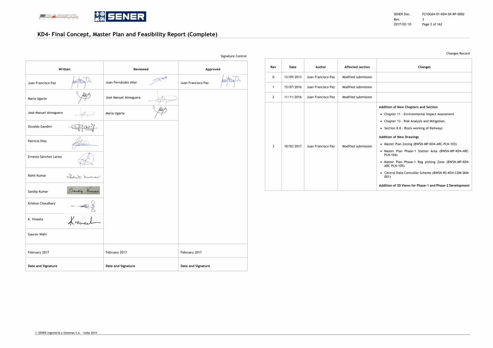
Signature Control
Written Reviewed Approved
Juan Francisco Paz Juan Fernández Aller Juan Francisco Paz
María Ugarte José Manuel Almoguera
José Manuel Almoguera María Ugarte
Osvaldo Gandini
Patricia Díaz
Ernesto Sánchez Larios
Rohit Kumar
Sandip Kumar
Krishna Choudhary
K. Vineela
Gaurav Wahi
February 2017 February 2017 February 2017
Date and Signature Date and Signature Date and Signature
Changes Record
Rev Date Author Affected section Changes
0 13/09/2013 Juan Francisco Paz Modified submission
1 15/07/2016 Juan Francisco Paz Modified submission
2 11/11/2016 Juan Francisco Paz Modified submission
3 10/02/2017 Juan Francisco Paz Modified submission
Addition of New Chapters and Section
Chapter 11 - Environmental Impact Assessment
Chapter 13 - Risk Analysis and Mitigation.
Section 8.8 - Block working of Railways
Addition of New Drawings
Master Plan Zoning (BWSN-MP-KD4-ARC-PLN-103)
Master Plan Phase-1 Station Area (BWSN-MP-KD4-ARC-PLN-104)
Master Plan Phase-1 Rag picking Zone (BWSN-MP-KD4-ARC-PLN-105)
Central Data Controller Scheme (BWSN-RS-KD4-COM-SKM-001)
Addition of 3D Views for Phase-1 and Phase-2 Development
SENER Doc. P210G04-01-KD4-SR-RP-0002
Rev. 3
2017/02/10 Page 3 of 162
KD4- Final Concept, Master Plan and Feasibility Report (Complete)
SENER Ingeniería y Sistemas S.A. - India 2014
TABLE OF CONTENTS
1 EXECUTIVE SUMMARY ..................................................................................... 13
2 INTRODUCTION ............................................................................................. 16
2.1 Background ........................................................................................ 16
2.2 Purpose of this Report ........................................................................... 18
2.3 Structure of this Report ......................................................................... 18
2.4 Master Plan Main Objectives ................................................................... 19
2.5 Developed Planning & Studies ................................................................. 19
2.5.1 Development Control Norms ............................................................ 19
2.5.2 Proposed Master Plan from Northern Railways in 2014 ............................. 23
2.5.3 Financial Feasibility Study of Bijwasan ............................................... 24
2.6 Clearances ......................................................................................... 27
3 STATION USERS STUDY ................................................................................... 30
3.1 Rail station complex design .................................................................... 30
3.1.1 Rail Passenger count at entry exit ..................................................... 30
3.1.2 Entry and exit surveys at landing of the FOB ........................................ 30
3.1.3 Entry and Exit surveys at the Reservation Counter ................................. 30
3.1.4 Analysis of interviews at ticket counters ............................................. 30
3.1.5 Willingness to Pay ........................................................................ 30
3.1.6 Parking Demand Survey .................................................................. 31
3.1.7 Influence area of railway station ...................................................... 32
3.1.8 Travel and socio economic characteristics ........................................... 32
3.1.9 Rail passengers characteristics ......................................................... 32
3.1.10 Type of ticket used ....................................................................... 33
3.1.11 Trip frequency to Bijwasan station .................................................... 33
3.1.12 Travel characteristics of main trip .................................................... 33
3.1.13 Travel characteristics of access/dispersal of trip ................................... 33
3.1.14 O-D pattern of Rail Passenger Traffic ................................................. 34
3.1.15 Distribution of passengers ............................................................... 34
3.1.16 Bus Stop Boarding / Alighting ........................................................... 34
3.1.17 Major observations ....................................................................... 34
3.2 Station Performance Assessment ............................................................. 35
3.2.1 Employee Strength Analysis ............................................................. 35
3.2.2 Conclusion .................................................................................. 37
4 OPERATIONAL STUDIES ................................................................................... 38
4.1 Existing scenario ................................................................................. 38
4.1.1 Current Mainline Capacity of the Section and its utilization ....................... 38
4.1.2 Present passenger traffic at Bijwasan station ........................................ 38
4.1.3 Analysis and Limitations of Current Yard .............................................. 38
4.1.4 Existing Operational Regime ............................................................. 38
4.1.5 Berthing of existing number of trains in the existing yard ......................... 38
4.1.6 Status of existing stations after commissioning of new Bijwasan Station ........ 38
4.2 Future scenario ................................................................................... 38
4.2.1 Traffic Projections –No of trains ........................................................ 38
4.2.2 Traffic Projections- No of Passengers .................................................. 39
4.2.3 Future Mainline Capacity of the Section ............................................... 39
4.2.4 Operational Facilities Planned at this Station ........................................ 39
4.3 Berthing of Trains ................................................................................ 40
4.3.1 The proposed berthing chart for the station is as under Figure 10 ................ 40
4.3.2 Stabling of trains .......................................................................... 42
4.4 Trains stabling and maintenance complex including sick lines ......................... 42
4.4.1 RPC- 4 Lines ................................................................................ 42
4.4.2 Adequacy of maintenance facilities .................................................... 42
4.4.3 C&W Facilities – external washing of rakes and coaches............................ 42
4.4.4 Running room facility for pilots/ guards at Bijwasan ................................ 43
4.4.5 C&W Maintenance office complex ...................................................... 43
4.5 Sick lines ........................................................................................... 43
4.6 Sidings .............................................................................................. 43
4.6.1 Saloon siding / VIP Siding ................................................................ 43
4.6.2 Track Machine Siding ..................................................................... 43
4.6.3 Parcel Handling Siding .................................................................... 43
4.7 Signalling infrastructure ........................................................................ 43
4.7.1 Advantages of electronic interlocking/ solid state interlocking ................... 44
4.8 Overhead line and traction power infrastructure ......................................... 44
4.9 Communication Infrastructure ................................................................ 44
4.9.1 Communication Control System (M & E SCADA-Supervisory Console and Data
Acquisition) ................................................................................. 45
SENER Doc. P210G04-01-KD4-SR-RP-0002
Rev. 3
2017/02/10 Page 4 of 162
KD4- Final Concept, Master Plan and Feasibility Report (Complete)
SENER Ingeniería y Sistemas S.A. - India 2014
4.9.2 Passenger Information Display System (PIDS) and Signages ........................ 45
4.9.3 ISDN Telephone Exchange ............................................................... 45
4.9.4 Public Address System ................................................................... 45
4.9.5 Wi Fi (Wireless Fidelity) ................................................................. 45
4.9.6 Access Control System (ACS) ............................................................ 45
4.9.7 Optical Fibre Networking ................................................................ 45
4.9.8 Electronic Weighing Scale ............................................................... 45
4.9.9 Security System ........................................................................... 45
4.9.10 GPRS Clock ................................................................................. 46
5 STATION PLANNING ....................................................................................... 47
5.1 Introduction ....................................................................................... 47
5.2 Existing Station Summary ....................................................................... 47
5.3 Vision of the New Station ....................................................................... 47
5.4 Station Planning Objective ..................................................................... 48
5.5 Selection of the Station Prototype ............................................................ 49
5.6 Circulation Principles ............................................................................ 49
5.6.1 Departing Passengers’ Circulation ..................................................... 50
5.6.2 Arriving Passenger’s Circulation ........................................................ 52
5.6.3 Suburban /Commuter Passengers’ Circulation ....................................... 53
5.6.4 Planning of Station Accesses ............................................................ 53
5.6.5 Overall Planning of Station Areas ...................................................... 53
5.6.6 Planning of Ticketing Areas ............................................................. 53
5.6.7 Planning of Departure Lounge and Arrival Hall ...................................... 54
5.6.8 Planning of Commercial Areas .......................................................... 54
5.6.9 Planning of Parcel, Linen and Catering Supplies Handling Areas ................. 55
5.6.10 Planning of Baggage Handling Areas ................................................... 55
5.6.11 Connections to Other Transport Buildings ............................................ 55
5.6.12 Provisional Scheduled of Accommodation ............................................ 55
5.7 Sizing & Planning of Station Elements ........................................................ 56
5.8 Station Building Design Principles ............................................................. 57
5.8.1 Architecture. Building Shapes and Detail Considerations .......................... 59
5.8.2 Station Building Area Program .......................................................... 60
5.8.3 Station building. Sustainable Design Strategies ...................................... 61
5.8.4 Station Interior Architecture............................................................ 62
5.8.5 Inclusive Mobility Design ................................................................. 63
5.9 Passenger Amenities ............................................................................. 64
5.10 Logistic Area ...................................................................................... 68
5.10.1 Logistic Area Planning Objective ....................................................... 68
5.10.2 Logistic Area Sizing and Location ....................................................... 68
5.10.3 Connections to Traffic Pattern .......................................................... 68
6 MASTER PLANNING ........................................................................................ 69
6.1 General Considerations ......................................................................... 69
6.2 Urban Context .................................................................................... 69
6.3 Station Master Plan .............................................................................. 73
6.3.1 Station as a Link ........................................................................... 73
6.3.2 Intermodal transportation Hub .......................................................... 73
6.3.3 Public spaces development .............................................................. 73
6.4 Master Plan ........................................................................................ 73
6.5 Phase 1 for the Master Plan .................................................................... 75
6.5.1 Phase 1 ...................................................................................... 76
6.5.2 Final Phase ................................................................................. 77
7 STRUCTURAL AND GEOTECHNICAL CONCEPTS ...................................................... 78
7.1 Introduction ....................................................................................... 78
7.2 Structural Considerations ...................................................................... 78
7.3 Design Codes and Standards ................................................................... 78
7.4 Materials ........................................................................................... 79
7.5 Loading Standards ................................................................................ 80
7.6 Structural Analysis and Design ................................................................ 81
7.7 Geo – technical engineering analysis and foundation concept .......................... 82
7.7.1 Design Approach ........................................................................... 82
7.7.2 Conditions for Shallow Foundations .................................................... 83
7.7.3 Conditions for Mat Foundations ......................................................... 83
7.7.4 Open Excavations for Underground Structures ....................................... 83
7.8 Site soil conditions ............................................................................... 84
7.8.1 Soil Profile .................................................................................. 84
7.9 Bearing Capacity of Foundations .............................................................. 85
7.9.1 Design criteria ............................................................................. 85
SENER Doc. P210G04-01-KD4-SR-RP-0002
Rev. 3
2017/02/10 Page 5 of 162
KD4- Final Concept, Master Plan and Feasibility Report (Complete)
SENER Ingeniería y Sistemas S.A. - India 2014
7.9.2 Design Methodology ...................................................................... 85
7.9.3 Open Foundation .......................................................................... 85
7.9.4 Analysis based on SPT values and Soil Parameters .................................. 86
7.9.5 Footing foundation ....................................................................... 86
7.10 Brief Description for End Support Structure ................................................ 87
8 CONSTRUCTION METHODOLOGY AND PLAN .......................................................... 89
8.1 Description of Structures ....................................................................... 89
8.1.1 Concourse Structure ...................................................................... 91
8.1.2 Roof Structure ............................................................................. 91
8.2 Site Restrictions .................................................................................. 92
8.3 Overall Construction Phasing .................................................................. 93
8.3.1 PHASE I ..................................................................................... 93
8.3.2 FINAL PHASE ............................................................................... 93
8.4 Construction Methodology of Station Building .............................................. 93
8.5 Sequence of Work for Spanning over Existing Tracks ..................................... 94
8.6 Sequence of Work for Underpasses ........................................................... 97
8.7 Station Construction Programme .............................................................. 97
8.8 Block Working in Railways- ..................................................................... 97
9 UTILITY INFRASTRUCTURE ............................................................................... 99
9.1 Review of Existing Infrastructure ............................................................. 99
9.1.1 Introduction ............................................................................... 99
9.1.2 Water Supply Facility .................................................................... 99
9.1.3 Drainage Facility .......................................................................... 99
9.1.4 Sewerage System ......................................................................... 99
9.2 Proposed Water Supply .......................................................................... 99
9.2.1 Assessment of future requirement of water for the World Class Station and
related Commercial Development ..................................................... 99
9.2.2 Integrated Water Resource Management ............................................ 102
9.2.3 Proposed Sources of Water Supply .................................................... 103
9.2.4 Required infrastructure ................................................................. 103
9.3 Drainage Facilities ............................................................................... 105
9.3.1 Storm Water Drainage Planning ....................................................... 105
9.3.2 Drainage Network in Bijwasan Station Area ......................................... 105
9.4 Sewerage Facilities ............................................................................. 106
9.4.1 Assessment of Future Sewage loads for the World Class Station and related
Commercial Development .............................................................. 106
9.4.2 Proposed Sewage Disposal of the Remodelled Station and Related
Development ............................................................................. 107
9.4.3 Required Infrastructure ................................................................ 107
9.5 Fire Fighting ...................................................................................... 108
9.5.1 Codes and Standards .................................................................... 109
9.5.2 Railway Station .......................................................................... 109
9.5.3 Mix and Other Uses ...................................................................... 112
9.6 Power supply ..................................................................................... 112
9.6.1 Basis of Design ........................................................................... 112
9.6.2 Estimated Electrical loads ............................................................. 113
9.6.3 Proposed Power Network .............................................................. 114
9.6.4 Supply Alternatives ...................................................................... 118
9.7 HVAC ............................................................................................... 119
9.7.1 Basis of Design & Parameters .......................................................... 119
9.7.2 Air Conditioning System ................................................................ 120
9.7.3 Ventilation System ...................................................................... 120
9.8 Gas supply ........................................................................................ 121
9.9 Utility summary .................................................................................. 121
10 TRAFFIC STUDY ........................................................................................... 122
10.1 Objectives ........................................................................................ 122
10.2 Approach involved in the Study .............................................................. 122
10.3 Scope of Works .................................................................................. 122
10.4 Site Location Analysis .......................................................................... 122
10.4.1 Current Situation ........................................................................ 123
10.4.2 Future Situation ......................................................................... 124
10.4.3 The Bijwasan Railway Station Demand .............................................. 125
10.4.4 Road Traffic in the Area ................................................................ 126
10.5 Demand Estimation ............................................................................. 128
10.5.1 Demand due to the Proposed Bijwasan Railway Station .......................... 128
10.5.2 Road Traffic in the Area ................................................................ 128
10.5.3 Volume/Capacity Ratio Analysis ...................................................... 130
SENER Doc. P210G04-01-KD4-SR-RP-0002
Rev. 3
2017/02/10 Page 6 of 162
KD4- Final Concept, Master Plan and Feasibility Report (Complete)
SENER Ingeniería y Sistemas S.A. - India 2014
10.5.4 Parking Demand Estimation at Bijwasan Railway Station ......................... 131
10.6 Conceptual Network Improvement Plans ................................................... 133
10.6.1 Concept Plan ............................................................................. 133
10.6.2 Proposed Actions......................................................................... 133
10.6.3 Impact of Network Improvement Plans (VISSIM Analysis) ......................... 135
11 ENVIRONMENTAL IMPACT ASSESSMENT .............................................................. 136
11.1 Purpose of EIA Report .......................................................................... 136
11.2 Brief Description of the Project .............................................................. 136
11.3 Environmental setting of the project ....................................................... 137
11.4 Relevant Extract of the Schedule of EIA notification .................................... 137
11.5 Review of Applicable Environmental Regulations ........................................ 138
11.6 Approaches to EIA ............................................................................... 140
11.6.1 Development Control Norms ........................................................... 140
11.7 Area Statement .................................................................................. 140
11.8 Water Source and Supply ...................................................................... 141
11.9 Sewage Treatment Plant ....................................................................... 143
11.10 Fire Fighting ...................................................................................... 144
11.11 Solid Waste ........................................................................................ 144
11.12 Power requirement ............................................................................. 144
11.13 Green Belt ......................................................................................... 145
11.14 Baseline environment .......................................................................... 145
11.14.1 General Environment ................................................................ 145
11.14.2 Water and Soil ........................................................................ 146
11.14.3 Noise .................................................................................... 146
11.14.4 Air Quality ............................................................................. 147
11.15 Flora of the Project area ...................................................................... 147
11.16 Seismicity (State Disaster management plan) ............................................. 147
11.17 Flood Hazard (State Disaster management plan) ......................................... 148
11.18 Socio-Economic Analysis ....................................................................... 148
11.19 Impact Identification, Analysis And Mitigation Measures ................................ 148
11.20 Analysis of Impacts .............................................................................. 149
11.21 Mitigation Measures ............................................................................. 149
11.22 Environmental Management Plan ............................................................ 155
11.23 Environmental Monitoring plan: .............................................................. 156
11.24 Cost Of Environmental Monitoring ........................................................... 156
11.25 Environmental Management System ........................................................ 157
11.26 Cost Estimates ................................................................................... 157
12 CAPEX ............................................................................................. 158
12.1 Station Structural and Architectural Building Works and Finishes Costing .......... 158
12.2 Station MEP Services Costing ................................................................. 159
13 RISK ANALYSIS AND MITIGATION ...................................................................... 160
13.1 Introduction ...................................................................................... 160
13.2 Risk Analysis and Mitigation on this Project. .............................................. 160
13.3 Proposals for the Mitigation of the Above Risks .......................................... 161
TABLE OF FIGURES
Figure 1: Directional Terminal in MPD-2021 .......................................................................... 17
Figure 2: Railway Map of Delhi .......................................................................................... 17
Figure 3: Planning Zone K-II .............................................................................................. 20
Figure 4: Bijwasan Existing Conditions ................................................................................. 21
Figure 5: New Developments Planned in the Area including New Dwarka-Gurgaon Highway .............. 21
Figure 6: Track Yard Proposed by Northern Railways in Inception Report from 2014 ....................... 24
Figure 7: Indicative Location of the Site .............................................................................. 25
Figure 8: Stay Cars considered .......................................................................................... 32
Figure 9: Stay Two Wheelers Considered ............................................................................. 32
Figure 10: Berthing Chart ................................................................................................. 41
Figure 11: Site View ....................................................................................................... 47
Figure 12: Cross-Section Scheme ....................................................................................... 49
Figure 13: General Cross-section ........................................................................................ 49
Figure 14: Segregated Flow .............................................................................................. 49
Figure 15: Circulation at Ground Level ................................................................................ 50
Figure 16: Phase-1 : Passenger Circulation (Departure) ........................................................... 50
SENER Doc. P210G04-01-KD4-SR-RP-0002
Rev. 3
2017/02/10 Page 7 of 162
KD4- Final Concept, Master Plan and Feasibility Report (Complete)
SENER Ingeniería y Sistemas S.A. - India 2014
Figure 17: Passenger Circulation (Departure/ Arrival) in Section ................................................ 50
Figure 18: Phase-2 : Passenger Circulation (Departure) ........................................................... 51
Figure 19: Passenger Circulation in Departure Hall and Proposed Parking ..................................... 51
Figure 20: Passenger Circulation around Platform .................................................................. 51
Figure 21: Phase-1 : Passenger Circulation (Arrival) ................................................................ 52
Figure 22: Phase-2 : Passenger Circulation (Arrival) ................................................................ 52
Figure 23: Basic Zones in the Station .................................................................................. 53
Figure 24: Areas at Ground Floor for Future Enlargement ........................................................ 55
Figure 25: Areas at the Basement for Future Enlargement of the Parking ..................................... 56
Figure 26: Areas at the First Floor for Future Enlargement of the Waiting and Passengers Supporting
Areas .......................................................................................................................... 56
Figure 27: Side View of the New Station .............................................................................. 57
Figure 28: Thermic Behaviour of the Station - Detail ............................................................... 57
Figure 29: Aerial View of the Phase-1 Development ................................................................ 58
Figure 30: Aerial View of the Phase-1 Station Building ............................................................ 58
Figure 31: Aerial View of Final Phase Development ................................................................ 58
Figure 32: Aerial View of the Station Building Final Phase ........................................................ 58
Figure 33: Roof Construction Scheme .................................................................................. 59
Figure 34: Chimneys ....................................................................................................... 62
Figure 35: View of the Roof Appearance .............................................................................. 62
Figure 36: Standards for Illumination in Railway Stations ......................................................... 63
Figure 37: Land Area Available .......................................................................................... 69
Figure 38: Other Planned Infrastructures ............................................................................. 70
Figure 39: Master Plan of Delhi 2021 Zone K-II (Dwarka) .......................................................... 71
Figure 40: General Plot ................................................................................................... 72
Figure 41: Aerial View of the Station and the Master Plan ........................................................ 73
Figure 42: General Layout ................................................................................................ 74
Figure 43: Phase-1 Development Landuse ............................................................................ 75
Figure 44: Phase-1 Development ........................................................................................ 76
Figure 45: Phase-1 Development Aerial View ........................................................................ 76
Figure 46: Final Phase Development ................................................................................... 76
Figure 47: Influence Areas according to UTTIPEC Policy ........................................................... 77
Figure 48: Final Phase Aerial View ..................................................................................... 77
Figure 49: View of the Final Phase Completed ....................................................................... 77
Figure 50: SPT Blows ....................................................................................................... 84
Figure 51: General Site Plan ............................................................................................. 89
Figure 52: Longitudinal Section of Phase-1 Station Building ...................................................... 89
Figure 53: Longitudinal Section (1 of 2) of Phase-2 Station Building ........................................... 89
Figure 54: Longitudinal Section (2 of 2) of Phase-2 Station Building ............................................ 89
Figure 55: Longitudinal Perspectives from North and South of Phase-2 Station Building ................... 89
Figure 56: Structural Solution for Main Deck and Roof Envelope ................................................ 90
Figure 57: Structural and Skin Sketch for 2 Dowels, Envelope and Deck ....................................... 90
Figure 58: Structural Solution for Longitudinal Maximum Span is Structural Deck ........................... 91
Figure 59: Transversal Section for the case of Envelope Landing to the Ground. Double Height in the
Station ........................................................................................................................ 91
Figure 60: Transversal Section for the case of Envelope not landing to the Ground. No Double Height in
the Station ................................................................................................................... 92
Figure 61: Transverse Expansion of Roof from the sides for Phase-2 (Part 1 of 2) ........................... 92
Figure 62: Transverse Expansion of Roof from the sides for Phase-2 (Part 2 of 2) ........................... 92
Figure 63: Airport Traffic Influence Plan .............................................................................. 92
Figure 64: Floors Constructions over Existing Tracks ............................................................... 94
Figure 65: Launching Device Situation and Box Girders Movement .............................................. 94
Figure 66: Command Tank in Ter-Llobregat Network, Barcelona (Spain) .................................... 104
Figure 67: Proposed Bijwasan Station Area Drainage Network ................................................. 105
Figure 68: Proposed Bijwasan Station Area Sewage Network ................................................... 107
Figure 69: Typical MBR Unit ............................................................................................ 108
SENER Doc. P210G04-01-KD4-SR-RP-0002
Rev. 3
2017/02/10 Page 8 of 162
KD4- Final Concept, Master Plan and Feasibility Report (Complete)
SENER Ingeniería y Sistemas S.A. - India 2014
Figure 70: Site Plan ...................................................................................................... 123
Figure 71: Dwarka Sector 21 and Metro Lines ...................................................................... 123
Figure 72: Airport Express .............................................................................................. 124
Figure 73: Additional New Transport Infrastructures ............................................................. 125
Figure 74: Proposed Northern Peripheral Road .................................................................... 125
Figure 75: Location of MB Survey and TM Volume Count Survey Spots in the Study Area ................ 126
Figure 76: Buses Traffic towards Dwarka on NH8 (Source: DIMTS - 2008) ................................... 129
Figure 77: Conflict Points ............................................................................................... 131
Figure 78: Demand for Cars and Two Wheelers .................................................................... 131
Figure 79: Drop-off Lanes for Phase-1 ............................................................................... 132
Figure 80: Pick-up Lanes for Phase-1 ................................................................................ 132
Figure 81: Drop-off Lanes for Phase-2 ............................................................................... 132
Figure 82: Pick-up Lanes for Phase-2 ................................................................................ 132
Figure 83: Conceptual Network Improvement Plan for Final Phase ........................................... 133
Figure 84: Proposed Round-about on UER II ........................................................................ 134
Figure 85: Suggested Underpass at Janki Junction ................................................................ 134
Figure 86: Dwarka Sector 9 Underpass .............................................................................. 134
Figure 87: Proposed Basement Level (Arrivals) & Ground Level (Departures) Parking Bays ............. 135
TABLE OF TABLES
Table 1: Other examples of FSI in Stations............................................................................ 21
Table 2: FAR in various Cities of the World ........................................................................... 22
Table 3: FSI and Built-up Area on Site ................................................................................. 22
Table 4: Master Plan of Delhi 2021 - Parking Standards ............................................................ 22
Table 5: Master Plan of Delhi 2021 - FAR on Site .................................................................... 25
Table 6: Modal Split in Delhi 2011 - 2022 (Source: DDA Delhi Master Plan -2021 (2010) ................... 31
Table 7: (a) Distribution of Trips - Phase 1 ........................................................................... 31
Table 8: (b) Distribution of Trips - Phase 2 ........................................................................... 31
Table 9: Distribution of Traffic Dwarka ................................................................................ 32
Table 10: Charted Capacity and Utilization ........................................................................... 38
Table 11: Lines provided by Northern Railway in the Yard Plan ................................................. 39
Table 12: Platforms Configuration ...................................................................................... 40
Table 13: Planned Trains ................................................................................................. 40
Table 14: Station Room Areas for Phase-1 ............................................................................ 60
Table 15: Station Built-up Areas ........................................................................................ 60
Table 16: Station Room Areas for Phase-2 ............................................................................ 61
Table 17: Proposed Facilities / Amenities in Station ................................................................ 67
Table 18: Area Statement Table ........................................................................................ 69
Table 19: Summary of Plot Areas ....................................................................................... 74
Table 20: FAR as per MPD 2021 ......................................................................................... 75
Table 21: Phase - 1 Area Statement .................................................................................... 75
Table 22: Phase-1 Development Built-up Area ....................................................................... 76
Table 23: IS Codes .......................................................................................................... 79
Table 24: Parameters related to Building and Soil .................................................................. 82
Table 25: Limits of Use of 'r ' ............................................................................................ 83
Table 26: Summary of Classification Properties ..................................................................... 84
Table 27: Chemical Analyses in Soil samples (Borehole 5) ......................................................... 84
Table 28: Chemical Analyses in Water Samples (Borehole 5) ..................................................... 85
Table 29: Settlement Criteria ............................................................................................ 87
Table 30: Settlement Criteria (Refer Fig: 9 of IS 8009 Part I) .................................................... 87
Table 31: Settlement Criteria (Refer Fig: 9 of IS 8009 Part I) .................................................... 87
Table 32: Rate of People Occupancy and Water Demand on Area Basis ...................................... 100
Table 33: Water Demand for Phase-1 ................................................................................ 101
Table 34: Water Demand for Phase-2 ................................................................................ 101
Table 35: Potable & Non-potable Water Demand for Phase-1 .................................................. 102
Table 36: Potable & Non-potable Water Demand for Phase-2 .................................................. 102
SENER Doc. P210G04-01-KD4-SR-RP-0002
Rev. 3
2017/02/10 Page 9 of 162
KD4- Final Concept, Master Plan and Feasibility Report (Complete)
SENER Ingeniería y Sistemas S.A. - India 2014
Table 37: Water Treatment Flow Rate ............................................................................... 103
Table 38: Bijwasan Station Run-off Flow Calculation ............................................................. 106
Table 39: Sewage Water Discharge in Bijwasan Station Estimation Phase-1 ................................. 106
Table 40: Sewage Water Discharge in Bijwasan Station Estimation Phase-2 ................................. 107
Table 41: Power Rates per Area ....................................................................................... 113
Table 42: Lighting Load Demand Factors ............................................................................ 113
Table 43: Total Electrical Load Estimation for Phase-I ........................................................... 114
Table 44: Total Electric Load Estimation for Phase-2............................................................. 114
Table 45: Electricity Demand and Supply for Entire Development ............................................ 115
Table 46: Illimination Levels ........................................................................................... 118
Table 47: Outside Conditions .......................................................................................... 119
Table 48: Filter for Fresh Air Ventilation ........................................................................... 120
Table 49: Utilities Summary Phasewise .............................................................................. 121
Table 50: Utilities Summary for Station and Commercial Area ................................................. 121
Table 51: Current Road Traffic ........................................................................................ 127
Table 52: Distribution of Traffic ....................................................................................... 128
Table 53: Source: DDA Delhi Master Plan - 2021 (2010) ......................................................... 129
Table 54: Traffic Demand due to the Sector-21 Delhi Metro Station .......................................... 129
Table 55: Distribution of Traffic ....................................................................................... 129
Table 56: Volume / Capacity Ration Analysis ....................................................................... 131
Table 57: The Environmental setting of the activity area is presented ....................................... 137
Table 58: Relevant Extract of the Schedule of EIA notification ................................................ 137
Table 59: Relevant Extract of amended notification ............................................................. 138
Table 60: Policy guidelines, Acts and Regulations for protection of Environment ......................... 140
Table 61: Development Control Guidelines for Railway Station ................................................ 140
Table 62:Details of Plot and BUA in Phase-1. ....................................................................... 141
Table 63: Summary of area statement for phase to buildings .................................................. 141
Table 64: Summary details of Water requirement for Phase - 1 ............................................... 142
Table 65: Summary details of Water requirement for Phase - 2 ............................................... 143
Table 66: Showing Sewage generation in Phase - 1 ............................................................... 144
Table 67: Showing Sewage generation in Phase - 2 ............................................................... 144
Table 68: Summary of the electric power required ............................................................... 145
Table 69: General ranges of various chemical constituents in ground water ................................ 146
Table 70: Surface Water Quality ...................................................................................... 146
Table 71: Noise levels at Dwaraka .................................................................................... 147
Table 72: AAQ data ....................................................................................................... 147
Table 73: Observations on land details .............................................................................. 148
Table 74: Checklist of Project's Likely Impacts .................................................................... 149
Table 75: Positive and Negative Impacts of Proposed Project .................................................. 149
Table 76: Likely/Residual impacts and Mitigation ................................................................. 149
Table 77: Environmental Management Plan ........................................................................ 156
Table 78: Environmental Monitoring Programme for Implementation during Project Operational Phase
............................................................................................................................... 156
Table 79: Environmental Monitoring Programme for Implementation during Project Construction Phase
............................................................................................................................... 156
Table 80: The Cost Required for Implementation of Environmental Monitoring Programme during Project
Construction Phase ....................................................................................................... 157
Table 81: The Cost Required for Implementation of Environmental Monitoring Programme during Project
Operation Phase .......................................................................................................... 157
Table 82: Capital Cost allocation for Environmental Management Plan (EMP) ................................ 157
Table 83: Station Areas and Other Areas used for Cost Estimation ............................................ 158
Annexure 1. Photographic report
Annexure 2. Examples of world class stations
Annexure 3. Classification of passengers
Annexure 4. Evacuation in case of fire. Criteria and calculation
Annexure 5. Airport constraints
SENER Doc. P210G04-01-KD4-SR-RP-0002
Rev. 3
2017/02/10 Page 10 of 162
KD4- Final Concept, Master Plan and Feasibility Report (Complete)
SENER Ingeniería y Sistemas S.A. - India 2014
Annexure 6. Sustainability
Annexure 7. Boundary constraints
Annexure 8. Communication with Delhi development authority
Annexure 9. Response on letter from Northern Railways
TABLE OF DRAWINGS
S.NO. DRAWING TITLE DRAWING NUMBER
A MASTER PLANS
1. MASTER PLAN – PHASE 1 AND FINAL PHASE (APPROVAL FROM NORTHERN RAILWAYS)
BWSN-F-07
2. MASTER PLAN – PHASE 1 AND FINAL PHASE (APPROVAL FROM UTTIPEC)
BWSN-F-07
3. LOCATION PLAN - AVAILABLE LAND BWSN-MP-KD4-ARC-PLN-001
4. SURVEY PLAN - EXISTING CONDITION BWSN-MP-KD4-ARC-PLN-002
5. MASTER PLAN - GENERAL LAYOUT BWSN-MP-KD4-ARC-PLN-100
6. MASTER PLAN - PHASE-1 DEVELOPMENT PLAN BWSN-MP-KD4-ARC-PLN-101
7. MASTER PLAN - PHASE-2 DEVELOPMENT PLAN BWSN-MP-KD4-ARC-PLN-102
8. MASTER PLAN – ZONING BWSN-MP-KD4-ARC-PLN-103
9. MASTER PLAN PHASE 1 – STATION AREA BWSN-MP-KD4-ARC-PLN-104
10. MASTER PLAN PHASE 1 – RAGPICK ZONE BWSN-MP-KD4-ARC-PLN-105
11. MASTER PLAN - SITE FACILITIES BWSN-MP-KD4-ARC-PLN-120
12. MASTER PLAN - PART PLAN SITE FACILITIES BWSN-MP-KD4-ARC-PLN-121
B CIRCULATION PLANS
13. CIRCULATION PLAN PHASE 1- GENERAL (VEHICLES) BWSN-CP-KD4-ARC-PLN-001
14. CIRCULATION PLAN PHASE 2- GENERAL (VEHICLES) BWSN-CP-KD4-ARC-PLN-002
15. CIRCULATION PLAN PHASE 1- ARRIVAL (VEHICLES) BWSN-CP-KD4-ARC-PLN-010
16. CIRCULATION PLAN PHASE 1- DEPARTURE (VEHICLES) BWSN-CP-KD4-ARC-PLN-020
17. CIRCULATION PLAN PHASE 1- ARRIVAL (TSR AND TAXI) BWSN-CP-KD4-ARC-PLN-011
18. CIRCULATION PLAN PHASE 1- DEPARTURE (TSR AND TAXI) BWSN-CP-KD4-ARC-PLN-021
19. CIRCULATION PLAN PHASE 1- ARRIVAL (BUS) BWSN-CP-KD4-ARC-PLN-012
20. CIRCULATION PLAN PHASE 1- DEPARTURE (BUS) BWSN-CP-KD4-ARC-PLN-022
21. CIRCULATION PLAN PHASE 1- ARRIVAL (PRIVATE VEHICLES) BWSN-CP-KD4-ARC-PLN-013
22. CIRCULATION PLAN PHASE 1- DEPARTURE (PRIVATE VEHICLES) BWSN-CP-KD4-ARC-PLN-023
23. CIRCULATION PLAN PHASE 1- ARRIVAL (COMMERCIAL/ SUPPORT) BWSN-CP-KD4-ARC-PLN-014
24. CIRCULATION PLAN PHASE 1-NMT BWSN-CP-KD4-ARC-PLN-024
25. PASSENGER CIRCULATION PLAN PHASE 1- BASEMENT PLAN BWSN-CP-KD4-ARC-PLN-030
26. PASSENGER CIRCULATION PLAN PHASE 1- GROUND FLOOR PLAN BWSN-CP-KD4-ARC-PLN-031
S.NO. DRAWING TITLE DRAWING NUMBER
27. PASSENGER CIRCULATION PLAN PHASE 1- FIRST FLOOR PLAN BWSN-CP-KD4-ARC-PLN-032
28. MASTER PLAN - PHASE-II : ARRIVALS CIRCULATION PLAN DETAIL AT BASEMENT LEVEL
BWSN-CP-KD4-ARC-PLN-101
29. MASTER PLAN - PHASE-II : DEPARTURES CIRCULATION PLAN DETAIL AT GROUND LEVEL
BWSN-CP-KD4-ARC-PLN-102
30. MASTER PLAN- PHASE-II : ARRIVALS TSR AND TAXI CIRCULATION BWSN-CP-KD4-ARC-PLN-103
31. MASTER PLAN- PHASE-II : DEPARTURES
TAXI AND TSR CIRCULATION BWSN-CP-KD4-ARC-PLN-104
32. MASTER PLAN -PHASE-II : DEPARTURES
BUS CIRCULATION BWSN-CP-KD4-ARC-PLN-105
33. MASTER PLAN - PHASE-II : ARRIVALS
BUS CIRCULATION BWSN-CP-KD4-ARC-PLN-106
34. MASTER PLAN - PHASE-II : ARRIVALS
PRIVATE CIRCULATION BWSN-CP-KD4-ARC-PLN-107
35. MASTER PLAN - PHASE-II : DEPARTURE PRIVATE CIRCULATION BWSN-CP-KD4-ARC-PLN-108
36. MASTER PLAN - PHASE-II : ARRIVALS COMMERCIAL OR SUPPORT CIRCULATION
BWSN-CP-KD4-ARC-PLN-109
37. MASTER PLAN - PHASE-II : DEPARTURE COMMERCIAL OR SUPPORT CIRCULATION
BWSN-CP-KD4-ARC-PLN-110
38. MASTER PLAN PHASE-II : DEPARTURE NMT CIRCULATION BWSN-CP-KD4-ARC-PLN-111
C RAILWAY STATION
PHASE – 1
39. STATION LAYOUT - UNDER GROUND FLOOR PLAN BWSN-RS-KD4-ARC-PLN-100
40. STATION LAYOUT - GROUND FLOOR PLAN BWSN-RS-KD4-ARC-PLN-101
41. STATION LAYOUT - FIRST FLOOR PLAN BWSN-RS-KD4-ARC-PLN-102
42. SECTIONS (PHASE-1) - SECTION -A , SECTION-B AND SECTION-C BWSN-RS-KD4-ARC-SEC-200
43. ELEVATIONS (PHASE-1) - FRONT (NORTH-WEST SIDE) , REAR (SOUTH-EAST), SIDE (NORTH-EAST) AND SIDE (SOUTH-WEST) BWSN-RS-KD4-ARC-ELE-300
PHASE – 2
44. STATION LAYOUT PHASE - II : UNDERGROUND PLAN BWSN-RS-KD4-ARC-PLN-201
45. STATION LAYOUT PHASE - II : GROUND FLOOR PLAN BWSN-RS-KD4-ARC-PLN-202
46. STATION LAYOUT PHASE- II : FIRST FLOOR PLAN BWSN-RS-KD4-ARC-PLN-203
47. PHASE-II : STATION LAYOUT - SECTIONS BWSN-RS-KD4-ARC-SEC-300
48. ELEVATIONS - (PHASE-II) FRONT (NORTH-WEST SIDE) , REAR (SOUTH-EAST), SIDE (NORTH-EAST) AND SIDE (SOUTH-WEST)
BWSN-RS-KD4-ARC-ELE-400
DETAILS
49. DETAILS - ARRIVAL PICK-UP AREA BWSN-RS-KD4-ARC-DET-400
50. DETAILS - DEPARTURE DROP-OFF AND PLAZA BWSN-RS-KD4-ARC-DET-401
51. DETAILS - PEDESTRIAN FOB (DEPARTURE TERMINAL BRIDGES) BWSN-RS-KD4-ARC-DET-402
SENER Doc. P210G04-01-KD4-SR-RP-0002
Rev. 3
2017/02/10 Page 11 of 162
KD4- Final Concept, Master Plan and Feasibility Report (Complete)
SENER Ingeniería y Sistemas S.A. - India 2014
S.NO. DRAWING TITLE DRAWING NUMBER
52. DETAILS - CARGO LOADING AND UNLOADING BWSN-RS-KD4-ARC-DET-403
53. DETAILS - TAXI AND RICKSHAW PARKING AREA BWSN-RS-KD4-ARC-DET-404
54. DETAILS - BUS PARKING BWSN-RS-KD4-ARC-DET-405
55. DETAILS - SURFACE PARKING BWSN-RS-KD4-ARC-DET-406
56. PLATFORM LAYOUT (PART PLAN-1) BWSN-RS-KD4-ARC-DET-410
57. PLATFORM LAYOUT (PART PLAN-2) BWSN-RS-KD4-ARC-DET-411
58. PLATFORM FLOORING LAYOUT (PART PLAN-1) BWSN-RS-KD4-ARC-DET-412
59. PLATFORM FLOORING LAYOUT (PART PLAN-2) BWSN-RS-KD4-ARC-DET-413
60. PLATFORM SHELTER DETAIL BWSN-RS-KD4-ARC-DET-414
D COMMERCIAL DEVELOPMENT
61. COMMERCIAL DEVELOPMENT - BLOCK-1 TYPICAL FLOOR PLANS, ELEVATIONS & SECTIONS
BWSN-CD-KD4-ARC-PLN-100
62. COMMERCIAL DEVELOPMENT - BLOCK-2 TYPICAL FLOOR PLANS, ELEVATIONS & SECTIONS
BWSN-CD-KD4-ARC-PLN-110
E HOSPITALITY DEVELOPMENT
63. HOSPITALITY DEVELOPMENT (BLOCK-1) - FLOOR PLANS BWSN-HD-KD4-ARC-PLN-100
64. HOSPITALITY DEVELOPMENT (BLOCK-1) - ELEVATIONS BWSN-HD-KD4-ARC-ELE-200
65. HOSPITALITY DEVELOPMENT (BLOCK-1) - SECTIONS BWSN-HD-KD4-ARC-SEC-300
66. HOSPITALITY DEVELOPMENT (BLOCK-2) - FLOOR PLANS BWSN-HD-KD4-ARC-PLN-110
67. HOSPITALITY DEVELOPMENT (BLOCK-2) - ELEVATIONS BWSN-HD-KD4-ARC-ELE-210
68. HOSPITALITY DEVELOPMENT (BLOCK-2) - SECTIONS BWSN-HD-KD4-ARC-SEC-310
69. HOSPITALITY DEVELOPMENT (BLOCK-3) - FLOOR PLANS BWSN-HD-KD4-ARC-PLN-120
70. HOSPITALITY DEVELOPMENT (BLOCK-3) - ELEVATIONS BWSN-HD-KD4-ARC-ELE-220
71. HOSPITALITY DEVELOPMENT (BLOCK-3) - SECTIONS BWSN-HD-KD4-ARC-SEC-320
F RAILWAY HOUSING
72. RAILWAY HOUSING : FLOOR PLAN BWSN-RH-KD4-ARC-PLN-100
73. RAILWAY HOUSING : ELEVATIONS & SECTIONS BWSN-RH-KD4-ARC-ELE/SEC-200
G LANDSCAPE
74. LANDSCAPE PLAN BWSN-LA-KD4-ARC-PLN-100
75. SITE SECTIONS AND ROAD DETAILS BWSN-LA-KD4-ARC-SEC-200
H TRACK
76. TRACK LAYOUT – GENERAL VIEW BWSN-TL-KD4-ARC-PLN-100
77. TRACK LAYOUT – SHEET 1 BWSN-TL-KD4-ARC-PLN-101
78. TRACK LAYOUT – SHEET 2 BWSN-TL-KD4-ARC-PLN-102
79. TRACK LAYOUT – SHEET 3 BWSN-TL-KD4-ARC-PLN-103
80. TRACK LAYOUT – SHEET 4 BWSN-TL-KD4-ARC-PLN-104
81. TRACK LAYOUT – SHEET 5 BWSN-TL-KD4-ARC-PLN-105
S.NO. DRAWING TITLE DRAWING NUMBER
I EXISTING UTILITIES
82. EXISTING INFRASTRUCTURES - ELECTRIC LINE BWSN-06-01
83. EXISTING INFRASTRUCTURES - IGL LINE BWSN-06-02
84. EXISTING INFRASTRUCTURES - WELL AND NALLA BWSN-06-03
85. EXISTING CONDITIONS – INFLUENCE ZONES BWSN-03-0
J STRUCTURE
86. COLUMN LAYOUT – UNDERGROUND FLOOR PLAN BWSN-RS-KD4-STR-PLN-100
87. COLUMN LAYOUT - GROUND FLOOR PLAN BWSN-RS-KD4-STR-PLN-101
88. COLUMN LAYOUT - FIRST FLOOR PLAN BWSN-RS-KD4-STR-PLN-102
89. FOUNDATION PLAN BWSN-RS-KD4-STR-PLN-150
90. STRUCTURAL FRAMING PLAN – GROUND FLOOR BWSN-RS-KD4-STR-PLN-200
91. STRUCTURAL FRAMING PLAN – FIRST FLOOR BWSN-RS-KD4-STR-PLN-201
92. ROOF DETAIL BWSN-RS-KD4-STR-DET-300
93. F.O.B DETAIL BWSN-RS-KD4-STR-DET-301
K WATER SUPPLY
94. WATER BALANCE DIAGRAM BWSN-RS-KD4-PHE-PLN-001
95. WATER SUPPLY LAYOUT FOR BASEMENT PLAN BWSN-RS-KD4-PHE-PLN-100
96. WATER SUPPLY LAYOUT FOR GROUND FLOOR BWSN-RS-KD4-PHE-PLN-101
97. WATER SUPPLY LAYOUT FOR FIRST FLOOR BWSN-RS-KD4-PHE-PLN-102
98. WATER SUPPLY LAYOUT FOR BASEMENT PLAN – DETAIL A BWSN-RS-KD4-PHE-PLN-110
99. WATER SUPPLY LAYOUT FOR BASEMENT PLAN – DETAIL B BWSN-RS-KD4-PHE-PLN-111
100. WATER SUPPLY LAYOUT FOR GROUND FLOOR – DETAIL A & B BWSN-RS-KD4-PHE-PLN-121
101. WATER SUPPLY LAYOUT FOR GROUND FLOOR – DETAIL C BWSN-RS-KD4-PHE-PLN-122
102. WATER SUPPLY LAYOUT FOR GROUND FLOOR – DETAIL D BWSN-RS-KD4-PHE-PLN-123
103. WATER SUPPLY LAYOUT FOR GROUND FLOOR – DETAIL E BWSN-RS-KD4-PHE-PLN-124
104. WATER SUPPLY LAYOUT FOR FIRST FLOOR – DETAIL A BWSN-RS-KD4-PHE-PLN-131
105. WATER SUPPLY LAYOUT FOR FIRST FLOOR – DETAIL B BWSN-RS-KD4-PHE-PLN-132
L DRAINAGE
106. DRAINAGE LAYOUT FOR BASEMENT PLAN BWSN-RS-KD4-DR-PLN-100
107. DRAINAGE LAYOUT FOR BASEMENT PLAN – ENLARGE VIEW BWSN-RS-KD4-DR-PLN-101
108. TOILET ENLARGE VIEW FOR BASEMENT PLAN BWSN-RS-KD4-DR-PLN-102
109. DRAINAGE LAYOUT FOR GROUND FLOOR BWSN-RS-KD4-DR-PLN-103
110. DRAINAGE LAYOUT FOR GROUND FLOOR – ENLARGE VIEW BWSN-RS-KD4-DR-PLN-104
111. TOILET ENLARGE VIEW FOR GROUND PLAN BWSN-RS-KD4-DR-PLN-105
112. DRAINAGE LAYOUT FOR FIRST FLOOR BWSN-RS-KD4-DR-PLN-106
113. TOILET ENLARGE VIEW FOR FIRST FLOOR BWSN-RS-KD4-DR-PLN-107
SENER Doc. P210G04-01-KD4-SR-RP-0002
Rev. 3
2017/02/10 Page 12 of 162
KD4- Final Concept, Master Plan and Feasibility Report (Complete)
SENER Ingeniería y Sistemas S.A. - India 2014
S.NO. DRAWING TITLE DRAWING NUMBER
M STORM WATER DRAINAGE
114. MASTER PLAN PHASE-1- STORM WATER DRAINAGE DETAIL -1 BWSN-MP-KD4-SWD-PLN-101
115. MASTER PLAN PHASE-1- STORM WATER DRAINAGE DETAIL - 2 BWSN-MP-KD4-SWD-PLN-102
116. MASTER PLAN PHASE-1- STORM WATER DRAINAGE DETAIL - 3 BWSN-MP-KD4-SWD-PLN-103
117. MASTER PLAN PHASE-1- STORM WATER DRAINAGE DETAIL - 4 BWSN-MP-KD4-SWD-PLN-104
118. MASTER PLAN PHASE-1- STORM WATER DRAINAGE DETAIL - 5 BWSN-MP-KD4-SWD-PLN-105
119. MASTER PLAN PHASE-1- STORM WATER DRAINAGE DETAIL - 6 BWSN-MP-KD4-SWD-PLN-106
N FIREFIGHTING
120. FIRE FIGHTING LAYOUT FOR BASEMENT PLAN BWSN-RS-KD4-FP-PLN-100
121. FIRE FIGHTING LAYOUT FOR BASEMENT PLAN – ENLARGE VIEW BWSN-RS-KD4-FP-PLN-101
122. FIRE FIGHTING LAYOUT FOR GROUND FLOOR BWSN-RS-KD4-FP-PLN-102
123. FIRE FIGHTING LAYOUT FOR GROUND FLOOR – ENLARGE VIEW BWSN-RS-KD4-FP-PLN-103
124. FIRE FIGHTING LAYOUT FOR FIRST FLOOR BWSN-RS-KD4-FP-PLN-104
125. FIRE FIGHTING LAYOUT FOR FIRST FLOOR – ENLARGE VIEW BWSN-RS-KD4-FP-PLN-105
O POWER SUPPLY
126. ELECTRICAL DISTRIBUTION SCHEMATIC BWSN-RS-KD4-PWR-PLN-001
127. STATION LAYOUT – UNDERGROUND FLOOR POWER LAYOUT BWSN-RS-KD4-PWR-PLN-100
128. STATION LAYOUT – GROUND FLOOR POWER LAYOUT BWSN-RS-KD4-PWR-PLN-101
129. STATION LAYOUT – FIRST FLOOR POWER LAYOUT BWSN-RS-KD4-PWR-PLN-102
P LIGHTING
130. STATION LAYOUT – UNDERGROUND FLOOR LIGHTING LAYOUT BWSN-RS-KD4-LTG-PLN-100
131. STATION LAYOUT – GROUND FLOOR LIGHTING LAYOUT BWSN-RS-KD4-LTG-PLN-101
132. STATION LAYOUT – FIRST FLOOR LIGHTING LAYOUT BWSN-RS-KD4-LTG-PLN-102
Q HVAC
133. STATION HVAC LAYOUT FOR GROUND FLOOR PLAN BWSN-RS-KD4-HVAC-PLN-101
134. STATION HVAC LAYOUT FOR FIRST FLOOR PLAN BWSN-RS-KD4-HVAC-PLN-102
R COMMUNICATION
135. CENTRAL DATA CONTROLLER SCHEME BWSN-RS-KD4-COM-SKM-001
SENER Doc. P210G04-01-KD4-SR-RP-0002
Rev. 3
2017/02/10 Page 13 of 162
KD4- Final Concept, Master Plan and Feasibility Report (Complete)
SENER Ingeniería y Sistemas S.A. - India 2014
1 EXECUTIVE SUMMARY
i. Bijwasan (BWSN) Station has been chosen by MOR to be one of the stations around India
to be redeveloped to world class station. The station is proposed to be executed as
Developer model leveraging the real estate development potential in the airspace above
the station and on the railway land around the station.
ii. This study deals with the design of the new station facility at Bijwasan as well as
developing a Master Plan for the strategic development of the railway land surrounding.
BWSN, is located in the south Western side of Delhi, on Delhi-Rewari section of Delhi, NR.
Lying within the proposed development of Dwarka subcity, in the Area called Dwarka
sector 21. It is flanked by residential area/built up area on its north, west and north-
west, the Delhi-Rewari railway line on its east, Bijwasan road on its south and a 6 lane
road running through the proposed site connecting to the National Highway-8(NH8).
Villages like Bagdola on the north and Bhartal on the south west side are also surrounding
the station area.
iii. The railway land available at Bijwasan for the construction of the new terminal is 145.39
ha. Land measuring 110.07 ha has been earmarked by DDA (Delhi Development Authority)
for Northern Railways; remaining of approximated 12.91 ha is under litigation between
DDA and current occupants (village, farmhouses, school, cremation yard, grace yard…).
However, during the land survey demarcation 109.57 ha of plot area can only be
established at the ground. In addition to this, approximately 22.90 ha of land abutting
this plot under existing main line will also be available for development. The total site
area for the final phase station building is 75,260 sq. m including first floor and airspace
area of 65,590 sq. m. Due to the present demand, station building is to be constructed in
two phases. The site area for phase I-building is truncated to 27,330 sq. m including
airspace area of 11,520 sq. m as per the initial demand.
iv. The site is crossed longitudinally by the current railway line from Delhi-Jaipur, close to
the Indira Gandhi International and also crossed transversally by the UER II road. There is
a metro station, called Dwarka-21, recently finished served by 2 lines: Airport Express
Line and Blue Line. Several Metro extensions are planned in the area. The Government of
Delhi is planning to develop an Inter State Bus Terminal (ISBT) adjoining the railway land
on the west. Second diplomatic enclave, is also planned to come up in sector 26-29. An
International Convention and Exhibition Center has been planned by DDA in sector 24.
Integrated freight complex was provided in the MPD 2021 but this is under review
considering the objections to congesting the roads by trucks.
v. Although the site is a greenfield, the boundary constraints has been taken into account,
specially
The Airport land and Air Funnel. Specially the restriction on the high of the
buildings.
The existing Mainline alignment
Railway land boundary towards airport and the existing road parallel to Railway
Main Line
UER II
Drain from Airport along and across UER II
The Metro Station building with two underground metro lines and their proposed
extensions.
The new Yard Plan designed by Northern Railways,
Some of the land is under litigation (villages, farms, schools, crematory)
Existing water bodies on the plot
HPCL depot on Rewari end.
Nallah (Drain) across the end of the plot in the North-East.
vi. Currently 21 trains halt at Bijwasan old Station every day. According to the Northern
Railway operation plans for the new Station and the growths of the last years, we can
expect for the next 40 years an important increase of the demand, approximating to
1,35,000 passengers/day*two directions. This figure is a bit lower than the maximum
capacity that the station and the line will achieve (1, 38,000 passengers/day*2 directions)
in the future taking into account reasonable measures aimed to increase the current
capacity. The Phase I station building is designed to handle approximately 88,000 pax /
day as per the initial demand till 2030.
vii. BWSN is designed under principals of a world class station with superior service for
passengers, superior train operation and efficient mobility through connectivity with
public transport, and modern office and retail space.
SENER Doc. P210G04-01-KD4-SR-RP-0002
Rev. 3
2017/02/10 Page 14 of 162
KD4- Final Concept, Master Plan and Feasibility Report (Complete)
SENER Ingeniería y Sistemas S.A. - India 2014
Important aspects for planning of world class stations are envisaged as high comfort,
modern facilities and passenger amenities, convenient access and friendly design with
pleasant environment, suitable for Indian conditions, adequate capacity, segregation of
arrival and departure, conflict free flow of passengers, adequate vertical
communications, good signage, barrier free movement for disability persons, integrated
security systems with modern technology, emergency evacuation in case of fire/
accidents, shops food stalls and other facilities for quality waiting time and modern train
operation and maintenance infrastructure. Integration with Transport network and Iconic
building is required. Building shall be conceptualized to give a pleasing look from aircrafts
as the area falls under the air funnel of the airport.
Seamless movement and ease of interchange with Metro Station and in the future with
the planned ISBT are paramount and have been fundamental in driving the Master plan
Organization as a true transportation hub. Keeping this into consideration an F.O.B. is
planned to connect the ISBT with the main station building in the Phase 2 Master Plan.
The Station is situated across the yard plan with access from one side. The total built up
area for the Station is 1, 31,397 sq. m including 15,850 sq. m. on Basement and 14,405
on Parking. The total built up area for the phase I station building is 48, 282 sq. m (Forty
eight thousand two hundred and two sq. m), including 18,350 sq. m (Eighteen thousand
three hundred and fifty sq. m) in the basement. A part of the land allocated for the phase
II of the station Building is used for surface parking for phase 1.
viii. The new Station generates an important and interesting urban core where commercial
and office activities that can be developed in an attractive way. The search for an
attractive building design takes importance. The station incorporates various mixed uses
within its volume, especially in connection area with Metro. The overall urban core
includes provisions for hotels & commercial towers which would include commercial
offices & retail areas. Total Built-up area dedicated for commercial development on site
is 11, 03,194.45 sq. m (Eleven lacs three thousand one hundred and ninety four sq. m.
3,99,579 sq. m (Three lacs ninety nine thousand five hundred and seventy nine sq. m) has
been earmarked for the phase 1 master plan development and 7, 03,615 sq. m (Seven
lacs three thousand six hundred and fifteen sq. m) has been earmarked for the phase 2
master plan development.
ix. The Master Plan is proposed to be developed in two phases. The first phase as per the
existing laws based on Master Plan Delhi 2021 (MPD 2021) and the second one for the
future if it is possible when all the land litigations are solved.
x. Traffic studies have been done. At this moment, there aren’t capacity problems on the
junctions more directly connected to the new Bijwasan Station. However, an analysis of
the infrastructures and new facilities planned in Dwarka sub-city and the estimated
increase of traffic due to them, the future capacity problems can be foreseen. The streets
that will get most congested will be the Dwarka internal road network.
In order to solve future traffic problems, improvements in 4 junctions are suggested
(mostly grade separators), to ensure smooth movement of traffic and with fewer delays
in order to reduce the expected travel time. The junctions where improvements are to
be implemented are following:
Sector 21 Road with UER II,
Sector 25 Junction on the UER II
Janki Chowk
Dwarka Sector 9 Metro station junction on
xi. Infrastructural issues such as the provision and up gradation of all the utilities, including
water, sewage, power and refuse collection are all addressed within the Report. As a
result of our surveys and detailed discussion with various local authorities, it is apparent
that not major improvements and upgrades are necessary.
xii. The water requirement for the Bijwasan station is delivered by the Municipal Corporation
of Delhi/Bore well /lakes. The Water from the above resource is treated and used for the
potable use and non-potable water as per our needs. The total water requirement for
Bijwasan station is calculated as 11700 m3/day, In that the potable water requirement is
calculated as 6312 m3/day and the non-potable water requirement is calculated as 5388
m3/day. From the total water requirement, 80% of Water is considered as sewage water.
So the total sewage generation for both the phases is calculated as 9360 m3/day. The
sewage treatment plant for 10000 m3/day is proposed. From that treatment 90% of
sewage water is converted into recycled water. The recycled water from the treatment
plant is calculated as 8424 m3/day. The treated water from the sewage treatment plant
is used for Horticulture, Carriage washing, Platform& Apron washing, Residential
SENER Doc. P210G04-01-KD4-SR-RP-0002
Rev. 3
2017/02/10 Page 15 of 162
KD4- Final Concept, Master Plan and Feasibility Report (Complete)
SENER Ingeniería y Sistemas S.A. - India 2014
(Flushing), Commercial (Flushing).The total power supply requirement for the entire
development at Bijwasan Station is calculated as 89MVA.The power supply requirement
for the station is calculated as 9.5MVA and 79.5MVA for Commercial Space. It is proposed
that 50% of the demand shall be feed from backup DG power supply. Variable Refrigent
flow type Air-conditioning system proposed for Railway station. District cooling and
heating system shall be proposed for the hotels, office and commercial areas in order to
reduce the energy consumption.
xiii. Geotechnical Studies have been done for information about the soil bearing strength and
based on the existing norms and the state of arts. The proposed buildings has been
designed in Reinforced Cement Concrete framed structures. Concrete structures are
preferred because they need less maintenance than steel structures, which accounts to
more economic and sustainable buildings, and will be used for underground elements
(walls, foundations, underpasses…) and for the vertical resisting elements, including
lateral stiffening structures. For the Station Building both concrete and steel structures
will be used: steel and composite structures are required for easy mounting and for long
span elements like roofs and floors to be built over non interruptible railway tracks. Since
Bijwasan is a Greenfield Project, the construction can be taken up with concrete
structures in the major part of the station.
xiv. The report also examines various aspects of the environmental impact associated with
the new development. Environmental concerns of the project is proposed to be addressed
as per the guidelines of Indian Green Building Council.
xv. The socio-economic impact of the development is also considered. The Environmental
and Social Impact Assessment will be carried out and submitted as Key Deliverable KD05.
xvi. In order to generate sufficient revenue to fund the project, the viability for station
development at subject site may be achieved as per the present land use plan. The real
estate component shall comprise of the FAR of 100 that can be used under permissible
activities which are related to Railway passengers, operations, goods handling, passengers
change over facilities, including watch & ward and Hotel. The developments proposed at
the site are hotel development, retail space and commercial office space. If this line of
action is pursued then the project may fetch an internal rate of return of 22.5%. The
station building is proposed to be developed in two phases. The first phase of the building
will be constructed to serve the passenger demand for the year 2030 and the next phase
will take care of the passenger till 2053. The phasing of the station building is introduced
in order to determine the actual cost of construction of the phase-1 construction with the
revenue generation from phase-1 commercial developments and based on this outcome
the second phase construction shall be taken forward and also to bring down the huge
capital cost required for the construction of the entire building.
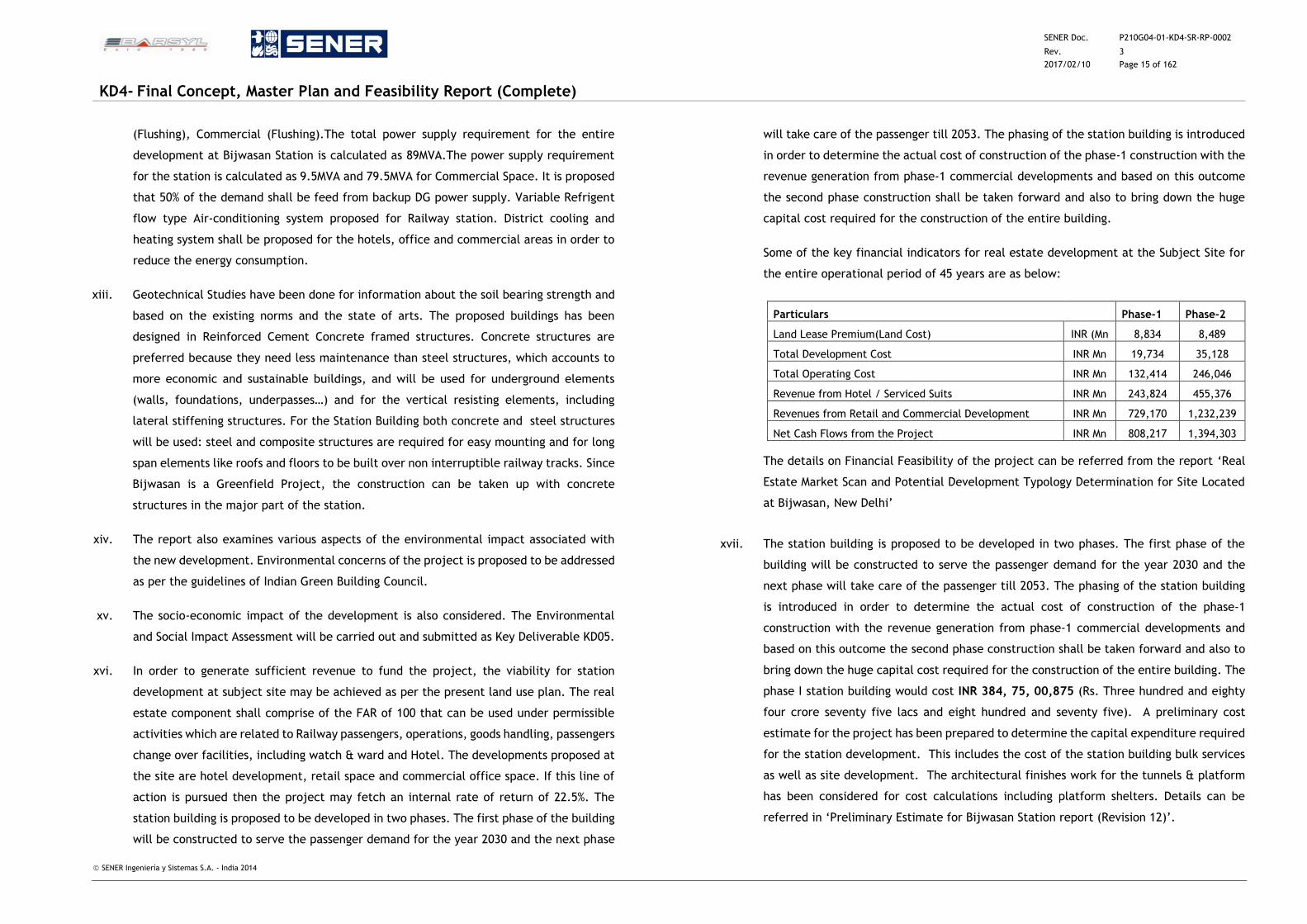
Some of the key financial indicators for real estate development at the Subject Site for
the entire operational period of 45 years are as below:
Particulars Phase-1 Phase-2
Land Lease Premium(Land Cost) INR (Mn 8,834 8,489
Total Development Cost INR Mn 19,734 35,128
Total Operating Cost INR Mn 132,414 246,046
Revenue from Hotel / Serviced Suits INR Mn 243,824 455,376
Revenues from Retail and Commercial Development INR Mn 729,170 1,232,239
Net Cash Flows from the Project INR Mn 808,217 1,394,303
The details on Financial Feasibility of the project can be referred from the report ‘Real
Estate Market Scan and Potential Development Typology Determination for Site Located
at Bijwasan, New Delhi’
xvii. The station building is proposed to be developed in two phases. The first phase of the
building will be constructed to serve the passenger demand for the year 2030 and the
next phase will take care of the passenger till 2053. The phasing of the station building
is introduced in order to determine the actual cost of construction of the phase-1
construction with the revenue generation from phase-1 commercial developments and
based on this outcome the second phase construction shall be taken forward and also to
bring down the huge capital cost required for the construction of the entire building. The
phase I station building would cost INR 384, 75, 00,875 (Rs. Three hundred and eighty
four crore seventy five lacs and eight hundred and seventy five). A preliminary cost
estimate for the project has been prepared to determine the capital expenditure required
for the station development. This includes the cost of the station building bulk services
as well as site development. The architectural finishes work for the tunnels & platform
has been considered for cost calculations including platform shelters. Details can be
referred in ‘Preliminary Estimate for Bijwasan Station report (Revision 12)’.
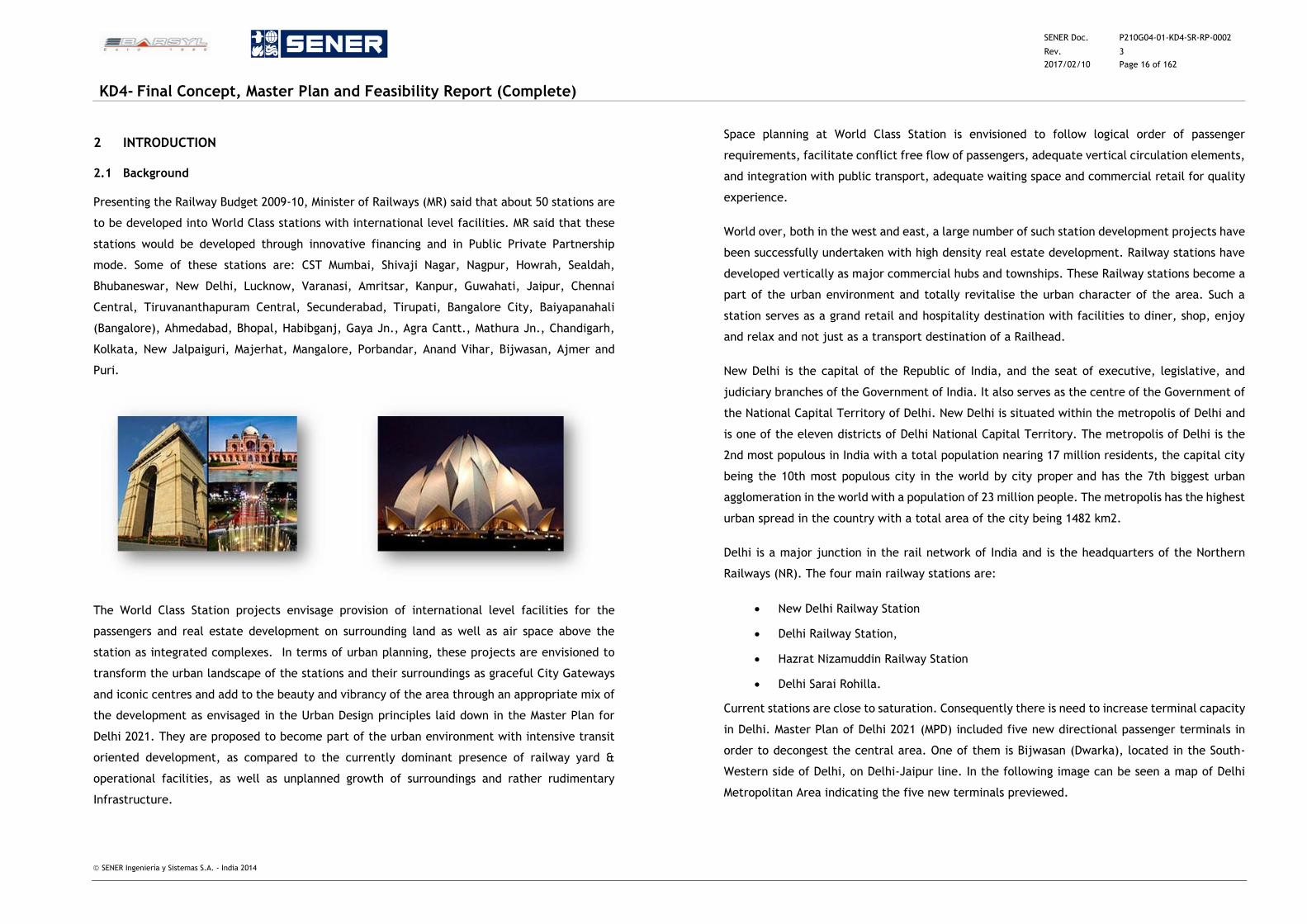
SENER Doc. P210G04-01-KD4-SR-RP-0002
Rev. 3
2017/02/10 Page 16 of 162
KD4- Final Concept, Master Plan and Feasibility Report (Complete)
SENER Ingeniería y Sistemas S.A. - India 2014
2 INTRODUCTION
2.1 Background
Presenting the Railway Budget 2009-10, Minister of Railways (MR) said that about 50 stations are
to be developed into World Class stations with international level facilities. MR said that these
stations would be developed through innovative financing and in Public Private Partnership
mode. Some of these stations are: CST Mumbai, Shivaji Nagar, Nagpur, Howrah, Sealdah,
Bhubaneswar, New Delhi, Lucknow, Varanasi, Amritsar, Kanpur, Guwahati, Jaipur, Chennai
Central, Tiruvananthapuram Central, Secunderabad, Tirupati, Bangalore City, Baiyapanahali
(Bangalore), Ahmedabad, Bhopal, Habibganj, Gaya Jn., Agra Cantt., Mathura Jn., Chandigarh,
Kolkata, New Jalpaiguri, Majerhat, Mangalore, Porbandar, Anand Vihar, Bijwasan, Ajmer and
Puri.
The World Class Station projects envisage provision of international level facilities for the
passengers and real estate development on surrounding land as well as air space above the
station as integrated complexes. In terms of urban planning, these projects are envisioned to
transform the urban landscape of the stations and their surroundings as graceful City Gateways
and iconic centres and add to the beauty and vibrancy of the area through an appropriate mix of
the development as envisaged in the Urban Design principles laid down in the Master Plan for
Delhi 2021. They are proposed to become part of the urban environment with intensive transit
oriented development, as compared to the currently dominant presence of railway yard &
operational facilities, as well as unplanned growth of surroundings and rather rudimentary
Infrastructure.
Space planning at World Class Station is envisioned to follow logical order of passenger
requirements, facilitate conflict free flow of passengers, adequate vertical circulation elements,
and integration with public transport, adequate waiting space and commercial retail for quality
experience.
World over, both in the west and east, a large number of such station development projects have
been successfully undertaken with high density real estate development. Railway stations have
developed vertically as major commercial hubs and townships. These Railway stations become a
part of the urban environment and totally revitalise the urban character of the area. Such a
station serves as a grand retail and hospitality destination with facilities to diner, shop, enjoy
and relax and not just as a transport destination of a Railhead.
New Delhi is the capital of the Republic of India, and the seat of executive, legislative, and
judiciary branches of the Government of India. It also serves as the centre of the Government of
the National Capital Territory of Delhi. New Delhi is situated within the metropolis of Delhi and
is one of the eleven districts of Delhi National Capital Territory. The metropolis of Delhi is the
2nd most populous in India with a total population nearing 17 million residents, the capital city
being the 10th most populous city in the world by city proper and has the 7th biggest urban
agglomeration in the world with a population of 23 million people. The metropolis has the highest
urban spread in the country with a total area of the city being 1482 km2.
Delhi is a major junction in the rail network of India and is the headquarters of the Northern
Railways (NR). The four main railway stations are:
New Delhi Railway Station
Delhi Railway Station,
Hazrat Nizamuddin Railway Station
Delhi Sarai Rohilla.
Current stations are close to saturation. Consequently there is need to increase terminal capacity
in Delhi. Master Plan of Delhi 2021 (MPD) included five new directional passenger terminals in
order to decongest the central area. One of them is Bijwasan (Dwarka), located in the South-
Western side of Delhi, on Delhi-Jaipur line. In the following image can be seen a map of Delhi
Metropolitan Area indicating the five new terminals previewed.
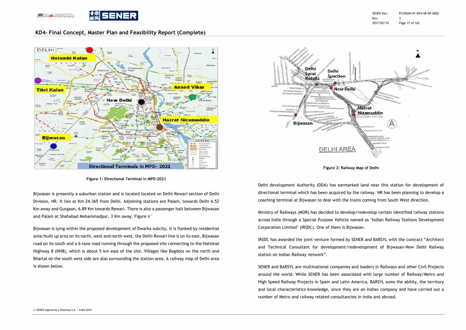
SENER Doc. P210G04-01-KD4-SR-RP-0002
Rev. 3
2017/02/10 Page 17 of 162
KD4- Final Concept, Master Plan and Feasibility Report (Complete)
SENER Ingeniería y Sistemas S.A. - India 2014
Figure 1: Directional Terminal in MPD-2021
Bijwasan is presently a suburban station and is located located on Delhi-Rewari section of Delhi
Division, NR. It lies at Km 24.365 from Delhi. Adjoining stations are Palam, towards Delhi 6.52
Km away and Gurgaon, 6.89 Km towards Rewari. There is also a passenger halt between Bijwasan
and Palam at Shahabad Mohammadpur, 3 Km away. Figure n°
Bijwasan is lying within the proposed development of Dwarka subcity, it is flanked by residential
area/built up area on its north, west and north-west, the Delhi-Rewari line is on its east, Bijwasan
road on its south and a 6-lane road running through the proposed site connecting to the National
Highway 8 (NH8), which is about 5 km east of the site. Villages like Bagdola on the north and
Bhartal on the south west side are also surrounding the station area. A railway map of Delhi area
is shown below.
Figure 2: Railway Map of Delhi
Delhi development Authority (DDA) has earmarked land near this station for development of
directional terminal which has been acquired by the railway. NR has been planning to develop a
coaching terminal at Bijwasan to deal with the trains coming from South West direction.
Ministry of Railways (MOR) has decided to develop/redevelop certain identified railway stations
across India through a Special Purpose Vehicle named as ‘Indian Railway Stations Development
Corporation Limited’ (IRSDC). One of them is Bijwasan.
IRSDC has awarded the joint venture formed by SENER and BARSYL with the contract “Architect
and Technical Consultant for development/redevelopment of Bijwasan-New Delhi Railway
station on Indian Railway network”.
SENER and BARSYL are multinational companies and leaders in Railways and other Civil Projects
around the world. While SENER has been associated with large number of Railway/Metro and
High Speed Railway Projects in Spain and Latin America, BARSYL sums the ability, the territory
and local characteristics knowledge, since they are an Indian company and have carried out a
number of Metro and railway related consultancies in India and abroad.
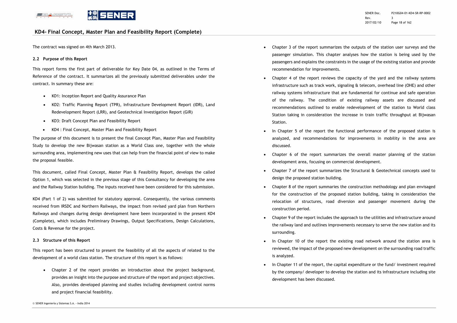
SENER Doc. P210G04-01-KD4-SR-RP-0002
Rev. 3
2017/02/10 Page 18 of 162
KD4- Final Concept, Master Plan and Feasibility Report (Complete)
SENER Ingeniería y Sistemas S.A. - India 2014
The contract was signed on 4th March 2013.
2.2 Purpose of this Report
This report forms the first part of deliverable for Key Date 04, as outlined in the Terms of
Reference of the contract. It summarizes all the previously submitted deliverables under the
contract. In summary these are:
KD1: Inception Report and Quality Assurance Plan
KD2: Traffic Planning Report (TPR), Infrastructure Development Report (IDR), Land
Redevelopment Report (LRR), and Geotechnical Investigation Report (GIR)
KD3: Draft Concept Plan and Feasibility Report
KD4 : Final Concept, Master Plan and Feasibility Report
The purpose of this document is to present the final Concept Plan, Master Plan and Feasibility
Study to develop the new Bijwasan station as a World Class one, together with the whole
surrounding area, implementing new uses that can help from the financial point of view to make
the proposal feasible.
This document, called Final Concept, Master Plan & Feasibility Report, develops the called
Option 1, which was selected in the previous stage of this Consultancy for developing the area
and the Railway Station building. The inputs received have been considered for this submission.
KD4 (Part 1 of 2) was submitted for statutory approval. Consequently, the various comments
received from IRSDC and Northern Railways, the impact from revised yard plan from Northern
Railways and changes during design development have been incorporated in the present KD4
(Complete), which includes Preliminary Drawings, Output Specifications, Design Calculations,
Costs & Revenue for the project.
2.3 Structure of this Report
This report has been structured to present the feasibility of all the aspects of related to the
development of a world class station. The structure of this report is as follows:
Chapter 2 of the report provides an introduction about the project background,
provides an insight into the purpose and structure of the report and project objectives.
Also, provides developed planning and studies including development control norms
and project financial feasibility.
Chapter 3 of the report summarizes the outputs of the station user surveys and the
passenger simulation. This chapter analyses how the station is being used by the
passengers and explains the constraints in the usage of the existing station and provide
recommendation for improvements.
Chapter 4 of the report reviews the capacity of the yard and the railway systems
infrastructure such as track work, signaling & telecom, overhead line (OHE) and other
railway systems infrastructure that are fundamental for continue and safe operation
of the railway. The condition of existing railway assets are discussed and
recommendations outlined to enable redevelopment of the station to World class
Station taking in consideration the increase in train traffic throughput at Bijwasan
Station.
In Chapter 5 of the report the functional performance of the proposed station is
analyzed, and recommendations for improvements in mobility in the area are
discussed.
Chapter 6 of the report summarizes the overall master planning of the station
development area, focusing on commercial development.
Chapter 7 of the report summarizes the Structural & Geotechnical concepts used to
design the proposed station building.
Chapter 8 of the report summaries the construction methodology and plan envisaged
for the construction of the proposed station building, taking in consideration the
relocation of structures, road diversion and passenger movement during the
construction period.
Chapter 9 of the report includes the approach to the utilities and infrastructure around
the railway land and outlines improvements necessary to serve the new station and its
surrounding.
In Chapter 10 of the report the existing road network around the station area is
reviewed, the impact of the proposed new development on the surrounding road traffic
is analyzed.
In Chapter 11 of the report, the capital expenditure or the fund/ investment required
by the company/ developer to develop the station and its infrastructure including site
development has been discussed.
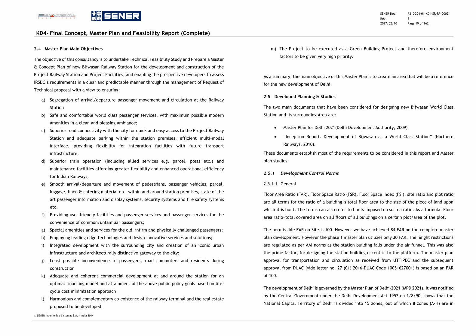
SENER Doc. P210G04-01-KD4-SR-RP-0002
Rev. 3
2017/02/10 Page 19 of 162
KD4- Final Concept, Master Plan and Feasibility Report (Complete)
SENER Ingeniería y Sistemas S.A. - India 2014
2.4 Master Plan Main Objectives
The objective of this consultancy is to undertake Technical Feasibility Study and Prepare a Master
& Concept Plan of new Bijwasan Railway Station for the development and construction of the
Project Railway Station and Project Facilities, and enabling the prospective developers to assess
IRSDC’s requirements in a clear and predictable manner through the management of Request of
Technical proposal with a view to ensuring:
a) Segregation of arrival/departure passenger movement and circulation at the Railway
Station
b) Safe and comfortable world class passenger services, with maximum possible modern
amenities in a clean and pleasing ambiance;
c) Superior road connectivity with the city for quick and easy access to the Project Railway
Station and adequate parking within the station premises, efficient multi-modal
interface, providing flexibility for integration facilities with future transport
infrastructure;
d) Superior train operation (including allied services e.g. parcel, posts etc.) and
maintenance facilities affording greater flexibility and enhanced operational efficiency
for Indian Railways;
e) Smooth arrival/departure and movement of pedestrians, passenger vehicles, parcel,
luggage, linen & catering material etc. within and around station premises, state of the
art passenger information and display systems, security systems and fire safety systems
etc.
f) Providing user-friendly facilities and passenger services and passenger services for the
convenience of common/unfamiliar passengers;
g) Special amenities and services for the old, infirm and physically challenged passengers;
h) Employing leading edge technologies and design innovative services and solutions;
i) Integrated development with the surrounding city and creation of an iconic urban
infrastructure and architecturally distinctive gateway to the city;
j) Least possible inconvenience to passengers, road commuters and residents during
construction
k) Adequate and coherent commercial development at and around the station for an
optimal financing model and attainment of the above public policy goals based on life-
cycle cost minimization approach
l) Harmonious and complementary co-existence of the railway terminal and the real estate
proposed to be developed.
m) The Project to be executed as a Green Building Project and therefore environment
factors to be given very high priority.
As a summary, the main objective of this Master Plan is to create an area that will be a reference
for the new development of Delhi.
2.5 Developed Planning & Studies
The two main documents that have been considered for designing new Bijwasan World Class
Station and its surrounding Area are:
Master Plan for Delhi 2021(Delhi Development Authority, 2009)
“Inception Report. Development of Bijwasan as a World Class Station” (Northern
Railways, 2010).
These documents establish most of the requirements to be considered in this report and Master
plan studies.
2.5.1 Development Control Norms
2.5.1.1 General
Floor Area Ratio (FAR), Floor Space Ratio (FSR), Floor Space Index (FSI), site ratio and plot ratio
are all terms for the ratio of a building´s total floor area to the size of the piece of land upon
which it is built. The terms can also refer to limits imposed on such a ratio. As a formula: Floor
area ratio=total covered area on all floors of all buildings on a certain plot/area of the plot.
The permissible FAR on Site is 100. However we have achieved 84 FAR on the complete master
plan development. However the phase 1 master plan utilizes only 30 FAR. The height restrictions
are regulated as per AAI norms as the station building falls under the air funnel. This was also
the prime factor, for designing the station building eccentric to the platform. The master plan
approval for transportation and circulation as received from UTTIPEC and the subsequent
approval from DUAC (vide letter no. 27 (01) 2016-DUAC Code 10051627001) is based on an FAR
of 100.
The development of Delhi is governed by the Master Plan of Delhi-2021 (MPD 2021). It was notified
by the Central Government under the Delhi Development Act 1957 on 1/8/90, shows that the
National Capital Territory of Delhi is divided into 15 zones, out of which 8 zones (A-H) are in
SENER Doc. P210G04-01-KD4-SR-RP-0002
Rev. 3
2017/02/10 Page 20 of 162
KD4- Final Concept, Master Plan and Feasibility Report (Complete)
SENER Ingeniería y Sistemas S.A. - India 2014
urban Delhi, 6 zones (J to N&P) are in urban extension /rural area. Zone-O is for River Yamuna
(River Front Area). A zone could be divided into sub-zones.
Future Bijwasan Railway Station falls under Dwarka sub-city, which belongs to zone-K and forms
part of the urban extension plan approved by the Authority vide Agenda no.79 dt. 30.06.1987 as
part of Master Plan of Delhi 2001.
The existing Land use of the surrounding area is primarily Residential (villages like Bagdola,
Bhartal, Bijwasan and Dwarka subcity), Industrial (proposed integrated freight complexes) and
Transportation (proposed ISBT Dwarka).
The urban extension plan was prepared to accommodate the projected population and was
conceived to be developed in four phases. Dwarka sub-city forms part of Phase 1A of the urban
extension plan. The Area where this Master Plan is developed is in the zone called K-II, as shown
in the next page. Railway Station is clearly been demarcated as a MPT.
Under Chapter 12.0 Transportation, (12.01.1 Rail), 5 directional Metropolitan Passenger
Terminals (MPT) has been proposed to clear the central area. Bhartal in Dwarka, South-West
Delhi, is the second in this list and is the same as is called Bijwasan in this document.
Figure 3: Planning Zone K-II

SENER Doc. P210G04-01-KD4-SR-RP-0002
Rev. 3
2017/02/10 Page 21 of 162
KD4- Final Concept, Master Plan and Feasibility Report (Complete)
SENER Ingeniería y Sistemas S.A. - India 2014
Figure 4: Bijwasan Existing Conditions
Though the MPT talks about TOD along MRTS corridor, with enhanced FAR in case of integrated
schemes, it is largely silent on the development controls for MPT´s
The Master Plan of Delhi is currently under revision. Meanwhile some other studies are being
developed:
Figure 5: New Developments Planned in the Area including New Dwarka-Gurgaon Highway
2.5.1.2 Development Controls
The development control guidelines as per MPD 2021 for a railway station are described in the
table below:
S. no Use premises Activities permitted
Development controls
Area under
operation (%)
Area under
building (%)
FAR*
Floor area that can be utilised for passenger accomodation
1.
Rail
terminal/integra
ted passenger
terminal
All facilities related to
railway passengers,
operations, goods
handling, passengers
change over facilities,
including watch and
ward, hotel.
70 30 100 15%
Note: the FAR is to be calculated on the building plot
Other examples of FSIs in other stations developments in India and all over the world are:
Station name Site area (Ha) Built-up area (m2) FSI
Seawood Darave, Navi Mumbai 16.5 2,32,257 1.5
New Delhi Railway station 84.7 11,00,000 1.3 (proposed)
New Guangzhou station (China) 25.4 495,900 1.95
Kowloon station (Hong-Kong) 13.5 220,000 1.62
King Cross station (London, UK) 6 80,000 1.33
Table 1: Other examples of FSI in Stations
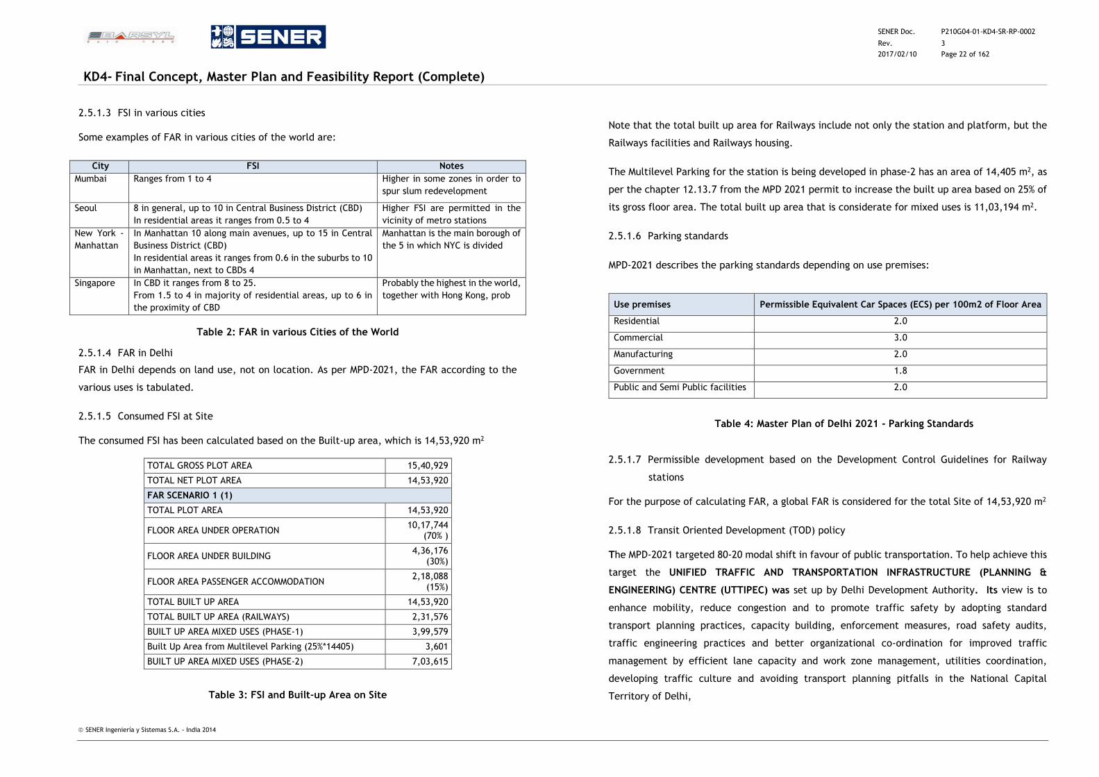
SENER Doc. P210G04-01-KD4-SR-RP-0002
Rev. 3
2017/02/10 Page 22 of 162
KD4- Final Concept, Master Plan and Feasibility Report (Complete)
SENER Ingeniería y Sistemas S.A. - India 2014
2.5.1.3 FSI in various cities
Some examples of FAR in various cities of the world are:
City FSI Notes
Mumbai Ranges from 1 to 4 Higher in some zones in order to
spur slum redevelopment
Seoul 8 in general, up to 10 in Central Business District (CBD)
In residential areas it ranges from 0.5 to 4
Higher FSI are permitted in the
vicinity of metro stations
New York -
Manhattan
In Manhattan 10 along main avenues, up to 15 in Central
Business District (CBD)
In residential areas it ranges from 0.6 in the suburbs to 10
in Manhattan, next to CBDs 4
Manhattan is the main borough of
the 5 in which NYC is divided
Singapore In CBD it ranges from 8 to 25.
From 1.5 to 4 in majority of residential areas, up to 6 in
the proximity of CBD
Probably the highest in the world,
together with Hong Kong, prob
Table 2: FAR in various Cities of the World
2.5.1.4 FAR in Delhi
FAR in Delhi depends on land use, not on location. As per MPD-2021, the FAR according to the
various uses is tabulated.
2.5.1.5 Consumed FSI at Site
The consumed FSI has been calculated based on the Built-up area, which is 14,53,920 m2
TOTAL GROSS PLOT AREA 15,40,929
TOTAL NET PLOT AREA 14,53,920
FAR SCENARIO 1 (1)
TOTAL PLOT AREA 14,53,920
FLOOR AREA UNDER OPERATION 10,17,744
(70% )
FLOOR AREA UNDER BUILDING 4,36,176
(30%)
FLOOR AREA PASSENGER ACCOMMODATION 2,18,088
(15%)
TOTAL BUILT UP AREA 14,53,920
TOTAL BUILT UP AREA (RAILWAYS) 2,31,576
BUILT UP AREA MIXED USES (PHASE-1) 3,99,579
Built Up Area from Multilevel Parking (25%*14405) 3,601
BUILT UP AREA MIXED USES (PHASE-2) 7,03,615
Table 3: FSI and Built-up Area on Site
Note that the total built up area for Railways include not only the station and platform, but the
Railways facilities and Railways housing.
The Multilevel Parking for the station is being developed in phase-2 has an area of 14,405 m2, as
per the chapter 12.13.7 from the MPD 2021 permit to increase the built up area based on 25% of
its gross floor area. The total built up area that is considerate for mixed uses is 11,03,194 m2.
2.5.1.6 Parking standards
MPD-2021 describes the parking standards depending on use premises:
Use premises Permissible Equivalent Car Spaces (ECS) per 100m2 of Floor Area
Residential 2.0
Commercial 3.0
Manufacturing 2.0
Government 1.8
Public and Semi Public facilities 2.0
Table 4: Master Plan of Delhi 2021 - Parking Standards
2.5.1.7 Permissible development based on the Development Control Guidelines for Railway
stations
For the purpose of calculating FAR, a global FAR is considered for the total Site of 14,53,920 m2
2.5.1.8 Transit Oriented Development (TOD) policy
The MPD‐2021 targeted 80‐20 modal shift in favour of public transportation. To help achieve this
target the UNIFIED TRAFFIC AND TRANSPORTATION INFRASTRUCTURE (PLANNING &
ENGINEERING) CENTRE (UTTIPEC) was set up by Delhi Development Authority. Its view is to
enhance mobility, reduce congestion and to promote traffic safety by adopting standard
transport planning practices, capacity building, enforcement measures, road safety audits,
traffic engineering practices and better organizational co-ordination for improved traffic
management by efficient lane capacity and work zone management, utilities coordination,
developing traffic culture and avoiding transport planning pitfalls in the National Capital
Territory of Delhi,
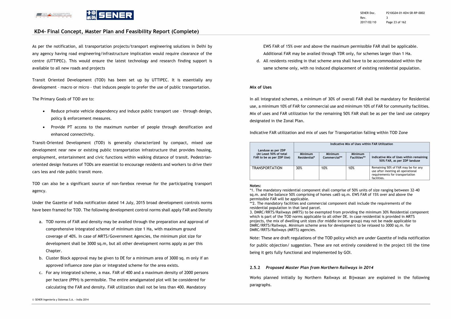
SENER Doc. P210G04-01-KD4-SR-RP-0002
Rev. 3
2017/02/10 Page 23 of 162
KD4- Final Concept, Master Plan and Feasibility Report (Complete)
SENER Ingeniería y Sistemas S.A. - India 2014
As per the notification, all transportation projects/transport engineering solutions in Delhi by
any agency having road engineering/infrastructure implication would require clearance of the
centre (UTTIPEC). This would ensure the latest technology and research finding support is
available to all new roads and projects
Transit Oriented Development (TOD) has been set up by UTTIPEC. It is essentially any
development – macro or micro – that induces people to prefer the use of public transportation.
The Primary Goals of TOD are to:
Reduce private vehicle dependency and induce public transport use – through design,
policy & enforcement measures.
Provide PT access to the maximum number of people through densification and
enhanced connectivity.
Transit‐Oriented Development (TOD) is generally characterized by compact, mixed use
development near new or existing public transportation infrastructure that provides housing,
employment, entertainment and civic functions within walking distance of transit. Pedestrian‐
oriented design features of TODs are essential to encourage residents and workers to drive their
cars less and ride public transit more.
TOD can also be a significant source of non‐farebox revenue for the participating transport
agency.
Under the Gazette of India notification dated 14 July, 2015 broad development controls norms
have been framed for TOD. The following development control norms shall apply FAR and Density
a. TOD norms of FAR and density may be availed through the preparation and approval of
comprehensive integrated scheme of minimum size 1 Ha, with maximum ground
coverage of 40%. In case of MRTS/Government Agencies, the minimum plot size for
development shall be 3000 sq.m, but all other development norms apply as per this
Chapter.
b. Cluster Block approval may be given to DE for a minimum area of 3000 sq. m only if an
approved influence zone plan or integrated scheme for the area exists.
c. For any integrated scheme, a max. FAR of 400 and a maximum density of 2000 persons
per hectare (PPH) is permissible. The entire amalgamated plot will be considered for
calculating the FAR and density. FAR utilization shall not be less than 400. Mandatory
EWS FAR of 15% over and above the maximum permissible FAR shall be applicable.
Additional FAR may be availed through TDR only, for schemes larger than 1 Ha.
d. All residents residing in that scheme area shall have to be accommodated within the
same scheme only, with no induced displacement of existing residential population.
Mix of Uses
In all integrated schemes, a minimum of 30% of overall FAR shall be mandatory for Residential
use, a minimum 10% of FAR for commercial use and minimum 10% of FAR for community facilities.
Mix of uses and FAR utilization for the remaining 50% FAR shall be as per the land use category
designated in the Zonal Plan.
Indicative FAR utilization and mix of uses for Transportation falling within TOD Zone
Landuse as per ZDP (At Least 50% of total
FAR to be as per ZDP Use)
Indicative Mix of Uses within FAR Utilization
Minimum Residential*
Minimum Commercial**
Minimum Facilities** Indicative Mix of Uses within remaining
50% FAR, as per ZDP landuse
TRANSPORTATION 30% 10% 10% Remaining 50% of FAR may be for any use after meeting all operational requirements for transportation facilities.
Notes: *1. The mandatory residential component shall comprise of 50% units of size ranging between 32-40 sq.m. and the balance 50% comprising of homes ≤a65 sq.m. EWS FAR of 15% over and above the permissible FAR will be applicable. **2. The mandatory facilities and commercial component shall include the requirements of the residential population in that land parcel. 3. DMRC/RRTS/Railways (MRTS) to be exempted from providing the minimum 30% Residential component which is part of the TOD norms applicable to all other DE. In case residential is provided in MRTS projects, the mix of dwelling unit sizes (for middle income group) may not be made applicable to DMRC/RRTS/Railways. Minimum scheme area for development to be relaxed to 3000 sq.m. for DMRC/RRTS/Railways (MRTS) agencies.
Note: These are draft regulations of the TOD policy which are under Gazette of India notification
for public objection/ suggestion. These are not entirely considered in the project till the time
being it gets fully functional and implemented by GOI.
2.5.2 Proposed Master Plan from Northern Railways in 2014
Works planned initially by Northern Railways at Bijwasan are explained in the following
paragraphs.
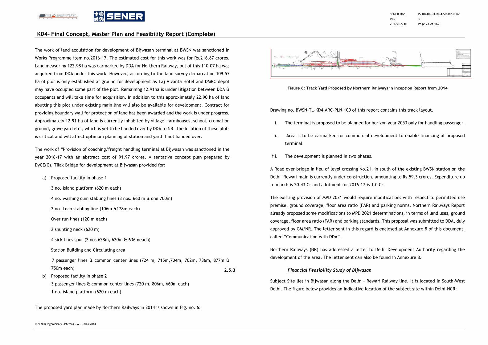
SENER Doc. P210G04-01-KD4-SR-RP-0002
Rev. 3
2017/02/10 Page 24 of 162
KD4- Final Concept, Master Plan and Feasibility Report (Complete)
SENER Ingeniería y Sistemas S.A. - India 2014
The work of land acquisition for development of Bijwasan terminal at BWSN was sanctioned in
Works Programme item no.2016-17. The estimated cost for this work was for Rs.216.87 crores.
Land measuring 122.98 ha was earmarked by DDA for Northern Railway, out of this 110.07 ha was
acquired from DDA under this work. However, according to the land survey demarcation 109.57
ha of plot is only established at ground for development as Taj Vivanta Hotel and DMRC depot
may have occupied some part of the plot. Remaining 12.91ha is under litigation between DDA &
occupants and will take time for acquisition. In addition to this approximately 22.90 ha of land
abutting this plot under existing main line will also be available for development. Contract for
providing boundary wall for protection of land has been awarded and the work is under progress.
Approximately 12.91 ha of land is currently inhabited by village, farmhouses, school, cremation
ground, grave yard etc., which is yet to be handed over by DDA to NR. The location of these plots
is critical and will affect optimum planning of station and yard if not handed over.
The work of “Provision of coaching/freight handling terminal at Bijwasan was sanctioned in the
year 2016-17 with an abstract cost of 91.97 crores. A tentative concept plan prepared by
DyCE(C), Tilak Bridge for development at Bijwasan provided for:
a) Proposed facility in phase 1
3 no. island platform (620 m each)
4 no. washing cum stabling lines (3 nos. 660 m & one 700m)
2 no. Loco stabling line (106m &178m each)
Over run lines (120 m each)
2 shunting neck (620 m)
4 sick lines spur (2 nos 628m, 620m & 636meach)
Station Building and Circulating area
7 passenger lines & common center lines (724 m, 715m,704m, 702m, 736m, 877m &
750m each)
b) Proposed facility in phase 2
3 passenger lines & common center lines (720 m, 806m, 660m each)
1 no. island platform (620 m each)
The proposed yard plan made by Northern Railways in 2014 is shown in Fig. no. 6:
Figure 6: Track Yard Proposed by Northern Railways in Inception Report from 2014
Drawing no. BWSN-TL-KD4-ARC-PLN-100 of this report contains this track layout.
i. The terminal is proposed to be planned for horizon year 2053 only for handling passenger.
ii. Area is to be earmarked for commercial development to enable financing of proposed
terminal.
iii. The development is planned in two phases.
A Road over bridge in lieu of level crossing No.21, in south of the existing BWSN station on the
Delhi –Rewari main is currently under construction, amounting to Rs.59.3 crores. Expenditure up
to march is 20.43 Cr and allotment for 2016-17 is 1.0 Cr.
The existing provision of MPD 2021 would require modifications with respect to permitted use
premise, ground coverage, floor area ratio (FAR) and parking norms. Northern Railways Report
already proposed some modifications to MPD 2021 determinations, in terms of land uses, ground
coverage, floor area ratio (FAR) and parking standards. This proposal was submitted to DDA, duly
approved by GM/NR. The letter sent in this regard is enclosed at Annexure 8 of this document,
called “Communication with DDA”.
Northern Railways (NR) has addressed a letter to Delhi Development Authority regarding the
development of the area. The letter sent can also be found in Annexure 8.
2.5.3 Financial Feasibility Study of Bijwasan
Subject Site lies in Bijwasan along the Delhi – Rewari Railway line. It is located in South-West
Delhi. The figure below provides an indicative location of the subject site within Delhi-NCR:
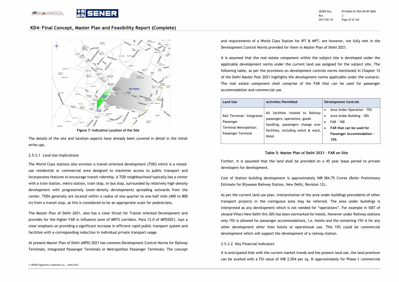
SENER Doc. P210G04-01-KD4-SR-RP-0002
Rev. 3
2017/02/10 Page 25 of 162
KD4- Final Concept, Master Plan and Feasibility Report (Complete)
SENER Ingeniería y Sistemas S.A. - India 2014
Figure 7: Indicative Location of the Site
The details of the site and location aspects have already been covered in detail in the initial
write-ups.
2.5.3.1 Land Use Implications
The World Class stations also envision a transit-oriented development (TOD) which is a mixed-
use residential or commercial area designed to maximize access to public transport and
incorporates features to encourage transit ridership. A TOD neighbourhood typically has a center
with a train station, metro station, tram stop, or bus stop, surrounded by relatively high-density
development with progressively lower-density developments spreading outwards from the
center. TODs generally are located within a radius of one-quarter to one-half mile (400 to 800
m) from a transit stop, as this is considered to be an appropriate scale for pedestrians.
The Master Plan of Delhi 2021, also has a clear thrust for Transit oriented Development and
provides for the higher FAR in influence zone of MRTS corridors. Para 12.0 of MPD2021, lays a
clear emphasis on providing a significant increase in efficient rapid public transport system and
facilities with a corresponding reduction in individual private transport usage.
At present Master Plan of Delhi (MPD) 2021 has common Development Control Norms for Railway
Terminals, Integrated Passenger Terminals or Metropolitan Passenger Terminals. The concept
and requirements of a World Class Station for IPT & MPT, are however, not fully met in the
Development Control Norms provided for them in Master Plan of Delhi 2021.
It is assumed that the real estate component within the subject site is developed under the
applicable development norms under the current land use assigned for the subject site. The
following table, as per the provisions on development controls norms mentioned in Chapter 12
of the Delhi Master Plan 2021 highlights the development norms applicable under the scenario.
The real estate component shall comprise of the FAR that can be used for passenger
accommodation and commercial use.
Land Use Activities Permitted Development Controls
Rail Terminal/ Integrated
Passenger
Terminal Metropolitan.
Passenger Terminal
All facilities related to Railway
passengers, operations, goods
handling, passengers change over
facilities, including watch & ward,
Hotel
Area Under Operation - 70%
Area Under Building - 30%
FAR – 100
FAR that can be used for
Passenger Accommodation –
15%
Table 5: Master Plan of Delhi 2021 - FAR on Site
Further, it is assumed that the land shall be provided on a 45 year lease period to private
developers for development.
Cost of Station building development is approximately INR 384.75 Crores (Refer Preliminary
Estimate for Bijwasan Railway Station, New Delhi, Revision 12).
As per the current land use plan, interpretation of the area under buildings precedents of other
transport projects in the contiguous area may be referred. The area under buildings is
interpreted as any development which is not needed for “operations”. For example in ISBT of
(Anand Vihar) New Delhi this 30% has been earmarked for hotels. However under Railway stations
only 15% is allowed for passenger accommodations, i.e. hotels and the remaining 15% is for any
other development other than hotels or operational use. This 15% could be commercial
development which will support the development of a railway station.
2.5.3.2 Key Financial Indicators
It is anticipated that with the current market trends and the present land use, the land premium
can be availed with a FSI value of INR 2,054 per sq. ft approximately for Phase-1 commercial
SENER Doc. P210G04-01-KD4-SR-RP-0002
Rev. 3
2017/02/10 Page 26 of 162
KD4- Final Concept, Master Plan and Feasibility Report (Complete)
SENER Ingeniería y Sistemas S.A. - India 2014
development and for Phase-2 with a the FSI value of INR 1,121 approximately (for details refer
Report - Real Estate Market Scan and Potential Development Typology Determination for Site
Located at Bijwasan, New Delhi). Therefore to meet the objectives of the station development
change in land use is not warranted.
However Railways can further enhance their revenue from this piece of real estate by changing
the land use to commercial.
Proposed real estate development components
Retail Mall Development
Commercial Development – Office space
Hospitality Development - Hotels
Area Statement – Phase I and II
The table below lists the details of development at the Subject Property under Phase 1 and
Phase 2:
Particulars Unit Area
Property Development for Phase 1 Sq. ft. 4,301,070
Property Development for Phase 2 Sq. ft. 7,573,715
Total Area Sq. ft. 11,874,785
Product Mix for Phase I
Table below lists the proposed product mix at the subject development under Phase I
Proposed Product Mix Distribution Built up Area (sq ft)
Hotel 215,054
Retail Development 408,602
Commercial Development – office space 3,677,415
Total Development under Phase I 4,301,070
Development Assumptions – Hospitality
Table below lists the key development assumptions for hotel development at the subject
property:
Construction Cost
Construction Cost Per unit cost (per sq. ft) Area Cost (in INR)
Base construction cost 3,000 215,054 645,160,560
Hotel construction and interiors 4,500 215,054 967,740,840
Total Construction Cost 1,612,901,400
Total Cost per room 4,500,000
Summation of Cashflows
The table below lists the summary of cashflows that the subject development will generate
over a 45 year period.
Particulars Total
Cash Outflows (INR Mn)
Land Cost 12,629
Development Costs, Other Exps 19,734
Operating Exps 132,414
Total Cash outflows 164,777
Cash Inflows (INR Mn)
Revenues from Hotel / Serviced Suites 243,824
Large Format Retail and Commercial Development 729,170
Total Cash inflows 972,994
Net Cashflows 808,217
Project IRR 22.5%
FSI value (INR / sq.ft) 2,054
The net cashflows generated from the subject property during a 45 year period is INR 808,217
Mn. IRR generated by the project is 22.5%.
Product Mix for Phase II
Table below lists the proposed product mix at the subject development under Phase II
Proposed Product Mix Distribution Built up Area (sq ft)
Hotel 378,686
Retail Development 719,503
Commercial Development – office space 6,475,526
Total Development under Phase II 7,573,715
SENER Doc. P210G04-01-KD4-SR-RP-0002
Rev. 3
2017/02/10 Page 27 of 162
KD4- Final Concept, Master Plan and Feasibility Report (Complete)
SENER Ingeniería y Sistemas S.A. - India 2014
Development Assumptions – Hospitality
Table below lists the key development assumptions for hotel development at the subject
property:
Construction Cost
Construction Cost Per unit cost (per sq. ft) Area Cost (in INR)
Base construction cost 3,000 378,686 1,136,057,215
Hotel construction and interiors 4,500 378,686 1,704,085,822
Total Construction Cost 2,840,143,037
Total Cost per room 4,500,000
Summation of Cashflows
The table below lists the summary of cashflows that the subject development will generate
over a 45 year period.
Particulars Total
Cash Outflows (INR Mn)
Land Cost 12,136
Development Costs, Other Exps 35,128
Operating Exps 246,046
Total Cash outflows 293,311
Cash Inflows (INR Mn)
Revenues from Hotel / Serviced Suites 455,376
Large Format Retail and Commercial Development 1,232,239
Total Cash inflows 1,687,614
Net Cashflows 1,394,303
Project IRR 22.5%
FSI value (INR / sq.ft) 1,121
The net cashflows generated from the subject property during a 45 year period is INR 1,394,303
Mn. IRR generated by the project is 22.5%.
Detailed Cost Calculations and Financial Feasibility Analysis are provided in separate reports
‘Preliminary Estimate for Bijwasan Railway Station and Real Estate Market Scan and Potential
Development Typology Determination for Site Located at Bijwasan, New Delhi’. The Preliminary
Drawings are included in this report and Specifications is provides in a separate report.
2.6 Clearances
All the proposals for public works must be prepared as per specific requirements of Client
Ministries / Departments and the residential and office space norms prescribed by the
Government. The proposals must comply with the local master plan, zoning regulations and
building byelaws and environment regulations. All the proposals must include provisions for
barrier free movement for physically challenged people i.e. providing non-handicapping built
environment for differently-abled people. The proposal must also conform to the regulations
pertaining to fire-protections, fire detection and fire-fighting as per National Building Code and
local fire office. All the public buildings must include provisions for green building environment
(complying with requirements of at least three star rating). Apart from obtaining conceptual
and administrative approval from the clients, financial approval/ expenditure sanction from the
competent authority in Government, the proposal should have all the requisite local approvals,
clearances, NOCs etc. before start of construction.
As per Delhi Master Plan (MPD) 2021, the list of various local approvals and clearances required
for construction of a large scale project in Delhi -such as Bijwasan station- as compiled by CPWD
is given below:
(A) PROJECT FEASILIBILITY/ PRE-SANCTION STAGE:
(A.1) APPROVALS FROM DDA
(A.1.1)* Land use plan approval for the plot is required from Delhi Development Authority (DDA)
and the Ministry of UD, when the land use is shown as Government land in the Master Plan of
Delhi (MPD-2021). The land use plan for land area is to be notified by the Ministry of UD after
the same is approved by DDA.
(A.1.2)* Approval for change in land use of the plot is required from DDA and the Ministry of UD
when the land use shown in MPD-2021/Zonal Plan (where the plot is located)/land allotment
letter is to be changed (as the same is not permitted / not compatible with MPD-2021/Zonal
Plan). The land use plan for land area is to be notified by the Ministry of UD after the same is
approved by DDA.
(A.1.3)* Relaxation in respect of density/ground coverage / FAR / setbacks / height prescribed
in MPD=2021 is required from DDA and the Ministry of UD for public works / projects of National
Importance.
SENER Doc. P210G04-01-KD4-SR-RP-0002
Rev. 3
2017/02/10 Page 28 of 162
KD4- Final Concept, Master Plan and Feasibility Report (Complete)
SENER Ingeniería y Sistemas S.A. - India 2014
(A.2) APPROVAL FROM AIRPORT AUTHORITYY OF INDIA
(A.2.1)* No Objection Certificate (legal document) is required for height clearance of buildings
/ structures Masts from the Directorate of Air Traffic Management, Airport Authority of India
(AAI), when the project lies within 20 km radius of the air strips / funnel.
(A.3) APPROVAL FROM L&DO
(A.3.1)* No Objection Certificate is required from L&DO when the land is leasehold, owned by
L&DO and no construction was undertaken within the time limit stipulated in the allotment
letter.
(B) SANCTION STAGE – LAYOUT PLAN / LOCAL AREA PLAN /URBAN DESIGN PLAN (for large
scale / multi-building proposals)
(B.1) APPROVAL FROM NATIONAL MONUMENT AUTHORITY
(B.1.1)* No Objection Certificate is required from the National Monument Authority (MNA)/
Archaeological Survey of India (ASI) when the entire project site or part/s of it is within 300 mtr.
radius from the declared boundary of any monument project under Ancient Monument Act and
is under the control of ASI.
(B.2) APPROVAL FROM FOREST DEPARTMENT
(B.2.1)*Approval is required from the Forest Department, GNCTD when there is a proposal for
tree cutting / felling and transplantation at the site.
(B.3) APPROVAL FROM DELHI METRO RAIL CORPORATION
(B.3.1)* NOC is required from the Delhi Metro Rail Corporation (DMRC) when the project site is
along or on the metro alignment or lies within 20 mtr. on either side of the metro alignment /
MRTS corridor (outer line of a metro line / structure)
(B.4) APPROVAL FROM GNCTD
(B.4.1)* NOC is required from the Government of National Capital Territory of Delhi (GNCTD)
when the project site is 500 m on either sides of Major Surface Transport Corridor like BRTS.
(B.5) APPROVAL FROM ROAD OWNING AGENCY
(B.5.1)* NOC is required from the Road Owning Agency (MCD, Delhi PWD, NDMC, DDA) when
cutting of footpath or road or service lane or right of way (ROW) is involved.
(B.6) APPROVAL FROM TRAFFIC POLICE
(B.6.1)* NOC is required from the Delhi Traffic Police when the proposal involves disruption of
general traffic movement / circulation pattern temporarily or permanently during and after the
construction of the project.
(B.7) APPROVAL FROM UTTIPEC
(B.7.1)* Clearance is required from the Unified Traffic & Transportation Infrastructure (Planning
& Engineering) Centre of DDA for all transportation projects, transport engineering solutions in
Delhi by any agency having road engineering /infrastructure implication.
(B.8) APPROVAL FROM CHIEF FIRE OFFICER
(B.8.1) Approval / Fire Safety Certificate is required from Chief Fire Officer (CFO) / Director,
Delhi Fire Service for the proposals at layout plan stage as stipulated in the Delhi building byelaws
and National Building Code (NBC)
(B.9) APPROVAL IS REQUIRED FROM DELHI URBAN ART COMMISSION (DUAC) for the proposals as
layout plan stage as stipulated in the DUAC Act.
(B.10)* ENVIRONMENT CLERANCE IS REQUIRED FROM MINISTRY OF ENVIRONMENT & FORESTS (MEF)
/ State level expert committee for all buildings / construction projects having built up area more
than 20,000 sq. m and area development projects / townships covering an area more than 50
hectare or built up area more than 1,50,000 sq. m
(C) SANCTION / BUILDING PERMIT STAGE
(C.1) APPROVAL FROM LOCAL BODY
(C.1.1) Approval is required from the local body / authority (DDA/ MCD/ NDMC) for sanction of
building plans / building permit under the provisions of Delhi Building byelaws, Master Plan of
Delhi and Local Body Acts. The local body forwards the proposals to the various other concerned
authorities (as mentioned above at S. No. B.2.1) in the city as required for issue of case specific
proposal / NOC before granting building permit.
SENER Doc. P210G04-01-KD4-SR-RP-0002
Rev. 3
2017/02/10 Page 29 of 162
KD4- Final Concept, Master Plan and Feasibility Report (Complete)
SENER Ingeniería y Sistemas S.A. - India 2014
(C.2) APPROVAL IS REQUIRED FROM THE POWER DISTRIBUTING SUPPLY AGENCY (NDMC / BSES /
NDPL)
(C.2.1) Approval is required from the Power distributing / supply agency (NDMC / BSES / NDPL)
for sanction of electrical load and requirement for the electrical substation and provision of
transformers. The temporary construction of power supply needs to be obtained from the
concerned authority before start of construction.
(C.3) APPROVAL / NOC / ASSURANCE IS REQUIRED FROM THE WATER SUPPLY AGENCY (NDMC for
NDMC area / DJB for rest of Delhi)
(C.5.1) Approval /NOC / Assurance is required from the water supply agency for NDMC area/ DJB
for rest of Delhi) for uninterrupted water supply, drainage and sewerage connections. The
temporary connection for water supply needs to be obtained from the concerned authority
before start of the construction.
(D) CONSTRUCTION STAGE
(D.1) PERMISSION IS REQUIRED FROM THE CENTRAL GROUND WATER AUTHORITY (CGWA)
(D.1.1) Permission is required from the Central Ground Water Authority (CGWA) to obstruct
ground water permission to obstruct ground water through any energize means i.e. for digging /
installation of a bore well water connection in the site for taking water in a notified /non-notified
area for household / industrial / infrastructure projects as per guide lines dated 15.11.12 under
Environmental Protection Act (EPA) (1986).
(D.2) INTIMATION TO THE LOCAL AUTHORITY (DDA / NDMC / MCD)
(D.2.1) The owner / applicant who has been granted a building permit shall intimate the local
authority (DDA/ NDMC / MCD) in writing before seven days of starting of construction work at
site in the prescribed form (Form-III, Appendix B, Byelaw No.7.2.1). An acknowledgement needs
to be obtained from the Authority of this notice.
(D.3) PLINTH LEVEL NOTICE
(D.3.1) Plinth Level Notice (information of completion of work up to plinth level in the prescribed
forms along with requisite documents, fee and charges mentioned therein is required to be
submitted by every owner lessee to the authority (DDA / NDMC / MCD). Ministry of Urban
Development & Poverty Alleviation, Government of India vide Notification No. 01154 (E) dated
21.11.2001 abolished C and D certificates and introduced intimation of completion of work up to
plinth level.
(E) COMPLETION CUM OCCUPANCY CERTIFICATE STAGE
(E.1) COMPLETION CUM OCCUPANCY CERTIFICATE from local body (DDA / NDMC / MCD).
(E.1.1) Completion cum occupancy certificate is required from local body /authority (DDA /
NDMC / MCD) before occupation of a building or part of a building for any purpose. The local
body forwards the proposals to the various other concerned authorities (as mentioned above at
B.2.1 and 2.3 and 2.4) in the city as required for issue of case specific approvals / NOC before
granting permission cum occupancy certificate.
(E.2) APPROVAL FROM LIFT INSPECTOR
(E.2.1) NOC is required from Lift Inspector, GNCTD before granting completion cum occupancy
certificate when lifts are installed in a building.
Note: (*) These approvals are project specific.
SENER Doc. P210G04-01-KD4-SR-RP-0002
Rev. 3
2017/02/10 Page 30 of 162
KD4- Final Concept, Master Plan and Feasibility Report (Complete)
SENER Ingeniería y Sistemas S.A. - India 2014
3 STATION USERS STUDY
3.1 Rail station complex design
3.1.1 Rail Passenger count at entry exit
The present Bijwasan station deals with a total of 4000 passengers per day – about 2000 inward
and 2000 outward. These passengers use the 10 pair of passenger train and one mail/express
which currently stop at Bijwasan. 600 passengers are dealt every day at Shahbad Mohammadpur
Halt.
However since both these stations – Bijwasan and Shahbad Mohammadpur Halt are proposed to
be closed after the new World Class Station at Sector 21 Dwarka is commissioned, these
passengers will no doubt be transferred partly to the new station and those with destinations
closer to Gurgaon station will shift to Gurgaon station since the new station will be about 2 Kms
further away towards Delhi.
Since no station exists at the site where the new Terminal is proposed to be constructed, it is
not possible to carry out any rail passenger count at this station. In view of this the projected
number of passengers at this new station has been assessed based on secondary survey data and
projections on the basis of planning of trains to be handled at this station.
These trains will approximately carry 26000 passengers each way that are supposed to be
transferred to Bijwasan. This assumes that trains which originate at present from New Delhi/Old
Delhi and Sarai Rohilla going towards West and South West of the Country will, in future, originate
from Bijwasan station and as such, the passengers from all over Delhi area bound for Western
and South Western India will necessarily come to Bijwasan to board the train. All trains in the
time horizon of 2030, the first year of commencement of operations, will have a composition of
26 coaches/train. Based on this train consist, a forecast of 26000 passengers per day is
considered reasonable as the train composition will be mostly of second class sleeper and general
second class coaches (70%) which will carry 75 passengers per coach. In addition, 32 trains
(against 21 pairs of trains at present) originate from elsewhere each way, are expected to stop
at Bijwasan station and by which about 10000 passengers will entrain/detrain at Bijwasan per
day. Thus, a total of 72000 passengers per day are likely to be dealt with at Bijwasan from the
first year of commencement of operation. Assuming a modest growth rate of 2% per annum, this
figure is likely to be increased to 129000 per day by the terminal year 2053. Considering the
effect of local development in the coming years and the number of railway staff and service
providers as well as platform ticket holding visitors who have come to receive and see off
passengers, a figure of 1, 38,000, footfalls are forecast which is also the number assessed in the
traffic report based on the line capacity has been adopted as station capacity for design of
facilities at this station.
While the Financial Consultant has given a projection of 1, 79,000 passengers per day, for reasons
explained above, we are sticking to 1, 38,000 passengers per day.
3.1.2 Entry and exit surveys at landing of the FOB
Since the existing station will be closed, the traffic on the FOB of this station is not relevant.
The new station has yet to come up and no FOB exists as such no survey was possible in this
regard.
There is no FOB proposed at this station. All passenger flows will be through sub-ways of which
adequate number and size have been planned and these have been discussed in the station
planning section of this report.
3.1.3 Entry and Exit surveys at the Reservation Counter
There are no Reservations counters at existing station and at the site of the proposed station. A
computerized Passenger Reservation Office, having state of the art facilities, is being planned
close to the Station. This has been included in the Master Plan and is discussed in the relevant
section of this report.
3.1.4 Analysis of interviews at ticket counters
Since this is a new station no interview for ticket counters could be conducted, however the
ticket counters are being designed as per MSSRS and international best practices. Details of these
are in the station planning section of this report
3.1.5 Willingness to Pay
An assessment based on similar developments generally indicates that the people are willing to
pay a small fee in return for improved amenities and services at the all new railway stations. It
is felt that the users will be willing to pay a nominal fee provided improved facilities are provided
to them.
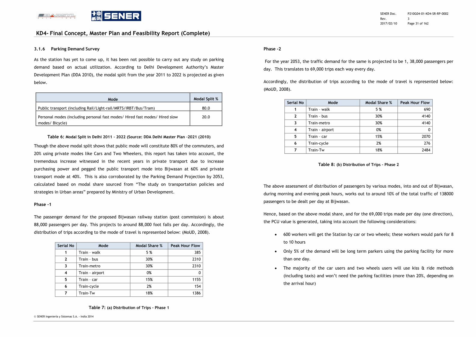
SENER Doc. P210G04-01-KD4-SR-RP-0002
Rev. 3
2017/02/10 Page 31 of 162
KD4- Final Concept, Master Plan and Feasibility Report (Complete)
SENER Ingeniería y Sistemas S.A. - India 2014
3.1.6 Parking Demand Survey
As the station has yet to come up, it has been not possible to carry out any study on parking
demand based on actual utilization. According to Delhi Development Authority’s Master
Development Plan (DDA 2010), the modal split from the year 2011 to 2022 is projected as given
below.
Mode Modal Split %
Public transport (including Rail/Light-rail/MRTS/IRBT/Bus/Tram) 80.0
Personal modes (including personal fast modes/ Hired fast modes/ Hired slow
modes/ Bicycle)
20.0
Table 6: Modal Split in Delhi 2011 - 2022 (Source: DDA Delhi Master Plan -2021 (2010)
Though the above modal split shows that public mode will constitute 80% of the commuters, and
20% using private modes like Cars and Two Wheelers, this report has taken into account, the
tremendous increase witnessed in the recent years in private transport due to increase
purchasing power and pegged the public transport mode into Bijwasan at 60% and private
transport mode at 40%. This is also corroborated by the Parking Demand Projection by 2053,
calculated based on modal share sourced from “The study on transportation policies and
strategies in Urban areas” prepared by Ministry of Urban Development.
Phase –1
The passenger demand for the proposed Bijwasan railway station (post commission) is about
88,000 passengers per day. This projects to around 88,000 foot falls per day. Accordingly, the
distribution of trips according to the mode of travel is represented below: (MoUD, 2008).
Serial No Mode Modal Share % Peak Hour Flow
1 Train – walk 5 % 385
2 Train – bus 30% 2310
3 Train-metro 30% 2310
4 Train - airport 0% 0
5 Train – car 15% 1155
6 Train-cycle 2% 154
7 Train-Tw 18% 1386
Table 7: (a) Distribution of Trips - Phase 1
Phase -2
For the year 2053, the traffic demand for the same is projected to be 1, 38,000 passengers per
day. This translates to 69,000 trips each way every day.
Accordingly, the distribution of trips according to the mode of travel is represented below:
(MoUD, 2008).
Serial No Mode Modal Share % Peak Hour Flow
1 Train – walk 5 % 690
2 Train – bus 30% 4140
3 Train-metro 30% 4140
4 Train - airport 0% 0
5 Train – car 15% 2070
6 Train-cycle 2% 276
7 Train-Tw 18% 2484
Table 8: (b) Distribution of Trips - Phase 2
The above assessment of distribution of passengers by various modes, into and out of Bijwasan,
during morning and evening peak hours, works out to around 10% of the total traffic of 138000
passengers to be dealt per day at Bijwasan.
Hence, based on the above modal share, and for the 69,000 trips made per day (one direction),
the PCU value is generated, taking into account the following considerations:
600 workers will get the Station by car or two wheels; these workers would park for 8
to 10 hours
Only 5% of the demand will be long term parkers using the parking facility for more
than one day.
The majority of the car users and two wheels users will use kiss & ride methods
(including taxis) and won’t need the parking facilities (more than 20%, depending on
the arrival hour)
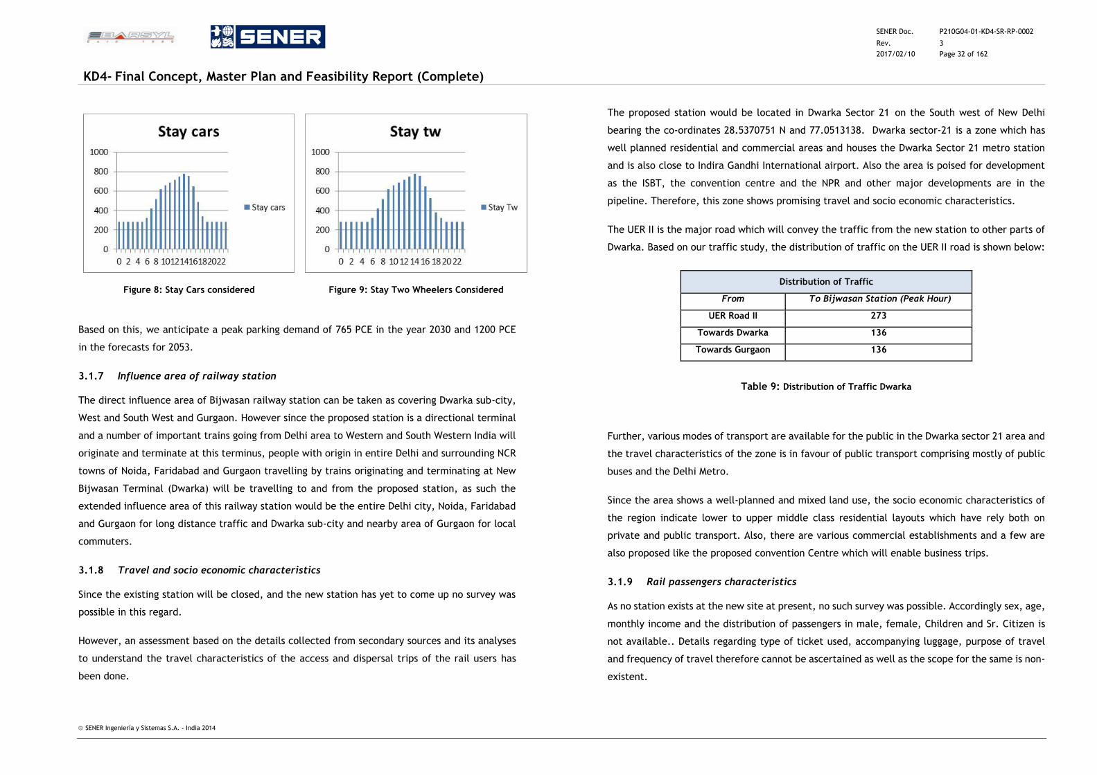
SENER Doc. P210G04-01-KD4-SR-RP-0002
Rev. 3
2017/02/10 Page 32 of 162
KD4- Final Concept, Master Plan and Feasibility Report (Complete)
SENER Ingeniería y Sistemas S.A. - India 2014
Figure 8: Stay Cars considered
Figure 9: Stay Two Wheelers Considered
Based on this, we anticipate a peak parking demand of 765 PCE in the year 2030 and 1200 PCE
in the forecasts for 2053.
3.1.7 Influence area of railway station
The direct influence area of Bijwasan railway station can be taken as covering Dwarka sub-city,
West and South West and Gurgaon. However since the proposed station is a directional terminal
and a number of important trains going from Delhi area to Western and South Western India will
originate and terminate at this terminus, people with origin in entire Delhi and surrounding NCR
towns of Noida, Faridabad and Gurgaon travelling by trains originating and terminating at New
Bijwasan Terminal (Dwarka) will be travelling to and from the proposed station, as such the
extended influence area of this railway station would be the entire Delhi city, Noida, Faridabad
and Gurgaon for long distance traffic and Dwarka sub-city and nearby area of Gurgaon for local
commuters.
3.1.8 Travel and socio economic characteristics
Since the existing station will be closed, and the new station has yet to come up no survey was
possible in this regard.
However, an assessment based on the details collected from secondary sources and its analyses
to understand the travel characteristics of the access and dispersal trips of the rail users has
been done.
The proposed station would be located in Dwarka Sector 21 on the South west of New Delhi
bearing the co-ordinates 28.5370751 N and 77.0513138. Dwarka sector-21 is a zone which has
well planned residential and commercial areas and houses the Dwarka Sector 21 metro station
and is also close to Indira Gandhi International airport. Also the area is poised for development
as the ISBT, the convention centre and the NPR and other major developments are in the
pipeline. Therefore, this zone shows promising travel and socio economic characteristics.
The UER II is the major road which will convey the traffic from the new station to other parts of
Dwarka. Based on our traffic study, the distribution of traffic on the UER II road is shown below:
Distribution of Traffic
From To Bijwasan Station (Peak Hour)
UER Road II 273
Towards Dwarka 136
Towards Gurgaon 136
Table 9: Distribution of Traffic Dwarka
Further, various modes of transport are available for the public in the Dwarka sector 21 area and
the travel characteristics of the zone is in favour of public transport comprising mostly of public
buses and the Delhi Metro.
Since the area shows a well-planned and mixed land use, the socio economic characteristics of
the region indicate lower to upper middle class residential layouts which have rely both on
private and public transport. Also, there are various commercial establishments and a few are
also proposed like the proposed convention Centre which will enable business trips.
3.1.9 Rail passengers characteristics
As no station exists at the new site at present, no such survey was possible. Accordingly sex, age,
monthly income and the distribution of passengers in male, female, Children and Sr. Citizen is
not available.. Details regarding type of ticket used, accompanying luggage, purpose of travel
and frequency of travel therefore cannot be ascertained as well as the scope for the same is non-
existent.
SENER Doc. P210G04-01-KD4-SR-RP-0002
Rev. 3
2017/02/10 Page 33 of 162
KD4- Final Concept, Master Plan and Feasibility Report (Complete)
SENER Ingeniería y Sistemas S.A. - India 2014
3.1.10 Type of ticket used
For the long distance trains, tickets for First AC, Second AC, Third AC , sleeper class and second
class sitting compartments will mostly be reserved tickets booked through computer on IRCTC
sites and travel agents as well as at computer reservation centers throughout the country. For
unreserved second class general coaches, Unreserved Ticketing System (UTS) tickets will be
available at the ticket windows at the station. Tickets can also be purchased directly from
Automatic Ticket Vending Machines (ATVM) for journeys upto approximately 200 kms.
For local trains, monthly season tickets (MST) and Quarterly Season tickets (QST) are used by
daily passengers. However UTS and ATVM tickets are also available for casual passengers.
Frequent/daily passengers prefer MST tickets which are very economical and there is saving of
time as they do not have to stand in queue. However there is a distance restriction of
approximately 200kms for such tickets.
3.1.11 Trip frequency to Bijwasan station
Currently, 16 Mail/Express and 9 passenger trains pass through Bijwasan though the number of
trains halting at this station is only 21. Most of these trains are inter-city and suburban trains
which ply mainly to Dwarka, Gurgaon (commuter) and also to Jaipur and Ahmadabad (Inter-city).
The trip frequency distribution of these rail passengers indicates that daily and weekly trips at
the existing Bijwasan station are 55 % to 60% for departure and arrival respectively. Most of the
people from Gurgaon and Dwarka (39%) were found to travel frequently on a daily and weekly
basis. This indicates mostly an outward movement to the main city of Delhi for work and business
trips. Also, long distance trips to states such as Rajasthan and Gujarat constituted 19% on weekly
and fortnightly basis.
3.1.12 Travel characteristics of main trip
Since Bijwasan railway station is proposed to be a new terminal, the survey of passengers at the
existing Bijwasan station is not relevant. However, the OD passenger survey was conducted to
understand the travel characteristics of the passengers as a study to gauge the travel pattern of
the region as a whole. The characteristics of main trips and access/dispersal trips were analysed
separately for each leg of the travel and are presented in this section:
The travel time for the passengers was also found from the data collected from passenger OD
survey. The travel time for various legs of the journey for passengers accessing and dispersing
from the railway station was found. It is observed that the maximum number of commuters (61%)
accessing the Bijwasan railway station travel for 15 to 30 minutes in their first leg of their journey
followed by 37% travelling to 30 to 60 minutes for the first leg of their journey to reach the
Bijwasan station. About 63% of the passengers travel for 10 to 30 minutes from the first halt to
Bijwasan station followed by 31% of passengers travelling 30 to 60 minutes to reach the railway
station from the first leg of their journey.
For passengers dispersing from the station, maximum percentage of passengers (65%) travel for
10 to 30 minutes for their first leg of their journey from the Bijwasan station and 21% of
passengers travel for 30 to 60 minutes for their first leg of the journey. For the second leg of
their journey i.e from the first halt to their final destination 47 % of the passengers travel for 10
to 30 minutes and 28% of the passengers travel for 30 to 60 minutes.
Further, the maximum numbers of passengers have a travel cost of between Rs.15 to Rs.50 for
both arriving and departing passengers and their percentage share being 41% and 46%
respectively. Also, the highest share is of passengers having a travel cost between Rs.250 and
Rs.350 was 14% and 16% for the arriving and departing passengers respectively.
3.1.13 Travel characteristics of access/dispersal of trip
The passengers accessing the Bijwasan railway station for their onward journey is based on the
modal split of the type of transport mode used to make the trip to the station. The public
transport, namely bus, was found to have a miniscule share of 9 % as there is no suitable access
by bus in the vicinity of Bijwasan station. Auto and cars were the next most preferred modes of
transport at 33% and 18% respectively. Also, walking was preferred by 29% of the passengers.
Also, the distribution of passengers using various modes of travel for their journey once they
reach their destination using the train has been found, which again indicates that the passengers
prefer car, auto and walking for this leg of journey. In case of arrival trips by passenger in which
there is dispersal from the station, maximum number of passengers use auto for their first leg of
their journey which is 41% followed by car and bus which has a share of 19% & 11% respectively.
Also, it is seen that the maximum number of passengers (33%) departing from the Bijwasan
station have a waiting time of 10 to 20 minutes for their first halt and 42% of the passengers have
0-5 minutes as a waiting time for their second halt and 25% of the passengers have 5-10 minutes
as the waiting time for their end mile connectivity which is their last leg of their journey after
arriving by train.
SENER Doc. P210G04-01-KD4-SR-RP-0002
Rev. 3
2017/02/10 Page 34 of 162
KD4- Final Concept, Master Plan and Feasibility Report (Complete)
SENER Ingeniería y Sistemas S.A. - India 2014
Passengers were also enquired about the cost of their travel in the OD also for their various legs
of the access and dispersal journeys to and from the station. It can be seen that 41% of passengers
spend INR20 to INR 50 for their first leg of the journey for accessing the railway station. This was
followed by 34% of passengers spending between INR10 to INR20 for this leg of their journey.
Also, 21% of passengers were found to have spent more than INR100 for undertaking this leg of
their journey.
3.1.14 O-D pattern of Rail Passenger Traffic
The results of the Origin-Destination pattern depict the major origin and destination points based
in the influence area of the Bijwasan railway station. As it has been mentioned in the earlier
section of the report that about 66% comprise of non-reserved Sub-urban, Inter-city, and regional
nature mostly generated by the business district centres in Dwarka and the outward traffic from
Janak Puri, Dwarka, Gurgaon etc and other places from the Delhi area.
Under the Destination pattern or departures, the maximum number of trips was local travel
based and intended for the commuter travel and the suburb trips. Maximum numbers of trips
departing from the Bijwasan railway station were made to the Dwarka (1459 trips), Gurgaon
followed next with 875 trips. The rest of the trips include other suburban areas like Manesar and
Rohini.
3.1.15 Distribution of passengers
The OD data collected was analysed and the trip matrix for the entire area was developed. The
distribution of trips into suburban trips and long distance trips was found from the data collected
from users of the passenger trains plying at this station every day and they include long distance
trains as well as the local commuter trains. It was observed that 60 % of the traffic movement
was by suburban commuter trains. Most of these trips were generated by the Delhi-Rewari
passenger, Rewari-Delhi-Nizamuddin, Delhi-Sarai-Rohilla, Rewari Meerut cantonment etc. Trip
time from these suburban trains was of 15 min to 45 min duration. Mode wise distribution of
traffic was found to be mainly from Gurgaon, Manesar, Bhiwadi, and Rewari in Haryana etc.
As per this analysis, long distance passenger’s volume stood second at 40% as this was the number
of passengers at the Bijwasan terminal who travelled in long distance trains. This is also due to
the fact that most of the long distance passenger trains do not halt at this station. However,
some of the prominent long distance passenger trains like the Rajasthan Sampark Kranti Express,
Howrah-Bikaner link etc.
3.1.16 Bus Stop Boarding / Alighting
At the moment there is no station and as such no bus stop serving the station and hence the Bus
stop boarding/alighting survey could not be conducted. However, an Inter-State Bus Terminal
(ISBT) of area about 10 ha in sector 22 has been proposed on 100 m road connecting Dwarka with
NH8 & NH10. There is also a link proposed from this ISBT to the proposed Bijwasan station in the
form of a skywalk and thus there is a tremendous scope to promote multi-modal transport
between the ISBT, the metro station and the proposed Bijwasan station.
Based on our traffic forecasts for the ISBT, the total traffic demand per day is found to be 37500
passengers currently. However, with a 24 % [figure of 24 % obtained thus: current- 37500/
(192000(projected)-37500) = 24%] the traffic demand for 2030 for the ISBT is projected to be
190500 passengers. Thereafter, with an anticipated growth of 10%, the traffic demand for the
year 2053 is forecasted to be 208820 passengers.
We can estimate that at least 10% of the passengers, i.e, 20880 will also be diverted to the
proposed Bijwasan terminal to provide a multi-modal connectivity or even as a feeder service.
3.1.17 Major observations
The current Bijwasan station is presently a sub-urban station and is located on the Delhi-Rewari
line. It is served by 21 passenger trains which halt at this station comprising of express/mail &
passenger trains though the number of through trains is 68. Based on the Passenger count survey
at the station entry/exit, a total of approximately 4000 passengers per day comprising of 2000
inward and outward passengers respectively were found at the existing Bijwasan station.
However, since no station exists at the site where the new terminal is proposed to be built, it is
not possible to carry out any rail passenger survey/count.
The proposed Bijwasan station will have more trains plying and also some of the trains from Delhi
will be diverted here. Thus the new station will have more long distance trains and more
commuter trains. This will extend the influence area of this railway station to the entire Delhi
city, Noida, Faridabad and Gurgaon for long distance traffic and Dwarka sub-city and nearby area
of Gurgaon for local commuter travel.
The existing Bijwasan railway station has limited passenger carrying capacity and has poor
connectivity with other modes of transport. However, the proposed station at Dwarka sector 21
will be located in a hub which has a significant scope for intermodal transport given that the
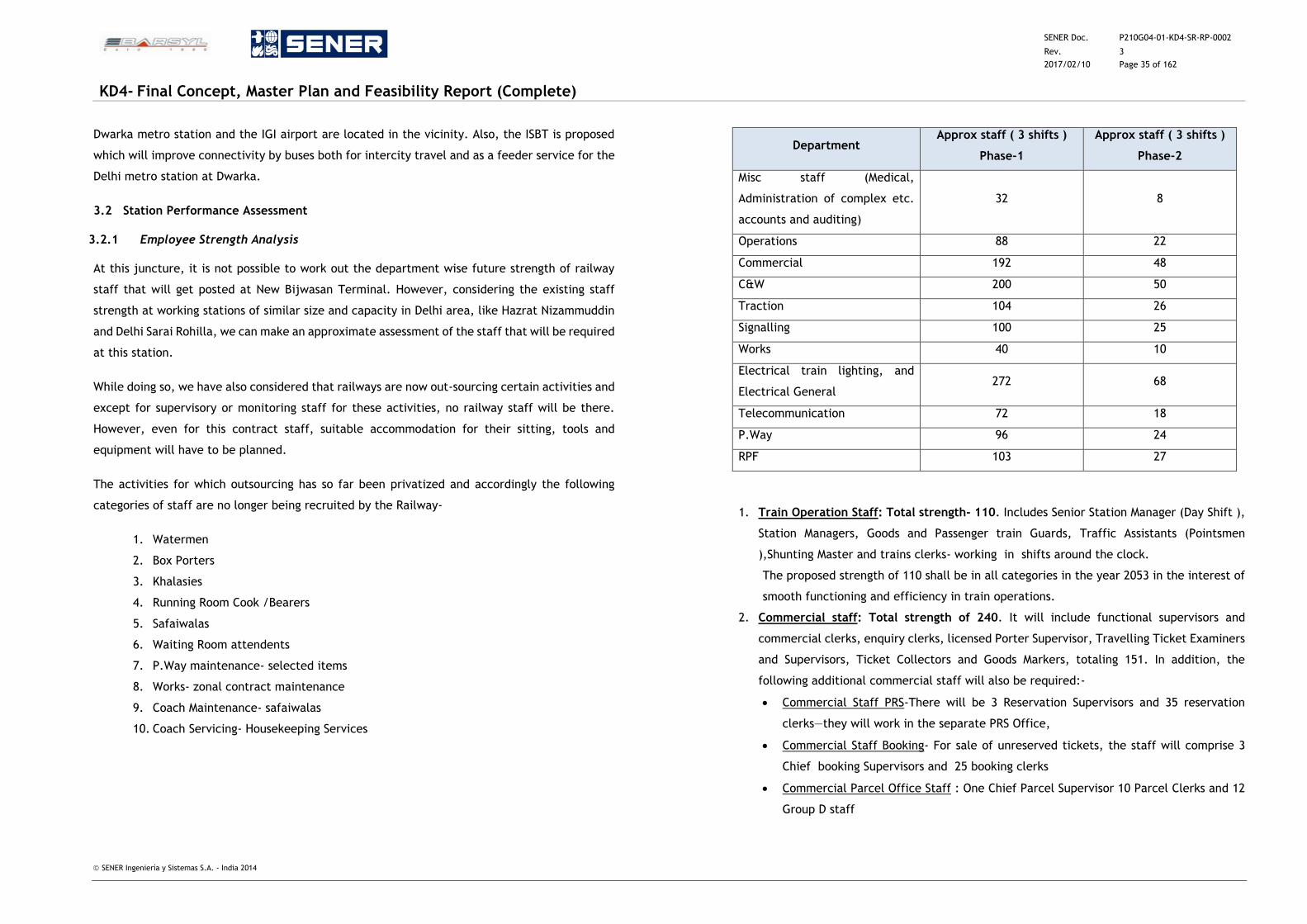
SENER Doc. P210G04-01-KD4-SR-RP-0002
Rev. 3
2017/02/10 Page 35 of 162
KD4- Final Concept, Master Plan and Feasibility Report (Complete)
SENER Ingeniería y Sistemas S.A. - India 2014
Dwarka metro station and the IGI airport are located in the vicinity. Also, the ISBT is proposed
which will improve connectivity by buses both for intercity travel and as a feeder service for the
Delhi metro station at Dwarka.
3.2 Station Performance Assessment
3.2.1 Employee Strength Analysis
At this juncture, it is not possible to work out the department wise future strength of railway
staff that will get posted at New Bijwasan Terminal. However, considering the existing staff
strength at working stations of similar size and capacity in Delhi area, like Hazrat Nizammuddin
and Delhi Sarai Rohilla, we can make an approximate assessment of the staff that will be required
at this station.
While doing so, we have also considered that railways are now out-sourcing certain activities and
except for supervisory or monitoring staff for these activities, no railway staff will be there.
However, even for this contract staff, suitable accommodation for their sitting, tools and
equipment will have to be planned.
The activities for which outsourcing has so far been privatized and accordingly the following
categories of staff are no longer being recruited by the Railway-
1. Watermen
2. Box Porters
3. Khalasies
4. Running Room Cook /Bearers
5. Safaiwalas
6. Waiting Room attendents
7. P.Way maintenance- selected items
8. Works- zonal contract maintenance
9. Coach Maintenance- safaiwalas
10. Coach Servicing- Housekeeping Services
Department Approx staff ( 3 shifts )
Phase-1
Approx staff ( 3 shifts )
Phase-2
Misc staff (Medical,
Administration of complex etc.
accounts and auditing)
32 8
Operations 88 22
Commercial 192 48
C&W 200 50
Traction 104 26
Signalling 100 25
Works 40 10
Electrical train lighting, and
Electrical General 272 68
Telecommunication 72 18
P.Way 96 24
RPF 103 27
1. Train Operation Staff: Total strength- 110. Includes Senior Station Manager (Day Shift ),
Station Managers, Goods and Passenger train Guards, Traffic Assistants (Pointsmen
),Shunting Master and trains clerks- working in shifts around the clock.
The proposed strength of 110 shall be in all categories in the year 2053 in the interest of
smooth functioning and efficiency in train operations.
2. Commercial staff: Total strength of 240. It will include functional supervisors and
commercial clerks, enquiry clerks, licensed Porter Supervisor, Travelling Ticket Examiners
and Supervisors, Ticket Collectors and Goods Markers, totaling 151. In addition, the
following additional commercial staff will also be required:-
Commercial Staff PRS-There will be 3 Reservation Supervisors and 35 reservation
clerks—they will work in the separate PRS Office,
Commercial Staff Booking- For sale of unreserved tickets, the staff will comprise 3
Chief booking Supervisors and 25 booking clerks
Commercial Parcel Office Staff : One Chief Parcel Supervisor 10 Parcel Clerks and 12
Group D staff
SENER Doc. P210G04-01-KD4-SR-RP-0002
Rev. 3
2017/02/10 Page 36 of 162
KD4- Final Concept, Master Plan and Feasibility Report (Complete)
SENER Ingeniería y Sistemas S.A. - India 2014
3. RPF (Railway Protection force): Total strength 135. The basic job of this force is to
protect the railway properties, the luggage of passengers, the traveling public and the
staff. The RPF staff has to ensure safety of the passengers of all the important
mail/express Trains specially covering the journey during nights. For this purpose the RPF
personnel accompany such trains. The RPF personnel is also assigned the job of preventing
the carriage of un-booked inflammable goods as passenger luggage. The number of staff
has been proposed, proportionately to cater to the workload and to deal with the cases in
the courts of law.
4. Signalling Department: Total strength 125. Consisting of Senior Section Engineers and
Technicians with support staff has to carry out regular maintenance of all signalling gear
in the interest of safety and efficiency round the clock. Some of the staff shall have to be
posted in the yard areas round the clock to regularly maintain the gears; spread all across
the yard area.
5. Telecommunication: Total strength: -90. It has to man the locations, where
telecommunication equipment is provided as well as maintain equipment of fast
communication, like Walkie-Talkie, VHF sets as also the field telephones, P.A. and PIDS
Systems, the control channels and other safety equipment .The work load of
telecommunication staff is to ensure availability of all means of communications at all
times.
6. Traction: Total strength 130. It will include Section Engineers, Technicians, Wiremen,
Linemen, Pump Drivers, and support staff-to maintain the OHE system and its equipment.
However, this staff will be required only after the electrification of the section is
commissioned.
7. Electrical train lighting: Total strength -250. Consisting of Section Engineers,
Technicians, wiremen and A.C. Staff will check repair and service the batteries, fans and
lights and other electrical fittings and air conditioning in all passenger coaches maintained
at this station and also man the electrical repair activities in the coach maintenance depot
at the station.
8. Electrical General: Total strength – 90. The work load on the power department will
increase as the number of staff quarters will increase manifold, when the staff in various
categories shall increase. The service buildings and the station building will also have a
heavy demand of power supply. The power distribution and maintenance of electrical
equipment and maintenance of Electrical Services in the Station Complex and Staff Colony
will be dealt by the Staff
9. Permanent Way: Total strength – 120. The maintenance of track in the yard, including
all running lines, washing lines, stabling lines, will increase the total track kilometer age.
The maintenance is proposed to be carried out by contracting several activities and having
a Core Group of Supervisors Technicians and Trackmen to attend to all exigencies
10. Works: Total strength 50. The Civil Maintenance of the station complex and service
buildings is proposed to be carried out through a zonal contractor. However, a Core Group
consisting of SSE, Supervisors and technicians of different trades to attend to emergencies
is proposed to be provided. Although the work load is likely to increase by double, yet the
increase of staff has been proposed strictly, where there is actual requirement.
11. C&W Maintenance: Total strength 250. It will consist of SSEs, Technicians, welders,
painters, riveters and trimmers and their support staff. This staff will be directly attending
to coach maintenance – primary and secondary maintenance of rakes, repairs on RPC lines
and manning the sick line complex. Safaiwalas engaged on cleaning of coaches is proposed
to be out sourced.
12. Medical Department: Based upon the proposed strength of total staff including, their
family members a health unit with a doctor, pharmacist and para-medical support staff
will also be provided at the station. The cleaning of the station complex and staff required
for the same will be out sourced and supervised by the Medical Deptt. as per practice on
Indian Railways.
13. Officers /Subordinates rest room: These locations do not require any other staff except
care takers which are also proposed to be out sourced.
14. Horticulture Staff. To maintain the trees and plants in the station complex, the gardeners
are proposed to be out sourced and supervised by the Works Deptt.
15. The new main station building shall contain the following office areas:
i. Station Management Office
ii. Office of the Station superintendent
iii. Office of Chief Ticketing Inspector
iv. Office of Station Master
v. Movement Control Officer (MCO) Office
vi. RPF Office
vii. GRP Office
viii. Accounts and Auditing Office
16. An officer and staff rest house and health unit (dispensary / Medical room) also be a part
of the main station building.
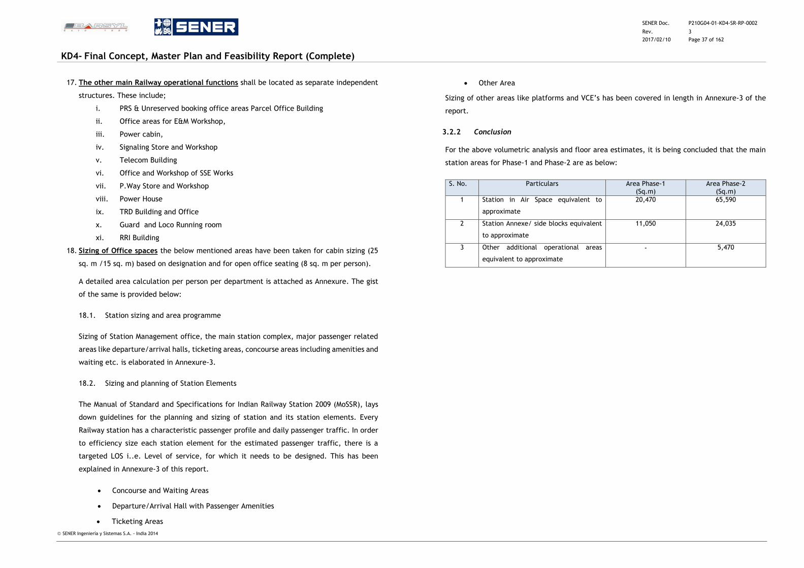
SENER Doc. P210G04-01-KD4-SR-RP-0002
Rev. 3
2017/02/10 Page 37 of 162
KD4- Final Concept, Master Plan and Feasibility Report (Complete)
SENER Ingeniería y Sistemas S.A. - India 2014
17. The other main Railway operational functions shall be located as separate independent
structures. These include;
i. PRS & Unreserved booking office areas Parcel Office Building
ii. Office areas for E&M Workshop,
iii. Power cabin,
iv. Signaling Store and Workshop
v. Telecom Building
vi. Office and Workshop of SSE Works
vii. P.Way Store and Workshop
viii. Power House
ix. TRD Building and Office
x. Guard and Loco Running room
xi. RRI Building
18. Sizing of Office spaces the below mentioned areas have been taken for cabin sizing (25
sq. m /15 sq. m) based on designation and for open office seating (8 sq. m per person).
A detailed area calculation per person per department is attached as Annexure. The gist
of the same is provided below:
18.1. Station sizing and area programme
Sizing of Station Management office, the main station complex, major passenger related
areas like departure/arrival halls, ticketing areas, concourse areas including amenities and
waiting etc. is elaborated in Annexure-3.
18.2. Sizing and planning of Station Elements
The Manual of Standard and Specifications for Indian Railway Station 2009 (MoSSR), lays
down guidelines for the planning and sizing of station and its station elements. Every
Railway station has a characteristic passenger profile and daily passenger traffic. In order
to efficiency size each station element for the estimated passenger traffic, there is a
targeted LOS i..e. Level of service, for which it needs to be designed. This has been
explained in Annexure-3 of this report.
Concourse and Waiting Areas
Departure/Arrival Hall with Passenger Amenities
Ticketing Areas
Other Area
Sizing of other areas like platforms and VCE’s has been covered in length in Annexure-3 of the
report.
3.2.2 Conclusion
For the above volumetric analysis and floor area estimates, it is being concluded that the main
station areas for Phase-1 and Phase-2 are as below:
S. No. Particulars Area Phase-1 (Sq.m)
Area Phase-2 (Sq.m)
1 Station in Air Space equivalent to
approximate
20,470 65,590
2 Station Annexe/ side blocks equivalent
to approximate
11,050 24,035
3 Other additional operational areas
equivalent to approximate
- 5,470
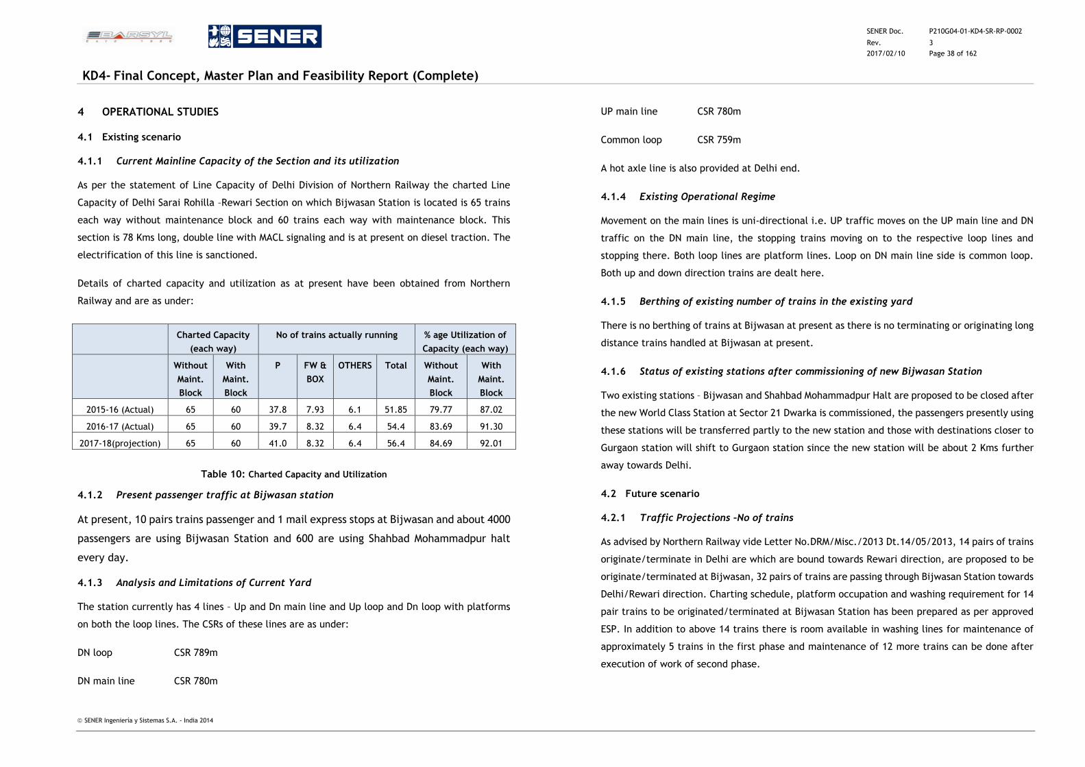
SENER Doc. P210G04-01-KD4-SR-RP-0002
Rev. 3
2017/02/10 Page 38 of 162
KD4- Final Concept, Master Plan and Feasibility Report (Complete)
SENER Ingeniería y Sistemas S.A. - India 2014
4 OPERATIONAL STUDIES
4.1 Existing scenario
4.1.1 Current Mainline Capacity of the Section and its utilization
As per the statement of Line Capacity of Delhi Division of Northern Railway the charted Line
Capacity of Delhi Sarai Rohilla –Rewari Section on which Bijwasan Station is located is 65 trains
each way without maintenance block and 60 trains each way with maintenance block. This
section is 78 Kms long, double line with MACL signaling and is at present on diesel traction. The
electrification of this line is sanctioned.
Details of charted capacity and utilization as at present have been obtained from Northern
Railway and are as under:
Charted Capacity
(each way)
No of trains actually running % age Utilization of
Capacity (each way)
Without
Maint.
Block
With
Maint.
Block
P FW &
BOX
OTHERS Total Without
Maint.
Block
With
Maint.
Block
2015-16 (Actual) 65 60 37.8 7.93 6.1 51.85 79.77 87.02
2016-17 (Actual) 65 60 39.7 8.32 6.4 54.4 83.69 91.30
2017-18(projection) 65 60 41.0 8.32 6.4 56.4 84.69 92.01
Table 10: Charted Capacity and Utilization
4.1.2 Present passenger traffic at Bijwasan station
At present, 10 pairs trains passenger and 1 mail express stops at Bijwasan and about 4000
passengers are using Bijwasan Station and 600 are using Shahbad Mohammadpur halt
every day.
4.1.3 Analysis and Limitations of Current Yard
The station currently has 4 lines – Up and Dn main line and Up loop and Dn loop with platforms
on both the loop lines. The CSRs of these lines are as under:
DN loop CSR 789m
DN main line CSR 780m
UP main line CSR 780m
Common loop CSR 759m
A hot axle line is also provided at Delhi end.
4.1.4 Existing Operational Regime
Movement on the main lines is uni-directional i.e. UP traffic moves on the UP main line and DN
traffic on the DN main line, the stopping trains moving on to the respective loop lines and
stopping there. Both loop lines are platform lines. Loop on DN main line side is common loop.
Both up and down direction trains are dealt here.
4.1.5 Berthing of existing number of trains in the existing yard
There is no berthing of trains at Bijwasan at present as there is no terminating or originating long
distance trains handled at Bijwasan at present.
4.1.6 Status of existing stations after commissioning of new Bijwasan Station
Two existing stations – Bijwasan and Shahbad Mohammadpur Halt are proposed to be closed after
the new World Class Station at Sector 21 Dwarka is commissioned, the passengers presently using
these stations will be transferred partly to the new station and those with destinations closer to
Gurgaon station will shift to Gurgaon station since the new station will be about 2 Kms further
away towards Delhi.
4.2 Future scenario
4.2.1 Traffic Projections –No of trains
As advised by Northern Railway vide Letter No.DRM/Misc./2013 Dt.14/05/2013, 14 pairs of trains
originate/terminate in Delhi are which are bound towards Rewari direction, are proposed to be
originate/terminated at Bijwasan, 32 pairs of trains are passing through Bijwasan Station towards
Delhi/Rewari direction. Charting schedule, platform occupation and washing requirement for 14
pair trains to be originated/terminated at Bijwasan Station has been prepared as per approved
ESP. In addition to above 14 trains there is room available in washing lines for maintenance of
approximately 5 trains in the first phase and maintenance of 12 more trains can be done after
execution of work of second phase.
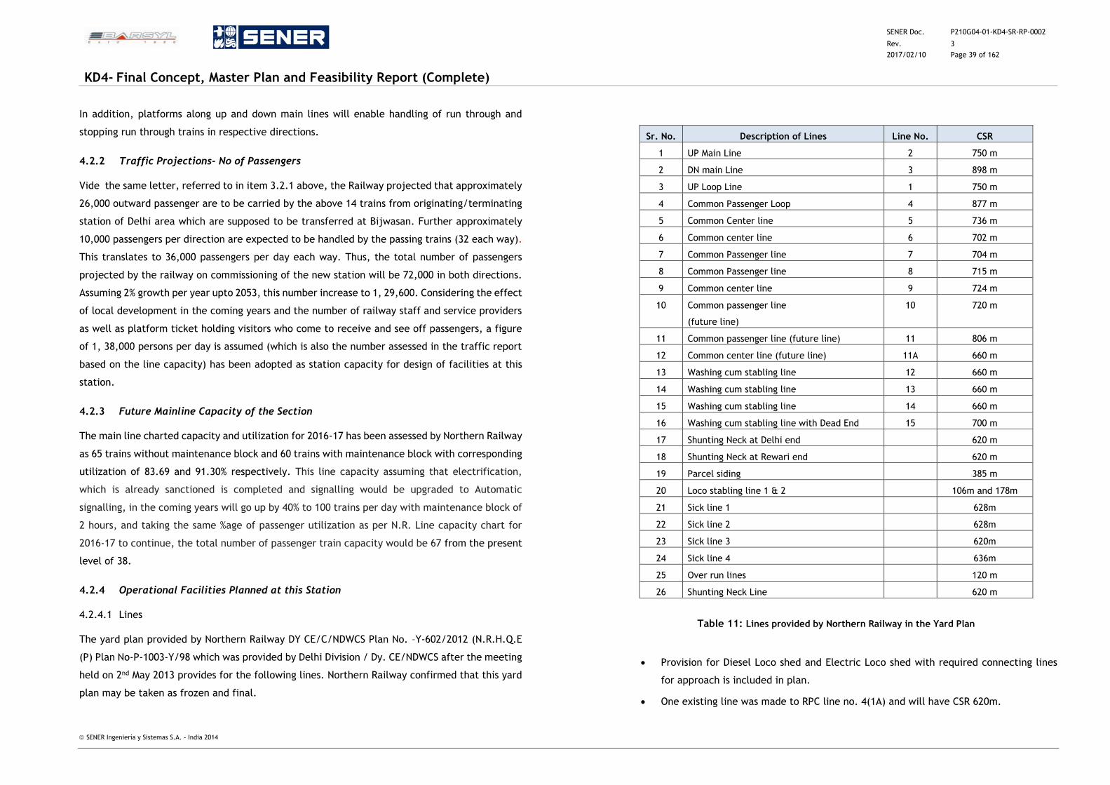
SENER Doc. P210G04-01-KD4-SR-RP-0002
Rev. 3
2017/02/10 Page 39 of 162
KD4- Final Concept, Master Plan and Feasibility Report (Complete)
SENER Ingeniería y Sistemas S.A. - India 2014
In addition, platforms along up and down main lines will enable handling of run through and
stopping run through trains in respective directions.
4.2.2 Traffic Projections- No of Passengers
Vide the same letter, referred to in item 3.2.1 above, the Railway projected that approximately
26,000 outward passenger are to be carried by the above 14 trains from originating/terminating
station of Delhi area which are supposed to be transferred at Bijwasan. Further approximately
10,000 passengers per direction are expected to be handled by the passing trains (32 each way).
This translates to 36,000 passengers per day each way. Thus, the total number of passengers
projected by the railway on commissioning of the new station will be 72,000 in both directions.
Assuming 2% growth per year upto 2053, this number increase to 1, 29,600. Considering the effect
of local development in the coming years and the number of railway staff and service providers
as well as platform ticket holding visitors who come to receive and see off passengers, a figure
of 1, 38,000 persons per day is assumed (which is also the number assessed in the traffic report
based on the line capacity) has been adopted as station capacity for design of facilities at this
station.
4.2.3 Future Mainline Capacity of the Section
The main line charted capacity and utilization for 2016-17 has been assessed by Northern Railway
as 65 trains without maintenance block and 60 trains with maintenance block with corresponding
utilization of 83.69 and 91.30% respectively. This line capacity assuming that electrification,
which is already sanctioned is completed and signalling would be upgraded to Automatic
signalling, in the coming years will go up by 40% to 100 trains per day with maintenance block of
2 hours, and taking the same %age of passenger utilization as per N.R. Line capacity chart for
2016-17 to continue, the total number of passenger train capacity would be 67 from the present
level of 38.
4.2.4 Operational Facilities Planned at this Station
4.2.4.1 Lines
The yard plan provided by Northern Railway DY CE/C/NDWCS Plan No. –Y-602/2012 (N.R.H.Q.E
(P) Plan No-P-1003-Y/98 which was provided by Delhi Division / Dy. CE/NDWCS after the meeting
held on 2nd May 2013 provides for the following lines. Northern Railway confirmed that this yard
plan may be taken as frozen and final.
Sr. No. Description of Lines Line No. CSR
1 UP Main Line 2 750 m
2 DN main Line 3 898 m
3 UP Loop Line 1 750 m
4 Common Passenger Loop 4 877 m
5 Common Center line 5 736 m
6 Common center line 6 702 m
7 Common Passenger line 7 704 m
8 Common Passenger line 8 715 m
9 Common center line 9 724 m
10 Common passenger line
(future line)
10 720 m
11 Common passenger line (future line) 11 806 m
12 Common center line (future line) 11A 660 m
13 Washing cum stabling line 12 660 m
14 Washing cum stabling line 13 660 m
15 Washing cum stabling line 14 660 m
16 Washing cum stabling line with Dead End 15 700 m
17 Shunting Neck at Delhi end 620 m
18 Shunting Neck at Rewari end 620 m
19 Parcel siding 385 m
20 Loco stabling line 1 & 2 106m and 178m
21 Sick line 1 628m
22 Sick line 2 628m
23 Sick line 3 620m
24 Sick line 4 636m
25 Over run lines 120 m
26 Shunting Neck Line 620 m
Table 11: Lines provided by Northern Railway in the Yard Plan
Provision for Diesel Loco shed and Electric Loco shed with required connecting lines
for approach is included in plan.
One existing line was made to RPC line no. 4(1A) and will have CSR 620m.
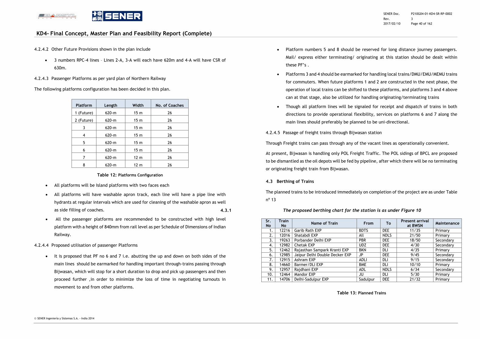
SENER Doc. P210G04-01-KD4-SR-RP-0002
Rev. 3
2017/02/10 Page 40 of 162
KD4- Final Concept, Master Plan and Feasibility Report (Complete)
SENER Ingeniería y Sistemas S.A. - India 2014
4.2.4.2 Other Future Provisions shown in the plan include
3 numbers RPC-4 lines – Lines 2-A, 3-A will each have 620m and 4-A will have CSR of
630m.
4.2.4.3 Passenger Platforms as per yard plan of Northern Railway
The following platforms configuration has been decided in this plan.
Platform Length Width No. of Coaches
1 (Future) 620-m 15 m 26
2 (Future) 620-m 15 m 26
3 620-m 15 m 26
4 620-m 15 m 26
5 620-m 15 m 26
6 620-m 15 m 26
7 620-m 12 m 26
8 620-m 12 m 26
Table 12: Platforms Configuration
All platforms will be Island platforms with two faces each
All platforms will have washable apron track, each line will have a pipe line with
hydrants at regular intervals which are used for cleaning of the washable apron as well
as side filling of coaches.
All the passenger platforms are recommended to be constructed with high level
platform with a height of 840mm from rail level as per Schedule of Dimensions of Indian
Railway.
4.2.4.4 Proposed utilisation of passenger Platforms
It is proposed that PF no 6 and 7 i.e. abutting the up and down on both sides of the
main lines should be earmarked for handling important through-trains passing through
Bijwasan, which will stop for a short duration to drop and pick up passengers and then
proceed further ,in order to minimize the loss of time in negotiating turnouts in
movement to and from other platforms.
Platform numbers 5 and 8 should be reserved for long distance journey passengers.
Mail/ express either terminating/ originating at this station should be dealt within
these PF’s .
Platforms 3 and 4 should be earmarked for handling local trains/DMU/EMU/MEMU trains
for commuters. When future platforms 1 and 2 are constructed in the next phase, the
operation of local trains can be shifted to these platforms, and platforms 3 and 4 above
can at that stage, also be utilized for handling originating/terminating trains
Though all platform lines will be signaled for receipt and dispatch of trains in both
directions to provide operational flexibility, services on platforms 6 and 7 along the
main lines should preferably be planned to be uni-directional.
4.2.4.5 Passage of freight trains through Bijwasan station
Through Freight trains can pass through any of the vacant lines as operationally convenient.
At present, Bijwasan is handling only POL Freight Traffic. The POL sidings of BPCL are proposed
to be dismantled as the oil depots will be fed by pipeline, after which there will be no terminating
or originating freight train from Bijwasan.
4.3 Berthing of Trains
The planned trains to be introduced immediately on completion of the project are as under Table
nº 13
4.3.1 The proposed berthing chart for the station is as under Figure 10
Sr. No
Train No
Name of Train From To Present arrival
at BWSN Maintenance
1. 12216 Garib Rath EXP BDTS DEE 11/35 Primary
2. 12016 Shatabdi EXP All NDLS 21/50 Primary
3. 19263 Porbander Delhi EXP PBR DEE 18/50 Secondary
4. 12982 Chetak EXP UDZ DEE 4/30 Secondary
5. 12462 Rajasthan Sampark Kranti EXP BKN DLI 4/35 Primary
6. 12985 Jaipur Delhi Double Decker EXP JP DEE 9/45 Secondary
7. 12915 Ashram EXP ADLI DLI 9/15 Secondary
8. 14660 Barmer/DLI EXP BME DLI 10/10 Primary
9. 12957 Rajdhani EXP ADL NDLS 6/34 Secondary
10. 12464 Mandor EXP JU DLI 5/30 Primary
11. 14706 Delhi-Sadulpur EXP Sadulpur DEE 21/32 Primary
Table 13: Planned Trains
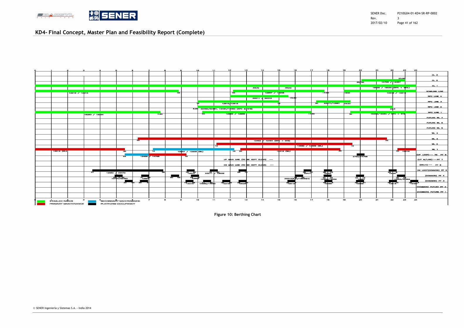
SENER Doc. P210G04-01-KD4-SR-RP-0002
Rev. 3
2017/02/10 Page 41 of 162
KD4- Final Concept, Master Plan and Feasibility Report (Complete)
SENER Ingeniería y Sistemas S.A. - India 2014
Figure 10: Berthing Chart
SENER Doc. P210G04-01-KD4-SR-RP-0002
Rev. 3
2017/02/10 Page 42 of 162
KD4- Final Concept, Master Plan and Feasibility Report (Complete)
SENER Ingeniería y Sistemas S.A. - India 2014
4.3.2 Stabling of trains
4.3.2.1 Use of platforms for stabling and berthing of trains in addition to receipt and dispatch
Six platforms are being provided at present and 2 are planned in future. Of these, 2 platforms
on main line will be used for run through / through trains stopping briefly at this station. The
remaining 4 platforms are for originating / terminating trains. The scheduled occupancy based
on time table of the 12 trains which are proposed to operate from Bijwasan terminal in the first
instance is shown in the above berthing plan. In the remaining time, the lines can be used for
stabling of local trains, as necessary.
4.3.2.2 Stabling lines
There are two stabling lines – will be used for stabling rakes.
4.3.2.3 Washing lines / RPC lines
Washing lines / RPC lines can be used for stabling rakes in slots shown in the berthing chart,
when maintenance work is not scheduled.
4.3.2.4 Common centre lines
Common centre lines can also be used for stabling rakes.
4.4 Trains stabling and maintenance complex including sick lines
The stabling of trains has already been covered in para 3.3 above. However, for maintenance
the facilities provided include washing lines and RPC lines. The RPC lines are to be constructed
in phase II. There proposed utilization has been covered in para 3.3.4.
Washing lines
The following washing lines have been
planned in phase I.
Line Holding Capacity (No. of Coaches)
Washing Line 1 26
Washing Line 2 26
Washing Line 3 26
Washing Line 4 26
Total 104
4.4.1 RPC- 4 Lines
One RPC 4 -1A is used in Phase I. 3 (Four) RPC lines (RPC Lines) which will be utilized for stabling
cum maintenance of rakes are proposed in phase II and, after this, these lines will also be
available for stabling.
RPC No. 1-A to RPC No 3-A of 620 meters length except line No 4-A provided with 630 meters
where the rakes of 24/25 coaches can be dealt with in the proposed berthing chart occupation
and availability slots given below :
RPC-1 from 8.30 to 10.30 for 2Hrs from 17.15 to 19.15 for 2 hours for stabling as
such cannot be utilized for maintenance as already explained.
RPC .2 22.00Hrs to 6.00Hrs for 8Hrs
RPC .3 19.30Hrs to 10.00 Hrs for 14.30 Hrs
RPC .4 16.00Hrs to 12.00Hrs for 20.00 Hrs
4.4.2 Adequacy of maintenance facilities
As per charting schedule platform occupation and washing requirement, the above facilities will
be adequate for the 14 trains planned to be originated/terminated on completion of this project.
In addition to the above 14 trains, there is room available in the washing lines for maintenance
of approximately 5 more trains in the 1st phase and 12 more trains after execution of works in
the second phase.
4.4.3 C&W Facilities – external washing of rakes and coaches
The system of external washing of the coaches is planned with automatic washing plant. 70 m x
9 m. The plant is planned to be installed on the lead line to the washing cum stabling lines and
all rakes proceeding to these lines will move at a slow speed with the train engine through this
plant. The outward cleaning of rake will take 30 minutes. However interior cleaning, charging
and filling of water tanks in the coaches shall take time as at present, after stabling the rake
and loco being sent back to traffic yard. This arrangement shall curtail time in washing the
coaches and in turn the requirement of staff shall be considerably reduced. Once the work of
cleaning of the coaches, charging and their side filling is completed the rake shall be removed
to make room for another rake. The rake thus removed shall have to be stabled somewhere till
such time this is placed on PF for boarding by the passengers.
SENER Doc. P210G04-01-KD4-SR-RP-0002
Rev. 3
2017/02/10 Page 43 of 162
KD4- Final Concept, Master Plan and Feasibility Report (Complete)
SENER Ingeniería y Sistemas S.A. - India 2014
4.4.4 Running room facility for pilots/ guards at Bijwasan
A suitable running room properly furnished and with facility of cooking meals will need to be
provided at a suitable location. The following staff shall be required for its maintenance and
operation: 1 care taker, 3 cooks cum helpers and 3 bearers with LR/RG provisions
4.4.5 C&W Maintenance office complex
Basing upon the modern equipment and system of work, it is anticipated that about 50 employees
of various categories will be required. Double storey C&W Office, Store Complex and Electric
Coaching complex
4.5 Sick lines
In the coach maintenance depot, two sick lines under shed 210m long have been provided with
a pit wheel lathe shed 100m long.
Other facilities planned are double storey carriage and wagon complex, store complex and
electrical charging, air compressor room and power cabin and a washing plant on the lead line
to the 4 washing cum stabling lines.
All other tools and plant, welding equipment, and all related spares and consumables will be
provided in the C&W complex close to the coach maintenance depot wherein the sick lines are
located.
Arrangement for charging and watering of coaches will also be provided in the complex so that
these operations can be done simultaneously with the repairs to reduce the down time of
coaching stock.
Electric loco pit line is planned in phase I and will be used after the section is electrified.
Diesel loco pit line to be provided in phase I. However, this may not be required if the line is
electrified and traction changed.
A repair and lathe machine line with covered shed will be provided for carriage and wagon and
electrical repair staff.
4.6 Sidings
4.6.1 Saloon siding / VIP Siding
From the yard plan of the railway there is no provision for any saloon siding / VIP siding.
Since long distance trains are proposed to terminate / originate at this station, provision of
Saloon siding / VIP Siding of adequate length, at a suitable location, will have to be planned at
this station. Till this is planned, the parcel siding which has separate road access can be used for
this purpose.
4.6.2 Track Machine Siding
There is no proposal in the NR yard plan for track machine siding at this station, the need for
such facility has to be examined considering the work load, location of existing and proposed
track machines, and their base stations. If required, provision of the required siding with water,
power, and charging facilities will have to be planned and provided. If required, this facility can
be created on the released hot axle siding at the existing Bijwasan station.
4.6.3 Parcel Handling Siding
There is a provision for parcel handling siding with CSR 385m in the NR Yard Plan at Bijwasan
with a platform of 300 m x 12 m length with circulating and truck parking area adjacent to it.
The parcel siding has an engine escape line and shunting neck.
4.7 Signalling infrastructure
The type of signalling which is existing is MACLS with Standard III interlocking and RRI (Route
Relay Inter-Locking)
Since the existing station and its signalling and interlocking will be dismantled on commissioning
of the new station, new state of the art signalling and interlocking system has to be designed
and provided at the proposed Bijwasan Terminal.
After completion of the new yard and all planned facilities, we are of the view and would
recommend solid state interlocking system wherein entire desired route can be selected and all
associated points and signals along the route can be set at once by a switch for receiving, holding,
blocking or dispatching trains. Provision of SSI will improve functioning of S&T system and train
movement. The searching of any failure/ fault shall be quick and easier and its rectification
efficiently.
SENER Doc. P210G04-01-KD4-SR-RP-0002
Rev. 3
2017/02/10 Page 44 of 162
KD4- Final Concept, Master Plan and Feasibility Report (Complete)
SENER Ingeniería y Sistemas S.A. - India 2014
4.7.1 Advantages of electronic interlocking/ solid state interlocking
The advantages of electronic interlocking/ solid state interlocking are:
Control through domino type panels or VDU terminals.
Concentrated as well as distributed type configuration
High reliability & efficiency
High processing capacity
The space requirement is minimal.
Capable of Easier repairing & restructuring
Capability of User friendly application programming
Easily adaptable to large installations
More effective Interfacing with other signaling equipment
Fail safe transmission through optical fiber cabling
Since the new terminal will be a Greenfield Project, suitable accommodation for the system and
its ancillary equipment such as relay room, battery room, standby power arrangements,
equipment store and accommodation for signalling staff will have to be provided.
All signals, with cabling will have to erected and installed afresh, since there are no old signals
which would need alteration, except at existing Bijwasan station which would be dismantled and
new shunting signals for the proposed stabling lines at the old station would be provided which
would be controlled by the station master of the new station from RRI
A suitable power cabin building consisting of panel room and associated S&T assets shall be
capable of accommodating the requirement of assets and various offices, including the
operation of SSI is proposed to be provided .The most suitable location of this building is being
determined and will be shown in the master plan.
4.8 Overhead line and traction power infrastructure
The system of traction at present is Diesel. However, electrification with 25 KVA overhead
electric traction is sanctioned and is expected to be taken up and completed in the coming years.
Conventional OHE is proposed to be provided on all the lines at Bijwasan station. The OHE
structures and foundations will be as per RDSO design and minimum height of contact wire will
be provided according to Indian Railways standard schedule of dimension.
As per planning of Northern Railway, ascertained from Delhi Division, in the proposed
electrification scheme, traction sub-stations are planned at Shahbad Mohammadpur and Gurgaon
and SSP at Garhi Harsaru. Suitable space would be kept for the traction sub-station at Shahbad
Mohammadpur in the master plan.
4.9 Communication Infrastructure
The system will cater to under mentioned requirements.
Train traffic control traction and auxiliary power control, emergency control and
maintenance control and maintenance control.
Dedicated inter station communication.
Telephone exchanges and their connectivity.
Passenger announcement system.
Centralized chronometry system.
Passenger information and display system
Mobile communication between moving train, maintenance personnel, yard personnel
and various controls.
Data channel for ATS and associated signaling functions, SCADA and automatic fare
collections.
Fiber Optic Transmission system. (FOTS)
Telephone System
Radio system.
PA system and PIDS
SCADA
SENER Doc. P210G04-01-KD4-SR-RP-0002
Rev. 3
2017/02/10 Page 45 of 162
KD4- Final Concept, Master Plan and Feasibility Report (Complete)
SENER Ingeniería y Sistemas S.A. - India 2014
4.9.1 Communication Control System (M & E SCADA-Supervisory Console and Data
Acquisition)
Optic fibre cables have been provided by RAILTEL from Delhi to Rewari. It will be possible to
connect the proposed new station at Bijwasan station to provide reliable control and
communication links on the section and to the control offices.
After the station is upgraded, it is proposed that M&E SCADA inter facing system will be provided
with industrial computers with HMI (Human Machine Interface) and suitable touch screen monitor
for data input and display will be provided which will enable interface with censors and actuators
to control electrical system, plumbing system, firefighting system, AC system with a links to
permit data exchange between devices controlling fire alarm fire fighting lifts and escalators,
lighting system UPS etc.
4.9.2 Passenger Information Display System (PIDS) and Signages
4.9.2.1 Passenger Information Display System (PIDS)
PIDS with LED passenger information display board and colour intelligent monitors are proposed
to be installed to provide state of the art user friendly real time display. The display would be
controlled and operated from the station master computer system.
4.9.2.2 Signages
Signages shall be user-friendly in line with world class station amenities and shall provide
information essential to passenger use, engendering a sense of reassurance, security and
orientation when entering, exiting or transferring. It shall guide passengers to various station
areas. These should provide information of the station and its services, provide information on
train services.
All signages shall have alternate pictorial images of same size as the letters. Passenger
information displays should be so located that passengers seeking information have ready access
without obstructing free flow of passengers.
4.9.3 ISDN Telephone Exchange
An ISDN Telephone Exchange of suitable capacity will be provided.
4.9.4 Public Address System
A public address system is available at the station and train running announcements are made
by the Railway staff. After remodelling of the station, the system will be upgraded to have facility
for all data communication via the network cable with user friendly audio processor and routing
of audio from any input to any output. The system will be programmable and capable of being
monitored from the central location in the control room. The system will also be provided with
stand by amplifier which shall automatically come into operation in case of failure of any working
amplifier
4.9.5 Wi Fi (Wireless Fidelity)
It is proposed to provide High Speed Wi Fi accessibility to internet in select areas of the station
such as waiting rooms, VIP and Ladies Lounges through wireless location area networks. Wi Fi
connectivity is also proposed in the station offices.
4.9.6 Access Control System (ACS)
Access control system is an integrated solution consisting of computer controlled hardware and
software which controls entry into selected areas and manages movement of passengers. The
system increase security by defining access based on area and time for each user and adjusts all
parameter of the system displays events related to movement of users, alarms and entry and
exit gates, and generate reports based on requirement.
4.9.7 Optical Fibre Networking
To provide reliable communication, state of the art fail safe, optic fibre technology shall be used
for connection between switches, servers, and routers. OFC has been recently laid by RAILTEL
from Delhi to Rewari.
4.9.8 Electronic Weighing Scale
In electronic weighing machine with embedded type metal platform, with LED/LCD display unit
will be provided for weighing of heavy luggage of passengers.
4.9.9 Security System
It is proposed to provide a suitable system to screen passengers and their baggage to ensure that
weapons and explosive which may be used to endanger safety of rail users and railway property.
This will consist of the measures in the following para. from 4.9.9.1 to 4.9.9.5
SENER Doc. P210G04-01-KD4-SR-RP-0002
Rev. 3
2017/02/10 Page 46 of 162
KD4- Final Concept, Master Plan and Feasibility Report (Complete)
SENER Ingeniería y Sistemas S.A. - India 2014
4.9.9.1 Passenger Baggage Screening System (PBSS)
This will be an x-ray screening machine with a conveyor system for moving baggage into the
system with manual monitoring by an authorized official.
4.9.9.2 Multi-zone Door Frame Metal Detector (DFMD)
Door Frame Metal Detector to detect both ferrous and non-ferrous metals carried by any
individual passing through the frame. Such detectors are normally positioned close to the x-ray
machine so that the luggage and individual are screened simultaneously
4.9.9.3 Hand Held Metal Detector (HHMD)
Hand held metal detectors, compatible with health safety regulations, will be provided to the
security personnel at the entry gates to enable detection of any unwanted or dangerous metal
objects on the body of the passenger without direct physical contact with the body. The detector
will produce an audio and visual alarm on locating such an object.
4.9.9.4 Surveillance CCTV (Closed Circuit Tele Vision) System
Surveillance CCTV system will be provided with effective coverage of the station area where the
system will provide an on line real time display of video images on TFT Monitors / video wall
located in central as well as local control rooms. It shall also create tamper proof record for post
event analysis. The video can be viewed using a hardware decoder (MPEG4) / compatible receiver
and shall be recorded on NVR / NAS with RAID
4.9.9.5 Explosive Trace Detector (ETD)
ETD is special security equipment which can detect explosives and narcotics being carried in
small quantities. The hand held ETD can be used by a trained personnel at the platform to
determine whether a bag contains explosives material or not.
4.9.10 GPRS Clock
GPS based clock will be installed. GPS based master clock will be installed in the control room
and slave units will be installed all platforms and station area at suitable locations. The system
will automatically synchronize with global timing.
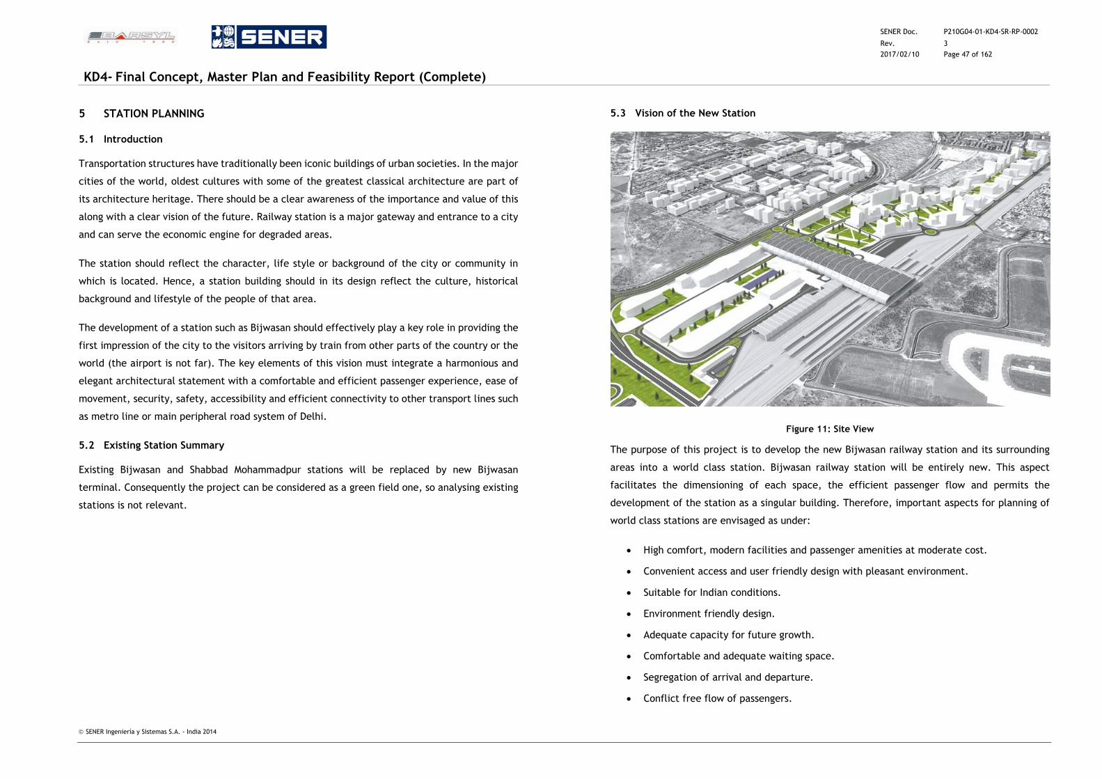
SENER Doc. P210G04-01-KD4-SR-RP-0002
Rev. 3
2017/02/10 Page 47 of 162
KD4- Final Concept, Master Plan and Feasibility Report (Complete)
SENER Ingeniería y Sistemas S.A. - India 2014
5 STATION PLANNING
5.1 Introduction
Transportation structures have traditionally been iconic buildings of urban societies. In the major
cities of the world, oldest cultures with some of the greatest classical architecture are part of
its architecture heritage. There should be a clear awareness of the importance and value of this
along with a clear vision of the future. Railway station is a major gateway and entrance to a city
and can serve the economic engine for degraded areas.
The station should reflect the character, life style or background of the city or community in
which is located. Hence, a station building should in its design reflect the culture, historical
background and lifestyle of the people of that area.
The development of a station such as Bijwasan should effectively play a key role in providing the
first impression of the city to the visitors arriving by train from other parts of the country or the
world (the airport is not far). The key elements of this vision must integrate a harmonious and
elegant architectural statement with a comfortable and efficient passenger experience, ease of
movement, security, safety, accessibility and efficient connectivity to other transport lines such
as metro line or main peripheral road system of Delhi.
5.2 Existing Station Summary
Existing Bijwasan and Shabbad Mohammadpur stations will be replaced by new Bijwasan
terminal. Consequently the project can be considered as a green field one, so analysing existing
stations is not relevant.
5.3 Vision of the New Station
Figure 11: Site View
The purpose of this project is to develop the new Bijwasan railway station and its surrounding
areas into a world class station. Bijwasan railway station will be entirely new. This aspect
facilitates the dimensioning of each space, the efficient passenger flow and permits the
development of the station as a singular building. Therefore, important aspects for planning of
world class stations are envisaged as under:
High comfort, modern facilities and passenger amenities at moderate cost.
Convenient access and user friendly design with pleasant environment.
Suitable for Indian conditions.
Environment friendly design.
Adequate capacity for future growth.
Comfortable and adequate waiting space.
Segregation of arrival and departure.
Conflict free flow of passengers.
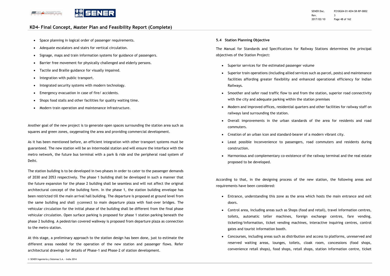
SENER Doc. P210G04-01-KD4-SR-RP-0002
Rev. 3
2017/02/10 Page 48 of 162
KD4- Final Concept, Master Plan and Feasibility Report (Complete)
SENER Ingeniería y Sistemas S.A. - India 2014
Space planning in logical order of passenger requirements.
Adequate escalators and stairs for vertical circulation.
Signage, maps and train information systems for guidance of passengers.
Barrier free movement for physically challenged and elderly persons.
Tactile and Braille guidance for visually impaired.
Integration with public transport.
Integrated security systems with modern technology.
Emergency evacuation in case of fire/ accidents.
Shops food stalls and other facilities for quality waiting time.
Modern train operation and maintenance infrastructure.
Another goal of the new project is to generate open spaces surrounding the station area such as
squares and green zones, oxygenating the area and providing commercial development.
As it has been mentioned before, an efficient integration with other transport systems must be
guaranteed. The new station will be an Intermodal station and will ensure the interface with the
metro network, the future bus terminal with a park & ride and the peripheral road system of
Delhi.
The station building is to be developed in two phases in order to cater to the passenger demands
of 2030 and 2053 respectively. The phase 1 building shall be developed in such a manner that
the future expansion for the phase 2 building shall be seamless and will not affect the original
architectural concept of the building form. In the phase 1, the station building envelope has
been restricted till the main arrival hall building. The departure is proposed at ground level from
the same building and shall ±connect to main departure plaza with foot-over bridges. The
vehicular circulation for the initial phase of the building shall be different from the final phase
vehicular circulation. Open surface parking is proposed for phase 1 station parking beneath the
phase 2 building. A pedestrian covered walkway is proposed from departure plaza as connection
to the metro station.
At this stage, a preliminary approach to the station design has been done, just to estimate the
different areas needed for the operation of the new station and passenger flows. Refer
architectural drawings for details of Phase-1 and Phase-2 of station development.
5.4 Station Planning Objective
The Manual for Standards and Specifications for Railway Stations determines the principal
objectives of the Station Project:
Superior services for the estimated passenger volume
Superior train operations (including allied services such as parcel, posts) and maintenance
facilities affording greater flexibility and enhanced operational efficiency for Indian
Railways.
Smoother and safer road traffic flow to and from the station, superior road connectivity
with the city and adequate parking within the station premises
Modern and improved offices, residential quarters and other facilities for railway staff on
railways land surrounding the station.
Overall improvements in the urban standards of the area for residents and road
commuters.
Creation of an urban icon and standard-bearer of a modern vibrant city.
Least possible inconvenience to passengers, road commuters and residents during
construction.
Harmonious and complementary co-existence of the railway terminal and the real estate
proposed to be developed.
According to that, in the designing process of the new station, the following areas and
requirements have been considered:
Entrance, understanding this zone as the area which hosts the main entrance and exit
doors.
Control area, including areas such as Shops (food and retail), travel information centres,
toilets, automatic teller machines, foreign exchange centres, fare vending,
ticketing/information, ticket vending machines, interactive inquiring centres, control
gates and tourist information booth.
Concourses, including areas such as distribution and access to platforms, unreserved and
reserved waiting areas, lounges, toilets, cloak room, concessions (food shops,
convenience retail shops), food shops, retail shops, station information centre, ticket
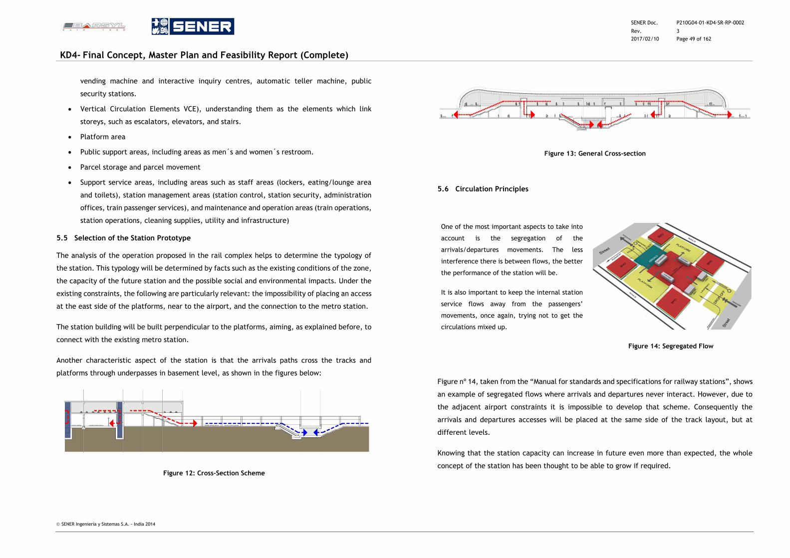
SENER Doc. P210G04-01-KD4-SR-RP-0002
Rev. 3
2017/02/10 Page 49 of 162
KD4- Final Concept, Master Plan and Feasibility Report (Complete)
SENER Ingeniería y Sistemas S.A. - India 2014
vending machine and interactive inquiry centres, automatic teller machine, public
security stations.
Vertical Circulation Elements VCE), understanding them as the elements which link
storeys, such as escalators, elevators, and stairs.
Platform area
Public support areas, including areas as men´s and women´s restroom.
Parcel storage and parcel movement
Support service areas, including areas such as staff areas (lockers, eating/lounge area
and toilets), station management areas (station control, station security, administration
offices, train passenger services), and maintenance and operation areas (train operations,
station operations, cleaning supplies, utility and infrastructure)
5.5 Selection of the Station Prototype
The analysis of the operation proposed in the rail complex helps to determine the typology of
the station. This typology will be determined by facts such as the existing conditions of the zone,
the capacity of the future station and the possible social and environmental impacts. Under the
existing constraints, the following are particularly relevant: the impossibility of placing an access
at the east side of the platforms, near to the airport, and the connection to the metro station.
The station building will be built perpendicular to the platforms, aiming, as explained before, to
connect with the existing metro station.
Another characteristic aspect of the station is that the arrivals paths cross the tracks and
platforms through underpasses in basement level, as shown in the figures below:
Figure 12: Cross-Section Scheme
Figure 13: General Cross-section
5.6 Circulation Principles
One of the most important aspects to take into
account is the segregation of the
arrivals/departures movements. The less
interference there is between flows, the better
the performance of the station will be.
It is also important to keep the internal station
service flows away from the passengers’
movements, once again, trying not to get the
circulations mixed up.
Figure nº 14, taken from the “Manual for standards and specifications for railway stations”, shows
an example of segregated flows where arrivals and departures never interact. However, due to
the adjacent airport constraints it is impossible to develop that scheme. Consequently the
arrivals and departures accesses will be placed at the same side of the track layout, but at
different levels.
Knowing that the station capacity can increase in future even more than expected, the whole
concept of the station has been thought to be able to grow if required.
Figure 14: Segregated Flow
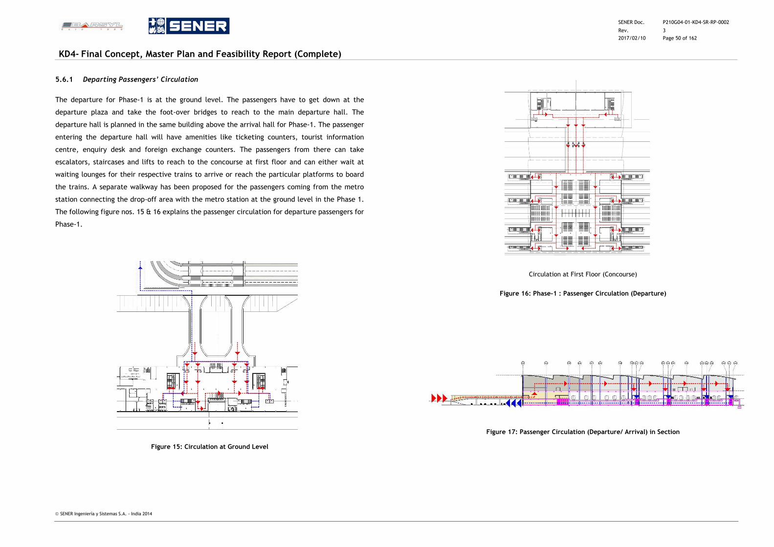
SENER Doc. P210G04-01-KD4-SR-RP-0002
Rev. 3
2017/02/10 Page 50 of 162
KD4- Final Concept, Master Plan and Feasibility Report (Complete)
SENER Ingeniería y Sistemas S.A. - India 2014
5.6.1 Departing Passengers’ Circulation
The departure for Phase-1 is at the ground level. The passengers have to get down at the
departure plaza and take the foot-over bridges to reach to the main departure hall. The
departure hall is planned in the same building above the arrival hall for Phase-1. The passenger
entering the departure hall will have amenities like ticketing counters, tourist information
centre, enquiry desk and foreign exchange counters. The passengers from there can take
escalators, staircases and lifts to reach to the concourse at first floor and can either wait at
waiting lounges for their respective trains to arrive or reach the particular platforms to board
the trains. A separate walkway has been proposed for the passengers coming from the metro
station connecting the drop-off area with the metro station at the ground level in the Phase 1.
The following figure nos. 15 & 16 explains the passenger circulation for departure passengers for
Phase-1.
Figure 15: Circulation at Ground Level
Circulation at First Floor (Concourse)
Figure 16: Phase-1 : Passenger Circulation (Departure)
Figure 17: Passenger Circulation (Departure/ Arrival) in Section
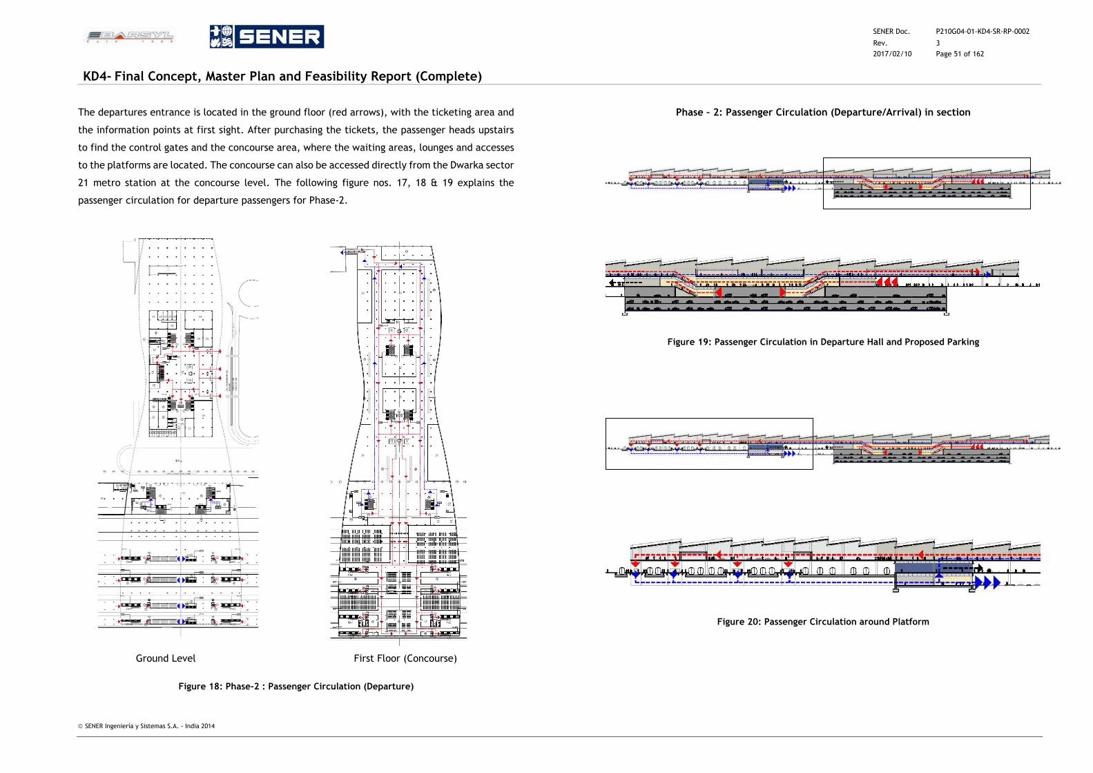
SENER Doc. P210G04-01-KD4-SR-RP-0002
Rev. 3
2017/02/10 Page 51 of 162
KD4- Final Concept, Master Plan and Feasibility Report (Complete)
SENER Ingeniería y Sistemas S.A. - India 2014
The departures entrance is located in the ground floor (red arrows), with the ticketing area and
the information points at first sight. After purchasing the tickets, the passenger heads upstairs
to find the control gates and the concourse area, where the waiting areas, lounges and accesses
to the platforms are located. The concourse can also be accessed directly from the Dwarka sector
21 metro station at the concourse level. The following figure nos. 17, 18 & 19 explains the
passenger circulation for departure passengers for Phase-2.
Ground Level First Floor (Concourse)
Figure 18: Phase-2 : Passenger Circulation (Departure)
Phase – 2: Passenger Circulation (Departure/Arrival) in section
Figure 19: Passenger Circulation in Departure Hall and Proposed Parking
Figure 20: Passenger Circulation around Platform
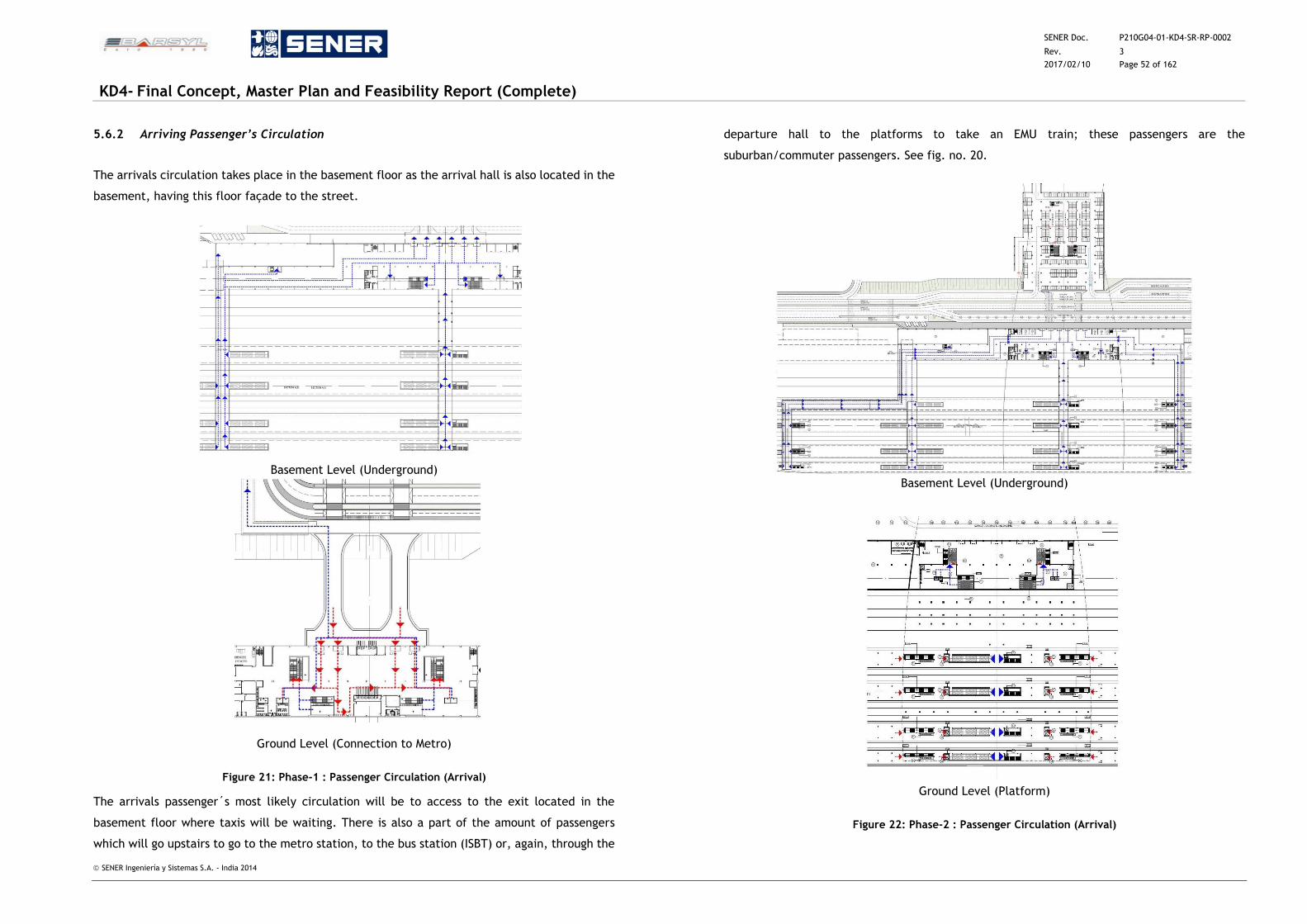
SENER Doc. P210G04-01-KD4-SR-RP-0002
Rev. 3
2017/02/10 Page 52 of 162
KD4- Final Concept, Master Plan and Feasibility Report (Complete)
SENER Ingeniería y Sistemas S.A. - India 2014
5.6.2 Arriving Passenger’s Circulation
The arrivals circulation takes place in the basement floor as the arrival hall is also located in the
basement, having this floor façade to the street.
Basement Level (Underground)
Ground Level (Connection to Metro)
Figure 21: Phase-1 : Passenger Circulation (Arrival)
The arrivals passenger´s most likely circulation will be to access to the exit located in the
basement floor where taxis will be waiting. There is also a part of the amount of passengers
which will go upstairs to go to the metro station, to the bus station (ISBT) or, again, through the
departure hall to the platforms to take an EMU train; these passengers are the
suburban/commuter passengers. See fig. no. 20.
Basement Level (Underground)
Ground Level (Platform)
Figure 22: Phase-2 : Passenger Circulation (Arrival)
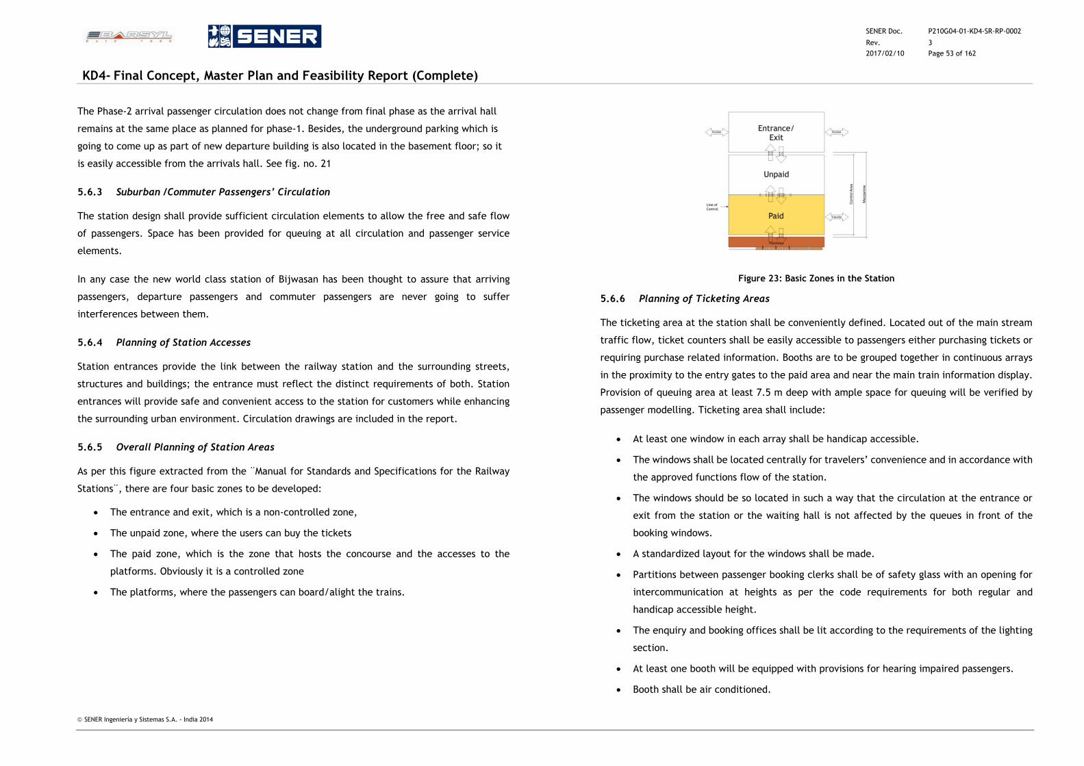
SENER Doc. P210G04-01-KD4-SR-RP-0002
Rev. 3
2017/02/10 Page 53 of 162
KD4- Final Concept, Master Plan and Feasibility Report (Complete)
SENER Ingeniería y Sistemas S.A. - India 2014
The Phase-2 arrival passenger circulation does not change from final phase as the arrival hall
remains at the same place as planned for phase-1. Besides, the underground parking which is
going to come up as part of new departure building is also located in the basement floor; so it
is easily accessible from the arrivals hall. See fig. no. 21
5.6.3 Suburban /Commuter Passengers’ Circulation
The station design shall provide sufficient circulation elements to allow the free and safe flow
of passengers. Space has been provided for queuing at all circulation and passenger service
elements.
In any case the new world class station of Bijwasan has been thought to assure that arriving
passengers, departure passengers and commuter passengers are never going to suffer
interferences between them.
5.6.4 Planning of Station Accesses
Station entrances provide the link between the railway station and the surrounding streets,
structures and buildings; the entrance must reflect the distinct requirements of both. Station
entrances will provide safe and convenient access to the station for customers while enhancing
the surrounding urban environment. Circulation drawings are included in the report.
5.6.5 Overall Planning of Station Areas
As per this figure extracted from the ¨Manual for Standards and Specifications for the Railway
Stations¨, there are four basic zones to be developed:
The entrance and exit, which is a non-controlled zone,
The unpaid zone, where the users can buy the tickets
The paid zone, which is the zone that hosts the concourse and the accesses to the
platforms. Obviously it is a controlled zone
The platforms, where the passengers can board/alight the trains.
Figure 23: Basic Zones in the Station
5.6.6 Planning of Ticketing Areas
The ticketing area at the station shall be conveniently defined. Located out of the main stream
traffic flow, ticket counters shall be easily accessible to passengers either purchasing tickets or
requiring purchase related information. Booths are to be grouped together in continuous arrays
in the proximity to the entry gates to the paid area and near the main train information display.
Provision of queuing area at least 7.5 m deep with ample space for queuing will be verified by
passenger modelling. Ticketing area shall include:
At least one window in each array shall be handicap accessible.
The windows shall be located centrally for travelers’ convenience and in accordance with
the approved functions flow of the station.
The windows should be so located in such a way that the circulation at the entrance or
exit from the station or the waiting hall is not affected by the queues in front of the
booking windows.
A standardized layout for the windows shall be made.
Partitions between passenger booking clerks shall be of safety glass with an opening for
intercommunication at heights as per the code requirements for both regular and
handicap accessible height.
The enquiry and booking offices shall be lit according to the requirements of the lighting
section.
At least one booth will be equipped with provisions for hearing impaired passengers.
Booth shall be air conditioned.
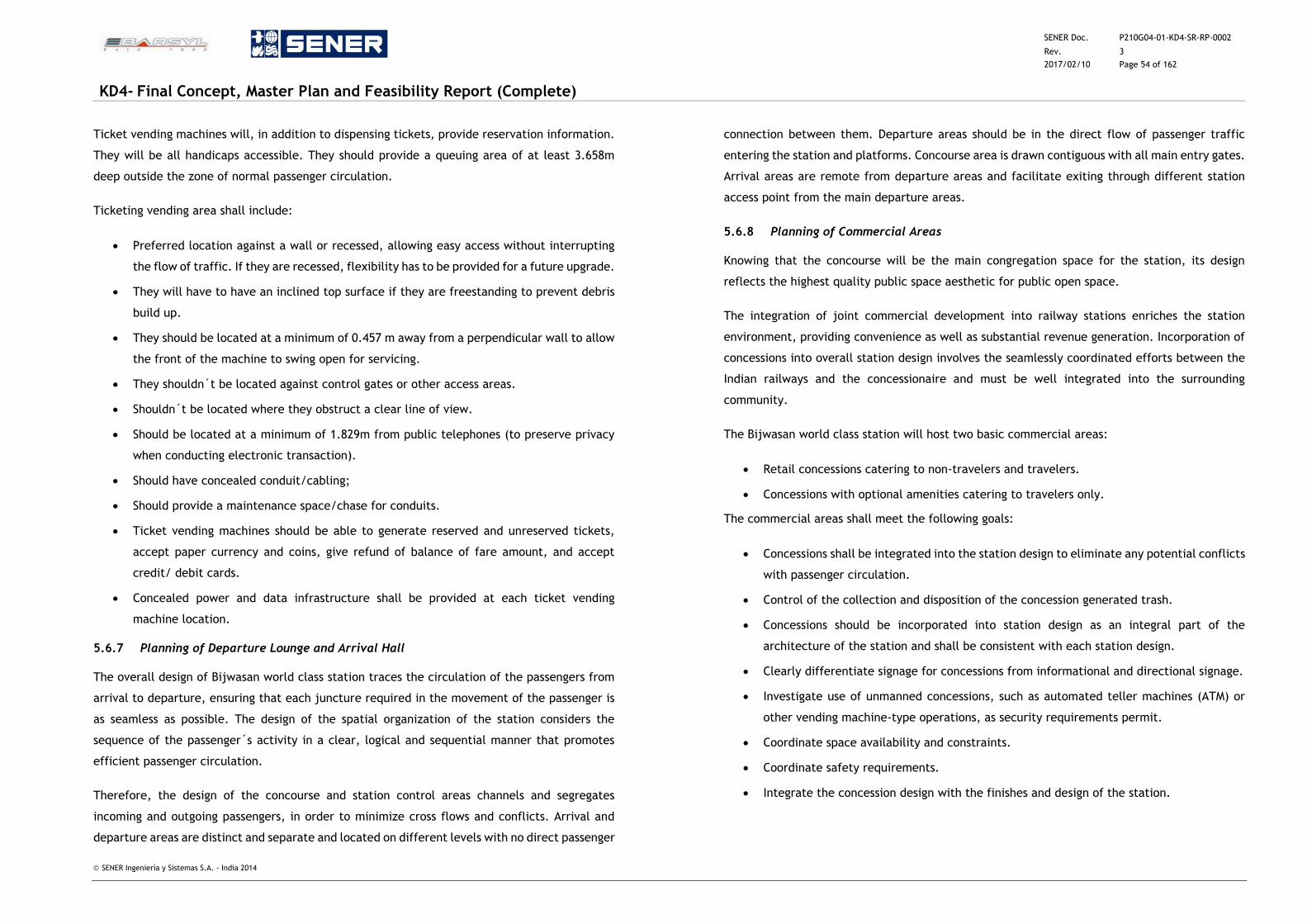
SENER Doc. P210G04-01-KD4-SR-RP-0002
Rev. 3
2017/02/10 Page 54 of 162
KD4- Final Concept, Master Plan and Feasibility Report (Complete)
SENER Ingeniería y Sistemas S.A. - India 2014
Ticket vending machines will, in addition to dispensing tickets, provide reservation information.
They will be all handicaps accessible. They should provide a queuing area of at least 3.658m
deep outside the zone of normal passenger circulation.
Ticketing vending area shall include:
Preferred location against a wall or recessed, allowing easy access without interrupting
the flow of traffic. If they are recessed, flexibility has to be provided for a future upgrade.
They will have to have an inclined top surface if they are freestanding to prevent debris
build up.
They should be located at a minimum of 0.457 m away from a perpendicular wall to allow
the front of the machine to swing open for servicing.
They shouldn´t be located against control gates or other access areas.
Shouldn´t be located where they obstruct a clear line of view.
Should be located at a minimum of 1.829m from public telephones (to preserve privacy
when conducting electronic transaction).
Should have concealed conduit/cabling;
Should provide a maintenance space/chase for conduits.
Ticket vending machines should be able to generate reserved and unreserved tickets,
accept paper currency and coins, give refund of balance of fare amount, and accept
credit/ debit cards.
Concealed power and data infrastructure shall be provided at each ticket vending
machine location.
5.6.7 Planning of Departure Lounge and Arrival Hall
The overall design of Bijwasan world class station traces the circulation of the passengers from
arrival to departure, ensuring that each juncture required in the movement of the passenger is
as seamless as possible. The design of the spatial organization of the station considers the
sequence of the passenger´s activity in a clear, logical and sequential manner that promotes
efficient passenger circulation.
Therefore, the design of the concourse and station control areas channels and segregates
incoming and outgoing passengers, in order to minimize cross flows and conflicts. Arrival and
departure areas are distinct and separate and located on different levels with no direct passenger
connection between them. Departure areas should be in the direct flow of passenger traffic
entering the station and platforms. Concourse area is drawn contiguous with all main entry gates.
Arrival areas are remote from departure areas and facilitate exiting through different station
access point from the main departure areas.
5.6.8 Planning of Commercial Areas
Knowing that the concourse will be the main congregation space for the station, its design
reflects the highest quality public space aesthetic for public open space.
The integration of joint commercial development into railway stations enriches the station
environment, providing convenience as well as substantial revenue generation. Incorporation of
concessions into overall station design involves the seamlessly coordinated efforts between the
Indian railways and the concessionaire and must be well integrated into the surrounding
community.
The Bijwasan world class station will host two basic commercial areas:
Retail concessions catering to non-travelers and travelers.
Concessions with optional amenities catering to travelers only.
The commercial areas shall meet the following goals:
Concessions shall be integrated into the station design to eliminate any potential conflicts
with passenger circulation.
Control of the collection and disposition of the concession generated trash.
Concessions should be incorporated into station design as an integral part of the
architecture of the station and shall be consistent with each station design.
Clearly differentiate signage for concessions from informational and directional signage.
Investigate use of unmanned concessions, such as automated teller machines (ATM) or
other vending machine-type operations, as security requirements permit.
Coordinate space availability and constraints.
Coordinate safety requirements.
Integrate the concession design with the finishes and design of the station.
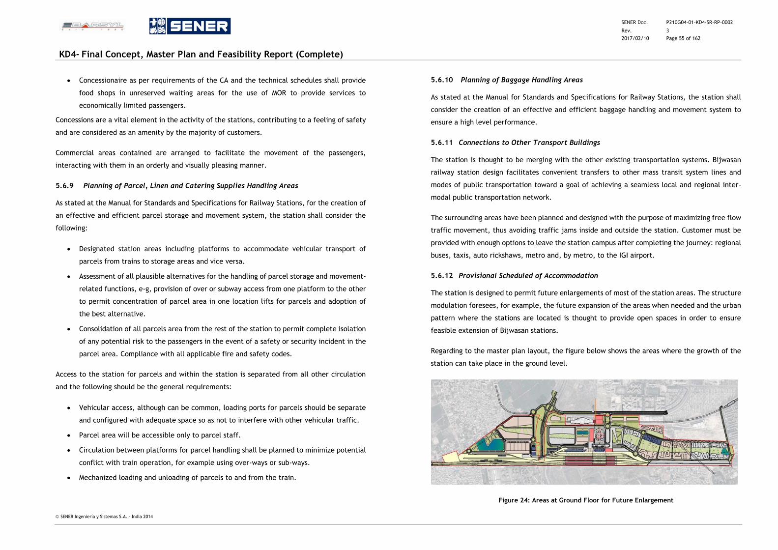
SENER Doc. P210G04-01-KD4-SR-RP-0002
Rev. 3
2017/02/10 Page 55 of 162
KD4- Final Concept, Master Plan and Feasibility Report (Complete)
SENER Ingeniería y Sistemas S.A. - India 2014
Concessionaire as per requirements of the CA and the technical schedules shall provide
food shops in unreserved waiting areas for the use of MOR to provide services to
economically limited passengers.
Concessions are a vital element in the activity of the stations, contributing to a feeling of safety
and are considered as an amenity by the majority of customers.
Commercial areas contained are arranged to facilitate the movement of the passengers,
interacting with them in an orderly and visually pleasing manner.
5.6.9 Planning of Parcel, Linen and Catering Supplies Handling Areas
As stated at the Manual for Standards and Specifications for Railway Stations, for the creation of
an effective and efficient parcel storage and movement system, the station shall consider the
following:
Designated station areas including platforms to accommodate vehicular transport of
parcels from trains to storage areas and vice versa.
Assessment of all plausible alternatives for the handling of parcel storage and movement-
related functions, e-g, provision of over or subway access from one platform to the other
to permit concentration of parcel area in one location lifts for parcels and adoption of
the best alternative.
Consolidation of all parcels area from the rest of the station to permit complete isolation
of any potential risk to the passengers in the event of a safety or security incident in the
parcel area. Compliance with all applicable fire and safety codes.
Access to the station for parcels and within the station is separated from all other circulation
and the following should be the general requirements:
Vehicular access, although can be common, loading ports for parcels should be separate
and configured with adequate space so as not to interfere with other vehicular traffic.
Parcel area will be accessible only to parcel staff.
Circulation between platforms for parcel handling shall be planned to minimize potential
conflict with train operation, for example using over-ways or sub-ways.
Mechanized loading and unloading of parcels to and from the train.
5.6.10 Planning of Baggage Handling Areas
As stated at the Manual for Standards and Specifications for Railway Stations, the station shall
consider the creation of an effective and efficient baggage handling and movement system to
ensure a high level performance.
5.6.11 Connections to Other Transport Buildings
The station is thought to be merging with the other existing transportation systems. Bijwasan
railway station design facilitates convenient transfers to other mass transit system lines and
modes of public transportation toward a goal of achieving a seamless local and regional inter-
modal public transportation network.
The surrounding areas have been planned and designed with the purpose of maximizing free flow
traffic movement, thus avoiding traffic jams inside and outside the station. Customer must be
provided with enough options to leave the station campus after completing the journey: regional
buses, taxis, auto rickshaws, metro and, by metro, to the IGI airport.
5.6.12 Provisional Scheduled of Accommodation
The station is designed to permit future enlargements of most of the station areas. The structure
modulation foresees, for example, the future expansion of the areas when needed and the urban
pattern where the stations are located is thought to provide open spaces in order to ensure
feasible extension of Bijwasan stations.
Regarding to the master plan layout, the figure below shows the areas where the growth of the
station can take place in the ground level.
Figure 24: Areas at Ground Floor for Future Enlargement
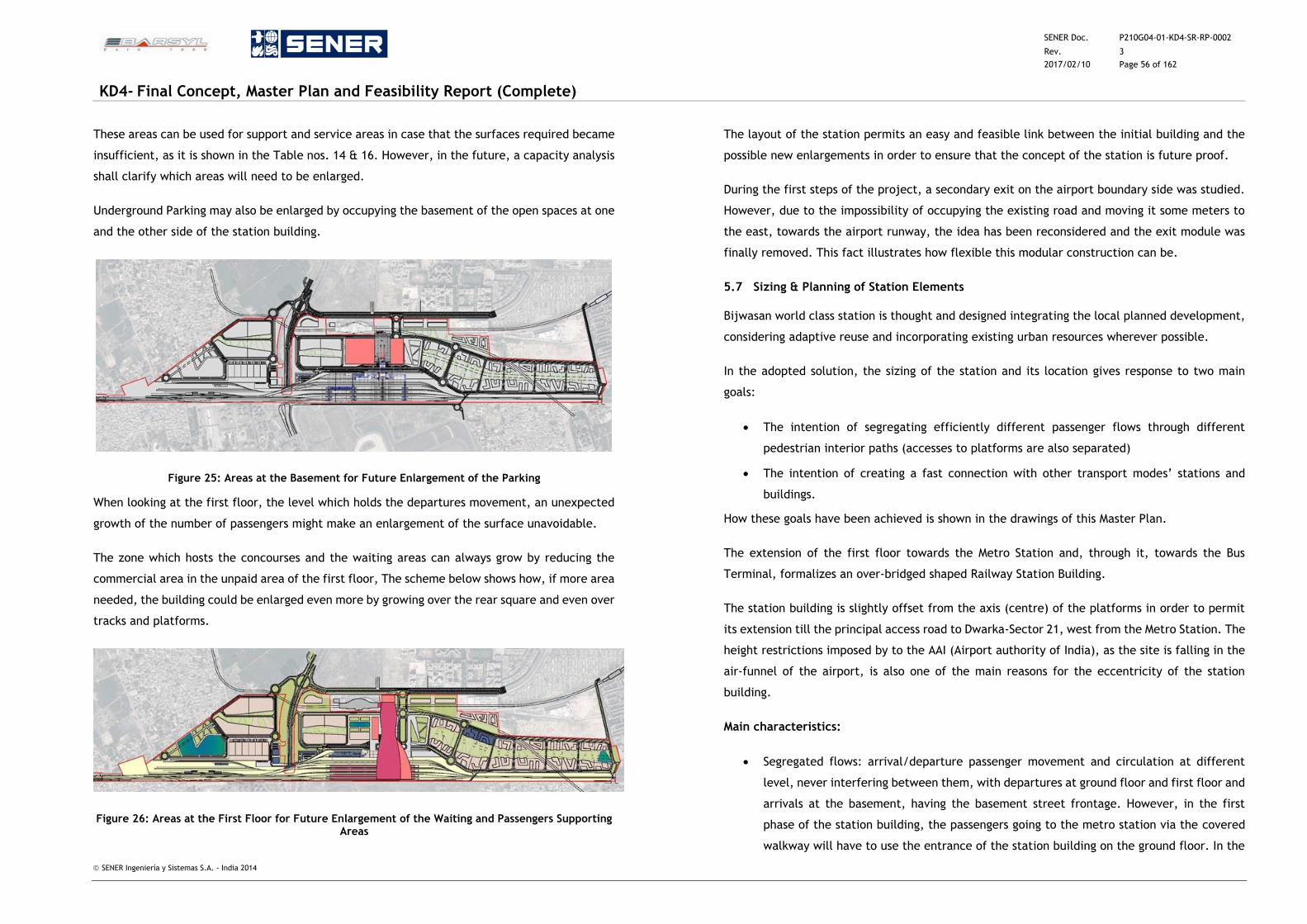
SENER Doc. P210G04-01-KD4-SR-RP-0002
Rev. 3
2017/02/10 Page 56 of 162
KD4- Final Concept, Master Plan and Feasibility Report (Complete)
SENER Ingeniería y Sistemas S.A. - India 2014
These areas can be used for support and service areas in case that the surfaces required became
insufficient, as it is shown in the Table nos. 14 & 16. However, in the future, a capacity analysis
shall clarify which areas will need to be enlarged.
Underground Parking may also be enlarged by occupying the basement of the open spaces at one
and the other side of the station building.
Figure 25: Areas at the Basement for Future Enlargement of the Parking
When looking at the first floor, the level which holds the departures movement, an unexpected
growth of the number of passengers might make an enlargement of the surface unavoidable.
The zone which hosts the concourses and the waiting areas can always grow by reducing the
commercial area in the unpaid area of the first floor, The scheme below shows how, if more area
needed, the building could be enlarged even more by growing over the rear square and even over
tracks and platforms.
Figure 26: Areas at the First Floor for Future Enlargement of the Waiting and Passengers Supporting Areas
The layout of the station permits an easy and feasible link between the initial building and the
possible new enlargements in order to ensure that the concept of the station is future proof.
During the first steps of the project, a secondary exit on the airport boundary side was studied.
However, due to the impossibility of occupying the existing road and moving it some meters to
the east, towards the airport runway, the idea has been reconsidered and the exit module was
finally removed. This fact illustrates how flexible this modular construction can be.
5.7 Sizing & Planning of Station Elements
Bijwasan world class station is thought and designed integrating the local planned development,
considering adaptive reuse and incorporating existing urban resources wherever possible.
In the adopted solution, the sizing of the station and its location gives response to two main
goals:
The intention of segregating efficiently different passenger flows through different
pedestrian interior paths (accesses to platforms are also separated)
The intention of creating a fast connection with other transport modes’ stations and
buildings.
How these goals have been achieved is shown in the drawings of this Master Plan.
The extension of the first floor towards the Metro Station and, through it, towards the Bus
Terminal, formalizes an over-bridged shaped Railway Station Building.
The station building is slightly offset from the axis (centre) of the platforms in order to permit
its extension till the principal access road to Dwarka-Sector 21, west from the Metro Station. The
height restrictions imposed by to the AAI (Airport authority of India), as the site is falling in the
air-funnel of the airport, is also one of the main reasons for the eccentricity of the station
building.
Main characteristics:
Segregated flows: arrival/departure passenger movement and circulation at different
level, never interfering between them, with departures at ground floor and first floor and
arrivals at the basement, having the basement street frontage. However, in the first
phase of the station building, the passengers going to the metro station via the covered
walkway will have to use the entrance of the station building on the ground floor. In the
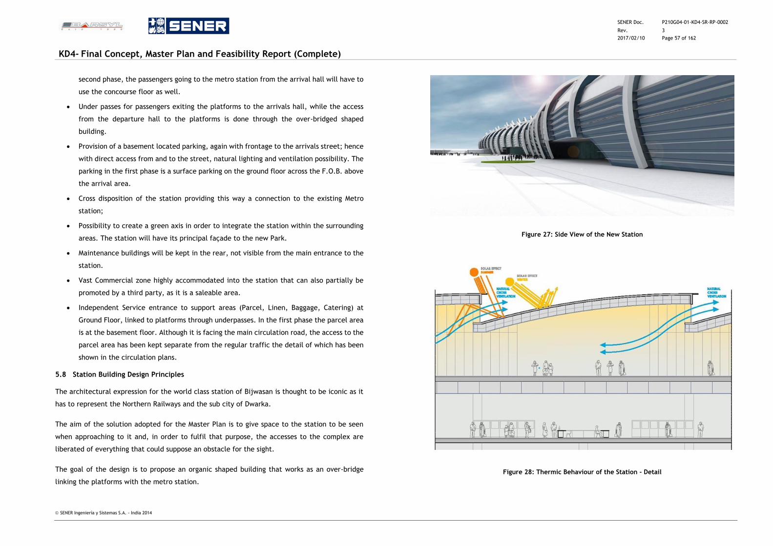
SENER Doc. P210G04-01-KD4-SR-RP-0002
Rev. 3
2017/02/10 Page 57 of 162
KD4- Final Concept, Master Plan and Feasibility Report (Complete)
SENER Ingeniería y Sistemas S.A. - India 2014
second phase, the passengers going to the metro station from the arrival hall will have to
use the concourse floor as well.
Under passes for passengers exiting the platforms to the arrivals hall, while the access
from the departure hall to the platforms is done through the over-bridged shaped
building.
Provision of a basement located parking, again with frontage to the arrivals street; hence
with direct access from and to the street, natural lighting and ventilation possibility. The
parking in the first phase is a surface parking on the ground floor across the F.O.B. above
the arrival area.
Cross disposition of the station providing this way a connection to the existing Metro
station;
Possibility to create a green axis in order to integrate the station within the surrounding
areas. The station will have its principal façade to the new Park.
Maintenance buildings will be kept in the rear, not visible from the main entrance to the
station.
Vast Commercial zone highly accommodated into the station that can also partially be
promoted by a third party, as it is a saleable area.
Independent Service entrance to support areas (Parcel, Linen, Baggage, Catering) at
Ground Floor, linked to platforms through underpasses. In the first phase the parcel area
is at the basement floor. Although it is facing the main circulation road, the access to the
parcel area has been kept separate from the regular traffic the detail of which has been
shown in the circulation plans.
5.8 Station Building Design Principles
The architectural expression for the world class station of Bijwasan is thought to be iconic as it
has to represent the Northern Railways and the sub city of Dwarka.
The aim of the solution adopted for the Master Plan is to give space to the station to be seen
when approaching to it and, in order to fulfil that purpose, the accesses to the complex are
liberated of everything that could suppose an obstacle for the sight.
The goal of the design is to propose an organic shaped building that works as an over-bridge
linking the platforms with the metro station.
Figure 27: Side View of the New Station
Figure 28: Thermic Behaviour of the Station - Detail
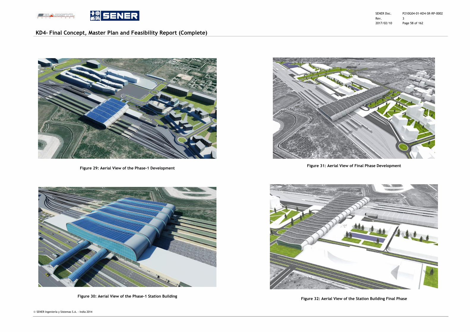
SENER Doc. P210G04-01-KD4-SR-RP-0002
Rev. 3
2017/02/10 Page 58 of 162
KD4- Final Concept, Master Plan and Feasibility Report (Complete)
SENER Ingeniería y Sistemas S.A. - India 2014
Figure 29: Aerial View of the Phase-1 Development
Figure 30: Aerial View of the Phase-1 Station Building
Figure 31: Aerial View of Final Phase Development
Figure 32: Aerial View of the Station Building Final Phase
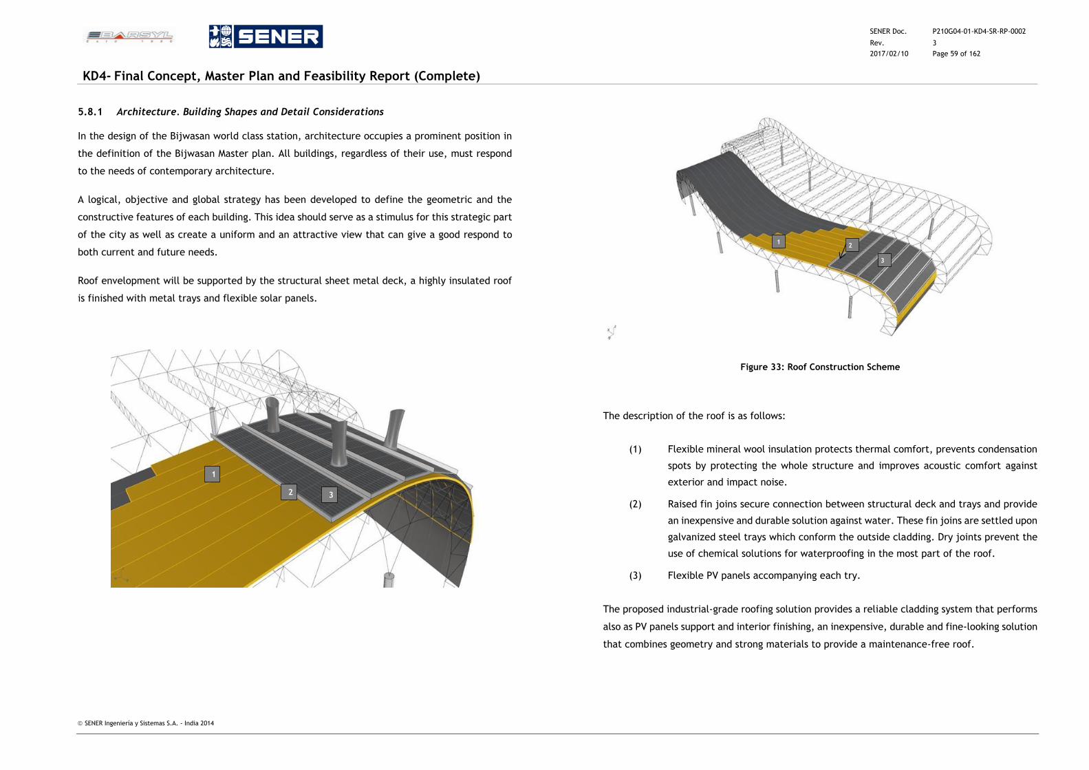
SENER Doc. P210G04-01-KD4-SR-RP-0002
Rev. 3
2017/02/10 Page 59 of 162
KD4- Final Concept, Master Plan and Feasibility Report (Complete)
SENER Ingeniería y Sistemas S.A. - India 2014
5.8.1 Architecture. Building Shapes and Detail Considerations
In the design of the Bijwasan world class station, architecture occupies a prominent position in
the definition of the Bijwasan Master plan. All buildings, regardless of their use, must respond
to the needs of contemporary architecture.
A logical, objective and global strategy has been developed to define the geometric and the
constructive features of each building. This idea should serve as a stimulus for this strategic part
of the city as well as create a uniform and an attractive view that can give a good respond to
both current and future needs.
Roof envelopment will be supported by the structural sheet metal deck, a highly insulated roof
is finished with metal trays and flexible solar panels.
Figure 33: Roof Construction Scheme
The description of the roof is as follows:
(1) Flexible mineral wool insulation protects thermal comfort, prevents condensation
spots by protecting the whole structure and improves acoustic comfort against
exterior and impact noise.
(2) Raised fin joins secure connection between structural deck and trays and provide
an inexpensive and durable solution against water. These fin joins are settled upon
galvanized steel trays which conform the outside cladding. Dry joints prevent the
use of chemical solutions for waterproofing in the most part of the roof.
(3) Flexible PV panels accompanying each try.
The proposed industrial-grade roofing solution provides a reliable cladding system that performs
also as PV panels support and interior finishing, an inexpensive, durable and fine-looking solution
that combines geometry and strong materials to provide a maintenance-free roof.
1
3
2
1
3 2
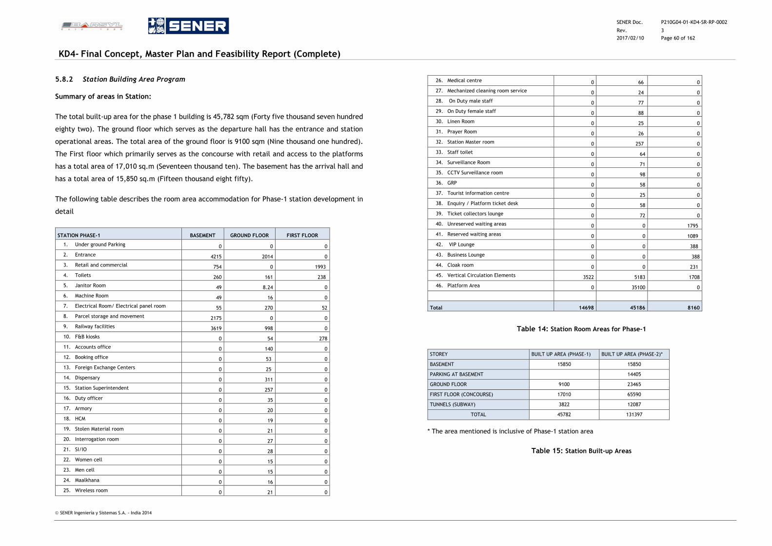
SENER Doc. P210G04-01-KD4-SR-RP-0002
Rev. 3
2017/02/10 Page 60 of 162
KD4- Final Concept, Master Plan and Feasibility Report (Complete)
SENER Ingeniería y Sistemas S.A. - India 2014
5.8.2 Station Building Area Program
Summary of areas in Station:
The total built-up area for the phase 1 building is 45,782 sqm (Forty five thousand seven hundred
eighty two). The ground floor which serves as the departure hall has the entrance and station
operational areas. The total area of the ground floor is 9100 sqm (Nine thousand one hundred).
The First floor which primarily serves as the concourse with retail and access to the platforms
has a total area of 17,010 sq.m (Seventeen thousand ten). The basement has the arrival hall and
has a total area of 15,850 sq.m (Fifteen thousand eight fifty).
The following table describes the room area accommodation for Phase-1 station development in
detail
STATION PHASE-1 BASEMENT GROUND FLOOR FIRST FLOOR
1. Under ground Parking 0 0 0
2. Entrance 4215 2014 0
3. Retail and commercial 754 0 1993
4. Toilets 260 161 238
5. Janitor Room 49 8.24 0
6. Machine Room 49 16 0
7. Electrical Room/ Electrical panel room 55 270 52
8. Parcel storage and movement 2175 0 0
9. Railway facilities 3619 998 0
10. F&B kiosks 0 54 278
11. Accounts office 0 140 0
12. Booking office 0 53 0
13. Foreign Exchange Centers 0 25 0
14. Dispensary 0 311 0
15. Station Superintendent 0 257 0
16. Duty officer 0 35 0
17. Armory 0 20 0
18. HCM 0 19 0
19. Stolen Material room 0 21 0
20. Interrogation room 0 27 0
21. SI/IO 0 28 0
22. Women cell 0 15 0
23. Men cell 0 15 0
24. Maalkhana 0 16 0
25. Wireless room 0 21 0
26. Medical centre 0 66 0
27. Mechanized cleaning room service 0 24 0
28. On Duty male staff 0 77 0
29. On Duty female staff 0 88 0
30. Linen Room 0 25 0
31. Prayer Room 0 26 0
32. Station Master room 0 257 0
33. Staff toilet 0 64 0
34. Surveillance Room 0 71 0
35. CCTV Surveillance room 0 98 0
36. GRP 0 58 0
37. Tourist information centre 0 25 0
38. Enquiry / Platform ticket desk 0 58 0
39. Ticket collectors lounge 0 72 0
40. Unreserved waiting areas 0 0 1795
41. Reserved waiting areas 0 0 1089
42. VIP Lounge 0 0 388
43. Business Lounge 0 0 388
44. Cloak room 0 0 231
45. Vertical Circulation Elements 3522 5183 1708
46. Platform Area 0 35100 0
Total 14698 45186 8160
Table 14: Station Room Areas for Phase-1
STOREY BUILT UP AREA (PHASE-1) BUILT UP AREA (PHASE-2)*
BASEMENT 15850 15850
PARKING AT BASEMENT 14405
GROUND FLOOR 9100 23465
FIRST FLOOR (CONCOURSE) 17010 65590
TUNNELS (SUBWAY) 3822 12087
TOTAL 45782 131397
* The area mentioned is inclusive of Phase-1 station area
Table 15: Station Built-up Areas
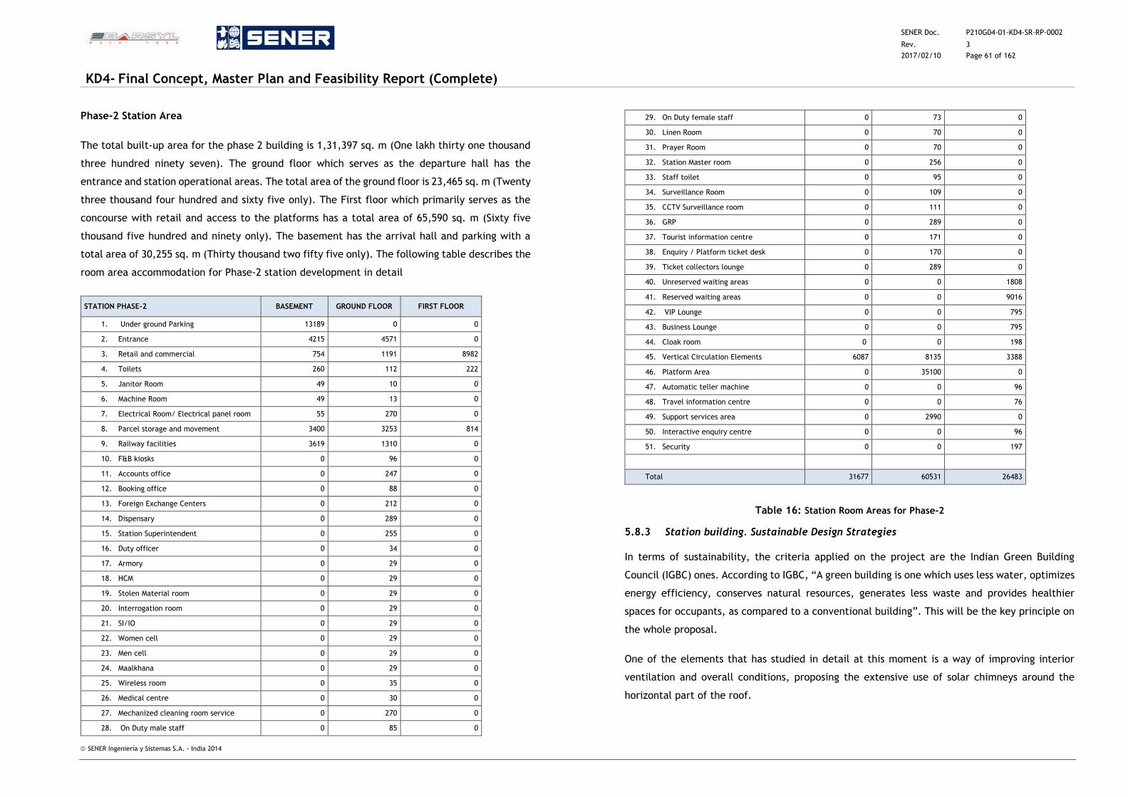
SENER Doc. P210G04-01-KD4-SR-RP-0002
Rev. 3
2017/02/10 Page 61 of 162
KD4- Final Concept, Master Plan and Feasibility Report (Complete)
SENER Ingeniería y Sistemas S.A. - India 2014
Phase-2 Station Area
The total built-up area for the phase 2 building is 1,31,397 sq. m (One lakh thirty one thousand
three hundred ninety seven). The ground floor which serves as the departure hall has the
entrance and station operational areas. The total area of the ground floor is 23,465 sq. m (Twenty
three thousand four hundred and sixty five only). The First floor which primarily serves as the
concourse with retail and access to the platforms has a total area of 65,590 sq. m (Sixty five
thousand five hundred and ninety only). The basement has the arrival hall and parking with a
total area of 30,255 sq. m (Thirty thousand two fifty five only). The following table describes the
room area accommodation for Phase-2 station development in detail
STATION PHASE-2 BASEMENT GROUND FLOOR FIRST FLOOR
1. Under ground Parking 13189 0 0
2. Entrance 4215 4571 0
3. Retail and commercial 754 1191 8982
4. Toilets 260 112 222
5. Janitor Room 49 10 0
6. Machine Room 49 13 0
7. Electrical Room/ Electrical panel room 55 270 0
8. Parcel storage and movement 3400 3253 814
9. Railway facilities 3619 1310 0
10. F&B kiosks 0 96 0
11. Accounts office 0 247 0
12. Booking office 0 88 0
13. Foreign Exchange Centers 0 212 0
14. Dispensary 0 289 0
15. Station Superintendent 0 255 0
16. Duty officer 0 34 0
17. Armory 0 29 0
18. HCM 0 29 0
19. Stolen Material room 0 29 0
20. Interrogation room 0 29 0
21. SI/IO 0 29 0
22. Women cell 0 29 0
23. Men cell 0 29 0
24. Maalkhana 0 29 0
25. Wireless room 0 35 0
26. Medical centre 0 30 0
27. Mechanized cleaning room service 0 270 0
28. On Duty male staff 0 85 0
29. On Duty female staff 0 73 0
30. Linen Room 0 70 0
31. Prayer Room 0 70 0
32. Station Master room 0 256 0
33. Staff toilet 0 95 0
34. Surveillance Room 0 109 0
35. CCTV Surveillance room 0 111 0
36. GRP 0 289 0
37. Tourist information centre 0 171 0
38. Enquiry / Platform ticket desk 0 170 0
39. Ticket collectors lounge 0 289 0
40. Unreserved waiting areas 0 0 1808
41. Reserved waiting areas 0 0 9016
42. VIP Lounge 0 0 795
43. Business Lounge 0 0 795
44. Cloak room 0 0 198
45. Vertical Circulation Elements 6087 8135 3388
46. Platform Area 0 35100 0
47. Automatic teller machine 0 0 96
48. Travel information centre 0 0 76
49. Support services area 0 2990 0
50. Interactive enquiry centre 0 0 96
51. Security 0 0 197
Total 31677 60531 26483
Table 16: Station Room Areas for Phase-2
5.8.3 Station building. Sustainable Design Strategies
In terms of sustainability, the criteria applied on the project are the Indian Green Building
Council (IGBC) ones. According to IGBC, “A green building is one which uses less water, optimizes
energy efficiency, conserves natural resources, generates less waste and provides healthier
spaces for occupants, as compared to a conventional building”. This will be the key principle on
the whole proposal.
One of the elements that has studied in detail at this moment is a way of improving interior
ventilation and overall conditions, proposing the extensive use of solar chimneys around the
horizontal part of the roof.
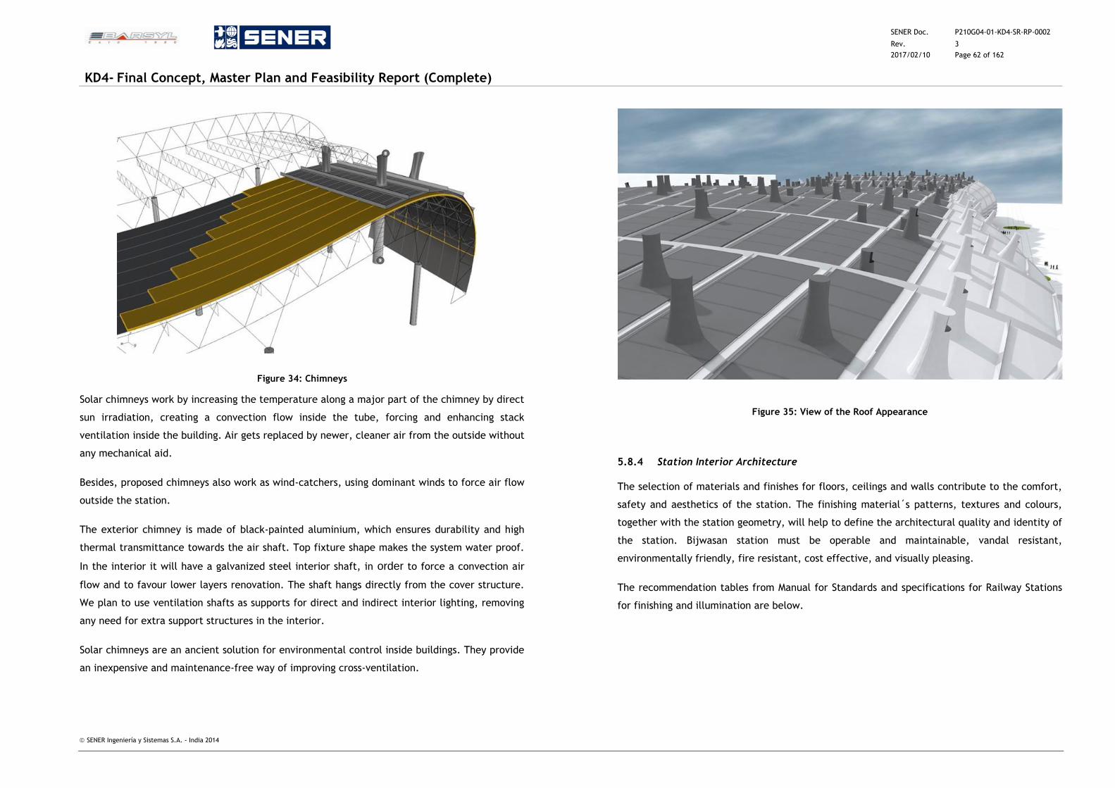
SENER Doc. P210G04-01-KD4-SR-RP-0002
Rev. 3
2017/02/10 Page 62 of 162
KD4- Final Concept, Master Plan and Feasibility Report (Complete)
SENER Ingeniería y Sistemas S.A. - India 2014
Figure 34: Chimneys
Solar chimneys work by increasing the temperature along a major part of the chimney by direct
sun irradiation, creating a convection flow inside the tube, forcing and enhancing stack
ventilation inside the building. Air gets replaced by newer, cleaner air from the outside without
any mechanical aid.
Besides, proposed chimneys also work as wind-catchers, using dominant winds to force air flow
outside the station.
The exterior chimney is made of black-painted aluminium, which ensures durability and high
thermal transmittance towards the air shaft. Top fixture shape makes the system water proof.
In the interior it will have a galvanized steel interior shaft, in order to force a convection air
flow and to favour lower layers renovation. The shaft hangs directly from the cover structure.
We plan to use ventilation shafts as supports for direct and indirect interior lighting, removing
any need for extra support structures in the interior.
Solar chimneys are an ancient solution for environmental control inside buildings. They provide
an inexpensive and maintenance-free way of improving cross-ventilation.
Figure 35: View of the Roof Appearance
5.8.4 Station Interior Architecture
The selection of materials and finishes for floors, ceilings and walls contribute to the comfort,
safety and aesthetics of the station. The finishing material´s patterns, textures and colours,
together with the station geometry, will help to define the architectural quality and identity of
the station. Bijwasan station must be operable and maintainable, vandal resistant,
environmentally friendly, fire resistant, cost effective, and visually pleasing.
The recommendation tables from Manual for Standards and specifications for Railway Stations
for finishing and illumination are below.
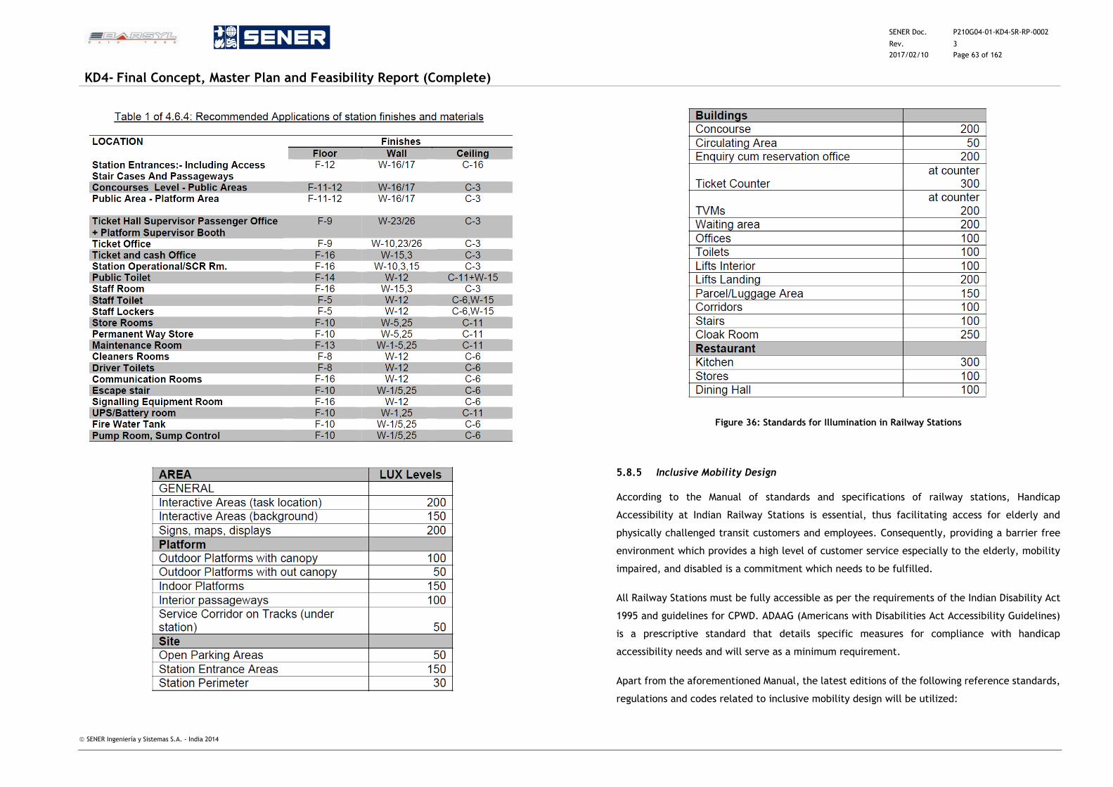
SENER Doc. P210G04-01-KD4-SR-RP-0002
Rev. 3
2017/02/10 Page 63 of 162
KD4- Final Concept, Master Plan and Feasibility Report (Complete)
SENER Ingeniería y Sistemas S.A. - India 2014
Figure 36: Standards for Illumination in Railway Stations
5.8.5 Inclusive Mobility Design
According to the Manual of standards and specifications of railway stations, Handicap
Accessibility at Indian Railway Stations is essential, thus facilitating access for elderly and
physically challenged transit customers and employees. Consequently, providing a barrier free
environment which provides a high level of customer service especially to the elderly, mobility
impaired, and disabled is a commitment which needs to be fulfilled.
All Railway Stations must be fully accessible as per the requirements of the Indian Disability Act
1995 and guidelines for CPWD. ADAAG (Americans with Disabilities Act Accessibility Guidelines)
is a prescriptive standard that details specific measures for compliance with handicap
accessibility needs and will serve as a minimum requirement.
Apart from the aforementioned Manual, the latest editions of the following reference standards,
regulations and codes related to inclusive mobility design will be utilized:
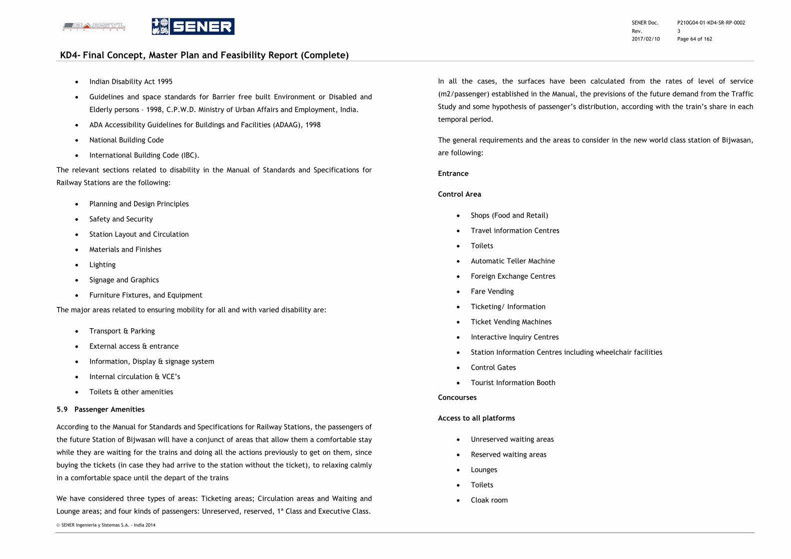
SENER Doc. P210G04-01-KD4-SR-RP-0002
Rev. 3
2017/02/10 Page 64 of 162
KD4- Final Concept, Master Plan and Feasibility Report (Complete)
SENER Ingeniería y Sistemas S.A. - India 2014
Indian Disability Act 1995
Guidelines and space standards for Barrier free built Environment or Disabled and
Elderly persons – 1998, C.P.W.D. Ministry of Urban Affairs and Employment, India.
ADA Accessibility Guidelines for Buildings and Facilities (ADAAG), 1998
National Building Code
International Building Code (IBC).
The relevant sections related to disability in the Manual of Standards and Specifications for
Railway Stations are the following:
Planning and Design Principles
Safety and Security
Station Layout and Circulation
Materials and Finishes
Lighting
Signage and Graphics
Furniture Fixtures, and Equipment
The major areas related to ensuring mobility for all and with varied disability are:
Transport & Parking
External access & entrance
Information, Display & signage system
Internal circulation & VCE’s
Toilets & other amenities
5.9 Passenger Amenities
According to the Manual for Standards and Specifications for Railway Stations, the passengers of
the future Station of Bijwasan will have a conjunct of areas that allow them a comfortable stay
while they are waiting for the trains and doing all the actions previously to get on them, since
buying the tickets (in case they had arrive to the station without the ticket), to relaxing calmly
in a comfortable space until the depart of the trains
We have considered three types of areas: Ticketing areas; Circulation areas and Waiting and
Lounge areas; and four kinds of passengers: Unreserved, reserved, 1ª Class and Executive Class.
In all the cases, the surfaces have been calculated from the rates of level of service
(m2/passenger) established in the Manual, the previsions of the future demand from the Traffic
Study and some hypothesis of passenger’s distribution, according with the train’s share in each
temporal period.
The general requirements and the areas to consider in the new world class station of Bijwasan,
are following:
Entrance
Control Area
Shops (Food and Retail)
Travel information Centres
Toilets
Automatic Teller Machine
Foreign Exchange Centres
Fare Vending
Ticketing/ Information
Ticket Vending Machines
Interactive Inquiry Centres
Station Information Centres including wheelchair facilities
Control Gates
Tourist Information Booth
Concourses
Access to all platforms
Unreserved waiting areas
Reserved waiting areas
Lounges
Toilets
Cloak room
SENER Doc. P210G04-01-KD4-SR-RP-0002
Rev. 3
2017/02/10 Page 65 of 162
KD4- Final Concept, Master Plan and Feasibility Report (Complete)
SENER Ingeniería y Sistemas S.A. - India 2014
Concessions( food shops, convenience retail shops)
Managed food shops ( Unreserved waiting areas)
Station Information Centre
Ticket Vending Machine
Interactive Inquiry Centres
Automatic Teller Machine
Public security stations
Vertical Circulation Elements
Platform Area
Waiting Area +Lounges
Seating
Toilets
Food courts
Retail shops
Public Support Areas
Men´s restroom
One accessible toilet
One urinal
Two lavatories with mirror (s)
One infant changing table
Women´s restroom
One accessible toilet
One standard toilet
Two lavatories with mirror (s)
One infant changing table
Parcel Storage and Parcel Movement
Support Service Areas
Staff
Lockers
Eating /Lounge Area
Toilets
Station Management
Station Control
Station Security
Administration offices
Train Passenger services
Catering
Bedroll services
Luggage Storage
Maintenance and Operation spaces
Operations
Train operations
Station operations
Cleaning and Supplies
Station cleaning
Supply storage
Fixture Supply storage
Janitors closet
Utility and Infrastructure
Electrical Service Rooms
Electrical Equipment Rooms
Mechanical Equipment Rooms
Plumbing Service Rooms
Sewage/Fire Suppression Service Rooms
Train control Rooms
Equipment Storage
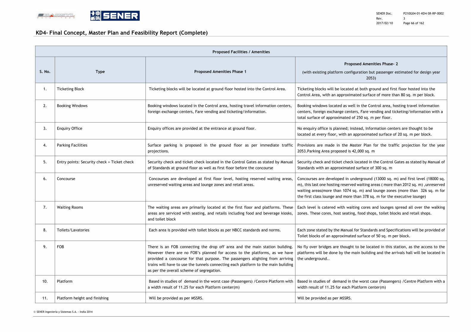
SENER Doc. P210G04-01-KD4-SR-RP-0002
Rev. 3
2017/02/10 Page 66 of 162
KD4- Final Concept, Master Plan and Feasibility Report (Complete)
SENER Ingeniería y Sistemas S.A. - India 2014
Proposed Facilities / Amenities
S. No. Type Proposed Amenities Phase 1
Proposed Amenities Phase- 2
(with existing platform configuration but passenger estimated for design year
2053)
1. Ticketing Block Ticketing blocks will be located at ground floor hosted into the Control Area. Ticketing blocks will be located at both ground and first floor hosted into the
Control Area, with an approximated surface of more than 80 sq. m per block.
2. Booking Windows Booking windows located in the Control area, hosting travel information centers,
foreign exchange centers, Fare vending and ticketing/information.
Booking windows located as well in the Control area, hosting travel information
centers, foreign exchange centers, Fare vending and ticketing/information with a
total surface of approximated of 250 sq. m per floor.
3. Enquiry Office Enquiry offices are provided at the entrance at ground floor. No enquiry office is planned; instead, Information centers are thought to be
located at every floor, with an approximated surface of 20 sq. m per block.
4. Parking Facilities Surface parking is proposed in the ground floor as per immediate traffic
projections.
Provisions are made in the Master Plan for the traffic projection for the year
2053.Parking Area proposed is 42,000 sq. m
5. Entry points: Security check + Ticket check Security check and ticket check located in the Control Gates as stated by Manual
of Standards at ground floor as well as first floor before the concourse
Security check and ticket check located in the Control Gates as stated by Manual of
Standards with an approximated surface of 300 sq. m
6. Concourse Concourses are developed at first floor level, hosting reserved waiting areas,
unreserved waiting areas and lounge zones and retail areas.
Concourses are developed in underground (13000 sq. m) and first level (18000 sq.
m), this last one hosting reserved waiting areas ( more than 2012 sq. m) ,unreserved
waiting areas(more than 1074 sq. m) and lounge zones (more than 326 sq. m for
the first class lounge and more than 378 sq. m for the executive lounge)
7. Waiting Rooms The waiting areas are primarily located at the first floor and platforms. These
areas are serviced with seating, and retails including food and beverage kiosks,
and toilet block
Each level is catered with waiting cores and lounges spread all over the walking
zones. These cores, host seating, food shops, toilet blocks and retail shops.
8. Toilets/Lavatories Each area is provided with toilet blocks as per NBCC standards and norms. Each zone stated by the Manual for Standards and Specifications will be provided of
Toilet blocks of an approximated surface of 50 sq. m per block.
9. FOB There is an FOB connecting the drop off area and the main station building.
However there are no FOB’s planned for access to the platforms, as we have
provided a concourse for that purpose. The passengers alighting from arriving
trains will have to use the tunnels connecting each platform to the main building
as per the overall scheme of segregation.
No fly over bridges are thought to be located in this station, as the access to the
platforms will be done by the main building and the arrivals hall will be located in
the underground..
10. Platform Based in studies of demand in the worst case (Passengers) /Centre Platform with
a width result of 11.25 for each Platform center(m)
Based in studies of demand in the worst case (Passengers) /Centre Platform with a
width result of 11.25 for each Platform center(m)
11. Platform height and finishing Will be provided as per MSSRS. Will be provided as per MSSRS.
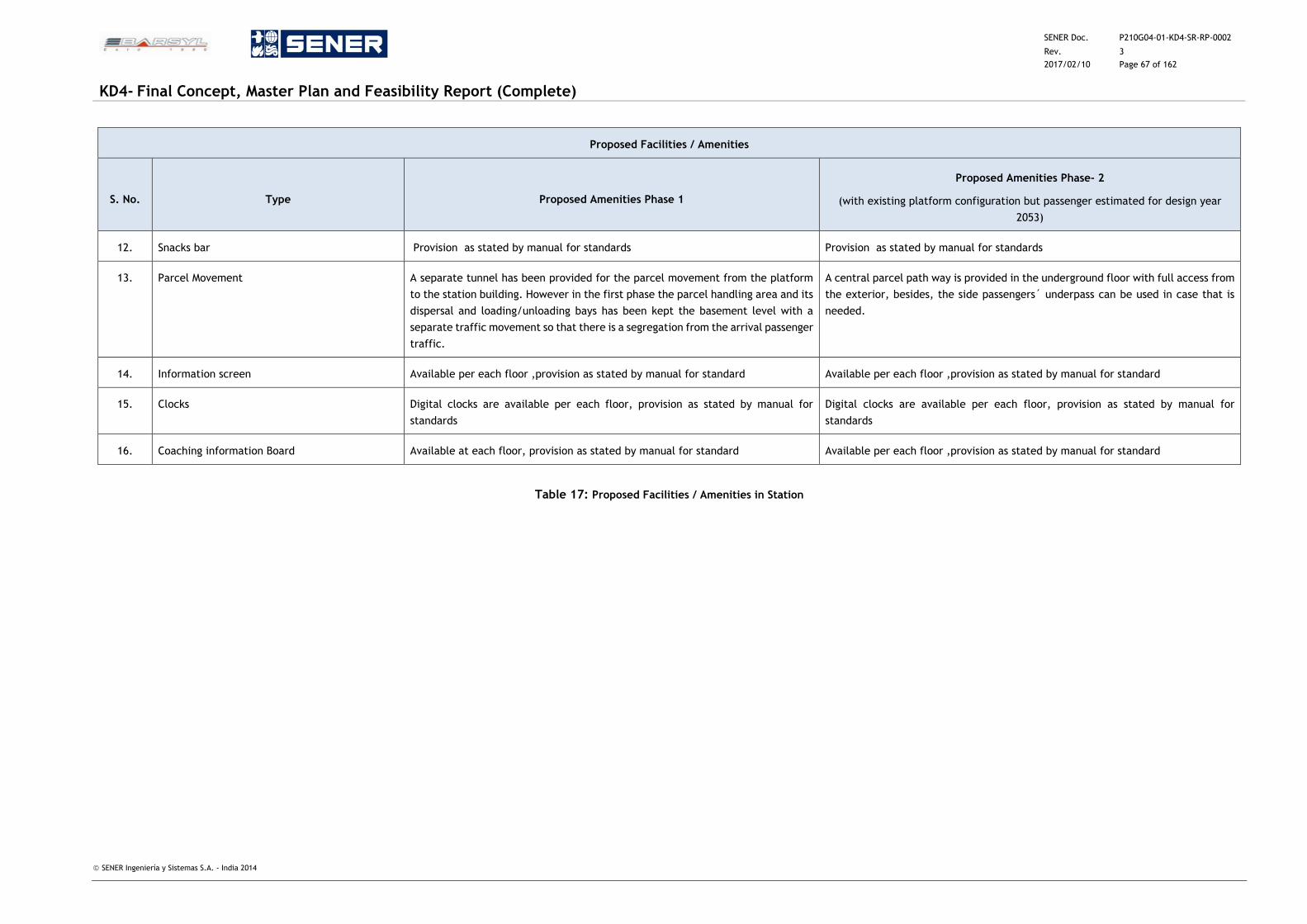
SENER Doc. P210G04-01-KD4-SR-RP-0002
Rev. 3
2017/02/10 Page 67 of 162
KD4- Final Concept, Master Plan and Feasibility Report (Complete)
SENER Ingeniería y Sistemas S.A. - India 2014
Proposed Facilities / Amenities
S. No. Type Proposed Amenities Phase 1
Proposed Amenities Phase- 2
(with existing platform configuration but passenger estimated for design year
2053)
12. Snacks bar Provision as stated by manual for standards Provision as stated by manual for standards
13. Parcel Movement A separate tunnel has been provided for the parcel movement from the platform
to the station building. However in the first phase the parcel handling area and its
dispersal and loading/unloading bays has been kept the basement level with a
separate traffic movement so that there is a segregation from the arrival passenger
traffic.
A central parcel path way is provided in the underground floor with full access from
the exterior, besides, the side passengers´ underpass can be used in case that is
needed.
14. Information screen Available per each floor ,provision as stated by manual for standard Available per each floor ,provision as stated by manual for standard
15. Clocks Digital clocks are available per each floor, provision as stated by manual for
standards
Digital clocks are available per each floor, provision as stated by manual for
standards
16. Coaching information Board Available at each floor, provision as stated by manual for standard Available per each floor ,provision as stated by manual for standard
Table 17: Proposed Facilities / Amenities in Station
SENER Doc. P210G04-01-KD4-SR-RP-0002
Rev. 3
2017/02/10 Page 68 of 162
KD4- Final Concept, Master Plan and Feasibility Report (Complete)
SENER Ingeniería y Sistemas S.A. - India 2014
However, it has to be taken into account that the areas and surfaces presented above are based
in the studies done during the KD3 stage, according to that, these areas represents the basis to
adjust and develop the definitive surfaces for this report.
5.10 Logistic Area
The Landuse Zonal Plan K-II for the Dwarka Project determines an exclusive Railway Passenger
Area for the Sector 21.
In addition to this use, a Logistic area is proposed to be developed on the other side of the UER
II road.
5.10.1 Logistic Area Planning Objective
Bijwasan World Class Station shall been designed following the principles detailed in the ¨Manual
for Specification for standards and specifications for railway stations¨.
The development of the Master Plan shall include a Logistic Area. This space has been designed
under the next key elements:
Accessibility
Safety and Security
Fast and Efficient handling zone
Flexible open spaces for tracks
Adequate storage areas
Controlled areas
5.10.2 Logistic Area Sizing and Location
The Logistic area is designed integrating the local planned development and shall incorporate
exiting urban resources wherever possible.
The road system proposed for this area is a ring road system that surrounds a central storage
core. One line of storage buildings is directly linked to the loading/unloading parcel platform. In
addition to this development, some facility buildings (such as railway administration and Hotel
for truckers or Railway personnel) are proposed to be located in this area to give service to
handling processes.
The rest of the area will be developed with Mixed Uses, mainly related to logistics and stores
due to the closeness to the Railways parcel area and to the logistic area proposed by DDA in the
neighbour sector. The height restrictions imposed by the airport lead to recommend logistic and
commercial uses like wholesalers, furniture stores, etc.
5.10.3 Connections to Traffic Pattern
The ring road system proposed in the Logistic area is connected directly to the UER II road which
is sufficiently broad to assimilate heavy traffic. Some roundabouts of the interior road system
are designed to connect with future urban pattern developments.
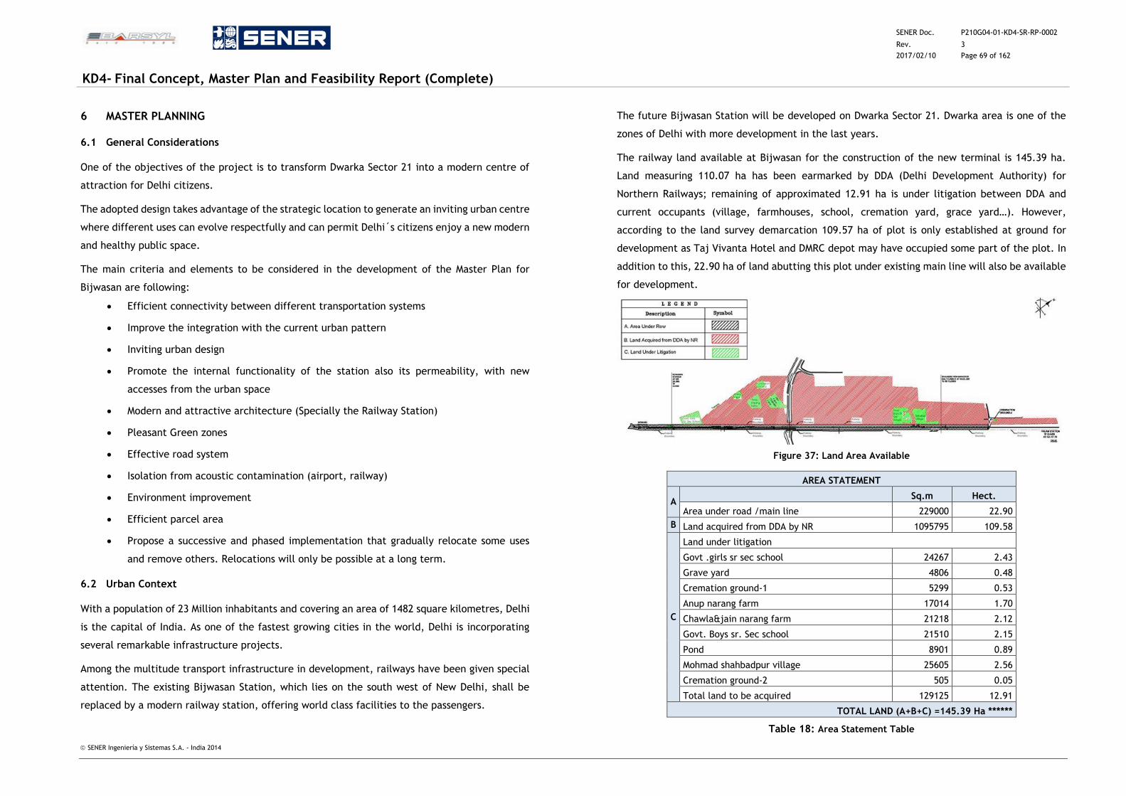
SENER Doc. P210G04-01-KD4-SR-RP-0002
Rev. 3
2017/02/10 Page 69 of 162
KD4- Final Concept, Master Plan and Feasibility Report (Complete)
SENER Ingeniería y Sistemas S.A. - India 2014
6 MASTER PLANNING
6.1 General Considerations
One of the objectives of the project is to transform Dwarka Sector 21 into a modern centre of
attraction for Delhi citizens.
The adopted design takes advantage of the strategic location to generate an inviting urban centre
where different uses can evolve respectfully and can permit Delhi´s citizens enjoy a new modern
and healthy public space.
The main criteria and elements to be considered in the development of the Master Plan for
Bijwasan are following:
Efficient connectivity between different transportation systems
Improve the integration with the current urban pattern
Inviting urban design
Promote the internal functionality of the station also its permeability, with new
accesses from the urban space
Modern and attractive architecture (Specially the Railway Station)
Pleasant Green zones
Effective road system
Isolation from acoustic contamination (airport, railway)
Environment improvement
Efficient parcel area
Propose a successive and phased implementation that gradually relocate some uses
and remove others. Relocations will only be possible at a long term.
6.2 Urban Context
With a population of 23 Million inhabitants and covering an area of 1482 square kilometres, Delhi
is the capital of India. As one of the fastest growing cities in the world, Delhi is incorporating
several remarkable infrastructure projects.
Among the multitude transport infrastructure in development, railways have been given special
attention. The existing Bijwasan Station, which lies on the south west of New Delhi, shall be
replaced by a modern railway station, offering world class facilities to the passengers.
The future Bijwasan Station will be developed on Dwarka Sector 21. Dwarka area is one of the
zones of Delhi with more development in the last years.
The railway land available at Bijwasan for the construction of the new terminal is 145.39 ha.
Land measuring 110.07 ha has been earmarked by DDA (Delhi Development Authority) for
Northern Railways; remaining of approximated 12.91 ha is under litigation between DDA and
current occupants (village, farmhouses, school, cremation yard, grace yard…). However,
according to the land survey demarcation 109.57 ha of plot is only established at ground for
development as Taj Vivanta Hotel and DMRC depot may have occupied some part of the plot. In
addition to this, 22.90 ha of land abutting this plot under existing main line will also be available
for development.
Figure 37: Land Area Available
AREA STATEMENT
A Sq.m Hect.
Area under road /main line 229000 22.90
B Land acquired from DDA by NR 1095795 109.58
C
Land under litigation
Govt .girls sr sec school 24267 2.43
Grave yard 4806 0.48
Cremation ground-1 5299 0.53
Anup narang farm 17014 1.70
Chawla&jain narang farm 21218 2.12
Govt. Boys sr. Sec school 21510 2.15
Pond 8901 0.89
Mohmad shahbadpur village 25605 2.56
Cremation ground-2 505 0.05
Total land to be acquired 129125 12.91
TOTAL LAND (A+B+C) =145.39 Ha ******
Table 18: Area Statement Table
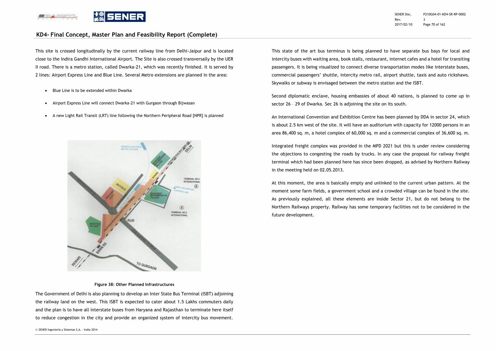
SENER Doc. P210G04-01-KD4-SR-RP-0002
Rev. 3
2017/02/10 Page 70 of 162
KD4- Final Concept, Master Plan and Feasibility Report (Complete)
SENER Ingeniería y Sistemas S.A. - India 2014
This site is crossed longitudinally by the current railway line from Delhi-Jaipur and is located
close to the Indira Gandhi International Airport. The Site is also crossed transversally by the UER
II road. There is a metro station, called Dwarka-21, which was recently finished. It is served by
2 lines: Airport Express Line and Blue Line. Several Metro extensions are planned in the area:
Blue Line is to be extended within Dwarka
Airport Express Line will connect Dwarka-21 with Gurgaon through Bijwasan
A new Light Rail Transit (LRT) line following the Northern Peripheral Road [NPR] is planned
Figure 38: Other Planned Infrastructures
The Government of Delhi is also planning to develop an Inter State Bus Terminal (ISBT) adjoining
the railway land on the west. This ISBT is expected to cater about 1.5 Lakhs commuters daily
and the plan is to have all interstate buses from Haryana and Rajasthan to terminate here itself
to reduce congestion in the city and provide an organized system of intercity bus movement.
This state of the art bus terminus is being planned to have separate bus bays for local and
intercity buses with waiting area, book stalls, restaurant, internet cafes and a hotel for transiting
passengers. It is being visualized to connect diverse transportation modes like interstate buses,
commercial passengers’ shuttle, intercity metro rail, airport shuttle, taxis and auto rickshaws.
Skywalks or subway is envisaged between the metro station and the ISBT.
Second diplomatic enclave, housing embassies of about 40 nations, is planned to come up in
sector 26 – 29 of Dwarka. Sec 26 is adjoining the site on its south.
An International Convention and Exhibition Centre has been planned by DDA in sector 24, which
is about 2.5 km west of the site. It will have an auditorium with capacity for 12000 persons in an
area 86,400 sq. m, a hotel complex of 60,000 sq. m and a commercial complex of 36,600 sq. m.
Integrated freight complex was provided in the MPD 2021 but this is under review considering
the objections to congesting the roads by trucks. In any case the proposal for railway freight
terminal which had been planned here has since been dropped, as advised by Northern Railway
in the meeting held on 02.05.2013.
At this moment, the area is basically empty and unlinked to the current urban pattern. At the
moment some farm fields, a government school and a crowded village can be found in the site.
As previously explained, all these elements are inside Sector 21, but do not belong to the
Northern Railways property. Railway has some temporary facilities not to be considered in the
future development.
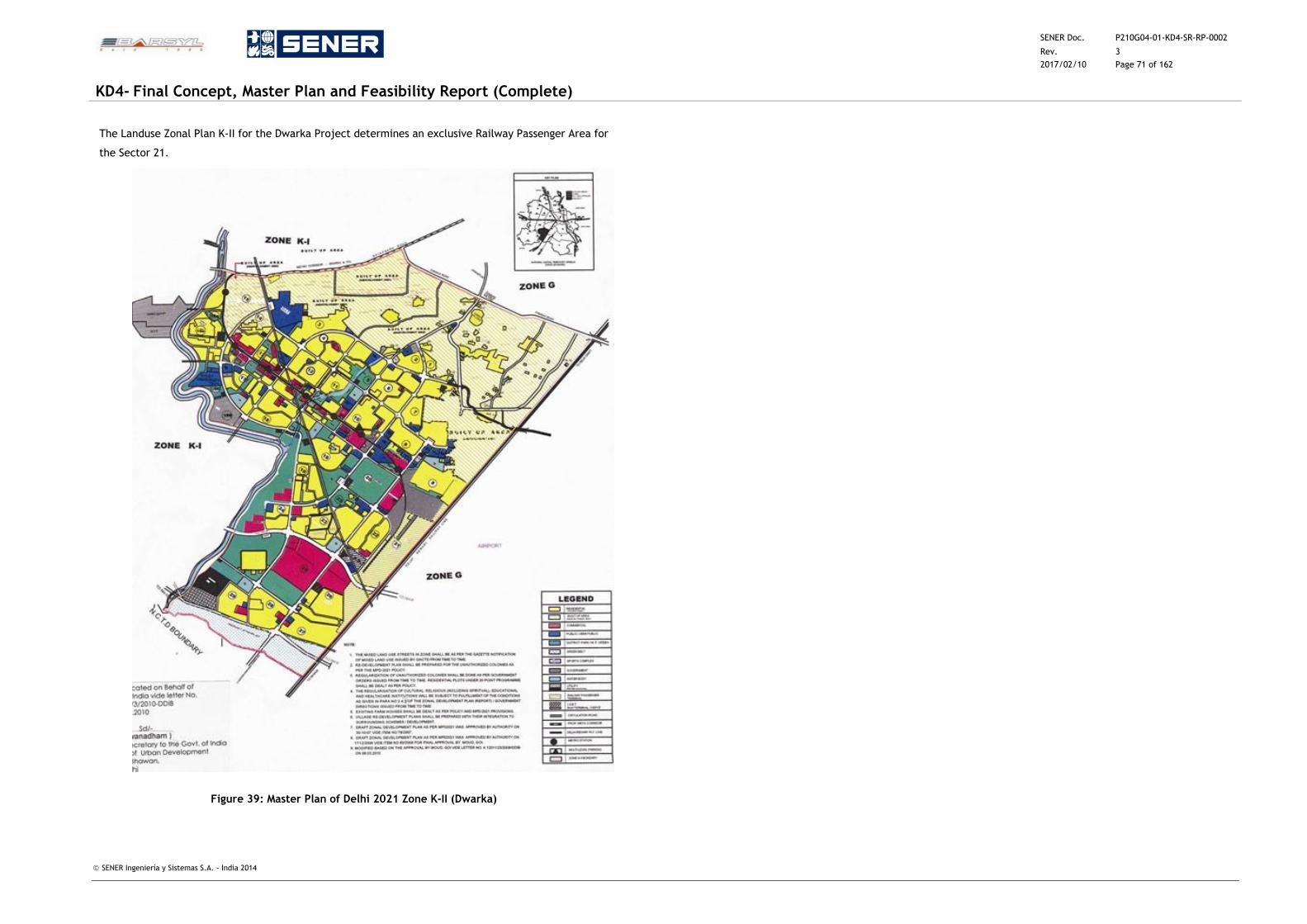
SENER Doc. P210G04-01-KD4-SR-RP-0002
Rev. 3
2017/02/10 Page 71 of 162
KD4- Final Concept, Master Plan and Feasibility Report (Complete)
SENER Ingeniería y Sistemas S.A. - India 2014
The Landuse Zonal Plan K-II for the Dwarka Project determines an exclusive Railway Passenger Area for
the Sector 21.
Figure 39: Master Plan of Delhi 2021 Zone K-II (Dwarka)
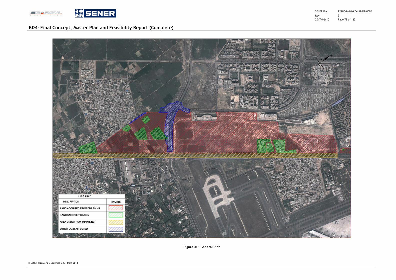
SENER Doc. P210G04-01-KD4-SR-RP-0002
Rev. 3
2017/02/10 Page 72 of 162
KD4- Final Concept, Master Plan and Feasibility Report (Complete)
SENER Ingeniería y Sistemas S.A. - India 2014
Figure 40: General Plot
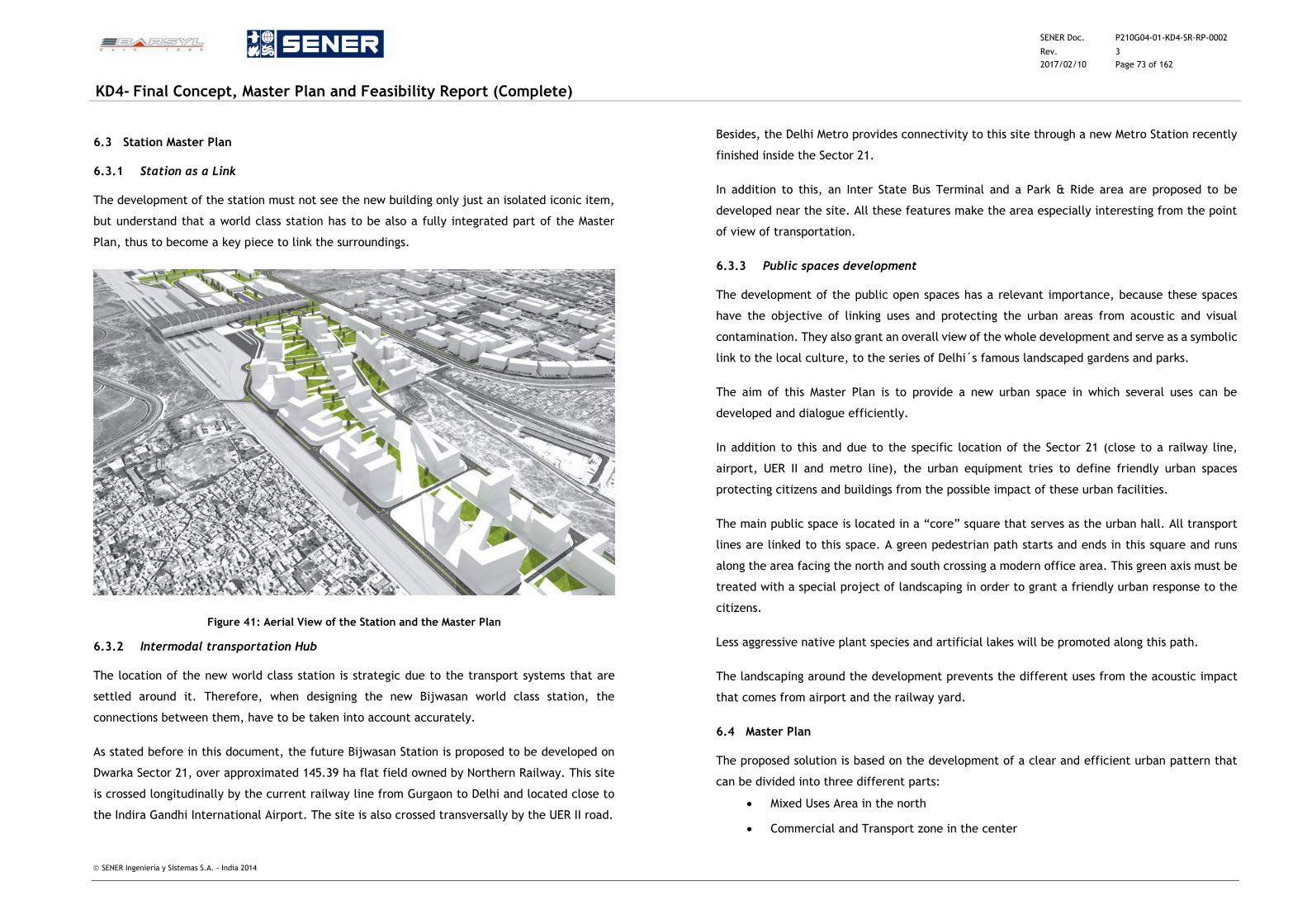
SENER Doc. P210G04-01-KD4-SR-RP-0002
Rev. 3
2017/02/10 Page 73 of 162
KD4- Final Concept, Master Plan and Feasibility Report (Complete)
SENER Ingeniería y Sistemas S.A. - India 2014
6.3 Station Master Plan
6.3.1 Station as a Link
The development of the station must not see the new building only just an isolated iconic item,
but understand that a world class station has to be also a fully integrated part of the Master
Plan, thus to become a key piece to link the surroundings.
Figure 41: Aerial View of the Station and the Master Plan
6.3.2 Intermodal transportation Hub
The location of the new world class station is strategic due to the transport systems that are
settled around it. Therefore, when designing the new Bijwasan world class station, the
connections between them, have to be taken into account accurately.
As stated before in this document, the future Bijwasan Station is proposed to be developed on
Dwarka Sector 21, over approximated 145.39 ha flat field owned by Northern Railway. This site
is crossed longitudinally by the current railway line from Gurgaon to Delhi and located close to
the Indira Gandhi International Airport. The site is also crossed transversally by the UER II road.
Besides, the Delhi Metro provides connectivity to this site through a new Metro Station recently
finished inside the Sector 21.
In addition to this, an Inter State Bus Terminal and a Park & Ride area are proposed to be
developed near the site. All these features make the area especially interesting from the point
of view of transportation.
6.3.3 Public spaces development
The development of the public open spaces has a relevant importance, because these spaces
have the objective of linking uses and protecting the urban areas from acoustic and visual
contamination. They also grant an overall view of the whole development and serve as a symbolic
link to the local culture, to the series of Delhi´s famous landscaped gardens and parks.
The aim of this Master Plan is to provide a new urban space in which several uses can be
developed and dialogue efficiently.
In addition to this and due to the specific location of the Sector 21 (close to a railway line,
airport, UER II and metro line), the urban equipment tries to define friendly urban spaces
protecting citizens and buildings from the possible impact of these urban facilities.
The main public space is located in a “core” square that serves as the urban hall. All transport
lines are linked to this space. A green pedestrian path starts and ends in this square and runs
along the area facing the north and south crossing a modern office area. This green axis must be
treated with a special project of landscaping in order to grant a friendly urban response to the
citizens.
Less aggressive native plant species and artificial lakes will be promoted along this path.
The landscaping around the development prevents the different uses from the acoustic impact
that comes from airport and the railway yard.
6.4 Master Plan
The proposed solution is based on the development of a clear and efficient urban pattern that
can be divided into three different parts:
Mixed Uses Area in the north
Commercial and Transport zone in the center
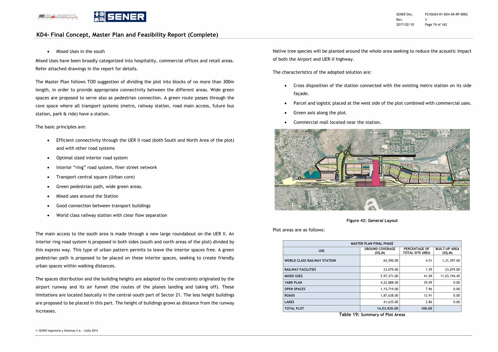
SENER Doc. P210G04-01-KD4-SR-RP-0002
Rev. 3
2017/02/10 Page 74 of 162
KD4- Final Concept, Master Plan and Feasibility Report (Complete)
SENER Ingeniería y Sistemas S.A. - India 2014
Mixed Uses in the south
Mixed Uses have been broadly categorized into hospitality, commercial offices and retail areas.
Refer attached drawings in the report for details.
The Master Plan follows TOD suggestion of dividing the plot into blocks of no more than 300m
length, in order to provide appropriate connectivity between the different areas. Wide green
spaces are proposed to serve also as pedestrian connection. A green route passes through the
core space where all transport systems (metro, railway station, road main access, future bus
station, park & ride) have a station.
The basic principles are:
Efficient connectivity through the UER II road (both South and North Area of the plot)
and with other road systems
Optimal sized interior road system
Interior “ring” road system, finer street network
Transport central square (Urban core)
Green pedestrian path, wide green areas.
Mixed uses around the Station
Good connection between transport buildings
World class railway station with clear flow separation
The main access to the south area is made through a new large roundabout on the UER II. An
interior ring road system is proposed in both sides (south and north areas of the plot) divided by
this express way. This type of urban pattern permits to leave the interior spaces free. A green
pedestrian path is proposed to be placed on these interior spaces, seeking to create friendly
urban spaces within walking distances.
The spaces distribution and the building heights are adapted to the constraints originated by the
airport runway and its air funnel (the routes of the planes landing and taking off). These
limitations are located basically in the central-south part of Sector 21. The less height buildings
are proposed to be placed in this part. The height of buildings grows as distance from the runway
increases.
Native tree species will be planted around the whole area seeking to reduce the acoustic impact
of both the Airport and UER-II highway.
The characteristics of the adopted solution are:
Cross disposition of the station connected with the existing metro station on its side
façade.
Parcel and logistic placed at the west side of the plot combined with commercial uses.
Green axis along the plot.
Commercial mall located near the station.
Figure 42: General Layout
Plot areas are as follows:
MASTER PLAN FINAL PHASE
USE GROUND COVERAGE
(SQ.M) PERCENTAGE OF TOTAL SITE AREA
BUILT-UP AREA (SQ.M)
WORLD CLASS RAILWAY STATION 65,590.00 4.51 1,31,397.00
RAILWAY FACILITIES 23,079.00 1.59 23,079.00
MIXED USES 5,97,371.00 41.09 11,03,194.45
YARD PLAN 4,22,888.00 29.09 0.00
OPEN SPACES 1,15,719.00 7.96 0.00
ROADS 1,87,638.00 12.91 0.00
LAKES 41,635.00 2.86 0.00
TOTAL PLOT 14,53,920.00 100.00
Table 19: Summary of Plot Areas
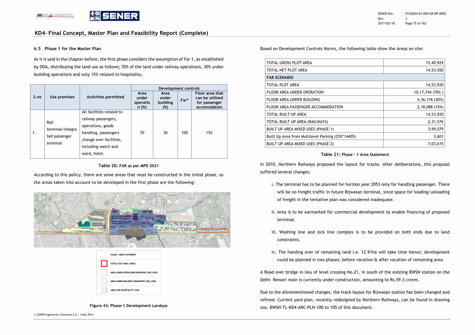
SENER Doc. P210G04-01-KD4-SR-RP-0002
Rev. 3
2017/02/10 Page 75 of 162
KD4- Final Concept, Master Plan and Feasibility Report (Complete)
SENER Ingeniería y Sistemas S.A. - India 2014
6.5 Phase 1 for the Master Plan
As it is said in the chapter before, the first phase considers the assumption of Far 1, as established
by DDA, distributing the land use as follows; 70% of the land under railway operations, 30% under
building operations and only 15% related to hospitality.
S.no Use premises Activities permitted
Development controls
Area under
operation (%)
Area under
building (%)
Far*
Floor area that can be utilised for passenger accomodation
1.
Rail
terminal/integra
ted passenger
terminal
All facilities related to
railway passengers,
operations, goods
handling, passengers
change over facilities,
including watch and
ward, hotel.
70 30 100 15%
Table 20: FAR as per MPD 2021
According to this policy, there are some areas that must be constructed in the initial phase, so
the areas taken into account to be developed in the first phase are the following:
Figure 43: Phase-1 Development Landuse
Based on Development Controls Norms, the following table show the Areas on site:
TOTAL GROSS PLOT AREA 15,40,929
TOTAL NET PLOT AREA 14,53,920
FAR SCENARIO
TOTAL PLOT AREA 14,53,920
FLOOR AREA UNDER OPERATION 10,17,744 (70% )
FLOOR AREA UNDER BUILDING 4,36,176 (30%)
FLOOR AREA PASSENGER ACCOMMODATION 2,18,088 (15%)
TOTAL BUILT UP AREA 14,53,920
TOTAL BUILT UP AREA (RAILWAYS) 2,31,576
BUILT UP AREA MIXED USES (PHASE-1) 3,99,579
Built Up Area from Multilevel Parking (25%*14405) 3,601
BUILT UP AREA MIXED USES (PHASE-2) 7,03,615
Table 21: Phase - 1 Area Statement
In 2010, Northern Railways proposed the layout for tracks. After deliberations, this proposal
suffered several changes:
i. The terminal has to be planned for horizon year 2053 only for handling passenger. There
will be no freight traffic in future Bijwasan terminal, since space for loading/unloading
of freight in the tentative plan was considered inadequate.
ii. Area is to be earmarked for commercial development to enable financing of proposed
terminal.
iii. Washing line and sick line complex is to be provided on both ends due to land
constraints.
iv. The handing over of remaining land i.e. 12.91ha will take time hence; development
could be planned in two phases: before vacation & after vacation of remaining area.
A Road over bridge in lieu of level crossing No.21, in south of the existing BWSN station on the
Delhi –Rewari main is currently under construction, amounting to Rs.59.3 crores.
Due to the aforementioned changes, the track layout for Bijwasan station has been changed and
refined. Current yard plan, recently redesigned by Northern Railways, can be found in drawing
nos. BWSN-TL-KD4-ARC-PLN-100 to 105 of this document.
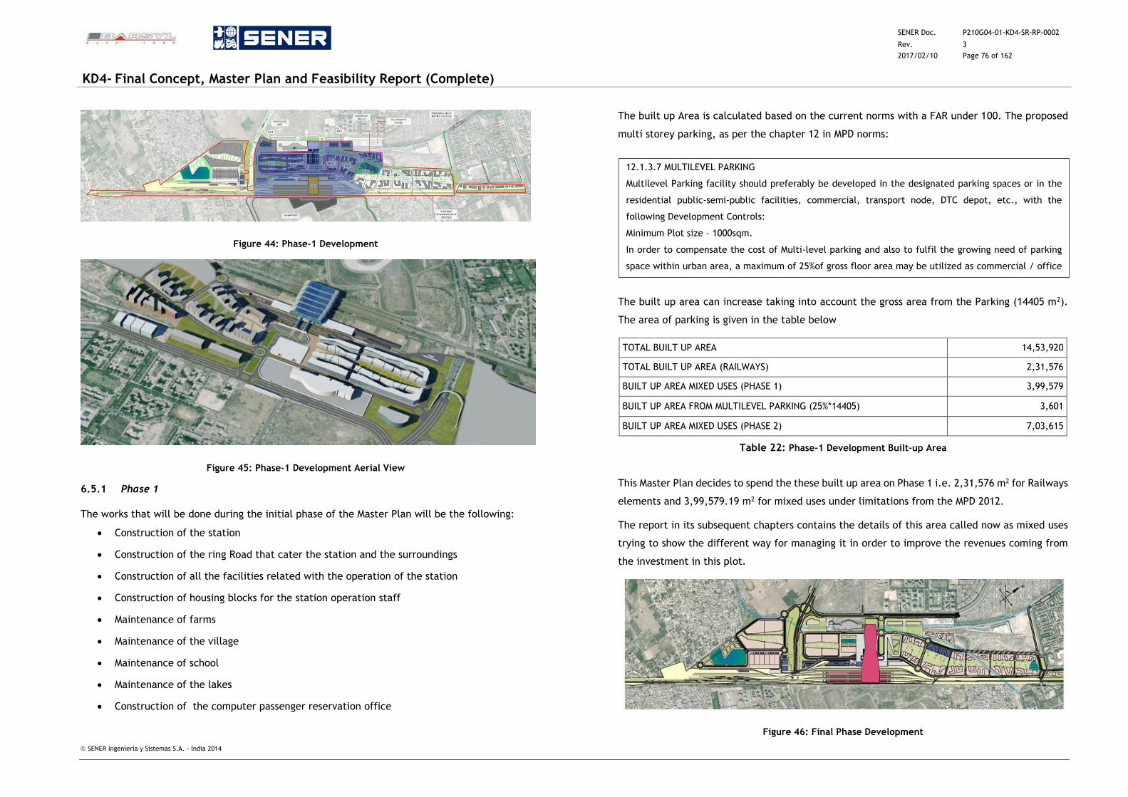
SENER Doc. P210G04-01-KD4-SR-RP-0002
Rev. 3
2017/02/10 Page 76 of 162
KD4- Final Concept, Master Plan and Feasibility Report (Complete)
SENER Ingeniería y Sistemas S.A. - India 2014
Figure 44: Phase-1 Development
Figure 45: Phase-1 Development Aerial View
6.5.1 Phase 1
The works that will be done during the initial phase of the Master Plan will be the following:
Construction of the station
Construction of the ring Road that cater the station and the surroundings
Construction of all the facilities related with the operation of the station
Construction of housing blocks for the station operation staff
Maintenance of farms
Maintenance of the village
Maintenance of school
Maintenance of the lakes
Construction of the computer passenger reservation office
The built up Area is calculated based on the current norms with a FAR under 100. The proposed
multi storey parking, as per the chapter 12 in MPD norms:
The built up area can increase taking into account the gross area from the Parking (14405 m2).
The area of parking is given in the table below
TOTAL BUILT UP AREA 14,53,920
TOTAL BUILT UP AREA (RAILWAYS) 2,31,576
BUILT UP AREA MIXED USES (PHASE 1) 3,99,579
BUILT UP AREA FROM MULTILEVEL PARKING (25%*14405) 3,601
BUILT UP AREA MIXED USES (PHASE 2) 7,03,615
Table 22: Phase-1 Development Built-up Area
This Master Plan decides to spend the these built up area on Phase 1 i.e. 2,31,576 m2 for Railways
elements and 3,99,579.19 m2 for mixed uses under limitations from the MPD 2012.
The report in its subsequent chapters contains the details of this area called now as mixed uses
trying to show the different way for managing it in order to improve the revenues coming from
the investment in this plot.
Figure 46: Final Phase Development
12.1.3.7 MULTILEVEL PARKING
Multilevel Parking facility should preferably be developed in the designated parking spaces or in the
residential public-semi-public facilities, commercial, transport node, DTC depot, etc., with the
following Development Controls:
Minimum Plot size – 1000sqm.
In order to compensate the cost of Multi-level parking and also to fulfil the growing need of parking
space within urban area, a maximum of 25%of gross floor area may be utilized as commercial / office
space.
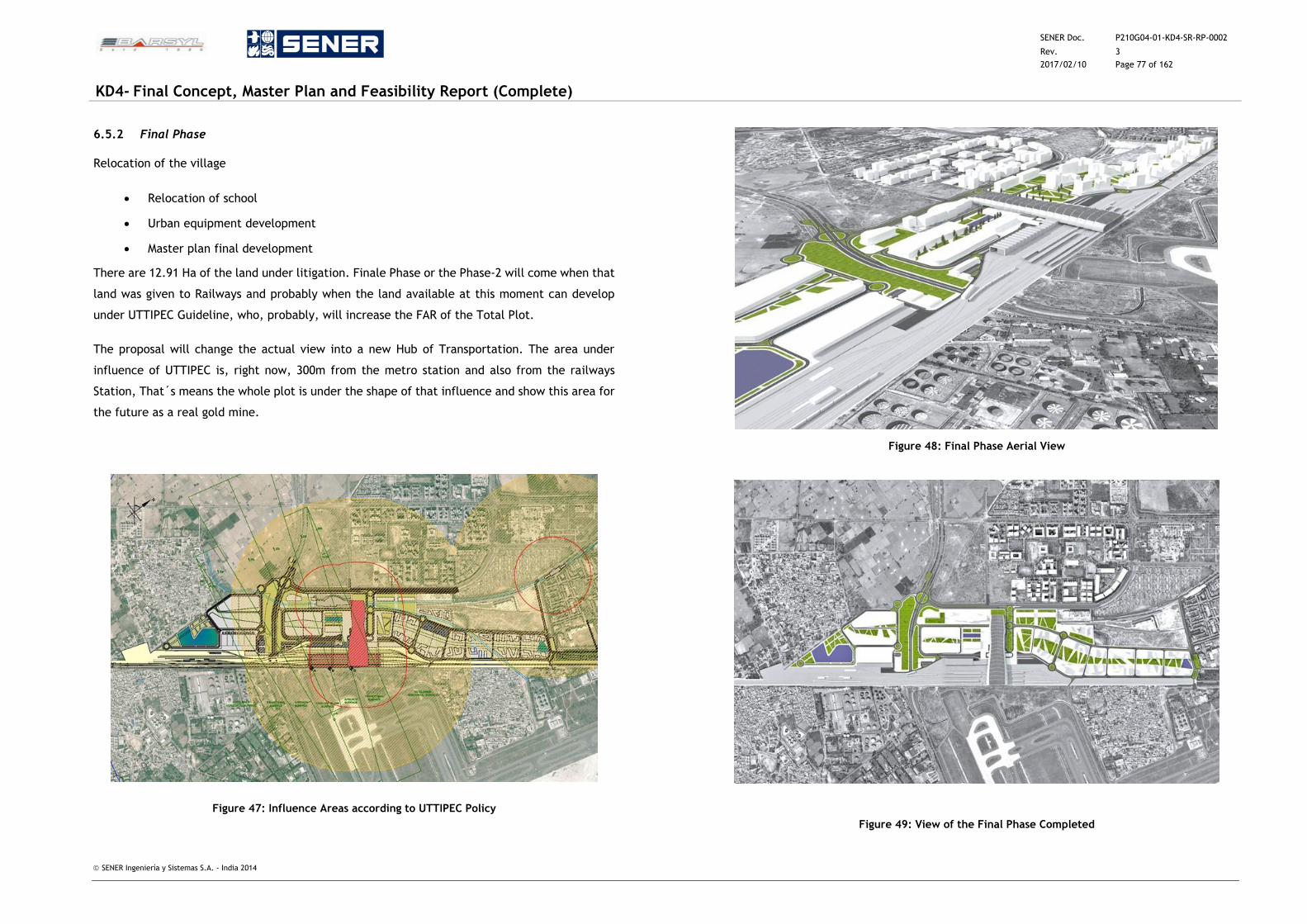
SENER Doc. P210G04-01-KD4-SR-RP-0002
Rev. 3
2017/02/10 Page 77 of 162
KD4- Final Concept, Master Plan and Feasibility Report (Complete)
SENER Ingeniería y Sistemas S.A. - India 2014
6.5.2 Final Phase
Relocation of the village
Relocation of school
Urban equipment development
Master plan final development
There are 12.91 Ha of the land under litigation. Finale Phase or the Phase-2 will come when that
land was given to Railways and probably when the land available at this moment can develop
under UTTIPEC Guideline, who, probably, will increase the FAR of the Total Plot.
The proposal will change the actual view into a new Hub of Transportation. The area under
influence of UTTIPEC is, right now, 300m from the metro station and also from the railways
Station, That´s means the whole plot is under the shape of that influence and show this area for
the future as a real gold mine.
Figure 47: Influence Areas according to UTTIPEC Policy
Figure 48: Final Phase Aerial View
Figure 49: View of the Final Phase Completed
SENER Doc. P210G04-01-KD4-SR-RP-0002
Rev. 3
2017/02/10 Page 78 of 162
KD4- Final Concept, Master Plan and Feasibility Report (Complete)
SENER Ingeniería y Sistemas S.A. - India 2014
7 STRUCTURAL AND GEOTECHNICAL CONCEPTS
7.1 Introduction
The structural design methodology explained in this chapter applies to the proposed station
buildings structure and all associated structures that are part of the development. The structural
concept design also contains brief references to all the facilities included on the Master Plan.
Bijwasan Railway Station Building will be a one-story building high over ground level structure,
and it will have a basement level and parking under this basement level at the west side (metro
station side).
The Station consists of a “bridge building” over the ground floor, leaving free room under their
spans for railway lines, roads and different vehicle or passenger access or exits.
7.2 Structural Considerations
The Design Concepts of the Structures is based on Limit State method of design as envisaged in
IS 456 – 2000, and all the structures will be designed for Dead loads, Imposed loads, Live loads,
Seismic loads and Wind loads taking into consideration the relevant Codes and load combination
specified in them. So, the objective of this chapter is to provide the concepts being adopted in
design of structures and facilities as per Relevant BIS, IRS and IRC codes while integrating
requirements of the project.
The proposed buildings will be designed in Reinforced Cement Concrete framed structures; steel
structures will be used for roofs and long span elements over the tracks. Concrete structures are
preferred because they need less maintenance than steel structures, which accounts to more
economic and sustainable buildings. Steel structures, on the other side, are required for easy
mounting and construction over non interruptible railway tracks, or where structural depth must
be keep to a minimum.
All underground structures, tanks, retaining walls, box culverts, etc. shall be designed as RCC
construction as per considered soil data. Waterproofing for water retaining structures shall be
carried out with injection type chemical grouting.
Given the huge dimensions of the Roof and its special variable shape, it will be worthy to conduct,
at a well-known Laboratory, a wind tunnel test to assess the real wind pressures on the structure.
These wind tunnels tests have long proved to be of economical and structural relevance. They
help to quickly point out potential local suction/pressure peak sources and also to produce subtle
changes in roof geometry and materials that greatly benefits the general output.
Wind tunnels structure tests generally let Designer use smaller global forces on the main
structure, due to the fact that Code formulae are envelopes of multiple possible (and generally
most adverse) situations, while a wind tunnel test is focused in the real structure to be built and
the actual or future conditions at its surroundings.
7.3 Design Codes and Standards
The designs of the structures shall comply with the following Codes will be used in various stages
of works.
IRC Codes:
IRC -5 – 1985 : Standard Specification and Code of practice for Road
Bridges General feature of designs
IRC -6 – 2010 : Standard Specification and Code of practice for Road
Bridges – Loads and Stress
IRC -21 – 2000 : Standard Specification and Code of practice for Road
Bridges – Cement Concrete (Plain and Reinforcement)
IRC -37 – 2001 : Guidelines for the Design Flexible Pavements
IRC -15 – 2002 : Standard Specification and Code of practice for
Construction of Concrete Roads
IRS Codes:
IRS Substructure and Foundation code - 1985
IRS Bridge Rules – 1986
IRS Concrete Bridge Code – 1997
SENER Doc. P210G04-01-KD4-SR-RP-0002
Rev. 3
2017/02/10 Page 79 of 162
KD4- Final Concept, Master Plan and Feasibility Report (Complete)
SENER Ingeniería y Sistemas S.A. - India 2014
IS Codes:
IS 456- 2000 : Plain and Reinforced Concrete – Code of Practice.
IS 800- 1998 : Code of Practice for General Construction in Steel
IS 2950(Part–1) : Code of Practice for Design and Construction of Raft Foundations.
IS 2911
(Part1/sec.1)
: Code of Practice for Design and Construction of Pile. Foundations for Driven Cast
In – Situ Concrete Piles.
IS 2911
(Part 1/sec.2)
: Code of Practice for Design and Construction of Pile. Foundations for Bored Cast
In – Situ Concrete Piles.
IS 2911
(Part 1/sec.3)
: Code of Practice for Design and Construction of Pile. Foundations for Driven
Precast Concrete Piles.
IS 2911
(Part 1/sec.4)
: Code of Practice for Design and Construction of Pile.
Foundations for Bored Precast Concrete Piles.
IS 2911(Part III) : Code of Practice for Design and Construction of Pile. Foundations for Under –
Reamed Piles.
IS 2911(Part IV) : Code of Practice for Design and Construction of Pile. Foundations for Load Test
on Piles.
IS 6403 : Code of practice for determination of bearing capacity of shallow foundations.
IS 9556 : Code of Practice for Design and Construction of Diaphragm Walls.
IS 1904 : Code of Practice for Design and Construction of Foundations in Soils –General
Requirements.
IS 14593 : Design and Construction of Bored Cast – in – situ Piles founded on Rock – General
Requirements.
IS 806 : Code of Practice for use of Steel Tubes in General Building Construction.
IS 1893 – 2002 : Criteria of Earthquake Resistant Design of Structures: Part – 1 – Buildings.
IS 875 : Code of Practice for Design Loads (Other than Earthquake) Parts 1 to 5.
IS 4326 : Earthquake Resistant Design and Construction of Buildings.
IS 13920 : Ductile Detailing of Reinforced Concrete Structures Subjected to Seismic Forces.
IS 8009 : Code of Practice for Calculation of Settlement of foundations (Part 1 and 2)
IS 1343 : Code of Practice for Prestressed Concrete.
IS 3370 : Code of Practice for concrete Structures for the Storage of Liquids (Parts 1 to 4)
IS 2974 : Code of Practice for Design and Construction of Machine Foundations (Parts 1 to
5)
IS 4923 : Hollow Steel Sections for Structural use.
IS 10270 : Guidelines for Design and Construction of Prestressing Rock Anchors.
IS 12070 : Code of Practice for Design and Construction of Shallow Foundations on Rock.
SP 16: 1980 : Design aids for reinforced concrete to IS 456: 1978
SP34: 1987 : Handbook on concrete reinforcement and detailing.
-- National Building Code of India
Table 23: IS Codes
Where the design is not covered by Indian Standards, reference shall be made to international
standards for guidance.
Standard Software:
STAAD Pro – for Analysis and Design
In-house developed Excel Spread Sheets for Designs
Auto Cad - for Drawings.
7.4 Materials
Concrete
Keeping the durability and structural requirement, the proposed strength of various elements of
structure will be as follows:
fck = 40 MPa (precast elements, if necessary)
fck = 30 MPa (all in situ structures, except foundations)
fck = 25 MPa (foundations)
fck = 10 MPa (levelling concrete)
Concrete characteristics as detailed above might need to be improved if the structure
environment is found to be particularly aggressive (soil or water). This shall be assessed on case-
by-case basis, determining the cement characteristics, water/cement ratio, additives, etc, as
required by the applicable Codes.
Reinforcement Steel
Thermo–Mechanically treated reinforcement bars of grade Fe500 conforming to IS – 1786 will be
adopted. Yield Stress: Fy – 500 MPa for Fe500.
Structural steel
Mild steel (MS) with a yield stress of 250 N/mm² shall be used for structural steel work. High
grade (H6) steel with a yield stress of 350 N/mm2.
SENER Doc. P210G04-01-KD4-SR-RP-0002
Rev. 3
2017/02/10 Page 80 of 162
KD4- Final Concept, Master Plan and Feasibility Report (Complete)
SENER Ingeniería y Sistemas S.A. - India 2014
7.5 Loading Standards
Dead load
All self-weight of structural members shall be considered as per IS 875 Part – I. Unit weights of
various buildings materials used are as follows:
25 kN/m3 For prestressed concrete
25 kN/m3 For reinforced cement concrete
24 kN/m3 For plain cement concrete
20 kN / m3 For Brick masonry
14 kN / m3 For Ordinary Portland cements
15.5 kN / m3 For Earth dry
19.0 kN / m3 For Earth moist
27 kN / m3 For Natural stone / Granite
20 kN / m3 For Cement Mortar
18 kN / m3 For Fine river sand
23.5 kN / m3 For Stone Masonry
78.5 kN / m3 For Steel
10 kN / m3 For Water
Imposed Loads
All the Imposed Loads shall be considered as per IS 875 Part-II.
The imposed loads recommended herein are for UDL (Uniformly Distributed Load) over the Floor.
Loading for floor finishes / Utilities / Piping / Cables / Ducts / False Ceiling etc. hanging from
slabs / beams shall be taken separately, in addition to the live loads mentioned below.
Live loads
The following Live loads are the estimated for the structural designing of the commercial &
residential buildings:
Live Load of 500 kg. / Sq. m. for commercial & public areas
Live Load of 200 kg. / Sq. m. for residential areas on buildings.
Live Load of 150 kg. / Sq. m. for terrace floor
Water tanks, cooling towers etc. shall be taken as per the manufacturer’s specs.
Wind Load
The Design Wind Load on Buildings shall be in accordance with IS 875 (Part 3): 1987
The Wind load on Building shall be calculated for:
The Building as a whole
Individual Structural elements as roofs and Walls
Individual Cladding units and including glazing and their fixings.
The design wind parameters are:
Basic design wind speed = 39 m/s (10m height in open terrain)
Buildings’ design life of 100 years
Terrain category 1
Class C structure
Topography plain
Seismic loads
Seismic load calculations shall be considered as per IS 1893
The proposed site is in seismic zone IV as per seismic zone map of India. Zone IV is a
High Damage Risk Zone.
SENER Doc. P210G04-01-KD4-SR-RP-0002
Rev. 3
2017/02/10 Page 81 of 162
KD4- Final Concept, Master Plan and Feasibility Report (Complete)
SENER Ingeniería y Sistemas S.A. - India 2014
Since the geometry of structure is irregular and higher seismic zone, dynamic analysis
shall be carried out.
The IS code establishes a maximum ground acceleration of 0.24 g for Zone 4, so Seismic
Loads are therefore very important and will play an important role on structure design.
Various design parameters for seismic analysis are as follows:
1. Zone factor (Z) = 0.24
2. Importance factor for the structure (I) = 1.0 / 1.5
3. Response reduction factor (R) = 5.0
4. Soil Type = Hard Soil
5. The horizontal earthquake force shall be calculated for the full dead load and 50%
of live loads.
6. The permissible stresses for concrete and steel shall be increased by 25% while
considering the seismic load. The SBC value shall be enhanced for all EQ
combinations as per Table – I of IS – 1893.
7. Base shear for the building shall be calculated as V ~ AhW considering the
coefficient defining the flexibility of the structure.
8. The horizontal and vertical load resisting elements of the stilt storey are to be
designed for 2.5 times storey shear and moments calculated under seismic load.
Load Combinations
All load combination shall be considered as per IS 1893.
Following Load Combinations shall be adopted for Analysis and Design of various Buildings:
1.5 (Dead Load + Live Load)
1.2 (Dead Load + Live Load + Earth Quake Wind Loads)
1.5 (Dead Load + Earth Quake / Wind Loads)
0.9 (Dead Load) +1.5 (Earth Quake / Wind Loads)
Load combination for Analysis and Design of stilt storey elements.
1.5 (Dead Load + Live Load)
1.2 (Dead Load + Live Load ± 2.5 Seismic)
1.5 (Dead Load ± 2.5* Earth Quake)
1.5 (Dead Load ± 2.5Live Load)
7.6 Structural Analysis and Design
All structural analysis and design work shall be carried out in conformance with IS-456, IS 800, IS
1893, IS 4326 and IS 13920, IS 3370 etc.
A 3-D Analysis and Design shall be carried out using standard software like STAAD. Soil
Investigations as performed shall be diligently followed while designing the foundations and the
same shall be checked for all the Load Cases including the Earthquake Load Combinations. As
per the soil test report, the Isolated/ combined / raft foundations shall be placed at a level 1.5m
to 4.5m below the rail level/ NGL whichever is lower. Minimum bearing pressure shall be taken
as per the soil report ranging 15 to 30t/m2 or as per the geotechnical survey report for various
types or locations.
The buildings shall be checked for short term and long term deflections.
Load Assumptions
Units
All units are specified in MKS system for solving equations. Forces are in KGs and moments are
in KG-M.
Sign Convention
Positive sign indicates compression and negative sign indicate Tension.
Dead Weight
The dead weight is assumed including all fittings.
Wind Loads
Basis wind speed, Vb is 47 m/s. (As per IS 875 Part 3)
Basic wind speed is modified according to following factors:
Vz = Vb x k1 x k2 x k3
K1 = 1.06 Risk factor considering communication buildings with mean probable life of 100 years.
SENER Doc. P210G04-01-KD4-SR-RP-0002
Rev. 3
2017/02/10 Page 82 of 162
KD4- Final Concept, Master Plan and Feasibility Report (Complete)
SENER Ingeniería y Sistemas S.A. - India 2014
K2 = Factor considering terrain height and structure size. Terrain category as 3 & class C,
structure height is 40m from ground; k2 = 1.09 (Main Station Building)
K3 = Topography factor. The site is surrounded by flat land, k3 = 1.
Vz = 47 x 1.06 x 1.09 x 1 = 54.3 m/s
Design wind pressure, Pz = 0.6 x Vz2 = 0.6 x 54.32 = 1769 N/m2 = 177 kg/m2
Seismic loading
Referring to IS 1893: 2002, the design horizontal seismic coefficient Ah for the structure shall be
calculated by the following expression.
Ah = (Z I Sa) / (2 R g)
Z = Zone factor = 0.24
I = Importance factor = 1.5
Sa/g = Average response acceleration coefficient = 2
R = Response reduction factor is taken as 5.
Ah = 0.072
Calculating base shear, VB = Ah x W
W = Seismic weight of the floor
7.7 Geo – technical engineering analysis and foundation concept
The Geotechnical Investigative Report gives a series of recommendations as follows:
Encountered soils are dense enough so buildings can be founded on shallow foundations at
minimum depth of 1.5m, always making sure that the Filling material is eliminated or passed
through. Thickness of Filling Material is up to 2 m thick in boreholes S-6 and S-8.
Foundations can consist of footings at allowable bearing pressures of 150 kPa on residual soils
and highly weathered rock, and 300 kPa on the underlying moderately weathered rock. Due to
seismic conditions, foundations may need to be tied in two directions.
Either footing or mat foundations are suitable.
Allowable bearing capacities for footings are in the range of 11 to 20 T/m2.
Calculations were made for widths 2 to 4 m and depths between 2 and 3 m.
Allowable bearing capacity for mat foundations is between 19 and 25 T/m2.
Seismicity: The project site lies in Zone IV with a/g = 0.24
The soils are not susceptible to liquefaction
7.7.1 Design Approach
To assess the (preliminary) suitable type of foundation, calculations can be made based on the
number of floors above and below ground. In this way, the approach that does not require too
many assumptions about load magnitudes and distributions, and it can cover all cases included
in the three Options, on building basis.
The approach followed is as follows: in general terms, foundations occupy an area of the building
plan in an amount that depends on the building loads, the building geometry and the soil
characteristics. The following parameters are related to the building and the soil:
𝒒𝒄 Unconfined Compression Stress of the soil. This value can be obtained directly from
the related laboratory test for clays, or from correlations from field tests (SPT blows,
dynamic tests (e.g. DPSH) or static tests (e.g. cone penetration tests).
𝝈𝑴 Maximum stress transmitted by the building. Calculated as the summation of all the
vertical column loads and dividing it by the influence area.
𝒁𝒙 Depth of basement excavation.
𝜸𝒙 Specific weight of excavated soil.
𝝈𝒔 Soil stress, defined as 𝜎𝑠 = 𝑞𝑐 + 𝛾𝑥 ∙ 𝑍𝑥
Table 24: Parameters related to Building and Soil
A discrimination criterion is defined as r, Stress Compensation Ratio:
r =σMσs
=σM
qc + γx ∙ Zx
The limits of use of r are established with some overlapping, so in certain zones, at least two
options are examined before taking a decision, as it is understood that the values of r are
provisional, and a detailed assessment (with more building and soil data) will verify the proposed
SENER Doc. P210G04-01-KD4-SR-RP-0002
Rev. 3
2017/02/10 Page 83 of 162
KD4- Final Concept, Master Plan and Feasibility Report (Complete)
SENER Ingeniería y Sistemas S.A. - India 2014
foundation. The only advantage of this approach is that it gives the more probable foundation
solution. These limits are as follows:
𝟎 ≤ 𝒓 ≤ 𝟎. 𝟔 Shallow foundation: Footings, combined footings and strip foundation
𝟎. 𝟒 ≤ 𝒓 ≤ 𝟏 Shallow foundation: Mat
𝟎. 𝟖 ≤ 𝒓 Deep foundation: Piles
Table 25: Limits of Use of 'r '
Applying this method, it was found that most of the buildings can be founded on footings, and
only those with big difference between weight of the building and weight of excavated soil (for
basements) would need mat foundation. Piled foundations were not needed.
7.7.2 Conditions for Shallow Foundations
From the preliminary evaluation, it was found that either footings or mat foundations were
suitable foundation types. The next step would be to analyze, on building basis, firstly the
suitability of a footing foundation, and, if conditions are no met, go for a mat foundation type.
A footing-based foundation should comply simultaneously with the following conditions:
1. Allowable bearing capacity
σ_ave< σ_allowable
The following values can be taken at different depths:
15-20 T/m2 near surface (as indicated by the Geotechnical Investigations report)
30 T/m2 for one or two basements
2. Geometric limitation of footing plan dimensions:
B, L > 0.8 m
B, L < 4 m (assumed for columns span in the order of 7 m)
Where B and L are the plan dimensions
3. Settlement limitation:
Total settlement: s< s_max=5 cm
Angular distortion: ∆s⁄l<1⁄500
Where:
s: Settlement under footing
l: Span (length separation) between adjacent columns
∆s: Differential settlement between adjacent columns or footings
7.7.3 Conditions for Mat Foundations
If the above three conditions are not met, then a mat foundation should be designed.
A mat foundation is also recommended when the building is heavy (high number of floors) with
basements, so the weight of the buildings is totally or partially compensated with the weight of
the excavated soil. It is not recommended for buildings where the foundation base is located less
than 2 m below ground level.
For buildings with a significant variation of loads (i.e. zones with different number of floors) mat
foundations has to be carefully analysed, as a significant variation in transmitted pressures to
the soil may cause differential settlements; additionally, the mat foundation has to be checked
against excessive eccentricity of the loads with respect to the soil reaction, as this can produce
an overturning moment.
7.7.4 Open Excavations for Underground Structures
In order to execute open excavations, the following is recommended:
Excavation for one basement: Can be done either with no earth support system but slope
inclination of at least 45º, if there is enough space around the site. Alternatively for vertical
excavation, sheet piles or soldier piles can be used.
Excavation for two basements: A suitable system can be sheet piles, with at least two levels of
support (either anchors or struts, depending on width of excavation).
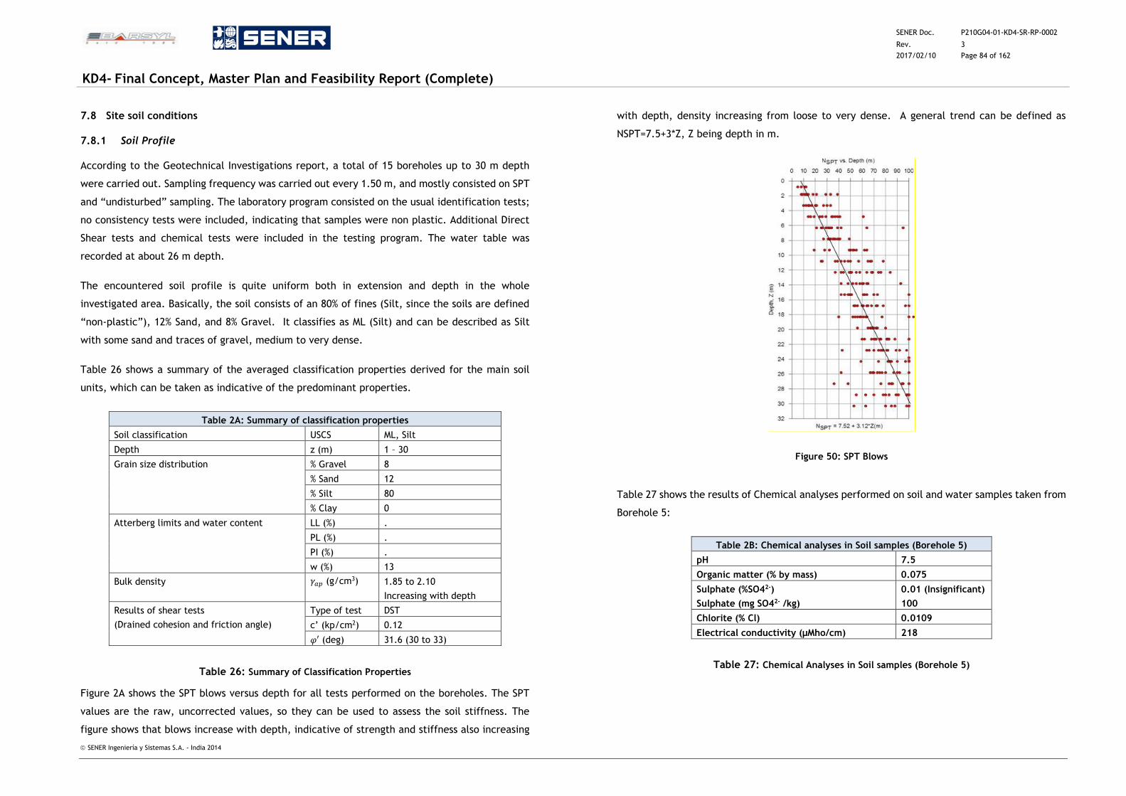
SENER Doc. P210G04-01-KD4-SR-RP-0002
Rev. 3
2017/02/10 Page 84 of 162
KD4- Final Concept, Master Plan and Feasibility Report (Complete)
SENER Ingeniería y Sistemas S.A. - India 2014
7.8 Site soil conditions
7.8.1 Soil Profile
According to the Geotechnical Investigations report, a total of 15 boreholes up to 30 m depth
were carried out. Sampling frequency was carried out every 1.50 m, and mostly consisted on SPT
and “undisturbed” sampling. The laboratory program consisted on the usual identification tests;
no consistency tests were included, indicating that samples were non plastic. Additional Direct
Shear tests and chemical tests were included in the testing program. The water table was
recorded at about 26 m depth.
The encountered soil profile is quite uniform both in extension and depth in the whole
investigated area. Basically, the soil consists of an 80% of fines (Silt, since the soils are defined
“non-plastic”), 12% Sand, and 8% Gravel. It classifies as ML (Silt) and can be described as Silt
with some sand and traces of gravel, medium to very dense.
Table 26 shows a summary of the averaged classification properties derived for the main soil
units, which can be taken as indicative of the predominant properties.
Table 2A: Summary of classification properties
Soil classification USCS ML, Silt
Depth z (m) 1 – 30
Grain size distribution % Gravel 8
% Sand 12
% Silt 80
% Clay 0
Atterberg limits and water content LL (%) .
PL (%) .
PI (%) .
w (%) 13
Bulk density 𝛾𝑎𝑝 (g/cm3) 1.85 to 2.10
Increasing with depth
Results of shear tests
(Drained cohesion and friction angle)
Type of test DST
c’ (kp/cm2) 0.12
𝜑′ (deg) 31.6 (30 to 33)
Table 26: Summary of Classification Properties
Figure 2A shows the SPT blows versus depth for all tests performed on the boreholes. The SPT
values are the raw, uncorrected values, so they can be used to assess the soil stiffness. The
figure shows that blows increase with depth, indicative of strength and stiffness also increasing
with depth, density increasing from loose to very dense. A general trend can be defined as
NSPT=7.5+3*Z, Z being depth in m.
Figure 50: SPT Blows
Table 27 shows the results of Chemical analyses performed on soil and water samples taken from
Borehole 5:
Table 2B: Chemical analyses in Soil samples (Borehole 5)
pH 7.5
Organic matter (% by mass) 0.075
Sulphate (%SO42-)
Sulphate (mg SO42- /kg)
0.01 (Insignificant)
100
Chlorite (% Cl) 0.0109
Electrical conductivity (μMho/cm) 218
Table 27: Chemical Analyses in Soil samples (Borehole 5)
SENER Doc. P210G04-01-KD4-SR-RP-0002
Rev. 3
2017/02/10 Page 85 of 162
KD4- Final Concept, Master Plan and Feasibility Report (Complete)
SENER Ingeniería y Sistemas S.A. - India 2014
The soils content in sulphate is considered insignificant, according to EN 206-1:2008:
Chemical analyses in Water samples (Borehole 5)
(Water table encountered at 26 m depth)
EN 206-1:2008 CLASSIFICATION
FOR WATER CORROSIVENESS
AGAINST CONCRETE
pH 7.6 > 6.5 (XA1)
Sulphate as S03
Sulphate as SO42- (mg/l)
158
190
< 200 (XA1)
Chlorite (Cl Mg/l) 2027
Organic solid contents (Mg/l) 15
Inorganic Solid contents (Mg/l) 3896
Suspended solids 224
Amount of 0.02 N NaOH required to
neutralize 100 ml sample of water using
phenolphthalein as indicator (ml)
1.18 and 22.43
Table 28: Chemical Analyses in Water Samples (Borehole 5)
Effective Strength parameters ( 'c ,')
In drained conditions, the DSTs (Direct Shear Tests) performed on samples give values of drained
cohesion of 0.12 kp /cm2, and friction angle of 31º on average. These values
agree well with soil composed of silt with small contents of sand.
Deformation parameters ( 50'E, urE'
)
The values of the stiffness parameter (elastic modulus) adopted in a calculation require special
attention, as many soils show a non-linear behaviour from the very beginning of loading. In soil
mechanics the initial slope is usually indicated as 0E and the secant modulus at 50% strength
is denoted 50'E . For loading of soils (i.e. settlement under shallow foundation) one generally uses
50'E . Considering unloading problems (i.e. open excavations and earth retaining systems), one
needs instead an unloading-reloading modulus urE' .
For soils, both the unloading modulus, urE' , and the first loading modulus, 50'E , tend to increase
with the confining pressure. Hence, deep soil layers tend to have greater stiffness than shallow
layers.
An elastic modulus 50'E for these units can be derived based on soil type and SPT values. For
example, Stroud (1989) derived a correlation between the E'⁄N60 and q ⁄ qult values. Knowing
the design load (q) and estimating the ultimate bearing capacity (qult), it is possible to use his
correlation graph to estimate the average ground stiffness at working load on the basis of SPT
blow counts.
7.9 Bearing Capacity of Foundations
The Geo – Technical analysis of the substratum was performed to determine net safe bearing
capacity. Parameters obtained are based on various field and laboratory tests.
7.9.1 Design criteria
Any foundation is to be safe against possible failure against
Excessive Shear failure (the bearing pressure should be within permissible limits) and
Excessive Settlement.
The latter depends upon not only on the type of soil in the foundation but also on the type of
foundation, material used for construction and functionality of the structure.
7.9.2 Design Methodology
Footing Foundation has been analysed at a depth of 2.0m and 3.0m below the ground level.
Foundation in the present case rests on non-plastic soil. An allowable settlement for the footing
foundation is considered as 50mm.
Alternatively Raft Foundation has been analysed at a depth of 2.0m and 3.0m below the ground
level. Foundation in the present case rests on non-plastic soil. An allowable settlement for the
footing foundation is considered as 75mm.
7.9.3 Open Foundation
7.9.3.1 Bearing Capacity for Open Foundation
The subsoil profile indicates the reasonably good soil/ SDR / HDR at shallow depths ranging from
3m to 4.5 m at borehole locations. The bearing capacity for Shallow Foundations in soil has been
analysed in accordance with IS: 6403 – 1981. Foundations should not fail in shear, Factor of safety
of 2.5 is provided against bearing capacity failure. Standard Penetration Test (SPT) results are
also used to determine the safe bearing capacity of shallow foundation in accordance with IS:
6403 – 1981 for non – cohesive soils, hard clay. While using this approach the N value are
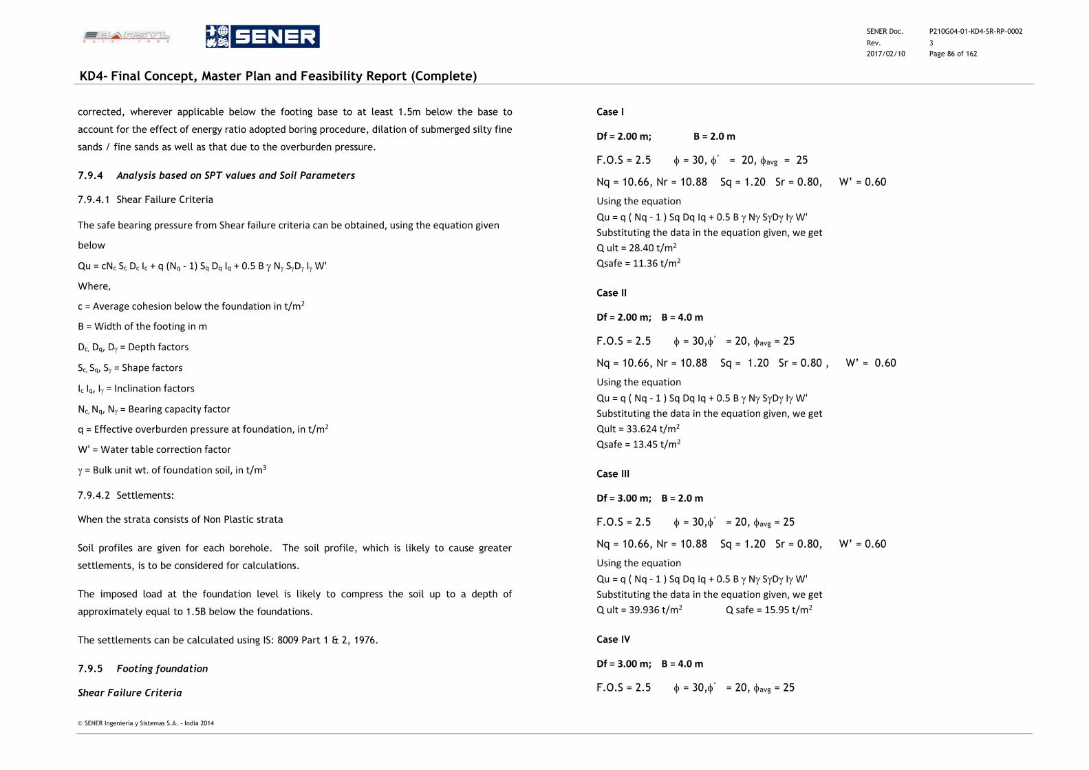
SENER Doc. P210G04-01-KD4-SR-RP-0002
Rev. 3
2017/02/10 Page 86 of 162
KD4- Final Concept, Master Plan and Feasibility Report (Complete)
SENER Ingeniería y Sistemas S.A. - India 2014
corrected, wherever applicable below the footing base to at least 1.5m below the base to
account for the effect of energy ratio adopted boring procedure, dilation of submerged silty fine
sands / fine sands as well as that due to the overburden pressure.
7.9.4 Analysis based on SPT values and Soil Parameters
7.9.4.1 Shear Failure Criteria
The safe bearing pressure from Shear failure criteria can be obtained, using the equation given
below
Qu = cNc Sc Dc Ic + q (Nq - 1) Sq Dq Iq + 0.5 B N SD I W'
Where,
c = Average cohesion below the foundation in t/m2
B = Width of the footing in m
Dc, Dq, D = Depth factors
Sc, Sq, S = Shape factors
Ic Iq, I = Inclination factors
Nc, Nq, N = Bearing capacity factor
q = Effective overburden pressure at foundation, in t/m2
W' = Water table correction factor
= Bulk unit wt. of foundation soil, in t/m3
7.9.4.2 Settlements:
When the strata consists of Non Plastic strata
Soil profiles are given for each borehole. The soil profile, which is likely to cause greater
settlements, is to be considered for calculations.
The imposed load at the foundation level is likely to compress the soil up to a depth of
approximately equal to 1.5B below the foundations.
The settlements can be calculated using IS: 8009 Part 1 & 2, 1976.
7.9.5 Footing foundation
Shear Failure Criteria
Case I
Df = 2.00 m; B = 2.0 m
F.O.S = 2.5 = 30, ’ = 20, avg = 25
Nq = 10.66, Nr = 10.88 Sq = 1.20 Sr = 0.80, W’ = 0.60
Using the equation
Qu = q ( Nq - 1 ) Sq Dq Iq + 0.5 B N SD I W'
Substituting the data in the equation given, we get
Q ult = 28.40 t/m2
Qsafe = 11.36 t/m2
Case II
Df = 2.00 m; B = 4.0 m
F.O.S = 2.5 = 30,’ = 20, avg = 25
Nq = 10.66, Nr = 10.88 Sq = 1.20 Sr = 0.80 , W’ = 0.60
Using the equation
Qu = q ( Nq - 1 ) Sq Dq Iq + 0.5 B N SD I W'
Substituting the data in the equation given, we get
Qult = 33.624 t/m2
Qsafe = 13.45 t/m2
Case III
Df = 3.00 m; B = 2.0 m
F.O.S = 2.5 = 30,’ = 20, avg = 25
Nq = 10.66, Nr = 10.88 Sq = 1.20 Sr = 0.80, W’ = 0.60
Using the equation
Qu = q ( Nq - 1 ) Sq Dq Iq + 0.5 B N SD I W'
Substituting the data in the equation given, we get
Q ult = 39.936 t/m2 Q safe = 15.95 t/m2
Case IV
Df = 3.00 m; B = 4.0 m
F.O.S = 2.5 = 30,’ = 20, avg = 25
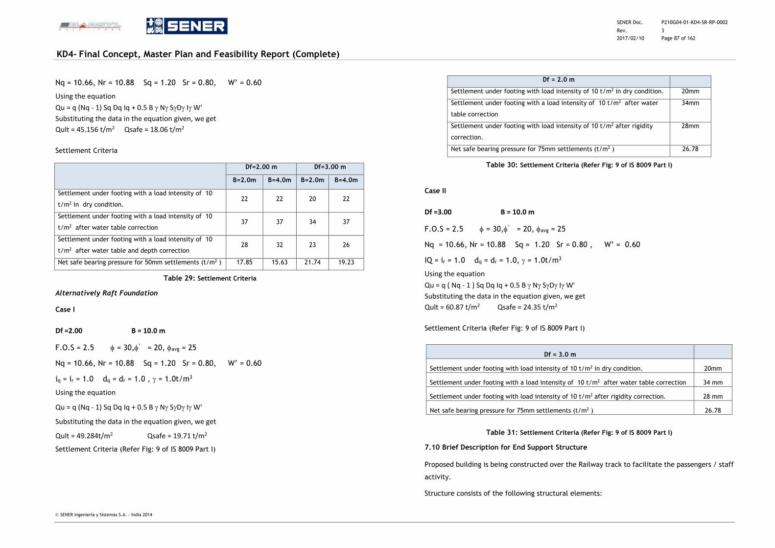
SENER Doc. P210G04-01-KD4-SR-RP-0002
Rev. 3
2017/02/10 Page 87 of 162
KD4- Final Concept, Master Plan and Feasibility Report (Complete)
SENER Ingeniería y Sistemas S.A. - India 2014
Nq = 10.66, Nr = 10.88 Sq = 1.20 Sr = 0.80, W’ = 0.60
Using the equation
Qu = q (Nq - 1) Sq Dq Iq + 0.5 B N SD I W'
Substituting the data in the equation given, we get
Qult = 45.156 t/m2 Qsafe = 18.06 t/m2
Settlement Criteria
Df=2.00 m Df=3.00 m
B=2.0m B=4.0m B=2.0m B=4.0m
Settlement under footing with a load intensity of 10
t/m2 in dry condition. 22 22 20 22
Settlement under footing with a load intensity of 10
t/m2 after water table correction 37 37 34 37
Settlement under footing with a load intensity of 10
t/m2 after water table and depth correction 28 32 23 26
Net safe bearing pressure for 50mm settlements (t/m2 ) 17.85 15.63 21.74 19.23
Table 29: Settlement Criteria
Alternatively Raft Foundation
Case I
Df =2.00 B = 10.0 m
F.O.S = 2.5 = 30,’ = 20, avg = 25
Nq = 10.66, Nr = 10.88 Sq = 1.20 Sr = 0.80, W’ = 0.60
iq = ir = 1.0 dq = dr = 1.0 , = 1.0t/m3
Using the equation
Qu = q (Nq - 1) Sq Dq Iq + 0.5 B N SD I W'
Substituting the data in the equation given, we get
Qult = 49.284t/m2 Qsafe = 19.71 t/m2
Settlement Criteria (Refer Fig: 9 of IS 8009 Part I)
Df = 2.0 m
Settlement under footing with load intensity of 10 t/m2 in dry condition. 20mm
Settlement under footing with a load intensity of 10 t/m2 after water
table correction
34mm
Settlement under footing with load intensity of 10 t/m2 after rigidity
correction.
28mm
Net safe bearing pressure for 75mm settlements (t/m2 ) 26.78
Table 30: Settlement Criteria (Refer Fig: 9 of IS 8009 Part I)
Case II
Df =3.00 B = 10.0 m
F.O.S = 2.5 = 30,’ = 20, avg = 25
Nq = 10.66, Nr = 10.88 Sq = 1.20 Sr = 0.80 , W’ = 0.60
IQ = ir = 1.0 dq = dr = 1.0, = 1.0t/m3
Using the equation
Qu = q ( Nq - 1 ) Sq Dq Iq + 0.5 B N SD I W'
Substituting the data in the equation given, we get
Qult = 60.87 t/m2 Qsafe = 24.35 t/m2
Settlement Criteria (Refer Fig: 9 of IS 8009 Part I)
Df = 3.0 m
Settlement under footing with load intensity of 10 t/m2 in dry condition. 20mm
Settlement under footing with a load intensity of 10 t/m2 after water table correction 34 mm
Settlement under footing with load intensity of 10 t/m2 after rigidity correction. 28 mm
Net safe bearing pressure for 75mm settlements (t/m2 ) 26.78
Table 31: Settlement Criteria (Refer Fig: 9 of IS 8009 Part I)
7.10 Brief Description for End Support Structure
Proposed building is being constructed over the Railway track to facilitate the passengers / staff
activity.
Structure consists of the following structural elements:
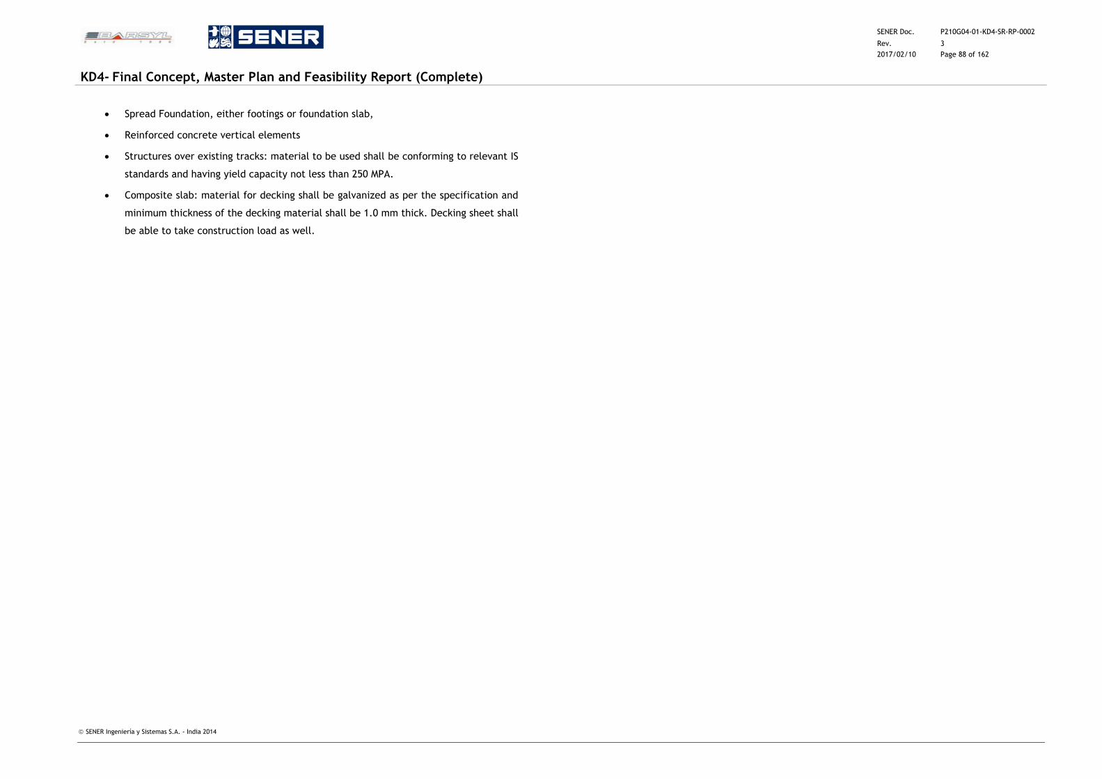
SENER Doc. P210G04-01-KD4-SR-RP-0002
Rev. 3
2017/02/10 Page 88 of 162
KD4- Final Concept, Master Plan and Feasibility Report (Complete)
SENER Ingeniería y Sistemas S.A. - India 2014
Spread Foundation, either footings or foundation slab,
Reinforced concrete vertical elements
Structures over existing tracks: material to be used shall be conforming to relevant IS
standards and having yield capacity not less than 250 MPA.
Composite slab: material for decking shall be galvanized as per the specification and
minimum thickness of the decking material shall be 1.0 mm thick. Decking sheet shall
be able to take construction load as well.
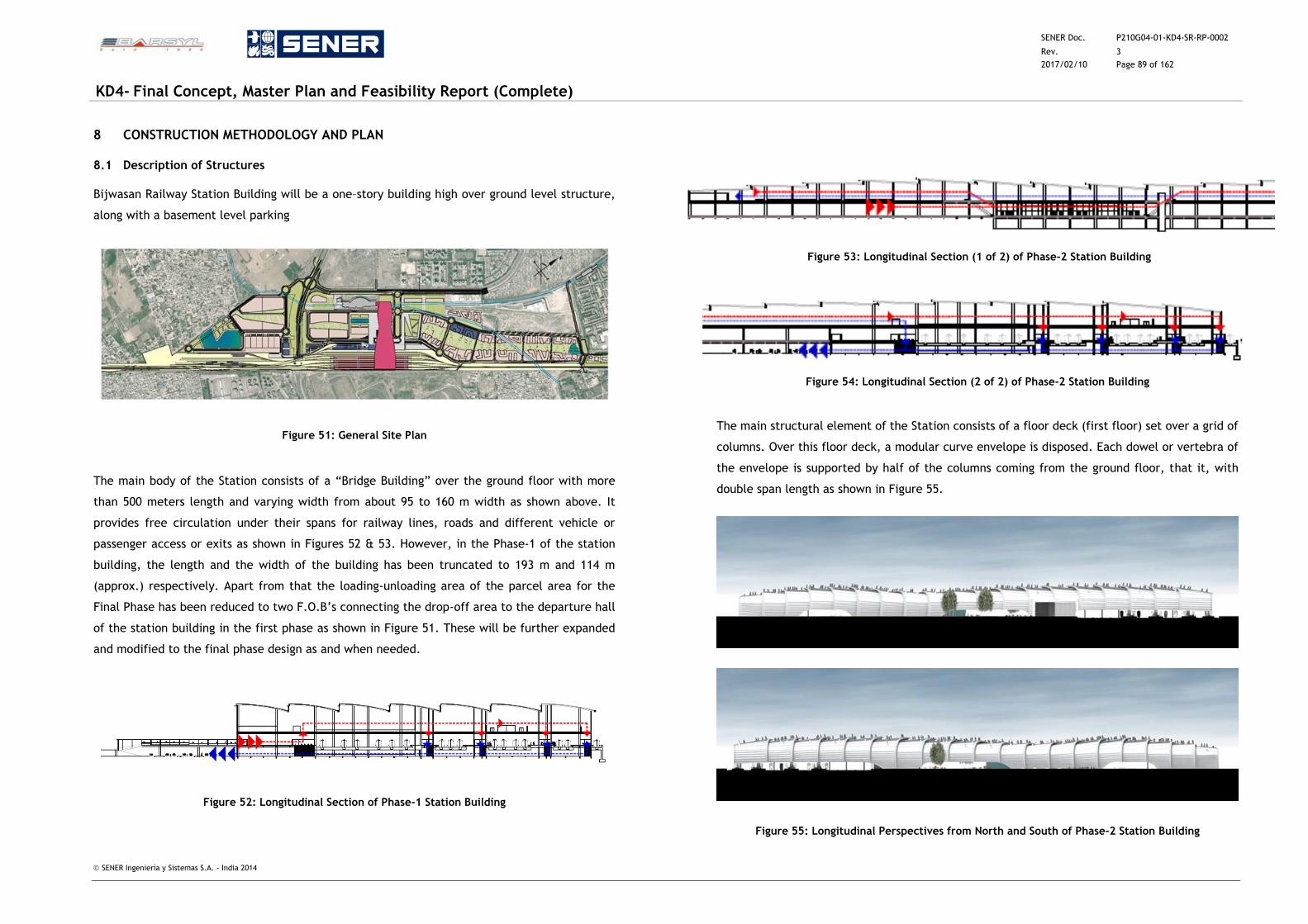
SENER Doc. P210G04-01-KD4-SR-RP-0002
Rev. 3
2017/02/10 Page 89 of 162
KD4- Final Concept, Master Plan and Feasibility Report (Complete)
SENER Ingeniería y Sistemas S.A. - India 2014
8 CONSTRUCTION METHODOLOGY AND PLAN
8.1 Description of Structures
Bijwasan Railway Station Building will be a one–story building high over ground level structure,
along with a basement level parking
Figure 51: General Site Plan
The main body of the Station consists of a “Bridge Building” over the ground floor with more
than 500 meters length and varying width from about 95 to 160 m width as shown above. It
provides free circulation under their spans for railway lines, roads and different vehicle or
passenger access or exits as shown in Figures 52 & 53. However, in the Phase-1 of the station
building, the length and the width of the building has been truncated to 193 m and 114 m
(approx.) respectively. Apart from that the loading-unloading area of the parcel area for the
Final Phase has been reduced to two F.O.B’s connecting the drop-off area to the departure hall
of the station building in the first phase as shown in Figure 51. These will be further expanded
and modified to the final phase design as and when needed.
Figure 52: Longitudinal Section of Phase-1 Station Building
Figure 53: Longitudinal Section (1 of 2) of Phase-2 Station Building
Figure 54: Longitudinal Section (2 of 2) of Phase-2 Station Building
The main structural element of the Station consists of a floor deck (first floor) set over a grid of
columns. Over this floor deck, a modular curve envelope is disposed. Each dowel or vertebra of
the envelope is supported by half of the columns coming from the ground floor, that it, with
double span length as shown in Figure 55.
Figure 55: Longitudinal Perspectives from North and South of Phase-2 Station Building
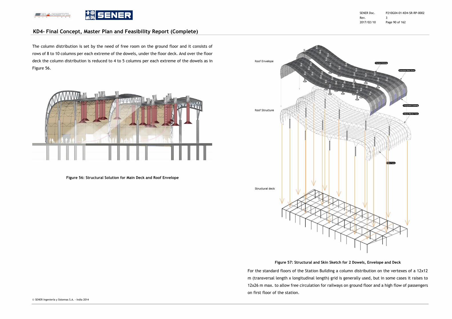
SENER Doc. P210G04-01-KD4-SR-RP-0002
Rev. 3
2017/02/10 Page 90 of 162
KD4- Final Concept, Master Plan and Feasibility Report (Complete)
SENER Ingeniería y Sistemas S.A. - India 2014
The column distribution is set by the need of free room on the ground floor and it consists of
rows of 8 to 10 columns per each extreme of the dowels, under the floor deck. And over the floor
deck the column distribution is reduced to 4 to 5 columns per each extreme of the dowels as in
Figure 56.
Figure 56: Structural Solution for Main Deck and Roof Envelope
Figure 57: Structural and Skin Sketch for 2 Dowels, Envelope and Deck
For the standard floors of the Station Building a column distribution on the vertexes of a 12x12
m (transversal length x longitudinal length) grid is generally used, but in some cases it raises to
12x26 m max. to allow free circulation for railways on ground floor and a high flow of passengers
on first floor of the station.
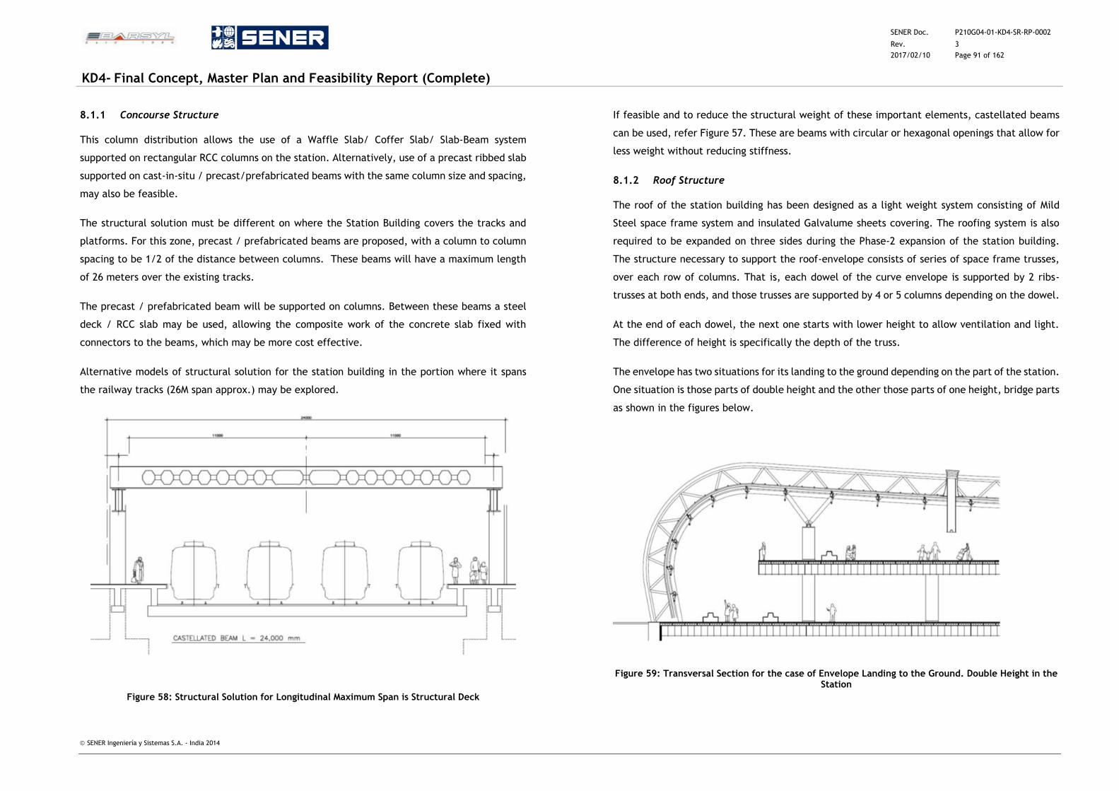
SENER Doc. P210G04-01-KD4-SR-RP-0002
Rev. 3
2017/02/10 Page 91 of 162
KD4- Final Concept, Master Plan and Feasibility Report (Complete)
SENER Ingeniería y Sistemas S.A. - India 2014
8.1.1 Concourse Structure
This column distribution allows the use of a Waffle Slab/ Coffer Slab/ Slab-Beam system
supported on rectangular RCC columns on the station. Alternatively, use of a precast ribbed slab
supported on cast-in-situ / precast/prefabricated beams with the same column size and spacing,
may also be feasible.
The structural solution must be different on where the Station Building covers the tracks and
platforms. For this zone, precast / prefabricated beams are proposed, with a column to column
spacing to be 1/2 of the distance between columns. These beams will have a maximum length
of 26 meters over the existing tracks.
The precast / prefabricated beam will be supported on columns. Between these beams a steel
deck / RCC slab may be used, allowing the composite work of the concrete slab fixed with
connectors to the beams, which may be more cost effective.
Alternative models of structural solution for the station building in the portion where it spans
the railway tracks (26M span approx.) may be explored.
Figure 58: Structural Solution for Longitudinal Maximum Span is Structural Deck
If feasible and to reduce the structural weight of these important elements, castellated beams
can be used, refer Figure 57. These are beams with circular or hexagonal openings that allow for
less weight without reducing stiffness.
8.1.2 Roof Structure
The roof of the station building has been designed as a light weight system consisting of Mild
Steel space frame system and insulated Galvalume sheets covering. The roofing system is also
required to be expanded on three sides during the Phase-2 expansion of the station building.
The structure necessary to support the roof-envelope consists of series of space frame trusses,
over each row of columns. That is, each dowel of the curve envelope is supported by 2 ribs-
trusses at both ends, and those trusses are supported by 4 or 5 columns depending on the dowel.
At the end of each dowel, the next one starts with lower height to allow ventilation and light.
The difference of height is specifically the depth of the truss.
The envelope has two situations for its landing to the ground depending on the part of the station.
One situation is those parts of double height and the other those parts of one height, bridge parts
as shown in the figures below.
Figure 59: Transversal Section for the case of Envelope Landing to the Ground. Double Height in the Station
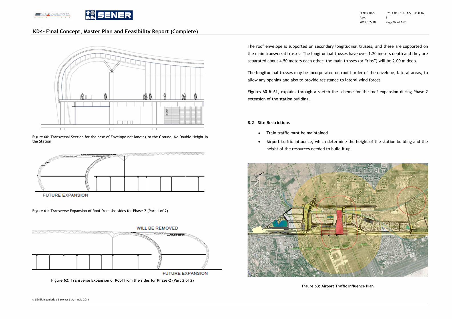
SENER Doc. P210G04-01-KD4-SR-RP-0002
Rev. 3
2017/02/10 Page 92 of 162
KD4- Final Concept, Master Plan and Feasibility Report (Complete)
SENER Ingeniería y Sistemas S.A. - India 2014
Figure 60: Transversal Section for the case of Envelope not landing to the Ground. No Double Height in the Station
Figure 61: Transverse Expansion of Roof from the sides for Phase-2 (Part 1 of 2)
Figure 62: Transverse Expansion of Roof from the sides for Phase-2 (Part 2 of 2)
The roof envelope is supported on secondary longitudinal trusses, and these are supported on
the main transversal trusses. The longitudinal trusses have over 1.20 meters depth and they are
separated about 4.50 meters each other; the main trusses (or “ribs”) will be 2.00 m deep.
The longitudinal trusses may be incorporated on roof border of the envelope, lateral areas, to
allow any opening and also to provide resistance to lateral wind forces.
Figures 60 & 61, explains through a sketch the scheme for the roof expansion during Phase-2
extension of the station building.
8.2 Site Restrictions
Train traffic must be maintained
Airport traffic influence, which determine the height of the station building and the
height of the resources needed to build it up.
Figure 63: Airport Traffic Influence Plan
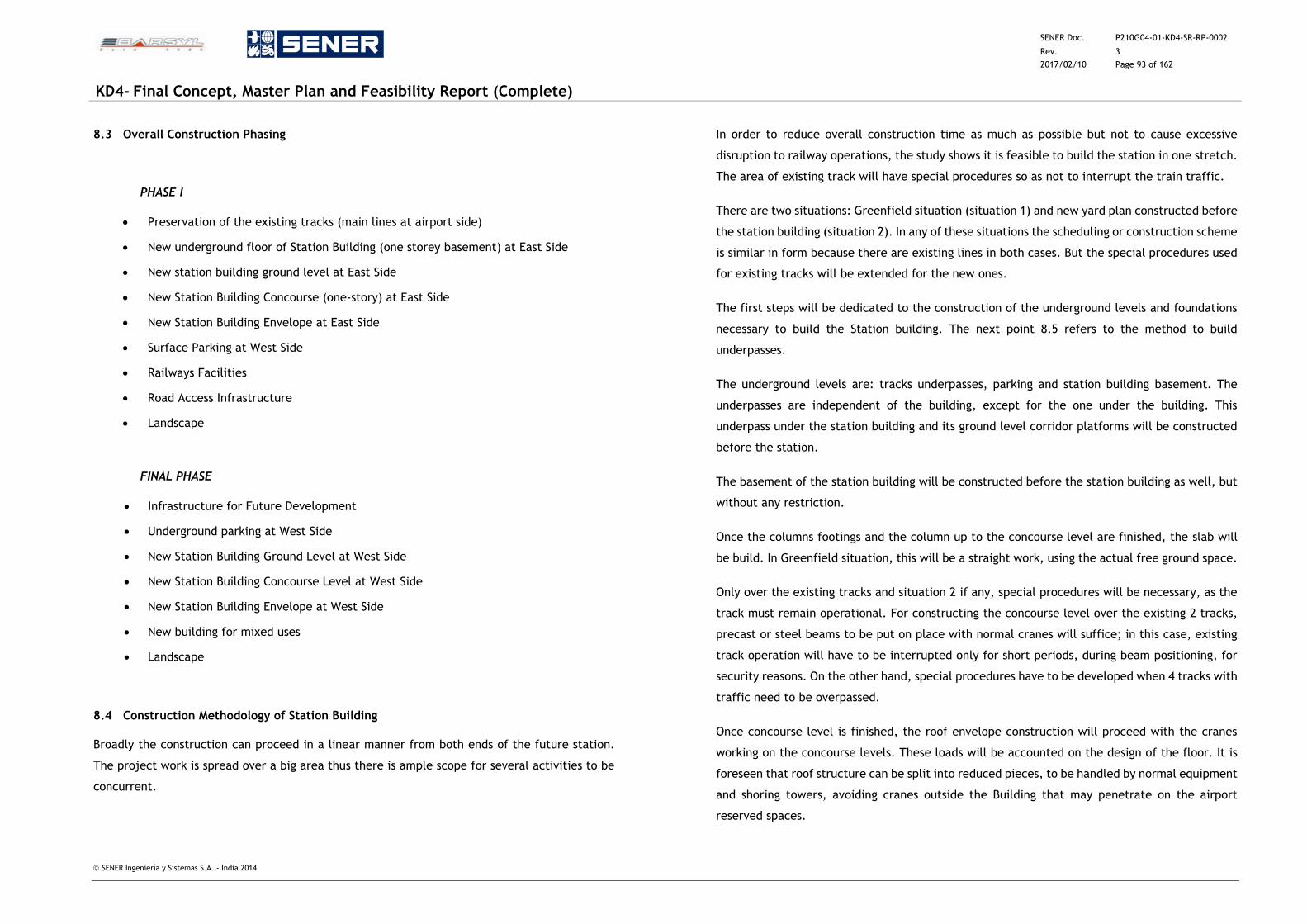
SENER Doc. P210G04-01-KD4-SR-RP-0002
Rev. 3
2017/02/10 Page 93 of 162
KD4- Final Concept, Master Plan and Feasibility Report (Complete)
SENER Ingeniería y Sistemas S.A. - India 2014
8.3 Overall Construction Phasing
8.3.1 PHASE I
Preservation of the existing tracks (main lines at airport side)
New underground floor of Station Building (one storey basement) at East Side
New station building ground level at East Side
New Station Building Concourse (one-story) at East Side
New Station Building Envelope at East Side
Surface Parking at West Side
Railways Facilities
Road Access Infrastructure
Landscape
8.3.2 FINAL PHASE
Infrastructure for Future Development
Underground parking at West Side
New Station Building Ground Level at West Side
New Station Building Concourse Level at West Side
New Station Building Envelope at West Side
New building for mixed uses
Landscape
8.4 Construction Methodology of Station Building
Broadly the construction can proceed in a linear manner from both ends of the future station.
The project work is spread over a big area thus there is ample scope for several activities to be
concurrent.
In order to reduce overall construction time as much as possible but not to cause excessive
disruption to railway operations, the study shows it is feasible to build the station in one stretch.
The area of existing track will have special procedures so as not to interrupt the train traffic.
There are two situations: Greenfield situation (situation 1) and new yard plan constructed before
the station building (situation 2). In any of these situations the scheduling or construction scheme
is similar in form because there are existing lines in both cases. But the special procedures used
for existing tracks will be extended for the new ones.
The first steps will be dedicated to the construction of the underground levels and foundations
necessary to build the Station building. The next point 8.5 refers to the method to build
underpasses.
The underground levels are: tracks underpasses, parking and station building basement. The
underpasses are independent of the building, except for the one under the building. This
underpass under the station building and its ground level corridor platforms will be constructed
before the station.
The basement of the station building will be constructed before the station building as well, but
without any restriction.
Once the columns footings and the column up to the concourse level are finished, the slab will
be build. In Greenfield situation, this will be a straight work, using the actual free ground space.
Only over the existing tracks and situation 2 if any, special procedures will be necessary, as the
track must remain operational. For constructing the concourse level over the existing 2 tracks,
precast or steel beams to be put on place with normal cranes will suffice; in this case, existing
track operation will have to be interrupted only for short periods, during beam positioning, for
security reasons. On the other hand, special procedures have to be developed when 4 tracks with
traffic need to be overpassed.
Once concourse level is finished, the roof envelope construction will proceed with the cranes
working on the concourse levels. These loads will be accounted on the design of the floor. It is
foreseen that roof structure can be split into reduced pieces, to be handled by normal equipment
and shoring towers, avoiding cranes outside the Building that may penetrate on the airport
reserved spaces.
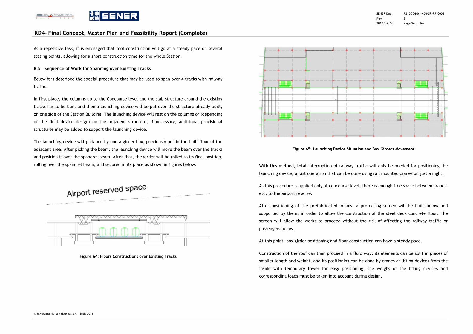
SENER Doc. P210G04-01-KD4-SR-RP-0002
Rev. 3
2017/02/10 Page 94 of 162
KD4- Final Concept, Master Plan and Feasibility Report (Complete)
SENER Ingeniería y Sistemas S.A. - India 2014
As a repetitive task, it is envisaged that roof construction will go at a steady pace on several
stating points, allowing for a short construction time for the whole Station.
8.5 Sequence of Work for Spanning over Existing Tracks
Below it is described the special procedure that may be used to span over 4 tracks with railway
traffic.
In first place, the columns up to the Concourse level and the slab structure around the existing
tracks has to be built and then a launching device will be put over the structure already built,
on one side of the Station Building. The launching device will rest on the columns or (depending
of the final device design) on the adjacent structure; if necessary, additional provisional
structures may be added to support the launching device.
The launching device will pick one by one a girder box, previously put in the built floor of the
adjacent area. After picking the beam, the launching device will move the beam over the tracks
and position it over the spandrel beam. After that, the girder will be rolled to its final position,
rolling over the spandrel beam, and secured in its place as shown in figures below.
Figure 64: Floors Constructions over Existing Tracks
Figure 65: Launching Device Situation and Box Girders Movement
With this method, total interruption of railway traffic will only be needed for positioning the
launching device, a fast operation that can be done using rail mounted cranes on just a night.
As this procedure is applied only at concourse level, there is enough free space between cranes,
etc, to the airport reserve.
After positioning of the prefabricated beams, a protecting screen will be built below and
supported by them, in order to allow the construction of the steel deck concrete floor. The
screen will allow the works to proceed without the risk of affecting the railway traffic or
passengers below.
At this point, box girder positioning and floor construction can have a steady pace.
Construction of the roof can then proceed in a fluid way; its elements can be split in pieces of
smaller length and weight, and its positioning can be done by cranes or lifting devices from the
inside with temporary tower for easy positioning; the weighs of the lifting devices and
corresponding loads must be taken into account during design.
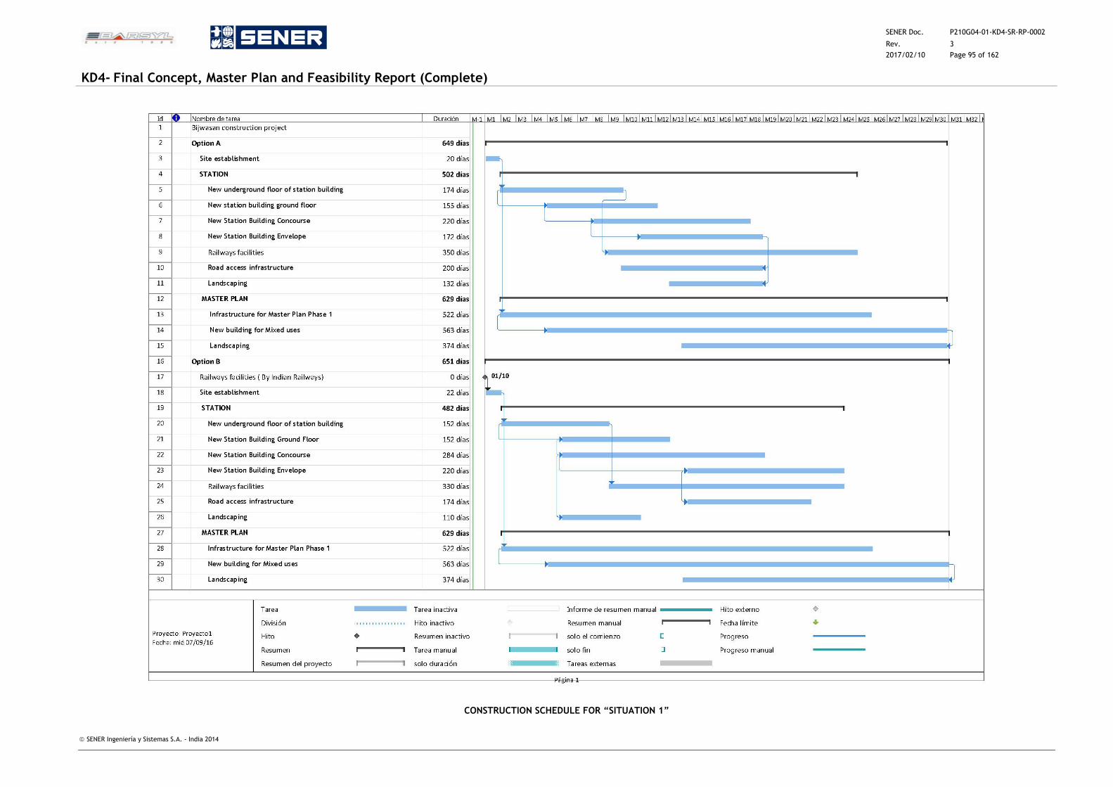
SENER Doc. P210G04-01-KD4-SR-RP-0002
Rev. 3
2017/02/10 Page 95 of 162
KD4- Final Concept, Master Plan and Feasibility Report (Complete)
SENER Ingeniería y Sistemas S.A. - India 2014
CONSTRUCTION SCHEDULE FOR “SITUATION 1”
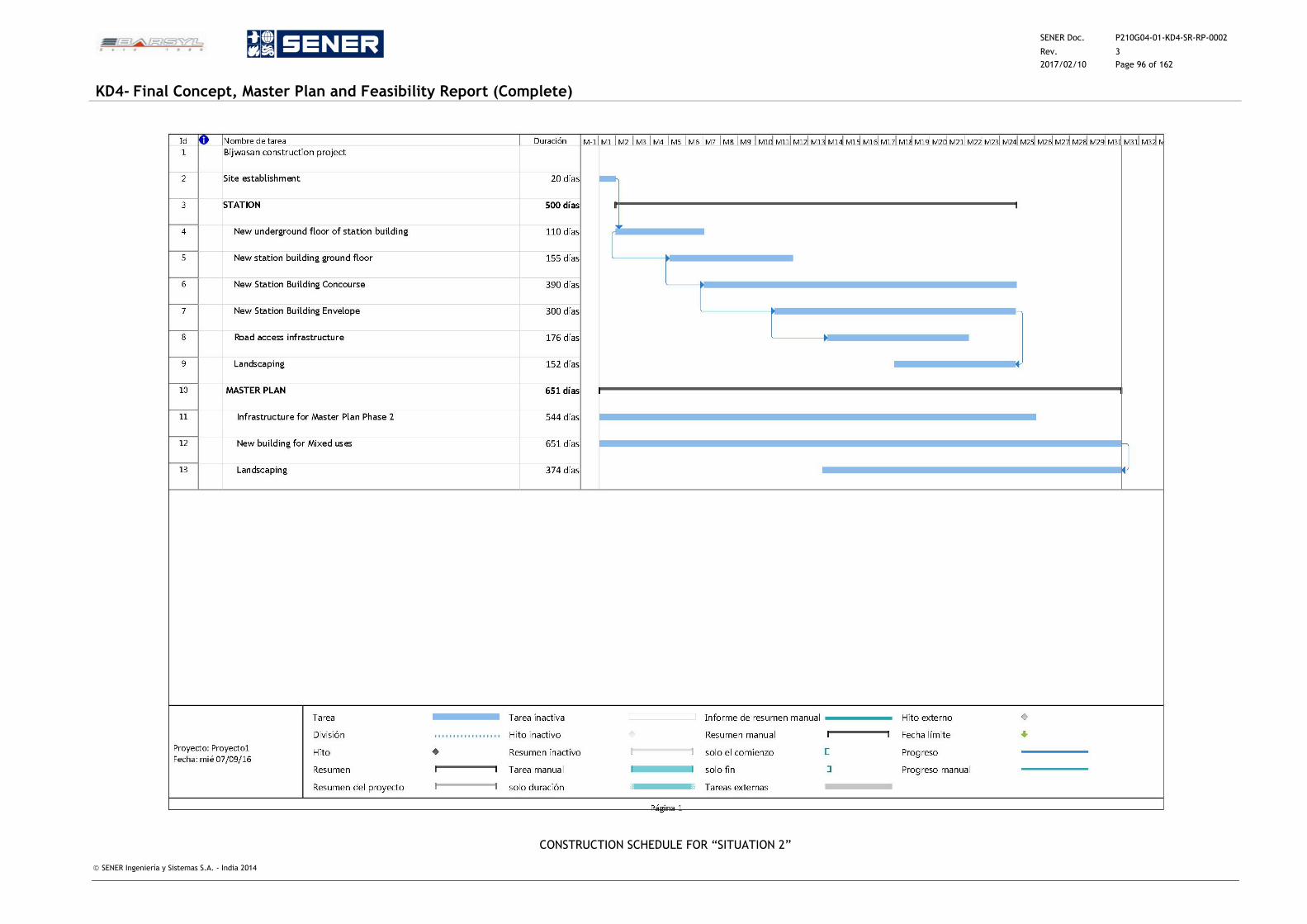
SENER Doc. P210G04-01-KD4-SR-RP-0002
Rev. 3
2017/02/10 Page 96 of 162
KD4- Final Concept, Master Plan and Feasibility Report (Complete)
SENER Ingeniería y Sistemas S.A. - India 2014
CONSTRUCTION SCHEDULE FOR “SITUATION 2”
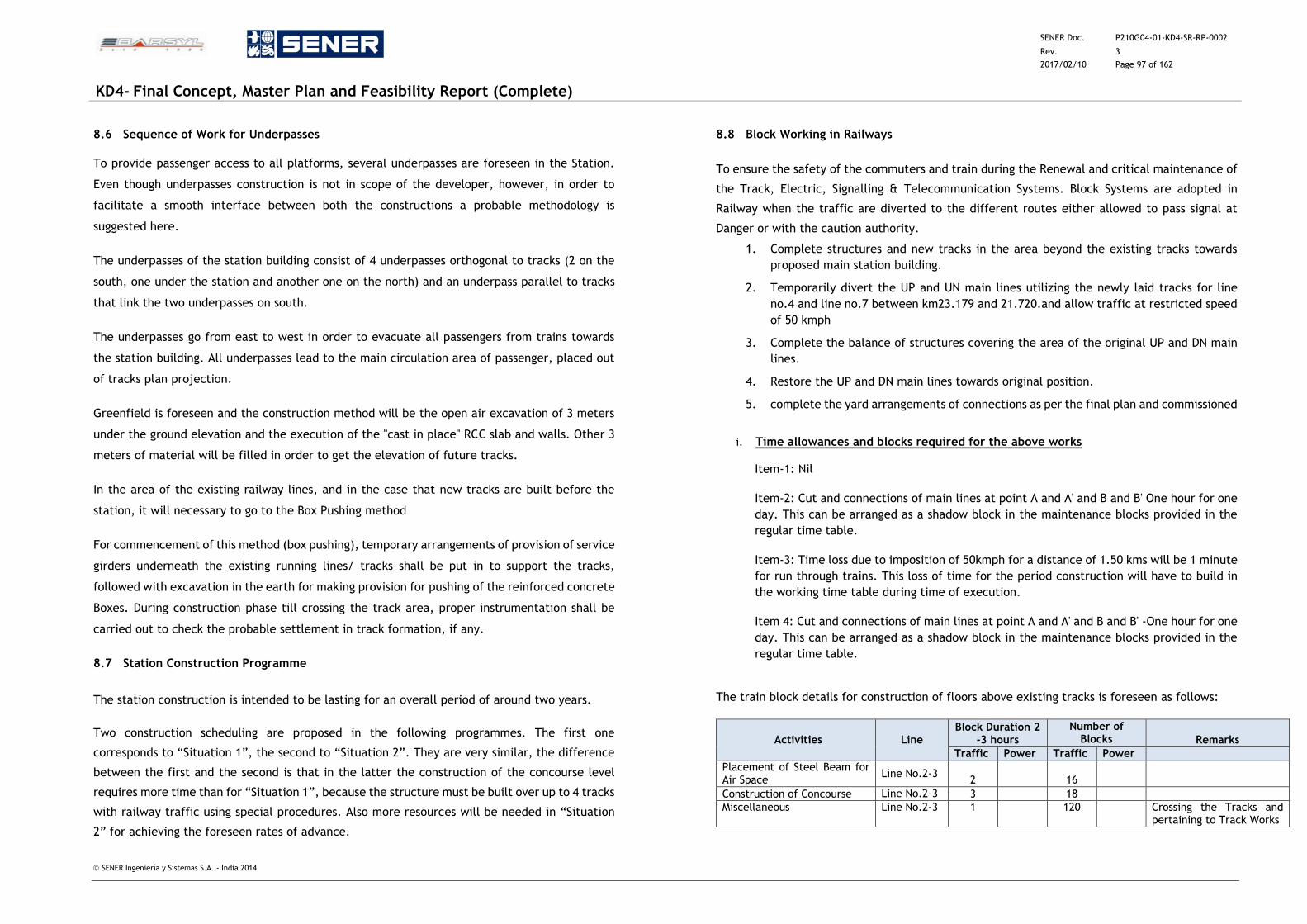
SENER Doc. P210G04-01-KD4-SR-RP-0002
Rev. 3
2017/02/10 Page 97 of 162
KD4- Final Concept, Master Plan and Feasibility Report (Complete)
SENER Ingeniería y Sistemas S.A. - India 2014
8.6 Sequence of Work for Underpasses
To provide passenger access to all platforms, several underpasses are foreseen in the Station.
Even though underpasses construction is not in scope of the developer, however, in order to
facilitate a smooth interface between both the constructions a probable methodology is
suggested here.
The underpasses of the station building consist of 4 underpasses orthogonal to tracks (2 on the
south, one under the station and another one on the north) and an underpass parallel to tracks
that link the two underpasses on south.
The underpasses go from east to west in order to evacuate all passengers from trains towards
the station building. All underpasses lead to the main circulation area of passenger, placed out
of tracks plan projection.
Greenfield is foreseen and the construction method will be the open air excavation of 3 meters
under the ground elevation and the execution of the "cast in place" RCC slab and walls. Other 3
meters of material will be filled in order to get the elevation of future tracks.
In the area of the existing railway lines, and in the case that new tracks are built before the
station, it will necessary to go to the Box Pushing method
For commencement of this method (box pushing), temporary arrangements of provision of service
girders underneath the existing running lines/ tracks shall be put in to support the tracks,
followed with excavation in the earth for making provision for pushing of the reinforced concrete
Boxes. During construction phase till crossing the track area, proper instrumentation shall be
carried out to check the probable settlement in track formation, if any.
8.7 Station Construction Programme
The station construction is intended to be lasting for an overall period of around two years.
Two construction scheduling are proposed in the following programmes. The first one
corresponds to “Situation 1”, the second to “Situation 2”. They are very similar, the difference
between the first and the second is that in the latter the construction of the concourse level
requires more time than for “Situation 1”, because the structure must be built over up to 4 tracks
with railway traffic using special procedures. Also more resources will be needed in “Situation
2” for achieving the foreseen rates of advance.
8.8 Block Working in Railways
To ensure the safety of the commuters and train during the Renewal and critical maintenance of
the Track, Electric, Signalling & Telecommunication Systems. Block Systems are adopted in
Railway when the traffic are diverted to the different routes either allowed to pass signal at
Danger or with the caution authority.
1. Complete structures and new tracks in the area beyond the existing tracks towards
proposed main station building.
2. Temporarily divert the UP and UN main lines utilizing the newly laid tracks for line
no.4 and line no.7 between km23.179 and 21.720.and allow traffic at restricted speed
of 50 kmph
3. Complete the balance of structures covering the area of the original UP and DN main
lines.
4. Restore the UP and DN main lines towards original position.
5. complete the yard arrangements of connections as per the final plan and commissioned
i. Time allowances and blocks required for the above works
Item-1: Nil
Item-2: Cut and connections of main lines at point A and A' and B and B' One hour for one
day. This can be arranged as a shadow block in the maintenance blocks provided in the
regular time table.
Item-3: Time loss due to imposition of 50kmph for a distance of 1.50 kms will be 1 minute
for run through trains. This loss of time for the period construction will have to build in
the working time table during time of execution.
Item 4: Cut and connections of main lines at point A and A' and B and B' -One hour for one
day. This can be arranged as a shadow block in the maintenance blocks provided in the
regular time table.
The train block details for construction of floors above existing tracks is foreseen as follows:
Activities Line Block Duration 2
-3 hours
Number of Blocks Remarks
Traffic Power Traffic Power
Placement of Steel Beam for Air Space
Line No.2-3 2 16
Construction of Concourse Line No.2-3 3 18
Miscellaneous Line No.2-3 1
120 Crossing the Tracks and pertaining to Track Works
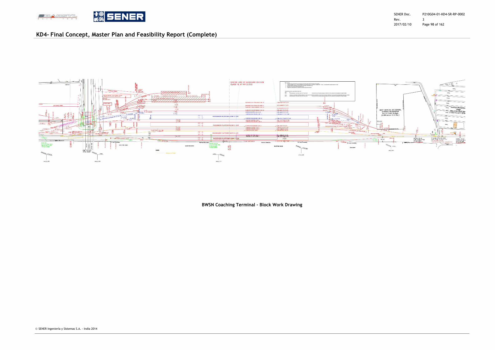
SENER Doc. P210G04-01-KD4-SR-RP-0002
Rev. 3
2017/02/10 Page 98 of 162
KD4- Final Concept, Master Plan and Feasibility Report (Complete)
SENER Ingeniería y Sistemas S.A. - India 2014
BWSN Coaching Terminal – Block Work Drawing
SENER Doc. P210G04-01-KD4-SR-RP-0002
Rev. 3
2017/02/10 Page 99 of 162
KD4- Final Concept, Master Plan and Feasibility Report (Complete)
SENER Ingeniería y Sistemas S.A. - India 2014
9 UTILITY INFRASTRUCTURE
9.1 Review of Existing Infrastructure
9.1.1 Introduction
The following paragraphs provide the utilities requirement for the redeveloped Bijwasan
Station and surrounding infrastructure.
The Railway station is located in Delhi State, close to the border with Haryana and Gurgaon city.
At present, the Railway Station comprises of the station building, two passenger platforms
connected with a foot over bridge and other related buildings located in the railway land. These
existing buildings are listed:
Station building: booking office, station manager office, panel and SM room, relay room,
battery and S&T equipment room, RPF staff, data logger and machine equipment, booking
and enquiry counters, booking counter queuing hall and covered sheds for waiting
passengers.
East Cabin at Delhi end with relay and battery room
West Cabin at Rewari end with relay and battery room
6 residential
16 new staff quarters are under construction near the ROB of Bijwasan
2 platforms (375m x 11m and 375m x 9m)
Foot over bridge
9.1.2 Water Supply Facility
The present supply of Water at existing Bijwasan station for the entire Railway complex
consisting of station and staff quarters is provided through pipe line by the Municipal
Corporation of Delhi. The existing supply is intermittent. However, since this station will be
closed after opening of the new station, the supply to the station can continue to be used by
railway staff working on maintenance and other activities for which the railway will use the
released infrastructure. The supply to the staff quarters will continue.
9.1.3 Drainage Facility
Storm water drainage at the existing Bijwasan station does not exist. However, the storm water
uses the normal slope of the land and flows over the surface into the local Nallah which ultimately
connect to Najafgarh drain about 3.5 Kms away.
9.1.4 Sewerage System
At present there is no sewage system at the existing Bijwasan station, where small individual
septic tanks are provided at the station and in the staff quarters.
9.2 Proposed Water Supply
9.2.1 Assessment of future requirement of water for the World Class Station and related
Commercial Development
Water supply shall fulfil the requirements of water demand for persons, washing and irrigation
purposes and also for firefighting purposes.
The daily water demand for the redevelopment of Bijwasan station has been estimated based
on Indian Railways Works Manual (IRWM), National Building Code 2005 (NBC 2005) and
Unified Building Bye Laws – 2013 (UBBL 2013) and Development Control Regulation of
Master Plan for Delhi – 2021 (MPD 2021), Delhi Urban Art Commission (DUAC).
The water demand for Railway station will depend on the number of passengers entraining at
station and the number of passenger detraining. F rom the Traffic Study Report it is estimated
a total 1,38,000 passengers using the Railway station in the year 2053.
In that for Phase -1, around 85,708 passengers and for Phase-2 52,292 passengers
for the year 2053. From this data, the calculation of potable water supply needed in the
station for Phase -1 has taken into account that 42,854 passengers will entrain and 42,854
passengers will detrain every day. As per IRWM, for calculation purpose 100% entraining
passenger (42,854) & 50% detraining passengers (21,427) are considered.
For Phase -2, has taken into account that 26,146 passengers will entrain and 26,146 passengers
will detrain every day. As per IRWM, for calculation purpose 100% entraining passenger (26,146)
& 50% detraining passengers (13,073) are considered.
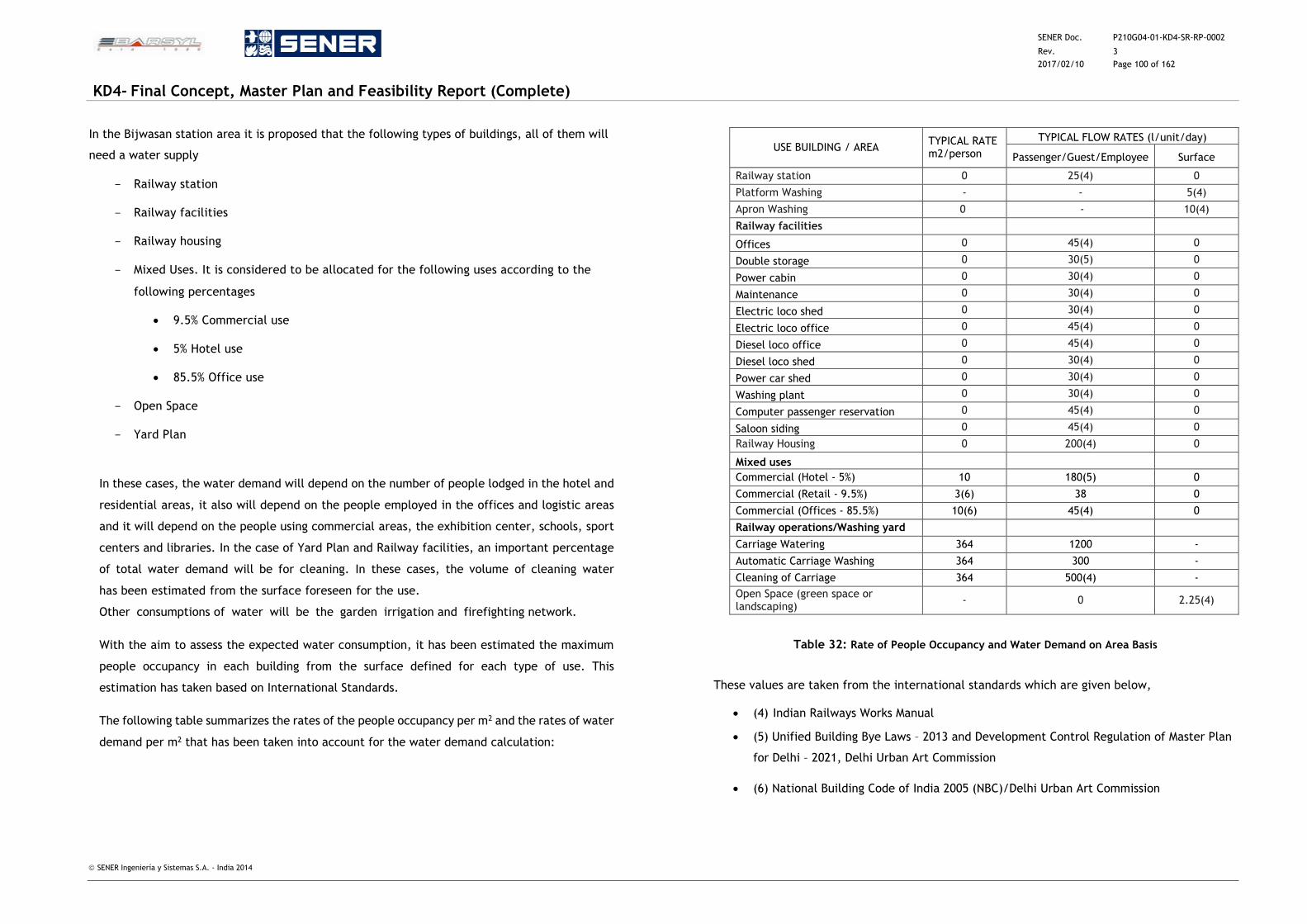
SENER Doc. P210G04-01-KD4-SR-RP-0002
Rev. 3
2017/02/10 Page 100 of 162
KD4- Final Concept, Master Plan and Feasibility Report (Complete)
SENER Ingeniería y Sistemas S.A. - India 2014
In the Bijwasan station area it is proposed that the following types of buildings, all of them will
need a water supply
Railway station
Railway facilities
Railway housing
Mixed Uses. It is considered to be allocated for the following uses according to the
following percentages
9.5% Commercial use
5% Hotel use
85.5% Office use
Open Space
Yard Plan
In these cases, the water demand will depend on the number of people lodged in the hotel and
residential areas, it also will depend on the people employed in the offices and logistic areas
and it will depend on the people using commercial areas, the exhibition center, schools, sport
centers and libraries. In the case of Yard Plan and Railway facilities, an important percentage
of total water demand will be for cleaning. In these cases, the volume of cleaning water
has been estimated from the surface foreseen for the use.
Other consumptions of water will be the garden irrigation and firefighting network.
With the aim to assess the expected water consumption, it has been estimated the maximum
people occupancy in each building from the surface defined for each type of use. This
estimation has taken based on International Standards.
The following table summarizes the rates of the people occupancy per m2 and the rates of water
demand per m2 that has been taken into account for the water demand calculation:
USE BUILDING / AREA TYPICAL RATE m2/person
TYPICAL FLOW RATES (l/unit/day)
Passenger/Guest/Employee Surface
Railway station 0 25(4) 0
Platform Washing - - 5(4)
Apron Washing 0 - 10(4)
Railway facilities
Offices 0 45(4) 0
Double storage 0 30(5) 0
Power cabin 0 30(4) 0
Maintenance 0 30(4) 0
Electric loco shed 0 30(4) 0
Electric loco office 0 45(4) 0
Diesel loco office 0 45(4) 0
Diesel loco shed 0 30(4) 0
Power car shed 0 30(4) 0
Washing plant 0 30(4) 0
Computer passenger reservation 0 45(4) 0
Saloon siding 0 45(4) 0
Railway Housing 0 200(4) 0
Mixed uses
Commercial (Hotel - 5%) 10 180(5) 0
Commercial (Retail - 9.5%) 3(6) 38 0
Commercial (Offices - 85.5%) 10(6) 45(4) 0
Railway operations/Washing yard
Carriage Watering 364 1200 -
Automatic Carriage Washing 364 300 -
Cleaning of Carriage 364 500(4) -
Open Space (green space or landscaping)
- 0 2.25(4)
Table 32: Rate of People Occupancy and Water Demand on Area Basis
These values are taken from the international standards which are given below,
(4) Indian Railways Works Manual
(5) Unified Building Bye Laws – 2013 and Development Control Regulation of Master Plan
for Delhi – 2021, Delhi Urban Art Commission
(6) National Building Code of India 2005 (NBC)/Delhi Urban Art Commission
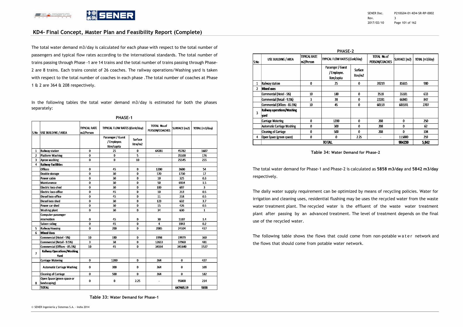
SENER Doc. P210G04-01-KD4-SR-RP-0002
Rev. 3
2017/02/10 Page 101 of 162
KD4- Final Concept, Master Plan and Feasibility Report (Complete)
SENER Ingeniería y Sistemas S.A. - India 2014
The total water demand m3/day is calculated for each phase with respect to the total number of
passengers and typical flow rates according to the international standards. The total number of
trains passing through Phase -1 are 14 trains and the total number of trains passing through Phase-
2 are 8 trains. Each trains consist of 26 coaches. The railway operations/Washing yard is taken
with respect to the total number of coaches in each phase .The total number of coaches at Phase
1 & 2 are 364 & 208 respectively.
In the following tables the total water demand m3/day is estimated for both the phases
separately:
PHASE-1
Table 33: Water Demand for Phase-1
PHASE-2
Table 34: Water Demand for Phase-2
The total water demand for Phase-1 and Phase-2 is calculated as 5858 m3/day and 5842 m3/day
respectively.
The daily water supply requirement can be optimized by means of recycling policies. Water for
irrigation and cleaning uses, residential flushing may be uses the recycled water from the waste
water treatment plant. The recycled water is the effluent of the waste water treatment
plant after passing by an advanced treatment. The level of treatment depends on the final
use of the recycled water.
The following table shows the flows that could come from non-potable w a t e r network and
the flows that should come from potable water network.
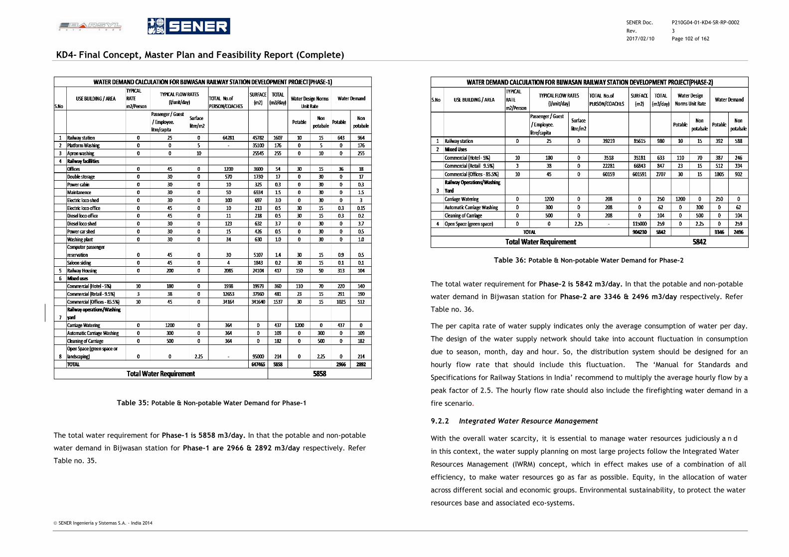
SENER Doc. P210G04-01-KD4-SR-RP-0002
Rev. 3
2017/02/10 Page 102 of 162
KD4- Final Concept, Master Plan and Feasibility Report (Complete)
SENER Ingeniería y Sistemas S.A. - India 2014
Table 35: Potable & Non-potable Water Demand for Phase-1
The total water requirement for Phase-1 is 5858 m3/day. In that the potable and non-potable
water demand in Bijwasan station for Phase-1 are 2966 & 2892 m3/day respectively. Refer
Table no. 35.
Table 36: Potable & Non-potable Water Demand for Phase-2
The total water requirement for Phase-2 is 5842 m3/day. In that the potable and non-potable
water demand in Bijwasan station for Phase-2 are 3346 & 2496 m3/day respectively. Refer
Table no. 36.
The per capita rate of water supply indicates only the average consumption of water per day.
The design of the water supply network should take into account fluctuation in consumption
due to season, month, day and hour. So, the distribution system should be designed for an
hourly flow rate that should include this fluctuation. The ‘Manual for Standards and
Specifications for Railway Stations in India’ recommend to multiply the average hourly flow by a
peak factor of 2.5. The hourly flow rate should also include the firefighting water demand in a
fire scenario.
9.2.2 Integrated Water Resource Management
With the overall water scarcity, it is essential to manage water resources judiciously a n d
in this context, the water supply planning on most large projects follow the Integrated Water
Resources Management (IWRM) concept, which in effect makes use of a combination of all
efficiency, to make water resources go as far as possible. Equity, in the allocation of water
across different social and economic groups. Environmental sustainability, to protect the water
resources base and associated eco-systems.
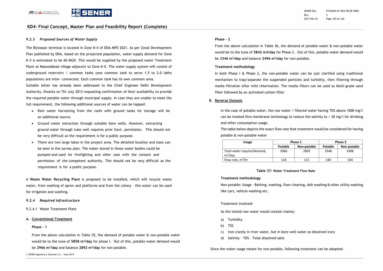
SENER Doc. P210G04-01-KD4-SR-RP-0002
Rev. 3
2017/02/10 Page 103 of 162
KD4- Final Concept, Master Plan and Feasibility Report (Complete)
SENER Ingeniería y Sistemas S.A. - India 2014
9.2.3 Proposed Sources of Water Supply
The Bijwasan terminal is located in Zone K-II of DDA MPD 2021. As per Zonal Development
Plan published by DDA, based on the projected population, water supply demand for Zone
K II is estimated to be 60 MGD. This would be supplied by the proposed water Treatment
Plant at Masoodabad village adjacent to Zone K-II. The water supply system will consist of
underground reservoirs / common tanks (one common tank to serve 1.5 to 2.0 lakhs
population) are inter- connected. Each common tank has its own common area.
Suitable letter has already been addressed to the Chief Engineer Delhi Development
Authority, Dwarka on 7th July 2013 requesting confirmation of their availability to provide
the required potable water through municipal supply. In case they are unable to meet the
full requirement, the following additional sources of water can be tapped:
Rain water harvesting from the roofs with ground tanks for storage will be
an additional source.
Ground water extraction through suitable bore wells. However, extracting
ground water through tube well requires prior Govt. permission. This should not
be very difficult as the requirement is for a public purpose.
There are two large lakes in the project area. The detailed location and sizes can
be seen in the survey plan. The water stored in these water bodies could be
pumped and used for firefighting and other uses with the consent and
permission of the competent authority. This should not be very difficult as the
requirement is for a public purpose.
A Waste Water Recycling Plant is proposed to be installed, which will recycle waste
water, from washing of apron and platforms and from the colony – this water can be used
for irrigation and washing.
9.2.4 Required infrastructure
9.2.4.1 Water Treatment Plant
A. Conventional Treatment
Phase - 1
From the above calculation in Table 35, the demand of potable water & non-potable water
would be to the tune of 5858 m3/day for phase I. Out of this, potable water demand would
be 2966 m3/day and balance 2892 m3/day for non-potable.
Phase - 2
From the above calculation in Table 36, the demand of potable water & non-potable water
would be to the tune of 5842 m3/day for Phase 2. Out of this, potable water demand would
be 3346 m3/day and balance 2496 m3/day for non-potable.
Treatment methodology
In both Phase I & Phase 2, the non-potable water can be just clarified using traditional
mechanism to trap/separate the suspended particles and turbidity, then filtering through
media filtration after mild chlorination. The media filters can be used as Multi-grade sand
filter followed by an activated carbon filter
B. Reverse Osmosis
In the case of potable water, the raw water / filtered water having TDS above 1000 mg/l
can be treated thro membrane technology to reduce the salinity to < 30 mg/l for drinking
and other consumption usage.
The table below depicts the exact flow rate that treatment would be considered for having
potable & non-potable water
Usage Phase 1 Phase 2
Potable Non-potable Potable Non-potable
Total water require/demand, m3/day
2966 2892 3346 2496
Flow rate, m3/hr 124 121 140 104
Table 37: Water Treatment Flow Rate
Treatment methodology
Non-potable: Usage – Bathing, washing, floor cleaning, dish washing & other utility washing
like cars, vehicle washing etc.
Treatment involved:
As the tested raw water would contain mainly:
a) Turbidity
b) TSS
c) Iron (rarely in river water, but in bore well water as dissolved iron)
d) Salinity – TDS – Total dissolved salts
Since the water usage meant for non-potable, following treatment can be adopted:
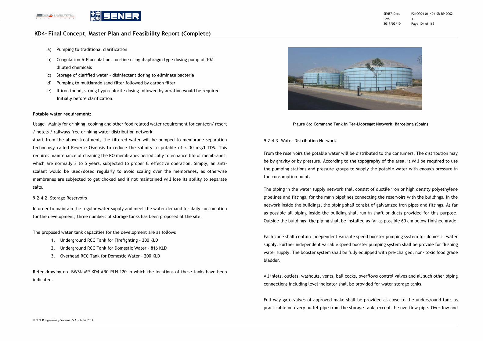
SENER Doc. P210G04-01-KD4-SR-RP-0002
Rev. 3
2017/02/10 Page 104 of 162
KD4- Final Concept, Master Plan and Feasibility Report (Complete)
SENER Ingeniería y Sistemas S.A. - India 2014
a) Pumping to traditional clarification
b) Coagulation & Flocculation – on-line using diaphragm type dosing pump of 10%
diluted chemicals
c) Storage of clarified water – disinfectant dosing to eliminate bacteria
d) Pumping to multigrade sand filter followed by carbon filter
e) If iron found, strong hypo-chlorite dosing followed by aeration would be required
Initially before clarification.
Potable water requirement:
Usage – Mainly for drinking, cooking and other food related water requirement for canteen/ resort
/ hotels / railways free drinking water distribution network.
Apart from the above treatment, the filtered water will be pumped to membrane separation
technology called Reverse Osmosis to reduce the salinity to potable of < 30 mg/l TDS. This
requires maintenance of cleaning the RO membranes periodically to enhance life of membranes,
which are normally 3 to 5 years, subjected to proper & effective operation. Simply, an anti-
scalant would be used/dosed regularly to avoid scaling over the membranes, as otherwise
membranes are subjected to get choked and if not maintained will lose its ability to separate
salts.
9.2.4.2 Storage Reservoirs
In order to maintain the regular water supply and meet the water demand for daily consumption
for the development, three numbers of storage tanks has been proposed at the site.
The proposed water tank capacities for the development are as follows
1. Underground RCC Tank for Firefighting - 200 KLD
2. Underground RCC Tank for Domestic Water – 816 KLD
3. Overhead RCC Tank for Domestic Water – 200 KLD
Refer drawing no. BWSN-MP-KD4-ARC-PLN-120 in which the locations of these tanks have been
indicated.
Figure 66: Command Tank in Ter-Llobregat Network, Barcelona (Spain)
9.2.4.3 Water Distribution Network
From the reservoirs the potable water will be distributed to the consumers. The distribution may
be by gravity or by pressure. According to the topography of the area, it will be required to use
the pumping stations and pressure groups to supply the potable water with enough pressure in
the consumption point.
The piping in the water supply network shall consist of ductile iron or high density polyethylene
pipelines and fittings, for the main pipelines connecting the reservoirs with the buildings. In the
network inside the buildings, the piping shall consist of galvanized iron pipes and fittings. As far
as possible all piping inside the building shall run in shaft or ducts provided for this purpose.
Outside the buildings, the piping shall be installed as far as possible 60 cm below finished grade.
Each zone shall contain independent variable speed booster pumping system for domestic water
supply. Further independent variable speed booster pumping system shall be provide for flushing
water supply. The booster system shall be fully equipped with pre-charged, non- toxic food grade
bladder.
All inlets, outlets, washouts, vents, ball cocks, overflows control valves and all such other piping
connections including level indicator shall be provided for water storage tanks.
Full way gate valves of approved make shall be provided as close to the underground tank as
practicable on every outlet pipe from the storage tank, except the overflow pipe. Overflow and
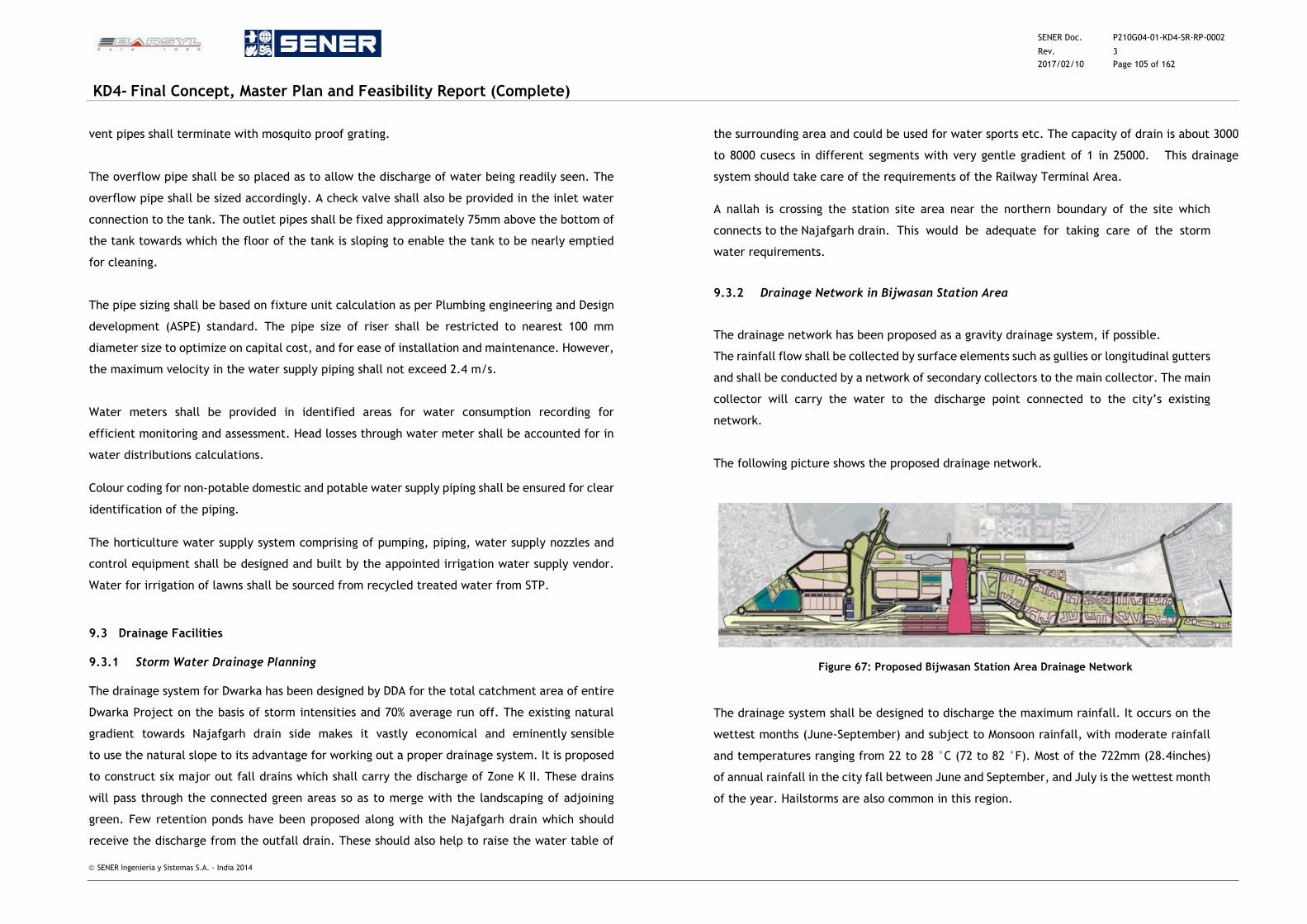
SENER Doc. P210G04-01-KD4-SR-RP-0002
Rev. 3
2017/02/10 Page 105 of 162
KD4- Final Concept, Master Plan and Feasibility Report (Complete)
SENER Ingeniería y Sistemas S.A. - India 2014
vent pipes shall terminate with mosquito proof grating.
The overflow pipe shall be so placed as to allow the discharge of water being readily seen. The
overflow pipe shall be sized accordingly. A check valve shall also be provided in the inlet water
connection to the tank. The outlet pipes shall be fixed approximately 75mm above the bottom of
the tank towards which the floor of the tank is sloping to enable the tank to be nearly emptied
for cleaning.
The pipe sizing shall be based on fixture unit calculation as per Plumbing engineering and Design
development (ASPE) standard. The pipe size of riser shall be restricted to nearest 100 mm
diameter size to optimize on capital cost, and for ease of installation and maintenance. However,
the maximum velocity in the water supply piping shall not exceed 2.4 m/s.
Water meters shall be provided in identified areas for water consumption recording for
efficient monitoring and assessment. Head losses through water meter shall be accounted for in
water distributions calculations.
Colour coding for non-potable domestic and potable water supply piping shall be ensured for clear
identification of the piping.
The horticulture water supply system comprising of pumping, piping, water supply nozzles and
control equipment shall be designed and built by the appointed irrigation water supply vendor.
Water for irrigation of lawns shall be sourced from recycled treated water from STP.
9.3 Drainage Facilities
9.3.1 Storm Water Drainage Planning
The drainage system for Dwarka has been designed by DDA for the total catchment area of entire
Dwarka Project on the basis of storm intensities and 70% average run off. The existing natural
gradient towards Najafgarh drain side makes it vastly economical and eminently sensible
to use the natural slope to its advantage for working out a proper drainage system. It is proposed
to construct six major out fall drains which shall carry the discharge of Zone K II. These drains
will pass through the connected green areas so as to merge with the landscaping of adjoining
green. Few retention ponds have been proposed along with the Najafgarh drain which should
receive the discharge from the outfall drain. These should also help to raise the water table of
the surrounding area and could be used for water sports etc. The capacity of drain is about 3000
to 8000 cusecs in different segments with very gentle gradient of 1 in 25000. This drainage
system should take care of the requirements of the Railway Terminal Area.
A nallah is crossing the station site area near the northern boundary of the site which
connects to the Najafgarh drain. This would be adequate for taking care of the storm
water requirements.
9.3.2 Drainage Network in Bijwasan Station Area
The drainage network has been proposed as a gravity drainage system, if possible.
The rainfall flow shall be collected by surface elements such as gullies or longitudinal gutters
and shall be conducted by a network of secondary collectors to the main collector. The main
collector will carry the water to the discharge point connected to the city’s existing
network.
The following picture shows the proposed drainage network.
Figure 67: Proposed Bijwasan Station Area Drainage Network
The drainage system shall be designed to discharge the maximum rainfall. It occurs on the
wettest months (June-September) and subject to Monsoon rainfall, with moderate rainfall
and temperatures ranging from 22 to 28 °C (72 to 82 °F). Most of the 722mm (28.4inches)
of annual rainfall in the city fall between June and September, and July is the wettest month
of the year. Hailstorms are also common in this region.
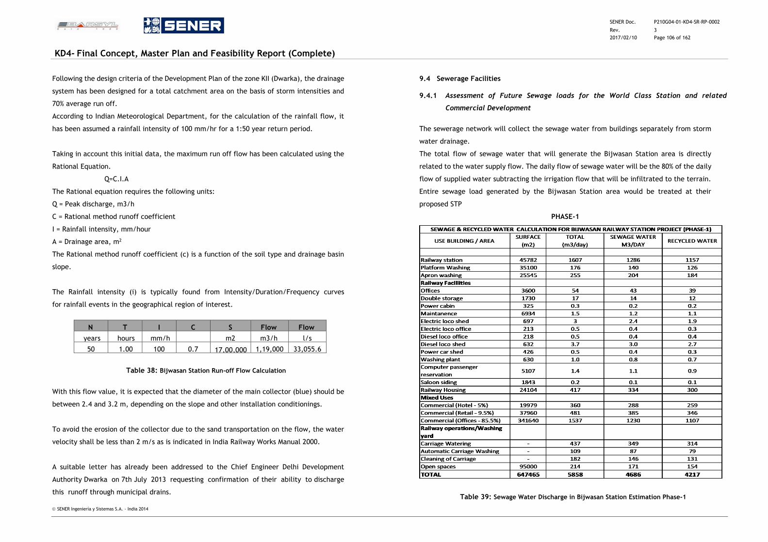
SENER Doc. P210G04-01-KD4-SR-RP-0002
Rev. 3
2017/02/10 Page 106 of 162
KD4- Final Concept, Master Plan and Feasibility Report (Complete)
SENER Ingeniería y Sistemas S.A. - India 2014
Following the design criteria of the Development Plan of the zone KII (Dwarka), the drainage
system has been designed for a total catchment area on the basis of storm intensities and
70% average run off.
According to Indian Meteorological Department, for the calculation of the rainfall flow, it
has been assumed a rainfall intensity of 100 mm/hr for a 1:50 year return period.
Taking in account this initial data, the maximum run off flow has been calculated using the
Rational Equation.
Q=C.I.A
The Rational equation requires the following units:
Q = Peak discharge, m3/h
C = Rational method runoff coefficient
I = Rainfall intensity, mm/hour
A = Drainage area, m2
The Rational method runoff coefficient (c) is a function of the soil type and drainage basin
slope.
The Rainfall intensity (i) is typically found from Intensity/Duration/Frequency curves
for rainfall events in the geographical region of interest.
N T I C S Flow Flow
years
hours
mm/h
m2
m3/h
l/s
50 1.00 100 0.7 17,00,000 1,19,000 33,055.6
Table 38: Bijwasan Station Run-off Flow Calculation
With this flow value, it is expected that the diameter of the main collector (blue) should be
between 2.4 and 3.2 m, depending on the slope and other installation conditionings.
To avoid the erosion of the collector due to the sand transportation on the flow, the water
velocity shall be less than 2 m/s as is indicated in India Railway Works Manual 2000.
A suitable letter has already been addressed to the Chief Engineer Delhi Development
Authority Dwarka on 7th July 2013 requesting confirmation of their ability to discharge
this runoff through municipal drains.
9.4 Sewerage Facilities
9.4.1 Assessment of Future Sewage loads for the World Class Station and related
Commercial Development
The sewerage network will collect the sewage water from buildings separately from storm
water drainage.
The total flow of sewage water that will generate the Bijwasan Station area is directly
related to the water supply flow. The daily flow of sewage water will be the 80% of the daily
flow of supplied water subtracting the irrigation flow that will be infiltrated to the terrain.
Entire sewage load generated by the Bijwasan Station area would be treated at their
proposed STP
PHASE-1
Table 39: Sewage Water Discharge in Bijwasan Station Estimation Phase-1
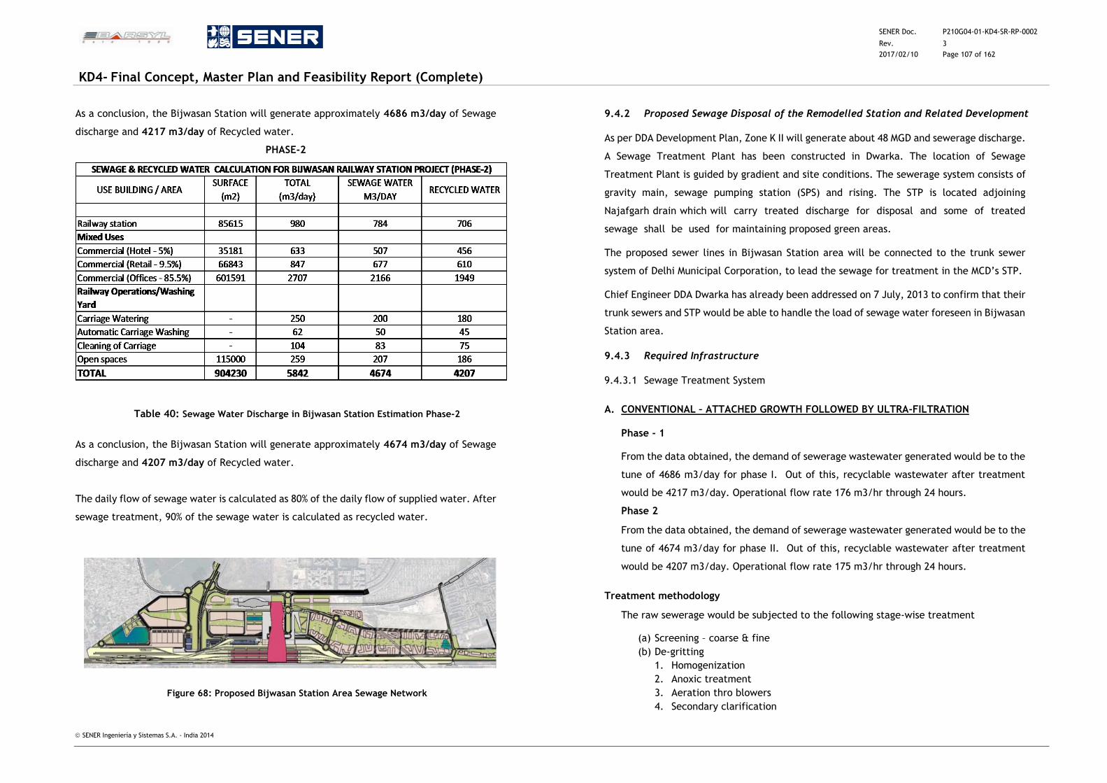
SENER Doc. P210G04-01-KD4-SR-RP-0002
Rev. 3
2017/02/10 Page 107 of 162
KD4- Final Concept, Master Plan and Feasibility Report (Complete)
SENER Ingeniería y Sistemas S.A. - India 2014
As a conclusion, the Bijwasan Station will generate approximately 4686 m3/day of Sewage
discharge and 4217 m3/day of Recycled water.
PHASE-2
Table 40: Sewage Water Discharge in Bijwasan Station Estimation Phase-2
As a conclusion, the Bijwasan Station will generate approximately 4674 m3/day of Sewage
discharge and 4207 m3/day of Recycled water.
The daily flow of sewage water is calculated as 80% of the daily flow of supplied water. After
sewage treatment, 90% of the sewage water is calculated as recycled water.
Figure 68: Proposed Bijwasan Station Area Sewage Network
9.4.2 Proposed Sewage Disposal of the Remodelled Station and Related Development
As per DDA Development Plan, Zone K II will generate about 48 MGD and sewerage discharge.
A Sewage Treatment Plant has been constructed in Dwarka. The location of Sewage
Treatment Plant is guided by gradient and site conditions. The sewerage system consists of
gravity main, sewage pumping station (SPS) and rising. The STP is located adjoining
Najafgarh drain which will carry treated discharge for disposal and some of treated
sewage shall be used for maintaining proposed green areas.
The proposed sewer lines in Bijwasan Station area will be connected to the trunk sewer
system of Delhi Municipal Corporation, to lead the sewage for treatment in the MCD’s STP.
Chief Engineer DDA Dwarka has already been addressed on 7 July, 2013 to confirm that their
trunk sewers and STP would be able to handle the load of sewage water foreseen in Bijwasan
Station area.
9.4.3 Required Infrastructure
9.4.3.1 Sewage Treatment System
A. CONVENTIONAL – ATTACHED GROWTH FOLLOWED BY ULTRA-FILTRATION
Phase - 1
From the data obtained, the demand of sewerage wastewater generated would be to the
tune of 4686 m3/day for phase I. Out of this, recyclable wastewater after treatment
would be 4217 m3/day. Operational flow rate 176 m3/hr through 24 hours.
Phase 2
From the data obtained, the demand of sewerage wastewater generated would be to the
tune of 4674 m3/day for phase II. Out of this, recyclable wastewater after treatment
would be 4207 m3/day. Operational flow rate 175 m3/hr through 24 hours.
Treatment methodology
The raw sewerage would be subjected to the following stage-wise treatment
(a) Screening – coarse & fine
(b) De-gritting
1. Homogenization
2. Anoxic treatment
3. Aeration thro blowers
4. Secondary clarification
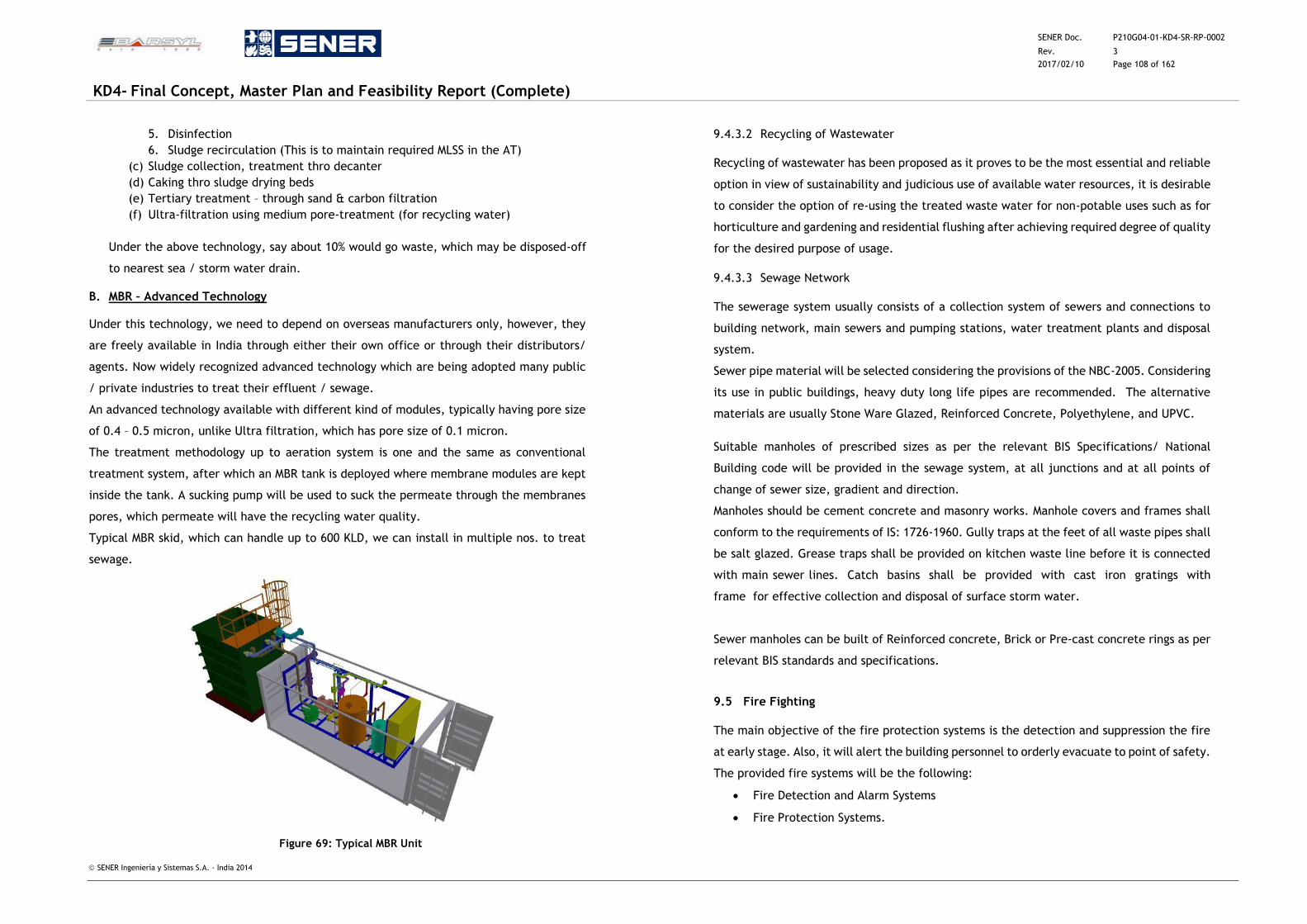
SENER Doc. P210G04-01-KD4-SR-RP-0002
Rev. 3
2017/02/10 Page 108 of 162
KD4- Final Concept, Master Plan and Feasibility Report (Complete)
SENER Ingeniería y Sistemas S.A. - India 2014
5. Disinfection
6. Sludge recirculation (This is to maintain required MLSS in the AT)
(c) Sludge collection, treatment thro decanter
(d) Caking thro sludge drying beds
(e) Tertiary treatment – through sand & carbon filtration
(f) Ultra-filtration using medium pore-treatment (for recycling water)
Under the above technology, say about 10% would go waste, which may be disposed-off
to nearest sea / storm water drain.
B. MBR – Advanced Technology
Under this technology, we need to depend on overseas manufacturers only, however, they
are freely available in India through either their own office or through their distributors/
agents. Now widely recognized advanced technology which are being adopted many public
/ private industries to treat their effluent / sewage.
An advanced technology available with different kind of modules, typically having pore size
of 0.4 – 0.5 micron, unlike Ultra filtration, which has pore size of 0.1 micron.
The treatment methodology up to aeration system is one and the same as conventional
treatment system, after which an MBR tank is deployed where membrane modules are kept
inside the tank. A sucking pump will be used to suck the permeate through the membranes
pores, which permeate will have the recycling water quality.
Typical MBR skid, which can handle up to 600 KLD, we can install in multiple nos. to treat
sewage.
Figure 69: Typical MBR Unit
9.4.3.2 Recycling of Wastewater
Recycling of wastewater has been proposed as it proves to be the most essential and reliable
option in view of sustainability and judicious use of available water resources, it is desirable
to consider the option of re-using the treated waste water for non-potable uses such as for
horticulture and gardening and residential flushing after achieving required degree of quality
for the desired purpose of usage.
9.4.3.3 Sewage Network
The sewerage system usually consists of a collection system of sewers and connections to
building network, main sewers and pumping stations, water treatment plants and disposal
system.
Sewer pipe material will be selected considering the provisions of the NBC-2005. Considering
its use in public buildings, heavy duty long life pipes are recommended. The alternative
materials are usually Stone Ware Glazed, Reinforced Concrete, Polyethylene, and UPVC.
Suitable manholes of prescribed sizes as per the relevant BIS Specifications/ National
Building code will be provided in the sewage system, at all junctions and at all points of
change of sewer size, gradient and direction.
Manholes should be cement concrete and masonry works. Manhole covers and frames shall
conform to the requirements of IS: 1726-1960. Gully traps at the feet of all waste pipes shall
be salt glazed. Grease traps shall be provided on kitchen waste line before it is connected
with main sewer lines. Catch basins shall be provided with cast iron gratings with
frame for effective collection and disposal of surface storm water.
Sewer manholes can be built of Reinforced concrete, Brick or Pre-cast concrete rings as per
relevant BIS standards and specifications.
9.5 Fire Fighting
The main objective of the fire protection systems is the detection and suppression the fire
at early stage. Also, it will alert the building personnel to orderly evacuate to point of safety.
The provided fire systems will be the following:
Fire Detection and Alarm Systems
Fire Protection Systems.
SENER Doc. P210G04-01-KD4-SR-RP-0002
Rev. 3
2017/02/10 Page 109 of 162
KD4- Final Concept, Master Plan and Feasibility Report (Complete)
SENER Ingeniería y Sistemas S.A. - India 2014
The chapter is focused in Railway Station and furthermore it is included the main lines to
be applied in the other buildings and surroundings areas
9.5.1 Codes and Standards
The basic code being followed for the Railway Station is NFPA-130. (It is understood from
the Manual on World Class Stations that this is the standard, for fire and life safety, for the
development of all world class stations by IR). The provisions of this code will be
supplemented for the design of the various sub systems as per related detailed codes for
different individual items, issued by NFPA. The important ones are listed below
Means of Egress/Evacuation Time Calculations NFPA-130/ NFPA-101
Fire Hydrants and Hose Reels NFPA-14
Automatic Sprinklers Systems NFPA-13/ IS:15105
Fire Pump, Fire Water Tanks NFPA-13/NFPA14; NBC–Pt.4
Wet Risers, Hydrants System NFPA-130; IS: 3844, IS: 13039
Automatic Gas Flooding System NFPA-2001
Portable Fire Extinguishers NFPA-10/ IS: 2190
Fire Detection & Alarm System NFPA -72/IS: 2189/IS: 15908
Smoke Extraction System NFPA-92/ NFPA-130
Emergency Lighting NFPA-130/ NFPA-70
Fire Stops/ Compartmentation NFPA-101/130;NBC–Pt.4
All fire protection systems in the Commercial/Retail/Residential areas would also be
designed to comply with the National Building Code Part-4 and the requirements of the Local
Fire Authority.
9.5.2 Railway Station
As specified in Manual for Standards and specifications for Railway Stations, Bijwasan railway
Station will be provided with automatic and manual suppression systems. Fire Detection and
Alarm Systems
All Common personnel areas and public areas
Offices
Critical Rooms
Electrical Rooms
Mechanical Rooms,
Workshops, trash room.
Automatic suppression systems shall be provided in:
Nonpublic areas with combustible loads (concessions areas, storage and trash
rooms)
Public areas (Escalators structures and enclosed public waiting areas)
Standpipe Systems: throughout the station
Portable firefighting equipment
9.5.2.1 Fire Detection and Alarm Systems
The fire alarm system shall be installed in the Railway Station. Related with its own activity,
each building area has its own hazard characteristic which will demand its own specific
alarm system, for instance public spaces shall be equipped with optical smoke sensors,
technical rooms shall be equipped with smoke sensors, mechanical rooms shall be equipped
with multi criteria sensors, etc. Critical rooms, such as main Communications room, shall be
equipped by aspirated sensors system to offer the most early and reliable fire detection.
The Fire Alarm System must be capable of interfacing with others systems such as, voice
evacuation system, fire extinguishing system, smoke extraction/ventilation system, train
SCADA/signaling system, etc. In emergency situation, the communication system, connected
to Fire Alarm Control Panels and to the Operating Control Center (OCC of IDR), shall provide
the safest procedure to follow.
The fire alarm system will have a -centralized in the local control room in the station system
The BMS (Building Management System) will interface with Fire Alarm System and allow
monitoring of the complete system. The monitoring features of the BMS of the fire alarm
system will include:
System status (Healthy, fault, alarm)
Loop status
Detector status
Planned Maintenance.
SENER Doc. P210G04-01-KD4-SR-RP-0002
Rev. 3
2017/02/10 Page 110 of 162
KD4- Final Concept, Master Plan and Feasibility Report (Complete)
SENER Ingeniería y Sistemas S.A. - India 2014
The fire alarm system for the project Buildings will harness the latest fire alarm technology
and be an advanced, expandable and scalable system.
The system will be an analogue addressable system and will be electrically supervised,
monitor the integrity of all conductors and will have proper approval from nationally
recognized agencies.
The system will be capable of providing the user with clear comprehensive information in
the event of a fire and also provide an entire historic log of the system’s management
information. Faults within the system will provide a detailed explanation allowing the user
to navigate through the faults history.
Fire Alarm Control Panel (FACP) located at Local Control room inside of the building to
control & monitor the fire devices.
The devices included in the fire detection and alarm systems are composed by
1. Initiating Devices
A combination of Photoelectric Smoke Detectors, Heat Detectors, Aspirating
Detector etc. will be used in the following areas:
All Common personnel areas,
Offices
Critical Rooms
Electrical Rooms
Plant Rooms
Workshops
In all areas with high background noise levels, xenon beacons will also be provided
in line with NFPA – 72. As per NFPA-72 addressable manual call point units will be
mounted in corridors within 1.5 meters of the entrances or exits or fire escape
route with a maximum travel distance of 60 meters to the nearest manual call point
unit.
Furthermore the NFPA – 72 international standard, in the design shall be applied the
Indian Standards: IS: 2189/IS: 15908
2. System Circuit Supervision
The fire alarm control panels will supervise all circuits to intelligent devices,
transponders, annunciators and peripheral equipment and annunciate loss of
communication with these devices. Interface unit will also be provided to monitor
the firefighting system components such as sprinkler system valves, standpipe control
valves, PRV, and main gate valves.
3. Interfacing with other systems
The FACP must have the ability to interface with other security, BMS, supervision of
sprinkler systems, smoke management systems, mechanical systems, etc. Following
are some of the 3rd party systems to be interfaced with the fire alarm system.
4. Systems/Devices to be monitored:
Clean Agent Gas - Control Panel
Pre-Action System
Smoke Extract Fan
Pressurization Fan
Damper associated with Smoke Extract Fan
Zone Control Valve for Sprinkler Pressure Switch & Supervisory Switch
Fire Pump Monitoring
Generator
5. Systems/Devices to be controlled
Sounder Circuit / Strobe Circuit
Access Control System
Smoke Extract Fan
Damper associated with Smoke Extract Fan
Pressurization Fan
AHU Shut Down
Fire Door
BMS System
Lighting Control
SENER Doc. P210G04-01-KD4-SR-RP-0002
Rev. 3
2017/02/10 Page 111 of 162
KD4- Final Concept, Master Plan and Feasibility Report (Complete)
SENER Ingeniería y Sistemas S.A. - India 2014
The fire alarm system will be developed in coordination with the firefighting strategy
and fire engineering design and all other relevant disciplines in the following stages
of design to ensure the system meets with all requirements and codes.
9.5.2.2 Fire Protection Systems
The following fire protection systems shall be provided for the Station as applicable:-
In the Station, the fire protection system shall assure the safety in all escape routes and in
all critical equipment. Different types of fire protection systems such as automatic sprinkler
system, standpipe and hose system, portable fire extinguishers and automatic gas
suppression system shall be combined.
The following systems will be provided inside the building:
1. Standpipe and Hose System
The standpipe and hose system consists of galvanized steel pipes, hose valves, hose
pipes, branch pipe with nozzles, first-aid hose reels. All these equipment shall be
placed inside the fire hose cabinet.
Each hose point shall be tapped off from the combined system risers and serve the
corresponding floors. Minimum size required to hose point tapping shall be 65mm.
Each internal hose point shall consist of hose valve, associated piping, 2 nos. of hose
pipes, 1 no. of nozzle and fire aid hose reel of 36 m long x 19 mm dia with an isolation
valve.
The first aid hose reel shall be tapped of from the riser and minimum size required
for the tapping shall be 25mm.
Common breeching inlet for sprinkler and standpipe system shall be provided.
Standpipe and hose system design shall be in accordance with NFPA 14 and in
accordance with IS:3844 and IS:884.
Fire water demand for standpipe and hose system shall be computed based on
cumulative water demand of 2 hose points for a single riser and maximum of 3 hose
points for more than one riser.
Number of hose points per floor / level shall be based on 60 m coverage per hose point.
Fire water storage required shall be calculated for minimum 60 minutes of total water
demand of the standpipe and hose system.
2. Automatic Sprinkler System, and its main characteristics are
The automatic sprinkler system consists of galvanized steel pipes, alarm check valves,
zone control valves, flow switches, pressure gauges, drain valves, test valves,
sprinkler heads, etc.
The sprinkler system main lines shall be tapped from the combined system risers and
serve the corresponding floor areas via the zone control valve. Zone control valves
shall be monitored and interfaced with BMS and flow switches shall be interfaced with
fire alarm system.
All the sprinkler heads shall be either pendent or upright of standard response and standard
coverage type and temperature rating shall be 68º C or 79º C.
All Zone Control Valve (ZCV) shall be of monitored butterfly valve type and drain & test
valve shall be of ball valve type.
Common breeching inlet for sprinkler and standpipe and hose system shall be provided.
Automatic sprinkler system design shall be in accordance with NFPA 130 and NFPA 13.
Fire water storage computation for sprinkler system shall be based on minimum 60 Minutes of sprinkler operation. Sprinklers shall be provided for all the floor / grade levels such as mezzanine, and for areas
such as MEP rooms, building office rooms, building service rooms, etc.
Sprinklers shall not be required for electrical risk areas which shall be protected by clean
agent gas flooding system.
3. Portable Fire Extinguishers
In general, all the different spaces shall be protected by means of portable
extinguishers and it shall be selected based on the class of fire. The standard for selection
and installation is NFPA 10.
SENER Doc. P210G04-01-KD4-SR-RP-0002
Rev. 3
2017/02/10 Page 112 of 162
KD4- Final Concept, Master Plan and Feasibility Report (Complete)
SENER Ingeniería y Sistemas S.A. - India 2014
The following type of fire extinguishers shall be provided corresponding to the class of fire.
Class A fire - ABC type
Class B fire - ABC type
Class C fire - CO2 type
All the fire extinguishers shall be placed inside the extinguisher cabinet or mounted in wall
by using the wall hooks.
4. Automatic Gas Suppression System
The automatic gas suppression system consists of Clean Agent gas inside the
gas cylinders, solenoid valves, manifolds, carbon steel pipes (seamless sch.40), and
gas discharge nozzles, etc., as part of mechanical items.
The electrical part of the system consists of gas release panels, wirings, abort
switches, manual releases, sounders and fire detectors.
Additionally, warning signage shall be provided at the entrance of the rooms to be
protected. The fire detectors shall be smoke or heat detector type. Fire detectors
shall wired based on cross zoning principle in order to avoid false discharge of gas.
The fire condition signal shall be interfaced to the main fire alarm panel through the
gas discharge panel.
In general, all the electrical risk rooms and areas shall be provided with total flooding
automatic gas suppression system. The gas agent shall be FM-200.
Electronics and telecommunication room
Electrical rooms
Generator rooms
Power supply rooms
Control rooms
5. Fire water storage and fire pumps
According to NFPA 13, standpipe systems shall be provided with an approved water
supply capable of supplying the system demand for a minimum of 1 hour. Taking into
account that the maximum flow rate expected will be about 3430 l/min (according
NFPA 14 – two fire hose of 947 l/min (250gpm) and 300m2 of sprinklers simultaneous),
the firefighting tank shall have a capacity of about 200 m3.
The Station shall be fitted out with a Fire Water Tank of 200 m3 and a Main Fire Pump,
a diesel engine operated Standby Fire Pump and a Jockey Pump. The Fire Pumps would
be in automatic operation mode. The Fire Pumps would be common to the Hydrant
and Sprinkler Systems. However, for Sprinklers there would be a dedicated mains right
from the fire pump delivery manifold.
The fire pump shall be designed and installed based on NFPA 20 standard. The fire
tanks shall be fitted with alarm detection, which shall be monitored by the Station
Fire Alarm Panel and Repeater Panel.
9.5.3 Mix and Other Uses
Regarding the surrounding buildings, each building will have its own automatic and manual
suppression systems. According to NFPA 14, standpipe systems shall be provided with
an approved water supply capable of supplying the system demand for a minimum of half an
hour (30 min). Taking into account that the maximum flow rate expected for each building
will be about 2918 l/min ((according NFPA 14 – two fire hose of 947l/min (250gpm) and
200m2 of sprinklers simultaneous), each building will have a firefighting tank of about 100
m3.
9.6 Power supply
In the following chapter, load estimation for Bijwasan station and surrounding buildings will
be done taking into account the surface of each building and the expected use.
9.6.1 Basis of Design
To determine the electric power considering the following design parameters:
1. Design surfaces
Railway station and Railway Station Parking
Railway facilities
Mixed Uses
It is considered to be allocated for the following uses according to the following
percentages:
SENER Doc. P210G04-01-KD4-SR-RP-0002
Rev. 3
2017/02/10 Page 113 of 162
KD4- Final Concept, Master Plan and Feasibility Report (Complete)
SENER Ingeniería y Sistemas S.A. - India 2014
9.5% retail
5% Hotel use
85.5% Office use
Open Space
Yard Plan
2. Power supply is required for the following subsystems
Lighting
Receptacle loads
Air conditioning and / or ventilation
Hot water (gas can be used instead)
3. Rates of the electric load estimation, taking into account the possible uses to be included:
ELECTRICAL LO ADS REQUIRED [VA/m2]
USE BUILDING/AREA lighting
Rec eptac le
loads
air
c onditioning
/ ventilation
hot water
Railway station 5 [3] 15.0 21,6 2.0
Railway fac ilities 5 [3] 15.0 44.0 2.0
Parc el logistic 3 [4] 3.0 33 [1] 0.0
Hotel 22 [4] 11.0 65 [1] 25 [1]
Commerc ial 33 [4] 3 [1] 44 [1] 0.0
O ffic e 39 [4] 11 [1] 65 [1] 6 [1]
Residential 33 [4] 11,0 44.0 25 [1]
Underground parking 6 [4] 0.0 20.0 0.0
Table 41: Power Rates per Area
The electrical rate of air conditioning and ventilation in Railway Station is an average
where is considered:
3.6% of total area: 65 VA/m2 to feed air conditioning/ventilation
Business lounge (621.18 m2)
VIP lounge (621.18 m2)
Reserved areas (4588.82 m2)
96.4% of total area: 20 VA/m2 to feed ventilation
The area of Railway Station is the total area included basement, ground floor and first
floor. The platform area is not included
9.6.2 Estimated Electrical loads
The estimated load requirements parameters are in accordance with the following standards
[1] IEEE Recommended Practice for Electric Power Systems in Commercial
Buildings.
IEEE Std 241-1990
[2] National Building Code of India
[3] Manual for standards and specifications for railway stations. Ministry of
Railways
(Railway Board). Government of India
[4] NFPA 70. American National Electrical Code. 2008 Edition
The Electrical Power Load Calculation in Bijwasan Station Development for Phase-1 & Phase
2 are given in the table: Table nº 43 & 44. Once the electric load estimation has been
calculated, in order to know the simultaneous required power, the following demand factors
have been considered:
Table 42: Lighting Load Demand Factors
Fixed electric space heating loads shall be computed at 100 % of the total connected load,
as specified in NFPA 70, American National Electrical Code. 2008 Edition
Lighting load demand factors
Type of occupancy
Portion of Lighting Load to which
demand factors applies (VA)
Demand factor [%]
Hotels
≤ 20,000 VA
From 20,001 to 100,000 VA
Remainder over 100,000 VA
50 %
40 %
30 %
Dwelling units
≤ 3,000 VA
From 3,001 to 12,0000 VA
Remainder over 120000
100 %
35 %
25 %
Warehouses (storage)
≤ 12,500 VA
Remainder over 12,500
100 %
50 %
All others
100 %
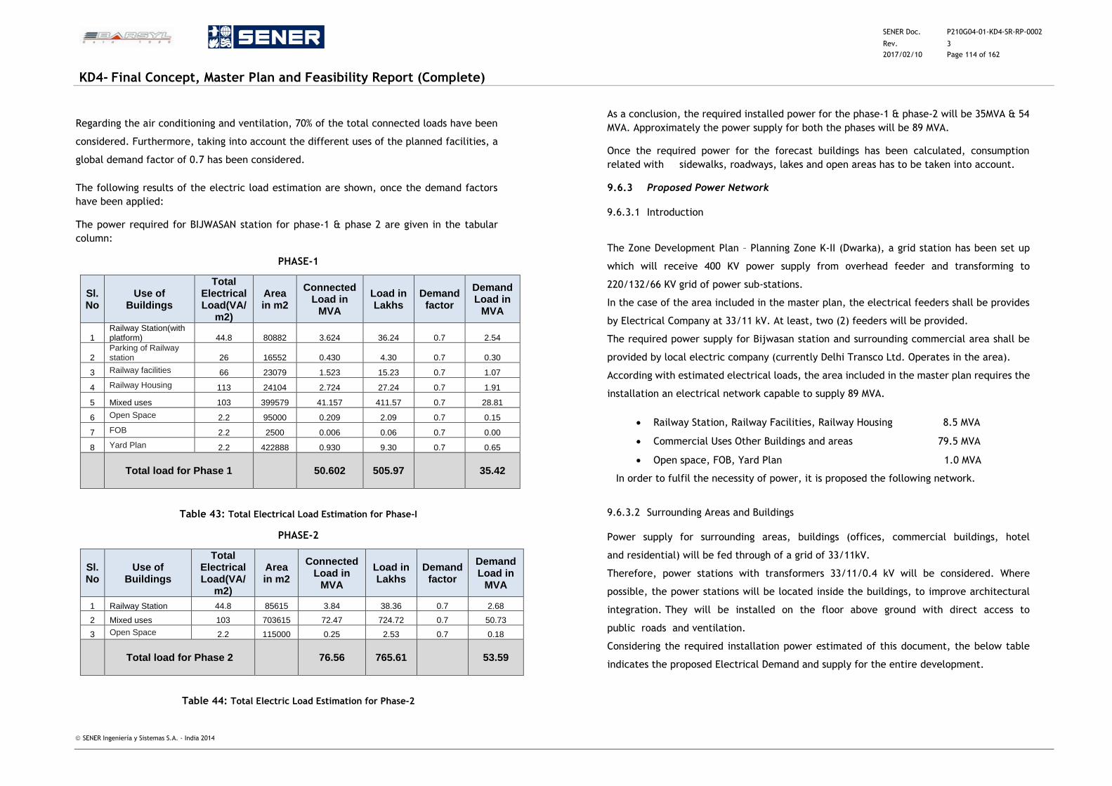
SENER Doc. P210G04-01-KD4-SR-RP-0002
Rev. 3
2017/02/10 Page 114 of 162
KD4- Final Concept, Master Plan and Feasibility Report (Complete)
SENER Ingeniería y Sistemas S.A. - India 2014
Regarding the air conditioning and ventilation, 70% of the total connected loads have been
considered. Furthermore, taking into account the different uses of the planned facilities, a
global demand factor of 0.7 has been considered.
The following results of the electric load estimation are shown, once the demand factors
have been applied:
The power required for BIJWASAN station for phase-1 & phase 2 are given in the tabular
column:
PHASE-1
Sl.No
Use of Buildings
Total Electrical Load(VA/
m2)
Area in m2
Connected Load in
MVA
Load in Lakhs
Demand factor
Demand Load in
MVA
1 Railway Station(with platform) 44.8 80882 3.624 36.24 0.7 2.54
2 Parking of Railway station 26 16552 0.430 4.30 0.7 0.30
3 Railway facilities 66 23079 1.523 15.23 0.7 1.07
4 Railway Housing 113 24104 2.724 27.24 0.7 1.91
5 Mixed uses 103 399579 41.157 411.57 0.7 28.81
6 Open Space 2.2 95000 0.209 2.09 0.7 0.15
7 FOB 2.2 2500 0.006 0.06 0.7 0.00
8 Yard Plan 2.2 422888 0.930 9.30 0.7 0.65
Total load for Phase 1
50.602 505.97 35.42
Table 43: Total Electrical Load Estimation for Phase-I
PHASE-2
Sl.No
Use of Buildings
Total Electrical Load(VA/
m2)
Area in m2
Connected Load in
MVA
Load in Lakhs
Demand factor
Demand Load in
MVA
1 Railway Station 44.8 85615 3.84 38.36 0.7 2.68
2 Mixed uses 103 703615 72.47 724.72 0.7 50.73
3 Open Space 2.2 115000 0.25 2.53 0.7 0.18
Total load for Phase 2
76.56 765.61 53.59
Table 44: Total Electric Load Estimation for Phase-2
As a conclusion, the required installed power for the phase-1 & phase-2 will be 35MVA & 54
MVA. Approximately the power supply for both the phases will be 89 MVA.
Once the required power for the forecast buildings has been calculated, consumption
related with sidewalks, roadways, lakes and open areas has to be taken into account.
9.6.3 Proposed Power Network
9.6.3.1 Introduction
The Zone Development Plan – Planning Zone K-II (Dwarka), a grid station has been set up
which will receive 400 KV power supply from overhead feeder and transforming to
220/132/66 KV grid of power sub-stations.
In the case of the area included in the master plan, the electrical feeders shall be provides
by Electrical Company at 33/11 kV. At least, two (2) feeders will be provided.
The required power supply for Bijwasan station and surrounding commercial area shall be
provided by local electric company (currently Delhi Transco Ltd. Operates in the area).
According with estimated electrical loads, the area included in the master plan requires the
installation an electrical network capable to supply 89 MVA.
Railway Station, Railway Facilities, Railway Housing 8.5 MVA
Commercial Uses Other Buildings and areas 79.5 MVA
Open space, FOB, Yard Plan 1.0 MVA
In order to fulfil the necessity of power, it is proposed the following network.
9.6.3.2 Surrounding Areas and Buildings
Power supply for surrounding areas, buildings (offices, commercial buildings, hotel
and residential) will be fed through of a grid of 33/11kV.
Therefore, power stations with transformers 33/11/0.4 kV will be considered. Where
possible, the power stations will be located inside the buildings, to improve architectural
integration. They will be installed on the floor above ground with direct access to
public roads and ventilation.
Considering the required installation power estimated of this document, the below table
indicates the proposed Electrical Demand and supply for the entire development.
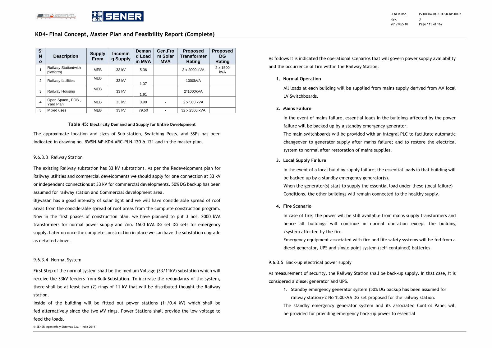
SENER Doc. P210G04-01-KD4-SR-RP-0002
Rev. 3
2017/02/10 Page 115 of 162
KD4- Final Concept, Master Plan and Feasibility Report (Complete)
SENER Ingeniería y Sistemas S.A. - India 2014
Sl No
Description Supply From
Incoming Supply
Demand Load in MVA
Gen.From Solar
MVA
Proposed Transformer
Rating
ProposedDG
Rating
1 Railway Station(with platform)
MEB 33 kV 5.36 3 x 2000 kVA 2 x 1500
kVA
2 Railway facilities MEB
33 kV 1.07
1000kVA
3 Railway Housing MEB
33 kV 1.91
2*1000kVA
4 Open Space , FOB , Yard Plan
MEB 33 kV 0.98 - 2 x 500 kVA
5 Mixed uses MEB 33 kV 79.50 - 32 x 2500 kVA
Table 45: Electricity Demand and Supply for Entire Development
The approximate location and sizes of Sub-station, Switching Posts, and SSPs has been
indicated in drawing no. BWSN-MP-KD4-ARC-PLN-120 & 121 and in the master plan.
9.6.3.3 Railway Station
The existing Railway substation has 33 kV substations. As per the Redevelopment plan for
Railway utilities and commercial developments we should apply for one connection at 33 kV
or independent connections at 33 kV for commercial developments. 50% DG backup has been
assumed for railway station and Commercial development area.
Bijwasan has a good intensity of solar light and we will have considerable spread of roof
areas from the considerable spread of roof areas from the complete construction program.
Now in the first phases of construction plan, we have planned to put 3 nos. 2000 kVA
transformers for normal power supply and 2no. 1500 kVA DG set DG sets for emergency
supply. Later on once the complete construction in place we can have the substation upgrade
as detailed above.
9.6.3.4 Normal System
First Step of the normal system shall be the medium Voltage (33/11kV) substation which will
receive the 33kV feeders from Bulk Substation. To increase the redundancy of the system,
there shall be at least two (2) rings of 11 kV that will be distributed thought the Railway
station.
Inside of the building will be fitted out power stations (11/0.4 kV) which shall be
fed alternatively since the two MV rings. Power Stations shall provide the low voltage to
feed the loads.
As follows it is indicated the operational scenarios that will govern power supply availability
and the occurrence of fire within the Railway Station:
1. Normal Operation
All loads at each building will be supplied from mains supply derived from MV local
LV Switchboards.
2. Mains Failure
In the event of mains failure, essential loads in the buildings affected by the power
failure will be backed up by a standby emergency generator.
The main switchboards will be provided with an integral PLC to facilitate automatic
changeover to generator supply after mains failure; and to restore the electrical
system to normal after restoration of mains supplies.
3. Local Supply Failure
In the event of a local building supply failure; the essential loads in that building will
be backed up by a standby emergency generator(s).
When the generator(s) start to supply the essential load under these (local failure)
Conditions, the other buildings will remain connected to the healthy supply.
4. Fire Scenario
In case of fire, the power will be still available from mains supply transformers and
hence all buildings will continue in normal operation except the building
/system affected by the fire.
Emergency equipment associated with fire and life safety systems will be fed from a
diesel generator, UPS and single point system (self-contained) batteries.
9.6.3.5 Back-up electrical power supply
As measurement of security, the Railway Station shall be back-up supply. In that case, it is
considered a diesel generator and UPS.
1. Standby emergency generator system (50% DG backup has been assumed for
railway station)-2 No 1500kVA DG set proposed for the railway station.
The standby emergency generator system and its associated Control Panel will
be provided for providing emergency back-up power to essential
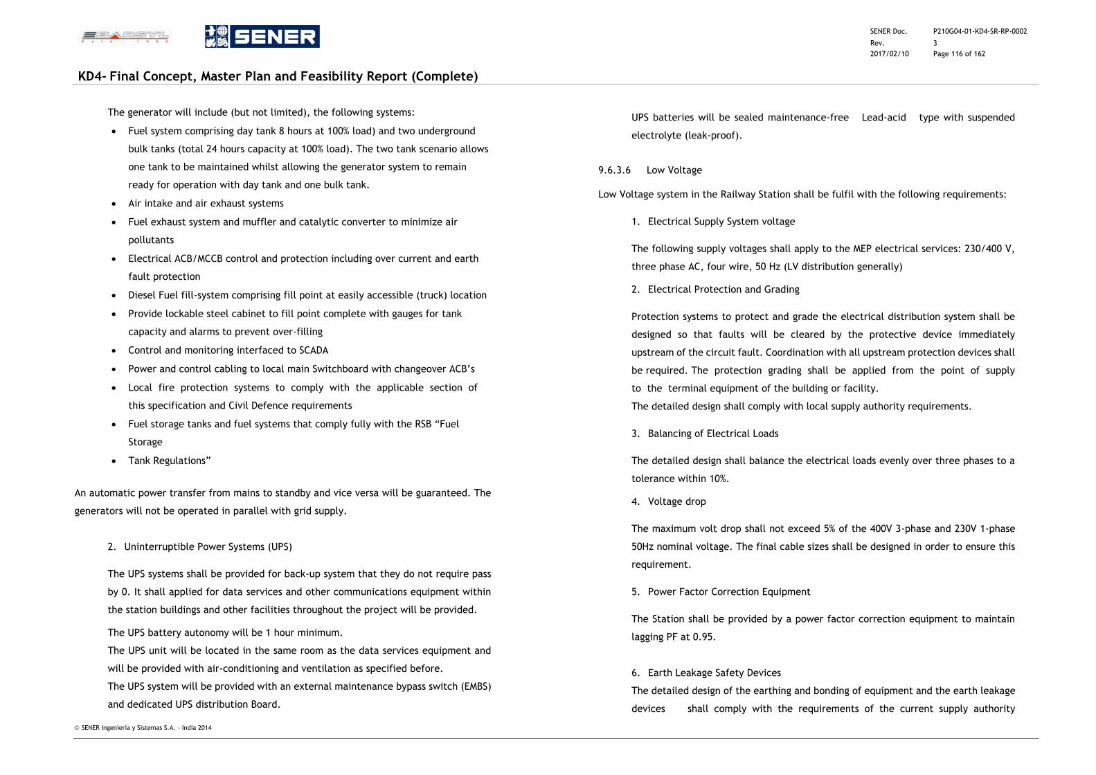
SENER Doc. P210G04-01-KD4-SR-RP-0002
Rev. 3
2017/02/10 Page 116 of 162
KD4- Final Concept, Master Plan and Feasibility Report (Complete)
SENER Ingeniería y Sistemas S.A. - India 2014
The generator will include (but not limited), the following systems:
Fuel system comprising day tank 8 hours at 100% load) and two underground
bulk tanks (total 24 hours capacity at 100% load). The two tank scenario allows
one tank to be maintained whilst allowing the generator system to remain
ready for operation with day tank and one bulk tank.
Air intake and air exhaust systems
Fuel exhaust system and muffler and catalytic converter to minimize air
pollutants
Electrical ACB/MCCB control and protection including over current and earth
fault protection
Diesel Fuel fill-system comprising fill point at easily accessible (truck) location
Provide lockable steel cabinet to fill point complete with gauges for tank
capacity and alarms to prevent over-filling
Control and monitoring interfaced to SCADA
Power and control cabling to local main Switchboard with changeover ACB’s
Local fire protection systems to comply with the applicable section of
this specification and Civil Defence requirements
Fuel storage tanks and fuel systems that comply fully with the RSB “Fuel
Storage
Tank Regulations”
An automatic power transfer from mains to standby and vice versa will be guaranteed. The
generators will not be operated in parallel with grid supply.
2. Uninterruptible Power Systems (UPS)
The UPS systems shall be provided for back-up system that they do not require pass
by 0. It shall applied for data services and other communications equipment within
the station buildings and other facilities throughout the project will be provided.
The UPS battery autonomy will be 1 hour minimum.
The UPS unit will be located in the same room as the data services equipment and
will be provided with air-conditioning and ventilation as specified before.
The UPS system will be provided with an external maintenance bypass switch (EMBS)
and dedicated UPS distribution Board.
UPS batteries will be sealed maintenance-free Lead-acid type with suspended
electrolyte (leak-proof).
9.6.3.6 Low Voltage
Low Voltage system in the Railway Station shall be fulfil with the following requirements:
1. Electrical Supply System voltage
The following supply voltages shall apply to the MEP electrical services: 230/400 V,
three phase AC, four wire, 50 Hz (LV distribution generally)
2. Electrical Protection and Grading
Protection systems to protect and grade the electrical distribution system shall be
designed so that faults will be cleared by the protective device immediately
upstream of the circuit fault. Coordination with all upstream protection devices shall
be required. The protection grading shall be applied from the point of supply
to the terminal equipment of the building or facility.
The detailed design shall comply with local supply authority requirements.
3. Balancing of Electrical Loads
The detailed design shall balance the electrical loads evenly over three phases to a
tolerance within 10%.
4. Voltage drop
The maximum volt drop shall not exceed 5% of the 400V 3-phase and 230V 1-phase
50Hz nominal voltage. The final cable sizes shall be designed in order to ensure this
requirement.
5. Power Factor Correction Equipment
The Station shall be provided by a power factor correction equipment to maintain
lagging PF at 0.95.
6. Earth Leakage Safety Devices
The detailed design of the earthing and bonding of equipment and the earth leakage
devices shall comply with the requirements of the current supply authority
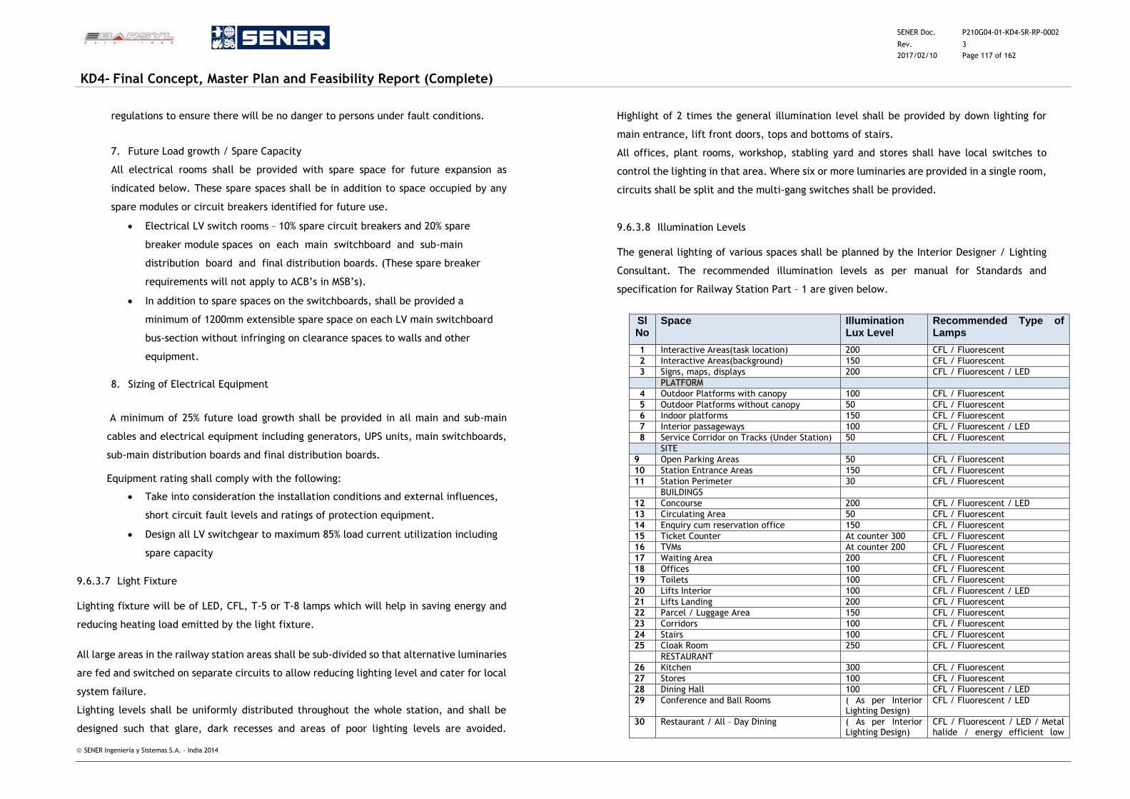
SENER Doc. P210G04-01-KD4-SR-RP-0002
Rev. 3
2017/02/10 Page 117 of 162
KD4- Final Concept, Master Plan and Feasibility Report (Complete)
SENER Ingeniería y Sistemas S.A. - India 2014
regulations to ensure there will be no danger to persons under fault conditions.
7. Future Load growth / Spare Capacity
All electrical rooms shall be provided with spare space for future expansion as
indicated below. These spare spaces shall be in addition to space occupied by any
spare modules or circuit breakers identified for future use.
Electrical LV switch rooms – 10% spare circuit breakers and 20% spare
breaker module spaces on each main switchboard and sub-main
distribution board and final distribution boards. (These spare breaker
requirements will not apply to ACB’s in MSB’s).
In addition to spare spaces on the switchboards, shall be provided a
minimum of 1200mm extensible spare space on each LV main switchboard
bus-section without infringing on clearance spaces to walls and other
equipment.
8. Sizing of Electrical Equipment
A minimum of 25% future load growth shall be provided in all main and sub-main
cables and electrical equipment including generators, UPS units, main switchboards,
sub-main distribution boards and final distribution boards.
Equipment rating shall comply with the following:
Take into consideration the installation conditions and external influences,
short circuit fault levels and ratings of protection equipment.
Design all LV switchgear to maximum 85% load current utilization including
spare capacity
9.6.3.7 Light Fixture
Lighting fixture will be of LED, CFL, T-5 or T-8 lamps which will help in saving energy and
reducing heating load emitted by the light fixture.
All large areas in the railway station areas shall be sub-divided so that alternative luminaries
are fed and switched on separate circuits to allow reducing lighting level and cater for local
system failure.
Lighting levels shall be uniformly distributed throughout the whole station, and shall be
designed such that glare, dark recesses and areas of poor lighting levels are avoided.
Highlight of 2 times the general illumination level shall be provided by down lighting for
main entrance, lift front doors, tops and bottoms of stairs.
All offices, plant rooms, workshop, stabling yard and stores shall have local switches to
control the lighting in that area. Where six or more luminaries are provided in a single room,
circuits shall be split and the multi-gang switches shall be provided.
9.6.3.8 Illumination Levels
The general lighting of various spaces shall be planned by the Interior Designer / Lighting
Consultant. The recommended illumination levels as per manual for Standards and
specification for Railway Station Part – 1 are given below.
Sl No
Space Illumination Lux Level
Recommended Type of Lamps
1 Interactive Areas(task location) 200 CFL / Fluorescent
2 Interactive Areas(background) 150 CFL / Fluorescent
3 Signs, maps, displays 200 CFL / Fluorescent / LED
PLATFORM
4 Outdoor Platforms with canopy 100 CFL / Fluorescent
5 Outdoor Platforms without canopy 50 CFL / Fluorescent
6 Indoor platforms 150 CFL / Fluorescent
7 Interior passageways 100 CFL / Fluorescent / LED
8 Service Corridor on Tracks (Under Station) 50 CFL / Fluorescent
SITE
9 Open Parking Areas 50 CFL / Fluorescent
10 Station Entrance Areas 150 CFL / Fluorescent
11 Station Perimeter 30 CFL / Fluorescent
BUILDINGS
12 Concourse 200 CFL / Fluorescent / LED
13 Circulating Area 50 CFL / Fluorescent
14 Enquiry cum reservation office 150 CFL / Fluorescent
15 Ticket Counter At counter 300 CFL / Fluorescent
16 TVMs At counter 200 CFL / Fluorescent
17 Waiting Area 200 CFL / Fluorescent
18 Offices 100 CFL / Fluorescent
19 Toilets 100 CFL / Fluorescent
20 Lifts Interior 100 CFL / Fluorescent / LED
21 Lifts Landing 200 CFL / Fluorescent
22 Parcel / Luggage Area 150 CFL / Fluorescent
23 Corridors 100 CFL / Fluorescent
24 Stairs 100 CFL / Fluorescent
25 Cloak Room 250 CFL / Fluorescent
RESTAURANT
26 Kitchen 300 CFL / Fluorescent
27 Stores 100 CFL / Fluorescent
28 Dining Hall 100 CFL / Fluorescent / LED
29 Conference and Ball Rooms ( As per Interior Lighting Design)
CFL / Fluorescent / LED
30 Restaurant / All – Day Dining ( As per Interior Lighting Design)
CFL / Fluorescent / LED / Metal halide / energy efficient low
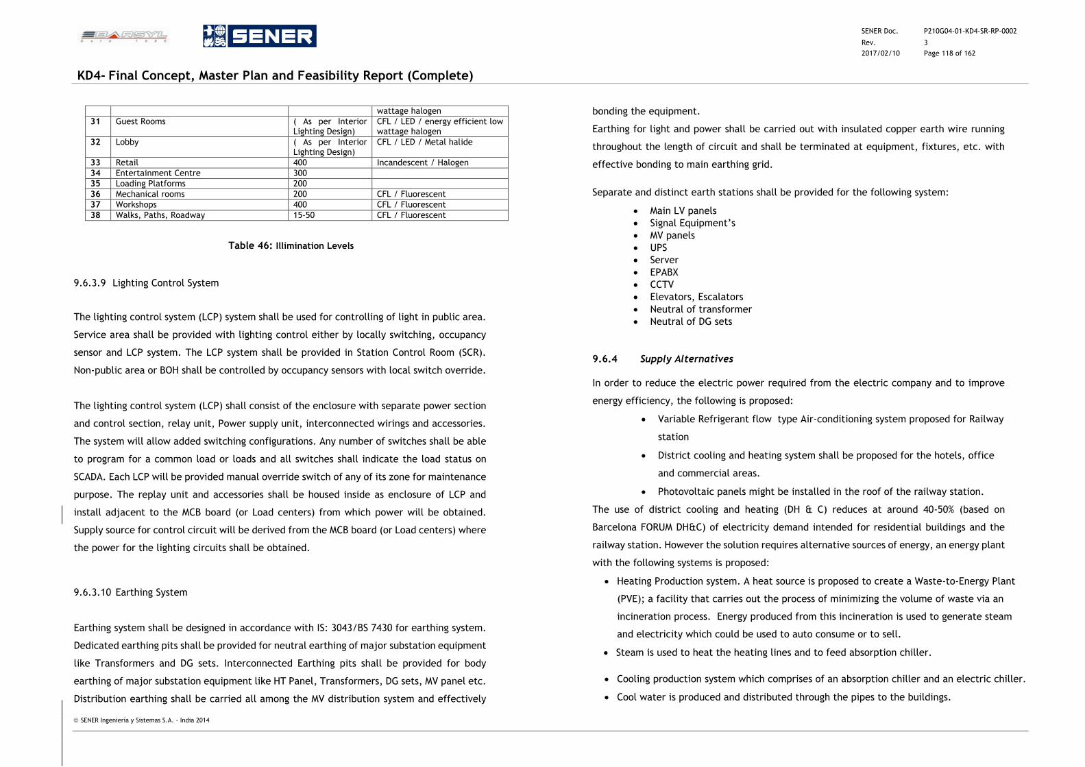
SENER Doc. P210G04-01-KD4-SR-RP-0002
Rev. 3
2017/02/10 Page 118 of 162
KD4- Final Concept, Master Plan and Feasibility Report (Complete)
SENER Ingeniería y Sistemas S.A. - India 2014
wattage halogen
31 Guest Rooms ( As per Interior Lighting Design)
CFL / LED / energy efficient low wattage halogen
32 Lobby ( As per Interior Lighting Design)
CFL / LED / Metal halide
33 Retail 400 Incandescent / Halogen
34 Entertainment Centre 300
35 Loading Platforms 200
36 Mechanical rooms 200 CFL / Fluorescent
37 Workshops 400 CFL / Fluorescent
38 Walks, Paths, Roadway 15-50 CFL / Fluorescent
Table 46: Illimination Levels
9.6.3.9 Lighting Control System
The lighting control system (LCP) system shall be used for controlling of light in public area.
Service area shall be provided with lighting control either by locally switching, occupancy
sensor and LCP system. The LCP system shall be provided in Station Control Room (SCR).
Non-public area or BOH shall be controlled by occupancy sensors with local switch override.
The lighting control system (LCP) shall consist of the enclosure with separate power section
and control section, relay unit, Power supply unit, interconnected wirings and accessories.
The system will allow added switching configurations. Any number of switches shall be able
to program for a common load or loads and all switches shall indicate the load status on
SCADA. Each LCP will be provided manual override switch of any of its zone for maintenance
purpose. The replay unit and accessories shall be housed inside as enclosure of LCP and
install adjacent to the MCB board (or Load centers) from which power will be obtained.
Supply source for control circuit will be derived from the MCB board (or Load centers) where
the power for the lighting circuits shall be obtained.
9.6.3.10 Earthing System
Earthing system shall be designed in accordance with IS: 3043/BS 7430 for earthing system.
Dedicated earthing pits shall be provided for neutral earthing of major substation equipment
like Transformers and DG sets. Interconnected Earthing pits shall be provided for body
earthing of major substation equipment like HT Panel, Transformers, DG sets, MV panel etc.
Distribution earthing shall be carried all among the MV distribution system and effectively
bonding the equipment.
Earthing for light and power shall be carried out with insulated copper earth wire running
throughout the length of circuit and shall be terminated at equipment, fixtures, etc. with
effective bonding to main earthing grid.
Separate and distinct earth stations shall be provided for the following system:
Main LV panels
Signal Equipment’s
MV panels
UPS
Server
EPABX
CCTV
Elevators, Escalators
Neutral of transformer
Neutral of DG sets
9.6.4 Supply Alternatives
In order to reduce the electric power required from the electric company and to improve
energy efficiency, the following is proposed:
Variable Refrigerant flow type Air-conditioning system proposed for Railway
station
District cooling and heating system shall be proposed for the hotels, office
and commercial areas.
Photovoltaic panels might be installed in the roof of the railway station.
The use of district cooling and heating (DH & C) reduces at around 40-50% (based on
Barcelona FORUM DH&C) of electricity demand intended for residential buildings and the
railway station. However the solution requires alternative sources of energy, an energy plant
with the following systems is proposed:
Heating Production system. A heat source is proposed to create a Waste-to-Energy Plant
(PVE); a facility that carries out the process of minimizing the volume of waste via an
incineration process. Energy produced from this incineration is used to generate steam
and electricity which could be used to auto consume or to sell.
Steam is used to heat the heating lines and to feed absorption chiller.
Cooling production system which comprises of an absorption chiller and an electric chiller.
Cool water is produced and distributed through the pipes to the buildings.
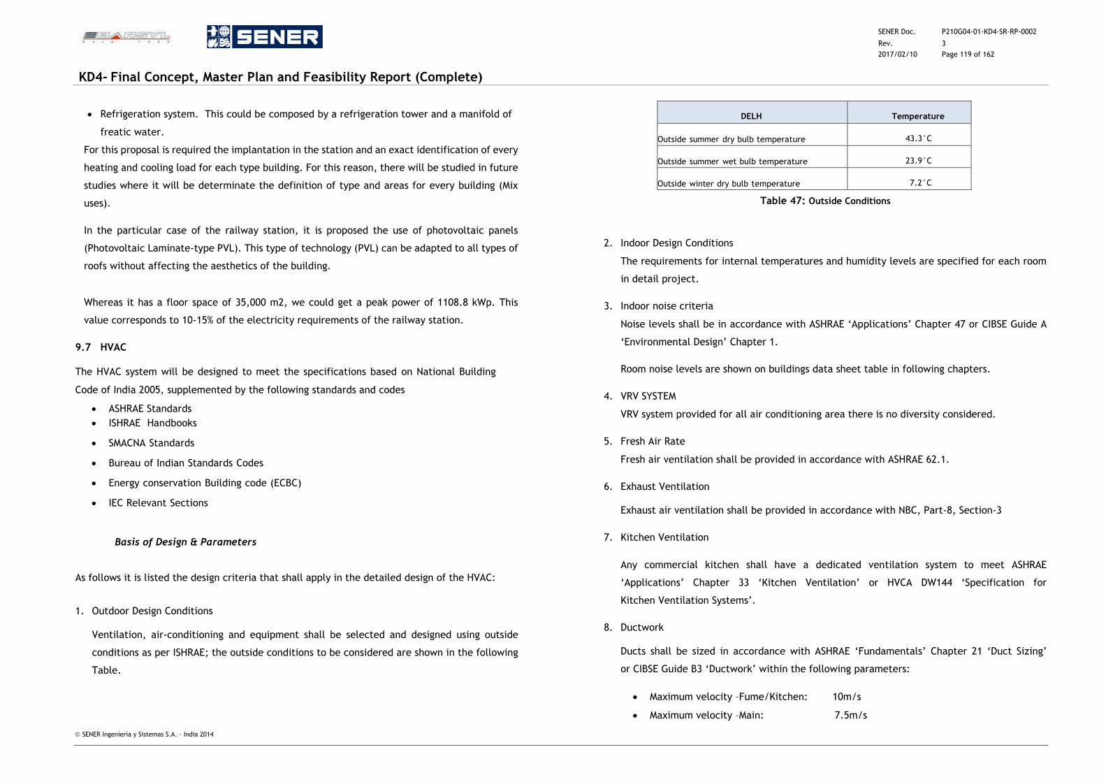
SENER Doc. P210G04-01-KD4-SR-RP-0002
Rev. 3
2017/02/10 Page 119 of 162
KD4- Final Concept, Master Plan and Feasibility Report (Complete)
SENER Ingeniería y Sistemas S.A. - India 2014
Refrigeration system. This could be composed by a refrigeration tower and a manifold of
freatic water.
For this proposal is required the implantation in the station and an exact identification of every
heating and cooling load for each type building. For this reason, there will be studied in future
studies where it will be determinate the definition of type and areas for every building (Mix
uses).
In the particular case of the railway station, it is proposed the use of photovoltaic panels
(Photovoltaic Laminate-type PVL). This type of technology (PVL) can be adapted to all types of
roofs without affecting the aesthetics of the building.
Whereas it has a floor space of 35,000 m2, we could get a peak power of 1108.8 kWp. This
value corresponds to 10-15% of the electricity requirements of the railway station.
9.7 HVAC
The HVAC system will be designed to meet the specifications based on National Building
Code of India 2005, supplemented by the following standards and codes
ASHRAE Standards
ISHRAE Handbooks
SMACNA Standards
Bureau of Indian Standards Codes
Energy conservation Building code (ECBC)
IEC Relevant Sections
9.7.1 Basis of Design & Parameters
As follows it is listed the design criteria that shall apply in the detailed design of the HVAC:
1. Outdoor Design Conditions
Ventilation, air-conditioning and equipment shall be selected and designed using outside
conditions as per ISHRAE; the outside conditions to be considered are shown in the following
Table.
Table 47: Outside Conditions
2. Indoor Design Conditions
The requirements for internal temperatures and humidity levels are specified for each room
in detail project.
3. Indoor noise criteria
Noise levels shall be in accordance with ASHRAE ‘Applications’ Chapter 47 or CIBSE Guide A
‘Environmental Design’ Chapter 1.
Room noise levels are shown on buildings data sheet table in following chapters.
4. VRV SYSTEM
VRV system provided for all air conditioning area there is no diversity considered.
5. Fresh Air Rate
Fresh air ventilation shall be provided in accordance with ASHRAE 62.1.
6. Exhaust Ventilation
Exhaust air ventilation shall be provided in accordance with NBC, Part-8, Section-3
7. Kitchen Ventilation
Any commercial kitchen shall have a dedicated ventilation system to meet ASHRAE
‘Applications’ Chapter 33 ‘Kitchen Ventilation’ or HVCA DW144 ‘Specification for
Kitchen Ventilation Systems’.
8. Ductwork
Ducts shall be sized in accordance with ASHRAE ‘Fundamentals’ Chapter 21 ‘Duct Sizing’
or CIBSE Guide B3 ‘Ductwork’ within the following parameters:
Maximum velocity –Fume/Kitchen: 10m/s
Maximum velocity –Main: 7.5m/s
DELHI
Temperature
Outside summer dry bulb temperature
43.3°C
Outside summer wet bulb temperature
23.9°C
Outside winter dry bulb temperature
7.2°C
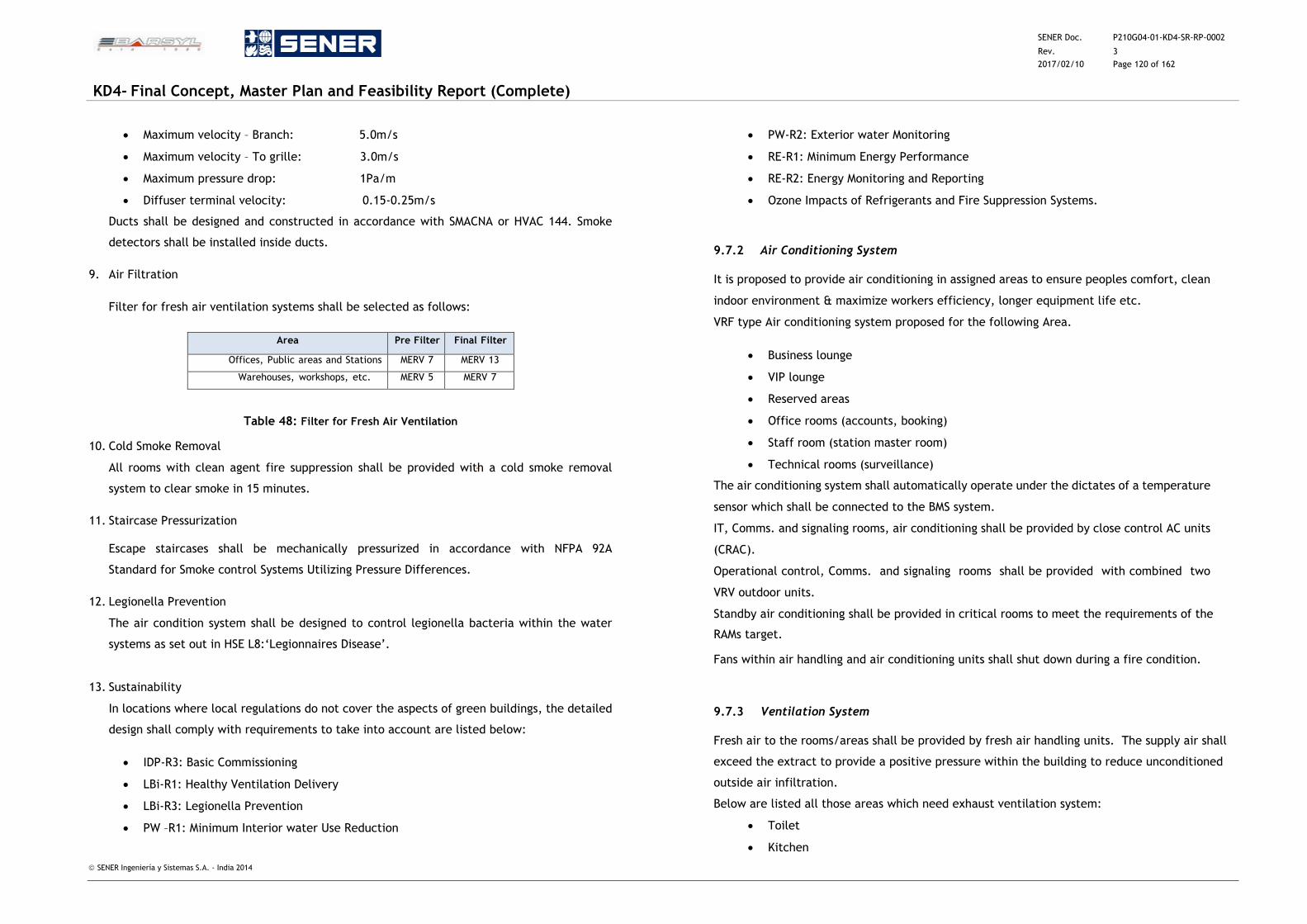
SENER Doc. P210G04-01-KD4-SR-RP-0002
Rev. 3
2017/02/10 Page 120 of 162
KD4- Final Concept, Master Plan and Feasibility Report (Complete)
SENER Ingeniería y Sistemas S.A. - India 2014
Maximum velocity – Branch: 5.0m/s
Maximum velocity – To grille: 3.0m/s
Maximum pressure drop: 1Pa/m
Diffuser terminal velocity: 0.15-0.25m/s
Ducts shall be designed and constructed in accordance with SMACNA or HVAC 144. Smoke
detectors shall be installed inside ducts.
9. Air Filtration
Filter for fresh air ventilation systems shall be selected as follows:
Area Pre Filter Final Filter
Offices, Public areas and Stations MERV 7 MERV 13
Warehouses, workshops, etc. MERV 5 MERV 7
Table 48: Filter for Fresh Air Ventilation
10. Cold Smoke Removal
All rooms with clean agent fire suppression shall be provided with a cold smoke removal
system to clear smoke in 15 minutes.
11. Staircase Pressurization
Escape staircases shall be mechanically pressurized in accordance with NFPA 92A
Standard for Smoke control Systems Utilizing Pressure Differences.
12. Legionella Prevention
The air condition system shall be designed to control legionella bacteria within the water
systems as set out in HSE L8:‘Legionnaires Disease’.
13. Sustainability
In locations where local regulations do not cover the aspects of green buildings, the detailed
design shall comply with requirements to take into account are listed below:
IDP-R3: Basic Commissioning
LBi-R1: Healthy Ventilation Delivery
LBi-R3: Legionella Prevention
PW –R1: Minimum Interior water Use Reduction
PW-R2: Exterior water Monitoring
RE-R1: Minimum Energy Performance
RE-R2: Energy Monitoring and Reporting
Ozone Impacts of Refrigerants and Fire Suppression Systems.
9.7.2 Air Conditioning System
It is proposed to provide air conditioning in assigned areas to ensure peoples comfort, clean
indoor environment & maximize workers efficiency, longer equipment life etc.
VRF type Air conditioning system proposed for the following Area.
Business lounge
VIP lounge
Reserved areas
Office rooms (accounts, booking)
Staff room (station master room)
Technical rooms (surveillance)
The air conditioning system shall automatically operate under the dictates of a temperature
sensor which shall be connected to the BMS system.
IT, Comms. and signaling rooms, air conditioning shall be provided by close control AC units
(CRAC).
Operational control, Comms. and signaling rooms shall be provided with combined two
VRV outdoor units.
Standby air conditioning shall be provided in critical rooms to meet the requirements of the RAMs target.
Fans within air handling and air conditioning units shall shut down during a fire condition.
9.7.3 Ventilation System
Fresh air to the rooms/areas shall be provided by fresh air handling units. The supply air shall
exceed the extract to provide a positive pressure within the building to reduce unconditioned
outside air infiltration.
Below are listed all those areas which need exhaust ventilation system:
Toilet
Kitchen
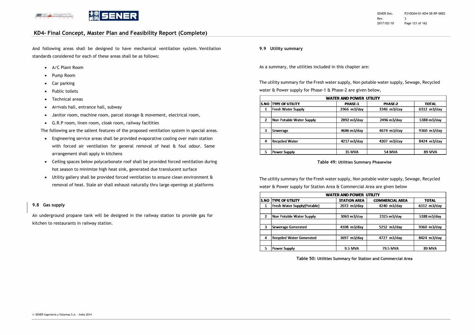
SENER Doc. P210G04-01-KD4-SR-RP-0002
Rev. 3
2017/02/10 Page 121 of 162
KD4- Final Concept, Master Plan and Feasibility Report (Complete)
SENER Ingeniería y Sistemas S.A. - India 2014
And following areas shall be designed to have mechanical ventilation system. Ventilation
standards considered for each of these areas shall be as follows:
A/C Plant Room
Pump Room
Car parking
Public toilets
Technical areas
Arrivals hall, entrance hall, subway
Janitor room, machine room, parcel storage & movement, electrical room,
G.R.P room, linen room, cloak room, railway facilities
The following are the salient features of the proposed ventilation system in special areas.
Engineering service areas shall be provided evaporative cooling over main station
with forced air ventilation for general removal of heat & foul odour. Same
arrangement shall apply in kitchens
Ceiling spaces below polycarbonate roof shall be provided forced ventilation during
hot season to minimize high heat sink, generated due translucent surface
Utility gallery shall be provided forced ventilation to ensure clean environment &
removal of heat. Stale air shall exhaust naturally thru large openings at platforms
9.8 Gas supply
An underground propane tank will be designed in the railway station to provide gas for
kitchen to restaurants in railway station.
9.9 Utility summary
As a summary, the utilities included in this chapter are:
The utility summary for the Fresh water supply, Non potable water supply, Sewage, Recycled
water & Power supply for Phase-1 & Phase-2 are given below,
Table 49: Utilities Summary Phasewise
The utility summary for the Fresh water supply, Non potable water supply, Sewage, Recycled
water & Power supply for Station Area & Commercial Area are given below
Table 50: Utilities Summary for Station and Commercial Area
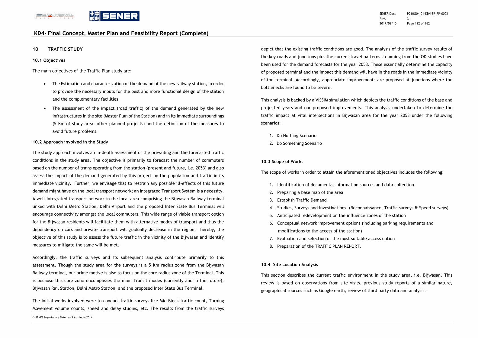
SENER Doc. P210G04-01-KD4-SR-RP-0002
Rev. 3
2017/02/10 Page 122 of 162
KD4- Final Concept, Master Plan and Feasibility Report (Complete)
SENER Ingeniería y Sistemas S.A. - India 2014
10 TRAFFIC STUDY
10.1 Objectives
The main objectives of the Traffic Plan study are:
The Estimation and characterization of the demand of the new railway station, in order
to provide the necessary inputs for the best and more functional design of the station
and the complementary facilities.
The assessment of the impact (road traffic) of the demand generated by the new
infrastructures in the site (Master Plan of the Station) and in its immediate surroundings
(5 Km of study area: other planned projects) and the definition of the measures to
avoid future problems.
10.2 Approach involved in the Study
The study approach involves an in-depth assessment of the prevailing and the forecasted traffic
conditions in the study area. The objective is primarily to forecast the number of commuters
based on the number of trains operating from the station (present and future, i.e. 2053) and also
assess the impact of the demand generated by this project on the population and traffic in its
immediate vicinity. Further, we envisage that to restrain any possible ill-effects of this future
demand might have on the local transport network; an Integrated Transport System is a necessity.
A well-integrated transport network in the local area comprising the Bijwasan Railway terminal
linked with Delhi Metro Station, Delhi Airport and the proposed Inter State Bus Terminal will
encourage connectivity amongst the local commuters. This wide range of viable transport option
for the Bijwasan residents will facilitate them with alternative modes of transport and thus the
dependency on cars and private transport will gradually decrease in the region. Thereby, the
objective of this study is to assess the future traffic in the vicinity of the Bijwasan and identify
measures to mitigate the same will be met.
Accordingly, the traffic surveys and its subsequent analysis contribute primarily to this
assessment. Though the study area for the surveys is a 5 Km radius zone from the Bijwasan
Railway terminal, our prime motive is also to focus on the core radius zone of the Terminal. This
is because this core zone encompasses the main Transit modes (currently and in the future),
Bijwasan Rail Station, Delhi Metro Station, and the proposed Inter State Bus Terminal.
The initial works involved were to conduct traffic surveys like Mid-Block traffic count, Turning
Movement volume counts, speed and delay studies, etc. The results from the traffic surveys
depict that the existing traffic conditions are good. The analysis of the traffic survey results of
the key roads and junctions plus the current travel patterns stemming from the OD studies have
been used for the demand forecasts for the year 2053. These essentially determine the capacity
of proposed terminal and the impact this demand will have in the roads in the immediate vicinity
of the terminal. Accordingly, appropriate improvements are proposed at junctions where the
bottlenecks are found to be severe.
This analysis is backed by a VISSIM simulation which depicts the traffic conditions of the base and
projected years and our proposed improvements. This analysis undertaken to determine the
traffic impact at vital intersections in Bijwasan area for the year 2053 under the following
scenarios:
1. Do Nothing Scenario
2. Do Something Scenario
10.3 Scope of Works
The scope of works in order to attain the aforementioned objectives includes the following:
1. Identification of documental information sources and data collection
2. Preparing a base map of the area
3. Establish Traffic Demand
4. Studies, Surveys and Investigations (Reconnaissance, Traffic surveys & Speed surveys)
5. Anticipated redevelopment on the influence zones of the station
6. Conceptual network improvement options (including parking requirements and
modifications to the access of the station)
7. Evaluation and selection of the most suitable access option
8. Preparation of the TRAFFIC PLAN REPORT.
10.4 Site Location Analysis
This section describes the current traffic environment in the study area, i.e. Bijwasan. This
review is based on observations from site visits, previous study reports of a similar nature,
geographical sources such as Google earth, review of third party data and analysis.
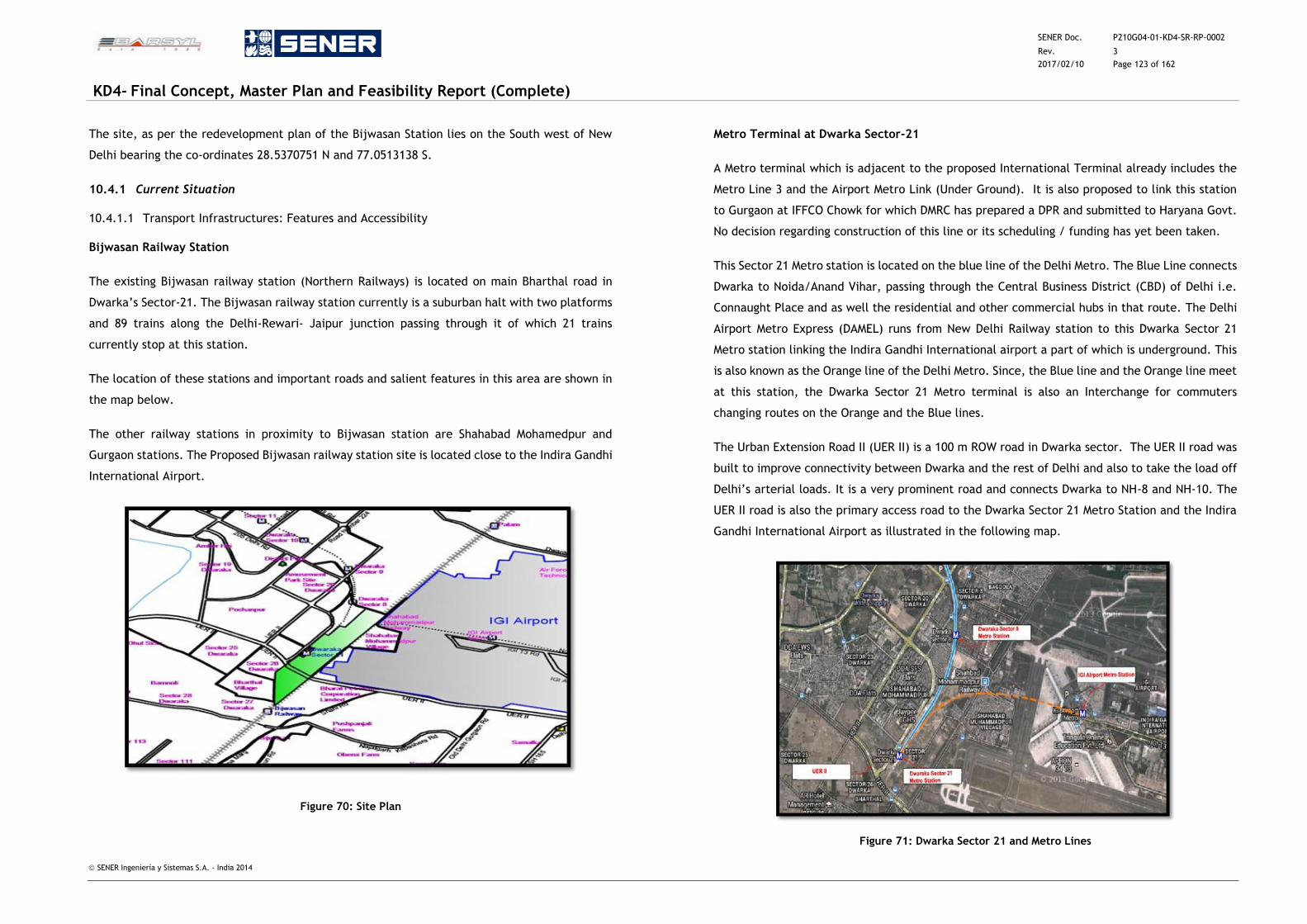
SENER Doc. P210G04-01-KD4-SR-RP-0002
Rev. 3
2017/02/10 Page 123 of 162
KD4- Final Concept, Master Plan and Feasibility Report (Complete)
SENER Ingeniería y Sistemas S.A. - India 2014
The site, as per the redevelopment plan of the Bijwasan Station lies on the South west of New
Delhi bearing the co-ordinates 28.5370751 N and 77.0513138 S.
10.4.1 Current Situation
10.4.1.1 Transport Infrastructures: Features and Accessibility
Bijwasan Railway Station
The existing Bijwasan railway station (Northern Railways) is located on main Bharthal road in
Dwarka’s Sector-21. The Bijwasan railway station currently is a suburban halt with two platforms
and 89 trains along the Delhi-Rewari- Jaipur junction passing through it of which 21 trains
currently stop at this station.
The location of these stations and important roads and salient features in this area are shown in
the map below.
The other railway stations in proximity to Bijwasan station are Shahabad Mohamedpur and
Gurgaon stations. The Proposed Bijwasan railway station site is located close to the Indira Gandhi
International Airport.
Figure 70: Site Plan
Metro Terminal at Dwarka Sector-21
A Metro terminal which is adjacent to the proposed International Terminal already includes the
Metro Line 3 and the Airport Metro Link (Under Ground). It is also proposed to link this station
to Gurgaon at IFFCO Chowk for which DMRC has prepared a DPR and submitted to Haryana Govt.
No decision regarding construction of this line or its scheduling / funding has yet been taken.
This Sector 21 Metro station is located on the blue line of the Delhi Metro. The Blue Line connects
Dwarka to Noida/Anand Vihar, passing through the Central Business District (CBD) of Delhi i.e.
Connaught Place and as well the residential and other commercial hubs in that route. The Delhi
Airport Metro Express (DAMEL) runs from New Delhi Railway station to this Dwarka Sector 21
Metro station linking the Indira Gandhi International airport a part of which is underground. This
is also known as the Orange line of the Delhi Metro. Since, the Blue line and the Orange line meet
at this station, the Dwarka Sector 21 Metro terminal is also an Interchange for commuters
changing routes on the Orange and the Blue lines.
The Urban Extension Road II (UER II) is a 100 m ROW road in Dwarka sector. The UER II road was
built to improve connectivity between Dwarka and the rest of Delhi and also to take the load off
Delhi’s arterial loads. It is a very prominent road and connects Dwarka to NH-8 and NH-10. The
UER II road is also the primary access road to the Dwarka Sector 21 Metro Station and the Indira
Gandhi International Airport as illustrated in the following map.
Figure 71: Dwarka Sector 21 and Metro Lines
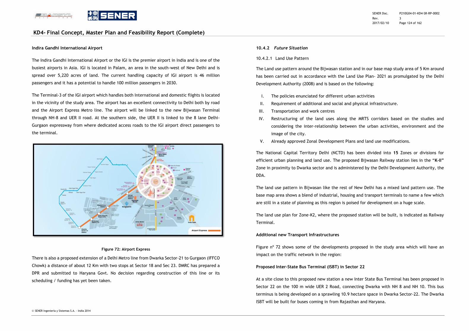
SENER Doc. P210G04-01-KD4-SR-RP-0002
Rev. 3
2017/02/10 Page 124 of 162
KD4- Final Concept, Master Plan and Feasibility Report (Complete)
SENER Ingeniería y Sistemas S.A. - India 2014
Indira Gandhi International Airport
The Indira Gandhi International Airport or the IGI is the premier airport in India and is one of the
busiest airports in Asia. IGI is located in Palam, an area in the south-west of New Delhi and is
spread over 5,220 acres of land. The current handling capacity of IGI airport is 46 million
passengers and it has a potential to handle 100 million passengers in 2030.
The Terminal-3 of the IGI airport which handles both International and domestic flights is located
in the vicinity of the study area. The airport has an excellent connectivity to Delhi both by road
and the Airport Express Metro line. The airport will be linked to the new Bijwasan Terminal
through NH-8 and UER II road. At the southern side, the UER II is linked to the 8 lane Delhi-
Gurgaon expressway from where dedicated access roads to the IGI airport direct passengers to
the terminal.
Figure 72: Airport Express
There is also a proposed extension of a Delhi Metro line from Dwarka Sector-21 to Gurgaon (IFFCO
Chowk) a distance of about 12 Km with two stops at Sector 18 and Sec 23. DMRC has prepared a
DPR and submitted to Haryana Govt. No decision regarding construction of this line or its
scheduling / funding has yet been taken.
10.4.2 Future Situation
10.4.2.1 Land Use Pattern
The Land use pattern around the Bijwasan station and in our base map study area of 5 Km around
has been carried out in accordance with the Land Use Plan- 2021 as promulgated by the Delhi
Development Authority (2008) and is based on the following:
I. The policies enunciated for different urban activities
II. Requirement of additional and social and physical infrastructure.
III. Transportation and work centres
IV. Restructuring of the land uses along the MRTS corridors based on the studies and
considering the inter-relationship between the urban activities, environment and the
image of the city.
V. Already approved Zonal Development Plans and land use modifications.
The National Capital Territory Delhi (NCTD) has been divided into 15 Zones or divisions for
efficient urban planning and land use. The proposed Bijwasan Railway station lies in the “K-II”
Zone in proximity to Dwarka sector and is administered by the Delhi Development Authority, the
DDA.
The land use pattern in Bijwasan like the rest of New Delhi has a mixed land pattern use. The
base map area shows a blend of industrial, housing and transport terminals to name a few which
are still in a state of planning as this region is poised for development on a huge scale.
The land use plan for Zone-K2, where the proposed station will be built, is indicated as Railway
Terminal.
Additional new Transport Infrastructures
Figure nº 72 shows some of the developments proposed in the study area which will have an
impact on the traffic network in the region:
Proposed Inter-State Bus Terminal (ISBT) in Sector 22
At a site close to this proposed new station a new Inter State Bus Terminal has been proposed in
Sector 22 on the 100 m wide UER 2 Road, connecting Dwarka with NH 8 and NH 10. This bus
terminus is being developed on a sprawling 10.9 hectare space in Dwarka Sector-22. The Dwarka
ISBT will be built for buses coming in from Rajasthan and Haryana.
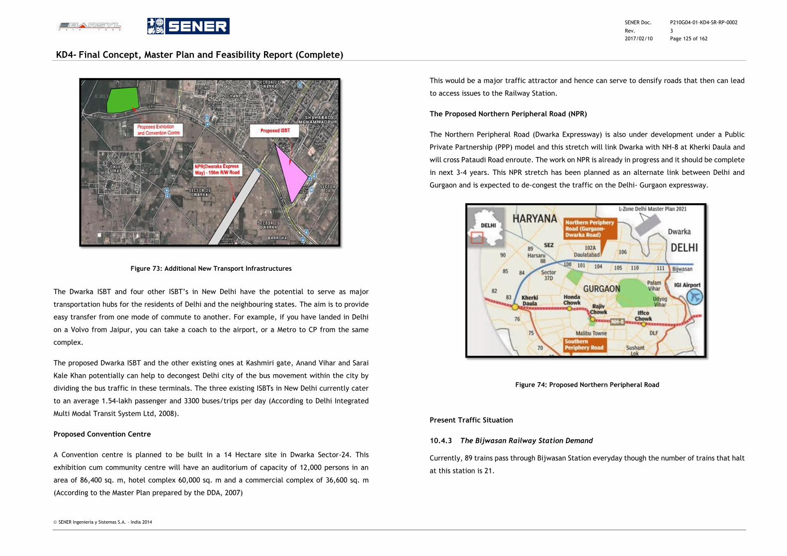
SENER Doc. P210G04-01-KD4-SR-RP-0002
Rev. 3
2017/02/10 Page 125 of 162
KD4- Final Concept, Master Plan and Feasibility Report (Complete)
SENER Ingeniería y Sistemas S.A. - India 2014
Figure 73: Additional New Transport Infrastructures
The Dwarka ISBT and four other ISBT’s in New Delhi have the potential to serve as major
transportation hubs for the residents of Delhi and the neighbouring states. The aim is to provide
easy transfer from one mode of commute to another. For example, if you have landed in Delhi
on a Volvo from Jaipur, you can take a coach to the airport, or a Metro to CP from the same
complex.
The proposed Dwarka ISBT and the other existing ones at Kashmiri gate, Anand Vihar and Sarai
Kale Khan potentially can help to decongest Delhi city of the bus movement within the city by
dividing the bus traffic in these terminals. The three existing ISBTs in New Delhi currently cater
to an average 1.54-lakh passenger and 3300 buses/trips per day (According to Delhi Integrated
Multi Modal Transit System Ltd, 2008).
Proposed Convention Centre
A Convention centre is planned to be built in a 14 Hectare site in Dwarka Sector-24. This
exhibition cum community centre will have an auditorium of capacity of 12,000 persons in an
area of 86,400 sq. m, hotel complex 60,000 sq. m and a commercial complex of 36,600 sq. m
(According to the Master Plan prepared by the DDA, 2007)
This would be a major traffic attractor and hence can serve to densify roads that then can lead
to access issues to the Railway Station.
The Proposed Northern Peripheral Road (NPR)
The Northern Peripheral Road (Dwarka Expressway) is also under development under a Public
Private Partnership (PPP) model and this stretch will link Dwarka with NH-8 at Kherki Daula and
will cross Pataudi Road enroute. The work on NPR is already in progress and it should be complete
in next 3-4 years. This NPR stretch has been planned as an alternate link between Delhi and
Gurgaon and is expected to de-congest the traffic on the Delhi- Gurgaon expressway.
Figure 74: Proposed Northern Peripheral Road
Present Traffic Situation
10.4.3 The Bijwasan Railway Station Demand
Currently, 89 trains pass through Bijwasan Station everyday though the number of trains that halt
at this station is 21.
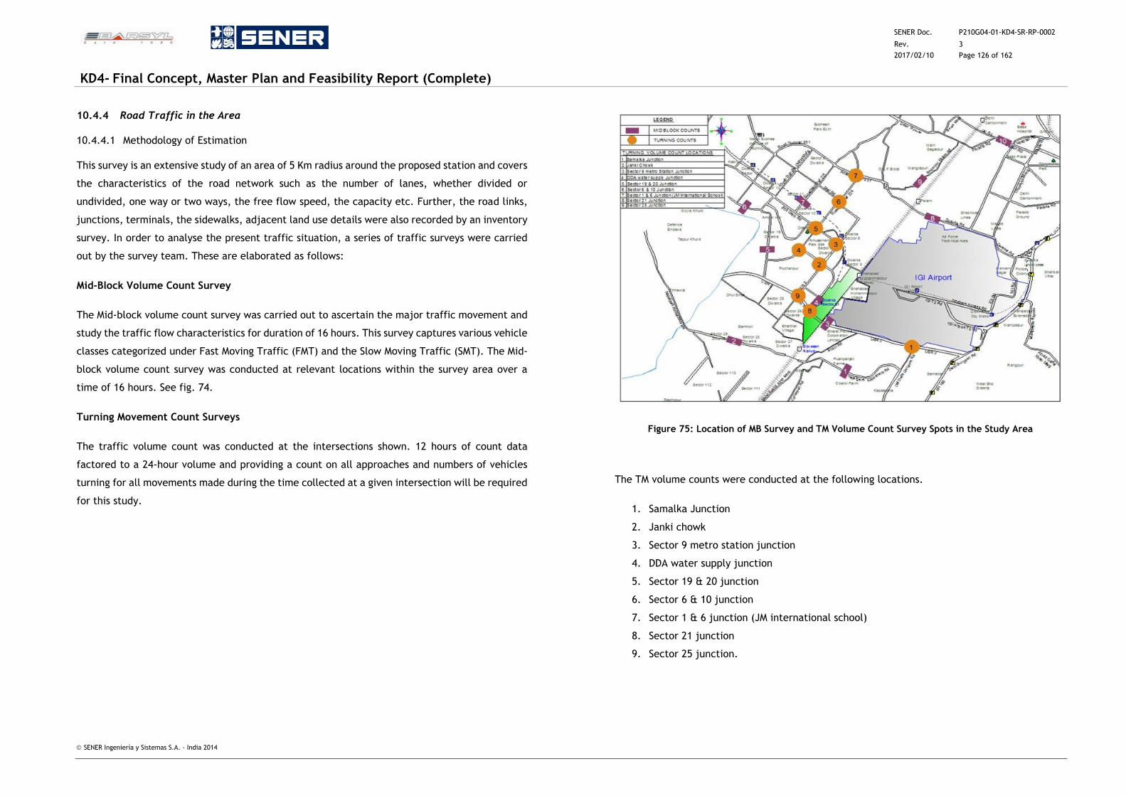
SENER Doc. P210G04-01-KD4-SR-RP-0002
Rev. 3
2017/02/10 Page 126 of 162
KD4- Final Concept, Master Plan and Feasibility Report (Complete)
SENER Ingeniería y Sistemas S.A. - India 2014
10.4.4 Road Traffic in the Area
10.4.4.1 Methodology of Estimation
This survey is an extensive study of an area of 5 Km radius around the proposed station and covers
the characteristics of the road network such as the number of lanes, whether divided or
undivided, one way or two ways, the free flow speed, the capacity etc. Further, the road links,
junctions, terminals, the sidewalks, adjacent land use details were also recorded by an inventory
survey. In order to analyse the present traffic situation, a series of traffic surveys were carried
out by the survey team. These are elaborated as follows:
Mid-Block Volume Count Survey
The Mid-block volume count survey was carried out to ascertain the major traffic movement and
study the traffic flow characteristics for duration of 16 hours. This survey captures various vehicle
classes categorized under Fast Moving Traffic (FMT) and the Slow Moving Traffic (SMT). The Mid-
block volume count survey was conducted at relevant locations within the survey area over a
time of 16 hours. See fig. 74.
Turning Movement Count Surveys
The traffic volume count was conducted at the intersections shown. 12 hours of count data
factored to a 24-hour volume and providing a count on all approaches and numbers of vehicles
turning for all movements made during the time collected at a given intersection will be required
for this study.
Figure 75: Location of MB Survey and TM Volume Count Survey Spots in the Study Area
The TM volume counts were conducted at the following locations.
1. Samalka Junction
2. Janki chowk
3. Sector 9 metro station junction
4. DDA water supply junction
5. Sector 19 & 20 junction
6. Sector 6 & 10 junction
7. Sector 1 & 6 junction (JM international school)
8. Sector 21 junction
9. Sector 25 junction.
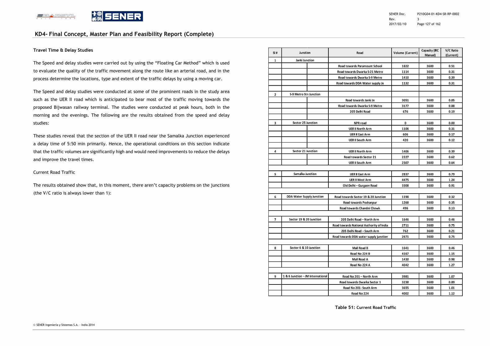
SENER Doc. P210G04-01-KD4-SR-RP-0002
Rev. 3
2017/02/10 Page 127 of 162
KD4- Final Concept, Master Plan and Feasibility Report (Complete)
SENER Ingeniería y Sistemas S.A. - India 2014
Travel Time & Delay Studies
The Speed and delay studies were carried out by using the “Floating Car Method” which is used
to evaluate the quality of the traffic movement along the route like an arterial road, and in the
process determine the locations, type and extent of the traffic delays by using a moving car.
The Speed and delay studies were conducted at some of the prominent roads in the study area
such as the UER II road which is anticipated to bear most of the traffic moving towards the
proposed Bijwasan railway terminal. The studies were conducted at peak hours, both in the
morning and the evenings. The following are the results obtained from the speed and delay
studies:
These studies reveal that the section of the UER II road near the Samalka Junction experienced
a delay time of 5:50 min primarily. Hence, the operational conditions on this section indicate
that the traffic volumes are significantly high and would need improvements to reduce the delays
and improve the travel times.
Current Road Traffic
The results obtained show that, in this moment, there aren’t capacity problems on the junctions
(the V/C ratio is always lower than 1):
Table 51: Current Road Traffic
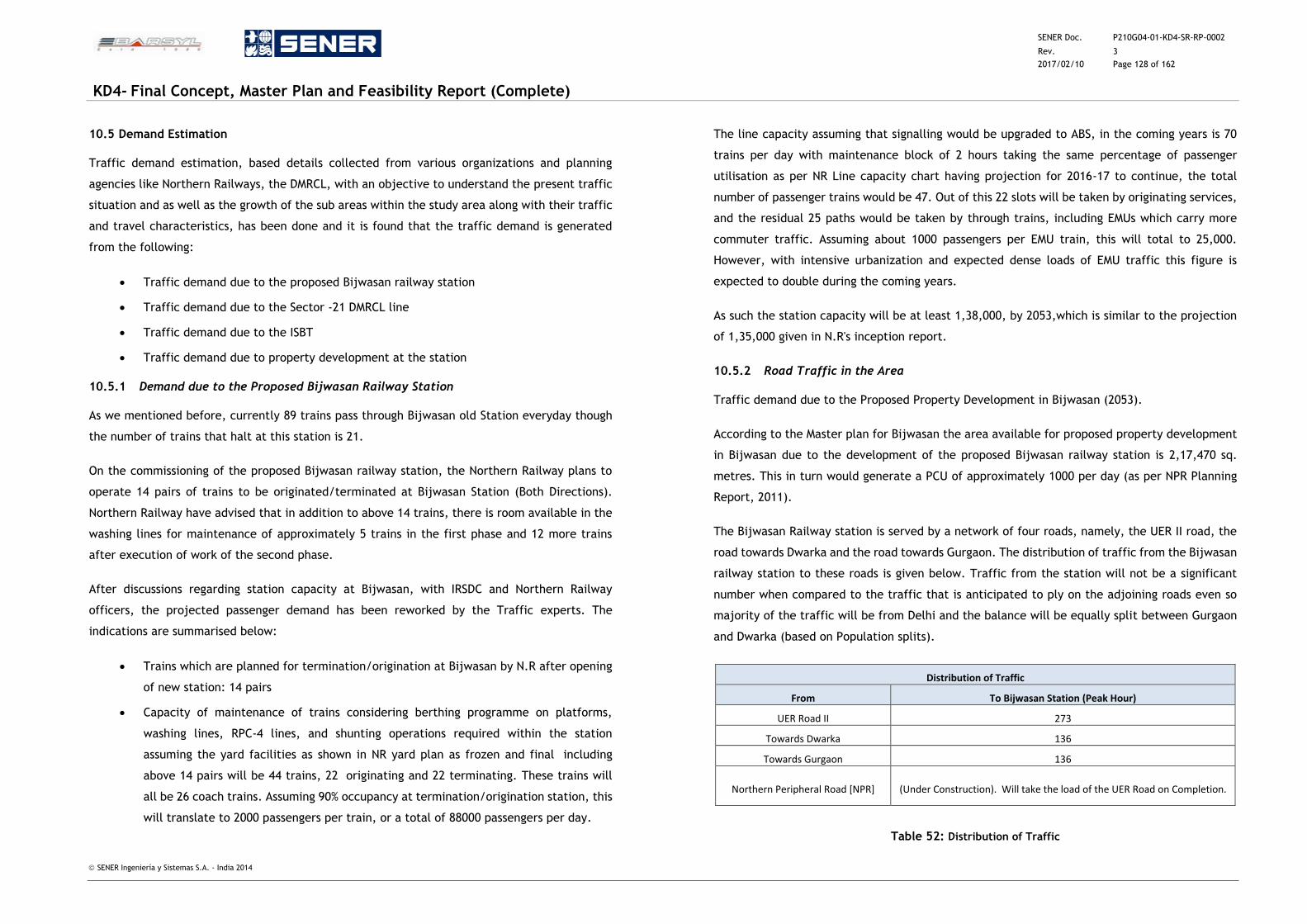
SENER Doc. P210G04-01-KD4-SR-RP-0002
Rev. 3
2017/02/10 Page 128 of 162
KD4- Final Concept, Master Plan and Feasibility Report (Complete)
SENER Ingeniería y Sistemas S.A. - India 2014
10.5 Demand Estimation
Traffic demand estimation, based details collected from various organizations and planning
agencies like Northern Railways, the DMRCL, with an objective to understand the present traffic
situation and as well as the growth of the sub areas within the study area along with their traffic
and travel characteristics, has been done and it is found that the traffic demand is generated
from the following:
Traffic demand due to the proposed Bijwasan railway station
Traffic demand due to the Sector -21 DMRCL line
Traffic demand due to the ISBT
Traffic demand due to property development at the station
10.5.1 Demand due to the Proposed Bijwasan Railway Station
As we mentioned before, currently 89 trains pass through Bijwasan old Station everyday though
the number of trains that halt at this station is 21.
On the commissioning of the proposed Bijwasan railway station, the Northern Railway plans to
operate 14 pairs of trains to be originated/terminated at Bijwasan Station (Both Directions).
Northern Railway have advised that in addition to above 14 trains, there is room available in the
washing lines for maintenance of approximately 5 trains in the first phase and 12 more trains
after execution of work of the second phase.
After discussions regarding station capacity at Bijwasan, with IRSDC and Northern Railway
officers, the projected passenger demand has been reworked by the Traffic experts. The
indications are summarised below:
Trains which are planned for termination/origination at Bijwasan by N.R after opening
of new station: 14 pairs
Capacity of maintenance of trains considering berthing programme on platforms,
washing lines, RPC-4 lines, and shunting operations required within the station
assuming the yard facilities as shown in NR yard plan as frozen and final including
above 14 pairs will be 44 trains, 22 originating and 22 terminating. These trains will
all be 26 coach trains. Assuming 90% occupancy at termination/origination station, this
will translate to 2000 passengers per train, or a total of 88000 passengers per day.
The line capacity assuming that signalling would be upgraded to ABS, in the coming years is 70
trains per day with maintenance block of 2 hours taking the same percentage of passenger
utilisation as per NR Line capacity chart having projection for 2016-17 to continue, the total
number of passenger trains would be 47. Out of this 22 slots will be taken by originating services,
and the residual 25 paths would be taken by through trains, including EMUs which carry more
commuter traffic. Assuming about 1000 passengers per EMU train, this will total to 25,000.
However, with intensive urbanization and expected dense loads of EMU traffic this figure is
expected to double during the coming years.
As such the station capacity will be at least 1,38,000, by 2053,which is similar to the projection
of 1,35,000 given in N.R's inception report.
10.5.2 Road Traffic in the Area
Traffic demand due to the Proposed Property Development in Bijwasan (2053).
According to the Master plan for Bijwasan the area available for proposed property development
in Bijwasan due to the development of the proposed Bijwasan railway station is 2,17,470 sq.
metres. This in turn would generate a PCU of approximately 1000 per day (as per NPR Planning
Report, 2011).
The Bijwasan Railway station is served by a network of four roads, namely, the UER II road, the
road towards Dwarka and the road towards Gurgaon. The distribution of traffic from the Bijwasan
railway station to these roads is given below. Traffic from the station will not be a significant
number when compared to the traffic that is anticipated to ply on the adjoining roads even so
majority of the traffic will be from Delhi and the balance will be equally split between Gurgaon
and Dwarka (based on Population splits).
Distribution of Traffic
From To Bijwasan Station (Peak Hour)
UER Road II 273
Towards Dwarka 136
Towards Gurgaon 136
Northern Peripheral Road [NPR] (Under Construction). Will take the load of the UER Road on Completion.
Table 52: Distribution of Traffic
SENER Doc. P210G04-01-KD4-SR-RP-0002
Rev. 3
2017/02/10 Page 129 of 162
KD4- Final Concept, Master Plan and Feasibility Report (Complete)
SENER Ingeniería y Sistemas S.A. - India 2014
According to the Delhi Development Authority’s Master Development Plan (DDA, 2010) for 2021,
the modal split in Delhi for the years 2011 to 2022 is projected as follows:
Mode Modal Split %
Public transport (including Rail/Light-rail/MRTS/IRBT/Bus/Tram) 80.0
Personal modes (including personal fast modes/ Hired fast modes/ Hired slow modes/
Bicycle) 20.0
Table 53: Source: DDA Delhi Master Plan - 2021 (2010)
If this is applied, the vehicular traffic demand would further reduce. However, for the sake of
evaluation we have considered the MOUD break up of traffic composition (To be conservative on
the impact of the development).
Traffic Demand due to the Sector -21 Delhi Metro Station
There is a proposal to extend the Airport metro line from the Dwarka sector to IFFCO Chowk in
Gurgaon which is a 12 km stretch out of which 1.5 Km is underground and the rest is elevated.
This facility is also projected to add more volumes to the already anticipated demand and thus
the section loads for the Metro extension (Based on information received from Sharma, S.D,
DMRCL) for 2021 is given as follows:
Corridor From To AM peak Both
Direction PHPDT Dir 1 Dir 2
Dwarka- Delhi
(extended upto
Gurgaon) 3.8 km
Dwarka sector 21 Dwarka sector 26 5517 7652 13169 8066
Dwarka sector 26 Bharthal 5846 8066 13912
Bharthal Bijwasan 5846 8066 13912
Bijwasan Delhi- Gurgaon border 5230 7267 12497
Table 54: Traffic Demand due to the Sector-21 Delhi Metro Station
Further, it is forecasted that the Daily Boarding trips (2021) on Metro/ light metro for Dwarka-
Delhi (Gurgaon border) will be around 69103 (Sharma, S.D, DMRCL).
Traffic Demand due to the ISBT
An ISBT of area about 10 ha in sector 22 has been proposed on 100 m road connecting Dwarka
with NH8 & NH10. According to Delhi Integrated Multi-Modal Transit system Limited (DIMTS,
2008), the number of buses coming to Dwarka via NH-8 is 5916 as shown in the following figure:
Figure 76: Buses Traffic towards Dwarka on NH8 (Source: DIMTS - 2008)
The total number of inbound passengers is 12500 and the number of outbound passengers in the
current bus terminal is 25000. The outbound flow is high because the inbound passengers are
offloaded at the terminal and they embark on another outbound trip and thus they are in transit.
Thus the total traffic demand per day is found to be 37500 passengers currently. However, with
a 24 % [figure of 24 % obtained thus: current- 37500/ (192000(projected)-37500) = 24%] the traffic
demand for 2030 for the ISBT is projected to be 190500 passengers. Thereafter, with an
anticipated growth of 10%, the traffic demand for the year 2053 is forecasted to be 208820
passengers.
The distribution of traffic from the link roads leading to the ISBT assuming the movements as per
Delhi Integrated Multi-Modal Transit System (DIMTS, 2008) is given as follows:
Distribution of Traffic
From To ISBT (Peak Hour)
1428
715
1428
Delhi (UER II)
Dwarka
Gurgaon
Table 55: Distribution of Traffic
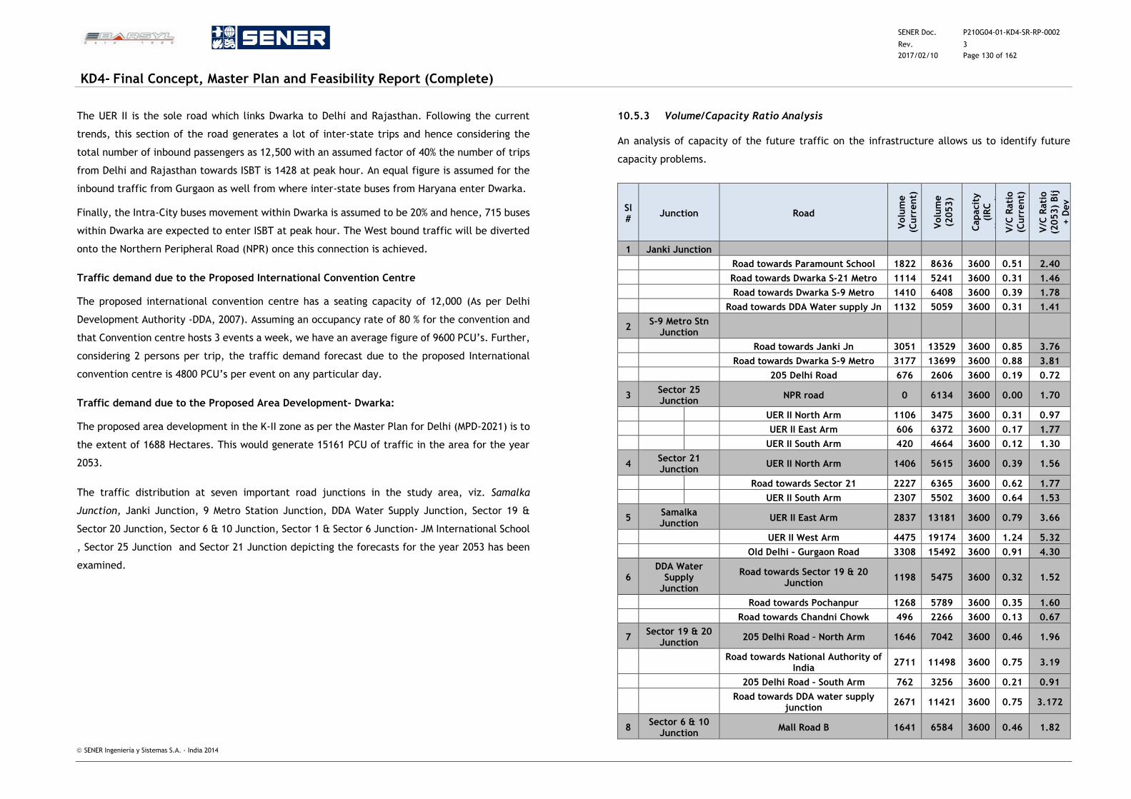
SENER Doc. P210G04-01-KD4-SR-RP-0002
Rev. 3
2017/02/10 Page 130 of 162
KD4- Final Concept, Master Plan and Feasibility Report (Complete)
SENER Ingeniería y Sistemas S.A. - India 2014
The UER II is the sole road which links Dwarka to Delhi and Rajasthan. Following the current
trends, this section of the road generates a lot of inter-state trips and hence considering the
total number of inbound passengers as 12,500 with an assumed factor of 40% the number of trips
from Delhi and Rajasthan towards ISBT is 1428 at peak hour. An equal figure is assumed for the
inbound traffic from Gurgaon as well from where inter-state buses from Haryana enter Dwarka.
Finally, the Intra-City buses movement within Dwarka is assumed to be 20% and hence, 715 buses
within Dwarka are expected to enter ISBT at peak hour. The West bound traffic will be diverted
onto the Northern Peripheral Road (NPR) once this connection is achieved.
Traffic demand due to the Proposed International Convention Centre
The proposed international convention centre has a seating capacity of 12,000 (As per Delhi
Development Authority -DDA, 2007). Assuming an occupancy rate of 80 % for the convention and
that Convention centre hosts 3 events a week, we have an average figure of 9600 PCU’s. Further,
considering 2 persons per trip, the traffic demand forecast due to the proposed International
convention centre is 4800 PCU’s per event on any particular day.
Traffic demand due to the Proposed Area Development- Dwarka:
The proposed area development in the K-II zone as per the Master Plan for Delhi (MPD-2021) is to
the extent of 1688 Hectares. This would generate 15161 PCU of traffic in the area for the year
2053.
The traffic distribution at seven important road junctions in the study area, viz. Samalka
Junction, Janki Junction, 9 Metro Station Junction, DDA Water Supply Junction, Sector 19 &
Sector 20 Junction, Sector 6 & 10 Junction, Sector 1 & Sector 6 Junction- JM International School
, Sector 25 Junction and Sector 21 Junction depicting the forecasts for the year 2053 has been
examined.
10.5.3 Volume/Capacity Ratio Analysis
An analysis of capacity of the future traffic on the infrastructure allows us to identify future
capacity problems.
Sl #
Junction Road
Volu
me
(Curr
ent)
Volu
me
(2053)
Capacit
y
(IR
C
Manual)
V
/C R
ati
o
(Curr
ent)
V/C
Rati
o
(2053)
Bij
+ D
ev
1 Janki Junction
Road towards Paramount School 1822 8636 3600 0.51 2.40
Road towards Dwarka S-21 Metro 1114 5241 3600 0.31 1.46
Road towards Dwarka S-9 Metro 1410 6408 3600 0.39 1.78
Road towards DDA Water supply Jn 1132 5059 3600 0.31 1.41
2 S-9 Metro Stn
Junction
Road towards Janki Jn 3051 13529 3600 0.85 3.76
Road towards Dwarka S-9 Metro 3177 13699 3600 0.88 3.81
205 Delhi Road 676 2606 3600 0.19 0.72
3 Sector 25 Junction
NPR road 0 6134 3600 0.00 1.70
UER II North Arm 1106 3475 3600 0.31 0.97
UER II East Arm 606 6372 3600 0.17 1.77
UER II South Arm 420 4664 3600 0.12 1.30
4 Sector 21 Junction
UER II North Arm 1406 5615 3600 0.39 1.56
Road towards Sector 21 2227 6365 3600 0.62 1.77
UER II South Arm 2307 5502 3600 0.64 1.53
5 Samalka Junction
UER II East Arm 2837 13181 3600 0.79 3.66
UER II West Arm 4475 19174 3600 1.24 5.32
Old Delhi – Gurgaon Road 3308 15492 3600 0.91 4.30
6 DDA Water
Supply Junction
Road towards Sector 19 & 20 Junction
1198 5475 3600 0.32 1.52
Road towards Pochanpur 1268 5789 3600 0.35 1.60
Road towards Chandni Chowk 496 2266 3600 0.13 0.67
7 Sector 19 & 20
Junction 205 Delhi Road – North Arm 1646 7042 3600 0.46 1.96
Road towards National Authority of
India 2711 11498 3600 0.75 3.19
205 Delhi Road – South Arm 762 3256 3600 0.21 0.91
Road towards DDA water supply
junction 2671 11421 3600 0.75 3.172
8 Sector 6 & 10
Junction Mall Road B 1641 6584 3600 0.46 1.82
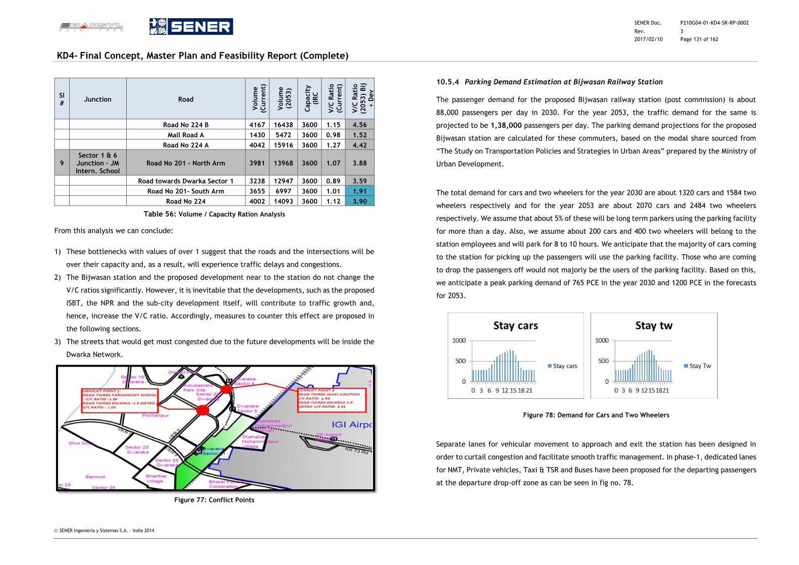
SENER Doc. P210G04-01-KD4-SR-RP-0002
Rev. 3
2017/02/10 Page 131 of 162
KD4- Final Concept, Master Plan and Feasibility Report (Complete)
SENER Ingeniería y Sistemas S.A. - India 2014
Sl #
Junction Road
Volu
me
(Curr
ent)
Volu
me
(2053)
Capacit
y
(IR
C
Manual)
V
/C R
ati
o
(Curr
ent)
V/C
Rati
o
(2053)
Bij
+ D
ev
Road No 224 B 4167 16438 3600 1.15 4.56
Mall Road A 1430 5472 3600 0.98 1.52
Road No 224 A 4042 15916 3600 1.27 4.42
9 Sector 1 & 6 Junction – JM Intern. School
Road No 201 – North Arm 3981 13968 3600 1.07 3.88
Road towards Dwarka Sector 1 3238 12947 3600 0.89 3.59
Road No 201- South Arm 3655 6997 3600 1.01 1.91
Road No 224 4002 14093 3600 1.12 3.90
Table 56: Volume / Capacity Ration Analysis
From this analysis we can conclude:
1) These bottlenecks with values of over 1 suggest that the roads and the intersections will be
over their capacity and, as a result, will experience traffic delays and congestions.
2) The Bijwasan station and the proposed development near to the station do not change the
V/C ratios significantly. However, it is inevitable that the developments, such as the proposed
ISBT, the NPR and the sub-city development itself, will contribute to traffic growth and,
hence, increase the V/C ratio. Accordingly, measures to counter this effect are proposed in
the following sections.
3) The streets that would get most congested due to the future developments will be inside the
Dwarka Network.
Figure 77: Conflict Points
10.5.4 Parking Demand Estimation at Bijwasan Railway Station
The passenger demand for the proposed Bijwasan railway station (post commission) is about
88,000 passengers per day in 2030. For the year 2053, the traffic demand for the same is
projected to be 1,38,000 passengers per day. The parking demand projections for the proposed
Bijwasan station are calculated for these commuters, based on the modal share sourced from
“The Study on Transportation Policies and Strategies in Urban Areas” prepared by the Ministry of
Urban Development.
The total demand for cars and two wheelers for the year 2030 are about 1320 cars and 1584 two
wheelers respectively and for the year 2053 are about 2070 cars and 2484 two wheelers
respectively. We assume that about 5% of these will be long term parkers using the parking facility
for more than a day. Also, we assume about 200 cars and 400 two wheelers will belong to the
station employees and will park for 8 to 10 hours. We anticipate that the majority of cars coming
to the station for picking up the passengers will use the parking facility. Those who are coming
to drop the passengers off would not majorly be the users of the parking facility. Based on this,
we anticipate a peak parking demand of 765 PCE in the year 2030 and 1200 PCE in the forecasts
for 2053.
Figure 78: Demand for Cars and Two Wheelers
Separate lanes for vehicular movement to approach and exit the station has been designed in
order to curtail congestion and facilitate smooth traffic management. In phase-1, dedicated lanes
for NMT, Private vehicles, Taxi & TSR and Buses have been proposed for the departing passengers
at the departure drop-off zone as can be seen in fig no. 78.
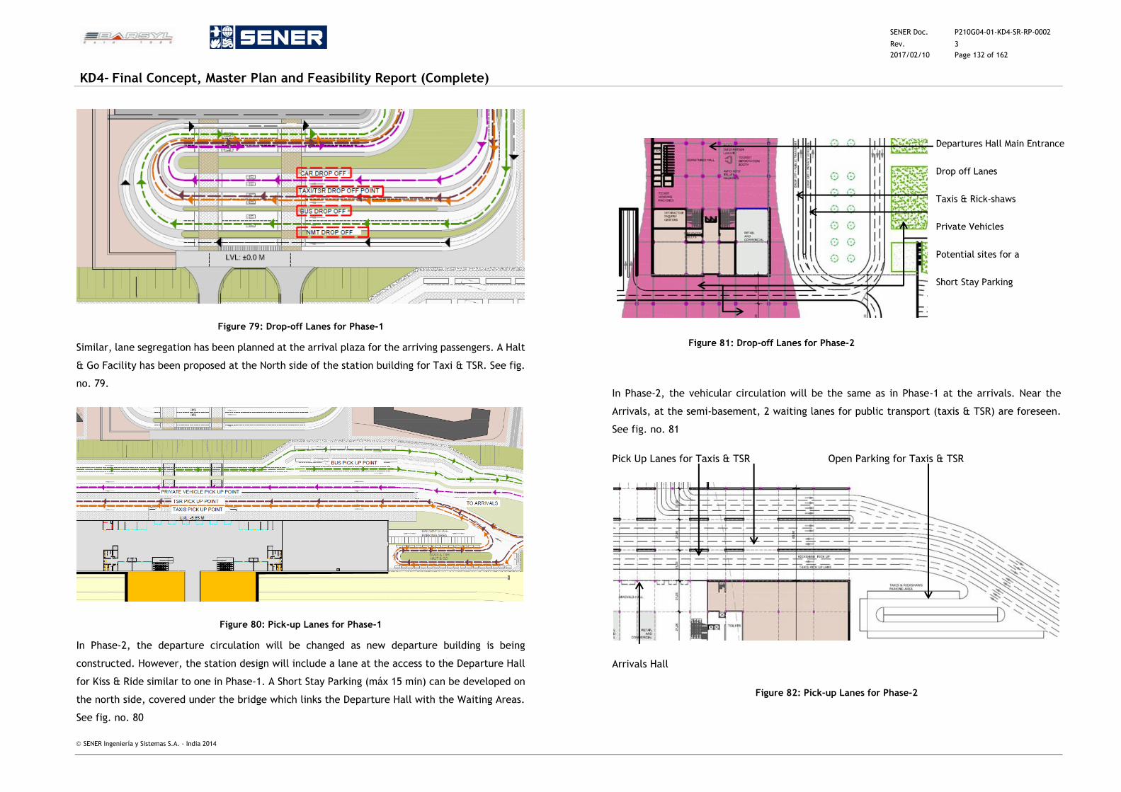
SENER Doc. P210G04-01-KD4-SR-RP-0002
Rev. 3
2017/02/10 Page 132 of 162
KD4- Final Concept, Master Plan and Feasibility Report (Complete)
SENER Ingeniería y Sistemas S.A. - India 2014
Figure 79: Drop-off Lanes for Phase-1
Similar, lane segregation has been planned at the arrival plaza for the arriving passengers. A Halt
& Go Facility has been proposed at the North side of the station building for Taxi & TSR. See fig.
no. 79.
Figure 80: Pick-up Lanes for Phase-1
In Phase-2, the departure circulation will be changed as new departure building is being
constructed. However, the station design will include a lane at the access to the Departure Hall
for Kiss & Ride similar to one in Phase-1. A Short Stay Parking (máx 15 min) can be developed on
the north side, covered under the bridge which links the Departure Hall with the Waiting Areas.
See fig. no. 80
Figure 81: Drop-off Lanes for Phase-2
Departures Hall Main Entrance
Drop off Lanes
Taxis & Rick-shaws
Private Vehicles
Potential sites for a
Short Stay Parking
In Phase-2, the vehicular circulation will be the same as in Phase-1 at the arrivals. Near the
Arrivals, at the semi-basement, 2 waiting lanes for public transport (taxis & TSR) are foreseen.
See fig. no. 81
Pick Up Lanes for Taxis & TSR Open Parking for Taxis & TSR
Arrivals Hall
Figure 82: Pick-up Lanes for Phase-2
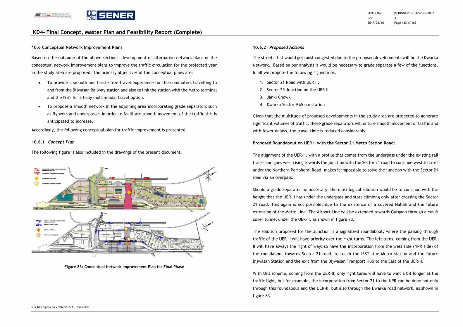
SENER Doc. P210G04-01-KD4-SR-RP-0002
Rev. 3
2017/02/10 Page 133 of 162
KD4- Final Concept, Master Plan and Feasibility Report (Complete)
SENER Ingeniería y Sistemas S.A. - India 2014
10.6 Conceptual Network Improvement Plans
Based on the outcome of the above sections, development of alternative network plans or the
conceptual network improvement plans to improve the traffic circulation for the projected year
in the study area are proposed. The primary objectives of the conceptual plans are:
To provide a smooth and hassle free travel experience for the commuters travelling to
and from the Bijwasan Railway station and also to link the station with the Metro terminal
and the ISBT for a truly multi-modal travel option.
To propose a smooth network in the adjoining area incorporating grade separators such
as flyovers and underpasses in order to facilitate smooth movement of the traffic this is
anticipated to increase.
Accordingly, the following conceptual plan for traffic improvement is presented.
10.6.1 Concept Plan
The following figure is also included in the drawings of the present document.
Figure 83: Conceptual Network Improvement Plan for Final Phase
10.6.2 Proposed Actions
The streets that would get most congested due to the proposed developments will be the Dwarka
Network. Based on our analysis it would be necessary to grade separate a few of the junctions.
In all we propose the following 4 junctions.
1. Sector 21 Road with UER II,
2. Sector 25 Junction on the UER II
3. Janki Chowk
4. Dwarka Sector 9 Metro station
Given that the multitude of proposed developments in the study area are projected to generate
significant volumes of traffic, these grade separators will ensure smooth movement of traffic and
with fewer delays, the travel time is reduced considerably.
Proposed Roundabout on UER II with the Sector 21 Metro Station Road:
The alignment of the UER-II, with a profile that comes from the underpass under the existing rail
tracks and goes west rising towards the junction with the Sector 21 road to continue west to cross
under the Northern Peripheral Road, makes it impossible to solve the junction with the Sector 21
road via an overpass.
Should a grade separator be necessary, the most logical solution would be to continue with the
height that the UER-II has under the underpass and start climbing only after crossing the Sector
21 road. This again is not possible, due to the existence of a covered Nallah and the future
extension of the Metro Line. The Airport Line will be extended towards Gurgaon through a cut &
cover tunnel under the UER-II, as shown in figure 73.
The solution proposed for the Junction is a signalized roundabout, where the passing through
traffic of the UER-II will have priority over the right turns. The left turns, coming from the UER-
II will have always the right of way: so have the incorporation from the west side (NPR side) of
the roundabout towards Sector 21 road, to reach the ISBT, the Metro station and the future
Bijwasan Station and the exit from the Bijwasan Transport Hub to the East of the UER-II.
With this scheme, coming from the UER-II, only right turns will have to wait a bit longer at the
traffic light, but for example, the incorporation from Sector 21 to the NPR can be done not only
through this roundabout and the UER-II, but also through the Dwarka road network, as shown in
figure 83.
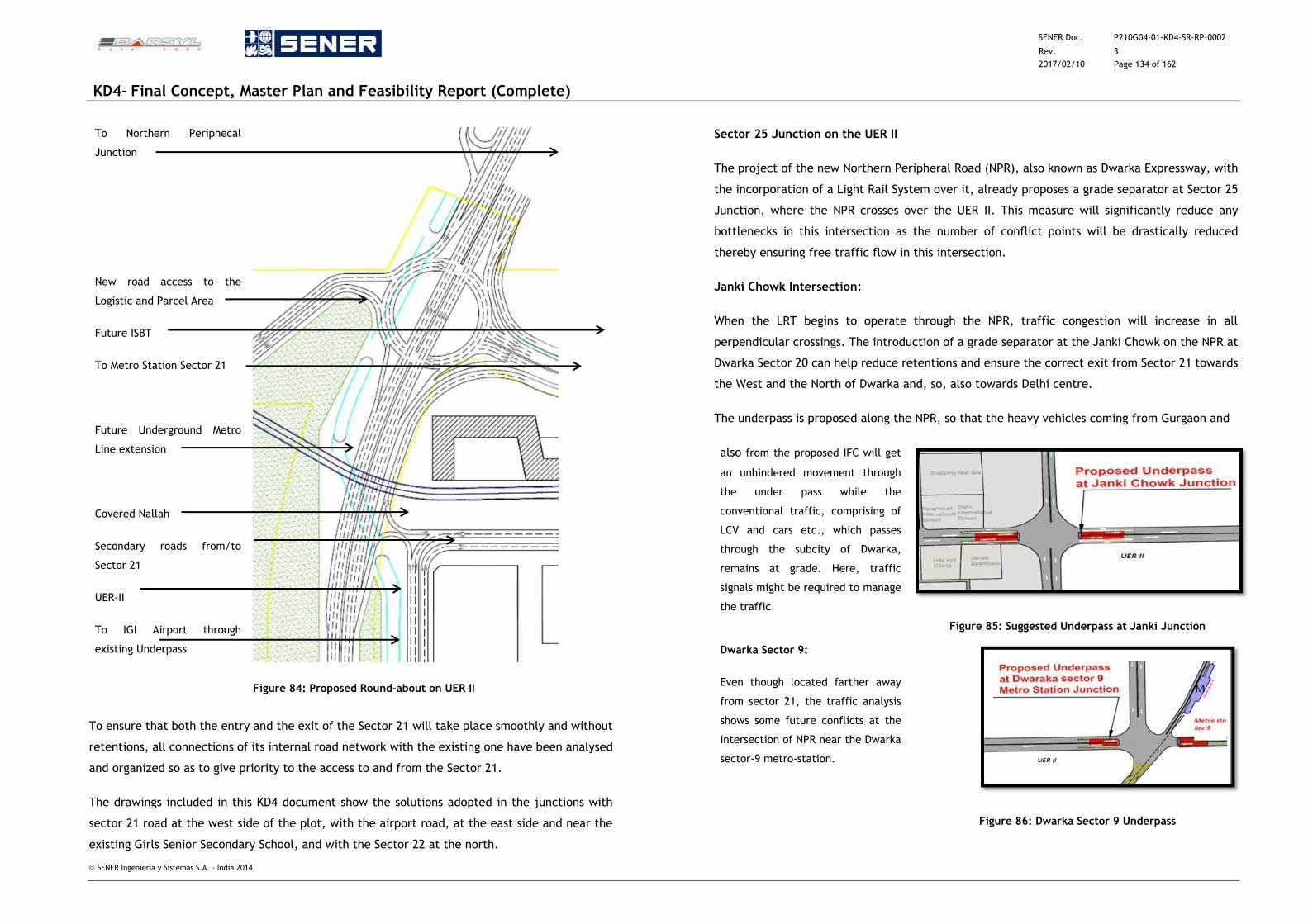
SENER Doc. P210G04-01-KD4-SR-RP-0002
Rev. 3
2017/02/10 Page 134 of 162
KD4- Final Concept, Master Plan and Feasibility Report (Complete)
SENER Ingeniería y Sistemas S.A. - India 2014
To Northern Periphecal
Junction
New road access to the
Logistic and Parcel Area
Future ISBT
To Metro Station Sector 21
Future Underground Metro
Line extension
Covered Nallah
Secondary roads from/to
Sector 21
UER-II
To IGI Airport through
existing Underpass
Figure 84: Proposed Round-about on UER II
To ensure that both the entry and the exit of the Sector 21 will take place smoothly and without
retentions, all connections of its internal road network with the existing one have been analysed
and organized so as to give priority to the access to and from the Sector 21.
The drawings included in this KD4 document show the solutions adopted in the junctions with
sector 21 road at the west side of the plot, with the airport road, at the east side and near the
existing Girls Senior Secondary School, and with the Sector 22 at the north.
Sector 25 Junction on the UER II
The project of the new Northern Peripheral Road (NPR), also known as Dwarka Expressway, with
the incorporation of a Light Rail System over it, already proposes a grade separator at Sector 25
Junction, where the NPR crosses over the UER II. This measure will significantly reduce any
bottlenecks in this intersection as the number of conflict points will be drastically reduced
thereby ensuring free traffic flow in this intersection.
Janki Chowk Intersection:
When the LRT begins to operate through the NPR, traffic congestion will increase in all
perpendicular crossings. The introduction of a grade separator at the Janki Chowk on the NPR at
Dwarka Sector 20 can help reduce retentions and ensure the correct exit from Sector 21 towards
the West and the North of Dwarka and, so, also towards Delhi centre.
The underpass is proposed along the NPR, so that the heavy vehicles coming from Gurgaon and
also from the proposed IFC will get
an unhindered movement through
the under pass while the
conventional traffic, comprising of
LCV and cars etc., which passes
through the subcity of Dwarka,
remains at grade. Here, traffic
signals might be required to manage
the traffic.
Figure 85: Suggested Underpass at Janki Junction
Dwarka Sector 9:
Even though located farther away
from sector 21, the traffic analysis
shows some future conflicts at the
intersection of NPR near the Dwarka
sector-9 metro-station.
Figure 86: Dwarka Sector 9 Underpass
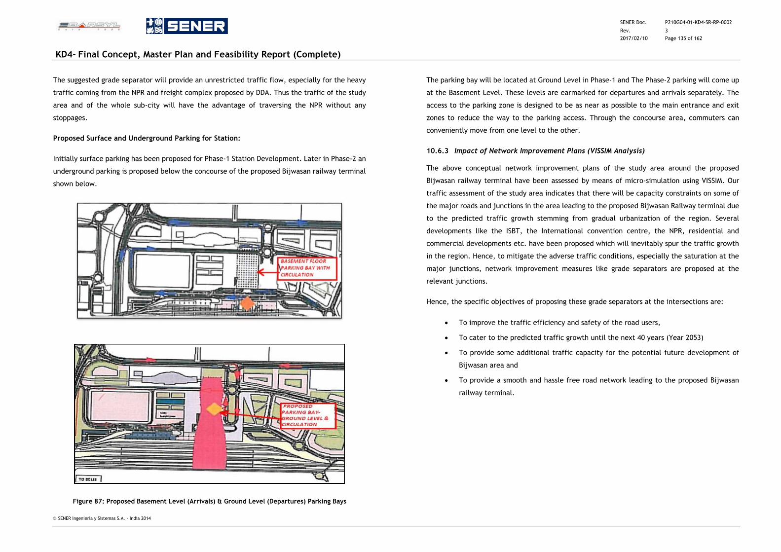
SENER Doc. P210G04-01-KD4-SR-RP-0002
Rev. 3
2017/02/10 Page 135 of 162
KD4- Final Concept, Master Plan and Feasibility Report (Complete)
SENER Ingeniería y Sistemas S.A. - India 2014
The suggested grade separator will provide an unrestricted traffic flow, especially for the heavy
traffic coming from the NPR and freight complex proposed by DDA. Thus the traffic of the study
area and of the whole sub-city will have the advantage of traversing the NPR without any
stoppages.
Proposed Surface and Underground Parking for Station:
Initially surface parking has been proposed for Phase-1 Station Development. Later in Phase-2 an
underground parking is proposed below the concourse of the proposed Bijwasan railway terminal
shown below.
Figure 87: Proposed Basement Level (Arrivals) & Ground Level (Departures) Parking Bays
The parking bay will be located at Ground Level in Phase-1 and The Phase-2 parking will come up
at the Basement Level. These levels are earmarked for departures and arrivals separately. The
access to the parking zone is designed to be as near as possible to the main entrance and exit
zones to reduce the way to the parking access. Through the concourse area, commuters can
conveniently move from one level to the other.
10.6.3 Impact of Network Improvement Plans (VISSIM Analysis)
The above conceptual network improvement plans of the study area around the proposed
Bijwasan railway terminal have been assessed by means of micro-simulation using VISSIM. Our
traffic assessment of the study area indicates that there will be capacity constraints on some of
the major roads and junctions in the area leading to the proposed Bijwasan Railway terminal due
to the predicted traffic growth stemming from gradual urbanization of the region. Several
developments like the ISBT, the International convention centre, the NPR, residential and
commercial developments etc. have been proposed which will inevitably spur the traffic growth
in the region. Hence, to mitigate the adverse traffic conditions, especially the saturation at the
major junctions, network improvement measures like grade separators are proposed at the
relevant junctions.
Hence, the specific objectives of proposing these grade separators at the intersections are:
To improve the traffic efficiency and safety of the road users,
To cater to the predicted traffic growth until the next 40 years (Year 2053)
To provide some additional traffic capacity for the potential future development of
Bijwasan area and
To provide a smooth and hassle free road network leading to the proposed Bijwasan
railway terminal.
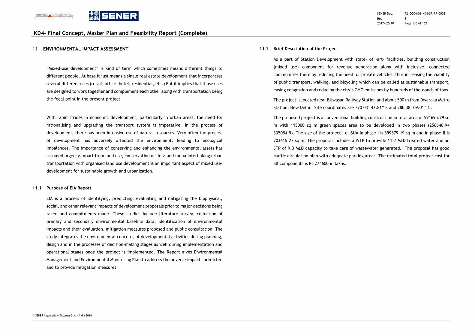
SENER Doc. P210G04-01-KD4-SR-RP-0002
Rev. 3
2017/02/10 Page 136 of 162
KD4- Final Concept, Master Plan and Feasibility Report (Complete)
SENER Ingeniería y Sistemas S.A. - India 2014
11 ENVIRONMENTAL IMPACT ASSESSMENT
“Mixed-use development” is kind of term which sometimes means different things to
different people. At base it just means a single real estate development that incorporates
several different uses (retail, office, hotel, residential, etc.) But it implies that those uses
are designed to work together and complement each other along with transportation being
the focal point in the present project.
With rapid strides in economic development, particularly in urban areas, the need for
rationalising and upgrading the transport system is imperative. In the process of
development, there has been intensive use of natural resources. Very often the process
of development has adversely affected the environment, leading to ecological
imbalances. The importance of conserving and enhancing the environmental assets has
assumed urgency. Apart from land use, conservation of flora and fauna interlinking urban
transportation with organised land use development is an important aspect of mixed use-
development for sustainable growth and urbanization.
11.1 Purpose of EIA Report
EIA is a process of identifying, predicting, evaluating and mitigating the biophysical,
social, and other relevant impacts of development proposals prior to major decisions being
taken and commitments made. These studies include literature survey, collection of
primary and secondary environmental baseline data, identification of environmental
impacts and their evaluation, mitigation measures proposed and public consultation. The
study integrates the environmental concerns of developmental activities during planning,
design and in the processes of decision-making stages as well during implementation and
operational stages once the project is implemented. The Report gives Environmental
Management and Environmental Monitoring Plan to address the adverse impacts predicted
and to provide mitigation measures.
11.2 Brief Description of the Project
As a part of Station Development with state- of -art- facilities, building construction
(mixed use) component for revenue generation along with inclusive, connected
communities there by reducing the need for private vehicles, thus increasing the viability
of public transport, walking, and bicycling which can be called as sustainable transport,
easing congestion and reducing the city’s GHG emissions by hundreds of thousands of tons.
The project is located near Bijwasan Railway Station and about 500 m from Dwaraka Metro
Station, New Delhi. Site coordinates are 770 03’ 42.81” E and 280 38’ 09.01” N.
The proposed project is a conventional building construction in total area of 591695.79 sq
m with 115000 sq m green spaces area to be developed in two phases (256640.9+
335054.9). The size of the project i.e. BUA in phase-I is 399579.19 sq m and in phase-II is
703615.27 sq m. The proposal includes a WTP to provide 11.7 MLD treated water and an
STP of 9.3 MLD capacity to take care of wastewater generated. The proposal has good
traffic circulation plan with adequate parking areas. The estimated total project cost for
all components is Rs 274600 in lakhs.
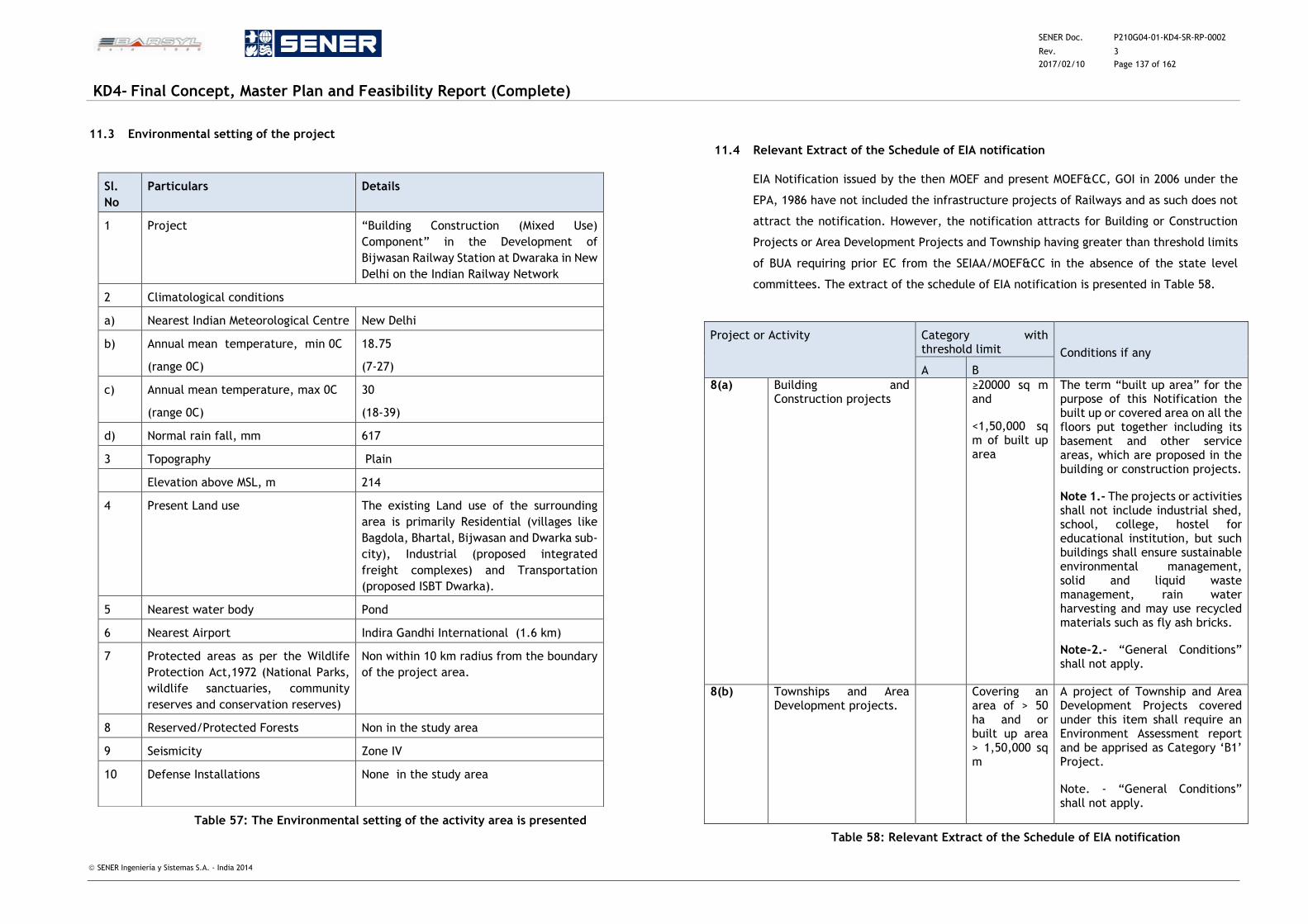
SENER Doc. P210G04-01-KD4-SR-RP-0002
Rev. 3
2017/02/10 Page 137 of 162
KD4- Final Concept, Master Plan and Feasibility Report (Complete)
SENER Ingeniería y Sistemas S.A. - India 2014
11.3 Environmental setting of the project
Table 57: The Environmental setting of the activity area is presented
11.4 Relevant Extract of the Schedule of EIA notification
EIA Notification issued by the then MOEF and present MOEF&CC, GOI in 2006 under the
EPA, 1986 have not included the infrastructure projects of Railways and as such does not
attract the notification. However, the notification attracts for Building or Construction
Projects or Area Development Projects and Township having greater than threshold limits
of BUA requiring prior EC from the SEIAA/MOEF&CC in the absence of the state level
committees. The extract of the schedule of EIA notification is presented in Table 58.
Project or Activity Category with threshold limit Conditions if any
A B
8(a) Building and Construction projects
≥20000 sq m and
<1,50,000 sq m of built up area
The term “built up area” for the purpose of this Notification the built up or covered area on all the floors put together including its basement and other service areas, which are proposed in the building or construction projects.
Note 1.- The projects or activities shall not include industrial shed, school, college, hostel for educational institution, but such buildings shall ensure sustainable environmental management, solid and liquid waste management, rain water harvesting and may use recycled materials such as fly ash bricks.
Note-2.- “General Conditions” shall not apply.
8(b) Townships and Area Development projects.
Covering an area of > 50 ha and or built up area > 1,50,000 sq m
A project of Township and Area Development Projects covered under this item shall require an Environment Assessment report and be apprised as Category ‘B1’ Project.
Note. - “General Conditions” shall not apply.
Table 58: Relevant Extract of the Schedule of EIA notification
Sl.
No
Particulars Details
1 Project “Building Construction (Mixed Use)
Component” in the Development of
Bijwasan Railway Station at Dwaraka in New
Delhi on the Indian Railway Network
2 Climatological conditions
a) Nearest Indian Meteorological Centre New Delhi
b) Annual mean temperature, min 0C
(range 0C)
18.75
(7-27)
c) Annual mean temperature, max 0C
(range 0C)
30
(18-39)
d) Normal rain fall, mm 617
3 Topography Plain
Elevation above MSL, m 214
4 Present Land use The existing Land use of the surrounding
area is primarily Residential (villages like
Bagdola, Bhartal, Bijwasan and Dwarka sub-
city), Industrial (proposed integrated
freight complexes) and Transportation
(proposed ISBT Dwarka).
5 Nearest water body Pond
6 Nearest Airport Indira Gandhi International (1.6 km)
7 Protected areas as per the Wildlife
Protection Act,1972 (National Parks,
wildlife sanctuaries, community
reserves and conservation reserves)
Non within 10 km radius from the boundary
of the project area.
8 Reserved/Protected Forests Non in the study area
9 Seismicity Zone IV
10 Defense Installations None in the study area
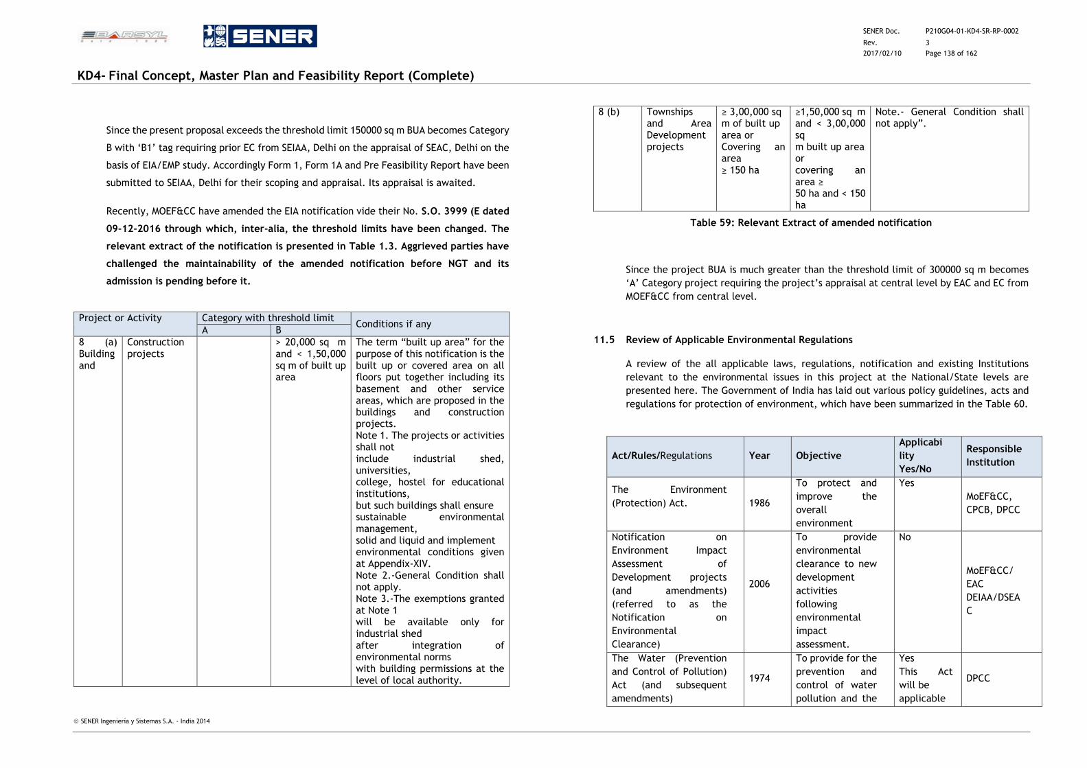
SENER Doc. P210G04-01-KD4-SR-RP-0002
Rev. 3
2017/02/10 Page 138 of 162
KD4- Final Concept, Master Plan and Feasibility Report (Complete)
SENER Ingeniería y Sistemas S.A. - India 2014
Since the present proposal exceeds the threshold limit 150000 sq m BUA becomes Category
B with ‘B1’ tag requiring prior EC from SEIAA, Delhi on the appraisal of SEAC, Delhi on the
basis of EIA/EMP study. Accordingly Form 1, Form 1A and Pre Feasibility Report have been
submitted to SEIAA, Delhi for their scoping and appraisal. Its appraisal is awaited.
Recently, MOEF&CC have amended the EIA notification vide their No. S.O. 3999 (E dated
09-12-2016 through which, inter-alia, the threshold limits have been changed. The
relevant extract of the notification is presented in Table 1.3. Aggrieved parties have
challenged the maintainability of the amended notification before NGT and its
admission is pending before it.
Project or Activity Category with threshold limit Conditions if any
A B
8 (a) Building and
Construction projects
> 20,000 sq m and < 1,50,000 sq m of built up area
The term “built up area” for the purpose of this notification is the built up or covered area on all floors put together including its basement and other service areas, which are proposed in the buildings and construction projects. Note 1. The projects or activities shall not include industrial shed, universities, college, hostel for educational institutions, but such buildings shall ensure sustainable environmental management, solid and liquid and implement environmental conditions given at Appendix-XIV. Note 2.-General Condition shall not apply. Note 3.-The exemptions granted at Note 1 will be available only for industrial shed after integration of environmental norms with building permissions at the level of local authority.
8 (b) Townships and Area Development projects
≥ 3,00,000 sq m of built up area or Covering an area ≥ 150 ha
≥1,50,000 sq m and < 3,00,000 sq m built up area or covering an area ≥ 50 ha and < 150 ha
Note.- General Condition shall not apply”.
Table 59: Relevant Extract of amended notification
Since the project BUA is much greater than the threshold limit of 300000 sq m becomes
‘A’ Category project requiring the project’s appraisal at central level by EAC and EC from
MOEF&CC from central level.
11.5 Review of Applicable Environmental Regulations
A review of the all applicable laws, regulations, notification and existing Institutions
relevant to the environmental issues in this project at the National/State levels are
presented here. The Government of India has laid out various policy guidelines, acts and
regulations for protection of environment, which have been summarized in the Table 60.
Act/Rules/Regulations Year Objective
Applicabi
lity
Yes/No
Responsible
Institution
The Environment
(Protection) Act.
1986
To protect and
improve the
overall
environment
Yes
MoEF&CC,
CPCB, DPCC
Notification on
Environment Impact
Assessment of
Development projects
(and amendments)
(referred to as the
Notification on
Environmental
Clearance)
2006
To provide
environmental
clearance to new
development
activities
following
environmental
impact
assessment.
No
MoEF&CC/
EAC
DEIAA/DSEA
C
The Water (Prevention
and Control of Pollution)
Act (and subsequent
amendments)
1974
To provide for the
prevention and
control of water
pollution and the
Yes
This Act
will be
applicable
DPCC
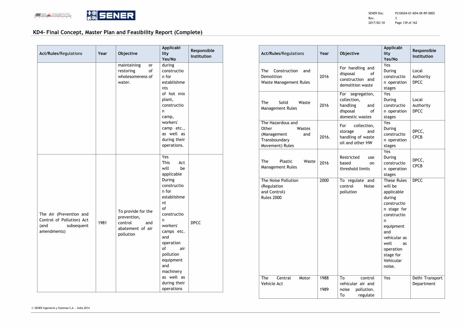
SENER Doc. P210G04-01-KD4-SR-RP-0002
Rev. 3
2017/02/10 Page 139 of 162
KD4- Final Concept, Master Plan and Feasibility Report (Complete)
SENER Ingeniería y Sistemas S.A. - India 2014
Act/Rules/Regulations Year Objective
Applicabi
lity
Yes/No
Responsible
Institution
maintaining or
restoring of
wholesomeness of
water.
during
constructio
n for
establishme
nts
of hot mix
plant,
constructio
n
camp,
workers'
camp etc.,
as well as
during their
operations.
The Air (Prevention and
Control of Pollution) Act
(and subsequent
amendments)
1981
To provide for the
prevention,
control and
abatement of air
pollution
Yes
This Act
will be
applicable
During
constructio
n for
establishme
nt
of
constructio
n
workers'
camps etc.
and
operation
of air
pollution
equipment
and
machinery
as well as
during their
operations
DPCC
Act/Rules/Regulations Year Objective
Applicabi
lity
Yes/No
Responsible
Institution
The Construction and
Demolition
Waste Management Rules
2016
For handling and
disposal of
construction and
demolition waste
Yes
During
constructio
n operation
stages
Local
Authority
DPCC
The Solid Waste
Management Rules 2016
For segregation,
collection,
handling and
disposal of
domestic wastes
Yes
During
constructio
n operation
stages
Local
Authority
DPCC
The Hazardous and
Other Wastes
(Management and
Transboundary
Movement) Rules
2016.
For collection,
storage and
handling of waste
oil and other HW
Yes
During
constructio
n operation
stages
DPCC,
CPCB
The Plastic Waste
Management Rules 2016
Restricted use
based on
threshold limits
Yes
During
constructio
n operation
stages
DPCC,
CPCB
The Noise Pollution
(Regulation
and Control)
Rules 2000
2000 To regulate and
control Noise
pollution
These Rules
will be
applicable
during
constructio
n stage for
constructio
n
equipment
and
vehicular as
well as
operation
stage for
Vehicular
noise.
DPCC
The Central Motor
Vehicle Act
1988
1989
To control
vehicular air and
noise pollution.
To regulate
Yes Delhi Transport
Department
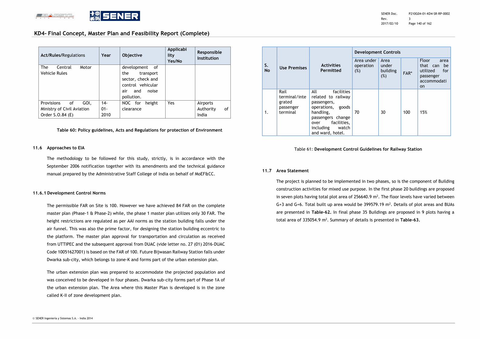
SENER Doc. P210G04-01-KD4-SR-RP-0002
Rev. 3
2017/02/10 Page 140 of 162
KD4- Final Concept, Master Plan and Feasibility Report (Complete)
SENER Ingeniería y Sistemas S.A. - India 2014
Act/Rules/Regulations Year Objective
Applicabi
lity
Yes/No
Responsible
Institution
The Central Motor
Vehicle Rules
development of
the transport
sector, check and
control vehicular
air and noise
pollution.
Provisions of GOI,
Ministry of Civil Aviation
Order S.O.84 (E)
14-
01-
2010
NOC for height
clearance
Yes Airports
Authority of
India
Table 60: Policy guidelines, Acts and Regulations for protection of Environment
11.6 Approaches to EIA
The methodology to be followed for this study, strictly, is in accordance with the
September 2006 notification together with its amendments and the technical guidance
manual prepared by the Administrative Staff College of India on behalf of MoEF&CC.
11.6.1 Development Control Norms
The permissible FAR on Site is 100. However we have achieved 84 FAR on the complete
master plan (Phase-1 & Phase-2) while, the phase 1 master plan utilizes only 30 FAR. The
height restrictions are regulated as per AAI norms as the station building falls under the
air funnel. This was also the prime factor, for designing the station building eccentric to
the platform. The master plan approval for transportation and circulation as received
from UTTIPEC and the subsequent approval from DUAC (vide letter no. 27 (01) 2016-DUAC
Code 10051627001) is based on the FAR of 100. Future Bijwasan Railway Station falls under
Dwarka sub-city, which belongs to zone-K and forms part of the urban extension plan.
The urban extension plan was prepared to accommodate the projected population and
was conceived to be developed in four phases. Dwarka sub-city forms part of Phase 1A of
the urban extension plan. The Area where this Master Plan is developed is in the zone
called K-II of zone development plan.
S. No
Use Premises Activities Permitted
Development Controls
Area under operation (%)
Area under building (%)
FAR*
Floor area that can be utilized for passenger accommodation
1.
Rail terminal/integrated passenger terminal
All facilities related to railway passengers, operations, goods handling, passengers change over facilities, including watch and ward, hotel.
70 30 100 15%
Table 61: Development Control Guidelines for Railway Station
11.7 Area Statement
The project is planned to be implemented in two phases, so is the component of Building
construction activities for mixed use purpose. In the first phase 20 buildings are proposed
in seven plots having total plot area of 256640.9 m2. The floor levels have varied between
G+3 and G+6. Total built up area would be 399579.19 m2. Details of plot areas and BUAs
are presented in Table-62. In final phase 35 Buildings are proposed in 9 plots having a
total area of 335054.9 m2. Summary of details is presented in Table-63.
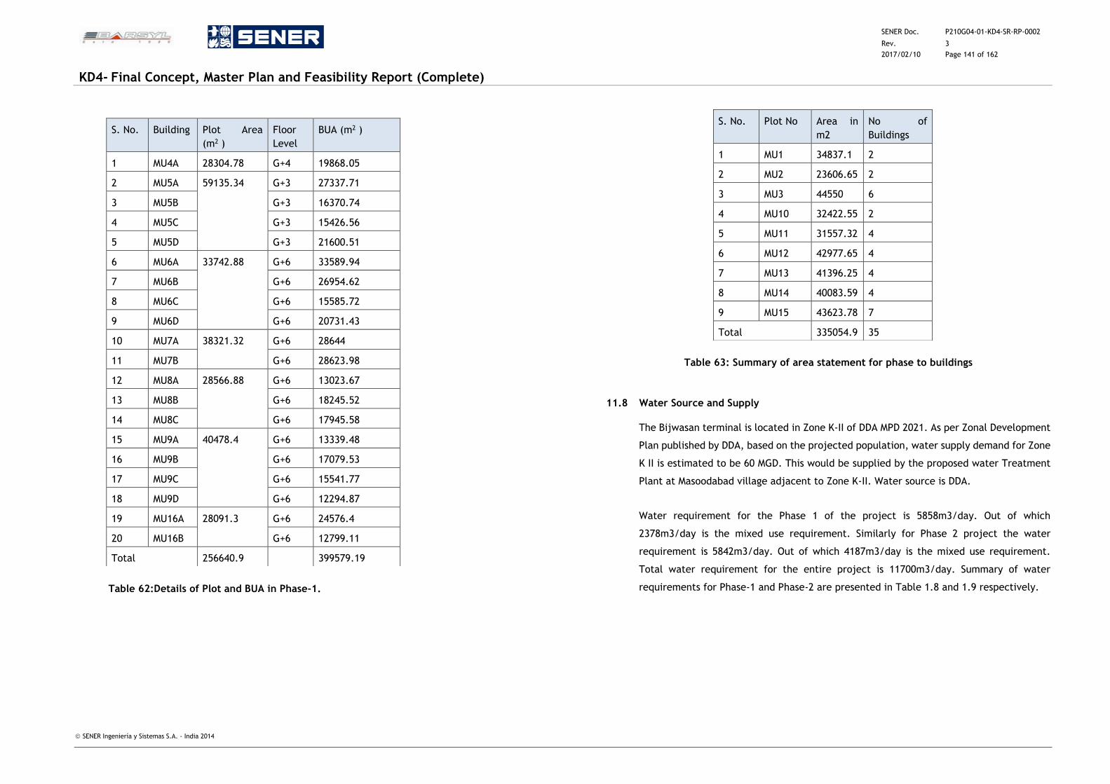
SENER Doc. P210G04-01-KD4-SR-RP-0002
Rev. 3
2017/02/10 Page 141 of 162
KD4- Final Concept, Master Plan and Feasibility Report (Complete)
SENER Ingeniería y Sistemas S.A. - India 2014
Table 62:Details of Plot and BUA in Phase-1.
Table 63: Summary of area statement for phase to buildings
11.8 Water Source and Supply
The Bijwasan terminal is located in Zone K-II of DDA MPD 2021. As per Zonal Development
Plan published by DDA, based on the projected population, water supply demand for Zone
K II is estimated to be 60 MGD. This would be supplied by the proposed water Treatment
Plant at Masoodabad village adjacent to Zone K-II. Water source is DDA.
Water requirement for the Phase 1 of the project is 5858m3/day. Out of which
2378m3/day is the mixed use requirement. Similarly for Phase 2 project the water
requirement is 5842m3/day. Out of which 4187m3/day is the mixed use requirement.
Total water requirement for the entire project is 11700m3/day. Summary of water
requirements for Phase-1 and Phase-2 are presented in Table 1.8 and 1.9 respectively.
S. No. Building Plot Area
(m2 )
Floor
Level
BUA (m2 )
1 MU4A 28304.78 G+4 19868.05
2 MU5A 59135.34 G+3 27337.71
3 MU5B G+3 16370.74
4 MU5C G+3 15426.56
5 MU5D G+3 21600.51
6 MU6A 33742.88 G+6 33589.94
7 MU6B G+6 26954.62
8 MU6C G+6 15585.72
9 MU6D G+6 20731.43
10 MU7A 38321.32 G+6 28644
11 MU7B G+6 28623.98
12 MU8A 28566.88 G+6 13023.67
13 MU8B G+6 18245.52
14 MU8C G+6 17945.58
15 MU9A 40478.4 G+6 13339.48
16 MU9B G+6 17079.53
17 MU9C G+6 15541.77
18 MU9D G+6 12294.87
19 MU16A 28091.3 G+6 24576.4
20 MU16B G+6 12799.11
Total 256640.9
399579.19
S. No. Plot No Area in
m2
No of
Buildings
1 MU1 34837.1 2
2 MU2 23606.65 2
3 MU3 44550 6
4 MU10 32422.55 2
5 MU11 31557.32 4
6 MU12 42977.65 4
7 MU13 41396.25 4
8 MU14 40083.59 4
9 MU15 43623.78 7
Total 335054.9 35
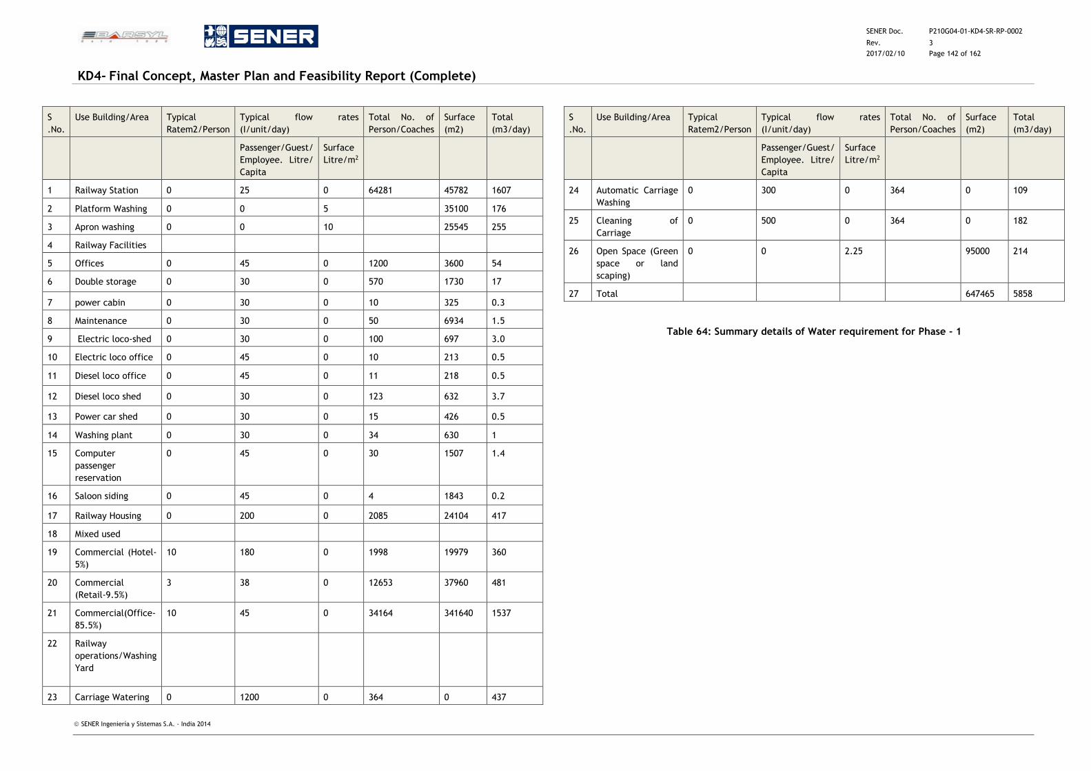
SENER Doc. P210G04-01-KD4-SR-RP-0002
Rev. 3
2017/02/10 Page 142 of 162
KD4- Final Concept, Master Plan and Feasibility Report (Complete)
SENER Ingeniería y Sistemas S.A. - India 2014
S
.No.
Use Building/Area Typical
Ratem2/Person
Typical flow rates
(I/unit/day)
Total No. of
Person/Coaches
Surface
(m2)
Total
(m3/day)
Passenger/Guest/
Employee. Litre/
Capita
Surface
Litre/m2
1 Railway Station 0 25 0 64281 45782 1607
2 Platform Washing 0 0 5 35100 176
3 Apron washing 0 0 10 25545 255
4 Railway Facilities
5 Offices 0 45 0 1200 3600 54
6 Double storage 0 30 0 570 1730 17
7 power cabin 0 30 0 10 325 0.3
8 Maintenance 0 30 0 50 6934 1.5
9 Electric loco-shed 0 30 0 100 697 3.0
10 Electric loco office 0 45 0 10 213 0.5
11 Diesel loco office 0 45 0 11 218 0.5
12 Diesel loco shed 0 30 0 123 632 3.7
13 Power car shed 0 30 0 15 426 0.5
14 Washing plant 0 30 0 34 630 1
15 Computer
passenger
reservation
0 45 0 30 1507 1.4
16 Saloon siding 0 45 0 4 1843 0.2
17 Railway Housing 0 200 0 2085 24104 417
18 Mixed used
19 Commercial (Hotel-
5%)
10 180 0 1998 19979 360
20 Commercial
(Retail-9.5%)
3 38 0 12653 37960 481
21 Commercial(Office-
85.5%)
10 45 0 34164 341640 1537
22 Railway
operations/Washing
Yard
23 Carriage Watering 0 1200 0 364 0 437
S
.No.
Use Building/Area Typical
Ratem2/Person
Typical flow rates
(I/unit/day)
Total No. of
Person/Coaches
Surface
(m2)
Total
(m3/day)
Passenger/Guest/
Employee. Litre/
Capita
Surface
Litre/m2
24 Automatic Carriage
Washing
0 300 0 364 0 109
25 Cleaning of
Carriage
0 500 0 364 0 182
26 Open Space (Green
space or land
scaping)
0 0 2.25 95000 214
27 Total 647465 5858
Table 64: Summary details of Water requirement for Phase - 1
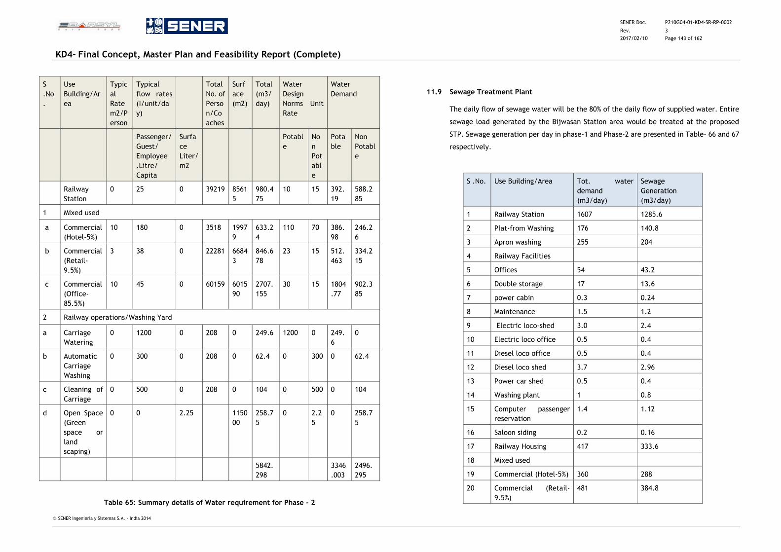
SENER Doc. P210G04-01-KD4-SR-RP-0002
Rev. 3
2017/02/10 Page 143 of 162
KD4- Final Concept, Master Plan and Feasibility Report (Complete)
SENER Ingeniería y Sistemas S.A. - India 2014
S
.No
.
Use
Building/Ar
ea
Typic
al
Rate
m2/P
erson
Typical
flow rates
(I/unit/da
y)
Total
No. of
Perso
n/Co
aches
Surf
ace
(m2)
Total
(m3/
day)
Water
Design
Norms Unit
Rate
Water
Demand
Passenger/
Guest/
Employee
.Litre/
Capita
Surfa
ce
Liter/
m2
Potabl
e
No
n
Pot
abl
e
Pota
ble
Non
Potabl
e
Railway
Station
0 25 0 39219 8561
5
980.4
75
10 15 392.
19
588.2
85
1 Mixed used
a Commercial
(Hotel-5%)
10 180 0 3518 1997
9
633.2
4
110 70 386.
98
246.2
6
b Commercial
(Retail-
9.5%)
3 38 0 22281 6684
3
846.6
78
23 15 512.
463
334.2
15
c Commercial
(Office-
85.5%)
10 45 0 60159 6015
90
2707.
155
30 15 1804
.77
902.3
85
2 Railway operations/Washing Yard
a Carriage
Watering
0 1200 0 208 0 249.6 1200 0 249.
6
0
b Automatic
Carriage
Washing
0 300 0 208 0 62.4 0 300 0 62.4
c Cleaning of
Carriage
0 500 0 208 0 104 0 500 0 104
d Open Space
(Green
space or
land
scaping)
0 0 2.25 1150
00
258.7
5
0 2.2
5
0 258.7
5
5842.
298
3346
.003
2496.
295
Table 65: Summary details of Water requirement for Phase - 2
11.9 Sewage Treatment Plant
The daily flow of sewage water will be the 80% of the daily flow of supplied water. Entire
sewage load generated by the Bijwasan Station area would be treated at the proposed
STP. Sewage generation per day in phase-1 and Phase-2 are presented in Table- 66 and 67
respectively.
S .No. Use Building/Area Tot. water
demand
(m3/day)
Sewage
Generation
(m3/day)
1 Railway Station 1607 1285.6
2 Plat-from Washing 176 140.8
3 Apron washing 255 204
4 Railway Facilities
5 Offices 54 43.2
6 Double storage 17 13.6
7 power cabin 0.3 0.24
8 Maintenance 1.5 1.2
9 Electric loco-shed 3.0 2.4
10 Electric loco office 0.5 0.4
11 Diesel loco office 0.5 0.4
12 Diesel loco shed 3.7 2.96
13 Power car shed 0.5 0.4
14 Washing plant 1 0.8
15 Computer passenger
reservation
1.4 1.12
16 Saloon siding 0.2 0.16
17 Railway Housing 417 333.6
18 Mixed used
19 Commercial (Hotel-5%) 360 288
20 Commercial (Retail-
9.5%)
481 384.8
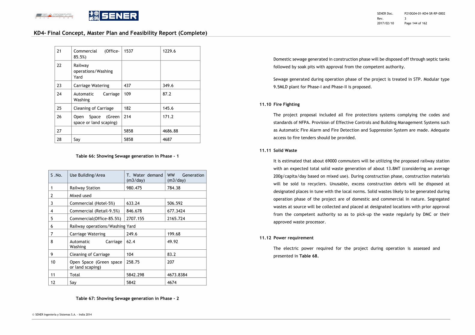
SENER Doc. P210G04-01-KD4-SR-RP-0002
Rev. 3
2017/02/10 Page 144 of 162
KD4- Final Concept, Master Plan and Feasibility Report (Complete)
SENER Ingeniería y Sistemas S.A. - India 2014
21 Commercial (Office-
85.5%)
1537 1229.6
22 Railway
operations/Washing
Yard
23 Carriage Watering 437 349.6
24 Automatic Carriage
Washing
109 87.2
25 Cleaning of Carriage 182 145.6
26 Open Space (Green
space or land scaping)
214 171.2
27
5858 4686.88
28 Say 5858 4687
Table 66: Showing Sewage generation in Phase - 1
S .No. Use Building/Area T. Water demand (m3/day)
WW Generation (m3/day)
1 Railway Station 980.475 784.38
2 Mixed used
3 Commercial (Hotel-5%) 633.24 506.592
4 Commercial (Retail-9.5%) 846.678 677.3424
5 Commercial(Office-85.5%) 2707.155 2165.724
6 Railway operations/Washing Yard
7 Carriage Watering 249.6 199.68
8 Automatic Carriage Washing
62.4 49.92
9 Cleaning of Carriage 104 83.2
10 Open Space (Green space or land scaping)
258.75 207
11 Total 5842.298 4673.8384
12 Say 5842 4674
Table 67: Showing Sewage generation in Phase - 2
Domestic sewage generated in construction phase will be disposed off through septic tanks
followed by soak pits with approval from the competent authority.
Sewage generated during operation phase of the project is treated in STP. Modular type
9.5MLD plant for Phase-I and Phase-II is proposed.
11.10 Fire Fighting
The project proposal included all fire protections systems complying the codes and
standards of NFPA. Provision of Effective Controls and Building Management Systems such
as Automatic Fire Alarm and Fire Detection and Suppression System are made. Adequate
access to fire tenders should be provided.
11.11 Solid Waste
It is estimated that about 69000 commuters will be utilizing the proposed railway station
with an expected total solid waste generation of about 13.8MT (considering an average
200g/capita/day based on mixed use). During construction phase, construction materials
will be sold to recyclers. Unusable, excess construction debris will be disposed at
designated places in tune with the local norms. Solid wastes likely to be generated during
operation phase of the project are of domestic and commercial in nature. Segregated
wastes at source will be collected and placed at designated locations with prior approval
from the competent authority so as to pick-up the waste regularly by DMC or their
approved waste processor.
11.12 Power requirement
The electric power required for the project during operation is assessed and
presented in Table 68.
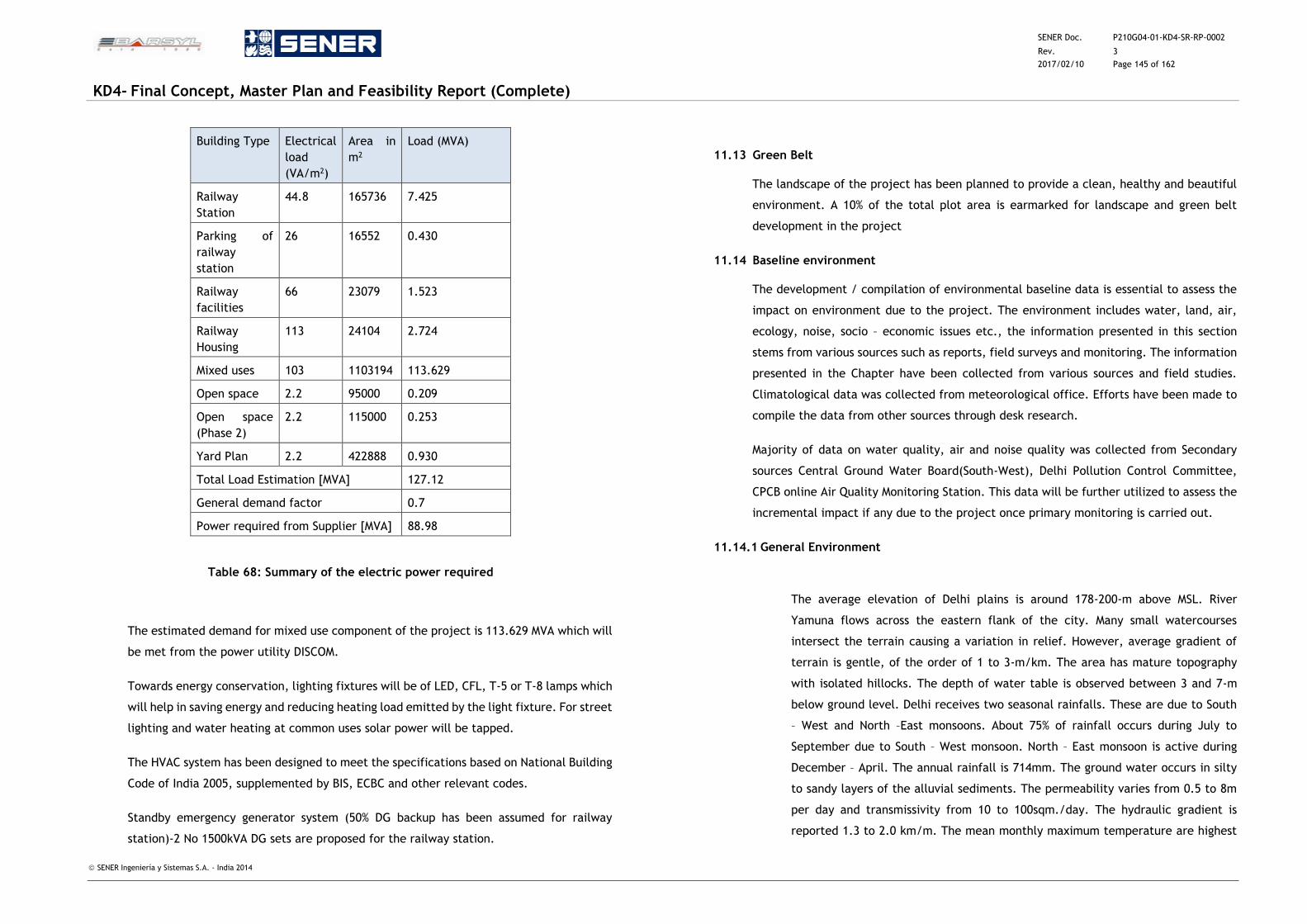
SENER Doc. P210G04-01-KD4-SR-RP-0002
Rev. 3
2017/02/10 Page 145 of 162
KD4- Final Concept, Master Plan and Feasibility Report (Complete)
SENER Ingeniería y Sistemas S.A. - India 2014
Building Type Electrical
load
(VA/m2)
Area in
m2
Load (MVA)
Railway
Station
44.8 165736 7.425
Parking of
railway
station
26 16552 0.430
Railway
facilities
66 23079 1.523
Railway
Housing
113 24104 2.724
Mixed uses 103 1103194 113.629
Open space 2.2 95000 0.209
Open space
(Phase 2)
2.2 115000 0.253
Yard Plan 2.2 422888 0.930
Total Load Estimation [MVA] 127.12
General demand factor 0.7
Power required from Supplier [MVA] 88.98
Table 68: Summary of the electric power required
The estimated demand for mixed use component of the project is 113.629 MVA which will
be met from the power utility DISCOM.
Towards energy conservation, lighting fixtures will be of LED, CFL, T-5 or T-8 lamps which
will help in saving energy and reducing heating load emitted by the light fixture. For street
lighting and water heating at common uses solar power will be tapped.
The HVAC system has been designed to meet the specifications based on National Building
Code of India 2005, supplemented by BIS, ECBC and other relevant codes.
Standby emergency generator system (50% DG backup has been assumed for railway
station)-2 No 1500kVA DG sets are proposed for the railway station.
11.13 Green Belt
The landscape of the project has been planned to provide a clean, healthy and beautiful
environment. A 10% of the total plot area is earmarked for landscape and green belt
development in the project
11.14 Baseline environment
The development / compilation of environmental baseline data is essential to assess the
impact on environment due to the project. The environment includes water, land, air,
ecology, noise, socio – economic issues etc., the information presented in this section
stems from various sources such as reports, field surveys and monitoring. The information
presented in the Chapter have been collected from various sources and field studies.
Climatological data was collected from meteorological office. Efforts have been made to
compile the data from other sources through desk research.
Majority of data on water quality, air and noise quality was collected from Secondary
sources Central Ground Water Board(South-West), Delhi Pollution Control Committee,
CPCB online Air Quality Monitoring Station. This data will be further utilized to assess the
incremental impact if any due to the project once primary monitoring is carried out.
11.14.1 General Environment
The average elevation of Delhi plains is around 178-200-m above MSL. River
Yamuna flows across the eastern flank of the city. Many small watercourses
intersect the terrain causing a variation in relief. However, average gradient of
terrain is gentle, of the order of 1 to 3-m/km. The area has mature topography
with isolated hillocks. The depth of water table is observed between 3 and 7-m
below ground level. Delhi receives two seasonal rainfalls. These are due to South
– West and North –East monsoons. About 75% of rainfall occurs during July to
September due to South – West monsoon. North – East monsoon is active during
December – April. The annual rainfall is 714mm. The ground water occurs in silty
to sandy layers of the alluvial sediments. The permeability varies from 0.5 to 8m
per day and transmissivity from 10 to 100sqm./day. The hydraulic gradient is
reported 1.3 to 2.0 km/m. The mean monthly maximum temperature are highest
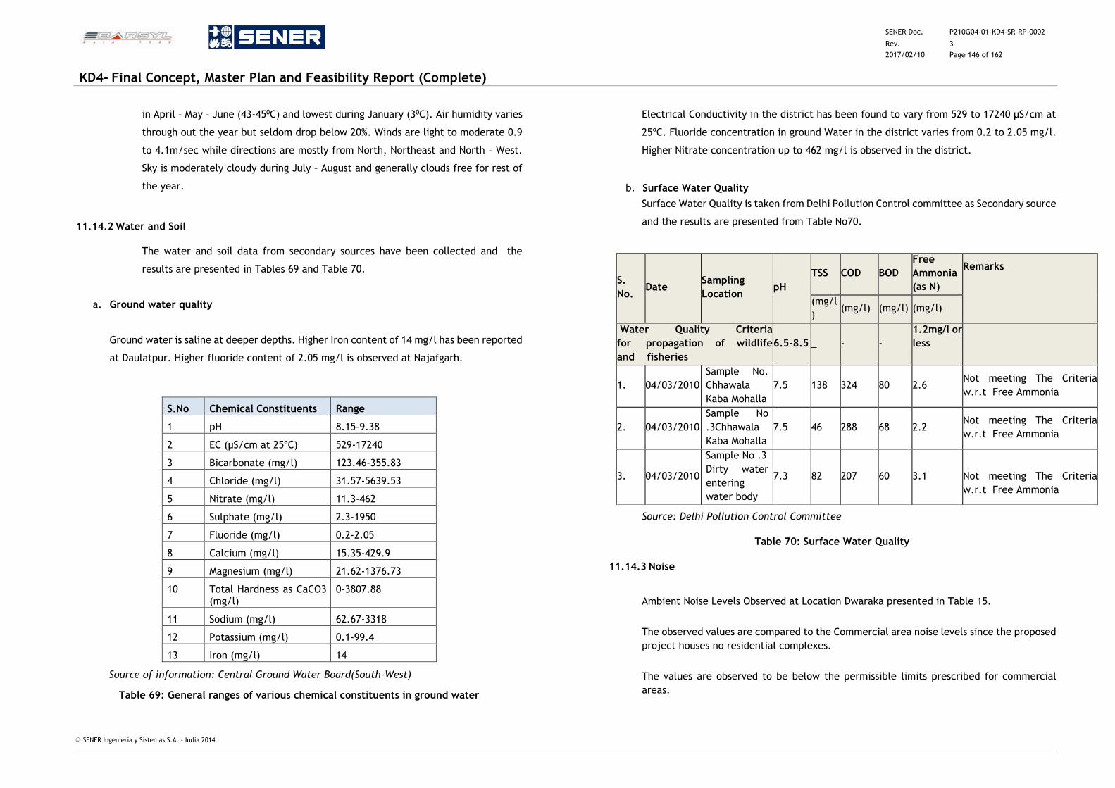
SENER Doc. P210G04-01-KD4-SR-RP-0002
Rev. 3
2017/02/10 Page 146 of 162
KD4- Final Concept, Master Plan and Feasibility Report (Complete)
SENER Ingeniería y Sistemas S.A. - India 2014
in April – May – June (43-450C) and lowest during January (30C). Air humidity varies
through out the year but seldom drop below 20%. Winds are light to moderate 0.9
to 4.1m/sec while directions are mostly from North, Northeast and North – West.
Sky is moderately cloudy during July – August and generally clouds free for rest of
the year.
11.14.2 Water and Soil
The water and soil data from secondary sources have been collected and the
results are presented in Tables 69 and Table 70.
a. Ground water quality
Ground water is saline at deeper depths. Higher Iron content of 14 mg/l has been reported
at Daulatpur. Higher fluoride content of 2.05 mg/l is observed at Najafgarh.
S.No Chemical Constituents Range
1 pH 8.15-9.38
2 EC (µS/cm at 25ºC) 529-17240
3 Bicarbonate (mg/l) 123.46-355.83
4 Chloride (mg/l) 31.57-5639.53
5 Nitrate (mg/l) 11.3-462
6 Sulphate (mg/l) 2.3-1950
7 Fluoride (mg/l) 0.2-2.05
8 Calcium (mg/l) 15.35-429.9
9 Magnesium (mg/l) 21.62-1376.73
10 Total Hardness as CaCO3 (mg/l)
0-3807.88
11 Sodium (mg/l) 62.67-3318
12 Potassium (mg/l) 0.1-99.4
13 Iron (mg/l) 14
Source of information: Central Ground Water Board(South-West)
Table 69: General ranges of various chemical constituents in ground water
Electrical Conductivity in the district has been found to vary from 529 to 17240 µS/cm at
25ºC. Fluoride concentration in ground Water in the district varies from 0.2 to 2.05 mg/l.
Higher Nitrate concentration up to 462 mg/l is observed in the district.
b. Surface Water Quality
Surface Water Quality is taken from Delhi Pollution Control committee as Secondary source
and the results are presented from Table No70.
Source: Delhi Pollution Control Committee
Table 70: Surface Water Quality
11.14.3 Noise
Ambient Noise Levels Observed at Location Dwaraka presented in Table 15.
The observed values are compared to the Commercial area noise levels since the proposed
project houses no residential complexes.
The values are observed to be below the permissible limits prescribed for commercial
areas.
S.
No. Date
Sampling
Location pH
TSS COD BOD
Free
Ammonia
(as N)
Remarks
(mg/l
) (mg/l) (mg/l) (mg/l)
Water Quality Criteria
for propagation of wildlife
and fisheries
6.5-8.5 _ - -
1.2mg/l or
less
1. 04/03/2010
Sample No.
Chhawala
Kaba Mohalla
7.5 138 324 80 2.6 Not meeting The Criteria
w.r.t Free Ammonia
2. 04/03/2010
Sample No
.3Chhawala
Kaba Mohalla
7.5 46 288 68 2.2 Not meeting The Criteria
w.r.t Free Ammonia
3. 04/03/2010
Sample No .3
Dirty water
entering
water body
7.3 82 207 60 3.1
Not meeting The Criteria
w.r.t Free Ammonia
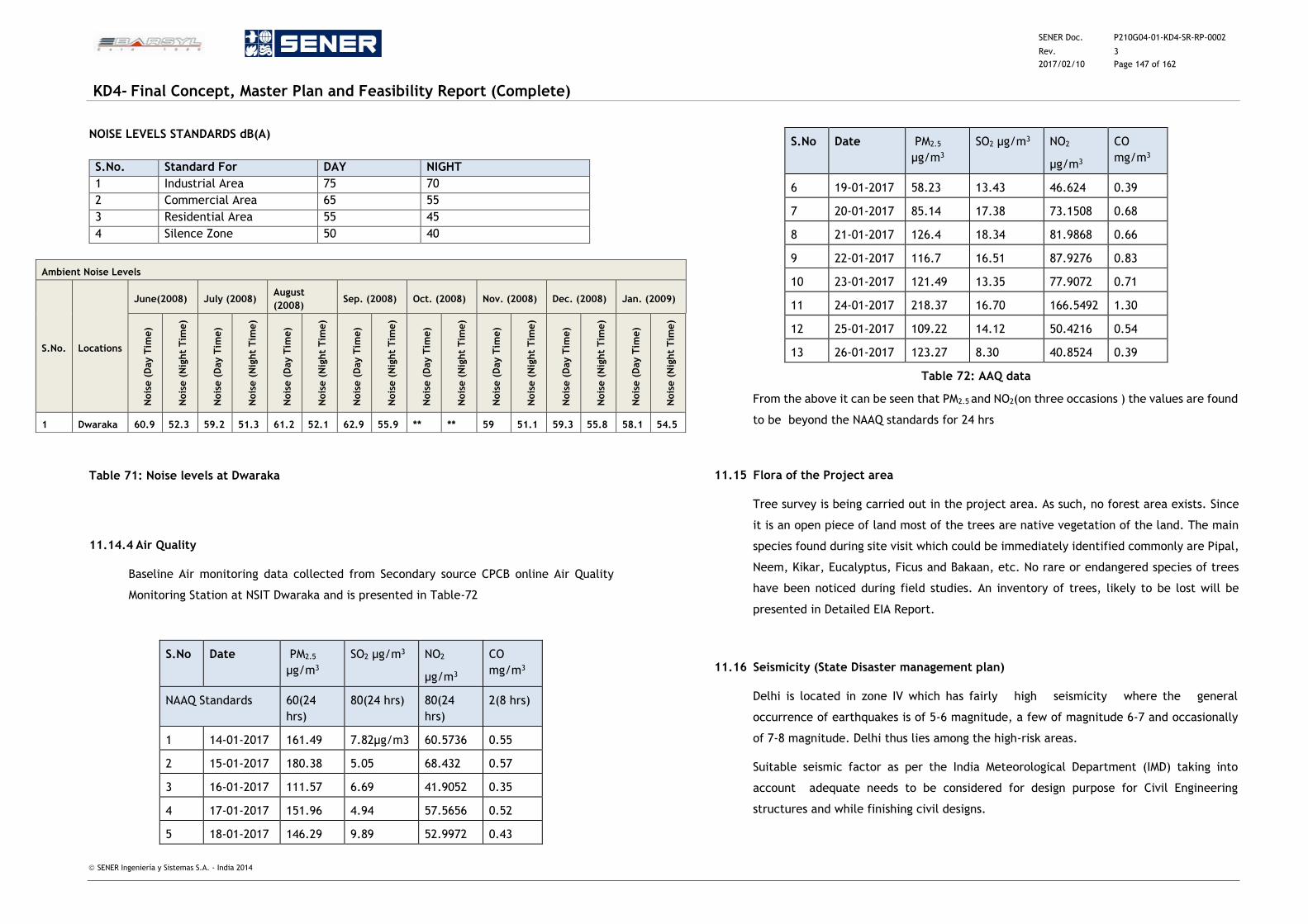
SENER Doc. P210G04-01-KD4-SR-RP-0002
Rev. 3
2017/02/10 Page 147 of 162
KD4- Final Concept, Master Plan and Feasibility Report (Complete)
SENER Ingeniería y Sistemas S.A. - India 2014
NOISE LEVELS STANDARDS dB(A)
S.No. Standard For DAY NIGHT
1 Industrial Area 75 70
2 Commercial Area 65 55
3 Residential Area 55 45
4 Silence Zone 50 40
Table 71: Noise levels at Dwaraka
11.14.4 Air Quality
Baseline Air monitoring data collected from Secondary source CPCB online Air Quality
Monitoring Station at NSIT Dwaraka and is presented in Table-72
S.No Date PM2.5
µg/m3
SO2 µg/m3 NO2
µg/m3
CO
mg/m3
NAAQ Standards 60(24
hrs)
80(24 hrs) 80(24
hrs)
2(8 hrs)
1 14-01-2017 161.49 7.82µg/m3 60.5736 0.55
2 15-01-2017 180.38 5.05 68.432 0.57
3 16-01-2017 111.57 6.69 41.9052 0.35
4 17-01-2017 151.96 4.94 57.5656 0.52
5 18-01-2017 146.29 9.89 52.9972 0.43
S.No Date PM2.5
µg/m3
SO2 µg/m3 NO2
µg/m3
CO
mg/m3
6 19-01-2017 58.23 13.43 46.624 0.39
7 20-01-2017 85.14 17.38 73.1508 0.68
8 21-01-2017 126.4 18.34 81.9868 0.66
9 22-01-2017 116.7 16.51 87.9276 0.83
10 23-01-2017 121.49 13.35 77.9072 0.71
11 24-01-2017 218.37 16.70 166.5492 1.30
12 25-01-2017 109.22 14.12 50.4216 0.54
13 26-01-2017 123.27 8.30 40.8524 0.39
Table 72: AAQ data
From the above it can be seen that PM2.5 and NO2(on three occasions ) the values are found
to be beyond the NAAQ standards for 24 hrs
11.15 Flora of the Project area
Tree survey is being carried out in the project area. As such, no forest area exists. Since
it is an open piece of land most of the trees are native vegetation of the land. The main
species found during site visit which could be immediately identified commonly are Pipal,
Neem, Kikar, Eucalyptus, Ficus and Bakaan, etc. No rare or endangered species of trees
have been noticed during field studies. An inventory of trees, likely to be lost will be
presented in Detailed EIA Report.
11.16 Seismicity (State Disaster management plan)
Delhi is located in zone IV which has fairly high seismicity where the general
occurrence of earthquakes is of 5-6 magnitude, a few of magnitude 6-7 and occasionally
of 7-8 magnitude. Delhi thus lies among the high-risk areas.
Suitable seismic factor as per the India Meteorological Department (IMD) taking into
account adequate needs to be considered for design purpose for Civil Engineering
structures and while finishing civil designs.
Ambient Noise Levels
S.No. Locations
June(2008) July (2008) August
(2008) Sep. (2008) Oct. (2008) Nov. (2008) Dec. (2008) Jan. (2009)
Nois
e (
Day T
ime)
Nois
e (
Nig
ht
Tim
e)
Nois
e (
Day T
ime)
Nois
e (
Nig
ht
Tim
e)
Nois
e (
Day T
ime)
Nois
e (
Nig
ht
Tim
e)
Nois
e (
Day T
ime)
Nois
e (
Nig
ht
Tim
e)
Nois
e (
Day T
ime)
Nois
e (
Nig
ht
Tim
e)
Nois
e (
Day T
ime)
Nois
e (
Nig
ht
Tim
e)
Nois
e (
Day T
ime)
Nois
e (
Nig
ht
Tim
e)
Nois
e (
Day T
ime)
Nois
e (
Nig
ht
Tim
e)
1 Dwaraka 60.9 52.3 59.2 51.3 61.2 52.1 62.9 55.9 ** ** 59 51.1 59.3 55.8 58.1 54.5
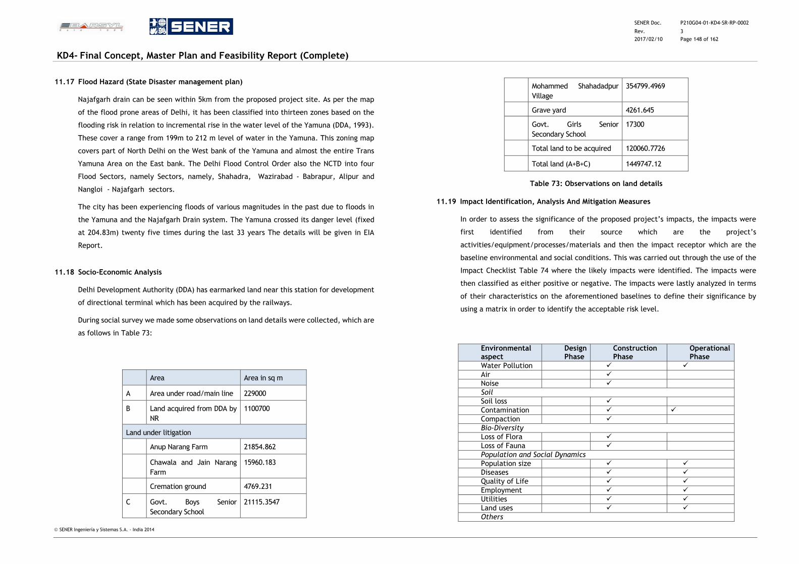
SENER Doc. P210G04-01-KD4-SR-RP-0002
Rev. 3
2017/02/10 Page 148 of 162
KD4- Final Concept, Master Plan and Feasibility Report (Complete)
SENER Ingeniería y Sistemas S.A. - India 2014
11.17 Flood Hazard (State Disaster management plan)
Najafgarh drain can be seen within 5km from the proposed project site. As per the map
of the flood prone areas of Delhi, it has been classified into thirteen zones based on the
flooding risk in relation to incremental rise in the water level of the Yamuna (DDA, 1993).
These cover a range from 199m to 212 m level of water in the Yamuna. This zoning map
covers part of North Delhi on the West bank of the Yamuna and almost the entire Trans
Yamuna Area on the East bank. The Delhi Flood Control Order also the NCTD into four
Flood Sectors, namely Sectors, namely, Shahadra, Wazirabad - Babrapur, Alipur and
Nangloi - Najafgarh sectors.
The city has been experiencing floods of various magnitudes in the past due to floods in
the Yamuna and the Najafgarh Drain system. The Yamuna crossed its danger level (fixed
at 204.83m) twenty five times during the last 33 years The details will be given in EIA
Report.
11.18 Socio-Economic Analysis
Delhi Development Authority (DDA) has earmarked land near this station for development
of directional terminal which has been acquired by the railways.
During social survey we made some observations on land details were collected, which are
as follows in Table 73:
Area Area in sq m
A Area under road/main line 229000
B Land acquired from DDA by
NR
1100700
Land under litigation
Anup Narang Farm 21854.862
Chawala and Jain Narang
Farm
15960.183
Cremation ground 4769.231
C Govt. Boys Senior
Secondary School
21115.3547
Mohammed Shahadadpur
Village
354799.4969
Grave yard 4261.645
Govt. Girls Senior
Secondary School
17300
Total land to be acquired 120060.7726
Total land (A+B+C) 1449747.12
Table 73: Observations on land details
11.19 Impact Identification, Analysis And Mitigation Measures
In order to assess the significance of the proposed project’s impacts, the impacts were
first identified from their source which are the project’s
activities/equipment/processes/materials and then the impact receptor which are the
baseline environmental and social conditions. This was carried out through the use of the
Impact Checklist Table 74 where the likely impacts were identified. The impacts were
then classified as either positive or negative. The impacts were lastly analyzed in terms
of their characteristics on the aforementioned baselines to define their significance by
using a matrix in order to identify the acceptable risk level.
Environmental aspect
Design Phase
Construction Phase
Operational Phase
Water Pollution
Air
Noise
Soil
Soil loss
Contamination
Compaction
Bio-Diversity
Loss of Flora
Loss of Fauna
Population and Social Dynamics
Population size
Diseases
Quality of Life
Employment
Utilities
Land uses
Others
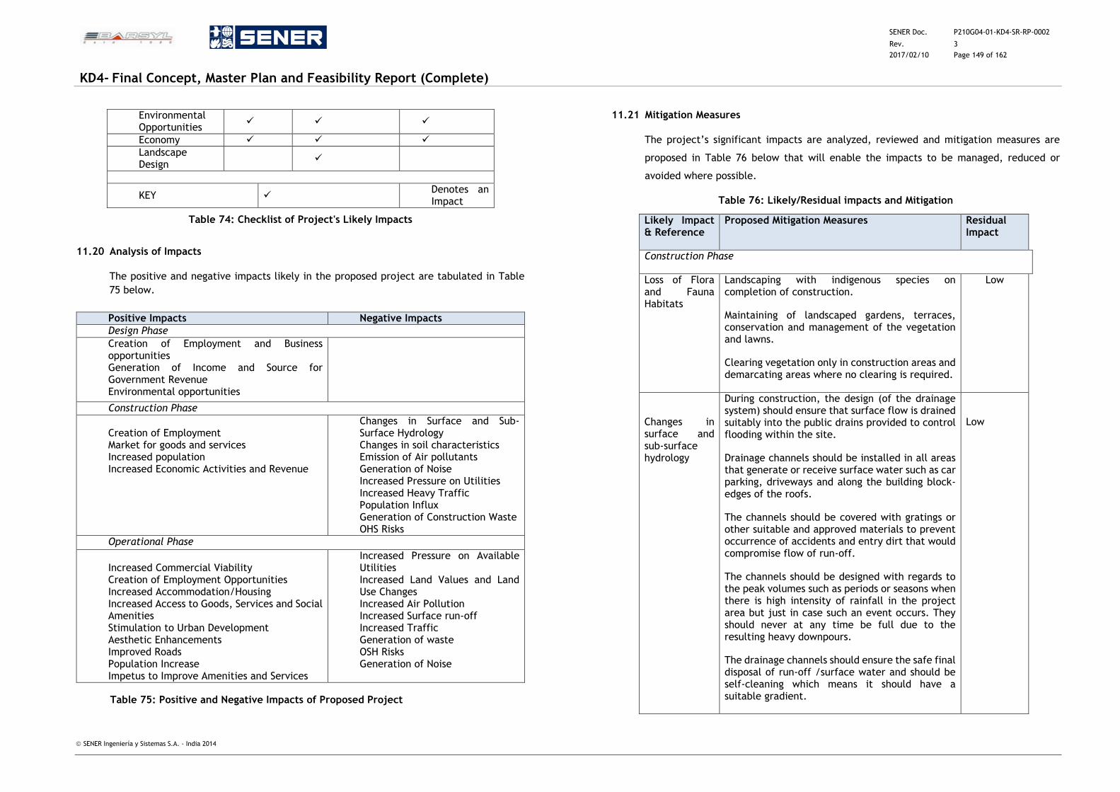
SENER Doc. P210G04-01-KD4-SR-RP-0002
Rev. 3
2017/02/10 Page 149 of 162
KD4- Final Concept, Master Plan and Feasibility Report (Complete)
SENER Ingeniería y Sistemas S.A. - India 2014
Environmental Opportunities
Economy
Landscape Design
KEY Denotes an Impact
Table 74: Checklist of Project's Likely Impacts
11.20 Analysis of Impacts
The positive and negative impacts likely in the proposed project are tabulated in Table
75 below.
Positive Impacts Negative Impacts
Design Phase
Creation of Employment and Business opportunities Generation of Income and Source for Government Revenue Environmental opportunities
Construction Phase
Creation of Employment Market for goods and services Increased population Increased Economic Activities and Revenue
Changes in Surface and Sub-Surface Hydrology Changes in soil characteristics Emission of Air pollutants Generation of Noise Increased Pressure on Utilities Increased Heavy Traffic Population Influx Generation of Construction Waste OHS Risks
Operational Phase
Increased Commercial Viability Creation of Employment Opportunities Increased Accommodation/Housing Increased Access to Goods, Services and Social Amenities Stimulation to Urban Development Aesthetic Enhancements Improved Roads Population Increase Impetus to Improve Amenities and Services
Increased Pressure on Available Utilities Increased Land Values and Land Use Changes Increased Air Pollution Increased Surface run-off Increased Traffic Generation of waste OSH Risks Generation of Noise
Table 75: Positive and Negative Impacts of Proposed Project
11.21 Mitigation Measures
The project’s significant impacts are analyzed, reviewed and mitigation measures are
proposed in Table 76 below that will enable the impacts to be managed, reduced or
avoided where possible.
Table 76: Likely/Residual impacts and Mitigation
Likely Impact & Reference
Proposed Mitigation Measures Residual Impact
Construction Phase
Loss of Flora and Fauna Habitats
Landscaping with indigenous species on completion of construction.
Maintaining of landscaped gardens, terraces, conservation and management of the vegetation and lawns.
Clearing vegetation only in construction areas and demarcating areas where no clearing is required.
Low
Changes in surface and sub-surface hydrology
During construction, the design (of the drainage system) should ensure that surface flow is drained suitably into the public drains provided to control flooding within the site.
Drainage channels should be installed in all areas that generate or receive surface water such as car parking, driveways and along the building block-edges of the roofs.
The channels should be covered with gratings or other suitable and approved materials to prevent occurrence of accidents and entry dirt that would compromise flow of run-off.
The channels should be designed with regards to the peak volumes such as periods or seasons when there is high intensity of rainfall in the project area but just in case such an event occurs. They should never at any time be full due to the resulting heavy downpours.
The drainage channels should ensure the safe final disposal of run-off /surface water and should be self-cleaning which means it should have a suitable gradient.
Low
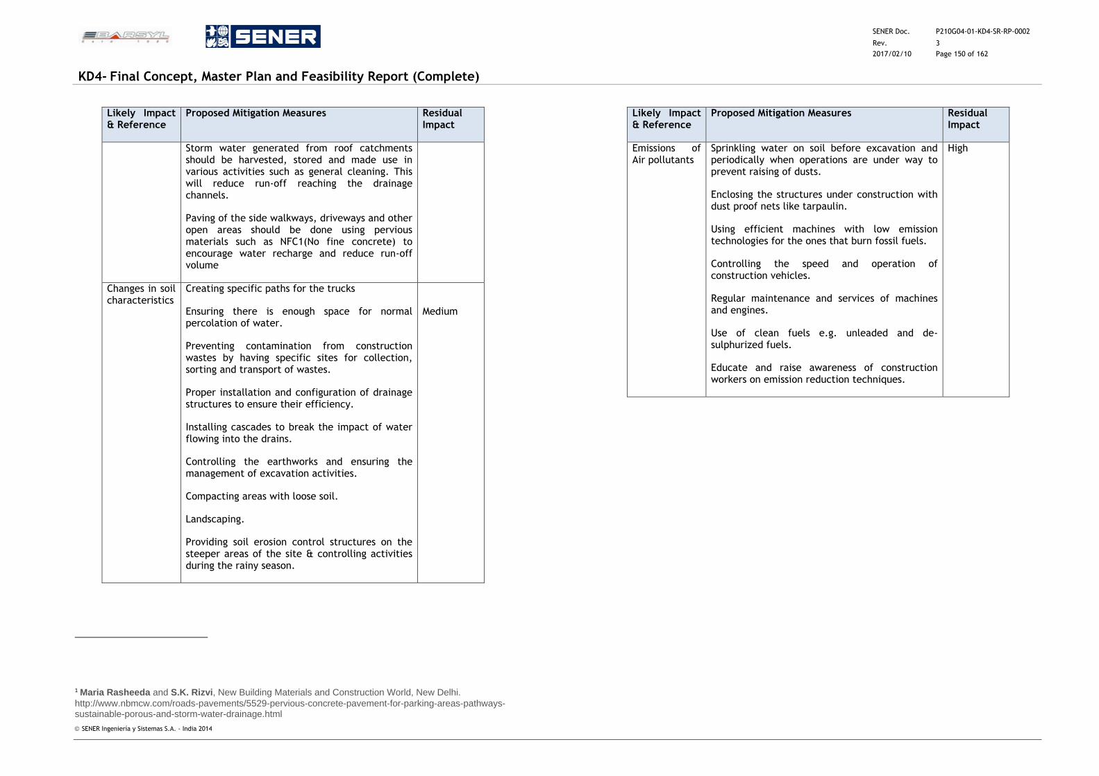
SENER Doc. P210G04-01-KD4-SR-RP-0002
Rev. 3
2017/02/10 Page 150 of 162
KD4- Final Concept, Master Plan and Feasibility Report (Complete)
SENER Ingeniería y Sistemas S.A. - India 2014
Likely Impact & Reference
Proposed Mitigation Measures Residual Impact
Storm water generated from roof catchments should be harvested, stored and made use in various activities such as general cleaning. This will reduce run-off reaching the drainage channels.
Paving of the side walkways, driveways and other open areas should be done using pervious materials such as NFC1(No fine concrete) to encourage water recharge and reduce run-off volume
Changes in soil characteristics
Creating specific paths for the trucks
Ensuring there is enough space for normal percolation of water.
Preventing contamination from construction wastes by having specific sites for collection, sorting and transport of wastes.
Proper installation and configuration of drainage structures to ensure their efficiency.
Installing cascades to break the impact of water flowing into the drains.
Controlling the earthworks and ensuring the management of excavation activities.
Compacting areas with loose soil.
Landscaping.
Providing soil erosion control structures on the steeper areas of the site & controlling activities during the rainy season.
Medium
1 Maria Rasheeda and S.K. Rizvi, New Building Materials and Construction World, New Delhi. http://www.nbmcw.com/roads-pavements/5529-pervious-concrete-pavement-for-parking-areas-pathways-sustainable-porous-and-storm-water-drainage.html
Likely Impact & Reference
Proposed Mitigation Measures Residual Impact
Emissions of Air pollutants
Sprinkling water on soil before excavation and periodically when operations are under way to prevent raising of dusts.
Enclosing the structures under construction with dust proof nets like tarpaulin.
Using efficient machines with low emission technologies for the ones that burn fossil fuels.
Controlling the speed and operation of construction vehicles.
Regular maintenance and services of machines and engines.
Use of clean fuels e.g. unleaded and de-sulphurized fuels.
Educate and raise awareness of construction workers on emission reduction techniques.
High
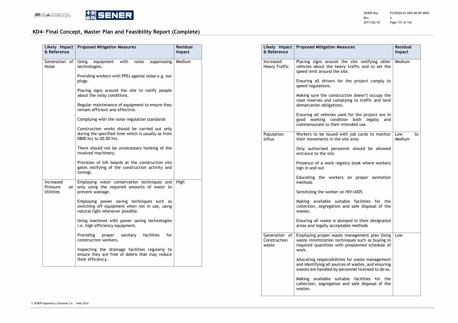
SENER Doc. P210G04-01-KD4-SR-RP-0002
Rev. 3
2017/02/10 Page 151 of 162
KD4- Final Concept, Master Plan and Feasibility Report (Complete)
SENER Ingeniería y Sistemas S.A. - India 2014
Likely Impact & Reference
Proposed Mitigation Measures Residual Impact
Generation of Noise
Using equipment with noise suppressing technologies.
Providing workers with PPEs against noise e.g. ear plugs.
Placing signs around the site to notify people about the noisy conditions.
Regular maintenance of equipment to ensure they remain efficient and effective.
Complying with the noise regulation standards
Construction works should be carried out only during the specified time which is usually as from 0800 hrs to 20.00 hrs.
There should not be unnecessary honking of the involved machinery.
Provision of bill boards at the construction site gates notifying of the construction activity and timings
Medium
Increased Pressure on Utilities
Employing water conservation techniques and only using the required amounts of water to prevent wastage.
Employing power saving techniques such as switching off equipment when not in use, using natural light whenever possible.
Using machines with power saving technologies i.e. high efficiency equipment.
Providing proper sanitary facilities for construction workers.
Inspecting the drainage facilities regularly to ensure they are free of debris that may reduce their efficiency.
High
Likely Impact & Reference
Proposed Mitigation Measures Residual Impact
Increased Heavy Traffic
Placing signs around the site notifying other vehicles about the heavy traffic and to set the speed limit around the site.
Ensuring all drivers for the project comply to speed regulations.
Making sure the construction doesn’t occupy the road reserves and complying to traffic and land demarcation obligations.
Ensuring all vehicles used for the project are in good working condition both legally and commensurate to their intended use.
Medium
Population Influx
Workers to be issued with job cards to monitor their movements in the site area
Only authorised personnel should be allowed entrance to the site
Presence of a work registry book where workers sign in and out
Educating the workers on proper sanitation methods
Sensitizing the worker on HIV/AIDS
Making available suitable facilities for the collection, segregation and safe disposal of the wastes.
Ensuring all waste is dumped in their designated areas and legally acceptable methods
Low to Medium
Generation of Construction waste
Employing proper waste management plan Using waste minimization techniques such as buying in required quantities with preplanned schedule of work.
Allocating responsibilities for waste management and identifying all sources of wastes, and ensuring wastes are handled by personnel licensed to do so.
Making available suitable facilities for the collection, segregation and safe disposal of the wastes.
Low
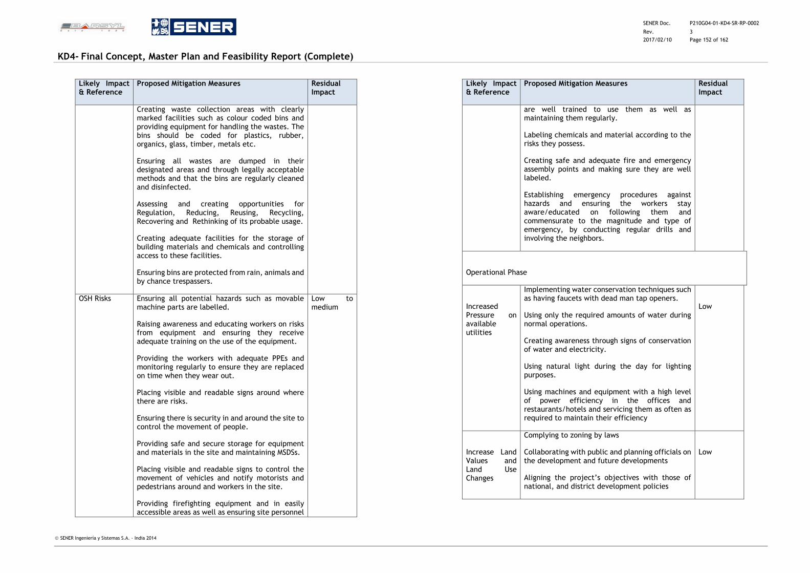
SENER Doc. P210G04-01-KD4-SR-RP-0002
Rev. 3
2017/02/10 Page 152 of 162
KD4- Final Concept, Master Plan and Feasibility Report (Complete)
SENER Ingeniería y Sistemas S.A. - India 2014
Likely Impact & Reference
Proposed Mitigation Measures Residual Impact
Creating waste collection areas with clearly marked facilities such as colour coded bins and providing equipment for handling the wastes. The bins should be coded for plastics, rubber, organics, glass, timber, metals etc.
Ensuring all wastes are dumped in their designated areas and through legally acceptable methods and that the bins are regularly cleaned and disinfected.
Assessing and creating opportunities for Regulation, Reducing, Reusing, Recycling, Recovering and Rethinking of its probable usage.
Creating adequate facilities for the storage of building materials and chemicals and controlling access to these facilities.
Ensuring bins are protected from rain, animals and by chance trespassers.
OSH Risks Ensuring all potential hazards such as movable machine parts are labelled.
Raising awareness and educating workers on risks from equipment and ensuring they receive adequate training on the use of the equipment.
Providing the workers with adequate PPEs and monitoring regularly to ensure they are replaced on time when they wear out.
Placing visible and readable signs around where there are risks.
Ensuring there is security in and around the site to control the movement of people.
Providing safe and secure storage for equipment and materials in the site and maintaining MSDSs.
Placing visible and readable signs to control the movement of vehicles and notify motorists and pedestrians around and workers in the site.
Providing firefighting equipment and in easily accessible areas as well as ensuring site personnel
Low to medium
Likely Impact & Reference
Proposed Mitigation Measures Residual Impact
are well trained to use them as well as maintaining them regularly.
Labeling chemicals and material according to the risks they possess.
Creating safe and adequate fire and emergency assembly points and making sure they are well labeled.
Establishing emergency procedures against hazards and ensuring the workers stay aware/educated on following them and commensurate to the magnitude and type of emergency, by conducting regular drills and involving the neighbors.
Operational Phase
Increased Pressure on available utilities
Implementing water conservation techniques such as having faucets with dead man tap openers.
Using only the required amounts of water during normal operations.
Creating awareness through signs of conservation of water and electricity.
Using natural light during the day for lighting purposes.
Using machines and equipment with a high level of power efficiency in the offices and restaurants/hotels and servicing them as often as required to maintain their efficiency
Low
Increase Land Values and Land Use Changes
Complying to zoning by laws
Collaborating with public and planning officials on the development and future developments
Aligning the project’s objectives with those of national, and district development policies
Low
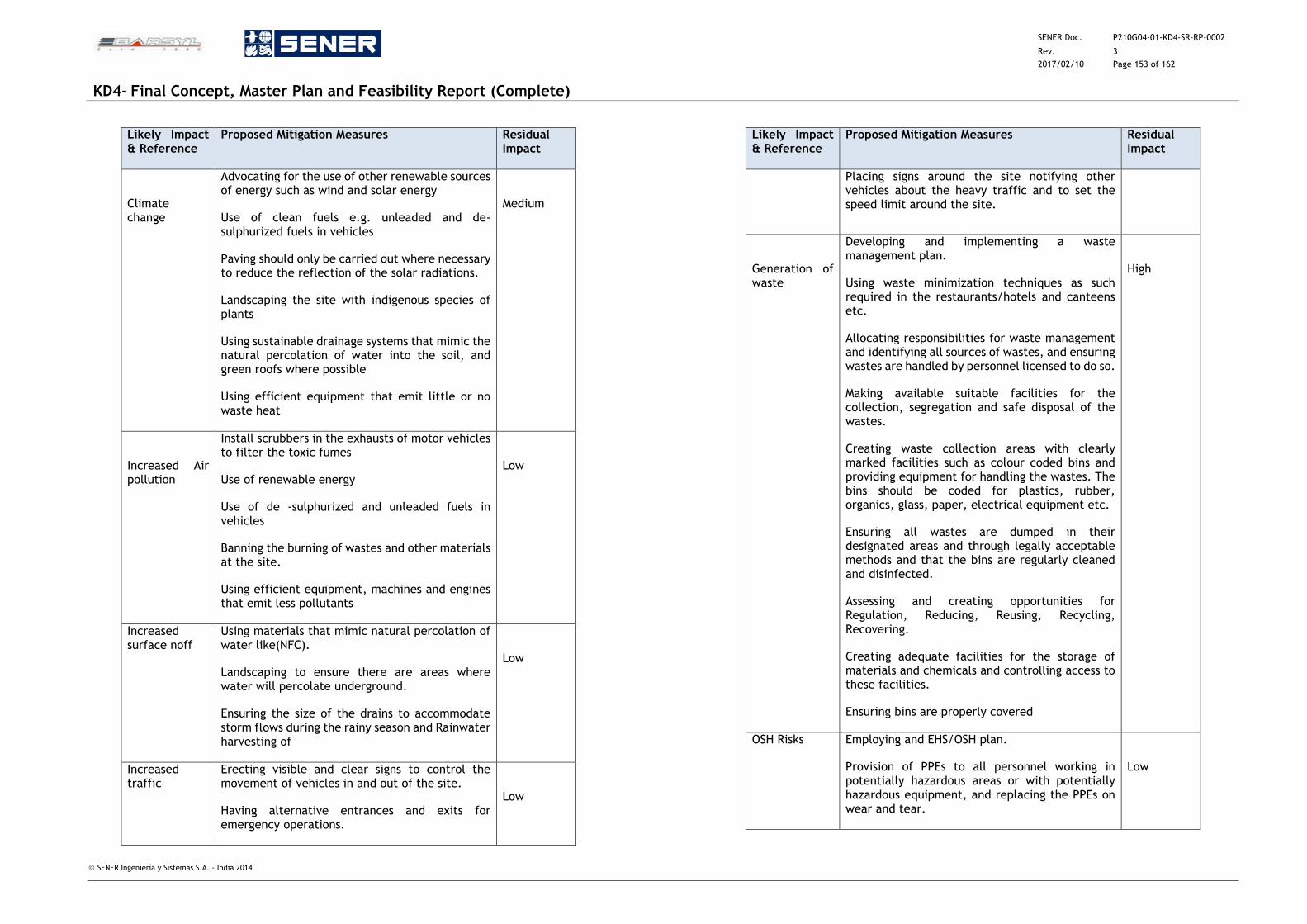
SENER Doc. P210G04-01-KD4-SR-RP-0002
Rev. 3
2017/02/10 Page 153 of 162
KD4- Final Concept, Master Plan and Feasibility Report (Complete)
SENER Ingeniería y Sistemas S.A. - India 2014
Likely Impact & Reference
Proposed Mitigation Measures Residual Impact
Climate change
Advocating for the use of other renewable sources of energy such as wind and solar energy
Use of clean fuels e.g. unleaded and de-sulphurized fuels in vehicles
Paving should only be carried out where necessary to reduce the reflection of the solar radiations.
Landscaping the site with indigenous species of plants
Using sustainable drainage systems that mimic the natural percolation of water into the soil, and green roofs where possible
Using efficient equipment that emit little or no waste heat
Medium
Increased Air pollution
Install scrubbers in the exhausts of motor vehicles to filter the toxic fumes
Use of renewable energy
Use of de -sulphurized and unleaded fuels in vehicles
Banning the burning of wastes and other materials at the site.
Using efficient equipment, machines and engines that emit less pollutants
Low
Increased surface noff
Using materials that mimic natural percolation of water like(NFC).
Landscaping to ensure there are areas where water will percolate underground.
Ensuring the size of the drains to accommodate storm flows during the rainy season and Rainwater harvesting of
Low
Increased traffic
Erecting visible and clear signs to control the movement of vehicles in and out of the site.
Having alternative entrances and exits for emergency operations.
Low
Likely Impact & Reference
Proposed Mitigation Measures Residual Impact
Placing signs around the site notifying other vehicles about the heavy traffic and to set the speed limit around the site.
Generation of waste
Developing and implementing a waste management plan.
Using waste minimization techniques as such required in the restaurants/hotels and canteens etc.
Allocating responsibilities for waste management and identifying all sources of wastes, and ensuring wastes are handled by personnel licensed to do so.
Making available suitable facilities for the collection, segregation and safe disposal of the wastes.
Creating waste collection areas with clearly marked facilities such as colour coded bins and providing equipment for handling the wastes. The bins should be coded for plastics, rubber, organics, glass, paper, electrical equipment etc.
Ensuring all wastes are dumped in their designated areas and through legally acceptable methods and that the bins are regularly cleaned and disinfected.
Assessing and creating opportunities for Regulation, Reducing, Reusing, Recycling, Recovering.
Creating adequate facilities for the storage of materials and chemicals and controlling access to these facilities.
Ensuring bins are properly covered
High
OSH Risks Employing and EHS/OSH plan.
Provision of PPEs to all personnel working in potentially hazardous areas or with potentially hazardous equipment, and replacing the PPEs on wear and tear.
Low
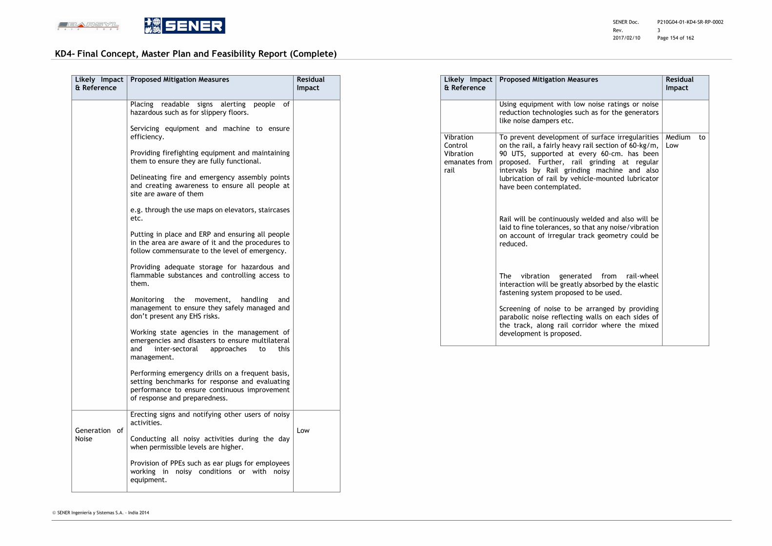
SENER Doc. P210G04-01-KD4-SR-RP-0002
Rev. 3
2017/02/10 Page 154 of 162
KD4- Final Concept, Master Plan and Feasibility Report (Complete)
SENER Ingeniería y Sistemas S.A. - India 2014
Likely Impact & Reference
Proposed Mitigation Measures Residual Impact
Placing readable signs alerting people of hazardous such as for slippery floors.
Servicing equipment and machine to ensure efficiency.
Providing firefighting equipment and maintaining them to ensure they are fully functional.
Delineating fire and emergency assembly points and creating awareness to ensure all people at site are aware of them
e.g. through the use maps on elevators, staircases etc.
Putting in place and ERP and ensuring all people in the area are aware of it and the procedures to follow commensurate to the level of emergency.
Providing adequate storage for hazardous and flammable substances and controlling access to them.
Monitoring the movement, handling and management to ensure they safely managed and don’t present any EHS risks.
Working state agencies in the management of emergencies and disasters to ensure multilateral and inter-sectoral approaches to this management.
Performing emergency drills on a frequent basis, setting benchmarks for response and evaluating performance to ensure continuous improvement of response and preparedness.
Generation of Noise
Erecting signs and notifying other users of noisy activities.
Conducting all noisy activities during the day when permissible levels are higher.
Provision of PPEs such as ear plugs for employees working in noisy conditions or with noisy equipment.
Low
Likely Impact & Reference
Proposed Mitigation Measures Residual Impact
Using equipment with low noise ratings or noise reduction technologies such as for the generators like noise dampers etc.
Vibration Control Vibration emanates from rail
To prevent development of surface irregularities on the rail, a fairly heavy rail section of 60-kg/m, 90 UTS, supported at every 60-cm. has been proposed. Further, rail grinding at regular intervals by Rail grinding machine and also lubrication of rail by vehicle-mounted lubricator have been contemplated.
Rail will be continuously welded and also will be laid to fine tolerances, so that any noise/vibration on account of irregular track geometry could be reduced.
The vibration generated from rail-wheel interaction will be greatly absorbed by the elastic fastening system proposed to be used.
Screening of noise to be arranged by providing parabolic noise reflecting walls on each sides of the track, along rail corridor where the mixed development is proposed.
Medium to Low
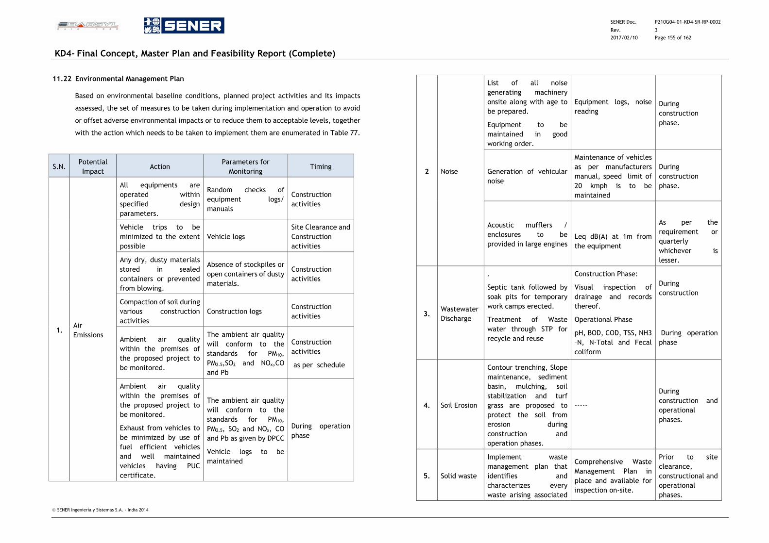
SENER Doc. P210G04-01-KD4-SR-RP-0002
Rev. 3
2017/02/10 Page 155 of 162
KD4- Final Concept, Master Plan and Feasibility Report (Complete)
SENER Ingeniería y Sistemas S.A. - India 2014
11.22 Environmental Management Plan
Based on environmental baseline conditions, planned project activities and its impacts
assessed, the set of measures to be taken during implementation and operation to avoid
or offset adverse environmental impacts or to reduce them to acceptable levels, together
with the action which needs to be taken to implement them are enumerated in Table 77.
S.N. Potential
Impact Action
Parameters for
Monitoring Timing
1. Air
Emissions
All equipments are
operated within
specified design
parameters.
Random checks of
equipment logs/
manuals
Construction
activities
Vehicle trips to be
minimized to the extent
possible
Vehicle logs
Site Clearance and
Construction
activities
Any dry, dusty materials
stored in sealed
containers or prevented
from blowing.
Absence of stockpiles or
open containers of dusty
materials.
Construction
activities
Compaction of soil during
various construction
activities
Construction logs Construction
activities
Ambient air quality
within the premises of
the proposed project to
be monitored.
The ambient air quality
will conform to the
standards for PM10,
PM2.5,SO2 and NOx,CO
and Pb
Construction
activities
as per schedule
Ambient air quality
within the premises of
the proposed project to
be monitored.
Exhaust from vehicles to
be minimized by use of
fuel efficient vehicles
and well maintained
vehicles having PUC
certificate.
The ambient air quality
will conform to the
standards for PM10,
PM2.5, SO2 and NOx, CO
and Pb as given by DPCC
Vehicle logs to be
maintained
During operation
phase
2 Noise
List of all noise
generating machinery
onsite along with age to
be prepared.
Equipment to be
maintained in good
working order.
Equipment logs, noise
reading
During
construction
phase.
Generation of vehicular
noise
Maintenance of vehicles
as per manufacturers
manual, speed limit of
20 kmph is to be
maintained
During
construction
phase.
Acoustic mufflers /
enclosures to be
provided in large engines
Leq dB(A) at 1m from
the equipment
As per the
requirement or
quarterly
whichever is
lesser.
3. Wastewater
Discharge
.
Septic tank followed by
soak pits for temporary
work camps erected.
Treatment of Waste
water through STP for
recycle and reuse
Construction Phase:
Visual inspection of
drainage and records
thereof.
Operational Phase
pH, BOD, COD, TSS, NH3
–N, N-Total and Fecal
coliform
During
construction
During operation
phase
4. Soil Erosion
Contour trenching, Slope
maintenance, sediment
basin, mulching, soil
stabilization and turf
grass are proposed to
protect the soil from
erosion during
construction and
operation phases.
-----
During
construction and
operational
phases.
5. Solid waste
Implement waste
management plan that
identifies and
characterizes every
waste arising associated
Comprehensive Waste
Management Plan in
place and available for
inspection on-site.
Prior to site
clearance,
constructional and
operational
phases.
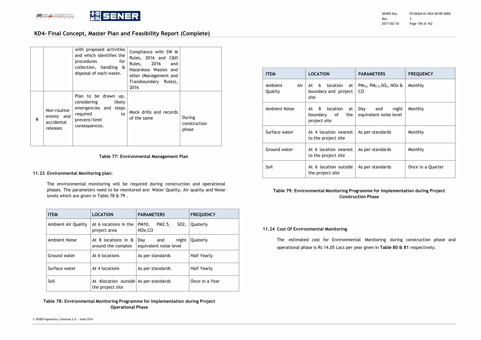
SENER Doc. P210G04-01-KD4-SR-RP-0002
Rev. 3
2017/02/10 Page 156 of 162
KD4- Final Concept, Master Plan and Feasibility Report (Complete)
SENER Ingeniería y Sistemas S.A. - India 2014
with proposed activities
and which identifies the
procedures for
collection, handling &
disposal of each waste.
Compliance with SW M
Rules, 2016 and C&D
Rules, 2016 and
Hazardous Wastes and
other (Management and
Transboundary Rules),
2016
6
Non-routine
events and
accidental
releases
Plan to be drawn up,
considering likely
emergencies and steps
required to
prevent/limit
consequences.
Mock drills and records
of the same
During
construction
phase
Table 77: Environmental Management Plan
11.23 Environmental Monitoring plan:
The environmental monitoring will be required during construction and operational
phases. The parameters need to be monitored are: Water Quality, Air quality and Noise
levels which are given in Table 78 & 79 .
Table 78: Environmental Monitoring Programme for Implementation during Project
Operational Phase
Table 79: Environmental Monitoring Programme for Implementation during Project
Construction Phase
11.24 Cost Of Environmental Monitoring
The estimated cost for Environmental Monitoring during construction phase and
operational phase is Rs 14.05 Lacs per year given in Table 80 & 81 respectively.
ITEM LOCATION PARAMETERS FREQUENCY
Ambient Air Quality At 6 locations in the
project area
PM10, PM2.5, SO2,
NOx,CO
Quaterly
Ambient Noise At 8 locations in &
around the complex
Day and night
equivalent noise level
Quaterly
Ground water At 6 locations As per standards Half Yearly
Surface water At 4 locations As per standards Half Yearly
Soil At 6location outside
the project site
As per standards Once in a Year
ITEM LOCATION PARAMETERS FREQUENCY
Ambient Air
Quality
At 6 location at
boundary and project
site
PM10, PM2.5,SO2, NOx &
CO
Monthly
Ambient Noise At 8 location at
boundary of the
project site
Day and night
equivalent noise level
Monthly
Surface water At 4 location nearest
to the project site
As per standards Monthly
Ground water At 6 location nearest
to the project site
As per standards Monthly
Soil At 6 location outside
the project site
As per standards Once in a Quarter
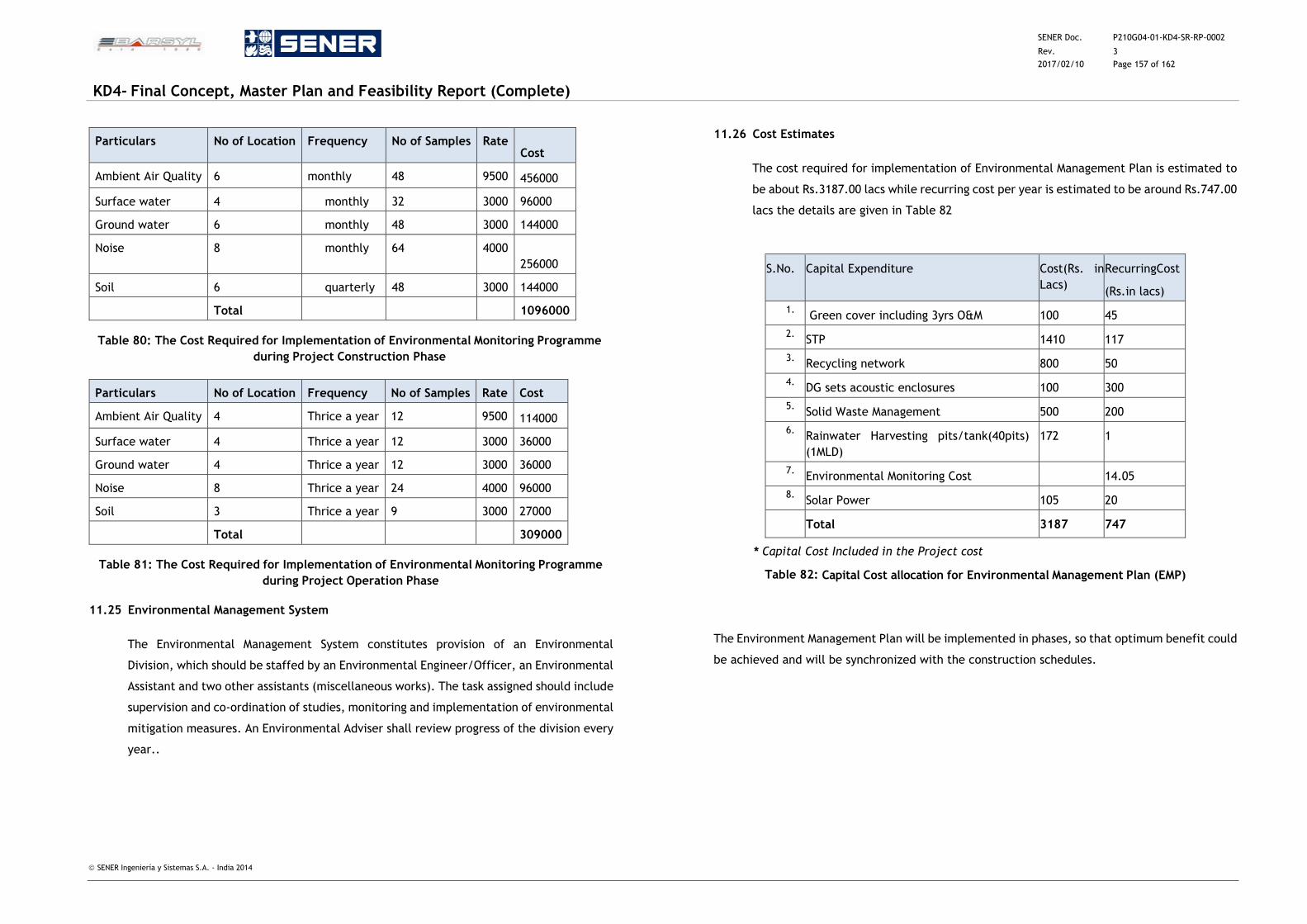
SENER Doc. P210G04-01-KD4-SR-RP-0002
Rev. 3
2017/02/10 Page 157 of 162
KD4- Final Concept, Master Plan and Feasibility Report (Complete)
SENER Ingeniería y Sistemas S.A. - India 2014
Particulars No of Location Frequency No of Samples Rate Cost
Ambient Air Quality 6 monthly 48 9500 456000
Surface water 4 monthly 32 3000 96000
Ground water 6 monthly 48 3000 144000
Noise 8 monthly 64 4000
256000
Soil 6 quarterly 48 3000 144000
Total 1096000
Table 80: The Cost Required for Implementation of Environmental Monitoring Programme
during Project Construction Phase
Particulars No of Location Frequency No of Samples Rate Cost
Ambient Air Quality 4 Thrice a year 12 9500 114000
Surface water 4 Thrice a year 12 3000 36000
Ground water 4 Thrice a year 12 3000 36000
Noise 8 Thrice a year 24 4000 96000
Soil 3 Thrice a year 9 3000 27000
Total 309000
Table 81: The Cost Required for Implementation of Environmental Monitoring Programme
during Project Operation Phase
11.25 Environmental Management System
The Environmental Management System constitutes provision of an Environmental
Division, which should be staffed by an Environmental Engineer/Officer, an Environmental
Assistant and two other assistants (miscellaneous works). The task assigned should include
supervision and co-ordination of studies, monitoring and implementation of environmental
mitigation measures. An Environmental Adviser shall review progress of the division every
year..
11.26 Cost Estimates
The cost required for implementation of Environmental Management Plan is estimated to
be about Rs.3187.00 lacs while recurring cost per year is estimated to be around Rs.747.00
lacs the details are given in Table 82
S.No. Capital Expenditure Cost(Rs. in
Lacs)
RecurringCost
(Rs.in lacs)
1. Green cover including 3yrs O&M 100 45
2. STP 1410 117
3. Recycling network 800 50
4. DG sets acoustic enclosures 100 300
5. Solid Waste Management 500 200
6. Rainwater Harvesting pits/tank(40pits)
(1MLD)
172 1
7. Environmental Monitoring Cost
14.05
8. Solar Power 105 20
Total 3187 747
* Capital Cost Included in the Project cost
Table 82: Capital Cost allocation for Environmental Management Plan (EMP)
The Environment Management Plan will be implemented in phases, so that optimum benefit could
be achieved and will be synchronized with the construction schedules.
SENER Doc. P210G04-01-KD4-SR-RP-0002
Rev. 3
2017/02/10 Page 158 of 162
KD4- Final Concept, Master Plan and Feasibility Report (Complete)
SENER Ingeniería y Sistemas S.A. - India 2014
12 CAPEX
The estimated cost has been based on CPWD PAR 2013 and supplement 2013 published
by Central Public Works Department, Government of India. The Plinth Area Rates (PAR)
are considered reasonable and adopted all over India for estimation purposes of different
building works. These rates are applied per sq. m Built-up area. The CPWD DSR 2014 has
been further used to calculate the estimated costs of specific items of work not included
in PAR.
The areas used to calculate the above estimate is given below in the Table no 1.1
S. No. Description Floor Height (m) Area (Sq m)
1 Basement-1 (includes FOB) 5.85 18350.00
2 Ground Floor 7.0 9100.00
3 Ground Floor Stilted 7.0 11520.00
4 First Floor Roof 8.5 20470.00
5 First Floor Usable Area 17010.00
6 Superstructure (2+3+4) 41090.00
7 RCC (1+2+3) 38970.00
8 Total Building Area (1+2+3+4) 59440.00
9 Additional Area of Retaining Wall along the
Station Edge for the Sunken Road (Surface
Area)
2700.00
10 Arrival Area Sunken Road, Ramps,
Embankment and Retaining Wall
48200.00
11 Platform Area (4 Islands) – Flooring and
Shelter considered in costing
35100.00
12 Basement 1B (Two Tunnels) 3822.00
13 Basement Area for Access Ramps/ Staircases
to Tunnel (Finishes considered for costing)
4030.00
14 Non-Road Site Area 88605.00
15 Approach/ Exit Road Area 79275.00
16 Total Site Area (14+15) 167880.00
Table 83: Station Areas and Other Areas used for Cost Estimation
12.1 Station Structural and Architectural Building Works and Finishes Costing
The Internal Services costs are also added as per norms given in CPWD plinth area rate
Oct. 2012. For Items not covered in these plinth area rates, market rates have been
adopted. These cost estimates are approximates and are based on typical relationships
of quantities such as floor area/volume etc. The cost estimate is based on built-up
area/floor area worked out from the master plans and the plinth area rates applied to
arrive at reasonable costs for taking administrative and financial decisions. The
quantities are multiplied by unit rates to arrive at the estimated cost.
The total cost of the Station Building is INR 384,75,00,875 (Rupees Three Hundred
Eighty Four Crores Seventy Five Lacs and Eight Hundred and Seventy Five). In the total
building cost mentioned above, the Total Civil Cost is INR 94,51,67,472.40 (Rupees
Ninety Four Crore Fifty One Lacs Sixty Seven Thousand Four Hundred and Seventy Two)
which includes fixed interiors e.g. flooring railing, partitions, paints etc. on the first
floor and steel barrel roof structure complete to specifications mentioned in the PE.
Items for Vertical Circulations (lifts and escalators) is INR 16,84,00,000 (Rupees
Sixteen Crores Eighty Four lacs).
The Basement Cost is calculated for an area of 18350 sq. m which is INR 70,34,16,667
(Rupees Seventy Crore Thirty Four Lacs Sixteen Thousand Six Hundred and Sixty Seven
only). The Platform Finishes and Shelter has been calculated to an extent of INR
23,83,79,676 (Rupees Twenty Three Crores Eighty Three Lacs Seventy Nine Thousands
Six Hundred and Seventy Six) as a separate item.
The cost of Site Development which would include site levelling, retaining walls etc. is
INR 29,12,24,803 (Rupees Twenty Nine Crore Twelve Lacs Twenty Four Thousand Eight
Hundred and Three). The contingencies on the costs are kept at 3%. The detailed break-
up along with annexure can be referred from the ‘Preliminary Estimate for Bijwasan
Station report (Revision 12)’.
SENER Doc. P210G04-01-KD4-SR-RP-0002
Rev. 3
2017/02/10 Page 159 of 162
KD4- Final Concept, Master Plan and Feasibility Report (Complete)
SENER Ingeniería y Sistemas S.A. - India 2014
12.2 Station MEP Services Costing
The Internal and external services costs are also added as per norms given in CPWD plinth
area rate Oct. 2012. For Items not covered in these plinth area rates, market rates have
been adopted. These cost estimates are approximates and are based on typical
relationships of quantities such as floor area/volume etc. The cost estimate is based on
built-up area/floor area worked out from the master plans and the plinth area rates
applied to arrive at reasonable costs for taking administrative and financial decisions. The
quantities are multiplied by unit rates to arrive at the estimated cost.
The cost incurred on the Internal Works for the station building which includes station
civil and electrical installations and connections, firefighting and fire alarm services is
coming approximately INR 62,46,47,746 (Rupees Sixty Two Crore Forty Six Lacs Forty
Seven Thousand Seven Hundred and Forty Six Rupees)
The Services cost for Site Development which includes External Sewer connection, Filter
Water Supply and its supply network and connections, Storm Water Drainage System,
Horticulture System, Street Lighting and Site Signage is approximately INR 9,96,41,022
(Rupees Nine Crore Ninety Six Lacs Forty One Thousand and Twenty Two).
Water Tanks Cost which includes underground and overhead storage tanks is
approximately INR 1,87,23,931 (One Crore Eighty Seven Lacs and Twenty Three
Thousand Nine Hundred and Thirty One Rupees)
Bulk Services Cost which includes Sub-station equipment, DG sets, Ventilation System for
Ground and First Floor, VRV/ VRF AC System, CCTV System, Hydropneumatic Water Supply
System, RO System, Scanning System and Equipment and Communications and SCADA is
approximately INR 27,21,76,144 (Twenty Seven Crore Twenty One Lacs Seventy Six
Thousand One Hundred and Forty Four Rupees)
Therefore, the Total MEP Cost estimated is coming approximately INR 101,51,88,843
(Hundred One Crore Fifty One Lakhs Eighty Eight Thousand Eight Hundred and Forty Three
Rupees Only). The contingencies on the costs are kept at 3%.
The detailed break-up along with annexures can be referred from the Preliminary Estimate
for Bijwasan Railway Station, New Delhi, Revision 12.
SENER Doc. P210G04-01-KD4-SR-RP-0002
Rev. 3
2017/02/10 Page 160 of 162
KD4- Final Concept, Master Plan and Feasibility Report (Complete)
SENER Ingeniería y Sistemas S.A. - India 2014
13 RISK ANALYSIS AND MITIGATION
13.1 Introduction
Careful planning, construction and operation schemes are essential to implement safely and with
reliability a project of this magnitude. The Bijwasan railway terminal project has characteristics
that make the project more complex than existing railway projects. It utilizes non-indigenous
technology, and therefore foreign system technology is being selected to provide state of the art
world class facilities, following due process, which put an extra burden on project scheduling and
cost control. Because it is a Greenfield construction, combinations of railway yard alignment as
being planned and executed by Northern Railway ,system technologies for the station building
and allied commercial and operating facilities as well as the coach maintenance, and rake
stabling as well as loco stabling and fuelling facilities have to be taken up concurrently.
This calls for much more complex decision processes involving local governments in addition to
the central government. Furthermore, it involves high uncertainties in terms of political risks, in
addition to financial and technological aspects. This stems from the long project duration that
spans many government departments and the large number of components as well as project size
that encompasses different administrative bodies.
In view of the above factors, the project calls for extensive risk analysis and management for
successful and safe completion that is much more complex than many other railway projects in
India..
13.2 Risk Analysis and Mitigation on this Project.
Risk is made up of two parts: the probability of something going wrong, and the negative
consequences if it does. We have to prepare for and manage risks which can arise during the
project implementation if by a consequence that we hadn't planned for, costs, time, and
reputations could be on the line.
Efforts have been made to identify possible risks during the course of execution of this project
till its completion.
Risk Analysis is complex, and we have drawn on the detailed project report & plans, financial
data, security protocols, marketing forecasts, and other relevant information.
On this project, the following risks have been identified:
i. Construction risks.
ii. Equipment or technology failure, theft, staff sickness, or natural disasters.
iii. Changes in government policy.
iv. Human Risks – Strikes / Bandhs / Accidents or Loss of a key individual.
v. Operational – Disruption to construction supplies and operations, loss of access to essential
assets.
vi. Procedural – Failures of accountability, internal systems, or controls, or from fraud.
vii. Project – Going over the budget, taking too long on key tasks or contractual failures –
Contractor not deploying adequate equipments, manpower & other required resources in
time.
viii. Financial – Business failure, stock market fluctuations, interest rate changes, or non-
availability of funding.
ix. Technical – Advances in technology, or from technical failure.
x. Natural – Weather, natural disasters such as earthquake, floods etc. or disease.
xi. Political – Changes in tax, public opinion, government policy, or foreign influence.
xii. Structural –Inadequacy of design, poor workmanship and quality of work.
xiii. Safety features adopted proving inadequate, leading to site accidents or failure of parts
of structures resulting in manpower or the structure being harmed as well as delaying the
completion of the project.
xiv. Change in the scope of work by the Railways – During the execution of the project there
could be situations where the Railway operational requirements undergo certain revisions
due to the highly dynamic nature of Railway operations. This could necessitate changes
in the planning leading to delays and additional costs.
xv. Having identified the threats as above, we need to assess likelihood of these threats
materializing, and their possible impact. The risks identified above and suggested action
for their mitigation is summarized below.
SENER Doc. P210G04-01-KD4-SR-RP-0002
Rev. 3
2017/02/10 Page 161 of 162
KD4- Final Concept, Master Plan and Feasibility Report (Complete)
SENER Ingeniería y Sistemas S.A. - India 2014
13.3 Proposals for the Mitigation of the Above Risks
i. Construction risks of station building and other related structures integrated with
concourse/airspace above the railway tracks as well as other commercial and residential
buildings which form a part of this project.
The above works which form a part of the Bijwasan project comprises of the design and
construction of all works and services necessary to complete the development / redevelopment
of the Station Buildings, railway yard, coach maintenance workshop & structures and loco shed
etc. as per the Development Agreement documents and the construction specifications.
The railway yard will be constructed by the Northern Railway with their own agency and under
their supervision and will not be the part of this project. However since the platforms and the
overhead structures above the platforms, the subways, escalators & other overhead structures
are to be constructed as a part of this project. These will be adjacent to the railway line; there
is an essential requirement of coordination between the execution of works by the Railway and
by the Concessionaire, since there could be a risk of infringement of the railway tracks. This can
be achieved by deployment of proper equipment and strict supervision. We have to ensure that
such infringements do not take place. No surplus excavated material should be stacked in any
infringing manner and such material should be taken away by the developer or disposed off in
the approved dumping area. Proper and safe scaffolding for construction of FOB’s, subways &
walkways which form part of this project. Safety precautions as required must be strictly
enforced in the installation, testing & commissioning of the lifts & escalators, underground &
above ground ancillary structures / facilities including plant room, water tanks & pumps ,
telecommunication and power cabling etc.
Proper barricading of construction site must be ensured to prevent unauthorised entry into the
protected area of the construction site to prevent unauthorised persons from accidental entry to
save them from falling debris, electric current.
Plumbing & pipelines must be made totally leak proof and electric cables, wires & ancillaries
must be carefully executed and taped to prevent short circuit or electrocution.
Water supply must be made contamination free by proper sealing and other required protection
works.
Suitable provisions in design will have to be made for safety at construction site during design &
erection of temporary woks to enable permanent construction since Delhi lies in a seismically
active zone and also keeping in mind the flooding at site as it is a low lying area (either due to
natural conditions or due to equipment failure such as pumps etc. during construction)
ii. Equipment or technology failure, theft, staff sickness or natural disasters, Weather or
disease.
In a project of this magnitude the quality and progress of work will be adversely affected if
adequate construction equipment is either not provided or is rendered ineffective by improper
maintenance or shortage of operators leading to idling
Further in case due to design defect or specification of selection of technology the work could
suffer. In view of this risk it is essential that selection of technology is done with great care and
implementation is carried out optimally and effectively. It is of great importance that utilities
such as fire fighting, communication & electricity are provided round the clock with proper back
up in case of any related equipment or power failure to avoid any untoward incident.
At large construction sites theft of spares, fuel etc are not uncommon but if they take place the
progress of work slows down besides idling of manpower. In view of this need for tight security
at work site cannot be understated.
The location of this project is in an area which is subject to seasonal sicknesses like skin diseases,
malaria, dengue etc which can affect the availability of manpower. It is therefore suggested that
proper sanitation & drainage at the worksite as well as arrangement of immunization of the
workmen should be arranged in time.
While natural disasters like earthquakes, floods etc cannot be wished away, adequate disaster
management plan must be in place to minimize the effect of such disasters. Also, Delhi being in
high seismic zone, the permanent and temporary structures both must be designed keeping
adequate and relevant provisions for seismic parameters in the design. The construction must
ensure that the safest and best engineering practices are followed while executing the project,
keeping seismic effects/ threats into consideration.
SENER Doc. P210G04-01-KD4-SR-RP-0002
Rev. 3
2017/02/10 Page 162 of 162
KD4- Final Concept, Master Plan and Feasibility Report (Complete)
SENER Ingeniería y Sistemas S.A. - India 2014
iii. Changes in government policy.
While the project is being taken up after due approvals from the different government bodies
like DDA, Delhi Jal Board, ASI, DUAC, AAI, UTTIPEC etc, nothing stops any of these bodies from
changing the policies which may affect the planning for this project. The effect of these changes
can be minimized by remaining in constant touch with these bodies & networking with them
suitably to know in advance of impending changes & planning to handle them.
iv. Human Risks – Strikes / Bandhs / Accidents or Loss of a key individual.
In India, it is not uncommon for strikes & bandhs, rallies & ‘dharnas’ to take place from time to
time in connection with agitations / representations etc, mostly for social and political issues not
related to the project. The effect of such activities results in occasional work stoppages. This is
perhaps inevitable & some provision for the days lost on this account should be planned initially
itself.
v. Operational – Disruption to construction supplies and operations.
Owing to short supply, transportation bottlenecks and interruptions and occasional non
availability of certain materials from time to time there could be delays and disruptions in certain
segments of work. This effect can be minimized by timely and early procurement and storage of
critical materials so that supply is not affected.
vi. Procedural – Failures of accountability, internal systems, or controls, or from fraud.
These are potential risks in all major projects & can be mitigated by having proper planning,
controls & monitoring systems in place during execution of the project.
vii. Project – Going over budget, taking too long on key tasks or contractual failures
The major reasons for delay in most projects is the contractor not deploying adequate
equipments, manpower & other required resources in time. This can be taken care of by providing
planned advances, timely payments for work done & proper monitoring of provision of equipment,
material & manpower by the contractor as required from time to time.
viii. Financial – Business failure, stock market fluctuations, interest rate changes, or non-
availability of funding.
These factors are normally not under the control of the project management team or the
contractor / concessionaire. They have to be factored in while estimating the project cost at the
time of taking up the project.
ix. Technical – Advances in technology, or from technical failure.
Due to this project involving provision of world class state of the art technology & facilities, it
may be necessary to change the proposed technology due to new developments which may come
about during the execution of the project.
x. Political – Changes in tax, public opinion, government policy, or foreign influence.
Since this project will be executed in about 650 days after commencement of work for the project
as per planning as such we must also factor in likely delays of up to 100 days for various reasons.
The possibility of changes in priority and annual allocation of funds not matching the planned and
required amounts, by the government cannot be ruled out. This may lead to further delay.
Changes in corporate tax may also affect the project finances & suitable provisions should be
made in the financial planning of the project.
Since this is a public utility project, at times the public opinion also builds up for provision,
shifting or shutting down of some activities which may result in some changes in the planning
with consequent variation in cost and requiring additional time . Adequate provisions should be
made both in funds and project schedules for meeting such contingencies.
xi. Insurance
Many of the above risks can be taken care by insurance coverage appropriate and adequate to
cover the extent of potential loses it may result from the risks. This should cover third party
risks, fire and theft, breakdown of equipment and group insurance for covering the workmen
against death and injury etc.
SENER Doc. P210G04-01-KD4-SR-AN-0001
Rev. 0
2013/09/13 Page 1 of 5
KD4- Final Concept, Master Plan and Feasibility Report (Complete)
SENER Ingeniería y Sistemas S.A. - India 2014
ANNEXURE 1 - PHOTOGRAPHIC REPORT
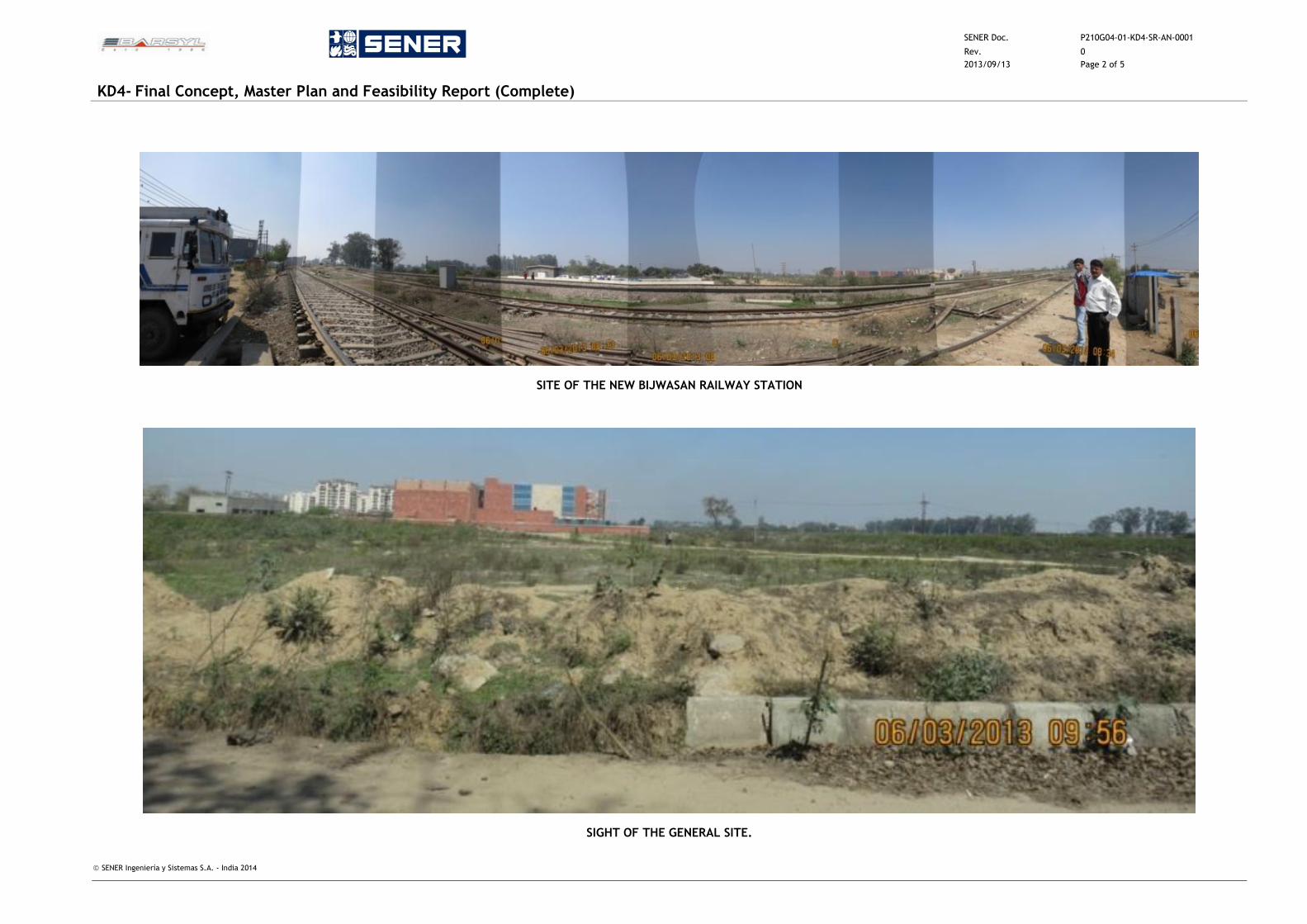
SENER Doc. P210G04-01-KD4-SR-AN-0001
Rev. 0
2013/09/13 Page 2 of 5
KD4- Final Concept, Master Plan and Feasibility Report (Complete)
SENER Ingeniería y Sistemas S.A. - India 2014
SITE OF THE NEW BIJWASAN RAILWAY STATION
SIGHT OF THE GENERAL SITE.
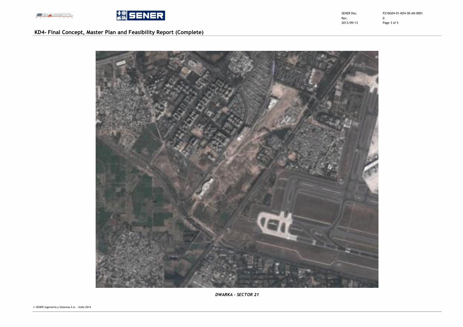
SENER Doc. P210G04-01-KD4-SR-AN-0001
Rev. 0
2013/09/13 Page 3 of 5
KD4- Final Concept, Master Plan and Feasibility Report (Complete)
SENER Ingeniería y Sistemas S.A. - India 2014
DWARKA - SECTOR 21
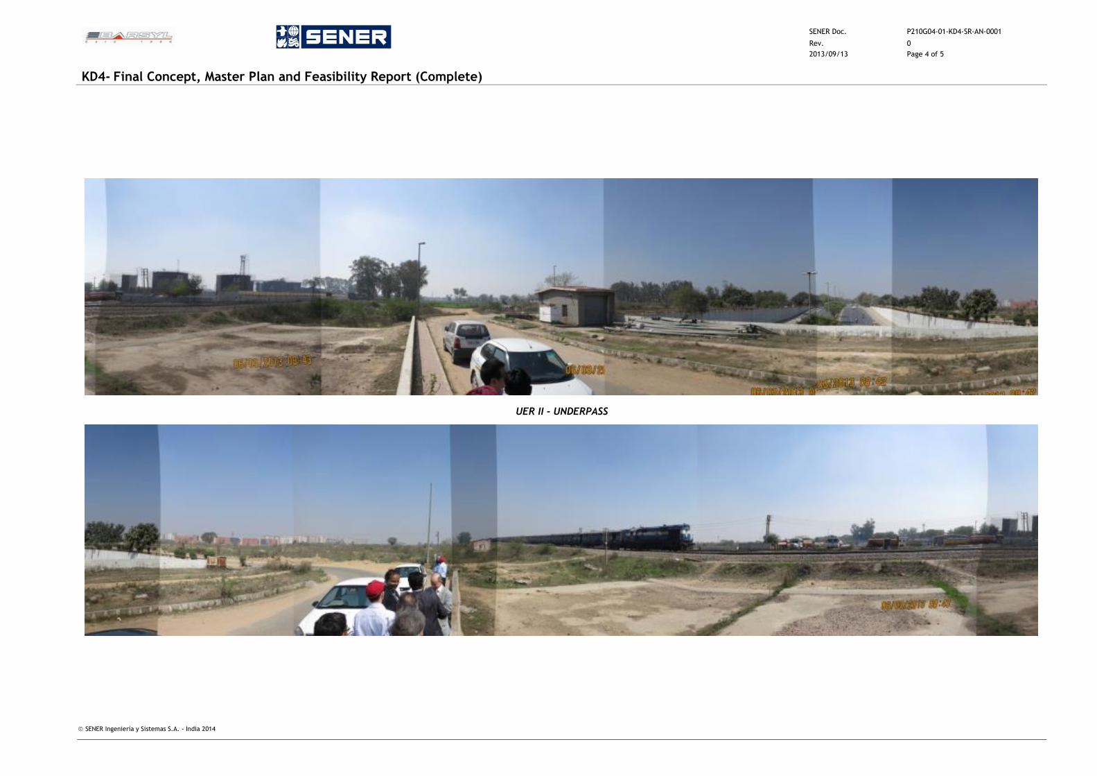
SENER Doc. P210G04-01-KD4-SR-AN-0001
Rev. 0
2013/09/13 Page 4 of 5
KD4- Final Concept, Master Plan and Feasibility Report (Complete)
SENER Ingeniería y Sistemas S.A. - India 2014
UER II - UNDERPASS
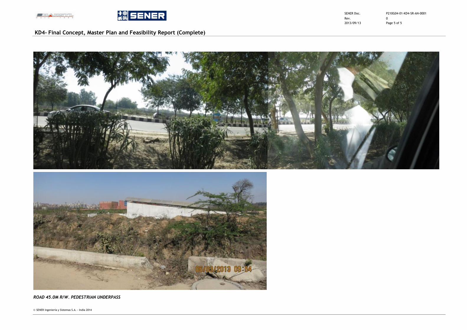
SENER Doc. P210G04-01-KD4-SR-AN-0001
Rev. 0
2013/09/13 Page 5 of 5
KD4- Final Concept, Master Plan and Feasibility Report (Complete)
SENER Ingeniería y Sistemas S.A. - India 2014
ROAD 45.0M R/W. PEDESTRIAN UNDERPASS
SENER Doc. P210G04-01-KD4-SR-AN-0002
Rev. 0
2013/09/13 Page 1 of 6
KD4- Final Concept, Master Plan and Feasibility Report (Complete)
SENER Ingeniería y Sistemas S.A. - India 2014
ANNEXURE 2 – EXAMPLES OF WORLD CLASS STATIONS
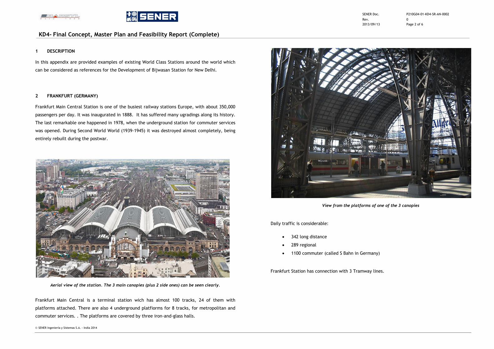
SENER Doc. P210G04-01-KD4-SR-AN-0002
Rev. 0
2013/09/13 Page 2 of 6
KD4- Final Concept, Master Plan and Feasibility Report (Complete)
SENER Ingeniería y Sistemas S.A. - India 2014
1 DESCRIPTION
In this appendix are provided examples of existing World Class Stations around the world which
can be considered as references for the Development of Bijwasan Station for New Delhi.
2 FRANKFURT (GERMANY)
Frankfurt Main Central Station is one of the busiest railway stations Europe, with about 350,000
passengers per day. It was inaugurated in 1888. It has suffered many ugradings along its history.
The last remarkable one happened in 1978, when the underground station for commuter services
was opened. During Second World World (1939-1945) it was destroyed almost completely, being
entirely rebuilt during the postwar.
Aerial view of the station. The 3 main canopies (plus 2 side ones) can be seen clearly.
Frankfurt Main Central is a terminal station wich has almost 100 tracks, 24 of them with
platforms attached. There are also 4 underground platfiorms for 8 tracks, for metropolitan and
commuter services. . The platforms are covered by three iron-and-glass halls.
View from the platforms of one of the 3 canopies
Daily traffic is considerable:
342 long distance
289 regional
1100 commuter (called S Bahn in Germany)
Frankfurt Station has connection with 3 Tramway lines.
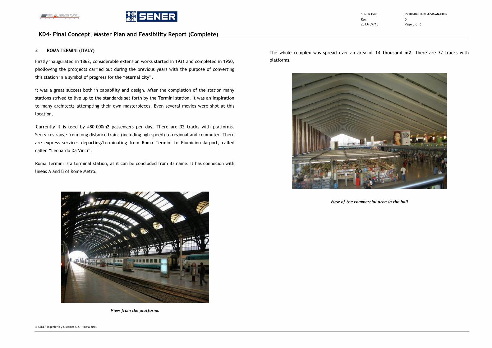
SENER Doc. P210G04-01-KD4-SR-AN-0002
Rev. 0
2013/09/13 Page 3 of 6
KD4- Final Concept, Master Plan and Feasibility Report (Complete)
SENER Ingeniería y Sistemas S.A. - India 2014
3 ROMA TERMINI (ITALY)
Firstly inaugurated in 1862, considerable extension works started in 1931 and completed in 1950,
phollowing the propjects carried out during the previous years with the purpose of converting
this station in a symbol of progress for the “eternal city”.
it was a great success both in capability and design. After the completion of the station many
stations strived to live up to the standards set forth by the Termini station. It was an inspiration
to many architects attempting their own masterpieces. Even several movies were shot at this
location.
Currently it is used by 480.000m2 passengers per day. There are 32 tracks with platforms.
Seervices range from long distance trains (including hgh-speed) to regional and commuter. There
are express services departing/terminating from Roma Termini to Fiumicino Airport, called
called “Leonardo Da Vinci”.
Roma Termini is a terminal station, as it can be concluded from its name. It has connecion with
lineas A and B of Rome Metro.
View from the platforms
The whole complex was spread over an area of 14 thousand m2. There are 32 tracks with
platforms.
View of the commercial area in the hall
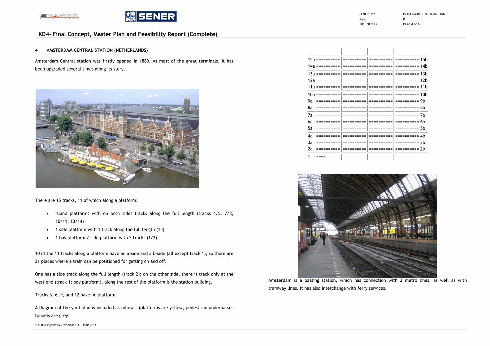
SENER Doc. P210G04-01-KD4-SR-AN-0002
Rev. 0
2013/09/13 Page 4 of 6
KD4- Final Concept, Master Plan and Feasibility Report (Complete)
SENER Ingeniería y Sistemas S.A. - India 2014
4 AMSTERDAM CENTRAL STATION (NETHERLANDS)
Amsterdam Central station was firstly opened in 1889. As most of the great terminals, it has
been upgraded several times along its story.
There are 15 tracks, 11 of which along a platform:
island platforms with on both sides tracks along the full length (tracks 4/5, 7/8,
10/11, 13/14)
1 side platform with 1 track along the full length (15)
1 bay platform / side platform with 2 tracks (1/2)
10 of the 11 tracks along a platform have an a-side and a b-side (all except track 1), so there are
21 places where a train can be positioned for getting on and off.
One has a side track along the full length (track 2); on the other side, there is track only at the
west end (track 1; bay platform), along the rest of the platform is the station building.
Tracks 3, 6, 9, and 12 have no platform.
A Diagram of the yard plan is included as follows: (platforms are yellow, pedestrian underpasses
tunnels are grey:
15a ==========
==========
==========
========== 15b
14a ========== ==========
==========
========== 14b
13a ========== ==========
==========
========== 13b
12a ========== ==========
==========
========== 12b
11a ========== ==========
==========
========== 11b
10a ========== ==========
==========
========== 10b
9a ========== ==========
==========
========== 9b
8a ========== ==========
==========
========== 8b
7a ========== ==========
==========
========== 7b
6a ========== ==========
==========
========== 6b
5a ========== ==========
==========
========== 5b
4a ========== ==========
==========
========== 4b
3a ========== ==========
==========
========== 3b
2a ========== ==========
==========
========== 2b
1 ====
Amsterdam is a passing station, which has connection with 3 metro lines, as well as with
tramway lines. It has also interchange with ferry services.
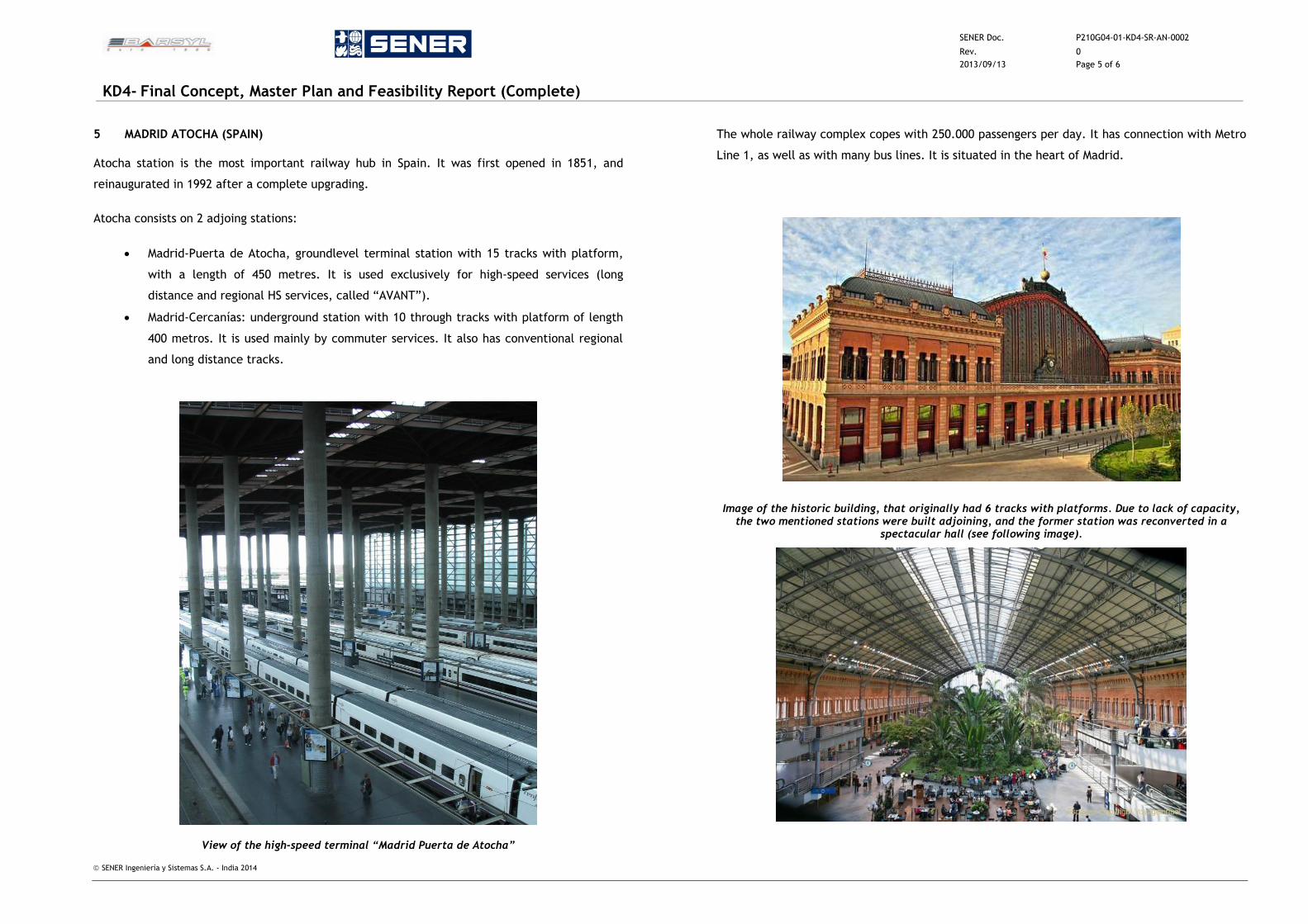
SENER Doc. P210G04-01-KD4-SR-AN-0002
Rev. 0
2013/09/13 Page 5 of 6
KD4- Final Concept, Master Plan and Feasibility Report (Complete)
SENER Ingeniería y Sistemas S.A. - India 2014
5 MADRID ATOCHA (SPAIN)
Atocha station is the most important railway hub in Spain. It was first opened in 1851, and
reinaugurated in 1992 after a complete upgrading.
Atocha consists on 2 adjoing stations:
Madrid-Puerta de Atocha, groundlevel terminal station with 15 tracks with platform,
with a length of 450 metres. It is used exclusively for high-speed services (long
distance and regional HS services, called “AVANT”).
Madrid-Cercanías: underground station with 10 through tracks with platform of length
400 metros. It is used mainly by commuter services. It also has conventional regional
and long distance tracks.
View of the high-speed terminal “Madrid Puerta de Atocha”
The whole railway complex copes with 250.000 passengers per day. It has connection with Metro
Line 1, as well as with many bus lines. It is situated in the heart of Madrid.
Image of the historic building, that originally had 6 tracks with platforms. Due to lack of capacity, the two mentioned stations were built adjoining, and the former station was reconverted in a
spectacular hall (see following image).
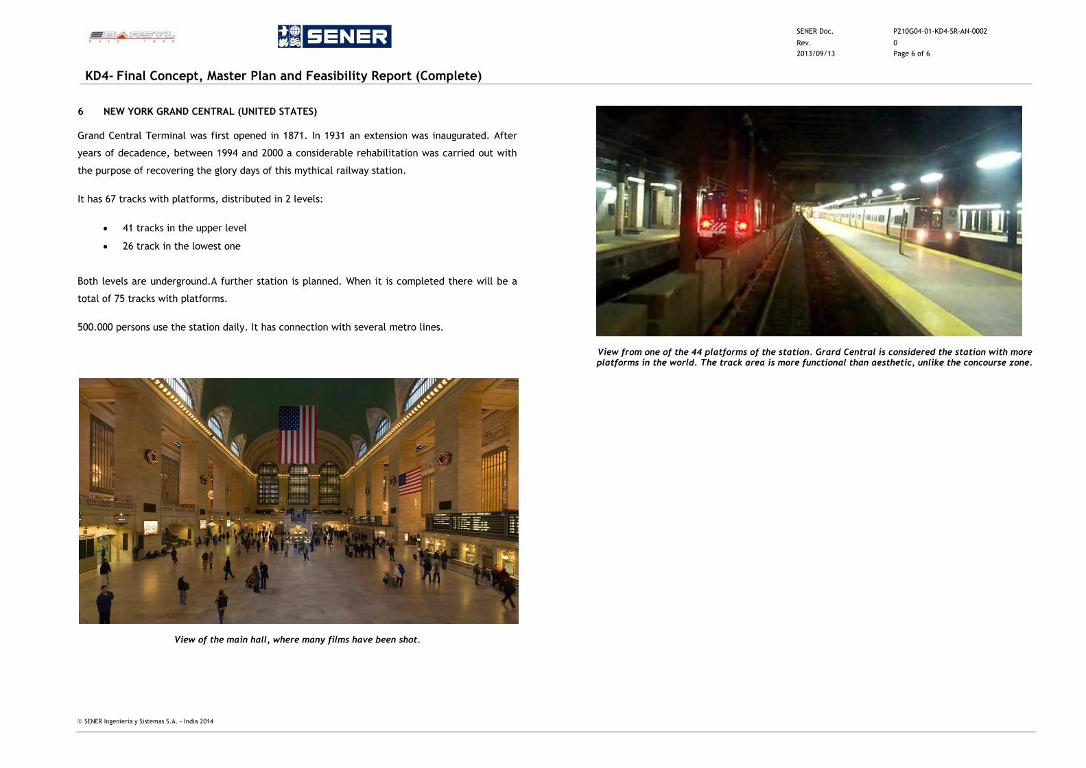
SENER Doc. P210G04-01-KD4-SR-AN-0002
Rev. 0
2013/09/13 Page 6 of 6
KD4- Final Concept, Master Plan and Feasibility Report (Complete)
SENER Ingeniería y Sistemas S.A. - India 2014
6 NEW YORK GRAND CENTRAL (UNITED STATES)
Grand Central Terminal was first opened in 1871. In 1931 an extension was inaugurated. After
years of decadence, between 1994 and 2000 a considerable rehabilitation was carried out with
the purpose of recovering the glory days of this mythical railway station.
It has 67 tracks with platforms, distributed in 2 levels:
41 tracks in the upper level
26 track in the lowest one
Both levels are underground.A further station is planned. When it is completed there will be a
total of 75 tracks with platforms.
500.000 persons use the station daily. It has connection with several metro lines.
View of the main hall, where many films have been shot.
View from one of the 44 platforms of the station. Grard Central is considered the station with more platforms in the world. The track area is more functional than aesthetic, unlike the concourse zone.
SENER Doc. P210G04-01-KD4-SR-AN-0003
Rev. 1
2016/07/15 Page 1 of 10
KD4- Final Concept, Master Plan and Feasibility Report (Complete)
SENER Ingeniería y Sistemas S.A. - India 2014
ANNEXURE 3 – PASSENGERS IN WAITING AREAS BASED ON THE NO. AND TYPE OF TRAINS ESTIMATED
SENER Doc. P210G04-01-KD4-SR-AN-0003
Rev. 1
2016/07/15 Page 2 of 10
KD4- Final Concept, Master Plan and Feasibility Report (Complete)
SENER Ingeniería y Sistemas S.A. - India 2014
1 INTRODUCTION
According to the Manual for Standards and Specifications for Railway Stations, the passengers
of the future Station of Bijwasan will have a conjunct of areas that allow them a comfortable
stay while they are waiting for the trains and doing all the actions previously to get on them,
since buying the tickets (in case they had arrive to the station without the ticket), to relaxing
calmly in a comfortable space until the depart of the trains
Four types of areas have been considered: Waiting and Lounge areas, Circulation areas, Ticketing
areas and Platforms; also four categories of passengers: unreserved, reserved, 1ª Class and
Executive Class. Special circulation areas are the Vertical Circular Elements (VCE) like Escalators,
Stairs and Lifts.
In all cases, the surfaces have been calculated based on the rates of level of service
(m2/passenger) established by the Manual, the previsions of the future demand based on the
Traffic Study and some hypothesis of passenger’s distribution according to the train’s share.
The surface needs have been established in order to accomplish the level of service indicated in
the Manual. Regarding the VCE, the special requirements for the evacuation of the trains have
also been taken into account.
Finally, the number of potential users of the station underground parking has been obtained to
determine the necessary capacity of that parking.
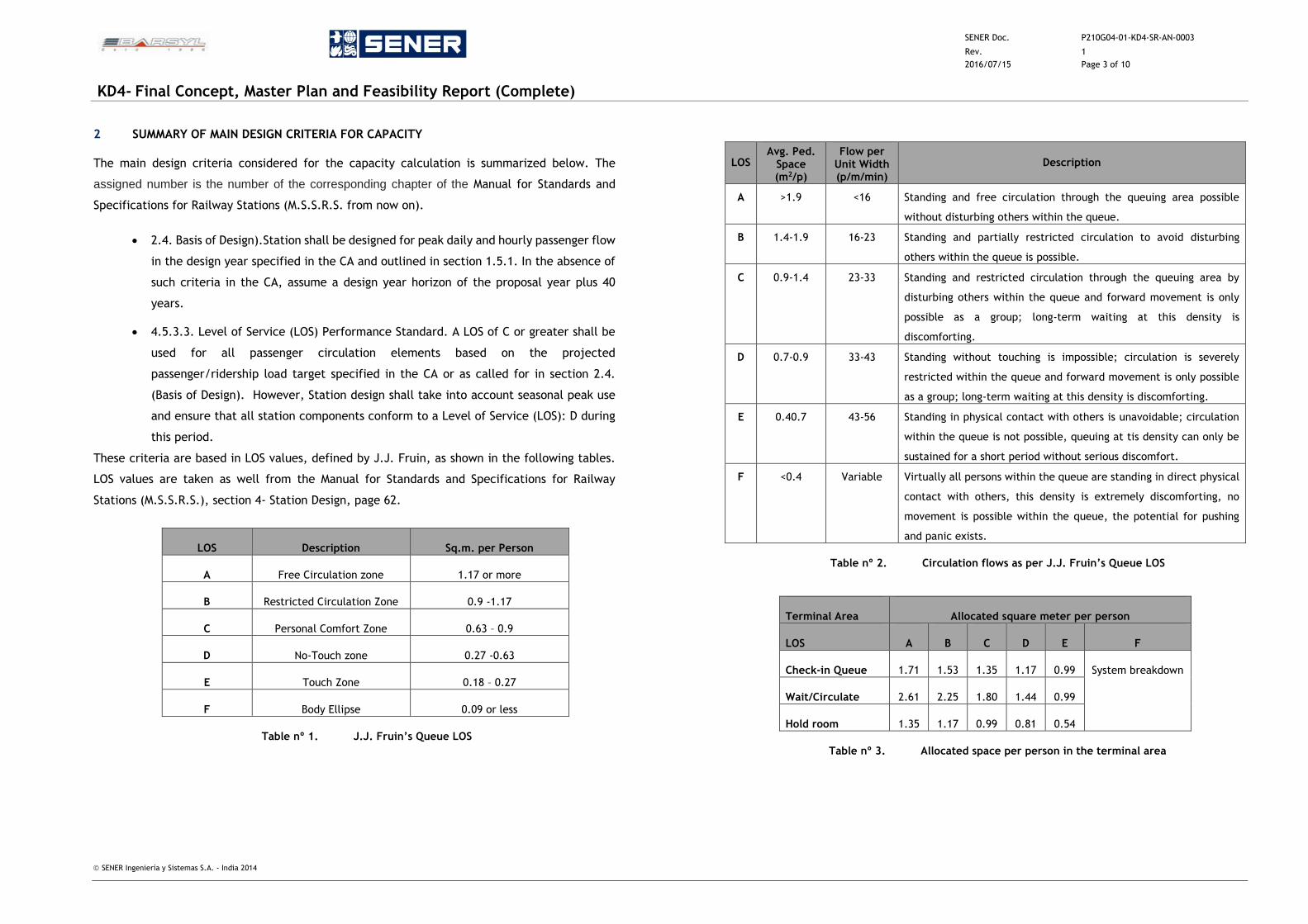
SENER Doc. P210G04-01-KD4-SR-AN-0003
Rev. 1
2016/07/15 Page 3 of 10
KD4- Final Concept, Master Plan and Feasibility Report (Complete)
SENER Ingeniería y Sistemas S.A. - India 2014
2 SUMMARY OF MAIN DESIGN CRITERIA FOR CAPACITY
The main design criteria considered for the capacity calculation is summarized below. The
assigned number is the number of the corresponding chapter of the Manual for Standards and
Specifications for Railway Stations (M.S.S.R.S. from now on).
2.4. Basis of Design).Station shall be designed for peak daily and hourly passenger flow
in the design year specified in the CA and outlined in section 1.5.1. In the absence of
such criteria in the CA, assume a design year horizon of the proposal year plus 40
years.
4.5.3.3. Level of Service (LOS) Performance Standard. A LOS of C or greater shall be
used for all passenger circulation elements based on the projected
passenger/ridership load target specified in the CA or as called for in section 2.4.
(Basis of Design). However, Station design shall take into account seasonal peak use
and ensure that all station components conform to a Level of Service (LOS): D during
this period.
These criteria are based in LOS values, defined by J.J. Fruin, as shown in the following tables.
LOS values are taken as well from the Manual for Standards and Specifications for Railway
Stations (M.S.S.R.S.), section 4- Station Design, page 62.
LOS Description Sq.m. per Person
A Free Circulation zone 1.17 or more
B Restricted Circulation Zone 0.9 -1.17
C Personal Comfort Zone 0.63 – 0.9
D No-Touch zone 0.27 -0.63
E Touch Zone 0.18 – 0.27
F Body Ellipse 0.09 or less
Table nº 1. J.J. Fruin’s Queue LOS
LOS Avg. Ped.
Space (m2/p)
Flow per Unit Width (p/m/min)
Description
A >1.9 <16 Standing and free circulation through the queuing area possible
without disturbing others within the queue.
B 1.4-1.9 16-23 Standing and partially restricted circulation to avoid disturbing
others within the queue is possible.
C 0.9-1.4 23-33 Standing and restricted circulation through the queuing area by
disturbing others within the queue and forward movement is only
possible as a group; long-term waiting at this density is
discomforting.
D 0.7-0.9 33-43 Standing without touching is impossible; circulation is severely
restricted within the queue and forward movement is only possible
as a group; long-term waiting at this density is discomforting.
E 0.40.7 43-56 Standing in physical contact with others is unavoidable; circulation
within the queue is not possible, queuing at tis density can only be
sustained for a short period without serious discomfort.
F <0.4 Variable Virtually all persons within the queue are standing in direct physical
contact with others, this density is extremely discomforting, no
movement is possible within the queue, the potential for pushing
and panic exists.
Table nº 2. Circulation flows as per J.J. Fruin’s Queue LOS
Terminal Area Allocated square meter per person
LOS A B C D E F
Check-in Queue 1.71 1.53 1.35 1.17 0.99 System breakdown
Wait/Circulate 2.61 2.25 1.80 1.44 0.99
Hold room 1.35 1.17 0.99 0.81 0.54
Table nº 3. Allocated space per person in the terminal area
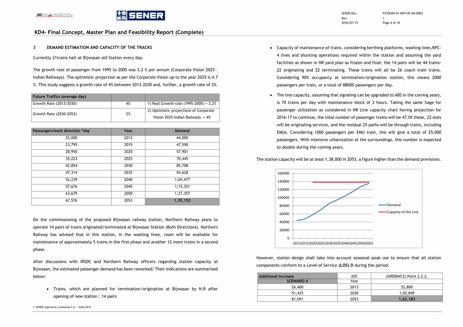
SENER Doc. P210G04-01-KD4-SR-AN-0003
Rev. 1
2016/07/15 Page 4 of 10
KD4- Final Concept, Master Plan and Feasibility Report (Complete)
SENER Ingeniería y Sistemas S.A. - India 2014
3 DEMAND ESTIMATION AND CAPACITY OF THE TRACKS
Currently 21trains halt at Bijwasan old Station every day.
The growth rate of passenger from 1995 to 2005 was 3.2 % per annum (Corporate Vision 2025 –
Indian Railways). The optimistic projection as per the Corporate Vision up to the year 2025 is 4.7
%. This study suggests a growth rate of 4% between 2013-2030 and, further, a growth rate of 2%.
Future Traffics (average day)
Growth Rate (2013-2030) 4% 1) Real Growth rate (1995-2005) = 3,2%
Growth Rate (2030-2053) 2% 2) Optimistic projections of Corporate
Vision 2025 Indian Railways = 4%
Passengers/each direction *day Year Demand
22,000 2013 44,000
23,795 2015 47,590
28,950 2020 57,901
35,223 2025 70,445
42,854 2030 85,708
47,314 2035 94,628
52,239 2040 1,04,477
57,676 2045 1,15,351
63,679 2050 1,27,357
67,576 2053 1,35,152
On the commissioning of the proposed Bijwasan railway station, Northern Railway plans to
operate 14 pairs of trains originated/terminated at Bijwasan Station (Both Directions). Northern
Railway has advised that in this station, in the washing lines, room will be available for
maintenance of approximately 5 trains in the first phase and another 12 more trains in a second
phase.
After discussions with IRSDC and Northern Railway officers regarding station capacity at
Bijwasan, the estimated passenger demand has been reworked; Their indications are summarised
below:
Trains, which are planned for termination/origination at Bijwasan by N.R after
opening of new station : 14 pairs
Capacity of maintenance of trains, considering berthing platforms, washing lines,RPC-
4 lines and shunting operations required within the station and assuming the yard
facilities as shown in NR yard plan as frozen and final: the 14 pairs will be 44 trains-
22 originating and 22 terminating. These trains will all be 26 coach train trains.
Considering 90% occupancy at termination/origination station, this means 2000
passengers per train, or a total of 88000 passengers per day.
The line capacity, assuming that signaling can be upgraded to ABS in the coming years,
is 70 trains per day with maintenance block of 2 hours. Taking the same %age for
passenger utilization as considered in NR Line capacity chart having projection for
2016-17 to continue, the total number of passenger trains will be 47.Of these, 22 slots
will be originating services, and the residual 25 paths will be through trains, including
EMUs. Considering 1000 passengers per EMU train, this will give a total of 25,000
passengers. With intensive urbanization at the surroundings, this number is expected
to double during the coming years.
The station capacity will be at least 1,38,000 in 2053, a figure higher than the demand previsions.
However, station design shall take into account seasonal peak use to ensure that all station
components conform to a Level of Service (LOS) D during the period.
Additional Increase 20% (ISRDBWCS) Point 2.2.2.
SCENARIO A Year
26,400 2013 52,800
51,425 2030 1,02,849
81,091 2053 1,62,183
0
20000
40000
60000
80000
100000
120000
140000
160000
2013201520202025203020352040204520502053
Demand
Capacity of the Line
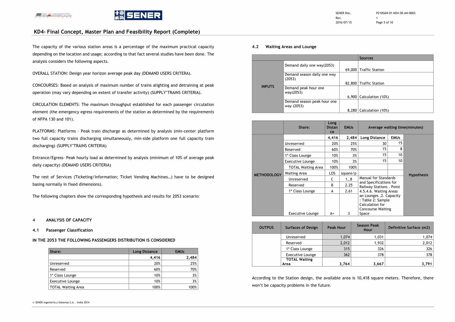
SENER Doc. P210G04-01-KD4-SR-AN-0003
Rev. 1
2016/07/15 Page 5 of 10
KD4- Final Concept, Master Plan and Feasibility Report (Complete)
SENER Ingeniería y Sistemas S.A. - India 2014
The capacity of the various station areas is a percentage of the maximum practical capacity
depending on the location and usage; according to that fact several studies have been done. The
analysis considers the following aspects.
OVERALL STATION: Design year horizon average peak day (DEMAND USERS CRITERA).
CONCOURSES: Based on analysis of maximum number of trains alighting and detraining at peak
operation (may vary depending on extent of transfer activity) (SUPPLY’TRAINS CRITERIA).
CIRCULATION ELEMENTS: The maximum throughput established for each passenger circulation
element (the emergency egress requirements of the station as determined by the requirements
of NFPA 130 and 101).
PLATFORMS: Platforms – Peak train discharge as determined by analysis (min-center platform
two full capacity trains discharging simultaneously, min-side platform one full capacity train
discharging) (SUPPLY’TRAINS CRITERIA)
Entrance/Egress- Peak hourly load as determined by analysis (minimum of 10% of average peak
daily capacity) (DEMAND USERS CRITERIA)
The rest of Services (Ticketing/Information; Ticket Vending Machines…) have to be designed
basing normally in fixed dimensions).
The following chapters show the corresponding hypothesis and results for 2053 scenario:
4 ANALYSIS OF CAPACITY
4.1 Passenger Classification
IN THE 2053 THE FOLLOWING PASSENGERS DISTRIBUTION IS CONSIDERED
Share: Long Distance EMUs
4,416 2,484
Unreserved 20% 25%
Reserved 60% 70%
1ª Class Lounge 10% 3%
Executive Lounge 10% 3%
TOTAL Waiting Area 100% 100%
4.2 Waiting Areas and Lounge
Sources
INPUTS
Demand daily one way(2053) 69,000 Traffic Station
Demand season daily one way (2053)
82,800 Traffic Station
Demand peak hour one way(2053)
6,900 Calculation (10%)
Demand season peak hour one way (2053)
8,280 Calculation (10%)
Share: Long
Distance
EMUs Average waiting time(minutes)
METHODOLOGY
4,416 2,484 Long Distance EMUs
Hypothesis
Unreserved 20% 25% 30 15
Reserved 60% 70% 15 8
1ª Class Lounge 10% 3% 15 10
Executive Lounge 10% 3% 15 10
TOTAL Waiting Area 100% 100%
Waiting Area LOS square/p
Unreserved C 1,.8 Manual for Standards and Specifications for Railway Stations . Point 4.5.4.6. Waiting Areas an Lounges .2. Capacity : Table 2: Sample Calculation for Concourse Waiting Space
Reserved B 2.25
1ª Class Lounge A 2.61
Executive Lounge A+ 3
OUTPUS Surfaces of Design Peak Hour Season Peak
Hour Definitive Surface (m2)
Unreserved 1,074 1,031 1,074
Reserved 2,012 1,932 2,012
1ª Class Lounge 315 326 326
Executive Lounge 362 378 378
TOTAL Waiting Area 3,764 3,667 3,791
According to the Station design, the available area is 10,418 square meters. Therefore, there
won’t be capacity problems in the future.
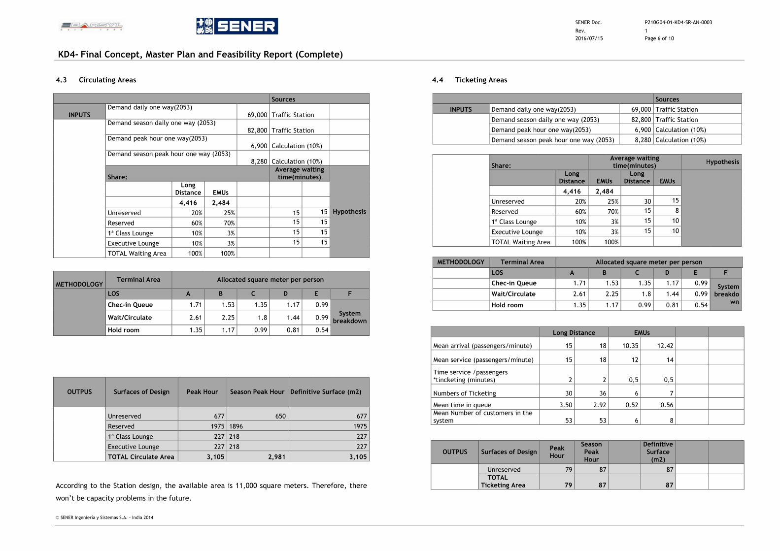
SENER Doc. P210G04-01-KD4-SR-AN-0003
Rev. 1
2016/07/15 Page 6 of 10
KD4- Final Concept, Master Plan and Feasibility Report (Complete)
SENER Ingeniería y Sistemas S.A. - India 2014
4.3 Circulating Areas
Sources
INPUTS Demand daily one way(2053)
69,000 Traffic Station
Demand season daily one way (2053) 82,800 Traffic Station
Demand peak hour one way(2053) 6,900 Calculation (10%)
Demand season peak hour one way (2053) 8,280 Calculation (10%)
Share: Average waiting time(minutes)
Hypothesis
Long Distance EMUs
4,416 2,484
Unreserved 20% 25% 15 15
Reserved 60% 70% 15 15
1ª Class Lounge 10% 3% 15 15
Executive Lounge 10% 3% 15 15
TOTAL Waiting Area 100% 100%
METHODOLOGY Terminal Area Allocated square meter per person
LOS A B C D E F
Chec-in Queue 1.71 1.53 1.35 1.17 0.99
System breakdown
Wait/Circulate 2.61 2.25 1.8 1.44 0.99
Hold room 1.35 1.17 0.99 0.81 0.54
OUTPUS Surfaces of Design Peak Hour Season Peak Hour Definitive Surface (m2)
Unreserved 677 650 677
Reserved 1975 1896 1975
1ª Class Lounge 227 218 227
Executive Lounge 227 218 227
TOTAL Circulate Area 3,105 2,981 3,105
According to the Station design, the available area is 11,000 square meters. Therefore, there
won’t be capacity problems in the future.
4.4 Ticketing Areas
Sources
INPUTS Demand daily one way(2053) 69,000 Traffic Station
Demand season daily one way (2053) 82,800 Traffic Station
Demand peak hour one way(2053) 6,900 Calculation (10%)
Demand season peak hour one way (2053) 8,280 Calculation (10%)
Share: Average waiting time(minutes)
Hypothesis
Long Distance EMUs
Long Distance EMUs
4,416 2,484
Unreserved 20% 25% 30 15
Reserved 60% 70% 15 8
1ª Class Lounge 10% 3% 15 10
Executive Lounge 10% 3% 15 10
TOTAL Waiting Area 100% 100%
METHODOLOGY Terminal Area Allocated square meter per person
LOS A B C D E F
Chec-in Queue 1.71 1.53 1.35 1.17 0.99 System
breakdown
Wait/Circulate 2.61 2.25 1.8 1.44 0.99
Hold room 1.35 1.17 0.99 0.81 0.54
Long Distance EMUs
Mean arrival (passengers/minute) 15 18 10.35 12.42
Mean service (passengers/minute) 15 18 12 14
Time service /passengers *tincketing (minutes) 2 2 0,5 0,5
Numbers of Ticketing 30 36 6 7
Mean time in queue 3.50 2.92 0.52 0.56 Mean Number of customers in the system 53 53 6 8
OUTPUS Surfaces of Design Peak Hour
Season Peak Hour
Definitive Surface
(m2)
Unreserved 79 87 87 TOTAL
Ticketing Area 79 87 87
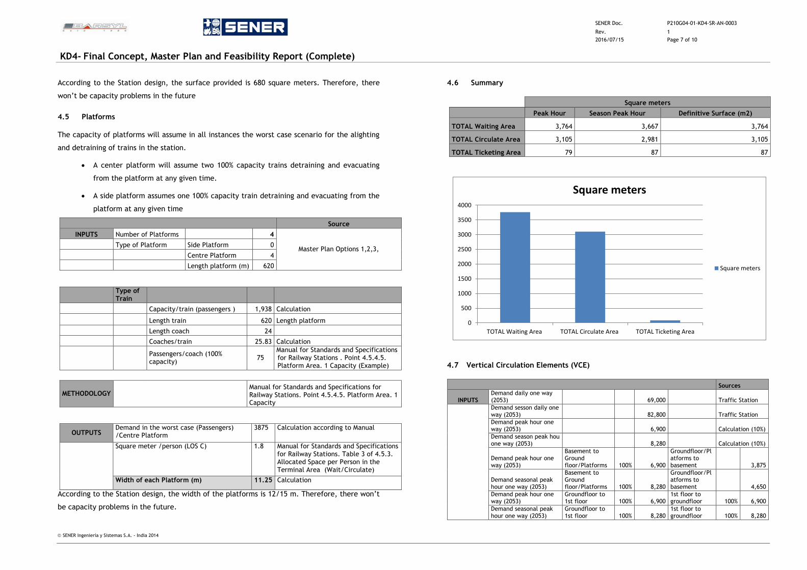
SENER Doc. P210G04-01-KD4-SR-AN-0003
Rev. 1
2016/07/15 Page 7 of 10
KD4- Final Concept, Master Plan and Feasibility Report (Complete)
SENER Ingeniería y Sistemas S.A. - India 2014
According to the Station design, the surface provided is 680 square meters. Therefore, there
won’t be capacity problems in the future
4.5 Platforms
The capacity of platforms will assume in all instances the worst case scenario for the alighting
and detraining of trains in the station.
A center platform will assume two 100% capacity trains detraining and evacuating
from the platform at any given time.
A side platform assumes one 100% capacity train detraining and evacuating from the
platform at any given time
Source
INPUTS Number of Platforms 4
Master Plan Options 1,2,3, Type of Platform Side Platform 0
Centre Platform 4
Length platform (m) 620
Type of Train
Capacity/train (passengers ) 1,938 Calculation
Length train 620 Length platform
Length coach 24
Coaches/train 25.83 Calculation
Passengers/coach (100% capacity)
75 Manual for Standards and Specifications for Railway Stations . Point 4.5.4.5. Platform Area. 1 Capacity (Example)
METHODOLOGY
Manual for Standards and Specifications for Railway Stations. Point 4.5.4.5. Platform Area. 1 Capacity
OUTPUTS Demand in the worst case (Passengers) /Centre Platform
3875 Calculation according to Manual
Square meter /person (LOS C) 1.8 Manual for Standards and Specifications for Railway Stations. Table 3 of 4.5.3. Allocated Space per Person in the Terminal Area (Wait/Circulate)
Width of each Platform (m) 11.25 Calculation
According to the Station design, the width of the platforms is 12/15 m. Therefore, there won’t
be capacity problems in the future.
4.6 Summary
Square meters
Peak Hour Season Peak Hour Definitive Surface (m2)
TOTAL Waiting Area 3,764 3,667 3,764
TOTAL Circulate Area 3,105 2,981 3,105
TOTAL Ticketing Area 79 87 87
4.7 Vertical Circulation Elements (VCE)
Sources
INPUTS Demand daily one way (2053) 69,000 Traffic Station
Demand sesson daily one way (2053) 82,800 Traffic Station
Demand peak hour one way (2053) 6,900 Calculation (10%)
Demand season peak hou one way (2053) 8,280 Calculation (10%)
Demand peak hour one way (2053)
Basement to Ground floor/Platforms 100% 6,900
Groundfloor/Platforms to basement 3,875
Demand seasonal peak hour one way (2053)
Basement to Ground floor/Platforms 100% 8,280
Groundfloor/Platforms to basement 4,650
Demand peak hour one way (2053)
Groundfloor to 1st floor 100% 6,900
1st floor to groundfloor 100% 6,900
Demand seasonal peak hour one way (2053)
Groundfloor to 1st floor 100% 8,280
1st floor to groundfloor 100% 8,280
0
500
1000
1500
2000
2500
3000
3500
4000
TOTAL Waiting Area TOTAL Circulate Area TOTAL Ticketing Area
Square meters
Square meters
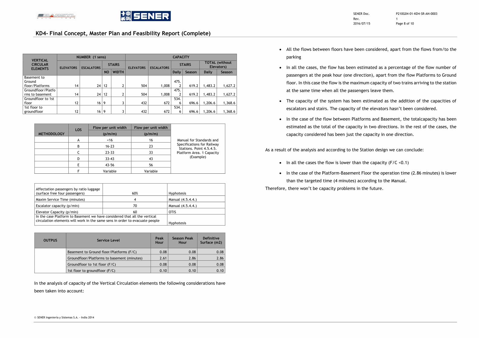
SENER Doc. P210G04-01-KD4-SR-AN-0003
Rev. 1
2016/07/15 Page 8 of 10
KD4- Final Concept, Master Plan and Feasibility Report (Complete)
SENER Ingeniería y Sistemas S.A. - India 2014
VERTICAL CIRCULAR ELEMENTS
NUMBER (1 sens) CAPACITY
ELEVATORS ESCALATORS STAIRS
ELEVATORS ESCALATORS STAIRS
TOTAL (without Elevators)
NO WIDTH Daily Season Daily Season
Basement to Ground floor/Platforms 14 24 12 2 504 1,008
475.2 619.2 1,483.2 1,627.2
Groundfloor/Platforms to basement 14 24 12 2 504 1,008
475.2 619.2 1,483.2 1,627.2
Groundfloor to 1st floor 12 16 9 3 432 672
534.6 696.6 1,206.6 1,368.6
1st floor to groundfloor 12 16 9 3 432 672
534.6 696.6 1,206.6 1,368.6
METHODOLOGY LOS
Flow per unit width Flow per unit width
Manual for Standards and Specifications for Railway Stations. Point 4.5.4.5.
Platform Area. 1 Capacity (Example)
(p/m/m) (p/m/m)
A <16 16
B 16-23 23
C 23-33 33
D 33-43 43
E 43-56 56
F Variable Variable
Affectation passengers by ratio luggage (surface free four passengers) 60% Hyphotesis
Maxim Service Time (minutes) 4 Manual (4.5.4.4.)
Escalator capacity (p/min) 70 Manual (4.5.4.4.)
Elevator Capacity (p/min) 60 OTIS
In the case Platform to Basement we have considered that all the vertical circulation elements will work in the same sens in order to evacuate people
Hyphotesis
OUTPUS Service Level Peak Hour
Season Peak Hour
Definitive Surface (m2)
Basement to Ground floor/Platforms (F/C) 0.08 0.08 0.08
Groundfloor/Platforms to basement (minutes) 2.61 2.86 2.86
Groundfloor to 1st floor (F/C) 0.08 0.08 0.08
1st floor to groundfloor (F/C) 0.10 0.10 0.10
In the analysis of capacity of the Vertical Circulation elements the following considerations have
been taken into account:
All the flows between floors have been considered, apart from the flows from/to the
parking
In all the cases, the flow has been estimated as a percentage of the flow number of
passengers at the peak hour (one direction), apart from the flow Platforms to Ground
floor. In this case the flow is the maximum capacity of two trains arriving to the station
at the same time when all the passengers leave them.
The capacity of the system has been estimated as the addition of the capacities of
escalators and stairs. The capacity of the elevators hasn’t been considered.
In the case of the flow between Platforms and Basement, the totalcapacity has been
estimated as the total of the capacity in two directions. In the rest of the cases, the
capacity considered has been just the capacity in one direction.
As a result of the analysis and according to the Station design we can conclude:
In all the cases the flow is lower than the capacity (F/C <0.1)
In the case of the Platform-Basement Floor the operation time (2.86 minutes) is lower
than the targeted time (4 minutes) according to the Manual.
Therefore, there won’t be capacity problems in the future.
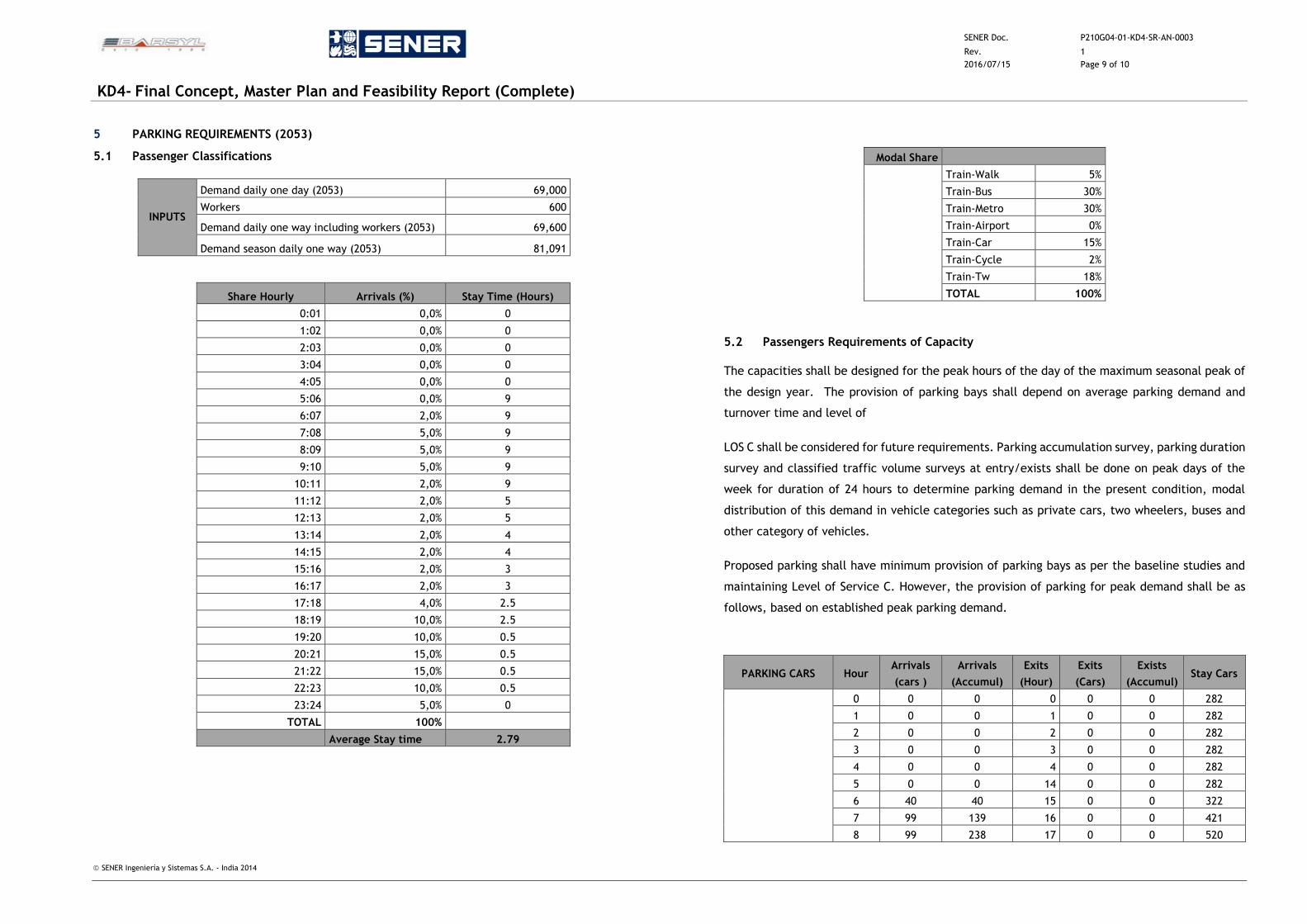
SENER Doc. P210G04-01-KD4-SR-AN-0003
Rev. 1
2016/07/15 Page 9 of 10
KD4- Final Concept, Master Plan and Feasibility Report (Complete)
SENER Ingeniería y Sistemas S.A. - India 2014
5 PARKING REQUIREMENTS (2053)
5.1 Passenger Classifications
INPUTS
Demand daily one day (2053) 69,000
Workers 600
Demand daily one way including workers (2053) 69,600
Demand season daily one way (2053) 81,091
Share Hourly Arrivals (%) Stay Time (Hours)
0:01 0,0% 0
1:02 0,0% 0
2:03 0,0% 0
3:04 0,0% 0
4:05 0,0% 0
5:06 0,0% 9
6:07 2,0% 9
7:08 5,0% 9
8:09 5,0% 9
9:10 5,0% 9
10:11 2,0% 9
11:12 2,0% 5
12:13 2,0% 5
13:14 2,0% 4
14:15 2,0% 4
15:16 2,0% 3
16:17 2,0% 3
17:18 4,0% 2.5
18:19 10,0% 2.5
19:20 10,0% 0.5
20:21 15,0% 0.5
21:22 15,0% 0.5
22:23 10,0% 0.5
23:24 5,0% 0
TOTAL 100%
Average Stay time 2.79
Modal Share
Train-Walk 5%
Train-Bus 30%
Train-Metro 30%
Train-Airport 0%
Train-Car 15%
Train-Cycle 2%
Train-Tw 18%
TOTAL 100%
5.2 Passengers Requirements of Capacity
The capacities shall be designed for the peak hours of the day of the maximum seasonal peak of
the design year. The provision of parking bays shall depend on average parking demand and
turnover time and level of
LOS C shall be considered for future requirements. Parking accumulation survey, parking duration
survey and classified traffic volume surveys at entry/exists shall be done on peak days of the
week for duration of 24 hours to determine parking demand in the present condition, modal
distribution of this demand in vehicle categories such as private cars, two wheelers, buses and
other category of vehicles.
Proposed parking shall have minimum provision of parking bays as per the baseline studies and
maintaining Level of Service C. However, the provision of parking for peak demand shall be as
follows, based on established peak parking demand.
PARKING CARS Hour Arrivals
(cars )
Arrivals
(Accumul)
Exits
(Hour)
Exits
(Cars)
Exists
(Accumul) Stay Cars
0 0 0 0 0 0 282
1 0 0 1 0 0 282
2 0 0 2 0 0 282
3 0 0 3 0 0 282
4 0 0 4 0 0 282
5 0 0 14 0 0 282
6 40 40 15 0 0 322
7 99 139 16 0 0 421
8 99 238 17 0 0 520
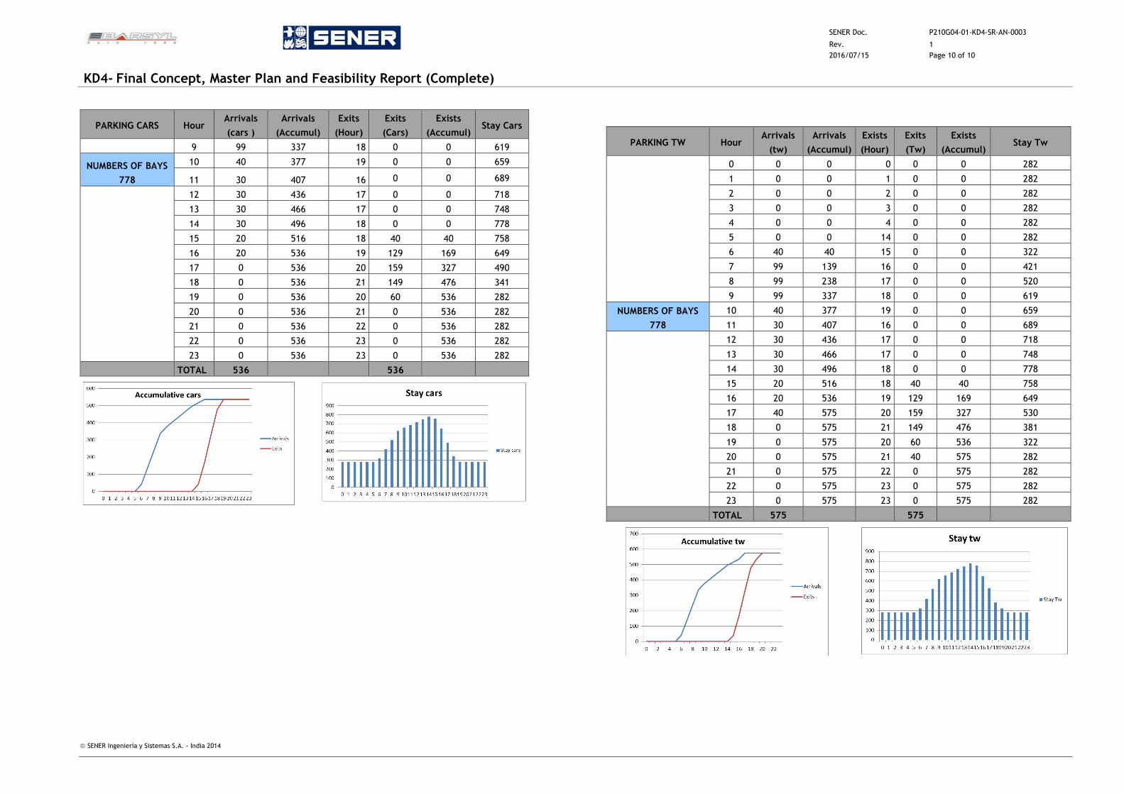
SENER Doc. P210G04-01-KD4-SR-AN-0003
Rev. 1
2016/07/15 Page 10 of 10
KD4- Final Concept, Master Plan and Feasibility Report (Complete)
SENER Ingeniería y Sistemas S.A. - India 2014
PARKING CARS Hour Arrivals
(cars )
Arrivals
(Accumul)
Exits
(Hour)
Exits
(Cars)
Exists
(Accumul) Stay Cars
9 99 337 18 0 0 619
NUMBERS OF BAYS
778
10 40 377 19 0 0 659
11 30 407 16 0 0 689
12 30 436 17 0 0 718
13 30 466 17 0 0 748
14 30 496 18 0 0 778
15 20 516 18 40 40 758
16 20 536 19 129 169 649
17 0 536 20 159 327 490
18 0 536 21 149 476 341
19 0 536 20 60 536 282
20 0 536 21 0 536 282
21 0 536 22 0 536 282
22 0 536 23 0 536 282
23 0 536 23 0 536 282
TOTAL 536 536
PARKING TW Hour Arrivals
(tw)
Arrivals
(Accumul)
Exists
(Hour)
Exits
(Tw)
Exists
(Accumul) Stay Tw
0 0 0 0 0 0 282
1 0 0 1 0 0 282
2 0 0 2 0 0 282
3 0 0 3 0 0 282
4 0 0 4 0 0 282
5 0 0 14 0 0 282
6 40 40 15 0 0 322
7 99 139 16 0 0 421
8 99 238 17 0 0 520
9 99 337 18 0 0 619
NUMBERS OF BAYS
778
10 40 377 19 0 0 659
11 30 407 16 0 0 689
12 30 436 17 0 0 718
13 30 466 17 0 0 748
14 30 496 18 0 0 778
15 20 516 18 40 40 758
16 20 536 19 129 169 649
17 40 575 20 159 327 530
18 0 575 21 149 476 381
19 0 575 20 60 536 322
20 0 575 21 40 575 282
21 0 575 22 0 575 282
22 0 575 23 0 575 282
23 0 575 23 0 575 282
TOTAL 575 575
SENER Doc. P210G04-01-KD4-SR-AN-0004
Rev. 0
2013/09/13 Page 1 of 4
KD4- Final Concept, Master Plan and Feasibility Report (Complete)
SENER Ingeniería y Sistemas S.A. - India 2014
ANNEXURE 4 - EVACUATION IN CASE OF FIRE. CRITERIA AND CALCULATION
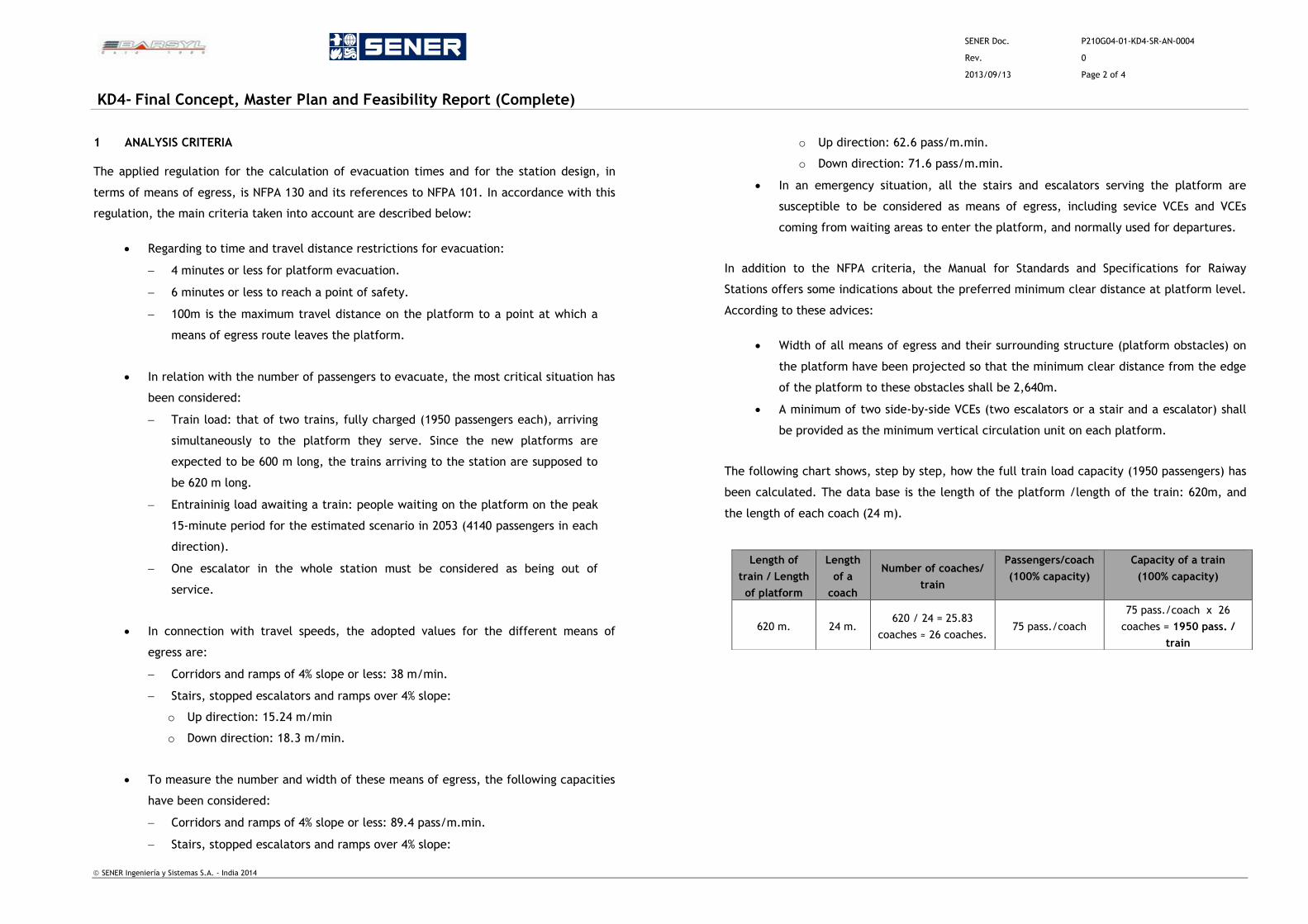
SENER Doc. P210G04-01-KD4-SR-AN-0004
Rev. 0
2013/09/13 Page 2 of 4
KD4- Final Concept, Master Plan and Feasibility Report (Complete)
SENER Ingeniería y Sistemas S.A. - India 2014
1 ANALYSIS CRITERIA
The applied regulation for the calculation of evacuation times and for the station design, in
terms of means of egress, is NFPA 130 and its references to NFPA 101. In accordance with this
regulation, the main criteria taken into account are described below:
Regarding to time and travel distance restrictions for evacuation:
4 minutes or less for platform evacuation.
6 minutes or less to reach a point of safety.
100m is the maximum travel distance on the platform to a point at which a
means of egress route leaves the platform.
In relation with the number of passengers to evacuate, the most critical situation has
been considered:
Train load: that of two trains, fully charged (1950 passengers each), arriving
simultaneously to the platform they serve. Since the new platforms are
expected to be 600 m long, the trains arriving to the station are supposed to
be 620 m long.
Entraininig load awaiting a train: people waiting on the platform on the peak
15-minute period for the estimated scenario in 2053 (4140 passengers in each
direction).
One escalator in the whole station must be considered as being out of
service.
In connection with travel speeds, the adopted values for the different means of
egress are:
Corridors and ramps of 4% slope or less: 38 m/min.
Stairs, stopped escalators and ramps over 4% slope:
o Up direction: 15.24 m/min
o Down direction: 18.3 m/min.
To measure the number and width of these means of egress, the following capacities
have been considered:
Corridors and ramps of 4% slope or less: 89.4 pass/m.min.
Stairs, stopped escalators and ramps over 4% slope:
o Up direction: 62.6 pass/m.min.
o Down direction: 71.6 pass/m.min.
In an emergency situation, all the stairs and escalators serving the platform are
susceptible to be considered as means of egress, including sevice VCEs and VCEs
coming from waiting areas to enter the platform, and normally used for departures.
In addition to the NFPA criteria, the Manual for Standards and Specifications for Raiway
Stations offers some indications about the preferred minimum clear distance at platform level.
According to these advices:
Width of all means of egress and their surrounding structure (platform obstacles) on
the platform have been projected so that the minimum clear distance from the edge
of the platform to these obstacles shall be 2,640m.
A minimum of two side-by-side VCEs (two escalators or a stair and a escalator) shall
be provided as the minimum vertical circulation unit on each platform.
The following chart shows, step by step, how the full train load capacity (1950 passengers) has
been calculated. The data base is the length of the platform /length of the train: 620m, and
the length of each coach (24 m).
Length of
train / Length
of platform
Length
of a
coach
Number of coaches/
train
Passengers/coach
(100% capacity)
Capacity of a train
(100% capacity)
620 m. 24 m. 620 / 24 = 25.83
coaches ≈ 26 coaches. 75 pass./coach
75 pass./coach x 26
coaches = 1950 pass. /
train
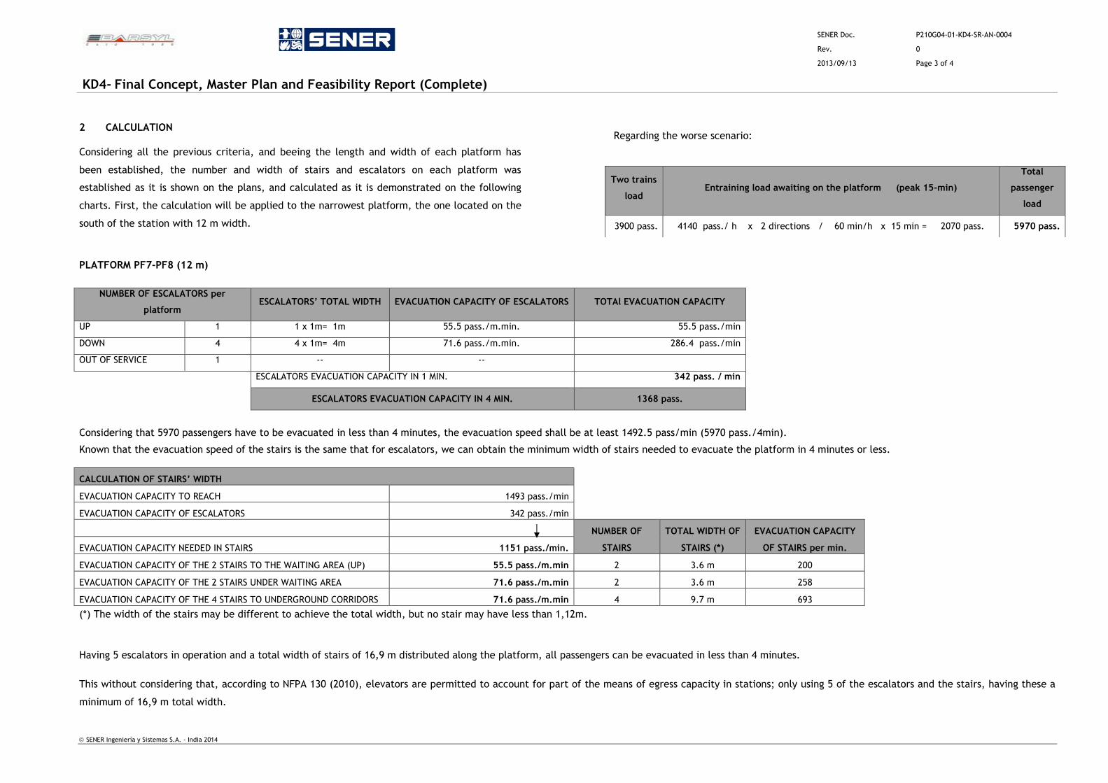
SENER Doc. P210G04-01-KD4-SR-AN-0004
Rev. 0
2013/09/13 Page 3 of 4
KD4- Final Concept, Master Plan and Feasibility Report (Complete)
SENER Ingeniería y Sistemas S.A. - India 2014
2 CALCULATION
Considering all the previous criteria, and beeing the length and width of each platform has
been established, the number and width of stairs and escalators on each platform was
established as it is shown on the plans, and calculated as it is demonstrated on the following
charts. First, the calculation will be applied to the narrowest platform, the one located on the
south of the station with 12 m width.
Regarding the worse scenario:
PLATFORM PF7-PF8 (12 m)
NUMBER OF ESCALATORS per
platform ESCALATORS’ TOTAL WIDTH EVACUATION CAPACITY OF ESCALATORS TOTAl EVACUATION CAPACITY
UP 1 1 x 1m= 1m 55.5 pass./m.min. 55.5 pass./min
DOWN 4 4 x 1m= 4m 71.6 pass./m.min. 286.4 pass./min
OUT OF SERVICE 1 -- --
ESCALATORS EVACUATION CAPACITY IN 1 MIN. 342 pass. / min
ESCALATORS EVACUATION CAPACITY IN 4 MIN. 1368 pass.
Considering that 5970 passengers have to be evacuated in less than 4 minutes, the evacuation speed shall be at least 1492.5 pass/min (5970 pass./4min).
Known that the evacuation speed of the stairs is the same that for escalators, we can obtain the minimum width of stairs needed to evacuate the platform in 4 minutes or less.
CALCULATION OF STAIRS’ WIDTH
EVACUATION CAPACITY TO REACH 1493 pass./min
EVACUATION CAPACITY OF ESCALATORS 342 pass./min
NUMBER OF
STAIRS
TOTAL WIDTH OF
STAIRS (*)
EVACUATION CAPACITY
OF STAIRS per min.
EVACUATION CAPACITY NEEDED IN STAIRS 1151 pass./min.
EVACUATION CAPACITY OF THE 2 STAIRS TO THE WAITING AREA (UP) 55.5 pass./m.min 2 3.6 m 200
EVACUATION CAPACITY OF THE 2 STAIRS UNDER WAITING AREA 71.6 pass./m.min 2 3.6 m 258
EVACUATION CAPACITY OF THE 4 STAIRS TO UNDERGROUND CORRIDORS 71.6 pass./m.min 4 9.7 m 693
(*) The width of the stairs may be different to achieve the total width, but no stair may have less than 1,12m.
Having 5 escalators in operation and a total width of stairs of 16,9 m distributed along the platform, all passengers can be evacuated in less than 4 minutes.
This without considering that, according to NFPA 130 (2010), elevators are permitted to account for part of the means of egress capacity in stations; only using 5 of the escalators and the stairs, having these a
minimum of 16,9 m total width.
Two trains
load Entraining load awaiting on the platform (peak 15-min)
Total
passenger
load
3900 pass. 4140 pass./ h x 2 directions / 60 min/h x 15 min = 2070 pass. 5970 pass.
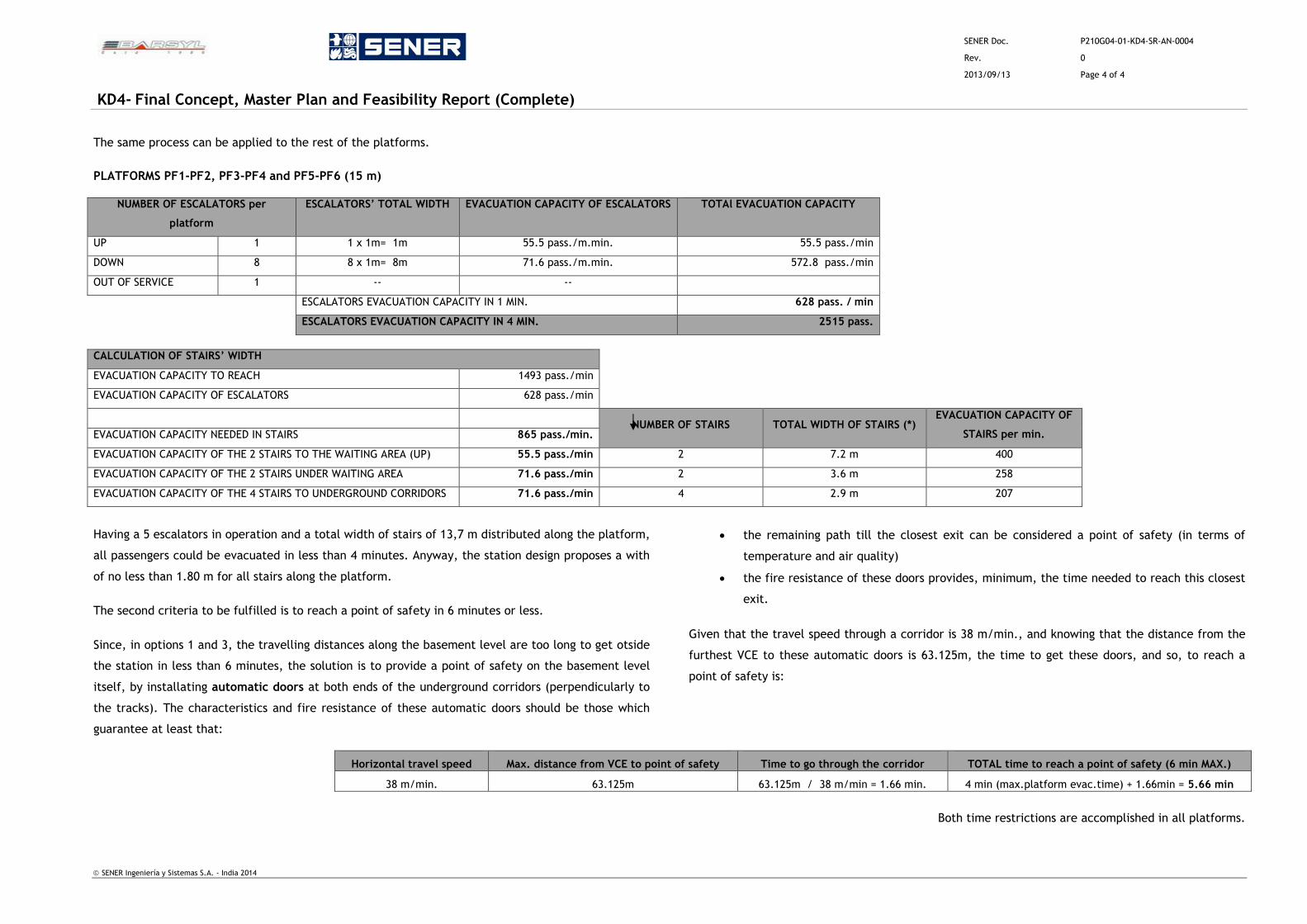
SENER Doc. P210G04-01-KD4-SR-AN-0004
Rev. 0
2013/09/13 Page 4 of 4
KD4- Final Concept, Master Plan and Feasibility Report (Complete)
SENER Ingeniería y Sistemas S.A. - India 2014
The same process can be applied to the rest of the platforms.
PLATFORMS PF1-PF2, PF3-PF4 and PF5-PF6 (15 m)
NUMBER OF ESCALATORS per
platform
ESCALATORS’ TOTAL WIDTH EVACUATION CAPACITY OF ESCALATORS TOTAl EVACUATION CAPACITY
UP 1 1 x 1m= 1m 55.5 pass./m.min. 55.5 pass./min
DOWN 8 8 x 1m= 8m 71.6 pass./m.min. 572.8 pass./min
OUT OF SERVICE 1 -- --
ESCALATORS EVACUATION CAPACITY IN 1 MIN. 628 pass. / min
ESCALATORS EVACUATION CAPACITY IN 4 MIN. 2515 pass.
CALCULATION OF STAIRS’ WIDTH
EVACUATION CAPACITY TO REACH 1493 pass./min
EVACUATION CAPACITY OF ESCALATORS 628 pass./min
NUMBER OF STAIRS TOTAL WIDTH OF STAIRS (*)
EVACUATION CAPACITY OF
STAIRS per min.
EVACUATION CAPACITY NEEDED IN STAIRS 865 pass./min.
EVACUATION CAPACITY OF THE 2 STAIRS TO THE WAITING AREA (UP) 55.5 pass./min 2 7.2 m 400
EVACUATION CAPACITY OF THE 2 STAIRS UNDER WAITING AREA 71.6 pass./min 2 3.6 m 258
EVACUATION CAPACITY OF THE 4 STAIRS TO UNDERGROUND CORRIDORS 71.6 pass./min 4 2.9 m 207
Having a 5 escalators in operation and a total width of stairs of 13,7 m distributed along the platform,
all passengers could be evacuated in less than 4 minutes. Anyway, the station design proposes a with
of no less than 1.80 m for all stairs along the platform.
The second criteria to be fulfilled is to reach a point of safety in 6 minutes or less.
Since, in options 1 and 3, the travelling distances along the basement level are too long to get otside
the station in less than 6 minutes, the solution is to provide a point of safety on the basement level
itself, by installating automatic doors at both ends of the underground corridors (perpendicularly to
the tracks). The characteristics and fire resistance of these automatic doors should be those which
guarantee at least that:
the remaining path till the closest exit can be considered a point of safety (in terms of
temperature and air quality)
the fire resistance of these doors provides, minimum, the time needed to reach this closest
exit.
Given that the travel speed through a corridor is 38 m/min., and knowing that the distance from the
furthest VCE to these automatic doors is 63.125m, the time to get these doors, and so, to reach a
point of safety is:
Horizontal travel speed Max. distance from VCE to point of safety Time to go through the corridor TOTAL time to reach a point of safety (6 min MAX.)
38 m/min. 63.125m 63.125m / 38 m/min = 1.66 min. 4 min (max.platform evac.time) + 1.66min = 5.66 min
Both time restrictions are accomplished in all platforms.

SENER Doc. P210G04-01-KD4-SR-AN-0005
Rev. 1
2016/07/15 Page 1 of 4
KD4- Final Concept, Master Plan and Feasibility Report (Complete)
SENER Ingeniería y Sistemas S.A. - India 2014
ANNEXURE 5 – BOUNDARY CONSTRAINTS
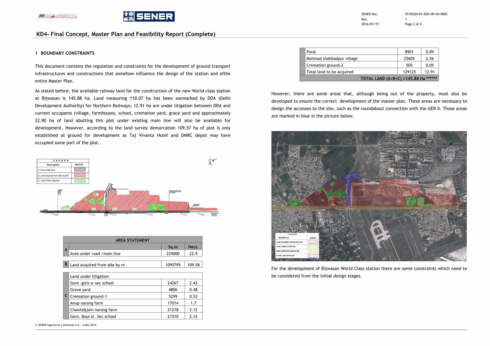
SENER Doc. P210G04-01-KD4-SR-AN-0005
Rev. 1
2016/07/15 Page 2 of 4
KD4- Final Concept, Master Plan and Feasibility Report (Complete)
SENER Ingeniería y Sistemas S.A. - India 2014
1 BOUNDARY CONSTRAINTS
This document contains the regulation and constraints for the development of ground transport
infrastructures and constructions that somehow influence the design of the station and ofthe
entire Master Plan.
As stated before, the available railway land for the construction of the new World class station
at Bijwasan is 145.88 ha. Land measuring 110.07 ha has been earmarked by DDA (Delhi
Development Authority) for Northern Railways; 12.91 ha are under litigation between DDA and
current occupants (village, farmhouses, school, cremation yard, grace yard and approximately
22.90 ha of land abutting this plot under existing main line will also be available for
development. However, according to the land survey demarcation 109.57 ha of plot is only
established at ground for development as Taj Vivanta Hotel and DMRC depot may have
occupied some part of the plot.
AREA STATEMENT
A Sq.m Hect.
Area under road /main line 229000 22.9
B Land acquired from dda by nr 1095795 109.58
C
Land under litigation
Govt .girls sr sec school 24267 2.43
Grave yard 4806 0.48
Cremation ground-1 5299 0.53
Anup narang farm 17014 1.7
Chawla&jain narang farm 21218 2.12
Govt. Boys sr. Sec school 21510 2.15
Pond 8901 0.89
Mohmad shahbadpur village 25605 2.56
Cremation ground-2 505 0.05
Total land to be acquired 129125 12.91
TOTAL LAND (A+B+C) =145.88 Ha ******
However, there are some areas that, although being out of the property, must also be
developed to ensure the correct development of the master plan. These areas are necessary to
design the accesses to the site, such as the roundabout connection with the UER II. Those areas
are marked in blue in the picture below.
For the development of Bijwasan World Class station there are some constraints which need to
be considered from the initial design stages.
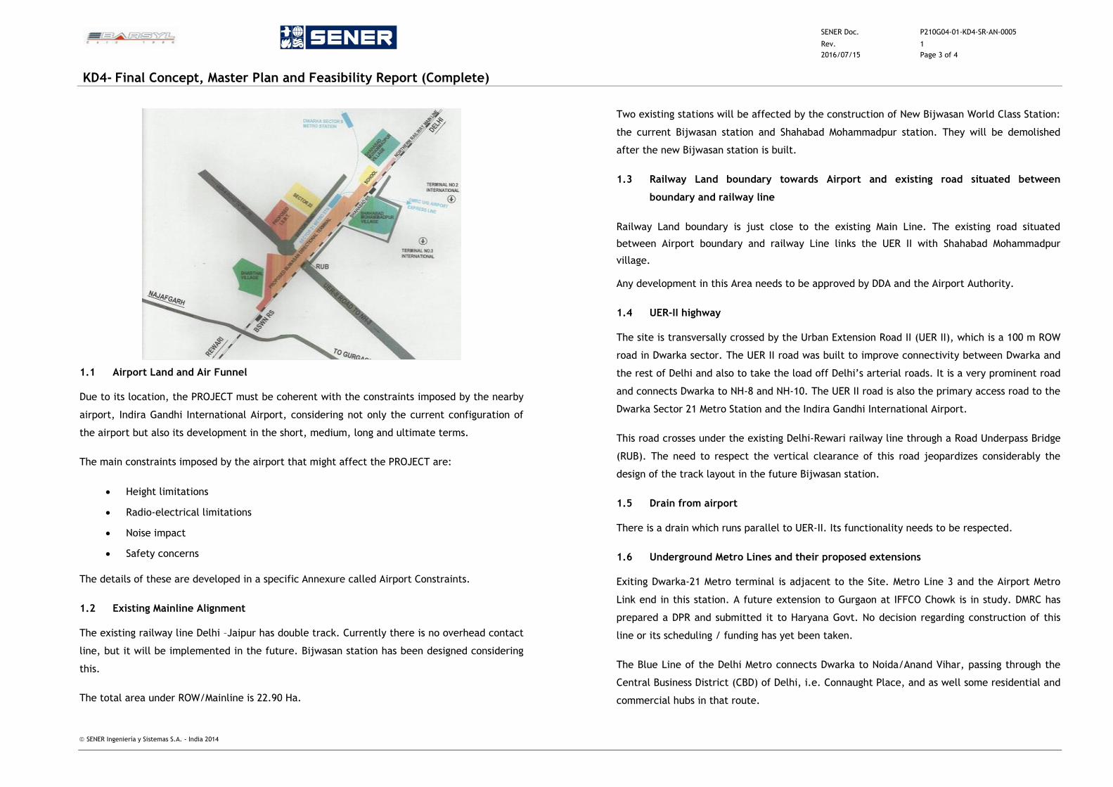
SENER Doc. P210G04-01-KD4-SR-AN-0005
Rev. 1
2016/07/15 Page 3 of 4
KD4- Final Concept, Master Plan and Feasibility Report (Complete)
SENER Ingeniería y Sistemas S.A. - India 2014
1.1 Airport Land and Air Funnel
Due to its location, the PROJECT must be coherent with the constraints imposed by the nearby
airport, Indira Gandhi International Airport, considering not only the current configuration of
the airport but also its development in the short, medium, long and ultimate terms.
The main constraints imposed by the airport that might affect the PROJECT are:
Height limitations
Radio-electrical limitations
Noise impact
Safety concerns
The details of these are developed in a specific Annexure called Airport Constraints.
1.2 Existing Mainline Alignment
The existing railway line Delhi –Jaipur has double track. Currently there is no overhead contact
line, but it will be implemented in the future. Bijwasan station has been designed considering
this.
The total area under ROW/Mainline is 22.90 Ha.
Two existing stations will be affected by the construction of New Bijwasan World Class Station:
the current Bijwasan station and Shahabad Mohammadpur station. They will be demolished
after the new Bijwasan station is built.
1.3 Railway Land boundary towards Airport and existing road situated between
boundary and railway line
Railway Land boundary is just close to the existing Main Line. The existing road situated
between Airport boundary and railway Line links the UER II with Shahabad Mohammadpur
village.
Any development in this Area needs to be approved by DDA and the Airport Authority.
1.4 UER-II highway
The site is transversally crossed by the Urban Extension Road II (UER II), which is a 100 m ROW
road in Dwarka sector. The UER II road was built to improve connectivity between Dwarka and
the rest of Delhi and also to take the load off Delhi’s arterial roads. It is a very prominent road
and connects Dwarka to NH-8 and NH-10. The UER II road is also the primary access road to the
Dwarka Sector 21 Metro Station and the Indira Gandhi International Airport.
This road crosses under the existing Delhi-Rewari railway line through a Road Underpass Bridge
(RUB). The need to respect the vertical clearance of this road jeopardizes considerably the
design of the track layout in the future Bijwasan station.
1.5 Drain from airport
There is a drain which runs parallel to UER-II. Its functionality needs to be respected.
1.6 Underground Metro Lines and their proposed extensions
Exiting Dwarka-21 Metro terminal is adjacent to the Site. Metro Line 3 and the Airport Metro
Link end in this station. A future extension to Gurgaon at IFFCO Chowk is in study. DMRC has
prepared a DPR and submitted it to Haryana Govt. No decision regarding construction of this
line or its scheduling / funding has yet been taken.
The Blue Line of the Delhi Metro connects Dwarka to Noida/Anand Vihar, passing through the
Central Business District (CBD) of Delhi, i.e. Connaught Place, and as well some residential and
commercial hubs in that route.
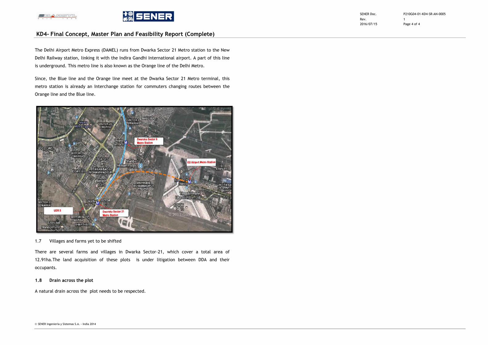
SENER Doc. P210G04-01-KD4-SR-AN-0005
Rev. 1
2016/07/15 Page 4 of 4
KD4- Final Concept, Master Plan and Feasibility Report (Complete)
SENER Ingeniería y Sistemas S.A. - India 2014
The Delhi Airport Metro Express (DAMEL) runs from Dwarka Sector 21 Metro station to the New
Delhi Railway station, linking it with the Indira Gandhi International airport. A part of this line
is underground. This metro line is also known as the Orange line of the Delhi Metro.
Since, the Blue line and the Orange line meet at the Dwarka Sector 21 Metro terminal, this
metro station is already an Interchange station for commuters changing routes between the
Orange line and the Blue line.
1.7 Villages and farms yet to be shifted
There are several farms and villages in Dwarka Sector-21, which cover a total area of
12.91ha.The land acquisition of these plots is under litigation between DDA and their
occupants.
1.8 Drain across the plot
A natural drain across the plot needs to be respected.

SENER Doc. P210G04-01-KD4-SR-AN-0006
Rev. 0
2013/09/13 Page 1 of 3
KD4- Final Concept, Master Plan and Feasibility Report (Complete)
SENER Ingeniería y Sistemas S.A. - India 2014
ANNEXURE 6 – SUSTAINABILITY
SENER Doc. P210G04-01-KD4-SR-AN-0006
Rev. 0
2013/09/13 Page 2 of 3
KD4- Final Concept, Master Plan and Feasibility Report (Complete)
SENER Ingeniería y Sistemas S.A. - India 2014
1 INDIAN GREEN BUILDING COUNCIL (IGBC). DESCRIPTION
In terms of sustainability, the criteria applied on the project is that of the Indian Green Building
Council (IGBC). According to IGBC, “A green building is one which uses less water, optimizes
energy efficiency, conserves natural resources, generates less waste and provides healthier
spaces for occupants, as compared to a conventional building”. This will be the key principle on
the whole proposal.
2 LEED CHECK LIST. INDIA CERTIFICATION LEVELS.
The parameters IGBC measures are based on LEED check list, adapted to India circumstances and
context. The final aim of this check list is to be awarded with the LEED Certificate.
The factors (Credits) LEED measures in India can be grouped into 6 chapters. Besides these
Credits, some Prerequisites on each chapter are required to get the LEED Certificate.
During the check process, each Credit is assigned a score (points), so that the highest the final
score is, the most prestigious the LEED Certification is awarded.
The following charts resume the Credits and Prerequisites which are measured according to LEED
check list. The third column gathers the maximum score for each credit.
I. SUSTAINABLE SITES (13 possible points)
Prerequisite: Erosion & Sedimentation Control Required
Credit 1 Site Selection 1 point
Credit 2 Development Density & Community Connectivity 1 point
Credit 3 Brownfield Redevelopment 1 point
Credit 4.1 Alternative Transportation, Public Transportation Access 1 point
Credit 4.2 Alternatie Transportation, Alternative Fuel Refueling Stations 1 point
Credit 4.3 Alternative Transportation, Parking Capacity 1 point
Credit 5.1 Reduced Site Disturbance, Protect or Restore Open Space 1 point
Credit 5.2 Reduced Site Disturbance, Development Footprint 1 point
Credit 6.1 Stormwater Design, Quantity Control 1 point
Credit 6.2 Stormwater Design, Quality Control 1 point
Credit 7.1 Heat Island Effect Non Roof 1 point
Credit 7.2 Heat Island Effect Roof 1 point
Credit 8 Light Pollution Reduction 1 point
II. WATER EFFICIENCY (6 possible points)
Credit 1.1 Water Efficient Landscaping: reduce by 50% 1 point
Credit 1.2 Water Efficient Landscaping. No Potable Use or No Irrigation. 1 point
Credit 2.1 Water Efficiency in Air-conditioning System: reduce by 50% 1 point
Credit 3 Innovative Wastewater Technologies. 1 point
Credit 4.1 Water Use Rrduction: 20% reduction. 1 point
Credit 4.2 Water Use Reduction: 30% reduction. 1 point
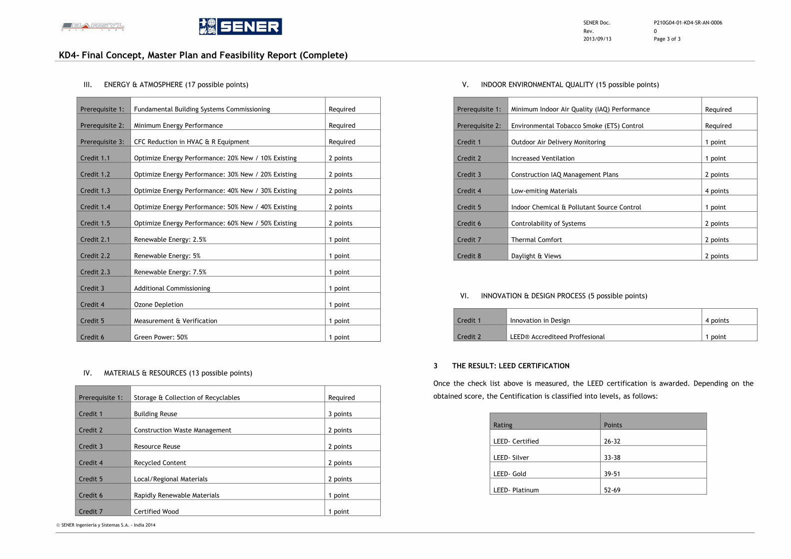
SENER Doc. P210G04-01-KD4-SR-AN-0006
Rev. 0
2013/09/13 Page 3 of 3
KD4- Final Concept, Master Plan and Feasibility Report (Complete)
SENER Ingeniería y Sistemas S.A. - India 2014
III. ENERGY & ATMOSPHERE (17 possible points)
Prerequisite 1: Fundamental Building Systems Commissioning Required
Prerequisite 2: Minimum Energy Performance Required
Prerequisite 3: CFC Reduction in HVAC & R Equipment Required
Credit 1.1 Optimize Energy Performance: 20% New / 10% Existing 2 points
Credit 1.2 Optimize Energy Performance: 30% New / 20% Existing 2 points
Credit 1.3 Optimize Energy Performance: 40% New / 30% Existing 2 points
Credit 1.4 Optimize Energy Performance: 50% New / 40% Existing 2 points
Credit 1.5 Optimize Energy Performance: 60% New / 50% Existing 2 points
Credit 2.1 Renewable Energy: 2.5% 1 point
Credit 2.2 Renewable Energy: 5% 1 point
Credit 2.3 Renewable Energy: 7.5% 1 point
Credit 3 Additional Commissioning 1 point
Credit 4 Ozone Depletion 1 point
Credit 5 Measurement & Verification 1 point
Credit 6 Green Power: 50% 1 point
IV. MATERIALS & RESOURCES (13 possible points)
Prerequisite 1: Storage & Collection of Recyclables Required
Credit 1 Building Reuse 3 points
Credit 2 Construction Waste Management 2 points
Credit 3 Resource Reuse 2 points
Credit 4 Recycled Content 2 points
Credit 5 Local/Regional Materials 2 points
Credit 6 Rapidly Renewable Materials 1 point
Credit 7 Certified Wood 1 point
V. INDOOR ENVIRONMENTAL QUALITY (15 possible points)
Prerequisite 1: Minimum Indoor Air Quality (IAQ) Performance Required
Prerequisite 2: Environmental Tobacco Smoke (ETS) Control Required
Credit 1 Outdoor Air Delivery Monitoring 1 point
Credit 2 Increased Ventilation 1 point
Credit 3 Construction IAQ Management Plans 2 points
Credit 4 Low-emiting Materials 4 points
Credit 5 Indoor Chemical & Pollutant Source Control 1 point
Credit 6 Controlability of Systems 2 points
Credit 7 Thermal Comfort 2 points
Credit 8 Daylight & Views 2 points
VI. INNOVATION & DESIGN PROCESS (5 possible points)
Credit 1 Innovation in Design 4 points
Credit 2 LEED® Accrediteed Proffesional 1 point
3 THE RESULT: LEED CERTIFICATION
Once the check list above is measured, the LEED certification is awarded. Depending on the
obtained score, the Centification is classified into levels, as follows:
Rating Points
LEED- Certified 26-32
LEED- Silver 33-38
LEED- Gold 39-51
LEED- Platinum 52-69
SENER Doc. P210G04-01-KD4-SR-AN-0007
Rev. 0
2013/09/13 Page 1 of 4
KD4- Final Concept, Master Plan and Feasibility Report (Complete)
SENER Ingeniería y Sistemas S.A. - India 2014
ANNEXURE 7 – AIRPORT CONSTRAINTS
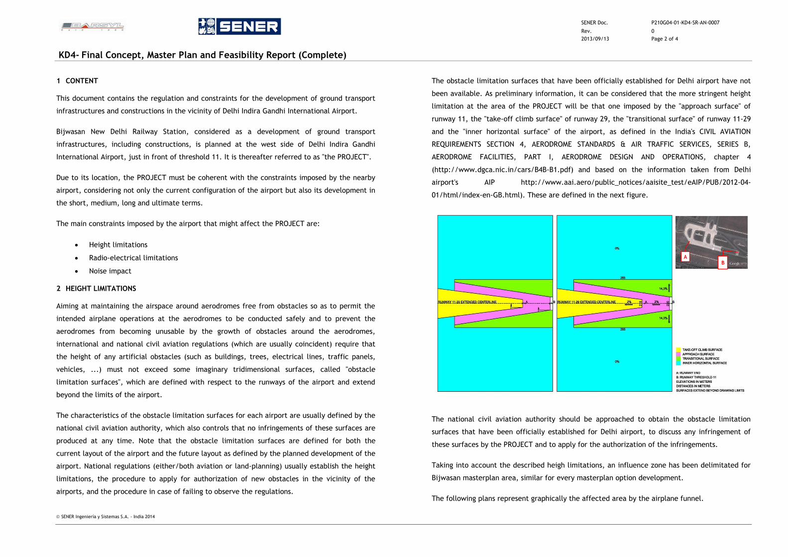
SENER Doc. P210G04-01-KD4-SR-AN-0007
Rev. 0
2013/09/13 Page 2 of 4
KD4- Final Concept, Master Plan and Feasibility Report (Complete)
SENER Ingeniería y Sistemas S.A. - India 2014
1 CONTENT
This document contains the regulation and constraints for the development of ground transport
infrastructures and constructions in the vicinity of Delhi Indira Gandhi International Airport.
Bijwasan New Delhi Railway Station, considered as a development of ground transport
infrastructures, including constructions, is planned at the west side of Delhi Indira Gandhi
International Airport, just in front of threshold 11. It is thereafter referred to as "the PROJECT".
Due to its location, the PROJECT must be coherent with the constraints imposed by the nearby
airport, considering not only the current configuration of the airport but also its development in
the short, medium, long and ultimate terms.
The main constraints imposed by the airport that might affect the PROJECT are:
Height limitations
Radio-electrical limitations
Noise impact
2 HEIGHT LIMITATIONS
Aiming at maintaining the airspace around aerodromes free from obstacles so as to permit the
intended airplane operations at the aerodromes to be conducted safely and to prevent the
aerodromes from becoming unusable by the growth of obstacles around the aerodromes,
international and national civil aviation regulations (which are usually coincident) require that
the height of any artificial obstacles (such as buildings, trees, electrical lines, traffic panels,
vehicles, ...) must not exceed some imaginary tridimensional surfaces, called "obstacle
limitation surfaces", which are defined with respect to the runways of the airport and extend
beyond the limits of the airport.
The characteristics of the obstacle limitation surfaces for each airport are usually defined by the
national civil aviation authority, which also controls that no infringements of these surfaces are
produced at any time. Note that the obstacle limitation surfaces are defined for both the
current layout of the airport and the future layout as defined by the planned development of the
airport. National regulations (either/both aviation or land-planning) usually establish the height
limitations, the procedure to apply for authorization of new obstacles in the vicinity of the
airports, and the procedure in case of failing to observe the regulations.
The obstacle limitation surfaces that have been officially established for Delhi airport have not
been available. As preliminary information, it can be considered that the more stringent height
limitation at the area of the PROJECT will be that one imposed by the "approach surface" of
runway 11, the "take-off climb surface" of runway 29, the "transitional surface" of runway 11-29
and the "inner horizontal surface" of the airport, as defined in the India's CIVIL AVIATION
REQUIREMENTS SECTION 4, AERODROME STANDARDS & AIR TRAFFIC SERVICES, SERIES B,
AERODROME FACILITIES, PART I, AERODROME DESIGN AND OPERATIONS, chapter 4
(http://www.dgca.nic.in/cars/B4B-B1.pdf) and based on the information taken from Delhi
airport's AIP http://www.aai.aero/public_notices/aaisite_test/eAIP/PUB/2012-04-
01/html/index-en-GB.html). These are defined in the next figure.
The national civil aviation authority should be approached to obtain the obstacle limitation
surfaces that have been officially established for Delhi airport, to discuss any infringement of
these surfaces by the PROJECT and to apply for the authorization of the infringements.
Taking into account the described heigh limitations, an influence zone has been delimitated for
Bijwasan masterplan area, similar for every masterplan option development.
The following plans represent graphically the affected area by the airplane funnel.
A B
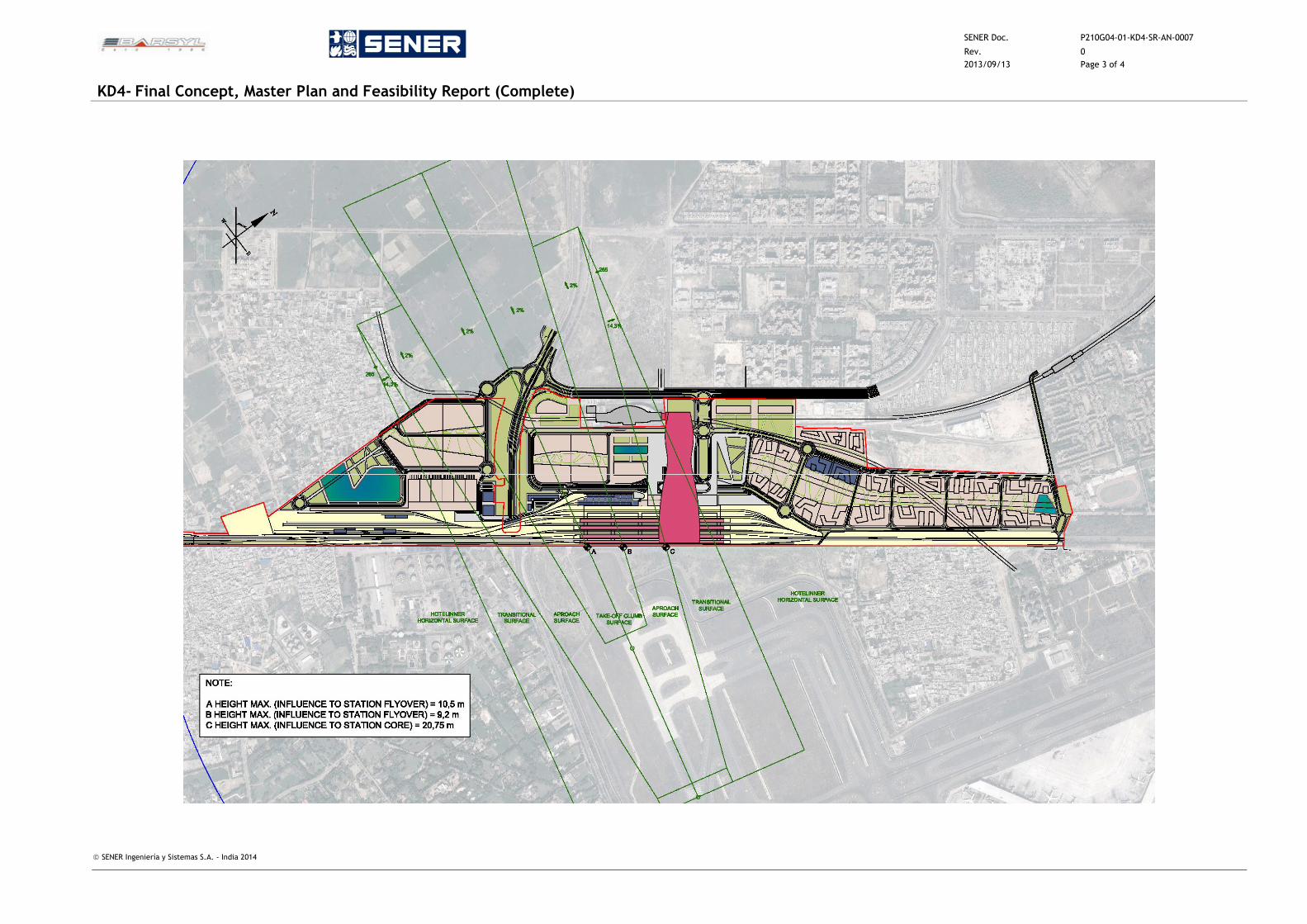
SENER Doc. P210G04-01-KD4-SR-AN-0007
Rev. 0
2013/09/13 Page 3 of 4
KD4- Final Concept, Master Plan and Feasibility Report (Complete)
SENER Ingeniería y Sistemas S.A. - India 2014
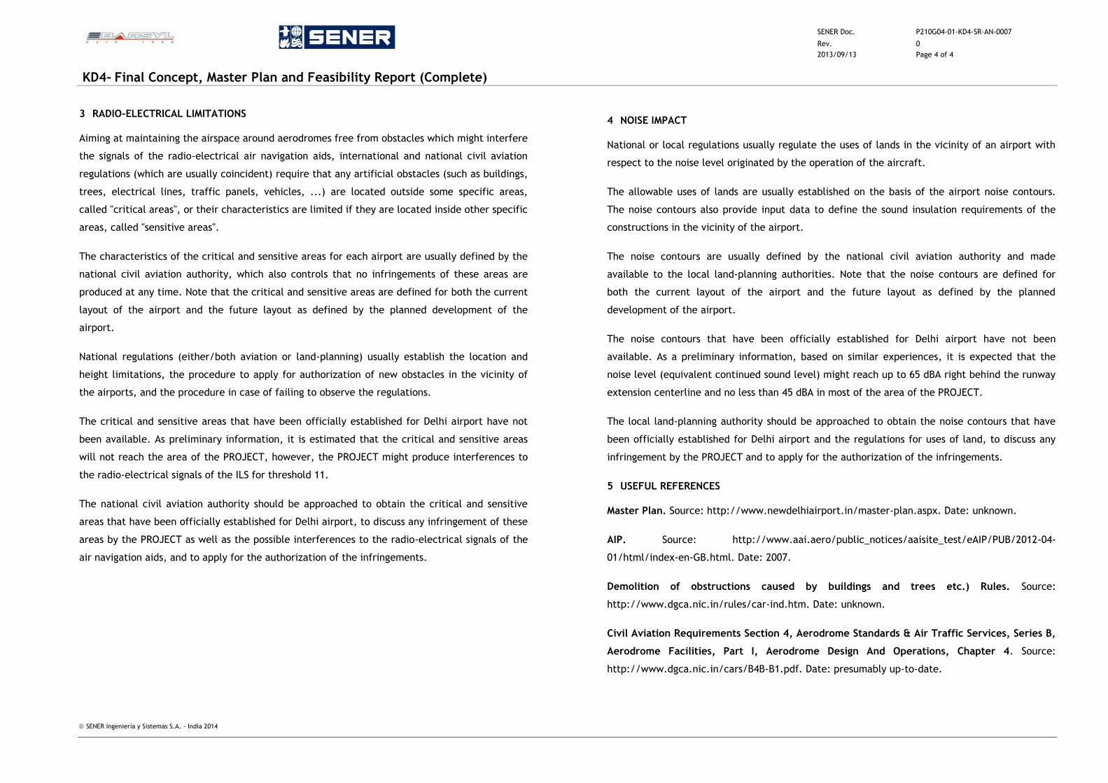
SENER Doc. P210G04-01-KD4-SR-AN-0007
Rev. 0
2013/09/13 Page 4 of 4
KD4- Final Concept, Master Plan and Feasibility Report (Complete)
SENER Ingeniería y Sistemas S.A. - India 2014
3 RADIO-ELECTRICAL LIMITATIONS
Aiming at maintaining the airspace around aerodromes free from obstacles which might interfere
the signals of the radio-electrical air navigation aids, international and national civil aviation
regulations (which are usually coincident) require that any artificial obstacles (such as buildings,
trees, electrical lines, traffic panels, vehicles, ...) are located outside some specific areas,
called "critical areas", or their characteristics are limited if they are located inside other specific
areas, called "sensitive areas".
The characteristics of the critical and sensitive areas for each airport are usually defined by the
national civil aviation authority, which also controls that no infringements of these areas are
produced at any time. Note that the critical and sensitive areas are defined for both the current
layout of the airport and the future layout as defined by the planned development of the
airport.
National regulations (either/both aviation or land-planning) usually establish the location and
height limitations, the procedure to apply for authorization of new obstacles in the vicinity of
the airports, and the procedure in case of failing to observe the regulations.
The critical and sensitive areas that have been officially established for Delhi airport have not
been available. As preliminary information, it is estimated that the critical and sensitive areas
will not reach the area of the PROJECT, however, the PROJECT might produce interferences to
the radio-electrical signals of the ILS for threshold 11.
The national civil aviation authority should be approached to obtain the critical and sensitive
areas that have been officially established for Delhi airport, to discuss any infringement of these
areas by the PROJECT as well as the possible interferences to the radio-electrical signals of the
air navigation aids, and to apply for the authorization of the infringements.
4 NOISE IMPACT
National or local regulations usually regulate the uses of lands in the vicinity of an airport with
respect to the noise level originated by the operation of the aircraft.
The allowable uses of lands are usually established on the basis of the airport noise contours.
The noise contours also provide input data to define the sound insulation requirements of the
constructions in the vicinity of the airport.
The noise contours are usually defined by the national civil aviation authority and made
available to the local land-planning authorities. Note that the noise contours are defined for
both the current layout of the airport and the future layout as defined by the planned
development of the airport.
The noise contours that have been officially established for Delhi airport have not been
available. As a preliminary information, based on similar experiences, it is expected that the
noise level (equivalent continued sound level) might reach up to 65 dBA right behind the runway
extension centerline and no less than 45 dBA in most of the area of the PROJECT.
The local land-planning authority should be approached to obtain the noise contours that have
been officially established for Delhi airport and the regulations for uses of land, to discuss any
infringement by the PROJECT and to apply for the authorization of the infringements.
5 USEFUL REFERENCES
Master Plan. Source: http://www.newdelhiairport.in/master-plan.aspx. Date: unknown.
AIP. Source: http://www.aai.aero/public_notices/aaisite_test/eAIP/PUB/2012-04-
01/html/index-en-GB.html. Date: 2007.
Demolition of obstructions caused by buildings and trees etc.) Rules. Source:
http://www.dgca.nic.in/rules/car-ind.htm. Date: unknown.
Civil Aviation Requirements Section 4, Aerodrome Standards & Air Traffic Services, Series B,
Aerodrome Facilities, Part I, Aerodrome Design And Operations, Chapter 4. Source:
http://www.dgca.nic.in/cars/B4B-B1.pdf. Date: presumably up-to-date.

SENER Doc. P210G04-01-KD4-SR-AN-0008
Rev. 0
2013/09/13 Page 1 of 4
KD4- Final Concept, Master Plan and Feasibility Report (Complete)
SENER Ingeniería y Sistemas S.A. - India 2014
ANNEXURE 8 – COMMUNICATION WITH DELHI DEVELOPMENT AUTHORITY
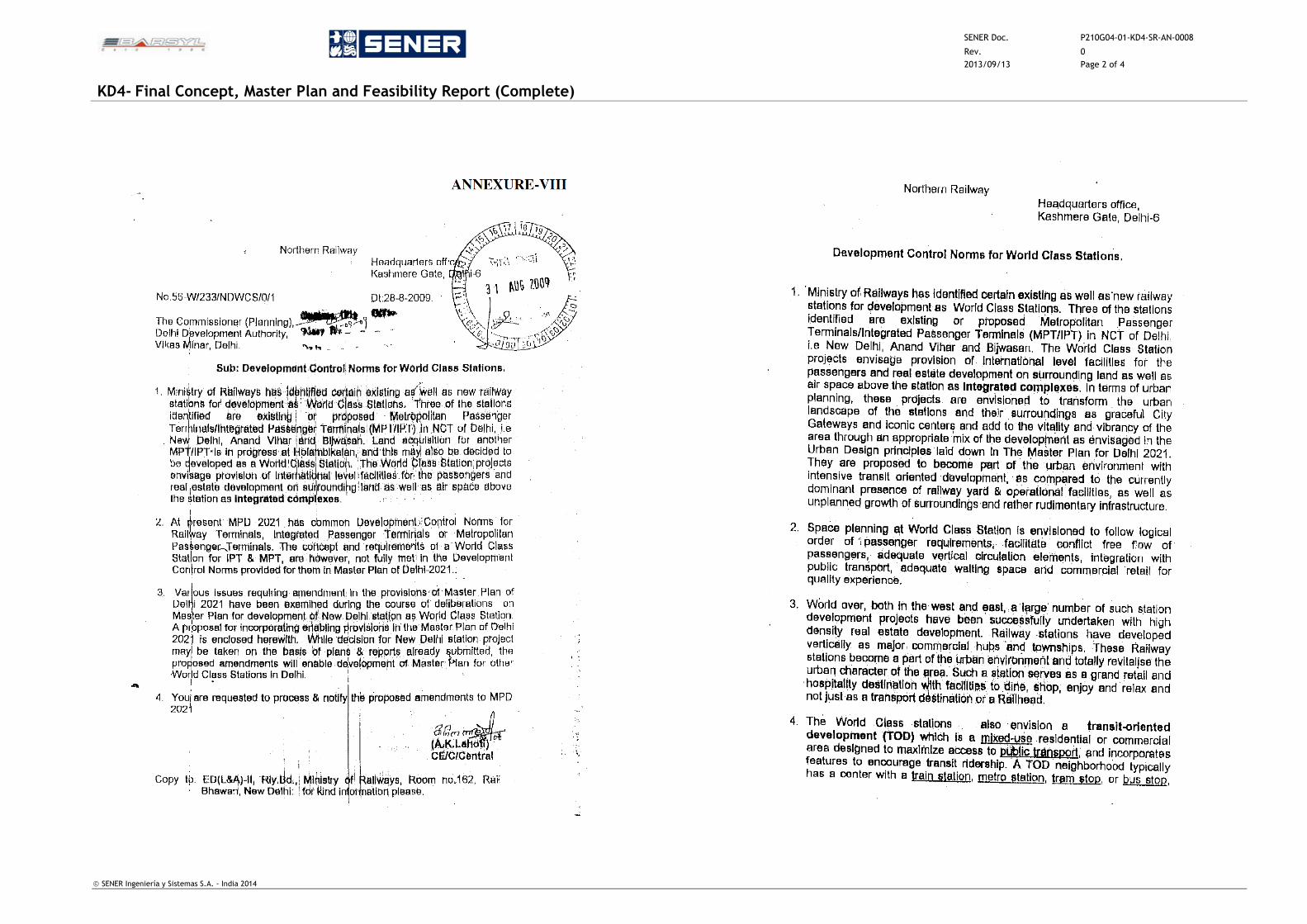
SENER Doc. P210G04-01-KD4-SR-AN-0008
Rev. 0
2013/09/13 Page 2 of 4
KD4- Final Concept, Master Plan and Feasibility Report (Complete)
SENER Ingeniería y Sistemas S.A. - India 2014
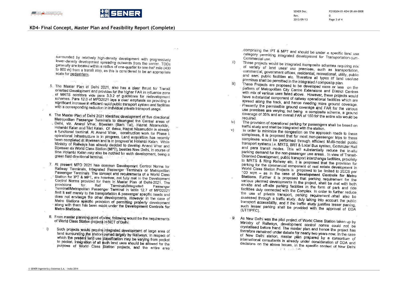
SENER Doc. P210G04-01-KD4-SR-AN-0008
Rev. 0
2013/09/13 Page 3 of 4
KD4- Final Concept, Master Plan and Feasibility Report (Complete)
SENER Ingeniería y Sistemas S.A. - India 2014
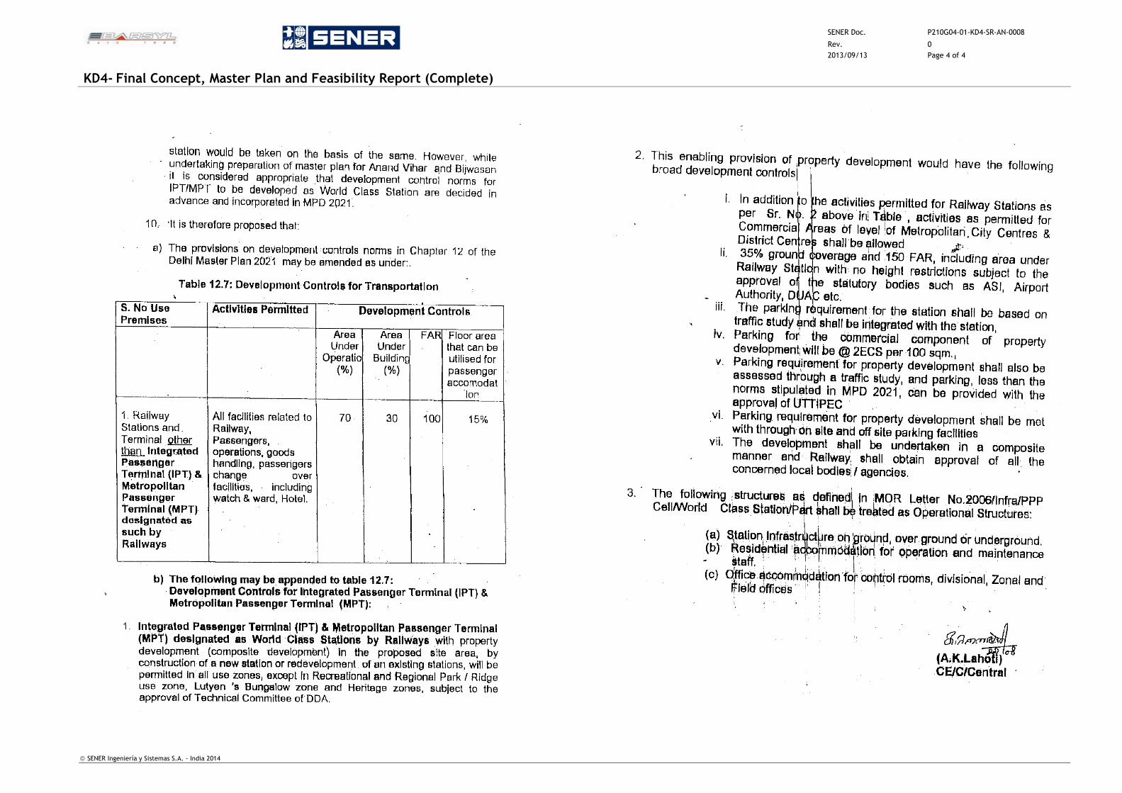
SENER Doc. P210G04-01-KD4-SR-AN-0008
Rev. 0
2013/09/13 Page 4 of 4
KD4- Final Concept, Master Plan and Feasibility Report (Complete)
SENER Ingeniería y Sistemas S.A. - India 2014
SENER Doc. P210G04-01-KD4-SR-AN-0009
Rev. 1
2016/11/11 Page 1 of 10
KD4- Final Concept, Master Plan and Feasibility Report (Complete)
SENER Ingeniería y Sistemas S.A. - India 2014
ANNEXURE 9
NORTHERN RAILWAY LETTER NO. 10-W/0/IRSDC/POLICY/LOOSE/BIJWASAN,
DATED 02-01-2014
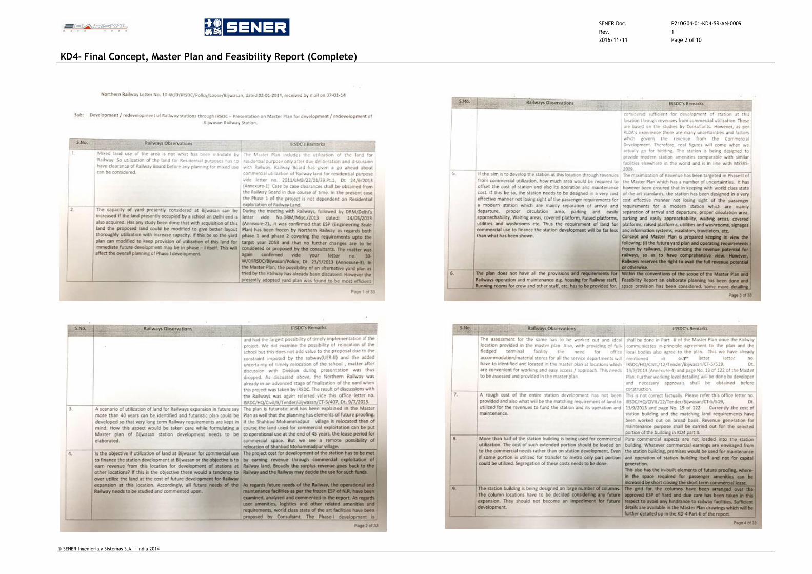
SENER Doc. P210G04-01-KD4-SR-AN-0009
Rev. 1
2016/11/11 Page 2 of 10
KD4- Final Concept, Master Plan and Feasibility Report (Complete)
SENER Ingeniería y Sistemas S.A. - India 2014
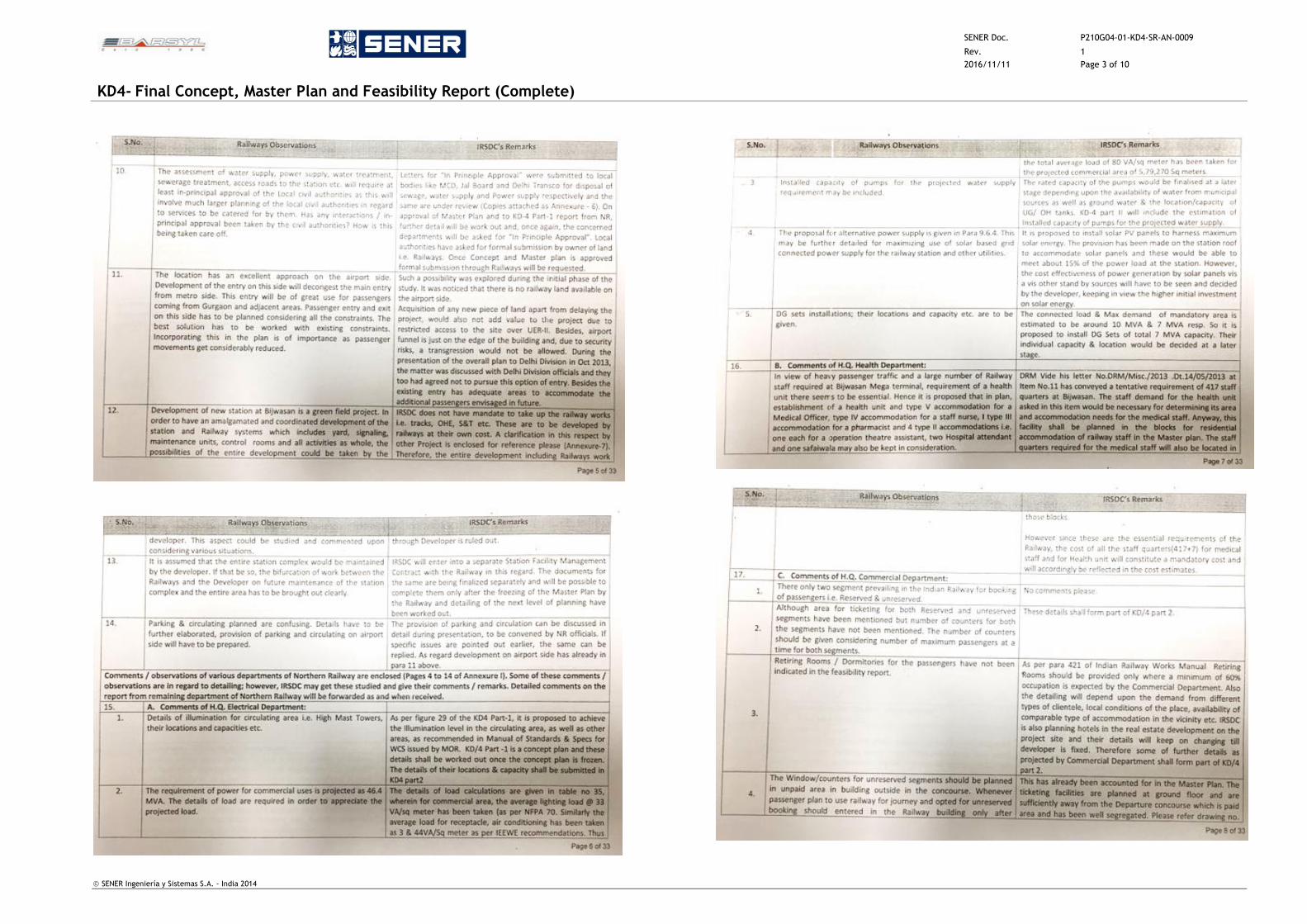
SENER Doc. P210G04-01-KD4-SR-AN-0009
Rev. 1
2016/11/11 Page 3 of 10
KD4- Final Concept, Master Plan and Feasibility Report (Complete)
SENER Ingeniería y Sistemas S.A. - India 2014
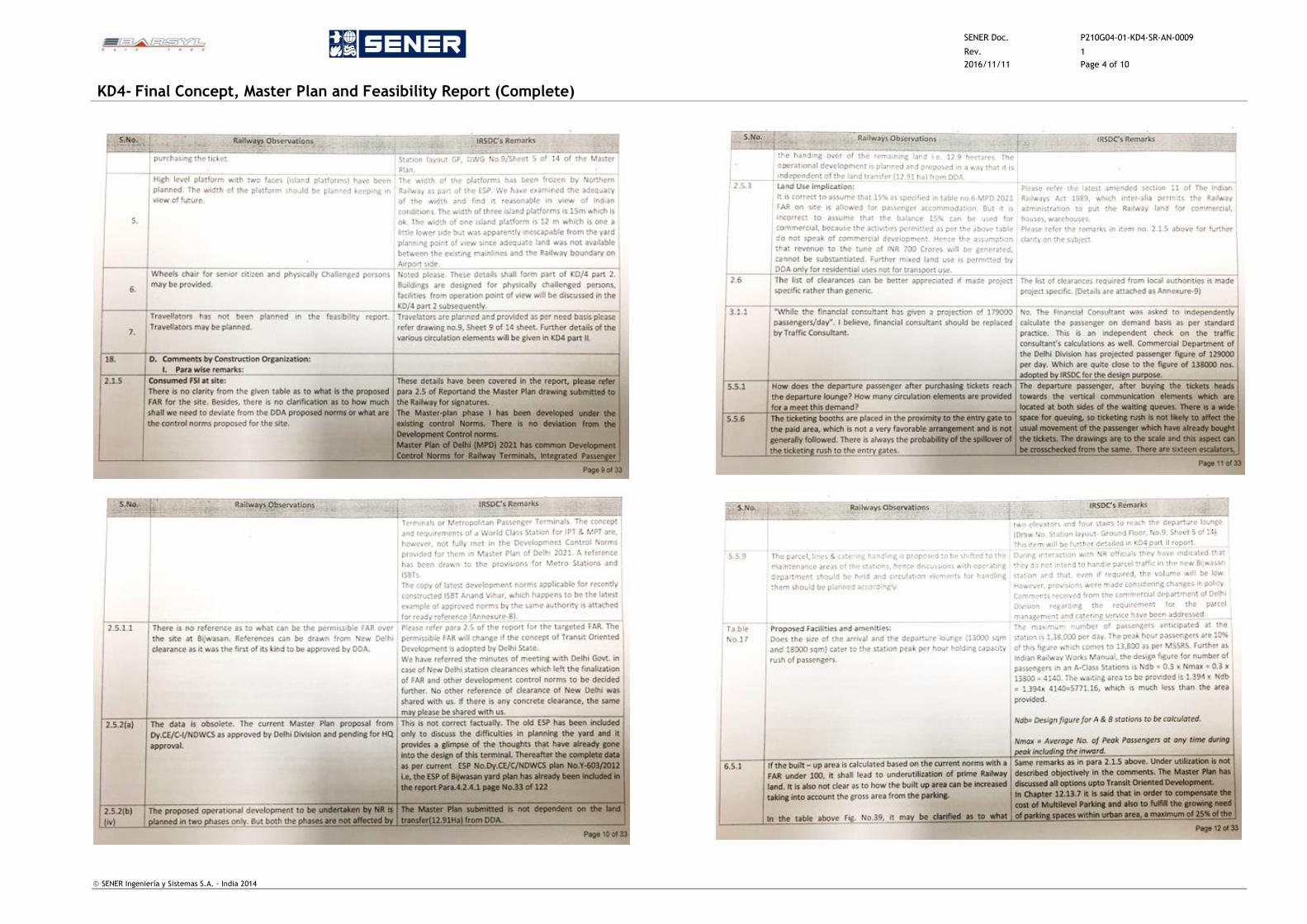
SENER Doc. P210G04-01-KD4-SR-AN-0009
Rev. 1
2016/11/11 Page 4 of 10
KD4- Final Concept, Master Plan and Feasibility Report (Complete)
SENER Ingeniería y Sistemas S.A. - India 2014
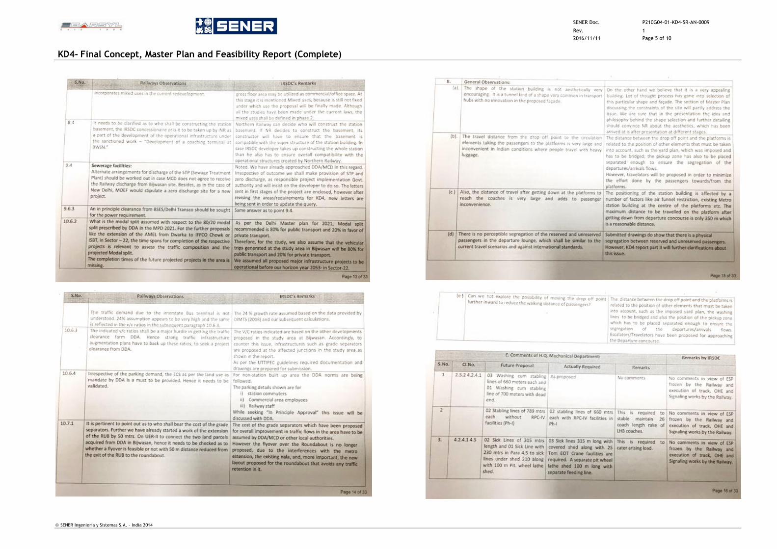
SENER Doc. P210G04-01-KD4-SR-AN-0009
Rev. 1
2016/11/11 Page 5 of 10
KD4- Final Concept, Master Plan and Feasibility Report (Complete)
SENER Ingeniería y Sistemas S.A. - India 2014
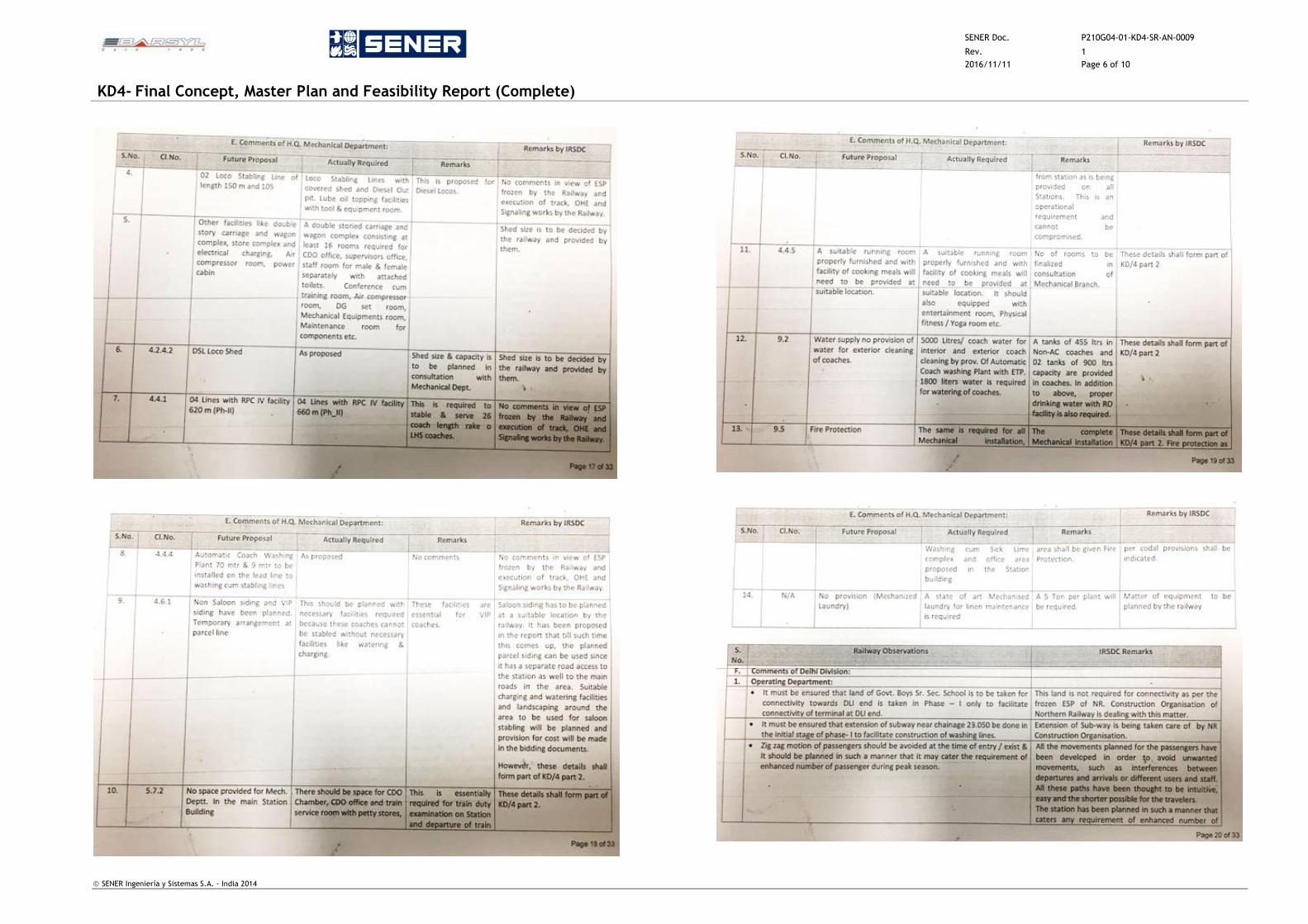
SENER Doc. P210G04-01-KD4-SR-AN-0009
Rev. 1
2016/11/11 Page 6 of 10
KD4- Final Concept, Master Plan and Feasibility Report (Complete)
SENER Ingeniería y Sistemas S.A. - India 2014

SENER Doc. P210G04-01-KD4-SR-AN-0009
Rev. 1
2016/11/11 Page 7 of 10
KD4- Final Concept, Master Plan and Feasibility Report (Complete)
SENER Ingeniería y Sistemas S.A. - India 2014
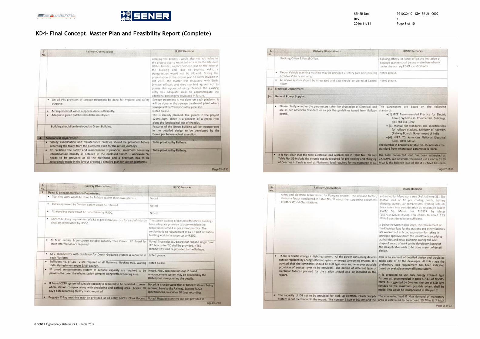
SENER Doc. P210G04-01-KD4-SR-AN-0009
Rev. 1
2016/11/11 Page 8 of 10
KD4- Final Concept, Master Plan and Feasibility Report (Complete)
SENER Ingeniería y Sistemas S.A. - India 2014
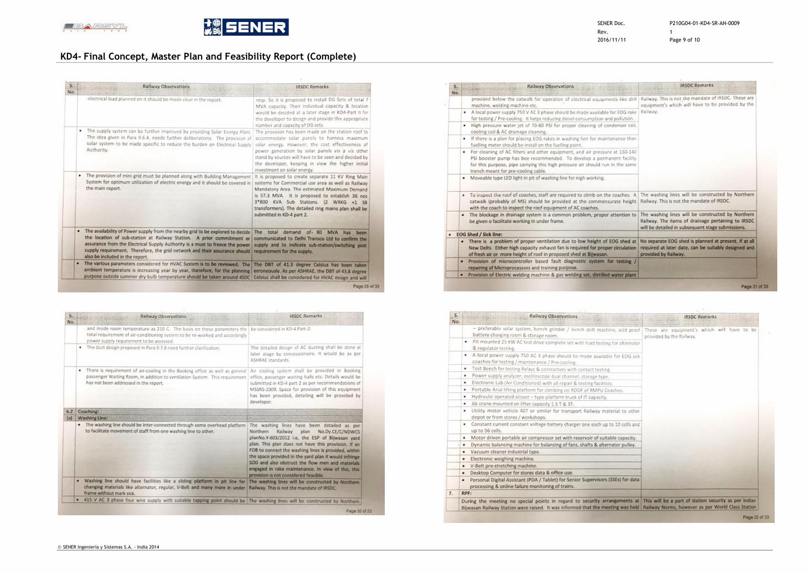
SENER Doc. P210G04-01-KD4-SR-AN-0009
Rev. 1
2016/11/11 Page 9 of 10
KD4- Final Concept, Master Plan and Feasibility Report (Complete)
SENER Ingeniería y Sistemas S.A. - India 2014
SENER Doc. P210G04-01-KD4-SR-AN-0009
Rev. 1
2016/11/11 Page 10 of 10
KD4- Final Concept, Master Plan and Feasibility Report (Complete)
SENER Ingeniería y Sistemas S.A. - India 2014
Related Documents