DOE-STD-5506-2021 AUGUST 2021 DOE STANDARD Preparation of Safety Basis Documents for Transuranic (TRU) Waste Facilities U.S. Department of Energy Washington, D.C. 20585 AREA-SAFT DISTRIBUTION STATEMENT A. Approved for public release; distribution is unlimited.

Welcome message from author
This document is posted to help you gain knowledge. Please leave a comment to let me know what you think about it! Share it to your friends and learn new things together.
Transcript
DOE-STD-5506-2021 AUGUST 2021
DOE STANDARD Preparation of Safety Basis Documents for Transuranic (TRU) Waste Facilities
U.S. Department of Energy Washington, D.C. 20585 AREA-SAFT DISTRIBUTION STATEMENT A. Approved for public release; distribution is unlimited.
DOE-STD-5506-2021
Available on the Department of Energy Technical Standards Program
Web Site at standards.doe.gov
i
DOE-STD-5506-2021
Foreword This Standard provides analytical assumptions and methods, as well as hazard controls to be used when developing Safety Basis documents for transuranic (TRU) waste facilities in the U.S. Department of Energy (DOE) Complex. This Standard complements the safe harbor methods in Appendix A to Subpart B of 10 CFR Part 830 (Nuclear Safety Management). It also provides supplemental technical information that is specific to TRU waste operations, so Federal employees and contractors can formulate, implement, and maintain safety bases for TRU waste operations in a consistent manner that is compliant with 10 CFR Part 830, Subpart B, requirements.
The information contained in this Standard is intended for use by all Department of Energy (DOE) and National Nuclear Security Administration (NNSA) sites and all contractors for DOE-owned or DOE-leased, Hazard Category 1, 2, or 3 nuclear facilities or nuclear operations that involve generation, handling, storage, and remediation of TRU waste. It may also be applied to these facilities having low-level waste.
Beneficial comments (recommendations, additions, and deletions), as well as any pertinent data that may be of use in improving this document, should be emailed to [email protected] or addressed to:
Office of Safety, Security, and Quality Assurance (EM-3.1) Office of Environment Management U.S. Department of Energy 1000 Independence Ave, SW Washington, DC 20585
The need for an existing, approved TRU waste facility Documented Safety Analysis (DSA) to be revised or revisited in light of the issuance of this Standard is addressed in Section 1.6; that decision will be made by the applicable DOE or NNSA program office and their Safety Basis Approval Authority for the facility. However, if a facility, site, or program office is required to, or chooses to, use this DOE-STD-5506-2021 for revising an existing DSA, then this Standard requires that all applicable “shall” statements be met if it is used to supplement the applicable “safe harbor” method from 10 CFR 830 Subpart B that is used for development of the DSA.
DOE-STD-5506-2021
ii
Table of Contents Section Page
Foreword ......................................................................................................................................... i Figures ......................................................................................................................................... viii Tables ............................................................................................................................................. ix
Introduction .............................................................................................................................1
1.1 Background ...............................................................................................................................1
1.2 Scope .........................................................................................................................................1
1.3 Purpose .....................................................................................................................................2
1.4 Applicability .............................................................................................................................2
1.5 Use of the Words Shall and Should ..........................................................................................3
1.6 Overview of Changes in this Revision .....................................................................................3
Acronyms .................................................................................................................................5
Identification and Evaluation of TRU Waste Events ..........................................................8
3.1 Purpose .....................................................................................................................................8
3.2 Hazard Identification and Standard Industrial Hazard Screening ............................................8
3.3 TRU Waste Operations Minimum Set of Accidents ...............................................................10 3.3.1 Fire Events ................................................................................................................12
Fuel Pool Fires (Event 1) .........................................................................................12 Small Fire (Event 2) .................................................................................................13 Enclosure Fire (Event 3) ..........................................................................................13 Large Fire (Event 4) .................................................................................................13
3.3.2 Explosion Events ......................................................................................................14
Ignition of Fumes Results in an Explosion (external to container) (Event 5) ..........14 Waste Container Deflagration (Event 6) ..................................................................14 Multiple Waste Container Deflagration (Event 7)....................................................15 Enclosure Deflagration (Event 8) .............................................................................15
3.3.3 Loss of Confinement/Containment ..........................................................................15
Vehicle/Equipment Impacts Waste/Waste Containers (Event 9) ..............................15 Drop/Impact/Spill Due to Improperly Handled Container, etc. (Event 10) .............16 Collapse of Stacked Containers (Event 11) ..............................................................16 Waste Container Over-Pressurization (Event 12) .....................................................16
3.3.4 Direct Exposure to Radiation Events (Event 13) .....................................................16 3.3.5 Criticality Events (Event 14) ....................................................................................16 3.3.6 Externally Initiated Events .......................................................................................16
DOE-STD-5506-2021
iii
Aircraft Impact with Fire (Event 15) ........................................................................16 External Vehicle Accident (Event 16) ......................................................................17 External Vehicle Accident with Fire (Combustible or Pool) (Event 17) ..................17 External Explosion (Event 18) .................................................................................17 External Fire (Event 19) ...........................................................................................17
3.3.7 Natural Phenomenon Hazard Initiated Events .........................................................17
Lightning (Event 20) ................................................................................................17 High Wind (Event 21) ..............................................................................................18 Tornado (Event 22) ...................................................................................................18 Snow/Ice/Volcanic Ash Build-up (Event 23) ...........................................................18 Seismic Event (Impact Only) (Event 24) .................................................................18 Seismic Event with Fire (Event 25) .........................................................................18 Flood Event (Event 26) ............................................................................................18
3.3.8 Chemical Initiated Events (Event 27) ......................................................................18
3.4 Expected Operational Events ..................................................................................................20
TRU Waste Source Term Analysis ......................................................................................22
4.1 Purpose ...................................................................................................................................22
4.2 Material-at-Risk ......................................................................................................................22 4.2.1 Data Uncertainties in Hazard and Accident Analysis ...............................................22 4.2.2 Defining a Bounding MAR for TRU Operations .....................................................23
4.3 Damage Ratios ........................................................................................................................26 4.3.1 Container Integrity ...................................................................................................28 4.3.2 Container Deflagration Events .................................................................................32 4.3.3 Fire Scenario Damage Ratios for TRU Waste Containers .......................................38
Drums Exposed by Flammable/Combustible Liquid Pool Fires ..............................39 Drums Exposed by Ordinary Combustible Fires .....................................................49 Fire Damage Ratios for Other Containers ................................................................50
4.3.4 Damage Ratios for Mechanical Insults ....................................................................53 4.3.5 Natural Phenomena Damage Ratios for TRU Waste Container
Storage ......................................................................................................................62
4.4 Airborne Release Fractions/Respirable Fractions ..................................................................67 4.4.1 Deflagration and Overpressure Events .....................................................................68 4.4.2 Fire Scenarios ...........................................................................................................74 4.4.3 Mechanical Insults ....................................................................................................75
Low-Energy Mechanical Insults ..............................................................................75 High-Energy Mechanical Insults ..............................................................................77
4.5 Chemical Reaction Source Term ............................................................................................79
4.6 Consequence Analysis ............................................................................................................81
DOE-STD-5506-2021
iv
TRU Waste Hazard Controls Selection and Standardization ..........................................83
5.1 Purpose ...................................................................................................................................83
5.2 TRU Waste Controls ...............................................................................................................83 5.2.1 TRU Waste MAR Effects on Control Selection .......................................................85
References ..............................................................................................................................97
Understanding and Using the MAR Algorithms .......................................... A-1
Fully Characterized MAR Algorithm .................................................................................. A-1
Limited Characterization MAR Algorithm .......................................................................... A-2
References for APPENDIX A .............................................................................................. A-7
Container Deflagrations ...................................................................................B-1
Introduction ...........................................................................................................................B-1 Hydrogen Measurements in TRU Waste Drums ....................................................B-4 Hydrogen Measurements in Drums from Culverts at SRS ....................................B-5
Review and Evaluation of Pertinent Experiments and Literature of Internal Deflagration in TRU Waste Containers .............................................................................. B-11
Idaho Drum H2 Explosion Tests ........................................................................... B-11 SRS Drum H2 Explosion Tests .............................................................................B-17 Burning of Ejected Wastes ...................................................................................B-19 Volatile Organic Compounds ...............................................................................B-22 Hydrogen Combustion and Deflagration-to-Detonation Transition (DDT) ...................................................................................................................B-26
B.2.5.1 Electric Power Research Institute (EPRI) Hydrogen Tests ..................................B-27 B.2.5.2 Sandia Hydrogen Tests .........................................................................................B-30 B.2.5.3 Rockwell Atomics International (AI) Hydrogen Tests .........................................B-33 B.2.5.4 ARROW-PAK™ DDT Test ...................................................................................B-36 B.2.5.5 Drum DDT Position Paper ...................................................................................B-37
Container Response to Internal Pressures ............................................................B-38 Drum Response to External Pressures .................................................................B-43 Other Waste-Container Considerations ................................................................B-45
B.2.8.1 Idaho Testing of Boxes and Bins ..........................................................................B-47
Deflagration Testing for CH Payload Containers and Filter Vents at Southwest Research Institute ...............................................................................B-48
Summary and Recommendations for Deflagration Release Parameters ............................B-51 Assumptions .........................................................................................................B-51 Material-at-Risk ...................................................................................................B-52 Damage Ratio .......................................................................................................B-52 Airborne Release Fraction and Respirable Fractions ...........................................B-53
DOE-STD-5506-2021
v
Overall Composite Release Fraction ....................................................................B-54
References for APPENDIX B .............................................................................................B-54
Damage Ratios for Container Insults and Fires ........................................... C-1
Fire Scenarios Damage Ratios for TRU Waste Container ....................................................C-2 Waste Container Fire Testing Insights ....................................................................C-3 Lid Loss and Ejection Fraction ............................................................................C-10 Seal Failures .........................................................................................................C-12 Pipe Overpack Container, Type 7A Drum, and Criticality Control Overpack Fire Testing ..........................................................................................C-18
C.1.4.1 Initial Pipe Overpack Container Fire Testing .......................................................C-18 C.1.4.2 Additional Pipe Overpack Container, Type 7A Drum, and Criticality
Control Overpack Fire Testing .............................................................................C-19 C.1.4.3 Criticality Control Overpack Testing ...................................................................C-22
Mechanical Insults (Low- and High-Energy) .....................................................................C-24 Container Test Results ..........................................................................................C-25
C.2.1.1 Drum Drop Tests ..................................................................................................C-25 C.2.1.2 Pallet Tests ............................................................................................................C-27 C.2.1.3 Welded-Metal Waste Box Tests ............................................................................C-29 C.2.1.4 Pipe Overpack Container Testing for Accidents Other Than Fires ......................C-30
Impact and Drop Accidents ..................................................................................C-34
C.2.2.1 Single Container Drops ........................................................................................C-34 C.2.2.2 Palletized Drum Falls ...........................................................................................C-37 C.2.2.3 Waste Container Puncture by Forklift ..................................................................C-40 C.2.2.4 Compressed-Gas-Cylinder-Missile Impact ..........................................................C-42 C.2.2.5 Damage Ratio Summary for Accidents ................................................................C-44
References for APPENDIX C .............................................................................................C-44
Criteria for TRU Waste Drums Requiring Venting/Purging Due to Elevated Internal Hydrogen Concentrations .................................................................. D-1
Executive Summary .................................................................................................................. D-1
Introduction .......................................................................................................................... D-1
Purpose ................................................................................................................................ D-3
Criteria ................................................................................................................................. D-3
Definitions ........................................................................................................................... D-3
TRU Waste ........................................................................................................................... D-4 55-Gallon DOT, Metal Drums ............................................................................... D-4 Types of Waste ...................................................................................................... D-5
Hydrogen from TRU Wastes ............................................................................................... D-6
DOE-STD-5506-2021
vi
Hydrogen Gas Properties ...................................................................................... D-6 Hydrogen Gas Combustion Phenomenon ............................................................. D-7 Combustion of Hydrogen–Air Mixtures ............................................................... D-7 Hydrogen Gas Combustion Properties .................................................................. D-8 Hydrogen Concentrations in TRU Waste Drums .................................................. D-8
Literature Data on Burning of Hydrogen–Air Mixtures ...................................................... D-9 AI 1973 .................................................................................................................. D-9
D.7.1.1 Detonation Tests .................................................................................................. D-11 D.7.1.2 Flame Tests .......................................................................................................... D-13
EPRI 1988 ........................................................................................................... D-14
D.7.2.1 Combustion in Premixed Hydrogen–Air–Steam Atmospheres ........................... D-17 D.7.2.2 Pre-Mixed Combustion Phenomenon ................................................................. D-17 D.7.2.3 Effect of Scale ..................................................................................................... D-18 D.7.2.4 Effect of Hydrogen and Steam Concentrations ................................................... D-18
SNL 1989 (Note: Complete document was not available for review.) ................ D-18
D.7.3.1 Abstract ............................................................................................................... D-18 D.7.3.2 Conclusions from Tests ....................................................................................... D-20 D.7.3.3 Adiabatic Isochoric (Constant Volume) Complete Combustion (AICC)
Pressure ............................................................................................................... D-20 D.7.3.4 Flammability Limits ............................................................................................ D-20 D.7.3.5 Ordinary Turbulent Deflagration ......................................................................... D-21 D.7.3.6 Flame Acceleration — Highly Accelerated Deflagration ................................... D-21 D.7.3.7 Deflagration-to-Detonation Transition ................................................................ D-21 D.7.3.8 Experimental Results ........................................................................................... D-23
LANL July 2002 .................................................................................................. D-24 EG&G 1983 (Experimental Studies of H2 Explosions in TRU Waste Drum) .......................................................................................... D-25 WSRC-TR-90-165 .............................................................................................. D-30
D.7.6.1 Pressure Vessel Tests ........................................................................................... D-30 D.7.6.2 Drum Mixing Tests .............................................................................................. D-31 D.7.6.3 Drum Explosion Test ........................................................................................... D-31 D.7.6.4 Results ................................................................................................................. D-31
WSMS 2006 (DDT) ............................................................................................ D-32
D.7.7.1 Introduction ......................................................................................................... D-33 D.7.7.2 Technical Position ............................................................................................... D-33 D.7.7.3 Literature Review ................................................................................................ D-34
EMRTC 2004 (DDT) .......................................................................................... D-35 WSRC 2007 ......................................................................................................... D-35
Summary and Conclusions ................................................................................................ D-36
DOE-STD-5506-2021
vii
References .......................................................................................................................... D-37
Energetic Chemical Events ..............................................................................E-1
Introduction ........................................................................................................................... E-1 WIPP Event ............................................................................................................ E-1 INL ARP V Event ................................................................................................... E-3
Radiological Source Term Evaluations of WIPP and INL Events ........................................ E-5
Modeling Energetic Release Parameters .............................................................................. E-8 Radiological Source-Term Evaluations of a Drum Over-pressurization Event ............................................................................................... E-9
References for APPENDIX E ............................................................................................. E-10
DOE-STD-5506-2021
viii
Figures Figure Page
Figure 4-1. Example Graphic Assessment of Pool Fire Damage.................................................. 45
Figure 4-2. Fire Damage Ratios (DRs) for Direct-Loaded Drums ............................................... 48
Figure 4-3. Comparison of Drum DR and ARF×RF for Contaminated Solids in Drops, Falls, and Vehicle Crashes ................................................................................................. 60
Figure 4-4. Example Graphic 20 mph Vehicle Crash with Follow-On Pool Fire ......................... 62
Figure C-1. Geometries for Determining Critical Incident Flux .............................................. C-14
Figure C-2. Comparison of Critical Incident Flux Criteria ....................................................... C-15
DOE-STD-5506-2021
ix
Tables Table Page
Table 3-1. Hazard Sources and Potential Events ............................................................................ 9
Table 3-2. Minimum TRU Waste Activity / Hazard Evaluation Event Matrix 1 ...........................11
Table 4-1. Bounding MAR Approach for TRU Waste Operations ............................................... 25
Table 4-2. Payload Container Integrity Checklist ......................................................................... 31
Table 4-3. Drum Deflagration Fractions of MAR ........................................................................ 34
Table 4-4. Critical Flux Criteria Required to Obtain Seal Failure ................................................ 42
Table 4-5. Container Drop and Impact Damage Ratios ................................................................ 57
Table 4-6. Vehicle Crash Damage Ratios ...................................................................................... 58 Table 4-7. Damage Ratios for Containers Impacted by Seismic Debris ....................................... 66 Table 4-8. ARF×RF Value Applicable to TRU Waste Accidents .................................................. 67
Table 5-1. Hazard Controls ........................................................................................................... 88
Table A-1. Order of Statistic (Container “r”) for a Given Waste Container Population ........................................................................................................................................A-4
Table A-2. Z-Score Values for Various Confidence Intervals ..................................................... A-6
Table B-1. Fraction of Stored TRU Waste Drums Containing Flammable Hydrogen Concentrations ............................................................................................................B-4Table B-2. Unvented Culvert Drum Initial Headspace Gas Results ............................................B-6
Table B-3. Fraction of Culvert Drums Capable of Complete Combustion with > 5-vol% O2 and at Least 50% of the Corresponding H2 Concentration ...........................................B-7
Table B-4. Drum H2 Concentration > 15.0 vol% (> 14.65 vol% with Uncertainty), 39 Drums ...................................................................................................................................... B-7Table B-5. Drum H2 Concentration Between 8 and 15 vol% (7.28–13.65 vol% with Uncertainty), 24 Drums ........................................................................................................ B-9 Table B-6. Drum H2 Concentration Between 4 and 8 vol% (3.64–7.28 vol% with Uncertainty), 22 Drums ..............................................................................................................B-10Table B-7. Purpose and Initial Conditions for Each Test .......................................................... B-12
Table B-8. Idaho Drum Deflagration Tests Result .................................................................... B-13
Table B-9. Pressure Vessel Test Data ........................................................................................ B-18
Table B-10. Drum Explosion Data .............................................................................................B-19
DOE-STD-5506-2021
x
Table B-11. Description of Combustibles Loaded into Drums ................................................. B-23
Table B-12. Summary of Mass Loss .............................................................................................B-25Table B-13. EPRI Test Conditions and Results ........................................................................ B-28
Table B-14. Summary of the Test Parameters and Some Test Results ..................................... B-31
Table B-15. Detonation Test Results ......................................................................................... B-34
Table B-16. Flame Tests Data Summary .................................................................................. B-35
Table B-17. Drum Capacities, Specifications, and Tests Conducted ........................................ B-39
Table B-18. INL Pneumatic Testing of 55-Gallon Drums ........................................................ B-42
Table B-19. Deflagration Test Results ...................................................................................... B-49
Table B-20. Overall Drum Composite Release Fraction .......................................................... B-54
Table C-1. Summary of Key Pool Fire Equations ...................................................................... C-3
Table D-1. Properties of Gaseous Hydrogen (H2) (After LANL 2002) ...................................... D-6
Table D-2. Hydrogen Gas Combustion Properties ..................................................................... D-8
Table D-3. Fraction of Stored TRU Waste Drums Containing Flammable Hydrogen Concentrations (from HNF-19492) ............................................................................ D-9
Table D-4. Detonation Test Summary (After AI 1973)............................................................. D-11
Table D-5. Flame Test Data Summary ...................................................................................... D-13
Table D-6. Test Conditions (EPRI 1988) .................................................................................. D-15
Table D-7. Summary of the Test Parameters and Some Test Results (SNL 1989) ................... D-23
Table D-8. Purpose and Initial Conditions for Each Test (EG&G 1983).................................. D-27
Table D-9. Gas Generation Tests Performed at the INEL Building FY-82 (EG&G 1983) ......................................................................................................................................... D-28
Table D-10. Pressure Vessel Test Data (WSRC-TR-90-165) .................................................... D-31
DOE-STD-5506-2021
1
Introduction 1.1 Background The DOE is responsible for the safe handling, packaging and ultimate disposal of transuranic (TRU) wastes at the Waste Isolation Pilot Plant (WIPP) located near Carlsbad, New Mexico. Much of this waste, which is a result of operations supporting the U.S. nuclear weapons mission, is now stored at numerous DOE sites located across the United States. These wastes can present significant hazards to workers, the environment, and the public if not adequately controlled.
While numerous and located within multiple states, facility operations supporting the TRU waste management mission have shared similarities in terms of the hazards and scope of operations. However, facilities often employ a variety of different controls to manage the TRU wastes. Recognition of these inconsistencies led the DOE to develop this technical Standard, which lays out expectations for analyzing and controlling TRU waste hazards.
To support this effort, DOE had to overcome several challenges. Chief among them was that TRU wastes are present at both large and small sites and involve wastes ranging from very low radioactive levels to those with significant radiological hazards. A one-size-fits-all approach could be overly expensive and not necessarily in line with relative lower risks.
A second challenge was that TRU waste operations are conducted in a variety of newly designed structures and existing buildings originally intended for other DOE missions. These older facilities may not meet current facility design requirements, although they may be compliant with their original design criteria (e.g., “code of record”). Therefore, it was recognized that protective features designed into existing facilities are not always reliable or available as in new facilities. Often, alternative controls such as Specific Administrative Controls per DOE-STD-1186-2016, Specific Administrative Controls, may become the primary controls available. [NOTE: This does not relieve a new facility or major facility modification from DOE Order O 420.1C, Facility Safety, nuclear facility requirements.]
To support these strategies, DOE collected hazard analysis and control data from all of its major TRU waste sites. This information was used to provide a baseline against which analytical methods and proposed controls could be evaluated, compared, and selected. It also highlighted inconsistencies among TRU waste sites that warranted further guidance. The technical bases for some of the hazard and accident analysis parameters recommended in this document are based on: (1) previously published DOE recommended safety analysis practices (2) extrapolation of experimental data from waste container testing and analytical analyses; or (3) precedents established in the DOE Complex during the development and approval of existing TRU waste facility DSAs.
1.2 Scope Based on the evaluation of existing Safety Basis information and input received from TRU waste operations personnel, analysts and DOE Safety Basis reviewers, the Standard focuses on topics related to hazard and accident analysis and hazard controls. These topics are addressed in a level of detail that supports the existing framework of nuclear facility Safety Basis requirements and standards.
DOE-STD-5506-2021
2
Specific topical areas covered in the Standard, and their associated sections are as follows:
• Section 2, Acronyms, provides definitions to all acronyms used in the Standard.
• Section 3, Identification and Evaluation of TRU Waste Events, discusses the types of hazardsexpected during TRU waste operations, defines a minimum set of accidents to be evaluated in theDSA, and addresses DSA provisions for addressing incidents that are inherent to normaloperations such that operational impacts from their occurrence are appropriately minimized.
• Section 4, TRU Waste Source Term Analysis, defines analytical methods and assumptions relatedto unmitigated analysis, Material-at-Risk, Damage Ratios, and Airborne ReleaseFractions/Respirable Fractions.
• Section 5, TRU Waste Hazard Controls Selection and Standardization, provides guidelines forstandardizing the hazard control selection process and gives specific controls that are appropriatefor TRU waste operations.
• Section 6, References, provides a list of all references cited in the main body of the Standard.Additional references are provided within each appendix.
• APPENDIX A, Understanding and Using the MAR Algorithms, provides discussion of thestatistical approach for determining Material-at-Risk (MAR) and for how to calculate values forthe approach described in Section 4.2.2 of the Standard.
• APPENDIX B, Container Deflagrations, provides the technical basis for Damage Ratiospresented in the Standard for deflagration events.
• APPENDIX C, Damage Ratios for Container Insults and Fires, provides technical justificationssupporting Damage Ratios presented in the Standard for fires and mechanical insult events.
• APPENDIX D, Criteria for TRU Waste Drums Requiring Venting/Purging Due toElevated Internal Hydrogen Concentrations, provides a basis for drum lid loss due todeflagrations in 55-gallon drums.
• APPENDIX E, Energetic Chemical Events, provides guidance for the unmitigated consequenceanalysis of potential energetic events from chemical reactions associated with TRU waste drums.
1.3 Purpose This Standard provides detailed guidance for consistently analyzing hazards and selecting controls for TRU waste activities. The hazards analysis, accident analysis, and controls for TRU waste activities shall be integrated into the overall Safety Basis documents for DOE Category 1, 2, or 3 nuclear facilities prepared in accordance with 10 CFR Part 830 (Nuclear Safety Management), Subpart B requirements (or alternate methodology where approved in accordance with the regulation).
1.4 Applicability The information contained in this Standard is intended for use by all DOE and National Nuclear Security Administration (NNSA) sites and all contractors for DOE- or NNSA-owned or -leased, Hazard Category 1, 2, or 3 nuclear facilities or nuclear operations that involve retrieval, generation, handling, storage, and processing (e.g., glovebox or hotcell operations) involving TRU or low-level waste. This Standard applies
3
DOE-STD-5506-2021
to Documented Safety Analyses (DSAs) complying with “safe harbor methods” in Table 2 to Appendix A of 10 CFR Part 830, Subpart B (or alternate methodology where approved in accordance with the regulation) and the associated Technical Safety Requirements (TSRs).
This Standard is not a safe harbor methodology as set forth in Appendix A to 10 CFR Part 830, Subpart B. Nothing in this Standard is intended to conflict with or modify the requirements for compliance with safe harbor methodologies listed in 10 CFR Part 830. In addition, the Standard is not intended to conflict with requirements of 10 CFR Part 830.206 related to new Hazard Category 1, 2, or 3 nuclear facilities or major modifications. In the case of an apparent conflict between this Standard and a 10 CFR Part 830, Subpart B requirements, as well as supporting “safe harbor” methodologies in Table 2 of Appendix A of 10 CFR Part 830, Subpart B, the language in the “safe harbor” method takes precedence, unless approval for an alternative methodology is requested and approved per the current DOE approval process for 10 CFR 830 exemptions or interpretations. DOE Standard 5506 is intended to supplement safe harbor methodologies, such as DOE-STD-3009-2014 (Preparation of Nonreactor Nuclear Facility Documented Safety Analysis) or DOE-STD-3011-2016 (or previous versions for existing facilities), and provides specific information pertinent to facilities that handle, store, or process transuranic waste.
The process used to justify deviations from methods prescribed in the Standard should not be confused with the process used for exemptions from DOE nuclear safety requirements. In the former case, technical justifications for analytical methods or key assumptions are developed and submitted to the DOE Safety Basis Approval Authority for their approval of deviation from this Standard. Such deviations should be documented in the Safety Evaluation Report. Deviations should not be used for safety controls that are needed to comply with nuclear safety design criteria of DOE Order 420.1C (i.e., a new facility or major modification).
Where controls cannot meet current requirements, exemptions with appropriate compensatory measures are generally needed to authorize acceptability of not meeting the requirement. Depending on the requirement and its applicability to existing facilities, the Safety Basis DOE Approval Authority may not be the same person as the DOE authority for an exemption to current DOE Orders or other requirements.
Furthermore, approval of exemptions to DOE Order requirements involving nuclear safety need concurrence of the DOE and/or NNSA Central Technical Authorities per the DOE exemption process in effect at the time of the request.
1.5 Use of the Words Shall and Should The verbs “shall” and “should” are used throughout this Standard. The word “shall” denotes actions that are required to satisfy this Standard. The word “should” is used to indicate recommended practices. The use of “may” with reference to application of a procedure or method indicates that the use of the procedure or method is optional.
1.6 Overview of Changes in this Revision This revision of DOE-STD-5506-2007, Preparation of Safety Basis Documents for Transuranic (TRU) Waste Facilities, incorporates experience and lessons learned from the DOE complex. It also updates the basis for source-term recommendations to reflect the latest available container testing and evaluation of
DOE-STD-5506-2021
4
available data. Previous DSA guidance was deleted from this Standard that is now adequately addressed in DOE-STD-3009-2014 and DOE-HDBK-1224-2018, Hazard and Accident Analysis Handbook.
DSAs that were prepared in accordance with DOE-STD-5506-2007 should evaluate the changes in this revision and determine whether a DSA update is needed. In particular, the following changes should be evaluated:
• Applicability of the newly added “Chemical Initiated Releases” event in Section 3.3, TRU WasteOperations Minimum Set of Accidents, as well as related source term guidance in Section 4.5,Chemical Reaction Source Term, and APPENDIX E, Energetic Chemical Events;
• Clarifications in the renumbered Section 4.2.2, Defining a Bounding MAR for TRU Operations,that includes corrections of typographical errors in Table 4-1, “Bounding MAR Approach forTRU waste operations,” new guidance for addressing statistical anomalies as described inFootnote 4, and additional conditions for when a statistical approach is appropriate fordetermining MAR;
• Updates to values and additional bases provided for the use of various source term factors inSection 4.3, Damage Ratios, and Section 4.4, Airborne Release Fractions/Respirable Fractions.
• Updates and clarifications of several safety controls described in Section 5.2, TRU WasteControls.
DSAs should be updated if conclusions of the hazard and accident analysis are no longer conservative or if new controls may be needed. The decision for updating the DSA to this revised Standard will be made by the DOE or NNSA program office and Safety Basis Approval Authority.
DOE-STD-5506-2021
5
Acronyms AA accident analysis AI (Rockwell) Atomics International AIB (DOE) Accident Investigation Board AICC adiabatic isochoric (constant volume) complete combustion AK acceptable knowledge ANSI American National Standards Institute ARF airborne release fraction ARP Accelerated Retrieval Project BoK Basis of Knowledge Document CCC criticality control container CCE chemical compatibility evaluation CCO criticality control overpack CFR Code of Federal Regulations CH contact-handled CVS confinement ventilation system DBE Design basis earthquake DNFSB Defense Nuclear Facilities Safety Board DOE U.S. Department of Energy DOT U.S. Department of Transportation DR damage ratio DSA documented safety analysis DU depleted uranium DVS drum venting system ED energy density EM (DOE Office of) Environmental Management EPA Environmental Protection Agency FRP fiberglass reinforced plywood (box) FSS fire suppression system L/D length/diameter (ratio) LANL Los Alamos National Laboratory LCO limiting conditions for operations LFL lower flammability limit LLNL Lawrence Livermore National Laboratory LPF leak-path factor MAR material-at-risk

DOE-STD-5506-2021
6
MOI maximally exposed offsite individual NCSE nuclear criticality safety evaluation NDA non-destructive assay NDE non-destructive examination NFPA National Fire Protection Association NNSA National Nuclear Security Administration NPH natural phenomena hazards OSHA U. S. Occupational Safety and Health Administration PC pipe component PE-Ci plutonium equivalent curies PISA potential inadequacy of the documented safety analysis PMMA polymethyl methacrylate PNNL Pacific Northwest National Laboratory POC pipe overpack container RF respirable fraction RH remote-handled RLC removable lid canister SAC specific administrative controls SC Safety Class SIH standard industrial hazard SFPE Society of Fire Protection Engineers SLB2 standard large box 2 SME subject matter expert SMP safety management program SRS Savannah River Site SSC structures, systems, and components ST source term SWB standard waste box TBD to be determined TDOP ten drum overpack TED total effective dose TI tolerance interval TRU transuranic TSR technical safety requirements UCL upper confidence limit USQ unreviewed safety question UTL upper tolerance limit

DOE-STD-5506-2021
7
VOC volatile organic compound WAC waste acceptance criteria WIPP Waste Isolation Pilot Plant

DOE-STD-5506-2021
8
Identification and Evaluation of TRU Waste Events 3.1 Purpose This section provides guidance on identification of hazards expected during various types of TRU waste operations, as well as a minimum set of accident events that are applicable based on these hazards.
The definition of Standard Industrial Hazards (SIH), as discussed in DOE-STD-3009-2014, is also clarified to help distinguish those hazards that do not require analysis within the DSA.
Finally, this section provides a distinction for certain operational events that are to be expected during the course of normal TRU waste operations.
3.2 Hazard Identification and Standard Industrial Hazard Screening The identification of hazards inherent in TRU waste activities is necessary to provide a sound basis for identifying potential accident events and performing a hazard evaluation. The hazard identification process results in a comprehensive list of hazardous materials and energy sources that are present in the facility or operation. This process shall be conducted in accordance with the DOE-STD-3009-2014, or applicable safe-harbor standard, for hazard identification and selection of accidents.
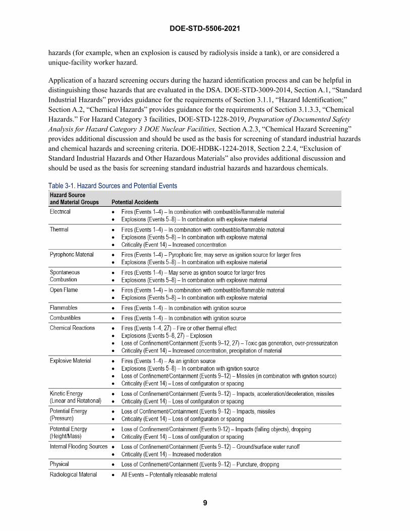
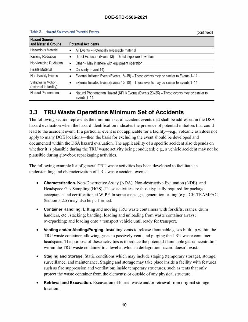
Hazards commonly expected for TRU waste operations are identified in Table 3-1, Hazard Sources and Potential Events. This listing provides major hazard sources and material groups that could be potential initiators for specific accident events discussed in Section 3.3. Where these hazards are present in a given TRU waste operation, analysts shall evaluate the applicability of the corresponding accident event(s).
Hazards identified in Table 3-1 do not always result in accidental release of radiological materials or hazardous chemicals and/or high direct radiation exposures (i.e., as required to be evaluated in the DSA). Depending on the location and specific characteristics of the hazard, it may be considered an SIH. DOE-STD-3009-2014 defines an SIH as a hazard that is “routinely encountered in general industry and construction.” Further, these hazards:
... are addressed by provisions of 10 C.F.R. 851, Worker Safety and Health Program, which requires identification and assessment of worker hazards and compliance with safety and health standards that provide specific safe practices and controls.
Examples of SIH types that are common to TRU waste operations include radiography equipment that is governed by American National Standard Institute (ANSI) standards and heavy equipment hazards regulated by the U.S. Occupational Safety and Health Administration (OSHA).
It is not the intention of the DSA to provide analysis of SIH type of hazards that are adequately controlled in accordance with 10 CFR 851 (Worker Safety and Health Program) or evaluate releases of hazardous chemicals, when such chemicals are determined to be adequately managed by a hazardous material protection program. These hazards are analyzed as part of the hazard scenario in a DSA only if they can be an event initiator (for example, 115-volt wiring as initiator of a fire), a contributor to a significant uncontrolled release of radioactive or other hazardous material, result from chemical or radiological
9
DOE-STD-5506-2021
hazards (for example, when an explosion is caused by radiolysis inside a tank), or are considered a unique-facility worker hazard.
Application of a hazard screening occurs during the hazard identification process and can be helpful in distinguishing those hazards that are evaluated in the DSA. DOE-STD-3009-2014, Section A.1, “Standard Industrial Hazards” provides guidance for the requirements of Section 3.1.1, “Hazard Identification;” Section A.2, “Chemical Hazards” provides guidance for the requirements of Section 3.1.3.3, “Chemical Hazards.” For Hazard Category 3 facilities, DOE-STD-1228-2019, Preparation of Documented Safety Analysis for Hazard Category 3 DOE Nuclear Facilities, Section A.2.3, “Chemical Hazard Screening” provides additional discussion and should be used as the basis for screening of standard industrial hazards and chemical hazards and screening criteria. DOE-HDBK-1224-2018, Section 2.2.4, “Exclusion of Standard Industrial Hazards and Other Hazardous Materials” also provides additional discussion and should be used as the basis for screening standard industrial hazards and hazardous chemicals.
Table 3-1. Hazard Sources and Potential Events
DOE-STD-5506-2021
10
3.3 TRU Waste Operations Minimum Set of Accidents The following section represents the minimum set of accident events that shall be addressed in the DSA hazard evaluation when the hazard identification indicates the presence of potential initiators that could lead to the accident event. If a particular event is not applicable for a facility—e.g., volcanic ash does not apply to many DOE locations—then the basis for excluding the event should be developed and documented within the DSA hazard evaluation. The applicability of a specific accident also depends on whether it is plausible during the TRU waste activity being conducted; e.g., a vehicle accident may not be plausible during glovebox repackaging activities.
The following example list of general TRU waste activities has been developed to facilitate an understanding and characterization of TRU waste accident events:
• Characterization. Non-Destructive Assay (NDA), Non-destructive Evaluation (NDE), andHeadspace Gas Sampling (HGS). These activities are those typically required for packageacceptance and certification at WIPP. In some cases, gas generation testing (e.g., CH-TRAMPAC,Section 5.2.5) may also be performed.
• Container Handling. Lifting and moving TRU waste containers with forklifts, cranes, drumhandlers, etc.; stacking; banding; loading and unloading from waste container arrays;overpacking; and loading onto a transport vehicle until ready for transport.
• Venting and/or Abating/Purging. Installing vents to release flammable gases built up within theTRU waste container, allowing gases to passively vent, and purging the TRU waste containerheadspace. The purpose of these activities is to reduce the potential flammable gas concentrationwithin the TRU waste container to a level at which a deflagration hazard doesn’t exist.
• Staging and Storage. Static conditions which may include staging (temporary storage), storage,surveillance, and maintenance. Staging and storage may take place inside a facility with featuressuch as fire suppression and ventilation; inside temporary structures, such as tents that onlyprotect the waste container from the elements; or outside of any physical structure.
• Retrieval and Excavation. Excavation of buried waste and/or retrieval from original storagelocation.
DOE-STD-5506-2021
11
• Waste Repackaging. Intrusive material handling. May include sorting, visual inspection ofwaste, size reduction, compaction, invasive sampling, dewatering, repackaging, consolidation,conditioning or treatment of reactive material, and absorption or solidification of liquids.
• Type B Container Loading/Unloading. Handling and storage/staging of Type B containers.
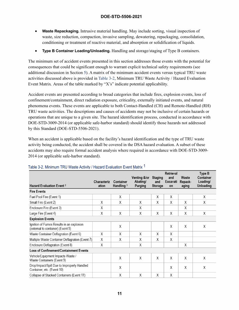
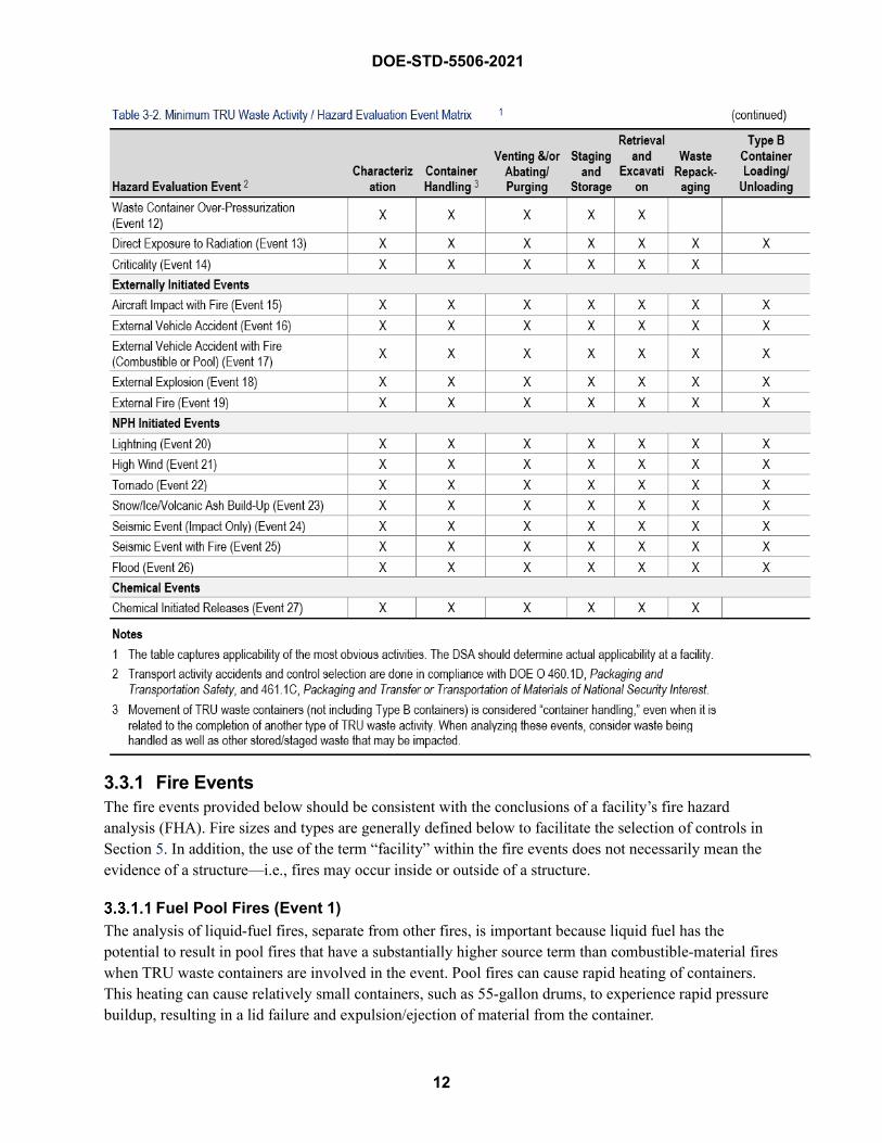
The minimum set of accident events presented in this section addresses those events with the potential for consequences that could be significant enough to warrant explicit technical safety requirements (see additional discussion in Section 5). A matrix of the minimum accident events versus typical TRU waste activities discussed above is provided in Table 3-2, Minimum TRU Waste Activity / Hazard Evaluation Event Matrix. Areas of the table marked by “X’s” indicate potential applicability.
Accident events are presented according to broad categories that include fires, explosion events, loss of confinement/containment, direct radiation exposure, criticality, externally initiated events, and natural phenomena events. These events are applicable to both Contact-Handled (CH) and Remote-Handled (RH) TRU waste activities. The descriptions and causes of accidents may not be inclusive of certain hazards or operations that are unique to a given site. The hazard identification process, conducted in accordance with DOE-STD-3009-2014 (or applicable safe-harbor standard) should identify those hazards not addressed by this Standard (DOE-STD-5506-2021).
When an accident is applicable based on the facility’s hazard identification and the type of TRU waste activity being conducted, the accident shall be covered in the DSA hazard evaluation. A subset of these accidents may also require formal accident analysis where required in accordance with DOE-STD-3009-2014 (or applicable safe-harbor standard).
Table 3-2. Minimum TRU Waste Activity / Hazard Evaluation Event Matrix 1
DOE-STD-5506-2021
12
3.3.1 Fire Events The fire events provided below should be consistent with the conclusions of a facility’s fire hazard analysis (FHA). Fire sizes and types are generally defined below to facilitate the selection of controls in Section 5. In addition, the use of the term “facility” within the fire events does not necessarily mean the evidence of a structure—i.e., fires may occur inside or outside of a structure.
Fuel Pool Fires (Event 1) The analysis of liquid-fuel fires, separate from other fires, is important because liquid fuel has the potential to result in pool fires that have a substantially higher source term than combustible-material fires when TRU waste containers are involved in the event. Pool fires can cause rapid heating of containers. This heating can cause relatively small containers, such as 55-gallon drums, to experience rapid pressure buildup, resulting in a lid failure and expulsion/ejection of material from the container.
13
DOE-STD-5506-2021
These potential fires are associated with the ignition of pools by various ignition sources, such as thermal energy from the equipment or sparks from moving containers. The fuel pool is formed from the leaking of equipment and/or vehicle flammable/combustible liquids or the spilling of the liquids during refueling, maintenance, or an impact from equipment/vehicles used to support TRU waste operations. The potential amount of fuel is dependent on the equipment/vehicles used within the facility footprint and may range from a few gallons to thousands of gallons. Separate fuel pool fire events should be included, as necessary, for complete hazard evaluation and control selection.
Additionally, if the fuel pool fire event is initiated by an equipment/vehicle impact and postulated to impact uncontainerized and/or containerized waste (See Event 9), an additional event that addresses the hazards of both the fuel pool fire and the vehicle impact shall be analyzed for complete hazard evaluation and control selection.
Small Fire (Event 2) Small fires may affect either one container during a container fire or one to several containers through exposure or direct impingement, but outside of any facility confinement enclosure (e.g., a glovebox). This type of fire is limited in size and is contained within a fire-limited area (as defined in the facility Fire Hazards Analysis) . Additionally, the intensity of a small fire may be inadequate to result in automatic Fire Suppression System (FSS) activation. These fires, in general, will cause material in containers to burn as confined material. However, some containers (e.g., those with relatively significant quantities of liquids or reactive materials) may result in drum pressurization, lid failure, and ejection of some of the container contents. The ejected material would burn as unconfined material, resulting in a greater release than confined material.
The event covers all small fires initiated within the facility but outside of any facility enclosures. This fire is started from the ignition of combustible and/or flammable materials within the facility as well as exposure fires from vehicles or other equipment within the facility. Fires of this type affect containers through exposure or direct impingement. Separate small-fire events from hazards associated with various facility activities may be required to ensure a complete hazard evaluation. The propagation of these fires into a larger fire is addressed in a separate event (Event 4).
Enclosure Fire (Event 3) For facilities using enclosures such as gloveboxes or hot cells, this fire is addressed separately from other small-fire events to ensure a complete hazard evaluation. This fire covers all internally initiated fires. The ignition source may be from pyrophoric or spontaneous combustion reaction, chemical reaction, or other source of internal heat generation. Flammable gas inside the enclosure may also result in a deflagration, which is addressed in a separate event. Additionally, if waste treatment activities not typically associated with TRU waste operations are conducted within an enclosure (e.g., stabilization of pyrophoric material through controlled oxidation), separate events may be required for complete hazard evaluation and control selection.
Large Fire (Event 4) This is a fire that propagates from any of the proposed smaller fire events. Propagated fires of different sizes may be proposed; the size will depend on the facility configuration. For example, a large, multilevel facility may have a room fire, a level fire, and a full-facility fire. The size of the fire analyzed within the
14
DOE-STD-5506-2021
DSA will depend on assumptions addressed in the FHA. For example, a full facility fire may not be plausible because of noncombustible facility construction/design and lack of operational needs for combustible/flammable materials (i.e., combustible loading is inherently low by the nature of the activity without the need to rely on credited controls to maintain that condition). Note, however, that if passive structures, systems or components (SSCs), such as fire-rated concrete walls, are assumed to prevent propagation of fire from one facility TRU waste container area to another, such SSCs typically need to be protected as TSR design features.
3.3.2 Explosion Events These events can be linked to causes such as radiolysis and generation of hydrogen or waste constituents generating volatile organic compounds. Chemical reactions within the waste stream, as discussed in Event 27, can also initiate events discussed in this section.
Ignition of Fumes Results in an Explosion (external to container) (Event 5) This event is caused by hazards external to the waste matrix, such as vehicle fuel/fumes, battery explosions, welding gases, or other explosive gases used in the facility. In addition to explosion overpressures, an explosion could produce missiles that could impact containers of waste or facility SSCs. For waste in containers, the release mechanism would essentially be an impact.
Waste Container Deflagration (Event 6) This event is due to hydrogen or other flammable/explosive gases or vapors (e.g., off-gas from Volatile Organic Compounds [VOCs]) inside the container) in a suspect container. A suspect container is one that has no vent; a plugged vent1; or an inadequate vent (e.g., flammable gas generation rate greater than venting capability); and meets at least one of the following criteria:
Obvious indications of pressurization;
Waste stream characteristics indicate a potential for generating concentrations of hydrogen greater than 8% by volume;
Waste stream characteristics indicate a potential for generating concentrations of other flammable gas mixtures greater than or equal to the Lower Flammability Limit (LFL); or
Waste stream data is either inadequate or unavailable to rule out the potential for generating concentrations of hydrogen greater than 8% by volume or other flammable gas mixtures greater than or equal to the LFL.
Application of these criteria will typically result in the need to analyze a deflagration at most TRU waste facilities, as data may be unavailable to rule out the potential for generating hydrogen concentrations greater than 8% by volume. A technical basis for ruling out the potential for rapid gas generation and high hydrogen concentrations within a container could include actual headspace gas sampling data, comparison to decay heat limits, or consideration of the form/composition of waste.
1 A plugged vent does not include temporary covering or blocking of filters to support flammable-gas analysis conducted in accordance with DOE/WIPP-06-3345, Waste Isolation Pilot Plant Flammable Gas Analysis (Revision 10 or later).
15
DOE-STD-5506-2021
As described in APPENDIX B and APPENDIX D, a mixture of 4% hydrogen (by volume) in air can deflagrate, but the pressure increase is relatively low and will not result in lid loss for a drum and possibly may cause a small release from drum seal failure. Based on experimental data with 55-gallon drums, lid loss can be expected at hydrogen concentrations of at least 15% in air (assuming the initial pressure is close to atmospheric). As discussed in APPENDIX D, DOE has added conservatism by selecting 8% hydrogen as the threshold for drum lid loss, to account for uncertainties. A lid that is forcefully ejected from a waste container during a deflagration presents a physical hazard to a facility worker. This hazard could cause serious injury or death to the worker and may necessitate controls for facility workers who are handling suspect drums. Analysts should not screen the hazard as an SIH.
Ignition sources include sparks, heat, static electricity, etc., that can ignite gases escaping the container, as well as potential ignition sources in the waste, such as metal objects, pyrophoric material, and heat-generating chemical reactions. More than one waste container deflagration event may be required; the exact number will depend on the number of various facility activities and the similarity of the postulated event causes and potential controls.
Multiple Waste Container Deflagration (Event 7) This event is due to waste container deflagration propagating horizontally or vertically to initiate additional container deflagrations. This event requires two suspect containers (see the definition in Event 6) that can be stacked or stored/staged immediately adjacent to each other (e.g., on a pallet). More thantwo containers should be considered if there is a potential for multiple suspect drums to be co-located. Itshould also be considered for situations where multiple newly generated containers that have beenrecently vented are commingled until determined by headspace sampling or has a technical basis thatsupports that the vent is adequate to reduce to a concentration lower than 8 vol% hydrogen.
Enclosure Deflagration (Event 8) For facilities using enclosures such as gloveboxes or hot cells, deflagrations within the enclosure are addressed as separate events to ensure a complete hazard evaluation. This event is caused by hydrogen or other flammable/explosive gases inside an enclosure or within a container that has been placed inside and opened within an enclosure. Flammable vapors could be concentrated or exacerbated by a loss of ventilation/purge. Ignition sources include sparks, heat, etc. that can ignite gases as well as potential ignition sources in the waste, such as metal objects, pyrophoric material, and heat-generating chemical reactions.
3.3.3 Loss of Confinement/Containment
Vehicle/Equipment Impacts Waste/Waste Containers (Event 9) This event is due to operation of vehicles or equipment associated with facility operations as described in the DSA. These vehicles and equipment may or may not be used in close proximity to the TRU waste. The impact type will vary based on the impact source and may involve, for example, a container puncture by forklift tines, or a larger vehicle impact resulting in container damage. Additionally, the potential for a fuel pool fire should be evaluated when vehicles/equipment with liquid fuels are involved in impacts with waste/waste containers; see Event 1.
16
DOE-STD-5506-2021
Drop/Impact/Spill Due to Improperly Handled Container, etc. (Event 10) This event is due to mishandling of containers or to drops/impacts caused by equipment failure. This subcategory of loss of confinement events includes drops of containers from a height hitting a hard surface or containers being impacted by an energy source that is not included in another of the loss-of-confinement subcategories (e.g., loads being dropped onto containers, gas cylinder missiles, maintenance activities), resulting in a spill of radioactive or hazardous material. If TRU waste containers may be dropped from elevated surfaces—e.g., drums falling from third tier or higher (see Figure 4-3, Comparison of Drum DR and ARF×RF for Contaminated Solids in Drops, Falls, and Vehicle Crashes, example of vertical stacking) during removal—a separate event will be required to ensure a complete hazard evaluation. Section 4.4.3 provides guidance on release estimates based on two levels of impact energies.
Collapse of Stacked Containers (Event 11) This event is a collapse of a stacked array of containers. The collapse may be a failure of the containers, pallets, or other stacking media due to corrosion, defective construction, damage, or improper stacking—e.g., exceeding limits, or an unstable array.
Waste Container Over-Pressurization (Event 12) This event is due to a buildup of pressure inside of a container. The pressure buildup may be due to radiolysis of water or other hydrogenous material, thermal expansion of material/gases inside the container, or chemical reactions inside the container. This is typically a slowly developing event (on the order of months), although containers with unknown material or with the potential for chemical reactions may pressurize more rapidly (on the order of hours to days).
3.3.4 Direct Exposure to Radiation Events (Event 13) This event is caused by ionizing radiation from the waste. The exposure may be due to normal operational conditions (e.g., handling, cleaning up a spill) or due to an accident that causes the loss of shielding inherent to the container/activity. If the facility processes both CH and RH TRU waste, separate events for these waste types should be included for complete hazard evaluation.
3.3.5 Criticality Events (Event 14) Criticality events can occur due to many different causes. These are typically evaluated in a Nuclear Criticality Safety Evaluation (NCSE) consistent with DOE-STD-3007-2017, Guidelines for Preparing Criticality Safety Evaluations at Department of Energy Nonreactor Nuclear Facilities. Events in the NCSE that require criticality controls should be explicitly presented in the DSA. Also, the NCSE events should be evaluated against other events in DSA to ensure that all potential upsets were considered in the NCSE.
3.3.6 Externally Initiated Events
Aircraft Impact with Fire (Event 15) This event occurs when a large commercial aircraft, small general-aviation aircraft, or helicopter crashes into the facility and a fire ensues. Site over-flights and nearby airports are contributors to this event.
Aircraft impact events are evaluated where deemed credible, or not screened out by other criteria, in accordance with DOE-STD-3014-2006, Accident Analysis for Aircraft Crash into Hazardous Facilities. A
17
DOE-STD-5506-2021
representative aircraft of the category indicated as credible per DOE-STD-3014 should be evaluated with a fire initiating coincident with the crash.
External Vehicle Accident (Event 16) This event is due to a vehicle, not associated with facility operations, impacting the facility/waste containers. Traffic on nearby roads contributes to this event. This event differs from the vehicle impact from operational activities previously discussed (Event 9) in that the vehicle is not associated with facility operations allowed in the DSA. Additionally, if controls are necessary, the control set for this event may differ from the control set used for operations-related equipment.
External Vehicle Accident with Fire (Combustible or Pool) (Event 17) This is a potential follow-on event for the external vehicle accident. After the vehicle accident, spilled combustible waste, and/or fuel from the vehicle ignite and burn.
External Explosion (Event 18) This event is similar to the explosion due to mechanical failure, with missiles occurring within the facility that was discussed in Section 3.3.2.1. The hazard is primarily from vehicles/roadways near the facility or storage location, or from nearby locations with large quantities of explosive gas—for example, from a nearby gas pipeline, propane tanks, or pressurized gas used for characterization or welding.
In addition to explosion overpressures, an explosion could produce missiles that could impact containers of waste or facility SSCs. For waste in containers, the release mechanism would essentially be an impact.
External Fire (Event 19) This is a fire that begins outside of the facility and propagates to the facility. The external fire could be from wildland fires, other facilities, or another fire source. If TRU waste may be within and/or outside of a building, external fires should address impacts both on waste handled/stored inside or outside of a building.
3.3.7 Natural Phenomenon Hazard Initiated Events
Lightning (Event 20) A lightning strike may cause fires in the electrical system (e.g., ignition of wire insulation in electrical systems) that could ignite nearby material. Lightning strikes that cause fires outside of the facility are addressed as external fires.
Additionally, lightning may strike a container or near stored/staged containers. The direct strike could cause rapid heating and pressurization of a container, with ejection of material. In the case of a direct lightning strike to an overpacked container, the overpack should not be assumed to provide any additional protection. The event should be modeled as an internal container deflagration, as described in Section 4.3.2. A direct lightning strike to an overpacked container should not be considered to prevent damage to the inner container, and this release should also be modeled as an internal deflagration. The nearby strike could cause small missiles (e.g., fragments of concrete).
18
DOE-STD-5506-2021
High Wind (Event 21) This event is due to high winds causing impacts to both the facility and the containers by falling objects. The falling objects may be nearby trees, pole, cranes, or parts of the facility structure.
Tornado (Event 22) This event is due to a direct effect of a tornado, falling objects, or tornado-produced missiles causing impacts to both the facility and the containers. Missiles may be produced from various pieces of equipment or material (e.g., pallets). The falling objects may be nearby trees, poles, cranes, or parts of the facility structure.
Snow/Ice/Volcanic Ash Build-up (Event 23) Accumulation of snow, ice, or volcanic ash may cause the roof of a facility or structure to collapse, or may cause nearby objects, such as trees, to fall and impact the waste containers.
Seismic Event (Impact Only) (Event 24) The seismic event can cause failure of the facility structure (partial or catastrophic, depending on the facility construction), failure of equipment inside the facility, or other structure failure, which impacts the waste. Additionally, the event can cause containers to fall and spill their contents.
Seismic Event with Fire (Event 25) The seismic event can cause failure of the facility, failure of equipment inside the facility, or failure of other structures, which impact the waste. Additionally, the event can cause containers to fall and spill their contents. The structural failure could involve damage to electrical systems that are not seismically qualified or involve other potential ignition sources (e.g., flammable materials or gas lines where present) that can ignite spilled combustible waste or other combustibles in the facility.
Flood Event (Event 26) A flood event can cause failure of facility structures or equipment, thereby impacting integrity of waste or waste containers. Relocation of waste containers is also possible, creating the potential for a criticality where fissionable inventory remains in uncharacterized2 TRU waste in containers.
3.3.8 Chemical Initiated Events (Event 27) Chemical constituents in waste streams can lead to uncontrolled reactions with subsequent heat generation, fire, explosion, formation of toxic fumes, formation of flammable gases, formation of shock and friction sensitive compounds, and pressurization in closed vessels. Such reactions can be initiators for other events described in Section 3.3 (e.g., deflagrations) and can be caused by incompatible mixtures of chemicals. Reactions can also be initiated by environmental effects, such as temperature, humidity, and oxygen in air, that may change over time or that could be associated with an unplanned event such as a fire. These types of situations should be evaluated in the DSA where applicable, e.g., as identified by the FHA or Chemical Compatibility Evaluation (CCE).
2 The term ñuncharacterizedò as used in this Standard refers to TRU waste being stored onsite, or retrieved from burial grounds, that has not been processed to meet WIPP Waste Acceptance Criteria and may have prohibited items and/or unknown chemical constituents.

19
DOE-STD-5506-2021
An example of adverse chemical reactions is related to oxidizing chemicals in the waste matrix, both in newly repackaged containers and during storage. When such chemicals come into contact with organic materials (e.g., neutralizing or buffering agents), rapid pressurization can occur and potentially explosive compounds can develop. Determination of the potential for accidents involving oxidizing chemicals should include an evaluation of whether such chemicals may be present in the waste (i.e., process chemistry where the waste originated and associated chemical constituents), relative quantities and concentration of chemicals present in the waste stream (especially concerned with strong acids), actions or additions to the waste planned during repackaging efforts, and stability of repackaged waste during storage (e.g., engineered organic polymer sorbents). Additional information on oxidizing chemical hazards can be found in DOE/WIPP-17-3589, Basis of Knowledge for Evaluating Oxidizing Chemicals in TRU Waste (Revision 1 or later). The resource is useful in evaluating waste with one or more oxidizing chemicals.
Another example hazard that may exist at some DOE sites (e.g., operations involving unique chemicals), are chemicals that are or may become shock-sensitive. Materials such as perchloric acid and other peroxide-formers can leave behind sensitive crystalline structures (e.g., on lids of laboratory beakers or containers) that are vulnerable to energetic reactions upon impact or jarring.
The hazard analysis shall include an evaluation of the chemicals potentially in the waste to consider whether adverse chemical reactions could occur. This evaluation should determine whether chemicals are present in a quantity or form sufficient to produce adverse reactions and whether reactions can be created by combinations of waste with incompatible chemicals. Chemicals should only be excluded from evaluation with technical justification. Chemicals that are present in small quantities can still play an important role in the progression of a chemical reaction.
A CCE is a required part of the Waste Isolation Pilot Plant waste certification process and is based on the method described in the 1980 EPA method EPA-600/2-80-076, A Method for Determining Compatibility of Hazardous Waste. This evaluation is intended to identify and evaluate potential reactions between dominant and minor chemical constituents within the waste stream and demonstrate that the waste will not lead to unanticipated or disastrous effects—will not, for example:
• Generate extreme heat or pressure, fire or explosions, or violent reactions,
• Produce uncontrolled toxic mists, fumes, dusts, or gases in sufficient quantities to threatenhuman health or the environment;
• Produce uncontrolled flammable fumes or gases in sufficient quantities to pose a risk of fire orexplosions;
• Damage the structural integrity of the device or facility;
• Threaten, through other like means, human health or the environment.
This methodology also addresses various waste-management scenarios, including situations where waste creator records may be inadequate (e.g., some uncharacterized waste streams). The EPA methodology is a useful tool for assessing chemical hazards in transuranic waste. This approach, or other systematic evaluation techniques, should be employed during DSA development to ensure a complete evaluation of

20
DOE-STD-5506-2021
chemical hazards. The evaluation should identify the chemicals that are potentially in (or in contact with) the waste, and should assess combinations of those chemicals to determine whether the waste could participate in adverse reactions.
Overall, the chemical compatibility evaluations should analyze:
• the origin of waste, including process chemistry from which it was generated and any off-normalconditions (e.g., spills),
• relative quantities and concentration of chemicals present in the waste stream,
• storage environment (e.g., temperature, slow reactions as the waste ages, and potential reactionswith air or water),
• actions or additions to the waste planned during repackaging efforts,
• stability of repackaged waste during storage.
Maximum possible use should be made of existing information from previous or current WIPP certification campaigns, such as the required acceptable knowledge (AK) documentation and available CCEs performed to meet WIPP requirements. The National TRU Program non-conformance reports should also be routinely evaluated for potential issues related to chemical reactions.
In some cases, waste records and AK documentation may not be sufficient to determine whether chemical constituents are present within waste streams. A careful review of the origin of waste, including facility processes from which it was generated, is necessary as part of the hazard identification process. Representative waste samples can be collected and analyzed, where feasible, to help determine waste characteristics. When this data or other technical basis is not available, the DSA should assume the presence of chemical constituents used in previous facility processes that generated the waste. The DSA should also analyze additional hazards associated with waste processing and repackaging activities and account for potential adverse effects of additives or mixing of incompatible chemicals.
3.4 Expected Operational Events A facility’s DSA addresses normal, abnormal, and accident conditions as required by 10 CFR Part 830. A subset of the events evaluated in the DSA includes certain operational events that are expected to occur during the lifetime of a given TRU waste operation even with preventive controls in place. As used in this Standard, expected events are defined as planned occurrences encountered during normal operations that result from hazards inherent to the material and activities. This definition does not include events caused by personnel errors, since these causes involve a control failure that warrants some level of investigation. For example, incidental fires or reactions might be expected during retrieval and excavation of TRU wastes involving flammable/explosive atmospheres.
In cases where an expected operational event occurs, it is prudent to validate that established protective measures function as intended, and then resume operations. This is similar in concept to initiating authorized required actions when a Limiting Condition for Operation (LCO) condition is entered. The DOE acknowledges the potential for the event and adequacy of the protective measures through approval of the DSA. Approval of a DSA in which response actions are cited for specified “expected events”
21
DOE-STD-5506-2021
effectively authorizes work to continue once the event conditions are evaluated, reported (where necessary in accordance with DOE O 231.1B, Environment, Safety and Health Reporting, or DOE O 232.2A, Occurrence Reporting and Processing of Operations Information), and it is confirmed that the expected event occurred as planned and no unanticipated behavior or consequences (e.g., worker injury) were exhibited. It should be noted that DSA coverage of an “expected operational event” does not apply to situations in which it is determined that a potentially inadequate safety analysis exist as discussed in 10 CFR 830, Subpart B (i.e., an operational event related to errors, inappropriate value, or otherwise inadequate analysis in the DSA).
For the purposes of this Standard, an expected operational event involves known hazards that are described in the DSA, and which does not result in significant consequences to workers or the public with preventive and mitigative controls in place. In other words, the protective features provided to perform operational processes ensure consequences are within the operational standards that apply to the work. For example, worker dose is limited to criteria established in 10 CFR Part 835, Occupational Radiation Protection.
The DSA provisions for documenting expected operational events are as follows:
• The event is documented in the facility process description of the DSA
• The response actions following occurrence of the expected event are specifically documented inthe DSA, although they may be as simple as “Evaluate and report the event to DOE” (wherenecessary in accordance with DOE O 231.1B and DOE O 232.2A).
• The event is analyzed in the DSA hazard evaluation.
• Worker protection measures for the operational event are identified in the DSA.
A primary benefit of identifying expected operational events is to provide DOE with the means of pre-approving actions for continued operation should certain events that meet the conditions of an expected event occur. Because these events are expected, appropriate protective measures and actions to ensure continuation of operations shall be identified and in place prior to beginning the operation.
DOE-STD-5506-2021
22
TRU Waste Source Term Analysis 4.1 Purpose This section provides guidance on source term development. The Source Term (ST) is the amount of airborne respirable radioactive material released to the environment. As specified in DOE-HDBK-3010-94, Airborne Release Fractions/Rates and Respirable Fractions for Nonreactor Nuclear Facilities, ST is used as part of the analysis of hazards/accidents and is determined by the following five-factor formula:
ST = MAR·× DR × ARF × RF × LPF Where,
MAR = Material-at-Risk is the amount of radionuclides available to be acted on by a given physical stress.
DR = Damage Ratio or fraction of the MAR that is impacted by the postulated accident scenario, unitless
ARF = Airborne Release Fraction, unitless
RF = Respirable Fraction, unitless
LPF = Leakpath Factor, unitless
Additional information on unmitigated analysis methodology and assumptions can be found in DOE-STD-3009-2014 and DOE-HDBK-1224-2018.
4.2 Material-at-Risk The amount of hazardous material that is assumed to be at risk from a postulated accident scenario, or MAR, will directly impact the doses received by both workers and the public. An overly conservative estimate of the MAR could very well lead to establishment of unnecessary controls and an ineffective use of resources. On the other hand, an optimistic (non-conservative) analysis could lead to major impacts on operations by discovering discrepant as-found-conditions, Potential Inadequacies in the Safety Analysis (PISAs), preparation of multiple Unreviewed Safety Questions (USQs) determinations, and even potentially creating conditions that could lead to accidents. Thus, there is a need to balance the level of conservatism associated with the MAR definition.
4.2.1 Data Uncertainties in Hazard and Accident Analysis The purpose of determining MAR estimates during Hazard Analysis (HA) and Accident Analysis (AA) is to identify a bounding value for the scenario being evaluated. During the HA, qualitative consequence severity categories are assigned to each of the postulated accident scenarios. Thus, there is a need for an understanding of the MAR expected to be involved. During AA, a more quantitative knowledge of the anticipated MAR is expected and is based on a quantitative assessment of the effects of the postulated release, a assessment that considers factors such as inventory, material form, and the energy sources involved with the release.
Data uncertainties associated with the MAR depend on many variables, such as the quality of the current inventory data, whether the data represents Acceptable Knowledge (AK) for uncharacterized waste or
23
DOE-STD-5506-2021
newly generated waste, and whether the inventory is based on actual characterization data. Most uncertainties associated with uncharacterized waste stem from the fact that requirements for—and formality associated with—AK documentation have changed significantly, with the requirements for the older documentation being less stringent than current requirements. Thus, uncertainties associated with characterized waste are much less significant (e.g., intrinsic uncertainties associated with NDA and NDE).
4.2.2 Defining a Bounding MAR for TRU Operations Table 4-1, Bounding MAR Approach for TRU Waste Operations, summarizes a bounding MAR approach that may be applied for TRU waste operations. The table provides an algorithm of MAR values based on the number of containers anticipated to be impacted by postulated scenarios (single container, payload, building, etc.), and inventory knowledge (e.g., whether the inventory has been partially or fully characterized). In cases where no characterization data is available, inventory estimates should be based on existing process knowledge or the use or extrapolation of characterization data from similar waste streams.
The quantities of TRU material presented in Table 4-1 follow the general algorithm that
• A single container scenario assumes the presence of the single maximum loaded container(including instrument uncertainty), while
• Multiple container accident scenarios assume the presence of some combination of containerscontaining the maximum container value, the 99th percentile value, the 95th percentile value, andthe mean value quantities of TRU material, from the population of containers being evaluated.
The algorithm also accounts for the extent of characterization associated with the inventory (limited or partial characterization, and fully characterized, e.g., WIPP compliant assay).
The use of an additional 20% margin is recommended for single-container events in which the container is not characterized or has limited characterization (e.g., not fully WIPP-compliant or otherwise acceptably characterized). A higher margin may be warranted for waste retrieval activities (i.e., from burial grounds) when container integrity or waste data records are questionable or unknown. In these cases, assumptions should be specifically derived in the DSA.
The methodology in Table 4-1 provides for additional conservatism to account for the increased uncertainty when the waste containers involved in the accident are not fully characterized. For those inventory populations with only limited or partial characterization, the MAR value shall be based on the non-parametric estimate of the 95% upper tolerance limit (UTL95) for the specified percentiles and the 95% upper confidence limit (UCL95) for the mean (arithmetic average); see APPENDIX A. Container populations, for which individual container inventories have all been determined, through measurement (and documented), may be considered to be fully characterized for application of the algorithm in Table 4-1.
The MAR approach in Table 4-1 defines a bounding approach for typical TRU waste operations. This approach, however, is intended to be used only in operations in which containers are randomly selected or placed within storage without a bias toward waste type or characteristic (e.g., high MAR containers segregated from a population). The MAR methodology is not intended for the following situations:
DOE-STD-5506-2021
24
• Operations that intentionally commingle containers from the upper end of the facility’sdistribution of radioactive material (e.g., the highest two or three containers in the same array thatis impacted by an accident stress);
• Operations in which it can’t be distinguished whether containers with the highest distribution ofradioactive material are commingled in a facility’s inventory (e.g., retrieval of uncharacterizedTRU waste in containers from burial grounds without data supporting such assumptions); or
• Containers that have been prepared for shipment in accordance with limits established in theWIPP waste acceptance criteria where containers are repackaged to the maximum of such limits(i.e., versus a practice such as one-for-one parent-to-daughter drum repackaging).
In the first two situations, the term “commingling” is relative to the proximity of containers that are concentrated in an area that can be impacted by a single accident stress—e.g., intentionally concentrating together or segregating high-MAR drums from the general population of drums.
The MAR approach in Table 4-1 should consider the combination of source-term factors that produce a conservative result. When a facility has a variety of waste types and container types, the DSA shall include assumptions that lead to a bounding source term, as opposed to a bounding MAR (unless otherwise directed in the guidance provided for specific events such as seismic impacts). These assumptions include a combination of factors, including the material form, the release fraction, individual container MAR loading, container response to event stress, and event MAR distribution to derive the conservative source term for the event. For example, for a fuel pool fire accident in which some containers lose their lids and others do not, the analyst would assume that the maximum container is in the population with lid loss. The MAR statistical method may be applied to subpopulations of containers within a facility (i.e., a portion of the overall containers that exists at a particular facility area), provided that the subpopulation meets the criteria for using Table 4-1. The subpopulation may be defined with separate MAR statistics (max, 95th percentile, mean) based on container type, MAR form, or other waste characteristics as supported by facility inventory controls. These methods for defining subpopulations may only be used if the MAR form and waste characteristics are well-understood. Additionally, the subpopulation shall not be subject to accident stresses that can simultaneously affect the remaining facility population of containers that lie outside the sub-population.
When using the MAR approach in Table 4-1, assumptions regarding the scope of container handling, staging, and storage shall be clearly stated in the DSA. DSA assumptions shall be reviewed periodically as necessary to ensure that MAR statistics have not changed in a non-conservative direction. Elements of safety management programs relied on to ensure MAR statistics remain conservative and up to date should also be discussed in the DSA (e.g., container management).
Administrative controls should be used to protect assumptions and conclusions of the hazard/accident analysis. These include specific limits (e.g., MAR container/area limits) or assumptions (e.g., combustible/noncombustible waste fractions) in the TSR that ensure the analysis remains valid or that are derived in the DSA mitigated analysis to ensure that accident consequences are not significant. Administrative controls should also be used to prohibit certain activities when there is potential that such activities could concentrate problematic containers, thereby invalidating the MAR methodology. Administrative controls should be evaluated to determine whether they should be designated as specific
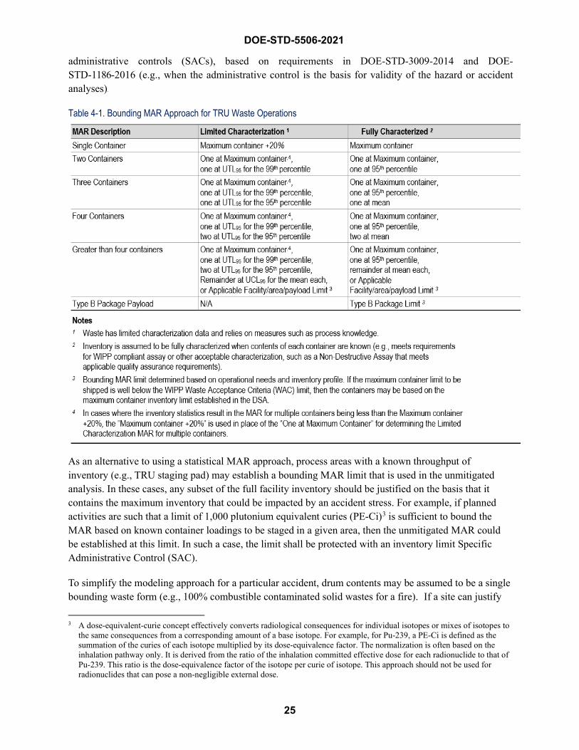
DOE-STD-5506-2021
25
administrative controls (SACs), based on requirements in DOE-STD-3009-2014 and DOE-STD-1186-2016 (e.g., when the administrative control is the basis for validity of the hazard or accident analyses).
Table 4-1. Bounding MAR Approach for TRU Waste Operations
As an alternative to using a statistical MAR approach, process areas with a known throughput of inventory (e.g., TRU staging pad) may establish a bounding MAR limit that is used in the unmitigated analysis. In these cases, any subset of the full facility inventory should be justified on the basis that it contains the maximum inventory that could be impacted by an accident stress. For example, if planned activities are such that a limit of 1,000 plutonium equivalent curies (PE-Ci)3 is sufficient to bound the MAR based on known container loadings to be staged in a given area, then the unmitigated MAR could be established at this limit. In such a case, the limit shall be protected with an inventory limit Specific Administrative Control (SAC).
To simplify the modeling approach for a particular accident, drum contents may be assumed to be a single bounding waste form (e.g., 100% combustible contaminated solid wastes for a fire). If a site can justify
3 A dose-equivalent-curie concept effectively converts radiological consequences for individual isotopes or mixes of isotopes to the same consequences from a corresponding amount of a base isotope. For example, for Pu-239, a PE-Ci is defined as the summation of the curies of each isotope multiplied by its dose-equivalence factor. The normalization is often based on the inhalation pathway only. It is derived from the ratio of the inhalation committed effective dose for each radionuclide to that of Pu-239. This ratio is the dose-equivalence factor of the isotope per curie of isotope. This approach should not be used for radionuclides that can pose a non-negligible external dose.
26
DOE-STD-5506-2021
bounding estimates for the distribution of combustible vs. other forms (e.g., 40% combustibles and 60% noncombustibles), the appropriate ARFs and RFs from DOE-HDBK-3010-94 and Section 4.4 of this Standard should be applied for the applicable segmented waste. This approach is intended to support an overall conservative analysis as required for DOE-STD-3009-2014. It is intended to be used only for TRU waste storage operations in which containers are randomly selected or placed within storage without a bias toward waste type or characteristic (e.g., all combustible waste containers segregated from the general population that would have higher release potential). The application of a waste form distribution for a particular accident is not intended for the following situations:
• Operations that intentionally commingle containers with the highest distribution of combustiblewaste material or other form of material that may have a higher release potential (e.g., the highestfew containers in the same array that is impacted by an accident stress that could invalidate thewaste form distribution); or
• Operations in which it can’t be distinguished whether containers with the highest distribution ofcombustible material or other form of material that may have a higher release potential arecommingled in a storage location (e.g., retrieval of uncertified containers without data supportingsuch assumptions).
In the above situations, the term “commingling” is relative to the proximity of containers that are concentrated in an area that can be impacted by a single accident stress such as a fire—e.g., intentionally concentrating together or segregating high-combustible drums from the general population of drums. For this situation, the analysis should consider the waste forms that could be present in the facility, and assume that the waste involved in the accident is of the form that gives the bounding source term.
4.3 Damage Ratios The DR is one of the parameters of the “five-factor formula” presented in the DOE-HDBK-3010-94 for estimating the airborne radiological release from an accident. The DR is defined in DOE-HDBK-3010-94 as the “fraction of the MAR actually impacted by the accident-generated conditions.” However, there is a degree of interdependence between the definitions of DR and MAR. If only the MAR directly affected is used, then the DR is 1.0. The DR may be less than 1.0, depending on the accident. What is important is that one convention be used consistently to avoid an obvious potential for assigning incorrect DR values.
The DR is estimated based upon engineering analysis of the response of structural materials and materials-of-construction for containment to the type and level of stress/force generated by the event. Standard engineering approximations are typically used. These approximations often include a degree of conservatism due to simplification of phenomena to obtain a usable model, but the purpose of the approximation is to obtain, to the degree possible, a realistic understanding of potential effects.
The DR term is used in a variety of ways in this Standard to account for the MAR affected and overall source term and may involve multiple adjustment factors. For example, in complex accidents where different portions of MAR undergo different accident stresses, DRs are assigned to fractions of MAR for the different release pathways, such as for a drum deflagration where a fraction of MAR is ejected, releasing material from shock-vibration and subsequent unconfined burning of combustible material, and confined burning of contents remaining in the drum. In other cases, DRs account for the protection
27
DOE-STD-5506-2021
provided by a container, or to adjust ARFs and RFs based on multiple accident stresses. In such complex cases, attention is needed to ensure mathematical consistency and to avoid double-counting that reduces the source term impacted by an accident.
A DR of 1.0 is often assumed, either for simplicity in performing the calculations as suggested in the DOE-HDBK-3010-94 or based on conservatism if the final radiological consequences do not drive the need for special TSRs to prevent or mitigate the accident. Section 7.3.6.2 of the DOE-HDBK-3010-94 provides a very important perspective on assigning DRs:
In the examples in this handbook, DRs are typically bounded by assuming a value of 1.0 for the sake of simplicity. The above discussion indicates how conservative such a bound can be. It is important not to lose sight of the fact that the phenomena being examined are generally unlikely to highly unlikely. By the time a maximum MAR has been assumed, the DR has been maximized as 1.0, the bounding ARFs and RFs of this document have been applied, no leakpath is accounted for, and 95% or greater meteorology has been used for dispersion, the answer obtained is extreme. Objectivity must be retained in the evaluation process so that a rote conception does not distract available resources from areas where greater real gains in safety can be made. As previously cautioned in this handbook, answers obtained are only as good as the decisions they lead to.
That perspective should be kept in mind when DRs are justified for any specific accident scenario, natural phenomena event, or external events. The selection of appropriate DRs shall support an overall conservative analysis consistent with the DOE-STD-3009-2014 (or applicable safe harbor standard) methodology. DRs are also selected in context with the conservatisms of the other parameters in the “five factor formula,” i.e., MAR; bounding ARFs and RFs per DOE-HDBK-3010-94; and Leakpath Factor (only for mitigated analysis).
When applying the methodologies in Section 4.3 of the Standard, there are cases where modeling a smaller number of drums would be more conservative. After determining the number of drums that could be involved in an event as recommended in this section, the analyst should consider whether a smaller number of drums could be more conservative. If the smaller number of drums yields a more conservative result, then the smaller number shall be used. For example, Section 4.3.3.2, Drums Exposed by Ordinary Combustible Fires, allows for a 0.5 DR for less than 10 drums exposed to an ordinary combustible fire. Applying the Table 4-1 limited characterization algorithm and assuming that a maximum drum has 300 PE-Ci, the UTL95 for the 99th percentile drum is 90 PE-Ci, the UTL95 for the 95th percentile drum is 10 PE-Ci, and the UCL95 for the mean drum is 3 PE-Ci, the MAR involved for 100 drums is 698 PE-Ci with a 0.5 DR or an effective MAR of 349 PE-Ci. However, nine (9) drums have a MAR of 425 PE-Ci with a 1.0 DR, therefore is more bounding.
The following subsections address container integrity. They also identify conservative DRs for drum deflagrations, fires, container loss of confinement (low-energy and high-energy mechanical insults), and natural-phenomenon events. These DRs are used in both the DSA unmitigated and mitigated
28
DOE-STD-5506-2021
hazard/accident analysis. Safety classification of containers should be determined in accordance with the applicable 10 CFR 830, Subpart B, safe-harbor methodology. Consistent with DOE guidance, qualitative bases for classification of containers may be used.
Contact-handled (CH) TRU wastes are packaged and shipped for disposal to the Waste Isolation Pilot Plant (WIPP) in U.S. Department of Transportation (DOT) 7A containers. The latest version (March 2013) of the CH TRAMPAC document on the National TRU Programs portal lists the following containers as “Payload Container Assemblies,” i.e., Type 7A CH containers:
• 55-gallon metal drum (and other sizes)
• Pipe Overpack Container (POC)
• Standard Waste Box (SWB)
• Ten Drum Overpack (TDOP)
• Standard Large Box 2 (SLB2)
• Criticality Control Overpack (CCO)
• Shielded Container Assembly (SCA)
The performance of these containers under various accident stresses are similar for some of the container types but are not the same for all of them. APPENDIX C summarizes which containers are considered to be equivalent to each other for accident types, based on the technical evaluations of them for the WIPP safety basis. All containers are not specifically identified in the discussions throughout the remainder of this section. The discussion, however, applies to the equivalent container unless unique differences are elaborated.
4.3.1 Container Integrity DOT 7A or equivalent containers purchased for the packaging and storage of TRU waste provide containment of radioactive materials and minimize release of radioactive material to the public and workers. DOT 7A containers meet the performance testing requirements specified in 49 CFR Part 173, Shippers – General Requirements for Shipments and Packaging. Those requirements include performance testing which demonstrates that the containers can withstand the following types of normal handling and accident conditions:
• Water spray test
• Free drop test
• Penetration test
• Stacking test
When purchased, TRU waste containers are certified to DOT specifications. However, containers can degrade over time, and DOT certification is effective for only one year after packaging. TRU waste containers greater than one year old, therefore, have lost their DOT certification, even though they have not stopped performing their intended function (hereafter, these are referred to as “uncertified” containers). Type 7A containers that meet DOT specifications and conditions most applicable to DOE TRU waste activities are qualified to withstand an impact from a 4-ft drop onto a hard surface without being breached.
It is not reasonable to assume that the structural capability of a container more than one year old has diminished significantly or that these containers will split open upon any impact. This is supported by field experience during handling, movement and storage evolutions. Although handling activities do not
29
DOE-STD-5506-2021
subject the containers to the same loads as does an impact from a drop, these activities, along with regular inspections, do provide some evidence that most of the containers have maintained structural capability.
During storage, handling, and movement, TRU waste containers may be punctured, crushed, toppled, or dropped, causing failure of the container and release of material. Uncertified container performance and the degree of damage from these accident stresses are largely dependent on the structural integrity of the container. Several individual-drum drop tests and palletized-drum drop tests have been conducted and conclude that uncertified drums will maintain confinement from a 4-ft drop, because any small degradation is likely to be less than the margin of safety in the original drum design.
The WIPP CH WAC recognizes that most TRU containers are no longer certified. It therefore provides an inspection checklist to document that a container meets the DOT 7A criteria. WIPP has established these criteria to address uncertified containers and qualify them against new container requirements. By applying the WIPP criteria to uncertified containers, they can be deemed DOT Type 7A-compliant. It is reasonable to conclude that containers that satisfy the WIPP container criteria may also be credited as meeting DOT specifications during storage. The WAC states:
Acceptance Criterion for CH-TRU and RH-TRU Waste. Both CH-TRU and RH-TRU waste payload containers shall –
• meet U.S. Department of Transportation (DOT) Specification7A, Type A, packaging requirements delineated in 49 CFR173.465 (Reference 4, Section 2.3.2; Reference 10, AttachmentA1, Section A1-1b),
• be made of steel and be in good and unimpaired condition priorto shipment from the DOE sites. To demonstrate compliancewith the requirement that payload containers be in good andunimpaired condition, the exterior of all payload containers shallundergo 100% visual inspection prior to loading into anauthorized package. The results of this visual inspection shall bedocumented using the Payload Container Integrity Checklistcontained in Appendix D. A payload container in good andunimpaired condition, 1) does not have significant rusting, 2) isof sound structural integrity, and 3) does not show signs ofleakage. Significant rusting is a readily observable loss of metaldue to oxidation (e.g., flaking, bubbling, or pitting) that causesdegradation of the payload container’s structural integrity.Rusting that causes discoloration of the payload containersurface or consists of minor flaking is not considered significant.A payload container is not of sound structural integrity if it hasbreaches or significant denting or deformation. Breaching isdefined as a penetration in the payload container that exposes theinternals of the container. Significant denting or deformation isdefined as damage to the payload container that results in
DOE-STD-5506-2021
30
creasing, cracking, or gouging of the metal, or damage that affects payload container closure. Dents or deformations that do not result in creasing, cracking, or gouging or affect payload container closure are not considered significant.
• be reported to the WWIS database referencing the number andtypes of payload containers planned for shipment to the WIPP.
These criteria have been assembled into a verification checklist, provided in Table 4-2. It should be noted that the WIPP WAC and container-integrity checklist criteria are subject to change based on field experience and feedback. The Table 4-2 criteria are based on DOE/WIPP-02-3122, Contact Handled Transuranic Waste Acceptance Criteria for the Waste Isolation Pilot Plant, that was in effect at the time of development of this Standard. The most current criteria shall be used to determine sound structural integrity of TRU containers.
The use of damage ratios specified in the Standard (i.e., DR < 1) are based on containers with sound integrity that meet these criteria. This applies to both direct-loaded and overpacked containers. An overpacked container is a metal container of sound integrity nested within a larger metal container of sound integrity (e.g., a drum, SWB, or Ten Drum Overpack [TDOP]). Application of these criteria assumes container integrity can be verified through an inspection program or process knowledge. Where this cannot be accomplished (e.g., TRU waste retrieval from a burial ground), a DR of less than 1 requires explicit justification. Additionally, in cases where a criterion is met in Table 4-2, Payload Container Integrity Checklist, the uncertified container cannot be assumed to be of sound integrity. Containers that are discovered to not be of sound integrity should be addressed per the site’s procedures for managing waste containers, and if necessary, might require specific TSR controls beyond those listed in Table 5-1. If a DSA uses the damage ratios in this Standard for containerized waste, the DSA shall document the basis for assuming that the containers have sound integrity (e.g., regular inspections).
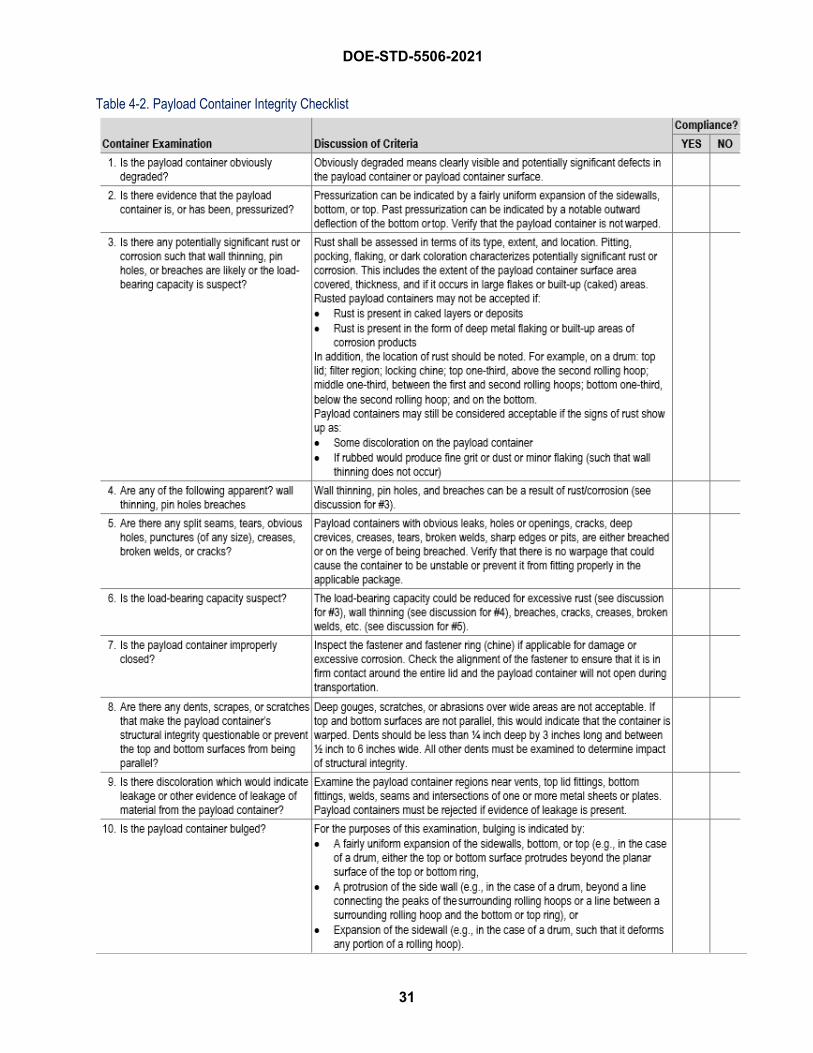
DOE-STD-5506-2021
31
Table 4-2. Payload Container Integrity Checklist
32
DOE-STD-5506-2021
4.3.2 Container Deflagration Events A container deflagration occurs when flammables (gases or vapors) inside the vapor space of a container ignite. The gases burn, with the flame front advancing at subsonic speeds (in contrast to a detonation). Heat and combustion products are released, leading to a rapid increase of pressure inside the container. Depending on the circumstances, the lid of the container may or may not be ejected. Waste can be released from the container as the excess pressure is vented through mechanisms such as lid loss, seal failure, and vent failure. The deflagration can also ignite the contents of the container and/or ejected materials, leading to airborne releases.
Three components are necessary for burning: fuel, oxidant, and an ignition source. Other factors will affect the ignition and combustion of fuel–air mixtures, such as concentrations of the reactants, the location of the ignition source, and presence of water vapor. Sufficient oxygen is assumed to be present unless a lack of it can be technically justified. An ignition source should always be assumed to be present for the unmitigated analysis.
The radiolysis of hydrogenous materials by the activity present in TRU waste generates hydrogen gas that may accumulate in the drums and other waste containers. Based on drum characterization studies for unvented drums, the oxygen content is simultaneously reduced, likely due to reaction with other materials present or hydrogen and oxygen forming water vapor, although this reduction could be offset by in-leakage past container seals due to breathing caused by barometric pressure and atmospheric temperature changes. However, characterization of unvented drums at the Savannah River Site has demonstrated that sufficient levels of oxygen are sometimes present to support combustion, in conjunction with levels of hydrogen that exceed its Lower Flammability Limit (see discussion in APPENDIX B). The vents in vented containers provide an additional pathway for fresh oxygen to enter the container, so it should also be assumed that such containers have sufficient oxygen.
Contained gases can explode (deflagrate or detonate) and result in loss of containment and ejection of surface-contaminated combustible contents. The energy release and the duration of the energy release is a function of the explosive reaction: deflagration or detonation. When the fuel and oxidant are in a gaseous state, the flammable mixtures deflagrate (fast burning), but under special conditions (such as proper concentration of the component gases, turbulent mixing, a strong ignition source, an adequate length/diameter ratio, run-up distance, etc.), a deflagration can transition into a detonation, in what’s known as a Deflagration-to-Detonation Transition. This phenomenon is addressed in APPENDIX B and APPENDIX D, which conclude that a deflagration in a drum will not transition to a detonation for most TRU waste packaged per standard practices in the DOE Complex when initially generated. However, if a site determines that they have a detonation hazard, then the methodology for analyzing deflagrations in this Standard does not apply. The guidance for analyzing detonations is provided in DOE-HDBK-3010-94.
There are many published experimental studies on the behavior of metal drums in the literature. Those that are relevant and available are reviewed in APPENDIX B, which summarizes hydrogen and oxygen concentrations measured in uncharacterized TRU waste in drums, provides the basis for the drum deflagration DRs, and covers the factors that influence the behavior of the contents of the 55-gallon metal TRU waste drums.
33
DOE-STD-5506-2021
The Idaho drum deflagration tests discussed in APPENDIX B indicated that sympathetic deflagration of a drum on top of the initial deflagration occurred. However, the lower drum did not lose its lid, due to the weight of the drum on top. No experimentation has been conducted nor observed on sympathetic deflagration of horizontally adjacent drums. Therefore, it is conservatively assumed that sympathetic deflagration is possible involving two suspect drums as defined by Event 7 in Section 3.3.2.3.
Although additional sympathetic drum deflagrations may be possible depending on the staging configuration and other factors, modeling more than two drum deflagrations is not deemed necessary, because adequate insights from the two-drum deflagration should be sufficient to establish appropriate controls to protect the facility worker, other onsite (co-located) workers, the public, and the environment, and based on the likelihood of three or more sympathetic deflagrations being very low, this is not perceived to be a significant risk. However, if multiple suspect drums are intentionally co-located such as for remediation, two or more sympathetic deflagrations should be evaluated for the unmitigated analysis to correspond to the number of suspect containers being staged/stored. The mitigated analysis should consider whether drums should be physically separated from adjacent drums to that could cause a sympathetic deflagration.
Releases from deflagrations > 8% hydrogen (by volume) in air involving combustible waste (e.g., cellulosic material and contaminated plastic) are assumed to bound releases from surface contaminated noncombustible solids. The contents of many drums are almost entirely combustible materials composed of cellulose and plastic substrates. These combustible materials are often present as a multilayer wrapped matrix, especially for glovebox waste with the highest potential inventory. For example, combustible waste is placed in a plastic bag with air expelled before sealing for ease of handling and space considerations, then placed in a heavy-wall plastic sleeve during extraction from the glovebox. The conservative estimates of DRs for a deflagration within a container of contaminated combustible solids from various initiating events (e.g., internal spark during material handling, impacts to drums), are addressed. The accident phenomenology is described in APPENDIX B, Container Deflagrations. The explosion ejects the drum lid and a fraction of the contents. Radioactive material is released to the environment from three accident stresses:
• Shock-vibration during ejection and impact with a hard surface;
• Assumed unconfined burning of a fraction of the material ejected; and
• Assumed burning of the remaining materials inside the drum.
Appropriate ARFs and RFs for the different contributions are described in Section 4.4. The MAR associated with a single, bounding drum or a two-drum deflagration are determined as described in Section 4.2. The damage ratios in Table 4-3, Drum Deflagration Fractions of MAR, do not apply to finely divided powders. The following DRs for deflagrations within a drum, which are summarized in Table 4-3, shall be used, unless otherwise justified, for contaminated combustible solids in metal drums:
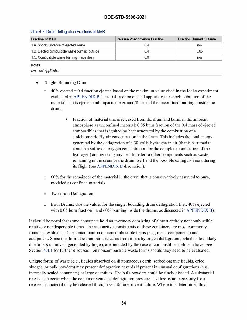
DOE-STD-5506-2021
34
Table 4-3. Drum Deflagration Fractions of MAR
• Single, Bounding Drum
o 40% ejected = 0.4 fraction ejected based on the maximum value cited in the Idaho experimentevaluated in APPENDIX B. This 0.4 fraction ejected applies to the shock–vibration of thematerial as it is ejected and impacts the ground/floor and the unconfined burning outside thedrum.
Fraction of material that is released from the drum and burns in the ambientatmosphere as unconfined material: 0.05 burn fraction of the 0.4 mass of ejectedcombustibles that is ignited by heat generated by the combustion of astoichiometric H2–air concentration in the drum. This includes the total energygenerated by the deflagration of a 30-vol% hydrogen in air (that is assumed tocontain a sufficient oxygen concentration for the complete combustion of thehydrogen) and ignoring any heat transfer to other components such as wasteremaining in the drum or the drum itself and the possible extinguishment duringits flight (see APPENDIX B discussion).
o 60% for the remainder of the material in the drum that is conservatively assumed to burn,modeled as confined materials.
o Two-drum Deflagration
o Both Drums: Use the values for the single, bounding drum deflagration (i.e., 40% ejectedwith 0.05 burn fraction), and 60% burning inside the drums, as discussed in APPENDIX B).
It should be noted that some containers hold an inventory consisting of almost entirely noncombustible, relatively nondispersible items. The radioactive constituents of these containers are most commonly found as residual surface contamination on noncombustible items (e.g., metal components) and equipment. Since this form does not burn, releases from it in a hydrogen deflagration, which is less likely due to less radiolysis-generated hydrogen, are bounded by the case of combustibles defined above. See Section 4.4.1 for further discussion on noncombustible waste forms should they need to be evaluated.
Unique forms of waste (e.g., liquids absorbed on diatomaceous earth, sorbed organic liquids, dried sludges, or bulk powders) may present deflagration hazards if present in unusual configurations (e.g., internally sealed containers) or large quantities. The bulk powders could be finely divided. A substantial release can occur when the container vents the deflagration pressure. Lid loss is not necessary for a release, as material may be released through seal failure or vent failure. Where it is determined this
35
DOE-STD-5506-2021
potential hazard exists, it should be analyzed with a DR of 1.0, unless a technical basis for a different value is established (e.g., ensure that DRs are not double-counting phenomena that are already included in the ARF value). ARF×RF values should be derived from the information in Section 4.4 of this standard or DOE-HDBK-3010-94.
At a given volume fraction of fuel, methane deflagrations lead to higher pressures than hydrogen deflagrations. However, a stoichiometric mixture of methane and air has less fuel than a stoichiometric mixture of hydrogen and air. Combining both effects, the maximum possible pressure rise for methane is similar to that of hydrogen. This conclusion is supported by test data documented in Cashdollar 2000 and Salzano 2012, which indicates a relative difference between deflagration pressures from the two gas mixtures of ≤ 15%. These tests were conducted using varying container sizes and initial pressures. Theoretical (adiabatic) calculations presented along with the tests showed a slightly narrower range of deflagration pressure difference, ≤ 10%. Therefore, it is appropriate to model methane deflagration in a TRU waste container the same as depicted in Table 4-3 for hydrogen deflagration.
The potential presence of prohibited items (e.g., cylinders of flammable/combustibles gases, VOCs) in uncharacterized waste also can generate flammable gas mixtures. Other reactions (e.g., chemical, microbial) can generate flammable gases, or sorbed organic materials can evaporate, leading to flammable vapors. APPENDIX B concludes that the behavior of TRU waste drums filled with combustible waste containing a limited quantity of VOC is bounded by the drum behavior resulting from the deflagration of an internal stoichiometric H2–air mixture. This applies to both the ejection fraction and the amount of combustibles that could burn outside the drum. Although the quantity of the VOC is small, under most TRU waste drum situations, larger quantities are not anticipated. Under special circumstances for drums containing liquid VOC or large quantities of cellulose wetted with solvents used to clean glove box interior that are packaged, larger quantities of VOC may be found. This situation would not be bounded by the H2 drum deflagration due to the amount of solvent-soaked combustibles that could burn outside the drum, and the possibility that a larger fraction of wastes may be ejected.
For combustible solid wastes with large quantities of VOCs (e.g., quantity exceeds the WIPP WAC requirement that observable liquid is less than 1 percent by volume of the outermost container at the time of radiography or visual examination) or a container with substantial sorbed organic liquids, a DR of 1.0 is conservatively assumed for ejection of 100% of combustible wastes and unconfined burning due to the lack of experimental data and uncertainty of what can occur under these conditions. If the contents are radioactive flammable or combustible liquids and have no combustible solid wastes, the release is modeled per recommendations in the DOE-HDBK-3010-94, assuming a DR of 1.0 for lid loss and subsequent burning of all the liquid.
Damage ratios for internal deflagrations for other container types are addressed as follows, along with corresponding ARF and RFs. The release models discussed above are for contaminated combustible solids (e.g., wipes, gloves, plastic sheets). Other waste forms, such as bulk powders, liquids absorbed on diatomaceous earth, sorbed organic liquids, and dried sludges, that may be direct loaded into a container, require individual evaluation consistent with Table 4-8.
For a direct-loaded Standard Waste Box (SWB), lid loss is not expected as a result of a deflagration, because the lid is very heavy and bolted onto the body of the box. No loss of lid was
DOE-STD-5506-2021
36
observed by deflagration testing of a SWB by the Southwest Research Institute (SWRI), as discussed in APPENDIX B, Section B.2.9, Deflagration Testing for CH Payload Containers and Filter Vents at Southwest Research Institute, albeit, the experiment reported results, which reported a maximum event pressure of 20 psig, are not fully conclusive of deflagration event overpressures.
However, a release from potential venting of particulates through breaches of the outer container gasket and vent filter media is expected, because test results indicated that a flour–fluorescein mixture leaked from the SWB. Therefore, a DR of 1.0 is assumed since the SWB gaskets can be affected by pressure rise from the deflagration. This DR is combined with an ARF×RF of 5E-4 from Section 4.4.2 and Table 4-8 that assumes confined burning of combustible wastes, which represents a conservative source term estimate that bounds shock–vibration and low-energy impact effects or container overpressure (ARF×RF of 1E-4 Table 4-8) from the deflagration.
Lid loss will also not occur for a direct-loaded RH waste container with a welded lid, or the Removable Lid Canister (RLC) for the RH-TRU 72-B cask. The RLC has a very robust lid-closure mechanism that uses grooved tabs (like the TRUPACT-II) and lock pins in lieu of bolting.4 However, a release via a breached lid closure or weld/container failure is assumed and is modeled similar to the SWB seal failure in item b.
Except as noted in item f, overpacking a suspect metal drum of sound integrity within a larger vented metal drum, SWB, or RH canister can be credited to contain lid loss of the inner drum and prevent ejection of contents. If, however, a drum that does not meet the criteria in Table 4-2 is placed within a larger container, this configuration does not meet the definition of an overpacked container. In that case, since the inner drum does not meet the requirement for a container of sound integrity, the outer container is modeled as direct-loaded (see discussion in items a and b for SWBs).
A significant release is not expected from overpacked suspect drums because the deflagration inside the inner drum is assumed to cause less damage to the outer overpack integrity than it would cause to a direct-loaded SWB as modeled in items a and b. A more limited release from potential venting through the outer container is assumed to occur in this case. For contaminated combustible waste, the release is modeled as an internal container fire with a confined burning ARF×RF of 5E-4, as noted in Sections 4.3.3 and 4.4.2 and Table 4-8. It is coupled, however, with a 0.2 DR for the outer drum overpack, as discussed in Section 4.3.3.3, Fire Damage Ratios for Other Containers. The deflagration release is therefore reduced by a factor of five (DR×ARF×RF = 1E-4) compared to the direct-loaded case discussed in item b. Note that the 0.2 DR is not applicable to highly energetic chemical reactions or similar container over-pressure events (i.e., events greater than about 50 psig release) where the outer overpack integrity may be compromised.
For drums overpacked in a much larger container (e.g., a 55-gallon drum in a 110-gallon overpack), there may be enough free volume for the internal container to suffer lid loss and waste ejection within the outer overpack container. This condition requires enough free head space and enough free annular space for the lid to be displaced so that waste could be ejected from the inner
4 See the latest WIPP procedure for more information.
DOE-STD-5506-2021
37
drum into the annular space between the drums. Absent analysis of a specific configuration, a conservative criterion of at least 8 inches of both free head space and free annular space is required for this phenomenon to occur. The outer container lid would be expected to remain in place. This event would be similar to item e, but it would involve an additional impact source term since material can eject from the inner container.
For contaminated combustible waste, the release is modeled as impact followed by fire. Impact release is based on the low-energy mechanical insult ARF×RF of 1E-4 noted in Section 4.3.3.1 and Table 4-8, for free-fall spill and shock-vibration stress and is applied to the 40% ejected from the experiment described above for a hydrogen deflagration in a direct-loaded drum). All of the material suspended from free-fall spill and shock-vibration inside the outer drum is not expected to be released via the seal and filter failures from the deflagration and overpressure; therefore, a factor-of-two reduction in the damage ratio is believed to be a conservative estimate, because two metal containers should provide some added protection; this results in an impact DR×ARF×RF of 2E-5 (0.5 × 40% × 1E-4). The release from a subsequent fire is modeled as the confined burning of the 60% inside the inner drum and the 40% ejected into the outer container with an ARF×RF of 5E-4 as noted in Sections 4.3.3 and 4.4.2 and Table 4-8; however, it is coupled with a 0.2 DR for the outer drum overpack, as discussed in item e above; this results in a fire DR×ARF×RF of 1E-4 (0.2 × 5E-4). The sum of these two releases results in an overall effective DR×ARF×RF of 1.2E-4.
For the Pipe Overpack Container (POC), pressure testing showed that even if a hydrogen deflagration should occur, its magnitude would not be enough to damage the pipe component or significantly degrade its sintered stainless steel filter.
See APPENDIX B, Section B.2.8, Other Waste-Container Considerations, for discussion of: (1) explosion tests performed by the Sandia National Laboratories (SNL 1998b) on the pipecomponent with a 1-inch sintered stainless steel filter; (2) hydrostatic pressure testing performedby Hauser Laboratories (Schierloh, 1998); and (3) a calculation that confirms the integrity of thepipe component for postulated internal explosion scenarios that evaluated pressures from adeflagration, detonation, DDT (deflagration-to detonation transition), and reflected wave effects(SRR 2011). See Section B.2.9, Deflagration Testing for CH Payload Containers and Filter Ventsat Southwest Research Institute, regarding the Sandia National Laboratories explosion tests andthe Hauser laboratories pressure tests (i.e., short-duration pressure bursts to simulate internalexplosions) that demonstrated the integrity of a sintered stainless steel filter and O-ring seal towithstand high pressures. If the pipe component does not have a sintered stainless steel filter, thena release should be evaluated similar to item b above based on the form of material and sealfailure of the 55-gallon POC lid.
For fiberglass reinforced wooden boxes of uncharacterized TRU wastes, the Idaho test results discussed in APPENDIX B concluded that sufficient hydrogen buildup is not possible due to its lack of leak-tightness.
For other containers, specific analyses are required to credit their ability to prevent lid loss and/or ejection of materials.

38
DOE-STD-5506-2021
4.3.3 Fire Scenario Damage Ratios for TRU Waste Containers This section addresses selection of DRs for fires involving TRU waste container storage for the facility DSA. The technical bases for the DR values presented in this section, including conservative assumptions where direct experimental data are not available, are included in APPENDIX C, Damage Ratios for Container Insults and Fires.
The most common TRU waste storage container is the open-top, 55-gallon steel drum with a bolted lid-locking ring, a DOT Type A container 5. Other drum sizes may include 15-gallon, 30-gallon, 35-gallon, 85-gallon, and 100-gallon. Waste may also be stored in SWBs, TDOPs, SLB2s, special-purposecontainers, and in some unique cases, DOT Type B containers.
In this section, drums are the primary focus, because they are bounding with respect to vulnerability to release. The term ñdrumò as used in this section means that it is a metal container of sound integrity as described in Section 4.3.1, so that it provides a confinement safety function. Although SWB and other bolted-lid container lids are bolted in place and are not expected to be lost, they are evaluated for releases from seal failure. This section also addresses overpacked containers (e.g., a metal drum of sound integrity nested within a larger metal drum or a SWB, TDOP, or SLB2), CCOs, and POCs. The RH canister is also evaluated for lid loss (direct-loaded) and seal failure (overpacked drums); as is the SCA which is used to permit handling RH waste as CH waste. Drum storage areas include rooms within buildings, transportainers, and domed structures, as well as staging or storage outdoors. Fires may also occur in drum loading and unloading areas for transportation.
For fire scenarios involving multiple drums, pallets, pads, or the inventory of a building, the general approach is to estimate DRs based on estimating the footprint of the design-basis or evaluation-basis fire to determine the area of impact of the fire, including both direct flame contact and the radiant heat and heat fluxes. From this area and the storage characteristics, the number of drums that could be impacted is estimated. Assumptions are made with respect to drums stacked on top of each other, to determine how they fail (i.e., seal failure venting or lid loss due to a fire). The potential for lid loss and ejection of contents is also considered.
For modeling drums exposed to flammable or combustible-liquid pool fires, an acceptable methodology is outlined in Chapter 65, ñLiquid Fuel Fires,ò of the SFPE Handbook of Fire Protection Engineering (SFPE 2016). That methodology can be used to establish fire-modeling inputs and assumptions to determine the number of drums involved, determine the extent of lid loss with ejected contents and seal failures, and to estimate the overall source term released.
The following simplified approach for flammable or combustible-liquid pool fires and for ordinary combustible fires has been conservatively established to determine the extent of lid loss with ejection vs. seal failures and appropriate DRs for the different ARFs and RFs. Other site-specific fire modeling
5 Type A and Type B refer to the robustness of the drums, as defined by meeting a series of tests (drop, fire, water, etc.) specified by the DOT and the Nuclear Regulatory Commission. Type B is the more robust of the two, because Type B containers are required to survive a 30-min. fire and 30-ft drop test. Type A containers have no requirements regarding fires and survive only a 4-ft drop.
39
DOE-STD-5506-2021
approaches, based on drum-fire testing results, may be applied if technically justified and appropriately conservative for development of the control set.
Drums Exposed by Flammable/Combustible Liquid Pool Fires Fire calculations to support the DSA analysis are typically needed to determine the size of a pool fire and the extent of sufficient radiant heat flux (for pool fires and non-pool fires), which in turn are used to define the number of drums involved. These calculations shall be consistent with standard fire protection engineering methods for the bounding type of fires associated with the facility. DSA and FHA modeling assumptions (e.g., pool burning characteristics and depth of an unconfined pool) should be consistent unless justified for the different objectives of the analyses (i.e., DSA unmitigated scenario versus a FHA Maximum Possible Fire Loss scenario). The facility FHA should serve as the basic input to the DSA fire scenario development and any fire analysis performed to support the DSA. As directed by DOE O 420.1C, Chg. 2, Facility Safety, the FHA “… must be integrated into safety basis documentation.” Integration of the FHA and DSA can be achieved through various approaches, the primary objective being the consistency of similar fire analyses, credited controls, and conclusions. Additional guidance for integration of the FHA and DSA is provided in Section 4.2.2 (Fire Analysis) of DOE-HDBK-1224-2018 and Appendix B (Fire Hazard Analysis) of DOE-STD-1066-2016, Fire Protection.
Two types of liquid-pool fires should be considered:
• Unconfined crash/instantaneous spill fires, and
• Confined spill fires if a means to contain liquid fuel exists
Additionally, unconfined continuously flowing (also called metered leak) spill fires should be considered if the FHA identifies a specific facility target of concern in an area where significant liquid fuel sources are allowed to be present. All fuel sources should be considered, consistent with the facility FHA evaluation of significant quantities that could affect TRU waste containers. However, the most likely liquid fuel sources present in TRU waste facilities (hydraulic fluid and diesel fuel) are those present on TRU waste handling vehicles (forklifts, pallet movers, transport trucks, etc.). Though less common inside facilities, gasoline may also be a potential liquid fuel source, particularly for external fire events.
General analysis aspects, applicable to all types of spill fires are summarized here; additional information is provided in APPENDIX C:
• It is common practice to model a pool fire as a right circular cylinder centered on the vehicleinvolved.
• The spill surface (where containers are located) should be taken as flat and level (not inclined)unless the slope is protected as a credited control in the safety basis.
• The spill area (footprint) should not be adjusted for objects (pallets, drums, etc.) within the poolperiphery. However, physical constraints such as curbs and room boundaries should beconsidered if present. Large depressions, ditches, or pits should be treated as a confined pool firewith defined pool fire boundaries.
DOE-STD-5506-2021
40
• A liquid reservoir/tank constructed of metal should consider that some amount of the fuel wouldnot likely be available to contribute to the pool fire diameter (i.e., a derated volume).
• The largest single flammable/combustible derated liquid tank capacity on each vehicle (i.e., onetank per vehicle) involved in the event should be considered as contributing to the footprint of apostulated pool fire unless it is plausible (based on proximity or the nature of the event) for morethan one tank per vehicle to be breached by the same impact. However, given the short durationof the instantaneous spill fire, only the single largest tank should be considered where a breach ispostulated due to fire propagation. It is not plausible to consider fire-induced breach of multipletanks at or near the same time in a manner that would combine their volumes when determining aconservative pool fire footprint. Where different fuels are involved (e.g., diesel fuel and hydraulicfluid), the tank that presents the highest ST should be used. As a rule of thumb (all else beingequal), the pool fire which can only cause seal failure would need to involve more than abouttwice the number of drums to match the consequences of a pool fire that causes both lid ejectionand seal failure. See APPENDIX C for more information.
An overview of an acceptable methodology is provided here for:
• modeling the unconfined crash/instantaneous and metered leak spill fires,
• modeling the involvement of vehicle tires in the metered leak spill fire,
• calculating critical incident flux to containers remote from the fire, and
• assessing pool fire damage to standard TRU waste containers.
The technical bases and derivation of the methodologies used are presented more fully in APPENDIX C and Pool Fire Analysis Methodology for Assessing Damage to Waste Containers (SRNS 2020). Container damage estimates, including potential lid ejection, should be consistent with those described below unless otherwise justified.
Modeling the Unconfined Crash/Instantaneous Spill Fire The unconfined crash/instantaneous spill fire should be modeled as having a 2.9-mm spill depth as specified in the SFPE Handbook (SFPE 2016) when combined with other conservative aspects of pool fire modeling outlined in APPENDIX C. For most liquid hydrocarbon fuels, a 2.9-mm-deep pool fire will burn for approximately 70 to 120 seconds, a range that falls within the minimum time frame required for either lid ejection (~70 seconds) or seal failure (~120 seconds) damage to a standard TRU waste container. The 15-to-20-second duration of the more-likely 0.7-mm-deep unconfined fuel spill is too short to cause damage to any standard TRU waste containers and should be considered only where damage to a thermally sensitive target (e.g. nearby combustibles) is identified as a concern by the fire scenario in the facility FHA.
Modeling the Unconfined Metered Leak Spill Fire The unconfined metered-leak spill fire need not be considered for assessing direct damage to TRU waste containers because it is always bounded by the unconfined crash/instantaneous spill fire. However, where the facility FHA identifies a target with a thermal stress failure threshold longer than about 120 to 300 seconds, the metered-leak spill fire should be evaluated. For those scenarios, such as failure of a structural

41
DOE-STD-5506-2021
steel support column or fire rated containment features (e.g., Type B shipping packages), the spill area should evaluate a spill rate that obtains the target failure threshold based on either fire duration or fire diameter (typically target engulfment). If the metered-leak spill fire results in a fire lasting about 10 minutes or longer, the vehicle tires would likely have an opportunity to influence the pool diameter and should be included, as described next.
Modeling Tire Involvement in the Unconfined Metered Leak Spill Fire Empirical testing of dual truck tires (SINTEF 1995) indicates that the pool size formed by the molten tires is maximized in about 10 minutes. The SINTEF testing is used (SRNS 2020) to derive a conservative estimate of the tire fire footprint based on dimensions and combustible mass of the burning tire(s). The modeling approach combines the footprint of the liquid metered-leak pool fire involving at least one tire set on the vehicle.
If the spill rate, tire parameters, and ignition timings are known, a steady-state spill diameter can be determined based on equations 65.26a and 65.26b or, for very large spill rates (150–600 gpm), equations 65.27a and 65.27b, from SFPE 2016.
Modeling the Confined Spill Fire Fuel spill into a confined area should be evaluated based on the geometry of the scenario. A postulated confined-spill pool fire should be modeled the same as an unconfined pool fire described above, except that the footprint is based on the size of the confined area and that a pool fire lasting longer than about 120 seconds is more likely to result in seal failure damage. A longer-duration pool fire (as might be expected for a confined spill) should apply an increased DR for seal failure (up to 1.0) regardless of the population, if the fire duration is expected to exceed about 120 seconds. Otherwise, a confined-spill pool fire does not alter the drum damage estimates described for unconfined pool fires. Though tire involvement is possible, it would not increase the pool size and doesn’t need to be considered for the confined spill fire. However, if the fire is of sufficient duration to result in pallet collapse and drum toppling, additional damage associated with material spill and unconfined burning shall be evaluated. See Appendix C for additional detail.
Calculating Critical Flux to Containers Remote from the Fire Critical flux is that necessary to cause seal failure in a TRU waste container remote from the postulated fire and has been defined, based on Kaiser-Hill 2000, as when at least one-third of the container is exposed to a heat flux exceeding 15.9 kW/m2. Insight from evaluation of these reports along with recent POC and TRU waste drum testing results (SNL 2018a and, SNL 2018b) suggests another seal failure criterion of 45 kW/m2 at the point on the surface of the container that is nearest to and directly facing the fire. In the more recent testing at SNL, the flux gauges were positioned beside (not attached to) the containers that experienced seal failure. In that configuration, it is expected that they would receive additional convective and radiative losses on the back side, thereby increasing the level of radiative heat flux measured. As discussed in APPENDIX C, a seal failure criterion of 40 kW/m2 in lieu of the suggested 45 kW/m2 for the point on the surface of the container nearest to and pointing directly at the fire, is determined to be more appropriate and a better analytical fit as well as being slightly more conservative.
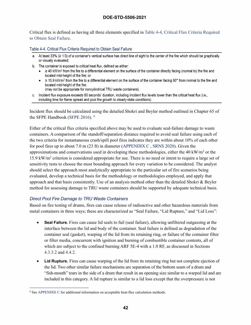
42
DOE-STD-5506-2021
Critical flux is defined as having all three elements specified in Table 4-4, Critical Flux Criteria Required to Obtain Seal Failure.
Table 4-4. Critical Flux Criteria Required to Obtain Seal Failure
Incident flux should be calculated using the detailed Shokri and Beyler method outlined in Chapter 65 of the SFPE Handbook (SFPE 2016). 6
Either of the critical flux criteria specified above may be used to evaluate seal-failure damage to waste containers. A comparison of the standoff/separation distance required to avoid seal failure using each of the two criteria for instantaneous crash/spill pool fires indicates they are within about 10% of each other for pool fires up to about 7.0 m (23 ft) in diameter (APPENDIX C , SRNS 2020). Given the approximations and conservatisms used in developing these methodologies, either the 40 kW/m2 or the 15.9 kW/m2 criterion is considered appropriate for use. There is no need or intent to require a large set of sensitivity tests to choose the most bounding approach for every variation to be considered. The analyst should select the approach most analytically appropriate to the particular set of fire scenarios being evaluated, develop a technical basis for the methodology or methodologies employed, and apply that approach and that basis consistently. Use of an analysis method other than the detailed Shokri & Beyler method for assessing damage to TRU waste containers should be supported by adequate technical basis.
Direct Pool Fire Damage to TRU Waste Containers Based on fire testing of drums, fires can cause release of radioactive and other hazardous materials from metal containers in three ways; these are characterized as “Seal Failure, “Lid Rupture,” and “Lid Loss”:
• Seal Failure. Fires can cause lid seals to fail (seal failure), allowing unfiltered outgassing at theinterface between the lid and body of the container. Seal failure is defined as degradation of thecontainer seal (gasket), warping of the lid from its retaining ring, or failure of the container filteror filter media, concurrent with ignition and burning of combustible container contents, all ofwhich are subject to the confined burning ARF 5E-4 with a 1.0 RF, as discussed in Sections4.3.3.2 and 4.4.2.
• Lid Rupture. Fires can cause warping of the lid from its retaining ring but not complete ejection ofthe lid. Two other similar failure mechanisms are separation of the bottom seam of a drum and“fish-mouth” tears in the side of a drum that result in an opening size similar to a warped lid and areincluded in this category. A lid rupture is similar to a lid loss except that the overpressure is not
6 See APPENDIX C for additional information on acceptable heat-flux calculation methods.
DOE-STD-5506-2021
43
sufficient to completely separate the lid from its retaining ring and waste is not ejected. This occurs in a relatively short period of time (e.g., less than ~3 minutes) that is the same as when lid loss occurs; however, a difference is that lid rupture usually results in a torch-like flame of the combustion gases around the breached lid seal occurring over an extended period of time as the waste continues to burn. For lid ruptures from pool fires and exposures fires involving contaminated combustible and noncombustible solid wastes, they are included in the evaluation of seal failures that are subject to the confined burning ARF 5E-4 with a 1.0 RF, as discussed in Sections 4.3.3.2 and 4.4.2. However, for powder-like wastes, ejection of material may occur and the release depends on the rupture pressure of the waste container and combustibility of the waste, as discussed later in this section.
• Lid Loss. Fires can cause the lid to be forcefully ejected (lid loss), possibly with anaccompanying ejection of material from within the container. Ejected materials are subject to theunconfined burning ARF of 1E-2 with a 1.0 RF, as discussed in Section 4.4.2. Notwithstandingthe recommendation in Section 4.3.2 regarding unconfined burning of a fraction of the ejectedwastes from a drum deflagration, all wastes ejected are assumed to burn unconfined due to theexternal fire source. All materials remaining in drums with lid loss are subject to the confinedburning ARF of 5E-4 with a 1.0 RF, as discussed in Section 4.4.2.
Since the different drum responses involving confined and unconfined burning result in significantly different estimates of airborne releases, damage ratios need to be addressed for both situations.
To simplify the modeling approach, drum contents are modeled in this section as 100% combustible contaminated solid wastes. Evaluation of direct pool fire damage to TRU waste containers with bulk powders is discussed below in the section Direct Pool Fire Damage to TRU Waste Containers.
Lid Loss Lid loss can occur only if specific conditions associated with an engulfing deep pool fire are met (e.g., a “fast” fire growth rate, “rapid” flame spread rate, direct flame impingement, or sufficient duration). Engulfing deep pool fires are those fires in which burning liquid fuel surrounds the container, is capable of gas-phase or rapid liquid-phase flame spread 7, and is capable of sustaining engulfing fire conditions in excess of 70 seconds. These fires can cause lid loss to a fraction of the engulfed drums, which may eject a portion of the contents.
From the fire testing experience described in APPENDIX C, not all unrestrained drums engulfed in a pool fire experienced lid loss. By conservative assumptions, 25% of the unrestrained drums8 engulfed in the pool fire experience lid loss and ejection of some contents, so the analytical model more accurately represents the results of the fire tests. This applies to the top tier of drums in a stacked pallet storage array and to all drums in a steel-rack storage array since the lids are unrestrained on each tier. Some unrestrained drums adjacent to the fire that have direct flame impingement (first-row-out) are also conservatively assumed to experience lid loss and ejection; therefore, apply the same 25% assumption.
7 The principal driver for flame spread is the temperature of spilled liquid relative to its flashpoint. See APPENDIX C. 8 It is noted that the test data indicates there is a higher propensity for lid ejection with drums dispersed or separated in a manner
to permit thermally thick (~>1 ft) flame impingement over a significant portion (~> 75%) of the drum’s vertical surface.

44
DOE-STD-5506-2021
A container fully outside the periphery of the fire (i.e., exposed to no flame impingement) and not adjacent to an engulfed drum should not be considered a first-row-out drum. It should instead be considered a possible second-row-out drum subject to seal failure damage as determined below. If containers are stacked, the drums on the lower tiers are expected to retain their lids, as the weight of the upper tiers will keep them in place or, at worst, result in partial lid displacement. These containers should also be considered to receive seal failure damage as described below. For modeling purposes, it is sufficient to assume that lid loss occurs only on the top tier, and some contents are ejected, as determined next. If the potential exists for a long duration pool fire, see the discussion on Modeling the Confined Spill Fire .
For drums that experience lid loss, one-third of the contents (33%) 9 are assumed to be ejected from the drum. During the ejection, this material is subject to shock-vibration stress due to its ejection and impact with a hard surface plus burning as unconfined materials. The other two-thirds (67%) of the MAR are assumed to stay inside the drum and burn as confined materials. The DR is 1.0 for each portion, or this could be thought of as a DR of 0.33 of the total MAR for the ejected portion and 0.67 for the remainder in the drum.
Seal Failure Container seal failure should be evaluated as possible from any of three damage mechanisms:
• Direct flame impingement (engulfed or along the edge of the pool but not experiencing lid loss)
• Proximity to drums experiencing lid loss (second-row-out drums)
• Sufficient radiant heating (critical flux)
Assessing Pool Fire Damage to Waste Containers As stated above, container seal failure damage is modeled as 100% confined burning of combustible materials for any of the three possible damage mechanisms. If a container on the top tier in the second row outside the pool area (second-row-out) is adjacent to a drum in the first-row-out along the edge of the pool fire that loses its lid, seal failure is also expected due to the likely magnitude of radiant heat flux from the open drum fire and lack of shielding from the first row. The number of second-row-out drums with seal failure should be the same as the number of first-row-out drums with lid ejection. Drums on lower tiers in the second-row-out below the top tier do not experience seal failures due to assumed shielding from the first row of lower-tier drums, which do not experience lid loss, and the limited “view factor” from any flame.
Containers remote from the pool fire but near enough that they can receive critical radiant flux as identified in Table 4-4 above, also experience seal failure damage with confined burning of the contents. From a DSA analysis perspective, this is modeled the same as container exposure from an ordinary combustible fire and is addressed in Section 4.3.3.2.
Determination of containers damaged in a postulated waste material handling vehicle pool fire is best determined graphically, as illustrated as a scaled diagram in Figure 4-1, Example Graphic Assessment of
9 See APPENDIX C discussion regarding how conservative this assumption is.
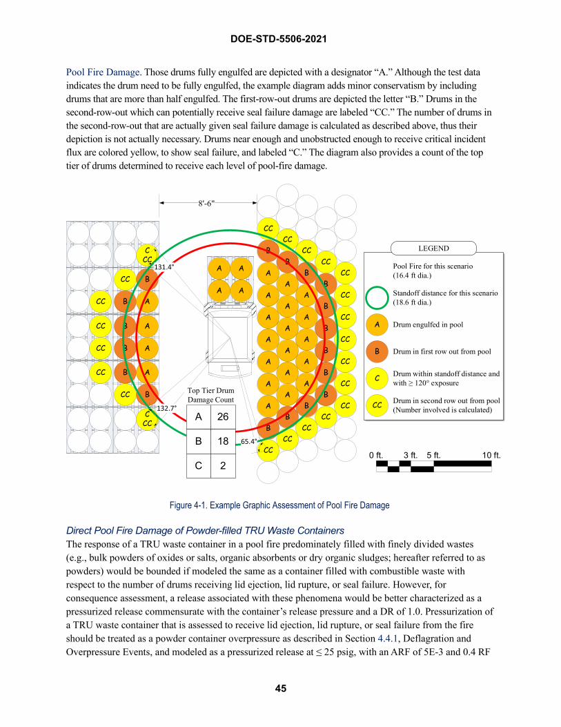
45
DOE-STD-5506-2021
Pool Fire Damage. Those drums fully engulfed are depicted with a designator “A.” Although the test data indicates the drum need to be fully engulfed, the example diagram adds minor conservatism by including drums that are more than half engulfed. The first-row-out drums are depicted the letter “B.” Drums in the second-row-out which can potentially receive seal failure damage are labeled “CC.” The number of drums in the second-row-out that are actually given seal failure damage is calculated as described above, thus their depiction is not actually necessary. Drums near enough and unobstructed enough to receive critical incident flux are colored yellow, to show seal failure, and labeled “C.” The diagram also provides a count of the top tier of drums determined to receive each level of pool-fire damage.
Figure 4-1. Example Graphic Assessment of Pool Fire Damage
Direct Pool Fire Damage of Powder-filled TRU Waste Containers The response of a TRU waste container in a pool fire predominately filled with finely divided wastes (e.g., bulk powders of oxides or salts, organic absorbents or dry organic sludges; hereafter referred to as powders) would be bounded if modeled the same as a container filled with combustible waste with respect to the number of drums receiving lid ejection, lid rupture, or seal failure. However, for consequence assessment, a release associated with these phenomena would be better characterized as a pressurized release commensurate with the container’s release pressure and a DR of 1.0. Pressurization of a TRU waste container that is assessed to receive lid ejection, lid rupture, or seal failure from the fire should be treated as a powder container overpressure as described in Section 4.4.1, Deflagration and Overpressure Events, and modeled as a pressurized release at ≤ 25 psig, with an ARF of 5E-3 and 0.4 RF
0 ft. 3 ft. 5 ft. 10 ft.
8'-6"
B
A
AA
AA
B
A
A
A
A
AA
AA
A
A
A
B
CCCC
BA
A
B
CC
CCCC
CC
B
C
B
A
Pool Fire for this scenario(16.4 ft dia.)
Standoff distance for this scenario (18.6 ft dia.)
Drum engulfed in pool
Drum in first row out from pool
Drum within standoff distance and with ≥ 120° exposure
Drum in second row out from pool (Number involved is calculated)CC
LEGEND
B
B
CC
B
B
B
CC
B
CC
CC
CC
CC
CC
CC
CC
A A
A A
CCC
CC B A
CC B
CC
CC
B A
B A
CC
CC
B A
CCC
B
A
B
C
26
18
2
Top Tier Drum Damage Count

46
DOE-STD-5506-2021
(ARF×RF = 2E-3). No significant amount of powder is expected to be expelled from the container for lid loss or lid rupture due to this low overpressure, and especially if there is interior packaging if metal convenience containers are used. Similar to the discussion in Section 4.4.1, no guidance is provided if a waste process generates a finely-divided combustible waste (such as organic absorbents or dry organic sludge that behaves like a powder) directly loaded into a standard waste container, which warrants an evaluation based on the unique properties of the waste and type of container involved in the pool fire.
If the FHA or other fire modeling for the DSA evaluates a hazard associated with a very long duration pool fire (much greater than the 3 minutes required for lid loss, lid rupture, or seal failures), noncombustible powders could contribute additional thermal stress to the portions remaining in the drum after depressurization (i.e., 1 – ARF of 5E-3 = 99.5%). However, this could only occur if the pool fire lasts long enough to heat all the mass of remaining powder. If analysis of pool fire duration and noncombustible powder mass indicates it is possible, the thermal stress release with ARF = 6E-3 and RF = 0.01 should be added to the pressurized release. The 6E-5 ARF×RF thermal contribution is added to the 2E-3 pressurized release, resulting in a composite ARF×RF of 2.06E-3, rounded to 2.1E-3.
For any of these release mechanisms, application of a 1.0 DR introduces significant conservatism because only the top few inches of powder would be expected to participate in the release. It is also noted that rupture mechanisms postulated to occur below the top surface of the powder mass (i.e., those related to a “fish-mouth” tear on the side of the container or separation at the bottom seam) are not plausible in a powder-filled drum due to the heat sink presented by the oxide, salt, or noncombustible matrix itself, based on insights from the SNL testing of pipe component containers with an oxide simulant (SNL 2020). Additional technical bases for these release fractions are presented in Section 4.4.1 on deflagrations/over-pressurizations and Section 4.4.2 on fires.
Other Spill Fire Considerations Hydraulic fluid pool fires10 should be treated differently from other hydrocarbon liquid fuels (e.g., diesel fuel). Because of the high flashpoint of typical hydraulic fluids, flame spread beyond the point of ignition is very unlikely. However, in the presence of a significant long-duration ignition source (such as a burning TRU waste-handling vehicle), heating of the liquid above its flash point is possible. In this case, liquid-phase flame spread is the only plausible mechanism that would permit the greater part of the hydraulic fluid spill to become involved in the fire. Flame spread would not approach the bounding liquid-phase flame spread rate presented in literature. Based on this, unconfined hydraulic fluid spills fires are not considered capable of creating rapid heating conditions necessary to cause lid ejection in exposed standard TRU waste drums. Although the slow propagation could enhance the possibility of seal failure damage, the depth of the unconfined pool will limit the fire duration to less than about 90 seconds. As described below, seal failure requires significant heat flux for longer than about 120 seconds. Given that engulfing pool fire conditions expose most of a container’s surface to high incident flux, it is not reasonable to conclude there is no seal failure damage. A conservative approximation considers that seal failure damage in an unconfined hydraulic fluid spill pool fire occurs on 50% (DR = 0.5) of the containers engulfed, in the first-row-out, or subjected to critical incident flux (Table 4-4). The population is inclusive
10 A pressurized spray of hydraulic fluid is not a spill. However, it presents an easily ignitable flame jet hazard to nearby objects or containers that should be considered. Though severe in nature, the consequences of flame jet impingement on a few TRU waste containers is typically bounded by the consequences of the pool fire modeled, as described here.
DOE-STD-5506-2021
47
of all containers assessed to receive seal failure damage. This DR should not be applied for a small population of containers (i.e., for < 10 containers based on consistency with Section 4.3.3.2 for seal failures due to exceeding critical incident flux, assume a DR of 1.0).
The following summarizes the above discussions. See APPENDIX C for additional detail.
Unconfined Flammable/Combustible Fuel Spill on Hard, Smooth, Flat Surface 11 • Unconfined fuel spills pool to a depth of 2.9 mm.
• Fuel spills of hydraulic fluid do not cause lid ejection of a TRU waste drum.
• Lid ejection damage to a standard TRU waste drum occurs only when the drum experiencesengulfing, or near-engulfing flame conditions, with a rapid heat-up profile and occurs withinabout 70 to 90 seconds.
• Seal failure damage to a standard TRU waste container is possible when the container is exposedto lid-ejection damage conditions but doesn’t experience lid ejection, or when the containerreceives critical incident flux, or greater, for longer than about 60 seconds.
This approach does not consider toppling of stacked drums and potential for additional unconfined burning of scattered wastes. Rapid pressurization is not expected to topple higher-tier drums based on the Idaho hydrogen deflagration experiment described in Section 4.3.2. The Hanford fire tests did not observe toppling. The drums, however, were banded to pallets that allowed the drums to slump vertically. Failure of metal pallets is much less likely and would require a sufficiently long-duration fire to cause failure, not typically associated with potential unconfined spill fires in TRU waste storage areas, and shall only be evaluated in the DSA if the potential exists for a long duration pool fire (see discussion on Modeling the Confined Spill Fire) or it is evaluated for the Fire Hazards Analysis based on the fixed and transient fuel loading associated with TRU waste operations. However, a fire would be expected to cause toppling of stacked drums on combustible (e.g., wooden or plastic) pallets, which shall be evaluated if this hazard exists at a site. Further, combustible pallets would be expected to participate in the fire, resulting in potentially increased fire severity heat release rate and lengthened fire duration.
Figure 4-2, Fire Damage Ratios (DRs) for Direct-Loaded Drums, illustrates the foregoing approach to estimate the source term from a pool fire. It also summarizes the approach to calculate non-pool fire source terms as presented in the next section. The term “DR” is used to reflect the different fractions of MAR that are affected differently—e.g., ejected waste vs remaining waste in the drum, or involvement of 10 or more drums to radiant heat exposure.
11 Hard and smooth indicates surface is generally non-porous and smooth to include bare concrete, coated concrete, brushed concrete, tile, and steel. Flat indicates a lack of surface depressions >~5 mm in depth. If the spill occurs on a surface that is not paved and smooth, use actual surface characteristics for analysis.
DOE-STD-5506-2021
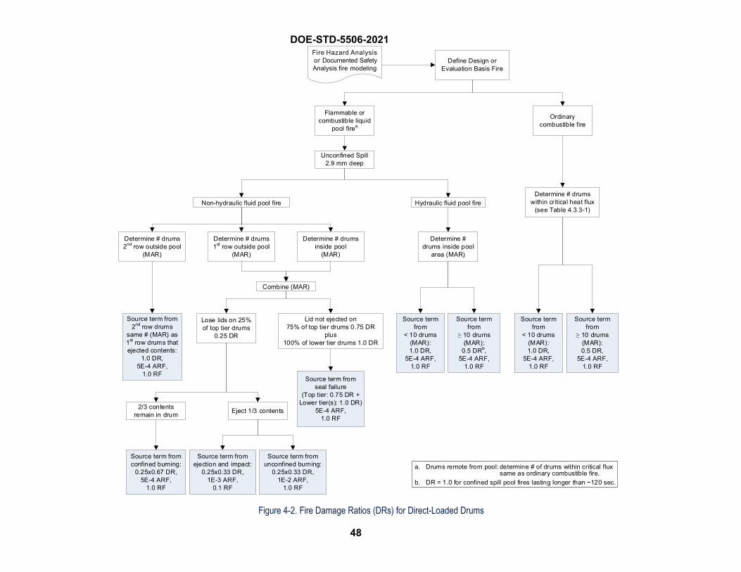
48
Ordinary combustible fire
Determine # drums within critical heat flux
(see Table 4.3.3-1)
Determine # drumsinside pool
(MAR)
Determine # drums 2nd row outside pool
(MAR)
Define Design or Evaluation Basis Fire
DOE-STD-5506-2021 Fire Hazard Analysis or Documented Safety Analysis fire modeling
Lose lids on 25% of top tier drums
0.25 DR
Lid not ejected on75% of top tier drums 0.75 DR
plus100% of lower tier drums 1.0 DR
Eject 1/3 contents
Source term from confined burning:
0.25x0.67 DR,5E-4 ARF,
1.0 RF
Source term from ejection and impact:
0.25x0.33 DR,1E-3 ARF,
0.1 RF
Source term from unconfined burning:
0.25x0.33 DR,1E-2 ARF,
1.0 RF
Source term from 2nd row drums
same # (MAR) as 1st row drums that ejected contents:
1.0 DR,5E-4 ARF,
1.0 RF
Source term from
< 10 drums (MAR):1.0 DR,
5E-4 ARF,1.0 RF
Source term from
≥ 10 drums (MAR):0.5 DR,
5E-4 ARF,1.0 RF
Unconfined Spill2.9 mm deep
Source term from
< 10 drums (MAR):1.0 DR,
5E-4 ARF,1.0 RF
Source term from
≥ 10 drums (MAR):
0.5 DRb,5E-4 ARF,
1.0 RF
Flammable or combustible liquid
pool firea
Determine # drums inside pool
area (MAR)
Non-hydraulic fluid pool fire
a. Drums remote from pool: determine # of drums within critical fluxsame as ordinary combustible fire.
b. DR = 1.0 for confined spill pool fires lasting longer than ~120 sec.
Hydraulic fluid pool fire
2/3 contents remain in drum
Determine # drums 1st row outside pool
(MAR)
Combine (MAR)
Source term from seal failure
(Top tier: 0.75 DR +Lower tier(s): 1.0 DR)
5E-4 ARF,1.0 RF
Figure 4-2. Fire Damage Ratios (DRs) for Direct-Loaded Drums
49
DOE-STD-5506-2021
Drums Exposed by Ordinary Combustible Fires Non-pool fires are those that involve ordinary combustibles such as trash, wooden boxes, or clothing. This type of fire has a “moderate” fire growth rate. Fire experiments have demonstrated that lid loss and ejection of contents is not expected, so for modeling purposes, only seal failures are evaluated. This could include trash fires and wooden crate fires. For direct flame impingement on only one side of a container from an adjacent ordinary combustible fire, the container is not heated rapidly enough to cause lid loss and ejection of contents. When heat transfer occurs only through radiation, fires involving non-liquid fuel packages (e.g., trash) were determined to not result in lid loss. The heat output of the fire is insufficient to increase temperature and pressure inside the drum quickly enough to eject the lid before venting (seal failure) occurs. The container has to be close enough to the fire that it is exposed to a sufficient heat flux (Table 4-4). To simplify the modeling approach, drum contents are assumed to be 100% combustible contaminated solid wastes.
DOE does not have an experimentally-derived release fraction (ARF×RF) for seal failure of metal drums caused by ordinary combustible fires. DOE has chosen to apply the ARF×RF value of 5E-4 from DOE Handbook 3010 to such drums in a waste fire example in its Section 7.3.9.1, “Hazard Summary” (of Section 7.3.9, Solid Waste Handling). This value is based on experiments involving cardboard cartons burned in a large steel tank. The tank was provided with passive ventilation openings at the top and bottom, which would support development of a buoyancy-driven chimney effect to enhance burning as compared to a TRU waste drum with a small opening only at the top of the container (seal degradation or vent filter opening). A correction factor of 0.5 is intended to account for differences between cartons and metal drums. Specifically, this damage ratio is used because DOE expects a lower degree of combustion/ pyrolysis (and thus aerosol generation) within an unventilated steel drum, compared to the cardboard carton in a large steel tank from the experiments.
It has been estimated that 50% of the combustible material burned in the tests with the cardboard cartons (Mishima 2001). In contrast, experiments with metal drums suggest that 25% of drum contents will burn or pyrolyze (Mishima 2001), although mass losses from pool fires with no lid ejection have a wide range from all of the fire drum tests. Thus, a correction factor of 0.5 is used to account for the difference between cartons and drums.
This correction factor includes an assumption that the generation of radioactive aerosols (ARF) is directly proportional to the mass of combustibles consumed by the fire. There are various reasons why this assumption would not hold, including the possibility that the radioactive material was not uniformly distributed throughout the combustible waste. A fire could preferentially burn the more contaminated portions of the waste, in which case ARF would not be proportional to mass loss.
To account for the possibility of a non-uniform distribution, DOE has decided not to apply the correction factor for events with less than 10 drums. With 10 or more drums, it is unlikely that the fire would only consume the most contaminated portion of the waste within every drum. Thus, the correction factor can be applied for events involving ten or more drums. 12
12 See Section C.1.3, Seal Failures, for additional discussion of a 0.5 DR for 10 or more drums.
50
DOE-STD-5506-2021
If room flashover is deemed plausible by the FHA or other fire modeling for the DSA unmitigated analysis, then all containers are subject to seal failures with a 1.0 DR.
Another type of fire that could cause a lid loss occurs when flammable/combustible liquid is present in the drum with other combustible solid wastes. A fire involving any type of fuel package may result in auto-ignition of flammable vapors inside the drum. For these mixed combustible wastes, based on assuming small amounts of the liquid, this phenomenon is modeled in accordance with assumptions presented in Section 4.3.2, unless otherwise justified. The Section 4.3.2 hydrogen deflagration modeling assumptions do not apply to drums of mixed wastes of combustible solid wastes with flammable or combustible liquids that exceed the small-quantity VOC assumption as described in APPENDIX B, Container Deflagrations, or drums of radioactive flammable or combustible liquids. For combustible solid wastes with large quantities of VOCs (e.g., where the VOC quantity exceeds the WIPP WAC requirement that observable free liquid is less than 1 percent by volume of the outermost container at the time of radiography or visual examination, or the equivalent amount of absorbed liquids), a DR of 1.0 is conservatively assumed for ejection of combustible wastes and unconfined burning because of the lack of experimental data and the uncertainty about what can occur under these conditions. If the contents are radioactive flammable or combustible liquids and have no combustible solid wastes, the release is modeled per recommendations in the DOE-HDBK-3010-94, assuming a DR of 1.0 for lid loss and subsequent burning of the liquid inside or outside the drum.
It should also be noted that the Hanford fire tests concluded that an internal fire in a single drum is not expected to propagate to an adjacent drum 13, whether the adjacent drum is to the side or above the drum with the internal fire. 14
Fire Damage Ratios for Other Containers A similar DR for seal failures of SWBs is established based on physical consideration that four drums are approximately equivalent to one SWB. This results in a DR of 0.5 for more than two SWBs involved in a fire (i.e., 10 drums divided by 4 and rounded up). However, a DR of 1.0 is assumed for one or two SWBs involved in the fire.
Overpacking a metal drum of sound integrity with a larger metal drum, an SWB, or a TDOP, can be credited to prevent lid loss and ejection of contents and modeled as seal failures. In addition to preventing lid loss, overpacked containers provide an additional level of protection from fires that allows a lower DR of 0.2 than those for directed-loaded drums or SWBs. The dimensions of the SWB are nominally 5 ft long, 4 ft wide, and 3 ft tall, with rounded sides to fit within the TRUPACT-II container for shipments to WIPP. The walls are typically 10-gauge to 12-gauge (about 0.1-in.) sheet metal, and the container is sealed with a gasket and lid with 42 bolts. The TDOP is constructed in a manner similar to a SWB and provides primary confinement to a large drum-like volume that can be loaded directly or as an overpack for 10 full 55-gallon drums, up to 6 full 85-gallon drums, or an SWB. Both the outer container and inner drums in an overpack assembly have vents installed in order to meet the requirements for an overpack assembly. For a radioactive material release to occur, the fire has to heat up the inside of the SWB/TDOP and also heat the inner contents of the 55-gallon drums resulting in pyrolization of the drum contents and subsequent venting from both containers. The SWB/TDOP configuration presents a significant heat sink
13 Fire Protection Guide for Waste Drum Storage Arrays, WHC-SD-SQA-ANAL-501 14 The heat generated by a fire within a drum and possible “torches” via seal failure were not significant enough to heat adjacent
drums to cause their failure. This is different than the sympathetic deflagration discussed in Section 4.3.2.

51
DOE-STD-5506-2021
and pyrolization of drum contents would require a very long-lasting fire or a very large fire. Another consideration is that the SWB/TDOP is large, and therefore it is not expected that all of the waste will be affected by a fire.
Although the drum-in-drum overpack does not provide the same level of heat sink, the overpacked drum fire testing described in Section B.2.4, Volatile Organic Compounds, reported the results of the 1993 LLNL test of 3-drum and 4-drum configurations in a 6-foot pool fire. The LLNL test involved the drums inside the pool fire, which is the basis for the 0.2 DR that was estimated from the average 0.1 mass loss for direct-loaded drums to the average 0.025 mass loss for the overpacked drums based on the data presented in Table B-12.
Therefore, a DR of 0.2 is assumed for overpacked drums of sound integrity whether overpacked in a larger drum, a SWB, or a TDOP. This assumption applies to a single or multiple overpacked containers exposed to the radiant heat flux that causes seal failures and to overpacked drums in a pool fire. Also, DRs presented in this section for “overpacked containers” are based on having two containers of sound integrity and do not apply to overpacked drums where the inner drum is not of sound integrity (Table 4-2), which is modeled as a single, direct-loaded drum.
Direct-loaded RH canisters may experience lid loss depending on the design of the lid restraint, because it is only required to be qualified as a DOT Type A container. As discussed in Section 4.3.2 for hydrogen deflagrations within a RH canister, lid loss will not occur for a direct-loaded RH container whose lid is welded, or the RLC for the RH-TRU 72-B cask. Although RH canisters with nested drums are expected to behave in a manner similar to SWBs and not experience lid loss, the SWB DRs above can be applied to overpacked RH drums in a canister. For RH canisters or drums handled outside a hot cell facility in a shielded “facility cask” or onsite shipping cask that does not meet the DOT Type B criteria 15, lower DRs may be appropriate. This can be justified based on a fire hazards analysis or DSA fire modeling to assess the extent of damage for bounding facility-specific fires or material-handling equipment fuel spills 16.
In the case of POCs and CCOs, the containers are designed in a manner that precludes their failure during expected storage area fires. Four POCs were subjected to Type B protocol thermal tests as summarized in APPENDIX C. The associated 150-MW fuel pool fire caused the one outer 55-gallon drum of a POC package with a metal filter to experience lid loss 17. This occurred within the first 3 minutes of the fire. Post-fire inspection showed the pipe component seal and filter gasket to be damaged. Associated leak rate testing of this POC showed a total leak rate of 24 cm3/s at a differential pressure of 87 kPa. This leak rate was later associated with an ARF of 6E-6 for the bounding material type in POCs (i.e., powder) 18. It should be noted that inspection of the POC packages remaining intact revealed that the POCs did not experience temperatures above 200 °F and remained leak-tight.
Similar results were observed in a series of more recent POC and CCO pool fire tests conducted at Sandia National Laboratories with combustible materials (POC only) and surrogate oxide payloads as
15 Casks that meet current Type B criteria normally are expected to survive facility fires typical of those that may occur in the DOE Complex where TRU wastes are stored or handled, unless a facility-specific hazard or accident can cause a mechanical breach of the cask or a much longer duration of fire is possible.
16 For example, see Damage Assessment of Waste Containers Involved in Accidents at the Waste Isolation Pilot Plant, PLG-1121.
17 The other POC packages had plastic filter seals, which melted during the fire. 18 See Section C.1.4.1, Initial Pipe Overpack Container Fire Testing, discussion.
52
DOE-STD-5506-2021
summarized in APPENDIX C (SNL 2017, SNL 2018a, SNL 2018b, SNL 2019, and SNL 2020). The POC test results support a conclusion that as long as the drum lid remains on the outer 55-gallon drum of the POC (even with seal degradation), the fiberboard insulation inside protects the inner pipe component. Maximum temperatures within the inner pipe component do not exceed 176 °F (80 °C), a temperature that does not threaten ordinary combustibles placed in the pipe. After tests where lid ejection did not occur, the filter gasket and O-ring of the pipe component were found to remain pristine. Use of the engineered UltraTech 9424S filter (Patent Pending), a special modification to the previous WIPP-approved UltraTech 9424 filter, prevents loss of the outer drum lid. The 9424S filter thereby ensures that the protective fiberboard insulation remains in place, though charring does occur.
For Safety Basis purposes, POCs that have the UltraTech 9424S filter installed per manufacturer’s specifications in the outer 55-gallon drum’s ¾-inch lid opening can be assigned a DR of zero, irrespective of whether they contain residues, particulates, combustibles, or any other waste form in an authorized configuration for scenarios bounded by the evaluated test conditions. POCs may be loaded with ordinary combustible material only if the outer 55-gallon drum is equipped with the UltraTech 9424S filter. This Standard does not provide guidance on modeling releases of ordinary combustible waste in a POC that lacks the UltraTech 9424S filter or a PC that contains flammable or combustible liquids with flash points less than 100° C without a sintered filter. Potential deflagrations in a POC are further discussed in Sections B.2.8, Other Waste-Container Considerations, and B.2.9, Deflagration Testing for CH Payload Containers and Filter Vents at Southwest Research Institute.
CCO testing did not include combustible materials inside the pipe component (criticality control container, CCC) except for minor combustible packaging materials (small bags and tape). The most recent testing (SNL 2020) of a CCO loaded with surrogate oxide packaged in a can–bag–can configuration inside the CCC documents that the inner bag and pieces of tape on the outer slip lid can were consumed in the fully engulfing 30-minute pool fire. The outer drum lid and upper plywood dunnage were ejected early in the test, exposing the top of the CCC to flame temperatures of ~1200 °C, which damaged the CCC lid filter. The report concludes:
The above result suggests the ARF for CCO fully engulfed in a thirty-minute fire is zero. However, this conclusion is only accurate to the level of uncertainty of the mass balance used to measure the average mass of the powder before and after the test. Certainly, it can be argued that some material was released from the primary canisters into the secondary canisters, and subsequently into the CCC. It is important to note that the plastic enclosing the primary canister melted much later and well after the peak pressure of 18 psig was reached inside the CCC. Thus, it can be concluded with certainty that no aerosol release occurred before the melting temperature of the plastic was reached. When the plastic melted, the CCC reached a momentary internal pressure of about 2 psig, followed by a slow decay in pressure. It is not known if these lower pressures are sufficient to cause release of aerosol first from inside the primary canister, then from the secondary canister, and finally from the CCC through the damaged filter. Posttest examination of the secondary canisters suggest their lids appear to remain in place throughout the test,
53
DOE-STD-5506-2021
implying the above sequence of events leading to release of aerosol from secondary canisters in highly unlikely.
The torturous path from the primary container through the secondary container and then out of the CCC supports the conclusion for the down blend powder a DR of zero is appropriate and is further supported by the fact that no powder was observed anywhere outside of the primary container.
Therefore, POCs or CCOs without combustibles in the inner pipe component (except incidental bags and tape used for packaging) involved in storage and room fires need not be further evaluated in an accident analysis. POCs may be loaded with combustible material only if the outer 55-gallon drum is equipped with the UltraTech 9424S filter installed per manufacturer’s specifications. CCOs loaded with combustible material should be analyzed with a DR=1.0. This Standard does not provide guidance on modeling releases of combustible waste in CCOs. A lower DR may be used if payload materials have unique waste form properties or cause unique behaviors in the container response to postulated thermal stresses, as long as explicit technical justification is provided for the lower value.
4.3.4 Damage Ratios for Mechanical Insults This section addresses DRs for the steel drums of various sizes (e.g., 55-gallon, 85-gallon, and 100-gallon), SWBs, RH canisters, POCs, and overpacked containers (e.g., a 55-gallon drum of sound integrity nested within an 85-gallon drum, or four drums in a SWB; the TDOP; or an RH canister with nested drums). Several tests have been performed for dropping 55-gallon drums from various heights and with various weights and contents, and for crushing drums. These are described in APPENDIX C, Damage Ratios for Container Insults and Fires. However, there has been no testing of the SWBs with “bolted down” lids, overpacked containers, or the TRUPACT-II double-stacked seven-pack drum configuration. Therefore, engineering judgment was applied to extrapolate the available test results to these configuration and accident scenarios. The term “drum” as used in this section means that it is a metal container of sound integrity as described in Section 4.3.1, so that it provides a confinement safety function. DRs presented in this section for “overpacked containers” do not apply to drums that are not of sound integrity, which shall be modeled as a single, direct-loaded drum.
Drops and impact stresses on TRU waste containers will result in a wide range of damage depending on the magnitude of these forces and condition of containers. Loss of confinement from a TRU waste container can result from severe shock and vibration stress, from impact events or dropping a container. Spills from a container can also result from the accidental falling or flowing of powders out of a confinement boundary resulting in an airborne release due to the free-fall of the powder in air. As stated in Section 4.3, the DR is that portion of the MAR that is affected by the accident stresses. For TRU waste containers, the materials are primarily contaminated combustible or noncombustible solid materials, solidified/vitrified sludges that do not contain free liquids, or powders of radioactive compounds. The term “loss of confinement” as used in this section refers to the hazard and accident analysis loss of confinement/containment categories as listed in Table 3-1, and may result in low-energy or high-energy mechanical insults to containers as discussed in Section 4.4.3, Mechanical Insults.
Containers may be punctured, crushed, toppled, or dropped, causing failure of the container and release of the material. Dispersal of the material will occur from the kinetic energy from the accident initiator and from the
54
DOE-STD-5506-2021
fall of material from the container failure point to the ground. In the case of container failure due to corrosion, the energy for dispersal is provided by the fall of the material from the container failure point to the ground. Significant release of non-dispersible wastes, such as those that have been vitrified or solidified with concrete in metal containers, would require higher energy input to release the wastes than is available from mechanically initiated spills, such as spills caused by container punctures, drops, or falls.
Examples of potential spill scenarios may include a spill from a metal container following a forklift puncture or impact by a compressed gas cylinder missile; a spill of waste container(s) due to drops/falls; or a spill of waste container(s) resulting from impact with material-handling equipment. Based on the Sandia, Hanford, and Rocky Flats experimental results of drum testing, each of these accident types is addressed in APPENDIX C to establish a range of DRs for various container types and waste forms. From this range of damages, DRs are established for other drop or impact events that can breach waste containers associated with heights typical of existing facilities in the DOE Complex that store and handle TRU wastes. Six broad categories were chosen to represent the range of damage ratios. Appropriate adjustments are made if the material form is contaminated solids (e.g., “bulkier materials” larger pieces, such as filters, or pieces of wood and metal, or contaminated combustible waste) versus sand-like material that may be free-flowing, as well as vitrified waste forms. An overview of APPENDIX C insights from drum and metal-box testing performed by Sandia National Laboratories, Hanford, and Rocky Flats follows.
A majority of the reported drum tests were performed with DOT Type 17C drums with a rigid polyethylene liner containing bagged waste of various forms. However, generators will also ship drums that currently have the designation of Type 17H (thinner wall), and both types of drums will be shipped with and without liners. The type of drum and the presence of a liner within it cannot be readily distinguished once it is packaged. Type 17C drums are made from 16-gauge material, which has a nominal wall thickness of 0.059 inch. The Type 17H drums are made from 18-gauge material, which has a typical wall thickness of 0.039 inch. Based on simple calculations of compression stress in the wall and axial buckling performed in the PLG-1121 report, Type 17C drums are stronger than the Type 17H drums. Because both types of drums are to be handled and stored, the characterization of drum failure should be based on the more limiting case of Type 17H drums.
DOT Type A drums are only qualified for a 4-ft drop as discussed in Section 4.3.1. Drum drop testing and static axial crush tests indicated that they perform very well, but results are significantly affected by impact orientation and weight of the contents, among other variables. For example, no lid failures (and thus, no material releases) occurred for drop heights less than 44 ft (13 m) or impact velocities less than ~35 mph for the heaviest drum tested of 748 lb. However, all 1,000-lb drums landing such that the lid locking ring bolt struck the test surface failed at a drop height of 11 ft (3.4 m). Obvious (highly visible) damage to a drum is not necessarily an indicator of drum integrity. Extensive damage to the drum walls may not be indicative of container breach, whereas a small amount of damage to the lid and upper sealing surface may cause lid separation and loss of container integrity. The testing concluded that drum deformation cannot be predicted by considering only the kinetic energy of the system; drum contents, too, are important because different materials absorb various amounts of energy. The DRs are based on the amount of spillage of sand-like materials (powders) from test results increased to account for shock-vibration effects that could suspend particulates; a factor of two reduction is assumed for contaminated bulkier materials.
55
DOE-STD-5506-2021
The SWBs are made from 10-gauge material (minimum thickness approximately 0.128 inch) and have a bolted lid. Because there are no tests for the SWBs, some insight is available from the results of the Rocky Flats DOT 7A welded-metal-box drop tests. There was no apparent failure of seams or closure welds and no contents were lost from either waste box for the 15-ft drop. For the 25-ft drop test, a pinhole leak was detected. Since the SWB uses a bolted lid and gasket configuration, its performance should be similar to the welded box. However, there is a lack of direct test data; the container is only required to meet the DOT Type A drop test for 4 ft; and it has a much larger load capacity (4,000 lb). For these reasons, DRs for drops are established based on those for the 55-gallon drum. This is also based on simple compression stress in the wall and axial buckling calculation performed in the PLG-1121 report. The report concluded that Type 17C drums appear to be stronger than the SWBs, which in turn are stronger than the Type 17H drums. However, the lids for the SWBs are bolted to the body of the container, implying that lid separation is much less likely for the SWBs than for the drums. DRs for forklift punctures are reduced by a factor of two, recognizing the much larger size of the container, as discussed in APPENDIX C, and for the accident involving falls equivalent to a fourth tier of drums (about 10 feet).
The RH waste canister for a 72-B shipping cask is a 0.25-inch-thick carbon steel cylindrical vessel having an outside diameter of 26 inches and an overall length of 121 inches. Standard vessel heads are welded to each end of the cylinder, or the top may have a mechanical lid such as the RLC described in Section 4.3.2. They are designed to DOT Type A criteria. It is reasonable to assume that their performance during drop and impact events would be at least as good as the performance of SWBs. Therefore, the SWB DR recommendations apply to spill events involving RH waste canisters. This is also supported by structural calculations in PLG-1305, Remote Handled Transuranic Waste Container (RH-TWC) Structural Analyses for Postulated Handling Accidents. For RH canisters or drums handled outside a hot-cell facility in a shielded “facility cask” or onsite shipping cask that does not meet the DOT Type B criteria19, lower DRs may be appropriate. This can be justified based on quantitative or qualitative arguments to credit the more robust container.
For overpacked containers, no test data are available. For the single-package drop event, a factor-of-two reduction in the damage ratio is believed to be a conservative estimate, because two metal containers should provide some added protection for drop events. This applies to containers of sound integrity overpacked in another container of sound integrity, e.g., a 55-gallon drum of sound integrity nested within an 85-gallon drum, or four drums in a SWB; the TDOP; or an RH canister with nested drums. It does not apply to overpacked containers that do not meet the Section 4.3.1 criteria.
The TRUPACT II payload configuration is a two seven-pack plastic-wrapped drum configuration. Based on the pallet drop testing discussed in Section C.2.2.2, Palletized Drum Falls, a DR of 0.2 for sand-like materials and 0.1 for bulkier contaminated items is recommended for a crane drop of the two 7-pack wrapped drum configuration. The overall DRs include an adjustment for the type of contents, an adjustment which is based on test data for maximum spillage for two drums and average spillage for the other five drums. In addition, the overall DRs round up to account for other shock-vibration effects and for conservatism.
The POC consists of a sealed pipe component (Schedule 40 pipe with a 6-inch diameter or Schedule 20 pipe with a 12-inch diameter), contained within a Type 17C 55-gallon drum. The pipe component is
19 Casks that meet current Type B criteria normally are expected to survive facility mechanical insults typical of those that may occur in the DOE Complex where TRU wastes are stored or handled, unless a facility-specific hazard or accident is more severe than the testing requirements.
56
DOE-STD-5506-2021
separated from the drum by fiberboard packing material and a plastic liner. The lids of both the drum and the pipe component have filtered vents. The robustness of the POC was assessed by Rocky Flats 20 based on data taken from reports of Type B protocol testing conducted at the Sandia National Laboratories (e.g., crush, 30-ft drop, and 30-min. fire tests), pressure tests, and finite-element computer modeling of crushing and puncturing. Rocky Flats concluded that the POC does not qualify as a DOT Type B container, for two reasons: (a) it was not subjected to the complete Type B protocol testing program, and (b) the pipe component is vented. However, the tests that were performed were passed, and it is expected that the puncture test would also have been passed, based on computer modeling and comparison with similar containers that are certified as Type B. The POC far surpassed the DOT Type A test requirements.
For spill scenarios, POCs are vulnerable only to drops/falls from a distance of greater than 30 ft, structural collapse of substantial construction facilities (where falling structural concrete slabs impact POCs such as seismic collapse addressed in Section 4.3.5, Natural Phenomena Damage Ratios for TRU Waste Container Storage), and puncture by forklift tines. Stacked POCs could be toppled following a forklift collision. The POCs would be expected to withstand the impact associated with the toppling of stacks of POCs, because the distance to fall is less than that in the Type B drop tests: a five-high drum-stacking configuration means that the top drum would fall a distance equal to the height of four drums plus the pallet separatorsðabout 13 ft altogether, less than half the distance used in the drop test. Due to the fiberboard material (CelotexÈ) fill in the POC, the robust design of the Schedule 20 or 40 inner pipe, and the POC drop test performance, no release is expected from a cylinder missile impact. The POC was determined by finite-element modeling to be vulnerable to the forklift tine puncture due to the chisel design assumption and very small impact area. A forklift tine puncture of a POC may cause a localized rapid release of powder material from a pipe component if the POC can be pinned against an unyielding surface. The likelihood that a POC will be punctured by a forklift is ñExtremely Unlikely,ò as discussed in Section C.2.1.4, Pipe Overpack Container Testing for Accidents Other Than Fires. Most of the conditionsdescribed in Appendix C are applicable to all the sites except conditions 1 and 2 described in APPENDIXC may be different for each site. The frequency qualitatively determined in APPENDIX C is ñBeyondExtremely Unlikelyò but is conservatively assumed to be ñExtremely Unlikelyò for the forklift tinepuncture of POC.
Regarding NPH-generated missiles impacting POCs, DOE-STD-1020-2016, Natural Phenomena Hazards Design and Evaluation Criteria for Department of Energy Facilities, establishes design basis wind/tornado missile criteria for design of new facilities and evaluation of existing facilities. These NPH design basis missiles do not have a small impact area/chisel design similar to a forklift tine; therefore, no release is expected from a wind/tornado design-basis missile impact. Other missiles could be generated from a high-wind/tornado event that have a small impact area and chisel edge similar to a forklift tine that could puncture a POC; however, considering additional atmospheric dispersion from the event, consequences are expected to be low and not drive the need for selecting safety significant controls.
Based on extrapolations and interpretation of the test data discussed in APPENDIX C for contaminated combustible and noncombustible wastes and sand-like waste forms, as well as DOE Complex precedence established for Safety Basis development, the Table 4-5 DRs for container drops or impacts shall be used, unless otherwise justified, for TRU waste operations. These DR recommendations apply a gradation based on energy imparted and container robustness for the range of container breaches presented. If
20 See discussions in APPENDIX C, Section C.1.4.1, Initial Pipe Overpack Container Fire Testing, and Section C.2.1.4, Pipe Overpack Container Testing for Accidents Other Than Fires.
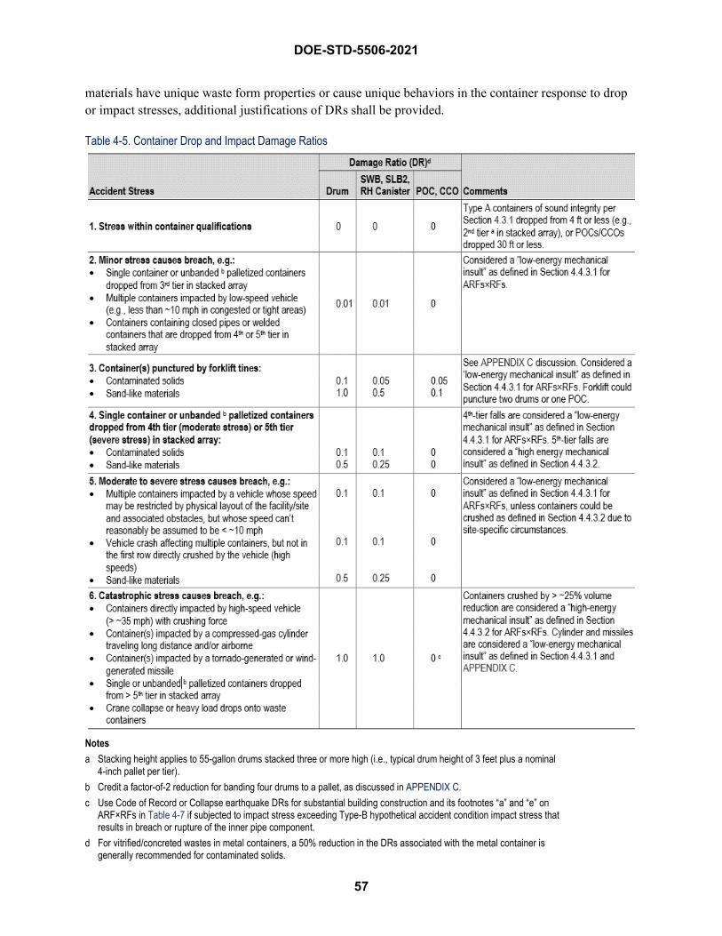
57
DOE-STD-5506-2021
materials have unique waste form properties or cause unique behaviors in the container response to drop or impact stresses, additional justifications of DRs shall be provided.
Table 4-5. Container Drop and Impact Damage Ratios
Notes a Stacking height applies to 55-gallon drums stacked three or more high (i.e., typical drum height of 3 feet plus a nominal
4-inch pallet per tier). b Credit a factor-of-2 reduction for banding four drums to a pallet, as discussed in APPENDIX C. c Use Code of Record or Collapse earthquake DRs for substantial building construction and its footnotes “a” and “e” on
ARF×RFs in Table 4-7 if subjected to impact stress exceeding Type-B hypothetical accident condition impact stress that results in breach or rupture of the inner pipe component.
d For vitrified/concreted wastes in metal containers, a 50% reduction in the DRs associated with the metal container is generally recommended for contaminated solids.
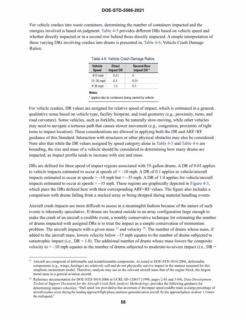
58
DOE-STD-5506-2021
For vehicle crashes into waste containers, determining the number of containers impacted and the energies involved is based on judgment. Table 4-5 provides different DRs based on vehicle speed and whether directly impacted or in a second row behind those directly impacted. A simple interpretation of these varying DRs involving crashes into drums is presented in, Table 4-6, Vehicle Crash Damage Ratios.
Table 4-6. Vehicle Crash Damage Ratios
For vehicle crashes, DR values are assigned for relative speed of impact, which is estimated in a general, qualitative sense based on vehicle type, facility footprint, and road geometry (e.g., proximity, turns, and road curvature). Some vehicles, such as forklifts, may be naturally slow-moving, while other vehicles may need to navigate a tortuous path that causes slower movement (e.g., congestion, proximity of tight turns to impact location). These considerations are allowed in applying both the DR and ARF×RF guidance of this Standard. Interaction with structures or other physical obstacles may also be considered. Note also that while the DR values assigned by speed category alone in Table 4-5 and Table 4-6 are bounding, the size and mass of a vehicle should be considered in determining how many drums are impacted, as impact profile tends to increase with size and mass.
DRs are defined for three speed of impact regions associated with 55-gallon drums. A DR of 0.01 applies to vehicle impacts estimated to occur at speeds of < ~10 mph. A DR of 0.1 applies to vehicle/aircraft impacts estimated to occur at speeds > ~10 mph but < ~35 mph. A DR of 1.0 applies for vehicle/aircraft impacts estimated to occur at speeds > ~35 mph. These regions are graphically depicted in Figure 4-3, which pairs the DRs defined here with their corresponding ARF×RF values. The figure also includes a comparison with drums falling from a stacked array or being dropped during material handling events.
Aircraft crash impacts are more difficult to assess in a meaningful fashion because of the nature of such events is inherently speculative. If drums are located outside in an array configuration large enough to make the crash of an aircraft a credible event, a notably conservative technique for estimating the number of drums impacted with assigned DRs is to treat the impact as a simple conservation of momentum problem. The aircraft impacts with a given mass 21 and velocity 22. The number of drums whose mass, if added to the aircraft mass, lowers velocity below ~35 mph equates to the number of drums subjected to catastrophic impact (i.e., DR = 1.0). The additional number of drums whose mass lowers the composite velocity to < ~10 mph equates to the number of drums subjected to moderate-to-severe impact (i.e., DR =
21 Aircraft are composed of deformable and nondeformable components. As noted in DOE-STD-3014-2006, deformable components (e.g., wings, fuselage) are relatively soft and do not physically survive impact in the manner assumed for this simplistic momentum model. Therefore, analysts may use as the relevant aircraft mass that of the engine block, the largest metal mass in a general aviation aircraft.
22 Reference documentation for DOE-STD-3014-2006 in UCRL-ID-124837 (1996, pages 2-45 and 3-84), Data Development Technical Support Document for the Aircraft Crash Risk Analysis Methodology, provides the following guidance for determining impact velocities: “Stall speed was provided so that an estimate of the impact speed could be made as a large percentage of aircraft crashes occur during the landing approach flight phase, and most general aviation aircraft fly the approach phase at about 1.3 times the stall speed.”
59
DOE-STD-5506-2021
0.1). Given the minor contribution of any additional drums below ~10 mph (DR = 0.01), their mass may be neglected when using this methodology for aircraft crashes.
This simplistic model may also be used for drums contained within a facility. It is not, however, required. The aircrafts identified as credible sources of impact per DOE-STD-3014-2006 are typically those in the general aviation category and most often on the smaller end of that category. Such aircrafts do not generate widespread destruction from impact alone and are significantly impeded by even medium construction buildings as defined in Section 4.3.5 (structural steel framing with sheet metal siding and roof). Therefore, a building’s physical interference potential may be accounted for in assigning qualitative bases for DRs and the associated ARF×RF values identified in Figure 4-3, Comparison of Drum DR and ARF×RF for Contaminated Solids in Drops, Falls, and Vehicle Crashes. Such bases may consider factors such as the degree of impedance offered by a structure, specific locations of impedance relative to plane dimensions, the geometry of the structure and drum positions relative to the plane, and the likelihood of only glancing impacts.

DOE-STD-5506-2021
60
Figure 4-3. Comparison of Drum DR and ARF×RF for Contaminated Solids in Drops, Falls, and Vehicle Crashes
1st Tier Fall Height, 0'-4"
2nd Tier Fall Height, 3'-8"
3rd Tier Fall Height, 7'-0"
4th Tier Fall Height, 10'-4"
5th Tier Fall Height, 13'-8"
Beyond 5th Tier Fall, >13'-8"
Stacked Container Fall Events
Vehicle/Aircraft Impact Events
DR=
0.01
DR=
0.1
DR=
1.0
ARFxRF=
Low Energy
MechanicalInsult
ARFxRF=
High Energy
Mechanical Insult
Vehiclea Crash< ~10 mph
Minor Accident Stress
Vehicle/Aircraft Crash
> ~10 but < ~35mph
Moderate / Severe Accident Stress
Vehicle/Aircraft Crash > ~35 mph
Catastrophic Accident Stress
1st Tier
2nd Tier
3rd Tier
4th Tier
5th Tier
>5th Tier
1st or 2nd Tier Fall, Within Container Qualification, No Accident Stress
3rd Tier Fall, Minor Accident
Stress
4th Tier Fall, Moderate Accident
Stress
5th Tier Fall, Moderate / Severe
Accident Stress
ARFxRF =
Low Energy
Mechanical Insult
(≤ 10'-4")(≤ 4th tier)
ARFxRF=
High Energy
Mechanical Insult
(> 10'-4")(> 4th tier)
> 5th Tier Fall, Catastrophic
Accident Stress
Drop Events
≤ 4'-0" Drop,Within Container Qualification, No Accident Stress
4'-0" to 7'-0" DropMinor Accident
Stress
DR=
0.0
DR=
0.01
DR=
0.1
7'-0" to 13'-8" Drop, Moderate / Severe
Accident Stress
> 13'-8" Drop,Catastrophic
Accident Stress
DR=
1.0
a Containers impacted by aircraft crash ≤ 10 mph may be neglected
61
DOE-STD-5506-2021
Vehicle Crash With Fire Another scenario of interest is a vehicle crash into waste containers and a subsequent fuel pool fire affecting ejected and confined wastes. Modeling a vehicle crash with follow-on fire involves combining the impact stress release, as described above, with the instantaneous crash/spill pool fire stress release, as described in Section 4.3.3. The number of containers impacted should be commensurate with the dimensions of the vehicle along with the vehicle speed sufficient to apply the Table 4-5 impact DRs. Generally, the amount of material in each impacted container (i.e., the impact DR) is assessed a high- or low-energy impact stress from Table 4-8. If the container payload is combustible, the same amount of material in each impacted container is assumed to be strewn outside the container and assessed as unconfined burning (ARF×RF = 1E-2). The remaining material in impacted containers receives confined burning (ARF×RF = 5E-4). Other containers in and near the pool fire are modeled as receiving pool fire damage, as discussed in Section 4.3.3.
An example diagram of a 20-mph forklift crash into a two-tier waste array with follow-on fire is provided in Figure 4-4, Example Graphic 20 mph Vehicle Crash with Follow-On Pool Fire. For this example, the four drums (two per tier) directly impacted at 20 mph would receive a moderate to severe stress 0.1 DR in accordance with Table 4-5. Thus, if the MAR is 100% combustible, 10% of the MAR in the four drums would be assessed to burn unconfined and 90% would experience confined burning. The six drums in the next row, along with the four being carried on the forklift, would receive a minor stress 0.01 DR with 1% of the MAR of all ten drums burning unconfined and 99% experiencing confined burning. Further, toppled drums that spill combustible waste would also experience confined and unconfined burning commensurate with the container’s elevation when toppled. The remaining drums would be damaged using the pool fire analysis methodology described in Section 4.3.3.
Table 4-5 identifies a DR of 0 as appropriate for POCs/CCOs receiving significant impacts. The evaluation above of available information on POCs concludes that “the POC far surpassed the DOT Type A test requirements” and survived the Type B individual impact and crush tests. For unconfined fuel pool fires from a vehicle due to the crash, the duration is short and no additional release from fire exposure is expected. Similarly, Section 4.3.3 addresses CCO performance in longer duration, 30-minute engulfing fire exposures. An overall DR of 0 for CCOs loaded with powder or POCs with any waste form is thus consistent with the Standard’s guidance for a vehicle crash followed by fires. CCOs passed similar tests for its expected payload of down-blended powder waste; however, if the payload is combustible waste, then CCOs are treated as vulnerable to fire exposure, as discussed in Section 4.3.3.
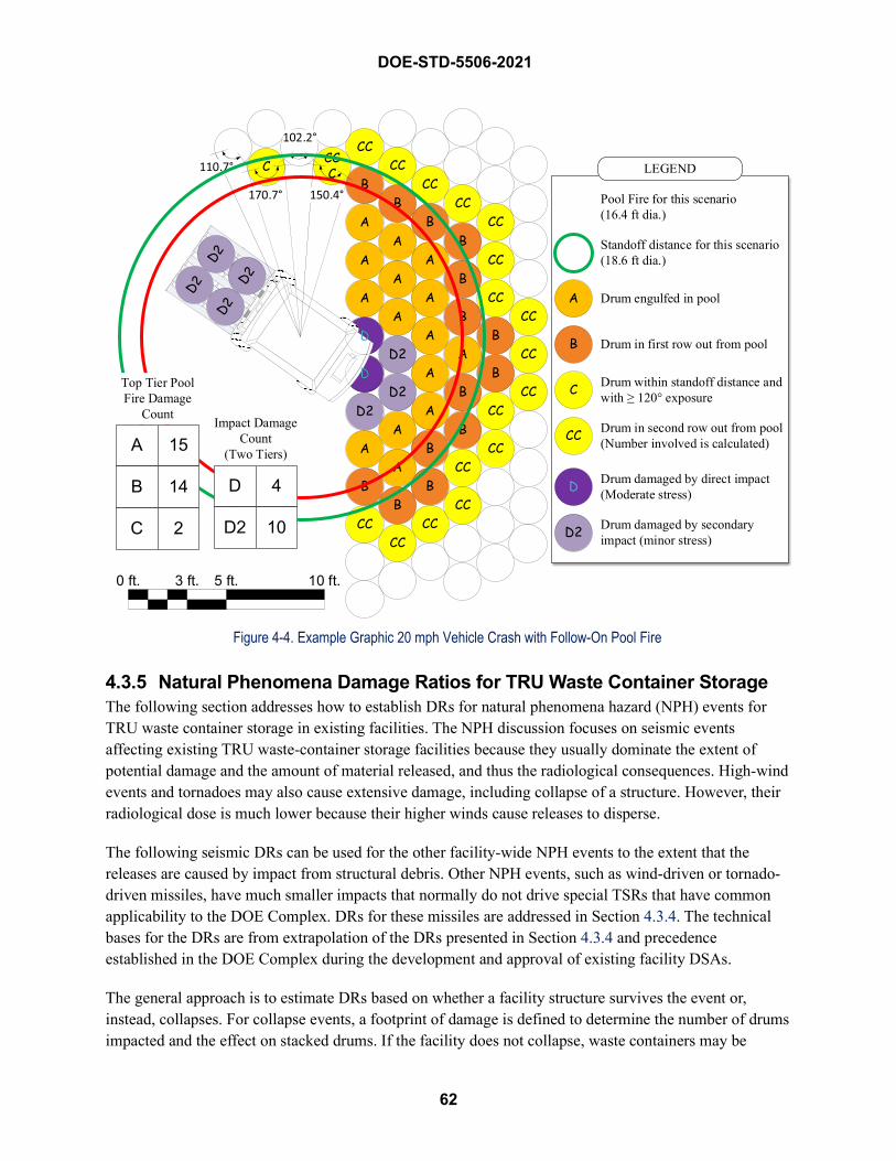
DOE-STD-5506-2021
62
Figure 4-4. Example Graphic 20 mph Vehicle Crash with Follow-On Pool Fire
4.3.5 Natural Phenomena Damage Ratios for TRU Waste Container Storage The following section addresses how to establish DRs for natural phenomena hazard (NPH) events for TRU waste container storage in existing facilities. The NPH discussion focuses on seismic events affecting existing TRU waste-container storage facilities because they usually dominate the extent of potential damage and the amount of material released, and thus the radiological consequences. High-wind events and tornadoes may also cause extensive damage, including collapse of a structure. However, their radiological dose is much lower because their higher winds cause releases to disperse.
The following seismic DRs can be used for the other facility-wide NPH events to the extent that the releases are caused by impact from structural debris. Other NPH events, such as wind-driven or tornado-driven missiles, have much smaller impacts that normally do not drive special TSRs that have common applicability to the DOE Complex. DRs for these missiles are addressed in Section 4.3.4. The technical bases for the DRs are from extrapolation of the DRs presented in Section 4.3.4 and precedence established in the DOE Complex during the development and approval of existing facility DSAs.
The general approach is to estimate DRs based on whether a facility structure survives the event or, instead, collapses. For collapse events, a footprint of damage is defined to determine the number of drums impacted and the effect on stacked drums. If the facility does not collapse, waste containers may be
0 ft. 3 ft. 5 ft. 10 ft.
A
A
AA
AA
A
A
A
A
BA
D2
D2
D2
A
B
CCCC
BB
A
CC
CC
BB
CCCC
B
A
C
B
A
Pool Fire for this scenario(16.4 ft dia.)
Standoff distance for this scenario (18.6 ft dia.)
Drum engulfed in pool
Drum in first row out from pool
Drum within standoff distance and with ≥ 120° exposure
Drum in second row out from pool(Number involved is calculated)CC
LEGEND
B
B
B
B
B
A
CC
CC
CC
CC
CC
B
B
CC
CC
CC
D
D
D
D
D Drum damaged by direct impact (Moderate stress)
Drum damaged by secondaryimpact (minor stress)D2
CC
CC
CC
C CCC
A
B
C
15
14
2
Top Tier Pool Fire Damage
CountImpact Damage
Count(Two Tiers)
D
D2
4
10
63
DOE-STD-5506-2021
impacted and breached by falling objects (e.g., lights, fire suppression sprinkler lines) and other overhead equipment not seismically rated in the structure that are not qualified to the “Code of Record” earthquake. Toppling of stacked containers is also considered for both events if the DOE requirements for a Design Basis Earthquake (DBE) 23 is sufficiently large based on the site-specific evaluation.
During an earthquake (and shortly thereafter), portions of a facility may fall onto containers of nuclear materials, breaching some of them, and containers may topple due to the earthquake causing a container breach. Three facility construction types are defined for use in damage assessment of containers and derivation of the corresponding values of DR. These are:
• Light construction (or none) includes weather enclosures such as tents or domes (e.g., aluminumor lightweight metal frame and fabric such as a Sprung® or Rubb® structure), wood framebuildings, and open storage areas with no protective structure at all.
• Medium construction includes structural steel framing with sheet metal siding and roof. Thisincludes Butler®-type buildings and cargo containers.
• Substantial construction includes buildings made of concrete, cinder block, etc.
Because of the robust nature of the packaging used for containing nuclear waste materials (e.g., metal 55-gallon drums and boxes), the collapse of a facility of light construction is not expected to breach the containers. Therefore, a DR = 0 should be assumed for facilities of light construction for seismic events.
For facilities of medium and substantial construction, the extent of damage to containers depends upon the magnitude of the earthquake. Various designations have been used for earthquakes of different sizes. A Code of Record earthquake is one that a facility was originally designed and built to withstand. Thus, it is not expected to experience any structural damage that could cause significant radiological releases. An earthquake that causes collapse of the structure is called a “Collapse Earthquake” for the purposes of this DR discussion.
During a Collapse Earthquake, 100% of the exposed packages may be assumed to be impacted by falling debris in a facility of substantial construction. This debris would include massive chunks of concrete from a ceiling or roof. All waste containers inside buildings are affected because of impact from falling objects and collapsing building components such as walls, roofs, and structural I-beams, and/or toppling. For a medium construction building, the number of containers impacted by falling I-beams may be estimated by determining the I-beam area relative to the total floor area for a large-size TRU waste-storage building. The I-beam area for each building can be determined as follows:
%I-beam area = [I-beam width (assumed to be 1 ft) × I-beam length (feet) × number of I-beams per building] / total area of building
Alternatively, in lieu of the above calculation for a specific building design, the number of packages impacted may be conservatively assumed as 10%, based on DOE Complex-wide application of the above formula for typical TRU waste medium construction facilities.
23 Or “Derivative DBE” or “Evaluation Basis Earthquake” for evaluation of existing nuclear facilities
64
DOE-STD-5506-2021
However, as discussed next, for either option not all impacted containers are assumed to be breached. For both medium and substantial construction facilities, the amount of damage to an impacted package depends on its construction, as follows:
• For drums, 10% of those impacted may be assumed breached (i.e., penetration of drum andinternal packaging). This value is based on engineering judgment. It takes into account thestrength of the drums and the types of overhead materials that may fall (i.e., they have to beheavy and fall with a sharp edge or corner hitting the package). Another interpretation as appliedto a population of containers impacted by an accident, assuming the total overall area/facilityMAR inventory, is that a DR of 0.1 represents:
o 100% of the affected containers spilling 10% of their contents;
o 10% of the affected containers spilling 100% of their contents; or
o a combination of these two.
A DR of 0.1 is considered conservative given the various mechanisms by which containers may be compromised (uplift, toppling, rolling and impact, equipment or building falling on the containers, missile strike). This value does not apply if a single direct-loaded SWB/SLB2 or four or fewer drums are impacted, where a 1.0 breach fraction shall be assumed.
• For SWBs, the same 10% assumption as for drums applies.
• For overpacked containers, a factor-of-two reduction from the drum DRs may be assumed to bebreached, yielding a DR of 0.05. This lower value is based on the configuration of the 55-gallonmetal drum nested within a larger metal container (e.g., four 55-gallon drum overpacked in alarger drum, or four 55-gallon drums inside a SWB or the TDOP, giving additional protection).This value does not apply if a single overpacked SWP/TDOP or four or fewer overpacked drum-in-drums are impacted, where a 0.5 breach fraction shall be assumed.
• POCs afford even greater protection and only 1% of those impacted may be assumed breached ina substantial construction facility. However, a DR of zero is expected in a medium constructionfacility, as the falling debris would not be as massive as it would be in a substantial-constructionfacility. POCs are vulnerable to being crushed by a collapsing concrete building, but notprefabricated metal buildings. The Rocky Flats report 24 noted that finite-element modeling of theimpact of falling heavy objects only evaluated the bare pipe components, not the complete POCs.Therefore, the results of these simulations can be used in either of two ways. First, the modelingresults can be considered conservative, because the drum and its packing material absorb some ofthe impact, as was demonstrated by the Type B crush tests. For example, in the top-impact crushtests, 500 kg (1,100 lbm) steel plates were dropped on the POCs. The drums were shortened byabout 13 cm (5 inches), but the pipe components were undamaged. The side-impact test alsoshowed that the drum and its packing material absorbs some of the impact energy. Second, thekinetic energy of the falling steel plate, which was absorbed by the drum and its packingmaterial, can be added to the kinetic energy assumed in the modeling to arrive at an estimate
24 See APPENDIX C.
DOE-STD-5506-2021
65
of the total kinetic energy involved in the simulation, therefore, the POC would be expected to survive more severe impacts than the pipe component.
• If direct loaded, RH canister performance should be similar to the SWB’s. Therefore, SWB DRscan be applied. RH canisters with nested drums are modeled similar to overpacked containers. Ifthe RH canister is handled outside a hot cell in a “facility cask” or onsite shipping cask that doesnot meet the DOT Type B criteria 25, lower DRs may be appropriate and can be modeled in amanner similar to the modeling of loss of confinement/containment events discussed in Section4.3.4.
The NPH DR is the product of the fraction impacted times the fraction breached from the preceding discussion. These two terms are intended to be applied together using the entire area/facility MAR (whether defined statistically or as an area/facility limit). For a substantial construction facility subject to a Collapse Earthquake, the NPH DR is 0.1 (i.e., 100% impacted × 10% breached) for drums and SWBs, and 0.01 (i.e., 100% impacted × 1% breached) for POCs. For a medium construction facility subject to a Collapse Earthquake, the NPH DR is 0.01 (i.e., 10% impacted × 10% breached) for drums and SWBs, and no release for POCs (i.e., DR = 0).
DRs for the Code of Record earthquake are scaled down from those for the Collapse Earthquake based on engineering judgment. They are based on the assumption of limited amount of non-seismically qualified overhead mounted equipment (e.g., suspended space heaters, electrical distributions and lighting, fire sprinklers, etc.) that could fall and impact containers. This limited amount of damage is expected to result in at least a factor-of-10 reduction from the NPH DRs applicable to the Collapse Earthquake. For the Code of Record earthquake, the DRs are for the exposed containers to the falling debris. If the containers are stacked, only the top tier is considered exposed. For example, four-high stacking means that only 25% of the containers are exposed.
Stacked drums can also topple during an earthquake of sufficient magnitude. In the event that stacked drums fall during an earthquake, only those falling from the third tier or higher as illustrated in Figure 4-3 could possibly rupture because their DOT Type A qualification means that the drums can withstand a 4-ft drop. For the unmitigated analysis, the DR values presented in Table 4-5 based on stacked tier height are applicable to seismic-induced toppling, e.g., 0.1 DR for all fourth-tier drums and 0.01 for all third-tier drums for contaminated solids (these are in addition to the above recommendations for releases from falling debris). These DRs do not consider the potential additional release from non-seismically qualified cranes that may be in TRU waste facilities. An additional evaluation of the extent of damage from the crane collapse shall be performed in the DSA based on the facility-specific circumstances.
If the drum banding (four drums to a pallet) is credited for the mitigated analysis, the chances of toppling are very small. The horizontal force would have to be great enough to cause the center of gravity of the stack to be displaced at least two feet from normal for the entire stack to topple. A site-specific structural engineering analysis should be performed to determine whether toppling is possible for unbanded and banded drums for the Code of Record and/or Collapse Earthquake being evaluated in the DSA. For the
25 Casks that meet current Type B criteria normally are expected to survive facility mechanical insults typical of those that may occur in the DOE Complex where TRU wastes are stored or handled, unless a facility-specific hazard or accident is more severe than the testing requirements.
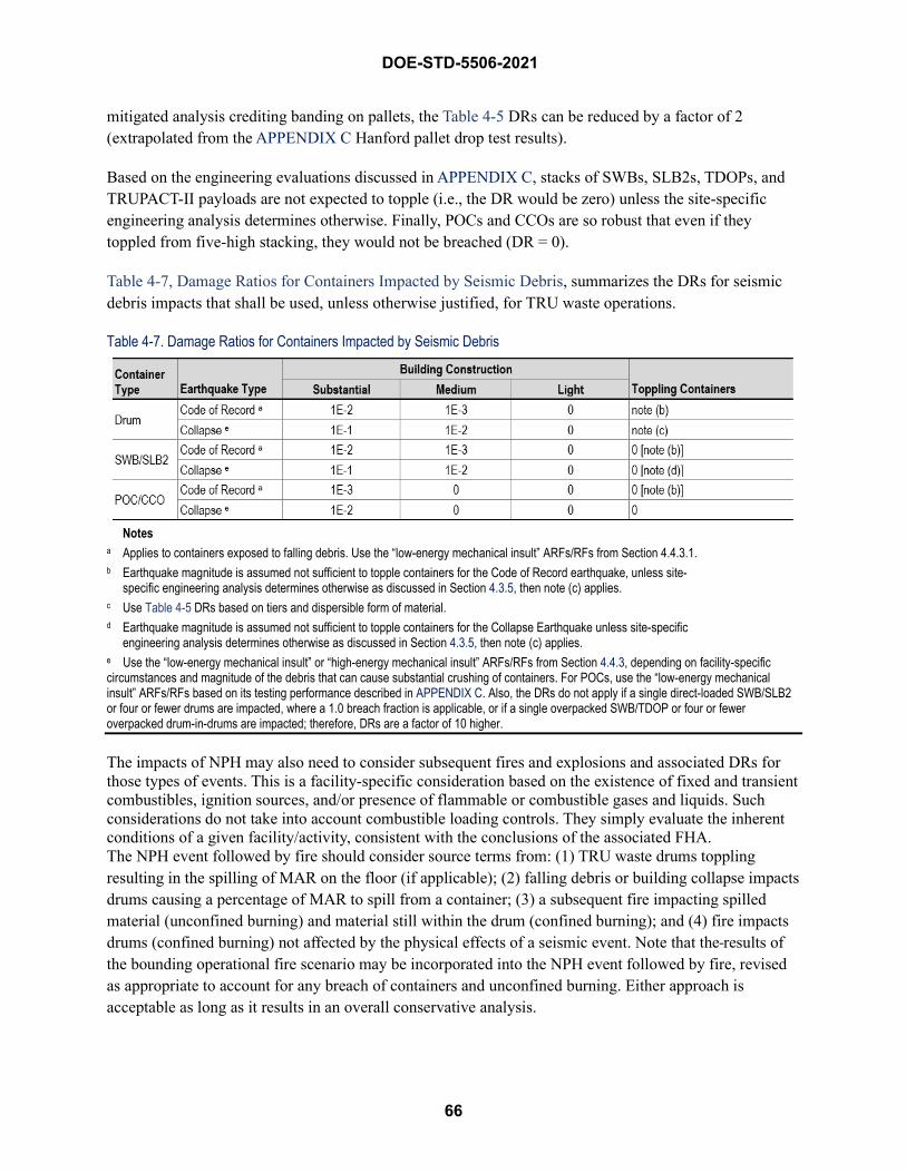
DOE-STD-5506-2021
66
mitigated analysis crediting banding on pallets, the Table 4-5 DRs can be reduced by a factor of 2 (extrapolated from the APPENDIX C Hanford pallet drop test results).
Based on the engineering evaluations discussed in APPENDIX C, stacks of SWBs, SLB2s, TDOPs, and TRUPACT-II payloads are not expected to topple (i.e., the DR would be zero) unless the site-specific engineering analysis determines otherwise. Finally, POCs and CCOs are so robust that even if they toppled from five-high stacking, they would not be breached (DR = 0).
Table 4-7, Damage Ratios for Containers Impacted by Seismic Debris, summarizes the DRs for seismic debris impacts that shall be used, unless otherwise justified, for TRU waste operations.
Table 4-7. Damage Ratios for Containers Impacted by Seismic Debris
Notes a Applies to containers exposed to falling debris. Use the “low-energy mechanical insult” ARFs/RFs from Section 4.4.3.1. b Earthquake magnitude is assumed not sufficient to topple containers for the Code of Record earthquake, unless site-
specific engineering analysis determines otherwise as discussed in Section 4.3.5, then note (c) applies. c Use Table 4-5 DRs based on tiers and dispersible form of material. d Earthquake magnitude is assumed not sufficient to topple containers for the Collapse Earthquake unless site-specific
engineering analysis determines otherwise as discussed in Section 4.3.5, then note (c) applies. e Use the “low-energy mechanical insult” or “high-energy mechanical insult” ARFs/RFs from Section 4.4.3, depending on facility-specific circumstances and magnitude of the debris that can cause substantial crushing of containers. For POCs, use the “low-energy mechanical insult” ARFs/RFs based on its testing performance described in APPENDIX C. Also, the DRs do not apply if a single direct-loaded SWB/SLB2 or four or fewer drums are impacted, where a 1.0 breach fraction is applicable, or if a single overpacked SWB/TDOP or four or fewer overpacked drum-in-drums are impacted; therefore, DRs are a factor of 10 higher.
The impacts of NPH may also need to consider subsequent fires and explosions and associated DRs for those types of events. This is a facility-specific consideration based on the existence of fixed and transient combustibles, ignition sources, and/or presence of flammable or combustible gases and liquids. Such considerations do not take into account combustible loading controls. They simply evaluate the inherent conditions of a given facility/activity, consistent with the conclusions of the associated FHA. The NPH event followed by fire should consider source terms from: (1) TRU waste drums toppling resulting in the spilling of MAR on the floor (if applicable); (2) falling debris or building collapse impacts drums causing a percentage of MAR to spill from a container; (3) a subsequent fire impacting spilled material (unconfined burning) and material still within the drum (confined burning); and (4) fire impacts drums (confined burning) not affected by the physical effects of a seismic event. Note that the results of the bounding operational fire scenario may be incorporated into the NPH event followed by fire, revised as appropriate to account for any breach of containers and unconfined burning. Either approach is acceptable as long as it results in an overall conservative analysis.
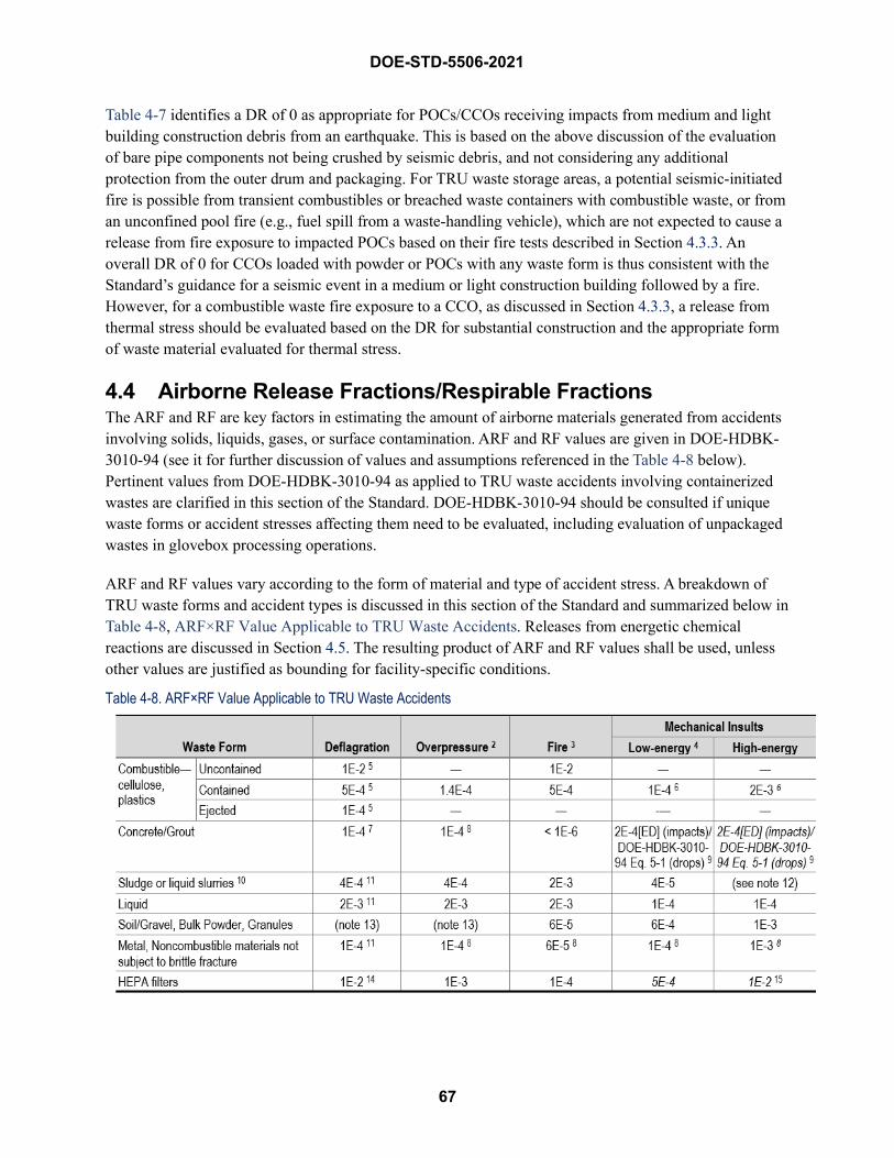
67
DOE-STD-5506-2021
Table 4-7 identifies a DR of 0 as appropriate for POCs/CCOs receiving impacts from medium and light building construction debris from an earthquake. This is based on the above discussion of the evaluation of bare pipe components not being crushed by seismic debris, and not considering any additional protection from the outer drum and packaging. For TRU waste storage areas, a potential seismic-initiated fire is possible from transient combustibles or breached waste containers with combustible waste, or from an unconfined pool fire (e.g., fuel spill from a waste-handling vehicle), which are not expected to cause a release from fire exposure to impacted POCs based on their fire tests described in Section 4.3.3. An overall DR of 0 for CCOs loaded with powder or POCs with any waste form is thus consistent with the Standard’s guidance for a seismic event in a medium or light construction building followed by a fire. However, for a combustible waste fire exposure to a CCO, as discussed in Section 4.3.3, a release from thermal stress should be evaluated based on the DR for substantial construction and the appropriate form of waste material evaluated for thermal stress.
4.4 Airborne Release Fractions/Respirable Fractions The ARF and RF are key factors in estimating the amount of airborne materials generated from accidents involving solids, liquids, gases, or surface contamination. ARF and RF values are given in DOE-HDBK-3010-94 (see it for further discussion of values and assumptions referenced in the Table 4-8 below). Pertinent values from DOE-HDBK-3010-94 as applied to TRU waste accidents involving containerized wastes are clarified in this section of the Standard. DOE-HDBK-3010-94 should be consulted if unique waste forms or accident stresses affecting them need to be evaluated, including evaluation of unpackaged wastes in glovebox processing operations.
ARF and RF values vary according to the form of material and type of accident stress. A breakdown of TRU waste forms and accident types is discussed in this section of the Standard and summarized below in Table 4-8, ARF×RF Value Applicable to TRU Waste Accidents. Releases from energetic chemical reactions are discussed in Section 4.5. The resulting product of ARF and RF values shall be used, unless other values are justified as bounding for facility-specific conditions.
Table 4-8. ARF×RF Value Applicable to TRU Waste Accidents
68
DOE-STD-5506-2021
Notes 1 See Section 4.5 and APPENDIX E for releases from energetic chemical events. 2 Internal pressure that fails the container and expels some fraction of the contents at a pressure ≤ 500 psig. 3 Thermal stress that ejects lid and some of the contents. Some fraction of the ejected combustible contents may burn as well as the residual
contents that remain in the open drum. 4 Some fraction of the contained powder and liquid contents are released from a location that is elevated to the equivalent of 3rd or 4th tier of
stacked drums as defined in Table 4-5 and impacts a hard, unyielding surface. 5 As discussed in Section 4.4.1, the approach specified in this Standard is to assume that some material ejects from the container, some of
this ejected material burns on the ground in an uncontained fashion, and the remaining unejected material burns confined. The relative fractions of each are defined as DRs in Section 4.3.2. Releases are also possible from other container configurations with contaminated combustible waste, in the absence of lid loss. Section 4.3.2 addresses the analysis of situations, primarily container overpacks, where the outer lid is not lost.
6 The container is impacted with two possible levels of force. For lower-energy impacts that do not crush the container, the “low-energy mechanical insult” ARF×RF value of 1E-4 is applicable as discussed in Section 4.4.3.1. For “high-energy mechanical insults” postulated that crush the container due to falling massive debris such as during a seismic ev, or an errant blow from a high-speed vehicle crash that crushes the container, the cited value of 2E-3 is applicable as discussed in Section 4.4.3.2. The phenomena in this category are complex; and, provided a defensible technical basis is developed, other ARF & RF values are allowed.
7 Values should not be applied if pulverized concrete/grout. See deflagration discussion in Section 4.4.1. 8 Of loose, surface-contamination present. Metal or concrete/grout fragmentation is not anticipated. 9 The 2E-4 × [energy density (ED)] correlation applies to events impacting the concrete/grout. For drop/fall events, use DOE-HDBK-3010-94
Equation 5-1 based on bounding concrete/grout density and drop height (e.g., see Figure 4-3 distances). 10 Some DOE sites may have wastes labeled as “sludge,” but this material can be very dry and easily dispersible, and thus better modeled as
a powder, not as a set sludge assumed to behave like a slurry. 11 See deflagration discussion in Section 4.4.1. 12 The ARF×RF can be estimated applying the Jardine, et. al., 1982 equation, 2E-4×[ED], by calculating the energy imparted to the slurry and
assuming a free-fall and impact from the height that would insert that energy into the material. 13 See the discussion in Section 4.4.1 based on container failure pressure, e.g., 2E-3 for ≤25 psig, 7E-2 for up to 500 psig, or application of
the NUREG/CR-6410 correlation from Section E.3.1 where container failure pressure can be conservatively determined. For Event 8 enclosure deflagration, or over-pressurization, 1.5E-3 ARF×RF applies for accelerated airflow over exposed powders.
14 Assumes deflagration blast passes through the High Efficiency Particulate Air (HEPA) filter prior to failure of the container. See discussion in Section 4.4.1. If, however, filters are packaged to preclude direct passage through the filter, no significant release occurs.
15 For an impacted HEPA filter where the media is not enclosed (e.g., packages, filter or plena housing).
4.4.1 Deflagration and Overpressure Events This following two subsections address releases from deflagration and overpressure events. Different waste forms are addressed as appropriate for the accident stress.
Deflagration Releases Deflagration accidents involve several types of accident stresses. Multiple models of release are possible, depending on the materials involved—e.g., contaminated combustible or noncombustible wastes, powders, etc. The historical modeling of this event is discussed in Section 3.3 and Section 4.3.2, and involves the ejection and ignition of combustible wastes. Section B.3, Summary and Recommendations for Deflagration Release Parameters, addresses ARF and RFs for drum deflagrations involving combustible waste that are coupled with DRs (and fractions of MAR), as discussed in Section 4.3.2. “Combustible waste” as used in this section refers to objects such as contaminated paper, wipes, gloves, etc. Finely divided combustible wastes (such as organic absorbents or dry organic sludge), if present, should be analyzed as powders. The ARFs and RFs for combustible wastes are as follows:
DOE-STD-5506-2021
69
• The 0.4 fraction of wastes that is ejected and burns is modeled consistent with DOE-HDBK-3010-94, Section 5.2.1.2, values for unconfined cellulosic or plastic materials. The bounding ARFis 1E-2 and the RF is 1.0.
• The ejected material is subject to shock-vibration stress as it is ejected and impacts a hard surface.The ARF and RF for this phenomenon are 1E-3 and 0.1. These values are applied to the0.4 fraction assumed to be ejected from the drum.
For free-fall spill, Section 5.2.3 of DOE-HDBK-3010-94 states the following: “Loss/dislodgement of surface contamination during the free-fall spill of contaminated, combustiblematerials would not appear to generate any significant stress upon the surface.” Section 5.2.3.1further states:
In many cases the combustible materials are light and have high surface area to mass ratios (e.g. paper, cardboard, plastic sheets and wrapping) and thus would generate little force during impact with surfaces. For such materials, no significant suspension of surface contamination is postulated. In the case of material with appreciable mass, the dislodgement of surface contamination upon impact would appear unlikely but would be bounded by the bounding ARF and RF described in subsection 5.3.3.2.2 for the suspension of surface contamination by vibration-shock.
Section 5.2.3.2 for impact further clarifies that the impact of concern for an ARF×RF value of 1 E-3 is associated with “unpackaged materials with appreciable mass that generate significant forces upon impact with a surface.” The original preparers of DOE-STD-5506-2007 did not consider the ejection release in the deflagration scenario to meet these stipulations. It is accordingly assigned an ARF×RF reduction factor of 10 to an ARF×RF of 1 E-4 instead of assuming no appreciable release as is suggested for this specific case by the discussion of more severe stresses in DOE-HDBK-3010-94.
• The surface-contaminated combustible material that remains in the open drum is also assumed toburn. The ARF and RF cited in DOE-HDBK-3010-94, Section 5.2.1.1, for “packaged waste” areapplied. The bounding values are 5E-4 and 1.0.
The above modeling of a hydrogen deflagration in a drum with combustible waste results in an overall effective ARF×RF with fractions ejected or remaining in the drum of 5.4E-4, as shown in Table B-20, Overall Drum Composite Release Fraction.
As described in Section 3.3.2.4 (Event 8), a deflagration may also occur within an enclosure. This situation is possible within enclosures such as gloveboxes that involve unpackaged waste (i.e., not in a drum or other enclosed container, including bags) that has the potential to release flammable vapors that could accumulate to concentrations greater than the LFL. For uncontained combustible waste in an enclosure such as a glovebox, a release from a deflagration is expected to be bounding by unconfined burning ARF×RF of 1E-2 conservatively assuming that it is loosely strewn waste and not agglomerated piles. Any additional contribution from waste that could be ejected from the glovebox would be subject to
70
DOE-STD-5506-2021
the 1E-4 ARFĬRF as discussed for a drum deflagration with combustible waste, and would not significantly increase the overall release estimate.
For other waste forms in a container, such as aggregate (concrete, grout), and solid metal (noncombustible), release from a deflagration can be conservatively treated as a detonation using the Steindler and Seefeldt correlation for detonations in/or contiguous to material, as discussed in DOE-HDBK-3010-94 Sections 3.2.2.1, 4.2.2.1, 4.3.2.1 and 5.3.2.2.1. This correlation applies a Mass Ratio (MR) that is equal to the mass of inert material (kg) divided by the TNT Equivalent (kg) of the explosion. Table 3-6 (page 3-46) in NUREG/CR-6410 provides ARF and RF values.
The maximum MR provided in Table 3.6 is 24, which corresponds to an ARFĬRF value of 9 E-5. For a 55-gallon drum that is 50% empty with a stoichiometric concentration of hydrogen in the void space, anunlikely configuration, the calculated TNT equivalent of a detonation is 66 grams. To exceed a MR of 24,the overall container matrix must weigh more than 1.6 kg. As the container alone will weigh more thanthat, a simple bounding ARFĬRF of 1 E-4 can be used for container deflagrations involving these otherforms.
As previously noted, a deflagration may also occur in an enclosure such as a glovebox used to unpackage and sort waste. If a deflagration occurs in such an enclosure containing unpackaged, loosely strewn waste, the ARFĬRF value assigned should be the applicable value for pressurized venting in DOE-HDBK-3010-94, based on the material type and the failure pressure of the enclosure. For sludges, slurries and liquids, this ARFĬRF value would be applied to the entire material volume. For concrete/grout and metals, it would be applied to loose surface contamination on the material. Estimates of loose surface contamination may be based on historical data or mg/ft2 values found in literature.
One other potential release scenario may also be applicable to aggregate. If aggregate is hurled with considerable velocity to impact, the crush-impact correlation of DOE-HDBK-3010-94 Section 4.3.3, ñFree-Fall Spill and Impaction Stressò (Nonmetallic or Composite Solids), may be used to characterize the response provided an impact velocity can be estimated (and no credit is given to the response of the metal container). A summary of the DOE-HDBK-3010-94 guidance follows, based on its discussion of the Jardine, et. al. 1982 experiments that measured the fraction and size distribution generated by the impact of various materials resting on an unyielding surface. Brittle materials (e.g., glass, aggregate such as mechanically compacted UO2, concrete, or limestone) can be fragmented when impacted or crushed. Figures 33 and 34 from Jardine (Figures 4-12 and 4-13 in DOE-HDBK-3010-94) show the correlation of respirable fraction against the energy density (ED, J/cc) for waste glass and Pyrex, respectively. The energy density is computed as the kinetic energy of the falling aggregate, divided by the volume of the falling aggregate. The slope of the straight line in these figures is approximately 2 E-4, yielding the following correlation for a total respirable release estimate of:
ARFĬRF = 2E-4Ĭ[ED]
For sludge or liquid slurries, see discussion below in the ñOverpressure Releasesò subsection for venting of pressurized slurries or wet sludges. For sludges or liquid slurries where the event is characterized instead as deflagration-induced pressurized venting effect, the overpressure values in Table 4-8 should be used. As noted in Table 4-8 footnote 10, some DOE sites may have wastes labeled as ñsludge,ò but this
71
DOE-STD-5506-2021
material can be very dry and easily dispersible, and thus is better modeled as a powder, not as a set sludge assumed to behave like a slurry.
For liquid waste forms, see discussion below in the “Overpressure Releases” subsection for venting of pressurized liquids. For liquid waste forms where the event is characterized instead as deflagration-induced pressurized venting effect, the overpressure values in Table 4-8 should be used.
For soil/gravel, bulk powder, and granules, release from a deflagration from packaged wastes is correlated to release from over-pressurization of the container in DOE-HDBK-3010-94. The associated ARF×RF value is a function of container failure pressure. Section 4.4.2.3.2, “Venting of Pressurized Powders or Pressurized Gases Through Powders, Pressure < 0.17 MPag,” recommends an ARF of 5E-3 with 0.4 RF (2E-3 ARF×RF) for the airborne release during the venting of pressurized powders at lower pressures (25 psig or less). An ARF and RF of 1E-1 and 0.7 (7E-2 ARF×RF) applies for more robust containers that fail at > 25 psig and up to 500 psig (DOE-HDBK-3010-94 Section 4.4.2.3.1, “Venting of Pressurized Powders or Pressurized Gases Through Powders, Pressure > 0.17 MPag” (> 25 psig). Alternately, a NUREG correlation as discussed in Section E.3.1, Radiological Source-Term Evaluations of a Drum Over-pressurization Event, can be applied if the failure pressure can be conservatively justified, and a stochiometric concentration of hydrogen-air can be assumed to be bounding. For TRU waste drums, a deflagration above powder is expected to be bounded by a low pressure (< 25 psig) release, however, for added conservatism, the recent slow pressure testing of drums as discussed in Section B.2.6, Container Response to Internal Pressures, shows that the worst failure was around 50 psig. Using that pressure, the NUREG correlation in Section E.3.1 yields an ARF of 2E-2 with 0.7 RF (1.4E-2 ARF×RF). Note, however, that Table B-10, Drum Explosion Data, indicates that an explosive mixture up to 15% hydrogen-air can be contained in a drum without lid loss. If it is possible to measure or calculate hydrogen concentration, a release may not need to be assumed. The preceding discussion applies to powders that are essentially noncombustible. No guidance is provided if a waste process generates a finely divided combustible waste (such as organic absorbents or dry organic sludge that behaves like a powder), which warrants an evaluation based on the unique properties of the waste. These recommendations do not consider a potential detonation within the powder-like matrix, which can be modeled per other recommendations in DOE-HDBK-3010-94 for soils.
In the case of an enclosure deflagration (Event 8), the event could again affect unpackaged waste (i.e., not in a drum or other enclosed container). For uncontained soil or powder-like waste in an enclosure such as a glovebox, a release from a deflagration should be modeled as accelerated airflow over the affected surface with an ARF of 5E-3 and 0.3 RF (1.5E-3 ARF×RF) per DOE-HDBK-3010-94 Section 4.4.2.2.2, “Shielded Blast Effects From Detonations and Large Volume, Confined Deflagrations,” since the gas flow is not through the bulk powder.
For deflagrations either inside a container or in an enclosure, if the event could initiate a fire or chemical reaction of a combustible powder-like matrix, evaluate per the relevant portions of DOE-HDBK-3010-94 or other guidance in this section of the Standard.
DOE-HDBK-3010-94 Section 5.4.2.2, “Blast Effects” (HEPA Filters), provides the basis for an ARF×RF of 1E-2 for a deflagration affecting HEPA filters. In the “Gregory et al., 1983” experiments cited by DOE-HDBK-3010-94, the researchers pre-loaded 1 kg of 0.46 mm diameter polystyrene latex beads on a
72
DOE-STD-5506-2021
HEPA filter, and subjected the filter to a pressure transient to simulate a tornado event. The pressure transient did not cause structural failure of the HEPA. Two runs were performed, with 1.46% and 0.71% of the pre-loaded material released from the filter. DOE-HDBK-3010-94 used these measurements to assign an ARF×RF of 1E-2 for blast effects. As noted in Table 4-8 footnote 14, application of this value assumes that the deflagration blast passes through the HEPA filter prior to failure of waste container. This is applicable to a deflagration postulated in an exhaust plenum of a confinement ventilation system, and could also apply to HEPA filters on the glovebox exhaust if a significant deflagration is being evaluated.
Overpressure Releases As stated in Section 3.3.3.4 (Event 12), over-pressurization events involve a buildup of pressure inside of a container. Deflagrations and other chemical reactions can cause pressurization, but are addressed elsewhere (above and Section 4.5, Chemical Reaction Source Term, respectively). This subsection applies to other causes of pressurization. These include gas generation by radiolysis (but not accompanied by ignition and deflagration), and the pressurization of an unvented container due to changes in ambient temperature or pressure (without any ensuing chemical reactions). These events generally do not include significant heating of the waste, so the ARF×RF values discussed below generally do not account for thermal stress.
Overpressure conditions primarily affect waste materials due to airflows associated with venting that pressure. In a typical 55-gallon container, which is generally filled with waste, there is only a limited amount of air available to vent. For example, if such a container is filled to 75% of its volume, the total air available is only 1.8 ft3. This tends to mitigate the venting affect for all but the forms most vulnerable to dispersion (e.g., loose, bulk powder). ARF×RF values for overpressure are assigned as discussed next.
For venting of pressurized gas over contaminated, combustible waste, DOE-HDBK-3010-94 assigns a bounding ARF×RF value of 1E-3 (DOE-HDBK-3010-94 Section 5.2.2.3). It notes, however, that this value applies only “to the portion of waste surfaces that are actually exposed.” Combustible waste is relatively densely packed in order to minimize the number of waste containers, and the greatest contamination levels come from glovebox and hot-cell operations, which are bagged out in one or more additional layers of plastic. The actual contaminated surfaces exposed to the air within a container are therefore small. The value of 1E-3 is accordingly reduced by an order of magnitude to an effective ARF×RF value of 1E-4 for venting of pressurized gas over combustible waste. However, it is also possible that the drum lid may be blown off and some combustible waste could also be ejected. There is no test data for this condition, so it is assumed that the release could be modeled similar to drum deflagration modeling of shock-vibration stress as it is ejected and impacts a hard surface, i.e., 1E-4 ARF×RF. This is only applied to the fraction ejected that is assumed to be bounded by the 40% ejected from a drum deflagration that has a much higher overpressure, i.e., 1E-4×0.4 = 4E-5 contribution. The total release from overpressure with contaminated combustible waste is the sum of the two stresses that results in an effective ARF×RF of 1.4E-4. For this event, if the waste is contaminated noncombustible waste, no ejection is assumed due to the higher mass involved and the lesser overpressure before lid loss than from a deflagration overpressure.
For aggregate and solid metal, Chapter 5 of DOE-HDBK-3010-94, “Surface Contamination,” specifically cites waste in containers only for combustible solids. The Handbook states “Noncombustible materials are generally large pieces associated with the facility structure, enclosure, or containers.” The general tenor of
73
DOE-STD-5506-2021
the noncombustible solid discussion indicate primary consideration is being given to contaminated surfaces in a facility. Before such equipment/installations are given clearance for removal from a facility, loose surface contamination has been extensively removed, leaving primarily fixed contamination, which DOE-HDBK-3010-94 does not identify as a source of airborne release. Also, if a waste container were to be filled with primarily aggregate or metal, radiolysis rates would be significantly reduced compared to combustible waste with its greater hydrogenous material content. Finally, as previously noted, the limited air volume coupled with the packed nature of internal materials does not provide a good interaction geometry to maximize release potential for contamination. As such, attempting to single out aggregate and metal waste forms for comparative overpressure evaluation against the historic norm of combustible materials is not judged to be a technically meaningful endeavor. These forms are assumed to be bounded by the more energetic deflagration and are accordingly assigned the ARF×RF of 1E-4.26
No specific ARF×RF value is given in DOE-HDBK-3010-94 for venting of pressurized slurries or wet sludges. DOE-HDBK-3010-94 does, however, identify lower ARF×RF values for venting of concentrated, heavy-metal solutions vice aqueous solutions (Section 3.2.2.3.2). It is intuitively evident that slurries and wet sludges should have lower ARF×RF values than solutions; lacking any specific basis in DOE-HDBK-3010-94, the bounding ARF×RF of 4E-4 for venting pressurized concentrated heavy metal solutions is assigned.
DOE-HDBK-3010-94 specifies an ARF×RF of 2E-3 for pressurized venting of aqueous solutions (Section 3.2.2.3.2). That value is assigned for liquids.
For soil/gravel, bulk powder, and granules, see the above subsection for discussion of deflagration releases that should also be used for a drum over-pressurization involving loose powder-like materials, based on expected “low/high” failure pressure of the container, or application of the NUREG correlation.
For HEPA filters in waste, there is no specific ARF×RF value available in DOE-HDBK-3010-94 except the 1E-2 value cited for deflagrations. In the case of deflagrations, that value was applied even though it is expected to be extremely conservative. The actual tests on which it is based were for simulated tornado transients on filters mounted in a wind tunnel so as to absorb the full brunt of airflow and differential pressure. Nothing like that condition exists in a waste container. Further, no instantaneous pressure spike occurs as is the case with a deflagration. As noted previously, the amount of air available to vent is small. Little, if any, release is expected from a HEPA filter under these conditions. HEPA filters are designed to trap particulates within the filter media, most of which would not be expected to be released by rapid depressurization of a drum; however, the amount of particulates trapped versus on the exposed face of the filter is unknown. The release of contamination on exposed surfaces of HEPA filters should be bounded on the low end by accelerated airflow over contaminated combustible wastes from DOE-HDBK-3010-94 Section 5.2.2.3 as discussed above, i.e., 1E-3 for exposed waste only, which was qualitatively reduced to 1E-4 for all the MAR due to compaction of the waste in a drum. The release is also expected to be bounded by 1.5E-3 ARF×RF for loose surface contamination due to venting of pressurized gas over solid, non-powder material from DOE-HDBK-3010-94 Section 5.3.2.3, as discussed above for concrete/grout. Based on these considerations, an ARF×RF of 1.5E-3 is recommended for a drum over-pressurization
26 If, however, gas generation rates for a specific aggregate or metal waste stream are known to be a potential pressurization concern that could plausibly yield a container breach, such streams should be individually evaluated for venting release potential.
74
DOE-STD-5506-2021
with contaminated HEPA filters. Historical data, however, may be used to estimate surface contamination levels in HEPA filters.
4.4.2 Fire Scenarios Airborne releases due to thermal stresses are primarily influenced by the form and combustibility of TRU waste materials and whether they are packaged or loosely strewn about. Cellulosic or plastic materials that are packaged are modeled consistent with DOE HDBK-3010-94 (Airborne Release Fractions/Rates and Respirable Fractions for Nonreactor Nuclear Facilities), Section 5.2.1.1, and the drum example described in its Section 7.3.9.1, “Hazard Summary” (Section 7.3.9 Solid Waste Handling), which assigns bounding ARF and RF values of 5E-4 and 1.0 for packaged wastes. The original experiments supporting these values were performed on wastes packaged in plastic bags and sealed in cardboard cartons. DOE-HDBK-3010-94 states that even waste placed together in a pile without bag containment forms a loosely agglomerate package of sorts. Therefore, combustion of TRU wastes that is contained in drums or boxes meets the definition of packaged waste, even when these containers have suffered lid degradation or loss.
Thermal stress on combustible cellulosic or plastic materials that are either ejected from containers or otherwise unconfined or packaged are assigned bounding ARF and RF values from Section 5.2.1.2, “Uncontained, Cellulosic Waste or Largely Cellulosic Mixed Waste,” of DOE-HDBK-3010-94, which are 1E-2 and 1.0, respectively. These values are also applied to the burning of unpackaged waste that is located in glovebox enclosures.
The ARF value for plastics in DOE-HDBK-3010-94 is 5E-2. This value is based upon the maximum measured value for a pile of ball-milled Depleted Uranium (DU) oxide powder lying on granular Polymethyl Methacrylate (PMMA). The phenomenon that suspends the particles from burning PMMA, a thermoplastic material, requires energy to melt the plastic prior to ignition and burning of the vapors. In drummed TRU waste, the contaminant is incorporated into the matrix of material that is folded with contaminant inside or high-activity material from glovebox in additional layers of plastics. The single value cited in DOE-HDBK-3010-94 for the ball-milled DU powder lying under the granular PMMA, ARF 1E-2, is most representative of the conditions here, but probably still overestimates the airborne release.
Other plastic materials, such as polystyrene, polycarbonate, and cellulose, have bounding ARFs of 1E-2 with RF values less than 1.0. Thus, a more representative, but still bounding, ARF for plastics under these conditions is ARF 1E-2. Because the ARF values for cellulose are 1E-2, the value is applied to all combustible material ejected from the drums that burn in the ambient atmosphere.
Other forms of TRU waste that are noncombustible may include concrete or grout form, sludge or liquids, soils/gravel/powders, or solid metal forms. ARF×RF values as described in Table 4-8 are based on DOE-HDBK-3010-94 are 2E-3 for sludges and liquids (assumed to be at boiling point of water, as discussed in DOE-HDBK-3010-94 Section 3.2.1.3, “Additional Evaporation and Bubbling Release Studies”); 1E-4 for HEPA filters (Section 5.4.1, Thermal Stress”); 6E-3×0.01 for contaminated metals and soil/powders (Section 4.4.1.1. Chemically Nonreactive Compounds”); and less than 1E-6 for grout forms (Section 4.3.1.2, “Aggregate,” without crediting a DR based on the discussion that “Up to 22% of the non-volatile activities would be at risk if adequate time at temperature is postulated at a temperature of 650 C or greater”). However, for containerized powders, a pressurized release from a fire could result in a larger
75
DOE-STD-5506-2021
release; see the Section 4.3.3.1 discussion “Direct Pool Fire Damage of Powder-filled TRU Waste Containers.”
Noncombustible waste fractions of inventory that are assumed in the DSA should be conservatively assumed and supported by waste creator data. This assumption shall not be used in single-drum accidents because of the potential that average waste composition for an entire inventory may not be bounding for single drums.
4.4.3 Mechanical Insults Another category of events analyzed for the DSA hazard and accident analysis is loss of confinement/containment events as listed in Table 3-1. DOE-HDBK-3010-94 provides bounding release estimates for free-fall spill and impaction stress to contaminated combustible and noncombustible waste and other forms of MAR (e.g., solid metal, powder, liquid), with limited guidance for releases from containers or enclosures such as gloveboxes. This section focuses on releases from TRU waste in containers. DOE-HDBK-3010-94 should be consulted for release estimates from unconfined TRU waste being repackaged or processed in enclosures such as a glovebox.
TRU waste containers can be dropped or impacted by a variety of forces (seismic, forklifts, wind, and other vehicles). Where these forces are significant, containers can be breached, and the contents dispersed. Many of the experiments for free-fall spills, as described in DOE-HDBK-3010-94, are based on a testing apparatus that dropped materials from a 10- to 12-ft distance. This distance closely approximates the height of the third tier in a stacked array of drums.
Accidents that involve container drops substantially higher than the equivalent of a 3rd or 4th tier of drums (as defined in Table 4-5), as well as high-energy accident stresses from vehicle crushing impacts or structural collapse of a concrete building during certain seismic events (Section 4.3.5), may not be bounded by ARF×RF values that are based on tests using the 10- to-12-ft-drop testing apparatus. Therefore, mechanical stresses are presented according to categories that consider container drops from either.
• 3rd- and 4th-tier falls and low-energy impacts to containers, labeled as “low-energy mechanicalinsults,” or
• higher-level drops and other higher-energy mechanical impacts to containers, labeled as “high-energy mechanical insults.”
Low-Energy Mechanical InsultsCellulosic or largely cellulosic mixed wastes that become dispersed from containers breached by a free-fall spill, a forklift puncture, a 3rd- or 4th-tier fall (based on APPENDIX C drum drop tests), or experience lower energy impacts from falling ceiling-mounted debris but not structural collapse or other stresses (e.g., a low-speed vehicle accident as defined in Table 4-5, a gas cylinder, or windborne missiles) that do not substantially crush the containers as discussed in Section 4.4.3.2 of this Standard, are considered to be bounded by ARF×RF values for the suspension of loose surface contamination from shock/impact stresses. The basis for this phenomenon and assumed bounding values are given in Section 5.2.3.2 of DOE-HDBK-3010-94.
DOE-STD-5506-2021
76
Regarding mechanical insults to containers, two levels of impact energies to assess the airborne release from impacts to containerized TRU waste are considered:
• Low-energy. For low-energy mechanical insult that fails the container confinement and dents thecontainer or simply displaces the container location, the appropriate ARF and RF values are mostclosely modeled by the values cited on page 5-3 in DOE-HDBK-3010-94 of ARF 1E-3 and RF0.1. These values are based on Langer’s experiments for shock-vibration of unconfined powderscovered in Section 4.4.3.3.2 of DOE-HDBK-3010-94—i.e., on the same value that isrecommended in Section 5.2.3.2 of DOE-HDBK-3010-94 for impact to a robust container.Although the experiments were performed on unconfined powders, some of the experimentsinvolved powder in open cans that showed significantly smaller ARF and RF values relative tothe experiments involving loose powder. This configuration is reasonably representative for thebehavior of surface-contaminated waste caused by shock-vibration forces and is conservative dueto the additional difficulty of dislodging particles entrenched on the substrate matrix, andadditional attenuation provided by the natural forces within the container that will reduce theamount of airborne particle prior to release (e.g., from deposition or agglomeration due toincreased particle sizes).
• High-energy. High-energy mechanical insults to containerized wastes from more severeaccidents such as container drops higher than the equivalent of a 4th tier of drums, vehiclecrushing impacts, or structural collapse of a concrete building, are addressed in Section 4.4.3.2 ofthis Standard.
The DOE-HDBK-3010-94 does not specifically recommend the 1E-4 ARF×RF for seismic debris impacting TRU waste containers. It does, however, extrapolate from the Langer tests with loose powders and those in cans, which is assumed applicable to TRU waste containers, as follows:
There appears to be a significant decrease in the overall respirable release, due most likely to some combination of shielding of the powder and interaction between the powder and confining surfaces. As in the estimate for loose powder, there is considerable uncertainty associated with this data. If the highest ARF from the data set (1E-3 for uncontained Al2O3 powder) is used in conjunction with the largest RF from the contained experiments (rounded up to 0.1), the bounding values would be the same as that assessed for vibration shock of loose, clump powders, and the overall ARF x RF would be a factor of 5 greater than that measured in the experiment (1E-4 vice 2E-5). Accordingly, for powder held in cans failed by debris, an ARF of 1E-3 with an RF of 0.1 is assessed to be bounding.
DOE-HDBK-3010-94 does not specifically address sludges, but this material form is considered to be bounded by experiments that measured ARF and RFs from the free-fall spill of slurries. The bounding ARF and RF values that are discussed in Section 3.2.3.2 of DOE-HDBK-3010-94 are 5E-5 and 0.8. The bounding ARF×RF for low-energy mechanical insults to liquids in a container is selected based on the airborne release of an aqueous liquid on impact after a free-fall spill from, and a height lower than, 10 ft (2E-4 and 0.5).
77
DOE-STD-5506-2021
No experimentally measured ARF and RF values are available for TRU waste that is composed of solid metal (e.g., equipment parts) in containers. No metal fragmentation is anticipated from free-fall spills. Section 5.3.3.1 of DOE-HDBK-3010-94 states that no significant suspension from contaminated metals is anticipated, and that the value assessed for crush impact will bound the phenomenon. The crush-impact value is discussed in DOE-HDBK-3010-94 in Section 5.3.3.2.2, ñSolids That Do Not Brittle Fracture,ò which states that solids that experience predominantly plastic deformation (e.g., metal, plastics), as opposed to brittle fracture, respond to vibration and shock of the material substrate. The section recommends a bounding ARF of 1E-3 with a RF of 1.0. However, this is for contaminated noncombustible materials that are not packaged in a metal container. For contaminated noncombustible waste in containers, the bounding ARFĬRF of 1E-3 and 0.1 are the same as the values described above for seismic low-energy mechanical insults to TRU waste containers.
Nonmetallic or composite solids can be fragmented when impacted or crushed. DOE-HDBK-3010-94, Section 5.3.3.2.1 provides a calculational method based on material density and energy imparted during the impact of the material with a hard, unyielding surface. Due to the numerous variables such as weight of material and impact energy, a specific ARFĬRF value is not given. Rather the DOE-HDBK-3010-94 Equation 5-1 should be applied for low-energy mechanical insults based on bounding estimates of grout density and drop height. For example, a drop of drums from a 4th tier (nominally 10 ft 4 inches per Figure 4-3) and assuming a heavy grout density near that of typical concrete of 2.4 g/cm3, the ARFĬRF is about1.5E-5. This result does not consider the energy absorption of the metal drum that adds to theconservatism of this calculation. As discussed in Section 4.4.1, DOE-HDBK-3010-94 Equation 5-1 can beexpressed by the correlation 2E-4Ĭ[ED].
The low-energy mechanical insult to TRU waste in the form of soils or loose powders in containers is approximated by experiments described in Section 4.4.3.1.2, ñFree-Fall Spill Experiments,ò of DOE-HDBK-3010-94. The bounding ARF and RF values for cohesionless powders are 2E-3 and 0.3; these values do not credit the additional protection afforded by the primary enclosure such as a seismically qualified glovebox. For powder-like material that is protected by a container, the ARF and RF are 1E-3 and 0.1, respectively, per DOE-HDBK-3010-94 Section 4.4.3.2, ñLarge Falling Object Impact or Induced Air Turbulence,ò for suspension of bulk powder due to vibration of substrate from shock impact to powder confinement (e.g., gloveboxes, cans) due to falling debris or external energy (e.g., seismic vibrations). These values are applied to spills involving low-energy mechanical insults as opposed to high-energy mechanical insults such as involving a drop of materials from a distance higher than 10 ft, seismically induced forces, or impacts from vehicle accidents.
A low-energy mechanical insult to contaminated HEPA filters in containers is approximated by experiments described in Section 5.4.4.1, ñEnclosed Filter Media,ò of DOE-HDBK-3010-94. The bounding ARF and RF values are 5E-4 and 1.0. These values do not credit the additional protection afforded by the metal containers. These values, moreover, which more appropriately apply to high-energy mechanical insults, are conservatively applied to low-energy mechanical insults to HEPA filters in containers.
High-Energy Mechanical Insults As stated in the preceding section, two levels of impact energies to assess the airborne release from mechanical insults to containerized TRU waste are considered. Impact energy that is higher than that
78
DOE-STD-5506-2021
associated with typical loss of confinement events and low-energy mechanical insults as described in Section 4.4.3.1 is characterized by internal volume reduction of more than ~25% (i.e., crushes the drum) and failure of drum confinement. This level of crushing is based on engineering judgment from the drum drop tests described in APPENDIX C.
The Sandia tests concluded that drum deformation cannot be predicted by considering only the kinetic energy of the system. Drum contents, too, are important because different materials absorb various amounts of energy. The Hanford tests concluded that obvious (highly visible) damage to a drum is not necessarily an indicator of drum integrity. Extensive damage to the drum walls may not be indicative of container breach, whereas a small amount of damage to the lid and upper sealing surface may cause lid separation and loss of container integrity. The 1E-4 ARF×RF for low-energy mechanical insult to a robust container—e.g., a 55-gallon metal drum, discussed in Section 4.4.3.1—is not representative for severe stresses that substantially crush the drum, since it was based on the Langer 12-ft drop tests with rocks weighing 2 to 5 lb each. Section 4.4.3.3.2 of the DOE-HDBK-3010-94 acknowledged the limitation of the data as related to seismic debris impact to loose powders, as follows:
The size and weight of the debris used and the fall heights appear to bound a number of phenomena in nonreactor nuclear facilities, including seismic vibration and impacts on large confinement structures such as gloveboxes. However, the size and weight of debris and the fall heights also appear to be unrealistically low for severe conditions in facilities such as a large building collapse, where large-sized debris from multiple levels may impact the released materials. In as much as the release mechanism appears to be air turbulence and shock-vibration, factors that can potentially increase with mass and size of debris and fall height. On the other hand, as the debris size increases, the impact effect is less likely to be fully concentrated in one area, and debris will provide cover for material that could limit releases.
Since there are no experiments involving TRU waste containers under such severe stress, this phenomenon should be conservatively modeled in DOE-HDBK-3010-94 by suspension of bulk powders from shock impacts due to falling massive debris from structural collapse of a concrete building or external energy. It is stated in Section 4.4.3.3.2 of DOE-HDBK-3010-94 that “Due to the uncertainty in the test conditions, a conservative bounding value for the ARF is assessed to be 1E-2 with an RF of 0.2” for large debris and vibration from a seismic event. Thus, the ARF×RF is selected as 2E-3 for application with the DRs recommended in Table 4-7 as qualified by its footnotes. This value is considered appropriate for the relatively higher levels of energy and container damage as compared to low-energy mechanical insults to containers. It applies to combustible and noncombustible solids not subject to brittle fracture. It does not apply to loose TRU wastes in gloveboxes or material forms that are not applicable including liquids, sludges or grout forms.
It is recognized that the above approach for evaluating severe seismic stresses produces similar results to the traditional approach in DOE-HDBK-3010-94. Accordingly, use of the original DOE-HDBK-3010-94 basis for an ARF×RF of 1E-4 coupled with a damage ratio of 1.0 is also acceptable. This approach may also be extended to drums that will clearly be buried under a significant amount of debris as discussed in DOE-HDBK-3010-94, or drums stored outside of facilities.
For solid materials that undergo brittle fracture (e.g., grout), the ARF and RF values are determined by the material mass and energy as discussed in Section 5.3.3.2.1, “Solids That Undergo Brittle Fracture,” of
79
DOE-STD-5506-2021
DOE-HDBK-3010-94. Due to the numerous variables such as weight of material and impact energy, a specific ARFĬRF value is not given. The ARF and RF value is calculated from the same correlation as presented in Section 4.4.1: ARFĬRF = 2E-4Ĭ[ED].
High-energy mechanical insults on liquid-filled drums are postulated to fail the drum and spill the entire liquid. The bounding ARF and RF values cited in DOE-HDBK-3010-94 Section 3.2.3.1 for the spill of an aqueous solution (spill height < 3 meters) is 2E-4 and 0.5, the same as recommended in Section 4.4.3.1 of this Standard for low-energy mechanical insults to liquids spilled from a container.
The bounding ARFĬRF for TRU waste in the form of soils or loose powders in containers for higher-energy mechanical insults involving a drop of materials greater than 10 ft, seismically induced forces, or impacts from vehicle accidents is 1E-3 ARFĬRF. This is based on reasoned judgment that the release should be higher than the low-energy mechanical insult ARFĬRF of 1E-3Ĭ0.1 (1E-4) described above and less than the 1E-2Ĭ0.2 ARFĬRF (2E-3) for uncontainerized loose powders directly impacted by debris and associated air currents as described in DOE-HDBK-3010-94 Section 4.4.3.3.2. The bounding 1E-3 ARFĬRF is also consistent with the highest ARF measured from the experimental data set for dropping debris on loose powders (1E-3 for uncontained Al2O3 powder) without crediting the RF.
The crush-impact value for contaminated noncombustible materials is discussed in the DOE-HDBK-3010-94 Section 5.3.3.2.2, ñSolids That Do Not Brittle Fracture,ò which states that solids that experience predominantly plastic deformation (e.g., metal, plastics), as opposed to brittle fracture, respond to vibration and shock of the material substrate, and recommends a bounding ARF of 1E-3 with a RF of 1.0. For conservatism, no additional credit is given for the added protection from the container for the high-energy mechanical insult stress to these materials in metal containers.
The bounding ARFĬRF of 5E-4 conservatively applied to high-energy mechanical insult to HEPA filters is assigned in this case. Note, however, that in the unusual case of filter media no longer held in its housing and impacted, DOE-HDBK-3010-94 assigns an ARFĬRF value of 1E-2.
4.5 Chemical Reaction Source Term Chemical reactions involving materials in the waste can lead to a variety of undesired results, such as (1) the generation of heat, fire, or flammable or non-flammable gases and (2) the formation of toxic orcorrosive fumes. In some cases, the initial reactions can lead to more reactive compounds, such as shock- and friction-sensitive compounds. This section specifically addresses the modeling of the radiologicalsource term for events that involve the over-pressurization of a waste container due to the generation ofheat and/or gases. The event may or may not involve fire, or container lid loss. Deflagrations (involvingthe ignition of flammable gases) are discussed in Sections 4.3.2 and 4.4.1. The importance of analyzingover-pressurization events was emphasized by the 2014 radiological release event at WIPP and the 2018event at Idaho National Laboratory. The experience of those two events helped inform the methods in thissection.
Facilities with waste streams having the potential for incompatible chemicals that generate unique or complex reactions (e.g., heat generation and secondary reactions) shall apply source-term assumptions derived in APPENDIX E and presented in this section. Damage ratios derived in Section 4.3 of the
80
DOE-STD-5506-2021
Standard shall be applied only to events involving chemical reactions in cases where the accident stress, material form, and container type are similar to conditions derived in the Standard.
A determination should be made consistent with Section 3.3.8 of the Standard regarding the potential for incompatible chemical reactions. As discussed in Section E.2, Radiological Source Term Evaluations of WIPP and INL Event, a composite ARFĬRF of 2E-1 shall be used for combustible waste when waste constituents have the potential for heat generation and rapid pressure buildup of combustible gases. This is based on 100% ejection of the waste (i.e., damage ratio of 1.0), 50% burning while suspended in air, and remaining 50% unconfined burning outside the drum. Unlike the modeling applied to hydrogen deflagration events involving combustible wastes, there is no technical basis to substantiate that only a portion of the contents are ejected. The 2E-1 ARFĬRF should also be applied if waste characterization information doesnôt exist to sufficiently rule out a similar energetic chemical reaction because of significant uncertainties regarding chemicals used in processes generating the wastes. An example of a waste stream that warrants the above source term assumptions involves large quantities of oxidizing chemicals (e.g., gallons of nitrate liquids) absorbed on very light, easily dispersed organic materials.
When analyzing drums for chemical reactions with significant heat generation (e.g., those modeled with the 2E-1 composite ARFxRF), depending on facility-specific configurations involving nearby combustibles (e.g., WIPP shrink-wrap and slip sheets), the event may start a fire involving the combustibles external to the drums. This event could lead to seal failure in surrounding drums.
If the chemical reaction event has the potential for rapid pressurization and the generation of combustible gases, but involves only noncombustible waste, then a bounding estimate of the release can be made using the ñDeflagrationò column from Table 4-8. Other similar waste containers not involved with the chemical reaction, but located in the immediate vicinity (i.e., first row in an array or stacked on top), should also be evaluated for damage using the same assumptions.
If the chemical reaction results in rapid pressurization and there is no generation of combustible gases (i.e., no fire or deflagration), then a bounding estimate of release can be made using the ñOverpressureò column from Table 4-8. Waste containers not involved with the chemical reaction, but stacked on top, should be evaluated for damage assuming a low-energy mechanical insult ARFĬRF in accordance with guidance in Section 4.4.3 with a 1.0 DR.
Where the chemical reaction event involves a noncombustible powder-like form of material and no concurrent fire, an overpressure condition is created similar to that discussed in Section 4.4.1. The bounding release estimate is dependent on the estimated burst pressure of the waste container. An ARF and RF of 1E-1 and 0.7 (7E-2 ARFĬRF) applies for powders in more robust containers that fail at > 25 psig and up to 500 psig.
As discussed in Section E.3, Modeling Energetic Release Parameters, lower release fractions may be appropriate based on anticipated failure pressure of waste containers. For example, pressure testing of 55-gallon drums supports a failure pressure as high as 52 psig, as discussed in Section B.2.6, ContainerResponse to Internal Pressures. Applying Equation E-2, a 55-gallon drum failure pressure of around50 psig translates to an ARF of 2E-2 and with an RF of 0.7 for bulk powders. Thus, the ARFĬRF is1.4E-2 for a known chemical reaction that only causes over-pressurization (i.e., not anticipated to cause
81
DOE-STD-5506-2021
rapid buildup of heat and pressure) of a bulk powder in a 55-gallon drum. However, based on the INEL ARP V event discussed in Section E.2, Radiological Source Term Evaluations of WIPP and INL Events, an energetic chemical reaction involving bulk powders could not only pressurize the drum expelling its lid and contents, but also involve rapid generation of a significant amount of gas, which may affect the MAR with an air-sparging type of stress. Therefore, for energetic chemical reactions (i.e., pressurization due to potential for rapid buildup of heat and pressure) of a bulk powder in a 55-gallon drum, an ARF of 5E-1 with RF of 10% (5E-2 ARFxRF) shall be assumed.
For the various chemical reaction events discussed in this section, the DSA should consider whether conditions exist in multiple waste containers having the potential for chemical reactions where the containers may not be immediately adjacent to one another.
4.6 Consequence Analysis Section 5 of the original Standard previously provided guidance for evaluating accident consequences. It addressed definitional aspects of such analyses (e.g., receptor definitions, qualitative hazard analysis concepts for facility workers, the established sixteen-sector meteorological dispersion model). These subjects are adequately addressed in other DOE guidance, such as DOE-STD-3009-2014, and DOE-HDBK-1224-2018.
Considerations of specific interest to TRU waste facilities include:
• Plume buoyancy may be used in meteorological dispersion, but only when modeling fires that areoutdoors or venting through a large breach in the facility. A large breach is considered to occurwhen a vehicle or aircraft penetrates the facility, when the building experiences a partial or totalcollapse, or anything else equivalent (e.g., such that development of thermal gradients to loftparticulates can plausibly occur). The breach is generated by the event itself as opposed to humanresponse to the event.
The fraction of the heat of combustion that is not radiated away is available to cause atemperature increase in the air and other gases emitted in the plume. This energy is sensible heatand will act to effectively increase the height of release if not counteracted by the building wake.The sensible heat is greater for a fire external to a building where hot air and other gases movedirectly upward without the potential for additional heat absorption in confined, interior spaces.For an equivalent size fuel pool, sensible heat attributed to an internal building fire shouldtherefore be less than that attributed to an external fire as determined by the FHA or other fireanalysis.
• Building wake effects should be modeled (when a building/structure is nearby the postulated fireevent) in conjunction with plume buoyancy in order to conservatively limit the enhanceddispersion from buoyancy. This use of building wake effects is predicated on applying a code thathas the capability to counteract buoyancy effects with wake effects (e.g., liftoff criterion inMACCS2). Building wake effects may also be credited (modeled) for evaluation of themaximally exposed offsite individual (MOI) as allowed in DOE-STD-3009-2014 whenincorporated into a plume meander model or if approved as part of a site/facility-specificmodeling protocol.

DOE-STD-5506-2021
82
• Generic building wake effects for a 10-m-by-36-m structure are included in the DOE-STD-3009-2014 default χ/Q of 3.5E-3 sec/m3 for ground-level release evaluation of the 100-m co-locatedworker., unless an alternate onsite χ/Q value is justified. The default value may not be appropriatefor certain unique situations, such as operations not conducted within a physical structure27.
• For determining the dose to the 100 m co-located worker, DOE-STD-3009-2014 also allows useof an alternate χ/Q value with technical justification. An obvious example would be a scenarioinvolving plume lofting, where a specific χ/Q value with building wake effects included (when abuilding/structure is nearby the postulated fire event) should be calculated.
27 Operating Experience Level 3, Atmospheric Dispersion Parameter (χ/Q) for Calculation of Co-located Worker Dose, dated April 2015, and associated technical report, NSRD-2015-TD01, Technical Report for Calculations of Atmospheric Dispersion at Onsite Locations for Department of Energy Nuclear Facilities, conclude that the default χ/Q value may not be appropriate for releases if a building is not present, or from a small building.
DOE-STD-5506-2021
83
TRU Waste Hazard Controls Selection and Standardization
5.1 Purpose This section of the Standard provides guidelines for standardizing the hazard-control selection process and gives specific controls that are appropriate for the most common TRU-waste accident events of concern. Section 5.2 and the associated hazard-control tables provide a set of preferred controls, as well as alternate controls that may be applied in certain situations.
5.2 TRU Waste Controls This section describes hazard controls that shall be implemented for those accident events that warrant safety-significant or safety-class designation within the Safety Basis documents based on the results of the hazard/accident analysis. The safety classification of controls (i.e., safety significant or safety class) is not specified in this section and is expected to vary at each DOE site, depending on facility/container specific MAR and the results of consequence analysis compared to thresholds specified in control selection guidelines.
Table 5-1, Hazard Controls, addresses safety-class or safety-significant controls, including Specific Administrative Controls (SACs) per DOE-STD-1186-2016. SMPs are not addressed in the table, because they are not credited as providing the equivalent safety functions of safety-related SSCs and SACs. However, SMPs are an essential part of defense in depth, and key elements of SMPs may be needed in the DSA consistent with guidance provided in DOE-STD-3009-2014. Examples of SMP provisions considered to be important for TRU waste operations include:
• Detection of radiological releases is accomplished through airborne and contaminationmonitoring as part of the radiological protection program. Timely detection of releases enhancesworker protection by allowing the facility to initiate response actions, such as sheltering andtaking protective measures before entering the area. Therefore, detection provides additionallayers of protection to the preventive and mitigative measures in Table 5-1 that reduce workerexposure.
• Periodic inspections for design features (e.g., container vents) addressed by provisions of theconfiguration management or in-service inspection programs (i.e., when not explicitly provided inthe TSR).
• Waste management practices addressing container handling and storage such as overpacking anduse of drum lid restraints, as well as preferentially storing higher-risk waste containers (e.g.,poorly characterized waste, waste with high quantities of MAR, or waste with incompatiblechemical constituents) in locations with more robust control sets, such as confinement ventilation.
• Inventory management programs that implement container or building/area MAR limits.
• A hazardous material protection program when hazardous chemicals are present in the facility(this program may be standalone or part of another SMP).
84
DOE-STD-5506-2021
Although hazardous chemicals may be screened out of the DSA during hazard identification on the basis of being adequately managed by the hazardous material protection program, chemicals are retained for analysis when they have the potential to be an accident initiator involving radioactive or hazardous material releases, or when they could compromise the ability of the facility operators to safely manage the facility. Implementation of this program should ensure that the program is sufficient to adequately control the chemical hazards, and prevent the generation of incompatible contents for newly generated waste containers. Table 5-1 provides controls that address upsets related to failures of the program.
Though some accident events may not have consequences that rise to a level of significance that warrants TSR controls (i.e., safety class or safety significant SSCs or SACs), it still may be prudent to apply controls established in this section. This is considered a good practice that is consistent with defense-in-depth principles.
The hazard controls (Table 5-1) at the end of this section are presented according to each type of accident event. Events are identified with unique numbers that link to accident descriptions in Section 3. Where an accident event applies to multiple types of TRU waste operations, and the control set differs for each activity, the event is listed multiple times with each control set designated. If no specific TRU waste operation is designated in the accident description, then it applies to all TRU waste operations that are designated in Table 3-2 for the event.
Minimal control functions are identified for each accident event. Each control function shall be met. “Preferred” and “Alternate” controls are listed for each function and are separated in some cases by a semicolon, in which case all of the controls are required. In other cases, controls may be separated by “or” statements indicating that either control is acceptable.
Preferred controls provide a high level of protection that gives precedence to the hierarchy of controls as described in DOE-STD-3009-2014 (i.e., passive over active, engineered over administrative, prevent over mitigate). The ordering of controls in Table 5-1 is presented in accordance with this hierarchy. Controls can be preventive or mitigative or both, depending on their control functions.
Preferred controls may not always be available in existing facilities. Modifying facilities may require substantial operational impact. In such cases, consideration may be given to the “Alternate” set of controls listed in Table 5-1. The selected control set should also include some combination of Preferred and Alternate controls, when only a portion of the Preferred controls can be met. In cases where Preferred and Alternate controls aren’t available or feasible to implement, other means for implementing stated control functions are acceptable if explicitly discussed and approved by the DOE Safety Basis Approval Authority. In those cases, technical justification for deviating from the Standard shall be provided.
With respect to TSR controls, the use of Alternate controls shall be substantiated by a sound technical basis that is communicated and agreed upon with the DOE Safety Basis Approval Authority. The supporting rationale for selecting Alternate controls should demonstrate that Preferred controls are either not available or not appropriate for the given facility situation. The rationale shall be documented in the DSA or in the hazard analysis document supporting the DSA.
85
DOE-STD-5506-2021
A variety of controls may be available to control a hazard that requires safety class or safety significant controls. This set of potential controls could include both engineered controls and administrative controls. Engineered controls typically provide the most robust approach to address a hazard. However, for operations in older facilities, the engineered controls may not meet the current design requirements for safety class or safety significant engineered controls. In all cases, the overall control suite must meet the required safety function as established in the DSA and TSR.
In such cases, the tendency may be to specify an administrative control (designating it as a SAC) as the primary control having the safety class or safety significant function, even though the engineered features exist and are in place, and would appear to more adequately control the hazard. Where engineered controls exist that are most capable of accomplishing the needed safety function, those controls should be designated as safety-class or safety-significant controls rather than less robust administrative controls. If exemptions to requirements become necessary because of the designation, they shall be obtained and appropriate compensatory measures proposed to ensure that the engineered controls provide protection commensurate with the protection warranted by the hazard. Specific Administrative Controls should not be proposed to avoid establishing an adequate set of engineered controls where it is possible to do so and not cost-prohibitive.
Though not indicated in the control sets for all accidents identified in Table 5-1, the use of MAR inventory limits is an acceptable approach for limiting consequences. However, this approach is not always prudent or feasible in TRU waste operations that accept and process uncharacterized TRU waste in containers. Where a MAR inventory limit is used to limit consequences within facilities or designated areas, it shall be listed as an initial condition 28 of the hazard analysis and protected as a TSR Specific Administrative Control. This concept also applies to other important initial conditions supporting the hazard analysis.
It should be noted that some unique hazards may not be covered by the controls listed in Table 5-1. Examples include highly dispersible forms of materials or unique waste treatment processes involving hazardous chemicals. Additionally, glovebox treatment activities of waste may require consideration of unique hazards beyond those specified in this table (for example, a pyrophoric-reaction fire). Consideration should be given to additional controls where these unique hazards are found. In some cases, chemical or physical processing of unique hazards may also be a control used to render waste less hazardous.
5.2.1 TRU Waste MAR Effects on Control Selection The distribution of TRU waste MAR inventory at some DOE sites may be such that it is dominated by a small percentage of containers compared to the overall population of containers—that is, a few percent of the containers may have MAR levels well above those of most of the remaining waste containers. The following example illustrates a case where MAR is dominant in only a few containers:
Facility X has a population of approximately 4,000 containers. The drum with the highest radioactivity level contains 300 Plutonium-239 Equivalent Curies (PE-Ci). Only six containers have greater than 200
2828See DOE-STD-3009 for additional requirements and guidance on initial conditions for the hazard and accident analysis.

DOE-STD-5506-2021
86
PE-Ci; 25 containers have greater than 100 PE-Ci; and less than one hundred containers have greater than 10 PE-Ci. Overall, 95% of the containers do not exceed 5 PE-Ci.
MAR variability has been reported in finite characterized populations where the higher-MAR containers are identifiable prior to handling. Conversely, it may be difficult to differentiate high-MAR containers during waste excavation and retrieval operations if characterization data is not well-known.
It may not be prudent to apply Preferred controls to an entire population of TRU waste containers when the risk is dominated by only a few containers (e.g., characteristics such as high quantity of MAR or a highly elevated airborne release potential due to a more dispersible form or higher release fractions). The following guidelines apply to control selection under these conditions:
If the proposed operations can be conducted with limited operational impact applying the controls driven by the highest-risk containers to all containers, doing so is the preferred approach.
If the highest-risk containers can be identified prior to handling and the controls required for the highest-risk containers would result in significant operational impacts if applied to the entire population, then separate controls for the subpopulation of concern are appropriate, as discussed further below.
If the highest-risk containers cannot be differentiated prior to handling, then separate controls for any subpopulation of concern should not be applied, as discussed further below.
Proposed use of Guideline b shall be justified in the DSA. In addition, limiting operational impacts, as well as limiting any risk impacts, should be discussed with DOE during the DSA and TSR review and approval process.
An acceptable approach for implementing Guideline b above is the use of TSR controls that have applicability criteria defining specific limitations for when a control is applicable. Use of this approach requires that the TSR provide explicit terms and conditions on when the control(s) are required (both for LCOs and SACs). One method for LCOs is to include provisions within the Mode Applicability. One method for SACs is to specify applicability directly within SAC statements. The LCO and SAC bases should provide clear applicability discussion along with justification.
Notes for Table 5-1, Hazard Controls For existing facilities, DOE may accept the risk from NPH and aircraft events based on contractor justification. (See DOE-STD-3009-2014 and DOE-STD-1104-2016 for the case where the mitigated consequences are greater than the Evaluation Guideline). The provisions for allowing some relief when applying NPH criteria to existing facilities applies to existing activities in existing structures. New operations and activities conducted within an existing structure may require an upgrade of those facilities to meet current standards. For changes to activities that require significant modifications to existing safety bases, such as the inclusion of new safety class controls, the provisions granted for existing facilities do not apply to the new controls.
Glovebox treatment activities of waste may involve unique hazards—for example, a pyrophoric reaction fire—that may require consideration of additional controls not specified in this table.
DOE-STD-5506-2021
87
Controls related to chemical reactions (Event 27) are applicable to containers with potential constituents that can cause adverse chemical reactions. It is assumed that the DSA’s description of the Hazardous Material Protection Program includes programmatic requirements addressing proper treatment of waste streams (e.g., dilution/buffering of nitric acids or avoiding unsafe mixtures of chemicals).
This table only applies to characterization, container handling, venting and/or abating/purging, staging and storage, retrieval and excavation, and waste repackaging activities. The control set for onsite transportation activities (as opposed to intra-facility movements addressed in handling) is governed by DOE Orders 460.1D, Packaging and Transportation Safety, and 461.1C, Packaging and Transfer or Transportation of Materials of National Security Interest.
The control for all Type B container activities is the container, once TRU waste materials are located in a closed, Type B container. These containers may be used as controls in lieu of those in Table 5-1. See DOE-STD-3009-2014 and DOE-STD-1027-2018 regarding crediting Type B containers for accidents within their qualifications.
Preventive versus mitigative control functions are denoted in the table by the letters “P” or “M”.
The term suspect container as used in Table 5-1 is defined in Section 3.3.2.2.
Table 5-1 should not be construed as providing relief for design requirements in DOE O 420.1C (e.g., confinement ventilation) at new transuranic facilities or major modifications involved at existing facilities.
The integrity of the outer waste container, as verified in accordance with inspection criteria of Section 4.3.1, is considered an initial condition of the analysis for all events and should be classified as SS or SC in accordance with DOE-STD-3009-2014 if relied on to prevent significant consequences. Containers that are discovered to not be of sound integrity should be addressed per the site’s procedures for managing waste containers, and if necessary, might require specific TSR controls beyond those listed in Table 5-1.
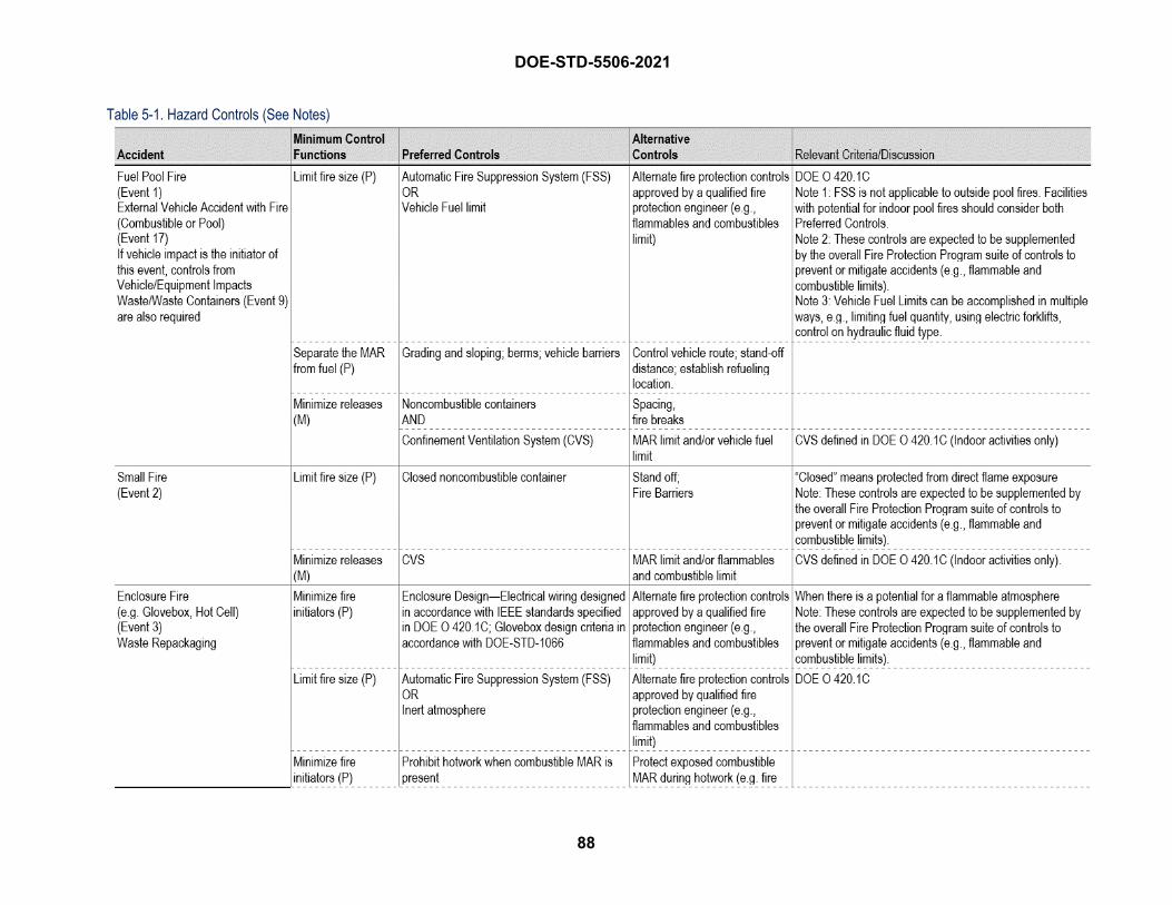
DOE-STD-5506-2021
88
Table 5-1. Hazard Controls (See Notes)
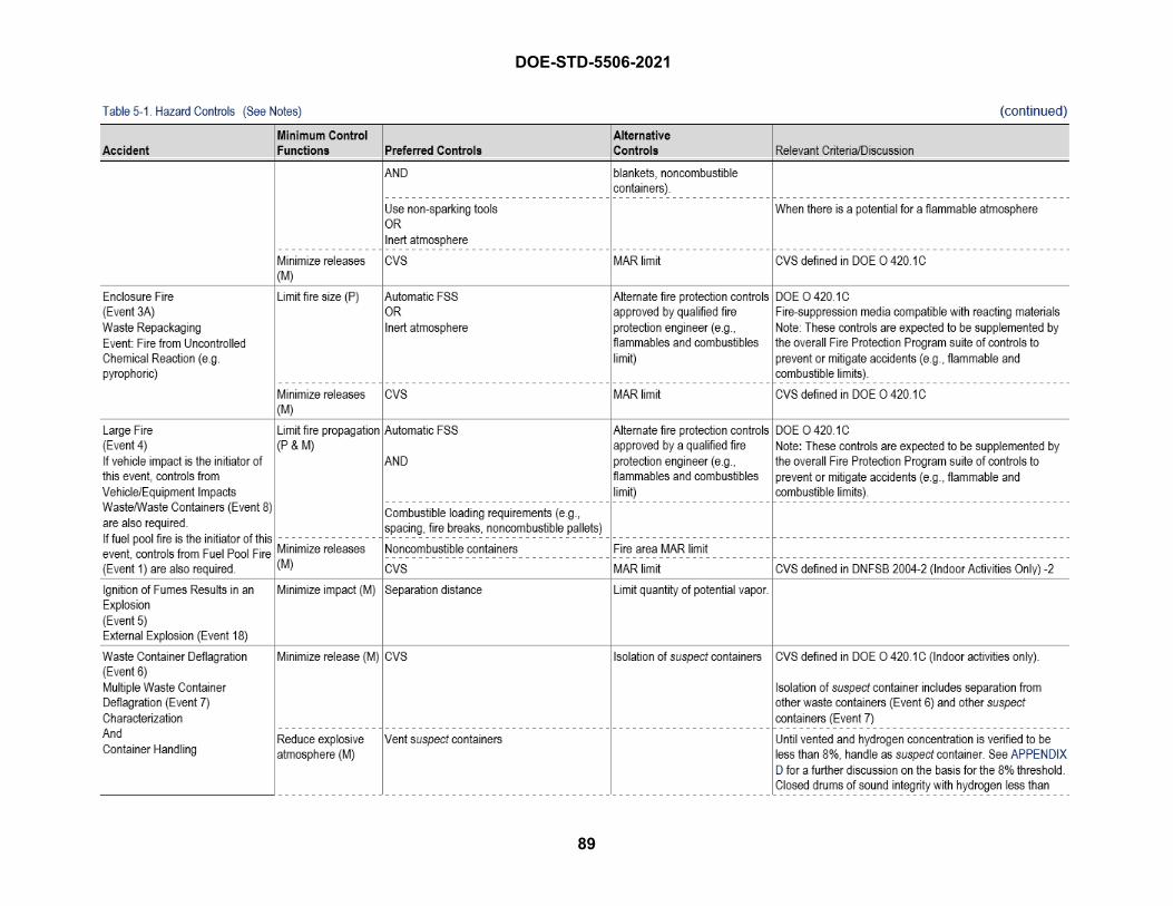
DOE-STD-5506-2021
89
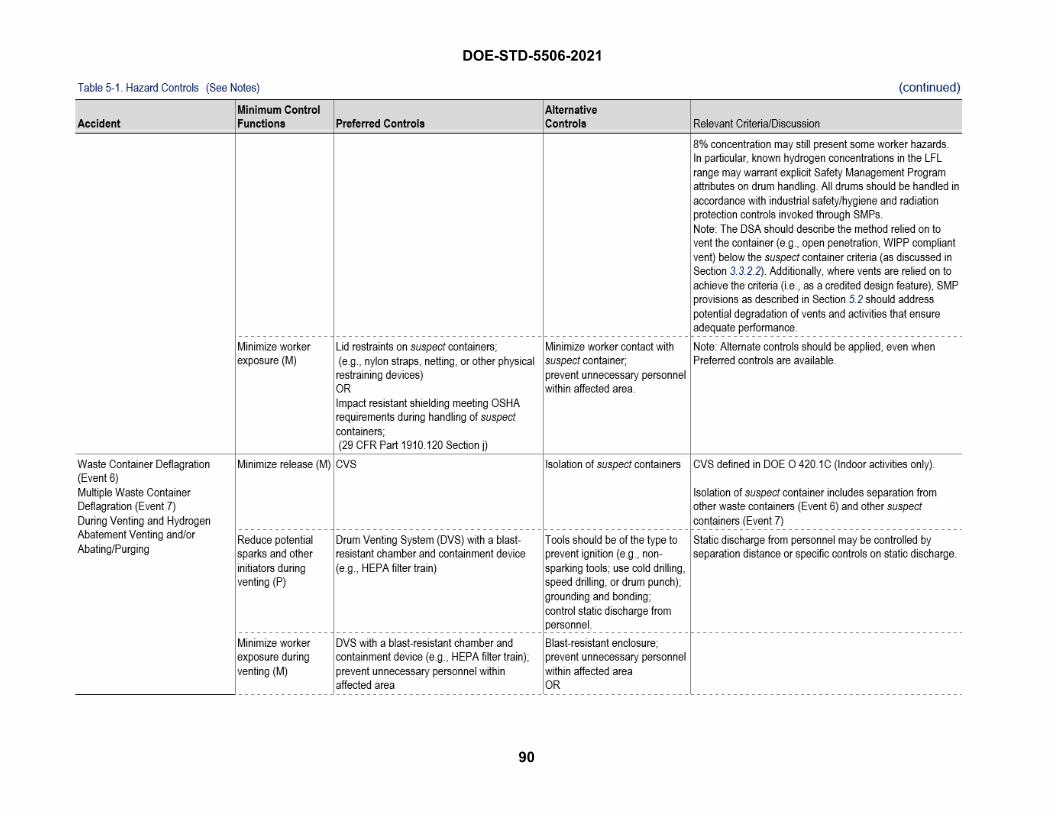
DOE-STD-5506-2021
90
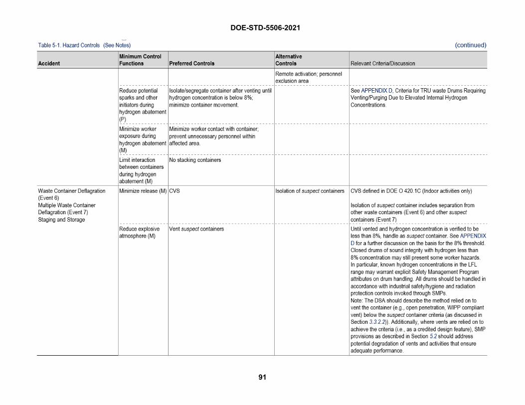
DOE-STD-5506-2021
91
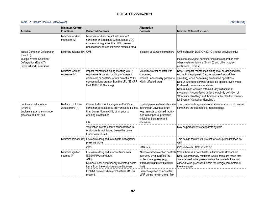
DOE-STD-5506-2021
92
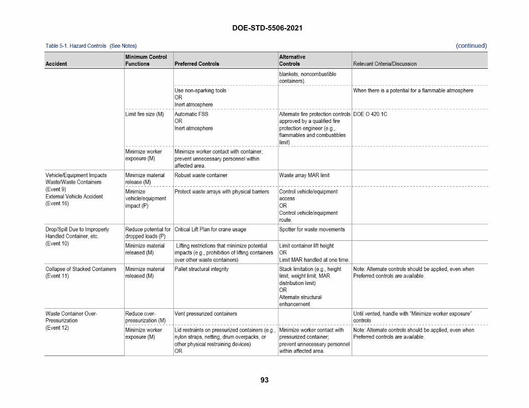
DOE-STD-5506-2021
93
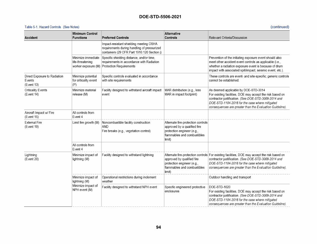
DOE-STD-5506-2021
94
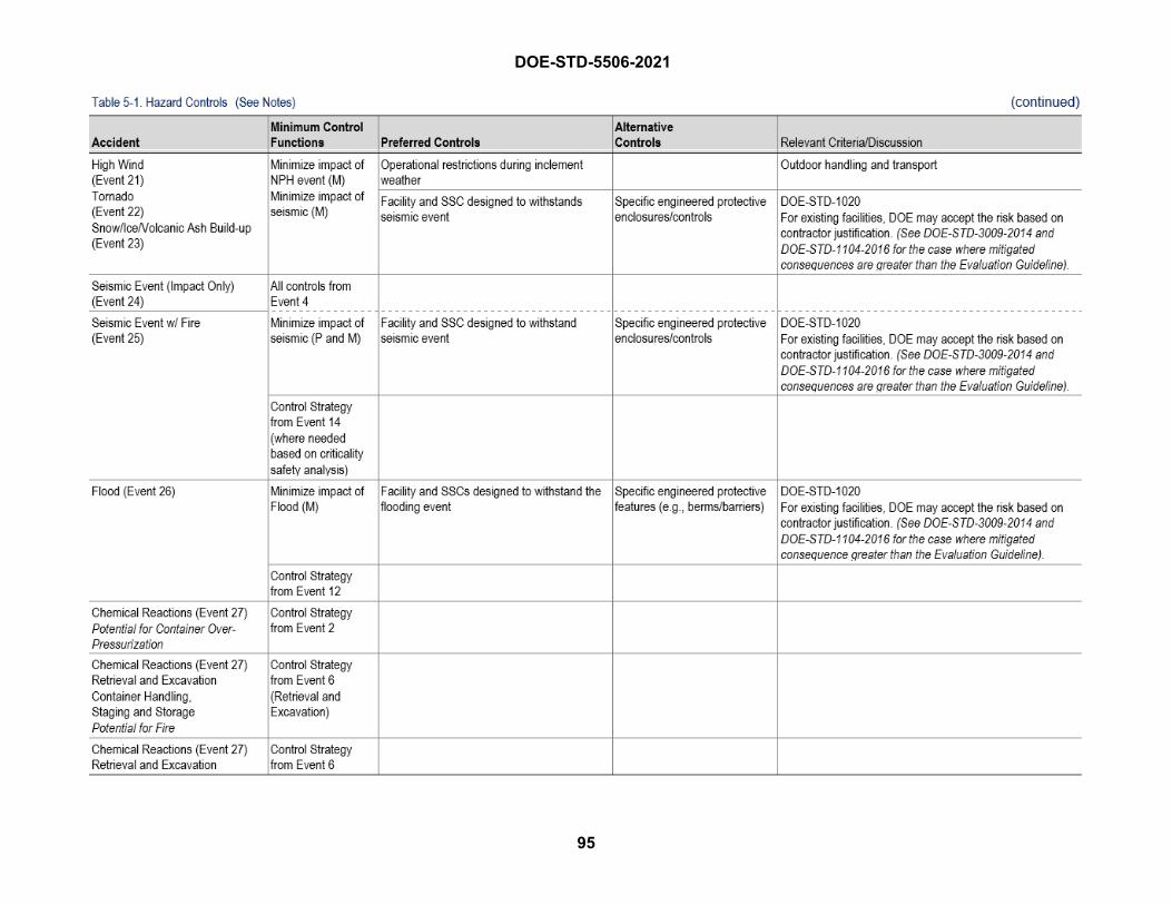
DOE-STD-5506-2021
95
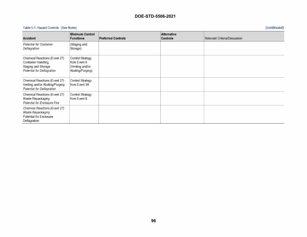
DOE-STD-5506-2021
96
DOE-STD-5506-2021
97
References Code of Federal Regulations
• 10 CFR Part 71, Packaging and Transportation of Radiological Material
• 10 CFR Part 830, Nuclear Safety Management
• 10 CFR Part 835, Occupational Radiation Protection
• 10 CFR 851, Worker Safety and Health Program
• 29 CFR Part 1910.20, “Access to Employee Exposure and Medical Records.” OccupationalSafety and Health Standards
• 29 CFR Part 1910, Occupational Safety and Health Standards, Section 1910.120, “Hazardouswaste operations and emergency response,” Subsection 1910.120(j), “Handling drums andcontainers”
• 49 CFR Part 173, Shippers—General Requirements for Shipments and Packaging
DOE Directives • DOE O 151.1D, Chg 1, Comprehensive Emergency Management System, October 2019
• DOE O 231.1B, Chg 1, Environment, Safety and Health Reporting, November 2012
• DOE O 232.A, Chg 1, Occurrence Reporting and Processing of Operations Information, October2019
• DOE O 420.1C, Chg 3, Facility Safety, November 2019
• DOE G 423.1-1B, Implementation Guide For Use In Developing Technical Safety Requirements,March 2015
• DOE O 425.1D, Chg 2, Startup and Restart of Nuclear Facilities, October 2019
• DOE O 460.1D, Chg 2, Packaging and Transportation Safety, December 2016
• DOE O 461.1C, Chg 1, Packaging and Transfer or Transportation of Materials of NationalSecurity Interest, October 2019
DOE Standards • DOE-HDBK-1224-2018, Hazard and Accident Analysis Handbook, August 2018
• DOE-HDBK-3010-94, Change Notice No. 1, Airborne Release Fractions/Rates and RespirableFractions for Nonreactor Nuclear Facilities, Volumes I and II, March 2000 (Reaffirmed 2013)
• DOE-STD-1020-2016, Natural Phenomena Hazards Design and Evaluation Criteria forDepartment of Energy Facilities, December 2016
• DOE-STD-1066-2016, Fire Protection Design Criteria, December 2016
• DOE-STD-1186-2016, Specific Administrative Controls, December 2016
DOE-STD-5506-2021
98
• DOE-STD-1228-2019, Preparation of Documented Safety Analysis for Hazard Category 3 DOENuclear Facilities, May 2019
• DOE-STD-3007-2017, Guidelines for Preparing Criticality Safety Evaluations at Department ofEnergy Nonreactor Nuclear Facilities, December 2017
• DOE-STD-3009-2014, Preparation Guidance for U.S. Department of Energy Nonreactor NuclearFacility Safety Analysis, November 2014
• DOE-STD-3014-2006, Accident Analysis for Aircraft Crash into Hazardous Facilities, October1996 (Reaffirmation May 2006)
Other Documents • Cashdollar 2000, Cashdollar, K.L., I. A. Zlochower, G.M. Green, et al., “Flammability of
methane, propane, and hydrogen gases,” Journal of Loss Prevention in the Process Industries,Vol. 13, pp. 327-340, 2000
• DOE/WIPP-02-3122, Contact-Handled Transuranic Waste Acceptance Criteria for the WasteIsolation Pilot Plant (current version)
• DOE/WIPP-17-3589, Basis of Knowledge for Evaluating Oxidizing Chemicals in TRU Waste
• EPA-600-80-076, A Method for Determining Compatibility of Hazardous Wastes, U.S.Environmental Protection Agency
• NUREG/CR-6410, Nuclear Fuel Cycle Facility Accident Analysis Handbook (1998)
• PLG-1121 Rev. 1, Damage Assessment of Waste Containers Involved in Accidents at the WasteIsolation Pilot Plant, Westinghouse Government Environmental Services Company (2000)
• PLG-1305, Remote Handled Transuranic Waste Container (RH-TWC) Structural Analyses forPostulated Handling Accidents, Westinghouse Government Environmental Services Company(2000)
• Salzano 2012, Salzano, E., F. Cammarota, A. Di Benedetto, et al., “Explosion behavior ofhydrogen–methane/air mixtures,” Journal of Loss Prevention in the Process Industries, Vol. 25,pp. 443–447, 2012.
• SNL 1997, Testing in Support of On-site Storage of Residues in Pipe Overpack Container (1997),SAND 97-0368, Sandia National Laboratories, Albuquerque, NM, 1977
• SFPE 2016, Gottuk, D. and White, D., “Liquid Fuel Fires,” Chapter 65, SFPE Handbook of FireProtection Engineering, 5th edition, M. Hurley, ed., Society of Fire Protection Engineers,Springer, New York, 2016.
• Shleien and Terpilak, The Health Physics and Radiological Health Handbook (1985)
• SINTEF 1995, Hansen, P.A., Fire in Tyres, Heat Release and Response of Vehicles, Report No.STF25 A95039, SINTEF Civil and Environmental Engineering, Norwegian Fire ResearchLaboratory, 1995
DOE-STD-5506-2021
99
• SNL 1979, Summary of Research and Development Activities in Support of Waste AcceptanceCriteria for WIPP, SAND79-1305, UC-70, Sandia Laboratories, Albuquerque, NM, June 1979
• SNL 2017, Figueroa, V.G., Ammerman, D.J., Lopez, C., and Gill, W. Pipe Overpack ContainerFire Testing: Phase I & II, SAND2017-5684, Sandia National Laboratories, Albuquerque, NM,May 2017
• SNL 2018a, Figueroa, V.G., Ammerman, D.J., Lopez, C., and Gill, W., “Pipe Overpack ContainerFire Testing Phase I, II, & III,” SAND2018-1425, Sandia National Laboratories, Albuquerque,NM, February 2018
• SNL 2018b, Mendoza, H., Figueroa, V.G., Gill, W., Ammerman, D.J., Sanborn, S., Pipe OverpackContainer Fire Testing: Phase II-A, SAND2018-6570, Sandia National Laboratories,Albuquerque, NM, June 2018
• SNL 2019, Mendoza, H., Figueroa, V.G., Gill, W., Ammerman, D.J., and Sanborn, S., PipeOverpack Container Fire Testing Phase II-B, SAND2019-9923, Sandia National Laboratories,Albuquerque, NM, August 2019
• SNL 2020, Figueroa, V.G., Ammerman, D.J., Lopez, C. and Gill, W., Criticality ControlOverpack Fire Testing: Phase III, SAND2020-0852, Sandia National Laboratories, Albuquerque,NM, January 2020
• SRNS 2020, Schluszas, V. and Sprankle, R., Pool Fire Analysis Methodology for AssessingDamage to Waste Containers, S-CLC-G-00395, Rev. 0, Savannah River Site, Aiken SC, June2020
• WHC-SD-TRP-233, Analytical and Experimental Evaluation of Solid Waste Drum FirePerformance, Westinghouse Hanford Company (1995)
• WHC-SD-WM-TRP-246, Solid Waste Drum Array, Fire Performance, Westinghouse HanfordCompany (1995)
• WHC-SD-SQA-ANAL-501 Fire Protection Guide for Waste Drum Storage Arrays, WestinghouseHanford Company (1996)

DOE-STD-5506-2021
100
THIS PAGE BLANK

DOE-STD-5506-2021 Appendix A
A-1
Understanding and Using the MAR Algorithms
The following sections discuss the derivation of the input parameters utilized by the MAR algorithms. It is acknowledged that statistical software applications can be used to derive the various input parameters discussed. The concepts, derivations, and examples discussed herein provide an introductory background into how the input parameters can be derived without the use of such statistical software applications. Numerical subscripts are used after most variables to designate the statistical parameter such as maximum, 95th or 99th percentile, or mean, and for some variables, subscripts are also used after the variable, e.g., 𝑈𝑈𝑈𝑈𝑈𝑈𝑝𝑝,(1−𝛼𝛼) where “p” is the percentile and “(1 − 𝛼𝛼)” is the confidence level for the upper tolerance limit (UTL) as used in this Appendix. Section 4.2.2, Defining a Bounding MAR for TRU Operations, provides more information on the statistical variables and abbreviations, their use in MAR algorithms, and are not repeated in this appendix.
Fully Characterized MAR Algorithm Table 4-1 defines the following algorithm for waste container inventories classified as “Fully Characterized”:
Where:
𝐼𝐼𝑚𝑚𝑚𝑚𝑚𝑚 = The highest single container inventory associated with the entire population of “n” waste containers
𝐼𝐼95% = The inventory associated with the 95th percentile of the entire population of “n” waste containers
𝐼𝐼𝑚𝑚𝑚𝑚𝑚𝑚𝑚𝑚 = The arithmetic mean inventory associated with the entire population of “n” waste containers
𝑘𝑘 = Number of MAR waste containers involved in the accident
The values for Imax, I95%, and Imean are respectively derived from the inventory distribution associated with the entire waste container population “of concern”.
The use of the arithmetic mean waste container inventory Imean is specified for use in the Fully Characterized MAR algorithm. The use of other statistical mean values (e.g., geometric mean, harmonic mean) are not intended for use with the Fully Characterized MAR algorithm. Additionally, the use of other statistical concepts, such as the median waste container inventory value or the mode value, are not acceptable to be used in lieu of the arithmetic mean, unless it can be demonstrated that selected statistical inventory value is greater than the arithmetic mean.
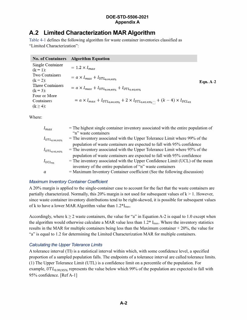
DOE-STD-5506-2021 Appendix A
A-2
Limited Characterization MAR Algorithm Table 4-1 defines the following algorithm for waste container inventories classified as “Limited Characterization”:
Where:
𝐼𝐼𝑚𝑚𝑚𝑚𝑚𝑚 = The highest single container inventory associated with the entire population of “n” waste containers
𝐼𝐼𝑈𝑈𝑈𝑈𝑈𝑈0.99,95% = The inventory associated with the Upper Tolerance Limit where 99% of the population of waste containers are expected to fall with 95% confidence
𝐼𝐼𝑈𝑈𝑈𝑈𝑈𝑈0.95,95% = The inventory associated with the Upper Tolerance Limit where 95% of the population of waste containers are expected to fall with 95% confidence
𝐼𝐼𝑈𝑈𝑈𝑈𝑈𝑈95 = The inventory associated with the Upper Confidence Limit (UCL) of the mean inventory of the entire population of “n” waste containers
𝑎𝑎 = Maximum Inventory Container coefficient (See the following discussion)
Maximum Inventory Container Coefficient A 20% margin is applied to the single-container case to account for the fact that the waste containers are partially characterized. Normally, this 20% margin is not used for subsequent values of k > 1. However, since waste container inventory distributions tend to be right-skewed, it is possible for subsequent values of k to have a lower MAR Algorithm value than 1.2*Imax.
Accordingly, where k ≥ 2 waste containers, the value for “a” in Equation A-2 is equal to 1.0 except when the algorithm would otherwise calculate a MAR value less than 1.2* Imax. Where the inventory statistics results in the MAR for multiple containers being less than the Maximum container + 20%, the value for “a” is equal to 1.2 for determining the Limited Characterization MAR for multiple containers.
Calculating the Upper Tolerance Limits A tolerance interval (TI) is a statistical interval within which, with some confidence level, a specified proportion of a sampled population falls. The endpoints of a tolerance interval are called tolerance limits.(1) The Upper Tolerance Limit (UTL) is a confidence limit on a percentile of the population. Forexample, 𝑈𝑈𝑈𝑈𝑈𝑈0.99,95% represents the value below which 99% of the population are expected to fall with95% confidence. [Ref A-1]

A-3
DOE-STD-5506-2021 Appendix A
The calculation of a distribution-free UTL utilizes a binomial probability density which models a comparative test of the inventory in each drum in a Boolean-valued outcome: success (with probability p) or failure (with probability q = 1−p). A binomial probability function is defined as:
𝑓𝑓(𝑟𝑟,𝑛𝑛,𝑝𝑝) = 𝐶𝐶𝑟𝑟𝑚𝑚 (𝑝𝑝𝑟𝑟)(1 − 𝑝𝑝)𝑚𝑚−𝑟𝑟 Eqn. A-3
Where:
𝑓𝑓(𝑟𝑟,𝑛𝑛,𝑝𝑝) = Probability of “r” successes in “n” trials 𝑝𝑝 = Success probability for each trial 𝑛𝑛 = Number of trials (a.k.a., Population of containers) 𝑟𝑟 = Number of successes (a.k.a., No. of containers that meet success criteria) 𝐶𝐶𝑟𝑟𝑚𝑚 = Different ways of distributing “r” successes in a sequence of n trials
The cumulative distribution function for the binomial probability function is expressed as follows:
𝐹𝐹(𝑟𝑟,𝑛𝑛,𝑝𝑝) = � 𝐶𝐶𝑗𝑗𝑚𝑚 �𝑝𝑝𝑗𝑗�(1 − 𝑝𝑝)𝑚𝑚−𝑗𝑗𝑗𝑗=𝑟𝑟
𝑗𝑗=0
Eqn. A-4
Where:
𝐹𝐹(𝑟𝑟,𝑛𝑛, 𝑝𝑝) = Cumulative probability of at least “r” successes in “n” trials
The cumulative binomial distribution can be used to derive the Upper Tolerance Limits 𝑈𝑈𝑈𝑈𝑈𝑈𝑝𝑝,(1−𝛼𝛼) by defining the parameters in Equation A-4 as follows:
� 𝐶𝐶𝑗𝑗𝑚𝑚 �𝑝𝑝𝑗𝑗�(1 − 𝑝𝑝)𝑚𝑚−𝑗𝑗𝑗𝑗=𝑟𝑟
𝑗𝑗=0
≥ 0.95 Eqn. A-5
Let:
𝑝𝑝 = Success probability that the MAR associated with a waste container is less than 𝑈𝑈𝑈𝑈𝑈𝑈𝑝𝑝,(1−𝛼𝛼)
𝑛𝑛 = Number of waste containers (a.k.a. total population) 𝑟𝑟 = Number of waste containers with an inventory less than 𝑈𝑈𝑈𝑈𝑈𝑈𝑝𝑝,95%
The computation of a nonparametric UTL requires the sequential ordering of the population of containers (arranged in ascending MAR content). A nonparametric UTL is computed by higher order statistics such as the largest, the second largest, the third largest, and so on. The order of statistic, r, used to compute a nonparametric UTL depends on the population size (n), coverage probability (p), and the desired coverage confidence level (=95%). As such, the order of statistic, r, is the container with a MAR content equal to the UTL. Table A-1. Order of Statistic (Container “r”) for a Given Waste Container Population, illustrates the order of statistic (identifies the “r” container) that is used to obtain the value for the 𝑈𝑈𝑈𝑈𝑈𝑈𝑝𝑝,(1−𝛼𝛼).
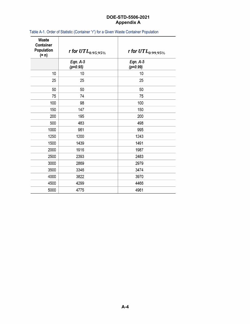
DOE-STD-5506-2021 Appendix A
A-4
Table A-1. Order of Statistic (Container “r”) for a Given Waste Container Population
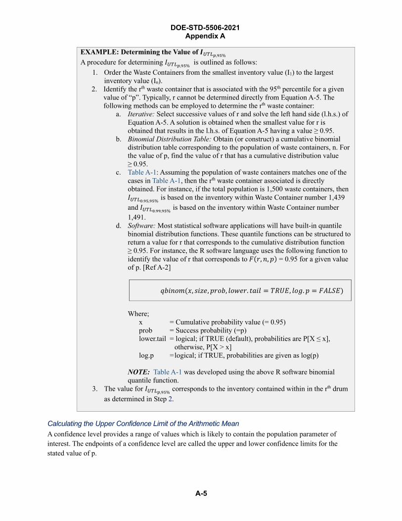
DOE-STD-5506-2021 Appendix A
A-5
EXAMPLE: Determining the Value of 𝑰𝑰𝑈𝑈𝑈𝑈𝑈𝑈𝑝𝑝,95% A procedure for determining 𝐼𝐼𝑈𝑈𝑈𝑈𝑈𝑈𝑝𝑝,95% is outlined as follows:
1. Order the Waste Containers from the smallest inventory value (I1) to the largestinventory value (In).
2. Identify the rth waste container that is associated with the 95th percentile for a givenvalue of “p”. Typically, r cannot be determined directly from Equation A-5. Thefollowing methods can be employed to determine the rth waste container:
a. Iterative: Select successive values of r and solve the left hand side (l.h.s.) ofEquation A-5. A solution is obtained when the smallest value for r isobtained that results in the l.h.s. of Equation A-5 having a value ≥ 0.95.
b. Binomial Distribution Table: Obtain (or construct) a cumulative binomialdistribution table corresponding to the population of waste containers, n. Forthe value of p, find the value of r that has a cumulative distribution value≥ 0.95.
c. Table A-1: Assuming the population of waste containers matches one of thecases in Table A-1, then the rth waste container associated is directlyobtained. For instance, if the total population is 1,500 waste containers, then𝐼𝐼𝑈𝑈𝑈𝑈𝑈𝑈0.95,95% is based on the inventory within Waste Container number 1,439and 𝐼𝐼𝑈𝑈𝑈𝑈𝑈𝑈0.99,95% is based on the inventory within Waste Container number1,491.
d. Software: Most statistical software applications will have built-in quantilebinomial distribution functions. These quantile functions can be structured toreturn a value for r that corresponds to the cumulative distribution function≥ 0.95. For instance, the R software language uses the following function toidentify the value of r that corresponds to 𝐹𝐹(𝑟𝑟,𝑛𝑛,𝑝𝑝) = 0.95 for a given valueof p. [Ref A-2]
𝑞𝑞𝑞𝑞𝑞𝑞𝑛𝑛𝑞𝑞𝑞𝑞(𝑥𝑥, 𝑠𝑠𝑞𝑞𝑠𝑠𝑠𝑠,𝑝𝑝𝑟𝑟𝑞𝑞𝑞𝑞, 𝑙𝑙𝑞𝑞𝑙𝑙𝑠𝑠𝑟𝑟. 𝑡𝑡𝑎𝑎𝑞𝑞𝑙𝑙 = 𝑈𝑈𝑇𝑇𝑈𝑈𝑇𝑇, 𝑙𝑙𝑞𝑞𝑙𝑙. 𝑝𝑝 = 𝐹𝐹𝐴𝐴𝑈𝑈𝐴𝐴𝑇𝑇)
Where; x = Cumulative probability value (= 0.95) prob = Success probability (=p) lower.tail = logical; if TRUE (default), probabilities are P[X ≤ x],
otherwise, P[X > x] log.p = logical; if TRUE, probabilities are given as log(p)
NOTE: Table A-1 was developed using the above R software binomial quantile function.
3. The value for 𝐼𝐼𝑈𝑈𝑈𝑈𝑈𝑈𝑝𝑝,95% corresponds to the inventory contained within in the rth drumas determined in Step 2.
Calculating the Upper Confidence Limit of the Arithmetic Mean A confidence level provides a range of values which is likely to contain the population parameter of interest. The endpoints of a confidence level are called the upper and lower confidence limits for the stated value of p.
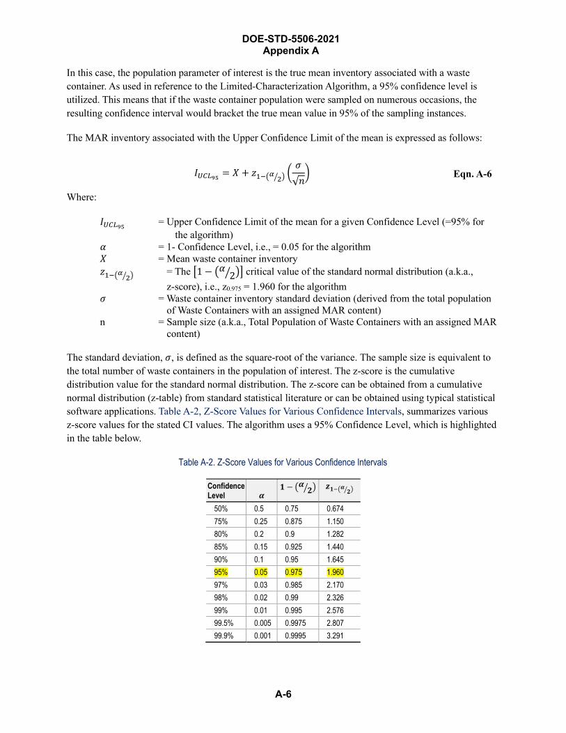
DOE-STD-5506-2021 Appendix A
A-6
In this case, the population parameter of interest is the true mean inventory associated with a waste container. As used in reference to the Limited-Characterization Algorithm, a 95% confidence level is utilized. This means that if the waste container population were sampled on numerous occasions, the resulting confidence interval would bracket the true mean value in 95% of the sampling instances.
The MAR inventory associated with the Upper Confidence Limit of the mean is expressed as follows:
𝐼𝐼𝑈𝑈𝑈𝑈𝑈𝑈95 = 𝑋𝑋 + 𝑠𝑠1−�𝛼𝛼 2� � �𝜎𝜎√𝑛𝑛� Eqn. A-6
Where:
𝐼𝐼𝑈𝑈𝑈𝑈𝑈𝑈95 = Upper Confidence Limit of the mean for a given Confidence Level (=95% for the algorithm)
𝛼𝛼 = 1- Confidence Level, i.e., = 0.05 for the algorithm 𝑋𝑋 = Mean waste container inventory 𝑠𝑠1−�𝛼𝛼 2� � = The �1 − �𝛼𝛼 2� �� critical value of the standard normal distribution (a.k.a.,
z-score), i.e., z0.975 = 1.960 for the algorithm𝜎𝜎 = Waste container inventory standard deviation (derived from the total population
of Waste Containers with an assigned MAR content) n = Sample size (a.k.a., Total Population of Waste Containers with an assigned MAR
content)
The standard deviation, 𝜎𝜎, is defined as the square-root of the variance. The sample size is equivalent to the total number of waste containers in the population of interest. The z-score is the cumulative distribution value for the standard normal distribution. The z-score can be obtained from a cumulative normal distribution (z-table) from standard statistical literature or can be obtained using typical statistical software applications. Table A-2, Z-Score Values for Various Confidence Intervals, summarizes various z-score values for the stated CI values. The algorithm uses a 95% Confidence Level, which is highlighted in the table below.
Table A-2. Z-Score Values for Various Confidence Intervals
Confidence Level 𝜶𝜶
𝟏𝟏 − �𝜶𝜶 𝟐𝟐� � 𝒛𝒛𝟏𝟏−�𝜶𝜶 𝟐𝟐� �
50% 0.5 0.75 0.674 75% 0.25 0.875 1.150 80% 0.2 0.9 1.282 85% 0.15 0.925 1.440 90% 0.1 0.95 1.645 95% 0.05 0.975 1.960 97% 0.03 0.985 2.170 98% 0.02 0.99 2.326 99% 0.01 0.995 2.576 99.5% 0.005 0.9975 2.807 99.9% 0.001 0.9995 3.291

DOE-STD-5506-2021 Appendix A
A-7
EXAMPLE: Calculating the 95% Upper Confidence Limit for the Mean Inventory Given:
n = 10,976 Waste Containers 𝑋𝑋 = 7.9515 PE-Ci 𝜎𝜎 = 41.29871 PE-Ci
a. Calculate 𝐼𝐼𝑈𝑈𝑈𝑈𝑈𝑈95𝛼𝛼 = 1 − 𝐶𝐶𝐼𝐼 = 1 − 0.95 = 0.05 1 − 𝛼𝛼
2= 1 − 0.05
2= 1 − 0.025 = 0.975
From Table A-2; 𝑠𝑠0.975=1.960 Using Equation A-7;
𝐼𝐼𝑈𝑈𝑈𝑈𝑈𝑈95 = 𝑋𝑋 + 𝑠𝑠0.975 �𝜎𝜎√𝑛𝑛
� = 7.9515 + 1.960 �41.29871√10,976
�
= 𝟖𝟖.𝟕𝟕𝟐𝟐𝟕𝟕𝟏𝟏 PE-Ci
References for APPENDIX A A-1 ProUCL Version 5.1 Technical Guide, EPA/600R-07/041, October 2015, www.epa.gov
A-2 The R-Project For Statistical Computing, http://r-project.org, The R Foundation.
DOE-STD-5506-2021 Appendix A
A-8
THIS PAGE BLANK
DOE-STD-5506-2021 Appendix B
B-1
Container Deflagrations Introduction
This appendix establishes the technical bases for the Damage Ratios (DRs) for a deflagration within a Transuranic (TRU) waste container as presented in Section 4.3.2, Container Deflagration Events. The accident phenomenology is described, and along with a review of the literature it establishes conservative estimates of DRs for this event.
The container response is different for waste containers other than drums. Different types of waste will also have different release characteristics in deflagration events. For metal drums containing combustible objects, the explosion ejects the lid and a fraction of the contents. Radioactive material is released to the environment from three accident stresses:
• From shock-vibration during ejection and impact with a hard surface
• From assumed unconfined burning of a fraction of the material ejected
• From assumed burning of the remaining materials inside the drum
Appropriate Airborne Release Fractions (ARFs) and Respirable Fractions (RFs) for the different contributions are described in Section 4.4, Airborne Release Fractions/Respirable Fractions. The Material-at-Risk (MAR) associated with a single, bounding drum or a two-drum deflagration are determined as described in Section 4.2.2, Defining a Bounding MAR for TRU Operations. All of these source-term parameters are put into perspective with the applicable DR values that are summarized in Section B.3.
TRU wastes are actinide surface contamination on combustible and noncombustible substrates. The contents of some drums are almost entirely combustible materials composed of cellulose and plastic substrates. The combustible materials are often found as multilayer wrapped, especially for most waste with highest potential inventory. For example, these materials may come from glove boxes where waste, especially cellulose waste, is placed in a plastic bag and the air expelled before sealing for ease of handling and space considerations, and placed in heavy-wall plastic sleeve during extraction from the glove box.
The contents of other drums may be composed almost entirely of noncombustible items. Other forms of TRU waste (e.g., sludge, decontaminated equipment, and liquids absorbed on diatomaceous earth) are also found.
Different processes can generate hydrogen gas that may accumulate in drums, including the radiolysis of hydrogenous materials by radioactivity present in the waste. Chemical reactions can also generate hydrogen. The radiolysis of TRU waste can produce flammable hydrogen (H2) concentrations in 55-gallon, unvented storage drums. Many aspects of the formation, avenues for generation (e.g., metal/solution reaction), and accumulation of the gas are not well-defined. The concern is the combustion of the H2 in the drums and the potential loss of confinement of the TRU waste and the activity present. The presence of air in the drums is a given because of the packaging of the material in an air atmosphere

B-2
DOE-STD-5506-2021 Appendix B
(typically 20 to 21 vol% O2). However, the generation of H2 may affect the O2 concentration by combination of H2 and O2 to form water vapor. Furthermore, O2 can combine with various components of the waste and packaging materials. DOE Complex experience has demonstrated that the oxygen content is usually either (a) reduced by reaction with other materials present or (b) combined with hydrogen generated to form moisture in an unvented drum. However, measurements on unvented drums have shown that some of these drums have sufficient oxygen and hydrogen to allow a deflagration. In a vented drum, it should be assumed that there is sufficient oxygen.
In addition to hydrogen, other flammable gases or vapors may also pose a hazard. Further, some flammable gases are heavier than air, therefore accumulating in containers rather than venting. Radiolysis can generate other gases such as methane, though generally in small proportions compared to hydrogen. Chemical reactions can generate a variety of flammable gases, depending on the reaction. Microbial action can generate methane under some conditions. Organic liquids (either free or absorbed) can evaporate, forming flammable vapors.
Analysis of the deflagration hazard should account for the variety of gases and vapors that could be present. However, most of the discussion in this Appendix is on hydrogen, given that it is the most common hazard.
For combustion to occur, three components are necessary for burning: a combustible–flammable vapor, oxidant in a gaseous form, and an ignition source. Other factors will affect the ignition and combustion of fuel–air mixtures, such as concentrations of the reactants, the location of the ignition source, and the presence of water vapor. Typically, for the purposes of an unmitigated hazard or accident analysis, the ignition source is assumed to be present, although the configuration of the waste and drums (presence of a plastic liner that may be of substantial thickness requiring destruction for heat transfer) may be resistant to the introduction of an ignition source.
In one historical example involving an explosion in a 55-gallon drum containing volatile organic compounds (xylene and pentane), the most likely source of ignition was an electrical discharge. This was either through static electricity from the plastic bags containing the waste or through electricity generated by piezoelectric crystals from a discarded ultrasonic cleaner (EEG 1991). The potential presence of prohibited items (e.g., cylinders of flammable/combustibles gases, Volatile Organic Compounds), in uncharacterized waste also can generate flammable gas mixtures.
The fuel and oxygen are assumed to be mixed and at a sufficient level to support the combustion. The Lower Flammable Limit (LFL) for a gas is the concentration that will support combustion. In the case of hydrogen, the LFL is about 4 volume percent (vol%), and at this concentration the flame “sparkles” through the mixture in an upward direction. A slightly higher H2 concentration (~5 vol%) is necessary to form a continuous flame front in an upward direction. Larger concentrations are necessary for a flame front to travel in the horizontal or downward directions for confined gases. An even greater concentration is required for the flame front to achieve a detonation velocity, as will be shown in the experimental studies cited later in this appendix. No experiments have been performed in the range of 4 to 8 vol% H2 in air and whether a release would occur from seal failure of a standard waste drum. APPENDIX D
B-3
DOE-STD-5506-2021 Appendix B
describes the difficulty of igniting and incomplete combustion of such lean concentrations. The closest perspective is a drum test involving 10 vol% H2 in air described in B.2.9, Deflagration Testing for CH Payload Containers and Filter Vents at Southwest Research Institute, which reported that only trace amounts of particulate near the retaining ring bolt were observed during post-test inspection, but not observed in the high-speed video. Therefore, no definitive conclusion can be drawn on whether drum seal failure would occur for lean mixtures < 8 vol% H2 in air, but should a release occur, it is expected to be a small quantity of particulates.
Contained gases can explode and result in loss of containment and ejection of surface-contaminated combustible and noncombustible contents. An explosion of a flammable gas can be either a detonation or a deflagration. A detonation is combustion fronts traveling at or above sonic 29 speeds relative to the unburned gases, with large overpressures. A deflagration is a combustion front traveling at subsonic speeds relative to the unburned gases, typically a speed much lower than sonic, with overpressures much lower than detonations. The magnitude and duration of the energy release are a function of the explosive reaction: deflagration or detonation. When the fuel and oxidant are in a gaseous state, the flammable mixtures deflagrate (are fast-burning). But under special conditions—for example, proper concentration of the component gases, turbulent mixing, a strong ignition source, an adequate Length/Diameter (L/D) ratio, or a sufficient run-up distance—a deflagration can transition into a detonation (Deflagration-to-Detonation Transition [DDT]). This phenomenon is also addressed in this appendix, which concludes that a deflagration in a drum will not transition to a detonation.
There are many published experimental studies on the behavior of metal drums in the literature. Those that are relevant and available are reviewed in this appendix. This appendix provides the basis for the drum deflagration DRs. It also covers the factors that influence the behavior of the contents (i.e., surface-contaminated combustible and noncombustible materials) of the 55-gallon metal TRU waste drums.
The reader should bear in mind the significance of the following factors when assessing the experimental studies cited in this appendix. Some of the factors that have a substantial effect on the combustion of hydrogen–air mixtures are:
• Hydrogen concentration
• Oxygen concentration
• Initial pressure
• Strength and location of ignition source
• Direction of flame propagation
• Size of enclosed volume
• Presence of obstacles that allow flow through/around them
29 Speed of sound (sonic velocity) is ~346 m/s at 25° C at 14.7 psia.
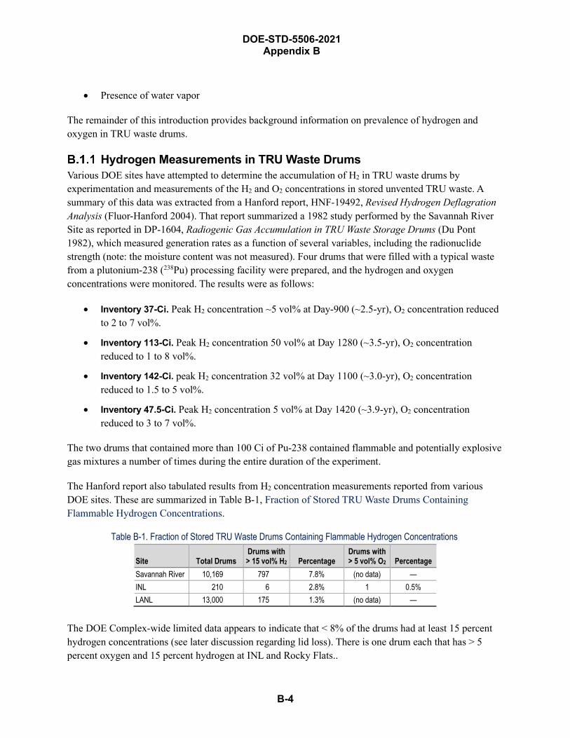
DOE-STD-5506-2021 Appendix B
B-4
• Presence of water vapor
The remainder of this introduction provides background information on prevalence of hydrogen and oxygen in TRU waste drums.
Hydrogen Measurements in TRU Waste Drums Various DOE sites have attempted to determine the accumulation of H2 in TRU waste drums by experimentation and measurements of the H2 and O2 concentrations in stored unvented TRU waste. A summary of this data was extracted from a Hanford report, HNF-19492, Revised Hydrogen Deflagration Analysis (Fluor-Hanford 2004). That report summarized a 1982 study performed by the Savannah River Site as reported in DP-1604, Radiogenic Gas Accumulation in TRU Waste Storage Drums (Du Pont 1982), which measured generation rates as a function of several variables, including the radionuclide strength (note: the moisture content was not measured). Four drums that were filled with a typical waste from a plutonium-238 (238Pu) processing facility were prepared, and the hydrogen and oxygen concentrations were monitored. The results were as follows:
• Inventory 37-Ci. Peak H2 concentration ~5 vol% at Day-900 (~2.5-yr), O2 concentration reducedto 2 to 7 vol%.
• Inventory 113-Ci. Peak H2 concentration 50 vol% at Day 1280 (~3.5-yr), O2 concentrationreduced to 1 to 8 vol%.
• Inventory 142-Ci. peak H2 concentration 32 vol% at Day 1100 (~3.0-yr), O2 concentrationreduced to 1.5 to 5 vol%.
• Inventory 47.5-Ci. Peak H2 concentration 5 vol% at Day 1420 (~3.9-yr), O2 concentrationreduced to 3 to 7 vol%.
The two drums that contained more than 100 Ci of Pu-238 contained flammable and potentially explosive gas mixtures a number of times during the entire duration of the experiment.
The Hanford report also tabulated results from H2 concentration measurements reported from various DOE sites. These are summarized in Table B-1, Fraction of Stored TRU Waste Drums Containing Flammable Hydrogen Concentrations.
Table B-1. Fraction of Stored TRU Waste Drums Containing Flammable Hydrogen Concentrations
Site Total Drums Drums with > 15 vol% H2 Percentage
Drums with > 5 vol% O2 Percentage
Savannah River 10,169 797 7.8% (no data) — INL 210 6 2.8% 1 0.5% LANL 13,000 175 1.3% (no data) —
The DOE Complex-wide limited data appears to indicate that < 8% of the drums had at least 15 percent hydrogen concentrations (see later discussion regarding lid loss). There is one drum each that has > 5 percent oxygen and 15 percent hydrogen at INL and Rocky Flats..
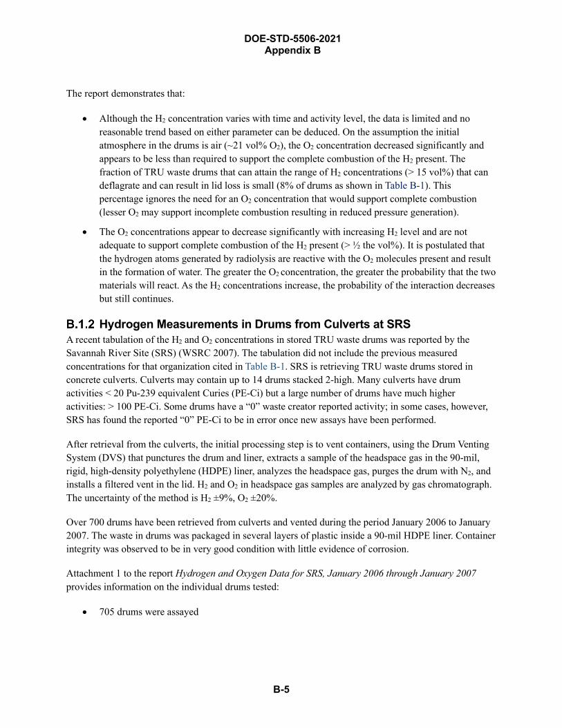
DOE-STD-5506-2021 Appendix B
B-5
The report demonstrates that:
• Although the H2 concentration varies with time and activity level, the data is limited and noreasonable trend based on either parameter can be deduced. On the assumption the initialatmosphere in the drums is air (~21 vol% O2), the O2 concentration decreased significantly andappears to be less than required to support the complete combustion of the H2 present. Thefraction of TRU waste drums that can attain the range of H2 concentrations (> 15 vol%) that candeflagrate and can result in lid loss is small (8% of drums as shown in Table B-1). Thispercentage ignores the need for an O2 concentration that would support complete combustion(lesser O2 may support incomplete combustion resulting in reduced pressure generation).
• The O2 concentrations appear to decrease significantly with increasing H2 level and are notadequate to support complete combustion of the H2 present (> ½ the vol%). It is postulated thatthe hydrogen atoms generated by radiolysis are reactive with the O2 molecules present and resultin the formation of water. The greater the O2 concentration, the greater the probability that the twomaterials will react. As the H2 concentrations increase, the probability of the interaction decreasesbut still continues.
Hydrogen Measurements in Drums from Culverts at SRSA recent tabulation of the H2 and O2 concentrations in stored TRU waste drums was reported by the Savannah River Site (SRS) (WSRC 2007). The tabulation did not include the previous measured concentrations for that organization cited in Table B-1. SRS is retrieving TRU waste drums stored in concrete culverts. Culverts may contain up to 14 drums stacked 2-high. Many culverts have drum activities < 20 Pu-239 equivalent Curies (PE-Ci) but a large number of drums have much higher activities: > 100 PE-Ci. Some drums have a “0” waste creator reported activity; in some cases, however, SRS has found the reported “0” PE-Ci to be in error once new assays have been performed.
After retrieval from the culverts, the initial processing step is to vent containers, using the Drum Venting System (DVS) that punctures the drum and liner, extracts a sample of the headspace gas in the 90-mil, rigid, high-density polyethylene (HDPE) liner, analyzes the headspace gas, purges the drum with N2, and installs a filtered vent in the lid. H2 and O2 in headspace gas samples are analyzed by gas chromatograph. The uncertainty of the method is H2 ±9%, O2 ±20%.
Over 700 drums have been retrieved from culverts and vented during the period January 2006 to January 2007. The waste in drums was packaged in several layers of plastic inside a 90-mil HDPE liner. Container integrity was observed to be in very good condition with little evidence of corrosion.
Attachment 1 to the report Hydrogen and Oxygen Data for SRS, January 2006 through January 2007 provides information on the individual drums tested:
• 705 drums were assayed
DOE-STD-5506-2021 Appendix B
B-6
• H2 concentrations range. 57.78-vol% (± 5.20 vol%) H2 with 0-vol% O2 for an inventory of88 PE-Ci to 0.0307-vol% H2 (± 0.00276 vol%; the Lower Detection Limit for analysis not givenin paper) with 16.98-vol% (± 3.40 vol%) O2 for an inventory of 14 PE-Ci
• O2 concentration range. 0 vol% for 8.3 PE-Ci to 21.8 vol% (±4.35 vol%) for 57 PE-Ci
The information from the attachment was segregated into three categories for this appendix:
• Drums with a H2 concentration > 13.65 vol% (15.0 ± 1.35 vol%)
• Drums with a H2 concentration > 7.28 vol% (8.0 ± 0.72 vol%)
• Drums with a H2 concentration > 3.64 vol% (4.0 ± 0.36 vol%)
Table B-2, Unvented Culvert Drum Initial Headspace Gas Results, summarizes the SRS data showing the number and percentages of drums with H2 concentrations > 4 vol%, > 8 vol%, and > 15 vol%. All drum totals include the uncertainty in estimating the concentrations (i.e., > 3.64 vol%, > 7.28 vol%, and > 13.65 vol%). The number of drums and percentages > 8 vol% and > 15-vol% H2 are included in the > 4-vol% H2 total. Likewise, the number of drums and percentages included in the > 15 vol% are included in the > 8 vol% total. The listing also shows the number of drums and percentages that have O2 concentrations> 5 vol% (4 vol% with the uncertainty considered).
Table B-2. Unvented Culvert Drum Initial Headspace Gas Results
The hydrogen data shows approximately 12% of the unvented culvert drums contain > 4-vol% hydrogen, and about one-quarter of these drums (3.1% of the total assayed) also have an oxygen concentration exceeding 5 vol%, the concentration that is necessary for flaming combustion. However, Table B-3, Fraction of Culvert Drums Capable of Complete Combustion with > 5-vol% O2 and at Least 50% of the Corresponding H2 Concentration, shows the percentage of drums that have sufficient O2 for complete combustion of the H2, i.e., at least 50% O2 concentration for the stated H2 concentration.
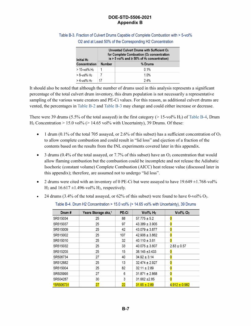
DOE-STD-5506-2021 Appendix B
B-7
Table B-3. Fraction of Culvert Drums Capable of Complete Combustion with > 5-vol% O2 and at Least 50% of the Corresponding H2 Concentration
It should also be noted that although the number of drums used in this analysis represents a significant percentage of the total culvert drum inventory, this drum population is not necessarily a representative sampling of the various waste creators and PE-Ci values. For this reason, as additional culvert drums are vented, the percentages in Table B-2 and Table B-3 may change and could either increase or decrease.
There were 39 drums (5.5% of the total assayed) in the first category (> 15-vol% H2) of Table B-4, Drum H2 Concentration > 15.0 vol% (> 14.65 vol% with Uncertainty), 39 Drums. Of these:
• 1 drum (0.1% of the total 705 assayed, or 2.6% of this subset) has a sufficient concentration of O2
to allow complete combustion and could result in “lid loss” and ejection of a fraction of thecontents based on the results from the INL experiments covered later in this appendix.
• 3 drums (0.4% of the total assayed, or 7.7% of this subset) have an O2 concentration that wouldallow flaming combustion but the combustion could be incomplete and not release the AdiabaticIsochoric (constant volume) Complete Combustion (AICC) heat release value (discussed later inthis appendix); therefore, are assumed not to undergo “lid loss”.
• 2 drums were cited with an inventory of 0 PE-Ci but were assayed to have 19.649 ±1.768-vol%H2 and 16.617 ±1.496-vol% H2, respectively.
• 24 drums (3.4% of the total assayed, or 62% of this subset) were found to have 0-vol% O2.
Table B-4. Drum H2 Concentration > 15.0 vol% (> 14.65 vol% with Uncertainty), 39 Drums

DOE-STD-5506-2021 Appendix B
B-8
Table B-4. Drum H2 Concentration > 15.0 vol% (> 14.65 vol% with Uncertainty), 39 Drums (continued)
Table B-5, Drum H2 Concentration Between 8 and 15 vol% (7.28–13.65 vol% with Uncertainty), 24 Drums, summarizes the 24 drums (3.4% of the total assayed) in the H2 concentration range between 7.28 vol% (8- ±0.72 vol%) and 13.65 vol% (15.0 ± 1.35 vol%):
• 6 drums (0.9% of total assayed, or 25% of this subset) have sufficient O2 for completecombustion, but the energy release (AICC value) does not result in “lid-loss” based on INLexperimental data.
• 1 drum has a reported H2 concentration of 11.065 ± 0.996 vol% but with an inventory of 0 PE-Ci.
• 3 drums (0.4% of the total assayed, or 13% of this subset) were assayed with an O2 concentrationof 0 vol%.
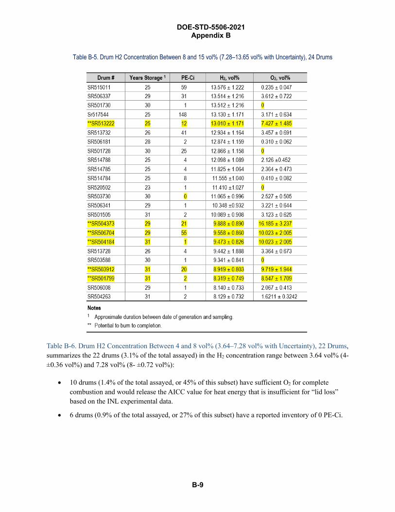
DOE-STD-5506-2021 Appendix B
B-9
Table B-5. Drum H2 Concentration Between 8 and 15 vol% (7.28–13.65 vol% with Uncertainty), 24 Drums
Table B-6. Drum H2 Concentration Between 4 and 8 vol% (3.64–7.28 vol% with Uncertainty), 22 Drums, summarizes the 22 drums (3.1% of the total assayed) in the H2 concentration range between 3.64 vol% (4- ±0.36 vol%) and 7.28 vol% (8- ±0.72 vol%):
• 10 drums (1.4% of the total assayed, or 45% of this subset) have sufficient O2 for completecombustion and would release the AICC value for heat energy that is insufficient for “lid loss”based on the INL experimental data.
• 6 drums (0.9% of the total assayed, or 27% of this subset) have a reported inventory of 0 PE-Ci.
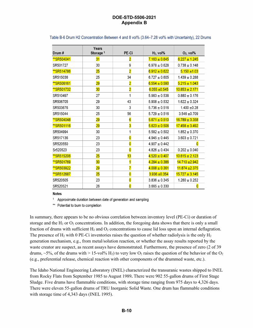
DOE-STD-5506-2021 Appendix B
B-10
Table B-6 Drum H2 Concentration Between 4 and 8 vol% (3.64–7.28 vol% with Uncertainty), 22 Drums
In summary, there appears to be no obvious correlation between inventory level (PE-Ci) or duration of storage and the H2 or O2 concentrations. In addition, the foregoing data shows that there is only a small fraction of drums with sufficient H2 and O2 concentrations to cause lid loss upon an internal deflagration. The presence of H2 with 0 PE-Ci inventories raises the question of whether radiolysis is the only H2
generation mechanism, e.g., from metal/solution reaction, or whether the assay results reported by the waste creator are suspect, as recent assays have demonstrated. Furthermore, the presence of zero (2 of 39 drums, ~5%, of the drums with > 15-vol% H2) to very low O2 raises the question of the behavior of the O2 (e.g., preferential release, chemical reaction with other components of the drummed waste, etc.).
The Idaho National Engineering Laboratory (INEL) characterized the transuranic wastes shipped to INEL from Rocky Flats from September 1985 to August 1989. There were 902 55-gallon drums of First Stage Sludge. Five drums have flammable conditions, with storage time ranging from 975 days to 4,326 days. There were eleven 55-gallon drums of TRU Inorganic Solid Waste. One drum has flammable conditions with storage time of 4,343 days (INEL 1995).
DOE-STD-5506-2021 Appendix B
B-11
Review and Evaluation of Pertinent Experiments and Literature of Internal Deflagration in TRU Waste Containers
Idaho Drum H2 Explosion Tests An experiment was performed by EG&G Idaho in 1983 to investigate the explosion potential of hydrogen–air mixtures deflagration within a 55-gallon steel drum (EG&G 1983). It was initiated to address the hazard of H2 gas generation in stored TRU waste, which had been recognized since retrievable TRU waste storage was started. However, it was generally believed that amount of α-emitters were insufficient to generated enough H2 to pose a problem. But in 1980, a Rocky Flats first-stage sludge drum was discovered with a bulged lid. In addition to this sludge waste, combustible waste (e.g., plastics) is the other most likely form to generate flammable gas.
A program was initiated to estimate the number of drums capable of accumulating flammable concentrations and to postulate a maximum credible hydrogen explosion in TRU waste drum retrieval at the Radioactive Waste Management Complex. The program also included tests to determine whether Fiberglass Reinforced Plywood (FRP) boxes and M-III bins were capable of accumulating gas.
The Idaho tests characterized H2 explosions in DOT 17C (55-gallon metal) drums tests by:
• Overpressure (compressed air injected into the drum with its lid attached per specifications; alsoestablished maximum internal pressure that could be used for explosion tests)
• Ignition of two H2–air mixtures (maximum observed in drums and calculated “worst case”). Twoignition sources, near the top of the drum, were used for explosions:
o Soft spark from sparkplug (20 mJ)
o Hard spark from electro-chemical squib (5 J)
• Drum dropped 12 feet onto a hard, unyielding surface
• Diving a puncturing device into the drum; and
• Sympathetic explosions (i.e., explosion induced in the donor drum initiates an explosion in therecipient drum stacked on top of the donor drum)
DOT 17C drums with 90-mil polyethylene liners and simulated wastes were used. The drum was penetrated through drum and liners in three places: (a) at the bottom of the drum; (b) at the gas inlet; and (c) through the exhaust lines.
Table B-7, Purpose and Initial Conditions for Each Test, presents the purpose of each test and initial conditions. Results are presented in Table B-8, Idaho Drum Deflagration Tests Result.
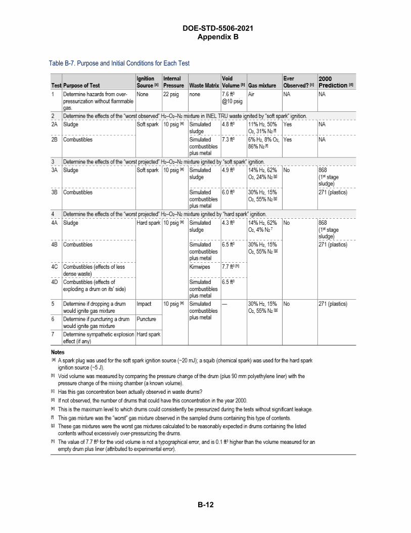
DOE-STD-5506-2021 Appendix B
B-12
Table B-7. Purpose and Initial Conditions for Each Test
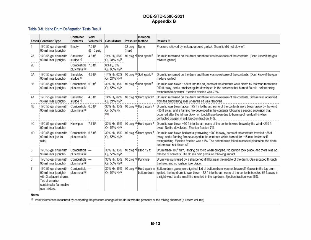
DOE-STD-5506-2021 Appendix B
B-13
Table B-8. Idaho Drum Deflagration Tests Result
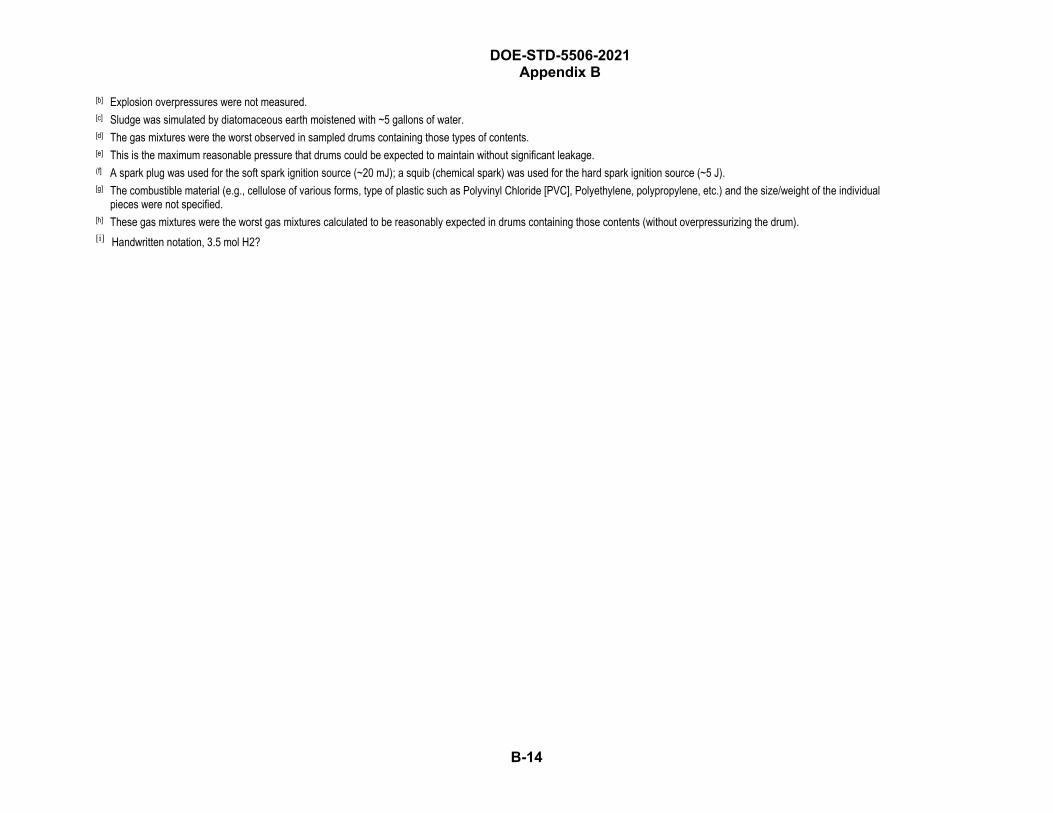
DOE-STD-5506-2021 Appendix B
B-14
[b] Explosion overpressures were not measured.[c] Sludge was simulated by diatomaceous earth moistened with ~5 gallons of water.[d] The gas mixtures were the worst observed in sampled drums containing those types of contents.[e] This is the maximum reasonable pressure that drums could be expected to maintain without significant leakage.(f] A spark plug was used for the soft spark ignition source (~20 mJ); a squib (chemical spark) was used for the hard spark ignition source (~5 J). [g] The combustible material (e.g., cellulose of various forms, type of plastic such as Polyvinyl Chloride [PVC], Polyethylene, polypropylene, etc.) and the size/weight of the individual
pieces were not specified.[h] These gas mixtures were the worst gas mixtures calculated to be reasonably expected in drums containing those contents (without overpressurizing the drum).[i] Handwritten notation, 3.5 mol H2?
DOE-STD-5506-2021 Appendix B
B-15
Observations and conclusions from the Table B-8 results: • Drum lid not blown off by 22 psig of internal pressure from compressed air, but this is not
representative of pressure increase due to an internal deflagration.
• All the gas mixtures were ignited by a hard spark. (5 J is 250 times more energetic than the softspark, 20 mJ.)
• The drums tested contained the pressure generated by the burning of H2–air mixtures up to14 vol% H2 with both hard-spark and soft-spark ignition. Uncertain if gas mixture was ignited bysoft spark, or burned to completion. If those tests that stated “drum lid not blown off” areassumed to have ignited but generated insufficient internal pressure to blow lid off, then need> 14% H2 to generate sufficient internal pressure to dislodge lid.
• All 5 drums with 30% H2 + 15% O2 (a stoichiometric 30 mixture) deflagrated and generatedsufficient internal pressure to blow-off their lids.
• Of the drums that blew off their lids and contained “combustibles and metal”, the ejectionfraction (i.e., the materials ejected from the drum, which were called the “release fraction” in thereport) were 27%, 14%, 7%, 41%, & 16%. This results in a bounding value of 41% (due to theonly drum that was located horizontally) and average value of 21%. If the one horizontal drum isexcluded, the bounding value for upright drums is 27% and the average is 16%.
• Fires were observed in the combustibles, but ejected contents did not sustain a fire. Only onedrum had to be extinguished.
o For the single upright drum containing “Kimwipes” (tissue), the ejection fraction was 7% fora stoichiometric concentration, and no subsequent burning occurred outside the drum.
o At H2 concentration > 14 vol% in air with a hard-spark ignition, a reaction was noted by thesmoldering polyethylene liner.
• Test 7 demonstrated that more than one drum can explode in a given scenario. Based on the onetest involving two stacked drums with H2–O2 stoichiometric concentrations, only the top(recipient) drum is expected to eject the its lid and partial contents in the scenario. The lid fromthe bottom (donor) drum was not displaced due to the weight of the drum on top, but ventingoccurred. The top drum lid was blown 182 ft and ~16% of its contents was ejected and blown 63ft. Fire was observed in the drum residue material. The results indicate that sympatheticdeflagration can occur for stacked drums.
• No significant shrapnel danger was apparent other than the danger from drum lids. Test 5demonstrates that impact from a 12-foot fall that rotated 180 degrees did not cause a shock-induced ignition or sparking of metal wastes to ignite the stoichiometric H2 concentration.Therefore, impact from a displaced lid is not likely to cause a sympathetic deflagration. But thisconjecture is based on a single test.
30 Composition of different gases in accordance with the Law of Definite Proportions.
DOE-STD-5506-2021 Appendix B
B-16
• The drum with a stoichiometric H2 concentration in air punctured by a sharpened drill did notignite (Test 6). This may be partially due to the presence of a 90-mil polyethylene liner.
• The two adjacent drums to the bottom (donor) drum did not contain a flammable concentration,so no conclusions can be drawn regarding sympathetic deflagrations to horizontally adjacentdrums with flammable concentrations due to lid/locking ring/bolt impact, shock-induced ignition,or vented hot gases heating adjacent drums to its auto-ignition temperature.
Impact on Single Drum Deflagration Recommendation Based on the Idaho measured values of amount of material ejected, a bounding value of 40% is assumed for a single-container deflagration. This value is used in conjunction with other bounding assumptions presented in Section B.3, Summary and Recommendations for Deflagration Release Parameters. The hydrogen concentration would need to exceed 14 vol% to cause lid loss and ejection of contents. The ejection fraction is based on the most conservative orientation, where a drum is lying on its side (e.g., during retrieval from a burial site), based on the Idaho maximum ejection fraction. This value is conservatively assumed to bound deflagrations from a single upright drum.
The ejected fraction of materials experience two release stresses during the flight through the air and impact with the ground, and from subsequent burning of unconfined wastes. The wastes remaining in the drum are assumed to burn as confined wastes. Section 4.4 provides guidance on the applicable release parameters. Unconfined and confined burning release parameters are further discussed in Section B.2.3, Burning of Ejected Wastes. For the flight through air and impact, the values for suspension from shock-vibration of 1E-3 ARF and 0.1 RF are conservative and applicable.
Impact on Sympathetic Drum Deflagrations The Idaho drum deflagration tests indicated that sympathetic deflagration of a drum on top of the initial deflagration occurred; the lower drum, however, did not lose its lid due to the weight of the drum on top.
No experimentation has been conducted, nor observed, on sympathetic deflagration of horizontally adjacent drums. Therefore, it is conservatively assumed that sympathetic deflagration is possible involving two unvented drums for TRU waste being retrieved from burial sites.
Although additional sympathetic drum deflagrations may be possible depending on the retrieval staging configuration and other factors, modeling more than two-drum deflagrations is not deemed necessary since adequate insights from the two-drum deflagration should be sufficient to establish appropriate Technical Safety Requirements (TSR) controls to protect the facility worker, other onsite (co-located) workers, the public, and the environment, and based on the likelihood of three or more sympathetic deflagrations being very low.
Based on the Idaho measured values of amount of material ejected, a bounding value of 25% per drum could be assumed. This value is rounded from the 27% maximum for upright drums and 21% average of upright and horizontal drums, since the two drums would need to be staged adjacent to each other, or in nearby proximity (i.e., the 40% ejection fraction was based on a drum lying on its side). However, as further discussed in Section B.2.3, Burning of Ejected Wastes, the combined effect with the fraction burned outside the drum does not significantly change the overall release estimate. Therefore, for a two-
B-17
DOE-STD-5506-2021 Appendix B
drum deflagration, the same assumptions as those used for a single, bounding drum above should be applied, i.e., 40% ejection.
Unless drums are recently vented, commingled in the same storage area, and lacking headspace sampling data, a sympathetic deflagrations need not be evaluated for the unmitigated analysis for TRU waste drum handling and staging/storage of newly generated drums associated with typical DOE Complex processes that generate contaminated, combustible wastes. This guidance is based on the low likelihood associated with multiple drums, located adjacent or in nearby proximity to each other, having sufficient hydrogen–air concentration necessary for lid loss (i.e., exceeding approximately a 15% hydrogen concentration with at least 7.5% oxygen, a small fraction of drums based on characterization experience, and the even lower chance that newly generated drums would achieve such levels).
SRS Drum H2 Explosion Tests Tests were conducted by the E.I. Du Pont Explosion Hazards Laboratory for the Savannah River Site (SRS) to determine a minimum concentration of H2 for “lid loss” of a 55-gallon drum (WSRC 1990). Secondary objectives were to obtain the maximum pressure and rate of pressure rise vs. hydrogen concentration. Preliminary tests were performed for the secondary objectives with a small-scale pressure vessel to establish the concentration range over which a drum lid loss might occur, and as a baseline for comparison with the drum measurements. Mixing tests were also performed to determine the equilibration time for two H2–air mixtures in a drum. Observations and results are summarized as follows.
Pressure Vessel Tests and Results • A 1.7-liter vessel was filled to slightly above ambient pressure (by pulling an initial vacuum) with
5 to 50 vol% H2 concentration31 and ignited.
Maximum pressure and pressure rise rate were determined to be highly dependent on H2 concentration, as shown in Table B-9, Pressure Vessel Test Data (see Figures 7 and 8 in WSRC 1990).
• A third-order polynomial was determined to be good fit to the data.
• The maximum pressure and pressure-rate rise occurred at slightly greater than the stoichiometricH2–air mixture. The maximum pressure measured was 268 psig for a 45 vol% H2 concentration atan initial pressure of 12.03 psig (near 2 atmospheres). The greatest pressure measured for a 30vol% H2 concentration (slightly less than stoichiometric for the experimental conditions) was240.1 psig.
• Results are consistent with basic combustion theory, i.e., as the stoichiometric H2 concentration isexceeded, oxygen becomes the limiting reagent and H2 would be in excess. Under non-idealconditions, with a limited supply of oxygen, excess H2 would be required for completecombustion to achieve the AICC pressure generated from this reaction (see later discussion).
31 oxidant gas not specified; air?

DOE-STD-5506-2021 Appendix B
B-18
Table B-9. Pressure Vessel Test Data
Drum Mixing Tests and Results • A standard 55-gallon drum with a rigid polyethylene liner was modified to plug the drum vent
and to install one inlet and three sampling ports.
• Five vol% and 25 vol% H2 were added (by pulling an initial vacuum) in the middle of the drum.
• H2 was equilibrated by natural convection.
• Caused some initial stratification along the drum length, but the air and hydrogen become well-mixed within 60 minutes, and 50 minutes was determined to be adequate for the drum explosiontests.
Drum Explosion Test and Results • A standard 55-gallon drum 32 was modified to plug the drum vent and to install one inlet through
the side of the drum in the middle. The drum was sealed and closed according to establishedprocedure.
32 Not stated whether the drum was filled with waste or its composition, if filled. It is presumed that all drums were empty.
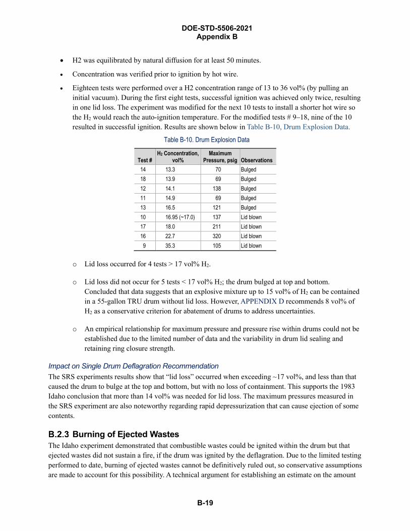
DOE-STD-5506-2021 Appendix B
B-19
• H2 was equilibrated by natural diffusion for at least 50 minutes.
• Concentration was verified prior to ignition by hot wire.
• Eighteen tests were performed over a H2 concentration range of 13 to 36 vol% (by pulling aninitial vacuum). During the first eight tests, successful ignition was achieved only twice, resultingin one lid loss. The experiment was modified for the next 10 tests to install a shorter hot wire sothe H2 would reach the auto-ignition temperature. For the modified tests # 9–18, nine of the 10resulted in successful ignition. Results are shown below in Table B-10, Drum Explosion Data.
Table B-10. Drum Explosion Data
Test # H2 Concentration,
vol% Maximum
Pressure, psig Observations 14 13.3 70 Bulged 18 13.9 69 Bulged 12 14.1 138 Bulged 11 14.9 69 Bulged 13 16.5 121 Bulged 10 16.95 (~17.0) 137 Lid blown 17 18.0 211 Lid blown 16 22.7 320 Lid blown 9 35.3 105 Lid blown
o Lid loss occurred for 4 tests > 17 vol% H2.
o Lid loss did not occur for 5 tests < 17 vol% H2; the drum bulged at top and bottom.Concluded that data suggests that an explosive mixture up to 15 vol% of H2 can be containedin a 55-gallon TRU drum without lid loss. However, APPENDIX D recommends 8 vol% ofH2 as a conservative criterion for abatement of drums to address uncertainties.
o An empirical relationship for maximum pressure and pressure rise within drums could not beestablished due to the limited number of data and the variability in drum lid sealing andretaining ring closure strength.
Impact on Single Drum Deflagration Recommendation The SRS experiments results show that “lid loss” occurred when exceeding ~17 vol%, and less than that caused the drum to bulge at the top and bottom, but with no loss of containment. This supports the 1983 Idaho conclusion that more than 14 vol% was needed for lid loss. The maximum pressures measured in the SRS experiment are also noteworthy regarding rapid depressurization that can cause ejection of some contents.
Burning of Ejected Wastes The Idaho experiment demonstrated that combustible wastes could be ignited within the drum but that ejected wastes did not sustain a fire, if the drum was ignited by the deflagration. Due to the limited testing performed to date, burning of ejected wastes cannot be definitively ruled out, so conservative assumptions are made to account for this possibility. A technical argument for establishing an estimate on the amount
B-20
DOE-STD-5506-2021 Appendix B
of material burned outside is presented in HNF-19492 developed for the Hanford site (Fluor Hanford 2004). That basis is provided here and calculations are revised based on a higher stoichiometric concentration than the Hanford “worst-case” concentration.
The stated intent of the Hanford document is to remove “excess conservatism” in the analysis for an accident involving a single drum during handling and transport within a facility. The document reviewed published literature on the growth of hydrogen concentrations during long-term storage and the measured hydrogen concentration in stored drummed TRU waste at various DOE sites. It noted the reduction of O2 levels with H2 growth. It also noted that drums with H2 concentrations that are adequate for deflagration have O2 concentrations that are not adequate to support complete combustion. The selected “worst-case” based on the conditions at Hanford were established as a 20-vol% H2 based on measured values from stored drummed TRU waste at Hanford and an assumed O2 concentration of > 10 vol% (i.e., the O2 required for complete combustion of the H2).
The fraction of the ejected waste that is ignited is based on the assumption that the total heat generated during the combustion of a 20 vol% H2–air mixtures goes into the ejected waste. It is that portion that is heated to the ignition temperature upon which the fraction of ejected waste ignited is based. The heat transferred to the material remaining in the drum, and to the drum itself, is ignored, which is contrary to the actual experience of the Idaho tests that resulted in burning inside the drum but not outside. Therefore, the assumption that all the heat goes to igniting ejected wastes, and that no burning would result inside the drum, is very conservative, and it double-counts the heat generated during the deflagration.
The calculation of the possible ignition is based upon the ignition temperature of paper that has the smallest ignition energy of the combustible materials considered. The possible extinguishment during flight from the air velocity over the ejected materials and by contact with the cooler ground is also ignored.
Relevant excerpts from HNF-19492 are as follows:
3.3 Conclusion that Ejected Waste Burns
Calculations performed in Section 2.3 with the worst-case drum show that it is unlikely that the ejected waste will be heated to ignition temperatures. Previous discussions in this document show that ejected waste is unlikely to continue burning, especially in light of the weaker ignition source from the worst-case drum conditions, as was the case in the INEEL tests.
However, as Section 3.2 shows, numerous unknowns and uncertainties cannot be resolved. As a result, it is assumed that waste ejected from the worst-case drum (Appendix A, Case 4 as discussed in Section 2.2) could ignite and burn. This assumption is made because these conditions are such that, as shown in Section 2.3, ignition and burning are marginally possible. Given that these conditions also represent the worst-case drum, the assumption is conservative. The assumption is considered to be
B-21
DOE-STD-5506-2021 Appendix B
reasonable given the few “knowns” and all of the “unknowns” and “uncertainties.”
3.4 Calculation of the Damage Ratio
Because the deflagration and ejection create turbulence, which can extinguish a flame that has been ignited or cool the surface such that ignition will not occur (or continue), and because the ejected waste likely is dispersed over an area larger than the drum, it is reasonable to assume that not all of the waste will burn. To be conservative, a value of 0.18 is calculated for the damage ratio (DR). The basis is as follows. The DR will be based on the quantity of waste that can be heated to ignition by the radiant energy from the deflagration divided by the quantity of waste ejected. Appendix A, Case 4 is used for the worst-case drum:
q = 4.3 x 10⁴ cal
The specific heat is the value for paper. This value is less than almost all of the values for plastics. The value is the same as that used in the SFPE Handbook of Fire Protection Engineering discussion in Section 2.3. The ignition temperature is taken to be 280 °C, the average ignition temperature from Section 2.3. The mass heated to ignition is found from:
m = q/(CpΔT)
= (4.3 x 10⁴ cal)(4.187 J/cal)/[(1340 J/kg-K)(553 K - 298 K)]
= 0.53 kg.
The net energy release of 4.3 × 10⁴ cal was based on adding 1.06 moles of H2 in the 20-vol% H2–air concentration. For a stoichiometric concentration of 30-vol% H2 in air, Case 3 in the HNF-19492 calculates the net energy released as 9.5 × 10⁴ cal from 2.14 moles of H2 and a 50% void fraction that was assumed above. This results in an increase factor of (9.5 × 10⁴) / (4.3 × 10⁴) = 2.2 for the amount of combustibles that can burn outside the drum. The calculated value shows that there is sufficient heat generation from the deflagration to ignite 0.53 kg of paper for 20 vol% H2 in air, so 1.2 kg of combustibles could burn outside from the 30 vol% H2 deflagration.
To determine the burn fraction for the 30 vol% H2–air stoichiometric concentration, the mass of ejected wastes that burns is divided by the mass of wastes ejected. According to the HNF-19492, the contents of the average drum weigh 57.2 kg 33. For the 40% ejection fraction recommended in Section B.2.1 as a bounding value for a single drum deflagration, the ejected portion weighs
33 This value is approximately half of the average weight of a drum received at the WIPP site as of 2006. Using the higher average drum weight would result in a smaller DR for burning of ejected wastes and less conservatism.
DOE-STD-5506-2021 Appendix B
B-22
0.4 × 57.2 kg = 22.9 kg
The burn fraction for a single drum deflagration is then:
1.2 kg / 22.9 kg = 0.05
For the 25% ejection fraction discussed in Appendix Section B.2.1 for a sympathetic deflagration of two horizontally adjacent, upright drums, the mass ejected from each drum is 14.3 kg (0.25 × 57.2 kg). The amount of mass that can burn from each drum is 1.2 kg, due to the conservative assumption that it is also at the stoichiometric H2–air concentration. The burn fraction for each drum in a sympathetic deflagration is then:
1.2 kg / 14.3 kg = 0.08
The combined effect of the 25% ejection with 0.08 burn fraction is the same as the 40% ejection with 0.05 burn fraction, i.e., a product of 0.02 due to rounding of the individual values. Considering the other two release phenomena of shock-vibration due to ejection and impact and burning in the drum and their different ARFs and RFs, the impact on the overall composite release fraction is not that great. This is also true if the donor drum is assumed to be 40% ejection with 0.05 burn fraction and the recipient drum is assumed to be 25% ejection with 0.08 burn fraction. Therefore, the recommendation is to apply the 40% ejection with 0.05 burn fraction to both drums.
Section 4.4 provides guidance on the applicable release parameters. For the combustibles ejected that burn unconfined, an ARF and RF of 1E-2 and 1.0, respectively, are applicable. These values are higher than those for confined burning (5E-4 ARF and 1.0 RF) that is assumed to still occur inside the drum. As stated earlier, this is double-counting the energy of the deflagration to cause ignition of both ejected wastes and wastes remaining inside the drum.
Volatile Organic Compounds A study of the potential to breach a drum due to a VOC explosion was performed for the Solid Waste Management Facility TRU Waste Drums at the Savannah River Site and the calculation was documented in Reference 9 of the position paper (WSMS 2006) that is discussed further in Section B.2.5.5, Drum DDT Position Paper. The results of the study showed that ignition of VOCs mixed with air are not sufficient to eject the lid of a drum. The calculation then evaluated a mixture of VOCs, hydrogen, and air to determine what level of this mixture would be a concern for lid ejection. This evaluation concluded that a VOC ignition with a hydrogen concentration at 4% by volume would not eject the lid of a drum. Higher concentrations of hydrogen with the VOCs were required for lid loss.
The Lawrence Livermore National Laboratory (LLNL) conducted fire tests on metal drums to “provide information on the fire performance of 55-gallon metal waste drums used for dry waste storage” (LLNL 1993). Drums with combustible wastes were seeded with 250 cm3 of isopropyl alcohol (allowed to dry for 30 minutes) in fires (Westinghouse Hanford 1994).
LLNL conducted six tests using three different types of drums. The first tests involved an empty drum heated in a furnace according to ASTM E119, Standard Test Methods for Fire Tests of Building

B-23
DOE-STD-5506-2021 Appendix B
Construction Materials, time-temp curve. The remaining five tests used various drum configurations filled with 10 kg [22 lb] class “A” combustibles exposed to a 60-ft-diameter pool fire. Table B-11, Description of Combustibles Loaded into Drums, shows the types and weights of combustibles loaded into drums. All drums except overpacks were loaded with the material described. Some tests included overpacked drums (drum nested within drum). Internal pressure and temperature were monitored, as well as the mass loss determined.
Table B-11. Description of Combustibles Loaded into Drums Number of Items Description Wt, Item, g Total Wt., g
25 Small polyethylene bags ~140 ~3,500 25 Tyvek® coveralls, white, with zipper ~120 ~3,000 25 3M Dust & Mist Respirator ~7.6 ~190 50 Dura-fit shoe covers ~8.5 ~425 50 9 oz. Cotton gloves ~21.8 ~1,090 25 Cap, Disposable, non-woven material ~3.6 ~90
Boxes* Soft-tech wipes
Notes * The number of wipes was varied to obtain the desired weight of 10 kg.
For the ASTM E-119 fire exposure test of the empty drums, the failure criterion of an internal temperature > 325 °F (163 °C) was reached in 140 seconds (s). The internal temperature closely tracked the furnacetemperature. Commonly used auto-ignition temperature for the type of waste material in drums is 500 °Cin ~400 s (~6.7 min). The pressure peaked at 16 psig with seal failing ~330 s (~5.5 min).
Isopropyl alcohol was used as the fuel for the pool fire. Drums were placed in a 6-ft-diameter (28.25 ft2 total-surface-area) metal pan, but the drum occupied a significant area of the pan (around half). WDPAN1-3 tests used 10 gallons of isopropyl alcohol, depth ~0.75 in. WDPAN4 and 5 tests used 12 gallons to account for additional space and to maintain the same depth. The pool fire burned for about 5 minutes. The heat release rate was estimated to be 0.5 to 1.0 MW.
Notes and observations from the report include:
• WDPAN1. Calibration burn using 4 DOT-17C epoxy coated drums. Ignition temperature forcontents in 3 of 4 drums in ~400 seconds (s), 4th drum followed fire temperature. All drumsvented in 300 s, indicated by sudden decrease in pressure. Fire duration ~10 min. No violentfailure of drums. Lid buckled or sidewall bulged. Contents burned or charred.
• WDPAN2 and 3. Two identical tests. Five drums each test. Three DOT 17C drums, one overpack(with inner drum), and one drum TRU with liner (PVC bag).
• WDPAN2 Events. Drum 1-4 vented [“seal failure”] in 194 s. Drum 1 blew its lid, emitting a fire-ball and a loud noise [not then typical drum behavior, “lid loss” after “seal failure”], and possiblydue to isopropyl alcohol vapors deflagration at auto-ignition temperature and material ejected.Contents burned except for drum #1, fire out ~960 s [~16 min], but ejected material continued toburn. Drum #1 extinguished.
DOE-STD-5506-2021 Appendix B
B-24
• WDPAN2 Results. Drum #1 vented at ~205 s with total loss of pressure @ 275 s. Max internaltemperature 480 °C. Drum #2 vented @ ~180 s with temperature of 400 °C. Drum #3 started tovent @ 180 s with total pressure loss @ 280 s, temperature 280 °C. Drum #4 (filtered vent)pressure oscillated between 0 to 1 psig; pressure constantly relieved, maximum temperature of700 °C. Drum #5 (inner drum) vented @ 550 s pressure just under 11 psig internal temperature~350 °C. Maximum temperature Drums #1, #4, and #5 ~700 °C; drums #3 and #5 ~440 °C and480 °C, respectively. Drum #1 underwent “lid loss” (was flipped upside down on drum, indicatingthat it did not have sufficient energy to travel far). Drum #2 lid buckled.
• WDPAN3 Events. Drum #2 vented (“seal failure”) @ 170 s. Drum #1 lid buckled @ 170 s drum“seal failure” @ 283 s. Drum #1 underwent “lid loss”. Fuel fire out ~960 s – debris from drum #1continued to burn (later extinguished). Drum # 2 stopped venting @ 1333 s. Drum #? (1 in bunghole) stopped venting @ 1753 s. TRU drum stopped venting @ 2103 s.
• WDPAN3 Results. Drum #1 initial vented @ 130 s, pressure increased to 12.5 psig and againvented @ 185 s, total loss of pressure@ 250 s, maximum temperature of 450 °C (“lid loss”).Drum #2 vented @ 75 s temperature of 300 °C. Overpacked drum vented @ 150 s temperature150 °C. TRU drum slow pressure increase to ~2.75 psig, dropped to < 2 psig @ 260 s. Inner drumof overpack vented @ 390 s temperature 220 °C. Max internal temperature of drum 400 to 600°C. Drum #4 (TRU drum) liner and contents in drum.
• WDPAN4 & 5. Two identical tests. 3 drums in triangular configuration: two 55-gallon and oneoverpack (#3 overpack and #4 inner). No TRU drum. Each drum had a 10-mil PE liner (bag).
• WDPAN4 Events. Drum 1 lid buckled @ 226 s, do not know if drum vented at this time butflames visible @ 953 s (“seal failure”), flame out @ 1553 s. Fuel fire ceased @ 1013 s. Drums1 & 2 lids buckled but no “lid loss”.
• WDPAN4 Results. Drum #1 initially vented @ 220 s (pressure 13.3 psig, temperature of 100 °C;continuously venting for 240 s. Drum #2 initially vented @ 150 s (pressure 14.2 psig, temperature300 °C) venting continuously for 225 s. Overpack vented @ 150 s (temperature ~190 °C,pressure 7 psig); inner drum vented @ 560 s (pressure 15.5 psig, temperature 500 °C).
• WDPAN5 Events. Drum #2 “lid loss” @ 203 s ejecting some of its contents, masked by drum #1and could not see if it vented prior to event. The fire continued after fuel fire out andextinguished. Drum #1 vented @ 232 s (“seal failure”), buckling noted @ 245 s. Fuel firediminished @ 785 s but flames from vents continued.
• WDPAN5 Results. Drum #1: vented @ 240 s. Drum #2 – vented @ 200 s, temperature probe lostand stopped recording @ ~400 °C, Overpack #3, vented @ 130 s, temperature 550 °C; innerdrum, #4, vented @ 475 s, temperature 400 °C.
Mass loss (Table B-12, Summary of Mass Loss) indicates significant amount of contained material was released during burning. The greatest loss was from drums that experienced “lid-loss”. Average weight loss from DOT-17C drum that did not undergo “lid-loss” was about 1 kg (i.e., about 10% of the loaded mass). Average weight loss from WDPAN2 and 3 was about 1½ kg. Although the filtered
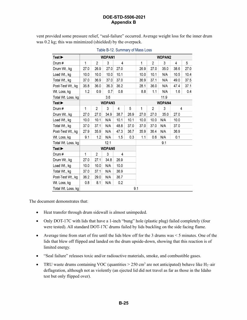
B-25
DOE-STD-5506-2021 Appendix B
vent provided some pressure relief, “seal-failure” occurred. Average weight loss for the inner drum was 0.2 kg; this was minimized (shielded) by the overpack.
Table B-12. Summary of Mass Loss
The document demonstrates that:
• Heat transfer through drum sidewall is almost unimpeded.
• Only DOT-17C with lids that have a 1-inch “bung” hole (plastic plug) failed completely (fourwere tested). All standard DOT-17C drums failed by lids buckling on the side facing flame.
• Average time from start of fire until the lids blew off for the 3 drums was < 5 minutes. One of thelids that blew off flipped and landed on the drum upside-down, showing that this reaction is oflimited energy.
• “Seal failure” releases toxic and/or radioactive materials, smoke, and combustible gases.
• TRU waste drums containing VOC (quantities > 250 cm3 are not anticipated) behave like H2–airdeflagration, although not as violently (an ejected lid did not travel as far as those in the Idahotest but only flipped over).
DOE-STD-5506-2021 Appendix B
B-26
• The material ejected from drums did continue to burn outside the drum. This is not a validobservation for the purpose of internal drum deflagrations from a flammable concentration due to“seeding” of waste with isopropyl alcohol.
• Quantity of ejected wastes was not measured, but the total mass loss, which includes burninginside the drum, was on the order of 10% of the combustible wastes.
• The internal pressure required for “lid loss” was 8 to 13 psig, indicating that overpressure from anexternal fire is about an order of magnitude less than that associated with an internal H2
deflagration as determined by the SRS tests.
Impact on Drum Deflagration Recommendation The behavior of TRU waste drums filed with combustible waste containing a limited quantity of VOC is bounded by the drum behavior resulting from the deflagration of an internal H2–air mixture. This bounding applies to both the ejection fraction and the amount of combustibles that could burn outside the drum. Although the quantity of the VOC is small, under most TRU waste drum situations, larger quantities are not anticipated. Under special circumstances for drums containing liquid VOC or large quantities of cellulose wetted with solvents used to clean glove box interior that are packaged, larger quantities of VOC may be found.
This situation would not be bounded by the H2 drum deflagration due to the amount of solvent-soaked combustibles that could burn outside the drum and the possibility that a larger fraction of wastes may be ejected. For combustible solid wastes with large quantities of VOCs (e.g., quantity exceeds the WIPP WAC requirement that observable liquid is less than 1 percent by volume of the outermost container at the time of radiography or visual examination), a DR of 1.0 is conservatively assumed for ejection of combustible wastes and unconfined burning due to the lack of experimental data and uncertainty of what can occur under these conditions.
If the contents are radioactive flammable or combustible liquids and no combustible solid wastes, the release is modeled per recommendations in the DOE-HDBK-3010-94, Airborne Release Fractions/Rates and Respirable Fractions for Nonreactor Nuclear Facilities (DOE 1994), assuming a DR of 1.0 for lid loss and subsequent burning of the liquid inside or outside the drum.
The low failure pressures determined in the ASTM test and the combustible waste tests are not indicative of those achieved during a H2 deflagration. The total mass loss both inside and outside the drum was on the order of 10%.
Hydrogen Combustion and Deflagration-to-Detonation Transition (DDT) The DDT phenomenon is addressed in this section. It is concluded that a H2 deflagration in a drum will not transition to a detonation. Various experiments are discussed, along with a review of H2 combustion and flame propagation behaviors, and other literature papers on this topic. For a further discussion of a DDT in a drum, see APPENDIX D Section D.7.7, WSMS 2006 (DDT), and APPENDIX D Section D.7.8, EMRTC 2004 (DDT).
B-27
DOE-STD-5506-2021 Appendix B
Regarding hydrogen combustion, in a review of published literature on H2 concentrations in air to burn in various directions, Los Alamos National Laboratory (LANL) quoted the following (from the McKinley 1980 reference in LANL 2002):
4 vol% H2 (LFL) for upwards propagation produces an average flame temperature of < 350° C, whereas the ignition temperature of H2 in air is 585° C …can be understood from observation that the flame in the mixture rises as luminous balls that consuming only part of the hydrogen … fresh hydrogen diffuses into the burning ball and yields higher effective concentrations of hydrogen than initially present. It has been observed that not all the hydrogen is consumed in upward propagation in a 2 in. diameter tube until a concentration of 19 vol% H2 was present. Similar experiments with horizontal tube resulted in a LFL of 6.5 vol% in air; downward propagation requires ~9 vol% H2 in air.
B.2.5.1 Electric Power Research Institute (EPRI) Hydrogen Tests Table B-13, EPRI Test Conditions and Results, The EPRI performed experiments to evaluate hydrogen combustion and the effect of steam. The study is published in Large-Scale Hydrogen Combustion Experiments, Volume 1: Methodology and Results, NP-3878 (EPRI 1988). A sphere, 2.3 m (8 ft) in diameter, and a large vessel (sphere, 16.0 m (52 ft) in diameter (making a surface-to-volume ratio of 0.39) resembling a reactor containment vessel with some equipment was filled with H2 concentrations from 5.3 vol% to 13.2 vol% in air with various concentrations of water vapor (4.2 to 38.7 vol%). Temperatures and pressure were measured at various locations and the completeness of combustion measured. Fans and obstructions (e.g., work platform, etc.) created turbulence in some experiments. Active igniter locations included the bottom, center, and top of the spherical vertical axis and along the equator walls. The AICC was computed. Test conditions and results are shown in Table B-134.
34 Suspect data were excluded; probably from water accumulation and boil-off in pressure sensing tubes.
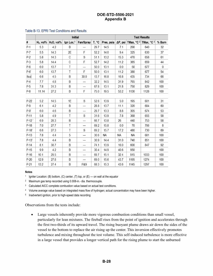
DOE-STD-5506-2021 Appendix B
B-28
Table B-13. EPRI Test Conditions and Results
Notes 1 Igniter Location: (B) bottom, (C) center, (T) top, or (E) — on wall at the equator 2 Maximum gas temp recorded using 0.008-in.- dia. thermocouple. 3 Calculated AICC complete combustion value based on actual test conditions. 4 Volume average value based on integrated mass flow of hydrogen; actual concentration may have been higher. 5 Inadvertent ignition, prior to high-speed data recording
Observations from the tests include:
• Large vessels inherently provide more vigorous combustion conditions than small vessel,particularly for lean mixtures. The fireball rises from the point of ignition and accelerates throughthe first two-thirds of its upward travel. The rising buoyant plume draws air down the sides of thevessel to the bottom to replace the air rising up the center. This inversion effectively promotesturbulence and mixing throughout the test volume. This self-induced turbulence is more effectivein a large vessel that provides a longer vertical path for the rising plume to start the unburned

B-29
DOE-STD-5506-2021 Appendix B
gases in motion. Furthermore, one might expect this scale effect to be most significant with bottom ignition.
• For lean mixture tests having an H2 concentration < 8 vol%, the report notes that the quiescentflame speeds that were generated as the flame front propagated away from the ignition site wereaugmented by the buoyant rise of hot gases. This augmentation caused the flame front to onlyaccelerate in the upward direction with little lateral growth during the initial period followingignition. During the upward inverse of the vessel, the growing flame front displaced cooler gasesfrom the upper region of the test vessel. When the flame reached the top of the vessel, themomentum of the plume was able to drive the flame front downward along the vessel wall, withfinal combustion occurring in the lower region of that vessel. In these cases, incompletecombustion occurred, i.e., burn fraction ranged from 30% to 70%”.
• In attempts to ignite quiescent lean mixture at 0.5 m (1.5 ft) below the top of the vessel, onlyminimal combustion occurred in the local region above the igniter. The initial upward flamepropagation impinged on dome surface and quenched. There was insufficient vertical heightabove the igniter for full development of rising plume, and global propagation throughout vesselwas precluded.
• For H2 concentration > 8 vol%, flame propagation was more spherical as H2 increased from 8 to13 vol%. For the Test P-20 with an H2 concentration of 12.9 vol%, the initial flame front wasessentially spherical.
• Hydrogen burn completion ranged from 0% to 100%. Fig. 4-12, Burn Completeness is a Functionof Hydrogen Concentration, in EPRI 1988, shows complete combustion for H2 concentrations> 7.7 vol% and up to 30 vol% steam (all bottom ignition). Top ignition under quiescentconditions resulted in very low burn completions due to quenching of flame at dome surface.
• Variations in peak pressure ratios with H2 concentrations were highly nonlinear (see Fig. 4-5 inthe EPRI document), particularly for lean mixtures. Pressure ratio began to depart significantlyfrom AICC values at H2 concentrations < 8 vol%. Maximum temperature ranged from essentiallyambient to 1102 °C.
Impact on Drum Deflagration Recommendation The scale effect for small-volume vs. large-volume combustion of hydrogen showed that the large vessel inherently provides more vigorous combustion conditions than small vessel, particularly for lean mixtures. Therefore, hydrogen combustion inside void spaces of metal drums may also result in limited combustion efficiency. This was demonstrated in the attempts to ignite a quiescent lean mixture at 1.5 ft below the top of the vessel, as a result of which (a) combustion in the local region above the igniter was minimal, and (b) the initial upward flame propagation impinged on the dome surface and quenched. This is an important observation for TRU waste drums where the drum is half-full of waste and the distance to the top is ~1.5 ft for lean mixtures (< 8 vol%). However, for richer mixtures (> 12.9%), the initial flame front was essentially spherical, so this may support the lid-loss observation of the Idaho and SRS tests in the 14-to-17 vol% range.
B-30
DOE-STD-5506-2021 Appendix B
B.2.5.2 Sandia Hydrogen Tests The Sandia National Laboratories performed research on flame acceleration and DDT for hydrogen–air mixtures in their FLAME facility (SNL 1989). Flame acceleration and DDT can generate high peak pressures that may cause reactor containment failure. FLAME is a ½-scale model of the upper plenum of ice condenser for a pressurized water reactor to evaluate the explosive hazard associated with a hydrogen leak.
Deflagrations are combustion fronts traveling at subsonic speeds relative to the unburned gases; typically much slower than sonic. Pressures are nearly uniform throughout containment and peak pressures are bounded by the AICC pressure. For these reasons, pressures can be computed with high accuracy by thermodynamic calculations. At most, the AICC pressure is 8 times the pre-combustion pressure for H2–air or H2–air–steam mixtures.
At deflagration, flame speed accelerated to > 100 m/s; shockwaves and peak instantaneous pressures are much higher. If accelerated to a fast enough speed, a deflagration may transition into a detonation, with combustion fronts traveling at supersonic speed relative to the unburned gases. Peak reflected pressure for a detonation is considerably greater than AICC, up to 35 times the pre-combustion pressure. Obstacles in the path of an expanding flame front promote/accelerate by enlarging the burning surface and increasing the local burning rate. A limited set of obstacle configurations were tested.
The FLAME facility is a large rectangular channel, 1.83 m (6.0 ft) wide, 2.44 m (8.0 ft) high, and 30.5 m (100 ft) long. This translates to an L/D ratio of ~25.6 (based on converting the cross sectional area into a hydraulic diameter). The channel was closed at the ignition end and open at the far end. H2 was inserted via three penetrations (one at each end and one in the middle), mixed by two air-driven fans (one at the ignition end and one near the exit). The ignition system had three independent ignition methods: bridge-wire, spark plug, and glow plug. All tests were conducted using single-point bridge-wire ignition (capacitive firing set used to provide high-amplitude current to vaporize the bridge wire). Test variables included:
• H2 mole fraction tested ranged from 12% to 30%
• Degree of transverse venting (by moving steel, top plate): 0%, 13%, and 50%
• The absence or presence of certain obstacles in the channel: 0 to 33% blockage ratio
Results are summarized in Table B-14, Summary of the Test Parameters and Some Test Results.
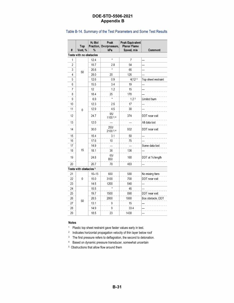
DOE-STD-5506-2021 Appendix B
B-31
Table B-14. Summary of the Test Parameters and Some Test Results
Notes 1 Plastic top sheet restraint gave faster values early in test. 2 Indicates horizontal propagation velocity of thin layer below roof 3 The first pressure refers to deflagration, the second to detonation. 4 Based on dynamic pressure transducer, somewhat uncertain 5 Obstructions that allow flow around them
DOE-STD-5506-2021 Appendix B
B-32
The tests led to several observations and conclusions:
• The hydrogen mole fraction is the most important variable. Reactivity of the mixture isdetermined by hydrogen concentration. For very lean mixtures, there is no significant flameacceleration and no DDT.
• Summary of tests with no venting or obstacles:
o The flame speed and pressure increased with increasing H2 concentration.
o Flame acceleration is evident for H2 mole fraction of 18 vol% and above, but not at 12 vol%.
o DDT first occurred at H2 mole fraction between 18.4 vol% and 24.7 vol% near the exit.
o The initially convex flame shape became slightly-to-strongly concave.
• DDT occurred under the following conditions:
o No obstacles and venting: at 24.7 and 30.0 vol% H2 in air (none noted at 18.4 vol% H2 in air)
o No obstacles and 15% venting: at 24.8 vol% H2 in air
o No obstacles and 50% venting: did not occur
o Obstacle and no venting: at 15.0 vol% H2 in air
o Obstacle and 50% venting: at 19.7 and 28.5 vol% H2 in air
• Obstacles greatly increased flame speed, overpressure, and the tendency for DDT. Differentobstacle configurations could have greater or lesser effect on flame acceleration and DDT. DDTwas observed at 15 vol% H2 with obstacles and no top venting.
• Obstacles lower the minimum mole fraction necessary for DDT to occur. Even if there is nodetonation, deflagrations accelerated to 500 to 700 m/s (sonic velocity ~330 m/s) and generatehigh pressure pulses.
• A large degree of transverse venting reduces flame speed, overpressure, and the possibility ofDDT. For reactive mixtures > 18 vol% H2, the effect of turbulence from venting is greater thanthe effect of turbulence from venting out of channel. Small degrees of transverse venting reduceflame speed and overpressure for less reactive mixtures but increase them for more reactivemixtures.
Impact on Drum Deflagration Recommendation The detonation results are not directly applicable to drums due to the large L/D of 25.6 to allow acceleration of the flame front to sonic speeds. The observation that flame acceleration is evident for an H2 mole fraction of 18 vol% and above, but not at 12 vol%, is in the same range as the Idaho and SRS lid loss conclusions of between 14 to 17 vol%.
B-33
DOE-STD-5506-2021 Appendix B
B.2.5.3 Rockwell Atomics International (AI) Hydrogen Tests The Rockwell AI experimental study was a part of an effort to obtain information on Loss-of-Coolant Accident (AI 1973). Known water droplets were dispersed in combustible mixtures of H2–air to limit combustion or detonation. This study used a shock tube to determine flame and detonation initiation and propagation characteristics.
The test conditions were as follows:
• H2 gas concentration: 4 to 28 vol% in air (dry basis)
• Initial pressure levels: 1, 1.5, 2 atm (abs)
• Initial temperature: ambient
• Water spray: 0 or 72 gpm
• Detonation source: spark gap; for a stoichiometric of H2–O2 driver-section
• Ignition sources for flame tests: continuous sparking across 0.050-inch spark gap of 16 vol% H2–air mixture in driver section, creating flame from ruptured diaphragm
• Test apparatus was a shock tube, 16 inches diameter × 40 feet long (L/D = 30) oriented inhorizontal direction.
Detonation Initiation Tests. Two series of experiments were conducted at H2 concentrations from 4 to 28 vol% in air and pressures ranging from 0.5 atm (7.4 psi) to 2 atm (29.4 psi). Initial test were performed at local ambient pressure (13.7 psi). Stoichiometric H2–O2 was added to the driver section. A detonation wave was established in the driver section to initiate subsequent detonations of H2–air mixtures in the shock tube. Results are summarized in Table B-15, Detonation Test Results.
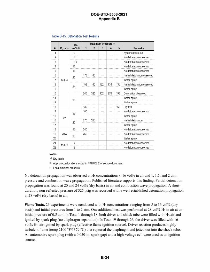
DOE-STD-5506-2021 Appendix B
B-34
Table B-15. Detonation Test Results
Notes [a] Dry basis[b] At photocon locations noted in FIGURE 2 of source document.[c] Local ambient pressure
No detonation propagation was observed at H2 concentrations < 16 vol% in air and 1, 1.5, and 2 atm pressure and combustion wave propagation. Published literature supports this finding. Partial detonation propagation was found at 20 and 24 vol% (dry basis) in air and combustion wave propagation. A short-duration, non-reflected pressure of 325 psig was recorded with a well-established detonation propagation at 28 vol% (dry basis) in air.
Flame Tests. 26 experiments were conducted with H2 concentrations ranging from 5 to 16 vol% (dry basis) and initial pressures from 1 to 2 atm. One additional test was performed at 28 vol% H2 in air at an initial pressure of 0.5 atm. In Tests 1 through 18, both driver and shock tube were filled with H2–air and ignited by spark plug (no diaphragm separation). In Tests 19 through 26, the driver was filled with 16 vol% H2–air ignited by spark plug (effective flame ignition source). Driver reaction produces highly turbulent flame (temp 2100 °F/1379 °C) that ruptured the diaphragm and jetted out into the shock tube. An automotive spark plug (with a 0.050-in. spark gap) and a high-voltage cell were used as an ignition source.
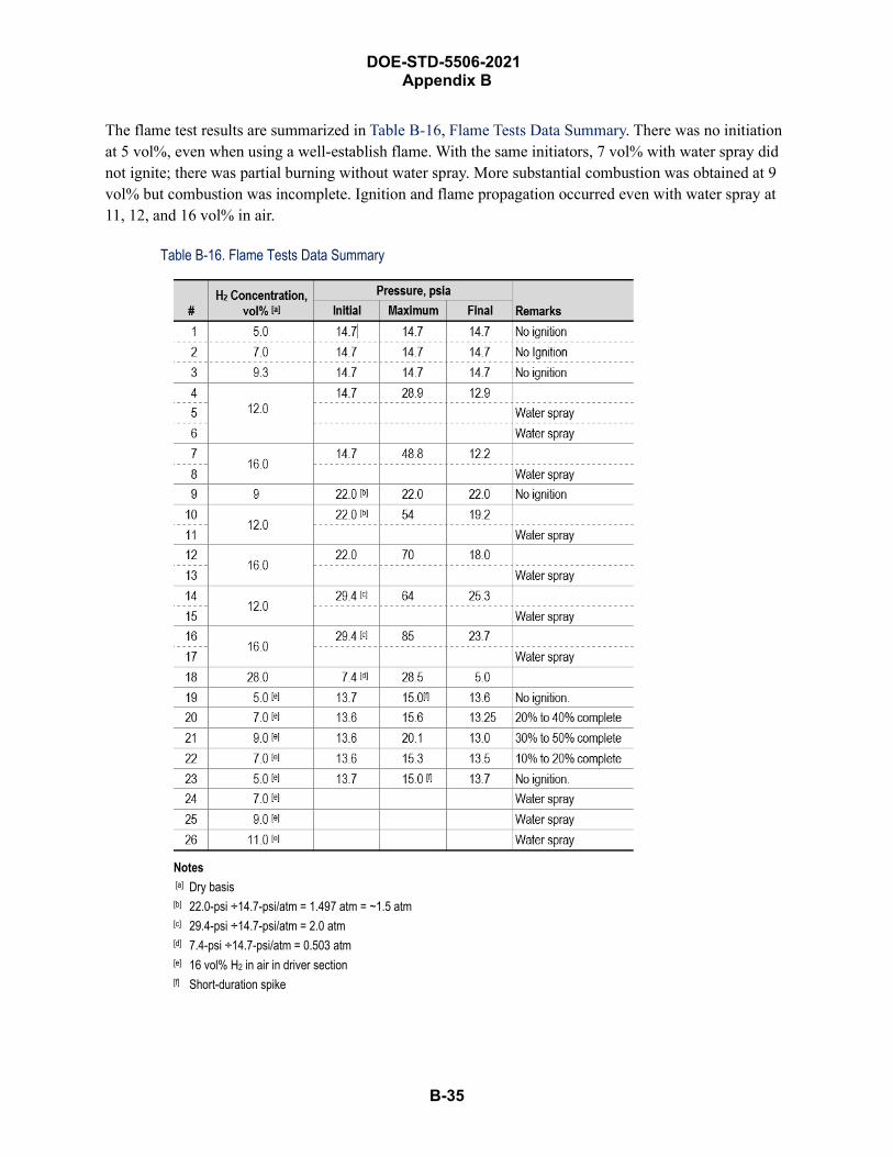
B-35
DOE-STD-5506-2021 Appendix B
The flame test results are summarized in Table B-16, Flame Tests Data Summary. There was no initiation at 5 vol%, even when using a well-establish flame. With the same initiators, 7 vol% with water spray did not ignite; there was partial burning without water spray. More substantial combustion was obtained at 9 vol% but combustion was incomplete. Ignition and flame propagation occurred even with water spray at 11, 12, and 16 vol% in air.
Table B-16. Flame Tests Data Summary
Notes [a] Dry basis [b] 22.0-psi ÷14.7-psi/atm = 1.497 atm = ~1.5 atm[c] 29.4-psi ÷14.7-psi/atm = 2.0 atm[d] 7.4-psi ÷14.7-psi/atm = 0.503 atm[e] 16 vol% H2 in air in driver section [f] Short-duration spike
DOE-STD-5506-2021 Appendix B
B-36
The report shows that:
• No detonation was maintained at H2 concentration < 16 vol%. This finding is supported by thepublished literature.
• Flame propagation in a horizontal direction resulted in a partial detonation at 20 and 24 vol% H2
in air; complete detonation requires 28 vol% H2 in air.
• Combustion wave propagation (burning) at ≥ 7 vol% (dry basis) – the H2 concentration that maydeflagrate, continued with varying degrees of completion.
• Complete burning was not propagated for H2 in air concentrations < 2 vol%.
• The behavior was similar for the tests with water vapor present.
• Values reported for burning in a horizontal direction may be high for burning in an upwarddirection and low for burning in a downward direction. If the shock tube is oriented in a verticaldirection with the ignition source at the lower end, the burning fraction for < 9 vol% H2–airwould increase significantly. If the flame direction is downward, < 9 vol% H2 in air probablywould not sustain flame.
• Initial pressure (more fuel and oxidant available) affects burning and (deflagration) maximumpressures.
Impact on Drum Deflagration Recommendation The detonation results are not directly applicable to drums due to the large L/D of 30 to allow acceleration of the flame front to sonic speeds. However, the burning characteristics indicate that H2 concentrations exceed more than twice the 4 vol% LFL to sustain vertical flame propagation. The behavior was similar for the tests with water vapor present—an important factor due to the presence of some level of moisture (relative humidity and potential water formation during radiolysis in TRU waste drums filled with hydrogenous materials).
B.2.5.4 ARROW-PAK™ DDT Test New Mexico School of Mining Technology, Energetic Materials Research and Testing Center (EMRTC) performed tests to evaluate the performance of ARROW- PAK™ to contain a stoichiometric hydrogen–air mixture deflagration (EMRTC 2002). ARROW- PAK™ is designed to fit into the TRUPACT-II. The container has drum-like internal dimensions (e.g., a small L/D and “run-up” distance, as described in Section B.2.5.5).
ARROW- PAK™ was tested to meet all the DOT CFR Part 49 paragraph 173.465 Type A packaging test requirements for free-drop, penetration, compression, and water spray. The EMRTC test design evaluated three operating conditions for defense in-depth against an accidental release of radioactive material.
EMRTC conducted a series of three DDT tests:
• In the first test, EMRTC would verify that the equipment could withstand < 3.5-psi absolute. (Atthis pressure O2 concentration will not support combustion at LFL.)

DOE-STD-5506-2021 Appendix B
B-37
• In the second test, 150 psi was applied, simulating pressure from H2 buildup by a high-wattageTRU.
• In the third test, EMRTC tested structural strength:
o A 1,248-lb drum was filled with inert material and sealed in ARROW- PAK™, total weight1,804 lb, dropped 4 ft onto unyielding surface.
o A 9,100-lb steel plate was placed on ARROW- PAK™ for 24 hours to demonstrate thestructural integrity of a 3-inch-diameter metal rod dropped on the side of ARROW- PAK™.
For the deflagration test, an electric match was inserted through the sidewall in the middle. H2 was injected to 6.2 psig (2:1 H2–O2 ratio in air). A piezoelectric pressure sensor was used, having a sampling rate of 20,000/s. A video camera (high-speed camera @10,000 frame/s) and microphone were used to confirm that deflagration had occurred.
The DDT tests resulted in several observations:
• Pressure from deflagration was 75 psig.
• Vessel remained closed for one hour after deflagration and internal pressure remained 1.5 psibelow atmospheric validating integrity of system.
• Post-test, the vessel was pressurized to 100 psig and pressure was held for 30 minutes to checkequipment integrity. Pressure was slowly increased to 125 psig/139.7 psia) and held for 30minutes (139.4 to 142.0 psi). Pressure was slowly increased again, this time to 150 psig (164.7psia). The vessel maintained integrity.
Impact on Drum Deflagration Recommendation A stoichiometric H2–air mixture was ignited in the equipment and no DDT was observed. Document findings confirm that H2–air mixtures do not transition into a detonation due to small L/D and insufficient “run-up” distances in the container.
B.2.5.5 Drum DDT Position Paper This section summarizes a technical paper, “Position Paper on the Potential for Explosions in Transuranic Waste Drums at the Melton Valley Solid Waste Storage Facilities in Oak Ridge, Tennessee,” developed to specifically address the potential of a DDT within a DOT 55-gallon metal TRU waste-filled drum (WSMS 2006). Based on a literature review of experiments, such as the Idaho experiment summarized in Appendix Section B.2.1, the SRS experiment summarized in Appendix Section B.2.2, other hydrogen and VOC explosion reports, and other relevant reports, the paper presents arguments to conclude that a DDT in a TRU drum is not credible (i.e., “not physically possible” rather than meaning “an incredible frequency of occurrence”). The paper also concludes that the appropriate type of explosion event for TRU waste drums is a deflagration with lid loss, not a detonation that produces catastrophic failure of the drum with shrapnel and collateral damage. Some of those arguments are summarized in this section.
Absent a very large ignition source, for a detonation to occur, a deflagration initially occurs, and then it transitions to a detonation, which requires specific, specialized conditions. One of the key parameters is

B-38
DOE-STD-5506-2021 Appendix B
the L/D ratio of the enclosure. The paper cites literature values that are typically in the range of a 60 L/D if not pre-pressurized. A pre-pressure of 4.5 atm (~66 psig) reduces the L/D to about 10. DOT-7A Type A packaging are designed for pressures to 11 psig. TRU waste drums are leaky, and the data indicates that these drums cannot hold pressure greater than 11 to 14 psig and typically start to bulge at 6 psig. The L/D of an empty 55-gallon drum is about 1.4 (ID 22.5 in., 32-in. inner height). Since the empty TRU drum L/D is much lower than the L/D of 10 for high pre-pressurization, a DDT would not occur.
Other factors are the “run-up” distance (distance from ignition point to transition) and contents of drum:
• Run-up distance in the literature is in the range of 10 m. TRU drums have an insufficient run-updistance due to the inner height of 32 in. (0.8 m). The distance available in a drum is about anorder of magnitude less than that necessary for a DDT.
• The TRU waste content reduces the free volume of a drum, thereby shortening the run-updistance and lowering the L/D, which reduces opportunity for DDT.
• Solids contents that do not compress (e.g. metal or glass) would not undergo radiolysis andcontribute to H2
generation in drums, thus lessening the likelihood to achieve sufficiently high H2
concentrations to support a detonation.
For a prompt detonation (i.e., without a run-up/transition), a strong energy source is required, on the order of 4,000 J. Energies have been reported as low as 1 to 10 J under ideal conditions for stoichiometric conditions of pure H2 and O2 that do not exist for waste drums. A value closer to 4,000 J is required for TRU waste drums. This energy is not commonly associated with movement, venting, and storage; for example, static electric discharge is about 100 mJ, though experiments have demonstrated that ~0.019 mJ can initiate the deflagration. These levels do not approach the high energy required for a directly initiated/prompt detonation.
Impact on Drum Deflagration Recommendation The DDT in a TRU waste drum is not possible. Therefore, a deflagration with lid loss and ejection of contents is the appropriate bounding accident to be evaluated for a DSA.
Container Response to Internal Pressures Los Alamos National Laboratory evaluated the response of metal and plastic drums to internal pressurizations and documented results in Pressure-Deformation Correlation in Waste Containers (PDCWC) (LANL 1998). Although not directly applicable to a H2 deflagration in a metal drum, it provides insights into container strength and failure modes. Information on the strength of plastic drums is not presented.
LANL reported that there were 123 incidents between 1992 and 1998 involving pressurization of drums due to mixing of incompatible chemicals. Pressurization of drums presents personnel hazards: injury from debris; exposure to hazardous contents; and exposure to pyrophoric 35, flammable, and combustible materials. Hazmat teams have little or no training in how to respond to bulging drums. There is no quick,
35 Material that spontaneously ignite at ambient temperature and pressure. For the purposes of these analyses, materials that ignite at elevated temperatures exposed to air.

B-39
DOE-STD-5506-2021 Appendix B
inexpensive method to determine pressures inside drums. LANL studied the effect of pressure on new, closed- and open-head 55-gallon metal and plastic drums and 30-gallon metal and plastic drums, 20-gallon plastic pails, and 8-gallon overpacks. The objectives were to determine at what pressures drums fail, to quantify deformation, to determine if data supports development of instrumentation to determine internal pressure, and to conduct a statistical analysis of mean failure pressure for 55-gallon drums.
Three sizes of metal drums (30-gallon, 55-gallon, and 85-gallon) and two head-closure designs were pressurized from 0 psig to failure in 5 psig increments. Open-head drums are like typical TRU waste drums with a locking ring. Closed-head drums have the top lid “permanently” fastened to the drum (e.g., a welded seam). Liner deformation along centerline and top and bottom were measured. Pressure increase allowed 30 seconds to stabilize. Table B-17, Drum Capacities, Specifications, and Tests Conducted, summarizes the test parameters.
Table B-17. Drum Capacities, Specifications, and Tests Conducted
Notes A Failure Pressure Characteristics B Failure Pressure Characteristics, Deformation
55-Gallon Metal Drum Tests Thirty-three tests of two types of drums were performed:
UN/1A1. (Closed-head) pressurized and observed under 3 treatments:
• ½ full of water
• ¾ full of water
• empty
UN/1A2. (Open-head) pressurized and observed under 3 treatments:
• ½ full of water
• ¾ full of water
• cement spun (partially filled with cement and spun in a machine similar to a centrifuge tosimulate waste packaging)
B-40
DOE-STD-5506-2021 Appendix B
Retaining rings of empty and water-filled open-head drums were tightened with an impact wrench and sledge hammer to within 1 cm of making the ring ends meet. The retaining ring made of a cement-filled open-head drum was tightened to 40 lb of torque. These closure techniques are not representative of TRU waste packaging procedures. The drums were pressurized to failure in 5 psig increments. Deformation was measured.
85-Gallon Metal Overpack Tests • Two empty drums were tested to failure. Top deformation was measured.
30 Gallon Metal Drum Tests • Four metal drums were tested to failure: two open-head and two closed-head. Deformation was
not measured because the device was not designed for this type of measurement. The drums wereslowly pressurized to failure or stopped at what was perceived to be a dangerously high pressure.
55-Gallon Metal Drum Results Observations for new closed-head and open-head 55-gallon metal drums are as follows:
• 55-gallon metal, open-head drums
o Drums appeared to vent immediately adjacent to nut and bolt fastener on ring, causing acrease in the metal at that location. (FIGURE 2 in the LANL report shows a bulged lid andmetal crease near the bolt.)
o Pinging was noticeable between 15 and 20 psig.
o 100% of the drums tested vented at pressures at or below 32 psig.
o The 55-gallon metal open-head drums appear to bulge at only the top and bottom ends.
o The drum’s body seam (top and bottom) experienced no visible distortion or apparentweakening.
• 55-gallon metal closed-head drums
o 95% of the drums failed explosively.
o Of the catastrophic failures, 68% failed at the bottom end, making the entire drum aprojectile.
o 100% of the drums tested failed at the top or bottom.
o When the drums were filled with liquid (½-full or ¾-full), bottom failures appear to beincreasingly violent with increasing water level to ¾-full.
o At ~5 psig before catastrophic failure, a significant amount of distortion of the drum chimebecame apparent (illustrated in Figure 3 in the reference document).
DOE-STD-5506-2021 Appendix B
B-41
o The 55-gallon metal closed-head drums appear to bulge at only the top and bottom ends.
o The drum’s body seam (top to bottom) experienced no visible distortion or apparentweakening.
o Pinging was noticeable between 15 and 20 psig. The pinging increased dramaticallyimmediately before drum failure.
o T-tests indicated a probability that failure will occur above 48.7 psig. Observations indicatedthat bulging drums, especially closed-head, are extremely dangerous. There was a noticeabledifference in behavior under pressure between open-head and closed-head drums.
85-Gallon Overpack Results Six drums were tested and failed at 16 psig or lower. Failure mode was self-venting at the nut and bolt closure. Like 55-gallon drums, the 85-gallon drums bulged only at their top and bottom ends.
30-Gallon Metal Drum Results Two open-head and two closed-head drums were tested. A significant hazard was created when these drums were pressurized. Some test observations follow.
• 30-gallon metal open-head drums
o Of 2 tested, 1 failed explosively and 1 self-vented.
o Both maintained < 50 psig.
o Both bulged at top and bottom only but did not ping.
• 30-gallon metal closed-head drums
o Extremely high pressures are possible (> 120 psig) without venting.
o The drums failed catastrophically and violently.
o The drums bulged at top and bottom only but did not ping.
The LANL report shows that:
• 55-gallon and 85-gallon metal, open-head drums (TRU waste containers) are capable of retaininghigher pressures than previously reported.
• Drums fail by self-venting at their nut and bolt closure.
• 55-gallon drums visibly deform (bulge) in the 5-to-25-psig range at the top and bottom. All 55-gallon drums failed at < 32 psig.
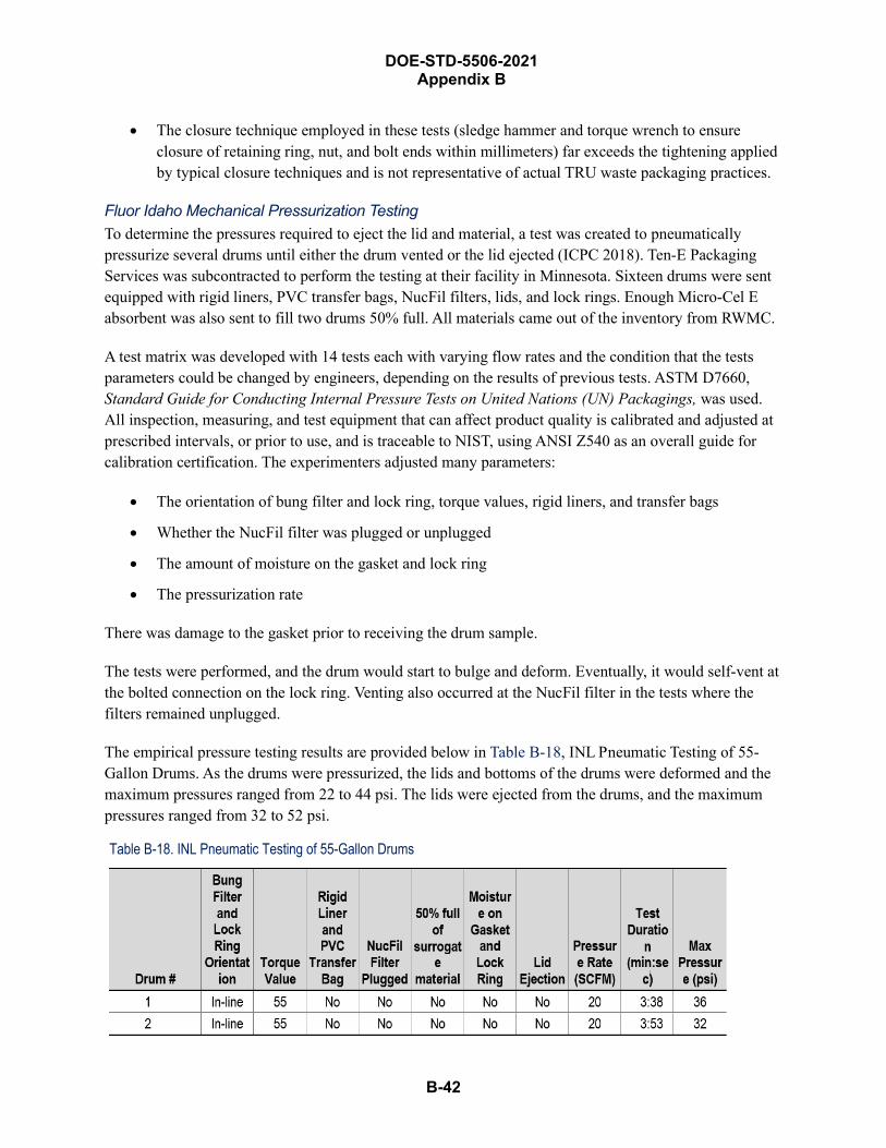
DOE-STD-5506-2021 Appendix B
B-42
• The closure technique employed in these tests (sledge hammer and torque wrench to ensureclosure of retaining ring, nut, and bolt ends within millimeters) far exceeds the tightening appliedby typical closure techniques and is not representative of actual TRU waste packaging practices.
Fluor Idaho Mechanical Pressurization Testing To determine the pressures required to eject the lid and material, a test was created to pneumatically pressurize several drums until either the drum vented or the lid ejected (ICPC 2018). Ten-E Packaging Services was subcontracted to perform the testing at their facility in Minnesota. Sixteen drums were sent equipped with rigid liners, PVC transfer bags, NucFil filters, lids, and lock rings. Enough Micro-Cel E absorbent was also sent to fill two drums 50% full. All materials came out of the inventory from RWMC.
A test matrix was developed with 14 tests each with varying flow rates and the condition that the tests parameters could be changed by engineers, depending on the results of previous tests. ASTM D7660, Standard Guide for Conducting Internal Pressure Tests on United Nations (UN) Packagings, was used. All inspection, measuring, and test equipment that can affect product quality is calibrated and adjusted at prescribed intervals, or prior to use, and is traceable to NIST, using ANSI Z540 as an overall guide for calibration certification. The experimenters adjusted many parameters:
• The orientation of bung filter and lock ring, torque values, rigid liners, and transfer bags
• Whether the NucFil filter was plugged or unplugged
• The amount of moisture on the gasket and lock ring
• The pressurization rate
There was damage to the gasket prior to receiving the drum sample.
The tests were performed, and the drum would start to bulge and deform. Eventually, it would self-vent at the bolted connection on the lock ring. Venting also occurred at the NucFil filter in the tests where the filters remained unplugged.
The empirical pressure testing results are provided below in Table B-18, INL Pneumatic Testing of 55-Gallon Drums. As the drums were pressurized, the lids and bottoms of the drums were deformed and the maximum pressures ranged from 22 to 44 psi. The lids were ejected from the drums, and the maximum pressures ranged from 32 to 52 psi.
Table B-18. INL Pneumatic Testing of 55-Gallon Drums
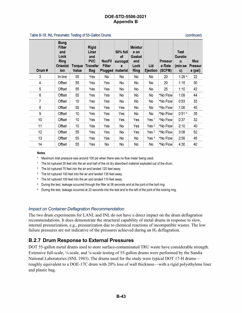
DOE-STD-5506-2021 Appendix B
B-43
Notes * Maximum inlet pressure was around 100 psi when there was no flow meter being used.1 The lid ruptured 35 feet into the air and half of the oil dry absorbent material exploded out of the drum.2 The lid ruptured 75 feet into the air and landed 120 feet away.3 The lid ruptured 100 feet into the air and landed 135 feet away.4 The lid ruptured 100 feet into the air and landed 110 feet away.a During the test, leakage occurred through the filter at 38 seconds and at the joint of the bolt ring.b During the test, leakage occurred at 22 seconds into the test and to the left of the joint of the locking ring.
Impact on Container Deflagration Recommendation The two drum experiments for LANL and INL do not have a direct impact on the drum deflagration recommendations. It does demonstrate the structural capability of metal drums in response to slow, internal pressurization, e.g., pressurization due to chemical reactions of incompatible wastes. The low failure pressures are not indicative of the pressures achieved during an H2 deflagration.
Drum Response to External Pressures DOT 55-gallon metal drums used to store surface-contaminated TRU waste have considerable strength. Extensive full-scale, ¼-scale, and ⅛-scale testing of 55-gallon drums were performed by the Sandia National Laboratories (SNL 1983). The drums used for the study were typical DOT 17-H drums—roughly equivalent to a DOE-17C drum with 20% loss of wall thickness—with a rigid polyethylene liner and plastic bag.
B-44
DOE-STD-5506-2021 Appendix B
Tests include static crush tests, single-drum dynamic impact due to free-fall and lateral impact, and side impact of an eight-stack of drums. Static crush forces were measured and crush energies were calculated. Scale-model tests were performed using a food pack can. Drum deformation and lid behavior are reported. Two computer techniques for calculating response of stacked drums are presented.
Scale-model testing demonstrated that in some aspects, scale models are a reasonable model for full-scale drums. Both models tested show that they may be used with some care.
Results and observations from the tests are as follows:
• Axial Crush Force. A peak force of ~88,800 N (20,000 lb) was required to initiate buckling of anempty drum. No lid separation was observed. Combustible-filled drums withstood a crush forceof 355,000 N (80,000 lb), four times the force for an empty drum. Sludge-filled drums exhibitedalmost identical responses to the combustible-filled drums. No complete “lid loss” occurred.
• Lateral Static Force. The lid separated (lid pulled out of sealing band) 5.3 to 6.1 cm (2.1 to 2.4in.) at a static crush force level of 17,500 to 21,500 lb. Drums containing combustible are stiffest;empty drums are softest. A lateral crush force of ~80,000 N (18,000 lb) was sufficient to result invisual initiation of loss of leak-tightness—i.e., some lid separation. The drum interior linerprevented spillage of materials.
• Single-Drum Impact Tests. Single empty drums and drums containing low-density and high-density sludge were dropped from 36.5 m (120 ft). The experimenters did not test drums filledwith combustible materials. All tests were performed for lateral (side) impact. Impact velocitiesranged up to 94 km/hr. (58 mph). The drums were dropped onto a rigid target (10-cm [4-in.]-thickarmor plate backed by 250 tons of concrete).
o Drum content had a significant influence on single-drum drop-test results. Worst drumdeformation resulted from Test #31 for the heaviest drum (340 kg / 748 lb) and highestimpact velocity (71 km/hr. / 44 mph). Empty drums exhibited less deformation for same-impact velocity than sludge-filled drums; the difference in deformation was small for a givenkinetic energy difference. Differences between the original diameter and reduction by testsranged from 1.24 to 7.27 cm (0.49 to 2.87 in.). In some tests, the inner plastic bag wasbroken, but only for Test #31 was some loss of contents observed.
• Two 8-drum stacks were drop-tested. Impact velocity for the first test was 48.5 km/hr. (30 mph) –stack remained vertical. Impact velocity for the second test was 46.9 km/hr. (29 mph) that usedpolyethylene pad to mitigate effects. The stack tipped over after impact and the polyethylene padwas crushed. Results show that drums withstand very significant impact without loss of contents.
• The drums behave differently under dynamic conditions. Under static testing, the drumsdeformed more they did under dynamic impact. However, static forces are difficult to convert to adynamic impact, such as the impact that terminates a free-fall.
• Lid displacement does not necessarily mean loss of contents: the rigid polyethylene liner andpolyethylene bag provide additional containment.
B-45
DOE-STD-5506-2021 Appendix B
Impact on Drum Deflagration Recommendation Although the data is not directly applicable to the response of TRU waste drums undergoing an internal deflagration, the data does provide information on the strength of the drums and their response if the drums are toppled during an event. Test results indicate that 55-gallon DOT drums filled with TRU waste can withstand significant lateral external forces, such as impacts by a vehicle or deflagrations that may occur near the drums. Applicability of the results is limited since only sludge-filled drums were tested for lateral impacts and an oblique impact on the ring closure was not assessed. The lid separation was defined as any displacement of the retaining ring and is not equivalent to “lid loss” for drums involved in fires or H2 deflagrations.
Other Waste-Container Considerations Damage ratios for internal deflagrations for other container types are addressed below, along with corresponding ARF and RFs. The release models discussed are for contaminated combustible solids (e.g., wipes, gloves, plastic sheets). Other waste forms, such as bulk powders, liquids absorbed on diatomaceous earth, sorbed organic liquids, dried sludges, that may be direct loaded into a container, require individual evaluation consistent with Table 4-7. These conclusions are based primarily on engineering judgment, since there has been limited explosion testing of the SWB, overpacked containers, Remote Handled (RH) waste containers, and the Pipe Overpack Container (POC). Results of deflagration testing of WIPP payload containers (including a SWB) are discussed in Section B.2.9, Deflagration Testing for CH Payload Containers and Filter Vents at Southwest Research Institute.
• For a direct-loaded SWB, lid loss is not expected as a result of a container deflagration becausethe lid is very heavy and bolted onto the body of the box. No loss of lid was observed bydeflagration testing of a SWB by the Southwest Research Institute (SWRI), as discussed inSection B.2.9, Deflagration Testing for CH Payload Containers and Filter Vents at SouthwestResearch Institute, albeit, the experiment results, which reported a maximum event pressure of20 psig, are not fully conclusive of deflagration event overpressures.
However, a release from potential venting of particulates through breaches of the outer containergasket and vent filter media is expected, because test results indicated that a flour–fluoresceinmixture leaked from the SWB. Therefore, a DR of 1.0 is assumed since the SWB gaskets can beaffected by pressure rise from the deflagration. This DR is combined with an ARF×RF of 5E-4from Section 4.4.2 and Table 4-7 that assumes confined burning of combustible wastes, whichrepresents a conservative source term estimate that bounds shock–vibration and low-energyimpact effects (ARF×RF of 1E-4 from Section 4.4.3.1 and Table 4-7) from the deflagration, orcontainer overpressure (ARFxRF of 1E-3 for accelerated airflow over the exposed waste surface),reduced by an order of magnitude, due to the very limited fraction of exposed surface area, to aneffective ARF×RF value of 1E-4.
• Lid loss will also not occur for a direct loaded RH waste container with a welded lid, or theRemovable Lid Canister (RLC) for the RH-TRU 72-B cask. The RLC has a very robust lid-closure mechanism that uses grooved tabs (like the TRUPACT-II) and lock pins in lieu of bolting.But lid loss may occur for other types of lid restraints if not similar to the bolted SWBconfiguration. However, a release via a breached lid closure or weld/container failure is assumed,modeled similar to the SWB seal failure above.
DOE-STD-5506-2021 Appendix B
B-46
• Except as noted below, overpacking a suspect metal drum of sound integrity within a largervented metal drum, an SWB, or RH canister to contain lid loss of the inner drum and preventejection of contents. If, however, a drum that does not meet the criteria in Table 4-2 is placedwithin a larger container, this configuration does not meet the definition of an overpackedcontainer. In that case, since the inner drum does not meet the requirement for a container ofsound integrity, the outer container is modeled as direct-loaded (see discussion in item a and b forSWBs).
• A significant release is not expected from overpacked suspect drums because the deflagrationinside the inner drum is assumed to cause less damage to the outer overpack integrity than itwould cause to a direct-loaded SWB as modeled above. A more limited release from potentialventing through the outer container is assumed to occur in this case. For contaminatedcombustible waste, the release is modeled as an internal container fire with a confined burningARF×RF of 5E-4, as noted in Sections 4.3.3 and 4.4.2 and Table 4-7. It is coupled, however, witha 0.2 DR for the outer drum overpack, as discussed in Section 4.3.3.3, Fire Damage Ratios forOther Containers. The fire release is therefore reduced by a factor of five (DR×ARF×RF = 1E-4)compared to the direct-loaded case discussed above. However, if the outer container has a ventedinner drum that is not a suspect container, an explosive concentration could exist in the annulusfrom the normal venting of the inner drum; therefore, this should be modeled as a direct-loadedcontainer.
• For the POC, explosion testing (SNL 1998b) showed that even if a hydrogen deflagration shouldoccur, its magnitude would not be enough to damage the pipe component or significantly degradeits 1” sintered stainless steel filter. Sandia National Laboratories conducted a series of internalexplosions on a 12-inch pipe component in a POC. The lid of the pipe component was equippedwith pressure, temperature, and strain sensors and with ports for evacuation of the pipe andinjection of hydrogen, oxygen, and nitrogen gases. The bottom of the pipe component wasequipped with a spark plug to ignite the gases and a fan to ensure mixing of the gases. Fifteen(15) tests were conducted, all with the same pipe component. The first five tests were made toestablish the proper test parameters, such as the combination of gases; after the first three tests itwas decided not to include nitrogen in the subsequent tests. The fourth test used equal amounts ofhydrogen and oxygen but the remainder used approximately stoichiometric mixtures (two partshydrogen to one part oxygen). The total gas pressure within the pipe component before theexplosion was set equal to atmospheric pressure, as the filtered vent ensures equal inside andoutside pressures. The sintered stainless steel filters were changed for each of these twelve tests.None of the explosions ruptured the pipe component or even caused it to leak. The peak internalpressures reached were typically in the range of 250 to 350 psig, the peak pressure occurringsome 5 to 10 ms after ignition. The temperature quickly peaked between 900 °C and 1,000 °C butdecayed to near the starting temperature within about a minute. The pipe component showed nosigns of anything having happened except that it became warm to the touch.
A hydrostatic pressure test was made on a 12-inch pipe component with a welded end at the Hauser Laboratories in Boulder, CO (Schierloh, 1998). The pipe component was filled with water (dyed red) and the internal pressure was increased until near to the onset of failure. The pipe component was immersed in a tank of water, both for safety reasons and to allow the rapid
DOE-STD-5506-2021 Appendix B
B-47
detection of a leak. Water under pressure was injected through a fitting in the vent hole of the lid. Pressure was increased incrementally to 1,000 psig (6,890 kPa), with intermediate stops at 300 psig (2,070 kPa) and 600 psig (4,140 kPa). There was no indication of leakage at either of these intermediate pressures. When the pressure was raised to 1,000 psig (6,890 kPa) the lid of the pipe component started to bulge. The pipe component did not leak, however. Inspection of the O-ring after the test showed no damage.
A study to evaluate and confirm the integrity of the POC pipe component postulated internal explosion scenarios was completed (SRR 2011). The explosion pressures are based on stoichiometric H2–air mixtures under dry air conditions. The pressure values computed assume adiabatic complete combustion. This provides a degree of conservatism in this analysis, above and beyond the structural margins on the capacity side. Structural integrity is evaluated relative to ASME Code equations for the deflagration pressure condition. Using ASME Code equations ensures structural integrity as well as pressure integrity. The explosion pressure included detonation, DDT and reflected wave pressure conditions. These pressures are extreme transients.
The POC pipe components were evaluated for explosion conditions, including deflagration, detonation, DDT (deflagration-to detonation transition), and reflected wave effects. Since both the 12-inch and the 6-inch vessel have relatively similar wall thickness and similar bolt details, the 12-inch vessel was used for a bounding assessment. The evaluation was based on the minimum required wall thickness listed on the drawings (0.219 inch). An initial condition of 20 psig internal pressure and a worst-case mixture of explosive gases (H2–air) was taken as the analysis condition.
The analysis shows that the vessel bottom head, cylindrical walls, top head, head bolts and filter access port can withstand the analysis basis explosion condition. The maximum demand capacity ratio occurs in the walls of the vessel with a value of 0.87 relative to vessel burst allowable (equivalent to ASME Service level D allowable). The bolts and vessel lid remain elastic during and after the explosion, thus maintaining pressure integrity at the O-ring gasket (SRR 2011).
The Idaho test of hydrogen deflagration in drums described in Appendix Section B.2.1 also included testing of other containers, but not for actual deflagrations. Rather, it tested the leak tightness of other types of containers and addressed the hydrogen buildup hazard. That test is described in the following section. The LLNL tests described in APPENDIX B Section B.2.4 are somewhat relevant, but those tests involved the flammable-liquid-soaked combustible wastes and are not repeated in this section. See results on the WDPAN4 and WDPAN5 tests involving drums #3 and #4.
B.2.8.1 Idaho Testing of Boxes and Bins Idaho performed two types of tests on the FRP wooden box, TX-4 box, and M-III metal bin that were used for TRU waste storage in the 1970s (EG&G 1983):
• Leak tests to investigate the pressure retention characteristics
• Tests to determine whether H2 gas would diffuse out of containers, and, if so, tests to measure therate of diffusion. To allay safety concerns, these tests used helium gas with diffusioncharacteristics similar to H2.
B-48
DOE-STD-5506-2021 Appendix B
Helium was injected into a container through a center tube; air was vented out a bottom tube. After a predetermined amount helium was injected, the valves were closed. Vacuum pumps were used to evacuate and purge sample cylinders. An initial sample was used to verify that sufficient helium had been injected to obtain a concentration of 25 vol% . The initial sample also served as the initial sampling point. Subsequent samples were taken periodically until the helium concentration decreased to a level < 4 vol% (i.e., LFL for H2). When that occurred, the experimenters recorded the time required.
The recorded average pressure decrease/min. (% of initial pressure) was:
• TX-4 box = 100[0.2 psig / 1.0 psig] ÷ 24 min. = 0.83%/min.
• M-III bin = 100[0.15 psig / 0.5 psig] ÷ 24 min. = 1.25%/min.
• FRP box could not be pressurized: its leak rate exceeded the capacity of the injection system.
The document provides some information that is potentially useful for other types of TRU containers. The utility is limited by the lack of detailed information on the container tested.
In summary:
• FRP boxes do not contain the gaseous materials in the container because those boxes are veryporous. Thus, this type of container would not be expected to accumulate large concentrations offlammable/combustible gases/vapors generated by the contained materials.
• Metal bins (M-III) are leaky but are capable of containing up to 0.5 psig overpressure and stillretain 70% of the initial pressure after 1 day.
• Vented metal bins (TX-4) demonstrated that they may hold greater than 1 psig overpressure andretain 80% of the initial pressure after 1 day.
Deflagration Testing for CH Payload Containers and Filter Vents atSouthwest Research Institute
A test series was performed to evaluate the response of contact-handled (CH) payload containers and filter vents that were subjected to pressures developed as a result of a hydrogen–air deflagration. Results are reported in Deflagration Testing for CH Payload Containers and Filter Vents (SwRI 2015). At the conclusion of each test, the container was visually inspected to determine whether confinement integrity had been maintained. This integrity was determined by ultraviolet inspection of the container to look for the external presence of a flour–fluorescein mixture that had been initially loaded within the container.
Testing was performed in a 55-gallon drum, a Standard Waste Box (SWB), a Ten Drum OverPack (TDOP) and a representative sample of WIPP-certified nuclear filter vents.
Dynamic pressures in the deflagration tank and test unit were measured with two PCB Piezotronics ICP Pressure Sensors with a range of 0–100 psig. Dynamic pressure sensors were continuously scanned at a rate of 20 kHz and saved data only after a rapid increase in pressure. To smooth the dynamic pressure curves, the data was filtered with a 20-point moving average. This correlated to a 1-ms moving average, since the dynamic pressure data was sampled at a rate of 20 kHz.
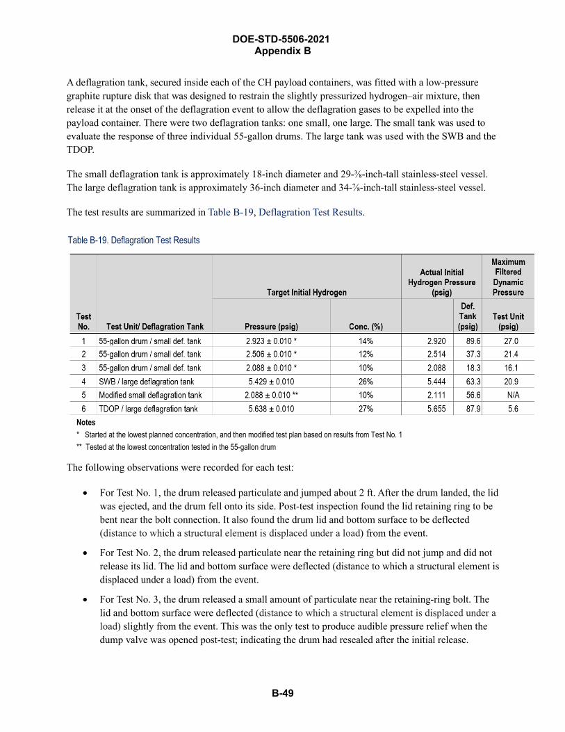
B-49
DOE-STD-5506-2021 Appendix B
A deflagration tank, secured inside each of the CH payload containers, was fitted with a low-pressure graphite rupture disk that was designed to restrain the slightly pressurized hydrogen–air mixture, then release it at the onset of the deflagration event to allow the deflagration gases to be expelled into the payload container. There were two deflagration tanks: one small, one large. The small tank was used to evaluate the response of three individual 55-gallon drums. The large tank was used with the SWB and the TDOP.
The small deflagration tank is approximately 18-inch diameter and 29-⅜-inch-tall stainless-steel vessel. The large deflagration tank is approximately 36-inch diameter and 34-⅞-inch-tall stainless-steel vessel.
The test results are summarized in Table B-19, Deflagration Test Results.
Table B-19. Deflagration Test Results
Notes * Started at the lowest planned concentration, and then modified test plan based on results from Test No. 1** Tested at the lowest concentration tested in the 55-gallon drum
The following observations were recorded for each test:
• For Test No. 1, the drum released particulate and jumped about 2 ft. After the drum landed, the lidwas ejected, and the drum fell onto its side. Post-test inspection found the lid retaining ring to bebent near the bolt connection. It also found the drum lid and bottom surface to be deflected(distance to which a structural element is displaced under a load) from the event.
• For Test No. 2, the drum released particulate near the retaining ring but did not jump and did notrelease its lid. The lid and bottom surface were deflected (distance to which a structural element isdisplaced under a load) from the event.
• For Test No. 3, the drum released a small amount of particulate near the retaining-ring bolt. Thelid and bottom surface were deflected (distance to which a structural element is displaced under aload) slightly from the event. This was the only test to produce audible pressure relief when thedump valve was opened post-test; indicating the drum had resealed after the initial release.
DOE-STD-5506-2021 Appendix B
B-50
• For Test No. 4, the SWB released particulate from the corners and a couple of locations aroundthe lid on the curved edges, leaking between the gasket and top lid, not through the gasketadhesive seal on the lid. The SWB jumped up about 2 ft. The lid did not release, but the lid,bottom surface, and straight sides were deformed from the event. The lid had approximately 1 to2 inches of deflection in the middle, and the bottom of the test unit was deflected approximately 4to 5 inches on all sides.
• For Test No. 5, the flour–fluorescein was released from the NucFil-019 initially, and then alsofrom NucFil-019SDS. Post-test inspection indicated that there was thermal degradation of thefilter media that was the likely cause of failure. No gasket leakage or damage to the deflagrationtank was observed.
• For Test No. 6, the TDOP released particulate from several locations around the lid near closurebolts, leaking between the gasket and top lid, not through the gasket adhesive seal on the lid. TheTDOP jumped up about 1 foot. The lid did not release but the lid and bottom surface weredeformed. The lid deflected about 1 inch in the middle, and the bottom of the test unit wasdeflected about 2 inches around the bottom perimeter.
There was no quantification of the amount of flour–fluorescein particulates released during the tests. In all tests. For the lowest concentration of 10 vol% H2 in air in a drum, Test No. 3 concluded that “Post-test inspection showed evidence of trace amounts of particulate near the retaining ring bolt. Evidence of the particulate release was not apparent from the high-speed video. Video documentation did show that the lid was not released, but the lid and the bottom surface deformed during the event. When the valve was opened post-test there was an audible pressure relief, indicating the lid resealed after the initial release of particulate.” In all tests, confinement integrity of the container was not maintained. All events observed were hydrogen deflagrations based on the unfiltered dynamic-pressure traces.
Of the five container filters tested at SWRI, only one was approved for use in the lid of the pipe component of a POC, the Ultratech 9400. The SWRI report only identifies that the NucFil-019 and NucFil-019S filters failed based on video observations and post-test inspections which showed that fluorescein particulates were released. There was no video or post-inspection evidence that indicated failures of the other three filters due to fluorescein powder being observed on all five filters mounted in the lid, however, it cannot be conclusively stated that there was no release from any of the other three filters since the filters were not sent for further examination. The filter media of the Ultratech 9400 is sintered stainless steel, and based on the explosion testing and discussions in Section B.2.8, no failure of the UT 9400 filter would be expected.
Filter on a Pipe Component of a POC Response During Hydrogen Explosion (NSTR 1997) A previous test with a sintered stainless steel filter in the pipe component in a POC provides another perspective regarding the integrity of the filter and O-ring seal. For the Sandia National Laboratories tests described in Section B.2.8 (Sandia, 1998b) that used a filter (the final twelve), a thin Kapton tape was placed over the filter holes to allow evacuation of the pipe component prior to the introduction of the hydrogen and oxygen; when the gases were ignited, this tape was not blown off, showing that the filter was effective in mitigating the pressure pulse. Likewise, the layer of masking tape that was placed on the joint between the lid and flange (as a visual aid for leakage detection) was not disturbed during any of the
B-51
DOE-STD-5506-2021 Appendix B
tests. The filters showed no obvious damage other than some scorching on the cover screens. The O-ring seal between the lid and the flange was effective in preventing leakage and did not exhibit any damage, despite being used for all 15 tests.
Filter on a Pipe Component of a POC Response During Pressure Test (NSTR 1997) Another set of tests was then conducted at the Hauser Laboratories (see Section B.2.8) to test the capability of the sintered metal filters to withstand high pressures. This consisted of short duration pressure bursts to simulate the internal explosions during the explosion testing described above. Ten (10) Ultratech and five Nuclear Filter Technology (NFT) filters were tested. The tests consisted of mounting the filter on a test fixture and supplying a burst of nitrogen through a quick-acting pneumatic valve. The pressures attained were in the 260 psig (1,790 kPa) to 415 psig (2,860 kPa) range. These pressures were reached within 100 ms and maintained for 5 s. The filters were then tested at the filter testing facilities of the manufacturers to determine filtration efficiency and flow rate. The Ultratech filter efficiencies were all 99.999% before the tests and ranged from 99.993% to 99.996% (average of 99.994%) after the tests; all of the filters thus remained above the required efficiency of 99.97%. The Ultratech filters showed a slight decrease in flow rate after the tests, ranging from a decrease of 8.7% to 17.4% (average of 12.9%). The NFT filter efficiencies were all 99.994% before the tests and 99.996% after; the efficiencies apparently improved, for unknown reasons. The NFT filters showed no change in flow rate.
Summary and Recommendations for Deflagration Release Parameters
Based on the experimental data and the analyses reviewed in the preceding sections, the following values for the [MAR][DR][ARF][RF][LPF] factors used to estimate the source term from an internal deflagration are recommended. For the unmitigated analysis, the LPF is always 1.0, i.e., no credit. Although the primary purpose of this appendix is to address the various DRs for drum deflagrations, the other source-term parameters are also presented to put them into perspective with the applicable DR values.
Assumptions Single Drum. Assumptions for modeling the deflagration within a single drum are:
• The drum contains only surface-contaminated, combustible waste (i.e., various forms of celluloseand thermoplastic materials).
• The event analyzed is the unmitigated, bounding event.
• The free volume of the drum contains a mixture of 30 vol% H2 and > 15 vol% O2. If the O2
concentration is less, the combustion is incomplete and the energy generated may not besufficient to achieve the postulated response.
• The drum is on the highest tier of an array or is staged in a one-high array so that the drum lidmovement is unrestrained by the weight of drum resting on the lid. The ejection fraction isactually based on the most conservative orientation of a drum lying on its side—e.g., during
B-52
DOE-STD-5506-2021 Appendix B
retrieval from a burial site—based on the Idaho maximum-ejection fraction. This value is conservatively assumed to bound deflagrations from upright drums.
• Three release phenomena occur due to (a) the ejection of a fraction of the contents that is ejectedand impacts the ground, (b) partial unconfined burning outside the drum, and (c) confinedburning inside the drum.
Multiple Drums. There is considerable sentiment in many sites that this type of event cannot occur or is “beyond extremely unlikely.” The values are cited to assist those situations where this type of event is considered. In some facilities, drums containing greater than some specific H2 concentration are segregated; thus, drums with known H2 concentrations may be located next to each other. Under this situation, more than a single drum containing elevated H2 levels may be involved in an event. EG&G 1983 has shown that drums that contain stoichiometric H2–air concentrations sitting on top of drums that deflagrate may have a sympathetic explosion. The experimental data did not test adjacent drum containing stoichiometric H2–air concentrations. Therefore, it is uncertain whether a sympathetic explosion will occur for that configuration.
The Idaho drum deflagration tests indicated that sympathetic deflagration of a drum on top of the initial deflagration occurred; the lower drum, however, did not lose its lid due to the weight of the drum on top. No experimentation has been conducted, nor observed, on sympathetic deflagration of horizontally adjacent drums. Therefore, it is conservatively assumed that sympathetic deflagration is possible involving two unvented drums for TRU waste being retrieved from burial sites. Although additional sympathetic drum deflagrations may be possible depending on the retrieval staging configuration and other factors, modeling more than two-drum deflagrations is not deemed necessary since adequate insights from the two-drum deflagration should be sufficient to establish appropriate TSR controls to protect the facility worker, other onsite (co-located) workers, the public, and the environment, and based on the likelihood of three or more sympathetic deflagrations being very low. However, if multiple suspect drums are intentionally co-located, more than two sympathetic deflagrations should be evaluated.
Solid Waste Box (SWB). The experimental deflagration tests of the SWB discussed in Section B.2.9, Deflagration Testing for CH Payload Containers and Filter Vents at Southwest Research Institute, reported that a SWB survived a dynamic pressure of 20.9 psig (Table B-19, Deflagration Test Results). Some release of particulates from venting through breached seals or the filter vent was expected.
Material-at-Risk The MAR associated with a single, bounding drum or a two-drum deflagration is determined as described in 4.2.2, Defining a Bounding MAR for TRU Operations. This depends on whether the containers meet the “limited characterization” or “fully characterized” assay.
Damage Ratio The following DRs are applicable for deflagrations within a drum, unless otherwise justified, for TRU wastes in metal drums:
DOE-STD-5506-2021 Appendix B
B-53
Single, Bounding Drum • 40% ejected = 0.4 fraction ejected based on the maximum value cited in the Idaho experiment, as
described in Section B.2.1. This 0.4 fraction ejected applies to the shock-vibration of the materialas it is ejected and impacts the ground/floor and the unconfined burning outside the drum.
o Fraction of material that is released from the drum and burns in the ambient atmosphere: 0.05burn fraction based on the 0.4 mass of the ejected combustibles that is ignited by heatgenerated by the combustion of a stoichiometric H2–air concentration in the drum, asdescribed in Section B.2.3. This includes the total energy generated by the deflagration of a30-vol% hydrogen in air (that is assumed to contain a sufficient oxygen concentration for thecomplete combustion of the hydrogen) and ignoring any heat transfer to other components,such as waste remaining in the drum or the drum itself, and the possible extinguishmentduring its flight.
• 60% for the remainder of the material in the drum that is conservatively assumed to burn,modeled as confined materials.
Two-drum Deflagration • Both drums: Use the values for the single, bounding drum deflagration (i.e., 40% ejected with
0.05 burn fraction, and 60% burning inside the drums).
Airborne Release Fraction and Respirable FractionsAppropriate ARFs and RFs for the different contributions are described in Section 4.4, Airborne Release Fractions/Respirable Fractions. A summary of the appropriate ARFs and RFs follows:
• Shock/vibration during flight through air and impacting hard surface (0.4 fraction). Thevalues for suspension from shock-vibration of ARF 1E-3, RF 0.1 in DOE-HDBK-3010-94,Sections 5.2.3.2 and 5.3.3.2.2, are conservative and applicable.
• Fraction of material (0.4 ejected times 0.05 burn fraction) that is released from the drum andburns in the ambient atmosphere. 1E-2 ARF and 1.0 RF for cellulose, contaminated plasticsfrom DOE-HDBK-3010-94, Section 5.2.1.2.
• Materials that remain in drum and burns (0.6 fraction). ARF 5E-4 from DOE-HDBK-3010-94,Section 5.2.1.1.
• Noncombustible material ejected from or remaining in the drum. If a site justifies a waste formdistribution applicable to a drum deflagration—e.g., for multiple drums segregated from thegeneral population during aspiration after installing a vent filter to remediate a suspectcontainer—although this class of material releases a fraction of its surface contaminant duringflight (i.e., from the 1E-3 ARF and 0.1 RF), no significant release is expected from its exposure tothe ambient atmosphere. The resuspension rate for the suspension of surface contaminant is forloose material that is already assumed to be released by shock-vibration during flight. Thissupports an ARF×RF of < 1E-6. However, since it is likely to remain in the drum, the 6E-3 × 0.01ARF×RF for heating of noncombustibles from DOE-HDBK-3010-94, Section 4.4.1.1, should beapplied.
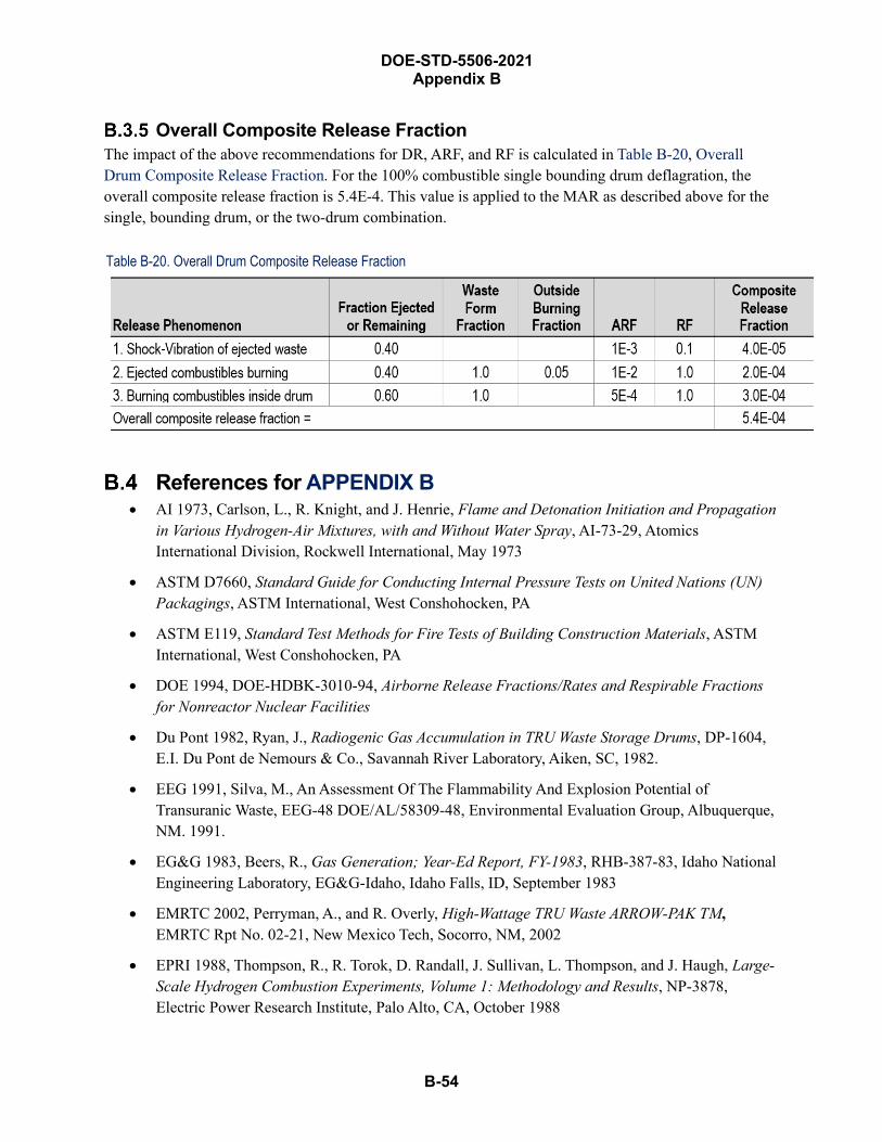
DOE-STD-5506-2021 Appendix B
B-54
Overall Composite Release Fraction The impact of the above recommendations for DR, ARF, and RF is calculated in Table B-20, Overall Drum Composite Release Fraction. For the 100% combustible single bounding drum deflagration, the overall composite release fraction is 5.4E-4. This value is applied to the MAR as described above for the single, bounding drum, or the two-drum combination.
Table B-20. Overall Drum Composite Release Fraction
References for APPENDIX B • AI 1973, Carlson, L., R. Knight, and J. Henrie, Flame and Detonation Initiation and Propagation
in Various Hydrogen-Air Mixtures, with and Without Water Spray, AI-73-29, AtomicsInternational Division, Rockwell International, May 1973
• ASTM D7660, Standard Guide for Conducting Internal Pressure Tests on United Nations (UN)Packagings, ASTM International, West Conshohocken, PA
• ASTM E119, Standard Test Methods for Fire Tests of Building Construction Materials, ASTMInternational, West Conshohocken, PA
• DOE 1994, DOE-HDBK-3010-94, Airborne Release Fractions/Rates and Respirable Fractionsfor Nonreactor Nuclear Facilities
• Du Pont 1982, Ryan, J., Radiogenic Gas Accumulation in TRU Waste Storage Drums, DP-1604,E.I. Du Pont de Nemours & Co., Savannah River Laboratory, Aiken, SC, 1982.
• EEG 1991, Silva, M., An Assessment Of The Flammability And Explosion Potential ofTransuranic Waste, EEG-48 DOE/AL/58309-48, Environmental Evaluation Group, Albuquerque,NM. 1991.
• EG&G 1983, Beers, R., Gas Generation; Year-Ed Report, FY-1983, RHB-387-83, Idaho NationalEngineering Laboratory, EG&G-Idaho, Idaho Falls, ID, September 1983
• EMRTC 2002, Perryman, A., and R. Overly, High-Wattage TRU Waste ARROW-PAK TM,EMRTC Rpt No. 02-21, New Mexico Tech, Socorro, NM, 2002
• EPRI 1988, Thompson, R., R. Torok, D. Randall, J. Sullivan, L. Thompson, and J. Haugh, Large-Scale Hydrogen Combustion Experiments, Volume 1: Methodology and Results, NP-3878,Electric Power Research Institute, Palo Alto, CA, October 1988
DOE-STD-5506-2021 Appendix B
B-55
• Fluor Hanford 2004, Marusich, R., Revised Hydrogen Deflagration Analysis, HNF-19492, Rev0A, Hanford Reservation, Fluor Hanford, Richland, WA, March 2004
• ICPC 2018, Technical Analysis of Drum Lid Ejections-ARP V, Idaho Cleanup Project Core, IdahoFalls, Idaho 83402, December 2018.
• INEL 1995, Idaho National Engineering Laboratory Code Assessment of the Rocky FlatsTransuranic Waste, Wastren Inc., Westminster, Colorado 80234, July 1995.
• LANL 1998, Larranage, M., D. Voltz, and F. Bolten, Pressure-Deformation Correlation in WasteContainers (PDCWC), Los Alamos National Laboratory, Los Alamos, NM, October 1998
• LANL 2002, Mishima, J. and C. Steele, Oxidation of Tritium Gas Under Accident and TransportConditions, LA-UR-02-38031, Los Alamos National Laboratory, Los Alamos, NM, May 2002
• LLNL 1993, Hasegawa, H., K. Staggs, and S. Doughty, Fire Testing of 55-gallon Metal WasteDrums for Dry Waste Storage, Lawrence Livermore National Laboratory, Livermore, CA, July1993
• SNL 1983, Huerta, M., et al., Analysis, Scale Modeling, and Full-Scale Tests of Low LevelNuclear Waste Drum Response to Accident Environments, SAND80-2517, Sandia NationalLaboratories, Albuquerque, NM, January 1983.
• SNL 1989, Sherman, M., S. Tieszen, and W. Benedick, FLAME Facility, The Effect of Obstaclesand Transverse Venting on Flame Acceleration and Transition to Detonation for Hydrogen-AirMixtures at Large Scale, NUREG/CR-5275, Sandia National Laboratories, Albuquerque, NM,April 1989
• SNL 1998, Ludwigsen, J., D. Ammerman, and H. Radloff, Analysis in Support of Storage ofResidues in the Pipe Overpack Container, SAND98-1003, UC-722, Sandia NationalLaboratories, Albuquerque, NM, April 1998.
• SRR 2011, Mckeel, C., Pressure Boundary Integrity of Pipe Component Vessels under InternalExplosion Condition, T-CLC-E-00038, Rev. 1, Savannah River Remediation, Savannah RiverSite, Aiken, SC, 2011.
• SwRI 2015, Deflagration Testing for CH Payload Containers and Filter Vents, SwRI Project No.:01.20698.01.001, Southwest Research Institute, San Antonio, TX, March 2015
• Westinghouse Hanford 1994, Bucci, H, et al., Waste Drum Fires, WHC-SA-2425-FP,Westinghouse Hanford Company, Richland, WA, May 1994
• WSMS 2006, Perkins, L., J. Menna, and M. Hitchler, “Position Paper on the Potential forExplosions in Transuranic Waste Drums at the Melton Valley Solid Waste Storage Facilities inOak Ridge, Tennessee”, BJC/OR-2470, WSMS Mid-America, prepared for Bechtel JacobsCompany, Oak Ridge, TN, 2006
• WSRC 1990, Dykes, K. and M. Myer, TRU Drum Hydrogen Explosion Tests, WSRC-TR-90-165,Westinghouse Savannah River Company, Aiken, SC, 1990

DOE-STD-5506-2021 Appendix B
B-56
• WSRC 2007, Looper, M., Interoffice Memorandum to W. Morrison, “Hydrogen and Oxygen Datafor Unvented Culvert Drums” M&O-TRU-2007-00005, Westinghouse Savannah River Company,Aiken, SC, February 9, 2007
DOE-STD-5506-2021 Appendix C
C-1
Damage Ratios for Container Insults and Fires
This appendix provides the technical justifications for the Damage Ratios (DRs) presented in Section 4.3.3, Fire Scenario Damage Ratios for TRU Waste Containers, and Section 4.3.4, Damage Ratios for Mechanical Insults.
Contact-handled (CH) TRU wastes are packaged and shipped for disposal to the Waste Isolation Pilot Plant (WIPP) in U.S. Department of Transportation (DOT) 7A containers. The latest version (03/13, Rev. 4) of the Contact-Handled Transuranic Waste Authorized Methods for Payload Control (CH-TRAMPAC) (NRC 2013) lists the following containers as “Payload Container Assemblies,” i.e., Type 7A CH containers:
• 55-gallon metal drum (and other sizes)
• Pipe Overpack Container (POC)
• Standard Waste Box (SWB)
• Ten Drum Overpack (TDOP)
• Standard Large Box 2 (SLB2)
• Criticality Control Overpack (CCO)
• Shielded Container Assembly (SCA)
The performance of these containers under various accident stresses are similar for some of the container types, but not the same for all of them. The following summarize which containers are considered to be equivalent to each other for accident types, based on the technical evaluations of them for the WIPP safety basis. Not all containers are specifically identified in the discussions throughout the remainder of this appendix. The discussion, however, is applicable to the equivalent container unless unique differences are elaborated.
CCO and POC Equivalence The impact and fire DRs for CCOs are near-identical in performance to POCs. This assumption is predicated on numerous comparisons between CCOs and POCs. The POC and CCO are a near-identical design: both are 6-inch steel pipes centered within a 55-gallon drum. The centering material for the CCO is plywood, while the POC uses fiberboard/plywood. Both designs of the POC inner Pipe Component (PC) and the CCO inner Criticality Control Container (CCC) use either a gasket or O-ring design for lid sealing, with closure bolts at one end. And both use a blind flange welded bottom cap. Note that the POC can also have a 12-inch pipe instead of a 6-inch pipe.
The POC and CCO have both completed portions of DOT/NRC Type B protocol testing. Most notably, they have both completed drop, impact, and thermal testing, though there was no sequential drop-fire testing as required by Type B hypothetical accident condition test protocols. These tests show the same performance for both POCs and CCOs.
C-2
DOE-STD-5506-2021 Appendix C
SWB and SLB2 Equivalence The SLB2 damage ratio is treated in a manner equivalent to SWB for impacts. This assumption is predicated on the design of the SLB2 as a bolted-lid container whose construction is similar to the SWB’s. The SLB2 is a vented stainless-steel container with bolted lid that occupies the same space as four waste assemblies on a facility pallet. The SWB is a DOT Type 7A steel-fabricated box with a lap-welded bottom and an internally flanged, bolted closure lid. The SWB is approximately 71 inches long, 54 inches wide, and 37 inches high. The SLB2 is a DOT Type 7A steel-fabricated box with a lap-welded bottom and an internally flanged, bolted closure lid. The SLB2 is approximately 108 inches long, 69 inches wide, and 73 inches high. Both the SWB and the SLB2 have a bolted closure lid, but the SLB2 is a larger container than the SWB.
The SLB2 is judged to have the same DR as the SWB because both the containers are steel, with the same lid closure mechanism.
The fire damage DRs for the SLB2 are equivalent to the SWB’s when taking into account the larger number of drums that the SLB2 can hold: the SLB2 can hold eight or more drums, a calculation that is based on the DOE-STD-5506-2007 assumption for SWBs to hold four drums. For example, two SLB2s is equivalent to more than 10 drums or three SWBs. Therefore, the 0.5 damage ratio would be applicable.
SCA Equivalence The impact DR of a shielded container is half of a drum DR. The shielded container is a vented carbon-steel and lead cylindrical structure with a removable lid designed to hold an inner 30-gallon container of RH waste. The shielded container meets the DOT 7A Type A requirements of 49 CFR 178.350. There are two metal containers that have to fail before the radioactive waste is impacted. Therefore, half of drum DR is appropriate for shielded containers, an overpack, to credit the second robust steel container. The shielded container has a DR of 1.0, or 0.5 for dropping a waste pallet down the waste shaft onto another waste pallet sitting at the bottom of the shaft. The shielded container is a robust container. Accordingly, a factor-of-2 reduction is considered reasonable for this container, compared to an overpacked drum or SWB-OP. A DR of 0.5 for substantial crushing is conservative when considering that an SWB has a DR of 0.1 for a collapse level event. Shielded containers could be breached in short- or long-duration pool fires because of uneven heating of the lead lining along with weakening of the outer container shell. A DR of 0.5 is applied to arrays of 10 or more shielded containers involved in an exposure or fully engulfing pool fire. A DR of 1.0 is applied for arrays of fewer than 10 shielded containers. A DR of 1.0 is also applied to shielded containers that experience impact followed by fire.
Fire Scenarios Damage Ratios for TRU Waste Container Section 4.3.3, Fire Scenario Damage Ratios for TRU Waste Containers, presents guidelines for selecting DRs for fires involving Transuranic (TRU) waste container storage in existing facilities for the facility Documented Safety Analysis (DSA). This section of the appendix provides the basis for the conservative assumptions used to establish the simplified alternative DR approach presented in Section 4.3.3; it does not repeat all of that discussion. It addresses insights from previous drum fire testing, considerations of lid loss versus seal failure, and the ejection fraction for lid loss and unconfined burning.
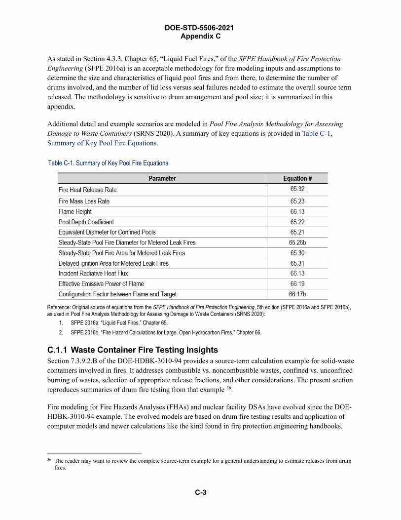
C-3
DOE-STD-5506-2021 Appendix C
As stated in Section 4.3.3, Chapter 65, “Liquid Fuel Fires,” of the SFPE Handbook of Fire Protection Engineering (SFPE 2016a) is an acceptable methodology for fire modeling inputs and assumptions to determine the size and characteristics of liquid pool fires and from there, to determine the number of drums involved, and the number of lid loss versus seal failures needed to estimate the overall source term released. The methodology is sensitive to drum arrangement and pool size; it is summarized in this appendix.
Additional detail and example scenarios are modeled in Pool Fire Analysis Methodology for Assessing Damage to Waste Containers (SRNS 2020). A summary of key equations is provided in Table C-1, Summary of Key Pool Fire Equations.
Table C-1. Summary of Key Pool Fire Equations
Reference: Original source of equations from the SFPE Handbook of Fire Protection Engineering, 5th edition (SFPE 2016a and SFPE 2016b), as used in Pool Fire Analysis Methodology for Assessing Damage to Waste Containers (SRNS 2020):
1. SFPE 2016a, “Liquid Fuel Fires,” Chapter 65.2. SFPE 2016b, “Fire Hazard Calculations for Large, Open Hydrocarbon Fires,” Chapter 66.
Waste Container Fire Testing InsightsSection 7.3.9.2.B of the DOE-HDBK-3010-94 provides a source-term calculation example for solid-waste containers involved in fires. It addresses combustible vs. noncombustible wastes, confined vs. unconfined burning of wastes, selection of appropriate release fractions, and other considerations. The present section reproduces summaries of drum fire testing from that example 36.
Fire modeling for Fire Hazards Analyses (FHAs) and nuclear facility DSAs have evolved since the DOE-HDBK-3010-94 example. The evolved models are based on drum fire testing results and application of computer models and newer calculations like the kind found in fire protection engineering handbooks.
36 The reader may want to review the complete source-term example for a general understanding to estimate releases from drum fires.

C-4
DOE-STD-5506-2021 Appendix C
Estimation of fire releases in drum storage considers the issue of drum pressurization. A summary of drum fire testing follows to support the DR recommendations presented in Section 4.3.3. Many of the fire properties used in the fire analyses are based on the results of small-scale specimens in overventilated conditions. Therefore, the results of these tests are conservative when applied to the postulated larger-scale scenarios (i.e., fire involving arrays of TRU drums).
Tests of drums under extreme fire conditions have been performed. Sandia National Laboratories (SNL, 1979) performed experiments where drums with and without liners were placed in square burn pans holding diesel fuel. In one test, closure rings were not used on five drums in the flame zone, so those drums were not actually sealed. As a result, the lids lifted on all of those drums. In another test, no lifting of lids was observed, most likely due to stacking drums on top of the bottom layer of drums that were exposed to the most intense heat.
In the 1979 Sandia large-scale test, 12 drums were sealed and placed in the diesel-soaked (190-liter) salt bed without stacking. Three of these drums were unlined, and four had ⅛-inch-diameter vents drilled through the centers of their lids. The fire burned for 45 minutes, with the majority of the visible flame zone centering on four drums due to wind conditions. Of these four maximally affected drums, the vented and unlined drum blew its lid 7 minutes into the burn, scattering burning debris over the area. Flaring was observed around the lid of a lined, unvented drum, and a flame torch emanated from the side of the upper lid of a lined, vented drum. The remaining lined, unvented drum experienced a rupture of the bottom seam on one side. In general, polyethylene liners in drums melted and badly pyrolyzed. However, it is possible that the insulation provided by the liners prevents a buildup of temperature and pressure as rapid as the buildups experienced by the unlined drums.
The dislodgement of drum lids or lack thereof is a function of the rate of pressure rise. A rapid pressure rise is more likely to blow off a drum lid; a slow pressure rise will cause localized failure at seal and seam edges followed by the emission of a torch of pyrolyzed gases. Tests at Lawrence Livermore National Laboratory (LLNL, 1993) used sealed 55-gallon metal drums without a vent plug, loaded with combustible materials and “salted” with isopropyl alcohol (Hanford, 1994). These drums were placed in an isopropyl alcohol flow flame and violently ejected their lids in some instances. The test configuration (drums in a pan with isopropyl alcohol) and the fuel are extreme. However, even in those instances where lids blew off, the filmed record showed bulk waste landing on the ground, where it proceeded to burn. There was no fragmentation of the drum or instantaneous combustion of significant quantities of waste.
Sealed 55-gallon metal drums, containing a mixture of combustible materials, did not lose their lids when placed in a wooden structure that was burned to the ground with combustibles purposefully stacked around the drums to produce a high fuel loading and associated heat flux (reference Greenhalgh, Demiter, and Olson, May 1994, as cited in DOE 1994). These drums exhibited a more typical phenomenon of lid seal failures, producing torch flames from pyrolysis gases generated in the drums. After the fire consumed the entire building, an examination of the drums revealed the majority of the contents to be uncombusted. This result provides some justifications for a DR < 1.0 for seal failures, as discussed later.
Drum fire tests performed by Hughes Associates, Inc. for the Hanford site are reported in Analytical and Experimental Evaluation of Solid Waste Drum Fire Performance, WHC-SD-TRP-233 (Westinghouse
C-5
DOE-STD-5506-2021 Appendix C
Hanford 1995b) and Solid Waste Drum Array, Fire Performance, WHC-SD-WM-TRP-246 (Westinghouse Hanford 1995c). These results were interpreted into a protocol to model drum fires for the Hanford site and published in the Fire Protection Guide for Waste Drum Storage Arrays, WHC-SD-SQA-ANAL-501 (Westinghouse Hanford 1996).
The most recent waste container testing included Pipe Overpack Containers (POCs), standard Type A TRU waste drums, and Criticality Control Overpacks (CCOs) and was conducted at Sandia National Laboratories, using a 30-minute jet-fuel pan fire with a diameter of 3 meters. The testing is documented in five SNL test reports (SNL 2017, SNL 2018a, SNL 2018b, SNL 2019, and SNL 2020), and discussed further in Section C.1.4, Pipe Overpack Container, Type 7A Drum, and Criticality Control Overpack Fire Testing.
Numerous FHAs throughout the DOE Complex have evaluated waste container storage configurations based on the general methodology outlined in Section 5 37 of the Hanford guide for specific fire modeling inputs and assumptions. An example of how this is applied for the DSA is presented in HNF-14741, Solid Waste Operations Complex Master Documented Safety Analysis (Fluor Hanford 2005), based on their site-specific FHA evaluation.
Numerous site-specific modifications of that methodology have also been justified in the past. One example is the approach developed for the Rocky Flats Environmental Technology Site as published in their Safety Analysis and Risk Assessment Handbook (SARAH) (Kaiser-Hill 2002). The SARAH approach is based on a letter report from J. Mishima to Kaiser-Hill Company, Applicable Airborne Release Fractions (ARFs) and Respirable Fraction (RFs) for Surface-Contaminated, Combustible Waste in 55-Gallon Metal Drums During Fires (Mishima 2001). The Mishima letter report provides an extensive review of the Hanford fire tests and the other experiments mentioned earlier. Based on this review, it recommends a protocol to evaluate pool and ordinary combustible fires involving drums.
The final methodology approved for FHA and DSA development at Rocky Flats with example applications was documented in the Applicable Airborne Release Fractions (ARFs) and Respirable Fractions (RFs) for Surface-Contaminated, Combustible Waste in 55-Gallon Metal Drums During Fires, NSTR-008-01 (Kaiser-Hill 2001), and summarized in SARAH 38. The Mishima 2001 reference and NSTR-008-001 results were the primary basis for the DR guidelines recommended in Section 4.4.3 of the previous edition of this DOE Standard, for the alternate methodology to the Hanford Fire Protection Guide.
The DR guidelines in this DOE Standard, previously provided in the Hanford Fire Protection Guide, have been modified based on evaluation of more recent test data, as summarized here and documented for Savannah River Site in Pool Fire Analysis Methodology for Assessing Damage to Waste Containers, S-CLC-G-00395 (SRNS 2020).
37 Use of the Hanford methodology for evaluating a postulated pool fire area based on a 70-second fire duration (Equations 4-1 & 5-1, Westinghouse Hanford, 1996) should be discontinued in lieu of evaluating a pool fire area based on pool depth as outlined in SFPE 2016a. Other aspects of the Hanford methodology remain applicable.
38 Not all recommendations of the Mishima 2001 report were adopted. For example, the graded application of DR estimates based on number of containers involved was not adopted.
C-6
DOE-STD-5506-2021 Appendix C
Two types of liquid pool fires should be considered: unconfined crash/instantaneous spill fires and confined spill fires. A third type, unconfined continuously flowing (also called metered leak) spill fires, should also be considered if the FHA identifies a specific facility target of concern in an area where significant liquid fuel sources are allowed to be present. The area occupied by the spill fire is the dominant factor in assessing damage to TRU waste containers in and near the spill. The instantaneous crash/spill pool fire is characterized as being caused by a breach in a flammable/combustible liquid tank/reservoir where all the available liquid spills and spreads to its maximum size prior to ignition of the liquid. The time required for fuel spread is neglected, making the spill, in effect, instantaneous. It is differentiated from the metered-leak spill fire, which assumes fuel ignition during the spill and is thus characterized by the spill rate. The confined spill fire is characterized by physical boundaries, which limit pool spread.
All combustible material sources should be considered consistent with the facility FHA. However, a flammable combustible liquid fuel spill fire typically presents a hazard to the largest number of TRU waste containers and therefore the largest potential consequences. The most likely liquid fuel sources in TRU waste facilities are those present on TRU waste-handling vehicles (forklifts, pallet movers, transport trucks, etc.).
General analysis aspects, applicable to all types of spill fires are summarized here:
• It is common practice to model a fire as a right circular cylinder with a diameter equal to the pooldiameter (SFPE 2016b). It’s also appropriate to model a pool fire as centered on the vehicleinvolved, a practice which assumes that the floor surface is relatively flat (not a designed incline)and even (free of depressions > ~5 mm). Although a liquid fuel spill could flow away from thevehicle toward TRU waste containers, it could just as easily flow the other way. Modeling thespill as centered on the vehicle presents an acceptably conservative approach. Where theseassumptions are not applicable, the PNNL analysis of spills on an inclined surface (PNNL 2004)may be used to assess the pool fire footprint based on the specific configurations being analyzed.Large depressions should be evaluated as confined-spill pool fire.
• Unless known to be otherwise, the spill surface should be taken as flat and not inclined.
• When estimating the pool area (footprint), it is generally acceptable to neglect the footprintoccupied by containers, pallets, and similar objects because contact between the base of theseitems and the floor is rarely liquid-tight. Neglecting their possible effect on pool fire footprintgreatly simplifies the required modeling effort and is compensated by also neglecting their effecton the fire heat release rate and flame height. However, physical constraints such as curbs androom boundaries should be considered if they are present. Large depressions, (depressions > ~5cm deep) ditches, or pits should be treated as a confined pool spill with defined pool fireboundaries. These features should only be assumed as an initial condition if they are credited ascontrols in the safety basis, or lead to a more conservative answer than ignoring their existence.
• Where a vehicle’s liquid reservoir/tank is constructed of metal, it is appropriate to consider thatsome amount of the fuel would not likely be available to contribute to the pool fire diameter. TheSRS methodology considers a conservative “derating” factor of 0.75; i.e., only 75% of the liquidfuel tank capacity is considered to contribute to the fire diameter based on derating concepts
DOE-STD-5506-2021 Appendix C
C-7
defined in Section 6, Chapter 6 of the NFPA Handbook (NFPA 1991). It is very unlikely that a liquid spill would result only from a breach/tear at the bottom of the tank, or that the tank would be filled to 100% of its capacity at the time of the postulated vehicle accident. Also, since liquid transfer lines (hoses, tubing, etc.) are typically connected through the top of the tank (reduces problems with sediment) it is less likely they would be capable of draining the entire contents of the tank if the tank were torn or breached in an accident. While it is likely that all of the combustible liquid would be consumed in the fire, a portion of it would be expected to burn within the tank, thus not contributing to increasing the pool footprint. If the tank/reservoir is constructed of plastic, no derating factor should be applied.
• For any vehicle pool fire scenario, it is reasonable to consider only the largest singleflammable/combustible liquid tank capacity as contributing to the footprint of the postulatedcrash/instantaneous spill fire. Other combustibles on the vehicle (additional liquid tank, tires,knobs, batteries, wires, seat cushions, etc.) would only contribute to the fire’s overall duration asthey become involved in the fire; they would not contribute to increasing the spill area (footprint).An instantaneous spill of the largest single flammable/combustible liquid tank would present thelargest pool footprint for determining damage to TRU waste containers. However, becausehydraulic fluid spills generally cause less damage than other liquids (i.e., diesel fuel), the analystshould consider which tank volume contributes most to the analyzed damage estimates based onthe combined source term factors (DR×ARF×RF). As a general rule of thumb (all else beingequal), a pool fire that can only cause seal failure would need to involve more than about twicethe number of drums to match the consequences of a pool fire that causes both lid ejection andseal failure.
• Very shallow pool fires do not need to be considered for assessing damage to TRU wastecontainers. The most recent edition of the SFPE Handbook (SFPE 2016a) specifies analysis of anunconfined flammable/combustible liquid fuel spill depth of 0.7 mm for most fuels andconditions. For most liquid hydrocarbon fuels, the very shallow (0.7 mm) pool is consumed inabout 15–20 seconds. Based on test data in earlier reports (Westinghouse Hanford 1995b,Westinghouse Hanford 1995c, and Westinghouse Hanford 1996) as well as data from more recentPOC testing (SNL 2018a, SNL 2018b, SNL 2019, and SNL 2020), the 15- to-20-second fireduration is much shorter than that required for either lid ejection (~70 seconds) or seal failure(~120 seconds). Therefore, the very shallow pool fire, though possible, is determined to result inno damage to TRU waste containers and does not need be considered further in contributing todirect fire damage to containers. It may however, need to be considered for propagation to othercombustible material accumulations as warranted by the fire scenario in the facility FHA.
• Hydraulic-fluid pool fires can only cause seal failure; lid ejection does not need to be considered.Test data described by Gottuk (SFPE 2016a) indicates that due to the high flashpoint of typicalhydraulic fluids, flame spread beyond the point of ignition is very unlikely. However, in thepresence of a significant long duration ignition source (such as a burning TRU waste handlingvehicle), heating of the liquid above its flash point is possible. In this case, liquid-phase flamespread is the only plausible mechanism to permit the greater part of the hydraulic fluid spill tobecome involved in the fire. Flame spread would be expected to be slow, not approaching thebounding liquid-phase flame spread rate (~8–12 cm/s for jet fuel) presented in literature (SFPE
DOE-STD-5506-2021 Appendix C
C-8
2016a). Based on this fact, unconfined hydraulic fluid spills fires are not considered capable of creating rapid heating conditions necessary to cause lid ejection in exposed standard TRU waste drums. The slow propagation could make seal-failure damage more likely. But the depth of the unconfined pool will limit the fire duration to less than about 90 seconds. As described in Section C.1.3, seal failure requires significant heat flux for longer than about 120 seconds. Given thatengulfing pool fire conditions expose most of a container’s surface to high incident flux, it is notreasonable to conclude there is no seal failure damage. A conservative approximation considersthat seal failure damage occurs, in an unconfined hydraulic fluid spill pool fire, on 50% (DR =0.5) of the containers engulfed, in the first-row-out, or subjected to critical incident flux (SectionC.1.3). The population is inclusive of all containers assessed to receive seal failure. This DRshould not be applied for a small population (< 10) of containers.
Unconfined Crash/Instantaneous Spill Fire The instantaneous crash/spill pool fire should be evaluated as a 2.9-mm-deep spill (SFPE 2016a) using the derated capacity of the largest single flammable/combustible liquid tank, centered on the vehicle involved. As stated above, because hydraulic fluid spills generally cause less damage than other liquids (i.e., diesel fuel), the analyst should consider which tank volume contributes most to the analyzed damage estimates based on the combined source-term factors (DR×ARF×RF). Additionally, the bounding case should be evaluated. As a rule of thumb, all else being equal, the hydraulic fluid pool fire would need to involve more than twice the number of drums to match the ST consequences of a diesel-fuel pool fire.
The analysis (typically done graphically) should, consistent with facility operations, depict the worst-case configuration (array) of drums, SWBs, overpacks, or other containers potentially exposed to the fire and position the fire to maximize container damage. The analysis should then determine the number of containers that are fully engulfed and the number of containers in the first-row-out from those fully engulfed. It would be acceptable to count only those containers entirely within the periphery as fully engulfed. However, a general practice considers that at least 50 to 75% of a container’s footprint would need to be within the periphery of the pool to be considered engulfed, thus adding a small amount of conservatism. The number of engulfed and first-row-out containers (drums) are then evaluated for lid loss and waste ejection as described below in Section C.1.2. The number of containers in the second-row-out from the pool, which are evaluated to receive seal failure, is calculated to be the same number as those in the first-row-out that receive lid ejection. These criteria are summarized in Figure 4-2.
Unconfined Metered Leak Spill Fire The spill area of an unconfined, metered-leak spill will continue to increase indefinitely until a physical boundary is reached or the fuel is ignited and burns. The transient nature of the metered-leak spill is very dependent on the timing of the ignition and the flame spread rate relative to the fuel flow rate and the fuel’s mass loss rate. A metered-leak spill fire will reach a steady-state burning size characterized by the equivalent steady-state diameter where the fire’s mass loss rate is equivalent to the spill flow rate. If fire ignition occurs after the spill reaches its steady-state diameter, the spill area will decrease to the steady-state diameter. If fire ignition occurs before the spill reaches the steady-state diameter, the spill area will increase to the steady-state diameter.

C-9
DOE-STD-5506-2021 Appendix C
These are just some of the scenarios that can occur. Complicating factors to alter the steady-state fire diameter include an unknown or variable leak size (flow orifice), changes in flow rate due to head pressure, and the potential involvement of molten vehicle-tire material.
With a fixed quantity of fuel, the spill area for a metered-leak pool fire is always bounded by the unconfined crash-type pool fire described above. Also, the prescriptive evaluation of pool fire damage to TRU waste containers, as provided in this DOE Standard, occurs quickly (within about 120 to 300 seconds) and is entirely dependent on pool fire diameter rather than duration. Therefore, the metered leak spill need not be considered when assessing direct pool fire damage to TRU waste containers.
However, where the facility FHA identifies a target with a thermal stress failure threshold longer than about 120 to 300 seconds, the metered-leak spill fire should be evaluated. If the spill rate is known, a steady-state spill diameter can be determined based on equations 65.26a and 65.26b or, for very large spill rates (150–600 gpm), equations 65.27a and 65.27b, from SFPE 2016a. For those scenarios, such as failure of a structural steel support column, the spill area should evaluate a spill rate that obtains the target failure threshold based on either fire duration or fire diameter (typically target engulfment), using guidance from SFPE 2016a.
If the metered-leak spill fire results in a fire lasting more than about 10 minutes, the vehicle tires would likely have an opportunity to influence the pool diameter and should be included, as described next.
Modeling Tire Involvement in the Unconfined Metered Leak Spill Fire Empirical testing of dual truck tires (SINTEF 1995) indicates that although the tires burn for a significant duration, the pool size formed by the molten rubber is maximized in about 10 minutes to a footprint about three times a single tire’s width and length based on a bounding interpretation of the tire fire photographs presented in SINTEF 1995. Where multiple tires are co-located (e.g., dual or tandem tire sets) and would obviously be involved in a single fire, the spacing between tires should be included in estimating the pool size. For a metered leak pool fire lasting > ~10 minutes, at least one tire set on a vehicle would likely contribute to increasing the size of the metered-leak spill and should therefore be included in the metered leak pool fire estimates.
The Savannah River Site (SRNS 2020) pool fire methodology calculation develops a very conservative approach to combining the liquid fuel and tire pool fire sizes that simply adds the footprints of the liquid and tire pools together. The approach overcomes the extensive uncertainties associated with scenario development by essentially assuming that the two fuel sources ignite concurrently. Additional nearby tire sets should be included based on propagation potential between tire sets which may be simply and conservatively modeled as normally ignitable material requiring an incident flux of 20 kW/m2 (NFPA 2016, equation 10.3.3.b). Otherwise, test data on automobile fires (Joyeux 1997) indicates that radiant heat ignition of nearby tires occurs at about 20 minutes, providing sufficient time for full tire pool development of more than one tire set.
Confined Spill Fire The confined spill fire is the same as the metered-leak spill fire except the pool fire footprint is defined by the mechanism containing the spill—for example, a curb, a wall, or a ditch. Test data described in SFPE
C-10
DOE-STD-5506-2021 Appendix C
2016a indicates that spill depths on the order of ~5 mm are sufficiently deep that asymptotic (peak) burning rates are achievable. The duration of the confined spill pool fire is dependent on the spill depth and could be very long. The analysis should include additional consideration given to these parameters and their effect on the assessment of damage to TRU waste containers; e.g., the 0.5 DR for a large population of containers in a hydraulic pool fire should not be applied if the fire duration exceeds ~120–300 seconds. Inclusion of tires should be based on the calculated duration of the postulated spill fire within the confined area, as described above.
Lid Loss and Ejection Fraction Based on the review of the fire tests, the Mishima 2001 reference provides the following basis for recommending that 25% of drums within a pool fire, or adjacent to a pool fire, are assumed to experience lid loss with the potential to eject some contents:
There does not appear to be any established correlation between fire generated conditions (e.g. wall temperature, heat energy flux impacting drums) and “lid loss” and “seal failure”. Consequently, the criteria used to predict these responses tend to be very conservative (tend to over-estimate their effect). Under the most rigorous test conditions (a flammable liquid fire engulfing combustible filled 55-gallon metal drum with liquid flammable fuel in the drum or fire that can transfer heat to all surfaces of the drums), less than 25% of the drums exhibited "lid loss". The “lid loss” is postulated to occur due to the auto-ignition of the flammable fuel vapor resulting in a very rapid increase in pressure, pyrolysis of solid combustible under intense heating conditions, or for long durations. Similar responses resulted from the explosion of hydrogen gas with its flammability limits in solid combustible 55-gallon metal drums (5 of 18 drums = 28%). In other tests in engulfing fires (Haecker et al., Sept. 1995), “lid loss” occurred from 0% for trash fires to 25% in a combustible fuel fire with drum containing solid combustible and noncombustible materials and a liquid hydrocarbon fuel. For a Pallet Storage Array (the storage configuration used within the DOE Complex), a predictive model proposed based on the previous test, over-predicted “lid loss” by a factor of 5.2 (94 lid failures predicted, 18 lid failures experienced). Of the 24 drums in the flames and 30 drums adjacent to the flames in the experimental Pallet Storage Array fire, only 2 drums (~3.7%) suffered “lid loss”; these were not in the top tier. The terminology describing the drum responses changed in the middle of the document revealing that the term lid loss/failure include both lid rupture (that does not physically remove the lid from the drum) and lid loss (lid physically removed from the drum). Based on this re-definition, the predictive model over-estimated “lid loss” by a factor of 47 (94 predicted vs. two with “lid loss”, a factor of 18/2 = 9 smaller than drums with “lid failure”).
C-11
DOE-STD-5506-2021 Appendix C
Each of the experiments mentioned in the previous section were critically reviewed in order to establish the 25% estimate of lid loss with ejection of contents that reflects the experimental record. Mishima noted that the different experiments did not use the same definition for lid loss, so interpretations of the results are somewhat subjective regarding whether contents were ejected. For the purpose of these guidelines, lid loss includes ejection of some contents. For the purpose of these guidelines, lid rupture where the lid was deformed but not displaced from the drum is considered to be the same as seal failures.
To establish a bounding estimate, the 25% of drums that experience lid loss is applied with a second DR adjustment. In the second adjustment, one-third of the contents (33%) is assumed to be ejected from the drum with the exception of heavy forms of waste (e.g., contaminated pieces of a glovebox). This bounding recommendation is based on a single data point taken during the drum fire experiments (Westinghouse Hanford 1995a) which indicated that approximately one-third of the combustible contents were ejected during a violent “lid loss” event (Mishima 2001).
Use of 33% ejected is recognized as the most bounding assumption. For a 30% hydrogen deflagration in a vertical drum with combustibles the ejection fraction is 7% to 27% 39. The amount ejected is a function of the pressure at which the drum lid comes off. That pressure, in turn, is a function of the rate of change of pressure. Both figures are much greater in a hydrogen deflagration than in a fire. WHC-SD-WM-TRP-233 (Westinghouse Hanford 1995b), Section 3.3 shows that for fire testing conducted at various DOE locations, the peak internal pressure is 28 psig. This peak occurs 93 seconds after the fire starts (2.1 m JP-5 pool fire, Drum 30-D1). The pressure at which the drum lid fails for a hydrogen deflagration is around 90 to 100 psig. Therefore, the amount ejected from a fire should not be anywhere near that of hydrogen. However, a notation in the comments section for drum 31-D4, which had a maximum pressure of 13 psig, a fairly low value of dP/dt, was that “1/3 of contents were ejected.” The major difference between this drum and an actual drum is that the simulated waste was layered in the drum using individual pieces e.g., rubber sheet 6 in. × 12 in. × 0.125 in., 6-mil plastic bag cotton towels, etc. (See pg. 2-6 and 2-7 of the reference.) Actual TRU waste is bagged, though the inner packaging of drums may have degraded depending on when they were packaged and their storage environment. The void volume of the drum in the fire test appears to be similar to that in the hydrogen deflagration tests. However, most of the hydrogen that burns is above the waste; in the fire test, by contrast, the pressurized air exists throughout the drum. When the lid lifts, the pressurized air can more easily eject the waste. So there is a potential reason why a fire can eject more waste than a hydrogen explosion.
On the other hand, in the test, each barrel is surrounded by at least 0.3 m of flames. The drums burn as individual drums in a fire, not as drums in an array (See FIGURE 16 of reference). In an array, even on the worst-case drum, only one side is burning. Because the drums are in a close-packed array not widely spaced and because the waste is packaged, not present as individual sheets, 33% ejected may be overly conservative.
Therefore, although the Hanford Fire Protection Guide recommends considering a 33% ejection fraction for a more conservative analysis, the application of this guide for Hanford DSAs assumed a 10% ejection fraction (which is applied to 100% of unrestrained drums in a pool fire and some lower-tier drums
39 compared to the 40% ejection fraction for a horizontal drum that is used for a bounding assumption for the drum deflagration DR in Section 4.4.2 and APPENDIX B.
DOE-STD-5506-2021 Appendix C
C-12
depending on toppling considerations). The 100% of the drums that experience lid loss but with 10% ejection (Hanford model) is about the same as assuming 25% of the drum population that experience lid loss with 33% ejection (the alternative approach). Either approach results in the same level of consequences and bases for derivation of TSR controls. And either approach is acceptable for a conservative estimate.
Seal Failures For the “fast” fire growth rate associated with the pool fires, those drums engulfed in the pool or along the edge of the pool that do not experience lid loss are assumed to experience seal failure. This DR is the remaining 75% fraction of drums involved.
For “moderate” fire growth rates (e.g., ordinary combustibles such as trash or wooden pallets and crates), lid loss and ejection of contents are not expected based on the drum testing results, so for modeling purposes, seal failures only are evaluated. Thermal stress due to direct flame impingement on only one side of a container, or heat transfer only through radiation, is determined to not result in lid loss. The heat output of the fire is insufficient to increase temperature and pressure inside the drum quickly enough to eject the lid before venting (seal failure 40) occurs. Seal failure damage requires that the container be close enough to the fire such that it is exposed to a sufficient heat flux (critical flux). The previous edition of this DOE Standard defined critical flux as:
A conservative criterion for seal failure (Kaiser-Hill 2000) is at least one third of the container is exposed to a heat flux exceeding 15.9-kW/m2 based on interpretations from the Hanford fire tests (Westinghouse Hanford 1995b, Westinghouse Hanford 1995c, and Westinghouse Hanford 1996).
Additional insight from evaluation of the earlier reports combined with video evidence from recent POC and CCO testing (SNL 2018a, SNL 2018b, SNL 2019, and SNL 2020) shows that a minimum exposure duration is also required to obtain seal failure. The test data indicates that seal failure occurs after incident radiative heating of the container surface for about 120 s. However, the heating duration is reduced to 60 s to add conservatism in this narrow time range.
Specific criteria for evaluating seal failure due to radiant heating is defined as requiring all of the following three elements:
1. At least 33% (≥ 1/3) of a container’s vertical surface has direct line of sight to the center of thefire which should be graphically or visually evaluated.
2. The container is exposed to critical heat flux, defined as either of the following:
40 Seal failure is defined as degradation of the container seal (gasket) warping of the lid from its retaining ring, or failure of the container filter or filter media, concurrent with ignition and burning of combustible material within the container.
DOE-STD-5506-2021 Appendix C
C-13
a. 40 kW/m2 from the fire to a differential element on the surface of the container directlyfacing (normal to) the fire and located mid-height of the fire
b. 15.9 kW/m2 from the fire to a differential element on the surface of the container facing60 degrees from normal to the fire and located mid-height of the fire. (This definitionmay not be appropriate for non-cylindrical TRU waste containers).
3. Incident flux exposure > 60 seconds’ duration, including incident flux levels lower than thecritical heat flux. That is, include time for flame spread and pool fire growth to steady-stateconditions.
Four methods for evaluating thermal radiation from hydrocarbon pool fires are described in Fire Hazard Calculations for Large, Open Hydrocarbon Fires (SFPE 2016b). Two are considered screening methods and two are more detailed procedures. The screening methods include the Point Source Model and the Shokri & Beyler Correlation. The procedures are the Detailed Shokri & Beyler Method, and the Detailed Mudan Method. A summary of the methods (pages 2620–2622) includes an evaluation of their accuracy with respect to empirical data and their ranges of applicability. The following are excerpts from this summary (emphasis added):
All the methods used with the indicated safety factors provide conservative results. However, the variations in the predicted versus measured heat fluxes (i.e., the goodness of fit) vary considerably between methods. Methods that minimize these variations are inherently more reliable in that the method better explains the experimental data. The methods that minimize the variation are the point source model and the Shokri and Beyler method, when used in their applicable ranges. The point source model and the Shokri and Beyler model are the preferred models based on both the conservative nature of these methods and the minimization of the variations between the data and the experiments.
The summary further states that the point-source model is applicable at incident flux ranges of 0–5 kW/m2 while the Detailed Shokri & Beyler method is applicable at incident flux ranges ≥ 5 kW/m2. Because heat fluxes below 5 kW/m2 cannot lead to ignition of combustibles and because heat fluxes below 15.9 kW/m2 cannot cause damage to a TRU waste container, use of the point-source model for assessing damage to TRU waste containers is considered inappropriate. The Detailed Shokri & Beyler method, then, is the only method that should be used 41. Analysis methods other that the Detailed Shokri & Beyler method, including the methods discussed here, are not explicitly excluded. However, the decision to use another
41 The SFPE Handbook (SFPE 2016b) recommends (page 2610) use of a 2.0 safety factor when the Detailed Shokri & Beyler method is used to calculate radiant heat to a target. However, the reference also recognizes that use of the 2.0 safety factor over predicts essentially all the empirical data and states (page 2611) that the safety factor should not be applied where realistic results are required. This analysis methodology derives conservative realistic results without the additional safety factor. Therefore, the safety factor should not be applied.
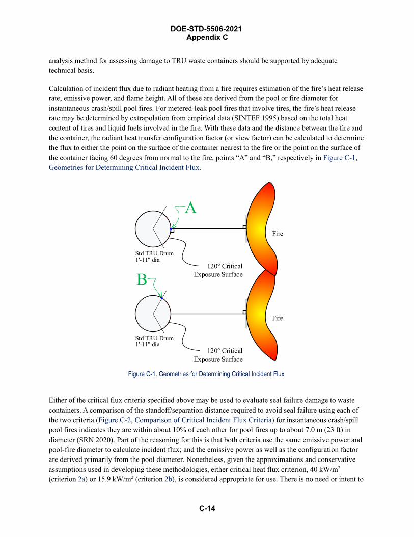
C-14
DOE-STD-5506-2021 Appendix C
analysis method for assessing damage to TRU waste containers should be supported by adequate technical basis.
Calculation of incident flux due to radiant heating from a fire requires estimation of the fire’s heat release rate, emissive power, and flame height. All of these are derived from the pool or fire diameter for instantaneous crash/spill pool fires. For metered-leak pool fires that involve tires, the fire’s heat release rate may be determined by extrapolation from empirical data (SINTEF 1995) based on the total heat content of tires and liquid fuels involved in the fire. With these data and the distance between the fire and the container, the radiant heat transfer configuration factor (or view factor) can be calculated to determine the flux to either the point on the surface of the container nearest to the fire or the point on the surface of the container facing 60 degrees from normal to the fire, points “A” and “B,” respectively in Figure C-1, Geometries for Determining Critical Incident Flux.
Fire
120° CriticalExposure Surface
B
Std TRU Drum 1'-11" dia
Fire
120° CriticalExposure Surface
A
Std TRU Drum 1'-11" dia
Figure C-1. Geometries for Determining Critical Incident Flux
Either of the critical flux criteria specified above may be used to evaluate seal failure damage to waste containers. A comparison of the standoff/separation distance required to avoid seal failure using each of the two criteria (Figure C-2, Comparison of Critical Incident Flux Criteria) for instantaneous crash/spill pool fires indicates they are within about 10% of each other for pool fires up to about 7.0 m (23 ft) in diameter (SRN 2020). Part of the reasoning for this is that both criteria use the same emissive power and pool-fire diameter to calculate incident flux; and the emissive power as well as the configuration factor are derived primarily from the pool diameter. Nonetheless, given the approximations and conservative assumptions used in developing these methodologies, either critical heat flux criterion, 40 kW/m2 (criterion 2a) or 15.9 kW/m2 (criterion 2b), is considered appropriate for use. There is no need or intent to
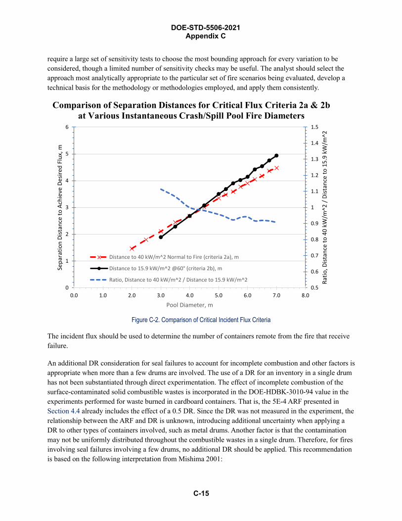
DOE-STD-5506-2021 Appendix C
C-15
require a large set of sensitivity tests to choose the most bounding approach for every variation to be considered, though a limited number of sensitivity checks may be useful. The analyst should select the approach most analytically appropriate to the particular set of fire scenarios being evaluated, develop a technical basis for the methodology or methodologies employed, and apply them consistently.
0.5
0.6
0.7
0.8
0.9
1
1.1
1.2
1.3
1.4
1.5
0
1
2
3
4
5
6
0.0 1.0 2.0 3.0 4.0 5.0 6.0 7.0 8.0
Ratio
, Dist
ance
to 4
0 kW
/m^2
/ Di
stan
ce to
15.
9 kW
/m^2
Sepa
ratio
n Di
stan
ce to
Ach
ieve
Des
ired
Flux
, m
Pool Diameter, m
Distance to 40 kW/m^2 Normal to Fire (criteria 2a), m
Distance to 15.9 kW/m^2 @60° (criteria 2b), m
Ratio, Distance to 40 kW/m^2 / Distance to 15.9 kW/m^2
Comparison of Separation Distances for Critical Flux Criteria 2a & 2bat Various Instantaneous Crash/Spill Pool Fire Diameters
Figure C-2. Comparison of Critical Incident Flux Criteria
The incident flux should be used to determine the number of containers remote from the fire that receive failure.
An additional DR consideration for seal failures to account for incomplete combustion and other factors is appropriate when more than a few drums are involved. The use of a DR for an inventory in a single drum has not been substantiated through direct experimentation. The effect of incomplete combustion of the surface-contaminated solid combustible wastes is incorporated in the DOE-HDBK-3010-94 value in the experiments performed for waste burned in cardboard containers. That is, the 5E-4 ARF presented in Section 4.4 already includes the effect of a 0.5 DR. Since the DR was not measured in the experiment, the relationship between the ARF and DR is unknown, introducing additional uncertainty when applying a DR to other types of containers involved, such as metal drums. Another factor is that the contamination may not be uniformly distributed throughout the combustible wastes in a single drum. Therefore, for fires involving seal failures involving a few drums, no additional DR should be applied. This recommendation is based on the following interpretation from Mishima 2001:
C-16
DOE-STD-5506-2021 Appendix C
If a DR is applied, the “bounding” ARF/RF values cited in DOE (1994) must be corrected for the incomplete combustion during the experiments and an assumption provided to ensure uniform concentration of the surface-contamination. Since the unburned fraction has not been quantified, any value has a considerable uncertainty associated with it. The unburned fraction during the experimental study used to establish the values cited in DOE-HDBK-3010-94 are estimated to be less than 50%. Use of a mass loss for DR must be coupled with some assurance of a relatively uniform distribution of the surface-contamination. Such an assumption can be valid for a number of drums with random surface-contamination distributions. With an adjustment in the “bounding” ARF/RF values for incomplete combustion during the experimental study, use of a fractional mass loss (DR) for an array of drums with a uniform distribution of surface-contamination on its contents is reasonable. Previously cited results of experimental studies of drums involved in fires indicate the DR (mass loss) values range from 10% during intense fire of short duration to 25% during cellulose fueled fire for a 2-hour duration.
But it is reasonable to assume that the release of the same combustibles as those in the cardboard container experiment, contained in a sealed metal drum, will be reduced by some factor due to the drum’s effect and vapor and particle transport. For example, a 0.06 DR was measured from the mass loss in the Hanford drum fire tests discussed earlier, and this DR is incorporated into the Fire Protection Guide methodology. Another perspective is provided by the U.S. General Service Administration recommended factors 42 for derating fire loads in an office occupancy, which is a conservative assumption for applying to TRU waste-drum storage areas. The derated fire load depends on the ratio of the weight of combustibles enclosed in metal desks or steel filing cabinets to the total weight of all combustibles, including the enclosed combustibles, free combustibles in the room, and 75% of combustibles in 5-sided open metal bookcases (which will be ignored for the examples cited next).
The largest derating factor is 0.1 for exceeding a ratio of 0.8— i.e., 80% of the combustibles in the room are completely enclosed. The least derating factor is 0.4 for a ratio under 0.5—i.e., half of the combustibles are completely enclosed. A derating of 0.2 is assigned for ratios between 0.5 to 0.8. This mid-range derating factor was selected at Rocky Flats as a sufficiently conservative estimate of a 0.2 DR for seal failures of TRU waste drums in designated storage areas (Kaiser-Hill 2000; Kaiser-Hill 2001, Kaiser-Hill 2004). Due to uncertainties in how much of the contents burn and extent of seal failure versus lid loss, for any event that involves 10 or more drums, an assumption of a uniform-like surface contamination is acceptable and a DR of 0.5 is considered conservative for the alternate methodology (Mishima 2001). This is based on a DR of 0.25 for the mass loss of the substrate by pyrolysis of the surface-contaminated combustibles divided by the DR of 0.5 already incorporated into the “bounding” ARF×RF value (Mishima 2001). The 0.25 mass-loss fraction is also supported by recent 7A drum fire
42 as reported in Chapter 6, “Confinement of Fire in Buildings,” in Section 6, Confining Fires,” of the NFPA Fire Protection Handbook (NFPA 1991)
C-17
DOE-STD-5506-2021 Appendix C
testing at SNL; see Section C.1.4. A DR of 1.0 is assumed for fewer than 10 drums due to this uncertainty over the amount burned and whether there is uniform contamination. The number of drums counted when applying the 0.5 DR should include all drums assessed to receive seal failure.
However, if room flashover is deemed plausible by the FHA or other fire modeling for the DSA unmitigated analysis, then all containers are subject to seal failures with a 1.0 DR.
A similar DR for seal failures of direct-loaded Standard Waste Boxes (SWBs) is established based on a physical consideration that four drums are approximately equivalent to one SWB. This results in a DR of 0.5 for more than two SWBs involved in a fire (i.e., 10 drums divided by 4 and rounded up). However, a DR of 1.0 is assumed for one or two SWBs involved in the fire.
As discussed in Section 4.4.2 on deflagration within a container, overpacking a metal drum of sound integrity within a larger metal drum, a SWB or a Ten Drum Overpack (TDOP), can be credited to prevent lid loss and ejection of contents and modeled as seal failures. In addition to preventing lid loss, overpacked containers provide an additional level of protection from fires that allows a lower DR than those for directed-loaded drums or SWBs. The dimensions of the SWB are nominally 5 ft long, 4 ft wide, and 3 ft tall, with rounded sides to fit within the TRUPACT-II container for shipments to Waste Isolation Pilot Plant (WIPP). The walls are typically 10- to 12-gauge (about 0.1 in.) sheet metal, and the container is sealed with a gasket and lid with 42 bolts.
The TDOP is constructed in a manner similar to a SWB and provides primary confinement to a large drum-like volume that can be loaded directly or as an overpack for 10 full 55-gallon drums, up to 6 full 85-gallon drums, or an SWB. Vents are required to be installed on both the outer container and innerdrums in an overpack assembly. For a radioactive material release to occur, the fire would need to heat upthe inside of the SWB/TDOP and also heat the inner contents of the 55-gallon drums, resulting inpyrolization of the drum contents and subsequent venting from both containers. The SWB/TDOPconfiguration presents a significant heat sink; pyrolization of drum contents would require a fire that isvery long-lasting or very large.
Another consideration is that the SWB/TDOP is large. As a result, it is not expected that all of the waste will be affected by a fire. Although the drum-in-drum overpack does not provide the same level of heat sink, the overpacked drum fire testing described in Section B.2.4, Volatile Organic Compounds, reported the results of the 1993 LLNL test of 3- and 4-drum configurations in a 6-foot pool fire. The LLNL test involved the drums inside the pool fire, which is the basis for the 0.2 DR that was estimated from the average 0.1 mass loss fir direct-loaded drums to the average 0.025 mass loss for the overpacked drums based on the data presented on Table B-12. Therefore, a DR of 0.2 is assumed for overpacked drums of sound integrity, whether the drums are overpacked in a larger drum, a SWB, or a TDOP. This assumption applies to a single overpacked container or to multiple overpacked containers exposed to the radiant heat flux that causes seal failures.
DOE-STD-5506-2021 Appendix C
C-18
Pipe Overpack Container, Type 7A Drum, and Criticality Control Overpack Fire Testing
The Pipe Overpack Container (POC) was designed and developed at the Rocky Flats Environmental Technology Site for interim storage of certain noncombustible TRU wastes. It was subsequently approved for shipping to WIPP. The container consists of a sealed pipe within a 55-gallon (0.21 m3) steel drum, with packing material between them. The packing material consists of a rigid drum liner (110-mil plastic adjacent to the steel drum) and fiberboard material (Celotex®) to separate the pipe from the liner. Layers of Celotex® also separate the pipe from the drum lid and from the bottom of the drum; the pipe component [PC] rests on a disk of plywood, which rests on the Celotex®. Two pipe diameters are used: 15.2 cm (6 inch), made of Schedule 40 steel pipe, and 30.5 cm (12 inch), made of Schedule 20 steel pipe. The nominal wall thickness of the 6-inch pipe is 0.71 cm (0.28 inch). The nominal wall thickness of the 12-inch pipe is 0.635 cm (0.25 inch). The inside length of the pipe is about 63.5 cm (25 inches) for eitherpipe diameter. The bottom of the pipe has either a formed (molded) end or a welded end, about 1.91 cm(0.75 inch) thick for either type of end. The top of the pipe has a welded flange, 2.54 cm (1 inch) thick,with a removable lid, 2.54 cm thick, fastened by bolts to the flange, sealed with an O-ring, and ventedwith a 2.54-cm (1-inch)-diameter sintered stainless-steel medium High-Efficiency Particulate Air (HEPA)filter in a stainless-steel housing. The filter efficiency for particulates in the size range of 0.3 to 0.5 µm israted at 99.97%. The pipe vent is to prevent pressure buildup within the pipe component, such as byhydrogen gas formed by the interaction of alpha radiation with plastic that may be in the waste orpackaging, or by gases formed during a fire.
POCs were initially used for stabilizing and repackaging residues from the Rocky Flats plutonium processing mission. They included dry ashes, salts, fines, and similar materials; most are granular (including powders) but some are chunky. At Rocky Flats, waste was not placed directly into the pipes. One configuration for the secondary containers called for the residue material to be placed into a small metal can with a slip lid, which is placed into one or possibly two plastic bag-out bags. This combination is then placed into a larger metal can with a screw-on lid, which is then placed in the Pipe Component. This combination is called “an interior package” below. The POC will hold from one to three interior packages. Other DOE sites have also used POCs for their TRU wastes that have higher alpha activity concentrations compared to the fissile concentration limit.
C.1.4.1 Initial Pipe Overpack Container Fire Testing The robustness of the POC was assessed by Rocky Flats (RMRS 2000), using data taken from reports of Type B protocol testing conducted at the Sandia National Laboratories (e.g., crush, 30-ft drop, and 30-minute fire tests), pressure tests, and finite-element computer modeling of crushing and puncturing.This section addresses only the DOT Type B fire tests, documented in Testing in Support of On-SiteStorage of Residues in the Pipe Overpack Container, SAND97-0368 (SNL 1997). See Section C.2.1.4,Pipe Overpack Container Testing for Accidents Other Than Fires, for further discussion of testing for non-fire stresses.
The SNL fire tests demonstrated that the POCs are designed in a manner that precludes their failure during expected storage area fires. Four POCs were subjected to Type B protocol thermal tests. The associated 150 MW fuel pool fire caused the one outer 55-gallon drum of a POC package with a metal
C-19
DOE-STD-5506-2021 Appendix C
filter to experience lid loss 43. The lid loss occurred within the first three minutes of the fire. Post-fire inspection showed the pipe component seal and filter gasket to be damaged. Associated leak rate testing of this POC showed a total leak rate of 24 cm3/s at a differential pressure of 87 kPa. This leak rate was later associated with an ARF of 6E-6 for the bounding material type in POCs (i.e., powder) in the Rocky Flats analysis in Section 3.2, “Fires” of RMRS 2000. That analysis evaluated leak paths through various hole sizes in the O-ring and gasket of the pipe component, and concluded that the velocity would be very low, such that any release from the pipe component due to thermal stress to the powder in a metal convenience can would be very low. A bounding 6E-6 ARF from DOE-HDBK-3010-94 Table 4-10, “Airborne Release from Nonreactive Powder During Heating in Flowing Air” was selected based on heating oxide for one hour with a 0.1 m/s air flow. The analysis did not credit a 0.01 RF which could have been applied based on the DOE-HDBK-3010-94 discussion, nor did it credit any leakpath factor from the convenience can or the pipe component. It should be noted that inspection of the POC packages remaining intact revealed that the POCs did not experience temperatures above 200° F and remained leak-tight. It was concluded from this original fire test that for POCs with noncombustible wastes need not be modeled in the DSA accident analysis due to the very low release potential.
C.1.4.2 Additional Pipe Overpack Container, Type 7A Drum, and Criticality Control Overpack Fire Testing
After the accident at WIPP on February 14, 2014, several reviews of information contained in this Standard were conducted. It was discovered that multiple sites were utilizing the POC for processing of reactive salts and combustible waste, interim storage, and potential subsequent shipment to WIPP. The use of the POCs for combustibles was not considered an appropriate extension of the 1996 SNL tests, and the ARFs could be significantly different for this application. The generating facilities, as well as WIPP, would like to be able to claim that some level of protection is provided by the POC for thermal assaults that could occur within DOE storage facilities. So a storage drum test program headed by the DOE Office of Environmental Management (EM) and the National Nuclear Security Agency (NNSA) was established for the POCs with combustible contents. In 2015, SNL started conducting fire tests with POCs in support of the EM/NNSA test program.
Fire tests were conducted in 2015 through 2019. The tests were documented in three reports:
• Pipe Overpack Container Fire Testing: Phase I and II, SAND2017-5684 (SNL 2017)
• Pipe Overpack Container Fire Testing: Phase IIA, SAND2018-6590 (SNL 2018)
• Pipe Overpack Container Fire Testing: Phase IIB, SAND2019-9923 (SNL 2019)
Two initial phases of tests began in 2015 and 2016. These fire tests were designated separately as Phase I and Phase II. Initially, their primary goal was to examine performance of POCs with inert materials inside the PCs; their secondary goal was to examine the behavior of 7A drums with combustibles inside. Initial pool fire tests were conducted for a duration of 1 hour. During that hour, extensive thermal data was collected with the intent of establishing benchmark data for use in subsequent computational modeling.
43 The other POC packages had plastic filter seals, which melted during the fire.

C-20
DOE-STD-5506-2021 Appendix C
For the POCs, results included temperature measurements of the exterior and interior of POC components and leak-test rates through the PC filter gaskets and PC O-rings, as well as qualitative data that showed the state of the POC components after the fire. For the 7As, results included temperature measurements of the exterior of these drums and qualitative data that showed how the drum filter and drum seal performed outside of the fire and the state of the combustible materials inside the drums after the test.
Review of the 1996 SNL tests led to an expectation that POC lid ejection would be expected during a pool fire. So the initial test was conducted without the POC drum lid or upper Celotex® in place. The intent was to gather as much explicit temperature data as possible and remains valid as a standard temperature profile for future analysis.
Two subsequent tests were then run with POCs with installed filtered drum lids. Temperature data was again gathered, but lid ejection was not experienced for either of these tests. Reevaluation of test parameters for these tests resulted in realization that manufacturers’ recommended torque for drum lid closure was not recognized or accomplished. As a result, follow-on tests, Phase II, were conducted with POCs with filtered drum lids torqued to manufacturer’s specifications.
Multiple subsequent tests with POCs inside the fire with appropriately torqued lids resulted in the lids and some of the components sitting on top of the PC to get ejected approximately 3 minutes into the fire. In these tests, the fuel consumption rate was 0.3 kg/s; therefore, in 3 minutes the fire would have burned approximately 54 kg (17 gal) of fuel. Slow burning of the Celotex® results in gradual exposure of the PC to the fire and smoldering of the Celotex® after the fire leads to higher thermal insult to the PC than would be the case if the smoldering Celotex® were extinguished at the end of the fire environment.
In all, temperature data collected for this scenario show temperatures inside the PC that can melt or decompose typical materials (i.e., high-density polyethylene and cellulosic material) within it. Therefore, for POCs inside the pool fire the DR would be considered 1.0. Moreover, post-test examination of PC components and leak testing conducted on the exposed PCs suggest an ARF greater than zero.
At this point, a pause in the test series was established to attempt to determine a path forward in determining appropriate ARF and RF values.
Outside the fire, the POC drum lids remained in place; the Celotex® insulation underwent some decomposition but not enough to cause a significant rise in the temperature of the PC and subsequent melting and/or decomposition of typical materials inside the POC. Accordingly, outside the fire the DR and ARF values should be zero for POCs at a distance experiencing a heat flux of 45 kW/m2 or lower under the fire conditions described in the report (SNL 2017).
The goal of the next test series, Phase IIA, was to examine the response of the POCs equipped with a UT9424S drum lid filter while exposed to a 30-minute pool file as an alternative to conducting further tests to establish appropriate ARF/RF values of release. Potential use of a filter with a polyethylene bushing was hypothesized as a solution to establish the stability of the POC in retrospect to results that were obtained in the original 1996 SNL tests. As shown in the initial Phase I tests, if the outer drum lid was maintained on the POC, internal temperatures remained relatively low. Prior to initiating the Phase
C-21
DOE-STD-5506-2021 Appendix C
IIA test series, the UT9424S filter was tested after installation on a Type A drum to verify that the filter would allow the Type A drum to maintain its certification.
Four tests were performed during Phase IIA. The first three tests tested a POC engulfed in a pool fire. The fourth tested 7A drums filled with combustibles in and near a pool fire.
For the POC tests, results included measurements of:
• Peak temperature measurements inside the PC
• Temperature measurements around the exterior of the POC
• Pressure measurements inside the POC drum
• Pressure measurements inside the PC
• Total POC mass loss measurements.
The results also included qualitative data that showed the state of the POC components after the fire.
For the 7A drums, results included total mass loss measurements as well as qualitative data that showed the state of the 7A components after the fire.
Based on the data collected, for a POC equipped with a UT9424S lid filter and exposed to the hottest region of a 30-minute pool fire, the lid filter ejects with 2 minutes of ignition. The filter ejection allows sufficient pressure relief from the POC drum to prevent lid ejection. During the fire, the POCs lost approximately 14% of their mass on average, mainly in the form of pyrolyzed polyethylene and Celotex® surrounding the PC.
Test #4 revealed that a 7A drum filled with approximately 50% plastic and 50% cellulose (by volume) also maintained its lid as the filter ejected under the same fire configuration as the POC tests. Furthermore, Test #4 revealed that a 7A drum placed at a distance corresponding to 35 kW/m2 of heat also ejects the UT9424S filter on the drum lid and allows enough pressure relief to prevent lid ejection.
However, some burning and charring was observed in the contents of the 7A tests. The most conservative case, where the 7A drum of interest was stacked on top of an empty drum in the middle of a pool fire, resulted in 27% mass loss. The 7A drum placed at 35 kW/m2 experienced negligible mass loss.
While this test series showed that ejection of the alternate metal-polyethylene filter (UT9424S) proved to relieve enough pressure to prevent lid ejection of the POCs when exposed to a 30-minute pool fire, the setup used in this test series isolated a POC drum at the hottest region in a fire with a vented, empty drum beneath it. During the fire, the tests showed that pyrolyzed gases exiting the filter orifice on the POC drum lid resulted in a flame jet. This flame jet created uncertainty on the outcome of POCs exposed to a fire in a real storage-site setup, where PCs are stacked one on top of another. As a result, the outcomes of Phase IIA would suggest that testing stacked POC drums that represented actual storage-site configurations was prudent. These tests were subsequently conducted during Phase IIB.

DOE-STD-5506-2021 Appendix C
C-22
Four tests were performed in Phase IIB:
• Tests #1 and #2 engulfed two-tier stacks of POCs in a 30-minute pool fire, where the POCs werestacked with typical pallet sections in between. Test #1 had the bottom drum oriented so that thelid filter was free from pallet interference, while Test #2 oriented the bottom POC so that the lidfilter was directly under a pallet stringer from the pallet above.
• Test #3 likewise was a two-tier stack of POCs. But instead of using a pallet between drums, thistest used two slip sheets, as is commonly used at WIPP. Since a fire longer than 5 minutes isnever expected to occur at WIPP due to the operational restrictions maintained at the site, the poolfire was limited to 5 minutes.
• Test #4 exposed a three-tier stack of POCs to a 30-minute pool fire with pallet sections placedbetween drums, and the filters were oriented to test the worst-case scenario by positioning thedrums in orientations where the filters resulted directly under a pallet stringer.
Based on the data collected, for stacked POCs equipped with a UT-9424S lid filter and exposed to a pool fire, the lid filter ejects within 2 minutes of ignition. The filter ejection allows sufficient pressure relief from the POC drums to prevent lid ejection. During the fire, the POCs lost approximately 13% of their original mass on average, mainly in the form of pyrolyzed polyethylene and Celotex® surrounding the PC. None of the PCs experienced any mass loss from the combustibles placed inside.
The results of this test series showed that, in the worst-case scenario for POCs stacked up to three tiers high where a pallet stringer lies directly over a POC lid filter, even though the ejection of the filter is affected, ejection is not prevented: all lid filters ejected within 2 minutes of the pool fire ignition. The result is that all POCs with a UT-1924S lid filter successfully retained their lid in a typical stack configuration during a 30-minute fully engulfing fire.
C.1.4.3 Criticality Control Overpack Testing A single Criticality Control Overpack (CCO) test was conducted in April of 2016 as part of the DOE EM storage drum test program (SNL 2019a). Specifically, the goal of this fire test series was to examine performance of CCO with combustible packaging material and aerosol surrogate materials inside the Criticality Control Container (CCC). The drum lids were torqued to standard specification (55 ft-lb).
Test data shows that during this test, the CCO drum was exposed to average flame temperatures in excess of 1000 °C and peak temperatures of about 1200 °C. Peak temperatures were much higher than those typically observed in this outdoor fire test because a fence surrounded the pool; insulation had been placed around the fence; and this insulation limited the amount of heat exchanged between the fire and the environment. The top of the CCC inside the CCO saw peak temperatures of about 1200 °C, which is also higher than expected. These unexpectedly high peaks occurred because early in the test, the drum lid and upper plywood dunnage ejected, exposing the top of the CCC to direct flames. The bottom of the CCC saw temperatures above 800 °C.
The high temperatures experienced by the CCO resulted in a peak pressure of about 18 psig inside the CCC before the CCO lid was ejected over 90 ft into the air within 2 minutes of the test start. As a result of
C-23
DOE-STD-5506-2021 Appendix C
this high pressure, the carbon media in the filter attached to the CCC lid failed approximately 1 minute after fully engulfing conditions were reached. Subsequently, the pressure was reduced to nearly ambient pressure. Later, a subsequent spike in pressure of 2 psig was observed at about the temperature at which plastic inside the secondary canisters of the CCC experience melting.
After the test, the remains of the drum were examined. The CCC was found leaning against the inner wall of the drum. Unexpectedly, a small amount of unburned plywood was found at the bottom of the CCC. The CCC was later pulled out of the drum and its lid opened. Remains of the degraded gasket were found on the top of the CCC vessel flange. Inside the CCC, both secondary canisters appear to be as assembled. When these canisters were opened, only the primary canisters were found inside. As expected, the plastic bag-out-bag that enclosed the primary canisters melted during the test. Some char remains from the plastic were observed on the inner walls and the bottom of the secondary canisters. Except for the fact that the filters in the primary canister lids were found loose with the filter carbon media still in its normal location inside the filter housing, the rest of the surfaces of the primary canister external walls were found in good condition.
Both primary canisters were weighed with the surrogate powder inside. To the level of uncertainty of the mass balanced used during pre and post-test measurements, no discernable differences were detected between the average mass of the primary canisters before and after the test. Note, however, that when uncertainties in mass balances used are considered, the results suggest that some aerosol material may have been lost from the primary canisters. However, the post-test conditions of the secondary canister suggest that the likelihood that this aerosol material escaped to the interior of the CCC, and subsequently to the exterior of the CCC, is very small.
The above results suggest that the ARF for the CCO fully engulfed in a thirty-minute fire is zero. This conclusion, however, is accurate only to the level of uncertainty of the mass balance used to measure the average mass of the powder before and after the test. Certainly, it can be argued that some material was released from the primary canisters into the secondary canisters, and subsequently into the CCC. It is important to note that the plastic enclosing the primary canister melted much later, at a time well after the peak pressure of 18 psig had been reached inside the CCC. Thus, it can be concluded with certainty that no aerosol release occurred before the melting temperature of the plastic was reached. When the plastic melted, the CCC reached a momentary internal pressure of about 2 psig, followed by a slow decay in pressure. It is not known whether these lower pressures are sufficient to cause release of aerosol first from inside the primary canister, then from the secondary canister, and finally from the CCC through the damaged filter. Post-test examination of the secondary canisters suggests their lids appear to remain in place throughout the test. This observation implies that the foregoing sequence of events leading to release of aerosol from secondary canisters is highly unlikely.
The tortuous path—from the primary container through the secondary container and then out of the CCC—supports the conclusion that for the down-blend powder, the main currently planned use of the CCO, a DR of zero is appropriate. This conclusion is further supported by the fact that no powder was observed anywhere outside the primary container.
DOE-STD-5506-2021 Appendix C
C-24
Mechanical Insults (Low- and High-Energy) This section of the appendix addresses DRs for the 55-gallon steel drum, SWBs, POCs, and overpacked containers (e.g., a 55-gallon drum nested within an 85-gallon drum, or an SWB, or the TDOP). This appendix provides the technical justifications for the DRs presented in Section 4.3.4, Damage Ratios for Mechanical Insults.
DOT Type A packaging (DOT 1997) is required to pass tests as described in Section 4.3.1, Container Integrity. Drops and impact stresses on TRU waste containers will result in a wide range of damage; the damage will depend on the magnitude of these forces, type of containers, and condition of containers. The estimates of the DR for contact-handled (CH) TRU waste containers are based primarily on interpretations of tests that have been performed for waste containers of the types to be shipped to the WIPP.
Axial crush and impact tests were performed for DOT 7A drums of the types that will be shipped to WIPP for emplacement, and for a metal box, but not for the SWB. In general, the available test data represent waste-container configurations during storage and handling that are unique to specific generators—for example, single drums and multiple drums in a stack configuration. Unfortunately, none of the reported tests were performed for waste drums or SWB configurations specific to loading and unloading the TRUPACT-II container for shipping to WIPP—for example, a plastic-wrapped stack of two seven-pack drum configurations. Therefore, the reported tests are considered to be indirect evidence, and the tests are evaluated using engineering judgment so they can be introduced in the application of existing test data for these other container configurations.
Most of the reported drum tests were performed with DOT Type 17C drums, each with a rigid polyethylene liner, containing bagged waste of various forms. Waste creators, however, will also ship drums that are currently designated Type 17H (thinner-wall); and drums of both types will be shipped both with and without liners. Once the drum is packaged, neither the type of drum nor the presence of a liner within it can be readily distinguished. Type 17C drums are made from 16-gauge material, which has a nominal wall thickness of 0.059 inch. The Type 17H drums are made from 18-gauge material, which has a typical wall thickness of 0.039 inch.
The SWBs are made from thicker, 10-gauge material (minimum thickness of approximately 0.128 inch). Moreover, each SWB has a bolted lid, so the lid is less likely to separate from the container upon impact.
Based on simple calculations of compression stress in the wall and axial buckling, Type 17C drums appear to be stronger than the SWBs, which in turn are stronger than the Type 17H drums (WIPP, 2000). However, the lids for the SWBs are bolted to the body of the container, implying that lid separation is much less likely for the SWBs than for the drums. Because both types of drums are to be handled and stored, the characterization of drum failure should be based on the more limiting case of Type 17H drums.
DOE-STD-5506-2021 Appendix C
C-25
Container Test Results The WIPP site performed an evaluation of the container drop and impact test data to establish DR estimates. The results are reported in PLG-1121, Damage Assessment of Waste Containers Involved in Accidents at the Waste Isolation Pilot Plant (WIPP, 2000). These results are based on three tests:
• Sandia test, as documented in SAND80-2517, Analysis, Scale Modeling, and Full-Scale Tests ofLow Level Nuclear Waste Drum Response to Accident Environments, (SNL 1983)
• Hanford test, as documented in WHC-SD-WM-TRP-231, Drum Drop Test Report,(Westinghouse Hanford 1995a)
• Rocky Flats test, as documented in WPS 88-001, Full-Scale Drop-Impact Tests with DOTSpecification 7A Waste Containers, (Rockwell 1988).
The discussions that follow are primarily focused on drop-test results rather than the axial loading tests. It is based on selected extracts 44 from the WIPP report PLG-1121 that summarized the experiments and test conclusions. Test information is also presented on POC.
C.2.1.1 Drum Drop Tests
Sandia Drum Drop Tests Sandia subjected DOT Type 17C drums (SNL 1983) to 29 tests:
• 12 static crush tests—8 with drums in the lateral configuration (sideways) and 4 with drums in thelongitudinal direction (axial or upright)
• 17 full-scale drop tests—all involving lateral impact. The drop tests were conducted with singledrums in a lateral configuration. No tests were conducted in the axial configuration.
The response of the containers was reported in terms of drum deformation and lid behavior. The DOT-17C drums were obtained from the Rocky Flats facility. They contained a rigid polyethylene liner and lid, providing two layers of confinement. In addition, the “payload” was placed in a light polyethylene plastic inner bag, providing a third layer of confinement. The metal drum lid was held in place with a clamping ring secured with a nut and bolt.
For most tests, the drums contained various forms of waste (combination waste and simulated sludge). But for four of the crush tests and six of the drop tests, the drums were empty.
The Rocky Flats procedure for packaging TRU waste at the time was as follows:
Waste material is loaded into the polyethylene bag and placed inside the liner.
The top of the bag is gathered, then taped shut.
44 Minor editing of the extracted information was performed for presentation in this document. The PLG-1121 report should be consulted for the entire discussion and interpretation of the test data.
C-26
DOE-STD-5506-2021 Appendix C
The bag is checked for contamination.
The liner lid is installed. The liner lid snaps into place after an adhesive has been applied.
The lid is banded with a circumferential stainless-steel strap.
The metal drum head is installed, using a gasket and adhesive.
The clamping ring is positioned, then secured with a nut and bolt.
The Sandia single-drum drop tests for DOT-17C drums produced the following results:
• The worst damage occurred with the heaviest drum (748 lb) and the highest impact velocity. Thattest marked the only time the inner plastic bag was broken. It also was the only test in whichcontents were lost.
• No lid failures (and thus, no material releases) occurred for drop heights less than 44 ft (13 m) orimpact velocities less than ~35 mph. No lid failures occurred for kinetic energies less than 29,413ft lb. Empty drums exhibited less deformation for the same impact velocity.
• Four lid failures occurred in the 17 drop tests. But only one drop test—the test involving the drumthat weighed the most (748 lb)—resulted in a “slight loss of contents.” Only a qualitativedescription of this loss was provided, but PLG-1121 assumed that less than 5% of the contentswas lost.
• Sandia concluded that drum deformation cannot be predicted by considering only the system’skinetic energy. Drum contents, too, are important because different materials absorb differentamounts of energy.
Hanford Drum Drop Tests Westinghouse Hanford Corporation (WHC) performed single-drum drop tests with six drums (Westinghouse Hanford 1995a): three Type 17C and three Type 17H. All six drums were received new and undamaged; no corrosion or other visible deterioration was observed prior to the tests.
All six drop tests were conducted on drums whose gross weight was 1,000 lb—the maximum drum weight allowed by the WIPP Waste Acceptance Criteria [WAC]). The locking ring bolts were torqued to 40 ft-lb. Each test drum was tilted 45 degrees to horizontal, landing in such a way that its lid locking-ring bolt struck the test surface.
To simulate waste, the experimenters placed sand and lead bricks directly in the drum. No liner or bags were used; the sealed drum liner and polyethylene bag would hold down the extent of spills.
The Hanford single-drum drop tests for DOT-17C and DOT-17H drums produced the following results:
• WHC concluded that single 1,000-lb drums dropped from 11 feet and impacting the locking ringat 45 degrees to horizontal are likely to spill some of their contents.

DOE-STD-5506-2021 Appendix C
C-27
o For Type 17C drums, the maximum spill was 250 lb (27% of the drum contents) and theaverage spill was 103 lb (11% of the drum contents). The Type 17C test with the smallestvoid volume produced the greatest spill.
o For Type 17H drums, the maximum spill was 500 lb (53% of the drum contents) and theaverage spill was 170 lb (18% of the drum contents).
All Type 17H tests and the remainder of the Type 17C tests had initial void volumes of 10%. The lid stayed attached to the drum in each of the six single-drum tests.
• In all tests, container breach occurred at the drum/lid-sealing surface.
• Obvious (highly visible) damage to a drum is not necessarily an indicator of drum integrity.Extensive damage to the drum walls may not be indicative of container breach. By contrast, asmall amount of damage to the lid and upper sealing surface may cause lid separation and loss ofcontainer integrity.
• Material larger than the simulated waste would not have been ejected. The simulated waste wasselected because of its density and ease of handling, not because it was representative of actualsolid waste materials.
C.2.1.2 Pallet Tests
Sandia Pallet Tests In addition to conducting the single-drum tests described earlier, Sandia conducted two drop tests with stacks of eight drums arranged laterally (SNL 1983). Each drum contained roughly 700 lb of simulated waste. The bottom of the stack was 30 feet from the target surface when dropped. One test was performed with a foam block at the bottom of the stack for energy absorption. In both tests, the impact velocity was approximately 30 mph. Like the 29 drums used for the single-drum tests, these 8 drums were obtained from the Rocky Flats facility, were of Type 17C, contained a rigid polyethylene liner, and held their “payload” in a light polyethylene bag.
Most of the drums, including the one with the foam block, underwent rather severe deformation. After testing, the compressed stack height was approximately 70% of its undeformed height. The lower six drums sustained approximately the same deformation—that is, approximately 60% of their original height. The top drum experienced deformation so minor, it was almost undetectable. Lid separation or content loss was not reported for these tests.
Rocky Flats Pallet Tests A full-scale drop test of a 12-drum array (4 high × 3 across) of DOT Type 17C 55-gallon drums used at Rocky Flats was performed by Rockwell International (Rockwell 1988). Each drum contained a rigid 90-mil polyethylene liner, and each drum’s lid was held in place with the closure ring. Inside the rigidliner was a 10-mil polyvinyl chloride (PVC) liner that was sealed with tape. Aligned laterally, the drumswere dropped 15 ft.
DOE-STD-5506-2021 Appendix C
C-28
The test configuration was designed to maximize the lateral crushing force borne by the lightest drums with the largest free volume. The drums weighed as follows:
• Row 1 (bottom): 116–135 lb
• Row 2 (lower middle): 321–586 lb
• Row 3 (upper middle): 643–666 lb
• Row 4 (top): 643–666 lb
The Rocky Flats pallet drop tests with DOT-17C drums arranged in a stacked array produced the following results:
• As expected, the lightest drums—the drums in the bottom row—showed the most significantdamage. Both the drum lids and the liner lids remain attached, but the lids creased, creating alarge lid-to-drum gap. The 10-mil bag was not breached.
• The failure mode was the loss of the seal between the drum lid and the body, primarily causedwhen the drum was crushed by adjacent drums.
• Four of the 12 drum lids, all from the bottom two rows, opened at impact. One, a drum containingsharp pieces of scrap metal, showed some evidence of chalk dust outside the bag. Trace amountsof chalk dust were found on the lid of its 90-mil rigid liner, but no chalk was found outside thedrum. Close examination of the bag revealed two small puncture holes, apparently caused by thesharp pieces of metallic scrap placed in the drum.
• None of the 12 drums lost any of their contents.
• Six drums contained a red chalk dust inside their 10-mil polyethylene bags. All six came from thebottom two rows—the rows where the severest damage had been expected.
PLG-1121 noted that it is apparent that a fraction of the contents in those drums whose lids opened on impact would have lost some of their contents had they not had a rigid liner and inner bag.
Hanford Pallet Tests In the Hanford pallet tests (Westinghouse Hanford 1995a), the pallet load consisted of four drums initially aligned in the vertical direction. Two of the drums weighed 500 lb each; the other two weighed 175 lb each. Metal banding was used to secure the drums to the pallet. The simulated waste was placed directly in the drum; that is, the drum did not contain a polyethylene liner and the experimenters did not use a polyethylene bag. The payload consisted of sand and lead bricks.
The tests were intended to allow the dropping of one edge of the pallet to simulate a situation where the pallet was either pushed off the top of a stack or the edge was tilted, causing motion. The drums were aligned so the heavier drums would fall onto the lighter ones. The lighter drums were aligned on the pallet so their lids’ locking-ring bolts would strike the test surface first.
C-29
DOE-STD-5506-2021 Appendix C
Preliminary tests indicated that the pallet rotated 90 degrees and landed on its side; that is, the drums impacted in the lateral orientation. But this was not the case for every test: some drum pallets rotated 180 degrees, making the drums land on their lids. Other pallets rotated 135 degrees, making their drums land on their edges. On one pallet, the banding slipped, scattering the drums at impact.
Six pallet tests were performed: three with Type 17C drums, three with Type 17H drums. All tests were performed with the bottom of the drums initially resting 11 ft from the test surface.
The Hanford pallet drop tests with DOT-17C and DOT-17H drums produced the following results:
• For the four drums banded to a pallet that dropped 11 ft, spilled material occurred in only one ofsix drop tests (of 24 drums). Only one of the 175-lb drums spilled part of its contents (< 5 lb or< 4.3%). In this test, the 175-lb drum landed on its edge. The average spill for 175-lb drums was< 0.42 lb (or < 0.24%). The average spill for 500-lb drums was 0.0 lb (mostly cushioned by thelower drums).
• Welded-container breach occurred at the drum/lid-sealing surface in all tests.
From these results, Hanford drew three conclusions:
• Obvious (highly visible) damage to a drum is not necessarily an indicator of drum integrity.Extensive damage to the drum walls may not be indicative of container breach. By contrast, asmall amount of damage to the lid and upper sealing surface may cause lid separation and loss ofcontainer integrity.
• The bottom drums in a multiple (pallet) drum drop cushion the upper drums.
• The landing configuration of palletized drums is unpredictable.
C.2.1.3 Welded-Metal Waste Box Tests Standard waste boxes are DOT Type A containers used in TRUPACT II shipments. The only test data available for waste boxes are the full-scale drop tests performed by Rockwell International (Rockwell 1988) for DOT 7A steel boxes used at Rocky Flats. Those tests involved two steel waste boxes stacked end-on-end. All seams, including the closure on both boxes, were welded rather than closed by the SWB bolted-lid configuration.
One of the steel boxes—Test Container A—was lined with a fiberboard liner and a 10-mil PVC liner and filled with coarse sand to a gross weight of 5,980 lb. Five empty 55-gallon steel drums were placed in the waste box to permit filling the entire box with sand without exceeding the 6,000-lb gross weight limit imposed by Rocky Flats for DOT 7A steel waste boxes.
The second box—Test Container B—was lined on all interior surfaces with three liners: fiberboard, 10-mil PVC, and 0.75-inch plywood. Pieces of stainless steel and mild steel, along with other metalfixtures, were loaded into the lined waste box. No effort was made to “pad” the jagged edges of this metalscrap. The gross weight of this container was 3,480 lb.
DOE-STD-5506-2021 Appendix C
C-30
Two drop tests were performed. In the first test, the two steel boxes were stacked side-on-side with Test Container A (the heavier container) on top of Test Container B. This configuration maximizes the crushing force borne by the lower package. The distance from the bottom of Test Container B to the test surface was 15 feet.
The steel boxes used in the 15-ft test were also used for the second test. The two boxes were again stacked side-by-side. But this time, Test Container B (the lighter box) was placed on top of Test Container A. The distance from the bottom of Test Container A to the test surface was 25 feet.
The Rocky Flats DOT 7A welded-metal-box drop tests produced the following results:
• For the 15-ft drop test, both boxes deformed as a result of the impact. However, there was noapparent failure of seams or closure welds, and no contents were lost from either waste box.
• For the 25-ft drop test, the lower package (Test Container A) was substantially deformed, and apinhole leak was detected in Test Container B. The leak was located at a corner of the waste box,adjacent to a lifting loop. No loss of contents was apparent.
C.2.1.4 Pipe Overpack Container Testing for Accidents Other Than Fires This section provides a summary of the Rocky Flats original design and SNL fire testing of the POC for interim storage of certain noncombustible TRU wastes and shipping to WIPP.
The robustness of the POC was assessed by Rocky Flats (RMRS 2000), using data taken from reports of Type B protocol testing conducted at the Sandia National Laboratories (e.g., crush, 30-ft drop, and 30-minute fire tests), pressure tests, and finite-element computer modeling of crushing and puncturing. While Rocky Flats concluded that the POC does not qualify as a DOT Type B container (because it was not subjected to the complete Type B protocol testing program and because the pipe component is vented); the tests that were performed were passed, and it is expected that the puncture test would also have been passed, based on computer modeling and comparison with similar containers that are certified as Type B. The POC far surpassed the DOT Type A test requirements.
Sandia performed DOT Type B protocol testing on POCs. The results were documented in two reports:
• Testing in Support of On-Site Storage of Residues in the Pipe Overpack Container,SAND97-0368 (SNL 1997)
• Analysis in Support of Storage of Residues in the Pipe Overpack Container, SAND98-1003 (SNL1998)
The first set of Type B protocol tests was summarized in the Certificate of Compliance for the TRUPACT-II container (NRC 1997); these tests included assorted drop tests and one side-impact test.
No Type B protocol puncture testing was conducted on the POCs. For the side-impact tests, finite-element modeling was performed to simulate an accident involving the collision of a forklift tine with the POC. Modeling was also performed to simulate the falling of heavy objects (such as roof members) onto the
C-31
DOE-STD-5506-2021 Appendix C
POC, progressively increasing the energy of the impact until failure occurred. Impacts were modeled with POCs having both the 6-inch and 12-inch pipe components.
The second set of Type B protocol tests was summarized in the Sandia (SNL 1997) report; these tests included crush, drop, and thermal tests.
These two sets of tests were conducted solely to qualify the POC for interim storage, not to certify that it qualified as a Type B package.
No immersion tests were conducted: they were precluded by the vents in the 55-gallon drums and the pipes. No spray, stacking, or penetration tests were conducted on the drum overpack: the POC already qualified as a Type A package. None of the secondary (inner) containers were included in the SNL tests: they were not needed for the testing.
The tests were conducted as follows:
• Drop tests. Two sets of drop tests were performed. In the first set (NRC 1997), threeconfigurations of POCs were dropped from 9 m. (For each test, two POCs were strapped togetherend-to-end to simulate the configuration in the TRUPACT-II container. In one test, the two POCscontained 6-inch pipes; in the second, 12-inch pipes; and in the third, one 6-inch and one 12-inchpipe.) For the second set of drop tests (SNL 1997), two bare pipes, one 6-inch and the other12-inch, both with welded bottoms, were dropped from a height of 10 ft (3.05 m) onto a flat,horizontal, essentially unyielding surface.
To achieve maximum damage, the pipes were dropped with their bolted ends down. Although some of the lid bolts loosened during both sets of tests (even when the pipes were within the 55-gallon drums), the pipe lids still remained fastened tightly enough that they continued to beleak-tight after the drop test.
In the first set of drop tests, a side-impact test was also performed on a TRUPACT-II container filled with 14 POCs. The TRUPACT-II container normally has both inner and outer containment vessels separated by crushable foam. But for this test, only the inner containment vessel was used; that is, the container was used without the foam or outer containment vessel.
• Crush tests. A POC was placed on an essentially unyielding flat, horizontal surface in an uprightposition. A flat steel plate, having an area of 1 m2 (10.8 ft2) and a mass of 500 kg (1,100 lbm), wasdropped along a guide wire onto the POC. When the plate neared the POC, it was released tofree-fall the remaining distance; the height of the drop was greater than the 9 m (30 ft) requiredby Type B testing to allow for the friction along the guide wires. The velocity upon impact wasthe required 13.3 m/s (30 mph). 45
Four crush tests were performed: two with the 6-inch pipes and two with the 12-inch pipes. Boththe formed ends and the welded bottom ends were tested.
45 For a free-fall, the velocity after a drop of nine meters is (2 gh)½ = (2 × 9.8 m/s2 × 9 m)½ = 13.3 m/s.
DOE-STD-5506-2021 Appendix C
C-32
• Simulated side-impact tests. The forklift-tine impact was modeled with a forklift traveling at4.5 m/s (10 mph); the forklift weighed 12,250 lb (5,670 kg mass). The drum was assumed to bestanding against a rigid wall. The tine was modeled very conservatively: to simulate themomentum of the forklift, the tine was given a squared-off end with sharp corners and was madeof an extremely dense material. (Real tines have blunt ends without sharp corners and are made ofsteel with density about the same as that of the drum material.) This scenario represents a moresevere accident than does the Type B protocol puncture testing, which uses a cylindrical rod 15cm (6 in.) in diameter with beveled edges and a momentum corresponding only to that of thecontainer, not to that of the forklift. However, the impact velocity modeled is the same as for theType B test: 4.5 m/s (10 mph).
The drum elements were defined to fail (tear) in this model when the equivalent plastic strain(fractional deformation) reached 20%; the wall of the pipe component was defined to fail whenthe equivalent plastic strain reached 80%. These strain limits were considered by the modelers tobe representative of the materials used.
The tests produced the following results:
• Drop-test results. The pipe components were undamaged. All the pipes were shown to be leak-tight following the side-impact test.
• Physical crush-test results. The 55-gallon drums suffered damage, shortening by about 13 cm(5 inches). But no pipe component was damaged. All of the pipes were tested to be leak-tight,both before and after the crush tests.
• Simulated-crush-test results. POCs are vulnerable to being crushed by a collapsing concretebuilding, but not by prefabricated metal buildings. The Rocky Flats report (RMRS 2000) notedthat finite-element modeling of the impact of falling heavy objects was done only for the barepipe components, not the complete POCs; therefore, the results of these simulations can be usedin either of two ways:
o The modeling results can be considered conservative because the drum and its packingmaterial absorb some of the impact, as was demonstrated by the Type B crush tests. Forexample, in the top-impact crush tests, 500-kg (1,100-lbm) steel plates were dropped on thePOCs; the drums were shortened by about 13 cm (5 in.), but the pipe components wereundamaged. The side-impact test also showed that the drum and its packing material absorbssome of the impact energy.
o Alternatively, the kinetic energy of the falling steel plate (½ mv2 = 0.5 × 500 kg × (13.3 m/s)2
= 4.4 × 10⁴ J = 4 × 105 in.-lb), which was absorbed by the drum and its packing material, canbe added to the kinetic energy assumed in the modeling to arrive at an estimate of the totalkinetic energy involved in the simulation.
• Simulated side-impact test results. The side-impacted simulations yielded the following results:
o The steel of the 55-gallon (0.21-m3) drum offered little resistance to the tine impact; thepacking material (the Celotex®) offered essentially no resistance, although its presence added
DOE-STD-5506-2021 Appendix C
C-33
enough stiffness behind the steel of the drum to allow the tine to penetrate the steel quickly rather than bend it significantly. The resistance offered by the drum slowed the tine speed from 4.5 m/s (10 mph) to 4.2 m/s (9.4 mph).
o The 12-inch pipe component was able to stop the tine and cause it to rebound. The strain inthe wall, however, exceeded the 80% limit at the square corners of the tine, resulting in smalltears at these corners. Had the corners of the tine been blunt, as they really are, it is probablethat the 80% limit would not have been reached at these corners, or anywhere else. Thissimulation was for a dead-center impact of the tine onto the pipe.
o The 6-inch pipe component was also able to stop the tine. But the pipe suffered considerablymore damage than did the 12-inch pipe component; its larger wall-thickness-to-diameter ratiomade it stiffer, decreasing the amount of bending and increasing the amount of tearing. Thetine was able to penetrate the 6-inch pipe but the tear remained localized. This simulation wasfor a dead-center impact of the tine onto the pipe.
o Another impact was also modeled, in which the tine struck the pipe off-center to see if thetear would be worse. It wasn’t worse. In that simulation, the pipe was dented but it movedaway from the tine, to the side and into the packing material, and no tear occurred.
Although the POC was determined by finite-element modeling to be vulnerable to the forklift tine puncture due to the chisel design assumption and very small impact area, the frequency of a POC puncture by a forklift should be assumed to be Extremely Unlikely. This is based on the following argument presented in the Rocky Flats Hazard Category 2 Waste Management Facilities Documented Safety Analysis (Kaiser-Hill 2004):
The puncture of the POC 55-gallon drum is considered an anticipated event. However, NSTR-001-97 (NSTR, 2000a) states that the likelihood of a POC pipe component puncture is extremely small, but credible. It also states that the forklift tine type of accident is not only quite unlikely (the conditions have to be exactly right) but corresponds to an accident more severe than the puncture test for Type B containers. For a pipe component puncture to occur the finite element modeling assumed that: (1) the forklift was traveling 10 miles per hour (mph) (the storageconfiguration does not lend itself to traveling 10 mph and the maximumspeed of most electric forklifts is 10 mph), (2) the forklift weighed12,250 lb (most of the forklifts used inside waste storage facilities arecloser to 8,000 lb), (3) the drum was against a rigid wall (many facilitieshave sheet metal walls), (4) the forklift tine had a squared-off end withsharp corners (real tines have blunt ends without sharp corners), (5) theforklift tine was made of an extremely dense material (real tines aremade of steel with density about the same as the drum material), and (6)a dead-center impact occurred between the tine and the pipe component(the storage configuration does not lend itself to being impacted dead-
C-34
DOE-STD-5506-2021 Appendix C
center). These are all conservative assumptions. Therefore, due to all of the conditions that must occur, the frequency of this accident scenario is probably closer to beyond extremely unlikely but is qualitatively evaluated as an extremely unlikely event. In addition, due to all of the conditions required for a POC puncture, it is assumed that only one POC is punctured in the accident scenario.
Impact and Drop Accidents
C.2.2.1 Single Container Drops The Sandia drop-test of DOT-17C drums from varying heights resulted in four lid failures occurring in the 17 drop tests. This is equivalent to a DR of about 0.25 (i.e., 4 failures ÷ 17 tests). However, only one test resulted in a “slight loss of contents.” The worst damage occurred with the heaviest drum (748 lb) and the highest impact velocity. That was the only case where the inner plastic bag was broken and the only test where contents were lost. Although only a qualitative description of this loss was provided, the PLG-1121 DR evaluation (WIPP, 2000) assumed that less than 5% of the contents were lost, yielding a DR of 0.05 for sand-like contents with inner plastic bags. No lid failures (and thus, no material releases) occurred for drop heights less than 44 ft (13 m) or impact velocities below 35.55 mph. At 44 ft, the heaviest drum experienced lid failure (but not loss of contents). But two other drums with similar weights (678 & 687 lb) survived higher drops (68 & 57 ft).
When using the Sandia tests to establish conservative DRs, analysts should bear in mind these test limitations:
• Drums were dropped in a lateral configuration. Sandia did not test drums for impact with the lidat an oblique angle, especially impact with the bolts on the locking ring. Nor did Sandia test anaxial impact to top and bottom.
• Drums heavier than 748 lb (up to the 1,000 lb shipping limit for 55-gallon drums) were not tested.
• Other material forms may behave substantially different than the sand that was used as asurrogate for TRU wastes. The surrogate form was “high-density sludge”—that is, a mixture ofsand and water. Other TRU waste forms were not tested.
• DOT-17H drums were not tested.
The results of the Hanford drop tests for DOT-17C and DOT-17H drums concluded that all six single 1,000-lb drums that were dropped from 11 ft and impacted the locking ring at 45° to horizontal resulted in drum failure and spillage of some contents. Container breach occurred at the drum/lid-sealing surface in all tests. Obvious (highly visible) damage to a drum is not necessarily an indicator of drum integrity. Extensive damage to the drum walls may not be indicative of container breach. By contrast, a small amount of damage to the lid and upper sealing surface may cause lid separation and loss of container integrity. For Type 17C drums, the maximum spill was 250 lb (27% of the drum contents) and the average for three tests was 103 lb (11% of the drum contents). For Type 17H drums, the maximum spill was 500 lb (53% of the drum contents) and the average was 170 lb (18% of the drum contents). For maximally
C-35
DOE-STD-5506-2021 Appendix C
loaded drums of sand-like contents with no inner packaging and based on the most limiting container (DOT-17H), this implies a 0.5 DR based on the maximum amount spilled.
Although overpacked drums were not tested and would be expected to perform much better than the Type 17H drum, a conservative DR of 0.25 is chosen based on the Type 17C results for maximally loaded drums of sand-like contents with no inner packaging. That is, 27% or 250 lb were spilled.
However, most TRU waste drums are not loaded near the 1,000 lb shipping limit. The Hanford drum test report noted that less than 1% of the Hanford waste drums at that time exceeded 1,000 lb and that more than 97% of the WHC drums weighed less than 500 lb 46 (Westinghouse Hanford 1995a). A search of the WIPP database showed that the maximum weight of a 55-gallon drum was 360 kg (793 lb), the 90th percentile weight was 213 kg (433 lb); and the average weight was 133 kg (203 lb). The most limiting release from the Sandia 17 drop tests with Type 17-C drums and inner packaging that resulted in slight loss of contents was observed for a drum weighing 748 lb and containing waste in 90-mil liners dropped from 44 feet.
Although the amount of “slight” spillage of the simulated sludge was not measured, a DR of 0.1 is chosen as a conservative estimate to bound releases from 55-gallon containers of contaminated materials dropped for the fourth or higher tier of stacking, considering the weaker DOT Type 17-H drum. This conservatism also reflects that impact could occur at an oblique angle on the locking ring, failing these lighter containers, as implied by the 11 ft drops of 1,000 lb drums. This DR applies to 55-gallon drums stacked four or more high—that is, a 10-foot fall based on a typical drum height of 3 feet plus a nominal 4-inch pallet per tier.
For sand-like TRU wastes, a DR of 0.5 is assumed to account for more spillage of contents, a value about an order of magnitude more conservative than the “slight loss of contents” from the 44-ft drop. The ARF and RF associated with a 4th-tier fall are based on the “low-energy impact” stress described in Section 4.4.3.1. However, a 5th tier fall is based on the “high-energy impact” ARFs and RFs.
Second-tier drums are not deemed vulnerable to a spill if dropped or knocked off the lower tier (approximate 3.3 ft) because of their DOT Type A 4-ft qualification, so DR = 0.
For falls from a third tier (approximately 6.7 ft), the drums would not likely fail, because they’ve met the 4-ft qualification requirement and they produced sufficiently good drop-test results, discussed above.However, since this is a fall with impact energy greater than that to which the drum is qualified, to assumeno release would be non-conservative. Therefore, the recommendation is to require a release that is afactor-of-10 lower than that from a fourth-tier fall—that is, a DR of 0.01. This is believed to besufficiently conservative because: (a) the Sandia tests concluded that no lid failures (and thus, no materialreleases) occurred for drop heights less than 44 ft; and (b) the worst damage occurred with the heaviestdrum (748 lb) and the highest impact velocity, but this was the only case in which the inner plastic bagwas broken and the only test in which a minor amount of sand-like TRU wastes contents was lost, e.g.,estimated to be less than 5%, and for contaminated wastes, even less release is expected. The ARF and RF
46 The average drum weight is approximately 127 lb (Fluor Hanford 2004a)

C-36
DOE-STD-5506-2021 Appendix C
associated with this magnitude of breach are based on the “low-energy mechanical insult” stress described in Section 4.4.3.1.
A DR of 0.01 is also recommended for a low-speed vehicle crash into multiple containers, because the Sandia tests concluded that no lid failures (and thus, no material releases) occurred for drum impact velocities below ~35 mph. A vehicle traveling at “low speeds” is interpreted to mean less than ~10 mph typically associated with traveling in congested or tight areas around drum storage sites.
For vehicles whose speed may be restricted by physical layout of the facility/site and associated obstacles, but whose speed can’t reasonably be assumed to be below ~10 mph, a DR of 0.1 is recommended, based on assumed impact energy similar to falling from the fourth tier of stack drums (i.e., this is considered to be a “moderate to severe” stress). For sand-like material in drums, a DR of 0.5 is recommended for moderate to severe stress from a vehicle impact based on analogy with the expected damage and release potential from 4th or 5th tier drops.
At speeds greater than ~35 mph, a DR of 1.0 (i.e., “catastrophic stress”) is assumed for those drums directly crushed, but a DR of 0.1 can be assumed for those adjacent drums that could be breached by the crushing forces from directly impacted drums (Fluor Hanford 2004).
For overpacked containers, no test data are available. For the single package drop event, a conservative estimate is believed to be a factor-of-two reduction in the DR—for example, a DR of 0.05 for the case where a 0.1 DR is used for direct loaded containers. The involvement of 5% of a waste-container inventory is judged to be conservative because two metal containers should provide some added protection for drop events.
Standard waste boxes are approximately 3 feet high; therefore, boxes may be susceptible to drops or falls that could result in a radioactive release if they are stacked above the second tier, just like 55-gallon drums (i.e., DR = 0 for second-tier SWB fall). Since there are no tests for the SWBs, some insight is available from the results of the Rocky Flats DOT 7A welded-metal-box drop tests. There was no apparent failure of seams or closure welds, and no contents were lost from either waste box for the 15-foot drop. For the 25-foot drop test, a pinhole leak was detected in Test Container B. The leak waslocated at a corner of the waste box, adjacent to a lifting loop. No loss of contents was apparent. Becauseof the bolted-lid and gasket configuration of the SWB, its performance should be similar to the weldedbox.
But direct test data is lacking; the container is only required to meet the DOT Type A drop test for 4 feet; and the container’s load capacity (4,000 lb) is much larger. For these reasons, a DR of 0.1 is recommended for “moderate to severe” accident stresses and falls from a fourth tier (which exceeds the fourth-tier drum fall height of about 10 ft), the same DR that was recommended for the 55-gallon drum with contaminated items. This recommendation is also based on simple compression stress in the wall and axial buckling calculation performed in the PLG-1121 report (WIPP, 2000) that concluded that Type 17C drums appear to be stronger than the SWBs, which in turn are stronger than the Type 17H drums. However, the lids for the SWBs are bolted to the body of the container implying that lid separation is much less likely for the SWBs than for the drums. For moderate-to-severe stress on SWBs with sand-like
C-37
DOE-STD-5506-2021 Appendix C
TRU wastes, the drum DR of 0.5 is reduced by a factor of 2 to a DR of 0.25 because of the much larger volume of the SWB that would provide self-shielding of the contents, such that not all of contents could experience the energy from the impact.
For SWB falls from the third tier and for “minor stress” impacts, the SWB DR is assumed to be the same as for drums: DR = 0.01.
There are no drop experiments with welded or closed pipes nested within steel drums (often used with remote handled wastes). Therefore, a DR of 0.01 for a fall from a fourth tier is recommended based on the same DR for a minor stress for the 55-gallon drum fall from a third tier, and no release for shorter falls.
C.2.2.2 Palletized Drum Falls A pallet of drums may be dropped or knocked off a stacked storage array. A payload of drums could also be dropped during loading of a shipping container with a crane. Either event could result in significant damage, compromising every drum on the pallet or in the payload and causing their contents to be released.
The Material-at-Risk (MAR) is assumed to be the maximum content of a drum multiplied by the number of drums on a pallet or shipping payload. For example, MAR could be four 55-gallon drums on a pallet, three 85-gallon overpacked drums on a pallet, or 14 plastic-wrapped drum configurations for the TRUPACT II shipping container.
The following evaluation of dropping the TRUPACT-II payload was performed for the WIPP site. The evaluation was based on the palletized drum drop tests (WIPP, 2000) 47. Selected excerpts from the PLG-1121 report are presented next. Together, the evaluation and the report excerpts are then used to recommend conservative DRs. From this evaluation, DRs for palletized drums are then recommended.
Scenario CH2 involves a crane failure that results in the drop of a TRUPACT II pallet consisting of up to two layers of drum seven-packs or two SWBs from a height of approximately 10 feet onto the floor of the Waste Handling Building.
As noted in the introduction to Section C.2, no test data is available for the WIPP drum seven-pack configuration. Moreover, none of the reported tests involved drums landing on the most likely orientation for the crane drop scenario: their bottom surface. As noted in Section C.2.1.2 (Pallet Tests), an array of Type 17C drums, four-high × three-across, was dropped from a height of 15 feet in a test performed by Rockwell International (Rockwell 1988). These drums were initially oriented and landed laterally— that is, on their sides. Their gross weight ranged from 116 lb to 666 lb, and the lighter drums were arrayed in the bottom two rows. Of the 12 drums, 4 suffered a gap between the lid and the drum wall, but no loss of contents was reported. Each drum had a rigid polyethylene liner with a lid, and the simulated waste was placed in an inner plastic bag. Had it not been for the liner and bag, it is likely that some of the contents of the four drums that developed gaps from the impact would have been released. All drums that developed
47 The PLG-1121 recommendations were revised to address additional conservatism for the Contact Handled (CH) Waste DSA revision 9 (DOE/WIPP-95-2065).
C-38
DOE-STD-5506-2021 Appendix C
these gaps were located in the bottom two rows. It is readily apparent that the bottom two drum rows “cushioned” the impact experienced by the upper two rows.
The six pallet tests performed at WHC involved a “four-pack” of drums. Two drums had gross weights of approximately 175 lb each; the other two weighed approximately 500 lb each. Three tests were performed with Type 17C drums and three tests were performed with Type 17H drums. Although the same test was performed each time, sometimes the drums landed on their edge, sometimes on their side, and sometimes on their lids. The tests were all performed from a height of 11 feet. No lid separation was observed in any of these tests. But one drum lost a small amount of its contents (< 5 lb or 4.3% of its contents).
Westinghouse Hanford Corporation likewise performed three single Type 17C drum drop tests and three single Type 17H drop tests from 11 feet. In each test, the gross weight of the drums was 1,000 lb and material—composed of sand and lead bricks used to simulate the waste—was released upon impact. The tests were designed so that the drum would land on its edge with the locking ring bolt at the lowest position. For the Type 17C drums, the maximum loss was 250 lb (27% of the contents) and the average loss for the three tests was 103 lb (11% of the contents). For the Type 17H drums, the maximum loss was 500 lb (53% of the contents) and the average loss was 170 lb (18% of the contents). The three tests performed for each type of drum were conducted in a similar manner. For the Type 17C drums, however, the losses of contents were 250 lb, 30 lb, and 30 lb. For the Type 17H tests, the loss of contents were 500, < 5, and < 5 lb. The variation in releases makes it apparent that random causes contributed to the total damage.
The indirect evidence indicates the following:
• The likelihood of failure is significant for drums (with a gross weight of 1,000 lb) that aredropped on their edge from a height only slightly greater than 10 feet. Since 1,000-lb drums willbe accepted by WIPP, it can be argued that heavy drums that directly impact the floor of theWaste Handling Building will be breached.
• The additional loads induced by overlying drums or SWBs significantly increase the degree ofdamage to the layer of waste containers that first contact the floor: the bottom layer.
• The extent of damage to overlying drums is significantly mitigated by the energy absorbed by theunderlying drums.
In the absence of WIPP-specific seven-pack data for drops from 10 feet, it is conservatively assumed for scenario CH2 that seven drums were breached. This damage level can be interpreted two ways:
• All seven drums in the bottom layer are breached but none in the top layer; or
• One or two drums in the bottom layer are not breached but a like number in the upper layer are.
The former interpretation is believed to be more likely and is equivalent to a DR of 0.5.
It is judged that the loss of contents from the seven breached drums would be limited to an average release (per drum) of approximately 5%. This estimate is based on the following interpretation of test
C-39
DOE-STD-5506-2021 Appendix C
results. The WHC Type 17H tests (Westinghouse Hanford 1995a) indicated an average loss of 18% for three single-drum tests from 11 feet. However, these tests were performed with drums having a gross weight of 1,000 lb, and the drums were dropped at an angle such that the lid locking ring would strike the test surface first, maximizing the extent of damage.
In the WHC pallet tests of Type 17H drums from a drop height of 11 feet, only one drum lost any of its contents (amounting to approximately 4.3%). In that particular test, the damaged drum landed on its edge.
The value of 5% is selected to represent the conditions at WIPP because it bounds the release measured in the WHC tests.
The above loss of contents percentage (5%) applies to drums containing a sand-like material. Less material will be released if the material is composed of larger pieces, such as filters, or pieces of wood and metal—materials often referred to as “bulkier materials.” For those cases, it is estimated that the average loss can be reduced to approximately 2.5%.
Note that the ARF will distinguish the amount of material actually released to the local atmosphere by various waste forms, not the amount of material spilled from the container. Since the analysis addresses the drop and impact of a pallet of containers, the contents are subject to shock-vibration forces; if the container fails, some fraction of the material that is airborne inside the drum can be expelled by the temporary compression of the contained volume. For this reason, the DR recommendations in this section rely on shock-vibration stress that is more conservative than the PLG-1121 recommendations.
For the two 7-pack plastic-wrapped drum configuration with sand-like materials, a DR of 0.5 was suggested above. That is, either the lower 7 drums all breached (the more likely consequence) or half the 14 drums on either tier failed. Since 14 drums experience the shock and vibration from the fall, the DR should be based on all 14 drums, in keeping with the traditional definition of a DR presented in Section 4.3.4, Damage Ratios for Mechanical Insults. Together with the 0.05 DR for sand-like materials from a single drum, the DR is 0.025 when applied to the 14-drum MAR. For the bulkier contaminated material release, the PLG recommendation is half this value; that is, 0.0125 DR affecting the 14 drums. These values may not be sufficiently conservative. But at least they would reveal the most likely consequences, from the perspective of a “best estimate” risk assessment.
The PLG recommendation of 0.05 was based primarily on the 4.3% spillage from the WHC pallet test. The discussion considered the average loss of 18% per drum for the 7 drums from the 1,000-lb single drum drops, but the single-drum drops were not chosen as the basis for the pallet fall recommendation. Although the dropped load is likely to impact on the bottom surfaces of the 7-pack, as stated above for a crane drop, it’s still possible that the wrapped configuration will rotate and impact at an angle to the lid and locking ring. Therefore, the results of the WHC single-drum drops would provide a more conservative estimate, both for this scenario and for the extrapolation to a dropping of palletized drums.
The average loss for the 7 drums is equivalent to 1.26 drum contents (7 × 0.18). If the maximum 53% were included for the first two drums to impact the floor at an angle, the result would be the equivalent of 1.96 drum contents (2 × 0.53) + (5 × 0.18). The DR for the 7 drums would be 1.96 ÷ 7 = 0.28, and the
C-40
DOE-STD-5506-2021 Appendix C
overall DR for the 14 drums involved in the fall would be 1.96 ÷ 14 or about 0.14. The effect of adding the maximum spill for two drums is to increase the average DR by about 56% (1.96 ÷ 1.26).
This approach is based on the concept similar to the approach for estimating a bounding MAR involving multiple containers; that approach was presented in Section 4.2.2, Defining a Bounding MAR for TRU Operations. Considering other uncertainties in drum performance, the 0.14 value is rounded to 0.2 for sand-like materials and 0.1 for bulkier contaminated items for this scenario, namely a crane drop of the two 7-pack wrapped drum configuration. These recommendations also apply to the mobile loading crane for outdoor loading of a TRUPACT-II container. For this drop event, the ARF and RF should be modeled as ”low-energy mechanical insults” using Table 4-8, rather than ”high-energy mechanical insults.”
This seems to be a reasonable extrapolation for dropping banded pallets. The analyst should credit container banding requirements, where drums that will be stacked above the second tier are required to be banded to each other. When a pallet of drums falls onto a concrete floor, one drum will impact the floor first, and the other three drums impact the first drum, causing it to breach (DR = 0.25). Assuming the 53% from the maximum drum spillage, the overall DR for the four drums is 0.13 for sand-like materials. This value is one-fourth the unbanded recommendation. It is also about the same as the 0.14 DR for the 14-drum drop discussed above. Considering other uncertainties in drum performance, the 0.13 value is rounded to 0.15 for sand-like materials for this scenario of dropping banded, palletized drums from the third, fourth, or fifth tier. For bulkier, contaminated items, the 0.25 DR is applied to the unbanded recommendation of 0.1 DR, resulting in 0.025 DR. However, considering uncertainties and rounding, a 0.05 DR is recommended for banded, 4-drum palletized falls of contaminated items.
The foregoing recommendations for dropping a payload do not apply when a bridge crane collapses onto the payload during an earthquake, or when a mobile loading crane on unstable soil topples because its outriggers were improperly installed. In those situations, the payload could be crushed, so a DR of 1.0 with an ARF×RF of 2E-3 per Table 4-8 may be more appropriate.
C.2.2.3 Waste Container Puncture by Forklift A radioactive material spill may occur when a TRU waste container is punctured by the tines of a forklift. For forklift-tine impacts, the specific parameters to be used are based on the type of container and the contents of the container. Through operator error, the forklift tines can puncture two adjacent TRU drums located on a pallet, or one POC, SWB, or TDOP48.
DOE-HDBK-3010-94 discusses this scenario for contaminated waste items in a container. It recommends setting the DR/ARF/RF parameters to 1.0/1E-3/0.1. The RF was set to 0.1 (from 1.0) to account for the degree of shielding provided by the waste drum. But the energy of the accident is not anticipated to decrease the proportion of respirable particles. For this reason, it is more appropriate to set the DR to 0.1 and leave the RF at 1.0. This RF value is appropriate for TRU and may be adjusted if particle-size distribution has been characterized at a specific site.
48 or four 55-gallon drums overpacked in one SWB
DOE-STD-5506-2021 Appendix C
C-41
For breached drums, it is assumed that 10% of the material exits the waste container(s) following the removal of the forklift tines from the container(s). The involvement of 10% of a waste container inventory is judged to be conservative. This judgment is based on four considerations:
a. A forklift tine puncture creates only a small breach of the container.
b. Few, if any, non-liquid wastes would “flow” out of the container through the breach.
c. Any packaging (plastic) in the container will tend to inhibit the “flow” of waste due to recoveryfrom the breach rather than undergo permanent deformation, as the metal container wall might.
d. Sand-like waste material that can “flow” will likely clog at the exit before much of the materialhas passed through the container hole. But to keep the inventory estimate conservative, acontainer filled with sand-like waste material is assumed to lose all its contents, so DR = 1.0.
A TDOP container or SWB 4-pack could also be punctured. At most, two of the 55-gallon drums packaged in the overpack could be punctured. This puncture is considered an unconfined material release because (a) the internal packaging of the 55-gallon drum and the SWB will be breached and (b) the packaging neither contains the material nor prevents it from being released to the atmosphere. It is assumed that 5% of the material exits the overpack configuration following the removal of the forklift tines from the waste container. The involvement of 5% of a waste container inventory is judged to be conservative. This judgment is based on considerations a through d above, plus a fifth consideration:
e. Waste material not only would need to exit the punctured 55-gallon drums but also would need toexit the void space in the overpack secondary confinement.
A factor-of-two reduction for forklift puncture of a 55-gallon drum with contaminated items is conservative. Therefore, the DR for puncturing an overpack container is 0.05.
The forklift tine accident with the POC was evaluated in the finite-element modeling discussed in Section C.2.1.4. A breach was shown to be possible for the POC holding the 6-inch pipe component. But a breachwas probably not possible for the 12-inch pipe, when considering a realistic tine shape. Not only is thistype of accident quite unlikely (since the conditions would need to be exactly “right”): it corresponds toan accident more severe than the puncture test for Type B containers.
Nonetheless, this accident type was considered, because forklift tines are normally present during routine material handling. A tine that punctures the 6-inch pipe component would probably also puncture an interior package within it; only one interior package would be breached. (Two pipes are stacked if a 12-inch pipe is not loaded.) The tine puncture would remain localized, so material could escape onlythrough the small tear, once the tine is removed. As long as the POC remained vertical, the amount ofmaterial that would escape through this opening and into the air would be very small. The amountescaping would depend on the nature of the material within the interior package; if it were chunky orbulky contaminated items, virtually none of the material would escape. But if it were a fine powder withlittle self-adhesion, some of it would be pulled out with the tine and might continue to flow out until theweight of the material situated above the hole could no longer overcome the flow resistance.

C-42
DOE-STD-5506-2021 Appendix C
The distance the powder would have to travel before reaching the air would be about 1 foot, which means that much of the powder escaping from the interior package would be trapped in the packaging before reaching the edge of the drum; the DR would be expected to be quite small.
If the POC toppled after the tine was removed, aiming the puncture hole downward, much of the material could pour out if it were a fine powder. On the other hand, if the hole became oriented upward, no fine powder would pour out.
Because there are no experimental data for this type of accident, the DR can only be estimated. For fine powders, the maximum value would be 1.0, assuming that the POC held only one interior package and the fall distance was very short. The DOE-HDBK-3010-94-recommended ARF and RF values of 2E-03 and 0.3 for < 3 m powder spill height would certainly be bounding. But with a 1.0 DR, these values are considered overly conservative. Therefore, a 0.1 DR is recommended with the free-fall spill ARF and RF for the puncture of a POC. For a forklift tine puncture of a POC with contaminated bulky items, the DR is reduced by a factor of 2 to 0.05.
For the SWB, the tines would create two holes as opposed to one for a drum. The DR is not doubled, however, because the volume of the crate is larger than the volume of a drum, and each hole in a box represents a smaller leak path than the leak path from a drum. 49 Consider three facts:
the SWB has about 9 times the volume of a 55-gallon drum (66.4 ÷ 7.45 ft3),
the SWB’s load capacity is a factor-of-4 higher (4,000 ÷ 1,000 lb), and
the contamination may not be uniformly distributed.
Given the foregoing considerations, a factor-of-2 reduction is conservative. Therefore, the DR is 0.05 for SWBs.
For sand-like materials, a DR of 0.5 is assumed due to the free-flowing potential of the contents. That is, the material could flow out until the weight of the material situated above the hole can no longer overcome the flow resistance as mentioned earlier. This value is much larger than a forklift puncture of a POC because the volume of the SWB is much larger. However, a DR of 0.5 is still a factor-of-2 less than the 1.0 DR used for the 55-gallon direct-loaded drum of sand-like materials.
C.2.2.4 Compressed-Gas-Cylinder-Missile Impact A radioactive material spill may occur as a result of puncturing a TRU waste container by compressed-gas bottles that become airborne missiles. Compressed gas cylinders—for example, cylinders containing liquid nitrogen, acetylene, or propane—are routinely used during maintenance activities. If a cylinder valve were accidentally sheared off during cylinder handling (that is, during change-out), the cylinder would become an airborne missile that could potentially impact and puncture nearby waste container(s), resulting in a release of a portion of the container contents.
49 Alternatively, two boxes could be modeled with one hole each, but the effect would be the same.
DOE-STD-5506-2021 Appendix C
C-43
The amount of damage caused by the impact of a compressed-gas-cylinder-turned-missile depends on many factors, including the following:
• the internal pressure of the gas in thecylinder
• the mass of the cylinder
• the molecular weight of the gas
• the cross-sectional area of the cylinder
• the robustness of the target
• the forces opposing the cylinder motion
• the manner in which the missile strikes thetarget
The scenarios of concern are those where the internal pressure of the cylinder is high enough that the compressed gas exits through the break—say, through a broken valve stem—at almost the speed of sound. For this to occur, the internal pressure would need to be approximately at least twice atmospheric pressure, and this is the case for the four typical compressed gases considered below (hydrogen, acetylene, oxygen, and propane). The theoretical maximum velocity that could be attained by such a missile is the sonic velocity of the gas in the cylinder. The cylinder would never reach this velocity, for these reasons:
• The expanding gas would be slowed by friction on the floor, banging into other objects, and (to asmaller extent) air resistance.
• The cylinder will expel all its gas before such a speed could be attained.
Without knowing the precise layout of the objects in the facility that could impede the cylinder or the direction of motion of the cylinder, it is impossible to determine the ultimate speed.
An estimate can be made, however, of the speed that the gas could attain at impact by assuming that it starts with zero velocity and travels a certain distance before impact. The precise distance would depend on how much space is available in which the gas can travel unimpeded. According to the calculation published by Rocky Flats SARAH (Kaiser-Hill 2002) for the short travel distance available for small drum-storage areas within nuclear processing facilities, 55-gallon drums could be breached by missiles created by hydrogen and oxygen cylinders but not by missiles created by acetylene and propane cylinders.
The cylinder missile has a far higher energy than a forklift tine puncture. For short distances, then, a 0.5 DR is recommended for puncturing 55-gallon drums, and a factor-of-two credit is recommended for overpacked drums, resulting in a DR = 0.25. These values assume an impact and puncture of only one drum.
For a large waste-container-storage area, the longer travel distance will likely allow the cylinder to become airborne or impact containers at a much higher velocity. Because of the higher energy of this event, a DR of 1.0 is recommended for impacting drums and overpacked drums over a larger travel distance.
C-44
DOE-STD-5506-2021 Appendix C
It is known, from industry experience where missiles have breached unreinforced masonry walls, that a compressed-gas-cylinder missile can impact more than one drum. Three drums are considered sufficiently conservative for this scenario.
The SWB and the POC, however, would not be breached by any of the compressed-gas-cylinder missiles for relatively short distances for small drum-storage areas (Kaiser-Hill 2002). Although the recommended value of DR for SWBs and POCs is zero, there may be an exception. If the cylinder were to travel a great distance, such as down an empty aisle separating rows of waste packages, and the cylinder were airborne the entire time, it might be possible for a cylinder to attain sufficient speed to rupture an SWB. For the longer travel distance, the SWB is expected to experience the shock and vibration forces of the cylinder missile. Therefore, no reduction in DR is recommended.
Because of the fiberboard material (Celotex®) fill in the POC, the robust design of the Schedule 20 or 40 inner pipe, and the POC drop test performance, no release is expected from a cylinder missile impact. The POC was determined to be vulnerable to the forklift tine puncture because of the chisel design assumption and the very small impact area. But this vulnerability does not come into play when a cylinder missile impacts the 55-gallon POC drum with the fiberboard fill.
Tornado-generated missiles or windborne missiles are assumed to cause damage similar to the gas cylinder missile, rather than the forklift tine punctures. Therefore, the same DRs apply.
The ARFs×RFs associated with missile impacts to waste containers are considered “low-energy impacts,” described in Section 4.4.3.1, because the drum absorbs some of the impact energy from the missile. Compared to a forklift puncture, the amount released is a factor-of-10 higher because of the 1.0 DR.
C.2.2.5 Damage Ratio Summary for Accidents Recommended Damage Ratios for mechanical impacts or drops are summarized in Table 4-5. The recommendations are based on extrapolations and interpretation of the test data discussed in this appendix as well as DOE Complex precedence established for Safety Basis development. The range of DRs found in the table reflect a gradation based on energy imparted and container robustness for the range of container breaches presented.
References for APPENDIX C • DOE 1994, Airborne Release Fractions/Rates and Respirable Fractions for Nonreactor Nuclear
Facilities”, DOE-DHBK-3010, U.S. Department of Energy, Washington, D.C., December 1994,Change Notice No. 1, March 2000
• DOT 1997, “Shippers – General Requirements for Shipments and Packagings, Subpart I –Radioactive Materials,” Title 49, Code of Federal Regulations, Part 173, U.S. Department ofTransportation, Washington, DC, revised November 30, 1997
• Fluor Hanford 2004, Safety Analysis and Risk Assessment Handbook, HNF-8739, Rev. 1, FluorHanford, Richland, WA, December 2004
• Fluor Hanford 2004a, Marusich, R., Revised Hydrogen Deflagration Analysis, HNF-19492, Rev0A, Hanford Reservation, Fluor Hanford, Richland, WA, March 2004
DOE-STD-5506-2021 Appendix C
C-45
• HNF-14741, Revision 3, Solid Waste Operation Complex Master Documented Safety Analysis,Fluor Hanford Company (2005)
• Kaiser-Hill 2000, Cutonilli, J. and D. Foti, Standard Drum / Crate Fire Methodology, CALC-RFP-00.1796-DJF, Rev. 0, Kaiser-Hill Company, Rocky Flats Environmental Technology Site,Golden, CO, September 18, 2000
• Kaiser-Hill 2001, Marr, J. Applicable Airborne Release Fractions (ARFs) and RespirableFractions (RFs) for Surface-Contaminated, Combustible Waste in 55-Gallon Metal DrumsDuring Fires, NSTR-008-01, Rev. 1, Kaiser-Hill Company, Rocky Flats EnvironmentalTechnology Site, Golden, CO, May 1, 2001
• Kaiser-Hill 2002, Safety Analysis and Risk Assessment Handbook, RFP-5098, Revision 4, Kaiser-Hill Company, Rocky Flats Environmental Technology Site, Golden, CO, December 2002
• Kaiser-Hill 2004, Hazard Category 2 Waste Management Facilities Documented Safety Analysis,Version 1, Kaiser-Hill Company, Rocky Flats Environmental Technology Site, Golden, CO,August 2004
• LLNL 1993, Hasegawa, H.K., Staggs, K.J., and Doughty, S.M., Fire Testing of 55-gallon MetalWaste Drums for Dry Waste Storage, Lawrence Livermore National Laboratory, July, 1993
• Joyeux 1997, Joyeux, D., Natural Fires in Closed Car Parks, Car Fire Tests, INC-96/294d-DJ/NB
• Mishima 2001, Mishima, J. and J. Marr, Applicable Airborne Release Fractions (ARFs) andRespirable Fraction (RFs) for Surface-Contaminated, Combustible Waste in 55-Gallon MetalDrums During Fires, Informal Letter Report, Science Applications International Corporation,Spokane, WA, Rev. 1 by V. Peterson, Kaiser-Hill Company, Rocky Flats EnvironmentalTechnology Site, Golden, CO, June 2001
• NFPA 1991, Fire Protection Handbook, 17th edition, National Fire Protection Association,Quincy, MA, 1991
• NFPA 2016, Guide on Methods for Evaluating Potential for Room Flashover, NFPA 555, 2017edition, National Fire Protection Edition, Quincy, MA, 2017
• NFPA 2017, Guide for Fire and Explosion Investigations, NFPA 921, 2017 edition, National FireProtection Edition, Quincy, MA, 2017
• NRC 1997, “Approval Record Model No. TRUPACT-II Package, Certificate of Compliance forRadioactive Materials Packages,” No. 9218, Revision 8, Nuclear Regulatory Commission,Washington, DC, February 20, 1997
• NRC 2013, Contact-Handled Transuranic Waste Authorized Methods for Payload Control (CH-TRAMPAC), Rev. 4, Office of Regulatory Procedures, U.S. Nuclear Regulatory Commission,Washington DC, March 2013
• PNNL 2004, Simmons, C. Keller, J., and Hylden, J., Spills on Flat Inclined Pavements, PNNL-14577, Pacific Northwest National Laboratory, Richland, Washington, March 2004
DOE-STD-5506-2021 Appendix C
C-46
• RMRS 2000, Peterson, V., Evaluation of Pipe Overpack Containers for TRU Waste Storage,Nuclear Safety Technical Report NSTR-001-97, Rev. 3, Rocky Mountain Remediation Services,Rocky Flats Environmental Technology Site, Golden, CO, March 2000
• Rockwell 1988, Bearly, L., et al., Full-Scale Drop-Impact Tests with DOT Specification 7A WasteContainers, WPS 88-001, Rockwell International, Rocky Flats Plant, Golden, CO, December1988
• SFPE 2016a, Gottuk, D. and White, D., “Liquid Fuel Fires,” Chapter 65, SFPE Handbook of FireProtection Engineering, 5th edition, M. Hurley, ed., Society of Fire Protection Engineers,Springer, New York, 2016
• SFPE 2016b, Beyler, C. “Fire Hazard Calculations for Large, Open Hydrocarbon Fires,”Chapter 66, SFPE Handbook of Fire Protection Engineering, 5th edition, M. Hurley, ed., Societyof Fire Protection Engineers, Springer, New York, 2016
• SINTEF 1995, Hansen, P.A., Fire in Tyres, Heat Release and Response of Vehicles, Report No.STF25 A95039, SINTEF Civil and Environmental Engineering, Norwegian Fire ResearchLaboratory, 1995
• SNL 1983, Huerta, M., et al., Analysis, Scale Modeling, and Full-Scale Tests of Low LevelNuclear Waste Drum Response to Accident Environments, SAND80-2517, Sandia NationalLaboratories, Albuquerque, NM, January 1983
• SNL 1997, Ammerman, D., J. Bobbe, and M. Arviso, Testing in Support of On-Site Storage ofResidues in the Pipe Overpack Container, SAND97-0368, TTC-1476, Sandia NationalLaboratories, Albuquerque, NM, February 1997
• SNL 1998, Ludwigsen, J., D. Ammerman, and H. Radloff, Analysis in Support of Storage ofResidues in the Pipe Overpack Container, SAND98-1003, UC-722, Sandia NationalLaboratories, Albuquerque, NM, April 1998
• SNL 1979, Summary of Research and Development Activities in Support of Waste AcceptanceCriteria for WIPP, SAND79-1305, UC-70, Sandia Laboratories, Albuquerque, NM, June 1979
• SNL 2017, Figueroa, V.G., Ammerman, D.J., Lopez, C., and Gill, W. Pipe Overpack ContainerFire Testing: Phase I & II, SAND2017-5684, Sandia National Laboratories, Albuquerque, NM,May 2017
• SNL 2019, Mendoza, H., V. Figueroa, W. Gill, D. Ammerman, and S. Sanborn, Pipe OverpackContainer Fire Testing, Phase II-B, SAND2019-9923, Sandia National Laboratories, NM, August2019
• SNL 2018a, Figueroa, V.G., Ammerman, D.J., Lopez, C., and Gill, W., “Pipe Overpack ContainerFire Testing Phase I, II, & III,” SAND2018-1425, Sandia National Laboratories, Albuquerque,NM, February 2018
• SNL 2018b, Mendoza, H., Figueroa, V.G., Gill, W., Ammerman, D.J., Sanborn, S., Pipe OverpackContainer Fire Testing: Phase II-A, SAND2018-6570, Sandia National Laboratories,Albuquerque, NM, June 2018
DOE-STD-5506-2021 Appendix C
C-47
• SNL 2019, Mendoza, H., Figueroa, V.G., Gill, W., Ammerman, D.J., and Sanborn, S., PipeOverpack Container Fire Testing Phase II-B, SAND2019-9923, Sandia National Laboratories,Albuquerque, NM, August 2019
• SNL 2020, Figueroa, V.G., Ammerman, D.J., Lopez, C. and Gill, W., Criticality ControlOverpack Fire Testing: Phase III, SAND2020-0852, Sandia National Laboratories, Albuquerque,NM, January 2020
• SRNS 2020, Schluszas, V. and Sprankle, R., Pool Fire Analysis Methodology for AssessingDamage to Waste Containers, S-CLC-G-00395, Rev. 0, Savannah River Site, Aiken SC, TBD2020.
• Westinghouse Hanford 1995a, McBeath, R., Drum Drop Test Report, WHC-SD-WM-TRP-231,Rev. 0, Westinghouse Hanford Company, Richland, WA, February 27, 1995
• Westinghouse Hanford 1995b, Haecker C., B. Rhodes, J. Beitel, D. Gottuk, C. Beyler, and E.Rosenbaum, Analytical and Experimental Evaluation of Solid Waste Drum Fire Performance Vol1, WHC-SD-TRP-233 Rev. 0, prepared by LATA and Hughes Associates, Inc. for WestinghouseHanford Company, Richland, WA, April 1995
• Westinghouse Hanford 1995c, Haecker, C. J. Beitel, D. Gottuk, B. Rhodes, and C. Beyler, SolidWaste Drum Array, Fire Performance, Volume I, WHC-SD-WM-TRP-246 Rev 0, prepared byLATA and Hughes Associates, Inc. for Westinghouse Hanford Company, Richland, WA,September 28, 1995
• Westinghouse Hanford 1996, Beyler, C. and D. Guttok, Fire Protection Guide for Waste DrumStorage Arrays, WHC-SD-SQA-ANAL-501, prepared by Hughes Associates, Inc. forWestinghouse Hanford Company, Richland WA, 1996
• WIPP 2000, Gerstner, D., A. Dykes, and L. Lincoln, Damage Assessment of Waste ContainersInvolved in Accidents at the Waste Isolation Pilot Plant, PLG-1121, Rev. 1, WestinghouseGovernment Environmental Services, Carlsbad, NM, September 2000

DOE-STD-5506-2021 Appendix C
C-48
THIS PAGE BLANK
DOE-STD-5506-2021 Appendix D
D-1
Criteria for TRU Waste Drums Requiring Venting/Purging Due to
Elevated Internal Hydrogen Concentrations Executive Summary A criterion is needed for safe handling of a 55-gallon transuranic waste drum to prevent a catastrophic ejection of the drum lid caused by the deflagration of an internally accumulated hydrogen gas–air mixture in the drum. This event can occur if the hydrogen–air mixture deflagrates and generates sufficient internal pressure (on the order of 100 psig or more) in a short time frame, typically in less than a few seconds. If internal pressure is generated more slowly, the drum closure has time to respond and typically results in seal failure (venting).
A 4% by volume (vol%) of a hydrogen–air mixture can burn, however the pressure increase is relatively low and will not result in lid loss. Complete burning does not occur until hydrogen reaches 8 vol% to 12 vol% in air. Burning does not propagate in the downward direction until the hydrogen concentration exceeds 9 vol%. Experimental data shows that “lid loss” does not occur in new Department of Transportation Type 7A drums until the hydrogen concentration exceeds 15 vol% in air. In cases where the lid loss does not occur during hydrogen deflagration, a release of radiological material can occur due to seal failure or filter failure. As discussed in Section B.1, no definitive conclusion can be drawn on whether drum seal failure would occur for lean mixtures < 8 vol% H2 in air, but any release would be expected to be a small quantity of particulates.
To compensate for the uncertainty of the structural strength of uncertified drums and the variation in wall thickness between 17-C and 17-H drums, a conservative value of 8-vol% hydrogen is chosen as the minimum hydrogen concentration that may generate sufficient internal pressure to result in catastrophic failure with lid loss and a concentration level at which special controls (e.g., aspiration wait time for adequate diffusion, segregation, etc.) are appropriate until the hydrogen concentration falls below this level.
Introduction Hydrogen (H2) gas generation in transuranic (TRU) waste drums is due to the radiolysis of hydrogenous materials (surface-contaminated cellulose and plastic materials) by the radioactive materials (principally plutonium [Pu] isotopes) in contact with the waste. But hydrogen gas may also be generated by other mechanisms, such as metal/solution reactions or chemical interactions between unique waste forms. The focus of APPENDIX D is on hydrogen, but other flammable gases and vapors can also contribute to the flammability hazard.
The presence of the H2 gas raises concerns for the consequences of the ignition of the internal H2–air mixture. The chief concern is that the event may fail the drum containment and pose a direct threat to workers from the debris and the airborne release of the actinide surface contamination (predominantly Pu isotopes) to the ambient environment that would pose a threat to workers and the public.
DOE-STD-5506-2021 Appendix D
D-2
Three components are necessary to ignite a flammable gas-oxidant mixture:
• A fuel concentration that will propagate the reaction
• Sufficient oxidant to support the combustion
• An ignition source
Typically, the latter two components are assumed to be present. Experimental and field study data on TRU waste drums indicate that during the generation of hydrogen gas within a TRU waste drum, the oxygen (O2) concentration in the air is reduced by some mechanism (potentially the reaction between the hydrogen ions generated and oxygen to form water vapor) and may be insufficient to support complete combustion of the H2. However, see APPENDIX B, Section B.1.2, which discusses data from the Savannah River Site on TRU drums with elevated H2 and O2 concentrations. In addition to the lower levels of oxygen, electrical ignition sources external to the drum are attenuated or prevented by the insulating properties of the liners, which are made of high-density polyethylene (HDPE).
For complete combustion of the gases, fuel vapors and oxidant (typically air) need to be premixed and have a free path that allows the flame to propagate. But this assumption is questionable when dealing with the waste configuration in drums. In waste drums, pockets are created from the presence of rigid noncombustible material; the loose, combustible materials compress by settling; and flexible hydrogenous material undergoes folding. Thus, although the free volume is considered, the void volume—the empty space above the contents and lid of the drum—may be the determinant volume.
The concern is the combustion of an internal accumulation of hydrogen that could result in a reaction that generates sufficient internal pressure to fail the container and release the actinide contaminant to the atmosphere.
For uncharacterized TRU waste in uncertified drums 50, there is no free passageway from the contents in a sealed “poly bag” or liner to the drum and ambient atmosphere. Gas generated in the contents is collected in the liner (6-mil poly bags or a 90-mil HDPE rigid liner). Over time, liners may degrade/harden (especially 6-mil poly bags that are sealed by twisting the material and securing with tape), losing their integrity and ultimately releasing the gaseous contents to the sealed drum. TRU waste drums generated to meet the Waste Isolation Pilot Plant (WIPP) Waste Acceptance Criteria (WAC) are vented to attenuate the accumulation of internal hydrogen gas or other gases and do not contain the prohibited items.
The drums of concern are typically recovered from long-term storage that could allow the generation and accumulation of hydrogen gas and degradation of the drums. The integrity of such drums of concern can be due to loss of structural strength under storage conditions. Visual inspections would detect the drums that are grossly compromised. These degraded drums are more likely to have pathways to the ambient atmosphere at seams and badly degraded spots, where the accumulated gases can vent.
50 Uncharacterized TRU waste in uncertified drums are drums previously generated that may be degraded due to long storage under conditions that may result in some loss of the drum structural integrity, are unvented, and may contain currently prohibited items (for example, aerosol spray cans, items that are considered “pyrophoric,” or liquids).
DOE-STD-5506-2021 Appendix D
D-3
This appendix covers the following topics:
• TRU waste and the drums that contain the waste (Section D.5, TRU Waste)
• Properties of hydrogen relevant to its combustion (Section D.6, Hydrogen from TRU Wastes)
• A review of the literature of selected experimental studies on hydrogen combustion anddeflagration (Section D.7, Literature Data on Burning of Hydrogen–Air Mixtures)
• The potential for deflagration-to-detonation transition (DDT) in TRU waste drums (SectionD.7.3, SNL 1989 (Note: Complete document was not available for review.))
• The minimum hydrogen concentration in TRU waste drums that may pose a threat for thecatastrophic loss of containment (Section D.8, Summary and Conclusions)
This appendix does not cover other mechanisms that may fail the containment, such as the behavior of volatile organic compounds (VOCs) or other combustible vapors, or venting of pressurized cylinders such as spray-paint cans. The potential deflagration pressure of TRU waste drums due to the presence of VOCs alone or in the presence of hydrogen is addressed in Evaluation of Deflagration Pressure of Solid Waste Drums with VOCs and Hydrogen at Concentrations Higher than the Lower Flammability Limit (U) (WSRC 2007), which is summarized in Section D.7.9.
Purpose This appendix provides a criterion for determining the level of hydrogen gas present in the free volume of a TRU waste drum that requires special treatment (venting/purging). By preventing concentrations of H2, this treatment removes the potential hazard of an internal deflagration that would fail stored/staged TRU waste-drum containment and release the actinide surface-contaminant to the ambient atmosphere.
Criteria The experimental data strongly indicate that hydrogen concentrations would need to exceed 15 vol%, with a minimum of 7.5-vol% oxygen, to fail new TRU waste drums and experimental data. This indication supports the position that complete combustion and, therefore higher internal pressures, are difficult even for higher H2 concentrations. Nevertheless, a conservative value of 8 vol% was selected to bound the uncertainties in (a) the measurement of hydrogen, (b) the location of the ignition, (c) the potential degradation of the drums structure, and (d) the physical configuration of the drums’ contents.
Definitions AICC Adiabatic isochoric (constant volume) complete combustion DDT Deflagration-to-detonation transition Deflagration Combustion fronts traveling at subsonic speeds relative to the unburned gases;
typically speeds much lower than sonic Detonation Combustion fronts traveling at or above sonic speeds relative to the unburned gases DOT Department of Transportation FRP boxes Fiberglass reinforced (wooden) box HDPE High-density polyethylene
DOE-STD-5506-2021 Appendix D
D-4
Inventory The quantity of the material-of-concern in terms of mass or activity that is found in the item or location
ℓ/d Length/diameter ratio LFL Lower flammable limit; for purpose of this appendix, it is the minimum concentration
of gas in air capable of propagating flame upon ignition. Lid displacement
Any displacement of the drum lid/retaining ring
Lid Loss The catastrophic, violent, physical ejection of the lid from an open-head 55-gallon drum caused by rapidly rising internal pressure > 27 psig
MAR Material-at-risk psia Pounds per square inch absolute psig Pounds per square inch above atmospheric pressure Pyrophoric material
Material that spontaneously ignite at ambient temperature and pressure. For the purposes of these analyses, materials that can ignite at elevated temperatures exposed to air
Release fraction (drum deflagration)
The fraction of the content ejected from the drum by the internal deflagration
Seal Failure The venting of the internal overpressure in a sealed, 55-gallon, open-head drum to a slow increase in pressure to a level > 14 psig
Speed of Sound, Sonic Velocity
~346 m/s at 25 °C at 14.7 psia, 1135 ft/s
Stoichiometric Composition in accordance with the Law of Definite Proportions TRU Waste Solid combustible and noncombustible material with an alpha-activity concentration
of > 100 nanocuries/gram; e.g., 300 lb of TRU waste would have a minimum of (100) (10-9 Ci/g) (300-lb) (453.6 g/lb) = 0.014 Ci, ~0.2-g 239Pu Equivalence [PE-Ci])
VOC Volatile organic compounds WIPP WAC waste
Contained TRU waste that does meets the WIPP Waste Acceptance Criteria (WAC)
TRU Waste
55-Gallon DOT, Metal Drums TRU waste covered in these analyses is predominantly stored in 55-gallon metal, DOT, open-head drums. Two categories of drums have been used: DOT 17-C and 17-H. The drums have a nominal diameter of 24 inches and height of 35 inches. DOT 17-C drums have a 16-gauge (0.060-in.) wall thickness and DOT 17-H have a 18-gauge (0.049-in.) wall thickness. The drums have a solid lid sealed with a flexible gasketand the lids are retained by a clamping ring with a bolted closure. TRU drums processed to meet WIPPWAC criteria being staged until they can be shipped, and TRU drums in above-ground longer-term
D-5
DOE-STD-5506-2021 Appendix D
storage facilities, have a filtered vent that allows light gas to escape. Drums with uncharacterized TRU waste being retrieved from burial grounds do not have a filtered vent.
Other containers, such as standard waste boxes, FRP wooden boxes, other-size waste drums, and remote-handled waste containers, are not considered in these analyses.
Types of Waste TRU wastes come in a variety of physical and compositional forms. Typical forms include the following:
• Combustible. Cellulose material forms (tissue, paper, rags, wood); and plastics (polyethylene,polyvinylchloride, polypropylene, polystyrene [a spent-ion-exchange resin])
• Noncombustible. Glassware, plastic containers, metal pieces, and containers
• Cemented wastes. Waste and powders containing trace quantities of actinides, spent ion-exchange resin, and non-radioactive salts entombed in Portland-type cement
Many other types of wastes are also possible, such as liquids mixed with sorbents, surplus plutonium oxide powder, etc.
Except for cemented waste, the contents of the drums are initially loosely packed (tossed) into drums, but they will settle with time. The contents will always have “pockets” of atmosphere in mass that are, most likely, not connected. Therefore, flammable mixtures will not propagate through these pockets.
Drummed TRU waste are typically small-sized materials that are actinidic (principally the isotopes of plutonium, although some higher-atomic-number TRU elements are also found), surface-contaminated combustible, and noncombustible. The waste is typically enclosed within the drum in a sealed 6-mil poly bag whose end is twisted and held shut with masking or duct tape, or in a 90-mil, rigid, HDPE liner (where the lid is sealed with adhesive and a flexible gasket). The inner bag or liner in WIPP WAC wastes also have filtered vents to attenuate the accumulation of flammable/combustible gases and vapors that are lighter than air.
The combustible waste can be one or all of various forms of cellulose or various compositions of plastics. Noncombustible materials can be glassware, metal, or sheet metal (containers, scraps, and tools). The exact composition of the waste depends on the process from which the waste was collected. Waste with known contamination—for example, waste from glove boxes or processing—is often compressed to remove air associated with the waste, then successively encased in containers and one or more layers of plastic wrap/bags.
WIPP WAC drummed TRU waste is configured to minimize the accumulation of flammable/combustible gases and vapors. For the purpose of these analyses, waste of this type is not considered further.
“Uncharacterized waste” is the item of concern. Wastes that were drummed prior to the promulgation of the WIPP WAC are older wastes that have been in storage under various environmental conditions, such as entombment under soil or in outdoor storage. Uncharacterized waste was generated and drummed under the conditions mandated at the time of generation. Bags of various plastics and thicknesses were used to hold the waste. Sometimes, multiple bags were placed into a single drum. Sometimes, bags were
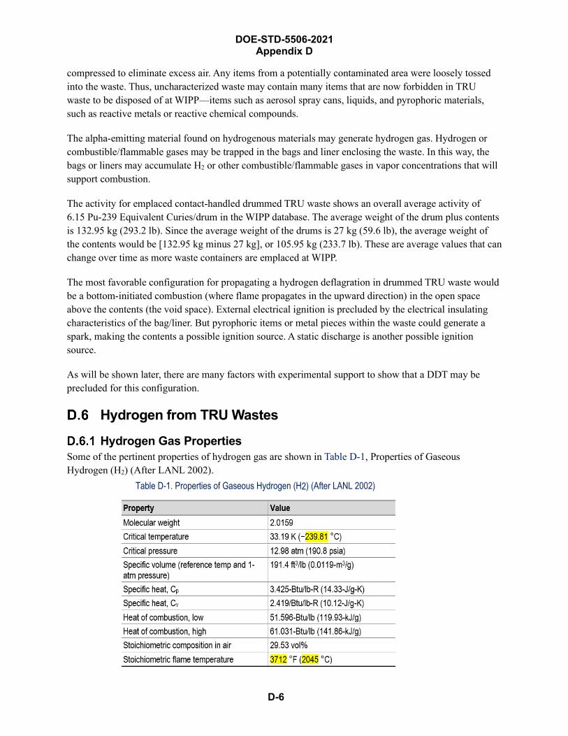
D-6
DOE-STD-5506-2021 Appendix D
compressed to eliminate excess air. Any items from a potentially contaminated area were loosely tossed into the waste. Thus, uncharacterized waste may contain many items that are now forbidden in TRU waste to be disposed of at WIPP—items such as aerosol spray cans, liquids, and pyrophoric materials, such as reactive metals or reactive chemical compounds.
The alpha-emitting material found on hydrogenous materials may generate hydrogen gas. Hydrogen or combustible/flammable gases may be trapped in the bags and liner enclosing the waste. In this way, the bags or liners may accumulate H2 or other combustible/flammable gases in vapor concentrations that will support combustion.
The activity for emplaced contact-handled drummed TRU waste shows an overall average activity of 6.15 Pu-239 Equivalent Curies/drum in the WIPP database. The average weight of the drum plus contents is 132.95 kg (293.2 lb). Since the average weight of the drums is 27 kg (59.6 lb), the average weight of the contents would be [132.95 kg minus 27 kg], or 105.95 kg (233.7 lb). These are average values that can change over time as more waste containers are emplaced at WIPP.
The most favorable configuration for propagating a hydrogen deflagration in drummed TRU waste would be a bottom-initiated combustion (where flame propagates in the upward direction) in the open space above the contents (the void space). External electrical ignition is precluded by the electrical insulating characteristics of the bag/liner. But pyrophoric items or metal pieces within the waste could generate a spark, making the contents a possible ignition source. A static discharge is another possible ignition source.
As will be shown later, there are many factors with experimental support to show that a DDT may be precluded for this configuration.
Hydrogen from TRU Wastes
Hydrogen Gas Properties Some of the pertinent properties of hydrogen gas are shown in Table D-1, Properties of Gaseous Hydrogen (H2) (After LANL 2002).
Table D-1. Properties of Gaseous Hydrogen (H2) (After LANL 2002)
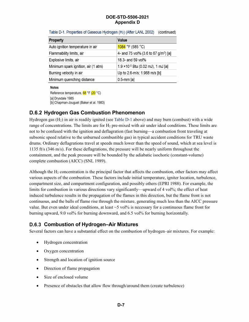
DOE-STD-5506-2021 Appendix D
D-7
Notes Reference temperature, 68 °F (20 °C) [a] Drysdale 1985[b] Chapman-Jouguet (Baker et al. 1983)
Hydrogen Gas Combustion Phenomenon Hydrogen gas (H2) in air is readily ignited (see Table D-1 above) and may burn (combust) with a wide range of concentrations. The limits are for H2 pre-mixed with air under ideal conditions. These limits are not to be confused with the ignition and deflagration (fast burning—a combustion front traveling at subsonic speed relative to the unburned combustible gas) in typical accident conditions for TRU waste drums. Ordinary deflagrations travel at speeds much lower than the speed of sound, which at sea level is 1135 ft/s (346 m/s). For these deflagrations, the pressure will be nearly uniform throughout the containment, and the peak pressure will be bounded by the adiabatic isochoric (constant-volume) complete combustion (AICC) (SNL 1989).
Although the H2 concentration is the principal factor that affects the combustion, other factors may affect various aspects of the combustion. These factors include initial temperature, igniter location, turbulence, compartment size, and compartment configuration, and possibly others (EPRI 1988). For example, the limits for combustion in various directions vary significantly—upward of 4 vol%; the effect of heat induced turbulence results in the propagation of the flames in this direction, but the flame front is not continuous, and the balls of flame rise through the mixture, generating much less than the AICC pressure value. But even under ideal conditions, at least ~5 vol% is necessary for a continuous flame front for burning upward, 9.0 vol% for burning downward, and 6.5 vol% for burning horizontally.
Combustion of Hydrogen–Air Mixtures Several factors can have a substantial effect on the combustion of hydrogen–air mixtures. For example:
• Hydrogen concentration
• Oxygen concentration
• Strength and location of ignition source
• Direction of flame propagation
• Size of enclosed volume
• Presence of obstacles that allow flow through/around them (create turbulence)
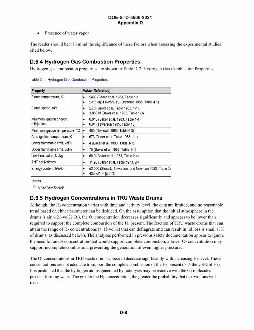
DOE-STD-5506-2021 Appendix D
D-8
• Presence of water vapor
The reader should bear in mind the significance of these factors when assessing the experimental studies cited below.
Hydrogen Gas Combustion Properties Hydrogen gas combustion properties are shown in Table D-2, Hydrogen Gas Combustion Properties.
Table D-2. Hydrogen Gas Combustion Properties
Notes [a] Chapman–Jouguet
Hydrogen Concentrations in TRU Waste Drums Although, the H2 concentration varies with time and activity level, the data are limited, and no reasonable trend based on either parameter can be deduced. On the assumption that the initial atmosphere in the drums is air (~21-vol% O2), the O2 concentration decreases significantly and appears to be lower than required to support the complete combustion of the H2 present. The fraction of TRU waste drums that can attain the range of H2 concentrations (> 15 vol%) that can deflagrate and can result in lid loss is small (8% of drums, as discussed below). The analyses performed in previous safety documentation appear to ignore the need for an O2 concentration that would support complete combustion; a lower O2 concentration may support incomplete combustion, preventing the generation of even higher pressures.
The O2 concentrations in TRU waste drums appear to decrease significantly with increasing H2 level. These concentrations are not adequate to support the complete combustion of the H2 present (> ½ the vol% of H2). It is postulated that the hydrogen atoms generated by radiolysis may be reactive with the O2 molecules present, forming water. The greater the H2 concentration, the greater the probability that the two ions will react.
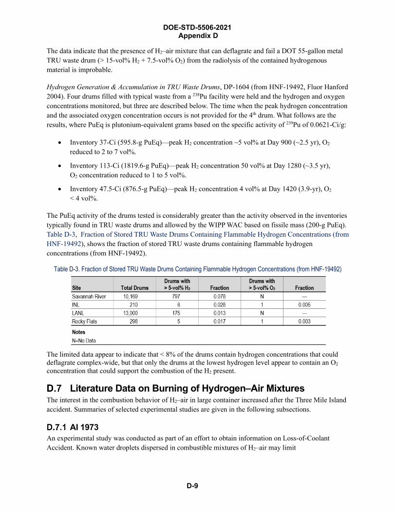
D-9
DOE-STD-5506-2021 Appendix D
The data indicate that the presence of H2–air mixture that can deflagrate and fail a DOT 55-gallon metal TRU waste drum (> 15-vol% H2 + 7.5-vol% O2) from the radiolysis of the contained hydrogenous material is improbable.
Hydrogen Generation & Accumulation in TRU Waste Drums, DP-1604 (from HNF-19492, Fluor Hanford 2004). Four drums filled with typical waste from a 238Pu facility were held and the hydrogen and oxygen concentrations monitored, but three are described below. The time when the peak hydrogen concentration and the associated oxygen concentration occurs is not provided for the 4th drum. What follows are the results, where PuEq is plutonium-equivalent grams based on the specific activity of 239Pu of 0.0621-Ci/g:
• Inventory 37-Ci (595.8-g PuEq)—peak H2 concentration ~5 vol% at Day 900 (~2.5 yr), O2
reduced to 2 to 7 vol%.
• Inventory 113-Ci (1819.6-g PuEq)—peak H2 concentration 50 vol% at Day 1280 (~3.5 yr),O2 concentration reduced to 1 to 5 vol%.
• Inventory 47.5-Ci (876.5-g PuEq)—peak H2 concentration 4 vol% at Day 1420 (3.9-yr), O2
< 4 vol%.
The PuEq activity of the drums tested is considerably greater than the activity observed in the inventories typically found in TRU waste drums and allowed by the WIPP WAC based on fissile mass (200-g PuEq). Table D-3, Fraction of Stored TRU Waste Drums Containing Flammable Hydrogen Concentrations (from HNF-19492), shows the fraction of stored TRU waste drums containing flammable hydrogen concentrations (from HNF-19492).
Table D-3. Fraction of Stored TRU Waste Drums Containing Flammable Hydrogen Concentrations (from HNF-19492)
The limited data appear to indicate that < 8% of the drums contain hydrogen concentrations that could deflagrate complex-wide, but that only the drums at the lowest hydrogen level appear to contain an O2 concentration that could support the combustion of the H2 present.
Literature Data on Burning of Hydrogen–Air Mixtures The interest in the combustion behavior of H2–air in large container increased after the Three Mile Island accident. Summaries of selected experimental studies are given in the following subsections.
AI 1973 An experimental study was conducted as part of an effort to obtain information on Loss-of-Coolant Accident. Known water droplets dispersed in combustible mixtures of H2–air may limit

D-10
DOE-STD-5506-2021 Appendix D
combustion/detonation. H2–air mixtures were ignited in a horizontal shock tube measuring 40 feet long × 16 inches in diameter and having a ℓ/D of 30.0. The test conditions were as follows:
• H2 gas concentration: 4 to 28 vol% (dry basis)
• Initial pressure levels: 1, 1.5, & 2 atm (abs)
• Initial temperature: ambient
• Water spray was 0 or 72 gpm
• Detonation source: spark-gap for stoichiometric of H2–O2 in the driver section
• Ignition sources for flame tests: continuous sparking across a 0.050-in. spark gap
H2 concentrations ranged between 5 vol% and 16 vol% (dry basis) in flame tests. There was also one flame test conducted at 28-vol% -air with an initial pressure of ½ atm. The flammable mixtures were initiated by spark, flame, and detonation.
The report contains the following findings:
• No detonation was initiated at an H2 concentration of < 16 vol% in air. This finding is supportedby the published literature.
• Flame propagation in a horizontal direction resulted in a partial detonation at 20 and 24 vol% H2
in air; complete detonation requires 28-vol% H2 in air.
• Combustion wave propagation (burning) at ≥ 7 vol% (dry basis), the H2 concentration that maydeflagrate, continued with varying degrees of completion.
• Complete burning was not propagated for H2 in air concentration < 12 vol%. That is, the internalpressure would be lower than the AICC value.
• The behavior was similar for the tests with water vapor present—an important factor due to thepresence of some level of moisture. The moisture comes from relative humidity and frompotential water formation during radiolysis in TRU waste drums filled with hydrogenousmaterials.
• Values reported for burning in a horizontal direction may be high for burning upward and low forburning downward.
• Initial pressure, as occurs when more fuel and oxidant is available, affects burning and(deflagration) maximum pressures: 29.9 psi @ 12-vol% H2 in air and 48.4 psi @ 16-vol% H2 inair.
• Ignition was not sustained at 5-vol% H2 in air; partial (erratic) burning was observed at 7 vol%and 9 vol% H2 in air.
No combustion was initiated at 5-vol% H2–air, even using a well-establish flame. With the same initiators, 7-vol% H2–air with a water spray did not ignite; partial burning was observed without water spray. Moresubstantial combustion was obtained at 9-vol% H2–air, but combustion was incomplete. No combustion
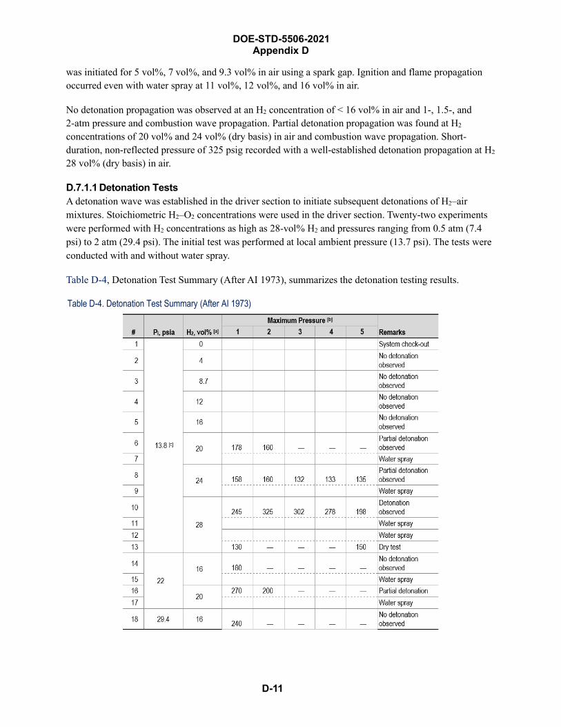
D-11
DOE-STD-5506-2021 Appendix D
was initiated for 5 vol%, 7 vol%, and 9.3 vol% in air using a spark gap. Ignition and flame propagation occurred even with water spray at 11 vol%, 12 vol%, and 16 vol% in air.
No detonation propagation was observed at an H2 concentration of < 16 vol% in air and 1-, 1.5-, and 2-atm pressure and combustion wave propagation. Partial detonation propagation was found at H2
concentrations of 20 vol% and 24 vol% (dry basis) in air and combustion wave propagation. Short-duration, non-reflected pressure of 325 psig recorded with a well-established detonation propagation at H2
28 vol% (dry basis) in air.
D.7.1.1 Detonation Tests A detonation wave was established in the driver section to initiate subsequent detonations of H2–air mixtures. Stoichiometric H2–O2 concentrations were used in the driver section. Twenty-two experiments were performed with H2 concentrations as high as 28-vol% H2 and pressures ranging from 0.5 atm (7.4 psi) to 2 atm (29.4 psi). The initial test was performed at local ambient pressure (13.7 psi). The tests were conducted with and without water spray.
Table D-4, Detonation Test Summary (After AI 1973), summarizes the detonation testing results.
Table D-4. Detonation Test Summary (After AI 1973)
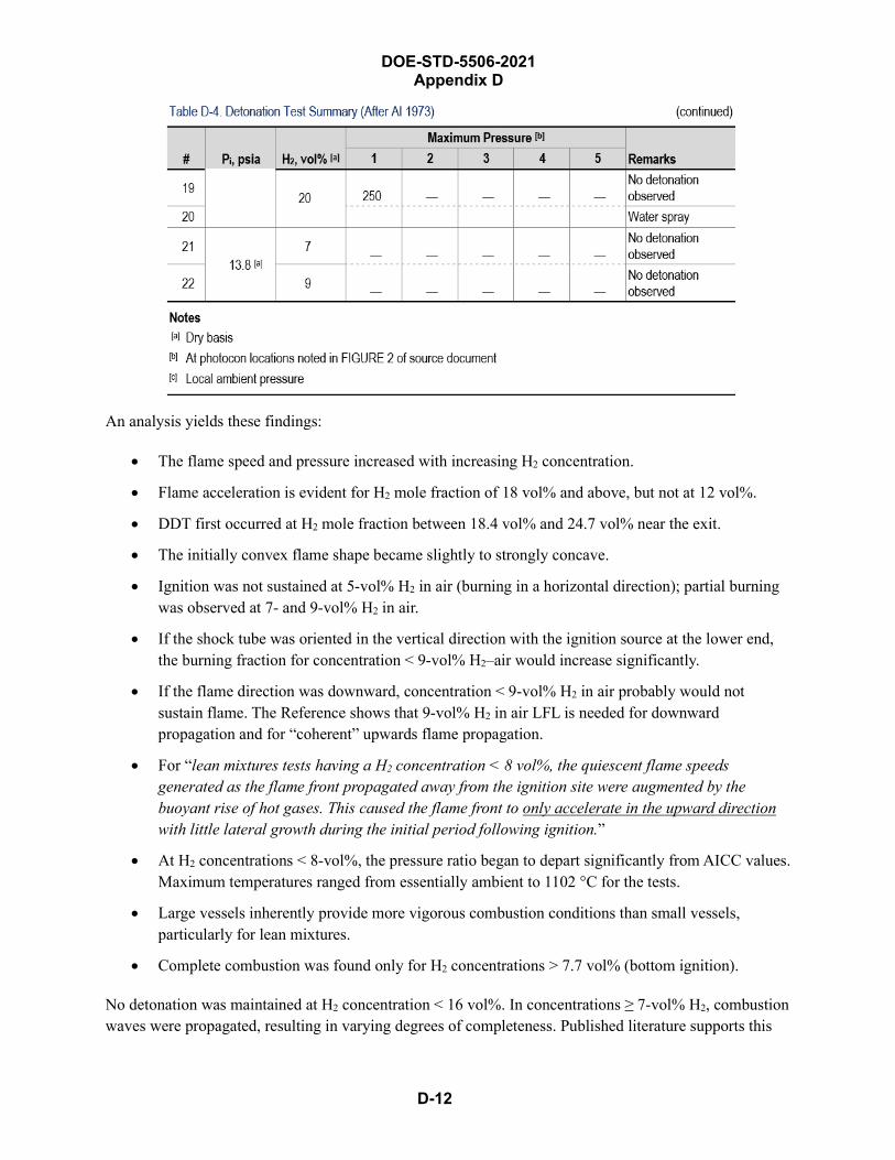
DOE-STD-5506-2021 Appendix D
D-12
An analysis yields these findings:
• The flame speed and pressure increased with increasing H2 concentration.
• Flame acceleration is evident for H2 mole fraction of 18 vol% and above, but not at 12 vol%.
• DDT first occurred at H2 mole fraction between 18.4 vol% and 24.7 vol% near the exit.
• The initially convex flame shape became slightly to strongly concave.
• Ignition was not sustained at 5-vol% H2 in air (burning in a horizontal direction); partial burningwas observed at 7- and 9-vol% H2 in air.
• If the shock tube was oriented in the vertical direction with the ignition source at the lower end,the burning fraction for concentration < 9-vol% H2–air would increase significantly.
• If the flame direction was downward, concentration < 9-vol% H2 in air probably would notsustain flame. The Reference shows that 9-vol% H2 in air LFL is needed for downwardpropagation and for “coherent” upwards flame propagation.
• For “lean mixtures tests having a H2 concentration < 8 vol%, the quiescent flame speedsgenerated as the flame front propagated away from the ignition site were augmented by thebuoyant rise of hot gases. This caused the flame front to only accelerate in the upward directionwith little lateral growth during the initial period following ignition.”
• At H2 concentrations < 8-vol%, the pressure ratio began to depart significantly from AICC values.Maximum temperatures ranged from essentially ambient to 1102 °C for the tests.
• Large vessels inherently provide more vigorous combustion conditions than small vessels,particularly for lean mixtures.
• Complete combustion was found only for H2 concentrations > 7.7 vol% (bottom ignition).
No detonation was maintained at H2 concentration < 16 vol%. In concentrations ≥ 7-vol% H2, combustion waves were propagated, resulting in varying degrees of completeness. Published literature supports this
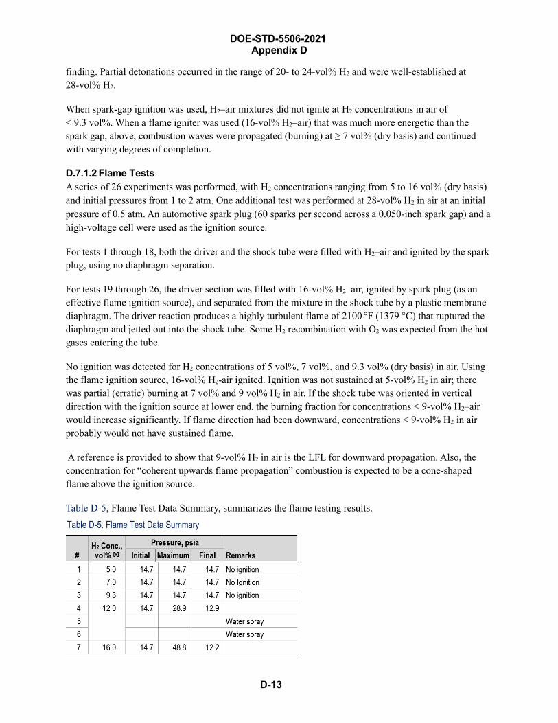
D-13
DOE-STD-5506-2021 Appendix D
finding. Partial detonations occurred in the range of 20- to 24-vol% H2 and were well-established at 28-vol% H2.
When spark-gap ignition was used, H2–air mixtures did not ignite at H2 concentrations in air of < 9.3 vol%. When a flame igniter was used (16-vol% H2–air) that was much more energetic than the spark gap, above, combustion waves were propagated (burning) at ≥ 7 vol% (dry basis) and continued with varying degrees of completion.
D.7.1.2 Flame Tests A series of 26 experiments was performed, with H2 concentrations ranging from 5 to 16 vol% (dry basis) and initial pressures from 1 to 2 atm. One additional test was performed at 28-vol% H2 in air at an initial pressure of 0.5 atm. An automotive spark plug (60 sparks per second across a 0.050-inch spark gap) and a high-voltage cell were used as the ignition source.
For tests 1 through 18, both the driver and the shock tube were filled with H2–air and ignited by the spark plug, using no diaphragm separation.
For tests 19 through 26, the driver section was filled with 16-vol% H2–air, ignited by spark plug (as an effective flame ignition source), and separated from the mixture in the shock tube by a plastic membrane diaphragm. The driver reaction produces a highly turbulent flame of 2100 °F (1379 °C) that ruptured the diaphragm and jetted out into the shock tube. Some H2 recombination with O2 was expected from the hot gases entering the tube.
No ignition was detected for H2 concentrations of 5 vol%, 7 vol%, and 9.3 vol% (dry basis) in air. Using the flame ignition source, 16-vol% H2-air ignited. Ignition was not sustained at 5-vol% H2 in air; there was partial (erratic) burning at 7 vol% and 9 vol% H2 in air. If the shock tube was oriented in vertical direction with the ignition source at lower end, the burning fraction for concentrations < 9-vol% H2–air would increase significantly. If flame direction had been downward, concentrations < 9-vol% H2 in air probably would not have sustained flame.
A reference is provided to show that 9-vol% H2 in air is the LFL for downward propagation. Also, the concentration for “coherent upwards flame propagation” combustion is expected to be a cone-shaped flame above the ignition source.
Table D-5, Flame Test Data Summary, summarizes the flame testing results. Table D-5. Flame Test Data Summary
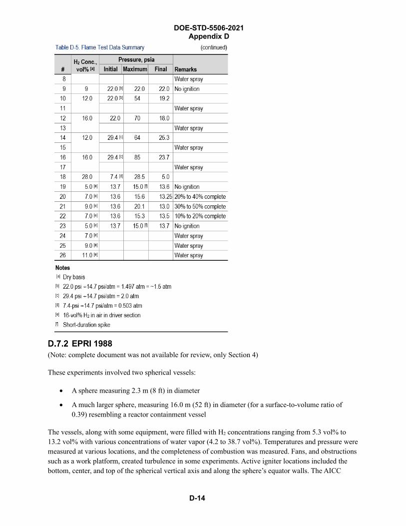
DOE-STD-5506-2021 Appendix D
D-14
EPRI 1988 (Note: complete document was not available for review, only Section 4)
These experiments involved two spherical vessels:
• A sphere measuring 2.3 m (8 ft) in diameter
• A much larger sphere, measuring 16.0 m (52 ft) in diameter (for a surface-to-volume ratio of0.39) resembling a reactor containment vessel
The vessels, along with some equipment, were filled with H2 concentrations ranging from 5.3 vol% to 13.2 vol% with various concentrations of water vapor (4.2 to 38.7 vol%). Temperatures and pressure were measured at various locations, and the completeness of combustion was measured. Fans, and obstructions such as a work platform, created turbulence in some experiments. Active igniter locations included the bottom, center, and top of the spherical vertical axis and along the sphere’s equator walls. The AICC
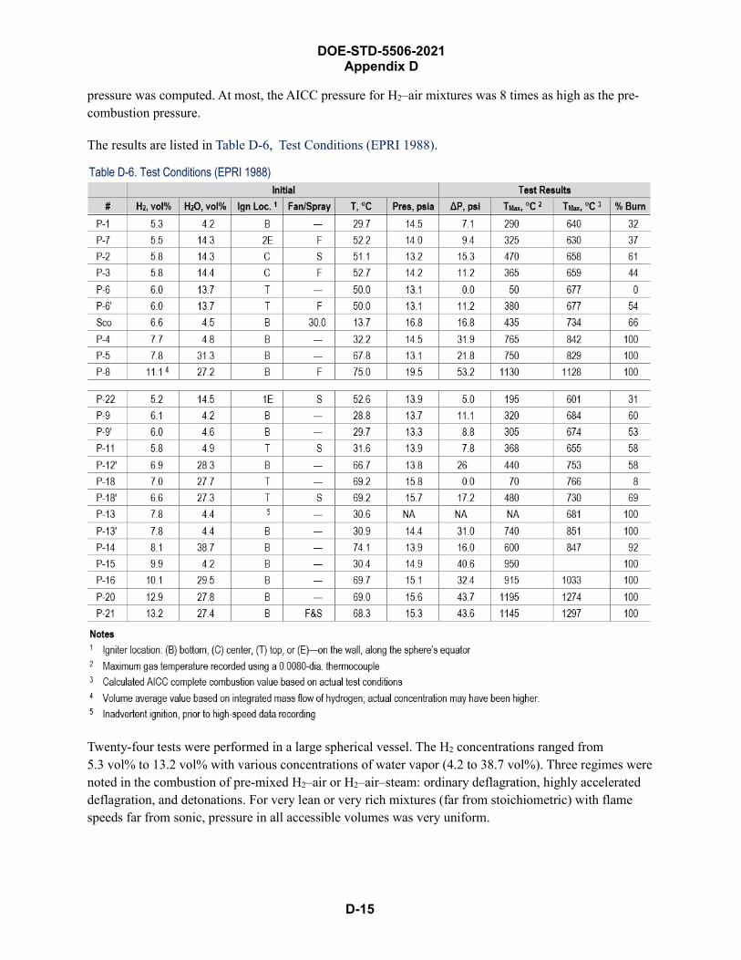
DOE-STD-5506-2021 Appendix D
D-15
pressure was computed. At most, the AICC pressure for H2–air mixtures was 8 times as high as the pre-combustion pressure.
The results are listed in Table D-6, Test Conditions (EPRI 1988).
Table D-6. Test Conditions (EPRI 1988)
Twenty-four tests were performed in a large spherical vessel. The H2 concentrations ranged from 5.3 vol% to 13.2 vol% with various concentrations of water vapor (4.2 to 38.7 vol%). Three regimes were noted in the combustion of pre-mixed H2–air or H2–air–steam: ordinary deflagration, highly accelerated deflagration, and detonations. For very lean or very rich mixtures (far from stoichiometric) with flame speeds far from sonic, pressure in all accessible volumes was very uniform.
D-16
DOE-STD-5506-2021 Appendix D
Flammability limits are the concentrations of the fuel that will propagate a deflagration. The limit was assumed to be independent of method of ignition, provided that it is sufficiently strong to ignite a flame. The limit was further assumed to be independent of size of enclosure, provided that the enclosure is much larger than the quenching distance of 0.5 mm (see Table D-1). Flammability limits depend on the direction of flame propagation. This dependence arises from the buoyancy effect: lean and rich limits have a wider range for upward propagation than for downward propagation. A moderate degree of turbulence has no significant effect on flammability limits.
For initially quiescent lean mixtures, this study shows combustion completeness varies with a low fraction in the upward direction and complete combustion in the downward direction
Note: The reader should bear in mind that the limits will differ, depending on direction of flame propagation.
For H2–air mixtures at room temperature, flame speed is ~3 m/s for a rich mixture (~40 vol%), 2 m/s for a stoichiometric mixture, and progressively less for leaner mixtures. For lean mixtures, the laminar flame front is not stable: it deforms and increases the flame surface area. This behavior could result in some small increase in flame speed.
The EPRI document included these conclusions and observations:
• For “lean mixtures tests having a H2 concentration < 8-vol%,” the “quiescent flame speedsgenerated as the flame front propagated away from the ignition site were augmented by thebuoyant rise of hot gases. This caused the flame front to only accelerate in the upward directionwith little lateral growth during the initial period following ignition. During the upwards inverseof the vessel, the growing flame front displaced cooler gases from the upper region of the testvessel. When the flame reached the top of the vessel, the momentum of the plume was able todrive the flame front downwards along the vessel wall with final combustion occurring in thelower region of that vessel. In these cases, incomplete combustion occurred (i.e., burn fractionranged from 30- to 70-%.”
• Two significant variations were noted:
o For attempts to ignite a quiescent lean mixture at 0.5-m (1.5-ft) below top of vessel; onlyminimal combustion occurred in the local region above igniter … initial upward flamepropagation impinged on dome surface and quenched. Insufficient vertical height aboveigniter precluded full development of rising plume and global propagation throughout vessel(an important observation for TRU waste drums that are half full of waste and the distance tothe top is ~1.5-ft);
o For H2 concentrations of > 8 vol%, flame propagation more spherical as H2 increased from 8to 13 vol% … test P-20, H2 12.9 vol%, initial flame front essentially spherical.
• Hydrogen burn completion ranged from 0% to 100%. Complete combustion was found only forH2 concentrations > 7.7 vol% and up to 30-vol% steam, all upwards flame direction (bottom
DOE-STD-5506-2021 Appendix D
D-17
ignition). Top ignition under quiescent conditions resulted in very low burn completions due to quenching of flame at dome surface
• Large vessels inherently provide more vigorous combustion conditions than small vessel,particularly for lean mixtures.
D.7.2.1 Combustion in Premixed Hydrogen–Air–Steam Atmospheres Twenty-four tests were performed with H2 concentrations of 5 to 13 vol% and 4- to 40-vol% H2O vapor concentrations.
Note: The reader should bear in mind that water vapor concentrations at the lower fractions are well within the relative humidity anticipated at generator sites during packaging and storage.
Fans and water sprays were used in nine tests. Active igniter locations included the bottom, center, and top of the sphere’s vertical axis and along the sphere’s equator wall. Saturated condition of water vapor was achieved at the beginning of each test with temperatures from 29 °C (84 °F) to 75 °C (167 °F). The test condition is listed in Table 7, “Peak Pressure Rise Measurements Premixed Combustion Tests,” of the referenced document. AICC and pressure ratios were calculated. Suspect data were excluded; they probably resulted from water accumulation and boil-off in one or more of the pressure-sensing tubes.
D.7.2.2 Pre-Mixed Combustion Phenomenon • Table 7, “Peak Pressure Rise Measurements Premixed Combustion Tests” (see referenced
document) shows that for “lean mixtures tests having a H2 concentration < 8-vol%, the quiescentflame speeds generated as the flame front propagated away from the ignition site were augmentedby the buoyant rise of hot gases. This caused the flame front to only accelerate in the upwarddirection with little lateral growth during the initial period following ignition. During theupwards inverse of the vessel, the growing flame front displaced cooler gases from the upperregion of the test vessel. When the flame reached the top of the vessel, the momentum of the plumewas able to drive the flame front downwards along the vessel wall with final combustionoccurring in the lower region of that vessel. In these cases, incomplete combustion occurred, i.e.burn fraction ranged from 30- to 70-%”.
Two significant variations were noted:
• For attempts to ignite quiescent lean mixture at 0.5-m (1.5-ft) below the top of vessel, onlyminimal combustion occurred in the local region above the igniter--initial upward flamepropagation impinged on dome surface and quenched. Insufficient vertical height above igniterprecluded full development of rising plume and global propagation throughout vessel
• For H2 concentrations > 8 vol%, flame propagation was more spherical as H2 increased from 8- to13-vol% … test P-20, H2 12.9-vol%, initial flame front essentially spherical with negligible flameacceleration
DOE-STD-5506-2021 Appendix D
D-18
The referenced document states that:
• “Igniter location affects combustion primarily through its role in buoyancy-induced mixing andturbulence”
• “… spark-ignition in an 8-ft diameter sphere at an initial temperature of 28° ± 2° C underquiescent conditions indicate that a top ignition will burn to completion at 8.5-vol% H2 …”
• “…The data illustrates that even though ‘global’ flame propagation might not occur under leanquiescent conditions with top ignition …”
Turbulence effects are more important for lean mixtures for flame speeds. Figure 4-39 on pg. 4-39 of the referenced document that plots “Upwards Flame Speed, m/s versus the Hydrogen Concentration” shows no significant increase in flame speed at < 10-vol% H2.
Pressure ratio began to depart significantly from AICC values at H2 concentrations < 8 vol%; maximum temperatures ranged from essentially ambient to 1102 °C for the tests.
D.7.2.3 Effect of Scale Prior to the EPRI tests, hydrogen combustion data came from bench-scale experiments. The EPRI tests show that scale affects two primary combustion parameters: pressure ratios and time to peak pressure.
Large vessels inherently provide more vigorous combustion conditions than small vessels, particularly for lean mixtures. The fireball rises from point of ignition and accelerates through the first two-thirds of its upward travel. The rising buoyant plume draws air down the sides of the vessel to the bottom to replace the air rising up the center. This drawing down effectively promotes turbulence and mixing throughout the test volume. This self-induced turbulence is more effective in a large vessel, because a large vessel provides a longer vertical path for the rising plume to start the unburned gases in motion.
D.7.2.4 Effect of Hydrogen and Steam Concentrations Variations in peak pressure ratios with H2 concentrations were highly nonlinear (see Figure 4-5 in the referenced document), particularly for lean mixtures. Pressure transient were affected by three factors, each with different sensitivity to H2 concentration:
• Burn completeness
• Flame speed
• Buoyancy-induced turbulence
All three increase with increasing H2 concentration.
SNL 1989 (Note: Complete document was not available for review.)
D.7.3.1 Abstract This report describes research on flame acceleration and DDT for hydrogen–air mixtures in the FLAME facility. Flame acceleration and DDT can generate high peak pressures that may cause containment failure.

D-19
DOE-STD-5506-2021 Appendix D
FLAME is a large, rectangular U-shaped channel made of heavily reinforced concrete. The facility measures 30.5 m long × 2.44 m high × 1.83 m wide (calculated hydraulic diameter and ℓ/D [2.44 m × 1.83 m = 4.465 m2, 4.465 ÷ 3.1416 = 1.4213 m2, √1.4213 ≈1.192-m radius, D ≈ 2.38 m ∴ ℓ/D ≈ 30.5 m ÷ 2.38 m] ≈ 12.8]). The facility is closed at the ignition end (by a polyethylene bag) and open at far end.
H2 was inserted into FLAME via three penetrations (one at each end and one in middle) and mixed by two air-driven fans (one at the ignition southeast end and one near the northwest exit). The ignition system was equipped with three independent ignition methods: bridge-wire, spark plug, and glow plug. All tests were conducted using single-point bridge-wire ignition; a capacitive firing set was used to provide high-amplitude current to vaporize the bridge wire.
The tests tested the effects of three variables:
• H2 mole fraction, ranging from 12% to 30%
• Degree of transverse venting (by moving steel, top plate): 0%, 13%, and 50%
• The absence or presence of certain obstacles in the channel, creating a 0 to 33% blockage ratio
The hydrogen mole fraction is the most important variable. Obstacles greatly increased flame speed, overpressure, and the tendency for DDT. Different obstacle configurations could have a greater or lesser effect on flame acceleration and DDT. A large degree of transverse venting reduces flame speed, overpressure, and the possibility of DDT. For reactive mixtures > 18% H2, the effect of turbulence from venting is greater than from venting out of channel. DDT was observed for H2 beyond some threshold level. DDT was observed at 15% H2 with obstacles and no transverse venting.
From the literature and past experiments, deflagrations have been defined as combustion fronts traveling at subsonic speeds relative to the unburned gases; typically much less than sonic. Pressures are nearly uniform throughout its containment and peak pressure is bounded by the AICC pressure. The AICC can be computed with high accuracy by thermodynamic calculations. At most, the AICC pressure is eight times the pre-combustion pressure for H2–air or H2–air–steam. However, see Section B.2.2, Tables B-9 and B-10, where measured pressures sometimes well exceeded what would be calculated for AICC conditions. Deflagration flame speed accelerated to > 100 m/s generate shock waves, and peak instantaneous pressures are much higher. If accelerated to a fast enough speed, deflagration may transition into a detonation—combustion fronts traveling at supersonic speed relative to the unburned gases. Peak reflected pressure for detonation is considerably greater than AICC, up to 35X pre-combustion pressure.
From the FLAME test results, obstacles in the path of expanding flame front promoted /accelerated combustion by enlarging the burning surface and increasing local burning rate. A limited set of obstacle configurations were tested. Obstacles lowered the minimum mole fraction that are necessary for DDT. Even if no detonation occurred, deflagrations accelerated to 500 to 700 m/s (sonic velocity ~330-m/s) and generated high pressure pulses. DDT was observed at 15% H2 with obstacles and no top venting. This is less than the old lean “detonation limit”. Venting effects were more complex.

DOE-STD-5506-2021 Appendix D
D-20
D.7.3.2 Conclusions from Tests • Reactivity of mixture was determined by hydrogen concentration. For very lean mixtures, there
was no significant flame acceleration and no DDT.
• The presence of obstacles in the path of flames greatly increases flame speeds and overpressures,reducing the lean limit for DDT.
• Large degrees of transverse venting reduce flame speed and overpressure.
• Small degrees of transverse venting reduce flame speed and overpressure for less reactivemixtures but increase them for more reactive mixtures.
D.7.3.3 Adiabatic Isochoric (Constant Volume) Complete Combustion (AICC) Pressure The combustion of H2–air or H2–air–steam occurs in three regimes:
• Ordinary deflagration
• Highly accelerated deflagration
• Detonation
At concentrations far from a stoichiometric mixture (~30% H2), and in very lean or very rich mixtures, speeds are small compared to sonic. Pressures in all accessible volume are uniform, rise for a few seconds, and decay as gas cools. The peak is bounded by AICC pressure and can be lower as a result of incomplete burning.
D.7.3.4 Flammability Limits Flammability limits of combustible mixture, at a given pressure and temperature, are the concentration of fuel that will propagate a deflagration indefinitely. Flammability limit depends on the direction of flame propagation: lean and rich limits are wider for the upward direction than for the downward. H2–air–steam flammability limits measured at temperatures to 200 °C, and pressures ranging from atmospheric to 7 atm are reported by several authors. Steam acts as a diluent, reducing the combustion temperature. Increasing the steam concentration narrows the combustible range. Sufficient steam may inert the reaction at a concentration of ~55%; the needed concentration varied from 52% to 63%.
A moderate degree of turbulence has no significant effect on flammability limits. Limits widen with increasing temperature.
The completeness of combustion for flammable hydrogen–air and hydrogen–air–steam mixtures was investigated at large scale and intermediate scale. For an initial quiescent lean mixture, combustion completeness varies from low fractions burned in the upward direction at the flammability limit (~5-vol% H2) to complete burning in downward flammability at the limit (9-vol% H2).
“Burning velocity” is defined as “normal component of velocity of a deflagration relative to the unburned gas ahead of the front.” Unless the unburned gases are stationary, the speed of propagation of a flame relative to a stationary observer will not be the burning velocity.
D-21
DOE-STD-5506-2021 Appendix D
Hydrogen burn completion ranged from 0% to 100%. Complete combustion was observed for H2 concentrations > 7.7 vol% and up to 30-vol% steam, all occurring during bottom ignition (see Fig 4-12, “Burn Completeness is a Function of Hydrogen Concentration” in the reference document). Top ignition under quiescent conditions resulted in very low burn completions because of quenching of flame at dome surface. Burn fractions reported by other experimenters were lower for H2 concentrations < 8.5 vol%.
One might expect this scale effect to be most significant with bottom ignition. “In lean quiescent mixtures with top ignition, combustion stopped before depleting all the hydrogen. Apparently, the buoyant plume did not have a long enough run to generate the turbulence required to start moving much of the test volume’s atmosphere.” For lean mixtures with H2 about 12 vol%, the flame speeds are low and do not increase significantly with distance. At an H2 concentration of 24.7 vol%, the pressure transitioned into a detonation near the exit of the 30.5-m-long tunnel.
Laminar burning velocity is the minimum burning velocity. For H2–air at room temperature, burning velocities are as follows:
• Rich mixture (~40-vol% H2): 3 m/s
• Stoichiometric mixture (30-vol% H2): 2 m/s
• Progressively lower velocity for lean mixtures
At 250 °C, a burning velocity of ~9 m/s was observed. The presence of steam reduces the velocity. Laminar flame speed is 6× the laminar burning velocity. For H2–air mixtures at ambient conditions, burning velocity was < 20 m/s, a value that is negligible compared to sonic velocity (~300 m/s).
D.7.3.5 Ordinary Turbulent Deflagration In ordinary accidents, flames will be turbulent (uncertain if conditions for drum deflagrations are included … document for PWR ice condenser system). With increasing turbulent intensity, turbulent flame speed reaches a maximum and decreases, then is quenched. The ratio of maximum turbulent flame speed to laminar flame speed is largest for near-stoichiometric mixtures. For H2–air mixtures at room temperature and pressure, the maximum ratio is > 16. The turbulent burning velocity may be as high as 35-m/s and turbulent flame speed as high as 200 m/s for high degree of turbulence. Flame speeds may be up to 15 m/s for 15-vol% H2.
D.7.3.6 Flame Acceleration — Highly Accelerated Deflagration It is possible to have deflagrations moving at 100 m/s, with considerable flame acceleration and strong shock waves, resulting in non-uniform pressures. Local pressures exceed AICC. DDT may occur between deflagrations and leading shock wave. For flames passing through an obstacle, the effective deflagration speed is greatly increased. In large volumes, the effect of hydrodynamic-combustion instabilities can greatly increase flame speed.
D.7.3.7 Deflagration-to-Detonation Transition There is considerable uncertainty whether transition can occur in practical accident situations. The “Gas Dynamic” explanation is one-dimensional: “The volume expansion of the hot burned gases generate shock waves moving into the unburned gases. The shock waves preheat the unburned gases increasing the burning rate, which leads to generation of further shock waves. Some of the shock waves merge into

D-22
DOE-STD-5506-2021 Appendix D
strong enough waves so that a local explosion that transforms into a steady detonation” (The transition and the effect on the upward flame propagation show the importance of temperature on the combustion of H2–air mixtures).
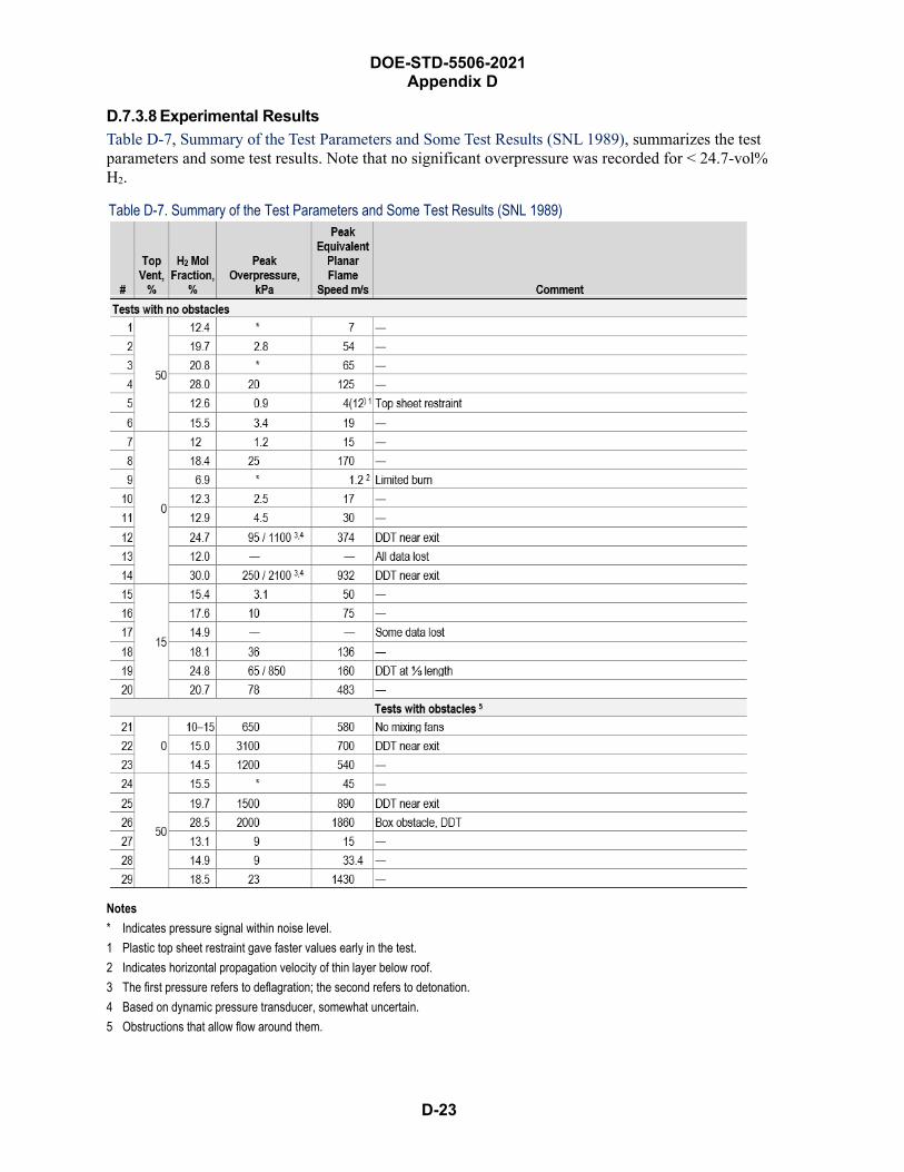
D-23
DOE-STD-5506-2021 Appendix D
D.7.3.8 Experimental Results Table D-7, Summary of the Test Parameters and Some Test Results (SNL 1989), summarizes the test parameters and some test results. Note that no significant overpressure was recorded for < 24.7-vol% H2.
Table D-7. Summary of the Test Parameters and Some Test Results (SNL 1989)
Notes * Indicates pressure signal within noise level.1 Plastic top sheet restraint gave faster values early in the test.2 Indicates horizontal propagation velocity of thin layer below roof.3 The first pressure refers to deflagration; the second refers to detonation.4 Based on dynamic pressure transducer, somewhat uncertain.5 Obstructions that allow flow around them.
DOE-STD-5506-2021 Appendix D
D-24
DDT occurred under the following conditions:
• No obstacles and venting: at 24.7- and 30.0-vol% H2 in air (none noted at 18.4-vol% H2 in air)
• No obstacles and 15% venting: at 24.8-vol% H2 in air
• No obstacles and 50% venting: did not occur
• Obstacle and no venting: at 15.0-vol% H2 in air
• Obstacle and 50% venting: at 19.7- and 28.5-vol% H2 in air
Tests F-7 to F-14 were evaluated with no obstacles and no top venting (Note: Test F-9 is different than all others and was considered separately). Some tests (F-10, F-8, F-12 and F-14) considered increasing H2 mole fractions (12.3%, 18.4%, 21.7% and 39.0%).
• Test F-10, 12.4-mole-fraction H2. Combustion-front trajectory showed a slight downwardconcavity; the flame’s curvature indicates some flame acceleration, but not dramatic. Peakpropagation velocity was 19.3 m/s. The deflagration front was initially convex, but graduallytransitioned into an unsymmetrical concave shape. Pressures are all relative to the ambient andtypically 84 kPa (12.2 psig).
• Test F-8, 18.4-mole-fraction H2. Deflagration speed was much higher than it was for F-10. Allpressure histories show a rise to ~130 ms, then a second rise and fall, and then a pressure spike.The exact location and condition of DDT is not known due to the instrumentation setup.
• Test F-14, 30% H2 mole fraction. More pronounced flame acceleration; the speed just prior todetonation was very large.
Summary of tests with no venting or obstacles:
• The flame speed and pressure increased with increasing H2 concentration.
• Flame acceleration is evident for an H2 mole fraction of 18% and above, but not at 12%.
• DDT first occurred at an H2 mole fraction between 18.4% and 24.7% near the exit.
• The flame shape was initially convex but became slightly to strongly concave.
LANL July 2002This document reviewed the published literature on H2 concentrations in air to burn in various directions. One document reviewed (McKinley 1980) states that “4-vol% H2 (LFL) for upwards propagation produces an average flame temperature of < 350 °C, whereas the ignition temperature of H2 in air is 585 °C …can be understood from observation that the flame in the mixture rises as luminous balls that consuming only part of the hydrogen … fresh hydrogen diffuses into the burning ball and yields higher effective concentrations of hydrogen than initially present. It has been observed that not all the hydrogen is consumed in upward propagation in a 2-in. diameter tube until a concentration of 19-vol% H2 was present. Similar experiments with horizontal tube resulted in a LFL of 6.5-vol% in air; downward propagation requires ~9-vol% H2 in air.”
DOE-STD-5506-2021 Appendix D
D-25
EG&G 1983 (Experimental Studies of H2 Explosions in TRU Waste Drum)
The document shows that:
• The drums tested contained the burning of H2–air mixtures up to 14-vol% H2 with both hard-spark and soft-spark ignition. At H2 concentration of 14 vol% in air with a hard-spark ignition, areaction was noted in the smoldering HDPE liner.
• All five tests with drums filled a stoichiometric H2 concentration in air deflagrated.
• For the drums that deflagrated (> 20-vol% H2), a fraction of the contents was ejected. Thefraction ranged from 7% to 41% (this drum was horizontally oriented). The ejected material wasthrown a maximum (wind-aided) 260 feet in Test #4C.
• One test was performed using a drum containing a stoichiometric H2 concentration in airsurrounded by three drums in an upright array. Only the donor drum and the drum above thedonor drum were filled with a stoichiometric H2 concentration in air. The lid from the donor drumwas not displaced. The top drum lid was blown 182 feet, and the drum’s content were blown 63feet. Fire was observed in the drum residue material with a release fraction (material ejected)~16%. This value indicates that sympathetic deflagration occurs.
• Fraction of contents ejected were: 27% (Test 3B), 14% (Test 4B), 7% (Test 4C), 41% (Test 4D),and 16% (Test 7). The maximum fraction of contents ejected was 41%, and the average was 16%.
• The drum with a stoichiometric H2 concentration in air was punctured by a sharpened drill but didnot ignite.
The experimental program was initiated to address problem with generation of H2 gas in stored TRU waste. The potential for gas generation has been recognized since TRU waste storage began. It was generally believed that the amount of α-emitters was insufficient to generate sufficient H2 to pose a problem. But a first-stage sludge drum found in 1980 had a bulged lid. So a program was initiated to estimate the number of drums capable of accumulating flammable concentrations and to postulate a maximum credible hydrogen explosion in TRU waste drum retrieval at the Idaho site.
Additionally, in FY 1983, tests were performed to determine whether FRP boxes and M-III bins were capable of accumulating gas. The work in FY 1983 was divided into two major tasks, both requiring field testing. The tasks characterized H2 explosions in new DOT 17C (55-gallon metal) drums tests by four factors:
• Overpressure
• Ignition
• Impact
• Puncture
• Sympathetic explosions (explosion induced in adjacent drums)
DOE-STD-5506-2021 Appendix D
D-26
Test 1 (over-pressurization tests). Compressed air was injected into a drum. Test 1 also established maximum internal pressure that could be used for explosion tests (see Table D-8).
Test 2. Seven ignition tests were performed using the two types of wastes most likely to generate flammable gas: sludge and combustibles. Two H2–air mixtures were tested: the maximum observed in drums and the calculated “worst case”. Two ignition sources were used near the top of drums:
• Soft sparks (spark-gap 20 mJ)
• Hard spark chemical squib (5 J)
This is a less favorable configuration for combustion propagation than ignition at the bottom of the void space burning in the upward direction.
In addition, a drum was dropped 12 feet onto a hard, unyielding surface, simulating the effect of driving a puncturing device into drum, and sympathetic explosion was tested.
New DOT 17C drums with 90-mil high-density polyethylene liners were used.
The drums for the tests were penetrated through the drum and liners in three places:
• Bottom of drum
• Gas inlet
• Exhaust lines
The initial conditions are presented in Table D-8, Purpose and Initial Conditions for Each Test (EG&G 1983). The results follow in Table D-9, Gas Generation Tests Performed at the INEL Building FY-82 (EG&G 1983).
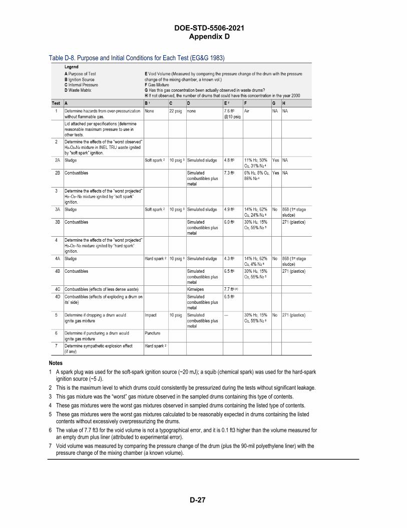
DOE-STD-5506-2021 Appendix D
D-27
Table D-8. Purpose and Initial Conditions for Each Test (EG&G 1983)
Notes 1 A spark plug was used for the soft-spark ignition source (~20 mJ); a squib (chemical spark) was used for the hard-spark
ignition source (~5 J). 2 This is the maximum level to which drums could consistently be pressurized during the tests without significant leakage. 3 This gas mixture was the “worst” gas mixture observed in the sampled drums containing this type of contents. 4 These gas mixtures were the worst gas mixtures observed in sampled drums containing the listed type of contents. 5 These gas mixtures were the worst gas mixtures calculated to be reasonably expected in drums containing the listed
contents without excessively overpressurizing the drums. 6 The value of 7.7 ft3 for the void volume is not a typographical error, and it is 0.1 ft3 higher than the volume measured for
an empty drum plus liner (attributed to experimental error). 7 Void volume was measured by comparing the pressure change of the drum (plus the 90-mil polyethylene liner) with the
pressure change of the mixing chamber (a known volume).
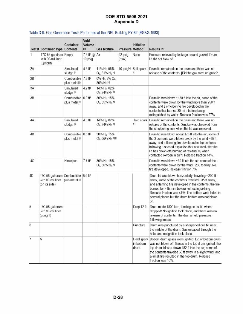
DOE-STD-5506-2021 Appendix D
D-28
Table D-9. Gas Generation Tests Performed at the INEL Building FY-82 (EG&G 1983)

DOE-STD-5506-2021 Appendix D
D-29
Notes [a] Void volume was measured by comparing the pressure change of the drum with the pressure of the mixing chamber
(a known volume).[b] Explosion overpressures were not measured.[c] Sludge was simulated by diatomaceous earth moistened with ~5 gallons of water.[d] The gas mixtures were the worst observed in sampled drums containing those types of contents.[e] This is the maximum reasonable pressure that drums could be expected to maintain without significant leakage.[f] A spark plug was used for the soft spark ignition source (~20 mJ); a squib (chemical spark) was used for the hard spark
ignition source (~5 J). [g] Neither the combustible material (e.g., cellulose of various forms, type of plastic such as PVC, PE, polypropylene, etc.) nor
the size/weight of the individual pieces is specified. [h] These gas mixtures were the worst gas mixtures calculated to be reasonably expected in drums containing those contents
(without overpressurizing the drum).[I] Handwritten notation, 3.5 mol H2?
Additional Notes • A 17C 55-gallon drum with 90-mil liner (upright) with 3 adjacent drums. The top drum also contained a flammable gas
mixture.• Calculated volume of gases at STP• Drum lid was not blown off by 22 psig of internal pressure.• Uncertain if all gas mixture ignited by soft spark. If the test that state “drum lid not blown off” are assumed to have ignited
but generated insufficient internal pressure to blow lid off, 100% of the drums deflagrated but > 14% H2 necessary togenerate sufficient internal pressure to dislodge lid.
• All the gas mixtures were ignited by a hard spark (5 J that is 1000× more energetic than the soft spark, 5 mJ). All thedrums with 30% H2 + 15% O2 (a stoichiometric mixture) generated sufficient internal pressure to blow off the lid.
• Of the drums that blew off their lids and contained “combustibles and metal”, the Release Fractions (assumed to be thematerials ejected from the drum) were as follows: 27%, 14%, 7%, 41%, and 16%. The bounding value 41%; the meanvalue was 21%.
• The single drum containing “Kimwipes” (tissue), the release fraction was 7%.
D-30
DOE-STD-5506-2021 Appendix D
The tests provided important scooping data that helped establish a maximum credible accident. They also produced several results and conclusions:
• No significant shrapnel danger was apparent other than from drum lids.
• Pressure tests at maximum observed pressure did not cause lid to come off.
• The worst explosive effect came from igniting drums containing a stoichiometric H2–air mixtureand simulated combustibles and metal.
• Fires were observed in the combustibles, but released contents did not sustain a fire. Only onedrum had to be extinguished.
• More than one drum can explode in a given scenario. Based on the one sympathetic explosiontest, only one drum is expected to eject its lid and contents in the scenario.
WSRC-TR-90-165The document findings are the following:
• General. The maximum pressure measured was 263.6 psig for a 47-vol% H2 concentration at aninitial pressure of 13.04 psig (near 2 atmospheres). The greatest pressure measured for a 30-vol%H2 concentration (slightly less than stoichiometric for the experimental conditions) was240.1 psig.
• TRU drum explosion tests. “Lid loss” was observed for drums with > 17 vol%. At < 17 vol%(five tests), the drum bulged at its top and bottom. Ignition of mixtures up to 15-vol% H2 wascontained in the drum without loss of containment.
Tests to determine minimum concentration for “lid loss” plus the maximum pressure and rate pressure rise vs. H2 concentration were performed. Preliminary small-scale pressure vessel tests were conducted to determine two factors:
• The relationship between H2 concentration vs. maximum pressure and pressure rise, over an H2
range of 5 to 50 vol%. But variability in the drum lid sealing and the retaining ring closuresprevented establishing relationship for drum.
• Drum mixing (equilibration time for two H2–air mixtures in drum, injection of 5 to 25 vol% inmiddle initial stratification but well-mixed in 50 minutes).
Nine tests were performed over the range of 13-vol% to 36-vol% H2. The results suggest that a concentration > 15-vol% H2 is necessary for “lid loss”. The drums were staged on a concrete pad. Both drum and liner had carbon composite filtered vents, but H2 formation could occur in individual plastic bags.
D.7.6.1 Pressure Vessel Tests • A 1.7-liter vessel was filled to slightly [not specified] above ambient pressure with H2 5- to 50-
vol% air concentration and ignited.
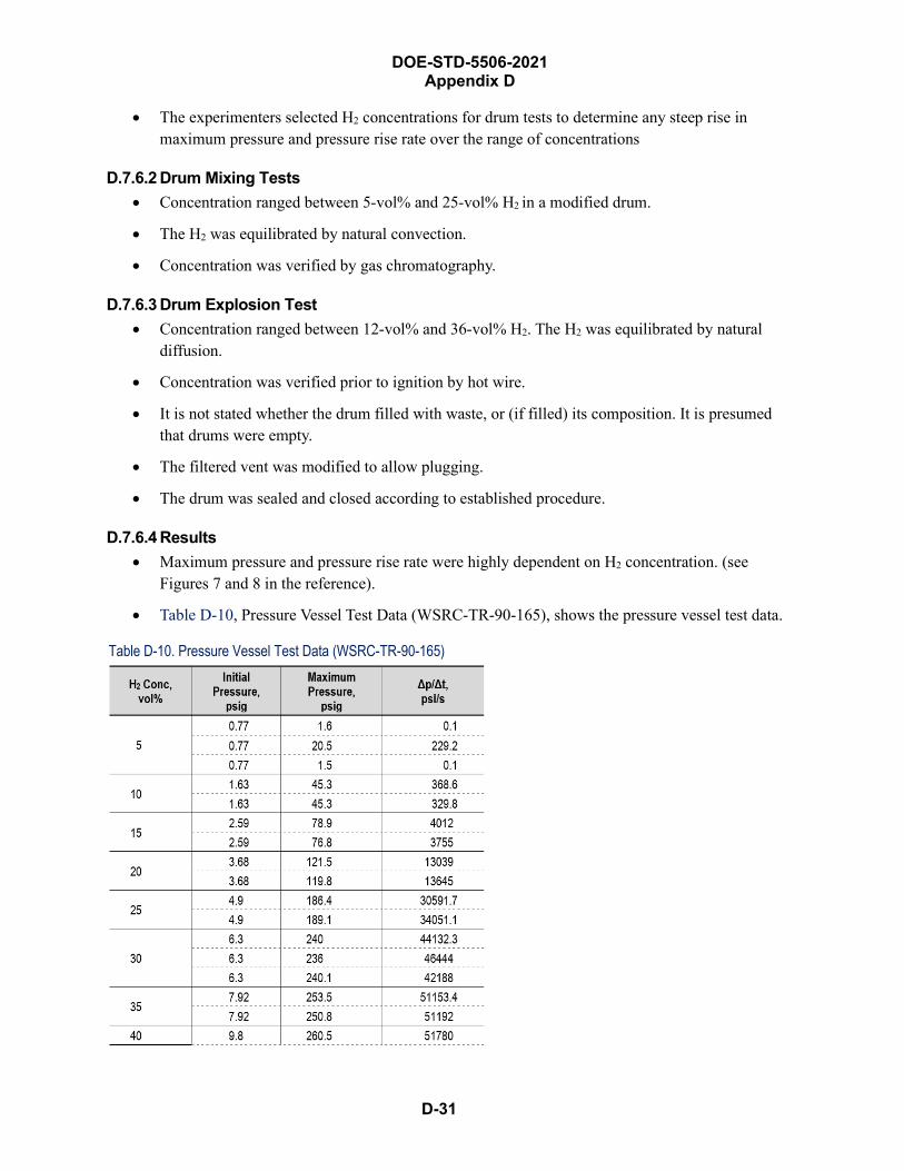
DOE-STD-5506-2021 Appendix D
D-31
• The experimenters selected H2 concentrations for drum tests to determine any steep rise inmaximum pressure and pressure rise rate over the range of concentrations
D.7.6.2 Drum Mixing Tests • Concentration ranged between 5-vol% and 25-vol% H2 in a modified drum.
• The H2 was equilibrated by natural convection.
• Concentration was verified by gas chromatography.
D.7.6.3 Drum Explosion Test • Concentration ranged between 12-vol% and 36-vol% H2. The H2 was equilibrated by natural
diffusion.
• Concentration was verified prior to ignition by hot wire.
• It is not stated whether the drum filled with waste, or (if filled) its composition. It is presumedthat drums were empty.
• The filtered vent was modified to allow plugging.
• The drum was sealed and closed according to established procedure.
D.7.6.4 Results • Maximum pressure and pressure rise rate were highly dependent on H2 concentration. (see
Figures 7 and 8 in the reference).
• Table D-10, Pressure Vessel Test Data (WSRC-TR-90-165), shows the pressure vessel test data.
Table D-10. Pressure Vessel Test Data (WSRC-TR-90-165)
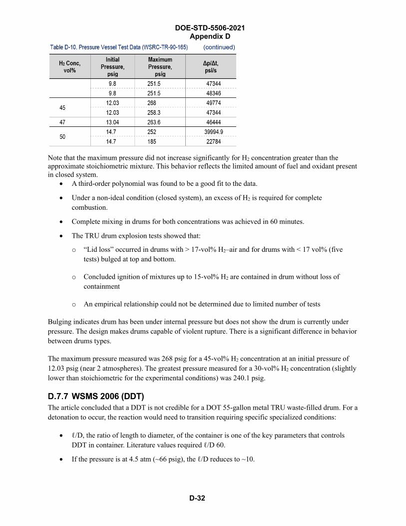
DOE-STD-5506-2021 Appendix D
D-32
Note that the maximum pressure did not increase significantly for H2 concentration greater than the approximate stoichiometric mixture. This behavior reflects the limited amount of fuel and oxidant present in closed system.
• A third-order polynomial was found to be a good fit to the data.
• Under a non-ideal condition (closed system), an excess of H2 is required for completecombustion.
• Complete mixing in drums for both concentrations was achieved in 60 minutes.
• The TRU drum explosion tests showed that:
o “Lid loss” occurred in drums with > 17-vol% H2–air and for drums with < 17 vol% (fivetests) bulged at top and bottom.
o Concluded ignition of mixtures up to 15-vol% H2 are contained in drum without loss ofcontainment
o An empirical relationship could not be determined due to limited number of tests
Bulging indicates drum has been under internal pressure but does not show the drum is currently under pressure. The design makes drums capable of violent rupture. There is a significant difference in behavior between drums types.
The maximum pressure measured was 268 psig for a 45-vol% H2 concentration at an initial pressure of 12.03 psig (near 2 atmospheres). The greatest pressure measured for a 30-vol% H2 concentration (slightly lower than stoichiometric for the experimental conditions) was 240.1 psig.
WSMS 2006 (DDT) The article concluded that a DDT is not credible for a DOT 55-gallon metal TRU waste-filled drum. For a detonation to occur, the reaction would need to transition requiring specific specialized conditions:
• ℓ/D, the ratio of length to diameter, of the container is one of the key parameters that controlsDDT in container. Literature values required ℓ/D 60.
• If the pressure is at 4.5 atm (~66 psig), the ℓ/D reduces to ~10.
DOE-STD-5506-2021 Appendix D
D-33
• TRU waste drums are leaky and data indicates that these drums cannot hold pressure > 11 to14 psig (DOE 7A drums are required to withstand only 11 psig and the EG&G-1983 studyreported that 17-C drum would not hold reliably > 10 psig.)
• The ℓ/D of a 55-gallon drum is ~1.4 (22½-inch inner diameter, 32-inch inner height)
Another factor is the run-up distance (distance from ignition point to transition) and the contents of a drum:
• Run-up distances in the literature fall in the range of 10 m; the distance in the void space of aDOT 55-gallon metal drum is insufficient (inner height 32 in., ~0.8 m). The distance available ina drum is an order-of-magnitude less than necessary for a DDT.
• Solid contents that do not compress (e.g., metal and glass) would not undergo radiolysis andhence would not contribute to H2
generation in drums.
• Contents reduce the drum’s free volume, reducing the opportunity for DDT.
Internal pressure could be a significant factor but pressure build-up in drums would be detected by bulging lids (> 6 psig) and would reach a point where the seal fails allowing the drum to vent (> 14 psig) … DOT-7A Type A packaging is designed for Δp ~11 psig. A large increase in pressure is required to reduce ℓ/D to 10.
A slow pressure buildup would result in failure (“seal failure”) of the drum at its weakest point, namely the lid, not the sidewall. Significant deflagration in the drum may result in a “fish mouth” opening in the drum’s sidewall.
For DDT to occur without transition, a strong energy source is required: ~4,000 J. Energies have been reported as low as 1 to 10 J under ideal conditions for stoichiometric conditions of pure H2 and O2 that do not exist for waste drums. A value closer to 4,000 J would be required for DDT to occur in TRU waste drums. The energy associated with movement, venting, and storage (e.g., a static electric discharge ~0.019 mJ, with a 100-mJ energy required for deflagration) do not approach a value sufficient for DDT. The article did not consider the effect of drums engulfed in a trash or liquid-hydrocarbon fire.
D.7.7.1 Introduction WSMS 2006 contained a literature review that evaluated the potential for hydrogen detonation versus hydrogen deflagration in TRU waste drums and evaluated the potential explosions in unvented TRU waste drums based on experimental data, field tests, and various published references of hydrogen and other VOC explosions. The type of explosion effects (lid loss + ejection of waste versus splitting the side wall seam) is the main concern.
D.7.7.2 Technical Position WSMS’s analysis provided the following conclusions:
• The appropriate level of explosion event for the safety basis for TRU waste drums is adeflagration, not detonation, that produces catastrophic failure of drum with shrapnel andcollateral damage.

DOE-STD-5506-2021 Appendix D
D-34
• A slow pressure buildup would result in a failure of the drum at its weakest point: the lid, not theside wall. Significant deflagration in the drum may result in a “fish mouth” opening in thesidewall. The top tier of stacked drums is expected to fail by “lid loss” or “fish mouth” failures.
• Waste Management Programs require periodic inspections that would detect bulging, degraded, orbreached drums.
D.7.7.3 Literature Review
WSRC-TR-90-165 (WSRC 1990) • An empty drum was used; waste drums that contain material would reduce the “free volume”
available for gas accumulation.
• H2 explosions were tested in TRU drums with 13-vol% to 36-vol% H2, using ignition by “hotwire”.
• The drum experienced failure by “lid loss” at > 15-vol% H2.
• The maximum pressure measured was 320 psig @22.72 vol%.
• The second-highest pressure measured was @17.97-vol% H2, 211 psig.
• The observed responses ranged from bulging to “lid loss” but there was not catastrophic failure ofthe side walls or the welded bottom.
• Ignition of VOC mixed with air did not generate sufficient internal pressure for “lid loss”.
• Ignition VOC + 4-vol% H2 mixed with air did not generate sufficient internal pressure for “lidloss”.
• Compression of contents prevents “lid-loss”.
• The minimum internal pressure for “lid loss” is estimated to be 105 psig.
• In an explosion, significant amounts of heat are absorbed by contents and drum (in duration ofdeflagration, ~0.2 s. This finding ran contrary to the conservative assumption that was made toestimate the burn fraction of ejected wastes in the Fluor Hanford 2004 report, (HNF-19492)limiting consequences.
• Bulging of the drum at the top and bottom increases the volume.
LLNL 2005 (see the WSMS 2006 paper) • The rate of reaction determines the potential damage.
• Because of three factors— spatial requirements, sufficient initiating energy, and a narrowerconcentration range requirement (matching the previous discussion)—the potential for a large,high-energy, failure of drum is incredibly high.
HNF-19492 (Fluor Hanford 2004) • Explosions of H2 may result in some ejection of contents.
DOE-STD-5506-2021 Appendix D
D-35
• A high concentration of H2 is required for “lid loss”. A “worst case” H2 explosion of 20-vol% H2
+ > 10-vol% O2 at 82 psig was calculated.
• A second explosion may occur from compression and trapping of gas.
• Estimates are a 5% ejection and 18% burning as a “base case”.
• A Worst-case ejection—33%—was evaluated in a sensitivity study.
The paper concluded that a DDT is not credible for TRU waste drums.
EMRTC 2004 (DDT) ARROW-PAK™ , a proposed “no consequence” container, has drum-like internal dimensions. A stoichiometric H2–air mixture was ignited in the equipment, and no DDT was observed. Document findings confirm that H2–air mixtures do not transition into a detonation because of the small ℓ/D and insufficient “run-up” distances in the item.
Relevant combustion characteristic of combustible materials that may be found in TRU waste are shown in the report.
The New Mexico School of Mining Technology, Energetic Materials Research and Testing Center (EMRTC) performed tests to evaluate the ability of ARROW-PAK™ to contain a stoichiometric hydrogen/air mixture deflagrated. ARROW-PAK™ is designed to fit into TRUPACT-II.
A DOT CFR Part 49, paragraph 173.465 Type A Packaging Test were performed on the package:
• Water Spray Test. The package was subjected to water spray for 1 hour.
• Free-Drop Test. The drum package was dropped from a height of 4 ft, 4½ in. onto a steel plateresting on a concrete slab. The drum weighed 1,248 lb. The package bounced and landed flat onits end, sustaining no significant damage.
• Stacking Test. Subjected for a period of at least 24 hours to a compressive load equivalent of fivetimes the mass of the actual package weight of 1804 pounds; no significant changes wereobserved.
• Penetration Test. A 1¼-in.-diameter bar weighing 13.2 lb with a hemispherical end was droppedfrom 4 ft to impact. The weakest point was found when the bar was dropped horizontally, creatinga 1/32-in. dimple.
WSRC 2007The objective of a Savannah River calculation, “Evaluation of Deflagration Pressure of Solid Waste Drums with VOCs and Hydrogen at Concentrations Higher than Lower Flammability Limit (U),” was to evaluate the deflagration pressure of unvented TRU drums that contain mixtures of Volatile Organic Compounds (VOCs) and hydrogen with concentration ranging from 4 vol% to 8 vol% (WSRC 2007). The VOCs that were selected inside the TRU waste drums for analysis were consistently identified in headspace gas analyses and have concentrations greater than 10 percent of the LFL value (WSRC 2005). Two series of drum explosion testing were conducted to determine the effects of igniting hydrogen–air
D-36
DOE-STD-5506-2021 Appendix D
mixtures inside TRU waste drums. Based on these experimental tests, it was determined that the minimum pressure that causes a lid to blow off the drum was 105 psig. This pressure is used as a Figure of Merit (FOM) for the results being reported here.
The calculated pressures from the combustion of the mixture of VOC and hydrogen at less than or equal to 8 volume percent are not expected to exceed the FOM, i.e., 105 psig, as a result of deflagration (WSRC 2007). This conclusion, however, is dependent on the following key conditions:
• The waste drums are standard DOT 55-gallon TRU vented drums.
• Drums are closed by using standard lid bolts and closure rings. No special effort is used to “seal”the drums.
• Hydrogen concentration does not exceed 8 vol%.
Summary and ConclusionsFor this appendix, the literature on hydrogen combustion/deflagrations was reviewed, along with experimental studies on the effects of hydrogen explosion in TRU waste drums. The reported results support the following positions:
• The flammability limits are a function of the direction in which the combustion is propagated:
o Upward: 4-vol% H2 for upward propagation produces an average flame temperature of < 350°C, whereas the ignition temperature of H2 in air is 585 C. This can be understood fromobservation that the flame in the mixture rises as luminous balls that consume only part of thehydrogen and fresh hydrogen diffuses into the burning ball and yields higher effectiveconcentrations of hydrogen than initially present. (Note: this is the traditional definition forthe LFL.)
o Horizontal: 6.5-vol% H2.
o Downward: ~9-vol% H2.
• The values from the large-vessel experiments that were cited overstate the effect anticipated for55-gallon drums because the available volume in a large vessel is limited.
• Complete burning was not propagated for H2 in air concentration < 12 vol%; the internal pressurein a drum would be less than the AICC value. The behavior was similar for the tests where watervapor was present—an important observation, because some level of moisture is present fromrelative humidity and potential water formation during radiolysis in TRU waste drums filled withhydrogenous materials. (AI 1973)
• The pressure ratio began to depart significantly from AICC values at H2 concentrations < 8 vol%.Maximum temperatures ranged from essentially ambient to 1102 °C for the tests (EPRI 1988).
• Two types of DOT 7A containers were used for packaging TRU waste: 17-C and 17-H open-head,metal 55-gallon drums. When new, the drums have a nominal capacity of 208 liters (55 gallons)and are constructed of 16-gauge steel (for a wall thickness of 1.52 mm [0.0598 in.]) for 17-C
DOE-STD-5506-2021 Appendix D
D-37
drums and 18-gauge steel (for a wall thickness of 1.214 mm [0.0478-in.]) for 17-H drums. The drums have a nominal diameter of 61 cm (24-in.) and are 86 cm (35 in.) tall. Each drum’s lid was held in place by a clamping ring secured with a nut and bolt. Waste drums that have passed their certification date may exhibit some loss of structural strength due to prolonged storage under unfavorable conditions. But significant degradation would be plainly visible when inspected prior to handling and movement. Experimental studies have shown that:
o DOT 7A containers are designed for an overpressure (Δp) of 11 psig. The drums bulge at ~6psig 51. For slow increases in internal pressure, TRU waste drums vent (“seal failure”) at < 14psig. EG&G-ID found that new 17-C drums with a sealed 90-mil HDPE liner could reliablymaintain an internal pressure of only 10 psig (EG&G 1983).
o “Lid loss” (physical, forceful ejection of the lid) required a rapid increase of pressure to> 27 psig (EG&G 1983, WSRC 1990, WSRS 2005, WSMS 2006, SwRI 2015).
• DDT is not a credible event for H2–air combustion in TRU waste drums.
• The calculated pressures from the combustion of the mixture of VOC and hydrogen at ≤ 8-vol%are not expected to cause lid loss as a result of deflagration.
Because of the potential degradation of the TRU waste drums (from prolonged storage and storage conditions), some level of loss of sidewall strength may occur. To compensate for this uncertainty, the H2–air concentration of 8 vol%, as opposed to the 15 vol% determined in both experimental studies, is selected as the H2 level that requires immediate venting/purging to eliminate the potential for the catastrophic ejection of the drum lid and, possibly, a fraction of the contained waste.
References • AI 1973, Carlson, L., R. Knight, and J. Henrie, Flame and Detonation Initiation and Propagation
in Various Hydrogen-Air Mixtures, with and Without Water Spray, AI-73-29, AtomicsInternational Division -Rockwell International, May 1973
• Baker et al. 1983, Bakker, W., P. Cox, P. Westine, J. Kulesz, and R. Strehlow, Explosion Hazardand Evaluation, Elsevier Scientific Publishing Co., New York, NY, 1983
• Drysdale 1985, Drysdale, D. An Introduction to Fire Dynamics, John Wiley and Sons, New York,NY, 1985
• EG&G 1983, Beers, R., Gas Generation: Year-Ed Report, FY-1983, RHB-387-83, EG&G-Idaho,Idaho Falls, ID, September 1983
• EMRTC 2002, Perryman, A. and R. Overly, High-Wattage TRU Waste ARROW-PAKTM, EMRTCRpt No. 02-21, New Mexico Tech, Socorro, NM, 2002
51 Based on the assumptions that (a) the free-volume of the drum is 100 liters (about 50% void space), (b) the sole source of the increase pressure is the H2 generation, and (c) the drum does not leak, the H2 concentration is 21 vol% and the O2 concentration is 19.4 vol%.

DOE-STD-5506-2021 Appendix D
D-38
• EPRI 1988, Thompson, R., R. Torok, D. Randall, J. Sullivan, L. Thompson, and J. Haugh, Large-Scale Hydrogen Combustion Experiments, Volume 1: Methodology and Results, NP-3878,Electric Power Research Institute, Palo Alto, CA, October 1988
• Fluor Hanford 2004, Marusich, R. Revised Hydrogen Deflagration Analysis, HNF-19492, Rev0A, Fluor Hanford, Richland, WA, March 2004
• LANL 2002, Mishima, J. and C. Steele, Oxidation of Tritium Gas Under Accident and TransportConditions, LA-UR-02-38031, Los Alamos National Laboratory, Los Alamos, NM, May 2002
• SNL 1989, Sherman, M., S. Tieszen, and W. Benedick, FLAME Facility, The Effect of Obstaclesand Transverse Venting on Flame Acceleration and Transition to Detonation for Hydrogen-AirMixtures at Large Scale, NUREG/CR-5275, Sandia National Laboratories, Albuquerque, NM,April 1989
• SwRI 2015, Deflagration Testing for CH Payload Containers and Filter Vents, SwRI Project No.:01.20698.01.001, Southwest Research Institute, San Antonio, TX, March 2015
• WSMS 2006, Perkins, L., J. Menna, and M. Hitchler, “Position Paper on the Potential forExplosions in Transuranic Waste Drums at the Melton Valley Solid Waste Storage Facilities inOak Ridge, Tennessee”, BJC/OR-2470, prepared by WSMS Mid-America for Bechtel JacobsCompany, Oak Ridge, TN, 2006
• WSRC 1990, Dykes, K. and M. Myer. TRU Drum Hydrogen Explosion Tests, WSRC-TR-90-165,Westinghouse Savannah River Company, Aiken, SC, 1990
• WSRC 2005, Yeung, M., Evaluation of Drum Breach Potential for Different Types of VOCs inTRU Drums at the Solid Waste Management Facility (U), S-CLC-F-00533, Rev. 5, WestinghouseSavannah River Company, Aiken, SC, March 2005
• WSRC 2007, Yeung, M., Evaluation of Deflagration Pressure of Solid Waste Drums with VOCsand Hydrogen at Concentrations Higher than Lower Flammability Limit (U), S-CLC-F-00599,Rev.0, Washington Savannah River Company, Aiken, SC, February 2007

DOE-STD-5506-2021 Appendix D
D-39
THIS PAGE BLANK
DOE-STD-5506-2021 Appendix E
E-1
Energetic Chemical Events Introduction
This appendix provides guidance for the unmitigated consequence analysis of potential energetic events from chemical reactions associated with transuranic (TRU) waste drums that are direct-loaded. These energetic events are caused by chemical reactions that (a) lead to rapid pressurization and possible seal failure and lid ejection, and (b) may or may not involve a fire or deflagration.
Two such events occurred in 2014 and 2018 in the Department of Energy (DOE) Complex. The two events caused 55-gallon drums to rapidly undergo over-pressurization and expel a significant quantity of the radioactive waste. The source term for these events were potentially significantly greater than values typically associated with TRU waste-facility accidents, as evaluated as recommended by Section 4, TRU Waste Source Term Analysis, of this Standard.
“Lessons learned” from those two events related to evaluating energetic events and their source terms are included in this appendix. Instead of ejecting the lid, energetic events like the kind addressed in this appendix may (a) cause the lid to severely buckle, allowing a significant release, or (b) cause severe seal failure and release of large quantities of Material-at-Risk (MAR). The exact outcome will depend on the overpressure and the form of the waste, such as powders.
These energetic events may also occur in direct-loaded waste containers other than in direct-loaded drums such as a standard waste box (SWB). But in that case, lid ejection would generally not be expected, as discussed in Section 4.3, Damage Ratios, of this Standard.
These events may also occur in overpacked configurations. There, lid ejection may or may not occur, depending on the robustness of the outer container and the magnitude of the accident stresses caused by the event.
Releases from these events may be modeled as recommended by the Section 4 guidance, in particular Section 4.5, Chemical Reaction Source Term, and could be influenced by some of the guidance in this appendix.
The two events are summarized in the following subsections.
WIPP Event An energetic release event occurred on February 14, 2014 at DOE’s Waste Isolation Pilot Plant (WIPP) near Carlsbad, NM. The DOE Accident Investigation Board (AIB) determined that the release was a result of an exothermic reaction involving the mixture of the organic materials (SWheat Scoop® absorbent and/or neutralizer) and nitrate salts present inside a TRU drum (DOE 2015a). The drum had been remediated and certified to meet the WIPP Waste Acceptance Criteria (WAC) at the Los Alamos National Laboratory (LANL) and subsequently shipped to WIPP for permanent disposal, namely emplacement in an underground disposal room. Chemical reactions resulted in heating inside the drum that led to a thermal runaway and rapid pressure buildup of combustible gases. The high temperatures and
E-2
DOE-STD-5506-2021 Appendix E
pressures exceeded the drum’s venting capacity, resulting in drum failure (lid rupture 52), expulsion of waste material from the drum, and a flash fire across the waste drum array that was followed by a localized propagating fire in the disposal room. The AIB further determined that other drums had been remediated with organic materials, making them potentially susceptible to an exothermic reaction and thermal runaway event with rapid pressurization.
Post the WIPP event, LANL researchers attempted to re-create the energetic reaction in order to understand the accident progression in both small-scale and drum-scale testing. They concluded that production of heat, either from low-level chemical reactions or from the growth of natural microbes, in concert with mixed metal nitrate salts, bismuth lined glovebox gloves, and/or lead nitrates, when combined with the Swheat organic kitty litter, generated a series of exothermic reactions that heated and pressurized the drum resulting in the venting of high-temperature gases and radioactive material (LANL, 2016). The complexity of materials and potential reactions highlights the need for knowledge of waste streams contents to facilitate adequate hazard analyses.
An additional conclusion of LANL 2016 was that an important contribution to the overall exothermic event was the contribution of gaseous phase reactions. Experimenters noted several potential contributors that could have contributed to blocking the vent on the WIPP drum. To demonstrate the potential effect of a blocked vent, LANL experimenters utilized surrogate full-scale drums with and without an installed vent. The full-scale experiment demonstrated that a functioning vent helped prevent reactive vapors from accumulating in the drum, and thus helped prevent runaway conditions (even though this is not the intended purpose of the vents). The experiment clearly demonstrated the importance of maintaining a clear vent path.
An Operating Experience Level 2 (OE-2) notice OE-2: 2015-1, “Evaluation of Nitrate-Bearing Transuranic Waste Streams,” was issued in June 2015 to initiate actions to perform an evaluation of nitrate-bearing TRU waste streams at DOE nuclear facilities (DOE 2015). The purpose of the evaluation was to review records and/or processes to identify and take actions to address any nitrate-bearing transuranic TRU waste streams that may have used any of the following agents:
• organic neutralizers, such as organic amines; and/or
• absorbers, such as cellulose, corncobs, or other plant-based sorbents, or organic polymers, such aspolyacrylates or polyacrylamide or co-polymers of polyacrylates and acrylamides
This event posed two concerns that led to issuing the OE-2:
• The control—that is, the remediation and certification to meet the WIPP WAC—that was reliedon to prevent an accident of this type was not adequately implemented.
• Data evaluated and modeled showed that the exothermic reaction in the drum was more energeticthan accidents previously considered in this DOE Standard and in DOE-HDBK-3010-94,
52 The presence of a 4,200-pound super sack of magnesium oxide likely prevented complete lid loss (ejection) but permitted the drum to eject a significant amount of nitrate salts mixed with absorbent material.
DOE-STD-5506-2021 Appendix E
E-3
Airborne Release Fractions/Rates and Respirable Fractions for Nonreactor Nuclear Facilities (DOE 1994).
The OE-2 noted a third concern: “If a similar accident were to occur in a surface facility or during onsite transit outside a U.S. Department of Transportation (DOT)-certified Type B container, consequences could exceed accidents previously analyzed.”
Upon review of the responses to the OE-2, except for LANL, which had already declared a Potential Inadequacy in the Safety Analysis, every responding site concluded that their waste streams did not present an ignitability hazard similar to the WIPP scenario because an oxidizer was not present in the waste. In all cases, the LANL – Carlsbad Operations Difficult Waste Team agreed with that conclusion, but in some cases they found that the conclusion followed from a technical rationale not provided by the site. For that reason, a follow-on OE-3 2016-05, “Nitrate Waste Evaluations,” was developed to provide methods for testing materials for the presence of an oxidizer, and for potential sources of error in making conclusions about ignitability hazards that were identified based on the responses to the OE-2.
INL ARP V Event An energetic release event occurred on April 11, 2018 at the Idaho National Laboratory (INL) Accelerated Retrieval Project (ARP) V facility. A thermal event led to subsequent energetic release of radioactive material from four 55-gallon drums of suspect TRU waste located in the ARP V airlock drum-storage area. While no personnel were inside the drum storage area at the moment any of the drums ruptured, the first responders only exited the area minutes before the second rupture. The drums were in a high-efficiency-particulate-air (HEPA)-filtered area.
In September 2019, notice OE-2: 2019-01, “Over-Pressurized Drum Event Involving Reactive Materials and Flammable Gases in Radioactive Waste,” was issued to provide information on a safety concern related to site waste-generation activities, waste generated and stored onsite or being repackaged, and retrieval and repackaging of wastes received from other DOE sites (DOE 2019). The following paragraphs are a summary assembled from the OE-2 and the investigation reports (ICPC 2018, ICPC 2018a).
During the initial response, INL firefighters entered the airlock where the drums were staged and observed one drum with a lid off; no flames were observed but smoke was emanating from the top of a drum (the fire alarm system activated), and the observed waste was described as “boiling sand” (indicating that significant gas generation was occurring). The firefighters attempted unsuccessfully to extinguish hot spots in the affected drum, moved the drum away from the array of staged drums, and exited the airlock. A loud noise was heard by personnel located at the external side of the airlock approximately 19 minutes later, indicative of a second drum breaching, and a loud bang from a third drum breach was heard approximately three hours later. Responders established a 24-hour facility surveillance, fire watch, radiological surveys and ventilation monitoring to assess conditions. Workers reentered the facility on April 19 and discovered a total of four vented drums had experienced
E-4
DOE-STD-5506-2021 Appendix E
exothermic chemical reactions, ejecting their lids and partially ejecting the drum contents. The breaches resulted in TRU waste being spread throughout the ARP V airlock area where the drums were staged (a filtered, uncontaminated area normally occupied by workers), resulting in a radioactive high contamination area and an airborne radioactivity area.
Analysis of the incident documented in the causal analysis investigation, Formal Cause Analysis for the ARP V (WMF 1617) Drum Event at the RWMC (RPT-1659), concluded that two previously unidentified mechanisms possibly led to the event: (1) oxidation of a pyrophoric oxide of depleted uranium (DU) metal powder and fines (heat source that initiated secondary reactions) over a period of approximately eight hours, and (2) generation of substantial amounts of methane by hydrolysis of beryllium carbide. Technical information from process knowledge and historical records identified processes at the former Rocky Flats Site as the potential source of the DU and beryllium carbide. While the possible presence of these components was understood to exist from wastes that originated from Rocky Flats, INL personnel were not aware of the possible presence of beryllium carbide in the SD-176 waste stream being retrieved, as it was not included in the compiled list of about 900 chemicals. Consequently, decisions and controls did not adequately reflect their potential reactivity, the timeframe of reactions, and the initiation of secondary reactions as related to the waste streams being retrieved and processed. Neither of these mechanisms was captured in existing Acceptable Knowledge documents for the waste streams being processed, and neither was anticipated.
The causal analysis report RPT-1659 (ICPC 2018) identified the direct cause of this event as the breach of four suspect TRU waste drums in the ARP V building resulting from an oxidation reaction initiated during drum waste repackaging whereby waste containing reactive uranium was mixed with additional parent drum material and exposed to the ambient atmosphere. The causal analysis investigation concluded that the initiating mechanism (heat source), based on sample results, was oxidation of the uranium metal, which then supported secondary chemical reactions (hydrolysis of beryllium carbide, which generated significant amounts of methane gas) that pressurized and breached the waste containers. This was supported by the follow-on investigation report RPT-1662, Technical Analysis of Drum Lid Ejections-ARP V (ICPC 2018a). At the time of issuance of the OE-2, it stated that “Based on analysis of the event scene, the methane gas did not ignite; however, the potential generation of flammable gases in packaged waste drums is an identified hazard across the DOE complex.” This was supported by conclusions stated in the technical report RPT-1662 (Sections 6.3, 7.1,
E-5
DOE-STD-5506-2021 Appendix E
and 7.3) that there was insufficient oxygen inside the drum to support methane combustion (i.e., oxygen concentration in the bulged drum was conservatively estimated to be 7.8%, well below the 12% required to support combustion), and that the lids were ejected from the drum strictly due to methane generation and subsequent over-pressurization, not combustion of the accumulated methane. It is not known whether a deflagration occurred outside the drum as the contents were being ejected and the methane mixed with ambient air.
Two important lessons learned from this event are unknown chemical constituents and incompatibilities with commingling waste streams. Beyond the non-destructive assay results, radiography, and visual appearance, site personnel had little information on what was in the waste other than expecting the presence of uranium with chemicals that were not of concern. This event also highlighted the commingling of waste that can occur during processing and repackaging where a drum from the new generation could contain material from multiple drums of the previous generation. The potential for such commingling can increase the potential for incompatibilities.
Radiological Source Term Evaluations of WIPP and INL Events The INL Potential Inadequacy of the Safety Analysis evaluation USQE-119493, “Sludge Repacking Project Drum Event at the Accelerated Retrieval Project V, WMF-1617” (ICPC 2018b) concluded that there was no increase in radiological consequences to previously analyzed drum breaches, energetic reaction between incompatibles, and hydrogen deflagration scenarios involving multiple drums. Hence, no new source terms were calculated.
ARP V technical report RPT-1662 (ICPC 2018a) documented that the initial fill volume of the four drums ranged from approximately 40% to 55% (see its Table 1, “Identified parent and event drums”). The report also documented that approximately 25% of the drum contents remained in each of the drums (see its Table 3, “Post-event Drum observations”). This retention fraction implies an ejection fraction of approximately 50% of the original Material-at-Risk (MAR); note that the tray liner and secondary debris placed on top of the waste was also ejected.
It is not known how much waste and its radionuclide content (approximately 10% uranium plus others such as plutonium and americium) remained as an airborne aerosol to estimate an Airborne Release Fraction (ARF) for the radiological release from the facility, versus the amount of waste that settled in the immediate vicinity of the drums. That is, it is not known how much waste and its radionuclide content was expelled from the drums but were not an airborne aerosol per the definition in DOE-HDBK-3010-94, or that settled out of the suspended aerosol prior to exiting the airlock via the ventilation system (i.e., a Leakpath Factor [LPF] not credited for unmitigated analyses). However, a perspective on the potential magnitude of release is summarized as follows.
• The RPT-1659 investigation report stated that about half the contents of the drums, which wereonly half filled, remained after the event. Therefore, an ARF as high as 5E-1 is implied.
• Operators reported obscured visibility in the airlock immediately after the first drum vented; avery dense fog, or when a 25 W lightbulb cannot be seen at 6 feet through a dense fog based on

DOE-STD-5506-2021 Appendix E
E-6
underground mining experience, is indicative of exceeding the minimum explosive concentration of flammable dust in the range of 10 to 30 g/m3. That magnitude of concentration was likely exceeded for the initial drum release, based on the 50% estimate of mass (MAR, soil, debris) ejected from the drums and a ballpark estimate of the volume of the airlock.
• Initial reports after re-entry indicated waste expelled from drums and deposited throughout theairlock with the thickest amount near the event drums and tapering radially from the drums.Photos in RPT-169 show a significant deposit of material throughout the airlock.
However, none of above discussions provide insight on the Respirable Fraction (RF), and the RF of the MAR/soil/debris matrix is not known. DOE-HDBK-3010 Section 4.4 provides guidance that the RF is limited to the host material particle size distribution, or if unknown, an RF of 0.1 can be assumed.
Applying this 0.1 RF with the 5E-1 ARF results in an ARF×RF of 5E-2. This is considered a conservative estimate of the magnitude of release potential from the ARP V chemical reaction.
Another approach to estimate the ARP V release is for rapid depressurization of the drum assuming that the drum failed at 50 psig and applying the NUREG correlation, i.e., 2E-2 ARF with 0.7 RF or 1.4E-2 ARF×RF (as discussed in Section E.3.1, Radiological Source-Term Evaluations of a Drum Over-pressurization Event). However, the event not only pressurized the drum expelling its lid and contents, it was also an energetic chemical reaction that rapidly generated a significant amount of methane gas, which may have affected the MAR with an air-sparging type of stress. Therefore, since the over-pressurization release estimate is less than the 5E-2 ARF×RF based on the above estimates, the event may not have behaved as a pressurized release of powder material.
The remainder of this section summarizes how an unmitigated source term was evaluated for the WIPP energetic event, since it resulted in a larger release potential due to both rapid pressure generation and subsequent fire. Insights from this event are used in Section E.3, Modeling Energetic Release Parameters. Specifically, the parameters of interest are the determination of MAR, ARF, and RF, since no credit is allowed by DOE-STD-3009-2014 for the LPF for an unmitigated analysis. Section 4 of this Standard provides guidance on developing source terms for MAR, Damage Ratio (DR), ARF, and RF. Per Section 4.4, Airborne Release Fractions/Respirable Fractions, the ARF and RF terms are specified as a single-term ARF×RF. A composite ARF×RF may be calculated for complex source terms.
Different types of accident scenarios that could cause the observed damage at WIPP were evaluated for the Phase 2 accident investigation. The evaluations were based on several factors:
• The hypotheses of two LANL teams and a DOE Technical Assistance Team
• Conclusions from the AIB report, specifically from Section 6, forensic analysis of (a) thephotographic and analytical sampling evidence and (b) the Fire Forensic Analysis Report
• Accident analysis described in the WIPP DSA that may be relevant
• Opinions of the AIB members and advisors
E-7
DOE-STD-5506-2021 Appendix E
Chemical reactivity within the drum received the most attention. Other initiating events, however, were also considered by LANL, the DOE Technical Assistance Team, and the AIB.
The AIB report concludes that the February 14, 2014 radiation release at WIPP was an ongoing exothermic reaction that resulted in a thermal runaway with an exponential temperature rise in the core and rapid generation of gases (some combustible) that overpressurized the drum, causing extrusion of the lid, venting of combustible gases, and ejection of an unknown quantity of SWheat® material that ignited in air, resulting in a 3-second expanding flame (DOE 2015a).
The AIB report and an update to the WIPP DSA also evaluated a propagating fire that could involve additional drums located near the drum that underwent the release. In addition, since additional drums of the same waste stream were emplaced in other disposal rooms in the underground that were already closed with a “substantial barrier and steel isolation bulkhead,” potential ongoing exothermic reactions were evaluated for an update to the WIPP DSA.
Material-at-Risk (MAR) Table 4-1, Bounding MAR Approach for TRU Waste Operations, of this Standard was applied to establish the MAR for the energetic exothermic reaction based on the known drum inventories of the nitrate-salt waste stream and other adjacent drums for both the AIB report and the WIPP DSA update. For the WIPP DSA update, other containers with a higher MAR were not considered for the exothermic reaction event. But these other containers were considered for a postulated follow-on fire. The maximum drum loading was used, along with the calculated 95th percentile and average drum MAR for the exothermic reaction event. Maximum drum loading was separately calculated for the follow-on fire event.
Based on a site’s Acceptable Knowledge for a waste stream being evaluated for an energetic chemical reaction, that characterization and understanding may be used to establish a bounding MAR estimate.
Respirable Airborne Release Fraction (ARF×RF) The AIB description of this event was not represented by anything in DOE-STD-5506-2007 or DOE HDBK-3010-94. The AIB discussed possible types of accidents that could cause a large release. The AIB team was able to estimate a possible range for the release fraction in the WIPP event. The team comparing the known inventory of the event drum (2.84 PE-Ci) to amount that reached the surface (0.1 PE-Ci), estimated from measurements at a fixed air sampler at Station A. The team used a range of leak path factors, based on experiments, to determine how much material might have been deposited in the underground. Using all these factors, the team derived a range for ARF as quoted below:
The 0.1 PE-Ci source term at Station A can be divided by the range of 0.01 to 0.05 LPFs (from the WIPP experiment) to estimate the range of source terms initially released in Panel 7 Room 7. This results in a range of 2 to 10 PE-Ci airborne in the room. Compared to the inventory in drum 68660 of 2.84 PE-Ci, the release parameters (ARF and fraction of drum expelled) would range from about 70 percent to 100 percent of the drum contents plus contributions from additional waste containers breached to total 10 PE-Ci. The 100 percent airborne release from drum 68660 is not likely, based on the experimental results summarized in
E-8
DOE-STD-5506-2021 Appendix E
DOE-HDBK-3010-94, and the lower 70 percent estimate requires a very energetic event. It is not known whether the LANL MIN02 waste constituents involving nitrate salts, organic kitty litter, and incompatible neutralizer that was applied to the free liquids, created an oxidant-fuel reaction that could cause this magnitude of radiological release.”
For the subsequent update to the WIPP DSA, it postulated an ARF×RF value of 0.205 in order to establish a bounding estimate for the energetic release based on the above perspectives from the AIB report. This ARF×RF value assumed 100% ejected material, an assumption based on photographic observation of Panel 7, Room 7 after the event.
A composite ARF×RF was developed. The development was based on two assumptions:
• 50% burning while the ejected light combustibles waste was suspended in air, with an ARF×RFof 0.4 (loosely contaminated combustible material that was driven airborne by an updraft fireballin DOE-HDBK-3010-94)
• 50% unconfined burning on the floor in ambient atmosphere with an ARF×RF of 0.01 (burning ofloosely-strewn combustibles from DOE-HDBK-3010-94).
Combining these values results in a composite ARF×RF of:
0.5 * (0.4) + 0.5 * (0.01) = 0.205 ≈ 2E-1 (E-1)
The potential severity of this release was driven by a large quantity of nitrate liquids (gallons) absorbed on very light, easily dispersed organic material (SWheat®).
Modeling Energetic Release Parameters Over-pressurization of a drum is difficult to model: the over-pressurization can be caused by unique chemical reactions, including heat generation and rapid pressure buildup of combustible gases. If flammable gases accumulate in the container (possibly including a slight increase in pressure), these can ignite, leading to a rapid and severe increase in pressure. As discussed in Section E.2, release estimates from the WIPP event for the DSA update yielded an ARF×RF of about 2E-1, based on the burning of the combustible waste while it was airborne and the subsequent burning of unconfined wastes that settled out in the immediate area.
The energetic event may result in an over-pressurization of the drum without a fire or a deflagration inside the drum. Over-pressurization of a drum can cause the drum to fail at a much lower rate and pressure (see Section E.3.1 below, and Section B.2.6, Container Response to Internal Pressures) than a deflagration (see APPENDIX B). If applicable, an estimate of the source term could be modeled, using the over-pressurization or deflagration requirements and guidance found in Section 4 of this Standard.
However, if the energetic event causes combustible waste expelled from the drum to undergo burning while airborne or when settled in the immediate vicinity of the drum, additional stresses should be evaluated, as was done, for example, for the WIPP event, where the analysis assumed ~2E-1 ARF×RF for
E-9
DOE-STD-5506-2021 Appendix E
100% ejection of the waste, 50% burning while suspended in air, and the remaining 50% unconfined burning outside the drum, as discussed in Section E.2 and recommended in Section 4.5.
It should be recognized that the high WIPP estimate is based on burning of the absorbent material (“kitty litter”) while it was suspended in air and may not be representative of the form of the TRU waste material that should be modeled differently. As discussed in Section 4.5, it may be possible to provide technical justifications if the specific form of waste and type of potential energetic reaction are known.
Subsequent to the 2014 WIPP energetic event, Section 4.5, “Analysis of Chemical Reactions,” of DOE-HDBK-1224-2018, Hazard and Accident Analysis Handbook, provided guidance relevant to modeling energetic releases. Applicable subsections include Section 4.5.3, “Organic Reaction Event,” and Section 4.5.5, “Chemical Reactions Accident Analysis.” Examples include assuming a DR of 1.0, and selection of appropriate ARFs×RFs from DOE-HDBK-3010-94 based on the form of material and the accident stress (deflagration, over-pressurization, or fire). See Section 4.5 for examples for other events such as generation and ignition of combustible gases involving noncombustible waste forms, rapid generation of gases without a fire or deflagration, and involving powder-like form of material based on container burst pressure.
A DR of 1.0 should be assumed unless a lower value can be technically justified.
Radiological Source-Term Evaluations of a Drum Over-pressurization Event
If the release is due solely to rapid pressurization and there is no fire or deflagration, then a bounding estimate of release from Table 4-8, ARF×RF Value Applicable to TRU Waste Accidents, may be established from powder-like form of material, where the ARF is 1E-1 and RF is 0.7, to arrive at an ARF×RF of 7E-2. This value was derived in DOE-HDBK-3010-94 based on a MAR distribution that was almost entirely respirable and up to 500 psig. If the waste form is contaminated combustibles, use the bounding estimate of release from Table 4-8.
Pressure testing of 55-gallon drums as documented in the INL ARP V report concluded that the failure pressure that had to be reached to eject lids was nominally 35 psig but ranged as high as 52 psig, as discussed in Section B.2.6 of APPENDIX B (though, as shown in APPENDIX B, much higher pressures can be attained in deflagration scenarios). SRS calculation S-CLC-G-00366, Evaluation of Powder Release from Pressurized Containers (Sprankle 2014), developed a relationship to estimate the ARF and RF for a known failure pressure based on the experimental results in DOE-HDBK-3010-94 and in NUREG/CR-6410, Nuclear Fuel Cycle Facility Accident Analysis Handbook. The bounding ARFs×RFs are recommended in both of those documents for a pressurized release of powder based on two discrete rupture pressure thresholds: (a) 0.17 MPag (25 psig); and (b) 3.4 MPag (500 psig), respectively. The ARF×RF values are 5.E-3× 0.4 (2.E-3) for up to 25 psig and 1.E-1× 0.7 (7.E-2) for more-elevated pressures ranging as high as 500 psig.
TRU waste containers may include inner robust containers that may fail at high pressures. For example, a welded, stainless steel container in a severe fire could fail at pressures greater than 500 psig. The SRS
E-10
DOE-STD-5506-2021 Appendix E
calculation presents a correlation to estimate the bounding release based on a known burst pressure from testing results. Alternatively, the burst pressure can be calculated by other methods:
• NUREG-1320, Nuclear Fuel Cycle Facility Accident Analysis Handbook, Section 2.1.2.5,“Failure Pressure”
• Standard engineering hand calculations, as defined by the facility to support the facility safety basis
• Finite-element modeling
The SRS correlation is applicable to any burst pressure > 25 psig.
The NUREG/CR-6410 handbook provides two correlations (it’s Equations 3.15 and 3.17) useful for calculating the upper-bound ARF of a pressurized powder release based on the velocity of the escaping gas. The mass of a container’s content would not change with temperature or pressure. The expected change in volume caused by increased temperature and pressure is considered negligible; so is the possible increase in the mass of contained gases. Using this basis, a correlation was developed as follows:
ARF2 = ARF1(P2/P1)0.7 (E-2)
The final failure pressure (P2) of a container is based on either the rupture pressure of the container or, as available, the known pressure at which the container would release for a given accident stress (fire, impact, or puncture). For failure pressures greater than 25 psig, Equation E-2 translates to the following:
ARF2 = 0.1(P2/500)0.7 (E-3)
The RF for powder release at a pressure > 25 psig is bounded at 0.7, based on the bounding RF value for a pressurized powder release at 25 to 500 psig as recommended in Section 4.4.2.3.1 of DOE-HDBK-3010-94. For pressures > 500 psig, an RF of 0.7 is assessed to be bounding, for two reasons:
• The RFs ranged from 0.29 to 0.88, with a median value of 0.44 and an average of 0.47.
• A release associated with the bounding ARF values (i.e., high pressure release) generates lowerfractions of respirable material, ranging only from 0.31 to 0.72.
Of these RF values, all but one RF value was at 0.54 or lower. Use of the bounding 0.7 RF determined to be appropriate for a pressurized release at 500 psig is considered to be bounding for pressures > 500 psig. However, site-specific data may be used to technically justify an alternate value.
Applying Equation E-3 for a 55-gallon drum failure pressure of around 50 psig translates to an ARF of 2E-2. With an RF of 0.7, the ARF×RF is 1.4E-2.
References for APPENDIX E • DOE 1994, Airborne Release Fractions/Rates and Respirable Fractions for Nonreactor Nuclear
Facilities”, DOE-HDBK-3010-94, U.S. Department of Energy, Washington, D.C., December1994, Change Notice No. 1, March 2000.
DOE-STD-5506-2021 Appendix E
E-11
• DOE 2015, Operating Experience Level 2, “Evaluation of Nitrate-Bearing Transuranic WasteStreams,” OE-2: 2015-1, Office of Environment, Health, Safety and Security, U.S. Department ofEnergy, Washington, D.C., June 2015.
• DOE 2015a, Accident Investigation Report: Phase 2, Radiological Release Event at the WasteIsolation Pilot Plant, February 14, 2014, Office of Environmental Management, U.S. Departmentof Energy, Washington, D.C., April 2015.
• DOE 2019, Operating Experience Level 2, “Over-Pressurized Drum Event Involving ReactiveMaterials and Flammable Gases in Radioactive Waste,” OE-2: 2019-01, Office of Environment,Health, Safety and Security, U.S. Department of Energy, Washington, D.C., September 2019.
• ICPC 2018, Formal Cause Analysis for the ARP V (WMF 1617) Drum Event at the RWMC, RPT-1659, Idaho Cleanup Project Core, Idaho Falls, Idaho, October 2018.
• ICPC 2018a, Technical Analysis of Drum Lid Ejections-ARP V, RPT-1662, Idaho Cleanup ProjectCore, Idaho Falls, Idaho, December 2018.
• ICPC 2018b, “Sludge Repacking Project Drum Event at the Accelerated Retrieval Project V,WMF-1617,” Potential Inadequacy of the Safety Analysis evaluation USQE-119493, IdahoCleanup Project Core, Idaho Falls, Idaho, June 2018.
• LANL 2016, The Path to Nitrate Salt Disposition, David John Funk, LA-UR-16-21760, LosAlamos National Laboratory, Los Alamos, NM, March 16, 2016.
• NUREG-1320, Nuclear Fuel Cycle Facility Accident Analysis Handbook, U.S. NuclearRegulatory Commission, Washington D.C., May 1988.
• NUREG/CR-6410, Nuclear Fuel Cycle Facility Accident Analysis Handbook, prepared byScience Applications International Corporation for the U.S. Nuclear Regulatory Commission,Washington D.C., March 1998.
• Sprankle 2014, Sprankle, R.A., Evaluation of Powder Release from Pressurized Containers.Engineering Calculation S-CLC-G-00366, Rev. 4, Savannah River Nuclear Solutions, SavanahRiver Site, Aiken, SC. September 2014.
Related Documents