Preparation of polyaniline/multiwalled carbon nanotube composite by novel electrophoretic route Chetna Dhand a,b , Sunil K. Arya a,b , Surinder Pal Singh a , Bhanu Pratap Singh a , Monika Datta b , B.D. Malhotra a, * a Biomolecular Electronics and Conducting Polymer Research Group, National Physical Laboratory, Dr. K.S. Krishnan Marg, New Delhi 110 012, India b Department of Chemistry, University of Delhi, Delhi 110 007, India ARTICLE INFO Article history: Received 10 March 2008 Accepted 20 July 2008 Available online 31 July 2008 ABSTRACT A nano-structured composite film comprising of emeraldine salt (ES) and carboxyl group functionalized multiwalled carbon nanotubes (MWCNT-c) has been electrophoretically pre- pared from their colloidal suspension on an indium–tin–oxide (ITO) coated glass plate. This nano-structured composite film (ES/MWCNT-c) has been characterized using atomic force microscopy (AFM), ultraviolet–visible (UV–visible) spectroscopy, Fourier transform infrared (FT-IR) spectroscopy, cyclic voltammetry (CV), electrochemical impedance spectroscopy (EIS), scanning electron microscopy (SEM) and transmission electron microscopy (TEM). The AFM studies reveal porous morphology with uniformly distributed MWCNT-c in this composite film. The SEM and TEM investigations reveal wrapping of MWCNT-c with the chains of ES. UV–visible and FT-IR investigations show the formation of MWCNT-c doped composite at the molecular level. The results of the CV and EIS studies indicate enhanced electrochemical and charge transfer behavior of the composite. The application of ES/ MWCNT-c/ITO electrode to biosensor for cholesterol indicates short response time (10 s) and high sensitivity (6800 nA mM 1 ). Ó 2008 Elsevier Ltd. All rights reserved. 1. Introduction Carbon nanotubes (CNT) owing to their unique structural, mechanical, electronic and thermal properties have recently triggered a great deal of interest [1,2]. CNT have been shown to have potential applications in field emitters, probe tips for scanning tunneling microscopy, nano-electronic switches, nano-transistors, biosensors and actuators, etc. [3–7]. How- ever aggregation and agglomeration of CNT, due to high sur- face free energy and existence of inter-tube van der Waals forces, is presently a major obstacle for the realization of their technological potential. To obtain processable CNT, two important approaches have been reported (i) covalent attach- ment of CNT with alkyl chains [8] and (ii) polymer/CNT com- posite preparation [9–14]. Among these, covalent chemical approach is known to disrupt the extended p-network at CNT surfaces resulting in their poor mechanical and electrical properties [15]. On the other hand, polymer/CNT composite preparation via non-covalent supra-molecular approach [16] helps to use their unique properties and makes them attrac- tive building blocks for development of novel nanomaterials for desired application. This approach involves the wrapping of CNT with high molecular weight polymers. These high molecular weight polymers could disrupt the van der Waals interactions without affecting the p-network of CNT that would otherwise cause the aggregation of CNT into bundles. This results in the uniform dispersion of CNT in a desired polymer matrix [16]. The polymer/CNT composite has been 0008-6223/$ - see front matter Ó 2008 Elsevier Ltd. All rights reserved. doi:10.1016/j.carbon.2008.07.028 * Corresponding author: E-mail address: [email protected] (B.D. Malhotra). CARBON 46 (2008) 1727 – 1735 available at www.sciencedirect.com journal homepage: www.elsevier.com/locate/carbon

Welcome message from author
This document is posted to help you gain knowledge. Please leave a comment to let me know what you think about it! Share it to your friends and learn new things together.
Transcript
C A R B O N 4 6 ( 2 0 0 8 ) 1 7 2 7 – 1 7 3 5
. sc iencedi rec t . com
ava i lab le a t wwwjournal homepage: www.elsevier .com/ locate /carbon
Preparation of polyaniline/multiwalled carbon nanotubecomposite by novel electrophoretic route
Chetna Dhanda,b, Sunil K. Aryaa,b, Surinder Pal Singha, Bhanu Pratap Singha,Monika Dattab, B.D. Malhotraa,*
aBiomolecular Electronics and Conducting Polymer Research Group, National Physical Laboratory, Dr. K.S. Krishnan Marg,
New Delhi 110 012, IndiabDepartment of Chemistry, University of Delhi, Delhi 110 007, India
A R T I C L E I N F O
Article history:
Received 10 March 2008
Accepted 20 July 2008
Available online 31 July 2008
0008-6223/$ - see front matter � 2008 Elsevidoi:10.1016/j.carbon.2008.07.028
* Corresponding author:E-mail address: [email protected]
A B S T R A C T
A nano-structured composite film comprising of emeraldine salt (ES) and carboxyl group
functionalized multiwalled carbon nanotubes (MWCNT-c) has been electrophoretically pre-
pared from their colloidal suspension on an indium–tin–oxide (ITO) coated glass plate. This
nano-structured composite film (ES/MWCNT-c) has been characterized using atomic force
microscopy (AFM), ultraviolet–visible (UV–visible) spectroscopy, Fourier transform infrared
(FT-IR) spectroscopy, cyclic voltammetry (CV), electrochemical impedance spectroscopy
(EIS), scanning electron microscopy (SEM) and transmission electron microscopy (TEM).
The AFM studies reveal porous morphology with uniformly distributed MWCNT-c in this
composite film. The SEM and TEM investigations reveal wrapping of MWCNT-c with the
chains of ES. UV–visible and FT-IR investigations show the formation of MWCNT-c doped
composite at the molecular level. The results of the CV and EIS studies indicate enhanced
electrochemical and charge transfer behavior of the composite. The application of ES/
MWCNT-c/ITO electrode to biosensor for cholesterol indicates short response time (10 s)
and high sensitivity (6800 nA mM�1).
� 2008 Elsevier Ltd. All rights reserved.
1. Introduction
Carbon nanotubes (CNT) owing to their unique structural,
mechanical, electronic and thermal properties have recently
triggered a great deal of interest [1,2]. CNT have been shown
to have potential applications in field emitters, probe tips
for scanning tunneling microscopy, nano-electronic switches,
nano-transistors, biosensors and actuators, etc. [3–7]. How-
ever aggregation and agglomeration of CNT, due to high sur-
face free energy and existence of inter-tube van der Waals
forces, is presently a major obstacle for the realization of their
technological potential. To obtain processable CNT, two
important approaches have been reported (i) covalent attach-
ment of CNT with alkyl chains [8] and (ii) polymer/CNT com-
er Ltd. All rights reservedt.in (B.D. Malhotra).
posite preparation [9–14]. Among these, covalent chemical
approach is known to disrupt the extended p-network at
CNT surfaces resulting in their poor mechanical and electrical
properties [15]. On the other hand, polymer/CNT composite
preparation via non-covalent supra-molecular approach [16]
helps to use their unique properties and makes them attrac-
tive building blocks for development of novel nanomaterials
for desired application. This approach involves the wrapping
of CNT with high molecular weight polymers. These high
molecular weight polymers could disrupt the van der Waals
interactions without affecting the p-network of CNT that
would otherwise cause the aggregation of CNT into bundles.
This results in the uniform dispersion of CNT in a desired
polymer matrix [16]. The polymer/CNT composite has been
.
1728 C A R B O N 4 6 ( 2 0 0 8 ) 1 7 2 7 – 1 7 3 5
known to exhibit properties of each of the constituent with
synergic effect [17,18].
CNT blends with polymers have been utilized for the fabri-
cation of photovoltaic devices [19], wherein CNT not only act
as electron acceptors but also provide exciton dissociation
centers. However, difficulties in the fabrication of homoge-
nous polymer/CNT based films have hindered their wide-
scale applications. Recently, polyaniline (PANI)/CNT compos-
ite has gained much attention [20,21]. The presence of small
amount of CNT in PANI nanofibers has been reported to result
in faster charge transport leading to enhanced actuation per-
formance [7]. CNT in PANI matrix has been reported to act as
dopant [22] resulting in improved electrical conductivity of
the PANI matrix both in its reduced and neutral state. It fur-
ther helps in increasing the mechanical and chemical stabil-
ity of a given matrix. The PANI/CNT composite has also been
found to improve electrocatalytic activation of the redox en-
zymes via enhancing electrochemical transduction of the bio-
chemical process [23,24]. The uniformly distributed CNT in
PANI matrix may lead to improved properties of composite
for biosensor and microelectronics devices. High mechanical
strength, high conductivity and large surface area associated
with CNT are particularly relevant for the fabrication of an
amperometric biosensor, as these properties may result in
high enzyme loading and improved signal response.
For the preparation of PANI/CNT composite, CNT suspen-
sion in neutral aqueous solution of aniline has been used
for electro-deposition [25,26]. However, poor solubility of ani-
line in aqueous solution and poor quality of the films pro-
duced has limited the use of this method. This difficulty of
dissolving aniline in neutral solution has been overcome by
adding CNT directly in pure aniline to form stable charge
transfer complex [25,26]. For composite formation, deposition
of PANI films onto preformed CNT layer whiskers has also
been tried [27]. However, this results in the non-uniform dis-
tribution of CNT in the given matrix and poor adherence of
the composite film onto the desired substrate. In these meth-
ods for PANI/CNT composite formation [25–27], CNT simply
provide porous structure and a network for enhanced elec-
tron conduction. However, the composite still requires addi-
tional anions for doping. In other words, the inclusion of
CNT in the PANI matrix does not result in any significant
improvement of its electrochemical behavior. To overcome
these problems, there is a considerable need to find new
methods for the PANI/CNT composite formation.
Electrophoretic deposition [28] has recently gained much
attention for the deposition of uniform, dense and electro-
chemically reversible films of conducting polymer from col-
loidal suspension of preformed polymer for desired
applications [29–31]. In addition, this technique provides a
unique strategy to prepare nano-structured conjugated poly-
mer films [32,33] with nanoporous and densely packed struc-
tures with controlled thickness and morphology.
In this work, attempts have been made for the electropho-
retic deposition of the composite comprising of emeraldine
salt (ES) and carboxyl group functionalized multiwalled car-
bon nanotubes (MWCNT-c), i.e., ES/MWCNT-c onto indium–
tin–oxide (ITO) coated glass plates. This ES/MWCNT-c film
has been investigated as immobilization matrix for the
enzyme (cholesterol oxidase, ChOx) to reveal its application
to biosensor for cholesterol.
2. Experimental
Multiwalled carbon nanotubes (MWCNTs) (90%) were syn-
thesized by catalytic chemical vapor deposition using a mix-
ture of ferrocene and toluene as a source of catalyst and
hydrocarbon, respectively [34]. These MWCNTs were then
purified and functionalized using boiling acid treatment
[35]. Polyaniline in its ES form was synthesized by oxidative
chemical polymerization of aniline (ANI) using ammonium
persulphate (APS) at a molar ratio of 1:1 [36]. For polyaniline
synthesis, solution of APS (11.4 g) in precooled 1 M HCl
(50 mL) and ANI (4.6 mL) again in precooled 1 M HCl
(50 mL) was prepared. The ANI solution was kept in ice bath
(0–5 �C) with continuous stirring. To this ANI solution, APS
was added dropwise over a period of 30 min with constant
stirring to ensure thorough mixing. The polymerization pro-
cess was carried out at 0–5 �C for 4 h with stirring after
which it was left overnight. Finally the product was filtered
and washing was done first with 1 M HCl and then with
THF until the filtrate became colourless. Emeraldine base
(EB) was prepared by de-protonating the wet ES in 10% aque-
ous ammonia solution. The prepared EB was then dried in a
vacuum oven and stored at room temperature.
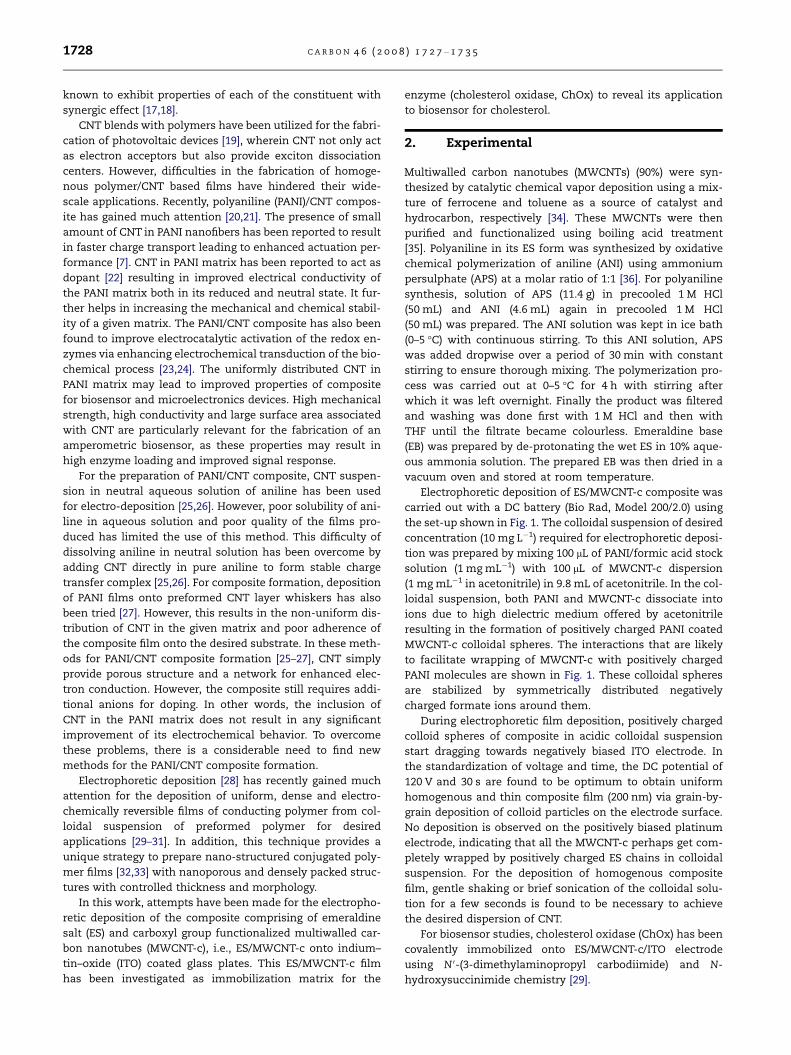
Electrophoretic deposition of ES/MWCNT-c composite was
carried out with a DC battery (Bio Rad, Model 200/2.0) using
the set-up shown in Fig. 1. The colloidal suspension of desired
concentration (10 mg L�1) required for electrophoretic deposi-
tion was prepared by mixing 100 lL of PANI/formic acid stock
solution (1 mg mL�1) with 100 lL of MWCNT-c dispersion
(1 mg mL�1 in acetonitrile) in 9.8 mL of acetonitrile. In the col-
loidal suspension, both PANI and MWCNT-c dissociate into
ions due to high dielectric medium offered by acetonitrile
resulting in the formation of positively charged PANI coated
MWCNT-c colloidal spheres. The interactions that are likely
to facilitate wrapping of MWCNT-c with positively charged
PANI molecules are shown in Fig. 1. These colloidal spheres
are stabilized by symmetrically distributed negatively
charged formate ions around them.
During electrophoretic film deposition, positively charged
colloid spheres of composite in acidic colloidal suspension
start dragging towards negatively biased ITO electrode. In
the standardization of voltage and time, the DC potential of
120 V and 30 s are found to be optimum to obtain uniform
homogenous and thin composite film (200 nm) via grain-by-
grain deposition of colloid particles on the electrode surface.
No deposition is observed on the positively biased platinum
electrode, indicating that all the MWCNT-c perhaps get com-
pletely wrapped by positively charged ES chains in colloidal
suspension. For the deposition of homogenous composite
film, gentle shaking or brief sonication of the colloidal solu-
tion for a few seconds is found to be necessary to achieve
the desired dispersion of CNT.
For biosensor studies, cholesterol oxidase (ChOx) has been
covalently immobilized onto ES/MWCNT-c/ITO electrode
using N 0-(3-dimethylaminopropyl carbodiimide) and N-
hydroxysuccinimide chemistry [29].
Colloidal suspension(MWCNT-c/ES)
ITO-coated glass
1cm
Platinum electrode
(+)(-)
Colloidal suspension(MWCNT-c/ES)
ITO-coated glass
1cm
Platinum electrode
(+)(-)
OO-
O-
O
OO
-
O-
O
N+
NH
NH
N+
..
H
H
n
N+
NH
NH
N+.
.
H
H n
NH
N+
N+
NH
.
.
H
H
H
N+
N+
NH NH ..H H
(a)
(b)O
O
O
O- O
-
OH
OH
O
O-
(c)
n
n
MWCNT-c wrapping by ES
+
MWCNT-c
Emeraldine salt (ES)
ES/MWCNT-c composite
(i)
(ii)
Fig. 1 – (i) Pictorial view of electrophoretic set-up used for composite film formation and (ii) interactions responsible for
ES/MWCNT-c composite formation: (a) p-stacking (b) electrostatic interactions and (c) hydrogen bonding.
C A R B O N 4 6 ( 2 0 0 8 ) 1 7 2 7 – 1 7 3 5 1729
The morphology and microstructures of ES/MWCNT-c film
have been investigated using Vecco DICP2 atomic force micro-
scope loaded with SPM-LAB analysis software. The investiga-
tion of wrapping of MWCNT-c with ES chains has been carried
out using scanning electron microscope (JEOL, JSM-35) and
transmission electron microscope (JEOL, JEM-2100). The
molecular analysis of all the samples has been done using
Fourier transform infrared (FT-IR) and ultraviolet–visible
(UV–visible) spectroscopies. The FT-IR spectra in the region
of 700–1800 cm�1 have been recorded using Perkin–Elmer
FT-IR model ‘‘Spectrum BX’’ equipped with the specular
reflectance accessory. The UV–visible studies have been car-
ried out using UV–visible spectrophotometer (Model
2200DPCV, Phoenix). Electrochemical investigations of both
ES and ES/MWCNT-c films have been carried out using Auto-
lab Potentiostat/Galvanostat (Eco Chemie, Netherlands) in a
conventional three-electrode electrochemical cell consisting
of Ag/AgCl as reference electrode and platinum foil as the
counter electrode. Cyclic voltammetry (CV) studies have been
carried out in phosphate buffer saline (PBS) solution (50 mM,
pH 7.0, 0.9% NaCl). Electrochemical impedance spectroscopy
(EIS) studies have been performed in the frequency range,
100 kHz–10 mHz with amplitude of 5 mV in PBS containing
mixture of 5 mM FeðCNÞ4�6 (ferrocyanide) and 5 mM of
FeðCNÞ3�6 (ferricyanide), i.e., 5 mM FeðCNÞ3�=4�6 as a redox
probe. All chemical reagents used in these experiments have
been procured from Sigma–Aldrich (USA) and have been used
as received. The response studies of ChOx/ES/MWCNT-c/ITO
bioelectrode have been done using linear sweep voltammetry
(LSV).
3. Results and discussion
3.1. FT-IR studies
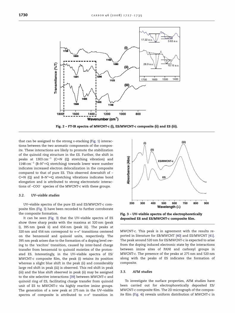
Fig. 2 shows the FT-IR spectra of (i) MWCNT-c, (ii) ES/MWCNT-
c composite and (iii) ES film in the region of 1800–700 cm�1. In
the FT-IR spectra of MWCNT-c (Fig. 2, curve (i)), the band at
1080 cm�1 is assigned to O–H deformation vibrations, peak
at 1166 cm�1 is assigned to C–O stretching vibrations. The
peak at 1728 cm�1 (Fig. 2, curve (i)) is attributed to –C@O
stretching vibrations in the carboxyl group. This indicates
the –COOH group functionalization of MWCNT [37]. Further,
FT-IR spectra shows a characteristic peak of MWCNT around
1600 cm�1 corresponding to –C@C– stretching. The FT-IR spec-
tra of ES (Fig. 2, curve (iii)) and the electrophoretically depos-
ited composite (Fig. 2, curve (ii)) show the presence of quinoid
and benzenoid ring vibrations at 1589 cm�1 and 1485 cm�1,
respectively [38]. The higher intensity of quinoid band com-
pared to that of the benzenoid band (Fig. 2, curve (iii)) is attrib-
uted to the presence of the PANI in its ES form.
The FT-IR spectrum of the ES/MWCNT-c composite (Fig. 2,
curve (ii)) film exhibits an increased quinoid (Q) to benzenoid
(B) band (1589/1486 cm�1) intensity ratio (4.73) compared to
that of the ES (2.85) without CNT. The observed increased ra-
tio reveals the richness of the composite with quinoid units
1800 1600 1400 1200 1000 800
(ii)
(iii)
(i)
1296
1123
11481303
1485
1589
1591
1600
1080
1166
1728
Tra
nsm
itan
ce (
%T
)
Wavenumber (cm-1)
17.22 a.u. 3.63 a.u.
28.9 a.u. 10.15 a.u.
1400150016001700
(ii)
(iii)
(i)
1296
1123
11481303
1485
1589
1591
1600
1080
1166
1728
Wavenumber (cm-1)
17.22 a.u. 3.63 a.u.
28.9 a.u. 10.15 a.u.
1400150016001700
17.22 a.u. 3.63 a.u.
28.9 a.u. 10.15 a.u.
1400150016001700
Fig. 2 – FT-IR spectra of MWCNT-c (i), ES/MWCNT-c composite (ii) and ES (iii).
200 300 400 500 600 700 800 900
(iii)
(ii)
(i)
ES
ES/MWCNT-c
Abs
orba
nce
(Abs
)
Wavelength (λ)
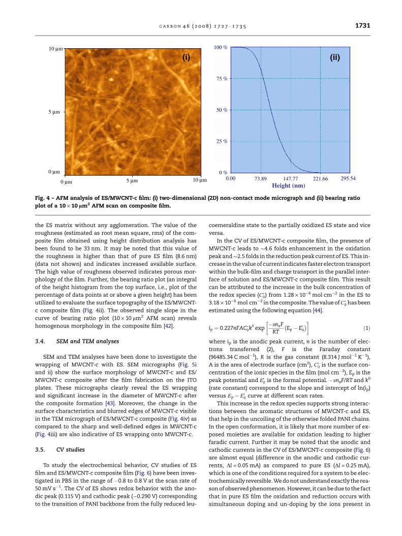
Fig. 3 – UV–visible spectra of the electrophoretically
deposited ES and ES/MWCNT-c composite film.
1730 C A R B O N 4 6 ( 2 0 0 8 ) 1 7 2 7 – 1 7 3 5
that can be assigned to the strong p-stacking (Fig. 1) interac-
tions between the two aromatic components of the compos-
ite. These interactions are likely to promote the stabilization
of the quinoid ring structure in the ES. Further, the shift in
peaks at 1303 cm�1 (C@N (Q) stretching vibration) and
1148 cm�1 (B–N+@Q stretching) towards lower wave number
indicates increased electron delocalization in the composite
compared to that of pure ES. This observed downshift of –
C@N (Q) and B–N+@Q stretching vibrations indicates bond
elongation and is attributed to strong electrostatic interac-
tions of –COO� species of the MWCNT-c with these groups.
3.2. UV–visible studies
UV–visible spectra of the pure ES and ES/MWCNT-c com-
posite film (Fig. 3) have been recorded to further corroborate
the composite formation.
It can be seen (Fig. 3) that the UV–visible spectra of ES
show three sharp peaks with the maxima at 320 nm (peak
i), 395 nm (peak ii) and 656 nm (peak iii). The peaks at
320 nm and 656 nm correspond to p–p* transitions centered
on the benzenoid and quinoid units, respectively. The
395 nm peak arises due to the formation of a doping level ow-
ing to the ‘exciton’ transition, caused by inter-band charge
transfer from benzenoid to quinoid moieties of the proton-
ated ES. Interestingly, in the UV–visible spectra of ES/
MWCNT-c composite film, the peak (i) retains its position
whereas a slight blue shift in the peak (ii) and considerably
large red shift in peak (iii) is observed. This red shift in peak
(iii) and the blue shift observed in peak (ii) may be assigned
to the site selective interactions [39] between MWCNT-c and
quinoid ring of ES, facilitating charge transfer from quinoid
unit of ES to MWCNT-c via highly reactive imine groups.
The generation of a new peak at 275 nm in the UV–visible
spectra of composite is attributed to p–p* transition in
MWCNT-c. This peak is in agreement with the results re-
ported in literature for EB/MWCNT [40] and ES/MWCNT [41].
The peak around 520 nm for ES/MWCNT-c is expected to arise
from the doping induced electronic state by the interactions
between imine sites of PANI and carboxyl groups in
MWCNT-c. The presence of the peaks at 275 nm and 520 nm
along with the peaks of ES indicates the formation of
composite.
3.3. AFM studies
To investigate the surface properties, AFM studies have
been carried out for electrophoretically deposited ES/
MWCNT-c composite film. The 2D micrograph of the compos-
ite film (Fig. 4i) reveals uniform distribution of MWCNT-c in
Height (nm)
(i) (ii)100 % 10 μm
10 μm
5 μm
5 μm
0 μm
0 μm
75 %
50 %
25 %
0 % 0.00 295.5473.89 147.77 221.66
Fig. 4 – AFM analysis of ES/MWCNT-c film: (i) two-dimensional (2D) non-contact mode micrograph and (ii) bearing ratio
plot of a 10 · 10 lm2 AFM scan on composite film.
C A R B O N 4 6 ( 2 0 0 8 ) 1 7 2 7 – 1 7 3 5 1731
the ES matrix without any agglomeration. The value of the
roughness (estimated as root mean square, rms) of the com-
posite film obtained using height distribution analysis has
been found to be 33 nm. It may be noted that this value of
the roughness is higher than that of pure ES film (8.6 nm)
(data not shown) and indicates increased available surface.
The high value of roughness observed indicates porous mor-
phology of the film. Further, the bearing ratio plot (an integral
of the height histogram from the top surface, i.e., plot of the
percentage of data points at or above a given height) has been
utilized to evaluate the surface topography of the ES/MWCNT-
c composite film (Fig. 4ii). The observed single slope in the
curve of bearing ratio plot (10 · 10 lm2 AFM scan) reveals
homogenous morphology in the composite film [42].
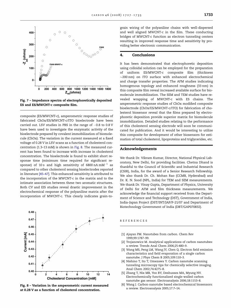
3.4. SEM and TEM analyses
SEM and TEM analyses have been done to investigate the
wrapping of MWCNT-c with ES. SEM micrographs (Fig. 5i
and ii) show the surface morphology of MWCNT-c and ES/
MWCNT-c composite after the film fabrication on the ITO
plates. These micrographs clearly reveal the ES wrapping
and significant increase in the diameter of MWCNT-c after
the composite formation [43]. Moreover, the change in the
surface characteristics and blurred edges of MWCNT-c visible
in the TEM micrograph of ES/MWCNT-c composite (Fig. 4iv) as
compared to the sharp and well-defined edges in MWCNT-c
(Fig. 4iii) are also indicative of ES wrapping onto MWCNT-c.
3.5. CV studies
To study the electrochemical behavior, CV studies of ES
film and ES/MWCNT-c composite film (Fig. 6) have been inves-
tigated in PBS in the range of �0.8 to 0.8 V at the scan rate of
50 mV s�1. The CV of ES shows redox behavior with the ano-
dic peak (0.115 V) and cathodic peak (�0.290 V) corresponding
to the transition of PANI backbone from the fully reduced leu-
coemeraldine state to the partially oxidized ES state and vice
versa.
In the CV of ES/MWCNT-c composite film, the presence of
MWCNT-c leads to �4.6 folds enhancement in the oxidation
peak and�2.5 folds in the reduction peak current of ES. This in-
crease in thevalue of current indicates fasterelectron transport
within the bulk-film and charge transport in the parallel inter-
face of solution and ES/MWCNT-c composite film. This result
can be attributed to the increase in the bulk concentration of
the redox species (C�0) from 1.28 · 10�6 mol cm�2 in the ES to
3.18 · 10�6 mol cm�2 in the composite. Thevalue of C�0 has been
estimated using the following equation [44].
ip ¼ 0:227nFAC�0k0 exp�anaF
RTEp � E00� �� �
ð1Þ
where ip is the anodic peak current, n is the number of elec-
trons transferred (2), F is the Faraday constant
(96485.34 C mol�1), R is the gas constant (8.314 J mol�1 K�1),
A is the area of electrode surface (cm2), C�0 is the surface con-
centration of the ionic species in the film (mol cm�2), Ep is the
peak potential and E00 is the formal potential. �anaF/RT and k0
(rate constant) correspond to the slope and intercept of ln(ip)
versus Ep � E00 curve at different scan rates.
This increase in the redox species supports strong interac-
tions between the aromatic structures of MWCNT-c and ES,
that help in the uncoiling of the otherwise folded PANI chains.
In the open conformation, it is likely that more number of ex-
posed moieties are available for oxidation leading to higher
faradic current. Further it may be noted that the anodic and
cathodic currents in the CV of ES/MWCNT-c composite (Fig. 6)
are almost equal (difference in the anodic and cathodic cur-
rents, DI = 0.05 mA) as compared to pure ES (DI = 0.25 mA),
which is one of the conditions required for a system to be elec-
trochemically reversible. We do not understand exactly the rea-
son of observed phenomenon. However, it can be due to the fact
that in pure ES film the oxidation and reduction occurs with
simultaneous doping and un-doping by the ions present in
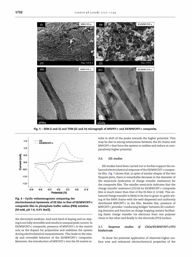
Fig. 5 – SEM (i and ii) and TEM (iii and iv) micrograph of MWNT-c and ES/MWCNT-c composite.
-0.9 -0.6 -0.3 0.0 0.3 0.6 0. 9
-1.5
-1.0
-0.5
0.0
0.5
1.0
1.5ES/MWCNT-cES
Cur
rent
(mA
)
Potential (V)
Fig. 6 – Cyclic voltammograms comparing the
electrochemical hysteresis of ES film to that of ES/MWCNT-c
composite film in phosphate buffer saline (PBS) solution
(50 mM, pH 7.0, 0.9% NaCl).
1732 C A R B O N 4 6 ( 2 0 0 8 ) 1 7 2 7 – 1 7 3 5
the electrolyte medium. And such kind of doping and un-dop-
ing is not fully reversible and results in unequal peak current. In
ES/MWCNT-c composite, presence of MWCNT-c in the matrix
acts as the dopant for polyaniline and stabilizes the system
during electrochemical measurements. This leads to the stea-
dy and reversible behavior of the ES/MWCNT-c composite.
Moreover, the introduction of MWCNT-c into the ES matrix re-
sults in shift of the peaks towards the higher potential. This
may be due to strong interactions between the ES chains and
MWCNT-c that force the system to oxidize and reduce at com-
paratively higher potential.
3.6. EIS studies
EIS studies have been carried out to further support the en-
hanced electrochemical response of the ES/MWCNT-c compos-
ite film. Fig. 7 shows that, in spite of similar shapes of the two
Nyquist plots, there is remarkable decrease in the diameter of
the semicircle (indicative of charge transfer resistance) for
the composite film. The smaller semicircle indicates that the
charge transfer resistance (210 X) for ES/MWCNT-c composite
film is much lower than that of the ES film (1.12 kX). This en-
hanced charge transfer is likely to be due to grain-to-grain wir-
ing of the PANI chains with the well-dispersed and uniformly
distributed MWCNT-c in the film. Besides this, presence of
MWCNT-c provides ‘conducting bridges’ between ES conduct-
ing domains and function as charge hopping centers facilitat-
ing faster charge transfer via electrons from one polymer
chain to the other and finally to the electrode (ITO) surface.
3.7. Response studies of ChOx/ES/MWCNT-c/ITObioelectrode
To show the potential application of observed higher sur-
face area and enhanced electrochemical properties of the
0 200 400 600 800 1000 1200 1400 1600 1800
0
100
200
300
400
PANI-MWNT-c
PANI
-Zim
(oh
ms)
Zre(ohms)
Fig. 7 – Impedance spectra of electrophoretically deposited
ES and ES/MWCNT-c composite film.
C A R B O N 4 6 ( 2 0 0 8 ) 1 7 2 7 – 1 7 3 5 1733
composite (ES/MWCNT-c), amperometric response studies of
fabricated ChOx/ES/MWCNT-c/ITO bioelectrode have been
carried out. LSV studies in PBS in the range of �0.8 to 0.8 V
have been used to investigate the enzymatic activity of the
bioelectrode prepared by covalent immobilization of biomole-
cule (ChOx). The variation in the current measured at a fixed
voltage of 0.28 V in LSV scans as a function of cholesterol con-
centration (1.3–13 mM) is shown in Fig. 8. The measured cur-
rent has been found to increase with increase in cholesterol
concentration. The bioelectrode is found to exhibit short re-
sponse time (minimum time required for significant re-
sponse) of 10 s and high sensitivity of 6800 nA mM�1 as
compared to other cholesterol sensing bioelectrodes reported
in literature [45–47]. This enhanced sensitivity is attributed to
the incorporation of the MWCNT-c in the matrix and to the
intimate association between these two aromatic structures.
Both CV and EIS studies reveal drastic improvement in the
electrochemical response of the polyaniline matrix after the
incorporation of MWCNT-c. This clearly indicates grain-to-
0 2 4 6 8 10 12 140.40
0.41
0.42
0.43
0.44
0.45
0.46
0.47
0.48
Cur
rent
[mA
]
Cholesterol Concentration [mM]
Fig. 8 – Variation in the amperometric current measured
at 0.28 V as a function of cholesterol concentration.
grain wiring of the polyaniline chains with well-dispersed
and well aligned MWCNT-c in the film. These conducting
bridges of MWCNT-c function as electron tunneling centers
resulting in improved response time and sensitivity by pro-
viding better electronic communication.
4. Conclusions
It has been demonstrated that electrophoretic deposition
using colloidal solution can be employed for the preparation
of uniform ES/MWCNT-c composite film (thickness
�200 nm) on ITO surface with enhanced electrochemical
and charge transfer properties. The AFM studies indicating
homogenous topology and enhanced roughness (33 nm) in
this composite film reveal increased available surface for bio-
molecule immobilization. The SEM and TEM studies have re-
vealed wrapping of MWCNT-c with ES chains. The
amperometric response studies of ChOx modified composite
bioelectrode (ChOx/ES/MWCNT-c/ITO) for fabrication of cho-
lesterol biosensor reveal that the films prepared by electro-
phoretic deposition provide superior matrix for biomolecule
immobilization. Detailed studies relating to the performance
of this cholesterol sensing electrode will soon be communi-
cated for publication. And it would be interesting to utilize
this composite for development of other biosensors for esti-
mation of total cholesterol, lipoproteins and triglycerides, etc.
Acknowledgements
We thank Dr. Vikram Kumar, Director, National Physical Lab-
oratory, New Delhi, for providing facilities. Chetna Dhand is
thankful to the Council of Scientific and Industrial Research
(CSIR), India, for the award of a Senior Research Fellowship.
We also thank Dr. Ch. Mohan Rao (CCMB, Hyderabad) and
Dr. K. N. Sood (NPL, India) for TEM and SEM measurements.
We thank Dr. Vinay Gupta, Department of Physics, University
of Delhi for AFM and film thickness measurements. We
acknowledge the financial support received from the Depart-
ment of Science and Technology (DST), Government of India,
India–Japan Project (DST/INT/JAP/P-21/07 and Department of
Biotechnology Government of India (DBT/GAP070832).
R E F E R E N C E S
[1] Ajayan PM. Nanotubes from carbon. Chem Rev1999;99:1787–99.
[2] Trojanowicz M. Analytical applications of carbon nanotubes:a review. Trends Anal Chem 2006;25:480–9.
[3] Wang MS, Peng LM, Wang JY, Chen Q. Electron field emissioncharacteristics and field evaporation of a single carbonnanotube. J Phys Chem B 2005;109:110–3.
[4] Nishino T, Ito T, Umezawa Y. Carbon nanotube scanningtunneling microscopy tips for chemically selective imaging.Anal Chem 2002;74:4275–8.
[5] Zhang T, Nix MB, Yoo BY, Deshusses MA, Myung NV.Electrochemically functionalized single-walled carbonnanotube gas sensor. Electroanalysis 2006;18:1153–8.
[6] Wang J. Carbon-nanotube based electrochemical biosensors:a review. Electroanalysis 2005;17:7–14.
1734 C A R B O N 4 6 ( 2 0 0 8 ) 1 7 2 7 – 1 7 3 5
[7] Spinks GM, Mottaghitalab V, Samani MB, Whitten PG, WallaceGG. Carbon-nanotube-reinforced polyaniline fibers for high-strength artificial muscles. Adv Mater 2006;18:637–40.
[8] Chen J, Hamon MA, Hu H, Chen Y, Rao AM, Eklund PC, et al.Solution properties of single-walled carbon nanotubes.Science 1998;282:95–8.
[9] Breuer O, Sundararaj U. Big returns from small fibers: areview of polymer/carbon nanotube composites. PolymCompos 2004;25:630–45.
[10] Dalton AB, Stephan C, Coleman JN, McCarthy B, Ajayan PM,Lefrant S, et al. Selective interaction of a semiconjugatedorganic polymer with single-wall nanotubes. J Phys Chem B2000;104:10012–6.
[11] Szleifera I, Rozen RY. Polymers and carbon nanotubes—dimensionality, interactions and nanotechnology. Polymer2005;46:7803–18.
[12] Xu XB, Li ZM, Shi L, Bian XC, Xiang ZD. Ultralight conductivecarbon-nanotube–polymer composite. Small 2007;3:408–11.
[13] Showkat AM, Lee KP, Gopalan AI, Kim SH, Choi SH, Sohn SH.Characterization and preparation of new multiwall carbonnanotube/conducting polymer composites by in situpolymerization. J Appl Polym Sci 2006;101:3721–9.
[14] Wu M, Snook GA, Gupta V, Shaffer M, Fray DJ, Chen GZ.Electrochemical fabrication and capacitance of compositefilms of carbon nanotubes and polyaniline. J Mater Chem2005;5:2297–303.
[15] Yang Z, Chen X, Chen C, Li W, Zhang H, Xu L, et al.Noncovalent-wrapped sidewall functionalization ofmultiwalled carbon nanotubes with polyimide. PolymCompos 2007;28:36–41.
[16] Star A, Stoddart JF, Steuerman D, Diehl M, Boukai A, WongEW, et al. Preparation and properties of polymer-wrappedsingle-walled carbon nanotubes. Angew Chem Int Ed2001;40:1721–5.
[17] Coleman JN, Curran S, Dalton AB, Davey AP, McCarthy B, BlauW, et al. Physical doping of a conjugated polymer withcarbon nanotubes. Synth Met 1999;02:1174–5.
[18] Kymakis E, Amaratunga GA. Single-wall carbon nanotube/conjugated polymer photovoltaic devices. Appl Phys Lett2002;80:112–4.
[19] Pradhan B, Batabyal SK, Pala AJ. Functionalized carbonnanotubes in donor/acceptor-type photovoltaic devices. ApplPhys Lett 2006;88. 093106-1–093106-3.
[20] Pandey SS, Ram MK, Srivastava VK, Malhotra BD. Electricalproperties of metal (indium)/polyaniline Schottky devices.J Appl Polym Sci 1997;5:2745–8.
[21] Pandey SS, Annaporni S, Malhotra BD. Synthesis andcharacterization of poly-(aniline-co-o-anisidine). Aprocessable conducting copolymer. Macromolecules1993;26:3190–3.
[22] Zengin H, Zhou W, Jin J, Czerw R, Smith DW, Echegoyen L,et al. Carbon nanotube doped polyaniline. Adv Mater2002;4:1481–3.
[23] Santhosh P, Manesh KM, Lee KP, Gopalana AI. Enhancedelectrocatalysis for the reduction of hydrogen peroxide atnew multiwall carbon nanotube grafted polydiphenylaminemodified electrode. Electroanalysis 2006;8:89403.
[24] Liu J, Tian S, Knoll W. Properties of polyaniline/carbonnanotube multilayer films in neutral solution and theirapplication for stable low-potential detection of reduced b-nicotinamide adenine dinucleotide. Langmuir2005;21:5596–9.
[25] Guo DJ, Li HL. Well-dispersed multi-walled carbon nanotube/polyaniline composite films. J Solid State Electrochem2005;9:445–9.
[26] Luo X, Killard AJ, Morrin A, Smyth MR. Enhancement of aconducting polymer-based biosensor using carbonnanotube-doped polyaniline. Anal Chim Acta 2006;575:39–44.
[27] Downs C, Nugent J, Ajayan PM, Duquette DJ, Santhanam KSV.Efficient polymerization of aniline at carbon nanotubeelectrodes. Adv Mater 1999;11:1028–31.
[28] Besra L, Liu M. A review on fundamentals and applications ofelectrophoretic deposition (EPD). Prog Mater Sci 2007;52:1–61.
[29] Dhand C, Singh SP, Arya SK, Datta M, Malhotra BD.Cholesterol biosensor based on electrophoretically depositedconducting polymer film derived from nano-structuredpolyaniline colloidal suspension. Anal Chim Acta2007;602:244–51.
[30] Tada K, Onoda M. Preparation and application ofnanostructured conjugated polymer film by electrophoreticdeposition. Thin Solid Films 2003;438–439:365–8.
[31] Tada K, Onoda M. Nanostructured conjugated polymer filmsfor electroluminescent and photovoltaic applications. ThinSolid Films 2005;477:187–92.
[32] Tada K, Onoda M. Nanostructured conjugated polymer filmsby electrophoretic deposition. Adv Funct Mater 2002;2:420–4.
[33] Li G, Martinez C, Semancik S. Controlled electrophoreticpatterning of polyaniline from a colloidal suspension. J AmChem Soc 2005;127:4903–9.
[34] Mathur RP, Chatterjee S, Singh BP. Growth of carbonnanotubes on carbon fibre substrates to produce hybrid/phenolic composites with improved mechanical properties.Compos Sci Technol 2008;68:1608–15.
[35] Du C, Pan N. High power density supercapacitor electrodes ofcarbon nanotube films by electrophoretic deposition.Nanotechnology 2006;17:5314–8.
[36] Morgan H, Foot PJS, Brooks NW. The effects of compositionand processing variables on the properties of thermoplasticpolyaniline blends and composites. J Mater Sci2001;36:5369–77.
[37] Yan XB, Han ZJ, Yang Y, Tay BK. Fabrication of carbonnanotube-polyaniline composites via electrostaticadsorption in aqueous colloids. J Phys Chem C2007;111:4125–31.
[38] Ping Z, Nauer GE, Neugebauer H, Theiner J, Neckel A.Protonation and electrochemical redox doping processes ofpolyaniline in aqueous solutions: Investigations using in situFTIR-ATR spectroscopy and a new doping system. J Chem SocFaraday Trans 1997;93:121–9.
[39] Cochet M, Maser WK, Benito AM, Callejas MA, Martinez MT,Benoit JM, et al. Synthesis of a new polyaniline/nanotubecomposite: ‘‘in-situ’’ polymerisation and charge transferthrough site-selective interaction. Chem Commun2001:1450–1.
[40] Sainz R, Benito AM, Martinez MT, Galindo JF, Sotres J, BaroAM, et al. Soluble self-aligned carbon nanotube/polyanilinecomposites. Adv Mater 2005;17:278–81.
[41] Panhuis M, Sainz R, Innis PC, Maguire LAP, Benito AM,Martinez T, et al. Optically active polymer carbon nanotubecomposite. J Phys Chem B 2005;109:22725–9.
[42] Guille C, Gandıa JJ, Morales A, Herrero J. SiO2 sol–gel-coatedconducting substrates for CuInSe2 electrodeposition. SurfCoat Technol 1999;115:45–51.
[43] Konyushenko EN, Stejskal J, Trchova M, Hradil J, Kovarova J,Prokes J, et al. Multi-wall carbon nanotubes coated withpolyaniline. Polymer 2006;47:5715–23.
[44] Prabhakar N, Arora K, Singh SP, Pandey MK, Singh H,Malhotra BD. Polypyrrole-polyvinyl sulphonate film baseddisposable nucleic acid biosensor. Anal Chim Acta2007;589:6–13.
[45] Zhou N, Wang J, Chen T, Yu Z, Li G. Enlargement of goldnanoparticles on the surface of self-assembled monolayermodified electrode: a mode in biosensor design. Anal Chem2006;78:5227–30.

C A R B O N 4 6 ( 2 0 0 8 ) 1 7 2 7 – 1 7 3 5 1735
[46] Solanki PR, Arya SK, Singh SP, Pandey MK, Malhotra BD.Application of electrochemically prepared poly-N-methylpyrrole-p-toluene sulphonate films to cholesterolbiosensor. Sens Actuators B 2007;123:829–39.
[47] Qiaocui S, Tuzhi P, Yunu Z, Yang CF. An electrochemicalbiosensor with cholesterol oxidase/sol–gel film on ananoplatinum/carbon nanotube electrode. Electroanalysis2005;17:857–61.
Related Documents