PREPARATION OF DENSE BARIUM CERATE FILM ON A PLANAR POROUS SUPPORT FOR HYDROGEN SEPARATION MEMBRANES By RUCHITA D. BAGUL A THESIS PRESENTED TO THE GRADUATE SCHOOL OF THE UNIVERSITY OF FLORIDA IN PARTIAL FULFILLMENT OF THE REQUIREMENTS FOR THE DEGREE OF MASTER OF SCIENCE UNIVERSITY OF FLORIDA 2004

Welcome message from author
This document is posted to help you gain knowledge. Please leave a comment to let me know what you think about it! Share it to your friends and learn new things together.
Transcript
PREPARATION OF DENSE BARIUM CERATE FILM ON A PLANAR POROUS
SUPPORT FOR HYDROGEN SEPARATION MEMBRANES
By
RUCHITA D. BAGUL
A THESIS PRESENTED TO THE GRADUATE SCHOOL OF THE UNIVERSITY OF FLORIDA IN PARTIAL FULFILLMENT
OF THE REQUIREMENTS FOR THE DEGREE OF MASTER OF SCIENCE
UNIVERSITY OF FLORIDA
2004
Copyright 2004
by
Ruchita D. Bagul

ACKNOWLEDGMENTS
I would like to thank Dr Eric Wachsman for giving me an opportunity to work
under his guidance. I would also like to thank Dr Daryl Butt and Dr Wolfgang Sigmund
for being on my committee. Also thanks go to Keith, Dr Hee-Sung Yoon, Sun-Ju, Jun,
Abhishek, Guojing, Matt, Jamie, Briggs and all others for helping me in my project.
Above all I thank my parents and my brother who supported me during all this time
and helped me overcome my problems.
iii

TABLE OF CONTENTS page ACKNOWLEDGMENTS ................................................................................................. iii
LIST OF TABLES............................................................................................................. vi
LIST OF FIGURES .......................................................................................................... vii
ABSTRACT....................................................................................................................... ix
CHAPTER 1 LITERATURE REVIEW .............................................................................................1
Introduction...................................................................................................................1 Ceramic Membranes and Protonic Conductivity..........................................................3 Why a Thin Dense Ceramic Film Required?................................................................5 Classification Of Proton Conductors ............................................................................7
High Temperature Proton Conducting Oxides(HTPC) .........................................7 Intermediate Temperature Proton Conductors ......................................................7 Low Temperature Proton Conducting Polymers ...................................................8
Transport Process........................................................................................................10 Proton Migration methods...................................................................................10 Proton Conduction...............................................................................................11 Proton Diffusion ..................................................................................................14
Stability of Perovskite Oxides ....................................................................................15 Processing of Ceramics...............................................................................................19
Pechini Process....................................................................................................20 Homogeneous Oxalate Coprecipitation...............................................................20 Glycine Nitrate Process .......................................................................................21 Porbaix Diagram..................................................................................................21
Film Deposition ..........................................................................................................24 Colloidal Deposition............................................................................................26 Spin Coating ........................................................................................................27 Tape Casting........................................................................................................28
2 PREPARATION OF DENSE BARIUM CERATE FILM ON A PLANAR POROUS
SUPPORT FOR HYDROGEN SEPARATION MEMBRANE.................................30
Experimental...............................................................................................................30
iv

Preparation of Barium Cerate Electrolyte Powders.............................................30 Results and Discussions..............................................................................................33
Characterization...................................................................................................33 TGA-DTA Results .......................................................................................33 XRD Observations .......................................................................................36 Particle Size distribution ..............................................................................41 Determination of optimum sintering temperature and microstructure of
film..........................................................................................................41 Conclusions.................................................................................................................42
3 PREPARATION OF DENSE EUROPIUM DOPED BARIUM-CERATE FILM ON
A PLANAR POROUS SUPPORT FOR HYDROGEN SEPARATION MEMBRANE .............................................................................................................47
Experimental...............................................................................................................48 Preparation of Eu Doped Barium Cerate Powder................................................48 Slurry preparation and Spin coating ....................................................................49
Results and Discussions..............................................................................................50 Conclusions.................................................................................................................51
CONCLUSIONS................................................................................................................66
LIST OF REFERENCES...................................................................................................71
BIOGRAPHICAL SKETCH .............................................................................................77
v

LIST OF TABLES
Table page 1 Possible devices using HTPC solid electrolytes ........................................................9
2 Composition of slurry for spin coating ....................................................................49
vi

LIST OF FIGURES
Figure page 1. Structure of a perovskite structure of type ABO3 (A=Ba, B=Ce in BaCeO3)..................4
2. Schematical use of mixed oxygen ion–electronic conductor for oxygen .......................6
3. The trace of a proton in a perovskite showing two principal features ..........................17
4. Effect of orthorhombic distortion of BaCeO3 and SrCeO3 on the basicity of O1 .......18
5. Porbaix diagrams for barium , cerium and europium metal ..........................................25
6. Schematic of a Tape Casting Machine...........................................................................29
7. Proton conductivities of various oxides as calculated from data on proton ..................32
8. TGA-DTA measurements of powders from Pechini process ......................................34
9. XRD spectra for powders made by Pechini process .....................................................37
10. XRD spectra according to content of citric acid ........................................................38
11. XRD spectra for powder calcined at 1100 oC by Oxalate method .............................39
12. Particle size distribution for powder calcined at 1100 oC from oxalate method. ........39
13. Particle size distribution for Pechini powder calcined at 1000 oC ..............................40
14. Shrinkage rate % vs Temperature between BaCeO3 and NiO-GDC powder ..............43
15. Surface view of film from oxalate powder sintered at 1300 oC...................................44
16. Surface view of film from oxalate powder sintered at 1400 oC...................................44
17. Surface view of film from oxalate powder sintered at 1500 oC...................................45
18. Cross-section view of film from oxalate powder sintered at 1500 oC .........................45
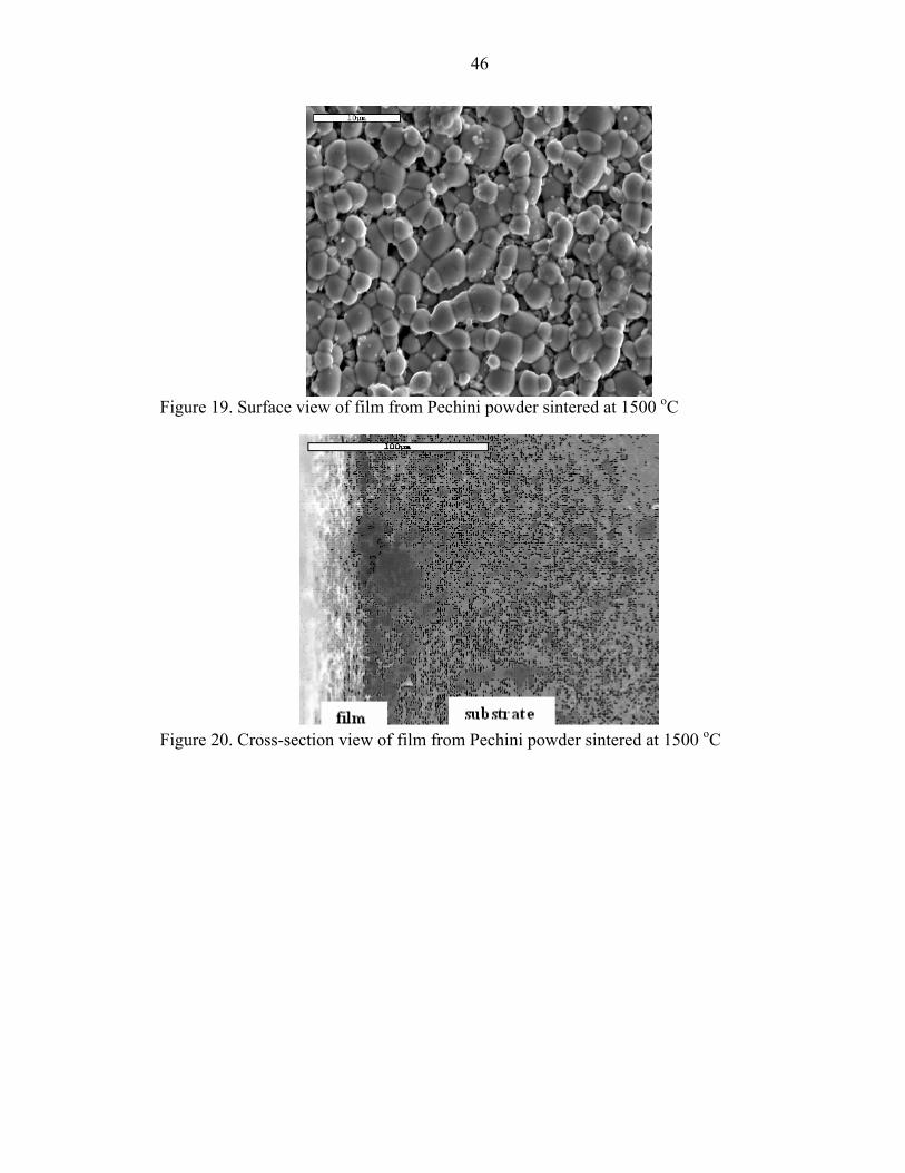
19. Surface view of film from Pechini powder sintered at 1500 oC ..................................46
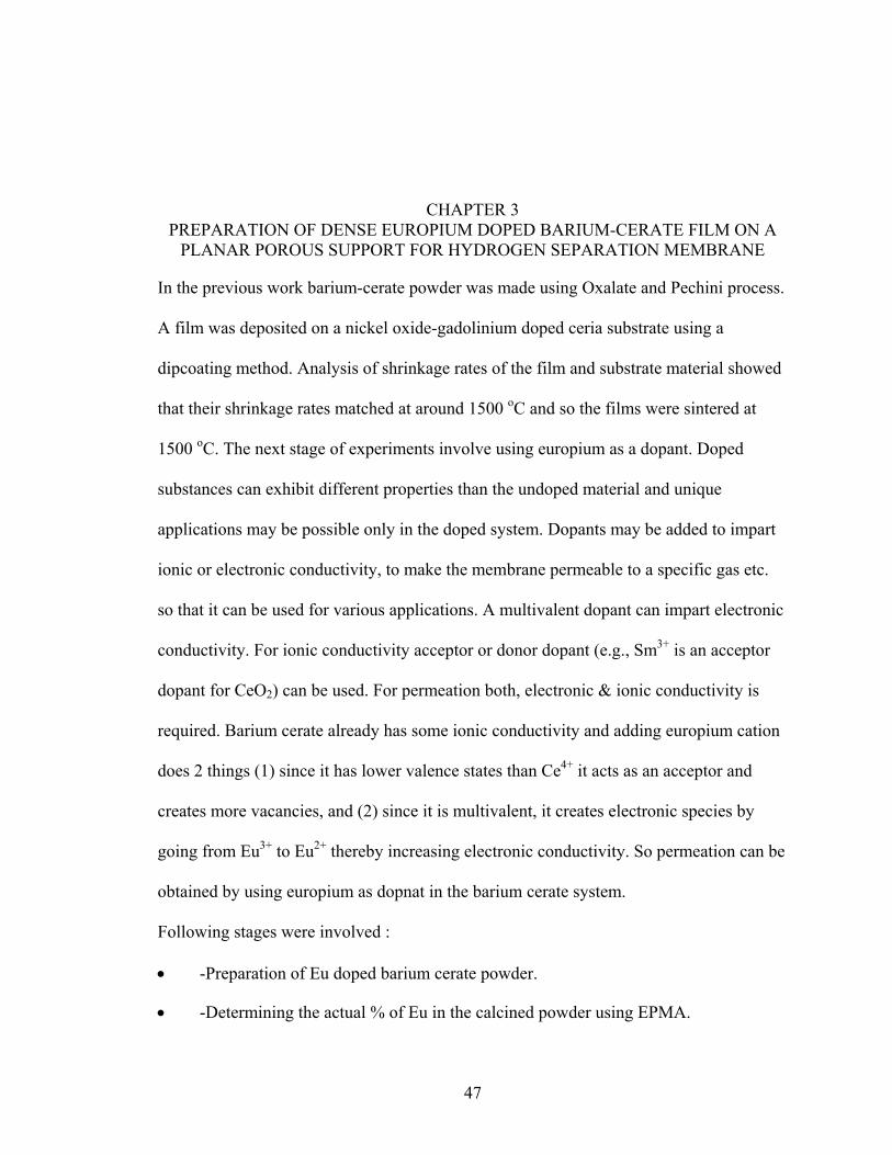
20. Cross-section view of film from Pechini powder sintered at 1500 oC.........................46
vii
21. Flow chart for preparation of Tape Cast substrate.......................................................53
22. Surface view of spin coated film sintered at 1400 oC on tape cast substrate...............54
23. Surface view of spin coated film sintered at 1450 oC on tape cast substrate...............55
24. Surface view of spin coated film sintered at 1500 oC on tape cast substrate.............56
25. Cross-section view of spin coated film sintered at 1500 oC on tape cast substrate .....57
26. Surface view of spin coated film sintered at 1400 oC on tape cast substrate...............58
27. Surface view of spin coated film sintered at 1500 oC on Uniaxially ..........................59
28. Cross-section view of spin coated film sintered at 1500 oC on Uniaxially ................60
29. Surface view of spin coated film sintered at 1500 oC on tape cast .............................61
30. Surface view of spin coated film sintered at 1500 oC on tape cast substrate...............62
31. Cross-section view of spin coated film sintered at 1500 oC on tape cast substrate .....63
32. Film sintered at 1500 oC.for 5hours.............................................................................64
33. Film sintered at 1500 oC for 8 hours............................................................................64
34. Film sintered at 1600 oC for 5 hours............................................................................65
35. Film sintered at 1600 oC for 8 hours............................................................................65
viii

Abstract of Thesis Presented to the Graduate School
of the University of Florida in Partial Fulfillment of the Requirements for the Degree of Master of Science
PREPARATION OF DENSE BARIUM CERATE FILM ON A PLANAR POROUS SUPPORT FOR HYDROGEN SEPARATION MEMBRANES
By
Ruchita D. Bagul
August 2004
Chair: Eric Wachsman Major Department: Materials Science and Engineering
Perovskite based compounds are being researched for their high proton
conductivities. Of the different perovskite materials available, barium cerate is widely
being studied as a potential material for hydrogen separation membranes. It has been
shown to exhibit high protonic conductivities at high temperatures in the presence of
watervapour or hydrogen atmosphere.
In the first phase barium cerate was prepared by the Pechini and Oxalate Co-
precipitation method, and the powder obtained was calcined at high temperatures. The
powder was characterized by XRD for determination of single phase and BET Coulter for
particle size. Nickel oxide-gadolinium doped ceria substrate was prepared by uniaxial
press method and barium cerate film was deposited by dip coating. The film was fired at
different temperatures to obtain a dense film. Scanning Electron Microscopy was done to
ix

determine the film density. Sintering temperature of 1500 oC was found to give a dense
film though the film still exhibited some porosity.
In the second phase europium doped barium cerate was made by the oxalate
method while the substrate was made by the tape casting method. Films were deposited
on uniaxially pressed and tape casted substrates by spin coating. Films on tape casted
substrate were more dense than those on the uniaxial pressed ones. Dense patches of film
with some pores were found which could be due to the difference in shrinkage rates
between the film and substrate material.
x
CHAPTER 1 LITERATURE REVIEW
Introduction
According to scientists hydrogen is believed to be formed during a “Big Bang”
some 15 million years ago. Discovered by an English chemist Henry Cavendish some
200 years ago (1), hydrogen is being looked at as a potential source for fulfilling the
worlds energy needs in the 21st century. Nations all over the world are trying to find ways
to harness this readily available energy so that it can be put to use.
So why is the entire world suddenly trying to move to a hydrogen economy? Let us
first have a brief overview of hydrogen first. The world hydrogen comes from the Greek
words “hydro” (meaning water) and “genes” (meaning generator) (1). It is the simplest,
lightest and most abundant element in the universe. And now it has been found that
hydrogen as a fuel could be the best alternative to replace the depleting natural energy
reserves.
To list a few advantages of using hydrogen as a fuel:
• It is an excellent energy carrier.
• No green house gases are generated in its use since there is no carbon in the fuel.
• Hydrogen can reduce the depletion of fossil fuel reserves.
• Hydrogen holds more chemical energy pound for pound than any other fuel.
• Hydrogen produces effectively zero emissions when it is burned in an engine and only water when powering a fuel cell.
• It can be produced from the abundantly available domestic resources such as natural gas, coal, biomass and even water.
1
2
A look at the American oil requirement shows that America imports 55% of the oil
it consumes which is expected to grow to 68% by 2025 (2). Hydrogen economy could
reduce this dependence by over 11 million barrels per day by 2040. This in turn could
reduce the greenhouse gas emissions from transportation alone by more than 500 million
metric tons of carbon equivalent each year by 2040 (2). Considering these socioeconomic
and environmental advantages which are also applicable more or less to the rest of the
world there is a huge incentive in trying to develop cost effective ways of producing
hydrogen.
There are a variety of ways by which hydrogen can be extracted from different
sources:
• Steam reforming of methane to produce hydrogen and carbon monoxide by reaction with steam over a nickel catalyst.
• Electrolysis to split water into hydrogen at cathode and oxygen at anode.
• Themochemical water splitting using chemicals and heat.
• Biological systems in which microbes break down biomass into hydrogen.
• Thermal water splitting using high temperatures.
• Photoelectrochemical systems use semiconducting materials to split water using sunlight.
For the next few decades, hydrogen will be generated from fossil fuels until cleaner
hydrogen sources can be developed. Pure H2 streams will need to be produced via
separation from mixed gas streams containing CO, CO2, H2O, hydrocarbons and other
gases by separation processes. Pure H2 is needed for fuel cells, to facilitate H2 storage, to
recover H2 from mixed gas products in the petrochemical industries, and for upgrading of
petroleum products to fuels (3). However at present there are no viable high temperature
separation membranes capable of producing pure H2 streams. This area of research needs

3
to be rapidly expanded over the next decade if the Hydrogen Economy is to become a
reality.
Ceramic Membranes and Protonic Conductivity
Ion transport membranes composed of proton conducting materials are a critical
component for future fuel processing and energy production systems, as well as ancillary
technologies such as fuel cells, sensors, and electrolyzers. Proton conducting membranes
are necessary to extract pure hydrogen from mixed gas streams in the processing of fossil
fuels and other petroleum and petrochemical processes. The best candidate membrane
materials for hydrogen separation at high temperatures are proton conducting ceramic
oxides.
In the 1980’s Iwahara et al. discovered that perovskite based oxides had the ability of
high temperature proton conduction. SrCeO3 and BaCeO3 doped with trivalent cations
such as Y, Yb, Gd and Eu have been identified as good high temperature proton
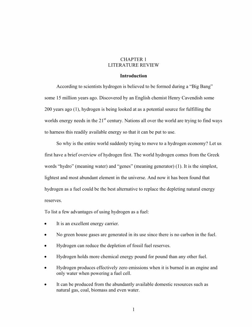
conductors (4,5-10). The general formula for representing these materials is ABO3,
Figure 1 or for doped perovskites A1-xAxB1-yByO3-δ, where x and y are the fraction of
dopants in the A and B site respectively and δ is the number of oxygen vacancies.
Oxygen vacancies can be produced by doping the B site with lower valence cations.
Different parameters such as dopant concentration, the number of oxygen vacancies,
atmospheric conditions and temperature etc. determine the quantity of proton charge
carriers that can be introduced in a given material. In case of BaCeO3 depending on the
exact composition and operation conditions proton concentrations varying from 0.1
mole% to greater than 10 mole% can be obtained (5,11-14). Doping these perovskite
materials increases the charge carrier concentration which in turn increases the proton
conductivity when compared with the undoped materials.
4
Figure 1. Structure of a perovskite structure of type ABO3 (A=Ba, B=Ce in BaCeO3)

5
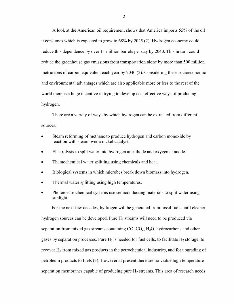
Hydrogen separation can be achieved using a dense ceramic based membrane.
Figure 2 shows how pure hydrogen can be extracted from a mixture of gases. Here a
syngas mixture (H2, CO and CO2) is passed across the membrane surface where catalytic
oxidation of hydrogen takes place. Protons and electrons are generated which incorporate
into the material membrane lattice, which are then conducted to the reduction surface. A
reverse reduction reaction occurs at this surface and pure hydrogen is produced. If this
technology is able to produce reasonable separation rates it can offer following
advantages over alternative separation methods (15):
• The membrane materials are relatively inexpensive and the system design is inherently simple.
• The membrane is nonporous, therefore only hydrogen is transported without other gases leaking through.
• As a result purification steps are not required and membranes are not subject to problems associated with pore clogging.
• The transport method in this materials occurs at temperatures compatible with incorporation into chemical processing streams.
• Being highly versatile the membrane system can be used to facilitate numerous chemical processing applications by appropriately adjusting the catalyst.
Why a Thin Dense Ceramic Film Required?
There are a number of advantages in fabricating thin film ceramic membranes. Ohmic
losses across ionic and mixed ionic-electronic conducting materials are reduced as
membrane thickness is reduced. When films are very thin the resistance of the electrolyte
at intermediate temperatures is almost negligible (16). As a result the electrochemical
device can operate at lower temperatures and higher thermodynamic efficiency. Thin
films also enhance surface exchange kinetics and diffusion phenomenon. The technical
challenge involves depositing pinhole and crack free dense layers of membrane 5 to 40
6
Figure 2. Schematical use of mixed oxygen ion–electronic conductor for oxygen separation with direct partial oxidation of methane, followed by use of mixed protonic–electronic conductor for hydrogen extraction.(From T. Norby, Solid State Ionics, 136 (2000) 139)

7
µm in thickness on substrates of high porosity. The film must be well bonded to the
substrate without excessive infilteration into the electrode porosity and there must be
minimal interface polarization (16).
Classification Of Proton Conductors
High Temperature Proton Conducting Oxides(HTPC)
Stotz and Wagner first investigated proton transport (17) after proton conductivity
was first reported in 1960’s (18). Cerates were reported to have highest proton
conductivity as reported by Iwahara et al (19). The perovskite type oxides exhibit p-type
electronic conductivity at high temperatures in absence of hydrogen or water-vapour. But
when exposed to elevated temperature in presence of hydrogen or reducing atmosphere,
protonic conduction appears with decrease in electronic conductivity. The conductivities
are of the order of 10-2 to 10-3 Scm-1 at 600-1000 oC (20,21). Among the cerate oxides
SrCeO3 and BaCeO3 exhibit the most protonic conductivity.
Proton conducting ceramics have two fundamental functions that can be used for
protonic devices. They are functions of electromotive force and electrochemical
hydrogen transport in solids (22). Possible devices using HTPC solid electrolytes are
listed in Table 1 classified according to the above functions .
Intermediate Temperature Proton Conductors
Very few materials show proton conductivity at intermediate temperatures (100-
400 oC). Heterocycles such as imidazole exhibits moderate proton conductivity at these
temperatures. The nitrogen group acts as a strong proton acceptor w.r.t. Bronsted acids
such as sulphonic acid groups forming protonic charge carriers (C3H3NH2)+ (34).The
protonated and unprotonated nitrogen groups in the nonpolar ring may act as donors and
acceptors in proton transfer reactions (5). The high melting point of these materials

8
supports proton conductivity at moderate temperature while chemical compatibility with
other compounds is due to its high basicity.
Low Temperature Proton Conducting Polymers
Polymer electrolyte membrane fuel cells (PEM-FC) have been used for a long time
in space crafts and submarines. Perfluorinated ion exchange membranes in their protonic
form such as NAFION are used as membrane material.
Nafion’s extremly hydrophobic perfluorinated polymer backbone provides good
mechanical stability in presence of water, while the sulphonic acid group is highly
hydrophilic and provides a very high proton conductivity due to high mobility of water
molecules that act as proton vehicles (23).
In the presence of water a stationary microstructure is formed which absorbs and
deabsorbs at moderate temperatures. The activation enthalpy for water diffusion in such
membranes is almost equal to that in pure water, while the absolute value of diffusion
coefficients decreases with decreasing water content (24).
Other sulphonated membrane materials are sulphonated styrene grafted FEP (25),
sulphonated ORMOCERs (26), partially fluorinated polystyrenes (27) and organically
modified layered phosphonates (28). Ryton and PEK (29) can be developed as
chemically durable proton conducting polymers (30,31). These allow for direct
electrophilic sulphonation which is inexpensive compared to fabrication of
perfluorosulphonic membranes. Comparing the properties of Nafion with these new
membranes shows that nanoseperation (32) has positive effects on proton and water
diffusion and morphological stability and it could provide an interesting route for
silmultaneously improving membrane properties for fuel cell applications (33).

9
Table 1: Possible devices using HTPC solid electrolytes Function Phenomena applicable Devices
Signal Hydrogen gas sensor Steam sensor Hydrocarbon sensor
EMF
Power Fuel cells Seperation Hydrogen extractor
Steam pump Isotope concentrator
Electrolysis H2S electrolyser for desulphurization HCl electrolyser for Cl2 recovery Steam electrolyser for H2 production
Electrochemical permeation of
hydrogen
Reaction Membrane reactors for hydrogenation and dehydrogenation of organic compounds
From H. Iwahara, Solid State Ionics 3-4, (2003) 164.

10
Structure of Nafion (From F. M. Krug, Doctoral Thesis, RWTH Aachen (1996)
Transport Process
Proton Migration methods
There are two ways of proton migration in oxides: Free migration and Vehicle
mechanism. In the free migration mechanism, the proton moves by jumping between
stationary host oxygen ions while the vehicle mechanism involves movement of proton as
a passenger on a larger ion like OH- or H3O+ (13). Free proton migration is a dominating
mechanism in oxides at high temperature. Isotope effects assume a large importance in
free migration of hydrogen than any other diffusion process due to the unique 1:2:3 mass
ratios of protium (H), deuterium (D) and tritium (T) isotopes of hydrogen. Three effects
are mainly recognized (34)
1. The “classical” difference: The preexponential of diffusion is inversely proportional to the square root of the mass of hydrogen isotope; DH:DD:DT = 1:(1/√2):(√3). Since these ratios are easy to detect they are used to distinguish between free hydrogen migration and vehicle mechanism.
2. The “nonclassical” difference;Hydrogen isotopes have different masses and so different zero-point energy levels due to which there is a difference in activation energy for diffusion.
11
3. Tunneling; Hydrogen diffusion is enhanced due to the tunneling effect made possible by light protons.
Proton Conduction
The introduction of protons into the perovskite ceramic is usually shown in terms
of moisture containing gas streams as an acid/base equilibrium between water molecules
and oxygen vacancies. Using Kroger-Vink notation (35) oxygen vacancies, Vo.., react
with water to fill lattice positions with oxide ions, Oox, and produce interstitial protons,
Hi., according to (5),
H2O + Vo.. ↔ Oo
x + 2Hi· (1)
Protons are retained in the material by associating with oxide ions at normal lattice sites,
Oox + Hi
. = OHo. (2)
So that the net reaction demonstrating the interaction of oxygen vacancies with water-
vapour to produce proton charge carriers can be written as,
H2O + Vo.. + Oo
x ↔ 2OHo. . (3)
But hydrogen in the gas stream is incorporated directly into the material as protons and
electrons (e’) through interaction with oxide ions in the absence of moisture according to,
1/2H2 + Oox ↔ OHo
. + e’ . (4)
Processes occurring at opposite surfaces of the membranes cause conduction of protons
and electrons across the ceramic membrane. The ratio of hydrogen partial pressure on
opposite sides of the membrane in case of hydrogen separation, causes a concentration
gradient corresponding to a Nernstian potential difference. This potential difference
determines the rate of conduction up to the catalysis, mass transfer or material limited
rate (15).

12
It has been argued that protons are conducted not only by transference between
oxygen ions at normal lattice site positions but also by OH- conduction as well
(5,11,13,35). A number of techniques have been used to determine the dominant charge
carrier in perovskite materials, and the conclusion of proton “hopping” at moderate
temperatures (less than 800oC) is based on
• Isotope effect studies that demonstrate the predicted √2factor greater conductivity for protons than deuterium ions (7,36)
• Chemical analysis of the product effluents from electrochemical cells under DC conditions (4,36-38).
• Comparision of measured and theoretical potentials from hydrogen and steam concentration cells (6,39,40)
• O diffusivity experiments that largely rule out OH- transport (35,36)
As oxygen ions move closer during a vibration, the energy barrier for proton
transfer diminishes (5). Quantum molecular dynamic simulation studies of proton
conduction in BaCeO3, BaTiO3 and BaZrO3 suggested the degree of covalence between
B site cations and oxygen anions, and the degree of hydrogen bonding within the lattice
are responsible for conductivity (41,42). Materials with open crystal structure mean
greater separation between oxygen anions and low B-O covalence which gives softer B-O
vibrations, facilitating transfer of protons between oxygen sites. Corresponding to the
molecular vibrations the potential barrier for proton transfer oscillates between high and
low values. In case of high hydrogen bonding since protons are in contact with adjacent
oxygen anions proton conduction is also said be to high. But this means more closely
packed oxygen anions and stiffer B-O vibrations which limits proton conduction. So a
compromise between oxygen-oxygen separation and the stiffness of the B-O bonds must
be achieved to maximize proton conductivity (41,42).

13
The formation of protonic defects can be considered as an amphoteric reaction
where the oxide acts as a base and acid as well since a water molecule is eventually split
into a hydroxide ion and a proton. As Bronsted basicity of the oxide decreases the
enthalpy of the hydration reaction tends to become more exothermic (43). Most negative
hydration enthalpies have been reported for similar electronegativities of A- and B- site
cations (44).This data has been compared for perovskites with A- site elements only. In
case of B- site element, with increasing electronegativity of the B- site cation the
equilibrium constant of the hydration reaction reaction decreases in the order of cerates
→ zirconate → niobate → titanate (45). For binary rare earth oxides vacancy on an oxide
ion is filled by an oxide ion. This difference could be due to the small variation of lattice
basicity in rare earth oxides and the low oxide ion formation enthalpies in perovskites as
a result of low bond strengths and strong relaxation effects. (43,46,47).
The principal features of the transport mechanism are rotational diffusion of the
protonic defect (Figure 3) and proton transfer towards a neighbouring oxide ion i.e. the
protons show long range diffusion while the oxygens reside on their crystallographic
positions. Experimental (48-50) and quantum molecular dynamic (MD) simulations
(41,51,52) have shown that rotational diffusion is fast with low activation barriers
suggesting that the proton transfer reaction is the rate limiting step in the perovskites. But
the strong red shifted OH-stretching absorptions in the IR spectra (5) indicate strong
hydrogen bond interactions, which favour fast proton transfer reactions rather than fast
reorientation processes.
Comparing SrCeO3 and BaCeO3 it is seen that O1 and O2 are the most basic ions
respectively (Figure 4). Assuming that protons are associated with these sites most of the

14
time, O2 site in BaCeO3 may lead to long range proton transport while in SrCeO3 it might
involve transfer between chemically different O1 and O2 sites. This along with the
observed biasing of defect reorientation (rotational diffusion) is thought to be the reason
for higher activation enthalpy and lower conductivity in SrCeO3 compared to BaCeO3
(53).
Proton Diffusion
The proton conductivity is proportional to the concentration of protons which
depends on oxygen, water vapour partial pressure, doping and temperature while mobility
and diffusivity are independent of defect concentration. Perovskite type oxides seem to
have high hydrogen diffusion coefficients (5). The self diffusion coefficient for protons
can be written as an Arrehenius expression (54):
D = Doexp(-∆Hm /RT)
= (zd2Nνo/6) exp(∆Sm/R) exp(-∆Hm /RT). (55)
Do is number of possible jump directions (z), jump distance (d), fraction of vacant jump
destinations (N), vibration frequency (νo) and jump entropy (∆Sm). ∆Hm is the activation
energy for proton migration.
It can be assumed that proton jumps only in one direction (z = 1) and over a
distance equal to the oxygen-oxygen seperation in the oxide, typically 3 oA. N = 1 for
small proton concentrations. The vibration frequency, νo = 1014s-1 from IR measurements
while exp(dSm/R) is taken to be around 10 (56), which gives the value of Do = 0.15 cm2/s.
Real values may vary because of complex migration routes. Calculated preexponential
values for proton diffusion in rutile, TiO2 and Yb doped SrCeO3 were found to be lower
15
by two magnitudes and so it was suggested that only a fraction of protons take part in
conduction process (20,57).
When 5% of the 4+ cation was substituted by Yb3+ it was seen that proton
conductivity decreased in the order of BaCeO3, SrCeO3, BaZrO3, CaHfO3 as a result of
increase in activation energy (20). This was attributed to decreasing lattice parameter
(58). Scherban et al. (57) showed that with increasing O-O separation distance for
acceptor doped KTaO3, SrCeO3 and BaCeO3 the measured activation energies decreases.
This indicates that simple proton transfer between oxygen ions is not rate limiting for
diffusion and more complex interactions between protons and lattice must be considered
(57).
Stability of Perovskite Oxides
For the thermodynamic stability of the oxide with respect to a certain reaction,
relative stabilities with respect to reaction products have to be considered. Highly basic
oxides useful in formation of proton charge carriers can also react easily with acidic or
amphoteric gases such as SO3, CO2, or H2O to form sulphates, carbonates or hydroxides.
The reaction of a simple perovskite ABO3 with CO2 can be written as
ABO3 +CO2 = AO + BO2 + CO2 = ACO3 + BO2
The thermodynamical data for reaction of Sr and Ba cerate with CO2 is very similar.
Since BaO is more basic than SrO, the formation of BaCO3 from BaO is more
advantageous than SrCeO3. Hence for the above reaction the B-cation determines the
stability especially if the A site is occupied by alkaline earth metals. The stability
increases in the order cerates → zirconates → titanates with increasing perovskite
tolerance factor (59) i.e., opposite to the direction of protonic defects. Protonic defects
16
are better stabilized in BaCeO3 than in SrCeO3, which has stronger orthorhombic
distortion (10).The acceptor dopant may have some local symmetry reducing effect
which is critical to the relation of the stability of the perovskite and the protonic defects.
Experiments have demonstrated that high proton conductivity and stability are
antagonistic properties (5,60-62).
The formation of protonic defects and decomposition of acidic gases is favoured by
oxide basicity, the stability of the oxide is anticipated to increase the formation of proton
charge carriers but suppress the decomposition reaction. Independent stability tests have
shown that SrCeO3 and BaCeO3 (a) are slightly stabilized with respect to decomposition
into the binary oxide (63), (b) react to carbonates at low levels of CO2 (64), (c) form
alkaline earth hydroxides at high water activities (65).
In binary oxides if B cation is large perovskites exhibit low tolerance factor and
low thermodynamic stabilization with respect to mechanical stability. The decomposition
partial pressures for alkaline earth cerates are only a little higher than the corresponding
alkaline earth oxides which is due to the small Gibbs free energy of formation from
binary oxides. It has been claimed that barium cerate is unstable with respect to its
decomposition into BaO and CeO2 (65). Occupation of B site by Ba2+ in BaCeO3 due to
change in the grain boundary region may weaken the microstructure and lead to further
destabilization (10,66). Formation of an intergrowth of Magneli and Ruddlesden-Popper
phases at the surface of perovskite have been identified (67) in stable perovskites like
BaTiO3, SrTiO3, PbTiO3 etc. due to structural instabilities and is attributed to changes in
oxygen partial pressure.

17
Figure 3. The trace of a proton in a perovskite showing two principal features of proton transport: rotational diffusion and proton transfer.(From K. D. Kreuer, Annu. Rev. Mater. Res., 33 (2003) 333)

18
Figure 4. Effect of orthorhombic distortion of BaCeO3 and SrCeO3 on the basicity of O1 and O2 (basicity indicated by darkness of oxygen). Predominant proton transfers are indicated by arrows (From K. D. Kreuer, Annu. Rev. Mater. Res., 33 (2003) 333)

19
While the equilibrium constant defines upper temperature limit with respect to
dehydration, for a high concentration of protonic defects, a high solubility limit is
important. Loosely packed structures with less covalency exhibit high proton mobilities.
Some rules for the occupation of A and B sites may help find the right perovskite for a
particular application. Occupation of A-site by Ba atom gives superior results for
thermodynamic stability, heat of hydration, water solubility limit and mobility of protonic
defects (5). For B cation there are some restrictions. A small cation reduces the water
solubility limit while a larger one results in poorer compatibility with the perovskite
phase making it thermodynamically unstable so the B cation should be of medium size.
The cation should be amphoteric in nature and not form any covalent bonding with the
oxygen ligands. If the B cation is too basic cation it may cause decomposition reactions
in acidic gases while a highly acidic cation may not generate enough negative hydration
enthalpy to retain protonic defects up to the operational temperature (5). Smaller A and B
cations can be used for applications where low concentration of protonic defects with
high proton mobilities are desired (44,68).
Processing of Ceramics
Various ionic and mixed-conducting ceramic devices require a dense membrane
and highly porous support. Dense membranes can be made by deposition of a thin film on
an appropriate substrate. The ceramic powder required for making the film can be
synthesized using different processes such as conventional ceramic processing, Pechini’s
method, modified Pechini process, homogeneous oxalate coprecipitation, electrostatic
spray pyrolysis, glycine nitrate process etc.
The conventional ceramic processing involves calcining mixtures of the respective
oxides, nitrates or carbonates and then sintering the powder compacts at temperatures of
20
1400-1600 oC (69). The solid state reaction is a diffusion controlled process which
requires intimacy of reacting species and uniform distribution of each species to obtain a
uniform product. The starting materials usually have a large particle size and so repeated
mixing and heating at high temperatures is required so as to obtain a single phase
homogeneous material (6). There is a high chance of contamination due to the abrasives
used in mechanical mixing (70). The prolonged calcination process may also cause
crystallite growth which is undesirable in fabrication of dense fine grained ceramics.
Considering the above disadvantages powders are generally prepared using wet chemical
processes such as pechini or oxalate process.
Pechini Process
In the Pechini process the desired metal cations are solvated in a solution using a
hydroxycarboxylic acid, such as citric acid or ethylene diamine tetracetic acid (EDTA) as
the chelating agent. EDTA is a stronger chelating agent than citric acid and is expected to
improve the uniformity of metal ion distribution in the solution (71) and is used in the
modified pechini method. A polyhydroxy alcohol such as ethylene glycol is then added to
the solution to promote esterification reaction. Metal ions are chelated by the carboxyl
groups and remain homogeneously distributed in the polymeric network (72). Further
heating of the solution leads to gelation and ultimately on calcining, a powder with good
compositional homogeneity and high purity is obtained. The process also requires less
equipment and so is relatively inexpensive (72).
Homogeneous Oxalate Coprecipitation
In this process ammonium oxlate is added to the oxide or nitrate solution to cause
precipitation of the powder. The oxalate is highly reactive and thus shortens the reaction
time as well as the particle size (73). The process also imparts better homogeneity and

21
improved reactivity and the necessary reactions proceed rapidly at low temperatures. The
addition can be done in two ways (74)
• direct strike: adding a base to an acididc cation solution • reverse strike: adding acidic cation solution to a base
These two techniques produce very different morphologies. With the direct strike
fine plately particles ~0.5 µm in size are produced while the other method produces large
(> 100 µm) irregular sized particles. The difference is attributed to the degree of
supersaturation in each case. Addition of base to the acidic cation solution increases the
pH slowly and causes gradual precipitation while addition of acidic solution to base
produces locally high supersaturation (74).
Glycine Nitrate Process
GNP is an attractive powder synthesis technique due to its potential for producing
high-purity nanocrystalline powders with excellent compositional homogeneity and low
energy-input requirements. Glycine is used as a fuel that can be encouraged to react with
(burn) metal nitrates. A small amount of heat is required to ignite the mass if the fuel and
oxidizer are intimately mixed, and if the burn is self-sustaining. In practice, however, lab
scale reactions do not proceed perfectly and result in noxious gasses, fuel residue, and
multi-phase product (individual metal oxides, carbonates, hydroxides, even nitrates) (75).
Porbaix Diagram
Pourbaix diagrams show the thermodynamic stability of species as a function of potential
and pH. Although many basic assumptions must be considered in their derivation, such
diagrams can provide valuable information in the study of corrosion phenomena.
Knowledge of the pH condition of the environment is not sufficient for predicting the
form in which an element will exist in natural waters. Consideration must be given to
22
whether the aqueous environment is well aerated (oxidizing) or polluted with organic
wastes (reducing) and so the reduction potential of the environment as well as the pH
have to be included in such diagram. This type of predominance diagram is known as a
Pourbaix diagram.Eo-pH diagram, or pE-pH diagram (76).
Reading Porbaix diagram(77)
• Vertical lines separate species that are in acid base equilibrium.
• Non vertical lines separate species related by redox equilibria.
• Horizontal lines separate species in redox equilibria not involving hydrogen or
hydroxide ions.
• Diagonal boundaries separate species in redox equilibria in which hydroxide or
hydrogen ions are involved.
• Dashed lines enclose the practical region of stability of the water solvent to oxidation
or reduction.
Porbain diagrams can give information about the following
• Any point on the diagram will give the thermodynamically most stable form of an
element at a given potential and pH condiation.
• Strong oxidizing agents and oxidizing conditions are found at the top of Porbaix
diagram while reducing agents and reducing conditions at the bottom of diagram.
• The element will undergo disproportionation when the predominance area for a given
oxidation state disappears completely above or below a given pH and the element is
in an intermediate oxidation state.
• A species that range from the top to the bottom of the diagram at a given pH will have
no oxidizing or reducing properties at that pH.

23
Limitations of Porbaix diagrams
• No information on corrosion kinetics is provided.
• Diagrams are derived for specific temperature and pressure conditions.
• Diagrams are derived for selected concentrations of ionic species.
• Most diagrams consider pure substances only. Additional computations are to be
made if other species are involved.
• In areas where a Porbaix diagram shows oxides to be thermodynamically stable these
oxides are not necessarily of a protective nature.
Figure 1 represents the Porbaix diagram for barium, cerium and europium metal.
When the metal nitrates are dissolved in water they separate into metal ions and nitrates
which then react with the oxalate to form metal oxalates But as evident from the figures
the pH range and potential of each of these metals varies over which precipitation starts
to occur. So it is difficult to achieve optimum precipitation. Some other compounds may
also be formed in the process.
Solubility also affects the number of ions formed. Solubility product Ksp is equal to the
product of concentration of the ions involved in the equilibrium and is constant for a
given solid at a given temperature. Ksp influences the precipitate formation. If the ion
product < Ksp no precipitation will occur because the molar concentration of ions is not
large enough to initiate the crystallization process for precipitation to occur. If ion
product > Ksp concentration is large enough for precipitation to occur. The concentration
of ions depends on the solubility and is related to the pH. High pH suppresses solubility
while a low pH will increase solubility (78).

24
Precipitation does not occur uniformly in a solution but proceeds through two stages
called nucleation and crystal growth. Nucleation is a process of formation of tiny
crystalline nuclei in the solution while crystal growth involves ordered growth of these
nuclei into large well formed crystals (79). Crystal growth occurs after nuclei are formed.
So larger the crystal growth, larger is the size of crystals and so larger the final particle
size. If more nucleation is allowed and crystal growth is controlled it is possible to obtain
particle size smaller than µm range.
Porbaix diagrams are important in case of oxalate precipitation since solubility is
important in this method. Precipitation occurs in the barium cerate system hence the ionic
product of the nitrates is greater than Ksp. Ammonium oxalate used in the system to
cause precipitation increases the pH of the system but a balance can be obtained by
adding just enough oxalate to cause precipitation and not cause a drastic increase in pH
so that maximum solubility and hence more precipitation can be obtained. So the oxalate
used was twice the amount of nitrates to ensure precipitation as well as enough metal ions
formation. In order to maintain the complete solubility the oxalate amount can be
decreased slightly but high enough to cause precipitation. The metal ions do not
precipitate at the same time. As for Pechini process, precipitation is not required, the
system is in the acidic medium and maxiumum solubility is obtained.
Film Deposition
There are several techniques of thin film fabrication which include vapour
deposition technique (80), tape calendaring (81), sol gel deposition (72), sputtering (82),
colloidal deposition (16), screen printing (83) and spin coating technique (84). High
quality films can be made using some of these techniques at the expense of high
equipment and operation costs while a few are relatively inexpensive.

25
Figure 5. Porbaix diagrams for barium , cerium and europium metal (From
www.wellesley.com

26
Colloidal Deposition
In this technique a sol is prepared by dispersing the powder in a solution which is
then dipcoated on a substrate and sintered to burn off the organics and get a dense
film.This technique requires that the film and substrate material are chemically
compatible at the processing temperature and there should be no mismatch of thermal
expansion between the layers to obtain a crack free dense film (85). The process is very
flexible in that a wide variety of materials can be deposited as thin films with little to no
alteration to the fabrication equipment. Also only small amount of material is needed for
bilayer fabrication which makes it suitable for expensive conductors (16).
The coating thickness of the film is mainly defined by the withdrawal speed, the
solid content and the viscosity of the liquid. If the withdrawal speed is chosen such that
the sheer rates keep the system in the Newtonian regime, the coating thickness can be
calculated by the Landau-Levich equation (86) (eq 5).
(5)
using:
h = coating thickness
η = viscosity
γLV = liquid-vapour surface tension
ρ = density
g = gravity
27
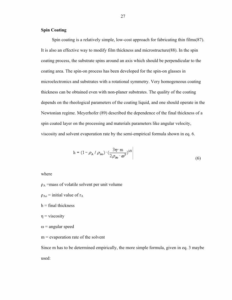
Spin Coating
Spin coating is a relatively simple, low-cost approach for fabricating thin films(87).
It is also an effective way to modify film thickness and microstructure(88). In the spin
coating process, the substrate spins around an axis which should be perpendicular to the
coating area. The spin-on process has been developed for the spin-on glasses in
microelectronics and substrates with a rotational symmetry. Very homogeneous coating
thickness can be obtained even with non-planer substrates. The quality of the coating
depends on the rheological parameters of the coating liquid, and one should operate in the
Newtonian regime. Meyerhofer (89) described the dependence of the final thickness of a
spin coated layer on the processing and materials parameters like angular velocity,
viscosity and solvent evaporation rate by the semi-empirical formula shown in eq. 6.
(6)
where
ρA =mass of volatile solvent per unit volume
ρAo = initial value of rA
h = final thickness
η = viscosity
ω = angular speed
m = evaporation rate of the solvent
Since m has to be determined empirically, the more simple formula, given in eq. 3 maybe
used:

28
(90)
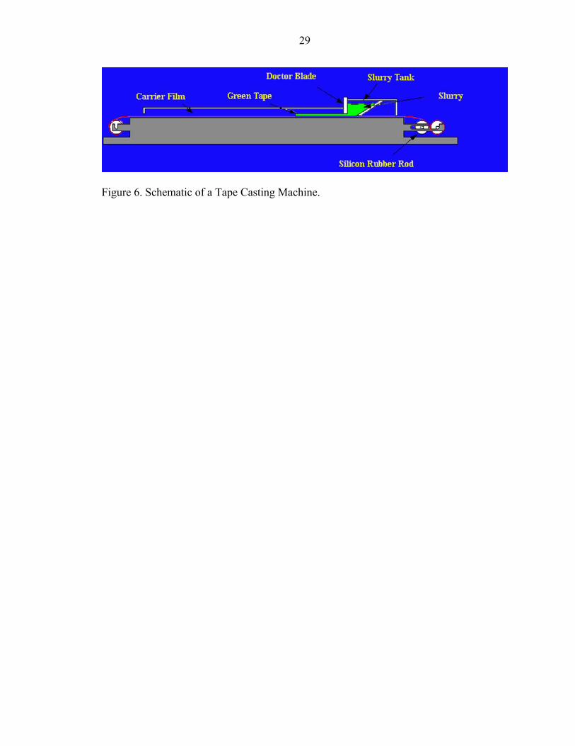
Tape Casting
This is a forming technique for producing thin, flat ceramics. The method was
originally developed for producing electronic ceramics (insulating substrates and
packages and multilayer capacitors). Structural laminates, knives, membranes and solid
oxide fuel cells are other applications for thin ceramics formed by tape casting. The tape
thickness that can be achieved is usually in the range of 25µm up to 1mm, but tapes with
5µm thickness can also be produced. Tape casting can be water based or organic solvent
based system. Aqueous systems are relatively inexpensive and reduce environmental and
health hazards but have disadvantages like slow drying, higher crack sensitivity, and
reaction of ceramic with water in some cases. So organic based solvent systems are
usually used in case of ceramics. Green tapes obtained through this method have high
quality with regard to surface smoothness, flexibility and green density (91). The slurry
for tape casting consists of the powder, a dispersant to stabilize the powder against
colloidal forces, a solvent to reduce the mix viscosity to allow casting, a binder for green
strength in the cast tape and a plasticizer to modify the properties of the binder. A powder
slurry layer is formed on a carrier film by the shearing action of a doctor blade on a
moving ceramic slurry. The tape is then dried. The tape contains a binder system which
gives it enough 'green strength' for it to be removed from the carrier film without damage.
For metal and ceramic powders the tape is then usually sintered. The binder is burnt out
and the material densifies (92). A schematic of the Tape casting machine is shown in
Figure 6.
29
Figure 6. Schematic of a Tape Casting Machine.

CHAPTER 2 PREPARATION OF DENSE BARIUM CERATE FILM ON A PLANAR POROUS
SUPPORT FOR HYDROGEN SEPARATION MEMBRANE
Proton conducting ion transport membranes have attracted attention for future fuel
processing and energy production systems as well as ancillary technologies such as fuel
cells, sensors and electrolyzers. Hydrogen from mixed gas streams during processing of
fuels and other petrochemical products has been separated by proton-electron conducting
perovskite oxides (93-98). Mixed strontium cerate-zirconate and barium cerate-zirconate
based perovskite type oxides exhibit protonic conduction at elevated temperatures in
atmospheres containing hydrogen or water vapour (98,99), Figure 7. Multivalent cation
doped barium cerate is being studied for its application in hydrogen separation
membranes due to its high temperature proton conductivity.
In this study we have made use of the Pechini process and Oxalate
coprecipitation methods to produce barium cerate powder. The ratio of metal nitrates to
citric acid was varied to test the effect of increase in citric acid on particle size and
calcination temperature. Simultaneous differential thermal analysis and thermogravimetry
was carried out on the powders which were then calcined and characterized by XRD.
Particle analysis was done using BET while the microstructure was studied under SEM.
Experimental
Preparation of Barium Cerate Electrolyte Powders
Powders of barium cerate were made by two processes: Pechini and Oxalate
coprecipitation method. In the Pechini process stoichiometric amounts of barium nitrate,
30

31
cerium nitrate and citric acid were dissolved in deionised water to which ethylene glycol
was later added. The solution was then heated on a hot plate to form a gel which was
further heated to burn off the organic constituents. The molar ratio of nitrates to citric
acid varied from 1:1 to 1:4 while the ratio of citric acid to ethylene glycol was kept
constant. These precursors were then calcined at 1000 oC for 8 hours to ensure a pure
barium cerate phase. Powder preparation using a 1:3:3 ratio was found to be much easier
to prepare and hence was used for more tests. In the Oxalate Coprecipitation process
barium nitrate and cerium nitrate were dissolved in deionised water, and then heated to
boil. Excess hot ammonium oxalate was added to the nitrate solution with vigorous
stirring to effect instantaneous coprecipitation. The precipitate formed was kept
overnight, filtered and dried in an oven at 110 oC for 6 hours. The dry powder was
calcined for a period of 8 hours at 1100 oC to get fine barium cerate powder.
Preparation of NiO-GDC substrate
Nickel oxide-gadolinium doped ceria powder was used as a substrate material
because of its steam reforming and chemically inactive properties at high temperatures.
In Uniaxial press method suitable volume % of nickel oxide and gadolinium doped ceria
were ballmilled together in propanol for 24 hours. This solution was dried in an oven and
the dry powder pressed in form of round pellets in a die. The pellets were then calcined at
850 oC.
Preparation of barium cerate and NiO-GDC pellets
The calcined barium cerate powder obtained from oxalate method and calcined
NiO-GDC powder from the Uniaxial method was pressed in the form of pellets
approximately 13 mm in diameter and 4 mm in thickness. The pellets were sintered at

32
Figure 7. Proton conductivities of various oxides as calculated from data on proton concentrations and mobilities, according to Norby and Larring (type of dopant is not indicated) Conductivities of perovskite type structures are shown by bold lines.
33
temperatures varying from 1100 oC to 1600 oC at an interval of 100 oC and at the heating
rate of 5 oC/min. The diameter and thickness of each pellet before and after sintering rate
of 5 oC/min. The diameter and thickness of each pellet before and after sintering was
measured and shrinkage rate determined for each temperature. A plot of shrinkage rate vs
temperature was plotted from this data.
Dipcoating and firing
A colloidal solution was made by dispersing barium cerate powders in propanol
and using PVB as the binder. The dispersions stabilized at a pH of about 6.5. The
presintered substrates made by Uniaxial method were then dipcoated for a couple of
times in the dispersion to get a reasonably thick film and dried in an oven at 70 oC. The
samples using oxalate powder were sintered at 1300 oC, 1400 oCand 1500 oC at a heating
rate of 5 oC/min for 5 hours while the powder from Pechini was sintered at 1500 oC at
the same firing schedule. Microstructure of the sintered samples was analysed under
SEM.
Results and Discussions
Characterization
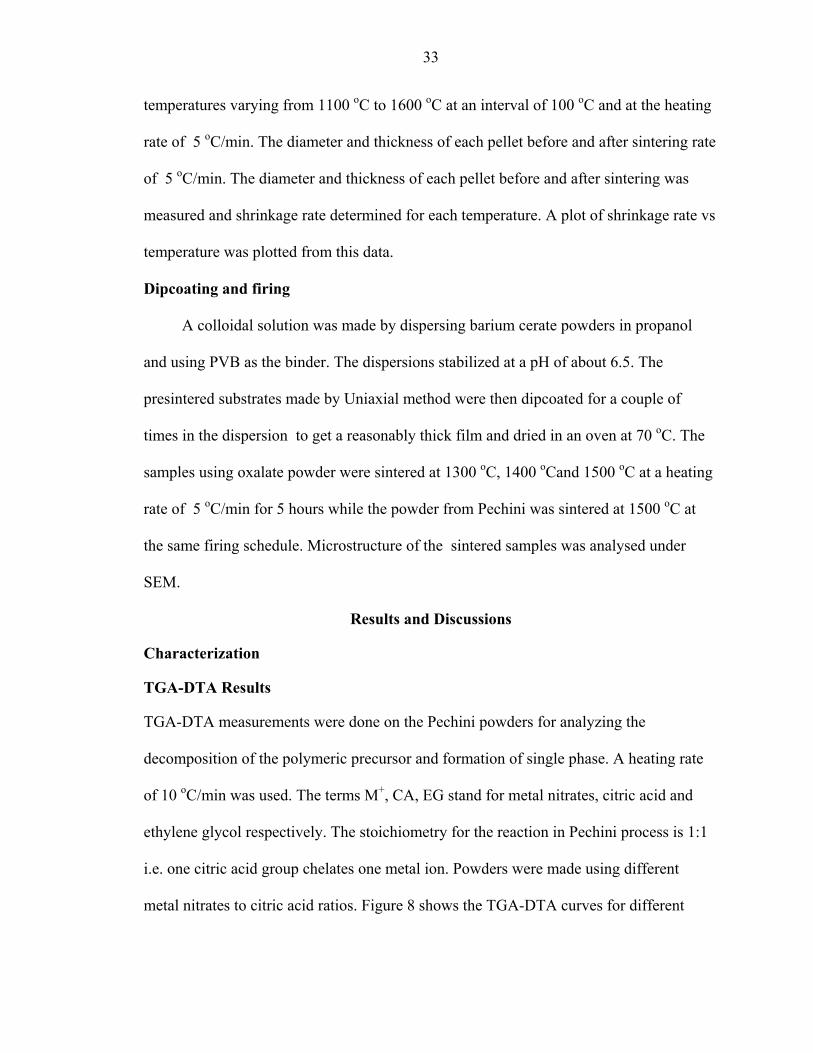
TGA-DTA Results
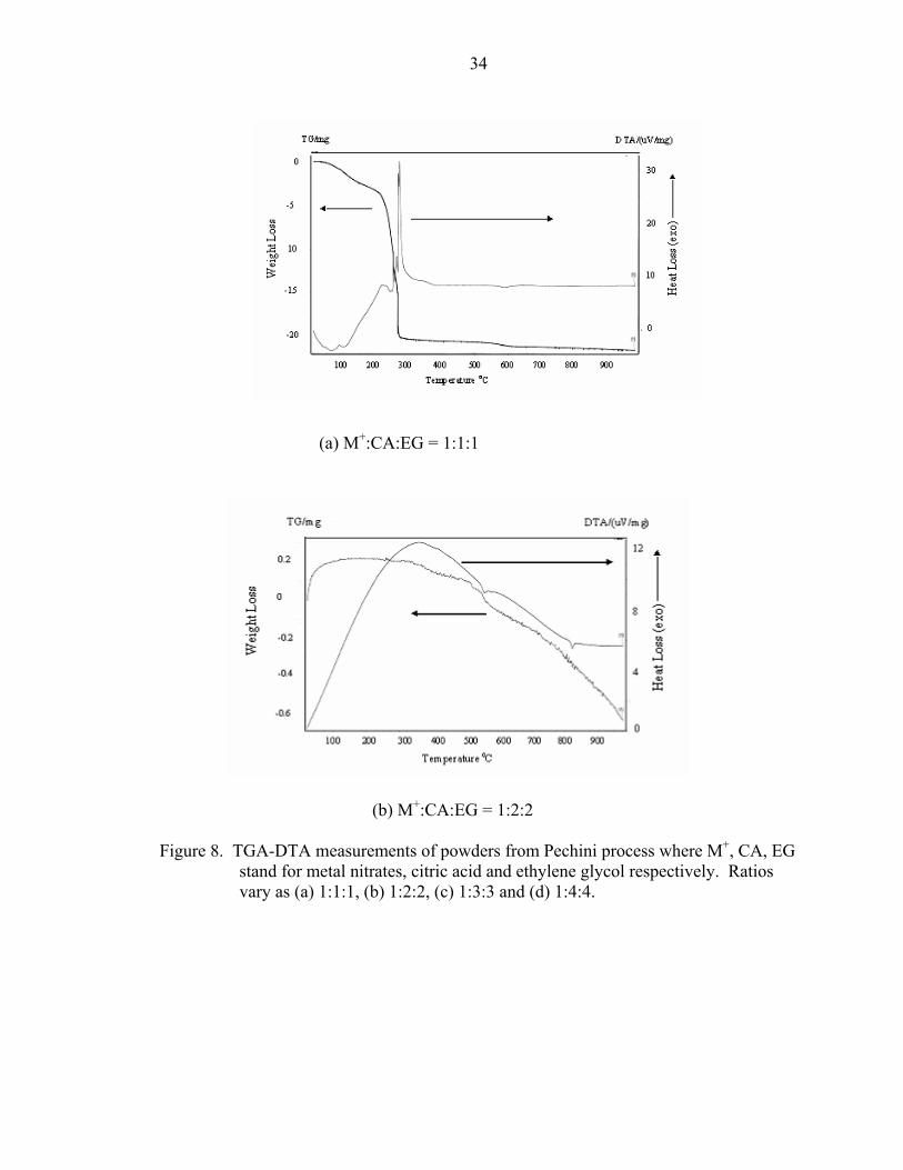
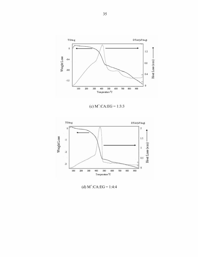
TGA-DTA measurements were done on the Pechini powders for analyzing the
decomposition of the polymeric precursor and formation of single phase. A heating rate
of 10 oC/min was used. The terms M+, CA, EG stand for metal nitrates, citric acid and
ethylene glycol respectively. The stoichiometry for the reaction in Pechini process is 1:1
i.e. one citric acid group chelates one metal ion. Powders were made using different
metal nitrates to citric acid ratios. Figure 8 shows the TGA-DTA curves for different
34
(a) M+:CA:EG = 1:1:1
(b) M+:CA:EG = 1:2:2
Figure 8. TGA-DTA measurements of powders from Pechini process where M+, CA, EG stand for metal nitrates, citric acid and ethylene glycol respectively. Ratios vary as (a) 1:1:1, (b) 1:2:2, (c) 1:3:3 and (d) 1:4:4.
35
(c) M+:CA:EG = 1:3:3
(d) M+:CA:EG = 1:4:4

36
ratios of metal nitrates to citric acid. For (a) the stoichiometric composition the precursor
was not burnt while the precursors in (b), (c) and (d) were partially burnt i.e. some
amount of organic matter in the precursor was burnt off at about 300 oC for 15 minutes
before performing TGA-DTA analysis. In (a) the ratio of nitrates to citric acid is 1:1
while for (b), (c) and (d) it is 1:2, 1:3 and 1:4 respectively. TGA curve shows a complete
mass loss by about 300 oC which could be due to the presence of primarily organics in
the precursor. Comparing (b), (c) and (d) it is seen that the heat loss and mass loss was
faster as the amount of citric acid increased. Also the organic loss continues even after
600 oC. This continous mass loss seen after 600 oC could be due to the evolution of
carbonates at high temperatures.
XRD Observations
The XRD spectra obtained by calcining the powder made from 1:3:3 ratio at
different temperatures is shown in Figure 9. It is seen that at 700 oC and 800 oC there is
dominant presence of carbonates and oxides. At 900 oC there is formation of the primary
phase along with some traces of a second phase. At 1000 oC the second phase
completely disappears and formation of barium cerate is complete. Figure 10 shows the
XRD spectra for powders made using different amounts of citric acid, also calcined at
1000 oC to determine if a single phase was obtained in all cases. The 1:1 ratio shows
presence of second phase even at 1000 oC while for powders from the 1:2 and 1:4 ratio
barium cerate is formed at 1000 oC. Powder from oxalate method was also calcined at
different temperatures and it was observed that single phase is obtained at 1100 oC as
seen in Figure 11.

37
Figure 9. XRD spectra for powders made by Pechini process using M+:CA=1:3 and calcined at different temperatures

38
Figure 10. XRD spectra according to content of citric acid in powders calcined at 1000 oC.

39
Figure 11. XRD spectra for powder calcined at 1100 oC by Oxalate method
Figure 12. Particle size distribution for powder calcined at 1100 oC from oxalate method.

40
M+:CA=1:1 M+:CA=1:2
M+:CA=1:3 M+:CA=1:4 Figure 13. Particle size distribution for Pechini powder calcined at 1000 oC for various
M+:CA ratios
1

41
Particle Size distribution
A smaller grain size and large grain boundary is desirable for good sintering
kinetics. Figure 12 shows the distribution for the Oxalate powder. Figure 13 shows the
particle size distribution of powders after calcining from the Pechini process. Judging
from the curves obtained for different amounts of citric acid it is seen that for1:1 ratio of
nitrates to citric acid the particle size distribution is the largest while it decreases for
higher amounts of citric acid. A bimodal size distribution is observed for 1:1 and 1:4
ratios of nitrates to citric acid. Comparing the distribution of the particle size from both
methods it is observed that Oxalate method yields larger particle size.
Determination of optimum sintering temperature and microstructure of film
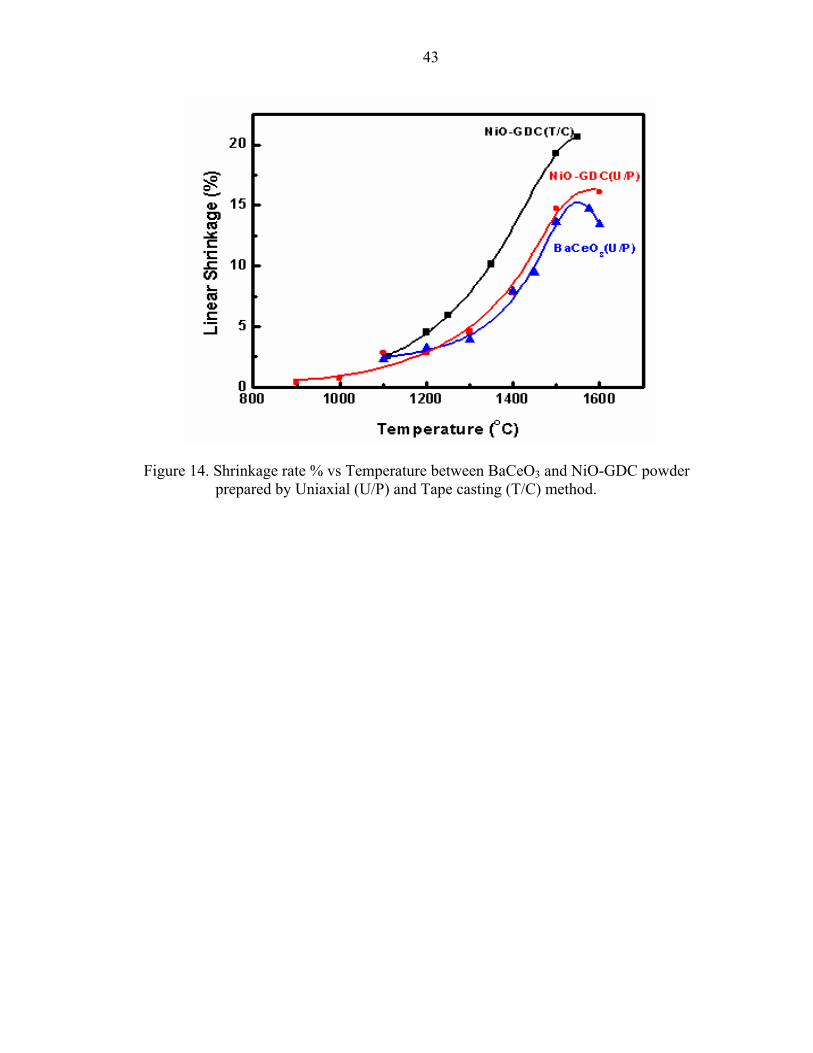
Mismatch in shrinkage rate between the film and the substrate is one of the
important reasons as to why films are obtained with cracks, warpage or other deformities.
Shrinkage rate varies not only because each material has a different thermal history but
also due to the presence of organic matter used while synthesizing the material. So it is
necessary to estimate the shrinkage rate of the film and substrate so as to arrive at an
optimum sintering temperature where the effects of shrinkage would be minimal. Figure
14 shows the plot of shrinkage rate % vs temperature for barium cerate and NiO-GDC
powder. All the curves run parallel to each other. The barium cerate curve appears to
deviate at around 1500 oC and it could be due to experimental error or some other
reasons. So following the curve trend a temperature of 1500 oC was assumed for sintering
of the dipcoated film. The idea was that since the curves deviate at about 1500 oC there
would be a shrinkage mismatch above this temperature which would lead to defects in the
film.
42
Figure 15 and 16 show the surface view of the films from oxalate method sintered
at 1300 oC and 1400 oC. Figure 17 and 18 show the surface and cross sectional view of
film at 1500 oC made from Oxalate method while Figure 19 and 20 from the Pechini
process sintered at 1500 oC. Below 1500 oC a porous microstructure is observed in the
film. But as the sintering temperature is increased the grains grow and increased density
of film is observed. The grain size in case of Oxalate powder is much larger as compared
to the Pechini powder. This could be due to the larger initial particle size of the powder
obtained from the Oxalate method. The film is more dense at 1500 oC but still shows
presence of scattered pores in both cases. The thickness of the film is about 7-10 µm for
both the powders.
Conclusions
Barium cerate was prepared by Pechini and Oxalate coprecipitation method. A
single phase was obtained at 1000 oC for powder from Pechini process and at 1100 oC for
Oxalate process. Oxalate method gave a larger particle size distribution which was also
reflected in the microstructure of the film in form of larger grain size compared to
Pechini method. Increase in sintering temperature lead to increase in grain growth and
increased density of film and the pores were limited to grain boundaries. A dense film
was obtained at 1500 oC.
43
Figure 14. Shrinkage rate % vs Temperature between BaCeO3 and NiO-GDC powder prepared by Uniaxial (U/P) and Tape casting (T/C) method.

44
Figure 15. Surface view of film from oxalate powder sintered at 1300 oC
Figure 16. Surface view of film from oxalate powder sintered at 1400 oC

45
Figure 17. Surface view of film from oxalate powder sintered at 1500 oC
Figure 18. Cross-section view of film from oxalate powder sintered at 1500 oC
46
Figure 19. Surface view of film from Pechini powder sintered at 1500 oC
Figure 20. Cross-section view of film from Pechini powder sintered at 1500 oC
CHAPTER 3 PREPARATION OF DENSE EUROPIUM DOPED BARIUM-CERATE FILM ON A
PLANAR POROUS SUPPORT FOR HYDROGEN SEPARATION MEMBRANE
In the previous work barium-cerate powder was made using Oxalate and Pechini process.
A film was deposited on a nickel oxide-gadolinium doped ceria substrate using a
dipcoating method. Analysis of shrinkage rates of the film and substrate material showed
that their shrinkage rates matched at around 1500 oC and so the films were sintered at
1500 oC. The next stage of experiments involve using europium as a dopant. Doped
substances can exhibit different properties than the undoped material and unique
applications may be possible only in the doped system. Dopants may be added to impart
ionic or electronic conductivity, to make the membrane permeable to a specific gas etc.
so that it can be used for various applications. A multivalent dopant can impart electronic
conductivity. For ionic conductivity acceptor or donor dopant (e.g., Sm3+ is an acceptor
dopant for CeO2) can be used. For permeation both, electronic & ionic conductivity is
required. Barium cerate already has some ionic conductivity and adding europium cation
does 2 things (1) since it has lower valence states than Ce4+ it acts as an acceptor and
creates more vacancies, and (2) since it is multivalent, it creates electronic species by
going from Eu3+ to Eu2+ thereby increasing electronic conductivity. So permeation can be
obtained by using europium as dopnat in the barium cerate system.
Following stages were involved :
• -Preparation of Eu doped barium cerate powder.
• -Determining the actual % of Eu in the calcined powder using EPMA.
47

48
• -Slurry preparation of the same.
• -Coating of slurry on tape casted substrate by spin coating.
• -Sintering and studying the microstructure of the film.
• -Testing for hydrogen permeation.
Substrates made by tape casting were used instead of those made by Uniaxial press.
Figure 21 shows the flow chart of the experimental method to prepare the same.
Experimental
Preparation of Eu Doped Barium Cerate Powder.
Stoichiometric amounts of barium nitrate, cerium nitrate and europium nitrate in
the molar ratio Ba:Ce:Eu = 1:0.85:0.15 were dissolved in distilled water. Ammonium
oxalate was dissolved separately, heated to about 100 oC and added to the nitrate solution.
The precipitate formed was allowed to stand overnight and later filtered and dried. The
powder was then calcined at 1200oC. Formation of single phase was determined using
XRD. Pechini process was also tried to synthesize the powder but the solution did not
polymerize under any condition and so doped powder could not be made by this route.
The actual % of europium present in the synthesized powder was determined using
EPMA(Electron Probe Micro-Analysis). For this the calcined powder was pressed in the
form of a pellet and sintered at 1500 oC. The results showed that Eu was approximately
12 % instead of 15 % and the amount of barium was also less by 3-4 % than originally
started with. This reduction in barium content can be attributed to the fact that the high
vapour pressure of barium oxide caused it to evaporate at 1500 oC. The reduction in the
amounts of the europium and barium can also be understood through Porbaix diagrams.
From figure 5 it is clear that all the metal cations do not precipitate at the same time and
hence the results with amounts lesser than actually started with.
49
Slurry preparation and Spin coating
The composition of the slurry is very important to achieve a desired viscosity for
spin coating. After some trial and errors a final slurry was made using the following
composition, Table 2, and ballmilled for 24 hours.
Table 2. Composition of slurry for spin coating MATERIAL AMOUNT IN GRAMS Eu doped barium cerate powder 5 Di butyl pthalate(DBP) 0.5 Polyvinyl butyral(PVB) 0.2 Ethanol+Toluene soln 1.5 each
PVB acts as a binder in this case while DBP functions as a plasticiser. The amount of
plasticiser is very important since it directly affects the flow properties of the slurry.
Ethanol and toluene were added in equal amounts to dissolve the PVB as well as impart
sufficient viscosity to the slurry.
The tape cast substrates were then coated with the slurry using the spin coating
method. The substrates were presintered at two temperatures, 1250 oC and 1550 oC. The
film was sintered at1400 oC , 1450 oC and 1500 oC.
A slurry was also prepared by adding PVB only as the binder to the doped barium
cerate –ethanol solution. A film was deposited by spin casting on tape cast and uniaxially
pressed substrates.
Doped barium cerate powder was pressed in the form of pellets and sintered at 1500 oC
and 1600 oC for different hold times to study the densification behaviour.
Testing for hydrogen permeation
A sample made by depositing film on uniaxially pressed substrate was about 1 inch in
diameter so that it could sit properly on the furnace tube and could be sealed properly to
conduct the permeation test. Before the actual permeation the sample was heated to 800 oC
50
and hydrogen was allowed to flow at a ramp rate of 10ccm for 6 hours. The sample was
allowed to cool in hydrogen atmosphere. Helium was used as the sweep gas for the
permeation experiment. The sample was sealed on a glass tube at a temperature of 875 oC.
After cooling the sample was tested for gas leakage at 850 oC using a mixture of helium and
argon gas.
Results and Discussions
Figures 22, 23 and 24 show the surface view of films sintered at 1400 oC, 1450 oC and
1500 oC and the substrate presintered at 1250 oC. Comparing the three figures show that the
grain size varies from 2-5 µm at lower sintering temperatures but becomes more uniform as
sintering temperature is increased. The grain size at 1500 oC is about 2µm. Few pores are
seen in Figure 24 as compared to Figure 22 and 23 which shows that density of the film also
increases with increase in the sintering temperature. Figure 25 shows the cross sectional view
of film sintered at 1500 oC. The thickness of the film is about 10µm. Warpage was observed
in all the three films due to thermal mismatch between the film and substrate material. Figure
26 shows the film sintered at 1450 oC but with the substrate presintered at 1550 oC. The film
is porous but no warpage was observed in this case.
Figure 27 shows the film microstructure on a uniaxially pressed substrate which was
presintered at 1250 oC . The film is highly porous even at sintering temperature of 1500 oC.
Figure 28 shows the porous cross section of the same. There was warpage observed in this
case also which was concave in nature Vs the convex warpage in case of tape cast substrates.
The film from tape cast substrate looks dense with intermittent cracks as seen in Figure 29 at
a low resolution. At higher resolution it is seen that the film is composed of dense patches
which are separated by cracks. At places where pores are seen there is also an underlying

51
layer of film so the pores are not interconnected, Figure 30. The cross-section shows the film
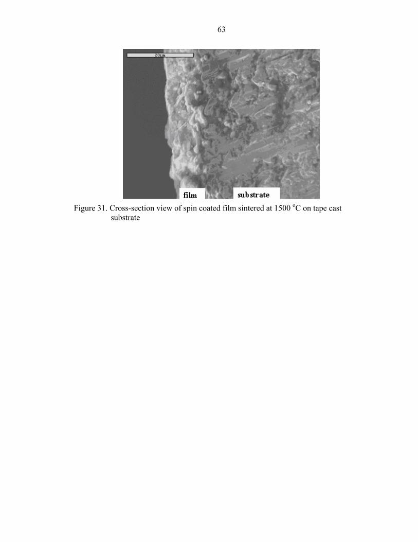
to be around 10 µm thick, Figure 31.
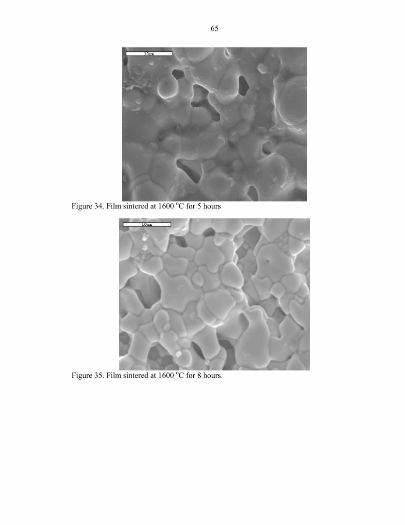
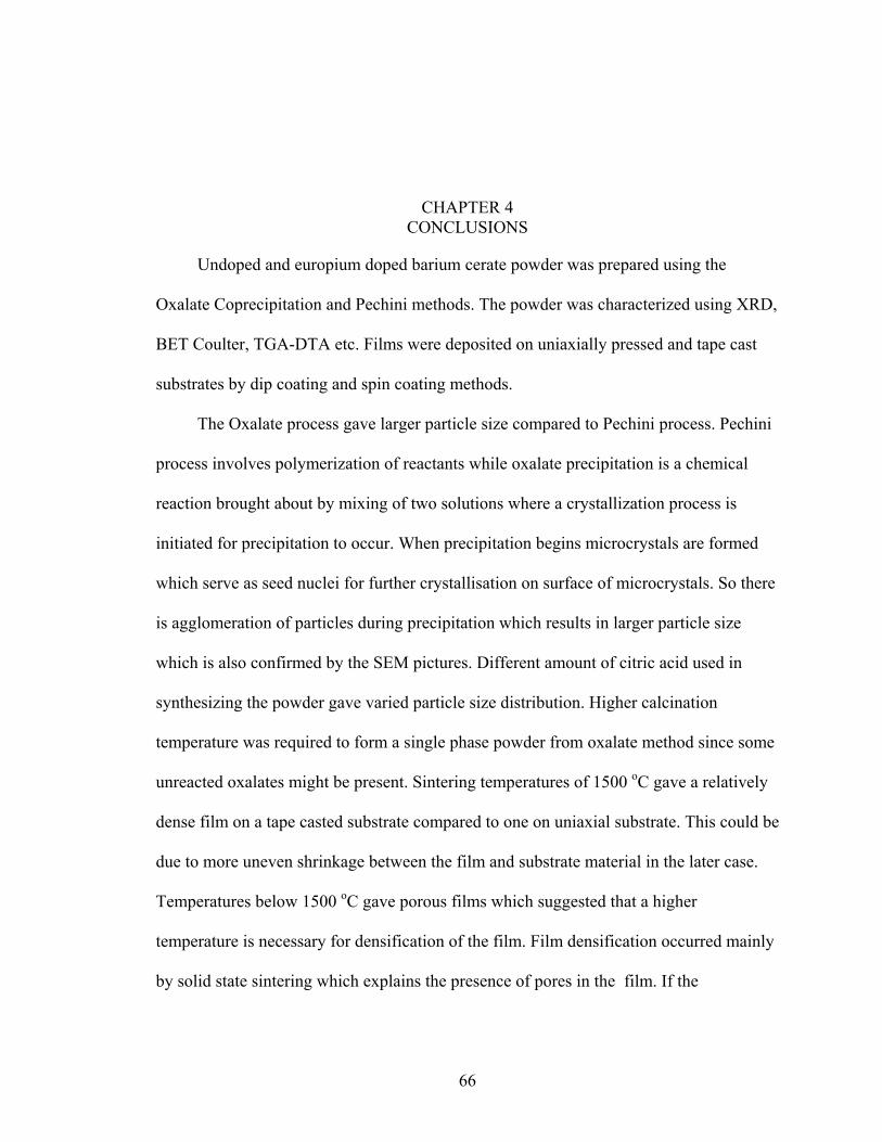
Barium cerate densifies by the solid state sintering mechanism and so it is very difficult
to obtain a dense film on a substrate. Figures 32 and 33 show barium cerate sintered at 1500
oC and held for 5 and 8 hours while Figure 34 and 35 at 1600 oC for 5 and 8 hours
respectively. At 1500 oC the material densifies by solid state sintering but as the temeparture
and holding time are raised some melting of the material is observed. Liquid phase sintering
is observed at 1600 oC but it does not seem to occur uniformly as is evident from Figure 34.
This could be responsible for the presence of pores even at these temperatures. More higher
temperatures and holding time may be required to complete the sintering process so as to
obtain a completely dense film. Another way could be to add a sintering aid which melts at
lower temperature so that it would fill up the pores created during the sintering process.
In case of permeation argon was present in the sweep gas indicating that the film was
porous which allowed the gas to permeate through. So film deposited on uniaxially pressed
substrate was porous. Samples could not be made using tape cast substrates for permeation
because the samples broke on sintering. Therefore hydrogen permeation results could not be
obtained.
Conclusions
Europium doped barium-cerate powder was prepared by Oxalate Coprecipitation
method since the Pechini process was not successful in synthesizing doped powder. EPMA
technique was used to determine the amount of europium in the sintered powder which was
about 12 % as compared to the 15 % added during preparation of the doped powder. Films
obtained from europium doped powder were more dense than the undoped ones. Films made
from slurry looked dense but the results could not be reproduced since a stable slurry was not

52
formed later on. It could be due to some contamination or change in temperatures. A simple
slurry consisting of binder, powder and ethanol was made and coated on tape cast substrate
which gave a relatively dense film compared to the film obtained on uniaxially pressed
substrate. This difference could be due to the different shrinkage rates in both cases. Film on
tape casted substrate was quite dense but with presence of cracks and pores. This means that
the composition of the substrate needs to be varied so as to accommodate the shrinkage rate
of the film material so that it does not crack. GDC is inactive at temperatures of 1500 o C so
the nickel is basically affecting the shrinkage. So nickel % can be reduced and see if it makes
any difference. Sintering temperatures of more than 1500 oC with high holding times can be
used so as to cause densification by liquid phase sintering as well. This might also ensure the
complete removal of pores and a completely dense film. Stress caused due to too fast or too
slow heating and cooling rate can also give rise to cracks. Presence of argon in sweep gas
during the permeation tests indicated that the film was porous. So hydrogen permeation
results could not be obtained.

53
Figure 21. Flow chart for preparation of Tape Cast substrates.

54
. Figure 22. Surface view of spin coated film sintered at 1400 oC on tape cast substrate

55
Figure 23. Surface view of spin coated film sintered at 1450 oC on tape cast substrate

56
Figure 24. Surface view of spin coated film sintered at 1500 oC on tape cast substrate

57
Figure 25. Cross-section view of spin coated film sintered at 1500 oC on tape cast
substrate

58
Figure 26. Surface view of spin coated film sintered at 1400 oC on tape cast substrate
(substrate sintered at 1550 oC)

59
Figure 27. Surface view of spin coated film sintered at 1500 oC on Uniaxially pressed
substrate

60
Figure 28. Cross-section view of spin coated film sintered at 1500 oC on Uniaxially
pressed substrate

61
Figure 29. Surface view of spin coated film sintered at 1500 oC on tape cast substrate
(1000X)

62
Figure 30. Surface view of spin coated film sintered at 1500 oC on tape cast substrate
(5000X)
63
Figure 31. Cross-section view of spin coated film sintered at 1500 oC on tape cast
substrate

64
Figure 32.. Film sintered at 1500 oC.for 5hours
Figure 33. Film sintered at 1500 oC for 8 hours.
65
Figure 34. Film sintered at 1600 oC for 5 hours
Figure 35. Film sintered at 1600 oC for 8 hours.
CHAPTER 4 CONCLUSIONS
Undoped and europium doped barium cerate powder was prepared using the
Oxalate Coprecipitation and Pechini methods. The powder was characterized using XRD,
BET Coulter, TGA-DTA etc. Films were deposited on uniaxially pressed and tape cast
substrates by dip coating and spin coating methods.
The Oxalate process gave larger particle size compared to Pechini process. Pechini
process involves polymerization of reactants while oxalate precipitation is a chemical
reaction brought about by mixing of two solutions where a crystallization process is
initiated for precipitation to occur. When precipitation begins microcrystals are formed
which serve as seed nuclei for further crystallisation on surface of microcrystals. So there
is agglomeration of particles during precipitation which results in larger particle size
which is also confirmed by the SEM pictures. Different amount of citric acid used in
synthesizing the powder gave varied particle size distribution. Higher calcination
temperature was required to form a single phase powder from oxalate method since some
unreacted oxalates might be present. Sintering temperatures of 1500 oC gave a relatively
dense film on a tape casted substrate compared to one on uniaxial substrate. This could be
due to more uneven shrinkage between the film and substrate material in the later case.
Temperatures below 1500 oC gave porous films which suggested that a higher
temperature is necessary for densification of the film. Film densification occurred mainly
by solid state sintering which explains the presence of pores in the film. If the
66
67
temperature is increased so as to induce liquid phase sintering it might be possible to
obtain completely dense films.
A number of factors such as binder content, substrate composition, substrate
presintering temperatures, final sintering temperature, holding time, incomplete
deairation, composition and viscosity of the solution etc. could affect the final
microstructure of the film. Insufficient amount of binder content does not allow the film
to adhere properly to the substrate and may peel off after sintering while a high binder
content will introduce large amount of organic material which after burning out may
result in a porous film. It is necessary to use a substrate material that does not react with
that of the film at high temperatures as well as exhibits a shrinkage behaviour similar to
the film material. Different shrinkage behaviour results in warpage and cracked films. If
substrate is presintered at low temperature it may not be strong enough and may break
during deposition of film or final sintering. Final sintering temperature and holding time
is important to ensure complete densification by completion of sintering processes and
avoid defects in the film.When preparing the slurry for film deposition it is ball milled to
get a homogeneous mixture and to remove any air bubbles introduced during the mixing
process. Incomplete deairation is when these bubbles are not completely removed and are
deposited on the substrate. These air pockets can hinder the complete densification of
film. A low viscosity may cause running away of the solution from the substrate while
too high viscosity might prevent uniform deposition. So viscosity has to be maintained
properly for proper deposition of film. Different binders, plasticizers, solvents etc. are
used to prepare slurry. These can drastically affect the flow properties of the slurry if not
68
used in the proper amounts. So a lot of factors need to be controlled to get a dense, defect
free film.
Considering the above factors and the results obtained in the lab it is possible to
synthesize undoped barium cerate by Pechini and Oxalate process at calcining
temperatures of 1000 oC and 1100 oC respectively. As for synthesizing europium doped
barium cerate only the oxalate method was successful. A single phase is formed at about
1300 oC. A binder content of about 0.2 grams for a powder of 5 grams is sufficient to
eliminate peel off of the film from the substrate. Nickel oxide-gadolinium doped ceria
acts as a good substrate material for depositing barium cerate film. A presintering
temperature of 1250 oC for the substrate is sufficient to impart enough green strength so
that it does not crack when film is deposited on it. While preparing the slurry for spin
coating a deairation time of 12 hours is sufficient to remove air bubbles from the solution.
A final sintering temperature of 1500 oC can give a dense film with some porosity so
higher temperatures should be studied to see if porosity can be completely eliminated.

LIST OF REFERENCES
1. Hydrogen Works, Introduction to Hydrogen, www. Hydrogen.com/intro.html,
1/20/2004
2. Basic Energy Sciences Advisory Committee, Development of an Atomistic Understanding of High Temperature Hydrogen Conductors, Washington DC, May 2002.
3. Alternative Fuel vehicle Group, Report on Hydrogen Economy, December 2003 www.altfuels.com/news.php, 1/20/2004
4. H. Iwahara, K. Uchida, K.Ogaki, J. Electrochem . Soc., 135 (1988) 529.
5. K.D. Kreuer, Solid State Ionics (1997), 97, 1.
6. N. Bonanos, B. Ellis, K. S. Knight, M. N. Mahmood, Solid State Ionics (1989), 35, 179.
7. N. Bonanos, Solid State Ionics (1992), 53-56, 967.
8. N. Bonanos, J. Phys. Chem. Solids, 54 (1993) 867.
9. H. Iwahara, H. Uchida, K. Morimoto, J. Electrochem. Soc., 137 (1990) 462.
10. D. Shima, S. Haile, Solid State Ionics, 97 (1997) 443.
11. T. Yajima, H. Iwahara, Solid State Ionics (1992), 50, 281.
12. K. Liang, A. Nowick, Solid State Ionics, 61 (1993) 77
13. T. Norby, Solid State Ionics (1990), 40/41, 857.
14. N. Bonanos, K. Knight, B. Ellis, Solid State Ionics, 79 (1995) 161.
15. S. E.Roark, R. Mackay, A. F.Sammells, DOE/NETL Contract No. DE-FC26-00NT40762, Eltron Research, Inc., Boulder, 6/11/2002
16. S. J. Visco, C. Jacobson, L. Jonghe, US-DOE Contract DE-AC03-76SF00098.Lawrence Berkeley National Laboratory, San Francisco, December 2002.
71

72
17. F. Krug, T. Schober, T. Springer, Solid State Ionics, 81 (1995) 111.
18. T. Schober, J. Friedrich, Solid State Ionics, 125 (1999) 319.
19. T.Tsuji, T. Nagano, Solid State Ionics, 136-137 (2000) 179.
20. T. Scherban, A. S. Nowick, Solid State Ionics, 35 (1989) 189.
21. N. Bonanos, B. Ellis, M. N. Mahmood, Solid State Ionics, 44 (1991) 305.
22. H. Iwahara, Y. Asakura, K. Katahira, M. Tanaka, Solid State Ionics, 3-4 (2003) 164.
23. F. M. Krug, Doctoral Thesis, RWTH Aachen (1996).
24. K.D. Kreur, Th. Dippel, W. Meyer, J. Maier, Mat. Res. Soc. Symp. Proc., 293 (1993) 273.
25. G. G. Scherer, E. Killer, D. Grman, Int. J. Hydrogen Energy, 17 (1992) 115.
26. M. Popall, Xin Min Du, Electrochim. Acta, 40 (1995) 2305.
27. J. Wei, C. Stone, A. E. Steck, patent W095/08581 (March 30, 1995).
28. G. Alberti, M. Casciola, Solid State Ionics, 97 (1997) 177.
29. C. A. Linkous, Int. J. Hydrogen Energy, 18 (1993) 641.
30. M. Rehahn, A. D. Schluter, G. Wegner, Makromol. Chem., 191 (1990) 1991.
31. K.D. Kreuer, Th. Dippel, J. Maier, Proc. Electrochem. Soc., 95 (1995) 241.
32. J. Maier, J. Electrochem. Soc., 134 (1987) 1524.
33. A. Kawada, A. R. Mcghie, M. M. Labes, J. Chem. Phys., 52 (1970) 3121.
34. T. Norby, in: Defect Chemistry of Solids, eds. ∅. Johannesen, A. Anderson, Elsevier, Amsterdam, (1990), p. 101.
35. F. A. Kroger, The Chemistry of Imperfect Crystals; North Holland Publishing Co., Amsterdam, (1964).
36. T. Norby, Y. Larring, Concentration and Transport of Protons and Oxygen Defects in Oxides; T. Norby, Y. Larring, Ed., The Institute of Materials, Maney Publishing North America, Cambridge, (1996), pp 83-93.
37. H. Iwahara, H. Uchida, K. Morimoto, S. Hosogi, J. Appl. Electrochem., 19 (1989) 448.
73
38. H. Iwahara, Solid State Ionics, 52 (1992) 99.
39. H. Iwahara, T. Hibino, T. Sunano, J. Appl. Electrochem., 26 (1996) 829.
40. T. Yajima, H. Kazeoka, T. Yoga, H. Iwahara, Solid State Ionics, 47 (1991)271.
41. W. Munch, G. Seifert, K. D. Kreuer, J. Maier, J. Solid State Ionics, 86-88 (1996) 647.
42. W. Munch, G. Seifert, K. D. Kreuer, J. Maier, Solid State Ionics, 97 (1997) 39.
43. K. D. Kreuer, Annu. Rev. Mater. Res., 33 (2003) 333.
44. T. Norby, Presented at Solid State Ionics Proc. SSPC-11, Survey, England, (2003).
45. K. D. Kreuer, Solid State Ionics, 125 (1999) 285.
46. Y. Larring, T. Norby, Solid State Ionics, 77 (1995) 147.
47. K. D. Kreuer, T. Dippel, Y. Baikov, J. Maier, Solid State Ionics, 86-88 (1996) 613.
48. M. Pionke, T. Mono, W. Schweika, T. Springer, Solid State Ionics, 97 (1997) 497.
49. T. Matzke, U. Stimming, C. Karmonik, M. Soetramo, R. Hempelmann, F. Guthoff, Solid State Ionics, 86-88 (1996) 621.
50. R. Hempelmann, M. Soetramo, O. Hartmann, R. Wappling, Solid State Ionics, 107 (1998) 269.
51. K. D. Kreuer, W. Munch, U. Traub, J. Maier, Ber. Bursenges. Phys. Chem., 102 (1998) 552.
52. F. Shimojo, K. Hashino, H. Okazaki, J. Phys. Soc. Jpn, 66 (1997) 8.
53. W. Munch, K. Kreuer, S. Adams, G. Seifert, J. Maier, Phase Transitions, 68 (1999) 567.
54. P. Kofstad, in: Non-stoichiometry, Diffusion and Electrical Conductivity of Binary Metal Oxides, Wiley, New York, (1972).
55. C. Wagner, Ber. Bunsenges, Physik. Chem., 72 (7) (1968) 778.
56. A. S. Nowick, W-K. Lee, H. Jain, Solid State Ionics, 28-30 (1988) 89.
57. J. Bates, J. Wang, R. Perkins, Phys. Rev. B, 19 (1979) 4130.
58. A. Mitsui, M. Miyayama, H. Yanagida, Solid State Ionics, 22 (1987) 213.

74
59. M. Scholten, J. Schoonman, J. van Miltenburg, HAJ. Oonk, Solid State Ionics, 61 (1993) 83.
60. S. Wienstroer, H. Weimhofer, Solid State Ionics, 101-103 (1997) 1113.
61. K. Ryu, S. Haile, Solid State Ionics, 122 (1999) 355.
62. K. Katahira, Y. Konchi, T. Shimura, H. Iwahara, Solid State Ionics, 138 (2000) 98.
63. M. Scholten, J. Schoonman, J. van Miltenburg, EHP. Cordfunke, Thermochim. Acta, 268 (1995) 161.
64. M. Scholten, J. Schoonman, J. van Miltenburg, HAJ. Oonk, Proc. Electrochem. Soc., 93/94 (1993) 146.
65. C. Tanner, A.Virkar, J. Electrochem. Soc., 143 (1996) 1386.
66. K. D. Kreuer, E. Schonherr, J. Maeir, in Proc. 14th Ris Int. Symp. On Materials Science, F. Poulsen, J. Bentzen, T. Jacobson, E. Skou, M. Ostergard, Eds. Ris, (1993) p. 297.
67. K. Szot, M. Pawelezyk, J. Herion, Ch. Freiburg, J. Albers, R. Waser, J. Hulliger, J. Kwapulinski, J. Appl. Phys. A, (1992).
68. S. Shin, H. Huang, M. Ishigame, Solid State Ionics, 40-41 (1990) 910.
69. H. Iwahara, T. Esaka, H. Uchida, N. Maeda, Solid State Ionics, 3-4 (1981) 359.
70. M. H. Zhen, X. Chen, Solid State Ionics, 70-71 (1994) 595.
71. V. Agarwal, M. Liu, J. Mat. Sci., 32 (1997) 619.
72. S. L. Peschle, M.Cifticioglu, D. H. Doughty, J. A. Voight, in Proc. Mat. Res. Soc. Symp., San Francisco, April 1992, edited by M. J. Hampden-Smith, W. G. Klemperer and C. J. Brinker, Mat. Res. Soc., Pittsburg, PA, (1992) p. 101.
73. M. Toprak, Yu Zhang, M. Muhammed, Materials Letters, 4460 (2003) 1.
74. P. S. Nicholson, Proc. Inter. Symp., Vol 7, The Metallurgical Society of Canadian Institute of Mining and Metallurgy, Calgary, Canada, June 1998.
75. R. D. Carneim, P. F. Becher, C-H. Hsueh, and T. R. Armstrong, Oak Ridge National Laboratory, Annual report, Oak Ridge, February 2002.
76. Western Oregon University, Constructing Porbaix diagrams, October 2000, www.wou.edu/las/physi/chapter 412/porbaix.htm, 4/3/2004
77. Eugenii Katz, Contributions of Marcel Porbaix, February 2004, www.geocities.com/neveyaakov/electroscience/porbaix.html, 4/4/2004

75
78. William F. Coleman, Porbaix diagrams, February 2003, www.wellesley.edu/Chemistry/chem120/pour.html, 4/3/2004
79. Albert I. King, Biocompatibility-Corrosion, January 1999, www.ttb.eng.wayne.edu/~grimm/BME5370/lect14Out.html, 4/4/2004
80. A. O. Isenberg, Solid State Ionics, 3/4, 431 (1981).
81. N. Minh, J. Am. Ceram. Soc., 76, 563 (1993).
82. A. Negishi, K. Nozaki, T. Ozawa, Solid State Ionics, 3/4, (1981) 443.
83. G. Meng, P. Wang, Y. Gu, D. Peng, Solid State Ionics, 136-137 (2000) 209.
84. M. C. Cheung, H. L. W. Chan, Q. F. Zhou, C. L. Choy, Nanostructured Materials, 11-7 (1999) 837.
85. L. Hong, X. Chen, Z. Cao, J. Euro. Ceram Soc., 21 (2001) 2207.
86. L. D. Landau, B. G. Levich, Acta Physiochim, U.R.S.S., 17 (1942) 42.
87. Debra L. Kaiser, Joseph J. Ritter- National Institute of Standards and Technology, Ceramic Division,Gaithersburg, June 2003,
88. Yanovskaya M. Ilyinichna: Promising Research Abstract PRA-4128, Karpov Institute Physical Chemistry, Moscow, June 1997.
89. M. Mennig, A. Kalleder, T. Koch, S. Mohr, C. Fink-Straube, S. Heusing, B. Munro, P. Zapp, H. Schmidt, proc. 2nd ICCG, Saarbrücken (1998).
90. C. J. Brinker, A. J. Hurd, K. J. Ward in Ultrastructure Processing of Advanced Ceramics, eds. J. D. Mackenzie and D. R.Ulrich, Wiley, New York (1988) 223.
91. Swedish Ceramic Institute, Tape Casting, November 2003, www.keram.se/eng/pdf/tapecasting, 2/10/2004.
92. School of Industrial and Manufacturing Science, UK, Engineering Design Systems, www.cranfield.ac, 2/5/2004.
93. S.-J. Song, E. D. Wachsman, S. E. Dorris and U. Balachandran, Solid State Ionics, 149 (2002) 1.
94. S.-J. Song, E. D. Wachsman, S. E. Dorris and U. Balachandran, J. Electrochem. Soc., 150 (2003) A1484.
95. S.-J. Song, E. D. Wachsman, S. E. Dorris and U. Balachandran, J. Electrochem. Soc., 150 (2003) A790.

76
96. S.-J. Song, E. D. Wachsman, S. E. Dorris and U. Balachandran, Solid State Ionics, accepted.
97. S.-J. Song, E. D. Wachsman, and H.-S. Yoon, J. Electrochem Soc., submitted.
98. S.-J. Song, E. D. Wachsman, J. Rhodes, S. E. Dorris and U. Balachandran, Solid State Ionics, in press.
99. S.-J. Song, E. D. Wachsman, J. Rhodes, H.-Yoon, G. Zhang, S. E. Dorris and U. Balachandran, J. Amer. Ceram. Soc., submitted.

BIOGRAPHICAL SKETCH
I was born in Dhule, India. After completing my high school I went to Maharashtra
Institute of Technology, Pune, and earned my bachelor’s degree in polymer engineering
in August 2001. I was a teaching assistant for a few months and then decided to attend
graduate school to pursue my Master of Science degree in materials science and
engineering at the University of Florida.
77
Related Documents


![Index [ftp.feq.ufu.br]ftp.feq.ufu.br/Luis_Claudio/Segurança/Safety/Double/fire_handbook... · Backdraft Explosion 174 Barium 216 Barium Carbonate 300 Barium Chlorate 300 Barium Nitrate](https://static.cupdf.com/doc/110x72/5ea2585052451660ed3ed304/index-ftpfequfubrftpfequfubrluisclaudioseguranasafetydoublefirehandbook.jpg)