CARDIFF UNIVERSTY C ardiff UNIVERSITY PRIFYSGOL CAeRDY£> Department o f Chemistry |H j Preparation and Characterisation of Vanadium Phosphorus Oxide Catalysts for Butane Oxidation to Maleic Anhydride Thesis submitted in accordance with the requirements of the University of Cardiff for the degree of Doctor of Philosophy By Raja Lafi AL-Otaibi January 2010

Welcome message from author
This document is posted to help you gain knowledge. Please leave a comment to let me know what you think about it! Share it to your friends and learn new things together.
Transcript
CARDIFF UNIVERSTY CardiffUN I V E R S I T Y
P R I F Y S G O LCAeRDY£>
Department o f Chemistry |H j
Preparation and Characterisation of Vanadium
Phosphorus Oxide Catalysts for Butane
Oxidation to Maleic Anhydride
Thesis submitted in accordance with the requirements o f the
University of Cardiff for the degree o f
Doctor of Philosophy
By
Raja Lafi AL-Otaibi
January 2010
UMI Number: U571273
All rights reserved
INFORMATION TO ALL USERS The quality of this reproduction is dependent upon the quality of the copy submitted.
In the unlikely event that the author did not send a complete manuscript and there are missing pages, these will be noted. Also, if material had to be removed,
a note will indicate the deletion.
Dissertation Publishing
UMI U571273Published by ProQuest LLC 2013. Copyright in the Dissertation held by the Author.
Microform Edition © ProQuest LLC.All rights reserved. This work is protected against
unauthorized copying under Title 17, United States Code.
ProQuest LLC 789 East Eisenhower Parkway
P.O. Box 1346 Ann Arbor, Ml 48106-1346

>11 0 ^4 .>11 -Oil *-4
In The Name Of Allah. The Most Beneficent.
The Most Merciful
Declaration
This work has not previously been accepted in substance for any degree and is not being
concurrently submitted in candidature for any degree
S ig n ed .................. ■...;............ .............................. (Candidate)
D ate................ ........................................................
Statement 1
This thesis is the result o f my own investigation, expect where otherwise stated. Other
sources are acknowledged by giving explicit references. A bibliography is attached in
the thesis.
S igned ..................... ............................................... (Candidate)
D ate................... ............................... .....................
Statement 1
I hereby give consent for my thesis, if accepted, to be available for photocopying and
for inter-library loan, and for the title and summary to be made available to outside
organisation.
Signed (Candidate)

For my parents
h i
Acknowledgments
I would like to begin with by thanking Allah the almighty, for his bounties upon us and
for his assistance in my studies and without him, nothing is possible.
I am deeply grateful to my supervisor, Professor Graham Hutchings, for his guidance,
teachings and constant support. I wish to thankfully acknowledge Dr. Jonathan Bartley
for his advice and unlimited support on resolving technical problems and discussing
experimental data. I am also very thankful to Dr. Nicholas Dummer for his suggestions
and corrections during the writing o f this thesis.
Thanks are due to my employer, King Abdulaziz City for Science and Technology
(KACST) in Saudi Arabia for financial support. Special thanks to my Friend Salem
Bawaked and all my friends in lab 1.88 and 1.96 for their help during my study in
Cardiff. Meanwhile I have to thank the Leigh University, USA for getting the TEM
images for my study.
To my beloved parents, you know how special you are how much you are loved.
Thanks for your prays for me and thanks for being there at the other end o f the phone...
Finally, I express my deep thanks to my wife for being here with me during my study
period, without you I do not think I could have made it.
IV
Abstract
The selective oxidation o f n-butane to maleic anhydride catalysed with vanadium phosphates continues to receive significant research attention due to its importance in academic and industrial sectors. The catalytic performance o f vanadium phosphates is highly dependent on the method o f preparation o f the catalyst precursors VOHPO4.O.5H2O. The morphology and surface area o f the precursor are factors o f importance to achieve good catalytic results. This thesis aims the study o f new preparative routes to get catalyst precursors VOHPO4.O.5H2O with good catalytic performance for the selective oxidation o f n-butane to maleic anhydride.
The use o f octane as co-solvent shows a significant effect on the morphology o f VOHPO4 .O.5 H2O precursor which was prepared via three different routes. The reaction o f VOPO4 .2 H2O with octane solvent shows the possibility o f the intercalation o f the octane solvent between the layers o f VOPO4 .2 H2O. This can lead to the formation o f VOHPO4 .O.5 H2O precursors with a new morphology after the reduction step using 1- butanol. In addition, the use o f octane as co-solvent with 1-butanol leads to the formation o f VOHPO4 .O.5 H2O with a different XRD pattern and new morphology. Testing these samples shows that the samples with a rosette morphology exhibit the highest conversion and selectivity compared with the new materials prepared.
A study of the factors influencing the preparation o f vanadium phosphates during the VPD type alcohol reduction of VOPO4 2 H2O. In this thesis, we demonstrate that the use o f seed crystals of vanadium phosphate can have a dramatic influence on the morphology and phase identity of the precursor materials. VOHPO4 O.5 H2O was prepared from VOPO4 2 H2O using 1- and 3-octanol, 2-butanol and 2-methyl-1-propanol as both solvent and reducing agent. With 1 -octanol the reaction temperature was found to be crucial in obtaining a high yield o f the precursor phase, and at temperatures >160 °C a solution, containing V4+ ions formed in preference to VOHPO4 O.5 H2O. However, VOHPO4 O.5 H2O formation can be achieved by the addition o f a small amount o f V-P- O material as seeds if carrying out the reduction process above this temperature. In contrast, when 3-octanol is used, VO(H2PC>4)2 is formed solely, but in the presence o f a V -P-0 seed significant amounts o f VOHPO4 O.5 H2O can also be formed.. Studying the reaction time online shows that V 0 (H2P0 4 ) 2 could be transformed to VOHPO4 .O.5 H2O, which has been attempted previously without success. Finally, testing these samples under reaction conditions shows that they demonstrate high selectivity toward MA and good conversion compared to V0 (H2P0 4 ) 2
Vanadium phosphate catalysts have successfully been prepared in aqueous media using hydrogen. The catalysts precursors obtained were poorly crystalline VOHPO4.0.5H2O and a minor amount o f an impurity detected by a reflection in the XRD pattern.
V

Activating these materials for n-butane oxidation show low selectivity o f MA (5%), which could be attributed to the presence o f V(V) phases after activation.
VI
Table of contents
Declaration............................................................................................................................... jj
Dediction.................................................................................................................................. jjj
Acknowledgments................................................................................................................... j y
Abstract..................................................................................................................................... y
Table o f contents..................................................................................................................... y j j
CHAPTER 1: Introduction
1.1 Introduction....................................................................................................................... I
1.2 Reaction M echanism....................................................................................................... 2
1.3 The active catalyst............................................................................................................ g
1.4 Activation of catalyst precursors.................................................................................. 2
1.4.1 Activation procedures..................................................................................... 12
1.4.2 Structural transformations.............................................................................. 13
1.5 The phosphorus to vanadium ratio o f the catalyst.................................................... 1 3
1.6 Promoted catalysts.......................................................................................................... 1
1.7 Preparation o f catalyst precursors VOHPO4 .O.5 H2O .............................................. 20
1.8 Preparation o f other VPO phases.................................................................................. 23
1.8.1 Preparation o f V 0 (H2 P0 4 ) 2 ........................................................................... 2 3
1.8.2 Preparation o f VOPO4 phases....................................................................... 24
1.9 Crystal structures o f vanadium phosphate phases.................................................... 25
VII
1.10 New preparative routes................................................................................................ 2 9
1.11 The aims of this study.................................................................................
1.12 References....................................................................................................................... 3 3
C H A P T E R 2: E xperim ental de ta ils .......................................................................... 3 g
2.1 Catalyst Preparation........................................................................................................ 3 g
2.1.1 Standard V -P-0 catalysts............................................................................................ 3 g
2.1.1.1 Preparation o f VOPO4 .2 H2O ..................................................................... 3 g
2.1.1.2 Preparation o f VOHPO4 .O.5 H2O using high pressure autoclave 38
2.1.1.3 Preparation o f VOHPO4 .O.5 H2O using co-solvent (Droute)............... 39
2.1.1.4 Preparation o f VOHPO4 .O.5 H2O using co solvent (C route)............... 39
2.1.2 Preparation o f VOHPO4.O.5 H2O by Seeding effect.............................................. 3 9
2.1.2.1 Preparation o f VOHPO4 .O.5 H2O using 1-octanol.................................. 3 9
2.1.2.2 Preparation of VOHPO4.O.5 H2O using alcohols by seeding with
vanadium phosphate phases................................................................................................. 39
2.1.2.3 Preparation o f V0 (H2P0 4 ) 2 using 3-octanol........................................... 3 9
2.1.2.4 Preparation o f VOHPO4.O.5 H2O using 3-octanol by seeding with
VOHPO4 .O.5 H2O (rosette and platelets)........................................................................... 40
2.1.3 Preparation o f VOHPO4 .O.5 H2O by new route using hydrogen as reducing
agent in water........................................................................................................................... 40
2.1.4 Direct reduction o f VOPO4.2 H2O to (VO)2P2 0 7 ...................................................
2.1.5 The reaction of VOPO4 .2 H2O with strong reducing agents................................ ^
2.1.5.1 The reaction o f VOPO4 .2 H2O with Hydrazine (N2H4) .......................
VIII
2.1.5.2 The reaction o f VOPO4 .2 H2O withNaBPL*............................................ 4 1
2.2 Catalyst testing.................................................................................................................. 4 1
2.2.1 M icro-reactor.................................................................................................... 4 2
2.2.2 Experimental procedure.................................................................................. 4 3
2.2.3 Product analysis............................................................................................... 4 3
2.3 Experimental techniques................................................................................................ 4 ^
2.3.1 X-ray powder diffraction (X RD ).................................................................. 4 2
2.3.2 Laser Raman spectroscopy (LRS)................................................................ 5 Q
2.3.3 Electron microscopy (SEM and TEM )........................................................ 5 4
2.3.4 Surface area measurements (BET)................................................................ ^
2.4 References......................................................................................................................... 5 g
CHAPTER 3: THE INFULANCE OF ALKANE CO-SOLVENT ON V-P-
O PRECORSUR SYTHESIS
3.1 Introduction....................................................................................................................... 5 9
3.2 Experimental....................................................................................................................
3.2.1 Preparation o f catalyst Precursors................................................................
3.2.2 Characterisation...............................................................................................60
3.2.3 Catalyst Testing................................................................................................ 6 1
3.3 Results and Discussions.................................................................................................61
3.3.1 Characterisation o f VOPO4 .2 H2O .............................................................................61
3.3.2 Characterisation o f VOHPO4 .O.5 H2O precursor prepared via three different
routes using co-solvents......................................................................................................... 65
IX
3.3.2.1 The Reaction o f VOPO4 .2 H2O with 1-butanol followed by the
reaction with octane (route A )............................................................................................. 6 6
3.3.2.2 The Reaction o f VOPO4 .2 H2O with octane followed by the reaction
with 1-butanol (C route)........................................................................................ 69
3.3.2.3 The Reaction o f VOPO4 .2 H2O with 1-butanol and octane (D route) 80
3.3.3 Summary........................................................................................................................ g^
3.3.4 Catalytic testing and characterisation...................................................................... g^
3.3.4.1 Catalyst testing.............................................................................................. g^
3.3.4.2 Catalyst characterisation............................................................................. 9 q
3.4 Discussion......................................................................................................................... g$
3.5 Conclusion........................................................................................................................ gg
3.6 References......................................................................................................................... jqq
CHAPTER 4: Vanadium phosphate oxide seeds and their influence on the
formation of V-P-O catalyst precursors
4.1 Introduction....................................................................................................................... jq 2
4.2 Experimental.................................................................................................................... J0 3
4.2.1 Precursors preparation................................................................................... 1 Q3
4.2.2 Characterisation...............................................................................................
4.2.3 Catalyst Testing............................................................................................... jq 3
4.3 Results................................................................................................................................ 1 0 4
4.3 .1 Seed preparation via standard m ethods.................................................................... j
4.3.2 Temperature effect and addition o f V -P-0 seeds with 1-octanol....................... 110
X
4.3.2.1 V -P-0 seeds with 1-octanol....................................................................... j ^2
4.3.2.2 Inorganic materials and phosphate compounds seeds with 1-
Octanol......................................................................................................................................118
4.3.3 Influence o f different alcohols on m orphology..................................................... j 1 9
4.3.3.1 2-methy-l-propanol..................................................................................
4.3.3.2 2-butanol................................................................................................... ^ 2 2
4.3.3.3 3-octanol..................................................................................................... 124
4.3.3.4 Synthesis time online................................................................................... 1 2 9
4.3.4 Catalytic testing............................................................................................................ J3 3
4.4 Discussion......................................................................................................................... 1 3 5
4.4.1 1-octanol........................................................................................................ j 3 5
4.4.2 2-methy-l-propanol...................................................................................... 1 3 9
4.4.3 2-Butanol...................................................................................................... 1 3 9
4.4.4 3-octanol........................................................................................................... 1 4 0
4.5 Conclusion........................................................................................................................ 4 3
4.6 References......................................................................................................................... I 4 4
CHAPTER 5: The reaction of V 0 P 04 .2H 20 with different hydrogen
sources
5.1 Introduction....................................................................................................................... 1 4 5
5.2 Experimental..................................................................................................................... 1 4 6
5.3 Results................................................................................................................................ 1 4 6
XI
5.3.1 The reaction o f VOPO4 .2 H2O with hydrogen as reducing agent in water 147
5.3.1.1 Characterisation o f new materials prepared using hydrogen as
reducing agent......................................................................................................................... 147
5.3.1.2 Catalytic testing............................................................................................ J5 3
5.3.1.3 Characterisation o f activated sam ples...................................................... 1 5 4
5.3.2.1 Characterisation o f the new material prepared using direct
reduction.................................................................................................................................. 156
5.3.2.2 Characterisation o f activated sam ples......................................................
5.3.3 Characterisation o f materials prepared using new reducing agent (N2H4 and
NaBRO...................................................................................................................................... 161
5.3.3.1 Characterisation o f materials prepared using hydrazine N 2H4 ........................ 162
5.3.3.2 Characterisation o f the new material prepared using N aB R j.......................... 165
5.3.3.3 Characterisation o f activated sam ples..................................................................
5.3.3.3.1 Characterisation o f activated sample prepared using N 2H4 ............. 167
5.3.3.3.2 Characterisation o f activated sample prepared using NaBR* 171
5.4 Discussion......................................................................................................................... 1 7 4
5.4.1 New materials prepared using hydrogen in high-pressure autoclave.... 174
5.4.2 Materials prepared using hydrogen via direct route to (V0 )2 ? 2 0 7 ....... 175
5.4.3 Materials prepared using new reducing agent (N2H4 and N aBRO 177
5.5 Conclusions....................................................................................................................... I 7 g
5.6 References......................................................................................................................... j 7 9
XII
CHAPTER 6: Conclusion and future w ork
6.1 Conclusion........................................................................................................................ Ig j
6.2 Future work....................................................................................................................... jg 5
6.3 References......................................................................................................................... Ig 7
APPENDIX A .................................................................................................................... lg8
XIII
CHAPTER 1
INTRODUCTION
1.1 Introduction
The global abundance o f short chain alkanes and the huge economic incentive o f
converting them to more valuable chemicals is a key goal o f the petrochemical industry.
There has been a great interest in selective oxidation processes to achieve these
conversions which is motivated by both the academic and industrial. These processes
include ammoxidation, oxidative dehydrogenation and selective oxidation. A well-
known catalytic functionalisation o f lower alkanes is the selective oxidation o f n-butane
to maleic anhydride (MA) over vanadium phosphorous oxide catalysts [1].
Originally MA was produced by the partial oxidation o f benzene over V2O3-M0 O3
catalysts. The conversion o f this process was 95%, with selectivity to MA of over 75%,
with carbon dioxide and carbon monoxide the main by-products [2]. From the 1970s,
butane oxidation over vanadium phosphate catalysts replaced benzene oxidation, as it
had the advantages o f lower cost, wider feedstock availability, safer operation and
environmental benefits.
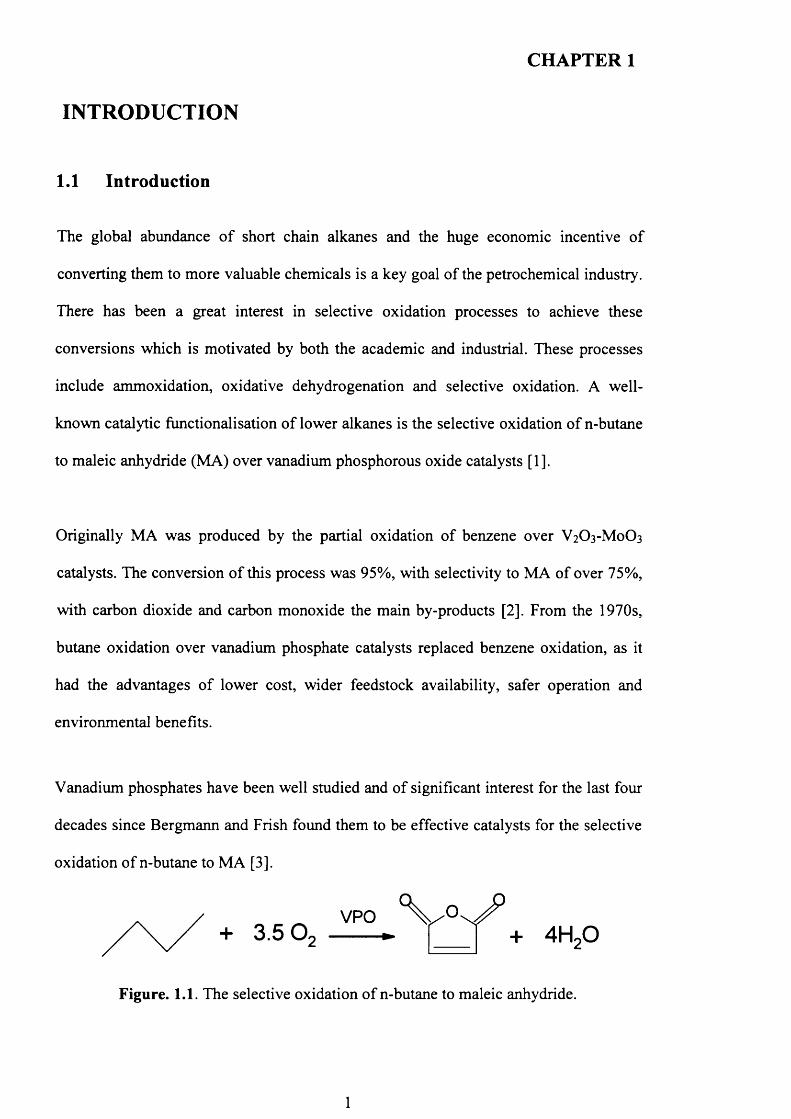
Vanadium phosphates have been well studied and o f significant interest for the last four
decades since Bergmann and Frish found them to be effective catalysts for the selective
oxidation o f n-butane to MA [3].
+ 3.5 O2V PO
Figure. 1.1. The selective oxidation o f n-butane to maleic anhydride.
1
CHAPTER 1
MA is useful feedstock for unsaturated polyester resins, agricultural chemicals such as
herbicides and pesticides. Moreover, it is also used as food additives and has recently
been utilized as a raw material for 1,4-butanediol, tetrahydrofuran and y-butyroloctane.
In addition, MA is used as an oil additive, which increases oil life time and improves
the engine efficiency o f cars.
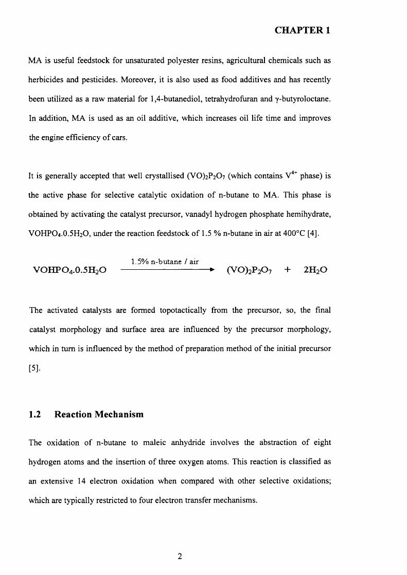
It is generally accepted that well crystallised (V0)2P2C>7 (which contains V4+ phase) is
the active phase for selective catalytic oxidation o f n-butane to MA. This phase is
obtained by activating the catalyst precursor, vanadyl hydrogen phosphate hemihydrate,
VOHPO4 .O.5 H2O, under the reaction feedstock o f 1.5 % n-butane in air at 400°C [4].
1.5% n-butane / airV O H P O 4.0 .5 H 2O ----------------------------------- ► ( V 0 ) 2P 20 7 + 2 H 20
The activated catalysts are formed topotactically from the precursor, so, the final
catalyst morphology and surface area are influenced by the precursor morphology,
which in turn is influenced by the method o f preparation method o f the initial precursor
[5].
1.2 Reaction Mechanism
The oxidation o f n-butane to maleic anhydride involves the abstraction o f eight
hydrogen atoms and the insertion o f three oxygen atoms. This reaction is classified as
an extensive 14 electron oxidation when compared with other selective oxidations;
which are typically restricted to four electron transfer mechanisms.
2
CHAPTER 1
To date, many researchers have developed different models for the mechanism o f n-
butane oxidation on the VPO catalyst [6]. Most o f these proposed models are based on
some experimental and theoretical findings, although there were no intermediates
observed under standard reaction condition. Despite the considerable debate in the
literature concerning the active site, the vanadyl pyrophosphate ((VO)2P2C>7) is
generally accepted to be the main active phase in the selective oxidation o f butane [5].
Therefore, most o f the proposed mechanisms are based on this crystalline phase as the
reaction surface.
The mechanism mostly thought to be operative for selective catalytic oxidation over
solid oxides is the Mars-Van-Krevelen mechanism, in which the catalyst is alternately
reduced by the compound to be oxidised and re-oxidised by gaseous molecular di
oxygen [7].
Taufiq-Yap et al [8] reported a study on n-butane, 1-butene and 1,3-butadiene using
temperature programmed reaction (TPR) and temperature programmed desorption
(TPD). Temperature programmed oxidation experiments proposed that the active
oxygen species for selective oxidation o f butane was lattice oxygen, and the
replenishment o f the surface oxygen from the bulk was the rate determining step which
can confirm that this catalytic reaction follows Mars-Van-Krevelen mechanism. It is
also suggested that the mechanism o f the partial oxidation o f n-butane on (VO)2P2C>7 is
butane —►but-l-ene —► but-l,3-diene —►dihydrofuran —► fur an —► maleic anhydride.
3

CHAPTER 1
The active oxygen species was studied by Abon et al using isotopic labelling
experiments [9]. It was found that lattice oxygen was incorporated into the products and
that as the reaction continued this oxygen was replenished by gas phase oxygen.
Centi et al. [10] have reported a comparison o f the rate constants for depletion o f the
C2-C7 alkane series on a (V0)2P2C>7 catalyst for the theoretical reaction o f simultaneous
abstraction o f two hydrogen atoms and obtained a linear correlation. Their studies
supported a hypothesis that the rate-determining step is the simultaneous removal o f
two hydrogen atoms from the carbon atoms in the 2- and 3-positions in n-butane. They
proposed that the Lewis acid site and the bridging oxygen abstract two hydrogen atoms
from the two methylene groups o f n-butane via a concerted mechanism.
Although, Centi et al. [10] did not give a full mechanism of oxidation o f n-butane to
maleic anhydride, they pointed out that the Bronsted acid sites may be involved in the
intermediate steps following the initial activation o f n-butane. The Bronsted acid sites
were detected by IR spectroscopy and attributed to the presence o f P-OH groups
belonging to terminal HPO4 and H2P2O7 species [11]. The P-OH groups may have
engaged in different functions such as facilitating the removal o f water formed during
the partial oxidation, stabilizing the reaction intermediates by forming the surface
phosphate esters (P-O-C bonds) and avoiding desorption o f these intermediates [12],
and also to facilitate the desorption o f maleic anhydride preventing its over oxidation
[13].
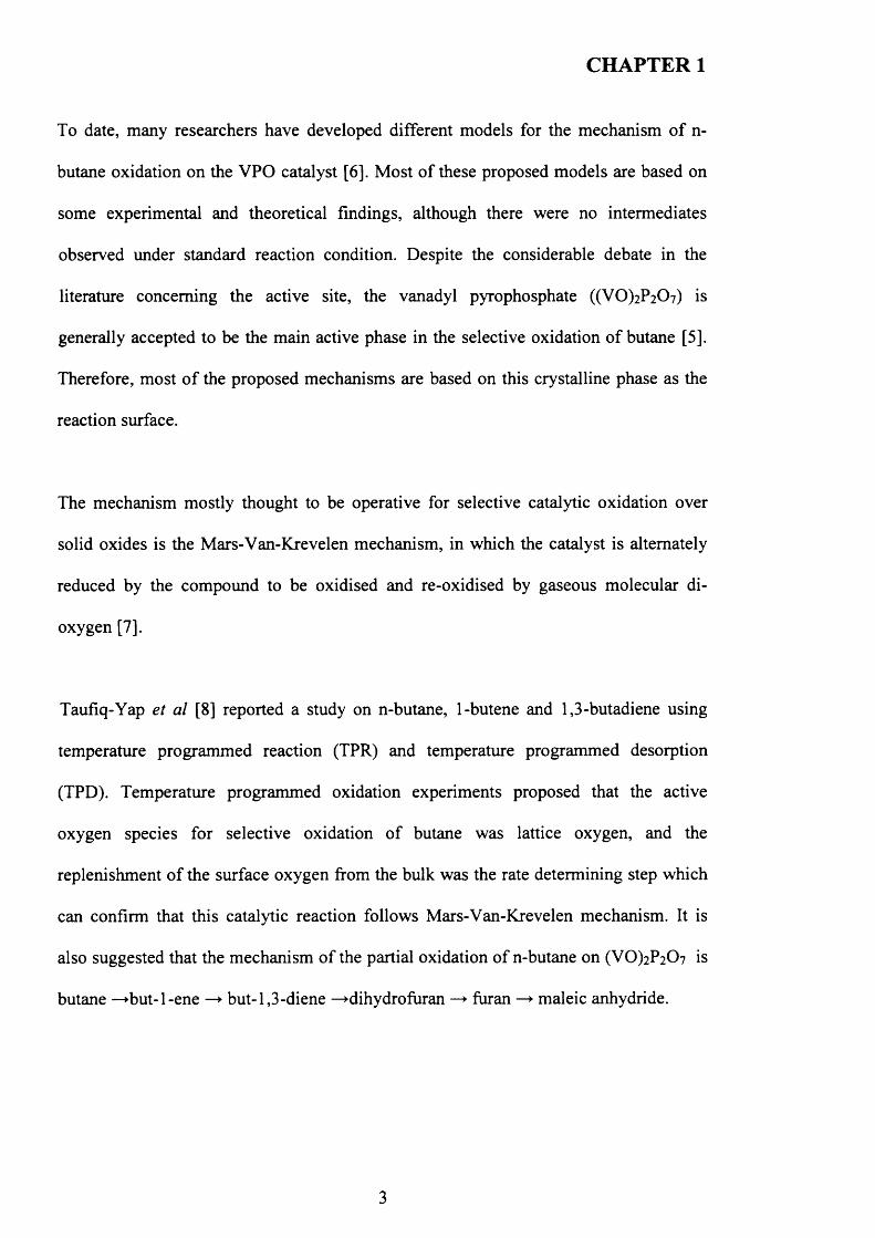
Ziolkowski et al. [14,15] proposed a concerted mechanism o f n-butane oxidation to
maleic anhydride based on theoretical calculations on the [100] plane o f (VO)2P2C>7 (
4
CHAPTER 1
Figure 1.2). It is suggested that the reaction occurred in one step after the adsorption o f
butane on the active site. The adsorbed butane is activated by hydrogen removal to give
butadiene before the concerted step to form maleic anhydride. The formation o f maleic
anhydride creates seven oxygen vacancies on the surface. The re-oxidation o f the
surface is proposed to be the rate determining step. There is, however, no experimental
evidence supporting this mechanism.
u \ X
/ \O------------ (
>-----------:SV "'s,
X -----------c
) c
3------------rC
y----------- - (
x , . .3---------- - (
/ \3-------------(
3 C
3------------ (
O------------0
\/
o
/ \o--------- o—oz—-o
/ \\ P° X\ I /
o -o o -o
V DL ^ ..o— 9*— c>----------o
\ X/ \
x p . \ iO-------------O----------p----------O
X X:o
-n X 'c'h / \
-o <
\ X/ \
Figure 1.2.The active site for the concerted mechanism proposed by Ziolkowski et al
[14,15]
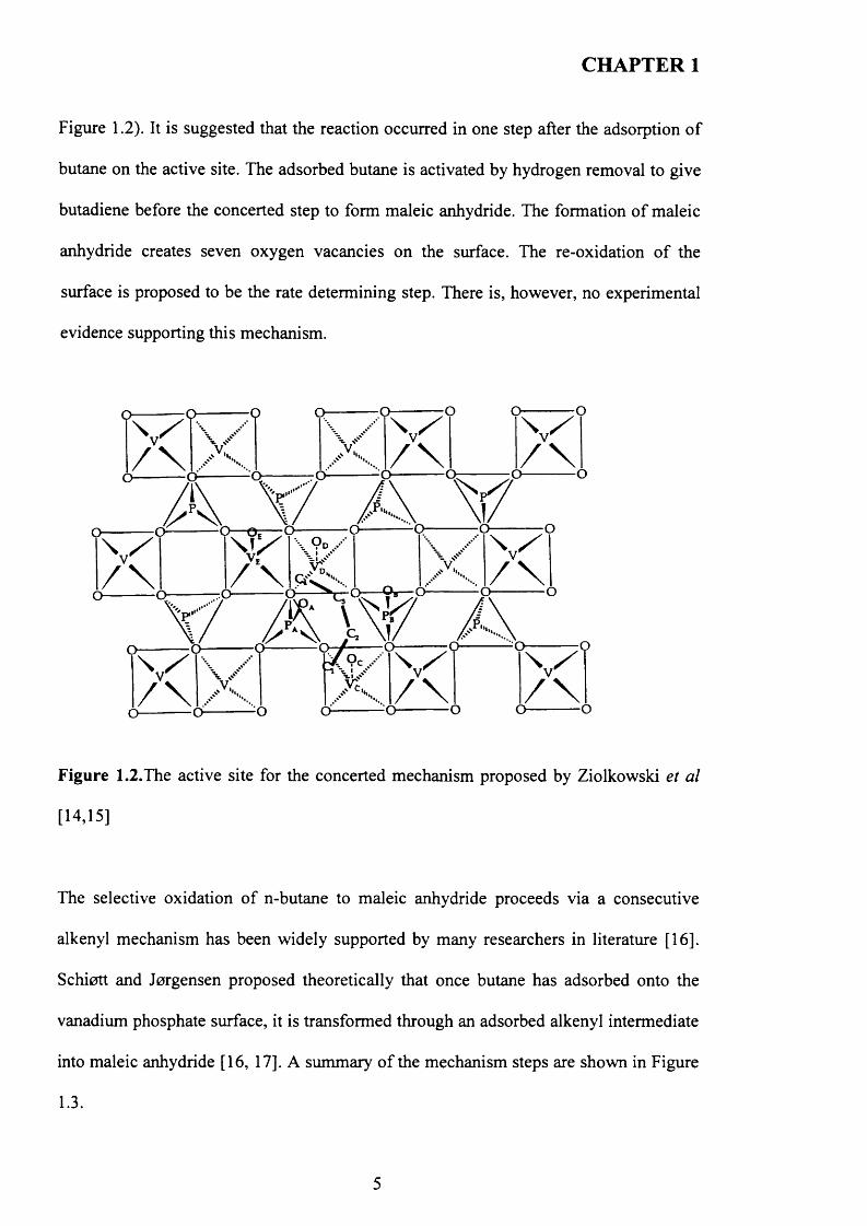
The selective oxidation o f n-butane to maleic anhydride proceeds via a consecutive
alkenyl mechanism has been widely supported by many researchers in literature [16].
Schiott and Jorgensen proposed theoretically that once butane has adsorbed onto the
vanadium phosphate surface, it is transformed through an adsorbed alkenyl intermediate
into maleic anhydride [16, 17]. A summary o f the mechanism steps are shown in Figure
1.3.
5
CHAPTER 1
n-butane
° \ y °V ° n/
maleic anhydride
1-butene
0
v°
asymetric lactone
1,3-butadiene
/ ° \
dihydrofuran
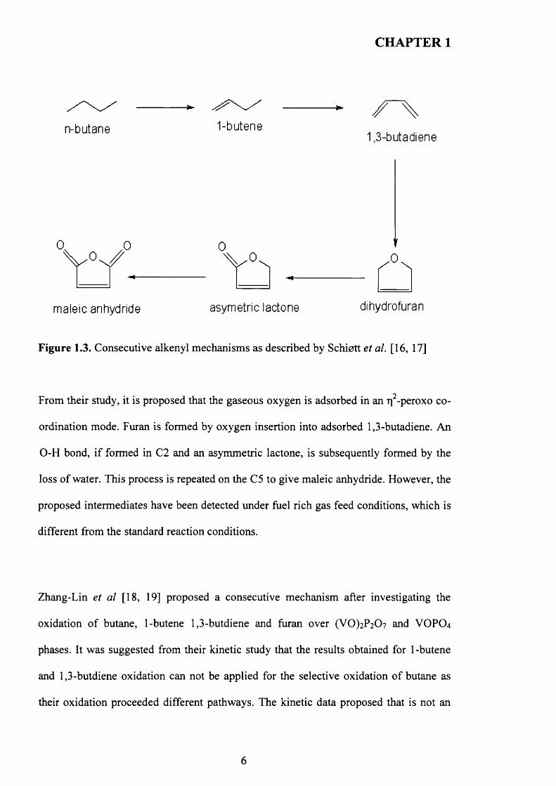
Figure 1.3. Consecutive alkenyl mechanisms as described by Schiott et al. [16, 17]
From their study, it is proposed that the gaseous oxygen is adsorbed in an rj -peroxo co
ordination mode. Furan is formed by oxygen insertion into adsorbed 1,3-butadiene. An
O-H bond, if formed in C2 and an asymmetric lactone, is subsequently formed by the
loss o f water. This process is repeated on the C5 to give maleic anhydride. However, the
proposed intermediates have been detected under fuel rich gas feed conditions, which is
different from the standard reaction conditions.
Zhang-Lin et al [18, 19] proposed a consecutive mechanism after investigating the
oxidation o f butane, 1-butene 1,3-butdiene and furan over (VO)2P207 and VOPO4
phases. It was suggested from their kinetic study that the results obtained for 1-butene
and 1,3-butdiene oxidation can not be applied for the selective oxidation o f butane as
their oxidation proceeded different pathways. The kinetic data proposed that is not an
6
CHAPTER 1
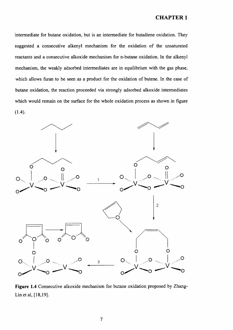
intermediate for butane oxidation, but is an intermediate for butadiene oxidation. They
suggested a consecutive alkenyl mechanism for the oxidation o f the unsaturated
reactants and a consecutive alkoxide mechanism for n-butane oxidation. In the alkenyl
mechanism, the weakly adsorbed intermediates are in equilibrium with the gas phase,
which allows furan to be seen as a product for the oxidation o f butene. In the case o f
butane oxidation, the reaction proceeded via strongly adsorbed alkoxide intermediates
which would remain on the surface for the whole oxidation process as shown in figure
(1.4).
Figure 1.4 Consecutive alkoxide mechanism for butane oxidation proposed by Zhang-
Lin et al, [18,19].
7
CHAPTER 1
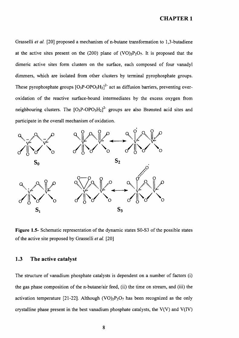
Grasselli et al. [20] proposed a mechanism of n-butane transformation to 1,3-butadiene
at the active sites present on the (200) plane o f (VO)2P2 0 7 . It is proposed that the
dimeric active sites form clusters on the surface, each composed o f four vanadyl
dimmers, which are isolated from other clusters by terminal pyrophosphate groups.
These pyrophosphate groups [O3P-OPO3H2] ' act as diffusion barriers, preventing over
oxidation o f the reactive surface-bound intermediates by the excess oxygen from
neighbouring clusters. The [O3P-OPO3H2] ' groups are also Bronsted acid sites and
participate in the overall mechanism of oxidation.
sa s3
Figure 1.5- Schematic representation of the dynamic states S0-S3 o f the possible states
o f the active site proposed by Grasselli et al. [20]
1.3 The active catalyst
The structure o f vanadium phosphate catalysts is dependent on a number o f factors (i)
the gas phase composition o f the n-butane/air feed, (ii) the time on stream, and (iii) the
activation temperature [21-22]. Although (V0 )2P2 0 7 has been recognized as the only
crystalline phase present in the best vanadium phosphate catalysts, the V(V) and V(IV)
8
CHAPTER 1
phosphate phases can be present in both crystalline and disordered state depending on
activation procedure and conditions [21]. This complexity o f the solid-state chemistry
o f the vanadium phosphate catalysts has opened a debate whether (V0 )2P2 0 7 is indeed
the active catalyst, or a combination o f phases are responsible for the reaction.
Bordes et al [23] proposed that the active sites in n-butane oxidation to maleic
anhydride are linked with coherent interfaces between slabs o f the (100) planes o f a
mixture o f VOPO4 phases and the (200) planes o f (VO)2P2C>7 along the (001) and (201)
planes, respectively. Nevertheless, the best (VO)2P2C>7 catalysts show a lack o f impurity
from VOPO4 phases. As a result, the mechanism of Bordes [23] could be suitable to
explain the catalytic behaviour o f over oxidized or non-equilibrated vanadium
phosphate catalysts.
Hutchings et al. [24] suggested that the active sites for n-butane oxidation to maleic
anhydride comprise a V4+/V5+ couple well dispersed on the surface o f a range o f
vanadium phosphate phases. The active phase suggested is well-dispersed micro
crystalline VOPO4 phases detected on the surface of (VO)2P207 phase.
Centi et al. [25] proposed that butane oxidation occurs through a series o f redox couples
on the vanadium phosphate catalysts and that V3+,V4+ and V5+ must exist for the
reaction to occur. The activation o f butane requiring a V4+-V3+ couple, while the
subsequent conversion to maleic anhydride involves V5+-V4+ couple.
Volta et a l [26] proposed that domains of Y-VOPO4 supported on a (VO)2P2C>7 matrix
*3 1are necessary for selective n-butane oxidation, which was confirmed by XRD, P MAS
9
CHAPTER 1
1NM R results. Conversely, XRD, Raman and P NM R studies demonstrated that the
best catalysts did not contain amorphous or microcrystalline V(V) phosphates [27].
Therefore, their mechanism may also explain the performance o f only non-equilibrated
or over oxidized vanadium phosphate catalysts that could contain VOPO4 phases.
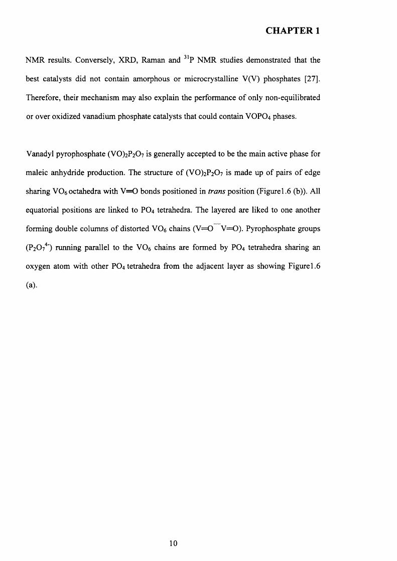
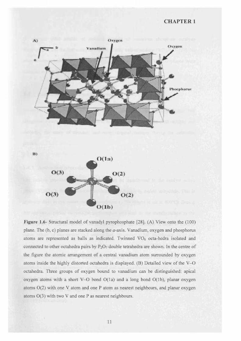
Vanadyl pyrophosphate (VO)2P2C>7 is generally accepted to be the main active phase for
maleic anhydride production. The structure o f (VO)2P2 0 7 is made up o f pairs o f edge
sharing VC>6 0 ctahedra with V = 0 bonds positioned in trans position (Figurel.6 (b)). All
equatorial positions are linked to PO4 tetrahedra. The layered are liked to one another
forming double columns o f distorted YOe chains (V = 0 V = 0 ). Pyrophosphate groups
(P2O74') running parallel to the VC>6 chains are formed by PO4 tetrahedra sharing an
oxygen atom with other PO4 tetrahedra from the adjacent layer as showing Figurel.6
(a).
10
CHAPTER 1
O xygen
Vanadium Ox>Rcn
PfioGphoru*
D)
Figure 1.6- Structural model o f vanadyl pyrophosphate [28]. (A) View onto the (100)
plane. The (b, c) planes are stacked along the a-axis. Vanadium, oxygen and phosphorus
atoms are represented as balls as indicated. Twinned VC>6 octa-hedra isolated and
connected to other octahedra pairs by P2O7 double tetrahedra are shown. In the centre of
the figure the atomic arrangement of a central vanadium atom surrounded by oxygen
atoms inside the highly distorted octahedra is displayed. (B) Detailed view of the V-O
octahedra. Three groups of oxygen bound to vanadium can be distinguished: apical
oxygen atoms with a short V-O bond 0(1 a) and a long bond O(lb), planar oxygen
atoms 0(2) with one V atom and one P atom as nearest neighbours, and planar oxygen
atoms 0(3) with two V and one P as nearest neighbours.
O ( l n )
0 (2}
0 (2)
O ( l b )
11
CHAPTER 1
In contrast, other studies o f standard models o f vanadium phosphate catalysts
demonstrated that the best catalysts contained only well-crystalline (VO)2P2 0 7 [29]. No
other microcrystalline or disordered impurity phases such as VOPO4 phases were
detected in such catalysts [29].
1.4 Activation of catalyst precursors
Investigation into the activation o f catalyst precursors can be divided into two
categories. Firstly, the effect o f different activation methods on the final catalyst, and
secondly, the study o f structure and morphological changes during the activation
process.
1.4.1 Activation procedures
The catalyst precursor VOHPO4.O.5H2O must be transformed to the catalyst active
phase (VO)2P2C>7 for the selective oxidation o f n-butane to maleic anhydride. This is
typically done in situ under reaction conditions (1.7% butane in air at 400°C). During
this activation period the catalyst performance increases as the transformation to the
active phase (VO)2P2C>7 occurs. The activation takes approximately 72 hours to achieve
stable values o f conversion and selectivities. However, a full transformation o f the
precursor to the active phase (VO)2P2C>7 requires approximately 1000 hours on-line in
order for the catalyst to be considered as totally transformed. Albonetti et al [30]
reported a comparison between equilibrated and non-equilibrated catalysts. It was found
from their studies that equilibrated catalysts that had been on-line for 1000 hours were
more crystalline and had higher surface area compared with non-equilibrated catalysts
(80-100 hours on-line).
12
CHAPTER 1
There have been a number o f crystalline VPO phases observed during the
transformation o f the VOHPO4.O.5 H2O precursor to the active phase (VO)2P2C>7 [21,
31]. Depending on several factors such as the activation temperature, period,
atmosphere, the morphology o f the precursor, the P/V ratio in the precursor and the
presence defects in the structure.
There are two different activation procedures commonly reported in the literature [6,
32]. Firstly, activation o f the catalyst precursor in an inert atmosphere at T 673K,
followed by the introduction o f the reactant mixture o f n-butane in air.
VOHPO4 .O.5 H2O transforms to poorly crystalline (VO)2P2C>7 during the first step,
which can be partially oxidized to V(V) orthophosphates (commonly VOPO4 phases)
after the introduction o f the reactant mixture. Calcination o f the catalyst precursor in air
at T 673K, after which the reactant mixture is introduced, leads to complete oxidation to
V5+.
1.4.2 Structural transformations
Johnson et al [33] studied the crystalline structure o f precursor and active catalysts and
concluded the topotactic nature o f this transformation. This means that the (VO)2P2C>7
catalyst preserves the morphology o f the VOHPO4 .O.5 H2O precursor. Insight into how
the transformation occurs could assist in the design o f pre-treatments and activations o f
catalyst precursor, which would produce catalysts with enhanced properties.
Kiely et al also confirmed that a direct topotactic transformation from catalyst precursor
VOHPO4.0.5H2O to (VO)2P2C>7 occurs at the periphery o f the crystallite, whereas
13
CHAPTER 1
VOHPO4.O.5H2O initially transforms epitaxially into S-VOPO4 in the interior o f the
crystallite. As the activation time increases the spheres o f 8-VOPO4, which are
embedded in a disordered matrix, shrink and are further reduced to give the (V0 )2 ? 2 0 7
[34].
Hutchings et al reported using Raman spectroscopy to study activation and reported that
the activation process does not proceed through the simple transformation o f crystalline
VOHPO4.O.5 H2O to crystalline (VO)2P2 0 7 only [35]. It was suggested that the bulk of
the VOHPO4 .O.5 H2O becomes amorphous on heating in an n-butane air mixture and the
crystallization to (VO)2P2C>7 takes place relatively slowly, which may affect the
crystallinity o f (V0 )2P2 0 7 .
Torardi et al [36] also investigated the transformation o f the VOHPO4 .O.5 H2O precursor
into (VO)2 ? 2 0 7 by electron and X-ray diffraction techniques and demonstrated that the
transformation was topotactic in the sense that the initial crystal morphology was
preserved during the transformation. It was found that single crystals o f
VOHPO4.0.5H2O were converted to pseudomorphs, which were unchanged in size or
shape with respect to the starting crystals o f the precursor.
Ryumon et al [37] studied the transformation o f VOHPO4 .O.5 H2O precursor to
(VO)2P2C>7 using water vapour. For these studies, they used small and large crystallites
in the presence and absence o f water vapour. It was found that a single-phase o f well-
crystallized (VO)2P2 0 7 formed within 5 hours under a reaction mixture (0.9% n-butane,
10% 0 2 ) containing 40% water vapour using the small crystallites, whereas the
transformation took more than 100 hours in reaction mixture without water vapour.
14
CHAPTER 1
Ryumon et al [37] also suggest that under the reaction conditions, water vapour
accelerated two processes in the transformation of VOHPO4 .O.5 H2O to (VO)2P2 0 7 : the
crystallization o f the amorphous VPO phase containing V4+ and V5+ to (VO)2P2 0 7 and
5 -VOPO4 and the transformation of 8 -VOPO4 to (VO)2P2 0 7 . However, water vapour
inhibited the topotactic transformation o f VOHPO 4 .O.5 H2O to (VO)2P2C>7.
More recently, Imai et al reported the transformation o f nano-sized VOHPO4 .O.5 H2O
crystallites to (VO)2P2 0 7 under reaction mixture [38]. It was found that the crystalline
structure o f VOHPO4.O.5 H2O rapidly collapsed to form an oxidized amorphous phase
within an hour followed by slow crystallization to (VO)2P2 0 7 . This is accompanied by
the formation o f sharply angular nano-sized crystallites (about 50 nm). Interestingly, no
crystalline phases other than (V0 )2P2C>7 were formed during this transformation, which
is quite different from the transformation o f large and thick VOHPO4 .O.5 H2O
crystallites, in which VOPO4 phases have been commonly detected in the resulting
catalyst [5].
1.5 The phosphorus to vanadium ratio of the catalyst
Most o f the commercial catalysts have been characterised with a slight excess o f
phosphorus, usually P/V ~1.1 [39]. It has been observed that part o f the phosphorus
sublimes during standard operation and methods for the replenishment o f the catalyst
with phosphorus have been reported without considerably interfering with the plant
operation [40].
15
CHAPTER 1
The enhancement o f the phosphorus surface concentration has been demonstrated to
have a beneficial effect on the performance o f VPO catalysts [41]. Some studies [42]
claim that a significant excess o f surface phosphate (P /V =l.5-3.0) could prevent the
bulk oxidation o f (V0)2P2 0 7 to the VOPO4 phases, which was characterised by XPS.
Matsuura et al [42], suggested that the excess phosphate terminates the side faces o f the
(200) plane o f (VO)2P2C>7 (i.e. 001, 021, etc.) in the form o f the surface V0 (P0 3 ) 2
phase, which prevents the oxidation o f vanadyl pyrophosphate (VO)2P2 0 7 due to lower
oxidizability o f V 0(P 0 3 )2. This show the right compromise between reducibility and
oxidizability needed in the final catalyst to obtain both high activity and selectivity in n-
butane oxidation.
However, it is quite clear from a large number o f studies that phosphorus in excess o f
the 1:1 stoichiometric ratio is important for the selective oxidation o f n-butane,
especially for catalyst prepared in aqueous media. Additionally, phosphorous is added
in industrial application to maintain P:V ratios.
1.6 Promoted catalysts
Most o f the industrial vanadium phosphates catalysts rarely use a bulk phase. The
activity o f vanadium phosphates is often enhanced by the addition o f low concentrations
o f metal cations known as promoters, which can act as texture promoters or improve the
activity and selectivity o f the active catalyst.
16
CHAPTER 1
The nature, the location and the roles o f metal promoters on vanadium phosphate
catalysts have been widely reviewed [43,44]. Hutchings [43] has provided an extensive
review o f most o f the promoters addressed in the patent literature. A broad series o f
promoters have been added to vanadium phosphate catalysts and a beneficial effect has
been claimed with Co, Cd, Ni, Bi, Cu, Zn, Zr, Li, Mg, Ti, La, Mo, Nb, B, Fe, Cr, Ce, Pt,
W and Ga. These promoters can act in two ways:
• Promoting the formation o f the required VPO phases or avoid the formation o f
spurious phases
• To enable the formation o f solid solutions with the active phase and can regulate
the catalytic activity.
However, some promoters can act in a different way depending on their interaction with
VPO phases and loading preparation methods. A brief introduction to most published
papers concerning this point is illustrated.
Sajip et al [45] investigated the effect o f Co and Fe ions added during the preparation o f
the catalyst precursor VOHPO4 .O.5 H2O on n-butane oxidation to maleic anhydride. At
low levels, both Co and Fe significantly improved the selectivity and intrinsic activity in
maleic anhydride formation. They found that the selectivity to maleic anhydride at 25 %
n-butane conversion was 63 mol. % for the promoted phases and only 50 mol. % for the
unpromoted VPO catalyst at 673 K. It was proposed that Co was insoluble in the
(VO)2 ? 2 0 7 phase. It was suggested that the origin o f the effect o f Co is related to its
interaction with the disordered VPO phase. In contrast, Fe ions may be soluble in the
(V0 )2? 2O7 lattice and, consequently, it can act as an electronic promoter for this phase,
17
CHAPTER 1
most likely enabling the re-oxidation o f the catalyst or aiding oxygen mobility. It is also
possible that Fe is associated with the disordered phase and could act in a similar
manner with this material.
Zazhigalov et al. modified the redox properties o f the VPO catalysts by incorporating
metallic Co in the catalyst precursor. It was reported from their study that presence o f
Co increases the content o f phosphorus at the surface, which modifies the surface
acidity and in turn improves the selectivity for n-butane oxidation. In addition, Cobalt
stabilizes the catalyst performance by forming cobalt phosphate, which reduces
phosphorus losses, improves its catalytic properties and prolongs its lifetime [46].
Zazhigalov et al also studied a range o f alkali and alkaline-earth metal ions as promoters
on VPO catalysts [47]. They found that Li, Na, K, Cs, Be, Mg, Ca and Ba cations
present at different concentrations, simply donated electrons to the VPO catalysts with
P/V ratios o f 1.07 and 1.20, leading to increased negative charge on lattice oxygen
atoms o f the catalyst and improving the butane conversion. The presence o f these
promoters caused an increase o f the surface P/V ratio and corresponding changes o f the
surface acidity. However, the preparation o f a catalyst characterized by high activity in
n-butane oxidation and high selectivity to maleic anhydride still needs improvement o f
the basicity o f surface oxygen atoms to facilitate the activation o f n-butane and the
surface acidity to control the residence times o f the reaction intermediates.
Beatriz et al [48] studied the promoting effect o f some elements (Cr, Mo and W) added
to the catalyst precursor VOHPO4 .O.5 H2O using different methods and loads. Cr, Mo or
W were either impregnated on catalyst precursor or co-precipitated during the precursor
18
CHAPTER 1
synthesis. It was found that the addition o f the promoters consistently increased the
catalytic activity, but in every case there was an optimum load to achieve the best
selectivity. They proposed that the reason for this maximum could be attributed to the
right balance between the presence o f very strong Lewis acid sites and the development
o f V5+ (VOPO4 phases) isolated sites in the matrix o f the active phase (V0 )2P2C>7.
Lopez-Nieto et al [49] reported the incorporation o f Bi in the VPO catalysts. It is found
that Bi promoter led to a modification in the surface properties that resulted in improved
catalytic performance. They claim that the incorporation o f Bi stabilised the active
phase (VO)2P2 0 7 structure and led to an increase in the specific surface area, which
enhanced the rate o f n-butane oxidation.
Taufiq-Yap et al [50] studied the addition o f Bi and Fe in three different methods: (i)
during the refluxing VOPO4 2 FI2C) with isobutanol, (ii) the simultaneous addition o f
BiFe oxide powder in the course o f the synthesis o f precursor VOHPO4 .O.5 H2O and (iii)
the mechanochemical treatment o f precursor VOHPO4 .O.5 H2O and Bi, Fe oxide in
ethanol. It was found that surface area o f the modified catalysts had increased except
with the simultaneous addition. They concluded that the conversion of w-butane
decreases with the increase o f oxygen species associated with V5+.
More recently, Sartoni et al [51] studied gallium promoted on vanadium phosphate
catalyst precursor for the mild oxidation o f n-butane to maleic anhydride. It was found
that Ga promoter “at low concentrations” (Ga/V < 1 %) improved the crystallinity o f the
hemihydrates (VOHPO4O.5H2O) precursor phase and increased its surface area
comparative to the undoped material. They also found that the presence o f Ga
19
CHAPTER 1
considerably shortens the activation time required to convert the hemihydrates precursor
into a well-crystallized vanadyl pyrophosphate (VO)2P2 0 7 phase under reaction
condition. In contrast, Ga at high concentrations (Ga/V ~ 5%), which could be found as
a GaPC>4 impurity phase, has a detrimental effect on the catalytic performance o f the Ga
promoted on VPO catalyst.
1.7 Preparation of catalyst precursors VOHPO 4 .O.5 H2O
The active vanadium phosphate catalysts are commonly obtained by activating the
catalyst precursor VOHPO4 O.5 FI2O under reaction conditions. This transformation is
believed to be topotactic [32]. For this reason, it is o f great importance to distinguish
between VOHPO4 O.5 H2O precursor prepared via different preparation methods and
also to focus on finding new preparative routes for the preparation o f the precursor.
VOHPO 4 O.5 H2O precursor can be prepared via three different preparation
methodologies [5].
The VPA method (vanadium phosphate catalyst prepared in aqueous media)
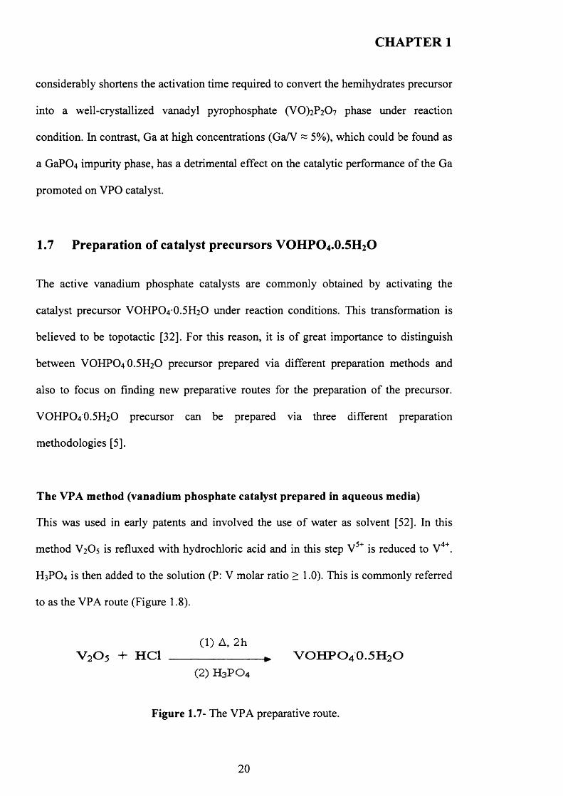
This was used in early patents and involved the use o f water as solvent [52]. In this
method V2O5 is refluxed with hydrochloric acid and in this step V5+ is reduced to V4+.
H3PO4 is then added to the solution (P: V molar ratio > 1.0). This is commonly referred
to as the VPA route (Figure 1.8).
(1) A, 2 hV205 + HC1 ________________ * VOHPO4O.5H2O
(2) H 3PO 4
Figure 1.7- The VPA preparative route.
20
CHAPTER 1
Other aqueous routes have been used by a number o f groups in order to prepare
VOHPO4 O.5H2O. Oxalic acid [53], phosphorus acid [54] and NH2OH.HCL [55] have
been reported as reducing agents as an alternative to HCL. However, significant
amounts o f impurity V0(H2P04)2 are also obtained during the preparation. In addition,
this method gives low surface area VOHPO4 O.5H2O precursors, which lead to lower
activity for n-butane oxidation.
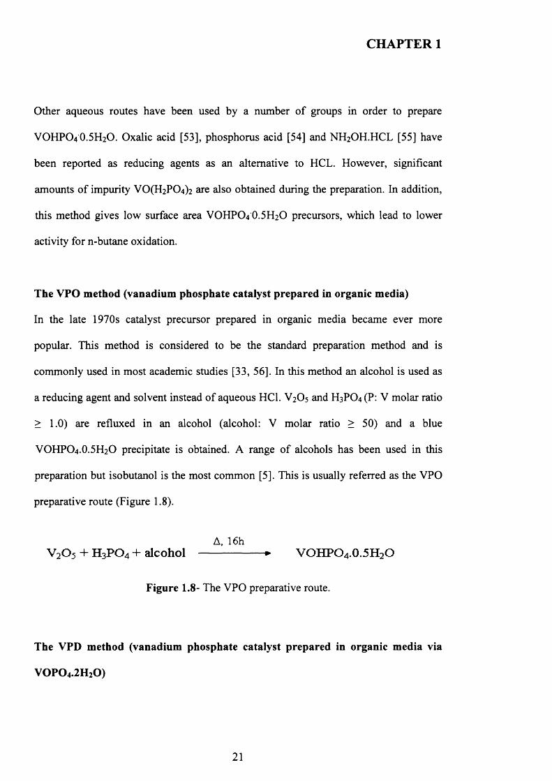
The VPO method (vanadium phosphate catalyst prepared in organic media)
In the late 1970s catalyst precursor prepared in organic media became ever more
popular. This method is considered to be the standard preparation method and is
commonly used in most academic studies [33, 56]. In this method an alcohol is used as
a reducing agent and solvent instead o f aqueous HC1. V2O5 and HsP04(P: V molar ratio
> 1.0) are refluxed in an alcohol (alcohol: V molar ratio > 50) and a blue
VOHPO4.O.5H2O precipitate is obtained. A range o f alcohols has been used in this
preparation but isobutanol is the most common [5]. This is usually referred as the VPO
preparative route (Figure 1.8).
A, 16hV 2 0 5 + H3 PO4 + alcohol ---------------- * VOHPO 4 .0.5H2O
Figure 1.8- The VPO preparative route.
The VPD method (vanadium phosphate catalyst prepared in organic media via
VOPO4 .2 H 2 O)
21
CHAPTER 1
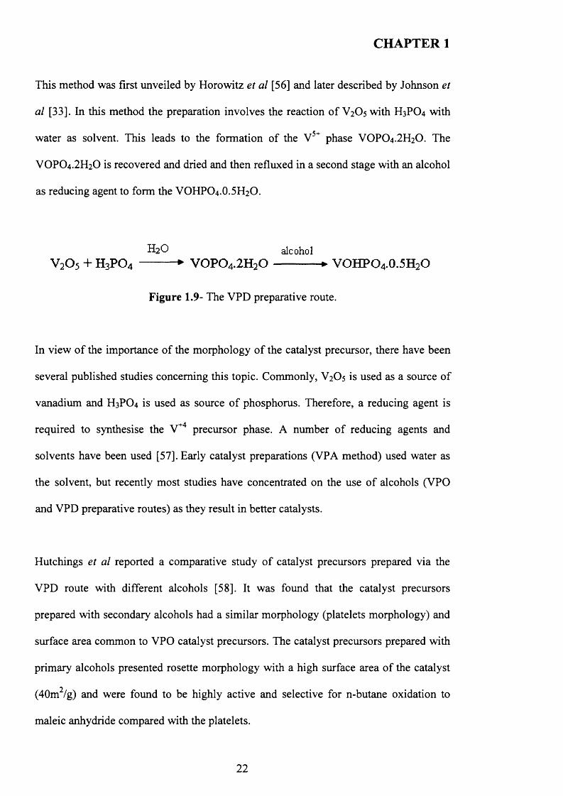
This method was first unveiled by Horowitz et al [56] and later described by Johnson et
al [33]. hi this method the preparation involves the reaction o f V2O5 with H3PO4 with
water as solvent. This leads to the formation of the V 5+ phase VOPO4.2H2O. The
VOPO4.2H2O is recovered and dried and then refluxed in a second stage with an alcohol
as reducing agent to form the VOHPO4.O.5H2O.
H2O alcoholV205 + H3PO4 --------- ► VOPO4.2H2O-------------► VOHPO4.O.5H2O
Figure 1.9- The VPD preparative route.
In view o f the importance o f the morphology o f the catalyst precursor, there have been
several published studies concerning this topic. Commonly, V2O5 is used as a source of
vanadium and H3PO4 is used as source o f phosphorus. Therefore, a reducing agent is
required to synthesise the V+4 precursor phase. A number o f reducing agents and
solvents have been used [57]. Early catalyst preparations (VPA method) used water as
the solvent, but recently most studies have concentrated on the use o f alcohols (VPO
and VPD preparative routes) as they result in better catalysts.
Hutchings et al reported a comparative study o f catalyst precursors prepared via the
VPD route with different alcohols [58]. It was found that the catalyst precursors
prepared with secondary alcohols had a similar morphology (platelets morphology) and
surface area common to VPO catalyst precursors. The catalyst precursors prepared with
primary alcohols presented rosette morphology with a high surface area o f the catalyst
(40m2/g) and were found to be highly active and selective for n-butane oxidation to
maleic anhydride compared with the platelets.
22
CHAPTER 1
1.8 Preparation of other VPO phases
1.8.1 Preparation of V 0 (H2P0 4 ) 2
It is generally accepted that the most active and selective catalyst for the oxidation o f n-
butane to maleic anhydride, is derived from the catalyst precursor VOHPO4 .O.5 H2O.
However, a number o f vanadium phosphate compounds have been reported to be fairly
effective catalysts for this reaction. Although a lower activity and selectivity than
(VO)2P2 0 7 the V 0(H 2P 0 4)2 phase, (defined as phase E in this thesis) has been
determined to be an impurity formed during the preparation o f the catalyst precursor.
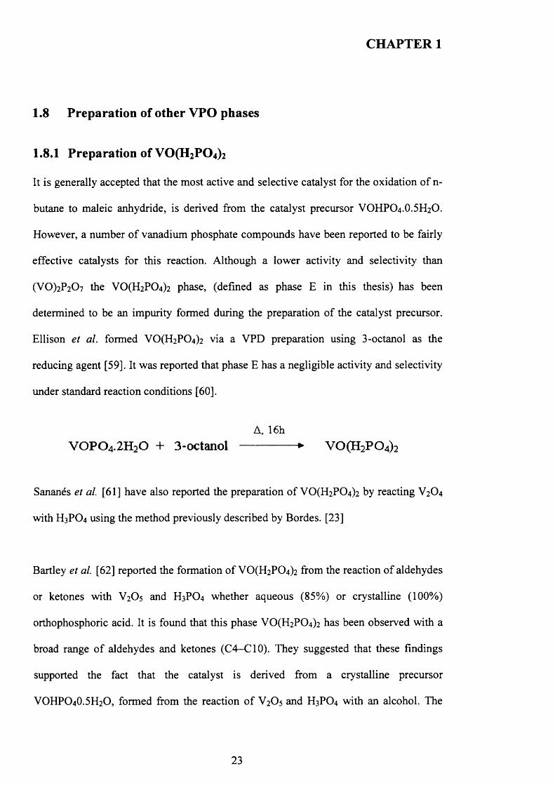
Ellison et al. formed V 0 (H2P0 4 ) 2 via a VPD preparation using 3-octanol as the
reducing agent [59]. It was reported that phase E has a negligible activity and selectivity
under standard reaction conditions [60].
A, 16hV 0 P 0 4.2H20 + 3-octanol -------------- ► V 0 (H 2P 0 4)2
Sananes et a l [61] have also reported the preparation o f VO(H2PC>4)2 by reacting V2O4
with H3PO4 using the method previously described by Bordes. [23]
Bartley et al. [62] reported the formation o f V 0 (H2P0 4 ) 2 from the reaction o f aldehydes
or ketones with V2O5 and H3PO4 whether aqueous (85%) or crystalline (100%)
orthophosphoric acid. It is found that this phase VO(H2P0 4 ) 2 has been observed with a
broad range o f aldehydes and ketones (C4-C10). They suggested that these findings
supported the fact that the catalyst is derived from a crystalline precursor
VOHPO4O.5H2O, formed from the reaction o f V2O5 and H3PO4 with an alcohol. The
23
CHAPTER 1
alcohol is oxidised to give an aldehyde or ketone as a result o f the reaction. The
presence o f these aldehydes and ketones in the mixture will lead to the formation o f
V 0 (H2P0 4)2 as an impurity. This led to an effect on the final catalyst V 0 (P0 3 ) 2 and its
performance for the selective oxidation o f n-butane to maleic anhydride.
1.8.2 Preparation of VOPO4 phases
Some o f V 5+ phases, mainly VOPO4 phases, have been observed in the active catalyst
[35-37]. However, the nature o f their effect in the active catalyst has been the subject o f
significant debate in the literature as mentioned in the previous section (1.4.2).
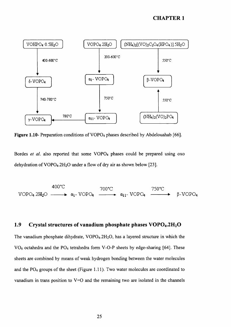
The preparation o f VOPO4 phases: ai- V 0 P0 4 ,a n - VOPO4, y-VOPO^ 5 -V0 P0 4 and P-
VOPO4 has been reported by Abdelouahab et al. [63] via calcinations o f VOPO4 .2 H2O
and VOHPO4 .0.5H2O in air.
Y-VOPO4, 8 -VOPO4 can be prepared by calcination o f VOHPO4.O.5 H2O in air and ai-
V O P0 4 , an -V 0 P0 4 can be prepared by calcination o f VOPO4.2 H2O in air. P-VOPO4
can be prepared by the decomposition o f NFLjCV0 2)2P0 4 in dry air. A summary o f the
preparation routes for VOPO4 phases is presented in Figure 1.10. As described by
Abdelouahab et al. [63]:
24
CHAPTER 1
200-600*C
780*C
ai- VOPO4
an- VOPO4
VOHPO4 0.5H2O (NH4)2[(V0 )2C204 (HP0 4 )].5H20
Figure 1.10- Preparation conditions o f VOPO4 phases described by Abdelouahab [66].
Bordes et al. also reported that some VOPO4 phases could be prepared using oxo
dehydration o f VOPO4.2 H2O under a flow o f dry air as shown below [23].
40CTC 7 0 ( r c 7 5 c rc
V 0 P 0 4 .2H20 -------- ► OL1-VOPO 4 --------- ► o-ii- VOPO4 -----------► P-VOPO4
1.9 Crystal structures of vanadium phosphate phases V 0 P 0 4.2H20
The vanadium phosphate dihydrate, VOPO4 .2 H2O, has a layered structure in which the
V 0 6 octahedra and the P 0 4 tetrahedra form V-O-P sheets by edge-sharing [64]. These
sheets are combined by means o f weak hydrogen bonding between the water molecules
and the P 0 4 groups o f the sheet (Figure 1.11). Two water molecules are coordinated to
vanadium in trans position to V = 0 and the remaining two are isolated in the channels
25

CHAPTER 1
formed by the hydrogen bonding network (Figure 1.12. W1 and W2). The water
molecules can be removed from the between the layers to give VOPO4 phases.
Figure 1.11-The crystal structure of VOPO4.2 H2O.
[ • = V, • = P, 0 = vanadyl oxygen, • = ( ) , H2O free or co-ordinated to vanadium]
26
CHAPTER 1
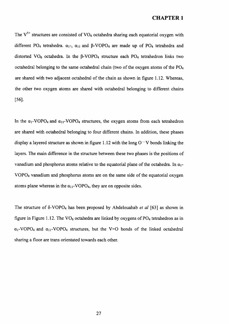
The V 5+ structures are consisted o f VC>6 octahedra sharing each equatorial oxygen with
different PO4 tetrahedra. di-, a n and P-VOPO4 are made up o f PO4 tetrahedra and
distorted V06 octahedra. In the P-VOPO4 structure each PO4 tetrahedron links two
octahedral belonging to the same octahedral chain (two of the oxygen atoms o f the PO4
are shared with two adjacent octahedral o f the chain as shown in figure 1.12. Whereas,
the other two oxygen atoms are shared with octahedral belonging to different chains
[56].
In the a i-V 0 P0 4 and an -V 0 P0 4 structures, the oxygen atoms from each tetrahedron
are shared with octahedral belonging to four different chains. In addition, these phases
display a layered structure as shown in figure 1.12 with the long O V bonds linking the
layers. The main difference in the structure between these two phases is the positions o f
vanadium and phosphorus atoms relative to the equatorial plane o f the octahedra. In a i-
VOPO4 vanadium and phosphorus atoms are on the same side o f the equatorial oxygen
atoms plane whereas in the an-VOPCU, they are on opposite sides.
The structure o f 5 -VOPO4 has been proposed by Abdelouahab et al [63] as shown in
figure in Figure 1.12. The V06 octahedra are linked by oxygens o f PO4 tetrahedron as in
ai-V 0 P0 4 and aii-VOPC>4 structures, but the V = 0 bonds o f the linked octahedral
sharing a floor are trans orientated towards each other.
27
CHAPTER 1
a,-VOPQ»
Y-VOPO4
an-VOPCX
8-VOFO4
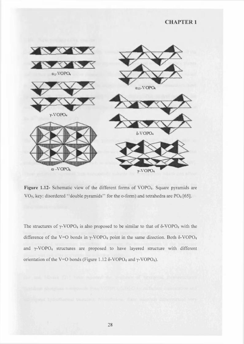
Y-VOFO4
Figure 1.12- Schematic view of the different forms of VOPO4. Square pyramids are
VO5, key: disordered “ double pyramids” for the o-form) and tetrahedra are PO4 [65].
The structures o f Y-VOPO4 is also proposed to be similar to that of 5-VOPO4 with the
difference of the V= 0 bonds in Y-VOPO4 point in the same direction. Both 6-VOPO4
and Y-VOPO4 structures are proposed to have layered structure with different
orientation of the V= 0 bonds (Figure 1.12 5-VOPO4 and Y-VOPO4).
q -VCPO*
28
CHAPTER 1
1.10 New preparative routes
Conventional preparation methods offer limited control over the desirable phase o f the
catalyst precursor and also preferential exposure of active and selective surface planes
and surface areas o f the active catalysts. All o f these define their catalytic performance
in selective oxidation o f n-butane. In recent years, the majority o f researchers have
focused on the VPD route as it results in better catalysts. This method involves the
reaction o f V 2O 5 with H 3PO4 with water as the solvent, which leads to the formation of
the V 5+ phase VOPO4.2 H2O.
The layered structures o f vanadium phosphate dihydrate VOPO4 .2 H2O is able to
accommodate some types o f organic molecules and, to date, a number o f intercalation
compounds have been reported, such as amine, [66-67] amide, [6 8 ] and alcohol, [69].
These structures represent host compounds suitable for intercalation which can affect
physical and chemical properties of the structures and can thus provide us with the
possibility to obtain catalyst precursors with high surface area with improved activities
for n-butane oxidation.
Iwamoto et al. [70] synthesised mesostructured vanadium phosphate compounds using
alkyl-trimethyl ammonium surfactants. However, the mesostructure in the precursor
phases was lost after activation for n-butane oxidation.
Doi and Miyake [71] have reported the synthesis o f hexagonal mesostructured
vanadium phosphate compounds from VOHPO4 .O.5 H2O by surfactant intercalation and
subsequent hydrothermal treatment. Nevertheless, these materials demonstrated very
29
CHAPTER 1
low thermal stability under the reaction condition and low phosphorus content that are
detrimental for their potential applications in n-butane oxidation.
Mount et a l have investigated the use o f an autoclave reactor to produce
VOHPO4.O.5H2O from reacting V2O5 and H3PO4 in the presence o f H3PO3 [72]. The
catalysts obtained reported about 15% better yield o f maleic anhydride than VPA
catalyst. However, these results are lower than catalysts prepared in an organic route
which are, therefore, still preferred.
Antonio et al. reported the synthesis o f VOHPO4O.5H2O using V2O4 and either H3PO4
or H4P2O7 as a starting material with water as solvent. The surface area o f the precursor
was significantly enhanced when water was added as a solvent. From their study it was
found that the catalytic performance data is comparable to other non-promoted
vanadium phosphate catalysts [73].
More recently, Okuhara et a l reported the intercalation and exfoliation o f VOPO4.2 H2O
in primary and secondary alcohols [74]. This was achieved with stepwise heating at a
low temperature and the subsequent reduction o f the exfoliated VOPO4 .2 H2O. It was
found that the VOHPO4 .O.5 H2O precursor was obtained with a different morphology. In
addition, the (VO)2P2 0 7 obtained from the precursor was found to be highly active and
selective for the selective oxidation o f n-butane.
30
CHAPTER 1
1.11 The aims of this study
It has been addressed that the catalytic activity o f the active vanadium phosphate
catalysts is dependent on the synthesis o f the catalyst precursor. In addition, it has been
mentioned earlier that the transformation o f the catalyst precursor VOHPO4.O.5H2O to
the active phase (VO)2P2 0 7 is repeatedly believed to be topotactic, which implies that
the morphology o f the final catalyst is controlled by the morphology of the precursor.
The preparation o f the catalyst precursor VOHPO4 .O.5 H2O is controlled by a number o f
factors such as vanadium phosphate sources, reducing agents, solvents, temperature and
reaction time. Co-solvents can play important roles in the preparation o f vanadium
phosphate catalysts and only a few studies have focused on this work, mainly mixed
alcohols have been used.
The first aim of the study, demonstrated in this thesis, is the study of precursor
preparation method with an alkane as a co-solvent using VOPO 4.2 H2O as starting
material.
To the best o f my knowledge, there has not been any report investigating the use o f V-
P-0 seeds in the preparation o f the catalyst precursor and their effects. Therefore, the
second aim o f the study is to investigate the effects of using V-P-0 seeds in primary ( 1-
octanol, iso-butanol) and secondary (2-butanol, 3-octanol) alcohols. The use o f
vanadium phosphate seeds will be discussed with a view to better understanding the
formation o f the catalyst precursor. A novel transformation o f V 0 (H2P0 4 ) 2 to catalyst
precursor VOHPO4.O.5H2O via seeding the reaction mixture will be investigated and
discussed.
31
CHAPTER 1
Attempts to prepare new vanadium phosphate materials by the reduction o f
VOPO4.2 H2O using hydrogen in aqueous media and strong reducing agents (N2H4 and
NaBRj). A direct reduction o f VOPO4 .2 H2O at different temperatures will also be
investigated.
32
CHAPTER 1
1.12 References:
[1] Y. H. Taufiq-Yap, C. S. Saw, R. Irmawati Catal. Lett. 105 (2005)103.
[2] A. Cruz-Lo'pez, N. Guilhaume, S. Miachon, J. Dalmon. /Catal. Today 107
(2005) 949.
[3] R. L. Bergmann and N. W. Frisch, US Patent 3293268, (1966).
[4] J.K. Bartley, J. Lopez-Sanchez, G. Hutchings. Catal. Today 81 (2003) 197.
[5] G.J. Hutchings, J. Mater. Chem 14 (2004) 3385.
[6] Cavani, F. Trifiro', Catalysis, 1994, 11, 246.
[7] P. Mars, D.W. van Krevelen, Chem. Eng. Sci. Spec. Suppl. 3 (1954), 41
[8] Y. H. Taufiq-Yap, B. H. Sakakini, K. C. Waugh, Catal. Lett. 46 (1997) 273-277.
[9] M Abon, K. E. Bere and P. Delichere, Catal. Today, (1997), 33, 15-23
[10] G. Centi, F. Trifiro' , J.R. Ebner, V.M. Franchetti, Chem. Rev. 1988, 88, 55
[11] J.R. Ebner, M.R. Thompson, Catal. Today 1993, 16, 51.
[12] G. Centi, F. Trifiro' , G. Busca, J.R. Ebner, J. Gleaves, Faraday Disc. Chem.
Soc. 1989,87,215.
[13] V.A. Zazhigalov, J. Haber, J. Stoch, A.I. Pyatnitskaya, G.A. Komashko, V.M.
Belousov, Appl. Catal. A 1993, 96, 135.
[14] J. Ziolkowski, E. Bordes, and P. Courtine. J. Mol., Catal., (1993), 84, 307-326
[15] J. Ziolkowski, E. Bordes. and P. Courtine. J. Catal., (1990), 122, 126-150
[16] B. Schiott, K. A. Jorgensen, Catal. Today,(1993), 16-79
[17] B. Schiott, K. A. Jorgensen, and R. Hoffmann, J. Phys. Chem., (1991), 95, 2297-
2307
[18] Y. Zhang-lin, M. Forissier , R. P. Sneeden, J. C. Vedrine, J. C. Volta, J. Catal.
1994, 145,256-266.
33
CHAPTER 1
[19] Y. Zhang-lin, M. Forissier, J. C. Vedrine, J. C. Volta, J. Catal. 1994, 145, 267-
275.
[20] P.A. Agaskar, L. DeCaul, R.K. Grasselli, Catal. Lett. 1994, 23, 339.
[21] G. Centi, F.Trifiro' , J.R. Ebner, V.M. Franchetti, Chem. Rev.1988, 88, 55.
[22] G. Centi, Catal. Today 1993, 16, 1.
[23] E. Bordes, Catal. Today 1987, 1, 499.
[24] G.J. Hutchings, C.J. Kiely, M.T. Sananes-Schulz, A. Burrows, J.C. Volta, Catal.
Today 1998, 40(2-3), 273.
[25] G. Centi, G. Fomasari, F. Trifiro, J. Catal. (1984), 89, 44-51.
[26] N. Harrouch-Batis, H. Batis, A. Ghorbel, J.C. Vedrine, J.C. Volta, J. Catal. 1991,
128, 248.
[27] V.V. Guliants, J.B. Benziger, S. Sundaresan, I.E. Wachs, J.M. Jehng, J.E.
Roberts, Catal. Today 1996, 28, 275.
[28] M. Havecker, A. Knop-Gericke, R. W. Mayer, M. Fait, H. Bluhm, R. Schlogl, J.
Electron Spectrosc. Relat. Phenom. 125 (2002) 79 -87
[29] G. Centi, F. Cavani, F. Trifiro, Selective Oxidation by Heterogeneous Catalysis.
Fundamental and Applied Catalysis, Kluwer Academic/Plenum Publishers: New
York, 2001.
[30] S. Albonetti, F. Cavani, F. Trifiro, P.Venturoli, G. Calestani, M. Granados, J. L.
G. Lopez; Fierro, J. Catal. 1996, 160, 1, 52.
[31] P. Ruiz, B. Delmon, Catal. Today 1987, 1, 2.
[32] L. M. Comaglia, C. Caspani, E. A. Lombardo, Appl. Catal. 1991, 74, 15.
[33] J. W. Johnson, D. C. Johnson, A. J. Jaceobson and J. F. Bordy, J. Am Chem.
Soc., (1984), 106,8123-8128.
34
CHAPTER 1
[34] C. J. Kiely, A. Burrows, G. J. Hutchings, K. E. Bere, J. C. Volta, A. Tuel, M.
Abon, Faraday Discuss. 105 (1996) 103
[35] G. J. Hutchings, A. Desmartin-Chamel, O. Oliver, J. C. Volta, Nature 348
(1994)41.
[36] C.C. Torardi, Z.G. Li, H.S. Horowitz, W. Liang, M.-H. Whangbo, J. Solid State
Chem. 1995, 119,2, 349.
[37] N. Ryumon, H. Imai, Y. Kamiya, T. Okuhara, Appl. Catal. 297 (2006) 73-80.
[38] H. Imai, Y. Kamiya, T. Okuhara H. Imai, Appl. Catal. 255 (2008) 213-219.
[39] M. O ’Connor, F. Dason, B. K. Hodnett, Appl. Catal. 1990, 64, 161.
[40] B. K. Hodnett, Catal. Rev. Sci. Eng., (1983), 27, 373-425
[41] B. K. Hodnett, □ Heterogeneous Catalytic Oxidation”, John Wiley & Sons LTD,
2000, ISBN 0471489948
[42] I. Matsuura, M. Yamazaki, In New Developments in Selective Oxidation, G.
Centi, F. Trifiro' , Eds.; Elsevier: Amsterdam, 1990, 563.
[43] G. J. Hutchings, Appl. Catal. 1991, 72, 1-32
[44] G. J. Hutchings,R. Higgins, J. Catal. 1996, 162,2, 153.
[45] S. Sajip, J.K. Bartley, A. Burrows, M.T. Sananes-Schulz, A. Tuel, J.C. Volta,
C.J. Kiely, G.J. Hutchings, New J. Chem. 2001, 25,1, 125.
[46] V. A. Zazhigalov, J. Haber, J. Stoch, A. I. Pyatnitzkaya, G. A. Komashko, V. M.
Belousov, Appl. Catal. 1993, 96, 135.
[47] V.A. Zazhigalov, J. Haber, J. Stoch, I.V. Bacherikova, G.A. Komashko, A.I.
Pyatnitskaya, Appl. Catal. 1996, 134, 2, 225.
[48] B. T. Pierini, E. A. Lombardo, Catal. Today 107-108 (2005) 323-329
[49] B. Solsona, V. A. Zazhigalov, J. M. Lopez Nieto, I. V. Bacherikova, E. A.
Diyuk, Appl. Catal. A, 2003, 249, 81.
35
CHAPTER 1
[50] C.K. Goh, Y.H. Taufiq-Yap, G.J. Hutchings, N. Dummer, J. Bartley,Catal.
Today 131 (2008) 408-^12
[51] L. Sartoni, A. Delimitis, J. K. Bartley, A. Burrows, H. Roussel, J. Herrmann, J.
Volta, C. J. Kielyc and G. J. Hutchings, J. Mater. Chem., 2006, 16, 4348-4360
[52] G. Centi, Catal. Today, 1994, 16.
[53] G. Poli, I. Resta, O. Ruggeri and F. Triifro, Appl. Catal., (1981), 1, 395-404
[54] G. J. Hutchings and R. Higgins, Appl. Catal., A, 1997, 154, 103.
[55] T. Shimoda, T. Okuhara and M. Misono, Bull. Chem. Soc. Jpn., (1985), 58,
2163-2171
[56] H. S. Horowitz, C. M. Blackstone, A. W. Sleight and G. Teufer, Appl. Catal.,
1988,38,211.
[57] J. A. Lopez-Sanchez, L. Griesel, J K. Bartley, R P. K. Wells, A. Liskowski, D.
Su, b R. Schlogl, J. Volta, and G. J. Hutchings. Phys. Chem., 5 (2003) 3525.
[58] G. J. Hutchings, M. T. Sananes, S. Sajip, C. J. Kiely, A. Burrows, I. J. Ellison,
J. C. Volta, Catal. Today 1997, 33, 161.
[59] M. T. Sananes, I. J. Ellison, S. Sajip, A. Burrows, C. J. Kiely, J. C. Volta and G.
J. Hutchings, J. Chem. Soc., Faraday Trans., 1996, 92, 1, 137.
[60] M. O, Connor, F. Dason and B. K. Hodnett, Appl. Catal., (1990), 64, 161-171.
[61] M. T. Sananes, G. J. Hutchings and J. C. Volta, J. Chem. Soc., Chem. Commun.,
(1994), 243-244
[62] J. K. Bartley, R. P. K. Wells and G .J. Hutchings, J. Catal. 195 (2000) 423
[63] F. Ben Abdelouahab, J.C. Volta, R. Olier, J. Catal. 148 (1994) 334.
[64] H. R Tietze, J. Aust. Chem. 1981, 34, 2035.
[65] N. Dupre, G. Wallez, J. Gaubicher and M. Quarton. / Journal o f Solid State
Chemistry 177 (2004) 2896-2902.
36
CHAPTER 1
[66] K. Beneke, G. Lagaly, Inorg. Chem. 1983, 22, 1503
[67] T. Yatabe, M. Nakano,; G. Matsubayashi, J. Mater. Chem. 1998, 8, 699.
[68] M. M. Lara, L. M.;Real, A. J. Lopez, S. B. Gamez, A. R.Garcia, Mater. Res.
Bull. 1986,21, 13.
[69] L. Benes, V. Zima, K. E. Melanova, J. Inorg. Chem. 2001, 1883.
[70] T. Abe, A. Taguchi, M. Iwamoto, Chem. Mater. 1995, 7, 1429.
[71] T. Doi, T. Miyake, Chem. Commun.1996, 1635.
[72] Ramon A. Mount and Harold Raffelson, assigned to Monsanto Company U.S.A
patent 4,337,174 (1982).
[73] J. K. Bartley, J. A. Lopez-Sanchez, G. J. Hutchings, Catal. Today, 81 (2003)
197-203.
[74] N. Yamamoto, N. Hiyoshi, and T. Okuhara, Chem. Mater. 2002, 14, 3882-3888.
37
CHAPTER 2
EXPERMINTAL DETAILS
2.1 Catalyst Preparation
2.1.1 Standard V-P-O catalysts
2.1.1.1 Preparation of VOPO4 .2 H 2O
Vanadium phosphate dihydrate was carried out following the procedure described by
Sananes et al. [1].
V2O5 (lOg, Aldrich) and H3PO4(60 ml, 85%, Aldrich) were refluxed in distilled water
(120 ml) under reflux conditions for 24 hours. The yellow solid was recovered by
vacuum filtration, washed with cold water ( 1 0 0 ml) and acetone ( 1 0 0 ml) and dried in
air at 110°C for 24 hours.
2.1.1.2 Preparation of VOHPO4 .O.5 H2 O via VOPO4 .2 H2 O using high-pressure
autoclave. (A route as defined in chapter 3)
The VOPO4.2 H2O (1 g) (V: alcohol = 1:50) was reacted with 1-butanol (23 ml) in an
autoclave at 150°C (0 bars) for 24 hours. The resultant solid was recovered by vacuum
filtration, and then washed with acetone (100 ml) and dried in air at 110°C for 24 hours.
2.1.1.2 Preparation of VOHPO4 .O.5 H2 O using co solvent method (D route as
defined in chapter 3)
The VOPO4 .2 H2O (1 g) was reacted with 1-butanol (23 ml) with octane (23 ml) in an
autoclave at 150°C (0 bars) for 24 hours. The resultant solid was recovered by vacuum
filtration, and then washed with acetone (100 ml) and dried in air at 110°C for 24 hours.
38
CHAPTER 2
2.1.1.3 Preparation of VOHPO4 .O.5 H2 O using co solvent (C route as defined in
chapter 3)
The VOPO4 .2 H2O (1 g) (V: octane = 1:50) was reacted with octane (23 ml) in an
autoclave at 150°C (0 bars) in the first step and then the materials reduced with 1-
butanol in second step for 24 hours. The resultant solid was recovered by vacuum
filtration, and then washed with acetone (100 ml) and dried in air at 110°C for 24 hours.
2.1.2 Preparation of VOHPO4 .O.5 H 2 O by Seeding effect
2.1.2.1 Preparation of VOHPO4 .O.5 H2 O using 1-octanol
The VOPO4.2 H2O (2g) was refluxed in 1-octanol (100ml) for 24 hours at (different
temperatures). The resultant solid was recovered by vacuum filtration, and then washed
with acetone (100 ml) and dried in air at 110°C for 24 hours.
2.1.2.2 Preparation of VOHPO4 .O.5 H2 O using alcohols by seeding with vanadium
phosphate phases
The VOPO4 .2 H2O (2g) was refluxed with VOHPO4 O.5 H2O (rosette and platelet
morphologies) or VO(H2PC>4)2 seeds (0.01, 0.05, O.lg) in alcohol( 1-octanol, isobutanol
and 2-butanol) (100m l) for 24 hours at (185 °C) The resultant solid was recovered by
vacuum filtration, and then washed with acetone (100 ml) and dried in air at 110°C for
24 hours.
2.1.2.3 Preparation of V 0 (H2 P0 4 ) 2 using 3-octanol
The VOPO4 .2 H2O (2g) was refluxed in 3-octanol (100ml) for 24 hours at (different
temperatures). The resultant solid was recovered by vacuum filtration, and then washed
with acetone (100 ml) and dried in air at 110°C for 24 hours.
39
CHAPTER 2
2.1.2.4 Preparation of VOHPO4 .O.5 H2 O using 3-octanol by seeding with
VOHPO4 .O.5 H2 O (rosette and platelets).
The VOPO4 .2 H2O (2g) was refluxed with VOHPO4 O.5 H2O (rosette and platelets
morphology) seed (0.01, 0.05, O.lg) in 3-octanol (100ml ) for 24h at (172 °C) The
resultant solid was recovered by vacuum filtration, and then washed with acetone (100
ml) and dried in air at 110°C.
2.1.3 Preparation of VOHPO4 .O.5 H2 O by new route using hydrogen as reducing
agent in water
The VOPO4.2 H2O (lg ) was reacted in (30ml) water under hydrogen pressure in
autoclave at 150 °C for 24 hours. The resultant solid was recovered by vacuum
filtration, and then washed with acetone (100 ml) and dried in air at 110°C for 24 hours.
2.1.4 Direct reduction of VOPO4 .2 H2 O to (VO)2 P2 < > 7
This experiment was carried out on the dihydrate VOPO4 2 H2 O material on attempt to
reduce the V(V) phase (VOPO4 2 H2 O) to vanadyl pyrophosphate vanadium (IV) phase.
Dihydrate V 0 P0 4 ’2 H2 0 (lg ) was heated to different temperatures (250, 350, and
1450 C) with 5% hydrogen flow in argon (50 cm m in . ') for 24 hours.
2.1.5 The reaction of VOPO4 .2 H2 O with strong reducing agents
2.1.5.1 The reaction of VOPO4 .2 H2 O with Hydrazine (N2 H4 )
The V 0 P 0 4 .2 H 2 0 (lg ) was refluxed with (10 ml hydrazine 51%) (1:30 mole ratio) in
water (30ml) at different time (30 minutes, 2, 6 and 24 hours). The resultant solid was
40
CHAPTER 2
recovered by vacuum filtration, and then washed with acetone ( 1 0 0 ml) and dried in air
at 110°C for 24 hours.
2.1.5.2 The reaction of VOPO4 .2 H2 O with NaBFLi
The VOPO4.2 H2O (lg ) was refluxed with (2g NaBH4) in 30ml ethanol (1: 12 mole
ratio) at different time (30 minutes, 2, 6 and 24 hours). The resultant solid was
recovered by vacuum filtration, and then washed with water ( 1 0 0 ml) and acetone ( 1 0 0
ml) and dried in air at 110°C for 24 hours.
2.2 Catalyst testing
A number o f selected catalyst precursors were tested for the selective oxidation o f n-
butane to maleic anhydride. The reaction took place in a continuous flow microreactor
placed inside a cylindrical furnace as shown in Figure 2.1. Mass flow controllers feed
the reactant gases to the microreactor and the products are analysed by on-line gas
chromatography before collection in a glass tube. These were carried out in the
instrument schematically shown below in Figure 2 .1 .
41
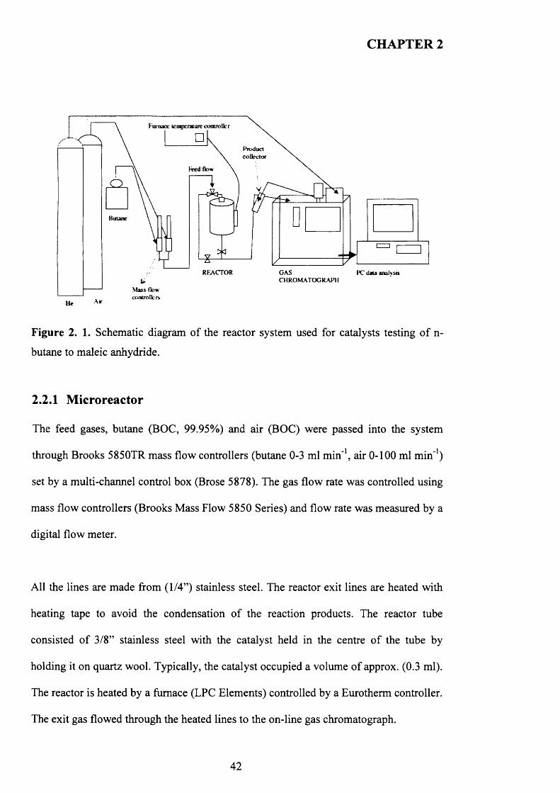
CHAPTER 2
Furnace temperature controller
\ Product n.\ collector
Fred flow \
n i v/Jy ? F
o
Butane
REACTOR
Air
Figure 2. 1. Schematic diagram of the reactor system used for catalysts testing o f n-
butane to maleic anhydride.
2.2.1 Microreactor
The feed gases, butane (BOC, 99.95%) and air (BOC) were passed into the system
through Brooks 5850TR mass flow controllers (butane 0-3 ml m in '1, air 0-100 ml m in '1)
set by a multi-channel control box (Brose 5878). The gas flow rate was controlled using
mass flow controllers (Brooks Mass Flow 5850 Series) and flow rate was measured by a
digital flow meter.
All the lines are made from (1/4”) stainless steel. The reactor exit lines are heated with
heating tape to avoid the condensation o f the reaction products. The reactor tube
consisted o f 3/8” stainless steel with the catalyst held in the centre o f the tube by
holding it on quartz wool. Typically, the catalyst occupied a volume o f approx. (0.3 ml).
The reactor is heated by a furnace (LPC Elements) controlled by a Eurotherm controller.
The exit gas flowed through the heated lines to the on-line gas chromatograph.
42
CHAPTER 2
2.2.2 Experimental procedure
Catalyst powder was pressed (5 tons) and sieved (250 pm - 1mm) in order to obtain
pellets, 0.2 g. (approx. 0.3ml) of precursor was placed in the centre o f the reactor tube
for evaluation. All catalysts precursors were activated in situ under the following
reaction conditions. Precursors were activated for a minimum period o f time o f 72 hours
or until stable conversion and selectivities were observed. The activation conditions
were normally:
• Feed flow rate o f (10 ml/min) with 1.7% of butane in air
• A gas hourly space velocity (GHSV) o f 2000 h '1 which can be defined as a
GHSV = (volumes o f feed as gas at STP/hr) / (volume o f the reactor or its
content o f catalyst)
• Testing reaction temperature o f 400°C with a temperature ramp o f 3°C/min.
2.2.3 Product analysis
The product analysis was carried out by using a Varian 3400 gas chromatograph. The
instrument is programmed to automatically make an injection at intervals o f 34 minutes
approximately, so that a detailed profile o f the composition o f the exhaust gases can be
obtained as a function o f time.
The GC used helium as the carrier gas, and two columns were used to separate the
components of the gas mixture. CO2, n-butane and maleic anhydride were eluted from a
Porapak Q (PQ, 2m x 2mm i.d.) while 0 2 , N2, and CO were eluted in a Molecular sieve
43

CHAPTER 2
13X (MS13X, 2m x 2mm i.d.). A thermal conductivity detector (TCD) was used for the
detection and quantification o f the products and un-reacted gases.
In the 3400 GC chromatograph varian, the sample loop (250 pL) is constantly filled
with the reactor effluent mixture. When an injection takes place, the carrier gas (helium)
injects the gases contained in the sample loop into the Porapak Q which is connected in
series to the molecular sieve column (both kept at 80°C). After 0.9 minutes the
molecular sieve column is parked, at this time, the lighter gases (O2, N 2 and CO) have
been eluted from the Porapak Q to a molecular sieve and are retained on the latter
column. CO2 and H2O are now eluted from the Porapak Q and detected for analysis.
The molecular sieve is re-connected and O2, N 2 and CO are now eluted to the detector.
When CO is finally eluted, the molecular sieve is bypassed again and the temperature o f
the oven is heated to 220°C with a ramp o f 50°C/min. This allows a quick elution o f the
un-reacted butane and finally the elution o f maleic anhydride from the Porapak Q. The
retention times are shown in Table 2. 1.
Table 2 .1 . The retention times o f the main products
Entry Eluted productRetention Time
(min)
1 carbon dioxide 0.90
2 oxygen 4.40
3 nitrogen 5.50
4 carbon monoxide 10.15
5 n- butane 13.6
6 maleic anhydride 26
44
CHAPTER 2
A TCD detects the difference between the heat capacities o f a reference gas flow
(carrier gas, He) and the sample gas flow (reactor products plus carrier gas). Differences
in the heat capacities o f different compounds mean that the results need to be corrected
with a response factor (RF). The peaks are integrated and the numeric value o f each
integrated peak is divided by the relative response factor o f the compound. The result is
the true response values. The response factors o f the products were obtained from Dietz
et al. [2]. Normalising the true response values gives the volume percentage o f each
compound. The carbon mass balances were approximately 94 to 106 for all catalytic
testing results presented.
All the products formed were identified according to the chromatogram retention time
observed (Table 2. 1). For each tested sample, conversion, selectivity and carbon mass
balances were calculated and plotted as function o f time on line (T.O.L). The
conversion o f butane at a specific time was obtained by dividing the difference between
the response value o f the butane peak when no reaction takes place and its value at that
specific time by the response value of the butane peak when no reaction takes place. To
obtain the response value o f butane in the feed flow (blank run), the reactor was cooled
to 200°C after each catalytic test and measurements taken for several runs. The
selectivity was defined as the amount o f product formed divided by the total amount o f
products formed and corrected for molar ratios.
An example calculation for specific activity and intrinsic activity for each catalyst
presented in thesis is illustrated as follow:
45
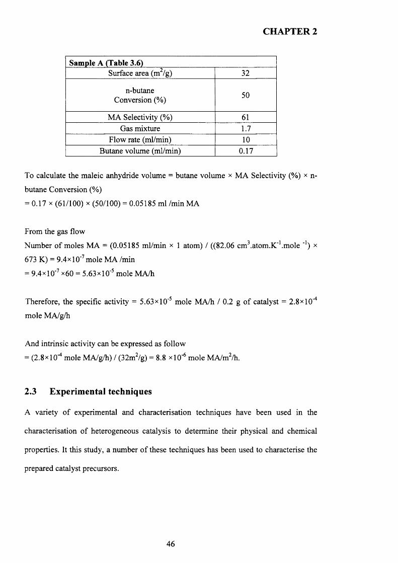
CHAPTER 2
Sam ple A (Table 3.6) ‘jSurface area (m /g) 32
n-butane Conversion (%) 50
MA Selectivity (%) 61Gas mixture 1.7
Flow rate (ml/min) 1 0
Butane volume (ml/min) 0.17
To calculate the maleic anhydride volume = butane volume x MA Selectivity (%) x n-
butane Conversion (%)
= 0.17 x (61/100) x (50/100) = 0.05185 ml /min MA
From the gas flow
Number o f moles MA = (0.05185 ml/min x 1 atom) / ((82.06 cm3.atom.K'1.mole _1) x
673 K) = 9.4x1 O’7 mole MA /min
= 9.4x10'7 x60 = 5.63x10'5 mole MA/h
Therefore, the specific activity = 5.63x10’5 mole MA/h / 0.2 g o f catalyst = 2.8x1 O'4
mole MA/g/h
And intrinsic activity can be expressed as follow
= (2.8x1 O’4 mole MA/g/h) / (32m2/g) = 8 . 8 xlO -6 mole MA/m2/h.
2.3 Experimental techniques
A variety o f experimental and characterisation techniques have been used in the
characterisation of heterogeneous catalysis to determine their physical and chemical
properties. It this study, a number o f these techniques has been used to characterise the
prepared catalyst precursors.
46
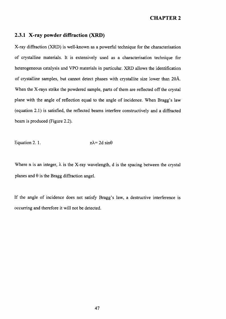
CHAPTER 2
2.3.1 X-ray powder diffraction (XRD)
X-ray diffraction (XRD) is well-known as a powerful technique for the characterisation
o f crystalline materials. It is extensively used as a characterisation technique for
heterogeneous catalysis and VPO materials in particular. XRD allows the identification
o f crystalline samples, but cannot detect phases with crystallite size lower than 20A.
When the X-rays strike the powdered sample, parts o f them are reflected off the crystal
plane with the angle o f reflection equal to the angle o f incidence. When Bragg’s law
(equation 2 .1 ) is satisfied, the reflected beams interfere constructively and a diffracted
beam is produced (Figure 2.2).
Equation 2 .1 . nX= 2d sin0
Where n is an integer, X is the X-ray wavelength, d is the spacing between the crystal
planes and 0 is the Bragg diffraction angel.
If the angle o f incidence does not satisfy Bragg’s law, a destructive interference is
occurring and therefore it will not be detected.
47
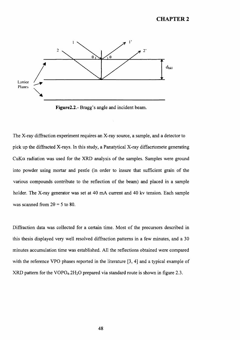
CHAPTER 2
/ dhkl
LatticePlanes
\Figure2.2.- Bragg’s angle and incident beam.
The X-ray diffraction experiment requires an X-ray source, a sample, and a detector to
pick up the diffracted X-rays. In this study, a Panatytical X-ray diffacrtomete generating
CuK a radiation was used for the XRD analysis o f the samples. Samples were ground
into powder using mortar and pestle (in order to insure that sufficient grain o f the
various compounds contribute to the reflection o f the beam) and placed in a sample
holder. The X-ray generator was set at 40 mA current and 40 kv tension. Each sample
was scanned from 20 = 5 to 80.
Diffraction data was collected for a certain time. Most o f the precursors described in
this thesis displayed very well resolved diffraction patterns in a few minutes, and a 30
minutes accumulation time was established. All the reflections obtained were compared
with the reference VPO phases reported in the literature [3, 4] and a typical example o f
XRD pattern for the VOPO4.2 H2O prepared via standard route is shown in figure 2.3.
48
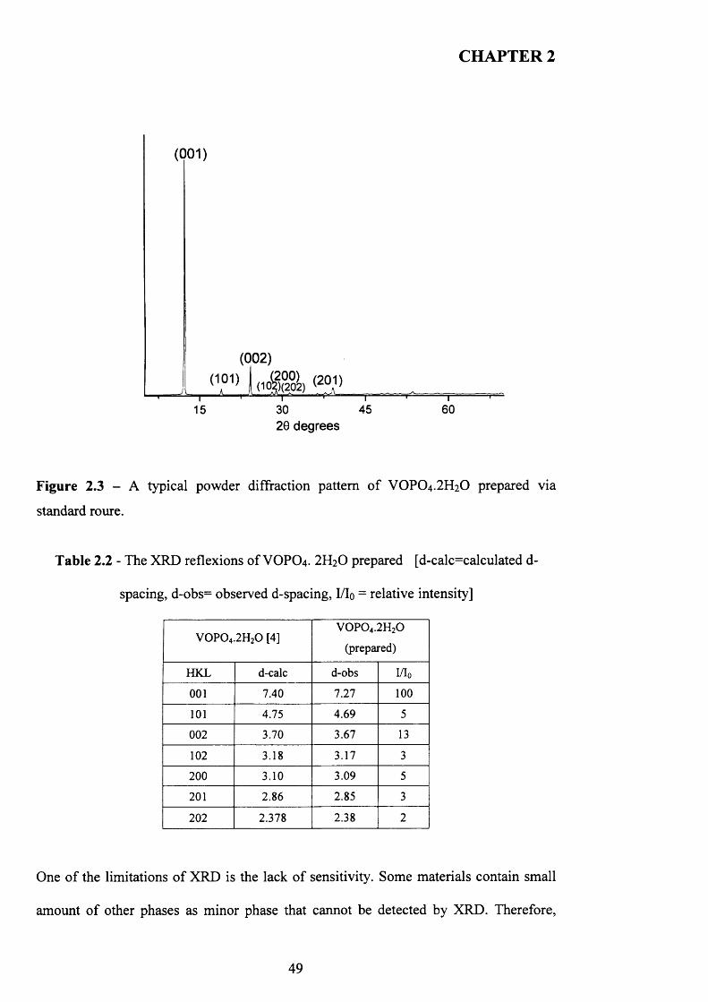
CHAPTER 2
(001)
T15
(101) A „
(002)(200)
) . (1Cg)(\02) (201)—T
3020 degrees
45—r~60
Figure 2.3 - A typical powder diffraction pattern o f VOPO4 .2 H2 O prepared via
standard roure.
Table 2.2 - The XRD reflexions of VOPO4. 2H2O prepared [d-calc=calculated d-
spacing, d-obs= observed d-spacing, I/Io = relative intensity]
V 0 P 0 4.2H20 [4]V 0 P 0 4.2H20
(prepared)
HKL d-calc d-obs W 0
001 7.40 7.27 100
101 4.75 4.69 5
002 3.70 3.67 13
102 3.18 3.17 3
200 3.10 3.09 5
201 2.86 2.85 3
202 2.378 2.38 2
One o f the limitations o f XRD is the lack o f sensitivity. Some materials contain small
amount o f other phases as minor phase that cannot be detected by XRD. Therefore,
49
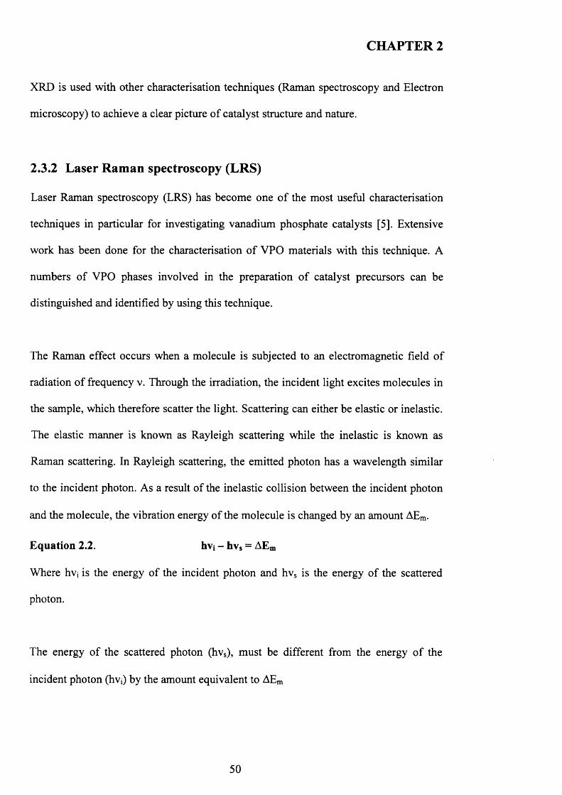
CHAPTER 2
XRD is used with other characterisation techniques (Raman spectroscopy and Electron
microscopy) to achieve a clear picture o f catalyst structure and nature.
2.3.2 Laser Raman spectroscopy (LRS)
Laser Raman spectroscopy (LRS) has become one o f the most useful characterisation
techniques in particular for investigating vanadium phosphate catalysts [5]. Extensive
work has been done for the characterisation o f VPO materials with this technique. A
numbers o f VPO phases involved in the preparation o f catalyst precursors can be
distinguished and identified by using this technique.
The Raman effect occurs when a molecule is subjected to an electromagnetic field o f
radiation o f frequency v. Through the irradiation, the incident light excites molecules in
the sample, which therefore scatter the light. Scattering can either be elastic or inelastic.
The elastic manner is known as Rayleigh scattering while the inelastic is known as
Raman scattering. In Rayleigh scattering, the emitted photon has a wavelength similar
to the incident photon. As a result o f the inelastic collision between the incident photon
and the molecule, the vibration energy of the molecule is changed by an amount AEm.
Equation 2.2. hvj - hvs = AEm
Where hvj is the energy o f the incident photon and hvs is the energy of the scattered
photon.
The energy o f the scattered photon (hvs), must be different from the energy o f the
incident photon (hvj) by the amount equivalent to AEm
50
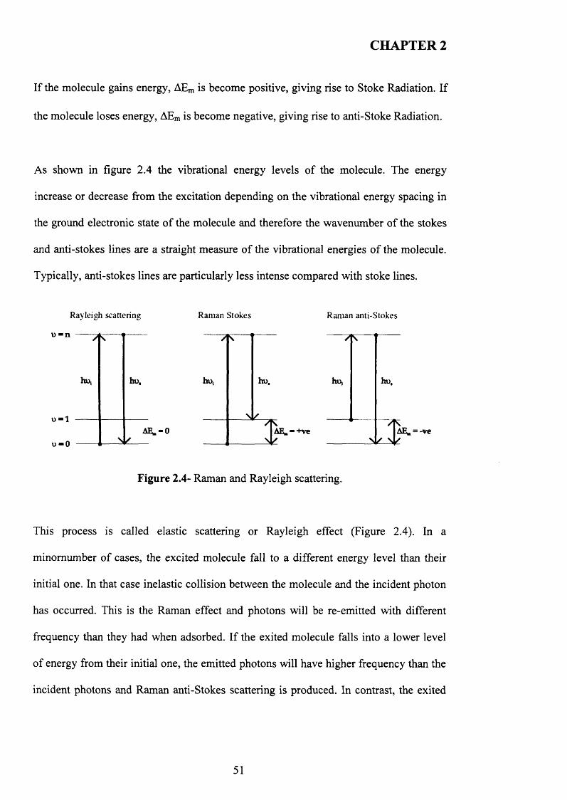
CHAPTER 2
If the molecule gains energy, AEm is become positive, giving rise to Stoke Radiation. If
the molecule loses energy, AEm is become negative, giving rise to anti-Stoke Radiation.
As shown in figure 2.4 the vibrational energy levels o f the molecule. The energy
increase or decrease from the excitation depending on the vibrational energy spacing in
the ground electronic state o f the molecule and therefore the wavenumber o f the stokes
and anti-stokes lines are a straight measure o f the vibrational energies o f the molecule.
Typically, anti-stokes lines are particularly less intense compared with stoke lines.
Rayleigh scattering
u -n
hu,
o - l
o-O
ho.
AE.-0
Raman Stokes
_f_
ho, ho.
Raman anti-Stokes
ho,
AH. - +ve
ho.
/fvAE, = -ve
Figure 2.4- Raman and Rayleigh scattering.
This process is called elastic scattering or Rayleigh effect (Figure 2.4). In a
minomumber o f cases, the excited molecule fall to a different energy level than their
initial one. In that case inelastic collision between the molecule and the incident photon
has occurred. This is the Raman effect and photons will be re-emitted with different
frequency than they had when adsorbed. If the exited molecule falls into a lower level
of energy from their initial one, the emitted photons will have higher frequency than the
incident photons and Raman anti-Stokes scattering is produced. In contrast, the exited
51
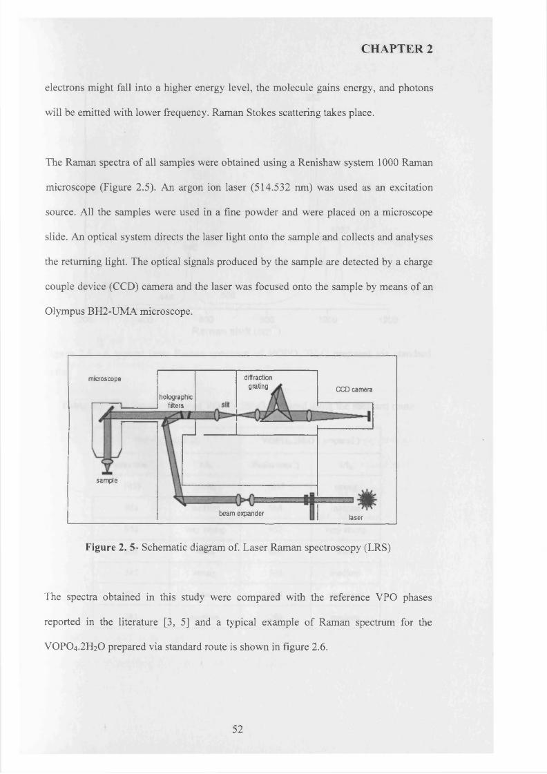
CHAPTER 2
electrons might fall into a higher energy level, the molecule gains energy, and photons
will be emitted with lower frequency. Raman Stokes scattering takes place.
The Raman spectra of all samples were obtained using a Renishaw system 1000 Raman
microscope (Figure 2.5). An argon ion laser (514.532 nm) was used as an excitation
source. All the samples were used in a fine powder and were placed on a microscope
slide. An optical system directs the laser light onto the sample and collects and analyses
the returning light. The optical signals produced by the sample are detected by a charge
couple device (CCD) camera and the laser was focused onto the sample by means of an
Olympus BH2-UMA microscope.
diffractiongrating
microscopeCCD camera
holographicfiters
sam ple
beam expanderlaser
Figure 2. 5- Schematic diagram of. Laser Raman spectroscopy (LRS)
The spectra obtained in this study were compared with the reference VPO phases
reported in the literature [3, 5] and a typical example of Raman spectrum for the
VOPO4.2 H2O prepared via standard route is shown in figure 2.6.
52
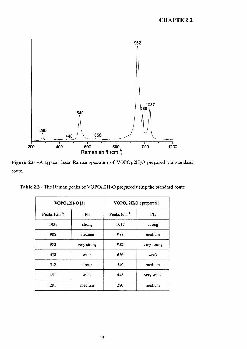
CHAPTER 2
952
1037
540
280656448
200 400 600 800 1000 1200Raman shift (cm'1)
Figure 2.6 -A typical laser Raman spectrum of VOPO4 .2 H2O prepared via standard
route.
Table 2.3 - The Raman peaks o f VOPO4 .2 H2O prepared using the standard route
V 0 P 0 4.2H20 [3] V 0 P 0 4.2H20 ( prepared )
Peaks (cm-1) I/Io Peaks (cm '1) I/I0
1039 strong 1037 strong
988 medium 988 medium
952 very strong 952 very strong
658 weak 656 weak
542 strong 540 medium
451 weak 448 very weak
281 medium 280 medium
53
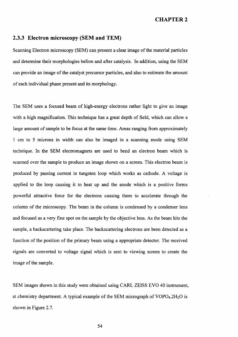
CHAPTER 2
2.3.3 Electron microscopy (SEM and TEM)
Scanning Electron microscopy (SEM) can present a clear image o f the material particles
and determine their morphologies before and after catalysis. In addition, using the SEM
can provide an image o f the catalyst precursor particles, and also to estimate the amount
of each individual phase present and its morphology.
The SEM uses a focused beam of high-energy electrons rather light to give an image
with a high magnification. This technique has a great depth o f field, which can allow a
large amount o f sample to be focus at the same time. Areas ranging from approximately
1 cm to 5 microns in width can also be imaged in a scanning mode using SEM
technique. In the SEM electromagnets are used to bend an electron beam which is
scanned over the sample to produce an image shown on a screen. This electron beam is
produced by passing current in tungsten loop which works as cathode. A voltage is
applied to the loop causing it to heat up and the anode which is a positive forms
powerful attractive force for the electrons causing them to accelerate through the
column o f the microscopy. The beam in the column is condensed by a condenser lens
and focused as a very fine spot on the sample by the objective lens. As the beam hits the
sample, a backscattering take place. The backscattering electrons are been detected as a
function o f the position o f the primary beam using a appropriate detector. The received
signals are converted to voltage signal which is sent to viewing screen to create the
image o f the sample.
SEM images shown in this study were obtained using CARL ZEISS EVO 40 instrument,
at chemistry department. A typical example o f the SEM micrograph o f VOPO4 .2 H2O is
shown in Figure 2.7.
54
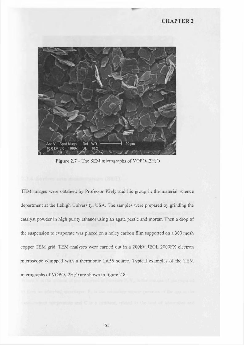
CHAPTER 2
Figure 2.7 - The SEM micrographs o f VOPO4.2 H2O
TEM images were obtained by Professor Kiely and his group in the material science
department at the Lehigh University, USA. The samples were prepared by grinding the
catalyst powder in high purity ethanol using an agate pestle and mortar. Then a drop of
the suspension to evaporate was placed on a holey carbon film supported on a 300 mesh
copper TEM grid. TEM analyses were carried out in a 200kV JEOL 2000FX electron
microscope equipped with a thermionic LaB6 source. Typical examples o f the TEM
micrographs o f VOPO4.2 H2O are shown in figure 2.8.
55
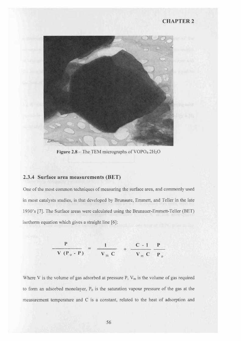
CHAPTER 2
Figure 2.8 - The TEM micrographs of VOPO4.2 H2O
2.3.4 Surface area measurements (BET)
One of the most common techniques of measuring the surface area, and commonly used
in most catalysts studies, is that developed by Brunaure, Emmett, and Teller in the late
1930’s [7]. The Surface areas were calculated using the Brunauer-Emmett-Teller (BET)
isotherm equation which gives a straight line [6 ]:
p = 1 C - l P
v (P 0 - P ) Vji c + vra c T 7
Where V is the volume of gas adsorbed at pressure P, Vm is the volume of gas required
to form an adsorbed monolayer, P0 is the saturation vapour pressure o f the gas at the
measurement temperature and C is a constant, related to the heat of adsorption and
56
CHAPTER 2
condensation o f gas. This equation is based on the assumption that the heat o f the
adsorption of the first monolayer is constant, the side interaction of adsorbed molecules
is negligible, multilayer of adsorption can take place on the top of the monolayer and
the heat of adsorption for all layers apart from the first layer is assumed to be equal to
the heat of condensation of the adsorbed gas.
Vm is calculated from the isotherm, and the surface area is determined by assuming each
molecule of adsorbed nitrogen occupied x = 0.162 nm2 (x is the area covered by a N2
molecule) using the following equation:
SA(m2/g) = (Vm/22414)N„x
Where Nais Avogadro’s number (6.023 X 10²³),
A Micromiretics 2000 ASAP instrument controlled by a PC computer was used, with all
adsorption carried out at liquid nitrogen temperature (77.35 K at one atmosphere
pressure). After degassing the samples were degassed for one hour at 120°C prior to the
analysis.
57
CHAPTER 2
2.4 References
[1] M. T. Sananes, I. J. Ellison, S. Sajip, A. Burrow, C. J. Kiely, J. C. Volta and G.
J. Hutchings, J. Chem. Soc., Faraday Trans., 1996, 92, 137.
[2] W. A. Deitz, Journal of Gas Chromatography, (February 1967), 70-74
[3] V. V Guliants,. J. B. Benziger, S.Sundaresan, I. E. Wachs, J. M. Jehng, [3]
J.E.Roberts, Catal. Today, 28(1996)275-295.
[4] E. Bordes, Catal. Today (1987), 1, 499
[5] F. Ben Abdelouahab, R. Olier, N. Guilhaume, F. Lefebvre and J. C. Volta, J.
Catal., (1992), 134, 151-167
[6 ] S. Brunauer, P. H. Emmett and E. Teller, J. Am. Chem. Soc., 1938, 60, 309.
[7] S. H. Nieman, Principle o f instrumental Analysis. 1997.
58
CHAPTER 3
THE INFULANCE OF ALKANE CO-SOLVENT ON V-P-O
PRECORSUR SYTHESIS
3.1 Introduction
Vanadium phosphate catalysts for the selective oxidation of n-butane to maleic
anhydride represent one of the most well-studied heterogeneous catalysts [1 ].
(VO)2P2 0 7 is usually prepared by the topotactic transformation o f VOHPO4 . 0 .5 H2O
under the reaction feedstock o f 1.5% n-butane in air at 400°C , in which the morphology
o f the catalyst precursor VOHPO4.0 .5 H2O is preserved.
In view o f the importance of the morphology o f the catalyst precursor, several studies
have been published concerning this topic. Commonly, V2O5 is used as a source o f
vanadium and H3PO4 is used as source o f phosphorus. Therefore, a reducing agent is
required to synthesise the V+4 precursor phase. A number o f reducing agents and
solvents have been used [7]. Early catalyst preparations (VPA method) used water as
the solvent, but recently, most studies have concentrated on the use o f alcohols (VPO
and VPD methods), as they result in better catalysts. The VPD method was first
unveiled by Horowitz et al. [8] and later described by Johnson et a l [9] This method
involves the reaction o f V2O5 with H3PO4 with water as the solvent. This leads to the
formation o f the V5+ phase VOPO4 .2 H2O. The VOPO4 .2 H2O is recovered and dried and
then refluxed in a second stage with an alcohol as the reducing agent to form
VOHPO4.0.5H2O.
59
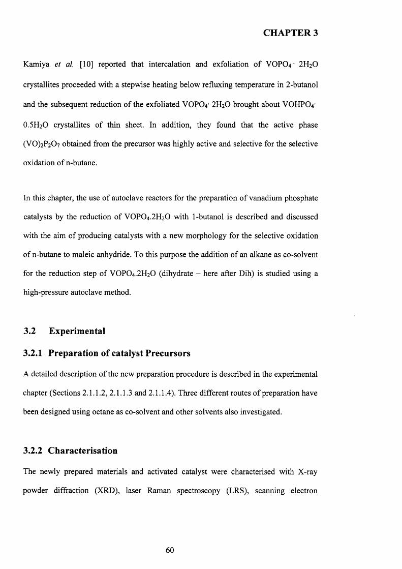
CHAPTER 3
Kamiya et a l [10] reported that intercalation and exfoliation o f VOPO4 • 2H2O
crystallites proceeded with a stepwise heating below refluxing temperature in 2-butanol
and the subsequent reduction o f the exfoliated VOPCV 2H2O brought about VOHPCV
O.5 H2O crystallites o f thin sheet. In addition, they found that the active phase
(VO)2P2 0 7 obtained from the precursor was highly active and selective for the selective
oxidation o f n-butane.
In this chapter, the use o f autoclave reactors for the preparation o f vanadium phosphate
catalysts by the reduction o f VOPO4.2 H2O with 1-butanol is described and discussed
with the aim o f producing catalysts with a new morphology for the selective oxidation
o f n-butane to maleic anhydride. To this purpose the addition o f an alkane as co-solvent
for the reduction step of VOPO4 .2 H2O (dihydrate - here after Dih) is studied using a
high-pressure autoclave method.
3.2 Experimental
3.2.1 Preparation of catalyst Precursors
A detailed description o f the new preparation procedure is described in the experimental
chapter (Sections 2.1.1.2, 2.1.1.3 and 2.1.1.4). Three different routes o f preparation have
been designed using octane as co-solvent and other solvents also investigated.
3.2.2 Characterisation
The newly prepared materials and activated catalyst were characterised with X-ray
powder diffraction (XRD), laser Raman spectroscopy (LRS), scanning electron
60
CHAPTER 3
microscopy (SEM), transmission electron microscopy (TEM) and nitrogen adsorption
(BET surface area measurements).
3.2.3 Catalyst Testing
The catalyst test from which the data are presented here were carried out under the
following reaction conditions: a gas mixture o f 1.7% butane to air, a gas hourly space
velocity o f 2000h_1, 0.2g o f catalyst (approx. 0.3ml), and 400°C (ramp rate 3°C m in'1).
Measurements were taken for 72h or until stable conversion and selectivities were
observed.
3.3 Results and Discussions
It this chapter, the results are divided in two sections. The first section is mainly a
characterisation o f the starting materials o f vanadium phosphate dihydrate
VOPO4 .2 H2O which will be the starting materials o f all reactions carried out in this
thesis. The second section is a characterisation o f the new hemihydrate
VOHPO4 .O.5 H2O precursor prepared via three different routes using co-solvents as
illustrated in the experimental diagram (figure 3.5)
3.3.1 Characterisation of VOPO4 .2 H2 O
The x-ray diffraction patterns o f VOPO4.2 H2O prepared using the standard route, as
reported in the literature [24], are shown in figure 3.1. This shows all the peaks can be
indexed to VOPO4 .2 H2O with the dominant reflection at 12.1° (^/-spacing = 7.27A)
indexed to the (001) plane. The d-spacing and relative intensities o f the XRD peaks of
VOPO4.2 H2O are shown in Table 3.1.
61
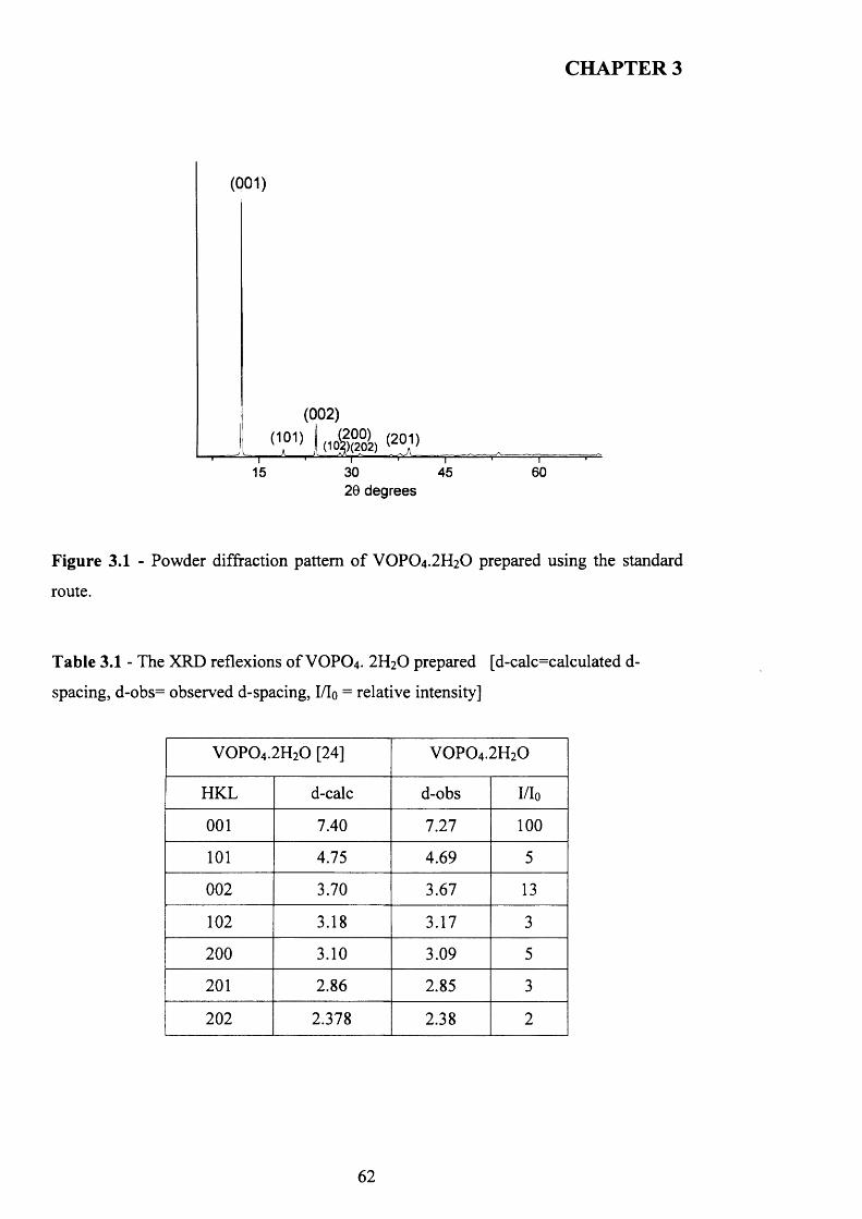
CHAPTER 3
(001)
(002)
15 30 45 6020 degrees
Figure 3.1 - Powder diffraction pattern o f VOPO4.2 H2O prepared using the standard
route.
Table 3.1 - The XRD reflexions o f VOPO4 . 2 H2O prepared [d-calc=calculated d-
spacing, d-obs= observed d-spacing, I/Io = relative intensity]
VOPO4 .2 H2O [24] VOPO4 .2 H2O
HKL d-calc d-obs I/Io
0 0 1 7.40 7.27 1 0 0
1 0 1 4.75 4.69 5
0 0 2 3.70 3.67 13
1 0 2 3.18 3.17 3
2 0 0 3.10 3.09 5
2 0 1 2 . 8 6 2.85 3
2 0 2 2.378 2.38 2
62
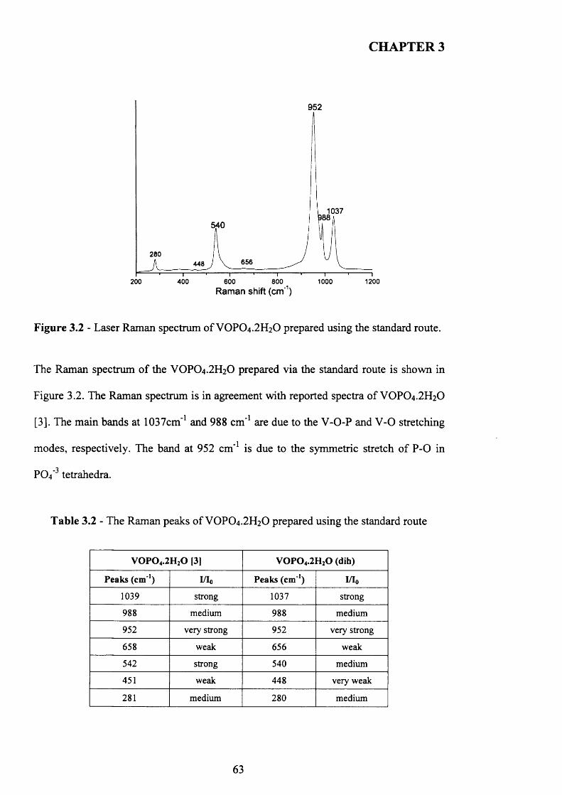
CHAPTER 3
952
1037540
280 6564481200200 400 600 800
Raman shift (cm'1)1000
Figure 3.2 - Laser Raman spectrum of VOPO4 .2 H2O prepared using the standard route.
The Raman spectrum of the VOPO4.2 H2O prepared via the standard route is shown in
Figure 3.2. The Raman spectrum is in agreement with reported spectra o f VOPO4 .2 H2O
[3]. The main bands at 1037cm*1 and 988 cm*1 are due to the V-O-P and V -0 stretching
modes, respectively. The band at 952 cm*1 is due to the symmetric stretch o f P -0 in
PO4’3 tetrahedra.
Table 3.2 - The Raman peaks of VOPO4 .2 H2O prepared using the standard route
V 0 P 0 4.2H20 [3] V 0 P 0 4.2H20 (dih)
Peaks (c m 1) I/I0 Peaks (cm '1) I/I0
1039 strong 1037 strong
988 medium 988 medium
952 very strong 952 very strong
658 weak 656 weak
542 strong 540 medium
451 weak 448 very weak
281 medium 280 medium
63
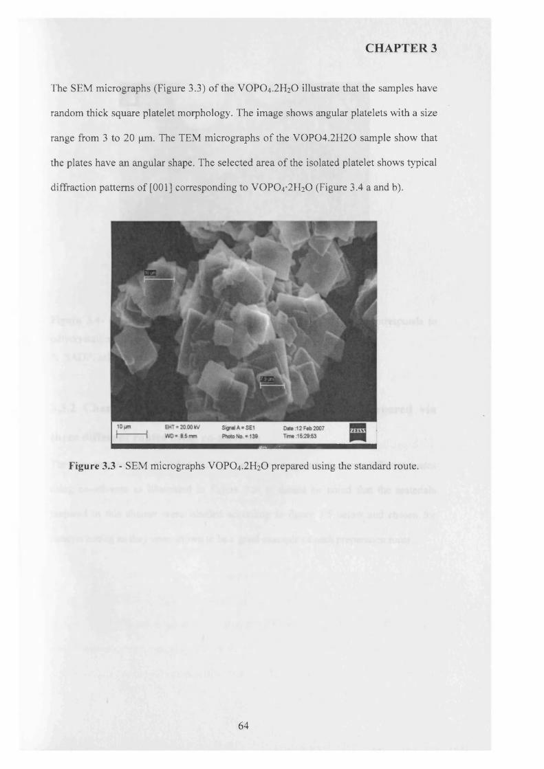
CHAPTER 3
The SEM micrographs (Figure 3.3) of the VOPO4 .2 H2O illustrate that the samples have
random thick square platelet morphology. The image shows angular platelets with a size
range from 3 to 20 pm. The TEM micrographs o f the V 0P04.2H 20 sample show that
the plates have an angular shape. The selected area of the isolated platelet shows typical
diffraction patterns of [001] corresponding to VOPO4 2 H2O (Figure 3.4 a and b).
Figure 3.3 - SEM micrographs VOPO4 .2 H2O prepared using the standard route.
64
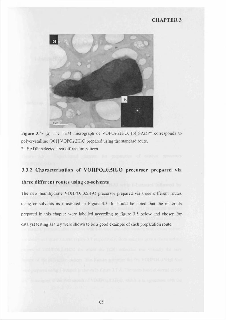
CHAPTER 3
Figure 3.4- (a) The TEM micrograph of VOPO4 2 H2O, (b) SADP* corresponds to
polycrystalline [0 0 1 ] VOPO4 2 H2O prepared using the standard route.
*: SADP: selected area diffraction pattern
3.3.2 C haracterisation o f V O H P O 4.0.5H 2O precursor prepared via
three different routes using co-solvents
The new hemihydrate VOHPO4.O.5 H2O precursor prepared via three different routes
using co-solvents as illustrated in Figure 3.5. It should be noted that the materials
prepared in this chapter were labelled according to figure 3.5 below and chosen for
catalyst testing as they were shown to be a good example of each preparation route.
65
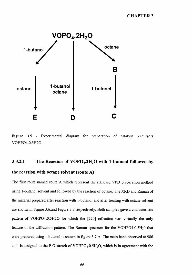
CHAPTER 3
V 0P04.2H20
1 -butc octane
B
octane 1 -butanol octane
1 -butanol
E D C
Figure 3.5 - Experimental diagram for preparation o f catalyst precursors
VOHPO4.0.5H2O.
3.3.2.1 The Reaction of VOPO4 .2 H2O with 1-butanol followed by
the reaction with octane solvent (route A)
The first route named route A which represent the standard VPD preparation method
using 1 -butanol solvent and followed by the reaction o f octane. The XRD and Raman of
the material prepared after reaction with 1 -butanol and after treating with octane solvent
are shown in Figure 3.6.and Figure 3.7 respectively. Both samples gave a characteristic
pattern of VOHPO4.0.5H2O for which the [220] reflection was virtually the only
feature of the diffraction pattern. The Raman spectrum for the VOHPO4 .O.5 H2O that
were prepared using 1-butanol is shown in figure 3.7 A. The main band observed at 986
cm"1 is assigned to the P -0 stretch o f VOHPO4 .O.5 H2O, which is in agreement with the
66
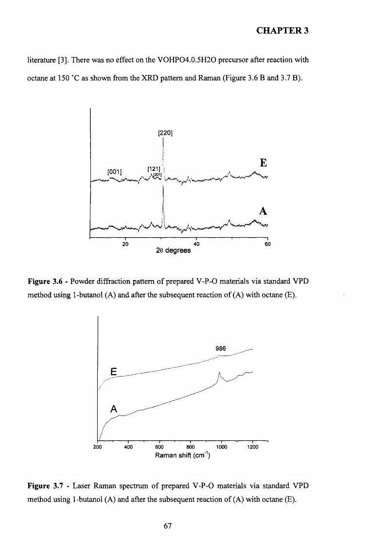
CHAPTER 3
literature [3]. There was no effect on the VOHPO4.0.5H2O precursor after reaction with
octane at 150 °C as shown from the XRD pattern and Raman (Figure 3.6 B and 3.7 B).
[220]
10011 ‘SI A
20 40 6020 degrees
Figure 3.6 - Powder diffraction pattern o f prepared V -P-0 materials via standard VPD
method using 1-butanol (A) and after the subsequent reaction o f (A) with octane (E).
986
200 1200400 600 800 1000Raman shift (cm-1)
Figure 3.7 - Laser Raman spectrum of prepared V -P-0 materials via standard VPD
method using 1-butanol (A) and after the subsequent reaction o f (A) with octane (E).
67
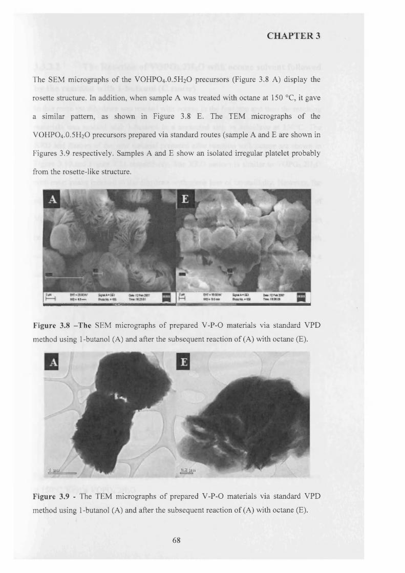
CHAPTER 3
The SEM micrographs of the VOHPO4.O.5 H2O precursors (Figure 3.8 A) display the
rosette structure. In addition, when sample A was treated with octane at 150 °C, it gave
a similar pattern, as shown in Figure 3.8 E. The TEM micrographs of the
VOHPO4.O.5 H2O precursors prepared via standard routes (sample A and E are shown in
Figures 3.9 respectively. Samples A and E show an isolated irregular platelet probably
from the rosette-like structure.
»|T1
Figure 3.8 -T he SEM micrographs o f prepared V-P-0 materials via standard VPD
method using 1-butanol (A) and after the subsequent reaction of (A) with octane (E).
Figure 3.9 - The TEM micrographs of prepared V -P-0 materials via standard VPD
method using 1-butanol (A) and after the subsequent reaction of (A) with octane (E).
68
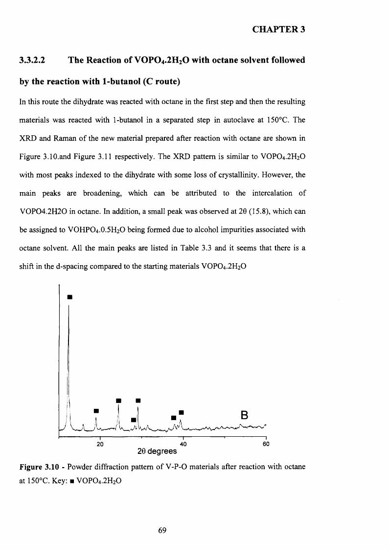
CHAPTER 3
3.3.2.2 The Reaction of VOPO4 .2 H 2O with octane solvent followed
by the reaction with 1-butanol (C route)
In this route the dihydrate was reacted with octane in the first step and then the resulting
materials was reacted with 1-butanol in a separated step in autoclave at 150°C. The
XRD and Raman o f the new material prepared after reaction with octane are shown in
Figure 3.10.and Figure 3.11 respectively. The XRD pattern is similar to VOPO4.2 H2O
with most peaks indexed to the dihydrate with some loss o f crystallinity. However, the
main peaks are broadening, which can be attributed to the intercalation o f
V 0 P 0 4 .2 H 2 0 in octane. In addition, a small peak was observed at 20 (15.8), which can
be assigned to VOHPO4 .O.5 H2O being formed due to alcohol impurities associated with
octane solvent. All the main peaks are listed in Table 3.3 and it seems that there is a
shift in the d-spacing compared to the starting materials VOPO4.2 H2O
60402020 degrees
Figure 3.10 - Powder diffraction pattern o f V -P-0 materials after reaction with octane
at 150°C. Key: ■ V 0 P 0 4.2H20
69
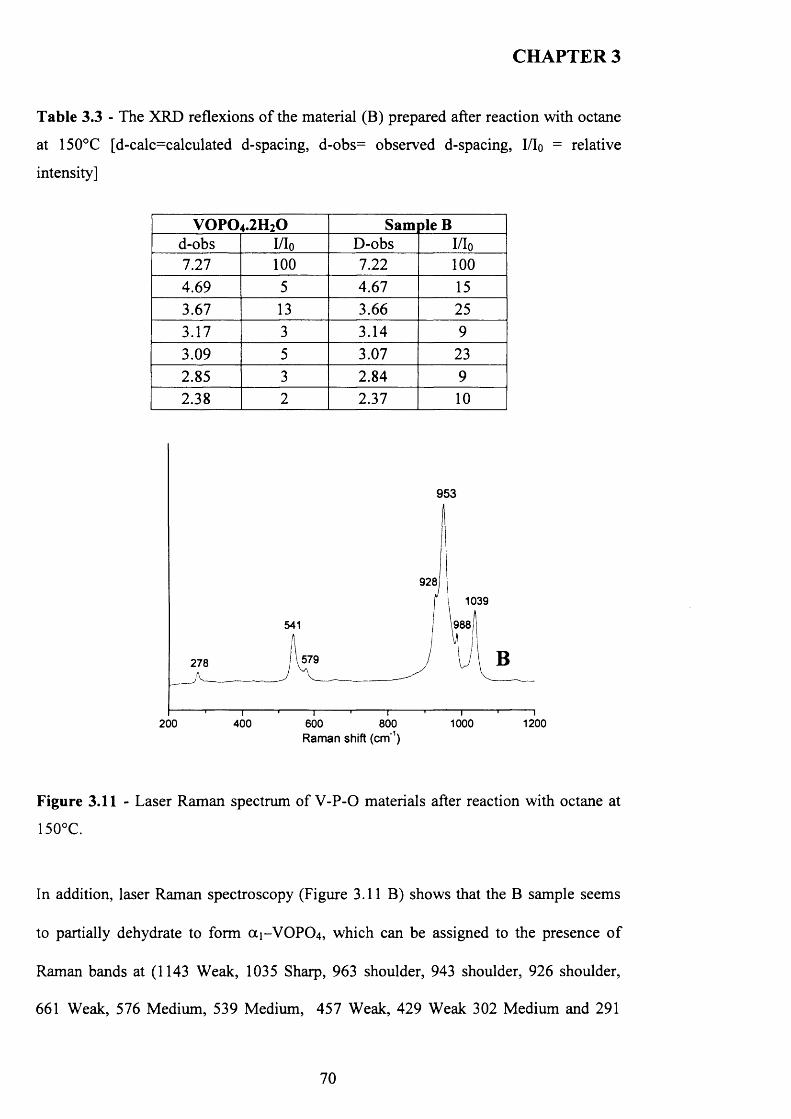
CHAPTER 3
Table 3.3 - The XRD reflexions o f the material (B) prepared after reaction with octane
at 150°C [d-calc=calculated d-spacing, d-obs= observed d-spacing, I/Io = relative
intensity]
v o p o 4.2h 2o Sam pie Bd-obs I/Io D-obs I/Io7.27 100 7.22 1004.69 5 4.67 153.67 13 3.66 253.17 3 3.14 93.09 5 3.07 232.85 3 2.84 92.38 2 2.37 10
953
9281039
1988541
579278
1000 1200200 400 600 800Raman shift (cm'1)
Figure 3.11 - Laser Raman spectrum of V -P-0 materials after reaction with octane at
150°C.
In addition, laser Raman spectroscopy (Figure 3.11 B) shows that the B sample seems
to partially dehydrate to form (X1-V O PO 4, which can be assigned to the presence o f
Raman bands at (1143 Weak, 1035 Sharp, 963 shoulder, 943 shoulder, 926 shoulder,
661 Weak, 576 Medium, 539 Medium, 457 Weak, 429 Weak 302 Medium and 291
70
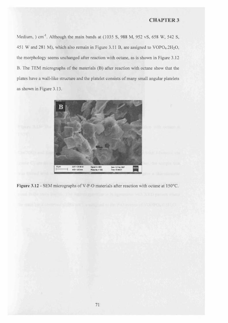
CHAPTER 3
M edium ,) cm '1. Although the main bands at (1035 S, 988 M, 952 vS, 658 W, 542 S,
451 W and 281 M), which also remain in Figure 3.11 B, are assigned to VOPO4.2 H2O,
the morphology seems unchanged after reaction with octane, as is shown in Figure 3.12
B. The TEM micrographs of the materials (B) after reaction with octane show that the
plates have a wall-like structure and the platelet consists of many small angular platelets
as shown in Figure 3.13.
«*■» m BfT-MOCW Cun U fA S t®I--------------- 1 WD* fllmn Tn»tS4ft3t
Figure 3.12 - SEM micrographs of V-P-0 materials after reaction with octane at 150°C.
71
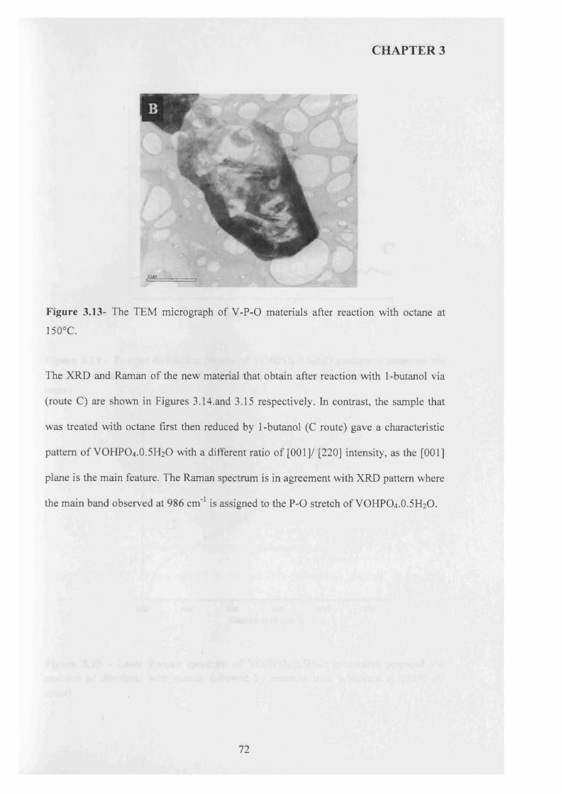
CHAPTER 3
Figure 3.13- The TEM micrograph of V -P-0 materials after reaction with octane at
150°C.
The XRD and Raman of the new material that obtain after reaction with 1-butanol via
(route C) are shown in Figures 3.14.and 3.15 respectively. In contrast, the sample that
was treated with octane first then reduced by 1-butanol (C route) gave a characteristic
pattern o f VOHPO4.O.5 H2O with a different ratio of [001]/ [220] intensity, as the [001]
plane is the main feature. The Raman spectrum is in agreement with XRD pattern where
the main band observed at 986 cm '1 is assigned to the P -0 stretch of VOHPO4.O.5 H2O.
72
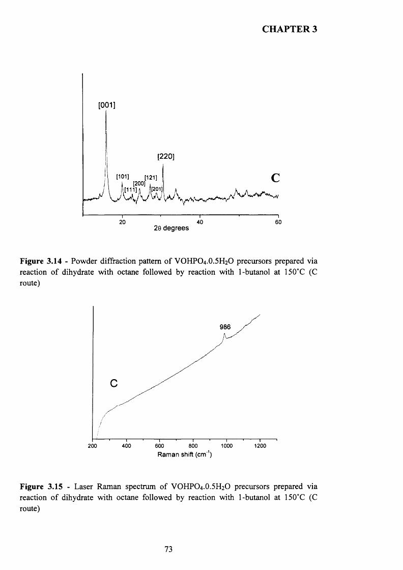
CHAPTER 3
[001]
[220]
t101] ___ [121]
[1 1 1 1 1 1 ' R 01[200]
20 40 6020 degrees
Figure 3.14 - Powder diffraction pattern o f VOHPO4.O.5 H2O precursors prepared via reaction o f dihydrate with octane followed by reaction with 1-butanol at 150°C (C route)
986
400 1000 1200200 600 800Ram an shift (crrf1)
Figure 3.15 - Laser Raman spectrum o f VOHPO4 .O.5 H2O precursors prepared via reaction o f dihydrate with octane followed by reaction with 1-butanol at 150°C (C route)
73
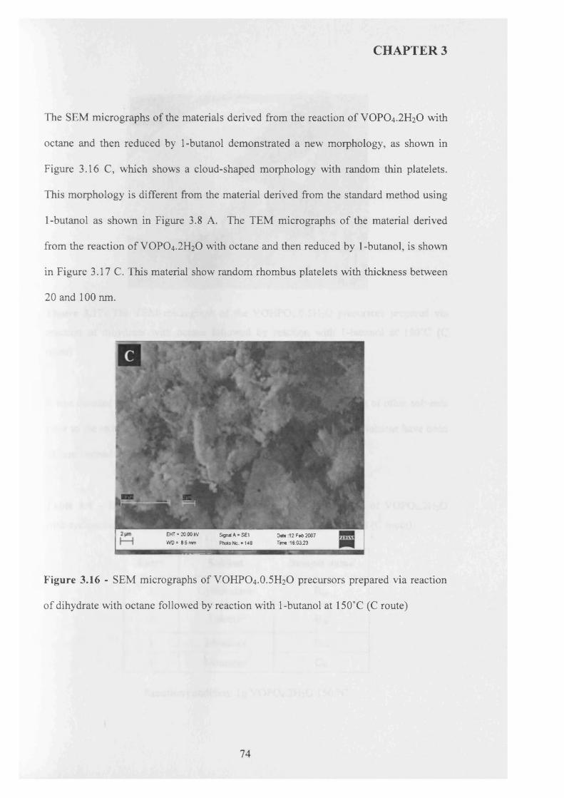
CHAPTER 3
The SEM micrographs of the materials derived from the reaction of VOPO4.2 H2O with
octane and then reduced by 1-butanol demonstrated a new morphology, as shown in
Figure 3.16 C, which shows a cloud-shaped morphology with random thin platelets.
This morphology is different from the material derived from the standard method using
1-butanol as shown in Figure 3.8 A. The TEM micrographs of the material derived
from the reaction of VOPO4.2 H2O with octane and then reduced by 1-butanol, is shown
in Figure 3.17 C. This material show random rhombus platelets with thickness between
2 0 and 1 0 0 nm.
EHT « 20.00 kV WD = 8.5 mm
SigndA»S£1 Photo No *148
Dote 12 Fob 2007 Time i 6:03:23
Figure 3.16 - SEM micrographs of VOHPO4 .0 .5 F12O precursors prepared via reaction
of dihydrate with octane followed by reaction with 1-butanol at 150°C (C route)
74
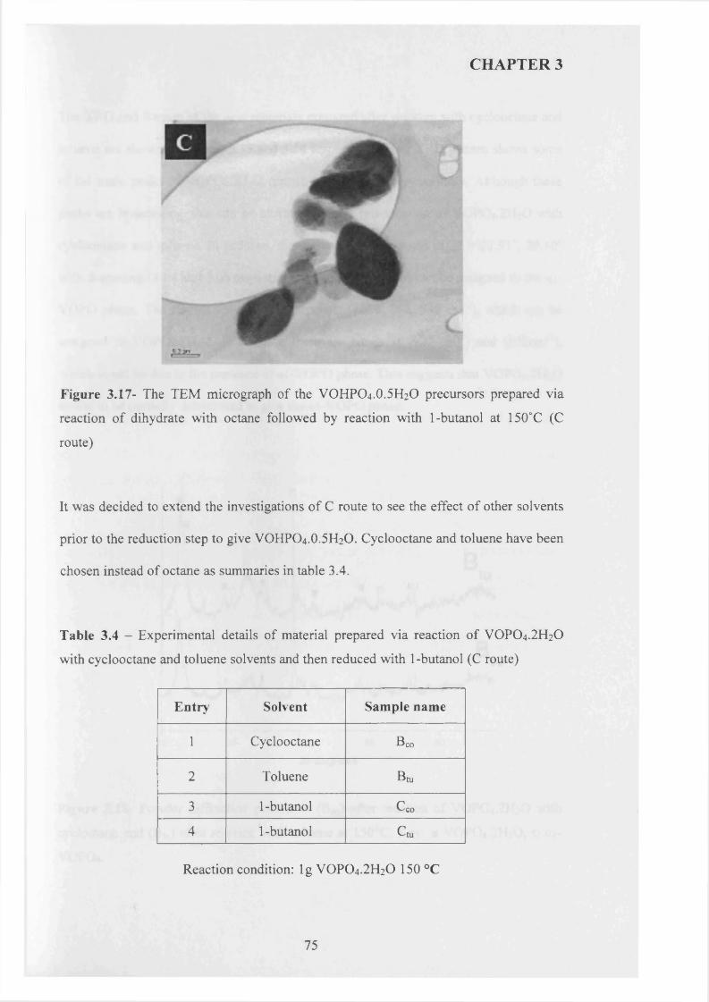
CHAPTER 3
Figure 3.17- The TEM micrograph of the VOHPO4 .O.5 H2O precursors prepared via
reaction of dihydrate with octane followed by reaction with 1-butanol at 150°C (C
route)
It was decided to extend the investigations of C route to see the effect of other solvents
prior to the reduction step to give VOHPO4 .O.5 H2O. Cyclooctane and toluene have been
chosen instead of octane as summaries in table 3.4.
Table 3.4 - Experimental details of material prepared via reaction of VOPO4.2 H2O
with cyclooctane and toluene solvents and then reduced with 1 -butanol (C route)
E ntry Solvent Sample name
1 Cyclooctane Bco
2 Toluene Bm
3 1 -butanol C o o
4 1-butanol C tu
Reaction condition: lg VOPO4 .2 H2O 150 °C
75
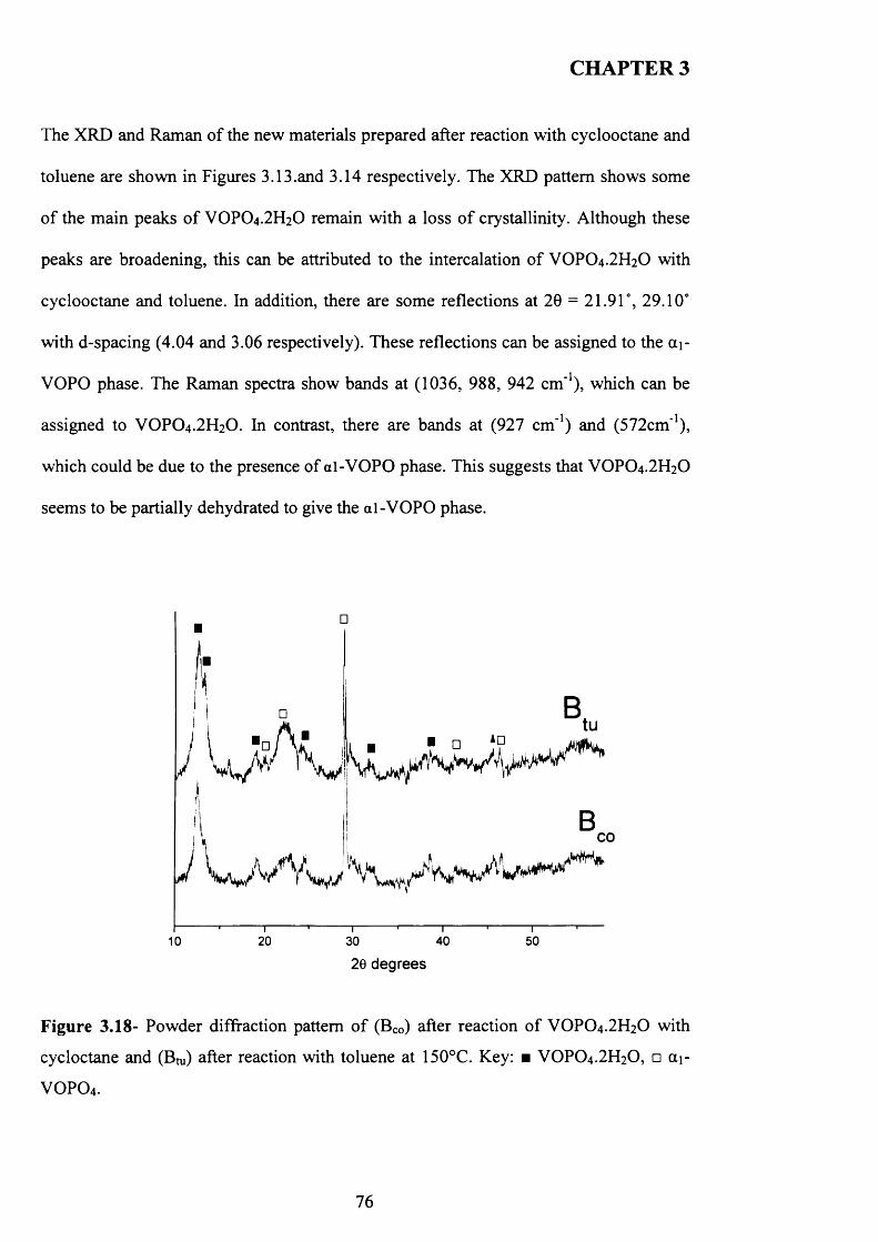
CHAPTER 3
The XRD and Raman of the new materials prepared after reaction with cyclooctane and
toluene are shown in Figures 3.13.and 3.14 respectively. The XRD pattern shows some
o f the main peaks o f VOPO4.2H2O remain with a loss o f crystallinity. Although these
peaks are broadening, this can be attributed to the intercalation o f VOPO4.2H2O with
cyclooctane and toluene. In addition, there are some reflections at 20 = 21.91°, 29.10°
with d-spacing (4.04 and 3.06 respectively). These reflections can be assigned to the a i-
VOPO phase. The Raman spectra show bands at (1036, 988, 942 cm '1), which can be
assigned to VOPO4.2H2O. In contrast, there are bands at (927 cm '1) and (572cm'1),
which could be due to the presence of al-VOPO phase. This suggests that VOPO4.2H2O
seems to be partially dehydrated to give the al-VOPO phase.
Btu
BCO
26 degrees
Figure 3.18- Powder diffraction pattern o f (Bco) after reaction o f VOPO4 .2 H2O with
cycloctane and (Bm) after reaction with toluene at 150°C. Key: ■ VOPO4 .2 H2O, □ ai-
VOPO4 .
76
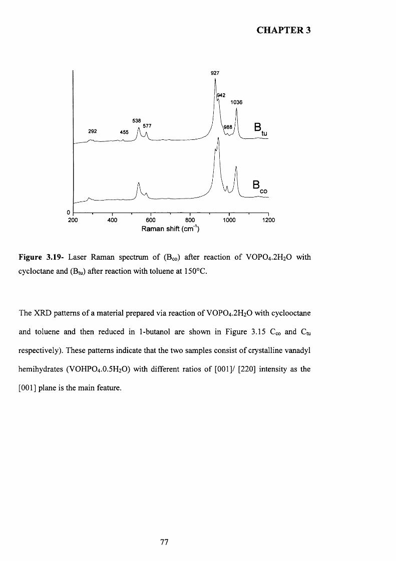
CHAPTER 3
927
9421036
538577 £88292 455
CO
0 - 200 400 600 800 1000 1200
Raman shift (cm'1)
Figure 3.19- Laser Raman spectrum of (Bco) after reaction o f VOPO4 .2 H2O with
cycloctane and (Btu) after reaction with toluene at 150°C.
The XRD patterns o f a material prepared via reaction o f VOPO4 .2 H2O with cyclooctane
and toluene and then reduced in 1-butanol are shown in Figure 3.15 Cco and Cm
respectively). These patterns indicate that the two samples consist o f crystalline vanadyl
hemihydrates (VOHPO4 .O.5 H2O) with different ratios o f [220] intensity as the
[001] plane is the main feature.
77
^
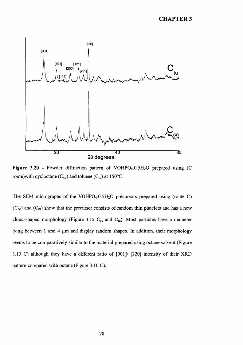
CHAPTER 3
[220]
[001]
20 degrees
Figure 3.20 - Powder diffraction pattern o f VOHPO4.O.5H2O prepared using (C
route)with cycloctane (Cco) and toluene (Cm) at 150°C.
The SEM micrographs o f the VOHPO4 .O.5 H2O precursors prepared using (route C)
(Cco) and ( C t u ) show that the precursor consists o f random thin platelets and has a new
cloud-shaped morphology (Figure 3.15 Cco and Cm). Most particles have a diameter
lying between 1 and 4 pm and display random shapes. In addition, their morphology
seems to be comparatively similar to the material prepared using octane solvent (Figure
3.13 C) although they have a different ratio o f [001]/ [220] intensity o f their XRD
pattern compared with octane (Figure 3.10 C).
78
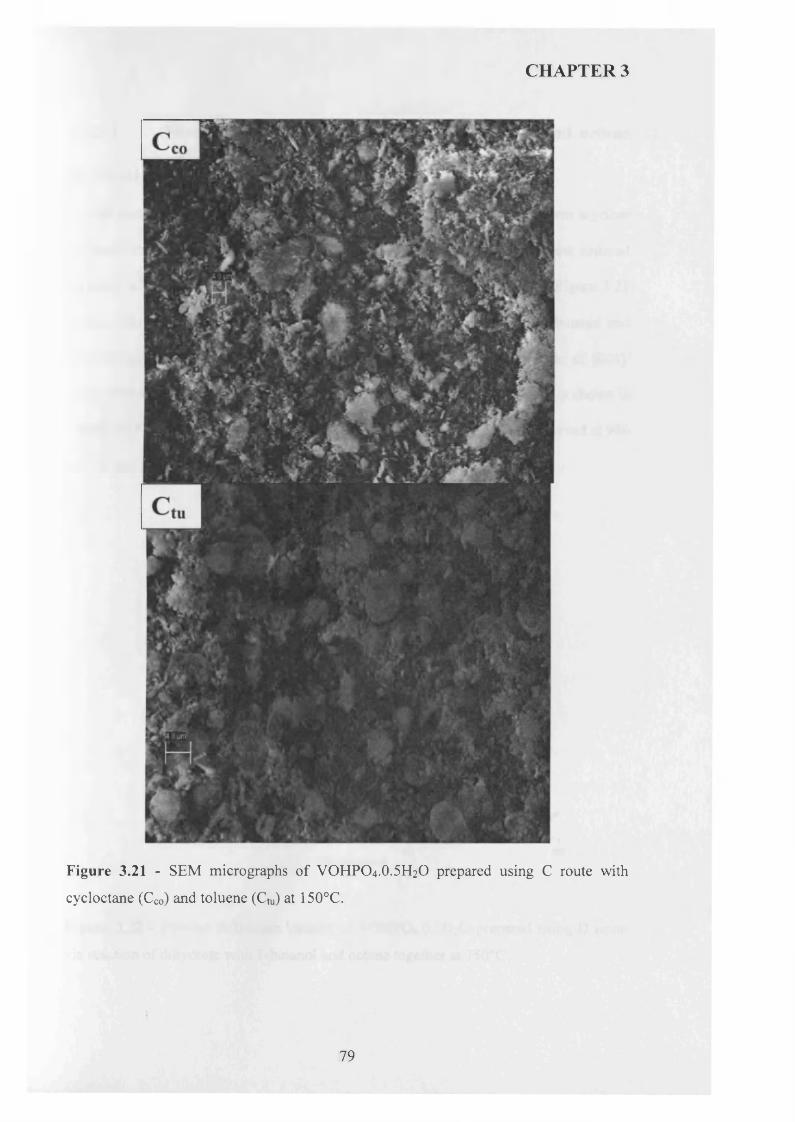
CHAPTER 3
Figure 3.21 - SEM micrographs of VOHPO4.O.5H2O prepared using C route with
cycloctane (Cco) and toluene (Cm) at 150°C.
79
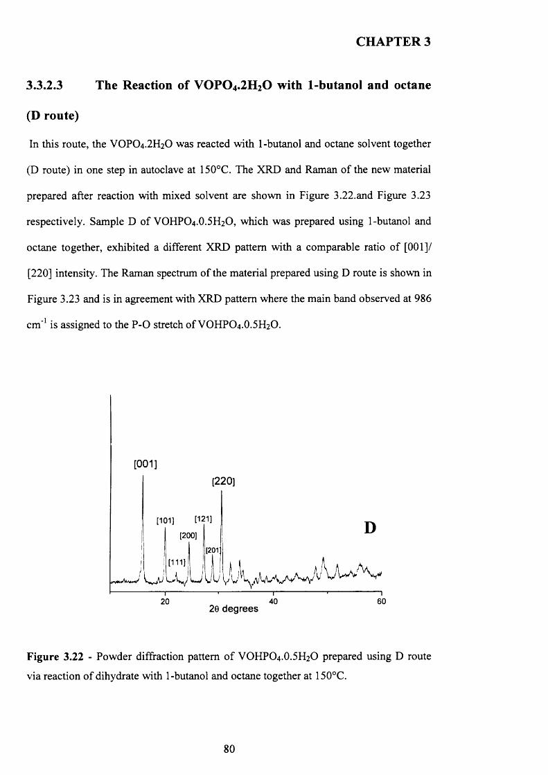
CHAPTER 3
3.3.2.3 The Reaction of VOPO 4 .2 H2O with 1-butanol and octane
(D route)
In this route, the VOPO4.2 H2O was reacted with 1-butanol and octane solvent together
(D route) in one step in autoclave at 150°C. The XRD and Raman o f the new material
prepared after reaction with mixed solvent are shown in Figure 3.22.and Figure 3.23
respectively. Sample D of VOHPO4.O.5 H2O, which was prepared using 1-butanol and
octane together, exhibited a different XRD pattern with a comparable ratio of [001]/
[220] intensity. The Raman spectrum of the material prepared using D route is shown in
Figure 3.23 and is in agreement with XRD pattern where the main band observed at 986
cm '1 is assigned to the P-O stretch of VOHPO4 .O.5 H2O.
[001]
[220]
[121][101]
[200]
[201
6020 4020 degrees
Figure 3.22 - Powder diffraction pattern o f VOHPO4 .O.5 H2O prepared using D route
via reaction o f dihydrate with 1-butanol and octane together at 150°C.
80
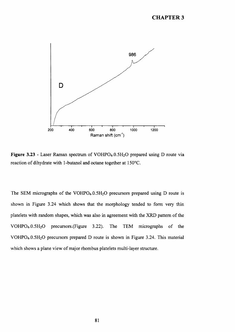
CHAPTER 3
986
200 600 1000400 800 1200Raman shift (cm'1)
Figure 3.23 - Laser Raman spectrum of VOHPO4.O.5 H2O prepared using D route via
reaction o f dihydrate with 1-butanol and octane together at 150°C.
The SEM micrographs o f the VOHPO4 .O.5 H2O precursors prepared using D route is
shown in Figure 3.24 which shows that the morphology tended to form very thin
platelets with random shapes, which was also in agreement with the XRD pattern o f the
VOHPO4 .O.5 H2O precursors.(Figure 3.22). The TEM micrographs o f the
VOHPO4.O.5 H2O precursors prepared D route is shown in Figure 3.24. This material
which shows a plane view o f major rhombus platelets multi-layer structure.
81
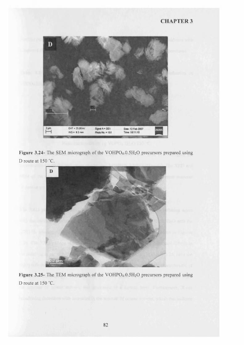
CHAPTER 3
EH7 * 20 00 l(V WO * 8 5 mm
Figure 3.24- The SEM micrograph of the VOHPO4.O.5 H2O precursors prepared using
D route at 150 °C.
Figure 3.25- The TEM micrograph of the VOHPO4.O.5 H2O precursors prepared using
D route at 150 °C.
82
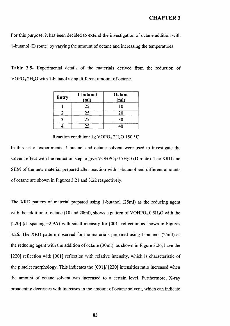
CHAPTER 3
For this purpose, it has been decided to extend the investigation o f octane addition with
1 -butanol (D route) by varying the amount o f octane and increasing the temperatures
Table 3.5- Experimental details o f the materials derived from the reduction o f
VOPO4.2 H2O with 1-butanol using different amount o f octane.
Entry 1-butanol(ml)
Octane(ml)
1 25 102 25 203 25 304 25 40
Reaction condition: lg VOPO4 .2 H2O 150 °C
In this set o f experiments, 1-butanol and octane solvent were used to investigate the
solvent effect with the reduction step to give VOHPO4 .O.5 H2O (D route). The XRD and
SEM of the new material prepared after reaction with 1-butanol and different amounts
o f octane are shown in Figures 3.21.and 3.22 respectively.
The XRD pattern o f material prepared using 1-butanol (25ml) as the reducing agent
with the addition o f octane (10 and 20ml), shows a pattern o f VOHPO4 .O.5 H2O with the
[220] (d- spacing =2.9A) with small intensity for [001] reflection as shown in Figures
3.26. The XRD pattern observed for the materials prepared using 1-butanol (25ml) as
the reducing agent with the addition of octane (30ml), as shown in Figure 3.26, have the
[220] reflection with [001] reflection with relative intensity, which is characteristic o f
the platelet morphology. This indicates the [001]/ [220] intensities ratio increased when
the amount o f octane solvent was increased to a certain level. Furthermore, X-ray
broadening decreases with increases in the amount of octane solvent, which can indicate
83
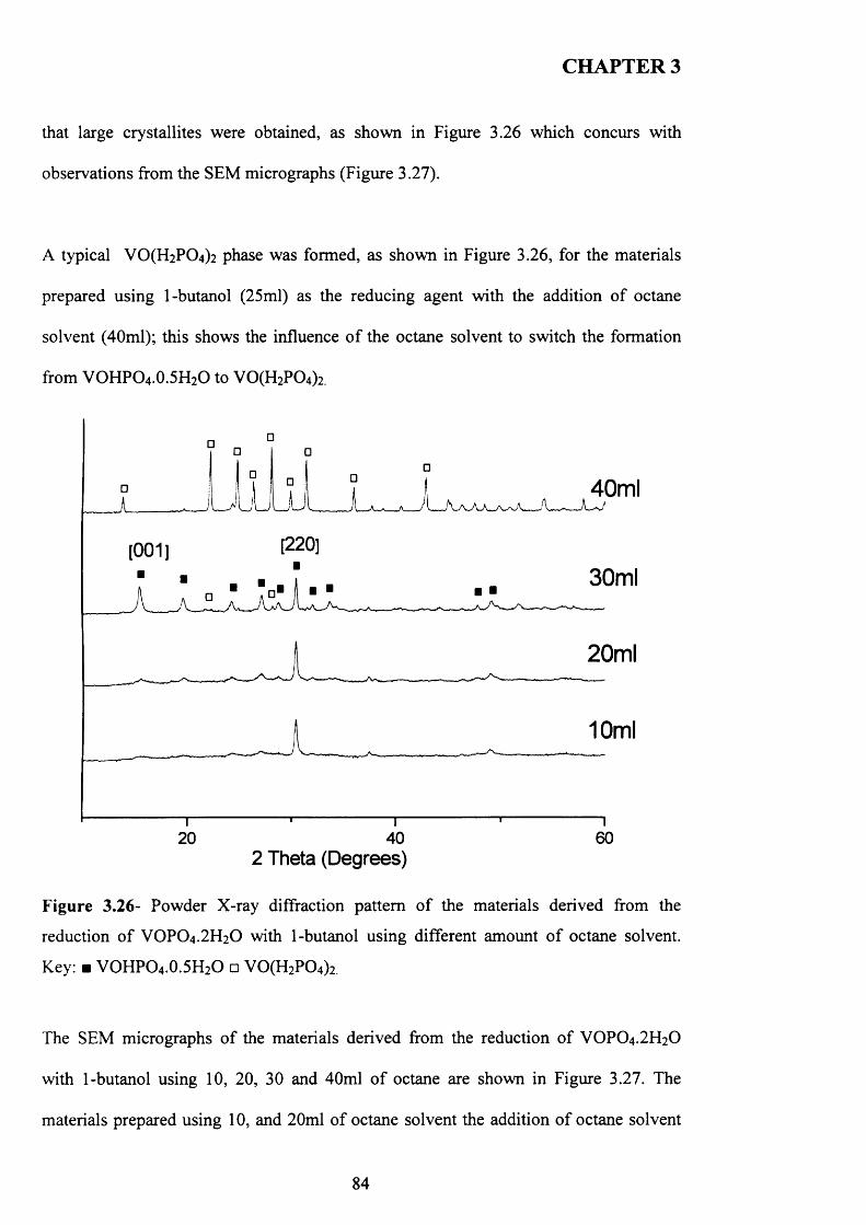
CHAPTER 3
that large crystallites were obtained, as shown in Figure 3.26 which concurs with
observations from the SEM micrographs (Figure 3.27).
A typical V 0 (H2P0 4 ) 2 phase was formed, as shown in Figure 3.26, for the materials
prepared using 1-butanol (25ml) as the reducing agent with the addition of octane
solvent (40ml); this shows the influence o f the octane solvent to switch the formation
from VOHPO4.0.5H2O to V0 (H2P0 4)2.
40ml
[220][001]
30ml
20ml
10ml
40 60202 Theta (Degrees)
Figure 3.26- Powder X-ray diffraction pattern o f the materials derived from the
reduction o f VOPO4 .2 H2O with 1-butanol using different amount o f octane solvent.
Key: ■ VOHPO4 .0.5H2O □ V0 (H2P0 4)2
The SEM micrographs o f the materials derived from the reduction o f VOPO4.2 H2O
with 1-butanol using 10, 20, 30 and 40ml o f octane are shown in Figure 3.27. The
materials prepared using 1 0 , and 2 0 ml o f octane solvent the addition o f octane solvent
84
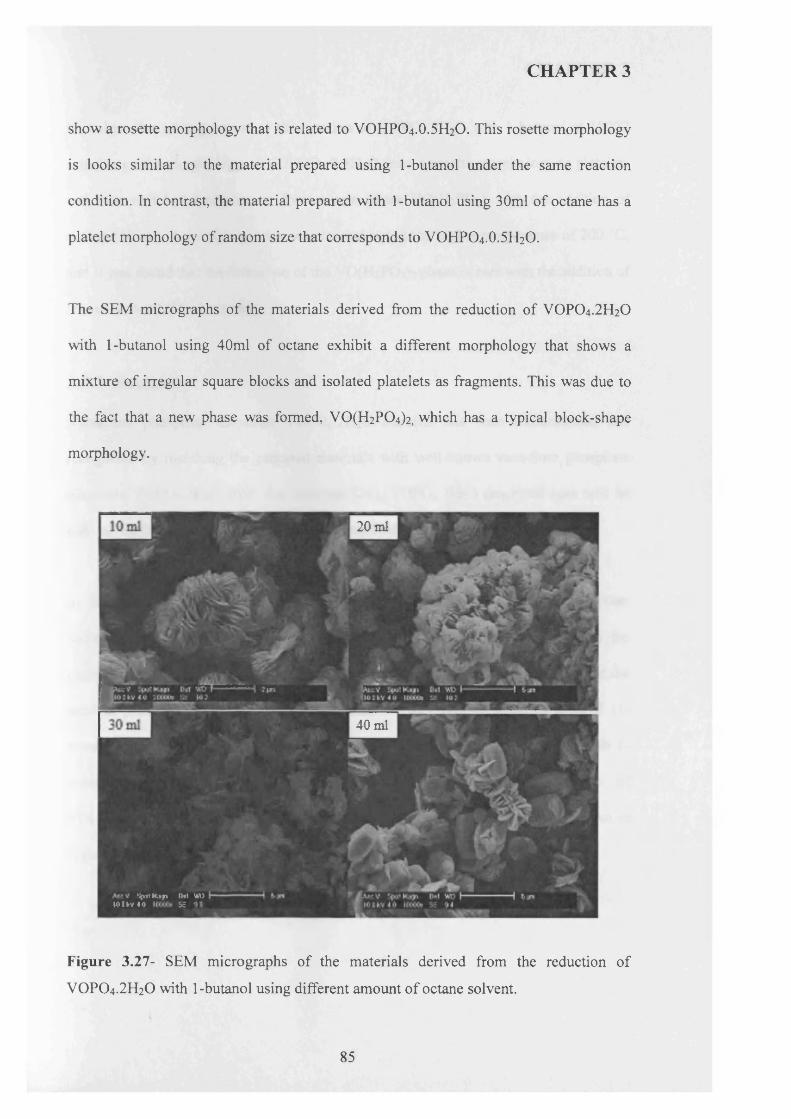
CHAPTER 3
show a rosette morphology that is related to VOHPO4.O.5 H2O. This rosette morphology
is looks similar to the material prepared using 1-butanol under the same reaction
condition. In contrast, the material prepared with 1-butanol using 30ml of octane has a
platelet morphology of random size that corresponds to VOHPO4.O.5 H2O.
The SEM micrographs of the materials derived from the reduction of VOPO4.2 H2O
with 1-butanol using 40ml of octane exhibit a different morphology that shows a
mixture of irregular square blocks and isolated platelets as fragments. This was due to
the fact that a new phase was formed, VO(H2P0 4 )2, which has a typical block-shape
morphology.
20 ml
40 ml
‘ip V K tp Utl Wl>i < m v « o s i
Figure 3.27- SEM micrographs of the materials derived from the reduction of
VOPO4 .2 H2O with 1-butanol using different amount of octane solvent.
85
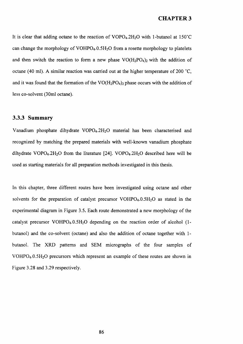
CHAPTER 3
It is clear that adding octane to the reaction o f VOPO4 .2 H2O with 1-butanol at 150°C
can change the morphology o f VOHPO4 .O.5 H2O from a rosette morphology to platelets
and then switch the reaction to form a new phase V 0 (H2P0 4 ) 2 with the addition o f
octane (40 ml). A similar reaction was carried out at the higher temperature o f 200 °C,
and it was found that the formation of the VO(H2PC>4)2 phase occurs with the addition of
less co-solvent (30ml octane).
3.3.3 Summary
Vanadium phosphate dihydrate VOPO4 .2 H2O material has been characterised and
recognized by matching the prepared materials with well-known vanadium phosphate
dihydrate VOPO4 .2 H2O from the literature [24]. VOPO4 .2 H2O described here will be
used as starting materials for all preparation methods investigated in this thesis.
In this chapter, three different routes have been investigated using octane and other
solvents for the preparation of catalyst precursor VOHPO4 .O.5 H2O as stated in the
experimental diagram in Figure 3.5. Each route demonstrated a new morphology o f the
catalyst precursor VOHPO4 .O.5 H2O depending on the reaction order o f alcohol (1-
butanol) and the co-solvent (octane) and also the addition o f octane together with 1-
butanol. The XRD patterns and SEM micrographs o f the four samples o f
VOHPO4 .O.5 H2O precursors which represent an example o f these routes are shown in
Figure 3.28 and 3.29 respectively.
86
CHAPTER 3
[001 ] [220]
[101][200]
[111]
20 40 6020 degrees
Figure 3.28 - XRD pattern o f VOHPO4.O.5 H2O precursors prepared via (A) reaction
with 1-butanol (E), after reaction with octane (C), route (reaction o f dihydrate with
octane followed by reaction with 1-butanol, (D) via D route (reaction o f dihydrate
with 1-butanol with octane together.
87
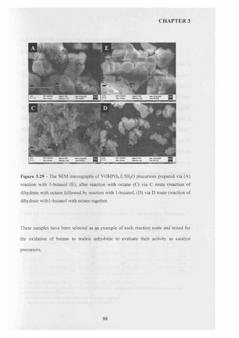
CHAPTER 3
Figure 3.29 - The SEM micrographs of VOHPO4 .O.5 H2O precursors prepared via (A)
reaction with 1-butanol (E), after reaction with octane (C) via C route (reaction of
dihydrate with octane followed by reaction with 1-butanol, (D) via D route (reaction of
dihydrate with 1-butanol with octane together.
These samples have been selected as an example of each reaction route and tested for
the oxidation of butane to maleic anhydride to evaluate their activity as catalyst
precursors.
88
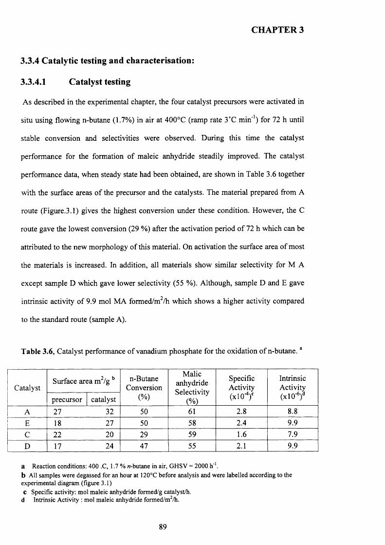
CHAPTER 3
3.3.4 Catalytic testing and characterisation:
3.3.4.1 Catalyst testing
As described in the experimental chapter, the four catalyst precursors were activated in
situ using flowing n-butane (1.7%) in air at 400°C (ramp rate 3°C min’1) for 72 h until
stable conversion and selectivities were observed. During this time the catalyst
performance for the formation o f maleic anhydride steadily improved. The catalyst
performance data, when steady state had been obtained, are shown in Table 3.6 together
with the surface areas o f the precursor and the catalysts. The material prepared from A
route (Figure.3.1) gives the highest conversion under these condition. However, the C
route gave the lowest conversion (29 %) after the activation period o f 72 h which can be
attributed to the new morphology o f this material. On activation the surface area o f most
the materials is increased. In addition, all materials show similar selectivity for M A
except sample D which gave lower selectivity (55 %). Although, sample D and E gave
intrinsic activity of 9.9 mol MA formed/m /h which shows a higher activity compared
to the standard route (sample A).
Table 3.6, Catalyst performance of vanadium phosphate for the oxidation o f n-butane.a
CatalystSurface area m2/g b n-Butane
Conversion(%)
MalicanhydrideSelectivity
(%)
Specific Activity (xlO Ay
IntrinsicActivity(x l0 '6)dprecursor catalyst
A 27 32 50 61 2.8 8.8
E 18 27 50 58 2.4 9.9
C 22 20 29 59 1.6 7.9
D 17 24 47 55 2.1 9.9
a Reaction conditions: 400 .C, 1.7 % H-butane in air, GHSV = 2000 h '1.b All samples were degassed for an hour at 120°C before analysis and were labelled according to the experimental diagram (figure 3.1)c Specific activity: mol maleic anhydride formed/g catalyst/h.
d Intrinsic Activity : mol maleic anhydride formed/m2/h.
89
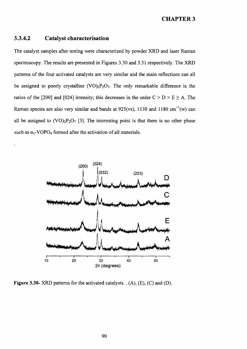
CHAPTER 3
3.3.4.2 Catalyst characterisation
The catalyst samples after testing were characterized by powder XRD and laser Raman
spectroscopy. The results are presented in Figures 3.30 and 3.31 respectively. The XRD
patterns o f the four activated catalysts are very similar and the main reflections can all
be assigned to poorly crystalline (VO)2P2C>7. The only remarkable difference is the
ratios o f the [200] and [024] intensity; this decreases in the order C > D > E > A. The
Raman spectra are also very similar and bands at 925(vs), 1130 and 1180 cm_1(w) can
all be assigned to (VO)2P2 0 7 [3]. The interesting point is that there is no other phase
such as ai-VOP0 4 formed after the activation o f all materials.
(024)
10 20 3020 (degrees)
40 50
Figure 3.30- XRD patterns for the activated catalysts.. (A), (E), (C) and (D).
90
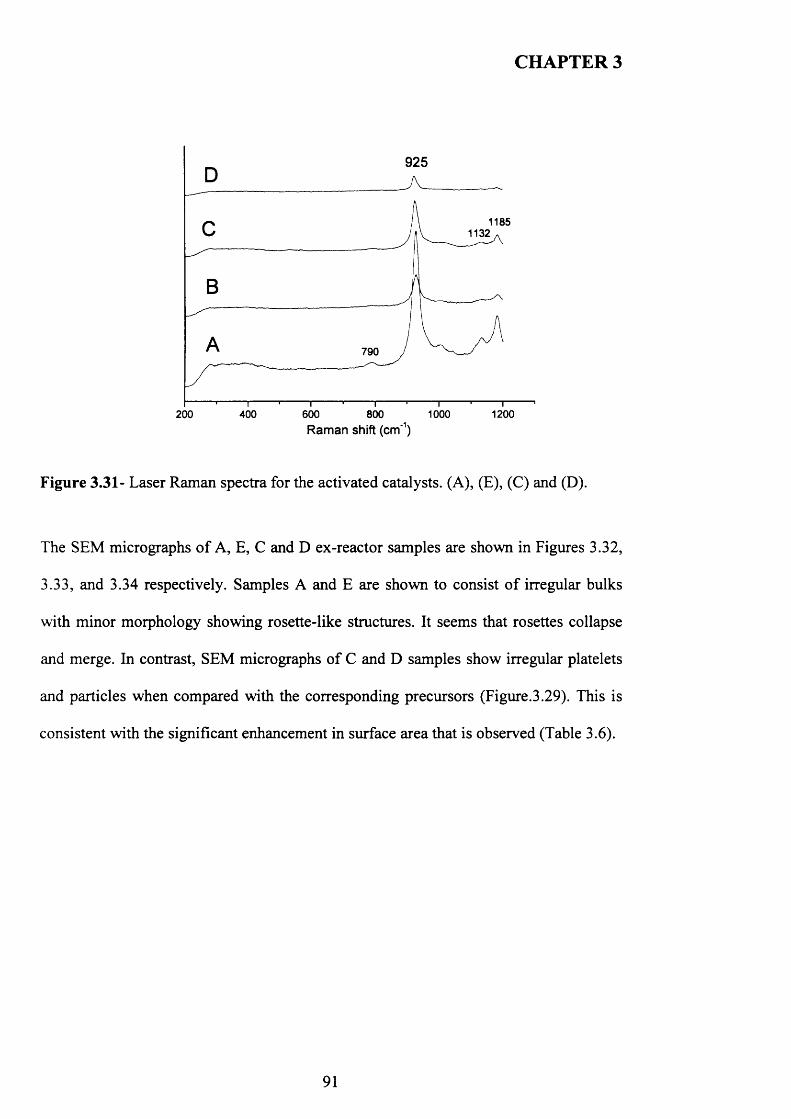
CHAPTER 3
925
11851132
790
400 600 800 1000 1200200Raman shift (cm'1)
Figure 3.31- Laser Raman spectra for the activated catalysts. (A), (E), (C) and (D).
The SEM micrographs o f A, E, C and D ex-reactor samples are shown in Figures 3.32,
3.33, and 3.34 respectively. Samples A and E are shown to consist o f irregular bulks
with minor morphology showing rosette-like structures. It seems that rosettes collapse
and merge. In contrast, SEM micrographs o f C and D samples show irregular platelets
and particles when compared with the corresponding precursors (Figure.3.29). This is
consistent with the significant enhancement in surface area that is observed (Table 3.6).
91
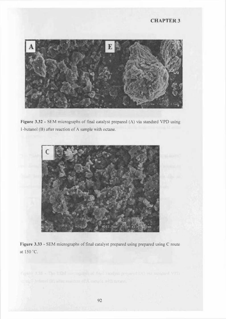
CHAPTER 3
Figure 3.32 - SEM micrographs of final catalyst prepared (A) via standard VPD using
1 -butanol (B) after reaction of A sample with octane.
Figure 3.33 - SEM micrographs of final catalyst prepared using prepared using C route
at 150 °C.
92
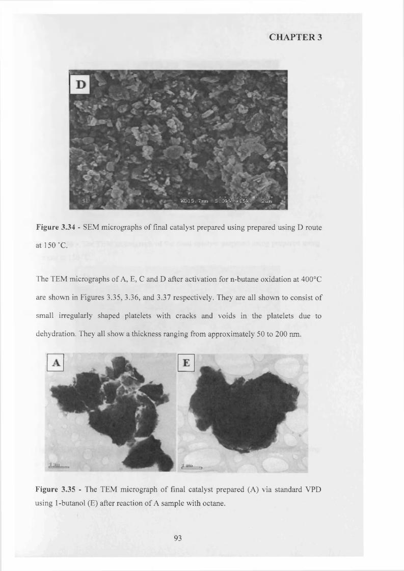
CHAPTER 3
Figure 3.34 - SEM micrographs of final catalyst prepared using prepared using D route
at 150 °C.
The TEM micrographs of A, E, C and D after activation for n-butane oxidation at 400°C
are shown in Figures 3.35, 3.36, and 3.37 respectively. They are all shown to consist of
small irregularly shaped platelets with cracks and voids in the platelets due to
dehydration. They all show a thickness ranging from approximately 50 to 200 nm.
Figure 3.35 - The TEM micrograph of final catalyst prepared (A) via standard VPD
using 1-butanol (E) after reaction of A sample with octane.
93
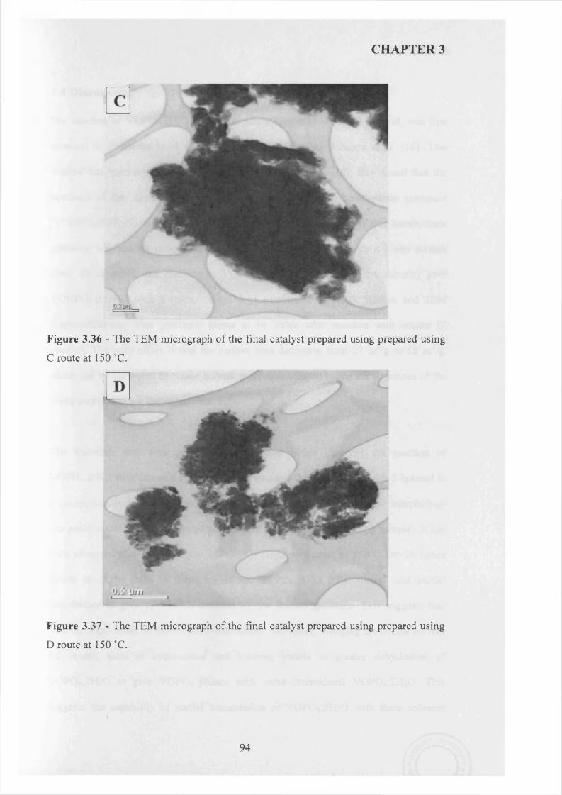
CHAPTER 3
Figure 3.36 - The TEM micrograph of the final catalyst prepared using prepared using
C route at 150 °C.
I
Figure 3.37 - The TEM micrograph of the final catalyst prepared using prepared using
D route at 150 °C.
94
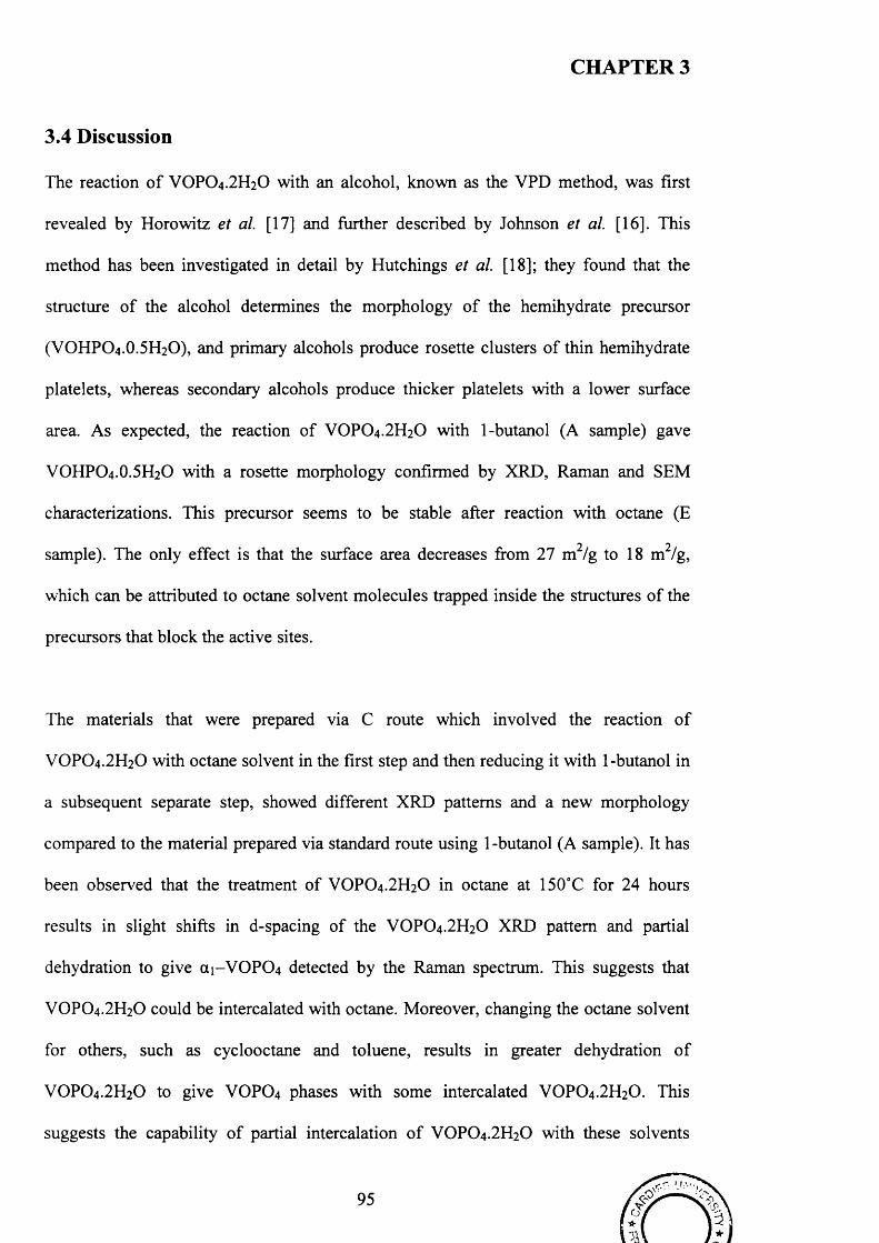
CHAPTER 3
3.4 Discussion
The reaction o f VOPO4 .2 H2O with an alcohol, known as the VPD method, was first
revealed by Horowitz et a l [17] and further described by Johnson et a l [16]. This
method has been investigated in detail by Hutchings et a l [18]; they found that the
structure o f the alcohol determines the morphology o f the hemihydrate precursor
(VOHPO4.O.5 H2O), and primary alcohols produce rosette clusters o f thin hemihydrate
platelets, whereas secondary alcohols produce thicker platelets with a lower surface
area. As expected, the reaction o f VOPO4 .2 H2O with 1-butanol (A sample) gave
VOHPO4 .O.5 H2O with a rosette morphology confirmed by XRD, Raman and SEM
characterizations. This precursor seems to be stable after reaction with octane (E
2 2sample). The only effect is that the surface area decreases from 27 m /g to 1 8 m /g,
which can be attributed to octane solvent molecules trapped inside the structures o f the
precursors that block the active sites.
The materials that were prepared via C route which involved the reaction o f
VOPO4.2 H2O with octane solvent in the first step and then reducing it with 1-butanol in
a subsequent separate step, showed different XRD patterns and a new morphology
compared to the material prepared via standard route using 1-butanol (A sample). It has
been observed that the treatment of VOPO4 .2 H2O in octane at 150°C for 24 hours
results in slight shifts in d-spacing of the VOPO4.2 H2O XRD pattern and partial
dehydration to give a i-V 0 P0 4 detected by the Raman spectrum. This suggests that
VOPO4 .2 H2O could be intercalated with octane. Moreover, changing the octane solvent
for others, such as cyclooctane and toluene, results in greater dehydration o f
VOPO4.2 H2O to give VOPO4 phases with some intercalated VOPO4 .2 H2O. This
suggests the capability o f partial intercalation o f VOPO4 .2 H2O with these solvents
95
CHAPTER 3
under the reaction conditions. Reacting these materials with 1-butanol in the second step
(C route) produced catalyst precursors VOHPO4.O.5 H2O with a different ratio o f [001]/
[220] intensity o f their XRD patterns. These materials shows a new morphology
compared to the materials that prepared using 1 -butanol only which indicate the effect
o f octane solvent on VOPO4.2 H2O prior to the reduction step.
Recently, Yamamoto et a l [15] reported the intercalation o f alcohol into layers o f
VOPO4 .2 H2O, exfoliation using alcohol into delaminated sheets, and following
reduction by reflux in alcohol into thin-layered VOHPO4 .O.5 H2O. It was found from
their studies that the processes o f intercalation, exfoliation and reduction in alcohol are
important for the catalyst precursor and, consequently, for the final catalyst. As
mentioned previously that VOPO4 .2 H2O has a capability to accommodate some types o f
organic molecules due to its layered structure. This means that the octane solvent could
be intercalated into the layers o f VOPO4 .2 H2O which therefore gave VOHPO4.O.5 H2O
precursor with a new morphology.
The second route that was investigated was the reaction o f VOPO4 .2 H2O with octane
solvent and 1 -butanol as the reducing agent together (D route). It was clear that, with
addition o f octane, the morphology o f the catalyst precursor VOHPO4.O.5 H2O changed
from a rosette morphology to random platelets with the addition o f 30ml of octane. In
contrast, a new phase V 0 (H2P0 4 ) 2 was formed when 40ml o f octane was added to the
reaction mixture. This indicates that the octane solvent can play an important role o f
controlling the morphology o f the catalyst precursors. However, this reaction was
carried out in a high pressure autoclave reactor with 70ml maximum volume, so a
similar study was conducted to investigate the reaction at the higher temperature o f
96
CHAPTER 3
200°C, and it was found that the formation o f the new phase V 0 (H2P0 4 ) 2 occurred with
less amount o f octane (30ml). This shows also that the temperature has a great influence
on the preparation o f the catalyst precursors.
Moreover, it is has been reported in the literature [19] that VO(H2PC>4)2 can be prepared
from VOPO4 .2 H2O when the V/P ratio is changed from 1:1 to 1>2 whereas
VOHPO4.O.5 H2O has 1:1 V/P ratio. This indicates that VOPO4 .2 H2O dissociates in the
alcohol and then V5+ species are reduced to V4+ by the alcohol.
Another investigation, recently reported by Umacaran [20], demonstrates that the use of
a long chain alkane as a co-solvent using the reflux method can control the morphology
of VOHPO4 .O.5 H2O. It was found that, the addition o f a high amount (50-100ml) of
alkane reduces the concentration o f alcohol in the reaction mixture. The low
concentration results in a decreased reaction rate o f the reduction step (1-butanol and
VOPO4 .2 H2O) and consequently affects the V4+: P ratio, which determines the
formation o f the phase formed.
It was also found from this study that adding octane with 1 -butanol for the reduction of
VOPO4 .2 H2O in a high pressure autoclave can control the morphology o f the catalyst
precursors VOHPO4 .O.5 H2O (D route). Furthermore, adding 40ml o f octane switched
the formation from VOHPO4 .O.5 H2O to V 0 (H2P0 4 ), which shows the influence o f the
co-solvent. It can be said that the use of octane as co-solvent can control the reaction by
changing the alcohol (1-butanol): alkane (octane) volume ratio, which therefore, can
alter the concentration o f alcohol. In addition, the present o f the co-solvent with alcohol
97
CHAPTER 3
can also affect the reduction step o f the VOPO4.2 H2O to give the catalyst precursors
VOHPO4 .0.5H2O.
Three different morphologies o f VOHPO4 .O.5 H2O precursor have been successfully
prepared using octane solvent. Evaluations o f these precursors for w-butane oxidation to
maleic anhydride demonstrate that all o f the catalyst precursors have transformed
topotactically to give poorly crystalline (VO)2P2 0 7 . However, the only significant
difference is the ratio o f the [200] and [024] intensity, which is believed to be essential
for the catalyst activity. Torardi et al. [21] reported that the poorly crystalline
(VO)2P2C>7 depends on the presence o f structural defects in the VOHPO4 O.5 H2O
structure. The VOHPO4 O.5 H2O precursors usually exhibit crystallographic disorder
associated with its retained alcohol (used in the preparation), which translates into a
similar disorder in the active phase (VO)2P2C>7 after activation at 400°C and is likely to
be responsible for the appearance o f an amorphous intermediate.
In contrast, Hutchings et al. [22] reported that the transformation does not only proceed
through the simple transformation of crystalline VOHPO4 .O.5 H2O to crystalline
(VO)2P2 0 7 , rather the majority o f the VOHPO4 .O.5 H2O becomes amorphous on heating
in an n-butane/air mixture and the crystallization to (VO)2P2C>7takes place relatively
slowly, which may affect the crystallinity o f (VO)2P2 0 7 .
After the activation, the surface areas o f most of the materials increase as the
VOHPO4 .O.5 H2O precursor is heated; the trapped alcohol molecules are released, which
creates structural defects, microcracks and increases the surface area which may also
suggest the effect o f the retained alcohol solvent on the final catalyst
98
CHAPTER 3
3.5 Conclusion
Three different morphologies o f VOHPO4 .O.5 H2O precursor have been successfully
prepared via three different routes with the use o f octane solvent. From these results, we
can say that octane solvent can plays an important role in VOHPO4 O.5 H2O preparation.
The reaction o f VOPO4 .2 H2O with octane solvent shows the possibility o f the
intercalation o f the octane solvent between the layers o f VOPO4 .2 H2O. This can lead to
the formation o f VOHPO4 .O.5 H2O precursors with a new morphology after the
reduction step using 1-butanol. In addition, adding the solvent together with the
reducing agent leads to the formation o f VOHPO4 .O.5 H2O with a different XRD pattern
and new morphology.
Finally, testing these samples shows that the new materials prepared with octane
(sample D) gave a higher activity compared to material prepared via the standard route
(sample A).
99
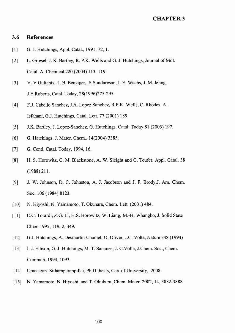
CHAPTER 3
3.6 References
[1] G. J. Hutchings, Appl. Catal., 1991, 72, 1.
[2] L. Griesel, J. K. Bartley, R. P.K. Wells and G. J. Hutchings, Journal o f Mol.
Catal. A: Chemical 220 (2004) 113-119
[3] V. V Guliants,. J. B. Benziger, S.Sundaresan, I. E. Wachs, J. M. Jehng,
J.E.Roberts, Catal. Today, 28(1996)275-295.
[4] F.J. Cabello Sanchez, J.A. Lopez Sanchez, R.P.K. Wells, C. Rhodes, A.
Isfahani, G.J. Hutchings, Catal. Lett. 77 (2001) 189.
[5] J.K. Bartley, J. Lopez-Sanchez, G. Hutchings. Catal. Today 81 (2003) 197.
[6] G. Hatchings. J. Mater. Chem., 14(2004) 3385.
[7] G. Centi, Catal. Today, 1994, 16.
[8] H. S. Horowitz, C. M. Blackstone, A. W. Sleight and G. Teufer, Appl. Catal. 38
(1988)211.
[9] J. W. Johnson, D. C. Johnston, A. J. Jacobson and J. F. Brody,J. Am. Chem.
Soc. 106(1984) 8123.
[10] N. Hiyoshi, N. Yamamoto, T. Okuhara, Chem. Lett. (2001) 484.
[11] C.C. Torardi, Z.G. Li, H.S. Horowitz, W. Liang, M.-H. Whangbo, J. Solid State
Chem. 1995, 119,2, 349.
[12] G.J. Hutchings, A. Desmartin-Chamel, O. Oliver, J.C. Volta, Nature 348 (1994)
[13] I. J. Ellison, G. J. Hutchings, M. T. Sananes, J. C.Volta, J.Chem. Soc., Chem.
Commun. 1994, 1093.
[14] Umacaran. Sithamparappillai, Ph.D thesis, Cardiff University, 2008.
[15] N. Yamamoto, N. Hiyoshi, and T. Okuhara, Chem. Mater. 2002, 14, 3882-3888.
100
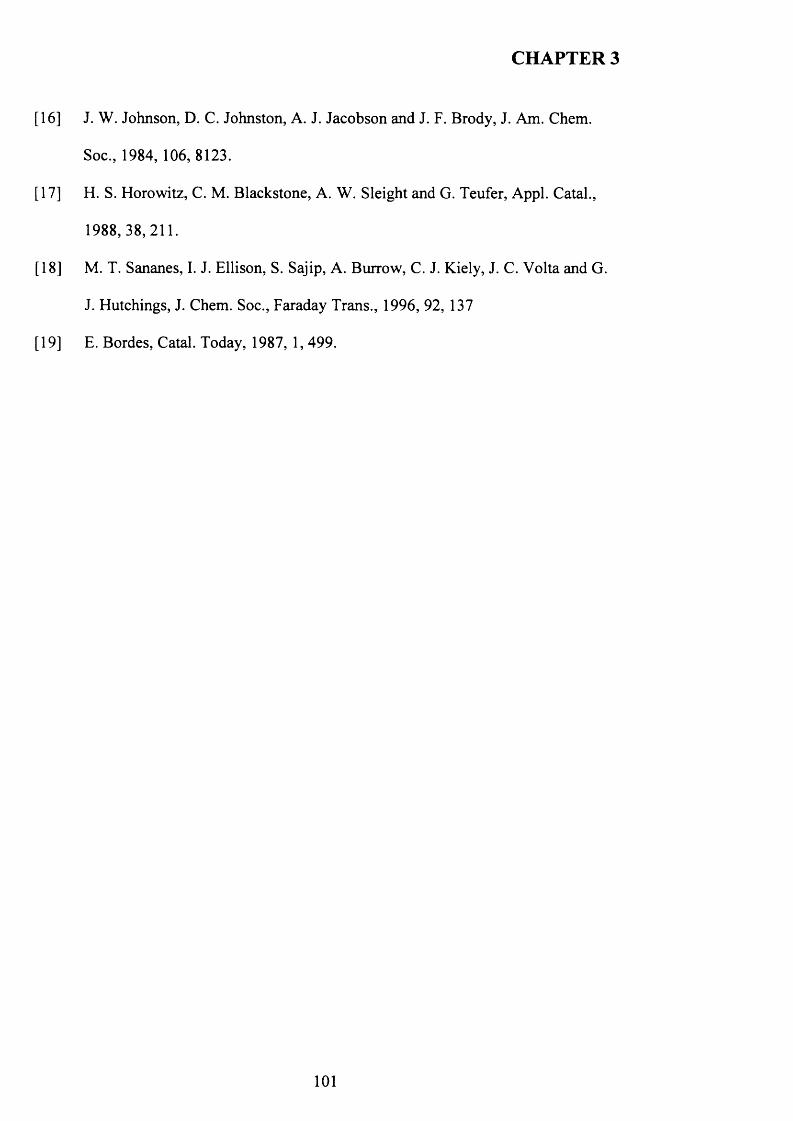
CHAPTER 3
[16] J. W. Johnson, D. C. Johnston, A. J. Jacobson and J. F. Brody, J. Am. Chem.
Soc., 1984, 106,8123.
[17] H. S. Horowitz, C. M. Blackstone, A. W. Sleight and G. Teufer, Appl. Catal.,
1988,38,211.
[18] M. T. Sananes, I. J. Ellison, S. Sajip, A. Burrow, C. J. Kiely, J. C. Volta and G.
J. Hutchings, J. Chem. Soc., Faraday Trans., 1996, 92, 137
[19] E. Bordes, Catal. Today, 1987, 1, 499.
CHAPTER 4
Vanadium phosphate oxide seeds and their influence on the
formation of V-P-O catalyst precursors
4.1 Introduction
Vanadium phosphate catalysts have been extensively studied for the selective oxidation
o f n-butane to maleic anhydride (MA). Vanadyl pyrophosphate, (VO)2P2 0 7 , is believed
to be the main active phase for the butane oxidation. This phase is usually derived from
the precursor VOHPO 4 .O.5 H2O via topotactic transformation [1-3].
There are many reports that describe the preparation methods o f VOHPO4 .O.5 H2O [4, 6]
including the use o f VOPO 4 .2 H2O as a starting material. Johnson et al. [5] reported that
VOHPO4 .O.5 H2O can be prepared via the direct reduction o f VOPO4 .2 H2O using
alcohols. Hutchings et al. [6] reported that the morphology o f the resulting
VOHPO4 .O.5 H2O was controlled by the nature o f the alcohol used in the reduction o f
VOPO4 .2 H2O. It has been found that catalysts derived from the reduction o f
VOPO4 .2 H2O with 1-alcohols tend to give high activity catalysts by virtue o f the high
surface area material (typically 40 m / g) produced by this preparation method.
In contrast to using 1-octanol, Ellison et al. reported that refluxing VOPO4 2 H2O with
3-octanol produces V 0 (H 2P0 4 ) 2 phase [7]. V 0 (H2P0 4 )2, (defined as phase E in this
thesis) has been classified as an impurity formed during the preparation o f the catalyst
precursor [8]. This phase displays distinctive cuboidal particles about 10pm in size and
with a low surface area o f ca. 2 m /g. It was reported that V 0 (H2P0 4 ) 2 has a negligible
activity and selectivity under standard reaction conditions [9].
102

CHAPTER 4
Presented here are our investigations o f the factors influencing the preparation o f
vanadium phosphates during the VPD type alcohol reduction o f VOPO4 2 H2O and the
effect o f reaction temperatures on the preparation using long chain alcohols (1-octanol
3-octanol). In particular, the use o f seed crystals o f vanadium phosphate can have a
dramatic influence on the morphology and phase identity o f the precursor materials.
4.2 Experimental
4.2.1 Precursors preparation
A detailed description o f the preparation methods is given in the experimental chapter
(sections 2.1.2.1, 2.1.2.2, 2.1.2.3 and 2.1.2.4).
4.2.2 Characterisation
All the new prepared materials and activated catalysts were characterised using a
combination o f X-ray powder diffraction, laser Raman spectroscopy, scanning electron
microscopy (SEM), transmission electron microscopy (TEM) and BET surface area
measurements.
4.2.3 Catalyst Testing
All the catalyst tests from which the data are presented here were carried out under the
following reaction conditions: a gas mixture o f 1.7% butane to air, a gas hourly space
velocity o f 2000b'1, 0.2g o f catalyst (approx. 0.3ml), and 400°C (ramp rate 3°C m in '1).
Measurements were taken for 72h or until stable conversion and selectivities were
observed.
103
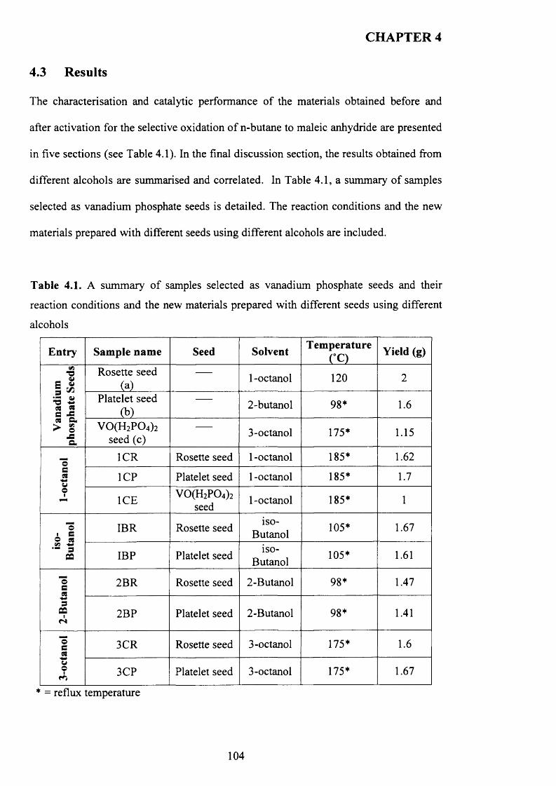
CHAPTER 4
4.3 Results
The characterisation and catalytic performance of the materials obtained before and
after activation for the selective oxidation o f n-butane to maleic anhydride are presented
in five sections (see Table 4.1). In the final discussion section, the results obtained from
different alcohols are summarised and correlated. In Table 4.1, a summary o f samples
selected as vanadium phosphate seeds is detailed. The reaction conditions and the new
materials prepared with different seeds using different alcohols are included.
Table 4.1. A summary o f samples selected as vanadium phosphate seeds and their
reaction conditions and the new materials prepared with different seeds using different
alcohols
Entry Sample name Seed Solvent Temperature(°C) Yield (g)
Van
adiu
m
phos
phat
e Se
eds Rosette seed
(a)1 -octanol 120 2
Platelet seed(b)
2-butanol 98* 1.6
V0(H 2P 0 4)2 seed (c) 3-octanol 175* 1.15
1-oc
tano
l IC R Rosette seed 1 -octanol 185* 1.62
1CP Platelet seed 1 -octanol 185* 1.7
IC E V 0(H 2P 0 4)2seed 1 -octanol 185* 1
iso-
But
anol IBR Rosette seed iso-Butanol 105* 1.67
IBP Platelet seed1SO-
Butanol 105* 1.61
2-B
utan
ol 2BR Rosette seed 2-Butanol 98* 1.47
2BP Platelet seed 2-Butanol 98* 1.41
3-oc
tano
l
3CR Rosette seed 3-octanol 175* 1.6
3CP Platelet seed 3-octanol 175* 1.67
* = reflux temperature
104
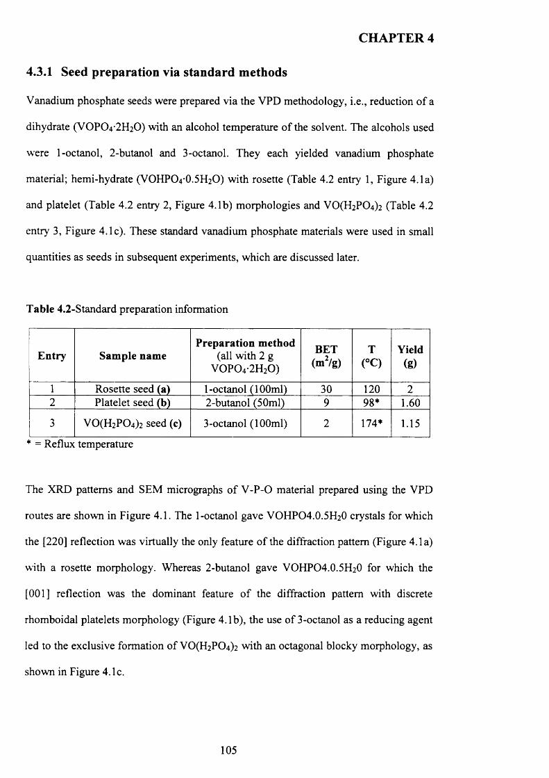
CHAPTER 4
4.3.1 Seed preparation via standard methods
Vanadium phosphate seeds were prepared via the VPD methodology, i.e., reduction o f a
dihydrate (VOPO 4 2 H2O) with an alcohol temperature o f the solvent. The alcohols used
were 1-octanol, 2-butanol and 3-octanol. They each yielded vanadium phosphate
material; hemi-hydrate (VOHPO4 O.5 FI2O) with rosette (Table 4.2 entry 1, Figure 4.1a)
and platelet (Table 4.2 entry 2, Figure 4.1b) morphologies and V0 (H2P0 4 ) 2 (Table 4.2
entry 3, Figure 4.1c). These standard vanadium phosphate materials were used in small
quantities as seeds in subsequent experiments, which are discussed later.
Table 4.2-Standard preparation information
Entry Sample namePreparation method
(all with 2 g V 0 P 0 4-2H20 )
BET(m2/g)
T(°C)
Yield(g)
1 Rosette seed (a) 1-octanol (100ml) 30 120 22 Platelet seed (b) 2-butanol (50ml) 9 98* 1.60
3 V 0(H 2P 0 4)2 seed (c) 3-octanol (100ml) 2 174* 1.15
* = Reflux temperature
The XRD patterns and SEM micrographs o f V -P -0 material prepared using the VPD
routes are shown in Figure 4.1. The 1-octanol gave VOHPO4.0.5H20 crystals for which
the [220] reflection was virtually the only feature o f the diffraction pattern (Figure 4.1a)
with a rosette morphology. Whereas 2-butanol gave VOHPO4 .O.5 H2O for which the
[001] reflection was the dominant feature o f the diffraction pattern with discrete
rhomboidal platelets morphology (Figure 4.1b), the use o f 3-octanol as a reducing agent
led to the exclusive formation o f V0 (H2P0 4 ) 2 with an octagonal blocky morphology, as
shown in Figure 4.1c.
105
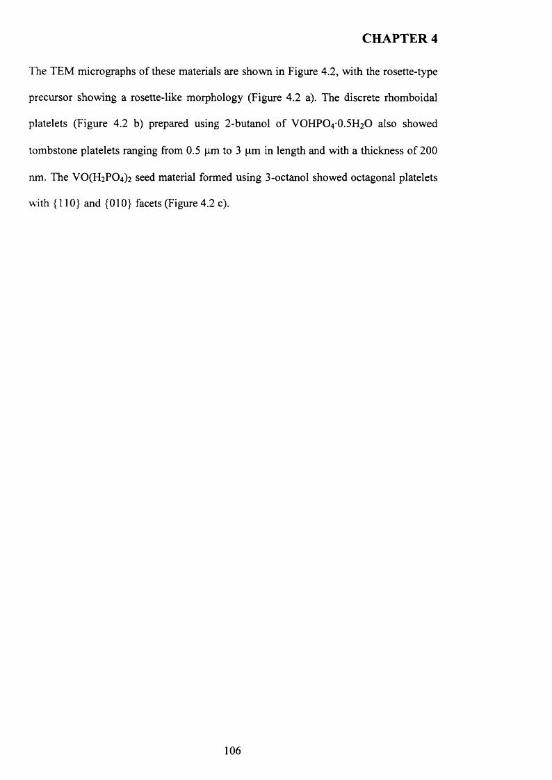
CHAPTER 4
The TEM micrographs o f these materials are shown in Figure 4.2, with the rosette-type
precursor showing a rosette-like morphology (Figure 4.2 a). The discrete rhomboidal
platelets (Figure 4.2 b) prepared using 2-butanol o f VOFIPO4 O.5 FI2O also showed
tombstone platelets ranging from 0.5 pm to 3 pm in length and with a thickness of 200
nm. The VO(H2P0 4 ) 2 seed material formed using 3-octanol showed octagonal platelets
with {110} and {010} facets (Figure 4.2 c).
106
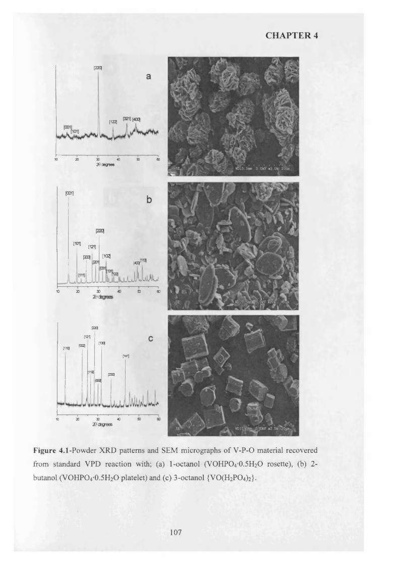
CHAPTER 4
[220|
[122)
K) 20 30 40 50 8020 degrees
poi]
[1011[121]
[iagPHwr
10 3D20 3D eo2D t
[22q[121]
[1*1PS! [1X1
[141]
|iq P3q
-i -------1------- 1------- r10 20 X 40
20 ctegnees
Figure 4.1-Powder XRD patterns and SEM micrographs of V-P-0 material recovered
from standard VPD reaction with; (a) 1-octanol (VOHPO4 O.5 H2O rosette), (b) 2-
butanol (VOHPO4 O.5 H2O platelet) and (c) 3-octanol {VO(H2PC>4)2}.
107
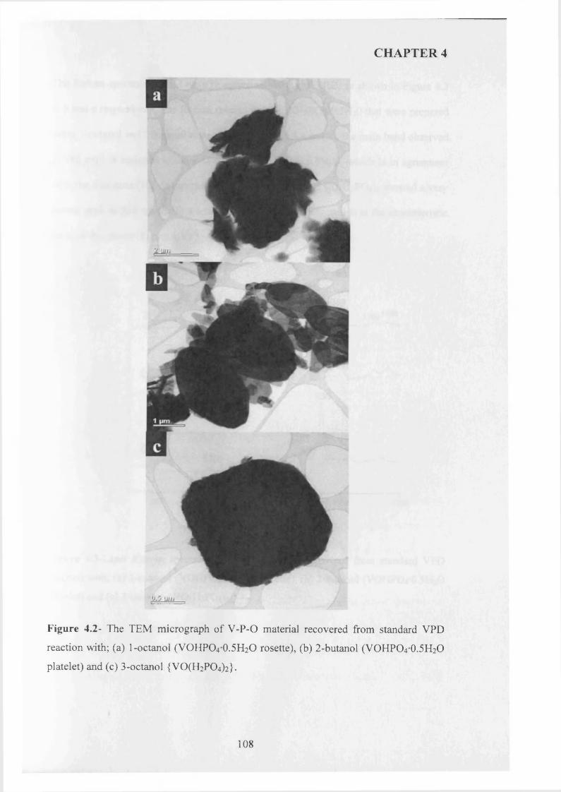
CHAPTER 4
Figure 4.2- The TEM micrograph of V-P-O material recovered from standard VPD
reaction with; (a) 1-octanol (VOHPO4 0.5H2O rosette), (b) 2-butanol (VOHPO4 0.5H2O
platelet) and (c) 3-octanol {V0(H2P 0 4)2}.
108
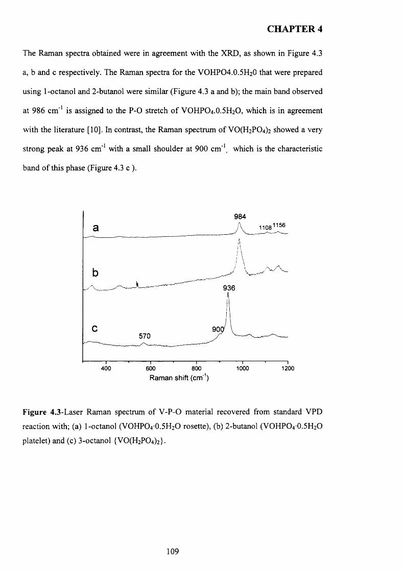
CHAPTER 4
The Raman spectra obtained were in agreement with the XRD, as shown in Figure 4.3
a, b and c respectively. The Raman spectra for the VOHPO4 .O.5 H2O that were prepared
using 1-octanol and 2-butanol were similar (Figure 4.3 a and b); the main band observed
at 986 cm '1 is assigned to the P -0 stretch o f VOHPO4 .O.5 H2O, which is in agreement
with the literature [10]. In contrast, the Raman spectrum o f VCXFhPO^ showed a very
strong peak at 936 cm*1 with a small shoulder at 900 cm"1, which is the characteristic
band o f this phase (Figure 4.3 c ).
984
936
570
1000400 600 800 1200Raman shift (cm'1)
Figure 4.3-Laser Raman spectrum of V-P-0 material recovered from standard VPD
reaction with; (a) 1-octanol (VOHPO4O.5FI2O rosette), (b) 2-butanol (VOHPO4O.5H2O
platelet) and (c) 3-octanol {VO(H2PC>4)2 }.
109
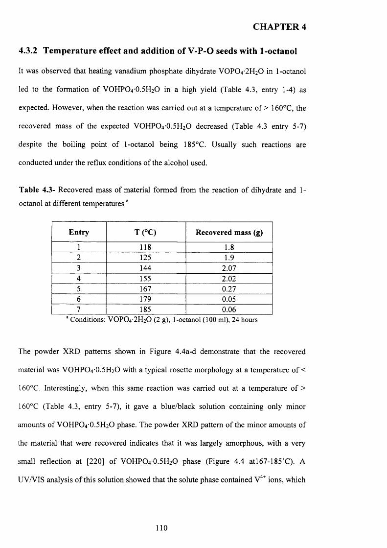
CHAPTER 4
4.3.2 Temperature effect and addition of V-P-O seeds with 1-octanol
It was observed that heating vanadium phosphate dihydrate VOPO4 2 H2O in 1-octanol
led to the formation of VOHPO4 O.5 H2O in a high yield (Table 4.3, entry 1-4) as
expected. However, when the reaction was carried out at a temperature o f > 160°C, the
recovered mass o f the expected VOHPO4 O.5 H2O decreased (Table 4.3 entry 5-7)
despite the boiling point o f 1-octanol being 185°C. Usually such reactions are
conducted under the reflux conditions o f the alcohol used.
T able 4.3- Recovered mass of material formed from the reaction o f dihydrate and 1-
octanol at different temperatures a
E n try T (°C ) R ecovered mass (g)
1 118 1.82 125 1.93 144 2.074 155 2.025 167 0.276 179 0.057 185 0.06
a Conditions: VOPO4 2 H2O (2 g), 1-octanol (100 ml), 24 hours
The powder XRD patterns shown in Figure 4.4a-d demonstrate that the recovered
material was VOHPO 4 O.5 H2O with a typical rosette morphology at a temperature o f <
160°C. Interestingly, when this same reaction was carried out at a temperature o f >
160°C (Table 4.3, entry 5-7), it gave a blue/black solution containing only minor
amounts o f VOHPO4 O.5 H2O phase. The powder XRD pattern o f the minor amounts o f
the material that were recovered indicates that it was largely amorphous, with a very
small reflection at [220] o f VOHPO4 O.5 H2O phase (Figure 4.4 atl67-185°C). A
UV/VIS analysis o f this solution showed that the solute phase contained V4+ ions, which
110
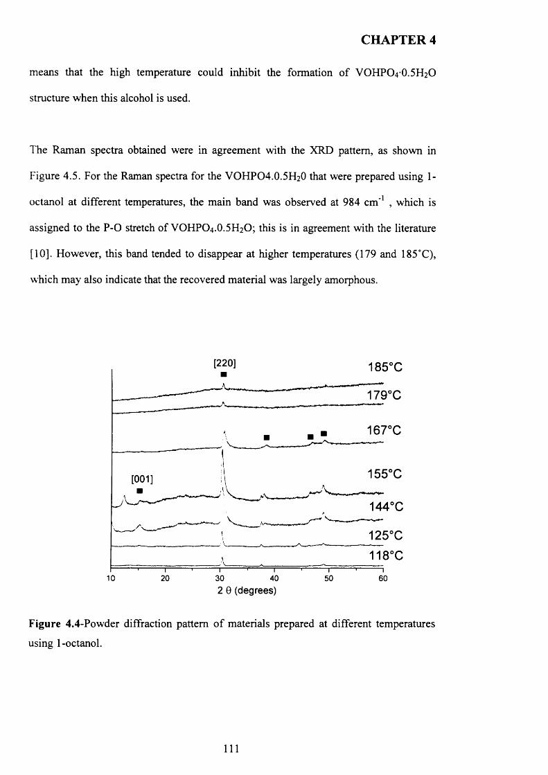
CHAPTER 4
means that the high temperature could inhibit the formation o f VOHPO4 O.5 H2O
structure when this alcohol is used.
The Raman spectra obtained were in agreement with the XRD pattern, as shown in
Figure 4.5. For the Raman spectra for the VOHPO 4 .O.5 H2O that were prepared using 1-
octanol at different temperatures, the main band was observed at 984 cm '1 , which is
assigned to the P -0 stretch of VOHPO4 .O.5 H2O; this is in agreement with the literature
[10]. However, this band tended to disappear at higher temperatures (179 and 185°C),
which may also indicate that the recovered material was largely amorphous.
[220] 185°C
179°C
167°C
155°C[001]
144°C
10 20 30 40 50 602 0 (degrees)
Figure 4.4-Powder diffraction pattern o f materials prepared at different temperatures
using 1-octanol.
I l l
CHAPTER 4
185°C
984
155°C
144°C
125°C
118°C
500 1000Raman shift (cm'1)
Figure 4.5- Laser Raman spectrum of materials prepared at different temperatures using
1-octanol.
4.3.2 . 1 V-P-O seeds with 1-octanol
In this section, an investigation of the addition o f V -P-0 seeds was studied for the
preparation o f catalyst precursors VOHPO4 O.5 H2O using 1-octanol as a solvent. A
summary o f the materials prepared with different V -P-0 seeds is presented in Table 4.4.
Interestingly, the addition o f a small amount o f VOHPO4 O.5 H2O (0.05 g) as a seed to
the reaction mixture before increasing the reflux temperature to 185°C resulted in a high
yield o f VOHPO4 O.5 H2O even at reflux temperatures (Figure 4.6). Even the small
amount o f VOHPO4 O.5 H2O seed (0.0lg added to the reaction mixture served to
produce a crystal to act as a nucleation site. This infers that seeding can increase the rate
o f VOHPO4 O.5 H2O formation.
1 1 2
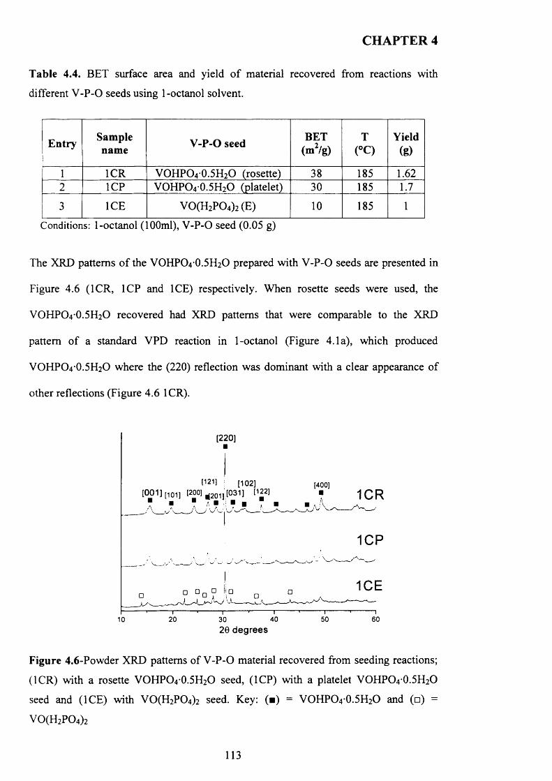
CHAPTER 4
Table 4.4. BET surface area and yield o f material recovered from reactions with
different V -P -0 seeds using 1-octanol solvent.
Entry Samplename V-P-O seed BET
(m2/g)T
(°C)Yield
(g)
1 ICR VOHPO4 0.5H2O (rosette) 38 185 1.622 1CP VOHPO4 0.5H2O (platelet) 30 185 1.7
3 ICE V 0(H 2P 0 4)2(E) 10 185 1
Conditions: 1-octanol ( 100ml), V -P-0 seed (0.05 g)
The XRD patterns o f the VOHPO4 -0 .5 H2 O prepared with V-P-0 seeds are presented in
Figure 4.6 (ICR, 1CP and ICE) respectively. When rosette seeds were used, the
VOHPO4 -0 .5 H2 O recovered had XRD patterns that were comparable to the XRD
pattern o f a standard VPD reaction in 1-octanol (Figure 4.1a), which produced
VOHPO4 O.5 H2O where the (220) reflection was dominant with a clear appearance o f
other reflections (Figure 4.6 ICR).
[220]
[400][001] [101] [200] '.[031] [122]
■ ■ ■ 7 ■ ■ ■ 7■ >■ A . A J ; \__
20 40 50 6010 3020 degrees
Figure 4.6-Powder XRD patterns of V -P -0 material recovered from seeding reactions;
(ICR) with a rosette VOFIPO4 O.5 H2O seed, (1CP) with a platelet VOHPO4 O.5 H2O
seed and (ICE) with VO(EhP0 4 ) 2 seed. Key: (■) = VOHPO4 O.5 H2O and (□) =
V 0(H 2P 0 4)2
113
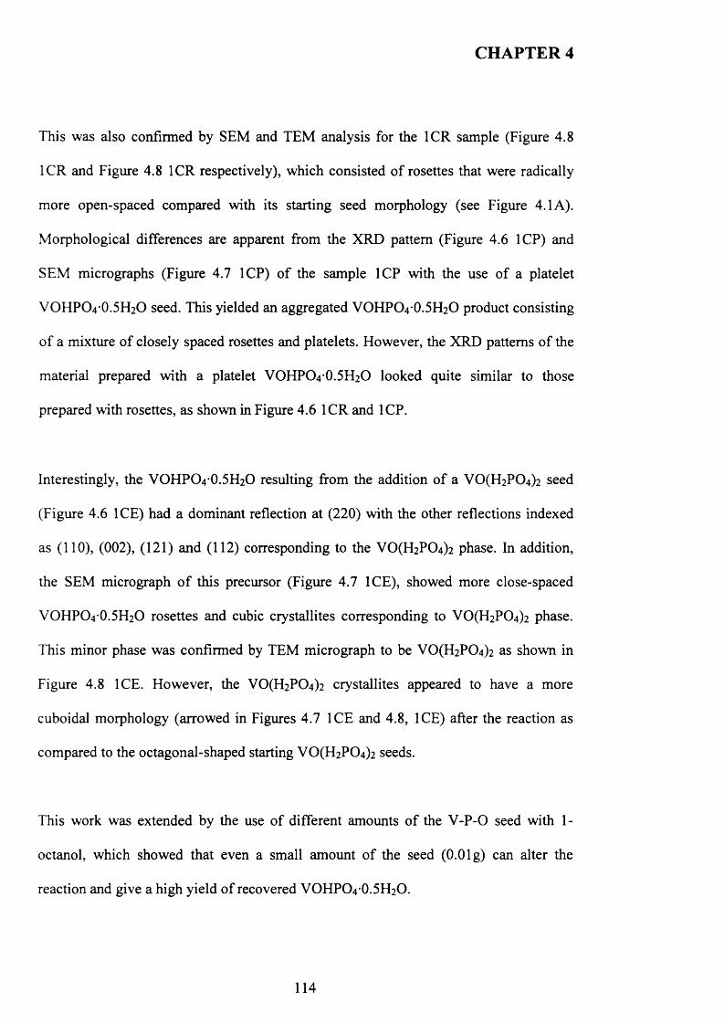
CHAPTER 4
This was also confirmed by SEM and TEM analysis for the ICR sample (Figure 4.8
ICR and Figure 4.8 ICR respectively), which consisted o f rosettes that were radically
more open-spaced compared with its starting seed morphology (see Figure 4.1 A).
M orphological differences are apparent from the XRD pattern (Figure 4.6 1CP) and
SEM micrographs (Figure 4.7 1CP) o f the sample 1CP with the use o f a platelet
VOHPO 4 O.5 H2O seed. This yielded an aggregated VOHPO4 O.5 H2O product consisting
o f a mixture o f closely spaced rosettes and platelets. However, the XRD patterns o f the
material prepared with a platelet VOHPO4 O.5 H2O looked quite similar to those
prepared with rosettes, as shown in Figure 4.6 IC R and 1CP.
Interestingly, the VOHPO 4 O.5 H2O resulting from the addition o f a V 0 (H2P0 4 ) 2 seed
(Figure 4.6 ICE) had a dominant reflection at (220) with the other reflections indexed
as (110), (002), (121) and (112) corresponding to the VO(H2PC>4)2 phase. In addition,
the SEM micrograph o f this precursor (Figure 4.7 ICE), showed more close-spaced
VOHPO4 O.5 H2O rosettes and cubic crystallites corresponding to V 0 (H2P0 4 ) 2 phase.
This minor phase was confirmed by TEM micrograph to be V 0 (H2P0 4 ) 2 as shown in
Figure 4.8 ICE. However, the VO(H2PC>4)2 crystallites appeared to have a more
cuboidal morphology (arrowed in Figures 4.7 IC E and 4.8, ICE) after the reaction as
compared to the octagonal-shaped starting VO(H 2P0 4 ) 2 seeds.
This work was extended by the use o f different amounts o f the V -P-0 seed with 1-
octanol, which showed that even a small amount o f the seed (0.0lg) can alter the
reaction and give a high yield o f recovered VOHPO4 O.5 H2O.
114
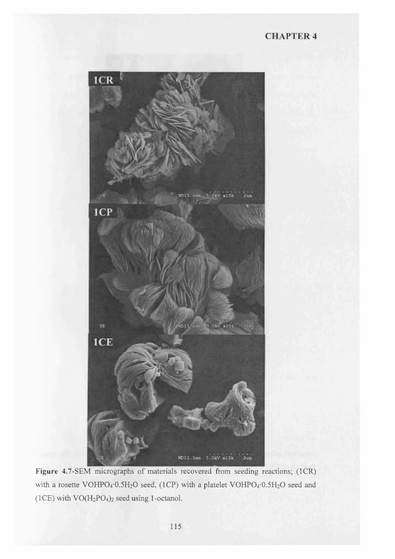
CHAPTER 4
Figure 4.7-SEM micrographs of materials recovered from seeding reactions; (ICR)
with a rosette VOHPO4 O.5 H2O seed, (1CP) with a platelet VOHPO4 O.5 H2O seed and
(ICE) with V0(H 2P 04)2 seed using 1-octanol.
115
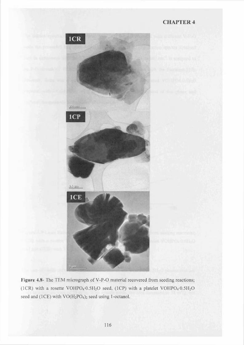
CHAPTER 4
Figure 4.8- The TEM micrograph of V-P-0 material recovered from seeding reactions;
(ICR) with a rosette VOHPO4 0.5H2O seed, (1CP) with a platelet VOHPO4*0.5H2O
seed and (ICE) with V0(H 2P 04)2 seed using 1-octanol.
116
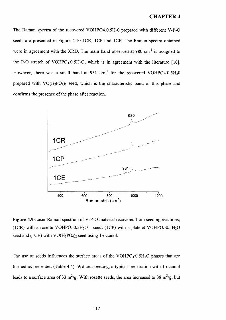
CHAPTER 4
The Raman spectra o f the recovered VOHPO4 .O.5 H2O prepared with different V -P-0
seeds are presented in Figure 4.10 ICR, 1CP and ICE. The Raman spectra obtained
were in agreement with the XRD. The main band observed at 980 cm '1 is assigned to
the P -0 stretch o f VOHPO4 .O.5 H2O, which is in agreement with the literature [10].
However, there was a small band at 931 cm '1 for the recovered VOHPO4 .O.5 H2O
prepared with V 0 (H2P0 4 ) 2 seed, which is the characteristic band of this phase and
confirms the presence o f the phase after reaction.
980
1CP931
400 600 800 1000 1200Raman shift (cm'1)
Figure 4.9-Laser Raman spectrum of V -P -0 material recovered from seeding reactions;
(ICR) with a rosette VOHPO4 0.5H2O seed, (1CP) with a platelet VOHPO4 0.5H2O
seed and (IC E ) with V 0 (H2P0 4 ) 2 seed using 1-octanol.
The use o f seeds influences the surface areas o f the VOHPO4* 0 .5 ^ 0 phases that are
formed as presented (Table 4.4). W ithout seeding, a typical preparation with 1-octanol
9 9leads to a surface area o f 33 m /g. W ith rosette seeds, the area increased to 38 m /g, but
117
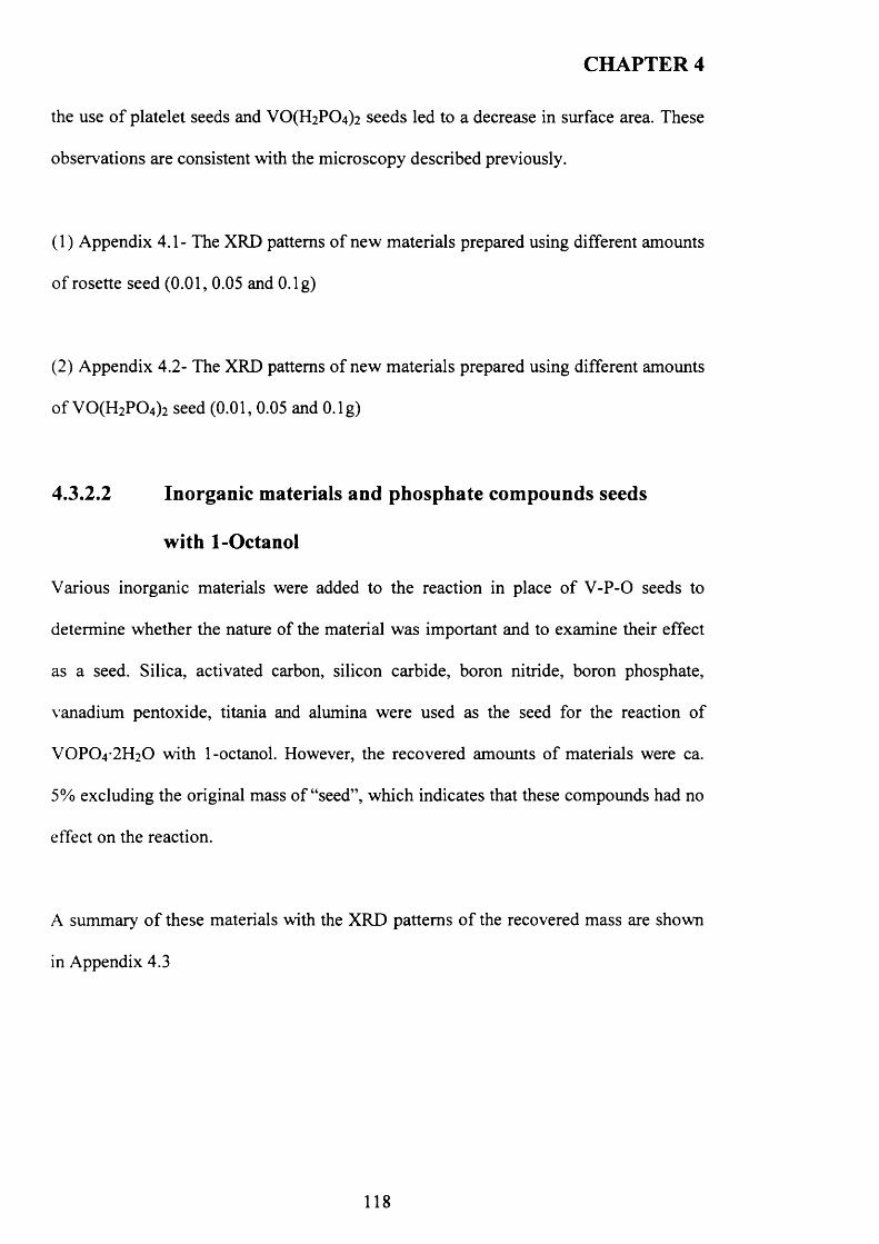
CHAPTER 4
the use o f platelet seeds and V 0 (H2P0 4 ) 2 seeds led to a decrease in surface area. These
observations are consistent with the microscopy described previously.
(1) Appendix 4.1- The XRD patterns o f new materials prepared using different amounts
o f rosette seed (0.01, 0.05 and O.lg)
(2) Appendix 4.2- The XRD patterns o f new materials prepared using different amounts
o f VO(H2P 0 4)2 seed (0.01, 0.05 and O.lg)
4.3.2.2 Inorganic materials and phosphate compounds seeds
with 1-Octanol
Various inorganic materials were added to the reaction in place o f V -P-0 seeds to
determine whether the nature of the material was important and to examine their effect
as a seed. Silica, activated carbon, silicon carbide, boron nitride, boron phosphate,
vanadium pentoxide, titania and alumina were used as the seed for the reaction o f
V 0 P (V 2 H 20 with 1-octanol. However, the recovered amounts o f materials were ca.
5% excluding the original mass o f “seed”, which indicates that these compounds had no
effect on the reaction.
A summary o f these materials with the XRD patterns o f the recovered mass are shown
in Appendix 4.3
118
CHAPTER 4
4.3.3 Influence of different alcohols on morphology
The use o f the V -P-0 seeds in the VPD type preparation using other alcohols, i.e., 2-
methy-1 -propanol, 2-butanol and 3-octanol, was also studied. These particular solvents
were selected based on the morphology o f the resulting V -P-0 material during a
standard VPD preparation.
4.3.3.1 2-methy-l-propanol
In this section, an investigation o f different VOHPO4 O.5 H2O seeds (platelet and
rosette) was studied for the preparation o f catalyst precursors VOHPO4 O.5 H2O using 2-
m ethy-1-propanol as a solvent. A summary o f the materials prepared with different
VOHPO4 O.5 H2O seeds (platelet and rosette) is presented in Table 4.5.
T able 4.5. BET surface area and yield o f material recovered from reactions with platelet
and rosette VOHPO4 O.5 H2O seeds using 2-methy-l-propanol solvent.
E n try Sam plenam e V-P-O seed BET
(m 2/g)T
(°C) Yield (g)
1 IBR VOHPO4 0.5H2O (rosette) 17 Reflux 1.67
2 IBP VOHPO4 0.5H2O (platelet) 14 Reflux 1.61
Conditions: 2-methy-l-propanol (50ml) + V -P -0 seed (0.05 g)
The XRD patterns o f the recovered VOHPO4 O.5 H2O prepared with rosette and platelet
seeds are shown in Figure 4.10 IBR and IBP respectively. Both materials have similar
patterns with (220) reflection as the dominant reflection with a clear appearance o f other
reflections o f VOHPO4 O.5 H2O. However, the intensities o f the reflections and the (001)
/ (220) ratio are higher for the materials prepared with platelet seeds than with rosette
119
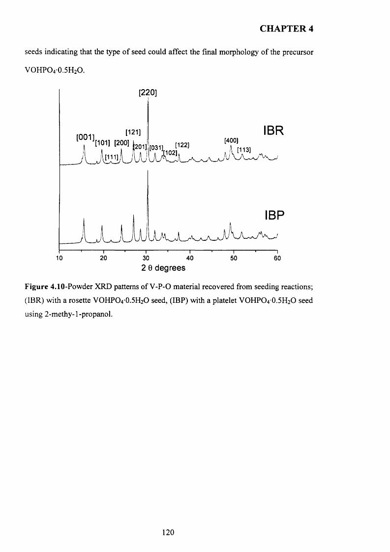
CHAPTER 4
seeds indicating that the type o f seed could affect the final morphology o f the precursor
VOHPO4-0.5H2O.
[220]
IBR[121] I [1°H [200] L 0J
i t”4 A A j[001] [400]
IBP
2010 30 40 50 602 0 degrees
F igure 4.10-Powder XRD patterns of V -P-0 material recovered from seeding reactions;
(IBR) with a rosette VOHPO4 O.5 H2O seed, (IBP) with a platelet VOHPO4 O.5 H2O seed
using 2-methy-l-propanol.
120
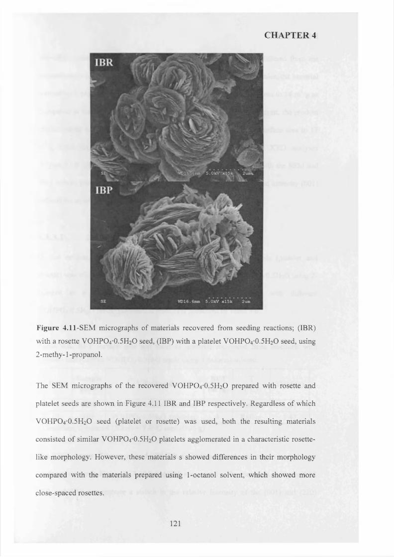
CHAPTER 4
Figure 4.11-SEM micrographs of materials recovered from seeding reactions; (IBR)
with a rosette VOHPO4 O.5 H2O seed, (IBP) with a platelet VOHPO4 O.5 H2O seed, using
2-methy-1 -propanol.
The SEM micrographs o f the recovered VOHPO4 O.5 H2O prepared with rosette and
platelet seeds are shown in Figure 4.11 IBR and IBP respectively. Regardless o f which
VOHPO4 O.5 H2O seed (platelet or rosette) was used, both the resulting materials
consisted of similar VOHPO4 O.5 H2O platelets agglomerated in a characteristic rosette
like morphology. However, these materials s showed differences in their morphology
compared with the materials prepared using 1-octanol solvent, which showed more
close-spaced rosettes.
121
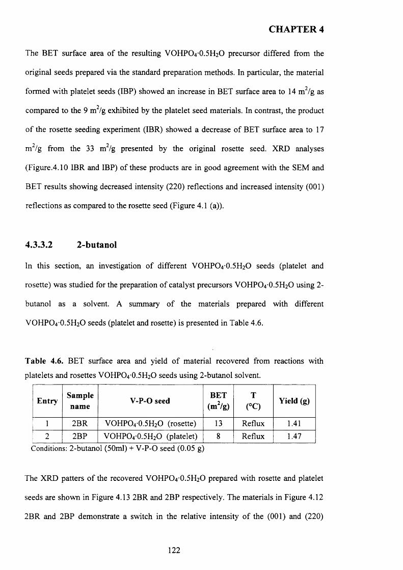
CHAPTER 4
The BET surface area o f the resulting VOHPO4 O.5 H2O precursor differed from the
original seeds prepared via the standard preparation methods. In particular, the material
formed with platelet seeds (IBP) showed an increase in BET surface area to 14 m2/g as
compared to the 9 m2/g exhibited by the platelet seed materials. In contrast, the product
o f the rosette seeding experiment (IBR) showed a decrease o f BET surface area to 17
m 2/g from the 33 m2/g presented by the original rosette seed. XRD analyses
(Figure.4.10 IBR and IBP) o f these products are in good agreement with the SEM and
BET results showing decreased intensity (220) reflections and increased intensity (001)
reflections as compared to the rosette seed (Figure 4.1 (a)).
4.3.3.2 2-butanol
In this section, an investigation o f different VOHPO4 O.5 H2O seeds (platelet and
rosette) was studied for the preparation o f catalyst precursors VOHPO4 O.5 H2O using 2-
butanol as a solvent. A summary o f the materials prepared with different
VOHPO4 O.5 H2O seeds (platelet and rosette) is presented in Table 4.6.
T able 4.6. BET surface area and yield o f material recovered from reactions with
platelets and rosettes VOHPO4 O.5 H2O seeds using 2-butanol solvent.
E n trySam plenam e
V-P-O seedBET
(m 2/g)
T(°C)
Yield (g)
1 2BR VOHPO4 O.5 H2O (rosette) 13 Reflux 1.41
2 2BP VOHPO4 0.5H2O (platelet) 8 Reflux 1.47Conditions: 2-butanol (50ml) + V -P-0 seed (0.05 g)
The XRD patters o f the recovered VOHPO4 O.5 H2O prepared with rosette and platelet
seeds are shown in Figure 4.13 2BR and 2BP respectively. The materials in Figure 4.12
2BR and 2BP demonstrate a switch in the relative intensity o f the (001) and (220)
122
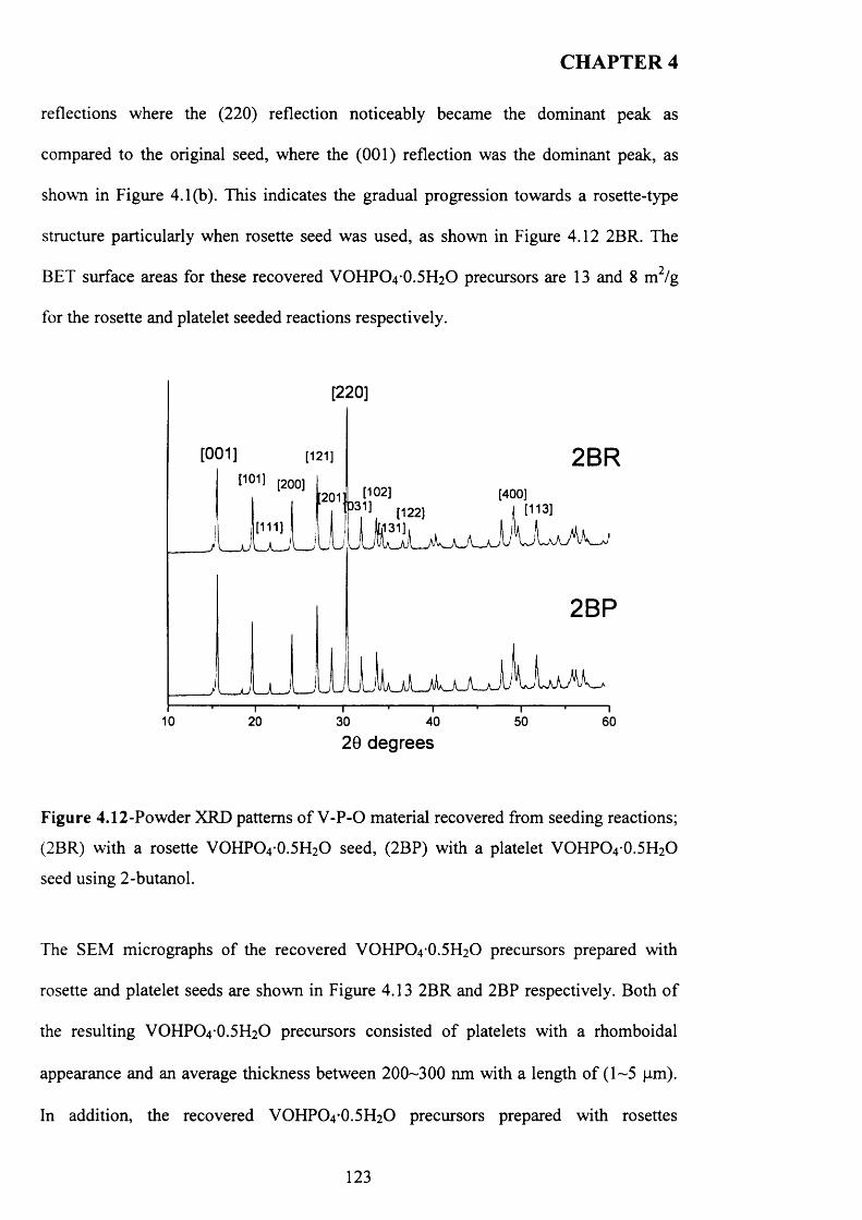
CHAPTER 4
reflections where the (220) reflection noticeably became the dominant peak as
compared to the original seed, where the (001) reflection was the dominant peak, as
shown in Figure 4.1(b). This indicates the gradual progression towards a rosette-type
structure particularly when rosette seed was used, as shown in Figure 4.12 2BR. The
BET surface areas for these recovered VOHPO4 O.5 H2O precursors are 13 and 8 m / g
for the rosette and platelet seeded reactions respectively.
[220]
[001] [121]I1011 [200] [102] [400]201
[113][122][111]
J \ __ U
10 20 30 40 50 6020 degrees
Figure 4.12-Powder XRD patterns o f V-P-O material recovered from seeding reactions;
(2BR) with a rosette VOHPO4 O.5 FI2O seed, (2BP) with a platelet VOHPO4 O.5 H2O
seed using 2-butanol.
The SEM micrographs of the recovered VOHPO4 O.5 H2O precursors prepared with
rosette and platelet seeds are shown in Figure 4.13 2BR and 2BP respectively. Both o f
the resulting VOHPO4 O.5 H2O precursors consisted o f platelets with a rhomboidal
appearance and an average thickness between 200-300 nm with a length o f (1-5 pm).
In addition, the recovered VOHPO4 O.5 H2O precursors prepared with rosettes
123
CHAPTER 4
demonstrated rhomboidal platelets and rosette-like aggregation (30-40 vol %), as
shown in Figure 4.13 (a, b), which may suggest that the nature of the seed can affect the
formation o f the VOHPO4 O.5 H2O precursor.
Figure 4.13-SEM micrographs of materials recovered from seeding reactions; (2BR (a
and b) with a rosette VOHPO4 O.5 H2O seed, (2BP) with a platelet VOHPO4 O.5 H2O
seed using 2-butanol.
4.3.3.3 3-octanol
In this section, an investigation o f different VOHPO4 O.5 H2O (platelets and rosettes)
was studied for the preparation of catalyst precursors VOFIPO4 O.5 FI2O using 3-octanol
124
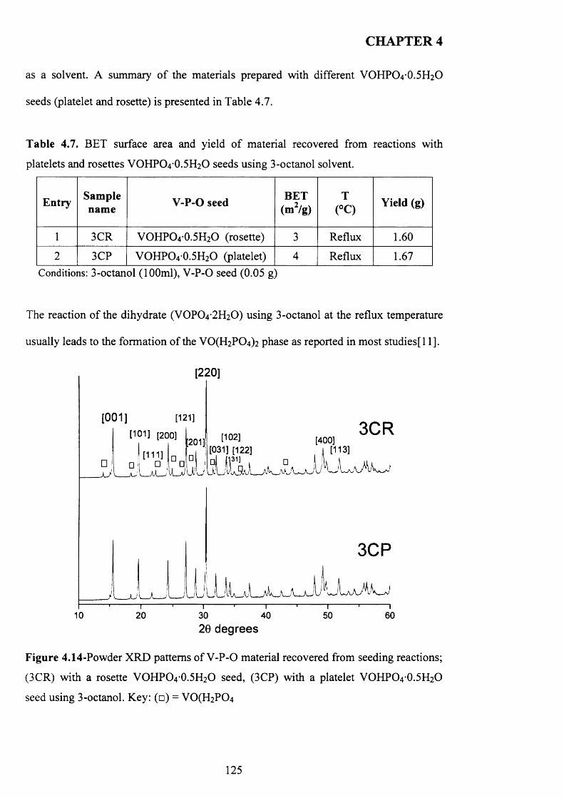
CHAPTER 4
as a solvent. A summary o f the materials prepared with different VOHPO4 O.5 H2O
seeds (platelet and rosette) is presented in Table 4.7.
Table 4.7. BET surface area and yield o f material recovered from reactions with
platelets and rosettes VOHPO4 O.5 H2O seeds using 3-octanol solvent.
Entry Sam plenam e V-P-O seed BET
(m 2/g)T
(°C) Yield (g)
1 3CR VOHPO4 0.5H2O (rosette) 3 Reflux 1.60
2 3CP VOHPO4 0.5H2O (platelet) 4 Reflux 1.67Conditions: 3-octanol (100ml), V -P-0 seed (0.05 g)
The reaction of the dihydrate (VOPO4 2 H2O) using 3-octanol at the reflux temperature
usually leads to the formation o f the V0 (H2P0 4 ) 2 phase as reported in most studies [11].
[220]
10
[0 0 1 ] [121]
[101] [200] [102][031] [122] I [113]
[400] [113]
3CR
3CP
LXaaAI
20 30 4020 degrees
i50
I60
Figure 4.14-Powder XRD patterns of V -P-0 material recovered from seeding reactions;
(3CR) with a rosette VOHPO4 O.5 H2O seed, (3CP) with a platelet VOHPO4 O.5 H2O
seed using 3-octanol. Key: (□) = V 0 (H2P0 4
125
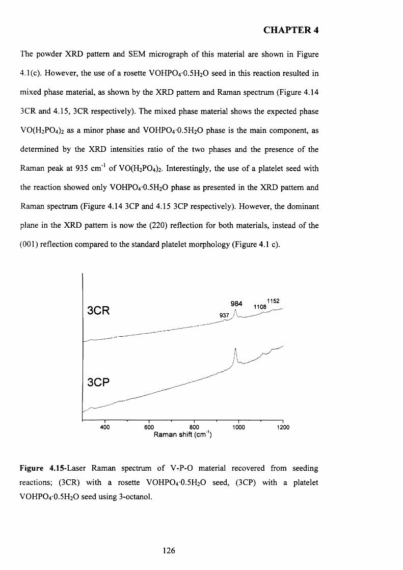
CHAPTER 4
The powder XRD pattern and SEM micrograph o f this material are shown in Figure
4.1(c). However, the use o f a rosette VOHPO4 O.5 H2O seed in this reaction resulted in
mixed phase material, as shown by the XRD pattern and Raman spectrum (Figure 4.14
3CR and 4.15, 3CR respectively). The mixed phase material shows the expected phase
V 0(H 2P 0 4)2 as a minor phase and VOHPO4 O.5 H2O phase is the main component, as
determined by the XRD intensities ratio o f the two phases and the presence o f the
Raman peak at 935 cm '1 o f VO(H2PC>4)2- Interestingly, the use o f a platelet seed with
the reaction showed only VOHPO4 O.5 H2O phase as presented in the XRD pattern and
Raman spectrum (Figure 4.14 3CP and 4.15 3CP respectively). However, the dominant
plane in the XRD pattern is now the (220) reflection for both materials, instead o f the
(001) reflection compared to the standard platelet morphology (Figure 4.1 c).
1152984 11083CR 937
3CP
400 600I 800R a m a n sh ift (cm '1)
1 0 0 0 1 2 0 0
Figure 4.15-Laser Raman spectrum o f V -P -0 material recovered from seeding
reactions; (3CR) with a rosette VOHPO4 O.5 H2O seed, (3CP) with a platelet
VOHPO4 O.5 H2O seed using 3-octanol.
126
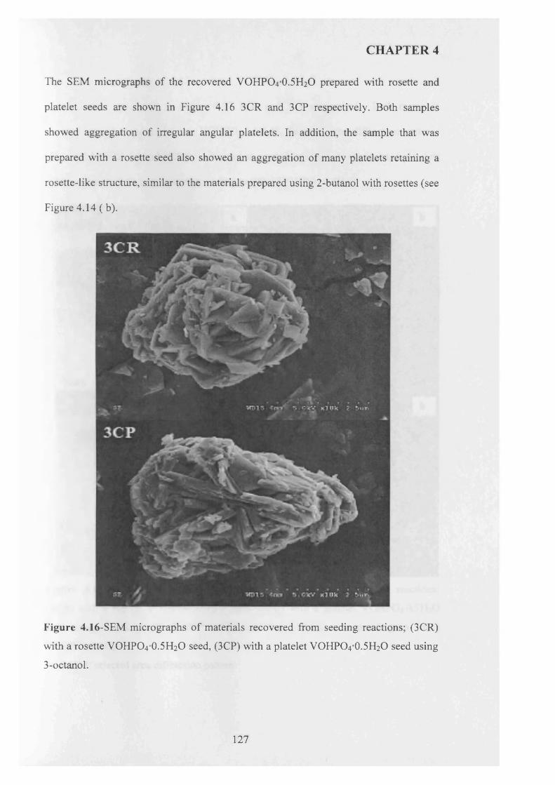
CHAPTER 4
The SEM micrographs of the recovered VOHPO4 O.5 H2O prepared with rosette and
platelet seeds are shown in Figure 4.16 3CR and 3CP respectively. Both samples
showed aggregation of irregular angular platelets. In addition, the sample that was
prepared with a rosette seed also showed an aggregation of many platelets retaining a
rosette-like structure, similar to the materials prepared using 2-butanol with rosettes (see
Figure 4.14 ( b).
Figure 4.16-SEM micrographs of materials recovered from seeding reactions; (3CR)
with a rosette VOHPO4*0.5H2O seed, (3CP) with a platelet VOFIPO4 O.5 H2O seed using
3-octanol.
127
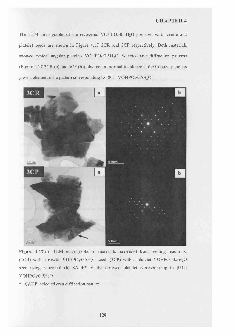
CHAPTER 4
The TEM micrographs of the recovered VOHPO4 O.5 H2O prepared with rosette and
platelet seeds are shown in Figure 4.17 3CR and 3CP respectively. Both materials
showed typical angular platelets VOHPO4 O.5 H2O. Selected area diffraction patterns
(Figure 4.17 3CR (b) and 3CP (b)) obtained at normal incidence to the isolated platelets
gave a characteristic pattern corresponding to [001] VOHPO4 O.5 H2O.
5 Unm
5 1inm
Figure 4.17-(a) TEM micrographs of materials recovered from seeding reactions;
(3CR) with a rosette VOHPO4 0.5H2O seed, (3CP) with a platelet VOHPO4 0.5H2O
seed using 3-octanol (b) SADP* of the arrowed platelet corresponding to [001]
VOHPO4 0.5H2O
*: SADP: selected area diffraction pattern
128
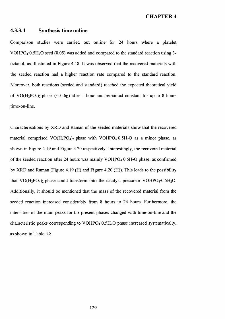
CHAPTER 4
4.3.3.4 Synthesis time online
Comparison studies were carried out online for 24 hours where a platelet
VOHPO4*0.5H2O seed (0.05) was added and compared to the standard reaction using 3-
octanol, as illustrated in Figure 4.18. It was observed that the recovered materials with
the seeded reaction had a higher reaction rate compared to the standard reaction.
Moreover, both reactions (seeded and standard) reached the expected theoretical yield
o f V 0(H 2P 0 4)2 phase (~ 0.6g) after 1 hour and remained constant for up to 8 hours
time-on-line.
Characterisations by XRD and Raman of the seeded materials show that the recovered
material comprised V 0 (H2P0 4 ) 2 phase with VOHPO4 O.5 H2O as a minor phase, as
shown in Figure 4.19 and Figure 4.20 respectively. Interestingly, the recovered material
of the seeded reaction after 24 hours was mainly VOFIPO4 O.5 H2O phase, as confirmed
by XRD and Raman (Figure 4.19 (H) and Figure 4.20 (FI)). This leads to the possibility
that V 0(H 2P 0 4)2 phase could transform into the catalyst precursor VOHPO4 O.5 H2O.
Additionally, it should be mentioned that the mass o f the recovered material from the
seeded reaction increased considerably from 8 hours to 24 hours. Furthermore, the
intensities o f the main peaks for the present phases changed with time-on-line and the
characteristic peaks corresponding to VOHPO4 O.5 H2O phase increased systematically,
as shown in Table 4.8.
129
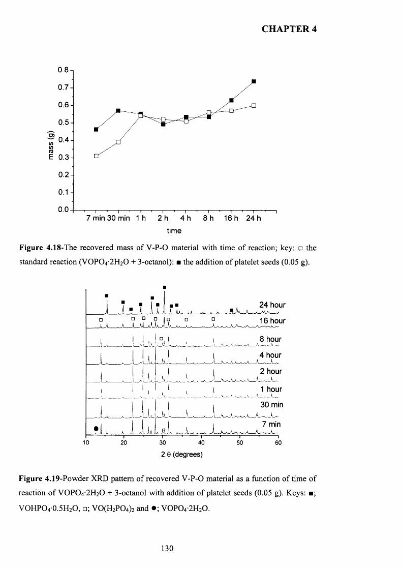
CHAPTER 4
0.8-,
0 .7 -
0 .6 -
0 .5 -
? 0 .4 -COCOE 0 .3 -
0 .2 -
0.07 min 30 min 1h 2 h 4 h 8 h 1 6 h 2 4 h
time
Figure 4.18-The recovered mass of V -P-0 material with time o f reaction; key: □ the
standard reaction (VOPO4 2 H2O + 3-octanol): ■ the addition o f platelet seeds (0.05 g).
24 hour
□ □ □ i □A_JL_a1_xGa_A_Aa
16 hour
8 hour
4 hour
2 hour
1 hour
30 min
7 min
10 20 30 40 50 60
2 0 (degrees)
Figure 4.19-Powder XRD pattern o f recovered V -P-0 material as a function o f time o f
reaction o f VOPO4 2 H2O + 3-octanol with addition o f platelet seeds (0.05 g). Keys: ■;
VOHPO4 0.5H2O, □; V 0(H 2P 0 4) 2 and • ; V 0 P 0 4 -2H20 .
130
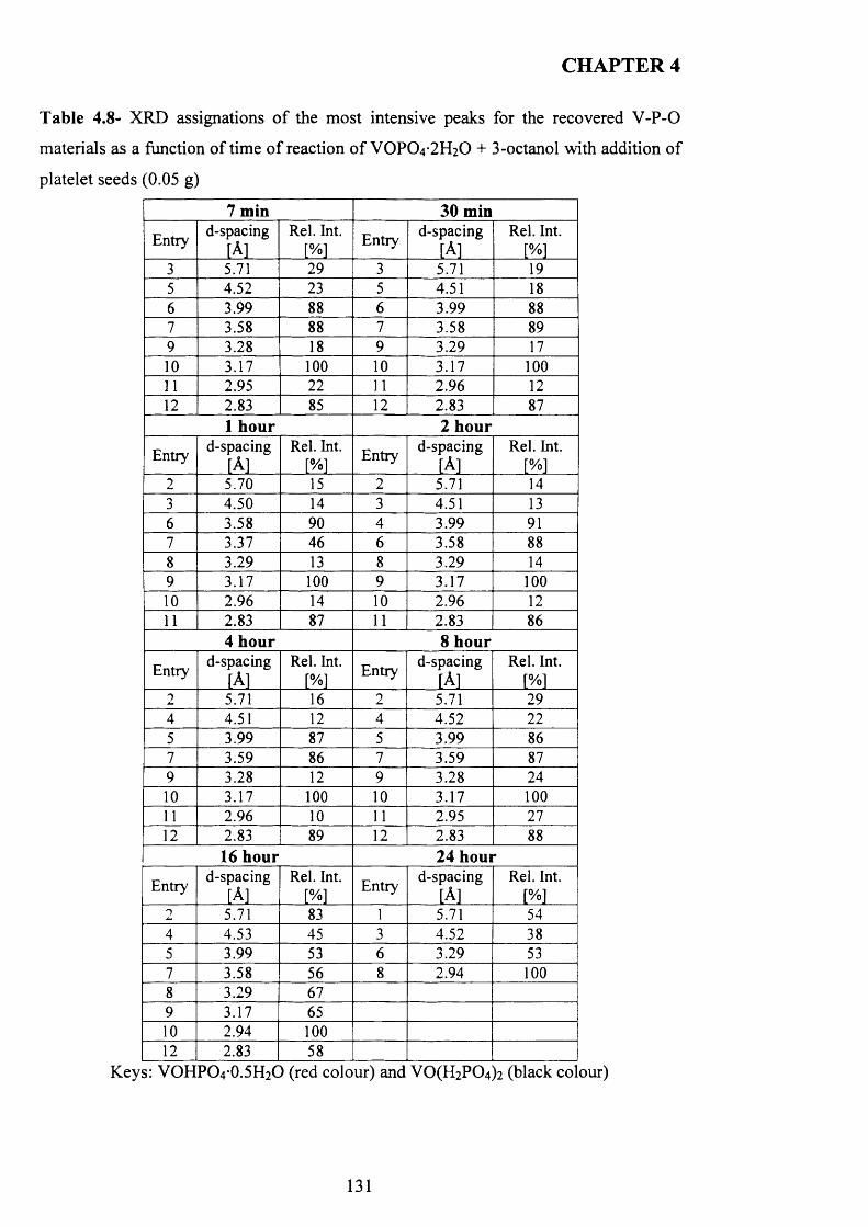
CHAPTER 4
Table 4.8- XRD assignations o f the most intensive peaks for the recovered V -P-0
materials as a function o f time o f reaction o f V 0 P 0 4-2H20 + 3-octanol with addition o f
platelet seeds (0.05 g)
7 min 30 minEntry
d-spacing[A]
Rel. Int.[%] Entry d-spacing
[A]Rel. Int.
[%]3 5.71 29 3 5.71 195 4.52 23 5 4.51 186 3.99 88 6 3.99 887 3.58 88 7 3.58 899 3.28 18 9 3.29 1710 3.17 100 10 3.17 10011 2.95 22 11 2.96 1212 2.83 85 12 2.83 87
1 hour 2 hourEntry d-spacing
[A]Rel. Int.
[%]Entry d-spacing
[A]Rel. Int.
[%]2 5.70 15 2 5.71 143 4.50 14 3 4.51 136 3.58 90 4 3.99 917 3.37 46 6 3.58 888 3.29 13 8 3.29 149 3.17 100 9 3.17 10010 2.96 14 10 2.96 1211 2.83 87 11 2.83 86
4 hour 8 hourEntry
d-spacing[A]
Rel. Int.
[%]Entry
d-spacing[A]
Rel. Int. [%]
2 5.71 16 2 5.71 294 4.51 12 4 4.52 225 3.99 87 5 3.99 867 3.59 86 7 3.59 879 3.28 12 9 3.28 2410 3.17 100 10 3.17 10011 2.96 10 11 2.95 2712 2.83 89 12 2.83 88
16 hour 24 hourEntry
d-spacing[A]
Rel. Int.[%] Entry
d-spacing[A]
Rel. Int.
[%]2 5.71 83 1 5.71 544 4.53 45 3 4.52 385 3.99 53 6 3.29 537 3.58 56 8 2.94 1008 3.29 679 3.17 6510 2.94 10012 2.83 58
Keys: VOHPO4 0.5H2O (red colour) and V 0(H 2P 0 4)2 (black colour)
131
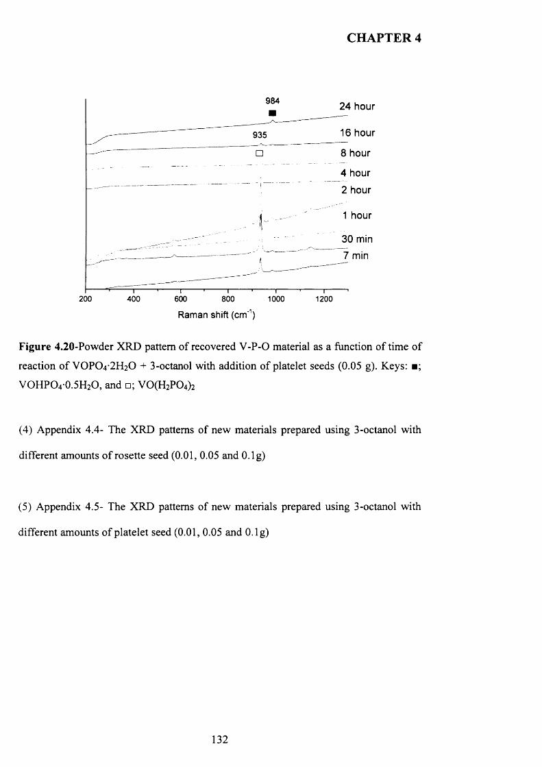
CHAPTER 4
984 24 hour
16 hour935
8 hour
4 hour
2 hour
1 hour
30 min
7 min
200 400 600 800 1000 1200
Raman shift (crrf1)
Figure 4.20-Powder XRD pattern of recovered V -P-0 material as a function o f time o f
reaction o f VOPO4 2 H2O + 3-octanol with addition o f platelet seeds (0.05 g). Keys: ■;
VOHPO4 0.5H2O, and □; V 0(H 2P 0 4) 2
(4) Appendix 4.4- The XRD patterns o f new materials prepared using 3-octanol with
different amounts o f rosette seed (0.01, 0.05 and O.lg)
(5) Appendix 4.5- The XRD patterns o f new materials prepared using 3-octanol with
different amounts o f platelet seed (0.01, 0.05 and O.lg)
132
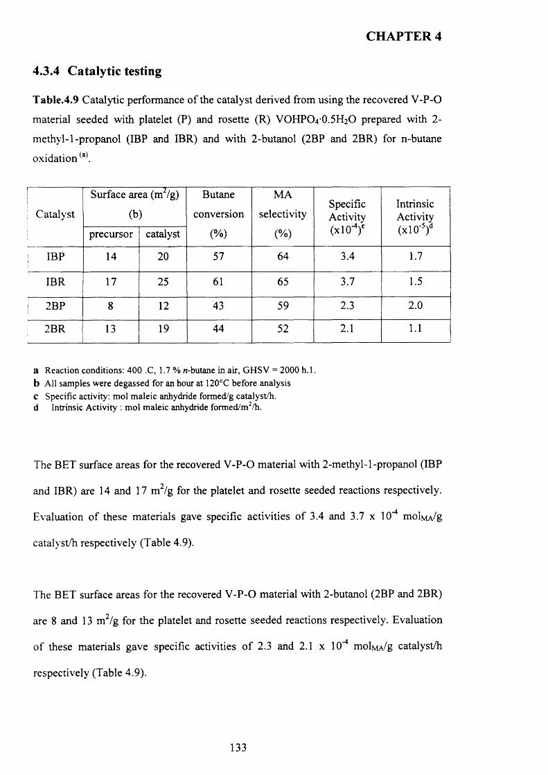
CHAPTER 4
4.3.4 Catalytic testing
Table.4.9 Catalytic performance o f the catalyst derived from using the recovered V-P-O
material seeded with platelet (P) and rosette (R) VOHPO4 O.5 H2O prepared with 2-
m ethyl-1-propanol (IBP and IBR) and with 2-butanol (2BP and 2BR) for n-butane
oxidation(a).
Catalyst
Surface area (m2/g)
(b)
Butane
conversion
(%)
MA
selectivity
(%)
SpecificActivity(xlO*4)0
IntrinsicActivity(x l0 '5)dprecursor catalyst
IBP 14 20 57 64 3.4 1.7
IBR 17 25 61 65 3.7 1.5
j 2BP 8 12 43 59 2.3 2.0
2BR 13 19 44 52 2.1 1.1
a Reaction conditions: 400 .C, 1.7 % w-butane in air, GHSV = 2000 h .l. b All samples were degassed for an hour at 120°C before analysis C Specific activity: mol maleic anhydride formed/g catalyst/h. d Intrinsic Activity : mol maleic anhydride formed/m2/h.
The BET surface areas for the recovered V-P-O material with 2-methyl-1-propanol (IBP
and IBR) are 14 and 17 m 2/g for the platelet and rosette seeded reactions respectively.
Evaluation o f these materials gave specific activities o f 3.4 and 3.7 x 10⁻⁴ m o W /g
catalyst/h respectively (Table 4.9).
The BET surface areas for the recovered V-P-O material with 2-butanol (2BP and 2BR)
are 8 and 13 m2/g for the platelet and rosette seeded reactions respectively. Evaluation
o f these materials gave specific activities o f 2.3 and 2.1 x 10"4 molMA/g catalyst/h
respectively (Table 4.9).
133
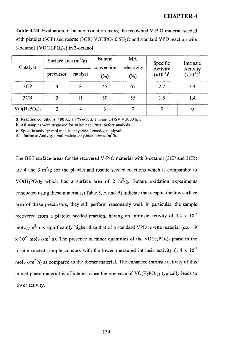
CHAPTER 4
T able 4.10. Evaluation of butane oxidation using the recovered V -P-0 material seeded
with platelet (3CP) and rosette (3CR) VOHPO4 0.5H2O and standard VPD reaction with
3-octanol {VO(H2P 0 4)2} in 3-octanol
I1j
Catalyst!
Surface are
precursor
a (m2/g)
catalyst
Butane
conversion
(%)
MA
selectivity
(%)
SpecificActivity(xlO-4/
IntrinsicActivity(x l0 ’5)d
3CP 4 8 45 65 2.7 3.4
j 3CR 3 11 30 55 1.5 1.4
; v o (h 2p o 4)2 2 4 3 0 0 0
a Reaction conditions: 400 .C, 1.7 % w-butane in air, GHSV = 2000 h .l. b All samples were degassed for an hour at 120°C before analysis c Specific activity: mol maleic anhydride formed/g catalyst/h. d Intrinsic Activity : mol maleic anhydride formed/m2/h.
The BET surface areas for the recovered V -P -0 material with 3-octanol (3CP and 3CR)
are 4 and 3 m2/g for the platelet and rosette seeded reactions which is comparable to
VO(H2P 0 4)2 which has a surface area o f 2 m /g. Butane oxidation experiments
conducted using these materials, (Table 5, A and B) indicate that despite the low surface
area o f these precursors, they still perform reasonably well. In particular, the sample
recovered from a platelet seeded reaction, having an intrinsic activity o f 3.4 x 10‘5
molMA/m2-h is significantly higher than that o f a standard VPD rosette material (ca. 1.9
x 10'5 mol\iA/m2-h). The presence of minor quantities o f the V 0(H 2P 0 4)2 phase in the
rosette seeded sample concurs with the lower measured intrinsic activity (1.4 x 10'5
molMA/m2 h) as compared to the former material. The enhanced intrinsic activity o f this
mixed phase material is o f interest since the presence o f V 0(H 2P 0 4)2 typically leads to
lower activity.
134
CHAPTER 4
4.4 Discussion
4.4.1 1-octanol
The XRD patterns of VOHPO4 .0 .5 H2 0 precursors prepared using the primary alcohols
(1-octanol in this study) are identical (Figure 4.1) with the [220] reflection; this was
virtually the only feature o f the diffraction pattern, which is characteristic o f
VOHPO 4 .0 .5 H2 0 with a rosette morphology. The SEM micrographs (Figure 4.1a) o f
these precursors showed a rosette-like morphology, which is in agreement with previous
studies using primary alcohols.
It was observed that heating vanadium phosphate dihydrate VOPO4 2 H2O in 1-octanol
led to the formation o f VOHPO4 O.5 H2O in a high yield (as illustrated in Table 4.3).
However, when the reaction was carried out at a temperature o f > 160°C, the recovered
mass o f the expected VOHPO4 O.5 H2O decreased giving a small amount, which
indicates the effect o f temperature on the formation o f VOHPO4 O.5 H2O despite the
boiling point o f 1-octanol being 185°C. Usually, such reactions are conducted under
reflux conditions although a small amount o f VOHPO 4 O.5 H2O formed under the reflux
condition o f 1 -octanol, which was confirmed by the XRD patterns and Raman spectra
(Figure 4.3 and Figure 4.4).
Moreover, the UV/VIS analysis o f the recovered blue/black solution showed that the
solute phase contained V4+ ions, which also contained minor amounts o f the
VOHPO4 O.5 H2O phase. This means that refluxing VOPO4 2 H2O with 1-octanol can
give VOHPO4 O.5 H 2O with a low yield (< 10%) compared with when the reaction is
carried out at a low temperature (< 160°C), which usually gives a (>90%) yield o f
VOHPO4 0.5H2O.
135
CHAPTER 4
Interestingly, the addition o f a small amount o f VOHPO4 O.5 H2O (0.05 g) as a seed to
the reaction mixture before increasing the reflux temperature to 185°C resulted in a high
yield o f VOHPO 4 O.5 H2O even at reflux temperatures (Figure 4.6). This seed served to
produce a crystal that could be acted upon as a nucleation site, therefore, lowering the
energy o f VOHPO 4 O.5 H2O formation.
For this reason, a comparison study was conducted where the yield o f hemi-hydrate
product was m onitored as a function of time-on-line for reactions using 1 -octanol with
and without a ‘V O H PO 4 O.5 FI2O seed’. This is presented in Figure 4.21, which shows
that the VOHPO4 O.5 H 2O material recovered an almost complete yield after 24h
refluxing at 185°C w ith the seed. The presence o f the VOHPO4 O.5 FI2O seed (having a
rosette morphology) resulted in rapid VOFIPO4 O.5 FI2O formation. This method, as a
result, overcomes the formation of the blue/black V4+ solute, which was observed at
reflux condition. It was also observed that the VOHPO4 O.5 H2O material recovered an
almost complete yield after 24h refluxing at 185°C with the seed. This indicates that the
nucleation process occurs at ca. 8 minutes from the beginning o f heating the reaction
from room temperature.
This finding is highly important for two reasons. Firstly, this is the first report o f the use
o f a seed to direct the formation of V -P-0 materials. Secondly, the use o f the seed can
lead to dramatic morphological changes in the resulting material compared to the
material prepared without the seed as illustrated in this report.
136
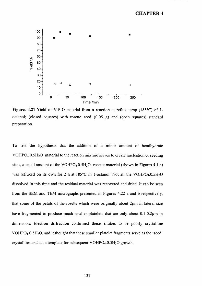
CHAPTER 4
100-
90-
80-
70-
60-0^T3 50-a>>- 40-
30-
20-
10-
0 -0 50 100 150 200 250
Time /min
Figure. 4.21-Yield o f V -P-0 material from a reaction at reflux temp (185°C) o f 1-
octanol; (closed squares) with rosette seed (0.05 g) and (open squares) standard
preparation.
To test the hypothesis that the addition o f a minor amount o f hemihydrate
VOHPO 4 .O.5 H2O material to the reaction mixture serves to create nucleation or seeding
sites, a small amount o f the VOHPO4.O.5 H2O rosette material (shown in Figures 4.1 a)
was refluxed on its own for 2 h at 185°C in 1-octanol. Not all the VOHPO4.O.5 H2O
dissolved in this time and the residual material was recovered and dried. It can be seen
from the SEM and TEM micrographs presented in Figures 4.22 a and b respectively,
that some o f the petals o f the rosette which were originally about 2pm in lateral size
have fragmented to produce much smaller platelets that are only about 0.1-0.2pm in
dimension. Electron diffraction confirmed these entities to be poorly crystalline
VOHPO4 .O.5 H2O, and it thought that these sm aller platelet fragments serve as the ‘seed’
crystallites and act a template for subsequent VOHPO 4 .O.5 H2O growth.
137
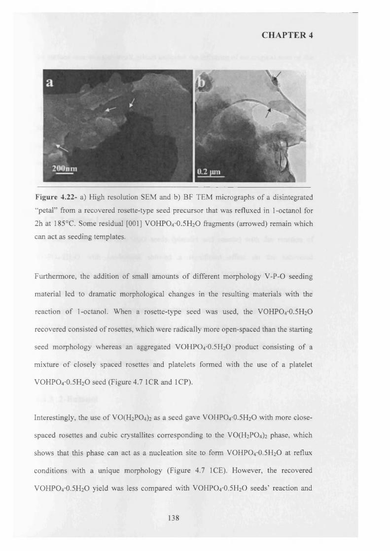
CHAPTER 4
Figure 4.22- a) High resolution SEM and b) BF TEM micrographs o f a disintegrated
“petal” from a recovered rosette-type seed precursor that was refluxed in 1 -octanol for
2h at 185°C. Some residual [001] VOHPO4 O.5 H2O fragments (arrowed) remain which
can act as seeding templates.
Furthermore, the addition of small amounts o f different morphology V-P-0 seeding
material led to dramatic morphological changes in the resulting materials with the
reaction o f 1-octanol. When a rosette-type seed was used, the VOHPO4 O.5 H2O
recovered consisted of rosettes, which were radically more open-spaced than the starting
seed morphology whereas an aggregated VOHPO4 O.5 H2O product consisting o f a
mixture o f closely spaced rosettes and platelets formed with the use of a platelet
VOHPO4 0.5H2O seed (Figure 4.7 ICR and 1CP).
Interestingly, the use o f V0 (H2P0 4 ) 2 as a seed gave VOHPO4 O.5 H2O with more close
spaced rosettes and cubic crystallites corresponding to the V0 (H2P0 4 ) 2 phase, which
shows that this phase can act as a nucleation site to form VOHPO4 O.5 H2O at reflux
conditions with a unique morphology (Figure 4.7 ICE). However, the recovered
VOHPO4 O.5 H2O yield was less compared with VOHPO4 O.5 H2O seeds’ reaction and
138
CHAPTER 4
the surface area was also small, which indicates the influence o f the original seed on the
final recovered VOHPO4 O.5 H2O materials.
The seeding study was extended using various inorganic materials, which were added to
the reaction in place o f V -P-0 seeds with 1-octanol solvent. However, the recovered
amounts o f materials were ca. 5% excluding the original mass o f “seed”, which
indicates that these compounds had no effect on the reaction of VOPO4 2 H2O with 1-
octanol.
4.4.2 2-methy-l-propanol
The use o f the VOHPO 4 O.5 H2O seeds (platelet and rosette) with the reaction o f
VOPO 4 2 H2O with iso-butanol showed a significant effect on the recovered
VOHPO4 O.5 H2O precursors. Irrespective o f whether a VOHPO4 O.5 H2O platelet or
rosette seed was used, the resulting materials both consisted o f similar VOHPO4 O.5 H2O
plates agglomerated in a characteristic rosette-like morphology (Figure 4.11 IBR and
IBP. However, these materials showed a significant difference in the morphology
compared with the materials prepared using 1-octanol solvent, which showed more
close-spaced rosettes (Figure 4.7 ICR).
4.4.3 2-Butanol
As previously reported, the use of 2-butanol with VOPO4 2 H2O in a standard un-seeded
VPD preparation resulted in VOHPO4 O.5 H2O for which the [001] reflection was the
dominant feature o f the diffraction pattern with discrete rhomboidal platelet morphology
(Figure 4.1b).
139
CHAPTER 4
In contrast, the recovered VOHPO4 O.5 H2O prepared with rosette and platelet seeds
using 2-butanol with VOPO4 2 H2O demonstrated a switch in the relative intensity o f the
(001) and (220) reflections where the (220) reflection became noticeably the dominant
peak, as shown from their XRD patterns (Figure 4.13 2BR and 2BP). This indicates the
gradual progression towards a rosette-type structure, particularly when rosette seed was
used, as shown in Figure 4.12 2BR. In addition, both materials prepared using different
seeds showed highly crystalline rhomboidal platelet morphology.
4.4.4 3-octanol
A number o f groups have studied V0 (H2P0 4 ) 2 as a catalyst precursor for the oxidation
o f butane to maleic anhydride [12-13]. M ount and Raffelson [14] reported a preparation
o f VO(H2P 0 4)2 via heating V2O5 and H3PO4 in autoclave at 150 °C. They found this
material decomposed at 360°C to give VO(P0 3 ) phase.
As mentioned previously, refluxing VOPO 4 2 H2O with 3-octanol produced
V0 (H2P0 4)2 phase, which also gave VO(PC>3) after activation for n-butane oxidation
[7]. This is in agreement with previous studies that have shown VO(P0 3 ) is not as
catalytically active as (VO)2P2 0 7 , which is typically obtained after activating
VOHPO4.O.5H2O precursor for n-butane oxidation.
Interestingly, the use o f a platelet seed with the reaction o f dihydrate (VOPO4 2 H2O)
using 3-octanol at the reflux temperature showed only VOHPO4 O.5 H2O phase as shown
in the XRD pattern (Figure 4.14, 3CP). However, the use o f rosette VOHPO4 O.5 H2O
seed in this reaction results in the mixed phases where V 0 (H2P0 4 ) 2 phase as a minor
140
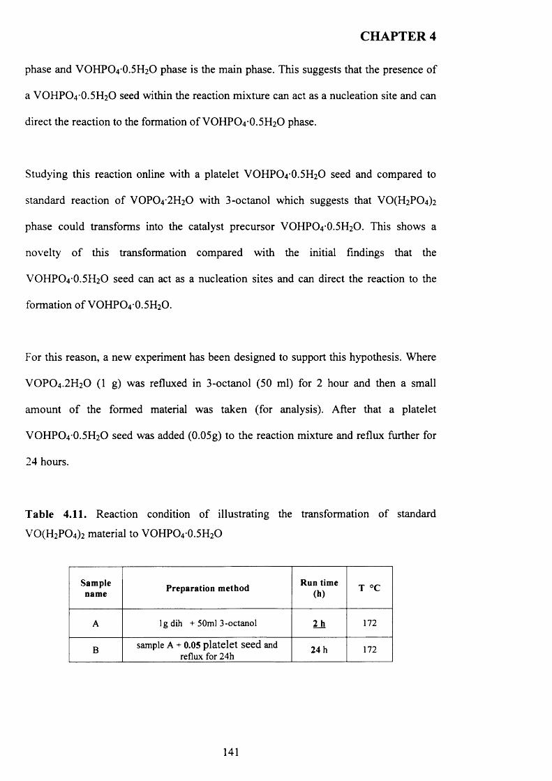
CHAPTER 4
phase and VOHPO4 O.5 H2O phase is the main phase. This suggests that the presence o f
a VOHPO4 O.5 H2O seed within the reaction mixture can act as a nucleation site and can
direct the reaction to the formation o f VOHPO4 O.5 H2O phase.
Studying this reaction online with a platelet VOHPO4 O.5 H2O seed and compared to
standard reaction o f VOPO4 2 H2O with 3-octanol which suggests that V0 (H2P0 4 ) 2
phase could transforms into the catalyst precursor VOHPO4 O.5 H2O. This shows a
novelty o f this transformation compared with the initial findings that the
VOHPO 4 O.5 H2O seed can act as a nucleation sites and can direct the reaction to the
formation o f VOHPO4 O.5 H2O.
For this reason, a new experiment has been designed to support this hypothesis. Where
VOPO 4 .2 H 2O (1 g) was refluxed in 3-octanol (50 ml) for 2 hour and then a small
am ount o f the formed material was taken (for analysis). After that a platelet
VOHPO 4 O.5 H2O seed was added (0.05g) to the reaction mixture and reflux further for
24 hours.
Table 4.11. Reaction condition o f illustrating the transformation o f standard
V 0 (H 2P 0 4)2 material to VOHPO4 0.5H2O
Samplename Preparation method Run time
(h)T °C
A lg dih + 50ml 3-octanol 2_h 172
B sample A + 0.05 p la te let seed and reflux for 24h
24 h 172
141
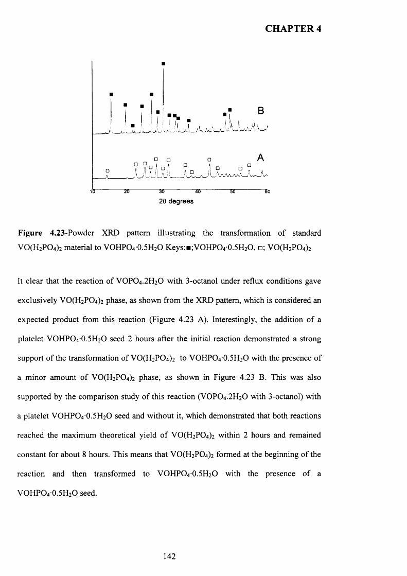
CHAPTER 4
iO 20 30 *0 50 5026 degrees
Figure 4.23-Powder XRD pattern illustrating the transformation o f standard
V 0(H 2P 0 4)2 material to VOHPO4 0.5H2O Keys:B;VOHPO4 0.5H2O, □; V 0(H 2P 0 4)2
It clear that the reaction o f V 0 P 0 4.2H20 with 3-octanol under reflux conditions gave
exclusively V 0(H 2P 0 4)2 phase, as shown from the XRD pattern, which is considered an
expected product from this reaction (Figure 4.23 A). Interestingly, the addition o f a
platelet VOHPO4 0.5H2O seed 2 hours after the initial reaction demonstrated a strong
support o f the transformation o f V 0(H 2P 0 4)2 to VOHPO4-0.5H2O with the presence o f
a minor amount o f V 0(H 2P 0 4)2 phase, as shown in Figure 4.23 B. This was also
supported by the comparison study o f this reaction (V 0 P 0 4.2H20 with 3-octanol) with
a platelet VOHPO4 0.5H2O seed and without it, which demonstrated that both reactions
reached the maximum theoretical yield o f V 0(H 2P 0 4)2 within 2 hours and remained
constant for about 8 hours. This means that V 0(H 2P 0 4)2 formed at the beginning o f the
reaction and then transformed to VOHPO4 0.5H2O with the presence o f a
VOHPO4 0.5H2O seed.
142
CHAPTER 4
4.5 Conclusion
The use o f small amounts o f vanadium phosphate materials as seeds during the reaction
o f VOPO 4 .2 H 2O with alcohols has been shown to be effective not only in altering the
morphology o f the product, but also in inducing certain phase transformations. The use
o f a seed in these cases shows that the rate o f material formation can be increased. In the
case o f reactions in 1-octanol, this overcomes a barrier to hemihydrate formation that
prevents the hemihydrate material crystallising and aggregating at reflux temperatures.
This has proved beneficial in the formation o f catalyst precursors for the partial
oxidation o f butane to MA.
This study also demonstrates that seeding VOHPO4 .O.5 H2O seeds (rosette or platelet)
with VOPO 4 .2 H2O using 3-octanol can control the reaction and form VOHPO4 .O.5 H2O
with a distinctive morphology. Studying the reaction time online shows that
VO(H2P 0 4)2 could be transformed to VOHPO 4 .O.5 H2O, which has been attempted
previously without success. This is the first report o f such a transformation occurring in
the liquid phase. Finally, testing these samples under reaction conditions shows that
they demonstrate high selectivity toward MA and good conversion compared to
V 0(H 2P 0 4)2
143
CHAPTER 4
4.6 References
[1] G. Centi, F. Trifiro' , J.R. Ebner, V.M. Franchetti, Chem. Rev. 88 (1998) 55.
[2] R. J. Ebner, R. M. Thompson, Catal. Today, 18, 51 (1994)
[3] G.J. Hutchings, J. Mater. Chem. 14 (2004) 3385.
[4] Johnson, J. W.; Johnson, D. C.; Jacobson, A. J.; Brody, J. F. J. Am. Chem. Soc.
1984, 106,8123.
[5] Bordes, E.; Courtine, P.; Johnson, J. W. J. Solid State Chem. 1984, 55, 270.
[6] Hutchings, G. J.; Sananes, M. T.; Sajip, S.; Kiely, C. J.; Burrows, A.; Ellison, I.
J.; Volta, J. C. Catal. Today 1997, 33, 161.
[7] Ellison, I. J.; Hutchings, G. J.; Sananes, M. T.; Volta, J. C. J. Chem. Soc., Chem.
Commun. 1994, 1093.
[8] M. T. Sananes, I. J. Ellison, S. Sajip, A. Burrows, C. J. Kiely, J. C. Volta and G.
J. Hutchings, J. Chem. Soc., Faraday Trans., 1996, 92, 1, 137.
[9] M. O, Connor, F. Dason and B. K. Hodnett, Appl. Catal., (1990), 64, 161-171.
[10] V. V Guliants,. J. B. Benziger, S.Sundaresan, I. E. Wachs, J. M. Jehng,
J.E.Roberts, Catal. Today, 28(1996)275-295.
[11] J. K. Bartley, C. Rhodes, C. J. Kiely, A. F. Carley, G. J. Hutchings, Phys. Chem.
Chem. Phys. 2000, 21, 4999-5006.
[12] J. K. Bartley, R. P. K. Wells, and G. J. Hutchings, J. Catal. (2000) 195, 423^127.
[13] M. T. Sananes, G. J Hutchings and J. C. Volta, J. Chem. Soc., (1995) 243.
[14] R. A. Mount, H. Raffelson and W. D. Robinson, Monsanto Co. U.S. Pat.
4116868, 1978.
[15] R. Higgins and G. J. Hutchings, U.S. Pat., 4222945, 1980.
144
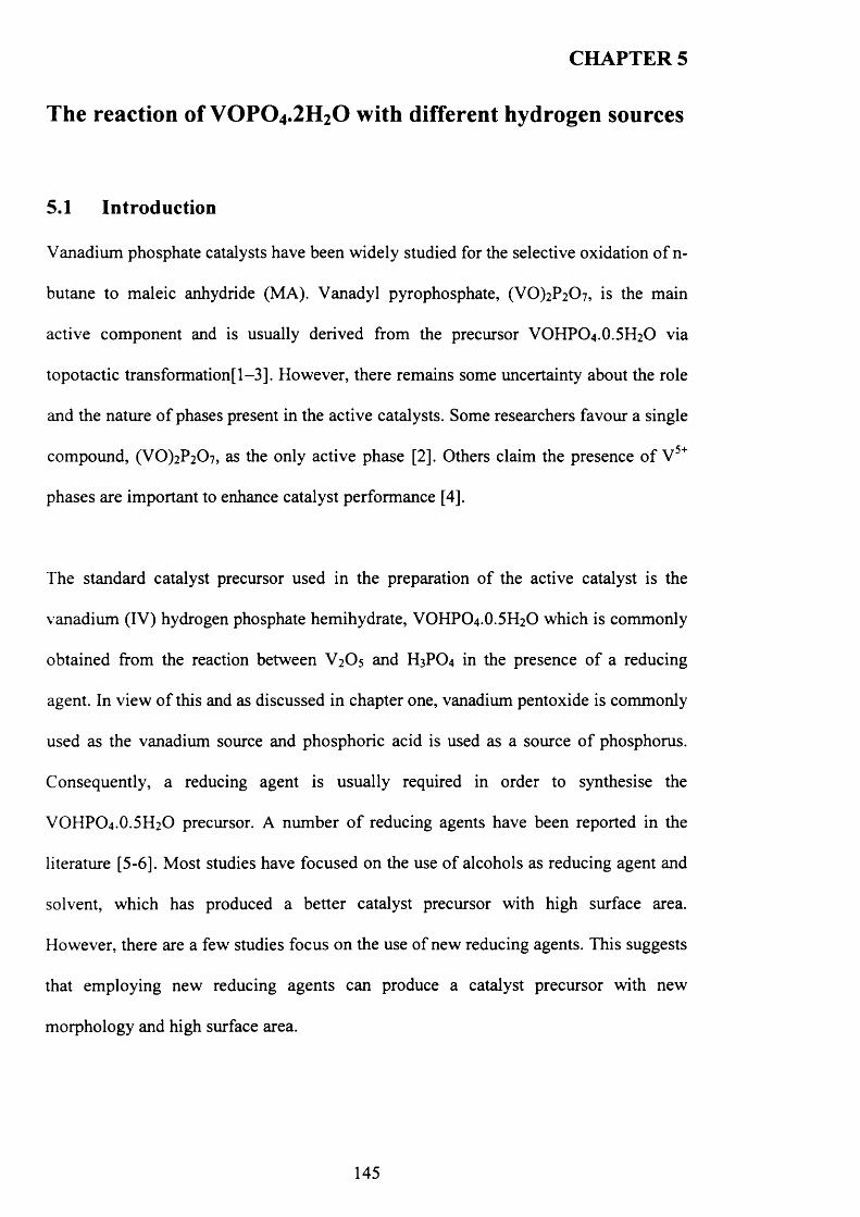
CHAPTER 5
The reaction of VOPO4.2H2O with different hydrogen sources
5.1 Introduction
Vanadium phosphate catalysts have been widely studied for the selective oxidation o f n-
butane to maleic anhydride (MA). Vanadyl pyrophosphate, (VO)2P2C>7, is the main
active component and is usually derived from the precursor VOHPO4 .O.5 H2O via
topotactic transformation]^ 1-3]. However, there remains some uncertainty about the role
and the nature o f phases present in the active catalysts. Some researchers favour a single
compound, (VO)2P2 0 7 , as the only active phase [2]. Others claim the presence o f V 5+
phases are important to enhance catalyst performance [4].
The standard catalyst precursor used in the preparation o f the active catalyst is the
vanadium (IV) hydrogen phosphate hemihydrate, VOHPO4 .O.5 H2O which is commonly
obtained from the reaction between V 2O 5 and H3PO4 in the presence o f a reducing
agent. In view o f this and as discussed in chapter one, vanadium pentoxide is commonly
used as the vanadium source and phosphoric acid is used as a source o f phosphorus.
Consequently, a reducing agent is usually required in order to synthesise the
VOHPO4 .O.5 H2O precursor. A number o f reducing agents have been reported in the
literature [5-6]. Most studies have focused on the use o f alcohols as reducing agent and
solvent, which has produced a better catalyst precursor with high surface area.
However, there are a few studies focus on the use of new reducing agents. This suggests
that employing new reducing agents can produce a catalyst precursor with new
morphology and high surface area.
145
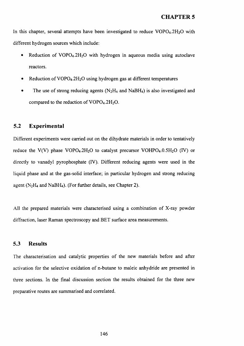
CHAPTER 5
In this chapter, several attempts have been investigated to reduce VOPO4 .2 H2O with
different hydrogen sources which include:
• Reduction o f VOPO4 .2 H2O with hydrogen in aqueous media using autoclave
reactors.
• Reduction o f VOPO4 .2 H2O using hydrogen gas at different temperatures
• The use o f strong reducing agents (N 2H4 and NaBFLi) is also investigated and
compared to the reduction o f VOPO4 .2 H2O.
5.2 Experimental
Different experiments were carried out on the dihydrate materials in order to tentatively
reduce the V(V) phase VOPO4 .2 H2O to catalyst precursor VOHPO4 .O.5 H2O (IV) or
directly to vanadyl pyrophosphate (IV). Different reducing agents were used in the
liquid phase and at the gas-solid interface; in particular hydrogen and strong reducing
agent (N2H4 and NaBFL*). (For further details, see Chapter 2).
All the prepared materials were characterised using a combination o f X-ray powder
diffraction, laser Raman spectroscopy and BET surface area measurements.
5.3 Results
The characterisation and catalytic properties o f the new materials before and after
activation for the selective oxidation o f n-butane to maleic anhydride are presented in
three sections. In the final discussion section the results obtained for the three new
preparative routes are summarised and correlated.
146
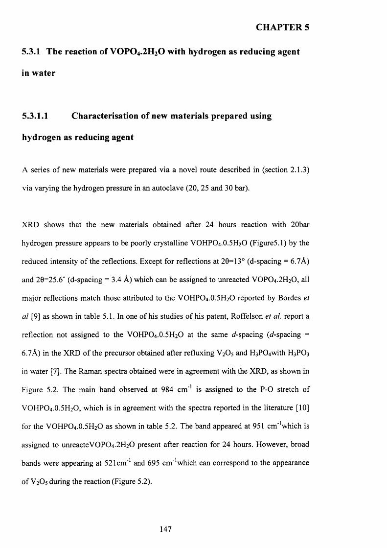
CHAPTER 5
5.3.1 The reaction of V 0 P 0 4 .2H20 with hydrogen as reducing agent
in water
5.3.1.1 Characterisation of new materials prepared using
hydrogen as reducing agent
A series o f new materials were prepared via a novel route described in (section 2.1.3)
via varying the hydrogen pressure in an autoclave (20, 25 and 30 bar).
XRD shows that the new materials obtained after 24 hours reaction with 20bar
hydrogen pressure appears to be poorly crystalline VOHPO4 .O.5 H2O (Figure5.1) by the
reduced intensity o f the reflections. Except for reflections at 20=13° (d-spacing = 6.7A)
and 20=25.6° (d-spacing = 3.4 A) which can be assigned to unreacted VOPO4 .2 H2O, all
major reflections match those attributed to the VOHPO4 .O.5 H2O reported by Bordes et
al [9] as shown in table 5.1. In one o f his studies o f his patent, Roffelson et a l report a
reflection not assigned to the VOHPO4 .O.5 H2O at the same d-spacing (d-spacing =
6.7A) in the XRD o f the precursor obtained after refluxing V2O5 and H3P0 4 with H3PO3
in water [7]. The Raman spectra obtained were in agreement with the XRD, as shown in
Figure 5.2. The main band observed at 984 cm '1 is assigned to the P -0 stretch o f
VOHPO4.O.5 H2O, which is in agreement with the spectra reported in the literature [10]
for the VOHPO4.O.5 H2O as shown in table 5.2. The band appeared at 951 cm^which is
assigned to unreacteV0 P0 4 .2 H2 0 present after reaction for 24 hours. However, broad
bands were appearing at 521cm '1 and 695 cm '1 which can correspond to the appearance
o f V2O5 during the reaction (Figure 5.2).
147
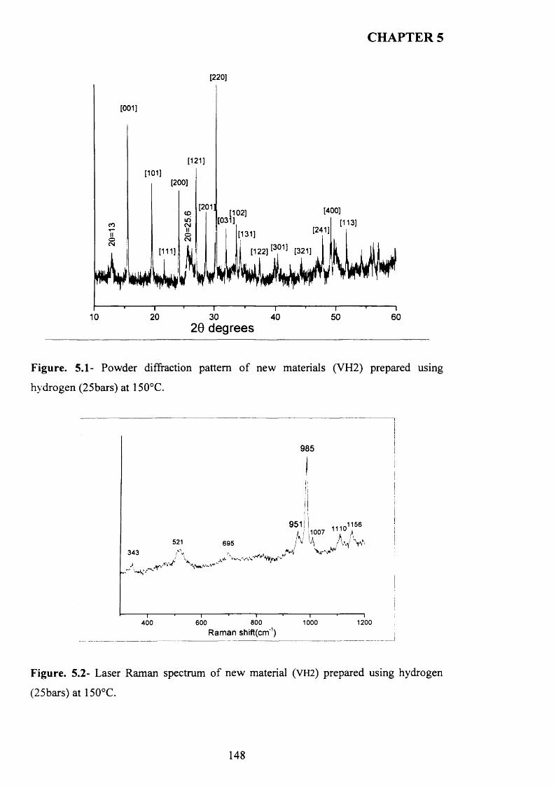
CHAPTER 5
[220]
[001]
co
[121]
[101]
i I I111)
[200]
[201[102]
[031].[400]
[131][122] [3?11 [32!]
10-I-------- [—
20 1-------- '-------- T"
30 4020 degrees
—r~ 50
I60
Figure. 5.1- Powder diffraction pattern o f new materials (VH2) prepared using
hydrogen (25bars) at 150°C.
985
951! ,115611101007521 695
343
800Raman shift(cm'1)
1200600 1000400
Figure. 5.2- Laser Raman spectrum o f new material (V H 2) prepared using hydrogen
(25bars) at 150°C.
148
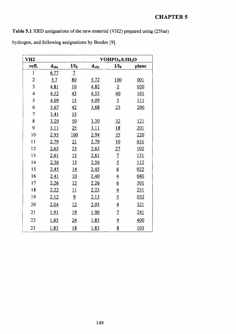
CHAPTER 5
T able 5.1 XRD assignations o f the new material (VH2) prepared using (25bar)
hydrogen, and following assignations by Bordes [9]
V H 2 V O H P O 4.0.5H 2Orefl. dobs I/Io dobs I/Io plane
1 6.77 72 51 80 5.72 100 0013 4.81 10 4.82 2 0204 4.52 43 4.53 40 1015 4.09 15 4.09 5 1116 3.67 42 3.68 23 2007 3.41 158 3.29 50 3.30 32 1219 3.11 25 3.11 18 20110 2.93 100 2.94 35 22011 2.79 21 2.79 10 03112 2.65 23 2.63 27 10213 2.61 15 2.61 7 13114 2.56 15 2.56 5 11215 2.45 14 2.45 6 02216 2.41 10 2.40 4 04017 2.26 12 2.26 6 30118 2.22 11 2.23 4 23119 2.12 9 2.13 5 032
20 2.04 12 2.05 4 321
21 1.91 19 1.90 7 241
22 1.85 24 1.85 9 400
23 1.83 18 1.83 8 103
149
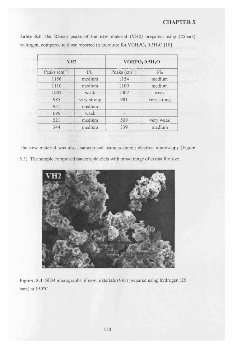
CHAPTER 5
Table 5.2 The Raman peaks of the new material (VH2) prepared using (25bars)
hydrogen, compared to those reported in literature for VOHPO4 .O.5 H2O [10]
VH2 VOHPO 4 .0.5H2O
Peaks (cm*1) I/I0 Peaks (cm*1) I/I0
1156 medium 1154 medium1 1 1 0 medium 1109 medium1007 weak 1007 weak985 very strong 981 very strong951 medium -
695 weak -
521 medium 509 very weak344 medium 339 medium
The new material was also characterised using scanning electron microscopy (Figure
5.3). The sample comprised random platelets with broad range of crystallite size.
Figure. 5.3- SEM micrographs of new materials (VH2) prepared using hydrogen (25
bars) at 150°C.
150
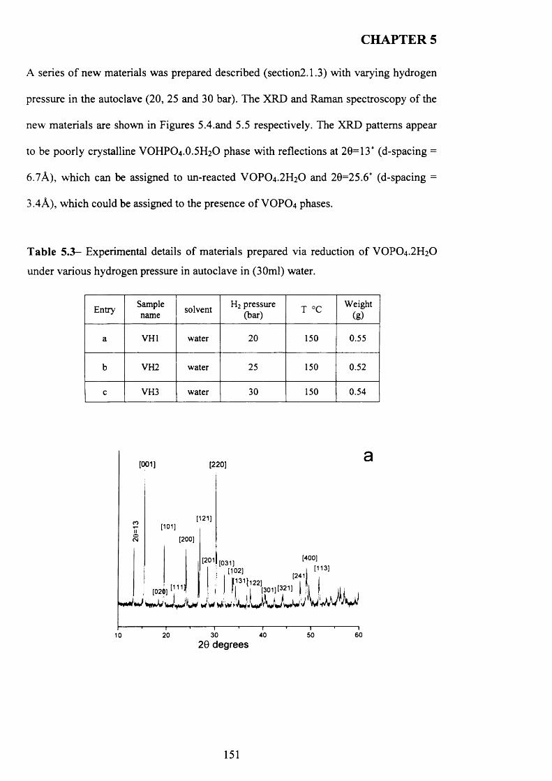
CHAPTER 5
A series o f new materials was prepared described (section2.1.3) with varying hydrogen
pressure in the autoclave (20, 25 and 30 bar). The XRD and Raman spectroscopy o f the
new materials are shown in Figures 5.4.and 5.5 respectively. The XRD patterns appear
to be poorly crystalline VOHPO4 .O.5 H2O phase with reflections at 20=13° (d-spacing =
6.7A), which can be assigned to un-reacted VOPO 4 .2 H2O and 20=25.6° (d-spacing =
3.4A), which could be assigned to the presence o f VOPO4 phases.
T ab le 5 .3 - Experimental details o f materials prepared via reduction o f VOPO4 .2 H2O
under various hydrogen pressure in autoclave in (30ml) water.
Entry Samplename solvent H2 pressure
(bar) T °C Weight(g)
a VH1 water 20 150 0.55
b VH2 water 25 150 0.52
c VH3 water 30 150 0.54
[001] [220]
------- .------- 1------- 1------- 1------- 1------- 1------- 1------- 1------- .------- 110 20 30 40 50 60
2 0 degrees
151
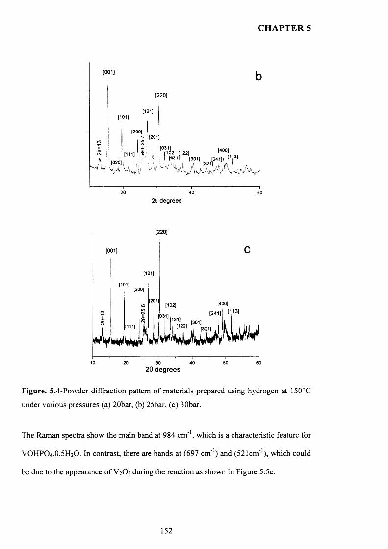
CHAPTER 5
[001]
[220]
[121][101]
[200]I [201?
CO
^pb] [122]' f ft31! [301]
20 40 60
20 degrees
[220]
[001]
[121]
[101][200]
[201] [400][102]CDuSCM [113][241]©
I1311 [301]I [122]
©CM
[111] [321]
10 20 40 5030 6029 degrees
Figure. 5.4-Powder diffraction pattern o f materials prepared using hydrogen at 150°C
under various pressures (a) 20bar, (b) 25bar, (c) 30bar.
The Raman spectra show the main band at 984 cm '1, which is a characteristic feature for
VOHPO4 .O.5 H2O. In contrast, there are bands at (697 cm*1) and (521cm"1), which could
be due to the appearance o f V 2O 5 during the reaction as shown in Figure 5.5c.
152
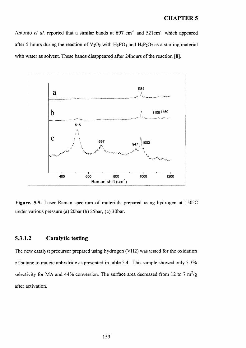
CHAPTER 5
Antonio et al. reported that a similar bands at 697 cm ' 1 and 521cm*1 which appeared
after 5 hours during the reaction o f V 2 O 5 with H 3 PO 4 and H4 P2 O 7 as a starting material
with water as solvent. These bands disappeared after 24hours o f the reaction [8 ].
984
515
697
400 600 800 1000 1200Raman shift (cm'1)
Figure. 5.5- Laser Raman spectrum o f materials prepared using hydrogen at 150°C
under various pressure (a) 20bar (b) 25bar, (c) 30bar.
5.3.1.2 Catalytic testing
The new catalyst precursor prepared using hydrogen (VH2) was tested for the oxidation
o f butane to maleic anhydride as presented in table 5.4. This sample showed only 5.3%
selectivity for MA and 44% conversion. The surface area decreased from 12 to 7 m /g
after activation.
153
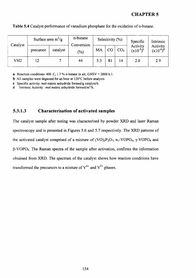
CHAPTER 5
T able 5.4 Catalyst performance o f vanadium phosphate for the oxidation o f n-butane.
CatalystSurface area m2/g n-butane
Conversion
(%)
Selectivity (%) SpecificActivity(x l0 '5)c
IntrinsicActivity(x l0 '6)dprecursor catalyst MA CO C 0 2
VH2 12 7 44 5.3 81 14 2.0 2.9
a Reaction conditions: 400 .C, 1.7 % w-butane in air, GHSV = 2000 h. 1. b All samples were degassed for an hour at 120°C before analysis c Specific activity: mol maleic anhydride formed/g catalyst/h. d Intrinsic Activity : mol maleic anhydride formed/m2/h.
5.3.1.3 Characterisation of activated samples
The catalyst sample after testing was characterised by powder XRD and laser Raman
spectroscopy and is presented in Figures 5.6 and 5.7 respectively. The XRD patterns o f
the activated catalyst comprised of a mixture o f (VO)2P2 0 7 , (X1-VOPO4, Y-VOPO4 and
P-VOPO4. The Raman spectra o f the sample after activation, confirms the information
obtained from XRD. The spectrum of the catalyst shows how reaction conditions have
transformed the precursors to a mixture o f V4+ and V 5+ phases.
154
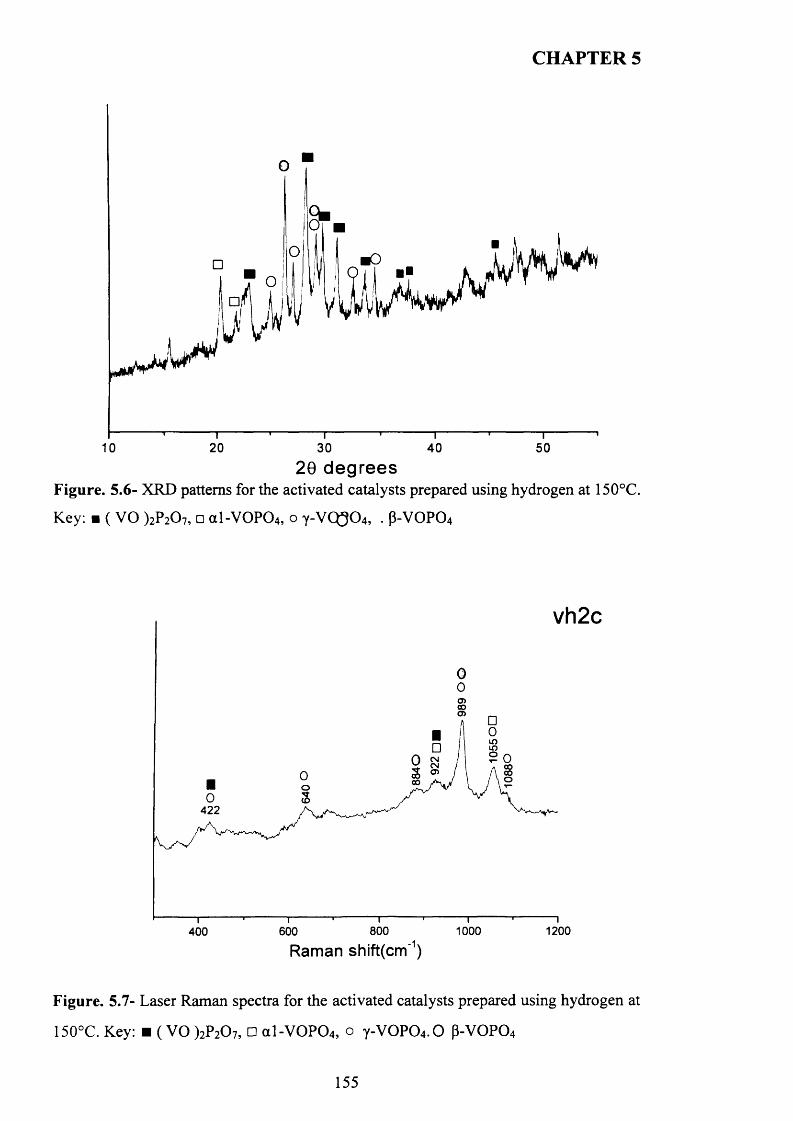
CHAPTER 5
■O■■
20 30 40 501020 d e g re e s
Figure. 5.6- XRD patterns for the activated catalysts prepared using hydrogen at 150°C.
Key: ■ ( VO )2P207, □ a l-V 0 P 0 4, o y -V Q 304, . p-V O P04
vh2c
in2 O/ \ Oo
422
1200800 1000600400Raman shift(cm‘1)
Figure. 5.7- Laser Raman spectra for the activated catalysts prepared using hydrogen at
150°C. Key: ■ ( VO )2P20 7, □ a l -V 0 P 0 4, o y -V 0 P 0 4. 0 P-VOP04
155
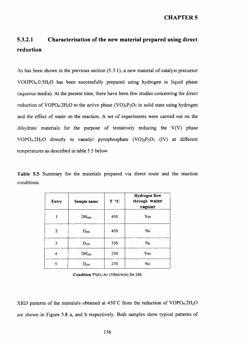
CHAPTER 5
5.3.2.1 Characterisation of the new material prepared using direct
reduction
As has been shown in the previous section (5.3.1), a new material o f catalyst precursor
VOHPO4 .O.5 H2O has been successfully prepared using hydrogen in liquid phase
(aqueous media). At the present time, there have been few studies concerning the direct
reduction o f VOPO4 2 H2O to the active phase (VO)2P2C>7 in solid state using hydrogen
and the effect o f water on the reaction. A set o f experiments were carried out on the
dihydrate materials for the purpose o f tentatively reducing the V(V) phase
VOPO4 .2 H 2O directly to vanadyl pyrophosphate (VO)2P2 0 7 (IV) at different
temperatures as described in table 5.5 below
Table 5.5 Summary for the materials prepared via direct route and the reaction
conditions
E ntry Sample name T °CHydrogen flow
through water vapour
1 DH450 450 Yes
2 D450 450 No
3 D350 350 No
4 d h 250 250 Yes
5 D250 250 No
Condition 5%H2/Ar (50ml/min) for 24h
XRD patterns o f the materials obtained at 450°C from the reduction of VOPO4 .2 H2O
are shown in Figure 5.8 a, and b respectively. Both samples show typical patterns o f
156
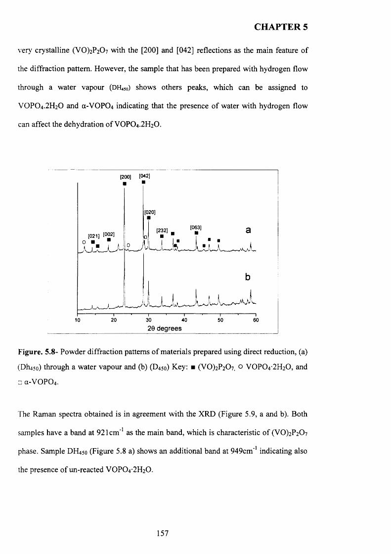
CHAPTER 5
very crystalline (VO)2P2C>7 with the [200] and [042] reflections as the main feature o f
the diffraction pattern. However, the sample that has been prepared with hydrogen flow
through a water vapour (DH 450) shows others peaks, which can be assigned to
VOPO4 .2 H2O and (X-VOPO4 indicating that the presence o f water with hydrogen flow
can affect the dehydration o f VOPO4.2 H2O.
[200] [042]
[020]
[063][232][021] [°02l
20 30 40 50 6010
20 degrees
F ig u r e . 5 .8 - Powder diffraction patterns of materials prepared using direct reduction, (a)
(DI1450) through a water vapour and (b) (D450) Key: ■ (VO)2P2C>7) o VOPO42H2O, and
□ C1-VOPO4.
The Raman spectra obtained is in agreement with the X R D (Figure 5 .9, a and b). Both
samples have a band at 921cm ' 1 as the main band, which is characteristic of (VO)2P207
phase. Sample DH450 (Figure 5.8 a) shows an additional band at 949cm ' 1 indicating also
the presence of un-reacted VOPO42H2O.
157
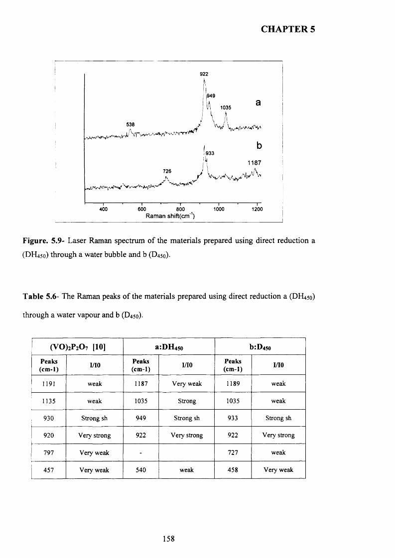
CHAPTER 5
922
|949u 1035
538
.'vV'\‘,Vv'V/
1933
726N
b
1187
J *
400— I------------------------- 1----------1-------------- 1—
600 800 1000 Raman shift(cm'1)
1200
Figure. 5.9- Laser Raman spectrum o f the materials prepared using direct reduction a
(DH450) through a water bubble and b (D45o)-
T ab le 5.6- The Raman peaks o f the materials prepared using direct reduction a (DH450)
through a water vapour and b (D450).
(V 0 )2P207 [10] a :D H 4so b:D4so
Peaks(cm -1) 1/10 Peaks
(cm-1) 1/10 Peaks(cm-1) 1/10
1191 weak 1187 Very weak 1189 weak
1135 weak 1035 Strong 1035 weak
930 Strong sh 949 Strong sh 933 Strong sh
920 Very strong 922 Very strong 922 Very strong
797 Very weak - 727 weak
457 Very weak 540 weak 458 Very weak
158
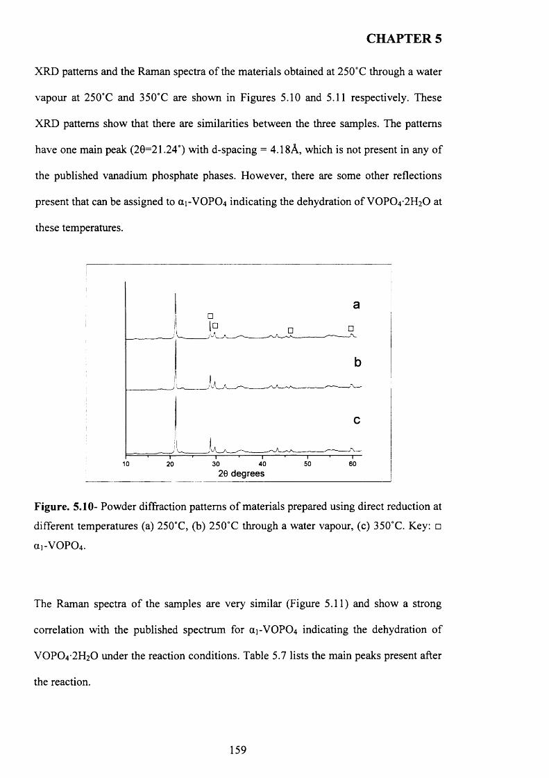
CHAPTER 5
XRD patterns and the Raman spectra o f the materials obtained at 250°C through a water
vapour at 250°C and 350°C are shown in Figures 5.10 and 5.11 respectively. These
XRD patterns show that there are similarities between the three samples. The patterns
have one main peak (20=21.24°) with d-spacing = 4.18A, which is not present in any o f
the published vanadium phosphate phases. However, there are some other reflections
present that can be assigned to a i-V 0 P0 4 indicating the dehydration o f VOPO4 2 H2O at
these temperatures.
10 50 6020 30 4020 degrees
Figure. 5.10- Powder diffraction patterns o f materials prepared using direct reduction at
different temperatures (a) 250°C, (b) 250°C through a water vapour, (c) 350°C. Key: □
(X1-VOPO4 .
The Raman spectra o f the samples are very similar (Figure 5.11) and show a strong
correlation with the published spectrum for ai-VOP0 4 indicating the dehydration o f
VOPO4 2 H2O under the reaction conditions. Table 5.7 lists the main peaks present after
the reaction.
159
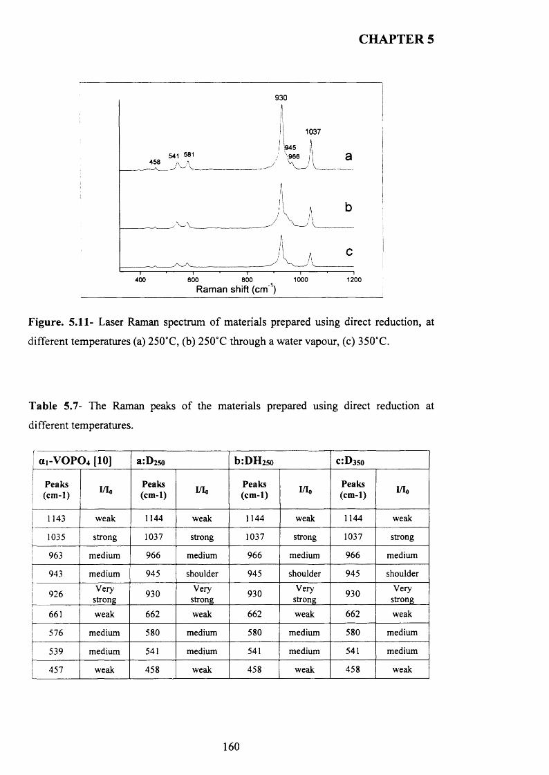
CHAPTER 5
930
1037
458
1200400 600 800Raman shift (cm‘1)
1000
Figure. 5.11- Laser Raman spectrum o f materials prepared using direct reduction, at
different temperatures (a) 250°C, (b) 250°C through a water vapour, (c) 350°C.
T able 5.7- The Raman peaks o f the materials prepared using direct reduction at
different temperatures.
(X1-V O PO 4 [10] a:D2so b :D H 25o c :D 3 so
Peaks(cm -1) I/Io Peaks
(cm -1) I/IoP eaks(cm -1) I/Io
Peaks(cm -1) I/I0
1143 weak 1144 weak 1144 weak 1144 weak
1035 strong 1037 strong 1037 strong 1037 strong
963 medium 966 medium 966 medium 966 medium
943 medium 945 shoulder 945 shoulder 945 shoulder
926 Verystrong 930 Very
strong 930 Verystrong 930 Very
strong
661 weak 662 weak 662 weak 662 weak
576 medium 580 medium 580 medium 580 medium
539 medium 541 medium 541 medium 541 medium
457 weak 458 weak 458 weak 458 weak
160
CHAPTER 5
5.3.2.2 Characterisation of activated samples
The (V0)2P2O7 phase and a l-V 0 P0 4 known to stable phase at the reaction temperature
for the oxidation o f n-butane to maleic anhydride (400°C). There were no changes
observed on their XRD and Raman patterns after activation for 24 hours and their XRD
patterns are shown in appendix (6).
(6) Appendix 5.1- The XRD patterns o f activated samples prepared using direct route at
450 °C and 250 °C respectively.
5.3.3 Characterisation of materials prepared using (N2H4 and NaBH4)
as reducing agent
Previous studies have focused on the use o f alcohols as reducing agent and solvent.
However, there have not been any published studies focusing on the use o f strong
reducing agents for the reduction o f VOPO4 .2 H2O.
Hydrazine is commonly used for the reduction o f metal cations to metal nano-particles
in solutions [11, 13]. Sodium borohydride (NaBPLj) is classified as a strong reducing
agent and widely used in the manufacture o f pharmaceuticals and other organic and
inorganic compounds as reducing agent [12, 14].
In this section, the use o f strong reducing agents such as hydrazine and sodium
borohydride is investigated for reduction o f VOPO 4 .2 H2O to catalyst precursors and
compared to the methods in the previous sections o f this chapter.
161
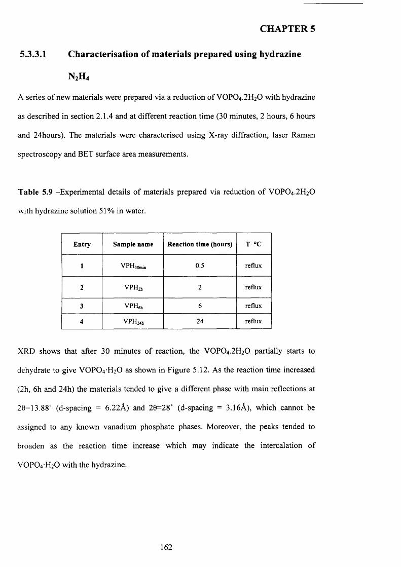
CHAPTER 5
5.3.3.1 Characterisation of materials prepared using hydrazine
N2H4
A series o f new materials were prepared via a reduction o f VOPO4 .2 H2O with hydrazine
as described in section 2.1.4 and at different reaction time (30 minutes, 2 hours, 6 hours
and 24hours). The materials were characterised using X-ray diffraction, laser Raman
spectroscopy and BET surface area measurements.
T able 5.9 -Experimental details o f materials prepared via reduction o f VOPO4 .2 H2O
with hydrazine solution 51 % in water.
Entry Sample name Reaction time (hours) T °C
1 VPHjOmu, 0.5 reflux
2 VPH^ 2 reflux
3 VPH$h 6 reflux
4 VPH24h 24 reflux
XRD shows that after 30 minutes o f reaction, the VOPO4.2 H2O partially starts to
dehydrate to give VOPO 4 H 2O as shown in Figure 5.12. As the reaction time increased
(2h, 6 h and 24h) the materials tended to give a different phase with main reflections at
20=13.88° (d-spacing = 6.22A) and 20=28° (d-spacing = 3.16A), which cannot be
assigned to any known vanadium phosphate phases. Moreover, the peaks tended to
broaden as the reaction time increase which may indicate the intercalation of
VOPO4 H2O with the hydrazine.
162

CHAPTER 5
24h
30min
10 30 40 5020 60
2 0 degrees I
F igu re . 5.12- Powder diffraction patterns o f materials prepared over time using
hydrazine, Key: ■ VOPO4 H2O
T ab le 5.10- XRD possible assignations o f the new materials prepared via reduction o f
VOPO 4 .2 H2O with hydrazine at different times.
VPHjOmin V PH 2hNo. ob* Possible assignations No. dob* Possible assignations
1 6.46 V 0 P 0 4 H 2 0 1 6.22 6.05 2 6.033 4.42 V 0 P 0 4 H 2 0 3 4.414 3.19 4 3.175 3.11 V 0 P 0 4 H 2 0 5 3.16 2.92 6 2.817 2.8 V 0 P 0 4 H 2 0 7 2.218 2.23 8 2.009 2.14 V 0 P 0 4 H 2 010 1.59 V 0 P 0 4 H 2 0
V PH 6h VPH 24hNo. dob* Possible assignations No. dob* Possible assignations
1 6.18 1 6.222 4.39 2 4.353 3.16 3 3.174 2.8 4 2.785 1.99 5 1.97
163
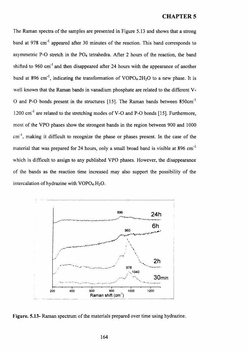
CHAPTER 5
The Raman spectra o f the samples are presented in Figure 5.13 and shows that a strong
band at 978 cm ' 1 appeared after 30 minutes o f the reaction. This band corresponds to
asymmetric P -0 stretch in the PO4 tetrahedra. After 2 hours o f the reaction, the band
shifted to 960 cm ' 1 and then disappeared after 24 hours with the appearance o f another
band at 896 cm '1, indicating the transformation o f VOPO4 .2 H2O to a new phase. It is
well known that the Raman bands in vanadium phosphate are related to the different V-
O and P -0 bonds present in the structures [15]. The Raman bands between 850cm '1
1200 cm ' 1 are related to the stretching modes o f V -0 and P -0 bonds [15]. Furthermore,
most o f the VPO phases show the strongest bands in the region between 900 and 1000
cm '1, making it difficult to recognize the phase or phases present. In the case o f the
material that was prepared for 24 hours, only a small broad band is visible at 896 cm ' 1
which is difficult to assign to any published VPO phases. However, the disappearance
o f the bands as the reaction time increased may also support the possibility o f the
intercalation o f hydrazine with VOPO4 .H2O.
896
960
30min
600 800Raman shift (cm1)
1000 1200200 400
Figure. 5.13- Raman spectrum o f the materials prepared over time using hydrazine.
164
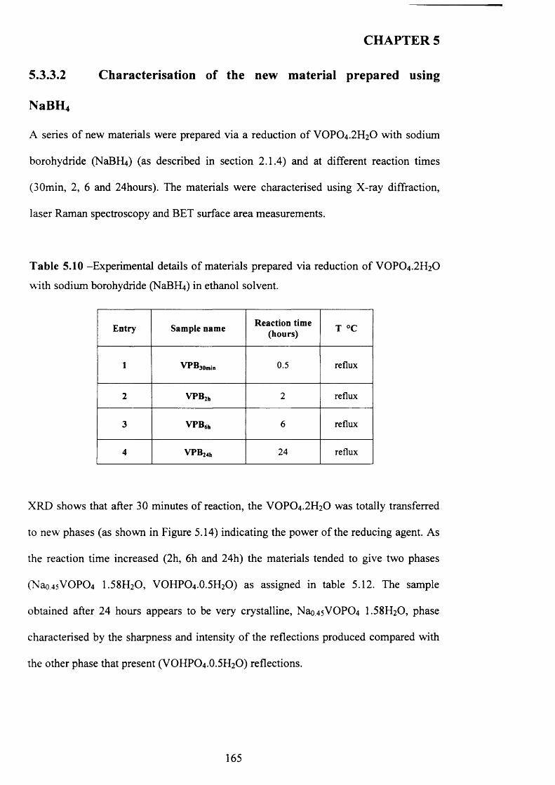
CHAPTER 5
5.3.3.2 Characterisation of the new material prepared using
NaBH4
A series o f new materials were prepared via a reduction o f VOPO4.2 H2O with sodium
borohydride (NaBR^) (as described in section 2.1.4) and at different reaction times
(30min, 2, 6 and 24hours). The materials were characterised using X-ray diffraction,
laser Raman spectroscopy and BET surface area measurements.
T ab le 5.10 -Experimental details o f materials prepared via reduction o f VOPO4 .2 H2O
with sodium borohydride (NaBfLO in ethanol solvent.
Entry Sample name Reaction time (hours) T °C
1 VPB3omjn 0.5 reflux
2 VPB2h 2 reflux
3 VPB6h 6 reflux
4 VPB24h 24 reflux
XRD shows that after 30 minutes o f reaction, the VOPO4 .2 H2O was totally transferred
to new phases (as shown in Figure 5.14) indicating the power o f the reducing agent. As
the reaction time increased (2h, 6 h and 24h) the materials tended to give two phases
(Nao45VOP0 4 I .5 8 H2O, VOHPO4.O.5 H2O) as assigned in table 5.12. The sample
obtained after 24 hours appears to be very crystalline, Nao.4sVOP0 4 I .5 8 H2O, phase
characterised by the sharpness and intensity o f the reflections produced compared with
the other phase that present (VOHPO4 .O.5 H2O) reflections.
165
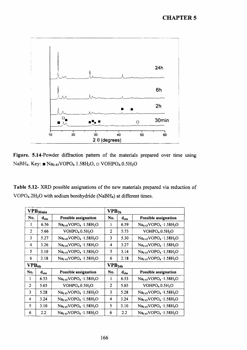
CHAPTER 5
24h
30min
3010 20 40 50 60
2 0 (degrees)
Figure. 5.14-Powder diffraction pattern o f the materials prepared over time using
NaBH4 . Key: ■ Nao45V O P04 1.58H20 , □ VOHPO4 .0.5H2O
T able 5.12- XRD possible assignations o f the new materials prepared via reduction o f
V 0 P 0 4.2H20 with sodium borohydride (NaBPLi) at different times.
V P B 3 0 m in VPB2hNo. dob* Possible assignation No. dob* Possible assignation
1 6.56 Nao45VOP04 1.58H20 1 6.59 Nao45V O P04 1.58H20
2 5.66 VOHPO4.0.5H2O 2 5.73 VOHPO4.0.5H2O
3 5.27 Nao45VOP04 1.58H20 3 5.30 Nao45V O P04 1.58H20
4 3.26 Nao45VOP04 1.58H20 4 3.27 Nao45V O P04 1.58H20
5 3.10 Nao45VOP04 1.58H20 5 3.14 Nao45V O P04 1.58H20
6 2.18 Nao45VOP04 1.58H20 6 2.18 Nao45V O P04 1.58H20
VPB6h VPB 24h
No. dob* Possible assignation No. dob* Possible assignation1 6.53 Nao45V O P04 1.58H20 1 6.53 Nao45V O P04 1.58H20
2 5.65 VOHPO4.0.5H2O 2 5.65 VOHPO4.0.5H2O
3 5.28 Nao45V O P04 1.58H20 3 5.28 Nao45V O P04 1.58H20
4 3.24 Nao45V O P04 1.58H20 4 3.24 Nao45V O P04 1.58H20
5 3.10 Nao45V O P04 1.58H20 5 3.10 Nao45V O P04 1.58H20
6 2.2 Nao45V O P04 1.58H20 6 2.2 Nao45V O P04 1.58H20
166
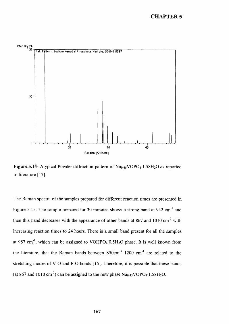
CHAPTER 5
Inten sity [*]1 0 0 - i
50"
Ref. Pa Item : Sodium vanadyl Phosphate Hydrate, 00-041-0087
Position [°2Theta]
Figure.5.14- Atypical Powder diffraction pattern o f Nao45VOPC>4.1.58H20 as reported
in literature [17].
The Raman spectra o f the samples prepared for different reaction times are presented in
Figure 5.15. The sample prepared for 30 minutes shows a strong band at 942 cm ’1 and
then this band decreases with the appearance o f other bands at 867 and 1010 cm ' 1 with
increasing reaction times to 24 hours. There is a small band present for all the samples
at 987 cm’1, which can be assigned to VOHPO4 .O.5 H2O phase. It is well known from
the literature, that the Raman bands between 850cm’1 1200 cm ' 1 are related to the
stretching modes o f V -0 and P -0 bonds [15]. Therefore, it is possible that these bands
(at 867 and 1010 cm’1) can be assigned to the new phase Nao,45VOP0 4 -1 .5 8 H2 0 .
167
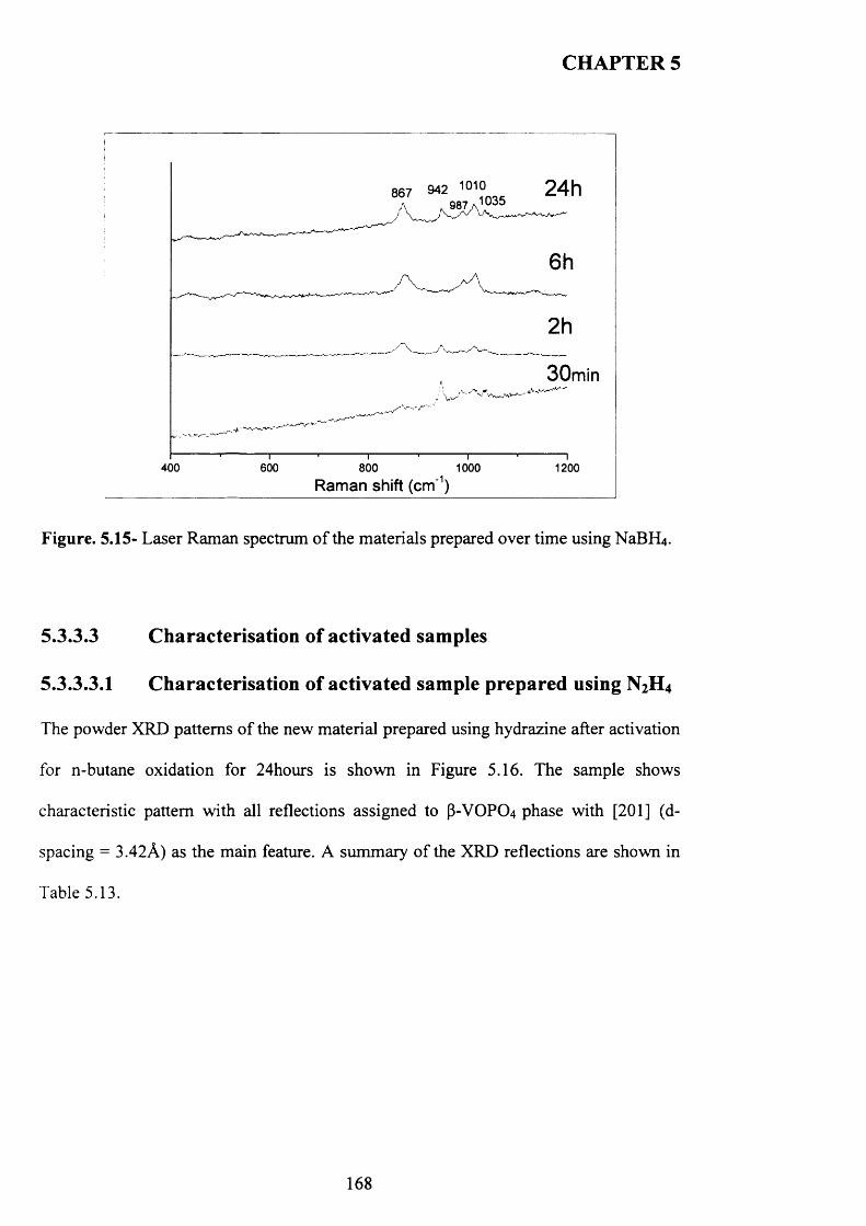
CHAPTER 5
24h867 942 1010A 987 a '035
30min
400 600 800
Raman shift (cm'1)1000 1200
Figure. 5.15- Laser Raman spectrum o f the materials prepared over time using NaBFLj.
5.3.3.3 Characterisation of activated samples
5.3.3.3.1 Characterisation of activated sample prepared using N2H 4
The powder XRD patterns o f the new material prepared using hydrazine after activation
for n-butane oxidation for 24hours is shown in Figure 5.16. The sample shows
characteristic pattern with all reflections assigned to P-VOPO4 phase with [2 0 1 ] (d-
spacing = 3.42A) as the main feature. A summary o f the XRD reflections are shown in
Table 5.13.
168
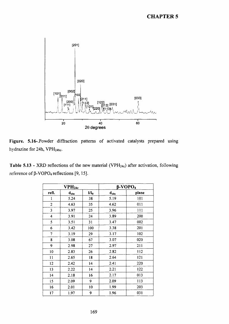
CHAPTER 5
[201]
[020]
[0 0 2 :[0,11] [033]211]
60402029 degrees
Figure. 5.16-.Powder diffraction patterns o f activated catalysts prepared using
hydrazine for 24h, VPH24hc-
T able 5.13 - XRD reflections o f the new material (VPH24c) after activation, following
reference o f P-VOPO4 reflections [9, 15].
V P H 24c p-vc>po4refl. dob» I/Io ob» plane
1 5.24 38 5.19 1012 4.63 35 4.62 011
3 3.97 25 3.96 1114 3.91 24 3.89 2005 3.51 31 3.47 002
6 3.42 100 3.38 201
7 3.19 29 3.17 102
8 3.08 67 3.07 020
9 2.98 27 2.97 211
10 2.83 26 2.82 11211 2.65 18 2.64 121
12 2.42 14 2.41 22013 2.22 14 2.21 12214 2.18 16 2.17 01315 2.09 9 2.09 113
16 2.01 10 1.99 203
17 1.97 9 1.96 031
169
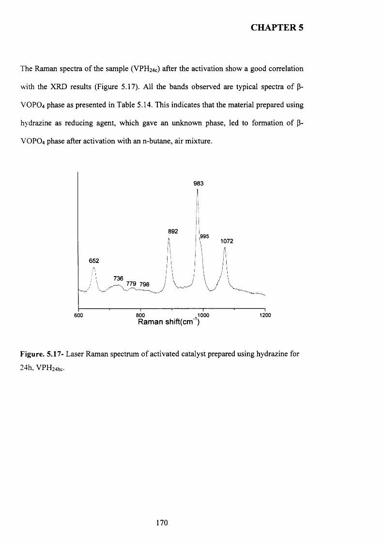
CHAPTER 5
The Raman spectra o f the sample (VPH24c) after the activation show a good correlation
with the XRD results (Figure 5.17). All the bands observed are typical spectra o f P-
VOPO4 phase as presented in Table 5.14. This indicates that the material prepared using
hydrazine as reducing agent, which gave an unknown phase, led to formation o f P-
VOPO4 phase after activation with an n-butane, air mixture.
983
892995
1072
652
736779 798
800 1000 Raman shift(cm')
1200600
Figure. 5.17- Laser Raman spectrum o f activated catalyst prepared using hydrazine for
24h , V P H 24hc.
170
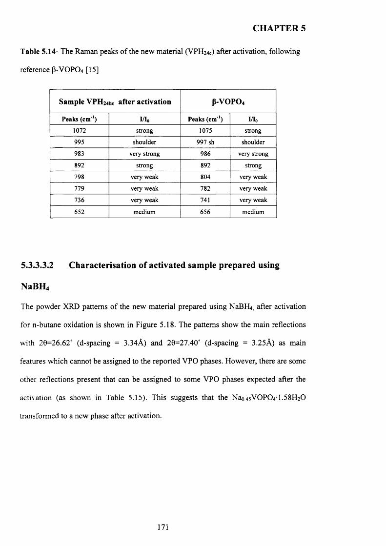
CHAPTER 5
Table 5.14- The Raman peaks o f the new material (VPH24C) after activation, following
reference (3-V0P04 [15]
Sample V P H 24hc after activation P -V O P O 4
Peaks (cm '1) I/I0 Peaks (c m 1) W o
1072 strong 1075 strong
995 shoulder 997 sh shoulder
983 very strong 986 very strong
892 strong 892 strong
798 very weak 804 very weak
779 very weak 782 very weak
736 very weak 741 very weak
652 medium 656 medium
5.3.3.3.2 Characterisation of activated sample prepared using
NaBH4
The powder XRD patterns o f the new material prepared using NaBFLj, after activation
for n-butane oxidation is shown in Figure 5.18. The patterns show the main reflections
with 20=26.62° (d-spacing = 3.34A) and 20=27.40° (d-spacing = 3.25A) as main
features which cannot be assigned to the reported VPO phases. However, there are some
other reflections present that can be assigned to some VPO phases expected after the
activation (as shown in Table 5.15). This suggests that the Nao.4sVOP0 4 T .5 8 H2 0
transformed to a new phase after activation.
171
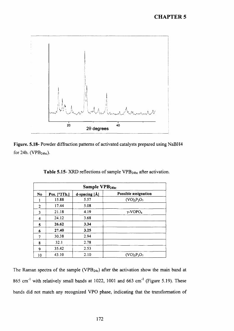
CHAPTER 5
20 4026 degrees
Figure. 5.18- Powder diffraction patterns o f activated catalysts prepared using NaBH4
for 24h. (VPB24hc).
Table 5 .15- XRD reflections o f sample VPB24hc after activation.
Sample V P B 24hc
No Pos. [°2Th.l d-spacing [A] Possible assignation
1 15.88 5.57 (V 0)2P20 7
2 17.44 5.08
3 21.18 4.19 y-v o p o 4
4 24.12 3.68
5 26.62 3.34
6 27.40 3.25
7 30.38 2.94
8 32.1 2.78
9 35.42 2.53
10 43.10 2.10 (VO)2P20 7
The Raman spectra o f the sample (VPB24C) after the activation show the main band at
865 cm ’1 with relatively small bands at 1022, 1001 and 663 cm ' 1 (Figure 5.19). These
bands did not match any recognized VPO phase, indicating that the transformation o f
172
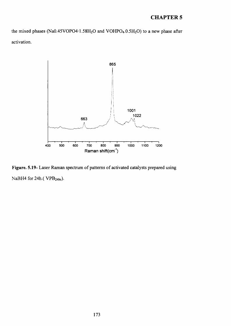
CHAPTER 5
the mixed phases (Na0.45VOPO41.58H2O and VOHPO4.O.5 H2O) to a new phase after
activation.
865
10011022
663
500 800 1100400 600 700 900 1000 1200
Raman shift(cm‘1)
Figure. 5.19- Laser Raman spectrum o f patterns o f activated catalysts prepared using
NaBH4 for 24h.( VPB24hc).
173
CHAPTER 5
5.4 Discussion
5.4.1 New materials prepared using hydrogen in high-pressure
autoclave
The catalyst precursors VOHPO4 .O.5 H2O were successfully prepared via a novel route
using hydrogen as reducing agent. This material appears to be poorly crystalline
VOHPO4 .O.5 H2O by the poor intensity o f the reflections produced (Figure5.1).
However, other reflections are present after the activation for butane oxidation,
indicating that the starting material VOPO4 .2 H2O was not fully reduced under the
reaction conditions. This is also confirmed by the Raman spectra obtained after the
reaction.
The incomplete reduction o f VOPO4 .2 H2O could be attributed to low hydrogen
solubility in water. It is known that hydrogen is not very soluble in water; only 1.9 mg
(0.95mmole) dissolves in a litre o f water at 0°C at one atmosphere [1] which represent
less than half o f the amount (0.5mmole) needed to complete this reaction. However,
increasing the pressure o f the hydrogen gas will increase its solubility in the water,
which can induce the reduction to take place.
Activating the new materials that were prepared using hydrogen for n-butane oxidation
shows a mixture o f (VO)2P2C>7 (IV) and some VOPO4 (V) phases, which also suggests
the incomplete reduction through the reaction. Furthermore, the testing data o f this
material shows a lower selectivity for maleic anhydride (5.3%) with (44%) conversion
of n-butane compared to standard material prepared using VPD route which typically
give 61% selectivity for maleic anhydride with (44%) conversion o f n-butane. This
could be attributed to the presence o f some VOPO4 (V) phases. It has been reported that
174
CHAPTER 5
(X1-VOPO4 is not selective for n-butane oxidation [5]. As a result, the active site o f
(V0 )2P2 0 7 can be obstructed by the presence o f the unselective sites.
5.4.2 Materials prepared using hydrogen via direct route to (VO^PiOt
Another preparative route was also investigated in order to reduce the VOPO4 .2 H2O (V)
directly to the active phase (VO)2P2 0 ? (IV) by using hydrogen. It was found that the
temperatures have a great influence on the reaction. At 250°C and 350°C, the XRD
patterns have one unknown reflection (20=21.24°), which makes it difficult for the bulk
structure to be proposed even though some suggestions can be made. However, there
are some other reflections present that can be assigned to a i-V 0 P0 4 . In addition, the
Raman spectra o f the samples are very similar (Figure 5.11) and show a strong
correlation with the published spectrum for a i-V 0 P0 4 [10]. There is a conflict between
XRD and Raman results, and the phases detected in the bulk structures do not match
with the phases detected at the surface. Powder XRD does not detect phases if their
content is less than 5%. Additionally, it is likely that some processes could take place on
the surface o f the material (e.g. dehydration) and therefore, as Raman spectroscopy is a
surface sensitive technique, so the changes occurring in the material would be more
readily detected than using XRD which is a bulk technique. Moreover, it could be
suggested that the materials are partially dehydrated to give ai-V 0 P0 4 phase or the
surface of the materials are dehydrated and the bulk structure is in hydrated form which
gave in expected XRD peaks at (20=21.24°),
In contrast, reducing the VOPO 4.2 H2O at 450°C with hydrogen flow through a water
vapour and without it led to the active phase (V0 )2P2 0 7 indicating the influence o f the
temperature on the reduction as shown in Figure 5.8 a, and b respectively. However, the
175
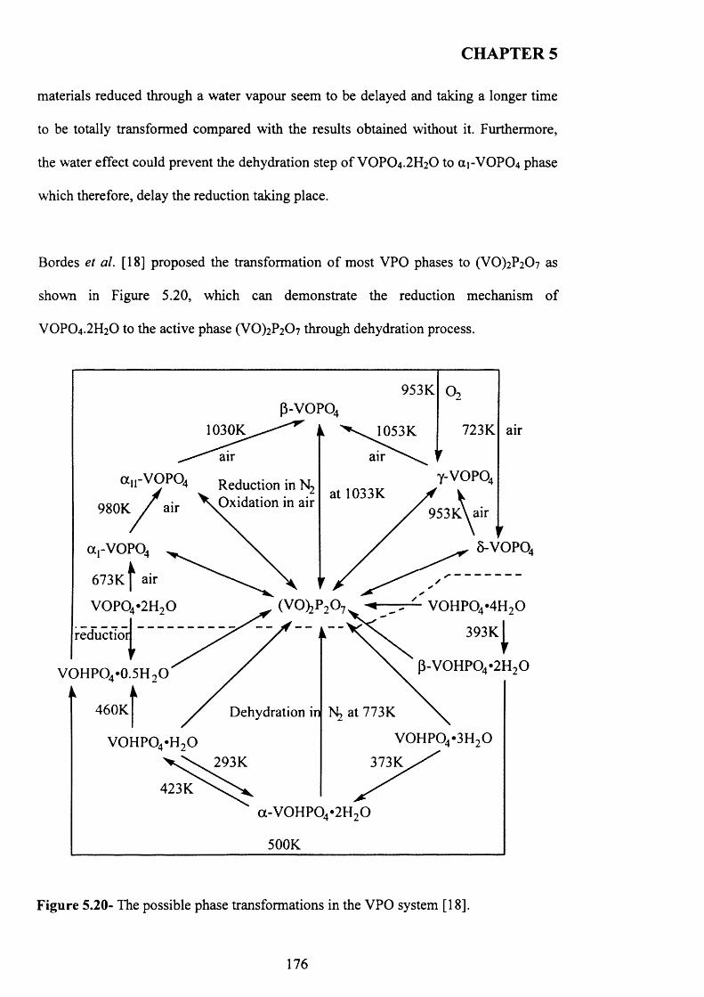
CHAPTER 5
materials reduced through a water vapour seem to be delayed and taking a longer time
to be totally transformed compared with the results obtained without it. Furthermore,
the water effect could prevent the dehydration step o f VOPO4 .2 H2O to (X1-VOPO4 phase
which therefore, delay the reduction taking place.
Bordes et al. [18] proposed the transformation o f most VPO phases to (VO)2P2 0 7 as
shown in Figure 5.20, which can demonstrate the reduction mechanism of
VOPO4.2 H2O to the active phase (V0 )2P2 0 7 through dehydration process.
953K
723K1030K 1053K air
air air
Reduction in N2
Oxidation in airat 1033K
980K 953KA air
5-V O PQa.-VOPQ
673KV air
(V 0 )2P 2 0 7 V 0 H P 0 4 *4H20
/f~~ f xC 393k[\ P -V 0 H P 0 4 -2H 20
reductioi
VOHPO4 *0.5H 90
460K Dehydration in N2 at 773K
V 0 H P 0 4 *3H90v o h p o 4 * h ,o293K 373K
423K
ot-V O H PO W H .O
500K
F igure 5.20- The possible phase transformations in the VPO system [18].
176
CHAPTER 5
5.4.3 Materials prepared using new reducing agent (N2 H4 and NaBH4)
In the last section o f this chapter, the use o f new reducing agents hydrazine (N2H4) and
sodium borohydride (NaBFLi) were explored. It was found that the reaction o f
VOPO4 .2 H2O with hydrazine gave a new phase after 24 hours, which is believed to be
V(V) after determining the oxidation state o f the sample indicates that no reduction
occurs. This phase has transformed to P-VOPO4 after activation for n-butane at 400°C
oxidation, which was confirmed by the unique characteristic XRD pattern and Raman
spectra o f P-VOPO4 .
According to the literature [19] P -V O P O 4 was prepared by the decomposition o f
NH4(V0 2 )2P0 4 in dry air. However, this requires a high temperature (600°C) for 10 h
before the P -V O P O 4 was obtained.
It could be proposed that the hydrazine may intercalate in the reaction with the VOPO4 .
2 H2O structure, or with VOPO4 .H2O through the reaction
The reaction o f VOPO4 .2 H2O with sodium borohydride was found to give Nao.45VOP0 4
I .5 8 H2O as the main phase with the present o f VOHPO4.0.5H2O as minor phase. This
suggests that the VOPO4 .2 H2O was reduced to (IV) under the reaction condition.
However, the presence o f sodium cations could favour the reaction to give Nao 45VOPO4
1.5 8 H2O instead o f the catalyst precursor VOHPO4.0.5H2O.
This phase was converted to an unknown phase after activation for n-butane as shown
by the XRD pattern and Raman. However, there are some reflections that can be
assigned to (VO)2P2 0 7 and other VOPO4 phases.
177
CHAPTER 5
5.5 Conclusions
Vanadium phosphate catalysts have successfully been prepared in aqueous media using
hydrogen. The catalysts precursors obtained were poorly crystalline VOHPO4.0.5H2O
and a minor amount o f an impurity detected by a reflection in the XRD pattern.
Activating these materials for n-butane oxidation show low selectivity o f MA (5%),
which could be attributed to the presence o f V(V) phases after activation.
The direct route using hydrogen as reducing agent shows a promising path way for
preparing the active phase (V0 )2P2 0 7 directly from the VOPO4 .2 H2O at high
temperature (over 450°C). In contrast, mixture o f partially dehydrated VOPO4 phases
were detected at 250°C and 350°C, indicating the dehydration o f VOPO4 .2 H2O under
the reaction conditions.
It was found that the reaction o f VOPO4 .2 H2O with hydrazine gave a new phase after 24
hours, which is believed to be V(V) after determining the oxidation state o f the sample
indicates that no reduction occurs. This phase has transformed to P-VOPO4 after
activation for n-butane at 400°C oxidation, which was confirmed by the unique
characteristic XRD pattern and Raman spectra o f P-VOPO4 . This could facilitate a new
preparative route for P-VOPO4 at lower temperature compared with the conventional
method reported in the literature [19].
The use o f sodium borohydride as a reducing agent led to the formation o f new
vanadium phosphate phase Nao.45VOP0 4 I .5 8 H2O with VOHPO4.0.5H2O as minor
phase detected which can be attributed to the present o f Na+ cation.
178
CHAPTER 5
5.6 References
[1] G. Centi, F. Trifiro' , J.R. Ebner, V.M. Franchetti, Chem. Rev. 8 8 (1998) 55.
[2] M. T. Sananes, I. J. Ellison, S. Sajip, A. Burrows, C. J. Kiely, J. C. Volta and G.
J. Hutchings, J. Chem. Soc., Faraday Trans., 1996, 92, 1, 137.
[3] G.J. Hutchings, J. Mater. Chem. 14 (2004) 3385.
[4] G. J. Hutchings, A. Desmartin-Chamel, O. Oliver, J. C. Volta, Nature 348
(1994)41.
[5] C.J. Kiely, A. Burrows, G.J. Hutchings, K.E. Bere, J.C. Volta, A. Tuel and M.
Abon, Faraday Discuss., (1996), 105, 103
[6 ] G.J. Hutchings and R. Higgins, J. Catal., (1996), 162, 153
[7] Ramon A. Mount and Harold RafFelson, assigned to Monsanto Company
U.S.A patent 4,337,174 (1982)
[8 ] J. K. Bartley, J. A. Lopez-Sanchez, G. J. Hutchings, Catal. Today, 81, 197
(2003)
[9] E. Bordes, Catal. Today 1 (1987) 499.
[10] V. V Guliants,. J. B. Benziger, S. Sundaresan, I. E. Wachs, J. M. Jehng, J.E.
Roberts, Catal. Today, 28(1996)275-295.
[11] Y. LI, L. LI, H. LIAO and H. WANG, J. Mater. Chem. 9 (1999) 2675.
[12] A. Hajos in: Houben-Weyl-Miiller, Methoden der organischen Chemie. Band
IV /ld, Thieme, Stuttgart 1981, p. 1.
[13] J . GAO, F. GUAN, Y. ZHAO, W. YANG and Y. MA, Mater. Chem. Phys. 71
(2001)215.
[14] E. R. H. Walker, Chem. Soc. Rev. 5 (1976) 23.
[15] F. Ben Abdelouahab, R. Olier, N. Guilhaume, F. Lefebvre and
179
CHAPTER 5
J. C. Volta, J. Catal., 1992, 134, 151.
[ 16] http://www.engineeringtoolbox.com/gases-solubility-water-d_l 148.html
[17] N. Casan, P. Amoros, R. Ibanez, E. Martinez-Tamayo, A. Belton-Porter, D.
Beltran-Porter, J. Inclusion Phenomena, 6, 193, (1988).
[18] E. Bordes, Catal. Today 1987, 1, 499.
[19] F. Ben Abdelouahab, J.C. Volta, R. Olier, J. Catal. 148 (1994) 334.
180
CHAPTER 6
Conclusion and future work
6.1 Conclusion
It has been reported that the catalytic activity o f the vanadium phosphate catalysts
depends on the preparation methods o f the catalyst precursors VOHPO4 .O.5 H2O [1].
The catalyst that is generally considered to be the main active phase for the selective
oxidation o f n-butane to maleic anhydride, is usually derived from the activation o f
VOHPO4.O.5 H2O, which gives a catalyst comprising o f (VO)2P2C>7 as the main phase.
The in situ transformation of the precursors VOHPO4 .O.5 H2O to the active catalyst
(VO)2P207is often topotactic, which means that the morphology and the surface area of
the catalyst is controlled by the morphology and the surface area o f the precursor.
Consequently, careful preparation of the catalyst precursor VOHPO4 .O.5 H2O is the key
important factor for obtaining an effective catalyst.
In this thesis, new preparative routes have been explored and characterised for the
synthesis of vanadium phosphate precursors. These precursors have been tested for the
selective oxidation o f n-butane to maleic anhydride. In addition, new reducing agents
have been used to reduce vanadium phosphate dihydrate VOPO4.2 H2O for the purpose
of preparing the catalyst precursors VOHPO4 .O.5 H2O with different morphology. In
chapter 3, long chain alkane (octane) has been used as co-solvent and also for the
treatment of VOPO4 .2 H2O prior to the reduction step with alcohol (1-butanol). These
materials have been characterised and tested for n-butane selective oxidation. Three
different morphologies o f VOHPO4.O.5 H2O precursor have been successfully prepared
via three different routes with the use o f octane solvent. From these results, we can say
that octane solvent can play an important role in VOHPO4 O.5 H2O preparation. The
181
CHAPTER 6
reaction o f VOPO4 .2 H2O with octane solvent shows the possibility o f the intercalation
o f the octane solvent between the layers o f VOPO4 .2 H2O. This can lead to the
formation o f VOHPO4.O.5 H2O precursors with a new morphology after the reduction
step using 1-butanol. In addition, adding the solvent together with the reducing agent
leads to the formation of VOHPO4.O.5 H2O with a different ratio o f [001]/ [220]
intensity and new morphology. Testing these samples shows that the samples with a
rosette morphology exhibit the highest conversion and selectivity compared with the
new materials prepared. Interestingly, The XRD patterns o f the four activated catalysts
are very similar and the main reflections can all be assigned to poorly crystalline
(VO)2P2 0 7 . The only remarkable difference is the ratios o f the [200] and [024] intensity
which the high ratio for the catalyst prepared via C route and decreases in the order C >
D > B > A. This can be attributed to the nature o f the original precursors and their
morphologies. Moreover, there is no other phases were detected in the final catalyst o f
all materials prepared using the three routes described.
In chapter 4, the use o f small amounts o f vanadium phosphate materials as seeds during
the reaction of VOPO4 .2 H2O with alcohols has been studied using different alcohols (1-
octanol, 2-methy-l-propanol, 2-butanol and 3-octanol). These particular solvents were
selected based on the differences o f the morphology o f the resulting V -P-0 material
during a standard VPD preparation. The use o f the seeds during the reaction o f
VOPO4 .2 H2O with alcohols has been shown to be effective not only in altering the
morphology of the product, but also in inducing certain phase transformations. The use
o f a seed in these cases shows that the rate o f material formation can be increased. For
example, the rate o f VOHPO4 O.5 H2O formation is high {i.e. 90% yield in 10 min) for
the seeded reaction based on the theoretical yield o f the VOHPO4 O.5 H2O compared to
182
CHAPTER 6
standard reaction without seed using 1-octanol (-10% ). Moreover, the addition o f small
amount o f VOHPO4 O.5 H2O (0.05 g) as a seed to the reaction mixture can overcome a
barrier to VOHPO4 O.5 H2O formation that prevents the VOHPO4 O.5 H2O material
crystallising and aggregating at reflux temperatures (185°C). This has proved beneficial
in the formation o f catalyst precursors for the partial oxidation o f butane to MA.
The use o f the VOHPO4 O.5 H2O seeds (platelet and rosette) with the reaction o f
VOPO4 2 H2O with iso-butanol and 2-butanol alcohols showed also a significant effect
on the morphology o f the recovered VOHPO4 O.5 H2O precursors.
The reaction o f the dihydrate (VOPO4 2 H2O) using 3-octanol at the reflux temperature
leads typically to the formation o f VO(H2PC>4)2 phase as reported in most studies [2].
This phase VO(H2PC>4)2 has a negligible activity and selectivity for the partial oxidation
o f butane to MA [2]. However, this study demonstrates that seeding the reaction o f
VOPO4.2 H2O using 3-octanol with VOHPO4 .O.5 H2O seeds (rosette or platelet) can
control the reaction and form VOHPO4 .O.5 H2O with a distinctive morphology.
Additionally, Studying the reaction time online shows that VO(H2PC>4)2 could be
transformed to VOHPO4 .O.5 H2O, which has been attempted previously without success.
This is the first report o f such a transformation occurring in the liquid phase. Finally,
testing these samples under reaction conditions shows that they demonstrate high
selectivity toward MA and good conversion compared to V0 (H2P0 4 )2-
In chapter 5, new materials have been prepared using hydrogen and two strong reducing
agents (hydrazine and sodium borohydride). When hydrogen was used as a reducing
agent in aqueous media, the catalyst precursors obtained were poorly crystalline
VOHPO4 .O.5 H2O and a minor amount o f an impurity detected by a reflection in the
183
CHAPTER 6
XRD pattern. Activating these materials for n -bu tane oxidation show low selectivity o f
MA (5%), which could be attributed to the p resen ce o f V(V) phases after activation.
The presence o f V 0 P 0 4 phases after activation in d ica te that the materials was not fully
reduced which can attributed to low solubility o f hyd ro g en in water.
The hydrogen also has been used via. a direct ro u te , in order to prepare the active
catalyst (VO)2P2 0 7 from V OPO 4 .2 H2O at d ifferen t tem peratures. This route shows a
promising path way for preparing the active p h ase (VO)2P2 0 ? directly from the
VOPO 4 .2 H2O at high temperature (over 450°C). H ow ever, mixtures o f VOPO4 phases
were detected at 250°C and 350°C, indicating th e dehydration o f VOPO 4 .2 H2O under
these temperatures compared to 450°C.
It was found that the reaction o f VOPO 4 .2 H2O w ith hydrazine gave a new phase after 24
hours, which is believed to be V(V) after determ in ing the oxidation state o f the sample
indicates that no reduction occurs. This phase has transformed to P-VOPO4 after
activation for n-butane at 400°C oxidation, w h ich was confirm ed by the unique
characteristic XRD pattern and Ram an spectra o f P-V O PO 4 . This could facilitate a new
preparative route for P-VOPO4 at lower tem peratu re compared w ith the conventional
method reported in the literature [3].
The use of sodium borohydride as a reducing agent led to the formation o f new
vanadium phosphate phase Nao.45VO P0 4 -1 .5 8 H 2 0 with VOHPO4.0.5H2O as minor
phase detected which can be attributed to the p re sen t o f Na+ cation.
184
CHAPTER 6
6.2 Future work
In view o f all the work presented in this thesis which would be improved with better
characterisation o f the vanadium phosphate materials and determining the new phases
that found in the investigations. The characterisation techniques available during this
study can facilitate the vanadium phosphate materials bulk to be determined, although
the powder x-ray diffraction was shown to be reasonably insensitive particularly to
minor phases present in the material. In addition, the Raman spectroscopy can only
provide limited information on these phases.
Some new unknown phases were obtained in this study which suggests additional
characterisation techniques to be used in order to identify the new phases and get a clear
21picture o f their morphologies. P NM R and XPS techniques should be used to assist
with the identification o f these phases and can distinguished between V3+, V4+ and V5+
phases and also provide an information on the nature o f the oxidation state o f the
catalyst surface.
The vanadium phosphate dihydrate VOPO4 .2 H2O showed a high capability o f
intercalation with different compounds. Therefore, it can be suggested to investigate the
intercalation o f new solvents with VOPO4 .2 H2O which will be useful to observe a
change in the morphology o f the catalyst precursors VOHPO4.O.5 H2O.
Moreover, as it was shown that the use o f VOHPO4 .O.5 H2O seeds (rosette or platelet)
during the reaction of VOPO4 .2 H2O with different alcohols can alter the morphology o f
the catalyst precursor VOHPO4.O.5 H2O and also can favour the transformations o f
certain phases during the reaction. These observations can open a great opportunity for
185

CHAPTER 6
future stu d y to in v estig a te the e ffec t o f d irect agen ts during the syn th esis o f the catalyst
precursors V O H P O 4 .O.5 H 2O
186
CHAPTER 6
6.3 References
[1] G.J. Hutchings, J. Mater. Chem 14 (2004) 3385.
[2] J. K. Bartley, C. Rhodes, C. J. Kiely, A. F. Carley, G. J. Hutchings, Phys. Chem.
Chem. Phys. 2000, 21, 4999-5006.
[3] F. Ben Abdelouahab, J.C. Volta, R. Olier, J. Catal. 148 (1994) 334.
187
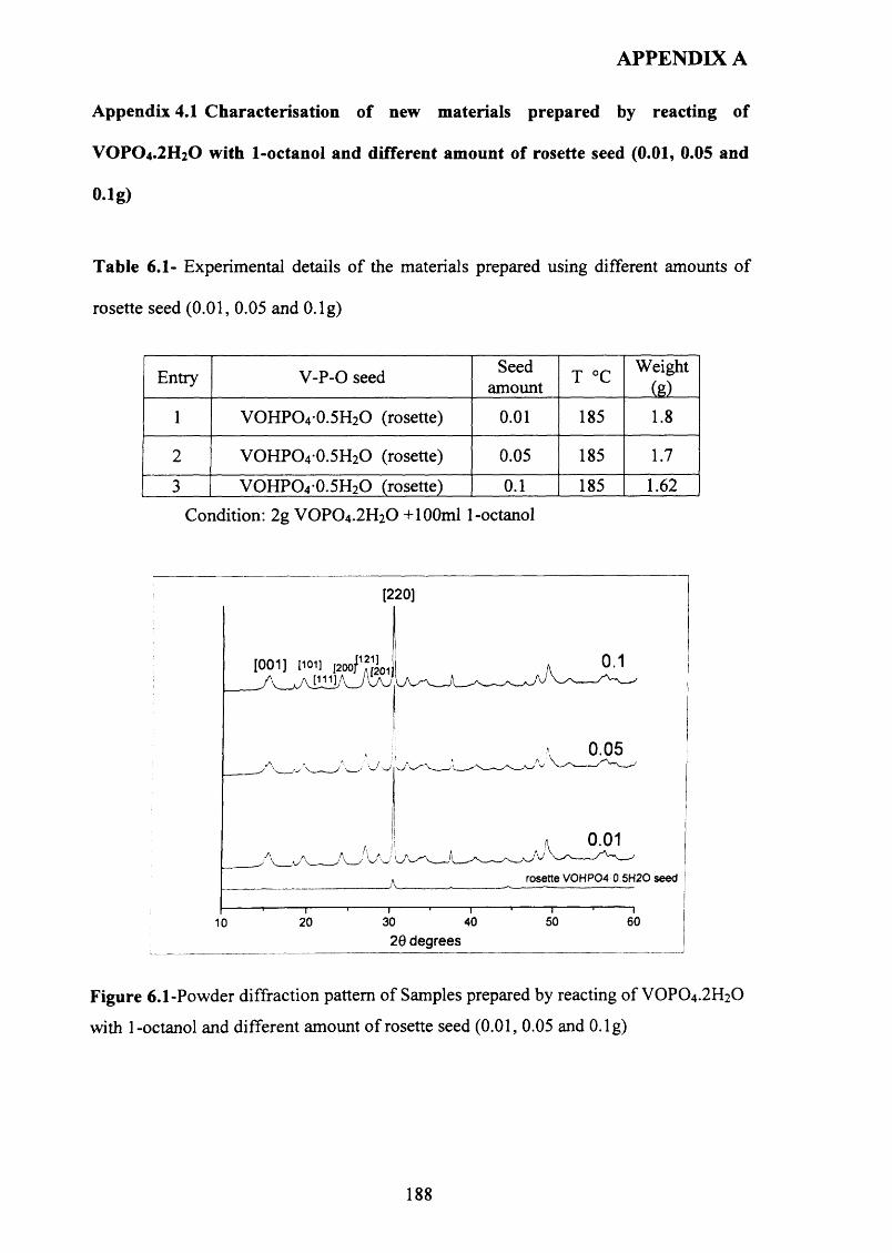
APPENDIX A
Appendix 4.1 Characterisation of new materials prepared by reacting of
VOPO 4 .2 H 2 O with 1-octanol and different amount of rosette seed (0.01, 0.05 and
O.lg)
Table 6.1- Experimental details o f the materials prepared using different amounts o f
rosette seed (0.01, 0.05 and O.lg)
Entry V -P-0 seedSeed
amount T °C Weight(g)
1 VOHPO 4 0.5H2O (rosette) 0 .0 1 185 1 .8
2 VOHPO 4 0.5H2O (rosette) 0.05 185 1.7
3 VOHPO 4 0.5H2O (rosette) 0 .1 185 1.62
Condition: 2g VOPO 4.2 H2O + 100ml 1-octanol
[220]
[201
0.05
0.01
rosette VOHP04 0.5H2O seed
50 6030 40201020 degrees
Figure 6.1-Powder diffraction pattern o f Samples prepared by reacting o f VOPO4 .2 H2O
with 1-octanol and different amount o f rosette seed (0.01, 0.05 and O.lg)
188
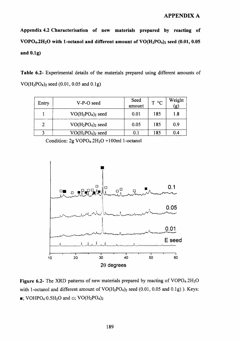
APPENDIX A
Appendix 4.2 Characterisation of new materials prepared by reacting of
VOPO 4 .2 H 2 O with 1-octanol and different amount of V 0 (H2 P0 4 ) 2 seed (0.01, 0.05
and O.lg)
Table 6.2- Experimental details o f the materials prepared using different amounts o f
V 0 (H2P0 4)2 seed (0 .0 1 , 0.05 and O.lg)
Entry V -P-0 seed Seedamount T °C
Weight(g)
1 V 0 (H2P0 4)2 seed 0 .0 1 185 1 .8
2 V 0 (H2P0 4)2 seed 0.05 185 0.9
3 VO(H2P0 4)2 seed 0 .1 185 0.4
Condition: 2g VOPO 4 .2 H2O + 100ml 1-octanol
0 .0 5
0.01
E seed
40 50 60302010
20 degrees
Figure 6.2- The XRD patterns o f new materials prepared by reacting o f VOPO4 .2 H2O
with 1-octanol and different amount o f VO(H2PC>4)2 seed (0.01, 0.05 and O .lg )). Keys:
■; VOHPO4 0.5H2O and □; V 0 (H2P0 4)2
189
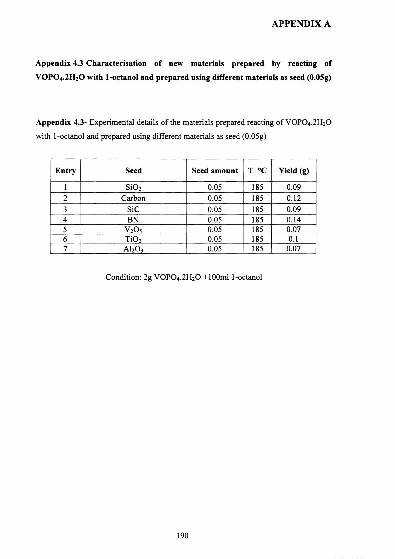
APPENDIX A
Appendix 4.3 Characterisation of new materials prepared by reacting of
VOPO 4 .2 H 2 O with 1-octanol and prepared using different materials as seed (0.05g)
Appendix 4.3- Experimental details o f the materials prepared reacting o f VOPO4 .2 H2O
with 1-octanol and prepared using different materials as seed (0.05g)
Entry Seed Seed amount T °C Yield (g)
1 S i0 2 0.05 185 0.092 Carbon 0.05 185 0 .1 2
3 SiC 0.05 185 0.094 BN 0.05 185 0.145 V 2O5 0.05 185 0.076 T i0 2 0.05 185 0 .1
7 AI2O3 0.05 185 0.07
Condition: 2g VOPO 4 .2 H2O + 100ml 1-octanol
190
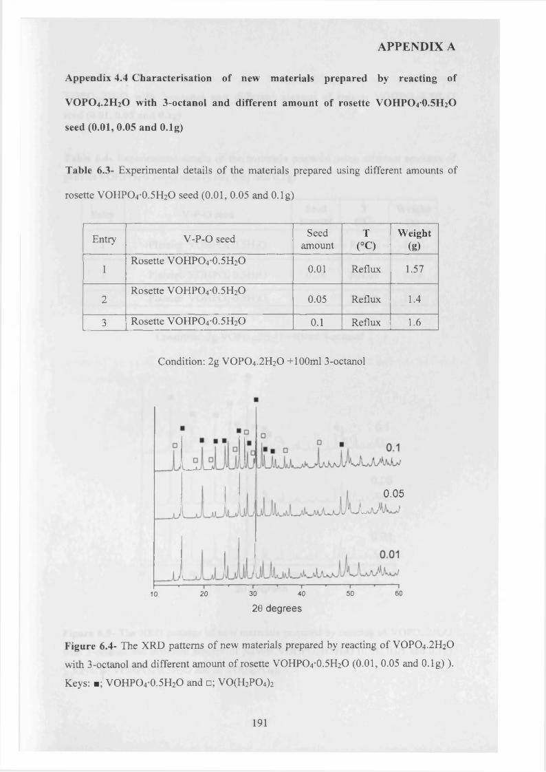
APPENDIX A
Appendix 4.4 C haracterisation of new m aterials prepared by reacting of
VOPO 4.2 H 2O with 3-octanol and different am ount of rosette VOHPO 4*0 .5 H 2O
seed (0.01, 0.05 and O.lg)
Table 6.3- Experimental details o f the materials prepared using different amounts of
rosette VOHPO4 0.5H2O seed (0.01, 0.05 and O.lg)
Entry V -P-0 seed Seedamount
T(°C)
Weight(g)
1Rosette VOHPO4 0.5H2O
0 .0 1 Reflux 1.57
2Rosette VOHPO4 0.5H2O
0.05 Reflux 1.4
3 Rosette VOHPO4 0.5H2O 0 .1 Reflux 1 .6
Condition: 2g VOPO4.2 H2O +100ml 3-octanol
0.05
L
50 6020 30 4010
20 degrees
Figure 6.4- The XRD patterns of new materials prepared by reacting of VOPO4 .2 H2O
with 3-octanol and different amount of rosette VOHPO4 0 .5 H2O (0.01, 0.05 and O.lg) ).
Keys: ■; VOHPO4 0.5H2O and □; V0 (H2P0 4)2
191
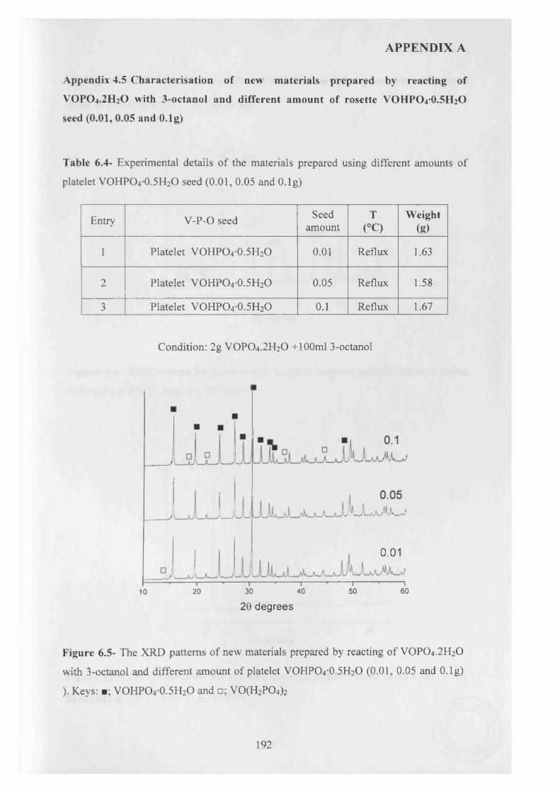
APPENDIX A
Appendix 4.5 C haracterisation of new m aterials prepared by reacting of
VOPO 4.2 H2O with 3-octanol and different am ount of rosette VOHPO 4*0 .5 H 2O
seed (0.01, 0.05 and O.lg)
Table 6.4- Experimental details o f the materials prepared using different amounts of
platelet VOHPO4 0.5H2O seed (0.01, 0.05 and O.lg)
Entry V -P-0 seed Seedamount
T(°C)
W eight(g)
1 Platelet VOHPO4 0.5H2O 0 .0 1 Reflux 1.63
2 Platelet VOHPO4 0.5H2O 0.05 Reflux 1.58
3 Platelet VOHPO4 0.5H2O 0 .1 Reflux 1.67
Condition: 2g VOPO4 .2 H2O +100ml 3-octanol
0.01
40 50 6020 3010
20 degrees
Figure 6.5- The XRD patterns o f new materials prepared by reacting of VOPO4 .2 H2O
with 3-octanol and different amount of platelet VOHPO4 O.5 H2O (0.01, 0.05 and O.lg)
). Keys: ■; VOHPO4 0.5H2O and □; V0(H2P04)2
192
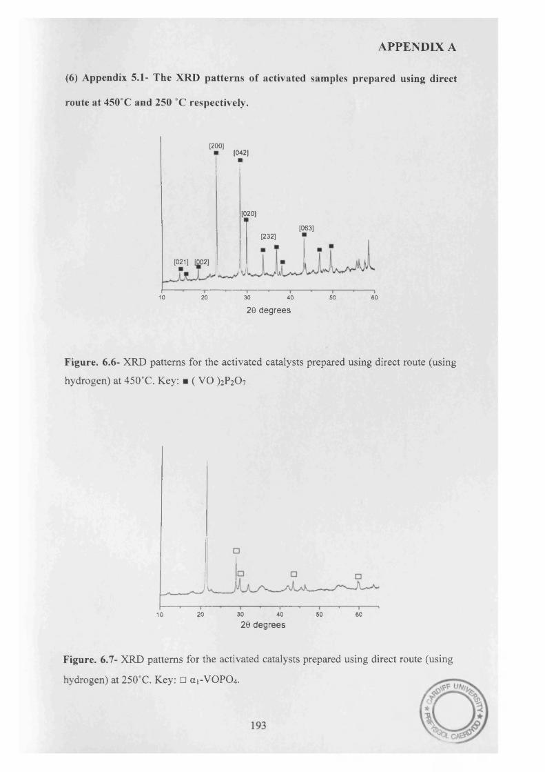
APPENDIX A
(6) Appendix 5.1- The XRD patterns of activated samples prepared using direct
route at 450°C and 250 °C respectively.
[200][042]
[020]
[063][232]
[021] [002]
10 20 30 40 50 60
20 degrees
Figure. 6.6- XRD patterns for the activated catalysts prepared using direct route (using
hydrogen) at 450°C. Key: ■ ( VO )2 ? 2 0 7
20 30 40 50 6010
20 degrees
Figure. 6.7- XRD patterns for the activated catalysts prepared using direct route (using
hydrogen) at 250°C. Key: □ (X1-VOPO 4 .
Related Documents