Shell Australia Pty Ltd 2.0 Prelude FLNG Terminal Information Book - LPG 06/12/2017 Document No: OPS_GEN_012470 UNRESTRICTED Page 1 of 87 “Copy No 01” is always electronic: all printed copies of “Copy No 01” are to be considered uncontrolled. Prelude FLNG Terminal Information Book LPG Originating Company Shell Australia Department General Operations Document Number OPS_GEN_012470 Revision Number 2.0 Document Type Manual [BMS] Document Status Final Publish Date 06/12/2017 Cyclical Review Cycle 06/12/2019 Safety Critical Content true Technical Reviewer TA 2 or SME Marine Coordinator Process Owner Head of Marine Security Classification Unrestricted Export Classification Number Non-US content - Non Controlled

Welcome message from author
This document is posted to help you gain knowledge. Please leave a comment to let me know what you think about it! Share it to your friends and learn new things together.
Transcript

Shell Australia Pty Ltd 2.0
Prelude FLNG Terminal Information Book - LPG 06/12/2017
Document No: OPS_GEN_012470 UNRESTRICTED Page 1 of 87
“Copy No 01” is always electronic: all printed copies of “Copy No 01” are to be considered uncontrolled.
Prelude FLNG Terminal Information Book LPG
Originating Company Shell Australia
Department General Operations
Document Number OPS_GEN_012470
Revision Number 2.0
Document Type Manual [BMS]
Document Status Final
Publish Date 06/12/2017
Cyclical Review Cycle 06/12/2019
Safety Critical Content true
Technical Reviewer TA2 or SME Marine Coordinator
Process Owner Head of Marine
Security Classification Unrestricted
Export Classification Number Non-US content - Non Controlled

Shell Australia Pty Ltd 2.0
Prelude FLNG Terminal Information Book - LPG 06/12/2017
Document No: OPS_GEN_012470 UNRESTRICTED Page 2 of 87
“Copy No 01” is always electronic: all printed copies of “Copy No 01” are to be considered uncontrolled.
Ver. Version Update Description Date Changed BCD Development Roles
Authors, Reviewers, Approvers
0.1 Draft issued for comments 9/17/2015
Richard Smith
Martin Howle
Stuart Symons
Peter Hicks
Jonathan Wilson
Author
Reviewer (IP)
Reviewer (TA2)
Reviewer (IP)
Reviewer (SME)
1.0 Issued for approval 5/29/2017
Jonathan Wilson
Enter Name.
Enter Name.
Enter Name.
Enter Name.
Approver (PO)
Choose an item.
Choose an item.
Choose an item.
Choose an item.
2.0
Minor updates- fitment of additional spool pieces
Location of additional spool pieces
Security Details
Document Review
Security Classification Change
11/28/2017
Tyron Grasso
Joseph Pereira
Jonathan Wilson
Enter Name.
Enter Name.
Reviewer (IP)
Reviewer (SME)
Approver (PO)
Choose an item.
Choose an item.
Click here to enter a date.
Enter Name.
Enter Name.
Enter Name.
Enter Name.
Enter Name.
Choose an item.
Choose an item.
Choose an item.
Choose an item.
Choose an item.
Shell Australia Pty Ltd 2.0
Prelude FLNG Terminal Information Book - LPG 06/12/2017
Document No: OPS_GEN_012470 UNRESTRICTED Page 3 of 87
“Copy No 01” is always electronic: all printed copies of “Copy No 01” are to be considered uncontrolled.
TABLE OF CONTENTS Abbreviation List ........................................................................................................................ 8
1. Objective – Prelude Terminal Information Book - LPG ............................................ 10
1.1. Conditions of Use .................................................................................................. 10
1.2. Safety Declaration ................................................................................................. 10
2. Prelude Description ............................................................................................. 11
3. Fire and Emergency Response ............................................................................. 12
3.1 Emergency Alarms ................................................................................................ 12
3.2 Emergency Communications ................................................................................... 12
3.3 Emergency Actions ................................................................................................ 13
3.4 Emergency Precautions .......................................................................................... 14
4. Safety and Security ............................................................................................. 15
4.1 General ................................................................................................................ 15
4.1.1 Anchors ................................................................................................................ 16
4.2 Port and Terminal Security ..................................................................................... 16
4.2.1 ISPS Requirements ................................................................................................. 16
4.2.2 Personnel Access ................................................................................................... 17
4.3 Engine Testing ....................................................................................................... 17
4.4 Diving Operations ................................................................................................. 17
5. Pre-Arrival Procedures ........................................................................................... 17
5.1 ETA Advice ........................................................................................................... 17
5.2 VHF Communication .............................................................................................. 18
5.3 Immigration, Customs, Quarantine and Health ........................................................ 18
5.3.1 Immigration .......................................................................................................... 18
5.3.2 Customs ................................................................................................................ 18
5.3.3 Quarantine ........................................................................................................... 18
5.3.4 Health .................................................................................................................. 18
5.4 National Fees and Levy’s ....................................................................................... 18
5.5 Pollution and the Environment ................................................................................ 18
5.6 Ballast Water Management .................................................................................... 19
6. Metocean Conditions .......................................................................................... 20
6.1 General ................................................................................................................ 20
6.2 Visibility ............................................................................................................... 22
6.3 Tsunami ................................................................................................................ 22
6.4 Solitons................................................................................................................. 23
Shell Australia Pty Ltd 2.0
Prelude FLNG Terminal Information Book - LPG 06/12/2017
Document No: OPS_GEN_012470 UNRESTRICTED Page 4 of 87
“Copy No 01” is always electronic: all printed copies of “Copy No 01” are to be considered uncontrolled.
7. Arrival off Port .................................................................................................... 24
7.1 Communications .................................................................................................... 24
7.2 Limiting Environmental Criteria – General ............................................................... 24
7.3 Limiting Environmental Criteria – Personnel Transfer ................................................ 25
7.4 Limiting Environmental Criteria – Spool Piece Transfer .............................................. 25
7.5 Limiting Environmental Criteria – Berthing ............................................................... 26
7.6 Limiting Environmental Criteria – Offtake ................................................................ 26
7.7 Approach to Prelude .............................................................................................. 27
7.8 Notice of Readiness ............................................................................................... 28
8. Berthing and Mooring ......................................................................................... 29
8.1 Berthing and Unberthing Criteria ............................................................................ 29
8.2 Pilotage ................................................................................................................ 29
8.2.1 Pilot Boarding Area ............................................................................................... 29
8.2.2 Personnel Transfer ................................................................................................. 29
8.2.3 Pilot Ladder ........................................................................................................... 29
8.2.4 Personnel Embarked on LPGC ................................................................................ 29
8.2.5 Personal Protective Equipment (PPE) ........................................................................ 30
8.3 Infield Support Vessels (ISV) ................................................................................... 30
8.4 ISV arrangements for berthing / un-berthing ........................................................... 30
8.5 ISV arrangements during cargo transfer .................................................................. 30
8.6 Manifold Spool Piece Targeting Cones .................................................................... 30
8.6.1 Spool Piece Transfer – General ............................................................................... 30
8.6.2 Spool Piece Transfer – LPGC Stinger ....................................................................... 31
8.6.3 Targeting Spool Piece Fitting and Removal .............................................................. 31
8.7 Helicopters ............................................................................................................ 33
8.8 LPGC Berthing – General ....................................................................................... 33
8.8.1 Ballast, Trim and Stability ....................................................................................... 33
8.9 Berthing ................................................................................................................ 33
8.9.1 Berthing Aid System .............................................................................................. 33
8.9.2 Berthing Method .................................................................................................... 34
8.10 Mooring ............................................................................................................... 36
8.10.1 Mooring - General ................................................................................................ 36
8.10.2 Mooring order of events......................................................................................... 37
8.11 Provision of Mooring Crews on Prelude ................................................................... 38
8.12 Weighted Heaving Lines ........................................................................................ 38
Shell Australia Pty Ltd 2.0
Prelude FLNG Terminal Information Book - LPG 06/12/2017
Document No: OPS_GEN_012470 UNRESTRICTED Page 5 of 87
“Copy No 01” is always electronic: all printed copies of “Copy No 01” are to be considered uncontrolled.
8.13 Fendering Arrangement ......................................................................................... 39
8.14 Provision of Ship / FLNG Access ............................................................................ 39
9. Communications ................................................................................................. 40
9.1 Language ............................................................................................................. 40
9.2 Operational Agreements ........................................................................................ 40
9.3 Communications Whilst Berthed ............................................................................. 40
9.4 ESD System ........................................................................................................... 40
9.4.1 ESD - Pyle National Electric Ship-Shore Link ............................................................ 41
9.4.2 ESD - SIGTTO Electric Ship-Shore Link .................................................................... 41
9.4.3 ESD – SIGTTO Pendant Ship-Shore Link .................................................................. 41
9.5 ESD Activation ...................................................................................................... 41
9.5.1 Stage 1 – Marine ESD 1 ........................................................................................ 41
9.5.2 Stage 2 – Marine ESD 2 ........................................................................................ 41
10. Operations Alongside ......................................................................................... 42
10.1 Vessel’s Arrival Condition ...................................................................................... 42
10.1.1 Heel and Arrival Temperature Requirements ............................................................ 42
10.1.2 Arrival Pressure ..................................................................................................... 42
10.2 Loading arm Connection ........................................................................................ 42
10.2.1 Strainers ............................................................................................................... 43
10.2.2 Pressure Test and Purge of Marine Loading Arms ..................................................... 43
10.3 Safety Inspection ................................................................................................... 43
10.4 Pre-Loading Meeting ............................................................................................. 43
10.5 Emergency Shut Down (ESD) system tests ................................................................ 44
10.6 Gauging ............................................................................................................... 45
10.6.1 Reliquefication Plants (Reliq Plants) ......................................................................... 45
10.7 Venting ................................................................................................................. 45
10.8 Cargo Transfer Procedures ..................................................................................... 45
10.8.1 Arm and Line Cooldown ........................................................................................ 45
10.9 Bulk Loading and Topping Off ................................................................................ 46
10.9.1 Vapour Return to Prelude ....................................................................................... 46
10.9.2 Ramp Up, Full Rate and Ramp Down ...................................................................... 46
10.10 Draining and Inerting Loading Arms ....................................................................... 47
10.11 Cargo Documentation and Early Departure Procedure (EDP) .................................... 48
11. Unmooring Parameters and Procedures ................................................................ 49
11.2 Removal of Spool Pieces .............................................................................................. 49

Shell Australia Pty Ltd 2.0
Prelude FLNG Terminal Information Book - LPG 06/12/2017
Document No: OPS_GEN_012470 UNRESTRICTED Page 6 of 87
“Copy No 01” is always electronic: all printed copies of “Copy No 01” are to be considered uncontrolled.
12. Services ............................................................................................................. 50
12.1 Medical Emergency ............................................................................................... 50
12.2 Craft Alongside ..................................................................................................... 50
12.3 Waterborne Testing of Lifeboats / Rescue Craft ....................................................... 50
12.4 Main Engine Readiness .......................................................................................... 50
12.5 Repairs ................................................................................................................. 50
12.6 Smoking ............................................................................................................... 51
12.7 Hot Work and Use of Naked Lights ......................................................................... 51
12.8 Ventilators and Air Condition Units ......................................................................... 51
12.9 Transmitting Devices .............................................................................................. 51
12.11 Drug and Alcohol Policy ........................................................................................ 52
Appendix A: Safety Letter ......................................................................................................... 53
Appendix B: Required Boarding Arrangement for Pilots TTL ......................................................... 54
Appendix C: Prelude FLNG–Declaration of Security between a ship and a port facility .................. 59
Appendix D: ETA Notices: LPG ................................................................................................. 61
Appendix E: Infield Support Vessel (ISV) Specifications ............................................................... 65
Appendix F: Targeting Spool Pieces........................................................................................... 66
Appendix G: Targeting Spool Pieces and Baskets ....................................................................... 67
Appendix H: Generic Mooring Plan – LPGC Tanker .................................................................... 68
Appendix I: Ship Shore Link Pin Configurations .......................................................................... 69
Appendix J: Marine Arms Connecting / Disconnecting ............................................................... 71
Appendix K: Ship / FLNG Safety Checklist................................................................................. 75
Appendix L: Cargo Handling Agreement ................................................................................... 84
Appendix M: ESD Envelopes ..................................................................................................... 85
Appendix N: Field Layout Diagram ........................................................................................... 87
Appendix O: Prelude/Ichthys Field Diagram .............................................................................. 87
Shell Australia Pty Ltd 2.0
Prelude FLNG Terminal Information Book - LPG 06/12/2017
Document No: OPS_GEN_012470 UNRESTRICTED Page 7 of 87
“Copy No 01” is always electronic: all printed copies of “Copy No 01” are to be considered uncontrolled.
LIST OF FIGURES
FIGURE 1: APPROXIMATE PRELUDE FLPG LOCATION ......................................................................... 11 FIGURE 2: ALL-YEAR WIND SPEED VS DIRECTION DISTRIBUTION FOR 10-MIN MEAN WIND SPEED AT
10M ABOVE SEA LEVEL ............................................................................................................ 21 FIGURE 3: ALL-YEAR SIGNIFICANT WAVE HEIGHT VS DIRECTION DISTRIBUTION FOR WIND-SEA ..... 22 FIGURE 4: FMC MAX PERMISSIBLE CANTILEVER ................................................................................ 31 FIGURE 5: CANTILEVER MEASUREMENT ........................................................................................... 32 FIGURE 6: EXTERNAL ANTENNAE UNIT FOR BERTHING AID SYSTEM ................................................ 34 FIGURE 7: EXTENDED ANTENNAE FOR BERTHING AID SYSTEM ........................................................ 34 FIGURE 8: BERTHING IN PREDOMINANTLY AHEAD METOCEAN ENVIRONMENT .............................. 35 FIGURE 9: BERTHING LINE ................................................................................................................ 35 FIGURE 10: MOORING TAIL / PENNANT FITTED WITH JOCKEY ROPE ............................................... 36 FIGURE 11: RIGGING OF EMERGENCY TOWING OFF PENNANT ..................................................... 38 FIGURE 12: PRELUDE – GENERAL FENDER CONFIGURATION (FENDER 3 & 4) ................................... 39 FIGURE 13: PILOT LADDER REQUIREMENTS FOR FREEBOARD EXCEEDING 9.0 METRES (SOLAS
CHAPTER V 23) ......................................................................................................................... 56 FIGURE 14: RIGGING OF COMBINATION AND TRAP DOOR LADDERS .............................................. 57 FIGURE 15: REQUIRED BOARDING ARRANGEMENTS FOR PILOT ...................................................... 58 FIGURE 16: TARGETING SPOOL PIECE - DESIGN ............................................................................... 66 FIGURE 17: TARGETING SPOOL PIECE TRANSFER BASKET ................................................................ 67
LIST OF TABLES TABLE OF CONTENTS......................................................................................................................... 3 TABLE 3.1: ALARM SIGNALS ............................................................................................................. 12 TABLE 3.2: EMERGENCY ACTION PROTOCOL .................................................................................. 13 TABLE 4.1: SECURITY CONTACT DETAILS .......................................................................................... 17 TABLE 5.1: PRELUDE MEAN WIND STATISTICS .................................................................................. 20 TABLE 5.2: PRELUDE MEAN RAINFALL STATISTICS ............................................................................. 20 TABLE 5.3: PRELUDE MEAN AIR TEMPERATURE STATISTICS ................................................................ 20 TABLE 5.4: PRELUDE MEAN SEA WATER TEMPERATURE STATISTICS .................................................. 21 TABLE 7.1: PRELUDE COMMUNICATION CHANNELS ........................................................................ 24 TABLE 7.2: ENVIRONMENTAL LIMITS FOR PERSONNEL TRANSFER .................................................... 25 TABLE 7.3: ENVIRONMENTAL LIMITS FOR SPOOL PIECE TRANSFER ................................................... 25 TABLE 7.4: ENVIRONMENTAL LIMITS FOR BERTHING ........................................................................ 26 TABLE 7.5: ENVIRONMENTAL LIMITS FOR OFFTAKE .......................................................................... 27 TABLE 7.6: PRELUDE OPERATOR CONTACT DETAILS ......................................................................... 28 TABLE 9.1: EXAMPLE OF RAMP UP RATE ........................................................................................... 46
Shell Australia Pty Ltd 2.0
Prelude FLNG Terminal Information Book - LPG 06/12/2017
Document No: OPS_GEN_012470 UNRESTRICTED Page 8 of 87
“Copy No 01” is always electronic: all printed copies of “Copy No 01” are to be considered uncontrolled.
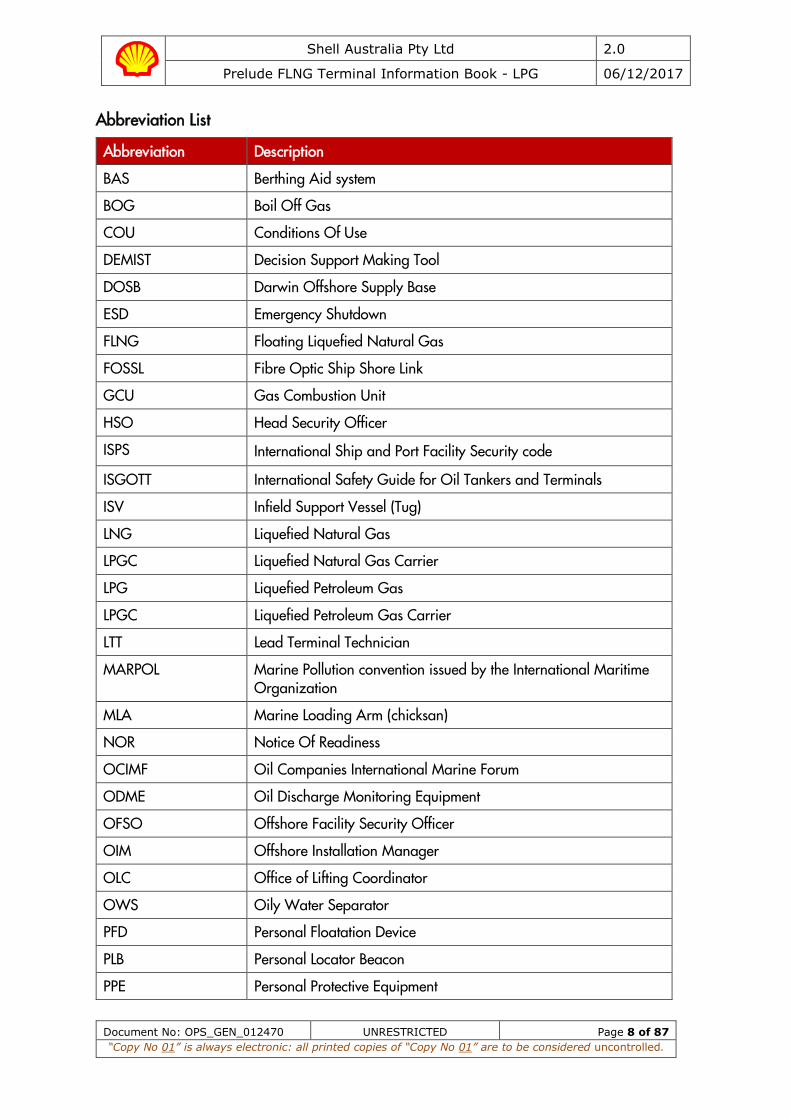
Abbreviation List
Abbreviation Description
BAS Berthing Aid system
BOG Boil Off Gas
COU Conditions Of Use
DEMIST Decision Support Making Tool
DOSB Darwin Offshore Supply Base
ESD Emergency Shutdown
FLNG Floating Liquefied Natural Gas
FOSSL Fibre Optic Ship Shore Link
GCU Gas Combustion Unit
HSO Head Security Officer
ISPS International Ship and Port Facility Security code
ISGOTT International Safety Guide for Oil Tankers and Terminals
ISV Infield Support Vessel (Tug)
LNG Liquefied Natural Gas
LPGC Liquefied Natural Gas Carrier
LPG Liquefied Petroleum Gas
LPGC Liquefied Petroleum Gas Carrier
LTT Lead Terminal Technician
MARPOL Marine Pollution convention issued by the International Maritime Organization
MLA Marine Loading Arm (chicksan)
NOR Notice Of Readiness
OCIMF Oil Companies International Marine Forum
ODME Oil Discharge Monitoring Equipment
OFSO Offshore Facility Security Officer
OIM Offshore Installation Manager
OLC Office of Lifting Coordinator
OWS Oily Water Separator
PFD Personal Floatation Device
PLB Personal Locator Beacon
PPE Personal Protective Equipment

Shell Australia Pty Ltd 2.0
Prelude FLNG Terminal Information Book - LPG 06/12/2017
Document No: OPS_GEN_012470 UNRESTRICTED Page 9 of 87
“Copy No 01” is always electronic: all printed copies of “Copy No 01” are to be considered uncontrolled.
Abbreviation Description
QC/DC Quick Connect / Disconnect
Reliq Plant Reliquefication Plants
SBT Segregated Ballast Tanks
SIGTTO Society of International Gas Tanker & Terminal Operators
TTL Terminal Team Leader (Pilot / Loading Master)
UHF Ultra-High Frequency
VHF Very High Frequency
WMS Integrate Weather Monitoring System

Shell Australia Pty Ltd 2.0
Prelude FLNG Terminal Information Book - LPG 06/12/2017
Document No: OPS_GEN_012470 UNRESTRICTED Page 10 of 87
“Copy No 01” is always electronic: all printed copies of “Copy No 01” are to be considered uncontrolled.
1. Objective – Prelude Terminal Information Book - LPG
This Terminal Information Book has been produced to meet the information needs of users (LPG Carriers) of the Prelude Floating Liquefied Natural Gas (FLNG) Terminal (hereafter referred to as Prelude in the Terminal Information book and FLNG Facility in the conditions of use).
The Booklet contains general port information, applicable regulations, safe work procedures and emergency response details, together with specific information governing the operations of ships at the Prelude Berths.
The information in the Booklet should be used in conjunction with the industry recommended practices contained in the latest edition of the “Liquid Gas Handling Principles on Ships and in Terminals published by the Society of International Gas Tanker & Terminal Operators (SIGTTO) and the International Safety Guide for Oil Tankers and Terminals (ISGOTT) published by Oil Companies International Marine Forum (OCIMF) as applicable and in particular the respective Ship/ Shore (FLNG) Safety Check List.
While the information herein is believed to be correct at the time of publishing this Booklet, the Terminal Operator makes no guarantee and assumes no responsibilities regarding it or any information which may appear in supplemental publications.
1.1. Conditions of Use Masters of all ship’s using the Prelude Marine Terminal will be required to sign a copy of the Conditions of Use (COU) in acknowledgement of the ship’s responsibilities and liabilities whilst calling at the terminal. A copy of the COU can be found in Prelude Terminal Regulations.
1.2. Safety Declaration Prior to commencing cargo operations, the Terminal Team Leader (TTL), and Master shall read, agree and sign a copy of the Prelude safety letter, available in Appendix A. The TTL will execute the pilotage and loadmaster activities.
Shell Australia Pty Ltd 2.0
Prelude FLNG Terminal Information Book - LPG 06/12/2017
Document No: OPS_GEN_012470 UNRESTRICTED Page 11 of 87
“Copy No 01” is always electronic: all printed copies of “Copy No 01” are to be considered uncontrolled.
2. Prelude Description
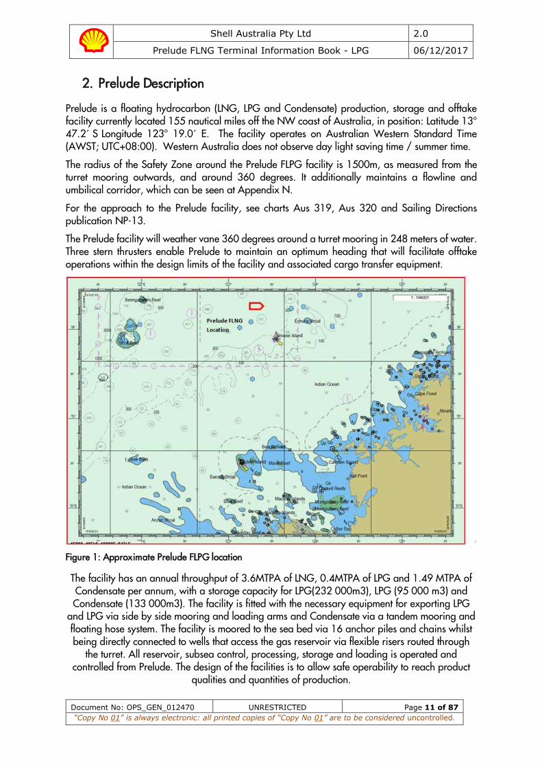
Prelude is a floating hydrocarbon (LNG, LPG and Condensate) production, storage and offtake facility currently located 155 nautical miles off the NW coast of Australia, in position: Latitude 13° 47.2´ S Longitude 123° 19.0´ E. The facility operates on Australian Western Standard Time (AWST; UTC+08:00). Western Australia does not observe day light saving time / summer time.
The radius of the Safety Zone around the Prelude FLPG facility is 1500m, as measured from the turret mooring outwards, and around 360 degrees. It additionally maintains a flowline and umbilical corridor, which can be seen at Appendix N.
For the approach to the Prelude facility, see charts Aus 319, Aus 320 and Sailing Directions publication NP-13.
The Prelude facility will weather vane 360 degrees around a turret mooring in 248 meters of water. Three stern thrusters enable Prelude to maintain an optimum heading that will facilitate offtake operations within the design limits of the facility and associated cargo transfer equipment.
Figure 1: Approximate Prelude FLPG location
The facility has an annual throughput of 3.6MTPA of LNG, 0.4MTPA of LPG and 1.49 MTPA of Condensate per annum, with a storage capacity for LPG(232 000m3), LPG (95 000 m3) and Condensate (133 000m3). The facility is fitted with the necessary equipment for exporting LPG
and LPG via side by side mooring and loading arms and Condensate via a tandem mooring and floating hose system. The facility is moored to the sea bed via 16 anchor piles and chains whilst being directly connected to wells that access the gas reservoir via flexible risers routed through
the turret. All reservoir, subsea control, processing, storage and loading is operated and controlled from Prelude. The design of the facilities is to allow safe operability to reach product
qualities and quantities of production.

Shell Australia Pty Ltd 2.0
Prelude FLNG Terminal Information Book - LPG 06/12/2017
Document No: OPS_GEN_012470 UNRESTRICTED Page 12 of 87
“Copy No 01” is always electronic: all printed copies of “Copy No 01” are to be considered uncontrolled.
3. Fire and Emergency Response
3.1 Emergency Alarms Alarm signals at this terminal are as follows:
Table 3.1: Alarm signals
Alarm Visual Audible Initiation
General alarm (GA) Flashing amber beacons in high noise areas
Sinusoidal tone over the public address system
ESD activation (either manual or automatic0 or “confirmed” fire and gas. Manual alarm point activation or manual GA initiation
Prepare to Abandon Facility Alarm (PAPA)
Flashing amber beacons in high noise areas
Continuous single tone + public address announcement
Responsibility of the OIM or his deputy as per the chain of command
Abandon Facility Alarm
Flashing amber beacons in high noise areas
Continuous single tone + OIM final instruction
Responsibility of the OIM or his deputy as per the chain of command
• By Ship: One or more long blasts on the ship’s whistle, each blast not less than ten seconds duration, supplemented by a continuous sound of the general alarm system.
3.2 Emergency Communications The Terminal Team Leader (TTL) will remain on-board during the vessel’s stay alongside as the Prelude representative and will liaise between the LPGC and Prelude in the event of an emergency.
The primary method of communication between Prelude and the LPGC will be via the dedicated ship-FLNG hotline. This hotline is provided via the Fibre Optic Ship Shore Link (FOSSL) or the Pyle-National electric ship-shore link, as appropriate.
Secondary means of communication will be via portable marine UHF radio provided by the Terminal Team Leader to the LPGC on their arrival. The LPGC may contact “Prelude Terminal” on this radio at any time.
For vessels fitted with a SIGTTO electrical ship-shore link, the primary means of communication between the Prelude and the LPGC will be via the portable marine UHF radio, as the SIGTTO ship-shore link does not allow for communications. The secondary means of communication will be via the marine VHF radio on the dedicated channels as instructed by the TTL during the pre-load meeting.
Additionally, the LPGC shall monitor the VHF Channels as specified by the Terminal at all times.

Shell Australia Pty Ltd 2.0
Prelude FLNG Terminal Information Book - LPG 06/12/2017
Document No: OPS_GEN_012470 UNRESTRICTED Page 13 of 87
“Copy No 01” is always electronic: all printed copies of “Copy No 01” are to be considered uncontrolled.
3.3 Emergency Actions LPGCs must remain in a state of readiness for vacating the berth at short notice. Therefore, no repairs, which would prevent or delay this departure, will be permitted
When the General Alarm is sounded, ships should stand by for possible stoppage of operations, including ESD.
Other than Marine ESD1, ship staff must not initiate any action of their own concerning shutting down of valves (etc) unless their ship is in immediate danger. Ships must await instruction from the TTL or “Prelude Terminal” before taking action regarding cargo operations.
No attempt must be made to unmoor and depart from Prelude without instructions from the Terminal Team Leader (TTL).
Table 3.2: Emergency Action Protocol
Action by LPGC Action by Prelude
Emergency on your LPGC Emergency on an LPGC
Raise the alarm Raise the alarm
Consider use of ESD1.
Stop de-ballast operation if safe to do so
Cease all cargo operations and close all valves Contact LPGC and establish nature of incident
Inform TTL and / or “Prelude Terminal” Activate Prelude’s emergency response procedures.
Activate LPGCs emergency response procedures. If necessary, stand by to assist fire fighting
Stand by to purge & disconnect MLAs Prepare to purge & disconnect MLAs
Bring engines to immediate standby Inform ISV and / or other vessels in vicinity
Prepare for departure from prelude Prepare for LPGC departure
Emergency on Prelude Emergency on Prelude
Stand by, and when instructed: Raise the alarm and activate Prelude’s emergency response procedures.
Consider use of ESD1.
Stop de-ballast operation if safe to do so.
Cease all cargo operations and close all valves Contact LPGC and explain nature of incident and LPGC requirements
Stand by to purge & disconnect MLAs Stand by to purge & disconnect MLAs
Bring engines to immediate standby Prepare for LPGC departure
Prepare to depart from prelude
Shell Australia Pty Ltd 2.0
Prelude FLNG Terminal Information Book - LPG 06/12/2017
Document No: OPS_GEN_012470 UNRESTRICTED Page 14 of 87
“Copy No 01” is always electronic: all printed copies of “Copy No 01” are to be considered uncontrolled.
3.4 Emergency Precautions All fire-fighting equipment shall be in good working order with portable equipment correctly stowed and ready for immediate use. The LPGC fire main shall be pressurized whilst alongside Prelude.
In order to manage potential emergencies, the LPGC shall arrange:
(a) A minimum of two fire hoses, fitted with jet/spray nozzles, uncoiled and connected to the fire main on the upper deck.
(b) A minimum of two fire hoses, fitted with jet/spray nozzles, uncoiled and connected to the fire main in the vicinity of the port manifold.
(c) The ships water deluge and dry chemical powder firefighting system should be prepared and ready for immediate use.
(d) The ships outboard lifeboat shall be rigged at embarkation level for use as an emergency escape, except for those vessels on which embarkation level is the normal stowed position.
(e) A pilot ladder or accommodation ladder shall be rigged or positioned on the outboard side of the vessel ready for immediate lowering as a means of escape in the event of emergency.
The above preparations on deck will be jointly checked by the responsible officer and the TTL during the safety inspection. In the event of an emergency, the Master shall proceed as agreed in the pre-operations meeting.
Shell Australia Pty Ltd 2.0
Prelude FLNG Terminal Information Book - LPG 06/12/2017
Document No: OPS_GEN_012470 UNRESTRICTED Page 15 of 87
“Copy No 01” is always electronic: all printed copies of “Copy No 01” are to be considered uncontrolled.
4. Safety and Security
4.1 General During cargo operations, the sea around the LPGC and Prelude shall be constantly monitored by Prelude and LPGC staff for any sign of oil / oily sheen or any abnormalities. If oil / oily sheen or any abnormality is observed, cargo operations will be suspended where required and an investigation initiated into the source of the oil. Cargo operations will not be resumed until the source is found and addressed, or it is determined that the oil is not emanating from either the LPGC or Prelude.
Fire-fighting or lifesaving appliances on the LPGC shall not be immobilised whilst within the 1500m safety zone; such equipment shall be prepared and in a state of readiness for immediate use.
Whilst alongside the Prelude, as practically as possible the LPGCs main engines and related auxiliaries shall be kept in a state of readiness such that the LPGC can leave under her own power in an emergency. Repairs and/or maintenance work to the main engines and related auxiliaries are prohibited.
The LPGC must ensure that the fuel rail is under constant circulation and ‘starting-air’ bottles are fully charged.
Whilst alongside Prelude, repairs and maintenance to the LPGCs machinery and equipment shall be restricted to those items, which do not impair or limit the use of:
• The fire detection or fire-fighting capability, • The safe and efficient handling of the cargo, • The propulsion system or manoeuvrability of the tanker, • The integrity of the mooring system, and • The safe operation of electrical equipment in gas dangerous zones.
Confined space entry activities are not permitted whilst alongside Prelude other than those specifically required for a safe cargo operations i.e Pumprooms, Compressor Rooms and Electrical Motor Rooms.
In the event that the vessel experiences an incident while moored at Prelude that affects the maneuverability of the vessel or safety of cargo transfer operations, the Terminal Team Leader (TTL) shall be immediately notified. The Terminal Team Leader (TTL) and vessel Master shall agree on appropriate actions to mitigate any dangers to both parties and the safety of cargo operations.
Consumption of alcohol and drugs should be strictly controlled and in accordance with the LPGC procedures.
Shell Australia Pty Ltd 2.0
Prelude FLNG Terminal Information Book - LPG 06/12/2017
Document No: OPS_GEN_012470 UNRESTRICTED Page 16 of 87
“Copy No 01” is always electronic: all printed copies of “Copy No 01” are to be considered uncontrolled.
4.1.1 Anchors
The vessels anchors are to be secured in the seagoing condition (lashing wire on and guillotine down) prior to commencing the approach to Prelude. Under no circumstances is the seagoing security of the anchors to be altered whilst the vessel is under pilotage.
Untrenched pipelines carrying hydrocarbons lie from the FLPG Prelude Turret in a SSE’ly direction. Refer to Appendix P for diagram of the Prelude subsea layout.
4.1.2 Cathodic Protection
A vessels cathodic protection should be turned off prior to arrival alongside Prelude. It may only be turned on once the vessel departs
4.2 Port and Terminal Security
4.2.1 ISPS Requirements
The Prelude Offshore Security Plan has been prepared in accordance with the provisions of the International Ship and Port Facility Security (ISPS) Code. It is a mandatory requirement to comply with the above code.
As a precaution against unauthorised access, the pilot / accommodation ladder must be kept at deck level unless requested by the Terminal Team Leader in order to prevent unpermitted access.
Any suspicious activity in the vicinity of your vessel must be immediately reported to the Terminal Team Leader (TTL) or Lead Terminal Technician (LTT).
Vessels are requested to ensure that all anti-piracy devices are removed from the following areas prior to arrival – Pilot access area, foc'sle, manifold area, and stern railings either side of the static tow point.
Entry into the Prelude 1500m safety zone is prohibited except when approved by the OIM.
The LPGC shall not be permitted to take bunkers or stores from other vessels whilst moored at Prelude or within the 1500m zone or allow any unauthorised vessel alongside.
Prelude ordinarily operates under Security Level 1. You will be informed by the Offshore Facility Security Officer (OFSO) of any change to this level and subsequent requirements. Prelude will not accept an LNGC with a security level of 3.
A Declaration of Security requirements is to be in accordance with the provisions of the ISPS code. In the event a Declaration of Security (DoS) is required, Prelude shall utilise the format provided at Appendix C.
The Offshore Facility Security Officer is the Prelude Services Coordinator and Deputy OFSO is the STL.
The TTL will act as security liaison, inboard the LNGC, with respect to any ISPS matters including completing the DoS if required.
Shell Australia Pty Ltd 2.0
Prelude FLNG Terminal Information Book - LPG 06/12/2017
Document No: OPS_GEN_012470 UNRESTRICTED Page 17 of 87
“Copy No 01” is always electronic: all printed copies of “Copy No 01” are to be considered uncontrolled.
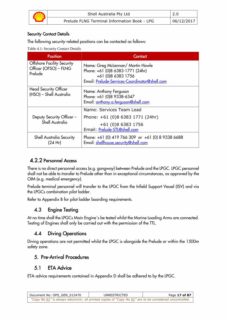
Security Contact Details
The following security-related positions can be contacted as follows:
Table 4.1: Security Contact Details
Position Contact
Offshore Facility Security Officer (OFSO) – FLNG Prelude
Name: Greg McLennan/ Martin Howle Phone: +61 (0)8 6383-1771 (24hr) +61 (0)8 6383 1756 Email: [email protected]
Head Security Officer (HSO) – Shell Australia
Name: Anthony Ferguson Phone: +61 (0)8 9338-6347 Email: [email protected]
Deputy Security Officer – Shell Australia
Name: Services Team Lead
Phone: +61 (0)8 6383 1771 (24hr)
+61 (0)8 6383 1756 Email: [email protected]
Shell Australia Security (24 Hr)
Phone: +61 (0) 419 766 309 or +61 (0) 8 9338 6688 Email: [email protected]
4.2.2 Personnel Access
There is no direct personnel access (e.g. gangway) between Prelude and the LPGC. LPGC personnel shall not be able to transfer to Prelude other than in exceptional circumstances, as approved by the OIM (e.g. medical emergency).
Prelude terminal personnel will transfer to the LPGC from the Infield Support Vessel (ISV) and via the LPGCs combination pilot ladder.
Refer to Appendix B for pilot ladder boarding requirements.
4.3 Engine Testing At no time shall the LPGCs Main Engine`s be tested whilst the Marine Loading Arms are connected. Testing of Engines shall only be carried out with the permission of the TTL.
4.4 Diving Operations Diving operations are not permitted whilst the LPGC is alongside the Prelude or within the 1500m safety zone.
5. Pre-Arrival Procedures
5.1 ETA Advice ETA advice requirements contained in Appendix D shall be adhered to by the LPGC.

Shell Australia Pty Ltd 2.0
Prelude FLNG Terminal Information Book - LPG 06/12/2017
Document No: OPS_GEN_012470 UNRESTRICTED Page 18 of 87
“Copy No 01” is always electronic: all printed copies of “Copy No 01” are to be considered uncontrolled.
5.2 VHF Communication Radio contact should be established with “Prelude Terminal” (VHF Channel 16 / 68) as follows:
a) As soon as the LPGC is within VHF range. The LPGC will be advised of the time and position for the TTL, LTT and Cargo Surveyor boarding, and
b) One (1) hour before the designated pilot on board (POB) time. As a matter of course, all LPGCs shall maintain a listening radio watch as required by international, statutory and flag regulations, as well as VHF channel 68, once initial contact with “Prelude Terminal” has been made.
5.3 Immigration, Customs, Quarantine and Health Prelude is located in waters which fall under Australian’s legal jurisdiction, including but not limited to immigration, customs and quarantine requirements.
Masters are advised to consult their Ship’s Agent for detailed information regarding applicable Australia law.
5.3.1 Immigration
Crew change and shore leave is not possible at the Prelude. Refer to Prelude FLNG Terminal Regulations for further details.
5.3.2 Customs
Prelude will not handle messages relating to customs. These matters should be dealt with via the ship’s agent or other party appointed by the ship’s operator. Refer to Prelude FLNG Terminal Regulations for further details.
5.3.3 Quarantine
Prelude will not handle messages relating to quarantine. These matters should be dealt with via the ship’s agent or other party appointed by the ship’s operator. Refer to Prelude FLNG Terminal Regulations for further details.
5.3.4 Health
Radio Pratique is required for LPGCs calling at Prelude. Vessels should send a Radio Pratique message as directed by the Australian government and via their Agent. Refer to Prelude FLNG Terminal Regulations for further details.
5.4 National Fees and Levy’s The LPGCs Master is expected to manage all Australian statutory marine levies which may apply (e.g. Marine Navigation Levy, Protection of the Sea Levy). These matters should be dealt with via the ship’s agent or other party appointed by the ship’s operator. Refer to Prelude FLNG Terminal Regulations for further details.
5.5 Pollution and the Environment The requirements of MARPOL Regulations, Australian National legislation and the tanker’s ISM shall be strictly adhered to at all times. In the event of any pollution from the tanker, it is the responsibility of the Master to initiate their SOPEP. The terminal equipment and personnel will
Shell Australia Pty Ltd 2.0
Prelude FLNG Terminal Information Book - LPG 06/12/2017
Document No: OPS_GEN_012470 UNRESTRICTED Page 19 of 87
“Copy No 01” is always electronic: all printed copies of “Copy No 01” are to be considered uncontrolled.
assist where practicable with clean-up operations however all associated costs will be to the LPGCs account.
The following shall be in place onboard the LPGC to aid pollution prevention:
a) Adherence to MARPOL to prevent any pollution. b) Whilst the vessel is within the vicinity of Prelude, no discharge from machinery space, bilge or
any other onboard space shall be made. (Overboard discharge via the ODME / OWS is to be locked closed at all times in the Safety Zone).
c) Food waste shall not be discharged to sea, including via the galley macerator. d) Vessel shall limit or refrain from the internal transfer of any oil, slops or bunker whilst alongside. e) Scuppers and ‘save alls’ on board are effectively plugged and drip trays are in position and
empty. f) Scuppers that are temporarily unplugged (for example, in order to drain clean rainwater from
the cargo deck) must be constantly and closely monitored. The scupper must be re-sealed immediately.
5.6 Ballast Water Management Prior to arrival, LPGCs intending to discharge clean ballast water at Prelude shall carry out a complete exchange of ballast water as required by Australian government’s mandatory Ballast Water Management Requirements (AQIS).
There are no ballast reception facilities at Prelude. Therefore, all ships must arrive with clean ballast in segregated ballast tanks (SBT).
Only clean ballast water from SBT tanks shall be discharged overboard. All ballast water contained in tanks not designated as SBT must be retained on board.
Safety of vessels and crews are of paramount importance. Vessels undertaking ballast water management to comply with Australian requirements should do so in accordance with the IMO Guidelines.

Shell Australia Pty Ltd 2.0
Prelude FLNG Terminal Information Book - LPG 06/12/2017
Document No: OPS_GEN_012470 UNRESTRICTED Page 20 of 87
“Copy No 01” is always electronic: all printed copies of “Copy No 01” are to be considered uncontrolled.
6. Metocean Conditions
6.1 General The climate of the region is monsoonal, and displays two distinct seasons, “winter” from April to September and “summer” from October to March, with very short transition seasons, generally in April and September/October between the two main seasons. The winter is generally dry due to South East Trade Winds coming from the Australian mainland. The summer is wet as a result of the North West Monsoon.
Occasional tropical cyclones occur during these months and result in short-lived, severe storm events, often with strong but variable winds. The summer (October – March) monsoonal surges and associated convective squalls, are also prevalent (although less severe than cyclones).
Tropical cyclones originate from south of the equator in the eastern Indian Ocean and in the Timor and Arafura Seas. They occur during the predominantly summer months November to April, being most active in the months of December to March. The most severe cyclones will most often occur in the months of December and March-April, when sea-surface temperatures are warmest.
Ambient wave conditions are dominated by swell propagating from the Indian Ocean, together with local wind-sea generated by the monsoonal winds. This can lead to significant angular differences between wind-sea and swell.
Currents result from a number of forcing mechanisms: tidal currents are high due to the strong tidal forcing, which extends much further offshore than in other regions; regional circulation related to the Pacific-Indian Ocean through-flow; currents generated by solitons, propagating onto the shelf slope in association with the internal tide; currents due to local wind stress, particularly during tropical cyclones; inertial currents following tropical cyclones. Table 6.1: Prelude Mean Wind Statistics
Typical Monthly Statistics of 10-min Mean Wind Speed (Kts)
Jan Feb Mar Apr May Jun Jul Aug Sep Oct Nov Dec All-year
Min 0.3 0.4 0.1 0.3 0.4 0.7 0.5 0.7 0.2 0.4 0.5 0.4 0.1
Max 25.6 20.8 33.4 43.8 15.3 14.4 14.6 13.0 13.0 11.6 14.5 28.6 43.8
Mean 6.8 6.8 5.3 4.8 5.8 6.5 6.2 5.0 4.3 4.5 4.8 5.8 5.6
Table 6.2: Prelude Mean Rainfall Statistics
Typical Monthly Statistics of Mean Rainfall (mm)
Jan Feb Mar Apr May Jun Jul Aug Sep Oct Nov Dec All-year
322 191 465 119 416 15 15 0 23 48 74 82 1770
Table 6.3: Prelude Mean Air Temperature Statistics
Shell Australia Pty Ltd 2.0
Prelude FLNG Terminal Information Book - LPG 06/12/2017
Document No: OPS_GEN_012470 UNRESTRICTED Page 21 of 87
“Copy No 01” is always electronic: all printed copies of “Copy No 01” are to be considered uncontrolled.
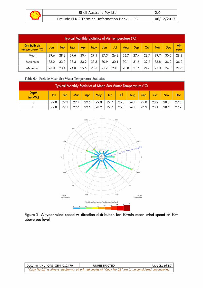
Typical Monthly Statistics of Air Temperature (°C)
Dry bulb air temperature (°C)
Jan Feb Mar Apr May Jun Jul Aug Sep Oct Nov Dec All-year
Mean 29.6 29.3 29.6 30.4 29.4 27.3 26.8 26.7 27.4 28.7 29.7 30.0 28.8
Maximum 33.2 33.0 33.3 33.2 33.3 30.9 30.1 30.1 31.5 32.2 33.8 34.2 34.2
Minimum 23.0 23.4 24.0 25.5 23.5 21.7 23.0 23.8 21.6 24.6 25.0 24.8 21.6
Table 6.4: Prelude Mean Sea Water Temperature Statistics
Typical Monthly Statistics of Mean Sea Water Temperature (°C)
Depth (m MSL)
Jan Feb Mar Apr May Jun Jul Aug Sep Oct Nov Dec
0 29.8 29.3 29.7 29.6 29.0 27.7 26.8 26.1 27.0 28.2 28.8 29.5
10 29.8 29.1 29.6 29.5 28.9 27.7 26.8 26.1 26.9 28.1 28.6 29.2
Figure 2: All-year wind speed vs direction distribution for 10-min mean wind speed at 10m above sea level
0.0%
Calms
2.5%5%
7.5%10%
12.5%15%
17.5%20%
N
NNE
NE
ENE
E
ESE
SE
SSE
S
SSW
SW
WSW
W
WNW
NW
NNW
100.0%
Data Return
701280
Observations
0 5 10 15 20 25 30 35 4045
WindSpeed [m/s] against WindDirection [deg from]

Shell Australia Pty Ltd 2.0
Prelude FLNG Terminal Information Book - LPG 06/12/2017
Document No: OPS_GEN_012470 UNRESTRICTED Page 22 of 87
“Copy No 01” is always electronic: all printed copies of “Copy No 01” are to be considered uncontrolled.
Figure 3: All-year significant wave height vs direction distribution for wind-sea
6.2 Visibility Ships’ observations indicate that typically visibility is greater than 5 nautical miles 95% of the time and less than 2 nautical miles 5% of the time on average with no obvious seasonal variation.
6.3 Tsunami The tsunami potential for the Northwest Shelf region is considered moderate. Historically, only four tsunami's have been known to affect this region in recorded history (1883, 1977, 1994, and 2004), although this observation should be qualified by the fact that the region has always been sparsely populated, and tsunami may well have gone unobserved, particularly if masked by the huge tides of the region. Tsunami emanating from these events would have been significantly smaller than the daily rise and fall of tide in this region (perhaps of the order of 2m).
Tsunamis in the deep ocean have length scales of several hundred kilometers, and are likely to pass round the 'relatively' small (much less than one wavelength) diameter shoal, without significant response to the local topography.
Therefore, the potential effect of a deep-water tsunami (in 250 meters water) on the relative motion of two vessels connected by a mooring line is considered to be low. However, there have been incidences of collision between two vessels moored side by side during the passage of a tsunami in relatively deep water, so the frequency of occurrence of tsunami and their potential impact on relative motions should be assessed during the next phase of the project.
0.0%
Calms
2.5%5%
7.5%10%
12.5%15%
17.5%20%
N
NNE
NE
ENE
E
ESE
SE
SSE
S
SSW
SW
WSW
W
WNW
NW
NNW
100.0%
Data Return
701280
Observations
0 1 2 3 4 5 6 7 8 9 10 11 12Hs_Sea [m] against MeanWaveDirection_Sea [deg from]

Shell Australia Pty Ltd 2.0
Prelude FLNG Terminal Information Book - LPG 06/12/2017
Document No: OPS_GEN_012470 UNRESTRICTED Page 23 of 87
“Copy No 01” is always electronic: all printed copies of “Copy No 01” are to be considered uncontrolled.
6.4 Solitons Solitary non-linear internal waves, which are waves propagating within the water column due to the interaction of strong tidal forcing, bathymetry and density differences between the surface and subsurface layers of the water column, are common in the Prelude location. Current speeds in excess of 2m/s (4 knots) near-surface may be sustained for 10-15 minutes during these events. Solitons are associated with the internal tide and as such may occur at tidal periods of ~12 hour intervals.
Solitons have been observed at the Prelude location throughout the year, but are more prevalent during the late summer, when stratification is most intense. There is a high degree of variability, however, depending on the state of the tide (spring-neap cycle) and the intensity of density stratification.
Shell Australia Pty Ltd 2.0
Prelude FLNG Terminal Information Book - LPG 06/12/2017
Document No: OPS_GEN_012470 UNRESTRICTED Page 24 of 87
“Copy No 01” is always electronic: all printed copies of “Copy No 01” are to be considered uncontrolled.
7. Arrival off Port
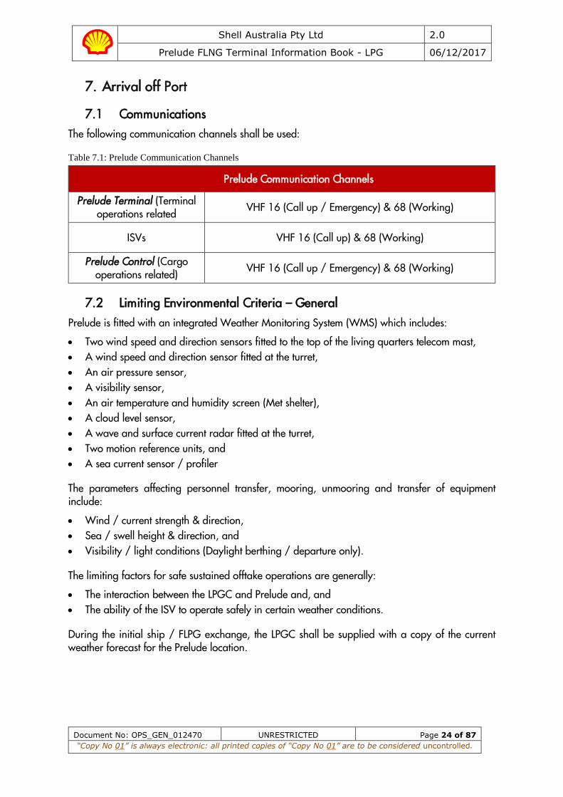
7.1 Communications The following communication channels shall be used:
Table 7.1: Prelude Communication Channels
Prelude Communication Channels
Prelude Terminal (Terminal operations related VHF 16 (Call up / Emergency) & 68 (Working)
ISVs VHF 16 (Call up) & 68 (Working)
Prelude Control (Cargo operations related) VHF 16 (Call up / Emergency) & 68 (Working)
7.2 Limiting Environmental Criteria – General Prelude is fitted with an integrated Weather Monitoring System (WMS) which includes:
• Two wind speed and direction sensors fitted to the top of the living quarters telecom mast, • A wind speed and direction sensor fitted at the turret, • An air pressure sensor, • A visibility sensor, • An air temperature and humidity screen (Met shelter), • A cloud level sensor, • A wave and surface current radar fitted at the turret, • Two motion reference units, and • A sea current sensor / profiler
The parameters affecting personnel transfer, mooring, unmooring and transfer of equipment include:
• Wind / current strength & direction, • Sea / swell height & direction, and • Visibility / light conditions (Daylight berthing / departure only).
The limiting factors for safe sustained offtake operations are generally:
• The interaction between the LPGC and Prelude and, and • The ability of the ISV to operate safely in certain weather conditions.
During the initial ship / FLPG exchange, the LPGC shall be supplied with a copy of the current weather forecast for the Prelude location.

Shell Australia Pty Ltd 2.0
Prelude FLNG Terminal Information Book - LPG 06/12/2017
Document No: OPS_GEN_012470 UNRESTRICTED Page 25 of 87
“Copy No 01” is always electronic: all printed copies of “Copy No 01” are to be considered uncontrolled.
In order to assess the effect of actual and forecast environmental conditions at the terminal, with respect to offtake operations, Prelude will utilise a Decision Making Support Tool (DEMIST). This tool will assist in determining if the forecast environmental conditions are suitable for safe and sustained operations throughout the offtake period, along with guidance on heading and thruster selection.
Prelude’s stern thrusters may be utilised as required to enable optimum heading control throughout the alongside operations.
Prelude will determine whether its status is open, restricted or closed and will inform the LPGC of any changes in status:
OPEN: An LPGC is allowed to berth between sunrise and sunset.
RESTRICTED: An LPGC shall not be allowed to berth. An LPGC already at the berth may continue offtake operation subject to TTL advice.
CLOSED: An LPGC shall not be allowed to berth. An LPGC already berthed shall be required to depart if it is safe to do so.
If the weather forecast indicates the limiting environmental conditions will be exceeded, during the course of berthing, mooring, cargo operations or other situation when an LPGC is at Prelude, those operations must cease prior to the stated limiting condition being reached. The limiting environmental conditions are described in the following tables.
Notwithstanding the statutory right of the Master, the decision for an LPGC to sail from Prelude (due to adverse weather conditions) will be made by the OIM, after consultation with the Terminal Team Leader and the LPGC Master.
The LPGC Master, however, remains solely responsible for the safety, condition, operation and proper navigation of their vessel. As such, the OIM shall collaborate closely with the TTL and LPGC Master when making adverse weather decisions which have an operational impact.
7.3 Limiting Environmental Criteria – Personnel Transfer The following limits exist for the transfer of personnel between the ISV and the LPGC:
Table 7.2: Environmental Limits for Personnel Transfer
Environmental limits for personnel transfer
Agreement between TTL and LPGC Master,
≤ 30 Knots Mean Wind Speed,
≤ 3.0m Significant Wave Height,
≥600m Visibility
7.4 Limiting Environmental Criteria – Spool Piece Transfer Transfer of spool pieces from ISV to LPGC will not be undertaken unless LPGC Master and ISV Master agree that conditions are suitable. Additionally, the following environmental limitations shall be adhered to when transferring spool pieces.
Table 7.3: Environmental Limits for Spool Piece Transfer
Shell Australia Pty Ltd 2.0
Prelude FLNG Terminal Information Book - LPG 06/12/2017
Document No: OPS_GEN_012470 UNRESTRICTED Page 26 of 87
“Copy No 01” is always electronic: all printed copies of “Copy No 01” are to be considered uncontrolled.
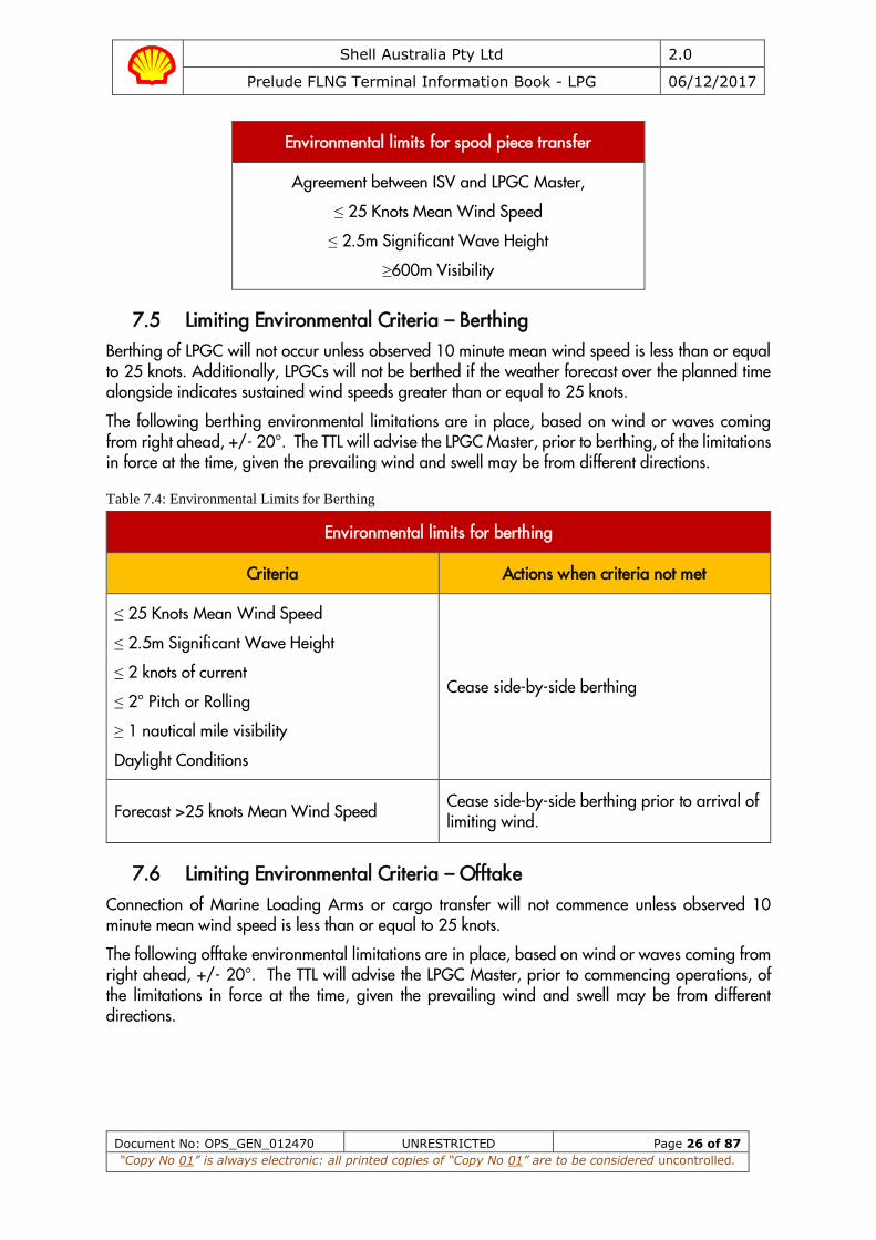
Environmental limits for spool piece transfer
Agreement between ISV and LPGC Master,
≤ 25 Knots Mean Wind Speed
≤ 2.5m Significant Wave Height
≥600m Visibility
7.5 Limiting Environmental Criteria – Berthing Berthing of LPGC will not occur unless observed 10 minute mean wind speed is less than or equal to 25 knots. Additionally, LPGCs will not be berthed if the weather forecast over the planned time alongside indicates sustained wind speeds greater than or equal to 25 knots.
The following berthing environmental limitations are in place, based on wind or waves coming from right ahead, +/- 20°. The TTL will advise the LPGC Master, prior to berthing, of the limitations in force at the time, given the prevailing wind and swell may be from different directions.
Table 7.4: Environmental Limits for Berthing
Environmental limits for berthing
Criteria Actions when criteria not met
≤ 25 Knots Mean Wind Speed
≤ 2.5m Significant Wave Height
≤ 2 knots of current
≤ 2° Pitch or Rolling
≥ 1 nautical mile visibility
Daylight Conditions
Cease side-by-side berthing
Forecast >25 knots Mean Wind Speed Cease side-by-side berthing prior to arrival of limiting wind.
7.6 Limiting Environmental Criteria – Offtake Connection of Marine Loading Arms or cargo transfer will not commence unless observed 10 minute mean wind speed is less than or equal to 25 knots.
The following offtake environmental limitations are in place, based on wind or waves coming from right ahead, +/- 20°. The TTL will advise the LPGC Master, prior to commencing operations, of the limitations in force at the time, given the prevailing wind and swell may be from different directions.

Shell Australia Pty Ltd 2.0
Prelude FLNG Terminal Information Book - LPG 06/12/2017
Document No: OPS_GEN_012470 UNRESTRICTED Page 27 of 87
“Copy No 01” is always electronic: all printed copies of “Copy No 01” are to be considered uncontrolled.
Table 7.5: Environmental Limits for Offtake
Environmental limits for offtake
Criteria Actions
25 Knots Mean Wind Speed 2.0m Significant Wave Height
Consultation between LPGC Master and TTL
Forecast ≥ 25 knots Mean Wind Speed Consider stopping LPG transfer and disconnecting from Prelude prior to arrival of limiting wind.
≥ 27 Knots Mean Wind Speed 2.5m Significant Wave Height 2° Pitch or Rolling
Cease LNG transfer, gas free, disconnect and retract MLAs. Consider unberthing.
30 Knots Mean Wind Speed 3.0m Significant Wave Height ≥ 2.0m Relative Surge ≥ 1.5m Relative Sway ≥ 1.5m Relative Heave 3° Pitch or Rolling
Unberth and sail LPGC clear of Prelude when ready.
Forecast >30 knots Mean Wind Speed Unberth and sail LPGC clear of Prelude when ready, prior to arrival of limiting wind.
Moorings and Fenders Actions
Mooring line monitor: More than five (5) peaks over 50% of MBL in three (3) hours across all lines or Mooring line monitor: Two (2) tension peaks above 50% of MBL in 2 minute period on same line. or >50% fender deflection
Cease offtake, gas free, disconnect and retract MLAs. Unberth and sail LPGC clear of Prelude when ready.
7.7 Approach to Prelude LPGCs should not approach within 6 nautical miles of Prelude until such time as it is progressing to the pilot boarding position.
When approaching Prelude, vessels should so far as possible avoid passing through the ICHTHYS field. See Appendix Q.
A wave buoy is established in position: Latitude (WGS84): 13° 49' 1.028" S Longitude (WGS84): 123° 16' 49.289" E. There is a 500m exclusion zone around this wave buoy.
Shell Australia Pty Ltd 2.0
Prelude FLNG Terminal Information Book - LPG 06/12/2017
Document No: OPS_GEN_012470 UNRESTRICTED Page 28 of 87
“Copy No 01” is always electronic: all printed copies of “Copy No 01” are to be considered uncontrolled.
The TTL will contact the tanker on VHF channel 68 prior to departing Prelude. The pilot will advise the LPGC when to commence its approach to the boarding position.
Under no circumstances should the vessel enter the 1500m safety zone without the express permission from the TTL and only then when the Infield Support Vessels (ISVs) are in attendance.
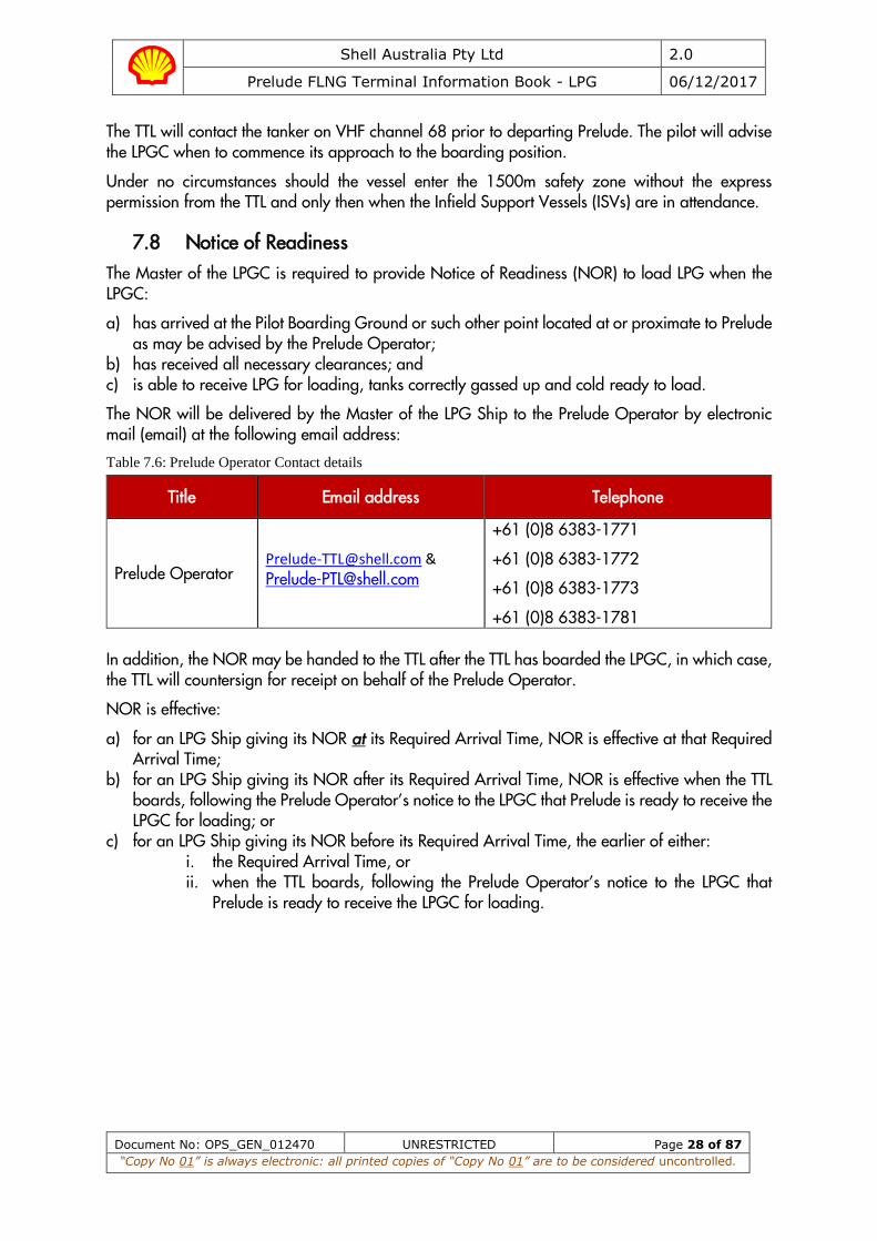
7.8 Notice of Readiness The Master of the LPGC is required to provide Notice of Readiness (NOR) to load LPG when the LPGC:
a) has arrived at the Pilot Boarding Ground or such other point located at or proximate to Prelude as may be advised by the Prelude Operator;
b) has received all necessary clearances; and c) is able to receive LPG for loading, tanks correctly gassed up and cold ready to load.
The NOR will be delivered by the Master of the LPG Ship to the Prelude Operator by electronic mail (email) at the following email address:
Table 7.6: Prelude Operator Contact details
Title Email address Telephone
Prelude Operator [email protected] &
+61 (0)8 6383-1771
+61 (0)8 6383-1772
+61 (0)8 6383-1773
+61 (0)8 6383-1781 In addition, the NOR may be handed to the TTL after the TTL has boarded the LPGC, in which case, the TTL will countersign for receipt on behalf of the Prelude Operator.
NOR is effective:
a) for an LPG Ship giving its NOR at its Required Arrival Time, NOR is effective at that Required Arrival Time;
b) for an LPG Ship giving its NOR after its Required Arrival Time, NOR is effective when the TTL boards, following the Prelude Operator’s notice to the LPGC that Prelude is ready to receive the LPGC for loading; or
c) for an LPG Ship giving its NOR before its Required Arrival Time, the earlier of either: i. the Required Arrival Time, or ii. when the TTL boards, following the Prelude Operator’s notice to the LPGC that
Prelude is ready to receive the LPGC for loading.
Shell Australia Pty Ltd 2.0
Prelude FLNG Terminal Information Book - LPG 06/12/2017
Document No: OPS_GEN_012470 UNRESTRICTED Page 29 of 87
“Copy No 01” is always electronic: all printed copies of “Copy No 01” are to be considered uncontrolled.
8. Berthing and Mooring
8.1 Berthing and Unberthing Criteria Berthing of an LPGC is restricted to daylight hours only. Daylight is considered between morning and evening civil twilight. For further criteria, see sections 7.5 and 7.6 of this book.
Unberthing is permitted in daylight and night-time conditions.
8.2 Pilotage Pilotage is compulsory for all vessels arriving and departing at Prelude.
All vessel’s shall stay at least 6 nautical miles from the Prelude until such time they are requested to proceed to the Pilot Boarding Ground.
8.2.1 Pilot Boarding Area
The pilot boarding ground is 3 nautical miles directly astern of Prelude or as advised by the TTL once radio contact is made.
8.2.2 Personnel Transfer
The LPGC shall adopt a course and speed as directed by “Prelude Terminal” or the ISV for the transfer of personnel from the ISV to the LPGC.
The following three (3) personnel will board the LPGC at the Pilot Boarding Ground:
a) 1 x Terminal Team Leader (TTL) who will conduct the pilotage and berthing of the LPGC. He will additionally act as the Prelude representative onboard the LPGC during the loading operation,
b) 1 x Lead Terminal Technician (LTT) who will assist the TTL, and c) 1 x Cargo Surveyor
8.2.3 Pilot Ladder
The pilot ladder is to be rigged above the water line as directed by the TTL, with two manropes, in full compliance with IMO Res A1045 (27) and IMPA recommendations. See Appendix B for full and specific Pilot boarding ladder arrangements.
All personnel overnight bags and Berthing Aid System will be transferred with the tool box described in section 8.6.1. As such, there will not be a requirement to transfer equipment from ISV to LPGC via heaving line.
8.2.4 Personnel Embarked on LPGC
The TTL, LTT and Surveyor will remain on board the LPGC throughout its stay alongside Prelude to liaise and assist the vessel’s Master and crew to:
• Manoeuvrer the LPGC to the berth, • Berth at (and un-berth from) Prelude, • Connect and disconnect the cargo transfer systems, • Communicate between Prelude Terminal and the vessel cargo watch-keeper • Oversee and ensure the overall safety of the total operation whilst within the 1500m
safety zone, and

Shell Australia Pty Ltd 2.0
Prelude FLNG Terminal Information Book - LPG 06/12/2017
Document No: OPS_GEN_012470 UNRESTRICTED Page 30 of 87
“Copy No 01” is always electronic: all printed copies of “Copy No 01” are to be considered uncontrolled.
• Witness and verify cargo measurements, including volume determination, temperature, pressure, list, trim and to prepare cargo documents.
LPGC Masters are requested to provide food and appropriate non-share officer’s accommodation for the TTL, LTT and surveyor. Prelude will provide advance notice should additional personnel (e.g. trainee TTL) be expected to also transfer and remain on the LPGC.
8.2.5 Personal Protective Equipment (PPE)
The TTL, LTT and surveyor will wear the following PPE (supplied by themselves) during personnel transfer and whilst working on the exposed decks of the LPGC
Boiler suit, safety shoes, gloves, safety glasses and a safety helmet. Additionally, they will don an inflatable personal floatation device (PFD) with AIS enabled personnel locator beacon (PLB) during personnel transfer operations.
Should the LPGC Master require the TTL or LTT to wear any additional PPE whilst on-board the LPGC, this should be supplied by the LPGC.
8.3 Infield Support Vessels (ISV) An LPGC calling at Prelude shall be assisted throughout their stay by at least two (2) multipurpose Infield Support Vessels (ISVs). These 42m long, 100 ton bollard pull tugs manoeuvre via a Rotor tug propulsion configuration, comprising of 3 azimuthing thrusters - two forward and one aft.
See Appendix E for ISV specifications.
The ISV towing gear is fitted with a 20m Coated Dyneema braided cover pennant with an eye length of 1.8m. A ship heaving line is required to facilitate transfer of the tow line.
8.4 ISV arrangements for berthing / un-berthing The two ISVs are made fast to bitts on deck of the LPGC - one made fast through the forward centre lead and one through the aft centre lead. Leads slightly to starboard of the centre line leads may be used depending on the outcome of the compatibility study. The LPGC shall ensure appropriate SWL securing arrangements are provided at both positions.
8.5 ISV arrangements during cargo transfer The two ISVs will be on standby and available at all times whilst an LPGC is alongside. Notwithstanding this, the ISVs will remain outside 200m of the LPGC whilst loading arms are connected unless required to act in event of an emergency or other exceptional circumstance.
8.6 Manifold Spool Piece Targeting Cones
8.6.1 Spool Piece Transfer – General
To assist with connecting the liquid and vapour Marine Loading Arms, Prelude shall provide either 16 / 14 / 12 / 10 inch, 150 ANSI spool pieces with integrated targeting cones. (Two liquid and one vapour manifold spool piece). See Appendix F for specifications of spool piece targeting cones.
Each spool piece is housed in its own integrated lifting basket, weighing a total of approximately 1.1 tonnes. These spool pieces shall be transferred to the LPGC from the ISV on each occasion that

Shell Australia Pty Ltd 2.0
Prelude FLNG Terminal Information Book - LPG 06/12/2017
Document No: OPS_GEN_012470 UNRESTRICTED Page 31 of 87
“Copy No 01” is always electronic: all printed copies of “Copy No 01” are to be considered uncontrolled.
the vessel calls at Prelude and returned to the ISV once the LPGC has departed and is clear of Prelude.
The transfer will take place outside the 1500m safety zone and on a course and speed as agreed between the TTL, the ISV Master and the LPGC Master.
On completion of personnel embarkation to the LPGC, the ISV shall manoeuvre as required to enable the LPGC port side amidships / manifold crane to hoist the following items from the aft deck of the ISV:
a) Three (3) steel baskets containing the LPGloading arm targeting spools, weighing approximately 1.1 tonnes each.
b) A tool box containing all necessary hand tools, nuts, bolts and gaskets required to secure the targeting spools, weighing approximately 0.8 tonnes.
It is recommended these boxes be secured at the LPGCs port side manifold ready for the spool pieces to be fitted to the respective manifold presentation flanges.
8.6.2 Spool Piece Transfer – LPGC Stinger
During spool piece transfer from the ISV, the LPGC shall utilise its own certified stinger (connected to the LPGC manifold crane hook) of sufficient length and SWL to provide protection to the ISV’s crew from the LPGCs crane block.
The crane block shall be marked in such a way that it is visible under all circumstances of operation. It is recommended that the LPGC Master and crew familiarise themselves with the appropriate sections of the Code of Safe Working Practices for Merchant Seafarers (COSWP).
To prevent waiting time, all tanker permits and risk assessments required to lift the tool box and fit the hose should be prepared and available prior to the TTL / LLT’s arrival onboard.
8.6.3 Targeting Spool Piece Fitting and Removal
An LPGC shall arrive with ALL existing spool pieces removed from manifold presentation flanges, as communicated by Prelude. This will facilitate the fitting of the targeting spool pieces However, issues may arise with targeting spool pieces clashing with manifold supports on LPG carriers fitted with sliding feet. A solution to avoid this is to fit an additional spool piece supplied by the carrier to the presentation flange, therefore eliminating any clash with manifold supports. Additionally, LPGC may be required to fit reducers to be compatible with FLNG.
FMC Technologies has confirmed the max permissible cantilever measurement of 1200mm which will allow fitment of vessel spool pieces/reducers. The calculated loads are given at the manifold flange (or coupler flange) at point A, before the length of 1.2 m. The manifold calculated stress is the maximum calculated stress (principal stresses / Von Mises stress) located between point A and point B.
Figure 4: FMC Max Permissible Cantilever
Shell Australia Pty Ltd 2.0
Prelude FLNG Terminal Information Book - LPG 06/12/2017
Document No: OPS_GEN_012470 UNRESTRICTED Page 32 of 87
“Copy No 01” is always electronic: all printed copies of “Copy No 01” are to be considered uncontrolled.
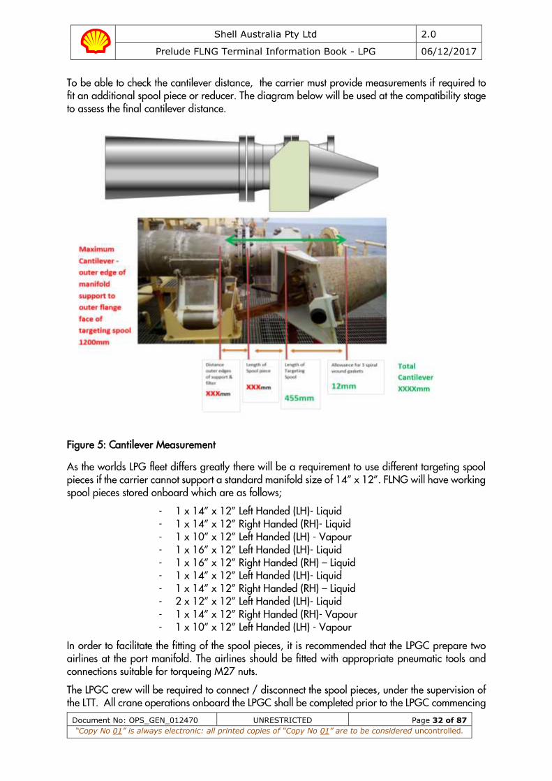
To be able to check the cantilever distance, the carrier must provide measurements if required to fit an additional spool piece or reducer. The diagram below will be used at the compatibility stage to assess the final cantilever distance.
Figure 5: Cantilever Measurement
As the worlds LPG fleet differs greatly there will be a requirement to use different targeting spool pieces if the carrier cannot support a standard manifold size of 14” x 12”. FLNG will have working spool pieces stored onboard which are as follows;
- 1 x 14” x 12” Left Handed (LH)- Liquid - 1 x 14” x 12” Right Handed (RH)- Liquid - 1 x 10” x 12” Left Handed (LH) - Vapour - 1 x 16” x 12” Left Handed (LH)- Liquid - 1 x 16” x 12” Right Handed (RH) – Liquid - 1 x 14” x 12” Left Handed (LH)- Liquid - 1 x 14” x 12” Right Handed (RH) – Liquid - 2 x 12” x 12” Left Handed (LH)- Liquid - 1 x 14” x 12” Right Handed (RH)- Vapour - 1 x 10” x 12” Left Handed (LH) - Vapour
In order to facilitate the fitting of the spool pieces, it is recommended that the LPGC prepare two airlines at the port manifold. The airlines should be fitted with appropriate pneumatic tools and connections suitable for torqueing M27 nuts.
The LPGC crew will be required to connect / disconnect the spool pieces, under the supervision of the LTT. All crane operations onboard the LPGC shall be completed prior to the LPGC commencing
Shell Australia Pty Ltd 2.0
Prelude FLNG Terminal Information Book - LPG 06/12/2017
Document No: OPS_GEN_012470 UNRESTRICTED Page 33 of 87
“Copy No 01” is always electronic: all printed copies of “Copy No 01” are to be considered uncontrolled.
an approach to Prelude berth. Final flanging of the spool pieces may be carried out during berthing, provided it does not require the use of the crane.
All LPGC permits and risk assessments required to lift and fit the spool pieces should be prepared and available prior to the vessel’s arrival at the Pilot Station.
8.7 Helicopters Prelude will not carry out helicopter operations during the LPGCs approach or berthing / mooring operations. Helicopter operations may take place during the loading of a LPGC.
When Prelude helicopter operations are planned during the loading operation, the TTL will advise the LPGCs staff at the pre-cargo Ship / FLNG Safety Meeting.
8.8 LPGC Berthing – General The TTL will discuss all aspects of the berthing operations with the LPGC Master prior to commencing the approach. When both parties have completed and signed the ‘Master / Pilot exchange’ checklists, the approach may then commence.
LPG tankers are secured and operated at Prelude in accordance with the latest editions of Oil Companies International Marine Forum (OCIMF) and Society of International Gas Tanker and Terminal Operators (SIGTTO) publications:
• Mooring Equipment Guidelines, • The Safe Transfer of Liquefied Gas in an Offshore Environment, and • Liquefied Gas Handling Principles on Ships and in Terminals.
8.8.1 Ballast, Trim and Stability
The LPGC must arrive with ballast equivalent to at least 30% of DWT and shall be trimmed by the stern by not more than 1m so that there is no adverse effect to the manoeuvrability or the visibility of the vessel. The propeller must remain fully immersed on arrival and throughout time berthed. The Master is required to maintain appropriate trim and list and to retain sufficient positive stability to enable safe cargo loading operations and emergency unmooring. Notwithstanding the above, the Master shall not allow the tanker to become trimmed by the head and endeavor to keep the vessel upright at all times.
LPGC cargo and ballast operations shall be conducted simultaneously, with the conduct of ballast transfer during berthing / unberthing operations prohibited at Prelude.
8.9 Berthing
8.9.1 Berthing Aid System
A real time Berthing Aid System (BAS) is supplied by Prelude for the berthing of the LPGC. The BAS continuously detects the position of the LPGC, relative to Prelude, and displays this position and forecast movement on a laptop device transferred onto the LPGC with the TTL. The communication link between the Prelude BAS base station and the LPGC BAS is via UHF. The GPS and antenna unit (figure 4), which are mounted on the LPGC bridge wing, are ATEX rated (i.e. intrinsically safe).
The antenna unit is magnetised and designed to attach to a flat steel surface on the LPGC bridge wing railing. The unit needs to be placed outside with a good view of the sky, clear of bulkheads and obstructions. The minimum distance from the unit’s extended antennas to smaller obstructions

Shell Australia Pty Ltd 2.0
Prelude FLNG Terminal Information Book - LPG 06/12/2017
Document No: OPS_GEN_012470 UNRESTRICTED Page 34 of 87
“Copy No 01” is always electronic: all printed copies of “Copy No 01” are to be considered uncontrolled.
(e.g. VHF antenna) is 1-2m; distance to larger obstructions (e.g. bulkheads) is 5-10m. Figure 5 shows the extended antenna.
In order to ensure greatest accuracy, the distance between antennas needs to be as long as possible, ideally 4m, but with a minimum of 2m.
The TTL will set up the BAS, and ensure its correct operation, prior to undertaking the Master / Pilot exchange.
Figure 6: External antennae unit for Berthing Aid System
Figure 7: Extended antennae for Berthing Aid System
8.9.2 Berthing Method
When the LPGC is between one and a half (1.5) and two (2) nautical miles astern of Prelude, and after all the relevant equipment has been taken off the ISV, the TTL will direct the two ISVs to make
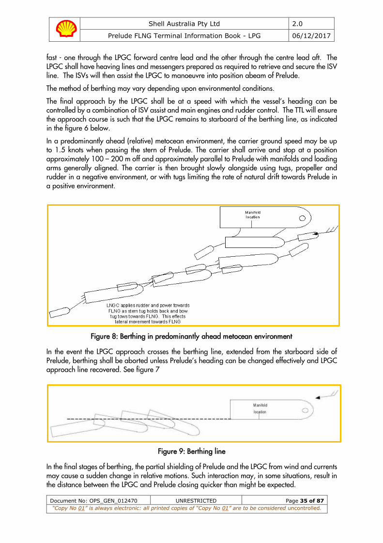
Shell Australia Pty Ltd 2.0
Prelude FLNG Terminal Information Book - LPG 06/12/2017
Document No: OPS_GEN_012470 UNRESTRICTED Page 35 of 87
“Copy No 01” is always electronic: all printed copies of “Copy No 01” are to be considered uncontrolled.
fast - one through the LPGC forward centre lead and the other through the centre lead aft. The LPGC shall have heaving lines and messengers prepared as required to retrieve and secure the ISV line. The ISVs will then assist the LPGC to manoeuvre into position abeam of Prelude.
The method of berthing may vary depending upon environmental conditions.
The final approach by the LPGC shall be at a speed with which the vessel’s heading can be controlled by a combination of ISV assist and main engines and rudder control. The TTL will ensure the approach course is such that the LPGC remains to starboard of the berthing line, as indicated in the figure 6 below.
In a predominantly ahead (relative) metocean environment, the carrier ground speed may be up to 1.5 knots when passing the stern of Prelude. The carrier shall arrive and stop at a position approximately 100 – 200 m off and approximately parallel to Prelude with manifolds and loading arms generally aligned. The carrier is then brought slowly alongside using tugs, propeller and rudder in a negative environment, or with tugs limiting the rate of natural drift towards Prelude in a positive environment.
Figure 8: Berthing in predominantly ahead metocean environment
In the event the LPGC approach crosses the berthing line, extended from the starboard side of Prelude, berthing shall be aborted unless Prelude’s heading can be changed effectively and LPGC approach line recovered. See figure 7
Figure 9: Berthing line
In the final stages of berthing, the partial shielding of Prelude and the LPGC from wind and currents may cause a sudden change in relative motions. Such interaction may, in some situations, result in the distance between the LPGC and Prelude closing quicker than might be expected.
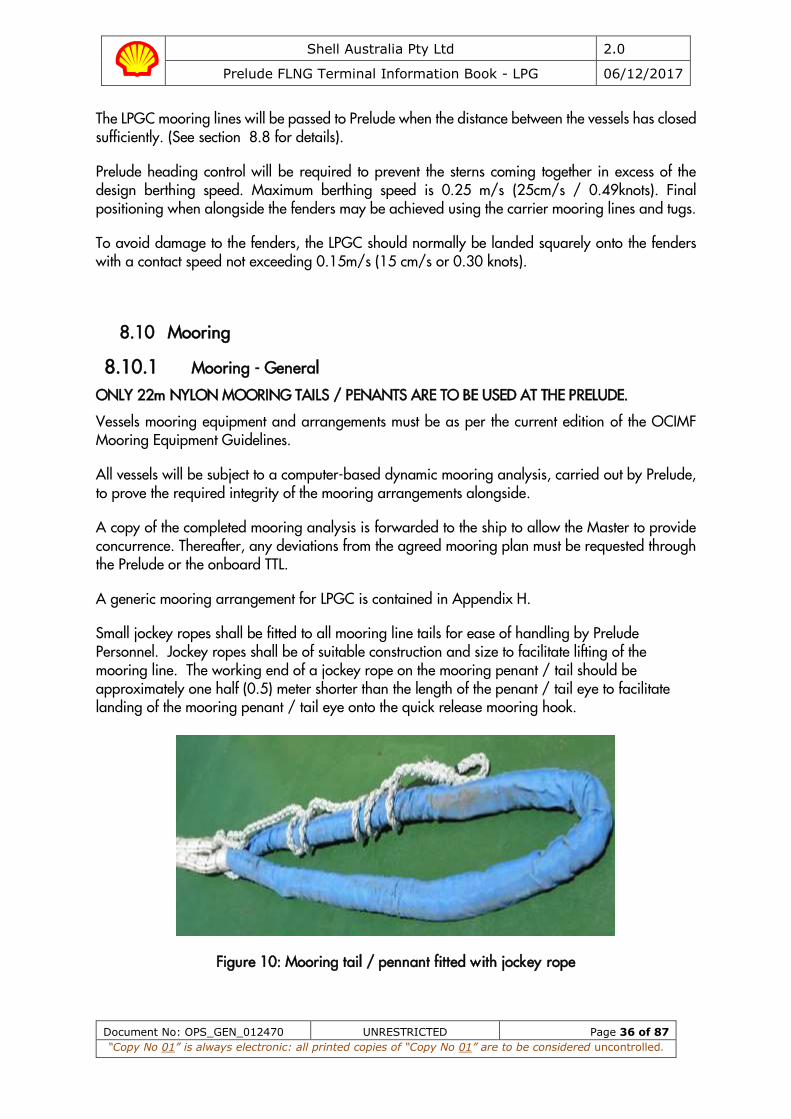
Shell Australia Pty Ltd 2.0
Prelude FLNG Terminal Information Book - LPG 06/12/2017
Document No: OPS_GEN_012470 UNRESTRICTED Page 36 of 87
“Copy No 01” is always electronic: all printed copies of “Copy No 01” are to be considered uncontrolled.
The LPGC mooring lines will be passed to Prelude when the distance between the vessels has closed sufficiently. (See section 8.8 for details).
Prelude heading control will be required to prevent the sterns coming together in excess of the design berthing speed. Maximum berthing speed is 0.25 m/s (25cm/s / 0.49knots). Final positioning when alongside the fenders may be achieved using the carrier mooring lines and tugs.
To avoid damage to the fenders, the LPGC should normally be landed squarely onto the fenders with a contact speed not exceeding 0.15m/s (15 cm/s or 0.30 knots).
8.10 Mooring
8.10.1 Mooring - General
ONLY 22m NYLON MOORING TAILS / PENANTS ARE TO BE USED AT THE PRELUDE.
Vessels mooring equipment and arrangements must be as per the current edition of the OCIMF Mooring Equipment Guidelines.
All vessels will be subject to a computer-based dynamic mooring analysis, carried out by Prelude, to prove the required integrity of the mooring arrangements alongside.
A copy of the completed mooring analysis is forwarded to the ship to allow the Master to provide concurrence. Thereafter, any deviations from the agreed mooring plan must be requested through the Prelude or the onboard TTL.
A generic mooring arrangement for LPGC is contained in Appendix H.
Small jockey ropes shall be fitted to all mooring line tails for ease of handling by Prelude Personnel. Jockey ropes shall be of suitable construction and size to facilitate lifting of the mooring line. The working end of a jockey rope on the mooring penant / tail should be approximately one half (0.5) meter shorter than the length of the penant / tail eye to facilitate landing of the mooring penant / tail eye onto the quick release mooring hook.
Figure 10: Mooring tail / pennant fitted with jockey rope

Shell Australia Pty Ltd 2.0
Prelude FLNG Terminal Information Book - LPG 06/12/2017
Document No: OPS_GEN_012470 UNRESTRICTED Page 37 of 87
“Copy No 01” is always electronic: all printed copies of “Copy No 01” are to be considered uncontrolled.
The Masters shall ensure that sufficient mooring rope slack is provided when running moorings. However, mooring ropes should not impede the safety of the ISV’s, foul the ship’s propeller or Prelude’s fenders, particularly when too much slack rope is deployed.
Once moored, ship’s winches must be secured out of gear with brakes set at the appropriate torque as per industry guidance. Winches must not be left on “Auto Tension.”
Masters of vessels are responsible for ensuring that:
• Their vessels are safely secured in accordance with the preceding paragraphs. • A strict watch is kept on their vessel’s moorings and that they are tended as required to
prevent slack or overly tight lines and undue movement of the vessel alongside. • Their vessel’s mooring ropes or wires are secured only to the proper fixtures provided for that
purpose, additionally fixed moorings are correctly wound onto the winch drums. • Sufficient persons are on duty to attend moorings whilst the vessel is alongside.
In the event of any incident involving mooring integrity (line parting, ship movement on the berth, etc.), cargo operations will be stopped and will not be restarted until the cause, or causes, of the particular incident have been investigated, and defective mooring lines replaced, as applicable.
8.10.2 Mooring order of events
Initial heaving line will be passed from Prelude to the LPGC via a Pneumatic Line throwing Device (PLD).
Unless otherwise agreed, first line will be a forward breast line. A maximum of 1 mooring line will be run at a time (forward and aft) via 28mm polypropylene rope messenger supplied by Prelude. The moorings forward will be run concurrently with the moorings aft.
The vessel shall have enough trained and competent crew standing by forward and aft to safely handle and carry out the mooring operation in a timely manner. Generally the first lines to be run will be the breast lines to assist bringing the vessel alongside (ISV’s will not push, other than in an emergency) followed by the spring lines, remainder of the breast lines, the head and stern lines.
Heaving on the stern mooring lines shall be avoided when the vessels are coming together, and heaving on forward lines at the direction of the Terminal Team Leader to control the LPGC / Prelude contact velocity.
Once the LPGC is made fast to Prelude and the TTL considers it appropriate, the carriers’ engine readiness may be placed from “standby” to an “agreed notice” with the TTL.
The LPGC deck watch crew on duty, as part of their responsibilities, must report hourly to the LPGC control room on vessel position. Any movements fore and aft or out (not touching the fenders) must be reported to the LPGC and FLNG control room.
In the following situations the TTL may request that the carrier’s engine be placed from “agreed notice” back to “standby”:
• Any situation where the LPGC is reported to be out of position with Prelude. • Any situation where the safety of the LPGC, ISV or Prelude (asset or people) might be at risk. • In the event that there is a substantial change in wind, swell or current.

Shell Australia Pty Ltd 2.0
Prelude FLNG Terminal Information Book - LPG 06/12/2017
Document No: OPS_GEN_012470 UNRESTRICTED Page 38 of 87
“Copy No 01” is always electronic: all printed copies of “Copy No 01” are to be considered uncontrolled.
8.10.3 Fire Wires (ETOPs)
Two Vulcan soft rope fire wires/ETOPs (Emergency Towing off Pennant) will be supplied to the carrier by the ISV on completion of mooring. The ETOPs are to be rigged on the starboard bow and starboard quarter. They should be secured to bitts with a minimum of five turns and be led directly to a ships side fairlead with no slack on deck. A heaving line is to be attached to the outboard end so the height of the eye can be maintained between 1-2 meters above the water. As per below diagram.
Figure 11: Rigging of Emergency Towing off Pennant
8.11 Provision of Mooring Crews on Prelude Mooring crews will be provided on-board Prelude to make fast / let go the LPGC. The mooring crew will be in radio contact with the TTL. All instructions to the mooring crew shall be passed by the TTL.
Mooring crew on Prelude will be ready at short notice in event of an emergency.
8.12 Weighted Heaving Lines Monkeys fist (or similar) may be used to weight the line for throwing.
The practice of weighting monkey fists (or heaving lines in general) with infills of metal and other heavy objects poses a significant risk of injury to ISV crew and terminal staff and is not acceptable at the Prelude.
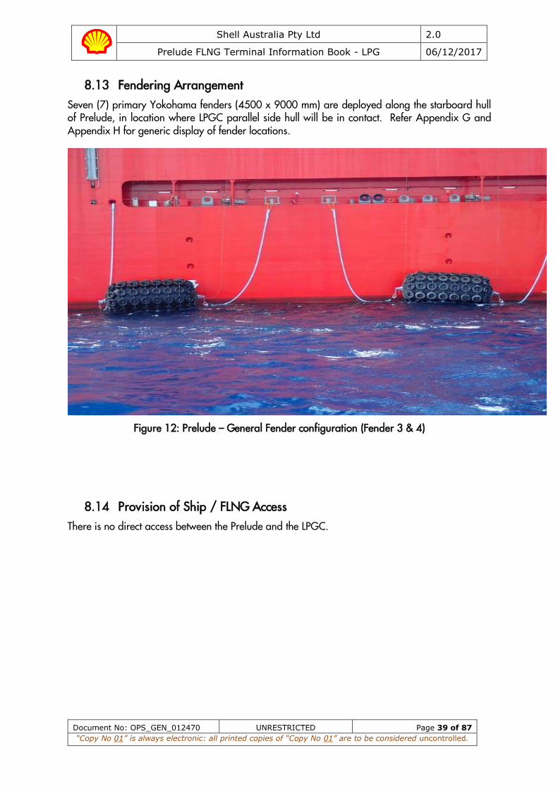
Shell Australia Pty Ltd 2.0
Prelude FLNG Terminal Information Book - LPG 06/12/2017
Document No: OPS_GEN_012470 UNRESTRICTED Page 39 of 87
“Copy No 01” is always electronic: all printed copies of “Copy No 01” are to be considered uncontrolled.
8.13 Fendering Arrangement Seven (7) primary Yokohama fenders (4500 x 9000 mm) are deployed along the starboard hull of Prelude, in location where LPGC parallel side hull will be in contact. Refer Appendix G and Appendix H for generic display of fender locations.
Figure 12: Prelude – General Fender configuration (Fender 3 & 4)
8.14 Provision of Ship / FLNG Access There is no direct access between the Prelude and the LPGC.

Shell Australia Pty Ltd 2.0
Prelude FLNG Terminal Information Book - LPG 06/12/2017
Document No: OPS_GEN_012470 UNRESTRICTED Page 40 of 87
“Copy No 01” is always electronic: all printed copies of “Copy No 01” are to be considered uncontrolled.
9. Communications
9.1 Language All communications, both verbal and written, shall be in the English language.
9.2 Operational Agreements On arrival at Prelude, the TTL will present the Master with a folder containing amongst other documents, the following:
• Safety Letter to Master (Appendix A), • Emergency Procedure Notice, • Ship / FLNG Safety Check List (Appendix K), and
The various forms, information and procedures laid out in the document formalise the conduct and procedures governing LPGC & Prelude operations at FLPG which are to be mutually agreed before operations commence.
The agreements reached in the document remain in force throughout the time a ship remains alongside Prelude. Any changes made to these agreements during the course of the cargo operation must be agreed in writing.
9.3 Communications Whilst Berthed The primary means of communication between the LPGC and Prelude is via a marine UHF radio provided by the TTL to LPGC on their arrival.
Supplementary means of communication will be via the Hotline, PABX or sound powered phone, this connection is provided through the Pyle-National electric ship-shore link.
For vessels fitted with a SIGTTO electrical link, the supplementary method of communications will be via Marine VHF on dedicated channels as instructed by the TTL during the pre-load meeting.
In the event that communication is lost between the tanker and Prelude, cargo operations shall be suspended until communications can be restored.
The cable shall be secured to the ship’s side rails by means of a light and secure lashing, such that the cable hangs in a loose bight. The cable must not be bent over the handrails.
The TTL, LTT and surveyor will remain on board the LPGC during the time alongside. The TTL will liaise between the LPGC and Prelude.
9.4 ESD System The LPGC will be connected to Prelude by means of a Pyle-National electrical ship-shore link or a SIGTTO electrical ship-shore link.
The Pyle National electrical cable will be passed to the tanker for connection once the tanker is all fast and will be removed prior to the tanker’s departure. The cable shall be secured to the ship’s side rails by means of a light and secure lashing, such that the cable hangs in a loose bight. The cable must not be bent over the handrails.
For vessels not fitted with a Pyle-National electric ship-shore link they will need to utilise the SIGTTO electrical link or SIGTTO pendant. These two links do not allow for phone communications
Shell Australia Pty Ltd 2.0
Prelude FLNG Terminal Information Book - LPG 06/12/2017
Document No: OPS_GEN_012470 UNRESTRICTED Page 41 of 87
“Copy No 01” is always electronic: all printed copies of “Copy No 01” are to be considered uncontrolled.
A pelicase will be placed onboard during the transfer of spool piece baskets, this pelicase will act as an interface between the Pyle-National electrical link and the SIGTTO electrical link.
9.4.1 ESD - Pyle National Electric Ship-Shore Link The electrical ESD system uses a Pyle National connector (37 pin) which allows for phone, data and ESD communication between the Prelude CCR and LNGC.
9.4.2 ESD - SIGTTO Electric Ship-Shore Link The SIGTTO ESD system uses a 5-pin connector which only allows for ESD communications between the Prelude and LPGC. The Prelude facility does not have a dedicated SIGTTO electrical cable, rather a pelicase is used as an interface to connect the facilities Pyle National link into the ships SIGTTO ship shore link. All equipment required for this purpose will be supplied by the Prelude.
9.4.3 ESD – SIGTTO Pendant Ship-Shore Link
The SIGTTO Pendant ESD system uses a pendant with a push button for ESD communications, the pendant is connected to an Ex-proof pelicase located at the manifold. The pelicase is connected to the Pyle National electric shore link passed over from the Prelude. This system only allows for one-way communication of an ESD from the ship to terminal.
See Appendix I for Ship-Shore Link Configuration
9.5 ESD Activation The Prelude emergency shutdown system (Marine ESD) has two stages of activity:
9.5.1 Stage 1 – Marine ESD 1
A Marine ESD 1 can be initiated manually or automatically from the LPGC or Prelude.
The Marine ESD 1 sequence is:
a) Prelude cargo transfer pumps stop immediately, b) Prelude MLA PERC valves close within 5 seconds of ESD activation, c) Prelude hydraulic loading valves on the loading lines close, d) The LNGC manifold valves close within 30 seconds after Marine ESD 1 signal is initiated.
In the event of an ESD1 activation, the ESD sequence must be allowed to complete. After completion of the ESD sequence the vessel must inhibit to allow the Prelude to reset and open the MLA PERC valves before thermal expansion can take place between the valves. Any investigation into the cause of the ESD will be undertaken after the MLA PERC valves have been re-opened.
9.5.2 Stage 2 – Marine ESD 2
A Marine ESD 2 can be initiated manually by Prelude or automatically from the Position Monitoring System (PMS).
The Marine ESD 2 sequence is:
a) Initiates an ESD 1, with all actions as described above,
b) PERC collar between the two closed ball valves uncouples within 2 seconds after the two ball valves have closed.
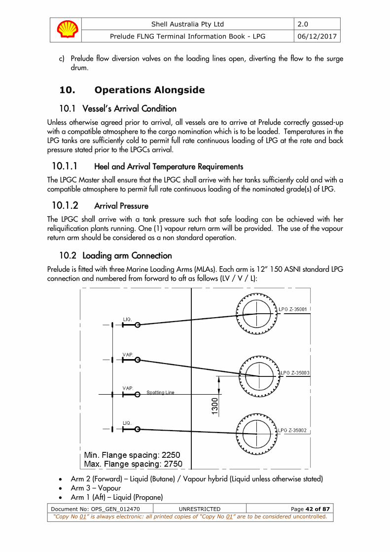
Shell Australia Pty Ltd 2.0
Prelude FLNG Terminal Information Book - LPG 06/12/2017
Document No: OPS_GEN_012470 UNRESTRICTED Page 42 of 87
“Copy No 01” is always electronic: all printed copies of “Copy No 01” are to be considered uncontrolled.
c) Prelude flow diversion valves on the loading lines open, diverting the flow to the surge drum.
10. Operations Alongside
10.1 Vessel’s Arrival Condition Unless otherwise agreed prior to arrival, all vessels are to arrive at Prelude correctly gassed-up with a compatible atmosphere to the cargo nomination which is to be loaded. Temperatures in the LPG tanks are sufficiently cold to permit full rate continuous loading of LPG at the rate and back pressure stated prior to the LPGCs arrival.
10.1.1 Heel and Arrival Temperature Requirements
The LPGC Master shall ensure that the LPGC shall arrive with her tanks sufficiently cold and with a compatible atmosphere to permit full rate continuous loading of the nominated grade(s) of LPG.
10.1.2 Arrival Pressure
The LPGC shall arrive with a tank pressure such that safe loading can be achieved with her reliquification plants running. One (1) vapour return arm will be provided. The use of the vapour return arm should be considered as a non standard operation.
10.2 Loading arm Connection Prelude is fitted with three Marine Loading Arms (MLAs). Each arm is 12” 150 ASNI standard LPG connection and numbered from forward to aft as follows (LV / V / L):
• Arm 2 (Forward) – Liquid (Butane) / Vapour hybrid (Liquid unless otherwise stated) • Arm 3 – Vapour • Arm 1 (Aft) – Liquid (Propane)
Shell Australia Pty Ltd 2.0
Prelude FLNG Terminal Information Book - LPG 06/12/2017
Document No: OPS_GEN_012470 UNRESTRICTED Page 43 of 87
“Copy No 01” is always electronic: all printed copies of “Copy No 01” are to be considered uncontrolled.
All three MLAs will be connected onto the LPG carrier. One MLA for butane loading, one MLA for propane loading and a vapour MLA will be connected to the carriers vapour manifold.
Boil-off vapour management for the LPGC cargo tanks should be handled onboard the LPG vessel using her own reliquification plants. However, the primary reason for connecting the vapour arm is to be used as a safety relief if the carriers tank vapour is close to an uncontrolled release through the PRVs. If vapour is required to be sent to Prelude this vapour will be directed to the flare.
The LPGC port manifold should be prepared to receive 2 liquid and 1 vapour loading arm, with a line-up as communicated by Prelude prior to arrival.
The TTL or LTT is responsible for connecting the targeting line to the targeting spool piece as well as manoeuvring and connecting the MLAs. See Appendix L.
Loading arm manoeuvring utilising the targeting spool pieces may be carried out day or night.
10.2.1 Strainers
Strainers will be fitted in Prelude’s loading line. The LPGC should prepare its own strainers such that the strainers may be fitted between the LPGC presentation flange/additional spool piece and the Prelude-supplied spool piece. Strainers should be 60 mesh.
In the event that finer strainers are required by Prelude, the requirements will be transmitted to the LPGC in advance.
10.2.2 Pressure Test and Purge of Marine Loading Arms
Loading arms will be pressure tested with nitrogen to a pressure of 500kpa (5 bar) for liquid arms and 200kpa (2 bar) for vapour arms. A leak test will be carried out on the manifold flange using a soap solution.
The arms will be depressurised by opening the drain or sample valve at the ship’s manifold, to a pressure of approximately 50 kpa. O2 readings will be taken at this valve outlet by ship staff using the LPGCs appropriately calibrated gas meter. The process of purging and sampling shall be repeated until the O2 content is less than or equal to 2% by volume.
Throughout the period the LPGC is moored at Prelude, the crew shall be required to maintain deck watches; in particular in the area around the port manifold. However, access to the manifold deck should be restricted to essential activities only from cooldown to liquid free to ensure ship’s crew are not exposed to potential hazards during the loading operation.
10.3 Safety Inspection Prior to commencing cargo operations, the TTL / LTT and a responsible Officer from the LPGC shall jointly conduct a safety inspection of the ship to ensure that the ship is effectively managing its obligations, as detailed in the Ship / FLNG Safety Check List (Refer to Appendix M).
In the event that safety or compatibility requirements have not been met, loading operations will not commence until corrective action is satisfactorily implemented. Prelude may revoke the LPGCs clearance to load if the deficiencies are not (or cannot be) rectified.
10.4 Pre-Loading Meeting A pre-loading meeting will be conducted between the TTL, LTT and the designated responsible ships officer(s) either during, or on completion of, the connection of the loading arms.
Shell Australia Pty Ltd 2.0
Prelude FLNG Terminal Information Book - LPG 06/12/2017
Document No: OPS_GEN_012470 UNRESTRICTED Page 44 of 87
“Copy No 01” is always electronic: all printed copies of “Copy No 01” are to be considered uncontrolled.
The purpose of this meeting is to ensure that all aspects of loading and associated activities are clearly understood and documented in the required format. The agenda for this meeting shall include as a minimum for loading, but not necessarily be limited to the following:
• Status of cargo tanks on arrival (pressure and temperature) • Exchange of ship / shore safety information (Safety pack not required) • Arm cool-down procedure • Bulk loading procedure • Hourly reporting requirements and action to be taken in the event of a discrepancy
between Terminal and Ship cargo loaded figures exceeding >0.5% and >0.3% (as per OPS_PRE_010522 Prelude FLNG Cargo Planning Manual).
• De-ballasting operation on board the LPGC • Forecast weather conditions during the transfer operations • Communications with Prelude and the Infield Support Vessels (ISVs) • Emergency procedures • Maritime Security • Confirmation of tank capacity tables, CTMS calibration, cooling tables and any other
certifications that may be required to be verified by the TTL and/ or independent surveyor.
Points of discussion will be in accordance with SIGTTO; principal to this will be the completion of the ship / FLNG safety check list and the requirement for its repeat checks. Compliance with the output from this meeting is paramount to ensure the safety of the operation, deviations from the plan must be discussed in advance with the LTT and/or the TTL.
A copy of the Ship / FLNG Safety checklist is contained in Appendix M.
10.5 Emergency Shut Down (ESD) system tests The Pyle-National Electric cable shall be passed between the LPGC and Prelude via a ship-supplied heaving line, and connected to the LPGCs appropriate socket by ship staff. The cable shall be secured to the ship’s side rail by means of a light lashing, ensuring that the cable hangs in a loose bight. The cable shall NOT be bent over the ship’s handrails for risk of damaging the cable.
Emergency Shut Down (ESD) tests shall be conducted as follows:
a) A logic test of the ESD link will be initiated by the LPGC, b) A “warm” ESD test before cool down, initiated by the LPGC from the CCR. The timing of
closure shall be recorded. LPGC manifold valves shall close within 25 ~ 30 seconds. Prelude ESD valves shall close in approximately15 seconds.
c) A second “warm” ESD test shall only be initiated by Prelude when an LPGC has arrived to lift its first cargo from Prelude, or the first cargo lift after refit.
d) A “cold” ESD valve stroke will be carried out on the LPGCs liquid ESD valves immediately on completion of cooldown. This is to confirm all valves still close correctly in the fully refrigerated condition, the closing timings for the LPGC and Prelude valves are to be recorded.
During the ESD test, personnel should remain clear of the LPGC manifold.
Shell Australia Pty Ltd 2.0
Prelude FLNG Terminal Information Book - LPG 06/12/2017
Document No: OPS_GEN_012470 UNRESTRICTED Page 45 of 87
“Copy No 01” is always electronic: all printed copies of “Copy No 01” are to be considered uncontrolled.
10.6 Gauging The Prelude is fitted with a fiscal meter as the primary means of producing a cargo transfer quantity which will be used in the production of the final Bill of Laden.
In addition, a Responsible Officer on the LPGC shall conduct initial / final gauging of the vessel’s cargo tanks at the direction of, and in the presence of, the TTL and the surveyor.
Initial gauging shall be carried out after the warm ESD test but prior to opening the vessel’s double-shut valves.
Final gauging should be carried out immediately after declaring “liquid free” at the vessel’s manifold.
The vessel shall have available at hand, for use by the TTL and / or surveyor, tank tables and certificates of calibration for cargo tanks, including gauging systems.
10.6.1 Reliquefication Plants (Reliq Plants)
All LPG carriers arriving at Prelude shall be fitted with Reliquefication Plants that are in good working condition. These are to be continually running during the Opening / Closing gauging as well as the loading operation to control tank pressures and manage BOG. The carriers reliquefication plant must be working and reliable, if there is stand-by compressors these must be ready for immediate use.
The carriers Reliquefication plant should be designed to handle 2.5% to 5% ethane mole concentration.
10.7 Venting Venting cargo vapour to the atmosphere is not permitted. The Master is required to take all action necessary to prevent venting.
If loading two grades simultaneously, the Master should ensure that the propane tanks vapour space is connected to the vapour manifold. It should also be possible to cross connect the vapour headers so that the butane vapour space can be connected to the vapour manifold.
Should venting from the vessel occur, or it becomes apparent that venting will occur, the LPGC Master shall advise the TTL immediately.
LPG carrier is to confirm PRV settings during the ship/shore safety checklist. If the carrier is able to vary the PRV settings, these settings are to be in line with the PRV setting values in the cargo operations manual.
10.8 Cargo Transfer Procedures Prior to the opening of LPGC or Prelude manifolds, the water curtains on the LPGC and Prelude shall be started. Other protective systems for tank domes and carriers superstructure shall be available for immediate use if so required. The fire main shall remain pressurized at all times.
10.8.1 Arm and Line Cooldown
Once Prelude and the LPGC confirm their respective system line up, cool down of the two liquid loading arms followed by LPGC lines will be conducted. An initial cooldown flow rate of 10m3/hr on one arm will be established, followed by the second on the agreement of the LPGC and TTL. The rate will be increased to 100m3/hr on each MLA as the liquid passes over the apex.

Shell Australia Pty Ltd 2.0
Prelude FLNG Terminal Information Book - LPG 06/12/2017
Document No: OPS_GEN_012470 UNRESTRICTED Page 46 of 87
“Copy No 01” is always electronic: all printed copies of “Copy No 01” are to be considered uncontrolled.
Cooldown is considered complete when the MLAs and LPGs header lines are cold and ready to load.
10.9 Bulk Loading and Topping Off
10.9.1 Vapour Return to Prelude
Cargo operations by the LPGC shall be by closed loading operation only.
LPGCs tank pressures are to be closely monitored at all times by ships staff in conjunction with the safe and efficient running of the LPGC reliq plants. If the vessel cannot safely handle the tank pressures using her reliq plants reducing the loading rate should be considered. In any case if tank pressures increase to 60% of MARVS the loading rate is to be reduced. If tank pressure continues to rise to 70% of MARVS the vessel shall request to stop loading.
If pressures continue to rise above 70% of MARVS the LPGC may return vapour to the Prelude via the vapour arm to be flared, however this is deemed as a non-routine operation. In any even vapour can only be returned to the Prelude at one grade at a time i.e Propane only or Butane only.
The maximum design flow on the Prelude’s vapour arm / flare is 16,840kg/hr.
10.9.2 Ramp Up, Full Rate and Ramp Down
On completion of cooldown, the initial transfer rate will be 500m3/h on each grade. It is recommended that the LPG carrier to commence loading into one tank first while concurrently introducing liquid into that tank via the top sprays. The LPGC shall request “Prelude Terminal” to increase the transfer rate to the next step when they are comfortable with the current rate, but in any event not less than 10 minutes apart per grade:
Time Elapsed Requested Rate (m3/h)
Start Loading 500
10 1000
20 1500
30 2000
40 2500
50 3000
Table 10.1: Example of Ramp Up rate
Once all pumps are online, the Prelude Control will stabilize the bulk loading rate.
Maximum LPG bulk loading rate is 6,000m3/hr through two (2) liquid loading arms (3,000m3/hr Propane and 3,000m3/hr Butane).
Average hourly loading rate, quantity loaded, quantity to go and estimated time of the commencement of rate rampdown are to be calculated and recorded by the LPGC. The LPGC shall exchange the above named values with Prelude Control hourly – on the hour.
A full exchange of figures shall be carried out hourly between the LPGC and the Prelude (Hourly rate sheet shall be provided by the TTL). This exchange shall include manifold pressures to give early indication in the strainers are becoming blocked.

Shell Australia Pty Ltd 2.0
Prelude FLNG Terminal Information Book - LPG 06/12/2017
Document No: OPS_GEN_012470 UNRESTRICTED Page 47 of 87
“Copy No 01” is always electronic: all printed copies of “Copy No 01” are to be considered uncontrolled.
The LPGC shall advise Prelude Control one (1) hour prior to commencement of ramping down from full rate of each grade. When topping off, the loading rate will be decreased in increments every ten (10) minutes, or as directed by the LPGC, in order to meet the agreed load quantity.
Time Elapsed Requested Rate (m3/h)
Start Ramp-down 3000
10 2500
20 2000
30 1500
40 1000
50 500
60 Stop Loading
The LPGC loading valves (not branch valves) are to be used during the topping off process and the ESD system must not be inhibited at any time during loading. Inhibiting of an individual tank’s Hi-Hi alarm shall be as agreed with the TTL during the pre-loading meeting. The independent tank alarm shall not be inhibited at any time except as part of tank alarm testing procedures, which occur after lifting the first cargo after refit and in agreement with the TTL during pre-loading meeting.
10.10 Draining and Inerting Loading Arms All draining and inerting of the manifold arms shall be carried out in compliance with SIGTTO’s “LNG Transfer Arms and Manifold Draining, Purging and Disconnection Procedure”.
The LPGC manifold shall remain clear of people whilst liquid remains in the loading arms. All activities associated with liquid purging shall be carried out from a position clear of the manifold. If this is not possible, the matter shall be addressed at the pre-cargo meeting, with appropriate barriers put in place to prevent injury to people.
On completion of loading the ESD system is to be inhibited, the Prelude liquid loading valves and the LPGC liquid loading manifold valves are to be closed. The LPGC valves shall not be closed until the TTL has confirmed the Prelude valves are closed. Both parties shall confirm when this is completed.
All nitrogen required for the following purging operation shall be supplied by Prelude.
The liquid loading arms will be pressurised with nitrogen to 500 kpa (5 bar). The nitrogen and remaining liquid will then be drained back through the loading arms to Prelude. This will be repeated until the terminal lines are deemed to be liquid free.
The loading arms will then be re-pressurised with nitrogen and lines drained back to the LPGC via the manifold loading cool-down line to the vessels cargo tanks. Nitrogen purging back to the LPGC will continue until each cargo arm contains less than 2% hydrocarbon by volume (in nitrogen), is recorded at each loading arm, measured at the manifold sample vent by ship staff using the LPGCs appropriately calibrated gas meter.
Shell Australia Pty Ltd 2.0
Prelude FLNG Terminal Information Book - LPG 06/12/2017
Document No: OPS_GEN_012470 UNRESTRICTED Page 48 of 87
“Copy No 01” is always electronic: all printed copies of “Copy No 01” are to be considered uncontrolled.
Manifold valves shall then be closed and with a software block in place if provided by the IAS / DCS. Liquid loading arms shall then be disconnected under the direction of the TTL/LTT.
The vapour manifold manifold valve shall then be closed with a software block in place if provided by the IAS / DCS. The arm shall be purged with 200 kpa (2 bar) nitrogen until a reading of less than 2% hydrocarbon by volume (in nitrogen), is recorded, measured at the manifold sample vent by ship staff using the LPGCs appropriately calibrated gas meter. A final nitrogen purge to the facility may be required. The vapour arm shall then be disconnected under the direction of the TTL/LTT.
The strainers of the loading arms are to be inspected by the TTL/LTT to confirm they are free of debris or damage. Any debris found should be collected for analysis. The inspection of the strainers shall be recorded in both events.
10.11 Cargo Documentation and Early Departure Procedure (EDP) Early Departure Procedures (EDP) applies to all products and is the preferred process to avoid delays to departure.
If EDP is enacted, by authorization being provided by the vessel master prior to commencement of loading, then the Terminal Team lead (TTL) will only provide a Provisional Cargo Manifest, Letter of Protest (if any), Timesheet, Master’s Receipt for Documents and Master's Receipt for Samples before the vessel departure.
The remaining documents, as outlined below, will be generated in Perth after the vessel departure and forwarded to the vessel Agent to sign on behalf of the Vessel Master.
Cargo documentation generated after departure will include documents such as the:
• Bill(s) of Lading, • Certificate of Quality, • Certificate of Quantity, • Certificate of Origin, • Cargo Manifest,
The provisional cargo manifest quantity will be relayed to the TTL by radio from the Prelude panel Operator. In the event of a dispute, the Vessel will be requested to recheck the measurement and calculations of the quantity, but the TTL will not witness such measurement and calculations. After both Vessel and Prelude figures have been verified, should an appreciable difference still exist, receipt of a Letter of Protest will be acknowledged by the TTL.
Letters of Protest, if any, should be handed to the TTL for onward delivery to the Prelude Operator. The TTL will acknowledge receipt of the Letter of Protest only, and is not authorised to approve such letters or otherwise.
Prior to the disembarkation of the TTL, the Vessel Master shall sight and verify the times and details contained in the documentation, sign the log in the space provided and affix the Vessel's official stamp thereto.
If the Master should so require, the TTL will sight, verify and sign, for receipt only, the Vessel's Record of Operations prior to his disembarkation.
If under exceptional circumstances, EDP is not enacted at the choice of the Vessel operator, then all documents will be issued Offshore, while the vessel waits at a safe distance away from the berth, so as not to interfere with subsequent Vessel loading operations.

Shell Australia Pty Ltd 2.0
Prelude FLNG Terminal Information Book - LPG 06/12/2017
Document No: OPS_GEN_012470 UNRESTRICTED Page 49 of 87
“Copy No 01” is always electronic: all printed copies of “Copy No 01” are to be considered uncontrolled.
11. Unmooring Parameters and Procedures
11.1 Unmooring
The LPGC shall, along with the TTL, monitor weather parameters, mooring line tension meter readings and loading arm proximity limits throughout the vessels stay at Prelude.
Once the loading arms have been fully recovered, the TTL will discuss all aspects of the unberthing operations with the LPGC Master prior to commencing the departure. Both parties shall complete and sign the ‘Master / Pilot exchange’ checklists.
When agreed, two (2) ISV’s shall make fast through the centre leads forward and aft. Once the ISV’s are fast, the ship’s crew are to stand clear of all moorings, then with the ISVs pin the vessel and on agreement between the TTL and LPGC Master, the LPGC main engines may be tested ahead and astern prior to unberthing.
Unberthing is permitted in daylight and night-time conditions.
The ISV’s will assist with manoeuvring the LPGC clear of Prelude and shall remain secured until the LPGC is clear of the Prelude safety zone.
Once clear of Prelude, the ship’s crew, under guidance from the LTT, may disconnect the manifold spool pieces and make ready the loading arm targeting equipment for return to the deck of the nominated ISV. When the spool pieces and tool box have been safely transferred to the ISV, then the TTL, LTT and surveyor will disembark to the nominated ISV.
11.2 Removal of Spool Pieces
Manifold crane operations (or use of any other such inboard crane) whilst alongside Prelude are not permitted. As such, spool pieces may only be removed from the vessel’s manifold (whilst alongside) with the aid of a manifold gantry or other such portable lifting appliance. If this is unavailable, and the manifold crane is required, spool pieces may only be removed utilising such a crane once the vessel is unmoored and clear of Prelude.

Shell Australia Pty Ltd 2.0
Prelude FLNG Terminal Information Book - LPG 06/12/2017
Document No: OPS_GEN_012470 UNRESTRICTED Page 50 of 87
“Copy No 01” is always electronic: all printed copies of “Copy No 01” are to be considered uncontrolled.
12. Services
The following services are not available at Prelude:
• Stores / spares / victualing • Bunkers (of any type) • Freshwater • Crew change / Repatriation • Shore leave • General hospital or dental services other than emergency medical care as agreed • Garbage, waste liquid, slops or ballast water reception
12.1 Medical Emergency In case of a medical emergency requiring assistance, Prelude Terminal should be contacted on VHF 68 and assistance will be rendered as required. Prelude cannot offer medical treatment of a general nature and is only able to assist in event of an emergency.
12.2 Craft Alongside During offloading no vessels shall operate within the 200m exclusion zone on the starboard side of the Prelude, this is incorporated in the Field Entry, Safety Zone Entry and Departure Checklists.
Additionally LPGCs moored at Prelude shall not have craft / service vessels alongside them whilst interacting in anyway with Prelude. Double banking shall not be undertaken at any given time.
12.3 Waterborne Testing of Lifeboats / Rescue Craft While it is recognised that there may be a need to conduct lifeboat drills, for safety and security reasons lifeboats and rescue boats shall not be permitted to be lowered into the water while alongside the Prelude nor within the 1500m safety zone.
12.4 Main Engine Readiness While alongside the Prelude, the LPGCs main engines and related auxiliaries are to be kept in a state of readiness at all times so that the vessel can sail under her own power in an emergency.
12.5 Repairs While alongside Prelude, any repair or maintenance work (either hot or cold) to machinery and equipment shall be limited to those items which do not impair or require the following:
• The fire detection, gas detection, lifesaving appliances or firefighting capability of the vessel.
• The safe and efficient handling of cargo. • The manoeuvrability or propulsive power of the vessel. • The safe operation of the mooring system. • The safe operation of electrical equipment located in gas dangerous zones.

Shell Australia Pty Ltd 2.0
Prelude FLNG Terminal Information Book - LPG 06/12/2017
Document No: OPS_GEN_012470 UNRESTRICTED Page 51 of 87
“Copy No 01” is always electronic: all printed copies of “Copy No 01” are to be considered uncontrolled.
12.6 Smoking Smoking is prohibited on vessels berthed alongside, except in the specifically designated ‘smoking areas’ on board.
A maximum of two (2) approved smoking areas will be permitted; these rooms shall be identified by Prelude Safety Notices, and in agreement with the vessel Master.
One of the recreation / TV lounges shall be designated as a non-smoking room. This is to prevent the negative health consequences of passive smoking to Prelude employees and contractors. Common work areas such as CCR, bridge or ship’s office are not deemed suitable “approved smoking areas” whilst berthed at Prelude.
The Master shall ensure that meetings held on board with Terminal staff are conducted in a smoke free atmosphere.
12.7 Hot Work and Use of Naked Lights All ‘HOT WORK’ is STRICTLY PROHIBITED within the 1500m safety zone and whilst alongside the Prelude.
Naked Lights means open flames or fires, exposed incandescent material or any other unconfined source of ignition.
The use of naked flames is strictly prohibited except:
• Under conditions approved by the OIM / TTL for the particular reason and purpose. • In the designated places at the times that smoking is permitted.
12.8 Ventilators and Air Condition Units Intakes of central air conditioning or mechanical ventilations systems (fans) should be adjusted to prevent entry of dangerous gases or vapours. This should be accomplished, If possible, by the recirculation of air within the enclosed spaces. Window type air conditioning units must not be used.
If at any time it is suspected that dangerous gas or vapour is being drawn into the accommodation the central air conditioning and / or mechanical ventilating systems should be stopped and the intakes covered or closed.
All doors, portholes and openings to the accommodation or machinery spaces shall be kept closed, except for access purposes.
12.9 Transmitting Devices All portable electronic equipment including radio transmitting equipment / mobile telephones etc. being used on Prelude and the decks of berthed LPGC shall be intrinsically safe. The use of non-intrinsically safe equipment outside of the accommodation / living quarters is strictly prohibited.
Fixed transmitting installations such as MF/HF radio installations shall be switched off and aerials grounded so far as possible. VHF and AIS equipment shall be switched to 1W mode.
Radars on LPGCs shall be either switched off or placed in standby mode whilst berthed. Transmission whilst loading arms are connected is prohibited.
LPGC satellite telecommunications systems are allowed for use when alongside subject to the TTL permission/approval.

Shell Australia Pty Ltd 2.0
Prelude FLNG Terminal Information Book - LPG 06/12/2017
Document No: OPS_GEN_012470 UNRESTRICTED Page 52 of 87
“Copy No 01” is always electronic: all printed copies of “Copy No 01” are to be considered uncontrolled.
12.10 Incinerators The running of or use of ships incinerators for disposal of garbage or sludge is STRICTLY PROHIBITED with within the 1500m safety zone and whilst alongside the Prelude.
12.11 Drug and Alcohol Policy It is the policy of Prelude that the workplace is entirely free from the effects of drugs and alcohol.
No person onboard either Prelude or the LPGC may work under the influence of alcohol or drugs.

Shell Australia Pty Ltd 2.0
Prelude FLNG Terminal Information Book - LPG 06/12/2017
Document No: OPS_GEN_012470 UNRESTRICTED Page 53 of 87
“Copy No 01” is always electronic: all printed copies of “Copy No 01” are to be considered uncontrolled.
Appendix A: Safety Letter
The Master, SS/MT: Date:
Responsibility for the safe conduct of operations and compliance with local, national and international laws / rules and regulations whilst your ship is at this terminal rests jointly with you, as Master of the ship, and with the responsible Terminal Representative. We wish, therefore, before operations start, to seek your full co-operation and understanding on the safety requirements set out in the Ship/FLNG Safety Check-List, which are based on safe practices that are widely accepted by the oil and tanker industries.
We expect you, and all under your command, to adhere strictly to these requirements throughout your ship's stay alongside this terminal and we, for our part, will ensure that our personnel do likewise, and co-operate fully with you in the mutual interest of safe and efficient operations.
Before the start of operations, and from time to time thereafter, for our mutual safety, a member of the terminal staff, where appropriate together with a Responsible Officer, will make a routine inspection of your ship to ensure that elements addressed within the scope of the Ship/FLNG Safety Check-List are being managed in an acceptable manner. Where corrective action is needed, we will not agree to operations commencing or, should they have been started, we will require them to be stopped.
Similarly, if you consider that safety is being endangered by any action on the part of our staff or by any equipment under our control, you should demand immediate cessation of operations, and bring this immediately to the notice of the Terminal Team Lead (TTL) or his deputy the Lead Terminal Technician (LTT).
We reserve the right in the event of continued or flagrant disregard of the safety requirements by any of your officers or crew to stop all operations and to order your ship off the berth for appropriate action to be taken by the Charterer and/or Owners concerned.
There can be no compromise with safety. Please acknowledge receipt of this letter by countersigning and returning the attached copy.
Signed: Signed:
Terminal Representative on duty: Master:
Position or Title: SS/MT:
Contact Details: VHF Channel Date/Time:

Shell Australia Pty Ltd 2.0
Prelude FLNG Terminal Information Book - LPG 06/12/2017
Document No: OPS_GEN_012470 UNRESTRICTED Page 54 of 87
“Copy No 01” is always electronic: all printed copies of “Copy No 01” are to be considered uncontrolled.
Appendix B: Required Boarding Arrangement for Pilots TTL
It is a requirement that “Pilot Boarding” Arrangements for TTL’s, LTT’s and other personnel who may board a vessel are to be in accordance with the international regulations. IMO Resolution A1045(27) and SOLAS Chapter V/23 regarding pilot transfer arrangements.
The boarding arrangement shall be rigged on the lee side of the vessel as directed by the TTL.
The attention of Masters is also drawn to AMSA Marine Notice 19/2015. The ladder should be clean, properly fitted with spreaders, well clear of all discharges and outlets, and all outboard fittings which might foul the pilot launch. Masters shall ensure that pilot ladder certification is available to be sighted by the TTL on request.
In addition the following items should also be attended to.
• Mechanical Pilot Hoists are not acceptable to at any time banned by SOLAS Chapter V/23. • When accommodation ladders are used in conjunction with a conventional pilot ladder the
accommodation ladder should be secured to the hull. The Pilot Ladder and associated • manropes should be secured to the hull approximately 2 metres above the accommodation
ladder platform. • Pilot ladders should rest firmly against the ships side and should not be rigged in areas where
the ladder will not rest against the ships side or areas of the hull with an overhang. • Tripping lines are not to be used. • Two (2) clean manila manropes of not less than 28mm diameter and not more than 32mm.
diameter are to be securely made fast to the ship. The manropes must never be made fast to the ladder at any point and should not be longer than the ladder.
• An officer should be in attendance at the ladder, with life-saving appliances ready for immediate use. The officer must also have a Portable Radio for immediate communication with the bridge.
• When a combination ladder is to be used, and there are no appropriate lashing arrangements then Prelude FLPGrequires that magnetic or suction devices be utilised to ensure the gangway and ladder can be properly secured to the hull.
• Any Hull door opening shall not open outwards. • The pilot ladder should be secured to the vessels main deck using the correct securing method
and not using the steps as a securing point. • Handhold Stanchions Min. Diam. 32mm, Min. 120 cm above Bulwark. • Handholds 70 to 80 cm apart. • The vessel must have a six metre unobstructed portion of ship side for the pilot vessel to land. • The accommodation ladder may only have a maximum slope of 45 degrees and should lead
aft. • The lower platform must be horizontal and must have a non-slip surface. • The lower platform shall be a minimum of 5 metres above the sea. • The responsible officer must be located on the lower platform with a hand-held VHF. • The handhold stanchions must be rigidly secured to the deck.
If any vessel is unable to meet these requirements early advice must be given so as an appropriate risk assessment can be made to allow a pilot to board the vessel safely.

Shell Australia Pty Ltd 2.0
Prelude FLNG Terminal Information Book - LPG 06/12/2017
Document No: OPS_GEN_012470 UNRESTRICTED Page 55 of 87
“Copy No 01” is always electronic: all printed copies of “Copy No 01” are to be considered uncontrolled.
As a workplace health and safety issue, Prelude FLPGreserves the right to delay vessel embarkation of a Marine Pilot until these procedures are fulfilled. Further, all instances of non-compliance will be reported to the Australian Maritime Safety Authority as a Port State Control matter.
Some examples of what is not acceptable:
• Shackles and knots on ladder. • Steps not equally spaced. • Steps not horizontal and no chocks securing rungs. • Spreaders must not be lashed between steps. • Side ropes must not be unequally spaced. • Steps must not be painted, be dirty or slippery. • No loops or tripping lines attached to ladder.

Shell Australia Pty Ltd 2.0
Prelude FLNG Terminal Information Book - LPG 06/12/2017
Document No: OPS_GEN_012470 UNRESTRICTED Page 56 of 87
“Copy No 01” is always electronic: all printed copies of “Copy No 01” are to be considered uncontrolled.
Figure 13: Pilot ladder requirements for freeboard exceeding 9.0 metres (SOLAS Chapter V 23)
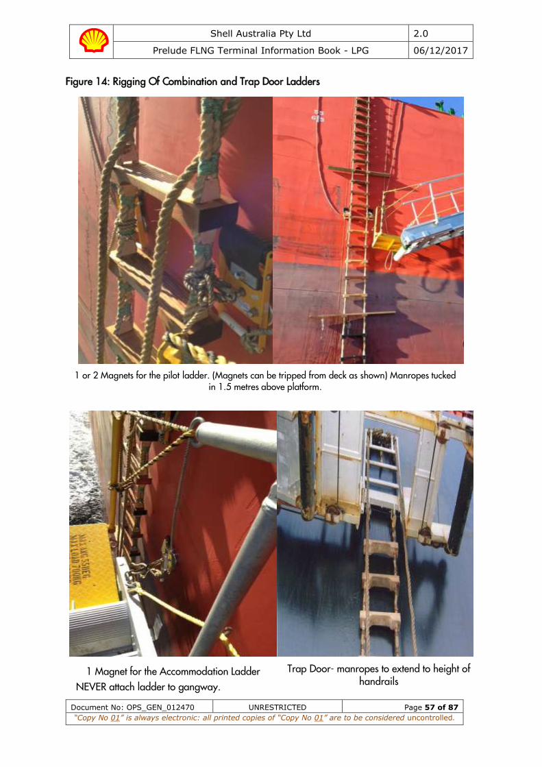
Shell Australia Pty Ltd 2.0
Prelude FLNG Terminal Information Book - LPG 06/12/2017
Document No: OPS_GEN_012470 UNRESTRICTED Page 57 of 87
“Copy No 01” is always electronic: all printed copies of “Copy No 01” are to be considered uncontrolled.
Figure 14: Rigging Of Combination and Trap Door Ladders
1 or 2 Magnets for the pilot ladder. (Magnets can be tripped from deck as shown) Manropes tucked
in 1.5 metres above platform.
1 Magnet for the Accommodation Ladder NEVER attach ladder to gangway.
Trap Door- manropes to extend to height of handrails

Shell Australia Pty Ltd 2.0
Prelude FLNG Terminal Information Book - LPG 06/12/2017
Document No: OPS_GEN_012470 UNRESTRICTED Page 58 of 87
“Copy No 01” is always electronic: all printed copies of “Copy No 01” are to be considered uncontrolled.
Figure 15: Required boarding arrangements for pilot
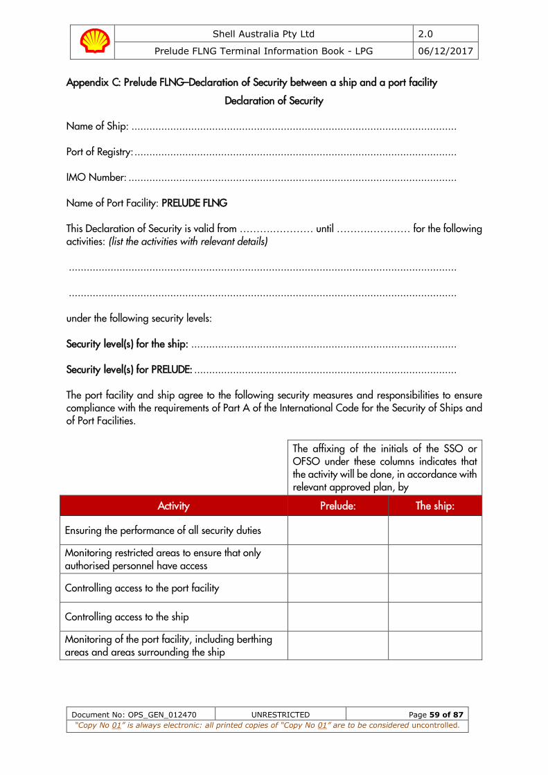
Shell Australia Pty Ltd 2.0
Prelude FLNG Terminal Information Book - LPG 06/12/2017
Document No: OPS_GEN_012470 UNRESTRICTED Page 59 of 87
“Copy No 01” is always electronic: all printed copies of “Copy No 01” are to be considered uncontrolled.
Appendix C: Prelude FLNG–Declaration of Security between a ship and a port facility
Declaration of Security Name of Ship: ............................................................................................................. Port of Registry: ............................................................................................................ IMO Number: .............................................................................................................. Name of Port Facility: PRELUDE FLNG This Declaration of Security is valid from ……….………… until ……….………… for the following activities: (list the activities with relevant details) .................................................................................................................................. .................................................................................................................................. under the following security levels: Security level(s) for the ship: ......................................................................................... Security level(s) for PRELUDE: ........................................................................................ The port facility and ship agree to the following security measures and responsibilities to ensure compliance with the requirements of Part A of the International Code for the Security of Ships and of Port Facilities.
The affixing of the initials of the SSO or OFSO under these columns indicates that the activity will be done, in accordance with relevant approved plan, by
Activity Prelude: The ship:
Ensuring the performance of all security duties
Monitoring restricted areas to ensure that only authorised personnel have access
Controlling access to the port facility
Controlling access to the ship
Monitoring of the port facility, including berthing areas and areas surrounding the ship
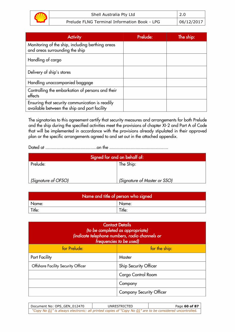
Shell Australia Pty Ltd 2.0
Prelude FLNG Terminal Information Book - LPG 06/12/2017
Document No: OPS_GEN_012470 UNRESTRICTED Page 60 of 87
“Copy No 01” is always electronic: all printed copies of “Copy No 01” are to be considered uncontrolled.
Activity Prelude: The ship:
Monitoring of the ship, including berthing areas and areas surrounding the ship
Handling of cargo
Delivery of ship’s stores
Handling unaccompanied baggage
Controlling the embarkation of persons and their effects
Ensuring that security communication is readily available between the ship and port facility
The signatories to this agreement certify that security measures and arrangements for both Prelude and the ship during the specified activities meet the provisions of chapter XI-2 and Part A of Code that will be implemented in accordance with the provisions already stipulated in their approved plan or the specific arrangements agreed to and set out in the attached appendix. Dated at .........................................on the ...............................................
Signed for and on behalf of: Prelude:
(Signature of OFSO)
The Ship: (Signature of Master or SSO)
Name and title of person who signed
Name: Name: Title: Title:
Contact Details (to be completed as appropriate)
(indicate telephone numbers, radio channels or frequencies to be used)
for Prelude: for the ship:
Port Facility Master
Offshore Facility Security Officer Ship Security Officer
Cargo Control Room
Company
Company Security Officer
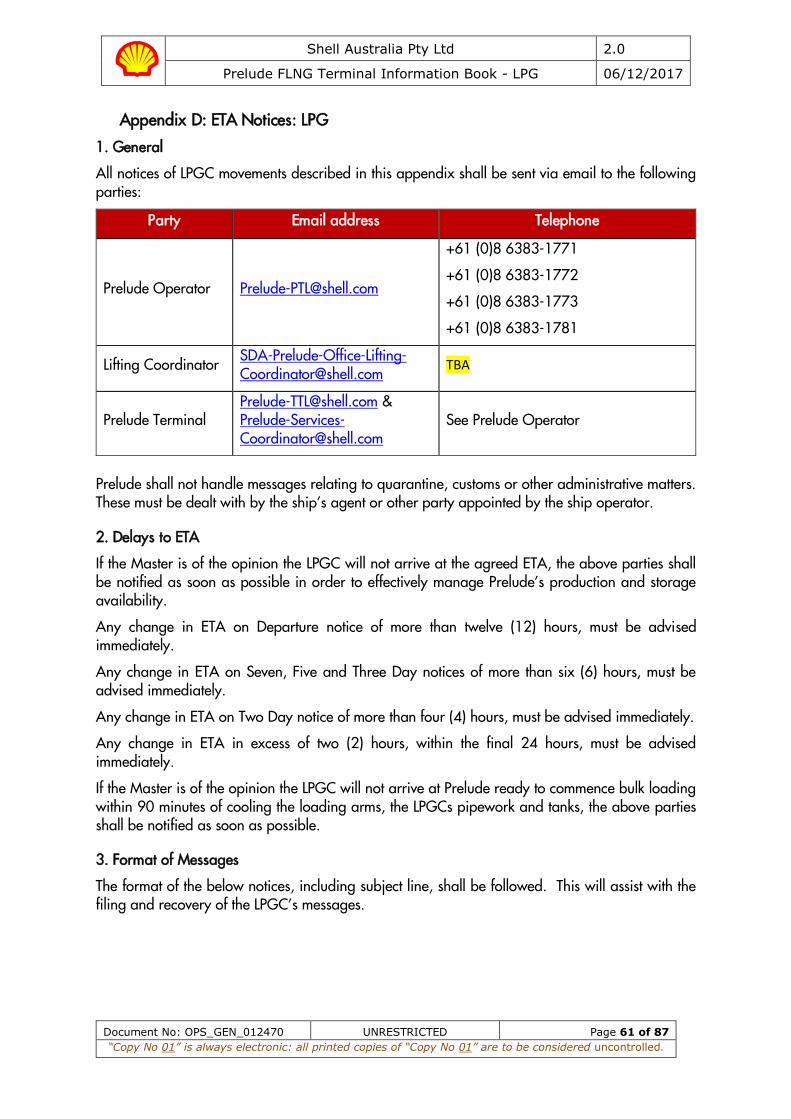
Shell Australia Pty Ltd 2.0
Prelude FLNG Terminal Information Book - LPG 06/12/2017
Document No: OPS_GEN_012470 UNRESTRICTED Page 61 of 87
“Copy No 01” is always electronic: all printed copies of “Copy No 01” are to be considered uncontrolled.
Appendix D: ETA Notices: LPG
1. General
All notices of LPGC movements described in this appendix shall be sent via email to the following parties:
Party Email address Telephone
Prelude Operator [email protected]
+61 (0)8 6383-1771
+61 (0)8 6383-1772
+61 (0)8 6383-1773
+61 (0)8 6383-1781
Lifting Coordinator [email protected]
TBA
Prelude Terminal [email protected] & [email protected]
See Prelude Operator
Prelude shall not handle messages relating to quarantine, customs or other administrative matters. These must be dealt with by the ship’s agent or other party appointed by the ship operator.
2. Delays to ETA
If the Master is of the opinion the LPGC will not arrive at the agreed ETA, the above parties shall be notified as soon as possible in order to effectively manage Prelude’s production and storage availability.
Any change in ETA on Departure notice of more than twelve (12) hours, must be advised immediately.
Any change in ETA on Seven, Five and Three Day notices of more than six (6) hours, must be advised immediately.
Any change in ETA on Two Day notice of more than four (4) hours, must be advised immediately.
Any change in ETA in excess of two (2) hours, within the final 24 hours, must be advised immediately.
If the Master is of the opinion the LPGC will not arrive at Prelude ready to commence bulk loading within 90 minutes of cooling the loading arms, the LPGCs pipework and tanks, the above parties shall be notified as soon as possible.
3. Format of Messages
The format of the below notices, including subject line, shall be followed. This will assist with the filing and recovery of the LPGC’s messages.
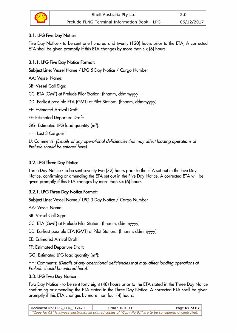
Shell Australia Pty Ltd 2.0
Prelude FLNG Terminal Information Book - LPG 06/12/2017
Document No: OPS_GEN_012470 UNRESTRICTED Page 62 of 87
“Copy No 01” is always electronic: all printed copies of “Copy No 01” are to be considered uncontrolled.
3.1. LPG Five Day Notice
Five Day Notice - to be sent one hundred and twenty (120) hours prior to the ETA, A corrected ETA shall be given promptly if this ETA changes by more than six (6) hours.
3.1.1. LPG Five Day Notice Format:
Subject Line: Vessel Name / LPG 5 Day Notice / Cargo Number
AA: Vessel Name:
BB: Vessel Call Sign:
CC: ETA (GMT) at Prelude Pilot Station: (hh:mm, ddmmyyyy)
DD: Earliest possible ETA (GMT) at Pilot Station: (hh:mm, ddmmyyyy)
EE: Estimated Arrival Draft:
FF: Estimated Departure Draft:
GG: Estimated LPG load quantity (m3):
HH: Last 3 Cargoes:
JJ: Comments: (Details of any operational deficiencies that may affect loading operations at Prelude should be entered here).
3.2. LPG Three Day Notice
Three Day Notice - to be sent seventy two (72) hours prior to the ETA set out in the Five Day Notice, confirming or amending the ETA set out in the Five Day Notice. A corrected ETA will be given promptly if this ETA changes by more than six (6) hours.
3.2.1. LPG Three Day Notice Format:
Subject Line: Vessel Name / LPG 3 Day Notice / Cargo Number
AA: Vessel Name:
BB: Vessel Call Sign:
CC: ETA (GMT) at Prelude Pilot Station: (hh:mm, ddmmyyyy)
DD: Earliest possible ETA (GMT) at Pilot Station: (hh:mm, ddmmyyyy)
EE: Estimated Arrival Draft:
FF: Estimated Departure Draft:
GG: Estimated LPG load quantity (m3):
HH: Comments: (Details of any operational deficiencies that may affect loading operations at Prelude should be entered here).
3.3. LPG Two Day Notice
Two Day Notice - to be sent forty eight (48) hours prior to the ETA stated in the Three Day Notice confirming or amending the ETA stated in the Three Day Notice. A corrected ETA shall be given promptly if this ETA changes by more than four (4) hours.

Shell Australia Pty Ltd 2.0
Prelude FLNG Terminal Information Book - LPG 06/12/2017
Document No: OPS_GEN_012470 UNRESTRICTED Page 63 of 87
“Copy No 01” is always electronic: all printed copies of “Copy No 01” are to be considered uncontrolled.
3.3.1. LPG Two Day Notice Format:
Subject Line: Vessel Name / LPG 2 Day Notice / Cargo Number
AA: Vessel Name:
BB: Vessel Call Sign:
CC: ETA (GMT) at Prelude Pilot Station: (hh:mm, ddmmyyyy)
DD: Earliest possible ETA (GMT) at Pilot Station: (hh:mm, ddmmyyyy)
EE: Estimated Arrival Draft:
FF: Estimated Departure Draft:
GG: Estimated LPG load quantity (m3):
HH: Verify the following systems have been tested / inspected and fully operational:
1. All navigation Equipment: Y / N 2. All LSA & FFA defect free, in good working order and ready for operation: Y / N 3. All mooring equipment, inc mooring lines, messengers: Y / N 4. Main Engine & Steering Gear: Y / N 5. Cargo containment, measurement and control system , including Hi / Low level and
pressure alarms: Y / N 6. Gas and fire detection systems: Y / N 7. ESD system: Y / N 8. All Remotely operated valves: Y / N 9. Cargo valves and confirmed not passing: Y / N 10. Port manifold crane operational with competent operator available (for spool piece
transfer) Y / N
JJ: Comments: (Details of any operational deficiencies that may affect loading operations at Prelude should be entered here).
3.4. LPG 24 Hour Notice
24 Hour Notice - to be sent twenty four (24) hours prior to the ETA stated in the Two Day Notice, confirming or amending the ETA stated in the Two Day Notice. A corrected ETA shall be given promptly if this ETA changes by more than Four (4) hours.
3.4.1. LPG 24 Hour Notice Format:
Subject Line: Vessel Name / LPG 24 Hour Notice / Cargo Number
AA: Vessel Name:
BB: Vessel Call Sign:
CC: ETA (GMT) at Prelude Pilot Station: (hh:mm, ddmmyyyy)
DD: Earliest possible ETA (GMT) at Pilot Station: (hh:mm, ddmmyyyy)
EE: Estimated Arrival Draft:
FF: Estimated Departure Draft:
GG: Estimated LPG load quantity (m3):
Shell Australia Pty Ltd 2.0
Prelude FLNG Terminal Information Book - LPG 06/12/2017
Document No: OPS_GEN_012470 UNRESTRICTED Page 64 of 87
“Copy No 01” is always electronic: all printed copies of “Copy No 01” are to be considered uncontrolled.
HH: Estimated tank condition on arrival:
Tank 1 Tank 2 Tank 3 Tank 4 Tank 5
Temp (oC)
Press (mb)
JJ: Comments: (Details of any operational deficiencies that may affect loading operations at Prelude should be entered here).
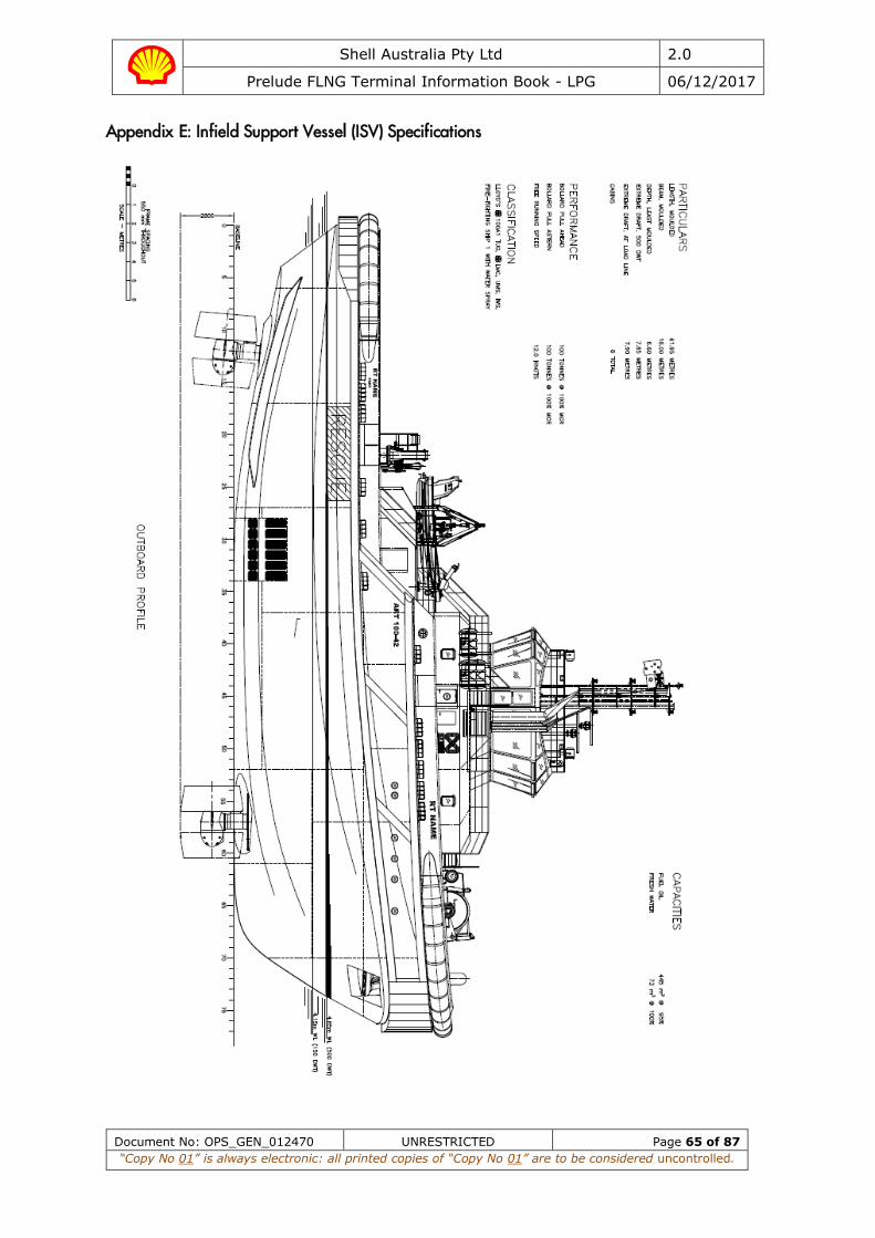
Shell Australia Pty Ltd 2.0
Prelude FLNG Terminal Information Book - LPG 06/12/2017
Document No: OPS_GEN_012470 UNRESTRICTED Page 65 of 87
“Copy No 01” is always electronic: all printed copies of “Copy No 01” are to be considered uncontrolled.
Appendix E: Infield Support Vessel (ISV) Specifications
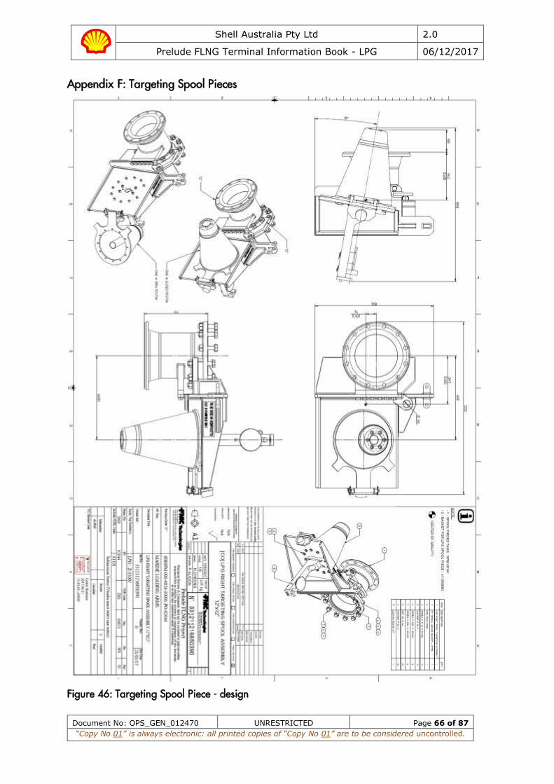
Shell Australia Pty Ltd 2.0
Prelude FLNG Terminal Information Book - LPG 06/12/2017
Document No: OPS_GEN_012470 UNRESTRICTED Page 66 of 87
“Copy No 01” is always electronic: all printed copies of “Copy No 01” are to be considered uncontrolled.
Appendix F: Targeting Spool Pieces
Figure 46: Targeting Spool Piece - design
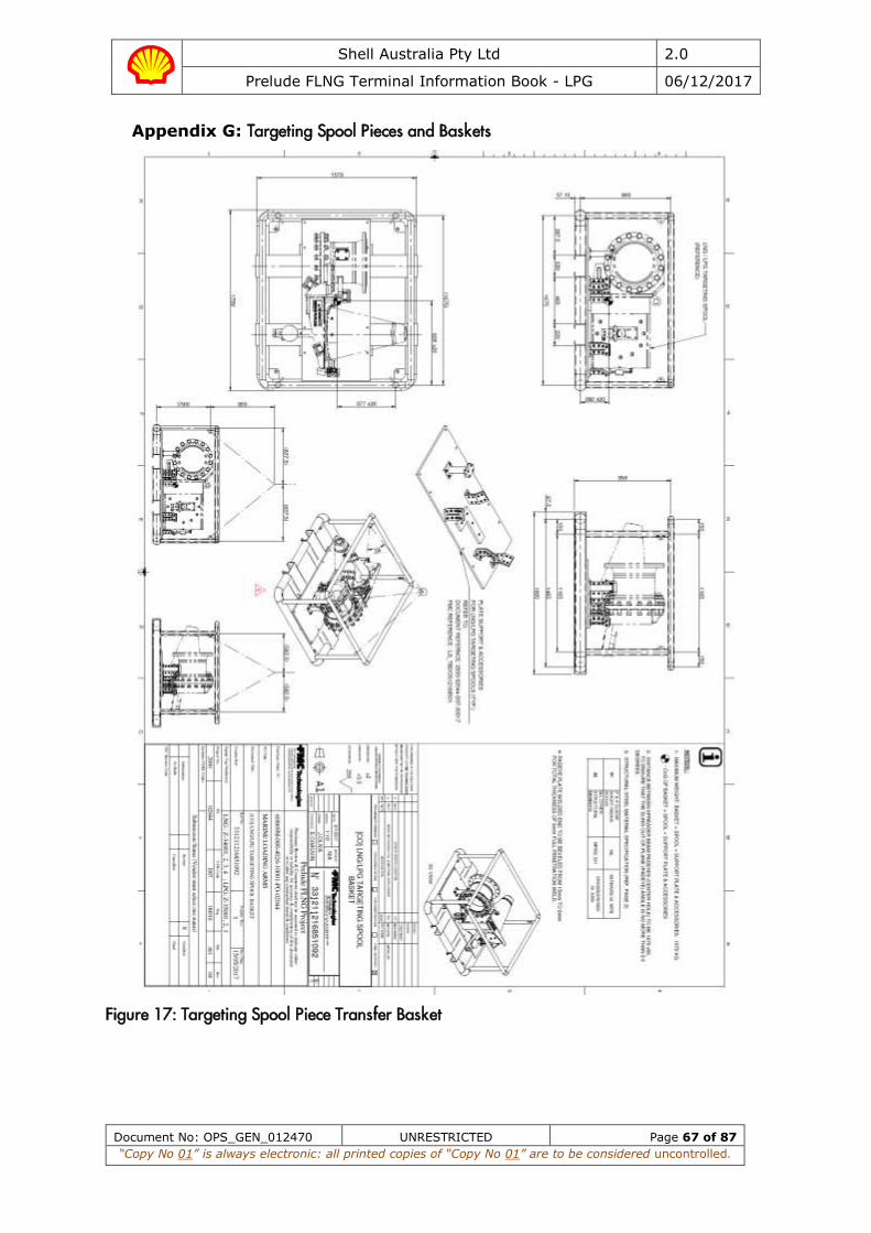
Shell Australia Pty Ltd 2.0
Prelude FLNG Terminal Information Book - LPG 06/12/2017
Document No: OPS_GEN_012470 UNRESTRICTED Page 67 of 87
“Copy No 01” is always electronic: all printed copies of “Copy No 01” are to be considered uncontrolled.
Appendix G: Targeting Spool Pieces and Baskets
Figure 17: Targeting Spool Piece Transfer Basket
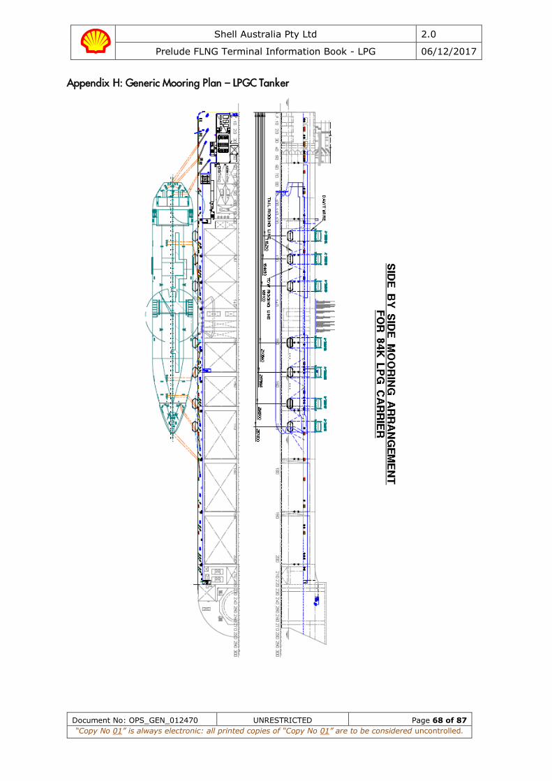
Shell Australia Pty Ltd 2.0
Prelude FLNG Terminal Information Book - LPG 06/12/2017
Document No: OPS_GEN_012470 UNRESTRICTED Page 68 of 87
“Copy No 01” is always electronic: all printed copies of “Copy No 01” are to be considered uncontrolled.
Appendix H: Generic Mooring Plan – LPGC Tanker

Shell Australia Pty Ltd 2.0
Prelude FLNG Terminal Information Book - LPG 06/12/2017
Document No: OPS_GEN_012470 UNRESTRICTED Page 69 of 87
“Copy No 01” is always electronic: all printed copies of “Copy No 01” are to be considered uncontrolled.
Appendix I: Ship Shore Link Pin Configurations
Fibre Optic 6 Core Connector
Connector Type Pin Number Pin used for Ship-Shore communications 1 Pin used for Shore-Ship communications 2 Pin used for ESD 1 Ship-Shore 3 Pin used for ESD 1 Shore-Ship 4 Spare 5 Spare 6
37 Pin Pyle-National Electrical Link
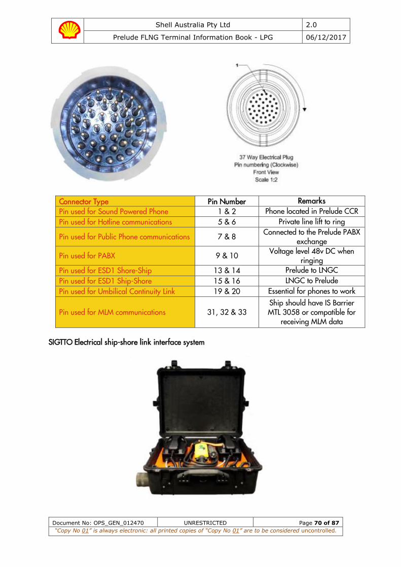
Shell Australia Pty Ltd 2.0
Prelude FLNG Terminal Information Book - LPG 06/12/2017
Document No: OPS_GEN_012470 UNRESTRICTED Page 70 of 87
“Copy No 01” is always electronic: all printed copies of “Copy No 01” are to be considered uncontrolled.
Connector Type Pin Number Remarks Pin used for Sound Powered Phone 1 & 2 Phone located in Prelude CCR Pin used for Hotline communications 5 & 6 Private line lift to ring
Pin used for Public Phone communications 7 & 8 Connected to the Prelude PABX exchange
Pin used for PABX 9 & 10 Voltage level 48v DC when ringing
Pin used for ESD1 Shore-Ship 13 & 14 Prelude to LNGC Pin used for ESD1 Ship-Shore 15 & 16 LNGC to Prelude Pin used for Umbilical Continuity Link 19 & 20 Essential for phones to work
Pin used for MLM communications 31, 32 & 33 Ship should have IS Barrier MTL 3058 or compatible for
receiving MLM data
SIGTTO Electrical ship-shore link interface system
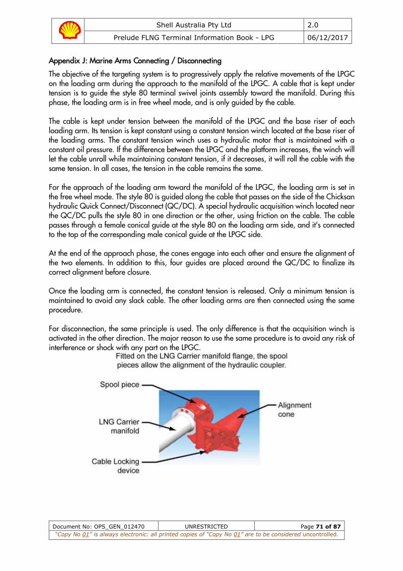
Shell Australia Pty Ltd 2.0
Prelude FLNG Terminal Information Book - LPG 06/12/2017
Document No: OPS_GEN_012470 UNRESTRICTED Page 71 of 87
“Copy No 01” is always electronic: all printed copies of “Copy No 01” are to be considered uncontrolled.
Appendix J: Marine Arms Connecting / Disconnecting
The objective of the targeting system is to progressively apply the relative movements of the LPGC on the loading arm during the approach to the manifold of the LPGC. A cable that is kept under tension is to guide the style 80 terminal swivel joints assembly toward the manifold. During this phase, the loading arm is in free wheel mode, and is only guided by the cable. The cable is kept under tension between the manifold of the LPGC and the base riser of each loading arm. Its tension is kept constant using a constant tension winch located at the base riser of the loading arms. The constant tension winch uses a hydraulic motor that is maintained with a constant oil pressure. If the difference between the LPGC and the platform increases, the winch will let the cable unroll while maintaining constant tension, if it decreases, it will roll the cable with the same tension. In all cases, the tension in the cable remains the same. For the approach of the loading arm toward the manifold of the LPGC, the loading arm is set in the free wheel mode. The style 80 is guided along the cable that passes on the side of the Chicksan hydraulic Quick Connect/Disconnect (QC/DC). A special hydraulic acquisition winch located near the QC/DC pulls the style 80 in one direction or the other, using friction on the cable. The cable passes through a female conical guide at the style 80 on the loading arm side, and it's connected to the top of the corresponding male conical guide at the LPGC side. At the end of the approach phase, the cones engage into each other and ensure the alignment of the two elements. In addition to this, four guides are placed around the QC/DC to finalize its correct alignment before closure. Once the loading arm is connected, the constant tension is released. Only a minimum tension is maintained to avoid any slack cable. The other loading arms are then connected using the same procedure. For disconnection, the same principle is used. The only difference is that the acquisition winch is activated in the other direction. The major reason to use the same procedure is to avoid any risk of interference or shock with any part on the LPGC.

Shell Australia Pty Ltd 2.0
Prelude FLNG Terminal Information Book - LPG 06/12/2017
Document No: OPS_GEN_012470 UNRESTRICTED Page 72 of 87
“Copy No 01” is always electronic: all printed copies of “Copy No 01” are to be considered uncontrolled.

Shell Australia Pty Ltd 2.0
Prelude FLNG Terminal Information Book - LPG 06/12/2017
Document No: OPS_GEN_012470 UNRESTRICTED Page 73 of 87
“Copy No 01” is always electronic: all printed copies of “Copy No 01” are to be considered uncontrolled.
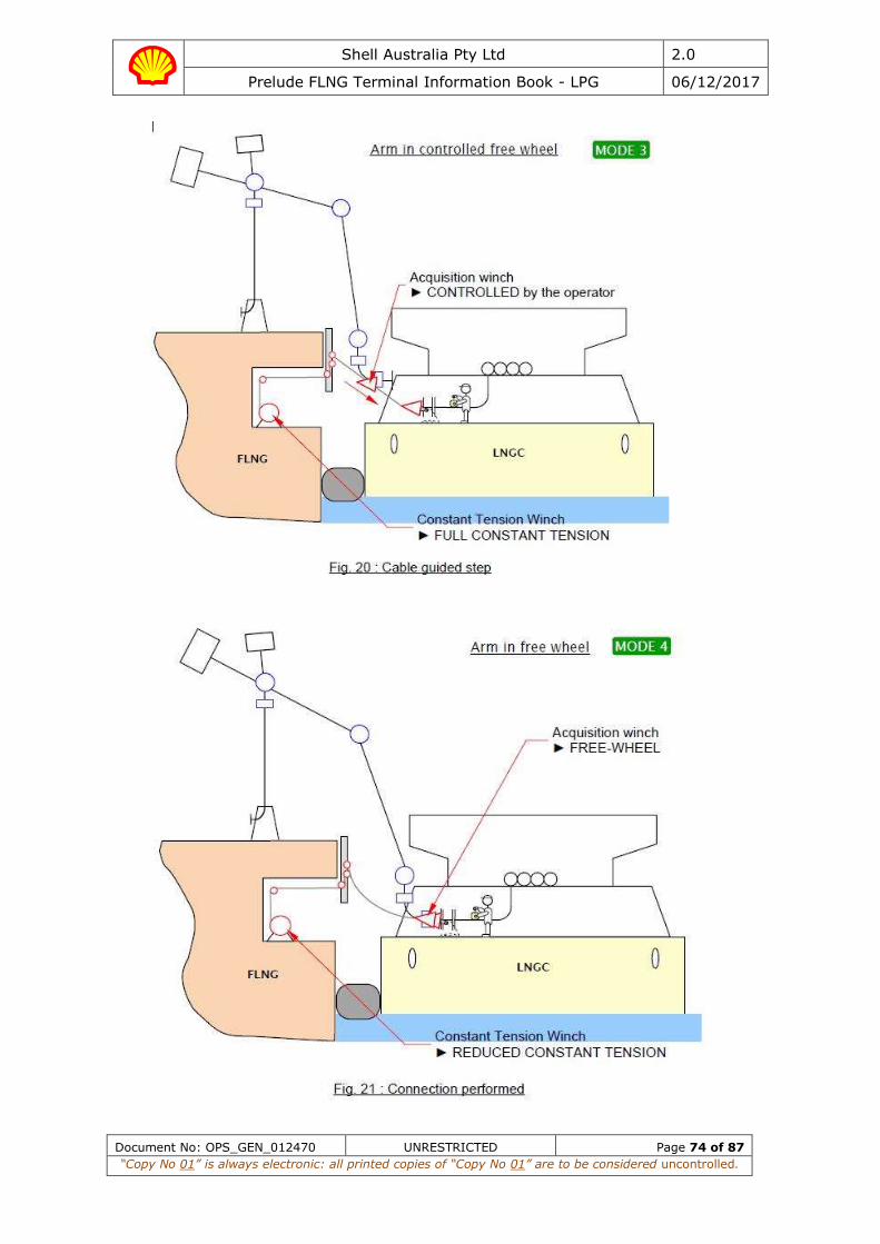
Shell Australia Pty Ltd 2.0
Prelude FLNG Terminal Information Book - LPG 06/12/2017
Document No: OPS_GEN_012470 UNRESTRICTED Page 74 of 87
“Copy No 01” is always electronic: all printed copies of “Copy No 01” are to be considered uncontrolled.

Shell Australia Pty Ltd 2.0
Prelude FLNG Terminal Information Book - LPG 06/12/2017
Document No: OPS_GEN_012470 UNRESTRICTED Page 75 of 87
“Copy No 01” is always electronic: all printed copies of “Copy No 01” are to be considered uncontrolled.
Appendix K: Ship / FLNG Safety Checklist
Ship’s Name: Port: Prelude
Date of Arrival: Time All Fast:
INSTRUCTIONS FOR COMPLETION
The safety of operations requires that all questions should be answered affirmatively by clearly ticking () the appropriate box. If an affirmative answer is not possible, the reason should be given and an agreement reached upon appropriate precautions to be taken between the ship and the terminal. Where any question is considered not to be applicable, then a note to that effect should be inserted in the remarks column.
A box in the columns ‘Ship’ and ‘Terminal’ indicates that checks should be carried out by the party concerned.
The presence of the letters A, P or R in the column ‘Code’ indicates the following:
A – any procedures and agreements should be in writing in the remarks column of this checklist or other mutually acceptable form. In either case, the signature of both parties should be required.
P – in the case of a negative answer, the operation should not be carried out without the permission of the OIM of the Prelude.
R – indicates items to be rechecked at intervals not exceeding that agreed in the declaration.
Prelude Requirements:
1. Prior to arrival at the Pilot Station, the vessel should have in their possession documents as follows:
• Applicable Terminal Information Book for your cargo operation (LNG, LPG or Condensate book)
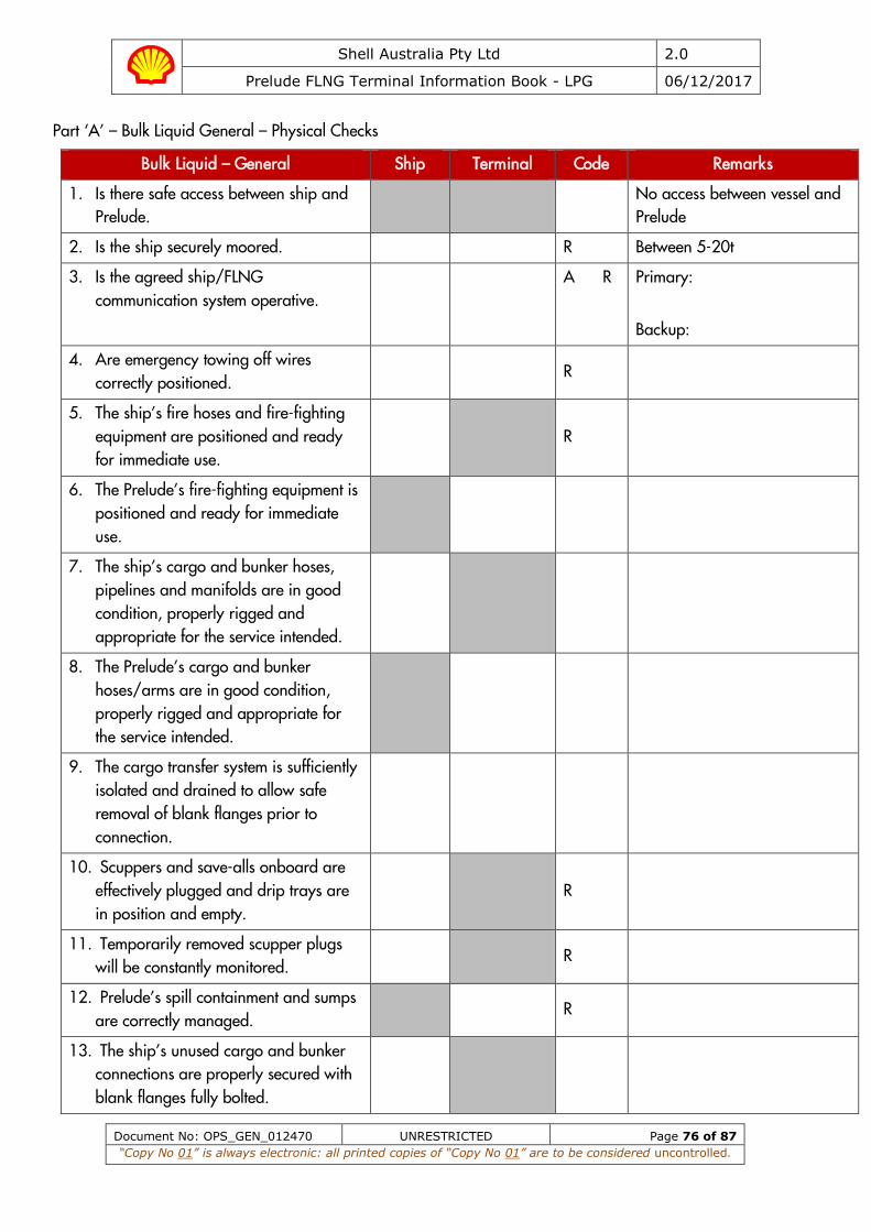
Shell Australia Pty Ltd 2.0
Prelude FLNG Terminal Information Book - LPG 06/12/2017
Document No: OPS_GEN_012470 UNRESTRICTED Page 76 of 87
“Copy No 01” is always electronic: all printed copies of “Copy No 01” are to be considered uncontrolled.
Part ‘A’ – Bulk Liquid General – Physical Checks
Bulk Liquid – General Ship Terminal Code Remarks
1. Is there safe access between ship and Prelude.
No access between vessel and Prelude
2. Is the ship securely moored. R Between 5-20t
3. Is the agreed ship/FLNG communication system operative.
A R Primary:
Backup:
4. Are emergency towing off wires correctly positioned.
R
5. The ship’s fire hoses and fire-fighting equipment are positioned and ready for immediate use.
R
6. The Prelude’s fire-fighting equipment is positioned and ready for immediate use.
7. The ship’s cargo and bunker hoses, pipelines and manifolds are in good condition, properly rigged and appropriate for the service intended.
8. The Prelude’s cargo and bunker hoses/arms are in good condition, properly rigged and appropriate for the service intended.
9. The cargo transfer system is sufficiently isolated and drained to allow safe removal of blank flanges prior to connection.
10. Scuppers and save-alls onboard are effectively plugged and drip trays are in position and empty.
R
11. Temporarily removed scupper plugs will be constantly monitored.
R
12. Prelude’s spill containment and sumps are correctly managed.
R
13. The ship’s unused cargo and bunker connections are properly secured with blank flanges fully bolted.

Shell Australia Pty Ltd 2.0
Prelude FLNG Terminal Information Book - LPG 06/12/2017
Document No: OPS_GEN_012470 UNRESTRICTED Page 77 of 87
“Copy No 01” is always electronic: all printed copies of “Copy No 01” are to be considered uncontrolled.
Bulk Liquid – General Ship Terminal Code Remarks
14. The Prelude’s unused cargo and bunker connections are properly secured with blank flanges fully bolted.
15. All cargo, ballast and bunker tank lids are closed.
16. Sea and overboard discharge valves, when not in use, are closed and visibly secured.
17. All external doors, ports and windows in the accommodation, stores and machinery spaces are closed. Engine room vents may be open.
R
18. The ship’s emergency fire control plans located externally.
Location:
Part ‘B’ – Bulk Liquid General – Verbal Verification
Bulk Liquid – General Ship Terminal Code Remarks
19. Is the ship ready to move under its own power.
P R
20. There is an effective deck watch in attendance onboard and adequate supervision of operations on the ship and Prelude.
R
21. There are sufficient personnel onboard and on Prelude to deal with an emergency.
R
22. The procedures for cargo and ballast handling have been agreed.
A R
23. The emergency signal and shutdown procedure to be used by the ship and Prelude have been explained and understood.
A
24. Material Safety Data Sheets (MSDS) for the cargo transfer have been exchanged where requested.
P R
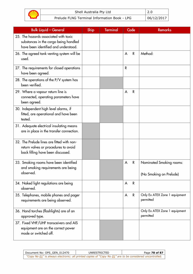
Shell Australia Pty Ltd 2.0
Prelude FLNG Terminal Information Book - LPG 06/12/2017
Document No: OPS_GEN_012470 UNRESTRICTED Page 78 of 87
“Copy No 01” is always electronic: all printed copies of “Copy No 01” are to be considered uncontrolled.
Bulk Liquid – General Ship Terminal Code Remarks
25. The hazards associated with toxic substances in the cargo being handled have been identified and understood.
26. The agreed tank venting system will be used.
A R Method:
27. The requirements for closed operations have been agreed.
R
28. The operations of the P/V system has been verified.
29. Where a vapour return line is connected, operating parameters have been agreed.
A R
30. Independent high level alarms, if fitted, are operational and have been tested.
31. Adequate electrical insulating means are in place in the transfer connection.
32. The Prelude lines are fitted with non-return valves or procedures to avoid back filling have been discussed.
33. Smoking rooms have been identified and smoking requirements are being observed.
A R Nominated Smoking rooms:
(No Smoking on Prelude)
34. Naked light regulations are being observed.
A R
35. Telephones, mobile phones and pager requirements are being observed.
A R Only Ex ATEX Zone 1 equipment permitted
36. Hand torches (flashlights) are of an approved type.
Only Ex ATEX Zone 1 equipment
permitted
37. Fixed VHF/UHF transceivers and AIS equipment are on the correct power mode or switched off.
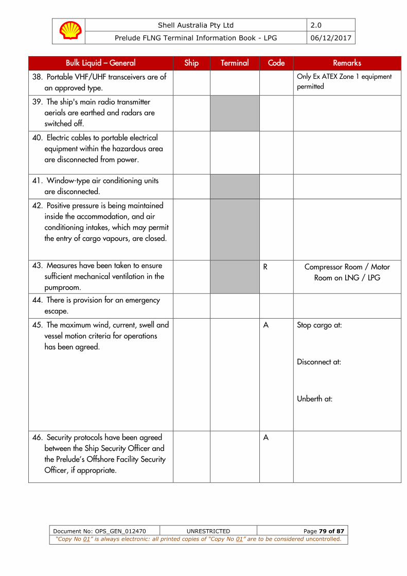
Shell Australia Pty Ltd 2.0
Prelude FLNG Terminal Information Book - LPG 06/12/2017
Document No: OPS_GEN_012470 UNRESTRICTED Page 79 of 87
“Copy No 01” is always electronic: all printed copies of “Copy No 01” are to be considered uncontrolled.
Bulk Liquid – General Ship Terminal Code Remarks
38. Portable VHF/UHF transceivers are of an approved type.
Only Ex ATEX Zone 1 equipment
permitted
39. The ship's main radio transmitter aerials are earthed and radars are switched off.
40. Electric cables to portable electrical equipment within the hazardous area are disconnected from power.
41. Window-type air conditioning units are disconnected.
42. Positive pressure is being maintained inside the accommodation, and air conditioning intakes, which may permit the entry of cargo vapours, are closed.
43. Measures have been taken to ensure sufficient mechanical ventilation in the pumproom.
R Compressor Room / Motor
Room on LNG / LPG
44. There is provision for an emergency escape.
45. The maximum wind, current, swell and vessel motion criteria for operations has been agreed.
A Stop cargo at:
Disconnect at:
Unberth at:
46. Security protocols have been agreed between the Ship Security Officer and the Prelude’s Offshore Facility Security Officer, if appropriate.
A
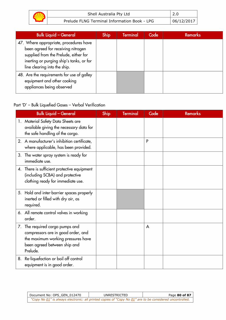
Shell Australia Pty Ltd 2.0
Prelude FLNG Terminal Information Book - LPG 06/12/2017
Document No: OPS_GEN_012470 UNRESTRICTED Page 80 of 87
“Copy No 01” is always electronic: all printed copies of “Copy No 01” are to be considered uncontrolled.
Bulk Liquid – General Ship Terminal Code Remarks
47. Where appropriate, procedures have been agreed for receiving nitrogen supplied from the Prelude, either for inerting or purging ship’s tanks, or for line clearing into the ship.
48. Are the requirements for use of galley equipment and other cooking appliances being observed
Part ‘D’ – Bulk Liquefied Gases – Verbal Verification
Bulk Liquid – General Ship Terminal Code Remarks
1. Material Safety Data Sheets are available giving the necessary data for the safe handling of the cargo.
2. A manufacturer’s inhibition certificate, where applicable, has been provided.
P
3. The water spray system is ready for immediate use.
4. There is sufficient protective equipment (including SCBA) and protective clothing ready for immediate use.
5. Hold and inter-barrier spaces properly inerted or filled with dry air, as required.
6. All remote control valves in working order.
7. The required cargo pumps and compressors are in good order, and the maximum working pressures have been agreed between ship and Prelude.
A
8. Re-liquefaction or boil off control equipment is in good order.

Shell Australia Pty Ltd 2.0
Prelude FLNG Terminal Information Book - LPG 06/12/2017
Document No: OPS_GEN_012470 UNRESTRICTED Page 81 of 87
“Copy No 01” is always electronic: all printed copies of “Copy No 01” are to be considered uncontrolled.
Bulk Liquid – General Ship Terminal Code Remarks
9. The gas detection equipment has been properly set for the cargo, is calibrated, has been tested and inspected and in good order.
10. Cargo system gauges and alarms are correctly set and in good order.
11. Emergency shutdown systems have been tested and are working properly.
12. Ship and Prelude have informed each other of the closing rate of the ESD valves, automatic valves or similar devices.
A Ship:
Prelude:
13. Information has been exchanged between ship and Prelude on the maximum/ minimum temperatures/ pressures of the cargo to be handled.
A
14. Cargo tanks are protected against inadvertent overfilling at all times while any cargo operations are in progress.
15. The compressor room is properly ventilated; the electrical motor room is properly pressurised and the alarm system is working.
16. Cargo tank relief valves are set correctly and actual relief valve settings clearly and visibly displayed. (Record settings below).
No.1 Tank No.4 Tank
No.2 Tank No.5 Tank
No.3 Tank

Shell Australia Pty Ltd 2.0
Prelude FLNG Terminal Information Book - LPG 06/12/2017
Document No: OPS_GEN_012470 UNRESTRICTED Page 82 of 87
“Copy No 01” is always electronic: all printed copies of “Copy No 01” are to be considered uncontrolled.
We, the undersigned, have checked the above items in Parts A, B and Part D, in accordance with the instructions and have satisfied ourselves that the entries we have made are correct to the best of our knowledge.
We have also made arrangements to carry out repetitive checks as necessary and agreed that those items with code ’R’ in the Checklist should be re-checked at intervals not exceeding ________hours (not to exceed 6 hours). If to our knowledge the status of any item changes, we will immediately inform the other party.
For Ship For Prelude
Name: Name:
Rank: Rank:
Signature: Signature:
Date Date
Time: Time:
The presence of the letters ‘A’, ‘P’ or ‘R’ in the column entitled ‘Code’ indicates the following:
A (‘Agreement’). This indicates an agreement or procedure that should be identified in the ‘Remarks’ column of the Check-List or communicated in some other mutually acceptable form.
P (‘Permission’). In the case of a negative answer to the statements coded ‘P’, operators should not be conducted without the written permission from the appropriate authority.
R (‘Re-check’). This indicates items to be re-checked at appropriate intervals, as agreed between both parties, at periods stated in the declaration.
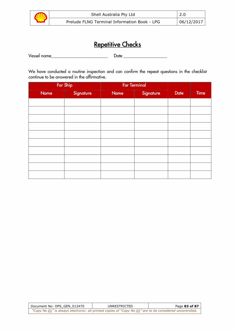
Shell Australia Pty Ltd 2.0
Prelude FLNG Terminal Information Book - LPG 06/12/2017
Document No: OPS_GEN_012470 UNRESTRICTED Page 83 of 87
“Copy No 01” is always electronic: all printed copies of “Copy No 01” are to be considered uncontrolled.
Repetitive Checks
Vessel name__________________________ Date ____________________
We have conducted a routine inspection and can confirm the repeat questions in the checklist continue to be answered in the affirmative.
For Ship For Terminal
Date
Time Name Signature Name Signature
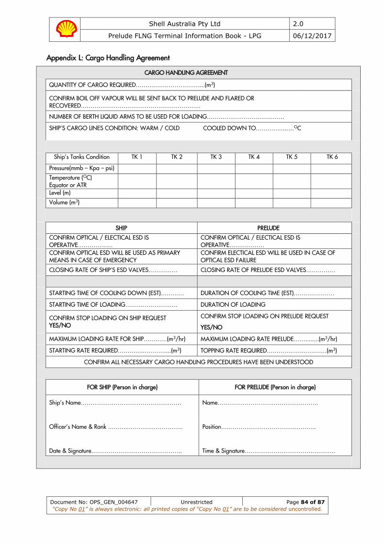
Shell Australia Pty Ltd 2.0
Prelude FLNG Terminal Information Book - LPG 06/12/2017
Document No: OPS_GEN_004647 Unrestricted Page 84 of 87
“Copy No 01” is always electronic: all printed copies of “Copy No 01” are to be considered uncontrolled.
Appendix L: Cargo Handling Agreement
CARGO HANDLING AGREEMENT
QUANTITY OF CARGO REQUIRED……………………………...(m3)
CONFIRM BOIL OFF VAPOUR WILL BE SENT BACK TO PRELUDE AND FLARED OR RECOVERED……………………………………………………..
NUMBER OF BERTH LIQUID ARMS TO BE USED FOR LOADING………………………………….
SHIP’S CARGO LINES CONDITION: WARM / COLD
COOLED DOWN TO……………..…OC
Ship’s Tanks Condition TK 1 TK 2 TK 3 TK 4 TK 5 TK 6
Pressure(mmb – Kpa – psi)
Temperature (OC) Equator or ATR
Level (m)
Volume (m3)
SHIP PRELUDE
CONFIRM OPTICAL / ELECTICAL ESD IS OPERATIVE………………
CONFIRM OPTICAL / ELECTICAL ESD IS OPERATIVE………………
CONFIRM OPTICAL ESD WILL BE USED AS PRIMARY MEANS IN CASE OF EMERGENCY
CONFIRM ELECTICAL ESD WILL BE USED IN CASE OF OPTICAL ESD FAILURE
CLOSING RATE OF SHIP’S ESD VALVES…………… CLOSING RATE OF PRELUDE ESD VALVES……………
STARTING TIME OF COOLING DOWN (EST)………… DURATION OF COOLING TIME (EST)…………………
STARTING TIME OF LOADING……………………… DURATION OF LOADING
CONFIRM STOP LOADING ON SHIP REQUEST YES/NO
CONFIRM STOP LOADING ON PRELUDE REQUEST
YES/NO
MAXIMUM LOADING RATE FOR SHIP…………(m3/hr) MAXIMUM LOADING RATE PRELUDE……........(m3/hr)
STARTING RATE REQUIRED………….…………...(m3) TOPPING RATE REQUIRED……………….…………(m3)
CONFIRM ALL NECESSARY CARGO HANDLING PROCEDURES HAVE BEEN UNDERSTOOD
FOR SHIP (Person in charge) FOR PRELUDE (Person in charge)
Ship’s Name…………………………………………….
Name…………………………………………….
Officer’s Name & Rank ………..……………………….
Position………………………………………….
Date & Signature……………………………………….. Time & Signature………………………………………..
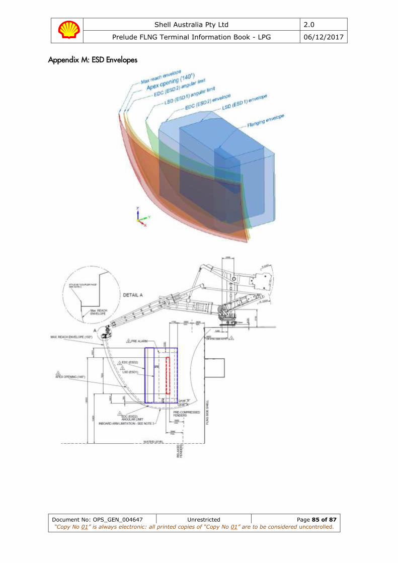
Shell Australia Pty Ltd 2.0
Prelude FLNG Terminal Information Book - LPG 06/12/2017
Document No: OPS_GEN_004647 Unrestricted Page 85 of 87
“Copy No 01” is always electronic: all printed copies of “Copy No 01” are to be considered uncontrolled.
Appendix M: ESD Envelopes
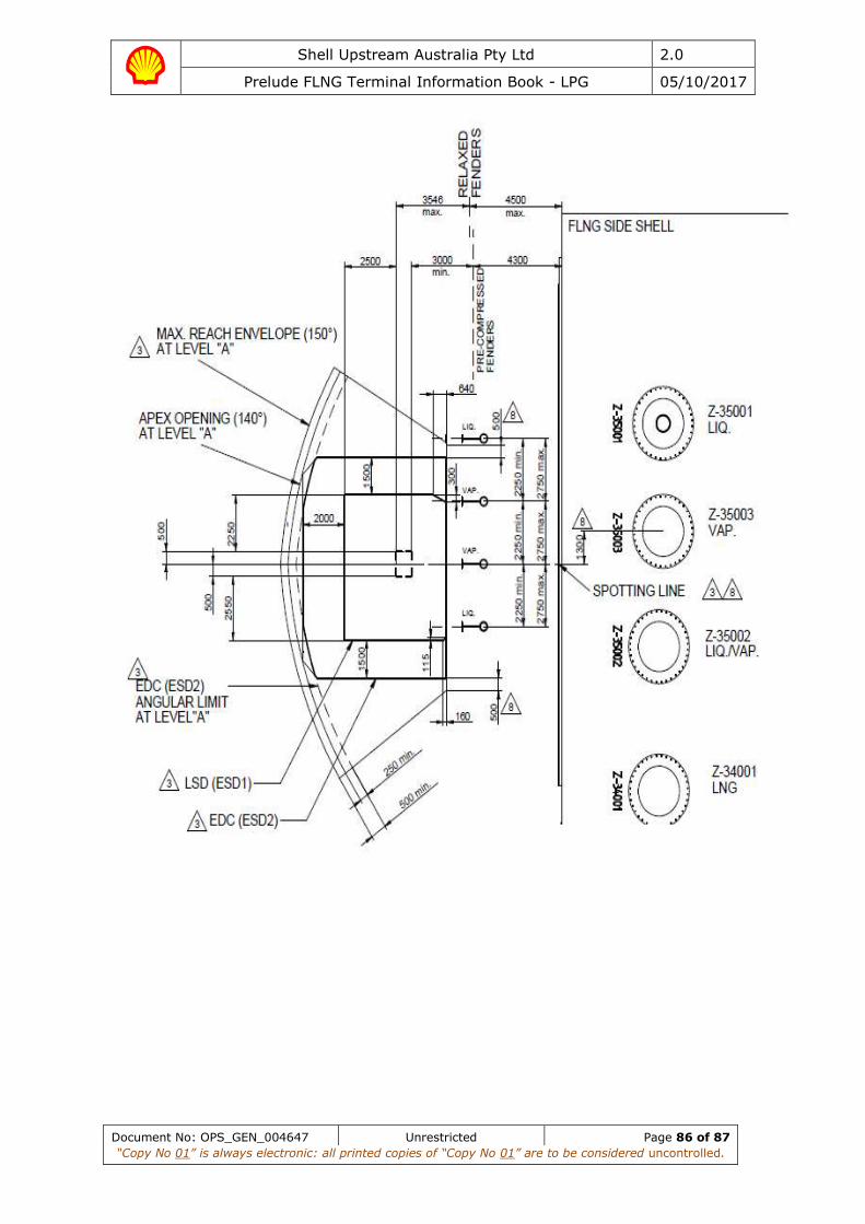
Shell Upstream Australia Pty Ltd 2.0
Prelude FLNG Terminal Information Book - LPG 05/10/2017
Document No: OPS_GEN_004647 Unrestricted Page 86 of 87
“Copy No 01” is always electronic: all printed copies of “Copy No 01” are to be considered uncontrolled.

Shell Australia Pty Ltd 2.0
Prelude FLNG Terminal Information Book - LPG 06/12/2017
Document No: OPS_GEN_004647 Unrestricted Page 87 of 87
“Copy No 01” is always electronic: all printed copies of “Copy No 01” are to be considered uncontrolled.
Appendix N: Field Layout Diagram
Field Diagram with 1500m Safety Zone.pdf
Appendix O: Prelude/Ichthys Field Diagram
Related Documents