IEEE TRANSACTIONS ON PLASMA SCIENCE, VOL. 21. NO. 6. DECEMBER 1993 625 Preliminary Investigation of Power Flow and Performance Phenomena in a Multimegawatt Coaxial Plasma Thruster Kurt F. Schoenberg, Richard A. Gerwin, Ivars Henins, Robert M. Mayo, Jay T. Scheuer, and Glen A. Wurden Abstract-This paper summarizes preliminary experimental and theoretical research that was directed toward the study of quasi-steady-state power flow in a large, unoptimized, multi- megawatt coaxial plasma thruster. The paper addresses large coaxial thruster operation and includes evaluation and inter- pretation of the experimental results with a view to the devel- opment of efficient, steady-state, megawatt-class magnetoplas- madynamic (MPD) thrusters. Experimental studies utilized the Coaxial Thruster Experi- ment (CTX) facility at the Los Alamos National Laboratory. The unoptimized thruster, 1 m in length with inner and outer tungsten-coated electrode diameters of 0.37 and 0.56 m, re- spectively, was operated over a range of peak power levels (nominally 10-40 MW) in order to ascertain high-power per- formance scaling. In addition to pure self-field operation, an unoptimized applied magnetic field configuration, with adjust- able flux densities, was used to form a rudimentary, annular magnetic nozzle. In this initial research, an accurate power bal- ance was precluded due to the lack of spatial resolution of power deposition on the electrodes. However, the data, together with a calorimetric IR data reduction algorithm, did quantify en- ergy flux deposition on electrode surfaces and provided a qual- itative picture of global power flow and thruster performance. Highlights of this study include the observations that the measured longitudinal flow velocity of the propellant was in es- sential agreement with the prediction of self-field nozzle theory, achieving Alfvknic flow velocities of = lo5 m /s. Furthermore, radiative emission was a negligible power loss mechanism (< 10%) over the operational power range studied. Preliminary measurements indicate that the magnetic topology between an- ode and cathode can produce a substantial influence on the elec- trode sheath potentials, especially on the anode fall. This thereby suggests a means for influencing the power deposited on the electrodes, with concomitant benefits to thruster effi- ciency, without relinquishing axisymmetry. I. INTRODUCTION HIS paper summarizes initial research performed on T the Los Alamos Coaxial Thruster Experiment (CTX) Manuscript received September 17, 1992; revised August 20, 1993. This work was supported in part by the NASA Lewis Research Center Low Thrust Propulsion Group, and reference work was supported by the U.S. Department of Energy. K. F. Schoenberg, R. A. Gewin, I. Henins, J. T. Scheuer, and G. A. Wurden are with Los Alamos National Laboratory, Los Alamos, NM 87545. R. M. Mayo was with Los Alamos National Laboratory, Los Alamos, NM. He is now with the Department of Nuclear Engineering, North Car- olina State University, Raleigh, NC 27695. IEEE Log Number 92 13483. facility that was directed toward establishing a perspec- tive and understanding of quasi-steady-state power utili- zation in large, high-power, electrodynamically driven plasma thrusters. Principal research objectives include developing an understanding of thruster efficiency and its dependence on device parameters such as spatial dimen- sion, power level, mass-flow rate, and electrode sheath properties in the limit of steady-state operation. The on- going work is motivated by the expectation that experi- ence amassed over years of research on coaxial plasma guns could be directly applicable to the design of more efficient, steady-state, high-power magnetoplasmady- namic (MPD) thrusters [ 11, [2]. The practical distinction drawn here between the former and the latter recognizes that, historically, much coaxial plasma gun research has been strongly motivated by basic science, without the constraints on size or power that arise from attempts to design economical space missions. Of course, one can find some examples of overlap that tend to blur this distinc- tion. Coaxial plasma thrusters, like MPD thrusters, utilize a magnetohydrodynamic plasma acceleration mechanism to produce thrust [3], [4]. In addition to the ionization losses and other (nominal) frozen-flow losses, thruster efficiency can be considered as limited by characteristic processes occurring in two distinct spatial regimes. One regime, which encompasses the part of the annular interelectrode volume that is dominated by the electrode sheath poten- tials, is characterized by electrode power losses acquired by the localized kinetic acceleration of charged particles, and leads to undesirable power deposition on the elec- trodes. This regime has presented a major impediment to the development of efficient MPD thrusters [2]. Its study comprises a major focus of the work reported here. The other regime involves the bulk of the annular vol- ume containing the main flow field. As discussed below, very basic considerations regarding the main flow field show that it also can have a substantial influence on thruster efficiency, and thus its presence and nature is an important constituent of our research. This is a fortiori true when a global power balance is ultimately attempted. Although these two spatial regimes are mutually interac- tive, and may conceivably be separated by graduated spa- 0093-3813/93$03,00 0 1993 IEEE

Welcome message from author
This document is posted to help you gain knowledge. Please leave a comment to let me know what you think about it! Share it to your friends and learn new things together.
Transcript
IEEE TRANSACTIONS ON PLASMA SCIENCE, VOL. 21. NO. 6. DECEMBER 1993 625
Preliminary Investigation of Power Flow and Performance Phenomena in a Multimegawatt
Coaxial Plasma Thruster Kurt F. Schoenberg, Richard A. Gerwin, Ivars Henins, Robert M . Mayo, Jay T . Scheuer,
and Glen A. Wurden
Abstract-This paper summarizes preliminary experimental and theoretical research that was directed toward the study of quasi-steady-state power flow in a large, unoptimized, multi- megawatt coaxial plasma thruster. The paper addresses large coaxial thruster operation and includes evaluation and inter- pretation of the experimental results with a view to the devel- opment of efficient, steady-state, megawatt-class magnetoplas- madynamic (MPD) thrusters.
Experimental studies utilized the Coaxial Thruster Experi- ment (CTX) facility at the Los Alamos National Laboratory. The unoptimized thruster, 1 m in length with inner and outer tungsten-coated electrode diameters of 0.37 and 0.56 m, re- spectively, was operated over a range of peak power levels (nominally 10-40 MW) in order to ascertain high-power per- formance scaling. In addition to pure self-field operation, an unoptimized applied magnetic field configuration, with adjust- able flux densities, was used to form a rudimentary, annular magnetic nozzle. In this initial research, an accurate power bal- ance was precluded due to the lack of spatial resolution of power deposition on the electrodes. However, the data, together with a calorimetric IR data reduction algorithm, did quantify en- ergy flux deposition on electrode surfaces and provided a qual- itative picture of global power flow and thruster performance.
Highlights of this study include the observations that the measured longitudinal flow velocity of the propellant was in es- sential agreement with the prediction of self-field nozzle theory, achieving Alfvknic flow velocities of = lo5 m /s. Furthermore, radiative emission was a negligible power loss mechanism (< 10%) over the operational power range studied. Preliminary measurements indicate that the magnetic topology between an- ode and cathode can produce a substantial influence on the elec- trode sheath potentials, especially on the anode fall. This thereby suggests a means for influencing the power deposited on the electrodes, with concomitant benefits to thruster effi- ciency, without relinquishing axisymmetry.
I. INTRODUCTION HIS paper summarizes initial research performed on T the Los Alamos Coaxial Thruster Experiment (CTX)
Manuscript received September 17, 1992; revised August 20, 1993. This work was supported in part by the NASA Lewis Research Center Low Thrust Propulsion Group, and reference work was supported by the U.S. Department of Energy.
K. F. Schoenberg, R. A. Gewin , I . Henins, J . T. Scheuer, and G. A . Wurden are with Los Alamos National Laboratory, Los Alamos, NM 87545.
R. M. Mayo was with Los Alamos National Laboratory, Los Alamos, NM. He is now with the Department of Nuclear Engineering, North Car- olina State University, Raleigh, NC 27695.
IEEE Log Number 92 13483.
facility that was directed toward establishing a perspec- tive and understanding of quasi-steady-state power utili- zation in large, high-power, electrodynamically driven plasma thrusters. Principal research objectives include developing an understanding of thruster efficiency and its dependence on device parameters such as spatial dimen- sion, power level, mass-flow rate, and electrode sheath properties in the limit of steady-state operation. The on- going work is motivated by the expectation that experi- ence amassed over years of research on coaxial plasma guns could be directly applicable to the design of more efficient, steady-state, high-power magnetoplasmady- namic (MPD) thrusters [ 11, [2]. The practical distinction drawn here between the former and the latter recognizes that, historically, much coaxial plasma gun research has been strongly motivated by basic science, without the constraints on size or power that arise from attempts to design economical space missions. Of course, one can find some examples of overlap that tend to blur this distinc- tion.
Coaxial plasma thrusters, like MPD thrusters, utilize a magnetohydrodynamic plasma acceleration mechanism to produce thrust [3], [4]. In addition to the ionization losses and other (nominal) frozen-flow losses, thruster efficiency can be considered as limited by characteristic processes occurring in two distinct spatial regimes. One regime, which encompasses the part of the annular interelectrode volume that is dominated by the electrode sheath poten- tials, is characterized by electrode power losses acquired by the localized kinetic acceleration of charged particles, and leads to undesirable power deposition on the elec- trodes. This regime has presented a major impediment to the development of efficient MPD thrusters [2]. Its study comprises a major focus of the work reported here.
The other regime involves the bulk of the annular vol- ume containing the main flow field. As discussed below, very basic considerations regarding the main flow field show that it also can have a substantial influence on thruster efficiency, and thus its presence and nature is an important constituent of our research. This is a fortiori true when a global power balance is ultimately attempted. Although these two spatial regimes are mutually interac- tive, and may conceivably be separated by graduated spa-
0093-3813/93$03,00 0 1993 IEEE
~
626 IEEE TRANSACTIONS ON PLASMA SCIENCE, VOL. 21. NO. 6 , DECEMBER 1993
tial subregimes, this zero-order idealization provides an efficacious framework for the study of thruster efficiency.
11. THE CTX FACILITY A N D THRUSTER OPERATION
A schematic of the CTX coaxial plasma thruster is shown in Fig. 1. Coaxial guns of this size have been ex- tensively used as plasma and magnetic helicity (linked magnetic flux) sources in magnetic fusion and defense program experiments at power levels exceeding 100 MW [SI, [6]. Pulsed coaxial plasma guns of similar design, albeit with different spatial and operational scales, have been flown in space to investigate the dynamic interaction of high-energy plasma with the upper atmosphere and the Earth’s geomagnetic field [7], as well as investigated for advanced propulsion applications [ 81 and materials pro- cessing [9].
For this study, the CTX facility was configured to op- erate in a power range from 10 to 40 MW. A 2 MJ (10 kV) capacitor bank was direct-coupled through ignitron switches to the electrodes, where the outer electrode (an- ode) was set at the reference ground potential. A 10-40 MW discharge required a bank charge voltage of only 1- 2 kV. At this low charge voltage, the banks accessed only 4% of their maximum energy capacity. Direct discharge of the banks into the thruster at this low energy, without pulse-forming networks or voltage transformers, pro- duced “round-top’’ current and voltage waveforms of ap- proximately 1 ms in duration as shown in Fig. 2. On the magnetohydrodynamic time scale for plasma evolution, however, the current and voltage were quasi-static. In this sense, the discharges were quasi-steady-state. This quasi- steady interpretation will be discussed in more detail in a later section of this paper.
The CTX thruster consists of two coaxial, stainless steel, tungsten-coated electrodes. The inner and outer electrodes are 1 m long and have diameters of 0.37 and 0.56 m, respectively. The working gas, typically hydro- gen or deuterium, is injected in the annular acceleration region by six fast puff valves that are fired roughly 1 ms before the electrodes are energized. The valves are mag- netically driven in parallel by a current pulse from a small (340 J at 2 kV) capacitor bank. They fully open in roughly 100 ps and empty a 1 cm3 volume of compressed (up to 7600 torr) gas per valve. On the 1 ms discharge timescale, primary fueling is strongly influenced by gas desorbtion off the electrode surfaces [SI. The thruster is fired inside a 5 ft (diameter) x 15 ft cylindrical vacuum tank. Three 500 I/s turbo-molecular pumps and three 2500 l / s vac- uum cryopumps maintain a base pressure of torr. Tank pressure directly due to injection from the plenum is estimated to be less than 1 mtorr.
The center electrode (cathode) contains a solenoidal coil that produces an applied B,, field (the nozzle field). The coil is driven by an ignitron-switched 1.19 mf capacitor bank. The nozzle field rises to peak value in 6 ms at which time the discharge is initiated. The vacuum field config- uration of B , would be approximately constant during
Coaxial Plasma Gun
Vacuum Tank
0 50 100
Scale - cm Fig. 1 . CTX thruster schematic
I I I I I I 0.4 /i i
-1 00 I \ I I r I I I
0 50 100 150 200 250
Microseconds Fig. 2. Nominal “round-top’’ voltage and current waveforms for a 40 MW
discharge.
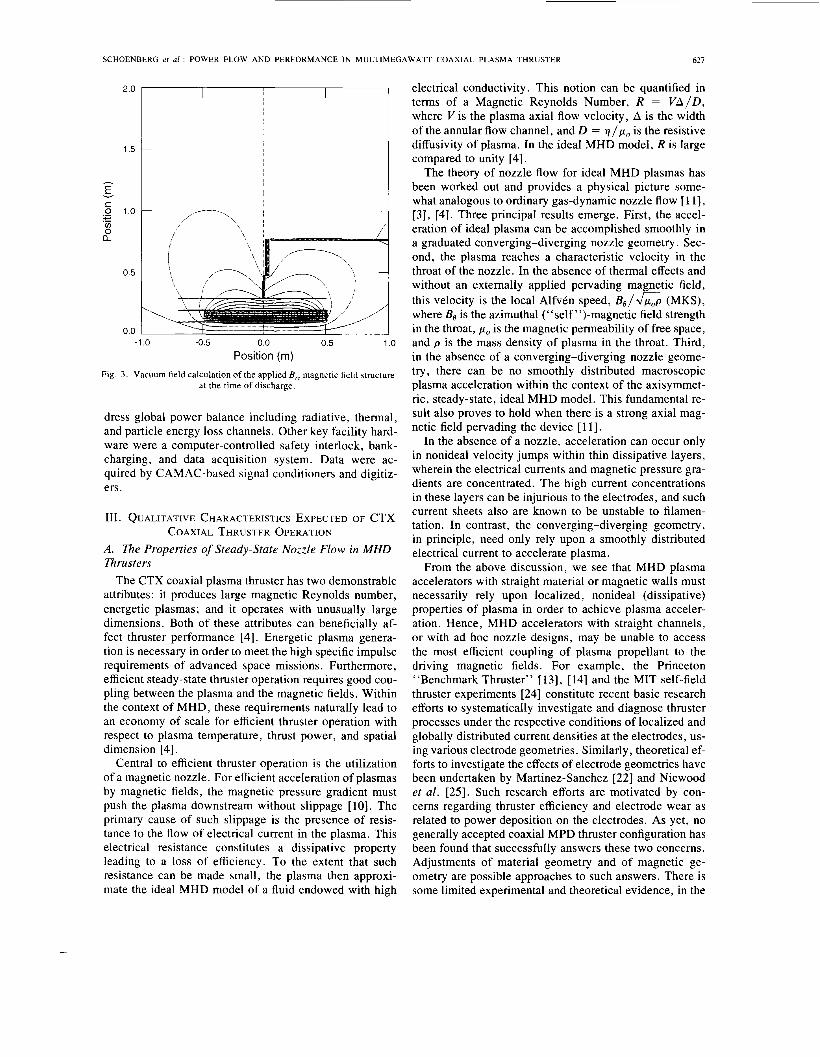
thruster operation. However, as discussed below, inter- action of the flowing plasma with the applied field distorts the vacuum field shape and is believed to form a rudi- mentary magnetic nozzle [ 5 ] . A numerical computation of the vacuum B, field at the time of discharge initiation is shown in Fig. 3 . This unoptimized B , field configura- tion is unconventional within MPD thruster research in that some of the applied magnetic field lines are inter- cepted by both electrodes, with a connection length esti- mated to be not very much larger than the interelectrode spacing (A = 0.1 m). Thus, from the MPD standpoint, the CTX plasma thruster is unusual with regard not only to size and power level, but also with regard to the applied magnetic configuration. Future research will focus on op- timizing the B , field configuration with respect to opti- mizing thruster performance.
Diagnostics, which measure properties within the thruster and the plasma plume, included voltage and cur- rent sensors, magnetic and electrostatic probes, CCD vis- ible imaging, x-ray imaging, infrared electrode calo- rimetry, multichord interferometry, visible spectroscopy, neutral particle spectroscopy, and wide bandwidth bo- lometry. This ensemble of diagnostics was chosen to ad-
~
SCHOENBERG er a l . : POWER FLOW AND PERFORMANCE IN MULTIMEGAWATT COAXIAL PLASMA THRUSTER
2.0
621
I
I I
1.5
h
E
.- 0 1.0
a
v
c + .- v) 0
I I
- /---”‘. 1’ ’\ I ‘ !I
-1 .o -0.5 0.0 0.5 1 .o Position (m)
Fig. 3 . Vacuum field calculation of the applied E,; magnetic field structure at the time of discharge.
dress global power balance including radiative, thermal, and particle energy loss channels. Other key facility hard- ware were a computer-controlled safety interlock, bank- charging, and data acquisition system. Data were ac- quired by CAMAC-based signal conditioners and digitiz- ers.
111. QUALITATIVE CHARACTERISTICS EXPECTED OF CTX
A . The Properties of Steady-State Nozzle Flow in MHD Thrusters
The CTX coaxial plasma thruster has two demonstrable attributes: it produces large magnetic Reynolds number, energetic plasmas; and it operates with unusually large dimensions. Both of these attributes can beneficially af- fect thruster performance [4]. Energetic plasma genera- tion is necessary in order to meet the high specific impulse requirements of advanced space missions. Furthermore, efficient steady-state thruster operation requires good cou- pling between the plasma and the magnetic fields. Within the context of MHD, these requirements naturally lead to an economy of scale for efficient thruster operation with respect to plasma temperature, thrust power, and spatial dimension [4].
Central to efficient thruster operation is the utilization of a magnetic nozzle. For efficient acceleration of plasmas by magnetic fields, the magnetic pressure gradient must push the plasma downstream without slippage [lo]. The primary cause of such slippage is the presence of resis- tance to the flow of electrical current in the plasma. This electrical resistance constitutes a dissipative property leading to a loss of efficiency. To the extent that such resistance can be made small, the plasma then approxi- mate the ideal MHD model of a fluid endowed with high
COAXIAL THRUSTER OPERATION
electrical conductivity. This notion can be quantified in terms of a Magnetic Reynolds Number, R = V A / D , where V is the plasma axial flow velocity, A is the width of the annular flow channel, and D = v / p , is the resistive diffusivity of plasma. In the ideal MHD model, R is large compared to unity [4].
The theory of nozzle flow for ideal MHD plasmas has been worked out and provides a physical picture some- what analogous to ordinary gas-dynamic nozzle flow [ 1 11, [3], [4]. Three principal results emerge. First, the accel- eration of ideal plasma can be accomplished smoothly in a graduated converging-diverging nozzle geometry. Sec- ond, the plasma reaches a characteristic velocity in the throat of the nozzle. In the absence of thermal effects and without an externally applied pervading magnetic field, this velocity is the local AlfvCn speed, B , / G (MKS), where Bo is the azimuthal (“self ”)-magnetic field strength in the throat, p, is the magnetic permeability of free space, and p is the mass density of plasma in the throat. Third, in the absence of a converging-diverging nozzle geome- try, there can be no smoothly distributed macroscopic plasma acceleration within the context of the axisymmet- ric, steady-state, ideal MHD model. This fundamental re- sult also proves to hold when there is a strong axial mag- netic field pervading the device [ 1 11.
In the absence of a nozzle, acceleration can occur only in nonideal velocity jumps within thin dissipative layers, wherein the electrical currents and magnetic pressure gra- dients are concentrated. The high current concentrations in these layers can be injurious to the electrodes, and such current sheets also are known to be unstable to filamen- tation. In contrast, the converging-diverging geometry, in principle, need only rely upon a smoothly distributed electrical current to accelerate plasma.
From the above discussion, we see that MHD plasma accelerators with straight material or magnetic walls must necessarily rely upon localized, nonideal (dissipative) properties of plasma in order to achieve plasma acceler- ation. Hence, MHD accelerators with straight channels, or with ad hoc nozzle designs, may be unable to access the most efficient coupling of plasma propellant to the driving magnetic fields. For example, the Princeton “Benchmark Thruster” [13], [14] and the MIT self-field thruster experiments [24] constitute recent basic research efforts to systematically investigate and diagnose thruster processes under the respective conditions of localized and globally distributed current densities at the electrodes, us- ing various electrode geometries. Similarly, theoretical ef- forts to investigate the effects of electrode geometries have been undertaken by Martinez-Sanchez [22] and Niewood et al. [25]. Such research efforts are motivated by con- cerns regarding thruster efficiency and electrode wear as related to power deposition on the electrodes. As yet, no generally accepted coaxial MPD thruster configuration has been found that successfully answers these two concerns. Adjustments of material geometry and of magnetic ge- ometry are possible approaches to such answers. There is some limited experimental and theoretical evidence, in the
628 IEEE TRANSACTIONS ON PLASMA SCIENCE, VOL. 21, NO. 6, DECEMBER 1993
above-mentioned references, that the performance of coaxial MHD thrusters with graduated variable geome- tries is somewhat improved, in some respects, over those with straight channel walls.
A properly designed nozzle geometry can, in principle, produce a smooth, gradual acceleration of plasma without relying primarily upon the presence of nonideal effects, and therefore has access to a more efficient regime of op- eration. Thus, any investigation of power flow channels, with a view towards optimization, should be mindful of the interrelation between nonideal power losses (includ- ing electrode losses) and the nature of the main flow field.
Such considerations are relevant to the applied mag- netic field configuration in CTX, since the axial flow of electrically conducting plasma imposes a downstream dis- tortion upon the applied vacuum magnetic field lines. In fact, there is evidence involving the “stuffing” and “un- stuffing” of the CTX thruster [5] that when the applied magnetic field strength is of order or smaller than the nominal strength of the self-field, the plasma propellant “blows out” the applied magnetic field. This process is believed to form, at least locally, a diverging nozzle con- figuration just downstream of the muzzle [5]. Moreover, one may expect that a converging nozzle throat may be formed just upstream of the muzzle because the self-field has been more or less “used up” in accelerating the plasma, and hence is unable to completely counterbalance the transverse magnetic pressure exerted by the applied B,, field.
These qualitative inferences are supported in CTX by the experimental verification of theoretical predictions for self-field-driven flows through converging-diverging an- nular nozzles. Measurements of the axial propellant ve- locity indicate flows at the AlfvCn speed [4]. Because the CTX electrodes are straight, we hypothesize that the “nozzle” is provided by the self-consistently distorted applied magnetic field. Direct experimental measurement of the nozzle field will be explored in future work. (It also is possible to produce self-field AlfvCnic velocities in con- figurations with straight-walled channels [22] but, as mentioned above, this would have to be achieved at the expense of high local concentrations of current at char- acteristic locations, for which there is no obvious evi- dence in the CTX experiment. In particular, the active electrode area in CTX appears to be characterized by a smoothly distributed surface texture of sandpaper quality over the final 0.2-0.3 m at the muzzle end of the accel- erator.)
To the extent that the present unoptimized CTX thruster produces a magnetic-nozzle geometry that is fairly commensurate both with the flow streamlines and the equipotential surfaces, one can expect that the electrode effects of acceleration and current flow (and concomitant power losses from the plasma) will be gradually distrib- uted on the CTX electrodes. This contrasts with thruster configurations where the currents are concentrated in small regions having a constant characteristic location [ 141, [221.
B. Time-Dependent Aspects of CKX Operation Some conditions which lead to the inference of validity
of the steady-state, ideal MHD self-field model to ap- proximately describe plasma flow within (but not far downstream of ) the CTX plasma accelerator are
the observation of “unstuffed operation” (the pres- ence of a plume) below a critical level of the CTX applied magnetic flux, together with a small value of radial magnetic field compared with the self-field; the existence of axial velocities comparable to self- field AlfvCnic velocities in axial channel flow during unstuffed operation; the “quasi-static’’ character of ambient applied magnetic field conditions in the flow channel during an axial transit time (but, also, the short duration of these “quasi-static’’ time scales in comparison to the discharge pulse duration, thus allowing the internal discharge configuration to undergo gradual adjust- ment within the external context of “constant” dis- charge currents and voltages); and the existence of downstream nonideal MHD detach- ment and annihilation processes, respectively, for plasma and self-field flux, which are sufficiently rapid that the effectiveness of the upstream magnetic pressure driving the flow is not impeded by a buildup during the discharge of downstream trapped thermal or magnetic pressure.
It is important to note that steady-state ideal MHD is not invoked far downstream of the muzzle. In fact, such a model must be relinquished downstream, as discussed below.
The first two conditions listed above are experimentally verified. First, the onset of a plume below a critical level of applied flux is observed to occur at all power levels of CTX operation tried so far; and the application of one or a few mWebers over a discharge length of several tens of centimeters leads to estimates in the CTX geometry of order 50 gauss for the radial magnetic field as compared to 500-1000 gauss for the self-field. (The presence of a highly conducting end plate on the cathode prevents sig- nificant axial dissemination of applied flux directly from the interior solenoid during the 0.5-1.0 ms pulse lengths of interest.) Second, axial velocities with magnitudes near that of the “in situ” self-field AlfvCnic velocity, lo5 m/s, have been observed by a “time-of-flight’’ detector, and these Alfvenic flows generally persist for a few hundreds of microseconds.
The third and fourth conditions have not been tested by direct experimental observation in CTX as regards the ac- count of research for this paper, but these conditions can at least be inferred as plausible from the results of theo- retical models. The scope and length of the present paper constrains us here to discussions that will invoke only the simplest relevant models. For example, 1-D (radial vari- ation) slab models can capture the axial and azimuthal distortions of poloidal (B,, B,) magnetic field lines in re- sponse to the channel flow of a resistive fluid.
SCHOENBERG et al.: POWER FLOW AND PERFORMANCE IN MULTIMEGAWATT COAXIAL PLASMA THRUSTER
__
629
Although the third condition has not been directly ver- ified (which would have required the insertion of mag- netic probes into the flow channel), it is qualitatively con- firmed from the results of simple models of the evolution of the CTX applied magnetic flux configuration in re- sponse to the channel flow of a resistive fluid. The prin- cipal characteristic time scale of the applied magnetic field evolution, to, is found to be
to = a 2 / ( n 2 ~ )
where A is the channel width and D = ( q / p o ) is the re- sistive diffusivity of plasma. For classical resistivity ap- plied to electron-ion collisions, this amounts to tD = 30 ps for a 10 eV electron temperature in CTX with A = 10 cm. In contrast, an upper limit for the Alfvenic transit time, 1,- = Zz/VA, over the entire 1 m channel length l,, would be tz = 10 ps. Corresponding to the magnetic noz- zle model developed in the paper of Barnes et al. [ 5 ] , this “stretching time” of 30 ps may be associated with the time needed for the applied magnetic field lines to be dis- torted so as to protrude beyond the muzzle and form the magnetic nozzle. (In [ 5 ] , the throat of the nozzle was pic- tured as being formed by the confluence of the axially departing and axially returning components of stretched field lines. It was shown there that the observed imped- ance characteristics of the CTX coaxial plasma gun could be explained in terms of such a magnetic nozzle.) Of course, those field lines that are near the muzzle to begin with could contribute to nozzle formation at times earlier than 30 ps.
Including the Hall effect in Ohm’s law proves to leave unchanged the basic evolutionary time scale mentioned above, but introduces into the applied field response an oscillation of cyclic frequency v H given by (see Appendix)
Q r V H = -
2 ?rtD
where Q , = e B , / m e v e is the electron Hall parameter in the radial magnetic field component. For relevant param- eters, vH is estimated to be about 50 kHz, and the period of this oscillation is 20 ps (for Br = 50 gauss, n = IOl4 ~ m - ~ , T, = 10 eV), which still is somewhat longer than the upper limit of the axial transit time. The presence of frequencies of order 50 kHz is, in fact, consistent with observations of power-spectra in CTX; see Fig. 12. Note that vH is independent of ion mass, and independent of electron collision frequency, v, , hence independent of electron temperature (for classical collisionality) .
Heimerdinger [24] has observed 50 kHz oscillations in a smaller self-field argon thruster at somewhat compara- ble current levels 2 6 0 kA, but such oscillations did not occur in the straight channel configuration. The onset of these oscillations in that thruster was observed to be cor- related with the transition to an anode-arcing mode of op- eration with curved walls (“curved” so as to produce a larger interelectrode separation than for the straight case) , but the origin of the oscillations was not positively iden- tified. Although similar causes of oscillations conceivably
may be active in CTX, it should be noted that CTX has straight channel walls, and a transverse applied magnetic field, neither of which was present in the MIT thruster with 50 kHz oscillations. Thus, it is also conceivable that the above-mentioned Hall mechanism may constitute a new source of oscillations directly associated with the presence of the CTX applied magnetic field. Spreads in the values of plasma density and radial magnetic field could contribute to a spread in vH, and hence could be partly responsible for the observed spectral width. How- ever, a positive identification of the specific origin of such oscillations is again lacking.
To summarize so far, simple modeling indicates that both the evolution time of the applied field and the Hall oscillation period in the response of that field appear to satisfy the requirements that they exceed the axial AlfvCnic transit time, but also are short compared to the duration of a discharge pulse.
Now, the above-described results are relevant to simple models of applied field lines stretched by the flow of a resistive fluid in a channel with perfectly conducting walls. In reality, the electrodes are slightly resistive so that the footpoints of field lines in the walls are not ab- solutely fixed in position. This introduces another char- acteristic time into the picture, which is the time for the applied flux to be dragged downstream by the flowing plasma to the end of the electrodes. Again, an extension of the simplest model to include this effect is possible, and it is found that the axial velocity of field line foot- points in the channel walls is only a small fraction of the plasma AlfvCnic velocity, in consonance with the quasi- static picture of ambient magnetic field conditions. In the simplest model, the ratio of footpoint axial velocity V,,p to axial flow velocity Vz,plas is found to be
VZ,~ 1 A OpIas - Vz,plas 2 6 o w
where A is channel width, 6 is wall thickness (which proves to be on the order of the resistive skin depth for time durations of interest), upplas is the plasma electrical conductivity, and U, is the wall electrical conductivity. For relevant parameters, this ratio is on the order of 0.1.
A more detailed model, taking into account that the stainless steel electrodes actually are coated with a sig- nificant layer of higher-conductivity tungsten, and that the active axial length of the discharge could be roughly 0.2 m as suggested by the textured electrode surfaces at the downstream portions of the electrodes, leads to an esti- mate of the characteristic time for the applied flux to be dragged to the ends of the electrodes, of order 50 p s . (Somewhat longer times would be required for field lines anchored farther upstream.) Such a time is much longer than the axial AlfvCnic transit time, but also is much shorter than the discharge-pulse duration. Moreover, such a time is consistent with the time at which a significant fraction of discharge current begins to flow in the tank wall [see Fig. 14(b)], as would be expected when a sub- stantial portion of discharge current flows along the set of
IEEE TRANSACTIONS ON PLASMA SCIENCE, VOL. 21, NO. 6 . DECEMBER 1993 630
applied magnetic field lines which have been dragged free of the electrodes and have connected to the tank wall.
Thus, a qualitative picture emerges, in which field lines originally anchored successively more upstream (see Fig. 3) are sequentially dragged downstream, at first protrud- ing from the muzzle and there contributing to nozzle for- mation as in [ 5 ] , and finally undergoing a transfer of their anchor points to the tank wall. This scenario implies that, in the present CTX experiment described here, the hy- pothesized magnetic nozzle structure exists in conjunction with the buildup of tank current, over a few hundred mi- croseconds, and this also is consistent with the observa- tion of AlfvCnic flows over a like time period.
This brings us to the fourth and last condition listed above. The downstream rate of detachment of plasma from the applied magnetic flux involves several complex and subtle issues beyond the scope of this paper; and, in any case, this detachment process is not amenable to a useful quantitative treatment in the absence of confirma- tion by comprehensive measurements of the downstream distributions of plasma and magnetic field quantities in CTX. Therefore, we shall only sketch here some quali- tative reasons why such detachment might occur at a rate that prevents interference with the flow of plasma within the accelerator.
For example, we at least can remark that, in a presumed expanding flow field downstream of the muzzle of CTX, ideal MHD itself predicts a pronounced adiabatic drop in temperature T(z) as a function of axial position z , due to “expansion-cooling. ” The conservation laws for quasi-lD, self-field ideal-MHD flow in a channel of vari- able width A(z) and constant average radius can be shown to lead to an equation for the axial temperature profile:
Here, we have set y = 2 for simplicity, and subscript “0” refers to values at the throat of a presumed annular nozzle. For simple model shapes of the diverging flow, with a characteristic axial length L of the flow field taken comparable to a few channel widths AO,
A(z) = A O J 1 + ( z / L ) ~
one finds that T”* drops by two orders of magnitude within a few meters downstream of the muzzle. (The vac- uum tank is about 5 m in length.) This implies a like re- duction in the classical electrical conductivity of plasma, and hence a substantially decreased downstream interac- tion of the plasma with the applied magnetic flux. Con- comitantly, the so-enhanced downstream resistivity of plasma can be expected to provide an enhanced annihi- lation rate of the self-field flux that has been convected downstream. The heat so generated would eventually be conducted or convected to the tank wall. (This expansion- cooling effect may be somewhat mitigated by parallel electron thermal conduction along the stretched applied magnetic field.) It also is possible that, in a plasma char- acterized by a large electron-Hall parameter, plasma mi-
croturbulence is induced in part of the downstream region by the “drift parameter” associated with the azimuthal plasma current that axially stretches the applied flux, thus giving rise to anomalous resistivity [23]. Thus, there are qualitative reasons to believe that the ideal MHD model will lose its applicability downstream, and that nonideal processes come’into play that allow detachment to pro- ceed apace. From a quantitative standpoint however, it must be acknowledged that the process of plasma detach- ment from applied magnetic fields in coaxial MHD thrusters remains an outstanding research problem.
IV. ELECTRODE PHENOMENA A . Infrared Electrode Calorimetry
An Inframetrics model 600 IR video camera was used to monitor and quantify surface heating on the electrodes. The camera provided absolutely calibrated measurements of electrode temperature. (The calibration procedure of necessity was non-standard in this experimental approach to detection of plasma-gun-electrode power deposition, and is described in an appendix in NASA Contractor Re- port 191084 by K. F . Schoenberg et al., March 1993.) Both end-on and side-on views of the cathode and anode were enabled using a combination of salt and germanium optics to image the nominal 10 pm infrared emission off the electrode surfaces.
The Inframetrics camera was operated in either an im- age mode (17 ms frame acquisition) or fast line scan (62 ps sweep) mode. Both temporal and spatial measurements of the heat pulse decay were made. Full coverage of the electrode surfaces, however, was not possible due to lim- ited optical access. Temperature excursions from a few degrees centigrade for 10 MW low power discharges, to 120” increases for 800 MW high power discharges, were observed. These temperature excursions were converted to peak power deposition estimates by using the calori- metric data reduction algorithm discussed in Section IV-B. In general, shot-to-shot heating nonuniformities were of order a factor of two. This variation was attributed to non- reproducible electrode heating due to surface arcing or time-dependent nonazimuthally symmetric discharge be- havior.
Since the plasma pulse duration and decay of electrode surface heat is short compared to the frame acquisition time, the camera, in image mode, gave a distribution of temperature increase that was convoluted with the tem- perature decay during the frame acquisition. Thus, in or- der to resolve the temporal and spatial behavior of elec- trode heating, the camera was operated in the line-scan mode.
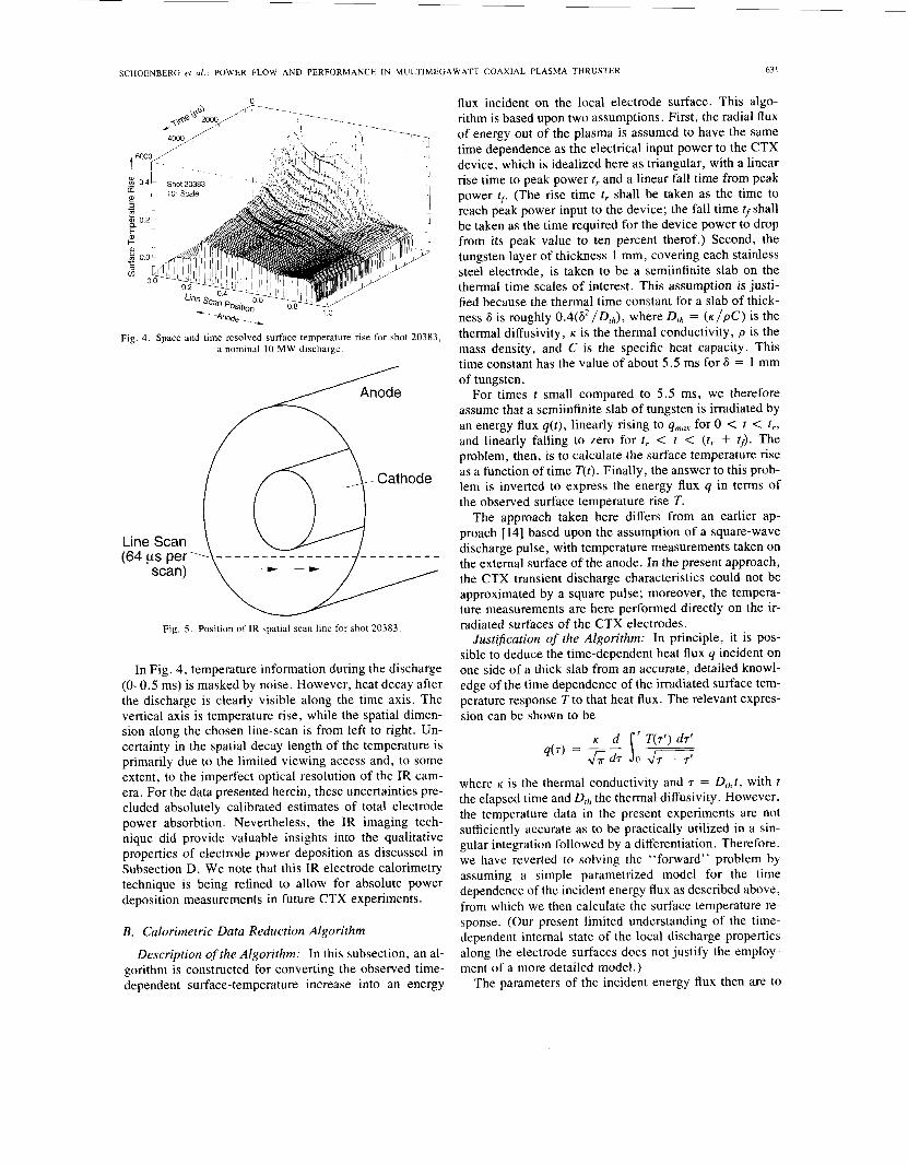
The infrared data can be displayed as either video im- ages or as computer-generated plots. An example of dig- itized line-scan data is shown in Fig. 4. Here, time runs from top to bottom of the frame, and the spatial axis runs left to right. These data were obtained by viewing the thruster at a 60” angle to the cathode face normal from a side-on port. The spatial position of the line scan for these data is shown in Fig. 5 .
63 1 SCHOENBERG et al.: POWER FLOW AND PERFORMANCE IN MULTIMEGAWATT COAXIAL PLASMA THRUSTER
Fig. 4. Space and time resolved surface temperature rise for shot 20383, a nominal I O MW discharge.
Fig. 5 . Position of IR spatial scan line for shot 20383
In Fig. 4 , temperature information during the discharge (0-0.5 ms) is masked by noise. However, heat decay after the discharge is clearly visible along the time axis. The vertical axis is temperature rise, while the spatial dimen- sion along the chosen line-scan is from left to right. Un- certainty in the spatial decay length of the temperature is primarily due to the limited viewing access and, to some extent, to the imperfect optical resolution of the IR cam- era. For the data presented herein, these uncertainties pre- cluded absolutely calibrated estimates of total electrode power absorbtion. Nevertheless, the IR imaging tech- nique did provide valuable insights into the qualitative properties of electrode power deposition as discussed in Subsection D. We note that this IR electrode calorimetry technique is being refined to allow for absolute power deposition measurements in future CTX experiments.
B. Calorimetric Data Reduction Algorithm
Description of the Algorithm: In this subsection, an al- gorithm is constructed for converting the observed time- dependent surface-temperature increase into an energy
flux incident on the local electrode surface. This algo- rithm is based upon two assumptions. First, the radial flux of energy out of the plasma is assumed to have the same time dependence as the electrical input power to the CTX device, which is idealized here as triangular, with a linear rise time to peak power 1, and a linear fall time from peak power tr. (The rise time tr shall be taken as the time to reach peak power input to the device; the fall time tf shall be taken as the time required for the device power to drop from its peak value to ten percent therof.) Second, the tungsten layer of thickness 1 mm, covering each stainless steel electrode, is taken to be a semiinfinite slab on the thermal time scales of interest. This assumption is justi- fied because the thermal time constant for a slab of thick- ness 6 is roughly O.4(A2/D,,), where Drh = ( K / ~ C ) is the thermal diffusivity, K is the thermal conductivity, p is the mass density, and C is the specific heat capacity. This time constant has the value of about 5.5 ms for 6 = 1 mm of tungsten.
For times t small compared to 5.5 ms, we therefore assume that a semiinfinite slab of tungsten is irradiated by an energy flux q(t) , linearly rising to qmar for 0 < t < t,, and linearly falling to zero for t , < t < (t, + t f) . The problem, then, is to calculate the surface temperature rise as a function of time T(t). Finally, the answer to this prob- lem is inverted to express the energy flux q in terms of the observed surface temperature rise T.
The approach taken here differs from an earlier ap- proach [14] based upon the assumption of a square-wave discharge pulse, with temperature measurements taken on the external surface of the anode. In the present approach, the CTX transient discharge characteristics could not be approximated by a square pulse; moreover, the tempera- ture measurements are here performed directly on the ir- radiated surfaces of the CTX electrodes.
JustiJication of the Algorithm: In principle, it is pos- sible to deduce the time-dependent heat flux q incident on one side of a thick slab from an accurate, detailed knowl- edge of the time dependence of the irradiated surface tem- perature response T to that heat flux. The relevant expres- sion can be shown to be
q(7) = - - ____ &d. s 0 - T(7’) drr
where K is the thermal conductivity and 7 = D,,t, with t the elapsed time and Drh the thermal diffusivity. However, the temperature data in the present experiments are not sufficiently accurate as to be practically utilized in a sin- gular integration followed by a differentiation. Therefore, we have reverted to solving the “forward” problem by assuming a simple parametrized model for the time dependence of the incident energy flux as described above, from which we then calculate the surface temperature re- sponse. (Our present limited understanding of the time- dependent internal state of the local discharge properties along the electrode surfaces does not justify the employ- ment of a more detailed model.)
The parameters of the incident energy flux then are to
632 IEEE TRANSACTIONS ON PLASMA SCIENCE, VOL. 21, NO. 6, DECEMBER 1993
be adjusted so that the computed temperature response agrees with the experimental observations. However, these results are offered only as semiquantitative indica- tions of the power density deposition on the electrodes rather than as quantitatively accurate, because the local conditions in the CTX plasma discharge are not well known, and are probably transient as discussed in Section 111.
Although the present approach is not completely rig- orous, this simple energy-flux-conversion algorithm does yield results that interrelate several disparate features of the CTX experiment. We shall briefly preview this self- consistency now, and further details will be described later in the paper.
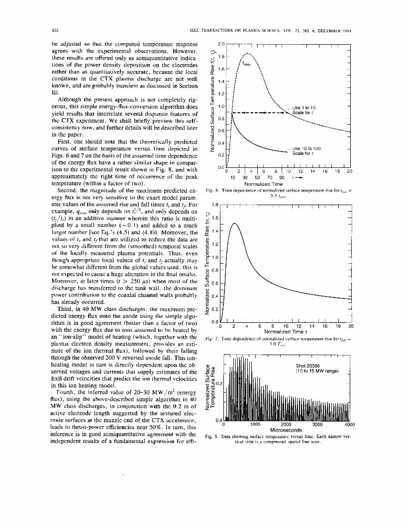
First, one should note that the theoretically predicted curves of surface temperature versus time depicted in Figs. 6 and 7 on the basis of the assumed time dependence of the energy flux have a rather similar shape in compar- ison to the experimental result shown in Fig. 8, and with approximately the right time of occurrence of the peak temperature (within a factor of two).
Second, the magnitude of the maximum predicted en- ergy flux is not very sensitive to the exact model param- eter values of the assumed rise and fall times t , and tr. For example, qmax only depends on t : / 2 , and only depends on (tf/t ,) in an additive manner wherein this ratio is multi- plied by a small number (-0.1) and added to a much larger number [see Eq.’s (4.5) and (4.8)1. Moreover, the values of t , and rf that are utilized to reduce the data are not so very different from the (smoothed) temporal scales of the locally measured plasma potentials. Thus, even though appropriate local values of t , and tf actually may be somewhat different from the global values used, this is not expected to cause a huge alteration in the final results. Moreover, at later times ( t > 250 ps) when most of the discharge has transferred to the tank wall, the dominant power contribution to the coaxial channel walls probably has already occurred.
Third, in 40 MW class discharges, the maximum pre- dicted energy flux onto the anode using the simple algo- rithm is in good agreement (better than a factor of two) with the energy flux due to ions assumed to be heated by an “ion-slip’’ model of heating (which, together with the plzisnia electron density measurement, provides an esti- mate of the ion thermal flux), followed by their falling through the observed 200 V reversed anode fall. This ion- heating model in turn is directly dependent upon the ob- served voltages and currents that supply estimates of the ExB drift velocities that predict the ion thermal velocities in this ion heating model.
Fourth, the inferred value of 20-30 MW/m2 (energy flux), using the above-described simple algorithm in 40 MW class discharges, in conjunction with the 0.2 m of active electrode length suggested by the textured elec- trode surfaces at the muzzle end of the CTX accelerator, leads to thrust-power efficiencies near 50%. In turn, this inference is in good semiquantitative agreement with the independent results of a fundamental expression for effi-
h
e- < 1.8
._ 1.6 [r
E 3 1.4
E
v c
4 - 4
x 1.2 5 + 1.0
‘t, 0.8 v) U 8 0.6
E 0.4 z
0.2
.- - m
0 1 2 1 4 1 6 1 8 / 1 0 12 14 16 18 20 10 30 50 70 90 T-
Normalized Time Fig. 6 . Time dependence of normalized surface temperature rise for =
5 . 5 t,,,,,.
Normalized Time z Fig. 7. Time dependence of normalized surface temperature rise for r,,,, =
3.0 Tr,w
l l l l l l l l l l l i l l l l ~ ....
Shot 20386 (10 to 15 MW range) 51.“
; $0.2 .- 8 Z 75% E: 9-
n n 0 1000 2000 3000 4000
Microseconds Fig. 8. Data showing surface temperature versus time. Each narrow ver-
tical strip is a compressed spatial line scan.
SCHOENBERG et al.: POWER FLOW AND PERFORMANCE IN MULTIMEGAWATT COAXIAL PLASMA THRUSTER
-
633
ciency incorporating values of current, mass flow, dis- charge voltage, and axial velocity [see Eq. (5.2)].
Taken as a whole, these four points tend to justify the application of the simple energy-flux-conversion algo- rithm. The aim here is to use it to infer approximate val- ues of energy flux on the electrodes, and as a means of understanding the general shape of the time dependence of the surface temperature. (Note that the present model predicts that the peak surface temperature exhibits a sig- nificant time-lag relative to the peak energy flux deposi- tion.) The peak energy flux values are here meant to be connected with thruster efficiency only in a transient, lim- ited time period, and not at all for the entire duration of the discharge. Clearly, at later times in the discharge, after a few hundred microseconds, when most of the current is flowing in the tank, presumably along the reattached ap- plied flux, the fundamental nature of the properties of the discharge within the channel have changed to the point that the simple pictures presented in Section I11 and here are no longer tenable.
Formal Solution Based Upon the Algorithm: The heat- flow problem as formulated here can be solved by apply- ing the method of Laplace transforms to the heat-diffusion equation. One then finds the temperature rise at the plasma-electrode surface to be
where
7 = t / t r , 7f = t f / t r (4.2) and the functionf(7, is given by
f(7, 7f) = u ( ~ ) ~ ~ / ~ - - i)(7 - 1)3/2(1 + 7y1) 3 / 2 - 1 + u(7 - 1 - T f ) ( 7 - 1 - Tf) 7f . (4.3)
Here, u(x ) is the unit step function which vanishes for x < 0 and is unity for x > 0. For reference, standard tung- sten values are adopted for the parameters used in (4.1)
K = 1.8 x lo2 (jouIe/m s "c)
p = 19 x lo3 (kg/m3)
and C = 1.3 x lo2 (joule/kg-"C). (4.4)
In the present discussion, we provisionally ignore the fact that the sprayed tungsten layer probably possesses some porosity, with concomitantly reduced values of mass den- sity and thermal conductivity. This will lead us to over- estimate the inferred energy flux on the electrode sur- faces. Examples of the time-dependent surface temperature rise, f(7, T~), are shown in Figs. 6 and 7 for 7f = 5 .5 and 3.0, respectively. A characteristic feature of this time dependence is an initially rapid decay transition- ing to a slow decay. A similar experimental result from a nominal 10 MW shot is illustrated in Fig. 8, which is composed of a time-sequence of repeated spatial scans. Here, each narrow (60 ~ s ) vertical strip is a single spatial
scan of the IR camera. Aside from the apparent "spikes" caused by the compressed spatial display of each scan, the "data envelope" is characterized by a temporal decay with a 0.25 ms characteristic time scale.
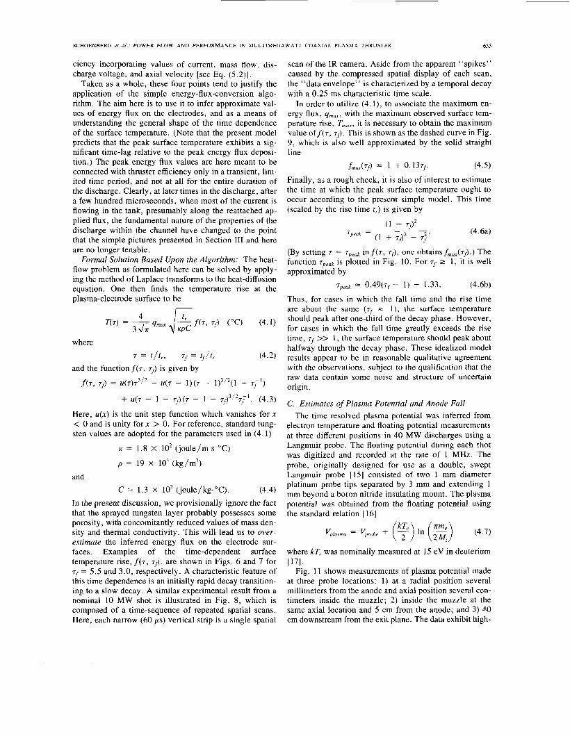
In order to utilize (4. l ) , to associate the maximum en- ergy flux, q,,, with the maximum observed surface tem- perature rise, T,,, it is necessary to obtain the maximum value off(7, T~). This is shown as the dashed curve in Fig. 9, which is also well approximated by the solid straight line
f,,(~j-) 1 + 0.13~f (4.5)
Finally, as a rough check, it is also of interest to estimate the time at which the peak surface temperature ought to occur according to the present simple model. This time (scaled by the rise time t,) is given by
(4.6a)
(By setting 7 = 'Tprak inf(7, T~), one obtains f,,(~~).) The function Tpeak is plotted in Fig. 10. For T~ 2 1 , it is well approximated by
'Tpeuk z O.49(7, - 1) + 1.33. (4.6b)
Thus, for cases in which the fall time and the rise time are about the same ( T ~ = l ) , the surface temperature should peak after one-third of the decay phase. However, for cases in which the fall time greatly exceeds the rise time, 7f >> 1 , the surface temperature should peak about halfway through the decay phase. These idealized model results appear to be in reasonable qualitative agreement with the observations, subject to the qualification that the raw data contain some noise and structure of uncertain origin.
C. Estimates of Plasma Potential and Anode Fall The time resolved plasma potential was inferred from
electron temperature and floating potential measurements at three different positions in 40 MW discharges using a Langmuir probe. The floating potential during each shot was digitized and recorded at the rate of 1 MHz. The probe, originally designed for use as a double, swept Langmuir probe [15] consisted of two 1 mm diameter platinum probe tips separated by 3 mm and extending 1 mm beyond a boron nitride insulating mount. The plasma potential was obtained from the floating potential using the standard relation [16]
( 1 + Tf)'
( 1 + Tf)* - 7;' 7peak =
where kTe was nominally measured at 15 eV in deuterium
Fig. 1 1 shows measurements of plasma potential made at three probe locations: 1 ) at a radial position several millimeters from the anode and axial position several cen- timeters inside the muzzle; 2) inside the muzzle at the same axial location and 5 cm from the anode; and 3) d.0 cm downstream from the exit plane. The data exhibit high-
~ 7 1 .
634 IEEE
2.6 2.4 2.2 2.0 - 1.8
Y 1.6 2 1.4 - 1.2 1 .o
-
fmax (T~) = 1 + 0.13 T~ within 10% from q = 0.1-20.0
0 . 2 ~ 1 1 1 1 , , I , I , , ~
1 2 3 4 5 6 7 8 9 1 0 1 1 1 2 o.oo
t f
Fig. 9. Normalized peak surface temperature rise versus (t,o,,/tr,3e) T~
I I 0 1 2 3 4 5 6
7 Fig. 10. Normalized time of occurrence of peak surface temperature rise
T,,..~ versus 7, [equation (4.6)].
400
- 0
0 -400 L -
c 0 0 E a 2oow
1 $ - 4 0 0 1 1 I -200
m - a I I I I I I 500
0
0.0 0 1 0 2 0.3 0 4 0 5 0 6
Discharge Time (ms) Fig. 11. Plasma potential versus time: (a) probe in muzzle, a few mm from anode; (b) probe in muzzle, 5 cm from anode; (c) probe 40 cm downstream of thruster exit.
frequency oscillations as well as long timescale vari- ations. Shot-to-shot variations were less than 50 V.
Power spectra of the voltage, plasma potential within
TRANSACTIONS ON PLASMA SCIENCE, VOL. 21, NO. 6 , DECEMBER 1993
the muzzle, and interferometer signal (center chord, 40 cm downstream of the exit) are shown in Fig. 12. These power spectra were ensemble averaged over 8 shots and have a nominal 250 kHz bandwidth. The oscillations in the discharge voltage and plasma potential are broad band, with a broad peak near 100 kHz. This spectral feature is too low for fundamental plasma oscillations. Possible causes of the observed oscillation spectrum were dis- cussed earlier in Section 111.
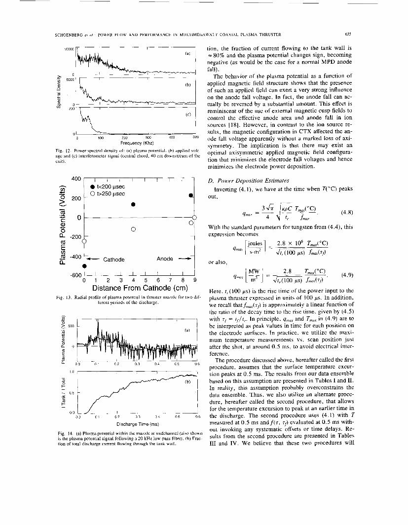
With respect to the slow variation of the plasma poten- tial, the data exhibit two distinct behaviors. The plasma potential at the points of measurement is substantially positive relative to the anode for the first 200 ps of the discharge, indicating a significantly reversed anode fall around the time of peak power. Following a short transi- tion period, the potential becomes negative for times greater than 250 ps. The probe floating potential, mea- sured at probe positions inside the muzzle, was averaged over time for these two periods and these results were av- eraged over an ensemble of shots taken under the same conditions. These results, along with the anode and cath- ode potentials, yield the potential profile in the muzzle (Fig. 13) for two different periods of the discharge. The plasma potential several millimeters from the anode (Fig. 13) is positive relative to the anode (confining plasma electrons) during the first 200 ps of the discharge and neg- ative for the remainder of the discharge.
The long timescale variation in the plasma potential, measured in the muzzle (Fig. l l ) , can be qualitatively explained by investigating the evolution of the magnetic field structure during a discharge. Calculation of the vac- uum magnetic field in the thruster at the time of a dis- charge is shown in Fig. 3 . At discharge initiation, field lines from the coil within the cathode provide a magnetic connection from cathode to anode. Electrons are only marginally collisional (for classical Coulomb collisions) on the spatial scale of the CTX thruster. Hence, we expect the arc voltage to accelerate current-carrying electrons to moderately high energies with respect to the bulk plasma electrons, forming a high-energy tail on the electron dis- tribution function. We note, however, that a complete treatment of this physical process must include the effects of microturbulent beam-plasma interactions.
Early in the discharge, the plasma potential several mil- limeters from the anode is = 225 V positive, confining the energetic electrons. As the discharge evolves, the field lines, which connect the cathode to the anode at early times, are stretched by the plasma and substantially change the magnetic field configuration connecting the anode and cathode. This behavior is evident in Fig. 14, which shows both the fraction of the discharge current flowing to the tank wall and the plasma potential in the muzzle. During the early portion of the discharge ( < 200 ps), the plasma potential at the point of measurement, several millimeters from the anode, is positive and the fraction of the discharge current flowing to the tank wall is = 30%. For times greater than 250 ps, presumably after a significant change in applied magnetic field configura-
SCHOENBERG et al.. POWER FLOW AND PERFORMANCE IN MULTIMEGAWATT COAXIAL PLASMA THRUSTER
10000 I 1 I 1
I I I
0 100 200 300 400 500
Frequency (Khz)
Fig. 12. Power spectral density of: (a) plasma potential, (b) applied volt- age and (c) interferometer signal (central chord, 40 cm downstream of the exit).
400 I 1 I I I I I I 0 k200 psec 0 b250 psec
v)
8 200 W 0
I I I I I I I I 0 1 2 3 4 5 6 7 8 9
Distance From Cathode (cm) Fig. 13. Radial profile of plasma potential in thruster muzzle for two dif-
ferent periods of the discharge.
- I 1 1 ' I 0 0 0 1 0 2 0 3 0 4 0 5 0 6
I I 1 0.0 0 1 0.2 0 3 0 4 0 5 0 6
Discharge Time (ms)
Fig. 14. (a) Plasma potential within the muzzle at midchannel (also shown is the plasma potential signal following a 20 kHz low-pass filter). (b) Frac- tion of total discharge current flowing through the tank wall.
635
tion, the fraction of current flowing to the tank wall is = 80% and the plasma potential changes sign, becoming negative (as would be the case for a normal MPD anode fall).
The behavior of the plasma potential as a function of applied magnetic field structure shows that the presence of such an applied field can exert a very strong influence on the anode fall voltage. In fact, the anode fall can ac- tually be reversed by a substantial amount. This effect is reminiscent of the use of external magnetic cusp fields to control the effective anode area and anode fall in ion sources [ 181. However, in contrast to the ion source re- sults, the magnetic configuration in CTX affected the an- ode fall voltage apparently without a marked loss of axi- symmetry. The implication is that there may exist an optimal axisymmetric applied magnetic field configura- tion that minimizes the electrode fall voltages and hence minimizes the electrode power deposition.
D. Power Deposition Estimates
out, Inverting (4. l ) , we have at the time when T("C) peaks
With the standard parameters for tungsten from (4.4), this expression becomes
or also,
Here, t , ( 100 ps) is the rise time of the power input to the plasma thruster expressed in units of 100 ps. In addition, we recall thatfma,(Tf) is approximately a linear function of the ratio of the decay time to the rise time, given by (4.5) with T~ = t f / t r . In principle, qmux and T,,,, in (4.9) are to be interpreted as peak values in time for each position on the electrode surfaces. In practice, we utilize the maxi- mum temperature measurements vs. scan position just after the shot, at around 0.5 ms, to avoid electrical inter- ference.
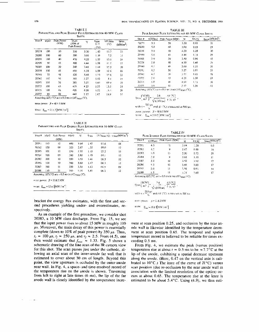
The procedure discussed above, hereafter called the first procedure, assumes that the surface temperature excur- sion peaks at 0.5 ms. The results from our data ensemble based on this assumption are presented in Tables I and 11. In reality, this assumption probably overconstrains the data ensemble. Thus, we also utilize an alternate proce- dure, hereafter called the second procedure, that allows for the temperature excursion to peak at an earlier time in the discharge. The second procedure uses (4.1) with T measured at 0.5 ms andf(7, T ~ ) evaluated at 0.5 ms with- out invoking any systematic offsets or time delays. Re- sults from the second procedure are presented in Tables I11 and IV. We believe that these two procedures will
636 IEEE TRANSACTIONS ON PLASMA SCIENCE. VOL. 21, NO. 6, DECEMBER 1993
TABLE I PARAMETERS AND PEAK ENERGY FLUX ESTIMATES FOR 40-MW-CLASS
SHOTS
20274 100 50 330 3.30 20280 100 60 300 3.00 20291 100 40 420 4.20 20300 90 45 400 4.44 20301 100 50 340 3.40 20338 100 40 450 4.50 20340 75 48 420 5.60 20341 I10 50 360 3.27 20342 110 50 360 3.27 20373 100 43 425 4.25 20375 100 46 400 4.00 20377 85 50 440 5.17 Assuming (AT) ('C) at t = 0.5 ms is (AT)max CC).
mean power: 13 = 48 t 5 MW
Mean: CT,.. =23f5[MW/m2]
1.43 11.7 1.39 7.2 1.55 13.5 1.58 11.7 1.44 15.3 1.59 12.6 1.73 12.6 1.43 8.1 1.43 09.9 1.55 13.5 1.52 15.3 1.67 18.9
23 14 24 22 30 22 23 15 19 24 28 34
TABLE I1 PARAMETERS AND PEAK ENERGY FLUX ESTIMATES FOR IO-MW-CLASS
SHOTS
Shot # tr(ps) Peak Power tf(ps) Tf fmax (AT)max('C) qma(MW/m2)
20381 110 12 400 3.64 1.47 03.6 20382 120 09 320 2.67 1.35 09.0 20383 100 15 250 2.50 1.33 07.2 20384 100 09 380 3.80 1.49 08.1 20385 100 10 350 3.50 1.46 06.3 20386 100 10 360 3.60 1.47 06.3 20387 100 1 1 330 3.30 1.43 04.5 20388 110 11 350 3.18 1.41 06.3
Assuming (AT)(*C) at t = 0.5 ms is (AT)max (T).
06 17 15
15 12 12 09 12
mean power: p = 11 f 2 MW
mean: qma, =12+3[MW/m2]
bracket the energy flux estimates, with the first and sec- ond procedures yielding under- and overestimates, re- spectively.
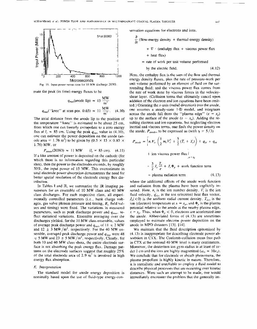
As an example of the first procedure, we consider shot 20383, a 10 MW class discharge. From Fig. 15, we see that the input power rises to about 15 MW in roughly 100 ps. Moreover, the main decay of this power is essentially complete (down to 10% of peak power) by 350 ps. Thus, f , = 100 ps, tf = 250 ps, and T~ = 2.5. From (4.5), one then would estimate that f,, = 1.33. Fig. 5 shows a schematic drawing of the line scan of the IR camera view for this shot. The scan passes just under the cathode, al- lowing an axial scan of the inner-anode far wall that is estimated to cover about 30 cm of length. Beyond this point, the view upstream is occluded by the outer-anode near wall. In Fig. 4, a space- and time-resolved record of the temperature rise on the anode is shown. Traversing from left to right at late times (6 ms), the lip of the far anode wall is clearly identified by the temperature incre-
TABLE 111 PEAK ENERGY FLUX ESTIMATES FOR 40-MW-CLASS SHOTS
Shot # T(500ps) Peak Power (MW) tf f('t,70
20274 5.0 50 3.30 0.93 20280 5.0 60 3.00 0.85 20291 5.0 40 4.20 1.28 20300 5.6 45 4.44 1.18 20301 5.0 50 3.40 0.96 20338 5.0 40 4.50 1.40 20340 6.7 48 5.60 1.31 20341 4.5 50 3.27 1.03 20342 4.5 50 3.27 1.03 20373 5.0 43 4.25 1.30
46 4.00 1.18 20375 5.0 20377 5.9 50 5 17 1.39
Assuming (AT)('C) at t = 0.5 ms IS not (AT)max (T) .
qmax(m/m2) 35 24 30 29 45 25 31 21 26 29 36 41
500 ps with T = and AT ('C) measured at 500 ps.
tr mean power: mean: ii,,, =31+7[MW/mZ]
= 48 k 5 MW
TABLE IV
Shot ' r(500ps) Pe* Power (MW) rf f(7,rf) qmax(m/& 20381 4.5 12 3.64 1.20 8.0 20382 4.2 9 2.67 0.88 26 20383 5.0 15 2.50 0.72 28 20384 5.0 9 3.80 1.10 21 20385 5.0 10 3.50 1.00 17 20386 5.0 10 3.60 1.03 17 20387 5 0 11 3.30 0.93 14 20388 4.5 11 3.18 1.00 17
PEAK ENERGY FLUX ESTIMATES FOR IO-MW-CLASS SHOTS
Assuming (AT)('C) at t = 0.5 ms is not (AT)max (T).
500 ps tr with T = ~ and AT (T) measured at 500 ps
mean power:
mean:
i, = 1 1 +_ 2MW
iT,.. = I8 f 5[ MW / m2]
ment at scan position 0.25, and occlusion by the near an- ode wall is likewise identified by the temperature decre- ment at scan position 0.65. The temporal and spatial temperature record is believed to be reliable for times ex- ceeding 0.5 ms.
From Fig. 4, we estimate the peak (versus position) temperature rise at about t = 0.5 ms to be =7.7"C at the lip of the anode, exhibiting a spatial decrease upstream along the anode. (Here, 0.47 on the vertical axis is cali- brated to 10°C.) The knee of the curve of T("C) versus scan position (due to occlusion by the near anode wall in association with the limited resolution of the optics) oc- curs at about 0.65. The temperature rise at the knee is estimated to be about 5.4"C. Using (4.9), we thus esti-
SCHOENBERG er al.: POWER FLOW AND PERFORMANCE IN MULTIMEGAWATT COAXIAL PLASMA THRUSTER 631
Microseconds Fig. 15. Input power versus time for 10 MW discharge 20383
mate the peak (in time) energy fluxes to be
MW m
q,-(anode lip) = 15
MW q,-(“knee” at scan pos. 0.65) = 11 -
m2 . (4.10)
The axial distance from the anode lip to the position of the temperature “knee” is estimated to be about 25 cm, from which one can linearly extrapolate to a zero energy flux at I , = 85 cm. Using the peak qmax value in (4.10), one can estimate the power deposition on the anode (an- ode area = 1.76 m2) to be given by (0.5 X 15 x 0.85 x 1.76) MW, or
PonOd,(20383) = 11 MW (1, = 85 cm). (4.11) If a like amount of power is deposited on the cathode (for which there is no information regarding this particular shot), then the power to the electrodes exceeds, by roughly 50%, the input power of 15 MW. This overestimate in total electrode power absorption demonstrates the need for better spatial resolution of the electrode energy flux dis- tribution.
In Tables I and 11, we summarize the IR imaging pa- rameters for an ensemble of 10 MW class and 40 MW class discharges. For each respective class, all experi- mentally controlled parameters (i.e., bank charge volt- ages, gas valve plenum pressure and timing, B, field val- ues and timing) were fixed. The variations in measured parameters, such as peak discharge power and qmm, re- flect statistical variations. Ensemble averaging over the discharges yielded, for the 10 MW class ensemble, values of average peak discharge power and qmm of 11 k 2 MW and 12 k 3 MW/m2, respectively. For the 40 MW en- semble, averaged peak discharge power and qmm were 48 k 5 MW and 23 _+ 5 MW/m2, respectively. Clearly, for both 10 and 40 MW class shots, the entire electrode sur- face is not absorbing the peak energy flux. Damage pat- terns on the electrode surfaces suggest that roughly 25% of the total electrode area of 2.9 m2 is involved in high energy flux absorption.
E. Interpretation The standard model for anode energy deposition is
nominally based upon the use of fluid-type energy-con-
servation equations for electrons and ions.
a at - (flow-energy density + thermal-energy density)
+ V * (enthalpy flux + viscous power flux
+ heat flux)
= rate of work per unit volume performed
by the electric field. (4.12)
Here, the enthalpy flux is the sum of the flow and thermal energy density fluxes, plus the rate of pressure-work per unit volume performed by an element of fluid on the sur- rounding fluid; and the viscous power flux comes from the rate of work done by viscous forces in the velocity- shear layer. (Collision terms that ultimately cancel upon addition of the electron and ion equations have been omit- ted.) Orienting the x-axis (radial direction) into the anode, one assumes a steady-state 1-D model, and integrates across the anode fall from the “plasma edge” (x = xp) up to the surface of the anode (x = xa). Adding the re- sulting electron and ion equations, but neglecting electron inertial and viscous terms, one finds the power density on the anode, Panode, to be expressed as (with y = 5/3)
1 x = xp + ion viscous power flux
5 Te - - J, - + J X G p + work function term 2 e
+ plasma radiation term (4.13)
where the additional effects of the anode work function and radiation from the plasma have been e_xplicitly in- serted. Here, ni is the ion number density, Vi is the ion fluid velocity, qi(el is the ion (electron) heat flux vector, Jx( < 0) is the uniform radial current density, Tcp, is the ion (electron) temperature at x = xp , and 9, is the plasma potential relative to the anode at the nearby plasma edge, x = x p . Thus, when +,, < 0, electrons are accelerated into the anode. Abbreviated forms of (4.13) are sometimes employed to estimate electron power deposition on the anode in MPD thrusters [ 131, [ 141.
We maintain that the fluid description epitomized by (4.13) is inappropriate for describing electrode power ab- sorbtion in CTX. The Coulomb-collision mean free path in CTX at the nominal 40 MW level is many centimeters. Moreover, the deuterium ion gyro-radius is at least of or- der 1 cm and the ions are highly magnetized (wCi = 10~~;) . We conclude that for electrode or sheath phenomena, the plasma propellant is highly kinetic in nature. Therefore, it is unrealistic and unreliable to employ a fluid model to describe physical processes that are occurring over kinetic distances. Were such an attempt to be made, one would immediately encounter the problem that the generally im-
638 IEEE TRANSACTIONS ON PLASMA SCIENCE, VOL. 21, NO. 6 , DECEMBER 1993
portant thermal conduction and viscous terms in (4.13) become large, ill-defined, and not usable. Moreover, their use would require some prior knowledge of the thermal and velocity gradients in the vicinity of the near-anode boundary layer.
Instead, we employ a simple and fundamentally kinetic estimate of charged particle power deposition onto the an- ode for 40 MW class shots. We note that during peak power, these shots actually exhibit a reversed anode fall, wherein the plasma is positive relative to the anode by as much as 220 V (time-averaged) within several millimeters of the anode surface. Thus, it is expected that plasma ions primarily are responsible for the observed power deposi- tion during the peak power phase of these shots. The bulk- plasma electrons, with temperatures measured between 10 and 20 eV, do not play a significant role in anode heating. Of course, a high-energy, low density tail must be present in the electron energy distribution that exceeds the ther- mal ion current to the anode.
The ion power deposition onto the anode in 40-MW shots can be estimated by calculating the ion thermal flux from the edge of the plasma toward the anode, and taking into account that the ions will acquire about 200 eV each, in falling through the reversed anode sheath. This consti- tutes a highly kinetic model for the ions, in the sense that the ion distribution function at the plasma edge is taken to be a half-Maxwellian. The exact ion temperature will little affect estimates of this ion thermal flux and, more- over, will prove to be only a minor addition to the 200 eV potential fall. The axial ion kinetic energy ( - 100 eV) is ignored in constructing this estimate because the radial profile of axial velocity is not well known in this device, and therefore it is possible that a boundary layer of re- duced axial velocity exists adjacent to the anode. This ap- proach will, therefore, provide a modest underestimate of the ion power deposition.
Although the axial flow energy in the main flow field will not be directly convected to the wall in a no-slip vis- cous boundary layer, it does supply energy for viscous heating within that layer. This extra heat will be partly conducted and convected downstream. Accurate esti- mates of these various effects in the highly kinetic regime would require the solution of kinetic equations for the non- Maxwellian deformations of the ion distribution function. We note that these neglected non-Maxwellian effects are driven by ion energies that do not dominate the reversed anode fall voltage, and probably contribute to only mod- erate increases in the estimates of ion power deposition onto the anode.
Ion temperature has not been directly measured within the thruster. Instead, it is estimated here from fundamen- tal considerations of the plasma production and entrain- ment process [4]. The T,, so estimated, proves to yield semiquantitative agreement with certain measurements of transverse energy in the plume. (See below.) The funda- mental observation here is that when a given mass at rest is abruptly legislated into a moving system of a specified velocity, simultaneous conservation of momentum and
energy forces the production of heat, such that the flow energy and the thermal energy are equalized. A simple example of this phenomenon in gas dynamics is the state of a shocked gas behind a piston-driven strong shock propagating into a gas at rest. One finds there that the postshock thermal energy density equals the flow energy density. Similarly, ions created from neutrals at rest or moving slowly relative to the propellant in the co_axial plasma thruster suddenly find themselves in crossed E and 2 fields, forced to move at the E / B drift velocity. Irre- spective of collisionality, it then can be shown that the ion thermal energy and drift kinetic energy must be equal [4]. (This effect is sometimes referred to as an “ion-slip’’ effect. In its collisional form, it previously has been rec- ognized and included in some theoretical studies [25] .)
The “stuffing versus unstuffing” property of CTX thruster operation leads us to infer that the relevant drift velocity seen by newly created ions is ( E r / & ) , since the applied magnetic field must be pushed aside by the self- field magneto-plasma, and because independent estimates based on the known poloidal magnetic flux yield the result that B: << Bi. For 40 MW shots, typical values are near E, = 4 x 10’ V / m and Bo = 0.08 Tesla in mid-channel, leading to initial drift velocities (created in the upstream region) of about 0.5 x lo5 m/s . For deuterium, this value corresponds to drift energies, and hence thermal energies, of about 25 eV. The velocity of any individual ion born at rest on a cycloidic orbit momentarily reaches twice the guiding-center velocity each orbital period. The eventual collisional thermalization of this velocity in the plume downstream could produce transverse energies up to 100 eV. (Ions created near the nozzle throat at the muzzle would have drift velocities, hence thermal velocities, near the AlfvCn speed, but would be swept downstream away from the muzzle.) Equating the ion thermal velocity to the drift velocity of newly created ions, and using a repre- sentative density measurement, n = 1.0 X lo2’ mP3 for 40 MW shots, we arrive at an estimate of the ion thermal flux, rrhr. Using the canonical expression for rth;,
Since each ion has acquired about 200 eV in falling through a gyro-radius spanning the reversed anode sheath, we arrive at an estimate of the ion power density at the anode, namely,
Panode = r , h ; x 200 eV = 40 MW/m2. (4.15)
This result is in semiquantitative agreement with the 24- 31 MW/m2 average energy flux shown in Tables I and 111.
In summary, an algorithm has been developed to con- vert the observed transient surface heating of the elec- trodes into estimates of incident peak surface power den- sity, and these estimates are in semiquantitative agreement with a simple model of ion thermal flux into the anode during the peak power phase with a reversed anode fall voltage.
SCHOENBERG et al.: POWER FLOW AND PERFORMANCE IN MULTIMEGAWATT COAXIAL PLASMA THRUSTER 639
V. GLOBAL DISTRIBUTIONS OF POWER A. Radiation
A new-style windowless XUV photodiode, absolutely calibrated at the University of Washington, was used with a scanned collimator to measure the absolute radiation losses from the end of the CTX plasma thruster. The bo- lometer consisted of an XUVlOOC silicon photodiode de- tector, current-to-voltage preamp, fiber-optic link, vac- uum housing, and pinhole aperture and collimator. These detectors have a highly stable internal quantum efficiency and flat spectral response up to 6 keV energy photons [ 191. The XUV photodiode sensitivity is 0.275 A / W (radiation incident). The bolometer has been cross calibrated against a relatively traditional (but more insensitive and bulky) gold foil calorimeter from Los Alamos [20] which was itself calibrated using a KrF pulsed laser at 248 nm wave- length [21]. The advantage of the XUV photodiode lies in its simplicity, greater sensitivity, and speed of re- sponse. Its principle disadvantage is the uncharacterized response to possible particle fluxes.
The bolometer viewed the plasma through a 100 pm diameter pinhole aperture, which was also limited by a 12 cm long, 0.79 cm diameter threaded tube to define the field of view. By taking into account the detector solid angle, correcting for the fraction of the plasma viewed, and assuming an isotropic radiation source, we calculate that only a tiny fraction of the plasma radiation (2.3 . lo-") hit the detector. In calibration, 1 pA out of the detector corresponds to 700 kW of total plasma radiation, with estimated 20% absolute error bars. Noise levels were at 100 nA or lower, and the instrumental response time (with electronics package) was better than 1 ps, but lim- ited to 4 ps to avoid aliasing at the digitizer.
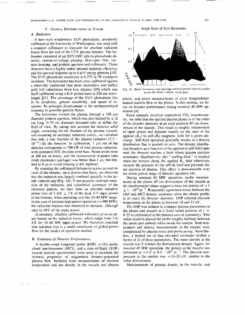
By scanning the collimated bolometer across an end-on view of the thruster, on a shot-to-shot basis, we observed that the radiation was largely confined spatially to the an- ode-cathode gap (Fig. 16). If one assumes isotropic emis- sion of the radiation, and cylindrical symmetry of the emission pattern, we then infer an absolute radiative power loss of 3-6% f 1 % of the peak I-V input power to the thruster, when operating over the 10-40 MW range. In the case of extreme high power operation ( = 900 MW), the radiation fraction was observed to increase, although only to 10% of the input power.
In summary, absolute calibrated bolometry gives an up- per bound on the radiation losses, which range from 3 to 6% for 10-40 MW input power. We therefore conclude that radiation loss is a small constituent of global power flow for the modes of operation studied.
B. Estimates of Thruster Performance A double-swept Langmuir probe (DSP), a CO2 multi-
chord interferometer (MCI), and a time-of-flight (TOF) neutral particle spectrometer were used to ascertain the intrinsic properties of magnetized thruster-generated plasma flow. Included were measurements of electron temperature and ion density in the muzzle and plasma
Angle Scan of XUV Bolometer
1.0 1 I I I I I I 0" 14"
Fig. 16. Spatial bolometry scan showing radiation profile with twin pe; across the anode-cathode-anode gaps.
s
plume, and direct measurements of axial (longitudina 1 neutral particle flow in the plume. In this section, we fo- cus on thruster performance during nominal 40 MW op- eration [4].
From spatially resolved multichord CO2 interferome- try, we infer that the ejected plasma plume is of the order of the thruster diameter at an axial position 40 cm down- stream of the muzzle. This result is roughly independent of input power and depends mainly on the ratio of the applied (B,) to self-(Bo) magnetic field for a given dis- charge. Self-field operation generally results in a density distribution that is peaked on axis. The density distribu- tion broadens as a function of the applied to self-field ratio until the thruster reaches a limit where plasma ejection terminates. Qualitatively, this "stuffing limit" is reached when the tension along the applied B,, field effectively exceeds the pressure in the self-BB field and prevents the net ejection of plasma. This effect is demonstrable over the entire power range of thruster operation [4].
During nominal 40 MW operation, probe measure- ments in the plume 40 cm downstream of the muzzle at the interferometer plane suggest a mean ion density of = 3 f 1 lOI9 m-3. Reasonable agreement exists between the DSP and MCI density estimates when the plume profile is of order the thruster diameter. DSP-inferred electron temperature in the plume is between 10 and 15 eV.
The DSP was utilized to compare plasma parameters in the plume and muzzle at a fixed radial position of r = 0.25 m (referenced to the thruster axis of symmetry). This radial position placed the probe roughly halfway between the anode and cathode when inside the muzzle. Both tem- perature and density measurements in the muzzle were complicated by plasma noise and probe arcing. Neverthe- less, a limited set of data provided estimates (within a factor of 2) of these parameters. The mean density at the muzzle was 3-4 times the downstream density. Again, for nominal 48 MW operation, the density at the muzzle was estimated at = 1.0 k 0.5 lo2' m-3. The electron tem- perature in the muzzle was = 10-20 eV, similar to the value downstream.
Measurements of plasma density in the muzzle, and
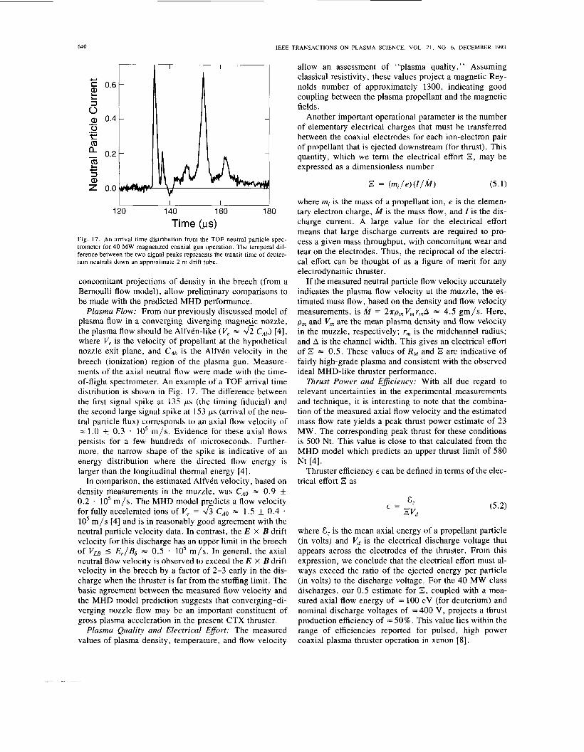
640 IEEE TRANSACTIONS ON PLASMA SCIENCE, VOL. 21, NO. 6, DECEMBER 1993
+ C 0.6 a, L L
5 a, 0.4 0 t:
- .- a a - 0.2 s a, z 0.0
120 140 160 180
Time (ps) Fig. 17. An arrival time distribution from the TOF neutral particle spec- trometer for 40 MW magnetized coaxial gun operation. The temporal dif- ference between the two signal peaks represents the transit time of deuter- ium neutrals down an approximate 2 m drift tube.
concomitant projections of density in the breech (from a Bernoulli flow model), allow preliminary comparisons to be made with the predicted MHD performance.
Plasma Flow: From our previously discussed model of plasma flow in a converging-diverging magnetic nozzle, the plasma flow should be AlfvCn-like (V, = h CAb) [4], where V, is the velocity of propellant at the hypothetical nozzle exit plane, and CA, is the AlfvCn velocity in the breech (ionization) region of the plasma gun. Measure- ments of the axial neutral flow were made with the time- of-flight spectrometer. An example of a TOF arrival time distribution is shown in Fig. 17. The difference between the first signal spike at 135 ps (the timing fiducial) and the second large signal spike at 153 ps (arrival of the neu- tral particle flux) corresponds to an axial flow velocity of = 1.0 f 0.3 . lo5 m / s . Evidence for these axial flows persists for a few hundreds of microseconds. Further- more, the narrow shape of the spike is indicative of an energy distribution where the directed flow energy is larger than the longitudinal thermal energy [4].
In comparison, the estimated AlfvCn velocity, based on density measurements in the muzzle, was CA, = 0.9 f 0.2 * 10’ m/s . The MHD model predicts a flow velocity for fully accelerated ions of V, = & CA, = 1.5 k 0.4 . lo5 m / s [4] and is in reasonably good agreement with the neutral particle velocity data. In contrast, the E x B drift velocity for this discharge has an upper limit in the breech of VEB I E,/Bo = 0.5 * 10’ m/s . In general, the axial neutral flow velocity is observed to exceed the E x B drift velocity in the breech by a factor of 2-3 early in the dis- charge when the thruster is far from the stuffing limit. The basic agreement between the measured flow velocity and the MHD model prediction suggests that converging-di- verging nozzle flow may be an important constituent of gross plasma acceleration in the present CTX thruster.
Plasma Quality and Electrical Efort: The measured values of plasma density, temperature, and flow velocity
allow an assessment of “plasma quality.” Assuming classical resistivity, these values project a magnetic Rey- nolds number of approximately 1300, indicating good coupling between the plasma propellant and the magnetic fields.
Another important operational parameter is the number of elementary electrical charges that must be transferred between the coaxial electrodes for each ion-electron pair of propellant that is ejected downstream (for thrust). This quantity, which we term the electrical effort E , may be expressed as a dimensionless number
,S = ( m i / e ) ( I / M ) (5.1)
where mi is the mass of a propellant ion, e is the elemen- tary electron charge, li/r is the mass flow, and I is the dis- charge current. A large value for the electrical effort means that large discharge currents are required to pro- cess a given mass throughput, with concomitant wear and tear on the electrodes. Thus, the reciprocal of the electri- cal effort can be thought of as a figure of merit for any electrodynamic thruster.
If the measured neutral particle flow velocity accurately indicates the plasma flow velocity at the muzzle, the es- timated mass flow, based on the density and flow velocity measurements, is k = 27rp,V,,,rmA = 4.5 gm/s . Here, p m and V,,, are the mean plasma density and flow velocity in the muzzle, respectively; r, is the midchannel radius; and A is the channel width. This gives an electrical effort of ,” = 0 . 5 . These values of Rw and are indicative of fairly high-grade plasma and consistent with the observed ideal MHD-like thruster performance.
Rrust Power and Eficiency: With all due regard to relevant uncertainties in the experimental measurements and technique, it is interesting to note that the combina- tion of the measured axial flow velocity and the estimated mass flow rate yields a peak thrust power estimate of 23 MW. The corresponding peak thrust for these conditions is 500 Nt. This value is close to that calculated from the MHD model which predicts an upper thrust limit of 580 Nt [4].
Thruster efficiency E can be defined in terms of the elec- trical effort E as
where I, is the mean axial energy of a propellant particle (in volts) and V, is the electrical discharge voltage that appears across the electrodes of the thruster. From this expression, we conclude that the electrical effort must al- ways exceed the ratio of the ejected energy per particle (in volts) to the discharge voltage. For the 40 MW class discharges, our 0 .5 estimate for Z, coupled with a mea- sured axial flow energy of = 100 eV (for deuterium) and nominal discharge voltages of -400 V , projects a thrust production efficiency of = 50%. This value lies within the range of efficiencies reported for pulsed, high power coaxial plasma thruster operation in xenon [8].
SCHOENBERG er al . : POWER FLOW AND PERFORMANCE IN MULTIMEGAWATT COAXIAL PLASMA THRUSTER
C. Thermal Plume Losses Plasma Heating: As previously discussed, ion entrain-
ment in a flow field coupled with ion-electron equiparti- tion results in plasma heating. The observed 10-20 eV electron temperature in the muzzle is understandable from this perspective. Over the 10-40 MW discharge condi- tions, ion temperature is predicted to reside in a 25-45 eV range as compared to axial flow energies of 100-200 eV. However, for energies exceeding 20 eV, the electrons ef- fectively decouple from the ions as their classical equi- partition time exceeds their axial transit time. Hence, the observations of electron temperature in the 10-20 eV range are consistent with heating to their equipartition limit by the higher temperature ions. They are also con- sistent with the estimated ineffectiveness of classical ohmic heating on the timescale of an electron axial transit [4]. It is possible that a moderate contribution to the elec- tron temperature is provided by microturbulence associ- ated with the lower hybrid drift and related instabilities, and by heating due to collective interactions with primary electrons from the cathode. These issues will be discussed in future work.
VI. SUMMARY In summary, various measurements and associated the-
oretical interpretations have been implemented in a pre- liminary investigation of power-flow in the CTX plasma thruster. The results are, so far, constrained by the limited number of measurements taken, the uncertainty inherent in certain measurements (e.g., the active electrode area), the lack of instantaneous mass flow control, the unopti- mized electrical circuitry driving the thruster, and the un- optimized nature of the applied magnetic field configura- tion. These constraints will be addressed in future research by ongoing upgrades in the electrical circuitry and mass flow control that will drive flat-topped long-pulse ( = 10 ms) discharges at 1-40 MW.
In our preliminary investigation, good agreement was found between the measured properties of CTX thruster operation and the predictions of a model based on ideal MHD. This agreement suggests that ideal MHD pro- cesses play an important role in coaxial plasma thruster dynamics. Within this context, CTX performance with re- spect to propellant flow velocity, thrust production, and operational impedance are reasonably well understood. Interpretation of the preliminary data also reinforces our belief that optimized magnetic nozzle design can be ben- eficial to thruster efficiency. Related considerations car- ried on in parallel to this work have lead to the conceptual design of an electrically adjustable, axisymmetric, annu- lar magnetic nozzle that is intended to address the simul- taneous control of plasma acceleration, electrode sheath potentials, and plasma detachment.
It is likely that the perceptions and concepts presented in this paper have efficacy in the development of efficient, megawatt-class MPD thrusters. Specifically, designing MPD thrusters (in power and spatial scale) to access ef- ficient plasma-magnetic field coupling and utilizing an
641
optimized B,, field configuration to maximize efficiency and minimize anode fall could prove advantageous. (We note that these perceptions are consonant with previous quasi-one-dimensional analysis of flow channel geometry effects on MPD thruster performance [22].) Future coax- ial thruster research will focus on these issues in the con- text of scaling multimegawatt thruster performance to the smaller spatial scales and operational power levels re- quired for MPD devices.
APPENDIX A one-dimensional description is sufficient to capture
the essential process of distortion of a transverse (radial) magnetic field by the given uniform axial channel flow of a resistive plasma. (An additional simplification made here will be to revert to slab geometry instead of the full coax- ial cylindrical geometry.) This 1-D model will thus be characterized by azimuthal symmetry (no ‘‘0” or “y” de- pendence) and by axial translational symmetry (no “z” dependence). The only significant coordinate for the spa- tial variation of vector fields will thus be the radial vari- able (“r” or “x”).
The first step in constructing this model is to discuss the role of the displacement curren_t, so that one must compare the plasmayrrent density J to the displacement current density EO(8E/8t), where eo is the permittivity of empty space and ,!? is thezlectric field vector. By utilizing Ohm’s law to estimate E with ideal, resistive, and Hall contributions to the electric field, one finds that the fol- lowing three requirements arise from having a small dis- placement current, respectively,
v2 << c 2 (AI) D t - << c2
D a- << c2 t
Here, Vis the plasma flow velocity, c is the speed of light, D is the resistive diffusivity of plasma ( q / p o ) , t is a time scale of interest ( z is the electron Hall parameter (eB) / (m, ve). For the relevant parameters in the CTX experiment, all of these conditions are satisfied by very many orders of magnitude, so that the displacement current is completely negligible.
It then follows from Ampere’s law, without the dis- placement current,
s), and
v x i i = p o 7 (‘44) together with the 1-D assumptions of azimuthal and axial symmetries, that the radial currenty density vanishes. Thus, only Jy and J, are significant in a 1-D model. (Imag- ine that the axial force, JIB,, has already been “used up” upstream in preaccelerating the plasma before the plasma runs into the radial magnetic field. Hence, the self-field pressure gradient, with its associated radial current, plays no direct role in this simplified model of field-line stretch- ing by a given plasma flow.)
Similarly, applying the assumed symmetries to the so-
~
642 IEEE TRANSACTIONS ON PLASMA SCIENCE, VOL. 21, NO. 6, DECEMBER 1993
lenoidal condition on the magnetic field V * = 0 yields the result that the radial magnetic field component B, is uniform in space. Moreover, because the channel walls are assumed to be perfectly conducting in the present sim- ple model, the radial (normal) flux is frozen into the walls, making Bx independent of the time variable.
Next, taking the curl of Ohm’s law (with uniform flow, 3 = V,2)
together with Faraday’s law
+ a’ at
V X E = - -
and using also (A4), there results
a D at ax ax
- --- a’ - -- ”’ + fix- (V x 2) (A7)
wherein
fi = - me v,
is the electron Hall parameter in the radial magnetic field component.
One can solve the i,nitial value problem of the distortion of the initially radial B field due to a uniform, steady flow, by taking the Laplace transform of (A7). The boundary conditions that influence B, and B, at the perfectly con- ducting walls are that the tangential electric field com- ponents, Ey and E,, vanish at x = +A/2. These boundary conditions are applied by taking the Laplace transform of Ohm’s law (A5) and applying this transformed equation within the plasma but extremely close to the walls. It also proves expeditious to utilize the symmetry of the mag- netic field configuration about midchannel at x = 0; that is, B, and B, clearly must possess odd symmetry about n = 0.
To proceed, then, the Laplace transform of (A7) yields the following relations between the transformed compo- nents of By and B,, denoted here by p, and &.
Here it has been assumed for simplicity that the initial magnetic field is purely radial, p is the Laplace transform variable, and “prime’ ’ denotes a derivative with respect to the radial variable x. Thus, we have a pair of coupled ordinary differential equations with constant coefficients.
In view of the above-mentioned symmetry, (A9a) and (A9b) are satisfied by a certain hyperbolic function, namely,
0, = A , & W (A 10)
provided that the characteristic inverse length k simulta- neously satisfies
and
(Alla)
(A1 lb)
The simultaneous (A1 la) and (A1 lb) do have nontrivial solutions for p, and P, provided that k is either k , or k - as follows:
with “i” being the unit imaginary.
ponent as a linear superposition Then one can write the total solution for each field com-
Here it is important to realize that upon substitution of (A13), the linear equations (A9a) and (A9b) then yield separate pairs of equations like (A1 1) that hold separately and simultaneously for each (+) component. We shall re- fer to this set of four equations as (A, 1 l ) , without writing down those equations.
As a consequence, the cross-pair of equations (A, 1 la) yields the following relation between the amplitudes of the field components:
The other cross-pair (A, 1 lb), is then automatically sat- isfied because of the particular expressions that define k , in (A12).
Finally, in order to apply the boundary conditions so as to determine the four amplitudes A i , the Laplace trans- forms of the y and z components of Ohm’s law (A5) may be written out at x = A/2, where E, and E, vanish. (Sym- metry takes care of x = -A/2.) One finds (at x = A/2)
(A15a)
and
0 = 0; + fi,p;. (A15b)
Although the perfectly conducting boundary conditions expressed here involve all four field amplitudes, A i , we have already found two other relations between them, as given by (A14). Therefore, the (A15) can be solved in terms of just two amplitudes. Accordingly, having ob- tained all four amplitudes by the utilization of (A13) and (A14) in the boundary conditions (A15), one obtains the time-dependent field components by applying the inverse Laplace transform to (A13). The field expressions then
SCHOENBERG er al . : POWER FLOW AND PERFORMANCE IN MULTIMEGAWATT COAXIAL PLASMA THRUSTER 643
are as follows, when By and BZ initially vanish:
BZ - v 1 B, 2 0 27ri c
1 sh(k-x) 1 + io, k _ c h ( k - A / 2 )
+- (A16a)
1 sh(k- x )
1 + io, k - c h ( k - A / 2 ) +- (A16b)
Here, the integration contour C lies to the right of and parallel to the imag. (p) axis.
There is a “steady-state pole” at p = 0, from which one may derive the final shapes of the axially (and azi- muthally) stretched magnetic field lines. (The effect of the “back-reaction’’ of these stretched field lines on the flow- ing plasma has been suppressed in the present simple model.) However, our interest here lies in the time scales that characterize the evolution to the final steady state. These time scales are identified from the poles in the com- plex-p plane that represent the decay of the transient terms, which, as they die away, gradually “uncover” the final steady state.
The poles in the p-plane that represent the decay of transients are found from the zeros of the hyperbolic co- sine, c h ( k i A / 2 ) , in the denominators of (A16). (Note that the vanishing of k , itself does not constitute a pole.) These zeros correspond to poles at
7r2D p = -n: - (1 T io.,)
A’
where no is an odd integer. The essential evolutionary time scales may be extracted from the slowest-decaying tran- sient, for which no = 1. One then finds the time depen- dence
Such a time dependence involves an exponential decay envelope having the resistive time scale
A 2 0
= - T2D
together with an oscillation frequency
(A 19a)
ACKNOWLEDGMENT
The authors appreciate the insights provided by Drs. D. Fradkin and R. Gribble of the Los Alamos National Lab- oratory, and Dr. R. Myers of the NASA Lewis Research Center. Also, the referee’s comments were very instru- mental in improving the presentation.
REFERENCES
[ I ] J . S . Sovey and M. A. Mantenieks, “Performance and lifetime as- sessment of magnetoplasmadynamic arc thruster technology,” J . Propulsion. vol. 7 , no. I , p. 71. 1991.
[2] R. M. Myers, “Applied field MPD thruster geometry effects,” pre- sented at the 27th Joint Propulsion Conf., Sacramento, CA, 1991, Tech. Rep. AIAA 91-2342.
131 R. A. Genvin, G. J . Marklin, A. G. Sgro, and A. H. Glasser, “Char- acterization of plasma flow through magnetic nozzles,” Air Force Astronaut. Lab., Tech. Rep. AL-TR-89-092, 1990.
[4] K. F . Schoenberg, R. A. Gerwin, C . Bames, 1. Henins, R. M. Mayo, R . W. Moses, J r . , R. Scarberry, and G. A. Wurden, “Coaxial plasma thrusters for high specific impulse propulsion,” Amer. Inst. Aero- naut. Astronaut., Tech. Rep. AIAA 91-3770, 1991.
[SI C . W. Bames, T . R. Jarboe, G. J . Marklin, S . 0. Knox, and I. Hen- ins, “Impedance and energy efficiency of a coaxial magnetized plasma source for Spheromak formation and sustainment,” Phys. Fluids B , vol. 2 , no. 8 , p. 1871, 1990.
[6] J . C . Femandez, “Review of advances in Spheromak understanding and research,’’ Los Alamos Nat. Lab., Tech. Rep. LA-UR-90.1820, 1990.
[7] R. S . Caird, C . M. Fowler, W . B. Gam, I . Henins, J . C. Ingraham, R. A. Jeffries, D. M. Kerr, J . Marshall, and D. B. Thomson, “Pay- load development for a high altitude plasma injection experiment,” Los Alamos Nat. Lab., Tech. Rep. LA-4302-MS, 1969.
[8] B. Gorowitz, T. W . Karras, and P. Gloersen, “Performance of an electricallv triggered repetitively pulsed coaxial plasma engine, ” AIAA J . , Gal. ;.-no. 6 , p. 1027,-1966. Y. V. Skvortsov, “Research on pulsed and steady-state plasma guns and their applications in the Troitsk branch of Kurchatov Institute of Atomic Energy,” Phys. Fluids B , vol. 4, no. 3 , p. 750, 1992. A similar comment applies to magnetically driven plasma spin-up in thrusters that utilize strong applied magnetic fields. Here, the swirl energy is eventually converted to axial flow energy in the diverging part of a downstream magnetic nozzle. A. I. Morozov and L. S. Solov’ev. “Steady-state plasma flow in a magnetic field,” in Reviews of Plasnza Physics, Vol. 8 , M . A. Leon- tovich, Ed. In less-ideal plasmas, such dissipative acceleration layers would be- come thicker or more diffuse. A . J . Saber and R. G. Jahn, “Anode power deposition in quasi-steady MPD arcs,” presented at the 10th AIAA Elec. Propulsion Conf., Lake Tahoe, NV, 1973, Tech. Rep. AIAA-73.1091. A . D. Gallimore, A. J . Kelly, and R. G. Jahn, “Anode power dep- osition in MPD thrusters,” presented at the 22nd Int. Elec. Propul- sion Conf., Viareggio, Italy, 1991, Tech. Rep. IEPC 91-125. 1. C. Ingraham, R. F. Ellis, J . N. Downing, C. P. Munson, P. G. Weber, and G. A. Wurden, “Energetic electron measurements in the edge of a reversed-field pinch.” Phys. Fluids B , vol. 2 , no. 1, pp. 143-159, 1990. F. F. Chen, in Plasma Diagnostic Techniques, R. H . Huddlestone and S . L. Leonard, Eds. New York: Academic, 1965, pp. 191-194. The collisionless, thin-sheath approximation with unmagnetized ions is adequate for analyzing CTX conditions (see P. M. Chung, L. Tal- bot, and K. J . Touryan, Electric Probes in Stationary and Flowing Plasmas. New York: Springer-Verlag, 1975). K. W. Ehlers and K. N. Leung, “Characteristics of the Berkeley mul- ticusp ion source,” Rev. Sci. Inst . , vol. 50, no. 11, p. 1353, 1979. R. Korde and L. R. Canfield. “Silicon photodiodes with stable. near- theoretical quantum efficiency in the soft x-ray region,” SPIE, vol. 1 1 4 0 , ~ . 126, 1989. I. C . Ingraham and G. Miller, “Infrared calorimeter for time-re- solved plasma energy flux measurement,” Rev. Sci. Instrum., vol. 54, no. 6 , pp. 673-676, 1983. R . J . Maqueda, G. A. Wurden, and E. A . Crawford, “Wideband silicon bolometers on the LSX field reversed configuration expen- ment,” Rev. Sci. Instrum., vol. 63, no. I O , pp. 4717-4719, 1991. M. Martinez-Sanchez, “Structure of self-field accelerated plasma flows,” J . Propulsion, vol. 7 , no. 1, p. 56, 1991. R. W. Moses, R. A. Gerwin, and K. F. Schoenberg, “Resistive plasma detachment in nozzle-based coaxial thrusters,” in 9th Symp. Space Nucl. Power Sys t . , 1992, Part Three, p. 1293. Amer. Inst. Phys., 1992, DOE CONF-920104. D. J . Heimerdinger and M. Martinez-Sanchez, “Design and perfor- mance of an annular magnetoplasmadynamic thruster,” J . P ropul- sion. vol. 7 , p. 975. 1991.
New York: Consultants Bureau, 1980.
641 IEEE TRANSACTIONS ON PLASMA SCIENCE, VOL. 21, NO. 6, DECEMBER 1993
[25] E. H. Niewood and M. Martinez-Sanchez, “Quasi-one-dimensional numerical simulation of magnetoplasmadynamic thrusters,’’ J . Pro- pulsion, vol. 8 , p . 1031, 1992.
Kurt F. Schoenberg received the B.S. degree (magna cum laude) in engineering physics from the University of Illinois in 1972, and the Ph.D. degree in physics from the University of Califor- nia, Berkeley, in 1979.
He joined the staff of the Controlled Thermo- nuclear Research Division at Los Alamos Na- tional Laboratory. For about 10 years he was prin- cipally involved in the experimental and theoretical investigation of the reversed field pinch as a potential fusion reactor system. From 1985 to
1990 he was head of the Z T 4 0 M research group and experimental facility. In 1990 he joined the Physics Division where he lead Los Alamos activities in experimental magnetic fusion energy (MFE) research and the application of MFE derived facilities and expertise to new research endeavors in ma- terials processing, advanced manufacturing, and advanced space propul- sion. He is currently a Plasma Physicist on the technical staff of the Los Alamos National Laboratory. He has authored over 70 publications, has served on several national NASA committees on advanced space propul- sion, the MFE National Task Force, and is presently a member of the To- kamak Physics Experirr lent (TPX) Physics Advisory Committee
Richard A. Gerwin was born in Chicago, IL, in 1934. He received the Bachelor’s and Master’s degrees in physics from the University of Chi- cago, and the doctoral degree (with distinction) from the Technical University, Eindhoven. The Netherlands.
He was with the Boeing Scientific Research Laboratories from 1959 to 1971 and worked on several plasma physics topics, including nonlinear RF fields in plasmas. plasma conductivity prop- erties from inelastic collisions of electrons, and
plasma surface waves. During a two-year leave of absence at The Instituut voor Plasmafysica in The Netherlands, he developed his doctoral thesis on the subject of magnetoplasma diffusion in the presence of nonlinear RF fields. In 1971 he joined the Plasma Focus group at Los Alamos National Laboratory (LANL), where he studied neutron and X-ray scaling. In 1973 he transferred to the LANL Controlled Thermonuclear Research Division in the theory group, where he researched magnetic confinement of plasmas as limited by microinstabilities, and the feasibility of plasma fusion energy when driven by imploding metallic “liners.” in 1979 he accepted the po- sition of Theory Group Leader whereby he helped to coordinate research on compact alternatives to the tokamak, a position that he held through 1989. In recent years he has been a staff member in the plasma theory group of the LANL Theory Division, where he has been studying the MHD-based physics of coaxial plasma accelerators as motivated by applications to space propulsion and materials processing.
Dr. Genvin was elected Fellow of the American Physical Society in 1983.
Ivars Henins was born in Latvia in 1933. He re- ceived the B.A. degree in physics from Friends University, Wichita, KS, in 1955, and the Ph.D. degree in physics from the Johns Hopkins Uni- versity, Baltimore. MD, in 1961.
He was Instructor of Physics at Johns Hopkins for one year, and since 1962 has been employed as a Technical Staff Member at the Los Alamos National Laboratory. He has been involved in thermonuclear fusion plasma research on plasmas produced by coaxial guns, very high voltage theta
Robert M. Mayo was born in Philadelphia, PA, in 1962. He received the B.S. degree in nuclear engineering in 1984 from the Pennsylvania State University, and the M.S. and Ph.D. degrees in nuclear engineeringlplasma physics from Purdue University in 1987 and 1989, respectively.
He joined the Los Alamos National Laboratory in 1989 as a Directors PostDoctoral Fellow where he worked on Spheromak confinement physics and hypervelocity research. He joined the faculty in the Department of Nuclear Engineering at the
North Carolina State University as Assistant Professor in 1991. His current research interests include plasma propulsion, plasma diagnostics, effects of flowing plasma on spacecraft diagnostics, magnetic fusion confinement physics, and effects of high field EMP on IC’s.
Jay T. Scheuer was born in Oshkosh, WI, in 1961. He received the B.S. degree in nuclear en- gineering in 1983, and the M.S. and Ph.D. de- grees in nuclear engineering and engineering physics from the University of Wisconsin in 1985 and 1988, respectively.
As a Research Associate and Assistant Scientist he performed theoretical and experimental inves- tigations of plasma source ion implantation at the University of Wisconsin from 1989 through 1991. He then joined Los Alamos National Laboratory
where he has been working on coaxial plasma accelerators and semicon- ductor applications of plasma source ion implantation.
Glen A. Wurden was born in Anchorage, AK, in 1955. He received the B.S. degrees in physics, mathematics, and chemistry from the University of Washington in 1977, and the M.S. and Ph.D. degrees in astrophysical sciences from Princeton University in 1979 and 1982.
He worked on the Shiva laser fusion experiment at LLNL in 1979, and he joined Los Alamos Na- tional Laboratory in 1982. He has since conducted research in plasma and magnetic fusion devices (reversed field pinches and tokamaks), using a
wide variety of plasma diagnostic techniques. From 1988 to 1989 he was a Los Alamos DOE exchange scientist at the ASDEX tokamak at the Max Planck Institute for Plasma Physics in Garching, Germany, and from 1990 to 1992 was an acting Associate Professor of Nuclear Engineering at the University of Washington. Presently he is again a staff member at Los Ala- mos, in the fusion section of the High Energy Density Physics Group, working with fast optical and nuclear-particle plasma diagnostics. His re- search interests have included fast soft x-ray and visible imaging systems, FIR interferometry, polarimetry, laser scattering on radiofrequency waves, and pellet iniection into plasmas.
pinches, and compact plasma toroids. Recently he has-helped to adapt the existing coaxial plasma gun installation for use in these directed plasma energy experiments.
D;. Wurdkn is the redipient of the 1977 President’s Medal (UW), has held an NSF Graduate Fellowship and an Oppenheimer Postdoctoral Fel- lowship, and is presently a member of the American Physical Society.
Related Documents