PRELIMINARY DESIGN OF A COMPOSITE MATERIAL WING FOR A GENERAL AVIATION AIRCRAFT 1 Candidate: Marco Ciceri Supervisors: Prof. Gianluca Ghiringhelli – Politecnico di Milano Eng. Marco Basaglia – Alenia Aermacchi S.p.A. Politecnico di Milano Master Degree Thesis in Aeronautical Engineering

Welcome message from author
This document is posted to help you gain knowledge. Please leave a comment to let me know what you think about it! Share it to your friends and learn new things together.
Transcript

PRELIMINARY DESIGN OF A COMPOSITE MATERIAL WING
FOR A GENERAL AVIATION AIRCRAFT
1
Candidate: Marco Ciceri
Supervisors:
Prof. Gianluca Ghiringhelli – Politecnico di Milano
Eng. Marco Basaglia – Alenia Aermacchi S.p.A.
Politecnico di Milano Master Degree Thesis in Aeronautical Engineering
2
Thesis activity
• The wing structure of an aircraft currently realized in
aluminium alloy is redesigned in composite material
• Layout of the wing structure: based on the original layout to
have no variations in the fuselage structural scheme
• Only the main wing spar passes through the fuselage

Objectives
• Stiffness equal to or greater than the one of the
original wing
• No buckling up to ultimate load
• Weight reduction
3

Load cases
• Most critical load cases for static analysis of the original wing:
– Pull-up manoeuvre (maximum load factor) at VA
– Negative manoeuvre
– Maximum roll acceleration: sudden deflection of the ailerons at VA
4

• Carbon fibre epoxy-matrix composites
• Mechanical properties in elevated temperature wet conditions1
• Hexagonal NOMEX® honeycomb
Materials
Unidirectional Fabric
Longitudinal Tension modulus [MPa] 164000 62000
Compression modulus [MPa] 142500 62000
Transverse Tension modulus [MPa] 5600 62000
Compression modulus [MPa] 8100 62000
Shear In-plane modulus [MPa] 2100 2200
Poisson’s ratio [-] 0.39 0.05
Density [kg/m3] 1580 1570
Fiber volume 57.3% 55.5%
Ply thickness [mm] 0.125 0.28
5
1 National Institute for Aviation Research, Wichita State University, 2011

Failure criteria
• Laminate: First Ply Failure
• Ply: Max Strain Failure Criterion:
𝑋𝜀𝐶 < 𝜀𝑥𝑥 < 𝑋𝜀𝑇
𝑌𝜀𝐶 < 𝜀𝑦𝑦 < 𝑌𝜀𝑇
𝛾𝑥𝑦 < 𝑆𝛾12
𝑋𝜀𝐶 , 𝑋𝜀𝑇 , 𝑌𝜀𝐶 , 𝑌𝜀𝑇 and 𝑆𝛾12 are the allowable strains
• Failure index: ratio of applied strain to allowable strain (must
be less than 1)
• CAI (Compression After Impact) allowable strains depend on
laminate thickness
6

Failure criteria
• CAI (Compression After Impact) allowable strains depend on
laminate thickness
7
Thickness
-ɛ1
-2ɛ1
ɛ

Finite element model
8
• The whole structure is modelled with CQUAD4 or CTRIA3, except
for the rib flanges (CROD)
• Overlaps between covers elements and spar caps elements
• Upper and lower covers are realized with sandwich panels, but
honeycomb is not present in the spar cap area
Optimization
• Optimization performed only on main spar caps and covers
sandwich panels (the other components of the wing are
simply designed with traditional techniques)
• Objective function to be minimized: mass
• Design constraints:
– Nodal displacements of the wing tip are constrained in the
normal direction to the wing plane (bending stiffness)
– Failure index less than 1 (strength constraint)
– No buckling up to ultimate load
• Manufacturing constraints
9

Optistruct optimization of composite
structures (1/2)
Phase I (free-sizing): determines the concept design of ply shapes
and thicknesses: for each super-ply Optistruct calculates 4 ply
shapes that constitute the starting model for Phase II
10
Optistruct optimization of composite
structures (2/2)
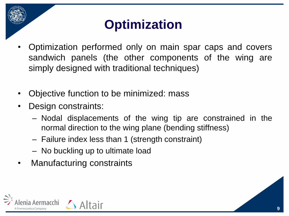
• Phase II (sizing): new constraints can be introduced in this phase,
that determines the number of plies of each ply patch (phase (b) e
(c))
• Phase III (ply-stacking optimization): determines the detailed
stacking sequence, considering various ply book rules (phase (d))
11

Free-sizing optimization (1/4)
• Starting model of the upper cover (same stacking sequence
considered for the lower cover):
– 1 fabric super-ply at a ±45-degree orientation
– 1 fabric super-ply at a 0/90-degree orientation
– 1 unidirectional super-ply at a 0-degree orientation
– 1 honeycomb super-ply at a 0-degree orientation
• Starting model of the spar caps:
– 1 fabric super-ply at a ±45-degree orientation
– 1 unidirectional super-ply at a 0-degree orientation
• SMEAR formulation for the laminates
12

Free-sizing optimization (2/4)
• Optimization constraints:
– Nodal displacements of the wing tip (bending stiffness)
– No buckling up to ultimate load
– Four fabric plies minimum on each spar cap
– Minimum 0.5 mm laminate thickness on both sides of the
honeycomb
– Minimum 6.35 mm honeycomb thickness
– In this phase constraints on failure indices not allowed
13

Free-sizing optimization (3/4)
Iteration history of the objective function: big changes in the
first few iterations
14

Free-sizing optimization (4/4)
• Unidirectional plies calculated from the original super-ply on
the upper spar cap:
• Unidirectional plies calculated from the original super-ply on
the upper cover:
15

Sizing optimization (1/3)
• Starting model: ply shapes obtained after free-sizing
optimization adjusted to be manufacturable
• Unnecessary plies removed (infinitesimal thickness)
• SYM (symmetric) formulation for the laminates
• New constraints added to the previous ones:
– Failure indices less than 1 everywhere (strength constraints)
– Allowable strains of a thick laminate (avoid excessive constraints
in optimization)
16

Sizing optimization (2/3)
Final models after free-sizing optimization (figures above) and
starting models for sizing optimization (figures below)
17
Upper spar cap, UD plies
Upper cover, UD plies

Sizing optimization (3/3)
Iteration history of the objective function: to satisfy the strength
constraints introduced in this phase, the structure needs a
greater mass
18

Local patches
• Static analysis performed after optimization considering the
correct allowable strains for each area with different thickness
• Some local strength problems on the upper and lower covers
(red areas)
• Some ply shapes modified and some local patches placed in
critical areas
19

Optimization results Upper cover: symmetric sandwich with a 6.35 mm-thick honeycomb
Only the laminate on one side of the core here represented: ply 10 is adjacent
to the honeycomb
20
N° ply Colour Unidirectional/
Fabric
Fiber orientation
1 Fabric* ±45°
2 Fabric ±45°
3 Fabric ±45°
4 Fabric ±45°
5 Fabric ±45°
6 Unidirectional 0°
7 Unidirectional 0°
8 Unidirectional 0°
9 Unidirectional 0°
10 Fabric 0°/90°
* Red plies are placed on the whole surface

Optimization results Lower cover: symmetric sandwich with a 6.35 mm-thick honeycomb
Only the laminate on one side of the core here represented: ply 8 is adjacent to
the honeycomb
21
N° ply Colour Unidirectional/
Fabric
Fiber orientation
1 Fabric* ±45°
2 Unidirectional 0°
3 Unidirectional 0°
4 Unidirectional 0°
5 Unidirectional 0°
6 Fabric 0°/90°
7 Unidirectional 0°
8 Unidirectional 0°
* Red plies are placed on the whole surface

Second optimization
• New optimization performed only on spar caps, laminates of
upper and lower covers are fixed
• Some plies can be removed thanks to the patches on the
covers
• Free-sizing optimization gives ply shapes that are manually
adjusted
22
Upper spar cap, UD plies Lower spar cap, UD plies

0
20
40
60
80
100
120
0 500 1000 1500 2000 2500 3000 3500
Th
ickn
ess
[-]
Wingspan [mm]
Upper cap
Lower cap
Optimization results
Spar caps
23

-0,5
-0,4
-0,3
-0,2
-0,1
0
0,1
0,2
0,3
0 500 1000 1500 2000 2500 3000 3500
To
rsio
n a
ng
le [
°]
Wingspan [mm]
Torsional rotation of a line
Original wing
Optimized wing
Optimization results
• Buckling load: 117% of the ultimate load
24
0
20
40
60
80
100
120
0 500 1000 1500 2000 2500 3000 3500
Vert
ical
dis
pla
cem
en
ts
[% t
ip o
rig
inal
win
g]
Wingspan [mm]
Vertical displacements
Original wing
Optimized wing

Ply-stacking optimization
• Unnecessary in this case. Simple considerations determine
the stacking sequence shown:
– The laminates are symmetric and the core is at the center of the
sequence
– The plies placed on the whole surface must be the cover layers
of the solid laminate on one side of the honeycomb
– Local patches are at the center of the sequence of the solid
laminate on one side of the core
25

Real structure mass estimation
• Various elements not present in the finite element model:
– Lightning strike protection
– Hysol® Synskin® HC 9837.1™
– Primer
– Structural adhesives
– Supported adhesive for sandwich panels fabrication
– Bolts and rivets
– Quasi-isotropic laminates for mechanical fasteners
– Symmetric spars
– Mass increase due to project development, strength problems in
structural tests, unexpected manufacturability constraints
26
Composite materials allow a mass reduction of 25% of
the structural mass of the original wing box.

Conclusions
• The study of a composite materials alternative for a wing box
structure led to a significant weight reduction
• All relevant load conditions and constraints must be
considered in structural optimization
• Excessive constraints must be avoided not to cause a useless
mass increase
27

Suggestions for future work
• Project development to a more detailed level
• Verify the robustness of the optimization procedure:
optimization of the whole structure
• Take a deeper look into the fabrication technologies required
(concurrent engineering)
• Study of a different structural scheme with the wing box
passing through the fuselage
28

29
THANKS FOR YOUR ATTENTION
Related Documents