Precision timing in ocean sensor systems This article has been downloaded from IOPscience. Please scroll down to see the full text article. 2012 Meas. Sci. Technol. 23 025801 (http://iopscience.iop.org/0957-0233/23/2/025801) Download details: IP Address: 147.83.82.7 The article was downloaded on 17/12/2011 at 10:59 Please note that terms and conditions apply. View the table of contents for this issue, or go to the journal homepage for more Home Search Collections Journals About Contact us My IOPscience

Welcome message from author
This document is posted to help you gain knowledge. Please leave a comment to let me know what you think about it! Share it to your friends and learn new things together.
Transcript
Precision timing in ocean sensor systems
This article has been downloaded from IOPscience. Please scroll down to see the full text article.
2012 Meas. Sci. Technol. 23 025801
(http://iopscience.iop.org/0957-0233/23/2/025801)
Download details:IP Address: 147.83.82.7The article was downloaded on 17/12/2011 at 10:59
Please note that terms and conditions apply.
View the table of contents for this issue, or go to the journal homepage for more
Home Search Collections Journals About Contact us My IOPscience
IOP PUBLISHING MEASUREMENT SCIENCE AND TECHNOLOGY
Meas. Sci. Technol. 23 (2012) 025801 (7pp) doi:10.1088/0957-0233/23/2/025801
Precision timing in ocean sensor systemsJoaquın del Rıo1, Daniel Toma1, Shahram Shariat-Panahi1,Antoni Manuel1 and Helena Geirinhas Ramos2
1 SARTI Research Group, Electronics Department, Universitat Politecnica de Catalunya, UPC,Barcelona, Spain2 Instituto de Telecomunicacoes, DEEC, Instituto Superior Tecnico, UTL, Lisboa, Portugal
E-mail: [email protected] and [email protected]
Received 14 June 2011, in final form 30 October 2011Published 16 December 2011Online at stacks.iop.org/MST/23/025801
AbstractThis paper discusses the use of the IEEE 1588 standard in ocean observatories. Theperformance result of prototype implementations of this standard in an Ethernet Marine SensorNetwork (MSN) is presented. The performance tests emulate an underwater-cabledobservatory with a Master Clock synchronized with GPS, located in an on-shore station, andwith underwater instruments requiring high-precision PPS (pulse s−1) signals forsynchronization purposes. These signals will be provided to the underwater station by anIEEE 1588 GPS Emulator connected to the observatory’s Local Area Network (LAN). Theexperimental setup emulates the underwater-cabled observatory OBSEA where thistechnology will be installed due to synchronization requirements of marine instruments suchas ocean bottom seismometers.
Keywords: IEEE 1588, ocean observatories, time synchronization
(Some figures in this article are in colour only in the electronic version)
1. Introduction
Ocean observatories are an important technological resourcethat can provide knowledge to forecast environment changesor to carry out ocean research [1–3]. Sensor data are collectedat different world locations and large streams of data must becorrelated with other events or data sources to study eitherlong-term tendencies or singular events [4]. Data in a locationcontext must be time-stamped in order to allow this analysis[5, 6]. For many observations, low time-stamp accuracyis adequate, whereas for other observations, sub-millisecondprecision level is needed.
OBSEA is a cabled seafloor observatory 4 km offshoreVilanova i la Geltru (Barcelona, Spain) at 20 m water depth,interconnected to the coast by an energy and communicationmixed cable [7]. As an underwater observatory, GPS (GlobalPositioning System) signals are unavailable due to seawaterattenuation at the sea bottom. For this reason, IEEE Std1588 was the protocol chosen to distribute time to the subseainstruments that make up the sea observatory. IEEE 1588, alsoknown as the ‘PrecisionTimeProtocol (PTP), defines amethodto synchronize real-time clocks in the nodes of a distributedsystem that communicates using standardized packet-based
networks such as Ethernet [8]. Its usage on CAN bus [9]or wireless networks [10] has been documented in recentreports. PTP is intended for relatively localized systems inmeasurement environments, its installation is administrationfree and it has minimal resource requirements in networks andhost components. The time signal delivered to the applicationdepends on the quality of the master clock and the applicationservice interface allowing all nodes to synchronize in the sub-millisecond range. This is the precision required for time-stamping some data collected at OBSEA. For instance, in orderto locate an earthquake epicenter, or the position of a soundsource installed in a boat or in an animal, the triangularizationof three measurements performed at the same moment isneeded. The resultant accuracy depends on the quantitiesmeasured (from seismometers [11] or from hydrophones[12]) and on their time-stamping accuracies. Other well-known synchronization protocols such as NTP (Network TimeProtocol) or SNTP (SingleNetwork Time Protocol) offer clocksynchronization with accuracies around milliseconds far awayfrom accuracies offered by PTP.
This paper describes the project and implementation oftiming signals delivered to the cabled ocean observatoryOBSEA using IEEE 1588 PTP [13, 14]. The accuracy
0957-0233/12/025801+07$33.00 1 © 2012 IOP Publishing Ltd Printed in the UK & the USA
Meas. Sci. Technol. 23 (2012) 025801 J del Rıo et al
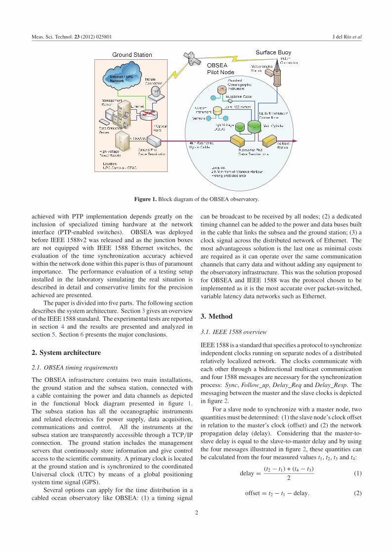
Figure 1. Block diagram of the OBSEA observatory.
achieved with PTP implementation depends greatly on theinclusion of specialized timing hardware at the networkinterface (PTP-enabled switches). OBSEA was deployedbefore IEEE 1588v2 was released and as the junction boxesare not equipped with IEEE 1588 Ethernet switches, theevaluation of the time synchronization accuracy achievedwithin the network done within this paper is thus of paramountimportance. The performance evaluation of a testing setupinstalled in the laboratory simulating the real situation isdescribed in detail and conservative limits for the precisionachieved are presented.
The paper is divided into five parts. The following sectiondescribes the system architecture. Section 3 gives an overviewof the IEEE 1588 standard. The experimental tests are reportedin section 4 and the results are presented and analyzed insection 5. Section 6 presents the major conclusions.
2. System architecture
2.1. OBSEA timing requirements
The OBSEA infrastructure contains two main installations,the ground station and the subsea station, connected witha cable containing the power and data channels as depictedin the functional block diagram presented in figure 1.The subsea station has all the oceanographic instrumentsand related electronics for power supply, data acquisition,communications and control. All the instruments at thesubsea station are transparently accessible through a TCP/IPconnection. The ground station includes the managementservers that continuously store information and give controlaccess to the scientific community. A primary clock is locatedat the ground station and is synchronized to the coordinatedUniversal clock (UTC) by means of a global positioningsystem time signal (GPS).
Several options can apply for the time distribution in acabled ocean observatory like OBSEA: (1) a timing signal
can be broadcast to be received by all nodes; (2) a dedicatedtiming channel can be added to the power and data buses builtin the cable that links the subsea and the ground station; (3) aclock signal across the distributed network of Ethernet. Themost advantageous solution is the last one as minimal costsare required as it can operate over the same communicationchannels that carry data and without adding any equipment tothe observatory infrastructure. This was the solution proposedfor OBSEA and IEEE 1588 was the protocol chosen to beimplemented as it is the most accurate over packet-switched,variable latency data networks such as Ethernet.
3. Method
3.1. IEEE 1588 overview
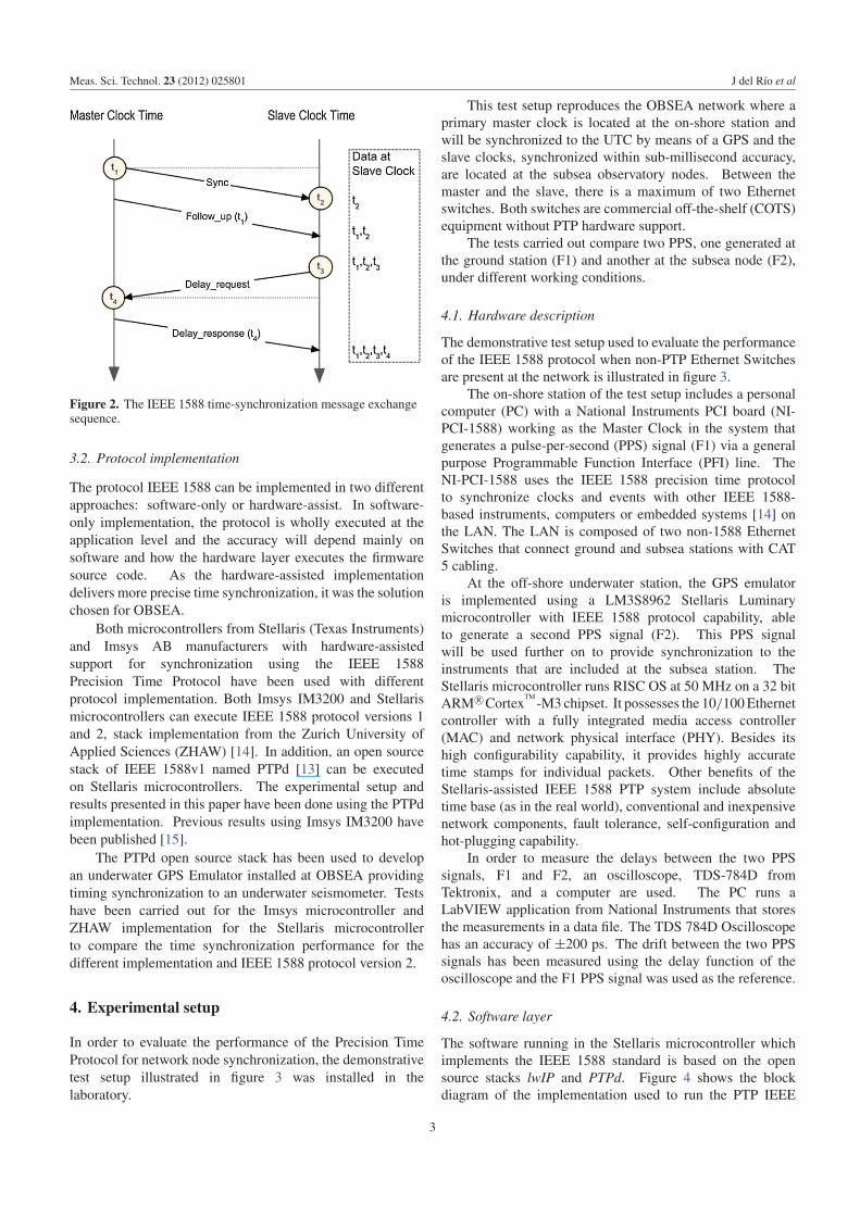
IEEE1588 is a standard that specifies a protocol to synchronizeindependent clocks running on separate nodes of a distributedrelatively localized network. The clocks communicate witheach other through a bidirectional multicast communicationand four 1588 messages are necessary for the synchronizationprocess: Sync, Follow_up, Delay_Req and Delay_Resp. Themessaging between the master and the slave clocks is depictedin figure 2.
For a slave node to synchronize with a master node, twoquantitiesmust be determined: (1) the slave node’s clock offsetin relation to the master’s clock (offset) and (2) the networkpropagation delay (delay). Considering that the master-to-slave delay is equal to the slave-to-master delay and by usingthe four messages illustrated in figure 2, these quantities canbe calculated from the four measured values t1, t2, t3 and t4:
delay = (t2 − t1) + (t4 − t3)
2(1)
offset = t2 − t1 − delay. (2)
2
Meas. Sci. Technol. 23 (2012) 025801 J del Rıo et al
Figure 2. The IEEE 1588 time-synchronization message exchangesequence.
3.2. Protocol implementation
The protocol IEEE 1588 can be implemented in two differentapproaches: software-only or hardware-assist. In software-only implementation, the protocol is wholly executed at theapplication level and the accuracy will depend mainly onsoftware and how the hardware layer executes the firmwaresource code. As the hardware-assisted implementationdelivers more precise time synchronization, it was the solutionchosen for OBSEA.
Both microcontrollers from Stellaris (Texas Instruments)and Imsys AB manufacturers with hardware-assistedsupport for synchronization using the IEEE 1588Precision Time Protocol have been used with differentprotocol implementation. Both Imsys IM3200 and Stellarismicrocontrollers can execute IEEE 1588 protocol versions 1and 2, stack implementation from the Zurich University ofApplied Sciences (ZHAW) [14]. In addition, an open sourcestack of IEEE 1588v1 named PTPd [13] can be executedon Stellaris microcontrollers. The experimental setup andresults presented in this paper have been done using the PTPdimplementation. Previous results using Imsys IM3200 havebeen published [15].
The PTPd open source stack has been used to developan underwater GPS Emulator installed at OBSEA providingtiming synchronization to an underwater seismometer. Testshave been carried out for the Imsys microcontroller andZHAW implementation for the Stellaris microcontrollerto compare the time synchronization performance for thedifferent implementation and IEEE 1588 protocol version 2.
4. Experimental setup
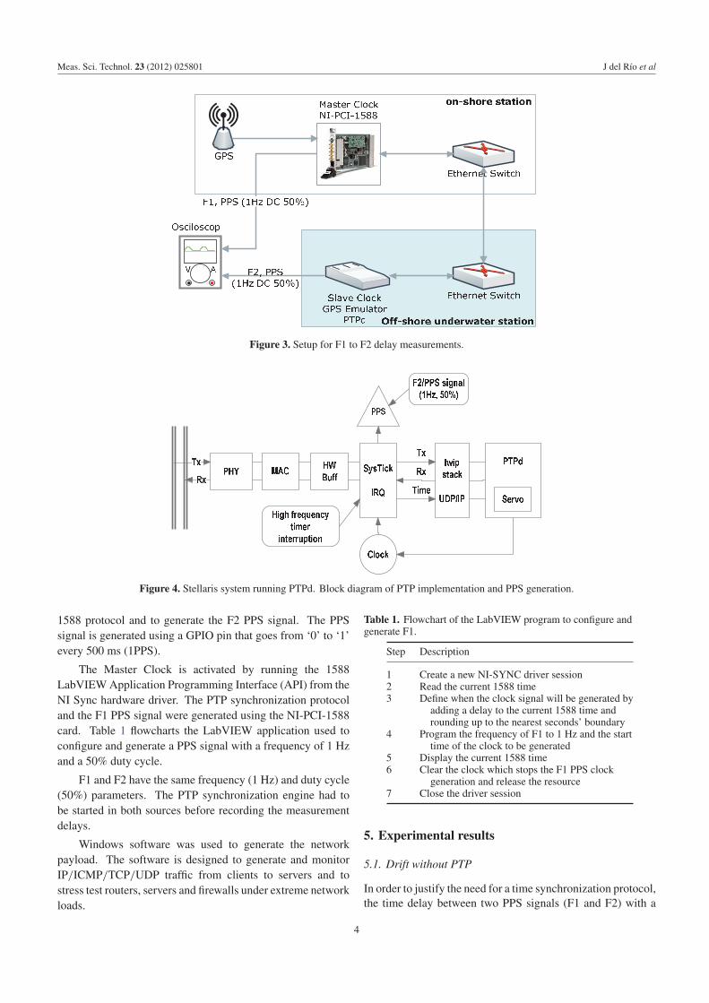
In order to evaluate the performance of the Precision TimeProtocol for network node synchronization, the demonstrativetest setup illustrated in figure 3 was installed in thelaboratory.
This test setup reproduces the OBSEA network where aprimary master clock is located at the on-shore station andwill be synchronized to the UTC by means of a GPS and theslave clocks, synchronized within sub-millisecond accuracy,are located at the subsea observatory nodes. Between themaster and the slave, there is a maximum of two Ethernetswitches. Both switches are commercial off-the-shelf (COTS)equipment without PTP hardware support.
The tests carried out compare two PPS, one generated atthe ground station (F1) and another at the subsea node (F2),under different working conditions.
4.1. Hardware description
The demonstrative test setup used to evaluate the performanceof the IEEE 1588 protocol when non-PTP Ethernet Switchesare present at the network is illustrated in figure 3.
The on-shore station of the test setup includes a personalcomputer (PC) with a National Instruments PCI board (NI-PCI-1588) working as the Master Clock in the system thatgenerates a pulse-per-second (PPS) signal (F1) via a generalpurpose Programmable Function Interface (PFI) line. TheNI-PCI-1588 uses the IEEE 1588 precision time protocolto synchronize clocks and events with other IEEE 1588-based instruments, computers or embedded systems [14] onthe LAN. The LAN is composed of two non-1588 EthernetSwitches that connect ground and subsea stations with CAT5 cabling.
At the off-shore underwater station, the GPS emulatoris implemented using a LM3S8962 Stellaris Luminarymicrocontroller with IEEE 1588 protocol capability, ableto generate a second PPS signal (F2). This PPS signalwill be used further on to provide synchronization to theinstruments that are included at the subsea station. TheStellaris microcontroller runs RISC OS at 50 MHz on a 32 bitARM R©Cortex
TM-M3 chipset. It possesses the 10/100Ethernet
controller with a fully integrated media access controller(MAC) and network physical interface (PHY). Besides itshigh configurability capability, it provides highly accuratetime stamps for individual packets. Other benefits of theStellaris-assisted IEEE 1588 PTP system include absolutetime base (as in the real world), conventional and inexpensivenetwork components, fault tolerance, self-configuration andhot-plugging capability.
In order to measure the delays between the two PPSsignals, F1 and F2, an oscilloscope, TDS-784D fromTektronix, and a computer are used. The PC runs aLabVIEW application from National Instruments that storesthe measurements in a data file. The TDS 784D Oscilloscopehas an accuracy of ±200 ps. The drift between the two PPSsignals has been measured using the delay function of theoscilloscope and the F1 PPS signal was used as the reference.
4.2. Software layer
The software running in the Stellaris microcontroller whichimplements the IEEE 1588 standard is based on the opensource stacks lwIP and PTPd. Figure 4 shows the blockdiagram of the implementation used to run the PTP IEEE
3
Meas. Sci. Technol. 23 (2012) 025801 J del Rıo et al
Figure 3. Setup for F1 to F2 delay measurements.
Figure 4. Stellaris system running PTPd. Block diagram of PTP implementation and PPS generation.
1588 protocol and to generate the F2 PPS signal. The PPSsignal is generated using a GPIO pin that goes from ‘0’ to ‘1’every 500 ms (1PPS).
The Master Clock is activated by running the 1588LabVIEWApplication Programming Interface (API) from theNI Sync hardware driver. The PTP synchronization protocoland the F1 PPS signal were generated using the NI-PCI-1588card. Table 1 flowcharts the LabVIEW application used toconfigure and generate a PPS signal with a frequency of 1 Hzand a 50% duty cycle.
F1 and F2 have the same frequency (1 Hz) and duty cycle(50%) parameters. The PTP synchronization engine had tobe started in both sources before recording the measurementdelays.
Windows software was used to generate the networkpayload. The software is designed to generate and monitorIP/ICMP/TCP/UDP traffic from clients to servers and tostress test routers, servers and firewalls under extreme networkloads.
Table 1. Flowchart of the LabVIEW program to configure andgenerate F1.
Step Description
1 Create a new NI-SYNC driver session2 Read the current 1588 time3 Define when the clock signal will be generated by
adding a delay to the current 1588 time androunding up to the nearest seconds’ boundary
4 Program the frequency of F1 to 1 Hz and the starttime of the clock to be generated
5 Display the current 1588 time6 Clear the clock which stops the F1 PPS clock
generation and release the resource7 Close the driver session
5. Experimental results
5.1. Drift without PTP
In order to justify the need for a time synchronization protocol,the time delay between two PPS signals (F1 and F2) with a
4
Meas. Sci. Technol. 23 (2012) 025801 J del Rıo et al
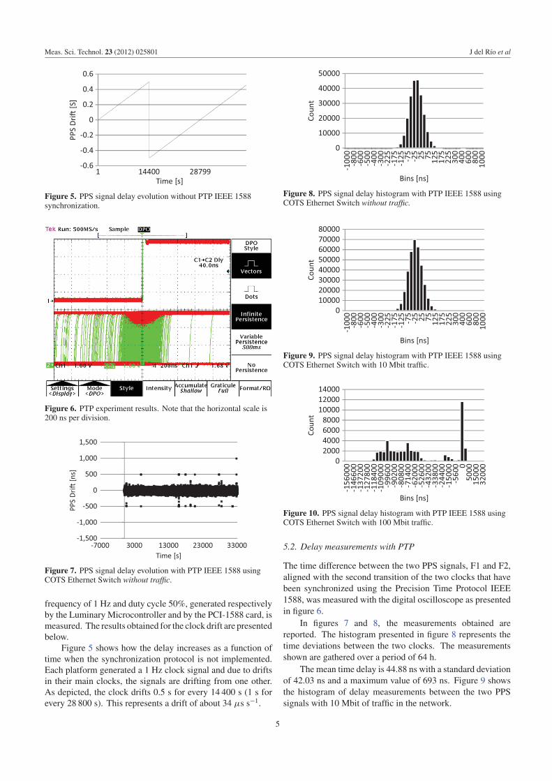
Figure 5. PPS signal delay evolution without PTP IEEE 1588synchronization.
Figure 6. PTP experiment results. Note that the horizontal scale is200 ns per division.
Figure 7. PPS signal delay evolution with PTP IEEE 1588 usingCOTS Ethernet Switch without traffic.
frequency of 1 Hz and duty cycle 50%, generated respectivelyby the Luminary Microcontroller and by the PCI-1588 card, ismeasured. The results obtained for the clock drift are presentedbelow.
Figure 5 shows how the delay increases as a function oftime when the synchronization protocol is not implemented.Each platform generated a 1 Hz clock signal and due to driftsin their main clocks, the signals are drifting from one other.As depicted, the clock drifts 0.5 s for every 14 400 s (1 s forevery 28 800 s). This represents a drift of about 34 μs s−1.
Figure 8. PPS signal delay histogram with PTP IEEE 1588 usingCOTS Ethernet Switch without traffic.
Figure 9. PPS signal delay histogram with PTP IEEE 1588 usingCOTS Ethernet Switch with 10 Mbit traffic.
Figure 10. PPS signal delay histogram with PTP IEEE 1588 usingCOTS Ethernet Switch with 100 Mbit traffic.
5.2. Delay measurements with PTP
The time difference between the two PPS signals, F1 and F2,aligned with the second transition of the two clocks that havebeen synchronized using the Precision Time Protocol IEEE1588, was measured with the digital oscilloscope as presentedin figure 6.
In figures 7 and 8, the measurements obtained arereported. The histogram presented in figure 8 represents thetime deviations between the two clocks. The measurementsshown are gathered over a period of 64 h.
The mean time delay is 44.88 ns with a standard deviationof 42.03 ns and a maximum value of 693 ns. Figure 9 showsthe histogram of delay measurements between the two PPSsignals with 10 Mbit of traffic in the network.
5
Meas. Sci. Technol. 23 (2012) 025801 J del Rıo et al
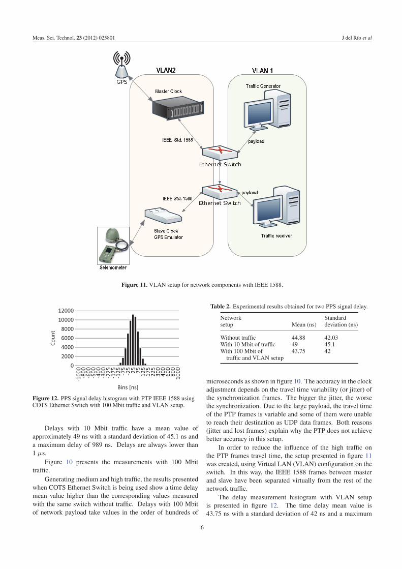
Figure 11. VLAN setup for network components with IEEE 1588.
Figure 12. PPS signal delay histogram with PTP IEEE 1588 usingCOTS Ethernet Switch with 100 Mbit traffic and VLAN setup.
Delays with 10 Mbit traffic have a mean value ofapproximately 49 ns with a standard deviation of 45.1 ns anda maximum delay of 989 ns. Delays are always lower than1 μs.
Figure 10 presents the measurements with 100 Mbittraffic.
Generating medium and high traffic, the results presentedwhen COTS Ethernet Switch is being used show a time delaymean value higher than the corresponding values measuredwith the same switch without traffic. Delays with 100 Mbitof network payload take values in the order of hundreds of
Table 2. Experimental results obtained for two PPS signal delay.
Network Standardsetup Mean (ns) deviation (ns)
Without traffic 44.88 42.03With 10 Mbit of traffic 49 45.1With 100 Mbit of 43.75 42traffic and VLAN setup
microseconds as shown in figure 10. The accuracy in the clockadjustment depends on the travel time variability (or jitter) ofthe synchronization frames. The bigger the jitter, the worsethe synchronization. Due to the large payload, the travel timeof the PTP frames is variable and some of them were unableto reach their destination as UDP data frames. Both reasons(jitter and lost frames) explain why the PTP does not achievebetter accuracy in this setup.
In order to reduce the influence of the high traffic onthe PTP frames travel time, the setup presented in figure 11was created, using Virtual LAN (VLAN) configuration on theswitch. In this way, the IEEE 1588 frames between masterand slave have been separated virtually from the rest of thenetwork traffic.
The delay measurement histogram with VLAN setupis presented in figure 12. The time delay mean value is43.75 ns with a standard deviation of 42 ns and a maximum
6
Meas. Sci. Technol. 23 (2012) 025801 J del Rıo et al
value of 832 ns. It can be seen that VLAN configurationhelps to reduce jitter of the frame’s travel time improving theaccuracy of the PTP protocol.
Experiments were made to study the stability of the PPSsignals and the time synchronization in the Ethernet MSN.
6. Conclusions
An experimental setup and the results obtained have beenpresented in order to evaluate delays between an on-shore master clock GPS PPS signal and an underwatersynchronization signal generated by a PTPGPSEmulator. TheIEEE 1588 protocol was implemented to synchronize the GPSEmulator signal using a GPS synchronized on-shore reference.Delay measurements are made building an Ethernet networkwith different data traffic payload. Table 2 shows a summaryof the measurement as a function of the network setup and ofthe traffic generated in the network.
With these results one can conclude that IEEE 1588standard is a valid strategy to synchronize distributed nodesin a Marine Sensor Network where Ethernet is used andinstruments with highly accurate clocks such as geophonesor hydrophones are required. The results also show thatthe OBSEA network requires a VLAN setup of switchesto separate the IEEE 1588 instrument traffic from PTPsynchronization frames.
Underwater seismometers implementing the IEEE 1588Precision Time Protocol have been developed and validatedto work in network systems such as the OBSEA network.We can conclude, after these laboratory tests, that instrumentsconnected to these networks can be synchronized with GPStime through the IEEE 1588 protocol with a precision up tohundreds of nanoseconds.
Acknowledgment
This work was supported by the Spanish Government underresearch projects: Interoperability in Environmental andMarine Sensor Networks (CTM2009-08867), Sismometremarı digital amb connexio per cable VALTEC09-1-0059, Centre D’innovacio i Desenvolupament Empresarial(CIDEM), Generalitat de Catalunya and ‘Integracion de
sensores para monitorizacion submarina en una red consincronizacion temporal’ PT2009-0080.
References
[1] Bermudez L, Delory E, O’Reilly T, del Rio and Fernandez J2009 Ocean observing systems demystified Proc. OCEANS2009, MTS/IEEE Biloxi—Marine Technology for OurFuture: Global and Local Challenges (26–29 October2009) pp 1–7
[2] Ocean Observatory at MBARI (Monterey Bay AquariumResearch Institute) http://www.mbari.org/rd
[3] Ocean Observatories Initiative http://www.oceanleadership.org/programs-and-partnerships/ocean-observing/
[4] Hofmann M 2010 Designing a network for ocean observatoriesProc. OCEANS (20–23 September 2010) pp 1–4
[5] Milevsky A and Walrod J 2008 Development and test of IEEE1588 precision timing protocol for ocean observatorynetworks Proc. OCEANS (15–18 September 2008) pp 1–7
[6] Lentz S and Lecroart A 2009 Precision timing in theNEPTUNE Canada network Proc. OCEANS 2009 (Europe)pp 1–5
[7] Manuel-Lazaro A, Nogueras M and del Rıo J 2010 OBSEA: anexpandable seafloor observatory Sea Technol. Mag. 51 37–9
[8] IEEE STD 1588 2008 Standard for a Precision ClockSynchronization Protocol for Networked Measurement andControl Systems (New York: IEEE)
[9] Paces P, Sipos M and Vesely M 2009 Verification ofIEEE1588 time synchronization in NASA agate data busstandard Proc. ICEMI 2009 pp 1–5
[10] Cooklev T, Eidson J C, Fellow L and Pakdaman A 2007 Animplementation of IEEE 1588 over IEEE 802.1 1b forsynchronization of wireless local area network nodes IEEETrans. Instrum. Meas. 56 1632–9
[11] Rodrıguez I, Manuel A, Carlosena A, Bermudez A, del Rıo Jand Shariat-Panahi S 2006 A signal processing in oceanbottom seismographs for refraction seismology IEEE Trans.Instrum. Meas. 55 652–8
[12] Andre M, van der Schaar M, Zaugg S, Houegnigan L,Sanchez A, Mas A, Morell M, Sole M and Castell J V 2010Listen to the deep: real-time monitoring of acoustic eventsProc. Eur. Conf. Underw. Acoust. vol 1 pp 77–80
[13] Correll K, Barendt N and Branicky M 2005 Designconsiderations for software only implementations of theIEEE 1588 precision time protocol Conf. on IEEE 1588
[14] InES Institute of Embedded Systems http://www.ines.zhaw.ch/en/engineering/ines/ieee-1588/overview.html
[15] del Rio J, Toma D, Manuel A and Ramos H 2009 Evaluationof IEEE 1588 applied to synchronized acquisition in marinesensor networks (MSN) Imeko 19th World Congress(Lisbon, Portugal, September 2009) pp 514–7
7
Related Documents