Precision Hybrid Stepper Linear Actuator Systems Changzhou DINGS Electrical & Mechanical Co. Ltd. Distributed by

Welcome message from author
This document is posted to help you gain knowledge. Please leave a comment to let me know what you think about it! Share it to your friends and learn new things together.
Transcript

Precision Hybrid Stepper Linear Actuator Systems
Changzhou DINGS Electrical & Mechanical Co. Ltd.
Distributed by

Motion Control Products Ltd. I Tel.: (+44) 01202 599922
INTRODUCTION
Motion Control Products Ltd., supplies quality leadscrew-style linear stepper motor actuator systems used to solve
motion applications in the industries including medical, laboratory automation, packaging, electronic assembly
and other special purpose machines throughout the world. Our company’s vision is to provide a wide range of
high QUALITY linear stepper motor actuators with COMPETITIVE prices.
Please visit our website at http://www.motioncontrolproducts.com for the latest information on new products
for all your motion control needs from components such as stepper and servo motors, drives, planetary gearboxes,
electric actuators and motion controllers to complete motion system such as gantry system and robot &
positioning stage and much more.
DISCLAIMER:
The information in this catalogue has been carefully checked and updated (version # V3.0 –REV0414/20160516) and is believed to be accurate; however no responsibility is assumed for inaccuracies. Motion Control Products reserves the right to make changes without further notice to any products herein to improve reliability, function, or design. Motion Control Products does not recommend the use of its products in life support or aircraft applications wherein a failure or malfunction of the product may directly threaten life or injury.
CONTACT
Motion Control Products Ltd. 11-15 Francis Avenue, Bournemouth, Dorset, UK BH11 8NX Tel: +44 (0)1202 599922 Fax: +44 (0)1202 599955 E-mail: [email protected] e-shop: www.motioncontrolproducts.co.uk Web: http://www.motioncontrolproducts.com
Motion Control Products Ltd. II www.motioncontrolproducts.com
TABLE OF CONTENTS
TECHNOLOGY OVERVIEW ················································································································· 1
AN EXPLANATION OF THE BASICS ····································································································· 1
BASIC SPECIFICATIONS FOR LINEAR SYSTEMS ···················································································· 8
PRODUCT SELECTION ························································································································ 9
HYBRID STEPPER LINEAR ACTUATOR OVERVIEW ············································································· 14
LEADSCREW & MOTOR SIZE CODE ·································································································· 15
NEMA SIZE 8 (20MM) HYBRID STEPPER MOTOR LINEAR ACTUATOR ··············································· 16
SIZE 11 (28MM) HYBRID STEPPER MOTOR LINEAR ACTUATOR························································· 22
SIZE 14 (35MM) HYBRID STEPPER MOTOR LINEAR ACTUATOR························································· 28
SIZE 17 (42MM) HYBRID STEPPER MOTOR LINEAR ACTUATOR························································· 37
SIZE 23 (57MM) HYBRID STEPPER MOTOR LINEAR ACTUATOR························································· 46
SIZE 34 (86MM) HYBRID STEPPER MOTOR LINEAR ACTUATOR························································· 55
GLOSSARY ······································································································································ 59
WARRANTY ···································································································································· 60

Motion Control Products Ltd. P a g e | 1 Tel.: (+44) 01202 599922
TECHNOLOGY OVERVIEW One of the most common methods of moving a load from point A to point B is through linear translation of a motor by a
mechanical leadscrew and nut. This section is here to assist and refresh your understanding of the basic principles of
leadscrew technology prior to selecting the system that is best for your application. Please also refer to the Glossary at the
end of the catalogue.
Some basic design considerations are as follows: 1. What is the load of your system? 2. What is the required speed to move from point A to point B? 3. What is the distance to travel? 4. What is the required time to move from point A to point B? 5. What accuracy does your application require? 6. What repeatability does your application require? 7. Horizontal vs vertical orientation?
An Explanation Of The Basics
LEADS VS PITCH Lead is the axial distance the nut advances on one revolution of the screw. Throughout this catalogue, lead will be the
term used for specifying a screw as it is the linear distance travelled for one revolution of the screw. The larger the lead,
the more linear distance travelled per one revolution of the screw.
Pitch is the axial distance between threads. Pitch is equal to lead in a single start screw. There may be more than one
thread “strand” on a single screw. These are called starts. Multiple start leadscrews are usually more stable and efficient
at power transmission.
LOAD It is typically quantified as either lbs or kg to move or pounds force (lbf) or kilogram force (kgf) for thrust.
VELOCITY (V) It is typically quantified as either inches/second or (mm/sec) required for your application.
DISTANCE It is typically quantified as either inches or mm, which is the required move distance.
TIME (t) It is typically quantified in seconds. Time period required for a given distance defines the velocity, acceleration (A), and
deceleration needed to reach commanded position.
HORIZONTAL OR VERTICAL APPLICATION Vertical orientation applications add the potential problem of backdriving when power to the motor is off and without
an installed brake. Vertical applications also have an additional gravity factor that must be part of the load/force
calculation.

Motion Control Products Ltd. P a g e | 2 www.motioncontrolproducts.com
ACCURACY OF SCREW It is specified as a measurement over a given length of the screw. For example: 0.0006 in per inch. Lead accuracy is the
difference between the actual distance travelled versus the theoretical distance travelled based on the lead. For
example: A screw with a 0.5 inch lead and 0.004 inch per foot lead accuracy rotated 24 times theoretically moves the
nut 12 inches.
However, with a lead accuracy of 0.004 inch per foot, actual travel could be from 11.996 to 12.004 inches.
TOTAL INDICATED RUNOUT The amount of “wobble” around the centerline of the screw
REPEATIBILITY Most motion applications put the most significance on the repeatability (vs accuracy of screw) of a system to reach the
same commanded position over and over again. For example: A repeatability of ± .005 inch means that after repeated
commands to reach the same target position, the linear error will be no more than ± .005 inch.
TENSION OR COMPRESSION LOADING A load that tends to stretch the screw is called a tension load.
A load that tends to “squeeze” or compress the screw is called a compression load.
Depending on the size of the load, designing the screw in tension utilizes the axial strength of the screw versus column
loading.
RADIAL LOAD A load perpendicular to the screw
This is not recommended unless additional mechanical support such as a linear guide is used.
AXIAL LOAD A load that exerted at the central line of the leadscrew
Motion Control Products Ltd. P a g e | 3 Tel.: (+44) 01202 599922
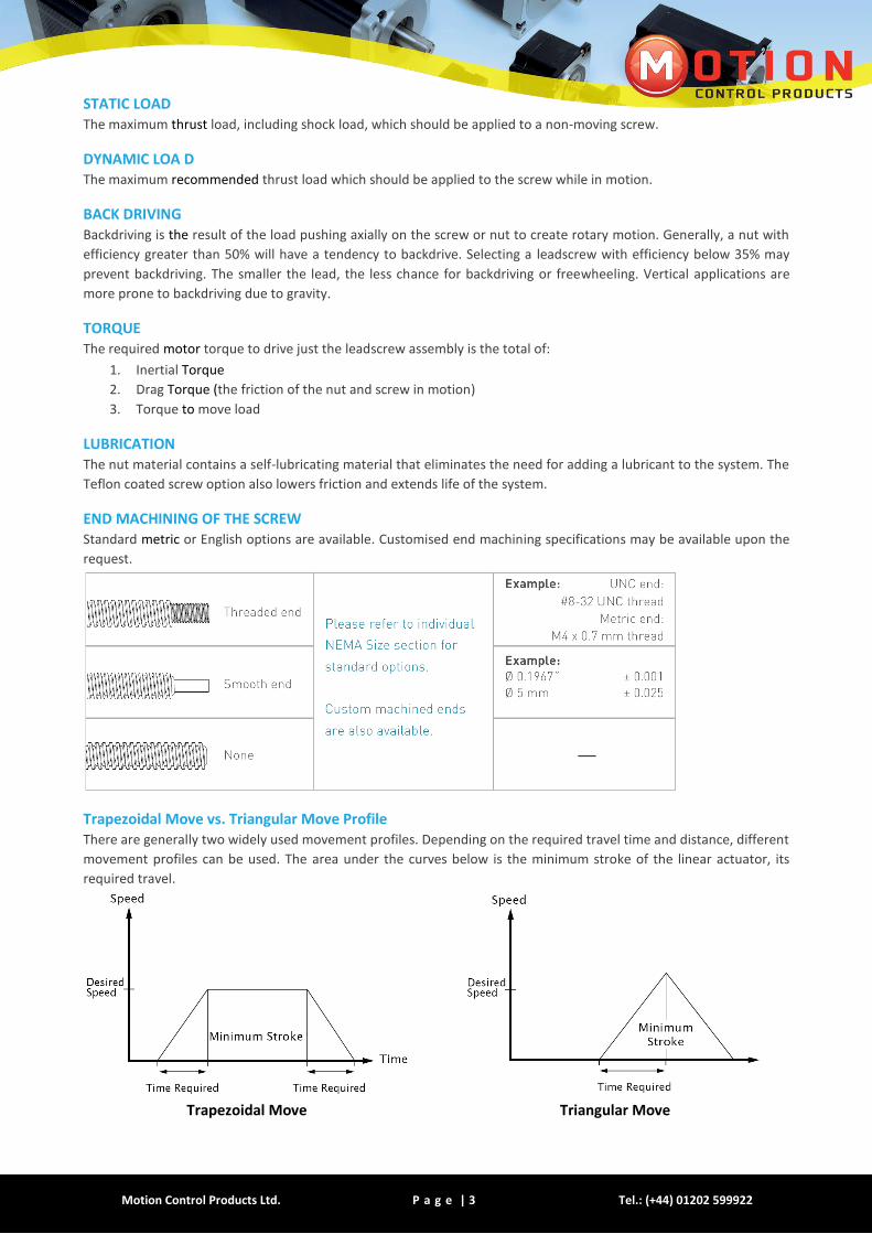
STATIC LOAD The maximum thrust load, including shock load, which should be applied to a non-moving screw.
DYNAMIC LOA D The maximum recommended thrust load which should be applied to the screw while in motion.
BACK DRIVING Backdriving is the result of the load pushing axially on the screw or nut to create rotary motion. Generally, a nut with
efficiency greater than 50% will have a tendency to backdrive. Selecting a leadscrew with efficiency below 35% may
prevent backdriving. The smaller the lead, the less chance for backdriving or freewheeling. Vertical applications are
more prone to backdriving due to gravity.
TORQUE The required motor torque to drive just the leadscrew assembly is the total of:
1. Inertial Torque
2. Drag Torque (the friction of the nut and screw in motion)
3. Torque to move load
LUBRICATION The nut material contains a self-lubricating material that eliminates the need for adding a lubricant to the system. The
Teflon coated screw option also lowers friction and extends life of the system.
END MACHINING OF THE SCREW Standard metric or English options are available. Customised end machining specifications may be available upon the
request.
Trapezoidal Move vs. Triangular Move Profile There are generally two widely used movement profiles. Depending on the required travel time and distance, different
movement profiles can be used. The area under the curves below is the minimum stroke of the linear actuator, its
required travel.
Trapezoidal Move Triangular Move
Motion Control Products Ltd. P a g e | 4 www.motioncontrolproducts.com
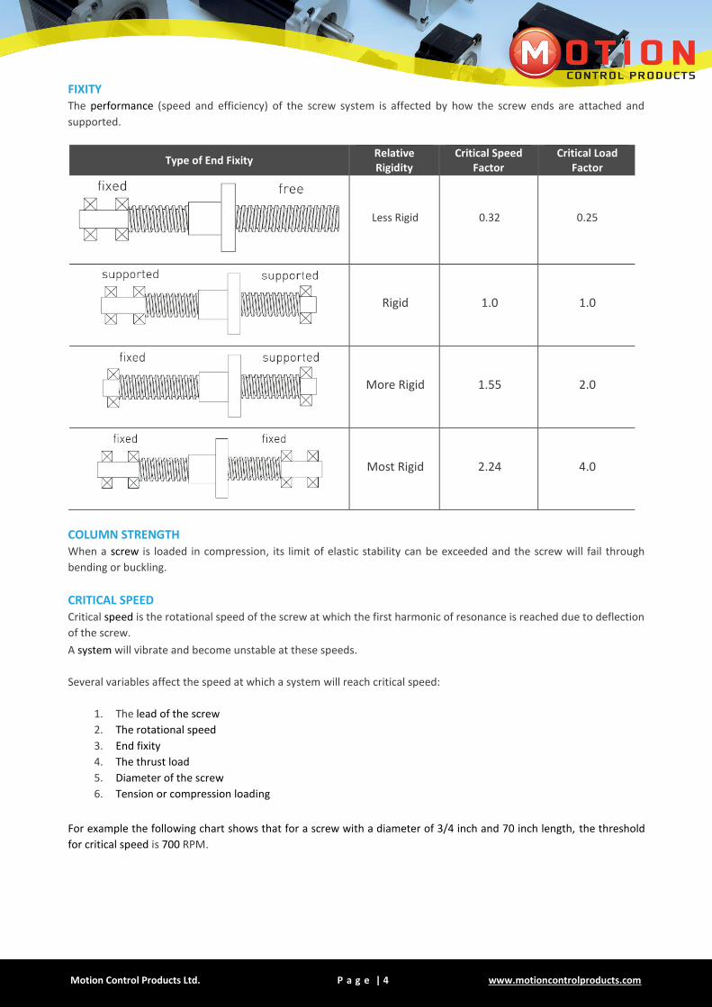
FIXITY The performance (speed and efficiency) of the screw system is affected by how the screw ends are attached and
supported.
Type of End Fixity Relative Rigidity
Critical Speed Factor
Critical Load Factor
Less Rigid 0.32 0.25
Rigid 1.0 1.0
More Rigid 1.55 2.0
Most Rigid 2.24 4.0
COLUMN STRENGTH When a screw is loaded in compression, its limit of elastic stability can be exceeded and the screw will fail through
bending or buckling.
CRITICAL SPEED Critical speed is the rotational speed of the screw at which the first harmonic of resonance is reached due to deflection
of the screw.
A system will vibrate and become unstable at these speeds.
Several variables affect the speed at which a system will reach critical speed:
1. The lead of the screw
2. The rotational speed
3. End fixity
4. The thrust load
5. Diameter of the screw
6. Tension or compression loading
For example the following chart shows that for a screw with a diameter of 3/4 inch and 70 inch length, the threshold
for critical speed is 700 RPM.

Motion Control Products Ltd. P a g e | 5 Tel.: (+44) 01202 599922
CRITICAL ROTATION SPEED (RPM) VS UNSUPPORTED SCREW LENGTH FOR VARIOUS SCREW DIAMETERS (INCH)
BACKLASH
Backlash is the relative axial movement between a screw and
nut at standstill. It is normal for backlash to increase with
wear over time. Backlash compensation or correction can be
accomplished through the application of an anti-backlash nut.
Backlash is usually only a concern with bi-directional
positioning.

Motion Control Products Ltd. P a g e | 6 www.motioncontrolproducts.com
ANTI-BACKLASH NUTS
Anti-backlash nut for
NEMA 8-11 linear stepper motor actuators Anti-backlash nut for
NEMA 14-17 linear stepper motor actuators
Anti-backlash nut for NEMA 23 linear stepper motor actuators
Motion Control Products Ltd. P a g e | 7 Tel.: (+44) 01202 599922
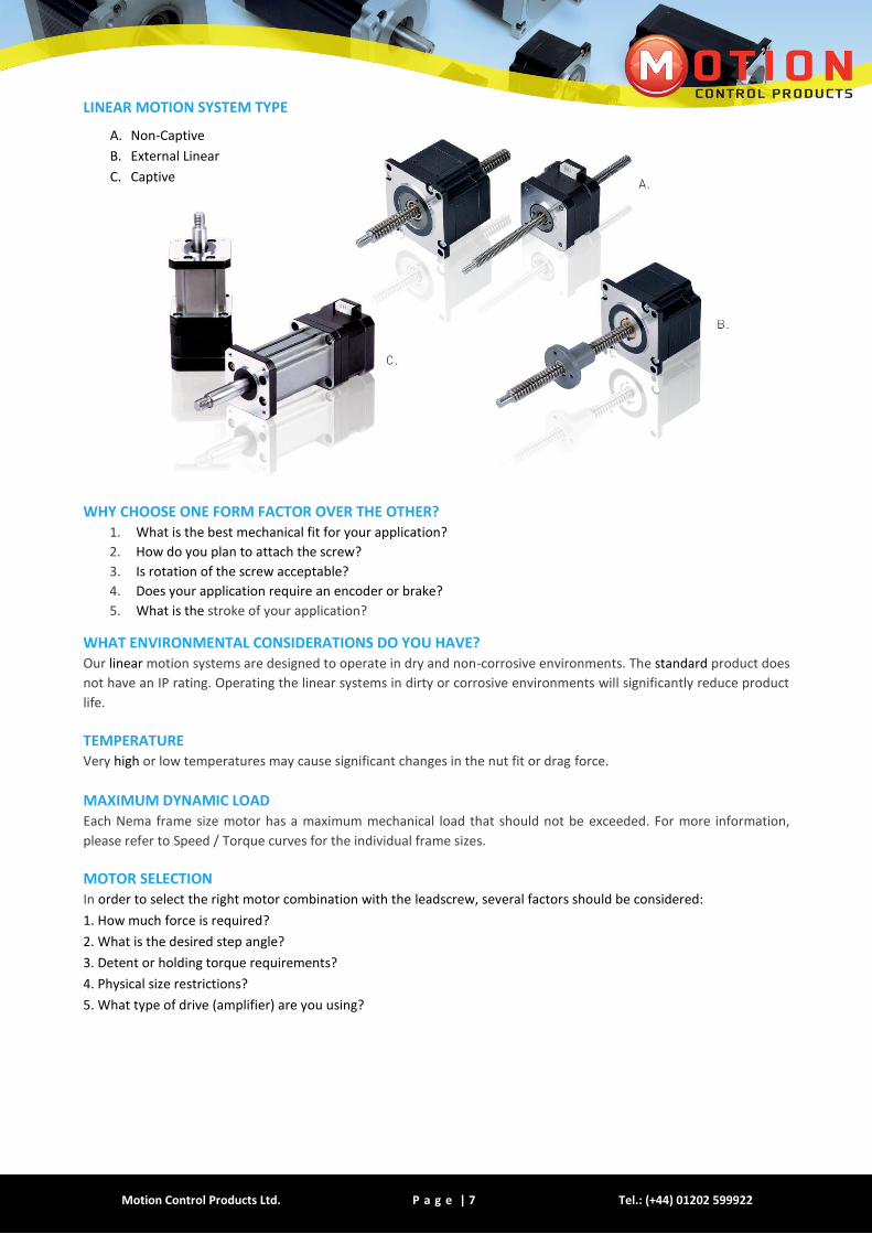
LINEAR MOTION SYSTEM TYPE
WHY CHOOSE ONE FORM FACTOR OVER THE OTHER? 1. What is the best mechanical fit for your application?
2. How do you plan to attach the screw?
3. Is rotation of the screw acceptable?
4. Does your application require an encoder or brake?
5. What is the stroke of your application?
WHAT ENVIRONMENTAL CONSIDERATIONS DO YOU HAVE? Our linear motion systems are designed to operate in dry and non-corrosive environments. The standard product does
not have an IP rating. Operating the linear systems in dirty or corrosive environments will significantly reduce product
life.
TEMPERATURE Very high or low temperatures may cause significant changes in the nut fit or drag force.
MAXIMUM DYNAMIC LOAD Each Nema frame size motor has a maximum mechanical load that should not be exceeded. For more information,
please refer to Speed / Torque curves for the individual frame sizes.
MOTOR SELECTION In order to select the right motor combination with the leadscrew, several factors should be considered:
1. How much force is required?
2. What is the desired step angle?
3. Detent or holding torque requirements?
4. Physical size restrictions?
5. What type of drive (amplifier) are you using?
A. Non-Captive
B. External Linear
C. Captive

Motion Control Products Ltd. P a g e | 8 www.motioncontrolproducts.com
Basic Specifications For Linear Systems
LEAD SCREW MATERIAL Unless otherwise noted, all reference to leadscrews in this catalogue has the following characteristics:
Leadscrew material: 303 Stainless precision cold rolled steel Screw Coating: Teflon coating is optional
Our lead screws are manufactured by a precision rolling process in USA Standard screw accuracy: 0.0006 in / inch (Lead accuracy) Screw repeatability: ±0.006 inch System repeatability: Nominally the same as screw repeatability, motor variance adds ±6 micro steps. (Motor and Screw) Screw straightness: 0.003 in /foot, measured as Total Indicated Runout (TIR).
All screws are carefully checked for straightness before shipment. Screw Efficiency: From 35% to 85% dependent on lead. It also depends on the usage of an anti-backlash nut with screw.
The larger the lead, the higher the efficiency of the screw. Operating temperature: -10 °C to +50 °C (14°F to 122°F)
Screw backlash: Depends on lead (nominally ±0.005 in) System backlash: Includes screw, motor, and attached mechanics. This will be the sum of all the backlash in your motion
axis.
Nut Material: Polyacetal with a lubricating additive. Standard is a free-wheeling nut. [Anti-backlash version is available]
Wear life of screw and nut: Depends on load, speed, duty cycle and environmental factors [typically > 5 million cycles] Note: Motion Control Products linear systems are manufactured from high quality materials. Due to the variable effects of
friction, lubrication and cleanliness, an exact life cannot be predicted for a given application.

Motion Control Products Ltd. P a g e | 9 Tel.: (+44) 01202 599922
PRODUCT SELECTION
There are many inter-related variables to consider when selecting the right linear motion system for your application. Your
load and speed requirements will determine other variables such as the size of motor, the lead of the screw and ultimately
the voltage and current requirements of your electronic motor drive. Depending on your application, trade-offs can be made
with many variables as your finalise the system that will meet your performance, form factor and cost specifications.
Quantify these basic variables first:
1. Load that you need to move (or push – thrust)
2. Velocity
3. Distance to travel (stroke)
4. Time required to move from point A to point B (acceleration required)
5. Torque requirements of your entire system
6. How much backlash is acceptable in your system?
7. What is the required positional repeatability?
8. Is this a vertical or horizontal orientation?
To reduce complexity and cost of a design, it is important to accurately size a motor/lead screw combination. Below are a few
simple steps in selecting the necessary components for a given application.
Step 1 – Choose a motor NEMA size (Force requirements) Here is a general overview of the output thrust vs. NEMA size:
NEMA Sizes Max Thrust Recommended Loan Limit
NEMA 8 78N
(17.5lbs) 43N
(9.7lbs)
NEMA 11 230N
(51lbs) 150N
(34lbs)
NEMA 14 450N
(100lbs) 230N
(52lbs)
NEMA 17 710N
(160lbs) 230N
(52lbs)
NEMA 23 1400N
(315lbs) 920N
(210lbs)
NEMA 3 2400N
(540lbs) 2160N
(485lbs)
As the NEMA size of the motor is increased, the output thrust of the actuator is consequently increased.

Motion Control Products Ltd. P a g e | 10 www.motioncontrolproducts.com
Step 2 – Choose a screw lead (Force and speed requirements) After estimating the required thrust and choosing a NEMA size that may fit your application, the speed and acceleration of the load must be considered and evaluated to choose an appropriate screw lead. Due to the nature of lead screws, the output speed and output thrust achievable by a motor/lead screw combination are two inversely proportional variables (i.e., increasing the required thrust will lower the achievable speed of a motor /lead screw combination). Therefore, the maximum output force of a system is lowered for applications that require higher speeds. For complete motor/lead screw selection data, please refer to the speed/thrust curves for each NEMA size.
Although these two steps provide a solid foundation in motor/lead screw selection, other variables must also be considered:
Duty cycle
Desired life of a System
Environmental considerations
Positional repeatability
Acceptable backlash
Acceleration/deceleration requirements
Driver specifications
Vertical or horizontal orientation
Because of the numerous variables involved in motor selection, it is highly recommended for users to proceed with physical testing to accurately determine the motor/lead screw combination required for a given application. NOTE: Although this section aims to provide a rough guide to selectin g a motor/lead screw combination that best fits an
application, we recommend contacting our application engineering staff for further assistance with the motor selection process.
Using the PRODUCT SELECTION SYSTEM along with the following charts and linear motor sections, you can select
your specific part number.
Product Part Number Configuration
P 17 N 2 1 15 K 4 101.6 T M S EK2FI
① ② ③ ④ ⑤ ⑥ ⑦ ⑧ ⑨ ⑩ ⑪ ⑫ ⑬
① Drive Option:
Blank= Motor only, without drive option D = Motor with drive option only P = Motor with programmable controller and drive
② Motor Size (in NEMA Size):
NEMA Size 8 11 14 17 23 34
Motor Size (in mm)
20 28 35 42 57 86
③ Leadscrew Shaft Style
N = Non-Captive Linear
E = External Linear
C = Captive Linear
④ Motor Step Angle
2 = 2-Phase with 1.8 degree step angle
4 = 2-Phase with 0.9 degree step angle
3 = 3-Phase with 1.2 degree step angle
5 = 5-Phase with 0.72 degree step angle
⑤ Motor Length
Choice of single or double-stack motor: 1 = Single Stack 2 = Double Stack

Motion Control Products Ltd. P a g e | 11 Tel.: (+44) 01202 599922
(CONTINUTED)
P 17 N 2 1 15 K 4 101.6 T M S EK2FI
① ② ③ ④ ⑤ ⑥ ⑦ ⑧ ⑨ ⑩ ⑪ ⑫ ⑬
⑥ Rated Current/Phase
XX = X.X (A)/Phase
⑦ Motor Leadscrew Code A-Z, AA-AF
⑧ Number Of Lead Wires
4 = Qty 4 Flying Leads
6 = Qty 6 Flying Leads
8 = Qty 8 Flying Leads
Notes: Nema 8 to Nema 17 motors have JST connector option. Nema 23 and Nema 34 motors have flying leads as only option.
⑨ Lead Screw Length/Stroke
XXX = XXX mm Lead Length
(For External Linear/Non-Captive Linear)
XXX = X.XX inch Stroke
(For Captive Linear)
⑩Leadscrew Surface
T = Teflon Coating
S = Standard (No Teflon Coating)
⑪ End Machining
M = Metric
U = UNC
S = Smooth
N = None
⑫ Nut Style
S = Standard Flange Nut
A = Anti-Backlash Nut
⑬ Encoder Option
EKXX = Encoder (XX = Encoder Code)
ERX = Encoder Ready (X = Encoder Version)
N = No Encoder nor Encoder Ready
Customised leadscrew and motor specifications might be available upon request, but minimum order quantity will apply. Please contact MCP sales team for more details on 44 (0)1202 599922 or [email protected]
*******************************************
EXAMPLE
Part Number P17N2115K4-101.6TMSEK2FI Description Programmable Controller and Drive NEMA 17 Non-Captive Linear Actuator 2 Phase with 1.8 Degree Step Angle Single Stack 1.5 A/Phase “K” Lead (0.1”/2.54 mm) 4 Flying Leads Screw Length: 101.6 mm Teflon Coated Screw Metric End Machining Standard Nut EK2 Encoder with Differential Output, 500 Lines, with Index

Motion Control Products Ltd. P a g e | 12 www.motioncontrolproducts.com
Encoder Options
EK1 ENCODER SINGLE ENDED OUTPUT EK1 ENCODER DIFFERENTIAL OUTPUT
EK2 ENCODER SINGLE ENDED OUTPUT EK2 ENCODER DIFFERENTIAL OUTPUT
Encoder Types
EK1 Line Count 100 108 120 125 128 200 250 256 300 360
Single Ended 0 1 2 3 4 5 6 7 8 9
Differential A B C D E F G H I J
EK2
Line Count 100 200 250 256 400 500 512 1000 1024
Single Ended 0 1 2 3 4 5 6 7 8
Differential A B C D E F G H I
Custom Encoder or Custom Line Count:
For Encoder Ready Motors: For EK2 with Index: Add “I” as a suffix. For Example, for EK2, 512 line count, with Differential, and Index: “EK2GI”
EC
ER1/ER2 FOR COMPLETE
ENCODER SPECIFICATIONS,
PLEASE CONTACT OUR
SALES ENGINEERS
Motion Control Products Ltd. P a g e | 13 Tel.: (+44) 01202 599922
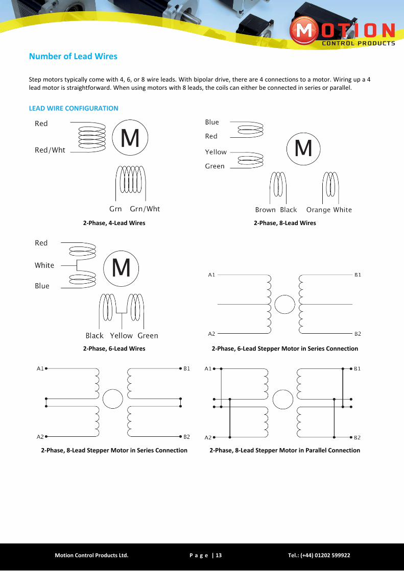
Number of Lead Wires
Step motors typically come with 4, 6, or 8 wire leads. With bipolar drive, there are 4 connections to a motor. Wiring up a 4 lead motor is straightforward. When using motors with 8 leads, the coils can either be connected in series or parallel.
LEAD WIRE CONFIGURATION
2-Phase, 4-Lead Wires 2-Phase, 8-Lead Wires
2-Phase, 6-Lead Wires 2-Phase, 6-Lead Stepper Motor in Series Connection
2-Phase, 8-Lead Stepper Motor in Series Connection 2-Phase, 8-Lead Stepper Motor in Parallel Connection
Motion Control Products Ltd. P a g e | 14 www.motioncontrolproducts.com
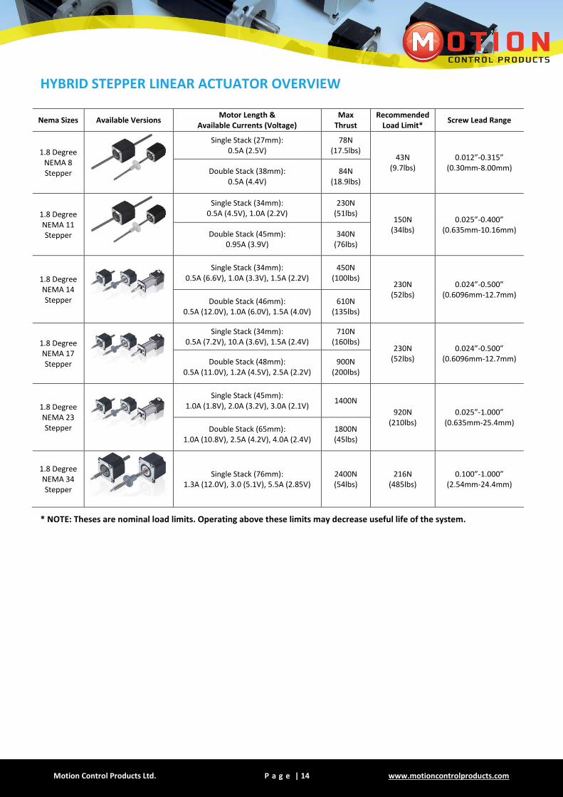
HYBRID STEPPER LINEAR ACTUATOR OVERVIEW
* NOTE: Theses are nominal load limits. Operating above these limits may decrease useful life of the system.
Nema Sizes Available Versions Motor Length &
Available Currents (Voltage) Max
Thrust Recommended
Load Limit* Screw Lead Range
1.8 Degree NEMA 8 Stepper
Single Stack (27mm): 0.5A (2.5V)
78N (17.5lbs)
43N (9.7lbs)
0.012”-0.315” (0.30mm-8.00mm) Double Stack (38mm):
0.5A (4.4V) 84N
(18.9lbs)
1.8 Degree NEMA 11 Stepper
Single Stack (34mm): 0.5A (4.5V), 1.0A (2.2V)
230N (51lbs)
150N (34lbs)
0.025”-0.400” (0.635mm-10.16mm) Double Stack (45mm):
0.95A (3.9V) 340N
(76lbs)
1.8 Degree NEMA 14 Stepper
Single Stack (34mm): 0.5A (6.6V), 1.0A (3.3V), 1.5A (2.2V)
450N (100lbs)
230N (52lbs)
0.024”-0.500” (0.6096mm-12.7mm)
Double Stack (46mm): 0.5A (12.0V), 1.0A (6.0V), 1.5A (4.0V)
610N (135lbs)
1.8 Degree NEMA 17 Stepper
Single Stack (34mm): 0.5A (7.2V), 10.A (3.6V), 1.5A (2.4V)
710N (160lbs)
230N (52lbs)
0.024”-0.500” (0.6096mm-12.7mm) Double Stack (48mm):
0.5A (11.0V), 1.2A (4.5V), 2.5A (2.2V) 900N
(200lbs)
1.8 Degree NEMA 23 Stepper
Single Stack (45mm): 1.0A (1.8V), 2.0A (3.2V), 3.0A (2.1V)
1400N
920N (210lbs)
0.025”-1.000” (0.635mm-25.4mm)
Double Stack (65mm): 1.0A (10.8V), 2.5A (4.2V), 4.0A (2.4V)
1800N (45lbs)
1.8 Degree NEMA 34 Stepper
Single Stack (76mm): 1.3A (12.0V), 3.0 (5.1V), 5.5A (2.85V)
2400N (54lbs)
216N (485lbs)
0.100”-1.000” (2.54mm-24.4mm)
Motion Control Products Ltd. P a g e | 15 Tel.: (+44) 01202 599922
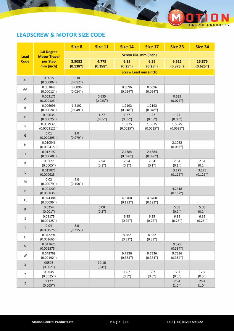
LEADSCREW & MOTOR SIZE CODE
Lead Code
1.8 Degree Motor Travel
per Step mm (inch)
Size 8 Size 11 Size 14 Size 17 Size 23 Size 34
Screw Dia. mm (inch)
3.5052 (0.138’’)
4.775 (0.188’’)
6.35 (0.25’’)
6.35 (0.25’’)
9.525 (0.375’’)
15.875 (0.625’’)
Screw Lead mm (inch)
AF 0.0015
(0.00006’’) 0.30
(0.012’’)
AA 0.003048
(0.00012’’) 0.6096
(0.024’’)
0.6096 (0.024’’)
0.6096 (0.024’’)
A 0.003175
(0.000125’’)
0.635 (0.025’’)
0.635
(0.025’’)
B 0.006096
(0.00024’’) 1.2192
(0.048’’)
1.2192 (0.048’’)
1.2192 (0.048’’)
D 0.00635
(0.00025’’)
1.27 (0.05’’)
1.27 (0.05’’)
1.27 (0.05’’)
1.27 (0.05’’)
F 0.0079375
(0.0003125’’)
1.5875 (0.0625’’)
1.5875 (0.0625’’)
1.5875 (0.0625’’)
G 0.01
(0.000395’’) 2.0
(0.079’’)
H 0.010541
(0.000415’’)
2.1082 (0.083’’)
J 0.012192
(0.00048’’)
2.4384 (0.096’’)
2.4384 (0.096’’)
K 0.0127
(0.0005’’)
2.54 (0.1’’)
2.54 (0.1’’)
2.54 (0.1’’)
2.54 (0.1’’)
2.54 (0.1’’)
L 0.015875
(0.000625’’)
3.175 (0.125’’)
3.175 (0.125’’)
M 0.02
(0.00079’’) 4.0
(0.158’’)
P 0.021209
(0.000835’’)
4.2418 (0.167’’)
Q 0.024384
(0.00096’’)
4.8768 (0.192’’)
4.8768 (0.192’’)
R 0.0254
(0.001’’)
5.08 (0.2’’)
5.08
(0.2’’) 5.08
(0.2’’)
S 0.03175
(0.00125’’)
6.35 (0.25’’)
6.35 (0.25’’)
6.35 (0.25’’)
6.35 (0.25’’)
T 0.04
(0.001575’’) 8.0
(0.315’’)
U 0.042291
(0.001665’’)
8.382 (0.33’’)
8.382 (0.33’’)
V 0.047625
(0.001875’’)
9.525 (0.384’’)
W 0.048768
(0.00192’’)
9.7536 (0.384’’)
9.7536 (0.384’’)
9.7536 (0.384’’)
X 00508
(0.002’’)
10.16 (0.4’’)
Y 0.0635
(0.0025’’)
12.7 (0.5’’)
12.7 (0.5’’)
12.7 (0.5’’)
12.7 (0.5’’)
Z 0.127
(0.005’’)
25.4 (1.0’’)
25.4 (1.0’’)

Motion Control Products Ltd. P a g e | 16 www.motioncontrolproducts.com
NEMA SIZE 8 (20mm)
Hybrid Stepper Motor Linear Actuator
Our smallest hybrid linear actuator can be integrated into various applications to provide precise linear positioning while occupying less than 1 in 2 of mounting footprint and providing up to 44.5N (10lbsF) of continuous thrust. Ball screw versions are also available.
Please contact our sales team for your customised specifications
Motor Specifications
Motor Voltage
(V) Current
(A) Resistance
(Ω) Inductance
(mH) Lead
Wire No. Motor Length
(mm)
8-2105 2.5 0.5 5.0 1.2 4 27
8-2205 4.4 0.5 8.8 2.7 4 38
For example: 8-2105: 8 = Nema 8 motor, 2105 = 2-phase, 1.8˚; single stack motor; 05 = 0.5 A
Available Leadscrews And Travel Per Step
Screw Dia. (inch) Screw Dia.
(mm) Lead (inch)
Lead (mm)
Lead Code
Travel Per Step @ 1.8 deg (mm)*
0.138 0.5052 0.012 0.30 AF 0.0015
0.138 0.5052 0.024 0.6096 AA 0.003
0.138 0.5052 0.048 1.2192 B 0.0061
0.138 0.5052 0.079 2.0 G 0.01
0.138 0.5052 0.158 4.0 M 0.02
0.138 0.5052 0.315 8.0 T 0.04
* values truncated
Motion Control Products Ltd. P a g e | 17 Tel.: (+44) 01202 599922
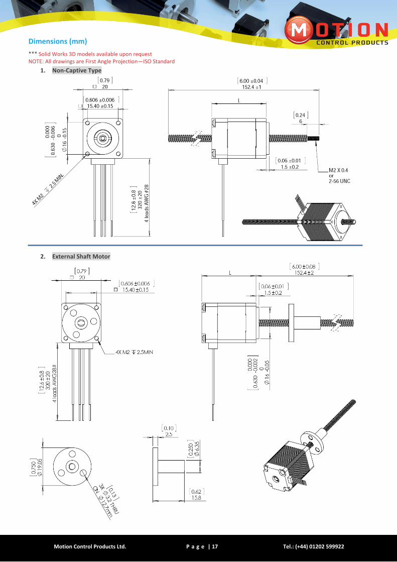
Dimensions (mm)
*** Solid Works 3D models available upon request NOTE: All drawings are First Angle Projection—ISO Standard
1. Non-Captive Type
2. External Shaft Motor
Motion Control Products Ltd. P a g e | 18 www.motioncontrolproducts.com
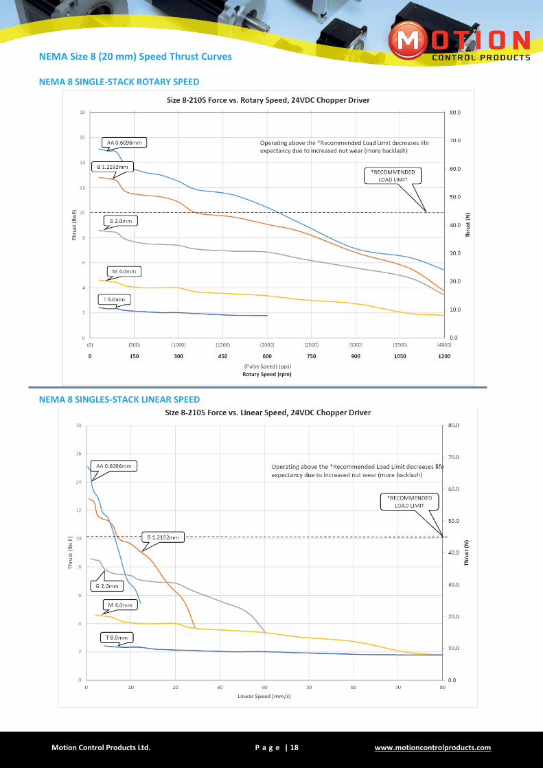
NEMA Size 8 (20 mm) Speed Thrust Curves
NEMA 8 SINGLE-STACK ROTARY SPEED
NEMA 8 SINGLES-STACK LINEAR SPEED

Motion Control Products Ltd. P a g e | 19 Tel.: (+44) 01202 599922
NEMA 8 DOUBLE-STACK ROTARY SPEED
NEMA 8 DOUBLE-STACK LINEAR SPEED
Motion Control Products Ltd. P a g e | 20 www.motioncontrolproducts.com
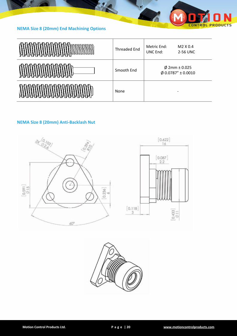
NEMA Size 8 (20mm) End Machining Options
Threaded End Metric End: M2 X 0.4 UNC End: 2-56 UNC
Smooth End Ø 2mm ± 0.025
Ø 0.0787” ± 0.0010
None -
NEMA Size 8 (20mm) Anti-Backlash Nut
Motion Control Products Ltd. P a g e | 21 Tel.: (+44) 01202 599922
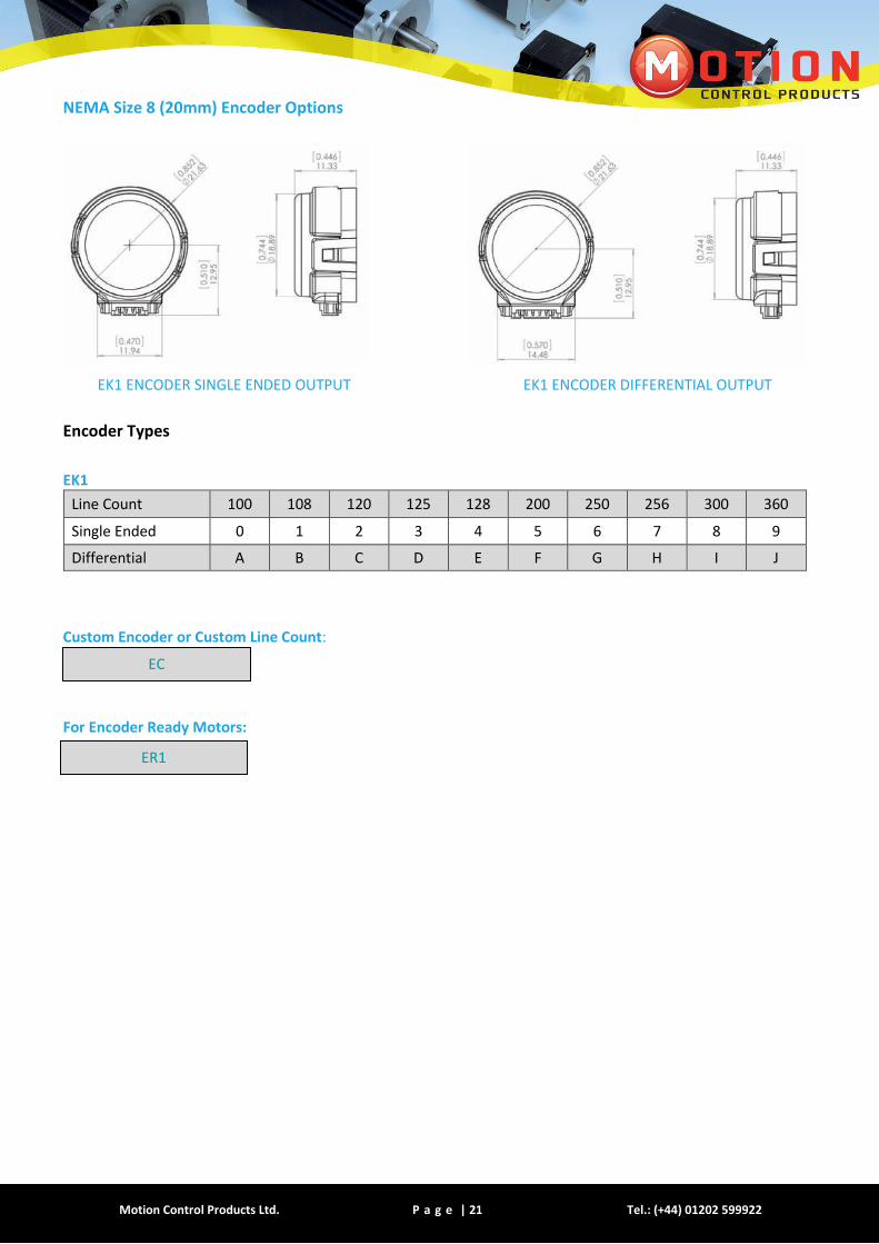
NEMA Size 8 (20mm) Encoder Options
EK1 ENCODER SINGLE ENDED OUTPUT EK1 ENCODER DIFFERENTIAL OUTPUT
Encoder Types
EK1
Line Count 100 108 120 125 128 200 250 256 300 360
Single Ended 0 1 2 3 4 5 6 7 8 9
Differential A B C D E F G H I J
Custom Encoder or Custom Line Count:
For Encoder Ready Motors:
EC
ER1

Motion Control Products Ltd. P a g e | 22 www.motioncontrolproducts.com
SIZE 11 (28mm)
Hybrid Stepper Motor Linear Actuator
The NEMA 11 hybrid linear actuator occupies a mounting footprint of slightly above 1 in 2 but provides over 3 times the continuous thrust 150N (33lbsF) than the NEMA 8. Ball screw versions are also available.
Motor Specifications
Motor Voltage (V)
Current (A)
Resistance (Ω)
Inductance (mH)
Lead Wire No.
Motor Length (mm)
11-2105 4.5 0.5 9.1 6.0 4 34
11-2110 2.2 1.0 2.2 1.5 4 34
11-2209 3.9 0.95 4.1 4.0 4 45
For example: 11-2105: 11 = Nema 11 motor, 2105 = 2-phase, 1.8˚; single stack motor; 05 = 0.5 A
Available LeadScrews And Travel Per Step
Screw Dia. (inch)
Screw Dia. (mm)
Lead (inch)
Lead (mm)
Lead Code
Travel Per Step @ 1.8 deg (mm)*
0.188 4.7752 0.025 0.635 A 0.0032
0.188 4.7752 0.05 1.27 D 0.0063
0.188 4.7752 0.1 2.54 K 0.0127
0.188 4.7752 0.2 5.08 R 0.0254
0.188 4.7752 0.4 10.16 X 0.0508
* values truncated

Motion Control Products Ltd. P a g e | 23 Tel.: (+44) 01202 599922
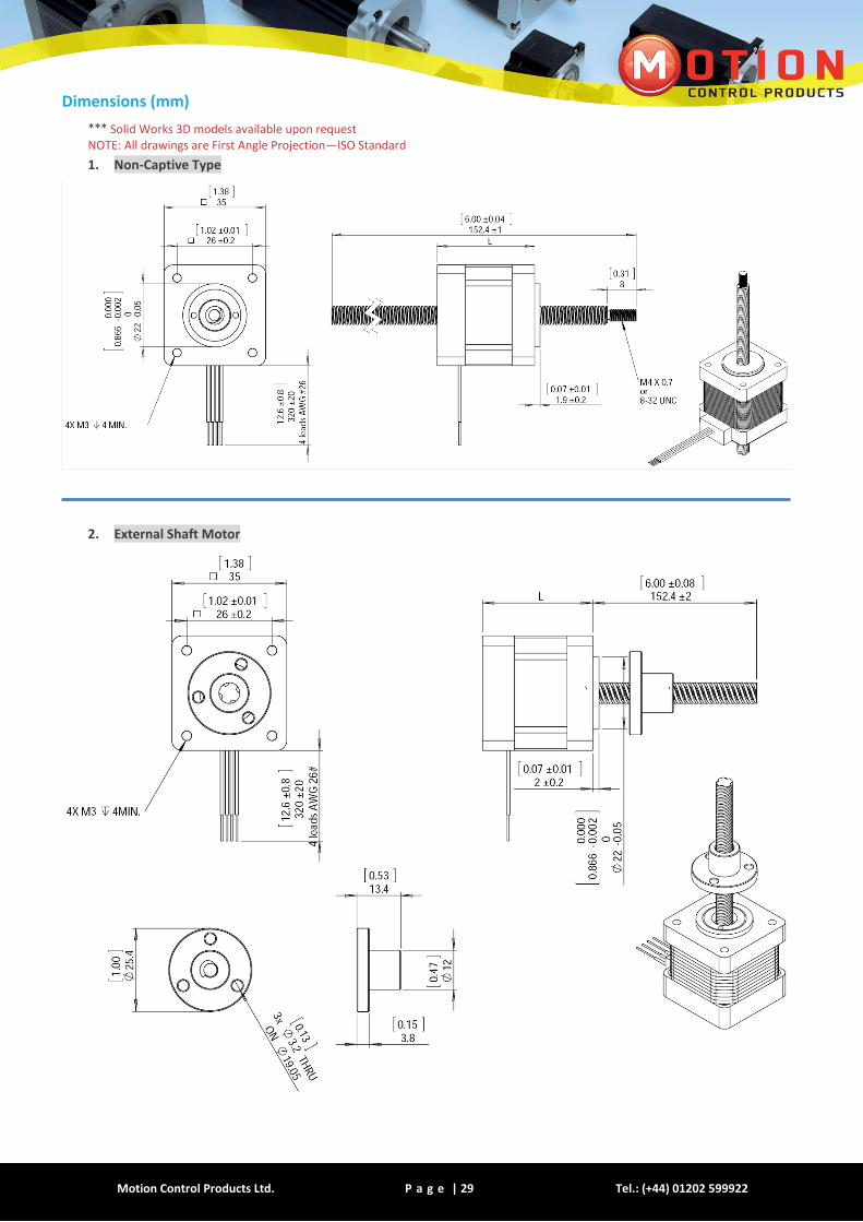
Dimensions (mm)
*** Solid Works 3D models available upon request NOTE: All drawings are First Angle Projection—ISO Standard
1. Non-Captive Type
2. External Shaft Motor
Motion Control Products Ltd. P a g e | 24 www.motioncontrolproducts.com
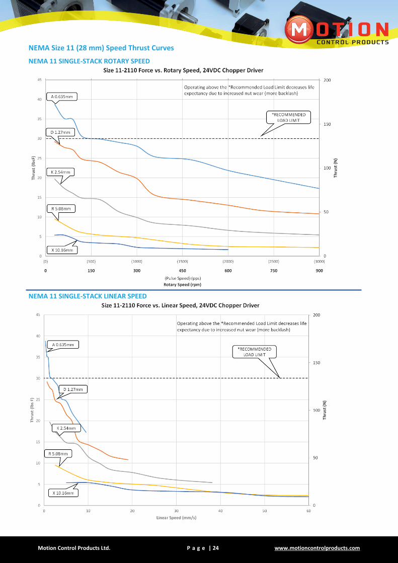
NEMA Size 11 (28 mm) Speed Thrust Curves
NEMA 11 SINGLE-STACK ROTARY SPEED
NEMA 11 SINGLE-STACK LINEAR SPEED
Motion Control Products Ltd. P a g e | 25 Tel.: (+44) 01202 599922
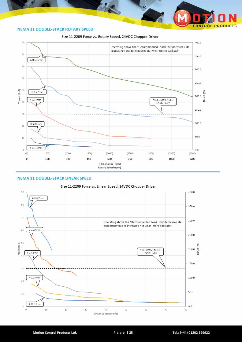
NEMA 11 DOUBLE-STACK ROTARY SPEED
NEMA 11 DOUBLE-STACK LINEAR SPEED
Motion Control Products Ltd. P a g e | 26 www.motioncontrolproducts.com
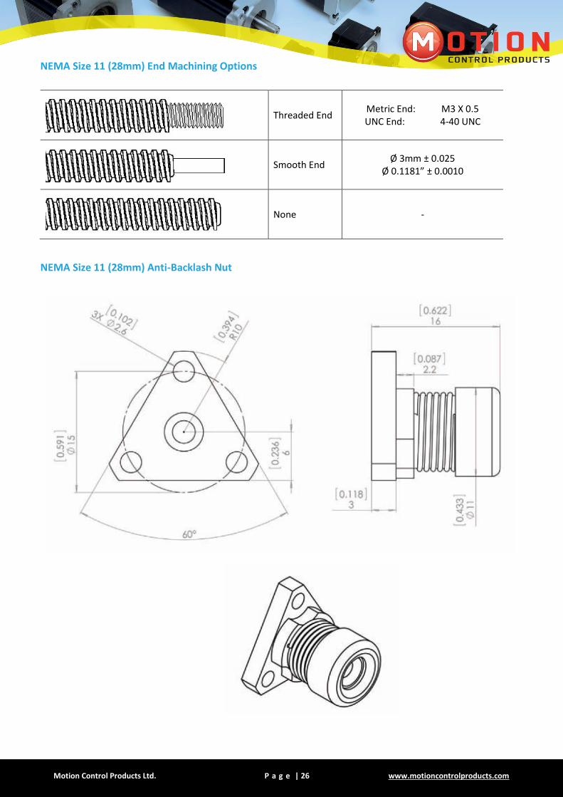
NEMA Size 11 (28mm) End Machining Options
Threaded End Metric End: M3 X 0.5 UNC End: 4-40 UNC
Smooth End Ø 3mm ± 0.025
Ø 0.1181” ± 0.0010
None -
NEMA Size 11 (28mm) Anti-Backlash Nut

Motion Control Products Ltd. P a g e | 27 Tel.: (+44) 01202 599922
NEMA Size 11 (28mm) Encoder Options
EK1 ENCODER SINGLE ENDED OUTPUT EK1 ENCODER DIFFERENTIAL OUTPUT
EK2 ENCODER SINGLE ENDED OUTPUT EK2 ENCODER DIFFERENTIAL OUTPUT
Encoder Types
EK1
Line Count 100 108 120 125 128 200 250 256 300 360
Single Ended 0 1 2 3 4 5 6 7 8 9
Differential A B C D E F G H I J
EK2
Line Count 100 200 250 256 400 500 512 1000 1024
Single Ended 0 1 2 3 4 5 6 7 8
Differential A B C D E F G H I
Custom Encoder or Custom Line Count:
For Encoder Ready Motors: For EK2 with Index: Add “I” as a suffix. For Example, for EK2, 512 line count, with Differential, and Index: “EK2GI”
EC
ER1
FOR COMPLETE ENCODER
SPECIFICATIONS, PLEASE
CONTACT OUR SALES ENGINEERS

Motion Control Products Ltd. P a g e | 28 www.motioncontrolproducts.com
SIZE 14 (35mm)
Hybrid Stepper Motor Linear Actuator
The NEMA 14 hybrid precision linear actuator provides up to 230N (52 lbs-force) of continuous thrust. A Captive version is available in this frame size. Ball screw versions are also available.
Motor Specifications
Motor Type
Voltage (V)
Current (A)
Resistance (Ω)
Inductance (mH)
Lead Wire No.
Motor Length (mm)
14-2105 6.6 0.5 13.2 14.0 4 34
14-2110 3.3 1.0 3.3 3.6 4 34
14-2115 2.2 1.5 1.5 1.6 4 34
14-2205 12.0 0.5 24.0 29.0 4 46
14-2210 6.0 1.0 6.0 7.2 4 46
14-2215 4.0 1.5 2.7 1.8 4 46
For example: 14-2105: 14 = Nema 14 motor, 2105 = 2-phase, 1.8˚; single stack motor; 05 = 0.5 A
Available Leadscrews And Travel Per Step
Screw Dia. (inch)
Screw Dia. (mm)
Lead (inch)
Lead [mm]
Lead Code
Travel Per Step (mm*)
Travel Per Step @ 0.9 deg (mm)*
0.25 6.35 0.024 0.6096 AA 0.003 0.0015
0.25 6.35 0.048 1.2192 B 0.006 0.003
0.25 6.35 0.05 1.27 D 0.006 0.0032
0.25 6.35 0.0625 1.5875 F 0.0079375 0.0039688
0.25 6.35 0.096 2.4384 J 0.012 0.0061
0.25 6.35 0.1 2.54 K 0.012 0.0064
0.25 6.35 0.192 4.8768 Q 0.024 0.0122
0.25 6.35 0.25 6.35 S 0.031 0.0159
0.25 6.35 0.33 8.382 U 0.041 0.021
0.25 6.35 0.384 9.7536 W 0.048 0.0244
0.25 6.35 0.5 12.7 Y 0.0635 0.03175
* values truncated
** Please contact us for any customised products
Motion Control Products Ltd. P a g e | 29 Tel.: (+44) 01202 599922
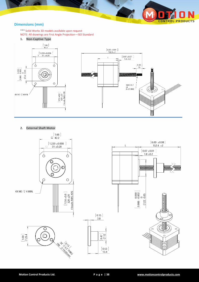
Dimensions (mm)
*** Solid Works 3D models available upon request NOTE: All drawings are First Angle Projection—ISO Standard
1. Non-Captive Type
2. External Shaft Motor

Motion Control Products Ltd. P a g e | 30 www.motioncontrolproducts.com
3. Captive Type
Stroke B inch (mm)
Dimension A (mm)
Dimension L (mm)
0.5 (12.7) 36.7
Single stack motor 35mm
Double stack motor 49mm
0.75 (19.05) 43.05
1.0 (25.4) 49.4
1.25 (31.8) 55.8
1.5 (38.1) 62.1
2 (50.8) 74.8
2.5 (63.5) 87.5
Motion Control Products Ltd. P a g e | 31 Tel.: (+44) 01202 599922
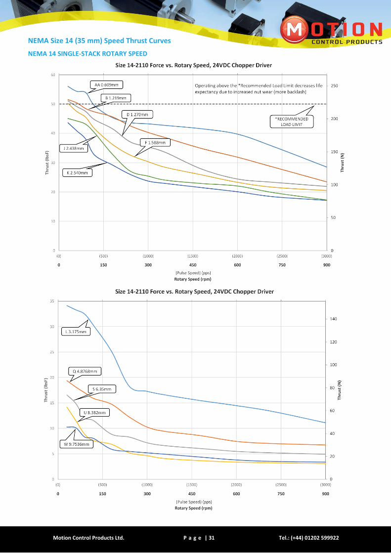
NEMA Size 14 (35 mm) Speed Thrust Curves
NEMA 14 SINGLE-STACK ROTARY SPEED

Motion Control Products Ltd. P a g e | 32 www.motioncontrolproducts.com
NEMA 14 SINGLE-STACK LINEAR SPEED

Motion Control Products Ltd. P a g e | 33 Tel.: (+44) 01202 599922
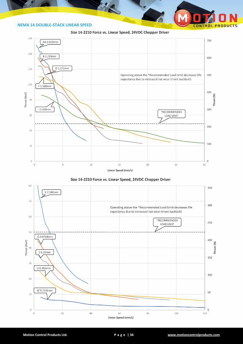
NEMA 14 DOUBLE-STACK ROTARY SPEED
Motion Control Products Ltd. P a g e | 34 www.motioncontrolproducts.com
NEMA 14 DOUBLE-STACK LINEAR SPEED
Motion Control Products Ltd. P a g e | 35 Tel.: (+44) 01202 599922
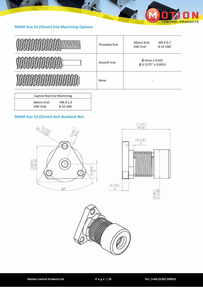
NEMA Size 14 (35mm) End Machining Options
Threaded End Metric End: M4 X 0.7 UNC End: 8-32 UNC
Smooth End Ø 4mm ± 0.025
Ø 0.1575” ± 0.0010
None -
Captive Rod End Machining
Metric End: M6 X 1.0 UNC End: 8-32 UNC
NEMA Size 14 (35mm) Anti-Backlash Nut

Motion Control Products Ltd. P a g e | 36 www.motioncontrolproducts.com
NEMA Size 14 (35mm) Encoder Options
EK1 ENCODER SINGLE ENDED OUTPUT EK1 ENCODER DIFFERENTIAL OUTPUT
EK2 ENCODER SINGLE ENDED OUTPUT EK2 ENCODER DIFFERENTIAL OUTPUT
Encoder Types
EK1 Line Count 100 108 120 125 128 200 250 256 300 360
Single Ended 0 1 2 3 4 5 6 7 8 9
Differential A B C D E F G H I J
EK2
Line Count 100 200 250 256 400 500 512 1000 1024
Single Ended 0 1 2 3 4 5 6 7 8
Differential A B C D E F G H I
Custom Encoder or Custom Line Count:
For Encoder Ready Motors: For EK2 with Index: Add “I” as a suffix. For Example, for EK2, 512 line count, with Differential, and Index: “EK2GI”
EC
ER1/ER2 FOR COMPLETE
ENCODER SPECIFICATIONS,
PLEASE CONTACT OUR
SALES ENGINEERS

Motion Control Products Ltd. P a g e | 37 Tel.: (+44) 01202 599922
SIZE 17 (42mm)
Hybrid Stepper Motor Linear Actuator
The NEMA 17 hybrid precision linear actuator provides up to 266N (60lbs-force) of continuous thrust. A Captive version is available in this frame size. Ball screw versions are also available.
Motor Characteristics
Motor Voltage
(V) Current
(A) Resistance
(Ω) Inductance
(mH) Lead
Wire No. Motor Length
(mm)
17-2105 7.2 0.5 14.4 19.8 4 34
17-2110 3.6 1.0 3.6 5.0 4 34
17-2115 2.4 1.5 1.6 2.2 4 34
17-2205 11.0 0.5 22.0 46.0 4 48
17-2212 4.5 1.2 3.8 8.0 4 48
17-2225 2.2 2.5 0.87 1.8 4 48
For example: 17-2105: 17 = Nema 17 motor, 2105 = 2-phase, 1.8˚; single stack motor; 05 = 0.5 A
Available Leadscrews And Travel Per Step
Screw Dia. (inch)
Screw Dia. (mm)
Lead (inch)
Lead (mm)
Lead Code
Travel Per Step @ 1.8 deg (mm)
Travel Per Step @ 0.9 deg (mm)*
0.25 6.35 0.024 0.6096 AA 0.003 0.0015
0.25 6.35 0.048 1.2192 B 0.006 0.003
0.25 6.35 0.05 1.27 D 0.006 0.0032
0.25 6.35 0.0625 1.6002 F 0.0079375 0.0039688
0.25 6.35 0.096 2.4384 J 0.012 0.0061
0.25 6.35 0.1 2.54 K 0.012 0.0064
0.25 6.35 0.192 4.8768 Q 0.024 0.0122
0.25 6.35 0.25 6.35 S 0.031 0.0159
0.25 6.35 0.33 8.382 U 0.041 0.021
0.25 6.35 0.384 9.7536 W 0.048 0.0244
0.25 6.35 0.5 12.7 Y 0.0635 0.03175
* values truncated Note: Custom lead screw diameter is available for NEMA 17
0.375’’ Diameter shaft only available with external shaft version.
** Please contact us for any customised products
Motion Control Products Ltd. P a g e | 38 www.motioncontrolproducts.com
Dimensions (mm)
*** Solid Works 3D models available upon request NOTE: All drawings are First Angle Projection—ISO Standard
1. Non-Captive Type
2. External Shaft Motor
Motion Control Products Ltd. P a g e | 39 Tel.: (+44) 01202 599922
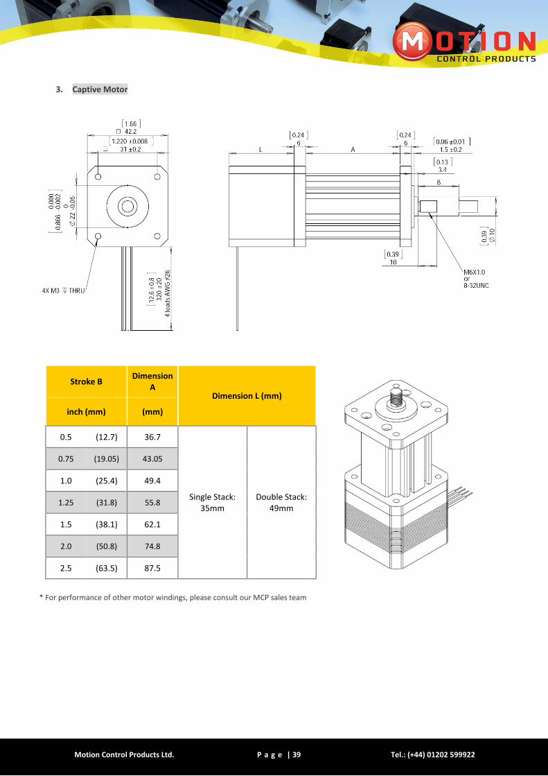
3. Captive Motor
Stroke B Dimension
A Dimension L (mm)
inch (mm) (mm)
0.5 (12.7) 36.7
Single Stack: 35mm
Double Stack: 49mm
0.75 (19.05) 43.05
1.0 (25.4) 49.4
1.25 (31.8) 55.8
1.5 (38.1) 62.1
2.0 (50.8) 74.8
2.5 (63.5) 87.5
* For performance of other motor windings, please consult our MCP sales team
Motion Control Products Ltd. P a g e | 40 www.motioncontrolproducts.com
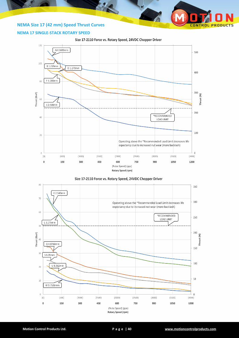
NEMA Size 17 (42 mm) Speed Thrust Curves
NEMA 17 SINGLE-STACK ROTARY SPEED

Motion Control Products Ltd. P a g e | 41 Tel.: (+44) 01202 599922
NEMA 17 SINGLE-STACK LINEAR SPEED

Motion Control Products Ltd. P a g e | 42 www.motioncontrolproducts.com
NEMA 17 DOUBLE-STACK ROTARY SPEED

Motion Control Products Ltd. P a g e | 43 Tel.: (+44) 01202 599922
NEMA 17 DOUBLE-STACK LINEAR SPEED

Motion Control Products Ltd. P a g e | 44 www.motioncontrolproducts.com
NEMA Size 17 (42mm) End Machining Options
Threaded End Metric End: M4 X 0.7 UNC End: 8-32 UNC
Smooth End Ø 4mm ± 0.025
Ø 0.1575” ± 0.0010
None -
Captive Rod End Machining
Metric End: M6 X 1.0 UNC End: 8-32 UNC
NEMA Size 17 (42mm) Anti-Backlash Nut
Motion Control Products Ltd. P a g e | 45 Tel.: (+44) 01202 599922
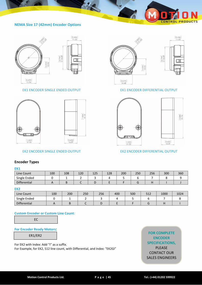
NEMA Size 17 (42mm) Encoder Options
EK1 ENCODER SINGLE ENDED OUTPUT EK1 ENCODER DIFFERENTIAL OUTPUT
EK2 ENCODER SINGLE ENDED OUTPUT EK2 ENCODER DIFFERENTIAL OUTPUT
Encoder Types
EK1 Line Count 100 108 120 125 128 200 250 256 300 360
Single Ended 0 1 2 3 4 5 6 7 8 9
Differential A B C D E F G H I J
EK2
Line Count 100 200 250 256 400 500 512 1000 1024
Single Ended 0 1 2 3 4 5 6 7 8
Differential A B C D E F G H I
Custom Encoder or Custom Line Count:
For Encoder Ready Motors: For EK2 with Index: Add “I” as a suffix. For Example, for EK2, 512 line count, with Differential, and Index: “EK2GI”
EC
ER1/ER2 FOR COMPLETE
ENCODER SPECIFICATIONS,
PLEASE CONTACT OUR
SALES ENGINEERS
Motion Control Products Ltd. P a g e | 46 www.motioncontrolproducts.com
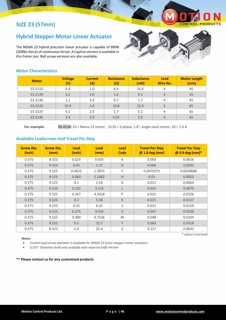
SIZE 23 (57mm)
Hybrid Stepper Motor Linear Actuator The NEMA 23 hybrid precision linear actuator is capable of 890N (200lbs-force) of continuous thrust. A Captive version is available in this frame size. Ball screw versions are also available.
Motor Characteristics
Motor Voltage
(V) Current
(A) Resistance
(Ω) Inductance
(mH) Lead
Wire No. Motor Length
(mm)
23-2110 6.4 1.0 6.4 16.4 4 45
23-2120 3.2 2.0 1.6 4.1 4 45
23-2130 2.1 3.0 0.7 1.7 4 45
23-2210 10.8 1.0 10.8 32.0 4 65
23-2225 4.2 2.5 1.7 5.2 4 65
23-2240 2.4 4.0 0.65 2.0 4 65
For example: 23-2110: 23 = Nema 23 motor; 2110 = 2-phase, 1.8˚; single stack motor; 10 = 1.0 A
Available Leadscrews And Travel Per Step
Screw Dia. (inch)
Screw Dia. (mm)
Lead (inch)
Lead (mm)
Lead Code
Travel Per Step @ 1.8 deg (mm)
Travel Per Step @ 0.9 deg (mm)*
0.375 9.525 0.025 0.635 A 0.003 0.0016
0.375 9.525 0.05 1.27 D 0.006 0.0032
0.375 9.525 0.0625 1.5875 F 0.0079375 0.0039688
0.375 9.525 0.083 2.1082 H 0.01 0.0053
0.375 9.525 0.1 2.54 K 0.012 0.0064
0.375 9.525 0.125 3.175 L 0.015 0.0079
0.375 9.525 0.167 4.2418 P 0.021 0.0106
0.375 9.525 0.2 5.08 R 0.025 0.0127
0.375 9.525 0.25 6.35 S 0.031 0.0159
0.375 9.525 0.375 9.525 V 0.047 0.0238
0.375 9.525 0.384 9.7536 W 0.048 0.0244
0.375 9.525 0.5 12.7 Y 0.063 0.0318
0.375 9.525 1.0 25.4 Z 0.127 0.0635
* values truncated
Notes:
Custom lead screw diameter is available for NEMA 23 linear stepper motor actuators
0.375’’ Diameter shaft only available with external shaft version
** Please contact us for any customised products
Motion Control Products Ltd. P a g e | 47 Tel.: (+44) 01202 599922
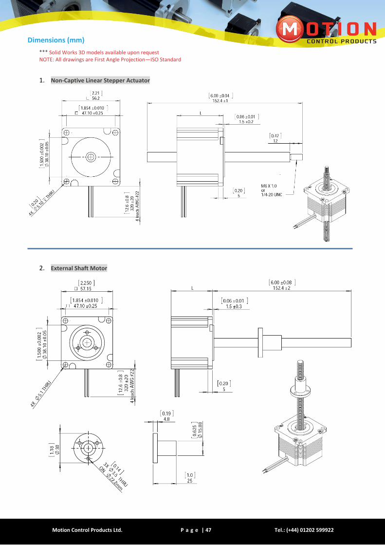
Dimensions (mm)
*** Solid Works 3D models available upon request NOTE: All drawings are First Angle Projection—ISO Standard
1. Non-Captive Linear Stepper Actuator
2. External Shaft Motor
Motion Control Products Ltd. P a g e | 48 www.motioncontrolproducts.com
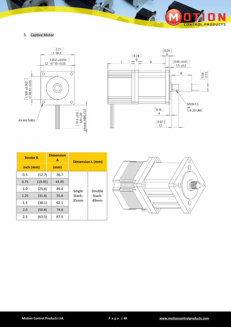
3. Captive Motor
Stroke B Dimension
A Dimension L (mm)
inch (mm) (mm)
0.5 (12.7) 36.7
Single Stack: 35mm
Double Stack: 49mm
0.75 (19.05) 43.05
1.0 (25.4) 49.4
1.25 (31.8) 55.8
1.5 (38.1) 62.1
2.0 (50.8) 74.8
2.5 (63.5) 87.5
Motion Control Products Ltd. P a g e | 49 Tel.: (+44) 01202 599922
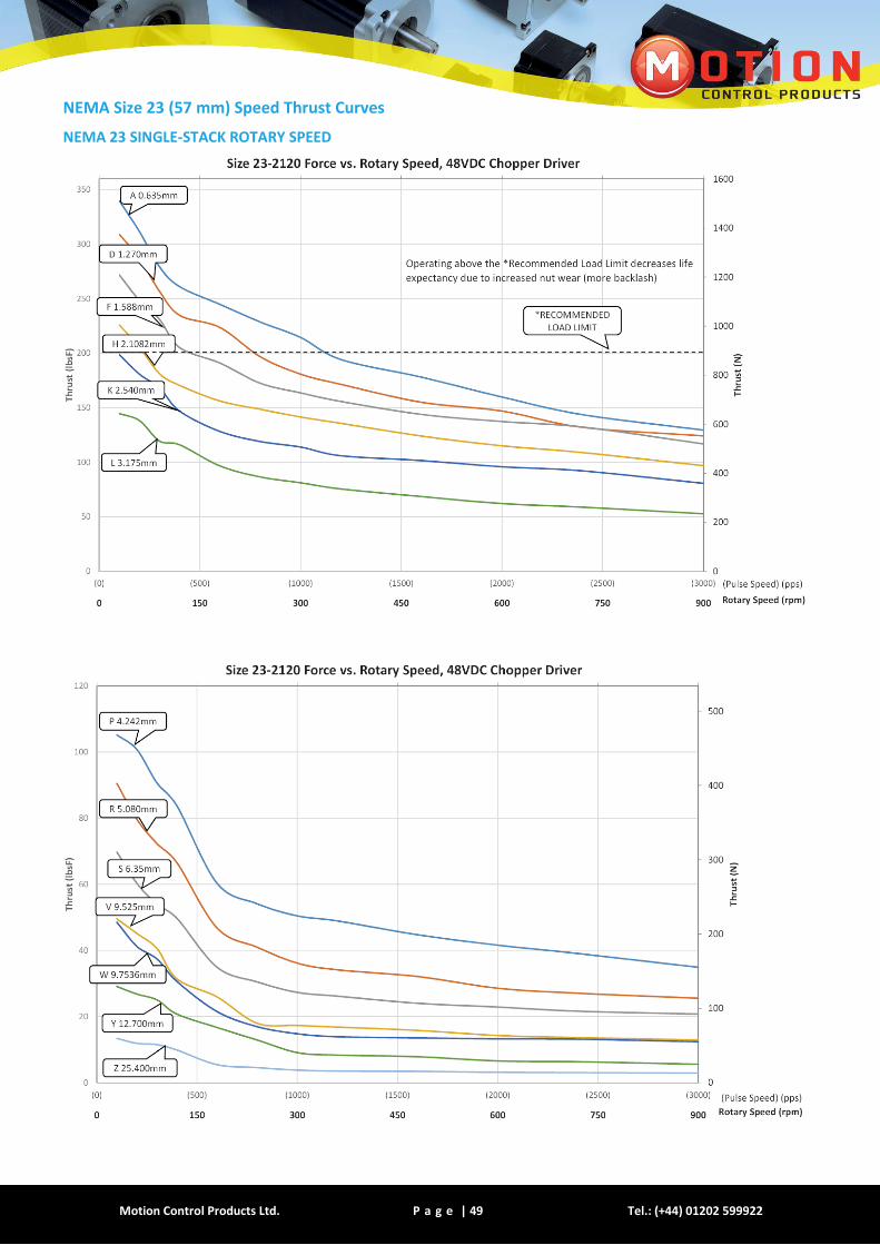
NEMA Size 23 (57 mm) Speed Thrust Curves
NEMA 23 SINGLE-STACK ROTARY SPEED
Motion Control Products Ltd. P a g e | 50 www.motioncontrolproducts.com
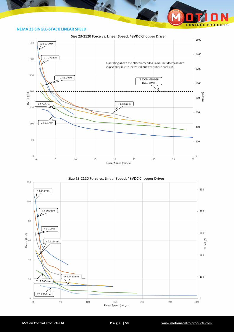
NEMA 23 SINGLE-STACK LINEAR SPEED
Motion Control Products Ltd. P a g e | 51 Tel.: (+44) 01202 599922
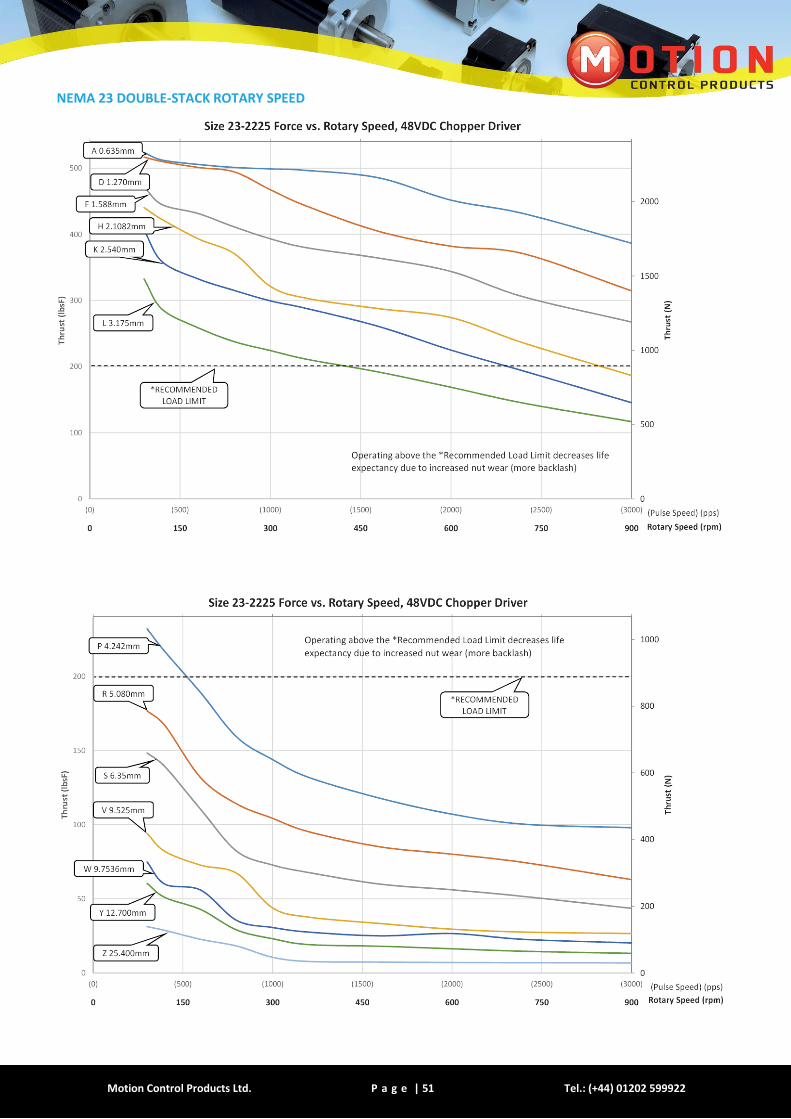
NEMA 23 DOUBLE-STACK ROTARY SPEED

Motion Control Products Ltd. P a g e | 52 www.motioncontrolproducts.com
NEMA 23 DOUBLE-STACK LINEAR SPEED
Motion Control Products Ltd. P a g e | 53 Tel.: (+44) 01202 599922
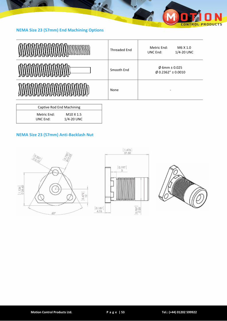
NEMA Size 23 (57mm) End Machining Options
Threaded End Metric End: M6 X 1.0
UNC End: 1/4-20 UNC
Smooth End Ø 6mm ± 0.025
Ø 0.2362” ± 0.0010
None -
Captive Rod End Machining
Metric End: M10 X 1.5 UNC End: 1/4-20 UNC
NEMA Size 23 (57mm) Anti-Backlash Nut

Motion Control Products Ltd. P a g e | 54 www.motioncontrolproducts.com
NEMA Size 23 (57mm) Encoder Options
EK2 ENCODER SINGLE ENDED OUTPUT EK2 ENCODER DIFFERENTIAL OUTPUT
Encoder Types
EK2
Line Count 100 200 250 256 400 500 512 1000 1024
Single Ended 0 1 2 3 4 5 6 7 8
Differential A B C D E F G H I
Custom Encoder or Custom Line Count:
For Encoder Ready Motors: For EK2 with Index: Add “I” as a suffix. For Example, for EK2, 512 line count, with Differential, and Index: “EK2GI”
EC
ER2 FOR COMPLETE
ENCODER SPECIFICATIONS,
PLEASE CONTACT OUR
SALES ENGINEERS
Motion Control Products Ltd. P a g e | 55 Tel.: (+44) 01202 599922
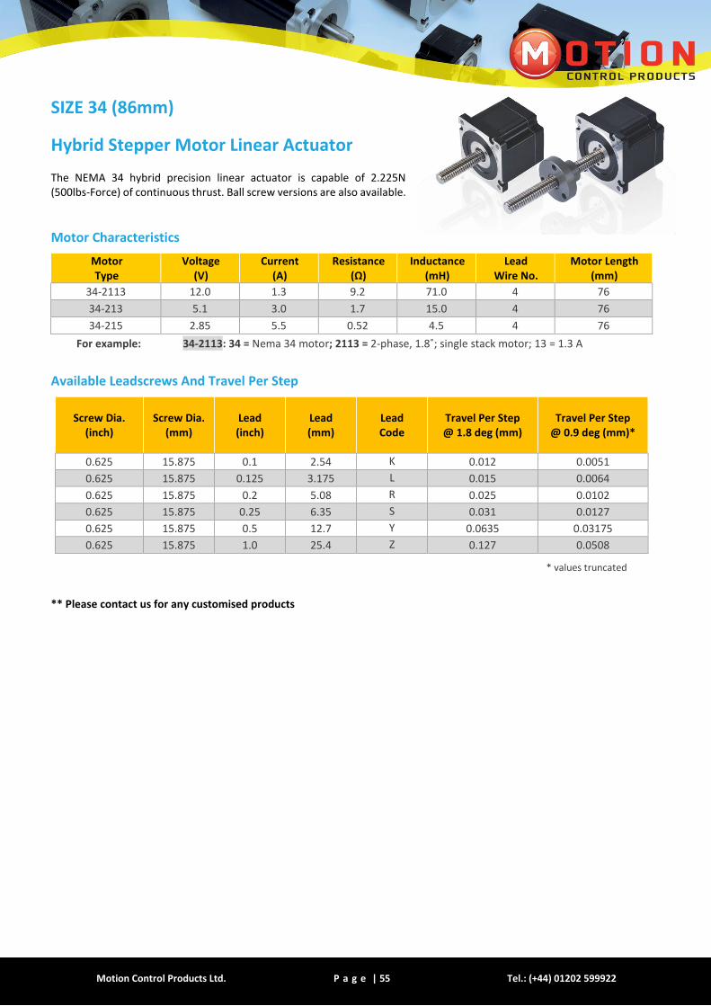
SIZE 34 (86mm)
Hybrid Stepper Motor Linear Actuator
The NEMA 34 hybrid precision linear actuator is capable of 2.225N (500lbs-Force) of continuous thrust. Ball screw versions are also available.
Motor Characteristics
Motor Type
Voltage (V)
Current (A)
Resistance (Ω)
Inductance (mH)
Lead Wire No.
Motor Length (mm)
34-2113 12.0 1.3 9.2 71.0 4 76
34-213 5.1 3.0 1.7 15.0 4 76
34-215 2.85 5.5 0.52 4.5 4 76
For example: 34-2113: 34 = Nema 34 motor; 2113 = 2-phase, 1.8˚; single stack motor; 13 = 1.3 A
Available Leadscrews And Travel Per Step
Screw Dia. (inch)
Screw Dia. (mm)
Lead (inch)
Lead (mm)
Lead Code
Travel Per Step @ 1.8 deg (mm)
Travel Per Step @ 0.9 deg (mm)*
0.625 15.875 0.1 2.54 K 0.012 0.0051
0.625 15.875 0.125 3.175 L 0.015 0.0064
0.625 15.875 0.2 5.08 R 0.025 0.0102
0.625 15.875 0.25 6.35 S 0.031 0.0127
0.625 15.875 0.5 12.7 Y 0.0635 0.03175
0.625 15.875 1.0 25.4 Z 0.127 0.0508
* values truncated
** Please contact us for any customised products

Motion Control Products Ltd. P a g e | 56 www.motioncontrolproducts.com
Dimensions (mm)
*** Solid Works 3D models available upon request NOTE: All drawings are First Angle Projection—ISO Standard
1. Non-Captive Type
2. External Motor
Motion Control Products Ltd. P a g e | 57 Tel.: (+44) 01202 599922
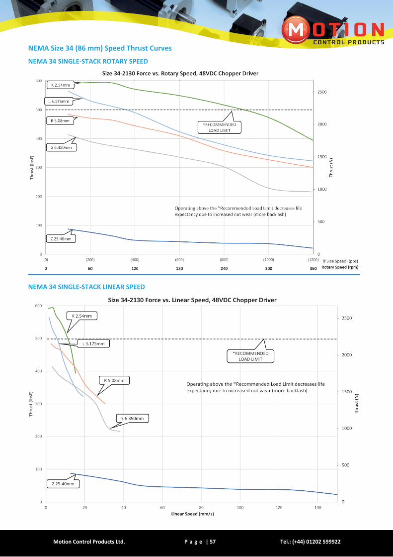
NEMA Size 34 (86 mm) Speed Thrust Curves
NEMA 34 SINGLE-STACK ROTARY SPEED
NEMA 34 SINGLE-STACK LINEAR SPEED
Motion Control Products Ltd. P a g e | 58 www.motioncontrolproducts.com
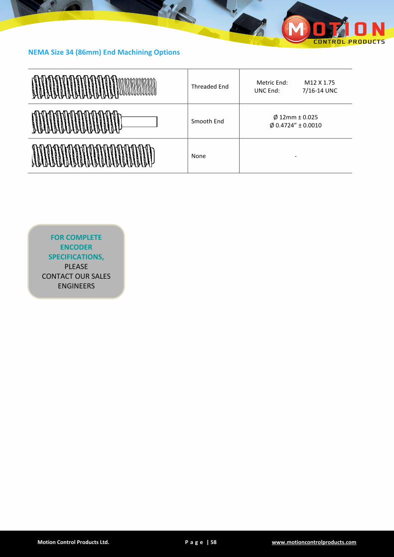
NEMA Size 34 (86mm) End Machining Options
Threaded End Metric End: M12 X 1.75
UNC End: 7/16-14 UNC
Smooth End Ø 12mm ± 0.025
Ø 0.4724” ± 0.0010
None -
FOR COMPLETE ENCODER
SPECIFICATIONS, PLEASE
CONTACT OUR SALES ENGINEERS

Motion Control Products Ltd. P a g e | 59 Tel.: (+44) 01202 599922
GLOSSARY
ACCURACY The difference between the actual distance travelled versus the theoretical distance travelled based on the lead
AXIAL LOAD A load that is exerted at the center line of the screw
BACKDRIVING Freewheeling of the nut an screw as a result of the load pushing axially on the screw
BACKLASH The relative axial movement between the screw and nut
CHOPPER DRIVE
A constant current drive is usually bipolar. The chopper drive gets its name from the technique of rapidly switching the power on and off to control motor current. A chopper drive allows a step motor to maintain greater torque of force at higher speeds.
COLUMN STRENGTH The ability of a screw to withstand a load in compression
CRITICAL SPEED The rotational speed of the screw at which the first harmonic of resonance is reached
DRAG TORQUE The amount of torque to overcome the friction of a system
DYNAMIC LOAD Load applied to the screw while in motion
EFFICIENCY The ability of a mechanical system to translate an input to an equal output
FIXITY (END) The method by which the ends of the screw secured or supported
LEAD The linear travel at one revolution of the screw
LEFT HAND THREAD Counter clockwise rotation
PITCH The axial distance between threads
RADIAL LOAD A load exerted at 90 degrees or perpendicular to a screw
REPEATIBILITY The capability of a screw and nut system to reach the same commanded position continuously
RESOLUTION Incremental linear distance the actuator‘s (motor) output shaft will move per input pulse
RESONANCE Vibration occurring when a system is a mechanical system is in an unstable range
RIGHT HAND THREAD Clockwise rotation
SIDELOADING Same as a radial load (very undesirable)
STATIC LOAD Load applied to the screw at standstill
STRAIGHTNESS Linear uniformity of a screw
TOTAL INDICATED RUNOUT
A measurement of the amount of straightness of a screw
TRAVEL PER STEP Linear translation of one full step of the motor
Motion Control Products Ltd. P a g e | 60 www.motioncontrolproducts.com
WARRANTY
24 month warranty
FIRST YEAR Full Replacement
SECOND YEAR Parts Replacement
Motion Control Products Ltd. warrants its products delivered hereunder to conform to stated specifications and
to be free from defects in materials and workmanship. This warranty shall not apply to any product which shall
have been improperly installed or subjected to misuse, neglect or which has been repaired or altered expect by
Motion Control Products Ltd.’s accredited representative, nor to any product which has been subjected to accident.
Copyright © 2015 Motion Control Products Ltd. All rights reserved.
All data subject to change without notice in advance
(V3.0 –REV0414/20160516)
Related Documents