Noname manuscript No. (will be inserted by the editor) Precision Deep-Stall Landing of Fixed-Wing UAVs using Nonlinear Model Predictive Control Siri Mathisen · Kristoffer Gryte · Sebastien Gros · Tor Arne Johansen Received: date / Accepted: date Abstract To be able to recover a fixed-wing unmanned aerial vehicle (UAV) on a small space like a boat deck or a glade in the forest, a steep and precise descent is needed. One way to reduce the speed of the UAV during landing is by performing a deep-stall landing manoeuvre, where the lift of the UAV is decreased until it is unable to keep the UAV level, at the same time as the drag is increased to minimize the speed of the UAV. However, this manoeuvre is highly non-linear and non- trivial to perform with high precision. To solve this, an on-line non-linear model predictive controller (NMPC) is implemented to guide the UAV in the landing phase, receiving inputs from the autopilot and guiding the UAV using pitch and throttle references. The UAV is guided along a custom path to a predefined deep- stall landing start point and performs a guided deep-stall. The simulation results show that the NMPC guides the UAV in a deep-stall landing with good precision and low speed, and that the results depend on a correct prediction model for the controller. Keywords Unmanned aerial vehicles · Real-time nonlinear model predictive control · Deep-stall landing · Autonomous landing · Guidance Mathematics Subject Classification (2010) MSC 90C90 This work is part of a project partly funded by the Research Council of Norway through the Centers of Excellence funding scheme, project number 223254. Centre for Autonomous Marine Operations and Systems (AMOS), Department of Engineering Cybernetics, Norwegian University of Science and Technology (NTNU), Trondheim, Norway S. Mathisen · K. Gryte · S. Gros · T. A. Johansen Centre for Autonomous Marine Operations and Systems (NTNU AMOS) Department of Engineering Cybernetics NTNU, Norwegian University of Science and Technology S. Mathisen SINTEF Energy Research Tel.: +47 41 10 01 79 E-mail: [email protected]

Welcome message from author
This document is posted to help you gain knowledge. Please leave a comment to let me know what you think about it! Share it to your friends and learn new things together.
Transcript
Noname manuscript No.(will be inserted by the editor)
Precision Deep-Stall Landing of Fixed-Wing UAVs
using Nonlinear Model Predictive Control
Siri Mathisen · Kristoffer Gryte ·
Sebastien Gros · Tor Arne Johansen
Received: date / Accepted: date
Abstract To be able to recover a fixed-wing unmanned aerial vehicle (UAV) on asmall space like a boat deck or a glade in the forest, a steep and precise descent isneeded. One way to reduce the speed of the UAV during landing is by performinga deep-stall landing manoeuvre, where the lift of the UAV is decreased until it isunable to keep the UAV level, at the same time as the drag is increased to minimizethe speed of the UAV. However, this manoeuvre is highly non-linear and non-trivial to perform with high precision. To solve this, an on-line non-linear modelpredictive controller (NMPC) is implemented to guide the UAV in the landingphase, receiving inputs from the autopilot and guiding the UAV using pitch andthrottle references. The UAV is guided along a custom path to a predefined deep-stall landing start point and performs a guided deep-stall. The simulation resultsshow that the NMPC guides the UAV in a deep-stall landing with good precisionand low speed, and that the results depend on a correct prediction model for thecontroller.
Keywords Unmanned aerial vehicles · Real-time nonlinear model predictivecontrol · Deep-stall landing · Autonomous landing · Guidance
Mathematics Subject Classification (2010) MSC 90C90
This work is part of a project partly funded by the Research Council of Norway throughthe Centers of Excellence funding scheme, project number 223254. Centre for AutonomousMarine Operations and Systems (AMOS), Department of Engineering Cybernetics, NorwegianUniversity of Science and Technology (NTNU), Trondheim, Norway
S. Mathisen · K. Gryte · S. Gros · T. A. JohansenCentre for Autonomous Marine Operations and Systems (NTNU AMOS)Department of Engineering CyberneticsNTNU, Norwegian University of Science and TechnologyS. MathisenSINTEF Energy ResearchTel.: +47 41 10 01 79E-mail: [email protected]
2 Siri Mathisen et al.
1 INTRODUCTION
During the recent years, autonomous flight has received a lot of attention in re-search (e.g. [1], [2], [3]) and the main challenges that arise are autonomous take-off,navigation and landing. This paper focuses on autonomous landing of fixed-wingunmanned aerial vehicles (UAVs), as this subgroup of UAVs generally has longerrange and endurance, which makes them preferable in many operations comparedto rotary-wing UAVs. Autonomous landing of UAVs has been studied before, seee.g. [4], [5], [6] and, more recently [7] and [8]. However, to further increase theusage of fixed-wing UAVs, autonomous landing without a runway is desired. Thisis motivated by maritime operations, where a UAV should be able to land on aship deck, which normally has limited space. One solution to this problem is toland the UAV in a net (e.g. [9], [10], [11]) though, while it simplifies the recoveryand enable landing on a ship, it yields significant structural loads on the UAV andnet, and requires infrastructure to support the net.
A decelerated landing of a UAV is achieved by increasing the angle of attackuntil the air flow separates from the airfoil of the wing, called the stall angle,and then beyond to reach a deep-stall [12]. A deep-stall is the state of the UAVwith a stable trim, with an angle of attack beyond the stall angle. More detailsabout the aerodynamics of deep-stall can be found in [13], [14], [15], [16], [17] and[18]. Landing an aircraft with the use of a deep-stall has been investigated in theliterature: [19] presents a study of a manned aircraft deep-stall and [20] presentsexperimental results from deep-stall landing with a UAV. In [21] a deep-stall land-ing is considered as a promising way of retrieving a UAV after flight tests in thefield. In [22] linear-quadratic regulator trees are presented as a way of controlling aUAV in deep-stall landing, with implementation, flight tests and promising results.In [23] the navigation part of the deep-stall landing and the safety aspect are con-sidered. In [24] a nonlinear model predictive controller for real-time autolanding indeep-stall of a UAV is described, built on the work presented in [25]. The ACADOframework is used for numerical optimization, just like in the current paper, butthe simulations are performed on the prediction model with no disturbances. In[26] the longitudinal aerodynamic characteristics of a deep-stall are investigated.In [27] a study on the use of flare for autonomous landing of a fixed-wing UAV ispresented, and [28] creates a trajectory for perched landing of a small fixed-wingUAV.
To guide a fixed-wing UAV in a deep-stall landing, this paper suggests theuse of a nonlinear model predictive controller (NMPC). An MPC is an optimalcontroller that provides control action rather than an explicit control law. Basedon a prediction model for the vehicle dynamics and the latest measurements orestimates of the model’s state variables as well as disturbances, a control trajec-tory for a given prediction horizon is calculated, optimizing a cost function. Thefirst control action from the trajectory predicted by the NMPC is used as inputto the UAV and the next measurement from the UAV is used as input for thestate estimator supporting the MPC. A linear MPC has a linear model and con-straints, and a quadratic cost function. Nonlinear MPC is more computationallydemanding, as it requires solving a generic, possibly con-convex Nonlinear Pro-gram, accurate computation of gradients and other numerical issues that prevents
Title Suppressed Due to Excessive Length 3
the problem to fall into the linear category [29]. Calculating an iterative solutionwithin a convergence criterion will be time consuming, while the alternative so-lution would be to abort the calculations before convergence has been reached tostay inside a time budget [30]. For more details about the NMPC, see [30] or [31].MPC has had great success in the process and petroleum industry, but due to itscomputationally costly nature, embedded MPC is not trivial [29]. A substantialresearch work has been done for improving the online embedded MPC, includingimprovements of the algorithms for solving the MPC faster (e.g. [32], [33], [34],[35]), software for embedded numerical optimal control using different algorithms,e.g. qpOASES [36], CVXGEN [37], HPMPC/MPMPI [32],[33] and environmentslike ACADO [38], or Acados [39], [40] where code generation is an important fea-ture (e.g. [34], [41], [42]).
In general, the control hierarchy of a UAV is divided into layers. Navigation,guidance and control form different layers handling state estimation, referencecomputation and control, respectively. Examples of control objective are path fol-lowing or energy minimization [43], [44]. MPC is applicable to several layers ofUAV control. In path planning, MPC can plan and re-plan the UAV trajectoryover a long prediction horizon, and this plan can be used as an input referencefor a lower control layer. In the lower control layers it is critical to get feedback.Depending on the computing power of the embedded computer, it can be possibleto solve the optimization problem on-board the UAV [45]. A viable alternative isto perform the computations on a remote computer and send the control input tothe UAV over a radio communication link as long as delays are small.
As the models of UAVs are inherently non-linear, linear MPCs for UAVs aretypically linearized around the trim states ([46], [47] and [48]). For regular flightconditions, the angle of attack α is usually much smaller than α0, where α0 is thestall angle. At low α, the drag, lift and pitch moment of the UAV can be describedas linear functions of α. In stall conditions, however, the drag, lift and pitch mo-ments are higly nonlinear functions of the angle of attack, and linear models arenot sufficient [44], [23]. Therefore, for transition into stall, linearization aroundtrim values are not useful and the full nonlinear prediction model is used.
Although there has been a substantial progress in computation time of NMPCdue to efficient cropping of algoritms and progress in embedded hardware [49],an NMPC is nevertheless a control technique with high computational consump-tion due to a high sampling frequency. In order to keep the computational powerconsumption as low as possible, it is desirable to use the NMPC only when thebenefits from using it outweighs the costs. One way of minimizing the computa-tion is to decouple lateral and longitudinal guidance and control. This has beenpreviously published in [48], where a longitudinal MPC controls the UAV directlyas an augmentation to a longitudinal autopilot and in [47], where an MPC usinga longitudinal model tracks a glide slope with the aim to land the UAV.
In [50], an NMPC is used in the lowest layer of a three-layered guidance,navigation and control system. A path planner provides waypoints and sensor in-formation to a navigation system, which converts the waypoint path referencesto speed, flight path and course angle references for the NMPC. The flight con-

4 Siri Mathisen et al.
trol system uses a genetic algorithm to solve the NMPC problem. This systemhas elevator, aileron, throttle and rudder as output from the NMPC flight controlsystem. In [51] the same output as the previous paper is used, based on a 6-DoFmodel of the UAV and an NMPC for attitude control. In [52], an NMPC uses a6-DoF model of the UAV to control the aircraft in extreme manoeuvres, using areference trajectory for the position.
The opposite approach concerning abstraction level would be to plan a refer-ence path in real time with the NMPC, and provide the autopilot with way pointsand airspeed references to follow this path. In [53], an on-line MPC on the groundstation tracks a pre-planned flight path and communicates the control signals tothe autopilot through the payload computer, using a radio link. The MPC controlsboth the attitude of an attached gimbal and the path, providing the autopilot withwaypoints and desired airspeed and the gimbal with pan and tilt commands.
If the objective of the relevant manoeuvre also requires control of the UAVat lower level than the flight path, then waypoint and speed references are notsufficient, and something between the full model and the waypoint solution is re-quired. In [54] this is solved by creating a control system with a layered structure:the goal is to fly a mid-sized fixed-wing UAV from a given point in the air to alanding point on the ground. An on-line NMPC plans the whole horizon of thelanding path at each time step. This path consists of two different optimizationproblems forming two different landing phases. The whole-horizon NMPC plans alanding trajectory for the UAV, and the path is followed using a high-levelH2/H∞
cascaded with a low-level PD controller. A similar structure is also seen in [55] andfurther detailed in [56], where a three-layer structure uses an attitude controller, apath-following guidance module based on MPC and a reference trajectory on top,which is followed by the guidance module. The MPC model is nonlinear, but theproposed optimization algorithm proceeds with the linearisation of the predictionmodel around a set of pre-computed control values, obtained by another guidancealgorithm, where an estimator is included to account for disturbances. The outputof the guidance layer is the flight path angle, bank angle and airspeed reference.This approach yields a sufficiently low abstraction level to control the UAV into adeep-stall, without controlling the attitude of the UAV. In [57] a high-level NMPCfor path following, speed stabilization and constraint handling is used, while thelow-level attitude and rates control is performed by the autopilot. In the presentpaper, we will follow the same idea, and use the NMPC for path control, whereasthe low level attitude control and rates control is performed by the autopilot.
This paper focuses on on-board, on-line NMPC. To reduce the computationtime without compromising the result, we decouple the lateral and the longitudi-nal guidance, performing the deep-stall NMPC guidance only in the longitudinalplane. The lateral guidance will use a separate controller that is not based onNMPC, and while it is included in the simulations it will not be the focus of thispaper. As a result, instead of a full 6-DoF prediction model, we use a 3-DoF pre-diction model of the UAV for the NMPC calculations. The main contributions ofthis paper are the implementation of a longitudinal NMPC in a custom softwarepackage intended for an on-board payload computer in small fixed-wing UAVs,and a path planner for safe deep-stall landing. The presented NMPC can guide
Title Suppressed Due to Excessive Length 5
the UAV in a deep-stall, driving the autopilot of the UAV with pitch and throttlereferences from the NMPC. The autopilot provides low-level attitude control. Thispaper makes a novel combination of NMPC and deep-stall landing. It continuesthe work done by [25] and [58], where a simulated modified Aerosonde fixed-wingUAV was guided in a deep-stall with an NMPC, and the work done by [59], wherea path planner is implemented for precision delivery with a small fixed-wing UAV.In this present paper, the NMPC system is taken one step further than in [58]towards flight testing. Where [58] uses lateral as well as longitudinal NMPC guid-ance, we here present only longitudinal NMPC guidance combined with a lateralline-of-sight-based guidance module in order to reduce computational complexity.The emphasis is placed on migration towards actual flight testing and integrationwith a realistic physical environment, including the autopilot software, whereas[58] guides a naıve UAV-simulator using the same model as the controller andtesting it with software-in-the-loop (SITL) simulation. The updated MPC in thispaper uses code generation with an online active set strategy solver, compared tothe interior point method used in [58]
This paper is organized as follows: Section 2 presents a path planning procedurefor the landing, introduces the three manoeuvres involved in the plan and derivesan algorithm for the computation of a start point for the deep-stall phase of thelanding. Section 3 presents the real-time environment for the NMPC calculationsand the control system structure for the on-board flight control system, whileSection 4 explains the deep-stall NMPC implementation and the UAV model.Section 5 presents the details of the SITL simulation and the simulation results.In Section 6, the results are discussed and some suggestions for future work aregiven, before the paper is concluded in Section 7.
2 Path Planner
To execute a safe deep-stall landing, a landing plan is composed. The main pur-pose of the landing plan is to calculate a point for deep-stall landing initiation, toguide the UAV to this point with the correct start state and to guide the UAVin the deep-stall such that it lands at a defined target position with minimumspeed. Besides, the plan must consider when a deep-stall should be aborted. TheUAV’s lateral landing path is a truncated Dubins path, shown in Fig. 1: First, theUAV aims for a geographical reference s and loiters around it with radius r untilit has the appropriate start altitude and start velocity for the deep-stall, and isdirected at the target, in point p. To minimize the ground speed in the landing, theUAV aspires to always land against the average wind direction. However, the windchanges with a change in the position of the UAV and time. Therefore, the windspeed and direction are estimated utilizing on-board sensors or ground infrastruc-ture before planning the landing path in Fig. 1. Further changes in the wind donot affect the lateral landing plan but will be used by the NMPC calculations. Inthe case of no wind, the landing direction should be decided by the geographicallanding conditions. After a short distance D with level flight, the NMPC takesover the longitudinal guidance of the UAV. The NMPC first guides the UAV ashort distance in level to ensure the numerical algorithm is suitably initialized forthe NMPC before the nonlinear deep-stall operation is initiated. Once the UAV

6 Siri Mathisen et al.
Fig. 1: The lateral path for the landing. Before longitudinal NMPC guidance isinitiated, the UAV is guided with line-of-sight-based lateral and longitudinal con-trollers.
reaches the Deep-Stall Start point, it initiates the deep-stall mode and stays indeep-stall until it touches the ground or until the predicted landing error is toolarge, in which case the UAV aborts the landing. The landing is initiated whenthe UAV receives the geographical coordinates of the landing target. Based onthe target coordinates, the wind velocity estimates and the UAV’s deep-stall pathangle, the start point of the deep-stall can be computed. Once the deep-stall startpoint is known, the truncated Dubins path is trivial to calculate. This path is usedin [59] and described further in [60].
The landing plan consists of three manoeuvres: the Landing Preparation, theDeep-Stall Landing and the Safety Abort. Each manoeuvre has a longitudinal anda lateral path controller, guiding the UAV with desired roll, pitch and throttlecommands sent to the autopilot. The autopilot performs attitude and propulsioncontrol. The NMPC is only used for the longitudinal control in the Deep-Stall
Landing manoeuvre; the two other manoeuvres use a longitudinal cascaded LOS-based controller. This controller consists of an altitude controller and a climb rateand speed controller. At the point NMPC Start in Fig. 1, the manoeuvre LandingPreparation ends and the manoeuvre Deep-Stall Landing initiates. The transitionbetween the two manoeuvres means that the algorithm for calculating desiredpitch and throttle commands changes. Any adverse effects of the switch betweenthe two guidance methods is minimized by proper initialization of the MPC toachieve bumpless transfer, and the switch does not cause any stability issues initself since it is a single event. A reference line with a start point and an end point,
Title Suppressed Due to Excessive Length 7
both using geographical coordinates and altitude, is sent to the altitude controller.It uses line-of-sight (LOS) guidance theory from [61] to produce a desired climbrate, which together with the desired speed is sent to an underlying total energycontrol-based controller in the autopilot. The output of the climb rate and speedcontroller is desired throttle and pitch, the same as for the longitudinal NMPCused for the deep-stall manoeuvre. The lateral LOS-guidance controller, which isalso based on [61], produces desired roll commands for the autopilot, by investi-gating the lateral acceleration necessary to eradicate the cross-track error.
If the NMPC is unable to control the UAV in a safe deep-stall landing, thelanding must be aborted, and the Safety Abort manoeuvre will initiate. This ma-noeuvre guides the UAV using LOS-based controllers with a waypoint interface tothe user. Reasons for aborting the deep-stall landing include an infeasible solutionfrom the model predictive controller or a too high predicted landing error at acritical height above the ground. Just like in the point NMPC Start in Fig. 1, thistransition involves a change of algorithms to calculate desired pitch and throttlecommands, and of course a different desired waypoint. The effects of this switchof guidance methods is not considered beyond getting the UAV to a safe height.If the Safety Abort manoeuvre is initiated while the UAV is in a deep-stall, it isin a state with critically low lift forces acting on the aircraft. One common wayof getting out of a deep-stall is to command sufficient use of throttle, requiring ahigh-powered UAV and sufficient available throttle potential during the deep-stall.
2.1 Computation of Deep-Stall Start Point
The Deep-Stall Landing manoeuvre consists of an initial phase where the UAVhas level flight, and a deep-stall phase where the UAV has a high angle of attackand a steep path angle, see Fig. 3. The relative path angle for a deep-stall, γDS
rel , ismodel dependent and its value is known from experiments. In a deep-stall landing,the conditions of a stable trim for are fulfilled for the pitch moment Cm [18]:
Cm = 0,dCm
dα≤ 0 (1)
allowing the UAV to passively reject minor longitudinal perturbations. A plot ofthe pitch moment, drag coefficient and lift coefficient with respect to the angle ofattack is shown in Figure 2.
This also means that once the UAV enters the deep-stall, it is costly to changeits path angle. Ideally, the UAV should have been able to follow a dynamic pathangle in a deep-stall, as was shown in [25] and [58] with much simpler simulationsand no modelling error. However, since this may be difficult to achieve with amore advanced simulation environment or in flight tests, the start point wherethe UAV enters the deep-stall will strongly influence the target error. Indeed, ifthe deep-stall starts too early, the UAV will be short of the target, and if it stallstoo late, it will land beyond the target. Additional to the predicted landing error,disturbances may cause an error between the reference path angle and the pathangle of the UAV, which can in turn lead to a landing error. However, the sameeffect that causes planned changes in the path angle of the UAV to be costly,

8 Siri Mathisen et al.
0 20 40 60 80 100Angle of Attack - Degrees
−0.5
0.0
0.5
1.0
1.5
2.0Drag coefficientLift coefficientPitch moment coefficient
Fig. 2: The drag coefficient, the lift coefficient and the pitch moment coefficient ofthe UAV model used in this paper, with respect to the angle of attack.
means that disturbance inflicted changes in the path angle of the UAV demandslarge disturbances.
The deep-stall occurs at a high angle of attack, α, as this typically gives a highdrag force and a low lift force. The angle of attack is the rotation about the bodyy-axis between the body x-axis and the air velocity vector, and is thus defined as:
α = arctan
(
w − ww
u− uw
)
, (2)
see e.g. [44], where u and w are the longitudinal and down velocities in thebody frame and uw and ww are the corresponding components of the airspeedvector in the body frame. The relationship between the angle of attack, the pitchangle θ and the relative path angle is:
γr = θ − α, (3)
see e.g. [44]. A constant angle of attack will therefore be obtained if the relativepath angle γr is also constant, as the pitch angle is independent on wind. γr isexpressed as
γr = − arctan
(
V relz
V relg
)
, (4)
Title Suppressed Due to Excessive Length 9
where V relz is the relative down speed in the inertial frame and V rel
g is therelative ground speed in the inertial frame. A constant γr will demand constantrelative ground speed and constant relative down speed, which means that theabsolute path angle γ of the deep-stall can, when the wind velocity, relative groundspeed and relative path angle is know, be expressed as:
γDS = − arctan
(
V relz + V wind
z
V relg + V wind
g
)
, (5)
V relz = −V rel
g tan(
γDSr
)
(6)
where V windg is the ground wind velocity in the inertial frame and V wind
z is thedown wind velocity in the inertial frame, and is dependent on the wind strength:For a landing against the wind, a stronger wind and constant airspeed will leadto steeper path angle. As the absolute path angle and the relative deep-stall pathangle are known, we can calculate where the deep-stall start point of Fig. 3 oughtto be placed.
However, the UAV will not transition from the steady flight to the deep-stallphase instantaneously. Between these two phases there is a transition phase, whichis highly nonlinear and nontrivial to calculate or predict. With sufficiently precisemodel parameters representing the UAV, including the autopilot, a path plannercould plan the whole landing offline with the UAV’s start altitude and start ve-locity, and use the planned path to compute a start point. Yet simulations show aconsiderable model mismatch between the NMPC’s model and the UAV’s model,so a simpler approach has to be used. A guess for the transition start point is awind dependent distance d2 ahead of the deep-stall start point, given by:
d2 = ∆TVrelg , (7)
where ∆T is an empirical value and and V relg is the ground speed of the UAV
in level flight relative to the surrounding air masses. Once d2, the start height hand the relative deep-stall angle γDS
r are known, we can compute the transitionstart point. The UAV should initiate the deep-stall once the longitudinal anglebetween the UAV and the target is steeper than a limit ∠lim, given by:
∠limtarget = − arctan
(
h
d2 + d3
)
, (8)
d3 = −h
tan (γDS)(9)
After the UAV has initiated the deep-stall and started descending, it soonreaches a stationary phase with a constant path angle and constant ground veloci-ties. Then the predicted landing error e, meaning the distance between the landingcoordinates and the target coordinates, is calculated, and if the predicted landingerror is larger than a limit eMAX, the UAV aborts the landing. The distance d2 isthen updated with the predicted error, assuming perfect lateral guidance:

10 Siri Mathisen et al.
Fig. 3: The longitudinal reference path for the deep-stall landing
dnew2 = dold2 + e (10)
The computation of the deep-stall start point is summarized in Algorithm 1.
Algorithm 1 Computation of deep-stall start point
Require: Airspeed, γDSr , V wind
z , V windg
Compute V relz using (6)
Compute γDS using (5)Compute a guess for d2 using (7)Compute ∠
limtarget using (8)
while e ≥ eMAX do
Update d2 using (10)end while
3 Real-time Integration and Control Structure
Testings of the NMPC formulation in a non-real time environment (CasADi, [62],[63], [64]) in [25] and [58] have delivered satisfactory results. Tests in a real-timeenvironment and an implementation of the controller is considered here. The real-time optimization environment selected for this work is the ACADO softwarereferred to previously. Promising results from simulations of this problem usingACADO are presented in [24]. We use the automatic code generation feature pro-vided by ACADO, which makes a stand-alone optimization package suited forembedded use. The QP solver used is qpOASES, based on an online active setstrategy [65]. After successfully testing the NMPC with a simple simulator using
Title Suppressed Due to Excessive Length 11
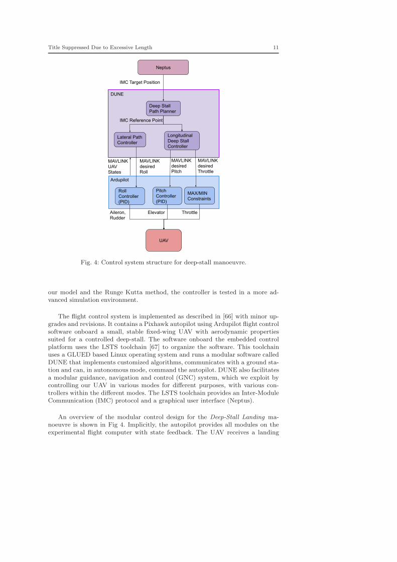
Fig. 4: Control system structure for deep-stall manoeuvre.
our model and the Runge Kutta method, the controller is tested in a more ad-vanced simulation environment.
The flight control system is implemented as described in [66] with minor up-grades and revisions. It contains a Pixhawk autopilot using Ardupilot flight controlsoftware onboard a small, stable fixed-wing UAV with aerodynamic propertiessuited for a controlled deep-stall. The software onboard the embedded controlplatform uses the LSTS toolchain [67] to organize the software. This toolchainuses a GLUED based Linux operating system and runs a modular software calledDUNE that implements customized algorithms, communicates with a ground sta-tion and can, in autonomous mode, command the autopilot. DUNE also facilitatesa modular guidance, navigation and control (GNC) system, which we exploit bycontrolling our UAV in various modes for different purposes, with various con-trollers within the different modes. The LSTS toolchain provides an Inter-ModuleCommunication (IMC) protocol and a graphical user interface (Neptus).
An overview of the modular control design for the Deep-Stall Landing ma-noeuvre is shown in Fig 4. Implicitly, the autopilot provides all modules on theexperimental flight computer with state feedback. The UAV receives a landing

12 Siri Mathisen et al.
command including the coordinates of the landing location, and the message isprocessed by a top-level unit, the landing plan. This module assigns the NMPCwith the longitudinal path control, and the lateral path control to the LOS-basedlateral controller described in Section 2. Both controllers receive the geographicalcoordinates of the landing location and the coordinates for the start point, whichthe lateral controller uses to create a reference line for the LOS. The output of thelateral path controller are roll (φ) commands, whereas the deep-stall manoeuvreoutputs pitch and throttle (θ, δt) commands. These commands are received by theautopilot, which performs low-level attitude control of the UAV and commandsits control surfaces and propeller. The output from the guidance algorithms aresent to an autopilot communication module that translates the references to aMAVlink protocol messages (see [66] for more details).
4 NMPC Implementation
The discrete-time NMPC is formulated as follows:
minx,u
N−1∑
k=0
‖h (xk, uk)− yk‖2Wk
+ ‖hN (xN )− yN‖2WN(11a)
s.t. x0 = x0, (11b)
xk+1 = F (xk, uk, zk) , for k = 0, ...,N − 1 (11c)
umin ≤ uk ≤ umax, for k = 0, ...,N − 1, (11d)
Cmin ≤ f (xk) ≤ Cmax, for k = 0, ...,N. (11e)
A time varying reference vector yk is provided to the NMPC scheme, as wellas the external input variables, zk =
[
uw ww prefd
]
, where uw and ww are wind
velocity with respect to the inertial frame expressed in the body frame, and prefd
is the desired down velocity in the inertial frame. The dynamics referred to in(11c) are numerical discretizations of the longitudinal model for the fixed-wing,unmanned aircraft described in [44], recalled here:
pnpduw
θp
=
cos (θ)u+ sin (θ)w− sin (θ) u+ cos (θ)w
−qw + 1M
fxqu+ 1
Mfz
q1Jy
m
(12)
The variables pn and pd are the position in the inertial landing direction anddown position of the UAV, u, w are the body frame velocities measured along thelongitudinal and vertical body frame axes, θ is the pitch angle, q is the pitch ratealong the body frame y-axis, M is the mass of the UAV while flying and Jy is themoment of inertia about the body frame y-axis. The forces acting on the bodyframe fx and fz are given by:

Title Suppressed Due to Excessive Length 13
[
fxfz
]
= fg + fa + fp, (13a)
fg =
[
−Mg sin (θ)Mg cos (θ)
]
, (13b)
fa =1
2ρVaS
[
CX(α) + CXq(α) c
2Vaq + CXδe
(α)δeCZ(α) + CZq
(α) c2Va
q + CZδe(α)δe
]
, (13c)
fp =1
2ρSpropCprop
[
(kmotorδt)2 − V 2
a
0
]
(13d)
where CX (α), CXq(α), CXδe
(α), CZ (α), CZq(α) and CZδe
(α) are functions ofthe aerodynamic drag and lift coefficients CD (α) and CL (α). The pitch momentm is given by
m =1
2ρSc[Cm(α) + Cmq
c
2Va
q + Cmδeδe], (14)
where the airspeed is:
Va =√
u2r + w2
r ,[
ur
wr
]
=
[
u− uw
w − ww
]
, (15)
assuming perfect lateral guidance.
The control of the UAV in the longitudinal plane is based on manipulatingthe throttle δt and the deflection of the elevator δe. However, our system structurerequires that pitch angle and throttle command references are sent to the autopilot,see Fig. 4. Whereas the NMPC is intended to guide the UAV in the longitudinalplane, the PID controller in the autopilot oversees the attitude control, using theelevator deflection to control the pitch angle of the UAV. The relationship of theautopilot between the desired pitch angle and the elevator command is given by aPID controller. To account for this in the prediction model, we introduce δe as anadditional state instead of as an output of the controller, and an additional inputθd for the desired pitch:
δe = −Kp
(
θd − q)
−Kd
(
θd − q)
−Ki (θd − θ) . (16)
We assume that θd = 0. The NMPC scheme generates two inputs for theautopilot, gathered in the control vector uk =
[
δt θd]
. The cost function in (11a)considers errors in h (xk, uk) with weighting Wk, and end term hN (xN ) withweighting WN . The purpose of the NMPC is to produce outputs that can bothkeep the UAV in level flight and in a precise deep-stall. We thus use the followingterms in the function h:
14 Siri Mathisen et al.
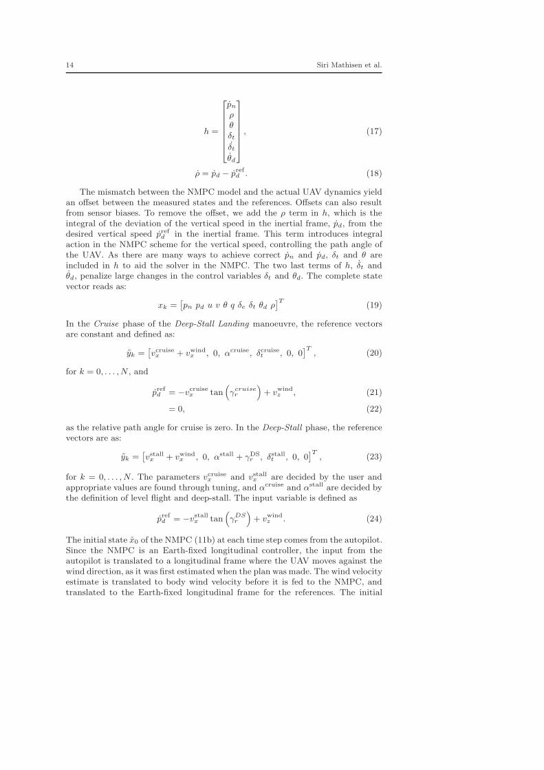
h =
pnρθδtδtθd
, (17)
ρ = pd − prefd . (18)
The mismatch between the NMPC model and the actual UAV dynamics yieldan offset between the measured states and the references. Offsets can also resultfrom sensor biases. To remove the offset, we add the ρ term in h, which is theintegral of the deviation of the vertical speed in the inertial frame, pd, from thedesired vertical speed prefd in the inertial frame. This term introduces integralaction in the NMPC scheme for the vertical speed, controlling the path angle ofthe UAV. As there are many ways to achieve correct pn and pd, δt and θ areincluded in h to aid the solver in the NMPC. The two last terms of h, δt andθd, penalize large changes in the control variables δt and θd. The complete statevector reads as:
xk =[
pn pd u v θ q δe δt θd ρ]T
(19)
In the Cruise phase of the Deep-Stall Landing manoeuvre, the reference vectorsare constant and defined as:
yk =[
vcruisex + vwindx , 0, αcruise, δcruiset , 0, 0
]T, (20)
for k = 0, . . . , N , and
prefd = −vcruisex tan(
γcruiser
)
+ vwindz , (21)
= 0, (22)
as the relative path angle for cruise is zero. In the Deep-Stall phase, the referencevectors are as:
yk =[
vstallx + vwindx , 0, αstall + γDS
r , δstallt , 0, 0]T
, (23)
for k = 0, . . . , N . The parameters vcruisex and vstallx are decided by the user andappropriate values are found through tuning, and αcruise and αstall are decided bythe definition of level flight and deep-stall. The input variable is defined as
prefd = −vstallx tan(
γDSr
)
+ vwindz . (24)
The initial state x0 of the NMPC (11b) at each time step comes from the autopilot.Since the NMPC is an Earth-fixed longitudinal controller, the input from theautopilot is translated to a longitudinal frame where the UAV moves against thewind direction, as it was first estimated when the plan was made. The wind velocityestimate is translated to body wind velocity before it is fed to the NMPC, andtranslated to the Earth-fixed longitudinal frame for the references. The initial
Title Suppressed Due to Excessive Length 15
guess for the control variables δt and θd is zero. The box constraints Cmin andCmax in (11d) and (11e) are constant constraints given by:
−40o ≤ θ ≤ 40o
−10o ≤ α ≤ 80o
−40o ≤ δe ≤ 40o
0 ≤ δt ≤ 1
−35o ≤ θd ≤ 35o (25)
(26)
where f (xk) =[
θ α δe δt θd]
.
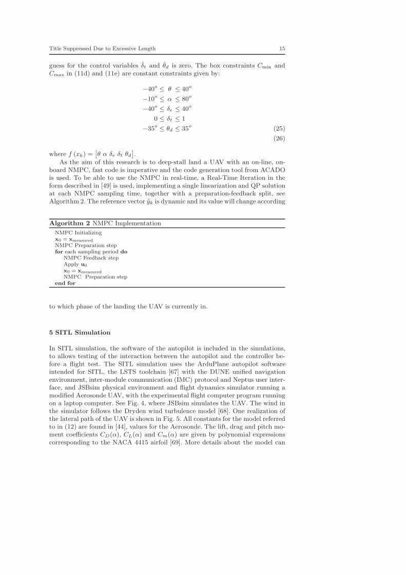
As the aim of this research is to deep-stall land a UAV with an on-line, on-board NMPC, fast code is imperative and the code generation tool from ACADOis used. To be able to use the NMPC in real-time, a Real-Time Iteration in theform described in [49] is used, implementing a single linearization and QP solutionat each NMPC sampling time, together with a preparation-feedback split, seeAlgorithm 2. The reference vector yk is dynamic and its value will change according
Algorithm 2 NMPC Implementation
NMPC Initializingx0 = xmeasured
NMPC Preparation stepfor each sampling period do
NMPC Feedback stepApply u0
x0 = xmeasured
NMPC Preparation stepend for
to which phase of the landing the UAV is currently in.
5 SITL Simulation
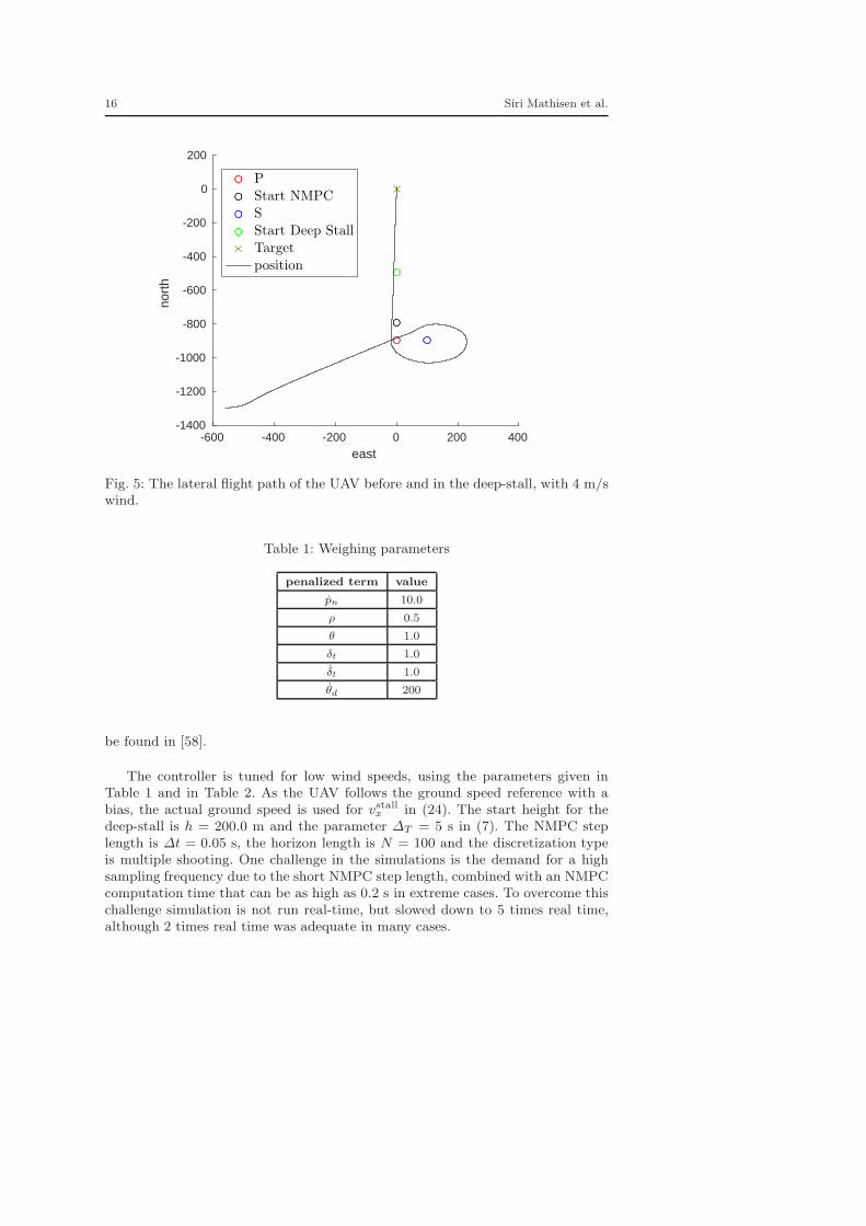
In SITL simulation, the software of the autopilot is included in the simulations,to allows testing of the interaction between the autopilot and the controller be-fore a flight test. The SITL simulation uses the ArduPlane autopilot softwareintended for SITL, the LSTS toolchain [67] with the DUNE unified navigationenvironment, inter-module communication (IMC) protocol and Neptus user inter-face, and JSBsim physical environment and flight dynamics simulator running amodified Aerosonde UAV, with the experimental flight computer program runningon a laptop computer. See Fig. 4, where JSBsim simulates the UAV. The wind inthe simulator follows the Dryden wind turbulence model [68]. One realization ofthe lateral path of the UAV is shown in Fig. 5. All constants for the model referredto in (12) are found in [44], values for the Aerosonde. The lift, drag and pitch mo-ment coefficients CD(α), CL(α) and Cm(α) are given by polynomial expressionscorresponding to the NACA 4415 airfoil [69]. More details about the model can
16 Siri Mathisen et al.
-600 -400 -200 0 200 400
east
-1400
-1200
-1000
-800
-600
-400
-200
0
200no
rth
P
Start NMPC
S
Start Deep Stall
Target
position
Fig. 5: The lateral flight path of the UAV before and in the deep-stall, with 4 m/swind.
Table 1: Weighing parameters
penalized term value
pn 10.0
ρ 0.5
θ 1.0
δt 1.0
δt 1.0
θd 200
be found in [58].
The controller is tuned for low wind speeds, using the parameters given inTable 1 and in Table 2. As the UAV follows the ground speed reference with abias, the actual ground speed is used for vstallx in (24). The start height for thedeep-stall is h = 200.0 m and the parameter ∆T = 5 s in (7). The NMPC steplength is ∆t = 0.05 s, the horizon length is N = 100 and the discretization typeis multiple shooting. One challenge in the simulations is the demand for a highsampling frequency due to the short NMPC step length, combined with an NMPCcomputation time that can be as high as 0.2 s in extreme cases. To overcome thischallenge simulation is not run real-time, but slowed down to 5 times real time,although 2 times real time was adequate in many cases.
Title Suppressed Due to Excessive Length 17
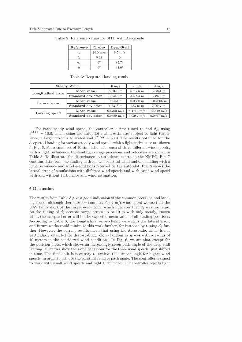
Table 2: Reference values for SITL with Aerosonde
Reference Cruise Deep-Stall
vx 24.0 m/s 6.5 m/s
δt 0.62 0
γr 0o 35.7o
α 0o 44.0o
Table 3: Deep-stall landing results
Steady Wind 0 m/s 2 m/s 4 m/s
Longitudinal errorMean value 6.2076 m 6.7386 m 3.6351 m
Standard deviation 3.0446 m 3.4994 m 3.4978 m
Lateral errorMean value 0.0464 m 0.0688 m −0.2306 m
Standard deviation 1.6313 m 1.5748 m 2.2647 m
Landing speedMean value 9.6700 m/s 8.4749 m/s 7.4619 m/s
Standard deviation 0.0389 m/s 0.0282 m/s 0.0307 m/s
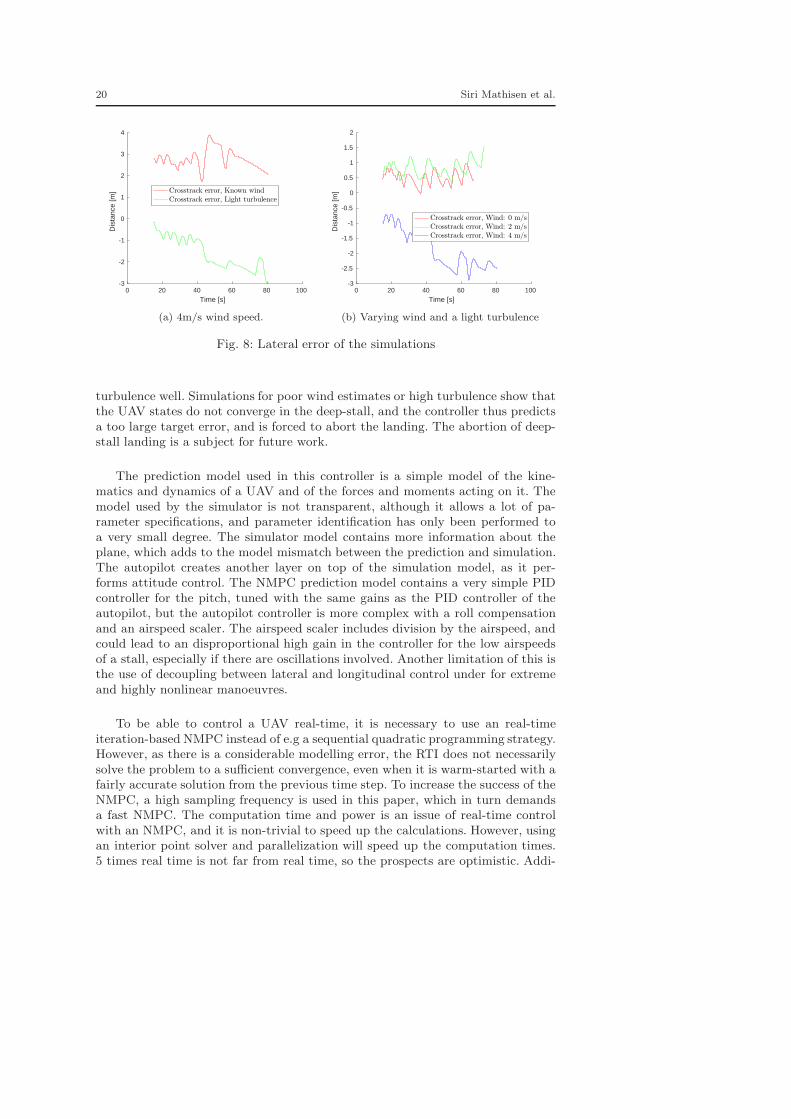
For each steady wind speed, the controller is first tuned to find d2, usingeMAX = 10.0. Then, using the autopilot’s wind estimates subject to light turbu-lence, a larger error is tolerated and eMAX = 50.0. The results obtained for thedeep-stall landing for various steady wind speeds with a light turbulence are shownin Fig. 6. For a small set of 10 simulations for each of three different wind speeds,with a light turbulence, the landing average precisions and velocities are shown inTable 3. To illustrate the disturbances a turbulence exerts on the NMPC, Fig. 7contains data from one landing with known, constant wind and one landing with alight turbulence and wind estimations received by the autopilot. Fig. 8 shows thelateral error of simulations with different wind speeds and with same wind speedwith and without turbulence and wind estimation.
6 Discussion
The results from Table 3 give a good indication of the common precision and land-ing speed, although there are few samples. For 2 m/s wind speed we see that theUAV lands short of the target every time, which indicates that d2 was too large.As the tuning of d2 accepts target errors up to 10 m with only steady, knownwind, the accepted error will be the expected mean value of all landing positions.According to Table 3, the longitudinal error clearly outweighs the lateral error,and future works could minimize this work further, for instance by tuning d2 fur-ther. However, the current results mean that using the Aerosonde, which is notparticularly intended for deep-stalling, allows landing in spaces with a radius of10 meters in the considered wind conditions. In Fig. 6, we see that except forthe position plots, which shows an increasingly steep path angle of the deep-stalllanding, all curves show the same behaviour for the three wind speeds, just shiftedin time. The time shift is necessary to achieve the steeper angle for higher windspeeds, in order to achieve the constant relative path angle. The controller is tunedto work with small wind speeds and light turbulence. The controller rejects light

18 Siri Mathisen et al.
200 400 600 800 1000
Longitudinal North [m]
-50
0
50
100
150
200
250
Hei
ght [
m]
Position, Wind: 0 m/sPosition, Wind: 2 m/sPosition, Wind: 4 m/sTarget, Wind: 0 mps
Target, Wind: 2 mps
Target, Wind: 4 mps
(a) Longitudinal position
0 20 40 60 80 100
Time [s]
-10
0
10
20
30
40
50
Ang
les
[deg
]
θ, Wind: 0 m/sα, Wind: 0 m/sθ, Wind: 2 m/sα, Wind: 2 m/sθ, Wind: 4 m/sα, Wind: 4 m/s
(b) Pitch angle and angle of attack
0 20 40 60 80 100
Time [s]
-50
-40
-30
-20
-10
0
10
20
30
40
Ang
les
[deg
]
γDSr , Wind: 0 mps
γDSr , Wind: 2 mps
γDSr , Wind: 4 mps
(c) Relative path angle
0 20 40 60 80 100
Time [s]
-15
-10
-5
0
5
10
15
20
25
30S
peed
[m/s
]
V relg , Wind: 0 m/s
V relz , Wind: 0 m/s
V relg , Wind: 2 m/s
V relz , Wind: 2 m/s
V relg , Wind: 4 m/s
V relz , Wind: 4 m/s
(d) Relative velocities in the inertial frame
0 20 40 60 80 100
Time [s]
-40
-35
-30
-25
-20
-15
-10
-5
Ang
les
[deg
]
δe, Wind: 0 mps
δe, Wind: 2 mps
δe, Wind: 4 mps
(e) Elevator deflection
0 20 40 60 80 100
Time [s]
0
0.1
0.2
0.3
0.4
0.5
0.6
0.7
Dut
y C
ycle
, fra
ctio
n of
1
δt, Wind: 0 m/sδt, Wind: 2 m/sδt, Wind: 4 m/s
(f) Throttle usage
Fig. 6: Estimated variables of the UAV while controlled by an NMPC from cruiseto deep-stall, for steady wind equal to 0 m/s, 2 m/s and 4 m/s, with a lightturbulence.

Title Suppressed Due to Excessive Length 19
300 400 500 600 700 800 900 1000
Longitudinal North [m]
-50
0
50
100
150
200
250
Hei
ght [
m]
Target, Known wind
Target, Light turbulence
Position, Known wind
Position, Light turbulence
(a) Longitudinal position
0 20 40 60 80 100
Time [s]
-5
0
5
10
15
20
25
30
35
40
45
Ang
les
[deg
] θ, Known wind
α, Known wind
θ, Light turbulence
α, Light turbulence
(b) Pitch angle and angle of attack
0 20 40 60 80 100
Time [s]
-40
-30
-20
-10
0
10
20
30
40
Ang
les
[deg
]
γDSr , Known wind
γDSr , Light turbulence
(c) Relative path angle
0 20 40 60 80 100
Time [s]
-10
-5
0
5
10
15
20
25
30S
peed
[m/s
]
V relg , Known wind
V relz , Known wind
V relg , Light turbulence
V relz , Light turbulence
(d) Relative velocities in the inertial frame
0 20 40 60 80 100
Time [s]
-40
-35
-30
-25
-20
-15
-10
-5
Ang
les
[deg
]
δe, Known wind
δe, Light turbulence
(e) Elevator deflection
0 20 40 60 80 100
Time [s]
0
0.1
0.2
0.3
0.4
0.5
0.6
0.7
Dut
y C
ycle
, fra
ctio
n of
1
δt, Known wind
δt, Light turbulence
(f) Throttle usage
Fig. 7: Estimated variables of the UAV while controlled by an NMPC from cruiseto deep-stall, with 4 m/s wind and no or light turbulences.
20 Siri Mathisen et al.
0 20 40 60 80 100
Time [s]
-3
-2
-1
0
1
2
3
4
Dis
tanc
e [m
] Crosstrack error, Known wind
Crosstrack error, Light turbulence
(a) 4m/s wind speed.
0 20 40 60 80 100
Time [s]
-3
-2.5
-2
-1.5
-1
-0.5
0
0.5
1
1.5
2
Dis
tanc
e [m
]
Crosstrack error, Wind: 0 m/sCrosstrack error, Wind: 2 m/sCrosstrack error, Wind: 4 m/s
(b) Varying wind and a light turbulence
Fig. 8: Lateral error of the simulations
turbulence well. Simulations for poor wind estimates or high turbulence show thatthe UAV states do not converge in the deep-stall, and the controller thus predictsa too large target error, and is forced to abort the landing. The abortion of deep-stall landing is a subject for future work.
The prediction model used in this controller is a simple model of the kine-matics and dynamics of a UAV and of the forces and moments acting on it. Themodel used by the simulator is not transparent, although it allows a lot of pa-rameter specifications, and parameter identification has only been performed toa very small degree. The simulator model contains more information about theplane, which adds to the model mismatch between the prediction and simulation.The autopilot creates another layer on top of the simulation model, as it per-forms attitude control. The NMPC prediction model contains a very simple PIDcontroller for the pitch, tuned with the same gains as the PID controller of theautopilot, but the autopilot controller is more complex with a roll compensationand an airspeed scaler. The airspeed scaler includes division by the airspeed, andcould lead to an disproportional high gain in the controller for the low airspeedsof a stall, especially if there are oscillations involved. Another limitation of this isthe use of decoupling between lateral and longitudinal control under for extremeand highly nonlinear manoeuvres.
To be able to control a UAV real-time, it is necessary to use an real-timeiteration-based NMPC instead of e.g a sequential quadratic programming strategy.However, as there is a considerable modelling error, the RTI does not necessarilysolve the problem to a sufficient convergence, even when it is warm-started with afairly accurate solution from the previous time step. To increase the success of theNMPC, a high sampling frequency is used in this paper, which in turn demandsa fast NMPC. The computation time and power is an issue of real-time controlwith an NMPC, and it is non-trivial to speed up the calculations. However, usingan interior point solver and parallelization will speed up the computation times.5 times real time is not far from real time, so the prospects are optimistic. Addi-
Title Suppressed Due to Excessive Length 21
tionally, it will be wise to invest time in the modelling of the UAV, to ensure amodel that is as realistic as possible and demands a lower sampling frequency.
7 Conclusion
The NMPC presented in this paper is able to guide a simulated UAV in a deep-stall landing to a target location with mean target error less than 10 m and meanlanding speed less than 10 m/s. The conclusion of this paper is that it is possibleto deep-stall land a fixed-wing UAV with an NMPC, but the results depend on acorrect prediction model for the controller. It is therefore advisable to invest timein a precise model, as this will minimize problems.
ACKNOWLEDGMENT
This work is part of a project partly funded by the Research Council of Norwaythrough the Centers of Excellence funding scheme, project number 223254. Centrefor Autonomous Marine Operations and Systems (AMOS), Department of Engi-neering Cybernetics, Norwegian University of Science and Technology (NTNU),Trondheim, Norway
References
1. L. Sun, R.W. Beard, in American Control Conference (2013). DOI10.1109/ACC.2014.6859132
2. C. Goerzen, Z. Kong, B. Mettler, Journal of Intelligent Robotic Systems: Theory andApplications (2010). DOI 10.1007/s10846-009-9383-1
3. A. Mcfadyen, L. Mejias, Progress in Aerospace Sciences (2016). DOIdoi.org/10.1016/j.paerosci.2015.10.002
4. A. Gautam, P. Sujit, S. Saripalli, in 2014 International Conference on Unmanned AircraftSystems (ICUAS) (2014). DOI 10.1109/ICUAS.2014.6842377
5. W. Kong, D. Zhang, X. Wang, Z. Xian, J. Zhang, in IEEE/RSJ International Conferenceon Intelligent Robots and Systems (IROS) (2013). DOI 10.1109/IROS.2013.6696776
6. P. Riseborough, in 5th Asian Control Conference (2004)7. M. Noor, M. Ismail, M. Khyasudeen, A. Shariffuddin, N. Kamel, S. Azzuhri, Frontiers in
Artificial Intelligence and Applications 299 (2017). DOI 10.3233/978-1-61499-828-0-4598. D. Zhang, X. Wang, Journal of Intelligent and Robotic Systems: Theory and Applications
(2017). DOI 10.1007/s10846-017-0512-y9. R. Skulstad, C. Syversen, M. Merz, N. Sokolova, T. Fossen, T. Johansen, IEEE Aerospace
and Electronic Systems Magazine 30(5), 18 (2015). DOI 10.1109/MAES.2015.711982110. K. Klausen, T.I. Fossen, T.A. Johansen, Journal of Field Robotics (2017). DOI DOI:
10.1002/rob.2177211. H.J. Kim, M. Kim, H. Lim, C. Park, S. Yoon, D. Lee, H. Choi, G. Oh, J. Park, Y. Kim,
IEEE/ASME Transactions on Mechatronics (2013). DOI 10.1109/TMECH.2013.224741112. M.D. White, G.E. Cooper, in NASA Conference on Aircraft Operating Problems (1965)13. M.V. Cook, Flight Dynamics Principles: A Linear Systems Approach to Aircraft Stability
(Butterworth-Heinemann, 1997)14. I.H. Abbott, A.E. von Doenhoff, Theory of Wing Sections (Dover Publications Inc., 1959)15. J.D. Anderson, Fundamentals of Aerodynamics, 2nd edn. (McGraw-Hill Inc., 1991)16. A.C. Kermode, Mechanics of Flight, 11th edn. (Pearson Prentice Hall, 2006)17. J.J. Bertin, R.M. Cummings, Aerodynamics for Engineers, 6th edn. (Person Education
Limited, 2014)
22 Siri Mathisen et al.
18. W.F. Phillips, Mechanics of Flight (Wiley, 2004)19. A.G. Sim, Flight characteristics of a manned, low-speed, controlled deep stall vehicle. Nasa
technical memorandum, NASA Aeronautics and Space Administration (1984)20. H. Tanaguchi, in 26th International Congress of the Aeronautical Sciences, vol. 3 (2008),
vol. 3, pp. 2498–250321. W. Crowther, K. Prassas, in 14th Bristol International Unmanned Air Vehicle Systems
Conference (1999)22. J. Moore, R. Cory, R. Tedrake, Bioinspiration and Biomimetics (2014)23. W. Pointner, G. Kotsis, P. Langthaler, M. Naderhim, in 2011 IEEE/AIAA 30th Digital
Avionics Systems Conference (DASC) (2011)24. E. Kanellis, G. Vasov, Real time nmpc for fixed wing uav applications. Master’s thesis,
Aalborg university, Electronics and IT (2016)25. S.H. Mathisen, T.I. Fossen, T.A. Johansen, in Unmanned Aircraft Systems (ICUAS), 2015
International Conference on (IEEE, 2015). DOI 10.1109/ICUAS.2015.715231026. B. Cheng, Z. Guo, (2018), pp. 269–274. DOI 10.1109/CMAME.2017.854017927. H.Z.I. Khan, J. Rajput, S. Ahmed, J. Riaz, (2019). DOI 10.1109/IBCAST.2019.866696228. A. Waldock, C. Greatwood, F. Salama, T. Richardson, Journal of Intelligent and Robotic
Systems: Theory and Applications (2018). DOI 10.1007/s10846-017-0696-129. T.A. Johansen, IEEE Systems Jounal (2017). DOI 10.1109/JSYST.2014.236812930. M. Diehl, H.J. Ferreau, N. Haverbeke, Nonlinear Model Predictive Control (Springer,
2009), chap. Efficient Numerical Methods for Nonlinear MPC and Moving Horizon Esti-mation, pp. 391–417. DOI 10.1007/978 − 3− 642− 01094 − 1 32
31. R. Findeisen, L. Imsland, F. Allgower, B.A. Foss, European Journal of Control (2003).DOI 10.3166/ejc.9.190-206
32. G. Frison, D.K.M. Kufoalor, L. Imsland, J.B. Jørgensen, in IEEE Conference on ControlApplications (CCA) (2014). DOI 10.1109/CCA.2014.6981589
33. G. Frison, H.B. Sørensen, B. Dammann, J.B. Jørgensen, in European Control Conference(ECC) (2014). DOI 10.1109/ECC.2014.6862490
34. D.K.M. Kufoalor, S. Richter, L. Imsland, T.A. Johansen, M. Morari, G.O. Eikrem, in2014 22nd Mediterranean Conference of Control and Automation (MED) (2014). DOI10.1109/MED.2014.6961399
35. S. Richter, C.N. Jones, M. Morari, IEEE Transactions on Automatic Control 57(6), 1391(2012). DOI 10.1109/TAC.2011.2176389
36. H.J. Ferreau, H.G. Bock, M. Diehl, International Journal of Robust and Nonlinear Control18(8), 816 (2008). DOI 10.1002/rnc.1251
37. J. Mattingley, S. Boyd, Optimization and Engineering 13, 1 (2012). DOI 10.1007/s11081-011-9176-9
38. B. Houska, H.J. Ferreau, M. Diehl, Optimal Control Applications and Methods (2010).DOI 10.1002/oca.939
39. acados, https://docs.acados.org/index.html40. R. Verschueren, G. Frison, D. Kouzoupis, N. van Duijkeren, A. Zanelli, R. Quirynen,
M. Diehl, in Proceedings of the IFAC Conference on Nonlinear Model Predictive Control(NMPC) (2018)
41. M. Vukov, A. Domahidi, H.J. Ferreau, M. Morari, M. Diehl, in Proceedings of the 52ndIEEE Conference on Decision and Control (2013)
42. B. Houska, H.J. Ferreau, M. Diehl, Automatica (2011). DOI10.1016/j.automatica.2011.08.020
43. J.H. Kim, S. Sukkarieh, S. Wishart, Field and Service Robotics (Springer, 2006), SpringerTracts in Advanced Robotics, vol. 24, chap. Real-Time Navigation, Guidance, and Controlof a UAV Using Low-Cost Sensors, pp. 299–309. DOI 10.1007/10991459 29
44. R.W. Beard, T.W. McLain, Small Unmanned Aircraft Theory and Practice (PrincetonUniversity Press, 2012)
45. M. Vukov, S. Gros, G. Horn, G. Frison, K. Geebelen, J. Jørgensen,J. Swevers, M. Diehl, Control Engineering Practice 45, 64(2015). DOI https://doi.org/10.1016/j.conengprac.2015.08.012. URLhttp://www.sciencedirect.com/science/article/pii/S0967066115300095
46. H.F. Erdogan, A. Kural, C. Ozsoy, Aircraft Engineering and Aerospace Technology 89(2),193 (2017). DOI http://dx.doi.org/10.1108/AEAT-03-2015-0074
47. S. Koo, S. Kim, J. Suk, IFAC-PapersOnLine pp. 59–64 (2015). DOI10.1016/j.ifacol.2015.06.464
Title Suppressed Due to Excessive Length 23
48. J. Gripp, U.P. Sampaio, in International Conference on Unmanned Aircraft Systems(ICUAS) (IEEE, 2014), pp. 1219–1224. DOI 10.1109/ICUAS.2014.6842378
49. S. Gros, M. Zanon, R. Quirynen, A. Bemporad, M. Diehl, International Journal of Controlpp. 1–19 (2016). DOI http://dx.doi.org/10.1080/00207179.2016.1222553
50. L.D. Filippis, G. Guglieri, F.B. Quagliotti, Aircraft Engineering and Aerospace Technol-ogy: An International Journal 86(3), 198 (2014). DOI http://dx.doi.org/10.1108/AEAT-01-2013-0016
51. D. Reinhardt, T.A. Johansen, in International Conference on Unmanned Aircraft Systems(ICUAS) (IEEE, 2019). DOI 10.1109/ICUAS.2019.8798229
52. S. Gros, R. Quirynen, M. Diehl, in 2012 IEEE 51st IEEE Conference on Decision andControl (CDC) (2012). DOI 10.1109/CDC.2012.6426439
53. E. Skjong, S.A. Nundal, F.S. Leira, T.A. Johansen, in International Conferenceon Unmanned Aircraft Systems (ICUAS) (IEEE, 2015), pp. 904–913. DOI10.1109/ICUAS.2015.7152377
54. M.A. Masri, S. Dbeis, M.A. Saba, Journal of Intelligent & Robotic Systems 86(2), 255(2017). DOI 10.1007/s10846-016-0455-8
55. F. Gavilan, R. Vazquez, S. Esteban, IFAC-PapersOnLine 48(9), 132 (2015). DOIhttps://doi.org/10.1016/j.ifacol.2015.08.072
56. F. GAVILAN, R. VAZQUEZ, E.F. CAMACHO, IEEE Transactions on Aerospace andElectronic Systems 51(3), 2406 (2015). DOI 10.1109/TAES.2015.140153
57. T. Stastny, R. Siegwart, in International Conferenco on Unmanned Aircraft Systems(ICUAS) (2018). DOI 10.1109/icuas.2018.8453377
58. S.H. Mathisen, K. Gryte, T.I. Fossen, T.A. Johansen, in AIAA Infotech @ Aerospace(AIAA Scitech Forum, 2016). DOI https://doi.org/10.2514/6.2016-0512
59. S.H. Mathisen, V. Grindheim, T.A. Johansen, in IFAC-PapersOnline (2017). DOIhttps://doi.org/10.1016/j.ifacol.2017.08.624
60. S.G. Mathisen, F.S. Leira, H.H. Helgesen, K. Gryte, T.A. Johansen, Autonomous Robots(2019). URL http : //folk.ntnu.no/torarnj/prec drop.pdf
61. D.I. You, Y.D. Jung, S.W. Cho, H.M. Shin, S.H. Lee, D.H. Shim, in AIAA Guidance,Navigation, and Control Conference (2012). DOI 10.2514/6.2012-4674
62. J. Andersson, J. Akesson, M. Diehl, Recent Advances in Algorithmic Differentiation(Springer, Berling, Heidelberg, 2012), chap. CasADi: A Symbolic Package for AutomaticDifferentiation and Optimal Control, pp. 297–307
63. J.A.E. Andersson, J. Gillis, G. Horn, J.B. Rawlings, M. Diehl, Mathematical ProgrammingComputation (In Press, 2018)
64. CasADi, https://web.casadi.org/65. QPOases, https://projects.coin-or.org/qpOASES66. A.P. Zolich, T.A. Johansen, K.P. Cisek, K. Klausen, in Workshop on Research, Education
and Development of Unmanned Aerial Systems (RED-UAS) (2015). DOI 10.1109/RED-UAS.2015.7441026
67. J. Pinto, P. Dias, R. Martins, J. Fortuna, E. Marques, J. Sousa, in MTS/IEEE OCEANS- Bergen (2013). DOI 10.1109/OCEANS-Bergen.2013.6608148
68. MathWorks, Dryden wind turbulence model (continuous) (2015). Following Military Spec-ification MIL-F-8785C
69. C. Ostowari, D. Naik, Post-stall wind tunnel data for naca 44xx series airfoil sections.Tech. rep., Solar Energy Research Institute (1985)
Related Documents