MinebeaMitsumi, Inc Miniature / Small-diameter Rolling Ball Bearings

Welcome message from author
This document is posted to help you gain knowledge. Please leave a comment to let me know what you think about it! Share it to your friends and learn new things together.
Transcript
MinebeaMitsumi, Inc
Miniature / Small-diameter Rolling Ball Bearings
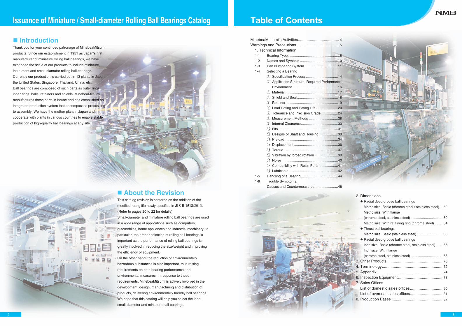
Thank you for your continued patronage of MinebeaMitsumi
products. Since our establishment in 1951 as Japan's first
manufacturer of miniature rolling ball bearings, we have
expanded the scale of our products to include miniature,
instrument and small-diameter rolling ball bearings.
Currently our production is carried out in 13 plants in Japan,
the United States, Singapore, Thailand, China, etc.
Ball bearings are composed of such parts as outer rings,
inner rings, balls, retainers and shields. MinebeaMitsumi
manufactures these parts in-house and has established an
integrated production system that encompasses processing
to assembly. We have the mother plant in Japan and
cooperate with plants in various countries to enable stable
production of high-quality ball bearings at any site.
This catalog revision is centered on the addition of the
modified rating life newly specified in JIS B 1518:2013.
(Refer to pages 20 to 22 for details)
Small-diameter and miniature rolling ball bearings are used
in a wide range of applications such as computers,
automobiles, home appliances and industrial machinery. In
particular, the proper selection of rolling ball bearings is
important as the performance of rolling ball bearings is
greatly involved in reducing the size/weight and improving
the efficiency of equipment.
On the other hand, the reduction of environmentally
hazardous substances is also important, thus raising
requirements on both bearing performance and
environmental measures. In response to these
requirements, MinebeaMitsumi is actively involved in the
development, design, manufacturing and distribution of
products, delivering environmentally friendly ball bearings.
We hope that this catalog will help you select the ideal
small-diameter and miniature ball bearings.
Introduction Introduction
About the Revision About the Revision
Issuance of Miniature / Small-diameter Rolling Ball Bearings Catalog
MinebeaMitsumi’s Activities...................................... 4Warnings and Precautions ....................................... 5
1. Technical Information 1-1 Bearing Type .....................................................8
1-2 Names and Symbols .......................................10
1-3 Part Numbering System ..................................11
1-4 Selecting a Bearing
1 Specification Process.................................14
2 Application Structure, Required Performance,
Environment ...............................................16
3 Material ......................................................17
4 Shield and Seal ..........................................18
5 Retainer......................................................19
6 Load Rating and Rating Life.......................20
7 Tolerance and Precision Grade .................24
8 Measurement Methods ..............................28
9 Internal Clearance......................................30
�� Fits .............................................................31
�� Designs of Shaft and Housing....................33
�� Preload.......................................................34
�� Displacement .............................................36
�� Torque........................................................37
�� Vibration by forced rotation ........................38
� Noise ..........................................................40
� Compatibility with Resin Parts....................41
�� Lubricants...................................................42
1-5 Handling of a Bearing ......................................44
1-6 Trouble Symptoms,
Causes and Countermeasures........................48
2. Dimensions Radial deep groove ball bearings
Metric size: Basic (chrome steel / stainless steel) ....52
Metric size: With flange
(chrome steel, stainless steel) ..................................60
Metric size: With retaining ring (chrome steel) .........64
Thrust ball bearings
Metric size: Basic (stainless steel)............................65
Radial deep groove ball bearings
Inch size: Basic (chrome steel, stainless steel) ........66
Inch size: With flange
(chrome steel, stainless steel) ..................................68
3. Other Products ....................................................70
4. Terminology.........................................................72
5. Appendix..............................................................74
6. Inspection Equipment ..........................................78
7. Sales Offices List of domestic sales offices...............................80
List of overseas sales offices...............................81
8. Production Bases ................................................82
Table of Contents
4
MinebeaMitsumi Group's CSR
The MinebeaMitsumi Group believes that enterprises have a mission to contribute to the sustainable development of the global environment and of humanity, not only through strict adherence to laws and regulations, but also through fair and proper management of our business in accordance with business ethics. To achieve this mission, we have established the “Five Principles” as our basic management policy, and on the basis of this policy, formulated the MinebeaMitsumi Group Basic CSR Policy and the MinebeaMitsumi Group’s CSR Implementation Principles to guide our CSR activities. We also stress the importance and strive to fulfill the Ten Principles of the UN Global Compact, to which we announced participation in 2012.
The MinebeaMitsumi Group’s Environmental Management
Be a company where our employees are proud to work Earn and preserve the trust of our valued customers Respond to our shareholders’ expectations Work in harmony with the local community Promote and contribute to global society
Basic Approach
The MinebeaMitsumi Group has established an environmental management system based on the MinebeaMitsumi Group Environmental Policy, and all Group companies are striving to contribute to the protection of the earth’s environment and the sustainable development of human kind.As examples of specific initiatives in this regard, we adopted highly energy-efficient equipment and processes and plan to reduce total Group CO2 emissions per basic unit of output by 5% by FY2015 compared with the baseline year (FY2010). We are also strengthening initiatives to minimize waste materials and wastewater from our plants in order to effectively utilize raw materials and water resources. We also make contributions to the environment through our products, including the active development of communications control technologies, sensors and new materials which are central to energy management in highly efficient motors, lighting, and energy conversion devices, as well as “smart” buildings, plants, and urban residential environments.
Basic Approach
The Five Principles
� The Five Principles and our Code of ConductIn promoting CSR activities, the MinebeaMitsumi Group will appropriately manage the organization in accordance with the “Five Principles,” and adhere to its Code of Conduct. Continuous improvement and raising of awareness
We will put forth goals to be achieved, based on understanding the MinebeaMitsumi Group’s social responsibilities and the key problems that need to be addressed, and continue to improve our CSR activities through implementation and continual review. We will also strive to raise awareness of CSR among all employees through CSR activities.
� Creation of Social Value through ProductsAs a manufacturer of precision products supporting society, the MinebeaMitsumi Group is actively developing reliable products which reduce energy consumption, and making them widely available.� Dialogue with stakeholdersConstructive dialogue with stakeholders (employees, customers, shareholders, local communities, global society, suppliers, and the environment) allows us to meet expectations and respond to requests, and we will improve transparency and accountability in our corporate activities.
The MinebeaMitsumi Group’s CSR Implementation Principles
The MinebeaMitsumi Group conducts business in consideration of the environment in accordance with "the Five Principles", and contributes to global environmental protection and the sustainable development of mankind.
1. Development and design of environmentally friendly products
2. Environmental considerations in manufacturing3. Environmental considerations in procurement and
distribution
4. Environmental considerations for national and local governments and surrounding areas
5. Contribution to the global society6. Raising awareness of environmental protection among
our employees
The MinebeaMitsumi Group Environmental Policy
As a manufacturer of precision products supporting society, the MinebeaMitsumi Group is working toward stable supply and making reliable products with low energy consumption widely available, to contribute to the sustainable development of the global environment and of humanity.
MinebeaMitsumi Group Basic CSR Policy
MinebeaMitsumi's Activities
5
Precautions
In the following circumstances, consult us to make selection. When used in environment of high-speed rotation, high precision, high/low temperature, high/low humidity and high load.
When used as important parts such as in aircrafts, space-related equipment, public facilities of electricity and gas, etc, automobiles and automobile-related parts, transportation/logistics equipment, multi-story parking equipment, lifting equipment, medical equipment, game machines/equipment, etc.
When resin is used for parts around rolling ball bearings.* Depending on the type of resin, grease or oil may cause the
resin parts to deteriorate or break.
When current may flow through the rolling ball bearings. When used in an environment that corrodes metals (corrosive gas, vapor, liquid).
The performance of rolling ball bearings will decline due to adhesion/intrusion of foreign matter, rusting and deterioration of grease, which may cause failure or damage. Be sure to observe the following when storing. Avoid high-temperature and high-humidity environments. Even while in package, do not place it directly on the floor. Store on a pallet to insure ventilation.
Avoid use in an environment that corrodes metals (corrosive gas, vapor, liquid).
Do not unpack unless necessary, and do not leave the ball bearings unprotected. When unpacking, use rubber gloves, etc. to avoid touching with bare hands.
Selecting a Bearing Bearing Storage
NMB is not responsible for damages to products used in applications that are unforeseeable by MinebeaMitsumi Group.
MinebeaMitsumi is not responsible for any damage caused by ball bearings if modified in any way.
MinebeaMitsumi is not responsible for any damage if application conditions and/or equipment specifications are changed after determining the ball bearing specification.
The products described in this catalog are not manufactured for nuclear equipment. MinebeaMitsumi is not responsible for damages caused by products used for nuclear applications.
Warnings
When vibration is applied to equipment incorporating ball bearings, wear marks due to fine movement (fretting) occur inside the bearings, causing noise and shortened life. Also, when impact is applied, the bearings will be scratched or indented, causing deterioration and shortening life of the rolling ball bearings, so pay attention to the following points. Consider the packaging of equipment incorporating rolling ball bearings so that vibrations and impacts can be buffered from the outside. Also, make sure the packaging does not allow rotary objects such as impellers to move.
Be careful not to subject the equipment to vibration or impact during transportation.
Please confirm the types of lubricants at the time of purchase. Some sealed and shielded bearings in the market use only oil lubrication.
Some ball bearings are subject to export restrictions under the Foreign Exchange and Foreign Trade Law. To export these cargoes, an export license from the Minister of Economy, Trade and Industry of Japan is required.
The contents of this catalog are subject to change without notice.
Storage and transportation of equipment Other
Scratches, indentations or foreign matter entering the bearings can cause noise and shorten the life of the bearings, so pay attention to the following points. Do not apply impact. Keep the operating environment clean.
Installation into equipment After assembling the ball bearing, perform an operation test to make sure it rotates normally. During operation test, increase the rotational speed as gradually as possible.
If any abnormalities are found during the operation check, stop operation immediately and carry out the check. Do not reuse ball bearings found to be abnormal.
Operation test
Warnings and Precautions
6
Technical Commentary
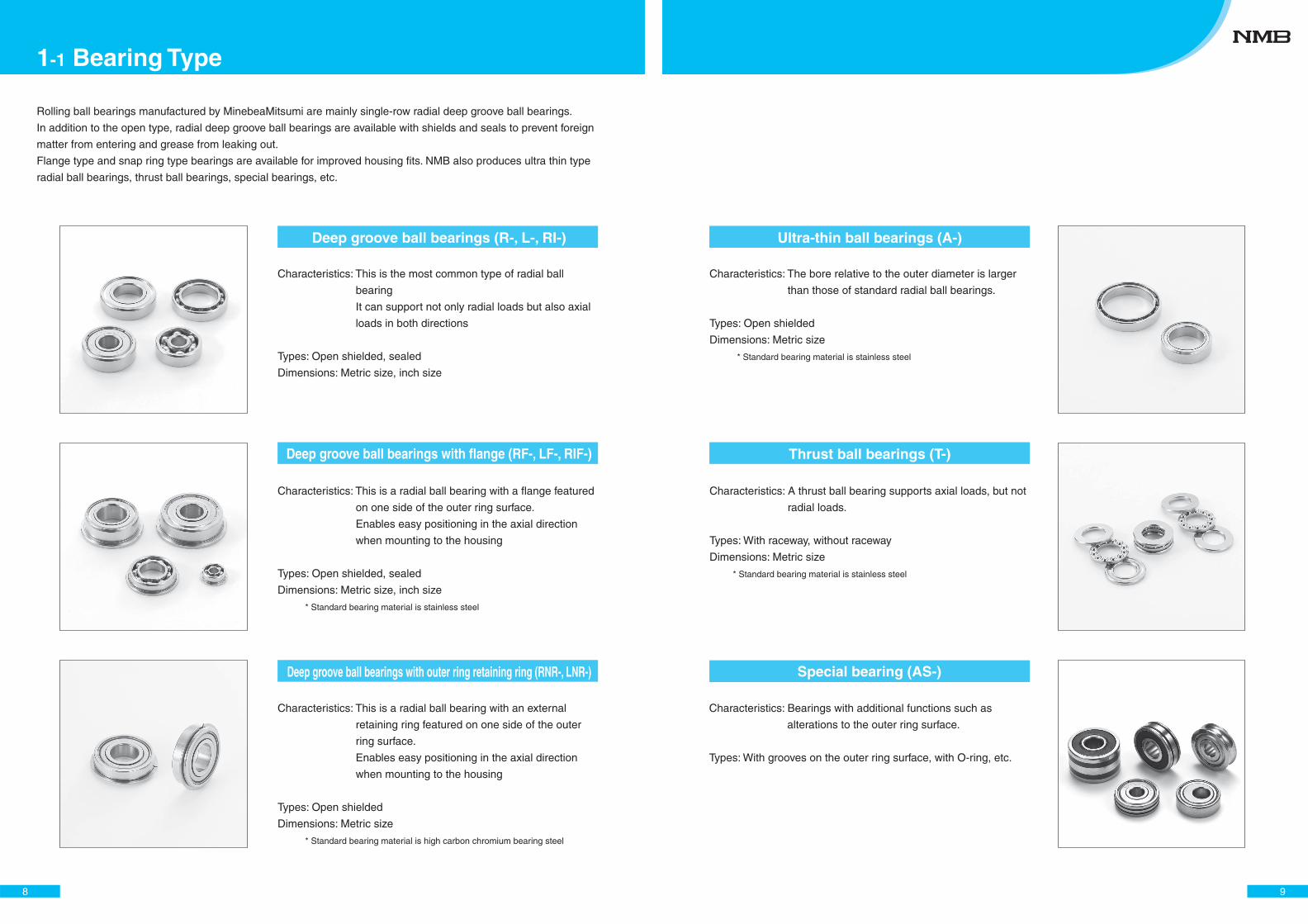
Rolling ball bearings manufactured by MinebeaMitsumi are mainly single-row radial deep groove ball bearings.
In addition to the open type, radial deep groove ball bearings are available with shields and seals to prevent foreign
matter from entering and grease from leaking out.
Flange type and snap ring type bearings are available for improved housing fits. NMB also produces ultra thin type
radial ball bearings, thrust ball bearings, special bearings, etc.
Deep groove ball bearings (R-, L-, RI-)
Deep groove ball bearings with flange (RF-, LF-, RIF-)
Deep groove ball bearings with outer ring retaining ring (RNR-, LNR-)
Characteristics: This is the most common type of radial ball
bearing
It can support not only radial loads but also axial
loads in both directions
Types: Open shielded, sealed
Dimensions: Metric size, inch size
Characteristics: This is a radial ball bearing with a flange featured
on one side of the outer ring surface.
Enables easy positioning in the axial direction
when mounting to the housing
Types: Open shielded, sealed
Dimensions: Metric size, inch size
* Standard bearing material is stainless steel
Characteristics: This is a radial ball bearing with an external
retaining ring featured on one side of the outer
ring surface.
Enables easy positioning in the axial direction
when mounting to the housing
Types: Open shielded
Dimensions: Metric size
* Standard bearing material is high carbon chromium bearing steel
8
1-1 Bearing Type
Ultra-thin ball bearings (A-)
Thrust ball bearings (T-)
Characteristics: A thrust ball bearing supports axial loads, but not
radial loads.
Types: With raceway, without raceway
Dimensions: Metric size
* Standard bearing material is stainless steel
Special bearing (AS-)
Characteristics: The bore relative to the outer diameter is larger
than those of standard radial ball bearings.
Types: Open shielded
Dimensions: Metric size
* Standard bearing material is stainless steel
Characteristics: Bearings with additional functions such as
alterations to the outer ring surface.
Types: With grooves on the outer ring surface, with O-ring, etc.
9
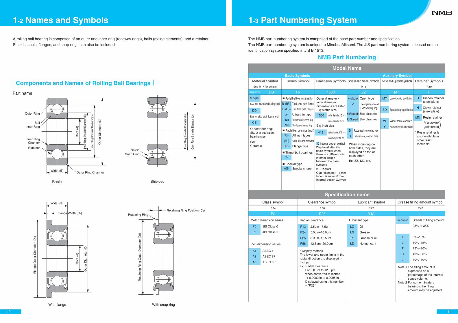
Components and Names of Rolling Ball Bearings
A rolling ball bearing is composed of an outer and inner ring (raceway rings), balls (rolling elements), and a retainer.
Shields, seals, flanges, and snap rings can also be included.
Shielded
With flange With snap ring
Part name
Basic
Outer Ring
ShieldSnap Ring
BallInner Ring
Outer Ring Chamfer
Retaining RingRetaining Ring Position (C2)
Bor
e (d
)
Out
er D
iam
eter
(D
)
Out
er R
ing
Shou
lder
Dia
met
er (L
o)
Inne
r Rin
g Sh
ould
er D
iam
eter
(Li)
Out
er R
ing
Shou
lder
Dia
met
er (L
o)
Inne
r Rin
g Sh
ould
er D
iam
eter
(Li)
Inner RingChamfer
Retainer
Width (B)
Width (B)
Flange Width (C1)
Fla
nge
Out
er D
iam
eter
(D
1)
Ret
aini
ng R
ing
Out
er D
iam
eter
(D
2)
Bor
e (d
)
Out
er D
iam
eter
(D
)
10
1-2 Names and Symbols
Basic Symbols
Material Symbol
DD R-
P0 P25 LY121 L
1560 ZZ MT RDisplay example
See P.17 for details P.18 P.19− − −
No display
P13
P24
P25
P58
2.5μm~ 7.5μm
5.0μm~10.0μm
5.0μm~12.5μm
12.5μm~20.0μm
LO
LG
LY
LD
Oil
Grease
Grease or oil
No lubricant
No display
X
L
T
H
J
Standard filling amount
25% to 35%
5%~10%
10%~15%
15%~20%
40%~50%
50%~60%
No display
Z
H (Pressed)
K (Staked)
Rubber seal, non-contact type
Rubber seal, contact type
MT
SD
W
Y
Low-noise motor specification
Special design specification
Wider than standard
Narrower than standard
Resin retainer
Polyamidereinforced
Series Symbol Dimension Symbols Shield and Seal Symbols Noise and Special Symbols
Clearance symbol Lubricant symbol Grease filling amount symbol
Auxiliary Symbol
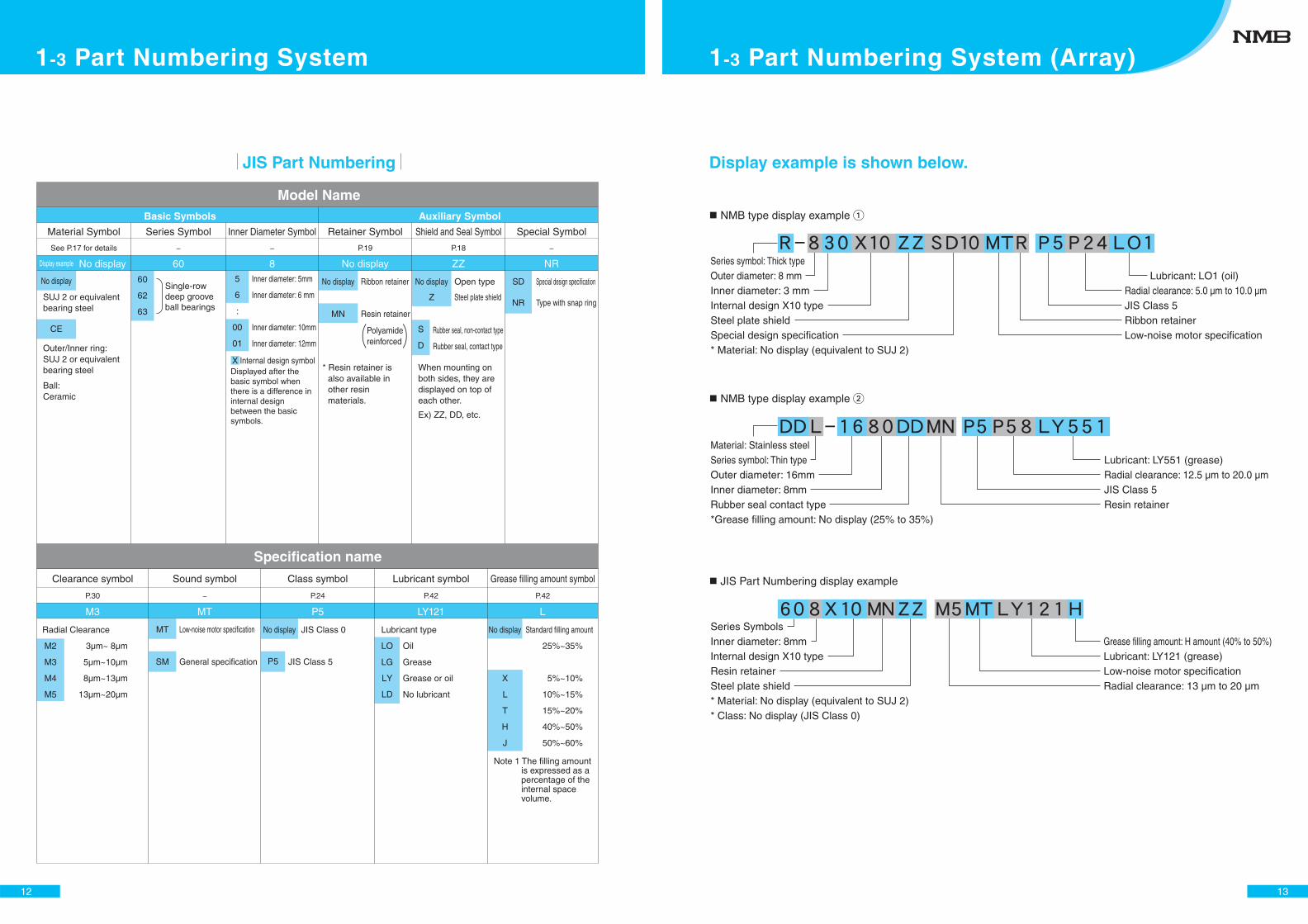
The NMB part numbering system is comprised of the base part number and specification.
The NMB part numbering system is unique to MinebeaMitsumi. The JIS part numbering system Is based on the
identification system specified in JIS B 1513.
Retainer Symbols
Model Name
Specification name
P.42P.30 P.42P.24
Class symbol
NMB Part Numbering
X
SUJ 2 or equivalent bearing steel
Martensitic stainless steel
Outer/Inner ring:SUJ 2 or equivalent bearing steel
Ball: Ceramic
Outer diameter - inner diameter dimensions are listed.Ex) Metric size
Displayed after the basic symbol when there is a difference in internal design between the basic symbols.
Ex) 1560X2Outer diameter: 15 mmInner diameter: 6 mmInternal design X2 type
When mounting on both sides, they are displayed on top of each other.
Ex) ZZ, DD, etc.
Open type
Steel plate shield(Fixed with snap ring)
Steel plate shield
Steel plate shield
S
D* Resin retainer is
also available in other resin materials.
Metric dimension series
JIS Class 0
JIS Class 5
P0
P5
Inch dimension series
* Display method The lower and upper limits in the radial direction are displayed in inches.Ex) Radial clearance
For 5.0 μm to 12.5 μm when converted to inches
0.0002 in to 0.0005 in Displayed using this number = "P25".
Note 1 The filling amount is expressed as a percentage of the internal space volume.
Note 2 For some miniature bearings, the filling amount may be adjusted.
DD
CE
Thick type (with flange)
Thin type (with flange)
Ultra-thin type
Thick type with snap ring
Thin type with snap ring
All inch types
*Used for some inch types
Flange type
Special shape
Radial ball bearings (metric)
Radial ball bearings (inch)
Thrust ball bearings
Special type
R- (RF-)
L- (LF-)
A-
RNR-
LNR-
RI-
(R-)
RIF-
T-
AS-
1560
418
outer diameter: 15 mm
inner diameter: 6 mm
Ex) Inch size
outer diameter: 4/16 inch
inner diameter: 1/8 inch
Internal design symbol
R
H
MN
Ribbon retainer(steel plate)
Crown retainer(steel plate)
A1
A3
A5
ABEC 1
ABEC 3P
ABEC 5P
Radial Clearance Lubricant type
11
1-3 Part Numbering System
Basic Symbols
Material Symbol
No display 60
M3 MT P5 LY121 L
8 No display ZZ NRDisplay example
No display 60
62
63
MT
SM
Radial Clearance Lubricant type
M2
M3
M4
M5
3μm~ 8μm
5μm~10μm
8μm~13μm
13μm~20μm
No display No display
X
L
T
H
J
25%~35%
5%~10%
10%~15%
15%~20%
40%~50%
50%~60%
LO
LG
LY
LD
5
6
:
00
01
Inner diameter: 5mm
Inner diameter: 6 mm
Inner diameter: 10mm
Inner diameter: 12mm
No display
MN
SD
NR
Special design specification
Type with snap ring
Series Symbol Inner Diameter Symbol Retainer Symbol Shield and Seal Symbol Special Symbol
Clearance symbol Class symbolSound symbol Lubricant symbol Grease filling amount symbol
Auxiliary Symbol
Model Name
JIS Part Numbering
P.18P.19
P.30 − P.42 P.42P.24
− − −See P.17 for details
Polyamide reinforced
Specification name
X Internal design symbol
SUJ 2 or equivalent bearing steel
CE
Single-row deep groove ball bearings
Displayed after the basic symbol when there is a difference in internal design between the basic symbols.
* Resin retainer is also available in other resin materials.
When mounting on both sides, they are displayed on top of each other.
Ex) ZZ, DD, etc.
Outer/Inner ring:SUJ 2 or equivalent bearing steel
Ball: Ceramic
Ribbon retainer
Resin retainer
Open type
Steel plate shield
Rubber seal, non-contact type
Rubber seal, contact type
No display
Z
S
D
Low-noise motor specification
General specification
JIS Class 0
JIS Class 5P5
Oil
Grease
Grease or oil
No lubricant
Standard filling amount
Note 1 The filling amount is expressed as a percentage of the internal space volume.
12
1-3 Part Numbering System
Display example is shown below.
NMB type display example �
NMB type display example �
JIS Part Numbering display example
Series symbol: Thick typeOuter diameter: 8 mmInner diameter: 3 mmInternal design X10 typeSteel plate shieldSpecial design specification* Material: No display (equivalent to SUJ 2)
Lubricant: LO1 (oil)Radial clearance: 5.0 μm to 10.0 μmJIS Class 5Ribbon retainerLow-noise motor specification
Material: Stainless steelSeries symbol: Thin typeOuter diameter: 16mmInner diameter: 8mmRubber seal contact type*Grease filling amount: No display (25% to 35%)
Lubricant: LY551 (grease)Radial clearance: 12.5 μm to 20.0 μmJIS Class 5Resin retainer
Series SymbolsInner diameter: 8mmInternal design X10 typeResin retainerSteel plate shield* Material: No display (equivalent to SUJ 2)* Class: No display (JIS Class 0)
Grease filling amount: H amount (40% to 50%)Lubricant: LY121 (grease)Low-noise motor specificationRadial clearance: 13 μm to 20 μm
13
1-3 Part Numbering System (Array)
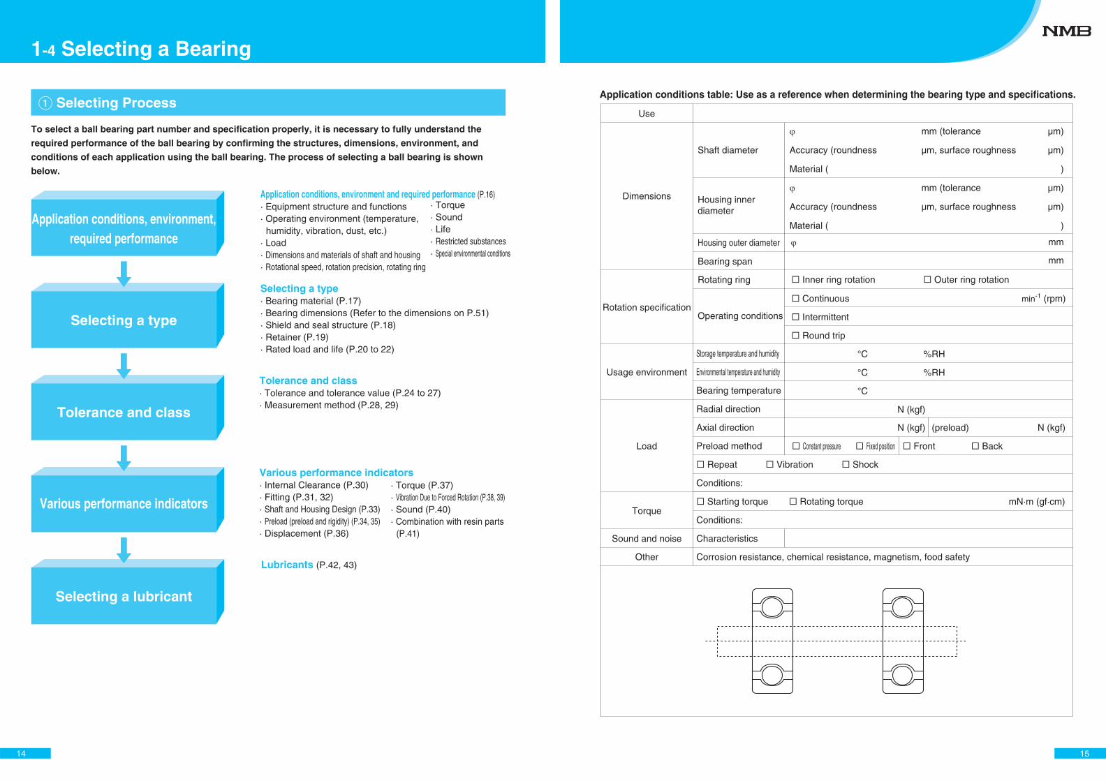
� Selecting Process
To select a ball bearing part number and specification properly, it is necessary to fully understand the
required performance of the ball bearing by confirming the structures, dimensions, environment, and
conditions of each application using the ball bearing. The process of selecting a ball bearing is shown
below.
Application conditions, environment and required performance (P.16)· Equipment structure and functions· Operating environment (temperature,
humidity, vibration, dust, etc.) · Load · Dimensions and materials of shaft and housing· Rotational speed, rotation precision, rotating ring
Selecting a type· Bearing material (P.17)· Bearing dimensions (Refer to the dimensions on P.51)· Shield and seal structure (P.18)· Retainer (P.19)· Rated load and life (P.20 to 22)
Tolerance and class· Tolerance and tolerance value (P.24 to 27)· Measurement method (P.28, 29)
Various performance indicators· Internal Clearance (P.30)· Fitting (P.31, 32)· Shaft and Housing Design (P.33)· Preload (preload and rigidity) (P.34, 35)· Displacement (P.36)
Lubricants (P.42, 43)
Application conditions, environment,required performance
Selecting a type
Tolerance and class
Various performance indicators
Selecting a lubricant
· Torque· Sound· Life· Restricted substances· Special environmental conditions
· Torque (P.37)· Vibration Due to Forced Rotation (P.38, 39)· Sound (P.40)· Combination with resin parts
(P.41)
14
1-4 Selecting a Bearing
Use
Dimensions
Rotation specification
Usage environment
Load
Torque
Sound and noise
Other Corrosion resistance, chemical resistance, magnetism, food safety
Shaft diameter
Housing inner diameter
Housing outer diameter
Bearing span
Rotating ring
Operating conditions
mm (tolerance μm)
Accuracy (roundness μm, surface roughness μm)
Material ( )
mm (tolerance μm)
Accuracy (roundness μm, surface roughness μm)
Material ( )
Inner ring rotation Outer ring rotation
Continuous min-1 (rpm)
Intermittent
Round trip
°C %RH
°C %RH
°C
N (kgf)
N (kgf) (preload) N (kgf)
Constant pressure Fixed position Front Back
Storage temperature and humidity
Environmental temperature and humidity
Bearing temperature
Radial direction
Axial direction
Preload method
Repeat Vibration Shock
Conditions:
Starting torque Rotating torque mN·m (gf·cm)
Conditions:
Characteristics
Application conditions table: Use as a reference when determining the bearing type and specifications.
mm
mm
15
16
Review the dimensions of the location where the bearing is to be mounted, the expected performance of
the bearing, the operating environment and conditions. In recent years, the size of equipment has been
reduced, and there are many cases where there are restrictions on the structure. However, in order to
maintain the required performance for a long period of time, it is recommended to provide as much space
as possible.
It is also important to take market factors into account for selecting the bearing part number and specification.
� Application Structure, Required Performance, Environment
1-4 Selecting a Bearing
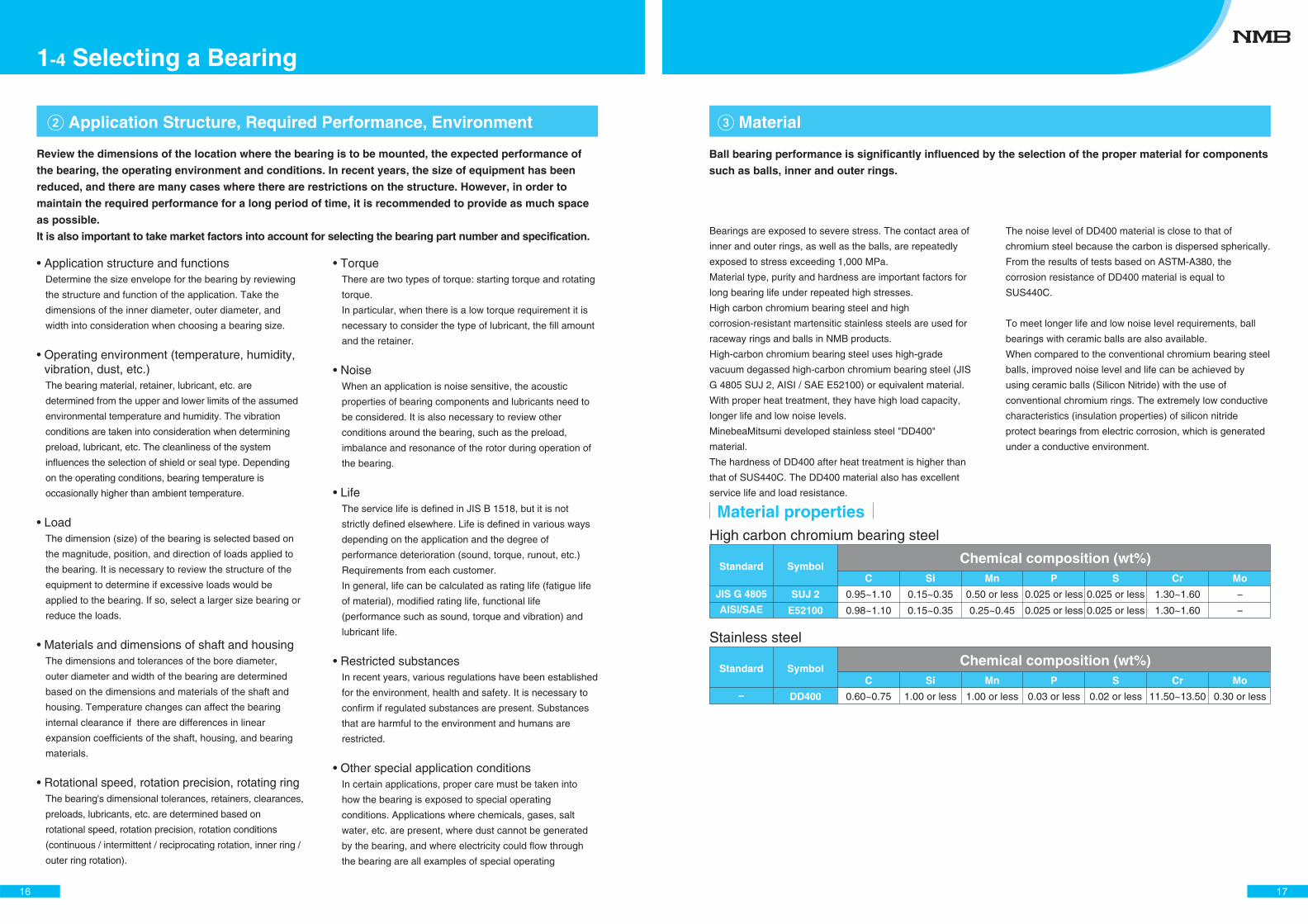
17
SymbolStandardC Si Mn P S Cr Mo
JIS G 4805
AISI/SAE
SUJ 2 −
−E52100
Chemical composition (wt%)
SymbolStandardC Si Mn P S Cr Mo
− DD400
Chemical composition (wt%)
Material properties
� Material
Ball bearing performance is significantly influenced by the selection of the proper material for components
such as balls, inner and outer rings.
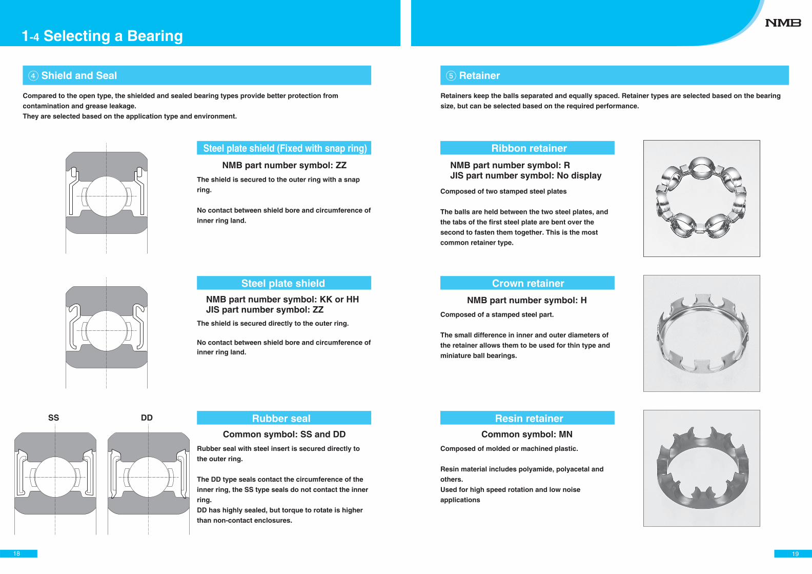
Steel plate shield (Fixed with snap ring)
Steel plate shield
Rubber seal
Rubber seal with steel insert is secured directly to
the outer ring.
The DD type seals contact the circumference of the
inner ring, the SS type seals do not contact the inner
ring.
DD has highly sealed, but torque to rotate is higher
than non-contact enclosures.
The shield is secured to the outer ring with a snap
ring.
No contact between shield bore and circumference of
inner ring land.
NMB part number symbol: ZZ
NMB part number symbol: KK or HHJIS part number symbol: ZZ
Common symbol: SS and DD
The shield is secured directly to the outer ring.
No contact between shield bore and circumference of inner ring land.
DDSS
� Shield and Seal
18
1-4 Selecting a Bearing
Compared to the open type, the shielded and sealed bearing types provide better protection from
contamination and grease leakage.
They are selected based on the application type and environment.
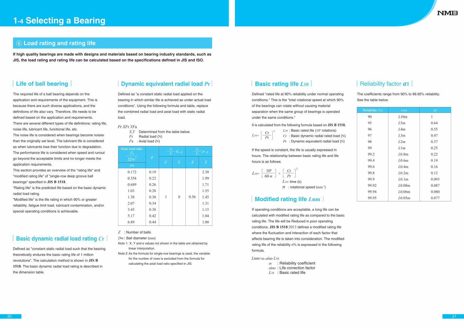
NMB part number symbol: RJIS part number symbol: No display
Common symbol: MN
Ribbon retainer
Crown retainer
Resin retainer
Composed of two stamped steel plates
The balls are held between the two steel plates, and
the tabs of the first steel plate are bent over the
second to fasten them together. This is the most
common retainer type.
NMB part number symbol: H
Composed of a stamped steel part.
The small difference in inner and outer diameters of
the retainer allows them to be used for thin type and
miniature ball bearings.
Composed of molded or machined plastic.
Resin material includes polyamide, polyacetal and
others.
Used for high speed rotation and low noise
applications
� Retainer
19
Retainers keep the balls separated and equally spaced. Retainer types are selected based on the bearing
size, but can be selected based on the required performance.
20
The required life of a ball bearing depends on the
application and requirements of the equipment. This is
because there are such diverse applications, and the
definitions of life also vary. Therefore, life needs to be
defined based on the application and requirements.
There are several different types of life definitions: rating life,
noise life, lubricant life, functional life, etc.
The noise life is considered when bearings become noisier
than the originally set level. The lubricant life is considered
as when lubricants lose their function due to degradation.
The performance life is considered when speed and runout
go beyond the acceptable limits and no longer meets the
application requirements.
This section provides an overview of the "rating life" and
"modified rating life" of "single-row deep groove ball
bearings" specified in JIS B 1518.
"Rating life" is the predicted life based on the basic dynamic
radial load rating.
"Modified life" is the life rating in which 90% or greater
reliability, fatigue limit load, lubricant contamination, and/or
special operating conditions is achievable.
Defined as "a constant static radial load applied on the
bearing in which similar life is achieved as under actual load
conditions". Using the following formula and table, replace
the combined radial load and axial load with static radial
load.
Defined as "constant static radial load such that the bearing
theoretically endures the basic rating life of 1 million
revolutions". The calculation method is shown in JIS B 1518. The basic dynamic radial load rating is described in
the dimension table.
If high quality bearings are made with designs and materials based on bearing industry standards, such as
JIS, the load rating and rating life can be calculated based on the specifications defined in JIS and ISO.
� Load rating and rating life
Life of ball bearing
Basic dynamic radial load rating Cr
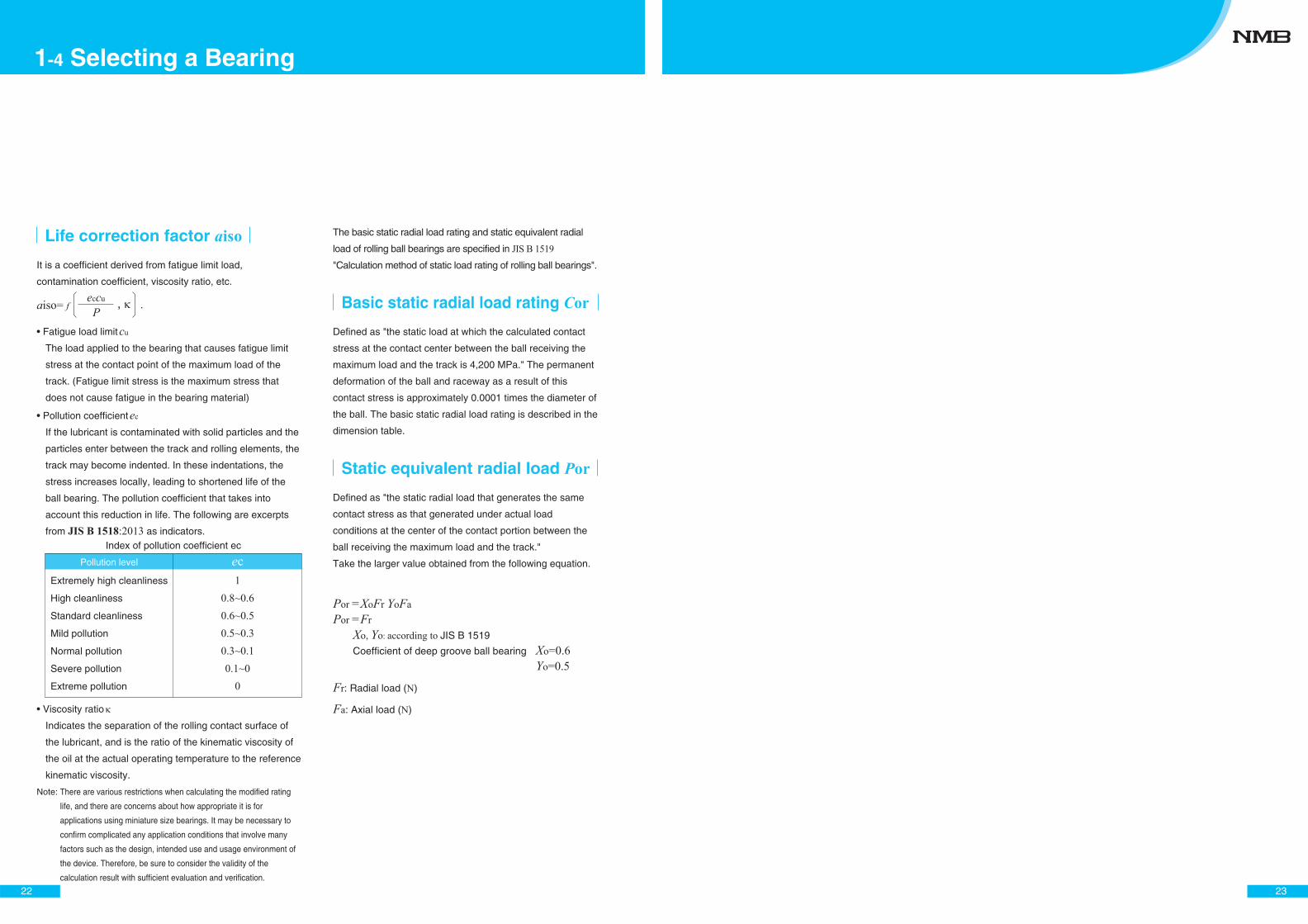
Dynamic equivalent radial load Pr
X,Y Determined from the table below.Fr Radial load (N)Fa : Axial load (N)
Axial load ratio
ZDW2
Fa
(N)
0.1720.3540.6891.031.382.073.455.176.89
0.190.220.260.280.300.340.380.420.44
2.301.991.711.551.451.311.151.041.00
e e
X Y X Y
Fr
Fa eFr
Fa
1 0 0.56
Pr XFr YFa
Z : Number of balls
Dw : Ball diameter (mm)Note 1: X, Y and e values not shown in the table are obtained by
linear interpolation.
Note 2: As the formula for single-row bearings is used, the variable
for the number of rows is excluded from the formula for
calculating the axial load ratio specified in JIS.
1-4 Selecting a Bearing
21
If operating conditions are acceptable, a long life can be
calculated with modified rating life as compared to the basic
rating life. The life will be Reduced in poor operating
conditions. JIS B 1518:2013 defines a modified rating life
where the fluctuation and interaction of each factor that
affects bearing life is taken into consideration. The modified
rating life of the reliability n% is expressed in the following
formula.
It is calculated from the following formula based on JIS B 1518.
Defined "rated life at 90% reliability under normal operating
conditions." This is the "total rotational speed at which 90%
of the bearings can rotate without causing material
separation when the same group of bearings is operated
under the same conditions."
Basic rating life L10
Modified rating life Lnm
The coefficients range from 90% to 99.95% reliability.
See the table below.
Reliability factor a1
L10 : Basic rated life (106 rotations)
Cr : Basic dynamic radial rated load (N)
Pr : Dynamic equivalent radial load (N)
L10 PrCr 3
L1060·n106
PrCr
×3
L10 : time (h)
n : rotational speed (min-1)
a1 : Reliability coefficientaiso : Life correction factorL10 : Basic rated life
Lnm=a1 aiso L10
Reliability (%)
90959697989999.299.499.699.899.999.9299.9499.95
L10mL5mL4mL3mL2mL1mL0.8mL0.6mL0.4mL0.2mL0.1mL0.08mL0.06mL0.05m
10.640.550.470.370.250.220.190.160.120.0930.0870.0800.077
Lnm a1
If the speed is constant, the life is usually expressed in
hours. The relationship between basic rating life and life
hours is as follows.
22
Defined as "the static load at which the calculated contact
stress at the contact center between the ball receiving the
maximum load and the track is 4,200 MPa." The permanent
deformation of the ball and raceway as a result of this
contact stress is approximately 0.0001 times the diameter of
the ball. The basic static radial load rating is described in the
dimension table.
Defined as "the static radial load that generates the same
contact stress as that generated under actual load
conditions at the center of the contact portion between the
ball receiving the maximum load and the track."
Take the larger value obtained from the following equation.
Basic static radial load rating Cor
Static equivalent radial load Por
The basic static radial load rating and static equivalent radial
load of rolling ball bearings are specified in JIS B 1519
"Calculation method of static load rating of rolling ball bearings".It is a coefficient derived from fatigue limit load,
contamination coefficient, viscosity ratio, etc.
Fatigue load limit cu
The load applied to the bearing that causes fatigue limit
stress at the contact point of the maximum load of the
track. (Fatigue limit stress is the maximum stress that
does not cause fatigue in the bearing material)
Pollution coefficient ec
If the lubricant is contaminated with solid particles and the
particles enter between the track and rolling elements, the
track may become indented. In these indentations, the
stress increases locally, leading to shortened life of the
ball bearing. The pollution coefficient that takes into
account this reduction in life. The following are excerpts
from JIS B 1518:2013 as indicators.
Viscosity ratio
Indicates the separation of the rolling contact surface of
the lubricant, and is the ratio of the kinematic viscosity of
the oil at the actual operating temperature to the reference
kinematic viscosity.
Note: There are various restrictions when calculating the modified rating
life, and there are concerns about how appropriate it is for
applications using miniature size bearings. It may be necessary to
confirm complicated any application conditions that involve many
factors such as the design, intended use and usage environment of
the device. Therefore, be sure to consider the validity of the
calculation result with sufficient evaluation and verification.
Life correction factor aiso
Index of pollution coefficient ec
aiso= f P, eccu
.
Extremely high cleanliness
High cleanliness
Standard cleanliness
Mild pollution
Normal pollution
Severe pollution
Extreme pollution
10.8~0.60.6~0.50.5~0.30.3~0.10.1~0
0
Pollution level ec
Por =XoFr YoFaPor =Fr
Xo, Yo: according to JIS B 1519
Coefficient of deep groove ball bearing Xo=0.6 Yo=0.5
Fr: Radial load (N)
Fa: Axial load (N)
1-4 Selecting a Bearing
23
24
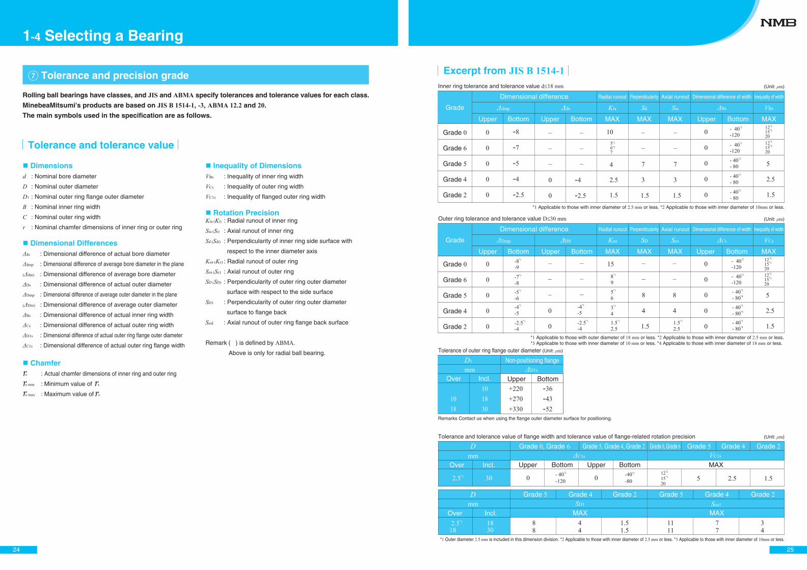
Dimensionsd : Nominal bore diameter
D : Nominal outer diameter
D1 : Nominal outer ring flange outer diameter
B : Nominal inner ring width
C : Nominal outer ring width
r : Nominal chamfer dimensions of inner ring or outer ring
Inequality of DimensionsVBs : Inequality of inner ring width
VCs : Inequality of outer ring width
VC1s : Inequality of flanged outer ring width
Rotation PrecisionKia (Ki) : Radial runout of inner ring
Sia (Si) : Axial runout of inner ring
Sd (Sdi) : Perpendicularity of inner ring side surface with
respect to the inner diameter axis
Kea (Ke) : Radial runout of outer ring
Sea (Se) : Axial runout of outer ring
SD (SD) : Perpendicularity of outer ring outer diameter
surface with respect to the side surface
SD1 : Perpendicularity of outer ring outer diameter
surface to flange back
Seal : Axial runout of outer ring flange back surface
Remark ( ) is defined by ABMA.
Above is only for radial ball bearing.
Dimensional Differencesds : Dimensional difference of actual bore diameter
dmp : Dimensional difference of average bore diameter in the plane
( dm) : Dimensional difference of average bore diameter
Ds : Dimensional difference of actual outer diameter
Dmp : Dimensional difference of average outer diameter in the plane
( Dm) : Dimensional difference of average outer diameter
Bs : Dimensional difference of actual inner ring width
Cs : Dimensional difference of actual outer ring width
D1s : Dimensional difference of actual outer ring flange outer diameter
C1s : Dimensional difference of actual outer ring flange width
� Tolerance and precision grade
Tolerance and tolerance value
Chamfers : Actual chamfer dimensions of inner ring and outer ring
s min : Minimum value of s
s max : Maximum value of s
Rolling ball bearings have classes, and JIS and ABMA specify tolerances and tolerance values for each class.
MinebeaMitsumi's products are based on JIS B 1514-1, -3, ABMA 12.2 and 20.
The main symbols used in the specification are as follows.
1-4 Selecting a Bearing
25
Grade 0
Grade 6
Grade 5
Grade 4
Grade 2
Grade
0
0
0
0
0
0
0
15
5*1
6
3*1
4
1.5*1
2.5 1.5*1
2.5
8
4
1.5
8
4
0
0
0
0
0
Dimensional difference
Dmp DS
Outer ring tolerance and tolerance value D 30 mm
Upper Bottom Upper Bottom MAX Upper Bottom MAXMAX MAX
Perpendicularity Dimensional difference of width Inequality of width
Kea SD Sea Cs VCs
- 40*2
-120
- 40*2
-120
- 40*3
- 80*4
- 40*3
- 80*4
- 40*3
- 80*4
-8*1
-9
-7*1
-8
-5*1
-6-4*1
-5
-2.5*1
-4
-4*1
-5
-2.5*1
-4
12*2
15*3
20 12*2
15*3
20
*1 Applicable to those with outer diameter of 18 mm or less. *2 Applicable to those with inner diameter of 2.5 mm or less.*3 Applicable to those with inner diameter of 10 mm or less. *4 Applicable to those with inner diameter of 18 mm or less.
(Unit: m)
8*1
9
Incl.
+220+270+330
-36-43-52
D1 Non-positioning flangemm D1s
Tolerance of outer ring flange outer diameter
Upper Bottom
Remarks Contact us when using the flange outer diameter surface for positioning.
(Unit: m)
Over
1018
Tolerance and tolerance value of flange width and tolerance value of flange-related rotation precision
*1 Outer diameter 2.5 mm is included in this dimension division. *2 Applicable to those with inner diameter of 2.5 mm or less. *3 Applicable to those with inner diameter of 10mm or less.
(Unit: m)
Incl.88
44
1.51.5
1111
SD1
Over77
34
Sea1
2.5*1
181830
Grade 5 Grade 4 Grade 2 Grade 5 Grade 4 Grade 2
MAXMAX
2.5*1
Incl.
0 0- 40*2
-120-40*3
-80
D Grade 0, Grade 6 Grade 5, Grade 4, Grade 2mm
Dmm
C1s
Upper Bottom Upper BottomOver12*2
15*3
205 2.5 1.5
VC1s
MAX
Grade 0, Grade 6 Grade 5 Grade 4 Grade 2
30
Grade 0
Grade 6
Grade 5
Grade 4
Grade 2
0
0
0
0
0
-8
-7
-5
-4
-2.5
0
0
-4
-2.5
5*1
6*2
7
7
3
1.5
4
2.5
1.5
7
3
1.5
5
2.5
1.5
5
2.5
1.5
0
0
0
0
0
- 40*1
-120
- 40*1
-120
- 40*2
- 80
- 40*2
- 80
- 40*2
- 80
12*1
15*2
2012*1
15*2
20
*1 Applicable to those with inner diameter of 2.5 mm or less. *2 Applicable to those with inner diameter of 10mm or less.
Grade
Dimensional difference
dmp ds
Upper Bottom Upper Bottom MAX Upper Bottom MAXMAX MAX
Radial runout Perpendicularity Axial runout
Radial runout Axial runout
Dimensional difference of width Inequality of width
Kia Sd Sia Bs VBs
10
Excerpt from JIS B 1514-1Inner ring tolerance and tolerance value d 18 mm (Unit: m)
101830
26
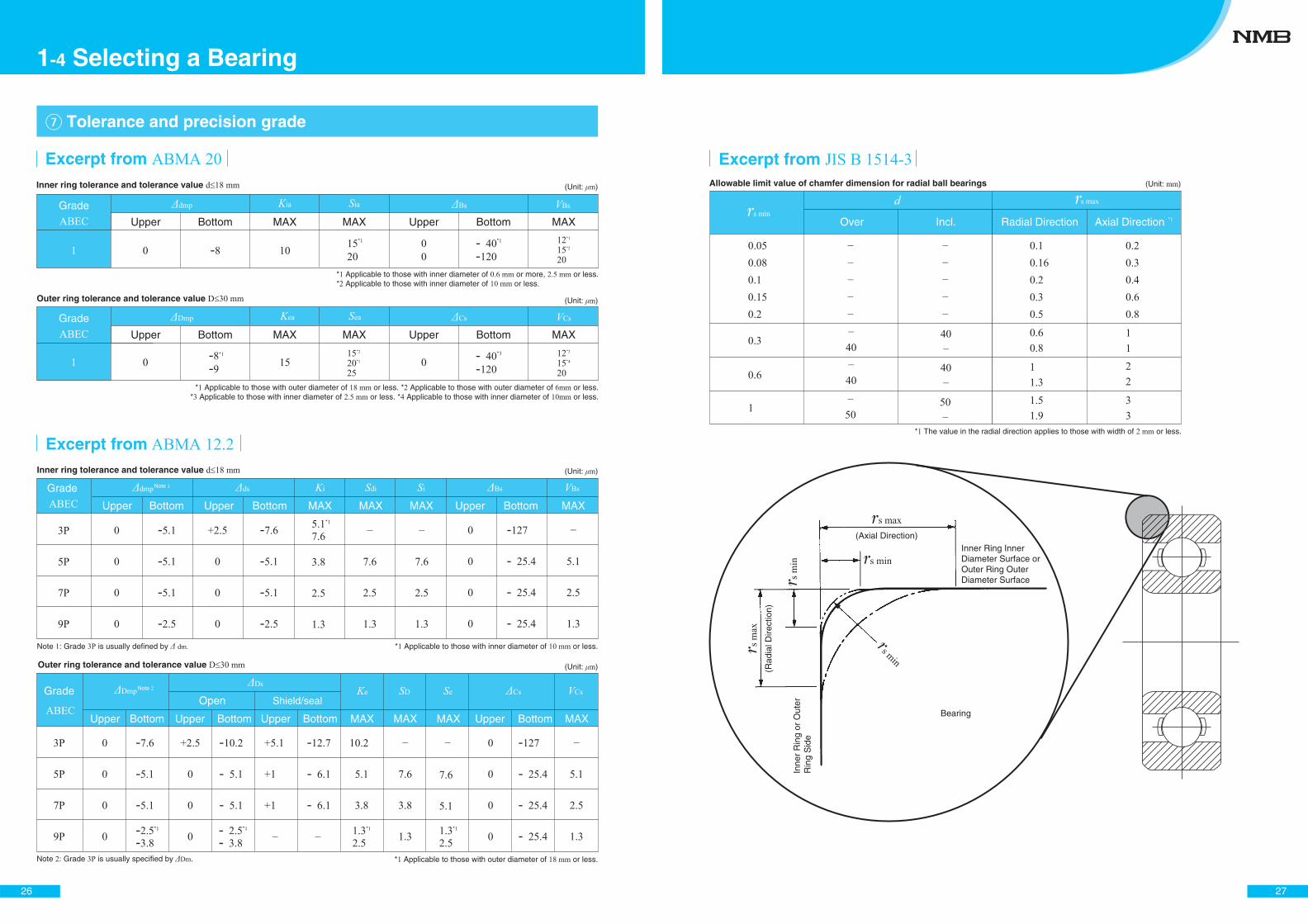
� Tolerance and precision grade
Outer ring tolerance and tolerance value
* *
* Applicable to those with outer diameter of or less.
GradeOpen
Upper Bottom Upper Bottom Upper Bottom MAX Upper Bottom MAXMAX MAX
Shield/sealS S V
Excerpt fromInner ring tolerance and tolerance value
Excerpt from Inner ring tolerance and tolerance value
*
* Applicable to those with inner diameter of or less.Note : Grade is usually defined by
Note : Grade is usually specified by .
(Unit: )
(Unit: )
Grade
Upper Bottom Upper Bottom MAX Upper Bottom MAXMAX MAX
K
K
S S V
* *
(Unit: )
* *
*
Upper Bottom Upper Bottom*
*
MAXMAXMAX
K S VGrade
Outer ring tolerance and tolerance value (Unit: )
*
Upper Bottom Upper Bottom*
*
*
*
MAXMAXMAX
K S VGrade
* Applicable to those with outer diameter of or less. * Applicable to those with outer diameter of or less.
* Applicable to those with inner diameter of or more, or less.* Applicable to those with inner diameter of or less.
* Applicable to those with inner diameter of or less. * Applicable to those with inner diameter of or less.
Note
Note
1-4 Selecting a Bearing
27
Incl.
d(Unit: )
Over Radial Direction Axial Direction
Excerpt from Allowable limit value of chamfer dimension for radial ball bearings
* The value in the radial direction applies to those with width of or less.
*
(Axial Direction)
(Rad
ial D
irect
ion)
Inner Ring Inner Diameter Surface or Outer Ring Outer Diameter Surface
Inne
r R
ing
or O
uter
R
ing
Sid
e
Bearing
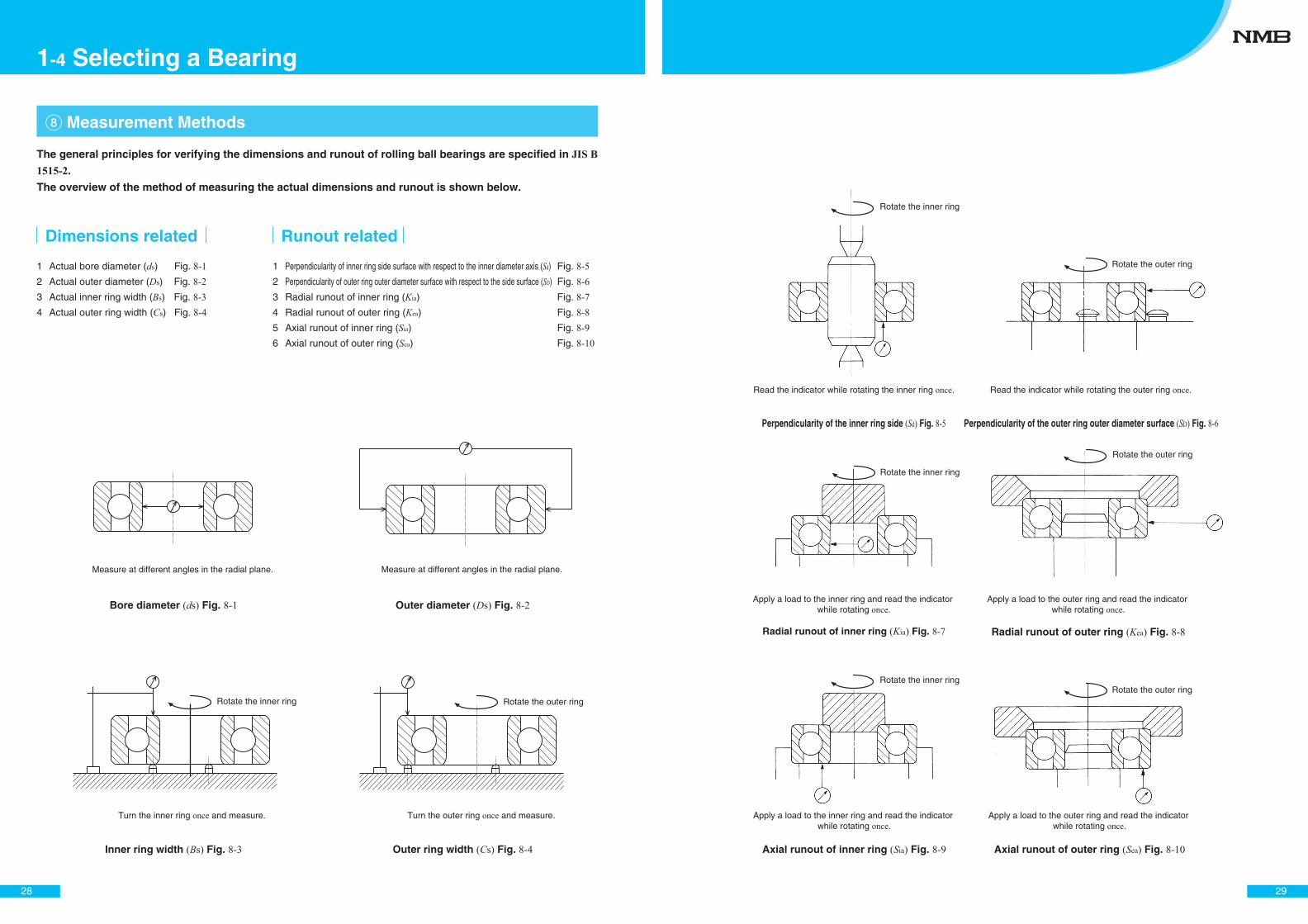
� Measurement Methods
1 Actual bore diameter (ds) Fig. 8-12 Actual outer diameter (Ds) Fig. 8-23 Actual inner ring width (Bs) Fig. 8-34 Actual outer ring width (Cs) Fig. 8-4
Dimensions related
1 Perpendicularity of inner ring side surface with respect to the inner diameter axis (Sd) Fig. 8-52 Perpendicularity of outer ring outer diameter surface with respect to the side surface (SD) Fig. 8-63 Radial runout of inner ring (Kia) Fig. 8-74 Radial runout of outer ring (Kea) Fig. 8-85 Axial runout of inner ring (Sia) Fig. 8-96 Axial runout of outer ring (Sea) Fig. 8-10
Runout related
Inner ring width (Bs) Fig. 8-3 Outer ring width (Cs) Fig. 8-4
Outer diameter (Ds) Fig. 8-2Bore diameter (ds) Fig. 8-1
Measure at different angles in the radial plane.
Turn the inner ring once and measure. Turn the outer ring once and measure.
Measure at different angles in the radial plane.
Rotate the inner ring Rotate the outer ring
28
1-4 Selecting a Bearing
The general principles for verifying the dimensions and runout of rolling ball bearings are specified in JIS B 1515-2.
The overview of the method of measuring the actual dimensions and runout is shown below.
Radial runout of inner ring (Kia) Fig. 8-7
Axial runout of outer ring (Sea) Fig. 8-10
Perpendicularity of the inner ring side (Sd) Fig. 8-5
Axial runout of inner ring (Sia) Fig. 8-9
Perpendicularity of the outer ring outer diameter surface (SD) Fig. 8-6
Rotate the inner ring
Rotate the inner ring
Rotate the outer ring
Rotate the outer ring
Rotate the outer ring
Rotate the inner ring
Read the indicator while rotating the inner ring once.
Radial runout of outer ring (Kea) Fig. 8-8
Apply a load to the outer ring and read the indicator while rotating once.
Read the indicator while rotating the outer ring once.
Apply a load to the inner ring and read the indicator while rotating once.
Apply a load to the outer ring and read the indicator while rotating once.
Apply a load to the inner ring and read the indicator while rotating once.
29
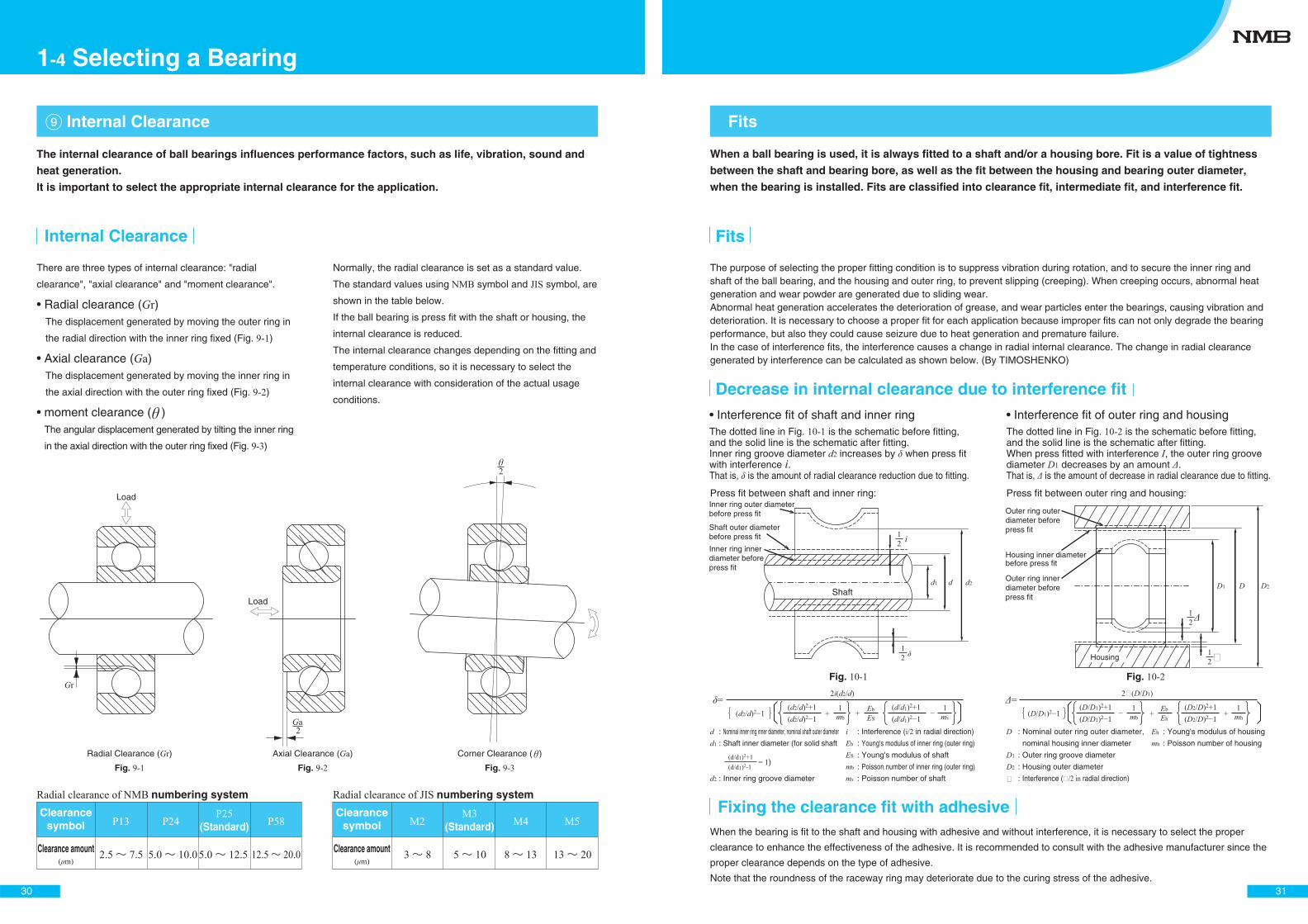
There are three types of internal clearance: "radial
clearance", "axial clearance" and "moment clearance".
Radial clearance (Gr)The displacement generated by moving the outer ring in
the radial direction with the inner ring fixed (Fig. 9-1)
Axial clearance (Ga)The displacement generated by moving the inner ring in
the axial direction with the outer ring fixed (Fig. 9-2)
moment clearance ( )The angular displacement generated by tilting the inner ring
in the axial direction with the outer ring fixed (Fig. 9-3)
Normally, the radial clearance is set as a standard value.
The standard values using NMB symbol and JIS symbol, are
shown in the table below.
If the ball bearing is press fit with the shaft or housing, the
internal clearance is reduced.
The internal clearance changes depending on the fitting and
temperature conditions, so it is necessary to select the
internal clearance with consideration of the actual usage
conditions.
� Internal Clearance
Radial clearance of NMB numbering system Radial clearance of JIS numbering system
Clearance amount( m)
Clearance amount( m)
2.5 7.5 5.0 10.05.0 12.5 12.5 20.0
P13 P24P25
(Standard) P58
3 8 5 10 8 13 13 20
M2M3
(Standard) M5M4Clearance
symbolClearance
symbol
Internal Clearance
Fig. 9-1 Fig. 9-2 Fig. 9-3
Gr
Ga2
2
Load
Load
Radial Clearance (Gr) Axial Clearance (Ga) Corner Clearance ( )
30
1-4 Selecting a Bearing
The internal clearance of ball bearings influences performance factors, such as life, vibration, sound and
heat generation.
It is important to select the appropriate internal clearance for the application.
The purpose of selecting the proper fitting condition is to suppress vibration during rotation, and to secure the inner ring and shaft of the ball bearing, and the housing and outer ring, to prevent slipping (creeping). When creeping occurs, abnormal heat generation and wear powder are generated due to sliding wear.Abnormal heat generation accelerates the deterioration of grease, and wear particles enter the bearings, causing vibration and deterioration. It is necessary to choose a proper fit for each application because improper fits can not only degrade the bearing performance, but also they could cause seizure due to heat generation and premature failure.In the case of interference fits, the interference causes a change in radial internal clearance. The change in radial clearance generated by interference can be calculated as shown below. (By TIMOSHENKO)
Fits
When a ball bearing is used, it is always fitted to a shaft and/or a housing bore. Fit is a value of tightness
between the shaft and bearing bore, as well as the fit between the housing and bearing outer diameter,
when the bearing is installed. Fits are classified into clearance fit, intermediate fit, and interference fit.
The dotted line in Fig. 10-2 is the schematic before fitting, and the solid line is the schematic after fitting.When press fitted with interference I, the outer ring groove diameter D1 decreases by an amount .That is, is the amount of decrease in radial clearance due to fitting.
=(d2/d)2
(d2/d)2
(d2/d)2+1+ mb
1(d/d1)2
(d/d1)2+1ms
1ES
Eb+
2i(d2/d)
D : Nominal outer ring outer diameter,
nominal housing inner diameter
D1 : Outer ring groove diameter
D2 : Housing outer diameter
: Interference ( /2 in radial direction)
Eh : Young's modulus of housing
mh : Poisson number of housing
=(D/D1)2
(D/D1)2
(D/D1)2+1mb
1(D2/D)2
(D2/D)2+1++ mh
1Eh
Eb
2 (D/D1)
When the bearing is fit to the shaft and housing with adhesive and without interference, it is necessary to select the proper
clearance to enhance the effectiveness of the adhesive. It is recommended to consult with the adhesive manufacturer since the
proper clearance depends on the type of adhesive.
Note that the roundness of the raceway ring may deteriorate due to the curing stress of the adhesive.
Fits
Decrease in internal clearance due to interference fit
The dotted line in Fig. 10-1 is the schematic before fitting, and the solid line is the schematic after fitting.Inner ring groove diameter d2 increases by when press fit with interference i.That is, is the amount of radial clearance reduction due to fitting.
Interference fit of shaft and inner ring Interference fit of outer ring and housing
d : Nominal inner ring inner diameter, nominal shaft outer diameter
d1 : Shaft inner diameter (for solid shaft
d2 : Inner ring groove diameter
i : Interference (i/2 in radial direction)
Eb : Young's modulus of inner ring (outer ring)
ES : Young's modulus of shaft
mb : Poisson number of inner ring (outer ring)
ms : Poisson number of shaft
(d/d1)2-1(d/d1)2+1
= 1)
Fixing the clearance fit with adhesive
Fig. 10-1 Fig. 10-2
Press fit between shaft and inner ring: Press fit between outer ring and housing:
d1 d d2 D1 D D2Shaft
21
21
i21
21
Housing inner diameter before press fit
Housing
Outer ring inner diameter before press fit
Outer ring outer diameter before press fit
Inner ring inner diameter before press fit
Shaft outer diameter before press fit
Inner ring outer diameter before press fit
31
32
Fitting of radial bearing to inner ring *1
Fitting of radial bearing to outer ring *3
*1 JIS B 1514-1 2 JIS B 0401 3 JIS B 1514-1
Dimensional tolerance of commonly used fitting holes m
mm
mm
3
6
10
18
3
6
10
18
30
GG7 H5
H
H6 H7 K5K
K6 K7 M5M
M6 M7 N6 N7JS5JS
JS6 JS7N P
P7+12+ 2+16+ 4+20+ 5+24+ 6+28+ 7
+40
+50
+60
+80
+90
± 2
± 2.5
± 3
± 4
± 4.5
± 3
± 4
± 4.5
± 5.5
± 6.5
± 5
± 6
± 7.5
± 9
±10.5
+60
+80
+90
+110
+130
+100
+120
+150
+180
+210
0-4 0-5+1 -5+2 -6+1 -8
0- 6+ 2- 6+ 2- 7+ 2- 9+ 2 -11
0-10 + 3
- 9 + 5-10
+ 6-12 + 6-15
- 2- 6- 3- 8- 4-10- 4-12- 5-14
- 2- 8- 1- 9- 3-12- 4-15- 4-17
- 2-12 0
-12 0
-15 0
-18 0
-21
- 4-10- 5-13
- 7-16- 9-20-11-24
- 4-14- 4-16- 4-19- 5-23- 7-28
- 6-16- 8-20- 9-24-11-29-14-35
Dimensional tolerance of commonly used fitting shafts m
3
6
3
6
10
ff6
hh5 h6h4
jsjs5 js6js4
kk5 k6k4 m6m5
g
g5 g6
nn6
pp6
rr6
m
- 6 -12-10-18-13-22
- 6
- 9
-11
- 2
- 4
- 5
- 2
- 4
- 5
- 8
-12
-14
0-30
-40
-4
0-40
-50
-6
0-60
-80
-9
±3
±4
±4.5
±2
±2.5
±3
±1.5
±2
±2
+3 0+5+1+5+1
+4 0+6+1+7+1
+ 6 0+ 9+ 1+10+ 1
+ 6
+ 9
+12
+ 2
+ 4
+ 6
+ 2
+ 4
+ 6
+ 8
+12
+15
+10+ 4+16+ 8+19+10
+12+ 6+20+12+24+15
+16+10+23+15+28+19
Excerpt from JIS B 1566
*2
r6 p6 f6
−
h5
h4
n6m6m5m5
k6k5k4
g6g5−
JS7JS6−
h6h5h5
js6js5js4
0, 6 5
*2
G7
K5
H7H6H5
JS7JS6JS5
0, 6 5
P7K7K6K5
M7M6M5
N7N6
�� Fits
Excerpt from JIS B 0401-1
Rotating inner ring load Stationary inner ring load Stationary outer ring load Rotating outer ring load Indeterminate direction load
1-4 Selecting a Bearing
33
as max
h
h
11-1
Fig. 11-1
Inner ring or outer ring's
chamfer dimensions
Shaft or housing
Corner radius For general use *1 For special use *2
h (minimum)
0.05*3
0.08*3
0.10.150.20.3
0.050.080.10.150.20.3
0.20.30.40.60.81.25
0.20.30.40.60.81
(Unit: mm)
�� Designs of Shaft and Housing
Shaft and housing Excerpt from JIS B 1566
s min
s min
as max
as max
h
h
s min as max
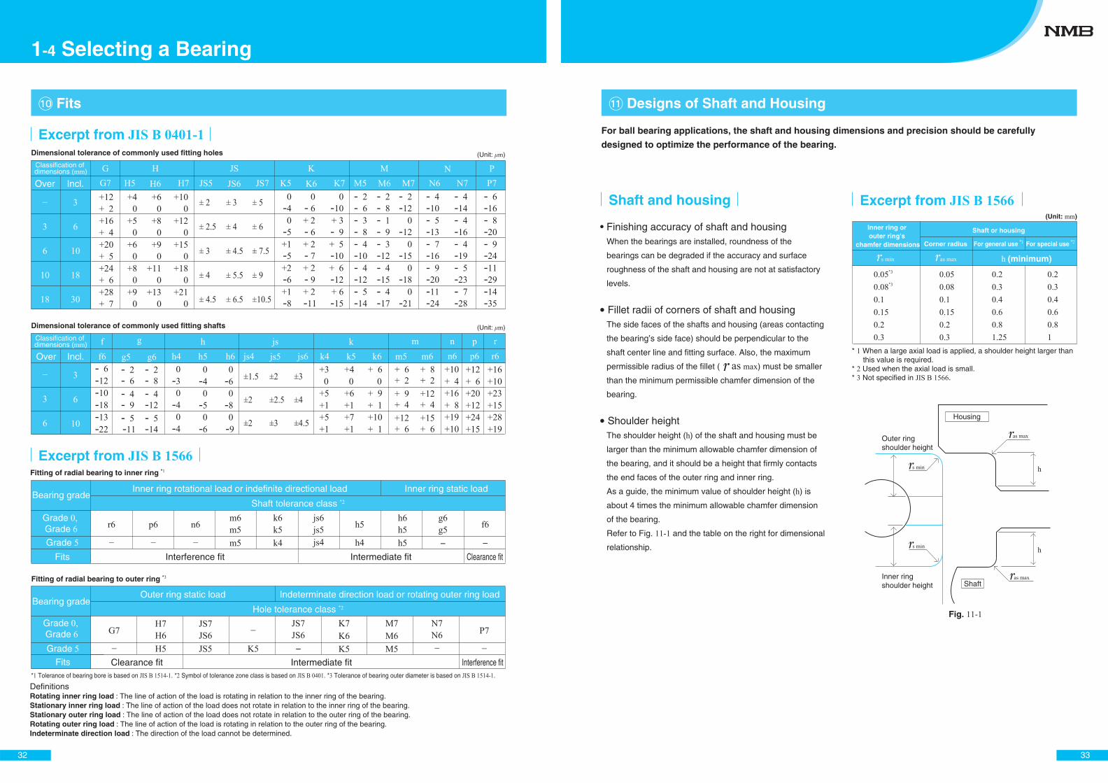
For ball bearing applications, the shaft and housing dimensions and precision should be carefully
designed to optimize the performance of the bearing.
1
23 JIS B 1566
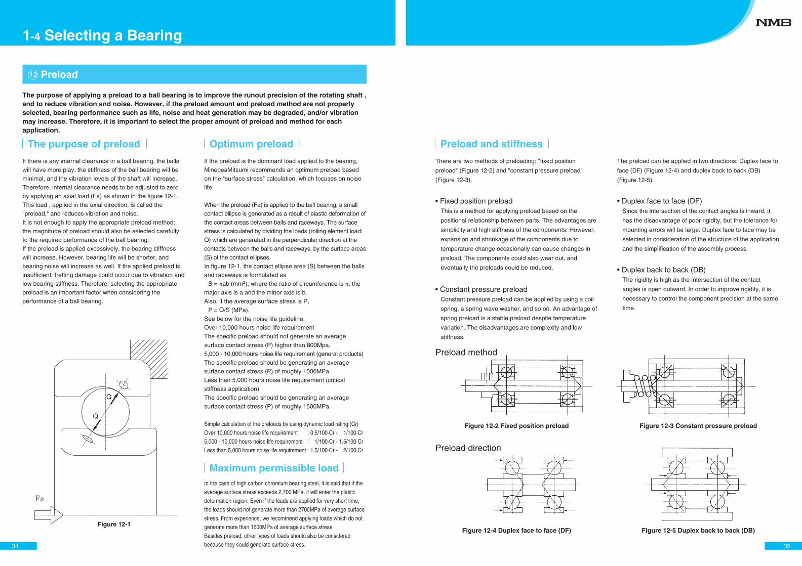
If there is any internal clearance in a ball bearing, the balls will have more play, the stiffness of the ball bearing will be minimal, and the vibration levels of the shaft will increase. Therefore, internal clearance needs to be adjusted to zero by applying an axial load (Fa) as shown in the figure 12-1. This load , applied in the axial direction, is called the "preload," and reduces vibration and noise.It is not enough to apply the appropriate preload method; the magnitude of preload should also be selected carefully to the required performance of the ball bearing.If the preload is applied excessively, the bearing stiffness will increase. However, bearing life will be shorter, and bearing noise will increase as well. If the applied preload is insufficient, fretting damage could occur due to vibration and low bearing stiffness. Therefore, selecting the appropriate preload is an important factor when considering the performance of a ball bearing.
�� Preload
The purpose of preload Optimum preload
If the preload is the dominant load applied to the bearing, MinebeaMitsumi recommends an optimum preload based on the "surface stress" calculation, which focuses on noise life.
When the preload (Fa) is applied to the ball bearing, a small contact ellipse is generated as a result of elastic deformation of the contact areas between balls and raceways. The surface stress is calculated by dividing the loads (rolling element load: Q) which are generated in the perpendicular direction at the contacts between the balls and raceways, by the surface areas (S) of the contact ellipses.In figure 12-1, the contact ellipse area (S) between the balls and raceways is formulated as
S = ab (mm2), where the ratio of circumference is , the major axis is a and the minor axis is b.Also, if the average surface stress is P,
P = Q/S (MPa).See below for the noise life guideline.Over 10,000 hours noise life requirement The specific preload should not generate an average surface contact stress (P) higher than 800Mpa. 5,000 - 10,000 hours noise life requirement (general products) The specific preload should be generating an average surface contact stress (P) of roughly 1000MPa. Less than 5,000 hours noise life requirement (critical stiffness application) The specific preload should be generating an average surface contact stress (P) of roughly 1500MPa.
Simple calculation of the preloads by using dynamic load rating (Cr)Over 10,000 hours noise life requirement : 0.5/100·Cr - 1/100·Cr5,000 - 10,000 hours noise life requirement : 1/100·Cr - 1.5/100·CrLess than 5,000 hours noise life requirement : 1.5/100·Cr - 2/100·Cr
Figure 12-1
In the case of high carbon chromium bearing steel, it is said that if the average surface stress exceeds 2,700 MPa, it will enter the plastic deformation region. Even if the loads are applied for very short time, the loads should not generate more than 2700MPa of average surface stress. From experience, we recommend applying loads which do not generate more than 1600MPa of average surface stress.Besides preload, other types of loads should also be considered because they could generate surface stress.
Maximum permissible load
Q
Q
The purpose of applying a preload to a ball bearing is to improve the runout precision of the rotating shaft , and to reduce vibration and noise. However, if the preload amount and preload method are not properly selected, bearing performance such as life, noise and heat generation may be degraded, and/or vibration may increase. Therefore, it is important to select the proper amount of preload and method for each application.
34
1-4 Selecting a Bearing
Preload method
Preload direction
Figure 12-2 Fixed position preload Figure 12-3 Constant pressure preload
Figure 12-4 Duplex face to face (DF) Figure 12-5 Duplex back to back (DB)
Preload and stiffness
There are two methods of preloading: "fixed position
preload" (Figure 12-2) and "constant pressure preload"
(Figure 12-3).
Fixed position preloadThis is a method for applying preload based on the
positional relationship between parts. The advantages are
simplicity and high stiffness of the components. However,
expansion and shrinkage of the components due to
temperature change occasionally can cause changes in
preload. The components could also wear out, and
eventually the preloads could be reduced.
Constant pressure preloadConstant pressure preload can be applied by using a coil
spring, a spring wave washer, and so on. An advantage of
spring preload is a stable preload despite temperature
variation. The disadvantages are complexity and low
stiffness.
The preload can be applied in two directions: Duplex face to
face (DF) (Figure 12-4) and duplex back to back (DB)
(Figure 12-5).
Duplex face to face (DF)Since the intersection of the contact angles is inward, it
has the disadvantage of poor rigidity, but the tolerance for
mounting errors will be large. Duplex face to face may be
selected in consideration of the structure of the application
and the simplification of the assembly process.
Duplex back to back (DB)The rigidity is high as the intersection of the contact
angles is open outward. In order to improve rigidity, it is
necessary to control the component precision at the same
time.
35
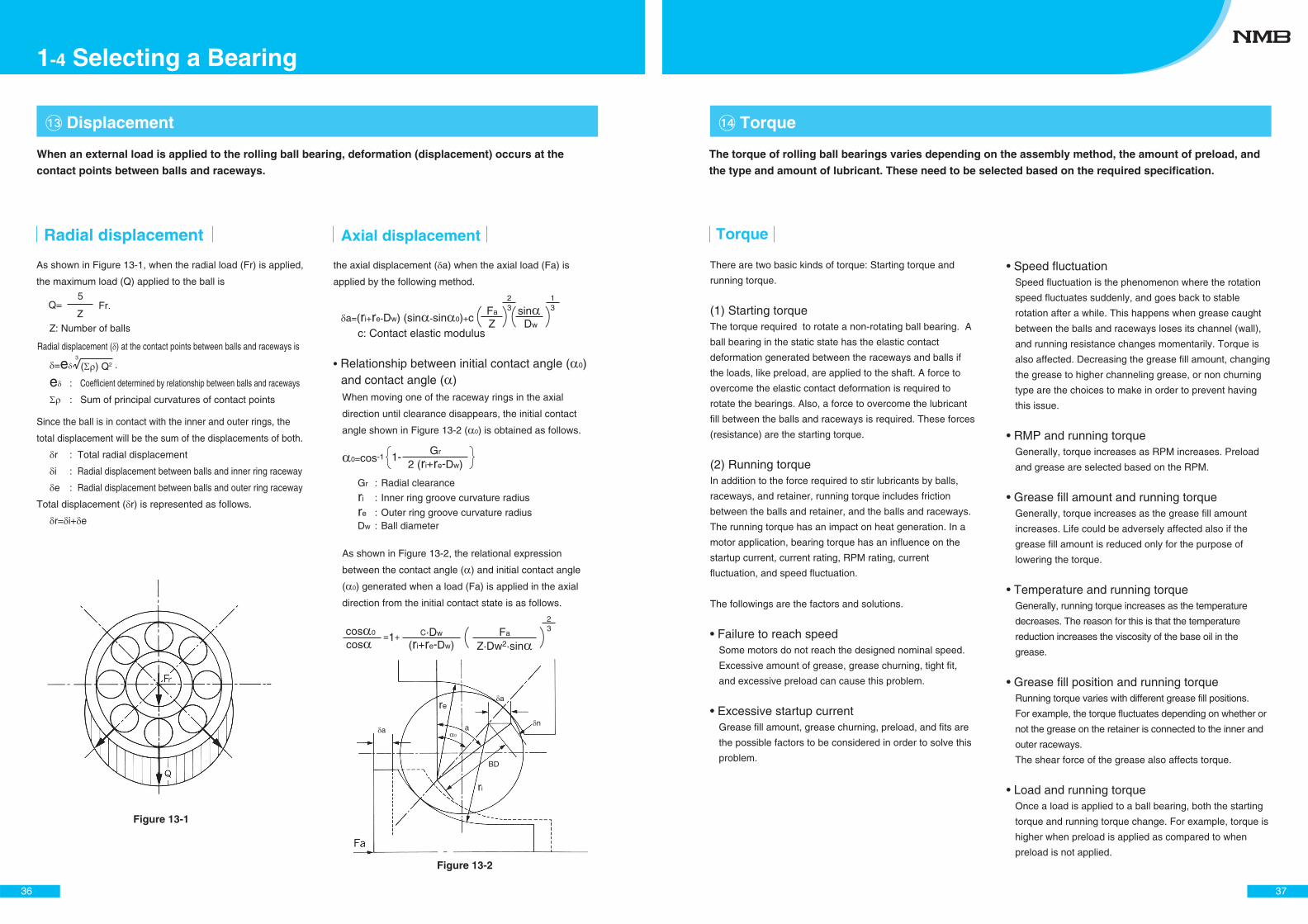
the axial displacement ( a) when the axial load (Fa) is
applied by the following method.
Relationship between initial contact angle ( 0) and contact angle ( )When moving one of the raceway rings in the axial
direction until clearance disappears, the initial contact
angle shown in Figure 13-2 ( 0) is obtained as follows.
As shown in Figure 13-2, the relational expression
between the contact angle ( ) and initial contact angle
( 0) generated when a load (Fa) is applied in the axial
direction from the initial contact state is as follows.
As shown in Figure 13-1, when the radial load (Fr) is applied,
the maximum load (Q) applied to the ball is
Radial displacement
(ri+re-Dw)coscos 0 =1+ C·Dw
Z·Dw2·sinFa
32
c: Contact elastic modulusZFa 3
231
a=(ri+re-Dw) (sin -sin 0)+c Dw
sin
�� Displacement
Axial displacement
Q=Z
5Fr.
( ) Q2=eRadial displacement ( ) at the contact points between balls and raceways is
e : Coefficient determined by relationship between balls and raceways
: Sum of principal curvatures of contact points
Since the ball is in contact with the inner and outer rings, the
total displacement will be the sum of the displacements of both.
r : Total radial displacement
i : Radial displacement between balls and inner ring raceway
e : Radial displacement between balls and outer ring raceway
Total displacement ( r) is represented as follows.
r= i+ e
3
.
Figure 13-1
Figure 13-2
Z: Number of balls
ri
BD
re
0a
a
an
0=cos-1 1-Gr
2 (ri+re-Dw)
Gr : Radial clearance
ri : Inner ring groove curvature radius
re : Outer ring groove curvature radiusDw : Ball diameter
When an external load is applied to the rolling ball bearing, deformation (displacement) occurs at the
contact points between balls and raceways.
36
1-4 Selecting a Bearing
There are two basic kinds of torque: Starting torque and
running torque.
(1) Starting torqueThe torque required to rotate a non-rotating ball bearing. A
ball bearing in the static state has the elastic contact
deformation generated between the raceways and balls if
the loads, like preload, are applied to the shaft. A force to
overcome the elastic contact deformation is required to
rotate the bearings. Also, a force to overcome the lubricant
fill between the balls and raceways is required. These forces
(resistance) are the starting torque.
(2) Running torqueIn addition to the force required to stir lubricants by balls,
raceways, and retainer, running torque includes friction
between the balls and retainer, and the balls and raceways.
The running torque has an impact on heat generation. In a
motor application, bearing torque has an influence on the
startup current, current rating, RPM rating, current
fluctuation, and speed fluctuation.
The followings are the factors and solutions.
Failure to reach speedSome motors do not reach the designed nominal speed.
Excessive amount of grease, grease churning, tight fit,
and excessive preload can cause this problem.
Excessive startup currentGrease fill amount, grease churning, preload, and fits are
the possible factors to be considered in order to solve this
problem.
Speed fluctuationSpeed fluctuation is the phenomenon where the rotation
speed fluctuates suddenly, and goes back to stable
rotation after a while. This happens when grease caught
between the balls and raceways loses its channel (wall),
and running resistance changes momentarily. Torque is
also affected. Decreasing the grease fill amount, changing
the grease to higher channeling grease, or non churning
type are the choices to make in order to prevent having
this issue.
RMP and running torqueGenerally, torque increases as RPM increases. Preload
and grease are selected based on the RPM.
Grease fill amount and running torqueGenerally, torque increases as the grease fill amount
increases. Life could be adversely affected also if the
grease fill amount is reduced only for the purpose of
lowering the torque.
Temperature and running torqueGenerally, running torque increases as the temperature
decreases. The reason for this is that the temperature
reduction increases the viscosity of the base oil in the
grease.
Grease fill position and running torqueRunning torque varies with different grease fill positions.
For example, the torque fluctuates depending on whether or
not the grease on the retainer is connected to the inner and
outer raceways.
The shear force of the grease also affects torque.
Load and running torqueOnce a load is applied to a ball bearing, both the starting
torque and running torque change. For example, torque is
higher when preload is applied as compared to when
preload is not applied.
�� Torque
Torque
The torque of rolling ball bearings varies depending on the assembly method, the amount of preload, and
the type and amount of lubricant. These need to be selected based on the required specification.
37
�� Vibration by forced rotation
The vibration is generated in axial, radial, and rotating
directions. Depending on the product in which rolling ball
bearings are used, the vibration has a significant impact on
performance.
This vibration sometimes causes components around the
axis to resonate as vibration energy is emitted.
It is necessary to understand the application characteristics
well in order to select a suitable bearing, and its specification.
Vibration caused by ball revolution (Fa)
Vibration caused by retainer rotation (Fb) Same as Fa
Vibration caused by ball rotation (Fc)
Vibration caused by ball pass (Fd) ZFa
Z (Fr−Fa)
Vibration caused by inner ring raceway dents or bumps (Fe) nZFa
Vibration caused by outer ring raceway dents or bumps (Ff)
Vibration in axial direction (Fft) nZ (Fr−Fa)
Vibration in radial direction (Ffr) Fft±Fr
Vibration caused by ball surface dents or bumps (Fg)
Vibration in axial direction (Fgt) 2nFc
Vibration in radial direction (Fgr) Fgt ±Fa
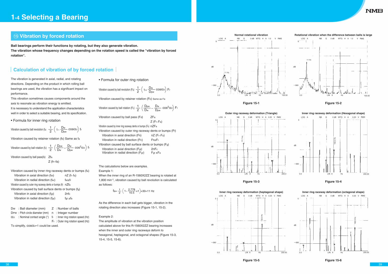
The calculations below are examples.
Example 1:
When the inner ring of an R-1560X2ZZ bearing is rotated at
1,800 min-1, vibration caused by ball revolution is calculated
as follows:
As the difference in each ball gets bigger, vibration in the
rotating direction also increases (Figure 15-1, 15-2).
Example 2:
The amplitude of vibration at the vibration position
calculated above for this R-1560X2ZZ bearing increases
when the inner and outer ring raceways deform to
hexagonal, heptagonal, and octagonal shapes (Figure 15-3,
15-4, 15-5, 15-6).
Vibration caused by ball revolution (fa)
Vibration caused by retainer rotation (fb) Same as fa
Vibration caused by ball rotation (fc)
Vibration caused by ball pass(fd) Zfa
Z (fr−fa)
Vibration caused by inner ring raceway dents or bumps (fe)
Vibration in axial direction (fet) nZ (fr−fa)
Vibration in radial direction (fer) fet±fr
Vibration caused by outer ring raceway dents or bumps (ff) nZfa
Vibration caused by ball surface dents or bumps (fg)
Vibration in axial direction (fgt) 2nfc
Vibration in radial direction (fgr) fgt ±fa
2fa= 1 1−
10.52.778 ×1 ×30=11 Hz
Calculation of vibration of by forced rotation
DW : Ball diameter (mm)DPW : Pitch circle diameter (mm)
0 : Nominal contact angle (°)
Z : Number of ballsn : Integer numberfr : Inner ring rotation speed (Hz)Fr : Outer ring rotation speed (Hz)
cos 02
fr11− Dpw
Dw
− cos20
2fr1 Dpw
Dw Dpw
Dw
cos 02
Fr1
1+
−
Dpw
Dw
cos20
2Fr
1 Dpw
Dw Dpw
Dw
Formula for inner ring rotation
Formula for outer ring rotation
To simplify, cos 0=1 could be used.
Ball bearings perform their functions by rotating, but they also generate vibration.
The vibration whose frequency changes depending on the rotation speed is called the "vibration by forced
rotation".
38
1-4 Selecting a Bearing
Figure 15-1 Figure 15-2
Figure 15-3 Figure 15-4
Figure 15-5 Figure 15-6
Normal rotational vibration Rotational vibration when the difference between balls is large
Outer ring raceway deformation (Triangle)
Inner ring raceway deformation (heptagonal shape) Inner ring raceway deformation (octagonal shape)
Inner ring raceway deformation (Hexagonal shape)
39
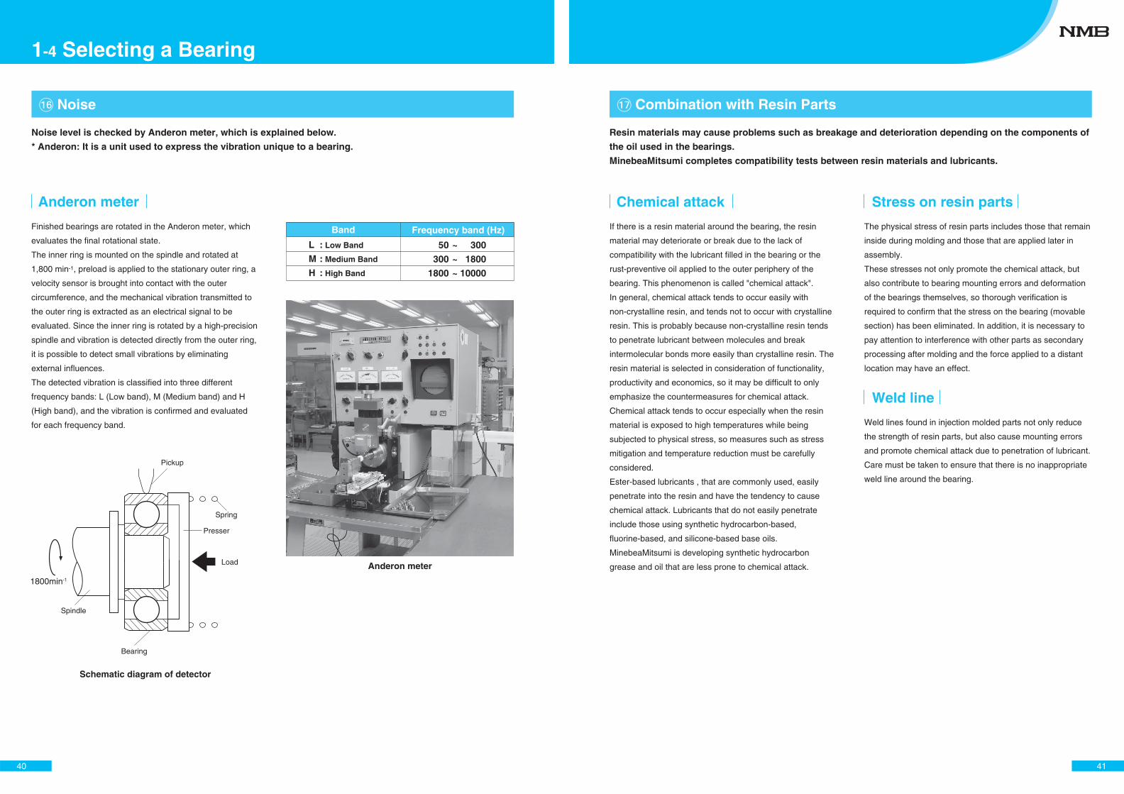
� Noise
L : Low Band
M : Medium Band
H : High Band
~
~
~
50
300
1800
300
1800
10000
Band Frequency band (Hz)
Anderon meter
Load
Spring
Presser
Bearing
Spindle
Pickup
1800min-1
Schematic diagram of detector
Finished bearings are rotated in the Anderon meter, which
evaluates the final rotational state.
The inner ring is mounted on the spindle and rotated at
1,800 min-1, preload is applied to the stationary outer ring, a
velocity sensor is brought into contact with the outer
circumference, and the mechanical vibration transmitted to
the outer ring is extracted as an electrical signal to be
evaluated. Since the inner ring is rotated by a high-precision
spindle and vibration is detected directly from the outer ring,
it is possible to detect small vibrations by eliminating
external influences.
The detected vibration is classified into three different
frequency bands: L (Low band), M (Medium band) and H
(High band), and the vibration is confirmed and evaluated
for each frequency band.
Noise level is checked by Anderon meter, which is explained below.
* Anderon: It is a unit used to express the vibration unique to a bearing.
Anderon meter
40
1-4 Selecting a Bearing
� Combination with Resin Parts
Chemical attack
If there is a resin material around the bearing, the resin
material may deteriorate or break due to the lack of
compatibility with the lubricant filled in the bearing or the
rust-preventive oil applied to the outer periphery of the
bearing. This phenomenon is called "chemical attack".
In general, chemical attack tends to occur easily with
non-crystalline resin, and tends not to occur with crystalline
resin. This is probably because non-crystalline resin tends
to penetrate lubricant between molecules and break
intermolecular bonds more easily than crystalline resin. The
resin material is selected in consideration of functionality,
productivity and economics, so it may be difficult to only
emphasize the countermeasures for chemical attack.
Chemical attack tends to occur especially when the resin
material is exposed to high temperatures while being
subjected to physical stress, so measures such as stress
mitigation and temperature reduction must be carefully
considered.
Ester-based lubricants , that are commonly used, easily
penetrate into the resin and have the tendency to cause
chemical attack. Lubricants that do not easily penetrate
include those using synthetic hydrocarbon-based,
fluorine-based, and silicone-based base oils.
MinebeaMitsumi is developing synthetic hydrocarbon
grease and oil that are less prone to chemical attack.
Stress on resin parts
The physical stress of resin parts includes those that remain
inside during molding and those that are applied later in
assembly.
These stresses not only promote the chemical attack, but
also contribute to bearing mounting errors and deformation
of the bearings themselves, so thorough verification is
required to confirm that the stress on the bearing (movable
section) has been eliminated. In addition, it is necessary to
pay attention to interference with other parts as secondary
processing after molding and the force applied to a distant
location may have an effect.
Weld line
Weld lines found in injection molded parts not only reduce
the strength of resin parts, but also cause mounting errors
and promote chemical attack due to penetration of lubricant.
Care must be taken to ensure that there is no inappropriate
weld line around the bearing.
Resin materials may cause problems such as breakage and deterioration depending on the components of
the oil used in the bearings.
MinebeaMitsumi completes compatibility tests between resin materials and lubricants.
41
�� Lubricants
Grease
Thickener is dispersed in base oil to make it semi-solid or
solid. It consists of base oil, thickener and additives, and the
characteristics are determined by the combination of these.
Base oil
Base oils are roughly classified into mineral oil, synthetic
oil and mixed oil.
Thickener
Thickener is added to disperse in base oils to make them
semi-solid (grease-like). It is an important substance in
setting the properties and performance of grease.
Thickeners are broadly classified into soap using metallic
soap (such as lithium) and non-soap (such as urea) that
does not use metallic soap.
Additive
Additive is utilized to improve the physical and chemical
performance of grease. Additive types include
antioxidant, rust inhibitor, corrosion inhibitor and extreme
pressure additive.
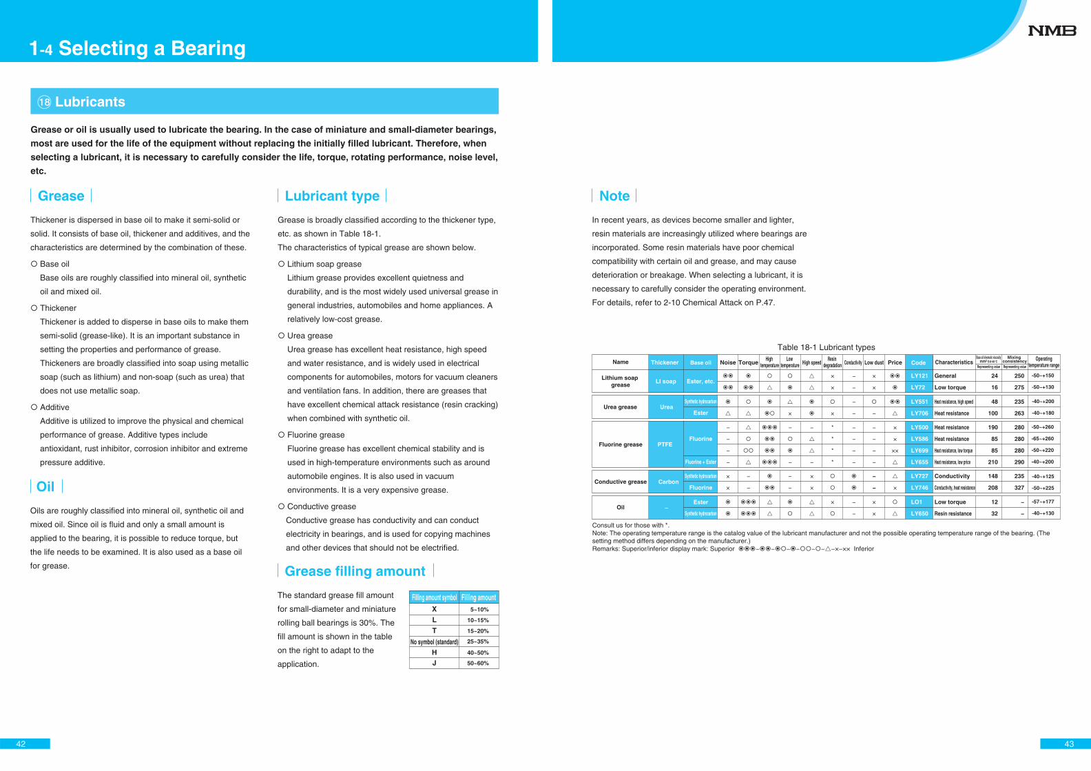
Grease is broadly classified according to the thickener type,
etc. as shown in Table 18-1.
The characteristics of typical grease are shown below.
Lithium soap grease
Lithium grease provides excellent quietness and
durability, and is the most widely used universal grease in
general industries, automobiles and home appliances. A
relatively low-cost grease.
Urea grease
Urea grease has excellent heat resistance, high speed
and water resistance, and is widely used in electrical
components for automobiles, motors for vacuum cleaners
and ventilation fans. In addition, there are greases that
have excellent chemical attack resistance (resin cracking)
when combined with synthetic oil.
Fluorine grease
Fluorine grease has excellent chemical stability and is
used in high-temperature environments such as around
automobile engines. It is also used in vacuum
environments. It is a very expensive grease.
Conductive grease
Conductive grease has conductivity and can conduct
electricity in bearings, and is used for copying machines
and other devices that should not be electrified.
Lubricant type
Oil
Oils are roughly classified into mineral oil, synthetic oil and
mixed oil. Since oil is fluid and only a small amount is
applied to the bearing, it is possible to reduce torque, but
the life needs to be examined. It is also used as a base oil
for grease.
Grease or oil is usually used to lubricate the bearing. In the case of miniature and small-diameter bearings,
most are used for the life of the equipment without replacing the initially filled lubricant. Therefore, when
selecting a lubricant, it is necessary to carefully consider the life, torque, rotating performance, noise level,
etc.
Filling amount symbolX
L
T
No symbol (standard)HJ
Filling amount5~10%
10~15%
15~20%
25~35%
40~50%
50~60%
Grease filling amount
The standard grease fill amount
for small-diameter and miniature
rolling ball bearings is 30%. The
fill amount is shown in the table
on the right to adapt to the
application.
42
1-4 Selecting a Bearing
LY121
LY72
LY551
LY706
LY500
LY586
LY699
LY655
LY727
LY746
LO1
LY650
Characteristics
General
Low torque
Heat resistance, high speed
Heat resistance
Heat resistance
Heat resistance
Heat resistance, low torque
Heat resistance, low price
Conductivity
Conductivity, heat resistance
Low torque
Resin resistance
Base oil kinematic viscositymm2 S@40°C
24
16
48
100
190
85
85
210
12
32
148
208
250
275
235
263
235
327
−
−
Mixing consistency Operating
temperature range
-50~+150
-50~+130
-40~+200
-40~+180
-50~+260
-65~+260
-50~+220
-40~+200
-40~+125
-50~+225
-57~+177
-40~+130
Representing value Representing value
280
280
280
290
CodeName
Lithium soap grease
Urea grease
Fluorine grease
Conductive grease
Oil
Noise TorqueHigh
temperatureLow
temperature High speedResin
degradation Conductivity Low dust Price
× ×
×
−
−
−
−
−
−
−
−
−
−
−
−
−
−
×
× ×
×
×
××
−
−
−
−
−
−
−
−
−
−
*
*
*
*
× −
−
−×
×
×
×
×
×
×
−
−
Synthetic hydrocarbon
Fluorine
Fluorine
Synthetic hydrocarbon
Thickener Base oil
LI soap
Urea
PTFE
Carbon
−
Ester, etc.
Ester
Synthetic hydrocarbon
Ester
Fluorine + Ester
Note
In recent years, as devices become smaller and lighter,
resin materials are increasingly utilized where bearings are
incorporated. Some resin materials have poor chemical
compatibility with certain oil and grease, and may cause
deterioration or breakage. When selecting a lubricant, it is
necessary to carefully consider the operating environment.
For details, refer to 2-10 Chemical Attack on P.47.
Table 18-1 Lubricant types
Consult us for those with *.Note: The operating temperature range is the catalog value of the lubricant manufacturer and not the possible operating temperature range of the bearing. (The setting method differs depending on the manufacturer.)Remarks: Superior/inferior display mark: Superior − − − − − − −×−×× Inferior
43
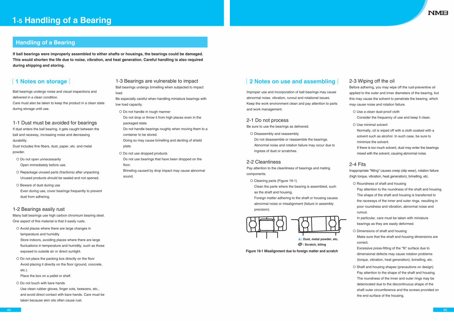
Handling of a Bearing
1 Notes on storage
Ball bearings undergo noise and visual inspections and
delivered in a clean condition.
Care must also be taken to keep the product in a clean state
during storage until use.
1-1 Dust must be avoided for bearingsIf dust enters the ball bearing, it gets caught between the
ball and raceway, increasing noise and decreasing
durability.
Dust includes fine fibers, dust, paper, etc. and metal
powder.
Do not open unnecessarily
Open immediately before use.
Repackage unused parts (fractions) after unpacking
Unused products should be sealed and not opened.
Beware of dust during use
Even during use, cover bearings frequently to prevent
dust from adhering.
1-2 Bearings easily rustMany ball bearings use high carbon chromium bearing steel.
One aspect of this material is that it easily rusts.
Avoid places where there are large changes in
temperature and humidity
Store indoors, avoiding places where there are large
fluctuations in temperature and humidity, such as those
exposed to outside air or direct sunlight.
Do not place the packing box directly on the floor
Avoid placing it directly on the floor (ground, concrete,
etc.).
Place the box on a pallet or shelf.
Do not touch with bare hands
Use clean rubber gloves, finger cots, tweezers, etc.,
and avoid direct contact with bare hands. Care must be
taken because skin oils often cause rust.
1-3 Bearings are vulnerable to impactBall bearings undergo brinelling when subjected to impact
load.
Be especially careful when handling miniature bearings with
low load capacity.
Do not handle in rough manner
Do not drop or throw it from high places even in the
packaged state.
Do not handle bearings roughly when moving them to a
container to be stored.
Doing so may cause brinelling and denting of shield
plate.
Do not use dropped products
Do not use bearings that have been dropped on the
floor.
Brineling caused by drop impact may cause abnormal
sound.
If ball bearings were improperly assembled to either shafts or housings, the bearings could be damaged.
This would shorten the life due to noise, vibration, and heat generation. Careful handling is also required
during shipping and storing.
44
1-5 Handling of a Bearing
2-3 Wiping off the oilBefore adhering, you may wipe off the rust-preventive oil
applied to the outer and inner diameters of the bearing, but
this may cause the solvent to penetrate the bearing, which
may cause noise and rotation failure.
Use a clean dust-proof cloth
Consider the frequency of use and keep it clean.
Use minimal solvent
Normally, oil is wiped off with a cloth soaked with a
solvent such as alcohol. In such case, be sure to
minimize the solvent.
If there is too much solvent, dust may enter the bearings
mixed with the solvent, causing abnormal noise.
2-4 FitsInappropriate "fitting" causes creep (slip wear), rotation failure
(high torque, vibration, heat generation), brinelling, etc.
Roundness of shaft and housing
Pay attention to the roundness of the shaft and housing.
The shape of the shaft and housing is transferred to
the raceways of the inner and outer rings, resulting in
poor roundness and vibration, abnormal noise and
runout.
In particular, care must be taken with miniature
bearings as they are easily deformed.
Dimensions of shaft and housing
Make sure that the shaft and housing dimensions are
correct.
Excessive press-fitting of the "fit" surface due to
dimensional defects may cause rotation problems
(torque, vibration, heat generation), brinelling, etc.
Shaft and housing shapes (precautions on design)
Pay attention to the shape of the shaft and housing.
The roundness of the inner and outer rings may be
deteriorated due to the discontinuous shape of the
shaft outer circumference and the screws provided on
the end surface of the housing.
2 Notes on use and assembling
Improper use and incorporation of ball bearings may cause
abnormal noise, vibration, runout and rotational issues.
Keep the work environment clean and pay attention to parts
and work management.
2-1 Do not processBe sure to use the bearings as delivered.
Disassembly and reassembly
Do not disassemble or reassemble the bearings.
Abnormal noise and rotation failure may occur due to
ingress of dust or scratches.
2-2 CleanlinessPay attention to the cleanliness of bearings and mating
components.
Cleaning parts (Figure 19-1)
Clean the parts where the bearing is assembled, such
as the shaft and housing.
Foreign matter adhering to the shaft or housing causes
abnormal noise or misalignment (failure in assembly
precision).
45
Figure 19-1 Misalignment due to foreign matter and scratch
: Dust, metal powder, etc.
: Scratch, biting
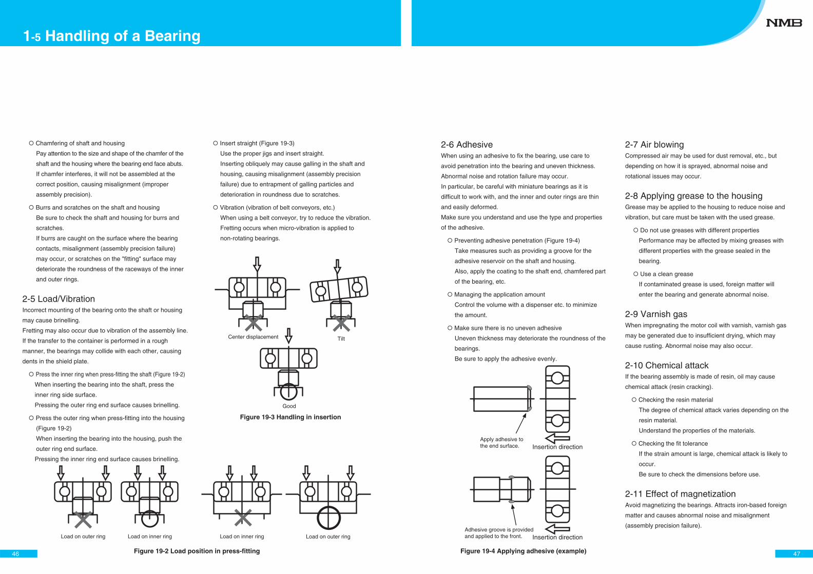
Chamfering of shaft and housing
Pay attention to the size and shape of the chamfer of the
shaft and the housing where the bearing end face abuts.
If chamfer interferes, it will not be assembled at the
correct position, causing misalignment (improper
assembly precision).
Burrs and scratches on the shaft and housing
Be sure to check the shaft and housing for burrs and
scratches.
If burrs are caught on the surface where the bearing
contacts, misalignment (assembly precision failure)
may occur, or scratches on the "fitting" surface may
deteriorate the roundness of the raceways of the inner
and outer rings.
2-5 Load/VibrationIncorrect mounting of the bearing onto the shaft or housing
may cause brinelling.
Fretting may also occur due to vibration of the assembly line.
If the transfer to the container is performed in a rough
manner, the bearings may collide with each other, causing
dents in the shield plate.
Press the inner ring when press-fitting the shaft (Figure 19-2)
When inserting the bearing into the shaft, press the
inner ring side surface.
Pressing the outer ring end surface causes brinelling.
Press the outer ring when press-fitting into the housing
(Figure 19-2)
When inserting the bearing into the housing, push the
outer ring end surface.
Pressing the inner ring end surface causes brinelling.
Insert straight (Figure 19-3)
Use the proper jigs and insert straight.
Inserting obliquely may cause galling in the shaft and
housing, causing misalignment (assembly precision
failure) due to entrapment of galling particles and
deterioration in roundness due to scratches.
Vibration (vibration of belt conveyors, etc.)
When using a belt conveyor, try to reduce the vibration.
Fretting occurs when micro-vibration is applied to
non-rotating bearings.
46
1-5 Handling of a Bearing
Figure 19-2 Load position in press-fitting
Load on outer ringLoad on inner ringLoad on outer ring Load on inner ring
Figure 19-3 Handling in insertion
Center displacement Tilt
Good
2-6 AdhesiveWhen using an adhesive to fix the bearing, use care to
avoid penetration into the bearing and uneven thickness.
Abnormal noise and rotation failure may occur.
In particular, be careful with miniature bearings as it is
difficult to work with, and the inner and outer rings are thin
and easily deformed.
Make sure you understand and use the type and properties
of the adhesive.
Preventing adhesive penetration (Figure 19-4)
Take measures such as providing a groove for the
adhesive reservoir on the shaft and housing.
Also, apply the coating to the shaft end, chamfered part
of the bearing, etc.
Managing the application amount
Control the volume with a dispenser etc. to minimize
the amount.
Make sure there is no uneven adhesive
Uneven thickness may deteriorate the roundness of the
bearings.
Be sure to apply the adhesive evenly.
2-7 Air blowingCompressed air may be used for dust removal, etc., but
depending on how it is sprayed, abnormal noise and
rotational issues may occur.
2-8 Applying grease to the housingGrease may be applied to the housing to reduce noise and
vibration, but care must be taken with the used grease.
Do not use greases with different properties
Performance may be affected by mixing greases with
different properties with the grease sealed in the
bearing.
Use a clean grease
If contaminated grease is used, foreign matter will
enter the bearing and generate abnormal noise.
2-9 Varnish gasWhen impregnating the motor coil with varnish, varnish gas
may be generated due to insufficient drying, which may
cause rusting. Abnormal noise may also occur.
2-10 Chemical attackIf the bearing assembly is made of resin, oil may cause
chemical attack (resin cracking).
Checking the resin material
The degree of chemical attack varies depending on the
resin material.
Understand the properties of the materials.
Checking the fit tolerance
If the strain amount is large, chemical attack is likely to
occur.
Be sure to check the dimensions before use.
2-11 Effect of magnetizationAvoid magnetizing the bearings. Attracts iron-based foreign
matter and causes abnormal noise and misalignment
(assembly precision failure).
47Figure 19-4 Applying adhesive (example)
Apply adhesive to the end surface. Insertion direction
Adhesive groove is provided and applied to the front. Insertion direction
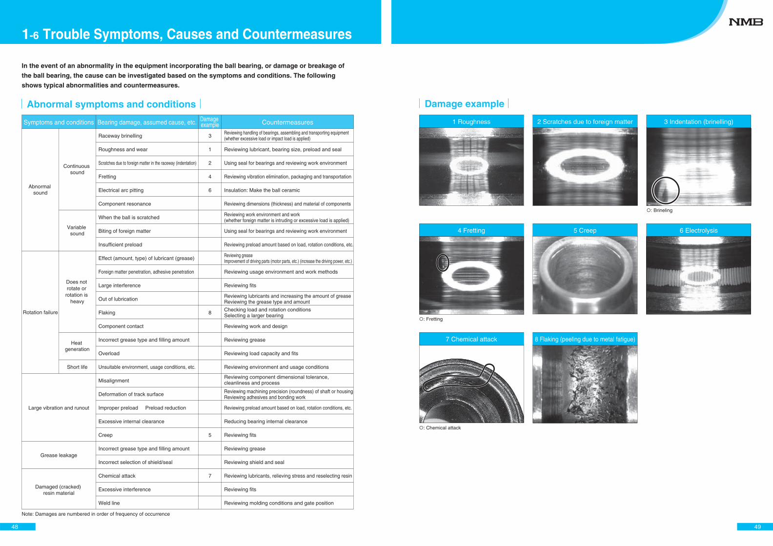
Abnormal symptoms and conditions
Symptoms and conditions Bearing damage, assumed cause, etc. Damage example Countermeasures
Variable sound
Short life
Large vibration and runout
Grease leakage
Damaged (cracked) resin material
Heat generation
Does not rotate or
rotation is heavy
Continuous sound
Abnormal sound
Raceway brinelling
Roughness and wear
Scratches due to foreign matter in the raceway (indentation)
Fretting
Electrical arc pitting
Component resonance
When the ball is scratched
Biting of foreign matter
Insufficient preload
Effect (amount, type) of lubricant (grease)
Foreign matter penetration, adhesive penetration
Large interference
Out of lubrication
Flaking
Component contact
Incorrect grease type and filling amount
Overload
Unsuitable environment, usage conditions, etc.
Misalignment
Deformation of track surface
Improper preload Preload reduction
Excessive internal clearance
Creep
Incorrect grease type and filling amount
Incorrect selection of shield/seal
Chemical attack
Excessive interference
Weld line
Reviewing lubricant, bearing size, preload and seal
Using seal for bearings and reviewing work environment
Reviewing vibration elimination, packaging and transportation
Insulation: Make the ball ceramic
Reviewing dimensions (thickness) and material of components
Using seal for bearings and reviewing work environment
Reviewing preload amount based on load, rotation conditions, etc.
Reviewing usage environment and work methods
Reviewing fits
Reviewing work and design
Reviewing grease
Reviewing load capacity and fits
Reviewing environment and usage conditions
Reviewing preload amount based on load, rotation conditions, etc.
Reducing bearing internal clearance
Reviewing fits
Reviewing grease
Reviewing shield and seal
Reviewing lubricants, relieving stress and reselecting resin
Reviewing fits
Reviewing molding conditions and gate position
3
1
2
4
6
8
5
7
In the event of an abnormality in the equipment incorporating the ball bearing, or damage or breakage of
the ball bearing, the cause can be investigated based on the symptoms and conditions. The following
shows typical abnormalities and countermeasures.
Rotation failure
Reviewing handling of bearings, assembling and transporting equipment (whether excessive load or impact load is applied)
Reviewing work environment and work (whether foreign matter is intruding or excessive load is applied)
Reviewing grease Improvement of driving parts (motor parts, etc.) (increase the driving power, etc.)
Reviewing lubricants and increasing the amount of grease Reviewing the grease type and amount
Checking load and rotation conditions Selecting a larger bearing
Reviewing machining precision (roundness) of shaft or housing Reviewing adhesives and bonding work
Reviewing component dimensional tolerance,cleanliness and process
Note: Damages are numbered in order of frequency of occurrence
48
1-6 Trouble Symptoms, Causes and Countermeasures
3 Indentation (brinelling)2 Scratches due to foreign matter
5 Creep
Damage example
: Brineling
1 Roughness
4 Fretting 6 Electrolysis
7 Chemical attack
: Fretting
: Chemical attack
8 Flaking (peeling due to metal fatigue)
49
50
Dimensions

52
Part numberInner
diameterd
Outerdiameter
DWidth B
Shoulder diameter
DimensionsQuantity
(pcs)Dynamic load
JIS number
Ball Basic rated load (N) Reference
Outer ringLo
Inner ringLi Cr
Static load
Cor
Chamfer s min.
OpenRadial Open Ball Bearings
ShieldedRadial Shielded Ball Bearings
rs
rs
B
D Lo d Li
B
rs
rs
D Lo d Li
L-310
L-415
L-415X5ZZ
L-520
L-520ZZ
L-520W52
L-520ZZW52
L-520X9ZZW52
R-620ZZ
R-620W52
R-620ZZY52
R-720ZZ
L-625ZZ
R-725ZZ
R-825ZZ
L-630
L-630ZZ
L-730
L-730ZZ
R-830
R-830ZZ
R-830X10ZZ
R-930ZZY04
R-1030
R-1030ZZ
L-740ZZ
L-840ZZ
L-940
L-940ZZ
L-1040X2
L-1040X2ZZ
0.5000
0.6350
0.6000
0.7938
0.7938
0.7938
0.7938
0.7938
1.1906
1.1906
1.1906
1.1906
0.7938
1.1906
1.5875
0.7938
0.7938
1.1906
1.1906
1.5875
1.5875
1.5875
1.5875
1.5875
1.5875
0.7938
1.1906
1.5875
1.5875
1.5875
1.5875
7
7
7
7
7
7
7
7
6
6
6
7
8
7
6
8
8
7
7
6
6
6
7
7
7
11
7
7
7
8
8
1.60
2.26
2.15
2.90
2.90
2.90
2.90
2.72
3.10
3.10
3.10
3.80
3.80
3.80
4.10
3.80
3.80
4.10
4.10
4.10
4.10
4.18
4.80
5.08
5.08
4.80
5.20
5.20
5.20
5.80
5.46
2.41
3.25
3.42
4.00
4.28
4.00
4.28
4.27
5.23
4.93
5.23
5.93
5.23
5.93
7.19
4.93
5.23
5.83
6.13
6.53
7.19
7.19
7.64
8.20
8.20
6.33
7.24
7.48
7.93
7.96
8.50
0.05
0.05
0.05
0.08
0.08
0.08
0.08
0.08
0.15
0.15
0.15
0.15
0.08
0.15
0.15
0.08
0.08
0.1
0.1
0.15
0.15
0.15
0.15
0.15
0.15
0.08
0.1
0.1
0.1
0.15
0.15
1
1.2
2
1.5
2.3
2.5
2.5
2.5
3
2.5
2.5
3.5
2.6
3.5
4
2
2.5
2
3
3
4
4
4
4
4
2.5
3
2.5
4
3
4
3
4
4
5
5
5
5
5
6
6
6
7
6
7
8
6
6
7
7
8
8
8
9
10
10
7
8
9
9
10
10
1
1.5
1.5
2
2
2
2
2
2
2
2
2
2.5
2.5
2.5
3
3
3
3
3
3
3
3
3
3
4
4
4
4
4
4
80
125
113
187
187
187
187
186
330
330
330
380
206
380
553
206
206
384
384
553
553
553
634
641
641
252
391
641
641
708
708
23
38
34
59
59
59
59
58
99
99
99
126
73
126
176
73
73
129
129
176
176
176
219
226
226
106
140
226
226
266
266
681
68/1.5
68/1.5
682
−
−
−
−
−
−
−
−
−
−
−
673
−
683
−
693
−
−
−
623
623ZZ
674
−
684
−
−
−
R- SeriesL- SeriesJIS- SeriesInner diameter: 1mm to 6mm
Metric size: Basic (chrome steel)Radial deep groove ball bearings
(Unit: mm)
53
R-1140
R-1140ZZ
R-1240
R-1240KK1
R-1340
R-1340HH
R-1340DD
R-1640
R-1640HH
R-1640DD
L-850
L-850ZZ
L-950ZZ
L-1050
L-1050ZZ
L-1050SS
L-1150
L-1150ZZ
L-1150ZZY04
R-1350
R-1350ZZ
R-1350DD
R-1350X2ZZ
R-1350X2DD
R-1350X2SS
R-1450
R-1450ZZ
R-1650
R-1650HH
R-1650DD
R-1650SS
635
635ZZ
L-1060
L-1060ZZ
L-1060DD
L-1060SS
L-1260
L-1260ZZ
L-1260X2DD
L-1360
1.5875
1.5875
2.0000
2.0000
2.3813
2.3813
2.3813
2.7781
2.7781
2.7781
0.7938
0.7938
1.1906
1.5875
1.5875
1.5875
1.5875
1.5875
1.5875
2.0000
2.0000
2.0000
2.0000
2.0000
2.0000
2.3813
2.3813
2.7781
2.7781
2.7781
2.7781
3.5000
3.5000
1.1906
1.1906
1.1906
1.1906
1.5875
1.5875
1.5875
2.0000
8
8
7
7
7
7
7
7
7
7
13
13
10
8
8
8
8
8
8
8
8
8
8
8
8
7
7
7
7
7
7
7
7
9
9
9
9
10
10
10
8
6.40
6.40
5.62
5.62
5.97
5.97
5.97
7.80
7.80
7.80
5.80
5.80
6.00
6.40
6.40
6.40
6.40
6.40
6.40
6.66
6.66
6.66
6.66
6.66
6.66
6.88
6.88
7.80
7.80
7.80
7.80
9.20
9.20
6.95
6.95
6.95
6.95
7.70
7.70
7.70
8.00
9.54
9.54
9.99
9.68
11.22
11.22
11.22
13.41
13.41
13.41
6.95
7.26
8.04
8.63
8.94
8.94
8.63
9.54
9.54
11.14
11.14
11.14
11.14
11.14
11.14
12.14
12.14
12.50
13.41
13.41
13.41
16.68
16.68
8.73
9.04
9.04
9.04
9.94
10.48
10.80
10.98
0.15
0.15
0.2
0.2
0.2
0.2
0.2
0.3
0.3
0.3
0.08
0.08
0.1
0.1
0.1
0.1
0.15
0.15
0.15
0.2
0.2
0.2
0.2
0.2
0.2
0.2
0.2
0.3
0.3
0.3
0.3
0.3
0.3
0.1
0.1
0.1
0.1
0.15
0.15
0.15
0.15
4
4
4
4
5
5
5
5
5
5
2
2.5
3
3
4
4
3
5
4
4
4
4
4
4
4
5
5
5
5
5
5
6
6
2.5
3
3
3
3
4
4
3.5
11
11
12
12
13
13
13
16
16
16
8
8
9
10
10
10
11
11
11
13
13
13
13
13
13
14
14
16
16
16
16
19
19
10
10
10
10
12
12
12
13
4
4
4
4
4
4
4
4
4
4
5
5
5
5
5
5
5
5
5
5
5
5
5
5
5
5
5
5
5
5
5
5
5
6
6
6
6
6
6
6
6
714
714
959
959
1306
1306
1306
1735
1735
1735
274
274
495
714
714
714
714
714
714
1074
1074
1074
1074
1074
1074
1329
1329
1735
1735
1735
1735
2614
2614
457
457
457
457
831
831
831
1083
276
276
347
347
487
487
487
671
671
671
130
130
207
276
276
276
276
276
276
422
422
422
422
422
422
508
508
671
671
671
671
1053
1053
194
194
194
194
363
363
363
438
694
694ZZ
604
604ZZ
624
624ZZ
624DD
634
634ZZ
634DD
675
−
−
−
−
−
685
−
−
695
695ZZ
695DD
695ZZ
695DD
695SS
605
605ZZ
625
625ZZ
625DD
625SS
635
635ZZ
676
−
−
−
−
−
−
686
Part numberInner
diameterd
Outerdiameter
DWidth B
Shoulder diameter
DimensionsQuantity
(pcs)Dynamic load
JIS number
Ball Basic rated load (N) Reference
Outer ringLo
Inner ringLi Cr
Static load
Cor
Chamfer s min.
(Unit: mm)
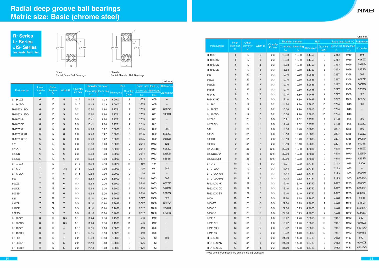
54
OpenRadial Open Ball Bearings
ShieldedRadial Shielded Ball Bearings
rs
rs
B
D Lo d Li
B
rs
rs
D Lo d Li
L-1360ZZ
L-1360DD
R-1560X13KK
R-1560X13DD
R-1660HH
R-1660DD
R-1760X2
R-1760X2KK
R-1760X2DD
626
626ZZ
626DD
626SS
L-1370ZZ
L-1470
L-1470KK
607
607ZZ
607DD
607SS
627
627ZZ
627DD
627SS
L-1280ZZ
L-1280DD
L-1480ZZ
L-1480DD
L-1680
L-1680KK
L-1680DD
2.0000
2.0000
2.7781
2.7781
2.7781
2.7781
3.5000
3.5000
3.5000
3.5000
3.5000
3.5000
3.5000
1.5875
2.0000
2.0000
3.5000
3.5000
3.5000
3.5000
3.9688
3.9688
3.9688
3.9688
1.1906
1.1906
1.5875
1.5875
2.3813
2.3813
2.3813
8
8
7
7
7
7
6
6
6
7
7
7
7
11
9
9
7
7
7
7
7
7
7
7
11
11
10
10
9
9
9
7.33
7.33
7.80
7.80
7.80
7.80
8.22
8.22
8.22
9.20
9.20
9.20
9.20
8.43
9.00
9.00
9.20
9.20
9.20
9.20
10.80
10.80
10.80
10.80
9.10
9.10
9.90
9.90
10.30
9.68
9.68
11.44
11.44
13.20
13.20
13.41
13.41
14.70
14.70
14.70
16.68
16.68
16.68
16.68
11.54
12.03
12.88
16.68
16.68
16.68
16.68
19.10
19.10
19.10
19.10
11.24
11.24
12.55
12.55
13.40
14.18
14.18
0.15
0.15
0.2
0.2
0.3
0.3
0.3
0.3
0.3
0.3
0.3
0.3
0.3
0.15
0.15
0.15
0.3
0.3
0.3
0.3
0.3
0.3
0.3
0.3
0.1
0.1
0.15
0.15
0.2
0.2
0.2
5
5
5
5
5
5
6
6
6
6
6
6
6
4
3.5
5
6
6
6
6
7
7
7
7
3.5
3.5
4
4
4
5
5
13
13
15
15
16
16
17
17
17
19
19
19
19
13
14
14
19
19
19
19
22
22
22
22
12
12
14
14
16
16
16
6
6
6
6
6
6
6
6
6
6
6
6
6
7
7
7
7
7
7
7
7
7
7
7
8
8
8
8
8
8
8
1083
1083
1735
1735
1735
1735
2265
2265
2265
2614
2614
2614
2614
880
1175
1175
2614
2614
2614
2614
3297
3297
3297
3297
506
506
819
819
1606
1606
1606
438
438
671
671
671
671
839
839
839
1053
1053
1053
1053
414
511
511
1053
1053
1053
1053
1368
1368
1368
1368
249
249
386
386
712
712
712
−
−
696ZZ
696DD
−
−
606
606ZZ
606DD
626
626ZZ
626DD
626SS
−
687
−
607
607ZZ
607DD
607SS
627
627ZZ
627DD
627SS
−
−
−
−
688
−
−
R- SeriesL- SeriesJIS- SeriesInner diameter: 6mm to 10mm
Part numberInner
diameterd
Outerdiameter
DWidth B
Shoulder diameter
DimensionsQuantity
(pcs)Dynamic load
JIS number
Ball Basic rated load (N) Reference
Outer ringLo
Inner ringLi Cr
Static load
Cor
Chamfer s min.
Metric size: Basic (chrome steel)Radial deep groove ball bearings
(Unit: mm)
55
R-1980
R-1980KK
R-1980DD
R-1980SS
608
608ZZ
608DD
608SS
R-2480
R-2480KK
L-1790
L-1790ZZ
L-1790DD
L-2090
L-2090KK
609
609ZZ
609DD
609SS
629ZZSD61
629DDSD61
629SSSD61
L-1910
L-1910DD
L-1910KKY05
L-1910DDY05
R-2210X3KK
R-2210X3DD
R-2210X3SS
6000
6000ZZ
6000DD
6000SS
L-2112
L-2112KK
L-2112DD
L-2112SS
R-2412X3
R-2412X3KK
R-2412X3DD
3.1750
3.1750
3.1750
3.1750
3.9688
3.9688
3.9688
3.9688
3.9688
3.9688
2.3813
2.3813
2.3813
2.7781
2.7781
3.9688
3.9688
3.9688
3.9688
4.7625
4.7625
4.7625
2.7781
2.7781
2.7781
2.7781
3.1750
3.1750
3.1750
4.7625
4.7625
4.7625
4.7625
2.3813
2.3813
2.3813
2.3813
3.5719
3.5719
3.5719
8
8
8
8
7
7
7
7
7
7
10
10
10
9
9
7
7
7
7
7
7
7
9
9
9
9
9
9
9
7
7
7
7
12
12
12
12
8
8
8
10.60
10.60
10.60
10.60
10.80
10.80
10.80
10.80
11.80
11.80
11.20
11.20
11.20
12.32
12.32
12.40
12.40
12.40
12.40
12.88
12.88
12.88
12.32
12.32
12.32
12.32
13.40
13.40
13.40
13.75
13.75
13.75
13.75
14.40
14.40
14.40
14.40
14.28
14.28
14.28
16.68
16.68
16.68
16.68
19.10
19.10
19.10
19.10
19.10
19.10
14.84
15.34
15.34
16.71
17.44
19.10
19.10
19.10
19.10
22.80
22.80
22.80
16.71
17.44
17.44
17.44
19.40
19.40
19.40
22.80
22.80
22.80
22.80
19.22
19.22
19.22
19.22
21.69
21.69
21.69
0.3
0.3
0.3
0.3
0.3
0.3
0.3
0.3
0.3
0.3
0.2
0.2
0.2
0.3
0.3
0.3
0.3
0.3
0.3
(0.6)
(0.6)
(0.6)
0.3
0.3
0.3
0.3
0.3
0.3
0.3
0.3
0.3
0.3
0.3
0.3
0.3
0.3
0.3
0.3
0.3
0.3
6
6
6
6
7
7
7
7
8
8
4
5
5
6
6
7
7
7
7
8
8
8
5
7
5
5
6
6
6
8
8
8
8
5
5
5
5
6
6
6
19
19
19
19
22
22
22
22
24
24
17
17
17
20
20
24
24
24
24
26
26
26
19
19
19
19
22
22
22
26
26
26
26
21
21
21
21
24
24
24
8
8
8
8
8
8
8
8
8
8
9
9
9
9
9
9
9
9
9
9
9
9
10
10
10
10
10
10
10
10
10
10
10
12
12
12
12
12
12
12
2463
2463
2463
2463
3297
3297
3297
3297
3297
3297
1724
1724
1724
2123
2123
3297
3297
3297
3297
4578
4578
4578
2123
2123
2123
2123
2697
2697
2697
4578
4578
4578
4578
1917
1917
1917
1917
3082
3082
3082
1059
1059
1059
1059
1368
1368
1368
1368
1368
1368
813
813
813
985
985
1368
1368
1368
1368
1970
1970
1970
985
985
985
985
1273
1273
1273
1970
1970
1970
1970
1042
1042
1042
1042
1433
1433
1433
698
698ZZ
698DD
698SS
608
608ZZ
608DD
608SS
628
628ZZ
689
−
−
699
699ZZ
609
609ZZ
609DD
609SS
629ZZ
629DD
629SS
6800
−
6800ZZ
6800DD
6900ZZ
6900DD
6900SS
6000
6000ZZ
6000DD
6000SS
6801
6801ZZ
6801DD
6801SS
6901
6901ZZ
6901DD
Those with parentheses are outside the JIS standard.
Part numberInner
diameterd
Outerdiameter
DWidth B
Shoulder diameter
DimensionsQuantity
(pcs)Dynamic load
JIS number
Ball Basic rated load (N) Reference
Outer ringLo
Inner ringLi Cr
Static load
Cor
Chamfer s min.
(Unit: mm)
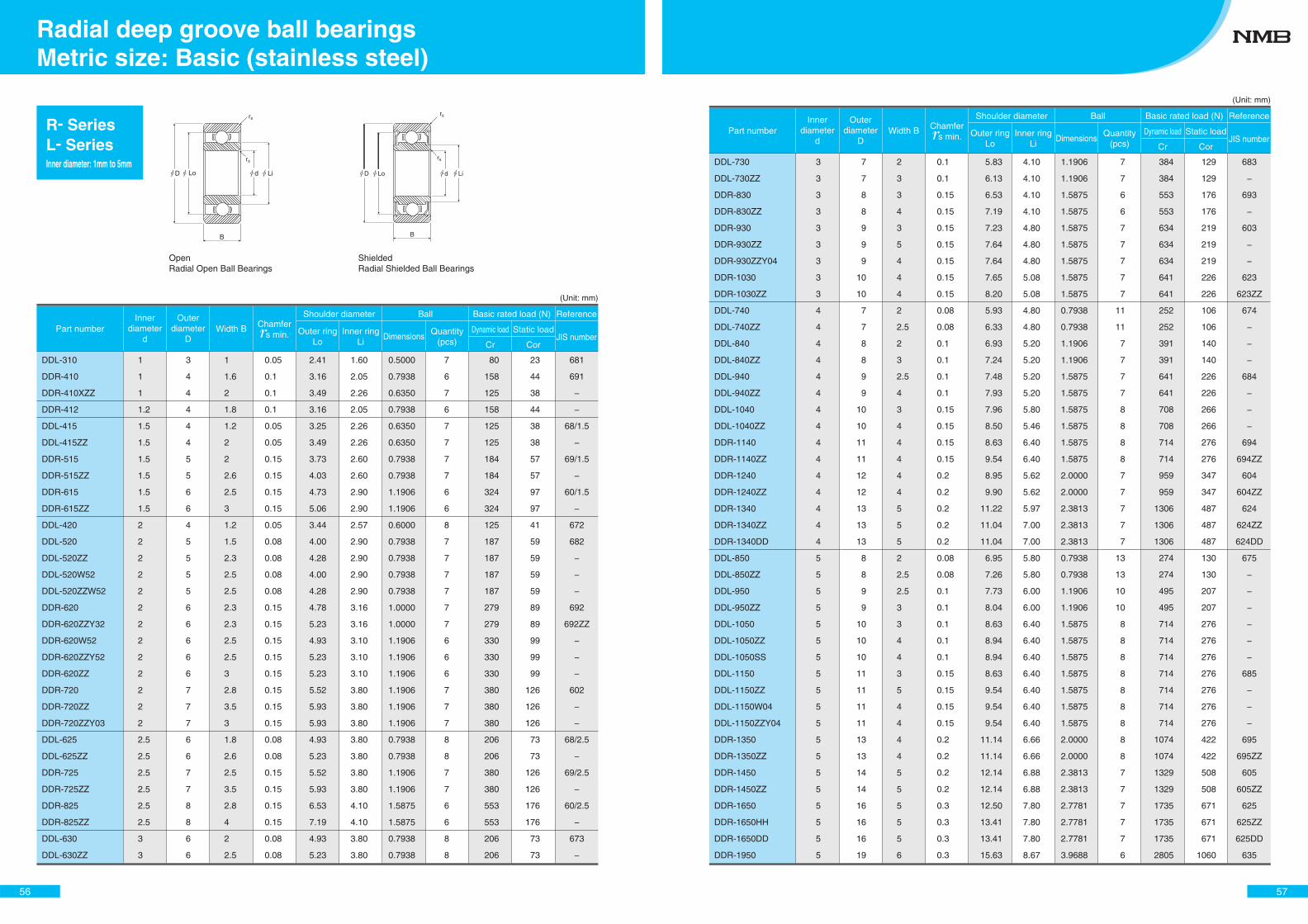
DDL-310
DDR-410
DDR-410XZZ
DDR-412
DDL-415
DDL-415ZZ
DDR-515
DDR-515ZZ
DDR-615
DDR-615ZZ
DDL-420
DDL-520
DDL-520ZZ
DDL-520W52
DDL-520ZZW52
DDR-620
DDR-620ZZY32
DDR-620W52
DDR-620ZZY52
DDR-620ZZ
DDR-720
DDR-720ZZ
DDR-720ZZY03
DDL-625
DDL-625ZZ
DDR-725
DDR-725ZZ
DDR-825
DDR-825ZZ
DDL-630
DDL-630ZZ
0.5000
0.7938
0.6350
0.7938
0.6350
0.6350
0.7938
0.7938
1.1906
1.1906
0.6000
0.7938
0.7938
0.7938
0.7938
1.0000
1.0000
1.1906
1.1906
1.1906
1.1906
1.1906
1.1906
0.7938
0.7938
1.1906
1.1906
1.5875
1.5875
0.7938
0.7938
7
6
7
6
7
7
7
7
6
6
8
7
7
7
7
7
7
6
6
6
7
7
7
8
8
7
7
6
6
8
8
1.60
2.05
2.26
2.05
2.26
2.26
2.60
2.60
2.90
2.90
2.57
2.90
2.90
2.90
2.90
3.16
3.16
3.10
3.10
3.10
3.80
3.80
3.80
3.80
3.80
3.80
3.80
4.10
4.10
3.80
3.80
2.41
3.16
3.49
3.16
3.25
3.49
3.73
4.03
4.73
5.06
3.44
4.00
4.28
4.00
4.28
4.78
5.23
4.93
5.23
5.23
5.52
5.93
5.93
4.93
5.23
5.52
5.93
6.53
7.19
4.93
5.23
0.05
0.1
0.1
0.1
0.05
0.05
0.15
0.15
0.15
0.15
0.05
0.08
0.08
0.08
0.08
0.15
0.15
0.15
0.15
0.15
0.15
0.15
0.15
0.08
0.08
0.15
0.15
0.15
0.15
0.08
0.08
1
1.6
2
1.8
1.2
2
2
2.6
2.5
3
1.2
1.5
2.3
2.5
2.5
2.3
2.3
2.5
2.5
3
2.8
3.5
3
1.8
2.6
2.5
3.5
2.8
4
2
2.5
3
4
4
4
4
4
5
5
6
6
4
5
5
5
5
6
6
6
6
6
7
7
7
6
6
7
7
8
8
6
6
1
1
1
1.2
1.5
1.5
1.5
1.5
1.5
1.5
2
2
2
2
2
2
2
2
2
2
2
2
2
2.5
2.5
2.5
2.5
2.5
2.5
3
3
80
158
125
158
125
125
184
184
324
324
125
187
187
187
187
279
279
330
330
330
380
380
380
206
206
380
380
553
553
206
206
23
44
38
44
38
38
57
57
97
97
41
59
59
59
59
89
89
99
99
99
126
126
126
73
73
126
126
176
176
73
73
681
691
−
−
68/1.5
−
69/1.5
−
60/1.5
−
672
682
−
−
−
692
692ZZ
−
−
−
602
−
−
68/2.5
−
69/2.5
−
60/2.5
−
673
−
OpenRadial Open Ball Bearings
ShieldedRadial Shielded Ball Bearings
rs
rs
B
D Lo d Li
B
rs
rs
D Lo d Li
R- SeriesL- SeriesInner diameter: 1mm to 5mm
Part numberInner
diameterd
Outerdiameter
DWidth B
Shoulder diameter
DimensionsQuantity
(pcs)Dynamic load
JIS number
Ball Basic rated load (N) Reference
Outer ringLo
Inner ringLi Cr
Static load
Cor
Chamfer s min.
56
Metric size: Basic (stainless steel)Radial deep groove ball bearings
(Unit: mm)
DDL-730
DDL-730ZZ
DDR-830
DDR-830ZZ
DDR-930
DDR-930ZZ
DDR-930ZZY04
DDR-1030
DDR-1030ZZ
DDL-740
DDL-740ZZ
DDL-840
DDL-840ZZ
DDL-940
DDL-940ZZ
DDL-1040
DDL-1040ZZ
DDR-1140
DDR-1140ZZ
DDR-1240
DDR-1240ZZ
DDR-1340
DDR-1340ZZ
DDR-1340DD
DDL-850
DDL-850ZZ
DDL-950
DDL-950ZZ
DDL-1050
DDL-1050ZZ
DDL-1050SS
DDL-1150
DDL-1150ZZ
DDL-1150W04
DDL-1150ZZY04
DDR-1350
DDR-1350ZZ
DDR-1450
DDR-1450ZZ
DDR-1650
DDR-1650HH
DDR-1650DD
DDR-1950
1.1906
1.1906
1.5875
1.5875
1.5875
1.5875
1.5875
1.5875
1.5875
0.7938
0.7938
1.1906
1.1906
1.5875
1.5875
1.5875
1.5875
1.5875
1.5875
2.0000
2.0000
2.3813
2.3813
2.3813
0.7938
0.7938
1.1906
1.1906
1.5875
1.5875
1.5875
1.5875
1.5875
1.5875
1.5875
2.0000
2.0000
2.3813
2.3813
2.7781
2.7781
2.7781
3.9688
7
7
6
6
7
7
7
7
7
11
11
7
7
7
7
8
8
8
8
7
7
7
7
7
13
13
10
10
8
8
8
8
8
8
8
8
8
7
7
7
7
7
6
4.10
4.10
4.10
4.10
4.80
4.80
4.80
5.08
5.08
4.80
4.80
5.20
5.20
5.20
5.20
5.80
5.46
6.40
6.40
5.62
5.62
5.97
7.00
7.00
5.80
5.80
6.00
6.00
6.40
6.40
6.40
6.40
6.40
6.40
6.40
6.66
6.66
6.88
6.88
7.80
7.80
7.80
8.67
5.83
6.13
6.53
7.19
7.23
7.64
7.64
7.65
8.20
5.93
6.33
6.93
7.24
7.48
7.93
7.96
8.50
8.63
9.54
8.95
9.90
11.22
11.04
11.04
6.95
7.26
7.73
8.04
8.63
8.94
8.94
8.63
9.54
9.54
9.54
11.14
11.14
12.14
12.14
12.50
13.41
13.41
15.63
0.1
0.1
0.15
0.15
0.15
0.15
0.15
0.15
0.15
0.08
0.08
0.1
0.1
0.1
0.1
0.15
0.15
0.15
0.15
0.2
0.2
0.2
0.2
0.2
0.08
0.08
0.1
0.1
0.1
0.1
0.1
0.15
0.15
0.15
0.15
0.2
0.2
0.2
0.2
0.3
0.3
0.3
0.3
2
3
3
4
3
5
4
4
4
2
2.5
2
3
2.5
4
3
4
4
4
4
4
5
5
5
2
2.5
2.5
3
3
4
4
3
5
4
4
4
4
5
5
5
5
5
6
7
7
8
8
9
9
9
10
10
7
7
8
8
9
9
10
10
11
11
12
12
13
13
13
8
8
9
9
10
10
10
11
11
11
11
13
13
14
14
16
16
16
19
3
3
3
3
3
3
3
3
3
4
4
4
4
4
4
4
4
4
4
4
4
4
4
4
5
5
5
5
5
5
5
5
5
5
5
5
5
5
5
5
5
5
5
384
384
553
553
634
634
634
641
641
252
252
391
391
641
641
708
708
714
714
959
959
1306
1306
1306
274
274
495
495
714
714
714
714
714
714
714
1074
1074
1329
1329
1735
1735
1735
2805
129
129
176
176
219
219
219
226
226
106
106
140
140
226
226
266
266
276
276
347
347
487
487
487
130
130
207
207
276
276
276
276
276
276
276
422
422
508
508
671
671
671
1060
683
−
693
−
603
−
−
623
623ZZ
674
−
−
−
684
−
−
−
694
694ZZ
604
604ZZ
624
624ZZ
624DD
675
−
−
−
−
−
−
685
−
−
−
695
695ZZ
605
605ZZ
625
625ZZ
625DD
635
Part numberInner
diameterd
Outerdiameter
DWidth B
Shoulder diameter
DimensionsQuantity
(pcs)Dynamic load
JIS number
Ball Basic rated load (N) Reference
Outer ringLo
Inner ringLi Cr
Static load
Cor
Chamfer s min.
57
(Unit: mm)
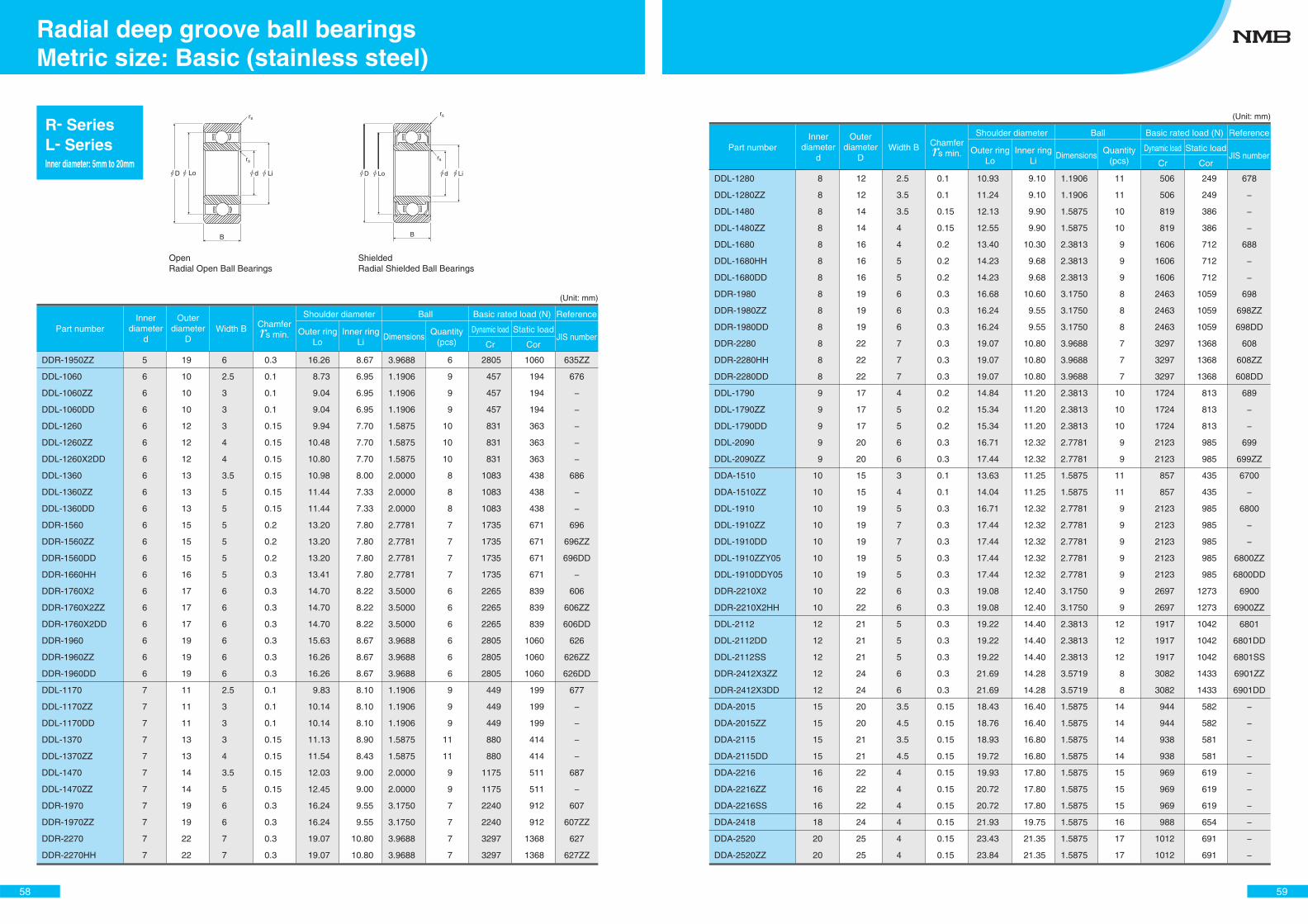
Part numberInner
diameterd
Outerdiameter
DWidth B
Shoulder diameter
DimensionsQuantity
(pcs)
Dynamic loadJIS number
Ball Basic rated load (N) Reference
Outer ringLo
Inner ringLi Cr
Static load
Cor
Chamfer s min.
OpenRadial Open Ball Bearings
ShieldedRadial Shielded Ball Bearings
rs
rs
B
D Lo d Li
B
rs
rs
D Lo d Li
R- SeriesL- SeriesInner diameter: 5mm to 20mm
DDR-1950ZZ
DDL-1060
DDL-1060ZZ
DDL-1060DD
DDL-1260
DDL-1260ZZ
DDL-1260X2DD
DDL-1360
DDL-1360ZZ
DDL-1360DD
DDR-1560
DDR-1560ZZ
DDR-1560DD
DDR-1660HH
DDR-1760X2
DDR-1760X2ZZ
DDR-1760X2DD
DDR-1960
DDR-1960ZZ
DDR-1960DD
DDL-1170
DDL-1170ZZ
DDL-1170DD
DDL-1370
DDL-1370ZZ
DDL-1470
DDL-1470ZZ
DDR-1970
DDR-1970ZZ
DDR-2270
DDR-2270HH
3.9688
1.1906
1.1906
1.1906
1.5875
1.5875
1.5875
2.0000
2.0000
2.0000
2.7781
2.7781
2.7781
2.7781
3.5000
3.5000
3.5000
3.9688
3.9688
3.9688
1.1906
1.1906
1.1906
1.5875
1.5875
2.0000
2.0000
3.1750
3.1750
3.9688
3.9688
6
9
9
9
10
10
10
8
8
8
7
7
7
7
6
6
6
6
6
6
9
9
9
11
11
9
9
7
7
7
7
8.67
6.95
6.95
6.95
7.70
7.70
7.70
8.00
7.33
7.33
7.80
7.80
7.80
7.80
8.22
8.22
8.22
8.67
8.67
8.67
8.10
8.10
8.10
8.90
8.43
9.00
9.00
9.55
9.55
10.80
10.80
16.26
8.73
9.04
9.04
9.94
10.48
10.80
10.98
11.44
11.44
13.20
13.20
13.20
13.41
14.70
14.70
14.70
15.63
16.26
16.26
9.83
10.14
10.14
11.13
11.54
12.03
12.45
16.24
16.24
19.07
19.07
0.3
0.1
0.1
0.1
0.15
0.15
0.15
0.15
0.15
0.15
0.2
0.2
0.2
0.3
0.3
0.3
0.3
0.3
0.3
0.3
0.1
0.1
0.1
0.15
0.15
0.15
0.15
0.3
0.3
0.3
0.3
6
2.5
3
3
3
4
4
3.5
5
5
5
5
5
5
6
6
6
6
6
6
2.5
3
3
3
4
3.5
5
6
6
7
7
19
10
10
10
12
12
12
13
13
13
15
15
15
16
17
17
17
19
19
19
11
11
11
13
13
14
14
19
19
22
22
5
6
6
6
6
6
6
6
6
6
6
6
6
6
6
6
6
6
6
6
7
7
7
7
7
7
7
7
7
7
7
2805
457
457
457
831
831
831
1083
1083
1083
1735
1735
1735
1735
2265
2265
2265
2805
2805
2805
449
449
449
880
880
1175
1175
2240
2240
3297
3297
1060
194
194
194
363
363
363
438
438
438
671
671
671
671
839
839
839
1060
1060
1060
199
199
199
414
414
511
511
912
912
1368
1368
635ZZ
676
−
−
−
−
−
686
−
−
696
696ZZ
696DD
−
606
606ZZ
606DD
626
626ZZ
626DD
677
−
−
−
−
687
−
607
607ZZ
627
627ZZ
58
Metric size: Basic (stainless steel)Radial deep groove ball bearings
(Unit: mm)
DDL-1280
DDL-1280ZZ
DDL-1480
DDL-1480ZZ
DDL-1680
DDL-1680HH
DDL-1680DD
DDR-1980
DDR-1980ZZ
DDR-1980DD
DDR-2280
DDR-2280HH
DDR-2280DD
DDL-1790
DDL-1790ZZ
DDL-1790DD
DDL-2090
DDL-2090ZZ
DDA-1510
DDA-1510ZZ
DDL-1910
DDL-1910ZZ
DDL-1910DD
DDL-1910ZZY05
DDL-1910DDY05
DDR-2210X2
DDR-2210X2HH
DDL-2112
DDL-2112DD
DDL-2112SS
DDR-2412X3ZZ
DDR-2412X3DD
DDA-2015
DDA-2015ZZ
DDA-2115
DDA-2115DD
DDA-2216
DDA-2216ZZ
DDA-2216SS
DDA-2418
DDA-2520
DDA-2520ZZ
1.1906
1.1906
1.5875
1.5875
2.3813
2.3813
2.3813
3.1750
3.1750
3.1750
3.9688
3.9688
3.9688
2.3813
2.3813
2.3813
2.7781
2.7781
1.5875
1.5875
2.7781
2.7781
2.7781
2.7781
2.7781
3.1750
3.1750
2.3813
2.3813
2.3813
3.5719
3.5719
1.5875
1.5875
1.5875
1.5875
1.5875
1.5875
1.5875
1.5875
1.5875
1.5875
11
11
10
10
9
9
9
8
8
8
7
7
7
10
10
10
9
9
11
11
9
9
9
9
9
9
9
12
12
12
8
8
14
14
14
14
15
15
15
16
17
17
9.10
9.10
9.90
9.90
10.30
9.68
9.68
10.60
9.55
9.55
10.80
10.80
10.80
11.20
11.20
11.20
12.32
12.32
11.25
11.25
12.32
12.32
12.32
12.32
12.32
12.40
12.40
14.40
14.40
14.40
14.28
14.28
16.40
16.40
16.80
16.80
17.80
17.80
17.80
19.75
21.35
21.35
10.93
11.24
12.13
12.55
13.40
14.23
14.23
16.68
16.24
16.24
19.07
19.07
19.07
14.84
15.34
15.34
16.71
17.44
13.63
14.04
16.71
17.44
17.44
17.44
17.44
19.08
19.08
19.22
19.22
19.22
21.69
21.69
18.43
18.76
18.93
19.72
19.93
20.72
20.72
21.93
23.43
23.84
0.1
0.1
0.15
0.15
0.2
0.2
0.2
0.3
0.3
0.3
0.3
0.3
0.3
0.2
0.2
0.2
0.3
0.3
0.1
0.1
0.3
0.3
0.3
0.3
0.3
0.3
0.3
0.3
0.3
0.3
0.3
0.3
0.15
0.15
0.15
0.15
0.15
0.15
0.15
0.15
0.15
0.15
2.5
3.5
3.5
4
4
5
5
6
6
6
7
7
7
4
5
5
6
6
3
4
5
7
7
5
5
6
6
5
5
5
6
6
3.5
4.5
3.5
4.5
4
4
4
4
4
4
12
12
14
14
16
16
16
19
19
19
22
22
22
17
17
17
20
20
15
15
19
19
19
19
19
22
22
21
21
21
24
24
20
20
21
21
22
22
22
24
25
25
8
8
8
8
8
8
8
8
8
8
8
8
8
9
9
9
9
9
10
10
10
10
10
10
10
10
10
12
12
12
12
12
15
15
15
15
16
16
16
18
20
20
506
506
819
819
1606
1606
1606
2463
2463
2463
3297
3297
3297
1724
1724
1724
2123
2123
857
857
2123
2123
2123
2123
2123
2697
2697
1917
1917
1917
3082
3082
944
944
938
938
969
969
969
988
1012
1012
249
249
386
386
712
712
712
1059
1059
1059
1368
1368
1368
813
813
813
985
985
435
435
985
985
985
985
985
1273
1273
1042
1042
1042
1433
1433
582
582
581
581
619
619
619
654
691
691
678
−
−
−
688
−
−
698
698ZZ
698DD
608
608ZZ
608DD
689
−
−
699
699ZZ
6700
−
6800
−
−
6800ZZ
6800DD
6900
6900ZZ
6801
6801DD
6801SS
6901ZZ
6901DD
−
−
−
−
−
−
−
−
−
−
Part numberInner
diameterd
Outerdiameter
DWidth B
Shoulder diameter
DimensionsQuantity
(pcs)
Dynamic loadJIS number
Ball Basic rated load (N) Reference
Outer ringLo
Inner ringLi Cr
Static load
Cor
Chamfer s min.
59
(Unit: mm)
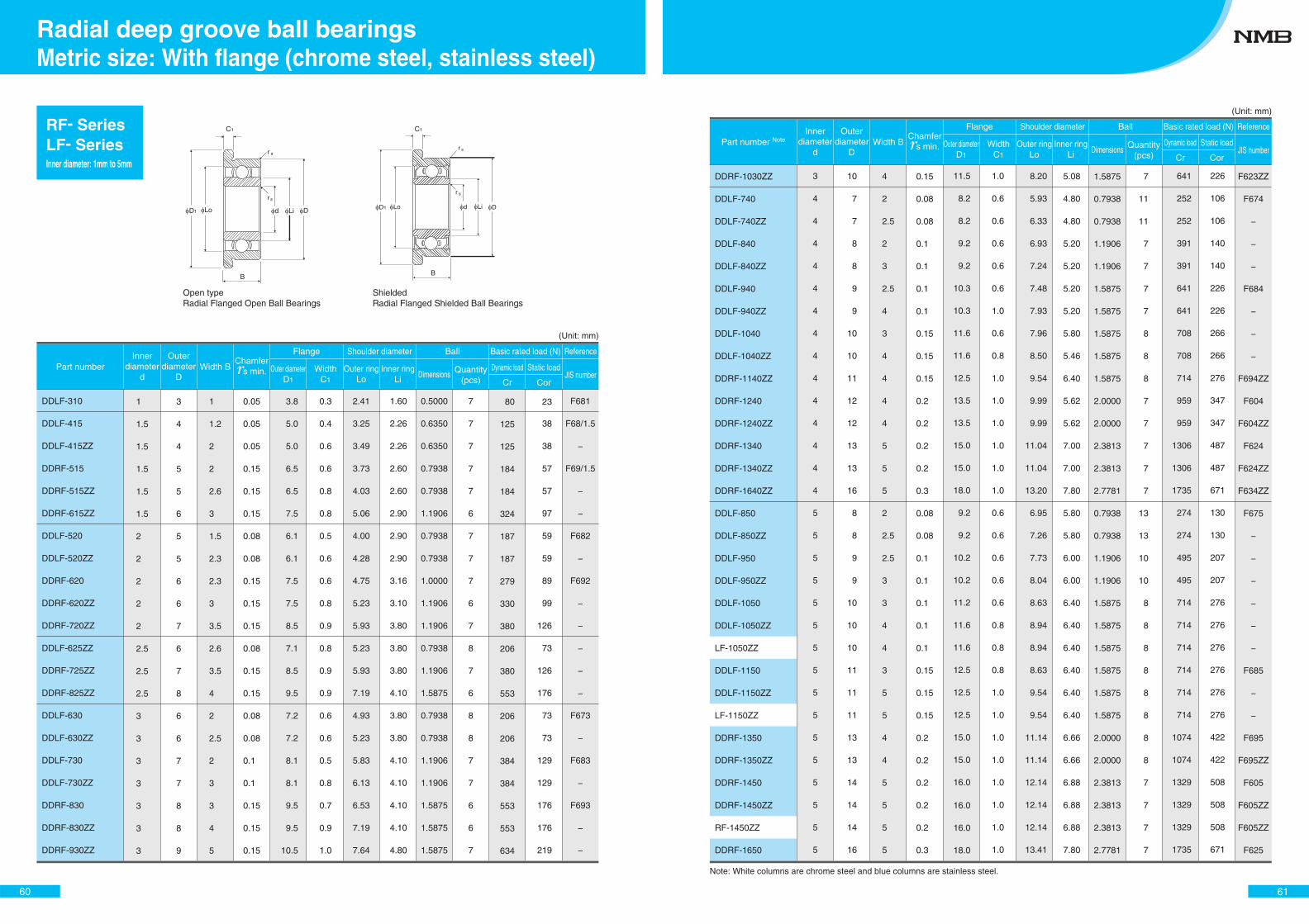
Part numberInner
diameterd
Outerdiameter
DWidth B
Shoulder diameter
Dimensions Quantity(pcs)
Dynamic loadJIS number
Ball Basic rated load (N) Reference
Outer ringLo
Inner ringLi Cr
Static load
Cor
Chamfer s min.
Flange
Outer diameterD1
WidthC1
D1 Lo d Li D
r
r
C1
s
s
B B
C1
D1 DLo d Li
r s
r s
Shielded Radial Flanged Shielded Ball Bearings
Open type Radial Flanged Open Ball Bearings
DDLF-310
DDLF-415
DDLF-415ZZ
DDRF-515
DDRF-515ZZ
DDRF-615ZZ
DDLF-520
DDLF-520ZZ
DDRF-620
DDRF-620ZZ
DDRF-720ZZ
DDLF-625ZZ
DDRF-725ZZ
DDRF-825ZZ
DDLF-630
DDLF-630ZZ
DDLF-730
DDLF-730ZZ
DDRF-830
DDRF-830ZZ
DDRF-930ZZ
0.5000
0.6350
0.6350
0.7938
0.7938
1.1906
0.7938
0.7938
1.0000
1.1906
1.1906
0.7938
1.1906
1.5875
0.7938
0.7938
1.1906
1.1906
1.5875
1.5875
1.5875
0.5000
0.6350
0.6350
0.7938
0.7938
1.1906
0.7938
0.7938
1.0000
1.1906
1.1906
0.7938
1.1906
1.5875
0.7938
0.7938
1.1906
1.1906
1.5875
1.5875
1.5875
7
7
7
7
7
6
7
7
7
6
7
8
7
6
8
8
7
7
6
6
7
7
7
7
7
7
6
7
7
7
6
7
8
7
6
8
8
7
7
6
6
7
1.60
2.26
2.26
2.60
2.60
2.90
2.90
2.90
3.16
3.10
3.80
3.80
3.80
4.10
3.80
3.80
4.10
4.10
4.10
4.10
4.80
1.60
2.26
2.26
2.60
2.60
2.90
2.90
2.90
3.16
3.10
3.80
3.80
3.80
4.10
3.80
3.80
4.10
4.10
4.10
4.10
4.80
2.41
3.25
3.49
3.73
4.03
5.06
4.00
4.28
4.75
5.23
5.93
5.23
5.93
7.19
4.93
5.23
5.83
6.13
6.53
7.19
7.64
2.41
3.25
3.49
3.73
4.03
5.06
4.00
4.28
4.75
5.23
5.93
5.23
5.93
7.19
4.93
5.23
5.83
6.13
6.53
7.19
7.64
0.3
0.4
0.6
0.6
0.8
0.8
0.5
0.6
0.6
0.8
0.9
0.8
0.9
0.9
0.6
0.6
0.5
0.8
0.7
0.9
1.0
0.3
0.4
0.6
0.6
0.8
0.8
0.5
0.6
0.6
0.8
0.9
0.8
0.9
0.9
0.6
0.6
0.5
0.8
0.7
0.9
1.0
3.8
5.0
5.0
6.5
6.5
7.5
6.1
6.1
7.5
7.5
8.5
7.1
8.5
9.5
7.2
7.2
8.1
8.1
9.5
9.5
10.5
3.8
5.0
5.0
6.5
6.5
7.5
6.1
6.1
7.5
7.5
8.5
7.1
8.5
9.5
7.2
7.2
8.1
8.1
9.5
9.5
10.5
0.05
0.05
0.05
0.15
0.15
0.15
0.08
0.08
0.15
0.15
0.15
0.08
0.15
0.15
0.08
0.08
0.1
0.1
0.15
0.15
0.15
0.05
0.05
0.05
0.15
0.15
0.15
0.08
0.08
0.15
0.15
0.15
0.08
0.15
0.15
0.08
0.08
0.1
0.1
0.15
0.15
0.15
1
1.2
2
2
2.6
3
1.5
2.3
2.3
3
3.5
2.6
3.5
4
2
2.5
2
3
3
4
5
1
1.2
2
2
2.6
3
1.5
2.3
2.3
3
3.5
2.6
3.5
4
2
2.5
2
3
3
4
5
3
4
4
5
5
6
5
5
6
6
7
6
7
8
6
6
7
7
8
8
9
3
4
4
5
5
6
5
5
6
6
7
6
7
8
6
6
7
7
8
8
9
1
1.5
1.5
1.5
1.5
1.5
2
2
2
2
2
2.5
2.5
2.5
3
3
3
3
3
3
3
1
1.5
1.5
1.5
1.5
1.5
2
2
2
2
2
2.5
2.5
2.5
3
3
3
3
3
3
3
80
125
125
184
184
324
187
187
279
330
380
206
380
553
206
206
384
384
553
553
634
80
125
125
184
184
324
187
187
279
330
380
206
380
553
206
206
384
384
553
553
634
23
38
38
57
57
97
59
59
89
99
126
73
126
176
73
73
129
129
176
176
219
23
38
38
57
57
97
59
59
89
99
126
73
126
176
73
73
129
129
176
176
219
F681
F68/1.5
−
F69/1.5
−
−
F682
−
F692
−
−
−
−
−
F673
−
F683
−
F693
−
−
F681
F68/1.5
−
F69/1.5
−
−
F682
−
F692
−
−
−
−
−
F673
−
F683
−
F693
−
−
RF- SeriesLF- SeriesInner diameter: 1mm to 5mm
60
Metric size: With flange (chrome steel, stainless steel)Radial deep groove ball bearings
(Unit: mm)
Part number NoteInner
diameterd
Outerdiameter
DWidth B
Shoulder diameter
Dimensions Quantity(pcs)
Dynamic loadJIS number
Ball Basic rated load (N) Reference
Outer ringLo
Inner ringLi Cr
Static load
Cor
Chamfer s min.
Flange
Outer diameterD1
WidthC1
DDRF-1030ZZ
DDLF-740
DDLF-740ZZ
DDLF-840
DDLF-840ZZ
DDLF-940
DDLF-940ZZ
DDLF-1040
DDLF-1040ZZ
DDRF-1140ZZ
DDRF-1240
DDRF-1240ZZ
DDRF-1340
DDRF-1340ZZ
DDRF-1640ZZ
DDLF-850
DDLF-850ZZ
DDLF-950
DDLF-950ZZ
DDLF-1050
DDLF-1050ZZ
LF-1050ZZ
DDLF-1150
DDLF-1150ZZ
LF-1150ZZ
DDRF-1350
DDRF-1350ZZ
DDRF-1450
DDRF-1450ZZ
RF-1450ZZ
DDRF-1650
1.5875
0.7938
0.7938
1.1906
1.1906
1.5875
1.5875
1.5875
1.5875
1.5875
2.0000
2.0000
2.3813
2.3813
2.7781
0.7938
0.7938
1.1906
1.1906
1.5875
1.5875
1.5875
1.5875
1.5875
1.5875
2.0000
2.0000
2.3813
2.3813
2.3813
2.7781
1.5875
0.7938
0.7938
1.1906
1.1906
1.5875
1.5875
1.5875
1.5875
1.5875
2.0000
2.0000
2.3813
2.3813
2.7781
0.7938
0.7938
1.1906
1.1906
1.5875
1.5875
1.5875
1.5875
1.5875
1.5875
2.0000
2.0000
2.3813
2.3813
2.3813
2.7781
7
11
11
7
7
7
7
8
8
8
7
7
7
7
7
13
13
10
10
8
8
8
8
8
8
8
8
7
7
7
7
7
11
11
7
7
7
7
8
8
8
7
7
7
7
7
13
13
10
10
8
8
8
8
8
8
8
8
7
7
7
7
5.08
4.80
4.80
5.20
5.20
5.20
5.20
5.80
5.46
6.40
5.62
5.62
7.00
7.00
7.80
5.80
5.80
6.00
6.00
6.40
6.40
6.40
6.40
6.40
6.40
6.66
6.66
6.88
6.88
6.88
7.80
5.08
4.80
4.80
5.20
5.20
5.20
5.20
5.80
5.46
6.40
5.62
5.62
7.00
7.00
7.80
5.80
5.80
6.00
6.00
6.40
6.40
6.40
6.40
6.40
6.40
6.66
6.66
6.88
6.88
6.88
7.80
8.20
5.93
6.33
6.93
7.24
7.48
7.93
7.96
8.50
9.54
9.99
9.99
11.04
11.04
13.20
6.95
7.26
7.73
8.04
8.63
8.94
8.94
8.63
9.54
9.54
11.14
11.14
12.14
12.14
12.14
13.41
8.20
5.93
6.33
6.93
7.24
7.48
7.93
7.96
8.50
9.54
9.99
9.99
11.04
11.04
13.20
6.95
7.26
7.73
8.04
8.63
8.94
8.94
8.63
9.54
9.54
11.14
11.14
12.14
12.14
12.14
13.41
1.0
0.6
0.6
0.6
0.6
0.6
1.0
0.6
0.8
1.0
1.0
1.0
1.0
1.0
1.0
0.6
0.6
0.6
0.6
0.6
0.8
0.8
0.8
1.0
1.0
1.0
1.0
1.0
1.0
1.0
1.0
1.0
0.6
0.6
0.6
0.6
0.6
1.0
0.6
0.8
1.0
1.0
1.0
1.0
1.0
1.0
0.6
0.6
0.6
0.6
0.6
0.8
0.8
0.8
1.0
1.0
1.0
1.0
1.0
1.0
1.0
1.0
11.5
8.2
8.2
9.2
9.2
10.3
10.3
11.6
11.6
12.5
13.5
13.5
15.0
15.0
18.0
9.2
9.2
10.2
10.2
11.2
11.6
11.6
12.5
12.5
12.5
15.0
15.0
16.0
16.0
16.0
18.0
11.5
8.2
8.2
9.2
9.2
10.3
10.3
11.6
11.6
12.5
13.5
13.5
15.0
15.0
18.0
9.2
9.2
10.2
10.2
11.2
11.6
11.6
12.5
12.5
12.5
15.0
15.0
16.0
16.0
16.0
18.0
0.15
0.08
0.08
0.1
0.1
0.1
0.1
0.15
0.15
0.15
0.2
0.2
0.2
0.2
0.3
0.08
0.08
0.1
0.1
0.1
0.1
0.1
0.15
0.15
0.15
0.2
0.2
0.2
0.2
0.2
0.3
0.15
0.08
0.08
0.1
0.1
0.1
0.1
0.15
0.15
0.15
0.2
0.2
0.2
0.2
0.3
0.08
0.08
0.1
0.1
0.1
0.1
0.1
0.15
0.15
0.15
0.2
0.2
0.2
0.2
0.2
0.3
4
2
2.5
2
3
2.5
4
3
4
4
4
4
5
5
5
2
2.5
2.5
3
3
4
4
3
5
5
4
4
5
5
5
5
4
2
2.5
2
3
2.5
4
3
4
4
4
4
5
5
5
2
2.5
2.5
3
3
4
4
3
5
5
4
4
5
5
5
5
10
7
7
8
8
9
9
10
10
11
12
12
13
13
16
8
8
9
9
10
10
10
11
11
11
13
13
14
14
14
16
10
7
7
8
8
9
9
10
10
11
12
12
13
13
16
8
8
9
9
10
10
10
11
11
11
13
13
14
14
14
16
3
4
4
4
4
4
4
4
4
4
4
4
4
4
4
5
5
5
5
5
5
5
5
5
5
5
5
5
5
5
5
3
4
4
4
4
4
4
4
4
4
4
4
4
4
4
5
5
5
5
5
5
5
5
5
5
5
5
5
5
5
5
641
252
252
391
391
641
641
708
708
714
959
959
1306
1306
1735
274
274
495
495
714
714
714
714
714
714
1074
1074
1329
1329
1329
1735
641
252
252
391
391
641
641
708
708
714
959
959
1306
1306
1735
274
274
495
495
714
714
714
714
714
714
1074
1074
1329
1329
1329
1735
226
106
106
140
140
226
226
266
266
276
347
347
487
487
671
130
130
207
207
276
276
276
276
276
276
422
422
508
508
508
671
226
106
106
140
140
226
226
266
266
276
347
347
487
487
671
130
130
207
207
276
276
276
276
276
276
422
422
508
508
508
671
F623ZZ
F674
−
−
−
F684
−
−
−
F694ZZ
F604
F604ZZ
F624
F624ZZ
F634ZZ
F675
−
−
−
−
−
−
F685
−
−
F695
F695ZZ
F605
F605ZZ
F605ZZ
F625
F623ZZ
F674
−
−
−
F684
−
−
−
F694ZZ
F604
F604ZZ
F624
F624ZZ
F634ZZ
F675
−
−
−
−
−
−
F685
−
−
F695
F695ZZ
F605
F605ZZ
F605ZZ
F625
61
(Unit: mm)
Note: White columns are chrome steel and blue columns are stainless steel.
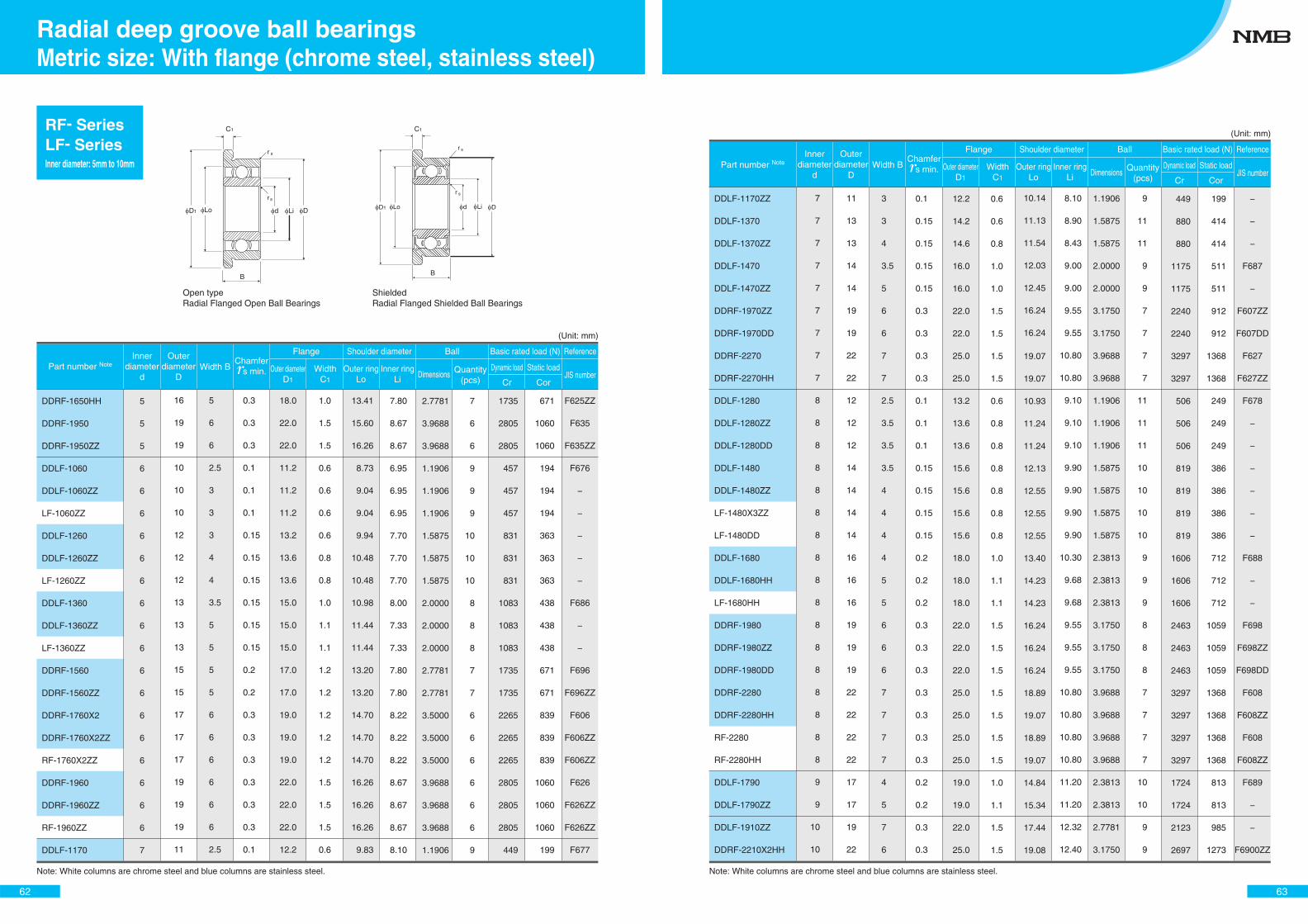
D1 Lo d Li D
r
r
C1
s
s
B B
C1
D1 DLo d Li
r s
r s
Shielded Radial Flanged Shielded Ball Bearings
Open type Radial Flanged Open Ball Bearings
DDRF-1650HH
DDRF-1950
DDRF-1950ZZ
DDLF-1060
DDLF-1060ZZ
LF-1060ZZ
DDLF-1260
DDLF-1260ZZ
LF-1260ZZ
DDLF-1360
DDLF-1360ZZ
LF-1360ZZ
DDRF-1560
DDRF-1560ZZ
DDRF-1760X2
DDRF-1760X2ZZ
RF-1760X2ZZ
DDRF-1960
DDRF-1960ZZ
RF-1960ZZ
DDLF-1170
RF- SeriesLF- SeriesInner diameter: 5mm to 10mm
2.7781
3.9688
3.9688
1.1906
1.1906
1.1906
1.5875
1.5875
1.5875
2.0000
2.0000
2.0000
2.7781
2.7781
3.5000
3.5000
3.5000
3.9688
3.9688
3.9688
1.1906
2.7781
3.9688
3.9688
1.1906
1.1906
1.1906
1.5875
1.5875
1.5875
2.0000
2.0000
2.0000
2.7781
2.7781
3.5000
3.5000
3.5000
3.9688
3.9688
3.9688
1.1906
7
6
6
9
9
9
10
10
10
8
8
8
7
7
6
6
6
6
6
6
9
7
6
6
9
9
9
10
10
10
8
8
8
7
7
6
6
6
6
6
6
9
7.80
8.67
8.67
6.95
6.95
6.95
7.70
7.70
7.70
8.00
7.33
7.33
7.80
7.80
8.22
8.22
8.22
8.67
8.67
8.67
8.10
7.80
8.67
8.67
6.95
6.95
6.95
7.70
7.70
7.70
8.00
7.33
7.33
7.80
7.80
8.22
8.22
8.22
8.67
8.67
8.67
8.10
13.41
15.60
16.26
8.73
9.04
9.04
9.94
10.48
10.48
10.98
11.44
11.44
13.20
13.20
14.70
14.70
14.70
16.26
16.26
16.26
9.83
13.41
15.60
16.26
8.73
9.04
9.04
9.94
10.48
10.48
10.98
11.44
11.44
13.20
13.20
14.70
14.70
14.70
16.26
16.26
16.26
9.83
1.0
1.5
1.5
0.6
0.6
0.6
0.6
0.8
0.8
1.0
1.1
1.1
1.2
1.2
1.2
1.2
1.2
1.5
1.5
1.5
0.6
1.0
1.5
1.5
0.6
0.6
0.6
0.6
0.8
0.8
1.0
1.1
1.1
1.2
1.2
1.2
1.2
1.2
1.5
1.5
1.5
0.6
18.0
22.0
22.0
11.2
11.2
11.2
13.2
13.6
13.6
15.0
15.0
15.0
17.0
17.0
19.0
19.0
19.0
22.0
22.0
22.0
12.2
18.0
22.0
22.0
11.2
11.2
11.2
13.2
13.6
13.6
15.0
15.0
15.0
17.0
17.0
19.0
19.0
19.0
22.0
22.0
22.0
12.2
0.3
0.3
0.3
0.1
0.1
0.1
0.15
0.15
0.15
0.15
0.15
0.15
0.2
0.2
0.3
0.3
0.3
0.3
0.3
0.3
0.1
0.3
0.3
0.3
0.1
0.1
0.1
0.15
0.15
0.15
0.15
0.15
0.15
0.2
0.2
0.3
0.3
0.3
0.3
0.3
0.3
0.1
5
6
6
2.5
3
3
3
4
4
3.5
5
5
5
5
6
6
6
6
6
6
2.5
5
6
6
2.5
3
3
3
4
4
3.5
5
5
5
5
6
6
6
6
6
6
2.5
16
19
19
10
10
10
12
12
12
13
13
13
15
15
17
17
17
19
19
19
11
16
19
19
10
10
10
12
12
12
13
13
13
15
15
17
17
17
19
19
19
11
5
5
5
6
6
6
6
6
6
6
6
6
6
6
6
6
6
6
6
6
7
5
5
5
6
6
6
6
6
6
6
6
6
6
6
6
6
6
6
6
6
7
1735
2805
2805
457
457
457
831
831
831
1083
1083
1083
1735
1735
2265
2265
2265
2805
2805
2805
449
1735
2805
2805
457
457
457
831
831
831
1083
1083
1083
1735
1735
2265
2265
2265
2805
2805
2805
449
671
1060
1060
194
194
194
363
363
363
438
438
438
671
671
839
839
839
1060
1060
1060
199
671
1060
1060
194
194
194
363
363
363
438
438
438
671
671
839
839
839
1060
1060
1060
199
F625ZZ
F635
F635ZZ
F676
−
−
−
−
−
F686
−
−
F696
F696ZZ
F606
F606ZZ
F606ZZ
F626
F626ZZ
F626ZZ
F677
F625ZZ
F635
F635ZZ
F676
−
−
−
−
−
F686
−
−
F696
F696ZZ
F606
F606ZZ
F606ZZ
F626
F626ZZ
F626ZZ
F677
Part number NoteInner
diameterd
Outerdiameter
DWidth B
Shoulder diameter
Dimensions Quantity(pcs)
Dynamic loadJIS number
Ball Basic rated load (N) Reference
Outer ringLo
Inner ringLi Cr
Static load
Cor
Chamfer s min.
Flange
Outer diameterD1
WidthC1
62
Metric size: With flange (chrome steel, stainless steel)Radial deep groove ball bearings
(Unit: mm)
Note: White columns are chrome steel and blue columns are stainless steel.
DDLF-1170ZZ
DDLF-1370
DDLF-1370ZZ
DDLF-1470
DDLF-1470ZZ
DDRF-1970ZZ
DDRF-1970DD
DDRF-2270
DDRF-2270HH
DDLF-1280
DDLF-1280ZZ
DDLF-1280DD
DDLF-1480
DDLF-1480ZZ
LF-1480X3ZZ
LF-1480DD
DDLF-1680
DDLF-1680HH
LF-1680HH
DDRF-1980
DDRF-1980ZZ
DDRF-1980DD
DDRF-2280
DDRF-2280HH
RF-2280
RF-2280HH
DDLF-1790
DDLF-1790ZZ
DDLF-1910ZZ
DDRF-2210X2HH
1.1906
1.5875
1.5875
2.0000
2.0000
3.1750
3.1750
3.9688
3.9688
1.1906
1.1906
1.1906
1.5875
1.5875
1.5875
1.5875
2.3813
2.3813
2.3813
3.1750
3.1750
3.1750
3.9688
3.9688
3.9688
3.9688
2.3813
2.3813
2.7781
3.1750
1.1906
1.5875
1.5875
2.0000
2.0000
3.1750
3.1750
3.9688
3.9688
1.1906
1.1906
1.1906
1.5875
1.5875
1.5875
1.5875
2.3813
2.3813
2.3813
3.1750
3.1750
3.1750
3.9688
3.9688
3.9688
3.9688
2.3813
2.3813
2.7781
3.1750
9
11
11
9
9
7
7
7
7
11
11
11
10
10
10
10
9
9
9
8
8
8
7
7
7
7
10
10
9
9
9
11
11
9
9
7
7
7
7
11
11
11
10
10
10
10
9
9
9
8
8
8
7
7
7
7
10
10
9
9
8.10
8.90
8.43
9.00
9.00
9.55
9.55
10.80
10.80
9.10
9.10
9.10
9.90
9.90
9.90
9.90
10.30
9.68
9.68
9.55
9.55
9.55
10.80
10.80
10.80
10.80
11.20
11.20
12.32
12.40
8.10
8.90
8.43
9.00
9.00
9.55
9.55
10.80
10.80
9.10
9.10
9.10
9.90
9.90
9.90
9.90
10.30
9.68
9.68
9.55
9.55
9.55
10.80
10.80
10.80
10.80
11.20
11.20
12.32
12.40
10.14
11.13
11.54
12.03
12.45
16.24
16.24
19.07
19.07
10.93
11.24
11.24
12.13
12.55
12.55
12.55
13.40
14.23
14.23
16.24
16.24
16.24
18.89
19.07
18.89
19.07
14.84
15.34
17.44
19.08
10.14
11.13
11.54
12.03
12.45
16.24
16.24
19.07
19.07
10.93
11.24
11.24
12.13
12.55
12.55
12.55
13.40
14.23
14.23
16.24
16.24
16.24
18.89
19.07
18.89
19.07
14.84
15.34
17.44
19.08
0.6
0.6
0.8
1.0
1.0
1.5
1.5
1.5
1.5
0.6
0.8
0.8
0.8
0.8
0.8
0.8
1.0
1.1
1.1
1.5
1.5
1.5
1.5
1.5
1.5
1.5
1.0
1.1
1.5
1.5
0.6
0.6
0.8
1.0
1.0
1.5
1.5
1.5
1.5
0.6
0.8
0.8
0.8
0.8
0.8
0.8
1.0
1.1
1.1
1.5
1.5
1.5
1.5
1.5
1.5
1.5
1.0
1.1
1.5
1.5
12.2
14.2
14.6
16.0
16.0
22.0
22.0
25.0
25.0
13.2
13.6
13.6
15.6
15.6
15.6
15.6
18.0
18.0
18.0
22.0
22.0
22.0
25.0
25.0
25.0
25.0
19.0
19.0
22.0
25.0
12.2
14.2
14.6
16.0
16.0
22.0
22.0
25.0
25.0
13.2
13.6
13.6
15.6
15.6
15.6
15.6
18.0
18.0
18.0
22.0
22.0
22.0
25.0
25.0
25.0
25.0
19.0
19.0
22.0
25.0
0.1
0.15
0.15
0.15
0.15
0.3
0.3
0.3
0.3
0.1
0.1
0.1
0.15
0.15
0.15
0.15
0.2
0.2
0.2
0.3
0.3
0.3
0.3
0.3
0.3
0.3
0.2
0.2
0.3
0.3
0.1
0.15
0.15
0.15
0.15
0.3
0.3
0.3
0.3
0.1
0.1
0.1
0.15
0.15
0.15
0.15
0.2
0.2
0.2
0.3
0.3
0.3
0.3
0.3
0.3
0.3
0.2
0.2
0.3
0.3
3
3
4
3.5
5
6
6
7
7
2.5
3.5
3.5
3.5
4
4
4
4
5
5
6
6
6
7
7
7
7
4
5
7
6
3
3
4
3.5
5
6
6
7
7
2.5
3.5
3.5
3.5
4
4
4
4
5
5
6
6
6
7
7
7
7
4
5
7
6
11
13
13
14
14
19
19
22
22
12
12
12
14
14
14
14
16
16
16
19
19
19
22
22
22
22
17
17
19
22
11
13
13
14
14
19
19
22
22
12
12
12
14
14
14
14
16
16
16
19
19
19
22
22
22
22
17
17
19
22
7
7
7
7
7
7
7
7
7
8
8
8
8
8
8
8
8
8
8
8
8
8
8
8
8
8
9
9
10
10
7
7
7
7
7
7
7
7
7
8
8
8
8
8
8
8
8
8
8
8
8
8
8
8
8
8
9
9
10
10
449
880
880
1175
1175
2240
2240
3297
3297
506
506
506
819
819
819
819
1606
1606
1606
2463
2463
2463
3297
3297
3297
3297
1724
1724
2123
2697
449
880
880
1175
1175
2240
2240
3297
3297
506
506
506
819
819
819
819
1606
1606
1606
2463
2463
2463
3297
3297
3297
3297
1724
1724
2123
2697
199
414
414
511
511
912
912
1368
1368
249
249
249
386
386
386
386
712
712
712
1059
1059
1059
1368
1368
1368
1368
813
813
985
1273
199
414
414
511
511
912
912
1368
1368
249
249
249
386
386
386
386
712
712
712
1059
1059
1059
1368
1368
1368
1368
813
813
985
1273
−
−
−
F687
−
F607ZZ
F607DD
F627
F627ZZ
F678
−
−
−
−
−
−
F688
−
−
F698
F698ZZ
F698DD
F608
F608ZZ
F608
F608ZZ
F689
−
−
F6900ZZ
−
−
−
F687
−
F607ZZ
F607DD
F627
F627ZZ
F678
−
−
−
−
−
−
F688
−
−
F698
F698ZZ
F698DD
F608
F608ZZ
F608
F608ZZ
F689
−
−
F6900ZZ
Part number NoteInner
diameterd
Outerdiameter
DWidth B
Shoulder diameter
Dimensions Quantity(pcs)
Dynamic loadJIS number
Ball Basic rated load (N) Reference
Outer ringLo
Inner ringLi Cr
Static load
Cor
Chamfer s min.
Flange
Outer diameterD1
WidthC1
63
(Unit: mm)
Note: White columns are chrome steel and blue columns are stainless steel.
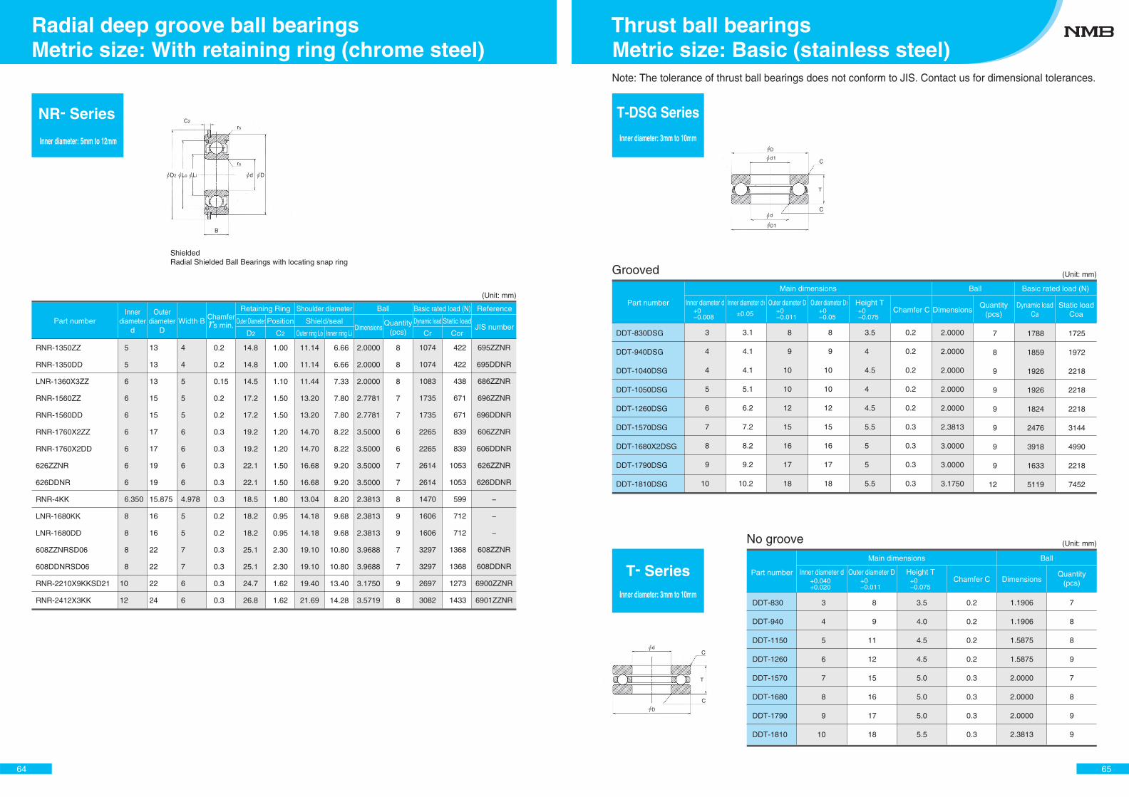
NR- Series
Inner diameter: 5mm to 12mm
RNR-1350ZZ
RNR-1350DD
LNR-1360X3ZZ
RNR-1560ZZ
RNR-1560DD
RNR-1760X2ZZ
RNR-1760X2DD
626ZZNR
626DDNR
RNR-4KK
LNR-1680KK
LNR-1680DD
608ZZNRSD06
608DDNRSD06
RNR-2210X9KKSD21
RNR-2412X3KK
2.0000
2.0000
2.0000
2.7781
2.7781
3.5000
3.5000
3.5000
3.5000
2.3813
2.3813
2.3813
3.9688
3.9688
3.1750
3.5719
2.0000
2.0000
2.0000
2.7781
2.7781
3.5000
3.5000
3.5000
3.5000
2.3813
2.3813
2.3813
3.9688
3.9688
3.1750
3.5719
8
8
8
7
7
6
6
7
7
8
9
9
7
7
9
8
8
8
8
7
7
6
6
7
7
8
9
9
7
7
9
8
Part numberInner
diameterd
Outerdiameter
DWidth B
Shoulder diameter
Shield/sealDimensions
Quantity(pcs)
Dynamic loadJIS number
Ball Basic rated load (N) Reference
Outer ring Lo Inner ring Li Cr
Static load
Cor
Chamfer s min.
6.66
6.66
7.33
7.80
7.80
8.22
8.22
9.20
9.20
8.20
9.68
9.68
10.80
10.80
13.40
14.28
6.66
6.66
7.33
7.80
7.80
8.22
8.22
9.20
9.20
8.20
9.68
9.68
10.80
10.80
13.40
14.28
11.14
11.14
11.44
13.20
13.20
14.70
14.70
16.68
16.68
13.04
14.18
14.18
19.10
19.10
19.40
21.69
11.14
11.14
11.44
13.20
13.20
14.70
14.70
16.68
16.68
13.04
14.18
14.18
19.10
19.10
19.40
21.69
Retaining Ring
D2 C2
Outer Diameter Position
1.00
1.00
1.10
1.50
1.50
1.20
1.20
1.50
1.50
1.80
0.95
0.95
2.30
2.30
1.62
1.62
1.00
1.00
1.10
1.50
1.50
1.20
1.20
1.50
1.50
1.80
0.95
0.95
2.30
2.30
1.62
1.62
14.8
14.8
14.5
17.2
17.2
19.2
19.2
22.1
22.1
18.5
18.2
18.2
25.1
25.1
24.7
26.8
14.8
14.8
14.5
17.2
17.2
19.2
19.2
22.1
22.1
18.5
18.2
18.2
25.1
25.1
24.7
26.8
0.2
0.2
0.15
0.2
0.2
0.3
0.3
0.3
0.3
0.3
0.2
0.2
0.3
0.3
0.3
0.3
0.2
0.2
0.15
0.2
0.2
0.3
0.3
0.3
0.3
0.3
0.2
0.2
0.3
0.3
0.3
0.3
4
4
5
5
5
6
6
6
6
4.978
5
5
7
7
6
6
4
4
5
5
5
6
6
6
6
4.978
5
5
7
7
6
6
13
13
13
15
15
17
17
19
19
15.875
16
16
22
22
22
24
13
13
13
15
15
17
17
19
19
15.875
16
16
22
22
22
24
5
5
6
6
6
6
6
6
6
6.350
8
8
8
8
10
12
5
5
6
6
6
6
6
6
6
6.350
8
8
8
8
10
12
1074
1074
1083
1735
1735
2265
2265
2614
2614
1470
1606
1606
3297
3297
2697
3082
1074
1074
1083
1735
1735
2265
2265
2614
2614
1470
1606
1606
3297
3297
2697
3082
422
422
438
671
671
839
839
1053
1053
599
712
712
1368
1368
1273
1433
422
422
438
671
671
839
839
1053
1053
599
712
712
1368
1368
1273
1433
695ZZNR
695DDNR
686ZZNR
696ZZNR
696DDNR
606ZZNR
606DDNR
626ZZNR
626DDNR
−
−
−
608ZZNR
608DDNR
6900ZZNR
6901ZZNR
695ZZNR
695DDNR
686ZZNR
696ZZNR
696DDNR
606ZZNR
606DDNR
626ZZNR
626DDNR
−
−
−
608ZZNR
608DDNR
6900ZZNR
6901ZZNR
Shielded Radial Shielded Ball Bearings with locating snap ring
64
(Unit: mm)
Metric size: With retaining ring (chrome steel)Radial deep groove ball bearings
DDT-830DSG
DDT-940DSG
DDT-1040DSG
DDT-1050DSG
DDT-1260DSG
DDT-1570DSG
DDT-1680X2DSG
DDT-1790DSG
DDT-1810DSG
T- SeriesInner diameter: 3mm to 10mm
T-DSG Series
Inner diameter: 3mm to 10mm
1
T
1
T
C
C
3.5
4
4.5
4
4.5
5.5
5
5
5.5
0.2
0.2
0.2
0.2
0.2
0.3
0.3
0.3
0.3
1788
1859
1926
1926
1824
2476
3918
1633
5119
1725
1972
2218
2218
2218
3144
4990
2218
7452
7
8
9
9
9
9
9
9
12
2.0000
2.0000
2.0000
2.0000
2.0000
2.3813
3.0000
3.0000
3.1750
C
C
Main dimensions
3
4
4
5
6
7
8
9
10
3.1
4.1
4.1
5.1
6.2
7.2
8.2
9.2
10.2
Inner diameter d+0−0.008
+0−0.011
+0−0.075±0.05
Inner diameter d1
8
9
10
10
12
15
16
17
18
8
9
10
10
12
15
16
17
18
Outer diameter D Outer diameter D1Part numberDimensions
Quantity(pcs)
Height T Dynamic loadCa
Static loadCoaChamfer C
Note: The tolerance of thrust ball bearings does not conform to JIS. Contact us for dimensional tolerances.
GroovedBall Basic rated load (N)
+0−0.05
No groove
3
4
5
6
7
8
9
10
8
9
11
12
15
16
17
18
3.5
4.0
4.5
4.5
5.0
5.0
5.0
5.5
0.2
0.2
0.2
0.2
0.3
0.3
0.3
0.3
1.1906
1.1906
1.5875
1.5875
2.0000
2.0000
2.0000
2.3813
7
8
8
9
7
8
9
9
Inner diameter d Outer diameter D
Ball
DDT-830
DDT-940
DDT-1150
DDT-1260
DDT-1570
DDT-1680
DDT-1790
DDT-1810
Part numberDimensions
Quantity(pcs)
Height T
Main dimensions
Chamfer C+0.040+0.020
+0−0.075
+0−0.011
65
(Unit: mm)
(Unit: mm)
Metric size: Basic (stainless steel)Thrust ball bearings
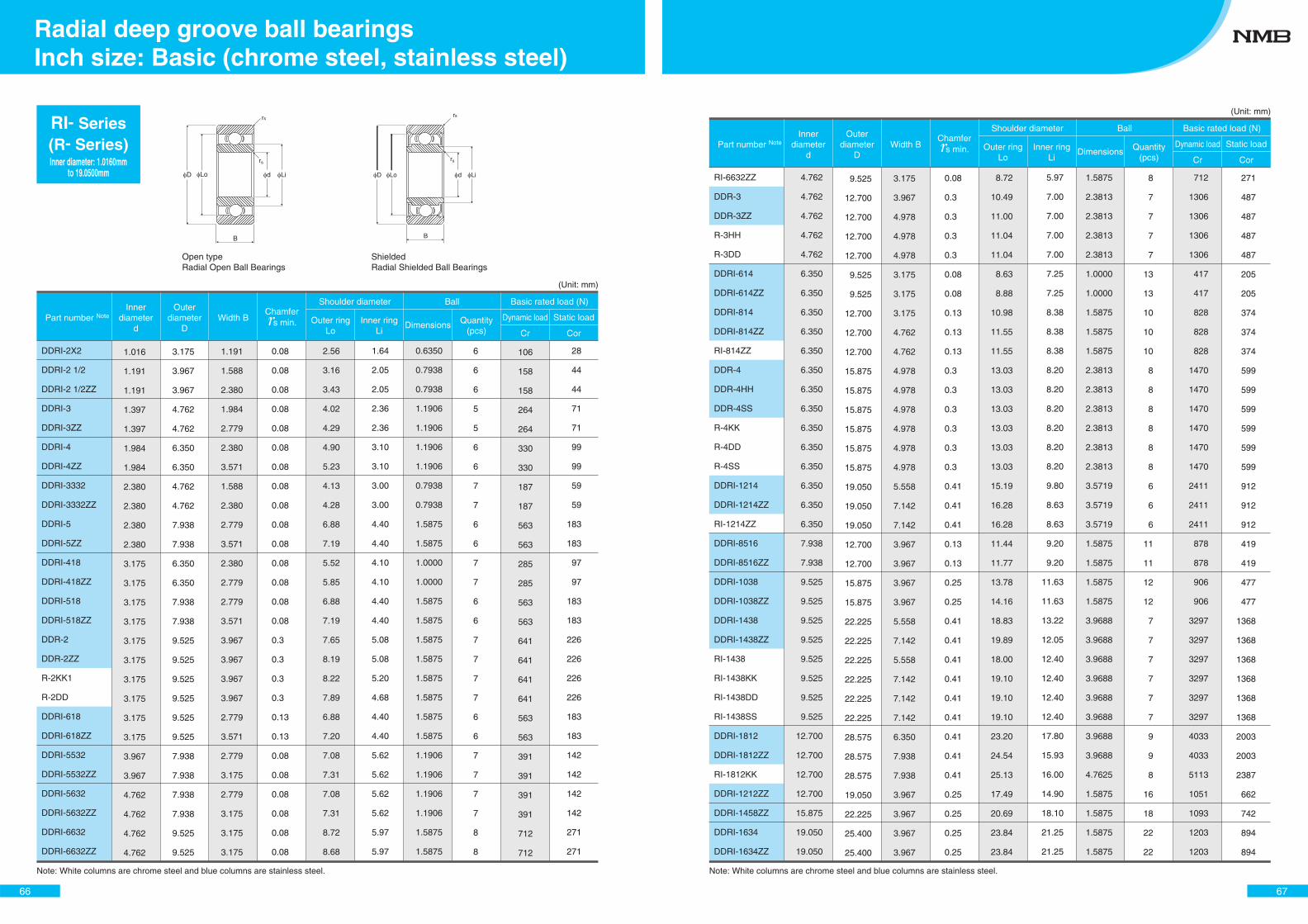
DDRI-2X2
DDRI-2 1/2
DDRI-2 1/2ZZ
DDRI-3
DDRI-3ZZ
DDRI-4
DDRI-4ZZ
DDRI-3332
DDRI-3332ZZ
DDRI-5
DDRI-5ZZ
DDRI-418
DDRI-418ZZ
DDRI-518
DDRI-518ZZ
DDR-2
DDR-2ZZ
R-2KK1
R-2DD
DDRI-618
DDRI-618ZZ
DDRI-5532
DDRI-5532ZZ
DDRI-5632
DDRI-5632ZZ
DDRI-6632
DDRI-6632ZZ
0.6350
0.7938
0.7938
1.1906
1.1906
1.1906
1.1906
0.7938
0.7938
1.5875
1.5875
1.0000
1.0000
1.5875
1.5875
1.5875
1.5875
1.5875
1.5875
1.5875
1.5875
1.1906
1.1906
1.1906
1.1906
1.5875
1.5875
0.6350
0.7938
0.7938
1.1906
1.1906
1.1906
1.1906
0.7938
0.7938
1.5875
1.5875
1.0000
1.0000
1.5875
1.5875
1.5875
1.5875
1.5875
1.5875
1.5875
1.5875
1.1906
1.1906
1.1906
1.1906
1.5875
1.5875
6
6
6
5
5
6
6
7
7
6
6
7
7
6
6
7
7
7
7
6
6
7
7
7
7
8
8
6
6
6
5
5
6
6
7
7
6
6
7
7
6
6
7
7
7
7
6
6
7
7
7
7
8
8
Note: White columns are chrome steel and blue columns are stainless steel.
Part number NoteInner
diameterd
Outerdiameter
DWidth B
Shoulder diameter
Dimensions Quantity(pcs)
Dynamic load Static load
Ball Basic rated load (N)
Outer ringLo
Inner ringLi Cr Cor
Chamfer s min.
1.64
2.05
2.05
2.36
2.36
3.10
3.10
3.00
3.00
4.40
4.40
4.10
4.10
4.40
4.40
5.08
5.08
5.20
4.68
4.40
4.40
5.62
5.62
5.62
5.62
5.97
5.97
1.64
2.05
2.05
2.36
2.36
3.10
3.10
3.00
3.00
4.40
4.40
4.10
4.10
4.40
4.40
5.08
5.08
5.20
4.68
4.40
4.40
5.62
5.62
5.62
5.62
5.97
5.97
2.56
3.16
3.43
4.02
4.29
4.90
5.23
4.13
4.28
6.88
7.19
5.52
5.85
6.88
7.19
7.65
8.19
8.22
7.89
6.88
7.20
7.08
7.31
7.08
7.31
8.72
8.68
2.56
3.16
3.43
4.02
4.29
4.90
5.23
4.13
4.28
6.88
7.19
5.52
5.85
6.88
7.19
7.65
8.19
8.22
7.89
6.88
7.20
7.08
7.31
7.08
7.31
8.72
8.68
0.08
0.08
0.08
0.08
0.08
0.08
0.08
0.08
0.08
0.08
0.08
0.08
0.08
0.08
0.08
0.3
0.3
0.3
0.3
0.13
0.13
0.08
0.08
0.08
0.08
0.08
0.08
0.08
0.08
0.08
0.08
0.08
0.08
0.08
0.08
0.08
0.08
0.08
0.08
0.08
0.08
0.08
0.3
0.3
0.3
0.3
0.13
0.13
0.08
0.08
0.08
0.08
0.08
0.08
1.191
1.588
2.380
1.984
2.779
2.380
3.571
1.588
2.380
2.779
3.571
2.380
2.779
2.779
3.571
3.967
3.967
3.967
3.967
2.779
3.571
2.779
3.175
2.779
3.175
3.175
3.175
1.191
1.588
2.380
1.984
2.779
2.380
3.571
1.588
2.380
2.779
3.571
2.380
2.779
2.779
3.571
3.967
3.967
3.967
3.967
2.779
3.571
2.779
3.175
2.779
3.175
3.175
3.175
3.175
3.967
3.967
4.762
4.762
6.350
6.350
4.762
4.762
7.938
7.938
6.350
6.350
7.938
7.938
9.525
9.525
9.525
9.525
9.525
9.525
7.938
7.938
7.938
7.938
9.525
9.525
3.175
3.967
3.967
4.762
4.762
6.350
6.350
4.762
4.762
7.938
7.938
6.350
6.350
7.938
7.938
9.525
9.525
9.525
9.525
9.525
9.525
7.938
7.938
7.938
7.938
9.525
9.525
1.016
1.191
1.191
1.397
1.397
1.984
1.984
2.380
2.380
2.380
2.380
3.175
3.175
3.175
3.175
3.175
3.175
3.175
3.175
3.175
3.175
3.967
3.967
4.762
4.762
4.762
4.762
1.016
1.191
1.191
1.397
1.397
1.984
1.984
2.380
2.380
2.380
2.380
3.175
3.175
3.175
3.175
3.175
3.175
3.175
3.175
3.175
3.175
3.967
3.967
4.762
4.762
4.762
4.762
106
158
158
264
264
330
330
187
187
563
563
285
285
563
563
641
641
641
641
563
563
391
391
391
391
712
712
106
158
158
264
264
330
330
187
187
563
563
285
285
563
563
641
641
641
641
563
563
391
391
391
391
712
712
28
44
44
71
71
99
99
59
59
183
183
97
97
183
183
226
226
226
226
183
183
142
142
142
142
271
271
28
44
44
71
71
99
99
59
59
183
183
97
97
183
183
226
226
226
226
183
183
142
142
142
142
271
271
RI- Series(R- Series)Inner diameter: 1.0160mm
to 19.0500mm
ShieldedRadial Shielded Ball Bearings
Open typeRadial Open Ball Bearings
rs
rs
B
D Lo d Li
B
rs
rs
D Lo d Li
66
Inch size: Basic (chrome steel, stainless steel)Radial deep groove ball bearings
(Unit: mm)
Note: White columns are chrome steel and blue columns are stainless steel.
RI-6632ZZ
DDR-3
DDR-3ZZ
R-3HH
R-3DD
DDRI-614
DDRI-614ZZ
DDRI-814
DDRI-814ZZ
RI-814ZZ
DDR-4
DDR-4HH
DDR-4SS
R-4KK
R-4DD
R-4SS
DDRI-1214
DDRI-1214ZZ
RI-1214ZZ
DDRI-8516
DDRI-8516ZZ
DDRI-1038
DDRI-1038ZZ
DDRI-1438
DDRI-1438ZZ
RI-1438
RI-1438KK
RI-1438DD
RI-1438SS
DDRI-1812
DDRI-1812ZZ
RI-1812KK
DDRI-1212ZZ
DDRI-1458ZZ
DDRI-1634
DDRI-1634ZZ
1.5875
2.3813
2.3813
2.3813
2.3813
1.0000
1.0000
1.5875
1.5875
1.5875
2.3813
2.3813
2.3813
2.3813
2.3813
2.3813
3.5719
3.5719
3.5719
1.5875
1.5875
1.5875
1.5875
3.9688
3.9688
3.9688
3.9688
3.9688
3.9688
3.9688
3.9688
4.7625
1.5875
1.5875
1.5875
1.5875
1.5875
2.3813
2.3813
2.3813
2.3813
1.0000
1.0000
1.5875
1.5875
1.5875
2.3813
2.3813
2.3813
2.3813
2.3813
2.3813
3.5719
3.5719
3.5719
1.5875
1.5875
1.5875
1.5875
3.9688
3.9688
3.9688
3.9688
3.9688
3.9688
3.9688
3.9688
4.7625
1.5875
1.5875
1.5875
1.5875
8
7
7
7
7
13
13
10
10
10
8
8
8
8
8
8
6
6
6
11
11
12
12
7
7
7
7
7
7
9
9
8
16
18
22
22
8
7
7
7
7
13
13
10
10
10
8
8
8
8
8
8
6
6
6
11
11
12
12
7
7
7
7
7
7
9
9
8
16
18
22
22
5.97
7.00
7.00
7.00
7.00
7.25
7.25
8.38
8.38
8.38
8.20
8.20
8.20
8.20
8.20
8.20
9.80
8.63
8.63
9.20
9.20
11.63
11.63
13.22
12.05
12.40
12.40
12.40
12.40
17.80
15.93
16.00
14.90
18.10
21.25
21.25
5.97
7.00
7.00
7.00
7.00
7.25
7.25
8.38
8.38
8.38
8.20
8.20
8.20
8.20
8.20
8.20
9.80
8.63
8.63
9.20
9.20
11.63
11.63
13.22
12.05
12.40
12.40
12.40
12.40
17.80
15.93
16.00
14.90
18.10
21.25
21.25
8.72
10.49
11.00
11.04
11.04
8.63
8.88
10.98
11.55
11.55
13.03
13.03
13.03
13.03
13.03
13.03
15.19
16.28
16.28
11.44
11.77
13.78
14.16
18.83
19.89
18.00
19.10
19.10
19.10
23.20
24.54
25.13
17.49
20.69
23.84
23.84
8.72
10.49
11.00
11.04
11.04
8.63
8.88
10.98
11.55
11.55
13.03
13.03
13.03
13.03
13.03
13.03
15.19
16.28
16.28
11.44
11.77
13.78
14.16
18.83
19.89
18.00
19.10
19.10
19.10
23.20
24.54
25.13
17.49
20.69
23.84
23.84
0.08
0.3
0.3
0.3
0.3
0.08
0.08
0.13
0.13
0.13
0.3
0.3
0.3
0.3
0.3
0.3
0.41
0.41
0.41
0.13
0.13
0.25
0.25
0.41
0.41
0.41
0.41
0.41
0.41
0.41
0.41
0.41
0.25
0.25
0.25
0.25
0.08
0.3
0.3
0.3
0.3
0.08
0.08
0.13
0.13
0.13
0.3
0.3
0.3
0.3
0.3
0.3
0.41
0.41
0.41
0.13
0.13
0.25
0.25
0.41
0.41
0.41
0.41
0.41
0.41
0.41
0.41
0.41
0.25
0.25
0.25
0.25
3.175
3.967
4.978
4.978
4.978
3.175
3.175
3.175
4.762
4.762
4.978
4.978
4.978
4.978
4.978
4.978
5.558
7.142
7.142
3.967
3.967
3.967
3.967
5.558
7.142
5.558
7.142
7.142
7.142
6.350
7.938
7.938
3.967
3.967
3.967
3.967
3.175
3.967
4.978
4.978
4.978
3.175
3.175
3.175
4.762
4.762
4.978
4.978
4.978
4.978
4.978
4.978
5.558
7.142
7.142
3.967
3.967
3.967
3.967
5.558
7.142
5.558
7.142
7.142
7.142
6.350
7.938
7.938
3.967
3.967
3.967
3.967
9.525
12.700
12.700
12.700
12.700
9.525
9.525
12.700
12.700
12.700
15.875
15.875
15.875
15.875
15.875
15.875
19.050
19.050
19.050
12.700
12.700
15.875
15.875
22.225
22.225
22.225
22.225
22.225
22.225
28.575
28.575
28.575
19.050
22.225
25.400
25.400
9.525
12.700
12.700
12.700
12.700
9.525
9.525
12.700
12.700
12.700
15.875
15.875
15.875
15.875
15.875
15.875
19.050
19.050
19.050
12.700
12.700
15.875
15.875
22.225
22.225
22.225
22.225
22.225
22.225
28.575
28.575
28.575
19.050
22.225
25.400
25.400
4.762
4.762
4.762
4.762
4.762
6.350
6.350
6.350
6.350
6.350
6.350
6.350
6.350
6.350
6.350
6.350
6.350
6.350
6.350
7.938
7.938
9.525
9.525
9.525
9.525
9.525
9.525
9.525
9.525
12.700
12.700
12.700
12.700
15.875
19.050
19.050
4.762
4.762
4.762
4.762
4.762
6.350
6.350
6.350
6.350
6.350
6.350
6.350
6.350
6.350
6.350
6.350
6.350
6.350
6.350
7.938
7.938
9.525
9.525
9.525
9.525
9.525
9.525
9.525
9.525
12.700
12.700
12.700
12.700
15.875
19.050
19.050
712
1306
1306
1306
1306
417
417
828
828
828
1470
1470
1470
1470
1470
1470
2411
2411
2411
878
878
906
906
3297
3297
3297
3297
3297
3297
4033
4033
5113
1051
1093
1203
1203
712
1306
1306
1306
1306
417
417
828
828
828
1470
1470
1470
1470
1470
1470
2411
2411
2411
878
878
906
906
3297
3297
3297
3297
3297
3297
4033
4033
5113
1051
1093
1203
1203
271
487
487
487
487
205
205
374
374
374
599
599
599
599
599
599
912
912
912
419
419
477
477
1368
1368
1368
1368
1368
1368
2003
2003
2387
662
742
894
894
271
487
487
487
487
205
205
374
374
374
599
599
599
599
599
599
912
912
912
419
419
477
477
1368
1368
1368
1368
1368
1368
2003
2003
2387
662
742
894
894
Part number NoteInner
diameterd
Outerdiameter
DWidth B
Shoulder diameter
Dimensions Quantity(pcs)
Dynamic load Static load
Ball Basic rated load (N)
Outer ringLo
Inner ringLi Cr Cor
Chamfer s min.
67
(Unit: mm)
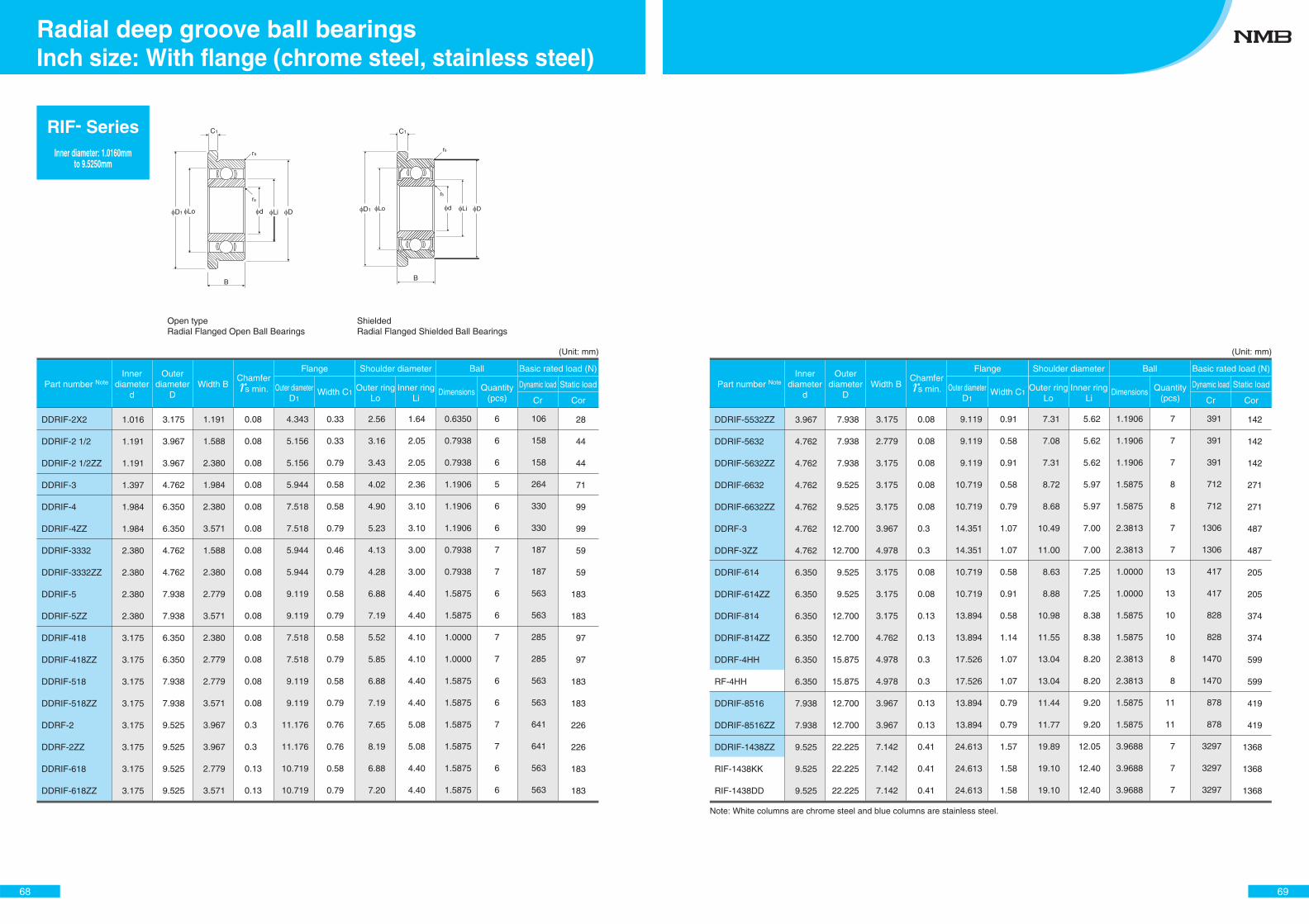
Open type Radial Flanged Open Ball Bearings
Shielded Radial Flanged Shielded Ball Bearings
Lo d Li DD1
r
r
s
s
B
C1 C1
B
D1 DLo Lid
rs
rs
(Unit: mm)
DDRIF-2X2
DDRIF-2 1/2
DDRIF-2 1/2ZZ
DDRIF-3
DDRIF-4
DDRIF-4ZZ
DDRIF-3332
DDRIF-3332ZZ
DDRIF-5
DDRIF-5ZZ
DDRIF-418
DDRIF-418ZZ
DDRIF-518
DDRIF-518ZZ
DDRF-2
DDRF-2ZZ
DDRIF-618
DDRIF-618ZZ
Part number NoteInner
diameterd
Outerdiameter
DWidth B
Flange Shoulder diameter
Dimensions Quantity(pcs)
Dynamic load Static load
Ball Basic rated load (N)
Outer diameterD1
Width C1Outer ring
LoInner ring
Li Cr Cor
Chamfer s min.
1.016
1.191
1.191
1.397
1.984
1.984
2.380
2.380
2.380
2.380
3.175
3.175
3.175
3.175
3.175
3.175
3.175
3.175
1.016
1.191
1.191
1.397
1.984
1.984
2.380
2.380
2.380
2.380
3.175
3.175
3.175
3.175
3.175
3.175
3.175
3.175
3.175
3.967
3.967
4.762
6.350
6.350
4.762
4.762
7.938
7.938
6.350
6.350
7.938
7.938
9.525
9.525
9.525
9.525
3.175
3.967
3.967
4.762
6.350
6.350
4.762
4.762
7.938
7.938
6.350
6.350
7.938
7.938
9.525
9.525
9.525
9.525
1.191
1.588
2.380
1.984
2.380
3.571
1.588
2.380
2.779
3.571
2.380
2.779
2.779
3.571
3.967
3.967
2.779
3.571
1.191
1.588
2.380
1.984
2.380
3.571
1.588
2.380
2.779
3.571
2.380
2.779
2.779
3.571
3.967
3.967
2.779
3.571
0.08
0.08
0.08
0.08
0.08
0.08
0.08
0.08
0.08
0.08
0.08
0.08
0.08
0.08
0.3
0.3
0.13
0.13
0.08
0.08
0.08
0.08
0.08
0.08
0.08
0.08
0.08
0.08
0.08
0.08
0.08
0.08
0.3
0.3
0.13
0.13
4.343
5.156
5.156
5.944
7.518
7.518
5.944
5.944
9.119
9.119
7.518
7.518
9.119
9.119
11.176
11.176
10.719
10.719
4.343
5.156
5.156
5.944
7.518
7.518
5.944
5.944
9.119
9.119
7.518
7.518
9.119
9.119
11.176
11.176
10.719
10.719
0.33
0.33
0.79
0.58
0.58
0.79
0.46
0.79
0.58
0.79
0.58
0.79
0.58
0.79
0.76
0.76
0.58
0.79
0.33
0.33
0.79
0.58
0.58
0.79
0.46
0.79
0.58
0.79
0.58
0.79
0.58
0.79
0.76
0.76
0.58
0.79
2.56
3.16
3.43
4.02
4.90
5.23
4.13
4.28
6.88
7.19
5.52
5.85
6.88
7.19
7.65
8.19
6.88
7.20
2.56
3.16
3.43
4.02
4.90
5.23
4.13
4.28
6.88
7.19
5.52
5.85
6.88
7.19
7.65
8.19
6.88
7.20
1.64
2.05
2.05
2.36
3.10
3.10
3.00
3.00
4.40
4.40
4.10
4.10
4.40
4.40
5.08
5.08
4.40
4.40
1.64
2.05
2.05
2.36
3.10
3.10
3.00
3.00
4.40
4.40
4.10
4.10
4.40
4.40
5.08
5.08
4.40
4.40
0.6350
0.7938
0.7938
1.1906
1.1906
1.1906
0.7938
0.7938
1.5875
1.5875
1.0000
1.0000
1.5875
1.5875
1.5875
1.5875
1.5875
1.5875
0.6350
0.7938
0.7938
1.1906
1.1906
1.1906
0.7938
0.7938
1.5875
1.5875
1.0000
1.0000
1.5875
1.5875
1.5875
1.5875
1.5875
1.5875
6
6
6
5
6
6
7
7
6
6
7
7
6
6
7
7
6
6
6
6
6
5
6
6
7
7
6
6
7
7
6
6
7
7
6
6
106
158
158
264
330
330
187
187
563
563
285
285
563
563
641
641
563
563
106
158
158
264
330
330
187
187
563
563
285
285
563
563
641
641
563
563
28
44
44
71
99
99
59
59
183
183
97
97
183
183
226
226
183
183
28
44
44
71
99
99
59
59
183
183
97
97
183
183
226
226
183
183
68
RIF- SeriesInner diameter: 1.0160mm
to 9.5250mm
Inch size: With flange (chrome steel, stainless steel)Radial deep groove ball bearings
(Unit: mm)
Note: White columns are chrome steel and blue columns are stainless steel.
Part number NoteInner
diameterd
Outerdiameter
DWidth B
Flange Shoulder diameter
Dimensions Quantity(pcs)
Dynamic load Static load
Ball Basic rated load (N)
Outer diameterD1
Width C1Outer ring
LoInner ring
Li Cr Cor
Chamfer s min.
DDRIF-5532ZZ
DDRIF-5632
DDRIF-5632ZZ
DDRIF-6632
DDRIF-6632ZZ
DDRF-3
DDRF-3ZZ
DDRIF-614
DDRIF-614ZZ
DDRIF-814
DDRIF-814ZZ
DDRF-4HH
RF-4HH
DDRIF-8516
DDRIF-8516ZZ
DDRIF-1438ZZ
RIF-1438KK
RIF-1438DD
3.967
4.762
4.762
4.762
4.762
4.762
4.762
6.350
6.350
6.350
6.350
6.350
6.350
7.938
7.938
9.525
9.525
9.525
3.967
4.762
4.762
4.762
4.762
4.762
4.762
6.350
6.350
6.350
6.350
6.350
6.350
7.938
7.938
9.525
9.525
9.525
7.938
7.938
7.938
9.525
9.525
12.700
12.700
9.525
9.525
12.700
12.700
15.875
15.875
12.700
12.700
22.225
22.225
22.225
7.938
7.938
7.938
9.525
9.525
12.700
12.700
9.525
9.525
12.700
12.700
15.875
15.875
12.700
12.700
22.225
22.225
22.225
3.175
2.779
3.175
3.175
3.175
3.967
4.978
3.175
3.175
3.175
4.762
4.978
4.978
3.967
3.967
7.142
7.142
7.142
3.175
2.779
3.175
3.175
3.175
3.967
4.978
3.175
3.175
3.175
4.762
4.978
4.978
3.967
3.967
7.142
7.142
7.142
0.08
0.08
0.08
0.08
0.08
0.3
0.3
0.08
0.08
0.13
0.13
0.3
0.3
0.13
0.13
0.41
0.41
0.41
0.08
0.08
0.08
0.08
0.08
0.3
0.3
0.08
0.08
0.13
0.13
0.3
0.3
0.13
0.13
0.41
0.41
0.41
9.119
9.119
9.119
10.719
10.719
14.351
14.351
10.719
10.719
13.894
13.894
17.526
17.526
13.894
13.894
24.613
24.613
24.613
9.119
9.119
9.119
10.719
10.719
14.351
14.351
10.719
10.719
13.894
13.894
17.526
17.526
13.894
13.894
24.613
24.613
24.613
0.91
0.58
0.91
0.58
0.79
1.07
1.07
0.58
0.91
0.58
1.14
1.07
1.07
0.79
0.79
1.57
1.58
1.58
0.91
0.58
0.91
0.58
0.79
1.07
1.07
0.58
0.91
0.58
1.14
1.07
1.07
0.79
0.79
1.57
1.58
1.58
7.31
7.08
7.31
8.72
8.68
10.49
11.00
8.63
8.88
10.98
11.55
13.04
13.04
11.44
11.77
19.89
19.10
19.10
7.31
7.08
7.31
8.72
8.68
10.49
11.00
8.63
8.88
10.98
11.55
13.04
13.04
11.44
11.77
19.89
19.10
19.10
5.62
5.62
5.62
5.97
5.97
7.00
7.00
7.25
7.25
8.38
8.38
8.20
8.20
9.20
9.20
12.05
12.40
12.40
5.62
5.62
5.62
5.97
5.97
7.00
7.00
7.25
7.25
8.38
8.38
8.20
8.20
9.20
9.20
12.05
12.40
12.40
1.1906
1.1906
1.1906
1.5875
1.5875
2.3813
2.3813
1.0000
1.0000
1.5875
1.5875
2.3813
2.3813
1.5875
1.5875
3.9688
3.9688
3.9688
1.1906
1.1906
1.1906
1.5875
1.5875
2.3813
2.3813
1.0000
1.0000
1.5875
1.5875
2.3813
2.3813
1.5875
1.5875
3.9688
3.9688
3.9688
7
7
7
8
8
7
7
13
13
10
10
8
8
11
11
7
7
7
7
7
7
8
8
7
7
13
13
10
10
8
8
11
11
7
7
7
391
391
391
712
712
1306
1306
417
417
828
828
1470
1470
878
878
3297
3297
3297
391
391
391
712
712
1306
1306
417
417
828
828
1470
1470
878
878
3297
3297
3297
142
142
142
271
271
487
487
205
205
374
374
599
599
419
419
1368
1368
1368
142
142
142
271
271
487
487
205
205
374
374
599
599
419
419
1368
1368
1368
69
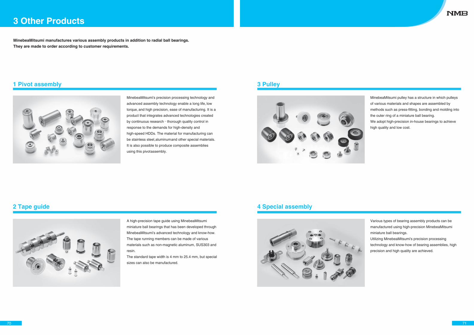
1 Pivot assembly
2 Tape guide
MinebeaMitsumi's precision processing technology and
advanced assembly technology enable a long life, low
torque, and high precision, ease of manufacturing. It is a
product that integrates advanced technologies created
by continuous research and thorough quality control in
response to the demands for high-density and
high-speed HDDs. The material for manufacturing can
be stainless steel, aluminum and other special materials.
It is also possible to produce composite assemblies
using this pivot assembly.
A high-precision tape guide using MinebeaMitsumi
miniature ball bearings that has been developed through
MinebeaMitsumi's advanced technology and know-how.
The tape running members can be made of various
materials such as non-magnetic aluminum, SUS303 and
resin.
The standard tape width is 4 mm to 25.4 mm, but special
sizes can also be manufactured.
MinebeaMitsumi manufactures various assembly products in addition to radial ball bearings.
They are made to order according to customer requirements.
70
3 Other Products
4 Special assembly
3 Pulley
MinebeaMitsumi pulley has a structure in which pulleys
of various materials and shapes are assembled by
methods such as press-fitting, bonding and molding into
the outer ring of a miniature ball bearing.
We adopt high-precision in-house bearings to achieve
high quality and low cost.
Various types of bearing assembly products can be
manufactured using high-precision MinebeaMitsumi
miniature ball bearings.
Utilizing MinebeaMitsumi's precision processing
technology and know-how of bearing assemblies, high
precision and high quality are achieved.
71
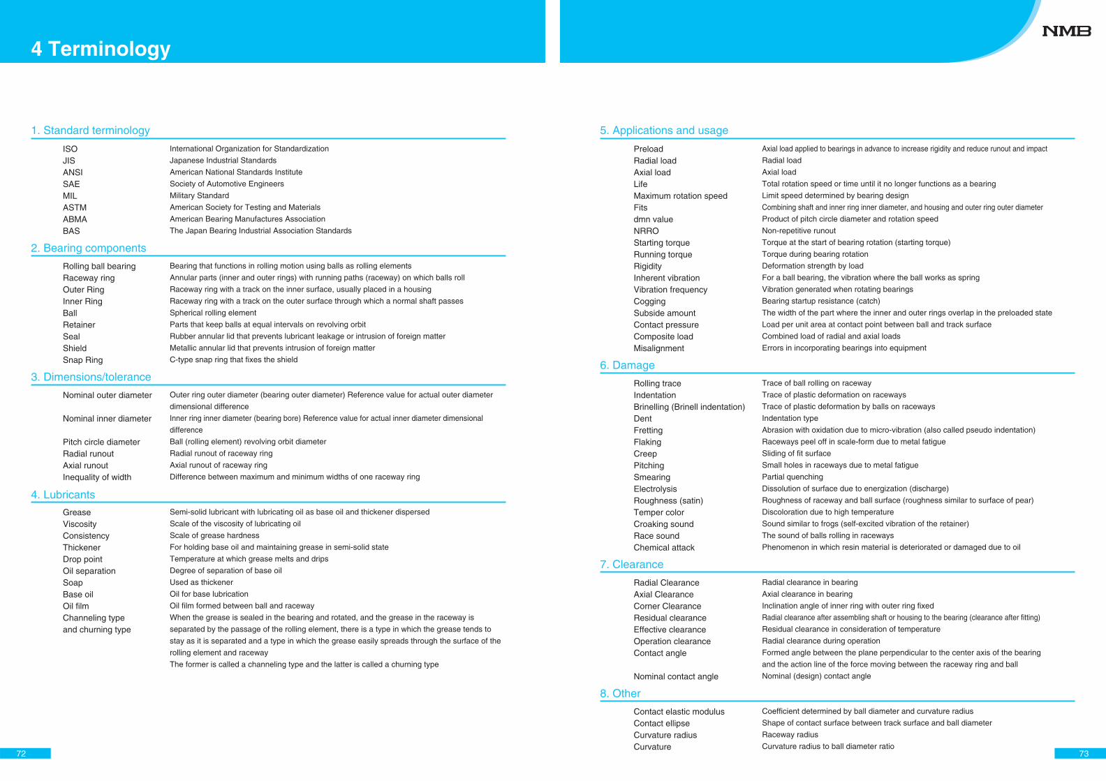
ISOJISANSISAEMILASTMABMABAS
Rolling ball bearingRaceway ringOuter RingInner RingBallRetainerSealShieldSnap Ring
Nominal outer diameter
Nominal inner diameter
Pitch circle diameterRadial runoutAxial runoutInequality of width
GreaseViscosityConsistencyThickener Drop pointOil separationSoapBase oilOil filmChanneling typeand churning type
International Organization for Standardization
Japanese Industrial Standards
American National Standards Institute
Society of Automotive Engineers
Military Standard
American Society for Testing and Materials
American Bearing Manufactures Association
The Japan Bearing Industrial Association Standards
Bearing that functions in rolling motion using balls as rolling elements
Annular parts (inner and outer rings) with running paths (raceway) on which balls roll
Raceway ring with a track on the inner surface, usually placed in a housing
Raceway ring with a track on the outer surface through which a normal shaft passes
Spherical rolling element
Parts that keep balls at equal intervals on revolving orbit
Rubber annular lid that prevents lubricant leakage or intrusion of foreign matter
Metallic annular lid that prevents intrusion of foreign matter
C-type snap ring that fixes the shield
Outer ring outer diameter (bearing outer diameter) Reference value for actual outer diameter
dimensional difference
Inner ring inner diameter (bearing bore) Reference value for actual inner diameter dimensional
difference
Ball (rolling element) revolving orbit diameter
Radial runout of raceway ring
Axial runout of raceway ring
Difference between maximum and minimum widths of one raceway ring
Semi-solid lubricant with lubricating oil as base oil and thickener dispersed
Scale of the viscosity of lubricating oil
Scale of grease hardness
For holding base oil and maintaining grease in semi-solid state
Temperature at which grease melts and drips
Degree of separation of base oil
Used as thickener
Oil for base lubrication
Oil film formed between ball and raceway
When the grease is sealed in the bearing and rotated, and the grease in the raceway is
separated by the passage of the rolling element, there is a type in which the grease tends to
stay as it is separated and a type in which the grease easily spreads through the surface of the
rolling element and raceway
The former is called a channeling type and the latter is called a churning type
1. Standard terminology
2. Bearing components
3. Dimensions/tolerance
4. Lubricants
72
4 Terminology
5. Applications and usage
PreloadRadial loadAxial loadLifeMaximum rotation speedFitsdmn valueNRROStarting torqueRunning torqueRigidityInherent vibrationVibration frequencyCoggingSubside amountContact pressureComposite loadMisalignment
Rolling traceIndentationBrinelling (Brinell indentation)DentFrettingFlakingCreepPitchingSmearingElectrolysisRoughness (satin)Temper colorCroaking soundRace soundChemical attack
Radial ClearanceAxial ClearanceCorner ClearanceResidual clearanceEffective clearanceOperation clearanceContact angle
Nominal contact angle
Contact elastic modulusContact ellipseCurvature radiusCurvature
Axial load applied to bearings in advance to increase rigidity and reduce runout and impact
Radial load
Axial load
Total rotation speed or time until it no longer functions as a bearing
Limit speed determined by bearing design
Combining shaft and inner ring inner diameter, and housing and outer ring outer diameter
Product of pitch circle diameter and rotation speed
Non-repetitive runout
Torque at the start of bearing rotation (starting torque)
Torque during bearing rotation
Deformation strength by load
For a ball bearing, the vibration where the ball works as spring
Vibration generated when rotating bearings
Bearing startup resistance (catch)
The width of the part where the inner and outer rings overlap in the preloaded state
Load per unit area at contact point between ball and track surface
Combined load of radial and axial loads
Errors in incorporating bearings into equipment
Trace of ball rolling on raceway
Trace of plastic deformation on raceways
Trace of plastic deformation by balls on raceways
Indentation type
Abrasion with oxidation due to micro-vibration (also called pseudo indentation)
Raceways peel off in scale-form due to metal fatigue
Sliding of fit surface
Small holes in raceways due to metal fatigue
Partial quenching
Dissolution of surface due to energization (discharge)
Roughness of raceway and ball surface (roughness similar to surface of pear)
Discoloration due to high temperature
Sound similar to frogs (self-excited vibration of the retainer)
The sound of balls rolling in raceways
Phenomenon in which resin material is deteriorated or damaged due to oil
Radial clearance in bearing
Axial clearance in bearing
Inclination angle of inner ring with outer ring fixed
Radial clearance after assembling shaft or housing to the bearing (clearance after fitting)
Residual clearance in consideration of temperature
Radial clearance during operation
Formed angle between the plane perpendicular to the center axis of the bearing
and the action line of the force moving between the raceway ring and ball
Nominal (design) contact angle
Coefficient determined by ball diameter and curvature radius
Shape of contact surface between track surface and ball diameter
Raceway radius
Curvature radius to ball diameter ratio
6. Damage
7. Clearance
8. Other
73
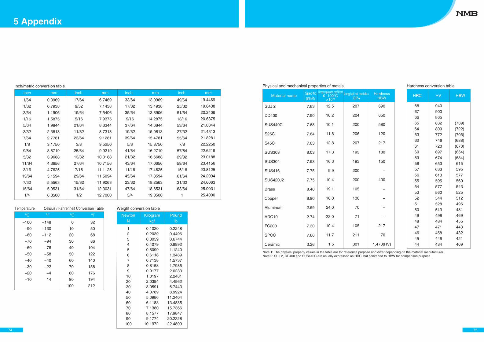
Inch/metric conversion table
inch mm inch mm inch mm inch mm
1/64
1/32
3/64
1/16
5/64
3/32
7/64
1/8
9/64
5/32
11/64
3/16
13/64
7/32
15/64
1/4
17/64
9/32
19/64
5/16
21/64
11/32
23/64
3/8
25/64
13/32
27/64
7/16
29/64
15/32
31/64
1/2
33/64
17/32
35/64
9/16
37/64
19/32
39/64
5/8
41/64
21/32
43/64
11/16
45/64
23/32
47/64
3/4
0.3969
0.7938
1.1906
1.5875
1.9844
2.3813
2.7781
3.1750
3.5719
3.9688
4.3656
4.7625
5.1594
5.5563
5.9531
6.3500
6.7469
7.1438
7.5406
7.9375
8.3344
8.7313
9.1281
9.5250
9.9219
10.3188
10.7156
11.1125
11.5094
11.9063
12.3031
12.7000
13.0969
13.4938
13.8906
14.2875
14.6844
15.0813
15.4781
15.8750
16.2719
16.6688
17.0656
17.4625
17.8594
18.2563
18.6531
19.0500
19.4469
19.8438
20.2406
20.6375
21.0344
21.4313
21.8281
22.2250
22.6219
23.0188
23.4156
23.8125
24.2094
24.6063
25.0031
25.4000
49/64
25/32
51/64
13/16
53/64
27/32
55/64
7/8
57/64
29/32
59/64
15/16
61/64
31/32
63/64
1
Temperature Celsius / Fahrenheit Conversion Table
ºC ºC
−100
−90
−80
−70
−60
−50
−40
−30
−20
−10
0
10
20
30
40
50
60
70
80
90
100
−148
−130
−112
−94
−76
−58
−40
−22
−4
14
32
50
68
86
104
122
140
158
176
194
212
Weight conversion table
NewtonN
Kilogramkgf
Poundlb
123456789
102030405060708090
100
0.22480.44960.67440.89921.12401.34891.57371.79852.02332.24814.49626.74438.9924
11.240413.488515.736617.984720.232822.4809
0.10200.20390.30590.40790.50990.61180.71380.81580.91771.01972.03943.05914.07895.09866.11837.13808.15779.1774
10.1972
ºF ºF
5 Appendix
74
Physical and mechanical properties of metals Hardness conversion table
Material nameSpecificgravity
Linear expansion coefficient0~100°C
×10-6
Longitudinal modulusGPa
HardnessHBW
HRC HV HBW
SUJ 2
DD400
SUS440C
S25C
S45C
SUS303
SUS304
SUS416
SUS420J2
Brass
Copper
Aluminum
ADC10
FC200
SPCC
Ceramic
7.83
7.90
7.68
7.84
7.83
8.03
7.93
7.75
7.75
8.40
8.90
2.69
2.74
7.30
7.86
3.26
12.5
10.2
10.1
11.8
12.8
17.3
16.3
9.9
10.4
19.1
16.0
24.0
22.0
10.4
11.7
1.5
207
204
200
206
207
193
193
200
200
105
130
70
71
105
211
301
690
650
580
120
217
180
150
−
400
−
−
−
−
217
70
68676665646362616059585756555453525150494847464544
940900865832800772746720697674653633613595577560544528513498484471458446434
(739)(722)(705)(688)(670)(654)(634)615595577560543525512496481469455443432421409
Note 1: The physical property values in the table are for reference purpose and differ depending on the material manufacturer.Note 2: SUJ 2, DD400 and SUS440C are usually expressed as HRC, but converted to HBW for comparison purpose.
1,470(HV)
75
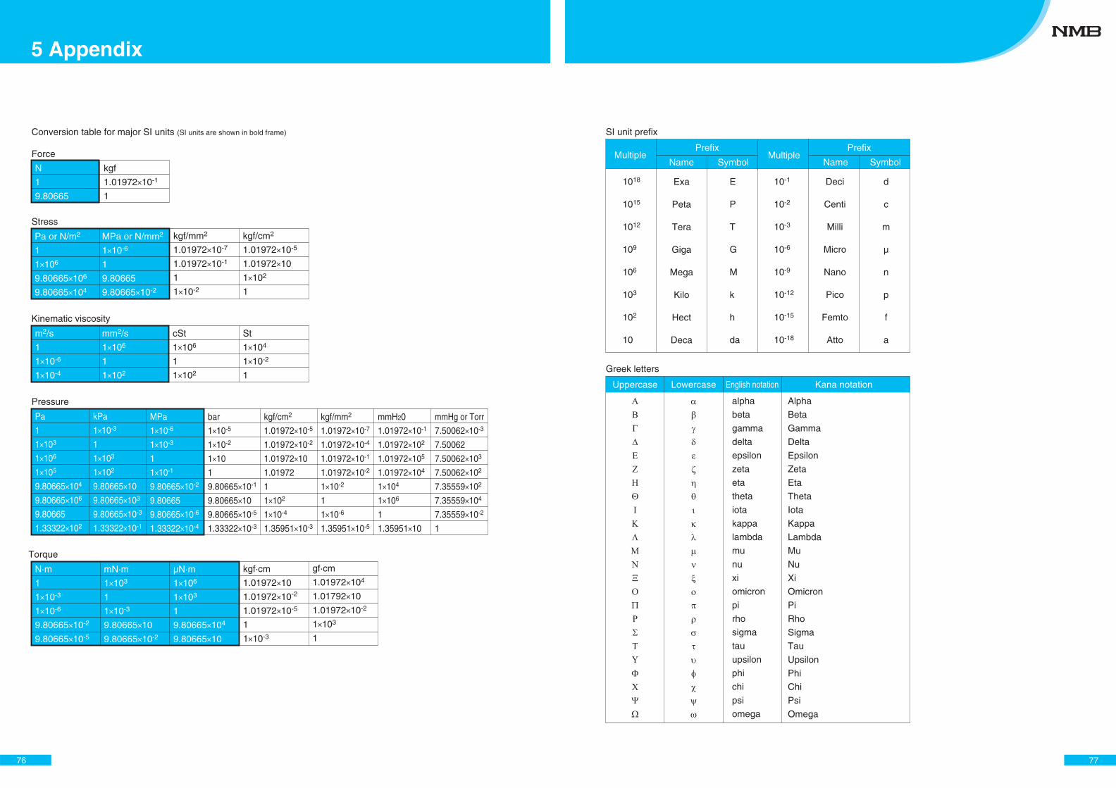
Conversion table for major SI units (SI units are shown in bold frame)
Force
N
1
9.80665
kgf
1.01972×10⁻¹
1
Kinematic viscosity
m2/s
1
1×10⁻⁶
1×10⁻⁴
mm2/s
1×10⁶
1
1×10²
cSt
1×10⁶
1
1×10²
St
1×10⁴
1×10⁻²
1
Stress
Pa or N/m2
1
1×10⁶
9.80665×10⁶
9.80665×10⁴
MPa or N/mm2
1×10⁻⁶
1
9.80665
9.80665×10⁻²
kgf/mm2
1.01972×10⁻⁷
1.01972×10⁻¹
1
1×10⁻²
kgf/cm2
1.01972×10⁻⁵
1.01972×10
1×10²
1
Torque
N·m
1
1×10⁻³
1×10⁻⁶
9.80665×10⁻²
9.80665×10⁻⁵
Pressure
Pa
1
1×10³
1×10⁶
1×10⁵
9.80665×10⁴
9.80665×10⁶
9.80665
1.33322×10²
kPa
1×10⁻³
1
1×10³
1×10²
9.80665×10
9.80665×10³
9.80665×10⁻³
1.33322×10⁻¹
MPa
1×10⁻⁶
1×10⁻³
1
1×10⁻¹
9.80665×10⁻²
9.80665
9.80665×10⁻⁶
1.33322×10⁻⁴
bar
1×10⁻⁵
1×10⁻²
1×10
1
9.80665×10⁻¹
9.80665×10
9.80665×10⁻⁵
1.33322×10⁻³
kgf/cm2
1.01972×10⁻⁵
1.01972×10⁻²
1.01972×10
1.01972
1
1×10²
1×10⁻⁴
1.35951×10⁻³
mmH20
1.01972×10⁻¹
1.01972×10²
1.01972×10⁵
1.01972×10⁴
1×10⁴
1×10⁶
1
1.35951×10
mmHg or Torr
7.50062×10⁻³
7.50062
7.50062×10³
7.50062×10²
7.35559×10²
7.35559×10⁴
7.35559×10⁻²
1
kgf/mm2
1.01972×10⁻⁷
1.01972×10⁻⁴
1.01972×10⁻¹
1.01972×10⁻²
1×10⁻²
1
1×10⁻⁶
1.35951×10⁻⁵
mN·m
1×10³
1
1×10⁻³
9.80665×10
9.80665×10⁻²
μN·m
1×10⁶
1×10³
1
9.80665×10⁴
9.80665×10
kgf·cm
1.01972×10
1.01972×10⁻²
1.01972×10⁻⁵
1
1×10⁻³
gf·cm
1.01972×10⁴
1.01792×10
1.01972×10⁻²
1×10³
1
76
5 Appendix
SI unit prefix
MultipleName Symbol
1018
1015
1012
109
106
103
102
10
alpha
beta
gamma
delta
epsilon
zeta
eta
theta
iota
kappa
lambda
mu
nu
xi
omicron
pi
rho
sigma
tau
upsilon
phi
chi
psi
omega
Alpha
Beta
Gamma
Delta
Epsilon
Zeta
Eta
Theta
Iota
Kappa
Lambda
Mu
Nu
Xi
Omicron
Pi
Rho
Sigma
Tau
Upsilon
Phi
Chi
Psi
Omega
Exa
Peta
Tera
Giga
Mega
Kilo
Hect
Deca
E
P
T
G
M
k
h
da
10-1
10-2
10-3
10-6
10-9
10-12
10-15
10-18
Deci
Centi
Milli
Micro
Nano
Pico
Femto
Atto
d
c
m
μ
n
p
f
a
PrefixMultiple
Name Symbol
Prefix
Greek letters
Uppercase Lowercase English notation Kana notation
77
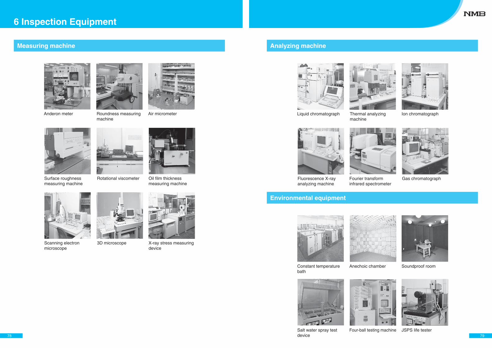
Anderon meter Roundness measuring machine
Air micrometer
Surface roughness measuring machine
Rotational viscometer Oil film thickness measuring machine
Scanning electron microscope
3D microscope X-ray stress measuring device
Measuring machine
78
6 Inspection Equipment
Constant temperature bath
Anechoic chamber Soundproof room
Salt water spray test device
Four-ball testing machine JSPS life tester
Liquid chromatograph Thermal analyzing machine
Ion chromatograph
Fluorescence X-ray analyzing machine
Fourier transform infrared spectrometer
Gas chromatograph
Analyzing machine
Environmental equipment
79
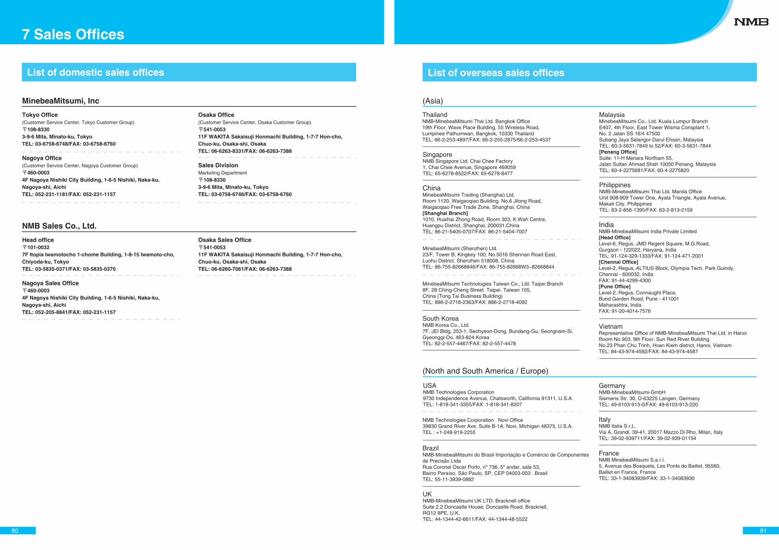
List of domestic sales offices
MinebeaMitsumi, Inc
Tokyo Office(Customer Service Center, Tokyo Customer Group)
108-83303-9-6 Mita, Minato-ku, TokyoTEL: 03-6758-6748/FAX: 03-6758-6760
Nagoya Office(Customer Service Center, Nagoya Customer Group)
460-00034F Nagoya Nishiki City Building, 1-6-5 Nishiki, Naka-ku, Nagoya-shi, AichiTEL: 052-231-1181/FAX: 052-231-1157
Osaka Office(Customer Service Center, Osaka Customer Group)
541-005311F WAKITA Sakaisuji Honmachi Building, 1-7-7 Hon-cho, Chuo-ku, Osaka-shi, OsakaTEL: 06-6263-8331/FAX: 06-6263-7388
Sales DivisionMarketing Department
108-83303-9-6 Mita, Minato-ku, TokyoTEL: 03-6758-6746/FAX: 03-6758-6760
NMB Sales Co., Ltd.
Head office101-0032
7F Itopia Iwamotocho 1-chome Building, 1-8-15 Iwamoto-cho, Chiyoda-ku, TokyoTEL: 03-5835-0371/FAX: 03-5835-0370
Nagoya Sales Office460-0003
4F Nagoya Nishiki City Building, 1-6-5 Nishiki, Naka-ku, Nagoya-shi, AichiTEL: 052-205-8841/FAX: 052-231-1157
Osaka Sales Office541-0053
11F WAKITA Sakaisuji Honmachi Building, 1-7-7 Hon-cho, Chuo-ku, Osaka-shi, OsakaTEL: 06-6260-7061/FAX: 06-6263-7388
80
7 Sales Offices
List of overseas sales offices
ThailandNMB-MinebeaMitsumi Thai Ltd. Bangkok Office 19th Floor, Wave Place Building, 55 Wireless Road,Lumpinee Pathumwan, Bangkok, 10330 ThailandTEL: 66-2-253-4897/FAX: 66-2-255-2875/66-2-253-4537
SingaporeNMB Singapore Ltd. Chai Chee Factory1, Chai Chee Avenue, Singapore 469059TEL: 65-6278-8522/FAX: 65-6278-8477
ChinaMinebeaMitsumi Trading (Shanghai) Ltd. Room 1120, Waigaoqiao Building, No.6 Jilong Road, Waigaoqiao Free Trade Zone, Shanghai, China[Shanghai Branch]1010, Huaihai Zhong Road, Room 303, K.Wah Centre,Huangpu District, Shanghai, 200031,ChinaTEL: 86-21-5405-0707/FAX: 86-21-5404-7007
MinebeaMitsumi (Shenzhen) Ltd. 23/F, Tower B, Kingkey 100, No.5016 Shennan Road East,Luohu District, Shenzhen 518008, ChinaTEL: 86-755-82668846/FAX: 86-755-82668W3~82668844
MinebeaMitsumi Technologies Taiwan Co., Ltd. Taipei Branch8F, 28 Ching-Cheng Street. Taipei, Taiwan 105,China (Tong Tai Business Building)TEL: 886-2-2718-2363/FAX: 886-2-2718-4092
USANMB Technologies Corporation 9730 Independence Avenue, Chatsworth, California 91311, U.S.A.TEL: 1-818-341-3355/FAX: 1-818-341-8207
(North and South America / Europe)
BrazilNMB-MinebeaMitsumi do Brasil Importação e Comércio de Componentesde Precisão LtdaRua Coronel Oscar Porto, nº 736, 5º andar, sala 53,Bairro Paraíso, São Paulo, SP, CEP 04003-003 . BrasilTEL: 55-11-3939-0882
UKNMB-MinebeaMitsumi UK LTD. Bracknell office Suite 2.2 Doncastle House, Doncastle Road, Bracknell,RG12 8PE, U.K.TEL: 44-1344-42-6611/FAX: 44-1344-48-5522
GermanyNMB-MinebeaMitsumi-GmbH Siemens Str. 30, D-63225 Langen, GermanyTEL: 49-6103-913-0/FAX: 49-6103-913-220
ItalyNMB Italia S.r.L. Via A, Grandi. 39-41, 20017 Mazzo Di Rho, Milan, ItalyTEL: 39-02-939711/FAX: 39-02-939-01154
FranceNMB MinebeaMitsumi S.a.r.l. 5, Avenue des Bosquets, Les Ponts de Baillet, 95560,Baillet en France, FranceTEL: 33-1-34083939/FAX: 33-1-34083930
(Asia)
NMB Technologies Corporation Novi Office 39830 Grand River Ave. Suite B-1A, Novi, Michigan 48375, U.S.A.TEL : +1-248-919-2255
South KoreaNMB Korea Co., Ltd. 7F. JEI Bldg, 253-1, Seohyeon-Dong, Bundang-Gu, Seongnam-Si,Gyeonggi-Do, 463-824 KoreaTEL: 82-2-557-4467/FAX: 82-2-557-4478
MalaysiaMinebeaMitsumi Co., Ltd. Kuala Lumpur Branch E407, 4th Floor, East Tower Wisma Consplant 1, No. 2 Jalan SS 16/4 47500Subang Jaya Selangor Darul Ehsan, MalaysiaTEL: 60-3-5631-7849 to 52/FAX: 60-3-5631-7844[Penang Office]Suite: 11-H Menara Northam 55,Jalan Sultan Ahmad Shah 10050 Penang, MalaysiaTEL: 60-4-2275681/FAX: 60-4-2275820
PhilippinesNMB-MinebeaMitsumi Thai Ltd. Manila Office Unit 908-909 Tower One, Ayala Triangle, Ayala Avenue,Makati City, PhilippinesTEL: 63-2-856-1395/FAX: 63-2-813-2159
IndiaNMB-MinebeaMitsumi India Private Limited[Head Office]Level-6, Regus, JMD Regent Square, M.G.Road,Gurgaon - 122022, Haryana, IndiaTEL: 91-124-329-1333/FAX: 91-124-471-2001[Chennai Office]Level-2, Regus, ALTIUS Block, Olympia Tech. Park Guindy,Chennai - 600032, IndiaFAX: 91-44-4299-4300[Pune Office]Level-2, Regus, Connaught Place,Bund Garden Road, Pune - 411001Maharashtra, IndiaFAX: 91-20-4014-7576
VietnamRepresentative Office of NMB-MinebeaMitsumi Thai Ltd, in HanoiRoom No.903, 9th Floor, Sun Red River Building,No.23 Phan Chu Trinh, Hoan Kiem district, Hanoi, VietnamTEL: 84-43-974-4582/FAX: 84-43-974-4587
81

Ayutthaya Plant (Thailand)Head Office / Karuizawa Plant
Jurong Plant (Singapore)
Bang Pa-in Plant (Thailand)
Chai Chi Plant (Singapore)
Peterborough Plant (USA) Myonic (Germany)
Cellovea (Germany)
Chatsworth Plant (USA)
Shanghai Plant (China)
82
8 Production Bases
MEMO
83

Handling
Issued in July, 2020
MinebeaMitsumi Homepagehttp://www.MinebeaMitsumi.co.jp/
Bearing Supervisory DepartmentSales Promotion Department, Sales Technology Division
For technical inquiries:
108-8330 3-9-6 Mita, Minato-ku, Tokyo TEL 03-6758-6772 FAX 03-6758-6760
Related Documents