Precision 5720 All-in-One Owner’s Manual Regulatory Model: W13C Regulatory Type: W13C001

Welcome message from author
This document is posted to help you gain knowledge. Please leave a comment to let me know what you think about it! Share it to your friends and learn new things together.
Transcript
Precision 5720 All-in-OneOwner’s Manual
Regulatory Model: W13CRegulatory Type: W13C001
Notes, cautions, and warnings
NOTE: A NOTE indicates important information that helps you make better use of your product.
CAUTION: A CAUTION indicates either potential damage to hardware or loss of data and tells you how to avoid the problem.
WARNING: A WARNING indicates a potential for property damage, personal injury, or death.
© 2017 Dell Inc. or its subsidiaries. All rights reserved. Dell, EMC, and other trademarks are trademarks of Dell Inc. or its subsidiaries. Other trademarks may be trademarks of their respective owners.
2017 - 04
Rev. A00
Contents
1 Working on your computer............................................................................................................................. 8Safety instructions............................................................................................................................................................. 8Before working inside your computer..............................................................................................................................8Turning off your computer................................................................................................................................................ 9
Turning off your computer — Windows 10...............................................................................................................9Turning off your computer — Windows 7................................................................................................................ 9
Safety precautions............................................................................................................................................................. 9Standby power............................................................................................................................................................. 9Bonding .......................................................................................................................................................................10
Electrostatic discharge (ESD) protection...................................................................................................................... 10ESD field service kit ........................................................................................................................................................ 10
Components of an ESD field service kit.................................................................................................................. 10ESD protection summary ...........................................................................................................................................11
Transporting sensitive components................................................................................................................................ 11Lifting equipment ........................................................................................................................................................11
After working inside your computer............................................................................................................................... 12
2 Removing and installing components............................................................................................................13USB dongle-bay cover..................................................................................................................................................... 13
Removing USB dongle-bay cover.............................................................................................................................13Installing dongle-bay cover........................................................................................................................................ 13
Back cover.........................................................................................................................................................................14Removing back cover ................................................................................................................................................14Installing back cover................................................................................................................................................... 14
Memory module................................................................................................................................................................ 15Removing memory module........................................................................................................................................15Installing memory module.......................................................................................................................................... 16
Hard drive.......................................................................................................................................................................... 16Removing HDD/SSD.................................................................................................................................................. 16Installing HDD/SSD.................................................................................................................................................... 18
System board shield......................................................................................................................................................... 18Removing system-board shield................................................................................................................................. 18Installing system-board shield................................................................................................................................... 19
M.2 PCIe SSD .................................................................................................................................................................. 19Removing M.2 PCIe SSD...........................................................................................................................................19Installing PCIe SSD.................................................................................................................................................... 20
Memory fan...................................................................................................................................................................... 20Removing memory fan.............................................................................................................................................. 20Installing memory fan................................................................................................................................................. 21
Heat sink........................................................................................................................................................................... 22Removing processor heatsink for systems with discrete graphics...................................................................... 22Removing heatsink for computers with integrated graphics................................................................................22Installing processor heatsink.....................................................................................................................................23
Contents 3
Processor.......................................................................................................................................................................... 23Removing processor.................................................................................................................................................. 23Installing processor.................................................................................................................................................... 24
Coin cell battery............................................................................................................................................................... 25Removing coin-cell battery.......................................................................................................................................25Installing coin-cell battery......................................................................................................................................... 25
WLAN card....................................................................................................................................................................... 26Removing wireless card.............................................................................................................................................26Installing the wireless card........................................................................................................................................ 27
Stand..................................................................................................................................................................................27Removing stand..........................................................................................................................................................27Installing stand............................................................................................................................................................28
System fan........................................................................................................................................................................28Removing system fan................................................................................................................................................ 28Installing system fan.................................................................................................................................................. 30
Power supply unit............................................................................................................................................................ 30Removing power supply unit.................................................................................................................................... 30Installing power supply unit.......................................................................................................................................32
Inner frame........................................................................................................................................................................33Removing inner frame............................................................................................................................................... 33Installing inner frame..................................................................................................................................................34
Built-in self test button....................................................................................................................................................34Removing built-in self test button............................................................................................................................34Installing the built-in self test button board............................................................................................................35
Microphone.......................................................................................................................................................................36Removing microphone...............................................................................................................................................36Installing microphone................................................................................................................................................. 37
I/O panel........................................................................................................................................................................... 38Removing I/O panel...................................................................................................................................................38Installing I/O panel..................................................................................................................................................... 39
USB-dongle port..............................................................................................................................................................40Removing USB-dongle port......................................................................................................................................40Installing USB-dongle port.........................................................................................................................................41
Diagnostic light and button board..................................................................................................................................42Removing the diagnostic light and button board ..................................................................................................42Installing diagnostic light and button board............................................................................................................ 44
Drive cage......................................................................................................................................................................... 44Removing HDD/SSD cage........................................................................................................................................44Installing HDD/SSD cage.......................................................................................................................................... 47
Converter board............................................................................................................................................................... 47Removing converter board....................................................................................................................................... 47Installing converter board..........................................................................................................................................49
Speaker............................................................................................................................................................................. 50Removing speakers....................................................................................................................................................50Installing speaker.........................................................................................................................................................51
Power button board.........................................................................................................................................................52Removing power-button board................................................................................................................................ 52
4 Contents
Installing power button board...................................................................................................................................53Media card reader............................................................................................................................................................53
Removing media-card reader................................................................................................................................... 53Installing media card reader...................................................................................................................................... 54
Camera..............................................................................................................................................................................54Removing camera...................................................................................................................................................... 54Installing camera........................................................................................................................................................ 55
System board................................................................................................................................................................... 56Removing system board............................................................................................................................................56Installing system board..............................................................................................................................................59System board callouts .............................................................................................................................................. 60
Display assembly............................................................................................................................................................... 61Removing display assembly....................................................................................................................................... 61Installing display assembly.........................................................................................................................................62
Middle frame.....................................................................................................................................................................63Removing middle frame............................................................................................................................................ 63Installing middle frame...............................................................................................................................................65
Speaker bezel................................................................................................................................................................... 66Removing speaker bezel........................................................................................................................................... 66Installing speaker bezel.............................................................................................................................................. 67
Display panel..................................................................................................................................................................... 67Removing display panel............................................................................................................................................. 67Installing display panel............................................................................................................................................... 68
3 Technology and components........................................................................................................................73Processors........................................................................................................................................................................ 73
Skylake processors.....................................................................................................................................................73Kaby Lake ................................................................................................................................................................... 74Identifying processors in Windows 7....................................................................................................................... 75Identifying processors in Windows 10......................................................................................................................75Verifying the processor usage in Task Manager (Windows 7 and Windows 10) ...............................................75Verifying the processor usage in Resource Monitor (Windows 7 and Windows 10) ........................................ 75
Chipsets............................................................................................................................................................................ 75Downloading the chipset driver................................................................................................................................75Identifying chipset in Device Manager on Windows 7...........................................................................................76Identifying the chipset in Device Manager on Windows 10.................................................................................. 76
Display options..................................................................................................................................................................76Identifying the display adapters in Windows 7........................................................................................................76Identifying the display adapters in Windows 10......................................................................................................76Graphics options.........................................................................................................................................................76Changing the screen resolution (Windows 7 and Windows 10)........................................................................... 76Adjusting brightness in Windows 7.......................................................................................................................... 77Adjusting brightness in Windows 10.........................................................................................................................77
Storage options................................................................................................................................................................ 77Hard drive options............................................................................................................................................................ 77
Identifying the hard drive in Windows 7.................................................................................................................. 77Identifying the hard drive in Windows 10.................................................................................................................77
Contents 5
Identifying the hard drive in BIOS setup program.................................................................................................. 77USB features.....................................................................................................................................................................78
USB 3.0 (SuperSpeed USB)..................................................................................................................................... 78Speed...........................................................................................................................................................................78Applications.................................................................................................................................................................79Compatibility............................................................................................................................................................... 79Downloading the USB 3.0 driver..............................................................................................................................80
HDMI................................................................................................................................................................................. 80Connecting to external display devices...................................................................................................................80
Wi-Fi.................................................................................................................................................................................. 80Turning Wi-Fi on or off.............................................................................................................................................. 80Configuring Wi-Fi........................................................................................................................................................81Downloading the Wi-Fi driver....................................................................................................................................81
Camera...............................................................................................................................................................................81Identifying the webcam in device manager.............................................................................................................81Starting the camera application............................................................................................................................... 82
Memory features..............................................................................................................................................................82Verifying system memory in Windows 10 and Windows 7 ...................................................................................82Verifying system memory in setup...........................................................................................................................82DDR4........................................................................................................................................................................... 83Testing memory using ePSA.....................................................................................................................................84
Media-card reader........................................................................................................................................................... 84Downloading the media-card reader driver............................................................................................................ 84
Realtek HD audio drivers.................................................................................................................................................84Downloading the audio driver...................................................................................................................................85
Operating System............................................................................................................................................................ 85Service tag location......................................................................................................................................................... 85
4 System setup............................................................................................................................................... 87BIOS Overview................................................................................................................................................................. 87
Boot menu...................................................................................................................................................................87Navigation Keys..........................................................................................................................................................87Updating the BIOS in Windows ...............................................................................................................................88
System setup options......................................................................................................................................................88
5 Software......................................................................................................................................................96Operating system configurations................................................................................................................................... 96Downloading graphic drivers.......................................................................................................................................... 96Intel Virtual Button driver................................................................................................................................................96Intel Wi-Fi and Bluetooth drivers....................................................................................................................................98Intel Trusted Execution Engine Interface...................................................................................................................... 98Intel Serial IO Driver......................................................................................................................................................... 99Intel chipset drivers......................................................................................................................................................... 101Graphics drivers...............................................................................................................................................................101Trusted Platform Module (TPM) .................................................................................................................................102
Overview................................................................................................................................................................... 102TPM 2.0 - Installing Dell TPM Update utility for Windows/DOS....................................................................... 102
6 Contents
6 Troubleshooting..........................................................................................................................................104System diagnostic lights................................................................................................................................................ 104Dell Enhanced Pre-Boot System Assessment (ePSA) diagnostic 3.0..................................................................... 105LCD built in self test (BIST).......................................................................................................................................... 105
Initiating BIST ........................................................................................................................................................... 107
7 Technical specifications..............................................................................................................................108System specifications.................................................................................................................................................... 108Memory specifications...................................................................................................................................................108Video specifications....................................................................................................................................................... 109Audio specifications....................................................................................................................................................... 109Communication specifications.......................................................................................................................................110Connectors.......................................................................................................................................................................110Display specifications...................................................................................................................................................... 110Storage specifications.................................................................................................................................................... 110Port and connector specifications................................................................................................................................ 110Power specifications........................................................................................................................................................111Camera specifications..................................................................................................................................................... 111Stand specifications.........................................................................................................................................................111Physical specifications.................................................................................................................................................... 112Environmental specifications......................................................................................................................................... 112
8 Contacting Dell........................................................................................................................................... 113
Contents 7
Working on your computer
Safety instructionsUse the following safety guidelines to protect your computer from potential damage and to ensure your personal safety. Unless otherwise noted, each procedure included in this document assumes that the following conditions exist:
• You have read the safety information that shipped with your computer.
• A component can be replaced or, if purchased separately, installed by performing the removal procedure in reverse order.
WARNING: Disconnect all power sources before opening the computer cover or panels. After you finish working inside the computer, replace all covers, panels, and screws before connecting to the power source.
WARNING: Before working inside your computer, read the safety information that shipped with your computer. For additional safety best practices information, see the Regulatory Compliance Homepage at www.Dell.com/regulatory_compliance
CAUTION: Many repairs may only be done by a certified service technician. You should only perform troubleshooting and simple repairs as authorized in your product documentation, or as directed by the online or telephone service and support team. Damage due to servicing that is not authorized by Dell is not covered by your warranty. Read and follow the safety instructions that came with the product.
CAUTION: To avoid electrostatic discharge, ground yourself by using a wrist grounding strap or by periodically touching an unpainted metal surface at the same time as touching a connector on the back of the computer.
CAUTION: Handle components and cards with care. Do not touch the components or contacts on a card. Hold a card by its edges or by its metal mounting bracket. Hold a component such as a processor by its edges, not by its pins.
CAUTION: When you disconnect a cable, pull on its connector or on its pull-tab, not on the cable itself. Some cables have connectors with locking tabs; if you are disconnecting this type of cable, press in on the locking tabs before you disconnect the cable. As you pull connectors apart, keep them evenly aligned to avoid bending any connector pins. Also, before you connect a cable, ensure that both connectors are correctly oriented and aligned.
NOTE: The color of your computer and certain components may appear differently than shown in this document.
Before working inside your computerTo avoid damaging your computer, perform the following steps before you begin working inside the computer.
1 Ensure that you follow the Safety instructions.
2 Ensure that your work surface is flat and clean to prevent the computer cover from being scratched.
3 Turn off your computer.
CAUTION: To disconnect a network cable, first unplug the cable from your computer and then unplug the cable from the network device.
4 Disconnect all network cables from the computer.
5 Disconnect your computer and all attached devices from their electrical outlets.
6 Press and hold the power button while the computer is unplugged to ground the system board.
7 Remove the cover.
CAUTION: Before touching anything inside your computer, ground yourself by using a wrist grounding strap or by periodically touching an unpainted metal surface at the same time as touching a connector on the back of the computer.
1
8 Working on your computer
Turning off your computer
Turning off your computer — Windows 10CAUTION: To avoid losing data, save and close all open files and exit all open programs before you turn off your computer.
1 Click or tap .
2 Click or tap and then click or tap Shut down.
NOTE: Ensure that the computer and all attached devices are turned off. If your computer and attached devices did not automatically turn off when you shut down your operating system, press and hold the power button for about 6 seconds to turn them off.
Turning off your computer — Windows 7CAUTION: To avoid losing data, save and close all open files and exit all open programs before you turn off your computer.
1 Click Start.
2 Click Shut Down.
NOTE: Ensure that the computer and all attached devices are turned off. If your computer and attached devices did not automatically turn off when you shut down your operating system, press and hold the power button for about 6 seconds to turn them off.
Safety precautionsThe safety precautions chapter details the primary steps to be taken before performing any disassembly instructions.
Observe the following safety precautions before you perform any installation or break/fix procedures involving disassembly or reassembly:
• Turn off the system and all attached peripherals.
• Disconnect the system and all attached peripherals from AC power.
• Disconnect all network cables, telephone, and telecommunications lines from the system.
• Use an ESD field service kit when working inside any desktop to avoid electrostatic discharge (ESD) damage.
• After removing any system component, carefully place the removed component on an anti-static mat.
• Wear shoes with nonconductive rubber soles to reduce the chance of getting electrocuted.
Standby powerDell products with standby power must be unplugged before you open the case. Systems that incorporate standby power are essentially powered while turned off. The internal power enables the system to be remotely turned on (wake on LAN) and suspended into a sleep mode and has other advanced power management features.
After unplugging the system and before removing components, wait approximately 30 to 45 seconds to allow the charge to drain from the circuits. Remove the battery from portable desktops.
Working on your computer 9
Bonding Bonding is a method for connecting two or more grounding conductors to the same electrical potential. This is done through the use of a field service electrostatic discharge (ESD) kit. When connecting a bonding wire, ensure that it is connected to bare metal and never to a painted or nonmetal surface. The wrist strap should be secure and in full contact with your skin, and ensure that you remove all jewelry such as watches, bracelets, or rings prior to bonding yourself and the equipment.
Electrostatic discharge (ESD) protectionESD is a major concern when you handle electronic components, especially sensitive components such as expansion cards, processors, memory DIMMs, and system boards. Very slight charges can damage circuits in ways that may not be obvious, such as intermittent problems or a shortened product life span. As the industry pushes for lower power requirements and increased density, ESD protection is an increasing concern.
Due to the increased density of semiconductors used in recent Dell products, the sensitivity to static damage is now higher than in previous Dell products. For this reason, some previously approved methods of handling parts are no longer applicable.
Two recognized types of ESD damage are catastrophic and intermittent failures.
• Catastrophic – Catastrophic failures represent approximately 20 percent of ESD-related failures. The damage causes an immediate and complete loss of device functionality. An example of catastrophic failure is a memory DIMM that has received a static shock and immediately generates a "No POST/No Video" symptom with a beep code emitted for missing or nonfunctional memory.
• Intermittent – Intermittent failures represent approximately 80 percent of ESD-related failures. The high rate of intermittent failures means that most of the time when damage occurs, it is not immediately recognizable. The DIMM receives a static shock, but the tracing is merely weakened and does not immediately produce outward symptoms related to the damage. The weakened trace may take weeks or months to melt, and in the meantime may cause degradation of memory integrity, intermittent memory errors, etc.
The more difficult type of damage to recognize and troubleshoot is the intermittent (also called latent or "walking wounded") failure.
Perform the following steps to prevent ESD damage:
• Use a wired ESD wrist strap that is properly grounded. The use of wireless anti-static straps in no longer allowed; they do not provide adequate protection. Touching the chassis before handling parts does not ensure adequate ESD protection on parts with increased sensitivity to ESD damage.
• Handle all static-sensitive components in a static-safe area. If possible, use anti-static floor pads and workbench pads.
• When unpacking a static-sensitive component from its shipping carton, do not remove the component from the anti-static packing material until you are ready to install the component. Before unwrapping the anti-static packaging, be sure ensure that you discharge static electricity from your body.
• Before transporting a static-sensitive component, place it in an anti-static container or packaging.
ESD field service kit The unmonitored Field Service kit is the most commonly used service kit. Each Field Service kit includes three main components: anti-static mat, wrist strap, and bonding wire.
Components of an ESD field service kitThe components of an ESD field service kit are:
• Anti-Static Mat – The anti-static mat is dissipative and parts can be placed on it during service procedures. When using an anti-static mat, your wrist strap should be snug and the bonding wire should be connected to the mat and to any bare metal on the system being worked on. Once deployed properly, service parts can be removed from the ESD bag and placed directly on the mat. ESD-sensitive items are safe in your hand, on the ESD mat, in the system, or inside a bag.
• Wrist Strap and Bonding Wire – The wrist strap and bonding wire can be either directly connected between your wrist and bare metal on the hardware if the ESD mat is not required, or connected to the anti-static mat to protect hardware that is temporarily placed on the mat. The physical connection of the wrist strap and bonding wire between your skin, the ESD mat, and the hardware is known as bonding. Use only Field Service kits with a wrist strap, mat, and bonding wire. Never use wireless wrist straps. Always be aware that the
10 Working on your computer
internal wires of a wrist strap are prone to damage from normal wear and tear, and must be checked regularly with a wrist strap tester in order to avoid accidental ESD hardware damage. It is recommended to test the wrist strap and bonding wire at least once per week.
• ESD Wrist Strap Tester – The wires inside of an ESD strap are prone to damage over time. When using an unmonitored kit, it is a best practice to regularly test the strap prior to each service call, and at a minimum, test once per week. A wrist strap tester is the best method for doing this test. If you do not have your own wrist strap tester, check with your regional office to find out if they have one. To perform the test, plug the wrist-strap's bonding-wire into the tester while it is strapped to your wrist and push the button to test. A green LED is lit if the test is successful; a red LED is lit and an alarm sounds if the test fails.
• Insulator Elements – It is critical to keep ESD sensitive devices, such as plastic heat sink casings, away from internal parts that are insulators and often highly charged.
• Working Environment – Before deploying the ESD Field Service kit, assess the situation at the customer location. For example, deploying the kit for a server environment is different than for a desktop or portable environment. Servers are typically installed in a rack within a data center; desktops or portables are typically placed on office desks or cubicles. Always look for a large open flat work area that is free of clutter and large enough to deploy the ESD kit with additional space to accommodate the type of system that is being repaired. The workspace should also be free of insulators that can cause an ESD event. On the work area, insulators such as Styrofoam and other plastics should always be moved at least 12 inches or 30 centimeters away from sensitive parts before physically handling any hardware components
• ESD Packaging – All ESD-sensitive devices must be shipped and received in static-safe packaging. Metal, static-shielded bags are preferred. However, you should always return the damaged part using the same ESD bag and packaging that the new part arrived in. The ESD bag should be folded over and taped shut and all the same foam packing material should be used in the original box that the new part arrived in. ESD-sensitive devices should be removed from packaging only at an ESD-protected work surface, and parts should never be placed on top of the ESD bag because only the inside of the bag is shielded. Always place parts in your hand, on the ESD mat, in the system, or inside an anti-static bag.
• Transporting Sensitive Components – When transporting ESD sensitive components such as replacement parts or parts to be returned to Dell, it is critical to place these parts in anti-static bags for safe transport.
ESD protection summary It is recommended that all field service technicians use the traditional wired ESD grounding wrist strap and protective anti-static mat at all times when servicing Dell products. In addition, it is critical that technicians keep sensitive parts separate from all insulator parts while performing service and that they use anti-static bags for transporting sensitive components.
Transporting sensitive componentsWhen transporting ESD sensitive components such as replacement parts or parts to be returned to Dell, it is critical to place these parts in anti-static bags for safe transport.
Lifting equipment Adhere to the following guidelines when lifting heavy weight equipment:
CAUTION: Do not lift greater than 50 pounds. Always obtain additional resources or use a mechanical lifting device.
1 Get a firm balanced footing. Keep your feet apart for a stable base, and point your toes out.
2 Tighten stomach muscles. Abdominal muscles support your spine when you lift, offsetting the force of the load.
3 Lift with your legs, not your back.
4 Keep the load close. The closer it is to your spine, the less force it exerts on your back.
5 Keep your back upright, whether lifting or setting down the load. Do not add the weight of your body to the load. Avoid twisting your body and back.
6 Follow the same techniques in reverse to set the load down.
Working on your computer 11
After working inside your computerAfter you complete any replacement procedure, ensure that you connect any external devices, cards, and cables before turning on your computer.
1 Replace the cover.
CAUTION: To connect a network cable, first plug the cable into the network device and then plug it into the computer.
2 Connect any telephone or network cables to your computer.
3 Connect your computer and all attached devices to their electrical outlets.
4 Turn on your computer.
5 If required, verify that the computer works correctly by running ePSA diagnostics.
12 Working on your computer
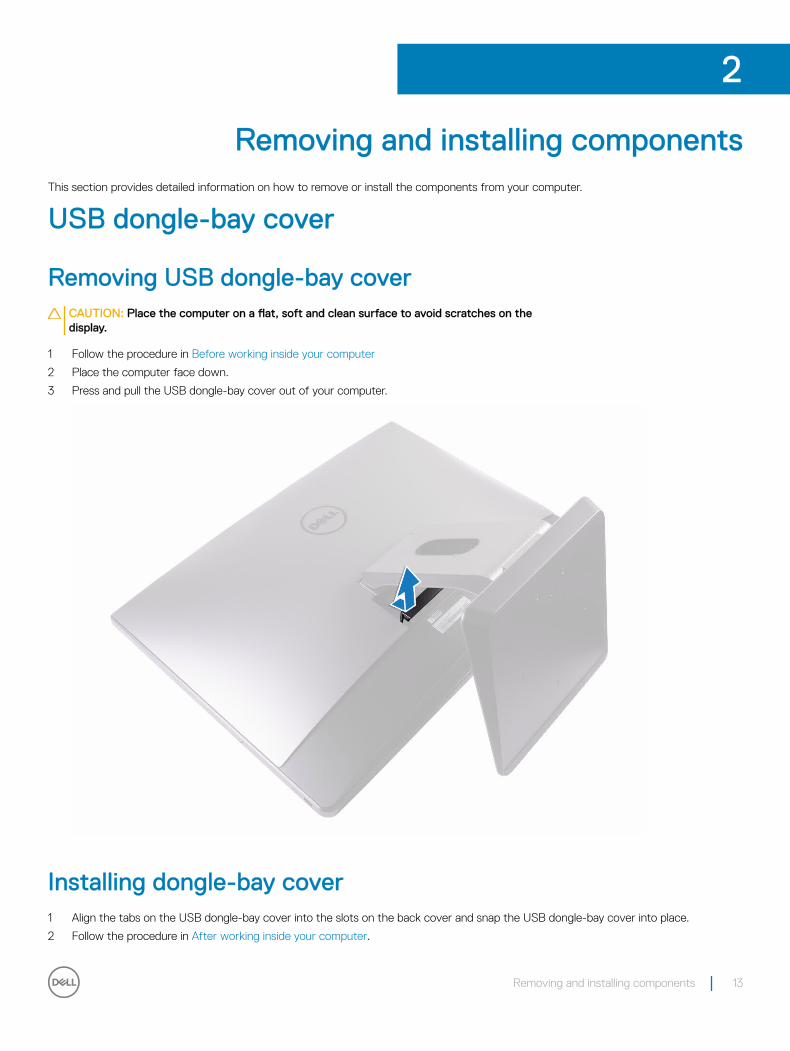
Removing and installing componentsThis section provides detailed information on how to remove or install the components from your computer.
USB dongle-bay cover
Removing USB dongle-bay coverCAUTION: Place the computer on a flat, soft and clean surface to avoid scratches on the display.
1 Follow the procedure in Before working inside your computer
2 Place the computer face down.
3 Press and pull the USB dongle-bay cover out of your computer.
Installing dongle-bay cover1 Align the tabs on the USB dongle-bay cover into the slots on the back cover and snap the USB dongle-bay cover into place.
2 Follow the procedure in After working inside your computer.
2
Removing and installing components 13
Back cover
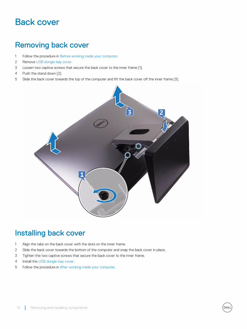
Removing back cover 1 Follow the procedure in Before working inside your computer.
2 Remove USB dongle-bay cover.
3 Loosen two captive screws that secure the back cover to the inner frame [1].
4 Push the stand down [2].
5 Slide the back cover towards the top of the computer and lift the back cover off the inner frame [3].
Installing back cover1 Align the tabs on the back cover with the slots on the inner frame.
2 Slide the back cover towards the bottom of the computer and snap the back cover in place.
3 Tighten the two captive screws that secure the back cover to the inner frame.
4 Install the USB dongle-bay cover.
5 Follow the procedure in After working inside your computer.
14 Removing and installing components
Memory module
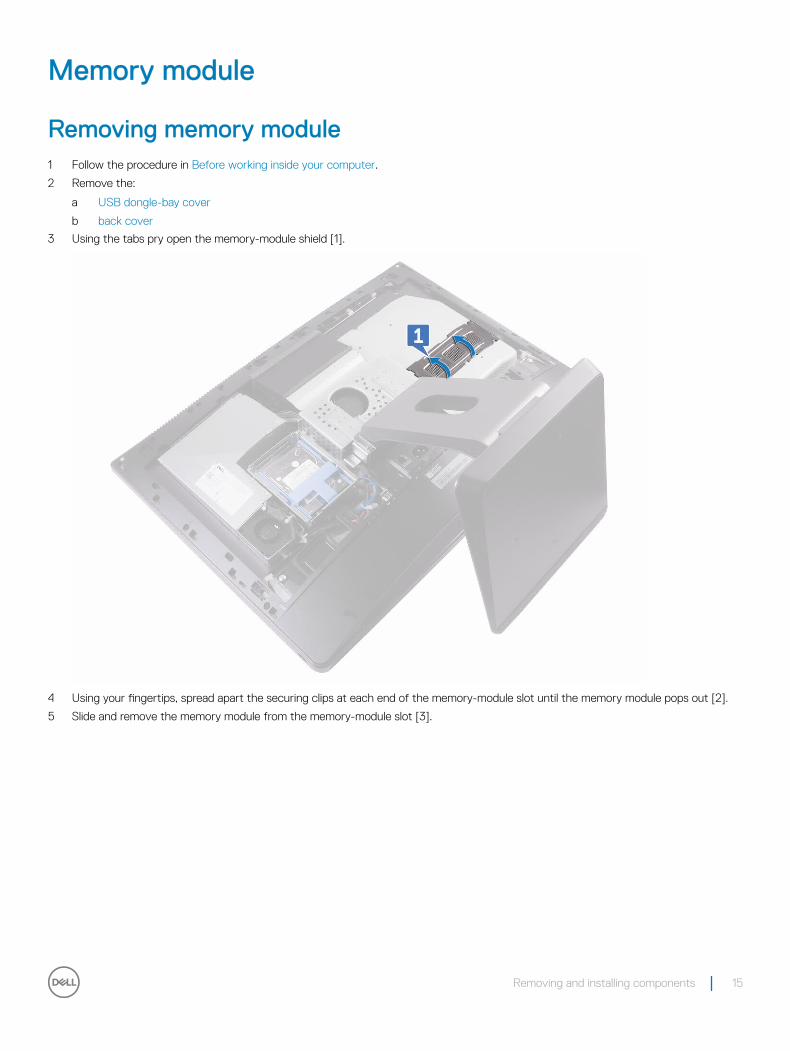
Removing memory module1 Follow the procedure in Before working inside your computer.
2 Remove the:
a USB dongle-bay cover
b back cover
3 Using the tabs pry open the memory-module shield [1].
4 Using your fingertips, spread apart the securing clips at each end of the memory-module slot until the memory module pops out [2].
5 Slide and remove the memory module from the memory-module slot [3].
Removing and installing components 15
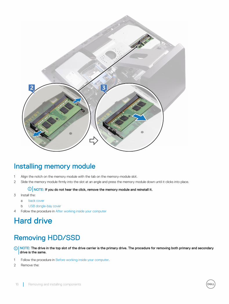
Installing memory module1 Align the notch on the memory module with the tab on the memory-module slot.
2 Slide the memory module firmly into the slot at an angle and press the memory module down until it clicks into place.
NOTE: If you do not hear the click, remove the memory module and reinstall it.
3 Install the:
a back cover
b USB dongle-bay cover
4 Follow the procedure in After working inside your computer
Hard drive
Removing HDD/SSDNOTE: The drive in the top slot of the drive carrier is the primary drive. The procedure for removing both primary and secondary drive is the same.
1 Follow the procedure in Before working inside your computer.
2 Remove the:
16 Removing and installing components
a USB dongle-bay cover
b back cover
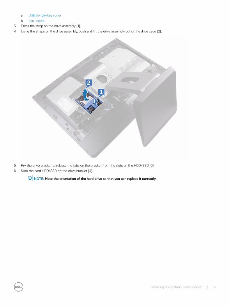
3 Press the strap on the drive assembly [1].
4 Using the straps on the drive assembly, push and lift the drive assembly out of the drive cage [2].
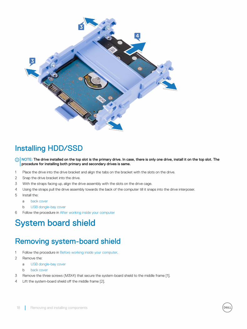
5 Pry the drive bracket to release the tabs on the bracket from the slots on the HDD/SSD [3].
6 Slide the hard HDD/SSD off the drive bracket [4].
NOTE: Note the orientation of the hard drive so that you can replace it correctly.
Removing and installing components 17
Installing HDD/SSDNOTE: The drive installed on the top slot is the primary drive. In case, there is only one drive, install it on the top slot. The procedure for installing both primary and secondary drives is same.
1 Place the drive into the drive bracket and align the tabs on the bracket with the slots on the drive.
2 Snap the drive bracket into the drive.
3 With the straps facing up, align the drive assembly with the slots on the drive cage.
4 Using the straps pull the drive assembly towards the back of the computer till it snaps into the drive interposer.
5 Install the:
a back cover
b USB dongle-bay cover
6 Follow the procedure in After working inside your computer
System board shield
Removing system-board shield1 Follow the procedure in Before working inside your computer.
2 Remove the:
a USB dongle-bay cover
b back cover
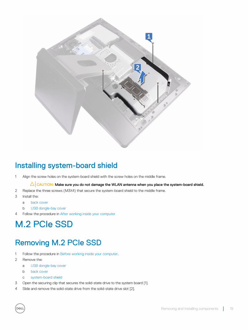
3 Remove the three screws (M3X4) that secure the system-board shield to the middle frame [1].
4 Lift the system-board shield off the middle frame [2].
18 Removing and installing components
Installing system-board shield1 Align the screw holes on the system-board shield with the screw holes on the middle frame.
CAUTION: Make sure you do not damage the WLAN antenna when you place the system-board shield.
2 Replace the three screws (M3X4) that secure the system-board shield to the middle frame.
3 Install the:
a back cover
b USB dongle-bay cover
4 Follow the procedure in After working inside your computer
M.2 PCIe SSD
Removing M.2 PCIe SSD1 Follow the procedure in Before working inside your computer.
2 Remove the:
a USB dongle-bay cover
b back cover
c system-board shield
3 Open the securing clip that secures the solid-state drive to the system board [1].
4 Slide and remove the solid-state drive from the solid-state drive slot [2].
Removing and installing components 19
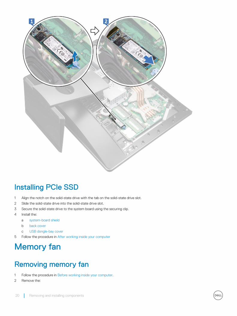
Installing PCIe SSD1 Align the notch on the solid-state drive with the tab on the solid-state drive slot.
2 Slide the solid-state drive into the solid-state drive slot.
3 Secure the solid-state drive to the system board using the securing clip.
4 Install the:
a system-board shield
b back cover
c USB dongle-bay cover
5 Follow the procedure in After working inside your computer
Memory fan
Removing memory fan1 Follow the procedure in Before working inside your computer.
2 Remove the:
20 Removing and installing components
a USB dongle-bay cover
b back cover
c system-board shield
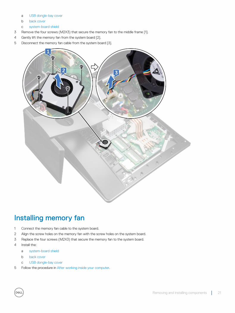
3 Remove the four screws (M2X3) that secure the memory fan to the middle frame [1].
4 Gently lift the memory fan from the system board [2].
5 Disconnect the memory fan cable from the system board [3].
Installing memory fan1 Connect the memory fan cable to the system board.
2 Align the screw holes on the memory fan with the screw holes on the system board.
3 Replace the four screws (M2X3) that secure the memory fan to the system board.
4 Install the:
a system-board shield
b back cover
c USB dongle-bay cover
5 Follow the procedure in After working inside your computer.
Removing and installing components 21
Heat sink
Removing processor heatsink for systems with discrete graphics
NOTE: Depending on the configuration you ordered, the appearance of the processor heatsink and the number of screws may differ.
NOTE: The procedure you see below is for the removal of heatsink with discrete graphics.
1 Follow the procedure in Before working inside your computer.
2 Remove the:
a USB dongle-bay cover
b back cover
c system-board shield
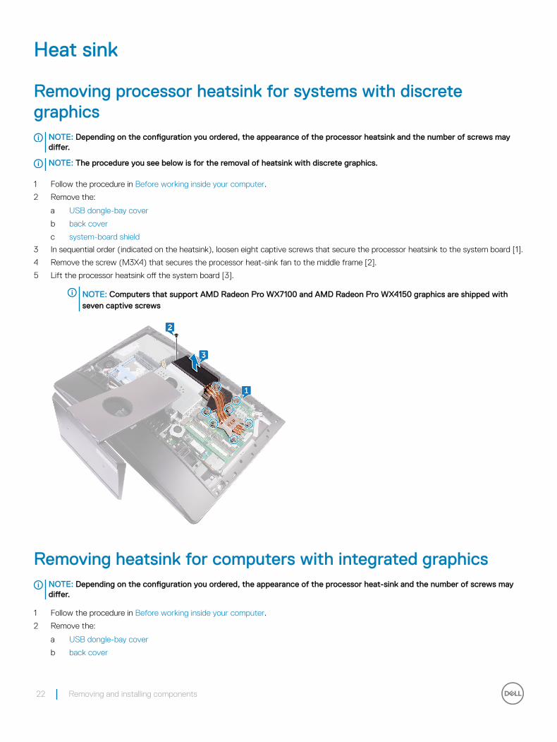
3 In sequential order (indicated on the heatsink), loosen eight captive screws that secure the processor heatsink to the system board [1].
4 Remove the screw (M3X4) that secures the processor heat-sink fan to the middle frame [2].
5 Lift the processor heatsink off the system board [3].
NOTE: Computers that support AMD Radeon Pro WX7100 and AMD Radeon Pro WX4150 graphics are shipped with seven captive screws
Removing heatsink for computers with integrated graphicsNOTE: Depending on the configuration you ordered, the appearance of the processor heat-sink and the number of screws may differ.
1 Follow the procedure in Before working inside your computer.
2 Remove the:
a USB dongle-bay cover
b back cover
22 Removing and installing components
c system-board shield
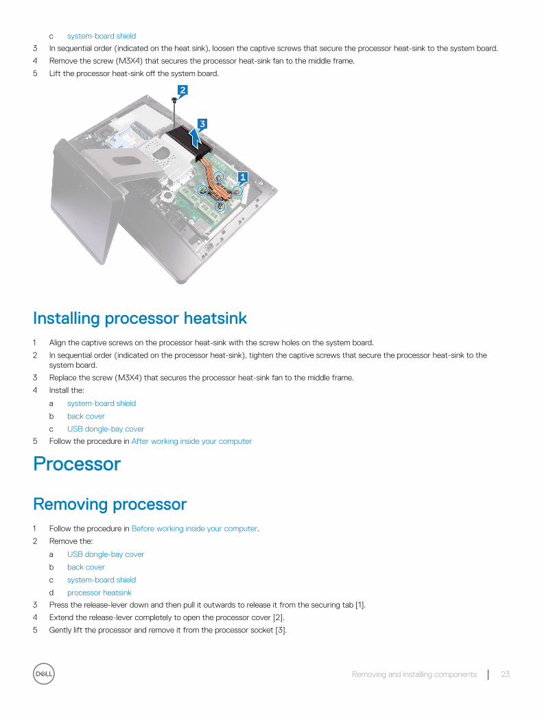
3 In sequential order (indicated on the heat sink), loosen the captive screws that secure the processor heat-sink to the system board.
4 Remove the screw (M3X4) that secures the processor heat-sink fan to the middle frame.
5 Lift the processor heat-sink off the system board.
Installing processor heatsink1 Align the captive screws on the processor heat-sink with the screw holes on the system board.
2 In sequential order (indicated on the processor heat-sink), tighten the captive screws that secure the processor heat-sink to the system board.
3 Replace the screw (M3X4) that secures the processor heat-sink fan to the middle frame.
4 Install the:
a system-board shield
b back cover
c USB dongle-bay cover
5 Follow the procedure in After working inside your computer
Processor
Removing processor1 Follow the procedure in Before working inside your computer.
2 Remove the:
a USB dongle-bay cover
b back cover
c system-board shield
d processor heatsink
3 Press the release-lever down and then pull it outwards to release it from the securing tab [1].
4 Extend the release-lever completely to open the processor cover [2].
5 Gently lift the processor and remove it from the processor socket [3].
Removing and installing components 23
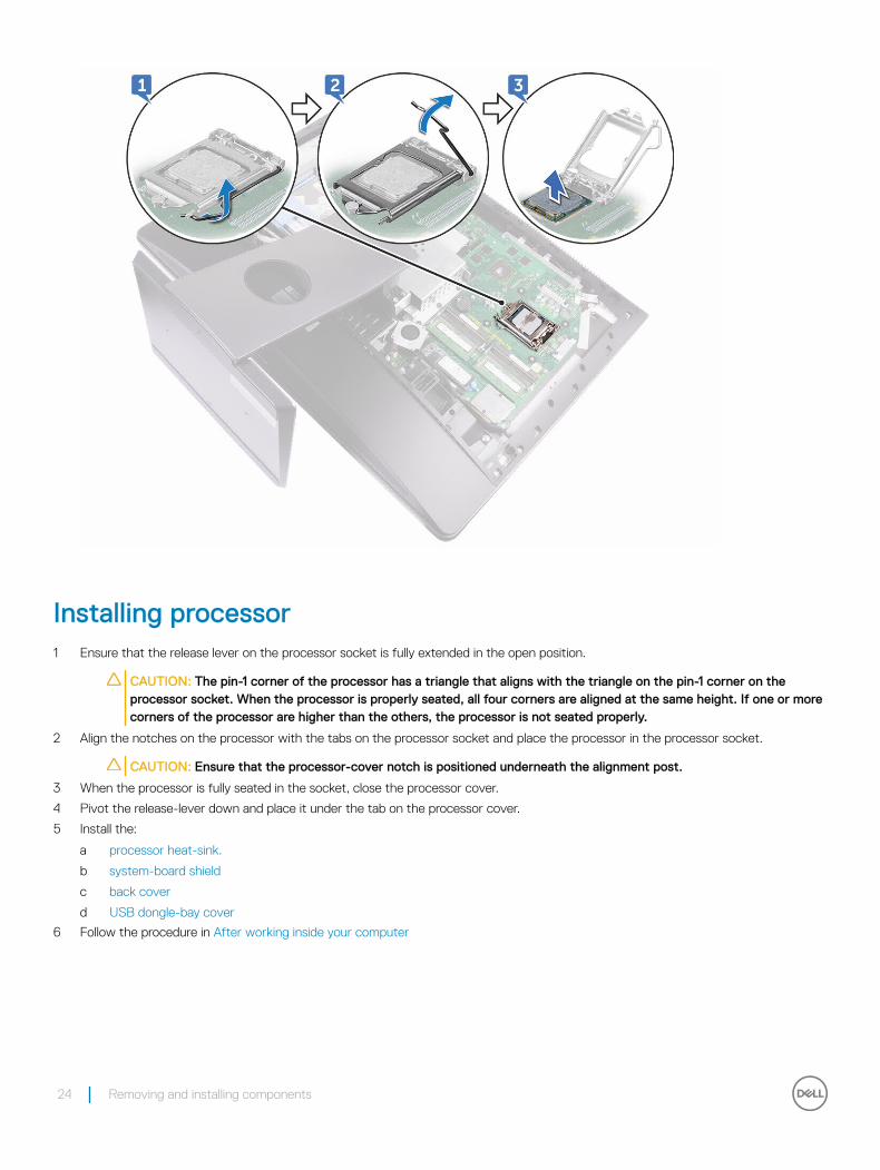
Installing processor1 Ensure that the release lever on the processor socket is fully extended in the open position.
CAUTION: The pin-1 corner of the processor has a triangle that aligns with the triangle on the pin-1 corner on the processor socket. When the processor is properly seated, all four corners are aligned at the same height. If one or more corners of the processor are higher than the others, the processor is not seated properly.
2 Align the notches on the processor with the tabs on the processor socket and place the processor in the processor socket.
CAUTION: Ensure that the processor-cover notch is positioned underneath the alignment post.
3 When the processor is fully seated in the socket, close the processor cover.
4 Pivot the release-lever down and place it under the tab on the processor cover.
5 Install the:
a processor heat-sink.
b system-board shield
c back cover
d USB dongle-bay cover
6 Follow the procedure in After working inside your computer
24 Removing and installing components
Coin cell battery
Removing coin-cell battery1 Follow the procedure in Before working inside your computer.
2 Remove the:
a USB dongle-bay cover
b back cover
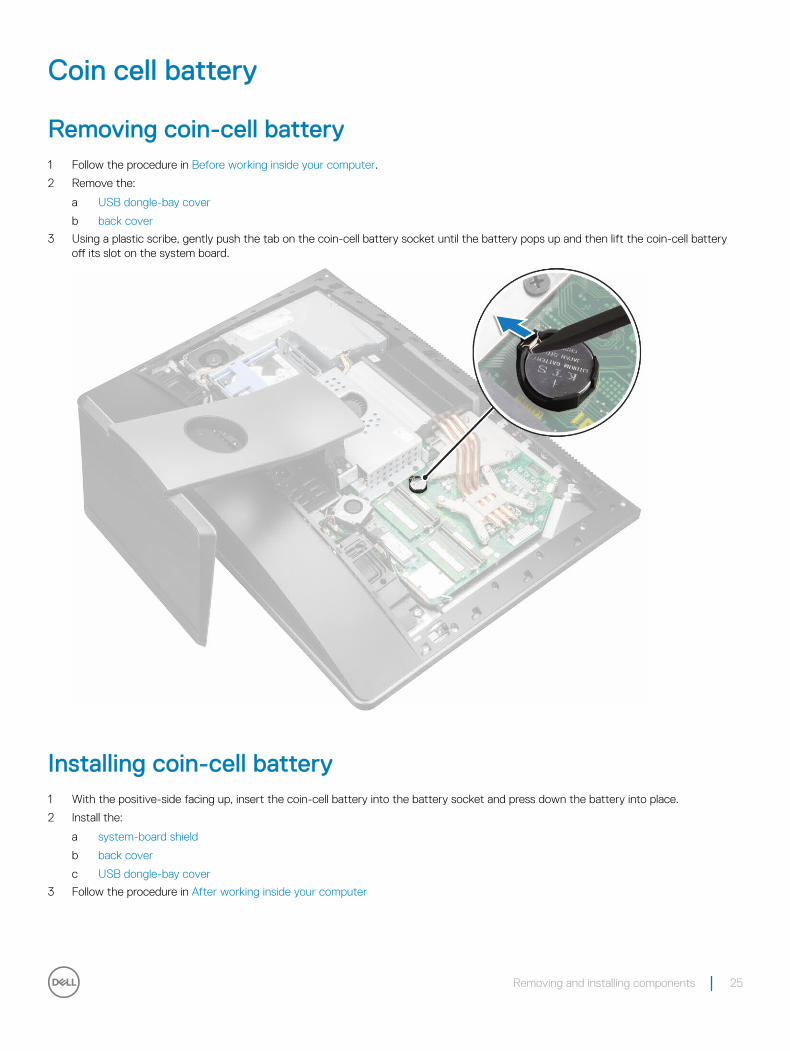
3 Using a plastic scribe, gently push the tab on the coin-cell battery socket until the battery pops up and then lift the coin-cell battery off its slot on the system board.
Installing coin-cell battery1 With the positive-side facing up, insert the coin-cell battery into the battery socket and press down the battery into place.
2 Install the:
a system-board shield
b back cover
c USB dongle-bay cover
3 Follow the procedure in After working inside your computer
Removing and installing components 25
WLAN card
Removing wireless card1 Remove the:
a USB dongle-bay cover
b back cover
c system-board shield
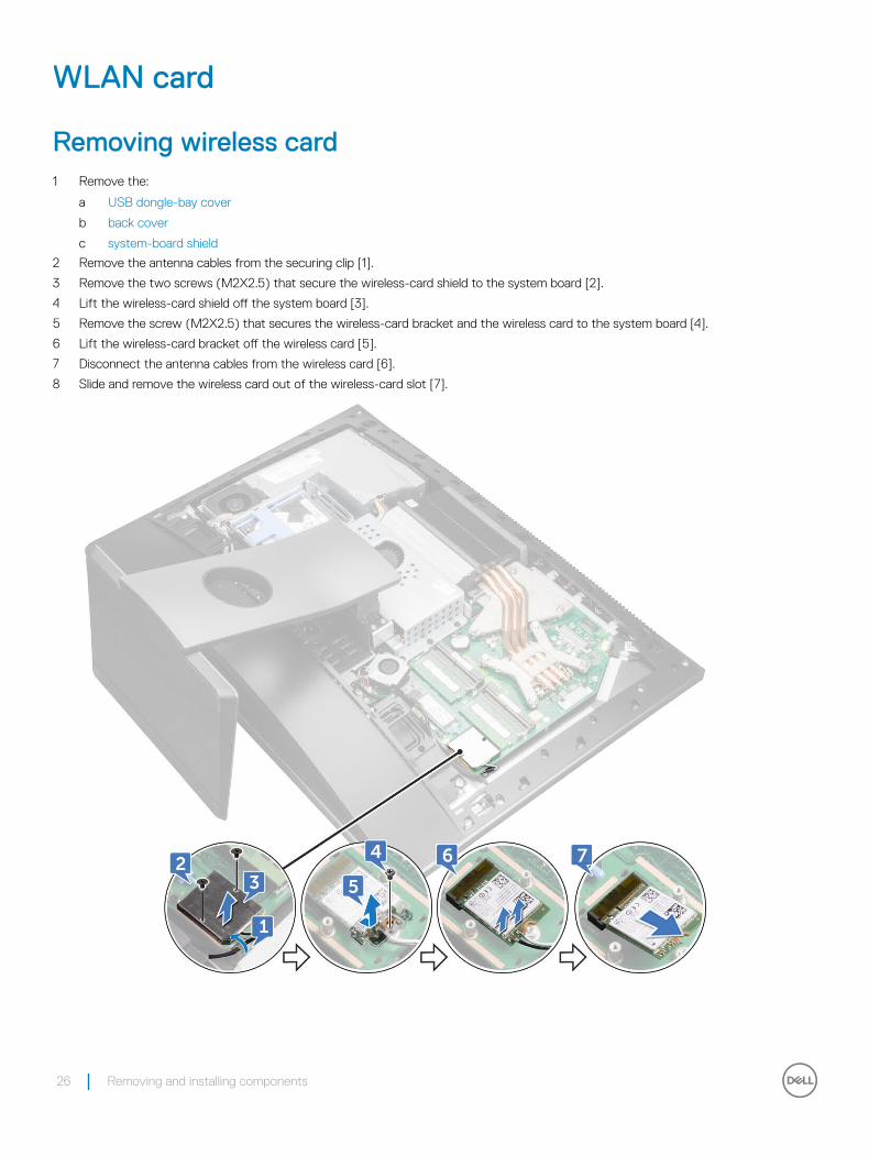
2 Remove the antenna cables from the securing clip [1].
3 Remove the two screws (M2X2.5) that secure the wireless-card shield to the system board [2].
4 Lift the wireless-card shield off the system board [3].
5 Remove the screw (M2X2.5) that secures the wireless-card bracket and the wireless card to the system board [4].
6 Lift the wireless-card bracket off the wireless card [5].
7 Disconnect the antenna cables from the wireless card [6].
8 Slide and remove the wireless card out of the wireless-card slot [7].
26 Removing and installing components
Installing the wireless cardCAUTION: To avoid damaging the wireless card, do not place any cables under it.
1 Align the notch on the wireless card with the tab on the wireless-card slot and slide the wireless card into the wireless-card slot.
2 Route the antenna cable through the routing guide.
3 Connect the antenna cables to the wireless card.
The following table provides the antenna-cable color scheme for the wireless card supported by your computer:
Table 1. : Wirelesscard colour scheme
Connectors on the wireless card Antenna-cable color
Main (white triangle) White
Auxiliary (black triangle) Black
4 Press down the other end of the wireless card and align the screw hole on the wireless-card bracket and wireless card with the screw hole on the system board.
5 Replace the screw (M2X2.5) that secures the wireless-card bracket and the wireless card to the system board.
6 Align the screw holes on the wireless-card shield with the screw holes on the system board.
7 Replace the two screws (M2X2.5) that secure the wireless-card shield to system board.
8 Route the antenna cables through the securing clip.
9 Install the:
a system-board shield
b back cover
c USB dongle-bay cover
10 Follow the procedure in After working inside your computer
Stand
Removing stand
1 Follow the procedure in Before working inside your computer.
2 Remove the:
a USB dongle-bay cover
b back cover
3 Remove the six screws (M4X6) that secure the stand to the middle frame [1].
4 Lift the stand off the computer [2].
Removing and installing components 27
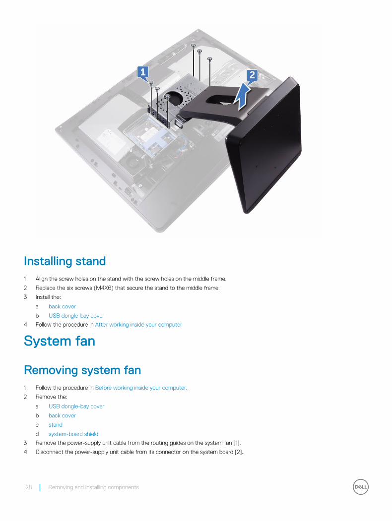
Installing stand1 Align the screw holes on the stand with the screw holes on the middle frame.
2 Replace the six screws (M4X6) that secure the stand to the middle frame.
3 Install the:
a back cover
b USB dongle-bay cover
4 Follow the procedure in After working inside your computer
System fan
Removing system fan1 Follow the procedure in Before working inside your computer.
2 Remove the:
a USB dongle-bay cover
b back cover
c stand
d system-board shield
3 Remove the power-supply unit cable from the routing guides on the system fan [1].
4 Disconnect the power-supply unit cable from its connector on the system board [2]..
28 Removing and installing components
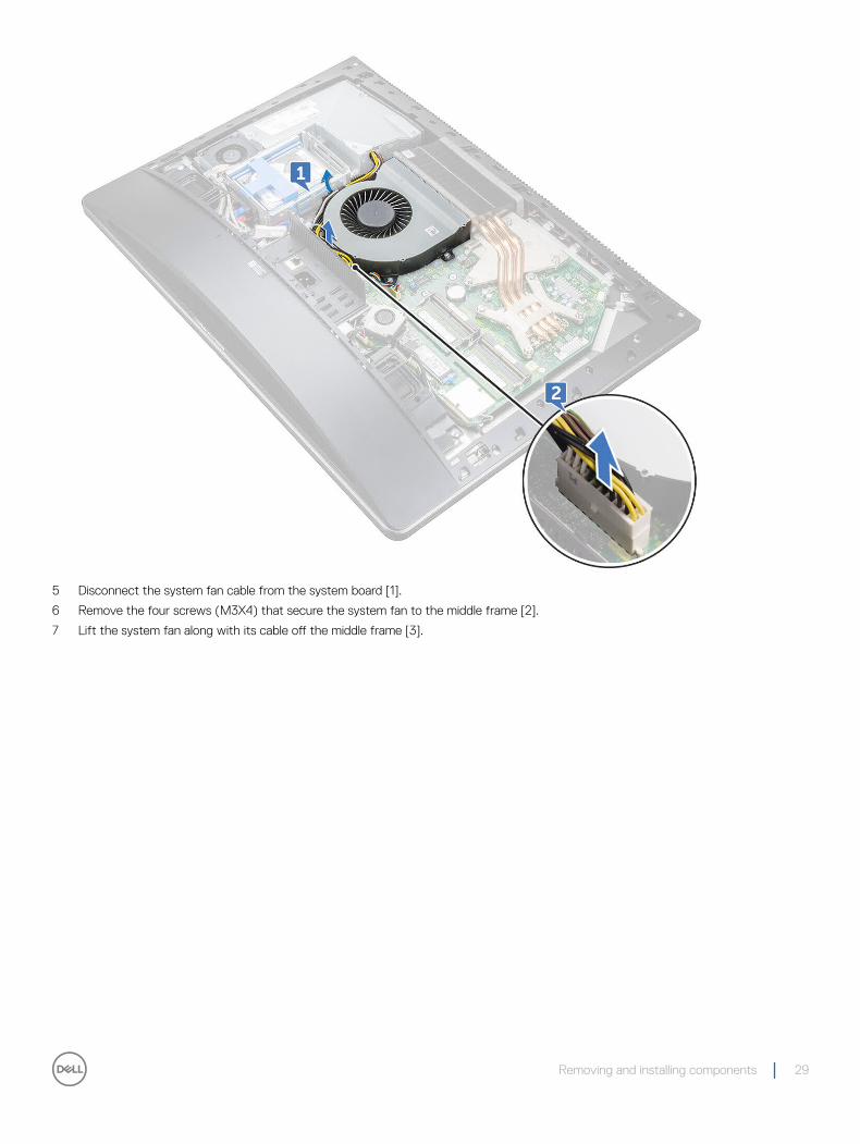
5 Disconnect the system fan cable from the system board [1].
6 Remove the four screws (M3X4) that secure the system fan to the middle frame [2].
7 Lift the system fan along with its cable off the middle frame [3].
Removing and installing components 29
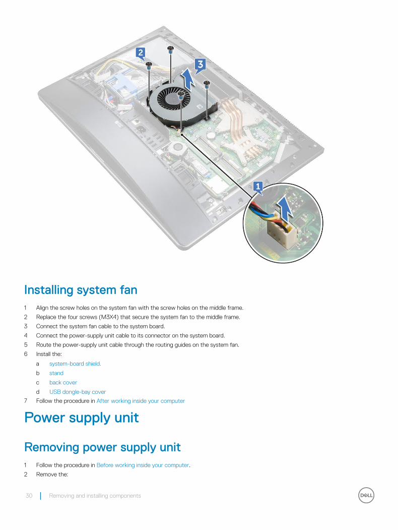
Installing system fan1 Align the screw holes on the system fan with the screw holes on the middle frame.
2 Replace the four screws (M3X4) that secure the system fan to the middle frame.
3 Connect the system fan cable to the system board.
4 Connect the power-supply unit cable to its connector on the system board.
5 Route the power-supply unit cable through the routing guides on the system fan.
6 Install the:
a system-board shield.
b stand
c back cover
d USB dongle-bay cover
7 Follow the procedure in After working inside your computer
Power supply unit
Removing power supply unit1 Follow the procedure in Before working inside your computer.
2 Remove the:
30 Removing and installing components
a USB dongle-bay cover
b back cover
c stand
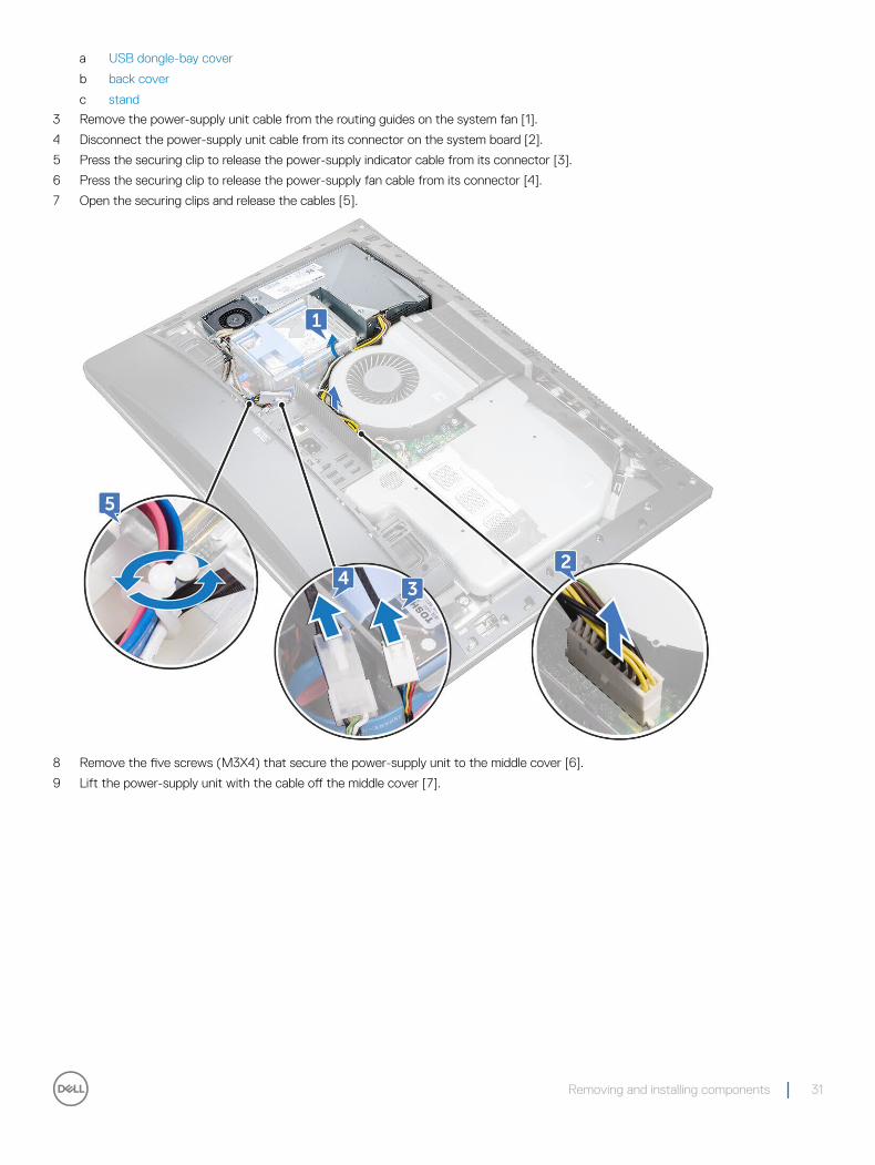
3 Remove the power-supply unit cable from the routing guides on the system fan [1].
4 Disconnect the power-supply unit cable from its connector on the system board [2].
5 Press the securing clip to release the power-supply indicator cable from its connector [3].
6 Press the securing clip to release the power-supply fan cable from its connector [4].
7 Open the securing clips and release the cables [5].
8 Remove the five screws (M3X4) that secure the power-supply unit to the middle cover [6].
9 Lift the power-supply unit with the cable off the middle cover [7].
Removing and installing components 31
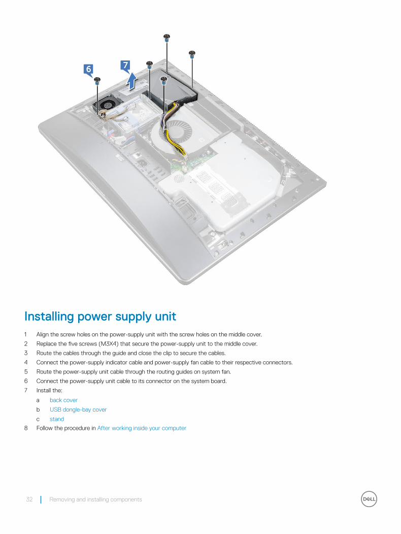
Installing power supply unit1 Align the screw holes on the power-supply unit with the screw holes on the middle cover.
2 Replace the five screws (M3X4) that secure the power-supply unit to the middle cover.
3 Route the cables through the guide and close the clip to secure the cables.
4 Connect the power-supply indicator cable and power-supply fan cable to their respective connectors.
5 Route the power-supply unit cable through the routing guides on system fan.
6 Connect the power-supply unit cable to its connector on the system board.
7 Install the:
a back cover
b USB dongle-bay cover
c stand
8 Follow the procedure in After working inside your computer
32 Removing and installing components
Inner frame
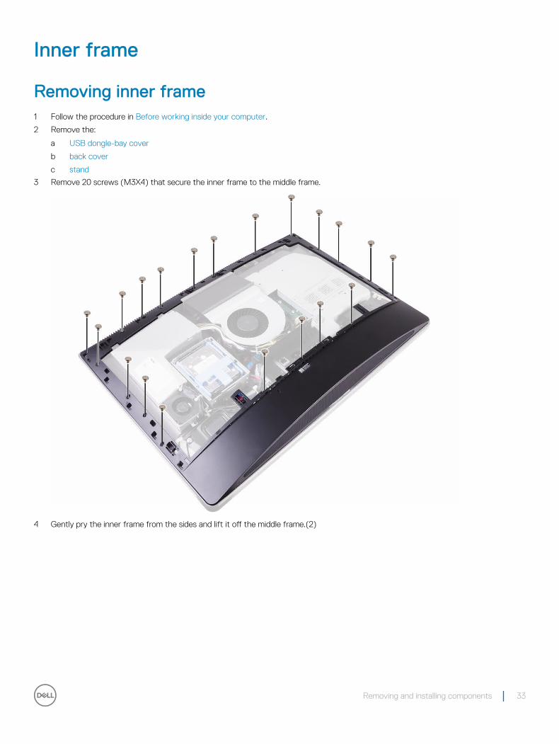
Removing inner frame1 Follow the procedure in Before working inside your computer.
2 Remove the:
a USB dongle-bay cover
b back cover
c stand
3 Remove 20 screws (M3X4) that secure the inner frame to the middle frame.
4 Gently pry the inner frame from the sides and lift it off the middle frame.(2)
Removing and installing components 33
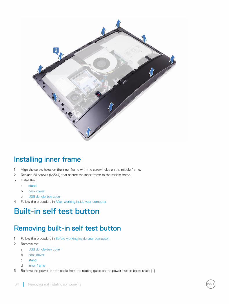
Installing inner frame1 Align the screw holes on the inner frame with the screw holes on the middle frame.
2 Replace 20 screws (M3X4) that secure the inner frame to the middle frame.
3 Install the:
a stand
b back cover
c USB dongle-bay cover
4 Follow the procedure in After working inside your computer
Built-in self test button
Removing built-in self test button1 Follow the procedure in Before working inside your computer.
2 Remove the:
a USB dongle-bay cover
b back cover
c stand
d inner frame
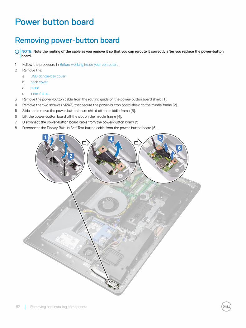
3 Remove the power-button cable from the routing guide on the power-button board shield [1].
34 Removing and installing components

4 Remove the two screws (M2X3) that secure the power-button board shield to the middle frame [2].
5 Slide forward and lift the power-button board shield off the middle frame [3].
6 Disconnect the Display Built-in Self Test button cable from the power-button board [4].
7 Remove the Display Built-in Self Test button cable from the routing guide on the middle frame [5].
8 Remove the two screws (M2X3) that secure the Display Built-in Self Test button board to the middle frame [6].
9 Lift the Display Built-in Self Test button board off the middle frame [7].
Installing the built-in self test button board1 Place the Display Built-in Self Test button board on the middle frame.
2 Align the screw holes on the Display Built-in Self Test button board with the screw holes on the middle frame.
3 Replace the two screws (M2X3) that secure the Display Built-in Self Test button board to the middle frame.
4 Route the Display Built-in Self Test button cable through the routing guides.
5 Connect the Display Built-in Self Test button cable to the power-button board.
6 Insert the power-button board shield into the slot on the middle frame until it clicks.
7 Align the screw holes on the power-button board shield with the screw holes on the middle frame.
8 Replace the two screws (M2X3) that secure the power-button board shield to the middle frame.
9 Route the power-button cable through the routing guides on the power-button board shield..
10 Install the:
Removing and installing components 35
a stand
b back cover
c USB dongle-bay cover
11 Follow the procedure in After working inside your computer
Microphone
Removing microphone1 Follow the procedure in Before working inside your computer.
2 Remove the:
a USB dongle-bay cover
b back cover
c system-board shield
d stand
e inner frame
3 Disconnect the microphone cable from the system board [1].
4 Remove the four screws (M2X2.2) that secure the microphone module to the middle frame [2].
5 Release microphone cable from the routing guides on the middle frame [3].
6 Using a plastic scribe, carefully pry and lift the microphone modules (4) with the cable off the slots on the middle frame [4].
36 Removing and installing components
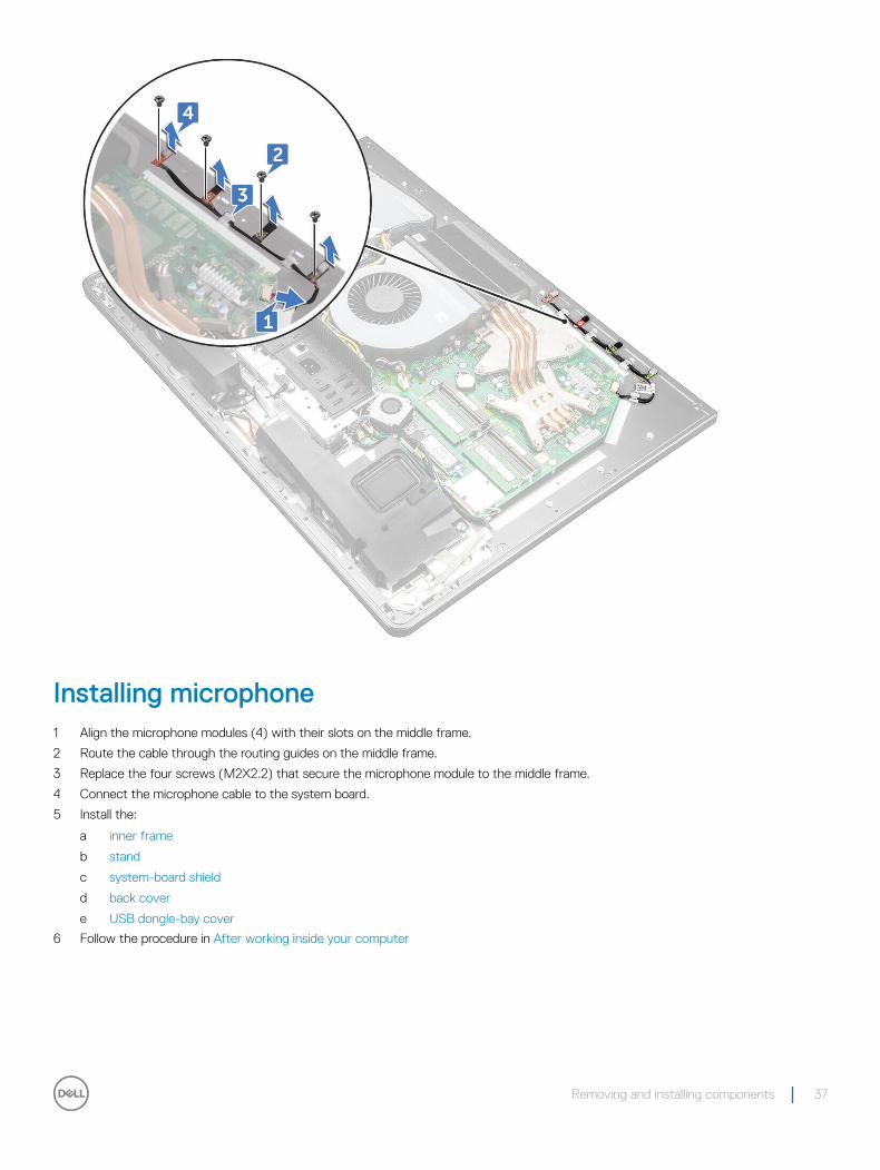
Installing microphone1 Align the microphone modules (4) with their slots on the middle frame.
2 Route the cable through the routing guides on the middle frame.
3 Replace the four screws (M2X2.2) that secure the microphone module to the middle frame.
4 Connect the microphone cable to the system board.
5 Install the:
a inner frame
b stand
c system-board shield
d back cover
e USB dongle-bay cover
6 Follow the procedure in After working inside your computer
Removing and installing components 37
I/O panel
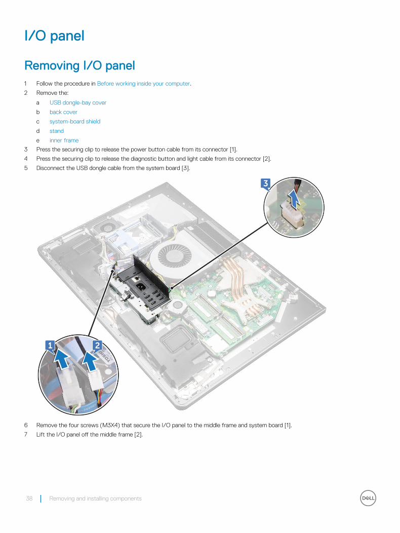
Removing I/O panel1 Follow the procedure in Before working inside your computer.
2 Remove the:
a USB dongle-bay cover
b back cover
c system-board shield
d stand
e inner frame
3 Press the securing clip to release the power button cable from its connector [1].
4 Press the securing clip to release the diagnostic button and light cable from its connector [2].
5 Disconnect the USB dongle cable from the system board [3].
6 Remove the four screws (M3X4) that secure the I/O panel to the middle frame and system board [1].
7 Lift the I/O panel off the middle frame [2].
38 Removing and installing components
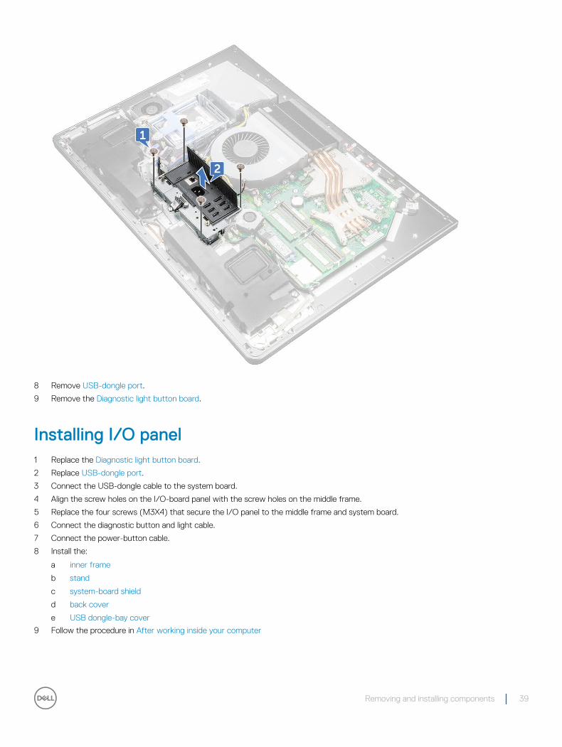
8 Remove USB-dongle port.
9 Remove the Diagnostic light button board.
Installing I/O panel1 Replace the Diagnostic light button board.
2 Replace USB-dongle port.
3 Connect the USB-dongle cable to the system board.
4 Align the screw holes on the I/O-board panel with the screw holes on the middle frame.
5 Replace the four screws (M3X4) that secure the I/O panel to the middle frame and system board.
6 Connect the diagnostic button and light cable.
7 Connect the power-button cable.
8 Install the:
a inner frame
b stand
c system-board shield
d back cover
e USB dongle-bay cover
9 Follow the procedure in After working inside your computer
Removing and installing components 39
USB-dongle port
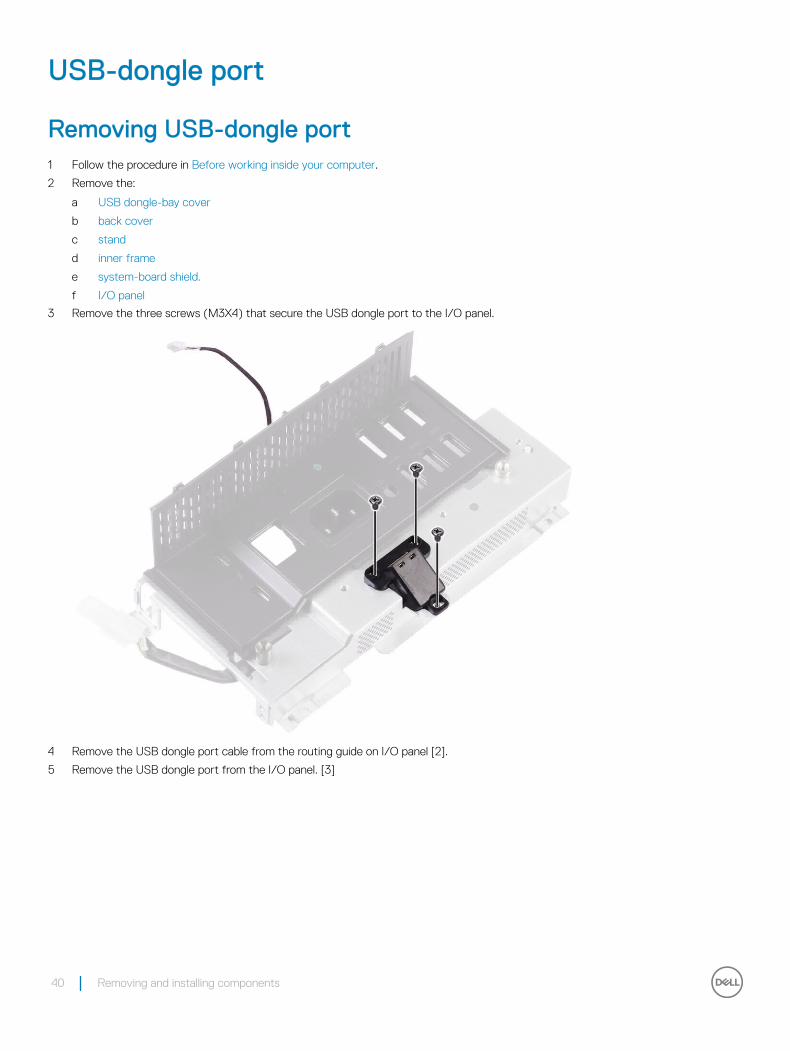
Removing USB-dongle port1 Follow the procedure in Before working inside your computer.
2 Remove the:
a USB dongle-bay cover
b back cover
c stand
d inner frame
e system-board shield.
f I/O panel
3 Remove the three screws (M3X4) that secure the USB dongle port to the I/O panel.
4 Remove the USB dongle port cable from the routing guide on I/O panel [2].
5 Remove the USB dongle port from the I/O panel. [3]
40 Removing and installing components
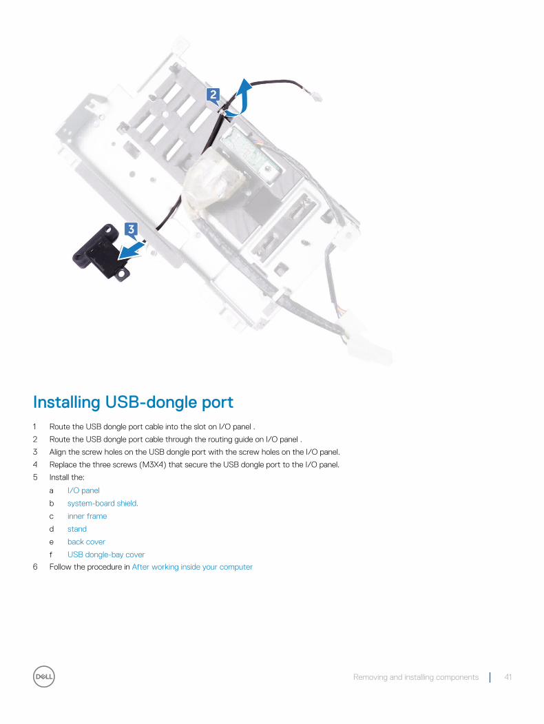
Installing USB-dongle port1 Route the USB dongle port cable into the slot on I/O panel .
2 Route the USB dongle port cable through the routing guide on I/O panel .
3 Align the screw holes on the USB dongle port with the screw holes on the I/O panel.
4 Replace the three screws (M3X4) that secure the USB dongle port to the I/O panel.
5 Install the:
a I/O panel
b system-board shield.
c inner frame
d stand
e back cover
f USB dongle-bay cover
6 Follow the procedure in After working inside your computer
Removing and installing components 41
Diagnostic light and button board
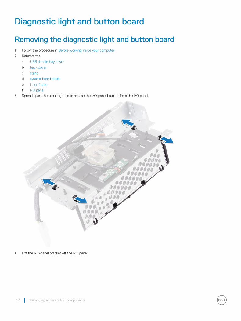
Removing the diagnostic light and button board 1 Follow the procedure in Before working inside your computer.
2 Remove the:
a USB dongle-bay cover
b back cover
c stand
d system-board shield.
e inner frame
f I/O panel
3 Spread apart the securing tabs to release the I/O-panel bracket from the I/O panel.
4 Lift the I/O-panel bracket off the I/O panel.
42 Removing and installing components
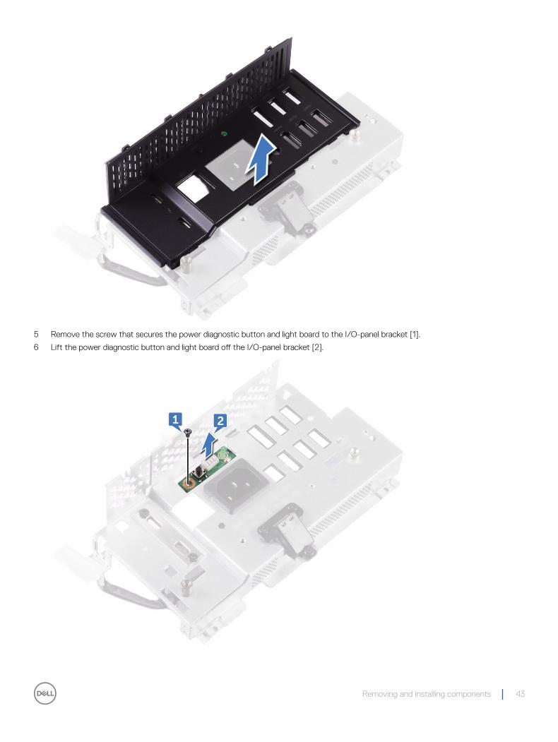
5 Remove the screw that secures the power diagnostic button and light board to the I/O-panel bracket [1].
6 Lift the power diagnostic button and light board off the I/O-panel bracket [2].
Removing and installing components 43
Installing diagnostic light and button board1 Align the screw holes on power diagnostic button and light board to the screw holes on the I/O-panel bracket.
2 Replace the screw that secures the power diagnostic button and light board to the I/O-panel bracket.
3 Align the tabs on the I/O-panel bracket with the slots on the I/O panel and snap the I/O-panel bracket in place.
4 Install the:
a I/O panel
b inner frame
c system-board shield.
d stand
e back cover
f USB dongle-bay cover
5 Follow the procedure in After working inside your computer
Drive cage
Removing HDD/SSD cage1 Follow the procedure in Before working inside your computer.
2 Remove the:
a USB dongle-bay cover
b back cover
c stand
d hard drive
e system-board shield.
f I/O panel
3 Remove the cable from the routing guide on drive cage [1].
4 Open the securing clips and release the HDD/SSD cables [2].
5 Disconnect the HDD/SSD cable from the system board [3].
6 Disconnect the HDD/SSD data cables from the system board [4].
44 Removing and installing components
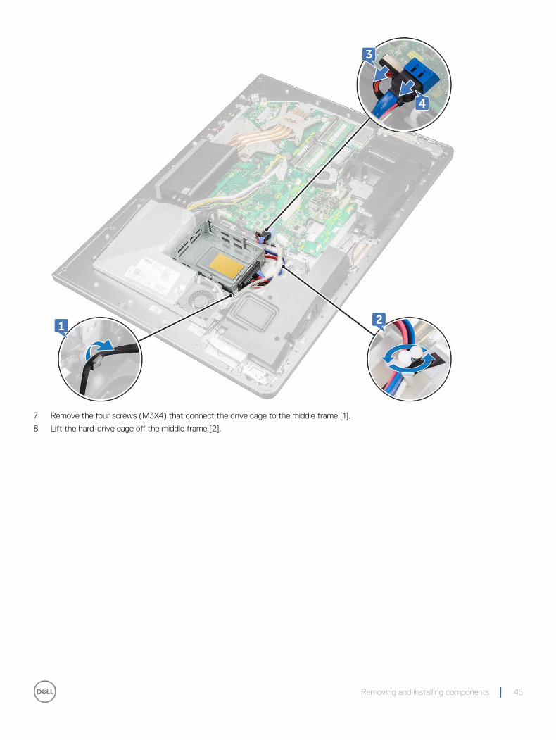
7 Remove the four screws (M3X4) that connect the drive cage to the middle frame [1].
8 Lift the hard-drive cage off the middle frame [2].
Removing and installing components 45
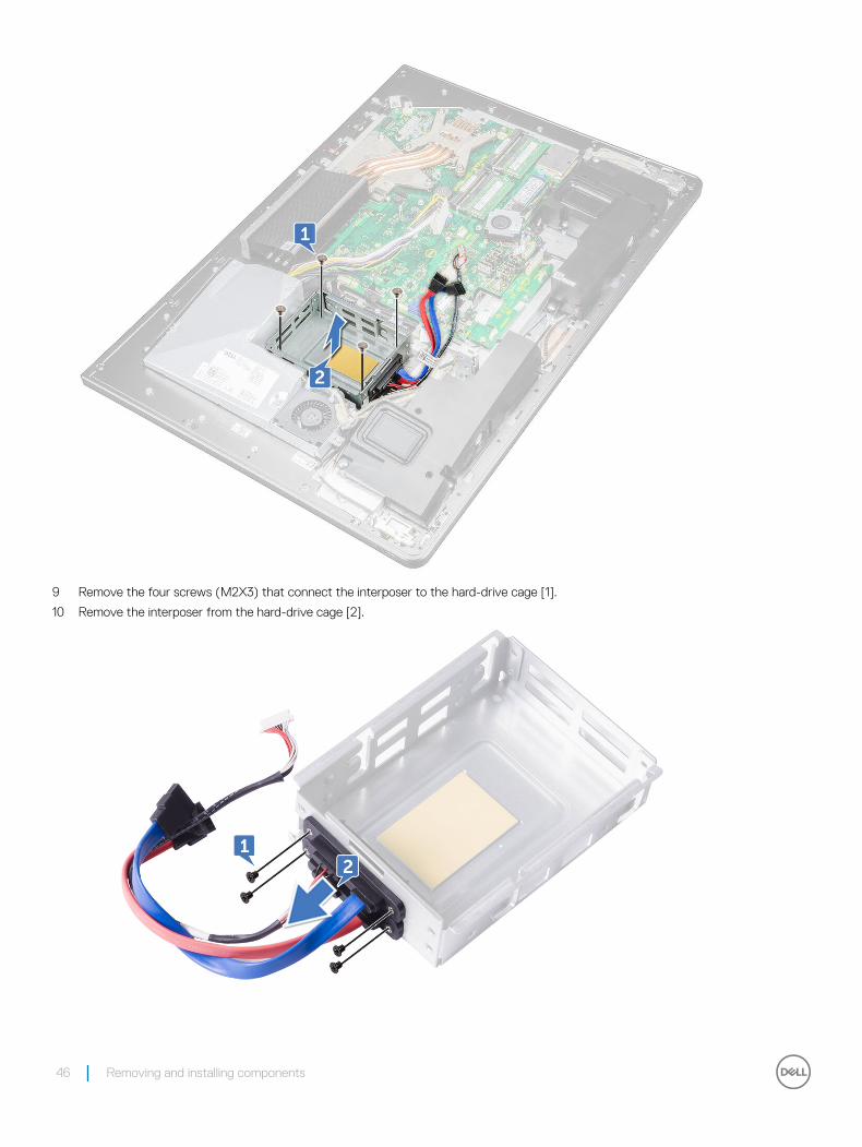
9 Remove the four screws (M2X3) that connect the interposer to the hard-drive cage [1].
10 Remove the interposer from the hard-drive cage [2].
46 Removing and installing components
Installing HDD/SSD cage1 Align the screw holes on the interposer with the screw holes on the drive cage.
2 Replace the four screws (M2X3) that connect the interposer to the drive cage.
3 Align the screw holes on the hard-drive cage to the screw holes on the middle frame.
4 Replace the four screws (M3X4) that secure the drive cage to the middle frame.
5 Connect the HDD/SSD cables and the HDD/SSD power cable to the system board.
NOTE: Connect the blue-colored cable at the top and red-colored cable to the bottom of the drive cage.
6 Route the cables through the guide and close the clip to secure the cables.
7 Install the:
a I/O panel
b system-board shield.
c stand
d hard drive
e back cover
f USB dongle-bay cover
8 Follow the procedure in After working inside your computer
Converter board
Removing converter board1 Follow the procedure in Before working inside your computer.
2 Remove the:
a USB dongle-bay cover
b back cover
c stand
d system-board shield
e inner frame
f I/O panel
3 Disconnect the left backlight power cable from the converter board [1].
4 Disconnect the converter-board cable from the converter board [2].
5 Disconnect the right backlight power cable from the converter board [3].
Removing and installing components 47
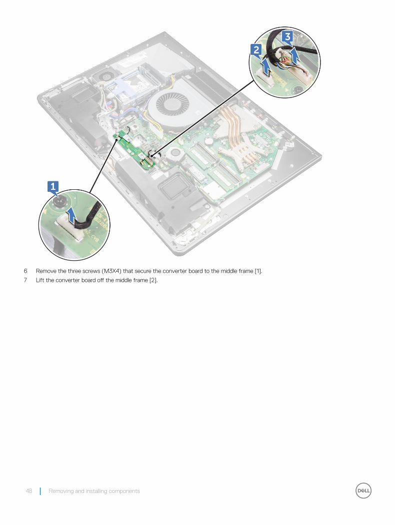
6 Remove the three screws (M3X4) that secure the converter board to the middle frame [1].
7 Lift the converter board off the middle frame [2].
48 Removing and installing components
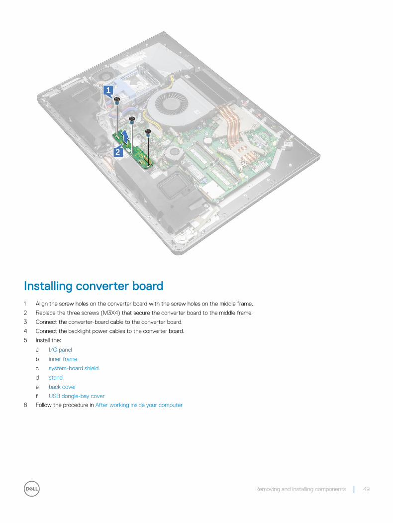
Installing converter board1 Align the screw holes on the converter board with the screw holes on the middle frame.
2 Replace the three screws (M3X4) that secure the converter board to the middle frame.
3 Connect the converter-board cable to the converter board.
4 Connect the backlight power cables to the converter board.
5 Install the:
a I/O panel
b inner frame
c system-board shield.
d stand
e back cover
f USB dongle-bay cover
6 Follow the procedure in After working inside your computer
Removing and installing components 49
Speaker
Removing speakers1 Follow the procedure in Before working inside your computer.
2 Remove the:
a USB dongle-bay cover
b back cover
c system-board shield
d stand
e inner frame
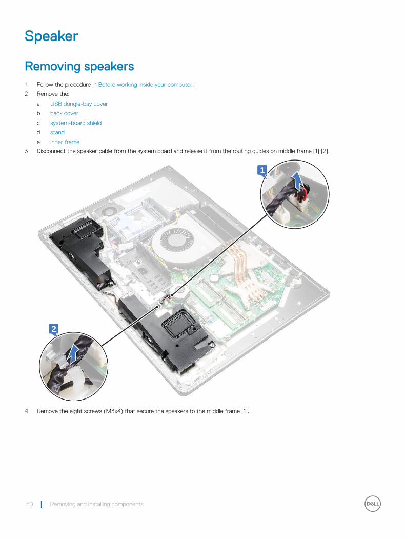
3 Disconnect the speaker cable from the system board and release it from the routing guides on middle frame [1] [2].
4 Remove the eight screws (M3x4) that secure the speakers to the middle frame [1].
50 Removing and installing components
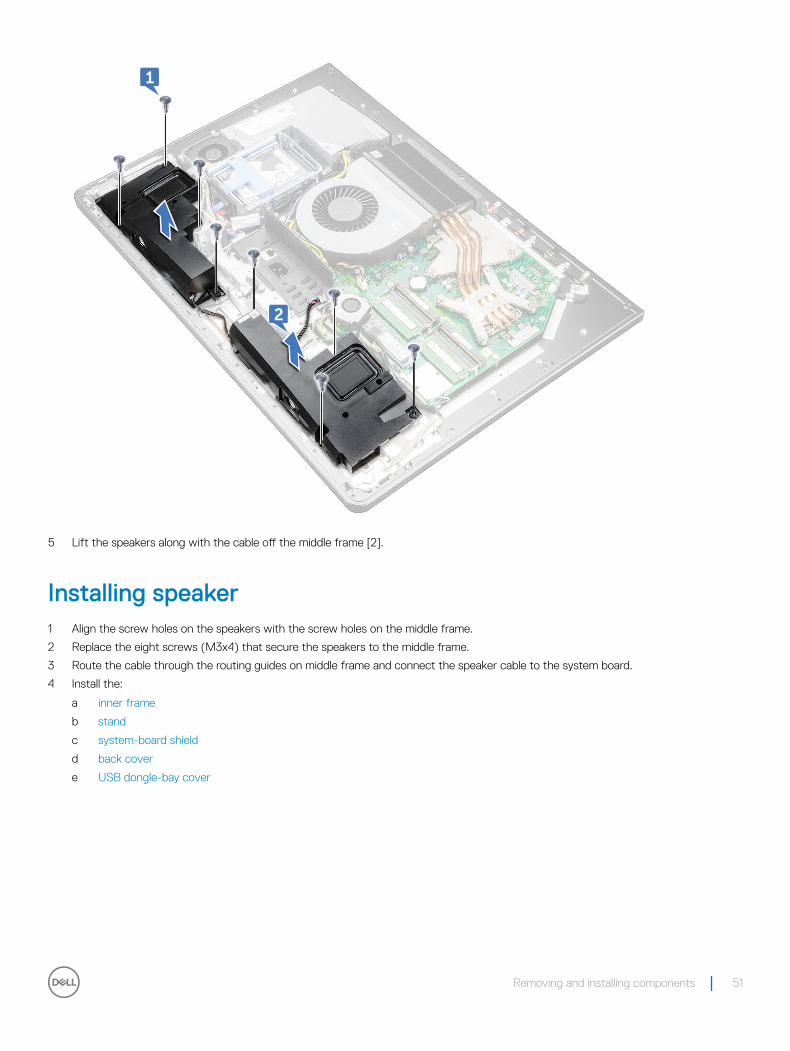
5 Lift the speakers along with the cable off the middle frame [2].
Installing speaker1 Align the screw holes on the speakers with the screw holes on the middle frame.
2 Replace the eight screws (M3x4) that secure the speakers to the middle frame.
3 Route the cable through the routing guides on middle frame and connect the speaker cable to the system board.
4 Install the:
a inner frame
b stand
c system-board shield
d back cover
e USB dongle-bay cover
Removing and installing components 51
Power button board
Removing power-button boardNOTE: Note the routing of the cable as you remove it so that you can reroute it correctly after you replace the power-button board.
1 Follow the procedure in Before working inside your computer.
2 Remove the:
a USB dongle-bay cover
b back cover
c stand
d inner frame
3 Remove the power-button cable from the routing guide on the power-button board shield [1].
4 Remove the two screws (M2X3) that secure the power-button board shield to the middle frame [2].
5 Slide and remove the power-button board shield off the middle frame [3].
6 Lift the power-button board off the slot on the middle frame [4].
7 Disconnect the power-button board cable from the power-button board [5].
8 Disconnect the Display Built-in Self Test button cable from the power-button board [6].
52 Removing and installing components
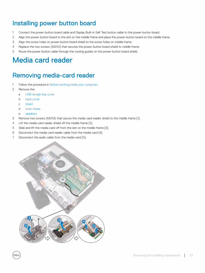
Installing power button board1 Connect the power-button board cable and Display Built-in Self Test button cable to the power-button board.
2 Align the power-button board to the slot on the middle frame and place the power-button board on the middle frame.
3 Align the screw holes on power-button board shield to the screw holes on middle frame.
4 Replace the two screws (M2X3) that secures the power-button board shield to middle frame.
5 Route the power-button cable through the routing guides on the power-button board shield.
Media card reader
Removing media-card reader1 Follow the procedure in Before working inside your computer.
2 Remove the:
a USB dongle-bay cover
b back cover
c stand
d inner frame
e speakers
3 Remove two screws (M2X3) that secure the media-card reader shield to the middle frame [1].
4 Lift the media-card reader shield off the middle frame [2].
5 Slide and lift the media-card off from the slot on the middle frame [3].
6 Disconnect the media-card reader cable from the media-card [4].
7 Disconnect the audio cable from the media-card [5].
Removing and installing components 53
Installing media card reader1 Connect the audio cable to the media card.
2 Connect the media-card reader cable to the media-card.
3 Align the media-card reader to the slot on the middle frame.
4 Align the screw hole on the media-card reader shield to the screw hole on the middle frame.
5 Replace the two screws (M2X3) that secure the media-card reader shield to the middle frame.
6 Install the:
a speakers.
b inner frame
c stand
d back cover
e USB dongle-bay cover
7 Follow the procedure in After working inside your computer
Camera
Removing camera1 Follow the procedure in Before working inside your computer.
2 Remove the:
a USB dongle-bay cover
b back cover
c stand
d inner frame
e speakers
3 Remove the two screws (M2X3) that secure the camera assembly to the middle frame [1].
4 Remove the camera cable from the routing guide on the middle frame [2].
5 Lift the metal foil and turn the camera assembly over [3].
6 Unrote the cable from the clip and disconnect the camera cable from the camera assembly [4]
54 Removing and installing components
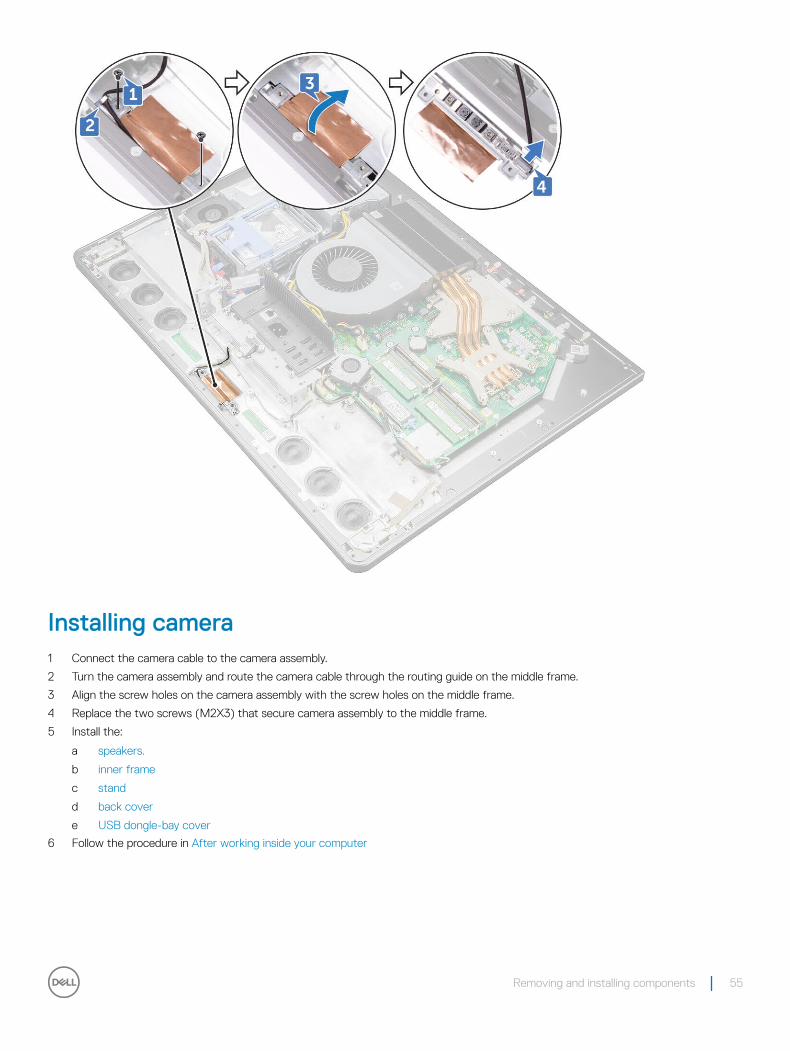
Installing camera1 Connect the camera cable to the camera assembly.
2 Turn the camera assembly and route the camera cable through the routing guide on the middle frame.
3 Align the screw holes on the camera assembly with the screw holes on the middle frame.
4 Replace the two screws (M2X3) that secure camera assembly to the middle frame.
5 Install the:
a speakers.
b inner frame
c stand
d back cover
e USB dongle-bay cover
6 Follow the procedure in After working inside your computer
Removing and installing components 55
System board
Removing system boardNOTE: To avoid any potential damage to the cables, ensure to release them from the routing guides.
1 Follow the procedure in Before working inside your computer.
2 Remove the:
a USB dongle-bay cover
b back cover
c memory modules
d stand
e system fan
f inner frame
g system-board shield.
h I/O panel
i processor heat-sink
j processor.
k coin-cell battery
l memory fan
m wireless card
n solid-state drive.
3 Using the pull tab, disconnect the display cable from the system board [3].
4 Disconnect the camera cable from the system board [2].
5 Using the pull tab, disconnect the USB-connection cable from the system board [3].
6 Disconnect the hard-drive power cable from the system board. [4]
7 Disconnect the hard-drive data cables from the system board [5].
56 Removing and installing components
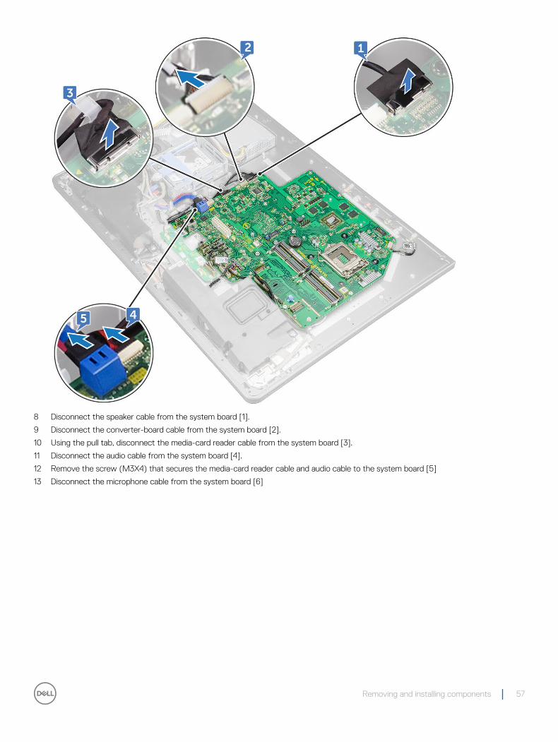
8 Disconnect the speaker cable from the system board [1].
9 Disconnect the converter-board cable from the system board [2].
10 Using the pull tab, disconnect the media-card reader cable from the system board [3].
11 Disconnect the audio cable from the system board [4].
12 Remove the screw (M3X4) that secures the media-card reader cable and audio cable to the system board [5]
13 Disconnect the microphone cable from the system board [6]
Removing and installing components 57
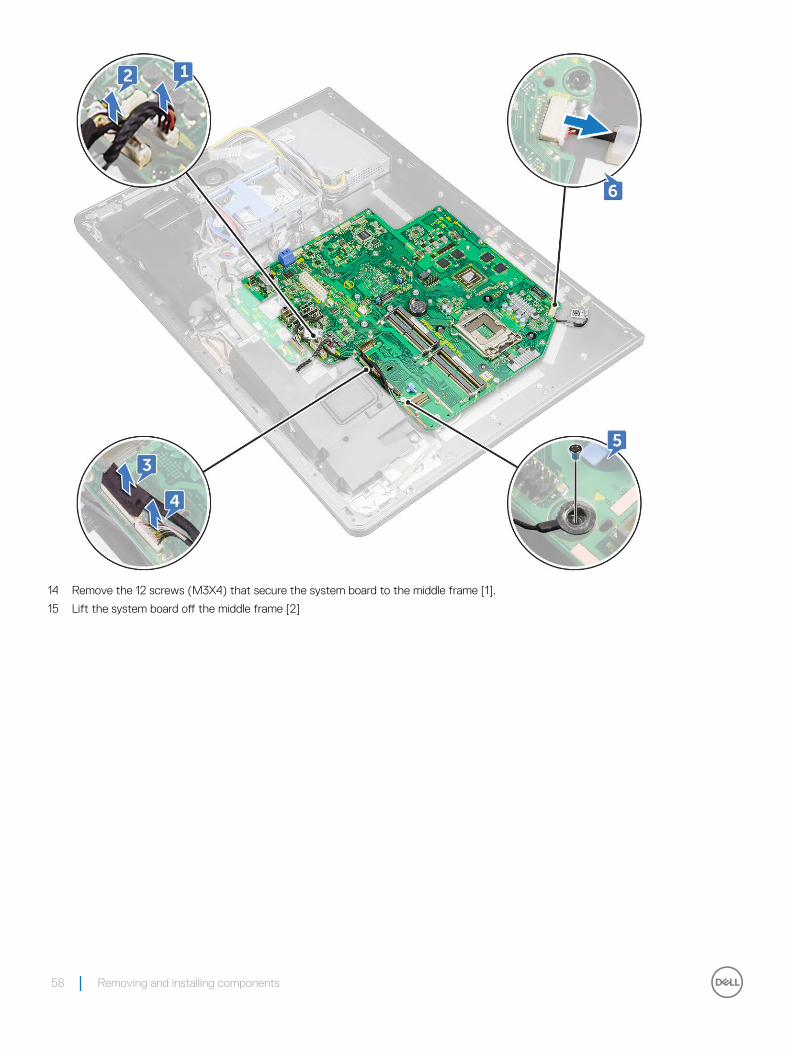
14 Remove the 12 screws (M3X4) that secure the system board to the middle frame [1].
15 Lift the system board off the middle frame [2]
58 Removing and installing components
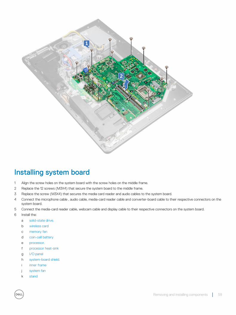
Installing system board1 Align the screw holes on the system board with the screw holes on the middle frame.
2 Replace the 12 screws (M3X4) that secure the system board to the middle frame.
3 Replace the screw (M3X4) that secures the media card reader and audio cables to the system board.
4 Connect the microphone cable , audio cable, media-card reader cable and converter-board cable to their respective connectors on the system board.
5 Connect the media-card reader cable, webcam cable and display cable to their respective connectors on the system board.
6 Install the:
a solid-state drive.
b wireless card
c memory fan
d coin-cell battery
e processor.
f processor heat-sink
g I/O panel
h system-board shield.
i inner frame
j system fan
k stand
Removing and installing components 59
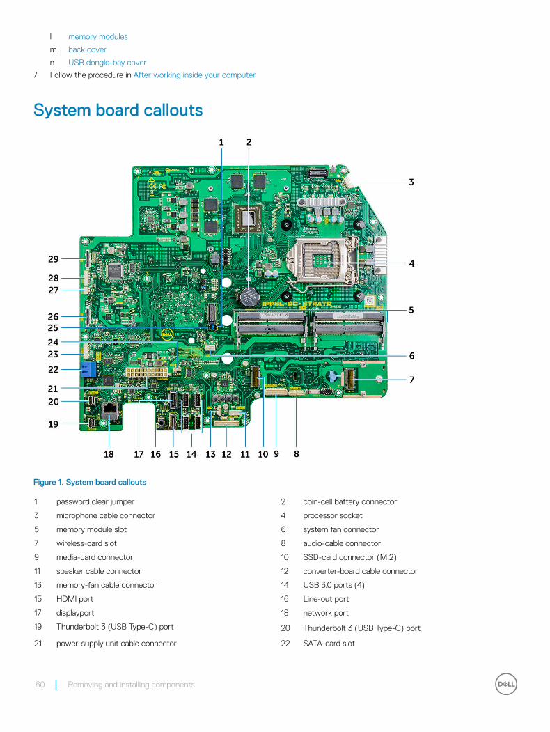
l memory modules
m back cover
n USB dongle-bay cover
7 Follow the procedure in After working inside your computer
System board callouts
Figure 1. System board callouts
1 password clear jumper 2 coin-cell battery connector
3 microphone cable connector 4 processor socket
5 memory module slot 6 system fan connector
7 wireless-card slot 8 audio-cable connector
9 media-card connector 10 SSD-card connector (M.2)
11 speaker cable connector 12 converter-board cable connector
13 memory-fan cable connector 14 USB 3.0 ports (4)
15 HDMI port 16 Line-out port
17 displayport 18 network port
19 Thunderbolt 3 (USB Type-C) port 20 Thunderbolt 3 (USB Type-C) port
21 power-supply unit cable connector 22 SATA-card slot
60 Removing and installing components
23 SATA power connector 24 USB connector
25 CMOS clear jumper 26 side USB connector
27 touch cable connector 28 camera connector
29 display connector
Display assembly
Removing display assembly1 Follow the procedure in Before working inside your computer.
2 Remove the:
a USB dongle-bay cover
b back cover
c memory modules
d stand
e system fan
f inner frame
g system-board shield
h I/O panel
i processor heat-sink
j processor
k coin-cell battery
l memory fan
m wireless card
n solid-state drive
o system board
3 Press the tabs on the cable to release it from the connector [1].
4 Disconnect the cable from its slot on the middle frame [2]
5 Press the tabs on the backlight cable [3].
6 Disconnect the backlight cable from its slot on the middle frame [4].
7 Open the latch and disconnect the display cable from its slot on the middle frame.
8 Lift the display cable off the middle frame.
Removing and installing components 61
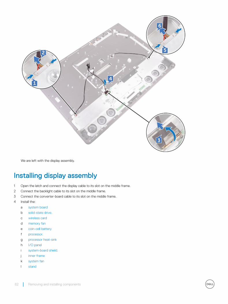
We are left with the display assembly.
Installing display assembly1 Open the latch and connect the display cable to its slot on the middle frame.
2 Connect the backlight cable to its slot on the middle frame.
3 Connect the converter-board cable to its slot on the middle frame.
4 Install the:
a system board
b solid-state drive.
c wireless card
d memory fan
e coin-cell battery
f processor.
g processor heat-sink
h I/O panel
i system-board shield.
j inner frame
k system fan
l stand
62 Removing and installing components
m memory modules
n back cover
o USB dongle-bay cover
5 Follow the procedure in After working inside your computer
Middle frame
Removing middle frameNOTE: The following steps are applicable only for non-touch systems.
NOTE: The middle frame can be removed by removing the following components only. In this scenario, the user has to remove 15 screws that secure the middle frame to the display panel and the speaker bezel, including one screw from the media-card reader and one screw from the power-button board.
1 USB dongle-bay cover
2 back cover
3 system-board shield
4 stand
5 inner frame
6 I/O panel
7 speakers
8 camera.
NOTE: The middle frame can also be removed by removing all the components given in the steps below. In this scenario, the user has to remove 13 screws that secure the middle frame to the display panel and speaker bezel
1 Follow the procedure in Before working inside your computer.
2 Remove the:
a USB dongle-bay cover
b back cover
c memory module
d hard drive
e stand
f system-board shield
g system fan
h wireless card.
i power-supply unit.
j memory fan
k inner frame
l microphones
m I/O panel
n processor heat-sink
o processor
p hard-drive cage.
q coin-cell battery
r solid-state drive
s converter board.
t speakers
u power-button board
Removing and installing components 63
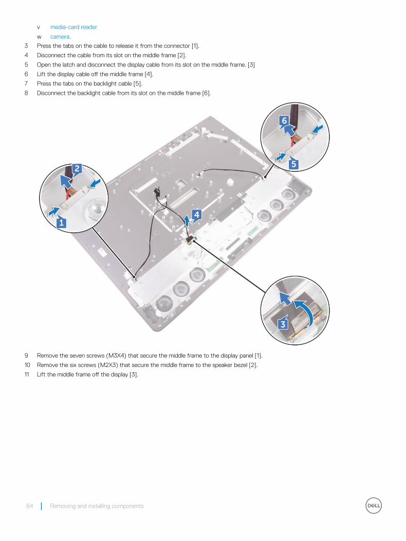
v media-card reader
w camera.
3 Press the tabs on the cable to release it from the connector [1].
4 Disconnect the cable from its slot on the middle frame [2].
5 Open the latch and disconnect the display cable from its slot on the middle frame. [3]
6 Lift the display cable off the middle frame [4].
7 Press the tabs on the backlight cable [5].
8 Disconnect the backlight cable from its slot on the middle frame [6].
9 Remove the seven screws (M3X4) that secure the middle frame to the display panel [1].
10 Remove the six screws (M2X3) that secure the middle frame to the speaker bezel [2].
11 Lift the middle frame off the display [3].
64 Removing and installing components
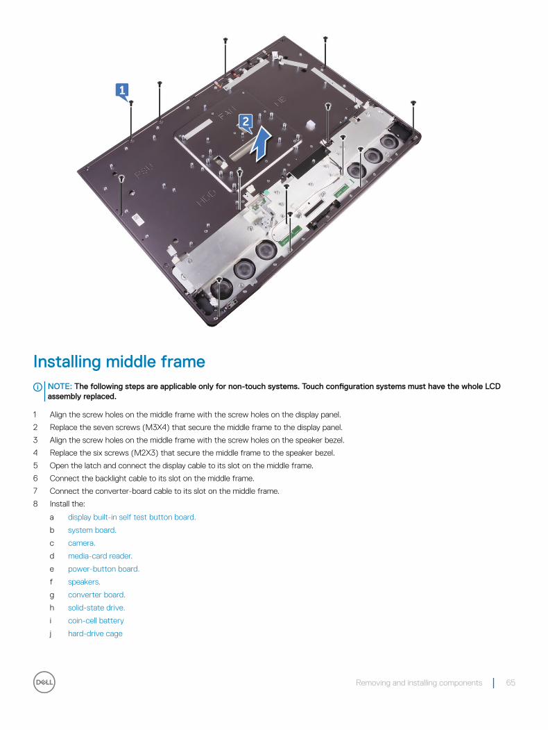
Installing middle frameNOTE: The following steps are applicable only for non-touch systems. Touch configuration systems must have the whole LCD assembly replaced.
1 Align the screw holes on the middle frame with the screw holes on the display panel.
2 Replace the seven screws (M3X4) that secure the middle frame to the display panel.
3 Align the screw holes on the middle frame with the screw holes on the speaker bezel.
4 Replace the six screws (M2X3) that secure the middle frame to the speaker bezel.
5 Open the latch and connect the display cable to its slot on the middle frame.
6 Connect the backlight cable to its slot on the middle frame.
7 Connect the converter-board cable to its slot on the middle frame.
8 Install the:
a display built-in self test button board.
b system board.
c camera.
d media-card reader.
e power-button board.
f speakers.
g converter board.
h solid-state drive.
i coin-cell battery
j hard-drive cage
Removing and installing components 65
k processor.
l processor heat-sink
m I/O panel
n microphones
o inner frame
p memory fan
q power-supply unit
r wireless card
s system-board shield.
t stand
u hard drive
v memory modules
w back cover
x USB dongle-bay cover
NOTE: The middle frame can be replaced by replacing the following components only. In this scenario, the user has to replace 13 screws securing the middle frame to the display panel.
a camera.
b speakers.
c I/O panel
d inner frame
e system-board shield.
f stand
g back cover
h USB dongle-bay cover
9 Follow the procedure in After working inside your computer
Speaker bezel
Removing speaker bezelNOTE: The following steps are applicable only for non-touch systems.
1 Follow the procedure in Before working inside your computer.
2 Remove the:
a USB dongle-bay coverb back coverc system-board shieldd stande inner framef I/O panelg speakersh camera.i middle frame
3 Lift the display panel.
4 Pull the speaker bezel away from the display panel.
66 Removing and installing components
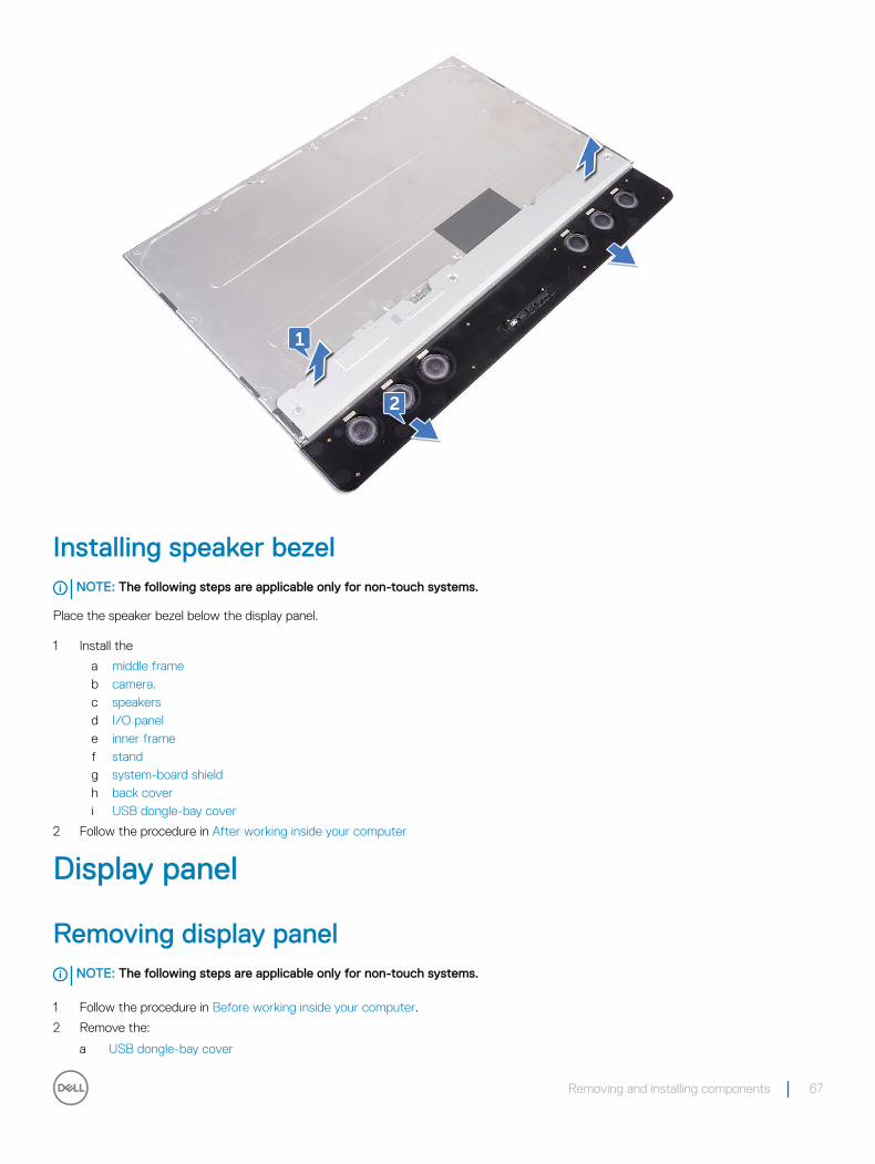
Installing speaker bezelNOTE: The following steps are applicable only for non-touch systems.
Place the speaker bezel below the display panel.
1 Install the
a middle frameb camera.c speakersd I/O panele inner framef standg system-board shieldh back coveri USB dongle-bay cover
2 Follow the procedure in After working inside your computer
Display panel
Removing display panelNOTE: The following steps are applicable only for non-touch systems.
1 Follow the procedure in Before working inside your computer.
2 Remove the:
a USB dongle-bay cover
Removing and installing components 67
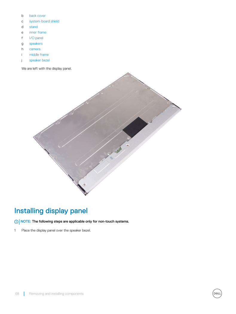
b back cover
c system-board shield
d stand
e inner frame
f I/O panel
g speakers
h camera.
i middle frame
j speaker bezel
We are left with the display panel.
Installing display panelNOTE: The following steps are applicable only for non-touch systems.
1 Place the display panel over the speaker bezel.
68 Removing and installing components
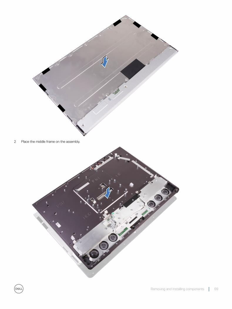
2 Place the middle frame on the assembly.
Removing and installing components 69
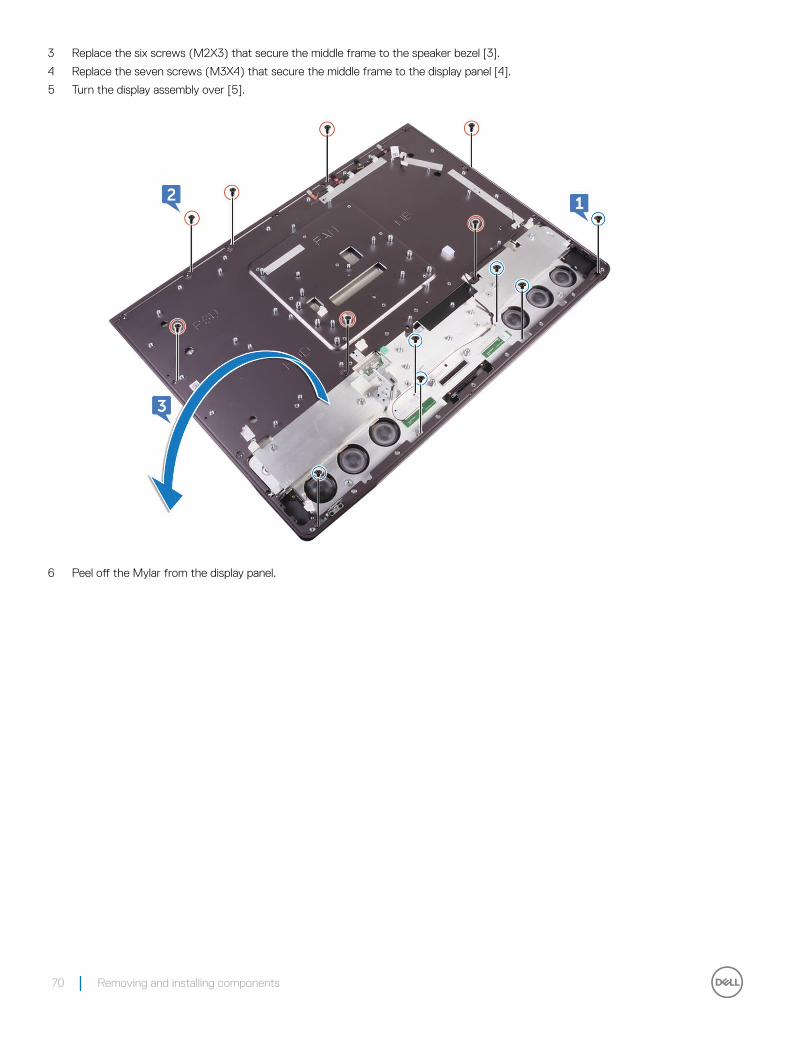
3 Replace the six screws (M2X3) that secure the middle frame to the speaker bezel [3].
4 Replace the seven screws (M3X4) that secure the middle frame to the display panel [4].
5 Turn the display assembly over [5].
6 Peel off the Mylar from the display panel.
70 Removing and installing components
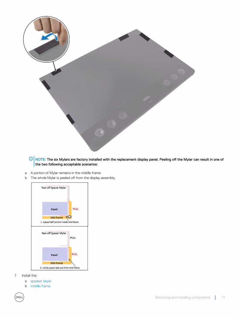
NOTE: The six Mylars are factory installed with the replacement display panel. Peeling off the Mylar can result in one of the two following acceptable scenarios:
a A portion of Mylar remains in the middle frame.b The whole Mylar is peeled off from the display assembly.
7 Install the:
a speaker bezelb middle frame
Removing and installing components 71

c camera.d speakerse I/O panelf inner frameg standh system-board shieldi back coverj USB dongle-bay cover
8 Follow the procedure in After working inside your computer
72 Removing and installing components
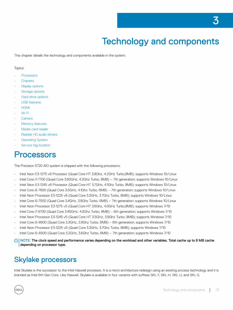
Technology and componentsThis chapter details the technology and components available in the system.
Topics:
• Processors
• Chipsets
• Display options
• Storage options
• Hard drive options
• USB features
• HDMI
• Wi-Fi
• Camera
• Memory features
• Media-card reader
• Realtek HD audio drivers
• Operating System
• Service tag location
ProcessorsThe Precision 5720 AIO system is shipped with the following processors:
• Intel Xeon E3-1275 v6 Processor (Quad Core HT 3.8Ghz, 4.2GHz Turbo,8MB); supports Windows 10/Linux
• Intel Core i7-7700 (Quad Core 3.60GHz, 4.2Ghz Turbo, 8MB) – 7th generation; supports Windows 10/Linux
• Intel Xeon E3-1245 v6 Processor (Quad Core HT 3.7GHz, 4.1Ghz Turbo, 8MB); supports Windows 10/Linux
• Intel Core i5-7600 (Quad Core 3.5GHz, 4.1Ghz Turbo, 6MB) – 7th generation; supports Windows 10/Linux
• Intel Xeon Processor E3-1225 v6 (Quad Core 3.3GHz, 3.7Ghz Turbo, 8MB); supports Windows 10/Linux
• Intel Core i5-7500 (Quad Core 3.4GHz, 3.8Ghz Turbo, 6MB) – 7th generation; supports Windows 10/Linux
• Intel Xeon Processor E3-1275 v5 (Quad Core HT 3.6Ghz, 4.0GHz Turbo,8MB); supports Windows 7/10
• Intel Core i7-6700 (Quad Core 3.40GHz, 4.0Ghz Turbo, 8MB) – 6th generation; supports Windows 7/10
• Intel Xeon Processor E3-1245 v5 (Quad Core HT 3.5GHz, 3.9Ghz Turbo, 8MB); supports Windows 7/10
• Intel Core i5-6600 (Quad Core 3.3GHz, 3.9Ghz Turbo, 6MB) – 6th generation; supports Windows 7/10
• Intel Xeon Processor E3-1225 v5 (Quad Core 3.3GHz, 3.7Ghz Turbo, 8MB); supports Windows 7/10
• Intel Core i5-6500 (Quad Core 3.2GHz, 3.6Ghz Turbo, 6MB) – 7th generation; supports Windows 7/10
NOTE: The clock speed and performance varies depending on the workload and other variables. Total cache up to 8 MB cache depending on processor type.
Skylake processorsIntel Skylake is the successor to the Intel Haswell processor. It is a micro architecture redesign using an existing process technology and it is branded as Intel 6th Gen Core. Like Haswell, Skylake is available in four variants with suffixes SKL-Y, SKL-H, SKL-U, and SKL-S.
3
Technology and components 73
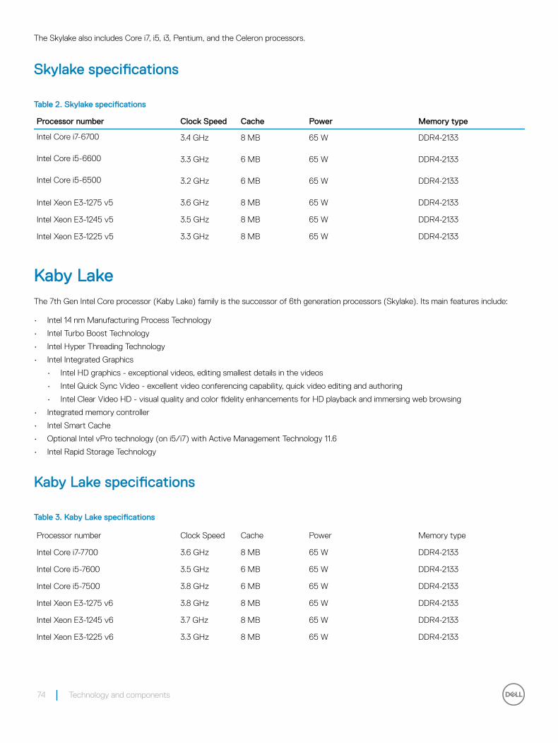
The Skylake also includes Core i7, i5, i3, Pentium, and the Celeron processors.
Skylake specifications
Table 2. Skylake specifications
Processor number Clock Speed Cache Power Memory type
Intel Core i7-6700 3.4 GHz 8 MB 65 W DDR4-2133
Intel Core i5-6600 3.3 GHz 6 MB 65 W DDR4-2133
Intel Core i5-6500 3.2 GHz 6 MB 65 W DDR4-2133
Intel Xeon E3-1275 v5 3.6 GHz 8 MB 65 W DDR4-2133
Intel Xeon E3-1245 v5 3.5 GHz 8 MB 65 W DDR4-2133
Intel Xeon E3-1225 v5 3.3 GHz 8 MB 65 W DDR4-2133
Kaby Lake The 7th Gen Intel Core processor (Kaby Lake) family is the successor of 6th generation processors (Skylake). Its main features include:
• Intel 14 nm Manufacturing Process Technology
• Intel Turbo Boost Technology
• Intel Hyper Threading Technology
• Intel Integrated Graphics
• Intel HD graphics - exceptional videos, editing smallest details in the videos
• Intel Quick Sync Video - excellent video conferencing capability, quick video editing and authoring
• Intel Clear Video HD - visual quality and color fidelity enhancements for HD playback and immersing web browsing
• Integrated memory controller
• Intel Smart Cache
• Optional Intel vPro technology (on i5/i7) with Active Management Technology 11.6
• Intel Rapid Storage Technology
Kaby Lake specifications
Table 3. Kaby Lake specifications
Processor number Clock Speed Cache Power Memory type
Intel Core i7-7700 3.6 GHz 8 MB 65 W DDR4-2133
Intel Core i5-7600 3.5 GHz 6 MB 65 W DDR4-2133
Intel Core i5-7500 3.8 GHz 6 MB 65 W DDR4-2133
Intel Xeon E3-1275 v6 3.8 GHz 8 MB 65 W DDR4-2133
Intel Xeon E3-1245 v6 3.7 GHz 8 MB 65 W DDR4-2133
Intel Xeon E3-1225 v6 3.3 GHz 8 MB 65 W DDR4-2133
74 Technology and components
Identifying processors in Windows 71 Click Start > Control Panel > Device Manager.
2 Expand Processors.
Identifying processors in Windows 101 Tap Search the Web and Windows.
2 Type Device Manager.
The Device Manager window is displayed.
3 Expand Processors.
Verifying the processor usage in Task Manager (Windows 7 and Windows 10) 1 Right click on the desktop.
2 Select Start Task Manager.
The Windows Task Manager window is displayed.
3 Click the Performance tab in the Windows Task Manager window.
Verifying the processor usage in Resource Monitor (Windows 7 and Windows 10) 1 Right click the desktop.
2 Select Start Task Manager.
The Windows Task Manager window is displayed.
3 Click the Performance tab in the Windows Task Manager window.
The processor performance details are displayed.
4 Click Open Resource Monitor.
ChipsetsAll Desktops communicate with the CPU through the chipset. This system is shipped with the Intel C236 series chipset.
Downloading the chipset driver1 Turn on the computer.
2 Go to Dell.com/support.
3 Click Product Support, enter the Service Tag of your computer, and then click Submit.
NOTE: If you do not have the Service Tag, use the autodetect feature or manually browse for your computer model.
4 Click Drivers and Downloads.
5 Click Find it myself tab.
6 Select the operating system installed in your computer.
Technology and components 75
7 Scroll down the page, expand Chipset, and select your chipset driver.
8 Click Download File to download the latest version of the chipset driver for your computer.
9 After the download is complete, navigate to the folder where you saved the driver file.
10 Double-click the chipset driver file icon and follow the instructions on the screen.
Identifying chipset in Device Manager on Windows 71 Click Start → Control Panel → Device Manager.
2 Expand System Devices and search for the chipset.
Identifying the chipset in Device Manager on Windows 10
1 Click inside the Cortana Search Box and type Control Panel and then click or press Enter on the keyboard, for the appropriate search result
2 From the Control Panel, select Device Manager.
3 Expand System Devices and search for the chipset.
Display options
Identifying the display adapters in Windows 71 Start the Search Charm and select Settings.
2 Type Device Manager in the search box, and tap Device Manager from the left pane.
3 Expand Display adapters.
Identifying the display adapters in Windows 10
1 Click All Settings on the Windows 10 Action bar.
2 Click Control Panel, select Device Manager , and expand Display adapters.
The installed adapters are listed under Display adapters.
Graphics optionsYour computer is shipped with one of the following Graphics chipsets depending on the configuration you order.
• Discrete graphics:
• AMD Radeon Pro WX 7100 with 8 GB GDDR5 dedicated memory
• AMD Radeon Pro WX 4150 with 4 GB GDDR5 dedicated memory
• Integrated graphics - Intel HD Graphics 530
Changing the screen resolution (Windows 7 and Windows 10)1 Right click on the desktop and select Display Settings.
2 Tap or click Advanced display settings.
76 Technology and components
3 Select the required resolution from the drop-down list and tap Apply.
Adjusting brightness in Windows 7To enable or disable automatic screen brightness adjustment:
1 Click Start → Control Panel → Display.
2 Use the Adjust brightness slider to enable or disable automatic-brightness adjustment.
NOTE: You can also use the Brightness level slider to adjust the brightness manually.
Adjusting brightness in Windows 10To enable or disable automatic screen brightness adjustment:
1 Click open Settings from Start menu on Windows 10.
2 Click System → Display.
3 Use the Adjust brightness level slider to enable or disable automatic-brightness adjustment.
Storage optionsThis computer supports up to two SSD/HDD and one M.2 PCIe SSD.
Hard drive optionsThis computer supports up to two HDD/SSD.
Identifying the hard drive in Windows 71 Click Start > Control Panel > Device Manager.
The hard drive is listed under Disk drives.
2 Expand Disk drives.
Identifying the hard drive in Windows 10
1 Click All Settings on the Windows 10 Charms Bar.
2 Click Control Panel, select Device Manager, and expand Disk drives.
The hard drive is listed under Disk drives.
Identifying the hard drive in BIOS setup program1 Turn on or restart your laptop.
2 When the Dell logo appears, perform one of the following actions to enter the BIOS setup program:
• With keyboard — Tap F2 until the Entering BIOS setup message appears. To enter the Boot selection menu, tap F12.
Hard drive is listed under the System Information under the General group.
Technology and components 77
USB featuresThe Universal Serial Bus, or well known as USB was introduced to the PC world in 1996 which dramatically simplified the connection between host computer and peripheral devices such as mice and keyboards, external hard drive or optical devices, Bluetooth and many more peripheral devices in the market.
Let's take a quick look on the USB evolution referencing to the table below.
Table 4. USB evolution
Type Data Transfer Rate Category Introduction Year
USB 3.0 5 Gbps Super Speed 2010
USB 2.0 480 Mbps High Speed 2000
USB 1.1 12 Mbps Full Speed 1998
USB 1.0 1.5 Mbps Low Speed 1996
USB 3.0 (SuperSpeed USB)For years, the USB 2.0 has been firmly entrenched as the de facto interface standard in the PC world with about 6 billion devices sold, and yet the need for more speed grows by ever faster computing hardware and ever greater bandwidth demands. The USB 3.0 finally has the answer to the consumers' demands with a theoretically 10 times faster than its predecessor. In a nutshell, USB 3.0 features are as follows:
• Higher transfer rates (up to 5 Gbps)
• Increased maximum bus power and increased device current draw to better accommodate power-hungry devices
• New power management features
• Full-duplex data transfers and support for new transfer types
• Backward USB 2.0 compatibility
• New connectors and cable
The topics below cover some of the most commonly asked questions regarding USB 3.0.
SpeedCurrently, there are 3 speed modes defined by the latest USB 3.0 specification. They are Super-Speed, Hi-Speed and Full-Speed. The new SuperSpeed mode has a transfer rate of 4.8Gbps. While the specification retains Hi-Speed, and Full-Speed USB mode, commonly known as USB 2.0 and 1.1 respectively, the slower modes still operate at 480Mbps and 12Mbps respectively and are kept to maintain backward compatibility.
USB 3.0 achieves the much higher performance by the technical changes below:
• An additional physical bus that is added in parallel with the existing USB 2.0 bus (refer to the picture below).
• USB 2.0 previously had four wires (power, ground, and a pair for differential data); USB 3.0 adds four more for two pairs of differential signals (receive and transmit) for a combined total of eight connections in the connectors and cabling.
78 Technology and components
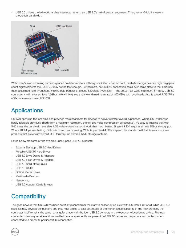
• USB 3.0 utilizes the bidirectional data interface, rather than USB 2.0's half-duplex arrangement. This gives a 10-fold increase in theoretical bandwidth.
With today's ever increasing demands placed on data transfers with high-definition video content, terabyte storage devices, high megapixel count digital cameras etc., USB 2.0 may not be fast enough. Furthermore, no USB 2.0 connection could ever come close to the 480Mbps theoretical maximum throughput, making data transfer at around 320Mbps (40MB/s) — the actual real-world maximum. Similarly, USB 3.0 connections will never achieve 4.8Gbps. We will likely see a real-world maximum rate of 400MB/s with overheads. At this speed, USB 3.0 is a 10x improvement over USB 2.0.
ApplicationsUSB 3.0 opens up the laneways and provides more headroom for devices to deliver a better overall experience. Where USB video was barely tolerable previously (both from a maximum resolution, latency, and video compression perspective), it's easy to imagine that with 5-10 times the bandwidth available, USB video solutions should work that much better. Single-link DVI requires almost 2Gbps throughput. Where 480Mbps was limiting, 5Gbps is more than promising. With its promised 4.8Gbps speed, the standard will find its way into some products that previously weren't USB territory, like external RAID storage systems.
Listed below are some of the available SuperSpeed USB 3.0 products:
• External Desktop USB 3.0 Hard Drives
• Portable USB 3.0 Hard Drives
• USB 3.0 Drive Docks & Adapters
• USB 3.0 Flash Drives & Readers
• USB 3.0 Solid-state Drives
• USB 3.0 RAIDs
• Optical Media Drives
• Multimedia Devices
• Networking
• USB 3.0 Adapter Cards & Hubs
CompatibilityThe good news is that USB 3.0 has been carefully planned from the start to peacefully co-exist with USB 2.0. First of all, while USB 3.0 specifies new physical connections and thus new cables to take advantage of the higher speed capability of the new protocol, the connector itself remains the same rectangular shape with the four USB 2.0 contacts in the exact same location as before. Five new connections to carry receive and transmitted data independently are present on USB 3.0 cables and only come into contact when connected to a proper SuperSpeed USB connection.
Technology and components 79
Windows 8/10 will be bringing native support for USB 3.0 controllers. This is in contrast to previous versions of Windows, which continue to require separate drivers for USB 3.0 controllers.
Microsoft announced that Windows 7 would have USB 3.0 support, perhaps not on its immediate release, but in a subsequent Service Pack or update. It is not out of the question to think that following a successful release of USB 3.0 support in Windows 7, SuperSpeed support would trickle down to Vista. Microsoft has confirmed this by stating that most of their partners share the opinion that Vista should also support USB 3.0.
Super-Speed support for Windows XP is unknown at this point. Given that XP is a seven-year-old operating system, the likelihood of this happening is remote.
Downloading the USB 3.0 driver1 Turn on your computer.
2 Go to Dell.com/support.
3 Click Product Support, enter the Service Tag of your computer and click Submit.
NOTE: If you do not have the Service Tag, use the auto-detect feature or manually browse for your computer model.
4 Click Drivers & downloads > Find it myself.
5 Scroll down the page and expand Chipset.
6 Click Download to download the USB 3.0 driver.
7 After the download is complete, navigate to the folder where you saved the USB 3.0 driver file.
8 Double-click the USB 3.0 driver file icon and follow the instructions on the screen.
HDMIThis computer supports HDMI to connect a TV or another HDMI-in enabled device. It provides video and audio output. The HDMI port is located on the back side of your computer.
NOTE: Appropriate converters (sold separately) are required to connect standard DVI and display port devices.
Connecting to external display devices1 Connect the HDMI cable to your computer and the external display device.
2 Push the on/off button on the right side of your computer to switch display modes.
Wi-FiThis computer is shipped with the following:
• Intel Dual Band Wireless-AC 8260 2x2 802.11AC+ Bluetooth 4.2 ready (Windows 10 supports up to 4.1)
• Intel Dual Band Wireless-AC 8260 2x2 802.11AC
• Qualcomm QCA61x4A 2x2 801.11ac + Bluetooth 4.1
Turning Wi-Fi on or offNOTE: There is no physical switch to enable or disable Wi-Fi. It has to be done through computer settings.
1 Swipe-in from the right edge of the display, or click the Action Center icon on the taskbar to access the Action Center.
2 Click Wi-Fi to turn Wi-Fi on or off.
80 Technology and components
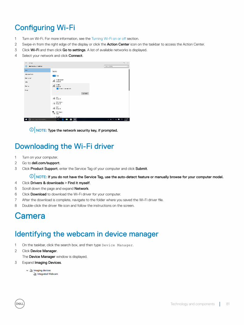
Configuring Wi-Fi1 Turn on Wi-Fi. For more information, see the Turning Wi-Fi on or off section.
2 Swipe-in from the right edge of the display or click the Action Center icon on the taskbar to access the Action Center.
3 Click Wi-Fi and then click Go to settings. A list of available networks is displayed.
4 Select your network and click Connect.
NOTE: Type the network security key, if prompted.
Downloading the Wi-Fi driver1 Turn on your computer.
2 Go to dell.com/support.
3 Click Product Support, enter the Service Tag of your computer and click Submit.
NOTE: If you do not have the Service Tag, use the auto-detect feature or manually browse for your computer model.
4 Click Drivers & downloads > Find it myself.
5 Scroll down the page and expand Network.
6 Click Download to download the Wi-Fi driver for your computer.
7 After the download is complete, navigate to the folder where you saved the Wi-Fi driver file.
8 Double-click the driver file icon and follow the instructions on the screen.
Camera
Identifying the webcam in device manager1 On the taskbar, click the search box, and then type Device Manager.
2 Click Device Manager.
The Device Manager window is displayed.
3 Expand Imaging Devices.
Technology and components 81
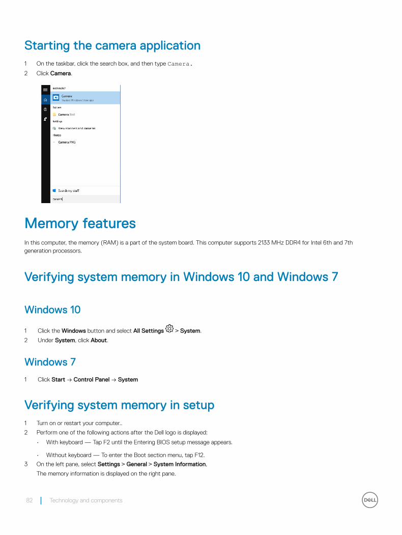
Starting the camera application1 On the taskbar, click the search box, and then type Camera.2 Click Camera.
Memory featuresIn this computer, the memory (RAM) is a part of the system board. This computer supports 2133 MHz DDR4 for Intel 6th and 7th generation processors.
Verifying system memory in Windows 10 and Windows 7
Windows 10
1 Click the Windows button and select All Settings > System.
2 Under System, click About.
Windows 7
1 Click Start → Control Panel → System
Verifying system memory in setup1 Turn on or restart your computer..
2 Perform one of the following actions after the Dell logo is displayed:
• With keyboard — Tap F2 until the Entering BIOS setup message appears.
• Without keyboard — To enter the Boot section menu, tap F12.
3 On the left pane, select Settings > General > System Information,
The memory information is displayed on the right pane.
82 Technology and components
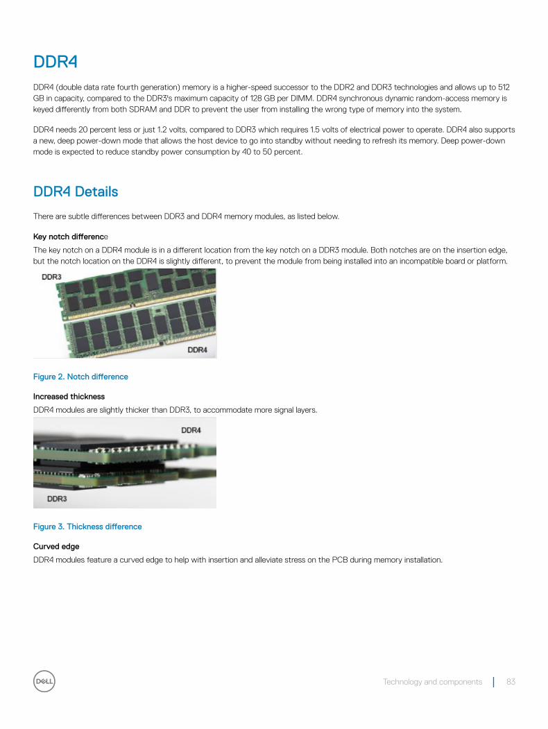
DDR4DDR4 (double data rate fourth generation) memory is a higher-speed successor to the DDR2 and DDR3 technologies and allows up to 512 GB in capacity, compared to the DDR3's maximum capacity of 128 GB per DIMM. DDR4 synchronous dynamic random-access memory is keyed differently from both SDRAM and DDR to prevent the user from installing the wrong type of memory into the system.
DDR4 needs 20 percent less or just 1.2 volts, compared to DDR3 which requires 1.5 volts of electrical power to operate. DDR4 also supports a new, deep power-down mode that allows the host device to go into standby without needing to refresh its memory. Deep power-down mode is expected to reduce standby power consumption by 40 to 50 percent.
DDR4 Details
There are subtle differences between DDR3 and DDR4 memory modules, as listed below.
Key notch difference
The key notch on a DDR4 module is in a different location from the key notch on a DDR3 module. Both notches are on the insertion edge, but the notch location on the DDR4 is slightly different, to prevent the module from being installed into an incompatible board or platform.
Figure 2. Notch difference
Increased thickness
DDR4 modules are slightly thicker than DDR3, to accommodate more signal layers.
Figure 3. Thickness difference
Curved edge
DDR4 modules feature a curved edge to help with insertion and alleviate stress on the PCB during memory installation.
Technology and components 83
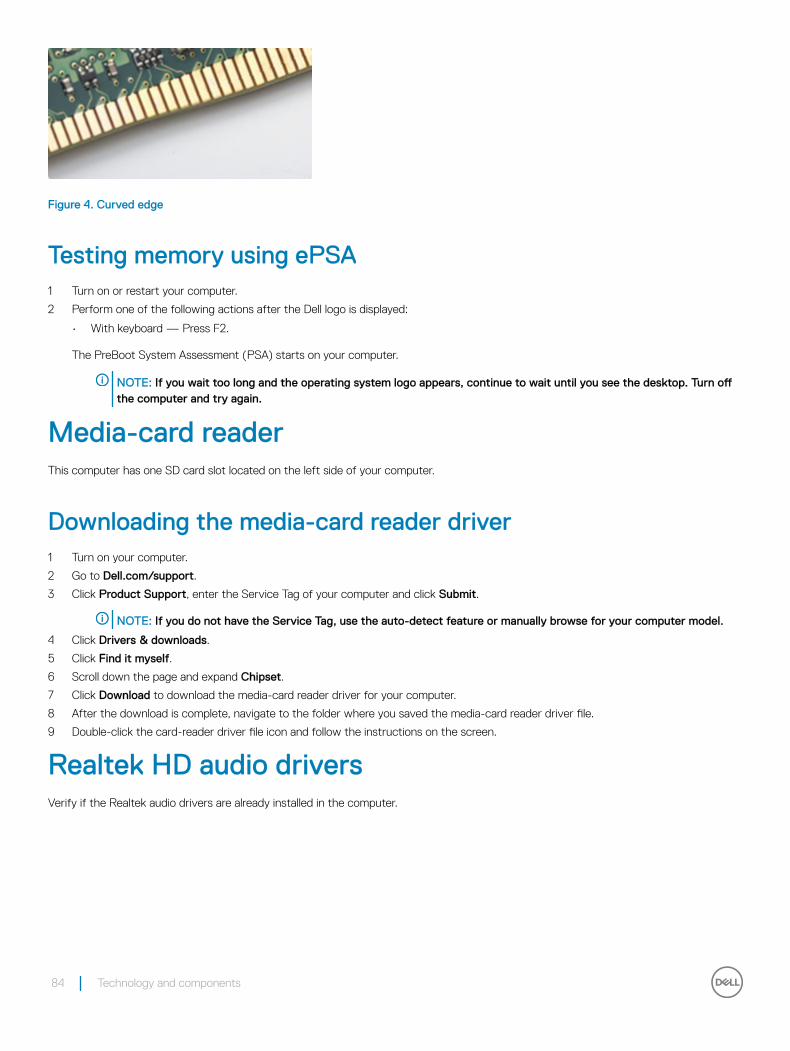
Figure 4. Curved edge
Testing memory using ePSA1 Turn on or restart your computer.
2 Perform one of the following actions after the Dell logo is displayed:
• With keyboard — Press F2.
The PreBoot System Assessment (PSA) starts on your computer.
NOTE: If you wait too long and the operating system logo appears, continue to wait until you see the desktop. Turn off the computer and try again.
Media-card readerThis computer has one SD card slot located on the left side of your computer.
Downloading the media-card reader driver1 Turn on your computer.
2 Go to Dell.com/support.
3 Click Product Support, enter the Service Tag of your computer and click Submit.
NOTE: If you do not have the Service Tag, use the auto-detect feature or manually browse for your computer model.
4 Click Drivers & downloads.
5 Click Find it myself.
6 Scroll down the page and expand Chipset.
7 Click Download to download the media-card reader driver for your computer.
8 After the download is complete, navigate to the folder where you saved the media-card reader driver file.
9 Double-click the card-reader driver file icon and follow the instructions on the screen.
Realtek HD audio driversVerify if the Realtek audio drivers are already installed in the computer.
84 Technology and components
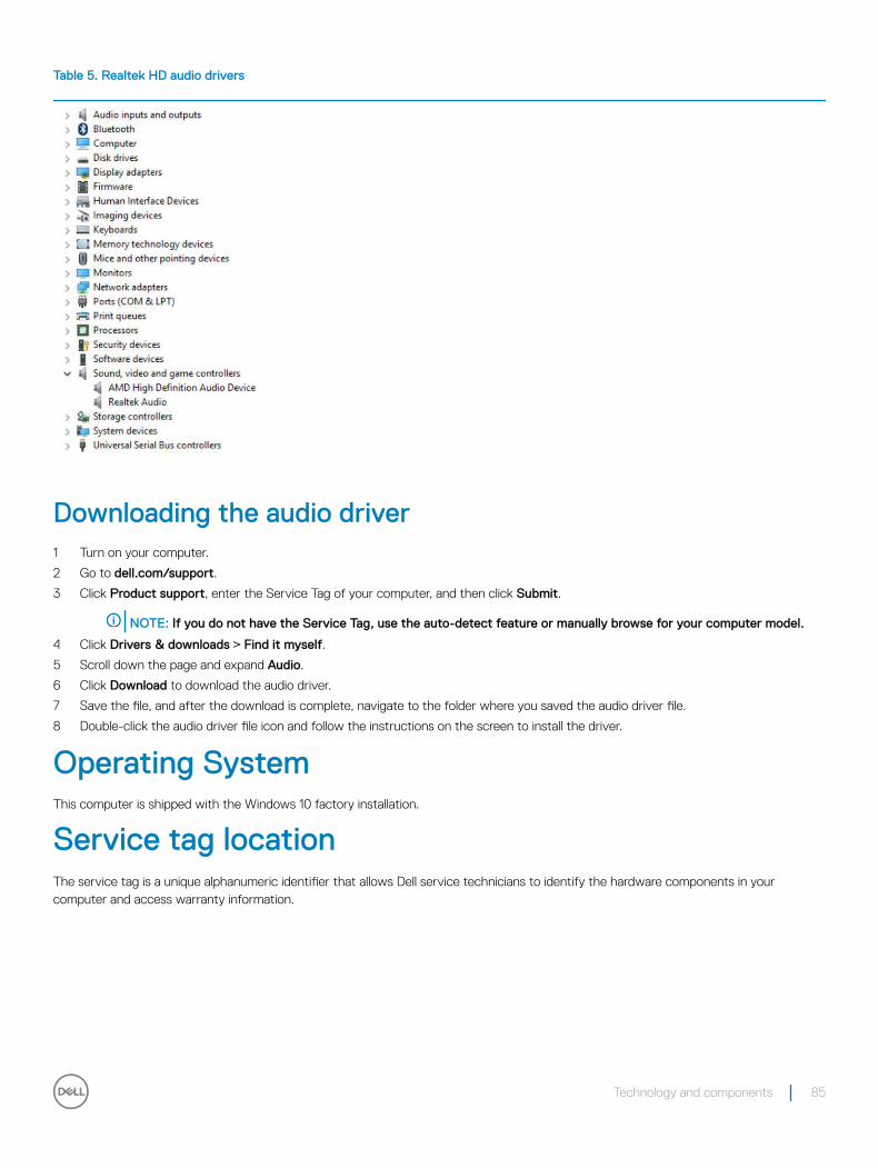
Table 5. Realtek HD audio drivers
Downloading the audio driver1 Turn on your computer.
2 Go to dell.com/support.
3 Click Product support, enter the Service Tag of your computer, and then click Submit.
NOTE: If you do not have the Service Tag, use the auto-detect feature or manually browse for your computer model.
4 Click Drivers & downloads > Find it myself.
5 Scroll down the page and expand Audio.
6 Click Download to download the audio driver.
7 Save the file, and after the download is complete, navigate to the folder where you saved the audio driver file.
8 Double-click the audio driver file icon and follow the instructions on the screen to install the driver.
Operating SystemThis computer is shipped with the Windows 10 factory installation.
Service tag locationThe service tag is a unique alphanumeric identifier that allows Dell service technicians to identify the hardware components in your computer and access warranty information.
Technology and components 85
86 Technology and components
System setupSystem Setup enables you to manage your desktop hardware and specify BIOS level options. From the System Setup, you can:
• Change the NVRAM settings after you add or remove hardware
• View the system hardware configuration
• Enable or disable integrated devices
• Set performance and power management thresholds
• Manage your computer security
Topics:
• BIOS Overview
• System setup options
BIOS Overview
Boot menu
Press <F12> when the Dell™ logo appears to initiate a one-time boot menu with a list of the valid boot devices for the system. Diagnostics and BIOS Setup options are also included in this menu. The devices listed on the boot menu depend on the bootable devices in the system. This menu is useful when you are attempting to boot to a particular device or to bring up the diagnostics for the system. Using the boot menu does not make any changes to the boot order stored in the BIOS.
The options are:
• Legacy Boot:
• Internal HDD
• Onboard NIC
• UEFI Boot:
• Windows Boot Manager
• Other Options:
• BIOS Setup
• BIOS Flash Update
• Diagnostics
• Change Boot Mode Settings
Navigation KeysThe following table displays the system setup navigation keys.
NOTE: For most of the system setup options, changes that you make are recorded but do not take effect until you re-start the system.
4
System setup 87
Table 6. Navigation Keys
Keys Navigation
Up arrow Moves to the previous field.
Down arrow Moves to the next field.
<Enter> Allows you to select a value in the selected field (if applicable) or follow the link in the field.
Spacebar Expands or collapses a drop‐down list, if applicable.
<Tab> Moves to the next focus area.
NOTE: For the standard graphics browser only.
<Esc> Moves to the previous page till you view the main screen. Pressing <Esc> in the main screen displays a message that prompts you to save any unsaved changes and restarts the system.
<F1> Displays the System Setup help file.
Updating the BIOS in Windows It is recommended to update your BIOS (System Setup), on replacing the system board or if an update is available. For laptops, ensure that your computer battery is fully charged and connected to a power outlet
NOTE: If BitLocker is enabled, it must be suspended prior to updating the system BIOS, and then re-enabled after the BIOS update is completed.
1 Restart the computer.
2 Go to Dell.com/support.
• Enter the Service Tag or Express Service Code and click Submit.
• ClickDetect Product and follow the instructions on screen,
3 If you are unable to detect or find the Service Tag, click the Choose from all products.
4 Choose the Products category from the list.
NOTE: Choose the appropriate category to reach the product page
5 Select your computer model and the Product Support page of your computer appears.
6 Click Get drivers and click Drivers and Downloads.
The Drivers and Downloads section opens.
7 Click Find it myself.
8 Click BIOS to view the BIOS versions.
9 Identify the latest BIOS file and click Download.
10 Select your preferred download method in the Please select your download method below window, click Download File.
The File Download window appears.
11 Click Save to save the file on your computer.
12 Click Run to install the updated BIOS settings on your computer.
Follow the instructions on the screen.
NOTE: It is recommended not to update the BIOS version for more than 3 revisions. For example: If you want to update the BIOS from 1.0 to 7.0, then install version 4.0 first and then install version 7.0.
System setup optionsNOTE: Depending on the computer and its installed devices, the items listed in this section may or may not appear.
88 System setup
Table 7. General
Option Description
System Information Displays the following information:
• System Information: Displays BIOS Version, Service Tag, Asset Tag, Ownership Tag, Ownership Date, Manufacture Date, and the Express Service Code.
• Memory Information: Displays Memory Installed, Memory Available, Memory Speed, Memory Channel Mode, Memory Technology, DIMM 1 Size, DIMM 2 Size, DIMM 3 Size, and DIMM 4 Size.
• PCI Information: Displays SLOT1 and SLOT2_M.2.
• Processor Information: Displays Processor Type, Core Count, Processor ID, Current Clock Speed, Minimum Clock Speed, Maximum Clock Speed, Processor L2 Cache, Processor L3 Cache, HT Capable, and 64-Bit Technology.
• Device Information: Displays SATA-0, SATA-1, SATA-4, M.2 PCIe SSD-0, LOM MAC Address, Video Controller, dGPU video controller, Video BIOS version, Video memory, panel type, Native resolution, Wi-Fi Device, Bluetooth Device, and Audio Controller. .
Boot Sequence Allows you to specify the order in which the computer attempts to find an operating system from the devices specified in this list.
• Legacy
• UEFI (default)
Advanced Boot Options Allows you to select the Enable Legacy Option ROMs option, when in UEFI boot mode.
Allows you to select the Enable Attempt Legacy Boot option.
Date/Time Allows you to set the date and time settings. Changes to the system date and time take effect immediately.
Table 8. System Configuration
Option Description
Integrated NIC Allows you to control the on-board LAN controller. The option ‘Enable UEFI Network Stack’ is not selected by default. The options are:
• Disabled
• Enabled
• Enabled w/PXE (default)
NOTE: Depending on the computer and its installed devices, the items listed in this section may or may not appear.
SATA Operation Allows you to configure the operating mode of the integrated hard drive controller.
• Disabled = The SATA controllers are hidden
• RAID ON = SATA is configured to support RAID mode (selected by default)
• AHCI= SATA is configured for AHCI mode
Drives Allows you to enable or disable the various drives on-board:
• SATA-0
• SATA-1
• SATA-4
• M.2 PCIE SSD-0
Smart Reporting This field controls whether hard drive errors for integrated drives are reported during system startup. The Enable Smart Reporting option is disabled by default.
USB Configuration Allows you to enable or disable the integrated USB controller for:
System setup 89
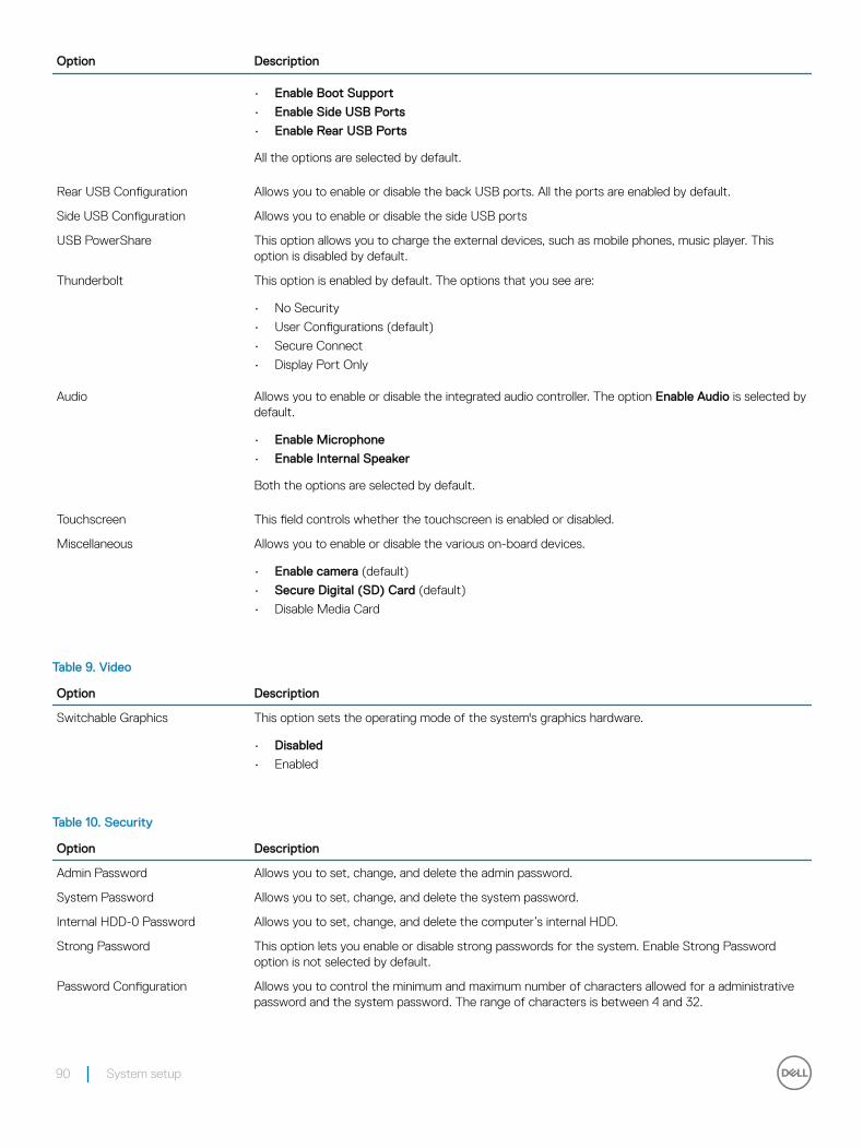
Option Description
• Enable Boot Support
• Enable Side USB Ports
• Enable Rear USB Ports
All the options are selected by default.
Rear USB Configuration Allows you to enable or disable the back USB ports. All the ports are enabled by default.
Side USB Configuration Allows you to enable or disable the side USB ports
USB PowerShare This option allows you to charge the external devices, such as mobile phones, music player. This option is disabled by default.
Thunderbolt This option is enabled by default. The options that you see are:
• No Security
• User Configurations (default)
• Secure Connect
• Display Port Only
Audio Allows you to enable or disable the integrated audio controller. The option Enable Audio is selected by default.
• Enable Microphone
• Enable Internal Speaker
Both the options are selected by default.
Touchscreen This field controls whether the touchscreen is enabled or disabled.
Miscellaneous Allows you to enable or disable the various on-board devices.
• Enable camera (default)
• Secure Digital (SD) Card (default)
• Disable Media Card
Table 9. Video
Option Description
Switchable Graphics This option sets the operating mode of the system's graphics hardware.
• Disabled
• Enabled
Table 10. Security
Option Description
Admin Password Allows you to set, change, and delete the admin password.
System Password Allows you to set, change, and delete the system password.
Internal HDD-0 Password Allows you to set, change, and delete the computer’s internal HDD.
Strong Password This option lets you enable or disable strong passwords for the system. Enable Strong Password option is not selected by default.
Password Configuration Allows you to control the minimum and maximum number of characters allowed for a administrative password and the system password. The range of characters is between 4 and 32.
90 System setup
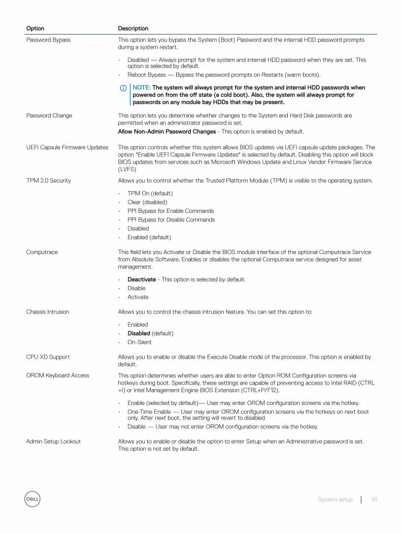
Option Description
Password Bypass This option lets you bypass the System (Boot) Password and the internal HDD password prompts during a system restart.
• Disabled — Always prompt for the system and internal HDD password when they are set. This option is selected by default.
• Reboot Bypass — Bypass the password prompts on Restarts (warm boots).
NOTE: The system will always prompt for the system and internal HDD passwords when powered on from the off state (a cold boot). Also, the system will always prompt for passwords on any module bay HDDs that may be present.
Password Change This option lets you determine whether changes to the System and Hard Disk passwords are permitted when an administrator password is set.
Allow Non-Admin Password Changes - This option is enabled by default.
UEFI Capsule Firmware Updates This option controls whether this system allows BIOS updates via UEFI capsule update packages. The option "Enable UEFI Capsule Firmware Updates" is selected by default. Disabling this option will block BIOS updates from services such as Microsoft Windows Update and Linux Vendor Firmware Service (LVFS)
TPM 2.0 Security Allows you to control whether the Trusted Platform Module (TPM) is visible to the operating system.
• TPM On (default)
• Clear (disabled)
• PPI Bypass for Enable Commands
• PPI Bypass for Disable Commands
• Disabled
• Enabled (default)
Computrace This field lets you Activate or Disable the BIOS module interface of the optional Computrace Service from Absolute Software. Enables or disables the optional Computrace service designed for asset management.
• Deactivate - This option is selected by default.
• Disable
• Activate
Chassis Intrusion Allows you to control the chassis intrusion feature. You can set this option to:
• Enabled
• Disabled (default)
• On-Silent
CPU XD Support Allows you to enable or disable the Execute Disable mode of the processor. This option is enabled by default.
OROM Keyboard Access This option determines whether users are able to enter Option ROM Configuration screens via hotkeys during boot. Specifically, these settings are capable of preventing access to Intel RAID (CTRL+I) or Intel Management Engine BIOS Extension (CTRL+P/F12).
• Enable (selected by default)— User may enter OROM configuration screens via the hotkey.
• One-Time Enable — User may enter OROM configuration screens via the hotkeys on next boot only. After next boot, the setting will revert to disabled.
• Disable — User may not enter OROM configuration screens via the hotkey.
Admin Setup Lockout Allows you to enable or disable the option to enter Setup when an Administrative password is set. This option is not set by default.
System setup 91
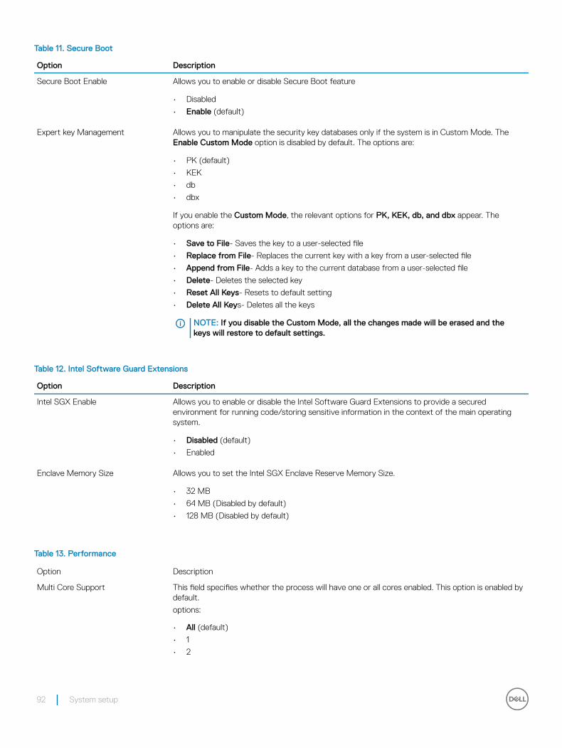
Table 11. Secure Boot
Option Description
Secure Boot Enable Allows you to enable or disable Secure Boot feature
• Disabled
• Enable (default)
Expert key Management Allows you to manipulate the security key databases only if the system is in Custom Mode. The Enable Custom Mode option is disabled by default. The options are:
• PK (default)
• KEK
• db
• dbx
If you enable the Custom Mode, the relevant options for PK, KEK, db, and dbx appear. The options are:
• Save to File- Saves the key to a user-selected file
• Replace from File- Replaces the current key with a key from a user-selected file
• Append from File- Adds a key to the current database from a user-selected file
• Delete- Deletes the selected key
• Reset All Keys- Resets to default setting
• Delete All Keys- Deletes all the keys
NOTE: If you disable the Custom Mode, all the changes made will be erased and the keys will restore to default settings.
Table 12. Intel Software Guard Extensions
Option Description
Intel SGX Enable Allows you to enable or disable the Intel Software Guard Extensions to provide a secured environment for running code/storing sensitive information in the context of the main operating system.
• Disabled (default)
• Enabled
Enclave Memory Size Allows you to set the Intel SGX Enclave Reserve Memory Size.
• 32 MB
• 64 MB (Disabled by default)
• 128 MB (Disabled by default)
Table 13. Performance
Option Description
Multi Core Support This field specifies whether the process will have one or all cores enabled. This option is enabled by default.
options:
• All (default)
• 1
• 2
92 System setup
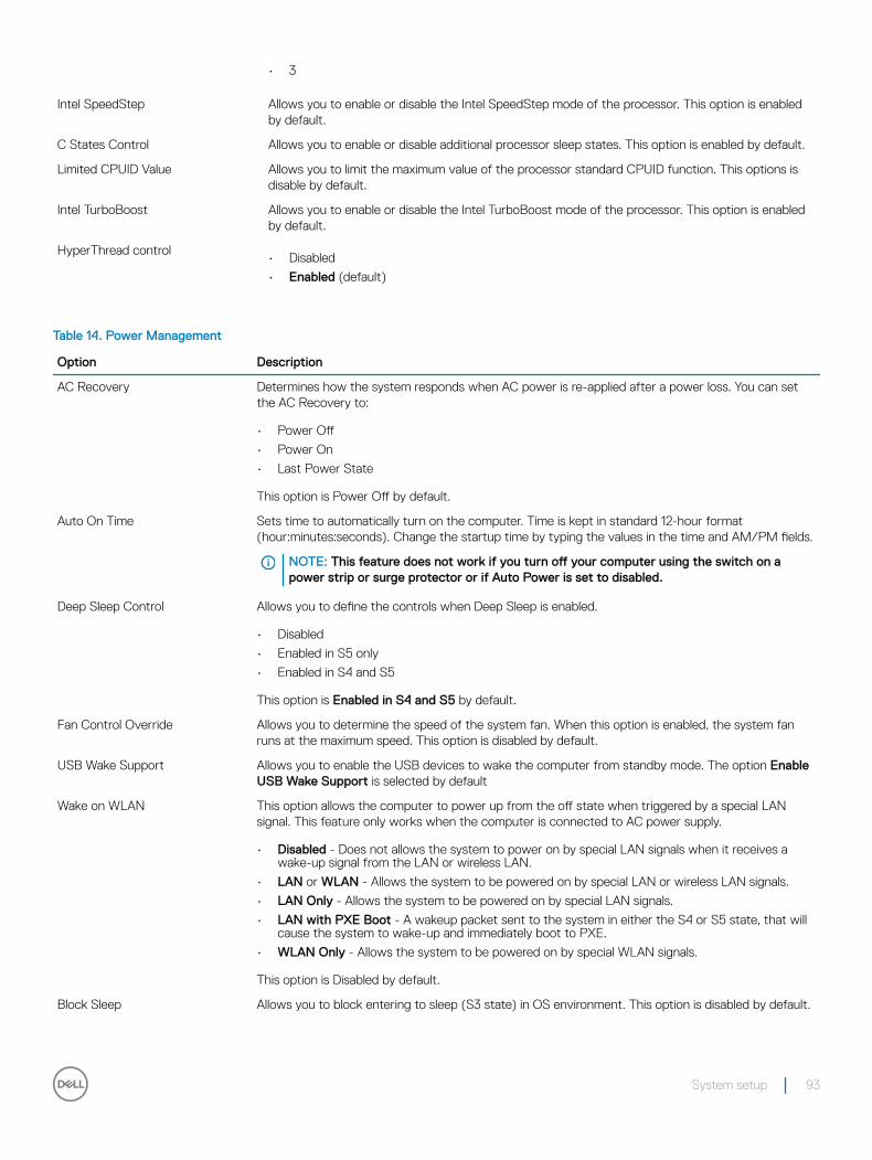
• 3
Intel SpeedStep Allows you to enable or disable the Intel SpeedStep mode of the processor. This option is enabled by default.
C States Control Allows you to enable or disable additional processor sleep states. This option is enabled by default.
Limited CPUID Value Allows you to limit the maximum value of the processor standard CPUID function. This options is disable by default.
Intel TurboBoost Allows you to enable or disable the Intel TurboBoost mode of the processor. This option is enabled by default.
HyperThread control• Disabled
• Enabled (default)
Table 14. Power Management
Option Description
AC Recovery Determines how the system responds when AC power is re-applied after a power loss. You can set the AC Recovery to:
• Power Off
• Power On
• Last Power State
This option is Power Off by default.
Auto On Time Sets time to automatically turn on the computer. Time is kept in standard 12-hour format (hour:minutes:seconds). Change the startup time by typing the values in the time and AM/PM fields.
NOTE: This feature does not work if you turn off your computer using the switch on a power strip or surge protector or if Auto Power is set to disabled.
Deep Sleep Control Allows you to define the controls when Deep Sleep is enabled.
• Disabled
• Enabled in S5 only
• Enabled in S4 and S5
This option is Enabled in S4 and S5 by default.
Fan Control Override Allows you to determine the speed of the system fan. When this option is enabled, the system fan runs at the maximum speed. This option is disabled by default.
USB Wake Support Allows you to enable the USB devices to wake the computer from standby mode. The option Enable USB Wake Support is selected by default
Wake on WLAN This option allows the computer to power up from the off state when triggered by a special LAN signal. This feature only works when the computer is connected to AC power supply.
• Disabled - Does not allows the system to power on by special LAN signals when it receives a wake-up signal from the LAN or wireless LAN.
• LAN or WLAN - Allows the system to be powered on by special LAN or wireless LAN signals.
• LAN Only - Allows the system to be powered on by special LAN signals.
• LAN with PXE Boot - A wakeup packet sent to the system in either the S4 or S5 state, that will cause the system to wake-up and immediately boot to PXE.
• WLAN Only - Allows the system to be powered on by special WLAN signals.
This option is Disabled by default.
Block Sleep Allows you to block entering to sleep (S3 state) in OS environment. This option is disabled by default.
System setup 93
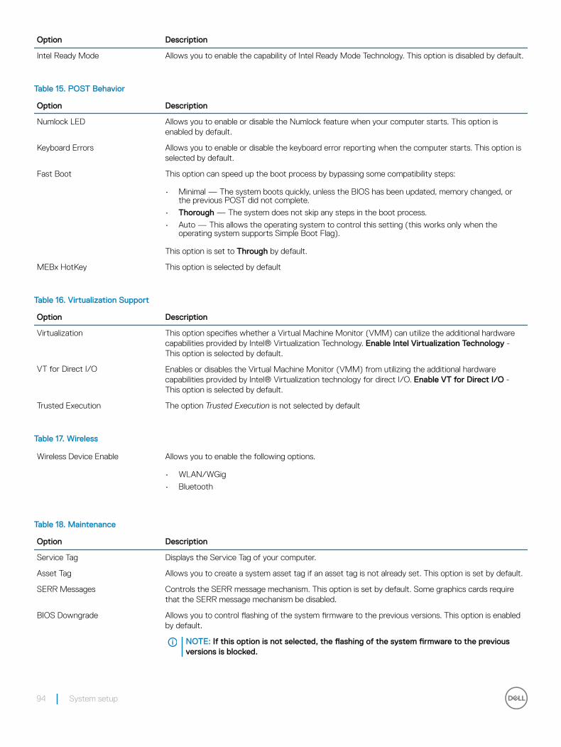
Option Description
Intel Ready Mode Allows you to enable the capability of Intel Ready Mode Technology. This option is disabled by default.
Table 15. POST Behavior
Option Description
Numlock LED Allows you to enable or disable the Numlock feature when your computer starts. This option is enabled by default.
Keyboard Errors Allows you to enable or disable the keyboard error reporting when the computer starts. This option is selected by default.
Fast Boot This option can speed up the boot process by bypassing some compatibility steps:
• Minimal — The system boots quickly, unless the BIOS has been updated, memory changed, or the previous POST did not complete.
• Thorough — The system does not skip any steps in the boot process.
• Auto — This allows the operating system to control this setting (this works only when the operating system supports Simple Boot Flag).
This option is set to Through by default.
MEBx HotKey This option is selected by default
Table 16. Virtualization Support
Option Description
Virtualization This option specifies whether a Virtual Machine Monitor (VMM) can utilize the additional hardware capabilities provided by Intel® Virtualization Technology. Enable Intel Virtualization Technology - This option is selected by default.
VT for Direct I/O Enables or disables the Virtual Machine Monitor (VMM) from utilizing the additional hardware capabilities provided by Intel® Virtualization technology for direct I/O. Enable VT for Direct I/O - This option is selected by default.
Trusted Execution The option Trusted Execution is not selected by default
Table 17. Wireless
Wireless Device Enable Allows you to enable the following options.
• WLAN/WGig
• Bluetooth
Table 18. Maintenance
Option Description
Service Tag Displays the Service Tag of your computer.
Asset Tag Allows you to create a system asset tag if an asset tag is not already set. This option is set by default.
SERR Messages Controls the SERR message mechanism. This option is set by default. Some graphics cards require that the SERR message mechanism be disabled.
BIOS Downgrade Allows you to control flashing of the system firmware to the previous versions. This option is enabled by default.
NOTE: If this option is not selected, the flashing of the system firmware to the previous versions is blocked.
94 System setup
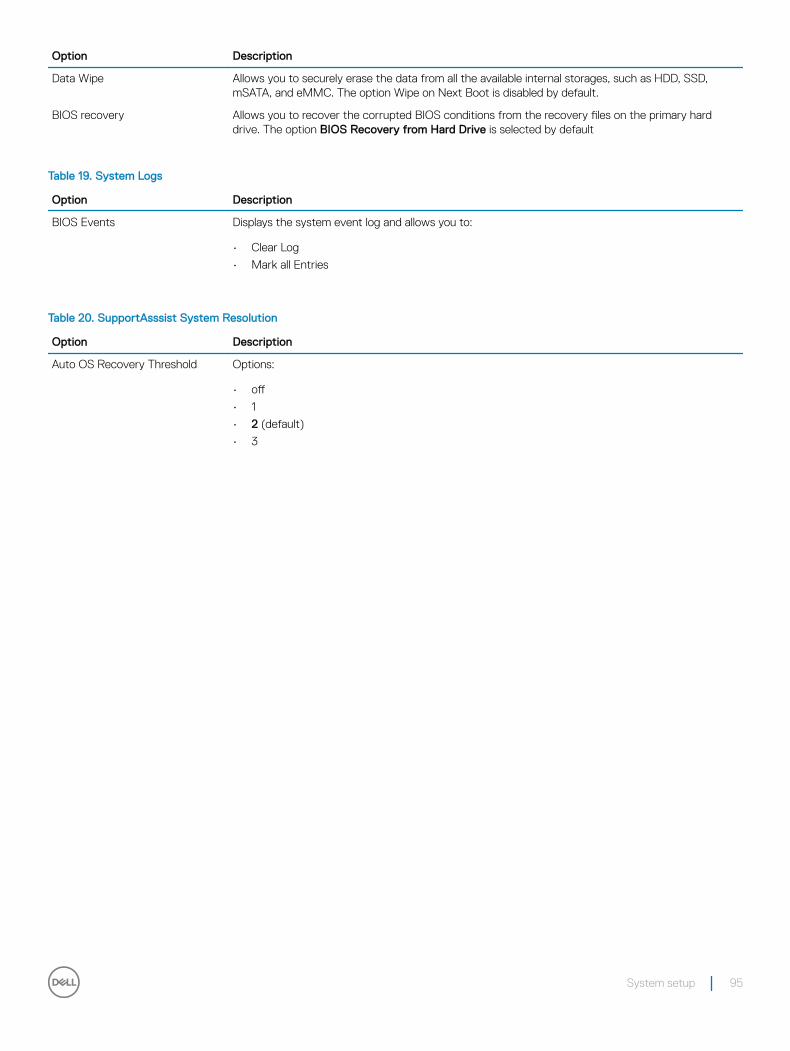
Option Description
Data Wipe Allows you to securely erase the data from all the available internal storages, such as HDD, SSD, mSATA, and eMMC. The option Wipe on Next Boot is disabled by default.
BIOS recovery Allows you to recover the corrupted BIOS conditions from the recovery files on the primary hard drive. The option BIOS Recovery from Hard Drive is selected by default
Table 19. System Logs
Option Description
BIOS Events Displays the system event log and allows you to:
• Clear Log
• Mark all Entries
Table 20. SupportAsssist System Resolution
Option Description
Auto OS Recovery Threshold Options:
• off
• 1
• 2 (default)
• 3
System setup 95
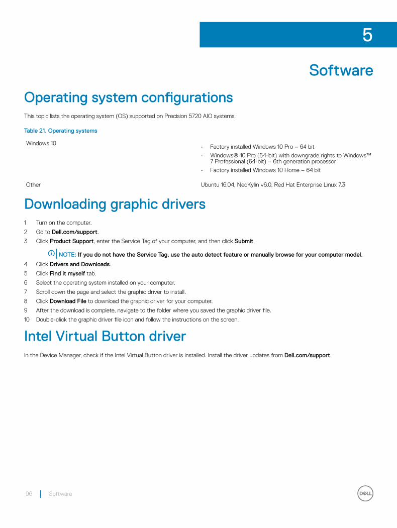
Software
Operating system configurationsThis topic lists the operating system (OS) supported on Precision 5720 AIO systems.
Table 21. Operating systems
Windows 10• Factory installed Windows 10 Pro – 64 bit
• Windows® 10 Pro (64-bit) with downgrade rights to Windows™ 7 Professional (64-bit) – 6th generation processor
• Factory installed Windows 10 Home – 64 bit
Other Ubuntu 16.04, NeoKylin v6.0, Red Hat Enterprise Linux 7.3
Downloading graphic drivers1 Turn on the computer.
2 Go to Dell.com/support.
3 Click Product Support, enter the Service Tag of your computer, and then click Submit.
NOTE: If you do not have the Service Tag, use the auto detect feature or manually browse for your computer model.
4 Click Drivers and Downloads.
5 Click Find it myself tab.
6 Select the operating system installed on your computer.
7 Scroll down the page and select the graphic driver to install.
8 Click Download File to download the graphic driver for your computer.
9 After the download is complete, navigate to the folder where you saved the graphic driver file.
10 Double-click the graphic driver file icon and follow the instructions on the screen.
Intel Virtual Button driverIn the Device Manager, check if the Intel Virtual Button driver is installed. Install the driver updates from Dell.com/support.
5
96 Software
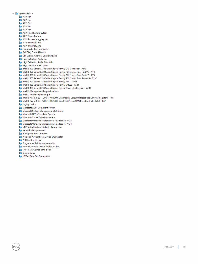
Software 97
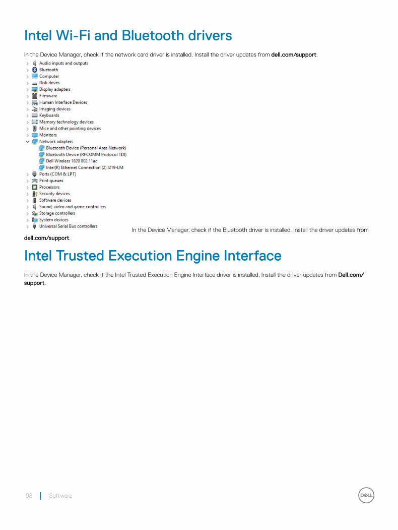
Intel Wi-Fi and Bluetooth driversIn the Device Manager, check if the network card driver is installed. Install the driver updates from dell.com/support.
In the Device Manager, check if the Bluetooth driver is installed. Install the driver updates from dell.com/support.
Intel Trusted Execution Engine InterfaceIn the Device Manager, check if the Intel Trusted Execution Engine Interface driver is installed. Install the driver updates from Dell.com/support.
98 Software
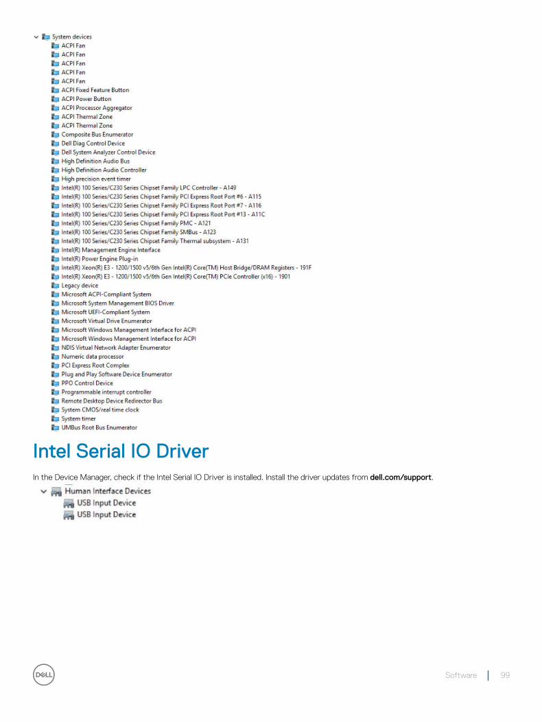
Intel Serial IO DriverIn the Device Manager, check if the Intel Serial IO Driver is installed. Install the driver updates from dell.com/support.
Software 99
100 Software
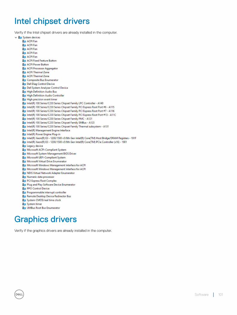
Intel chipset driversVerify if the Intel chipset drivers are already installed in the computer.
Graphics driversVerify if the graphics drivers are already installed in the computer.
Software 101
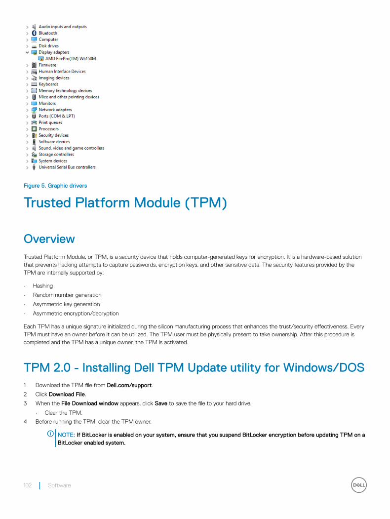
Figure 5. Graphic drivers
Trusted Platform Module (TPM)
OverviewTrusted Platform Module, or TPM, is a security device that holds computer-generated keys for encryption. It is a hardware-based solution that prevents hacking attempts to capture passwords, encryption keys, and other sensitive data. The security features provided by the TPM are internally supported by:
• Hashing
• Random number generation
• Asymmetric key generation
• Asymmetric encryption/decryption
Each TPM has a unique signature initialized during the silicon manufacturing process that enhances the trust/security effectiveness. Every TPM must have an owner before it can be utilized. The TPM user must be physically present to take ownership. After this procedure is completed and the TPM has a unique owner, the TPM is activated.
TPM 2.0 - Installing Dell TPM Update utility for Windows/DOS1 Download the TPM file from Dell.com/support.
2 Click Download File.
3 When the File Download window appears, click Save to save the file to your hard drive.
• Clear the TPM.
4 Before running the TPM, clear the TPM owner.
NOTE: If BitLocker is enabled on your system, ensure that you suspend BitLocker encryption before updating TPM on a BitLocker enabled system.
102 Software
NOTE: The TPM must be ON and Enabled in BIOS Setup, and the TPM must not be owned. If the TPM is owned, go to BIOS Setup and clear the TPM before proceeding. You may need to run TPM.msc to re-initial the TPM under Windows OS.
NOTE: When the TPM ownership is cleared, an operating system will automatically take ownership of the TPM on the next boot (TPM AutoProvisioning). This feature will need to be disabled in the operating system to proceed with the update.
• Clear the TPM.
5 Boot to Windows.
• Launch the PowerShell Command window in Administrator mode.
• At the Powershell command prompt, execute the command: > Disable-TpmAutoProvisioning.
• Confirm the following results:- AutoProvisioning: Disabled .
• Reboot the system to BIOS Setup by pressing F2.
• Navigate to Security > TPM 1.2/2.0 Security.
• Click the Clear checkbox and select Yes at the prompt to clear the TPM settings. (You can skip it if the item is grayed out).
• Click Exit to save changes.
• Reboot system to Windows.
• Confirm that the TPM is not owned. The TPM should no longer be automatically provisioned by Windows.
• When the TPM update is complete, launch the PowerShell command in Administrator mode to re-enable the auto provisioning. > Enable-TpmAutoProvisioning..
• Confirm the following results:- AutoProvisioning: Enabled .
• Run the TPM update utility from Windows environment.
• Browse to the location where you downloaded the file and double-click the new file.
• Windows System will auto restart and update the TPM during the system startup.
• When the TPM update is complete the system will auto reboot to take effect.
• When the TPM update is complete the system will auto reboot to take effect.
• Run the TPM update utility from DOS environment, if Legacy Boot mode (Non-Windows users).
• Copy the downloaded file to a bootable DOS USB key.
• Power on the system, then Press F12 key and Select "USB Storage Device" and Boot to DOS prompt.
• Run the file by typing copied file name where the executable is located.
• DOS system will auto restart and update the TPM during the system startup.
• When the TPM update is finished, the system will auto reboot to take effect.
• Run the BIOS update utility from DOS environment if UEFI Boot Mode (Non-Windows users).
• Copy the downloaded file to a bootable DOS USB key.
• Power on the system, then go to BIOS Setup by pressing F2 and go to General > Boot Sequence > Boot List Option.
• Change UEFI to Legacy of Boot List Option.
• Click Apply, Exit to save changes and reboot system.
• Press F12, then Select USB Storage Device and Boot to DOS prompt.
• Run the file by typing copied file name where the executable is located.
• When the TPM update is finished, the system will auto reboot to take effect.
• Go to BIOS Setup by pressing F2 and go to General > Boot Sequence > Boot List Option.
• Change Legacy to UEFI Boot Option.
• Click Apply, Exit to save changes and reboot system.
Software 103
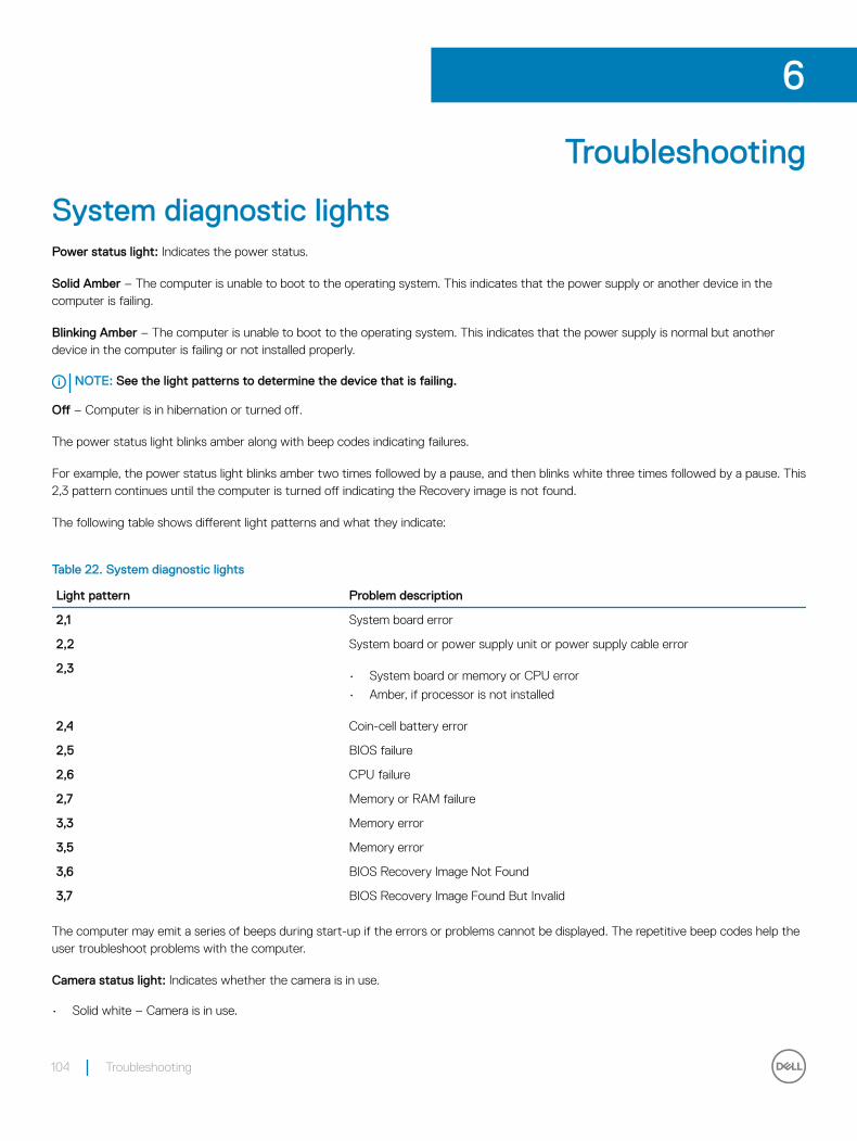
Troubleshooting
System diagnostic lightsPower status light: Indicates the power status.
Solid Amber – The computer is unable to boot to the operating system. This indicates that the power supply or another device in the computer is failing.
Blinking Amber – The computer is unable to boot to the operating system. This indicates that the power supply is normal but another device in the computer is failing or not installed properly.
NOTE: See the light patterns to determine the device that is failing.
Off – Computer is in hibernation or turned off.
The power status light blinks amber along with beep codes indicating failures.
For example, the power status light blinks amber two times followed by a pause, and then blinks white three times followed by a pause. This 2,3 pattern continues until the computer is turned off indicating the Recovery image is not found.
The following table shows different light patterns and what they indicate:
Table 22. System diagnostic lights
Light pattern Problem description
2,1 System board error
2,2 System board or power supply unit or power supply cable error
2,3• System board or memory or CPU error
• Amber, if processor is not installed
2,4 Coin-cell battery error
2,5 BIOS failure
2,6 CPU failure
2,7 Memory or RAM failure
3,3 Memory error
3,5 Memory error
3,6 BIOS Recovery Image Not Found
3,7 BIOS Recovery Image Found But Invalid
The computer may emit a series of beeps during start-up if the errors or problems cannot be displayed. The repetitive beep codes help the user troubleshoot problems with the computer.
Camera status light: Indicates whether the camera is in use.
• Solid white – Camera is in use.
6
104 Troubleshooting
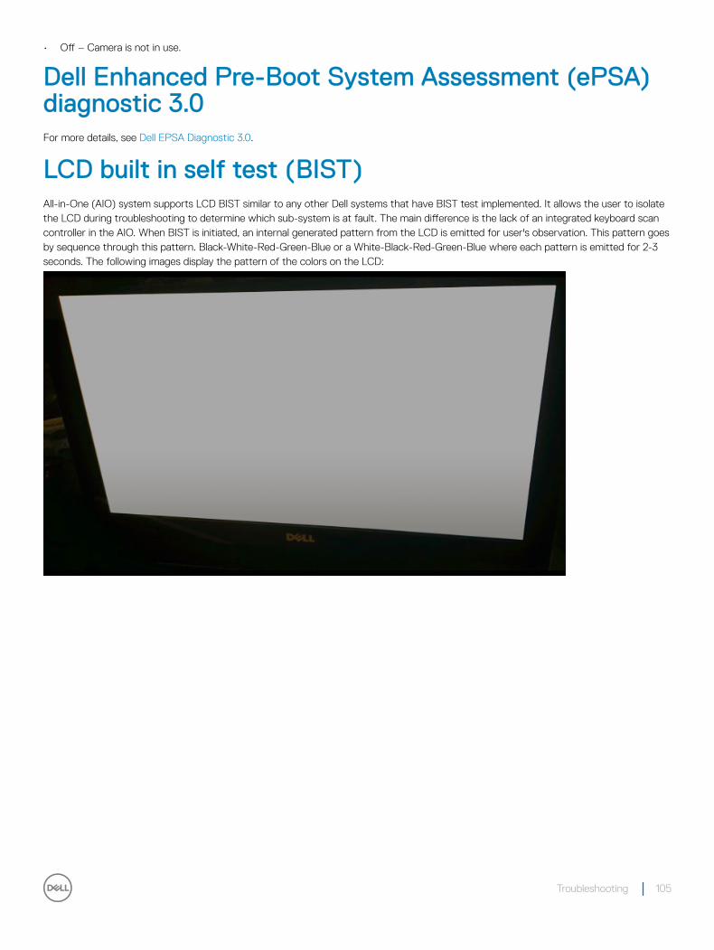
• Off – Camera is not in use.
Dell Enhanced Pre-Boot System Assessment (ePSA) diagnostic 3.0For more details, see Dell EPSA Diagnostic 3.0.
LCD built in self test (BIST)All-in-One (AIO) system supports LCD BIST similar to any other Dell systems that have BIST test implemented. It allows the user to isolate the LCD during troubleshooting to determine which sub-system is at fault. The main difference is the lack of an integrated keyboard scan controller in the AIO. When BIST is initiated, an internal generated pattern from the LCD is emitted for user's observation. This pattern goes by sequence through this pattern. Black-White-Red-Green-Blue or a White-Black-Red-Green-Blue where each pattern is emitted for 2-3 seconds. The following images display the pattern of the colors on the LCD:
Troubleshooting 105

106 Troubleshooting
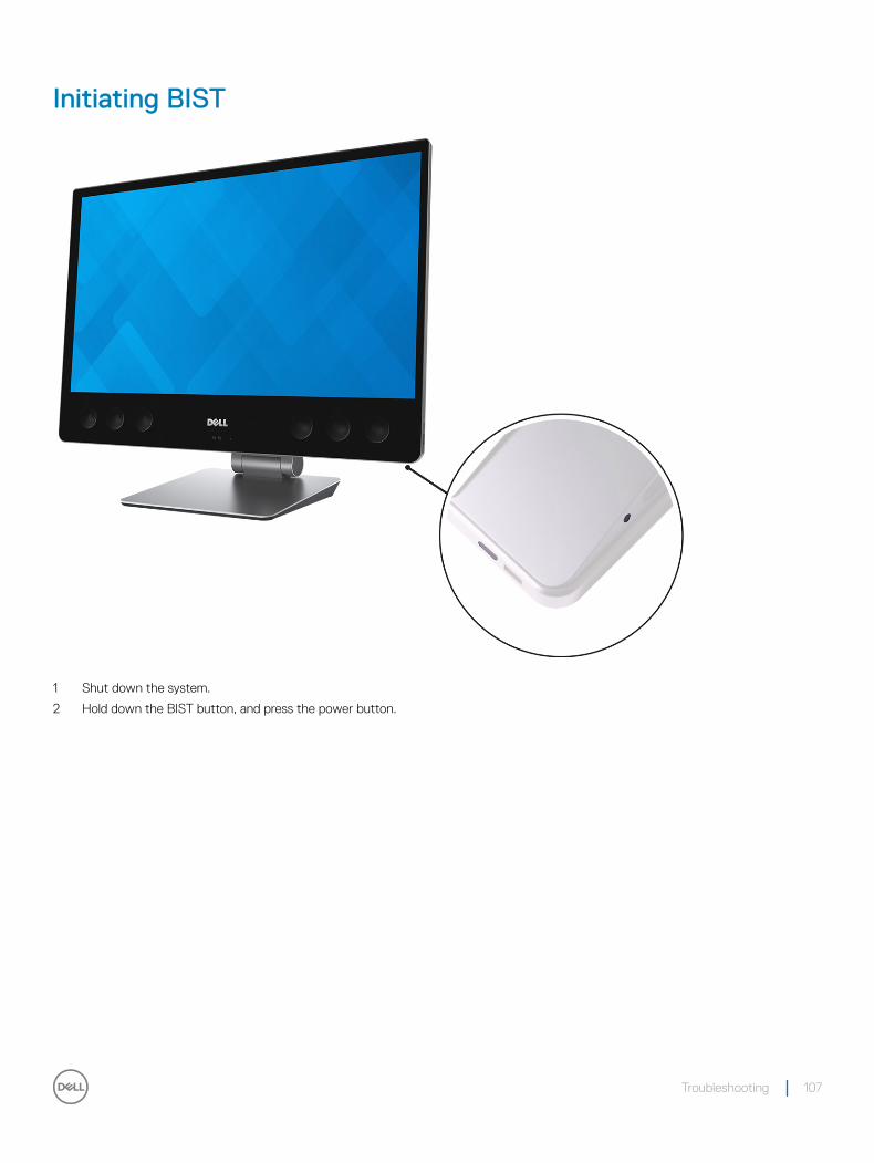
Initiating BIST
1 Shut down the system.
2 Hold down the BIST button, and press the power button.
Troubleshooting 107
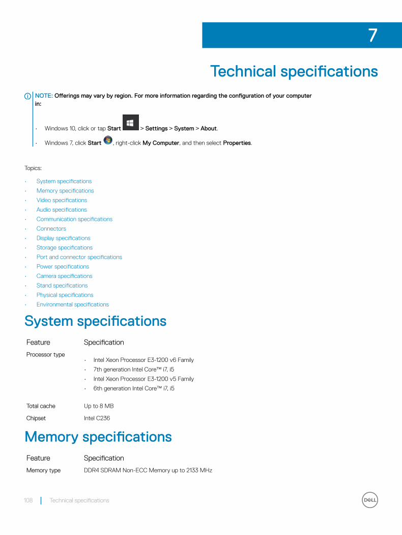
Technical specificationsNOTE: Offerings may vary by region. For more information regarding the configuration of your computer in:
• Windows 10, click or tap Start > Settings > System > About.
• Windows 7, click Start , right-click My Computer, and then select Properties.
Topics:
• System specifications
• Memory specifications
• Video specifications
• Audio specifications
• Communication specifications
• Connectors
• Display specifications
• Storage specifications
• Port and connector specifications
• Power specifications
• Camera specifications
• Stand specifications
• Physical specifications
• Environmental specifications
System specificationsFeature Specification
Processor type• Intel Xeon Processor E3-1200 v6 Family
• 7th generation Intel Core™ i7, i5
• Intel Xeon Processor E3-1200 v5 Family
• 6th generation Intel Core™ i7, i5
Total cache Up to 8 MB
Chipset Intel C236
Memory specificationsFeature Specification
Memory type DDR4 SDRAM Non-ECC Memory up to 2133 MHz
7
108 Technical specifications
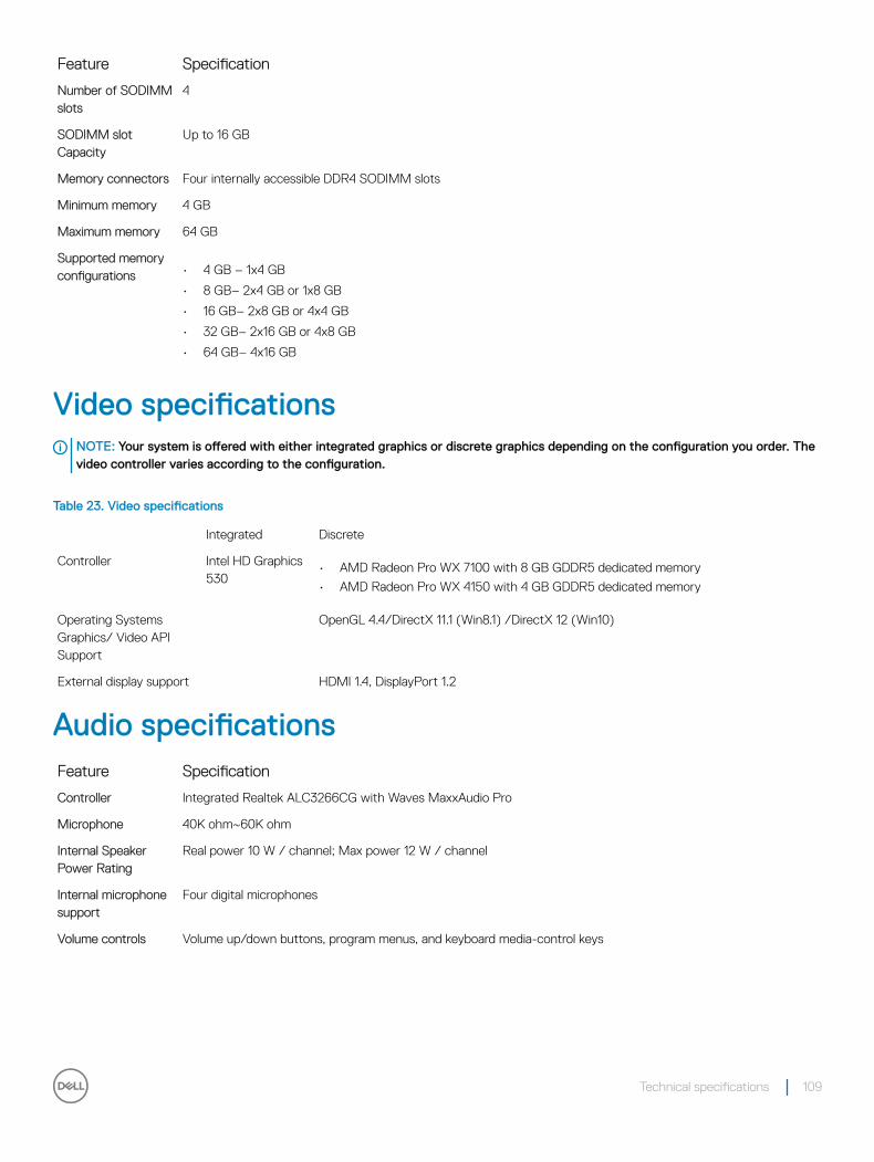
Feature Specification
Number of SODIMM slots
4
SODIMM slot Capacity
Up to 16 GB
Memory connectors Four internally accessible DDR4 SODIMM slots
Minimum memory 4 GB
Maximum memory 64 GB
Supported memory configurations • 4 GB – 1x4 GB
• 8 GB– 2x4 GB or 1x8 GB
• 16 GB– 2x8 GB or 4x4 GB
• 32 GB– 2x16 GB or 4x8 GB
• 64 GB– 4x16 GB
Video specificationsNOTE: Your system is offered with either integrated graphics or discrete graphics depending on the configuration you order. The video controller varies according to the configuration.
Table 23. Video specifications
Integrated Discrete
Controller Intel HD Graphics 530
• AMD Radeon Pro WX 7100 with 8 GB GDDR5 dedicated memory
• AMD Radeon Pro WX 4150 with 4 GB GDDR5 dedicated memory
Operating Systems Graphics/ Video API Support
OpenGL 4.4/DirectX 11.1 (Win8.1) /DirectX 12 (Win10)
External display support HDMI 1.4, DisplayPort 1.2
Audio specificationsFeature Specification
Controller Integrated Realtek ALC3266CG with Waves MaxxAudio Pro
Microphone 40K ohm~60K ohm
Internal Speaker Power Rating
Real power 10 W / channel; Max power 12 W / channel
Internal microphone support
Four digital microphones
Volume controls Volume up/down buttons, program menus, and keyboard media-control keys
Technical specifications 109
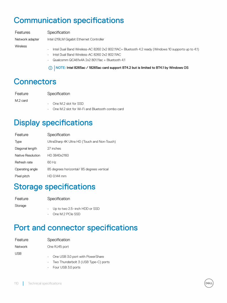
Communication specificationsFeatures Specification
Network adapter Intel i219LM Gigabit Ethernet Controller
Wireless• Intel Dual Band Wireless-AC 8260 2x2 802.11AC+ Bluetooth 4.2 ready (Windows 10 supports up to 4.1)
• Intel Dual Band Wireless-AC 8260 2x2 802.11AC
• Qualcomm QCA61x4A 2x2 801.11ac + Bluetooth 4.1
NOTE: Intel 8265ac / 18265ac card support BT4.2 but is limited to BT4.1 by Windows OS
ConnectorsFeature Specification
M.2 card• One M.2 slot for SSD
• One M.2 slot for Wi-Fi and Bluetooth combo card
Display specificationsFeature Specification
Type UltraSharp 4K Ultra HD (Touch and Non-Touch)
Diagonal length 27 inches
Native Resolution HD 3840x2160
Refresh rate 60 Hz
Operating angle 85 degrees horizontal/ 85 degrees vertical
Pixel pitch HD 0.144 mm
Storage specificationsFeature Specification
Storage• Up to two 2.5–inch HDD or SSD
• One M.2 PCIe SSD
Port and connector specificationsFeature Specification
Network One RJ45 port
USB• One USB 3.0 port with PowerShare
• Two Thunderbolt 3 (USB Type-C) ports
• Four USB 3.0 ports
110 Technical specifications
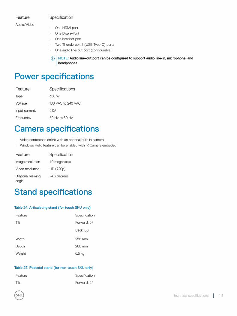
Feature Specification
Audio/Video• One HDMI port
• One DisplayPort
• One headset port
• Two Thunderbolt 3 (USB Type-C) ports
• One audio line-out port (configurable)
NOTE: Audio line-out port can be configured to support audio line-in, microphone, and headphones
Power specificationsFeature Specifications
Type 360 W
Voltage 100 VAC to 240 VAC
Input current: 5.0A
Frequency 50 Hz to 60 Hz
Camera specifications• Video conference online with an optional built-in camera
• Windows Hello feature can be enabled with IR Camera embeded
Feature Specification
Image resolution 1.0 megapixels
Video resolution HD (720p)
Diagonal viewing angle
74.6 degrees
Stand specifications
Table 24. Articulating stand (for touch SKU only)
Feature Specification
Tilt Forward: 5°
Back: 60°
Width 258 mm
Depth 260 mm
Weight 6.5 kg
Table 25. Pedestal stand (for non-touch SKU only)
Feature Specification
Tilt Forward: 5°
Technical specifications 111
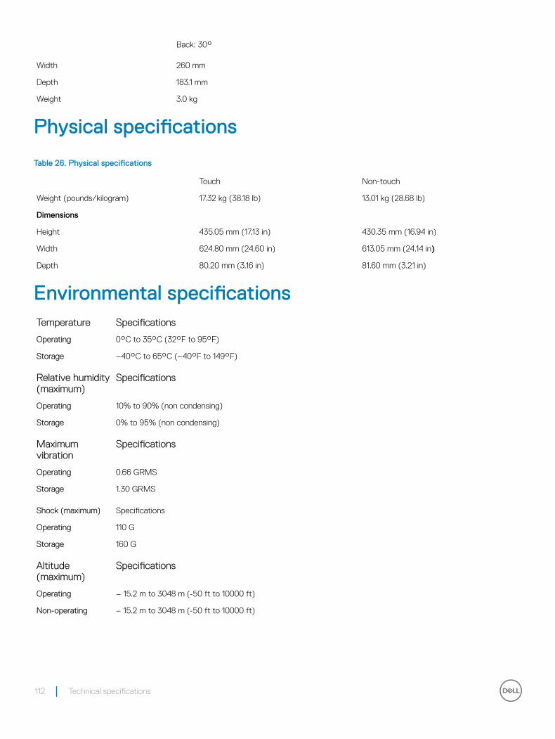
Back: 30°
Width 260 mm
Depth 183.1 mm
Weight 3.0 kg
Physical specifications
Table 26. Physical specifications
Touch Non-touch
Weight (pounds/kilogram) 17.32 kg (38.18 lb) 13.01 kg (28.68 lb)
Dimensions
Height 435.05 mm (17.13 in) 430.35 mm (16.94 in)
Width 624.80 mm (24.60 in) 613.05 mm (24.14 in)
Depth 80.20 mm (3.16 in) 81.60 mm (3.21 in)
Environmental specificationsTemperature Specifications
Operating 0°C to 35°C (32°F to 95°F)
Storage –40°C to 65°C (–40°F to 149°F)
Relative humidity (maximum)
Specifications
Operating 10% to 90% (non condensing)
Storage 0% to 95% (non condensing)
Maximum vibration
Specifications
Operating 0.66 GRMS
Storage 1.30 GRMS
Shock (maximum) Specifications
Operating 110 G
Storage 160 G
Altitude (maximum)
Specifications
Operating – 15.2 m to 3048 m (-50 ft to 10000 ft)
Non-operating – 15.2 m to 3048 m (-50 ft to 10000 ft)
112 Technical specifications
Contacting DellNOTE: If you do not have an active Internet connection, you can find contact information on your purchase invoice, packing slip, bill, or Dell product catalog.
Dell provides several online and telephone-based support and service options. Availability varies by country and product, and some services may not be available in your area. To contact Dell for sales, technical support, or customer service issues:
1 Go to Dell.com/support.
2 Select your support category.
3 Verify your country or region in the Choose a Country/Region drop-down list at the bottom of the page.
4 Select the appropriate service or support link based on your need.
8
Contacting Dell 113
Related Documents