General Description The Tyco ® Model DV-5 Double Inter- lock Preaction System with Elec- tric/Electric Actuation (Fig. 1) is de- signed for use in applications, such as refrigerated areas, requiring the maxi- mum degree of protection against in- advertent flooding of the sprinkler sys- tem piping. The Model DV-5 Double Interlock Pre- action System with Electric/Electric Actuation utilizes a Model DV-5 Del- uge Valve and a Riser Check Valve. The Riser Check Valve (that does not require the use of priming water) iso- lates the Deluge Valve from the sys- tem air pressure. The releasing trim for the Deluge Valve utilizes a Solenoid Valve that is operated by energizing the releasing circuit of a Cross-Zone Deluge Valve Releasing Panel (auto- matic control unit). Zone 1 of the Releasing Panel is oper- ated by either a fire detection device or manual pull station. Zone 2 of the Re- leasing Panel is operated by a Low Air Pressure Alarm Switch in response to a loss of system air pressure due to the opening of an automatic sprinkler. The Solenoid Valve remains closed until it is electrically energized by the Releas- ing Panel. In order for the Double Interlock Pre- action System to automatically actu- ate, two independent events must oc- cur. Zone 1 of the Releasing Panel must operate upon automatic opera- tion of the electric fire detection initiat- ing circuit or operation of the electric- manual pull initiating circuit, and Zone 2 of the Releasing Panel must operate via the Low Air Pressure Alarm Switch upon loss of air pressure from the sprinkler system piping, due to opera- tion of one or more sprinklers. The Double Interlock Preaction Sys- tem will automatically actuate only when both Zone 1 and Zone 2 of the Releasing Panel have operated, ener- gizing the Solenoid Valve. Accidental loss of system air pressure (for exam- ple: a lift truck accidentally dislodges a sprinkler), or operation of just the fire detection circuit (for example: an acci- dental operation of an electric pull sta- tion), will only cause an alarm, and will not actuate the system or flood the sprinkler system piping. The Model DV-5 Deluge Valve (de- scribed in Technical Data Sheet TFP1305) is a diaphragm style valve that depends upon water pressure in the Diaphragm Chamber to hold the Diaphragm closed against the water supply pressure. When the DV-5 Valve is set for service, the Diaphragm Chamber is pressurized through the trim connections from the inlet side of the system’s main control valve, for example an O.S.&Y. gate valve or but- terfly valve (Fig. 1). Operation the Solenoid Valve releases water from the Diaphragm Chamber faster than it can be replenished through the 1/8 inch (3,2 mm) restric- tion provided by the Model ASV-1 Automatic Shut-Off Valve in the dia- phragm supply connections (Item 5 - Fig. 2A, also described in Technical Page 1 of 14 TFP1465 MAY, 2009 Preaction System with Model DV-5 Deluge Valve Double Interlock — Electric/Electric Actuation 1-1/2 thru 8 Inch (DN40 thru DN200) Technical Services: Tel: (800) 381-9312 / Fax: (800) 791-5500 (TEXT CONTINUED ON PAGE 9)

Welcome message from author
This document is posted to help you gain knowledge. Please leave a comment to let me know what you think about it! Share it to your friends and learn new things together.
Transcript

GeneralDescriptionThe Tyco® Model DV-5 Double Inter-lock Preaction System with Elec-tric/Electric Actuation (Fig. 1) is de-signed for use in applications, such asrefrigerated areas, requiring the maxi-mum degree of protection against in-advertent flooding of the sprinkler sys-tem piping.
The Model DV-5 Double Interlock Pre-action System with Electric/ElectricActuation utilizes a Model DV-5 Del-uge Valve and a Riser Check Valve.The Riser Check Valve (that does notrequire the use of priming water) iso-lates the Deluge Valve from the sys-tem air pressure. The releasing trim forthe Deluge Valve utilizes a SolenoidValve that is operated by energizingthe releasing circuit of a Cross-ZoneDeluge Valve Releasing Panel (auto-matic control unit).
Zone 1 of the Releasing Panel is oper-ated by either a fire detection device ormanual pull station. Zone 2 of the Re-leasing Panel is operated by a Low AirPressure Alarm Switch in response toa loss of system air pressure due to theopening of an automatic sprinkler. TheSolenoid Valve remains closed until itis electrically energized by the Releas-ing Panel.
In order for the Double Interlock Pre-action System to automatically actu-ate, two independent events must oc-cur. Zone 1 of the Releasing Panelmust operate upon automatic opera-tion of the electric fire detection initiat-ing circuit or operation of the electric-manual pull initiating circuit, and Zone2 of the Releasing Panel must operatevia the Low Air Pressure Alarm Switchupon loss of air pressure from thesprinkler system piping, due to opera-tion of one or more sprinklers.
The Double Interlock Preaction Sys-tem will automatically actuate onlywhen both Zone 1 and Zone 2 of the
Releasing Panel have operated, ener-gizing the Solenoid Valve. Accidentalloss of system air pressure (for exam-ple: a lift truck accidentally dislodges asprinkler), or operation of just the firedetection circuit (for example: an acci-dental operation of an electric pull sta-tion), will only cause an alarm, and willnot actuate the system or flood thesprinkler system piping.
The Model DV-5 Deluge Valve (de-scribed in Technical Data SheetTFP1305) is a diaphragm style valvethat depends upon water pressure inthe Diaphragm Chamber to hold theDiaphragm closed against the water
supply pressure. When the DV-5 Valveis set for service, the DiaphragmChamber is pressurized through thetrim connections from the inlet side ofthe system’s main control valve, forexample an O.S.&Y. gate valve or but-terfly valve (Fig. 1).
Operation the Solenoid Valve releaseswater from the Diaphragm Chamberfaster than it can be replenishedthrough the 1/8 inch (3,2 mm) restric-tion provided by the Model ASV-1Automatic Shut-Off Valve in the dia-phragm supply connections (Item 5 -Fig. 2A, also described in Technical
Page 1 of 14 TFP1465MAY, 2009
Preaction System with Model DV-5 Deluge ValveDouble Interlock — Electric/Electric Actuation1-1/2 thru 8 Inch (DN40 thru DN200)
Technical Services: Tel: (800) 381-9312 / Fax: (800) 791-5500
(TEXT CONTINUED ON PAGE 9)
Page 2 of 14 TFP1465
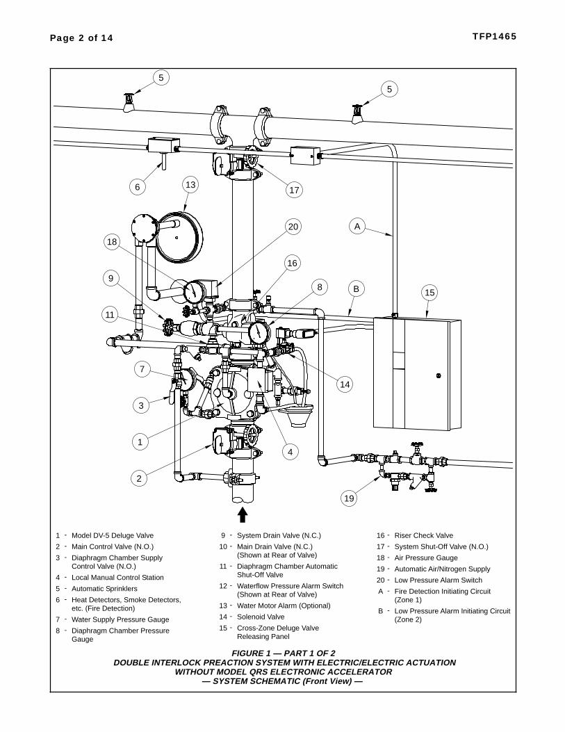
FIGURE 1 — PART 1 OF 2DOUBLE INTERLOCK PREACTION SYSTEM WITH ELECTRIC/ELECTRIC ACTUATION
WITHOUT MODEL QRS ELECTRONIC ACCELERATOR— SYSTEM SCHEMATIC (Front View) —
Model DV-5 Deluge Valve
Main Control Valve (N.O.)
1
2
-
-
Diaphragm Chamber Supply3 -
Local Manual Control Station4 -
Automatic Sprinklers5 -
Heat Detectors, Smoke Detectors,6 -
Water Supply Pressure Gauge7 -
Diaphragm Chamber Pressure8 -
Control Valve (N.O.)
13
7
3
1
2
4
98
Gauge
etc. (Fire Detection)
14
5
15
System Drain Valve (N.C.)9 -
Main Drain Valve (N.C.)10 -
Diaphragm Chamber Automatic11 -
Waterflow Pressure Alarm Switch12 -
Water Motor Alarm (Optional)13 -
Solenoid Valve14 -
Cross-Zone Deluge Valve15 -
Shut-Off Valve
(Shown at Rear of Valve)
(Shown at Rear of Valve)
Releasing Panel
Riser Check Valve16 -
System Shut-Off Valve (N.O.)17 -
Air Pressure Gauge18 -
Automatic Air/Nitrogen Supply19 -
Low Pressure Alarm Switch20 -
Fire Detection Initiating CircuitA -(Zone 1)
Low Pressure Alarm Initiating CircuitB -(Zone 2)
5
17
19
11
18
20
16
B
A
6

Page 3 of 14TFP1465
FIGURE 1 — PART 2 OF 2DOUBLE INTERLOCK PREACTION SYSTEM WITH ELECTRIC/ELECTRIC ACTUATION
WITHOUT MODEL QRS ELECTRONIC ACCELERATOR— SYSTEM SCHEMATIC (Rear View) —
Model DV-5 Deluge Valve
Main Control Valve (N.O.)
1
2
-
-
Diaphragm Chamber Supply3 -
Local Manual Control Station4 -
Automatic Sprinklers5 -
Heat Detectors, Smoke Detectors,6 -
Water Supply Pressure Gauge7 -
Diaphragm Chamber Pressure8 -
Control Valve (N.O.)
Gauge (Shown at Front of Valve)
etc. (Fire Detection)
System Drain Valve (N.C.)9 -
Main Drain Valve (N.C.)10 -
Diaphragm Chamber Automatic11 -
Waterflow Pressure Alarm Switch12 -
Water Motor Alarm (Optional)13 -
Solenoid Valve14 -
Cross-Zone Deluge Valve15 -
Shut-Off Valve
Releasing Panel
Riser Check Valve16 -
System Shut-Off Valve (N.O.)17 -
Air Pressure Gauge18 -
Automatic Air/Nitrogen Supply19 -
Low Pressure Alarm Switch20 -
Fire Detection Initiating CircuitA -(Zone 1)
Low Pressure Alarm Initiating CircuitB -(Zone 2)
11
1
2
3
10
12
1415
55
(Shown at Front of Valve)
19
13
B
A
16
20 17
9
(Shown at Front of Valve)
(Shown at Front of Valve)
6
Page 4 of 14 TFP1465
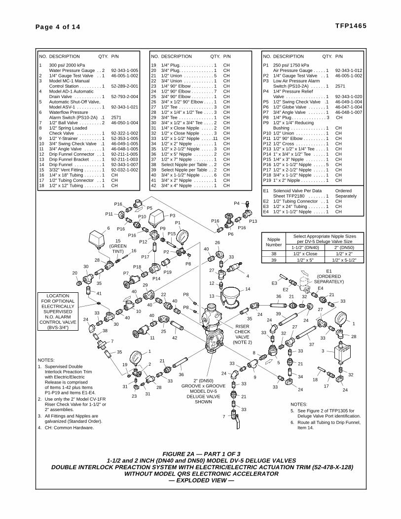
FIGURE 2A — PART 1 OF 31-1/2 and 2 INCH (DN40 and DN50) MODEL DV-5 DELUGE VALVES
DOUBLE INTERLOCK PREACTION SYSTEM WITH ELECTRIC/ELECTRIC ACTUATION TRIM (52-478-X-128)WITHOUT MODEL QRS ELECTRONIC ACCELERATOR
— EXPLODED VIEW —
with Electric/ElectricRelease is comprisedof Items 1-42 plus Items
Supervised Double1.NOTES:
Interlock Preaction Trim
P1-P19 and Items E1-E4.
P1
46-005-1-002P2 1/4" Gauge Test Valve 1. .92-343-1-012
250 psi/ 1750 kPa1Air Pressure Gauge . . . . .
P3 Low Air Pressure AlarmSwitch (PS10-2A) 25711. . . . . .
P4 1/4" Pressure ReliefValve 92-343-1-0201. . . . . . . . . . . . . . . .
P5 1/2" Swing Check Valve 46-049-1-0041.46-047-1-004P6 1/2" Globe Valve 1. . . . . . .
P8 1/4" Plug 3. . . . . . . . . . . . . . CHP7
P9 1/2" x 1/4" ReducingBushing CH1. . . . . . . . . . . . . .
P10 1/2" Union 1. . . . . . . . . . . . CHP11 1/2" 90° Elbow 1. . . . . . . . . CHP12 1/2" Cross 1. . . . . . . . . . . . CH
1/2" x 1/2" x 1/4" Tee 1 CH. . . .P131" x 3/4" x 1/2" Tee 1 CH. . . . .P14
P15 1/4" x 3" Nipple 1 CH. . . . . . . .1/2" x 1-1/2" Nipple 5 CHP16 . . . . .
P19 1" x 2" Nipple 1 CH. . . . . . . . . .
46-048-1-0073/4" Angle Valve 1. . . . . . .
46-005-1-0022 1/4" Gauge Test Valve 1. .3 Model MC-1 Manual
Control Station 52-289-2-0011. . . . . . . . .4 Model AD-1 Automatic
Drain Valve 52-793-2-0041. . . . . . . . . . .
181/2" Tubing Connector CH1. .
13 92-211-1-00392-343-1-00714
Drip Funnel BracketDrip Funnel
11. . . . . . . . . . .
. . . .
1692-032-1-0023/32" Vent Fitting . . . . . . . 1
171/4" x 18" Tubing CH1. . . . . . .
9 52-353-1-0051. . . . . . . . .1/2" Y-Strainer
892-322-1-002
1/2" Spring Loaded1Check Valve . . . . . . . . . .
11 46-048-1-0053/4" Angle Valve 1. . . . . . .
46-050-1-0041/2" Ball Valve 2. . . . . . . . .7
46-049-1-0053/4" Swing Check Valve 1.10
31 1/4" x Close Nipple 2 CH. . . . .
22
3/4" Plug 1. . . . . . . . . . . . . . CH201/4" Plug 1. . . . . . . . . . . . . . CH
1/2" x 12" Tubing CH1. . . . . . .
1/2" x Close Nipple 3 CH33
. . . . .1/2" x 1-1/2" Nipple 11 CH
34. . . . .
28
3/4" x 1/2" x 3/4" Tee29
NO.
1
QTY.DESCRIPTION P/N
92-343-1-005300 psi/ 2000 kPa
2Water Pressure Gauge . .19
6
35 1/2" x 2-1/2" Nipple36
38
413/4" x 1-1/2" Nipple
3 CH. . . . .
1/2" x 7" Nipple 1 CH. . . . . . . .
6 CH. . . . .3/4" x 2" Nipple 1 CH. . . . . . . .
27 1/2" Tee 3 CH. . . . . . . . . . . . . .26
1/4" 90° Elbow 1. . . . . . . . . CH
1/2" Union 5. . . . . . . . . . . . CH
233/4" Union 1. . . . . . . . . . . . CH
251/2" 90° Elbow 7. . . . . . . . . CH
92-211-1-005Drip Funnel Connector 1. .12
NO. QTY.DESCRIPTION P/N NO. QTY.DESCRIPTION P/N
92-343-1-0211Model ASV-1 . . . . . . . . . .5 Automatic Shut-Off Valve,
21
1/2" x 1/4" x 1/2" Tee
40
30
3 CH. . . .
2 CH. . . .
32
3/4" 90° Elbow 1. . . . . . . . . CH
3/4" Tee 1 CH. . . . . . . . . . . . . .
37
39
3/4" x 4" Nipple 1 CH. . . . . . . .
15
24
1-1/2" (DN40)1/2" x Close
Number
38
Nipple
1/2" x 5"39
2" (DN50)1/2" x 2"
1/2" x 5-1/2"
per DV-5 Deluge Valve SizeSelect Appropriate Nipple Sizes
Select Nipple per Table 2 CH. .Select Nipple per Table 2 CH. .
1/2" x 2" Nipple 1 CH. . . . . . . .
1/2" x 5" Nipple 2 CH. . . . . . . .
Waterflow PressureAlarm Switch (PS10-2A) 25711.
3/4" x 1-1/2" Nipple 1 CHP18 . . . . .1/2" x 2-1/2" Nipple 1 CHP17 . . . . .
3/4" x 1/2" 90° Elbow 1. . . . CH
42OrderedSeparately
Solenoid Valve Per Data1Sheet TFP2180 . . . . . . .
E1
E2 1/2" Tubing Connector CH1. .E3
1/2" x 1-1/2" Nipple 1 CH. . . . .E41/2" x 24" Tubing CH1. . . . . . .
See Figure 2 of TFP1305 forDeluge Valve Port identification.
5.
Item 14.Route all Tubing to Drip Funnel,6.
2.
All Fittings and Nipples aregalvanized (Standard Order).CH: Common Hardware.
3.
4.
NOTES:Use only the 2" Model CV-1FRRiser Check Valve for 1-1/2" or2" assemblies.
30
1
23
19
38
7
3128
3336
33
33
21
33
8
33
21
3337
28
1
33
3
24
3218
17
5
3227
33
2439
2424
21
27
32
312" (DN50)
MODEL DV-5DELUGE VALVE
SHOWN
3321
24
221
3640
34
7
GROOVE x GROOVE
4010
24
33
9
24
29
40
35
35
2511 42
40
14
33
P9P15
P8
P16
40
P5
P10
27
P16P16
P12
P11
P2
P1
12
P3
P6
4
P16
26
2830
20
15(GREEN
TINT)
35
41
16
6
FOR OPTIONALELECTRICALLY
CONTROL VALVE(BVS-3/4")
LOCATION
N.O. ALARMSUPERVISED
13
P7P18
P17
P14P19
P16 P13
4022
VALVECHECK
(NOTE 2)
RISER
P8
P8E2
E3 SEPARATELY)(ORDERED
E1
E4
P4

FIGURE 2A — PART 1 OF 33 INCH (DN80) MODEL DV-5 DELUGE VALVES
DOUBLE INTERLOCK PREACTION SYSTEM WITH ELECTRIC/ELECTRIC ACTUATION TRIM (52-478-X-125)WITHOUT MODEL QRS ELECTRONIC ACCELERATOR
— EXPLODED VIEW —
P4
See Figure 2 of TFP1305 forDeluge Valve Port identification.
5.
Item 14.Route all Tubing to Drip Funnel,6.
2.
All Fittings and Nipples aregalvanized (Standard Order).CH: Common Hardware.
3.
4.
NOTES:
with Electric/ElectricRelease is comprisedof Items 1-44 plus Items
Supervised Double1.NOTES:
Interlock Preaction Trim
P1-P18 and Items E1-E4.
P1
46-005-1-002P2 1/4" Gauge Test Valve 1. .92-343-1-012
250 psi/ 1750 kPa1Air Pressure Gauge . . . . .
P3 Low Air Pressure AlarmSwitch (PS10-2A) 25711. . . . . .
P4 1/4" Pressure ReliefValve 92-343-1-0201. . . . . . . . . . . . . . . .
P5 1/2" Swing Check Valve 46-049-1-0041.46-047-1-004P6 1/2" Globe Valve 1. . . . . . .
P8 1/4" Plug 3. . . . . . . . . . . . . . CHP7
P9 1/2" x 1/4" ReducingBushing CH1. . . . . . . . . . . . . .
P10 1/2" Union 1. . . . . . . . . . . . CHP11 1/2" 90° Elbow 1. . . . . . . . . CHP12 1/2" Cross 1. . . . . . . . . . . . CH
1/2" x 1/2" x 1/4" Tee 1 CH. . . .P131-1/4" x 1-1/4" x 1/2" Tee 1 CH.P14
P15 1/4" x 3" Nipple 1 CH. . . . . . . .1/2" x 1-1/2" Nipple 6 CHP16 . . . . .
P17 1-1/4" x 2" Nipple 1 CH. . . . . . .P18 1-1/4" x 3" Nipple 1 CH. . . . . . .
30
4326
44
1
23
19
33
7
3128
3337
33
33
21
33
833
21
3340
28
1
33
3
24
3218
17
5
3232
33
2440
2424
21
27
33
31
11
3" (DN80)
MODEL DV-5DELUGE VALVE
SHOWN
3321
24
221
3941
35
46-005-1-0022 1/4" Gauge Test Valve 1. .3 Model MC-1 Manual
Control Station 52-289-2-0011. . . . . . . . .4 Model AD-1 Automatic
Drain Valve 52-793-2-0041. . . . . . . . . . .
18
1/2" Tubing Connector CH1. .
1492-211-1-00392-343-1-007
15
Drip Funnel BracketDrip Funnel
11. . . . . . . . . . .
. . . .
1692-032-1-0023/32" Vent Fitting . . . . . . . 1
171/4" x 18" Tubing CH1. . . . . . .
9 52-353-1-0051. . . . . . . . .1/2" Y-Strainer
892-322-1-002
1/2" Spring Loaded1Check Valve . . . . . . . . . .
11
46-050-1-0041/2" Ball Valve 2. . . . . . . . .7
46-049-1-0053/4" Swing Check Valve 1.10
1246-048-1-0071-1/4" Angle Valve 1. . . . . .
31 1/4" x Close Nipple 2 CH. . . . .
22
3/4" Plug 1. . . . . . . . . . . . . CH201/4" Plug 1. . . . . . . . . . . . . CH1/2" x 18" Tubing CH1. . . . . . .
1/2" x Close Nipple 2 CH33
. . . . .1/2" x 1-1/2" Nipple 13 CH
34. . . . .
28
3/4" x 1/2" x 3/4" Tee29
NO.
1
QTY.DESCRIPTION P/N
92-343-1-005300 psi/ 2000 kPa
2Water Pressure Gauge . . 19
6 Waterflow PressureAlarm Switch (PS10-2A) 25711.
351/2" x 2-1/2" Nipple
36 1/2" x 4" Nipple 1 CH. . . . . . . .
38 1/2" x 5" Nipple 1 CH. . . . . . . .
4142
3/4" x 1-1/2" Nipple
1 CH. . . . .
1/2" x 7" Nipple 2 CH. . . . . . . .5 CH. . . . .
44
3/4" x 2" Nipple 1 CH. . . . . . . .1-1/4" x 2" Nipple 1 CH. . . . . . .
1 CH
27 1/2" Tee 3 CH. . . . . . . . . . . . . .26
1/4" 90° Elbow 1. . . . . . . . . CH
1/2" Union 5. . . . . . . . . . . . CH
233/4" Union 1. . . . . . . . . . . . CH
251/2" 90° Elbow 7. . . . . . . . . CH
92-211-1-005Drip Funnel Connector 1. .13
NO. QTY.DESCRIPTION P/N NO. QTY.DESCRIPTION P/N
92-343-1-0211Model ASV-1 . . . . . . . . . .5 Automatic Shut-Off Valve,
21
1/2" x 1/4" x 1/2" Tee
401/2" x 5-1/2" Nipple 1 CH. . . . .
30
3 CH. . . .
2 CH. . . .
32
3/4" Tee 1 CH. . . . . . . . . . . . . .
7
GROOVE x GROOVE
4110
24
33
9
24
29
4141
22
36
38
1/2" x 3-1/2" Nipple 1 CH. . . . .
37 1/2" x 4-1/2" Nipple 1 CH. . . . .
39
431-1/4" x 4" Nipple . . . . . . .
2830
20
15(GREEN
TINT) 14
13
P8
P8
34
33
42
P16
P9P15
P8
P16
41
P16
P5
P10
27
16
P16P16
P12
P11
P2
P1
CHECK VALVERISER
(NOTE 2)
UNUSEDPLUG
PORTS
12
6
P3
P6
4
P13P16
FOR OPTIONALELECTRICALLY
CONTROL VALVE(BVS-3/4")
LOCATION
N.O. ALARMSUPERVISED
P14P18
P17
P7
1-1/4" 90° Elbow 1. . . . . . . CH3/4" x 1/2" 90° Elbow 1. . . . CH
46-048-1-0071-1/4" Angle Valve 1. . . . . .
24
25
E2E3 SEPARATELY)
(ORDEREDE1
OrderedSeparately
Solenoid Valve Per Data1Sheet TFP2180 . . . . . . .
E1
E2 1/2" Tubing Connector CH1. .E3
1/2" x 1-1/2" Nipple 1 CH. . . . .E41/2" x 24" Tubing CH1. . . . . . .
E4
Use only the Model CV-1FRRiser Check Valve.
Page 5 of 14TFP1465
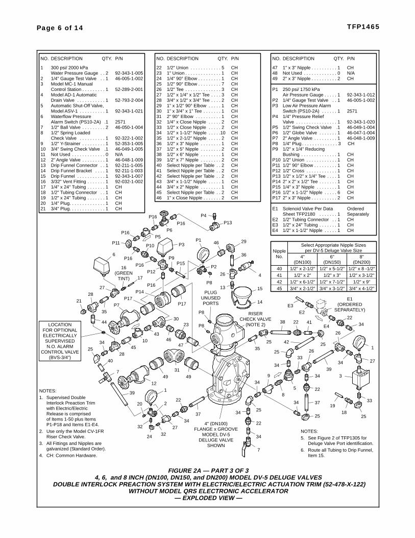
FIGURE 2A — PART 3 OF 34, 6, and 8 INCH (DN100, DN150, and DN200) MODEL DV-5 DELUGE VALVES
DOUBLE INTERLOCK PREACTION SYSTEM WITH ELECTRIC/ELECTRIC ACTUATION TRIM (52-478-X-122)WITHOUT MODEL QRS ELECTRONIC ACCELERATOR
— EXPLODED VIEW —
P4
E2E3
SEPARATELY)(ORDERED
E1
E4
OrderedSeparately
Solenoid Valve Per Data1Sheet TFP2180 . . . . . . .
E1
E2 1/2" Tubing Connector CH1. .E3
1/2" x 1-1/2" Nipple 1 CH. . . . .E41/2" x 24" Tubing CH1. . . . . . .
46-005-1-0022 1/4" Gauge Test Valve 1. .3 Model MC-1 Manual
Control Station 52-289-2-0011. . . . . . . . .4 Model AD-1 Automatic
Drain Valve 52-793-2-0041. . . . . . . . . . .
18 1/2" Tubing Connector CH1. .
14 92-211-1-00392-343-1-00715
Drip Funnel BracketDrip Funnel
11. . . . . . . . . . .
. . . .
16 92-032-1-0023/32" Vent Fitting . . . . . . . 117 1/4" x 24" Tubing CH1. . . . . . .
9 52-353-1-0051. . . . . . . . .1/2" Y-Strainer
892-322-1-002
1/2" Spring Loaded1Check Valve . . . . . . . . . .
11
46-050-1-0041/2" Ball Valve 2. . . . . . . . .7
46-049-1-0053/4" Swing Check Valve 1.10
12 46-048-1-0092" Angle Valve 1. . . . . . . . .
2" 90° Elbow 1. . . . . . . . . .31 CH32 1/4" x Close Nipple 2 CH. . . . .
22
3/4" Plug 1. . . . . . . . . . . . . . CH20 1/4" Plug 1. . . . . . . . . . . . . . CH
1/2" x 24" Tubing CH1. . . . . . .
1/2" x Close Nipple 2 CH33 . . . . .1/2" x 1-1/2" Nipple 10 CH34 . . . . .
28 3/4" x 1/2" x 3/4" Tee29
1" x 3/4" x 1" Tee
NO.
1
QTY.DESCRIPTION P/N
92-343-1-005300 psi/ 2000 kPa
2Water Pressure Gauge . .
19
6
35 1/2" x 2-1/2" Nipple36 1/2" x 3" Nipple 1 CH. . . . . . . .37 1/2" x 5" Nipple 2 CH. . . . . . . .
3940 Select Nipple per Table 2 CH. .
43 3/4" x 1-1/2" Nipple
2 CH. . . . .
1/2" x 7" Nipple 2 CH. . . . . . . .
1 CH. . . . .44 3/4" x 2" Nipple 1 CH. . . . . . . .45
1" x Close Nipple 2 CH. . . . . . .
47 1" x 3" Nipple 1 CH. . . . . . . . . .4849 2" x 3" Nipple 2 CH. . . . . . . . . .
271/2" Tee 3 CH. . . . . . . . . . . . . .26
24 1/4" 90° Elbow 1. . . . . . . . . CH
1/2" Union 5. . . . . . . . . . . . CH23 1" Union 1. . . . . . . . . . . . . . CH
25 1/2" 90° Elbow 7. . . . . . . . . CH
46
92-211-1-005Drip Funnel Connector 1. .13
NO. QTY.DESCRIPTION P/N NO. QTY.DESCRIPTION P/N
92-343-1-0211Model ASV-1 . . . . . . . . . .5 Automatic Shut-Off Valve,
21
1/2" x 1/4" x 1/2" Tee
38 1/2" x 6" Nipple 1 CH. . . . . . . .
41
P1
46-005-1-002P2 1/4" Gauge Test Valve 1. .92-343-1-012
250 psi/ 1750 kPa1Air Pressure Gauge . . . . .
P3
P4 1/4" Pressure ReliefValve 92-343-1-0201. . . . . . . . . . . . . . . .
P5 1/2" Swing Check Valve 46-049-1-0041.46-047-1-004P6 1/2" Globe Valve 1. . . . . . .
P8 1/4" Plug 3. . . . . . . . . . . . . . CHP7 46-048-1-0092" Angle Valve 1. . . . . . . . .
P9 1/2" x 1/4" ReducingBushing CH1. . . . . . . . . . . . . .
P10 1/2" Union 1. . . . . . . . . . . . CHP11 1/2" 90° Elbow 1. . . . . . . . . CHP12 1/2" Cross 1. . . . . . . . . . . . CH
1/2" x 1/2" x 1/4" Tee 1 CH. . . .P132" x 2" x 1/2" Tee 1 CH. . . . . . .P14
P15 1/4" x 3" Nipple 1 CH. . . . . . . .1/2" x 1-1/2" Nipple 6 CHP16 . . . . .
P17 2" x 3" Nipple 2 CH. . . . . . . . . .
30
42Select Nipple per Table 2 CH. .Select Nipple per Table 2 CH. .
Select Nipple per Table 2 CH. .
3 CH. . . .2 CH. . . .
1 CH. . . . . . .
N/ANot Used 0. . . . . . . . . . . . .
1" x 1/2" 90° Elbow 1 CH. . . . .
Waterflow PressureAlarm Switch (PS10-2A) 25711.
Low Air Pressure AlarmSwitch (PS10-2A) 25711. . . . . .
N/ANot Used 0. . . . . . . . . . . . .
2728
21
4510
28
4931
49
1
24
20
40
39
7
3227
46
3437
16(GREEN
TINT)
FOR OPTIONALELECTRICALLY
CONTROL VALVE(BVS-3/4")
LOCATION
N.O. ALARMSUPERVISED 34
7
34
22
25
34
34
8
34 37
22
3439
27
1
34
3
25
3319
1825
9
5
3326
34
25
42 2525
22
35
26
41
32
15
14
P8
12
P835
36
44
43
P16
P9P15
P8
P16
46
P16
P5
P10
2617
P16P16
P12
P11
P2
P17
P1
34CHECK VALVE
RISER
(NOTE 2)
UNUSEDPLUG
PORTS
13
22
25
222
38
47
P17
P14
P7
2330
6
P3
P6
4
P13P16
29
4" (DN100)
MODEL DV-5DELUGE VALVE
SHOWN
FLANGE x GROOVE
(DN100)1/2" x 2-1/2"
No.Nipple
1/2" x 2"1/2" x 6-1/2"3/4" x 2-1/2"
(DN150)1/2" x 5-1/2"
1/2" x 3"1/2" x 7-1/2"3/4" x 3-1/2"
per DV-5 Deluge Valve SizeSelect Appropriate Nipple Sizes
4" 6"(DN200)
1/2" x 8 -1/2"1/2" x 3-1/2"
1/2" x 9"3/4" x 4-1/2"
8"
40414245
with Electric/ElectricRelease is comprisedof Items 1-50 plus Items
Supervised Double1.NOTES:
Interlock Preaction Trim
P1-P18 and Items E1-E4.2.
All Fittings and Nipples aregalvanized (Standard Order).CH: Common Hardware.
3.
4.
See Figure 2 of TFP1305 forDeluge Valve Port identification.
5.
Item 15.Route all Tubing to Drip Funnel,6.
NOTES:Riser Check Valve.Use only the Model CV-1FR
Page 6 of 14 TFP1465

Page 7 of 14TFP1465
FIGURE 2B1-1/2 thru 8 INCH (DN40 thru DN200) MODEL DV-5 DELUGE VALVES
DOUBLE INTERLOCK PREACTION SYSTEM WITH ELECTRIC/ELECTRIC ACTUATION TRIMWITHOUT MODEL QRS ELECTRONIC ACCELERATOR
— OPERATIONAL COMPONENTS —
CONDUIT1/2 INCH
FOR "ELECTRICCONNECTION
DETECTION"
(NORMALLY CLOSED)
SOLENOID VALVE,ORDERED SEPARATELY
TEST VALVEALARM
(NORMALLYCLOSED)
PRESSUREGAUGE
SUPPLYWATER
SYSTEM
CLOSED)(NORMALLY
DRAIN VALVEMAIN
A
B
C
ALARMWATER MOTOR
CONNECTION FOR3/4 INCH NPT
VENT FITTING(GREEN TINT)
CONNECTION FROMWATER SUPPLY
CONTROL VALVECHAMBER SUPPLY
1/2 INCH NPT
D
(NORMALLYOPEN)
DIAPHRAGM
UNUSEDPLUG
PORTS
CLOSED)(NORMALLY
DRAIN VALVESYSTEM MAIN
AUTOMATICDRAIN
(NORMALLYCONTROL VALVE
AIR SUPPLYSYSTEM
E
F
OPEN)
1NIPPLE
4NIPPLE
PRESSUREALARM SWITCH
LOW AIR
MAIN DRAINCONNECTION
(SIZED PER TABLE)
MAIN DRAINCONNECTION(SIZED PER
TABLE)
SYSTEM
CONNECTIONTO DRAIN
INCH NPTWITH 1-1/4
FUNNEL
VALVE
DRIP
1/2 INCH NPTCONNECTIONFOR SYSTEM
SYSTEMAIR SUPPLYPRESSURE
GAUGE
AIR SUPPLY
4" (DN100)
MODEL DV-5DELUGE VALVE
SHOWN
FLANGE x GROOVE
1-1/2" (DN40)1/2" x Close
Number
1
Nipple
1/2" x Close21/2" x 5"3
3/4" x 1-1/2"4
2" (DN50)1/2" x 2"
1/2" x Close1/2" x 5-1/2"3/4" x 1-1/2"
Select Appropriate Nipple Sizes per DV-5 Deluge Valve Size4" (DN100)1/2" x 2-1/2"
1/2" x 2"1/2" x 6-1/2"3/4" x 2-1/2"
6" (DN150)1/2" x 5-1/2"
1/2" x 3"1/2" x 7-1/2"3/4" x 3-1/2"
3" (DN80)1/2" x 1-1/2"1/2" x 1-1/2"
1/2" x 7"3/4" x 1-1/2"
SizeMain Drain
3/4" NPT 3/4" NPT 2" NPT 2" NPT1-1/4" NPT
8" (DN200)1/2" x 8-1/2"1/2" x 3-1/2"
1/2" x 9"3/4" x 4-1/2"
2" NPT
SizeMain Drain 3/4" NPT 3/4" NPT 2" NPT 2" NPT1-1/4" NPT 2" NPT
System
PRESSUREALARM SWITCH
WATERFLOW
(NORMALLY
AUTOMATICSHUT-OFF VALVE
OPEN)
CHECK VALVERISER
(NOTE 1)
CONTROLSTATION
MANUAL
PRESSUREGAUGE
DIAPHRAGMCHAMBER
3NIPPLE
2NIPPLE
NOTES:
See Figure 2 of TFP1305 for Deluge ValvePort identification.
4.
Route all Tubing to Drip Funnel.5.
Install subassemblies in alphabetical order.
2.
3.
1.
Nipples 1-4 vary in length relative to theModel DV-5 size used. Select per thetable. All other nipples packed unassembledshall be installed per the appropriate trimexploded view, Figure 2A Part 1, 2, or 3.
Use only the 2" Model CV-1FR Riser CheckValve with 1-1/2" and 2" DV-5 Valves. Usecorresponding sized Model CV-1FR RiserCheck Valves for 3"-8" Model DV-5 Valves.
Page 8 of 14 TFP1465
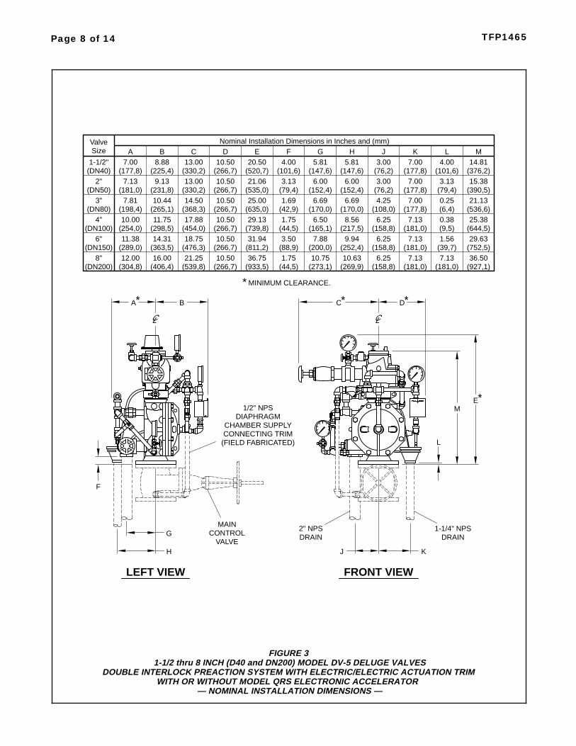
FIGURE 31-1/2 thru 8 INCH (D40 and DN200) MODEL DV-5 DELUGE VALVES
DOUBLE INTERLOCK PREACTION SYSTEM WITH ELECTRIC/ELECTRIC ACTUATION TRIMWITH OR WITHOUT MODEL QRS ELECTRONIC ACCELERATOR
— NOMINAL INSTALLATION DIMENSIONS —
CHAMBER SUPPLYCONNECTING TRIM
(FIELD FABRICATED)
MAINCONTROL
VALVE
DA
E
2" NPSDRAIN
DIAPHRAGM
L
1/2" NPS
G
H KJ
LEFT VIEW FRONT VIEW
* *
*
1-1/4" NPSDRAIN
B
F
M
C*
(231,8)9.13
(266,7)10.50
(535,0)21.06
(152,4)6.00
(152,4)6.00
(390,5)15.38
(DN50)2"
(79,4)3.13
(177,8)7.00
(225,4)8.88
(330,2)13.00
(266,7)10.50
(520,7)20.50
(147,6)5.81
(147,6)5.81
(76,2)3.00
(101,6)4.00
(376,2)14.81
(DN40)1-1/2"
(101,6)4.00
(177,8)7.00
(181,0)7.13
(330,2)13.00
(76,2)3.00
(177,8)7.00
(79,4)3.13
(254,0)10.00
(289,0)11.38
(298,5)11.75
(363,5)14.31
(454,0)17.88
(476,3)18.75
(266,7)10.50
(739,8)29.13
(811,2)31.94
(165,1)6.50
(200,0)7.88
(217,5)8.56
(252,4)9.94
(158,8)6.25
(181,0)7.13
(9,5)0.38
(39,7)1.56
(644,5)25.38
(752,5)29.63
(44,5)1.75
(88,9)3.50
(266,7)10.50
(181,0)7.13
(198,4)7.81
(265,1)10.44
(266,7)10.50
(635,0)25.00
(170,0)6.69
(108,0)4.25
(536,6)21.13
(DN80)3"
(368,3)14.50
(42,9)1.69
(177,8)7.00
A B C D E G H J K L MFNominal Installation Dimensions in Inches and (mm)
SizeValve
(170,0)6.69
(6,4)0.25
(DN100)4"
(DN150)6"
(158,8)6.25
(304,8)12.00
(406,4)16.00
(539,8)21.25
(933,5)36.75
(273,1)10.75
(269,9)10.63
(927,1)36.50
(DN200)8"
(44,5)1.75
(266,7)10.50
(158,8)6.25
(181,0)7.13
(181,0)7.13
MINIMUM CLEARANCE.*

Data Sheet TFP1384). This results ina rapid pressure drop in the Dia-phragm Chamber below the valve trippoint. The water supply pressure thenforces the Diaphragm open permittingwater to flow into the system piping, aswell as through the Alarm Port to actu-ate the system alarms.
As water flows into the system, thepilot chamber of the Model ASV-1Automatic Shut-Off Valve (Item 5 - Fig.2A) becomes pressurized and theASV-1 automatically shuts off the dia-phragm chamber supply flow to theDV-5 Diaphragm Chamber. Shuttingoff the diaphragm chamber supply flowprevents the DV-5 Diaphragm Cham-ber from becoming re-pressurized,thereby preventing inadvertent closingof the DV-5 during a fire (as may be thecase should the Solenoid Valve be-come de-energized after its initial op-eration).
NOTICE
The Model DV-5 Double Interlock Pre-action System with Electric/ElectricActuation described herein must beinstalled and maintained in compli-ance with this document and with theapplicable standards of the NationalFire Protection Association, in additionto the standards of any authorities hav-ing jurisdiction. Failure to do so mayimpair the performance of the relateddevices.
The owner is responsible for maintain-ing their fire protection system and de-vices in proper operating condition.The installing contractor or manufac-turer should be contacted with anyquestions.
TechnicalDataApprovalsUL and C-UL Listed. FM Approved.
Deluge ValveModel DV-5.
Riser Check ValveModel CV-1FR.
Note:1-1/2 inch (DN40) risers utilize a2 inch (DN50) Riser Check Valve incombination with the 1-1/2 (DN40)Model DV-5 Deluge Valve.
Valve TrimThe Double Interlock Preaction Sys-tem with Electric/Electric ActuationTrim (Fig. 2A/2B) forms a part of thelaboratory listings and approvals. Thetrim is necessary for proper operationof the DV-5 Valve.
Each package of trim includes the fol-lowing items:
• Water Supply Pressure Gauge• Diaphragm Chamber
Pressure Gauge• Diaphragm Chamber Connections• Manual Control Station• Main Drain Valve• System Drain Valve• Alarm Test Valve• Automatic Drain Valve• System Air Pressure Gauge• Air Supply Connections• Low Air Pressure Alarm Switch• Waterflow Pressure Alarm Switch
To ease field assembly of the trim ar-rangement, the trim components areprovided partially assembled asshown in Figure 2B.
The trim arrangement is provided withgalvanized or black nipples and fit-tings. The galvanized trim is intendedfor non-corrosive or corrosive condi-tions, whereas the black trim is princi-pally intended for use with AFFF sys-tems.
Note: When the system pressure isgreater than 175 psi (12,1 bar), provi-sion is to be made to replace the stand-ard order 300 psi (20,7 bar) WaterPressure Gauges, shown in Figure2A/2B with separately ordered 600 psi(41,4 bar) Water Pressure Gauges.
System Design ConsiderationsBecause a double interlock preactionsystem requires time for a drop in sys-tem air pressure to occur (concurrentlywith the response time for the separatefire detection system), before it willallow water to enter the system piping,this system has characteristics similarto a dry pipe sprinkler system. There-fore, the system design considerationsfor a dry pipe system are normally ap-plied to a double interlock preactionsystem — including a 30% increase indesign area; a maximum 1 minutewater delivery time for system capaci-ties of 750 gallons (2800 litres) ormore; and, prohibition of gridded sys-tem piping.
As an option the Model DV-5 DoubleInterlock Preaction System with Elec-tric/Electric Actuation may beequipped with the Model QRS Elec-tronic Accelerator to reduce the thetime to valve actuation following theoperation of the electric detection sys-tem and one or more automatic sprin-klers. Refer to Technical Data SheetTFP1100 for details regarding installa-tion requirements and pressure rat-ings.
In order to readily perform the SystemInspection Procedure described in theCare and Maintenance section, it isrecommended that a System Shut-OffValve be installed above the RiserCheck Valve, as shown in Figure 1.The System Shut-Off Valve should bea listed or approved (as appropriate)indicating valve with a supervisoryswitch to monitor the normally openposition.
Detection SystemThe Double Interlock Preaction Sys-tem With Electric/Electric ActuationTrim provides for electric operation ofthe DV-5 Valve by a detection systemconsisting of electrical devices such asheat sensitive thermostats, smoke de-tectors, and/or electric manual pull sta-tions. Information on the various typesof separately ordered Solenoid Valvesthat may be used with this trim pack-age is given in Technical Data SheetTFP2180. Nominal installation dimen-sions for the Double Interlock Preac-tion System With Electric/Electric Ac-tuation Trim are shown in Figure 3.
The cross-zone deluge valve releasingpanel (automatic control unit) with bat-tery back-up, fire detection devices,manual pull stations, and signaling de-vices, that are utilized with the DoubleInterlock Preaction System with Elec-tric/Electric Actuation must be ULListed, ULC Listed, C-UL Listed, or FMApproved, as applicable.
Note: Approval by Factory Mutual iscontingent on the use of an FM Ap-proved 24VDC Solenoid Valve (P/N52-287-1-024 or P/N 52-287-1-124).FM only approves solenoid valves foruse in non-hazardous locations.
Note: Consult with the Authority Hav-ing Jurisdiction regarding installationcriteria pertaining to electric actuationcircuitry.
The Double Interlock Preaction Sys-tem With Electric/Electric ActuationTrim is provided with a Model ASV-1Automatic Shut-Off Valve (Item 5 - Fig.2A); consequently, the release circuitof the releasing panel need only pro-vide the standard ten minutes of alarmcondition intended to energize the So-lenoid Valve to open. After the tenminute duration, at which point shouldthe Solenoid Valve become de-ener-gized and close (especially while oper-ating under battery back-up), the Auto-matic Shut-Off Valve will have alreadyautomatically closed, thereby prevent-ing the DV-5 Diaphragm Chamberfrom becoming re-pressurized andpreventing an inadvertent closing ofthe DV-5 during a fire event.
System Air Pressure RequirementsThe recommended system air pres-
Page 9 of 14TFP1465
Page 10 of 14 TFP1465
200 400 1000 3000200060010050
FLOW RATE IN GALLONS PER MINUTE (GPM)
3.0
NO
MIN
AL
PR
ES
SU
RE
DR
OP
IN P
OU
ND
S P
ER
SQ
UA
RE
INC
H(P
SI)
0.8
0.4
0.5
0.6
0.7
1.00.9
2.0
6.0
4.0
5.0
9.0
7.0
8.0
10.0
15.0
FLOW RATE IN LITRES PER MINUTE (LPM)
200 1000600400
(1 GPM = 3,785 LPM)
2000 70003000 5000 10000
(1P
SI=
0,06
895
BA
R)
NO
MIN
AL
PR
ES
SU
RE
DR
OP
IN B
AR
0,040
0,030
0,050
0,080
0,060
0,070
0,0900,100
0,200
0,800
0,400
0,300
0,600
0,500
0,700
1,0000,900
2 IN
CH
(DN
50)
1-1/
2IN
CH
(DN
40)
6 IN
CH
(DN
150)
4 IN
CH
(DN
100)
3 IN
CH
(DN
80)
8 IN
CH
(DN
200)
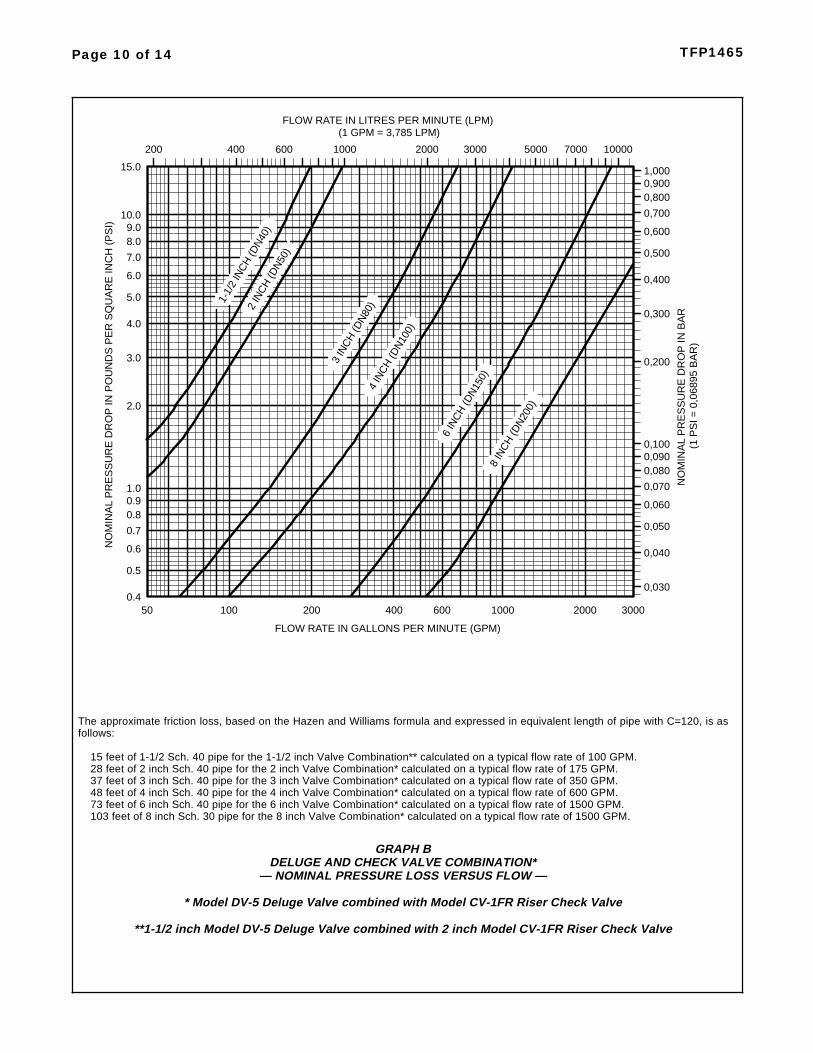
GRAPH BDELUGE AND CHECK VALVE COMBINATION*
— NOMINAL PRESSURE LOSS VERSUS FLOW —
* Model DV-5 Deluge Valve combined with Model CV-1FR Riser Check Valve
**1-1/2 inch Model DV-5 Deluge Valve combined with 2 inch Model CV-1FR Riser Check Valve
The approximate friction loss, based on the Hazen and Williams formula and expressed in equivalent length of pipe with C=120, is asfollows:
15 feet of 1-1/2 Sch. 40 pipe for the 1-1/2 inch Valve Combination** calculated on a typical flow rate of 100 GPM.28 feet of 2 inch Sch. 40 pipe for the 2 inch Valve Combination* calculated on a typical flow rate of 175 GPM.37 feet of 3 inch Sch. 40 pipe for the 3 inch Valve Combination* calculated on a typical flow rate of 350 GPM.48 feet of 4 inch Sch. 40 pipe for the 4 inch Valve Combination* calculated on a typical flow rate of 600 GPM.73 feet of 6 inch Sch. 40 pipe for the 6 inch Valve Combination* calculated on a typical flow rate of 1500 GPM.103 feet of 8 inch Sch. 30 pipe for the 8 inch Valve Combination* calculated on a typical flow rate of 1500 GPM.

sure for the Double Interlock PreactionSystem with Electric/Electric Actuationis nominally 15 psi (1,0 bar), irrespec-tive of the water supply pressure. Theuse of a higher system air pressuremay increase water delivery time, andthe use of a lower system air pressuremay prevent clearing the alarm of theLow Air Pressure Alarm Switch (ItemP3 - Fig. 2A) on increasing pressure.The Low Pressure Alarm Switch isfield set to alarm at nominally 12 psi(0,8 bar) on decreasing pressure. It isrecommended that the system airpressure be maintained by either ofthe following methods.
• A maximum 200 psi (13,8 bar) plantair supply in combination with theModel AMD-1 Air Maintenance De-vice described in Technical DataSheet TFP1221.
• A maximum 3000 psi (206,9 bar)nitrogen cylinder in combination withthe Model AMD-3 Nitrogen Mainte-nance Device described in Techni-cal Data Sheet TFP1241.
NOTESIt is recommended that the pressuremaintenance device be of a type thatmaintains a constant system pressure,i.e., a pressure maintenance devicethat utilizes a pressure regulator ver-sus a pressure switch (e.g., the AMD-1or AMD-3). Use of a pressure switchoperated pressure maintenance de-vice with a cut-in/cut-out differentialmay result in a delay in the operationof the system due to a fire, because ofthe cut-out pressure being higher thanthe recommended nominal system airpressure.
The dew point of the air or nitrogensupply, for a system exposed to freez-ing conditions, must be maintained be-low the lowest ambient temperature towhich the system piping will be ex-posed. Introduction of moisture intothe system piping can create ice buildup which could prevent proper opera-tion of the system.
The Pressure Relief Valve (Item P4-Fig. 2A) is typically field set to crackopen at a pressure of about 20 psi (1,4bar).
Friction LossThe nominal pressure loss versus flowdata for the Model DV-5 Deluge Valveplus Riser Check Valve is provided inGraph A.
InstallationNOTICE
1-1/2 inch (DN40) risers utilize a 2 inch(DN50) Riser Check Valve in combina-tion with the 1-1/2 (DN40) Model DV-5Deluge Valve.
Proper operation of the Model DV-5Deluge Valves depends upon their trimbeing installed in accordance with theinstructions given in this TechnicalData Sheet. Failure to follow the ap-propriate trim diagram may preventthe DV-5 Valve from functioning prop-erly, as well as void listings, approvals,and the manufacturer’s warranties.
Field adjustments of the Air Mainte-nance Device, Low Pressure AlarmSwitch, and Pressure Relief Valve arerequired. The Air Maintenance Deviceand the Low Pressure Alarm Switchshould be set as close as possible tothe specified settings in order to mini-mize water delivery time.
When using compressed air as op-posed to compressed nitrogen for re-frigerated area service, alternate airsupply connections with an air dryermay be required by the Authority Hav-ing Jurisdiction. The “1/2 Inch NPTConnection For System Air Supply”shown in Figure 2B is to be pluggedwhen using an alternate air supplyconnection; the location of the AirPressure Maintenance is to be asspecified by the Authority Having Ju-risdiction; and, Step 10 regarding theadjustment of the Pressure ReliefValve can be omitted, since the Pres-sure Relief Valve in this case will beineffective.
The DV-5 Valve must be installed in areadily visible and accessible location.
The DV-5 Valve and associated trimmust be maintained at a minimum tem-perature of 40°F/4°C.
Heat tracing of the DV-5 Valve or itsassociated trim is not permitted. Heattracing can result in the formation ofhardened mineral deposits that canprevent proper operation.
The Tyco® Model DV-5 Deluge Valveis to be installed in accordance withthe following criteria:
Step 1. All nipples, fittings, and de-vices must be clean and free of scaleand burrs before installation. Use pipethread sealant sparingly on male pipethreads only.
Step 2. The DV-5 Valve must betrimmed in accordance with Figure2A/2B (or TFP1100 when using ModelQRS Electronic Accelerator)
Step 3. Care must be taken to ensure
that check valves, strainers, globevalves, etc. are installed with the flowarrows in the proper direction.
Step 4. Drain tubing to the drip funnelmust be installed with smooth bendsthat will not restrict flow.
Step 5. The main drain and drip funneldrain may be interconnected provideda check valve is located at least 12inches (300 mm) below the drip funnel.
Step 6. Suitable provision must bemade for disposal of drain water.Drainage water must be directed sothat it will not cause accidental dam-age to property or danger to persons.
Step 7. Connect the DiaphragmChamber Supply Control Valve to theinlet side of the system’s main controlvalve in order to facilitate setting of theDV-5 Valve (Fig. 3).
Step 8. Unused pressure alarmswitch connections must be plugged.
Step 9. A suitable automatic supervi-sory air (nitrogen) supply, as de-scribed in the Technical Data Section,is to be installed in accordance withthe applicable Technical Data Sheetand set to maintain nominally 15 psi(1,0 bar).
Step 10. Adjust the Pressure ReliefValve (P4-Fig. 2A), as applicable, tocrack open at approximately 20 psi(1,4 bar). As shipped, it is set to openat approximately 45 psi (3,1 bar).
To reset the Pressure Relief Valve,first loosen the jam nut and then adjustthe cap accordingly — clockwise for ahigher pressure setting or counter-clockwise for a lower pressure setting.After verifying the desired pressuresetting, tighten the jam nut.
Step 11. Adjust the Low PressureAlarm Switch (P3-Fig. 2A) to transferthe electrical contacts at nominally 12psi (0,8 bar) on decreasing pressure.As shipped, the switch is set to transferthe electrical contacts at approxi-mately 5 psi (0,3 bar) on decreasingpressure.
Use the instructions provided with theswitch to adjust the pressure setting.
Step 12. Conduit and electrical con-nections are to be made in accordancewith the requirements of the authorityhaving jurisdiction and/or the NationalElectric Code.
NOTICE
The heat detection devices are to beconnected to the Zone 1 initiating cir-cuit contacts of the Cross-Zone Del-uge Valve Releasing Panel.
The Low Air Pressure Alarm Switch
Page 11 of 14TFP1465

contacts are to be connected to theZone 2 initiating circuit contacts of theCross-Zone Deluge Valve ReleasingPanel.
Step 13. Before a system hydrostatictest is performed in accordance withNFPA 13 system acceptance test re-quirements, the DV-5 DiaphragmChamber is to be depressurized; theAutomatic Drain Valve (4, Fig. 2A) is tobe temporarily replaced with a 1/2 inchNPT plug, the 3/32 inch Vent Fitting(16 - Fig. 2A) is to be temporarily re-placed with a 1/4 inch NPT plug, andthe Diaphragm Cover Bolts must beuniformly and securely tightenedusing a cross-draw sequence. Aftertightening, double-check to make cer-tain that all of the Diaphragm CoverBolts are securely tightened.
Valve SettingProcedureSteps 1 through 15 are to be per-formed when initially setting the Tyco®
Model DV-5 Deluge Valve; after anoperational test of the fire protectionsystem; or, after system operation dueto a fire.
Step 1. Close the Main Control Valve.
Step 2. Close the Diaphragm Cham-ber Supply Control Valve and the Sys-tem Air Supply Control Valve.
Step 3. Open the Main Drain Valve,System Drain Valve, and all auxiliarydrains in the system. After waterceases to discharge, close the SystemDrain Valve and auxiliary drain valves.Leave the Main Drain Valve open.
Note: Do not open the Inspector’s TestConnection and auxiliary drains if re-setting after a system test; otherwise,system air pressure will be relievedunnecessarily.
Step 4. Depress the plunger of theAutomatic Drain Valve to verify that itis open and that the DV-5 Valve iscompletely drained.
Step 5. Clean the Strainer in the Dia-phragm Chamber Supply connectionby removing the clean-out plug andstrainer basket. The Strainer may beflushed out by momentarily openingthe Diaphragm Chamber Supply Con-trol Valve.
Step 6. Inspect for and clear all iceplugs where system piping has beenexposed to freezing conditions andwhen there has been a flow of waterinto the system.
Step 7. Replace all damaged or oper-ated sprinklers. Replacement sprin-
klers must be of the same type andtemperature rating as those that oper-ated.
NOTICE
In order to prevent the possibility of asubsequent operation of an over-heated solder type sprinkler, any sol-der type sprinklers that were possiblyexposed to a temperature greater thantheir maximum rated ambient mustalso be replaced.
Step 8. Service the air dryer, if appli-cable, in accordance with the manu-facturer’s instructions.
Step 9. Open the System Air SupplyControl Valve and allow the system toautomatically re-establish its nominalair pressure of 15 psi (1,0 bar). Ob-serve the Automatic Drain Valve forleaks. If there are leaks, deter-mine/correct the cause of the leakageproblem within the Riser Check Valve.
Step 10. Reset the actuation system.
Manual Actuation — Push the operat-ing lever up; however, do not close thehinged cover at this time.
Electric Actuation — Reset the electricdetection system in accordance withthe manufacturer’s instructions to de-energize the Solenoid Valve.
Note: For systems eqipped with theModel QRS Electronic Accelerator in-stalled per Technical Data SheetTFP1100, momentarily press the “Sys-tem Reset” button (Figure 6 inTFP1100). Zone 1 Alarm and Zone 2Low Air Alarm should then clear.
Step 11. Open the Diaphragm Cham-ber Supply Control Valve and allow fullpressure to build up in the DiaphragmChamber.
Step 12. Operate (open) the ManualControl Station to vent trapped air fromthe Diaphragm Chamber. If neces-sary, first open the hinged cover, andthen fully pull down on the operatinglever. SLOWLY close the operatinglever, by pushing it up, after aeratedwater ceases to discharge from theManual Control Station drain tubing.Close the hinged cover and insert anew break rod in the small holethrough the top of the enclosing box.
Step 13. Inspect the drain connectionsfrom the Manual Control Station andthe Solenoid Valve. Any leaks must becorrected before proceeding to thenext step.
Step 14. Verify the ability for the DV-5Diaphragm to hold pressure as fol-lows:
With the diaphragm chamber pressur-ized per Step 12, temporarily close the
Diaphragm Chamber Supply ControlValve, and monitor the DiaphragmChamber Pressure Gauge for a dropin pressure.
If a drop in pressure is noted, the DV-5Diaphragm is to be replaced and/orany leaks must be corrected beforeproceeding to the next step.
If the Diaphragm Chamber PressureGauge does not indicate a drop inpressure, re-open the DiaphragmChamber Supply Control Valve andproceed to the next step.
Step 15. Slowly open the Main ControlValve. Close the Main Drain Valve assoon as water discharges from thedrain connection. Observe the Auto-matic Drain Valve for leaks. If there areleaks, determine/correct the cause ofthe leakage problem. If there are noleaks, the DV-5 Valve is ready to beplaced in service and the Main ControlValve must then be fully opened.
NOTICE
When the Main Control Valve isopened, the pressure on the Dia-phragm Chamber may increase. Thisincrease in pressure is normal, and ifthe pressure is greater than 250 psi(17,2 bar), the pressure is to be re-lieved by partially and temporarilyopening the Manual Control Station;however, do not allow the pressure asindicated on the Diaphragm ChamberPressure Gauge to drop below thesupply pressure shown on the WaterSupply Pressure Gauge, since this ac-tion may result in tripping of the DV-5Valve.
After setting a fire protection system,notify the proper authorities and ad-vise those responsible for monitoringproprietary and/or central stationalarms.
Care andMaintenanceThe following procedures, inspections,and maintenance must be performedas indicated, in addition to any specificrequirements of the NFPA, and anyimpairment must be immediately cor-rected.
The owner is responsible for the in-spection, testing, and maintenance oftheir fire protection system and de-vices in compliance with this docu-ment, as well as with the applicablestandards of the National Fire Protec-tion Association (e.g., NFPA 25), inaddition to the standards of anyauthority having jurisdiction. The in-stalling contractor or product manufac-
Page 12 of 14 TFP1465

turer should be contacted relative toany questions.
Automatic sprinkler systems are rec-ommended to be inspected, tested,and maintained by a qualified Inspec-tion Service in accordance with localrequirements and/or national codes.
It is recommended that the SystemInspection Procedure be performed atleast semi-annually by a qualified In-spection Service. The Double Inter-lock Preaction System Inspection Pro-cedure may be followed in lieu ofperforming any of the operational testsrecommended in the Technical DataSheets for the Model DV-5 DelugeValve, Riser Check Valve, 24 VDC So-lenoid Valve, and Model MC-1 ManualControl Station.
NOTICE
It is recommended that the individualsresponsible for the care and mainte-nance of the Double Interlock Preac-tion System develop a working under-standing of the system, in general,prior to performing inspection and/ormaintenance procedures. These in-structions, as well as individual in-structions for the deluge valve, risercheck valve, solenoid valve, manualcontrol station, switches, and pressuremaintenance device should be re-viewed.
The following procedures pertain tothe automatic control valve portion ofthe Double Interlock Preaction Sys-tem. Refer to the manufacturer’s in-structions and NFPA 25 for care andmaintenance procedures for all otherdevices (e.g., electric detection, maincontrol and system shut-off valves, su-pervisory devices, sprinklers, etc.).
Before performing the System Inspec-tion Procedure, which will result in op-eration of alarms, notify the properauthorities and all personnel who maybe affected.
Before closing a fire protection systemmain control valve for maintenancework on the fire protection system thatit controls, permission to shut down theaffected fire protection system must beobtained from the proper authoritiesand all personnel who may be affectedby this action must be notified.
System Inspection Procedure
Step 1. Close the Main Control Valve(Fig. 1) and then open the DV-5 MainDrain Valve (Fig. 2B).
Step 2. Manually operate Zone 1 of theReleasing Panel, and verify the follow-ing:
• Verify the operation of the ReleasingPanel and its associated alarms.
• Verify that there is no leakage fromthe Solenoid Valve (Fig. 2B).
Note: During this procedure, the Sole-noid Valve should remain closed andthe DV-5 Deluge Valve DiaphragmChamber should remain pressurized.
This procedure is used to verify thatthe DV-5 Deluge Valve will remain setif the electric detection system(Zone 1)operates but the sprinkler system(Zone 2) remains in its normally pres-surized condition.
Step 4. Restore the electric fire detec-tion system to a normal condition inaccordance with the manufacturer’sinstructions.
Step 5. Open the Inspector’s TestConnection to relieve system air pres-sure, and verify the following:
• Verify that the Low Air PressureAlarm Switch (Fig. 2B) and Zone 2of the Releasing Panel, as well as itsassociated alarms, operate prop-erly. The Low Pressure AlarmSwitch should operate at approxi-mately 12 psi (0,8 bar).
• Verify that there is no leakage fromthe Solenoid Valve (Fig. 2B).
Close the Inspector’s Test Connec-tion.
Note: During this procedure, the Sole-noid Valve should remain closed andthe DV-5 Deluge Valve DiaphragmChamber should remain pressurized.
This procedure is used to verify thatthe DV-5 Deluge Valve will remain setif the Low Pressure Alarm Switch(Zone 2) operates due to loss of sys-tem air pressure and the electric de-tection system (Zone 1) remains in anormal condition.
Step 6. Restore the electric fire detec-tion system to a normal condition inaccordance with the manufacturer’sinstructions after the system air pres-sure has automatically been restoredto normal.
Step 7. Close the System Shut-offValve (Fig. 1).
Step 8. Open the Main Control Valve(Fig. 1) one turn beyond the position atwhich water just begins to flow fromthe Main Drain Valve (Fig. 2B).
Step 9. Close the Main Drain Valve.
Step 10. Close the Air Supply ControlValve.
Step 11. Manually operate Zone 1 ofthe Releasing Panel, and then operateZone 2 of the Releasing Panel by par-
tially opening the System Main DrainValve (Fig. 2B) to relieve air pressureat the Low Pressure Alarm Switch, andverify the following:
• Verify that the DV-5 Deluge Valveoperates, as is indicated by a dis-charge of water from the SystemMain Drain Valve.
• Verify that the Waterflow PressureAlarm Switch (Fig. 2B) and its asso-ciated alarms properly operate.
• Verify that the Water Motor Alarm, ifapplicable, properly operates.
Note: This procedure simulates auto-matic system operation upon bothelectric detection and loss of systemair pressure.
Step 12. Reset the Double InterlockDry System in accordance with theSystem Setting Procedure section.
Quarterly Waterflow Alarm TestProcedureTesting of the system waterflowalarms must be performed quarterly.To test the waterflow alarm, open theAlarm Test Valve, which will allow aflow of water to the Waterflow Pres-sure Alarm Switch and/or Water MotorAlarm. Upon satisfactory completionof the test, close the Alarm Test Valve.
LimitedWarrantyProducts manufactured by Tyco FireSuppression & Building Products(TFSBP) are warranted solely to theoriginal Buyer for ten (10) yearsagainst defects in material and work-manship when paid for and properlyinstalled and maintained under normaluse and service. This warranty will ex-pire ten (10) years from date of ship-ment by TFSBP. No warranty is givenfor products or components manufac-tured by companies not affiliated byownership with TFSBP or for productsand components which have beensubject to misuse, improper installa-tion, corrosion, or which have not beeninstalled, maintained, modified or re-paired in accordance with applicableStandards of the National Fire Protec-tion Association, and/or the standardsof any other Authorities Having Juris-diction. Materials found by TFSBP tobe defective shall be either repaired orreplaced, at TFSBP’s sole option.TFSBP neither assumes, nor author-izes any person to assume for it, anyother obligation in connection with thesale of products or parts of products.TFSBP shall not be responsible forsprinkler system design errors or inac-
Page 13 of 14TFP1465
curate or incomplete information sup-plied by Buyer or Buyer’s repre-sentatives.
In no event shall TFSBP be liable, incontract, tort, strict liability or underany other legal theory, for incidental,indirect, special or consequential dam-ages, including but not limited to laborcharges, regardless of whetherTFSBP was informed about the possi-bility of such damages, and in no eventshall TFSBP’s liability exceed anamount equal to the sales price.
The foregoing warranty is made in lieuof any and all other warranties, ex-press or implied, including warrantiesof merchantability and fitness for a par-ticular purpose.
This limited warranty sets forth the ex-clusive remedy for claims based onfailure of or defect in products, materi-als or components, whether the claimis made in contract, tort, strict liabilityor any other legal theory.
This warranty will apply to the full ex-tent permitted by law. The invalidity, inwhole or part, of any portion of thiswarranty will not affect the remainder.
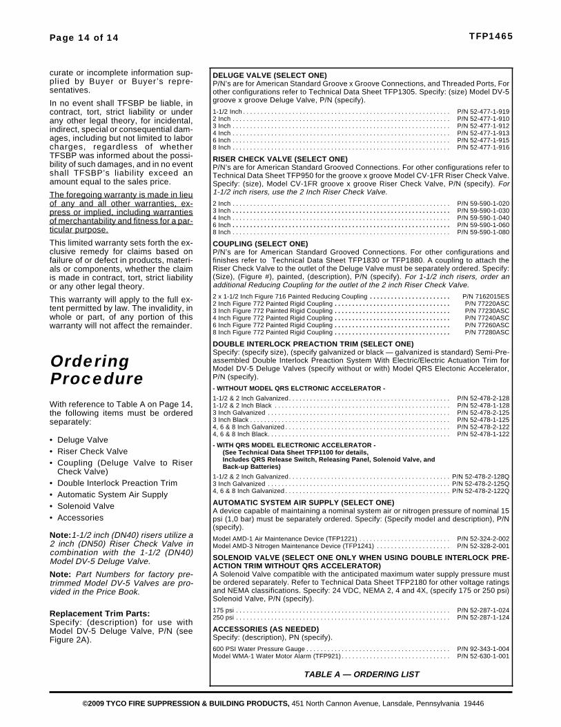
OrderingProcedureWith reference to Table A on Page 14,the following items must be orderedseparately:
• Deluge Valve• Riser Check Valve• Coupling (Deluge Valve to Riser
Check Valve)• Double Interlock Preaction Trim• Automatic System Air Supply• Solenoid Valve• Accessories
Note:1-1/2 inch (DN40) risers utilize a2 inch (DN50) Riser Check Valve incombination with the 1-1/2 (DN40)Model DV-5 Deluge Valve.
Note: Part Numbers for factory pre-trimmed Model DV-5 Valves are pro-vided in the Price Book.
Replacement Trim Parts:Specify: (description) for use withModel DV-5 Deluge Valve, P/N (seeFigure 2A).
Page 14 of 14 TFP1465
©2009 TYCO FIRE SUPPRESSION & BUILDING PRODUCTS, 451 North Cannon Avenue, Lansdale, Pennsylvania 19446
DELUGE VALVE (SELECT ONE)P/N’s are for American Standard Groove x Groove Connections, and Threaded Ports, Forother configurations refer to Technical Data Sheet TFP1305. Specify: (size) Model DV-5groove x groove Deluge Valve, P/N (specify).
1-1/2 Inch . . . . . . . . . . . . . . . . . . . . . . . . . . . . . . . . . . . . . . . . . . . . . . . . . . . . . . . . . . . P/N 52-477-1-9192 Inch . . . . . . . . . . . . . . . . . . . . . . . . . . . . . . . . . . . . . . . . . . . . . . . . . . . . . . . . . . . . . . P/N 52-477-1-9103 Inch . . . . . . . . . . . . . . . . . . . . . . . . . . . . . . . . . . . . . . . . . . . . . . . . . . . . . . . . . . . . . . P/N 52-477-1-9124 Inch . . . . . . . . . . . . . . . . . . . . . . . . . . . . . . . . . . . . . . . . . . . . . . . . . . . . . . . . . . . . . . P/N 52-477-1-9136 Inch . . . . . . . . . . . . . . . . . . . . . . . . . . . . . . . . . . . . . . . . . . . . . . . . . . . . . . . . . . . . . . P/N 52-477-1-9158 Inch . . . . . . . . . . . . . . . . . . . . . . . . . . . . . . . . . . . . . . . . . . . . . . . . . . . . . . . . . . . . . . P/N 52-477-1-916
RISER CHECK VALVE (SELECT ONE)P/N’s are for American Standard Grooved Connections. For other configurations refer toTechnical Data Sheet TFP950 for the groove x groove Model CV-1FR Riser Check Valve.Specify: (size), Model CV-1FR groove x groove Riser Check Valve, P/N (specify). For1-1/2 inch risers, use the 2 Inch Riser Check Valve.
2 Inch . . . . . . . . . . . . . . . . . . . . . . . . . . . . . . . . . . . . . . . . . . . . . . . . . . . . . . . . . . . . . . P/N 59-590-1-0203 Inch . . . . . . . . . . . . . . . . . . . . . . . . . . . . . . . . . . . . . . . . . . . . . . . . . . . . . . . . . . . . . . P/N 59-590-1-0304 Inch . . . . . . . . . . . . . . . . . . . . . . . . . . . . . . . . . . . . . . . . . . . . . . . . . . . . . . . . . . . . . . P/N 59-590-1-0406 Inch . . . . . . . . . . . . . . . . . . . . . . . . . . . . . . . . . . . . . . . . . . . . . . . . . . . . . . . . . . . . . . P/N 59-590-1-0608 Inch . . . . . . . . . . . . . . . . . . . . . . . . . . . . . . . . . . . . . . . . . . . . . . . . . . . . . . . . . . . . . . P/N 59-590-1-080
COUPLING (SELECT ONE)P/N’s are for American Standard Grooved Connections. For other configurations andfinishes refer to Technical Data Sheet TFP1830 or TFP1880. A coupling to attach theRiser Check Valve to the outlet of the Deluge Valve must be separately ordered. Specify:(Size), (Figure #), painted, (description), P/N (specify). For 1-1/2 inch risers, order anadditional Reducing Coupling for the outlet of the 2 inch Riser Check Valve.
2 x 1-1/2 Inch Figure 716 Painted Reducing Coupling . . . . . . . . . . . . . . . . . . . . . . . P/N 7162015ES2 Inch Figure 772 Painted Rigid Coupling . . . . . . . . . . . . . . . . . . . . . . . . . . . . . . . . . P/N 77220ASC3 Inch Figure 772 Painted Rigid Coupling . . . . . . . . . . . . . . . . . . . . . . . . . . . . . . . . . P/N 77230ASC4 Inch Figure 772 Painted Rigid Coupling . . . . . . . . . . . . . . . . . . . . . . . . . . . . . . . . . P/N 77240ASC6 Inch Figure 772 Painted Rigid Coupling . . . . . . . . . . . . . . . . . . . . . . . . . . . . . . . . . P/N 77260ASC8 Inch Figure 772 Painted Rigid Coupling . . . . . . . . . . . . . . . . . . . . . . . . . . . . . . . . . P/N 77280ASC
DOUBLE INTERLOCK PREACTION TRIM (SELECT ONE)Specify: (specify size), (specify galvanized or black — galvanized is standard) Semi-Pre-assembled Double Interlock Preaction System With Electric/Electric Actuation Trim forModel DV-5 Deluge Valves (specify without or with) Model QRS Electonic Accelerator,P/N (specify).
- WITHOUT MODEL QRS ELCTRONIC ACCELERATOR -
1-1/2 & 2 Inch Galvanized. . . . . . . . . . . . . . . . . . . . . . . . . . . . . . . . . . . . . . . . . . . . . . P/N 52-478-2-1281-1/2 & 2 Inch Black . . . . . . . . . . . . . . . . . . . . . . . . . . . . . . . . . . . . . . . . . . . . . . . . . . P/N 52-478-1-1283 Inch Galvanized . . . . . . . . . . . . . . . . . . . . . . . . . . . . . . . . . . . . . . . . . . . . . . . . . . . . P/N 52-478-2-1253 Inch Black . . . . . . . . . . . . . . . . . . . . . . . . . . . . . . . . . . . . . . . . . . . . . . . . . . . . . . . . . P/N 52-478-1-1254, 6 & 8 Inch Galvanized . . . . . . . . . . . . . . . . . . . . . . . . . . . . . . . . . . . . . . . . . . . . . . . P/N 52-478-2-1224, 6 & 8 Inch Black. . . . . . . . . . . . . . . . . . . . . . . . . . . . . . . . . . . . . . . . . . . . . . . . . . . . P/N 52-478-1-122
- WITH QRS MODEL ELECTRONIC ACCELERATOR -(See Technical Data Sheet TFP1100 for details,Includes QRS Release Switch, Releasing Panel, Solenoid Valve, andBack-up Batteries)
1-1/2 & 2 Inch Galvanized. . . . . . . . . . . . . . . . . . . . . . . . . . . . . . . . . . . . . . . . . . . . . . P/N 52-478-2-128Q3 Inch Galvanized . . . . . . . . . . . . . . . . . . . . . . . . . . . . . . . . . . . . . . . . . . . . . . . . . . . . P/N 52-478-2-125Q4, 6 & 8 Inch Galvanized . . . . . . . . . . . . . . . . . . . . . . . . . . . . . . . . . . . . . . . . . . . . . . . P/N 52-478-2-122Q
AUTOMATIC SYSTEM AIR SUPPLY (SELECT ONE)A device capable of maintaining a nominal system air or nitrogen pressure of nominal 15psi (1,0 bar) must be separately ordered. Specify: (Specify model and description), P/N(specify).
Model AMD-1 Air Maintenance Device (TFP1221) . . . . . . . . . . . . . . . . . . . . . . . . . . P/N 52-324-2-002Model AMD-3 Nitrogen Maintenance Device (TFP1241) . . . . . . . . . . . . . . . . . . . . . P/N 52-328-2-001
SOLENOID VALVE (SELECT ONE ONLY WHEN USING DOUBLE INTERLOCK PRE-ACTION TRIM WITHOUT QRS ACCELERATOR)A Solenoid Valve compatible with the anticipated maximum water supply pressure mustbe ordered separately. Refer to Technical Data Sheet TFP2180 for other voltage ratingsand NEMA classifications. Specify: 24 VDC, NEMA 2, 4 and 4X, (specify 175 or 250 psi)Solenoid Valve, P/N (specify).
175 psi . . . . . . . . . . . . . . . . . . . . . . . . . . . . . . . . . . . . . . . . . . . . . . . . . . . . . . . . . . . . . P/N 52-287-1-024250 psi . . . . . . . . . . . . . . . . . . . . . . . . . . . . . . . . . . . . . . . . . . . . . . . . . . . . . . . . . . . . . P/N 52-287-1-124
ACCESSORIES (AS NEEDED)Specify: (description), PN (specify).
600 PSI Water Pressure Gauge . . . . . . . . . . . . . . . . . . . . . . . . . . . . . . . . . . . . . . . . . P/N 92-343-1-004Model WMA-1 Water Motor Alarm (TFP921) . . . . . . . . . . . . . . . . . . . . . . . . . . . . . . . P/N 52-630-1-001
TABLE A — ORDERING LIST
Related Documents