Development of Structural Core Components for Breeder Reactors N. Saibaba Chief Executive Nuclear Fuel Complex Hyderabad, India International Conference on Fast Reactors and Related Fuel Cycles Safe Technologies and Sustainable Scenarios (FR13) Paris, France, March 5, 2013

Welcome message from author
This document is posted to help you gain knowledge. Please leave a comment to let me know what you think about it! Share it to your friends and learn new things together.
Transcript

Development of Structural Core Components
for Breeder Reactors
N. SaibabaChief Executive
Nuclear Fuel Complex
Hyderabad, India
International Conference on Fast Reactors and Related Fuel Cycles Safe Technologies and Sustainable Scenarios (FR13)
Paris, France, March 5, 2013

3-STAGE NUCLEAR POWER
PROGRAMME
Dr. Homi Jehangir Bhabhaformulated the three stage Indian
Nuclear Power Programme linking
the fuel cycles of PHWRs and FBRs.
STAGE I
Consists of PHWRs and BWRs.
These reactors produce power
from natural U fuel. Pu239 is also
produced as a bye product.
STAGE II
Consists of FBRs. These reactors
produce power from Pu239 as fuel.
Here fuel breeding is carried out by
converting Th232 to U233 and U238 to
Pu239.
STAGE III
Consists of PHWRs and
AHWRs. These reactors
produce power by using U233
and Pu239 from stage II as
fuel.

500 MWe PFBR CORE
FUEL CLAD TUBES
(6.6 x 0.45 x 2555 mm)
41000/50000 Nos
REFLECTOR CLAD TUBES
(44 x 1 x 1070 mm)
1200/1200 Nos
BLANKET CLAD TUBES
(14.33 x 0.56 x 2350 mm)
6000/8200 Nos
CSR CLAD TUBES
(22.4 x 1 x 1260 mm)
1000/1000 Nos
DSR CLAD TUBES
(21.4 x 0.7 x 1110 mm)
500/500 Nos
IBC CLAD TUBES
(44 x 1 x 3325 mm)
1100/1100 Nos
TUBES FOR CORE STRUCTURALS
01 Main Vessel
02 Core Support Structure
03 Core Catcher
04 Grid Plate
05 Core
06 Inner Vessel
07 Roof Slab
08 Large Rotating Plug
09 Small Rotating Plug
10 Control Plug
11 CSRDM / DSRDM
12 Transfer Arm
13 Intermediate Heat Exchanger
14 Primary Sodium Pump
15 Safety Vessel
16 Reactor Vault

Fuel Cycle Cost vs Burn-up
FR Burn-up (MWd/Kg)
Re
lati
ve f
ue
l cy
cle
co
st
Advantages of high burn-up
IN FBRs, 200 GWd/t BURN-UP IS DESIRED TO
REDUCE THE FUEL CYCLE COST
To Lower Unit Energy Cost
MINIMISE WASTE GENERATION
Less Minor Actinides and
Fission Products per MWe
REDUCE MAN-REM EXPOSURE
per MWe
But…
Radiation damage of the core
components is the major
concern

Core Structural Materials
• Though the desire is to have only fuel in the core, structural material form 25% of the total core
–To support and to retain the fuel in position
– Provide necessary ducts to make coolant flow through & transfer/remove heat
• For 500 MWe FBR with Oxide fuel (Peak Linear Power 450 W/cm), total fuel pins required in the core are of the order 39277 pins (both inner & outer core Fuel SA)
• Considering 217 pins/Fuel SA there are 181 Fuel SA wrapper tubes
• These structural materials see hostile core with max temperature and neutron flux
Sl no Structural components Wt (%)
1 Clad tubes 50
2 Wrapper 40
3 spacer wire 10

STRINGENT IN-SERVICE CONDITIONS IN FBRs
� High energy neutron irradiation leads to displacement of atoms (vacanciesand interstitials)
� Agglomeration of vacancies
� Void formation and swelling
�Density of neutron flux 3·1015 – 1016 n/cm2s
�Rate of He generation 20 – 30 appm/year
�Dose rate 100 – 200 dpa/year
�Temperature 400 – 6500С

Fresh Core Bowed Core BowingDilation(Swelling + Creep)
Irradiation Induced Dimensional Changes

Fuel Subassembly – Clad & Wrapper
Agglomeration
of vacancies
Intense Neutron Flux
(1015n/cm2/s)
FAST REACTOR CORE
STRUCTURAL
MATERIALS
High Temperature 400-
700oC- clad 400-600oC
wrapper
DISPLACEMENT
OF ATOMS
VOID SWELLING
Irradiation Creep
Dimensional Changes and Deterioration in
Mechanical Properties
100 – 200 dpa
Vacancies and
Interstitials
Irradiated
Unirradiated
Core
fuel

CRITERIA FOR MATERIAL SELECTION
IRRADIATION
EFFECTS
MECHANICAL
PROPERTIES
CORROSION
PROPERTIES
• Void Swelling
• Irradiation creep
• Irradiation embrittlement
• Tensile Strength
• Tensile Ductility
• Compatibility with Sodium

Materials for Core Structural Components of FBRs
Choice of Materials for Clad Tubes:
�Austenitic Stainless Steels
� F-M Steels
�ODS Steels
�Bi-Metallic

SELECTION OF SS D9 OVER SS 316
1. Higher Nickel: Nickel reduces void nucleation by enhancing vacancy diffusion
coefficient and thus reducing vacancy supersaturation.
2. Lower Chromium: Reducing chromium increases the stability of γγγγ phase against
precipitation of alloying elements that are responsible for reduced void swelling.
3. Solutes: Ti, Si, B and C play a dominant role in improving void swelling resistance
by extending the duration of the transient regime of void swelling.
4. Cold Work (higher dislocation density) improves void swelling resistance by:
• providing sinks for vacancies
• providing nucleation sites for ppts.
• improving phase stability during irradiation.
5. In general, factors that improve void swelling resistance are observed to improve
irradiation creep resistance.

ALLOY D9
• Primary carbides accelerate recrystallization (thusremoving the effect of cold work)
• Increasing Ti/C ratio leads to formation of primarycarbides (restricted to 6).
• 20% prior cold worked hexcans, for better void swellingresistance
– Ti/C = 4 →→→→ best creep resistance
– Ti/C = 6 →→→→ best mechanical properties and acceptable creepresistance
• 20% CW → optimum to avoid recrystallization of coldworked material and retard void swelling.

• Focus on increasing the threshold &
incubation fluence
• Linear swelling rate remains almost
constant
Swe
llin
g
%
Fluence (dpa)
Linear swelling
regime, insensitive to
initial microstructure
Transient swelling
regimeMicrochemical
evolution
Current
austenitic
stainless
steels can
support
up to 150
dpa
DIA
ME
TR
AL D
EF
OR
MA
TIO
N (
%)
3
553500000
1
2
5
4
6
CW 316
7
8
CW 15-15 Ti
1359575
DOSE (dpa)
115
CW Si-MOD 15-15 Ti
CW 316 Ti
Swelling behaviour of different Materials
(irradiation temp ~ 670-870 K)
Strategy for Improving Swelling Resistance in
Austenitic Stainless Steels
1.0E-10
1.0E-09
1.0E-08
1.0E-07
1.0E-06
1.0E-05
200 250 300
Stress (MPa)
Min
imu
m C
reep
Rate
(p
er
sec)
έ = A σn exp(−Q / RT )
SS D9 exhibits lower creep rate
as compared to SS 316 at 923 K

Austenitic 316 SS
C Cr Ni Mo Mn Si S P
0.04-0.07 16-18 12-14 2.0-2.5 1.4-2.0 0.75 0.025 0.03
Material for clad
and wrapper
tubes in FBTR
(initial core)
50nm
40 dpaUNIRRADIATED CONDITION
Cold worked
structure
Void – Ppt.
Association
M6C ηηηη carbide
Si: 8.1%
Cr: 21.5
Fe: 28.7
Ni: 33.7
Mo 1.7
Ni – Si rich
G phaseDefect formation at
low doses
Precipitation of M23C6
and M6C
Formation of Ni, Si
rich G Phase at high
dose
316 SS has good thermal creep properties
Breakaway swelling beyond 50 dpa

1. Increase nickel
2. Reduce chromium
3. Add titanium
4. Control Silicon
5. Use of phosphorous as
alloying element
C Cr Ni Mo Mn Si S P Ti
316 SS 0.04-0.07 16-18 12-14 2.0-2.5 1.4-
2.0
0.75 0.025 0.03
D9 .035-.045 13.5-
14.5
14.5-
15.5
2.0-2.5 1.4
2.0
0.5-
0.75
0.025 0.01 0.25
D9-I .035-.045 13.5-
14.5
14.5-
15.5
2.0-2.5 1.4
2.0
0.75-
0.8
0.025 0.035-
0.045
0.25
Improvements of Swelling resistance by Change in composition
swelling resistance increases from 50 to 100 to 150 dpa

10010
-11
10-10
10-9
10-8
10-7
10-6
300200
Min
imu
m c
reep
rate
/s
Applied stress,MPa
D9 923 K
316 SS 923 K
D9 973 K
316 SS 973 K
D9 1023 K
316 SS 1023 K
Creep Properties of 316 SS and D9 SS Clad Tubes

9% Cr steels shows minimum shift in DBTT
Ferritic- Martensitic Steels
Mod. 9Cr-1Mo steel shows lower DBTT Shift than HT-9
HT9 Steel for wrapper ( Fe-9Cr-1Mo-0.07C- 0.2-0.6 Si)
Target: to be used for irradiation doses up to 200 dpa
Beneficial to start with materials with high purity to ensure low DBTT
HT91 Steel for cladding of metal fuel reactors (HT9+ Nb- 0.06-0.1, V- 0.18 – 0.25 , N -0.03-0.07)
� Exellent void sewlling resistance dose up to 200dpa
� Inferior High Temperature creep properties above 600 deg. C
� Formation of low melting (725 0C) eutectic phase with Uranium

Bi-metalic clad tube for metallic fuel
UZr
HT91
Effectiveness of Zr liner U-Fe Phase diagram
Eutectic formation at 725oC
U-Zr Phase diagramNo Eutectic formation in U-Zr system
Zr liner
U T91T91
Diffusion couple

• ODS ferritic - martensitic steels (Fe - 9 Cr- 0.1 C- 2W-0.2 Ti + 0.35 Y2O3 )
Combines swelling resistance of ferritic-martensitic steels with high-
temperature creep resistance of austenitic steels
�For use as cladding material for achieving high burn-up targets
�Can be used up to fluence of 200dpa
Final option: Oxide Dispersion Strengthened Ferritic-Martensitic Steels
100 150 200 250Neutron Dose (dpa)
1000
950
900
850
PH Ferritic/
Martensitic
Austenitic
ODS
High TemperatureHigh TemperatureHigh TemperatureHigh TemperatureStrengthStrengthStrengthStrength
RadiationRadiationRadiationRadiationResistanceResistanceResistanceResistance
Maxim
um
Tem
per
atu
re (
K)

Manufacture of
D9 & Mod-9Cr-1Mo Clad tubes

Specifications for D9 and Mod-9Cr-1Mo Fuel Clad Tubes
• Dimensional Tolerances:
� OD : 6.6 + 0.02 mm
� ID : 5.7 + 0.02 mm
� WT : 0.43 min
� Length : 2555 + 1/-0 mm
� Straightness : 0.25/500
• Cold Work : 20 + 4 %
• Grain Size after final annealing : 7-9 (ASTM
E-112)
• IGC: ASTM A 262 Pr A @ 100 X
magnification
• Hardness : 220-290 VHN
• Surface Finish: 0.5 µRa
• ECT: 0.3 + 0.03 mm through holes
• UT: 0.05 + 0.002 mm X 1.5 mm Lg 600 V
Notch
• Dimensional Tolerances:
� OD : 6.6 + 0.02 mm
� ID : 5.7 + 0.02 mm
� WT : 0.43 min
� Length : 2555 + 1/-0 mm
� Straightness : 0.25/500
• Hardness : 250 VHN max
• Surface Finish: 0.5 µRa
• ECT: 0.3 + 0.03 mm through holes
• UT: 0.05 + 0.002 mm X 1.5 mm Lg
600 V Notch
Property At Room
Temp.
@ 5400C
YS (Mpa) 420 Min 275
UTS (Mpa) 558-760 320
% e (min) 20 To be reported
Property At Room
Temp.
@ 5400C
YS (Mpa) 550-760 430-585
UTS (Mpa) 700-830 500-690
% e (min) 20 10

Basic Manufacturing Process
HOT EXTRUSION To Obtain Mother Hollows.
Cold Pilgering
Cold Drawing
(only for D9)
With high reductions up to75% with reduced number of cold working passes.
Final Process to obtain very close dimensional tolerances with higher rates of production where limited final cold work of 20% specified.
Heat treatment
Final Annealing at 1050 to 1080C/ 2min followed by fast cooling (175C/min) for D9
Normalizing at 1050-1080C/ 30min/ Air cooling followed by tempering at 760-780C/60min/Air cooling for Mod-9Cr-1Mo Grade

Stringent Specifications at
ET & UT
CHALLENGES DURING
MANUFACTURING
CLAD TUBES
CONTROLLED
CHEMISTRY
C - pick up problem
N- pick up problem

Nitrogen Pick up upto 450 ppm
Cracked
Ammonia
Ar + H2
Controlling Nitrogen and Carbon Pick up
0
50
100
150
200
250
300
350
1 2 3 4 5 6
N V
alu
es in
PP
M
Number of Annealing
N PICKUP VS NO. OF ANNEALING
100% CA 20% Ar + 80% CA
50% Ar + 50% CA 100% Ar
88% Ar + 12% H2
� Carbon pick up was controlled by Special vapor Degreasing system to ensurethorough cleaning of lubricants used during cold working operations such asPilgering and Drawing.
� Nitrogen pick up was controlled by modifying Furnace Atmosphere

Tensile properties Specified value Result obtained
UTS (MPa) 700 - 830 793
YS(MPa) 550 - 760 691
% Elg.(Gl=5.65√A) 20 min. 23
Hardness (VHN) 220 - 290 271
HIGH TEMPERATURE (AT 5400C) MECHANICAL PROPERTIES
ROOM TEMPERATURE MECHANICAL PROPERTIES
Tensile properties Specified value Result obtained
UTS (MPa) 500 - 690 615
YS(MPa) 430 - 585 579
% Elg.(Gl=5.65√A) 10 min. 11
Typical Mechanical Test Results of D9 Tubes

Characterization of Mod-9 Cr- 1 Mo Clad Tubes
Pinning of Sub-grain
boundaries during Creep
Microstructure of modified 9Cr-1Mo (a) Optical (b) TEM (c) Particle size distribution
MX : Nb(C,N) & VN
Parameter Specified Value Result Achieved
Y.S.( Mpa) 420 Min. 535 - 578
UTS (MPa) 585 - 760 695 -714
Hardness HB 250 Max. 243 - 248
% Elongation 20 Min. 23 - 26
Simulated heat treatment values
Y.S.( Mpa) RT 420 min. 470 - 520
UTS (MPa) RT 585 - 760. 660 - 710% Elongation RT 20 min. 25 - 26
Y.S.( Mpa) HT 275 min. 370 - 420UTS (MPa) HT 370 min. 465 - 525
% Elongation HT To be reported 20 - 22

Manufacturing of ODS Clad Tube

Challenges In Processing ODS
� size and uniform distribution of yttria (Y2O3) duringmechanical alloying.
� Selection of Deglassing techniques after extrusionrequiring chemical compatibility
� Detection and removal of MS patches from the surface.
� Machinability of extruded mother hollow surface
� Selection of cold working parameters Ex: Feed rate, inputlength, reduction per pass, Tool design etc.
� Selection of Heat Treatment parameters e.g., soakingtime and temperature & furnace atmosphere.

PrePrePrePre----alloyed Powderalloyed Powderalloyed Powderalloyed Powder
YYYY2222OOOO3333 PowderPowderPowderPowder
Mechanical Alloying (MA)(Ball Milling)
Hot Extrusion at 1150 C
Raw MaterialPowder
CanningDegassing at 400 C
Dispersoid Size Control
Mother Tube
36363636mm OD x mm OD x mm OD x mm OD x 4444mm WT mm WT mm WT mm WT
Annealing
(Φ14mm)
Drilling
Powder Metallurgy (PM) Process for Mother Tubes

NDE for Detection of MS patches
Ph
oto
gra
ph
Th
erm
al
Ima
ge
�NDE techniques could reliably detect MS patches
�Small MS patches could also be detected
Uncoated region
Coated with black paint
A.U
.
36mm OD X 4 mm WT ODS
steel mother tubes

NDE could detect sub-surface MS inclusion
� EC and MBE revealed less sensitivity but could reliably detect the sub-surface
MS inclusions
�Thermal imaging could not detect the sub-surface MS inclusion.
0 10 20 30 40 50 60 70 80 90 100
30
40
50
60
70
MB
E R
MS
Valu
e, A
U
Scan position, mm

Synthesis &
consolidation
Pass schedule for manufacture of ODS clad
tubes: 11 stages of cold pilgering with three
intermediate annealing and a final normalising-
tempering heat treatment, from mother tube
to clad tube.
Development of 9Cr-2W-0.1C-0.2Ti-0.35Y2O3 ODS Clad Tube by Rod extrusion Synthesis and Processing
Nano Yttria powder
35µm
Atomized alloy powder
(Fe-9Cr-0.13C-0.2Ti-2W)
150µm
Mechanical Alloying
Canning and Degassing
Upsetting
Hot extrusion to blank
Pilgering (11passes)
Evaluation of tubes
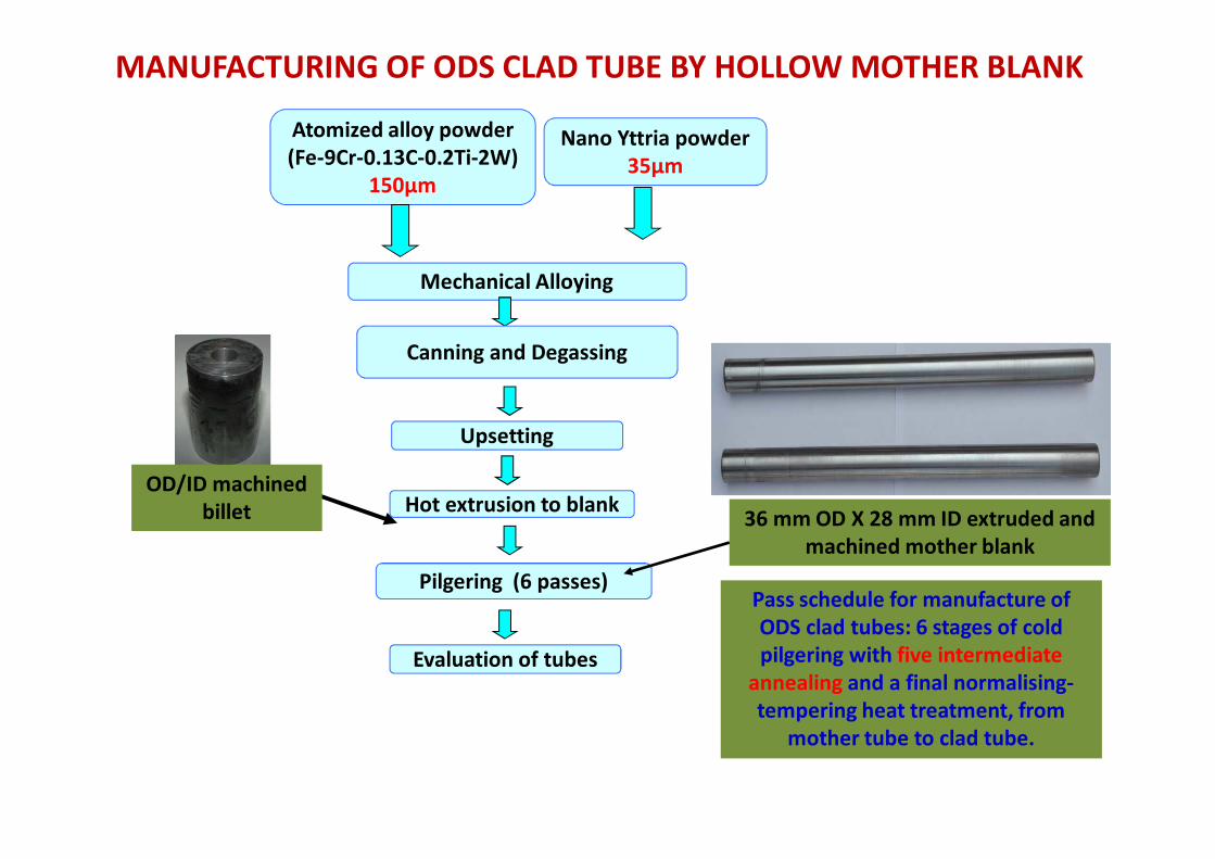
Nano Yttria powder
35µm
Atomized alloy powder
(Fe-9Cr-0.13C-0.2Ti-2W)
150µm
Mechanical Alloying
Canning and Degassing
Upsetting
Hot extrusion to blank
Pilgering (6 passes)
Evaluation of tubes
OD/ID machined
billet 36 mm OD X 28 mm ID extruded and
machined mother blank
MANUFACTURING OF ODS CLAD TUBE BY HOLLOW MOTHER BLANK
Pass schedule for manufacture of
ODS clad tubes: 6 stages of cold
pilgering with five intermediate
annealing and a final normalising-
tempering heat treatment, from
mother tube to clad tube.

Upset Billets
Preheated Billet
undergoing OD lubrication with glass powder
Billet transferred into extrusion press
container vertically630 T Extrusion Press24 Ø mm rod in red hot condition

MATERIAL UTS (MPa) YS (MPa) % ELONG.
SPECIFICATION FOR D9 700 - 830 550 - 760 20
D9 PROPERTIES (TYPICAL) 724 600 21
ODS PROPERTIES (TYPICAL)959 811 -
921 830 22.7
MATERIAL UTS (MPa) YS (MPa) % ELONG.
SPECIFICATION FOR D9 500 - 690 430 - 580 10
D9 PROPERTIES (TYPICAL) 548 488 14
ODS PROPERTIES (TYPICAL) 554 519 14
ROOM TEMPERATURE PROPERTIES
HIGH TEMPERATURE PROPERTIES(540OC)
Mechanical Properties of ODS Steel Clad Tube
17.75 Ø mm X 1.75 mm WT
machined & polished ODS
Tube
Finished ODS Steel Clad tube
6.6mm OD X 0.45mm WT

Alloy powder, Plate-like,
varying sizes <300 µµµµm
=20 µm; IPF Coloured; Step=0.8 µm; Grid146x115
{111}Pole Figures
[Project4.cpr]
Iron bcc (old) (m3m)
Complete data set
16737 data points
Equal Area projection
Upper hemispheres
Half width:10°
Cluster size:5°
Exp. densities (mud):
Min= 0.38, Max= 2.45
1
2
NO TEXTURE
EBSD/ pole figures
0
100
200
300
400
freq
uen
cy o
f th
e d
isp
ers
oid
s
Size (nm)2.5 4.5 6.5 8.5 10.5 12.5 15
Metallurgical Characterization

Element C Cr W Ti Y2O3 Mn N O (Total)
Spec. 0.11 - 0.13 8.8 - 9.2 1.9 - 2.1 0.19 - 0.22 0.32 - 0.35 0.04 max < 0.01
Typical 0.12 8.85 2.01 0.21 0.36 0.01 0.01 0.12
100 1000 10000
30
40
50
60708090
200
300
Grade 91
India ODS clad tube
9Cr-ODS Japan
Alloy D9
Ap
pli
ed
str
es
s,
MP
a
Rupture life, hour
700 oCTest in progress
Clad-tubes with 6.6 mm O.D., 0.45 mm thick and 4.2 m length have been successfully produced
Rupture Life
Chemical Composition

�Better creep strength than Austenitic SS.
�DBTT is close to room temperature.
�No carbon leaching in sodium environment.
�Ferritic structure provides better resistance to
neutron damage and has better void swelling
resistance (Compared to austenitics).
Ferritic Steel Vs Austenitic Stainless Steel
for FBR Applications

Development of Double Clad Tubes for Metallic Fuel
Advantages of Metallic Fuels
�higher burn-up-
�higher breeding ratio (i.e. shorter doubling
time)
�Improved safety, as the reactor can be
safely shut down without operator assistance.

METHODS OF FABRICATION
�Co-extrusion
�Zr-2 clad tube lined with Zr-4 for high burn
up in PHWRs.
�Co-Pilgering
�9Cr-1Mo clad tube lined with Zr-4 for
metallic fuel in fast breeders.
�Co-Drawing
�SS tube lined with Zircaloy for chemical
applications
�Explosive Cladding

Route adopted
Co-Pilgering
9Cr-1Mo clad tube lined with Zr-4 for
metallic fuel in fast breeders

Schematic of Double Clad Tube
Fabricated at NFC
Fabrication Criticalities
�End Fusing of T91 & Zr-Alloy tubes is to be
done so as to prevent relative slip between
inner & outer tubes and ingress of oil during
pilgering. (Achieved by Electron Beam
Welding)
�T91 & Zr alloy show different deformation
behavior in pilgering. Hence, fixing of
dimensions of T91 & Zr tubes at pre-final stage
is very critical to achieve the finished
dimensions after co-pilgering.
CO-PILGERING TECHNIQUE FOR MANUFACTURE OF DOUBLE
CLAD TUBE OF SIZE 6.6 MM OD X 0.6 MM WT

SEM PHOTOS OF DOUBLE CLAD TUBE
X-SECTION
Tube Section showing Outer & Inner
Walls of T91 & Zr Alloy
Enlarged View showing no gap at
T91-Zr Interface along with wall
thickness measurement

NDT Examination in Tubing
• Immersion Ultrasonic Testing (L & T): 100%
for deep defects.
• Eddy Current Testing (Saturation field):
100% Surface and sub-surface defects.
• Visual Examination: 100% OD surface
defects

Effectiveness of Zr liner at different temperatures
700oC/1500h 750oC/1500h 850oC/1000
U ZrU Zr T91 U Zr T91 T91
Line spectra on white
phase on Zr liner

� T91, Zr, U strongly bonded at interfaces.
� No interfacial gap ensuring no resistance to heat transfer during reactor
operation.
EPMA Scan along U/Zr/T91 Interface
700ºC,1505 hrs
Zr
Fe
U
Cr
T91Zr4

Development & Manufacture of D9 Hexcan
wrapper using Hex-Hex Pilgering

SCHEMATIC OF HEXCAN PILGERING
MANDREL
ROLLER
CRTM 60 -160 Pilger Mill Fuel subassembly wrapper tube

Consistency Of Hardness(VHN) & Strength on Hex-can,
manufactured by Hexcan To Hexcan Pilgering Route
500
550
600
650
700
750
800
16 17 18 19 20 21
Percentage Cold Work
Strength
(M
Pa)
UTS
YS
Variation of UTS and YS with cold work in hexcans of SS D9

Specifications for D9 Hexcan Wrapper Tubes
• Chemical CompositionElement Wt% Element Wt%
C 0.035-0.05 Ta 0.02 max
Cr 13.5-14.5 Ti 5C-7.5 C
Ni 14.5-15.5 Al 0.05 max
Mo 2-2.5 Si 0.5-0.75
Mn 1.65-2.35 Co 0.05 max
N 0.005 max Cu 0.04 max
S 0.01 max As 0.03 max
P 0.02 max V 0.04 max
B 10-20 ppm Fe balance
Nb 0.05 max
• Dimensional Tolerances:
� Width A/F (outside) : 131.6 + 0.3mm
� Width A/F (Inside) : 124.9 + 0.3mm
� WT : 3.2 + 0.3min
� Length : 3600 + 5/-0 mm
� Straightness : 1/2500
� Twist: 15’/ cross-section apart by 1m
• Cold Work : 20 + 4 %
• Grain Size after final annealing prior to
cold drawing : 5-9 (ASTM E-112)• Surface finish : 2µ Ra in OD & ID
• IGC: ASTM A 262 Pr A @ 100 X magnification
• Hardness : 220-290 VHN
• UT: 0.1 + 0.01 mm X 10 + 0.15 mm Lg
600 V Notch
• LPT : As per ASTM E 165 on the OD of the
tube
Property @ Room Temp. @ 5400C
YS (Mpa) 550-760 430-585
UTS (Mpa) 700-830 500-690
% e (min) 20 10
Mechanical Properties:

Development of process route for Manufacture of Hexcan
Machined Ingots
Extrusion to Rods
Deep Hole Drilling, Expansion
Extrusion to Blanks
Blank Conditioning
Blank Heat Treatment
First pass pilgering
circular tube 146mm OD
x 4mm WT
Heat Treatment
2nd pass pilgering to Hexagonal
Tube
134.0 mm (A/F) x 3.3 mm WT
Heat Treatment
Final pass pilgering Hexcan to
Hex-Can
131.6 mm(A/F) x 3.2 mm WT
Inspection and Testing

3780T Horizontal Extrusion Press

Hot Extruded SS D9 Blank

DRX WINDOWS
Practical zone of
working in Extrusion
Process Maps for D9 Stainless Steel

Extrusion of SS D9
As extruded TD Micrograph As extruded LD Micrograph
Hot extruded Modified D9 Blanks Size : 160mm OD X 9mm WT
Temperature
range: 1140oC to
1180oC
Ram Speed: 80 to
100mm/sec

Challenges during fabrication of D9 Hexcans
� Formation of twist
� Formation of bow
� Wall variation

HEXCAN TO HEXCANEQUIPMENT MODIFICATION
Mandrel Rod
Earlier mandrel rod is made with a circular cross section. This was
modified by providing a hexagonal adaptor (350mm) for fixing the
mandrel at the end of mandrel rod. In addition, hexagonal half cup bushes
of soft aluminum bronze (to avoid lines on ID) were brazed on the mandrel
rod at periodic intervals of 1m with appropriate alignment. These
measures were necessary to ensure that the hexagonal profile of the
ingoing tube matches with that of the hexagonal mandrel.

HEXCAN TO HEXCANEQUIPMENT MODIFICATION
• Inlet Bushes: Old inlet bushes had a circular cross section and were fixed.
These were replaced by inlet bushes with a hexagonal cross section to
guide the hexagonal ingoing tube. The new bushes were free to rotate in
their groove to mach the rotation of the ingoing hexagonal tube during
feed-and-turn. These bushes were made of copper to avoid lines on OD
surface of tubes.
Circular Bush
For Fixing the BushHexagonal Copper Bush
– Free to Rotate

HEXCAN TO HEXCANEQUIPMENT MODIFICATION
• Inlet Chuck Jaws: The old inlet chuck jaws had a circular profile. These
were replaced by jaws with a hexagonal profile. The mill was designed for
circular to hexagonal pilgering, where the orientation relationship of the
inlet chuck and hexagonal mandrel was not a concern. It was noticed that
the hexagonal mandrel and the inlet chuck jaws were offset with respect
to each other. Therefore the inlet jaws were redesigned with a suitable
offset to match the orientation of the mandrel during feed and turn.
Inlet Jaws
Ingoing Tube
CIRC TO HEX HEX TO HEX HEX TO HEX
With Redesigned Jaws
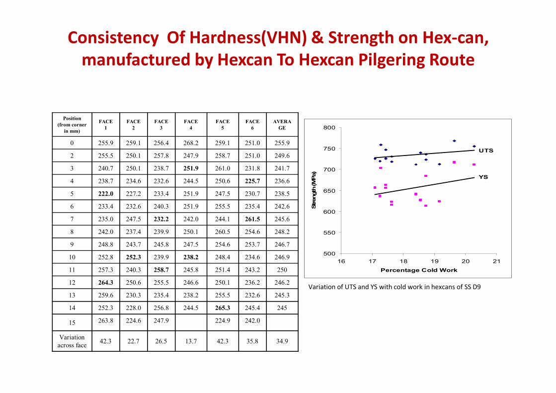
Consistency Of Hardness(VHN) & Strength on Hex-can,
manufactured by Hexcan To Hexcan Pilgering Route
Position
(from corner
in mm)
FACE
1
FACE
2
FACE
3
FACE
4
FACE
5
FACE
6
AVERA
GE
0 255.9 259.1 256.4 268.2 259.1 251.0 255.9
2 255.5 250.1 257.8 247.9 258.7 251.0 249.6
3 240.7 250.1 238.7 251.9 261.0 231.8 241.7
4 238.7 234.6 232.6 244.5 250.6 225.7 236.6
5 222.0 227.2 233.4 251.9 247.5 230.7 238.5
6 233.4 232.6 240.3 251.9 255.5 235.4 242.6
7 235.0 247.5 232.2 242.0 244.1 261.5 245.6
8 242.0 237.4 239.9 250.1 260.5 254.6 248.2
9 248.8 243.7 245.8 247.5 254.6 253.7 246.7
10 252.8 252.3 239.9 238.2 248.4 234.6 246.9
11 257.3 240.3 258.7 245.8 251.4 243.2 250
12 264.3 250.6 255.5 246.6 250.1 236.2 246.2
13 259.6 230.3 235.4 238.2 255.5 232.6 245.3
14 252.3 228.0 256.8 244.5 265.3 245.4 245
15 263.8 224.6 247.9 224.9 242.0
Variation
across face42.3 22.7 26.5 13.7 42.3 35.8 34.9
500
550
600
650
700
750
800
16 17 18 19 20 21
Percentage Cold Work
Strength
(M
Pa)
UTS
YS
Variation of UTS and YS with cold work in hexcans of SS D9

Variation of micro hardness across the face of hexcan, manufactured by
hexcan to hexcan and circular to hexcan pilgering.
150
170
190
210
230
250
270
290
0 5 10 15 20 25 30
DIST FROM CORNER
MIC
RO
HA
RD
NE
SS
(V
HN
)FACE 1
FACE 2
FACE 3
FACE 4
FACE 5
FACE 6
AVERAGE
CIR TO HEX

PILGER MILL FOR PILGERING OF
HEXCANS

HEAT TREATMENT
• After each stage of cold working (except final coldworking) the material is subjected to solutionisingtreatment at 1020
0to 1080
0C in LPG Annealing
Furnace.
• The channels are passed slowly through the heatingzone to achieve the required time for soaking.
• After the heat treatment, the hexcans areimmediately quenched in water to avoid sensitization.

INSPECTION AND QUALITY CONTROL PROCEDURE
At each stage of manufacturing, process quality control measures areadequately taken to obtain consistent quality in the product.
– During extrusion process, important process parameters such asextrusion temperature, strain rate and lubrication conditions arecritically monitored
– The extruded hollows are thoroughly tested for their soundness byUltrasonic Examination with 5% wall thickness standard in additionto visual & dimensional checks.
– By proper control of process parameters during pilgering such astool design, lubrication, feed and speed etc., consistent quality ofproduct in terms of surface finish, dimensional tolerances areachieved.
– After each stage of pilgering, the dimensional accuracy and surface-finish are monitored.

MICROSTRUCTURAL STUDIES
MICROSTRUCTURE OF D9 HEXCAN
IN PILGERED CONDITION
MICROSTRUCTURE AFTER
SENSITISATION AT 6500 C FOR 1 HR,
SHOWING DUAL MICROSTRUCTURE
MICROSTRUCTURE AFTER
SENSITISATION AT 6500 C FOR
1 HR SHOWING DITCHED
MICROSTRUCTURE
ACCEPTABLE UNACCEPTABLE

Comparison of FBTR & PFBR Subassembly Design
Reactor FBTR- 13MWe PFBR- 500MWe
No. of Subassemblies
(SA) /core
65 (85+96=181)
Fuel PuC (70% ) + UC PuO2 (21.7 & 28.7%) + UO2
Clad SS316M D9
Wrapper SS316L D9
Structural
components
SS316L SS316LN
Pin design Fuel & Lower and Upper
blankets put in separate pins
Integrated design-all in same pin
No of pins/SA 61 217
Lower plenum Provided with a tube / disc-
supporting the fuel column
Fuel column supported on a
middle plug crimped in the clad
Overall Dimension 1.6m & 49.8mm (Hex. A/F) 4.5m & 131.6mm (Hex. A/F)
Weight 30kg 250kg

1st End Plug Welding Machine

2nd End Plug Welding Machine

Spacer Wire Wrapping &
Spot Welding Machine

• Precision current control to ±0.5Amps withfeedback system with smooth arc start and arcstability in Helium atmosphere.
• Automatic initial arc gap setting and arc gapcontrol.
• Automatic data acquisition and feedback controlsystem with recording facilities for criticalparameters like current, voltage, (arc distance),weld speed, vacuum level, Helium pressure,oxygen level (inert gas quality), etc.
• Precision special purpose fixtures for GTAW,Resistance welding techniques.
Special Features of the Equipment
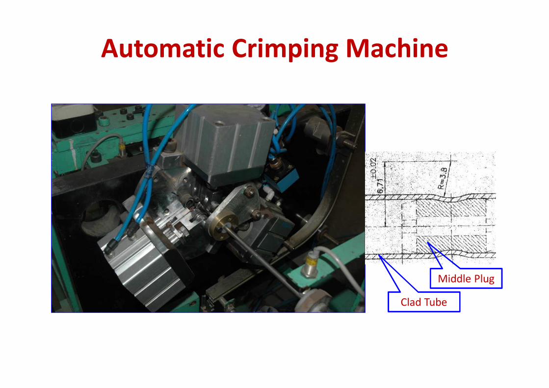
Automatic Crimping Machine
Middle Plug
Clad Tube

Button Forming Machine

i. Lower Part
ii. Hexcan welded to Handling Head
iii. 217 Fuel Pins loaded in 2 Pin Magazines
Manufacture of Subassemblies

Automatic Hexcan
Welding Machine
� Automatic torch inclination with Torch
oscillation axis provided for keeping it
perpendicular to welding face in
synchronization with tube rotation.
� Software based automatic control with
feedback system for all critical parameters
with recording facilities.
� Electronic Arc Distance Control provided for
welding while rotating the hexcan

Thanks for your attention
Related Documents